| GENX-1B CLEANING,INSPECTION,AND REPAIR MANUAL | Dated: 04/30/2019 | |
| CIR 72-32-01 , REPAIR 006 | ||
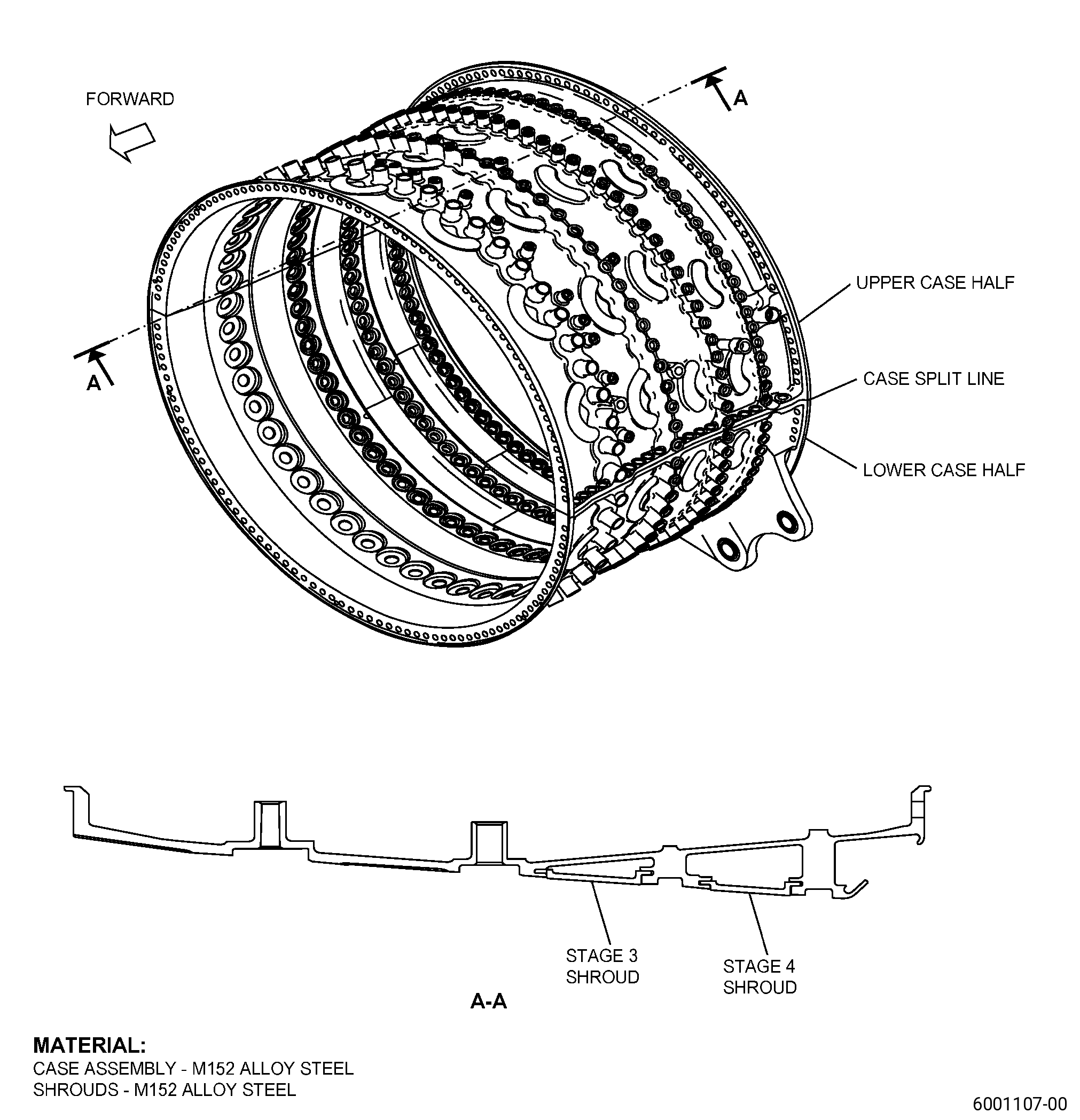
| HIGH PRESSURE COMPRESSOR STATOR FORWARD CASE ASSEMBLY - REPAIR - REPLACEMENT OF THE STAGE 3 AND STAGE 4 SHROUDS | ||
| GENX-1B CLEANING,INSPECTION,AND REPAIR MANUAL | Dated: 04/30/2019 | |
| CIR 72-32-01 , REPAIR 006 | ||
| HIGH PRESSURE COMPRESSOR STATOR FORWARD CASE ASSEMBLY - REPAIR - REPLACEMENT OF THE STAGE 3 AND STAGE 4 SHROUDS | ||
| * * * FOR ALL |
| TASK 72-32-01-300-806 |
| 1 . | Replacement of the Stage 3 and Stage 4 Shrouds. |
| A. | This procedure gives instructions to repair the HPC stator forward case assembly (case assembly) by removing and replacing the damaged stage 3 and/or stage 4 shrouds. Refer to Figure 901. |
| B. | The following maximum repairable limits apply to this repair: |
| NOTE: |
|
| (4) | Visual Inspection. |
| (c) | Do an inspection of the stage 3 shroud and stage 4 shroud flowpath surfaces for: |
| 1 | Rubs and gouges: |
| Maximum repairable limit: |
|
| 2 | Nicks, dents, and scratches: |
| Maximum repairable limit: |
|
| 3 | Local scabs (positive metal pickup from the blades): |
| Maximum repairable limit: |
|
| C. | The subsequent table gives a list of the part numbers that are applicable to this procedure. All part numbers are applicable to all paragraphs unless specified differently. |
|
|||||||||||||||||||||||
| D. | Proprietary/Complex Process Statement. |
| (1) | None. |
| 2 . | Tools, Equipment, and Materials. |
| NOTE: |
|
| A. | Tools and Equipment. |
| (1) | Special Tools. None. |
| (2) | Standard Tools and Equipment. None. |
| (3) | Locally Manufactured Tools. None. |
| B. | Consumable Materials. None. |
| C. | Referenced Procedures. |
| D. | Expendable Parts. None. |
| E. | SPD Information. |
| (1) | Spares Supplied. |
|
| (2) | Protected Spares. None. |
| (3) | Locally Manufactured Spares. None. |
| F. | Special Solutions. None. |
| G. | Test Specimens. None. |
| 3 . | Dimensional Information. |
| Subtask 72-32-01-220-118 |
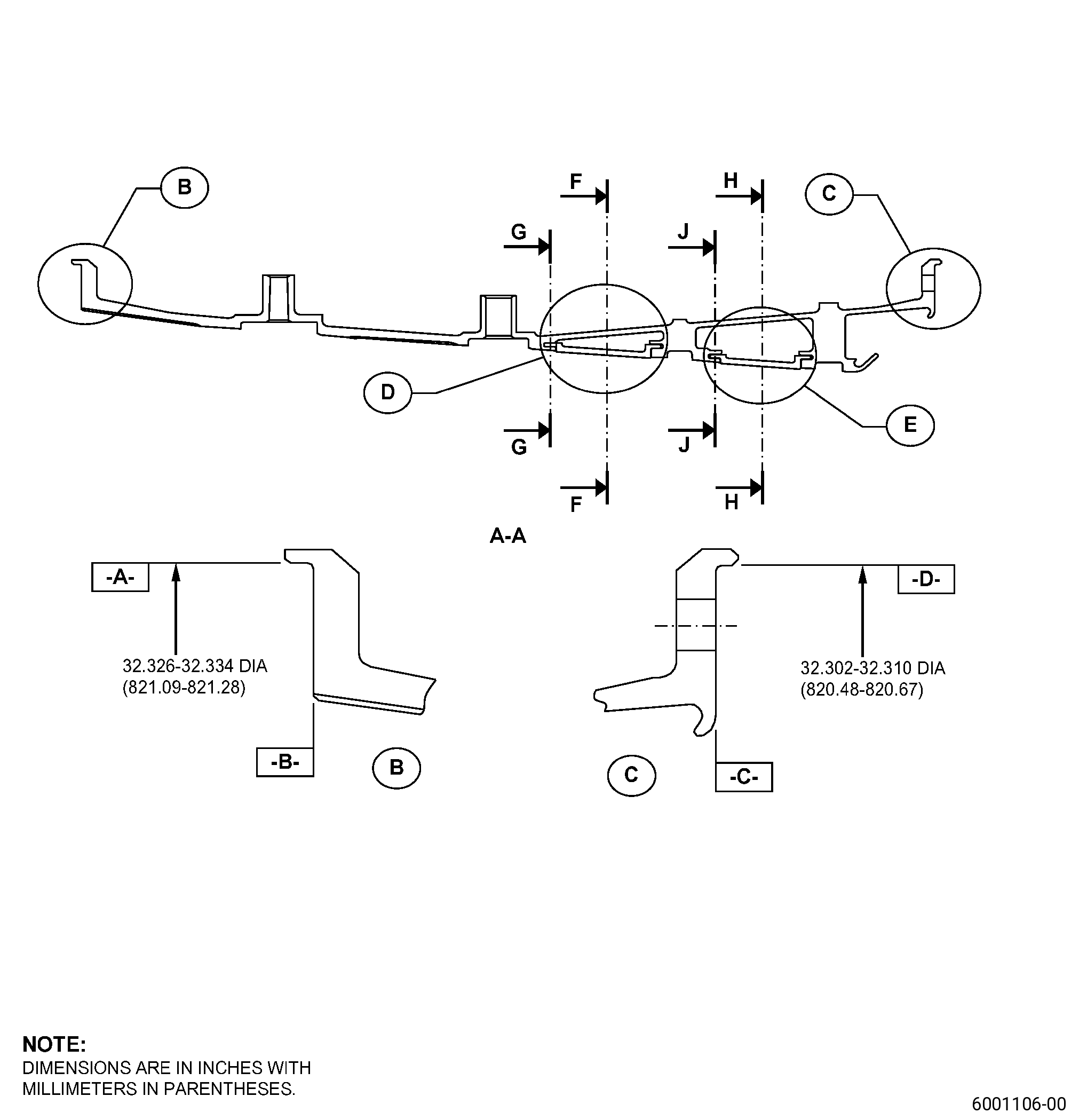
| A. | Refer to Figure 901 for specified dimensions and locations. |
| NOTE: |
|
| NOTE: |
|
| 4 . | Setup Information. |
| Subtask 72-32-01-350-064 |
| A. | Set-up the case assembly for machining. Refer to Figure 901 and as follows: |
| Subtask 72-32-01-930-004 |
| (1) | If necessary, make a machining fixture to attach surface C and diameter D of the case assembly to the machine table. |
| Subtask 72-32-01-350-065 |
| (2) | Put the case assembly, aft end down, on the machine table and do as follows: |
| (a) | Adjust the position of the case assembly on the machine table until the flatness of surface C is 0.001 inch (0.02 mm) or less. |
| (b) | Adjust the position of the case assembly on the machine table until the circular runout of diameter D is 0.001 inch (0.02 mm) or less, full indicator reading (FIR). |
| (c) | Attach the case assembly to the machine table. |
| Subtask 72-32-01-220-119 |
| (3) | Do a check of the forward flange dimensions as follows: |
| (a) | Surface B must be parallel to surface C in 0.002 inch (0.05 mm). |
| (b) | Diameter A must be concentric to diameter B in 0.003 inch (0.07 mm). |
| Subtask 72-32-01-350-066 |
| (4) | If necessary, do Subtask 72-32-01-930-004 (paragraph 4.A.(1)) thru Subtask 72-32-01-220-119 (paragraph 4.A.(3)) again to get the correct dimensions. |
| 5 . | Procedure. |
| Subtask 72-32-01-160-009 |
| A. | If necessary, clean the case assembly. Refer to TASK 72-32-01-100-801 (72-32-01, CLEANING 001). |
| Subtask 72-32-01-350-067 |
| B. | If necessary, disassemble the case assembly to disconnect the upper and lower case halves. Refer to Figure 901. |
| Subtask 72-32-01-350-068 |
| C. | If necessary, remove the stage 3 shrouds from the case assembly. Refer to Figure 901 and as follows: |
| (1) | If there is a stage 3 spline seal, remove it from the end slot of the stage 3 shroud. |
| NOTE: |
|
| NOTE: |
|
| (2) | Smoothly move a stage 3 shroud to remove it from the rail. |
| (3) | Remove a lock key from the related case assembly slot. |
| (4) | Do Subtask 72-32-01-350-068 (paragraph 5.C.(1)) thru (paragraph 5.C.(3)) again until you remove all stage 3 shrouds. |
| (5) | Discard all stage 3 shrouds, spline seals, and lock keys. Stage 3 shrouds are not repairable. |
| Subtask 72-32-01-350-069 |
| D. | If necessary, remove the stage 4 shrouds from the case assembly. Refer to Figure 901 and as follows: |
| (1) | If there is a stage 4 spline seal, remove it from the end slot of the stage 4 shroud. |
| NOTE: |
|
| NOTE: |
|
| (2) | Smoothly move a stage 4 shroud to remove it from the rail. |
| (3) | Remove a lock key from the related case assembly slot. |
| (4) | Do Subtask 72-32-01-350-069 (paragraph 5.D.(1)) thru (paragraph 5.D.(3)) again until you remove all stage 4 shrouds. |
| (5) | Discard all stage 4 shrouds, spline seals, and lock keys. Stage 4 shrouds are not repairable. |
| Subtask 72-32-01-350-070 |
| E. | Get new sets of stage 3 and/or stage 4 shrouds and lock keys. Refer to Figure 902, Figure 903, paragraph 2.E., and do as follows: |
| (1) | You must replace the shrouds with a new set for each stage as necessary and as follows: |
| (a) | Make sure that you get the correct quantity and position for each set. |
| NOTE: |
|
| Subtask 72-32-01-350-071 |
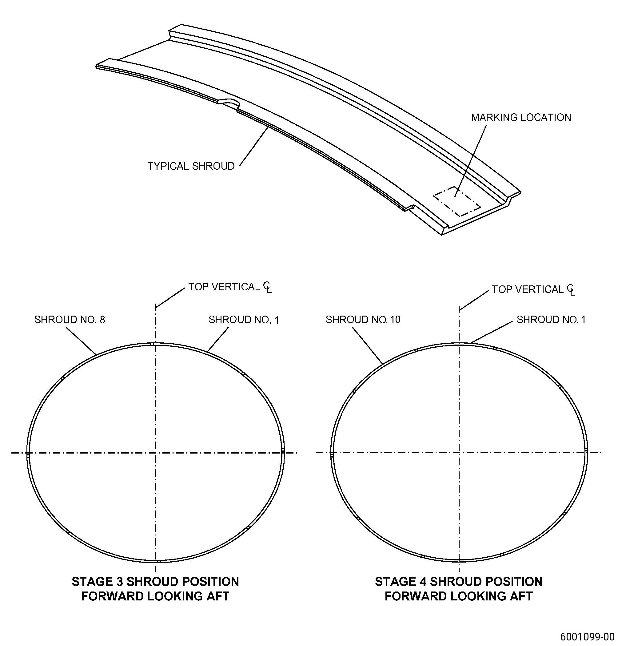
| (2) | Alternative Procedure Available. Put clock location marks on the new stage 3 and/or stage 4 shrouds. Refer to TASK 70-16-00-350-001 (MARKING PRACTICES), TASK 70-16-04-350-019 (VIBRO-PEEN MARKING), Figure 904, and as follows: |
| (a) | Start with the stage 3 shroud that is at the 12 o’clock position and continue clockwise, forward looking aft, put marks of numbers from 1 to 8 on the stage 3 shrouds. |
| (b) | Start with the stage 4 shroud that is at the 12 o’clock position and going clockwise, forward looking aft, put marks of numbers from 1 to 10 on the stage 4 shrouds. |
| (c) | Put a mark with the serial number of the case assembly on all stage 3 and/or stage 4 shrouds. |
| Subtask 72-32-01-350-072 |
| (2).A. | Alternative Procedure. Put clock location marks on the new stage 3 and/or stage 4 shrouds. Refer to TASK 70-16-00-350-001 (MARKING PRACTICES), TASK 70-16-08-350-001 (DOT PEEN MARKING FOR OPTICAL CHARACTER RECOGNITION), Figure 904, and as follows: |
| (a) | Start with the stage 3 shroud that is at the 12 o’clock position and continue clockwise, forward looking aft, put marks of numbers from 1 to 8 on the stage 3 shrouds. |
| (b) | Start with the stage 4 shroud that is at the 12 o’clock position and continue clockwise, forward looking aft, put marks of numbers from 1 to 10 on the stage 4 shrouds. |
| (c) | Put a mark with the serial number of the case assembly on all stage 3 and/or stage 4 shrouds. |
| Subtask 72-32-01-350-073 |
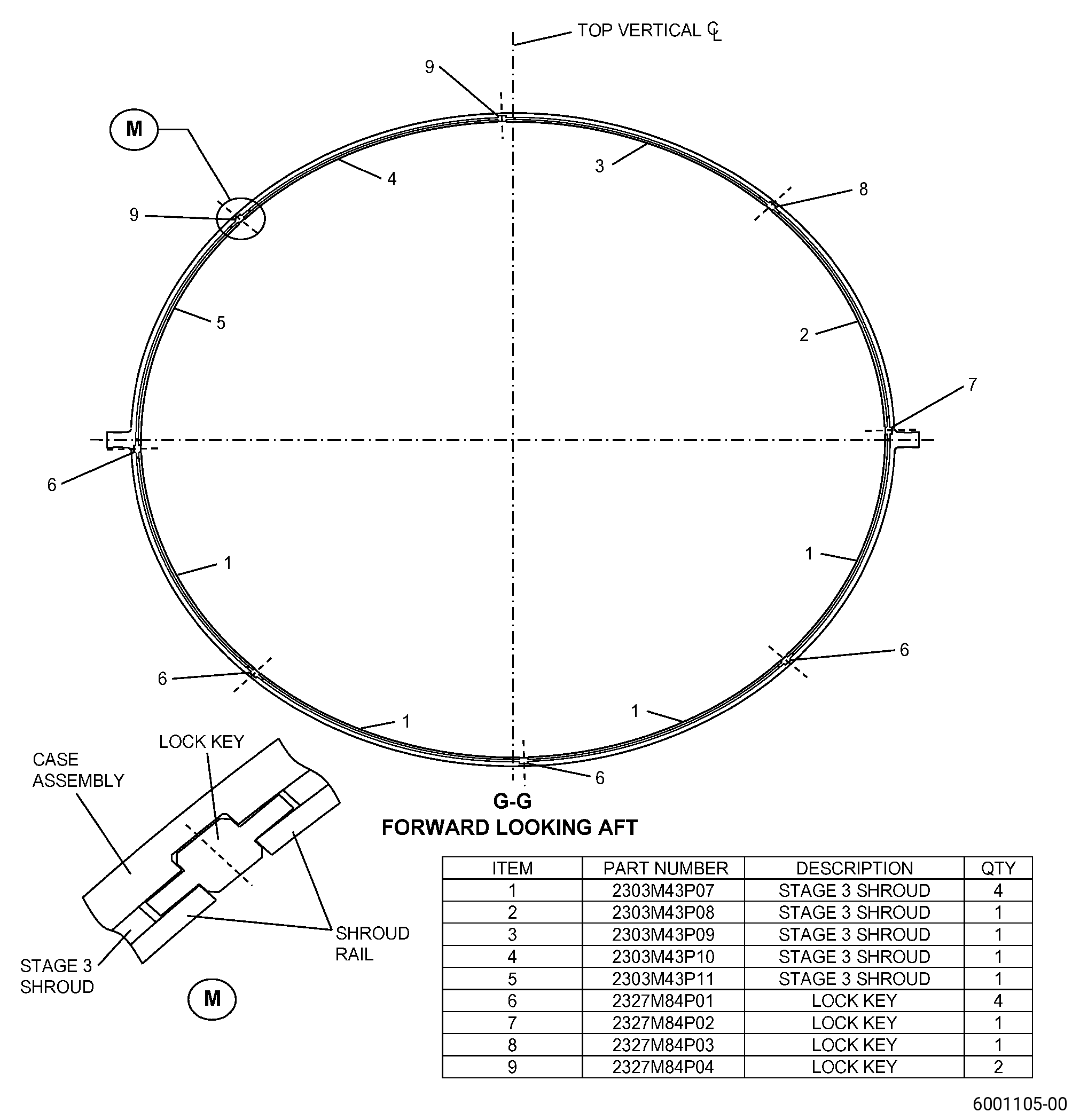
| F. | If necessary, install the new stage 3 shrouds into the upper and lower case halves. Refer to Figure 902 and as follows: |
| (1) | Install the shrouds in the upper case half as follows: |
| (a) | Move the shroud (item 3) into the rail at the 3 o’clock position until it is fully through the lock key (item 8) position. |
| (b) | Move the shroud (item 2) into the rail at the 3 o’clock position until it is fully through the lock key (item 7) position. |
| (c) | Install the lock key (item 7) into the slot. |
| (d) | Move the shroud (item 2) in the opposite direction until it engages with the lock key (item 7). |
| (e) | Install the lock key (item 8) into the slot. |
| (f) | Move the shroud (item 3) in the opposite direction until it engages with the lock key (item 8). |
| (g) | Install the lock key (item 9) into the slot at the 12 o’clock position. |
| (h) | Move the shroud (item 4) into the rail at the 9 o’clock position until it engages with the lock key (item 9). |
| (i) | Install the lock key (item 9) into the slot at the 10:30 o’clock position. |
| (j) | Move the shroud (item 5) into the rail at the 9 o’clock position until it engages with the lock key (item 9). |
| (2) | Install the shrouds in the lower case half as follows: |
| (a) | Move the shroud (item 1) into the rail at the 9 o’clock position until it is fully through the lock key (item 6) position at the 7:30 o’clock position. |
| (b) | Move the shroud (item 1) into the rail at the 9 o’clock position until it is fully through the lock key (item 6) at the 9 o’clock position. |
| (c) | Install the lock key (item 6) into the slot at the 9 o’clock position. |
| (d) | Move the shroud (item 1) that you installed second in the opposite direction until it engages with the lock key (item 6) at the 9 o’clock position. |
| (e) | Install the lock key (item 6) into the slot at the 7:30 o’clock position. |
| (f) | Move the shroud (item 1) that you installed first in the opposite direction until it engages with the lock key (item 6) at the 7:30 o’clock position. |
| (g) | Install the lock key (item 6) into the slot at the 6 o’clock position. |
| (h) | Move the shroud (item 1) into the rail at the 3 o’clock position until it engages with the lock key (item 6) at the 6 o’clock position. |
| (i) | Install the lock key (item 6) into the slot at the 4:30 o’clock position. |
| (j) | Move the shroud (item 1) into the rail at the 3 o’clock position until it engages with the lock key (item 6) at the 4:30 o’clock position. |
| Subtask 72-32-01-350-074 |
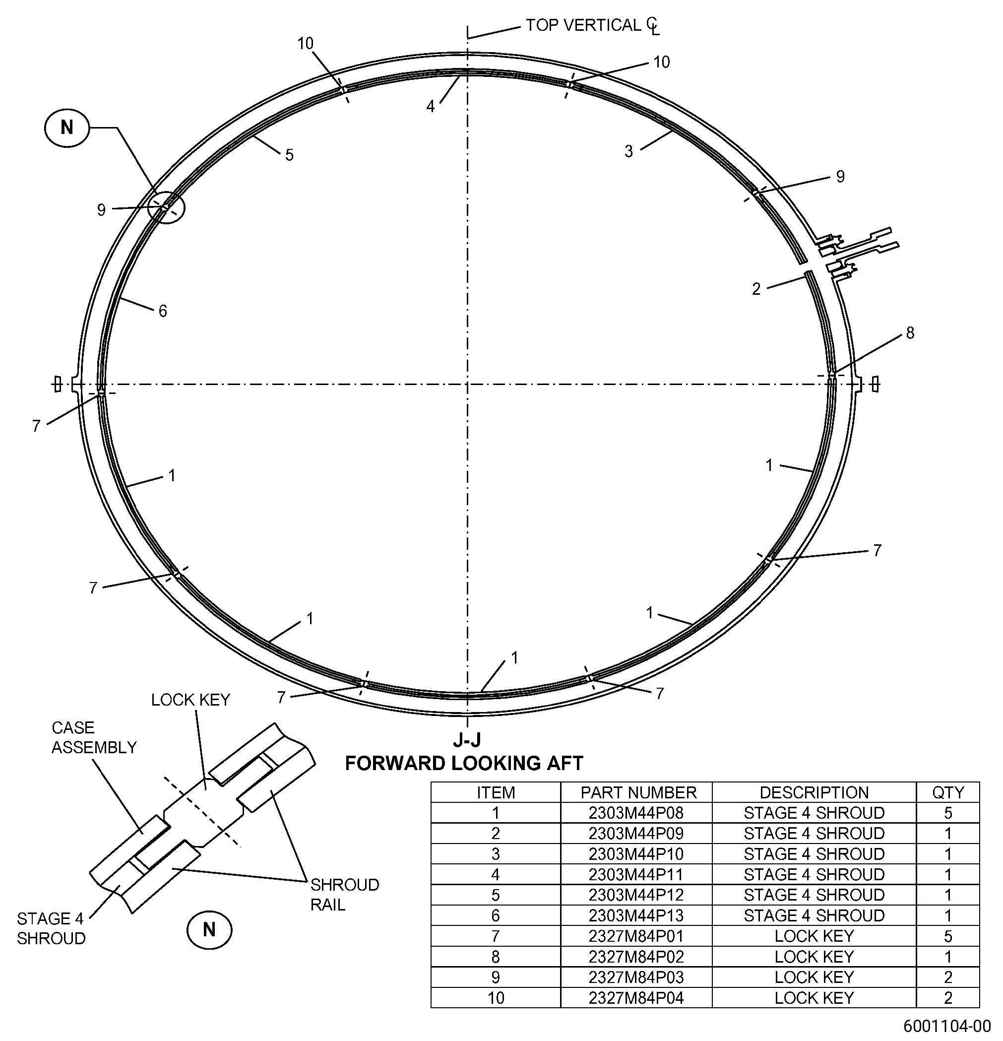
| G. | If necessary, install the new stage 4 shrouds into the upper and lower case halves. Refer to Figure 903 and as follows: |
| (1) | Install the shrouds in the upper case half as follows: |
| (a) | Move the shroud (item 3) into the rail at the 3 o’clock position until it is fully through the lock key (item 9) position at the 2 o’clock position. |
| (b) | Move the shroud (item 2) into the rail at the 3 o’clock position until it is fully through the lock key (item 8) position. |
| (c) | Install the lock key (item 8) into the slot. |
| (d) | Move the shroud (item 2) in the opposite direction until it engages with the lock key (item 8). |
| (e) | Install the lock key (item 9) into slot at the 2 o’clock position. |
| (f) | Move the shroud (item 3) in the opposite direction until it engages with the lock key (item 9) at the 2 o’clock position. |
| (g) | Install the lock key (item 10) into the slot at the 12:30 o’clock position. |
| (h) | Move the shroud (item 4) into the rail at the 9 o’clock position until it engages with the lock key (item 10) at the 12:30 o’clock position. |
| (i) | Install the lock key (item 10) into the slot at the 11:30 o’clock position. |
| (j) | Move the shroud (item 5) into the rail at the 9 o’clock position until it engages with the lock key (item 10) at the 11:30 o’clock position. |
| (k) | Install the lock key (item 9) into the slot at the 10 o’clock position. |
| (l) | Move the shroud (item 6) into the rail at the 9 o’clock position until it engages with the lock key (item 9) at the 10 o’clock position. |
| (2) | Install the shrouds in the lower case half as follows: |
| (a) | Move the shroud (item 1) into the rail at the 9 o’clock position until it is fully through the lock key (item 7) position at the 8 o’clock position. |
| (b) | Move the shroud (item 1) into the rail at the 9 o’clock position until it is fully through the lock key (item 7) position at the 9 o’clock position. |
| (c) | Install the lock key (item 7) into the slot at the 9 o’clock position. |
| (d) | Move the shroud (item 1) that you installed second in the opposite direction until it engages with the lock key (item 7) at the 9 o’clock position. |
| (e) | Install the lock key (item 7) into the slot at the 8 o’clock position. |
| (f) | Move the shroud (item 1) that you installed first in the opposite direction until it engages with the lock key (item 7) at the 8 o’clock position. |
| (g) | Install the lock key (item 7) into the slot at the 6:30 o’clock position. |
| (h) | Move the shroud (item 1) into the rail at the 3 o’clock position until it engages with the lock key (item 7) at the 6:30 o’clock position. |
| (i) | Install the lock key (item 7) into the slot at the 5:30 o’clock position. |
| (j) | Move the shroud (item 1) into the rail at the 3 o’clock position until it engages with the lock key (item 7) at the 5:30 o’clock position. |
| (k) | Install the lock key (item 7) into the slot at the 4 o’clock position. |
| (l) | Move the shroud (item 1) into the rail at the 3 o’clock position until it engages with the lock key (item 7) at the 4 o’clock position. |
| Subtask 72-32-01-350-075 |
| H. | Assemble the upper and lower case halves of the case assembly. Refer to TASK 72-32-01-200-801 (72-32-01, INSPECTION 001). |
| Subtask 72-32-01-320-013 |
| I. | Machine the stage 3 and/or stage 4 shroud flow paths. Refer to TASK 70-00-03-800-004 (MACHINING DATA), Figure 905, and as follows: |
| (1) | Set-up the case assembly for machining. Refer to Subtask 72-32-01-350-064 (paragraph 4.A.). |
| (2) | Do not machine into the adjacent case assembly surfaces. |
| Subtask 72-32-01-320-014 |
| J. | Machine the lobes on the stage 3 and/or stage 4 shroud flow paths. Refer to TASK 70-00-03-800-004 (MACHINING DATA), Figure 904, Figure 906, Figure 907, and as follows: |
| (1) | If necessary, machine the stage 3 shroud flow path only between point JU and point JV. |
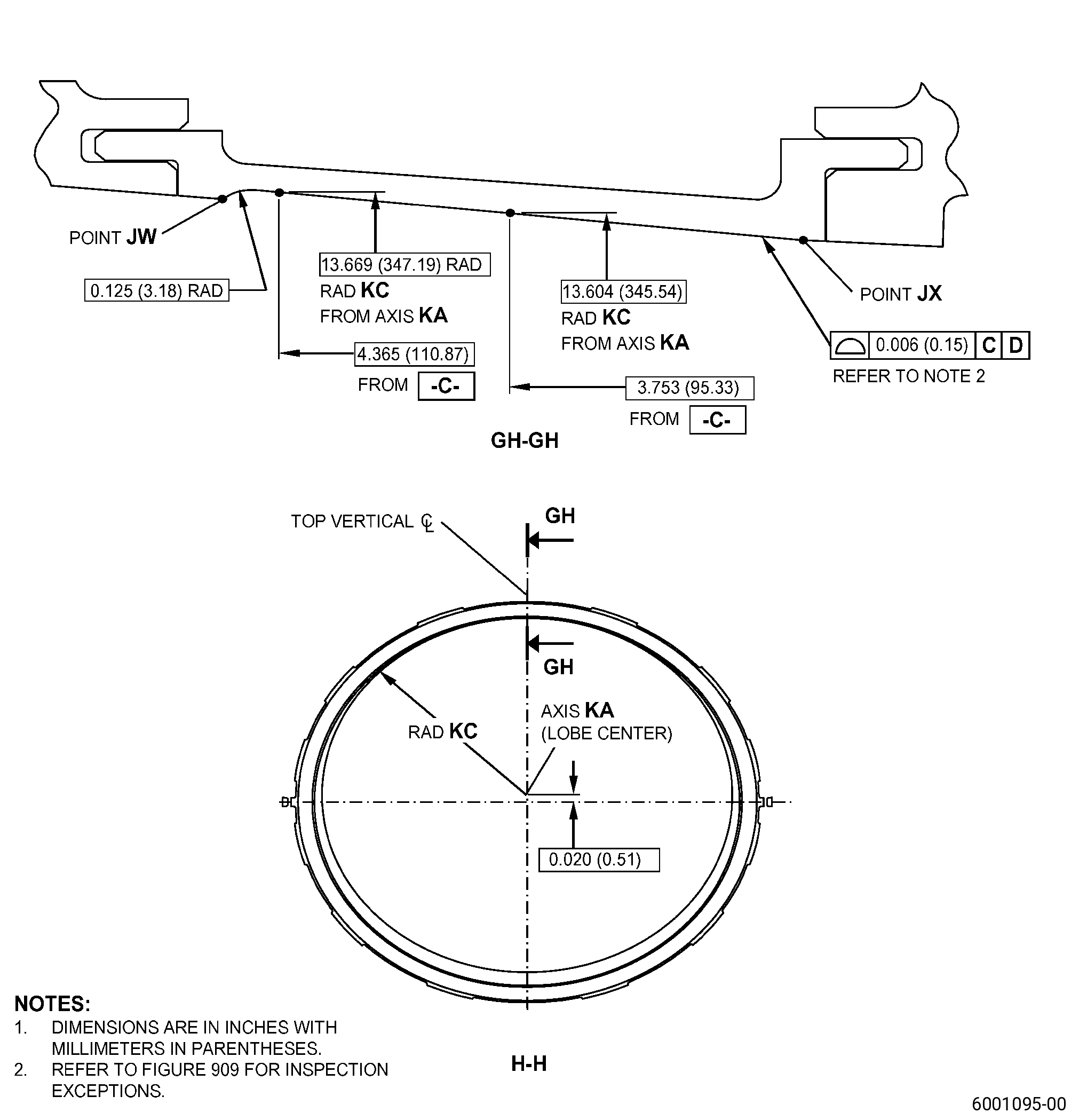
| (2) | If necessary, machine the stage 4 shroud flow path only between point JW and point JX. |
| Subtask 72-32-01-350-076 |
| CAUTION: |
|
| K. | Blend the stage 3 and/or stage 4 shrouds. Refer to TASK 70-42-00-350-002 (BLENDING AND REMOVAL OF HIGH METAL PROCEDURES) and as follows: |
| (1) | Blend the forward and aft edges of the stage 3 and/or stage 4 shroud flow paths to get a step of 0.004 inch (0.10 mm) or less from the stage 3 and/or stage 4 shrouds to the adjacent case assembly surfaces. |
| (2) | Do not remove material from the case assembly surfaces. |
| Subtask 72-32-01-350-077 |
| L. | Disassemble the case assembly to disconnect the upper and lower case halves. Refer to TASK 72-30-00-030-803 (72-30-00, DISASSEMBLY 002). |
| Subtask 72-32-01-350-078 |
| M. | Remove the stage 3 and/or stage 4 shrouds from the case assembly. Refer to Subtask 72-32-01-350-068 (paragraph 5.C.) thru Subtask 72-32-01-350-069 (paragraph 5.D.). |
| Subtask 72-32-01-160-010 |
| N. | Clean the stage 3 and/or stage 4 shrouds and case assembly. Refer to TASK 70-21-00-110-051 (CHEMICAL CLEANING) and TASK 70-21-03-160-001 (CLEANING METHOD NO. 3 - STEAM CLEANING). |
| Subtask 72-32-01-110-017 |
| O. | Etch the machined areas of stage 3 and/or stage 4 shrouds. Refer to TASK 70-24-00-110-033 (ETCHING PROCEDURES FOR FLUORESCENT-PENETRANT INSPECTION), TASK 70-24-01-110-034 (SWAB ETCHING PROCEDURE), and as follows: |
| (1) | Use Class C etchant. |
| Subtask 72-32-01-220-120 |
| P. | Do an inspection of the stage 3 and/or stage 4 shrouds machined areas. Refer to TASK 70-32-00-200-002 (INDIRECT INSPECTION METHODS), TASK 70-32-03-230-002 (SPOT-FLUORESCENT-PENETRANT INSPECTION), and as follows: |
| (1) | Use Class D penetrant. |
| (2) | Refer to TASK 70-31-02-220-003 (ACCEPTABILITY LIMITS FOR FLUORESCENT PENETRANT INSPECTION) and as follows: |
| (a) | Use Class A limits. |
| Subtask 72-32-01-350-079 |
| Q. | Install the machined stage 3 and/or stage 4 shrouds into the upper and lower case halves. Refer to Subtask 72-32-01-350-073 (paragraph 5.F.) thru Subtask 72-32-01-350-074 (paragraph 5.G.). |
| Subtask 72-32-01-350-080 |
| R. | Assemble the upper and lower case halves of the case assembly. Refer to TASK 72-32-01-200-801 (72-32-01, INSPECTION 001). |
| Subtask 72-32-01-220-121 |
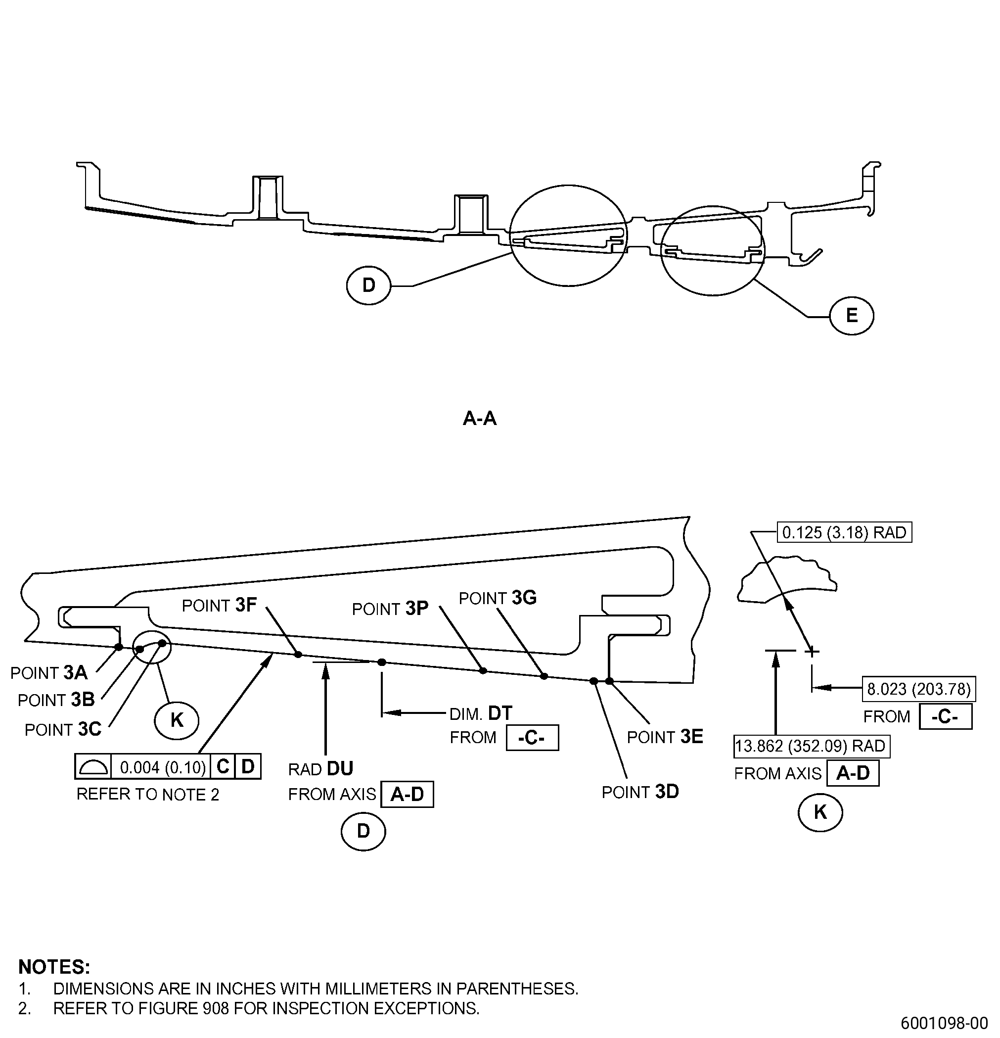
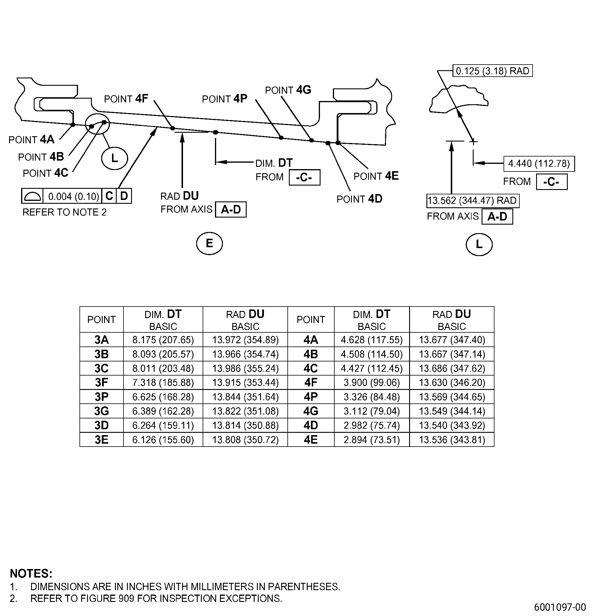
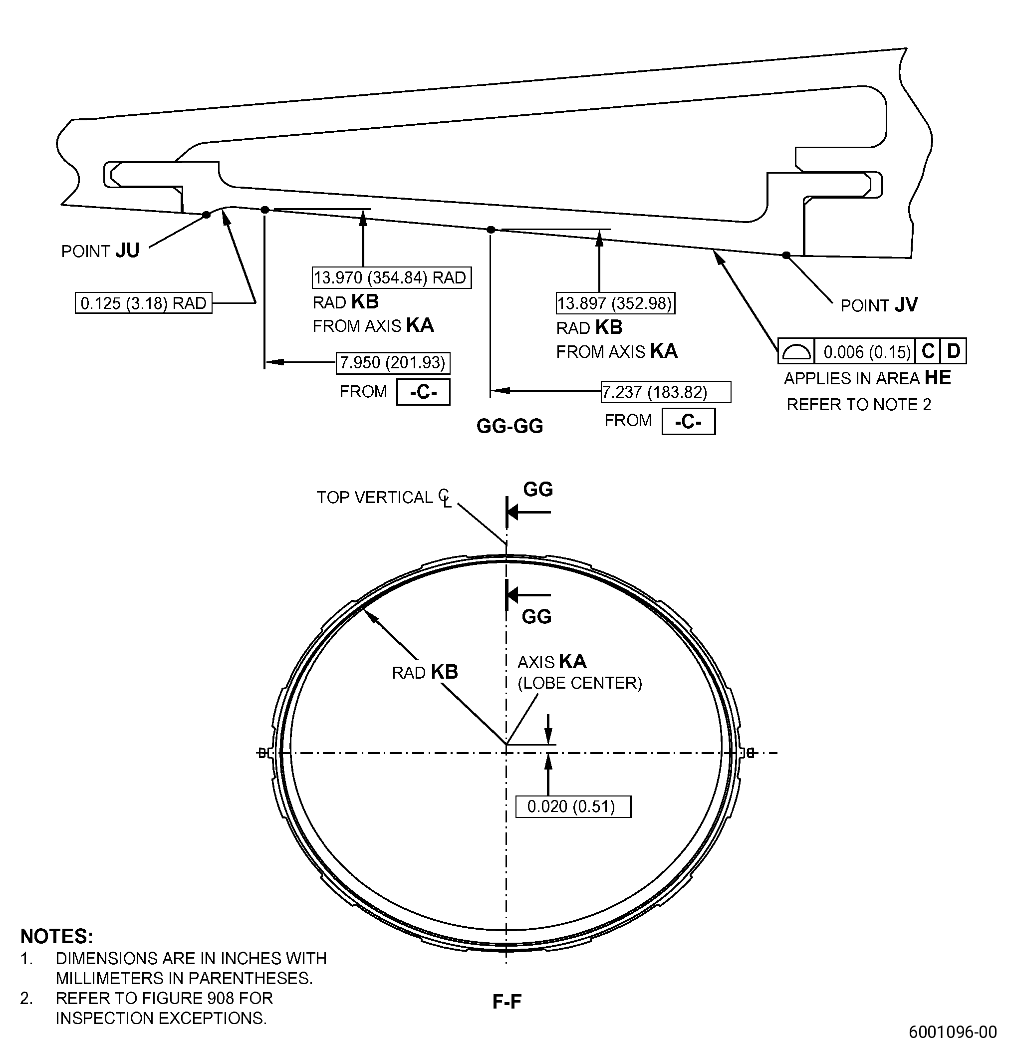
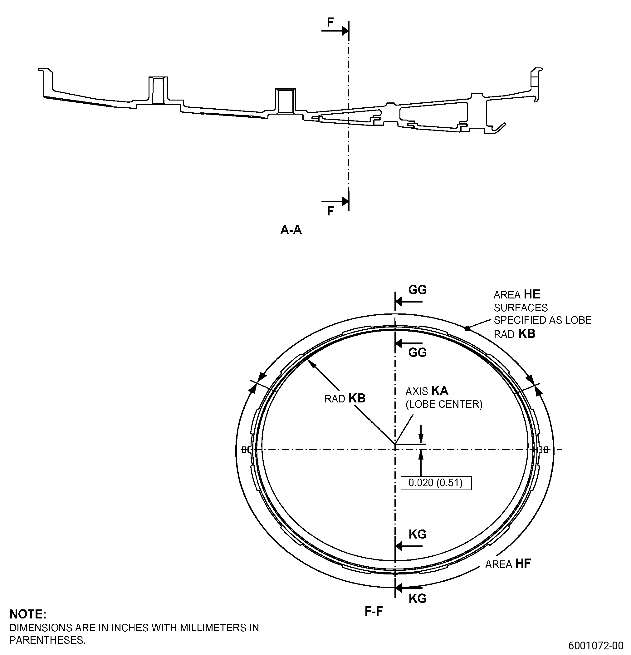
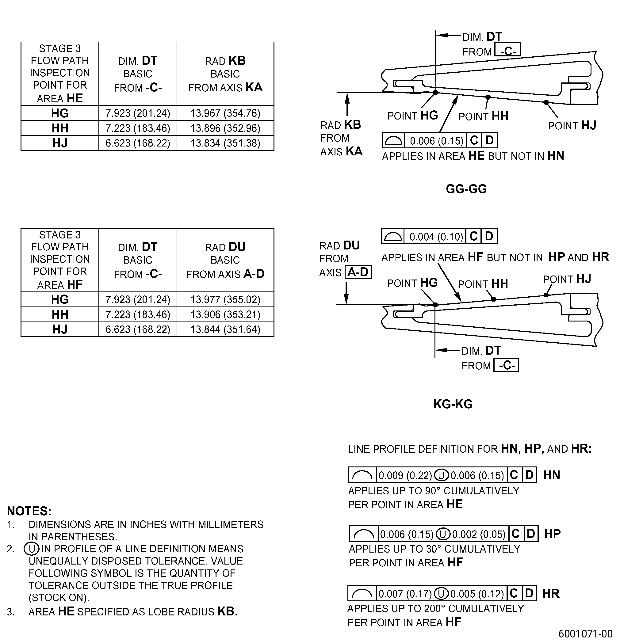
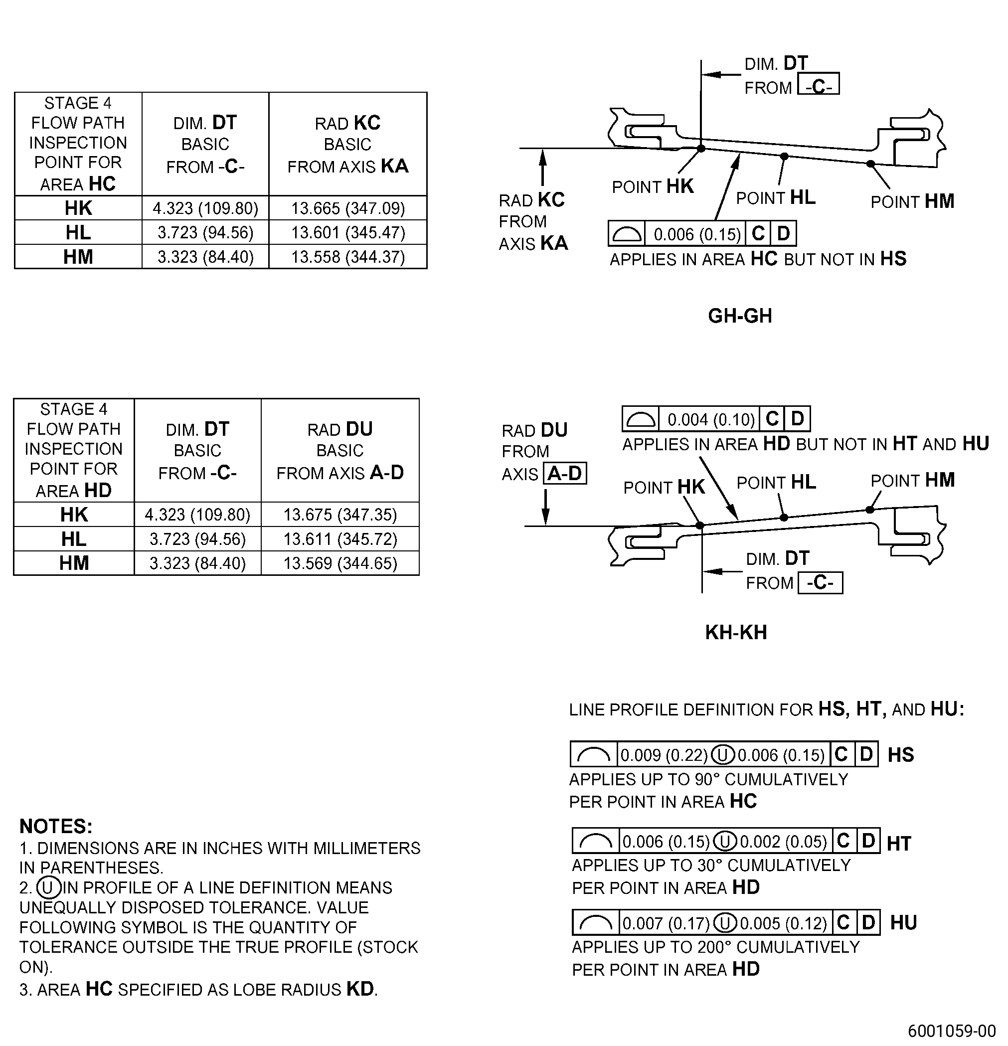
| S. | Do a dimensional inspection of the stage 3 and/or stage 4 flow paths. Refer to Figure 901, Figure 908, Figure 909, and as follows: |
| (1) | For the lobe machined area HE (stage 3) and/or area HC (stage 4), do an inspection of the stage 3 at point HG, point HH, and point HJ, and/or do an inspection of the stage 4 at point HK, point HL, and point HM, and as follows: |
| (a) | Do an inspection of each point at 10 degree increments, full circumference. |
| (b) | The line profile definition gives circumferential relief for machined areas that are more than the 0.006 (0.15 mm) surface profile tolerance. |
| (2) | For the non-lobe machined area HF (stage 3) and/or area HD (stage 4), do an inspection of the stage 3 at point HG, point HH, and point HJ, and/or do an inspection of the stage 4 at point HK, point HL, and point HM, and as follows: |
| (a) | Do an inspection of each point at 10 degree increments, full circumference. |
| (b) | The line profile definition gives circumferential relief for machined areas that are more than the 0.004 inch (0.10 mm) surface profile tolerance. |