| GENX-1B CLEANING,INSPECTION,AND REPAIR MANUAL | Dated: 08/13/2024 | |
| CIR 72-32-01 , REPAIR 005 | ||
| HIGH PRESSURE COMPRESSOR STATOR FORWARD CASE ASSEMBLY - REPAIR - THERMAL SPRAY REPAIR OF THE CIRCUMFERENTIAL FLANGES AND RABBETS | ||
| GENX-1B CLEANING,INSPECTION,AND REPAIR MANUAL | Dated: 08/13/2024 | |
| CIR 72-32-01 , REPAIR 005 | ||
| HIGH PRESSURE COMPRESSOR STATOR FORWARD CASE ASSEMBLY - REPAIR - THERMAL SPRAY REPAIR OF THE CIRCUMFERENTIAL FLANGES AND RABBETS | ||
| * * * FOR ALL |
| TASK 72-32-01-300-805 |
| 1 . | Thermal Spray Repair of the Circumferential Flanges and Rabbets. |
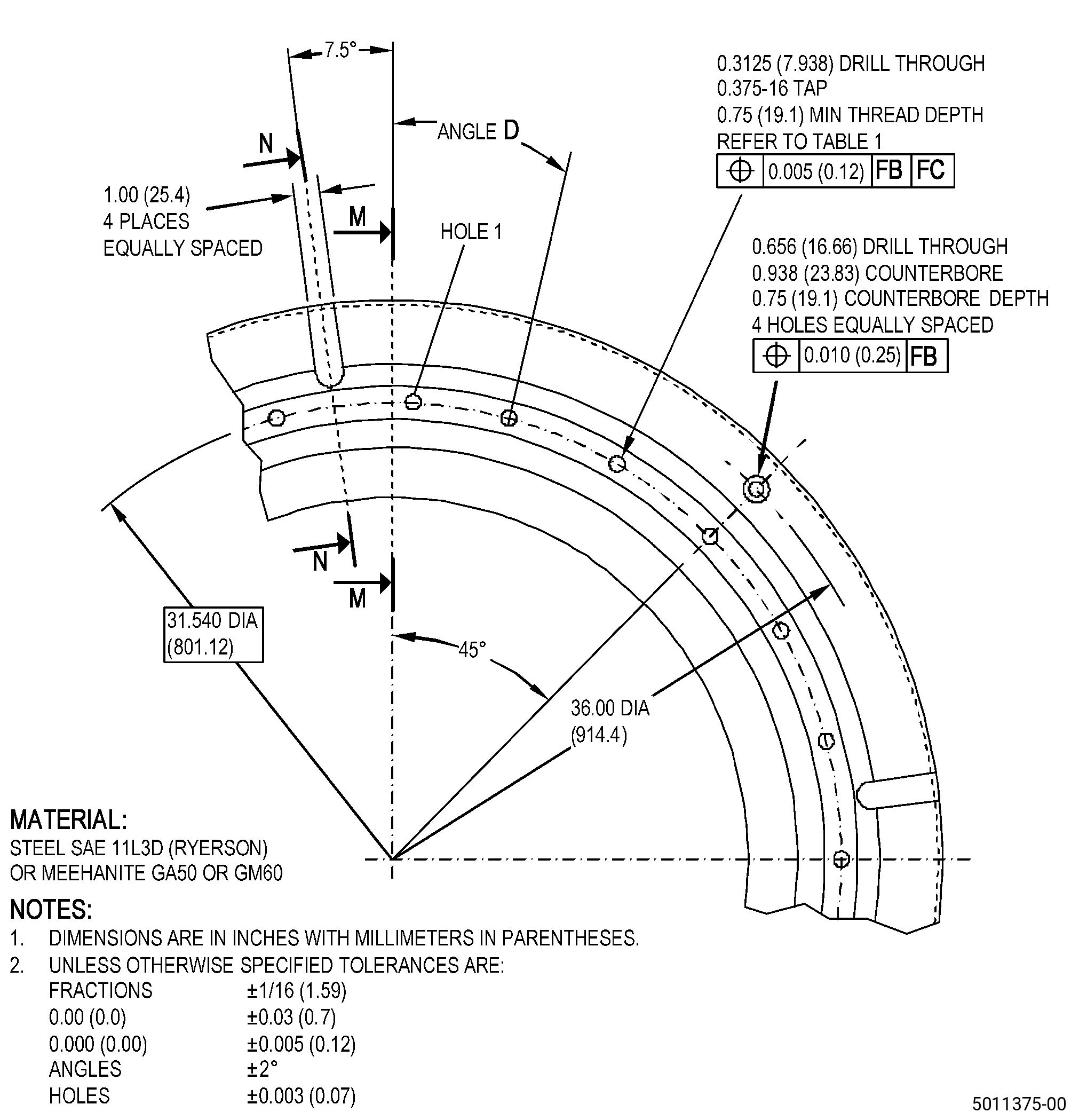
| A. | This procedure gives instructions to repair the HPC stator forward case assembly (case assembly) by thermal spraying to restore the forward circumferential flange and rabbet (forward flange) and the aft circumferential flange and rabbet (aft flange). Refer to Figure 901. |
| B. | The following maximum repairable limits apply to this repair: |
| NOTE: |
|
| (4) | Visual Inspection. |
| (e) | Do an inspection of the circumferential flanges for the following. Refer to Figure 802. |
| 2 | Nicks and scratches on the mating surface: |
| Maximum repairable limit: |
|
| 4 | Fretting or galling on the mating surface: |
| Maximum repairable limit: |
|
| (5) | Dimensional Inspection. |
| (b) | Do a dimensional inspection as follows. Measure each diameter at 10 equally spaced locations. Calculate the average diameter dimension. Compare the average diameter to the dimensions that follow: |
| 1 | Diameter A: |
| Maximum repairable limit: |
|
| 2 | Diameter D: |
| Maximum repairable limit: |
|
| 6 | Surface B flatness: |
| Maximum repairable limit: |
|
| 7 | Surface B parallel to surface C: |
| Maximum repairable limit: |
|
| 8 | Diameter D concentric with reference axis: |
| Maximum repairable limit: |
|
| 9 | Diameter D roundness: |
| Maximum repairable limit: |
|
| 10 | Diameter A roundness: |
| Maximum repairable limit: |
|
| C. | The subsequent table gives a list of the part numbers that are applicable to this repair. All part numbers are applicable to all paragraphs unless specified differently. |
|
|||||||||||||||||||||||
| D. | Proprietary/Complex Process Statement. |
| (1) | None. |
| 2 . | Tools, Equipment, and Materials. |
| NOTE: |
|
| A. | Tools and Equipment. |
| (1) | Special Tools. None. |
| (2) | Standard Tools and Equipment. None. |
| (3) | Locally Manufactured Tools. |
|
| B. | Consumable Materials. |
|
| C. | Referenced Procedures. |
| D. | Expendable Parts. None. |
| E. | SPD Information. None. |
| F. | Special Solutions. None. |
| G. | Test Specimens. Refer to TASK 70-49-36-340-038 (HIGH DENSITY INCONEL 718 COATING APPLIED BY HVOF THERMAL SPRAY) . |
| 3 . | Dimensional Information. |
| Subtask 72-32-01-220-078 |
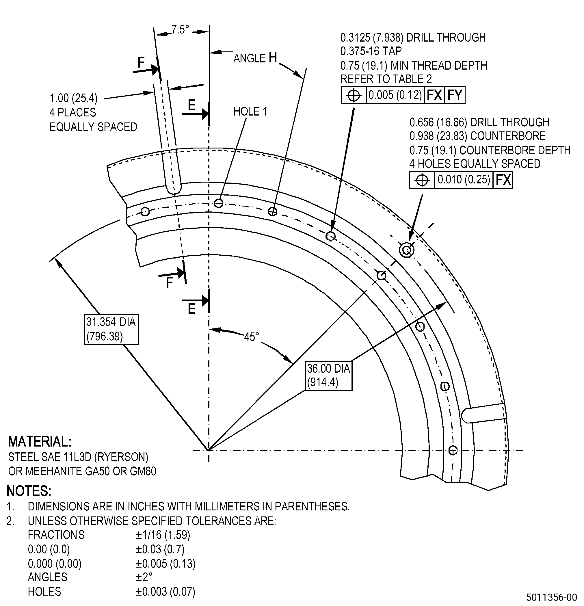
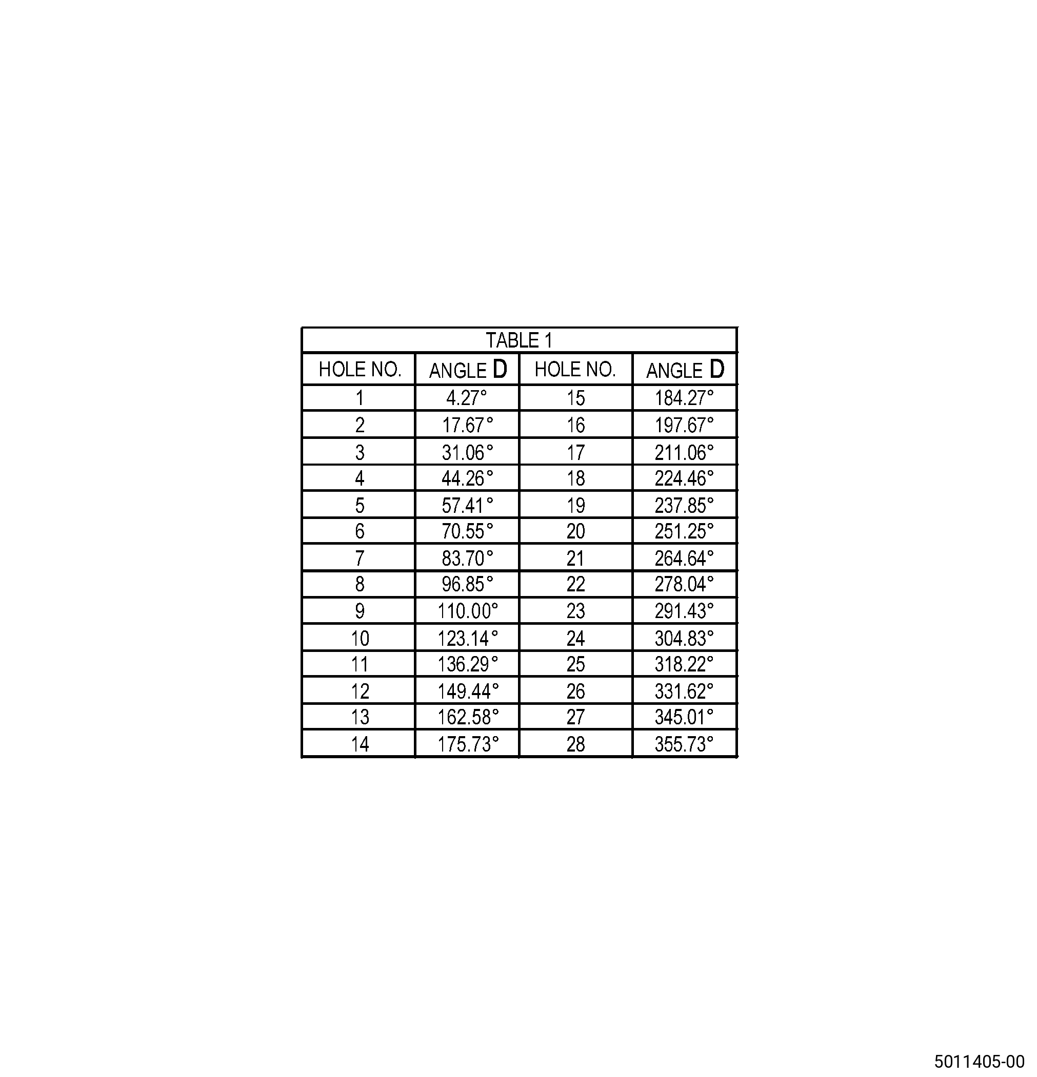
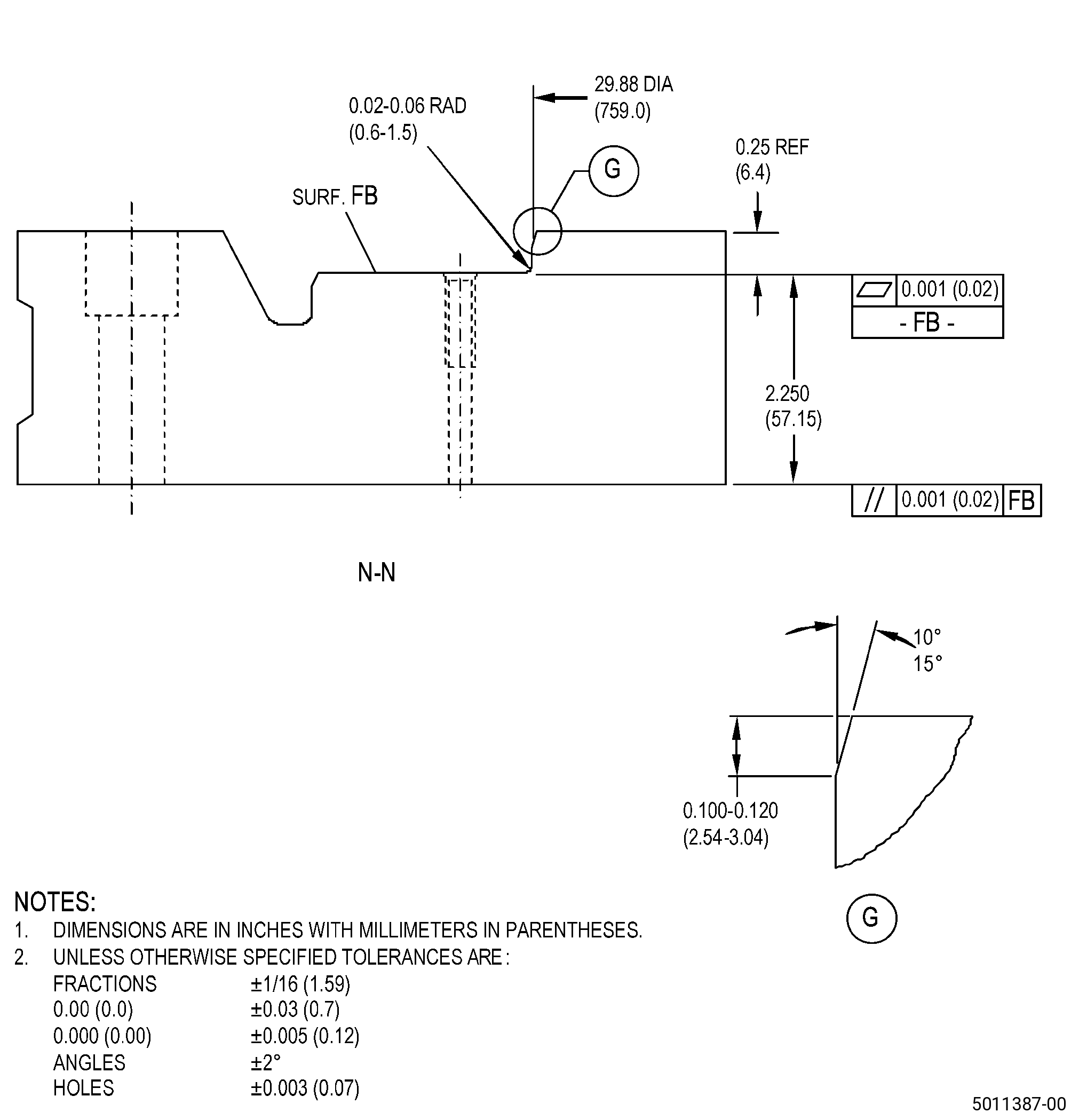
| A. | Refer to Figure 901 and Figure 902 for specified dimensions and locations. |
| NOTE: |
|
| NOTE: |
|
| NOTE: |
|
| NOTE: |
|
| NOTE: |
|
| 4 . | Setup Information. |
| Subtask 72-32-01-350-023 |
| A. | Set-up the case assembly to machine the forward flange. Refer to Figure 901, Figure 904, and as follows: |
| Subtask 72-32-01-930-001 |
| (1) | If necessary, make the forward flange fixture. |
| Subtask 72-32-01-350-024 |
| (2) | Install the forward flange fixture on the machining table and do as follows: |
| Subtask 72-32-01-350-040 |
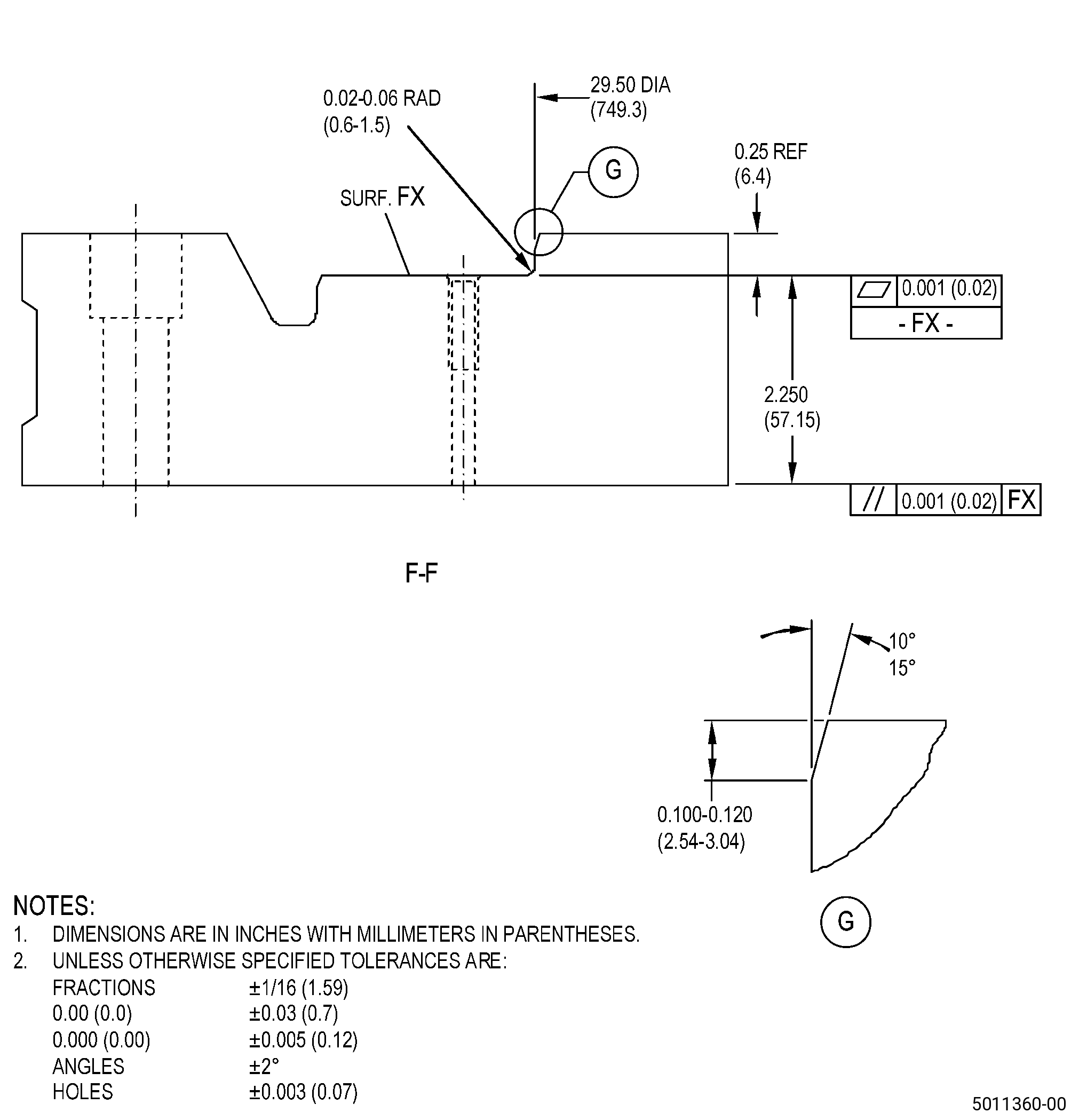
| (a) | Make surface FX flat to 0.001 inch (0.02 mm) or less and as follows: |
| 1 | If necessary, put C10-155 shims between the forward flange fixture and the machining table. |
| Subtask 72-32-01-350-041 |
| (b) | Make diameter FW concentric to the machining table axis to 0.001 inch (0.02 mm) or less. |
| (c) | Use clamps or 0.625 inch (15.88 mm) bolts to attach the forward flange fixture to the machining table and do as follows: |
| 1 | Make sure that surface FX flatness and diameter FW concentricity agree with the requirements specified in Subtask 72-32-01-350-040 (paragraph 4.A.(2)(a)) and Subtask 72-32-01-350-041 (paragraph 4.A.(2)(b)). |
| (3) | Assemble the upper and lower case halves to make the case assembly. Refer to TASK 72-32-01-200-801 (72-32-01, INSPECTION 001), (paragraph 5.A.). |
| (4) | Put the case assembly on the forward flange fixture with the aft flange (surface C) down and as follows: |
| (a) | Put the case assembly on the forward flange fixture and align the aft flange boltholes with the boltholes on the forward flange fixture. |
| (b) | Use twenty-six 0.375-16 bolts with washers to attach the case assembly to the forward flange machining fixture. |
| Subtask 72-32-01-220-100 |
| (5) | Make sure that the case assembly surface C is flat to the aft flange machining fixture surface FX to 0.001 inch (0.02 mm) or less. |
| (6) | Make sure that the plane established by the stage 1 vane bores is perpendicular to the machine spindle to 0.004 inch (0.10 mm) or less as follows: |
| (a) | Use three stage 1 vane bores equally-spaced that do not show wear. |
| CAUTION: |
|
| (b) | If necessary, put C10-155 shims between the forward flange fixture and the machining table. |
| Subtask 72-32-01-350-026 |
| B. | Set-up the case assembly to machine the aft flange. Refer to Figure 901, Figure 905, and as follows: |
| Subtask 72-32-01-930-002 |
| (1) | If necessary, make the aft flange fixture. |
| Subtask 72-32-01-350-027 |
| (2) | Install the aft flange fixture on the machining table and as follows: |
| Subtask 72-32-01-350-042 |
| (a) | Make surface FB flat to 0.001 inch (0.02 mm) or less and as follows: |
| 1 | If necessary, put C10-155 shims between the aft flange fixture and the machining table. |
| Subtask 72-32-01-350-043 |
| (b) | Make diameter FA concentric to the machining table axis to 0.001 inch (0.02 mm) or less. |
| (c) | Use clamps or 0.625 inch (15.88 mm) bolts to attach the aft flange fixture to the machining table and do as follows: |
| 1 | Make sure that surface FB flatness and diameter FA concentricity agree with the requirements specified in Subtask 72-32-01-350-042 (paragraph 4.B.(2)(a)) and Subtask 72-32-01-350-043 (paragraph 4.B.(2)(b)). |
| (3) | Assemble the upper and lower case halves to make the case assembly. Refer to TASK 72-32-01-200-801 (72-32-01, INSPECTION 001), (paragraph 5.A.). |
| (4) | Put the case assembly on the aft flange fixture with the forward flange (surface B) down and as follows: |
| (a) | Put the case assembly on the aft flange fixture and align the forward flange boltholes with the boltholes on the aft flange fixture. |
| (b) | Use twenty-eight 0.375-16 bolts with washers to attach the case assembly to the aft flange fixture. |
| Subtask 72-32-01-220-101 |
| (5) | Make sure that the case assembly surface B is flat to the aft flange machining fixture surface FB to 0.001 inch (0.02 mm) or less. |
| 5 . | Procedure. |
| Subtask 72-32-01-160-005 |
| A. | Clean the case assembly. Refer to TASK 72-32-01-100-801 (72-32-01, CLEANING 001). |
| Subtask 72-32-01-220-085 |
| B. | Do an inspection of the thermal spray coating on the stage 2 rub land of the case assembly. Refer to TASK 72-32-01-200-801 (72-32-01, INSPECTION 001) and as follows: |
| (1) | If the thermal spray coating agrees with the inspection criteria, apply masking to give protection to the thermal spray coating on the stage 2 rub land as follows: |
| (a) | Use C10-012 masking tape and/or fabricated shields to give protection to thermal spray coating on the stage 2 rub land of the case assembly. |
| (2) | If the thermal spray coating does not agree with the inspection criteria, remove the thermal spray coating applied to the stage 2 rub land of the case assembly. Refer to TASK 72-32-01-300-804 (72-32-01, REPAIR 004). |
| Subtask 72-32-01-330-001 |
| C. | Remove the thermal spray coating applied to the stage 1 rub land of the case assembly. Refer to TASK 72-32-01-300-804 (72-32-01, REPAIR 004). |
| Subtask 72-32-01-220-086 |
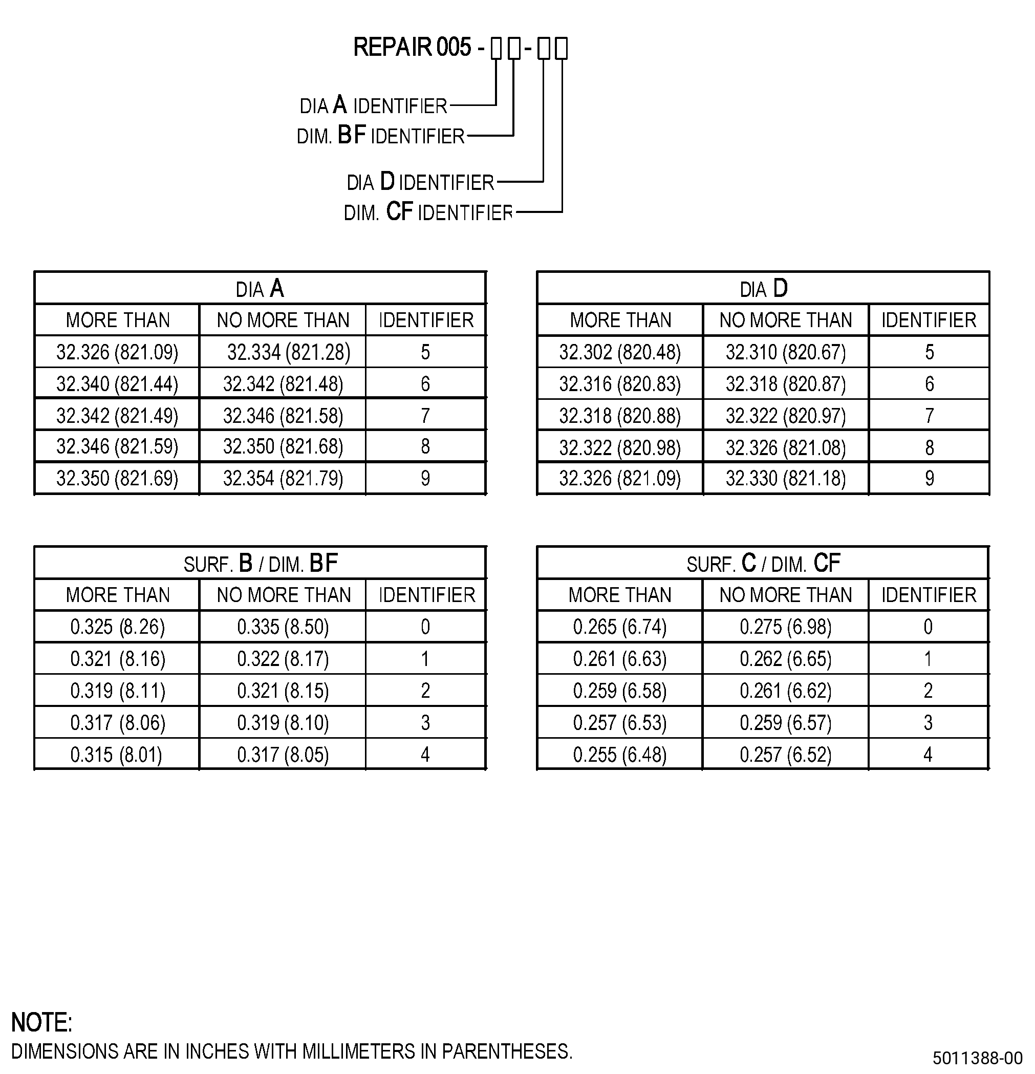
| D. | Look near the identification numbers on the upper and lower case halves to see if there is an earlier repair to the case assembly with this procedure. Refer to Figure 901, Figure 902, Figure 903, and as follows: |
| (1) | If there is an earlier repair, the upper and lower case halves will have a Repair 005 mark with a sequence of identifiers. |
| Subtask 72-32-01-320-003 |
| E. | Machine the case assembly diameter A and/or surface B to remove thermal spray coating, indications, or wear. Refer to TASK 70-00-03-800-004 (MACHINING DATA), Subtask 72-32-01-220-078 (paragraph 3.A.), Figure 901, Figure 902, Figure 903, and as follows: |
| NOTE: |
|
| NOTE: |
|
| (1) | Set-up the case assembly to machine the forward flange. Refer to Subtask 72-32-01-350-023 (paragraph 4.A.). |
| (2) | Find diameter A identifier and do as follows: |
| (a) | If diameter A was not previously repaired or the identifier is 5, machine diameter A to no more than 32.354 inches (821.79 mm). |
| (b) | If the identifier is 6, machine diameter A to no more than 32.342 inches (821.48 mm). |
| (c) | If the identifier is 7, machine diameter A to no more than 32.346 inches (821.58 mm). |
| (d) | If the identifier is 8, machine diameter A to no more than 32.350 inches (821.69 mm). |
| (e) | If the identifier is 9, machine diameter A to no more than 32.354 inches (821.79 mm). |
| (3) | Find surface B identifier and do as follows: |
| (a) | If surface B was not previously repaired or the identifier is 0, machine dimension BF to no more than 0.325 inch (8.25 mm). |
| (b) | If the identifier is 1, machine dimension BF to no more than 0.321 inch (8.15 mm). |
| (c) | If the identifier is 2, machine dimension BF to no more than 0.319 inch (8.10 mm). |
| (d) | If the identifier is 3, machine dimension BF to no more than 0.317 inch (8.05 mm). |
| (e) | If the identifier is 4, machine dimension BF to no more than 0.315 inch (8.00 mm). |
| (4) | Remove the case assembly from the forward flange fixture. |
| Subtask 72-32-01-350-029 |
| F. | Blend the case assembly diameter A and/or surface B. Refer to TASK 70-42-00-350-002 (BLENDING AND REMOVAL OF HIGH METAL PROCEDURES) and as follows: |
| (1) | Break all sharp edges to 0.005-0.010 inch (0.13-0.25 mm). |
| Subtask 72-32-01-110-009 |
| G. | Etch the case assembly diameter A and/or surface B. Refer to TASK 70-24-00-110-033 (ETCHING PROCEDURES FOR FLUORESCENT-PENETRANT INSPECTION), TASK 70-24-01-110-034 (SWAB ETCHING PROCEDURE), and as follows: |
| (1) | Use Class C etchant. |
| Subtask 72-32-01-230-006 |
| H. | Do an inspection of the case assembly diameter A and/or surface B. Refer to TASK 70-32-00-200-002 (INDIRECT INSPECTION METHODS), TASK 70-32-03-230-002 (SPOT-FLUORESCENT-PENETRANT INSPECTION), and as follows: |
| (1) | Use Class D penetrant. |
| (2) | Look for signs of thermal spray coating not applied by HVOF process and as follows: |
| NOTE: |
|
| NOTE: |
|
| (a) | If you find thermal spray coating, go to Subtask 72-32-01-320-004 (paragraph 5.I.). |
| Subtask 72-32-01-220-087 |
| (3) | Use the acceptability limits that follow: |
| Subtask 72-32-01-220-088 |
| (a) | Through indications are not permitted. |
| Subtask 72-32-01-220-089 |
| (b) | Indications more than 0.02 inch (0.5 mm) are not permitted in the flange fillets or bases of the flanges. |
| (c) | Other indications than those given in Subtask 72-32-01-220-088 (paragraph 5.H.(3)(a)) and Subtask 72-32-01-220-089 (paragraph 5.H.(3)(b)) , use the acceptability limits that follow: |
| 1 | Indications less than 0.030 inch (0.76 mm) are permitted if they are clearly separated. |
| 2 | Indications 0.030-0.060 inch (0.77-1.52 mm) are permitted if they agree with the conditions that follow: |
| a | The indications are not interpreted as linear. |
| NOTE: |
|
| b | There must be a minimum distance of 0.25 inch (6.4 mm) between indications. |
| Subtask 72-32-01-220-090 |
| (4) | If the case assembly does not agree with the acceptability limits for diameter A and/or surface B after machining, go to Subtask 72-32-01-320-004 (paragraph 5.I.). |
| Subtask 72-32-01-320-004 |
| CAUTION: |
|
| I. | If necessary, machine the case assembly diameter A and/or surface B to remove thermal spray coating, indications, or wear. Refer to TASK 70-00-03-800-004 (MACHINING DATA), Subtask 72-32-01-220-078 (paragraph 3.A.), Figure 901, Figure 902, Figure 903, and as follows: |
| NOTE: |
|
| NOTE: |
|
| (1) | Set-up the case assembly to machine the forward flange. Refer to Subtask 72-32-01-350-023 (paragraph 4.A.). |
| (2) | Machine the case assembly to remove thermal spray coating, indications, or wear as follows: |
| (a) | Diameter A and/or surface B must agree with the in-process dimensions. |
| (b) | If you cannot remove the thermal spray coating, indications, or wear when you machine to the in-process dimensions, then you cannot repair the case assembly with this procedure. |
| (3) | Remove the case assembly from the forward flange fixture. |
| (4) | Do Subtask 72-32-01-350-029 (paragraph 5.F.), Subtask 72-32-01-110-009 (paragraph 5.G.), and Subtask 72-32-01-230-006 (paragraph 5.H.) again. |
| Subtask 72-32-01-350-030 |
| J. | If you applied masking to the thermal spray coating on the stage 2 rub land of the case assembly in Subtask 72-32-01-220-085 (paragraph 5.B.), remove the masking from the case assembly. |
| Subtask 72-32-01-160-008 |
| K. | Clean the case assembly. Refer to TASK 70-21-00-110-051 (CHEMICAL CLEANING) and TASK 70-21-03-160-001 (CLEANING METHOD NO. 3 - STEAM CLEANING). |
| Subtask 72-32-01-220-091 |
| L. | Measure and record the values for the case assembly diameter A and dimension BF. Refer to Subtask 72-32-01-220-078 (paragraph 3.A.), Figure 902, and as follows: |
| (1) | If the values of diameter A and dimension BF agree with the finish dimensions, go to Subtask 72-32-01-220-093 (paragraph 5.T.). |
| (2) | If one of the values agrees with the in-process dimensions, go to Subtask 72-32-01-340-001 (paragraph 5.M.). |
| Subtask 72-32-01-340-001 |
| WARNING: |
|
| M. | Thermal-spray the case assembly diameter A and/or surface B and the test specimens. Refer to TASK 70-49-00-340-001 (THERMAL SPRAYING), TASK 70-49-36-340-038 (HIGH DENSITY INCONEL 718 COATING APPLIED BY HVOF THERMAL SPRAY), Figure 901, Figure 902, and as follows: |
| (1) | Apply masking to the case assembly as follows: |
| (a) | If there is thermal spray coating on the stage 2 rub land, do as follows: |
| 1 | Use C10-012 masking tape and/or fabricated shields to give protection to thermal spray coating on the stage 2 rub land of the case assembly. |
| 2 | The masking you apply to the thermal spray coating on the stage 2 rub land must stay on the case assembly when you machine the thermal spray coating applied to diameter A and/or surface B. |
| (b) | Thermal spray coating is not permitted in boltholes and as follows: |
| 1 | Use C10-198 plugs or equivalent to apply masking to the boltholes. |
| (2) | Apply thermal spray coating to the case assembly. Refer to Subtask 72-32-01-220-078 (paragraph 3.A.) and as follows: |
| (a) | Apply sufficient thermal spray coating to make sure that the case assembly agrees with the finish dimensions after final machining and as follows: |
| 1 | After final machining a minimum of 0.003 inches (0.08 mm) of thermal spray coating is necessary. |
| (3) | Do all the quality assurance testing specified in TASK 70-49-00-340-001 (THERMAL SPRAYING) and TASK 70-49-36-340-038 (HIGH DENSITY INCONEL 718 COATING APPLIED BY HVOF THERMAL SPRAY). |
| Subtask 72-32-01-350-031 |
| N. | Remove the masking from the case assembly as follows: |
| (1) | Remove the masking from the boltholes. |
| (2) | If you applied masking to the thermal spray coating on the stage 2 rub land of the case assembly in Subtask 72-32-01-340-001 (paragraph 5.M.), do not remove this masking from the case assembly. |
| Subtask 72-32-01-320-005 |
| O. | Machine the case assembly diameter A and/or surface B to the finish dimensions. Refer to TASK 70-00-03-800-004 (MACHINING DATA), Subtask 72-32-01-220-078 (paragraph 3.A.), Figure 901, Figure 902, and as follows: |
| (1) | Set-up the case assembly to machine the forward flange. Refer to Subtask 72-32-01-350-023 (paragraph 4.A.). |
| (2) | Machine the case assembly to the finish dimensions. |
| (3) | Remove the case assembly from the forward flange fixture. |
| Subtask 72-32-01-350-032 |
| P. | Blend the case assembly diameter A and/or surface B. Refer to TASK 70-42-00-350-002 (BLENDING AND REMOVAL OF HIGH METAL PROCEDURES) and as follows: |
| (1) | Break all sharp edges to 0.005-0.010 inch (0.13-0.25 mm). |
| Subtask 72-32-01-350-033 |
| Q. | If you applied masking to the thermal spray coating on the stage 2 rub land of the case assembly in Subtask 72-32-01-340-001 (paragraph 5.M.), remove the masking from the case assembly. |
| Subtask 72-32-01-160-006 |
| R. | Clean the case assembly. Refer to TASK 72-32-01-100-801 (72-32-01, CLEANING 001). |
| Subtask 72-32-01-220-092 |
| S. | Do a visual inspection of the thermal spray coating applied to the case assembly diameter A and/or surface B and as follows: |
| (1) | If the thermal spray coating does not agree with the acceptability limits specified in TASK 70-49-00-340-001 (THERMAL SPRAYING), and TASK 70-49-36-340-038 (HIGH DENSITY INCONEL 718 COATING APPLIED BY HVOF THERMAL SPRAY), do as follows: |
| Subtask 72-32-01-320-011 |
| (a) | Machine the case assembly diameter A and/or surface B to remove the thermal spray coating. Refer to TASK 70-00-03-800-004 (MACHINING DATA), Figure 901, Figure 902, and as follows: |
| 1 | Set-up the case assembly to machine the forward flange. Refer to Subtask 72-32-01-350-023 (paragraph 4.A.). |
| 2 | Machine diameter A and/or surface B to make it agree with the values recorded in Subtask 72-32-01-220-091 (paragraph 5.L.). |
| 3 | Remove the case assembly from the forward flange fixture. |
| (b) | Do Subtask 72-32-01-350-029 (paragraph 5.F.) thru Subtask 72-32-01-220-092 (paragraph 5.S.) again. |
| Subtask 72-32-01-220-093 |
| T. | Do an inspection of the case assembly. Refer to Subtask 72-32-01-220-078 (paragraph 3.A.), Figure 901, Figure 902, and as follows: |
| (1) | Record the values for diameter A and dimension BF. |
| Subtask 72-32-01-340-002 |
| U. | If there is thermal spray coating on the stage 2 rub land, apply masking to give protection to the thermal spray coating on the stage 2 rub land as follows: |
| (1) | Use C10-012 masking tape and/or fabricated shields to give protection to thermal spray coating on the stage 2 rub land of the case assembly. |
| Subtask 72-32-01-350-044 |
| V. | Remove the self-locking inserts from the aft flange (surface C) of the case assembly. Refer to TASK 72-32-01-300-802 (72-32-01, REPAIR 002). |
| Subtask 72-32-01-320-006 |
| W. | Machine the case assembly diameter D and/or surface C to remove thermal spray coating, indications, or wear. Refer to TASK 70-00-03-800-004 (MACHINING DATA), Subtask 72-32-01-220-078 (paragraph 3.A.), Figure 901, Figure 902, Figure 903, and as follows: |
| NOTE: |
|
| NOTE: |
|
| (1) | Set-up the case assembly to machine the aft flange. Refer to Subtask 72-32-01-350-026 (paragraph 4.B.). |
| (2) | Find diameter D identifier and do as follows: |
| (a) | If diameter D was not previously repaired or the identifier is 5, machine diameter D to no more than 32.310 inches (820.67 mm). |
| (b) | If the identifier is 6, machine diameter D to no more than 32.318 inches (820.87 mm). |
| (c) | If the identifier is 7, machine diameter D to no more than 32.322 inches (820.97 mm). |
| (d) | If the identifier is 8, machine diameter D to no more than 32.326 inches (821.08 mm). |
| (e) | If the identifier is 9, machine diameter D to no more than 32.330 inches (821.18 mm). |
| (3) | Find surface C identifier and do as follows: |
| (a) | If surface C was not previously repaired or the identifier is 0, machine dimension CF to no more than 0.265 inch (6.73 mm). |
| (b) | If the identifier is 1, machine dimension CF to no more than 0.261 inch (6.62 mm). |
| (c) | If the identifier is 2, machine dimension CF to no more than 0.259 inch (6.57 mm). |
| (d) | If the identifier is 3, machine dimension CF to no more than 0.257 inch (6.52 mm). |
| (e) | If the identifier is 4, machine dimension CF to no more than 0.255 inch (6.47 mm). |
| (4) | Remove the case assembly from the aft flange fixture. |
| Subtask 72-32-01-350-034 |
| X. | Blend the case assembly diameter D and/or surface C. Refer to TASK 70-42-00-350-002 (BLENDING AND REMOVAL OF HIGH METAL PROCEDURES) and as follows: |
| (1) | Break all sharp edges to 0.005-0.010 inch (0.13-0.25 mm). |
| Subtask 72-32-01-110-012 |
| Y. | Etch the case assembly diameter D and/or surface C. Refer to TASK 70-24-00-110-033 (ETCHING PROCEDURES FOR FLUORESCENT-PENETRANT INSPECTION), TASK 70-24-01-110-034 (SWAB ETCHING PROCEDURE), and as follows: |
| (1) | Use Class C etchant. |
| Subtask 72-32-01-230-007 |
| Z. | Do an inspection of the case assembly diameter D and/or surface C. Refer to TASK 70-32-00-200-002 (INDIRECT INSPECTION METHODS), TASK 70-32-03-230-002 (SPOT-FLUORESCENT-PENETRANT INSPECTION), and as follows: |
| (1) | Use Class D penetrant. |
| (2) | Look for signs of thermal spray coating not applied by HVOF process and do as follows: |
| NOTE: |
|
| NOTE: |
|
| (a) | If you find thermal spray coating, go to Subtask 72-32-01-320-008 (paragraph 5.AA.). |
| Subtask 72-32-01-220-094 |
| (3) | Use the acceptability limits that follow: |
| Subtask 72-32-01-220-095 |
| (a) | Through indications are not permitted. |
| Subtask 72-32-01-220-096 |
| (b) | Indications more than 0.02 inch (0.5 mm) are not permitted in the flange fillets or bases of the flanges. |
| (c) | Other indications than those given in Subtask 72-32-01-220-095 (paragraph 5.Z.(3)(a)) and Subtask 72-32-01-220-096 (paragraph 5.Z.(3)(b)) , use the acceptability limits that follow: |
| 1 | Indications less than 0.030 inch (0.76 mm) are permitted if they are clearly separated. |
| 2 | Indications 0.030-0.060 inch (0.77-1.52 mm) are permitted if they agree with the conditions that follow: |
| a | The indications are not interpreted as linear. |
| NOTE: |
|
| b | There must be a minimum distance of 0.25 inch (6.4 mm) between indications. |
| Subtask 72-32-01-320-007 |
| (4) | If the case assembly does not agree with the acceptability limits for diameter D and/or surface C after machining, go to Subtask 72-32-01-320-008 (paragraph 5.AA.). |
| Subtask 72-32-01-320-008 |
| CAUTION: |
|
| AA. | If necessary, machine the case assembly diameter D and/or surface C to remove thermal spray coating, indications, or wear. Refer to TASK 70-00-03-800-004 (MACHINING DATA), Subtask 72-32-01-220-078 (paragraph 3.A.), Figure 901, Figure 902, Figure 903, and as follows: |
| NOTE: |
|
| NOTE: |
|
| (1) | Set-up the case assembly to machine the aft flange. Refer to Subtask 72-32-01-350-026 (paragraph 4.B.). |
| (2) | Machine the case assembly to remove thermal spray coating, indications, or wear as follows: |
| (a) | Diameter D and/or surface C must agree with the in-process dimensions. |
| (b) | If you cannot remove the thermal spray coating, indications, or wear when you machine to the in-process dimensions, then you cannot repair the case assembly with this procedure. |
| (3) | Remove the case assembly from the aft flange fixture. |
| (4) | Do Subtask 72-32-01-350-034 (paragraph 5.X.), Subtask 72-32-01-110-012 (paragraph 5.Y.), and Subtask 72-32-01-230-007 (paragraph 5.Z.) again. |
| Subtask 72-32-01-350-035 |
| AB. | If you applied masking to the thermal spray coating on the stage 2 rub land of the case assembly in Subtask 72-32-01-340-002 (paragraph 5.U.), remove the masking from the case assembly. |
| Subtask 72-32-01-160-004 |
| AC. | Clean the case assembly. Refer to TASK 70-21-00-110-051 (CHEMICAL CLEANING) and TASK 70-21-03-160-001 (CLEANING METHOD NO. 3 - STEAM CLEANING). |
| Subtask 72-32-01-220-097 |
| AD. | Measure and record the values for the case assembly diameter D and dimension CF. Refer to Subtask 72-32-01-220-078 (paragraph 3.A.), Figure 902, and as follows: |
| (1) | If the values of diameter D and dimension CF agree with the finish dimensions, go to Subtask 72-32-01-340-004 (paragraph 5.AL.). |
| (2) | If one of the values agrees with the in-process dimensions, go to Subtask 72-32-01-340-003 (paragraph 5.AE.). |
| Subtask 72-32-01-340-003 |
| WARNING: |
|
| AE. | Thermal-spray the case assembly diameter D and/or surface C and the test specimens. Refer to TASK 70-49-00-340-001 (THERMAL SPRAYING), TASK 70-49-36-340-038 (HIGH DENSITY INCONEL 718 COATING APPLIED BY HVOF THERMAL SPRAY), Figure 901, Figure 902, and as follows: |
| (1) | Apply masking to the case assembly as follows: |
| (a) | If there is thermal spray coating on the stage 2 rub land, do as follows: |
| 1 | Use C10-012 masking tape and/or fabricated shields to give protection to thermal spray coating on the stage 2 rub land of the case assembly. |
| 2 | The masking you apply to the thermal spray coating on the stage 2 rub land must stay on the case assembly when you machine the thermal spray coating applied to diameter D and/or surface C. |
| (b) | Thermal spray coating is not permitted in the self-locking insert bores. |
| (c) | Thermal spray coating is not permitted in boltholes and as follows: |
| 1 | Use C10-198 plugs or equivalent to apply masking to the boltholes. |
| (2) | Apply thermal spray coating to the case assembly. Refer to Subtask 72-32-01-220-078 (paragraph 3.A.) and as follows: |
| (a) | Apply sufficient thermal spray coating to make sure that the case assembly agrees with the finish dimensions after final machining and as follows: |
| 1 | After final machining, a minimum of 0.003 inch (0.08 mm) of thermal spray coating is necessary. |
| (3) | Do all the quality assurance testing specified in TASK 70-49-00-340-001 (THERMAL SPRAYING) and TASK 70-49-36-340-038 (HIGH DENSITY INCONEL 718 COATING APPLIED BY HVOF THERMAL SPRAY). |
| Subtask 72-32-01-350-036 |
| AF. | Remove the masking from the case assembly as follows: |
| (1) | Remove the masking from the self-locking insert bores. |
| (2) | Remove the masking from the boltholes. |
| (3) | If you applied masking to the thermal spray coating on the stage 2 rub land of the case assembly in Subtask 72-32-01-340-003 (paragraph 5.AE.), do not remove this masking from the case assembly. |
| Subtask 72-32-01-320-009 |
| AG. | Machine the case assembly diameter D and/or surface C to the finish dimensions. Refer to TASK 70-00-03-800-004 (MACHINING DATA), Subtask 72-32-01-220-078 (paragraph 3.A.), Figure 901, Figure 902, and as follows: |
| (1) | Set-up the case assembly to machine the aft flange. Refer to Subtask 72-32-01-350-026 (paragraph 4.B.). |
| (2) | Machine the case assembly to the finish dimensions. |
| (3) | Remove the case assembly from the aft flange fixture. |
| Subtask 72-32-01-350-037 |
| AH. | Blend the case assembly diameter D and/or surface C. Refer to TASK 70-42-00-350-002 (BLENDING AND REMOVAL OF HIGH METAL PROCEDURES) and as follows: |
| (1) | Break all sharp edges to 0.005-0.010 inch (0.13-0.25 mm). |
| Subtask 72-32-01-350-038 |
| AI. | If you applied masking to the thermal spray coating on the stage 2 rub land of the case assembly in Subtask 72-32-01-340-003 (paragraph 5.AE.), remove the masking from the case assembly. |
| Subtask 72-32-01-160-007 |
| AJ. | Clean the case assembly. Refer to TASK 72-32-01-100-801 (72-32-01, CLEANING 001). |
| Subtask 72-32-01-220-098 |
| AK. | Do a visual inspection of the thermal spray coating applied to the case assembly diameter D and/or surface C and as follows: |
| (1) | If the thermal spray coating does not agree with the acceptability limits specified in TASK 70-49-00-340-001 (THERMAL SPRAYING), and TASK 70-49-36-340-038 (HIGH DENSITY INCONEL 718 COATING APPLIED BY HVOF THERMAL SPRAY), do as follows: |
| Subtask 72-32-01-320-010 |
| (a) | Machine the case assembly diameter D and/or surface C to remove the thermal spray coating. Refer to TASK 70-00-03-800-004 (MACHINING DATA), Figure 901, Figure 902, and as follows: |
| 1 | Set-up the case assembly to machine the aft flange. Refer to Subtask 72-32-01-350-026 (paragraph 4.B.). |
| 2 | Machine diameter D and/or surface C to make it agree with the values recorded in Subtask 72-32-01-220-097 (paragraph 5.AD.). |
| 3 | Remove the case assembly from the aft flange fixture. |
| (b) | Do Subtask 72-32-01-350-034 (paragraph 5.X.) thru Subtask 72-32-01-220-098 (paragraph 5.AK.) again. |
| Subtask 72-32-01-340-004 |
| AL. | Thermal-spray the stage 1 rub land and the stage 2 rub land. Refer to TASK 72-32-01-300-804 (72-32-01, REPAIR 004) and as follows: |
| (1) | Prepare the stage 1 rub land and apply the thermal spray coating. |
| (2) | If necessary, prepare the stage 2 rub land and apply the thermal spray coating. |
| Subtask 72-32-01-350-045 |
| AM. | Install the self-locking inserts in the aft flange (surface C). Refer to TASK 72-32-01-300-802 (72-32-01, REPAIR 002). |
| Subtask 72-32-01-220-099 |
| AN. | Do an inspection of the case assembly. Refer to Subtask 72-32-01-220-078 (paragraph 3.A.), Figure 901, Figure 902, and as follows: |
| (1) | Record the values for diameter D and dimension CF. |
| Subtask 72-32-01-350-039 |
| AO. | Alternative Procedure Available. Put a mark on the case assembly. Refer to TASK 70-16-00-350-001 (MARKING PRACTICES), TASK 70-16-04-350-019 (VIBRO-PEEN MARKING), Figure 902, Figure 903, and as follows: |
| (1) | Refer to Subtask 72-32-01-220-091 (paragraph 5.L.) and Subtask 72-32-01-220-097 (paragraph 5.AD.) for parent material measurement values. |
| (2) | If there is an earlier repair to the case assembly with this procedure, line-out the existing identifiers after the Repair 005 mark on the upper and lower case halves. |
| (3) | Put a mark on the upper and lower case halves near the identification numbers to show the quantity of parent material on the flange and rabbet features. |
| Subtask 72-32-01-350-063 |
| AO.A. | Alternative Procedure. Put a mark on the case assembly. Refer to TASK 70-16-00-350-001 (MARKING PRACTICES), TASK 70-16-08-350-001 (DOT PEEN MARKING FOR OPTICAL CHARACTER RECOGNITION), Figure 902, Figure 903, and as follows: |
| (1) | Intermediate depth must be 0.001-0.004 inch (0.03-0.10 mm). |
| (2) | Refer to Subtask 72-32-01-220-091 (paragraph 5.L.) and Subtask 72-32-01-220-097 (paragraph 5.AD.) for parent material measurement values. |
| (3) | If there is an earlier repair to the case assembly with this procedure, line-out the existing identifiers after the Repair 005 mark on the upper and lower case halves. |
| (4) | Put a mark on the upper and lower case halves near the identification numbers to show the quantity of parent material on the flange and rabbet features. |