| COMMERCIAL ENGINE STANDARD PRACTICES MANUAL | Dated: 03/20/2020 | |
| SPM 70-49-00 THERMAL SPRAYING | ||
| COMMERCIAL ENGINE STANDARD PRACTICES MANUAL | Dated: 03/20/2020 | |
| SPM 70-49-00 THERMAL SPRAYING | ||
| TASK 70-49-00-340-001 |
| 1 . | General. |
| A. | Thermal spray is a general term describing a group of coating processes that are used to apply a tightly bonded coating by spraying molten or semi-molten metallic and nonmetallic particles. The methods used to melt the coating materials include combustion, wire arc, and plasma. The materials may be supplied as powder, wire, or rod stock. The thermal spray coating process is used widely in the repair and modification of hardware. The most frequent uses for the thermal spray coatings include, but are not limited to: |
| (1) | Repair or restoration of worn or damaged surfaces. |
| (2) | A clearance control coating, abradable and/or abrasive. |
| (3) | A thermal barrier coating. |
| (4) | An aid in correcting the balance of rotating hardware. |
| (5) | An anti-wear and/or anti-galling coating in high load or rubbing conditions. |
| B. | General Requirements. |
| (1) | The thermal spray process is monitored by: |
| (a) | The general thermal spray requirements in this procedure (70-49-00), |
| (b) | The specific thermal spray procedure (for example, TASK 70-49-10-340-011, Thermal Spraying Nickel-Aluminum (Powder)), |
| (c) | The specific testing procedures (for example, TASK 70-71-04-700-005, Metallographic Evaluation of Thermal Spray Coatings), and |
| (d) | The general testing requirements in TASK 70-70-00-700-001, Testing and Quality Analysis. |
| (2) | Original Equipment Manufacturer (OEM) specifications can cover the same procedures and requirements for thermal spray and are frequently more stringent. It is therefore acceptable to use processing and quality systems formulated for the coating of new aircraft engine hardware and approved by major engine manufacturers to meet the intent of the repair standard practices concerning thermal spray. |
| (3) | Alternative processes to apply the same thermal spray coating chemistry may be used provided that all process qualification, evaluation, validation, coating quality, and metalographic requirements are achieved by the alternative process. |
| C. | The application methods used most frequently are: |
| (1) | Flame spraying with a spray gun that uses an oxyacetylene or oxyhydrogen flame. |
| (a) | The flame spray gun has a standard oxyacetylene or oxyhydrogen torch and a nozzle that supplies the compressed air required to propel the molten metal. |
| (b) | The coating material goes into the gun as a powder or a wire. |
| (2) | Plasma arc spraying with a plasma generator/gun. |
| (a) | In the plasma spray gun, a mixture of gases is supplied through a constricted electric arc. |
| (b) | The electric arc is created between an axial cathode made from thoriated tungsten and a copper electrode that forms the exhaust nozzle. |
| (c) | The plasma-generating atmosphere may be argon, nitrogen, hydrogen, or helium. |
| (d) | The coating material is injected as a powder, either directly into the gun or a few millimeters downstream of the anode exit. |
| (e) | Power required: |
| For current needs: 20 to 40 kW. |
| For future needs: 40 to 100 kW. |
| (f) | The power supply system shall maintain a regular, smooth, and equal flow rate. |
| (3) | High velocity oxy-fuel (HVOF). |
| (a) | The process uses the continuous internal combustion of oxygen and a liquid or gaseous fuel. This pressurized combustion propels a hot exhaust jet stream at a high velocity. |
| (b) | Powder is injected into the jet stream, where it is heated and accelerated toward the part to be sprayed. |
| (c) | An HVOF system should consist of: |
| 1 | An HVOF gun system with a satisfactory controller. |
| 2 | A gas controller that can supply up to 1,000 SCFH oxygen, 1,600 SCFH hydrogen, 300 SCFH propylene, and if required, 800 SCFH air. If liquid fuel is used, an appropriate controller is required. The unit shall also provide a power control for the gun and an air delivery rate. |
| 3 | A pressurized powder feeder that can supply powder at a typical rate of 4-15 lbs/hr (2-7 kg/hr). |
| 4 | An air source that can supply up to 800 SCFH clean, filtered air. |
| (4) | Electric arc wire spray system, Praxair / TAFA Concord and Sulzer Metco are recommended suppliers. |
| (a) | An arc wire gun control unit that uses pneumatically or electrically driven motors to supply spooled wire to the arc wire gun manually or automatically. The gun control unit shall also have a power control for the arc wire gun and give the rate at which air is supplied. |
| (b) | Two consumable electrodes are supplied to an atomizing air stream in the gun, where a DC arc is formed between them. |
| (c) | The atomizing gas (usually compressed air) goes directly across the arc and molten wire tips, shearing off the droplets and forming a high- velocity spray stream. |
| (d) | An electric arc power feed that can supply 50-350 amps at 20-38 open-circuit volts. |
| (e) | A clean, filtered air source that can supply 50 SCFM at 80 psi (552 kPa). |
| D. | Various safety precautions should be addressed before performing the thermal spray coating process: |
| (1) | Personal protection, including a respirator and ear protection, should be used by personnel performing this process. Eye protection equivalent to welder's goggles should also be used by personnel who are viewing the thermal spray process while it is being performed. |
| (2) | Because fine powdered metals are used in this process, steps should be taken to reduce or eliminate the possibility of ingesting or absorbing these materials. |
| WARNING: |
|
| (3) | A continuous-flow exhaust system should be supplied to remove the fumes and overspray particles. |
| (4) | The training of thermal spray personnel shall include a segment on thermal spray process safety. The segment shall describe, and give the proper use of, the personal protection devices that are used in the thermal spray process. |
| 2 . | Processing Qualification. |
| Subtask 70-49-00-340-011 |
| A. | General. |
| (1) | Initial qualification for thermal spray involves two areas: Equipment and Operators. |
| (2) | It is possible and acceptable that qualifications of operators and equipment can occur on a simultaneous basis. This would allow a qualification set-up to be used for validation of both operators and equipment. Installations for thermal spraying shall be applicable to the work to be performed. They shall agree with existing aircraft industry specifications as well as the applicable regulations that exist in the country where the repair shop is located. |
| B. | Equipment Qualification Requirements. |
| NOTE: |
|
| (1) | Initial Qualification |
| (a) | Qualify each thermal spray system for all of the powders/wires that shall be applied with that system. Qualify the system as follows: |
| 1 | Coat a first set of test specimens that are representative the part material/coating combination. Record all parameters that apply to the thermal spraying process. Figure 3 is a sample form for recording equipment qualification data. |
| NOTE: |
|
| 2 | Shut the thermal spray equipment down completely after coating the first set of test specimens. |
| 3 | Coat a second set of test specimens, using the same thermal spray parameters as were used to coat the first set of specimens. |
| 4 | Test both sets of test specimens. The coatings must agree with the requirements of: |
| a | The general thermal spray requirements in this procedure (70-49-00), |
| b | The specific thermal spray procedure (for example, TASK 70-49-10-340-011, Thermal Spraying Nickel-Aluminum (Powder), |
| c | The specific testing procedures (for example, TASK 70-71-04-700-005, Metallographic Evaluation of Thermal Spray Coatings, and |
| d | The general testing requirements in TASK 70-70-00-700-001, Testing and Quality Analysis. |
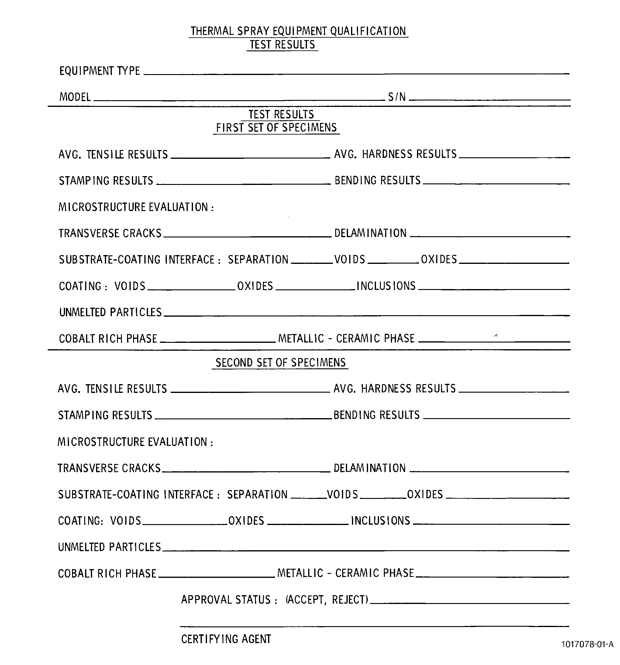
| 5 | Record the results of the test. Refer to Figure 2 for a sample test report. |
| 6 | If the spray parameters that were used for the initial equipment qualification are changed, the equipment shall be qualified again. |
| (2) | Equipment Requalification. |
| The thermal spray coating equipment shall be requalified for any one of the following reasons: |
| (a) | The coating equipment has not been used within a 12 month period. |
| (b) | Three sets of tests of the same coating equipment, one after the other, do not agree with the requirements. |
| (c) | The coating equipment is dismantled and repositioned. |
| (d) | The coating equipment receives a major overhaul or replacement of a major component. This may include, but is not limited to, a gas head, a combustion gas gun body, a rectifier, or a control console. |
| (e) | The equipment settings are modified. |
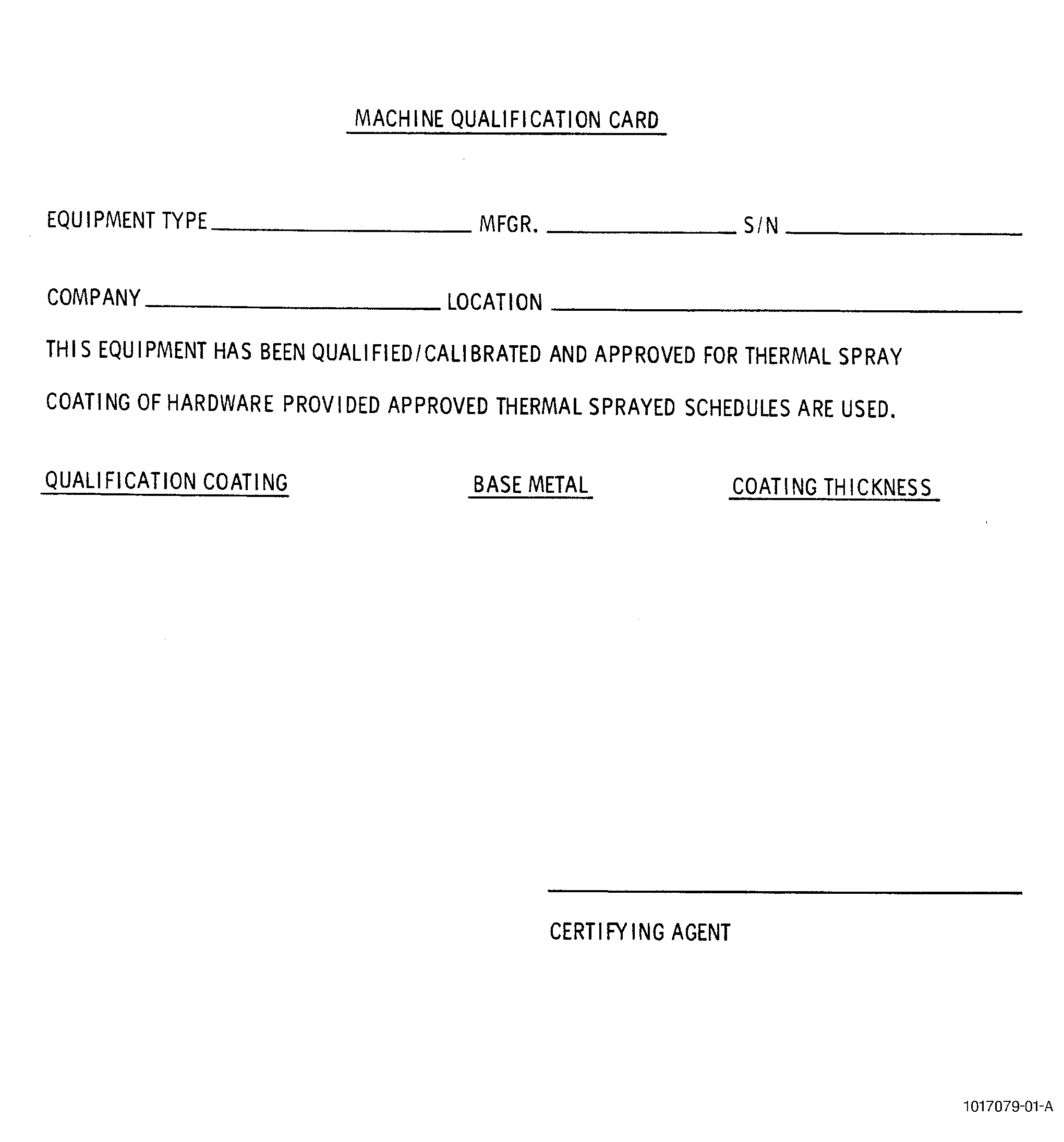
| (3) | Records. |
| A card shall be attached to the coating equipment after qualification to show agreement with the requirements that are specified here. Figure 1 is a sample machine qualification card that shows the necessary information. |
| C. | Qualification of Personnel. |
| (1) | General. |
| (a) | An experienced operator who can use the thermal spraying equipment correctly again and again is very important to the quality of the coating that is applied. |
| (b) | It is recommended that a formal training program be developed to make sure that the thermal spray operators receive sufficient practical experience to apply high-quality coatings again and again. The training should also address safety issues related to the different thermal spray processes. |
| (2) | Initial Qualification Tests. |
| (a) | These tests are intended to make sure that the skill of a thermal spray operator is sufficient and that he can apply satisfactory coatings again and again. Each operator shall be qualified for each thermal spray process (plasma, HVOF, electric arc, etc.) that he will perform. Tests are performed as follows: |
| NOTE: |
|
| 1 | Test the operator on the following families of coatings: |
| a | Metals, General. |
| b | Ceramics. |
| c | Abradables. |
| d | Metal-Based Carbides. |
| 2 | Coat a first set of test specimens that are representative of the coating(s). |
| NOTE: |
|
| 3 | Shut the thermal spray equipment down completely after coating the first set of test specimens. |
| 4 | Coat a second set of test specimens. |
| 5 | Test both sets of test specimens. The coatings must agree with the requirements of: |
| a | The general thermal spray requirements in this procedure (70-49-00), |
| b | The specific thermal spray procedure (for example, TASK 70-49-10-340-011, Thermal Spraying Nickel-Aluminum (Powder), |
| c | The specific testing procedures (for example, TASK 70-71-04-700-005, Metallographic Evaluation of Thermal Spray Coatings, and |
| d | The general testing requirements in TASK 70-70-00-700-001, Testing and Quality Analysis. |
| (3) | Requalification Tests. |
| (a) | Each operator should receive training at intervals to make sure that he can apply satisfactory coatings again and again. The frequency of the training and testing shall be established by the repair source. |
| NOTE: |
|
| (4) | Automated Computerized Robotic Spray Systems. |
| (a) | Sources with only automated closed-loop computerized robotic spray systems are exempt from Step 2.C.(2), Initial Qualification Tests. Closed-loop is defined as the equipment that has the capability to monitor and adjust specific parameters to maintain nominal set points. |
| 3 . | Thermal Spray Procedure. |
| Subtask 70-49-00-340-013 |
| A. | Consumable Materials. |
| (1) | The repair shop should have a procedure for the control of the powders and wires that are used in the thermal spray process. This procedure should do the following: |
| (a) | Make sure that the certification from the powder manufacturer for each lot of material is correct. |
| (b) | Perform a sprayability test on each lot to make sure that it will give an acceptable coating. The sprayability test shall be performed on the complete set of test specimens, as defined in TASK 70-70-00-700-001, Testing and Quality Analysis. |
| (2) | Commercial quality gases, as defined in TASK 70-00-06-800-007, Quality of Gases, are recommended. Longer nozzle life and greater stability for the plasma process will result if pure gases, as defined in TASK 70-00-06-800-007, Quality of Gases, are used. |
| B. | Preliminary Operations. |
| (1) | Powder shall be free of moisture and shall be a homogeneous mixture before spraying. If the powder contains moisture, the material can be dried in an oven at 150°F ± 15°F (66°C ± 8°C) for a minimum of one hour. If the powder is not homogeneous, blend the material. For small quantities, rotate the powder within the container for 10-15 minutes. For large quantities, use a V-type blender, or equivalent, to blend the powder. |
| (2) | All repair operations on the base material, including cleaning, welding, heat treating, and surface treatments, shall be completed before thermal spray coating begins. No chemical coating or other operation that would harm the sprayed coating shall be performed. |
| (3) | When building up worn areas by thermal spraying, machine the areas to a depth that will permit a sufficient coating thickness after processing. |
| WARNING: |
|
| CAUTION: |
|
| (4) | Before preparation for thermal spray operations, clean the parts thoroughly by one of these methods: TASK 70-21-22-110-042, Cleaning Method No. 22 - Light Duty Aqueous Cleaning; TASK 70-21-03-160-001, Cleaning Method No. 3 - Steam Cleaning; TASK 70-21-02-110-002, Cleaning Method No. 2 - Vapor Degreasing; or TASK 70-21-01-110-001, Cleaning Method No. 1 - Solvent Degreasing. |
| (5) | Mask the areas of the part that are not to be sprayed. The masking may be fabricated shields, a pressure-sensitive tape like one of those in the C10-012 list, or masking putty C10-193 . If tape or putty is used, check to make sure that all edges stay in firm contact with the part throughout the thermal spray process. |
| WARNING: |
|
| CAUTION: |
|
| (6) | Unless otherwise specified by the process document, roughen the surface by grit blasting as follows: |
| (a) | The grit should be aluminum oxide that is free from oil, moisture, dust, and other contaminates. |
| (b) | The grit size should be 60 mesh C04-173 or 120 mesh C04-114 . Grit sizes in the range of 60 to 120 mesh are permitted as approved alternatives. Finer grit may be used as specified in the process document, or if you make sure that it gives an adequate surface finish for bonding. Grit sizes as large as 36 grit may be used to meet the roughness requirements specified below if the grit blast process is automated (computer controlled), the process parameters have been substantiated and documented, and all automatic process parameter changes are controlled by the local quality system. Surface finishes are required as follows: |
| (c) | No abrasive spray pulsation is permitted. |
| (d) | Nozzle to part angles should not be 90 degrees to the part surface, when applicable. Prevent grit entrapments on the part surface. |
| (e) | Do not extend beyond minimum duration necessary to get a uniform surface with a matte finish. |
| (f) | Blast in one direction, when applicable, to minimize cold working substrate surfaces. |
| (g) | Spray distance, angle, and speed across the part shall be held as constant as possible during roughening. |
| WARNING: |
|
| (h) | Remove the dust particles from the part. Use dry shop air, a vacuum cleaner, or a lint-free cloth moistened with acetone C04-003 , methyl-ethyl-ketone C04-001 , or isopropyl alcohol C04-035 . |
| (i) | All the test specimens should be grit-blasted with the same parameters as the part being processed. |
| CAUTION: |
|
| (7) | Examine the part(s) for shiny spots or other indications of insufficient roughness. If you find such indications, repeat the grit blasting and dust removal processes. |
| (8) | Attach the test specimens to the part as specified in the process document. |
| (a) | The test specimen material shall be representative of the part material to be coated. The material used for test specimens shall be either same as parts they represent or as stated in Table 2 of TASK 70-70-00-700-001, Testing and Quality Analysis. |
| (b) | Put the specimens with the part so that they receive the spray from the same distance and angle, but do not prevent the application of the spray material in the areas of the part that are to be sprayed. |
| (9) | When required in the process document, mount the roughened part onto a spray fixture and preheat the part to 150 to 300°F (66 to 140°C), while preparing the thermal spray gun for the required coating. Check the temperature of the part with a calibrated pyrometer. |
| NOTE: |
|
| C. | Spraying Procedure. |
| (1) | If required, apply a bond coat of the material to the thickness that is specified in the Engine/Shop Manual. The requirements are as follows: |
| (a) | Bond coats should be applied in a manner to minimize the number of passes required to spray the material to the proper thickness and coverage. |
| (b) | A maximum of 15 minutes is permitted for interruptions to measure the bonding coat thickness and examine the sufficiency of its coverage. If this time is more than 15 minutes, strip and recoat the part. |
| (c) | Unless otherwise specified, a maximum of 2 hours is permitted between completion of the bonding coat and the beginning of the top coat application. If this time is more than 2 hours, strip and recoat the part. |
| (d) | Use the parameters for the specific coating materials as guidelines for applying the bonding coat. |
| (2) | Apply a top coat of the material to the thickness that is specified in the Engine/Shop Manual. The parameters listed for the different thermal coating materials are published not as rigid specifications, but as guides. Use them to develop thermal spraying methods that provide high-quality coatings again and again in the specific conditions of your repair shop. |
| (3) | Interruptions during the spraying of a coating must be one hour or less unless otherwise specified in this procedure or in the process document. |
| (4) | The protective masking material and all tape residues must be removed before next operation. TASK 70-21-23-110-053, Cleaning Method No. 23 - Hand-Wipe Degreasing, is an acceptable method to clean the tape residues. No surface damage to the part substrate is permitted when removing masking or residue from the part. |
|
| 4 . | Quality Control. |
| Subtask 70-49-00-340-016 |
| A. | Equipment Calibration. |
| Devices such as controls, meters, and gages that are used to measure the thermal spray process parameters shall be calibrated at intervals prior to use. |
| B. | To make sure that the thermal spray coating agrees with the minimum quality standards, visually examine the part itself and do the appropriate tests on the coating specimens. Specific test values are given in the Engine/Shop Manual when applicable; however, all thermal spray coatings shall agree with the applicable requirements below: |
| (1) | Visual indications of oil seepage into the coating during the spraying operation shall be cause for rejection. The part may be stripped and recoated if the base material dimensions are not reduced below minimum and it is not harmed by the coating removal. |
| (2) | Visual examination of the sprayed surface shall show no lumps (berries), flaking, or spattered particles of material that are loosely bonded or not atomized. The sprayed surface shall be evenly coated and shall be free of cracks, blisters and voids. |
| (3) | The wire brush test requirement has been deleted from the Standard Practices Manual. |
| (4) | The bend test requirement has been deleted from the Standard Practices Manual. |
| (5) | The tensile bond specimens that were sprayed with the part shall be tested. Refer to TASK 70-71-01-700-002, Bond Strength Tensile Testing of Thermal Spray Coatings. |
| (6) | The metallographic test specimen that was sprayed with the part shall be sectioned, mounted, and correctly prepared for metallographic examination. The structure of the specimen shall be free of excessive porosity and inclusions (oxides). The coating-substrate interface shall be tight and free of cracks and voids. Refer to TASK 70-71-04-700-005, Metallographic Evaluation of Thermal Spray Coatings. |
| (7) | The lap shear test requirement has been deleted from the Standard Practices Manual. |
| (8) | The hardness test specimen that was sprayed with the part shall be tested. Refer to TASK 70-71-03-700-004, Scratch-Hardness Testing of Thermal Spray Coatings, or TASK 70-34-03-220-009, Rockwell Hardness Testing. |