| GENX-1B CLEANING,INSPECTION,AND REPAIR MANUAL | Dated: 04/10/2024 | |
| CIR 72-32-01 , REPAIR 004 | ||
| HIGH PRESSURE COMPRESSOR STATOR FORWARD CASE ASSEMBLY - REPAIR - STAGE 1 AND STAGE 2 RUB LAND FLOW-PATH RESTORATION | ||
| GENX-1B CLEANING,INSPECTION,AND REPAIR MANUAL | Dated: 04/10/2024 | |
| CIR 72-32-01 , REPAIR 004 | ||
| HIGH PRESSURE COMPRESSOR STATOR FORWARD CASE ASSEMBLY - REPAIR - STAGE 1 AND STAGE 2 RUB LAND FLOW-PATH RESTORATION | ||
| * * * FOR ALL |
| TASK 72-32-01-300-804 |
| 1 . | Stage 1 and Stage 2 Rub Land Flow-Path Restoration. |
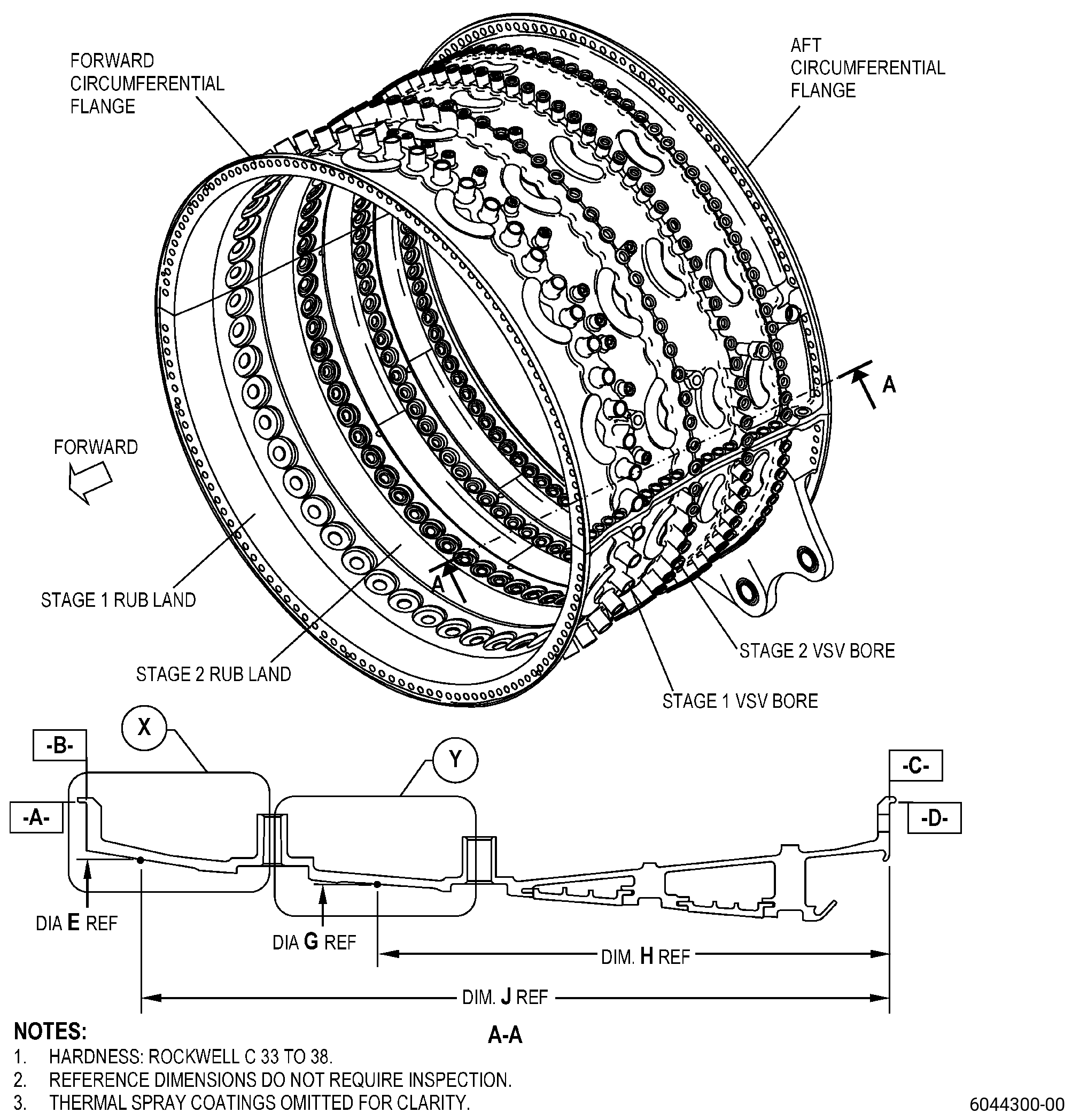
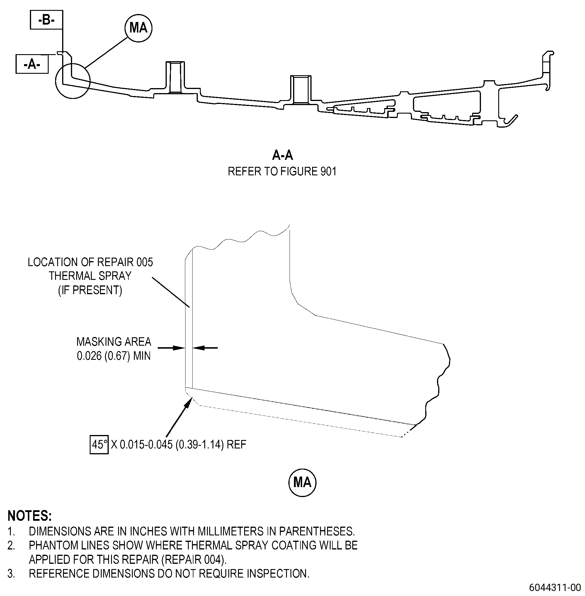
| A. | This procedure gives instructions to repair the high pressure compressor (HPC) stator forward case assembly (case assembly) by removing and replacing the worn abradable flow-path coating (thermal spray coating) on the stage 1 and/or stage 2 rub land flow-path. Refer to Figure 901. |
| B. | The following maximum repairable limits apply to this repair: |
| NOTE: |
|
| (4) | Visual Inspection. |
| (b) | Do an inspection of the surfaces of the stages 1 and 2 rotor blade rub lands for: |
| 1 | Nicks, dents, and scratches: |
| Maximum repairable limit: |
|
| (5) | Dimensional Inspection. |
| (b) | Do a dimensional inspection as follows. Measure each diameter at 10 equally-spaced locations. Calculate the average diameter dimension. Compare the average diameter to the dimensions that follow: |
| 4 | Diameter E at a point of 17.195 inches (436.75 mm) (dimension J) from surface C: |
| Maximum repairable limit: |
|
| 5 | Diameter G from a point of 11.449 inches (290.80 mm) (dimension H) from surface C: |
| Maximum repairable limit: |
|
| C. | The subsequent table gives a list of the part numbers that are applicable to this procedure. All part numbers are applicable to all paragraphs unless specified differently. |
|
|||||||||||||||||||||||
| D. | Proprietary/Complex Process Statement. |
| (1) | None. |
| 2 . | Tools, Equipment, and Materials. |
| NOTE: |
|
| A. | Tools and Equipment. |
| (1) | Special Tools. None. |
| (2) | Standard Tools and Equipment. |
| (3) | Locally Manufactured Tools. |
|
| B. | Consumable Materials |
|
| C. | Referenced Procedures. |
|
| D. | Expendable Parts. None. |
| E. | SPD Information. |
| (1) | Spares Supplied. None. |
| (2) | Protected Spares. None |
| (3) | Locally Manufactured Spares. None. |
| F. | Special Solutions. None. |
| G. | Test Specimens. |
|
| 3 . | Dimensional Information. |
| Subtask 72-32-01-220-132 |
| A. | Refer to Figure 901, Figure 902, and Figure 903 for specified dimensions and locations. |
| NOTE: |
|
| NOTE: |
|
| NOTE: |
|
| 4 . | Setup Information. |
| Subtask 72-32-01-350-088 |
| A. | Set-up the case assembly for machining. Refer to Figure 901 and as follows: |
| (1) | If necessary, make a machining fixture (fixture) to attach surface C and diameter D of the case assembly to the machine table. |
| (2) | Put the case assembly aft end down on the machine table, and do as follows: |
| (a) | Adjust the position of the case assembly on the machine table until the flatness of surface C is 0.001 inch (0.02 mm) or less and as follows: |
| 1 | If necessary, use C10-155 shims between the fixture and machine table to adjust the flatness. |
| (b) | Adjust the position of the case assembly on the machine table until the circular runout of diameter D is 0.001 inch (0.02 mm) or less, full indicator reading (FIR). |
| (c) | Attach the case assembly to the machine table. |
| (3) | Do a check of the forward flange dimensions as follows: |
| (a) | Surface B must be parallel to surface C in 0.002 inch (0.05 mm) or less. |
| (b) | Diameter A must be concentric to diameter B in 0.003 inch (0.07 mm) or less. |
| (4) | If necessary, do Subtask 72-32-01-350-088 (paragraph 4.A.) again to get the correct dimensions. |
| 5 . | Procedure. |
| Subtask 72-32-01-160-015 |
| NOTE: |
|
| NOTE: |
|
| A. | If necessary, clean the case assembly. Refer to TASK 72-32-01, CLEANING 001, and as follows: |
| (1) | If necessary, disassemble the two halves of the case assembly before cleaning. |
| Subtask 72-32-01-350-089 |
| B. | Remove the thermal spray coating from the case assembly repair areas. Refer to Figure 901, Figure 902, and as follows: |
| NOTE: |
|
| (1) | Alternative Procedure Available. Remove the thermal spray coating from the repair areas of the case assembly. Refer to TASK 70-23-00-100-001 (STRIPPING PROCEDURES) and TASK 70-23-23-330-008 (REMOVAL OF COATINGS BY HIGH PRESSURE WATER STRIPPING). |
| Subtask 72-32-01-350-090 |
| CAUTION: |
|
| (1).A. | Alternative Procedure. Remove the thermal spray coating from the repair areas of the case assembly. Refer to TASK 70-00-03-800-004 (MACHINING DATA), Figure 902, and as follows: |
| (a) | Set-up the case assembly for machining. Refer to Subtask 72-32-01-350-088 (paragraph 4.A.). |
| (b) | Machine the case assembly to remove the thermal spray coating. |
| NOTE: |
|
| NOTE: |
|
| (c) | Remove the case assembly from the machine table. |
| Subtask 72-32-01-230-011 |
| C. | Do an inspection of the repair areas of the case assembly for signs of remaining thermal spray coating. Refer to TASK 70-32-00-200-002 (INDIRECT INSPECTION METHODS), TASK 70-32-03-230-002 (SPOT-FLUORESCENT-PENETRANT INSPECTION), and as follows: |
| (1) | Use Class D penetrant. |
| (2) | Look for signs of remaining thermal spray coating, and do as follows: |
| (a) | If you find remaining thermal spray coating, go to Subtask 72-32-01-350-089 (paragraph 5.B.). |
| NOTE: |
|
| (b) | If you do not find remaining thermal spray coating, go to Subtask 72-32-01-160-016 (paragraph 5.C.(3)). |
| Subtask 72-32-01-160-016 |
| (3) | Clean the case assembly. Refer to TASK 72-32-01-100-801 (72-32-01, CLEANING 001), and as follows: |
| (a) | If necessary, disassemble the two halves of the case assembly before cleaning. |
| Subtask 72-32-01-220-133 |
| D. | Etch the repair areas of the case assembly. Refer to TASK 70-24-00-110-033 (ETCHING PROCEDURES FOR FLUORESCENT-PENETRANT INSPECTION), TASK 70-24-01-110-034 (SWAB ETCHING PROCEDURE), and as follows: |
| (1) | Use Class C etchant. |
| Subtask 72-32-01-230-012 |
| E. | Do an inspection of the repair areas of the case assembly. Refer to TASK 70-32-00-200-002 (INDIRECT INSPECTION METHODS), TASK 70-32-03-230-002 (SPOT-FLUORESCENT-PENETRANT INSPECTION), and as follows: |
| (1) | Use Class D penetrant. |
| (2) | Use the acceptability limits that follow: |
| (a) | Through indications are not permitted. |
| (b) | All indications 0.03 inch (0.7 mm) or less that are not specified in Subtask 72-32-01-230-012 (paragraph 5.E.(2)(a)) are permitted. |
| (c) | Indications 0.03-0.06 inch (0.8-1.5 mm) that are not specified in Subtask 72-32-01-230-012 (paragraph 5.E.(2)(a)) and Subtask 72-32-01-230-012 (paragraph 5.E.(2)(b)) are permitted, and as follows: |
| 1 | No linear indications are permitted. |
| NOTE: |
|
| 2 | There must be a minimum distance of 0.25 inch (6.4 mm) between indications. |
| Subtask 72-32-01-320-018 |
| (3) | If necessary, machine the repair areas to remove not permitted indications as follows: |
| (a) | Set-up the case assembly for machining. Refer to Subtask 72-32-01-350-088 (paragraph 4.A.). |
| CAUTION: |
|
| (b) | Machine the areas with not permitted indications. Refer to TASK 70-00-03-800-004 (MACHINING DATA), Figure 902, and as follows: |
| 1 | Machine the minimum quantity of material to remove the indications. |
| NOTE: |
|
| (c) | Remove the case assembly from the machine table. |
| (d) | Blend the areas of the case assembly that you machined. Refer to TASK 70-42-00-350-002 (BLENDING AND REMOVAL OF HIGH METAL PROCEDURES) and as follows: |
| 1 | Break all sharp edges. |
| (e) | Do the etch and FPI procedures specified in Subtask 72-32-01-220-133 (paragraph 5.D.) and Subtask 72-32-01-230-012 (paragraph 5.E.) again to make sure that you removed the indications. |
| Subtask 72-32-01-110-021 |
| F. | Clean the case assembly as follows: |
| (1) | If necessary, disassemble the two halves of the case assembly before cleaning. |
| (2) | Alternative Procedure Available. Clean the two halves of the case assembly. Refer to TASK 70-21-00-110-051 (CHEMICAL CLEANING) and TASK 70-21-03-160-001 (CLEANING METHOD NO. 3 - STEAM CLEANING). |
| (2).A. | Alternative Procedure. Clean the two halves of the case assembly. Refer to TASK 70-21-00-110-051 (CHEMICAL CLEANING) and TASK 70-21-22-110-042 (CLEANING METHOD NO. 22 - LIGHT DUTY AQUEOUS CLEANING). |
| (3) | If necessary, assemble the two halves of the case assembly. Refer to TASK 72-32-01-200-801 (72-32-01, INSPECTION 001). |
| Subtask 72-32-01-220-134 |
| G. | Do a dimensional inspection of the repair areas of the case assembly. Refer to TASK 70-31-00-220-001 (DIMENSIONAL INSPECTION), Figure 902 and as follows: |
| NOTE: |
|
| Subtask 72-32-01-340-005 |
| H. | Thermal-spray the case assembly in the repair areas. Refer to Figure 901, Figure 902, and as follows: |
| (1) | Test specimens must be thermal-sprayed at the same time as you thermal-spray the case assembly. Refer to Subtask 72-32-01-220-134 (paragraph 2.G.)for coating thickness requirements. |
| (2) | Before you thermal-spray, apply masking to the areas adjacent to the repair areas. Refer to TASK 70-18-00-330-801 (MASKING PROCEDURES), Figure 901, Figure 905, and as follows: |
| (a) | Apply masking to the stage 1 and/or stage 2 VSV bores, as applicable for the repair areas, as follows: |
| 1 | Use C10-198 plugs. |
| (b) | Apply masking to the forward face and the rabbet diameter on the forward circumferential flange as follows: |
| NOTE: |
|
| 1 | Alternative Procedure Available. Use fabricated shields and C10-012 tape. |
| 1.A. | Alternative Procedure. Use C10-012 tape and as follows: |
| a | Make sure that all the edges tightly touch with the case assembly during the thermal spray process. |
| (3) | Thermal-spray the bond coat on the repair areas of the case assembly and the test specimens. Refer to TASK 70-49-00-340-001 (THERMAL SPRAYING), TASK 70-49-10-340-011 (THERMAL SPRAYING NICKEL-ALUMINUM (POWDER)), Figure 901, and as follows: |
| (a) | Apply the bond coating to the applicable repair areas as follows: |
| NOTE: |
|
| 1 | Use a combustion flame spray process. |
| NOTE: |
|
| 2 | Use multiple spray passes to build-up the bond coating to the necessary thickness. |
| 3 | Bond coating thickness must be 0.003-0.007 inch (0.08-0.17 mm). |
| 4 | Overspray and mismatch are permitted in areas GP only. |
| (b) | Do all the quality assurance testing as follows: |
| 1 | Do all the quality assurance testing for the bond coating on the test specimens as specified in TASK 70-49-00-340-001 (THERMAL SPRAYING), TASK 70-49-10-340-011 (THERMAL SPRAYING NICKEL-ALUMINUM (POWDER)), and as follows: |
| a | Uniformity of bond coating coverage must be as follows: |
| (1) | The bond coating on the coating system test specimen must show uniformity of bond coating coverage not less than C-2 in GE Photo Standard 8906004. |
| (2) | A maximum of 10 percent of the total specimen interface length can show uniformity of bond coating coverage not less than C-3 in GE Photo Standard 8906004. |
| 2 | Do the tensile test on the test specimen. Refer to TASK 70-71-01-700-002 (BOND STRENGTH TENSILE TESTING OF THERMAL SPRAY COATINGS), and as follows: |
| a | Bond coating adhesion must be as follows: |
| (1) | Test the tensile bond strength of the bond coating and use the requirements that follow: |
| (a) | The tensile bond strength of the bond coating at room temperature 65 to 85°F (18 to 29°C) must be a minimum of 2750 psi (19.0 MPa). |
| b | Failures on the tensile bond strength testing for the bond coating must be cohesive (in the coating) or epoxy failures. |
| 3 | Do the metallographic examination to the test specimens. Refer to TASK 70-71-04-700-005 (METALLOGRAPHIC EVALUATION OF THERMAL SPRAY COATINGS), but use the specific requirements that follow: |
| a | Bond coating microstructure must be as follows: |
| (1) | The bond coating on the coating system test specimen must show unmelts and voids not more than UV-2 in GE Photo Standard 8906001 and delaminations must be not more than D-2 in GE Photo Standard 8906002. |
| b | A maximum of 10 percent of the total specimen bond coating area can show unmelts and voids not more than UV-3 in GE Photo Standard 8906001 and delaminations not more than D-3 in GE Photo Standard 8906002. |
| 4 | Substrate/bond coating interface grit and contamination must be as follows: |
| a | The substrate/bond coating interface grit and contamination of the coating system test specimen must not be more than I-2 in GE Photo Standard 8906003. |
| b | A maximum of 10 percent of the total specimen interface can show grit and contamination not more than I-3 in GE Photo Standard 8906003. |
| (c) | If one of the quality assurance tests for the bond coating test specimens is unsatisfactory, go back to Subtask 72-32-01-350-089 (paragraph 5.B.) to remove the bond coating, and do the procedure again. |
| (4) | Thermal-spray the top coating on the repair areas of the case assembly and the test specimens. Refer to TASK 70-49-00-340-001 (THERMAL SPRAYING), 70-49-61-340-000 (THERMAL SPRAY PROCEDURES - THERMAL SPRAYING NICKEL CHROMIUM-ALUMINUM-BENTONITE (POWDER)), Figure 901, and as follows: |
| NOTE: |
|
| (a) | Apply the top coating to the applicable repair areas as follows: |
| NOTE: |
|
| 1 | Use a combustion flame spray process. |
| NOTE: |
|
| 2 | Apply sufficient material to make sure that the part agrees with finish dimensions and useful coating thickness range after final machining and as follows: |
| NOTE: |
|
| a | For tensile bond and erosivity number test specimens, top coating thickness must be 0.030-0.035 inch (0.77-0.88 mm). |
| 3 | Overspray and mismatch is permitted in areas GP only. |
| (b) | Do all the quality assurance testing as follows: |
| 1 | Do all the quality assurance testing for the coating system test specimens as specified in TASK 70-49-00-340-001 (THERMAL SPRAYING), 70-49-61-340-000 (THERMAL SPRAY PROCEDURES - THERMAL SPRAYING NICKEL CHROMIUM-ALUMINUM-BENTONITE (POWDER)), and as follows: |
| a | Measure the top coat thickness as follows: |
| (1) | Use a standard flat-anvil-and-spindle micrometer. |
| (2) | The top coat must have a minimum thickness of 0.060 inch (1.52 mm). |
| (3) | Calculate the coating thickness to the nearest 0.001 inch (0.03 mm) at three different locations. |
| b | Do a visual inspection of the top coating to make sure that it agrees with the requirements that follow: |
| (1) | The top coating must show full and equal coverage in the repair areas. |
| NOTE: |
|
| (2) | Overspray and mismatch are permitted in areas GP only. |
| (3) | The top coating must show no spalling or lifting |
| (4) | The top coating must have no cracks, blisters, spatter, chipping, and flaking. |
| 2 | Do the metallographic examination to the test specimens. Refer to TASK 70-71-04-700-005 (METALLOGRAPHIC EVALUATION OF THERMAL SPRAY COATINGS), but use the specific requirements that follow: |
| a | Top coating microstructure must be as follows: |
| (1) | The top coating must have a constant microstructure made of a metal matrix with oval bentonite particles equally-spaced (or fragments of bentonite particles). |
| (2) | The top coating must have a constant intentional porosity. |
| (3) | See GE Photo Standard 8906005 and GE Photo Standard 8906006 for typical permitted microstructures for the top coating. |
| (4) | Do not examine transverse cracks in the top coating microstructure to accept or reject them. |
| 3 | Do the tensile test on the test specimen. Refer to TASK 70-71-01-700-002 (BOND STRENGTH TENSILE TESTING OF THERMAL SPRAY COATINGS), and as follows: |
| a | Top coating adhesion must be as follows: |
| (1) | Test the tensile bond strength of the top coating system and use the requirements that follow: |
| (a) | The tensile bond strength of the top coating at room temperature 65 to 85°F (18 to 29°C) must be in the range of 300-800 psi (2.1-5.5 MPa). |
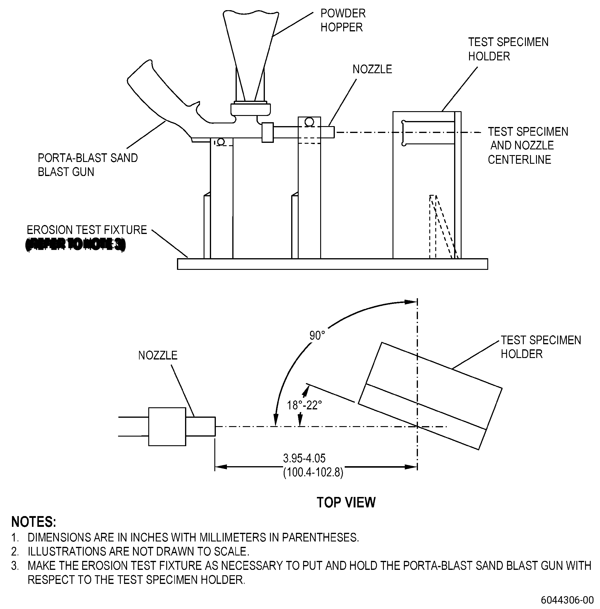
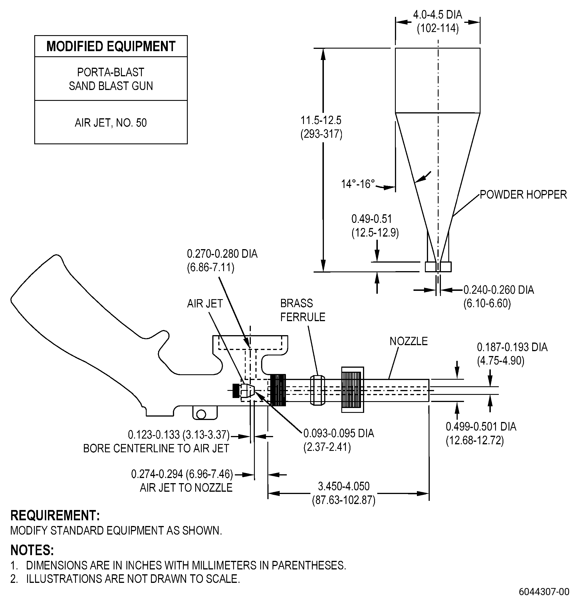
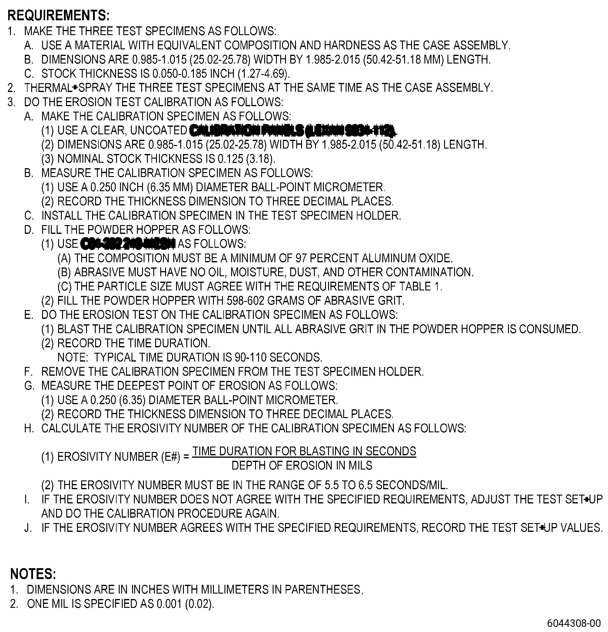
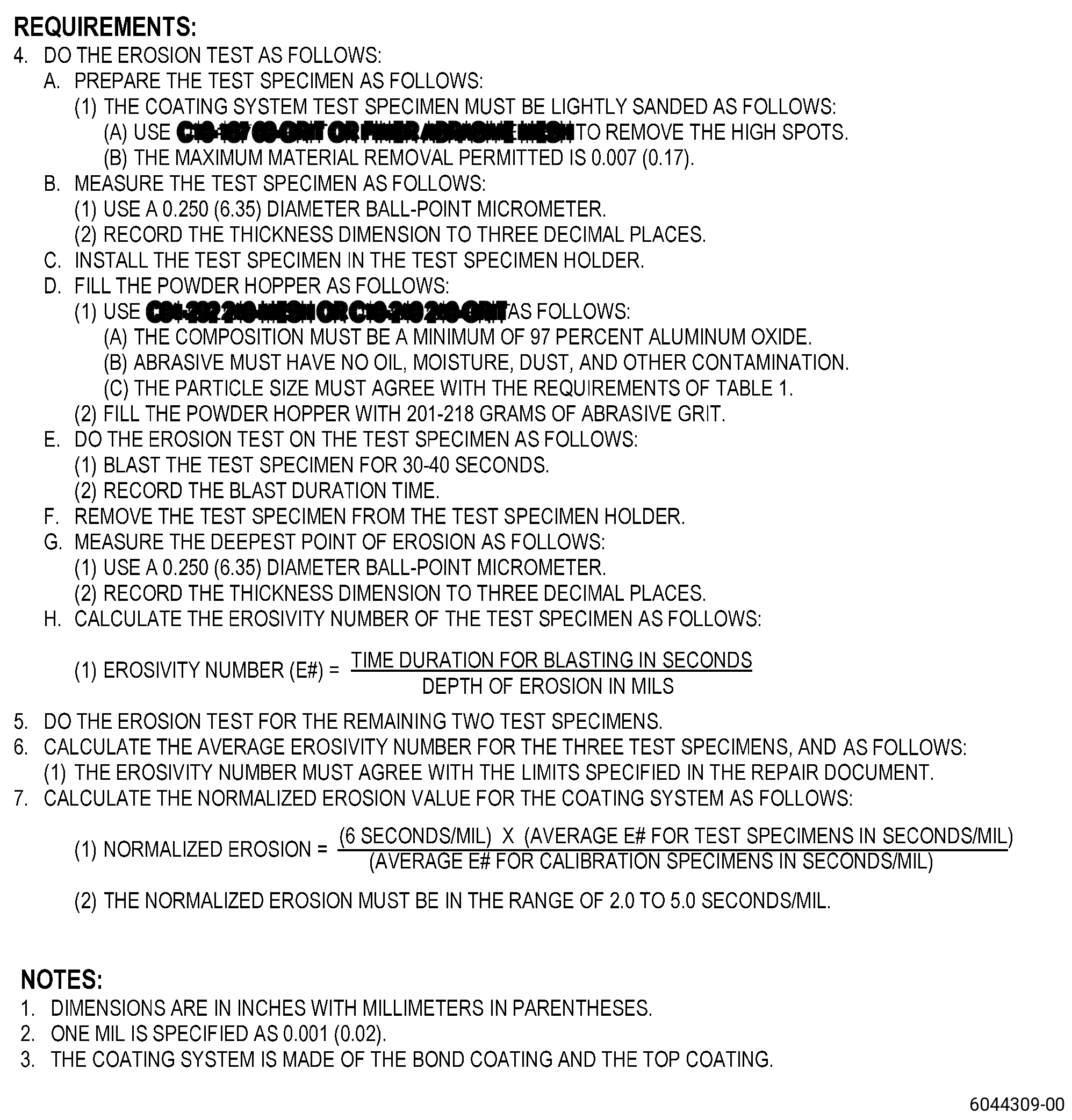
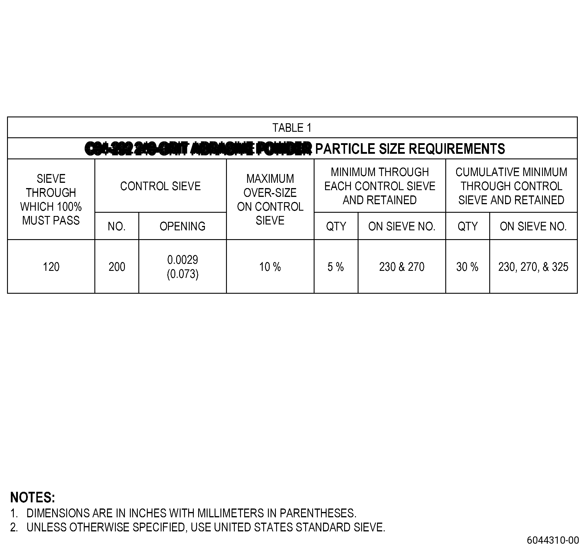
| 4 | Do the erosion test on the top coating of the test specimen. Refer to TASK 70-71-09-700-000 (EROSION TESTING OF THERMAL SPRAY COATINGS) and Figure 904 for test procedure and acceptability criteria. |
| (c) | If one of the quality assurance tests for the top coating test specimens is unsatisfactory, go back to Subtask 72-32-01-350-089 (paragraph 5.B.) to remove the bond coating and top coating, and do the procedure again. |
| Subtask 72-32-01-320-019 |
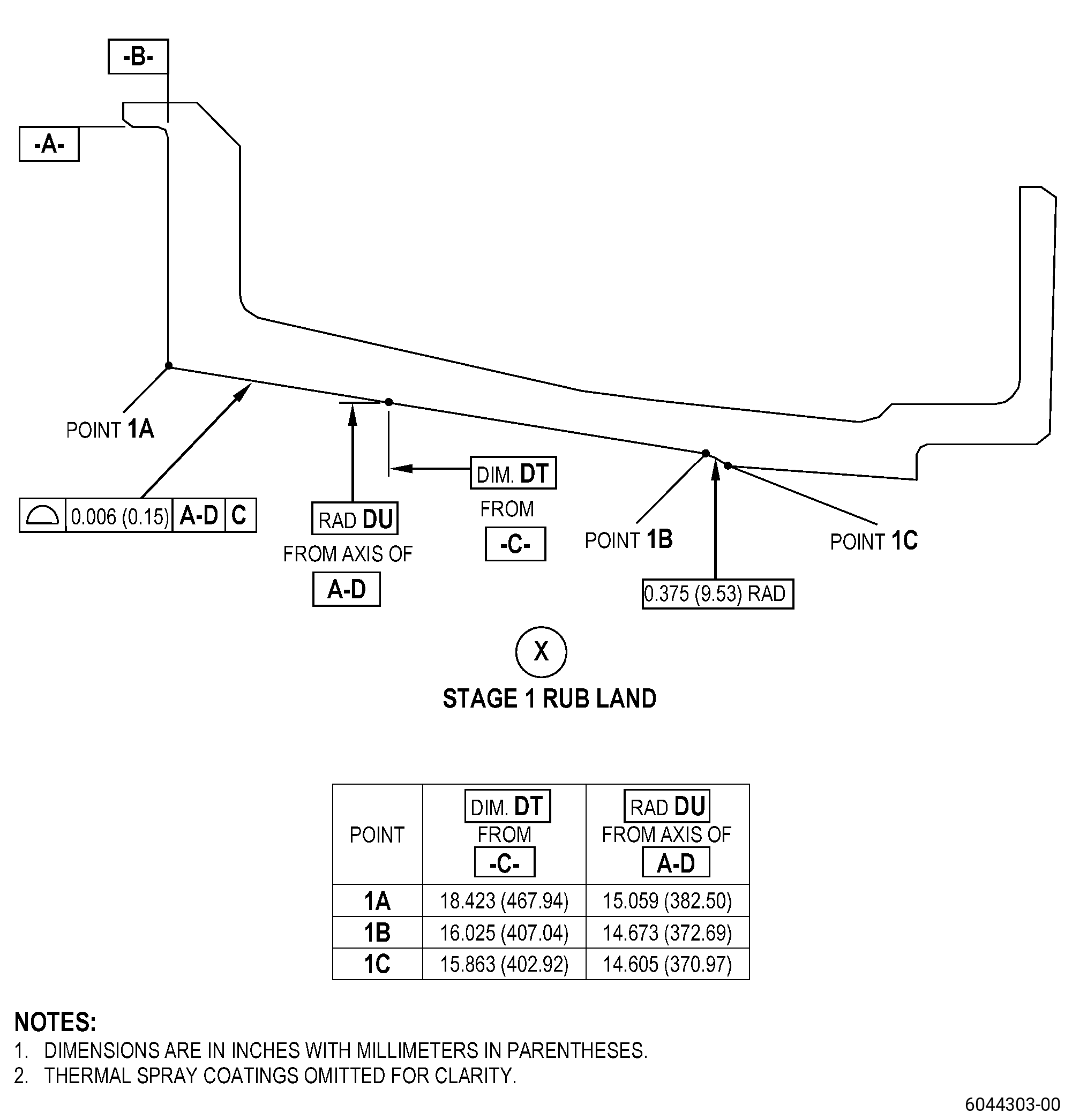
| I. | Machine the repair areas of the case assembly to the finish dimensions. Refer to TASK 70-00-03-800-004 (MACHINING DATA), Figure 901, Figure 903, and as follows: |
| (1) | Set-up the case assembly for machining. Refer to Subtask 72-32-01-350-088 (paragraph 4.A.). |
| (2) | Machine the top coating until the case assembly agrees with the finish dimensions. |
| NOTE: |
|
| (3) | Remove the case assembly from the machine table. |
| (4) | Blend the case assembly. Refer to TASK 70-42-00-350-002 (BLENDING AND REMOVAL OF HIGH METAL PROCEDURES), and as follows: |
| (a) | Break all sharp edges. |
| Subtask 72-32-01-160-017 |
| J. | Clean the case assembly. Refer to TASK 72-32-01-100-801 (72-32-01, CLEANING 001), and as follows: |
| (1) | If necessary, disassemble the two halves of the case assembly before cleaning. |
| Subtask 72-32-01-220-135 |
| K. | Do an inspection of the top coating in the repair areas of the case assembly. Refer to Figure 901 and as follows: |
| (1) | Do a check of the surface finish of the machined top coating and as follows: |
| (a) | The maximum surface finish must not be more than 1000 RA. |
| (2) | Do a visual inspection of the top coating as follows: |
| (a) | Chips and local discontinuities are permitted if they are not more than the visual limits that follow: |
| 1 | Maximum diameter of 0.08 inch (2.0 mm). |
| 2 | Maximum depth of 0.02 inch (0.5 mm). |
| 3 | Maximum of 10 each in areas GM and GN if there is a minimum distance of 0.12 inch (3.1 mm) between defects. |
| (b) | Steps that point forward are not permitted. |
| (c) | If the repaired case assembly does not agree with the visual inspection criteria, go back to Subtask 72-32-01-350-089 (paragraph 5.B.) to remove all thermal spray coating, and do the procedure again. |
| Subtask 72-32-01-230-013 |
| L. | Etch the case assembly adjacent to the repaired stage 1 and stage 2 rub lands. Refer to TASK 70-24-00-110-033 (ETCHING PROCEDURES FOR FLUORESCENT-PENETRANT INSPECTION), TASK 70-24-01-110-034 (SWAB ETCHING PROCEDURE), and as follows: |
| (1) | Use Class C etchant. |
| Subtask 72-32-01-230-014 |
| M. | Do an inspection of the areas adjacent to the repaired stage 1 and stage 2 rub lands on the case assembly. Refer to TASK 70-32-00-200-002 (INDIRECT INSPECTION METHODS), TASK 70-32-03-230-002 (SPOT-FLUORESCENT-PENETRANT INSPECTION), and as follows: |
| (1) | Use Class D penetrant. |
| (2) | Use the acceptability limits that follow: |
| (a) | Through indications are not permitted. |
| (b) | All indications 0.03 inch (0.7 mm) or less that are not specified in Subtask 72-32-01-230-014 (paragraph 5.M.(2)(a)) are permitted. |
| (c) | All indications more than 0.03-0.06 inch (0.8-1.5 mm) that are not specified in Subtask 72-32-01-230-014 (paragraph 5.M.(2)(a)) and Subtask 72-32-01-230-014 (paragraph 5.M.(2)(b)) are permitted, and as follows: |
| 1 | No linear indications are permitted. |
| NOTE: |
|
| 2 | There must be a minimum distance of 0.25 inch (6.4 mm) between indications. |
| (3) | If necessary, machine the case assembly to remove not permitted indications as follows: |
| (a) | Set-up the case assembly for machining. Refer to Subtask 72-32-01-350-088 (paragraph 4.A.). |
| CAUTION: |
|
| (b) | Machine the case assembly areas with not permitted indications. Refer to TASK 70-00-03-800-004 (MACHINING DATA), Figure 902, and as follows: |
| 1 | Machine the minimum quantity of material to remove the indications. |
| NOTE: |
|
| (c) | Remove the case assembly from the machine table. |
| (d) | Blend the case assembly areas that you machined. Refer to TASK 70-42-00-350-002 (BLENDING AND REMOVAL OF HIGH METAL PROCEDURES), and as follows: |
| 1 | Break all sharp edges. |
| (e) | Do the etch and FPI procedures in Subtask 72-32-01-230-013 (paragraphs 5.L.) and Subtask 72-32-01-230-014 (paragraph 5.M.) again to make sure that you removed all the indications. |
| Subtask 72-32-01-160-018 |
| N. | Clean the case assembly as follows: |
| (1) | If necessary, disassemble the two halves of the case assembly before cleaning. |
| (2) | Alternative Procedure Available. Clean the two halves of the case assembly. Refer to TASK 70-21-00-110-051 (CHEMICAL CLEANING) and TASK 70-21-03-160-001 (CLEANING METHOD NO. 3 - STEAM CLEANING). |
| (2).A. | Alternative Procedure. Clean the two halves of the case assembly. Refer to TASK 70-21-00-110-051 (CHEMICAL CLEANING) and TASK 70-21-22-110-801 (CLEANING METHOD NO. 22 - LIGHT DUTY AQUEOUS CLEANING). |
| (3) | If necessary, assemble the two halves of the case assembly. Refer to TASK 72-32-01-200-801 (72-32-01, CLEANING 001). |
| Subtask 72-32-01-220-136 |
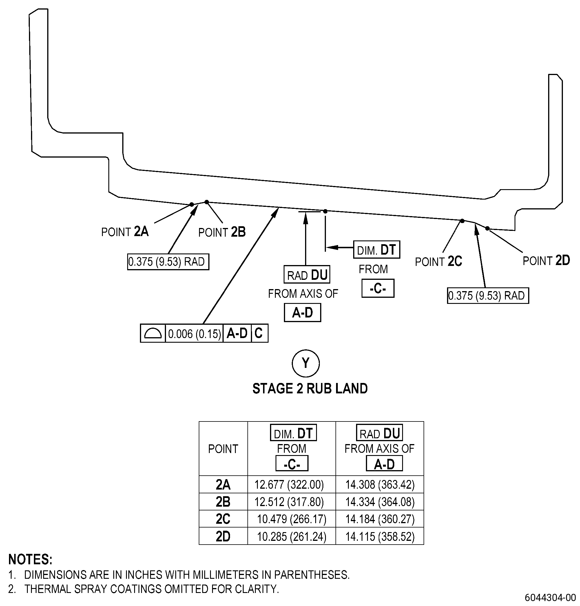
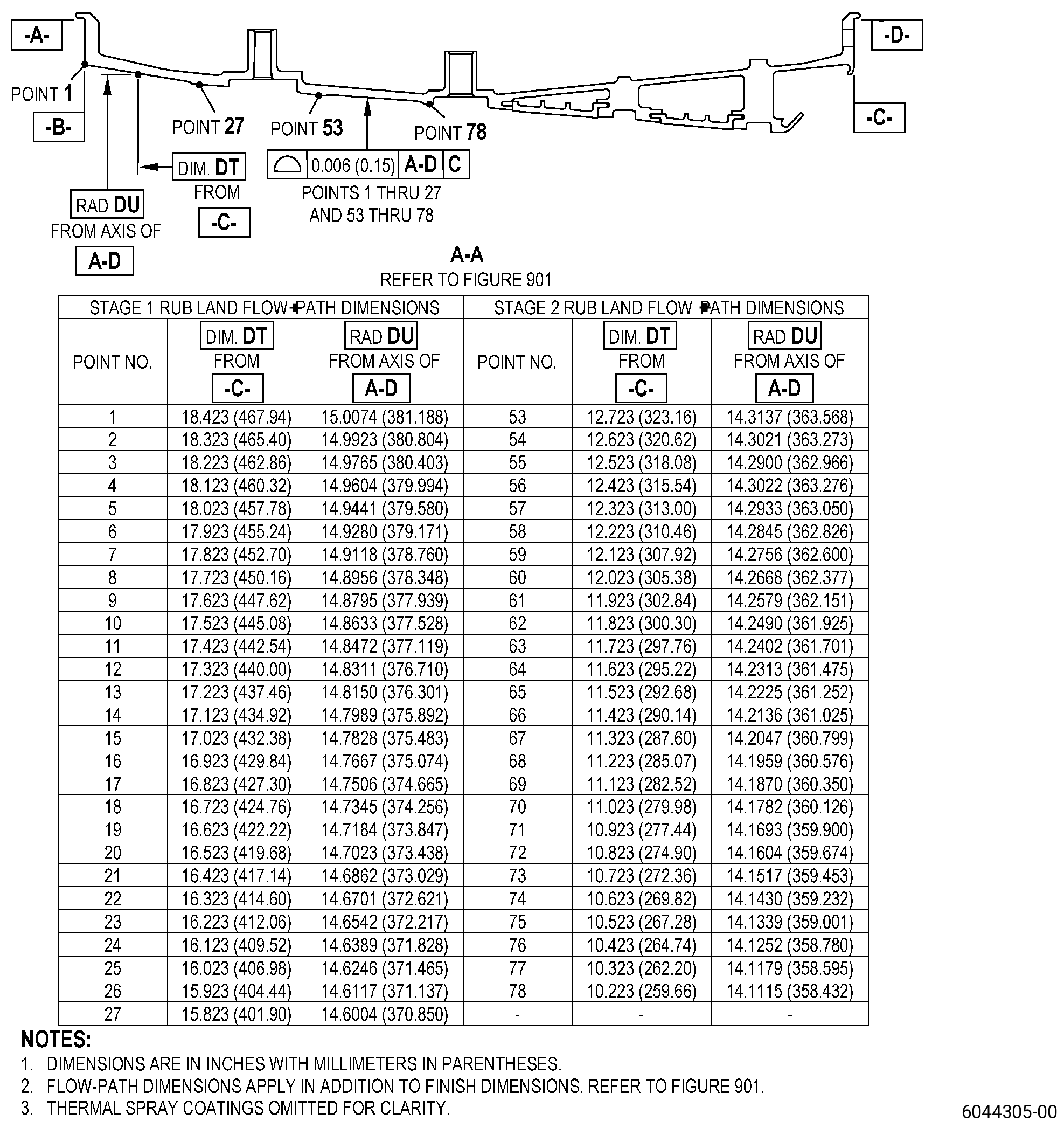
| O. | Do a dimensional inspection of the flowpath in the case assembly repair areas. Refer to TASK 70-31-00-220-001 (DIMENSIONAL INSPECTION), Figure 901, and as follows: |
| (1) | Measure and record the flowpath dimensions in the repair areas as follows: |
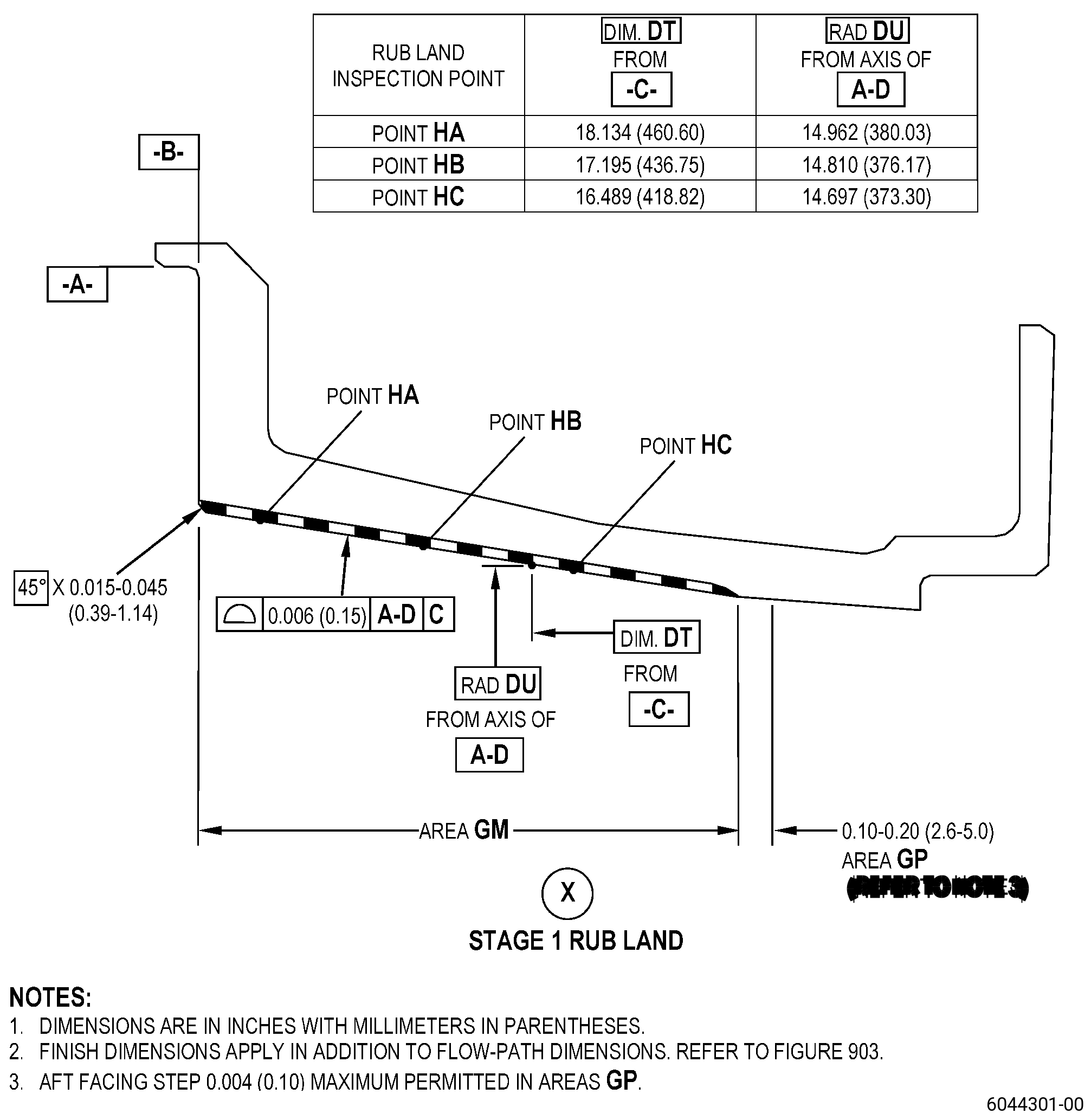
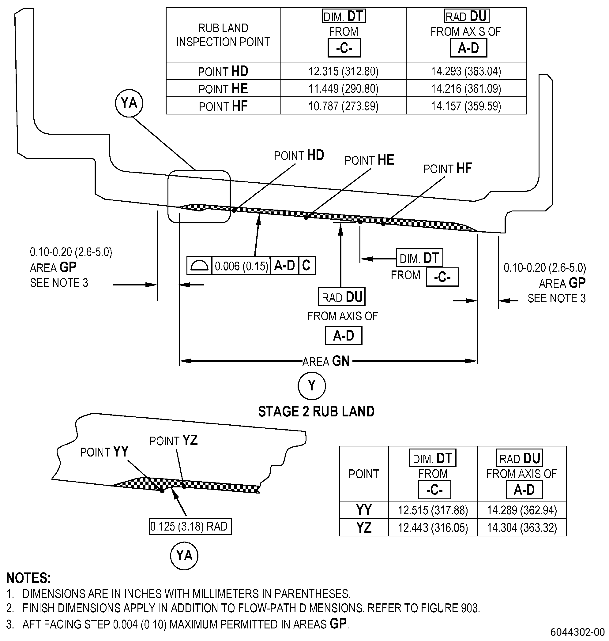
| (a) | Measure radius DU at 10 degree increments around the whole circumference for each rub land inspection point as follows: |
| NOTE: |
|
| 1 | For stage 1 rub land, measure point HA, point HB, and point HC. |
| 2 | For stage 2 rub land, measure point HD, point HE, and point HF. |
| 3 | Surface profile at each point must be 0.006 inch (0.15 mm) or less and as follows: |
| a | If radius DU measurement does not agree with this surface profile, go back to Subtask 72-32-01-350-089 (paragraph 5.B.) to remove all thermal spray coating, and do the procedure again. |