| GENX-1B CLEANING,INSPECTION,AND REPAIR MANUAL | Dated: 04/08/2020 | |
| CIR 72-32-01 , REPAIR 009 | ||
| HIGH PRESSURE COMPRESSOR STATOR FORWARD CASE ASSEMBLY - REPAIR - CORROSION REPAIR OF THE AFT FLANGE BOLTHOLE | ||
| GENX-1B CLEANING,INSPECTION,AND REPAIR MANUAL | Dated: 04/08/2020 | |
| CIR 72-32-01 , REPAIR 009 | ||
| HIGH PRESSURE COMPRESSOR STATOR FORWARD CASE ASSEMBLY - REPAIR - CORROSION REPAIR OF THE AFT FLANGE BOLTHOLE | ||
| * * * FOR ALL |
| TASK 72-32-01-300-809 |
| 1 . | Corrosion Repair of the Aft Flange Bolthole. |
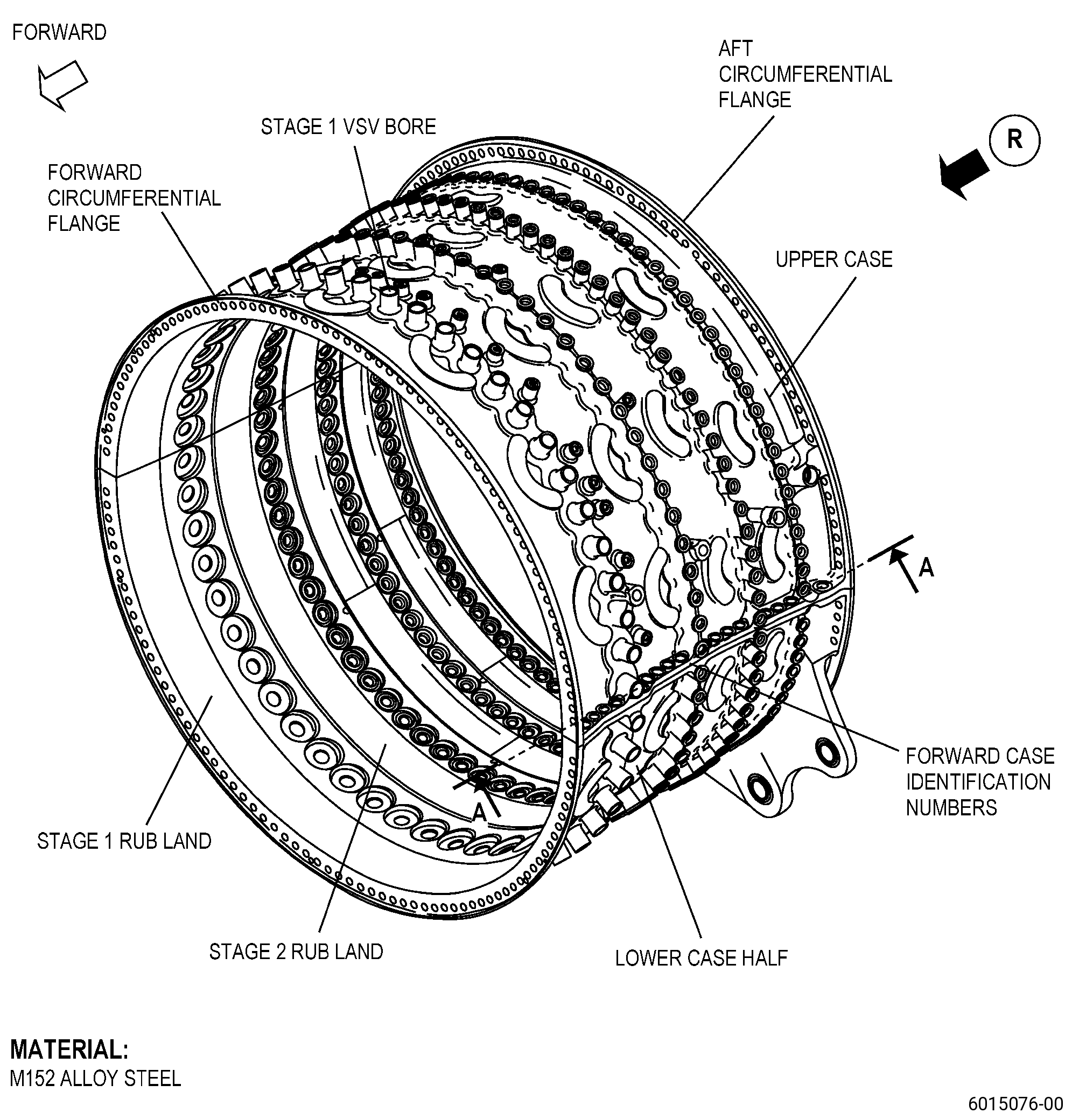
| A. | This procedure gives instructions to repair the high pressure compressor stator forward case assembly (HPC case) by reaming the aft flange boltholes to remove corrosion pitting. Refer to Figure 901. |
| NOTE: |
|
| B. | The following maximum repairable limits apply to this repair: |
| NOTE: |
|
| (4) | Visual Inspection. |
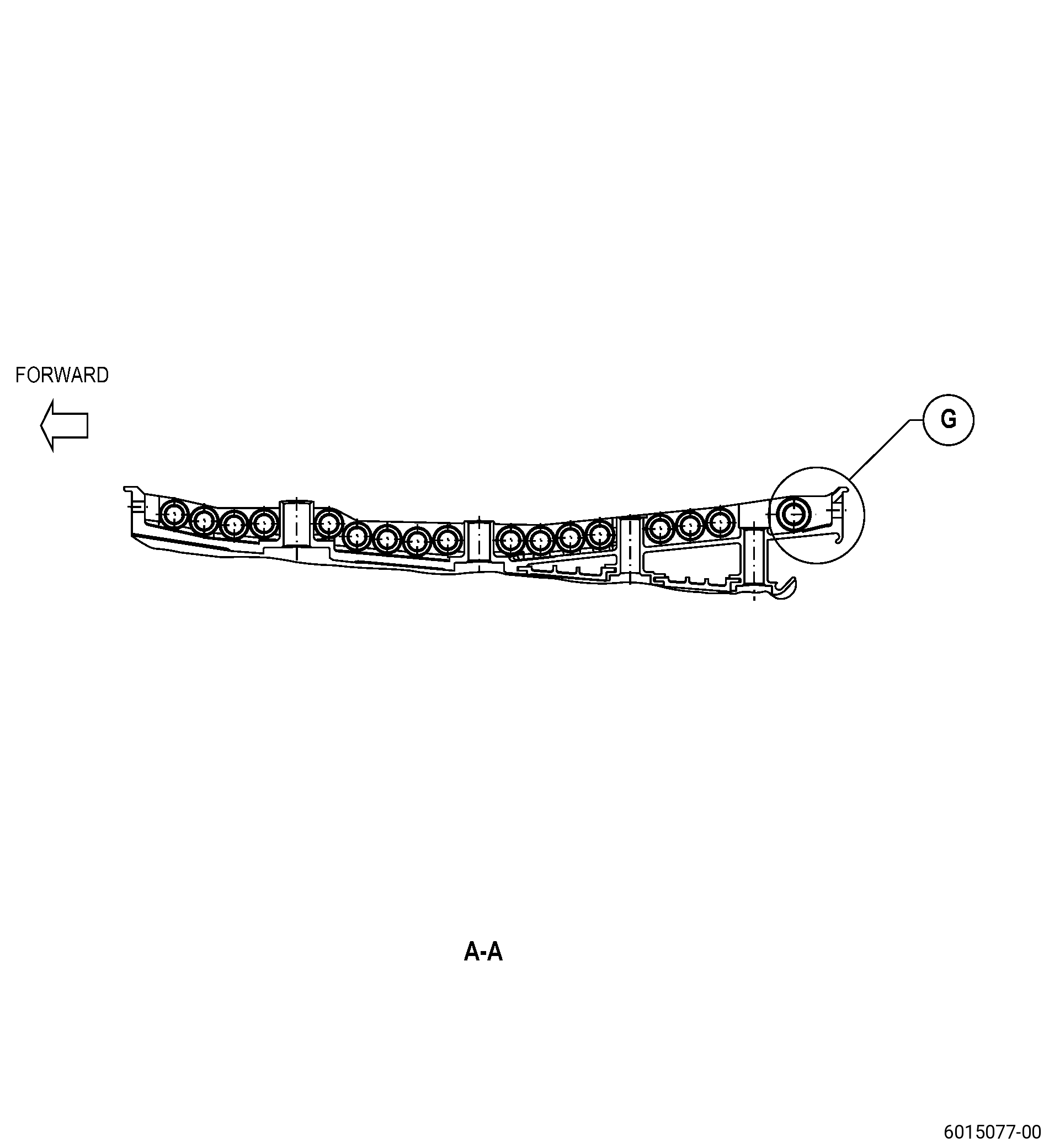
| (e) | Do an inspection of the circumferential flanges. Refer to Figure 802 and as follows: |
| 5 | Corrosion pitting in the aft circumferential flange boltholes: |
| Maximum repairable limit: |
|
| C. | The subsequent table gives a list of the part numbers that are applicable to this repair. All part numbers are applicable to all paragraphs unless specified differently. |
|
|||||||||||||||||||||||
| D. | Proprietary/Complex Process Statement. |
| (1) | None. |
| 2 . | Tools, Equipment, and Materials. |
| NOTE: |
|
| A. | Tools and Equipment. |
| (1) | Special Tools. None. |
| (2) | Standard Tools and Equipment. |
|
| (3) | Locally Manufactured Tools. |
|
| B. | Consumable Materials. |
|
| C. | Referenced Procedures. |
| D. | Expendable Parts. None. |
| E. | SPD Information. |
| (1) | Spares Supplied. None. |
| (2) | Protected Spares. None. |
| (3) | Locally Manufactured Spares. None. |
| F. | Special Solutions. None. |
| G. | Test Specimens. None. |
| 3 . | Dimensional Information. |
| Subtask 72-32-01-220-124 |
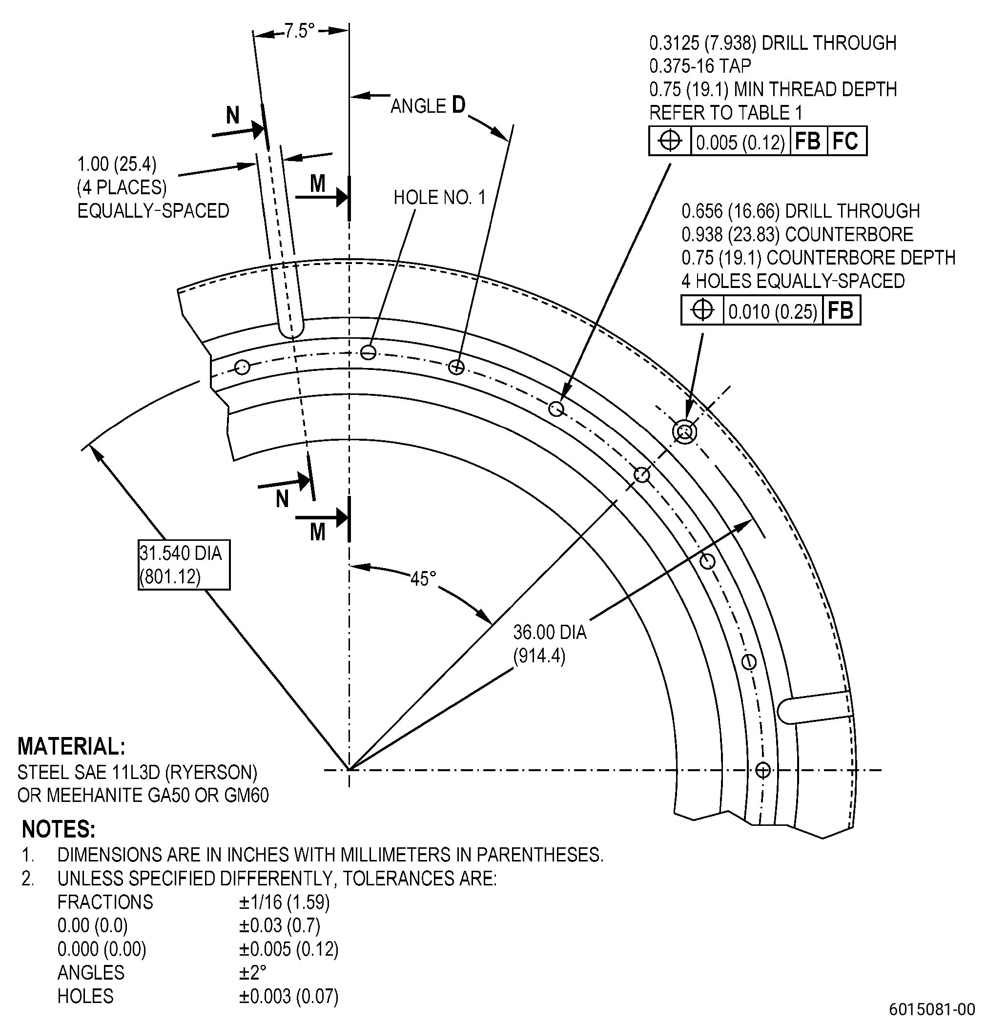
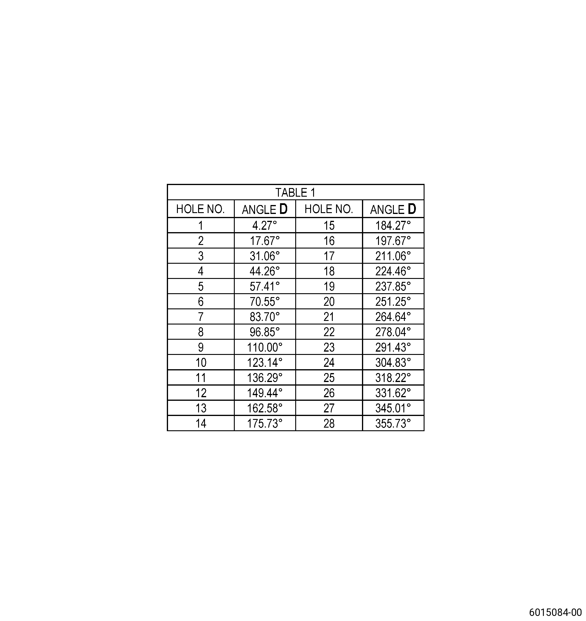
| A. | Refer to Figure 901 for specified dimensions and locations. |
| NOTE: |
|
| NOTE: |
|
| 4 . | Setup Information. |
| Subtask 72-32-01-320-015 |
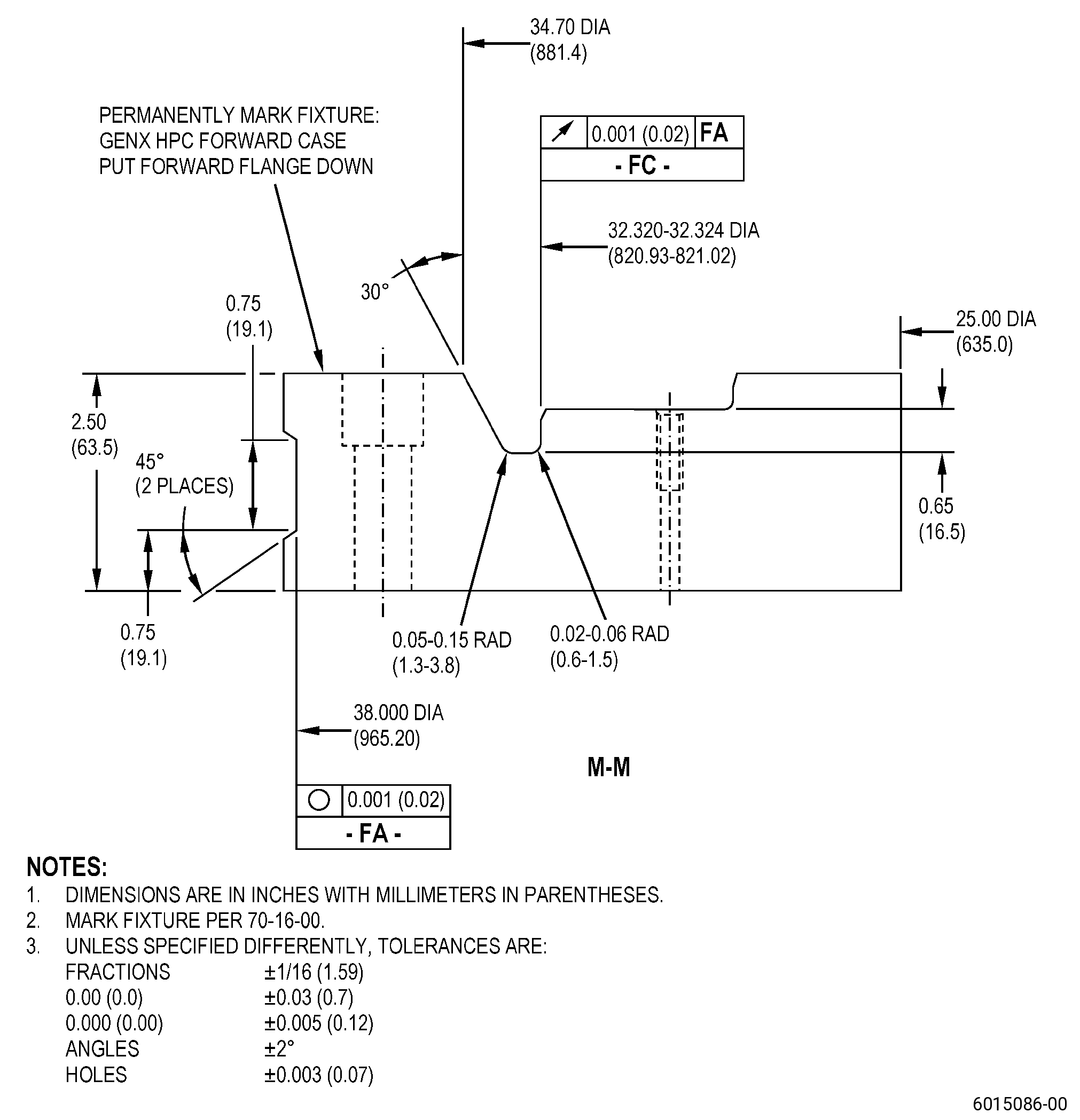
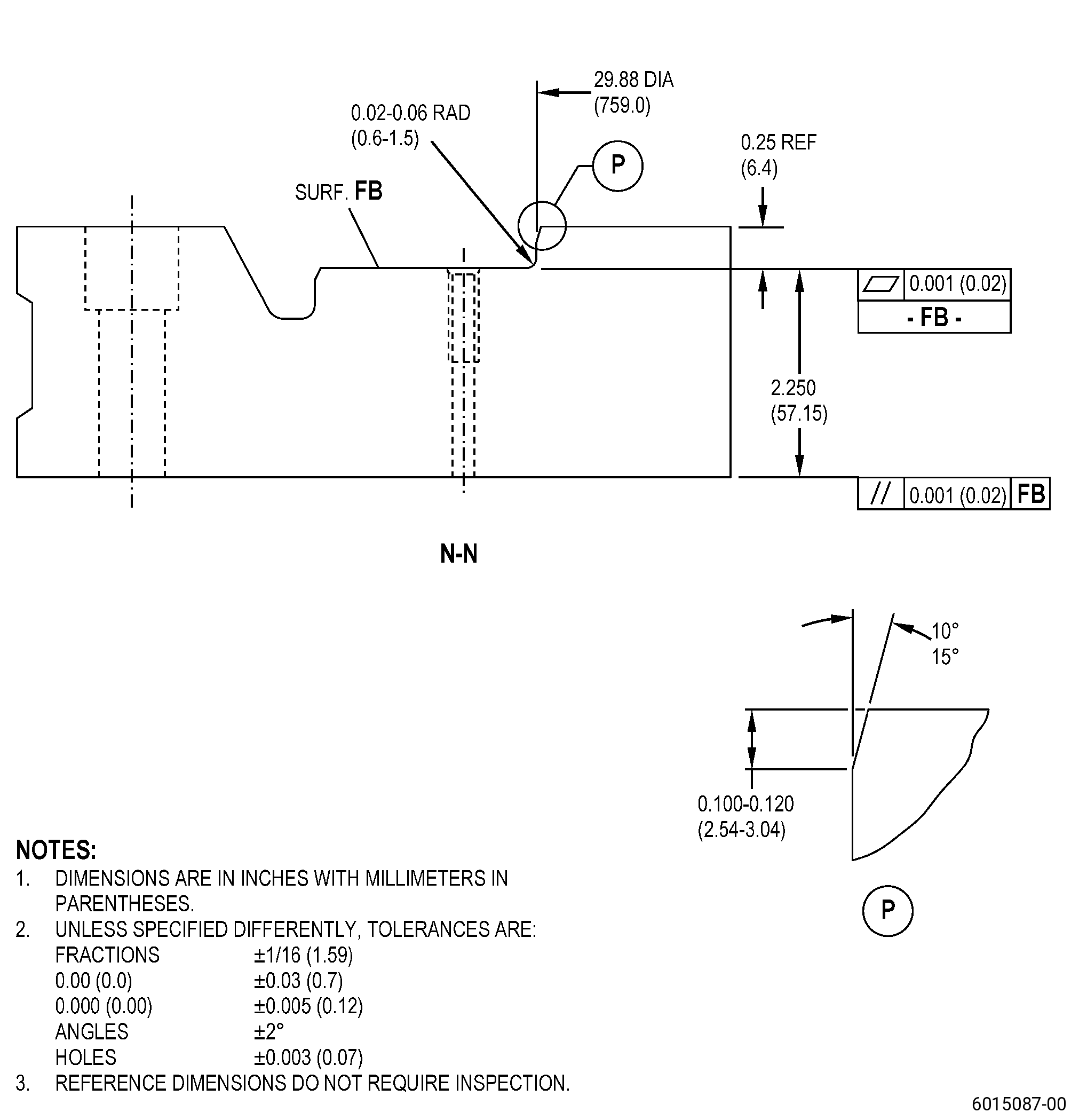
| A. | Alternative Procedure Available. Set-up the HPC case for machining. Refer to Figure 902 and as follows: |
| (1) | If necessary, make the machining fixture. Refer to Figure 905. |
| (2) | Install the machining fixture on the machining table and do as follows: |
| (a) | Make surface FB flat to 0.001 inch (0.02 mm) or less and as follows: |
| 1 | If necessary, put C10-155 shims between the machining fixture and the machining table. |
| (b) | Make diameter FA concentric to the machining table axis to 0.001 inch (0.02 mm) or less. |
| (c) | Use clamps or 0.625 inch (15.88 mm) bolts to attach the machining fixture to the machining table. |
| (3) | If necessary, assemble the upper and lower HPC case halves to make the HPC case assembly. Refer to TASK 72-32-01-200-801 (72-32-01, INSPECTION 001). |
| (4) | Put the assembled HPC case on the machining fixture and do as follows: |
| (a) | Put the forward flange of the HPC case (surface B) on the machining fixture as follows: |
| 1 | Align the forward flange boltholes with the boltholes on the machining fixture. |
| 2 | Use 28 0.375-16 bolts with 28 washers to attach the HPC case assembly to the machining fixture. |
| Subtask 72-32-01-320-016 |
| A.A. | Alternative Procedure. Set-up the HPC case for machining. Refer to Figure 902 and as follows: |
| (1) | If necessary, assemble the upper and lower HPC case halves to make the HPC case assembly. Refer to TASK 72-32-01-200-801 (72-32-01, INSPECTION 001). |
| (2) | If there is no fixture available, install the HPC case assembly with the forward flange (surface B) down on ground blocks. Refer to Figure 901 and as follows: |
| (a) | Make surface C flat to 0.002 inch (0.05 mm) or less and as follows: |
| 1 | If necessary, put C10-155 shims between the restraining fixture and the machining table. |
| (b) | Make diameter D concentric to the machining table axis to 0.002 inch (0.05 mm) or less. |
| (c) | Attach the forward flange with machine clamps with Teflon spacers to prevent damage to the forward flange. |
| 5 . | Procedure. |
| Subtask 72-32-01-160-012 |
| A. | Clean the HPC case. Refer to TASK 72-32-01-100-801 (72-32-01, CLEANING 001), and as follows: |
| Subtask 72-32-01-110-018 |
| CAUTION: |
|
| (1) | Alternative Procedure Available. If the boltholes have C03-038 paint on them, clean the circumferential aft flange of the HPC case. Refer to TASK 70-21-00-110-051 (CHEMICAL CLEANING), TASK 70-21-06-110-004 (CLEANING METHOD NO. 6 - HEAVY-DUTY ALKALINE CLEANER (WITHOUT INHIBITED PHOSPHORIC ACID)), and as follows: |
| (a) | Clean all the aft circumferential flange boltholes with a nylon brush to remove all the unwanted material from the surface and as follows: |
| 1 | Do not clean the boltholes with a BZ mark on them. |
| Subtask 72-32-01-100-005 |
| (1).A. | Alternative Procedure. If the boltholes have C03-038 paint on them, remove it from the circumferential aft flange of the HPC case. Refer to TASK 70-23-00-100-001 (STRIPPING PROCEDURES), TASK 70-23-23-330-008 (REMOVAL OF COATINGS BY HIGH PRESSURE WATER STRIPPING). |
| Subtask 72-32-01-220-125 |
| B. | Do a visual inspection of the aft flange boltholes of the HPC case as follows: |
| (1) | Do a check of the aft flange boltholes for signs of corrosion and as follows: |
| (a) | If you find signs of corrosion, use a C05-003 marking pen to do a circular mark on the damaged boltholes. |
| Subtask 72-32-01-320-017 |
| CAUTION: |
|
| C. | Machine the marked aft flange boltholes to remove corrosion from the HPC case. Refer to TASK 70-00-03-800-004 (MACHINING DATA), Figure 901, Figure 902, Figure 904, and as follows: |
| (1) | Set-up the HPC case for machining. Refer to Subtask 72-32-01-320-015 (paragraph 4.A.). |
| (2) | For the boltholes that will be machined, make sure that you set-up the HPC case boltholes within 0.001 inch (0.02 mm) or better to the machine spindle. |
| Subtask 72-32-01-350-083 |
| (3) | Use the reamers to remove corrosion from the boltholes as follows: |
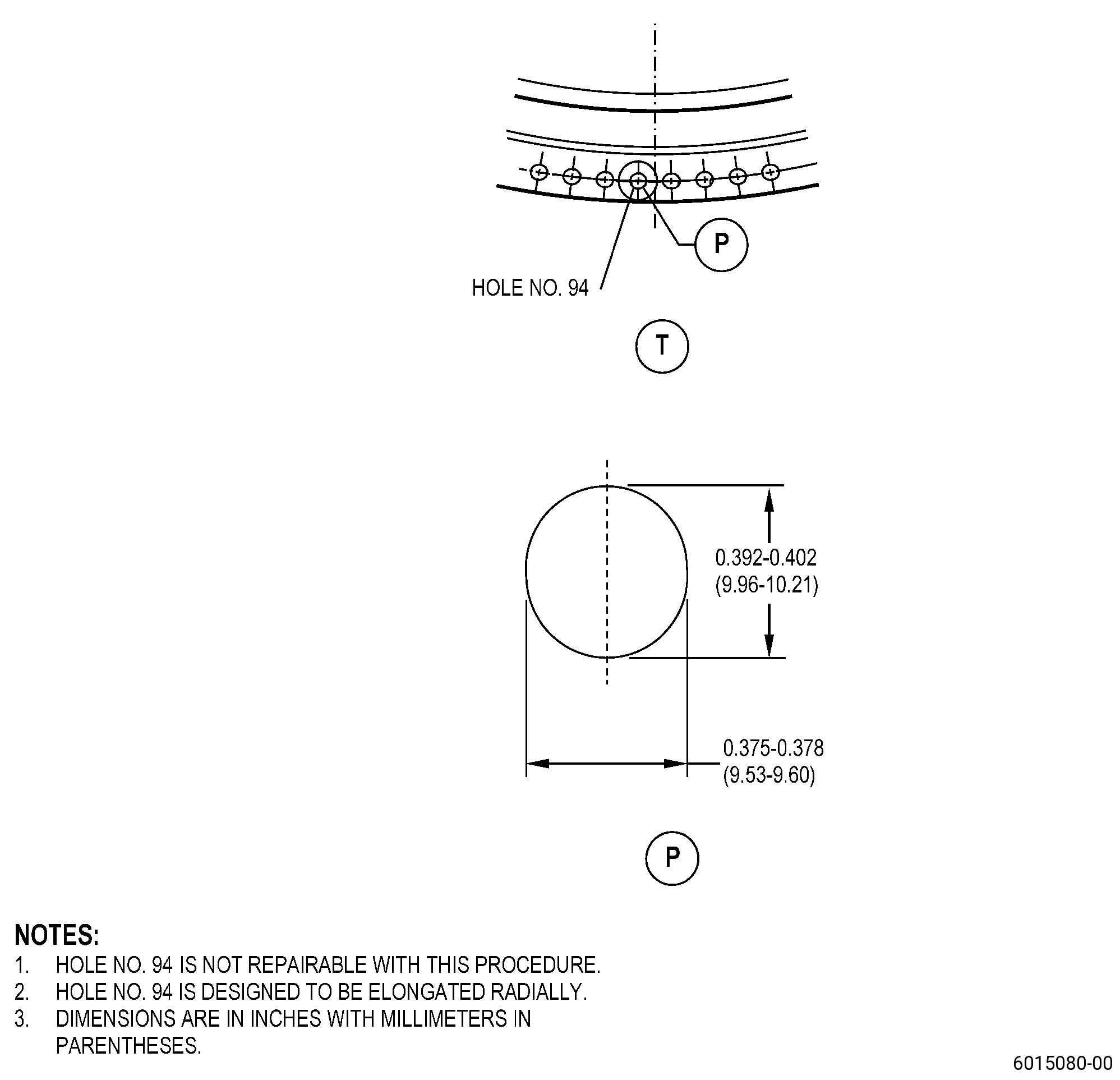
| (a) | You cannot repair bolthole No. 94 with this procedure. |
| (b) | Ream the corroded boltholes to 0.402 inch (10.21 mm) in diameter. |
| Subtask 72-32-01-220-126 |
| (4) | Do a visual inspection of the boltholes for remaining corrosion. |
| Subtask 72-32-01-350-084 |
| (5) | If there is remaining corrosion more than the serviceable limits, continue to ream the bolthole to remove a minimum quantity of material and as follows: |
| (a) | Make sure that you do not increase the bolthole diameter more than 0.417 inch (10.59 mm). |
| (b) | For the serviceable limits. Refer to TASK 72-32-01-200-801 (72-32-01, INSPECTION 001). |
| Subtask 72-32-01-220-127 |
| D. | Do an inspection of the HPC case reamed boltholes and do as follows: |
| (1) | Remaining corrosion cannot be more than the serviceable limits specified in TASK 72-32-01-200-801 (72-32-01, INSPECTION 001). |
| (2) | If the remaining corrosion is more than the serviceable limits specified in TASK 72-32-01-200-801 (72-32-01, INSPECTION 001), you cannot repair the case with this procedure. |
| Subtask 72-32-01-350-085 |
| E. | Blend the HPC case. Refer to TASK 70-42-00-350-002 (BLENDING AND REMOVAL OF HIGH METAL PROCEDURES) and as follows: |
| (1) | If necessary, blend the repaired boltholes to remove unwanted material. |
| (2) | If necessary, break the edges to 0.005-0.015 inch (0.13-0.38 mm). |
| Subtask 72-32-01-220-128 |
| F. | Do a dimensional inspection of each repaired HPC case bolthole. Refer to Figure 902 and as follows: |
| (1) | Make sure that the diameter of the repaired boltholes are not more than 0.417 inch (10.59 mm) and the remaining corrosion depth is not more than the serviceable limits specified in TASK 72-32-01-200-801 (72-32-01, INSPECTION 001). |
| Subtask 72-32-01-040-001 |
| G. | Disassemble the HPC case halves. |
| Subtask 72-32-01-160-013 |
| H. | Clean the HPC case halves. Refer to TASK 72-32-01-100-801 (72-32-01, CLEANING 001). |
| Subtask 72-32-01-230-009 |
| I. | Swab-etch the case flange reamed boltholes of the HPC case. Refer to TASK 70-24-00-110-033 (ETCHING PROCEDURES FOR FLUORESCENT-PENETRANT INSPECTION), TASK 70-24-01-110-034 (SWAB ETCHING PROCEDURE), and as follows: |
| (1) | Use Class C etchant. |
| Subtask 72-32-01-230-010 |
| J. | Do an inspection of the flange reamed boltholes of the HPC case. Refer to TASK 70-32-00-200-002 (INDIRECT INSPECTION METHODS), TASK 70-32-03-230-002 (SPOT-FLUORESCENT-PENETRANT INSPECTION) and as follows: |
| (1) | Use Class D penetrant. |
| (2) | For acceptability limits, refer to TASK 70-31-02-220-003 (ACCEPTABILITY LIMITS FOR FLUORESCENT PENETRANT INSPECTION), and as follows: |
| (a) | Use Class A limits. |
| Subtask 72-32-01-110-019 |
| K. | Clean the HPC case as follows: |
| (1) | Clean the circumferential flange boltholes. Refer to TASK 70-21-00-110-051 (CHEMICAL CLEANING), TASK 70-21-14-110-012 (CLEANING METHOD NO. 14 - MANUALLY-ASSISTED DETERGENT CLEANING), and as follows: |
| (a) | Clean all the boltholes with a nylon brush to remove all the unwanted material from the surface and as follows: |
| 1 | Do not clean the boltholes with a BZ mark on them. |
| Subtask 72-32-01-110-020 |
| (2) | Clean the HPC case. Refer to TASK 70-21-00-110-051 (CHEMICAL CLEANING), TASK 70-21-03-160-001 (CLEANING METHOD NO. 3 - STEAM CLEANING) and as follows: |
| (a) | Fully flush the aft circumferential flange boltholes with water. |
| Subtask 72-32-01-350-086 |
| L. | Apply C03-038 paint to all aft circumferential flange boltholes of the HPC case. Refer to Figure 904 and as follows: |
| (1) | Do not apply C03-038 paint to the boltholes with a BZ mark on them. |
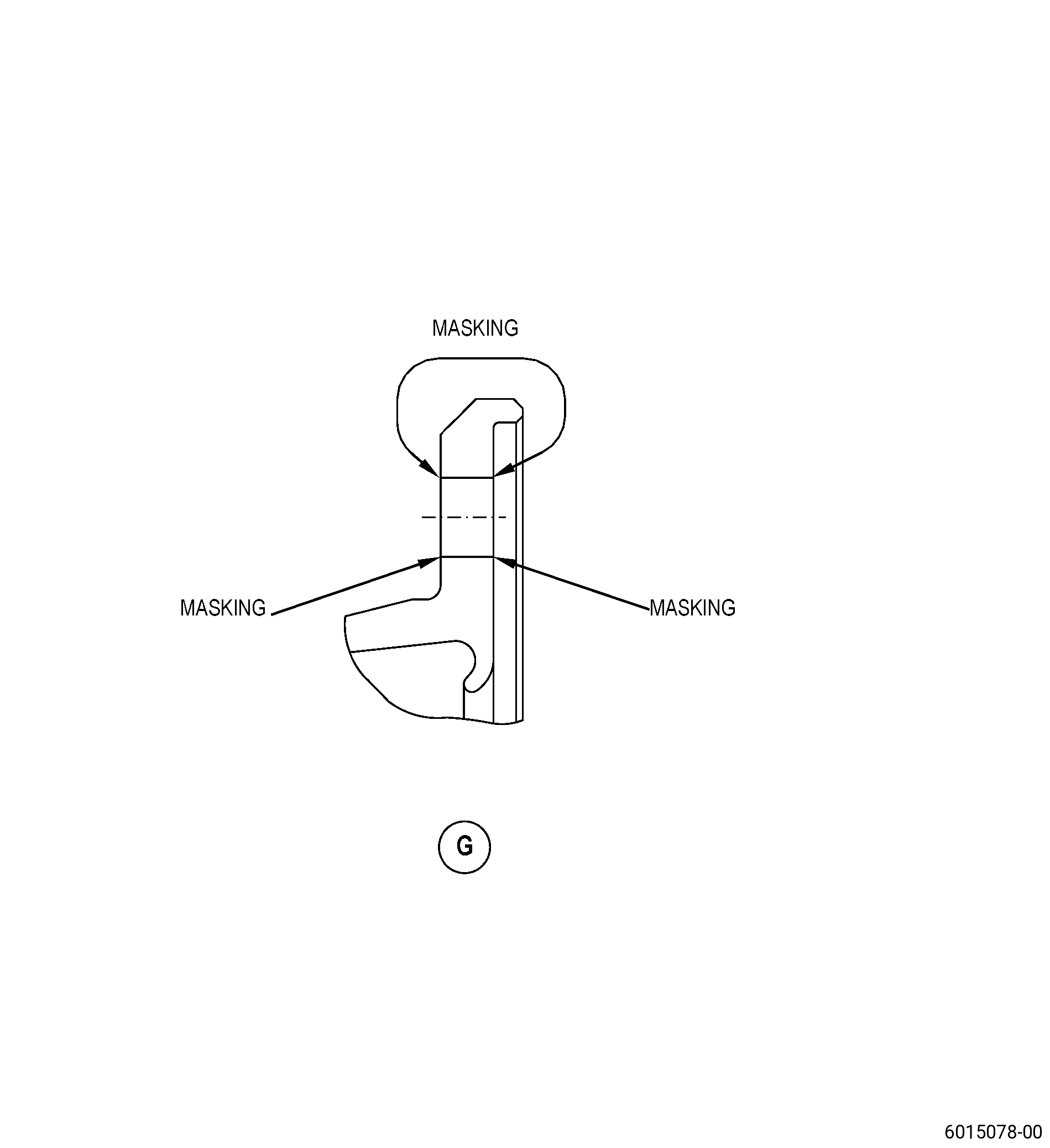
| (2) | Apply C10-012 masking tape to the areas of the HPC case that you will not paint. Refer to Figure 903 and as follows: |
| (a) | If necessary, use a locally manufactured fixture, tape, plastic caps, rubber plugs, or plastic screws to apply mask to the areas that you will not paint. |
| (b) | Make sure that the edges of the C10-012 masking tape get fully in contact with the HPC case. |
| Subtask 72-32-01-350-087 |
| (3) | Apply C03-038 paint to the boltholes as follows: |
| (a) | Apply a layer of C03-038 paint with a brush or spray gun to the inner surface of the boltholes. Refer to TASK 70-43-05-380-005 (INORGANIC ALUMINUM PROTECTIVE COATING), Figure 904, and as follows: |
| 1 | Do not apply coating to the boltholes with a BZ mark on them. |
| 2 | If you will spray the C03-038 paint, it is recommended to use spray paint tips for the inner diameter. |
| 3 | Apply a first layer of C03-038 paint to 0.0007-0.0015 inch (0.018-0.038 mm) in thickness and let the C03-038 paint dry. |
| 4 | Apply an optional second layer of C03-038 paint to 0.0014-0.0030 inch (0.036-0.076 mm) total thickness. Refer to Figure 904 and as follows: |
| a | Do not apply a second layer of C03-038 paint to bolthole No. 94. |
| NOTE: |
|
| (4) | Remove the masking tape from the HPC case. |
| Subtask 72-32-01-220-129 |
| (5) | Do a check at the aft flange faces to make sure that there is no C03-038 paint overspray and remove as necessary. |
| Subtask 72-32-01-370-003 |
| WARNING: |
|
| (6) | Cure the HPC case at 600 to 750°F (316 to 399°C) for 30 to 40 minutes and then let its temperature decrease to room temperature. |
| Subtask 72-32-01-220-130 |
| (7) | Do a check of the painted boltholes of the HPC case to make sure that the aluminum paint is fully applied on the inner diameter of all the boltholes. |
| Subtask 72-32-01-160-014 |
| M. | Clean the aft circumferential flange boltholes of the HPC case. Refer to TASK 72-32-01-100-801 (72-32-01, CLEANING 001). |
| Subtask 72-32-01-200-002 |
| N. | Do an inspection of the HPC case. Refer to TASK 72-32-01-200-801 (72-32-01, INSPECTION 001). |