| GENX-1B CLEANING,INSPECTION,AND REPAIR MANUAL | Dated: 04/30/2016 | |
| CIR 72-32-70 , REPAIR 001 | ||
| HIGH PRESSURE COMPRESSOR STATOR STAGES 1 THRU 4 VARIABLE STATOR VANE LEVER ARMS - REPAIR - MISSING PAINT | ||
| GENX-1B CLEANING,INSPECTION,AND REPAIR MANUAL | Dated: 04/30/2016 | |
| CIR 72-32-70 , REPAIR 001 | ||
| HIGH PRESSURE COMPRESSOR STATOR STAGES 1 THRU 4 VARIABLE STATOR VANE LEVER ARMS - REPAIR - MISSING PAINT | ||
| * * * FOR ALL |
| TASK 72-32-70-300-801 |
| 1 . | Missing Paint. |
| A. | This procedure gives instructions to repair the HPC stator stage 1 thru 4 lever arms (lever arms) by applying missing paint. Refer to Figure 901. |
| B. | The following maximum repairable limits apply to this repair: |
| NOTE: |
|
| NOTE: |
|
| (4) | Visual Inspection. |
| (f) | Do an inspection of the lever arm, P/N 2373M22G06 , for: |
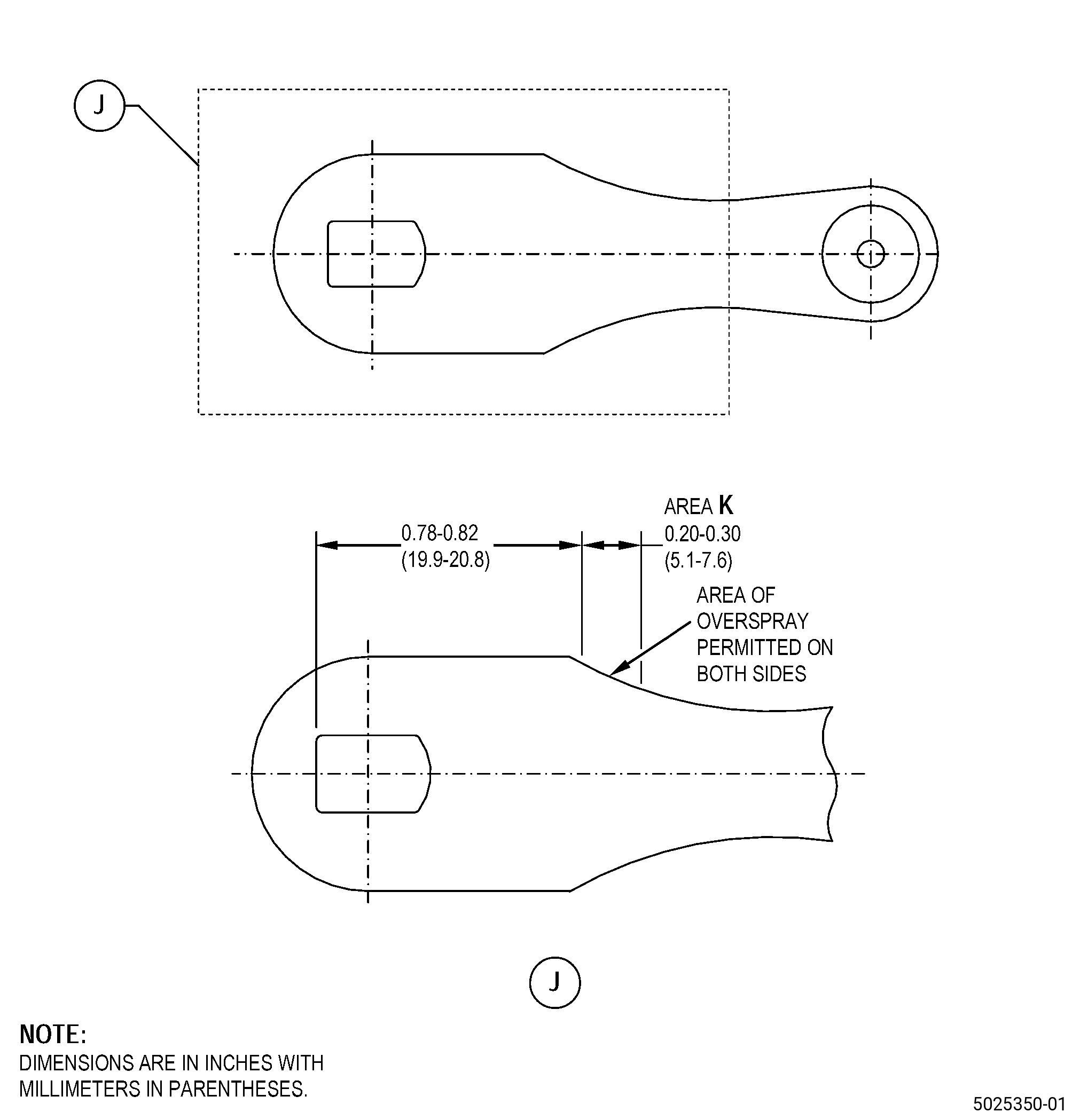
| 1 | Missing paint on area K: |
| Maximum repairable limit: |
|
| C. | The subsequent table gives a list of the part numbers that are applicable to this repair. All part numbers are applicable to all paragraphs unless specified differently. |
|
|||||||||||||||||||||||
| D. | Proprietary/Complex Process Statement. |
| (1) | None. |
| 2 . | Tools, Equipment, and Materials. |
| NOTE: |
|
| A. | Tools and Equipment. |
| (1) | Special Tools. None. |
| (2) | Standard Tools and Equipment. None. |
| (3) | Locally Manufactured Tools. None. |
| B. | Consumable Materials. |
|
| C. | Referenced Procedures. |
|
| D. | Expendable Parts. None. |
| E. | SPD Information. |
| (1) | Locally Manufactured SPD. None. |
| F. | Special Solutions. None. |
| G. | Test Specimens. None. |
| 3 . | Dimensional Information. |
| Subtask 72-32-70-220-032 |
| A. | Refer to Figure 901 for specified dimensions and locations. |
| NOTE: |
|
| NOTE: |
|
| 4 . | Setup Information. |
| None. |
| 5 . | Procedure. |
| Subtask 72-32-70-160-003 |
| A. | Alternative Procedure Available. Clean the lever arms. Refer to TASK 72-32-70-100-801 (72-32-70, CLEANING 001). |
| Subtask 72-32-70-110-013 |
| WARNING: |
|
| A.A. | Alternative Procedure. Clean the lever arm as follows: |
| (1) | Use a lint free cloth moist with C04-003 acetone, or C04-035 isopropyl alcohol. Let the lever arm air dry. |
| Subtask 72-32-70-380-001 |
| B. | Apply fluorocarbon rubber cement, A15B68C1 or PLV 2038 white in area K of the lever arm. Refer to Figure 901 and as follows: |
| (1) | Overspray on the two edges of the lever arms is permitted because the overspray is not more than area K tolerances. |
| Subtask 72-32-70-380-002 |
| A. | Alternative Procedure Available. Let the paint on the lever arm cure at room temperature for 48 hours. |
| Subtask 72-32-70-370-001 |
| WARNING: |
|
| A.A. | Alternative Procedure. Let the paint on the lever arm cure as follows: |
| (1) | Use a heat gun to increase the temperature of area K of the lever arm for 20 minutes at 300°F (149°C). |