| GENX-1B CLEANING,INSPECTION,AND REPAIR MANUAL | Dated: 03/17/2023 | |
| CIR 72-32-70 , INSPECTION 001 | ||
| HPC STATOR STAGES 1 THRU 4 VSV LEVER ARMS - INSPECTION | ||
| GENX-1B CLEANING,INSPECTION,AND REPAIR MANUAL | Dated: 03/17/2023 | |
| CIR 72-32-70 , INSPECTION 001 | ||
| HPC STATOR STAGES 1 THRU 4 VSV LEVER ARMS - INSPECTION | ||
| * * * FOR ALL |
| TASK 72-32-70-200-801 |
| 1 . | General. |
| A. | This procedure gives instructions to do an inspection of the HPC stator stages 1 thru 4 VSV lever arms (lever arms): |
| (1) | There are two interchangeable types of VSV stage 1-4 kit, which consist of vanes, lever arms, ring segments, bridge connectors, and sleeves. Complete stage sets of the old and new hardware can be installed on the same HPC forward case assembly. The entire set of hardware for each stage must be changed at the same time. Refer to Figure 801. |
| (2) | HPC stator stages 1 thru 4 VSV lever arms include: |
|
| • |
|
| • |
|
| • |
|
| • |
|
| • |
|
| • |
|
|
| • |
|
| • |
|
| • |
|
| 2 . | Tools, Equipment, and Materials. |
| NOTE: |
|
| A. | Tools and Equipment. |
| (1) | Special Tools. None. |
| (2) | Standard Tools and Equipment. None. |
| (3) | Locally Manufactured Tools. None. |
| B. | Consumable Materials. None. |
| C. | Referenced Procedures. |
| D. | Expendable Parts. None. |
| 3 . | Specific Inspection Procedure. |
| Subtask 72-32-70-220-001 |
| A. | Do a fluorescent penetrant inspection on the lever arms as follows: |
| Subtask 72-32-70-230-001 |
| (1) | Alternative Procedure Available. Do a Class A fluorescent penetrant inspection on the lever arms. Refer to TASK 70-32-02-230-001 (FLUORESCENT PENETRANT INSPECTION). |
| Subtask 72-32-70-220-002 |
| (1).A. | Alternative Procedure. Do a spot-fluorescent-penetrant to make sure there are no cracks in the lever arms. Refer to TASK 70-32-03-230-002 (SPOT-FLUORESCENT-PENETRANT INSPECTION). |
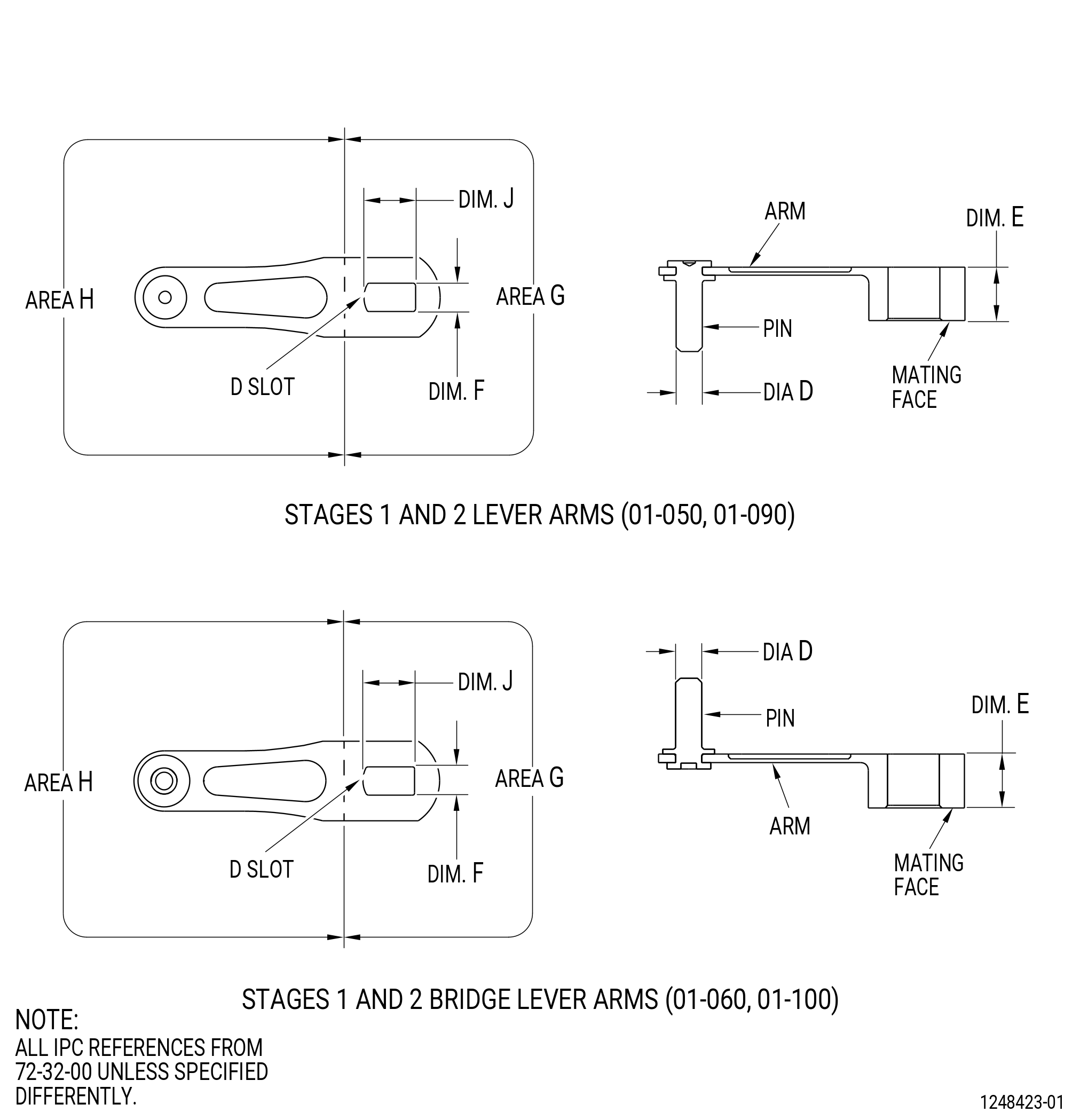
| 4 . | Visual Inspection. |
| Refer to Figure 801. |
| Subtask 72-32-70-220-003 |
| A. | Do an inspection of all surfaces for: |
| (1) | Cracks: |
| Maximum serviceable limit: |
|
| Repair method: |
|
|
|
|
|
| Subtask 72-32-70-220-004 |
| B. | Do an inspection of the lever arms for: |
| (1) | Distorted or bent: |
| Maximum serviceable limit: |
|
| Repair method: |
|
| Subtask 72-32-70-220-005 |
| (2) | Nicks, dents, and scratches in area H: |
| Maximum serviceable limit: |
|
| Repair method: |
|
| Subtask 72-32-70-220-006 |
| (3) | Nicks, dents, and scratches in area G for lever arms (071D1, 071D2, 071D3, 071D6, 071D7, 071D8): |
| Maximum serviceable limit: |
|
| Maximum repairable limit: |
|
| Repair method: |
|
| Subtask 72-32-70-220-024 |
| (4) | Nicks, dents, and scratches in area G for lever arms (071D4, 071D9): |
| Maximum serviceable limit: |
|
| Maximum repairable limit: |
|
| Repair method: |
|
| Subtask 72-32-70-220-007 |
| C. | Do an inspection of the mating face for: |
| (1) | Nicks, dents, and scratches on mating faces: |
| Maximum serviceable limit: |
|
| Maximum repairable limit: |
|
| Repair method: |
|
| Subtask 72-32-70-220-008 |
| (2) | Wear, fretting or galling on the mating faces: |
| Maximum serviceable limit: |
|
| Maximum repairable limit: |
|
| Repair method: |
|
| Subtask 72-32-70-220-010 |
| D. | Do an inspection of the pin for: |
| (1) | Loose, missing, or distorted: |
| Maximum serviceable limit: |
|
| Repair method: |
|
| Subtask 72-32-70-220-011 |
| (2) | Wear on pin: |
| Maximum serviceable limit: |
|
| Maximum repairable limit: |
|
| Repair method: |
|
| Subtask 72-32-70-220-012 |
| (3) | Discoloration: |
| Maximum serviceable limit: |
|
| Repair method: |
|
| Subtask 72-32-70-220-013 |
| E. | Do an inspection of the D slot surfaces for: |
| (1) | Fretting, galling, or wear: |
| Maximum serviceable limit: |
|
| Repair method: |
|
| Subtask 72-32-70-220-014 |
| (2) | Rub marks: |
| Maximum serviceable limit: |
|
| Repair method: |
|
| Subtask 72-32-70-220-025 |
| (3) | Nicks and dents: |
| Maximum serviceable limit: |
|
| Maximum repairable limit: |
|
| Repair method: |
|
| Subtask 72-32-70-220-033 |
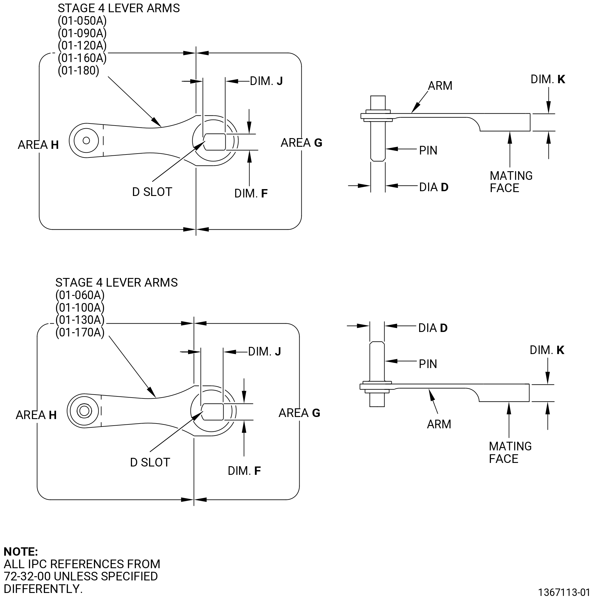
| A. | Do an inspection of the lever arm, P/N 2373M22G06 , for: |
| (1) | Missing paint on area K: |
| Maximum serviceable limit: |
|
| Repair method: |
|
| 5 . | Special Dimensional Inspection. |
| Subtask 72-32-70-220-031 |
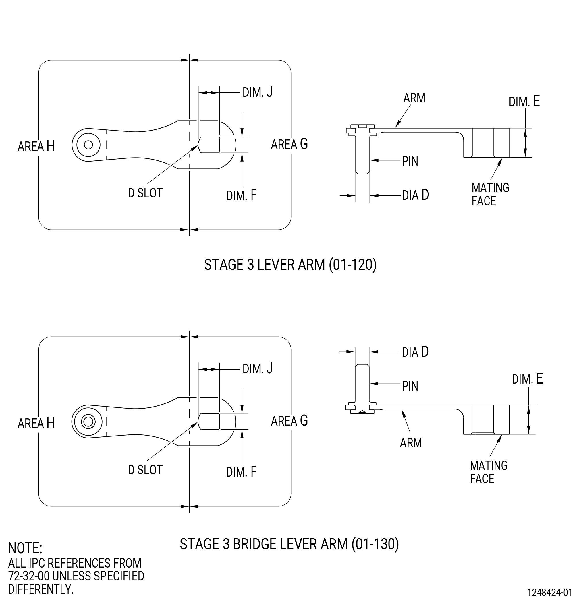
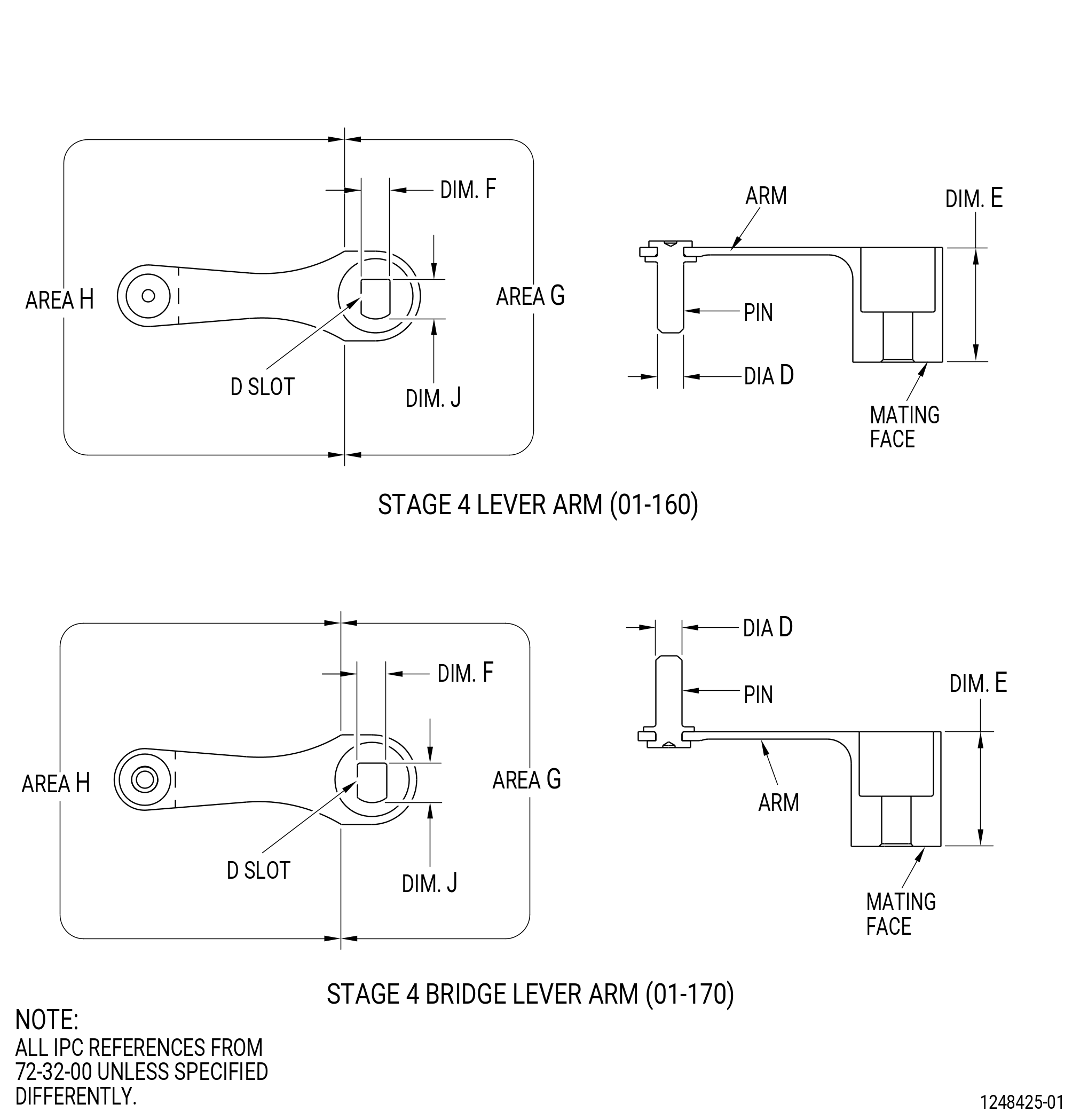
| A. | Do this dimensional inspection only if a visual inspection or other defect conditions make it necessary for further inspection. Refer to Figure 801 and Figure 801A. |
| Subtask 72-32-70-220-015 |
| B. | Measure the diameter as follows. Refer to Figure 801 and Figure 801A. |
| (1) | Diameter D (pin): |
| Minimum serviceable limit: |
|
| Repair method: |
|
| Subtask 72-32-70-220-019 |
| * * * PRE SB 72-0052( Configuration 1 ) |
| C. | Measure the thickness as follows. Refer to Figure 801. |
| (1) | Dimension E (stages 1 and 2): |
| Minimum serviceable limit: |
|
| Repair method: |
|
| NOTE: |
|
| Subtask 72-32-70-220-020 |
| (2) | Dimension E (stage 3): |
| Minimum serviceable limit: |
|
| Repair method: |
|
| NOTE: |
|
| Subtask 72-32-70-220-021 |
| (3) | Dimension E (stage 4): |
| Minimum serviceable limit: |
|
| Repair method: |
|
| NOTE: |
|
| Subtask 72-32-70-220-022 |
| D. | Measure the D slot as follows. Refer to Figure 801. |
| (1) | Dimension F (stages 1 and 2): |
| Maximum serviceable limit: |
|
| Repair method: |
|
| Subtask 72-32-70-220-026 |
| (2) | Dimension F (stages 3 and 4): |
| Maximum serviceable limit: |
|
| Repair method: |
|
| Subtask 72-32-70-220-027 |
| (3) | Dimension J (stage 1 and stage 2): |
| Maximum serviceable limit: |
|
| Repair method: |
|
| Subtask 72-32-70-220-023 |
| (4) | Dimension J (stage 3 and stage 4): |
| Maximum serviceable limit: |
|
| Repair method: |
|
| * * * END PRE SB 72-0052 |
| Subtask 72-32-70-220-028 |
| * * * SB 72-0052( Configuration 2 ) |
| E. | Measure the thickness as follows. Refer to Figure 801A. |
| (1) | Dimension K (stages 1 thru 4): |
| Minimum serviceable limit: |
|
| Repair method: |
|
| NOTE: |
|
| Subtask 72-32-70-220-029 |
| F. | Measure the D slot as follows. Refer to Figure 801A. |
| (1) | Dimension F (stages 1 thru 4): |
| Maximum serviceable limit: |
|
| Repair method: |
|
| Subtask 72-32-70-220-030 |
| (2) | Dimension J (stage 1 thru 4): |
| Maximum serviceable limit: |
|
| Repair method: |
|
| * * * END SB 72-0052 |