| GENX-1B CLEANING,INSPECTION,AND REPAIR MANUAL | Dated: 10/31/2019 | |
| CIR 72-41-20 , REPAIR 001 | ||
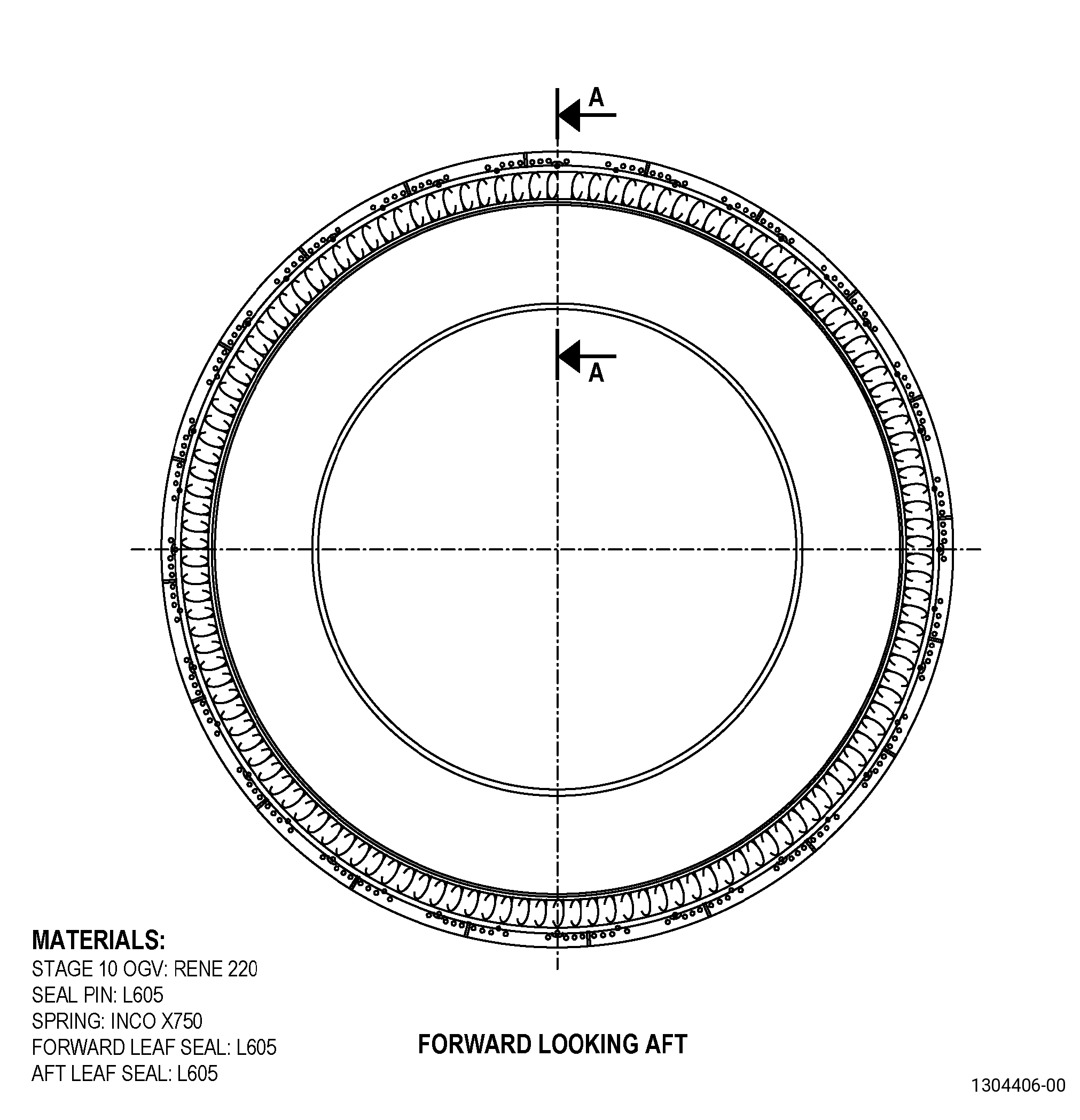
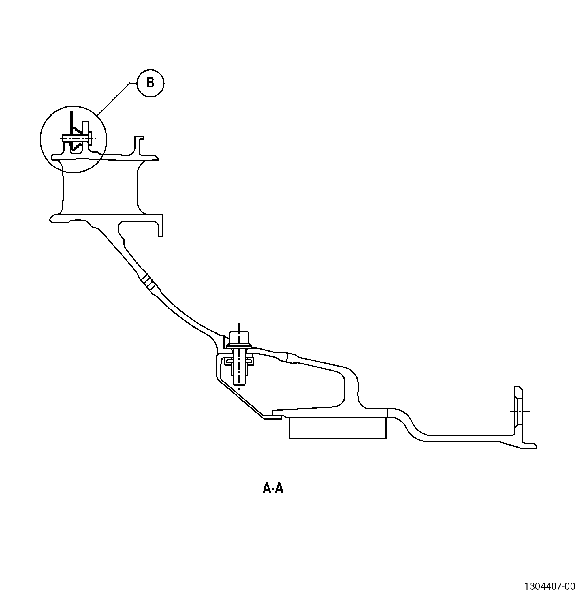
| STAGE 10 OUTLET GUIDE VANE - REPAIR - REPLACEMENT OF THE LEAF SEALS, SPRINGS, AND SEAL PINS | ||
| GENX-1B CLEANING,INSPECTION,AND REPAIR MANUAL | Dated: 10/31/2019 | |
| CIR 72-41-20 , REPAIR 001 | ||
| STAGE 10 OUTLET GUIDE VANE - REPAIR - REPLACEMENT OF THE LEAF SEALS, SPRINGS, AND SEAL PINS | ||
| * * * FOR ALL |
| TASK 72-41-20-300-801 |
| 1 . | Repair for the Stage 10 Outlet Guide Vane. |
| A. | This procedure gives instructions to repair the stage 10 outlet guide vanes (OGV) assembly by removing and replacing the damaged leaf seals, springs, and seal pins with new spare parts. Refer to Figure 901. |
| B. | The following maximum repairable limits apply to this repair: |
| NOTE: |
|
| (4) | Visual Inspection. |
| (f) | Do an inspection of the leaf seal for: |
| 1 | Dents, tears, and cracks: |
| Maximum repairable limit: |
|
| 2 | Wear: |
| Maximum repairable limit: |
|
| 3 | Leaf seal missing: |
| Maximum repairable limit: |
|
| 4 | Compressed or missing spring: |
| Maximum repairable limit: |
|
| 6 | Pin wear: |
| Maximum repairable limit: |
|
| C. | The subsequent table gives a list of the part numbers that are applicable to this repair. All part numbers are applicable to all paragraphs unless specified differently. |
|
|||||||||||||||||||||||
| D. | Proprietary/Complex Process Statement. |
| (1) | None. |
| 2 . | Tools, Equipment, and Materials. |
| NOTE: |
|
| A. | Tools and Equipment. |
| (1) | Special Tools. None. |
| (2) | Standard Tools and Equipment. None. |
| (3) | Locally Manufactured Tools. None. |
| B. | Consumable Materials. |
|
| C. | Referenced Procedures |
| D. | Expendable Parts. None |
| E. | SPD Information. |
|
| F. | Special Solutions. None. |
| G. | Test Specimens. None. |
| 3 . | Dimensional Information. |
| Subtask 72-41-20-220-035 |
| A. | Refer to Figure 901 for specified dimensions and locations. |
| NOTE: |
|
| NOTE: |
|
| 4 . | Setup Information. |
| None. |
| 5 . | Procedure. |
| Subtask 72-41-20-100-001 |
| A. | If necessary, clean the stage 10 OGV assembly. Refer to TASK 72-41-20-100-801 (72-41-20, CLEANING 001). |
| Subtask 72-41-20-350-001 |
| B. | Remove the forward leaf seals, aft leaf seals, springs, and seal pins that you will replace from the stage 10 OGV assembly. Refer to Figure 901 and as follows: |
| (1) | Blend the stage 10 OGV to remove the welds from the seal pins. Refer to TASK 70-42-00-350-002 (BLENDING AND REMOVAL OF HIGH METAL PROCEDURES) and as follows: |
| (a) | Use a rotary file mounted in an air-powered hand grinder. |
| (b) | Make sure that you keep the removal of the parent material of the stage 10 OGV to a minimum. |
| (c) | Make the cut in the welds on the pin side of the weld joints. |
| NOTE: |
|
| (2) | Remove the forward leaf seals, aft leaf seals, springs, and seal pins that you will replace and discard them. |
| (3) | Blend the stage 10 OGV to remove the high metal from the tabs. Refer to TASK 70-42-00-350-002 (BLENDING AND REMOVAL OF HIGH METAL PROCEDURES) and as follows: |
| CAUTION: |
|
| (a) | Make sure that you keep the removal of the parent material to a minimum. |
| Subtask 72-41-20-100-002 |
| C. | If necessary, clean the stage 10 OGV. Refer to TASK 72-41-20-100-801 (72-41-20, CLEANING 001). |
| Subtask 72-41-20-110-002 |
| D. | Etch the stage 10 OGV blended areas. Refer to TASK 70-24-00-110-033 (ETCHING PROCEDURES FOR FLUORESCENT-PENETRANT INSPECTION), TASK 70-24-01-110-034 (SWAB ETCHING PROCEDURE), and as follows: |
| (1) | Use Class C etchant. |
| Subtask 72-41-20-230-015 |
| E. | Do an inspection of the stage 10 OGV repair area. Refer to TASK 70-32-00-200-002 (INDIRECT INSPECTION METHODS), TASK 70-32-03-230-002 (SPOT-FLUORESCENT-PENETRANT INSPECTION), and as follows: |
| (1) | Use Class A penetrant. |
| (2) | All indications less than 0.030 inch (0.76 mm) are permitted. |
| (3) | Indications 0.030-0.060 inch (0.77-1.52 mm) are permitted if they agree with the conditions that follow: |
| (a) | The indications are not linear. |
| NOTE: |
|
| (b) | There is a minimum space of 0.25 inch (6.4 mm) between indications. |
| (4) | If you find indications on the parent material of the tabs of the stage 10 OGV that do not agree with the limits specified in Subtask 72-41-20-230-015 (paragraph 5.E.(2)) and Subtask 72-41-20-230-015 (paragraph 5.E.(3)), you cannot repair the stage 10 OGV with this procedure. |
| Subtask 72-41-20-220-036 |
| F. | Do an inspection of the stage 10 OGV repair area. Refer to Figure 901 and as follows: |
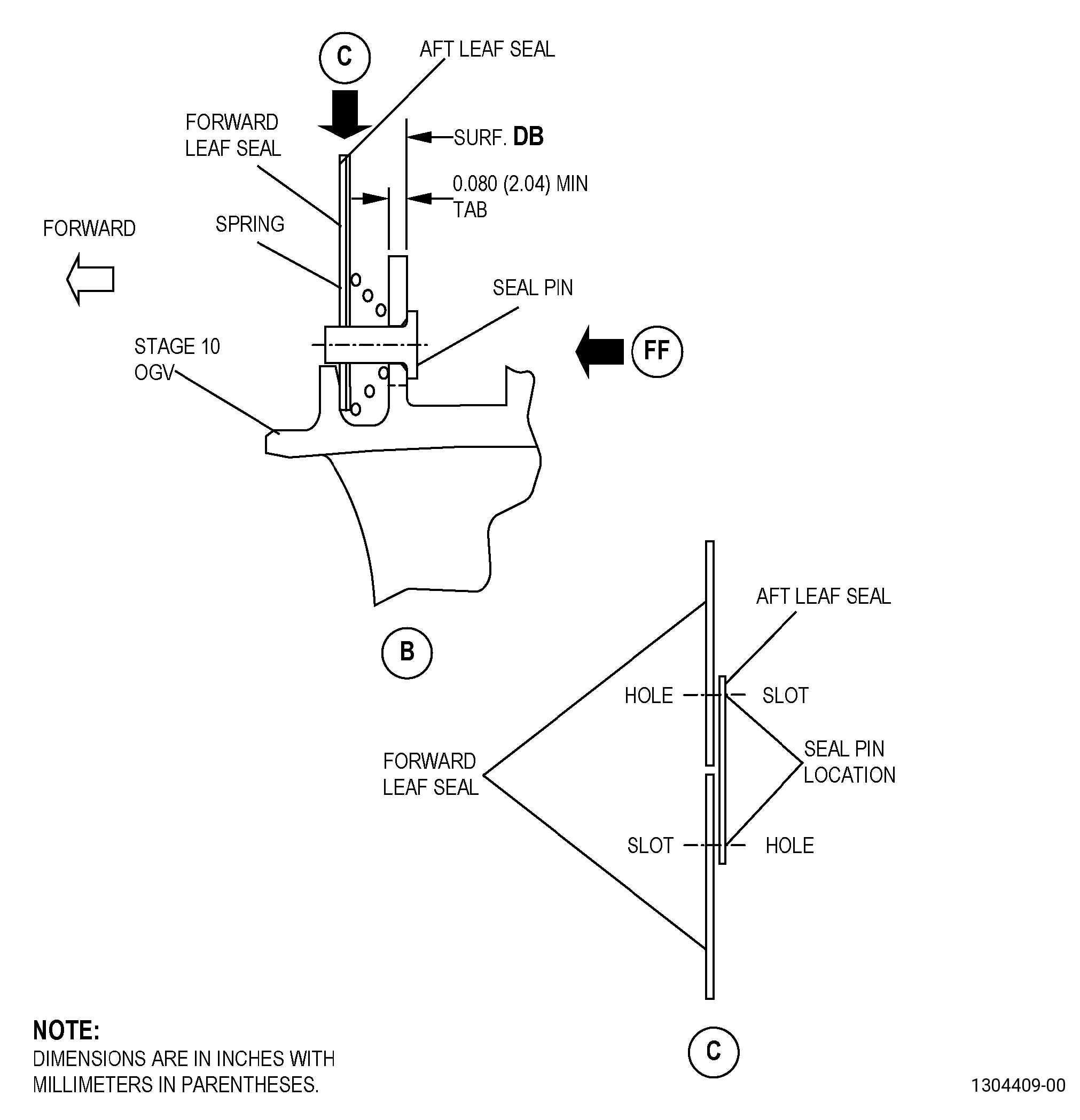
| (1) | If the tab thickness is less than 0.080 inch (2.04 mm), you cannot repair the stage 10 OGV with this procedure. |
| Subtask 72-41-20-440-001 |
| G. | Assemble the forward leaf seals, 2303M34P01, aft leaf seals, 2303M35P01, springs, 1709M70P01, and seal pins, 9527M86P10, to the stage 10 OGV assembly. Refer to Figure 901 and as follows: |
| Subtask 72-41-20-110-003 |
| (1) | Clean all the contact surfaces between the forward leaf seals, 2303M34P01, aft leaf seals, 2303M35P01, springs, 1709M70P01, and seal pins, 9527M86P10. Refer to TASK 70-21-00-110-051 (CHEMICAL CLEANING) and TASK 70-21-23-110-053 (CLEANING METHOD 23 - HAND-WIPE DEGREASING). |
| Subtask 72-41-20-440-002 |
| (2) | Install the forward leaf seals, 2303M34P01, and the aft leaf seals, 2303M35P01, as follows: |
| (a) | Put the adjacent ends of two adjacent forward leaf seals, 2303M34P01, at the center of the aft leaf seals, 2303M35P01, as follows: |
| 1 | Make sure that the slots in the forward leaf seals, 2303M34P01, are aligned with the round holes in the aft leaf seals, 2303M35P01. |
| 2 | Make sure that the slots in the aft leaf seals, 2303M35P01, are aligned with the round holes in the forward leaf seals, 2303M34P01. |
| CAUTION: |
|
| (3) | Install the springs, 1709M70P01, and the seal pins, 9527M86P10, as follows: |
| (a) | The larger end of the springs, 1709M70P01, must touch the aft leaf seals, 2303M35P01. |
| Subtask 72-41-20-210-001 |
| (4) | Do a check of each spring, 1709M70P01, to make sure that it will pre-load the forward leaf seals, 2303M34P01, and the aft leaf seals, 2303M35P01, against the seating surface and as follows: |
| NOTE: |
|
| (a) | If a spring, 1709M70P01, does not pre-load the forward leaf seals, 2303M34P01, and the aft leaf seals, 2303M35P01, against the seating surface, replace the spring. |
| Subtask 72-41-20-310-001 |
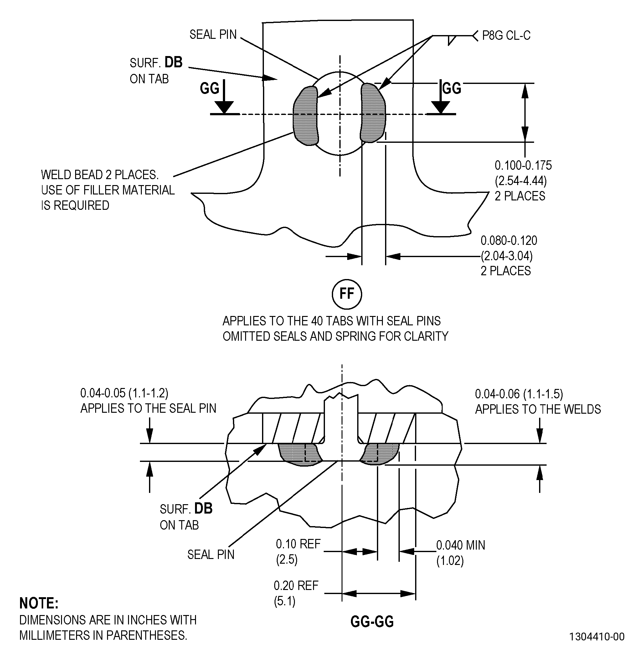
| H. | Weld the seal pins, 9527M86P10, in the correct position. Refer to TASK 70-41-00-310-001 (WELDING AND BRAZING PRACTICES), Figure 901, and as follows: |
| (1) | Use C06-053 Haynes weld wire filler material. |
| (2) | Weld the seal pins, 9527M86P10, in two locations, 170-190 degrees apart. |
| (3) | Root fusion is not necessary in the breakedge of the pin. |
| Subtask 72-41-20-200-002 |
| I. | Do a visual inspection of the welds and heat-affected zones. Refer to TASK 70-32-00-200-002 (INDIRECT INSPECTION METHODS), TASK 70-32-11-220-011 (WHITE LIGHT INSPECTION) , and as follows: |
| (1) | Use 10X magnification. |
| (2) | Indications less than 0.020 inch (0.50 mm) are permitted. |
| (3) | Indications larger than 0.020 inch (0.51 mm) are permitted if they are not linear. |
| NOTE: |
|
| (4) | If you find indications in the welds or the head of the seal pin, 9527M86P10, that do not agree with the limits specified in Subtask 72-41-20-200-002 (paragraph 5.I.(1)) and Subtask 72-41-20-200-002 (paragraph 5.I.(2)), do Subtask 72-41-20-100-001 (paragraph 5.A.) thru Subtask 72-41-20-200-002 (paragraph 5.I.) again. |
| Subtask 72-41-20-210-002 |
| J. | Do a check of each spring, 1709M70P01, to make sure that it will pre-load the leaf seals against the seating surface and as follows: |
| NOTE: |
|
| (1) | If a spring, 1709M70P01, does not pre-load the forward leaf seals, 2303M34P01, and the aft leaf seals, 2303M35P01, against the seating surface, do Subtask 72-41-20-100-001 (paragraph 5.A.) thru Subtask 72-41-20-210-002 (paragraph 5.J.) again. |