| GENX-1B CLEANING,INSPECTION,AND REPAIR MANUAL | Dated: 10/31/2018 | |
| CIR 72-53-40 , SPECIAL PROCEDURES 001 | ||
| HIGH PRESSURE TURBINE ROTOR STAGE 1 DISK - SPECIAL PROCEDURE - FOCUSED INSPECTION OF THE FORWARD MIDDLE RADIAL RABBET FOR DENTS | ||
| GENX-1B CLEANING,INSPECTION,AND REPAIR MANUAL | Dated: 10/31/2018 | |
| CIR 72-53-40 , SPECIAL PROCEDURES 001 | ||
| HIGH PRESSURE TURBINE ROTOR STAGE 1 DISK - SPECIAL PROCEDURE - FOCUSED INSPECTION OF THE FORWARD MIDDLE RADIAL RABBET FOR DENTS | ||
| * * * FOR ALL |
| TASK 72-53-40-800-802 |
| 1 . | General. |
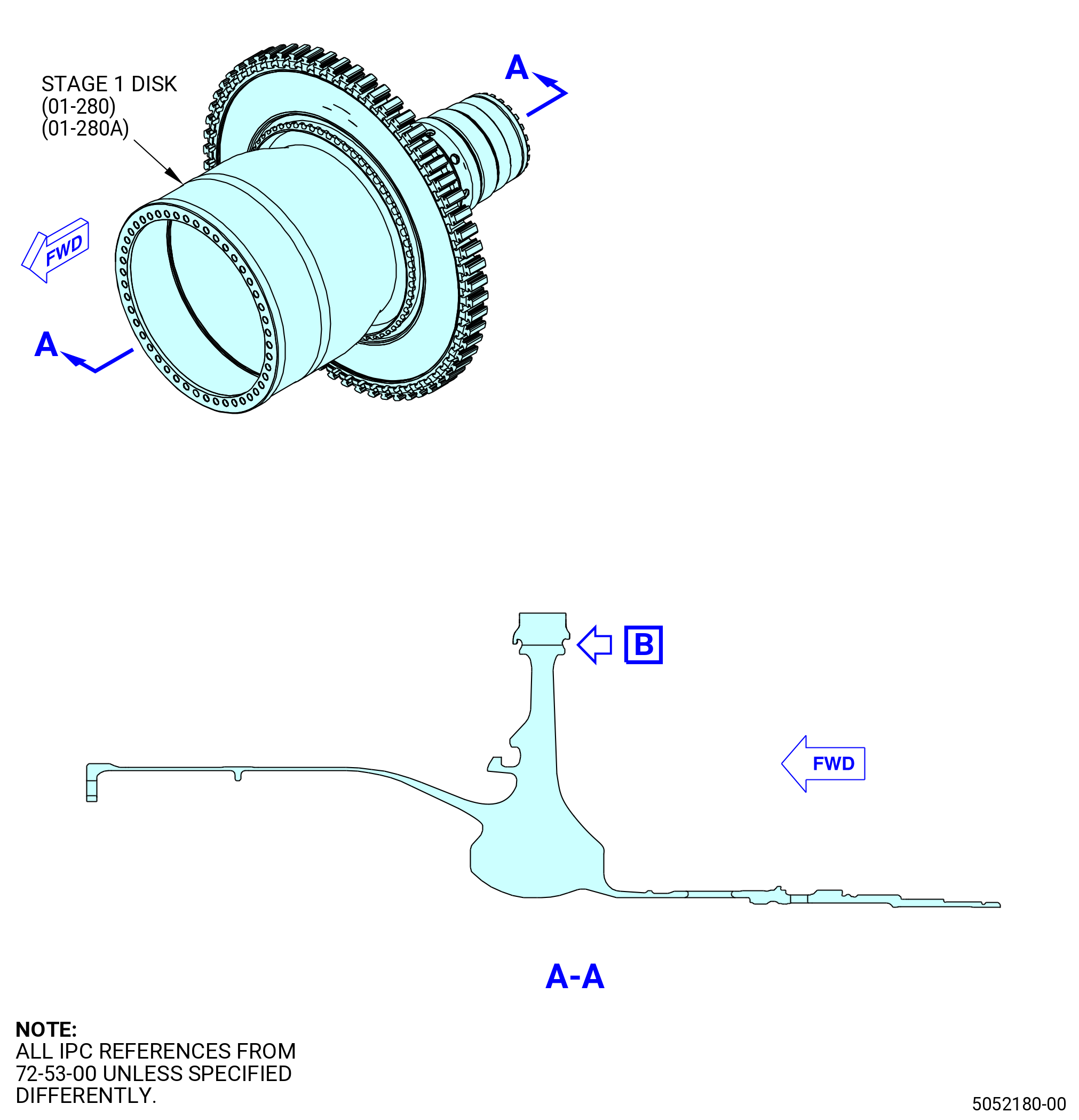
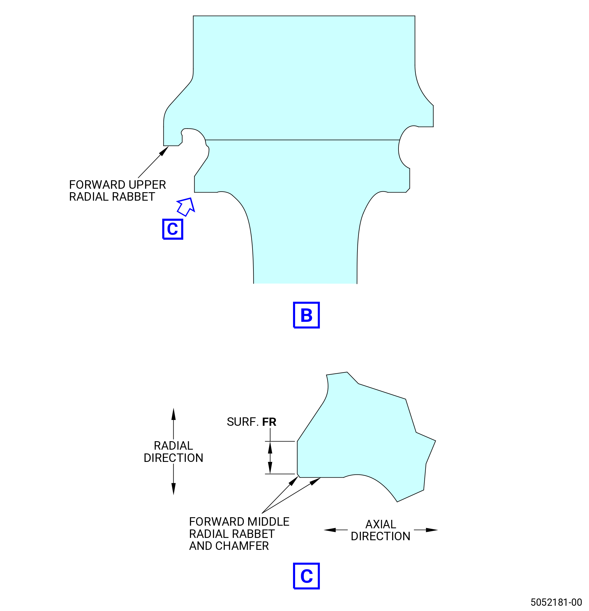
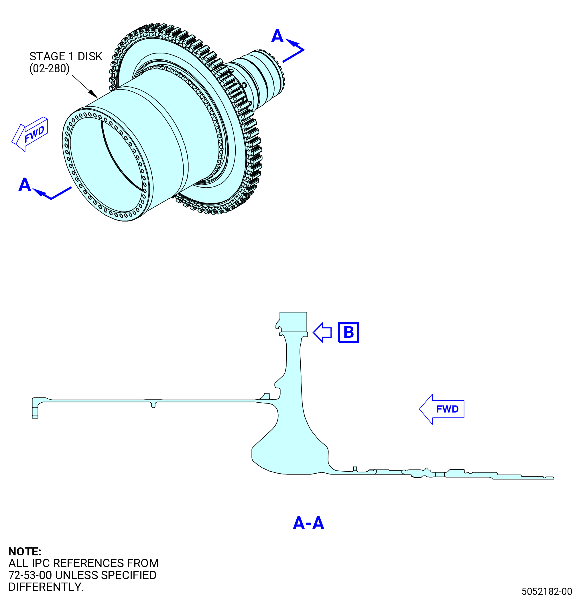
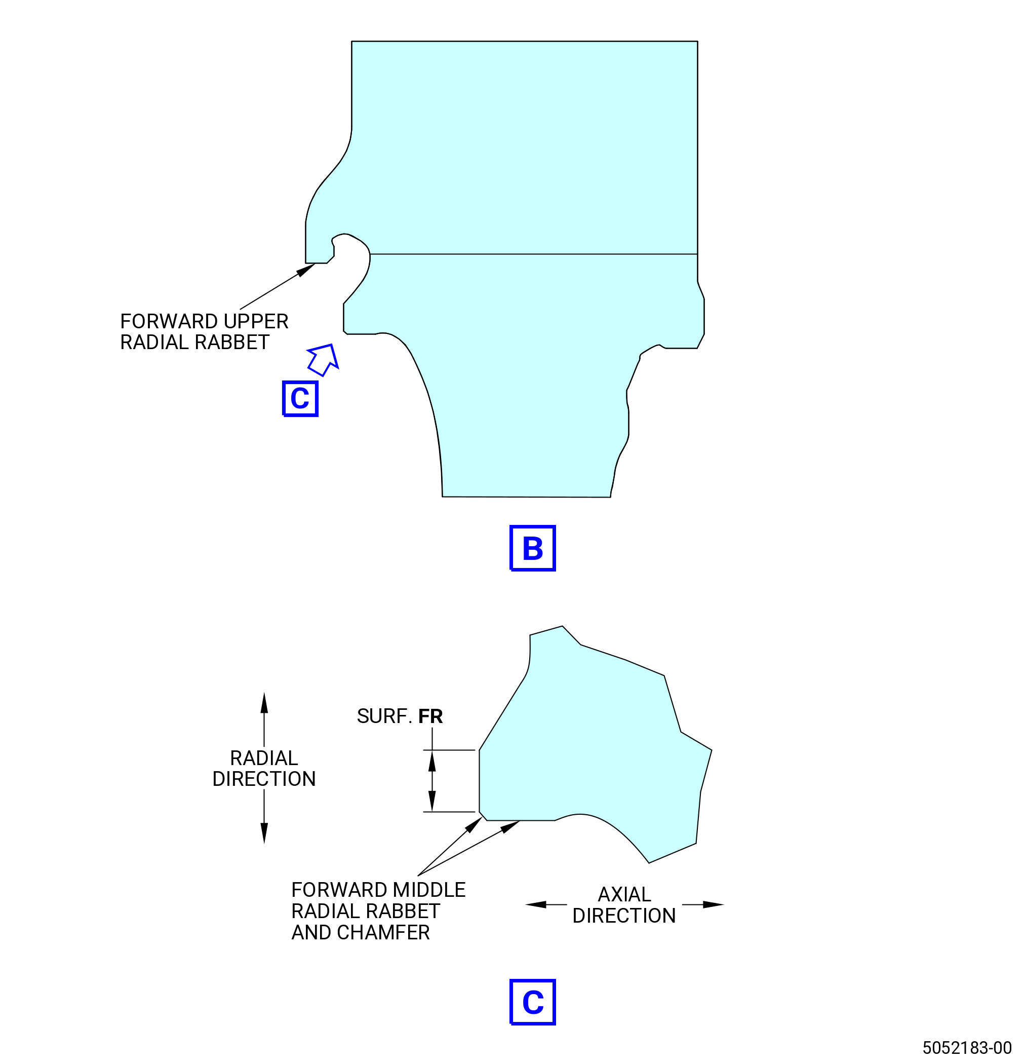
| A. | This procedure gives instructions to do a focused inspection of the forward middle radial rabbet of the HPT rotor stage 1 disk (stage 1 disk) (01-280 , 72-53-00) (SIN 150A1) or (01-280A , 72-53-00) (SIN 150A1) or (02-280 , 72-53-00) (SIN 150A1) for dents. If dent(s) is observed then the adjacent axial face (surface FR) will receive a focused inspection. |
| B. | Any reject indications observed during the accomplishment of the following inspection should be reported by e-mail to Fleet Support at Aviation.Fleet.Support1@ge.com. Please include the following details: |
| • Part number and serial number |
| • Customer/Operator |
| • Time since new |
| • Cycles since new |
| • Time since overhaul |
| • Cycles since overhaul |
| • Indication size(s) |
| • Photos of the indication(s). |
| Alternatively, this information can be submitted as a Service Request (SR) via myGEAviation.com. |
| 2 . | Tools, Equipment, and Materials. |
| NOTE: |
|
| A. | Tools and Equipment. |
| (1) | Special Tools. None. |
| (2) | Standard Tools and Equipment. None. |
| (3) | Locally Manufactured Tools. None. |
| B. | Consumable Materials. |
|
| C. | Referenced Procedures. |
| D. | Expendable Parts. None. |
| 3 . | Specific Inspection Procedure. |
| Subtask 72-53-40-220-218 |
| A. | Do a focused inspection of the HPT rotor stage 1 disk forward middle radial rabbet as follows: |
| (1) | Make sure that the disk is clean. Refer to TASK 72-53-40-100-801 (72-53-40, CLEANING 001). |
| (2) | Do a 10X white light visual inspection of the forward middle radial rabbet for any dents. |
| NOTE: |
|
| (3) | At each dent location found, do a 10X white light visual inspection of the adjacent face (surface FR) and adjacent chamfer for signs of bulging, refer to Figure 201, Figure 202, and do as follows: |
| (a) | For bulging/plastic deformation less than or equal to 0.002 inch (0.05 mm) do as follows: |
| NOTE: |
|
| NOTE: |
|
| 1 | For every dent, locally polish the adjacent face (surface FR with the chamfer) with a C10-010 scotch brite pad (or equivalent) to get a better surface finish than the adjacent area. |
| Subtask 72-53-40-110-022 |
| 2 | Locally etch the polished area(s). Refer to TASK 70-24-00-110-033 (ETCHING PROCEDURES FOR FLUORESCENT-PENETRANT INSPECTION), TASK 70-24-01-110-034 (SWAB ETCHING PROCEDURE), and as follows: |
| a | Use Class C etchant or Class G etchant. |
| Subtask 72-53-40-230-013 |
| 3 | Do a spot-fluorescent penetrant inspection with 10X under black light to the etched location(s). Refer to TASK 70-32-00-200-002 (INDIRECT INSPECTION METHODS), TASK 70-32-03-230-002 (SPOT-FLUORESCENT-PENETRANT INSPECTION), and as follows: |
| a | Use Class G penetrant. |
| b | Use non-aqueous wet developer (NAWD). |
| c | Make sure that the penetrant application procedure has a minimum dwell time of 50 minutes. |
| d | No linear indications are permitted. Do as follows: |
| NOTE: |
|
| (1) | If you find linear indications, do a solvent wipe process to find if the indication is repeatable. Refer to TASK 70-32-02-230-001 (FLUORESCENT PENETRANT INSPECTION). |
| (2) | If the indication does not re-appear after the solvent wipe process, apply NAWD again, wait 10 minutes and do the inspection again. If the original indication does not come into view again then the definition of the condition is non-repeatable, and is permitted. |
| (3) | You must report back all linear indication(s) to Fleet Support. Refer to paragraph 1.B. for contact details and information needed. Include the additional details: |
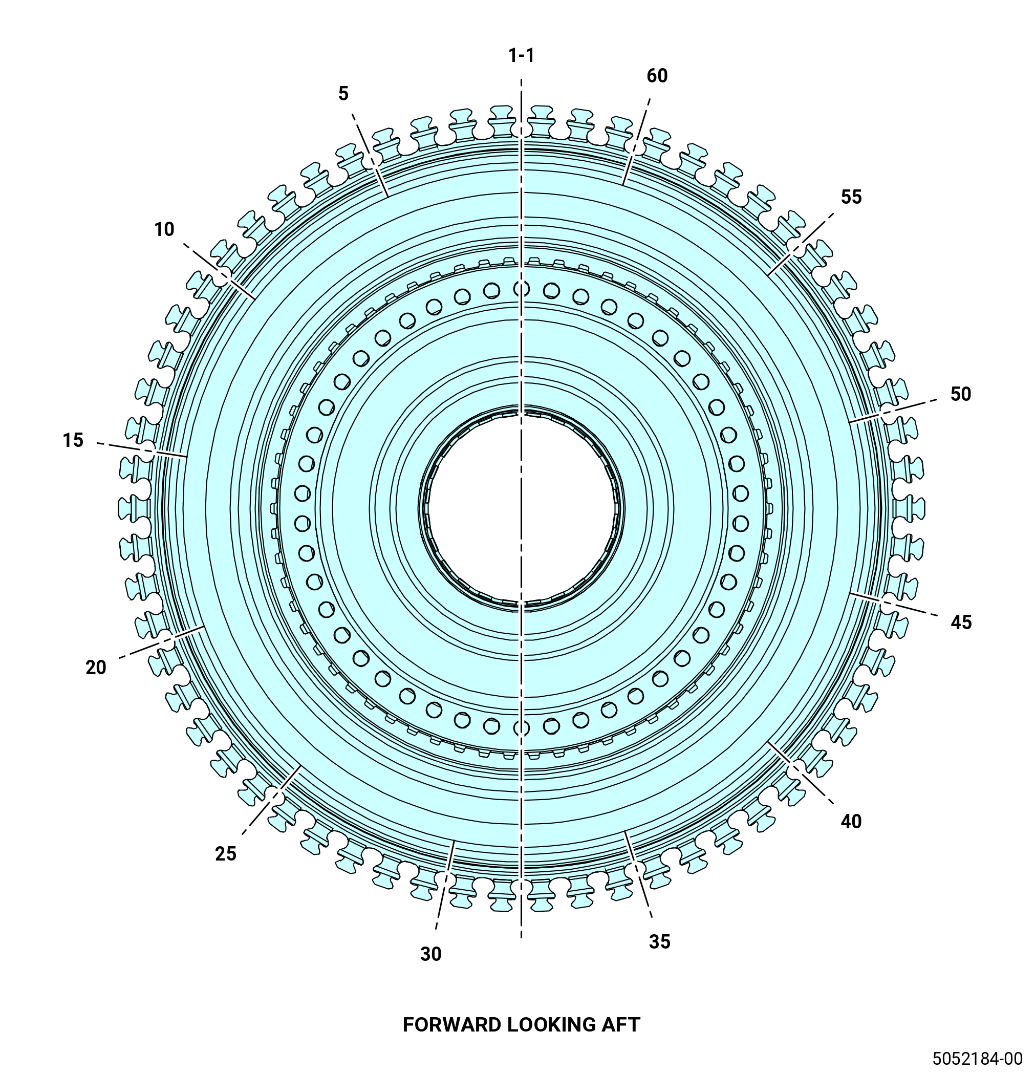
| • Location of the indication relative to the blade slot location. Refer to Figure 203 to map location of the indication |
| • Dent dimensions (with photos) |
| • Photos and details of the indication(s). |
| Subtask 72-53-40-220-219 |
| (b) | If you find signs of bulging more than 0.002 inch (0.051 mm), the disk is not serviceable and do as follows: |
| 1 | Report all findings, including linear indication(s) to Fleet Support. Refer to paragraph 1.B. for contact details and information needed. Include the additional details: |
| • Location of dent relative to the blade slot location. Refer to Figure 203 to map location of defect |
| • Dent dimensions (include photos, position of the dent relative to the forward edge, and include dimensions of the bulge-height of deformed material relative to the adjacent surface). |