| GENX-1B CLEANING,INSPECTION,AND REPAIR MANUAL | Dated: 03/29/2022 | |
| CIR 72-53-40 , REPAIR 007 | ||
| HIGH PRESSURE TURBINE ROTOR STAGE 1 DISK - REPAIR - BLEND REPAIR | ||
| GENX-1B CLEANING,INSPECTION,AND REPAIR MANUAL | Dated: 03/29/2022 | |
| CIR 72-53-40 , REPAIR 007 | ||
| HIGH PRESSURE TURBINE ROTOR STAGE 1 DISK - REPAIR - BLEND REPAIR | ||
| * * * FOR ALL |
| TASK 72-53-40-300-803 |
| 1 . | Blend Repair. |
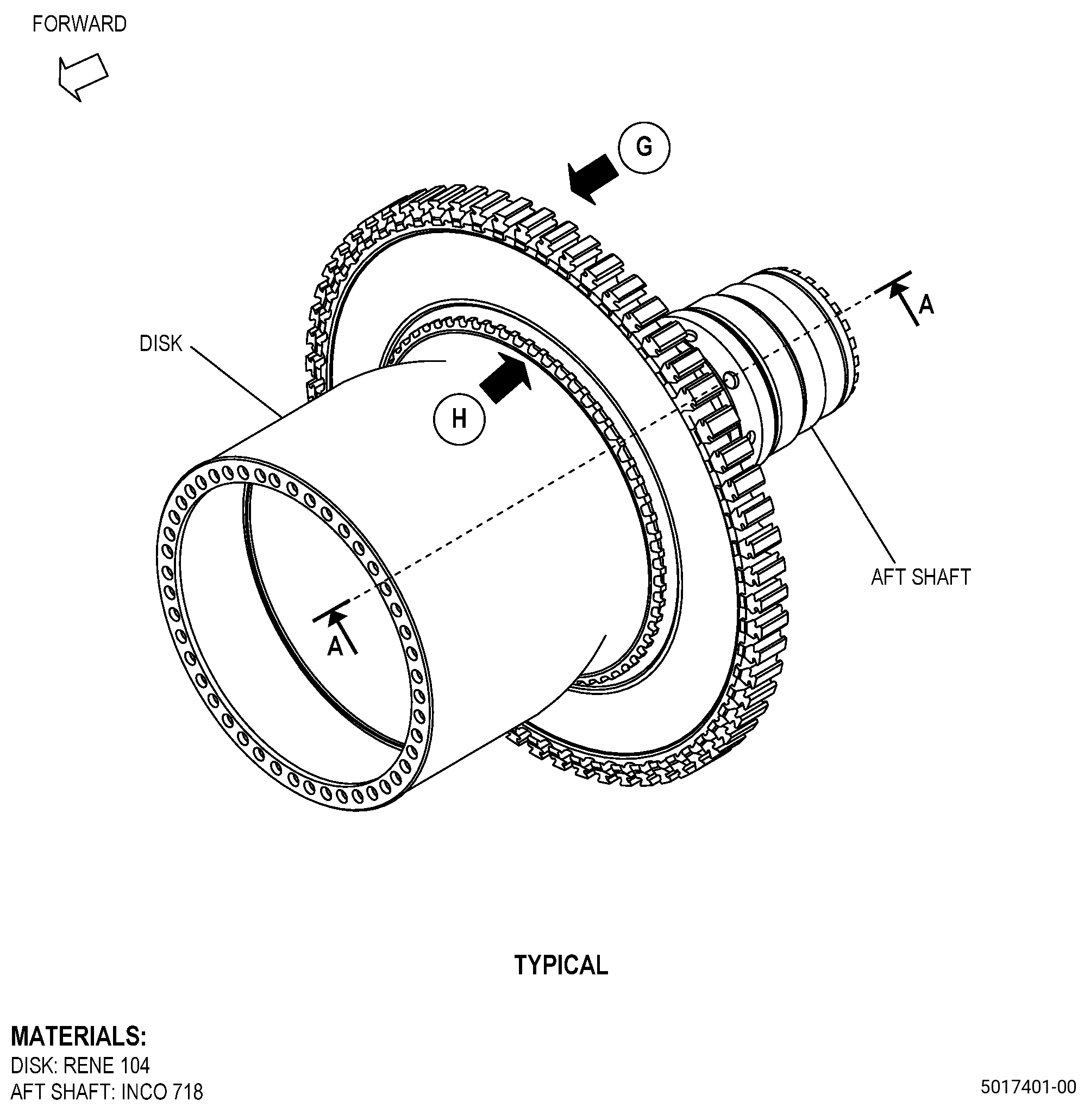
| A. | This procedure gives instructions to repair the high pressure turbine rotor stage 1 disk (disk) by doing a blend repair. Refer to Figure 901. |
| B. | The following maximum repairable limits apply to this repair: |
| NOTE: |
|
| (4) | Visual Inspection. |
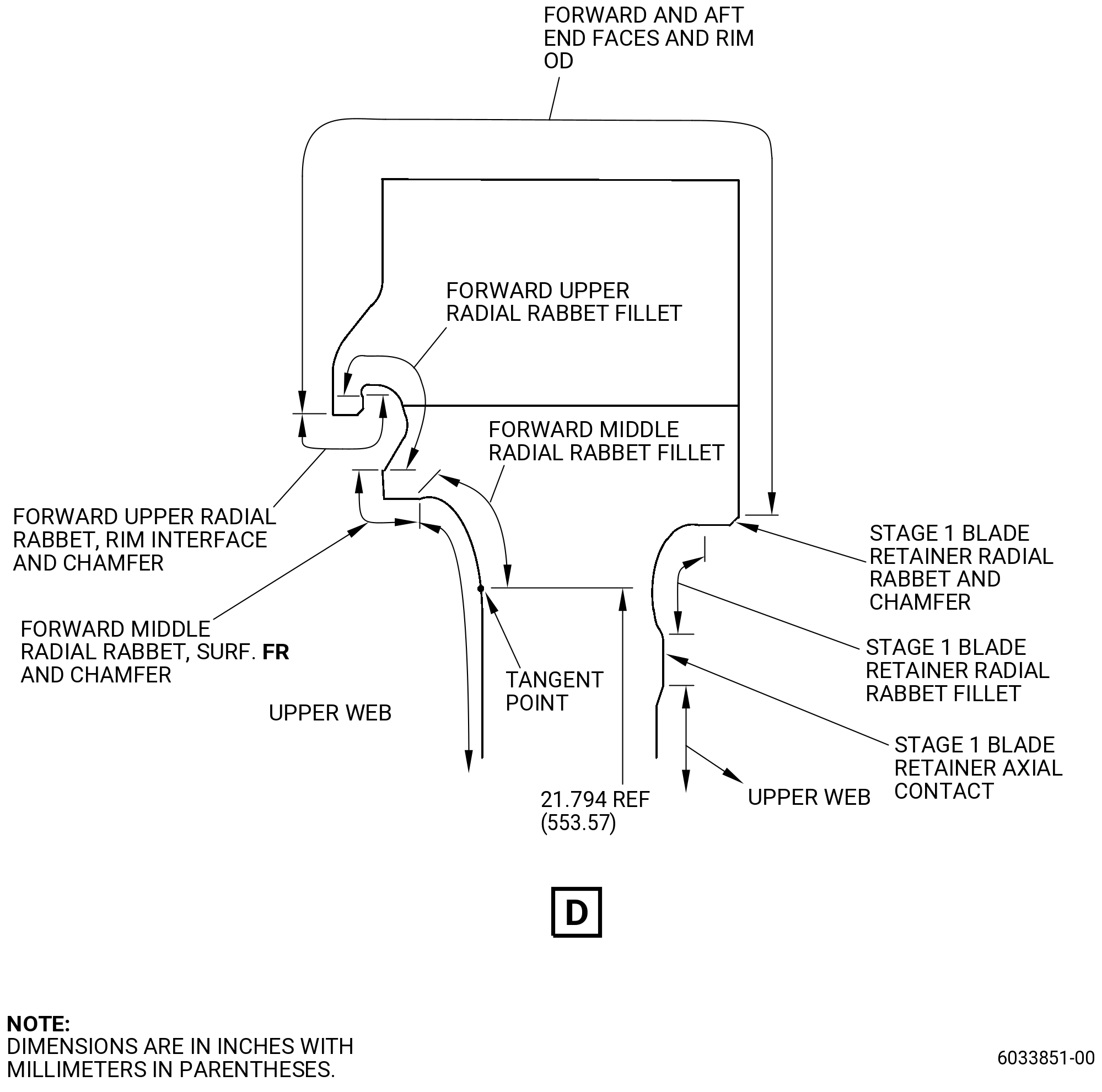
| (e) | Do an inspection of the rim OD and end faces as follows. Refer to Figure 810. |
| 1 | Nicks: |
| Maximum repairable limit: |
|
| 2 | Dents: |
| Maximum repairable limit: |
|
| 3 | Scratches: |
| Maximum repairable limit: |
|
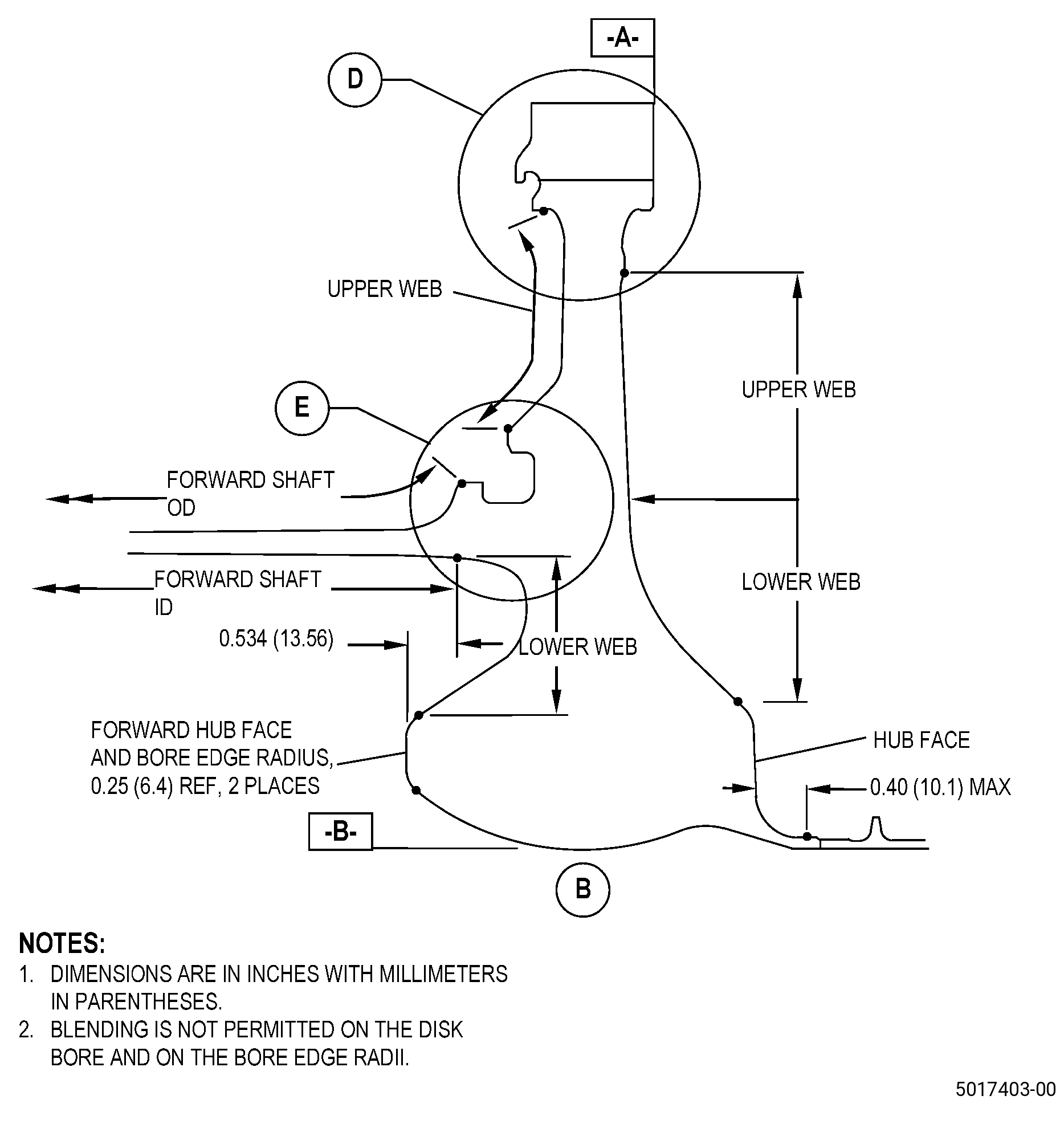
| (f) | Do an inspection of the web and hub faces as follows. Refer to Figure 810. |
| 1 | Nicks, dents, and scratches on the forward upper web, do not include the forward radial rabbet fillet area A: |
| Maximum repairable limit: |
|
| 2 | Nicks, dents, and scratches on the forward lower web and forward hub face: |
| Maximum repairable limit: |
|
| 3 | Nicks, dents, and scratches on the aft upper web, aft lower web, and aft hub face, do not include the bumper pad: |
| Maximum repairable limit: |
|
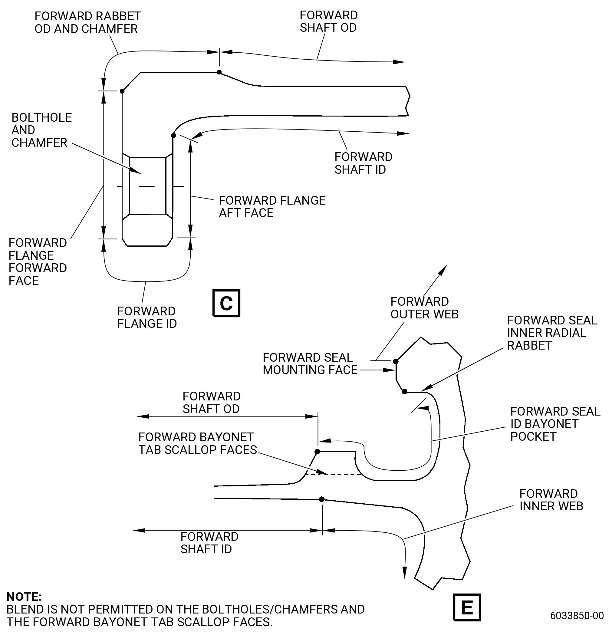
| (g) | Do an inspection of the forward flange forward face, and forward flange ID. Refer to Figure 811 and as follows: |
| 2 | Nicks, dents, and scratches on the forward flange forward face: |
| Maximum repairable limit: |
|
| 3 | Nicks, dents, and scratches on the forward flange ID: |
| Maximum repairable limit: |
|
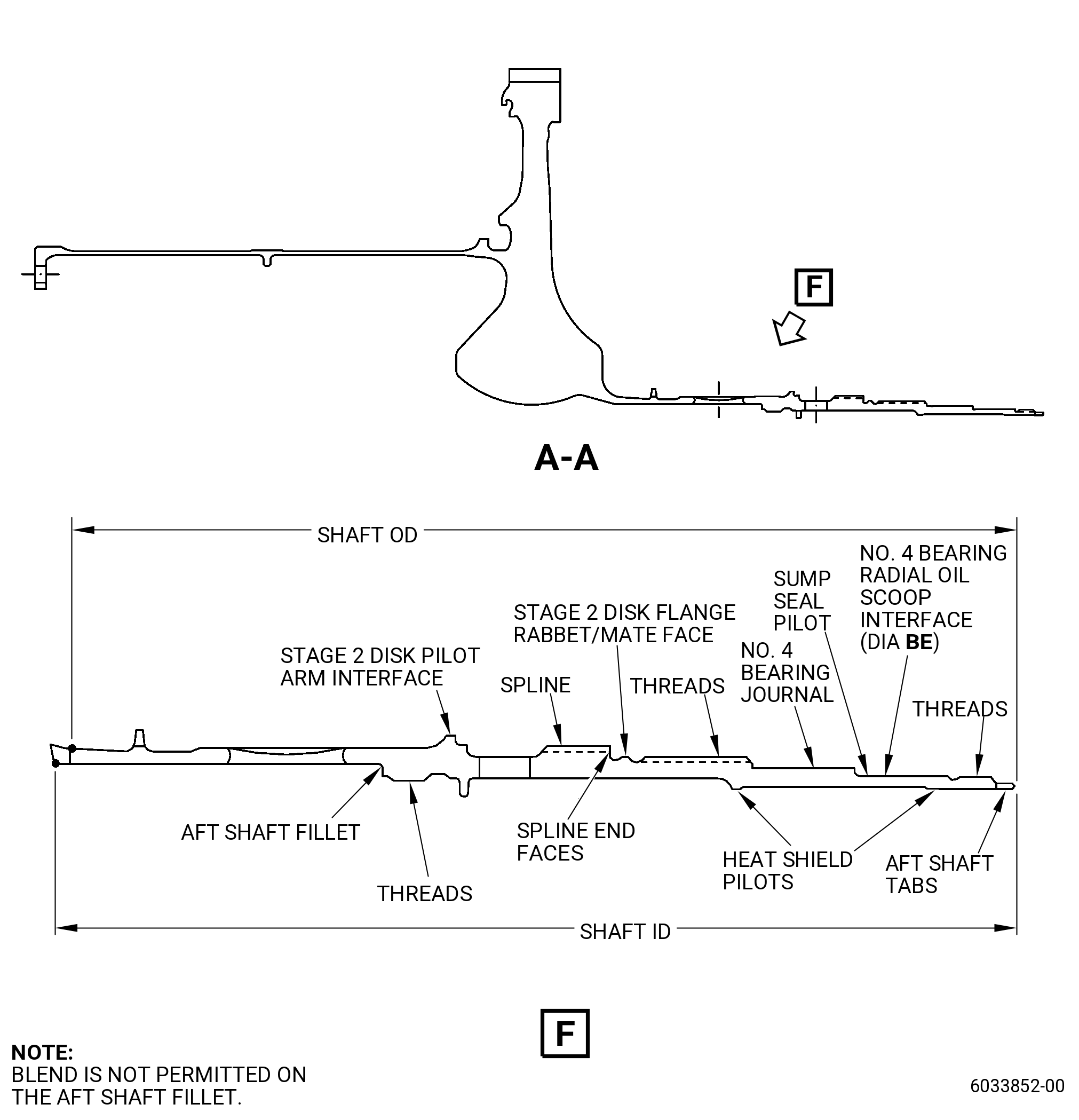
| (h) | Do an inspection of the stage 2 disk pilot arm interface. Figure 812 and as follows: |
| 2 | Nicks, dents, and scratches: |
| Maximum repairable limit: |
|
| 6 | Deleted. |
| Maximum repairable limit: |
|
| 7 | Deleted. |
| Maximum repairable limit: |
|
| (i) | Do an inspection of the forward seal mounting face as follows. Refer to Figure 811 for: |
| 2 | Nicks, dents, and scratches: |
| Maximum repairable limit: |
|
| (j) | Do an inspection of the mounting face of the sump seal pilot. Refer to Figure 812 and as follows: |
| 2 | Nicks, dents, and scratches: |
| Maximum repairable limit: |
|
| (l) | Deleted. |
| 4 | Deleted. |
| Maximum repairable limit: |
|
| (n) | Do an inspection of the spline surfaces on the aft shaft. Refer to Figure 812 and as follows: |
| 3 | Nicks, dents, and scratches on major diameter and pressure faces (except root fillets): |
| Maximum repairable limit: |
|
| (p) | Do an inspection of the internal and external surfaces in zone FA (critical) on the forward shaft as follows. Refer to Figure 811. |
| 1 | Nicks, dents, and scratches: |
| Maximum repairable limit: |
|
| (q) | Do an inspection of the internal and external surfaces in zone FB (do not include the mounting face of the sump seal pilot and aft shaft fillets) on the aft shaft as follows. Refer to Figure 812. |
| 1 | Nicks and scratches: |
| Maximum repairable limit: |
|
| 2 | Dents: |
| Maximum repairable limit: |
|
| (r) | Do an inspection of the heat shield pilots as follows. Refer to Figure 812. |
| 2 | Nicks, dents, and scratches: |
| Maximum repairable limit: |
|
| (t) | Do an inspection of the No. 4 bearing journal surface on the aft shaft as follows. Refer to Figure 812. |
| 2 | Nick and dents: |
| Maximum repairable limit: |
|
| 3 | Scores and scratches: |
| Maximum repairable limit: |
|
| (v) | Do an inspection of the No. 4 bearing radial oil scoop diameter (diameter BE) on the aft shaft as follows. Refer to Figure 812. |
| 2 | Nicks and dents: |
| Maximum repairable limit: |
|
| 3 | Scores and scratches: |
| Maximum repairable limit: |
|
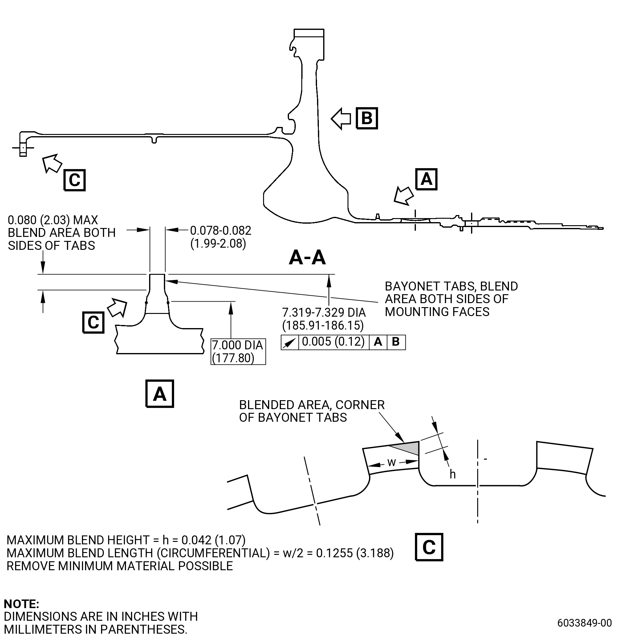
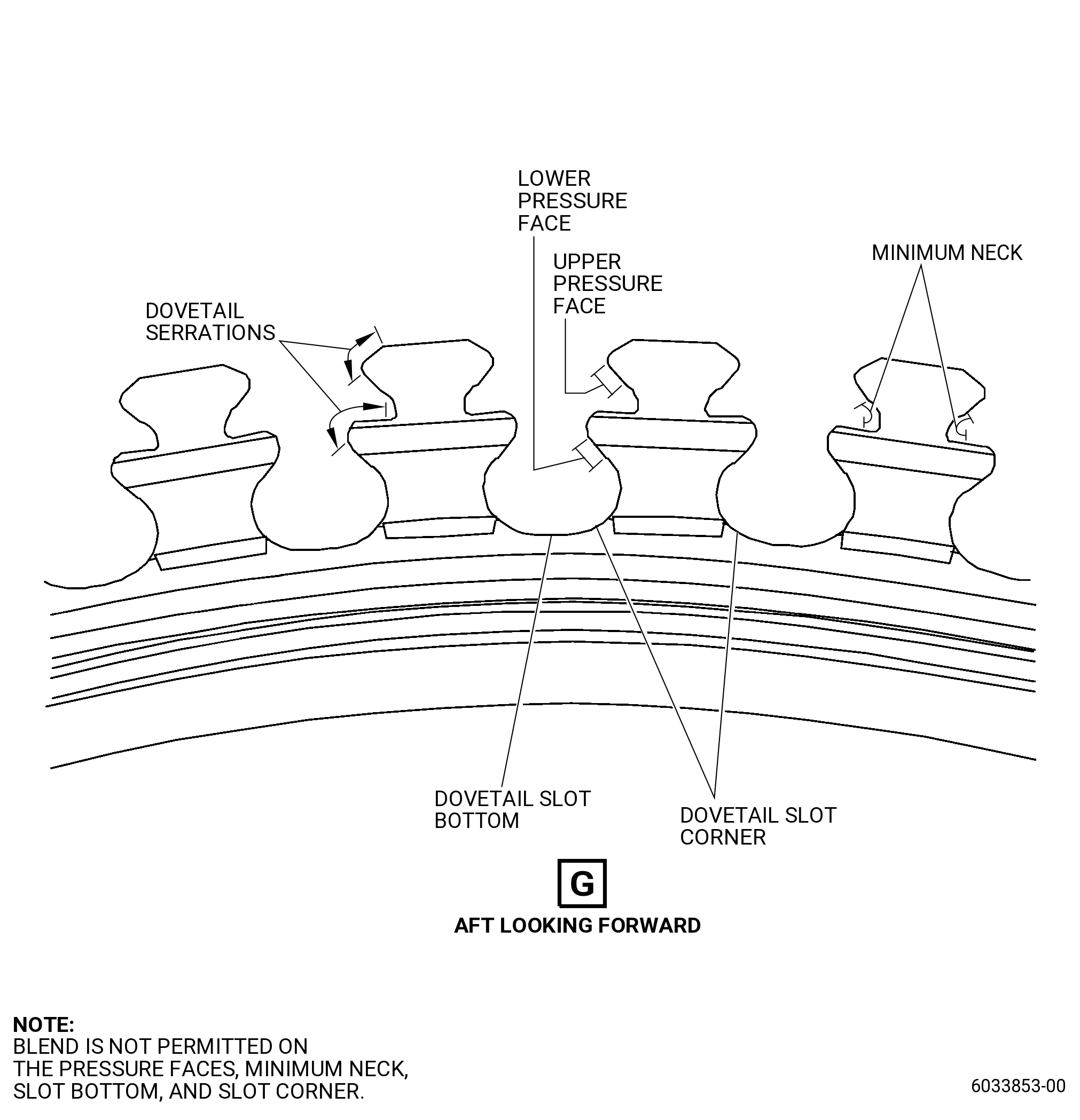
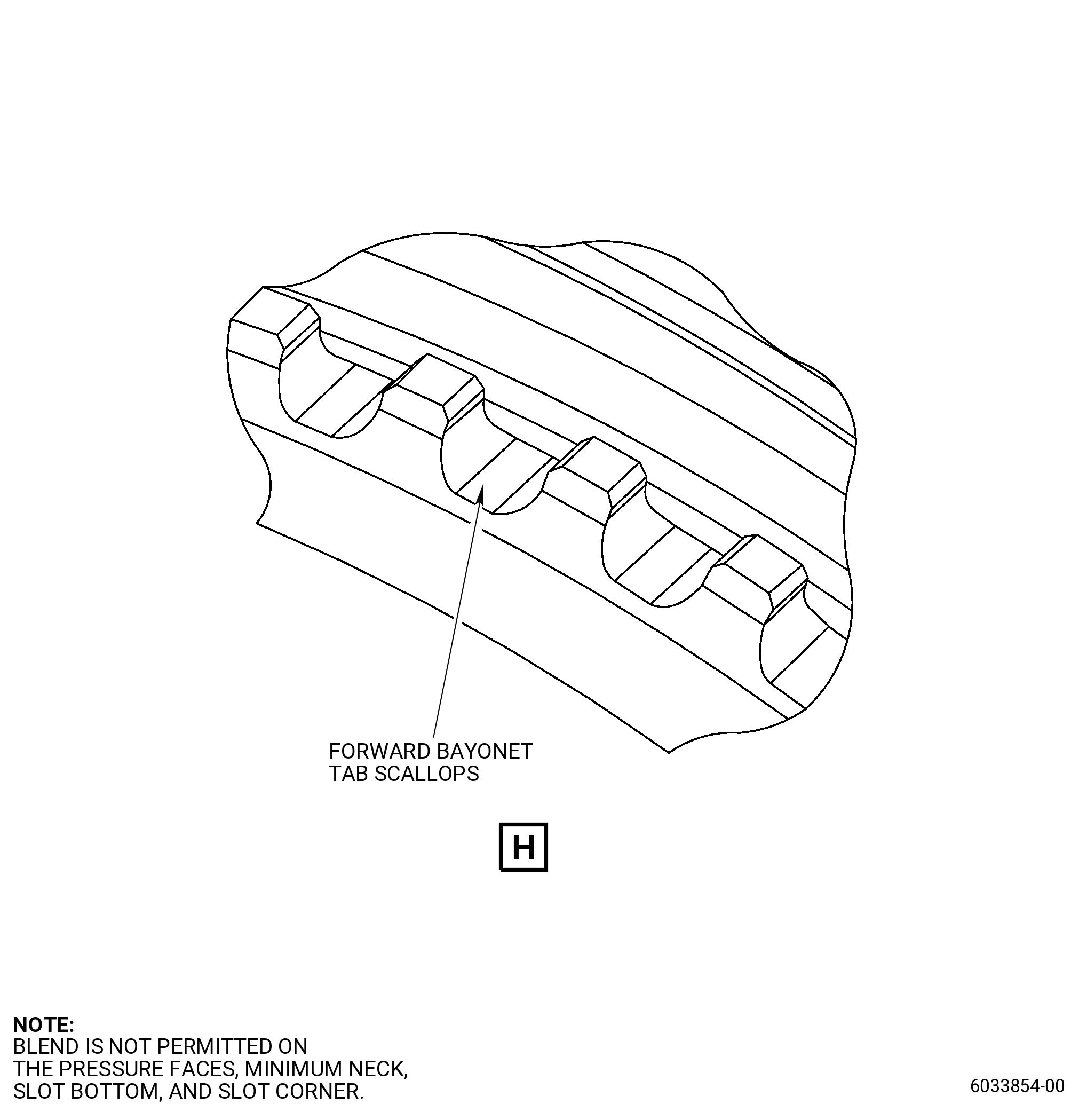
| (y) | Do an inspection of the interstage seal disk ID bayonet. Refer to Figure 812 and as follows: |
| 2 | Nicks, dents and scratches: |
| Maximum repairable limit: |
|
| 4 | Wear on the sides of bayonets: |
| Maximum repairable limit: |
|
| 5 | Nicks, dents, scratches, and wear on the corner of bayonet tabs: |
| Maximum repairable limit: |
|
| (z) | Do an inspection of the aft shaft tabs. Refer to Figure 812 and as follows: |
| 1 | Fretting and wear: |
| Maximum repairable limit: |
|
| 2 | Nicks, dents, and scratches: |
| Maximum repairable limit: |
|
| (ab) | Do an inspection of damper interface on the ID of the forward shaft. Refer to Figure 811 and as follows:. |
| 2 | Nicks, dents and scratches (other than rib faces): |
| Maximum repairable limit: |
|
| 3 | Nick, dents and scratches on damper rib faces: |
| Maximum repairable limit: |
|
| (ac) | Do an inspection of forward flange aft face. Refer to Figure 811 and as follows: |
| 2 | Nicks and dents on disk-bolt contact surface: |
| Maximum repairable limit: |
|
| 3 | Scratches on disk-bolt contact surface: |
| Maximum repairable limit: |
|
| 4 | Nicks, dents and scratches on aft face, other than disk-bolt contact surface: |
| Maximum repairable limit: |
|
| (ad) | Do an inspection of the stage 2 disk flange rabbet/mate face for: |
| 2 | Nicks and dents: |
| Maximum repairable limit: |
|
| 3 | Scratches: |
| Maximum repairable limit: |
|
| (af) | Do an inspection of the forward seal inner radial rabbet surface. Refer to Figure 811 and as follows: |
| 1 | Nicks and dents: |
| Maximum repairable limit: |
|
| C. | The subsequent table gives a list of the part numbers that are applicable to this repair. All part numbers are applicable to all paragraphs unless specified differently. |
|
|||||||||||||||||||||||
| D. | Proprietary/Complex Process Statement. |
| (1) | None. |
| 2 . | Tools, Equipment, and Materials. |
| NOTE: |
|
| A. | Tools and Equipment. |
| (1) | Special Tools. None. |
| (2) | Standard Tools and Equipment. None. |
| (3) | Locally Manufactured Tools. None. |
| B. | Consumable Materials. |
|
| C. | Referenced Procedures. |
| D. | Expendable Parts. None. |
| E. | SPD Information. |
| (1) | Locally Manufactured SPD. None. |
| F. | Special Solutions. None. |
| G. | Test Specimens. None. |
| 3 . | Dimensional Information. |
| Subtask 72-53-40-220-173 |
| A. | Refer to Figure 901 for specified dimensions and locations. |
| NOTE: |
|
| NOTE: |
|
| 4 . | Setup Information. |
| None. |
| 5 . | Procedure. |
| Subtask 72-53-40-350-003 |
| A. | Blend the disk damaged areas. Refer to TASK 70-42-00-350-002 (BLENDING AND REMOVAL OF HIGH METAL PROCEDURES), Figure 901, and do as follows: |
| (1) | Do not blend disk areas that have fretting. |
| (2) | Blend the disk to the limits specified in TASK 72-53-40-200-802 (72-53-40, INSPECTION 001, CONFIG 02), as follows: |
| (a) | The minimum blend radius must be 0.250 inch (6.35 mm). |
| (b) | Refer to Figure 901 for areas where blending is not permitted. |
| Subtask 72-53-40-160-009 |
| (3) | Clean the disk blended areas. Refer to TASK 70-21-00-110-051 (CHEMICAL CLEANING), and TASK 70-21-03-160-001 (CLEANING METHOD NO. 3 - STEAM CLEANING). |
| Subtask 72-53-40-110-007 |
| B. | Etch the disk blended areas. Refer to TASK 70-24-00-110-033 (ETCHING PROCEDURES FOR FLUORESCENT-PENETRANT INSPECTION), TASK 70-24-01-110-034 (SWAB ETCHING PROCEDURE), and as follows: |
| (1) | Use Class C or Class G etchant. |
| Subtask 72-53-40-230-007 |
| C. | Alternative Procedure Available. Do an inspection of the disk blended areas. Refer to TASK 70-32-00-200-002 (INDIRECT INSPECTION METHODS), TASK 70-32-02-230-001 (FLUORESCENT PENETRANT INSPECTION), and as follows: |
| (1) | Use Class G penetrant. |
| (2) | Indications less than 0.015 inch (0.38 mm) are permitted. |
| (3) | No other indications are permitted. |
| Subtask 72-53-40-230-008 |
| C.A. | Alternative Procedure. Do an inspection of the disk blended areas. Refer to TASK 70-32-00-200-002 (INDIRECT INSPECTION METHODS), TASK 70-32-03-230-002 (SPOT-FLUORESCENT-PENETRANT INSPECTION), and as follows: |
| (1) | Use Class G penetrant. |
| (2) | Indications less than 0.015 inch (0.38 mm) are permitted. |
| (3) | No other indications are permitted. |
| Subtask 72-53-40-380-002 |
| D. | Peen the disk fretted and/or blended areas. Refer to TASK 70-47-01-380-016 (SHOTPEENING), Figure 902, and do as follows: |
| (1) | Apply mask with C10-021 plastic tape to area BP. |
| (2) | Overspray is permitted but not on the areas that have a protection of masking. |
| (3) | Use C04-166 CCW14 steel shot. |
| (4) | Peen the disk to an intensity of 6-12N. |
| (5) | Coverage of the disk must be a minimum of 125 percent. |
| (6) | Direct impingement is necessary. |
| (7) | Ricochet peening is permitted in area BB. |
| (8) | Use simulative fixture for intensity verification. |