| GENX-1B CLEANING,INSPECTION,AND REPAIR MANUAL | Dated: 04/30/2017 | |
| CIR 72-53-41 , REPAIR 004 | ||
| HIGH PRESSURE TURBINE ROTOR STAGE 2 DISK - REPAIR - BLEND REPAIR | ||
| GENX-1B CLEANING,INSPECTION,AND REPAIR MANUAL | Dated: 04/30/2017 | |
| CIR 72-53-41 , REPAIR 004 | ||
| HIGH PRESSURE TURBINE ROTOR STAGE 2 DISK - REPAIR - BLEND REPAIR | ||
| * * * FOR ALL |
| TASK 72-53-41-300-802 |
| 1 . | Repair for the High Pressure Turbine Rotor Stage 2 Disk. |
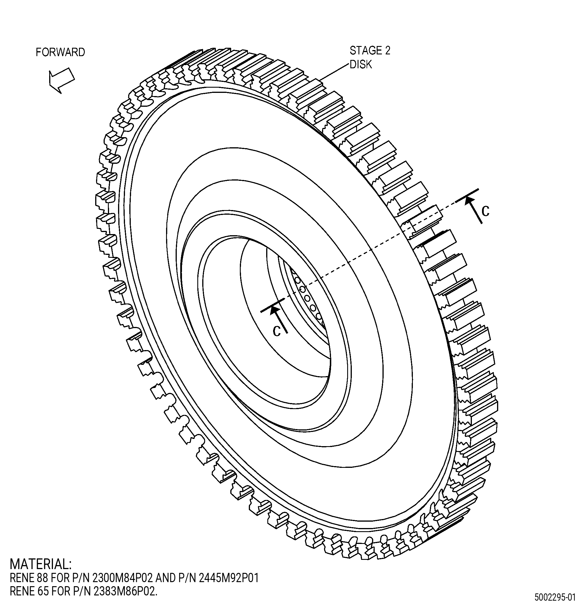
| A. | This procedure gives instructions to repair the high pressure turbine (HPT) rotor stage 2 disk (disk) by blending to remove surface damage. Refer to Figure 901. |
| B. | The following maximum repairable limits apply to this repair: |
| NOTE: |
|
| NOTE: |
|
| (4) | Visual Inspection. |
| (a) | Do an inspection of the dovetail serrations for: |
| 1 | Nicks and dents: |
| Maximum repairable limit: |
|
| Repair method: |
|
| 2 | Scratches: |
| Maximum repairable limit: |
|
| Repair method: |
|
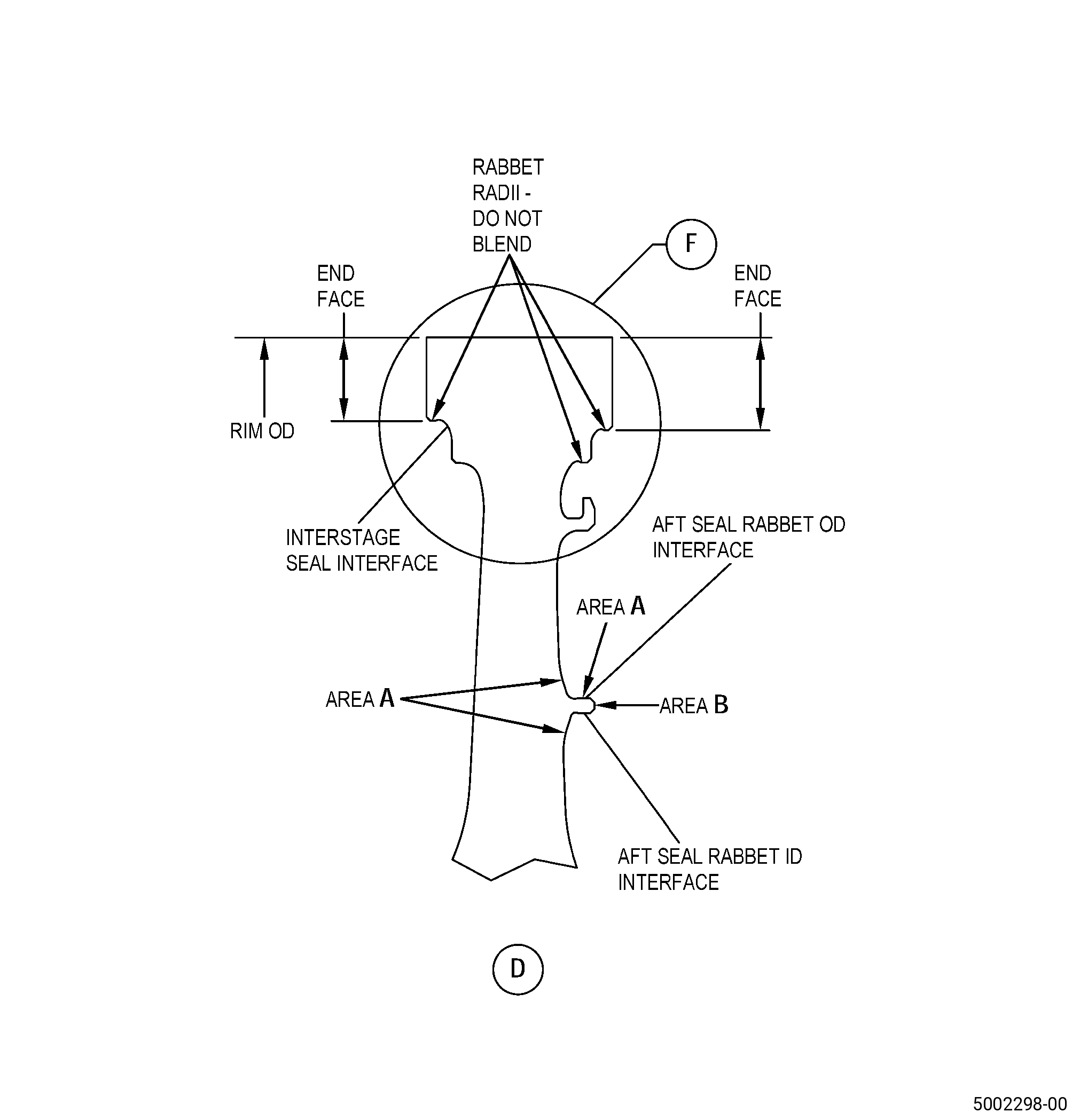
| (e) | Do an inspection of the rim OD and end faces for: |
| 1 | Nicks: |
| Maximum repairable limit: |
|
| Repair method: |
|
| 2 | Dents: |
| Maximum repairable limit: |
|
| Repair method: |
|
| 3 | Scratches: |
| Maximum repairable limit: |
|
| Repair method: |
|
| 4 | Galling and fretting: |
| Maximum repairable limit: |
|
| Repair method: |
|
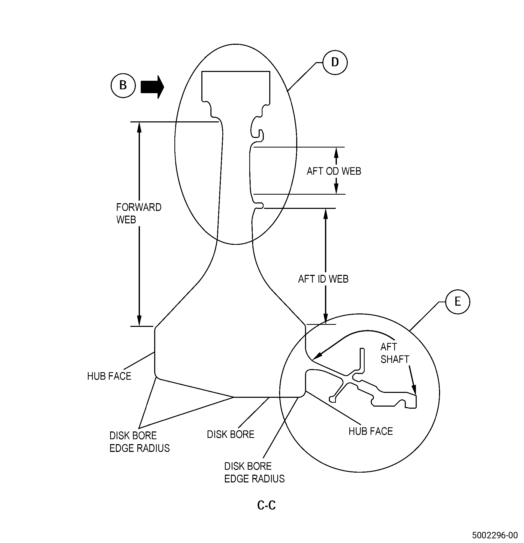
| (f) | Do an inspection of the forward and aft web and hub faces for: |
| 1 | Nicks and scratches that are 0.25 inch (6.4 mm) or less from any fillet radius: |
| Maximum repairable limit: |
|
| Repair method: |
|
| 2 | Nicks and scratches in other areas: |
| Maximum repairable limit: |
|
| Repair method: |
|
| 3 | Dents: |
| Maximum repairable limit: |
|
| Repair method: |
|
| (g) | Do an inspection of the aft seal mounting face for: |
| 1 | Fretting: |
| Maximum repairable limit: |
|
| Repair method: |
|
| 2 | Nicks, dents, and scratches: |
| Maximum repairable limit: |
|
| Repair method: |
|
| (h) | Do an inspection of the disk bore and disk bore edge radii for: |
| 1 | Nicks and scratches: |
| Maximum repairable limit: |
|
| Repair method: |
|
| 2 | Dents: |
| Maximum repairable limit: |
|
| Repair method: |
|
| 3 | Deleted. |
| Maximum repairable limit: |
|
| Repair method: |
|
| (i) | Do an inspection of area A for: |
| 1 | Nicks, dents, scratches, or other damage: |
| Maximum repairable limit: |
|
| Repair method: |
|
| (j) | Do an inspection of area B for: |
| 1 | Nicks, dents, scratches, or other damage: |
| Maximum repairable limit: |
|
| Repair method: |
|
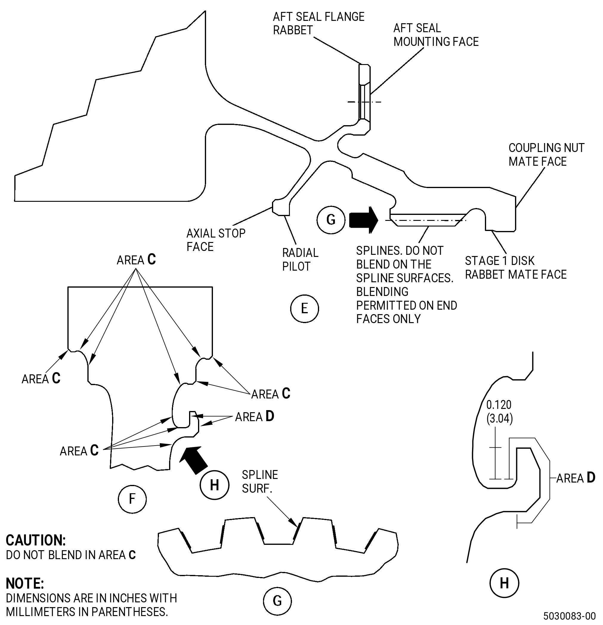
| (l) | Do an inspection of the aft seal rabbet OD, ID, and axial interfaces for: |
| 2 | Nicks, dents, and scratches: |
| Maximum repairable limit: |
|
| Repair method: |
|
| (m) | Do an inspection of the spline surfaces for: |
| 4 | Nicks, dents, or scratches on the end faces, refer to Figure 902: |
| Maximum repairable limit: |
|
| Repair method: |
|
| (n) | Do an inspection of the coupling nut mate face for: |
| 1 | Galling: |
| Maximum repairable limit: |
|
| Repair method: |
|
| (o) | Do an inspection of all other areas of the aft shaft: |
| 1 | Nicks, dents, and scratches: |
| Maximum repairable limit: |
|
| Repair method: |
|
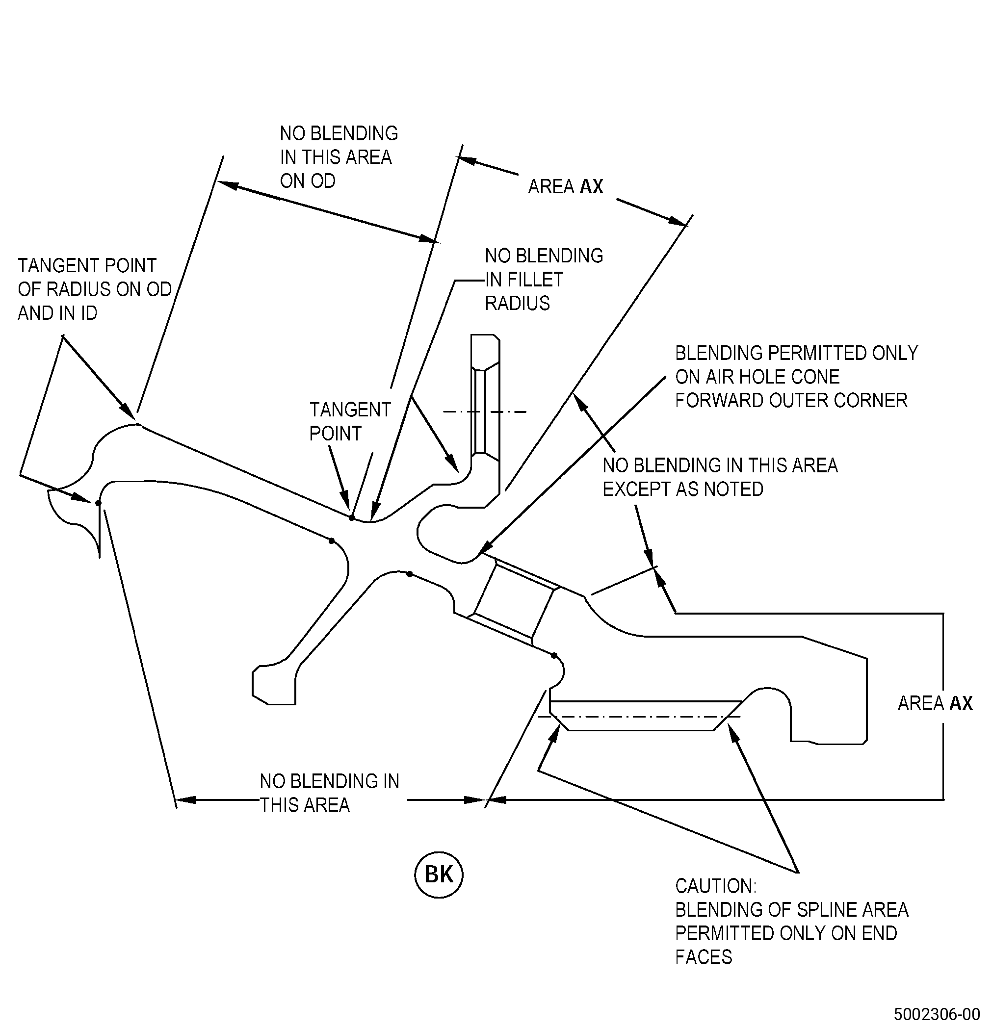
| (q) | Do an inspection of the air hole cone forward outer corner: |
| 1 | Nicks, dents, and scratches: |
| Maximum repairable limit: |
|
| Repair method: |
|
| (s) | Do an inspection of area D for: |
| 1 | Nicks, dents, and scratches: |
| Maximum repairable limit: |
|
| Repair method: |
|
| C. | The subsequent table gives a list of the part numbers that are applicable to this repair. All part numbers are applicable to all paragraphs unless specified differently. |
|
|||||||||||||||||||||||
| D. | Proprietary/Complex Process Statement. |
| (1) | None. |
| 2 . | Tools, Equipment, and Materials. |
| NOTE: |
|
| A. | Tools and Equipment. |
| (1) | Special Tools. None. |
| (2) | Standard Tools and Equipment. None. |
| (3) | Locally Manufactured Tools. None. |
| B. | Consumable Materials. |
|
| C. | Referenced Procedures. |
| D. | Expendable Parts. None. |
| E. | SPD Information. None. |
| (1) | Locally Manufactured SPD. None. |
| F. | Special Solutions. None. |
| G. | Test Specimens. None. |
| 3 . | Dimensional Information. |
| Subtask 72-53-41-220-054 |
| A. | Refer to Figure 901 for specified dimensions and locations. |
| NOTE: |
|
| 4 . | Setup Information. |
| None. |
| 5 . | Procedure. |
| Subtask 72-53-41-100-001 |
| A. | Clean the disk. Refer to TASK 70-21-00-110-051 (CHEMICAL CLEANING) and TASK 70-21-03-160-001 (CLEANING METHOD NO. 3 - STEAM CLEANING). |
| Subtask 72-53-41-200-001 |
| B. | Do a visual inspection of the disk. Refer to TASK 72-53-41-200-801 (72-53-41, INSPECTION 001). |
| Subtask 72-53-41-350-003 |
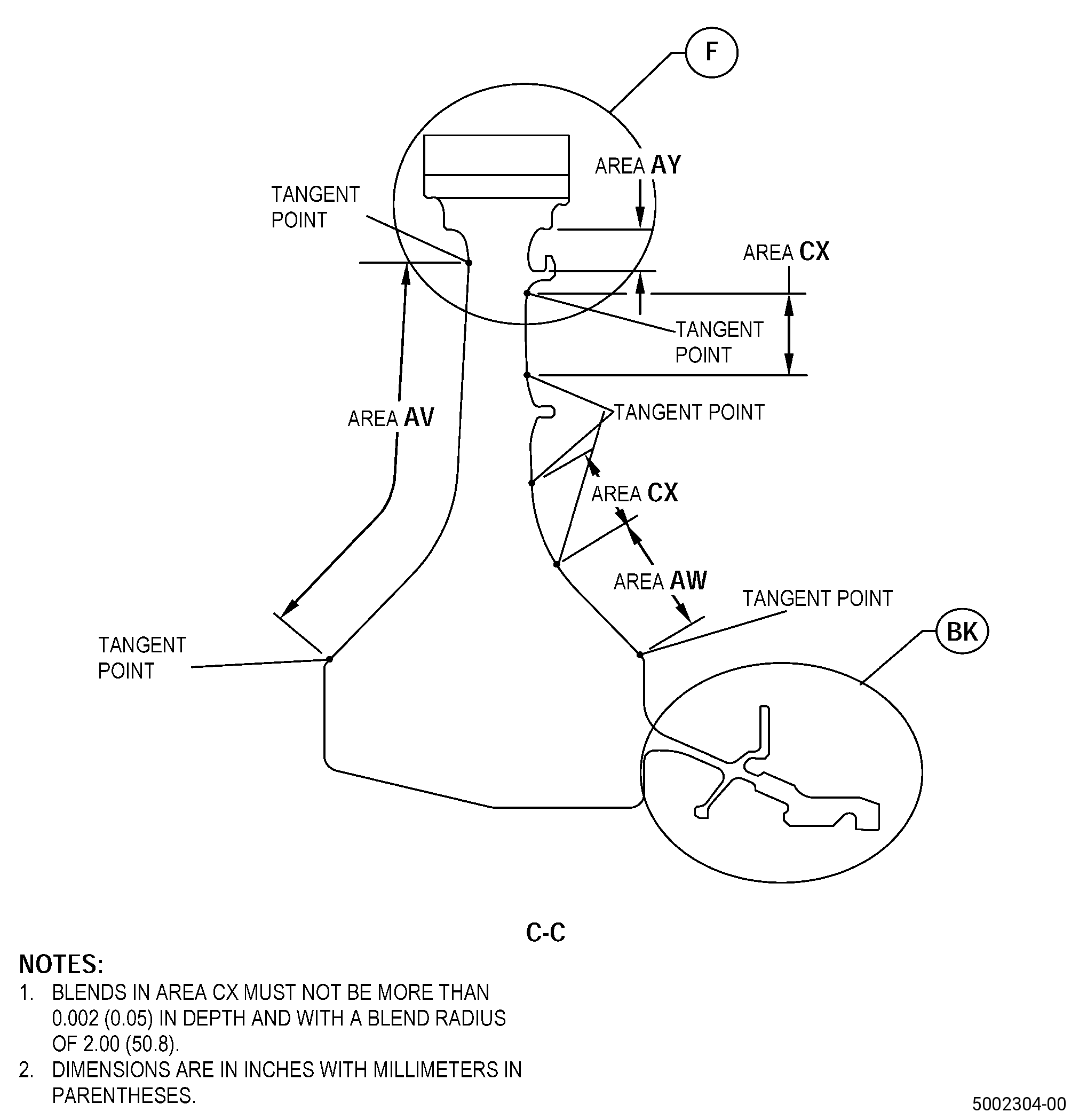
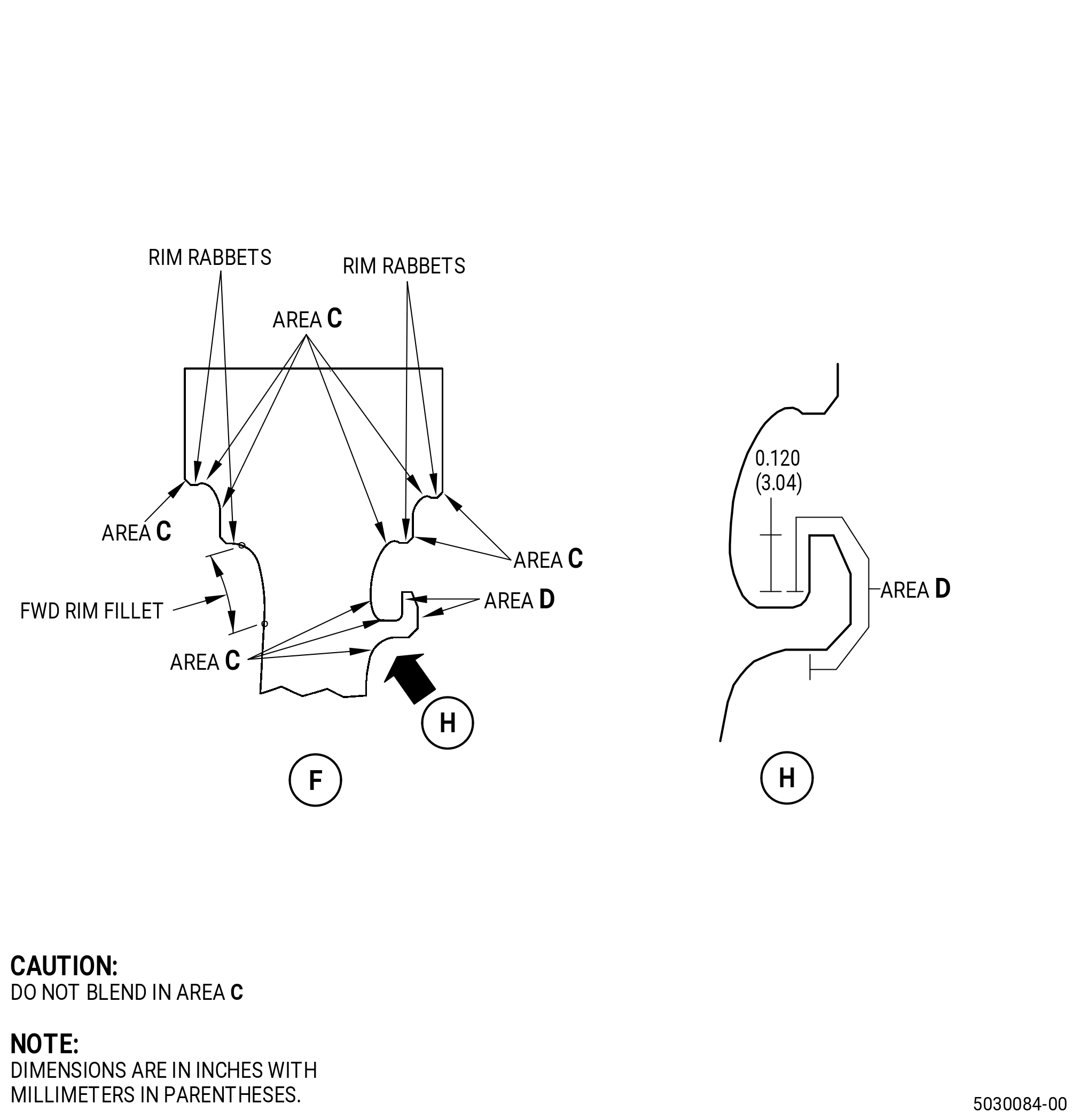
| C. | Blend the disk. Refer to TASK 70-42-00-350-002 (BLENDING AND REMOVAL OF HIGH METAL PROCEDURES), Figure 902, and as follows: |
| (1) | Blend in the area AV, area AW, area AX, and area AY, except as noted not to blend. |
| (2) | For area CX only, blending must not be more than 0.002 inch (0.05 mm) in depth and with a blend radius of 2.00 inches (50.8 mm). |
| (3) | For the blending limits refer to TASK 72-53-41-200-801 (72-53-41, INSPECTION 001). |
| Subtask 72-53-41-100-002 |
| D. | Clean the repaired areas. Refer to TASK 70-21-00-110-051 (CHEMICAL CLEANING) and TASK 70-21-03-160-001 (CLEANING METHOD NO. 3 - STEAM CLEANING). |
| Subtask 72-53-41-110-004 |
| E. | Etch the repaired areas. Refer to TASK 70-24-00-110-033 (ETCHING PROCEDURES FOR FLUORESCENT-PENETRANT INSPECTION), TASK 70-24-01-110-034 (SWAB ETCHING PROCEDURE), and as follows: |
| (1) | Use Class C or Class G etchant. |
| Subtask 72-53-41-200-002 |
| F. | Alternative Procedure Available. Do an inspection of the repaired areas. Refer to TASK 70-32-00-200-002 (INDIRECT INSPECTION METHODS), TASK 70-32-02-230-001 (FLUORESCENT PENETRANT INSPECTION), as follows: |
| (1) | Use Class G penetrant. |
| (2) | Indications more than 0.015 inch (0.38 mm) are not permitted. |
| (3) | Indications which cross corners are not permitted. |
| (4) | Linear indications are not permitted. |
| NOTE: |
|
| Subtask 72-53-41-200-003 |
| F.A. | Alternative Procedure. Do an inspection of the repaired areas. Refer to TASK 70-32-00-200-002 (INDIRECT INSPECTION METHODS), TASK 70-32-03-230-002 (SPOT-FLUORESCENT-PENETRANT INSPECTION), as follows: |
| (1) | Use Class G penetrant. |
| (2) | Indications more than 0.015 inch (0.38 mm) are not permitted. |
| (3) | Indications which cross corners are not permitted. |
| (4) | Linear indications are not permitted. |
| NOTE: |
|
| Subtask 72-53-41-350-001 |
| WARNING: |
|
| G. | Polish the disk to remove the effects of the swab etching procedure as follows: |
| (1) | Use C10-010 abrasive cloth. |
| Subtask 72-53-41-380-001 |
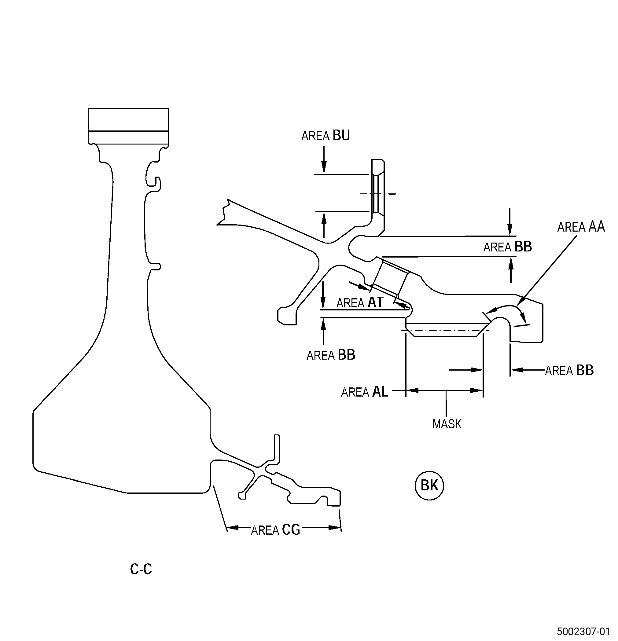
| H. | Peen the repaired areas. Refer to TASK 70-47-01-380-016 (SHOTPEENING), Figure 903, and as follows: |
| (1) | Apply a mask using C10-021 plastic tape to all areas you will not peen. |
| (2) | Use C04-166 CCW14 steel shot. |
| (3) | Peen to an intensity of 0.006N-0.012N. |
| (4) | Use simulative fixture for intensity verification. |
| (5) | Ricochet peening is permitted in area BB, area CG, hole AT and hole BU. |
| (6) | Overspray is permitted in area AL. |
| Subtask 72-53-41-220-055 |
| (7) | Do an inspection of the intensity in all the disk repaired areas with C10-205 almen test strips and an almen test strip holder. |
| Subtask 72-53-41-350-002 |
| (8) | Remove all masking from the part. |
| Subtask 72-53-41-100-003 |
| I. | Clean the repaired areas. Refer to TASK 70-21-00-110-051 (CHEMICAL CLEANING) and TASK 70-21-03-160-001 (CLEANING METHOD NO. 3 - STEAM CLEANING). |
| Subtask 72-53-41-200-004 |
| J. | Do a final inspection of the disk. Refer to TASK 72-53-41-200-801 (72-53-41, INSPECTION 001) and as follows: |
| (1) | Burrs or rollover edges are not permitted. |