| GENX-1B CLEANING,INSPECTION,AND REPAIR MANUAL | Dated: 09/26/2022 | |
| CIR 72-53-42 , REPAIR 004 | ||
| HIGH PRESSURE TURBINE ROTOR FORWARD SEAL - REPAIR - GENERAL BLEND REPAIR | ||
| GENX-1B CLEANING,INSPECTION,AND REPAIR MANUAL | Dated: 09/26/2022 | |
| CIR 72-53-42 , REPAIR 004 | ||
| HIGH PRESSURE TURBINE ROTOR FORWARD SEAL - REPAIR - GENERAL BLEND REPAIR | ||
| * * * FOR ALL |
| TASK 72-53-42-300-804 |
| 1 . | General Blend Repair. |
| A. | This procedure gives instructions to repair the HPT rotor forward seal (seal) by blending to remove defects from different areas of the seal. Refer to Figure 901. |
| B. | The following maximum repairable limits apply to this repair: |
| NOTE: |
|
| (4) | Visual Inspection. |
| (c) | Do an inspection of all seal serrations for: |
| 2 | Nicks, dents, and scratches on the sides of the forward and middle teeth of the OD seal serrations and on the sides of the ID serrations: |
| NOTE: |
|
| Maximum repairable limit: |
|
| 2.A. | Nicks, dents, and scratches on the sides of the aft tooth of the OD seal serrations: |
| NOTE: |
|
| Maximum repairable limit: |
|
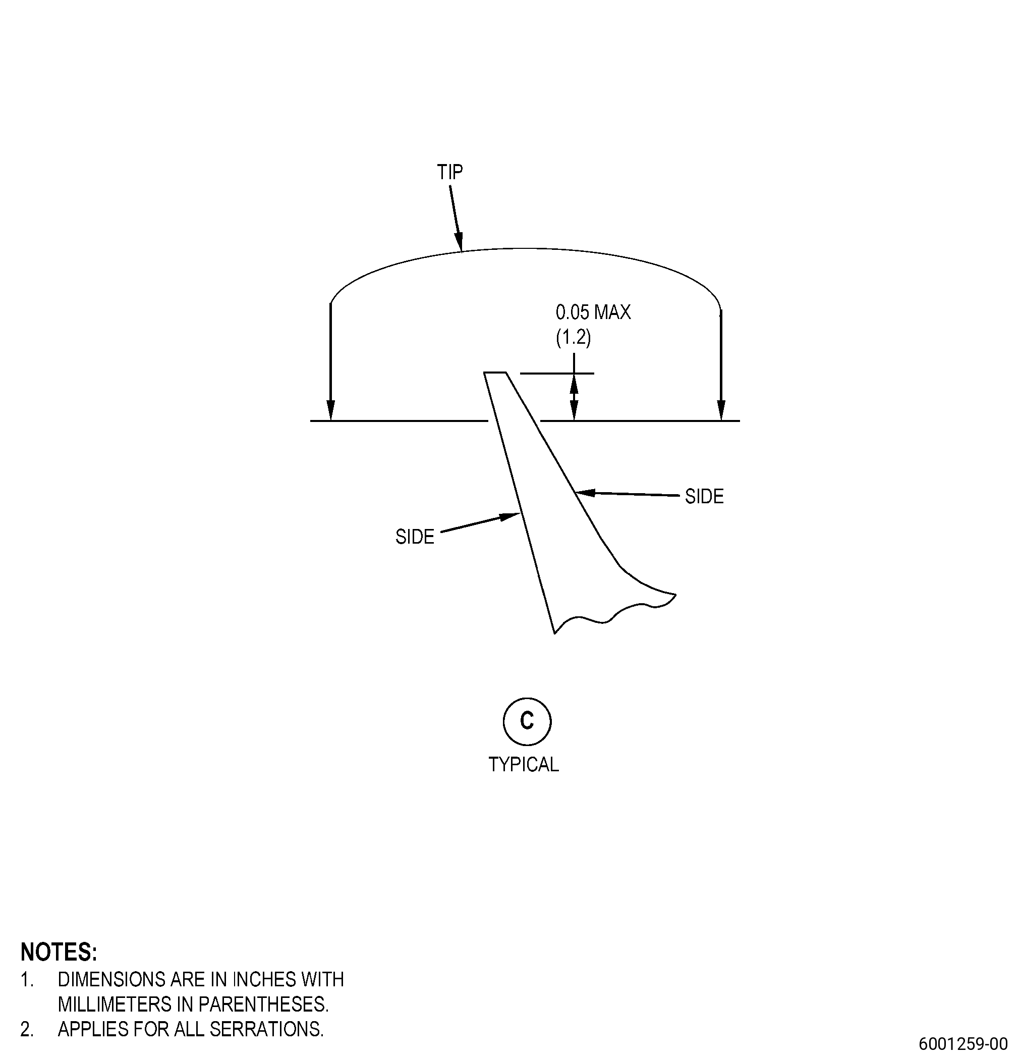
| 3 | Nicks, dents, and scratches on the tips of the forward and middle teeth of the OD seal serrations and on the tip of the ID serrations: |
| NOTE: |
|
| Maximum repairable limit: |
|
| 3.A. | Nicks, dents, and scratches on the tip of the aft tooth of the OD seal serrations: |
| NOTE: |
|
| Maximum repairable limit: |
|
| 4 | Bends in the tips of the forward and middle teeth of the OD seal serrations and in the tip of the ID serrations: |
| NOTE: |
|
| Maximum repairable limit: |
|
| 4.A. | Bends in the tip of the aft tooth of the OD seal serrations: |
| NOTE: |
|
| Maximum repairable limit: |
|
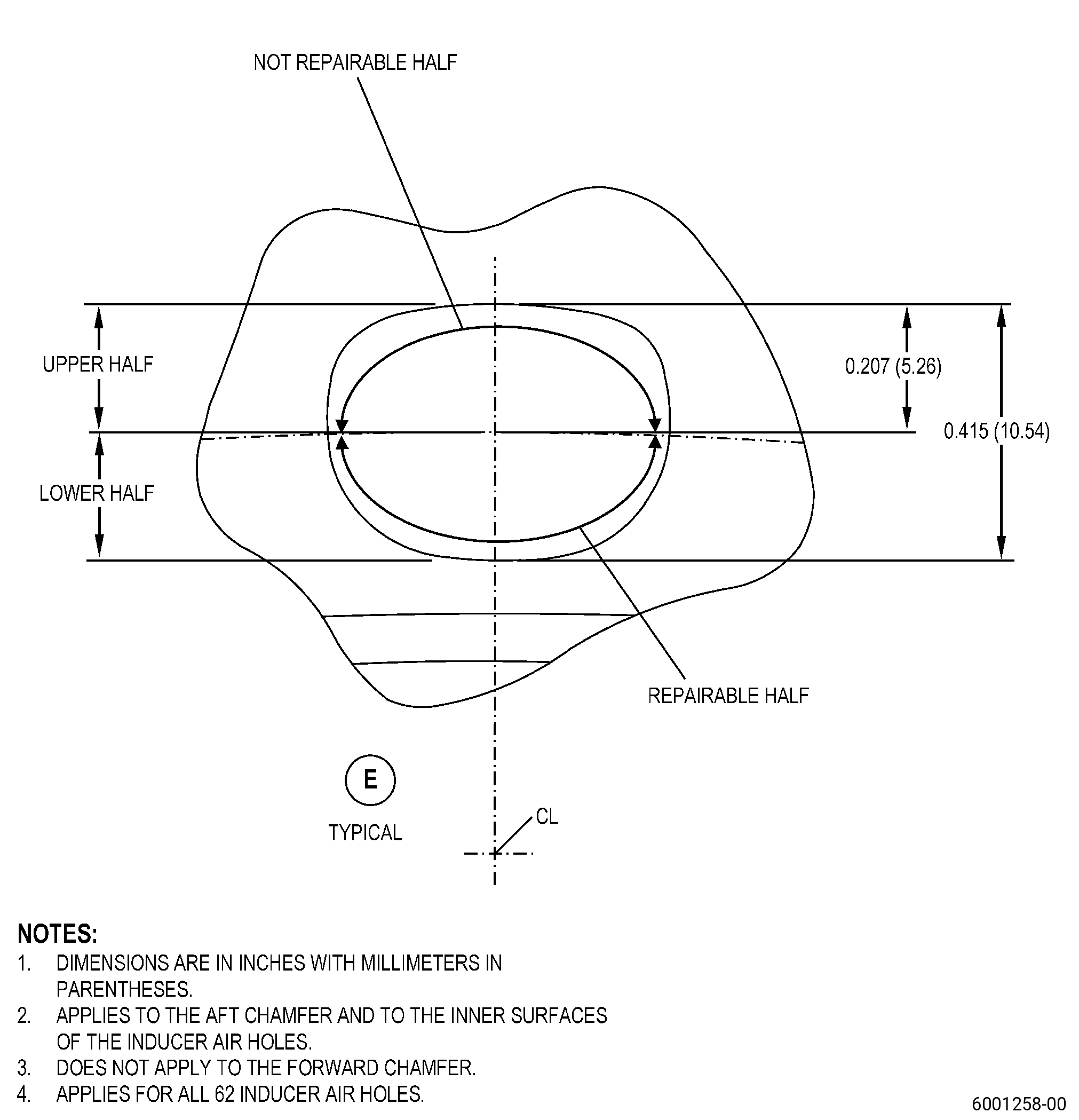
| (d) | Do an inspection of the inducer air holes (62 holes) for: |
| 1 | Nicks, dents, and scratches in the top surface (upper half) of the inducer air holes: |
| NOTE: |
|
| Maximum repairable limit: |
|
| 2 | Nicks, dents, and scratches in the lower surface (lower half) of the inducer air holes: |
| Maximum repairable limit: |
|
| 3 | Nicks, dents, and scratches all around the surface of the forward chamfer of the inducer air holes: |
| Maximum repairable limit: |
|
| 4 | Nicks, dents, and scratches in the top surfaces (upper half) of the aft chamfer of the inducer air holes: |
| Maximum repairable limit: |
|
| 5 | Nicks, dents, and scratches in the lower surfaces (lower half) of the aft chamfer of the inducer air holes: |
| Maximum repairable limit: |
|
| (e) | Do an inspection of the blade retainer (forward and aft) for: |
| 1 | Nicks, dents, and scratches: |
| Maximum repairable limit: |
|
| (f) | Do an inspection of the stage 1 blade interface for: |
| 2 | Nicks, dents, and scratches: |
| Maximum repairable limit: |
|
| (g) | Do an inspection of the OD bayonet (this does not include fillets adjacent to the bayonet) for: |
| 2 | Nicks, dents, and scratches: |
| Maximum repairable limit: |
|
| (h) | Do an inspection of the Spiroloc interface for: |
| 1 | Wear: |
| Maximum repairable limit: |
|
| 2 | Nicks, dents, and scratches: |
| Maximum repairable limit: |
|
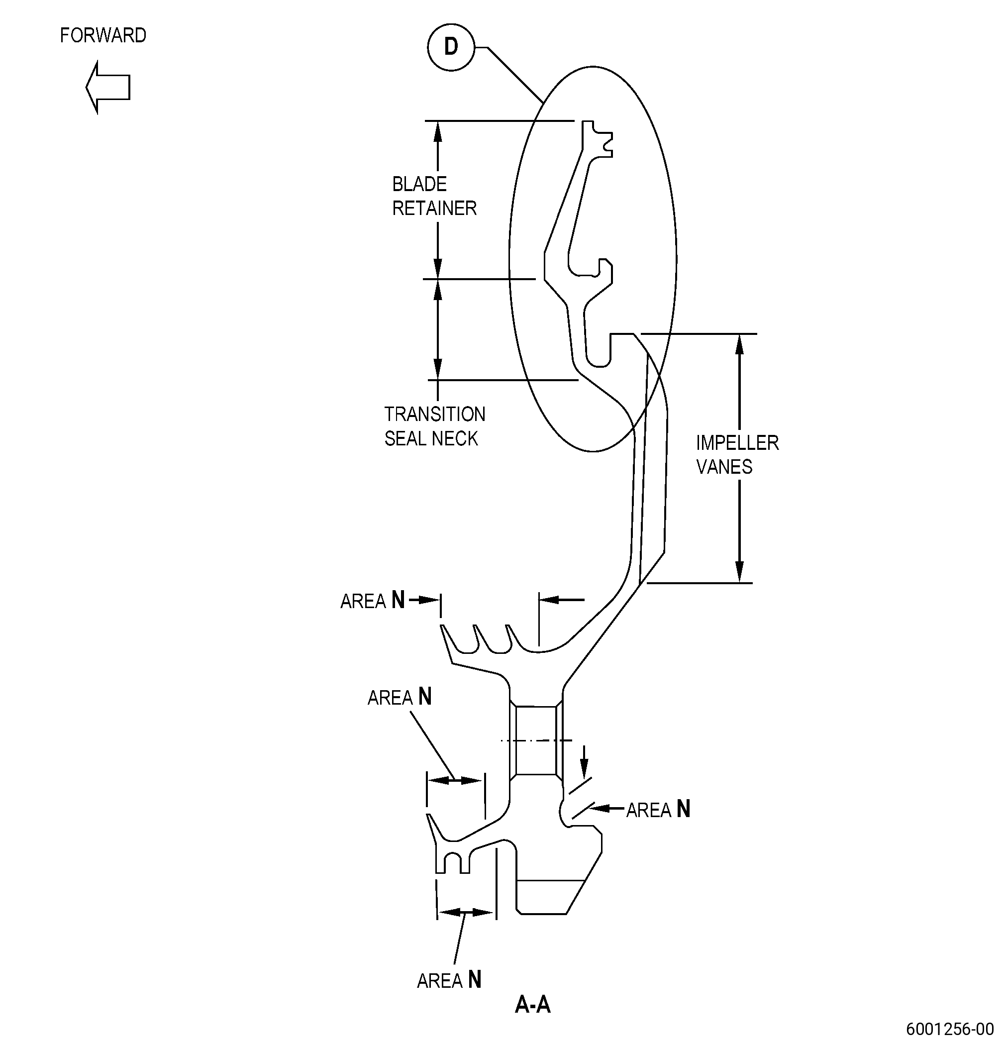
| (j) | Do an inspection of the transition seal neck (forward and aft) for: |
| 1 | Nicks, dents, and scratches: |
| Maximum repairable limit: |
|
| (k) | Do an inspection of the web for: |
| 1 | Nicks, dents, and scratches: |
| Maximum repairable limit: |
|
| (l) | Do an inspection of the OD seal rack and fillet for: |
| 1 | Nicks, dents, and scratches: |
| Maximum repairable limit: |
|
| (m) | Do an inspection of the inducer pad for: |
| 1 | Nicks, dents, and scratches: |
| Maximum repairable limit: |
|
| (n) | Do an inspection of the ID seal arm upper for: |
| 1 | Nicks, dents, and scratches: |
| Maximum repairable limit: |
|
| (o) | Do an inspection of the ID seal arm lower and fillet for: |
| 1 | Nicks, dents, and scratches: |
| Maximum repairable limit: |
|
| (p) | Do an inspection of the bayonet bore for: |
| 1 | Nicks, dents, and scratches: |
| Maximum repairable limit: |
|
| (q) | Do an inspection of the ID bayonet (including forward and aft surfaces) (this does not include fillets adjacent to the bayonet) for: |
| 2 | Nicks, dents, and scratches: |
| Maximum repairable limit: |
|
| (r) | Do an inspection of the seal wire groove for: |
| 1 | Nicks, dents, and scratches: |
| Maximum repairable limit: |
|
| (s) | Do an inspection of the stage 1 disk rim interface and fillet for: |
| 2 | Nicks, dents, and scratches: |
| Maximum repairable limit: |
|
| (t) | Do an inspection of the outer air slot for: |
| 1 | Nicks, dents, and scratches: |
| Maximum repairable limit: |
|
| (u) | Do an inspection of the impeller vanes for: |
| 1 | Nicks, dents, and scratches: |
| Maximum repairable limit: |
|
| (v) | Do an inspection of the impeller vane slot for: |
| 1 | Nicks, dents, and scratches: |
| Maximum repairable limit: |
|
| (w) | Do an inspection of the aft web transition for: |
| 1 | Nicks, dents, and scratches: |
| Maximum repairable limit: |
|
| (x) | Do an inspection of the stage 1 disk inner interface for: |
| 1 | Nicks, dents, and scratches: |
| Maximum repairable limit: |
|
| (y) | Do an inspection of the ID rabbet fillet for: |
| 1 | Nicks, dents, and scratches: |
| Maximum repairable limit: |
|
| (z) | Do an inspection of the inner air slot for: |
| 1 | Nicks, dents, and scratches: |
| NOTE: |
|
| Maximum repairable limit: |
|
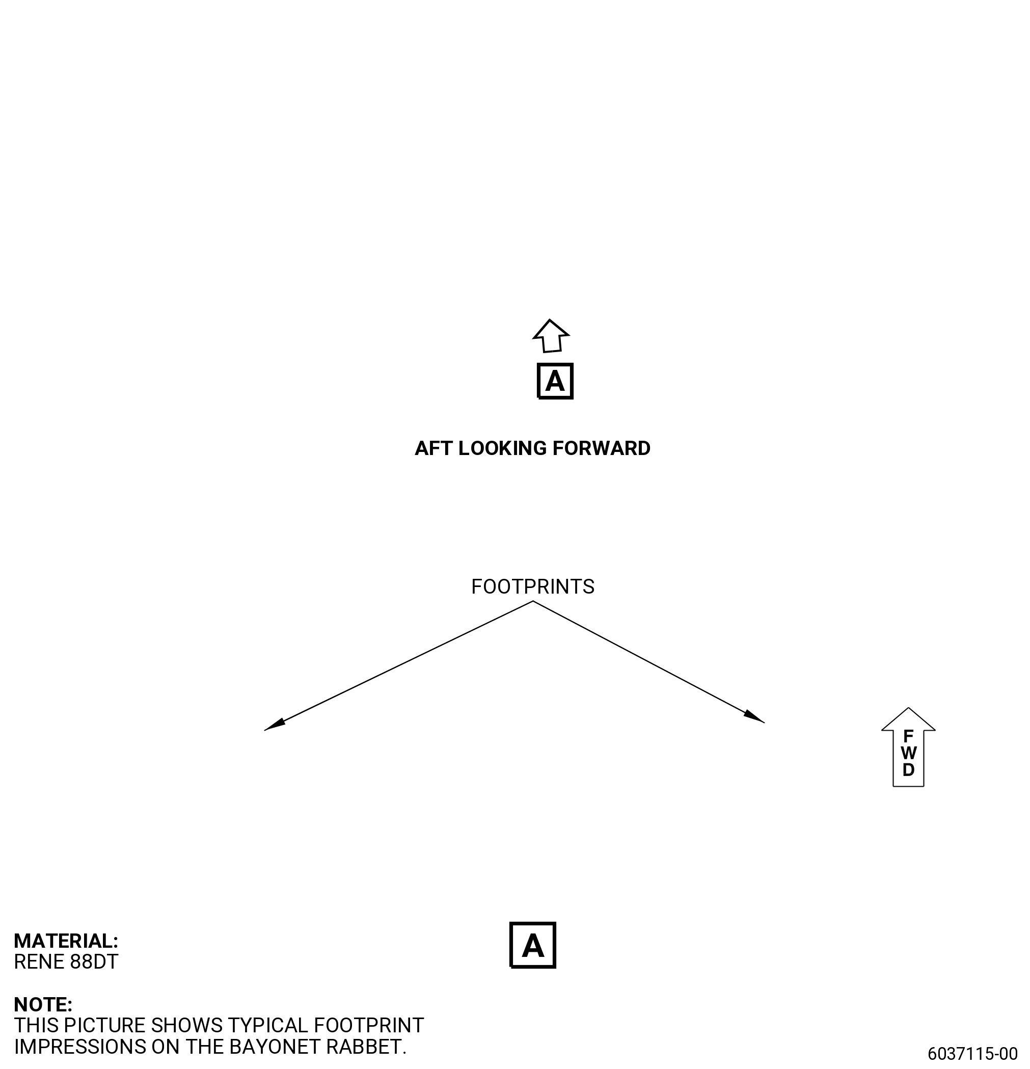
| (aa) | Do an inspection of the bayonet rabbet for: |
| 3 | Footprint impressions on the bayonet rabbet (caused by contact from the HPT stage 1 disk bayonet hook). |
| Maximum repairable limit: |
|
| C. | The subsequent table gives a list of the part numbers that are applicable to this repair. All part numbers are applicable to all paragraphs unless specified differently. |
|
||||||||||||||||||||||||||||||||||||
| D. | Proprietary/Complex Process Statement. |
| (1) | None. |
| 2 . | Tools, Equipment, and Materials. |
| NOTE: |
|
| A. | Tools and Equipment. |
| (1) | Special Tools. None. |
| (2) | Standard Tools and Equipment. None. |
| (3) | Locally Manufactured Tools. None. |
| B. | Consumable Materials. |
|
| C. | Referenced Procedures. |
| D. | Expendable Parts. None. |
| E. | SPD Information. |
| (1) | Locally Manufactured SPD. None. |
| F. | Special Solutions. None. |
| G. | Test Specimens. None. |
| 3 . | Dimensional Information. |
| Subtask 72-53-42-220-036 |
| A. | Refer to Figure 901 for specified dimensions and locations. |
| NOTE: |
|
| NOTE: |
|
| 4 . | Setup Information. |
| None. |
| 5 . | Procedure. |
| Subtask 72-53-42-160-003 |
| A. | If necessary, clean the seal. Refer to TASK 70-21-00-110-051 (CHEMICAL CLEANING) and TASK 70-21-03-160-001 (CLEANING METHOD NO. 3 - STEAM CLEANING). |
| Subtask 72-53-42-220-037 |
| B. | Do a visual inspection of the seal areas that you will repair. Refer to TASK 72-53-42-200-801 (72-53-42, INSPECTION 001) and as follows: |
| (1) | If there are footprint impressions on the bayonet rabbet, polish the footprint impressions to prepare them for inspection. Refer to Subtask 72-53-42-350-007 (paragraph 5.C.). |
| (2) | If there are other damaged areas on the seal, blend the damage. Refer to Subtask 72-53-42-350-004 (paragraph 5.D.). |
| Subtask 72-53-42-350-007 |
| CAUTION: |
|
| C. | Polish the footprint impressions on the bayonet rabbet. Refer to Figure 901 and do as follows: |
| (1) | Use C10-010 abrasive cloth to polish the footprint impressions to remove smeared or burred material. |
| (2) | Make sure that you polish the footprint impressions and do not blend into parent metal. Refer to TASK 72-53-42-200-801 (72-53-42, INSPECTION 001) and as follows: |
| (a) | If the footprint impression after polishing is more than the depth limit, you cannot repair the seal with this procedure. |
| Subtask 72-53-42-350-004 |
| CAUTION: |
|
| D. | Blend the damaged areas of the seal. Refer to TASK 70-42-00-350-002 (BLENDING AND REMOVAL OF HIGH METAL PROCEDURES), Figure 901, and do as follows: |
| (1) | Blend the damaged areas of the seal to the maximum repairable limits specified in this repair procedure. Refer to TASK 72-53-42-200-801 (72-53-42, INSPECTION 001) and as follows: |
| (a) | If you blend more than the repairable limits, you cannot repair the seal with this procedure. |
| Subtask 72-53-42-160-004 |
| E. | Clean the seal blended areas. Refer to TASK 70-21-00-110-051 (CHEMICAL CLEANING) and TASK 70-21-03-160-001 (CLEANING METHOD NO. 3 - STEAM CLEANING). |
| Subtask 72-53-42-110-008 |
| F. | Etch the seal blended areas. Refer to TASK 70-24-00-110-033 (ETCHING PROCEDURES FOR FLUORESCENT-PENETRANT INSPECTION), TASK 70-24-01-110-034 (SWAB ETCHING PROCEDURE), and as follows: |
| (1) | Use Class C or Class G etchant. |
| Subtask 72-53-42-230-003 |
| G. | Alternative Procedure Available. Do an inspection of the seal blended areas. Refer to TASK 70-32-00-200-002 (INDIRECT INSPECTION METHODS), TASK 70-32-02-230-001 (FLUORESCENT PENETRANT INSPECTION), and as follows: |
| (1) | Use Class G penetrant. |
| (2) | For the inspection of the polished footprint impressions on the bayonet rabbet, do as follows: |
| (a) | Use a non-aqueous wet developer (NAWD) only. |
| (b) | Make sure that the penetrant application process has a minimum dwell time of 50 minutes. |
| (3) | Indications less than 0.015 inch (0.38 mm) are permitted. |
| (4) | Linear indications are not permitted. |
| NOTE: |
|
| (5) | No other indications are permitted. |
| Subtask 72-53-42-230-004 |
| G.A. | Alternative Procedure. Do an inspection of the seal blended areas. Refer to TASK 70-32-00-200-002 (INDIRECT INSPECTION METHODS), TASK 70-32-03-230-002 (SPOT-FLUORESCENT-PENETRANT INSPECTION), and as follows: |
| (1) | Use Class G penetrant. |
| (2) | For the inspection of the polished footprint impressions on the bayonet rabbet, do as follows: |
| (a) | Use non-aqueous wet developer (NAWD) only. |
| (b) | Make sure that the penetrant application process has a minimum dwell time of 50 minutes. |
| (3) | Indications less than 0.015 inch (0.38 mm) are permitted. |
| (4) | Linear indications are not permitted. |
| NOTE: |
|
| (5) | No other indications are permitted. |
| Subtask 72-53-42-350-005 |
| H. | Polish the seal to remove the effects of the swab etching procedure as follows: |
| (1) | Use C10-010 abrasive cloth. |
| Subtask 72-53-42-380-002 |
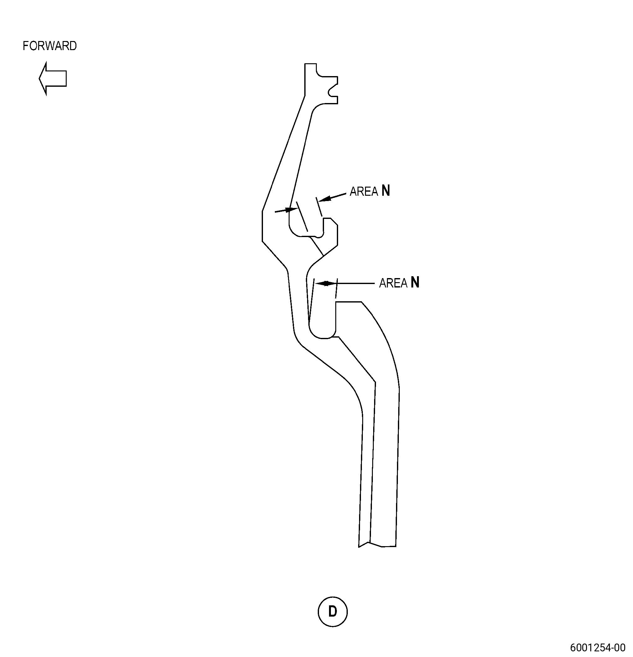
| I. | Peen the seal blended and polished areas. Refer to TASK 70-47-01-380-016 (SHOTPEENING), Figure 901, Figure 902, Figure 903, and as follows: |
| (1) | Apply masking with C10-021 plastic tape to the areas with thermal spray coating. |
| (2) | Use C04-166 CCW14 steel shot. |
| (3) | Peen the seal to an intensity of 6-12N. |
| (4) | Ricochet peening is permitted in area N. |
| (5) | Overspray is permitted. |
| (6) | Coverage of the seal must be a minimum of 125 percent. |
| (7) | Use a scrap part or simulative part fixture for intensity verification and curve generation. |
| (8) | Do an inspection of the intensity in all the seal peened areas with C10-205 Type N and an Almen test strip holder. |
| (9) | Remove all masking from the part. |
| Subtask 72-53-42-160-005 |
| J. | Clean the seal repaired areas. Refer to TASK 70-21-00-110-051 (CHEMICAL CLEANING) and TASK 70-21-03-160-001 (CLEANING METHOD NO. 3 - STEAM CLEANING). |
| Subtask 72-53-42-350-006 |
| K. | Complete all the necessary repairs. |
| Subtask 72-53-42-220-038 |
| L. | Do a final inspection of the seal. Refer to TASK 72-53-42-200-801 (72-53-42, INSPECTION 001). |