| GENX-1B CLEANING,INSPECTION,AND REPAIR MANUAL | Dated: 06/01/2020 | |
| CIR 72-53-43 , SPECIAL PROCEDURES 001 | ||
| HIGH PRESSURE TURBINE ROTOR INTERSTAGE SEAL - SPECIAL PROCEDURE - FOCUSED INSPECTION OF THE AIR CROSSOVER HOLES | ||
| GENX-1B CLEANING,INSPECTION,AND REPAIR MANUAL | Dated: 06/01/2020 | |
| CIR 72-53-43 , SPECIAL PROCEDURES 001 | ||
| HIGH PRESSURE TURBINE ROTOR INTERSTAGE SEAL - SPECIAL PROCEDURE - FOCUSED INSPECTION OF THE AIR CROSSOVER HOLES | ||
| * * * FOR ALL |
| TASK 72-53-43-800-801 |
| 1 . | General. |
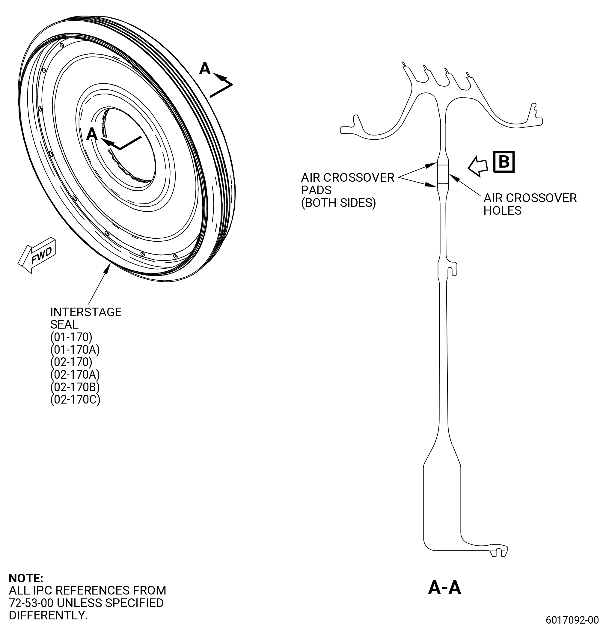
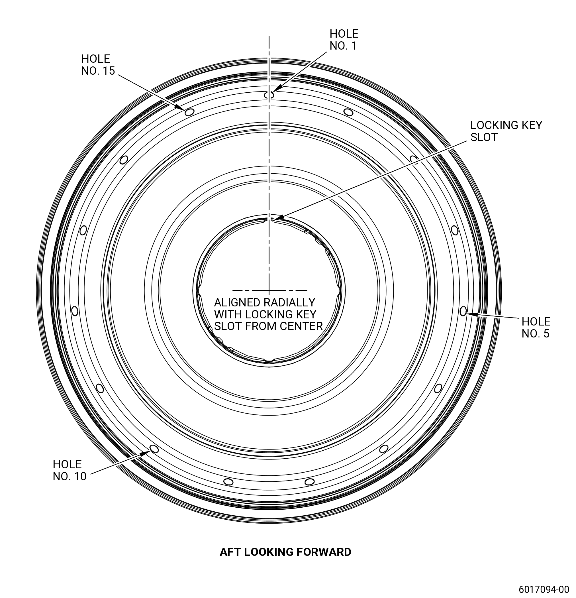
| A. | This procedure gives instructions to do a focused inspection of the air crossover holes of the HPT rotor interstage seal (interstage seal) (01-170 , 72-53-00) (SIN 150B3) or (01-170A , 72-53-00) (SIN 150B3) or (02-170 , 72-53-00) (SIN 150B3) or (02-170A , 72-53-00) (SIN 150B3) or (02-170B , 72-53-00) (SIN 150B3) or (02-170C , 72-53-00) (SIN 150B3) for linear indications. |
| B. | Any reject indications observed during the accomplishment of the following inspection should be reported to Fleet Support at Aviation.Fleet.Support1@ge.com. Please include the following details: |
| • Part number and serial number |
| • Engine serial number |
| • Customer/Operator |
| • Time since new |
| • Cycles since new |
| • Time since overhaul |
| • Cycles since overhaul |
| • Indication size(s) |
| • Photos of the indication(s). |
| Alternatively, this information can be submitted as a Service Request (SR) via myGEAviation.com. |
| 2 . | Tools, Equipment, and Materials. |
| NOTE: |
|
| A. | Tools and Equipment. |
| (1) | Special Tools. None. |
| (2) | Standard Tools and Equipment. None. |
| (3) | Locally Manufactured Tools. None. |
| B. | Consumable Materials. None. |
| C. | Referenced Procedures. |
| D. | Expendable Parts. None. |
| 3 . | Specific Inspection Procedure. |
| Subtask 72-53-43-220-115 |
| A. | Do a focused inspection of the HPT rotor interstage seal air crossover holes as follows: |
| (1) | Make sure that the interstage seal is clean. Refer to TASK 72-53-43-100-801 (72-53-40, CLEANING 001, CONFIG 01) or TASK 72-53-43-100-802 (72-53-40, CLEANING 001, CONFIG 02). |
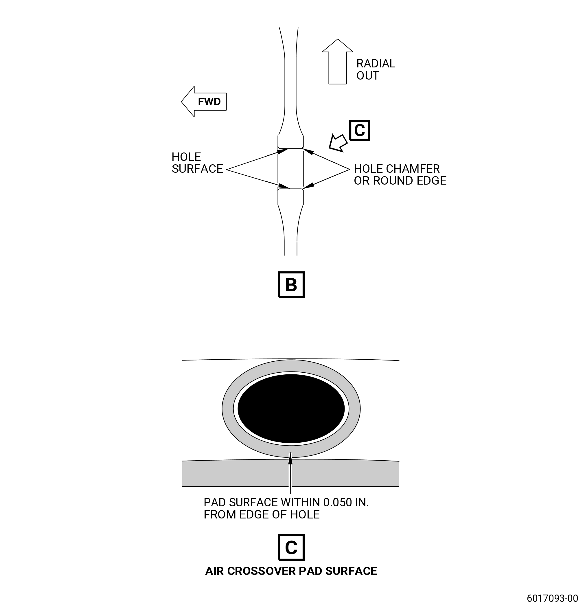
| (2) | Do a 10X white light visual inspection of the air crossover hole surfaces, hole chamfer or round edge surfaces and air crossover pad surface within at least 0.050 inch (1.27 mm) of the hole edge for any linear indications. Refer to Figure 201 and do as follows: |
| NOTE: |
|
| (a) | Record any findings of linear indications and report them as, refer to Subtask 72-53-43-210-001 (paragraph 3.A.(4)). |
| (b) | Review any indications in detail with fluorescent penetrant inspection, refer to Subtask 72-53-43-230-009 (paragraph 3.A.(3)) to confirm if indications are real. |
| Subtask 72-53-43-230-009 |
| (3) | Do a fluorescent penetrant inspection with a 10X under black light to inspect the crossover hole surfaces, hole chamfer or round edge surfaces and air crossover pad surfaces within at least 0.050 inch (1.27 mm) of the hole edge for linear indications. Refer to TASK 70-32-00-200-002 (INDIRECT INSPECTION METHODS), TASK 70-32-03-230-002 (SPOT-FLUORESCENT-PENETRANT INSPECTION), and as follows: |
| (a) | Use Class G penetrant. |
| (b) | Use non-aqueous wet developer (NAWD). |
| (c) | Make sure that the penetrant application procedure has a minimum dwell time of 50 minutes. |
| (d) | No linear indications are permitted. Do as follows: |
| NOTE: |
|
| 1 | If you find linear indications, do a solvent wipe process to find if the indication is repeatable. Refer to TASK 70-32-02-230-001 (FLUORESCENT PENETRANT INSPECTION). |
| 2 | If the indication does not re-appear after the solvent wipe process, apply NAWD again, wait 10 minutes and do the inspection again. If the original indication does not come into view again then the definition of the condition is non-repeatable, and is permitted. |
| 3 | Record any findings of linear indications and report them as, refer to Subtask 72-53-43-210-001 (paragraph 3.A.(4)). |
| Subtask 72-53-43-210-001 |
| (4) | Report all findings of linear indications(s) to Fleet Support. Refer to TASK 72-53-43-800-801 (paragraph 1.B.). Include the following additional details: |
| • |
|
| • |
|
| • |
|