| GENX-1B CLEANING,INSPECTION,AND REPAIR MANUAL | Dated: 04/30/2013 | |
| CIR 72-56-47 , REPAIR 001 | ||
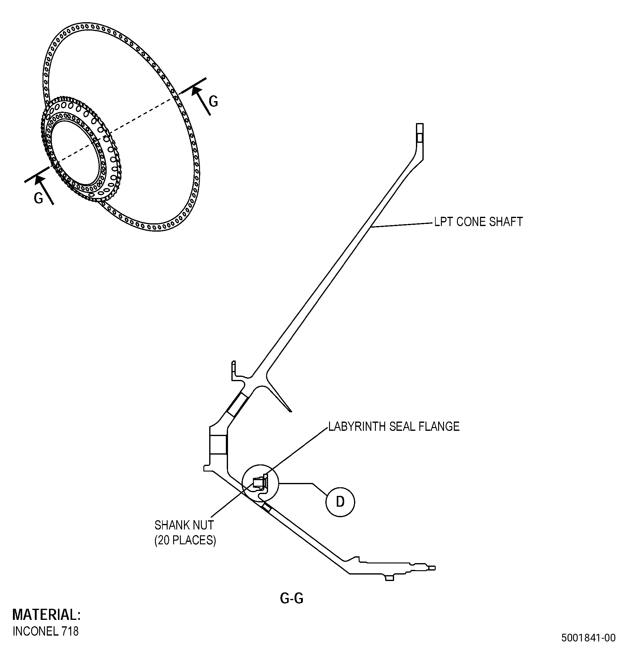
| LOW PRESSURE TURBINE CONE SHAFT ASSEMBLY - REPAIR - REPLACEMENT OF THE DAMAGED SHANK NUTS | ||
| GENX-1B CLEANING,INSPECTION,AND REPAIR MANUAL | Dated: 04/30/2013 | |
| CIR 72-56-47 , REPAIR 001 | ||
| LOW PRESSURE TURBINE CONE SHAFT ASSEMBLY - REPAIR - REPLACEMENT OF THE DAMAGED SHANK NUTS | ||
| * * * FOR ALL |
| TASK 72-56-47-300-801 |
| 1 . | Repair for the Low Pressure Turbine Cone Shaft Assembly. |
| A. | This procedure gives instructions to repair the low pressure turbine (LPT) cone shaft assembly (shaft) by replacing the damaged shank nuts. Refer to Figure 901. |
| B. | The following maximum repairable limits apply to this repair: |
| NOTE: |
|
| NOTE: |
|
| (4) | Visual Inspection. |
| (i) | Do an inspection of the shank nuts for: |
| 1 | Missing: |
| Maximum repairable limit: |
|
| 2 | Cracks: |
| Maximum repairable limit: |
|
| 3 | Damaged threads: |
| Maximum repairable limit: |
|
| 4 | Self-locking feature: |
| Maximum repairable limit: |
|
| 5 | Looseness: |
| Maximum repairable limit: |
|
| C. | The subsequent table gives a list of the part numbers that are applicable to this repair. All part numbers are applicable to all paragraphs unless specified differently. |
|
|||||||||||||||||||||||
| D. | Proprietary/Complex Process Statement. |
| (1) | None. |
| 2 . | Tools, Equipment, and Materials. |
| NOTE: |
|
| A. | Tools and Equipment. |
| (1) | Special Tools. None. |
| (2) | Standard Tools and Equipment. |
|
| (3) | Locally Manufactured Tools. None. |
| B. | Consumable Materials. |
|
| C. | Referenced Procedures. |
| D. | Expendable Parts. None. |
| E. | SPD Information. |
|
| (1) | Locally Manufactured SPD. None. |
| F. | Special Solutions. None. |
| G. | Test Specimens. None. |
| 3 . | Dimensional Information. |
| Subtask 72-56-47-220-065 |
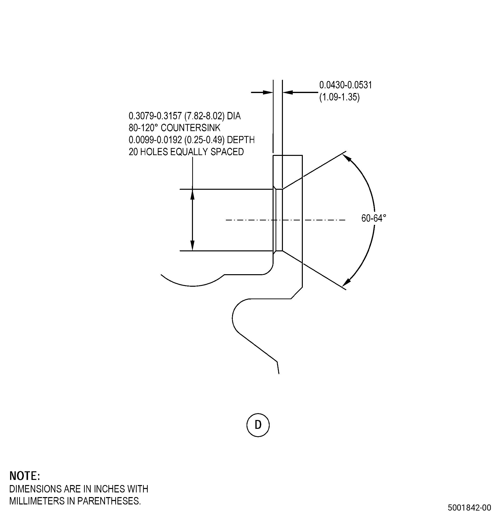
| A. | Refer to Figure 901 and Figure 902 for specified dimensions and locations. |
| NOTE: |
|
| NOTE: |
|
| 4 . | Setup Information. |
| None. |
| 5 . | Procedure. |
| Subtask 72-56-47-350-005 |
| A. | Remove the damaged shank nuts from the shaft. Refer to TASK 70-48-13-350-024 (SHANK NUT REPAIR), Figure 901, Figure 902, and as follows: |
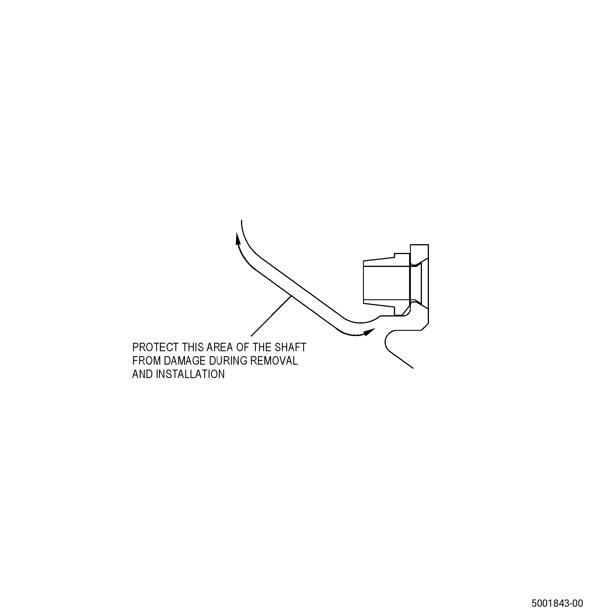
| (1) | Apply C10-021 plastic tape, C10-067 platers tape, or an equivalent maskant to the shaft to prevent damage to the shaft during removal. |
| (2) | Use a drill bit of 0.272-0.307 inch (6.9-7.8 mm) in diameter with a conical cutting edge of 60-62 degrees. |
| (3) | Drill the shank nut to a depth that is sufficient to make the base of the flared shank of the shank nut thin/loose. |
| (4) | Install a 0.25-28 UNJ-3A screw into the shank nut. |
| (5) | Lightly tap the 0.25-28 UNJ-3A screw with a hammer to remove the nut from the shank nut hole. |
| (6) | Remove the 0.25-28 UNJ-3A screw and nut from the shaft. |
| Subtask 72-56-47-110-003 |
| B. | Clean the exposed shaft boltholes. Refer to TASK 70-21-00-110-051 (CHEMICAL CLEANING) and TASK 70-21-23-110-053 (CLEANING METHOD 23 - HAND-WIPE DEGREASING). |
| Subtask 72-56-47-110-004 |
| C. | Etch the shaft boltholes. Refer to TASK 70-24-00-110-033 (ETCHING PROCEDURES FOR FLUORESCENT-PENETRANT INSPECTION), TASK 70-24-01-110-034 (SWAB ETCHING PROCEDURE), and as follows: |
| (1) | Use Class C etchant. |
| Subtask 72-56-47-200-001 |
| D. | Do an inspection of the shaft boltholes where you removed the damaged shank nuts. Refer to TASK 70-32-00-200-002 (INDIRECT INSPECTION METHODS), TASK 70-32-03-230-002 (SPOT-FLUORESCENT-PENETRANT INSPECTION), and as follows: |
| (1) | Use Class G penetrant. |
| (2) | Refer to TASK 72-56-47-200-801 (72-56-47, INSPECTION 001) for the acceptability limits. |
| Subtask 72-56-47-200-002 |
| E. | Do a visual inspection of the shaft boltholes where you removed the damaged shank nuts. Refer to TASK 72-56-47-200-801 (72-56-47, INSPECTION 001). |
| Subtask 72-56-47-220-066 |
| F. | Do a dimensional inspection of the shaft boltholes where you removed the damaged shank nuts. Refer to Figure 902. |
| Subtask 72-56-47-350-006 |
| G. | Install the new shank nuts on the shaft. Refer to TASK 70-48-13-350-024 (SHANK NUT REPAIR), Figure 901, Figure 902, and as follows: |
| (1) | Apply C10-021 plastic tape, C10-067 platers tape, or an equivalent maskant to the shaft to prevent damage to the shaft during installation. |
| Subtask 72-56-47-110-005 |
| (2) | If necessary, clean the shaft boltholes. Refer to TASK 70-21-00-110-051 (CHEMICAL CLEANING) and TASK 70-21-23-110-053 (CLEANING METHOD 23 - HAND-WIPE DEGREASING). |
| Subtask 72-56-47-350-007 |
| (3) | Use a shank nut P/N 2331M83P01 or shank nut P/N 1767M45P02 . |
| (4) | Axial or transverse movement in the shank nut is not permitted after you install the shank nut on the shaft. |