| GENX-1B CLEANING,INSPECTION,AND REPAIR MANUAL | Dated: 10/31/2018 | |
| CIR 72-58-40 , REPAIR 004 | ||
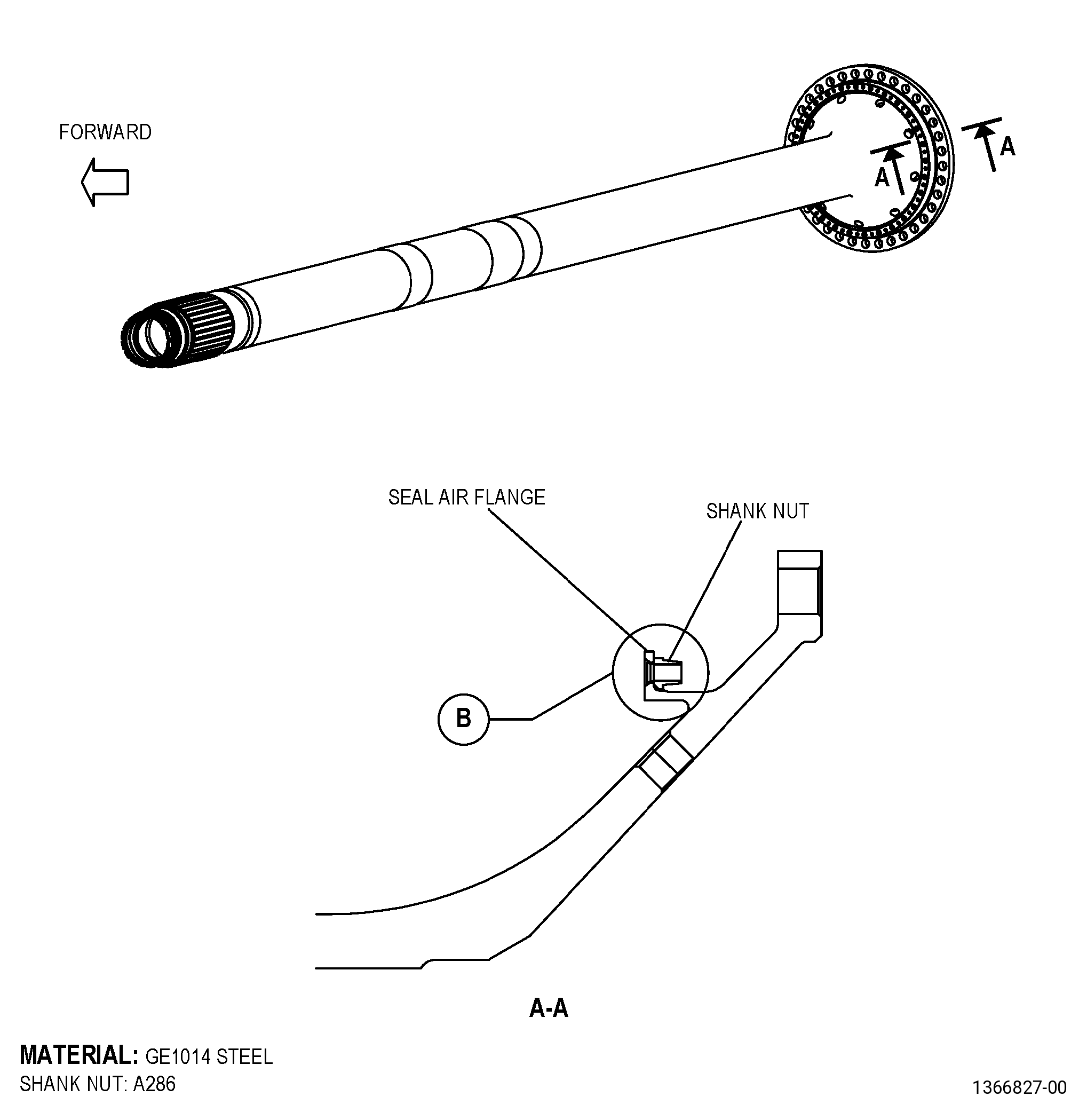
| MID FAN SHAFT - REPAIR - REPLACEMENT OF DAMAGED SHANK NUT | ||
| GENX-1B CLEANING,INSPECTION,AND REPAIR MANUAL | Dated: 10/31/2018 | |
| CIR 72-58-40 , REPAIR 004 | ||
| MID FAN SHAFT - REPAIR - REPLACEMENT OF DAMAGED SHANK NUT | ||
| * * * FOR ALL |
| TASK 72-58-40-300-802 |
| 1 . | Repair for the Mid Fan Shaft. |
| A. | This procedure gives instructions to repair the mid fan shaft (shaft) by replacing the damaged shank nuts. Refer to Figure 901. |
| B. | The following maximum repairable limits apply to this repair: |
| NOTE: |
|
| (4) | Visual Inspection. |
| (t) | Do an inspection of the shank nut on the seal air flange for: |
| 1 | Loss of self-locking quality: |
| Maximum repairable limit: |
|
| 2 | Damaged threads: |
| Maximum repairable limit: |
|
| 4 | Cracks in the shank: |
| Maximum repairable limit: |
|
| 5 | Missing shank nut: |
| Maximum repairable limit: |
|
| C. | The subsequent table gives a list of the part numbers that are applicable to this repair. All part numbers are applicable to all paragraphs unless specified differently. |
|
|||||||||||||||||||||||||||||||||||||||||||||||||
| D. | Proprietary/Complex Process Statement. |
| (1) | None. |
| 2 . | Tools, Equipment, and Materials. |
| NOTE: |
|
| A. | Tools and Equipment. |
| (1) | Special Tools. None. |
| (2) | Standard Tools and Equipment. |
|
| (3) | Locally Manufactured Tools. None. |
| B. | Consumable Materials. None. |
| C. | Referenced Procedures. |
|
| D. | Expendable Parts. None. |
| E. | SPD Information. |
|
| F. | Special Solutions. None. |
| G. | Test Specimens. None. |
| 3 . | Dimensional Information. |
| Subtask 72-58-40-220-078 |
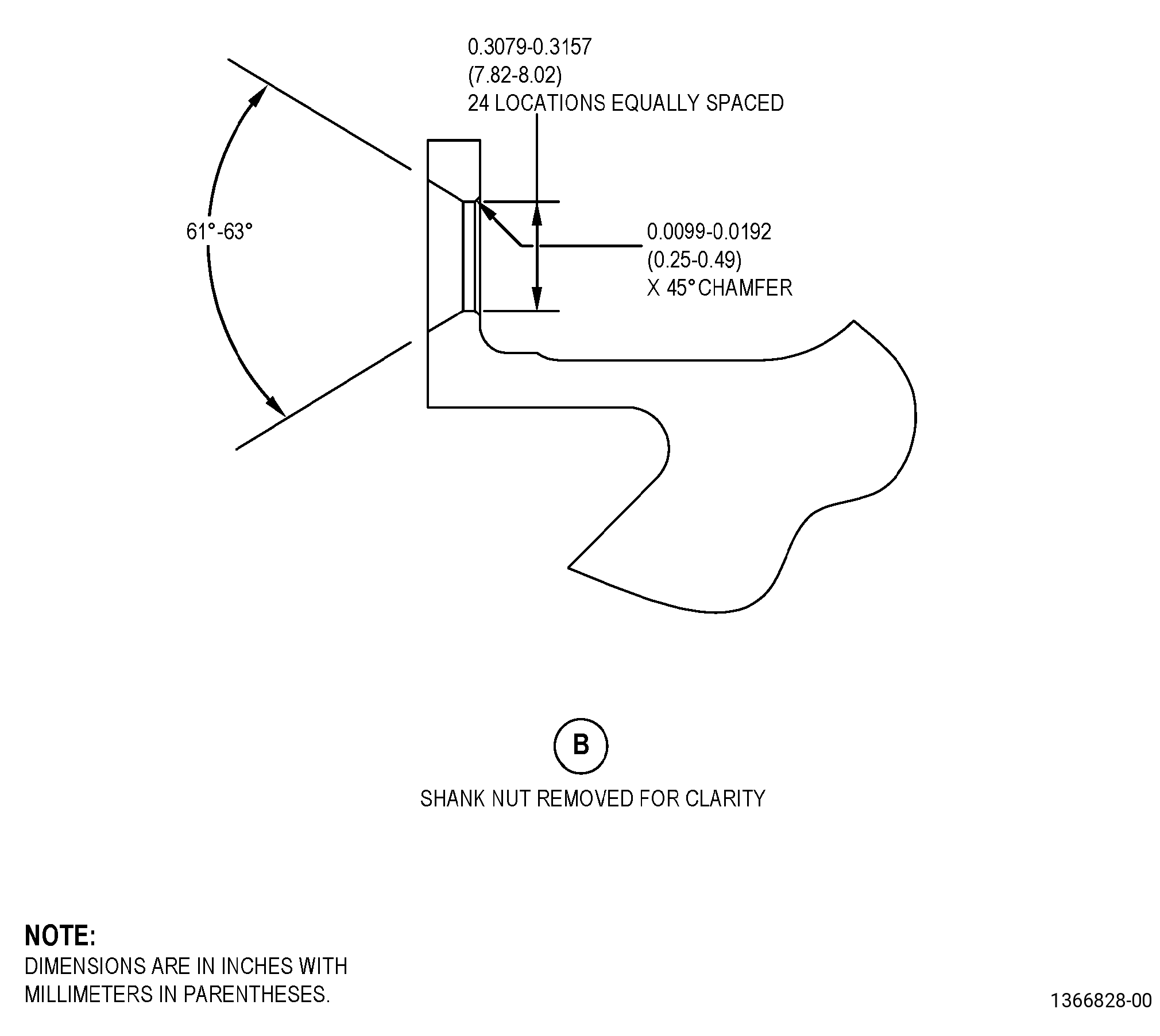
| A. | Refer to Figure 901 for specified dimensions and locations. |
| NOTE: |
|
| 4 . | Setup Information. |
| None. |
| 5 . | Procedure. |
| Subtask 72-58-40-350-010 |
| A. | Remove the damaged shank nuts. Refer to TASK 70-48-13-350-024 (SHANK NUT REPAIR), Figure 901, and as follows: |
| NOTE: |
|
| (1) | Use a 0.272-0.307 inch (6.9-7.8 mm) diameter drill bit with 60-62 degrees conical cutting edge. |
| (2) | Drill to a depth that is sufficient to make the base of the flared shank of the shank nut thin. |
| (3) | Install a 0.25-28 UNJ-3A screw into the shank nut. |
| (4) | Lightly tap the screw with a hammer to detach the nut from the flared shank. |
| (5) | Remove the screw and nut. |
| Subtask 72-58-40-110-007 |
| B. | Clean the exposed boltholes. Refer to TASK 70-21-00-110-051 (CHEMICAL CLEANING) and TASK 70-21-23-110-053 (CLEANING METHOD 23 - HAND-WIPE DEGREASING). |
| Subtask 72-58-40-200-001 |
| C. | Do a magnetic-particle inspection of the boltholes where you removed the damaged shank nuts. Refer to TASK 72-58-40-200-801 (72-58-40, INSPECTION 001). |
| Subtask 72-58-40-350-011 |
| D. | Install the new shank nuts. Refer to TASK 70-48-13-350-024 (SHANK NUT REPAIR), Figure 901, and as follows: |
| NOTE: |
|
| Subtask 72-58-40-110-008 |
| (1) | If necessary, clean the boltholes. Refer to TASK 70-21-00-110-051 (CHEMICAL CLEANING) and TASK 70-21-23-110-053 (CLEANING METHOD 23 - HAND-WIPE DEGREASING). |
| Subtask 72-58-40-350-012 |
| (2) | Use a shank nut (P/N 2331M83P01 ) or shank nut (P/N 1767M45P02 ). |