| GENX-1B CLEANING,INSPECTION,AND REPAIR MANUAL | Dated: 10/31/2022 | |
| CIR 72-64-11 , REPAIR 001 | ||
| RIGHT HAND VERTICAL LINK - REPAIR - SPHERICAL BEARING REPLACEMENT | ||
| GENX-1B CLEANING,INSPECTION,AND REPAIR MANUAL | Dated: 10/31/2022 | |
| CIR 72-64-11 , REPAIR 001 | ||
| RIGHT HAND VERTICAL LINK - REPAIR - SPHERICAL BEARING REPLACEMENT | ||
| * * * FOR ALL |
| TASK 72-64-11-300-801 |
| 1 . | Repair for the Right Hand Vertical Link. |
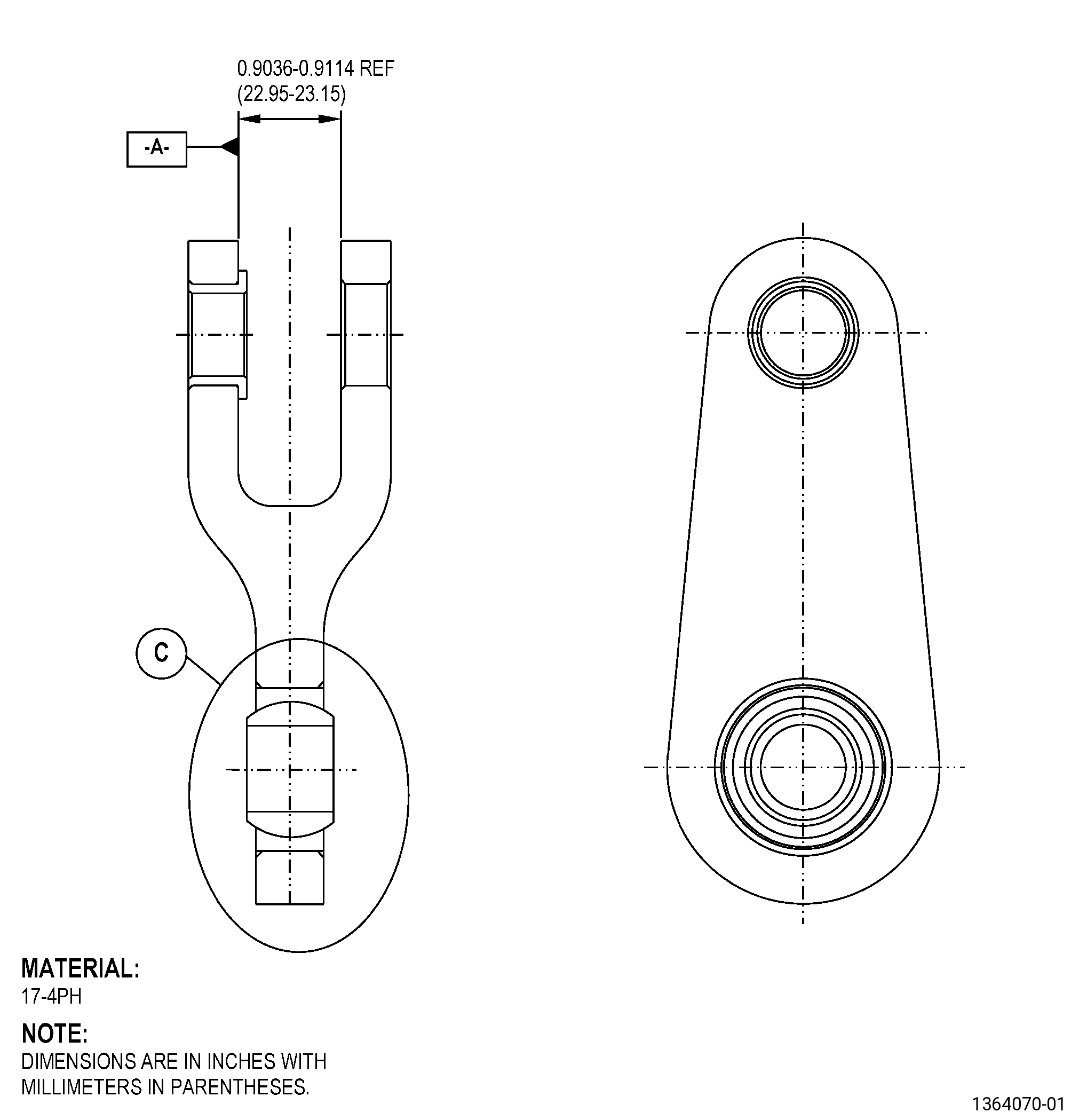
| A. | This procedure gives instructions to repair the right hand vertical link (vertical link) by replacing the damaged spherical bearing. Refer to Figure 901. |
| B. | The following maximum repairable limits apply to this repair: |
| NOTE: |
|
| NOTE: |
|
| (4) | Visual Inspection. |
| (b) | Do an inspection of the spherical bearing for: |
| 1 | Nicks, dents, or scratches: |
| Maximum repairable limit: |
|
| 3 | Wear on the sphere ID and on the spherical surfaces: |
| Maximum repairable limit: |
|
| (5) | Dimensional Inspection. |
| (a) | Do an inspection of the subsequent diameters: |
| 1 | Diameter at location B (bearing internal diameter): |
| Maximum repairable limit: |
|
| C. | The subsequent table gives a list of the part numbers that are applicable to this repair. All part numbers are applicable to all paragraphs unless specified differently. |
|
|||||||||||||||||||||||
| D. | Proprietary/Complex Process Statement. |
| (1) | None. |
| 2 . | Tools, Equipment, and Materials. |
| NOTE: |
|
| A. | Tools and Equipment. |
| (1) | Special Tools. None. |
| (2) | Standard Tools and Equipment. |
| (3) | Locally Manufactured Tools. None. |
| B. | Consumable Materials. |
|
| C. | Referenced Procedures. |
|
| D. | Expendable Parts. None. |
| E. | SPD Information. |
|
| F. | Special Solutions. None. |
| G. | Test Specimens. None. |
| 3 . | Dimensional Information. |
| Subtask 72-64-11-220-021 |
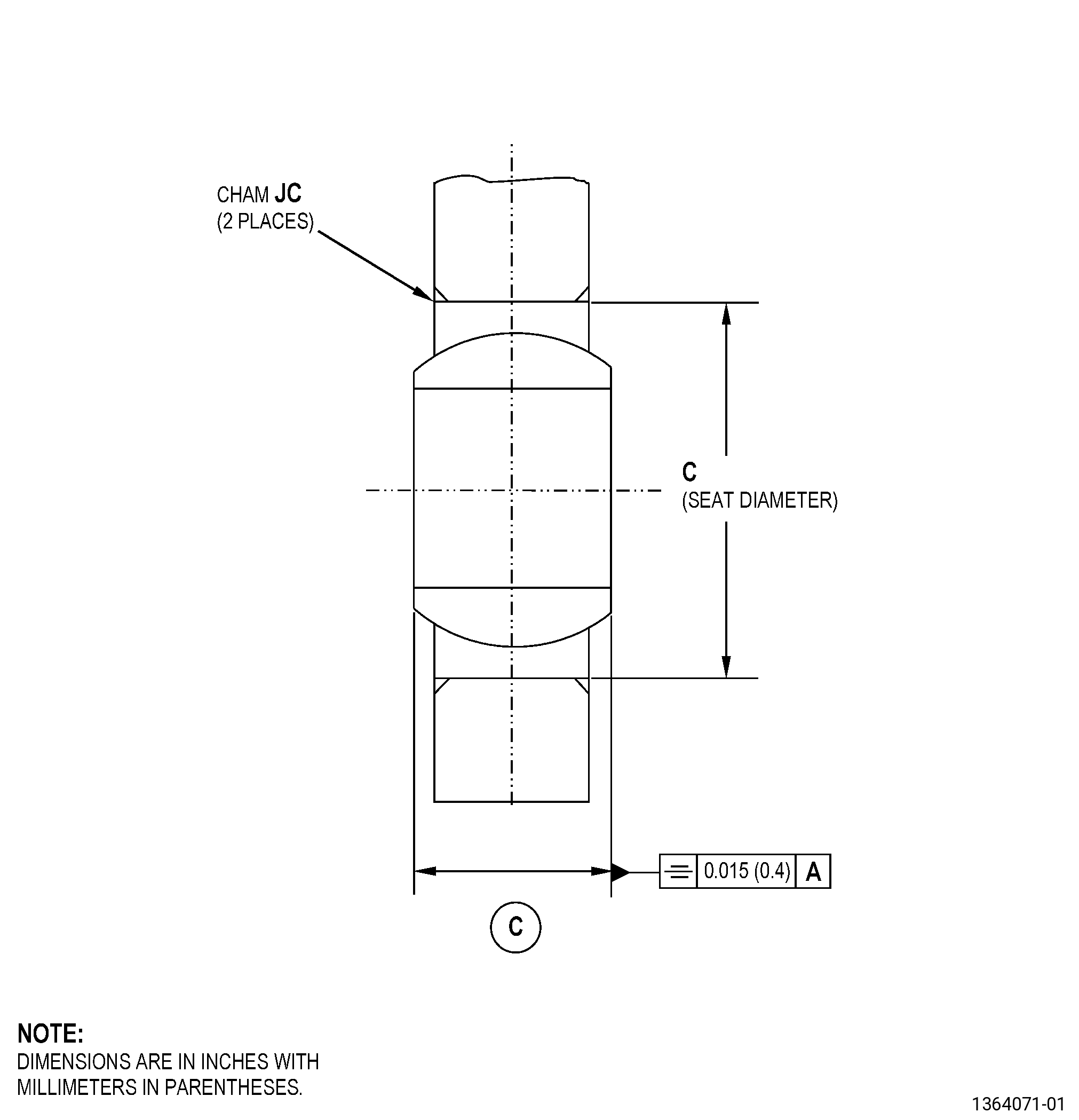
| A. | Refer to Figure 901 for specified dimensionsand locations. |
| NOTE: |
|
| NOTE: |
|
|
| 4 . | Setup Information. |
| Subtask 72-64-11-350-001 |
| A. | Set-up the verticallink to machine the swaged lip of the spherical bearing as follows: |
| NOTE: |
|
| (1) | Put the base assembly and the verticallink on the machine table. Refer to Figure 901 and do as follows: |
| (a) | Make sure that the vertical link surfaceadjacent to the spherical bearing is perpendicular to the machinespindle to 0.0011 inch (0.03 mm) or less. |
| (b) | Align the machine spindle with theinner diameter (ID) of the spherical bearing to 0.0011 inch (0.03mm) or less. |
| (2) | Use clamps to attach the vertical linkto the machine table. |
| 5 . | Procedure. |
| Subtask 72-64-11-350-002 |
| A. | Remove the sphericalbearing from the vertical link as follows: |
| Subtask 72-64-11-320-001 |
| CAUTION: |
|
| (1) | Machine the vertical link. Refer to TASK 70-00-03-800-004(MACHINING DATA) and as follows: |
| (a) | Set-up the vertical link to machinethe swaged lip of the spherical bearing. Refer to Subtask 72-64-11-350-001(paragraph 4.A.), Setup Information. |
| (b) | Machine the vertical link to weakenthe swaged lip of the spherical bearing. |
| Subtask 72-64-11-350-003 |
| CAUTION: |
|
| (2) | Remove the spherical bearing as follows: |
| (a) | Put the bearing pusher tool on thevertical link and align it on the top of the spherical bearing. |
| (b) | Push on the side where you removedthe staking swaged lip of the spherical bearing. |
| (c) | Apply pressure to the top of the pusherwith the ram of the arbor press to remove the spherical bearing. |
| Subtask 72-64-11-220-022 |
| B. | Do a dimensional inspectionof the center bore and chamfer of the vertical link. Refer to Subtask 72-64-11-220-021(paragraph 3.A.), Dimensional Information, Figure 901, and do as follows: |
| Subtask 72-64-11-350-004 |
| (1) | If necessary, blend the vertical linkto remove all the high metal. Refer to TASK 70-42-00-350-002(BLENDING AND REMOVAL OF HIGH METAL PROCEDURES). |
| Subtask 72-64-11-110-007 |
| C. | Etch the vertical linkrepair area. Refer to TASK 70-24-00-110-033 (ETCHING PROCEDURESFOR FLUORESCENT-PENETRANT INSPECTION), TASK 70-24-01-110-034(SWAB ETCHING PROCEDURE), and as follows: |
| (1) | Use Class C etchant. |
| Subtask 72-64-11-200-001 |
| D. | Do an inspection ofthe vertical link repair area. Refer to TASK 70-32-00-200-002(INDIRECT INSPECTION METHODS), TASK 70-32-02-230-001(FLUORESCENT PENETRANT INSPECTION), and as follows: |
| (1) | Use Class A penetrant. |
| (2) | Linear indications are not permitted. |
| NOTE: |
|
| (3) | Indications 0.0299 inch (0.76 mm) orless are permitted. |
| (4) | Indications 0.0300-0.0598 inch (0.76-1.52mm) are permitted if there is a minimum space of 0.500 inch (12.7mm) between them. |
| Subtask 72-64-11-100-001 |
| E. | Clean the verticallink. Refer to TASK 70-21-00-110-051 (CHEMICAL CLEANING) and TASK 70-21-03-160-001(CLEANING METHOD NO. 3 - STEAM CLEANING). |
| Subtask 72-64-11-110-008 |
| F. | Clean the new sphericalbearing, ABK12VCR-3. Refer to TASK 70-21-00-110-051 (CHEMICAL CLEANING) and TASK 70-21-23-110-053(CLEANING METHOD 23 - HAND-WIPE DEGREASING). |
| Subtask 72-64-11-300-001 |
| G. | Install the new sphericalbearing, ABK12VCR-3, in the vertical link as follows: |
| WARNING: |
|
| (1) | Increase the temperature of the vertical link area where youwill install the spherical bearing with a C10-054 hot air gun to a temperature range of 203to 212°F (95 to 100°C). Use a pyrometer to do a check of thetemperature. |
| WARNING: |
|
| (2) | Freeze the spherical bearing in dry ice or liquid nitrogen.Refer to TASK 70-14-00-620-003 (HANDLING OF BEARINGS). |
| Subtask 72-64-11-350-006 |
| CAUTION: |
|
| CAUTION: |
|
| (3) | Install the spherical bearing into the vertical link bore asfollows: |
| (a) | Install the spherical bearing as soonas possible after the heating operation. |
| (b) | Use a bearing pusher. |
| (c) | Apply a maximum load of 1124 lb (5000N) to the outer ring of the spherical bearing. |
| Subtask 72-64-11-350-005 |
| H. | Stake the new sphericalbearing, ABK12VCR-3, to the vertical link as follows: |
| (1) | Set-up the vertical link to stake theswage lip of the spherical bearing as follows: |
| (a) | Make sure that the spherical bearinginstalled in the vertical link bore agrees with the symmetry tolerancewhen you stake the spherical bearing on the vertical link chamferbore. Refer to Figure 901. |
| (2) | Stake the first side of the sphericalbearing swaged lip as follows: |
| (a) | Use the applicable staking tool tostake the spherical bearing. Refer to paragraph 2.A.(2), StandardTools and Equipment, and as follows: |
| 1 | Use the circular staking tool (withthe internal angle not higher than 30 degrees and the external anglenot higher than 45 degrees) to stake the groove of the spherical bearing. |
| 2 | Gradually apply a load to a maximumof 25403 lb (113000 N) on the end of the spherical bearing housing. |
| 3 | Make a retention lip in the sphericalbearing race until it touches the vertical link bore chamfer. |
| 4 | Do the lip swaging operation againeach 90 degrees. |
| (3) | Stake the second side of the sphericalbearing swage lip as follows: |
| (a) | Use the applicable staking tool tostake the spherical bearing. Refer to paragraph 2.A.(2), StandardTools and Equipment, and as follows: |
| 1 | Use the circular staking tool (withthe internal angle not higher than 30 degrees and the external anglenot higher than 45 degrees) to stake the groove of the spherical bearing. |
| 2 | Gradually apply a load to a maximumof 25403 lb (113000 N) on the end of the spherical bearing housing. |
| 3 | Make a retention lip in the sphericalbearing race until it touches the vertical link bore chamfer. |
| 4 | Do the lip swaging operation againeach 90 degrees. |
| Subtask 72-64-11-220-023 |
| I. | Do a visual inspectionof the swaged area of the spherical bearing as follows: |
| (1) | Linear indications are not permitted. |
| NOTE: |
|
| Subtask 72-64-11-220-024 |
| J. | Do an inspection ofthe new spherical bearing, ABK12VCR-3, installation in the verticallink as follows: |
| (1) | Do an inspection of the ball for freemovement as follows: |
| (a) | Use finger pressure to move the ball. |
| Subtask 72-64-11-210-001 |
| (2) | Do a check of the radial play as follows: |
| (a) | Make sure that the radial play thatis below a load of 5.5 lb (24.5 N) between the spherical bearing balland the ball spherical bearing seat is 0.00099-0.00190 inch(0.025-0.050 mm). |
| Subtask 72-64-11-300-002 |
| (3) | If movement is not free and the radialclearance does not agree with the limits specified in Subtask 72-64-11-210-001(paragraph 5.J.(2)(a)), remove the spherical bearing andinstall a new spherical bearing as follows: |
| (a) | Do Subtask 72-64-11-350-002 (paragraph 5.A.) thru Subtask 72-64-11-220-024(paragraph 5.J.) again. |
| (b) | Use less staking force in the installation. |
| Subtask 72-64-11-220-025 |
| NOTE: |
|
| (4) | Do an inspection for symmetry. Referto Figure 901. |