| GENX-1B CLEANING,INSPECTION,AND REPAIR MANUAL | Dated: 10/31/2017 | |
| CIR 72-64-12 , REPAIR 002 | ||
| AXIAL LINK - REPAIR - BUSHING REPLACEMENT | ||
| GENX-1B CLEANING,INSPECTION,AND REPAIR MANUAL | Dated: 10/31/2017 | |
| CIR 72-64-12 , REPAIR 002 | ||
| AXIAL LINK - REPAIR - BUSHING REPLACEMENT | ||
| * * * FOR ALL |
| TASK 72-64-12-300-802 |
| 1 . | Bushing Replacement. |
| A. | This procedure gives instructions to repair the axial link (link) by removing and replacing damaged or worn bushings. Refer to Figure 901. |
| B. | The following maximum repairable limits apply to this repair: |
| NOTE: |
|
| (4) | Visual Inspection. |
| (c) | Do an inspection of the bushing for: |
| 1 | Fretting on the ID of the bushing: |
| Maximum repairable limit: |
|
| 2 | Loose bushing: |
| Maximum repairable limit: |
|
| (5) | Dimensional Inspection. |
| (a) | Do an inspection of the subsequent diameters: |
| 3 | Diameter E (bushing internal diameter): |
| Maximum repairable limit: |
|
| C. | The subsequent table gives a list of the part numbers that are applicable to this repair. All part numbers are applicable to all paragraphs unless specified differently. |
|
|||||||||||||||||||||||
| D. | Proprietary/Complex Process Statement. |
| (1) | None. |
| 2 . | Tools, Equipment, and Materials. |
| NOTE: |
|
| A. | Tools and Equipment. |
| (1) | Special Tools. None. |
| (2) | Standard Tools and Equipment. None. |
| (3) | Locally Manufactured Tools. |
|
| B. | Consumable Materials. |
|
| C. | Referenced Procedures. |
| D. | Expendable Parts. None. |
| E. | SPD Information. |
|
| F. | Special Solutions. None. |
| G. | Test Specimens. None. |
| 3 . | Dimensional Information. |
| Subtask 72-64-12-220-018 |
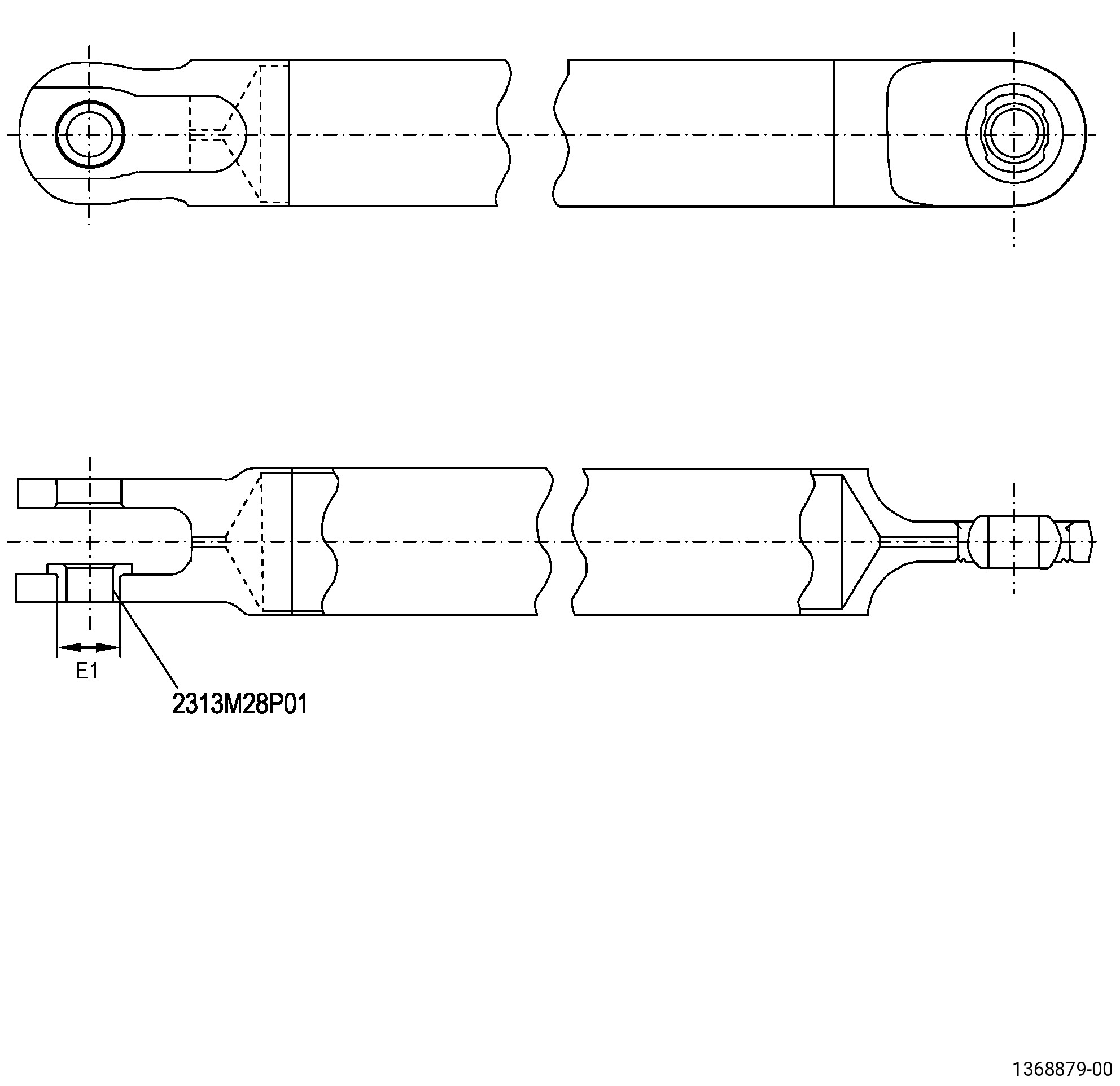
| A. | Refer to Figure 901 for specified dimensions and locations. |
| NOTE: |
|
| NOTE: |
|
|
| 4 . | Setup Information. |
| None. |
| 5 . | Procedure. |
| Subtask 72-64-12-930-001 |
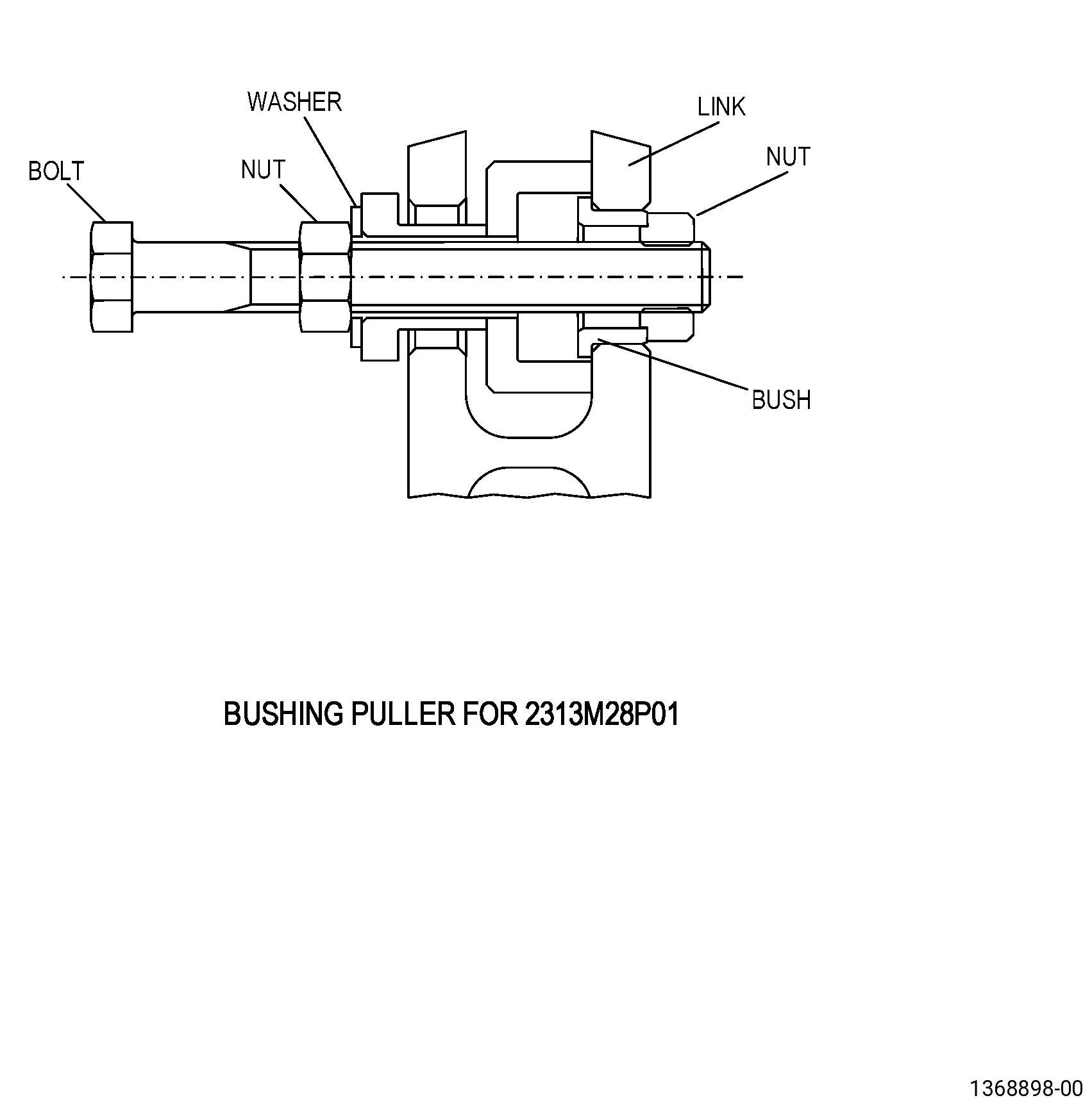
| A. | If necessary, make the bushing puller. Refer to Figure 902. |
| Subtask 72-64-12-350-012 |
| B. | Remove the damaged bushing from the link diameter E1. Refer to Figure 902 and as follows: |
| (1) | Assemble the bushing puller into the correct position. |
| (2) | Tighten the bushing puller bolt to pull the bushing through the hole. |
| WARNING: |
|
| CAUTION: |
|
| (3) | If necessary, make a small cut along the axis of the bushing to help release it. |
| Subtask 72-64-12-110-004 |
| C. | Etch the link repair area. Refer to TASK 70-24-00-110-033 (ETCHING PROCEDURES FOR FLUORESCENT-PENETRANT INSPECTION), TASK 70-24-01-110-034 (SWAB ETCHING PROCEDURE), and as follows: |
| (1) | Use Class C penetrant. |
| Subtask 72-64-12-230-002 |
| D. | Do an inspection of the link repair area. Refer to TASK 70-32-00-200-002 (INDIRECT INSPECTION METHODS), TASK 70-32-02-230-001 (FLUORESCENT PENETRANT INSPECTION), and as follows: |
| (1) | Use Class D penetrant. |
| (2) | Indications lower than 0.015 inch (0.4 mm) are permitted. |
| NOTE: |
|
| (3) | Discard the link if you find indications more than 0.015 inch (0.4 mm). |
| Subtask 72-64-12-220-019 |
| E. | Do an inspection of the link diameter E1. Refer to Subtask 72-64-12-220-018 (paragraph 3.A.), Figure 901, and as follows: |
| (1) | Do a visual inspection of the link diameter E1 and as follows: |
| (a) | If you find dents, nicks, scratches, or wear, discard the link. |
| (2) | Measure the link diameter E1 at the bushing location. |
| (3) | Discard link if the bushing hole size is more than the maximum in-process dimension. |
| Subtask 72-64-12-350-013 |
| F. | Install the new bushing, P/N 2313M28P01 , in the link bushing hole as follows: |
| Subtask 72-64-12-160-001 |
| (1) | Clean the link repair area. Refer to TASK 70-21-00-110-051 (CHEMICAL CLEANING) and TASK 70-21-23-110-053 (CLEANING METHOD NO. 23 - HAND-WIPE DEGREASING). |
| Subtask 72-64-12-350-014 |
| WARNING: |
|
| WARNING: |
|
| CAUTION: |
|
| (2) | Freeze the bushing, P/N 2313M28P01 , at a minimum temperature of -94°F (-70°C) or in liquid nitrogen. |
| WARNING: |
|
| (3) | Increase the temperature of the link to a range of 212 to 248°F (100 to 120°C). |
| (4) | Push the bushing, P/N 2313M28P01 , into the hole until the bushing shoulder is fully faced with the link shoulder. |
| (5) | Apply a load of 5000N to stake the bushing, P/N 2313M28P01 , in the correct position and keep it until the link and the bushing, P/N 2313M28P01 , get room temperature. |
| Subtask 72-64-12-210-002 |
| (6) | Do a check of the correct assembly with a 0.0012 inch (0.03 mm) feeler. |
| Subtask 72-64-12-220-020 |
| G. | Do an inspection of the link. Refer to TASK 72-64-12-200-801 (72-64-12, INSPECTION 001). |