| GENX-1B CLEANING,INSPECTION,AND REPAIR MANUAL | Dated: 11/30/2023 | |
| CIR 72-31-44, CLEANING 001 | ||
| HPC ROTOR STAGE 5 BLISK - CLEANING | ||
| GENX-1B CLEANING,INSPECTION,AND REPAIR MANUAL | Dated: 11/30/2023 | |
| CIR 72-31-44, CLEANING 001 | ||
| HPC ROTOR STAGE 5 BLISK - CLEANING | ||
| * * * FOR ALL |
| TASK 72-31-44-100-801 |
| 1. | General. |
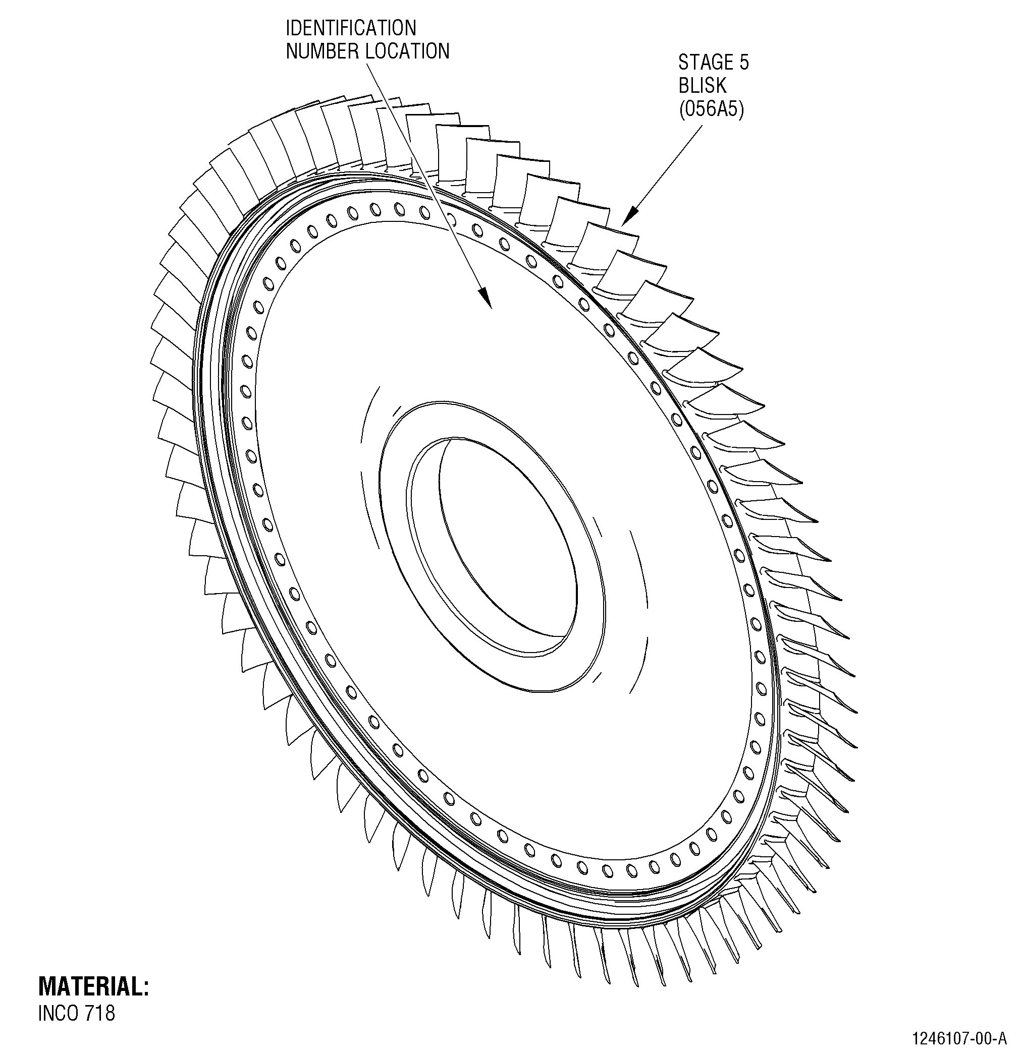
| A. | This procedure gives instructions to clean the HPC rotor stage 5 blisk (blisk) (01-490 ,72-31-00) (SIN 056A5) and (02-490 ,72-31-00) (SIN 056A5). Refer to Figure 601. |
| B. | Use the 11C3185 lift fixture to position, lift, or turn the blisk in the working area. Refer to Subtask 72-31-44-420-001 (paragraph 4.A.) for instructions about installation and removal of the tool. |
| 2. | Tools, Equipment, and Materials. |
| NOTE: |
|
| A. | Tools and Equipment. |
| (1) | Special Tools. |
|
| (2) | Standard Tools and Equipment. None |
| (3) | Locally Manufactured Tools. None. |
| B. | Consumable Materials. None |
| C. | Referenced Procedures. |
| D. | Expendable Parts. None. |
| 3 . | General Cleaning. |
| Subtask 72-31-44-160-002 |
| A. | Alternative Procedures Available. Steam clean the stage 5 blisk. Refer to TASK 70-21-03-160-001 (CLEANING METHOD 3 - STEAM CLEANING). |
| Subtask 72-31-44-160-003 |
| A.A. | Alternative Procedure. Heavy-duty alkaline clean the stage 5 blisk. Refer to TASK 70-21-06-110-004 (CLEANING METHOD 6 - HEAVY-DUTY ALKALINE CLEANER (WITHOUT INHIBITED PHOSPHORIC ACID)). |
| Subtask 72-31-44-120-011 |
| A.B. | Alternative Procedure. Dry abrasive blast clean the stage 5 blisk. Refer to TASK 70-21-04-120-B01 (Dry Abrasive Blast Cleaning Method 4B). |
| NOTE: |
|
| Subtask 72-31-44-120-012 |
| A.C. | Alternative Procedure. Dry abrasive blast clean the stage 5 blisk. Refer to TASK 70-21-04-120-E01 (DRY ABRASIVE BLAST CLEANING METHOD 4E). |
| NOTE: |
|
| Subtask 72-31-44-110-004 |
| A.D. | Alternative Procedure. Three-step heavy-duty alkaline descale the stage 5 blisk. Refer to TASK 70-21-07-110-005 (CLEANING METHOD 7 - THREE-STEP HEAVY-DUTY ALKALINE DESCALING (WITHOUT INHIBITED PHOSPHORIC ACID)). |
| Subtask 72-31-44-110-005 |
| A.E. | Alternative Procedure. Four-step alkaline clean and acidic descale the stage 5 blisk. Refer to TASK 70-21-10-110-008 (CLEANING METHOD 10 - FOUR-STEP ALKALINE CLEANING AND ACIDIC DESCALING (WITHOUT INHIBITED PHOSPHORIC ACID)) |
| Subtask 72-31-44-110-006 |
| A.F. | Alternative Procedure. Three-step heavy-duty alkaline descale the stage 5 blisk. Refer to TASK 70-21-17-110-037 (CLEANING METHOD 17 - THREE-STEP HEAVY-DUTY ALKALINE DESCALING (WITH INHIBITED PHOSPHORIC ACID)). |
| Subtask 72-31-44-110-007 |
| A.G. | Alternative Procedure. Four-step alkaline clean and acidic descale the stage 5 blisk. Refer to TASK 70-21-20-110-038 (CLEANING METHOD 20 - FOUR-STEP ALKALINE CLEANING AND ACIDIC DESCALING (WITH INHIBITED PHOSPHORIC ACID)). |
| Subtask 72-31-44-120-013 |
| A.H. | Alternative Procedure. Wet abrasive blast clean the stage 5 blisk with 500 grit aluminum oxide. Refer to TASK 70-21-05-120-B02 (WET ABRASIVE BLAST CLEANING METHOD 5B) and TASK 70-00-99-801-054 (S1054 - WET ABRASIVE BLASTING - ALUMINUM OXIDE 500 GRIT). |
| NOTE: |
|
| 4 . | Tool Installation and Removal. |
| Subtask 72-31-44-420-001 |
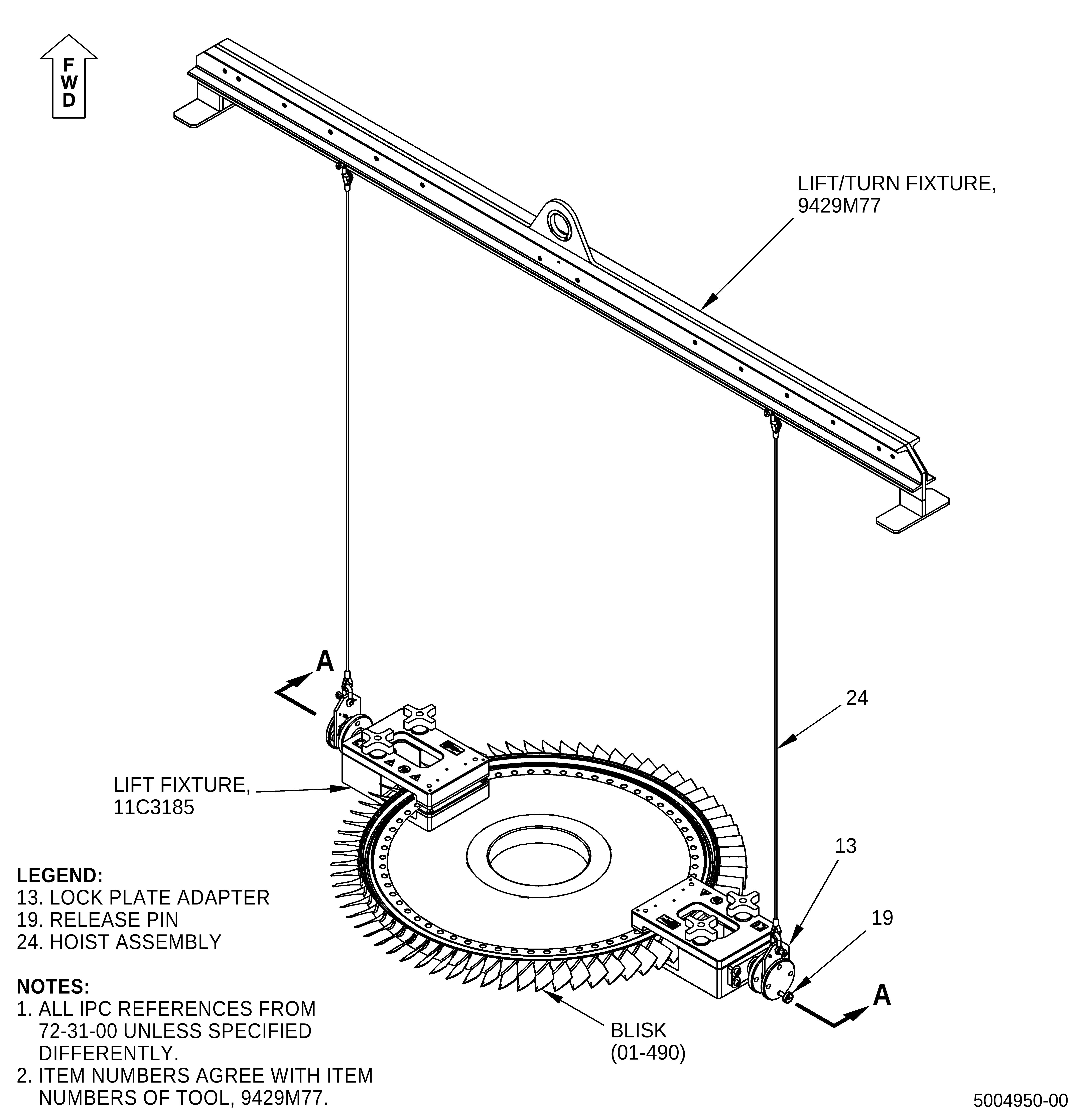
| A. | Install the 11C3185 lift fixture. Refer to Figure 602 and do as follows: |
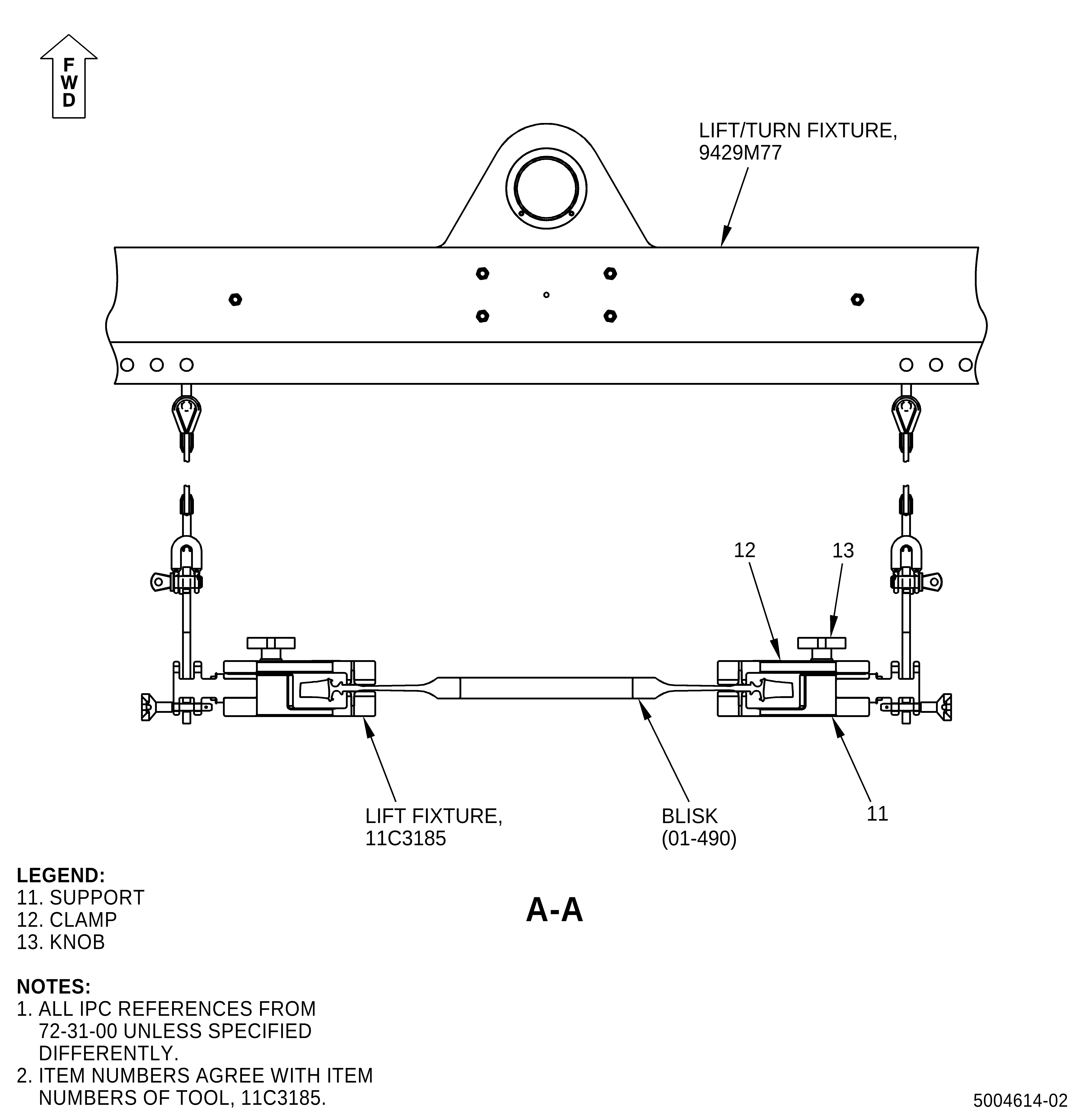
| (1) | Put the support (item 11) below the forward side of the blisk (01-490 ,72-31-00) (SIN 056A5). |
| (2) | Put the clamp (item 12) on the blisk (01-490 ,72-31-00) (SIN 056A5) and align it with the support (item 11). Use the holes on the two items as a reference. |
| (3) | Attach firmly the clamp (item 12) against the support (item 11) with the knob (item 13). |
| (4) | Install the other support (item 11) and clamp (item 12) assembly 180 degrees apart from the first assembly to make sure that the blisk (01-490 ,72-31-00) (SIN 056A5) is balanced when it is lifted. |
| (5) | Attach firmly the other clamp (item 12) against the support (item 11) with the knob (item 13). |
| (6) | Install the 9429M77 lift/turn fixture on the 11C3185 lift fixture. |
| (7) | Put the lock plate adapter (item 13) on the 11C3185 lift fixture and attach it with the release pin (item 19). |
| (8) | Use the 9429M77 lift/turn fixture to move the 11C3185 lift fixture. |
| Subtask 72-31-44-020-001 |
| B. | Remove the 11C3185 lift fixture. Refer to Figure 602 and do as follows: |
| (1) | Remove the 9429M77 lift/turn fixture from the 11C3185 lift fixture as follows: |
| (a) | Remove the release pin (item 19) and lock plate adapter (item 13) from the 11C3185 lift fixture. |
| (2) | Loosen the knob (item 13). |
| (3) | Remove the supports (item 11) and clamps (item 12) from the blisk (01-490 ,72-31-00) (SIN 056A5). |