| GENX-1B ENGINE MANUAL | Dated: 10/05/2023 | |
| EM 72-32-00 , ASSEMBLY 001 | ||
| HIGH PRESSURE COMPRESSOR FORWARD STATOR ASSEMBLY - ASSEMBLY 001 - CONFIGURATION 02 | ||
| GENX-1B ENGINE MANUAL | Dated: 10/05/2023 | |
| EM 72-32-00 , ASSEMBLY 001 | ||
| HIGH PRESSURE COMPRESSOR FORWARD STATOR ASSEMBLY - ASSEMBLY 001 - CONFIGURATION 02 | ||
| * * * FOR ALL PIP 2 |
| TASK 72-32-00-440-802 |
| 1 . | General. |
| A. | This procedure gives instructions to assemble the high pressure compressor (HPC) forward stator assembly (fwd stator assembly) (05-201 , 72-30-00) (SIN 07000). Refer to Figure 1001. |
| B. | Left and right sides of the forward stator assembly (15-011) (SIN 073A0) and case halves are always from aft looking forward (ALF). |
| C. | Make sure that you build the forward stator assembly in an area that has two hoists available. |
| D. | The upper forward stator assembly case half has four borescope ports and the lower forward stator assembly case half has built-in brackets. |
| 2 . | Tools, Equipment, and Materials. |
| NOTE: |
|
| A. | Tools and Equipment. |
| (1) | Special Tools. |
| (2) | Standard Tools and Equipment. |
|
| (3) | Locally Manufactured Tools. None. |
| B. | Consumable Materials. |
|
| C. | Referenced Procedures. |
|
| D. | Expendable Parts. |
|
| 3 . | Procedure. |
| Subtask 72-32-00-440-055 |
| A. | Install each forward case assembly (15-011) (SIN 073A0) half on a clean work table or on the 11C3301 adapter stand as follows: |
| NOTE: |
|
| NOTE: |
|
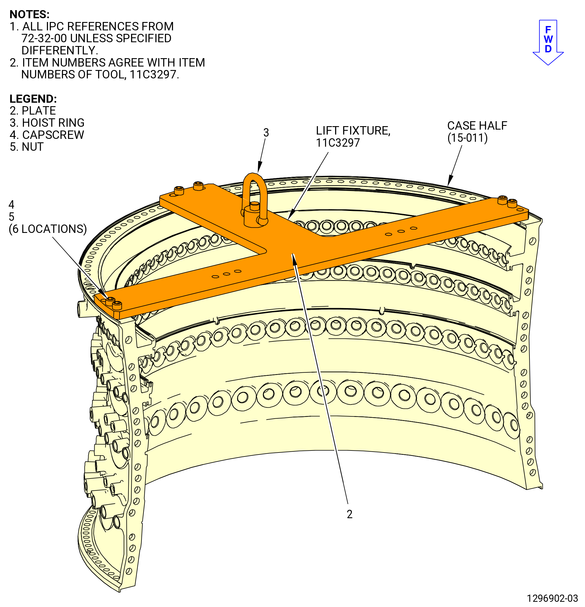
| (1) | Attach the 11C3297 lift fixture on the case half assembly. Refer to Figure 1002 and do as follows: |
| (a) | Put the plate (item 2) on the aft flange of the case half. |
| (b) | Align the boltholes of the plate (item 2) with the boltholes in the aft flange and attach the plate to the upper case half with six capscrews (item 4) and nuts (item 5). |
| (c) | Attach an overhead hoist to the hoist ring (item 3) of the 11C3297 lift fixture. |
| WARNING: |
|
| (2) | Lift the case half assembly and put the forward side down on the adapter (item 2) of the 11C3301 adapter stand. Make sure that the first and last boltholes in the forward flange are aligned with the holes in the support. Refer to Figure 1003. |
| (3) | Attach the case half assembly to the adapter (item 2) as follows: |
| (a) | Put the washers (item 4) on the top of the first and last holes of the forward flange. |
| (b) | Install the capscrews (item 3) through the washers, flange holes, and adapter (item 2) holes. |
| (c) | Attach the washers (item 4) and the nuts (item 5) to the capscrews (item 3) and tighten them. |
| (4) | Install the 26 bushings (01-070) (SIN 071T1) on the upper forward case assembly. |
| (5) | Install the 25 remaining bushings on the lower forward case assembly. |
| (6) | Make sure that the bushings are fully seated. |
| Subtask 72-32-00-440-056 |
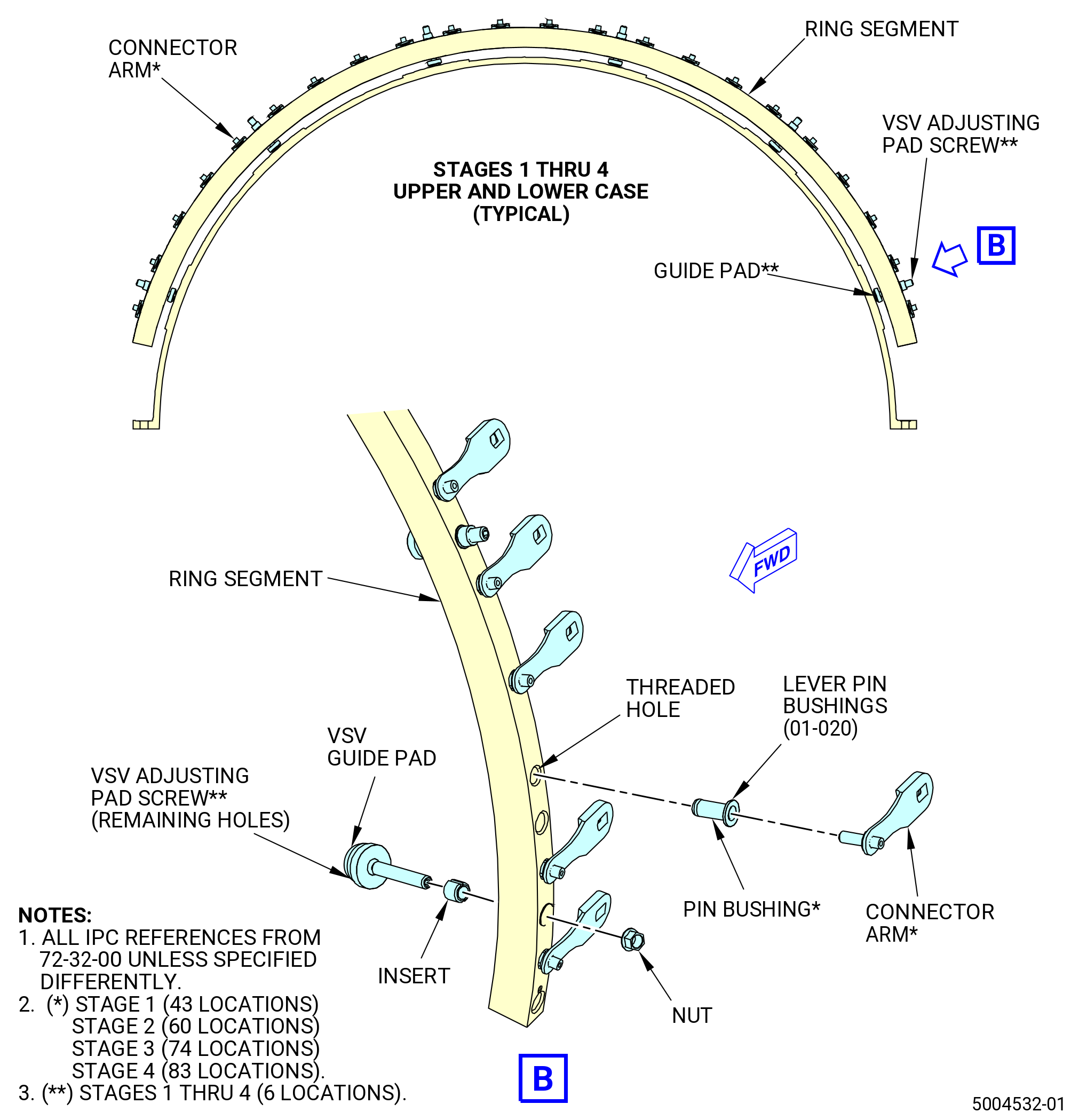
| B. | Assemble the variable stator vanes (VSV) adjusting pad screws and lever pin bushings (01-020) (SIN 071TB) into each of the stage 1-4 actuating rings (ring segments). Refer to Figure 1004 and do as follows: |
| (1) | Find all eight ring segments and make sure that you have the correct ring segments for each case half. The ring segments have marks for the correct identification as follows: |
| • |
|
| • |
|
| • |
|
| • |
|
| • |
|
| • |
|
| (2) | From the inboard side of the ring segment, install the long threaded end of the VSV adjusting pad screws into the ring insert. Turn the VSV adjusting pad screw clockwise (CW) in the ring segment until it turns freely. Refer to Figure 1004. |
| NOTE: |
|
| NOTE: |
|
| (3) | Attach the self-locking nut (nut) (01-010) (SIN 071K0) to the VSV adjusting pad screw on the outer side of the ring segment. |
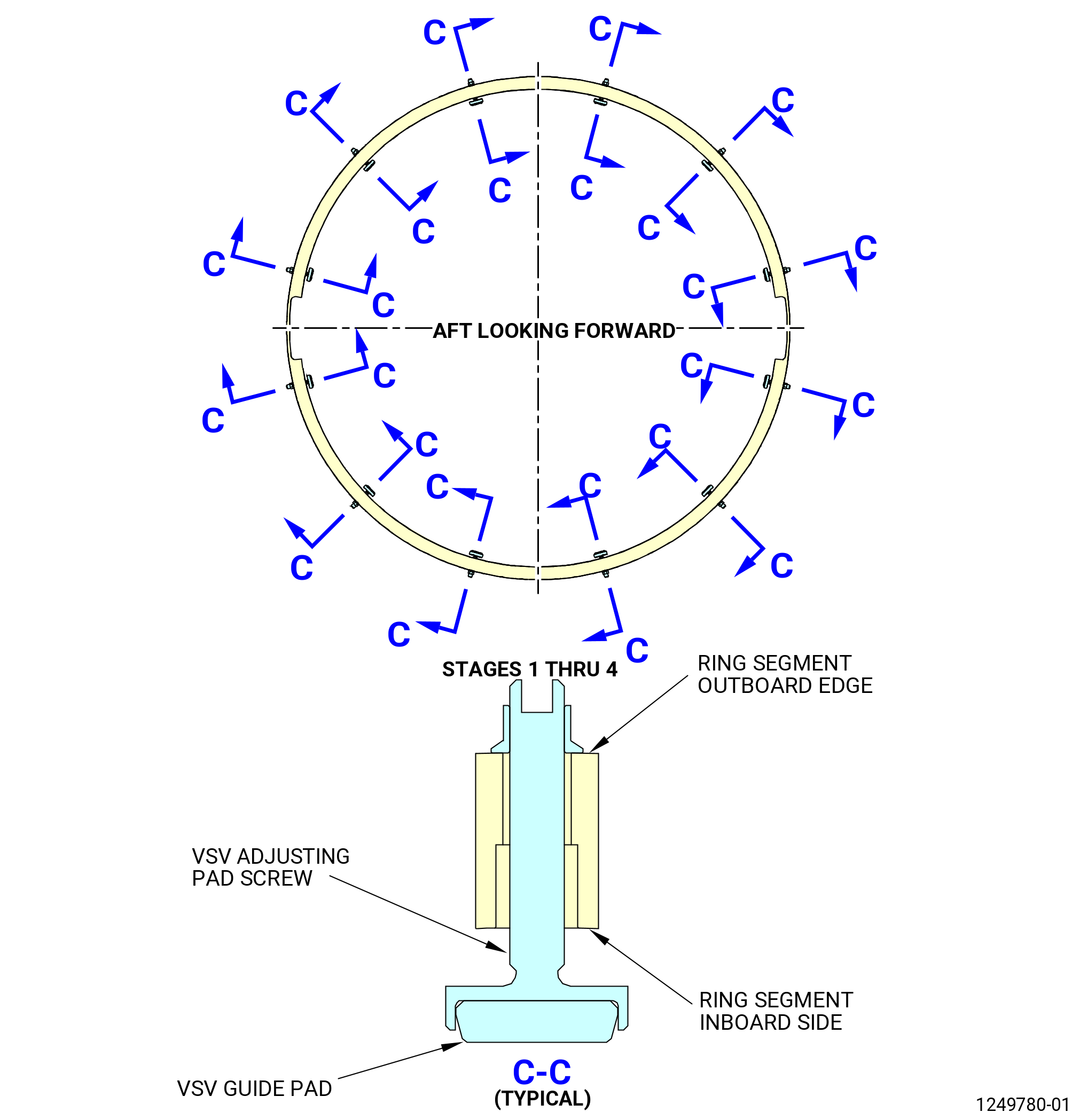
| (4) | Adjust each of the VSV adjusting pad screws of the ring segment to the limit of dimension A and dimension B. Refer to Figure 1005 and do as follows: |
| NOTE: |
|
| (a) | Stage 1 upper/lower ring segments (01-030) (SIN 071A1), (01-040) (SIN 071A6), dimension A: 0.301-0.311 inch (7.65-7.90 mm). |
| (b) | Stage 2 upper/lower ring segments (01-080) (SIN 071A2), dimension A: 0.386-0.396 inch (9.80-10.06 mm). |
| (c) | Stage 3 upper/lower ring segments (01-110) (SIN 071A3), dimension A: 0.296-0.306 inch (7.52-7.77 mm). |
| (d) | Stage 4 upper/lower ring segments (01-140) (SIN 071A4), (01-150) (SIN 071A9), dimension B: 0.296-0.300 inch (7.52-7.62 mm). |
| (5) | Hold the threaded end of the VSV adjusting pad screws with a hex-head wrench and torque the self-locking nut to 60.0-70.0 lb in. (6.78-7.91 N.m). Make sure that you do not turn the VSV adjusting pad screw, or dimension A or B can change. |
| (6) | Use the 11C3302 bushing pusher to install the lever pin bushings from the outboard side of the ring segment. Refer to Figure 1006 and do as follows: |
| (a) | Do not install a lever pin bushing in the last two holes on either side of a ring segment next to the splitline flange (eight holes in each stage). Those bushings will be installed in a later step. |
| (b) | Make sure that each bushing is fully installed in each hole where a connector arm will be installed. |
| (c) | Install the support bed (items 8 through 11) under the actuator ring segment. |
| NOTE: |
|
| (d) | Align the lever pin bushing in the bore where it will be installed with its protrude opposite to the segment ring. |
| (e) | Insert the mounting pin (item 2) in the internal diameter of the lever pin bushing. |
| (f) | Carefully tap the mounting pin (item 2) as necessary with a rubber hammer, until the lever pin bushing is fully seated. |
| (7) | Install the lever pin bushings in stage 1-4 ring segments. Refer to Subtask 72-32-00-440-056 (paragraph 3.B.(6)) and Figure 1004. |
| (a) | Install 43 lever pin bushings in the stage 1 ring segments. |
| (b) | Install 60 lever pin bushings in the stage 2 ring segments. |
| (c) | Install 74 lever pin bushings in the stage 3 ring segments. |
| (d) | Install 83 lever pin bushings in the stage 4 ring segments. |
| Subtask 72-32-00-440-057 |
| C. | Install the VSV and washers, into the upper and lower case half assemblies. Refer to Figure 1007 and do as follows: |
| NOTE: |
|
| (1) | Install the VSV with the leading edge forward from the inside of the case into the vane holes. Make sure that the leading edge of each VSV is facing forward (down) as follows: |
| • |
|
| • |
|
| • |
|
| • |
|
| Subtask 72-32-00-440-058 |
| (2) | Find each of the eight actuation ring segments and make sure that you have the correct ring segments for each case half. The ring segments have marks for the correct identification. Find the correct type and quantity lever arms for the segment you will install. |
| • |
|
| • |
|
| • |
|
| • |
|
| • |
|
| • |
|
| • |
|
| • |
|
| • |
|
| • |
|
| Subtask 72-32-00-220-007 |
| (3) | Do an inspection of all the VSV vanes for correct orientation as follows: |
| Subtask 72-32-00-440-080 |
| (a) | Alternative Procedure Available. Install the 11C4657 installation tool on the stage 1 vanes (10-042) (SIN 072A1). Starting from the left when facing the inside of a stator half-case, slide the stage 1/1 over the first several vanes. Resistance to the tool fitting over the vanes is likely an indication that there is a reversed vane. If there is resistance to the tool fitting over the vanes, remove the tool and do an inspection of the vane section for a reversed vane. If a vane is found in the reverse direction, correct the vane orientation. Refer to Figure 1008 and Figure 1009. |
| WARNING: |
|
| CAUTION: |
|
| CAUTION: |
|
| 1 | Do this procedure again for the remaining sections of stage 1 as well as for the tool stages 2-4. |
| 2 | Do not remove this tool now, this tool will also be used to restrain rotation while torquing the nuts (01-010) (SIN 071K0). |
| Subtask 72-32-00-220-008 |
| (a).A. | Alternative Procedure. Do a visual inspection to all the vanes to make sure that they are installed in right direction. No vane must be installed in the reverse direction. |
| Subtask 72-32-00-440-059 |
| CAUTION: |
|
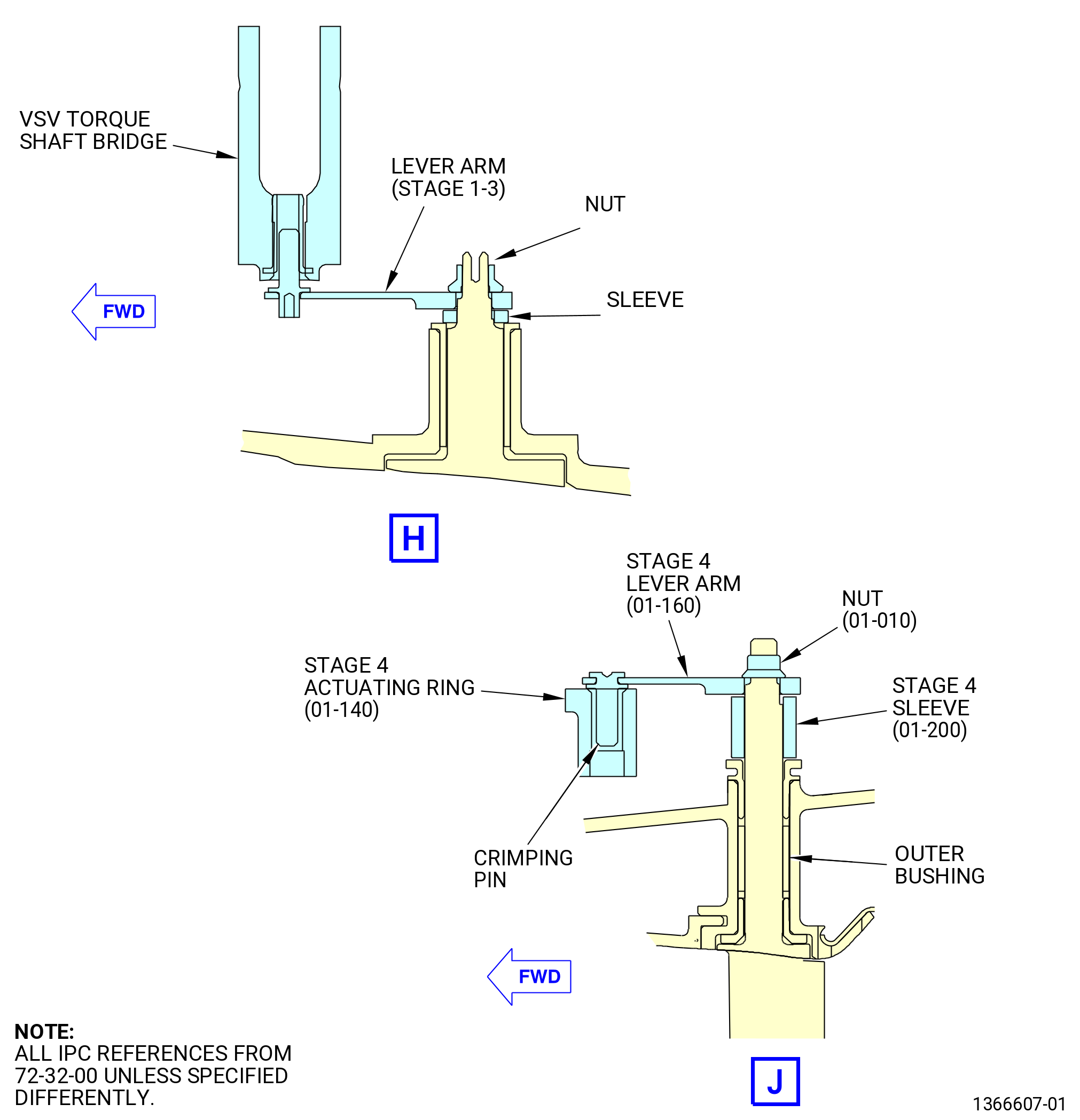
| (4) | Put a ring segment in position on the outside of the case and temporarily attach it to the case half assembly with three equally spaced sleeves (01-190) (SIN 071T3), (01-200) (SIN 071T4), and lever arms (01-050) (SIN 071D1), (01-090) (SIN 071D2), (01-120) (SIN 071D3), and (01-160) (SIN 071D4) (stage 1, 2, 3, and 4 respectively) and pushed onto the VSV. |
| (a) | Insert the crimping pin of each lever arm into the related bushing in the ring segment. |
| (b) | Make sure that the flat side of the lever arm hole touches the flat side of the tip of the VSV. Make sure that the rounded side of the lever arm hole touches the rounded side of the tip of the VSV. Refer to Figure 1007. |
| NOTE: |
|
| Subtask 72-32-00-440-060 |
| (5) | Install the remaining lever arms (01-050) (SIN 071D1), (01-090) (SIN 071D2), (01-120) (SIN 071D3), and (01-160) (SIN 071D4) (stage 1, 2, 3, and 4 respectively), and rigging lever arms (01-180) (SIN 071C0) on the ring segments. Make sure that four rigging lever arms (01-180) (SIN 071C0) are installed in correct vane locations as follows: |
| • |
|
| • |
|
| • |
|
| • |
|
| NOTE: |
|
| Subtask 72-32-00-440-061 |
| (6) | Push the lever arms on the VSV with the crimping pin pointed inward into the ring segment. |
| (7) | Make sure that the flat side of the lever arm hole touches the flat side of the tip of the VSV. |
| (8) | Make sure that the rounded side of the lever arm hole touches the rounded side of the tip of the VSV. Refer to Figure 1007. |
| (9) | Do not install lever arms on the last two vanes on each side of the split line flange on any of the stages 1-4. Those lever arms will be installed in a later step. |
| (10) | Attach the nuts (01-010) (SIN 071K0) to the threads of the VSV and tighten them by hand. |
| Subtask 72-32-00-440-081 |
| (11) | Alternative Procedure Available. Torque the nuts (01-010) (SIN 071K0) as follows: |
| (a) | For the installation of the 11C4657 installation tool on stages 1, 2, 3, and 4. Refer to Subtask 72-32-00-440-080 (paragraph 3.C.(3)(a)), Figure 1008, and Figure 1009. |
| (b) | Torque the nuts (01-010) (SIN 071K0) to 58 to 66 lb in. (6.6 to 7.4 Nm). |
| (c) | Manually turn the VSVs to make sure that they do not interfere with the case half assembly. |
| Subtask 72-32-00-440-082 |
| (11).A. | Alternative Procedure. Torque the nuts (01-010) (SIN 071K0) as follows: |
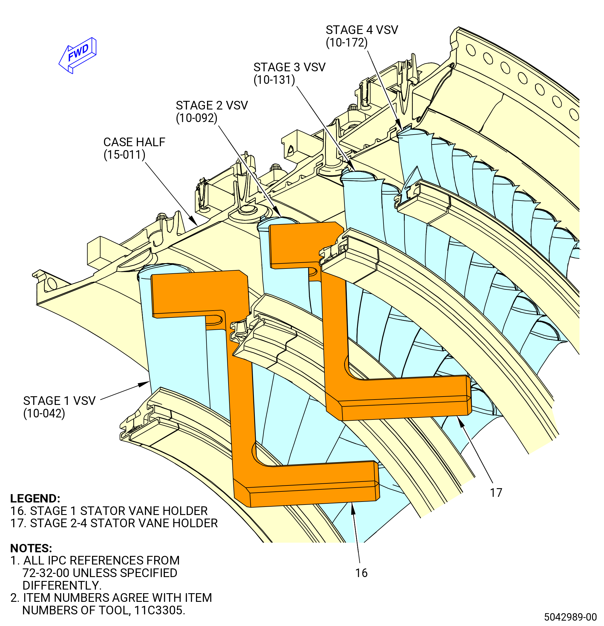
| (a) | Install the 11C3305 countertorque tool to hold the stages 1, 2, 3, and 4 ring segments (01-030) (SIN 071A1), (01-040) (SIN 071A6), (01-080) (SIN 071A2), (01-110) (SIN 071A3), (01-140) (SIN 071A4), and (01-150) (SIN 071A9). Refer to Figure 1010 and do as follows: |
| 1 | Put the block (item 6) on the stages 1,2, 3, and 4 upper/lower sectors (item 2, item 3, item 4, item 5, item 13, and item 14). |
| 2 | Install the capscrew (item 19) to attach the block (item 6) to the stages 1, 2, 3, and 4 upper/lower sectors (item 2, item 3, item 4, item 5, item 13, and item 14). |
| 3 | Put the upper stage 1 sector (item 2) (STG 1 UPPER) on the stage 1 upper ring segment (01-030) (SIN 071A1). |
| 4 | Put the lower stage 1 sector (item 14) (STG 1 LOWER) on the stage 1 lower ring segment (01-040) (SIN 071A6). |
| 5 | Put the stage 2 sector (item 3) (STG 2) on the upper and lower stage 2 ring segment (01-080) (SIN 071A2). |
| 6 | Put the stage 3 sector (item 4) (STG 3) on the upper and lower stage 2 ring segment (01-110) (SIN 071A3). |
| 7 | Put the upper stage 4 sector (item 5) (STG 4 UPPER) on the stage 4 upper ring segment (01-140) (SIN 071A4). |
| 8 | Put the lower stage 4 sector (item 13) (STG 4 LOWER) on the stage 4 lower ring segment (01-150) (SIN 071A9). |
| 9 | Tighten the two threaded screws (item 17) to attach the stages 1, 2, 3, and 4 upper/lower sectors (item 2, item 3, item 4, item 5, item 13, and item 14) to the stages 1, 2 ,3 and 4 ring segments (01-030) (SIN 071A1), (01-040) (SIN 071A6), (01-080) (SIN 071A2), (01-110) (SIN 071A3), (01-140) (SIN 071A4), and (01-150) (SIN 071A9). |
| NOTE: |
|
| 10 | Torque the nuts (01-010) (SIN 071K0) to 58 to 66 lb in. (6.6 to 7.4 Nm). |
| (b) | Manually turn the VSVs to make sure that they do not interfere with the case half assembly. |
| (c) | Remove the 11C3305 countertorque tool from stages 1, 2, 3, and 4. |
| Subtask 72-32-00-440-083 |
| (12) | Deleted. |
| Subtask 72-32-00-440-062 |
| (13) | Install the lever arms with the crimping pins pointed outward on the last two VSVs on each side of the split line flange on the stages 1-4 on the upper and lower case assemblies as follows: |
| • |
|
| • |
|
| • |
|
| • |
|
| Subtask 72-32-00-440-063 |
| (14) | Attach the nuts (01-010) (SIN 071K0) to the threads of the tip of the VSV and tighten them by hand. |
| Subtask 72-32-00-440-084 |
| (15) | Alternative Procedure Available. Torque the nuts (01-010) (SIN 071K0) as follows: |
| (a) | For the installation of the 11C4657 installation tool on the stages 1, 2, 3 and 4 vanes. Refer to Subtask 72-32-00-440-080 (paragraph 3.C.(3)(a)) , Figure 1008 and Figure 1009. |
| (b) | Torque the nuts (01-010) (SIN 071K0) to 58 to 66 lb in. (6.6 to 7.4 Nm). |
| (c) | Remove the 11C4657 installation tool from all stages 1, 2, 3, and 4. |
| Subtask 72-32-00-440-085 |
| (15).A. | Alternative Procedure. Torque the nuts (01-010) (SIN 071K0) as follows: |
| (a) | Put the stage 1 stator vane holder (item 16) of the 11C3305 countertorque tool on the stage 1 VSV (10-042) (SIN 072A1). |
| (b) | Put the stages 2, 3, and 4 stator vane holder (item 17) of the 11C3305 countertorque tool on the stages 2, 3, and 4 VSV (10-092) (SIN 072A2), (10-131) (SIN 072A3), and (10-172 ) (SIN 072A4). |
| (c) | Torque the nuts (01-010) (SIN 071K0) to 58 to 66 lb in. (6.6 to 7.4 Nm). |
| (d) | Remove the 11C3305 countertorque tool from the stage 1 stator vane holder (item 16) and the stages 2, 3, and 4 stator vane holder (item 17). |
| Subtask 72-32-00-440-086 |
| (16) | Deleted. |
| Subtask 72-32-00-440-064 |
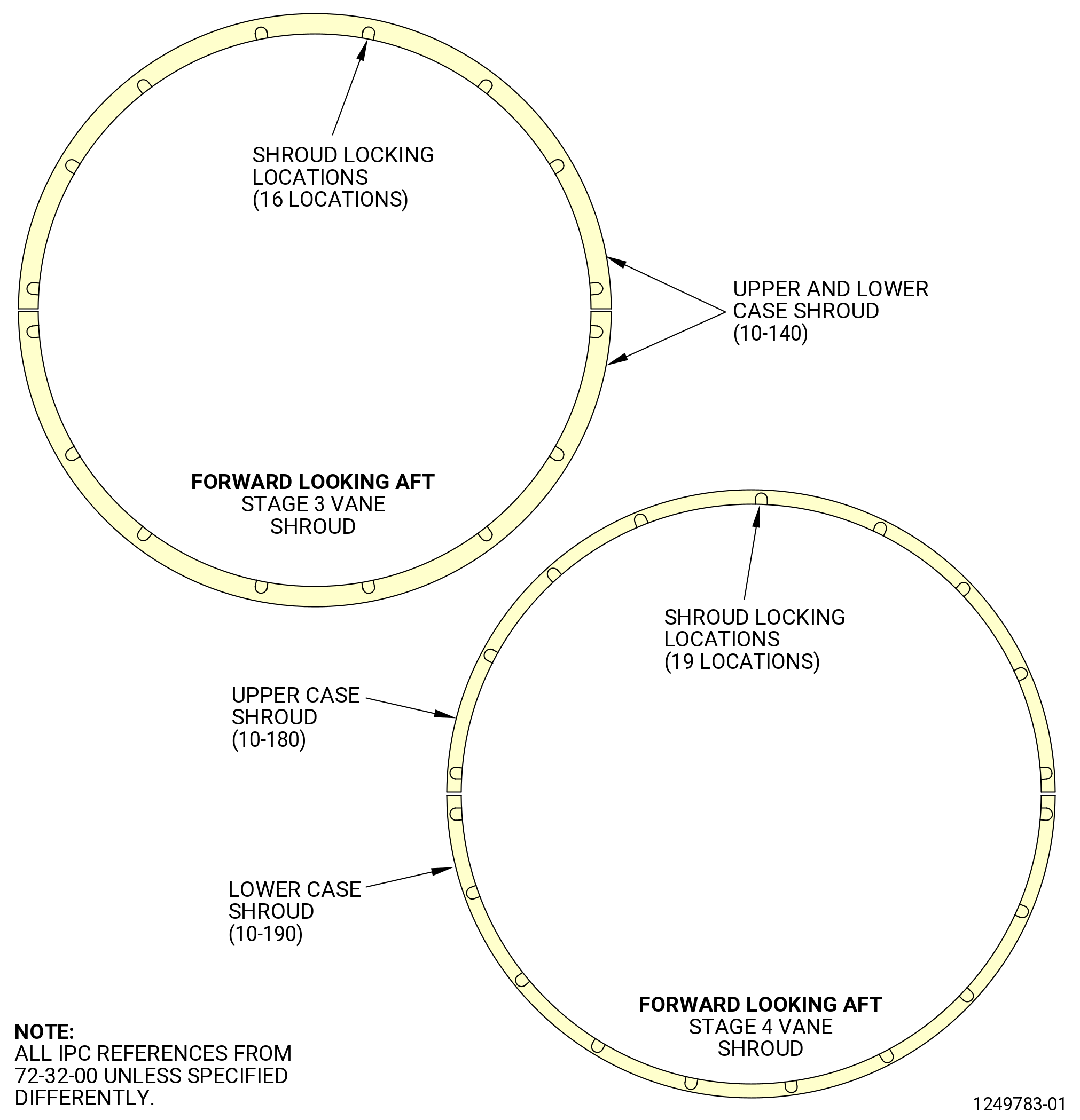
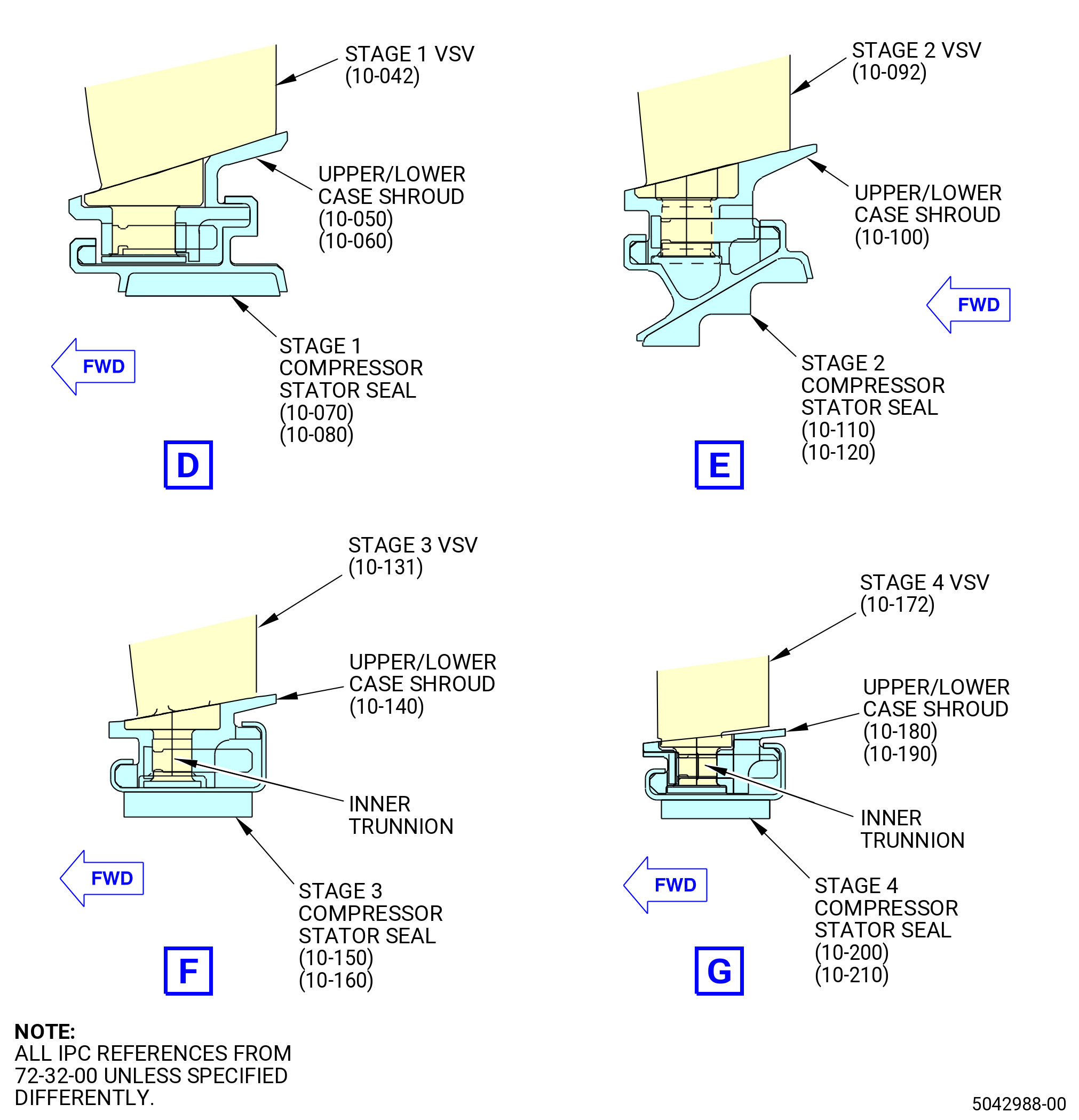
| D. | Install the stages 1-4 compressor stator vane shrouds (vane shrouds) (10-050) (SIN 071B1), (10-060) (SIN 071B6), (10-100) (SIN 071B2), (10-140) (SIN 071B3), (10-180) (SIN 071B4), and (10-190) (SIN 071B9). Refer to Figure 1007 and do as follows: |
| NOTE: |
|
| (1) | Install the stage 4 shrouds (10-180) (SIN 071B4), (10-190) (SIN 071B9) as follows: |
| NOTE: |
|
| (a) | Install the upper case vane shroud (10-180) (SIN 071B4) on the inner trunnions of the vanes and on the upper case half assembly. |
| (b) | Install the lower case vane shroud (10-190) (SIN 071B9) on the inner trunnions of the vanes and on the lower case half assembly. |
| (c) | Install the bolts (10-020) (SIN 071F1) and nuts (10-030) (SIN 071K2) with the flat of the bolt head facing inboard on the stage 4 upper/lower case vane shrouds. |
| (d) | Torque the nuts to 32-38 lb in. (3.7-4.3 N.m). |
| (2) | Install the stage 3 vane shrouds (10-140) (SIN 071B3) as follows: |
| NOTE: |
|
| (a) | Put the upper and lower case vane shrouds (10-140) (SIN 071B3) on the inner trunnion of the vanes. |
| (b) | Install the bolts (10-020) (SIN 071F1) and nuts (10-030) (SIN 071K2) with the flat of the bolt head pointing inboard on the stage 3 upper/lower case shrouds. |
| (c) | Torque the nuts to 32-38 lb in. (3.7-4.3 N.m). |
| (3) | Install the stage 2 vane shrouds (10-100) (SIN 071B2) as follows: |
| NOTE: |
|
| (a) | Put the upper and lower case vane shrouds (10-100) (SIN 071B2) on the inner trunnions of the vanes. |
| (b) | Install the bolts (10-020) (SIN 071F1) and nuts (10-030) (SIN 071K2) with the flat of the bolt head facing inboard on the stage 2 upper/lower case shrouds. |
| (c) | Torque the nuts to 32-38 lb in. (3.7-4.3 N.m). |
| (4) | Install the stage 1 vane shrouds (10-050) (SIN 071B1), (10-060) (SIN 071B6) as follows: |
| NOTE: |
|
| (a) | Install the upper case vane shroud (10-050) (SIN 071B1) on the inner trunnions of the vanes and on the upper case half assembly. |
| (b) | Install the lower case vane shroud (10-060) (SIN 071B6) on the inner trunnions of the vanes and on the lower case half assembly. |
| (c) | Install the bolts (10-020) (SIN 071F1) and nuts (10-030) (SIN 071K2) with the flat of the bolt head facing inboard on the stage 1 upper/lower case vane shrouds. |
| (d) | Torque the nuts to 32-38 lb in. (3.7-4.3 N.m). |
| Subtask 72-32-00-440-065 |
| E. | Install the stages 1-4 HPC compressor stator seals (stator seals). Refer to Figure 1007 and do as follows: |
| • |
|
| • |
|
| • |
|
| • |
|
| NOTE: |
|
| WARNING: |
|
| (1) | Apply a large quantity of C02-008 petrolatum to the stator seals where they will mate with the vane shroud slots. |
| CAUTION: |
|
| (2) | Use your hand to slide the stator seals into place against the vane shroud slots. Begin sliding the stator seals at the horizontal split line as follows: |
| (a) | The stator seals (10-070) (SIN 076A1), (10-110) (SIN 076A2), (10-150) (SIN 076A3), (10-200) (SIN 076A4) will be installed from the 3:00 o'clock split line to the 12:00 o'clock position and from the 9:00 o'clock split line to the 6:00 o'clock position. |
| (b) | The stator seals (10-080) (SIN 076AA), (10-120) (SIN 076AB), (10-160) (SIN 076AC), (10-210) (SIN 076AD) will be installed from the 3:00 o'clock split line to the 6:00 o'clock position and from the 9:00 o'clock split line to the 12:00 o'clock position. |
| (3) | Make sure that the stator seals are seated correctly against the upper and lower vane shrouds. Make sure that the ends of the stator seals do not extend past the split line flange. Make sure that after assembly, the stage 3 stator seal (10-160) (SIN 076AC) and stage 4 stator seal (10-210) (SIN 076AD) sit flush with the upper and lower vane shrouds. Refer to Figure 1011 for comparison. If the seals do not sit flush per Figure 1011, refer to TASK 72-32-09-100-803 (72-32-09, INSPECTION 001) Subtask 72-32-09-220-031 for HPC stator stage 3 vane shrouds or TASK 72-32-10-200-801 (72-32-10, INSPECTION 001) Subtask 72-32-10-220-004 for HPC stator stage 4 vane shrouds, for repair options. |
| Subtask 72-32-00-440-066 |
| F. | Actuate by hand each ring segment and each lever arm that is not captured by a ring segment. Make sure that the ring segment moves smoothly with no binding. If too much force is necessary, do a check for assembly errors and correct. |
| Subtask 72-32-00-440-067 |
| * * * PRE SB 72-0305( Old Aft Covers Configuration ) |
| G. | Install the aft covers (15-021) (SIN 070AG) and (15-041) (SIN 070AJ) on the rear flanges of the compressor case half assembly. Refer to Figure 1012. |
| WARNING: |
|
| (1) | If necessary, clean the rails on the upper/lower case half assembly and the aft covers with C04-035 isopropyl alcohol. |
| WARNING: |
|
| (2) | Apply a thin film of C02-008 petrolatum to the edges installed first in the case assembly. |
| (3) | Manually move the aft covers (15-021) (SIN 070AG) and (15-041) (SIN 070AJ) in the upper half case assembly. The aft cover (15-041) (SIN 070AJ) will be installed from the 12:00 o'clock to the 3:00 o'clock of the case assembly. The aft cover (15-021) (SIN 070AG) will be installed from the 9:00 o'clock to the 12:00 o'clock of the case assembly. Move the aft cover around until the stop seats against the case assembly. |
| (4) | Manually move the aft covers (15-021) (SIN 070AG) and (15-041) (SIN 070AJ) in the lower half case assembly. The aft cover (15-021) (SIN 070AG) will be installed from the 3:00 o'clock to the 6:00 o'clock of the case assembly. The aft cover (15-041) (SIN 070AJ) will be installed from the 6:00 o'clock to the 9:00 o'clock of the case assembly. Move the aft cover around until the stop seats against the case assembly. |
| * * * END PRE SB 72-0305( ) |
| Subtask 72-32-00-440-087 |
| * * * SB 72-0305( New Aft Covers Configuration ) |
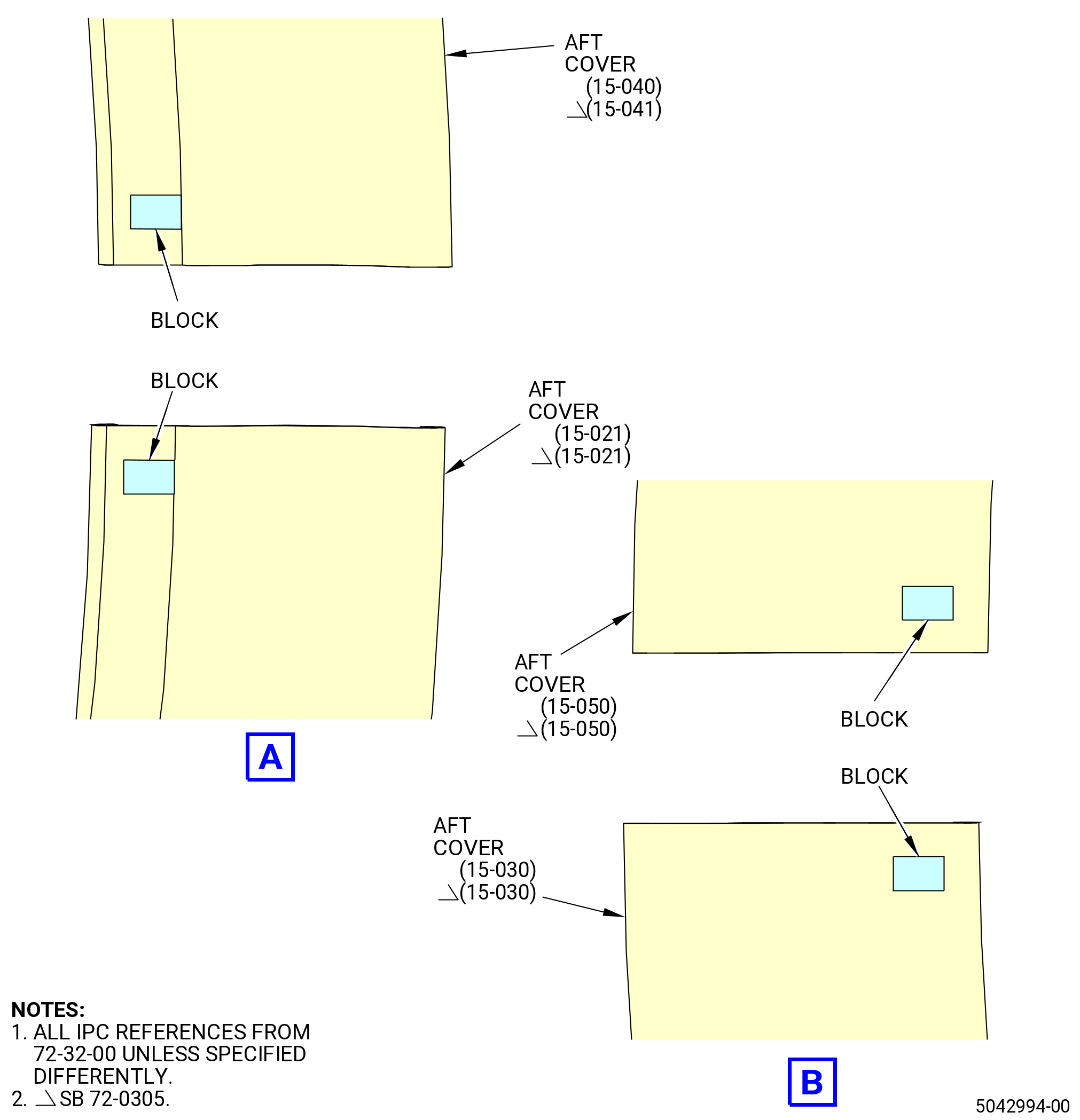
| G.A. | Install the aft covers (15-021) (SIN 070AG), (15-041) (SIN 070AJ), (15-030) (SIN 070AR), and (15-050) (SIN 070AS) or (15-021) (SIN 070AG), (15-040) (SIN 070AJ), (15-030) (SIN 070AR), and (15-050) (SIN 070AS) on the rear flanges of the compressor case half assembly. Refer to Figure 1012 and do as follows: |
| WARNING: |
|
| (1) | If necessary, clean the rails on the upper/lower case half assembly and the aft covers with C04-035 isopropyl alcohol. |
| WARNING: |
|
| (2) | Apply a thin film of C02-008 petrolatum to the edges installed first in the case assembly. |
| (3) | Manually move the aft covers (15-041) (SIN 070AJ) or (15-040) (SIN 070AJ) and (15-050) (SIN 070AS) in the upper half case assembly. The aft cover (15-041) (SIN 070AJ) or (15-040) (SIN 070AJ) will be installed from the 12:00 o'clock to the 3:00 o'clock position of the case assembly. The aft cover (15-050) (SIN 070AS) will be installed from the 9:00 o'clock to the 12:00 o'clock position of the case assembly. Move the aft cover around until the stop seats against the case assembly. |
| NOTE: |
|
| (4) | Manually move the aft covers (15-021) (SIN 070AG) and (15-030) (SIN 070AR) in the lower half case assembly. The aft cover (15-021) (SIN 070AG) will be installed from the 3:00 o'clock to the 6:00 o'clock position of the case assembly. The aft cover (15-030) (SIN 070AR) will be installed from the 6:00 o'clock to the 9:00 o'clock position of the case assembly. Move the aft cover around until the stop seats against the case assembly. |
| NOTE: |
|
| * * * END SB 72-0305 |
|
|
|
|
| Subtask 72-32-00-220-010 |
| H. | Do a visual inspection of the borescope plugs and ports. Refer to TASK 72-00-00-800-804 (72-00-00, SPECIAL PROCEDURE 004) (paragraph 5.A. and 5.B.). |
| Subtask 72-32-00-440-068 |
| * * * PRE SB 72-0246 |
| I. | Install the borescope plugs (05-010) (SIN 070AK) stage 2, (05-020) (SIN 070AL) stage 3, (05-030) (SIN 070AM) stage 4, and (05-040) (SIN 070AB) stage 5 into the upper half case assembly. Refer to Figure 1012 and do as follows: |
| (1) | Make sure that a 0.250 inch (6.35 mm) minimum diameter pin will pass through each borescope hole in the upper half case assembly. |
| WARNING: |
|
| (2) | Apply C02-071 anti-seize to the threads and friction surfaces of each borescope plug. |
| (3) | Turn the borescope plugs into the borescope ports until tight. |
| (4) | Torque the borescope plugs to 81-95 lb in. (9.2-10.7 N.m). |
| (5) | After the plug has been torqued, perform a visual inspection of the plug and make sure that the locking feature is fully engaged with the lug on the borescope boss. Also make sure that the head of the borescope plug is fully seated against the borescope boss. If one of the two conditions are not met, the ratcheting feature of the plug can be seized or locked. Apply a penetrating oil directly in between the locking ring and the head of the plug. Re-apply torque to the plug until the plug begins to rotate freely. Tighten the plug from 81 to 95 lb in. (9.2 to 10.7 Nm). Do the visual inspection again before proceeding. If the conditions above cannot be met, replace the plug. Refer to Figure 1013. |
| * * * END PRE SB 72-0246 |
| Subtask 72-32-00-440-091 |
| * * * SB 72-0246 |
| I.A. | Install the borescope plugs (05-010) (SIN 070AK) stage 2, (05-020) (SIN 070AL) stage 3, (05-030) (SIN 070AM) stage 4, and (05-040) (SIN 070AB) stage 5 into the upper half case assembly. Refer to Figure 1012 and do as follows: |
| (1) | Make sure that a 0.250 inch (6.35 mm) minimum diameter pin will pass through each borescope hole in the upper half case assembly. |
| WARNING: |
|
| (2) | Apply C02-071 anti-seize to the threads and friction surfaces of each borescope plug. |
| (3) | Turn the borescope plugs into the borescope ports until tight. |
| (4) | Torque the borescope plugs to 81 to 95 lb in. (9.2 to 10.7 Nm). |
| * * * END SB 72-0246 |
|
|
| Subtask 72-32-00-440-069 |
| J. | Install the 32 lever pin bushings (02-470 , 72-30-00) (SIN 071TB) into the stages 1-4 actuation ring bridges (bridges) (01-320 , 72-30-00) (SIN 071E1), (01-270 , 72-30-00) (SIN 071E2), (01-280 , 72-30-00) (SIN 071E3), (01-310 , 72-30-00) (SIN 071E4), (01-260 , 72-30-00) (SIN 071E6), and (01-290 , 72-30-00) (SIN 071E9). Refer to Figure 1014 and do as follows: |
| NOTE: |
|
| (1) | Align the lever pin bushing in the bore where it will be installed with its protrude opposite to the bridge. |
| (2) | Insert the mounting pin (item 2) of the 11C3302 bushing pusher in the internal diameter of the lever pin bushing. |
| (3) | Carefully tap the mounting pin (item 2) as necessary with a rubber hammer, until the bushing is fully seated. |
| Subtask 72-32-00-440-070 |
| K. | Install the two VSV actuator supports (05-050) (SIN 075C0). Refer to Figure 1015 and do as follows: |
| (1) | Install one VSV actuator support on each case assembly half with the bolts (05-060) (SIN 075F3). The VSV actuator support boltholes are between the stages 1 and 2 VSV holes, between 35 and 60 degrees CCW from the horizontal centerline of the case assembly. |
| WARNING: |
|
| (2) | Lubricate the threads of the bolts with C02-058 lubricant. |
| (3) | Torque the bolts (05-060) (SIN 075F3) to 106-124 lb in. (12.0-14.0 N.m). |
| (4) | Make sure that all of the vane holes in each stage of the case half assembly have a inner bushing and an outer bushing. |
| Subtask 72-32-00-440-071 |
| L. | Put the remaining parts that you will install at the next higher assembly level in bags as follows: |
| • |
|
| • |
|
| • |
|
| • |
|
| • |
|