| GENX-1B ENGINE MANUAL | Dated: 02/26/2025 | |
| EM 72-00-00 , SPECIAL PROCEDURES 004 | ||
| ENGINE ASSEMBLY - SPECIAL PROCEDURE - ENGINE BORESCOPE INSPECTION | ||
| GENX-1B ENGINE MANUAL | Dated: 02/26/2025 | |
| EM 72-00-00 , SPECIAL PROCEDURES 004 | ||
| ENGINE ASSEMBLY - SPECIAL PROCEDURE - ENGINE BORESCOPE INSPECTION | ||
| * * * FOR ALL |
| TASK 72-00-00-800-804 |
| 1 . | General |
| A. | This procedure gives instructions to prepare the borescope inspection of the engine. |
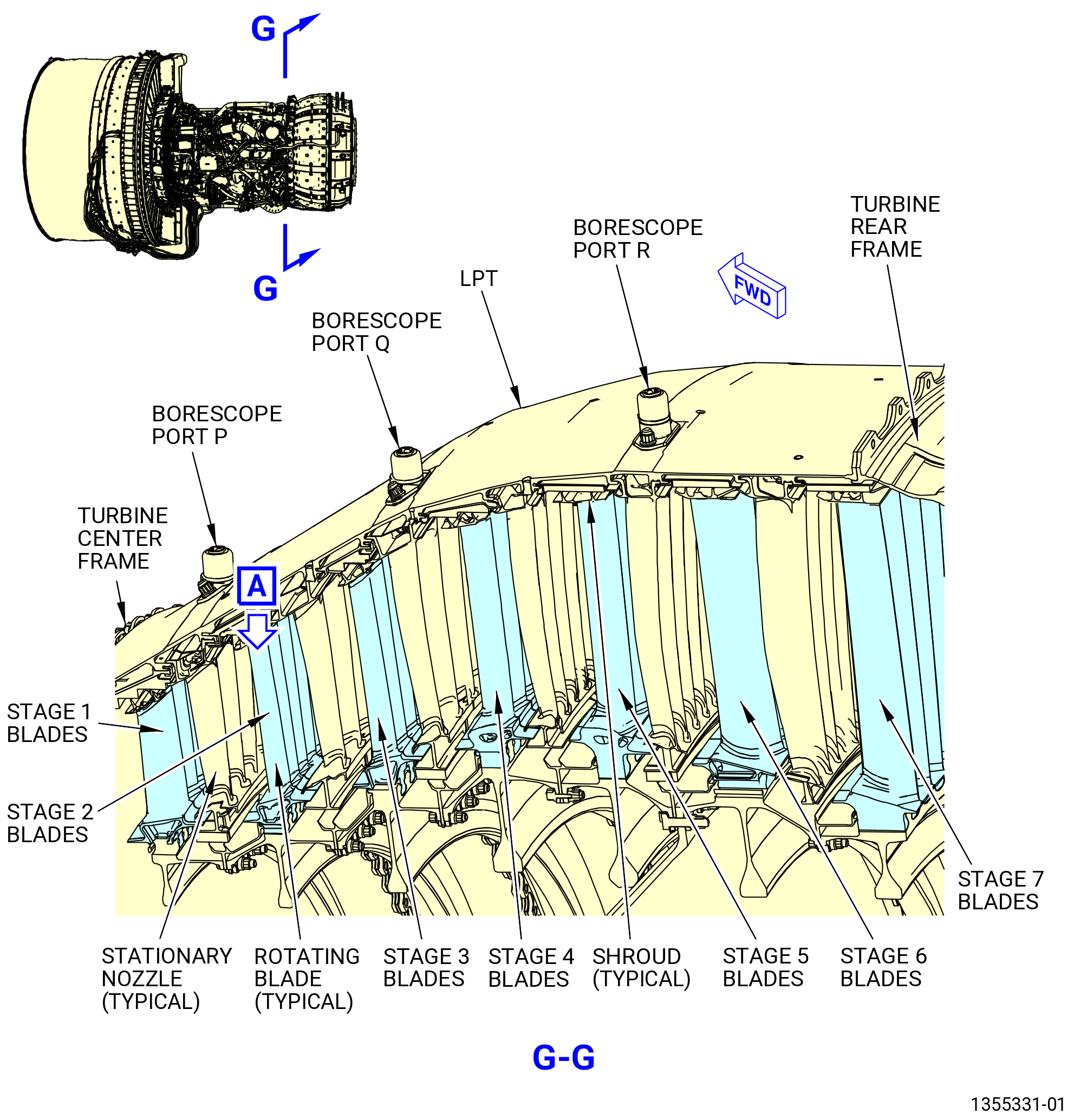
| B. | The borescope procedure can be used to inspect the gas path of the primary airstream. |
| C. | These are the sections of the engine that can be inspected with the borescope procedure: |
| • |
|
| • |
|
| • |
|
| • |
|
| • |
|
| • |
|
| • |
|
| • |
|
| • |
|
| • |
|
| • |
|
| • |
|
| • |
|
| • |
|
| • |
|
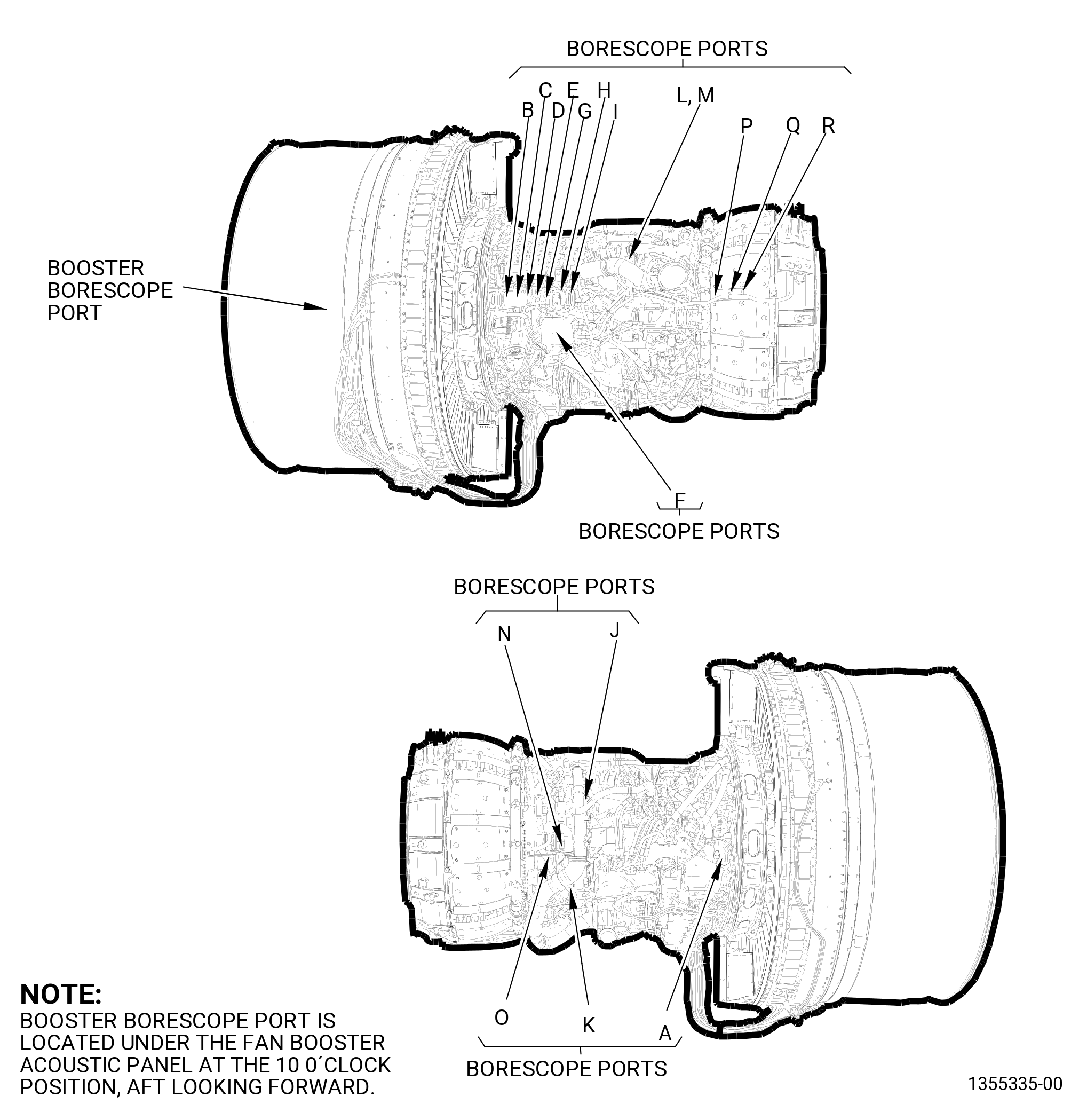
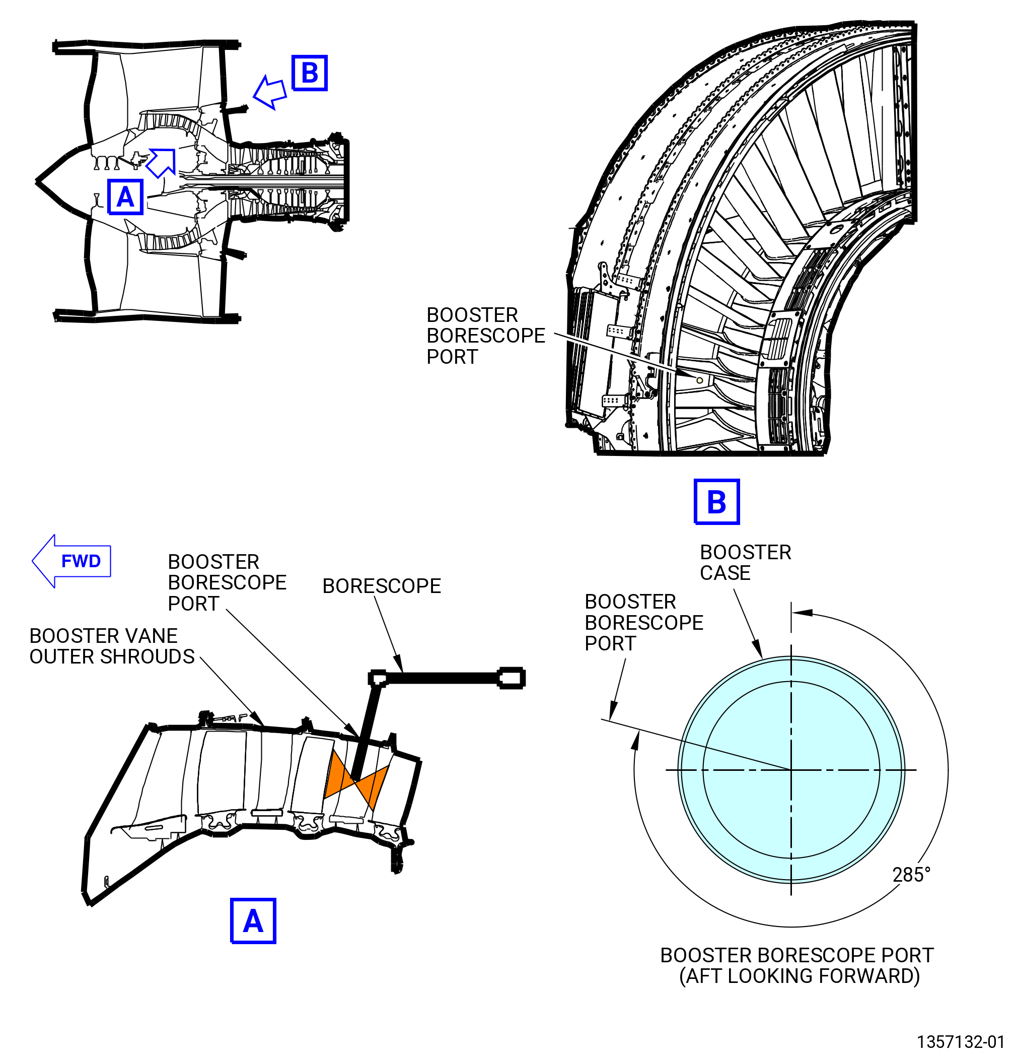
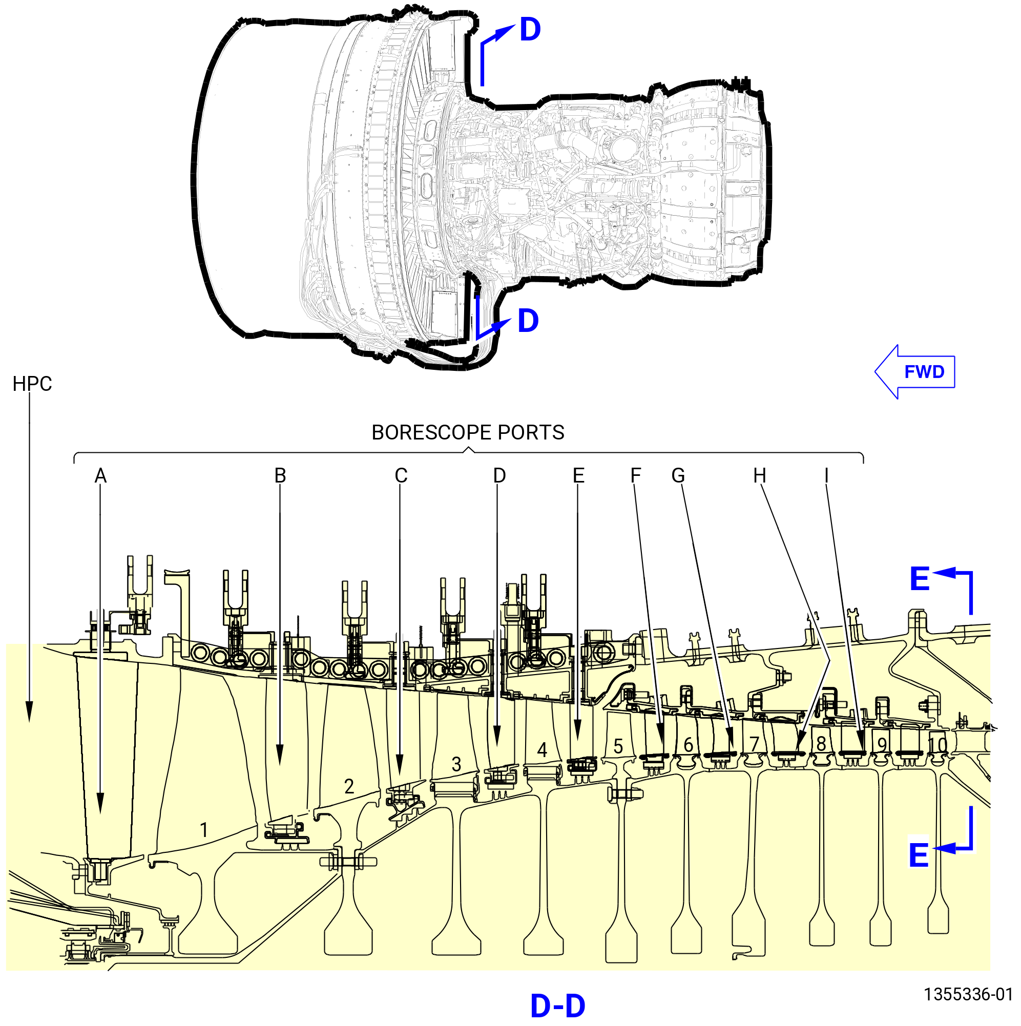
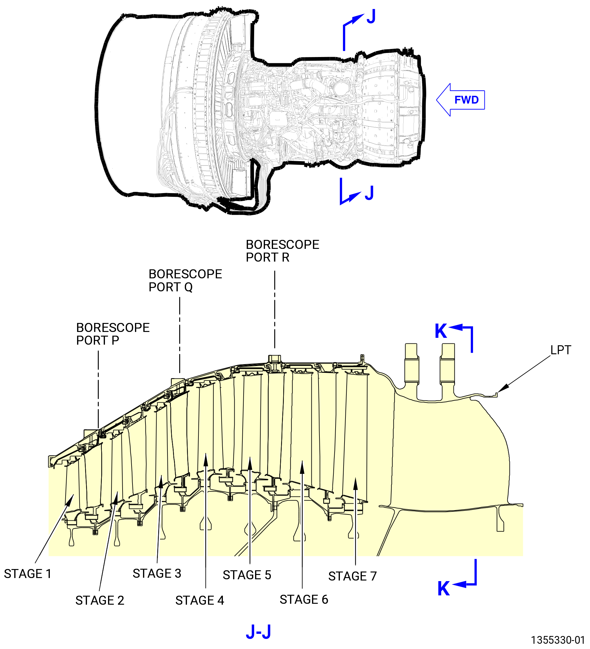
| D. | There are 19 engine borescope ports that give access for the borescope inspection. Refer to Figure 206. |
| E. | The borescope ports have threaded plugs that must be removed to do the borescope inspection. Refer to Table 201 and Figure 209. |
| NOTE: |
|
| F. | The borescope inspection procedures give the maximum serviceable limits. The engine must be repaired if there is damage or wear that exceeds the maximum serviceable limit. |
| 2 . | Tools, Equipment, and Materials. |
| NOTE: |
|
| A. | Tools and Equipment. |
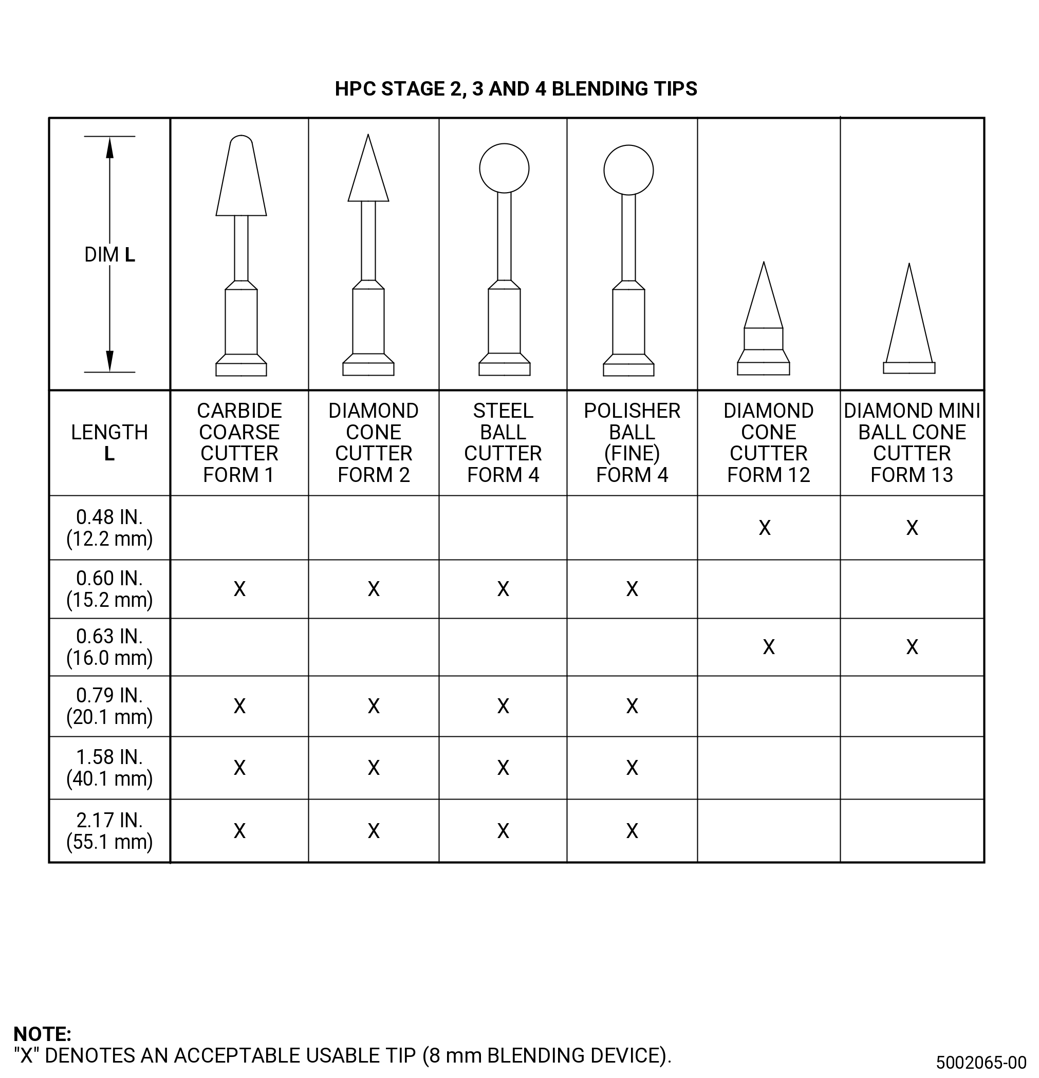
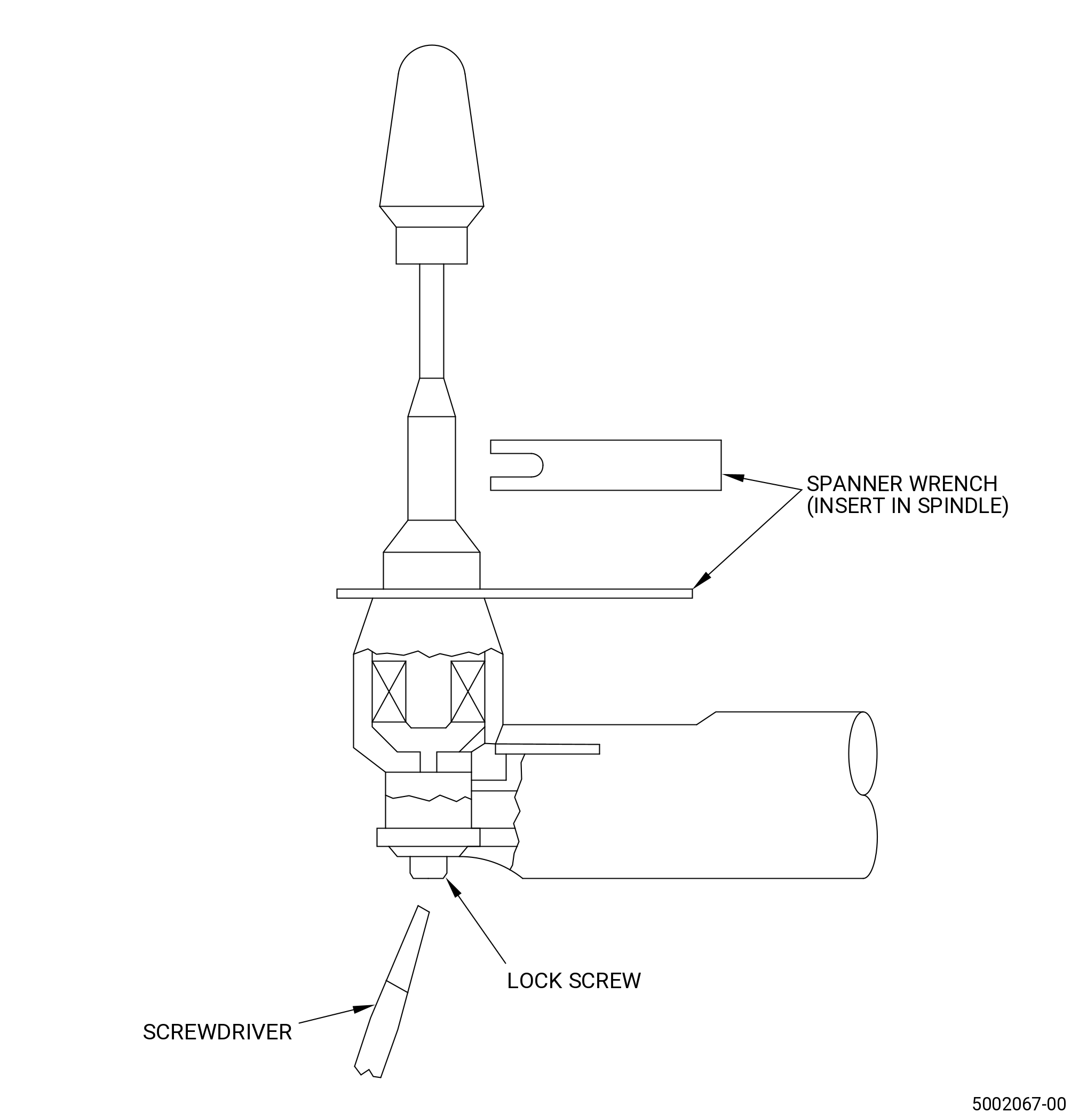
| (1) | Special Tools. |
| (2) | Standard Tools and Equipment. |
|
| (3) | Locally Manufactured Tools. None. |
| B. | Consumable Materials. |
|
| C. | Referenced Procedures. |
|
| D. | Expendable Parts. None. |
| E. | SPD Information. None. |
| F. | Special Solutions. None. |
| G. | Test Specimens. None. |
| 3 . | Dimensional Information. |
| None. |
| 4 . | Setup Information. |
| Subtask 72-00-00-450-001 |
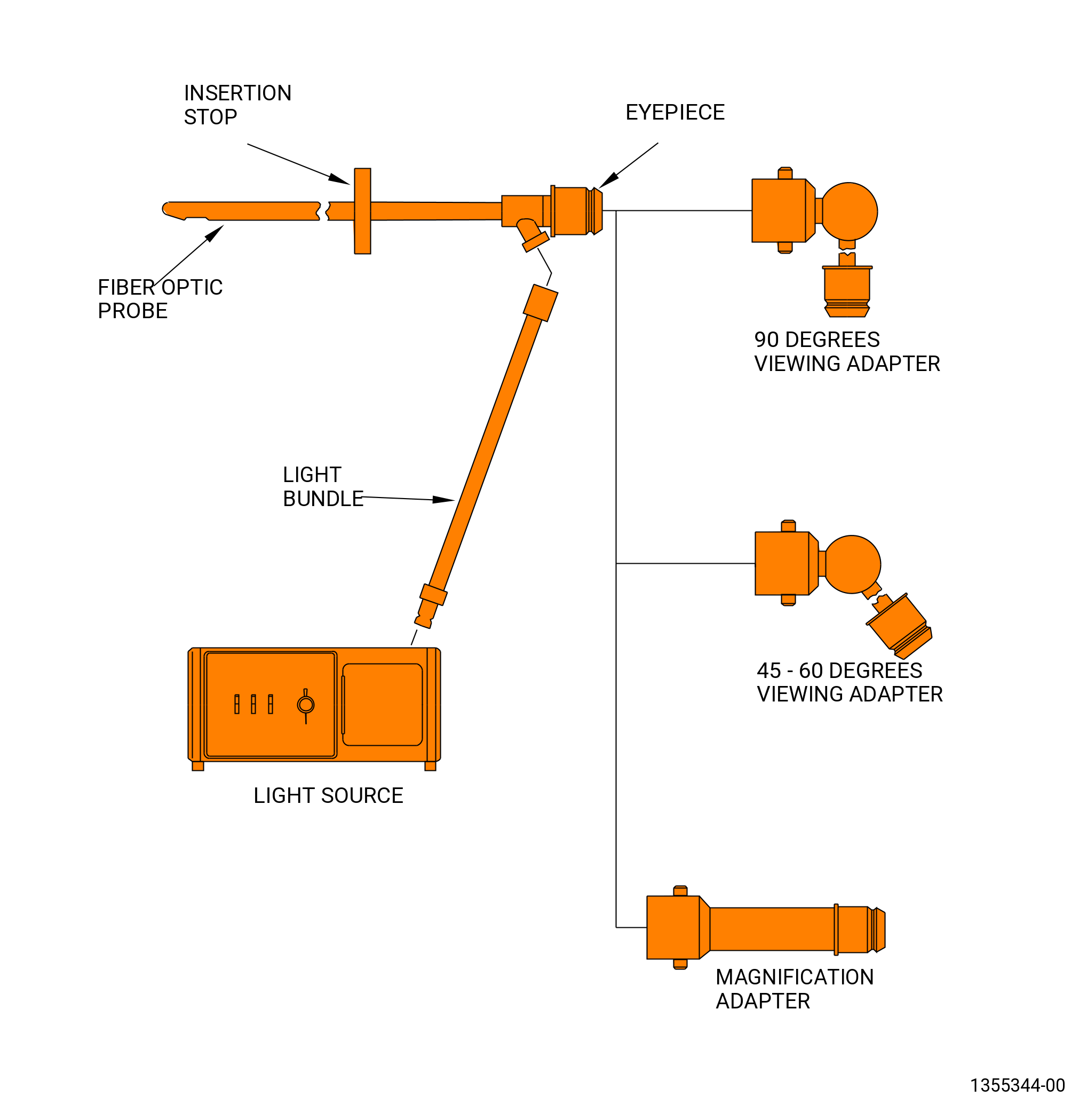
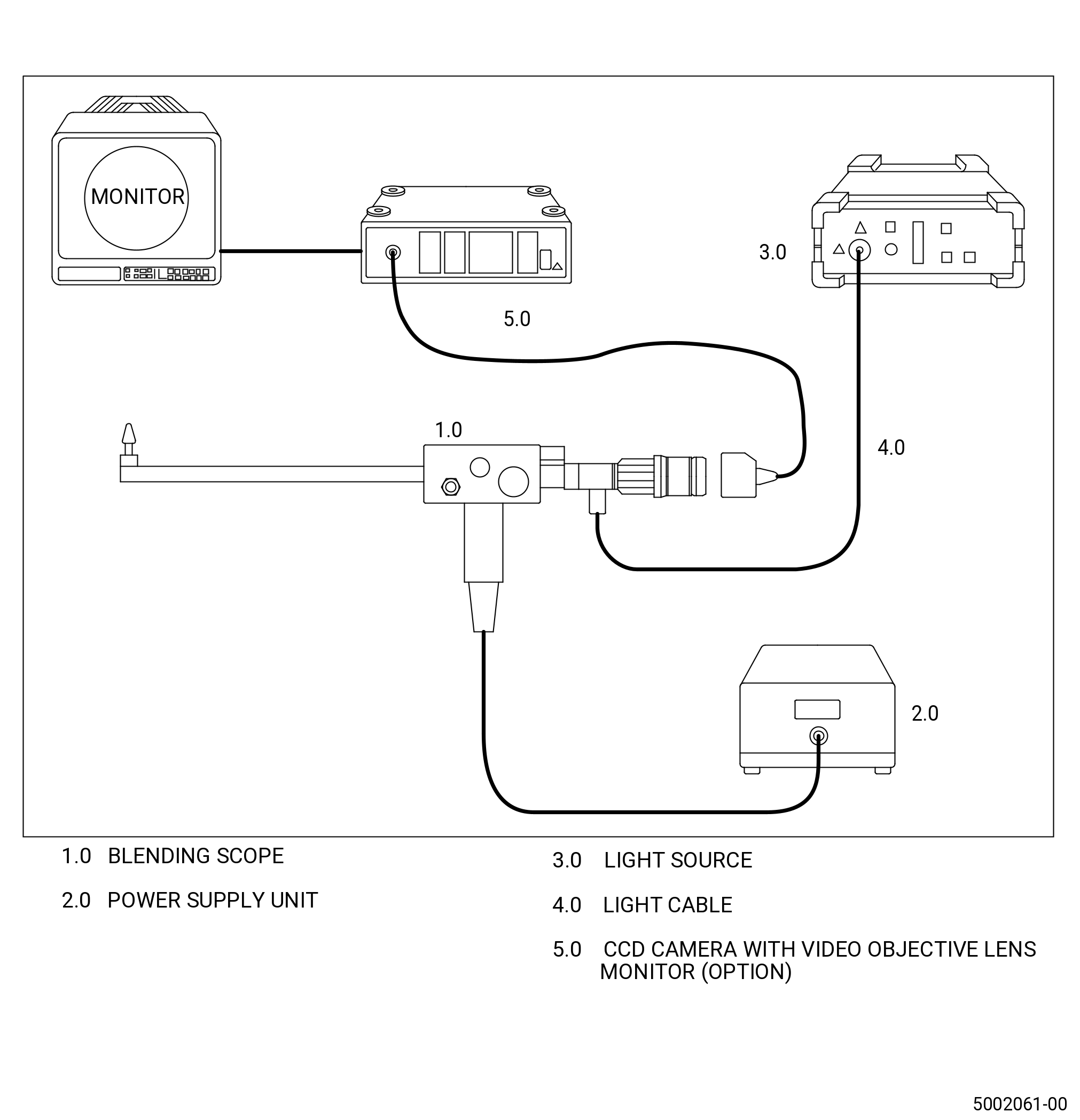
| A. | Assemble the borescope inspection tools. |
| NOTE: |
|
| NOTE: |
|
| NOTE: |
|
| CAUTION: |
|
| (1) | Make sure that the internal and external temperature of the engine is less than 150°F (66°C) before you insert the borescope probe into the engine. |
| (2) | If the engine was recently run, measure the temperature of the engine with a metal probe type thermometer. |
| NOTE: |
|
| NOTE: |
|
| Subtask 72-00-00-220-031 |
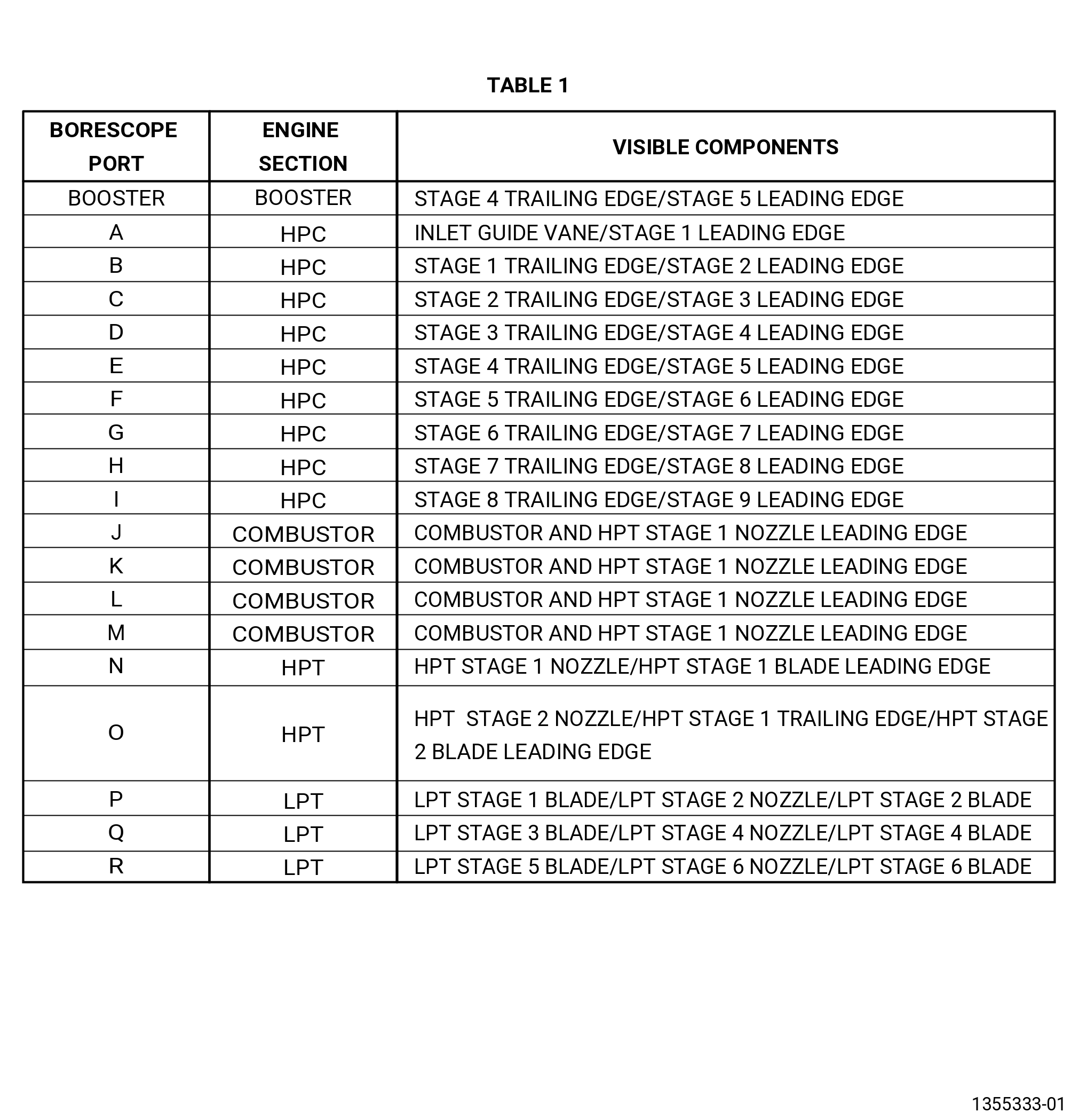
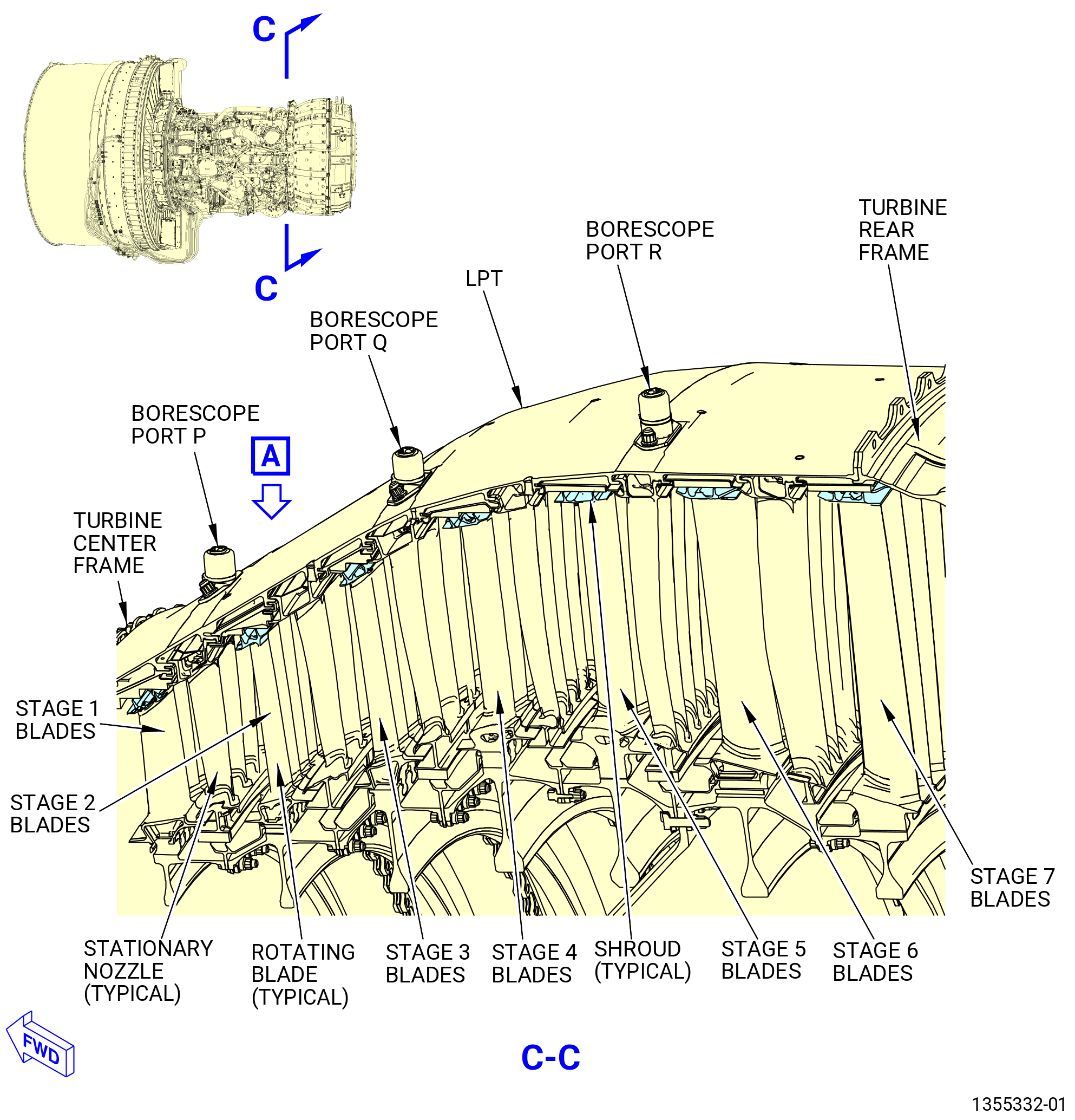
| B. | The components of the engine that can be inspected at each borescope port location are listed in Table 1. Refer to Figure 204. |
| Subtask 72-00-00-220-032 |
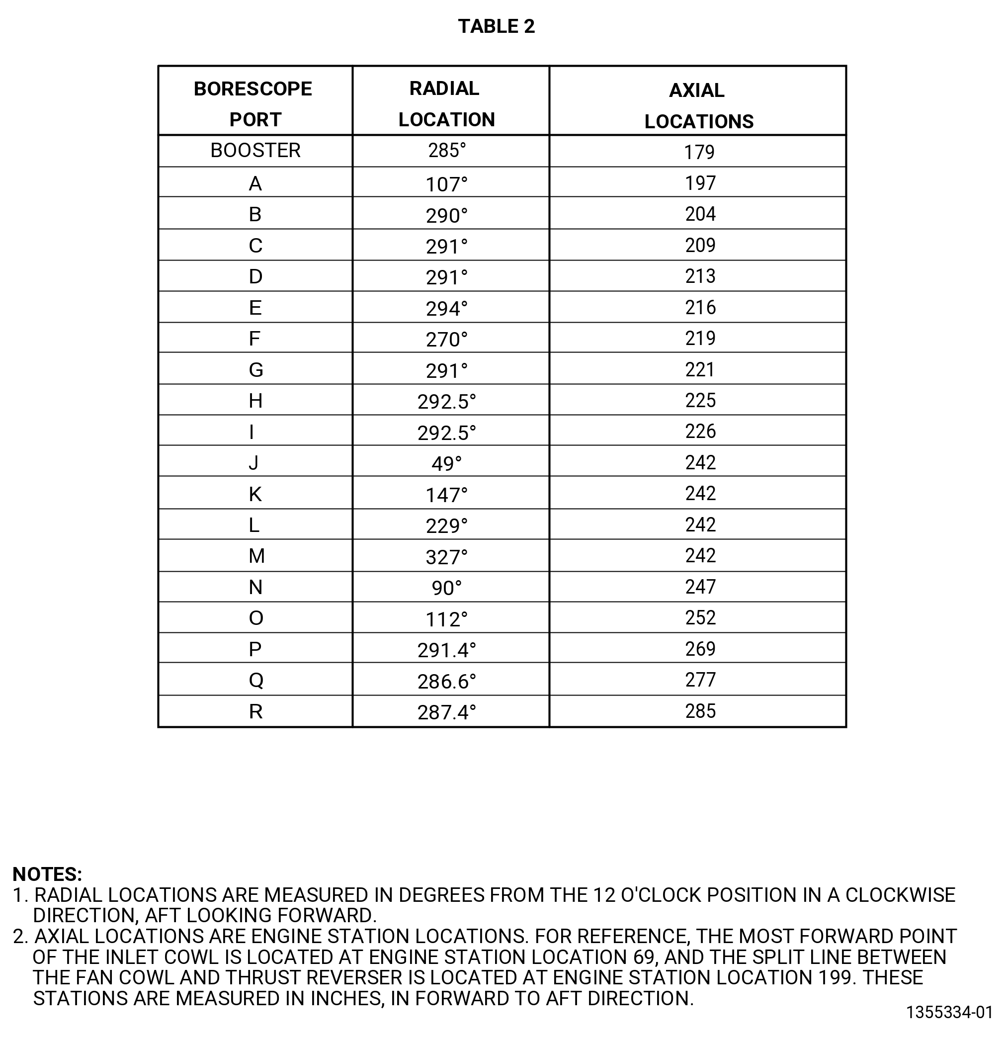
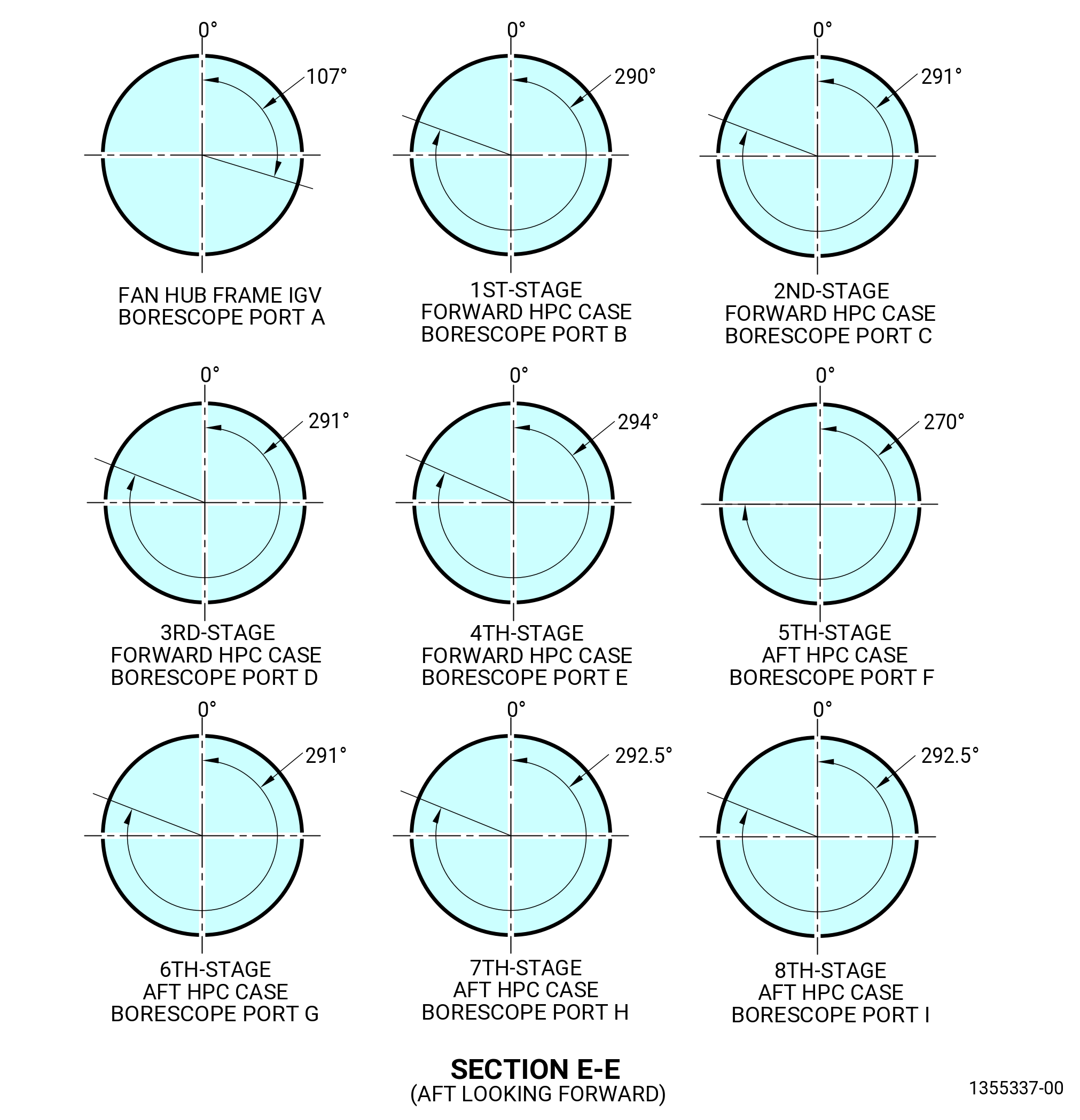
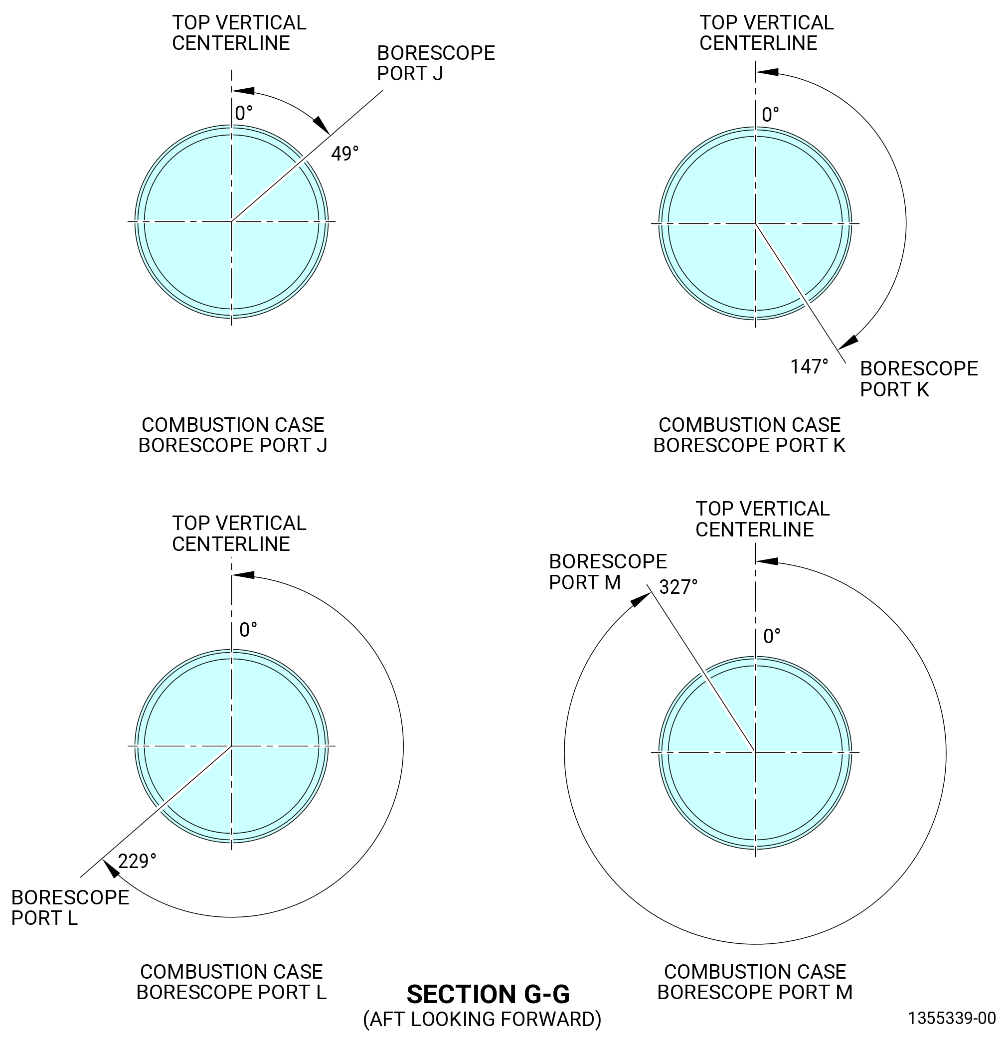
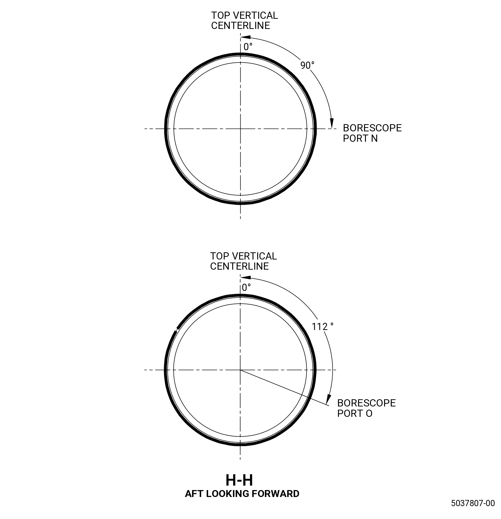
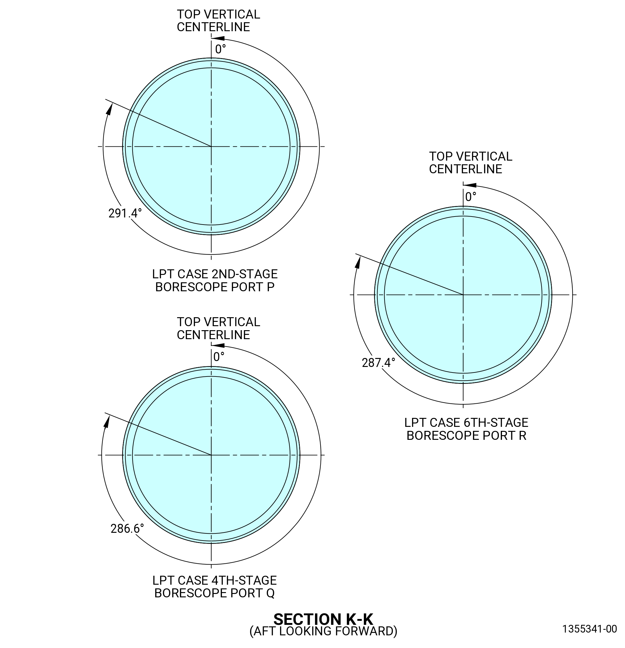
| C. | Radial and axial locations for each borescope port are listed in the Table 2. Refer to Figure 205. |
| Subtask 72-00-00-220-033 |
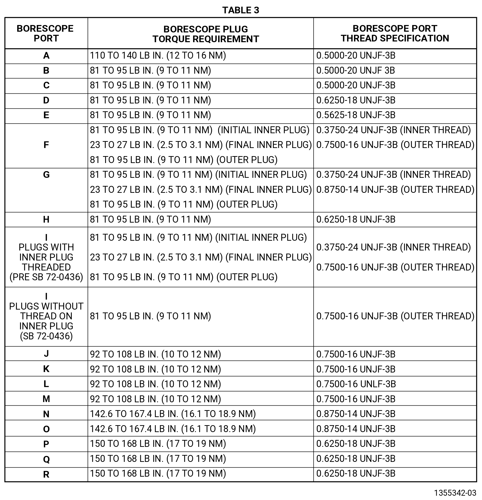
| D. | Torque values and thread specifications for the borescope plugs are listed in the Table 3. Refer to Figure 207. |
| NOTE: |
|
| Subtask 72-00-00-220-034 |
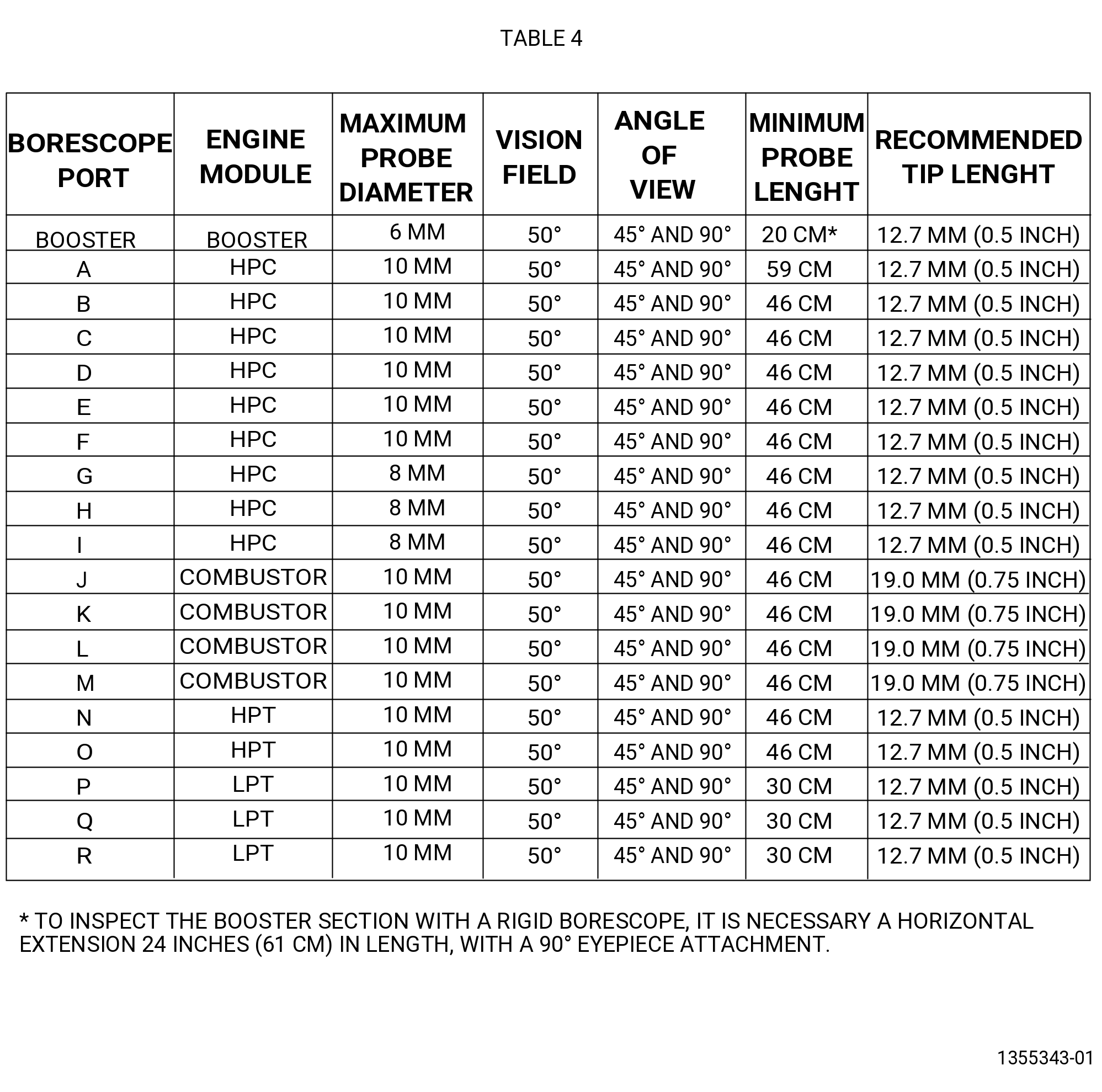
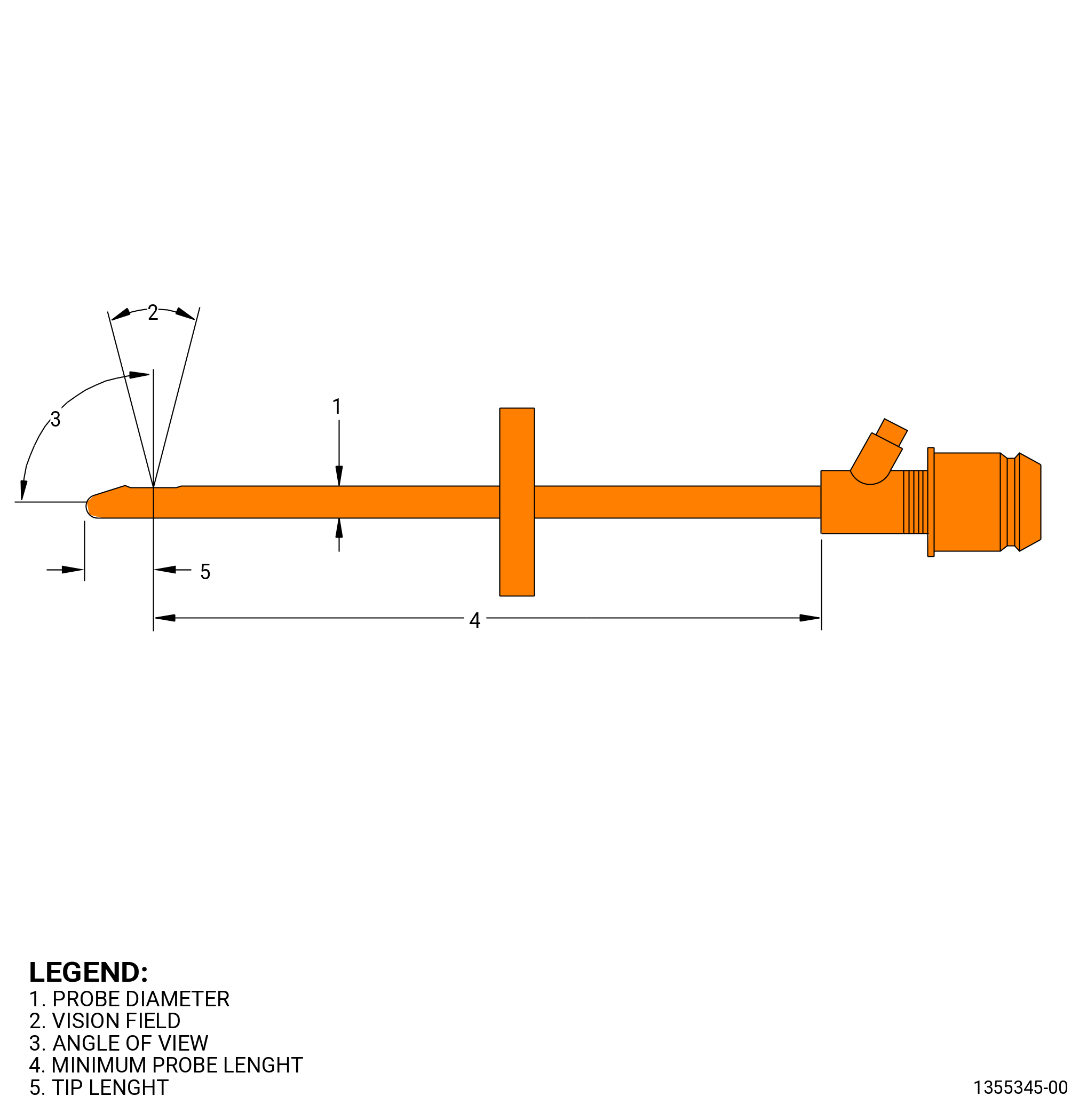
| E. | Borescope probe configuration requirements for each borescope port are listed in the Table 4. Refer to Figure 208. |
| Subtask 72-00-00-040-022 |
| F. | To motor the engine core: |
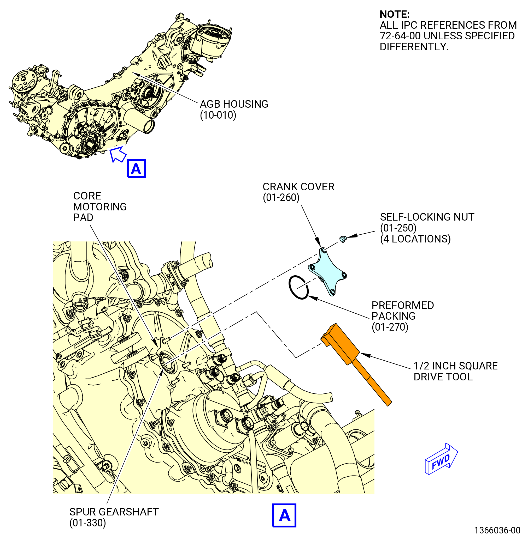
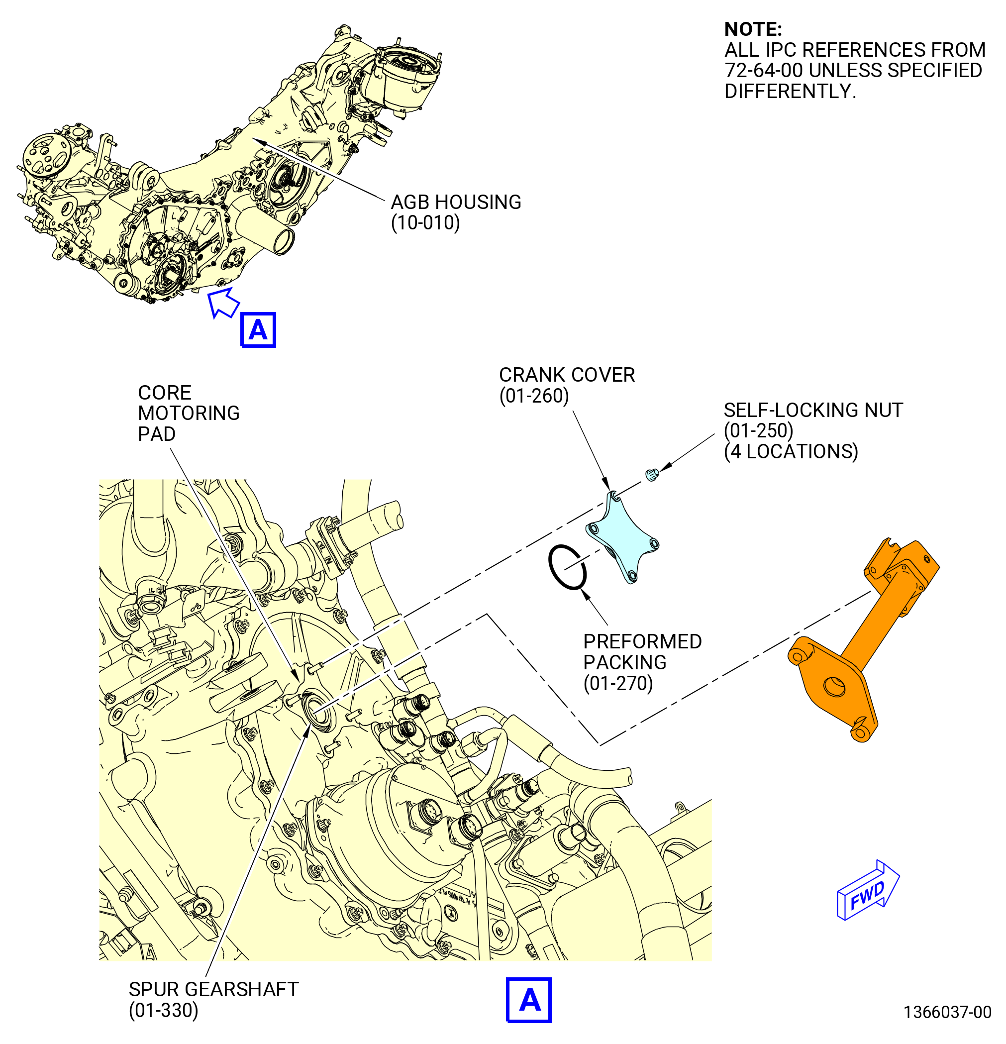
| (1) | Remove the crank cover (01-260 , 72-64-00) (SIN 038AF) from the spur idler crank gearshaft (spur gearshaft) (01-330 , 72-64-00) (SIN 038B5). Refer to Figure 201, Figure 202, and do as follows: |
| (a) | Loosen and remove the four self-locking nuts (01-250 , 72-64-00) (SIN 038W0) that attach the crank cover to the hydraulic pump housing (01-160 , 72-64-00) (SIN 038A9). |
| (b) | Remove the crank cover from the housing. If necessary, use the 2129M73 puller. |
| (c) | Remove and discard the preformed packing (01-270 , 72-64-00) that is installed on the crank cover. |
| Subtask 72-00-00-490-021 |
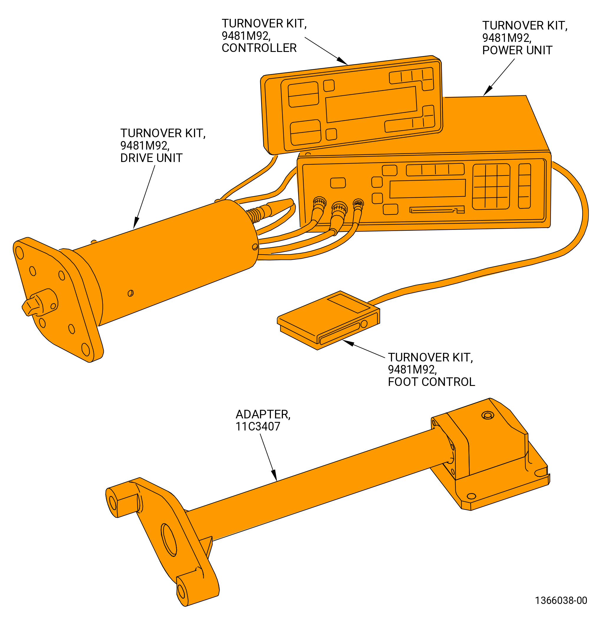
| (2) | Install the 9481M92 turnover kit and 11C3407 adapter or a 1/2-inch square-drive tool. |
| Subtask 72-00-00-220-353 |
| G. | Prepare for inspection of the booster, HPC, HPT, and LPT as follows: |
| (1) | Do the zero-index alignment as follows: |
| (a) | Use a borescope to view the applicable rotor blade platforms. |
| (b) | With the 9481M92 turnover kit or a 1/2-inch square-drive tool, turn the core motoring counterclockwise (CCW) to turn the rotor. |
| (c) | Look through the borescope, until you see the first locking lug. |
| (d) | Continue to turn the rotor with the core motoring until you see the second locking lug. |
| (e) | Align the leading edge of the blade that follows the second locking lug with the previous stage stator vane. |
| (f) | If the 1/2-inch square-drive tool is used to identify the zero-index point, do as follows: |
| 1 | Count the number of blades to know when a full turn of the rotor is complete. |
| (g) | If the 9481M92 turnover kit is used to identify the zero-index point, do as follows: |
| 1 | Use the manufacturer supplied instructions to set the motoring tool display to zero degrees. |
| (2) | Do the required borescope inspection. |
| Subtask 72-00-00-090-008 |
| H. | Remove the motoring tool when the borescope inspection is done and install the crank cover (01-260 , 72-64-00) (SIN 038AF) as follows: |
| (1) | Remove the 9481M92 turnover kit and 11C3407 adapter or a 1/2-inch square-drive tool. |
| Subtask 72-00-00-490-022 |
| (2) | Install the crank cover (01-260 , 72-64-00) (SIN 038AF) on the spur gearshaft (01-330 , 72-64-00) (SIN 038B5). Refer to Figure 201, Figure 202, and do as follows: |
| WARNING: |
|
| (a) | Apply C02-019 engine oil or C02-023 engine oil to the preformed packing (01-270 , 72-64-00) (SIN 038NC). |
| (b) | Install the new preformed packing (01-270 , 72-64-00) (SIN 038NC) on the crank cover. |
| (c) | Install the crank cover on the hydraulic pump housing (01-160 , 72-64-00) (SIN 038A9). |
| WARNING: |
|
| (d) | Apply C02-019 engine oil or C02-023 engine oil to the four self-locking nuts (01-250 , 72-64-00) (SIN 038W0). |
| (e) | Install the four self-locking nuts (01-250 , 72-64-00) (SIN 038W0) that attach the crank cover to the accessory gearbox (AGB) housing. |
| (f) | Torque the four self-locking nuts (01-250 , 72-64-00) (SIN 038W0) to 57-67 lb in. (6.4-7.6 N.m). Make sure that the minimum locking torque is 3.45 lb in. (0.390 N.m). |
| Subtask 72-00-00-450-002 |
| I. | Install the removed borescope plugs as follows. Refer to Figure 204 and Figure 206. |
| WARNING: |
|
| (1) | Apply C02-071 lubricant on the borescope plug threads and the mating surfaces. |
| NOTE: |
|
| (2) | Install the borescope plug (01-450 , 72-26-00) (SIN 84090) on the port A as follows: |
| (a) | Do a visual inspection of the borescope plugs and ports. Refer to TASK 72-00-00-800-804 (72-00-00, SPECIAL PROCEDURE 004) (paragraph 5.A. and 5.B.). |
| (b) | Remove the identification tag from borescope plug A. |
| WARNING: |
|
| (c) | Put C02-071 lubricant on the borescope plug threads and the mating surfaces. |
| (d) | Install the borescope plug in fan hub frame borescope port. |
| NOTE: |
|
| (e) | Torque the borescope plug to 110 to 140 lb in. (12.4 to 15.8 Nm). |
| (f) | Deleted. |
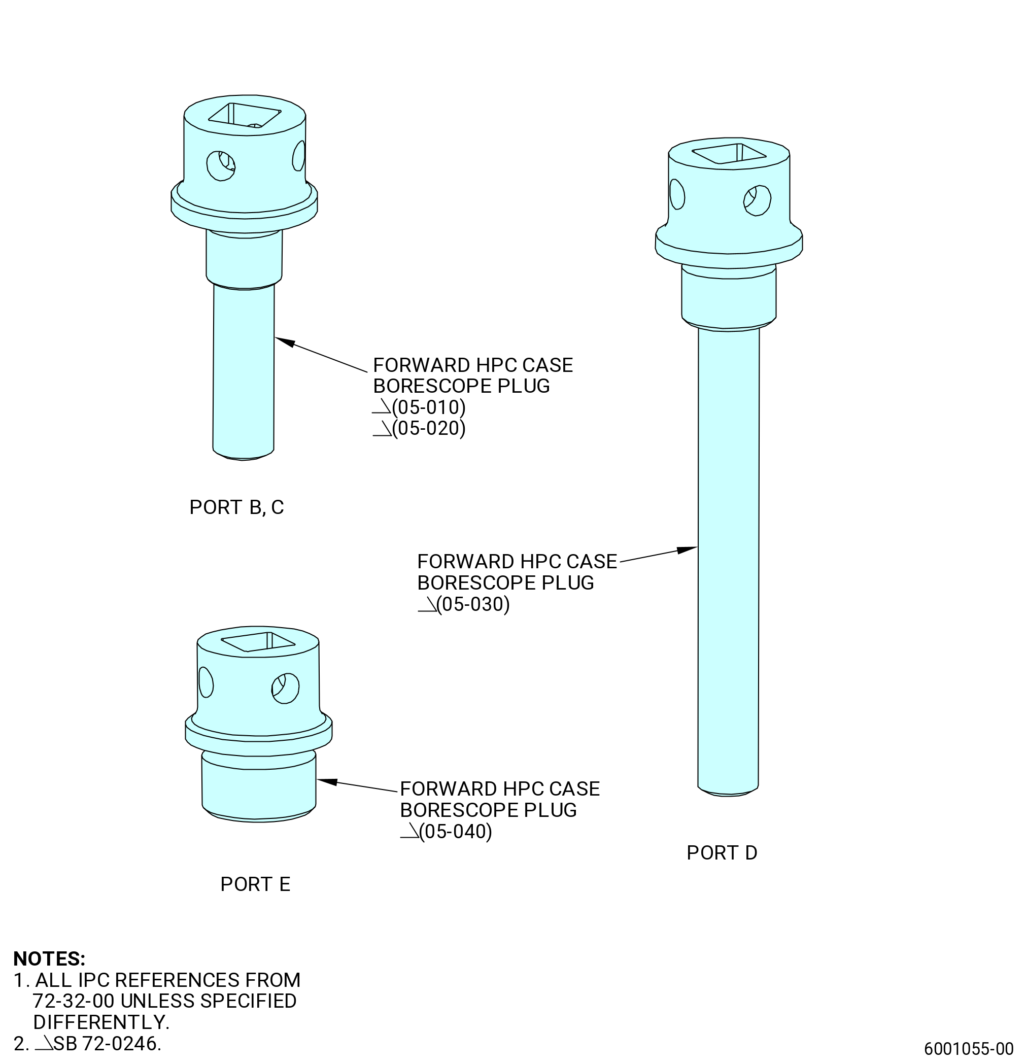
| (3) | Install the forward HPC case borescope plug (05-010 , 72-32-00) (SIN 070AK) on the port B, forward HPC case borescope plug (05-020 , 72-32-00) (SIN 070AL) on the port C, forward HPC case borescope plug (05-030 , 72-32-00) (SIN 070AM) on the port D, and forward HPC case borescope plug (05-040 , 72-32-00) (SIN 070AB) on the port E as follows: |
| Subtask 72-00-00-220-670 |
| * * * PRE SB 72-0246 |
| (a) | Do a visual inspection of the borescope plugs and borescope ports. Refer to Subtask 72-00-00-220-035 (paragraph 5.A.) and Subtask 72-00-00-220-042 (paragraph 5.B.). |
| Subtask 72-00-00-450-015 |
| 1 | Remove the identification tag from borescope plug B through borescope plug E. |
| Subtask 72-00-00-640-003 |
| WARNING: |
|
| 2 | Put C02-071 lubricant on the borescope plug threads and the mating surfaces. |
| NOTE: |
|
| Subtask 72-00-00-450-018 |
| 3 | Install the borescope plugs in the correct forward compressor stator case borescope port. Refer to Figure 201. |
| NOTE: |
|
| 4 | Torque the borescope plugs to 81 to 95 lb in. (9.1 to 10.7 Nm). |
| Subtask 72-00-00-220-672 |
| 5 | After the borescope plug has been torqued, do a visual inspection of the borescope plug and make sure that the locking feature is fully engaged with the lug on the borescope boss. Also make sure that the head of the borescope plug is fully seated against the borescope boss. If one of the two conditions are not met, the ratcheting feature of the borescope plug can be seized or locked. Apply a penetrating oil directly in between the locking ring and the head of the borescope plug. |
| Subtask 72-00-00-450-019 |
| 6 | Re-apply torque to the borescope plug until the borescope plug begins to rotate freely. Tighten the borescope plug from 81 to 95 lb in. (9.1 to 10.7 Nm). |
| Subtask 72-00-00-220-673 |
| 7 | Do the visual inspection again before proceeding. If the conditions above cannot be met, replace the borescope plug. |
| * * * END PRE SB 72-0246 |
| Subtask 72-00-00-220-671 |
| * * * SB 72-0246 |
| (a).A. | Do a visual inspection of the borescope plugs and borescope ports. Refer to Subtask 72-00-00-220-035 (paragraph 5.A.) and Subtask 72-00-00-220-042 (paragraph 5.B.). |
| Subtask 72-00-00-450-016 |
| 1 | Remove the identification tag from borescope plug B through borescope plug E. |
| Subtask 72-00-00-640-004 |
| WARNING: |
|
| 2 | Put C02-071 lubricant on the borescope plug threads and the mating surfaces. |
| NOTE: |
|
| Subtask 72-00-00-450-020 |
| 3 | Install the borescope plugs in the correct forward compressor stator case borescope port. Refer to Figure 201. |
| 4 | Torque the borescope plugs to 81 to 95 lb in. (9.1 to 10.7 Nm). |
| * * * END SB 72-0246 |
| Subtask 72-00-00-450-017 |
| (4) | Install the stage 6 borescope plug (10-010 , 72-30-00) (SIN 080AD) on the port F and stage 7 borescope plug (10-020 , 72-30-00) (SIN 080AU) on the port G as follows: |
| NOTE: |
|
| (a) | Do a visual inspection of the borescope plugs and ports. Refer to TASK 72-00-00-800-804 (72-00-00, SPECIAL PROCEDURE 004) (paragraph 5.A. and 5.B.). |
| (b) | Remove the identification tag from borescope plug F and G. |
| WARNING: |
|
| (c) | Put C02-071 lubricant on the borescope plug threads and the mating surfaces. |
| NOTE: |
|
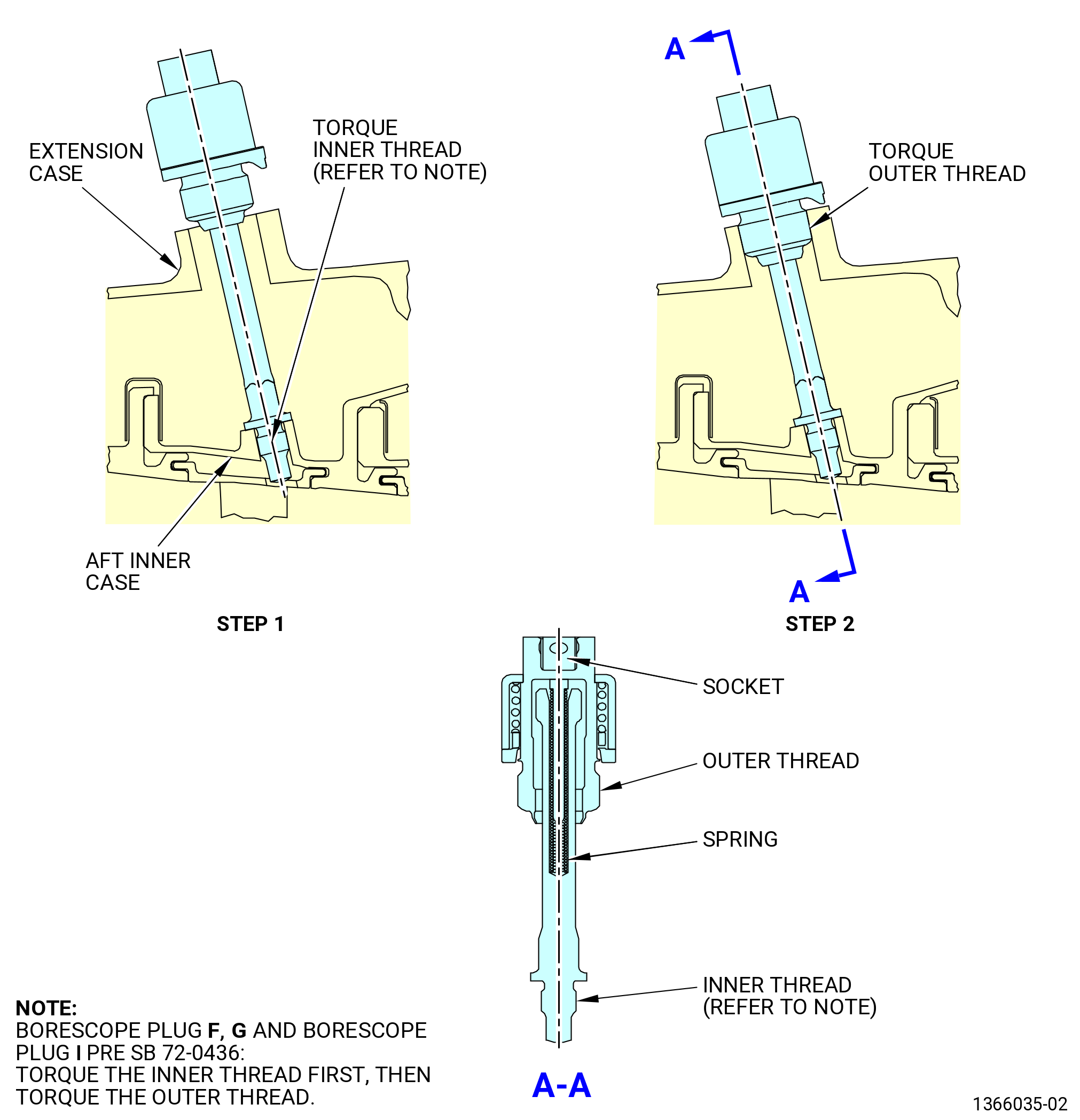
| (d) | Install the borescope plugs in the correct extension case borescope ports as follows: |
| NOTE: |
|
| 1 | Put the borescope plugs in the correct port and hand tighten the inner thread. |
| NOTE: |
|
| 2 | Make sure that the inner threads are correctly mated. |
| 3 | Torque the inner threads to 81-95 lb in. (9.1-10.7 N.m). |
| 4 | Loosen and torque the inner threads again to 23-27 lb in. (2.6-3.1 N.m). |
| 5 | Compress the spring and install the outer threads and hand tighten the borescope plugs. |
| 6 | Torque the outer threads to 81-95 lb in. (9.1-10.7 N.m). |
| (e) | After the plug has been torqued, perform a visual inspection of the plug and make sure that the locking feature is fully engaged with the lug on the borescope boss. Also make sure that the head of the borescope plug is fully seated against the borescope boss. If one of the two conditions are not met, the ratcheting feature of the plug can be seized or locked. Apply a penetrating oil directly in between the locking ring and the head of the plug. Re-apply torque to the plug until the plug begins to rotate freely. Tighten the plug from 81 to 95 lb in. (9.1 to 10.7 Nm). Do the visual inspection again before proceeding. If the conditions above cannot be met, replace the plug. |
| Subtask 72-00-00-450-021 |
| * * * PRE SB 72-0436 |
| (5) | Install the stage 9 borescope plug (10-040 , 72-30-00) (SIN 080BA) on port I as follows: |
| NOTE: |
|
| (a) | Do a visual inspection of the borescope plugs and ports. Refer to TASK 72-00-00-800-802 (72-00-00, SPECIAL PROCEDURE 002) (paragraph 5.A. and 5.B.). |
| (b) | Remove the identification tag from borescope plug I. |
| WARNING: |
|
| (c) | Put C02-071 lubricant on the borescope plug threads and the mating surfaces. |
| NOTE: |
|
| (d) | Install the borescope plugs in the correct extension case borescope ports as follows: |
| NOTE: |
|
| 1 | Put the borescope plugs in the correct port and hand-tighten the inner thread. |
| NOTE: |
|
| 2 | Make sure that the inner threads are correctly mated. |
| 3 | Torque the inner threads to 81 to 95 lb in. (9.1 to 10.7 Nm). |
| 4 | Loosen and torque the inner threads again to 23 to 27 lb in. (2.6 to 3.1 Nm). |
| 5 | Compress the spring and install the outer threads and hand-tighten the borescope plugs. |
| 6 | Torque the outer threads to 81 to 95 lb in. (9.1 to 10.7 Nm). |
| (e) | After the plug has been torqued, perform a visual inspection of the plug and make sure that the locking feature is fully engaged with the lug on the borescope boss. Also make sure that the head of the borescope plug is fully seated against the borescope boss. If one of the two conditions are not met, the ratcheting feature of the plug can be seized or locked. |
| (f) | Apply a penetrating oil directly in between the locking ring and the head of the plug. |
| (g) | Re-apply torque to the plug until the plug begins to rotate freely. Torque the plug from 81 to 95 lb in. (9.1 to 10.7 Nm). |
| (h) | Do the visual inspection again before proceeding. If the conditions above cannot be met, replace the plug. |
| * * * END PRE SB 72-0436 |
| Subtask 72-00-00-450-022 |
| * * * SB 72-0436 |
| (5).A. | Install the stage 9 borescope plug (10-040 , 72-30-00) (SIN 080BA) on port I as follows: |
| NOTE: |
|
| (a) | Do a visual inspection of the borescope plugs and ports. Refer to TASK 72-00-00-800-802 (72-00-00, SPECIAL PROCEDURE 002) (paragraph 5.A. and 5.B.). |
| (b) | Remove the identification tag from borescope plug I. |
| WARNING: |
|
| (c) | Put C02-071 lubricant on the borescope plug threads and the mating surfaces. |
| NOTE: |
|
| (d) | Install the borescope plugs in the correct extension case borescope ports as follows: |
| NOTE: |
|
| 1 | Put the borescope plugs in the correct port. |
| 2 | Make sure that the inner plug is correctly fitted. |
| 3 | Compress the spring and install the outer threads and hand-tighten the borescope plug. |
| 4 | Torque the outer threads to 81 to 95 lb in. (9.1 to 10.7 Nm). |
| (e) | After the plug has been torqued, perform a visual inspection of the plug and make sure that the locking feature is fully engaged with the lug on the borescope boss. Also make sure that the head of the borescope plug is fully seated against the borescope boss. If one of the two conditions are not met, the ratcheting feature of the plug can be seized or locked. |
| (f) | Apply a penetrating oil directly in between the locking ring and the head of the plug. |
| (g) | Re-apply torque to the plug until the plug begins to rotate freely. Torque the plug from 81 to 95 lb in. (9.1 to 10.7 Nm). |
| (h) | Do the visual inspection again before proceeding. If the conditions above cannot be met, replace the plug. |
| * * * END SB 72-0436 |
| Subtask 72-00-00-450-023 |
| (6) | Install the stage 8 borescope plug (10-030 , 72-30-00) (SIN 080AW) on the port H as follows: |
| (a) | Do a visual inspection of the borescope plugs and ports. Refer to TASK 72-00-00-800-804 (72-00-00, SPECIAL PROCEDURE 004) (paragraph 5.A. and 5.B.). |
| (b) | Remove the identification tag from borescope plug H. |
| WARNING: |
|
| (c) | Put C02-071 lubricant on the borescope plug threads and the mating surfaces. |
| NOTE: |
|
| (d) | Install the borescope plug H in the correct extension case borescope port. |
| NOTE: |
|
| (e) | Torque the plug to 81-95 lb in. (9.1-10.7 N.m). |
| (f) | After the plug has been torqued, perform a visual inspection of the plug and make sure that the locking feature is fully engaged with the lug on the borescope boss. Also make sure that the head of the borescope plug is fully seated against the borescope boss. If one of the two conditions are not met, the ratcheting feature of the plug can be seized or locked. Apply a penetrating oil directly in between the locking ring and the head of the plug. Re-apply torque to the plug until the plug begins to rotate freely. Tighten the plug from 81 to 95 lb in. (9.1 to 10.7 Nm). Do the visual inspection again before proceeding. If the conditions above cannot be met, replace the plug. |
| (7) | Do a visual inspection of the borescope plugs and mating ports. Refer to TASK 72-00-00-800-804 (72-00-00, SPECIAL PROCEDURE 004) (paragraph 5.A. and 5.B.). |
| NOTE: |
|
| WARNING: |
|
| (8) | Apply C02-071 lubricant to the borescope plug threads and mating surfaces of borescope plugs J, K, L, and M. |
| NOTE: |
|
| (9) | Install the borescope plug J (01-030 , 72-41-00) (SIN 12090), borescope plug K (01-030 , 72-41-00) (SIN 12090), borescope plug L (01-030 , 72-41-00) (SIN 12090), and borescope plug M (01-030 , 72-41-00) (SIN 12090) as follows: |
| (a) | Install the borescope plugs in the combustor case borescope ports. Make sure that the running torque is no more than 15 lb in. (1.7 Nm). |
| NOTE: |
|
| (b) | Torque the borescope plugs to 92 to 108 lb in. (10.4 to 12.2 Nm). |
| (c) | After the plug has been torqued, perform a visual inspection of the plug and make sure that the locking feature is fully engaged with the lug on the borescope boss. Also make sure that the head of the borescope plug is fully seated against the borescope boss. If one of the two conditions are not met, the ratcheting feature of the plug can be seized or locked. Apply a penetrating oil directly in between the locking ring and the head of the plug. Re-apply torque to the plug until the plug begins to rotate freely. Tighten the plug from 92 to 108 lb in. (10.4 to 12.2 Nm). Do the visual inspection again before proceeding. If the conditions above cannot be met, replace the plug. |
| (10) | Do a visual inspection of the borescope plugs and ports. Refer to TASK 72-00-00-800-804 (72-00-00, SPECIAL PROCEDURE 004) (paragraph 5.A. and 5.B.). |
| NOTE: |
|
| WARNING: |
|
| (11) | Apply C02-097 lubricant to the borescope plug threads and mating surfaces of borescope plugs N and O. |
| NOTE: |
|
| NOTE: |
|
| (12) | Install borescope plug N (34-250 , 72-00-02) (SIN 17290) and borescope plug O (01-340 , 72-52-00) (SIN 17490) as follows: |
| (a) | Install the borescope plugs in the correct HPT case borescope ports. Make sure that the running torque is no more than 15 lb in. (1.7 Nm). |
| NOTE: |
|
| (b) | Torque the borescope plugs to 142.6 to 167.4 lb in. (16.1 to 18.9 Nm). |
| (c) | After the plug has been torqued, do a visual inspection of the plug and make sure that the locking feature is fully engaged with the lug on the borescope boss. Also make sure that the head of the borescope plug is fully seated against the borescope boss. If one of the two conditions are not met, the ratcheting feature of the plug can be seized or locked. Apply a penetrating oil directly in between the locking ring and the head of the plug. Re-apply torque to the plug until the plug begins to rotate freely. Tighten the plug from 142.6 to 167.4 lb in. (16.1 to 18.9 Nm). Do the visual inspection again before proceeding. If the conditions above cannot be met, replace the plug. |
| (13) | Do a visual inspection of the borescope plugs and ports. Refer to TASK 72-00-00-800-804 (72-00-00, SPECIAL PROCEDURE 004) (paragraph 5.A. and 5.B.). |
| NOTE: |
|
| WARNING: |
|
| (14) | Apply C02-071 lubricant to the borescope plug threads and mating surfaces of borescope plugs P, Q, and R. |
| (15) | Install borescope plug P (01-020 , 72-56-00) (SIN 935S0), borescope plug Q (01-030 , 72-56-00) (SIN 935S1), and borescope plug R (01-040 , 72-56-00) (SIN 935S2) as follows: |
| (a) | Install the borescope plugs in the correct LPT case borescope ports. Make sure that the running torque is no more than 15 lb in. (1.7 Nm). |
| NOTE: |
|
| (b) | Torque the borescope plugs to 150 to 168 lb in. (16.9 to 18.9 Nm). |
| (c) | After the plug has been torqued, perform a visual inspection of the plug and make sure that the locking feature is fully engaged with the lug on the borescope boss. Also make sure that the head of the borescope plug is fully seated against the borescope boss. If one of the two conditions are not met, the ratcheting feature of the plug can be seized or locked. Apply a penetrating oil directly in between the locking ring and the head of the plug. Re-apply torque to the plug until the plug begins to rotate freely. Tighten the plug from 150 to 168 lb in. (16.9 to 18.9 Nm). Do the visual inspection again before proceeding. If the conditions above cannot be met, replace the plug. |
| (16) | Install the blank off plate (30-150 , 72-00-02) (SIN 9500J) as follows: |
| WARNING: |
|
| (a) | Apply C02-019 engine oil or C02-023 engine oil on the threads of four machine bolts (bolts) (30-160 , 72-00-02) (SIN 9502C). |
| (b) | Attach the plate (30-150 , 72-00-02) (SIN 9500J) to the cowl support (30-011 , 72-00-02) (SIN 95001) at the 3:30 o’clock position with the four bolts (30-160 , 72-00-02) (SIN 9502C). |
| (c) | Torque the four bolts (30-160 , 72-00-02) (SIN 9502C) to 106-124 lb in. (12.0- 14.0 N.m). |
| (17) | Install the blankoff panel (25-520) (SIN 9500D) to the deflector panels (25-550) (SIN 9500A) at the 3:00 and 4:00 o’clock positions on the cowl support (30-011 , 72-00-02) (SIN 95001) as follows: |
| WARNING: |
|
| (a) | Apply C02-058 lubricant on the threads of the machine screws (25-510) (SIN 95025). |
| (b) | Install the blankoff panel to the deflector panels at the 3:00 and 4:00 o’clock positions with the machine screws (25-510) (SIN 95025). |
| (c) | Torque the machine screws (25-510) (SIN 95025) to 60-70 lb in. (6.8-7.9 N.n). |
| 5 . | Visual Inspection. |
| Subtask 72-00-00-220-035 |
| A. | Do an inspection of the borescope plugs for. Refer to Table 201 and Figure 209. |
|
| (1) | Cracks: |
| Maximum serviceable limit: |
|
| Repair method: |
|
| Subtask 72-00-00-220-036 |
| (2) | Wear on locking device seating face: |
| Maximum serviceable limit: |
|
| Repair method: |
|
| Subtask 72-00-00-220-037 |
| (3) | Deformation: |
| Maximum serviceable limit: |
|
| Repair method: |
|
| Subtask 72-00-00-220-038 |
| (4) | Broken plug spring: |
| Maximum serviceable limit: |
|
| Repair method: |
|
| Subtask 72-00-00-220-039 |
| (5) | Damaged threads: |
| Maximum serviceable limit: |
|
| Repair method: |
|
| Subtask 72-00-00-220-040 |
| (6) | Anti-rotation feature: |
| (a) | Axially compress the spring by pushing the tabbed locking ring to the plug body with hand force. Keep the spring compressed and turn the plug manually. |
| Maximum serviceable limit: |
|
| • |
|
| • |
|
| • |
|
| • |
|
| • |
|
| Repair method: |
|
| Subtask 72-00-00-220-041 |
| (7) | Damaged or bent locking lugs: |
| Maximum serviceable limit: |
|
| Repair method: |
|
| Subtask 72-00-00-220-042 |
| B. | Do a visual inspection of the ports for: |
| (1) | Loose or missing locking inserts: |
| Maximum serviceable limit: |
|
| Repair method: |
|
| Subtask 72-00-00-220-043 |
| (2) | Damaged threads: |
| Maximum serviceable limit: |
|
| Maximum repairable limit: |
|
| Repair method: |
|
| Subtask 72-00-00-220-044 |
| C. | Do an inspection of the stage 4 blades (blades). |
| NOTE: |
|
| (1) | All areas for: |
| (a) | Cracks and tears (high metal): |
| Maximum serviceable limit: |
|
| Repair method: |
|
| Subtask 72-00-00-220-354 |
| (b) | Erosion or spalling: |
| Maximum serviceable limit: |
|
| Repair method: |
|
| Subtask 72-00-00-220-045 |
| (2) | Area A for: |
| (a) | Nicks, dents, and scratches in the concave and convex surfaces, not in the leading and trailing edges: |
| Maximum serviceable limit: |
|
| Repair method: |
|
| Subtask 72-00-00-220-046 |
| (b) | Nicks, dents, and scratches on the leading and trailing edges: |
| Maximum serviceable limit: |
|
| Repair method: |
|
| Subtask 72-00-00-220-047 |
| (c) | Distortion on the leading or trailing edges: |
| Maximum serviceable limit: |
|
| Repair method: |
|
| Subtask 72-00-00-220-048 |
| (3) | Area B for: |
| (a) | Nicks, dents, and scratches: |
| Maximum serviceable limit: |
|
| Repair method: |
|
| Subtask 72-00-00-220-049 |
| (b) | Local distortion on the leading and/or trailing edge: |
| Maximum serviceable limit: |
|
| Repair method: |
|
| Subtask 72-00-00-220-055 |
| (4) | Area C for: |
| (a) | Nicks, dents, and scratches: |
| Maximum serviceable limit: |
|
| Repair method: |
|
| Subtask 72-00-00-220-056 |
| (5) | Area D for: |
| (a) | Nicks, dents, and scratches on the leading and trailing edges: |
| Maximum serviceable limit: |
|
| Repair method: |
|
| Subtask 72-00-00-220-057 |
| (b) | Nicks, dents, and scratches on the concave and convex surfaces: |
| Maximum serviceable limit: |
|
| Repair method: |
|
| Subtask 72-00-00-220-355 |
| (c) | Tip curl: |
| Maximum serviceable limit: |
|
| Repair method: |
|
| Subtask 72-00-00-220-356 |
| (d) | Tip burrs: |
| Maximum serviceable limit: |
|
| Repair method: |
|
| Subtask 72-00-00-220-357 |
| (e) | Local rub marks on blade tip: |
| Maximum serviceable limit: |
|
| Repair method: |
|
| Subtask 72-00-00-220-358 |
| (f) | Wear on blade tip leading and trailing edges: |
| Maximum serviceable limit: |
|
| Repair method: |
|
| Subtask 72-00-00-220-058 |
| (g) | Missing metal from leading and trailing edge tip corner: |
| Maximum serviceable limit: |
|
| Repair method: |
|
| Subtask 72-00-00-220-059 |
| (6) | Blade platforms for: |
| (a) | Nicks, dents, and scratches: |
| Maximum serviceable limit: |
|
| Maximum repairable limit: |
|
| Repair method: |
|
| Subtask 72-00-00-220-060 |
| (b) | Interplatform gap: |
| Maximum serviceable limit: |
|
| Repair method: |
|
| Subtask 72-00-00-220-061 |
| D. | Do an inspection of the stage 5 blades (blades). |
| NOTE: |
|
| (1) | All areas for: |
| (a) | Cracks and tears (high metal): |
| Maximum serviceable limit: |
|
| Repair method: |
|
| Subtask 72-00-00-220-062 |
| (b) | Erosion or spalling: |
| Maximum serviceable limit: |
|
| Repair method: |
|
| Subtask 72-00-00-220-063 |
| (2) | Area A for: |
| (a) | Nicks, dents, and scratches in the concave and convex surfaces, not in the leading and trailing edges: |
| Maximum serviceable limit: |
|
| Repair method: |
|
| Subtask 72-00-00-220-064 |
| (b) | Nicks, dents, and scratches on the leading edges: |
| Maximum serviceable limit: |
|
| Repair method: |
|
| Subtask 72-00-00-220-689 |
| (c) | Nicks, dents, and scratches on the trailing edges: |
| Maximum serviceable limit: |
|
| Repair method: |
|
| Subtask 72-00-00-220-065 |
| (d) | Distortion on the leading or trailing edges: |
| Maximum serviceable limit: |
|
| Repair method: |
|
| Subtask 72-00-00-220-066 |
| (3) | Area B for: |
| (a) | Nicks, dents, and scratches: |
| Maximum serviceable limit: |
|
| Repair method: |
|
| Subtask 72-00-00-220-067 |
| (b) | Local distortion on the leading and/or trailing edge: |
| Maximum serviceable limit: |
|
| Repair method: |
|
| Subtask 72-00-00-220-073 |
| (4) | Area C for: |
| (a) | Nicks, dents, and scratches: |
| Maximum serviceable limit: |
|
| Repair method: |
|
| Subtask 72-00-00-220-074 |
| (5) | Area D for: |
| (a) | Nicks, dents, and scratches on the leading and trailing edges: |
| Maximum serviceable limit: |
|
| Repair method: |
|
| Subtask 72-00-00-220-075 |
| (b) | Nicks, dents, and scratches on the concave and convex surfaces: |
| Maximum serviceable limit: |
|
| Repair method: |
|
| Subtask 72-00-00-220-359 |
| (c) | Tip curl: |
| Maximum serviceable limit: |
|
| Repair method: |
|
| Subtask 72-00-00-220-360 |
| (d) | Tip burrs: |
| Maximum serviceable limit: |
|
| Repair method: |
|
| Subtask 72-00-00-220-361 |
| (e) | Local rub marks on blade tip: |
| Maximum serviceable limit: |
|
| Repair method: |
|
| Subtask 72-00-00-220-362 |
| (f) | Wear on blade tip leading and trailing edges: |
| Maximum serviceable limit: |
|
| Repair method: |
|
| Subtask 72-00-00-220-076 |
| (g) | Missing metal from leading and trailing edge tip corner: |
| Maximum serviceable limit: |
|
| Repair method: |
|
| Subtask 72-00-00-220-077 |
| (6) | Blade platforms for: |
| (a) | Nicks, dents, and scratches: |
| Maximum serviceable limit: |
|
| Maximum repairable limit: |
|
| Repair method: |
|
| Subtask 72-00-00-220-078 |
| (b) | Interplatform gap: |
| Maximum serviceable limit: |
|
| Repair method: |
|
| Subtask 72-00-00-220-079 |
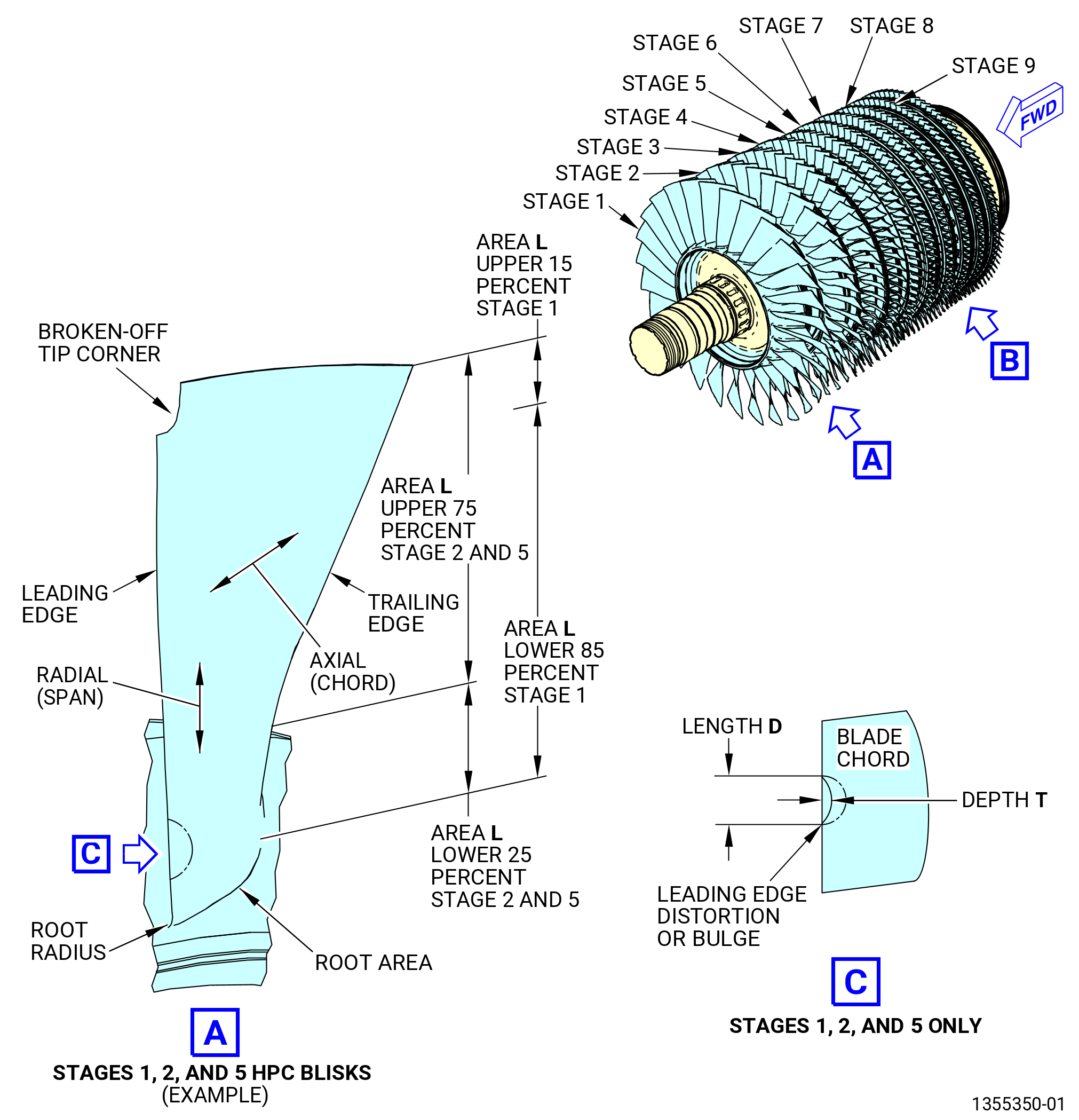
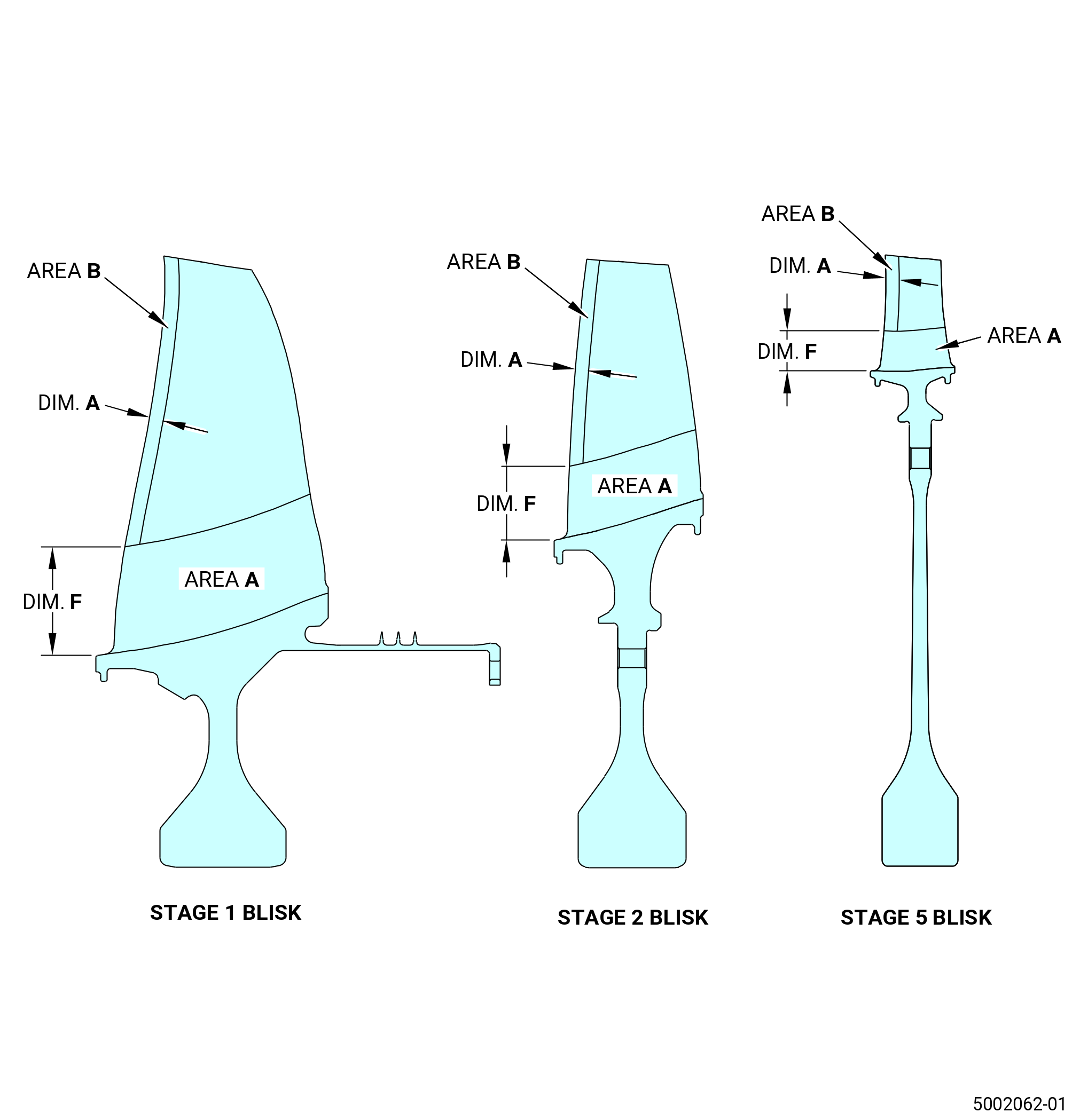
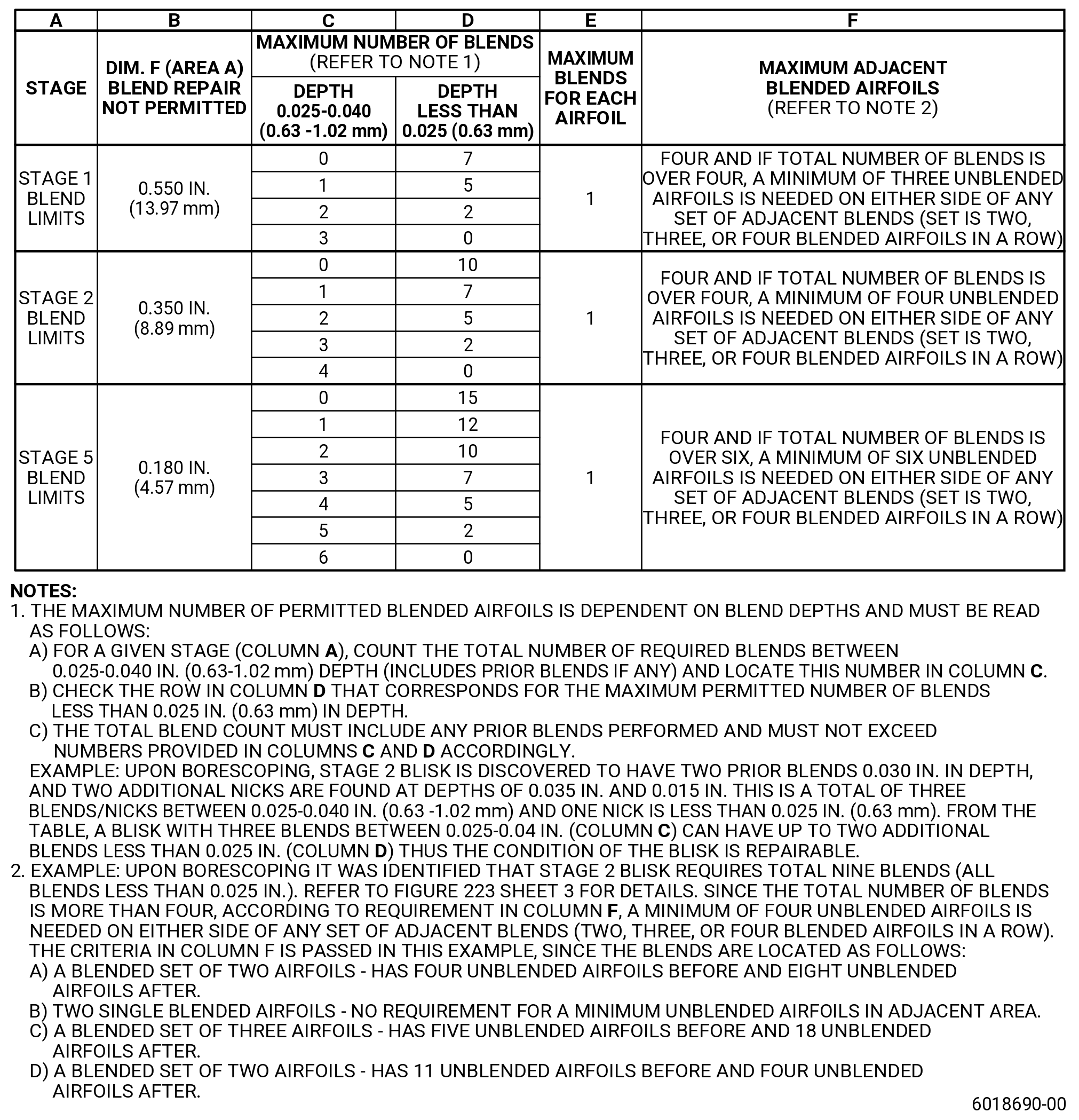
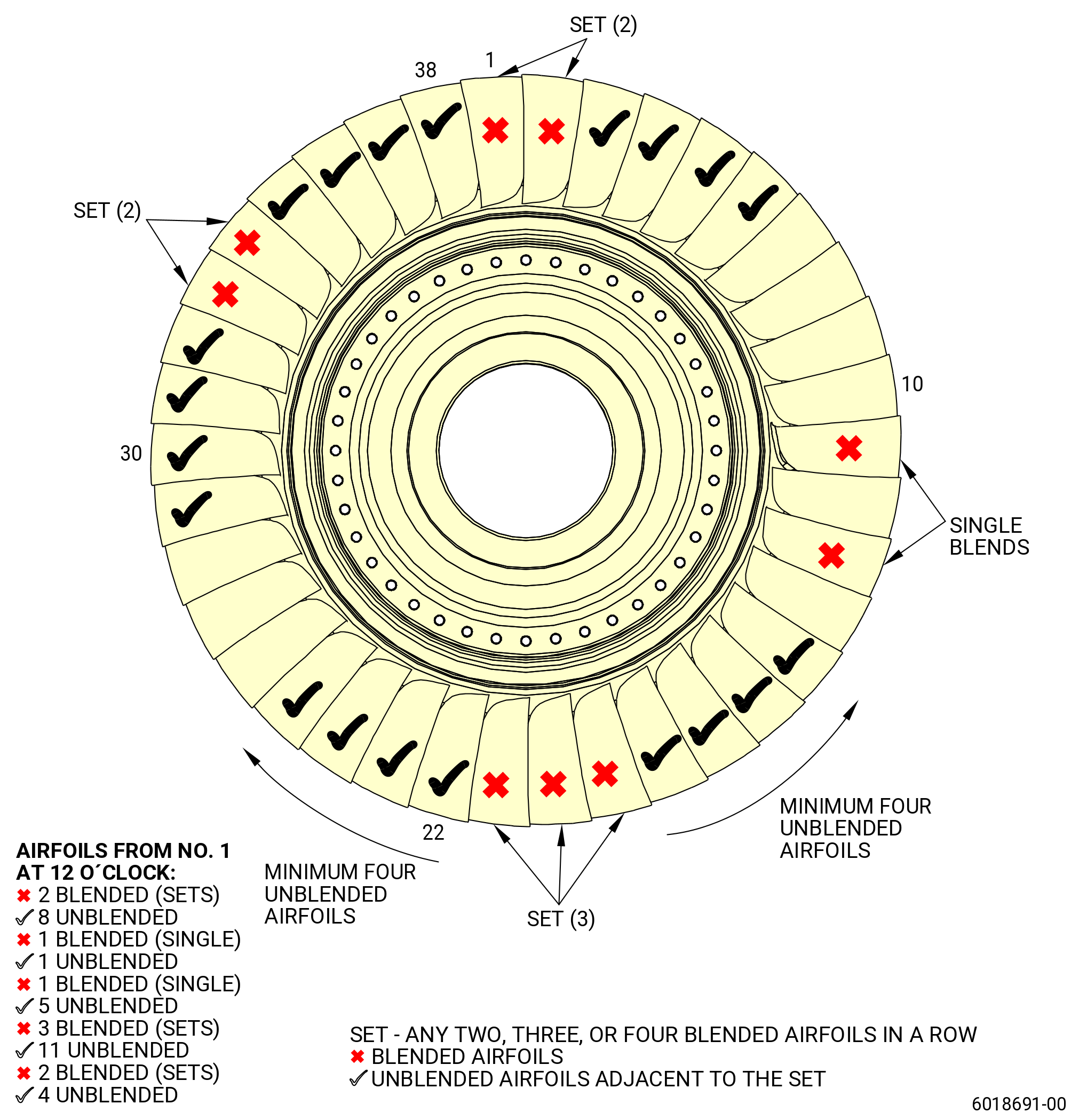
| E. | Do an inspection of the stage 1 blisk (blisk) (056A1) airfoils. Refer to Figure 211. |
| (1) | All areas for: |
| (a) | Cracks and tears: |
| Maximum serviceable limit: |
|
| Maximum repairable limit: |
|
| Repair method: |
|
| Subtask 72-00-00-220-080 |
| (b) | Scratches: |
| Maximum serviceable limit: |
|
| Maximum repairable limit: |
|
| Repair method: |
|
| Subtask 72-00-00-220-081 |
| (2) | Nicks and dents in the center of the airfoil: |
| Maximum serviceable limit: |
|
| Repair method: |
|
| Subtask 72-00-00-220-082 |
| (3) | Nicks, dents, distortion, or material that is missing on the leading and trailing edges of the airfoil: |
| Maximum serviceable limit: |
|
| Maximum repairable limit: |
|
| Repair method: |
|
| Subtask 72-00-00-220-083 |
| (4) | Nicks and dents in the airfoil root radius: |
| Maximum serviceable limit: |
|
| Repair method: |
|
| Subtask 72-00-00-220-084 |
| (5) | Missing airfoil tip corners: |
| Maximum serviceable limit: |
|
| Repair method: |
|
| NOTE: |
|
| Subtask 72-00-00-220-085 |
| (6) | Curled blade tips: |
| Maximum serviceable limit: |
|
| Repair method: |
|
| Subtask 72-00-00-220-086 |
| (7) | Distortion or bulging of the leading edge: |
| Maximum serviceable limit: |
|
| Repair method: |
|
| Subtask 72-00-00-220-641 |
| (8) | Particles on the blade or tip surfaces: |
| Maximum serviceable limit: |
|
| Repair method: |
|
| Subtask 72-00-00-220-087 |
| F. | Do an inspection of the stage 2 blisk (blisk) (056A2) airfoils. Refer to Figure 211. |
| (1) | All areas for: |
| (a) | Cracks and tears: |
| Maximum serviceable limit: |
|
| Maximum repairable limit: |
|
| Repair method: |
|
| Subtask 72-00-00-220-088 |
| (b) | Scratches: |
| Maximum serviceable limit: |
|
| Maximum repairable limit: |
|
| Repair method: |
|
| Subtask 72-00-00-220-089 |
| (2) | Nicks and dents in the center of the airfoil: |
| Maximum serviceable limit: |
|
| Repair method: |
|
| Subtask 72-00-00-220-090 |
| (3) | Nicks, dents, distortion, or material that is missing on the leading and trailing edges of the airfoil: |
| Maximum serviceable limit: |
|
| Maximum repairable limit: |
|
| Repair method: |
|
| Subtask 72-00-00-220-091 |
| (4) | Nicks and dents in the airfoil root radius: |
| Maximum serviceable limit: |
|
| Repair method: |
|
| Subtask 72-00-00-220-092 |
| (5) | Missing airfoil tip corners: |
| Maximum serviceable limit: |
|
| Repair method: |
|
| NOTE: |
|
| Subtask 72-00-00-220-093 |
| (6) | Curled blade tips: |
| Maximum serviceable limit: |
|
| Repair method: |
|
| Subtask 72-00-00-220-094 |
| (7) | Distortion or bulging of the leading edge: |
| Maximum serviceable limit: |
|
| Repair method: |
|
| Subtask 72-00-00-220-095 |
| (8) | Particles on the blade or tip surfaces: |
| Maximum serviceable limit: |
|
| Repair method: |
|
| Subtask 72-00-00-220-096 |
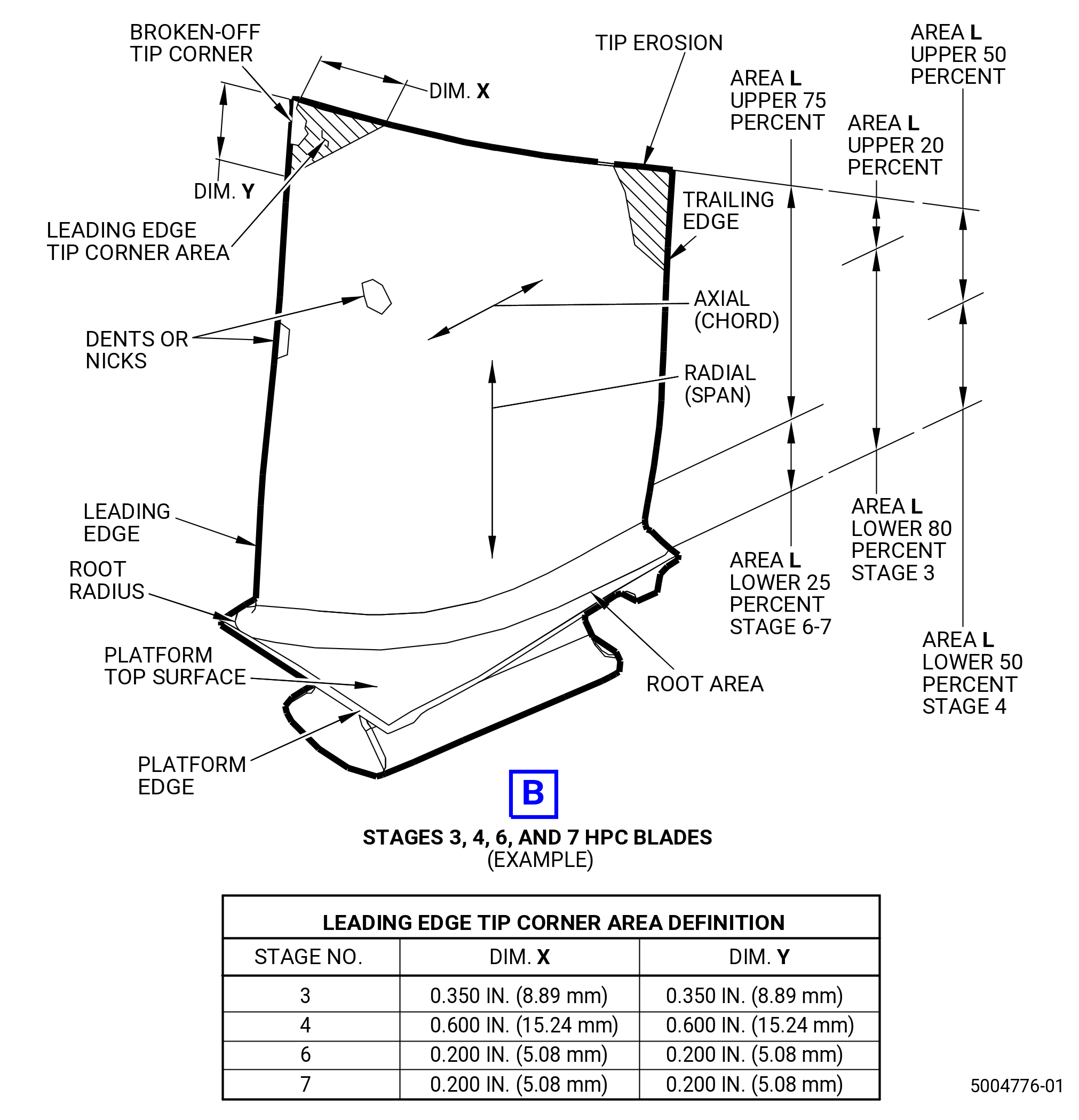
| G. | Do an inspection of the stage 3 compressor rotor blades (057A3). |
| NOTE: |
|
| (1) | All areas for: |
| (a) | Cracks and tears: |
| Maximum serviceable limit: |
|
| Maximum repairable limit: |
|
| Repair method: |
|
| Subtask 72-00-00-220-097 |
| (b) | Radial tip cracks: |
| Maximum serviceable limit: |
|
| Repair method: |
|
| Subtask 72-00-00-220-098 |
| (c) | Scratches: |
| Maximum serviceable limit: |
|
| Maximum repairable limit: |
|
| Repair method: |
|
| Subtask 72-00-00-220-099 |
| (2) | Nicks and dents in the center of the airfoil: |
| Maximum serviceable limit: |
|
| Repair method: |
|
| Subtask 72-00-00-220-100 |
| (3) | Nicks, dents, distortion, or material that is missing on the leading and trailing edges of the airfoil, except the tip corner: |
| Maximum serviceable limit: |
|
| Maximum repairable limit: |
|
| Repair method: |
|
| Subtask 72-00-00-220-101 |
| (4) | Nicks and dents in the airfoil root radius (except leading edge of root radius): |
| Maximum serviceable limit: |
|
| Repair method: |
|
| Subtask 72-00-00-220-755 |
| (5) | Nicks and dents on the leading edge of the airfoil root radius: |
| Maximum serviceable limit: |
|
| Repair method: |
|
| Subtask 72-00-00-220-102 |
| (6) | Missing airfoil tip corners: |
| Maximum serviceable limit: |
|
| Repair method: |
|
| NOTE: |
|
| Subtask 72-00-00-220-103 |
| (7) | Curled blade tips: |
| Maximum serviceable limit: |
|
| Repair method: |
|
| Subtask 72-00-00-220-104 |
| (8) | Cracks, tears, nicks, dents, distortion, and material that is missing from the tip corner: |
| Maximum serviceable limit: |
|
| Repair method: |
|
| Subtask 72-00-00-220-105 |
| (9) | Particles on the blade or tip surfaces: |
| Maximum serviceable limit: |
|
| Repair method: |
|
| Subtask 72-00-00-220-106 |
| (10) | Erosion of the tip, airfoil, and tip corner: |
| Maximum serviceable limit: |
|
| Repair method: |
|
| Subtask 72-00-00-220-107 |
| (11) | Burrs and high metal on the blade tips due to blade rub: |
| Maximum serviceable limit: |
|
| Repair method: |
|
| Subtask 72-00-00-220-743 |
| (12) | Nicks, dents, pits, and scratches on the top surface of the platform: |
| Maximum serviceable limit: |
|
| Repair method: |
|
| Subtask 72-00-00-220-744 |
| (13) | Nicks, dents, pits, rubs, and scratches on the edges of the platform: |
| Maximum serviceable limit: |
|
| Repair method: |
|
| Subtask 72-00-00-220-108 |
| H. | Do an inspection of the stage 4 compressor rotor blades (blades) (057A4). |
| NOTE: |
|
| NOTE: |
|
| NOTE: |
|
| (1) | All areas for: |
| (a) | Cracks and tears: |
| Maximum serviceable limit: |
|
| Maximum repairable limit: |
|
| Repair method: |
|
| Subtask 72-00-00-220-109 |
| (b) | Radial tip cracks: |
| Maximum serviceable limit: |
|
| Repair method: |
|
| Subtask 72-00-00-220-110 |
| (c) | Scratches: |
| Maximum serviceable limit: |
|
| Maximum repairable limit: |
|
| Repair method: |
|
| Subtask 72-00-00-220-111 |
| (2) | Nicks and dents in the center of the airfoil: |
| Maximum serviceable limit: |
|
| Repair method: |
|
| Subtask 72-00-00-220-112 |
| (3) | Nicks, dents, distortion, or material that is missing on the leading and trailing edges of the airfoil, except the tip corner: |
| Maximum serviceable limit: |
|
| Maximum repairable limit: |
|
| Repair method: |
|
| Subtask 72-00-00-220-113 |
| (4) | Nicks and dents in the airfoil root radius: |
| Maximum serviceable limit: |
|
| Repair method: |
|
| Subtask 72-00-00-220-114 |
| (5) | Missing airfoil tip corners: |
| Maximum serviceable limit: |
|
| Repair method: |
|
| NOTE: |
|
| Subtask 72-00-00-220-115 |
| (6) | Curled blade tips: |
| Maximum serviceable limit: |
|
| Repair method: |
|
| Subtask 72-00-00-220-116 |
| (7) | Cracks, tears, nicks, dents, distortion, and material that is missing from the tip corner: |
| Maximum serviceable limit: |
|
| Repair method: |
|
| Subtask 72-00-00-220-117 |
| (8) | Particles on the blade or tip surfaces: |
| Maximum serviceable limit: |
|
| Repair method: |
|
| Subtask 72-00-00-220-118 |
| (9) | Erosion of the tip, airfoil, and tip corner: |
| Maximum serviceable limit: |
|
| Repair method: |
|
| Subtask 72-00-00-220-119 |
| (10) | Burrs and high metal on the blade tips due to blade rub: |
| Maximum serviceable limit: |
|
| Repair method: |
|
| Subtask 72-00-00-220-745 |
| (11) | Nicks, dents, pits, and scratches on the top surface of the platform: |
| Maximum serviceable limit: |
|
| Repair method: |
|
| Subtask 72-00-00-220-746 |
| (12) | Nicks, dents, pits, rubs, and scratches on the edges of the platform: |
| Maximum serviceable limit: |
|
| Repair method: |
|
| Subtask 72-00-00-220-120 |
| I. | Do an inspection of the stage 5 blisk (blisk) (056A5) airfoils. |
| (1) | All areas for: |
| (a) | Cracks and tears: |
| Maximum serviceable limit: |
|
| Maximum repairable limit: |
|
| Repair method: |
|
| Subtask 72-00-00-220-121 |
| (b) | Scratches: |
| Maximum serviceable limit: |
|
| Maximum repairable limit: |
|
| Repair method: |
|
| Subtask 72-00-00-220-122 |
| (2) | Nicks and dents in the center of the airfoil: |
| Maximum serviceable limit: |
|
| Repair method: |
|
| Subtask 72-00-00-220-123 |
| (3) | Nicks, dents, distortion, or material that is missing on the leading and trailing edges of the airfoil, except the tip corner: |
| Maximum serviceable limit: |
|
| Maximum repairable limit: |
|
| Repair method: |
|
| Subtask 72-00-00-220-124 |
| (4) | Nicks and dents in the airfoil root radius: |
| NOTE: |
|
| Maximum serviceable limit: |
|
| Repair method: |
|
| Subtask 72-00-00-220-125 |
| (5) | Missing airfoil tip corners: |
| Maximum serviceable limit: |
|
| Repair method: |
|
| NOTE: |
|
| Subtask 72-00-00-220-126 |
| (6) | Curled blade tips: |
| Maximum serviceable limit: |
|
| Repair method: |
|
| Subtask 72-00-00-220-127 |
| (7) | Distortion or bulging of the leading edge: |
| Maximum serviceable limit: |
|
| Repair method: |
|
| Subtask 72-00-00-220-368 |
| (8) | Airfoil tip heat discoloration: |
| Maximum serviceable limit: |
|
| Repair method: |
|
| Subtask 72-00-00-220-642 |
| (9) | Particles on the blade or tip surfaces: |
| Maximum serviceable limit: |
|
| Repair method: |
|
| Subtask 72-00-00-220-128 |
| J. | Do an inspection of the stage 6 blades (blades) (057A6, 057AD, 057AE, 057AF). Refer to Figure 211. |
| NOTE: |
|
| (1) | All areas for: |
| (a) | Cracks and tears: |
| Maximum serviceable limit: |
|
| Maximum repairable limit: |
|
| Repair method: |
|
| Subtask 72-00-00-220-129 |
| (b) | Radial tip cracks: |
| Maximum serviceable limit: |
|
| Repair method: |
|
| Subtask 72-00-00-220-130 |
| (c) | Scratches: |
| Maximum serviceable limit: |
|
| Maximum repairable limit: |
|
| Repair method: |
|
| Subtask 72-00-00-220-131 |
| (2) | Nicks and dents in the center of the airfoil: |
| Maximum serviceable limit: |
|
| Repair method: |
|
| Subtask 72-00-00-220-132 |
| (3) | Nicks, dents, distortion, or material that is missing on the leading and trailing edges of the airfoil, except the tip corner: |
| Maximum serviceable limit: |
|
| Maximum repairable limit: |
|
| Repair method: |
|
| Subtask 72-00-00-220-133 |
| (4) | Nicks in the airfoil root radius: |
| Maximum serviceable limit: |
|
| Repair method: |
|
| Subtask 72-00-00-220-643 |
| * * * FOR ALL.ALL |
| (5) | Dents in the airfoil root radius except leading edge of the root radius: |
| Maximum serviceable limit: |
|
| Repair method: |
|
| Subtask 72-00-00-220-644 |
| * * * FOR ALL.ALL |
| (6) | Dents in leading edge of the root radius: |
| Maximum serviceable limit: |
|
| Repair method: |
|
| Subtask 72-00-00-220-134 |
| (7) | Missing airfoil tip corners: |
| Maximum serviceable limit: |
|
| Repair method: |
|
| NOTE: |
|
| Subtask 72-00-00-220-135 |
| (8) | Curled blade tips: |
| Maximum serviceable limit: |
|
| Repair method: |
|
| Subtask 72-00-00-220-136 |
| (9) | Cracks, tears, nicks, dents, distortion, and material that is missing from the tip corner: |
| Maximum serviceable limit: |
|
| Repair method: |
|
| Subtask 72-00-00-220-137 |
| (10) | Particles on the blade or tip surfaces: |
| Maximum serviceable limit: |
|
| Repair method: |
|
| Subtask 72-00-00-220-138 |
| (11) | Erosion of the tip, airfoil, and tip corner: |
| Maximum serviceable limit: |
|
| Repair method: |
|
| Subtask 72-00-00-220-139 |
| (12) | Burrs and high metal on the blade tips due to blade rub: |
| Maximum serviceable limit: |
|
| Repair method: |
|
| Subtask 72-00-00-220-747 |
| (13) | Nicks, dents, pits, and scratches on the top surface of the platform: |
| Maximum serviceable limit: |
|
| Repair method: |
|
| Subtask 72-00-00-220-748 |
| (14) | Nicks, dents, pits, rubs, and scratches on the edges of the platform: |
| Maximum serviceable limit: |
|
| Repair method: |
|
| Subtask 72-00-00-220-140 |
| K. | Do an inspection of the stage 7 blades (blade) (057A7, 057AG, 057AH, 057AJ). Refer to Figure 211. |
| NOTE: |
|
| (1) | All areas for: |
| (a) | Cracks and tears: |
| Maximum serviceable limit: |
|
| Maximum repairable limit: |
|
| Repair method: |
|
| Subtask 72-00-00-220-141 |
| (b) | Radial tip cracks: |
| Maximum serviceable limit: |
|
| Repair method: |
|
| Subtask 72-00-00-220-142 |
| (c) | Scratches: |
| Maximum serviceable limit: |
|
| Maximum repairable limit: |
|
| Repair method: |
|
| Subtask 72-00-00-220-143 |
| (2) | Nicks and dents in the center of the airfoil: |
| Maximum serviceable limit: |
|
| Repair method: |
|
| Subtask 72-00-00-220-144 |
| (3) | Nicks, dents, distortion, or material that is missing on the leading and trailing edges of the airfoil, except the tip corner: |
| Maximum serviceable limit: |
|
| Maximum repairable limit: |
|
| Repair method: |
|
| Subtask 72-00-00-220-145 |
| (4) | Nicks in the airfoil root radius: |
| Maximum serviceable limit: |
|
| Repair method: |
|
| Subtask 72-00-00-220-645 |
| * * * FOR ALL.ALL |
| (5) | Dents in the airfoil root radius except leading edge of the root radius: |
| Maximum serviceable limit: |
|
| Repair method: |
|
| Subtask 72-00-00-220-646 |
| * * * FOR ALL.ALL |
| (6) | Dents in leading edge of the root radius: |
| Maximum serviceable limit: |
|
| Repair method: |
|
| Subtask 72-00-00-220-146 |
| (7) | Missing airfoil tip corners: |
| Maximum serviceable limit: |
|
| Repair method: |
|
| NOTE: |
|
| Subtask 72-00-00-220-147 |
| (8) | Curled blade tips: |
| Maximum serviceable limit: |
|
| Repair method: |
|
| Subtask 72-00-00-220-148 |
| (9) | Cracks, tears, nicks, dents, distortion, and material that is missing from the tip corner: |
| Maximum serviceable limit: |
|
| Repair method: |
|
| Subtask 72-00-00-220-149 |
| (10) | Particles on the blade or tip surfaces: |
| Maximum serviceable limit: |
|
| Repair method: |
|
| Subtask 72-00-00-220-150 |
| (11) | Erosion of the tip, airfoil, and tip corner: |
| Maximum serviceable limit: |
|
| Repair method: |
|
| Subtask 72-00-00-220-151 |
| (12) | Burrs and high metal on the blade tips due to blade rub: |
| Maximum serviceable limit: |
|
| Repair method: |
|
| Subtask 72-00-00-220-749 |
| (13) | Nicks, dents, pits, and scratches on the top surface of the platform: |
| Maximum serviceable limit: |
|
| Repair method: |
|
| Subtask 72-00-00-220-750 |
| (14) | Nicks, dents, pits, rubs, and scratches on the edges of the platform: |
| Maximum serviceable limit: |
|
| Repair method: |
|
| Subtask 72-00-00-220-152 |
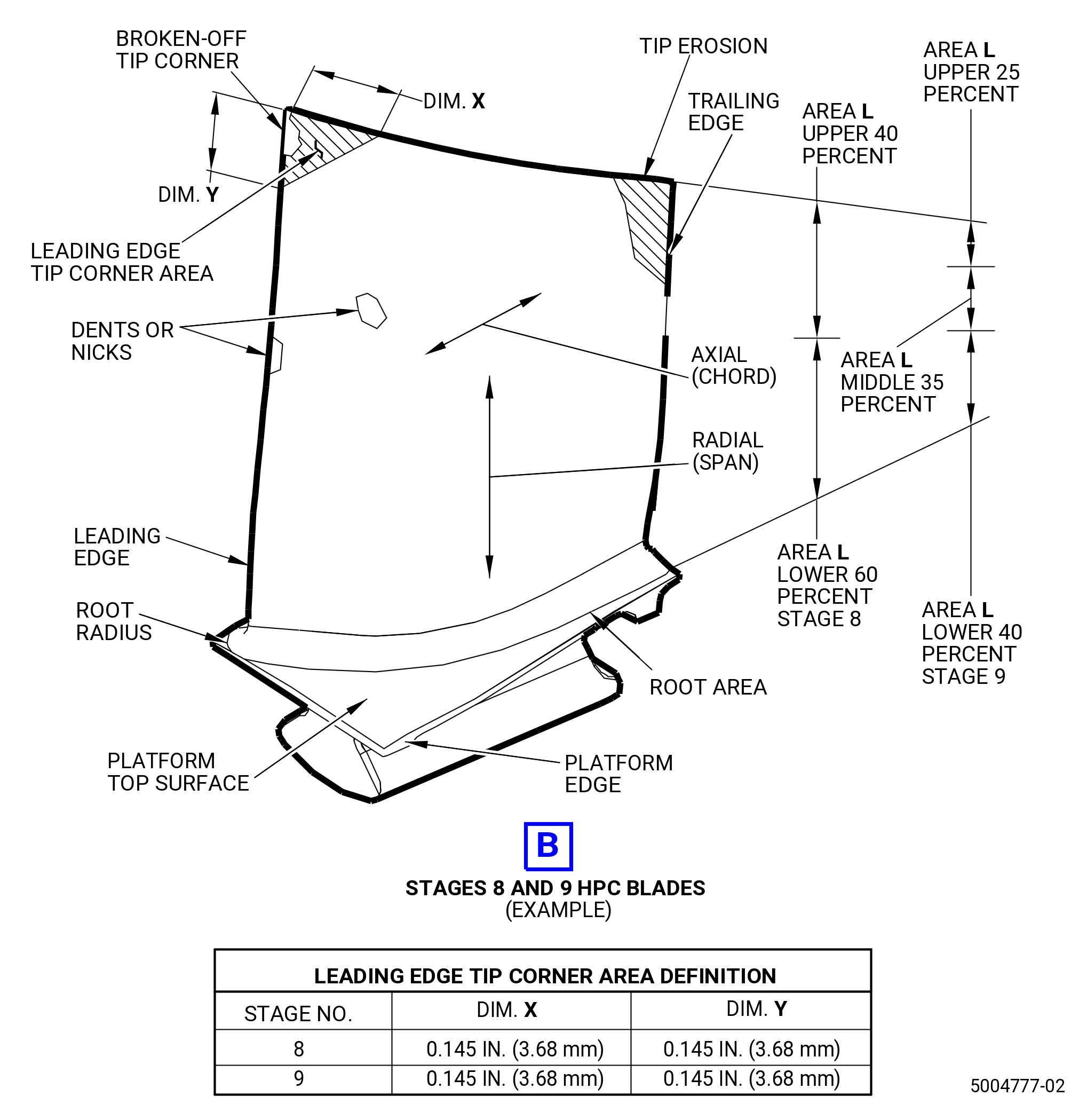
| L. | Do an inspection of the stage 8 regular blades (blades) (057A8, 057B8, 057C8, 057D8). |
| NOTE: |
|
| (1) | All areas for: |
| (a) | Cracks and tears: |
| Maximum serviceable limit: |
|
| Maximum repairable limit: |
|
| Repair method: |
|
| Subtask 72-00-00-220-153 |
| (b) | Radial tip cracks: |
| Maximum serviceable limit: |
|
| Repair method: |
|
| Subtask 72-00-00-220-154 |
| (c) | Scratches: |
| Maximum serviceable limit: |
|
| Maximum repairable limit: |
|
| Repair method: |
|
| Subtask 72-00-00-220-155 |
| (2) | Nicks and dents in the center of the airfoil: |
| Maximum serviceable limit: |
|
| Repair method: |
|
| Subtask 72-00-00-220-156 |
| (3) | Nicks, dents, distortion, or material that is missing on the leading and trailing edges of the airfoil, except the tip corner: |
| Maximum serviceable limit: |
|
| Maximum repairable limit: |
|
| Repair method: |
|
| Subtask 72-00-00-220-157 |
| (4) | Nicks in the airfoil root radius: |
| Maximum serviceable limit: |
|
| Repair method: |
|
| Subtask 72-00-00-220-647 |
| * * * FOR ALL.ALL |
| (5) | Dents in the airfoil root radius except leading edge of the root radius: |
| Maximum serviceable limit: |
|
| Repair method: |
|
| Subtask 72-00-00-220-648 |
| * * * PRE SB 72-0157 |
| (6) | Dents in leading edge of the root radius: |
| Maximum serviceable limit: |
|
| • |
|
| • |
|
| Repair method: |
|
| * * * END PRE SB 72-0157 |
| Subtask 72-00-00-220-714 |
| * * * SB 72-0157 |
| (6).A. | Dents in leading edge of the root radius: |
| Maximum serviceable limit: |
|
| • |
|
| • |
|
| Repair method: |
|
| * * * END SB 72-0157 |
| Subtask 72-00-00-220-158 |
| (7) | Missing airfoil tip corners: |
| Maximum serviceable limit: |
|
| Repair method: |
|
| NOTE: |
|
| Subtask 72-00-00-220-159 |
| (8) | Curled blade tips: |
| Maximum serviceable limit: |
|
| Repair method: |
|
| Subtask 72-00-00-220-160 |
| (9) | Cracks, tears, nicks, dents, distortion, and material that is missing from the tip corner: |
| Maximum serviceable limit: |
|
| Repair method: |
|
| Subtask 72-00-00-220-161 |
| (10) | Particles on the blade or tip surfaces: |
| Maximum serviceable limit: |
|
| Repair method: |
|
| Subtask 72-00-00-220-162 |
| (11) | Erosion of the tip, airfoil, and tip corner: |
| Maximum serviceable limit: |
|
| Repair method: |
|
| Subtask 72-00-00-220-163 |
| (12) | Burrs and high metal on the blade tips due to blade rub: |
| Maximum serviceable limit: |
|
| Repair method: |
|
| Subtask 72-00-00-220-751 |
| * * * FOR ALL.ALL |
| (13) | Nicks, dents, pits, and scratches on the top surface of the platform: |
| Maximum serviceable limit: |
|
| Repair method: |
|
| Subtask 72-00-00-220-752 |
| * * * FOR ALL.ALL |
| (14) | Nicks, dents, pits, rubs, and scratches on the edges of the platform: |
| Maximum serviceable limit: |
|
| Repair method: |
|
| Subtask 72-00-00-220-164 |
| M. | Do an inspection of the stage 9 regular blades (blades) (057A9, 057B9, 057C9, 057D9). |
| NOTE: |
|
| (1) | All areas for: |
| (a) | Cracks and tears: |
| Maximum serviceable limit: |
|
| Maximum repairable limit: |
|
| Repair method: |
|
| Subtask 72-00-00-220-165 |
| (b) | Radial tip cracks: |
| Maximum serviceable limit: |
|
| Repair method: |
|
| Subtask 72-00-00-220-166 |
| (c) | Scratches: |
| Maximum serviceable limit: |
|
| Maximum repairable limit: |
|
| Repair method: |
|
| Subtask 72-00-00-220-167 |
| (2) | Nicks and dents in the center of the airfoil: |
| Maximum serviceable limit: |
|
| Repair method: |
|
| Subtask 72-00-00-220-168 |
| (3) | Nicks, dents, distortion, or material that is missing on the leading and trailing edges of the airfoil, except the tip corner: |
| Maximum serviceable limit: |
|
| Maximum repairable limit: |
|
| Repair method: |
|
| Subtask 72-00-00-220-169 |
| (4) | Nicks in the airfoil root radius: |
| Maximum serviceable limit: |
|
| Repair method: |
|
| Subtask 72-00-00-220-649 |
| * * * FOR ALL.ALL |
| (5) | Dents in the airfoil root radius except leading edge of the root radius: |
| Maximum serviceable limit: |
|
| Repair method: |
|
| Subtask 72-00-00-220-650 |
| * * * FOR ALL.ALL |
| (6) | Dents in leading edge of the root radius: |
| Maximum serviceable limit: |
|
| Repair method: |
|
| Subtask 72-00-00-220-170 |
| (7) | Missing airfoil tip corners: |
| Maximum serviceable limit: |
|
| Repair method: |
|
| NOTE: |
|
| Subtask 72-00-00-220-171 |
| (8) | Curled blade tips: |
| Maximum serviceable limit: |
|
| Repair method: |
|
| Subtask 72-00-00-220-172 |
| (9) | Cracks, tears, nicks, dents, distortion, and material that is missing from the tip corner: |
| Maximum serviceable limit: |
|
| Repair method: |
|
| Subtask 72-00-00-220-173 |
| (10) | Particles on the blade or tip surfaces: |
| Maximum serviceable limit: |
|
| Repair method: |
|
| Subtask 72-00-00-220-174 |
| (11) | Erosion of the tip, airfoil, and tip corner: |
| Maximum serviceable limit: |
|
| Repair method: |
|
| Subtask 72-00-00-220-175 |
| (12) | Burrs and high metal on the blade tips due to blade rub: |
| Maximum serviceable limit: |
|
| Repair method: |
|
| Subtask 72-00-00-220-753 |
| * * * FOR ALL.ALL |
| (13) | Nicks, dents, pits, and scratches on the top surface of the platform: |
| Maximum serviceable limit: |
|
| Repair method: |
|
| Subtask 72-00-00-220-754 |
| * * * FOR ALL.ALL |
| (14) | Nicks, dents, pits, rubs, and scratches on the edges of the platform: |
| Maximum serviceable limit: |
|
| Repair method: |
|
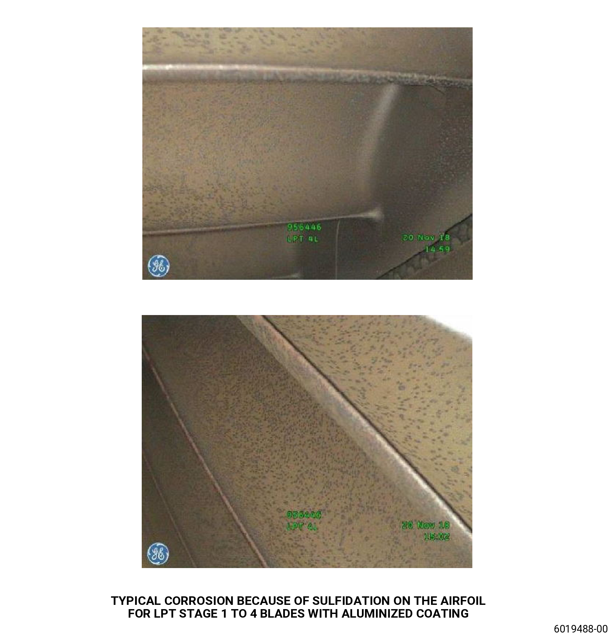
| Subtask 72-00-00-220-176 |
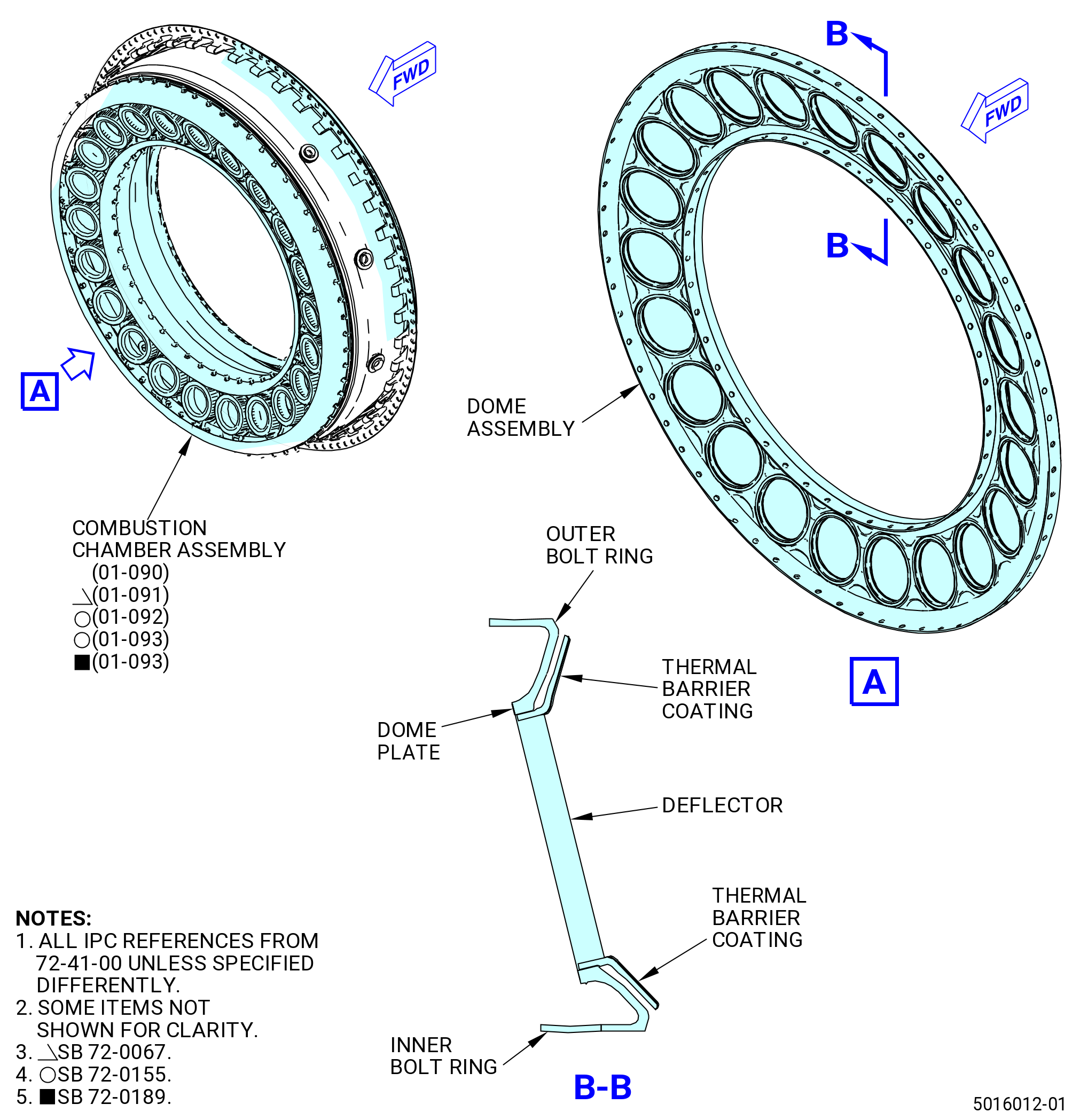
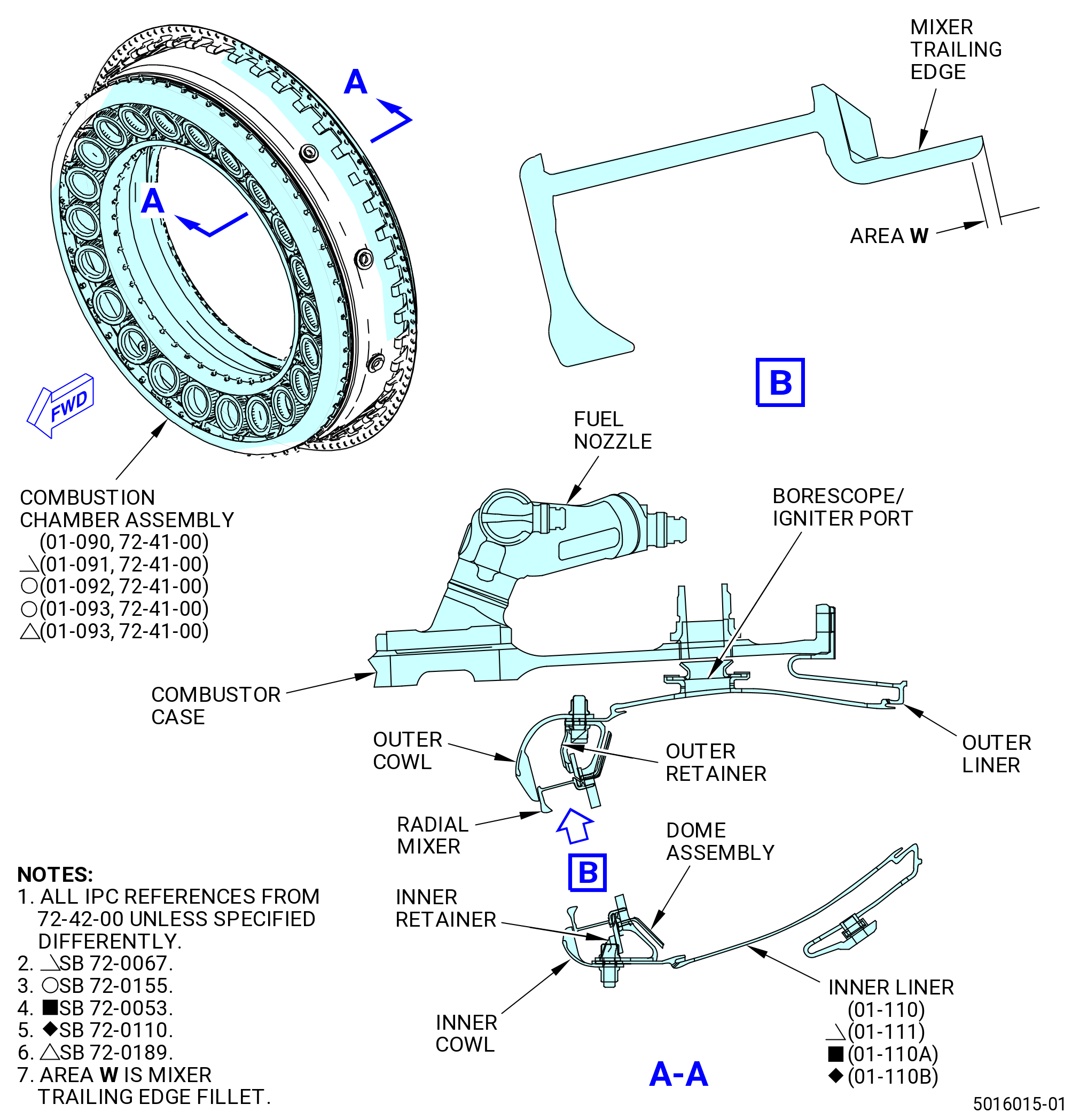
| N. | Do an inspection of the combustion chamber assembly (01-090 , 72-41-00) (SIN 12400) or (01-091 , 72-41-00) (SIN 12400) or (01-092 , 72-41-00) (SIN 12400) or (01-093 , 72-41-00) (SIN 12400). Refer to Figure 213 and as follows: |
| (1) | All areas for: |
| (a) | Discoloration: |
| Maximum serviceable limit: |
|
| Repair method: |
|
| Subtask 72-00-00-220-177 |
| (b) | Carbon accumulation: |
| Maximum serviceable limit: |
|
| Repair method: |
|
| Subtask 72-00-00-220-178 |
| (2) | Deflectors on the combustion chamber dome assembly (dome assembly) for: |
| (a) | Circumferential or radial cracks (this does not include dome plate): |
| Maximum serviceable limit: |
|
| Repair method: |
|
| Subtask 72-00-00-220-179 |
| (b) | Circumferential or radial cracks on dome plate: |
| Maximum serviceable limit: |
|
| Repair method: |
|
| Subtask 72-00-00-220-180 |
| (c) | Spalling or missing thermal barrier coating (TBC): |
| Maximum serviceable limit: |
|
| Repair method: |
|
| Subtask 72-00-00-220-181 |
| (d) | Missing material, burns, and erosion: |
| Maximum serviceable limit: |
|
| Repair method: |
|
| Subtask 72-00-00-220-182 |
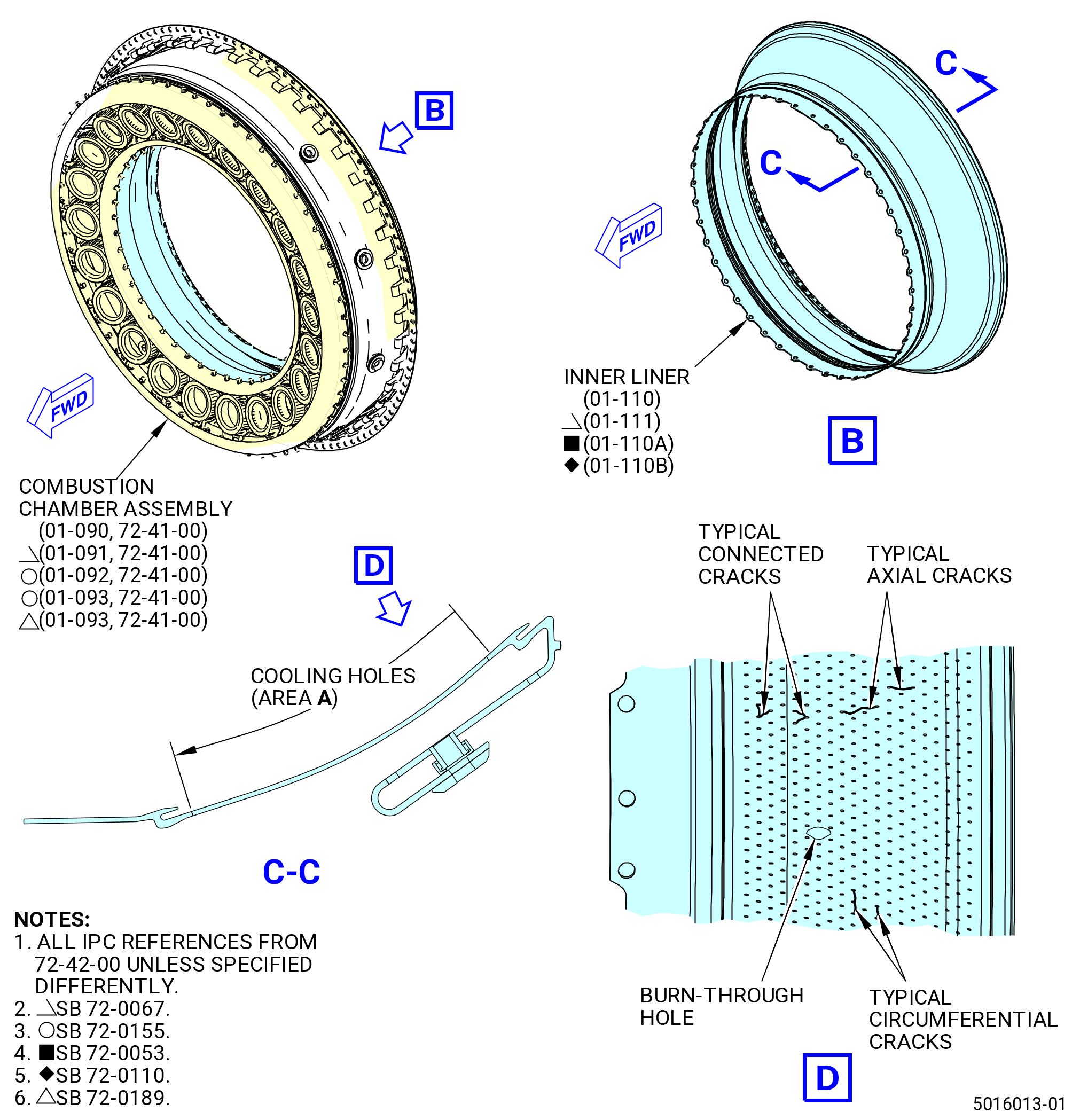
| (3) | Combustion chamber inner liner (inner liner) (01-110 , 72-42-00) (SIN 12400 3) or (01-110A , 72-42-00) (SIN 12400 3) or (01-110B , 72-42-00) (SIN 12400 3) or (01-111 , 72-42-00) (SIN 12400 3). Refer to Figure 214. |
| (a) | Cracks: |
| Maximum serviceable limit: |
|
| Repair method: |
|
| Subtask 72-00-00-220-183 |
| (b) | Burn through or missing material: |
| Maximum serviceable limit: |
|
| Repair method: |
|
| Subtask 72-00-00-220-184 |
| (c) | Distortion: |
| Maximum serviceable limit: |
|
| Repair method: |
|
| Subtask 72-00-00-220-185 |
| (d) | Spalling or erosion of the thermal barrier coating: |
| Maximum serviceable limit: |
|
| Repair method: |
|
| Subtask 72-00-00-220-186 |
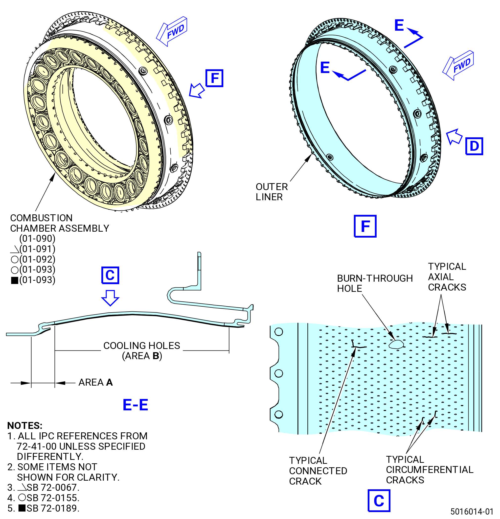
| (4) | Combustion chamber outer liner (outer liner) for. Refer to Figure 215. |
| (a) | Cracks: |
| Maximum serviceable limit: |
|
| Repair method: |
|
| Subtask 72-00-00-220-187 |
| (b) | Burn through or missing material: |
| Maximum serviceable limit: |
|
| Repair method: |
|
| Subtask 72-00-00-220-188 |
| (c) | Distortion: |
| Maximum serviceable limit: |
|
| Repair method: |
|
| Subtask 72-00-00-220-189 |
| (d) | Spalling or erosion of the thermal barrier coating: |
| Maximum serviceable limit: |
|
| Repair method: |
|
| Subtask 72-00-00-220-190 |
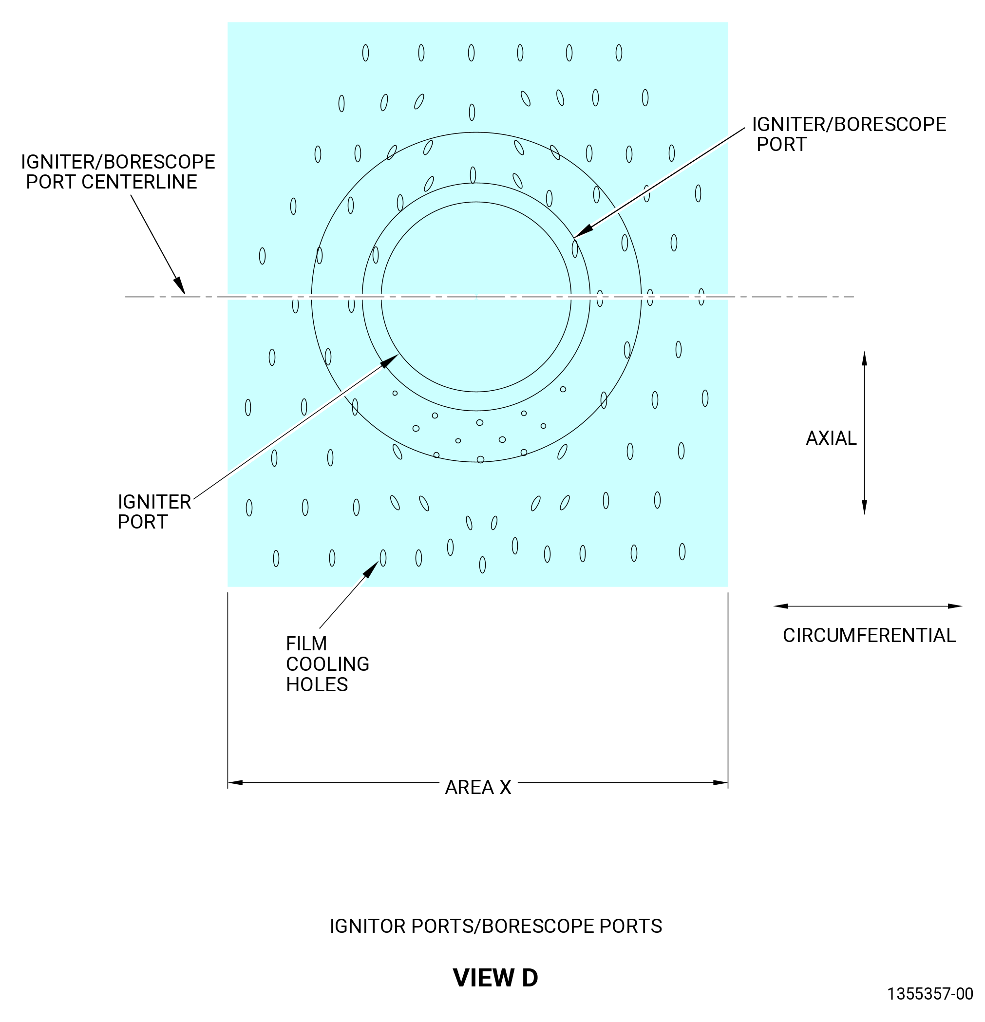
| (5) | Borescope and igniter ports of the outer liner area X for. Refer to Figure 216. |
| (a) | Missing thermal barrier coating: |
| Maximum serviceable limit: |
|
| Repair method: |
|
| Subtask 72-00-00-220-191 |
| (b) | Circumferential cracks: |
| Maximum serviceable limit: |
|
| Repair method: |
|
| Subtask 72-00-00-220-192 |
| (c) | Axial cracks: |
| Maximum serviceable limit: |
|
| Repair method: |
|
| Subtask 72-00-00-220-193 |
| (d) | Connected cracks: |
| Maximum serviceable limit: |
|
| Repair method: |
|
| Subtask 72-00-00-220-194 |
| (e) | Burn through or missing material: |
| Maximum serviceable limit: |
|
| Repair method: |
|
| Subtask 72-00-00-220-195 |
| (6) | Radial mixer area W for. Refer to Figure 216. |
| (a) | Oxidation or missing metal: |
| Maximum serviceable limit: |
|
| Repair method: |
|
| Subtask 72-00-00-220-196 |
| (7) | Fuel nozzles: |
| (a) | Carbon accumulation: |
| Maximum serviceable limit: |
|
| Repair method: |
|
| Subtask 72-00-00-220-197 |
| (b) | Missing thermal barrier coating: |
| Maximum serviceable limit: |
|
| Repair method: |
|
| Subtask 72-00-00-220-198 |
| (c) | Oxidation or missing metal: |
| Maximum serviceable limit: |
|
| Repair method: |
|
| Subtask 72-00-00-220-199 |
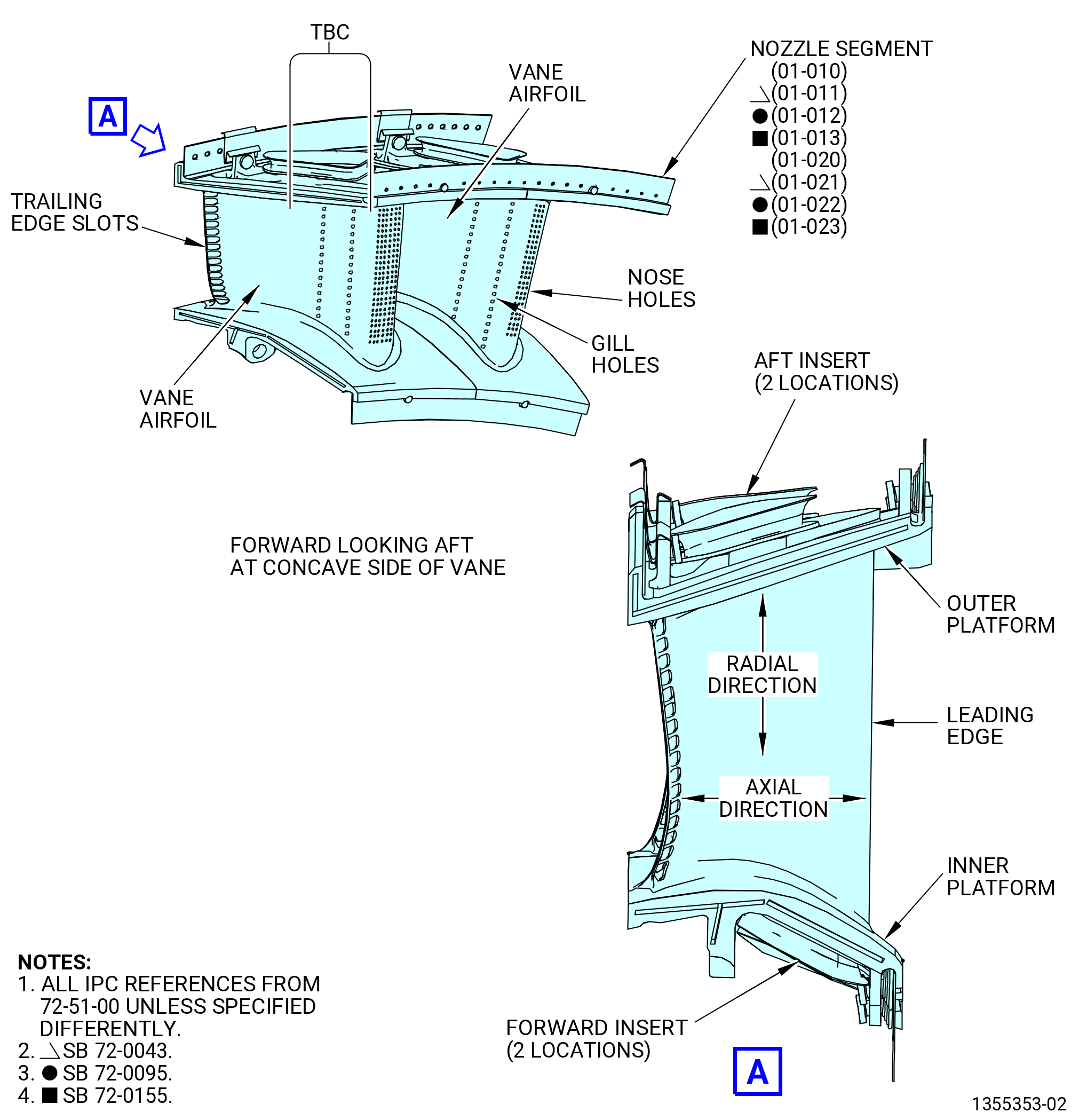
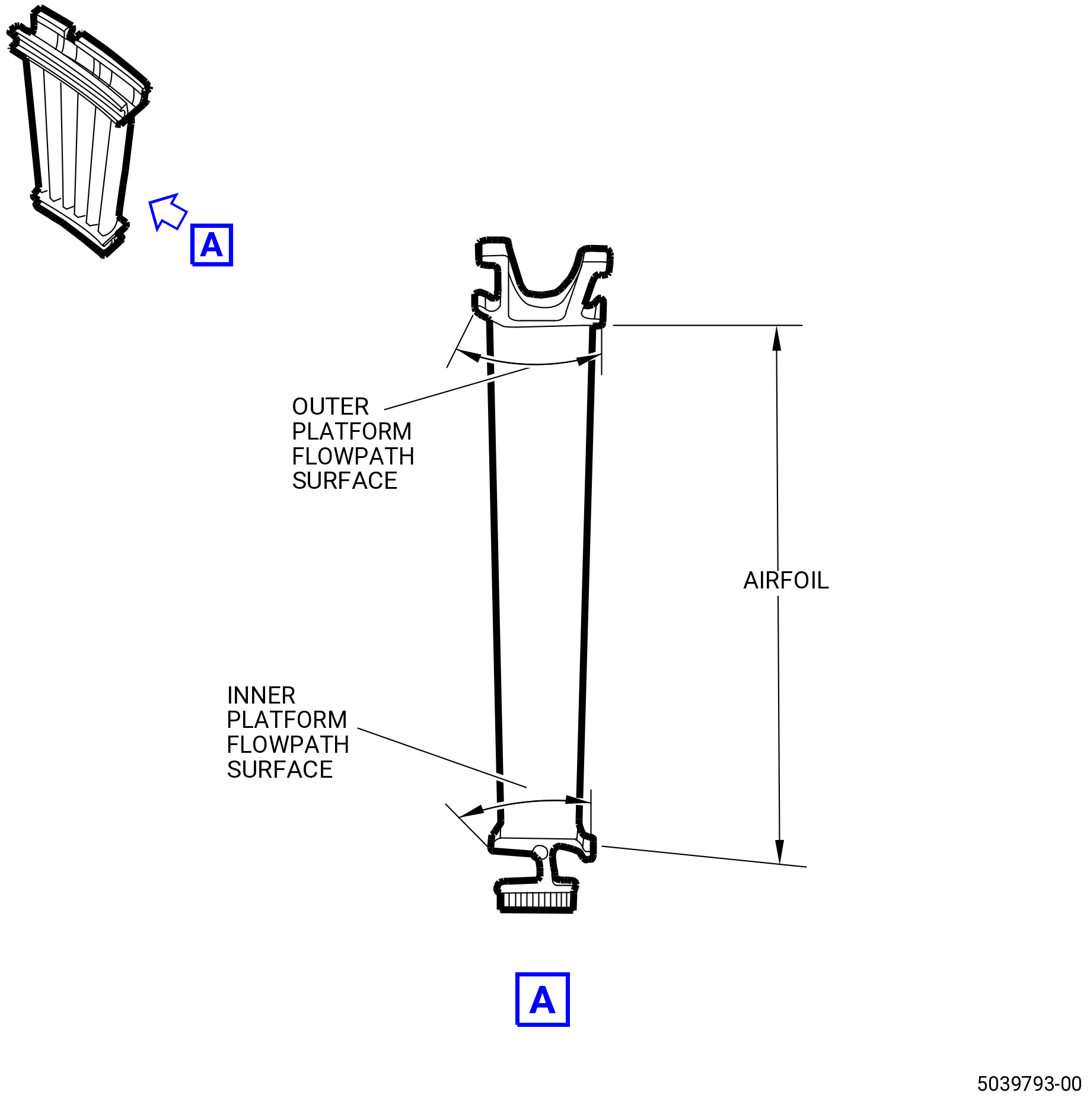
| O. | Do an inspection of the stage 1 nozzles (nozzle segments) (01-020 , 72-51-00) (SIN 172A0) or (01-021 , 72-51-00) (SIN 172A0) or (01-022 , 72-51-00) (SIN 172A0) or (01-023 , 72-51-00) (SIN 172A0) and (01-010 , 72-51-00) (SIN 172A8) or (01-011 , 72-51-00) (SIN 172A8) or (01-012 , 72-51-00) (SIN 172A8) or (01-013 , 72-51-00) (SIN 172A8). Refer to Figure 212. |
| (1) | Leading edges of the vane airfoils for: |
| (a) | Missing thermal barrier coating: |
| Maximum serviceable limit: |
|
| Repair method: |
|
| Subtask 72-00-00-220-200 |
| (b) | Cracks that connect the nose holes: |
| Maximum serviceable limit: |
|
| Repair method: |
|
| Subtask 72-00-00-220-201 |
| (c) | Cracks that extend from a nose hole(s) but do not connect with another nose hole(s): |
| Maximum serviceable limit: |
|
| Repair method: |
|
| Subtask 72-00-00-220-202 |
| (d) | Burns or erosion (the surface is burned and no holes through the parent metal): |
| Maximum serviceable limit: |
|
| Repair method: |
|
| Subtask 72-00-00-220-203 |
| P. | Do an inspection of the nozzle segments (01-020 , 72-51-00) (SIN 172A0) or (01-021 , 72-51-00) (SIN 172A0) or (01-022 , 72-51-00) (SIN 172A0) or (01-023 , 72-51-00) (SIN 172A0) and (01-010 , 72-51-00) (SIN 172A8) or (01-011 , 72-51-00) (SIN 172A8) or (01-012 , 72-51-00) (SIN 172A8) or (01-013 , 72-51-00) (SIN 172A8). Refer to Figure 212. |
| (1) | Concave side of each vane airfoil on the nozzle: |
| (a) | Radial cracks that connect gill holes of the forward row: |
| Maximum serviceable limit: |
|
| Repair method: |
|
| Subtask 72-00-00-220-204 |
| (b) | Axial cracks: |
| Maximum serviceable limit: |
|
| Repair method: |
|
| Subtask 72-00-00-220-205 |
| (c) | Cracks in the fillet area adjacent to the inner and outer platforms: |
| Maximum serviceable limit: |
|
| Repair method: |
|
| Subtask 72-00-00-220-206 |
| (d) | Other cracks, not in the gill holes: |
| Maximum serviceable limit: |
|
| Repair method: |
|
| Subtask 72-00-00-220-207 |
| (e) | Burns (no holes through the vane airfoil): |
| Maximum serviceable limit: |
|
| Repair method: |
|
| Subtask 72-00-00-220-208 |
| (2) | Convex side of each vane airfoil on the nozzle for: |
| (a) | Radial cracks that connect gill holes of the forward row: |
| Maximum serviceable limit: |
|
| Repair method: |
|
| Subtask 72-00-00-220-209 |
| (b) | Axial cracks: |
| Maximum serviceable limit: |
|
| Repair method: |
|
| Subtask 72-00-00-220-210 |
| (c) | Cracks in the fillet area adjacent to the inner and outer platforms: |
| Maximum serviceable limit: |
|
| Repair method: |
|
| Subtask 72-00-00-220-211 |
| (d) | Other cracks, not in the gill holes: |
| Maximum serviceable limit: |
|
| Repair method: |
|
| Subtask 72-00-00-220-212 |
| (e) | Burns (no holes through the vane airfoil): |
| Maximum serviceable limit: |
|
| Repair method: |
|
| Subtask 72-00-00-220-213 |
| (3) | Trailing edge of each vane airfoil on the nozzle: |
| (a) | Axial cracks in that start at the slots adjacent to the trailing edge: |
| Maximum serviceable limit: |
|
| Repair method: |
|
| Subtask 72-00-00-220-214 |
| (b) | Bulging or bowing: |
| Maximum serviceable limit: |
|
| Repair method: |
|
| Subtask 72-00-00-220-215 |
| (c) | Missing material: |
| Maximum serviceable limit: |
|
| Repair method: |
|
| Subtask 72-00-00-220-216 |
| (4) | All areas of the nozzle segment for: |
| (a) | Craze cracks: |
| Maximum serviceable limit: |
|
| Repair method: |
|
| Subtask 72-00-00-220-217 |
| (b) | Nicks, scores, scratches, and dents: |
| Maximum serviceable limit: |
|
| Repair method: |
|
| Subtask 72-00-00-220-218 |
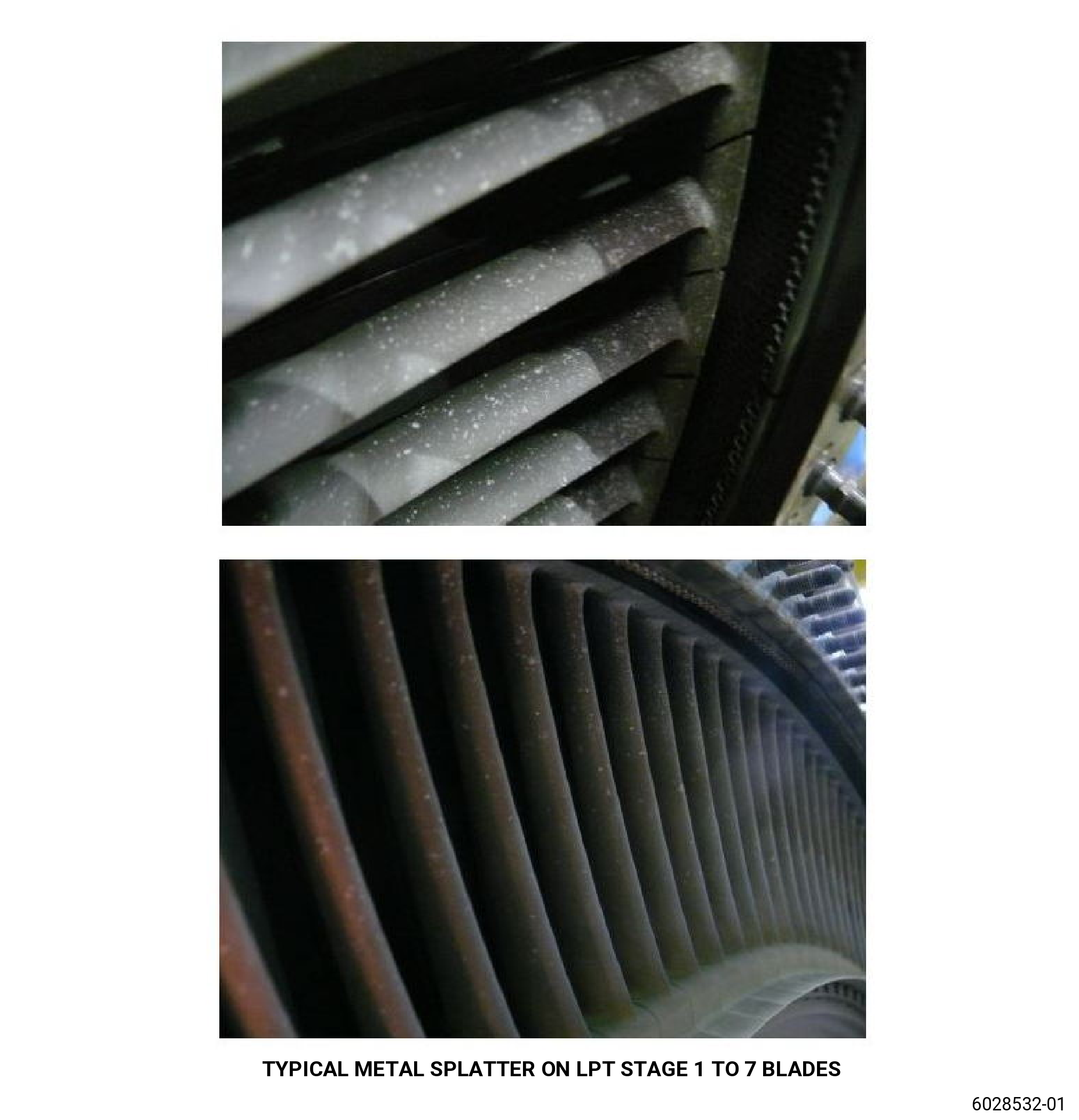
| (c) | Metal splatter: |
| Maximum serviceable limit: |
|
| Repair method: |
|
| Subtask 72-00-00-220-219 |
| (5) | Inner platform of each nozzle segment: |
| (a) | Cracks in parent metal: |
| Maximum serviceable limit: |
|
| Repair method: |
|
| Subtask 72-00-00-220-220 |
| (b) | Nicks, scores, scratches, and dents: |
| Maximum serviceable limit: |
|
| Repair method: |
|
| Subtask 72-00-00-220-221 |
| (c) | Burns (no holes through the platform): |
| Maximum serviceable limit: |
|
| Repair method: |
|
| Subtask 72-00-00-220-222 |
| (d) | Bulging or bowing: |
| Maximum serviceable limit: |
|
| Repair method: |
|
| Subtask 72-00-00-220-223 |
| (6) | Outer platform of each nozzle segment for: |
| (a) | Cracks in parent metal: |
| Maximum serviceable limit: |
|
| Repair method: |
|
| Subtask 72-00-00-220-224 |
| (b) | Nicks, scores, scratches, and dents: |
| Maximum serviceable limit: |
|
| Repair method: |
|
| Subtask 72-00-00-220-225 |
| (c) | Burns (no holes through the platform): |
| Maximum serviceable limit: |
|
| Repair method: |
|
| Subtask 72-00-00-220-226 |
| (d) | Bulging or bowing: |
| Maximum serviceable limit: |
|
| Repair method: |
|
| Subtask 72-00-00-220-227 |
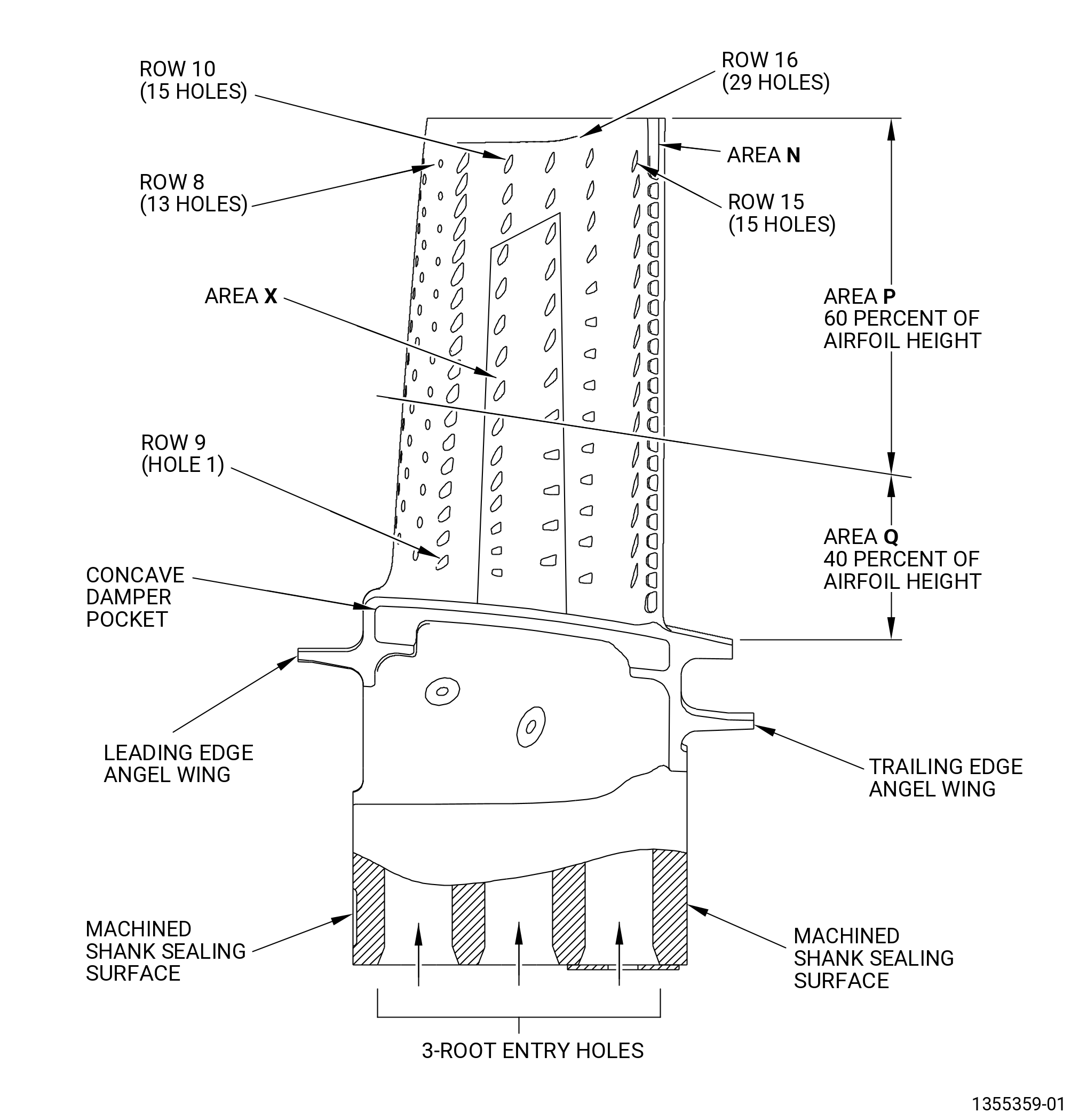
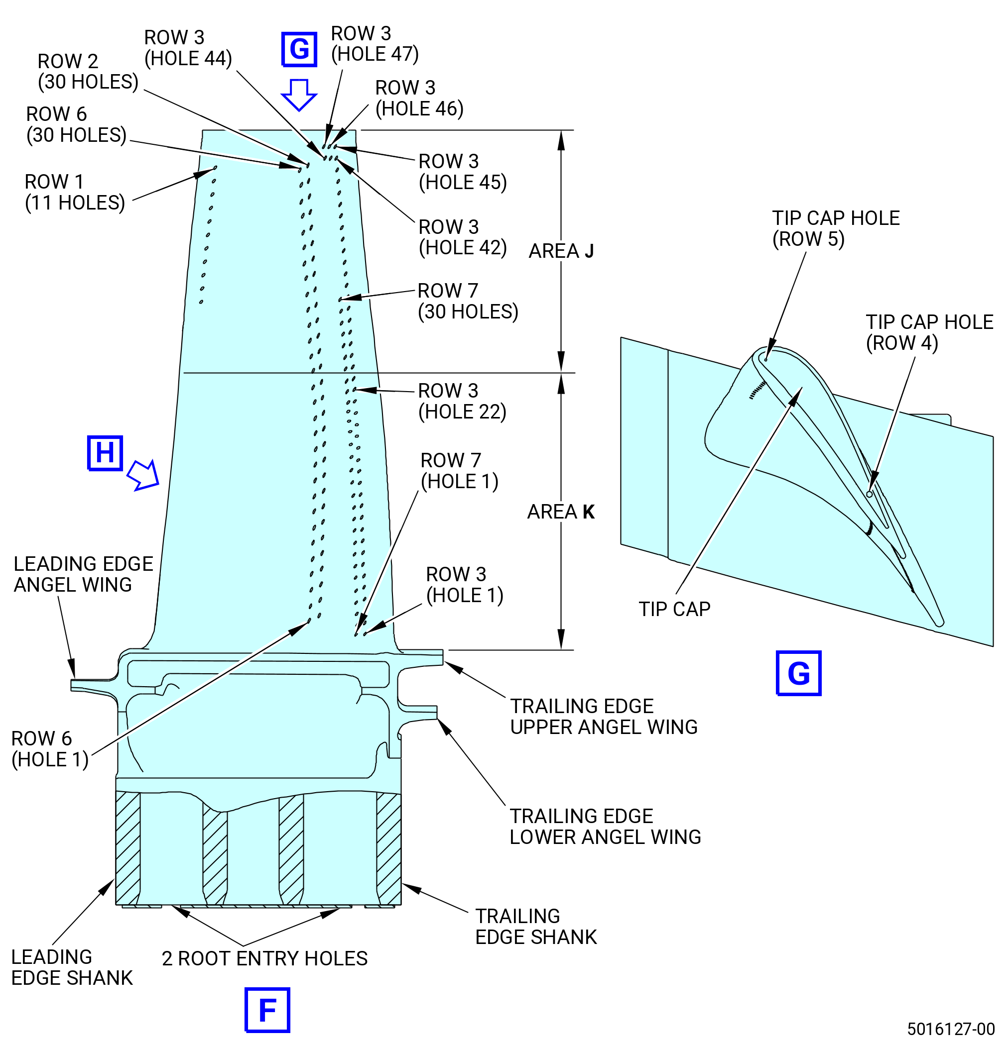
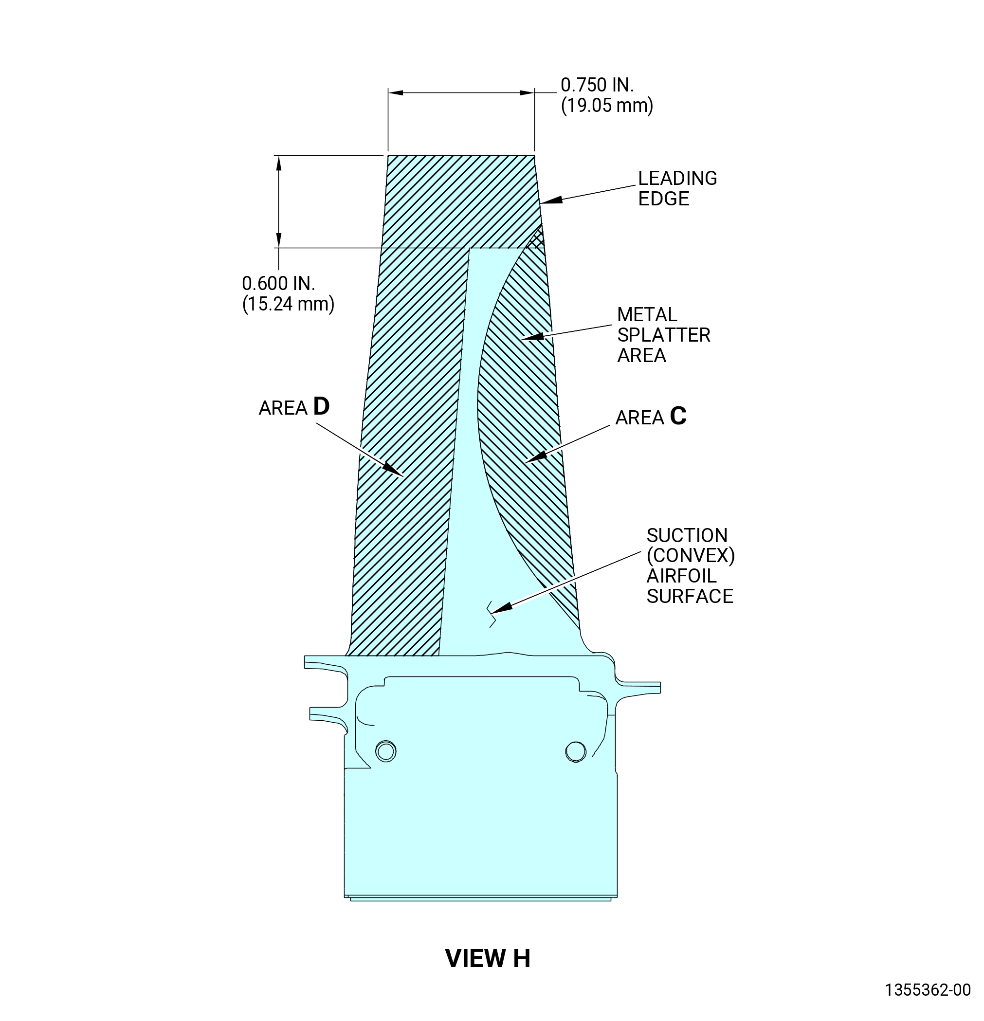
| Q. | Do an inspection of the HPT stage 1 blades (blades) (150A0). Refer to Figure 217. |
| (1) | Airfoil surfaces of each blade: |
| (a) | Missing surface coating: |
| Maximum serviceable limit: |
|
| Repair method: |
|
| Subtask 72-00-00-220-228 |
| (b) | Radial cracks on the pressure (concave) airfoil between, but not related to row 9 and 10 air holes: |
| Maximum serviceable limit: |
|
| Repair method: |
|
| Subtask 72-00-00-220-229 |
| (c) | Cracks on concave side of the airfoil that come from row 10 cooling holes 8 through 15: |
| Maximum serviceable limit: |
|
| Repair method: |
|
| Subtask 72-00-00-220-363 |
| (d) | Cracks on the concave side of the airfoil that go out of row 15 of the cooling holes toward row 12 of the cooling holes: |
| Maximum serviceable limit: |
|
| Repair method: |
|
| Subtask 72-00-00-220-230 |
| (2) | Leading edge for: |
| (a) | Axial and radial cracks in the nose holes (rows 4 thru 8) in area P: |
| Maximum serviceable limit: |
|
| Repair method: |
|
| Subtask 72-00-00-220-231 |
| (b) | Axial cracks in the nose holes (rows 4 thru 8) in area Q: |
| Maximum serviceable limit: |
|
| Repair method: |
|
| Subtask 72-00-00-220-232 |
| (c) | Radial cracks that go out of the area Q leading edge holes: |
| Maximum serviceable limit: |
|
| Repair method: |
|
| Subtask 72-00-00-220-233 |
| (d) | Nicks and dents in area P: |
| Maximum serviceable limit: |
|
| Repair method: |
|
| Subtask 72-00-00-220-234 |
| (e) | Nicks and dents in area Q: |
| Maximum serviceable limit: |
|
| Repair method: |
|
| Subtask 72-00-00-220-235 |
| (f) | Missing material in areas P and Q: |
| Maximum serviceable limit: |
|
| Repair method: |
|
| Subtask 72-00-00-220-236 |
| (g) | Deleted. |
| Subtask 72-00-00-220-364 |
| (h) | Blocked nose holes (rows 4 thru 8) in area P: |
| Maximum serviceable limit: |
|
| Repair method: |
|
| Subtask 72-00-00-220-365 |
| (i) | Blocked nose holes (rows 4 thru 8) in area Q: |
| Maximum serviceable limit: |
|
| Repair method: |
|
| Subtask 72-00-00-220-237 |
| (3) | Concave side of each blade for: |
| (a) | Radial cracks at the film and gill hole: |
| Maximum serviceable limit: |
|
| Repair method: |
|
| Subtask 72-00-00-220-238 |
| (b) | Radial cracks in areas P and Q other than at the film or gill holes: |
| Maximum serviceable limit: |
|
| Repair method: |
|
| Subtask 72-00-00-220-239 |
| (c) | Deleted. |
| Subtask 72-00-00-220-240 |
| (d) | Radial cracks that go out of the tips of the film holes: |
| Maximum serviceable limit: |
|
| Repair method: |
|
| Subtask 72-00-00-220-241 |
| (e) | Nicks and dents in area P: |
| Maximum serviceable limit: |
|
| Repair method: |
|
| Subtask 72-00-00-220-242 |
| (f) | Nicks and dents in area Q: |
| Maximum serviceable limit: |
|
| Repair method: |
|
| Subtask 72-00-00-220-243 |
| (g) | Axial cracks in areas P and Q: |
| Maximum serviceable limit: |
|
| Repair method: |
|
| Subtask 72-00-00-220-244 |
| (h) | Twisted, bent, burnt, or melted airfoil surfaces: |
| Maximum serviceable limit: |
|
| Repair method: |
|
| Subtask 72-00-00-220-245 |
| (4) | Convex side of each blade for: |
| (a) | Radial cracks at the film and gill hole: |
| Maximum serviceable limit: |
|
| Repair method: |
|
| Subtask 72-00-00-220-246 |
| (b) | Radial cracks in areas P and Q other than at the film or gill holes: |
| Maximum serviceable limit: |
|
| Repair method: |
|
| Subtask 72-00-00-220-247 |
| (c) | Deleted. |
| Subtask 72-00-00-220-248 |
| (d) | Radial cracks that go out of the tips of the film holes: |
| Maximum serviceable limit: |
|
| Repair method: |
|
| Subtask 72-00-00-220-249 |
| (e) | Nicks and dents in area P: |
| Maximum serviceable limit: |
|
| Repair method: |
|
| Subtask 72-00-00-220-250 |
| (f) | Nicks and dents in area Q: |
| Maximum serviceable limit: |
|
| Repair method: |
|
| Subtask 72-00-00-220-251 |
| (g) | Axial cracks in areas P and Q: |
| Maximum serviceable limit: |
|
| Repair method: |
|
| Subtask 72-00-00-220-252 |
| (h) | Twisted, bent, burnt, or melted airfoil surfaces: |
| Maximum serviceable limit: |
|
| Repair method: |
|
| Subtask 72-00-00-220-253 |
| (5) | Trailing edge for: |
| (a) | Axial cracks in area P: |
| Maximum serviceable limit: |
|
| Repair method: |
|
| Subtask 72-00-00-220-254 |
| (b) | Axial cracks in area Q but not in the root fillet radius: |
| Maximum serviceable limit: |
|
| Repair method: |
|
| Subtask 72-00-00-220-255 |
| (c) | Axial cracks in the fillet radius: |
| Maximum serviceable limit: |
|
| Repair method: |
|
| Subtask 72-00-00-220-256 |
| (d) | Nicks in areas P and Q: |
| Maximum serviceable limit: |
|
| Repair method: |
|
| Subtask 72-00-00-220-257 |
| (e) | Deleted. |
| Subtask 72-00-00-220-258 |
| (f) | Dents in areas P and Q: |
| Maximum serviceable limit: |
|
| Repair method: |
|
| Subtask 72-00-00-220-259 |
| (g) | Deleted. |
| Subtask 72-00-00-220-260 |
| (h) | Tears in areas P and Q: |
| Maximum serviceable limit: |
|
| Repair method: |
|
| Subtask 72-00-00-220-261 |
| (i) | Deleted. |
| Subtask 72-00-00-220-262 |
| (j) | Oxidation in the root fillet radius: |
| Maximum serviceable limit: |
|
| Repair method: |
|
| Subtask 72-00-00-220-263 |
| (k) | Missing metal in areas P and Q, but not in the root fillet radius: |
| Maximum serviceable limit: |
|
| Repair method: |
|
| Subtask 72-00-00-220-264 |
| (l) | Missing metal in the root fillet radius: |
| Maximum serviceable limit: |
|
| Repair method: |
|
| Subtask 72-00-00-220-265 |
| (6) | Blade tip area for: |
| NOTE: |
|
| (a) | Axial cracks: |
| Maximum serviceable limit: |
|
| Repair method: |
|
| Subtask 72-00-00-220-266 |
| (b) | Bent or curled blade tips: |
| Maximum serviceable limit: |
|
| Repair method: |
|
| Subtask 72-00-00-220-267 |
| (c) | Buildup of first stage shroud material: |
| Maximum serviceable limit: |
|
| Repair method: |
|
| Subtask 72-00-00-220-268 |
| (d) | Radial cracks that start at the concave or convex blade tip: |
| Maximum serviceable limit: |
|
| Repair method: |
|
| Subtask 72-00-00-220-269 |
| (e) | Missing metal on concave or convex side: |
| Maximum serviceable limit: |
|
| Repair method: |
|
| Subtask 72-00-00-220-270 |
| (7) | Blade platform for: |
| (a) | Cracks on the pressure side of the platform: |
| Maximum serviceable limit: |
|
| Repair method: |
|
| Subtask 72-00-00-220-271 |
| (b) | Cracks on the trailing edge of the platform: |
| Maximum serviceable limit: |
|
| Repair method: |
|
| Subtask 72-00-00-220-272 |
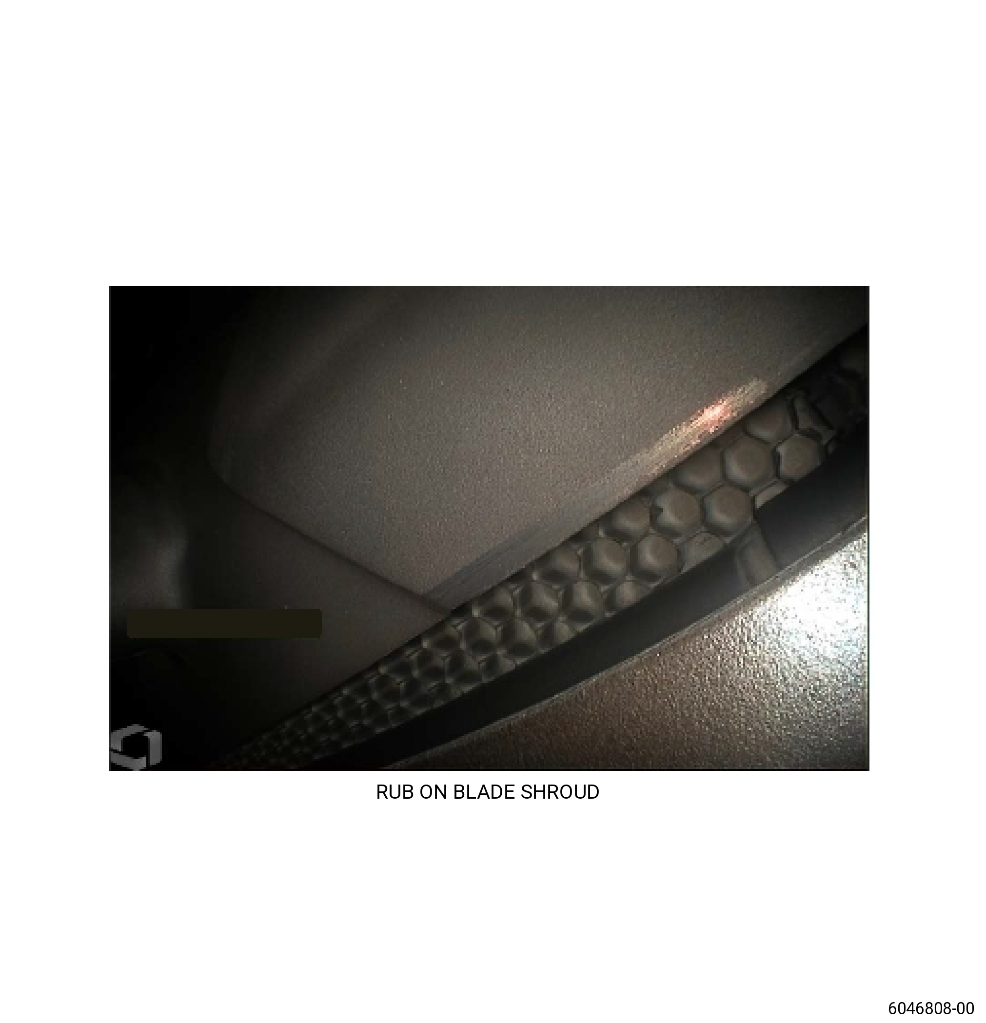
| R. | Do an inspection of the HPT stage 2 nozzle assembly (HPT stage 2 nozzle). This inspection is limited to what can be seen with a rigid borescope. Refer to Figure 218. |
| (1) | HPT stage 1 shroud (stage 1 shroud) (17300) flowpath surface for: |
| (a) | Axial cracks: |
| Maximum serviceable limit: |
|
| Repair method: |
|
| Subtask 72-00-00-220-273 |
| (b) | Circumferential cracks: |
| Maximum serviceable limit: |
|
| Repair method: |
|
| Subtask 72-00-00-220-274 |
| (2) | Vane airfoils of each HPT stage 2 nozzle (nozzle segment) (174A0, 174A1) for. This inspection is limited to what can be seen with a rigid borescope. |
| (a) | Missing surface coating: |
| Maximum serviceable limit: |
|
| Repair method: |
|
| Subtask 72-00-00-220-275 |
| (b) | Nicks, scores, scratches, and dents: |
| Maximum serviceable limit: |
|
| Repair method: |
|
| Subtask 72-00-00-220-276 |
| (3) | Leading edge of each vane airfoil on the nozzle segments (174A0, 174A1) for: |
| (a) | Axial cracks: |
| Maximum serviceable limit: |
|
| Repair method: |
|
| Subtask 72-00-00-220-277 |
| (b) | Burns: |
| Maximum serviceable limit: |
|
| Repair method: |
|
| Subtask 72-00-00-220-278 |
| (4) | Concave surfaces of each vane airfoil on the nozzle segments (174A0, 174A1) for: |
| (a) | Cracks: |
| Maximum serviceable limit: |
|
| Repair method: |
|
| Subtask 72-00-00-220-279 |
| (b) | Burns (no holes through the vane airfoil): |
| Maximum serviceable limit: |
|
| Repair method: |
|
| Subtask 72-00-00-220-280 |
| (5) | Convex surfaces of each vane airfoil on the nozzle segments (174A0, 174A1) for: |
| (a) | Cracks to the outer platform fillet area: |
| Maximum serviceable limit: |
|
| Repair method: |
|
| Subtask 72-00-00-220-281 |
| (b) | Cracks: |
| Maximum serviceable limit: |
|
| Repair method: |
|
| Subtask 72-00-00-220-282 |
| (c) | Burns (no holes through the vane airfoil): |
| Maximum serviceable limit: |
|
| Repair method: |
|
| Subtask 72-00-00-220-283 |
| (6) | Trailing edge of each vane airfoil on the nozzle segments (174A0, 174A1) for: |
| (a) | Axial cracks that are more than 0.40 inch (10.2 mm) from the inner and outer platform: |
| Maximum serviceable limit: |
|
| Repair method: |
|
| Subtask 72-00-00-220-284 |
| (b) | Axial cracks or craze cracks that are less than 0.40 inch (10.2 mm) from the inner platform: |
| Maximum serviceable limit: |
|
| Repair method: |
|
| Subtask 72-00-00-220-285 |
| (c) | Missing material: |
| Maximum serviceable limit: |
|
| Repair method: |
|
| Subtask 72-00-00-220-286 |
| (7) | Inner platform of each vane airfoil on the nozzle segments (01-370 , 72-52-00) (SIN 174A0) or (01-371 , 72-52-00) (SIN 174A0) or (01-372 , 72-52-00) (SIN 174A0) for: |
| (a) | Cracks: |
| Maximum serviceable limit: |
|
| Repair method: |
|
| Subtask 72-00-00-220-287 |
| (b) | Craze cracks: |
| Maximum serviceable limit: |
|
| Repair method: |
|
| Subtask 72-00-00-220-288 |
| (c) | Cracks on the trailing edge of the platform: |
| Maximum serviceable limit: |
|
| Repair method: |
|
| Subtask 72-00-00-220-289 |
| (d) | Nicks, scores, scratches, and dents: |
| Maximum serviceable limit: |
|
| Repair method: |
|
| Subtask 72-00-00-220-290 |
| (e) | Missing surface coating: |
| Maximum serviceable limit: |
|
| Repair method: |
|
| Subtask 72-00-00-220-291 |
| (f) | Heat distress (network of fine cracks): |
| Maximum serviceable limit: |
|
| Repair method: |
|
| Subtask 72-00-00-220-292 |
| (g) | Burns: |
| Maximum serviceable limit: |
|
| Repair method: |
|
| Subtask 72-00-00-220-293 |
| (8) | Outer platform of each vane airfoil on the nozzle segments (174A0, 174A1) for: |
| (a) | Cracks: |
| Maximum serviceable limit: |
|
| Repair method: |
|
| Subtask 72-00-00-220-294 |
| (b) | Craze cracks: |
| Maximum serviceable limit: |
|
| Repair method: |
|
| Subtask 72-00-00-220-295 |
| (c) | Cracks on the trailing edge of the platform: |
| Maximum serviceable limit: |
|
| Repair method: |
|
| Subtask 72-00-00-220-296 |
| (d) | Nicks, scores, scratches, and dents: |
| Maximum serviceable limit: |
|
| Repair method: |
|
| Subtask 72-00-00-220-297 |
| (e) | Missing surface coating: |
| Maximum serviceable limit: |
|
| Repair method: |
|
| Subtask 72-00-00-220-298 |
| (9) | Rub surface of each HPT stator stage 2 shroud (stage 2 shroud) (17800) for: |
| (a) | Pickup caused by blade rub: |
| Maximum serviceable limit: |
|
| Repair method: |
|
| Subtask 72-00-00-220-299 |
| S. | Do an inspection of the stage 2 blade (150B0). Refer to Figure 218. |
| (1) | Airfoil surfaces of each stage 2 blade for: |
| (a) | Missing platinum aluminide coating: |
| Maximum serviceable limit: |
|
| Repair method: |
|
| Subtask 72-00-00-220-366 |
| * * * SB 72-0042( Stage 2 Blade with Thermal Barrier Coating ) |
| * * * PRE SB 72-0080( Stage 2 Blade with Thermal Barrier Coating ) |
| (b) | Missing thermal barrier coating: |
| Maximum serviceable limit: |
|
| Repair method: |
|
| NOTE: |
|
| * * * END SB 72-0042 |
| * * * END PRE SB 72-0080 |
| Subtask 72-00-00-220-300 |
| (c) | Deleted. |
| Subtask 72-00-00-220-301 |
| (2) | Leading edge for: |
| (a) | Cracks in area J: |
| Maximum serviceable limit: |
|
| Repair method: |
|
| Subtask 72-00-00-220-302 |
| (b) | Cracks in area K: |
| Maximum serviceable limit: |
|
| Repair method: |
|
| Subtask 72-00-00-220-303 |
| (c) | Nicks and dents in areas J and K: |
| Maximum serviceable limit: |
|
| Repair method: |
|
| Subtask 72-00-00-220-304 |
| (d) | Missing metal in areas J and K: |
| Maximum serviceable limit: |
|
| Repair method: |
|
| Subtask 72-00-00-220-305 |
| (e) | Metal splatter: |
| Maximum serviceable limit: |
|
| Repair method: |
|
| Subtask 72-00-00-220-306 |
| (3) | Concave side of each blade for: |
| (a) | Cracks: |
| Maximum serviceable limit: |
|
| Repair method: |
|
| Subtask 72-00-00-220-307 |
| (b) | Nicks and dents: |
| Maximum serviceable limit: |
|
| Repair method: |
|
| Subtask 72-00-00-220-308 |
| (c) | Positive braze metal in area D: |
| Maximum serviceable limit: |
|
| Repair method: |
|
| Subtask 72-00-00-220-309 |
| (4) | Convex side of each blade for: |
| (a) | Cracks: |
| Maximum serviceable limit: |
|
| Repair method: |
|
| Subtask 72-00-00-220-310 |
| (b) | Nicks and dents: |
| Maximum serviceable limit: |
|
| Repair method: |
|
| Subtask 72-00-00-220-311 |
| (c) | Positive braze metal in area D: |
| Maximum serviceable limit: |
|
| Repair method: |
|
| Subtask 72-00-00-220-312 |
| (5) | Trailing edge for: |
| (a) | Cracks in area J: |
| Maximum serviceable limit: |
|
| Repair method: |
|
| Subtask 72-00-00-220-313 |
| (b) | Cracks in area K: |
| Maximum serviceable limit: |
|
| Repair method: |
|
| Subtask 72-00-00-220-314 |
| (c) | Nicks and dents in areas J and K: |
| Maximum serviceable limit: |
|
| Repair method: |
|
| Subtask 72-00-00-220-315 |
| (d) | Missing metal in areas J and K: |
| Maximum serviceable limit: |
|
| Repair method: |
|
| Subtask 72-00-00-220-316 |
| (e) | Metal splatter: |
| Maximum serviceable limit: |
|
| Repair method: |
|
| Subtask 72-00-00-220-317 |
| (6) | Blade tip area for: |
| (a) | Radial cracks: |
| Maximum serviceable limit: |
|
| Repair method: |
|
| Subtask 72-00-00-220-318 |
| (b) | Axial cracks: |
| Maximum serviceable limit: |
|
| Repair method: |
|
| Subtask 72-00-00-220-319 |
| (c) | Bent or curled blade tips: |
| Maximum serviceable limit: |
|
| Repair method: |
|
| Subtask 72-00-00-220-320 |
| (d) | Missing metal and tears: |
| Maximum serviceable limit: |
|
| Repair method: |
|
| Subtask 72-00-00-220-321 |
| (e) | Buildup of second stage shroud material: |
| Maximum serviceable limit: |
|
| Repair method: |
|
| Subtask 72-00-00-220-322 |
| T. | Do an inspection of the LPT stage 1 blades. Refer to Figure 219. |
| (1) | All areas for: |
| (a) | Metal deposit: |
| Maximum serviceable limit: |
|
| Repair method: |
|
| Subtask 72-00-00-220-725 |
| * * * FOR ALL.ALL |
| (a).A. | Metal splatter: |
| Maximum serviceable limit: |
|
| Repair method: |
|
| Subtask 72-00-00-220-700 |
| (b) | Corrosion on the airfoil, tip and root radius: |
| Maximum serviceable limit: |
|
| Repair method: |
|
| Subtask 72-00-00-220-701 |
| (c) | Corrosion on the platform and angel wing (does not include tip and root radius): |
| Maximum serviceable limit: |
|
| Repair method: |
|
| Subtask 72-00-00-220-323 |
| (2) | Shroud gas path (does not include blade tip fillet radius, fillet in area Z, and shroud lock) for: |
| (a) | Cracks: |
| Maximum serviceable limit: |
|
| Repair method: |
|
| Subtask 72-00-00-220-324 |
| (b) | Nicks and scratches: |
| Maximum serviceable limit: |
|
| Repair method: |
|
| Subtask 72-00-00-220-325 |
| (c) | Dents: |
| Maximum serviceable limit: |
|
| Repair method: |
|
| Subtask 72-00-00-220-756 |
| * * * FOR ALL.ALL |
| (d) | Bending on trailing edge: |
| Maximum serviceable limit: |
|
| Repair method: |
|
| Subtask 72-00-00-220-326 |
| (3) | Leading edge (does not include area Z) for: |
| NOTE: |
|
| (a) | Cracks: |
| Maximum serviceable limit: |
|
| Repair method: |
|
| Subtask 72-00-00-220-327 |
| (b) | Tears: |
| Maximum serviceable limit: |
|
| Repair method: |
|
| Subtask 72-00-00-220-328 |
| (c) | Nicks, scores, scratches, and pittings: |
| Maximum serviceable limit: |
|
| Repair method: |
|
| Subtask 72-00-00-220-329 |
| (d) | Dents: |
| Maximum serviceable limit: |
|
| Repair method: |
|
| Subtask 72-00-00-220-330 |
| (4) | Leading edge in area Z (does not include tip and root radius) for: |
| (a) | Cracks: |
| Maximum serviceable limit: |
|
| Repair method: |
|
| Subtask 72-00-00-220-331 |
| (b) | Tears: |
| Maximum serviceable limit: |
|
| Repair method: |
|
| Subtask 72-00-00-220-332 |
| (c) | Nicks, scores, scratches, and pittings: |
| Maximum serviceable limit: |
|
| Repair method: |
|
| Subtask 72-00-00-220-333 |
| (d) | Dents: |
| Maximum serviceable limit: |
|
| Repair method: |
|
| Subtask 72-00-00-220-334 |
| (e) | Deleted. |
| Subtask 72-00-00-220-389 |
| (5) | Trailing edge (does not include blade tip and blade root fillet radiuses) for: |
| NOTE: |
|
| (a) | Cracks: |
| Maximum serviceable limit: |
|
| Repair method: |
|
| Subtask 72-00-00-220-390 |
| (b) | Tears: |
| Maximum serviceable limit: |
|
| Repair method: |
|
| Subtask 72-00-00-220-391 |
| (c) | Nicks: |
| Maximum serviceable limit: |
|
| Repair method: |
|
| Subtask 72-00-00-220-726 |
| * * * FOR ALL.ALL |
| (c).A. | Scores, scratches, and pitting: |
| Maximum serviceable limit: |
|
| Repair method: |
|
| Subtask 72-00-00-220-392 |
| (d) | Dents: |
| Maximum serviceable limit: |
|
| Repair method: |
|
| Subtask 72-00-00-220-393 |
| (e) | Deleted. |
| Maximum serviceable limit: |
|
| Repair method: |
|
| Subtask 72-00-00-220-394 |
| (6) | Tip and root fillet radiuses for: |
| (a) | Cracks: |
| Maximum serviceable limit: |
|
| Repair method: |
|
| Subtask 72-00-00-220-395 |
| (b) | Nicks scratches, scores, and pits: |
| Maximum serviceable limit: |
|
| Repair method: |
|
| Subtask 72-00-00-220-396 |
| (c) | Dents: |
| Maximum serviceable limit: |
|
| Repair method: |
|
| Subtask 72-00-00-220-397 |
| (d) | Deleted. |
| Subtask 72-00-00-220-398 |
| (7) | Airfoil concave and convex surfaces (does not include blade tip and blade root fillet radiuses) for: |
| NOTE: |
|
| (a) | Cracks: |
| Maximum serviceable limit: |
|
| Repair method: |
|
| Subtask 72-00-00-220-399 |
| (b) | Nicks and dents: |
| Maximum serviceable limit: |
|
| Repair method: |
|
| Subtask 72-00-00-220-400 |
| (8) | Top surface of the platform (does not include blade root fillet radiuses) for: |
| (a) | Cracks: |
| Maximum serviceable limit: |
|
| Repair method: |
|
| Subtask 72-00-00-220-401 |
| (b) | Nicks and scratches: |
| Maximum serviceable limit: |
|
| Repair method: |
|
| Subtask 72-00-00-220-727 |
| * * * FOR ALL.ALL |
| (b).A. | Dents: |
| Maximum serviceable limit: |
|
| Repair method: |
|
| Subtask 72-00-00-220-402 |
| (c) | Deleted. |
| Subtask 72-00-00-220-403 |
| (1) | Forward and aft angel wings for: |
| (a) | Cracks: |
| Maximum serviceable limit: |
|
| Repair method: |
|
| Subtask 72-00-00-220-404 |
| (b) | Nicks and scratches: |
| Maximum serviceable limit: |
|
| Repair method: |
|
| Subtask 72-00-00-220-742 |
| * * * FOR ALL.ALL |
| (c) | Dents: |
| Maximum serviceable limit: |
|
| Repair method: |
|
| Subtask 72-00-00-220-405 |
| (d) | Missing, rubbed, or twisted material: |
| Maximum serviceable limit: |
|
| Repair method: |
|
| Subtask 72-00-00-220-406 |
| (e) | Deleted. |
| Subtask 72-00-00-220-407 |
| U. | Do an inspection of the stage 1 LPT blade shroud. Refer to Figure 221. |
| (1) | Circumferential mate faces for: |
| (a) | Signs of wear (irregular or jagged): |
| Maximum serviceable limit: |
|
| Repair method: |
|
| Subtask 72-00-00-220-408 |
| (2) | Shroud interlocks for: |
| (a) | Wear: |
| Maximum serviceable limit: |
|
| Repair method: |
|
| Subtask 72-00-00-220-409 |
| (b) | Shingling or disconnected tip shrouds: |
| Maximum serviceable limit: |
|
| Repair method: |
|
| Subtask 72-00-00-220-410 |
| (c) | Interlock gap: |
| NOTE: |
|
| Maximum serviceable limit: |
|
| Repair method: |
|
| Subtask 72-00-00-220-411 |
| V. | Do an inspection of the LPT stage 2 blades. Refer to Figure 219. |
| (1) | All areas for: |
| (a) | Metal deposit: |
| Maximum serviceable limit: |
|
| Repair method: |
|
| Subtask 72-00-00-220-728 |
| * * * FOR ALL.ALL |
| (a).A. | Metal splatter: |
| Maximum serviceable limit: |
|
| Repair method: |
|
| Subtask 72-00-00-220-702 |
| (b) | Corrosion on the airfoil, tip and root radius: |
| Maximum serviceable limit: |
|
| Repair method: |
|
| Subtask 72-00-00-220-703 |
| (c) | Corrosion on the platform and angel wing (does not include tip and root radius): |
| Maximum serviceable limit: |
|
| Repair method: |
|
| Subtask 72-00-00-220-412 |
| (2) | Shroud gas path (does not include blade tip fillet radius, fillet in area Z, and shroud interlock) for: |
| (a) | Cracks: |
| Maximum serviceable limit: |
|
| Repair method: |
|
| Subtask 72-00-00-220-413 |
| (b) | Nicks and scratches: |
| Maximum serviceable limit: |
|
| Repair method: |
|
| Subtask 72-00-00-220-414 |
| (c) | Dents: |
| Maximum serviceable limit: |
|
| Repair method: |
|
| Subtask 72-00-00-220-415 |
| (3) | Leading edge (does not include area Z) for: |
| NOTE: |
|
| (a) | Cracks: |
| Maximum serviceable limit: |
|
| Repair method: |
|
| Subtask 72-00-00-220-416 |
| (b) | Tears: |
| Maximum serviceable limit: |
|
| Repair method: |
|
| Subtask 72-00-00-220-417 |
| (c) | Nicks, scores, scratches, and pittings: |
| Maximum serviceable limit: |
|
| Repair method: |
|
| Subtask 72-00-00-220-418 |
| (d) | Dents: |
| Maximum serviceable limit: |
|
| Repair method: |
|
| Subtask 72-00-00-220-419 |
| (4) | Leading edge in area Z (does not include tip and root radius) for: |
| (a) | Cracks: |
| Maximum serviceable limit: |
|
| Repair method: |
|
| Subtask 72-00-00-220-420 |
| (b) | Tears: |
| Maximum serviceable limit: |
|
| Repair method: |
|
| Subtask 72-00-00-220-421 |
| (c) | Nicks, scores, scratches, and pittings: |
| Maximum serviceable limit: |
|
| Repair method: |
|
| Subtask 72-00-00-220-422 |
| (d) | Dents: |
| Maximum serviceable limit: |
|
| Repair method: |
|
| Subtask 72-00-00-220-423 |
| (e) | Deleted. |
| Subtask 72-00-00-220-424 |
| (5) | Trailing edge (does not include blade tip and blade root fillet radiuses) for: |
| NOTE: |
|
| (a) | Cracks: |
| Maximum serviceable limit: |
|
| Repair method: |
|
| Subtask 72-00-00-220-425 |
| (b) | Tears: |
| Maximum serviceable limit: |
|
| Repair method: |
|
| Subtask 72-00-00-220-426 |
| (c) | Nicks: |
| Maximum serviceable limit: |
|
| Repair method: |
|
| Subtask 72-00-00-220-729 |
| * * * FOR ALL.ALL |
| (c).A. | Scores, scratches, and pitting: |
| Maximum serviceable limit: |
|
| Repair method: |
|
| Subtask 72-00-00-220-427 |
| (d) | Dents: |
| Maximum serviceable limit: |
|
| Repair method: |
|
| Subtask 72-00-00-220-428 |
| (e) | Deleted. |
| Maximum serviceable limit: |
|
| Repair method: |
|
| Subtask 72-00-00-220-429 |
| (6) | Tip and root fillet radiuses for: |
| (a) | Cracks: |
| Maximum serviceable limit: |
|
| Repair method: |
|
| Subtask 72-00-00-220-430 |
| (b) | Nicks, scratches, scores, and pits: |
| Maximum serviceable limit: |
|
| Repair method: |
|
| Subtask 72-00-00-220-431 |
| (c) | Dents: |
| Maximum serviceable limit: |
|
| Repair method: |
|
| Subtask 72-00-00-220-432 |
| (d) | Deleted. |
| Subtask 72-00-00-220-433 |
| (7) | Airfoil concave and convex surfaces (does not include blade tip and blade root fillet radiuses) for: |
| NOTE: |
|
| (a) | Cracks: |
| Maximum serviceable limit: |
|
| Repair method: |
|
| Subtask 72-00-00-220-434 |
| (b) | Nicks and dents: |
| Maximum serviceable limit: |
|
| Repair method: |
|
| Subtask 72-00-00-220-435 |
| (8) | Top surface of the platform (does not include blade root fillet radiuses) for: |
| (a) | Cracks: |
| Maximum serviceable limit: |
|
| Repair method: |
|
| Subtask 72-00-00-220-436 |
| (b) | Nicks and dents: |
| Maximum serviceable limit: |
|
| Repair method: |
|
| Subtask 72-00-00-220-730 |
| * * * FOR ALL.ALL |
| (c) | Scratches: |
| Maximum serviceable limit: |
|
| Repair method: |
|
| Subtask 72-00-00-220-437 |
| (d) | Deleted. |
| Subtask 72-00-00-220-438 |
| (9) | Forward and aft angel wings for: |
| (a) | Cracks: |
| Maximum serviceable limit: |
|
| Repair method: |
|
| Subtask 72-00-00-220-439 |
| (b) | Nicks, dents, and scratches: |
| Maximum serviceable limit: |
|
| Repair method: |
|
| Subtask 72-00-00-220-440 |
| (c) | Missing, rubbed, or twisted material: |
| Maximum serviceable limit: |
|
| Repair method: |
|
| Subtask 72-00-00-220-441 |
| (d) | Deleted. |
| Subtask 72-00-00-220-442 |
| W. | Do an inspection of the stage 2 LPT blade shroud. Refer to Figure 221. |
| (1) | Circumferential mate faces for: |
| (a) | Signs of wear (irregular or jagged): |
| Maximum serviceable limit: |
|
| Repair method: |
|
| Subtask 72-00-00-220-443 |
| (2) | Shroud interlocks for: |
| (a) | Wear: |
| Maximum serviceable limit: |
|
| Repair method: |
|
| Subtask 72-00-00-220-444 |
| (b) | Shingling or disconnected tip shrouds: |
| Maximum serviceable limit: |
|
| Repair method: |
|
| Subtask 72-00-00-220-445 |
| (c) | Interlock gap: |
| NOTE: |
|
| Maximum serviceable limit: |
|
| Repair method: |
|
| Subtask 72-00-00-220-446 |
| X. | Do an inspection of the LPT stage 3 blades. Refer to Figure 219. |
| (1) | All areas for: |
| (a) | Metal deposit: |
| Maximum serviceable limit: |
|
| Repair method: |
|
| Subtask 72-00-00-220-731 |
| * * * FOR ALL.ALL |
| (a).A. | Metal splatter: |
| Maximum serviceable limit: |
|
| Repair method: |
|
| Subtask 72-00-00-220-704 |
| (b) | Corrosion on the airfoil, tip and root radius: |
| Maximum serviceable limit: |
|
| Repair method: |
|
| Subtask 72-00-00-220-705 |
| (c) | Corrosion on the platform and angel wing (does not include tip and root radius): |
| Maximum serviceable limit: |
|
| Repair method: |
|
| Subtask 72-00-00-220-447 |
| (2) | Shroud gas path (does not include blade tip fillet radius, fillet in area Z, and shroud interlock) for: |
| (a) | Cracks: |
| Maximum serviceable limit: |
|
| Repair method: |
|
| Subtask 72-00-00-220-448 |
| (b) | Nicks and scratches: |
| Maximum serviceable limit: |
|
| Repair method: |
|
| Subtask 72-00-00-220-449 |
| (c) | Dents: |
| Maximum serviceable limit: |
|
| Repair method: |
|
| Subtask 72-00-00-220-757 |
| * * * FOR ALL.ALL |
| (d) | Bending on trailing edge: |
| Maximum serviceable limit: |
|
| Repair method: |
|
| Subtask 72-00-00-220-450 |
| (3) | Leading edge (does not include area Z) for: |
| NOTE: |
|
| (a) | Cracks: |
| Maximum serviceable limit: |
|
| Repair method: |
|
| Subtask 72-00-00-220-451 |
| (b) | Tears: |
| Maximum serviceable limit: |
|
| Repair method: |
|
| Subtask 72-00-00-220-452 |
| (c) | Nicks, scores, scratches, and pittings: |
| Maximum serviceable limit: |
|
| Repair method: |
|
| Subtask 72-00-00-220-453 |
| (d) | Dents: |
| Maximum serviceable limit: |
|
| Repair method: |
|
| Subtask 72-00-00-220-454 |
| (4) | Leading edge in area Z (does not include tip and root radius) for: |
| (a) | Cracks: |
| Maximum serviceable limit: |
|
| Repair method: |
|
| Subtask 72-00-00-220-455 |
| (b) | Tears: |
| Maximum serviceable limit: |
|
| Repair method: |
|
| Subtask 72-00-00-220-456 |
| (c) | Nicks, scores, scratches, and pittings: |
| Maximum serviceable limit: |
|
| Repair method: |
|
| Subtask 72-00-00-220-457 |
| (d) | Dents: |
| Maximum serviceable limit: |
|
| Repair method: |
|
| Subtask 72-00-00-220-458 |
| (e) | Deleted. |
| Subtask 72-00-00-220-459 |
| (5) | Trailing edge (does not include blade tip and blade root fillet radiuses) for: |
| NOTE: |
|
| (a) | Cracks: |
| Maximum serviceable limit: |
|
| Repair method: |
|
| Subtask 72-00-00-220-460 |
| (b) | Tears: |
| Maximum serviceable limit: |
|
| Repair method: |
|
| Subtask 72-00-00-220-461 |
| (c) | Nicks: |
| Maximum serviceable limit: |
|
| Repair method: |
|
| Subtask 72-00-00-220-732 |
| * * * FOR ALL.ALL |
| (c).A. | Scores, scratches, and pitting: |
| Maximum serviceable limit: |
|
| Repair method: |
|
| Subtask 72-00-00-220-462 |
| (d) | Dents: |
| Maximum serviceable limit: |
|
| Repair method: |
|
| Subtask 72-00-00-220-463 |
| (e) | Deleted. |
| Maximum serviceable limit: |
|
| Repair method: |
|
| Subtask 72-00-00-220-464 |
| (6) | Tip and root fillet radiuses for: |
| (a) | Cracks: |
| Maximum serviceable limit: |
|
| Repair method: |
|
| Subtask 72-00-00-220-465 |
| (b) | Nicks, scratches, scores, and pits: |
| Maximum serviceable limit: |
|
| Repair method: |
|
| Subtask 72-00-00-220-466 |
| (c) | Dents: |
| Maximum serviceable limit: |
|
| Repair method: |
|
| Subtask 72-00-00-220-467 |
| (d) | Deleted. |
| Subtask 72-00-00-220-468 |
| (7) | Airfoil concave and convex surfaces (does not include blade tip and blade root fillet radiuses) for: |
| NOTE: |
|
| (a) | Cracks: |
| Maximum serviceable limit: |
|
| Repair method: |
|
| Subtask 72-00-00-220-469 |
| (b) | Nicks and dents: |
| Maximum serviceable limit: |
|
| Repair method: |
|
| Subtask 72-00-00-220-470 |
| (8) | Top surface of the platform (does not include blade root fillet radiuses) for: |
| (a) | Cracks: |
| Maximum serviceable limit: |
|
| Repair method: |
|
| Subtask 72-00-00-220-471 |
| (b) | Nicks and dents: |
| Maximum serviceable limit: |
|
| Repair method: |
|
| Subtask 72-00-00-220-733 |
| * * * FOR ALL.ALL |
| (c) | Scratches: |
| Maximum serviceable limit: |
|
| Repair method: |
|
| Subtask 72-00-00-220-472 |
| (d) | Deleted. |
| Subtask 72-00-00-220-473 |
| (9) | Forward and aft angel wings for: |
| (a) | Cracks: |
| Maximum serviceable limit: |
|
| Repair method: |
|
| Subtask 72-00-00-220-474 |
| (b) | Nicks, dents, and scratches: |
| Maximum serviceable limit: |
|
| Repair method: |
|
| Subtask 72-00-00-220-475 |
| (c) | Missing, rubbed, or twisted material: |
| Maximum serviceable limit: |
|
| Repair method: |
|
| Subtask 72-00-00-220-476 |
| (d) | Deleted. |
| Subtask 72-00-00-220-477 |
| Y. | Do an inspection of the stage 3 LPT blade shroud. Refer to Figure 221. |
| (1) | Circumferential mate faces for: |
| (a) | Signs of wear (irregular or jagged): |
| Maximum serviceable limit: |
|
| Repair method: |
|
| Subtask 72-00-00-220-478 |
| (2) | Shroud interlocks for: |
| (a) | Wear: |
| Maximum serviceable limit: |
|
| Repair method: |
|
| Subtask 72-00-00-220-479 |
| (b) | Shingling or disconnected tip shrouds: |
| Maximum serviceable limit: |
|
| Repair method: |
|
| Subtask 72-00-00-220-480 |
| (c) | Interlock gap: |
| NOTE: |
|
| Maximum serviceable limit: |
|
| Repair method: |
|
| Subtask 72-00-00-220-481 |
| Z. | Do an inspection of the LPT stage 4 blades. Refer to Figure 219. |
| (1) | All areas for: |
| (a) | Metal deposit: |
| Maximum serviceable limit: |
|
| Repair method: |
|
| Subtask 72-00-00-220-734 |
| * * * FOR ALL.ALL |
| (a).A. | Metal splatter: |
| Maximum serviceable limit: |
|
| Repair method: |
|
| Subtask 72-00-00-220-706 |
| (b) | Corrosion on the airfoil, tip and root radius: |
| Maximum serviceable limit: |
|
| Repair method: |
|
| Subtask 72-00-00-220-707 |
| (c) | Corrosion on the platform and angel wing (does not include tip and root radius): |
| Maximum serviceable limit: |
|
| Repair method: |
|
| Subtask 72-00-00-220-482 |
| (2) | Shroud gas path (does not include blade tip fillet radius, fillet in area Z, and shroud interlock) for: |
| (a) | Cracks: |
| Maximum serviceable limit: |
|
| Repair method: |
|
| Subtask 72-00-00-220-483 |
| (b) | Nicks and scratches: |
| Maximum serviceable limit: |
|
| Repair method: |
|
| Subtask 72-00-00-220-484 |
| (c) | Dents: |
| Maximum serviceable limit: |
|
| Repair method: |
|
| Subtask 72-00-00-220-758 |
| * * * FOR ALL.ALL |
| (d) | Rub: |
| Maximum serviceable limit: |
|
| Repair method: |
|
| Subtask 72-00-00-220-485 |
| (3) | Leading edge (does not include area Z) for: |
| NOTE: |
|
| (a) | Cracks: |
| Maximum serviceable limit: |
|
| Repair method: |
|
| Subtask 72-00-00-220-486 |
| (b) | Tears: |
| Maximum serviceable limit: |
|
| Repair method: |
|
| Subtask 72-00-00-220-487 |
| (c) | Nicks, scores, scratches, and pittings: |
| Maximum serviceable limit: |
|
| Repair method: |
|
| Subtask 72-00-00-220-488 |
| (d) | Dents: |
| Maximum serviceable limit: |
|
| Repair method: |
|
| Subtask 72-00-00-220-489 |
| (4) | Leading edge in area Z (does not include tip and root radius) for: |
| (a) | Cracks: |
| Maximum serviceable limit: |
|
| Repair method: |
|
| Subtask 72-00-00-220-490 |
| (b) | Tears: |
| Maximum serviceable limit: |
|
| Repair method: |
|
| Subtask 72-00-00-220-491 |
| (c) | Nicks, scores, scratches, and pittings: |
| Maximum serviceable limit: |
|
| Repair method: |
|
| Subtask 72-00-00-220-492 |
| (d) | Dents: |
| Maximum serviceable limit: |
|
| Repair method: |
|
| Subtask 72-00-00-220-493 |
| (e) | Deleted. |
| Subtask 72-00-00-220-494 |
| (5) | Trailing edge (does not include blade tip and blade root fillet radiuses) for: |
| NOTE: |
|
| (a) | Cracks: |
| Maximum serviceable limit: |
|
| Repair method: |
|
| Subtask 72-00-00-220-495 |
| (b) | Tears: |
| Maximum serviceable limit: |
|
| Repair method: |
|
| Subtask 72-00-00-220-496 |
| (c) | Nicks: |
| Maximum serviceable limit: |
|
| Repair method: |
|
| Subtask 72-00-00-220-735 |
| * * * FOR ALL.ALL |
| (c).A. | Scores, scratches, and pitting: |
| Maximum serviceable limit: |
|
| Repair method: |
|
| Subtask 72-00-00-220-497 |
| (d) | Dents: |
| Maximum serviceable limit: |
|
| Repair method: |
|
| Subtask 72-00-00-220-498 |
| (e) | Deleted. |
| Maximum serviceable limit: |
|
| Repair method: |
|
| Subtask 72-00-00-220-499 |
| (6) | Tip and root fillet radiuses for: |
| (a) | Cracks: |
| Maximum serviceable limit: |
|
| Repair method: |
|
| Subtask 72-00-00-220-500 |
| (b) | Nicks, scratches, scores, and pits: |
| Maximum serviceable limit: |
|
| Repair method: |
|
| Subtask 72-00-00-220-501 |
| (c) | Dents: |
| Maximum serviceable limit: |
|
| Repair method: |
|
| Subtask 72-00-00-220-502 |
| (d) | Deleted. |
| Subtask 72-00-00-220-503 |
| (7) | Airfoil concave and convex surfaces (does not include blade tip and blade root fillet radiuses) for: |
| NOTE: |
|
| (a) | Cracks: |
| Maximum serviceable limit: |
|
| Repair method: |
|
| Subtask 72-00-00-220-504 |
| (b) | Nicks and dents: |
| Maximum serviceable limit: |
|
| Repair method: |
|
| Subtask 72-00-00-220-505 |
| (8) | Top surface of the platform (does not include blade root fillet radiuses) for: |
| (a) | Cracks: |
| Maximum serviceable limit: |
|
| Repair method: |
|
| Subtask 72-00-00-220-506 |
| (b) | Nicks and dents: |
| Maximum serviceable limit: |
|
| Repair method: |
|
| Subtask 72-00-00-220-736 |
| * * * FOR ALL.ALL |
| (c) | Scratches: |
| Maximum serviceable limit: |
|
| Repair method: |
|
| Subtask 72-00-00-220-507 |
| (d) | Deleted. |
| Subtask 72-00-00-220-508 |
| (9) | Forward and aft angel wings for: |
| (a) | Cracks: |
| Maximum serviceable limit: |
|
| Repair method: |
|
| Subtask 72-00-00-220-509 |
| (b) | Nicks and dents: |
| Maximum serviceable limit: |
|
| Repair method: |
|
| Subtask 72-00-00-220-510 |
| (c) | Missing, rubbed, or twisted material: |
| Maximum serviceable limit: |
|
| Repair method: |
|
| Subtask 72-00-00-220-511 |
| (d) | Deleted. |
| Subtask 72-00-00-220-512 |
| AA. | Do an inspection of the stage 4 LPT blade shroud. Refer to Figure 221. |
| (1) | Circumferential mate faces for: |
| (a) | Signs of wear (irregular or jagged): |
| Maximum serviceable limit: |
|
| Repair method: |
|
| Subtask 72-00-00-220-513 |
| (2) | Shroud interlocks for: |
| (a) | Wear: |
| Maximum serviceable limit: |
|
| Repair method: |
|
| Subtask 72-00-00-220-514 |
| (b) | Shingling or disconnected tip shrouds: |
| Maximum serviceable limit: |
|
| Repair method: |
|
| Subtask 72-00-00-220-515 |
| (c) | Interlock gap: |
| NOTE: |
|
| Maximum serviceable limit: |
|
| Repair method: |
|
| Subtask 72-00-00-220-516 |
| AB. | Do an inspection of the LPT stage 5 blades. Refer to Figure 219. |
| (1) | All areas for: |
| (a) | Metal deposit: |
| Maximum serviceable limit: |
|
| Repair method: |
|
| Subtask 72-00-00-220-737 |
| * * * FOR ALL.ALL |
| (a).A. | Metal splatter: |
| Maximum serviceable limit: |
|
| Repair method: |
|
| Subtask 72-00-00-220-708 |
| (b) | Corrosion on the airfoil tip and root radius. Refer to Figure 219 as follows: |
| Maximum serviceable limit: |
|
| Repair method: |
|
| Subtask 72-00-00-220-709 |
| (c) | Corrosion on the platform and angel wing (does not include tip and root radius). Refer to Figure 219 as follows: |
| Maximum serviceable limit: |
|
| Repair method: |
|
| Subtask 72-00-00-220-517 |
| (2) | Shroud gas path (does not include blade tip fillet radius, fillet in area Z, and shroud interlock) for: |
| (a) | Cracks: |
| Maximum serviceable limit: |
|
| Repair method: |
|
| Subtask 72-00-00-220-518 |
| (b) | Nicks and scratches: |
| Maximum serviceable limit: |
|
| Repair method: |
|
| Subtask 72-00-00-220-519 |
| (c) | Dents: |
| Maximum serviceable limit: |
|
| Repair method: |
|
| Subtask 72-00-00-220-759 |
| * * * FOR ALL.ALL |
| (d) | Bending on trailing edge: |
| Maximum serviceable limit: |
|
| Repair method: |
|
| Subtask 72-00-00-220-520 |
| (3) | Leading edge (does not include area Z) for: |
| NOTE: |
|
| (a) | Cracks: |
| Maximum serviceable limit: |
|
| Repair method: |
|
| Subtask 72-00-00-220-521 |
| (b) | Tears: |
| Maximum serviceable limit: |
|
| Repair method: |
|
| Subtask 72-00-00-220-522 |
| (c) | Nicks, scores, scratches, and pittings: |
| Maximum serviceable limit: |
|
| Repair method: |
|
| Subtask 72-00-00-220-523 |
| (d) | Dents: |
| Maximum serviceable limit: |
|
| Repair method: |
|
| Subtask 72-00-00-220-524 |
| (4) | Leading edge in area Z (does not include tip and root radius) for: |
| (a) | Cracks: |
| Maximum serviceable limit: |
|
| Repair method: |
|
| Subtask 72-00-00-220-525 |
| (b) | Tears: |
| Maximum serviceable limit: |
|
| Repair method: |
|
| Subtask 72-00-00-220-526 |
| (c) | Nicks, scores, scratches, and pittings: |
| Maximum serviceable limit: |
|
| Repair method: |
|
| Subtask 72-00-00-220-527 |
| (d) | Dents: |
| Maximum serviceable limit: |
|
| Repair method: |
|
| Subtask 72-00-00-220-528 |
| (e) | Deleted. |
| Subtask 72-00-00-220-529 |
| (5) | Trailing edge (does not include blade tip and blade root fillet radiuses) for: |
| NOTE: |
|
| (a) | Cracks: |
| Maximum serviceable limit: |
|
| Repair method: |
|
| Subtask 72-00-00-220-530 |
| (b) | Tears: |
| Maximum serviceable limit: |
|
| Repair method: |
|
| Subtask 72-00-00-220-531 |
| (c) | Nicks: |
| Maximum serviceable limit: |
|
| Repair method: |
|
| Subtask 72-00-00-220-738 |
| * * * FOR ALL.ALL |
| (c).A. | Scores, scratches, and pitting: |
| Maximum serviceable limit: |
|
| Repair method: |
|
| Subtask 72-00-00-220-532 |
| (d) | Dents: |
| Maximum serviceable limit: |
|
| Repair method: |
|
| Subtask 72-00-00-220-533 |
| (e) | Deleted. |
| Maximum serviceable limit: |
|
| Repair method: |
|
| Subtask 72-00-00-220-534 |
| (6) | Tip and root fillet radiuses for: |
| (a) | Cracks: |
| Maximum serviceable limit: |
|
| Repair method: |
|
| Subtask 72-00-00-220-535 |
| (b) | Nicks, scratches, scores, and pits: |
| Maximum serviceable limit: |
|
| Repair method: |
|
| Subtask 72-00-00-220-536 |
| (c) | Dents: |
| Maximum serviceable limit: |
|
| Repair method: |
|
| Subtask 72-00-00-220-537 |
| (d) | Deleted. |
| Subtask 72-00-00-220-538 |
| (7) | Airfoil concave and convex surfaces (does not include blade tip and blade root fillet radiuses) for: |
| NOTE: |
|
| (a) | Cracks: |
| Maximum serviceable limit: |
|
| Repair method: |
|
| Subtask 72-00-00-220-539 |
| (b) | Nicks and dents: |
| Maximum serviceable limit: |
|
| Repair method: |
|
| Subtask 72-00-00-220-540 |
| (8) | Top surface of the platform (does not include blade root fillet radiuses) for: |
| (a) | Cracks: |
| Maximum serviceable limit: |
|
| Repair method: |
|
| Subtask 72-00-00-220-541 |
| (b) | Nicks and dents: |
| Maximum serviceable limit: |
|
| Repair method: |
|
| Subtask 72-00-00-220-739 |
| * * * FOR ALL.ALL |
| (c) | Scratches: |
| Maximum serviceable limit: |
|
| Repair method: |
|
| Subtask 72-00-00-220-542 |
| (d) | Deleted. |
| Subtask 72-00-00-220-543 |
| (9) | Forward and aft angel wings for: |
| (a) | Cracks: |
| Maximum serviceable limit: |
|
| Repair method: |
|
| Subtask 72-00-00-220-544 |
| (b) | Nicks, dents, and scratches: |
| Maximum serviceable limit: |
|
| Repair method: |
|
| Subtask 72-00-00-220-545 |
| (c) | Missing, rubbed, or twisted material: |
| Maximum serviceable limit: |
|
| Repair method: |
|
| Subtask 72-00-00-220-546 |
| (d) | Deleted. |
| Subtask 72-00-00-220-547 |
| AC. | Do an inspection of the stage 5 LPT blade shroud. Refer to Figure 221. |
| (1) | Circumferential mate faces for: |
| (a) | Signs of wear (irregular or jagged): |
| Maximum serviceable limit: |
|
| Repair method: |
|
| Subtask 72-00-00-220-548 |
| (2) | Shroud interlocks for: |
| (a) | Wear: |
| Maximum serviceable limit: |
|
| Repair method: |
|
| Subtask 72-00-00-220-549 |
| (b) | Shingling or disconnected tip shrouds: |
| Maximum serviceable limit: |
|
| Repair method: |
|
| Subtask 72-00-00-220-550 |
| (c) | Interlock gap: |
| NOTE: |
|
| Maximum serviceable limit: |
|
| Repair method: |
|
| Subtask 72-00-00-220-551 |
| CAUTION: |
|
| AD. | Do an inspection of the LPT stage 6 blades. Refer to Figure 219. |
| (1) | All areas for: |
| (a) | Metal deposit: |
| Maximum serviceable limit: |
|
| Repair method: |
|
| Subtask 72-00-00-220-740 |
| * * * FOR ALL.ALL |
| (b) | Metal splatter: |
| Maximum serviceable limit: |
|
| Repair method: |
|
| Subtask 72-00-00-220-552 |
| (2) | Shroud gas path (does not include blade tip fillet radius, fillet in area Z, and shroud lock) for: |
| (a) | Cracks: |
| Maximum serviceable limit: |
|
| Repair method: |
|
| Subtask 72-00-00-220-553 |
| (b) | Nicks and scratches: |
| Maximum serviceable limit: |
|
| Repair method: |
|
| Subtask 72-00-00-220-554 |
| (c) | Dents: |
| Maximum serviceable limit: |
|
| Repair method: |
|
| Subtask 72-00-00-220-555 |
| (3) | Leading edge (does not include area Z) for: |
| NOTE: |
|
| (a) | Cracks: |
| Maximum serviceable limit: |
|
| Repair method: |
|
| Subtask 72-00-00-220-556 |
| (b) | Tears: |
| Maximum serviceable limit: |
|
| Repair method: |
|
| Subtask 72-00-00-220-557 |
| (c) | Nicks, scores, scratches, and pittings: |
| Maximum serviceable limit: |
|
| Repair method: |
|
| Subtask 72-00-00-220-558 |
| (d) | Dents: |
| Maximum serviceable limit: |
|
| Repair method: |
|
| Subtask 72-00-00-220-760 |
| * * * FOR ALL.ALL |
| (e) | Missing material: |
| Maximum serviceable limit: |
|
| Repair method: |
|
| Subtask 72-00-00-220-559 |
| (4) | Leading edge in area Z (includes shroud/leading edge fillet radius and platform/leading edge fillet radius) for: |
| (a) | Cracks: |
| Maximum serviceable limit: |
|
| Repair method: |
|
| Subtask 72-00-00-220-560 |
| (b) | Tears: |
| Maximum serviceable limit: |
|
| Repair method: |
|
| Subtask 72-00-00-220-561 |
| (c) | Nicks, scores, scratches, and pittings: |
| Maximum serviceable limit: |
|
| Repair method: |
|
| Subtask 72-00-00-220-562 |
| (d) | Dents: |
| Maximum serviceable limit: |
|
| Repair method: |
|
| Subtask 72-00-00-220-761 |
| * * * FOR ALL.ALL |
| (e) | Missing material: |
| Maximum serviceable limit: |
|
| Repair method: |
|
| Subtask 72-00-00-220-563 |
| (5) | Trailing edge (does not include blade tip and blade root fillet radiuses) for: |
| NOTE: |
|
| (a) | Cracks: |
| Maximum serviceable limit: |
|
| Repair method: |
|
| Subtask 72-00-00-220-564 |
| (b) | Tears: |
| Maximum serviceable limit: |
|
| Repair method: |
|
| Subtask 72-00-00-220-565 |
| (c) | Nicks: |
| Maximum serviceable limit: |
|
| Repair method: |
|
| Subtask 72-00-00-220-566 |
| (d) | Dents: |
| Maximum serviceable limit: |
|
| Repair method: |
|
| Subtask 72-00-00-220-762 |
| * * * FOR ALL.ALL |
| (e) | Missing material: |
| Maximum serviceable limit: |
|
| Repair method: |
|
| Subtask 72-00-00-220-567 |
| (6) | Airfoil, tip, and root fillet radiuses (does not include area Z) for: |
| (a) | Cracks: |
| Maximum serviceable limit: |
|
| Repair method: |
|
| Subtask 72-00-00-220-568 |
| (b) | Nicks and scratches: |
| Maximum serviceable limit: |
|
| Repair method: |
|
| Subtask 72-00-00-220-569 |
| (c) | Dents: |
| Maximum serviceable limit: |
|
| Repair method: |
|
| Subtask 72-00-00-220-570 |
| (7) | Airfoil concave and convex surfaces (does not include blade tip and blade root fillet radiuses) for: |
| NOTE: |
|
| (a) | Cracks: |
| Maximum serviceable limit: |
|
| Repair method: |
|
| Subtask 72-00-00-220-571 |
| (b) | Nicks: |
| Maximum serviceable limit: |
|
| Repair method: |
|
| Subtask 72-00-00-220-572 |
| (c) | Dents: |
| Maximum serviceable limit: |
|
| Repair method: |
|
| Subtask 72-00-00-220-573 |
| (8) | Top surface of the platform (does not include blade root fillet radiuses) for: |
| (a) | Cracks: |
| Maximum serviceable limit: |
|
| Repair method: |
|
| Subtask 72-00-00-220-574 |
| (b) | Nicks: |
| Maximum serviceable limit: |
|
| Repair method: |
|
| Subtask 72-00-00-220-575 |
| (c) | Dents: |
| Maximum serviceable limit: |
|
| Repair method: |
|
| Subtask 72-00-00-220-576 |
| (9) | Forward and aft angel wings for: |
| (a) | Cracks: |
| Maximum serviceable limit: |
|
| Repair method: |
|
| Subtask 72-00-00-220-577 |
| (b) | Nicks: |
| Maximum serviceable limit: |
|
| Repair method: |
|
| Subtask 72-00-00-220-578 |
| (c) | Dents: |
| Maximum serviceable limit: |
|
| Repair method: |
|
| Subtask 72-00-00-220-579 |
| (d) | Missing, rubbed, or twisted material: |
| Maximum serviceable limit: |
|
| Repair method: |
|
| Subtask 72-00-00-220-580 |
| AE. | Do an inspection of the stage 6 LPT blade shroud. Refer to Figure 221. |
| (1) | Circumferential mate faces for: |
| (a) | Signs of wear (irregular or jagged): |
| Maximum serviceable limit: |
|
| Repair method: |
|
| Subtask 72-00-00-220-581 |
| (2) | Shroud interlocks for: |
| (a) | Wear: |
| Maximum serviceable limit: |
|
| Repair method: |
|
| Subtask 72-00-00-220-582 |
| (b) | Shingling or disconnected tip shrouds: |
| Maximum serviceable limit: |
|
| Repair method: |
|
| Subtask 72-00-00-220-583 |
| (c) | Interlock gap: |
| NOTE: |
|
| Maximum serviceable limit: |
|
| Repair method: |
|
| Subtask 72-00-00-220-584 |
| CAUTION: |
|
| AF. | Do an inspection of the LPT stage 7 blades. Refer to Figure 219. |
| (1) | All areas for: |
| (a) | Metal deposit: |
| Maximum serviceable limit: |
|
| Repair method: |
|
| Subtask 72-00-00-220-741 |
| * * * FOR ALL.ALL |
| (b) | Metal splatter: |
| Maximum serviceable limit: |
|
| Repair method: |
|
| Subtask 72-00-00-220-585 |
| (2) | Shroud gas path (does not include blade tip fillet radius and fillet in area Z) for: |
| (a) | Cracks: |
| Maximum serviceable limit: |
|
| Repair method: |
|
| Subtask 72-00-00-220-586 |
| (b) | Nicks and scratches: |
| Maximum serviceable limit: |
|
| Repair method: |
|
| Subtask 72-00-00-220-587 |
| (c) | Dents: |
| Maximum serviceable limit: |
|
| Repair method: |
|
| Subtask 72-00-00-220-588 |
| (3) | Leading edge (does not include area Z) for: |
| NOTE: |
|
| (a) | Cracks: |
| Maximum serviceable limit: |
|
| Repair method: |
|
| Subtask 72-00-00-220-589 |
| (b) | Tears: |
| Maximum serviceable limit: |
|
| Repair method: |
|
| Subtask 72-00-00-220-590 |
| (c) | Nicks, scores, scratches, and pittings: |
| Maximum serviceable limit: |
|
| Repair method: |
|
| Subtask 72-00-00-220-591 |
| (d) | Dents: |
| Maximum serviceable limit: |
|
| Repair method: |
|
| Subtask 72-00-00-220-763 |
| * * * FOR ALL.ALL |
| (e) | Missing material: |
| Maximum serviceable limit: |
|
| Repair method: |
|
| Subtask 72-00-00-220-592 |
| (4) | Leading edge in area Z (includes shroud/leading edge fillet radius and platform/leading edge fillet radius) for: |
| (a) | Cracks: |
| Maximum serviceable limit: |
|
| Repair method: |
|
| Subtask 72-00-00-220-593 |
| (b) | Tears: |
| Maximum serviceable limit: |
|
| Repair method: |
|
| Subtask 72-00-00-220-594 |
| (c) | Nicks, scores, scratches, and pittings: |
| Maximum serviceable limit: |
|
| Repair method: |
|
| Subtask 72-00-00-220-595 |
| (d) | Dents: |
| Maximum serviceable limit: |
|
| Repair method: |
|
| Subtask 72-00-00-220-764 |
| * * * FOR ALL.ALL |
| (e) | Missing material: |
| Maximum serviceable limit: |
|
| Repair method: |
|
| Subtask 72-00-00-220-596 |
| (5) | Trailing edge (does not include blade tip and blade root fillet radiuses) for: |
| NOTE: |
|
| (a) | Cracks: |
| Maximum serviceable limit: |
|
| Repair method: |
|
| Subtask 72-00-00-220-597 |
| (b) | Tears: |
| Maximum serviceable limit: |
|
| Repair method: |
|
| Subtask 72-00-00-220-598 |
| (c) | Nicks: |
| Maximum serviceable limit: |
|
| Repair method: |
|
| Subtask 72-00-00-220-599 |
| (d) | Dents: |
| Maximum serviceable limit: |
|
| Repair method: |
|
| Subtask 72-00-00-220-765 |
| * * * FOR ALL.ALL |
| (e) | Missing material: |
| Maximum serviceable limit: |
|
| Repair method: |
|
| Subtask 72-00-00-220-600 |
| (6) | Airfoil, tip, and root fillet radiuses (does not include area Z) for: |
| (a) | Cracks: |
| Maximum serviceable limit: |
|
| Repair method: |
|
| Subtask 72-00-00-220-601 |
| (b) | Nicks and scratches: |
| Maximum serviceable limit: |
|
| Repair method: |
|
| Subtask 72-00-00-220-602 |
| (c) | Dents: |
| Maximum serviceable limit: |
|
| Repair method: |
|
| Subtask 72-00-00-220-603 |
| (7) | Airfoil concave and convex surfaces (does not include blade tip and blade root fillet radiuses) for: |
| NOTE: |
|
| (a) | Cracks: |
| Maximum serviceable limit: |
|
| Repair method: |
|
| Subtask 72-00-00-220-604 |
| (b) | Nicks: |
| Maximum serviceable limit: |
|
| Repair method: |
|
| Subtask 72-00-00-220-605 |
| (c) | Dents: |
| Maximum serviceable limit: |
|
| Repair method: |
|
| Subtask 72-00-00-220-606 |
| (8) | Top surface of the platform (does not include blade root fillet radiuses, unless specified differently) for: |
| (a) | Cracks: |
| Maximum serviceable limit: |
|
| Repair method: |
|
| Subtask 72-00-00-220-607 |
| (b) | Nicks and chips: |
| Maximum serviceable limit: |
|
| Repair method: |
|
| Subtask 72-00-00-220-608 |
| (c) | Dents: |
| Maximum serviceable limit: |
|
| Repair method: |
|
| Subtask 72-00-00-220-609 |
| (9) | Forward and aft angel wings for: |
| (a) | Cracks: |
| Maximum serviceable limit: |
|
| Repair method: |
|
| Subtask 72-00-00-220-610 |
| (b) | Nicks: |
| Maximum serviceable limit: |
|
| Repair method: |
|
| Subtask 72-00-00-220-611 |
| (c) | Dents: |
| Maximum serviceable limit: |
|
| Repair method: |
|
| Subtask 72-00-00-220-612 |
| (d) | Missing, rubbed, or twisted material: |
| Maximum serviceable limit: |
|
| Repair method: |
|
| Subtask 72-00-00-220-613 |
| AG. | Do an inspection of the stage 7 LPT blade shroud. Refer to Figure 221. |
| (1) | Circumferential mate faces for: |
| (a) | Signs of wear (irregular or jagged): |
| Maximum serviceable limit: |
|
| Repair method: |
|
| Subtask 72-00-00-220-614 |
| (2) | Shroud interlocks for: |
| (a) | Wear: |
| Maximum serviceable limit: |
|
| Repair method: |
|
| Subtask 72-00-00-220-615 |
| (b) | Shingling or disconnected tip shrouds: |
| Maximum serviceable limit: |
|
| Repair method: |
|
| Subtask 72-00-00-220-616 |
| (c) | Interlock gap: |
| NOTE: |
|
| Maximum serviceable limit: |
|
| Repair method: |
|
| Subtask 72-00-00-220-617 |
| AH. | Do an inspection of the stage 2 LPT nozzles. Refer to Figure 221. |
| NOTE: |
|
| (1) | Cracks (all areas, in parent metal): |
| Maximum serviceable limit: |
|
| Repair method: |
|
| Subtask 72-00-00-220-618 |
| (2) | Nicks or dents on the airfoil (does not include fillet radiuses with platforms): |
| Maximum serviceable limit: |
|
| Repair method: |
|
| Subtask 72-00-00-220-619 |
| (3) | Nicks or dents on the leading and trailing edges (does not include area X and area Z): |
| Maximum serviceable limit: |
|
| Repair method: |
|
| Subtask 72-00-00-220-620 |
| * * * PRE SB 72-0160 |
| (4) | Nicks or dents on the leading and trailing edges in area X: |
| Maximum serviceable limit: |
|
| Repair method: |
|
| * * * END PRE SB 72-0160 |
| Subtask 72-00-00-220-715 |
| * * * FOR ALL.ALL |
| * * * SB 72-0160 |
| (5) | Nick or dents on the leading and trailing edges in area X: |
| Maximum serviceable limit: |
|
| Repair method: |
|
| * * * END SB 72-0160 |
| Subtask 72-00-00-220-621 |
| (6) | Nicks or dents on the leading and trailing edges in area Z: |
| Maximum serviceable limit: |
|
| Repair method: |
|
| Subtask 72-00-00-220-622 |
| (7) | Nicks or dents on inner and outer platforms (does not include fillet radiuses with airfoil and does not include area Z and area X): |
| Maximum serviceable limit: |
|
| Repair method: |
|
| Subtask 72-00-00-220-623 |
| * * * PRE SB 72-0160 |
| (8) | Nicks or dents in airfoil fillet radiuses (does not include area Z and area X): |
| Maximum serviceable limit: |
|
| Repair method: |
|
| * * * END PRE SB 72-0160 |
| Subtask 72-00-00-220-716 |
| * * * FOR ALL.ALL |
| * * * SB 72-0160 |
| (9) | Nick or dents in airfoil fillet radiuses (does not include area Z and area X): |
| Maximum serviceable limit: |
|
| Repair method: |
|
| * * * END SB 72-0160 |
| Subtask 72-00-00-220-624 |
| (10) | Corrosion: |
| Maximum serviceable limit: |
|
| Repair method: |
|
| Subtask 72-00-00-220-625 |
| AI. | Do an inspection of the stage 4 LPT nozzles. Refer to Figure 221. |
| NOTE: |
|
| (1) | Cracks (all areas, in parent metal): |
| Maximum serviceable limit: |
|
| Repair method: |
|
| Subtask 72-00-00-220-626 |
| (2) | Nicks or dents on the airfoil (does not include fillet radiuses with platforms): |
| Maximum serviceable limit: |
|
| Repair method: |
|
| Subtask 72-00-00-220-627 |
| (3) | Nicks or dents on the leading and trailing edges (does not include area X and area Z): |
| Maximum serviceable limit: |
|
| Repair method: |
|
| Subtask 72-00-00-220-628 |
| * * * PRE SB 72-0160 |
| (4) | Nicks or dents on the leading and trailing edges in area X: |
| Maximum serviceable limit: |
|
| Repair method: |
|
| Subtask 72-00-00-220-629 |
| (5) | Nicks or dents on the leading and trailing edges in area Z: |
| Maximum serviceable limit: |
|
| Repair method: |
|
| * * * END PRE SB 72-0160 |
| Subtask 72-00-00-220-717 |
| * * * FOR ALL.ALL |
| * * * SB 72-0160 |
| (6) | Nicks or dents on the leading and trailing edges in area X: |
| Maximum serviceable limit: |
|
| Repair method: |
|
| Subtask 72-00-00-220-718 |
| * * * FOR ALL.ALL |
| (7) | Nicks or dents on the leading and trailing edges in area Z: |
| Maximum serviceable limit: |
|
| Repair method: |
|
| * * * END SB 72-0160 |
| Subtask 72-00-00-220-630 |
| (8) | Nicks or dents on inner and outer platforms (does not include fillet radiuses with airfoil and does not include area Z and area X): |
| Maximum serviceable limit: |
|
| Repair method: |
|
| Subtask 72-00-00-220-631 |
| * * * PRE SB 72-0160 |
| (9) | Nicks or dents in airfoil fillet radiuses (does not include area Z and area X): |
| Maximum serviceable limit: |
|
| Repair method: |
|
| * * * END PRE SB 72-0160 |
| Subtask 72-00-00-220-719 |
| * * * FOR ALL.ALL |
| * * * SB 72-0160 |
| (10) | Nicks or dents in airfoil fillet radiuses (does not include area X and area Z): |
| Maximum serviceable limit: |
|
| Repair method: |
|
| * * * END SB 72-0160 |
| Subtask 72-00-00-220-632 |
| (11) | Corrosion: |
| Maximum serviceable limit: |
|
| Repair method: |
|
| Subtask 72-00-00-220-633 |
| AJ. | Do an inspection of the stage 6 LPT nozzles. Refer to Figure 221. |
| NOTE: |
|
| (1) | Cracks (all areas, in parent metal): |
| Maximum serviceable limit: |
|
| Repair method: |
|
| Subtask 72-00-00-220-634 |
| * * * PRE SB 72-0160 |
| (2) | Nicks or dents on the airfoil (does not include fillet radiuses with platforms): |
| Maximum serviceable limit: |
|
| Repair method: |
|
| Subtask 72-00-00-220-635 |
| (3) | Nicks or dents on the leading and trailing edges (does not include area X and area Z): |
| Maximum serviceable limit: |
|
| Repair method: |
|
| Subtask 72-00-00-220-636 |
| (4) | Nicks or dents on the leading and trailing edges in area X: |
| Maximum serviceable limit: |
|
| Repair method: |
|
| Subtask 72-00-00-220-637 |
| (5) | Nicks or dents on the leading and trailing edges in area Z: |
| Maximum serviceable limit: |
|
| Repair method: |
|
| * * * END PRE SB 72-0160 |
| Subtask 72-00-00-220-720 |
| * * * FOR ALL.ALL |
| * * * SB 72-0160 |
| (6) | Nicks or dents on the airfoil (does not include fillet radiuses with platforms): |
| Maximum serviceable limit: |
|
| Repair method: |
|
| Subtask 72-00-00-220-721 |
| * * * FOR ALL.ALL |
| (7) | Nicks or dents on the leading and trailing edges (does not include area X and area Z): |
| Maximum serviceable limit: |
|
| Repair method: |
|
| Subtask 72-00-00-220-722 |
| * * * FOR ALL.ALL |
| (8) | Nicks or dents on the leading and trailing edges in area X: |
| Maximum serviceable limit: |
|
| Repair method: |
|
| Subtask 72-00-00-220-723 |
| * * * FOR ALL.ALL |
| (9) | Nicks or dents on the leading and trailing edges in area Z: |
| Maximum serviceable limit: |
|
| Repair method: |
|
| * * * END SB 72-0160 |
| Subtask 72-00-00-220-638 |
| (10) | Nicks or dents on inner and outer platforms (does not include fillet radiuses with airfoil and does not include area Z and area X): |
| Maximum serviceable limit: |
|
| Repair method: |
|
| Subtask 72-00-00-220-639 |
| * * * PRE SB 72-0160 |
| (11) | Nicks or dents in airfoil fillet radiuses (does not include area Z and area X): |
| Maximum serviceable limit: |
|
| Repair method: |
|
| * * * END PRE SB 72-0160 |
| Subtask 72-00-00-220-724 |
| * * * FOR ALL.ALL |
| * * * SB 72-0160 |
| (12) | Nicks or dents in airfoil fillet radiuses (does not include area X and area Z): |
| Maximum serviceable limit: |
|
| Repair method: |
|
| * * * END SB 72-0160 |
| Subtask 72-00-00-220-640 |
| (13) | Corrosion: |
| Maximum serviceable limit: |
|
| Repair method: |
|
| Subtask 72-00-00-220-766 |
| * * * FOR ALL.ALL |
| AK. | Do an inspection of the stage 1 LPT shrouds. Refer to Figure 222. |
| NOTE: |
|
| (1) | Cracks on honeycomb: |
| Maximum serviceable limit: |
|
| Repair method: |
|
| Subtask 72-00-00-220-767 |
| * * * FOR ALL.ALL |
| (2) | Missing walls on honeycomb cells: |
| Maximum serviceable limit: |
|
| Repair method: |
|
| Subtask 72-00-00-220-768 |
| * * * FOR ALL.ALL |
| AL. | Do an inspection of the stage 2 LPT shrouds. Refer to Figure 222. |
| NOTE: |
|
| (1) | Cracks on honeycomb: |
| Maximum serviceable limit: |
|
| Repair method: |
|
| Subtask 72-00-00-220-769 |
| * * * FOR ALL.ALL |
| (2) | Missing walls on honeycomb cells: |
| Maximum serviceable limit: |
|
| Repair method: |
|
| Subtask 72-00-00-220-770 |
| * * * FOR ALL.ALL |
| AM. | Do an inspection of the stage 3 LPT shrouds. Refer to Figure 222. |
| NOTE: |
|
| (1) | Cracks on honeycomb: |
| Maximum serviceable limit: |
|
| Repair method: |
|
| Subtask 72-00-00-220-771 |
| * * * FOR ALL.ALL |
| (2) | Missing walls on honeycomb cells: |
| Maximum serviceable limit: |
|
| Repair method: |
|
| Subtask 72-00-00-220-772 |
| * * * FOR ALL.ALL |
| AN. | Do an inspection of the stage 4 LPT shrouds. Refer to Figure 222. |
| NOTE: |
|
| (1) | Cracks on honeycomb: |
| Maximum serviceable limit: |
|
| Repair method: |
|
| Subtask 72-00-00-220-773 |
| * * * FOR ALL.ALL |
| (2) | Missing walls on honeycomb cells: |
| Maximum serviceable limit: |
|
| Repair method: |
|
| Subtask 72-00-00-220-774 |
| * * * FOR ALL.ALL |
| AO. | Do an inspection of the stage 5 LPT shrouds. Refer to Figure 222. |
| NOTE: |
|
| (1) | Cracks on honeycomb: |
| Maximum serviceable limit: |
|
| Repair method: |
|
| Subtask 72-00-00-220-775 |
| * * * FOR ALL.ALL |
| (2) | Missing walls on honeycomb cells: |
| Maximum serviceable limit: |
|
| Repair method: |
|
| Subtask 72-00-00-220-776 |
| * * * FOR ALL.ALL |
| AP. | Do an inspection of the stage 6 LPT shrouds. Refer to Figure 222. |
| NOTE: |
|
| (1) | Cracks on honeycomb: |
| Maximum serviceable limit: |
|
| Repair method: |
|
| Subtask 72-00-00-220-777 |
| * * * FOR ALL.ALL |
| (2) | Missing walls on honeycomb cells: |
| Maximum serviceable limit: |
|
| Repair method: |
|
| Subtask 72-00-00-220-778 |
| * * * FOR ALL.ALL |
| AQ. | Do an inspection of the stage 7 LPT shrouds. Refer to Figure 222. |
| NOTE: |
|
| (1) | Cracks on honeycomb: |
| Maximum serviceable limit: |
|
| Repair method: |
|
| Subtask 72-00-00-220-779 |
| * * * FOR ALL.ALL |
| (2) | Missing walls on honeycomb cells: |
| Maximum serviceable limit: |
|
| Repair method: |
|
| * * * FOR ALL.ALL |
| 6 . | Blending Procedure for the HPC Stage 1, 2, 5 Blisk and Stage 3, 4, 6, 7, 8, 9 Blades with the 11C3414 Borescope Blending Kit |
| Subtask 72-00-00-350-002 |
| A. | Blend stages 1, 2, and 5 HPC blisk and stages 3-4 and stages 6-9 blade as follows: |
| (1) | Set up the 11C3414 borescope blending kit and engine to do a borescope blend to the HPC blades and blisk airfoil stages 1-9. Refer to Figure 223. |
| (2) | Install the 11C3407 adapter . Refer to Subtask 72-00-00-040-022 (paragraph 4.F) and Subtask 72-00-00-220-353 (paragraph 4.G.). |
| (3) | Remove the applicable borescope plug (A through I) from the high pressure compressor stator assembly. Refer to Figure 226. |
| (a) | Put the tag on the borescope plug to identify its access port. |
| (4) | Do a zero index of the HPC rotor. Refer to Subtask 72-00-00-220-353 (paragraph 4.G.). |
| (5) | For blending limits refer to Subtask 72-00-00-220-079 (paragraph 5.E.) thru Subtask 72-00-00-220-164 (paragraph 5.M.) and Figure 224. |
| (6) | Find the dimensions of the necessary blend repair as follows: |
| CAUTION: |
|
| (a) | Put the drive shaft head in the 90 degree position, install the measuring grid tip, and tighten the lock screw. Refer to Figure 225 and Figure 226. |
| (b) | Put the drive shaft head in the zero degree position. |
| (c) | Put the borescope drive shaft head into the compressor through the applicable borescope access port. |
| (d) | Turn ON the engine of the 11C3414 borescope blending kit. |
| (e) | Monitor the borescope image of the measuring grid tip while moving the measuring grid tip from the zero degree to the 90 degree position. |
| (f) | Monitor the borescope image of the measuring grid tip as follows: |
| 1 | Put the measuring grid tip near each blade and blisk airfoil damaged area. Use the grid tip to find and record the dimensions of the damage as follows: |
| a | The maximum depth of the damaged area. |
| b | The maximum width of the damaged area. |
| c | The maximum length of the damaged area. |
| d | The location of the edges of the damaged area from the nearest edge of the airfoil. |
| (g) | Find if a blend repair is permitted for each area on a blade and/or blisk as follows: |
| 1 | Examine the blend repair limits for the HPC stage 1-2 and 5 blisks and stages 3-4, 6-9 blades. Refer to Subtask 72-00-00-220-079 (paragraph 5.E.) thru Subtask 72-00-00-220-164 (paragraph 5.M.) and Figure 224. |
| 2 | Compare the data for the location of each damaged area to the blend repair limits. |
| 3 | For each damaged area permitted to be repaired: |
| a | On a blade, calculate the minimum blend repair length as eight times dimension A (the maximum depth of the damage). |
| b | On a blisk, calculate the minimum blend repair length as six times dimension A and the maximum repair length as eight times dimension A. |
| c | Adjust the damaged area to the center in the blend repair calculation. Refer to Figure 224 and Figure 227. |
| 4 | Put the borescope drive shaft head in the zero degree position and remove the borescope shaft from the access port. |
| CAUTION: |
|
| 5 | Put the borescope drive shaft head in the 90 degree position, loosen the lock screw, and remove the measuring grid tip. Refer to Figure 226. |
| CAUTION: |
|
| (7) | Blend each blade and/or blisk airfoil damaged area that is permitted to repair as follows. Refer to TASK 70-42-00-350-002 (BLENDING AND REMOVAL OF HIGH METAL PROCEDURES). |
| (a) | For limits on number of blade or blisk airfoils that can be blended per stage and how many adjacent blade or blisk airfoils can be blended per stage. Refer to Figure 224. |
| (b) | Get the correct blending tip for the size and/or the shape of the blade and/or blisk damaged area. Refer to Figure 225. |
| CAUTION: |
|
| (c) | Put the borescope drive shaft head in the 90 degree position, install the blending tip and tighten the lock screw. Refer to Figure 225 and Figure 226. |
| (d) | Put the blending tip in the 90 degree position, turn the blending tip until it points away from you and briefly operate the motor. |
| 1 | Make sure that the blending tip turns in the clockwise (CW) direction. |
| NOTE: |
|
| 2 | If the blending tip turns in the counterclockwise (CCW) direction, do a check of the drive belt for a twisted installation. |
| a | If the drive belt is twisted, correct the belt so that it is not twisted. |
| b | If the belt was twisted and the blending tip turned in the CCW direction, make sure that the blending tip is not loose or disconnected from the drive shaft head. |
| (e) | Put the drive shaft head in the zero degree position. |
| (f) | Put the borescope drive shaft head into the compressor through the correct borescope access port. |
| (g) | Turn ON the motor of the 11C3414 borescope blending kit. |
| (h) | Monitor the borescope image of the blending tip while putting the blending tip near the blade and/or blisk damaged area. |
| (i) | Turn OFF the motor of the 11C3414 borescope blending kit and put the blending tip in the location of the damaged area to find the minimum blend area as follows: |
| 1 | Use the blending tip to make a mark on the airfoil at the center of the maximum damaged length. Refer to Figure 227. |
| 2 | Use the blending tip to make a mark on each side of the center mark at four (for blades) or at three (for blisk airfoils) times dimension A (the maximum depth of the damage). Refer to Figure 227 and as follows: |
| a | The distance between the two marks will be the minimum blend length of the repair. |
| CAUTION: |
|
| (j) | Move the blending tip to simulate the movement necessary to start the blend repair across the minimum blend repair length. |
| (k) | Make sure to know the necessary movements of the blending tip and that the borescope view is in the center of the blend area and is clear before turning the motor ON. |
| (l) | Carefully apply pressure to the damaged area and start to blend. Start with slow movements and apply only light pressure to the damaged area. |
| (m) | When the blend movements become correct, increase the speed and pressure of the blending tip on the blade or blisk damaged. |
| (n) | Make sure not to apply too much pressure, the drive belt will not turn the blending tip. Lift the tip a small distance from the damaged area to continue blending. |
| (o) | Remove all sharp edges by blending onto the edge of the blade or blisk after the blend repair is completed. Refer to Figure 228. |
| NOTE: |
|
| (p) | Turn the motor OFF. |
| (q) | Put the borescope drive shaft head in the zero degree position and remove the blending tip from the borescope access port. |
| CAUTION: |
|
| (r) | Put the borescope drive shaft head in the 90 degree position, loosen the lock screw, and remove the blending tip. Refer to Figure 226. |
| CAUTION: |
|
| (s) | Put the borescope drive shaft head in the 90 degree position, install the polishing tip on the drive shaft head, and tighten the lock screw as follows. Refer to Figure 225 and Figure 226. |
| 1 | Make sure that the tip turns in the CW direction. |
| NOTE: |
|
| (t) | Put the borescope drive shaft head in the zero degree position. |
| (u) | Put the borescope drive shaft head into the compressor through the correct borescope access port. |
| WARNING: |
|
| (v) | Turn ON the motor of the 11C3414 borescope blending kit and polish the surface of the repaired area with the polishing tip. |
| (w) | Turn the motor OFF. |
| (x) | Put the borescope drive shaft head in the zero degree position and remove the polishing tip from the borescope access port. |
| (8) | Do a borescope inspection of the blade and/or blisk airfoil blended areas. Refer to Subtask 72-00-00-220-079 (paragraph 5.E.) thru Subtask 72-00-00-220-164 (paragraph 5.M.), Figure 224, and Figure 227. Blend must be viewed from both sides (convex and concave) of the blade/airfoil to make sure that the damage is completely removed. |
| (9) | Turn the 11C3414 borescope blending kit to OFF after all the repairs are complete. |
| (10) | Install the applicable borescope plugs. Refer to Subtask 72-00-00-450-002 (paragraph 4.I.). |
| (11) | Remove the 11C3407 adapter from the engine. Refer to Subtask 72-00-00-090-008 (paragraph 4.H.). |
| (12) | Do an inspection of the borescope plugs and the crank pad cover as follows: |
| (a) | Make sure to install the borescope plugs and the crank pad cover correctly. |
| (b) | Make sure that there are no remaining borescope electrical leads or video cables on the engine assembly. |
| 7 . | Blending Procedure for the LPT Stage 1, 2, 3, 4, 5, 6, and 7 Blades with the 11C3414 Borescope Blending Kit. |
| Subtask 72-00-00-350-012 |
| * * * SB 72-0040 |
| A. | Blend the stages 1-7 blades as follows: |
| (1) | Set-up the 11C3414 borescope blending kit and engine to do a borescope blend to the stages 1-7 LPT blades. Refer to Figure 223. |
| (a) | The stage 7 blade trailing edge can be repaired thru the turbine rear frame flange. |
| (2) | Install the 11C3407 adapter . Refer to Subtask 72-00-00-040-022 (paragraph 4.F) and Subtask 72-00-00-220-353 (paragraph 4.G.). |
| (3) | Remove the applicable borescope plug from the low pressure turbine stator assembly. Refer to Figure 226. |
| (a) | Put the tag on the borescope plug to identify its access port. |
| (4) | Do a zero index of the LPT rotor. Refer to Subtask 72-00-00-220-353 (paragraph 4.G.). |
| (5) | For blending limits refer to Subtask 72-00-00-220-322 (paragraph 5.T.) thru Subtask 72-00-00-220-584 (paragraph 5.AF.) and Figure 229. |
| (6) | Find the dimensions of the necessary blend repair as follows: |
| CAUTION: |
|
| (a) | Put the drive shaft head in a 90 degree position, install the measuring grid tip, and tighten the lock screw. Refer to Figure 225 and Figure 226. |
| (b) | Put the drive shaft head in a zero degree position. |
| (c) | Put the borescope drive shaft head into the turbine through the applicable borescope access port. |
| (d) | Turn ON the engine of the 11C3414 borescope blending kit. |
| (e) | Monitor the borescope image of the measuring grid tip while moving the measuring grid tip from the zero degree to the 90 degree position. |
| (f) | Monitor the borescope image of the measuring grid tip as follows: |
| 1 | Put the measuring grid tip near each blade damaged area. Use the grid tip to find and record the dimensions of the damage as follows: |
| a | The maximum depth of the damaged area. |
| b | The maximum width of the damaged area. |
| c | The maximum length of the damaged area. |
| d | The location of the edges of the damaged area from the nearest edge of the airfoil. |
| (g) | Find if a blend repair is permitted for each area on a blade as follows: |
| 1 | Examine the blend repair limits for the stages 1-7 LPT blades. Refer to Subtask 72-00-00-220-322 (paragraph 5.T.) thru Subtask 72-00-00-220-584 (paragraph 5.AF.) and Figure 229. |
| 2 | Do an inspection of the damaged airfoils to identify previous blends on the leading edge and the trailing edge. |
| 3 | Compare the data of each damaged area to the blend repair limits. |
| 4 | For each damaged area permitted to be repaired on a stage 1 thru 5 blade, calculate the minimum blend repair length as eight times dimension A (the maximum depth of the damage). For each damaged area permitted to be repaired on a stage 6 and 7 blade, calculate the minimum blend repair length as 10 times dimension A (the maximum depth of the damage). |
| a | Adjust the damaged area to the center in the blend repair calculation. Refer to Figure 229. |
| 5 | Put the borescope drive shaft head in a zero degree position and remove the borescope shaft from the access port. |
| CAUTION: |
|
| 6 | Put the borescope drive shaft head in a 90 degree position, loosen the lock screw, and remove the measuring grid tip. Refer to Figure 226. |
| (7) | Blend each blade damaged area that is permitted to repair. Refer to TASK 70-42-00-350-002 (BLENDING AND REMOVAL OF HIGH METAL PROCEDURES) and do as follows: |
| (a) | Get the correct blending tip for the size and/or the shape of the blade damaged area. Refer to Figure 225. |
| CAUTION: |
|
| (b) | Put the borescope drive shaft head in a 90 degree position, install the blending tip and tighten the lock screw. Refer to Figure 225 and Figure 226. |
| (c) | Put the blending tip in a 90 degree position, turn the blending tip until it points away from you and briefly operate the motor. |
| 1 | Make sure that the blending tip turns in the clockwise (CW) direction. |
| NOTE: |
|
| 2 | If the blending tip turns in the counterclockwise (CCW) direction, do a check of the drive belt for a twisted installation. |
| a | If the drive belt is twisted, correct the belt so that it is not twisted. |
| b | If the belt was twisted and the blending tip turned in the CCW direction, make sure that the blending tip is not loose or disconnected from the drive shaft head. |
| (d) | Put the drive shaft head in a zero degree position. |
| (e) | Put the borescope drive shaft head into the turbine through the correct borescope access port. |
| (f) | Turn ON the motor of the 11C3414 borescope blending kit. |
| (g) | Monitor the borescope image of the blending tip while putting the blending tip near the blade damaged area. |
| (h) | Turn OFF the motor of the 11C3414 borescope blending kit and put the blending tip in the location of the damaged area to find the minimum blend area as follows: |
| 1 | Use the blending tip to make a mark on the airfoil at the center of the maximum damaged length. |
| 2 | Use the blending tip to make a mark on each side of the center mark at four times dimension A (the maximum depth of the damage) for stage 1 thru 5 blades, and five times dimension A for stage 6 and 7 blades. |
| CAUTION: |
|
| (i) | Move the blending tip to simulate the movement necessary to start the blend repair across the minimum blend repair length. |
| (j) | Make sure to know the necessary movements of the blending tip and that the borescope view is in the center of the blend area and is clear before turning the motor ON. |
| (k) | Carefully apply pressure to the damaged area and start to blend. Start with slow movements and apply only light pressure to the damaged area. |
| (l) | When the blend movements become correct, increase the speed and pressure of the blending tip on the damaged blade. |
| (m) | Make sure not to apply too much pressure, the drive belt will not turn the blending tip. Lift the tip a small distance from the damaged area to continue blending. |
| (n) | Remove all sharp edges by blending onto the edge of the blade after the blend repair is completed. Refer to Figure 228. |
| NOTE: |
|
| (o) | Turn the motor OFF. |
| (p) | Put the borescope drive shaft head in a zero degree position and remove the blending tip from the borescope access port. |
| CAUTION: |
|
| (q) | Put the borescope drive shaft head in a 90 degree position, loosen the lock screw, and remove the blending tip. Refer to Figure 226. |
| CAUTION: |
|
| (r) | Put the borescope drive shaft head in a 90 degree position, install the polishing tip on the drive shaft head, and tighten the lock screw. Refer to Figure 225, Figure 226, and do as follows: |
| 1 | Make sure that the tip turns in the CW direction. |
| NOTE: |
|
| (s) | Put the borescope drive shaft head in a zero degree position. |
| (t) | Put the borescope drive shaft head into the turbine through the correct borescope access port. |
| WARNING: |
|
| (u) | Turn ON the motor of the 11C3414 borescope blending kit and polish the surface of the repaired area with the polishing tip. |
| (v) | Turn the motor OFF. |
| (w) | Put the borescope drive shaft head in a zero degree position and remove the polishing tip from the borescope access port. |
| (8) | Do a borescope inspection of the blade blended areas. Refer to Subtask 72-00-00-220-322 (paragraph 5.T.) thru Subtask 72-00-00-220-584 (paragraph 5.AF.) and Figure 229. |
| (9) | Turn the 11C3414 borescope blending kit to OFF after all the repairs are complete. |
| (10) | Install the applicable borescope plugs. Refer to Subtask 72-00-00-450-002 (paragraph 4.I.). |
| (11) | Remove the 11C3407 adapter from the engine. Refer to Subtask 72-00-00-090-008 (paragraph 4.H.). |
| (12) | Do an inspection of the borescope plugs and the crank pad cover as follows: |
| (a) | Make sure to install the borescope plugs and the crank pad cover correctly. |
| (b) | Make sure that there are no remaining borescope electrical leads or video cables on the engine assembly. |
| * * * END SB 72-0040 |