| GENX-1B ENGINE MANUAL | Dated: 03/24/2023 | |
| EM 72-00-00 , SPECIAL PROCEDURES 002 | ||
| LOW PRESSURE TURBINE ASSEMBLY - SPECIAL PROCEDURE - STAGE 7 BLADE REPLACEMENT | ||
| GENX-1B ENGINE MANUAL | Dated: 03/24/2023 | |
| EM 72-00-00 , SPECIAL PROCEDURES 002 | ||
| LOW PRESSURE TURBINE ASSEMBLY - SPECIAL PROCEDURE - STAGE 7 BLADE REPLACEMENT | ||
| * * * FOR ALL |
| TASK 72-00-00-800-802 |
| 1 . | General |
| A. | This procedure gives instructions to remove the stage 7 low pressure turbine (LPT) blades (stage 7 LPT blade) from an assembled GEnx engine assembly (engine assembly) or propulsor module assembly (propulsor assembly) for replacement. |
| Stage 7 LPT blades: |
| • |
|
| • |
|
| Engine assembly: |
| • |
|
| Propulsor assembly: |
| • |
|
| • |
|
| • |
|
| • |
|
| B. | Before starting these procedures, read the Assembly and Disassembly Techniques section. Refer to TASK 70-10-00-800-009 (ASSEMBLY AND DISASSEMBLY TECHNIQUES) . |
| CAUTION: |
|
| C. | For this procedure, the engine will stay in the horizontal position in the 11C3281 pedestals. Refer to TASK 72-00-00-800-803 (72-00-00, SPECIAL PROCEDURE 003) . |
| NOTE: |
|
| D. | This procedure gives instructions to replace the stage 7 LPT blades in shop with minimum engine disassembly. |
| E. | Make sure that the engine is leveled in the proper pedestal configuration. |
| F. | To make the disassembly easier, apply C02-026 penetrating oil to the bolts and nuts as necessary and let them soak for 30 minutes. |
| G. | Identify all the removed parts. |
| H. | All directions are aft looking forward (ALF), unless specified differently. |
| 2 . | Tools, Equipment, and Materials. |
| NOTE: |
|
| A. | Tools and Equipment. |
| (1) | Special Tools. |
| (2) | Standard Tools and Equipment. None. |
| (3) | Locally Manufactured Tools. None. |
| B. | Consumable Materials. |
|
| C. | Referenced Procedures. |
|
| D. | Expendable Parts. |
|
| 3 . | Setup Information. |
| None. |
| 4 . | Procedure. |
| Subtask 72-00-00-020-030 |
| A. | Remove and disassemble the M10 engine as follows: |
| (1) | Remove the aft mount and thrust links. Refer to Boeing 787 AMM TASK DMC-B787-A-G71-21-02-00A-520A-A and AMM TASK DMC-B787-A-G71-21-04-00A-520A-A. |
| Subtask 72-00-00-030-250 |
| B. | Remove the TRF as follows: |
| (1) | Loosen the brackets (25010, 25011, 25012, 25014) after removal of the primary nozzle. |
| NOTE: |
|
| (2) | Loosen the C-sump tube bracket (45-400 , 72-00-02) (SIN 48710) and a cushion loop clamp (10-100 , 79-22-40) (SIN 48780) after removal of the primary nozzle. Remove the machine bolt (bolt) (10-090 , 79-22-40) (SIN 48720) from the C-sump tube bracket. Remove the C-sump drain manifold (10-080 , 79-22-40) (SIN 48700) from the TRF interfacing tube end. Refer to TASK 72-00-02-030-802 (72-00-02, DISASSEMBLY 002 - CONFIG 01) or TASK 72-00-02-030-808 (72-00-02, DISASSEMBLY 002 - CONFIG 02). |
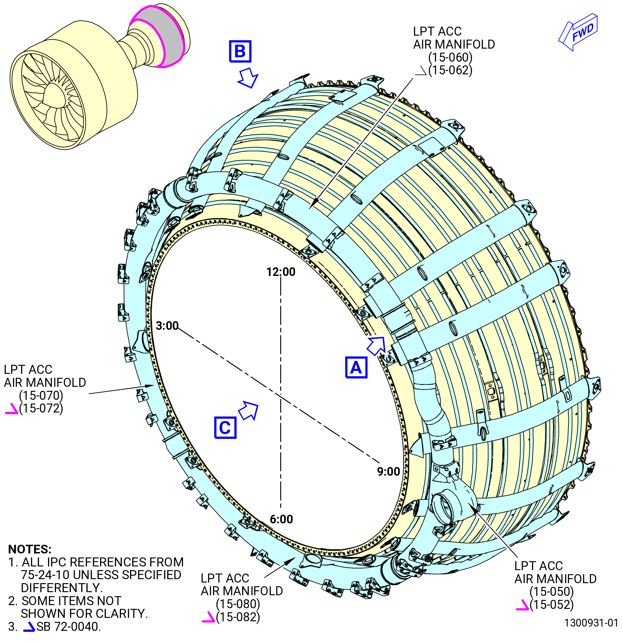
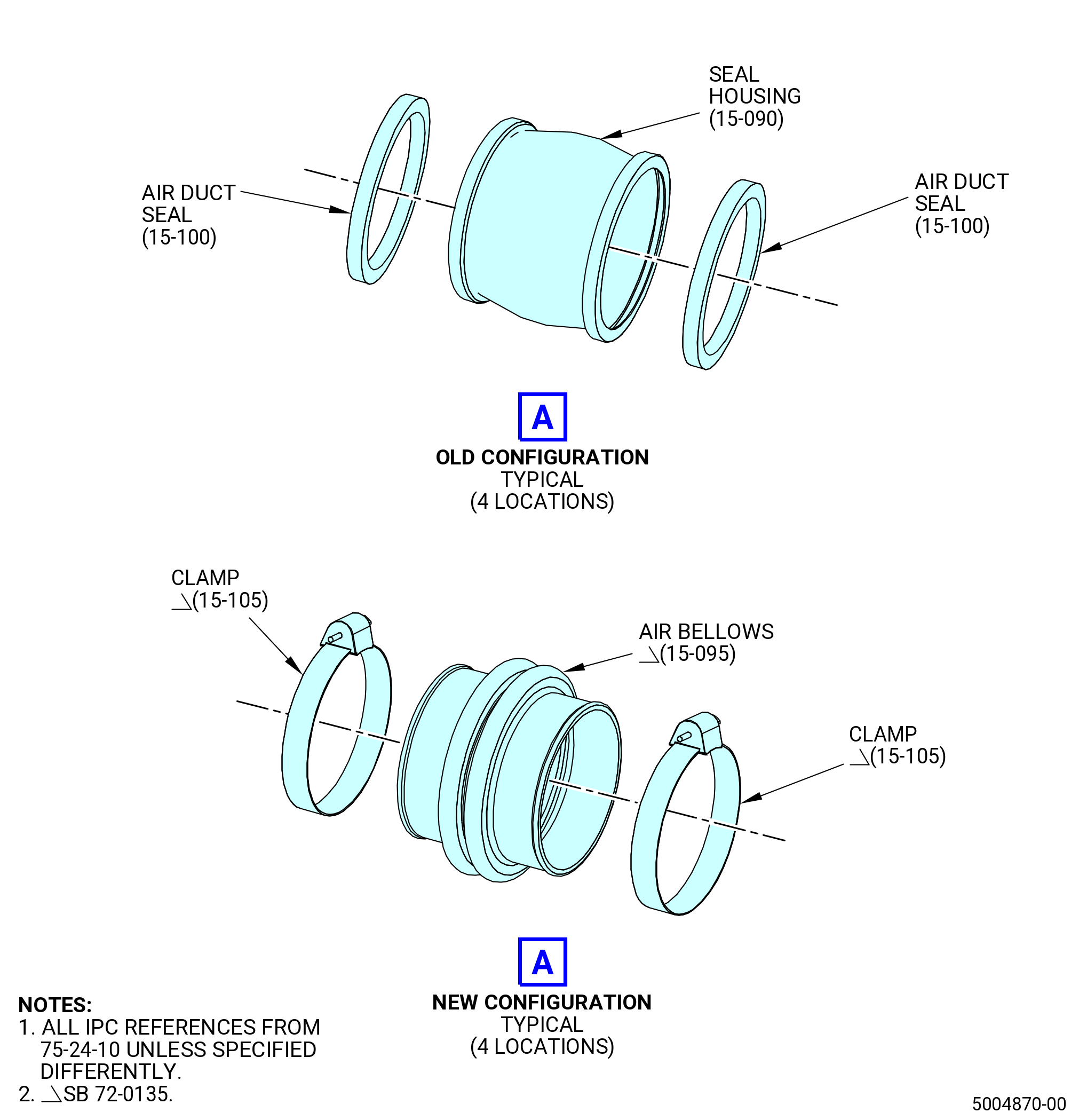
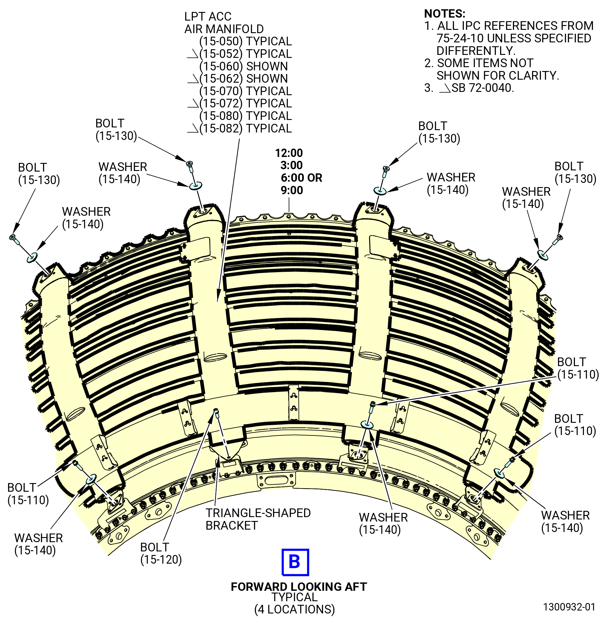
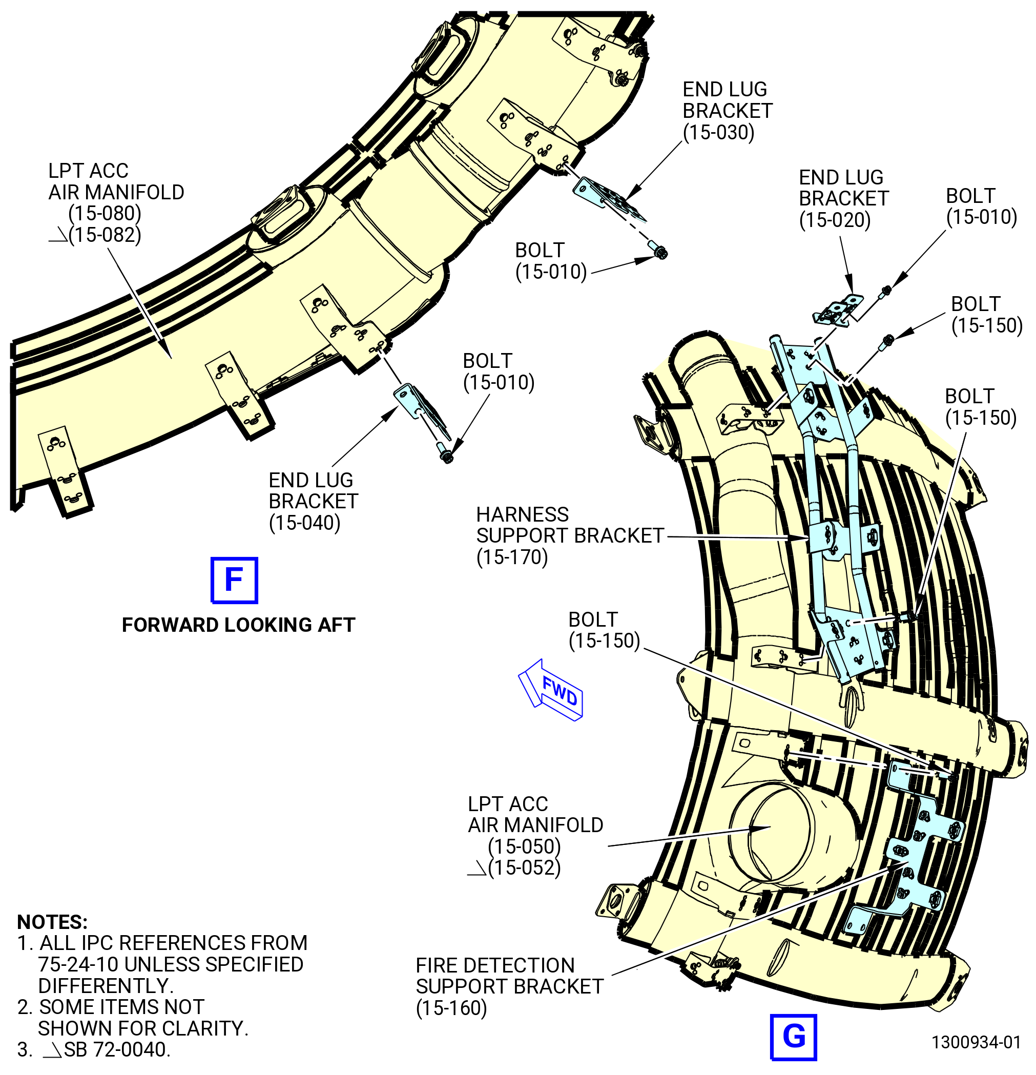
| (3) | The LPT active clearance control (ACC) air manifolds connections point to the support brackets listed below, on the LPT/TRF flange. Remove the machine bolts (bolts) (15-110 , 72-24-10) (SIN 62221), (15-120 , 75-24-10) (SIN 62220), and (15-130 , 75-24-10) (SIN 62223) and washers (15-140 , 75-24-10) (SIN 62232). Refer to Figure 201 and TASK 72-00-02-030-802 (72-00-02, DISASSEMBLY 002 - CONFIG 01) or TASK 72-00-02-030-808 (72-00-02, DISASSEMBLY 002 - CONFIG 02). |
| • |
|
| • |
|
| • |
|
| • |
|
| • |
|
| • |
|
| • |
|
| • |
|
| • |
|
| • |
|
| • |
|
| • |
|
| • |
|
| • |
|
| • |
|
| • |
|
| • |
|
| • |
|
| • |
|
| • |
|
| • |
|
| • |
|
| • |
|
| • |
|
| Subtask 72-00-00-030-253 |
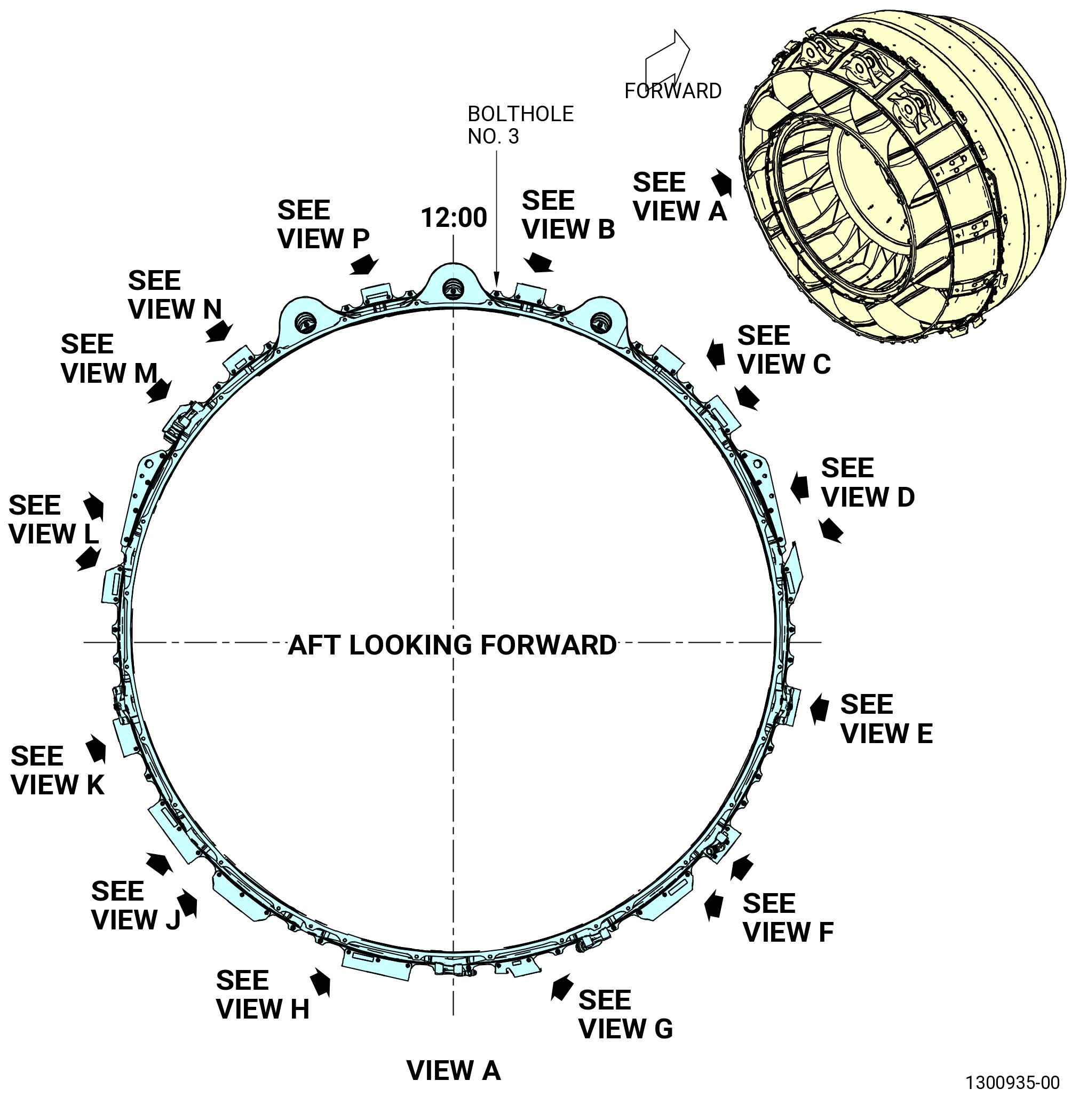
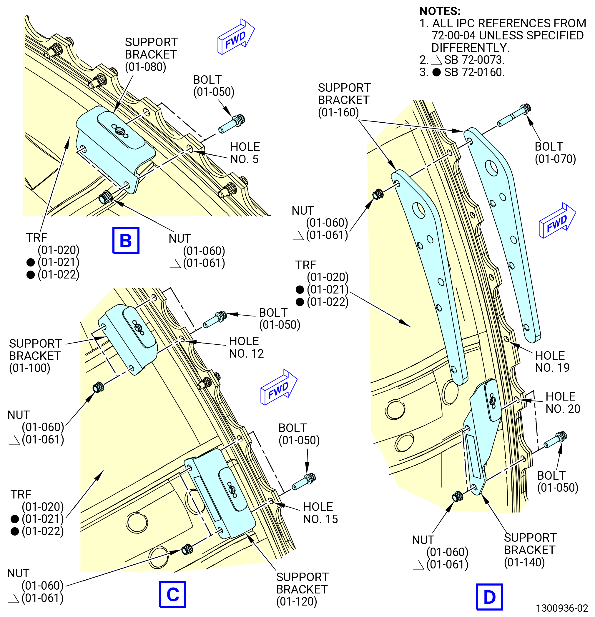
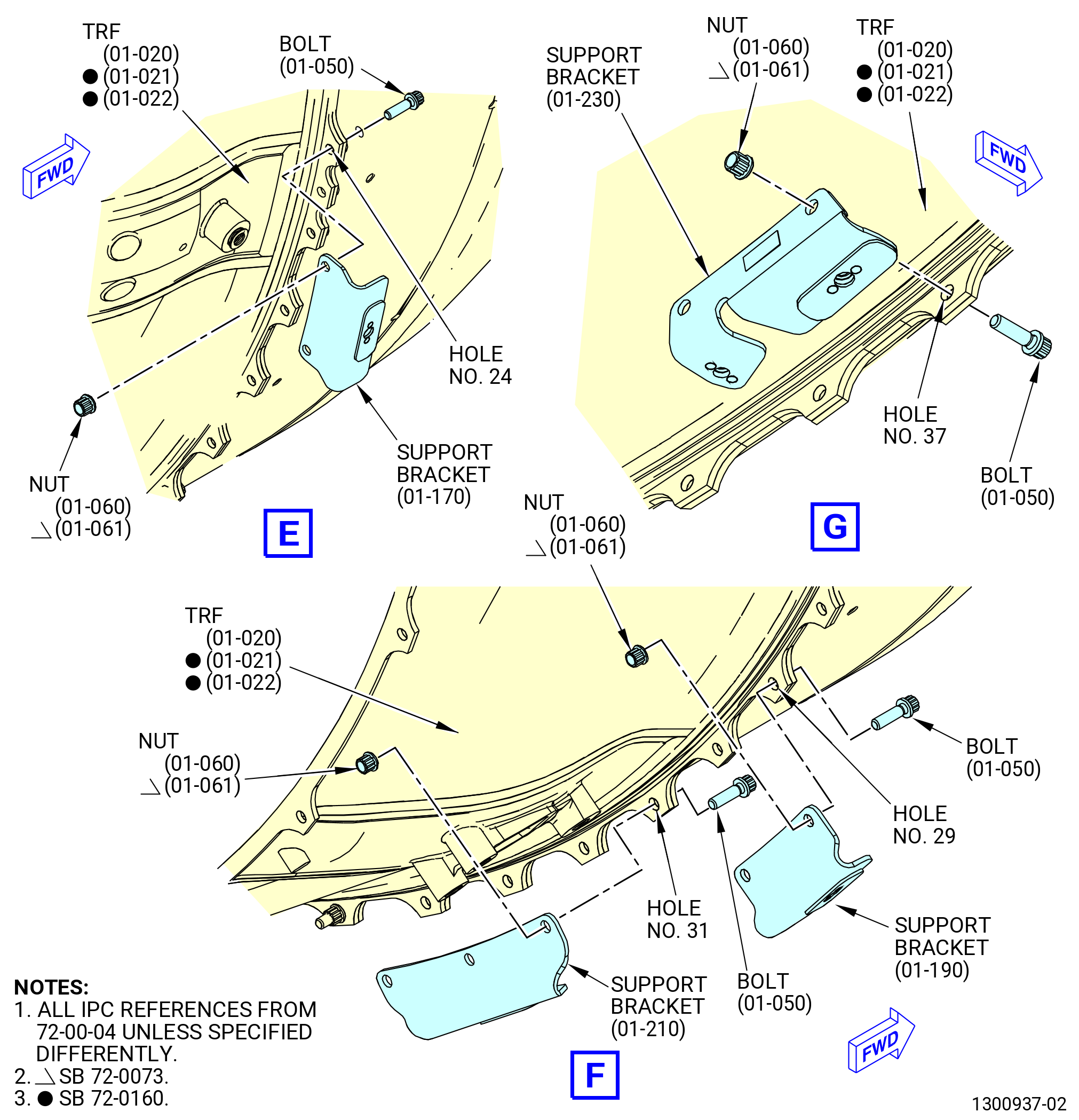
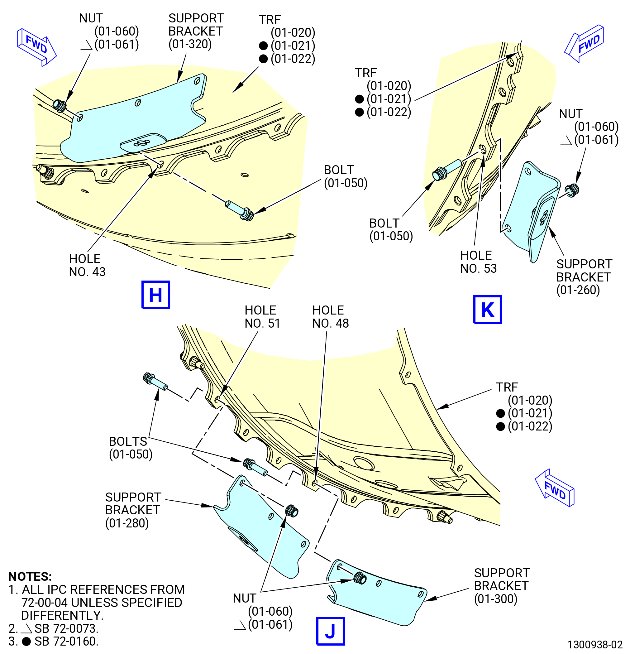
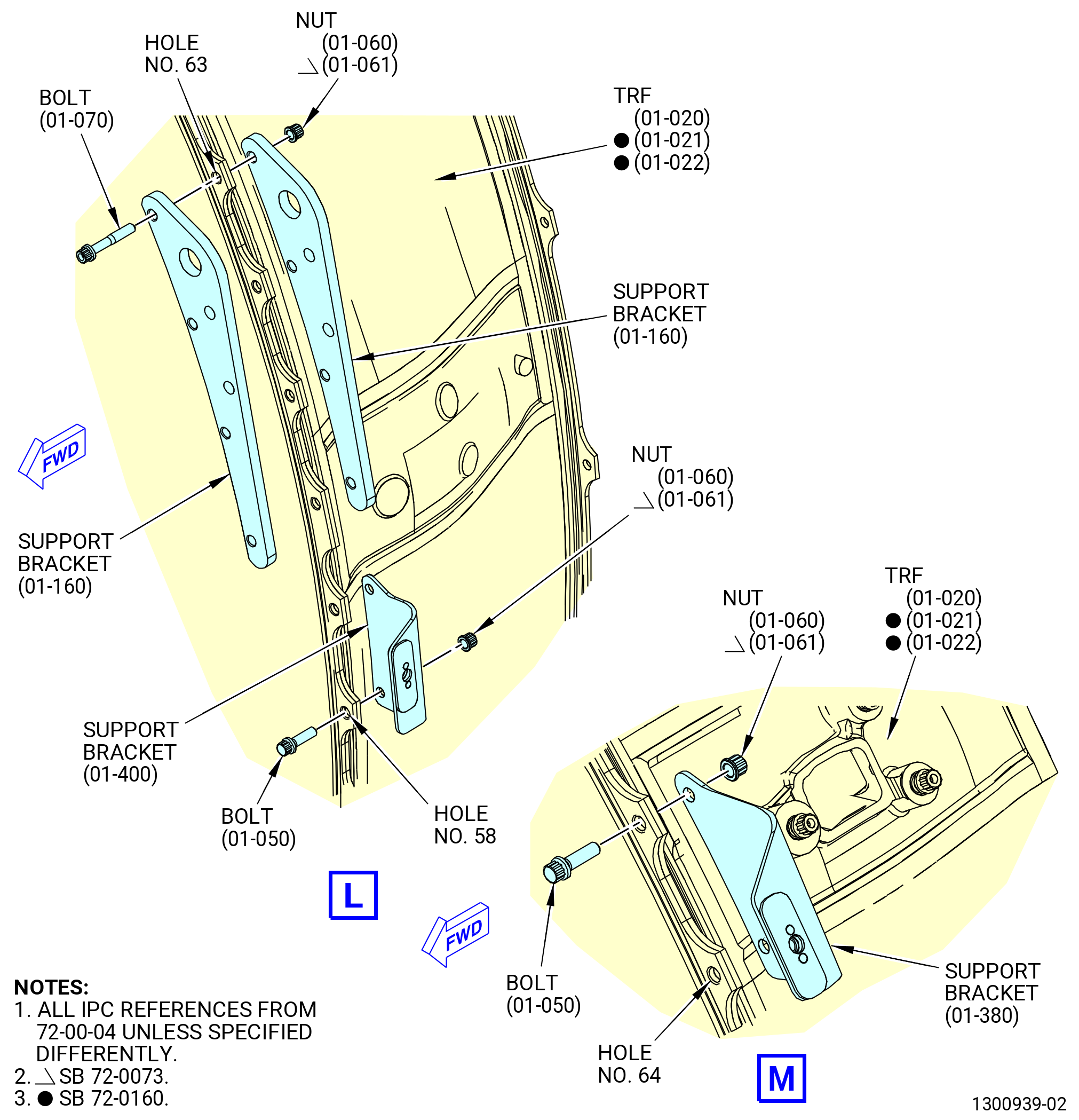
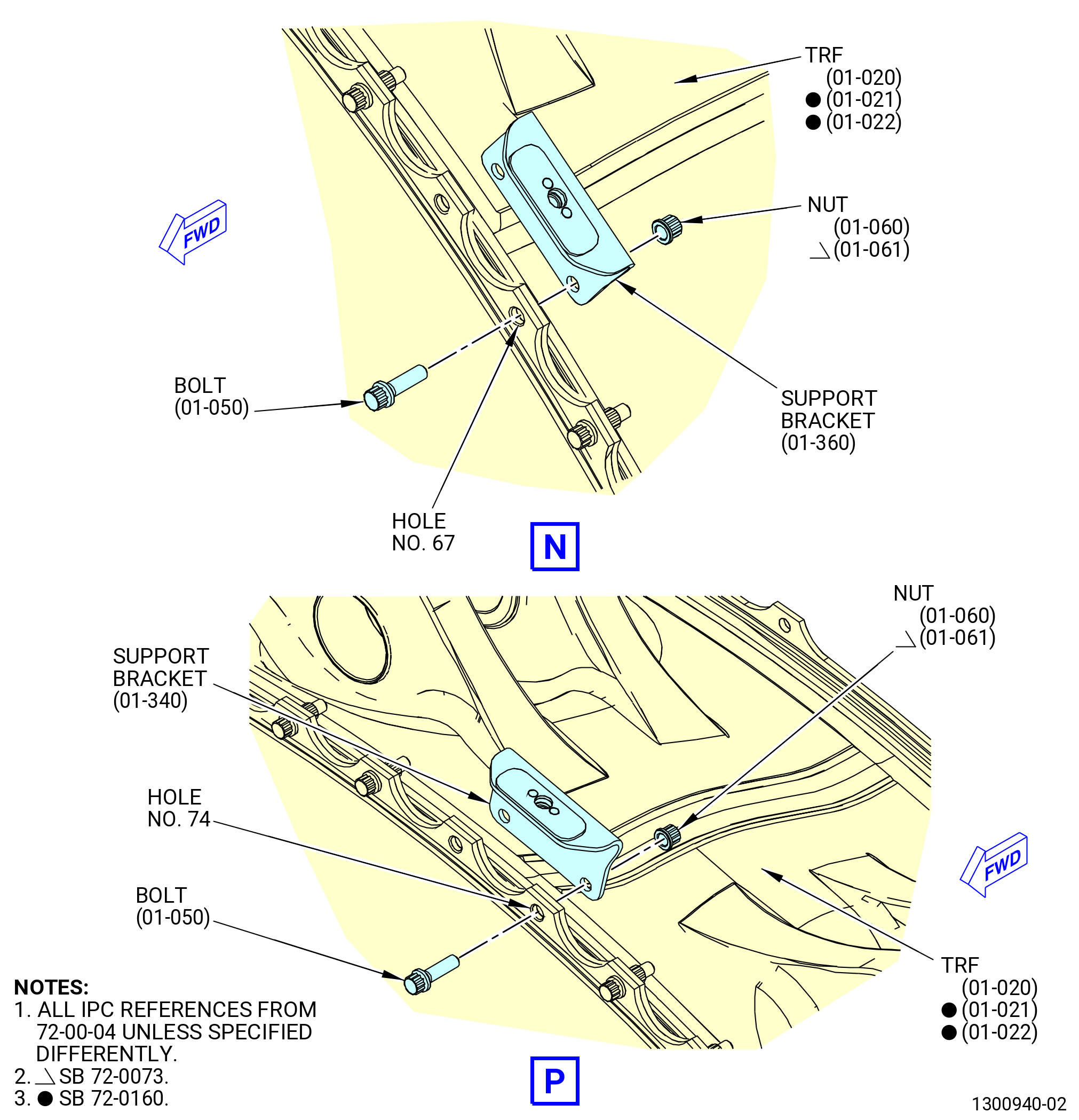
| (4) | Remove the self-locking nut (nut) (01-060 , 72-00-04) (SIN 94040) or (01-061 , 72-00-04) (SIN 94040), machine bolts (bolts) (01-050 , 72-00-04) (SIN 94020), (01-070 , 72-00-04) (SIN 94022), and support brackets listed below, from the LPT rotor/stator assembly aft flange and the TRF forward flange. Discard the nuts. Refer to Figure 202 and TASK 72-00-04-030-801 (72-00-04, DISASSEMBLY 001). |
| • |
|
| • |
|
| • |
|
| • |
|
| • |
|
| • |
|
| • |
|
| • |
|
| • |
|
| • |
|
| • |
|
| • |
|
| • |
|
| • |
|
| • |
|
| • |
|
| • |
|
| Subtask 72-00-00-030-254 |
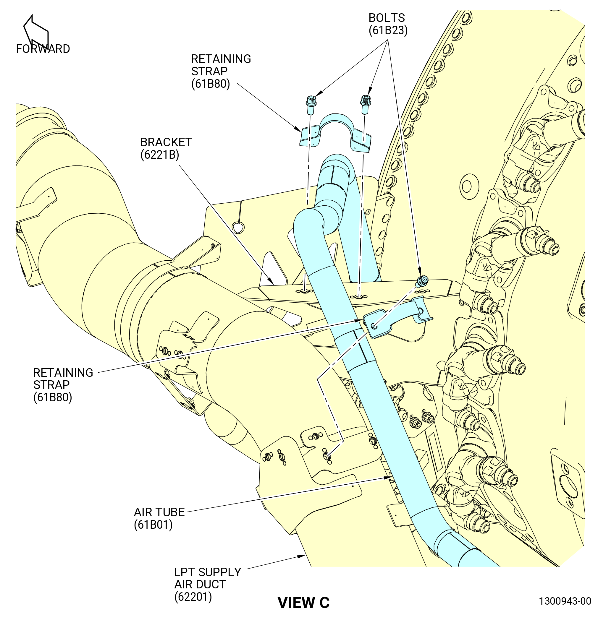
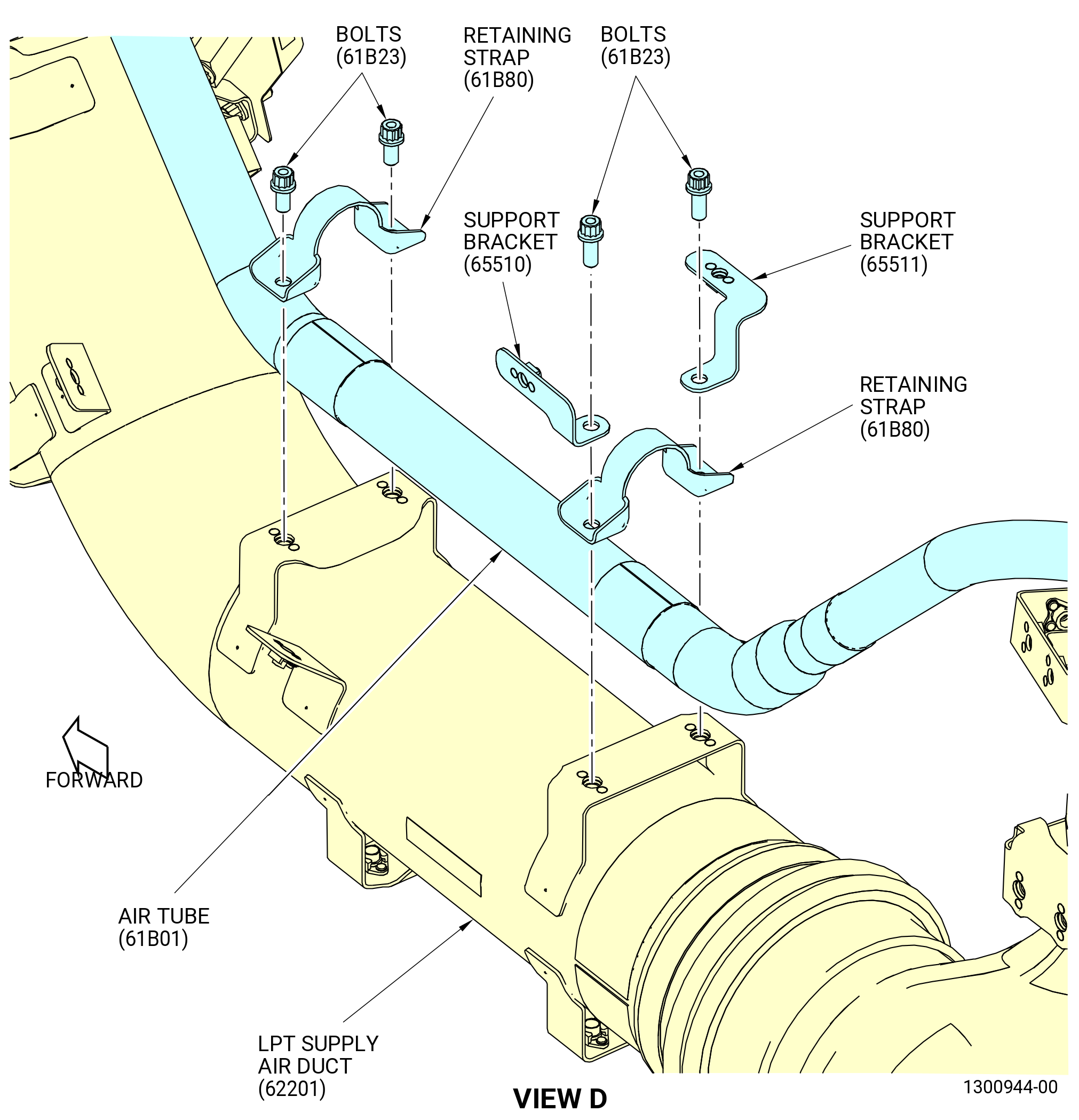
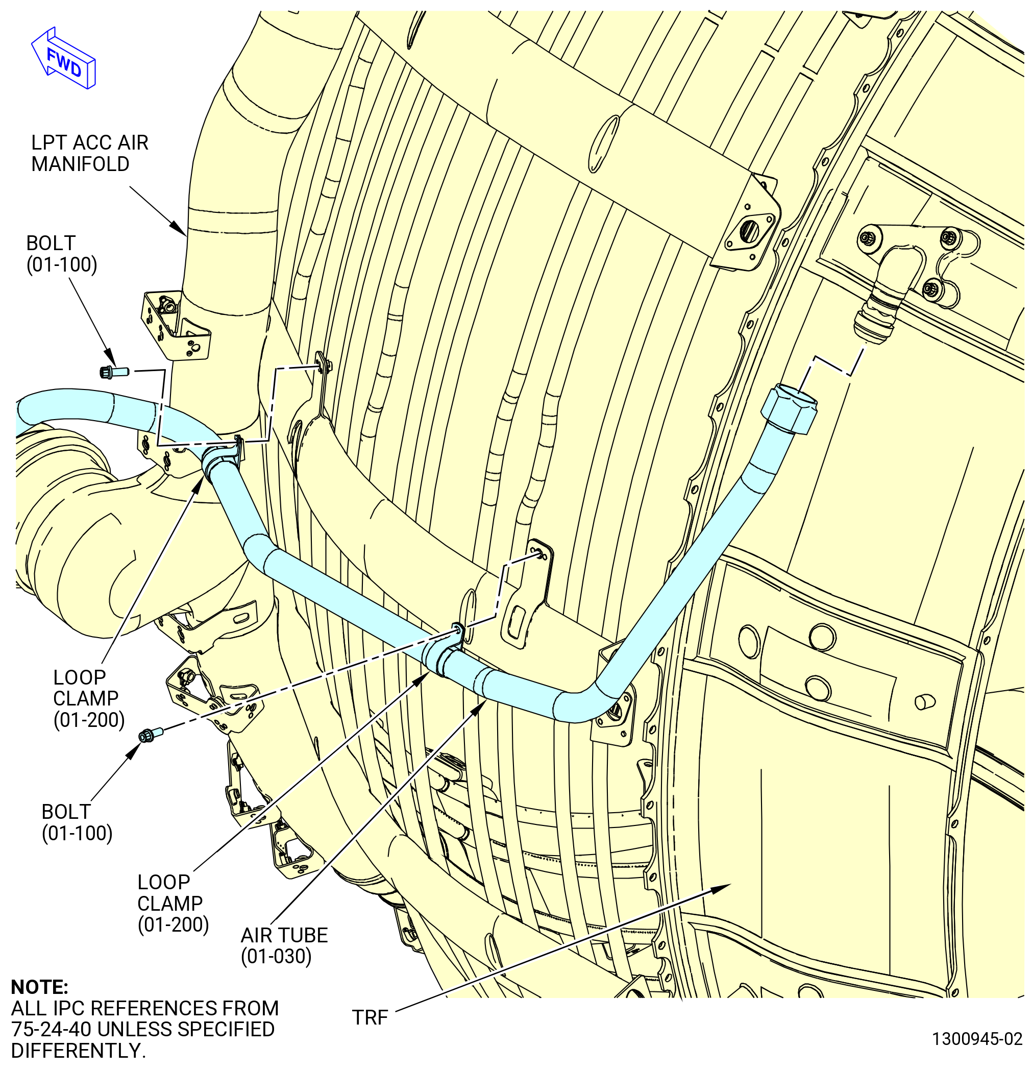
| (5) | Loosen the B-nut on the eductor air tube (air tube) (01-030 , 75-24-40) (SIN 61B01) at the 10:00 o'clock position outer surface of the TRF. Refer to Figure 203, TASK 72-00-02-030-803 (72-00-02, DISASSEMBLY 003), and do as follows: |
| (a) | Remove the machine bolts (bolts) (01-100 , 75-24-40) (SIN 61B22) from the two loop clamps (01-200 , 75-24-40) (SIN 61B84) just forward of the TRF to LPT flange. |
| (b) | Do not fully remove the air tube. |
| Subtask 72-00-00-030-255 |
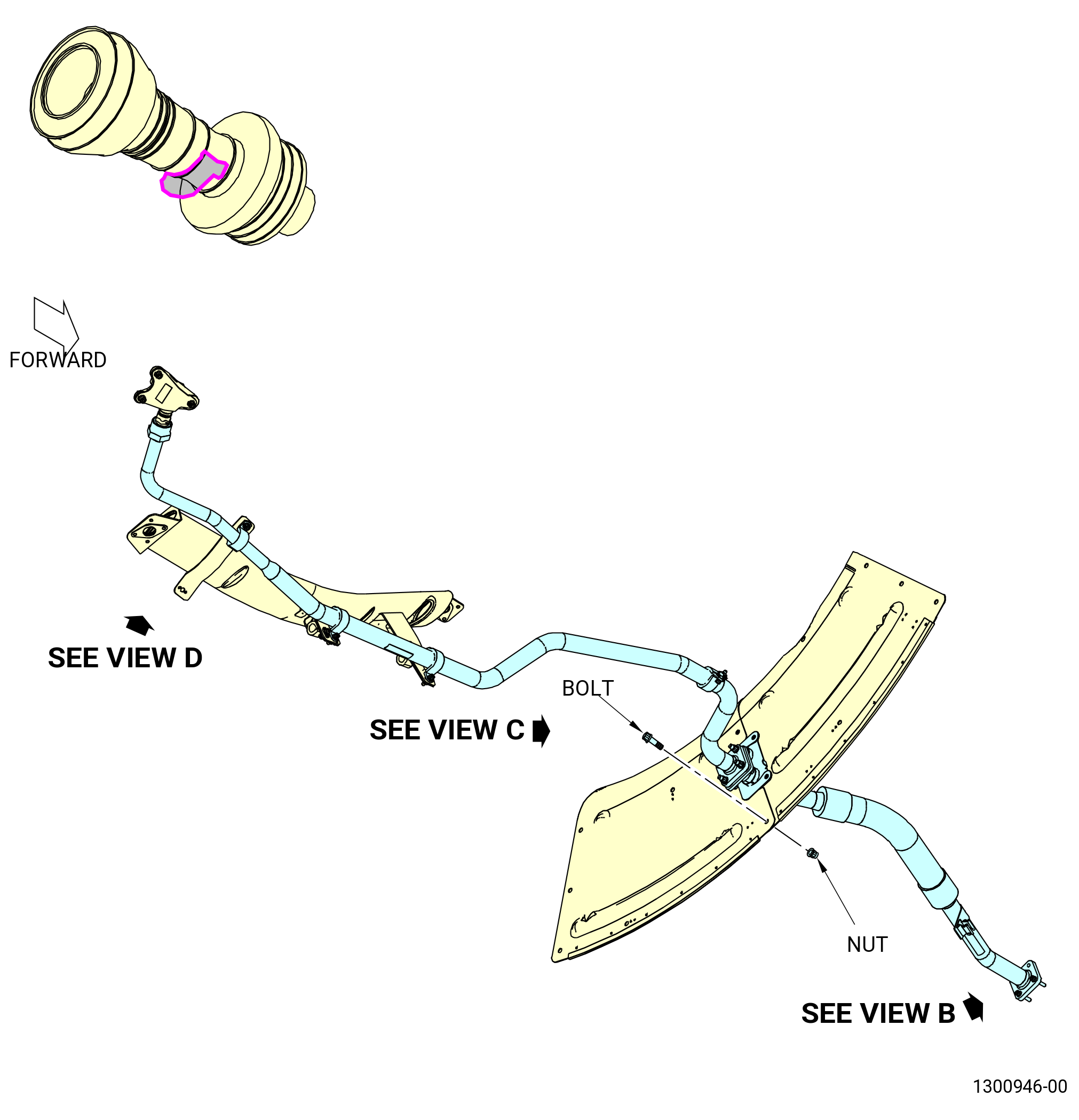
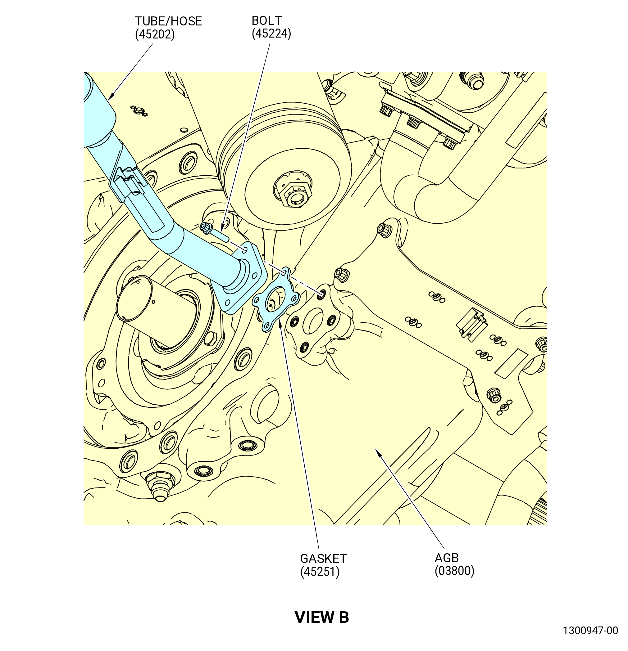
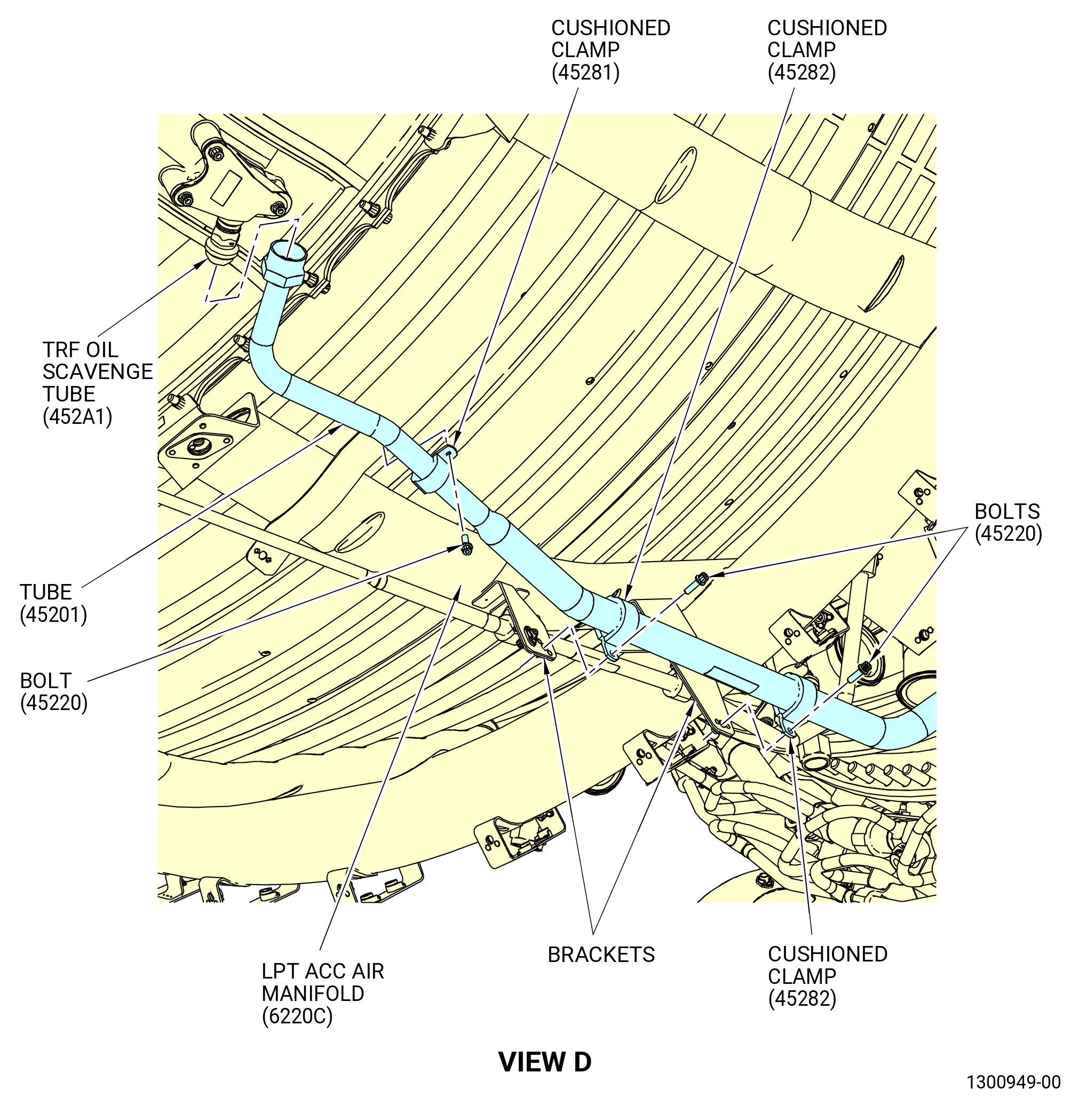
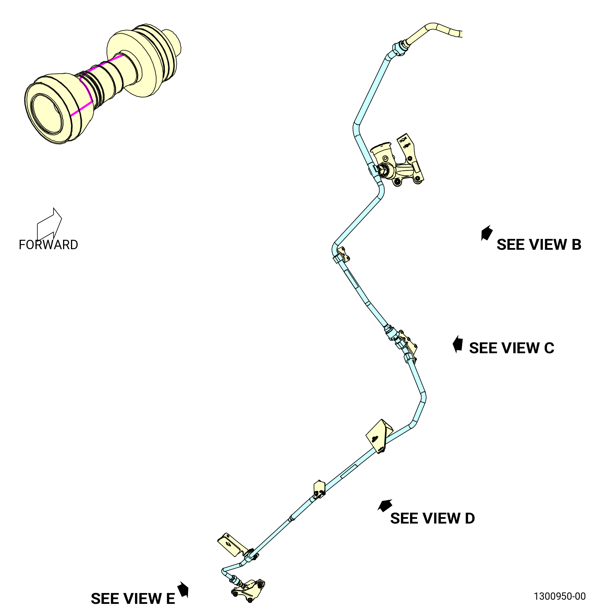
| (6) | Loosen the B-nut on the scavenge oil tube (tube) (10-100 , 79-22-20) (SIN 45201) at the 5:00 o'clock position outer surface of the TRF. Refer to Figure 204, TASK 72-00-02-030-802 (72-00-02, DISASSEMBLY 002 - CONFIG 01) or TASK 72-00-02-030-808 (72-00-02, DISASSEMBLY 002 - CONFIG 02), and do as follows: |
| (a) | Remove the machine bolts (bolts) (10-180 , 79-22-20) (SIN 45220) from the three cushioned loop clamps (cushioned clamps) (10-190 , 79-22-20) (SIN 45282) and one cushioned clamp (10-200 , 79-22-20) (SIN 45281) just forward of the TRF to LPT flange. |
| (b) | Remove all the cushioned clamps (10-190 , 79-22-20) (SIN 45282) and (10-200 , 79-22-20) (SIN 45281). |
| (c) | Do not fully remove the tube. |
| Subtask 72-00-00-030-256 |
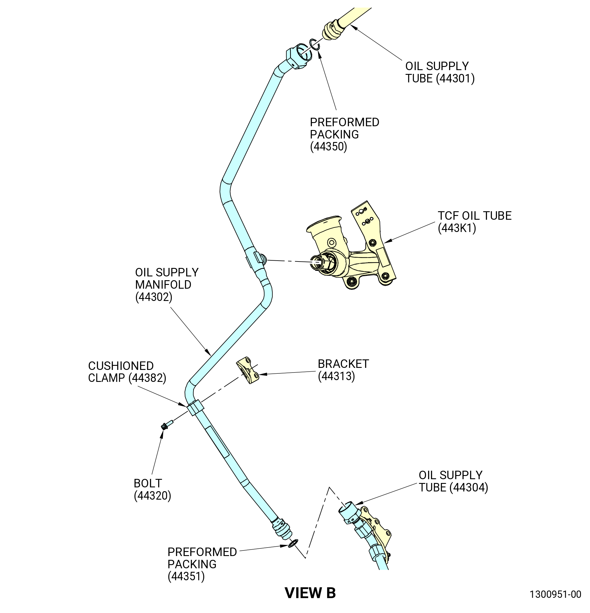
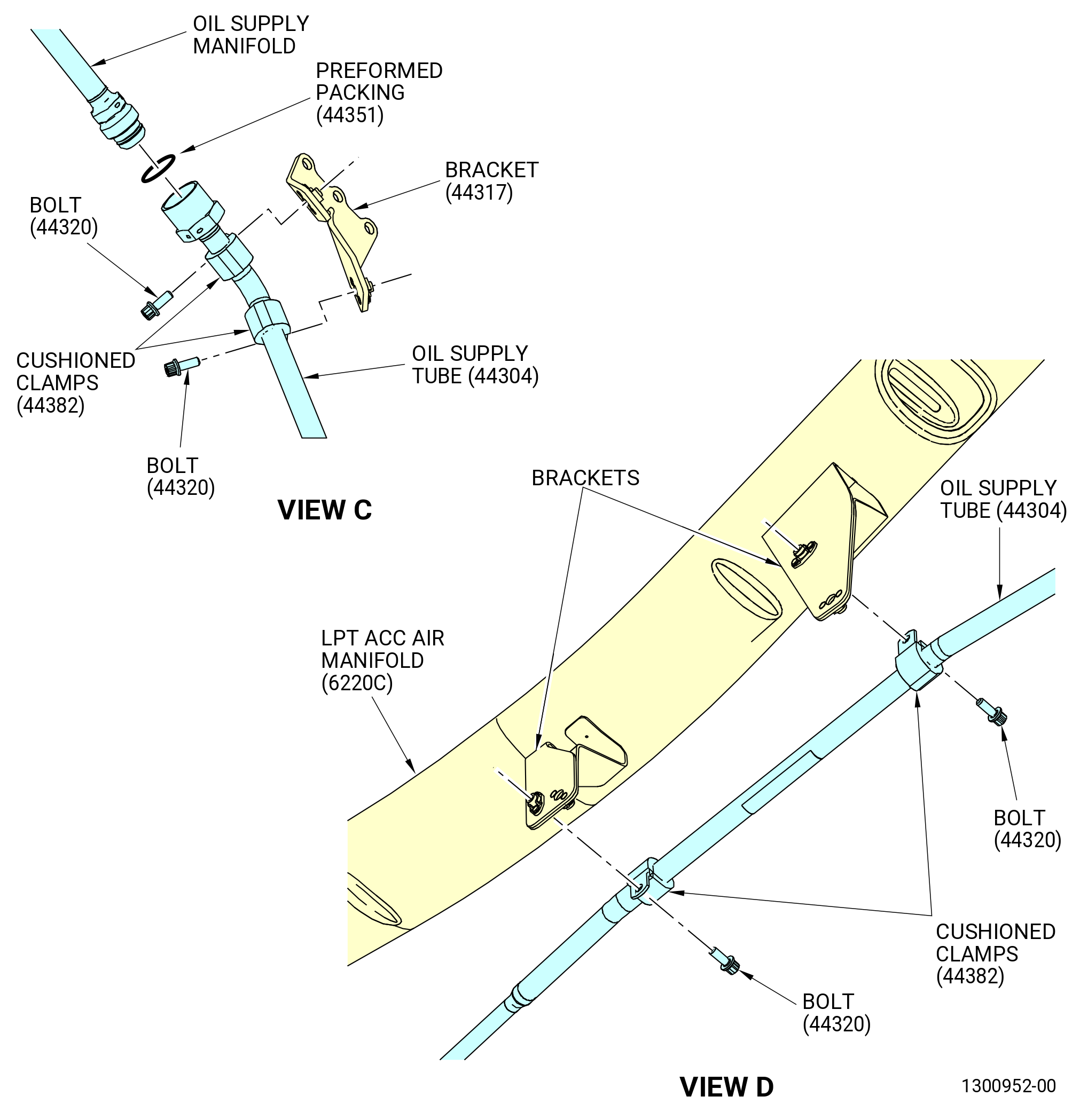
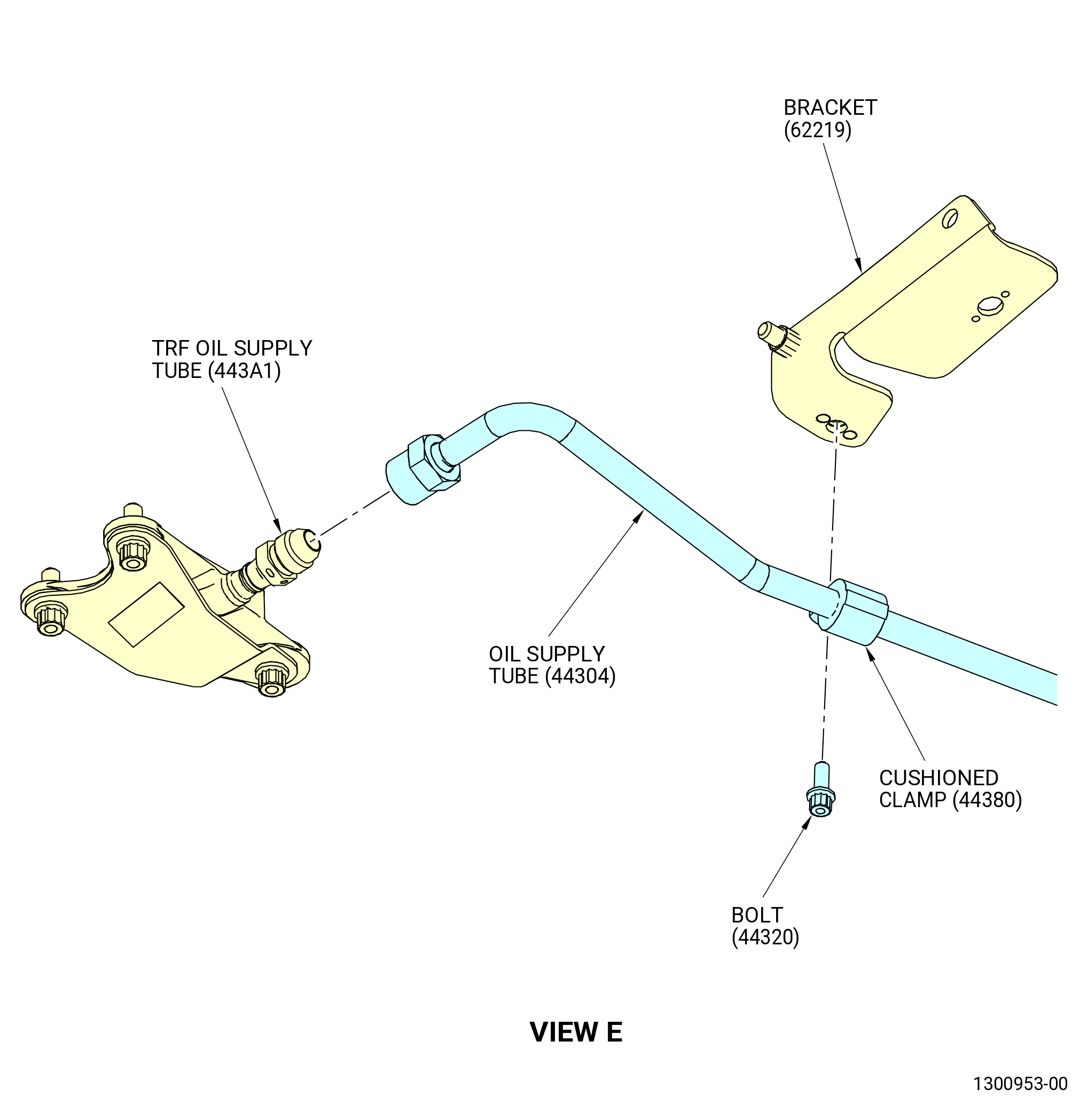
| (7) | Loosen the B-nut on the oil supply tube (20-130 , 79-22-10) (SIN 44304) at the 6:00 o'clock position outer surface of the TRF. Refer to Figure 205, TASK 72-00-02-030-802 (72-00-02, DISASSEMBLY 002 - CONFIG 01) or TASK 72-00-02-030-808 (72-00-02, DISASSEMBLY 002 - CONFIG 02), and do as follows: |
| (a) | Remove the machine bolts (bolts) (20-020 , 79-22-10) (SIN 44320) from the two cushioned loop clamps (cushioned clamps) (20-050 , 79-22-10) (SIN 44380) just forward of the TRF to LPT flange. |
| (b) | Remove the cushioned clamps (20-050 , 79-22-10) (SIN 44380). |
| (c) | Do not fully remove the oil supply tube. |
| Subtask 72-00-00-020-001 |
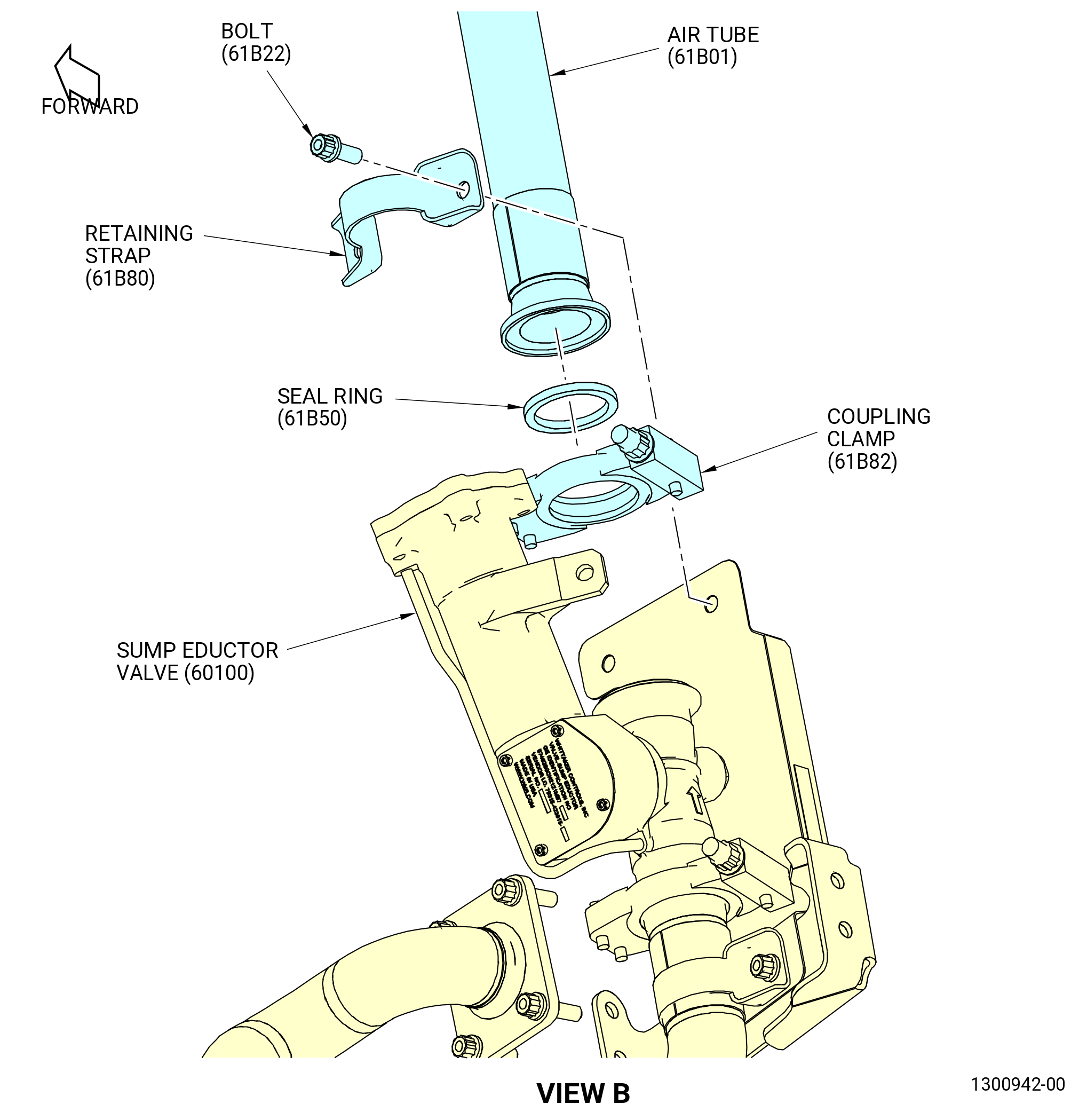
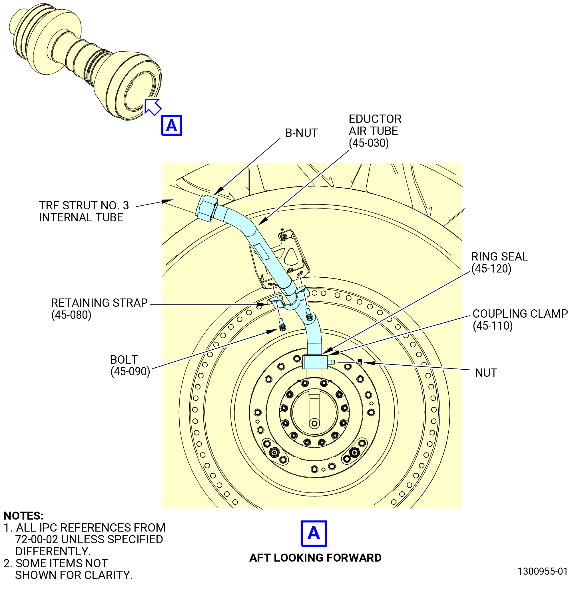
| (8) | Loosen the outer B-nut end of the eductor air tube (45-030 , 72-00-02) (SIN 61BA1) at the 10:00 o'clock position inner surface of the TRF. Refer to Figure 206, TASK 72-00-04-020-801 (72-00-04, REMOVAL 001), and do as follows: |
| (a) | Remove the coupling clamp (45-110 , 72-00-02) (SIN 61BV1) from the lower end of the eductor air tube. |
| (b) | Remove and discard the ring seal (45-120 , 72-00-02) (SIN 61BN0). |
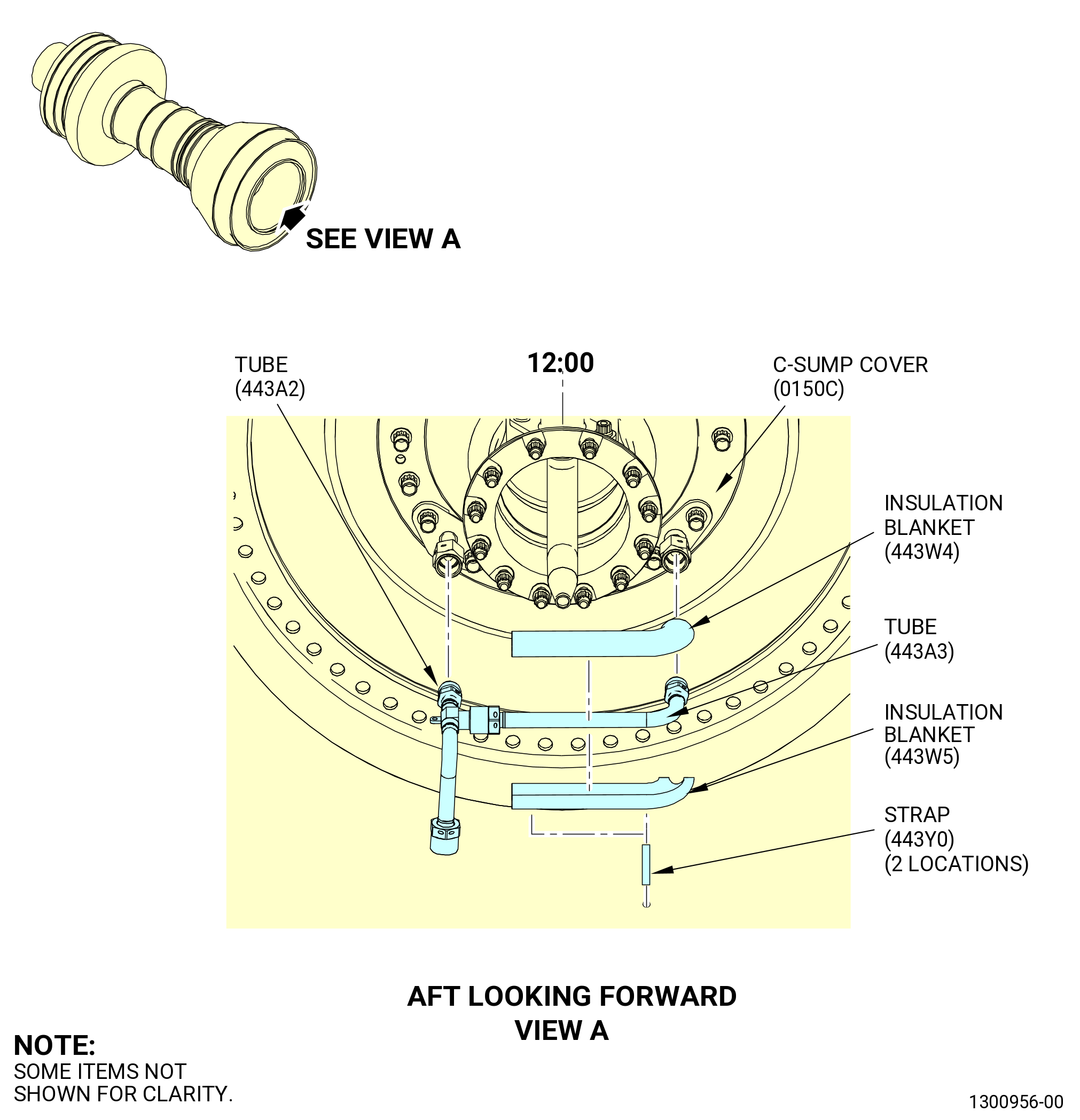
| (9) | Remove the connector supply tubes (tubes) (443A2, 443A3) and associated safety cable. Do not remove the supply insulation blankets (insulation blankets) (443W4, 443W5) from these tubes. Refer to TASK 72-00-04-020-801 (72-00-04, REMOVAL 001) and Figure 206. |
| Subtask 72-00-00-020-003 |
| * * * PRE SB 72-0039( Old Oil Nozzle Design ) |
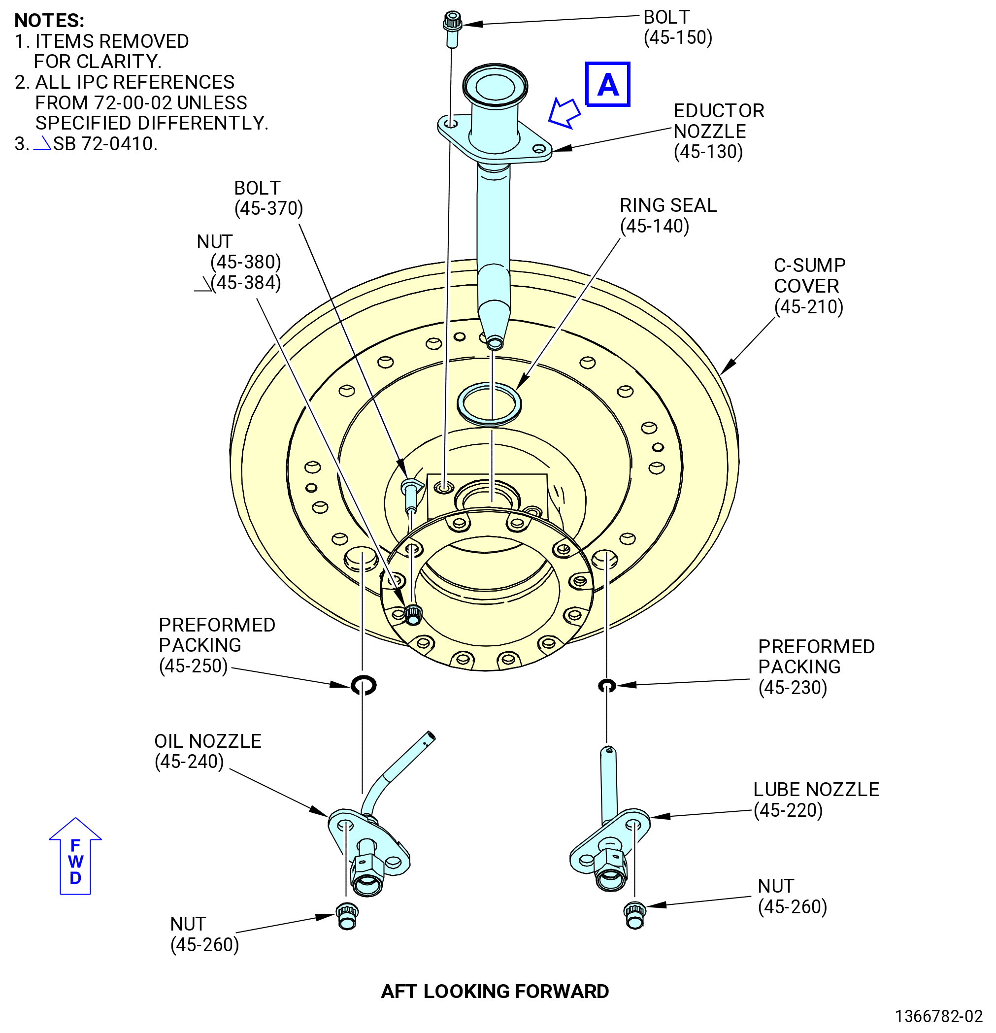
| (10) | Remove the A/O seal nozzle (oil nozzle) (45-240 , 72-00-02) and A/O No. 5 nozzle (lube nozzle) (01509) by removing the self-locking nuts (nuts) (01544). Remove and discard the preformed packing (01555, 0155B). Refer to TASK 72-00-04-020-801 (72-00-04, REMOVAL 001) and Figure 207. |
| * * * END PRE SB 72-0039 |
| Subtask 72-00-00-020-019 |
| * * * SB 72-0039( New Oil Nozzle Design ) |
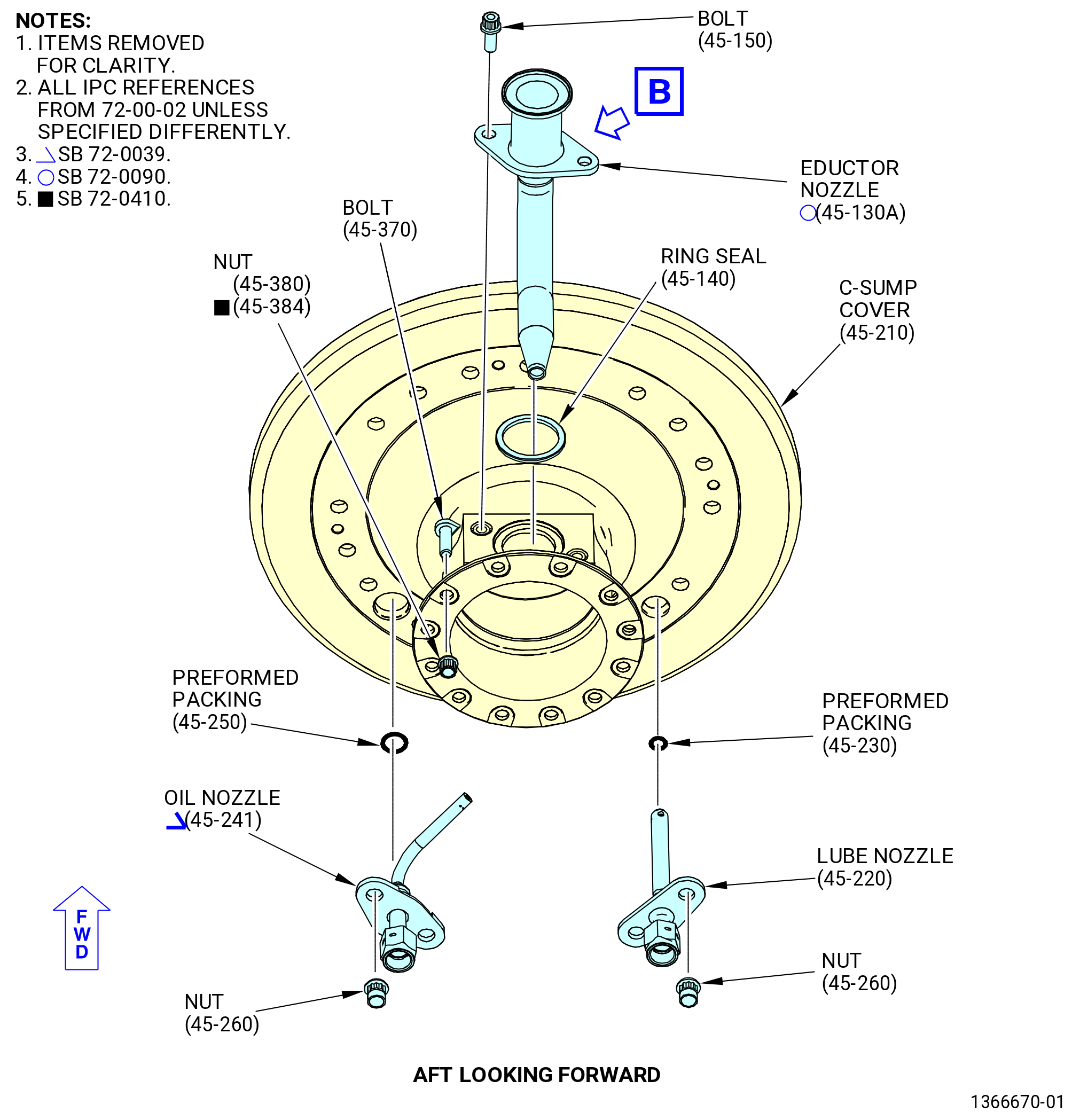
| (10).A. | Remove the A/O seal nozzle (oil nozzle) (45-241 , 72-00-02) and lube nozzle (01509) by removing the nuts (01544). Remove and discard the preformed packing (01555, 0155B). Refer to TASK 72-00-04-020-801 (72-00-04, REMOVAL 001) and Figure 207. |
| * * * END SB 72-0039 |
| Subtask 72-00-00-020-020 |
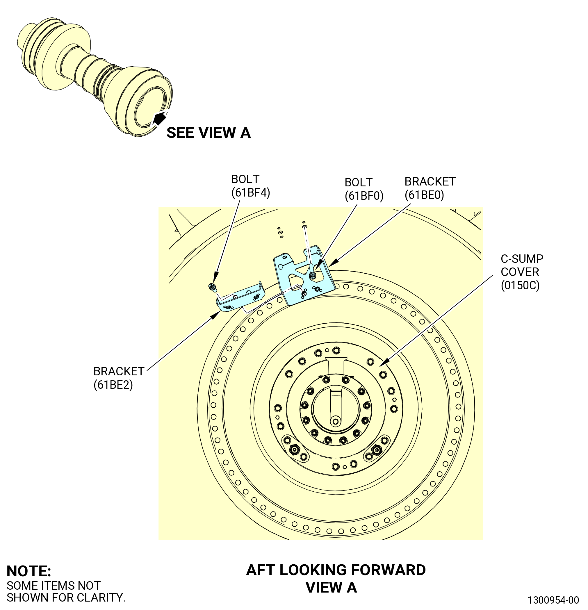
| (11) | Remove the A/O C-sump cover (C-sump cover) (45-210 , 72-00-02) (SIN 0150C) and the No. 5 bearing carbon seal (carbon seal) (45-350 , 72-00-02) (SIN 01558). Do not remove neither the slabbed head bolts (bolts) (45-370 , 72-00-02) (SIN 912F0), self-locking nuts (nuts) (45-380 , 72-00-02) (SIN 912K1) or (45-384 , 72-00-02) (SIN 912K1), machine bolts (bolts) (45-150 , 72-00-02) (SIN 015F1), nor the eductor nozzle (45-130 , 72-00-02) (SIN 015K3) from the C-sump cover. Remove and discard the preformed packing (45-340 , 72-00-02) (SIN 01551). Refer to TASK 72-00-04-020-801 (72-00-04, REMOVAL 001) and Figure 207. |
| Subtask 72-00-00-220-024 |
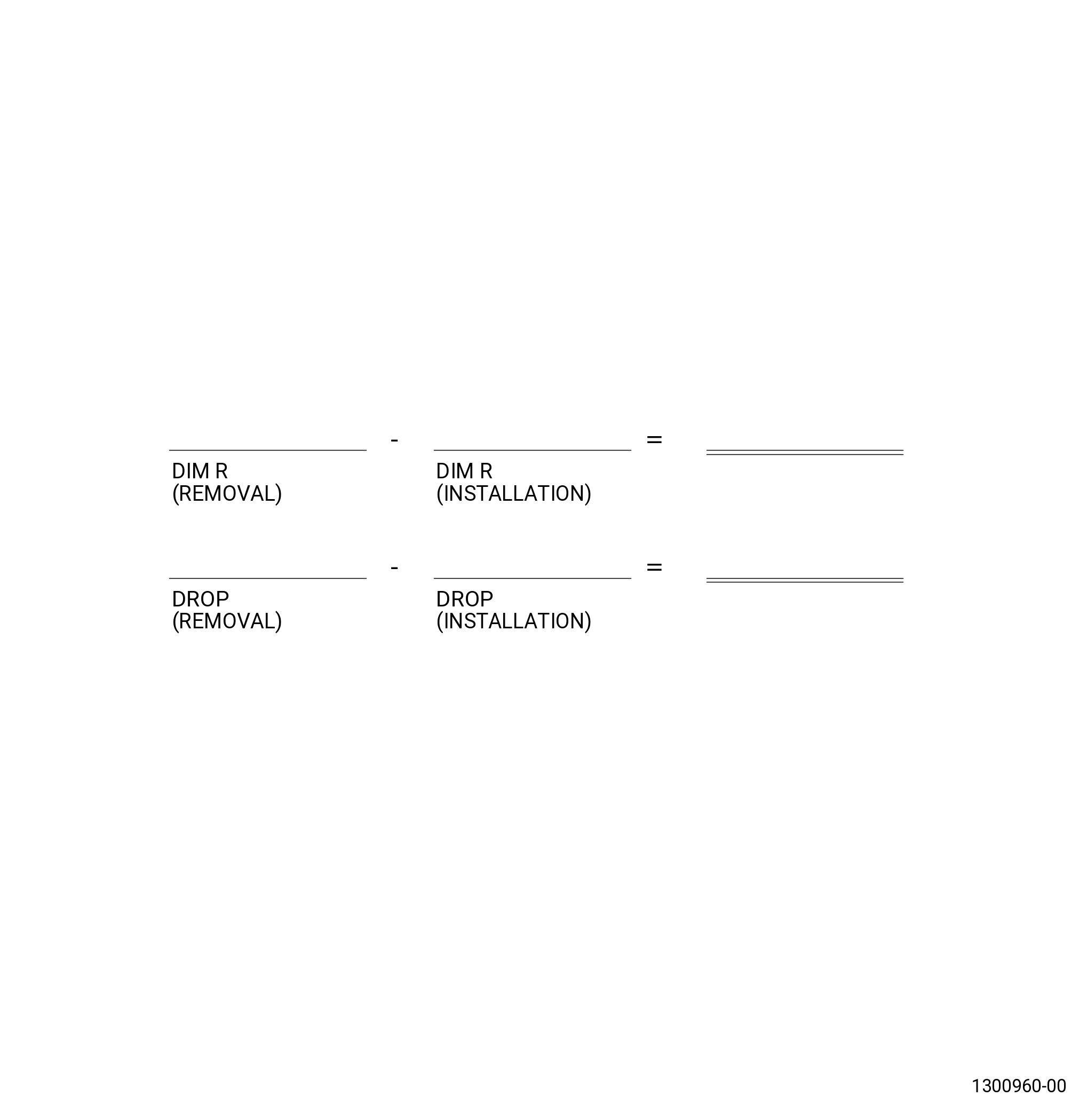
| (12) | Measure and record dimension R from the aft face of the aft No. 5 bearing housing (01501) to the aft end of the A/O LPT cone shaft (LPT cone shaft) (930D1) (aft end of tab on shaft). Measure at four locations and average. This is a dimension to use as reference. The actual dimension is set by the LPT shim. Refer to Figure 208 and Figure 209. |
| Subtask 72-00-00-220-025 |
| (13) | Measure and record the drop from the aft end of the castellations of the No. 5 roller bearing locknut to the aft end of the castellations on the aft shaft. |
| Subtask 72-00-00-020-005 |
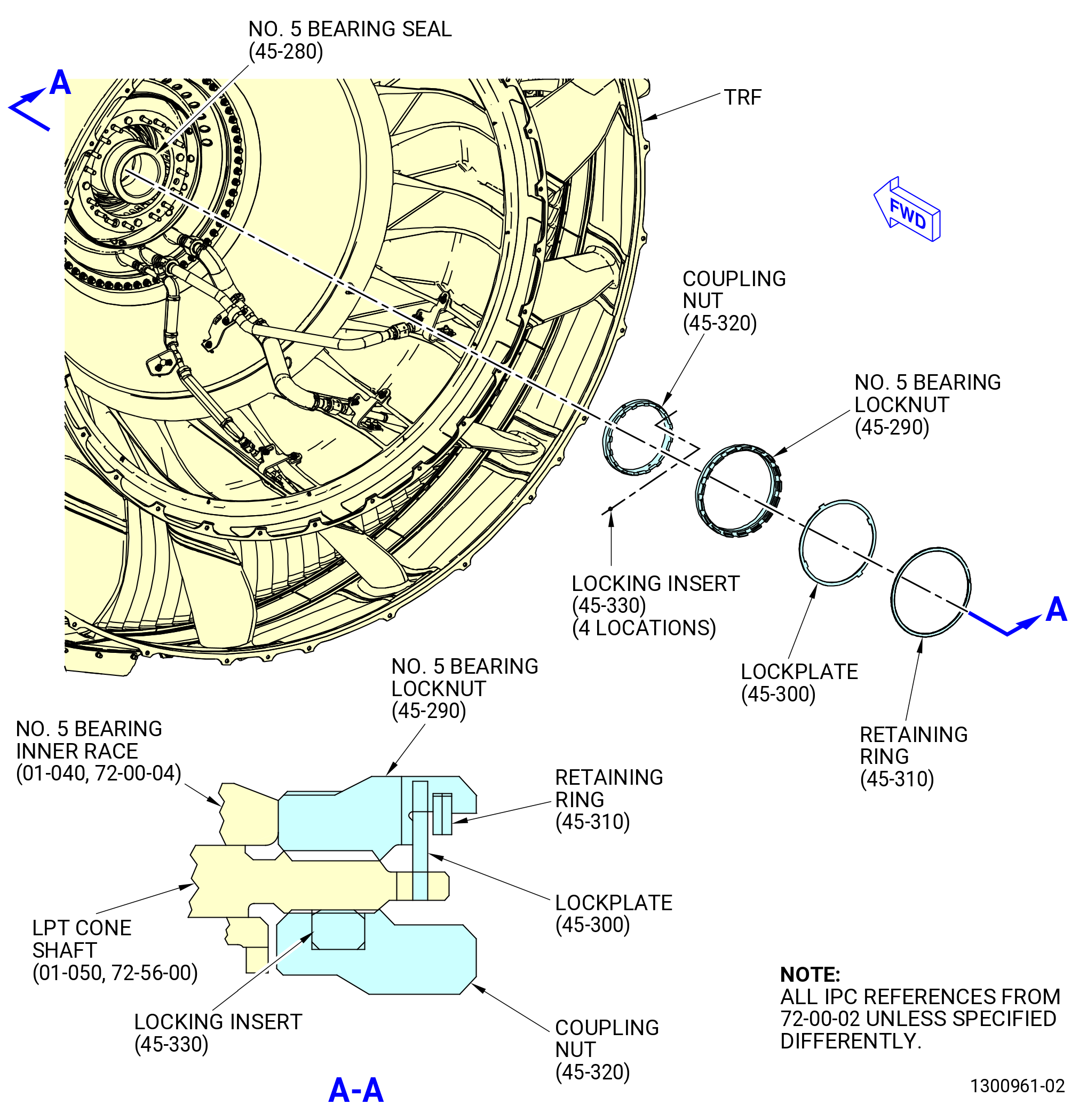
| (14) | Remove the retaining ring (01593) and No. 5 bearing lockplate (lockplate) (01592) from the No. 5 bearing locknut (01503). Refer to TASK 72-00-04-020-801 (72-00-04, REMOVAL 001), Figure 210, and as follows: |
| (a) | Remove the retaining ring from the groove inside the castellations of the No. 5 bearing locknuts as follows: |
| 1 | Locate one end of the retaining ring (where the retaining ring overlaps itself). |
| 2 | Use a pick (or equivalent small, pointy tool) and make contact with the end of the retaining ring. |
| CAUTION: |
|
| 3 | Compress the retaining ring radially inward. Move the pick around the outside circumference of the retaining ring. This will force the retaining ring to spring out of the groove inside the castellations. |
| (b) | Use a pick and remove the lockplate from the slots on the No. 5 bearing locknut and the LPT cone shaft (930D1). |
| (15) | Remove the No. 5 bearing locknut (45-290 , 72-00-02) (SIN 01503). Refer to TASK 72-00-04-020-801 (72-00-04, REMOVAL 001). |
| Subtask 72-00-00-420-527 |
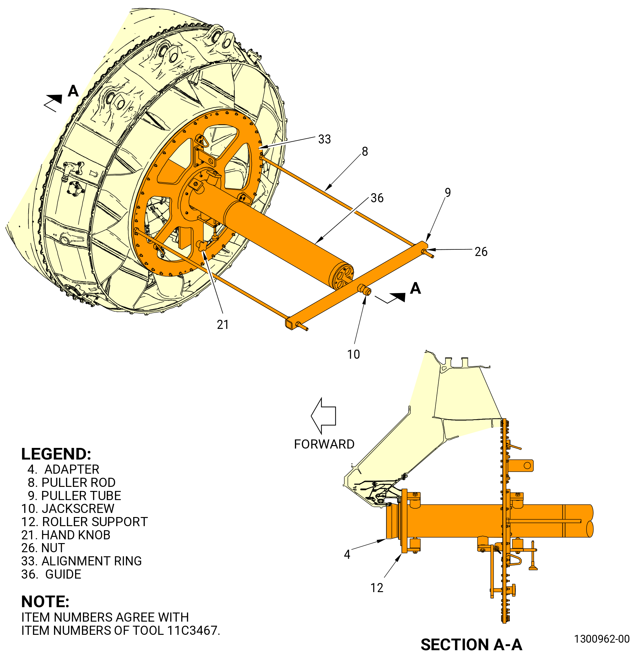
| (16) | Install the 11C3467 TRF guide fixture as follows: |
| (a) | Install the adapter (item 4) to the LPT cone shaft (01-050 , 72-56-00) (SIN 930D1). |
| (b) | Install the roller support (item 12). |
| (c) | Attach the alignment ring (item 33) to the TRF with a single hoist attached to the top lift eye, where the forward centerbody was attached. |
| (d) | Use slave nuts and bolts. |
| (e) | Torque the slave nuts to 200 lb in. (22.6 N.m). |
| WARNING: |
|
| (f) | Lift the assembled guide tube (item 36) with nylon straps and install through the alignment ring (item 33). Thread the guide tube (item 36) of the 11C3467 TRF guide fixture to the threads of the cone shaft where the plain round No. 5 bearing nut was attached. Hand-tighten the tube by attaching a square plate to the aft end with a 0.50 inch (12.7 mm) drive. |
| NOTE: |
|
| Subtask 72-00-00-490-009 |
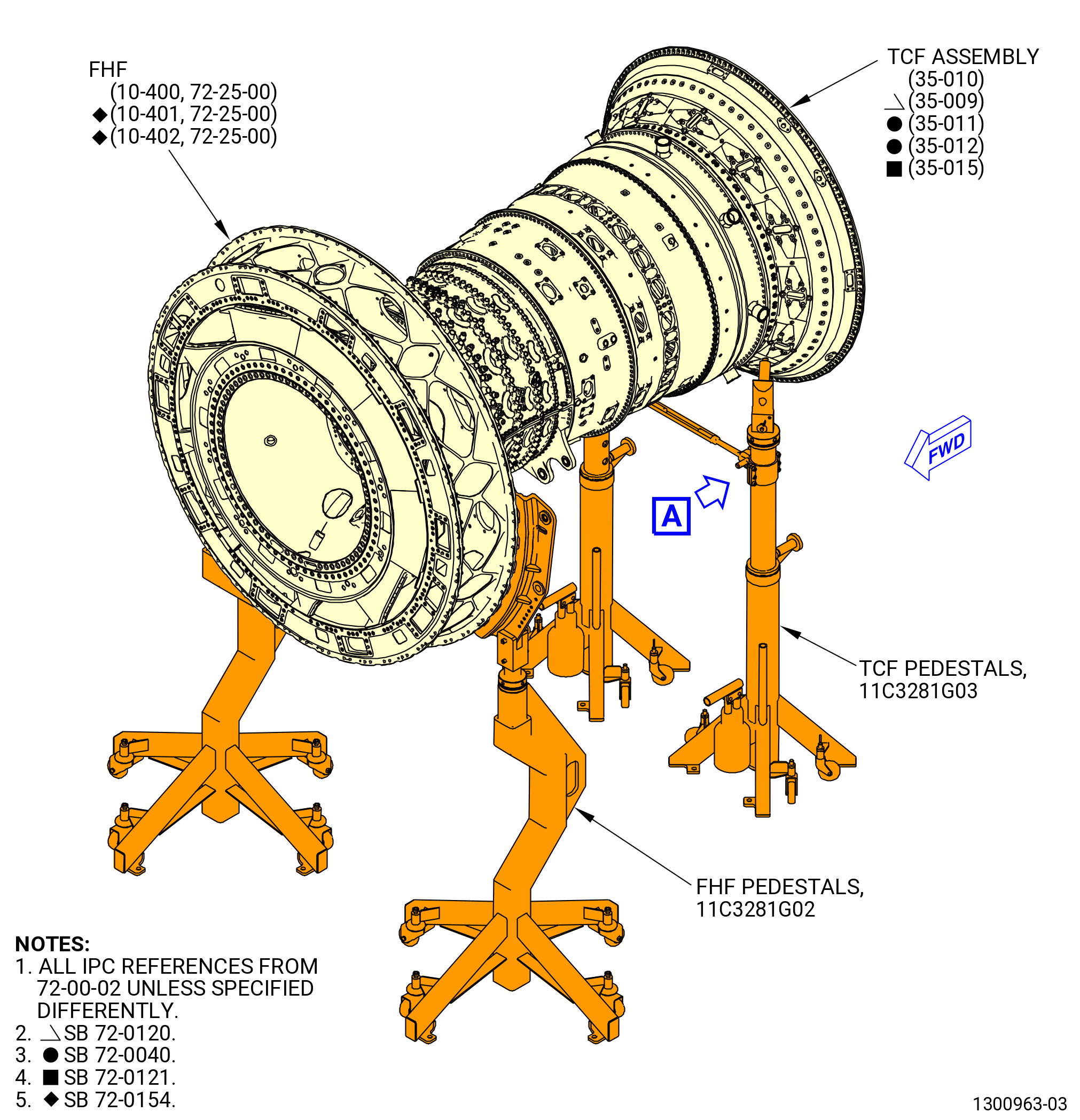
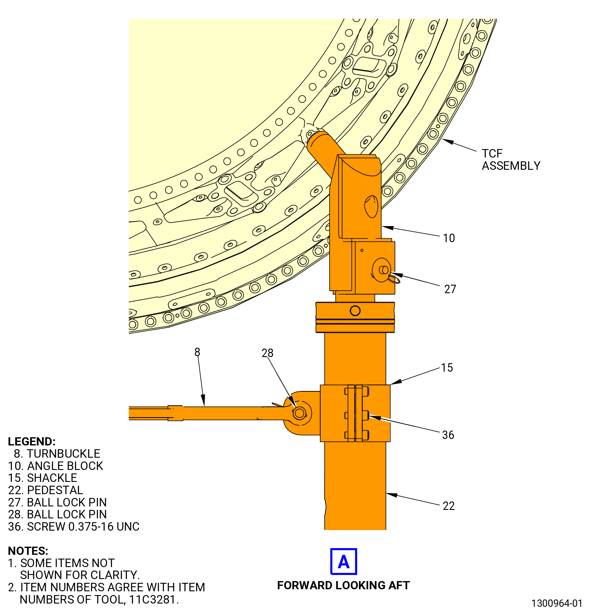
| (17) | Install the 11C3281G03 TCF pedestals as follows. Refer to Figure 212. |
| WARNING: |
|
| (a) | With the ball lock pin (item 27) removed, lower the angle block (item 10) on the pedestal shaft (item 22). Install the ball lock pin (item 27) in the hole. |
| (b) | Set the correct height on the 11C3281G03 TCF pedestals and move the pedestal/support assembly to the turbine center frame (TCF) assembly (35-009 , 72-00-02) (SIN 92500), (35-010 , 72-00-02) (SIN 92500), (35-011 , 72-00-02) (SIN 92500), (35-012 , 72-00-02) (SIN 92500), or (35-015 , 72-00-02) (SIN 92500). |
| (c) | Engage the bar of the angle block (item 10) in the mounting holes of the TCF assembly. |
| (d) | Install the opposite side pedestal/support assembly. Refer to Subtask 72-00-00-490-009 (paragraph 4.A.(16)(a)) thru Subtask 72-00-00-490-009 (paragraph 4.A.(16)(c)). |
| CAUTION: |
|
| (e) | Install the support shackles (item 15) on the pedestal with six screws (item 36) each. |
| (f) | Install the turnbuckle (item 8) on the support shackle (item 15) with the two ball lock pins (item 28). |
| (g) | Adjust the turnbuckle (item 8) to decrease the tension between the two pedestals. |
| (h) | Lower the engine weight on the pedestals. |
| Subtask 72-00-00-490-010 |
| (18) | Deleted. |
| (19) | Deleted. |
| (20) | Deleted. |
| (21) | Put the 11C3468 TRF pedestal set below the guide tube (item 36) of the 11C3467 TRF guide fixture at the most aft position to let the TRF to move approximately 6.00 inches (152.4 mm) aft. Refer to Figure 211 and Figure 214. |
| (22) | Adjust to remove all clearance between the support and the guide tube (item 36). |
| (23) | Make sure that the hydraulic load cell is half filled with oil. Apply a load of 470 lb. (213 kg) on the 11C3468 TRF pedestal set. |
| (24) | Make sure that the engine is level in the correct pedestal configuration. |
| WARNING: |
|
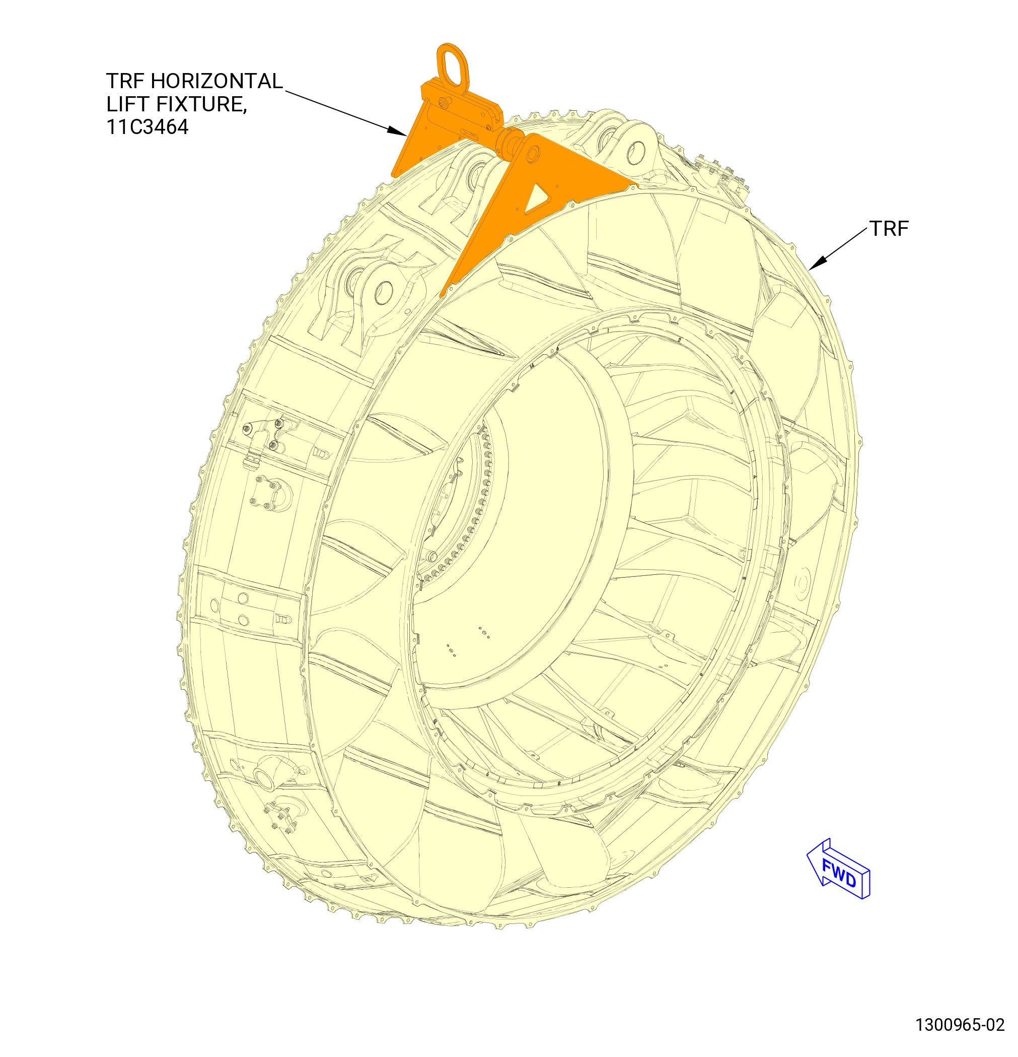
| (25) | Install the 11C3464 TRF horizontal lift fixture and a dynamometer to an overhead hoist. Do not install front two bolts in the fixture. Refer to Figure 213. |
| (26) | Lift the hoist to transition a load of 600 lb. (273 kg) to the TRF. Make sure that the load on the guide tube pedestal is maintained at 470 lb. (213 kg). |
| Subtask 72-00-00-030-257 |
| (27) | Remove the LPT/TRF flange hardware. Refer to TASK 72-00-04-030-801 (72-00-04, DISASSEMBLY 001). |
| Subtask 72-00-00-490-011 |
| (28) | Install the puller rods (item 8), puller tubes (item 9), and nuts (item 26) of the 11C3467 TRF guide fixture. Refer to Figure 211. |
| (29) | Carefully apply tension to the puller tooling to break the flanges apart and relieve the interference. A minimum amount of force must be necessary. |
| Subtask 72-00-00-090-006 |
| (30) | Remove the mechanical puller portion of the 11C3467 TRF guide fixture. |
| Subtask 72-00-00-490-012 |
| (31) | Manually move the TRF, approximately 6.00 inches (152.4 mm) aft, to disengage the bearing and seals. |
| (32) | Continue to move the TRF aft toward the aft pedestal. Constantly monitor the load carried by the guide tube pedestal 470 lb. (213 kg) and the overhead crane 600 lb. (273 kg). |
| NOTE: |
|
| (33) | Install the 11C3468 TRF pedestal set under the guide tube (item 36) of the 11C3467 TRF guide fixture at a position between the TRF and the low pressure turbine rotor (LPTR) on the forward portion of the guide tube. Adjust the forward pedestal up to remove all clearance between the pedestal and guide tube. Slowly lower the aft pedestal to transition the 470 lb. (213 kg) load to the forward pedestal. Remove the aft pedestal when all its load is relieved. Refer to Figure 213. |
| Subtask 72-00-00-490-013 |
| (34) | Keep moving the TRF aft until it is clear from the guide tube (item 36) of the 11C3467 TRF guide fixture. |
| (35) | Monitor the load on the overhead hoist during this operation to make sure that the load stay on 600 lb. (273 kg). |
| (36) | Deleted. |
| (37) | Put a protective wrap around the No. 5 roller bearing inner bearing track within the LPT module assembly (45-020 , 72-00-02) (SIN 00105) or (45-021 , 72-00-02) (SIN 00105) or (45-022 , 72-00-02) (SIN 00105). |
| (38) | Turn the TRF and place it on shipping skid aft end down. |
| NOTE: |
|
| (39) | Place protective cover wrap around the No. 5 roller bearing area of the TRF to prevent contamination. |
| (40) | Install the 11C3468 TRF pedestal set under the guide tube (item 36) of the 11C3467 TRF guide fixture at the aft end and remove the forward pedestal ensuring the aft pedestal maintains an 470 lb. (213 kg) load. Refer to Figure 214. |
| Subtask 72-00-00-030-259 |
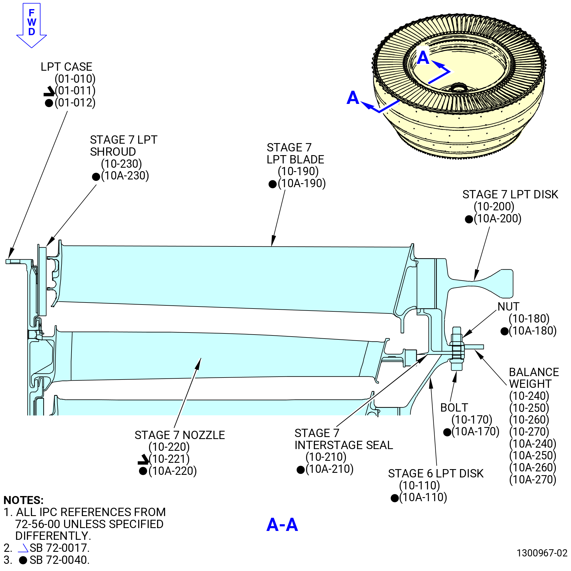
| C. | Removal of the stage 7 LPTR disk (stage 7 LPT disk) (10-200 , 72-56-00) (SIN 930B7) or (10A-200 , 72-56-00) (SIN 930B7) and stage 7 LPT blades (10-190 , 72-56-00) (SIN 930A7) or (10A-190 , 72-56-00) (SIN 930A7). |
| CAUTION: |
|
| (1) | Use a C05-003 pen to put a match-mark across the LPTR stage 7 disk, the LPTR stage 7 seal (10-210 , 72-56-00) (SIN 930C7) or (10A-210 , 72-56-00) (SIN 930C7) and the LPTR stage 6 disk (10-110 , 72-56-00) (SIN 930B6) or (10A-110 , 72-56-00) (SIN 930B6). This match-mark becomes the 1-1 marking for purposes of the special procedure. Refer to Figure 214 and TASK 70-16-02-350-017 (TEMPORARY MARKING). |
| (2) | Identify and record the location of any LPT balance weights. Mark the weights with bolt location on the stage 7 LPT disk. |
| NOTE: |
|
| Subtask 72-00-00-030-305 |
| (3) | Deleted. |
| Subtask 72-00-00-030-306 |
| (3).A. | Deleted. |
| Subtask 72-00-00-030-412 |
| (4) | Use a C05-003 pen to put a mark on the LPT stage 7 blades 1, 2, 3 through 98 clockwise from the LPTR stage 7 disk position 1-1. |
| Subtask 72-00-00-030-307 |
| (5) | Deleted. |
| CAUTION: |
|
| (6) | Remove and discard all but four equally spaced self-locking nuts (nuts) (10-180 , 72-56-00) (SIN 930K6) or (10A-180 , 72-56-00) (SIN 930K6) and double hexagon bolts (bolts) (10-170 , 72-56-00) (SIN 930F6) or (10A-170 , 72-56-00) (SIN 930F6) from the stage 6 LPT disk (10-110 , 72-56-00) (SIN 930B6) or (10A-110 , 72-56-00) (SIN 930B6), stage 7 interstage seal (10-210 , 72-56-00) (SIN 930C7) or (10A-210 , 72-56-00) (SIN 930C7), and stage 7 LPT disk (10-200 , 72-56-00) (SIN 930B7) or (10A-200 , 72-56-00) (SIN 930B7). |
| Subtask 72-00-00-490-014 |
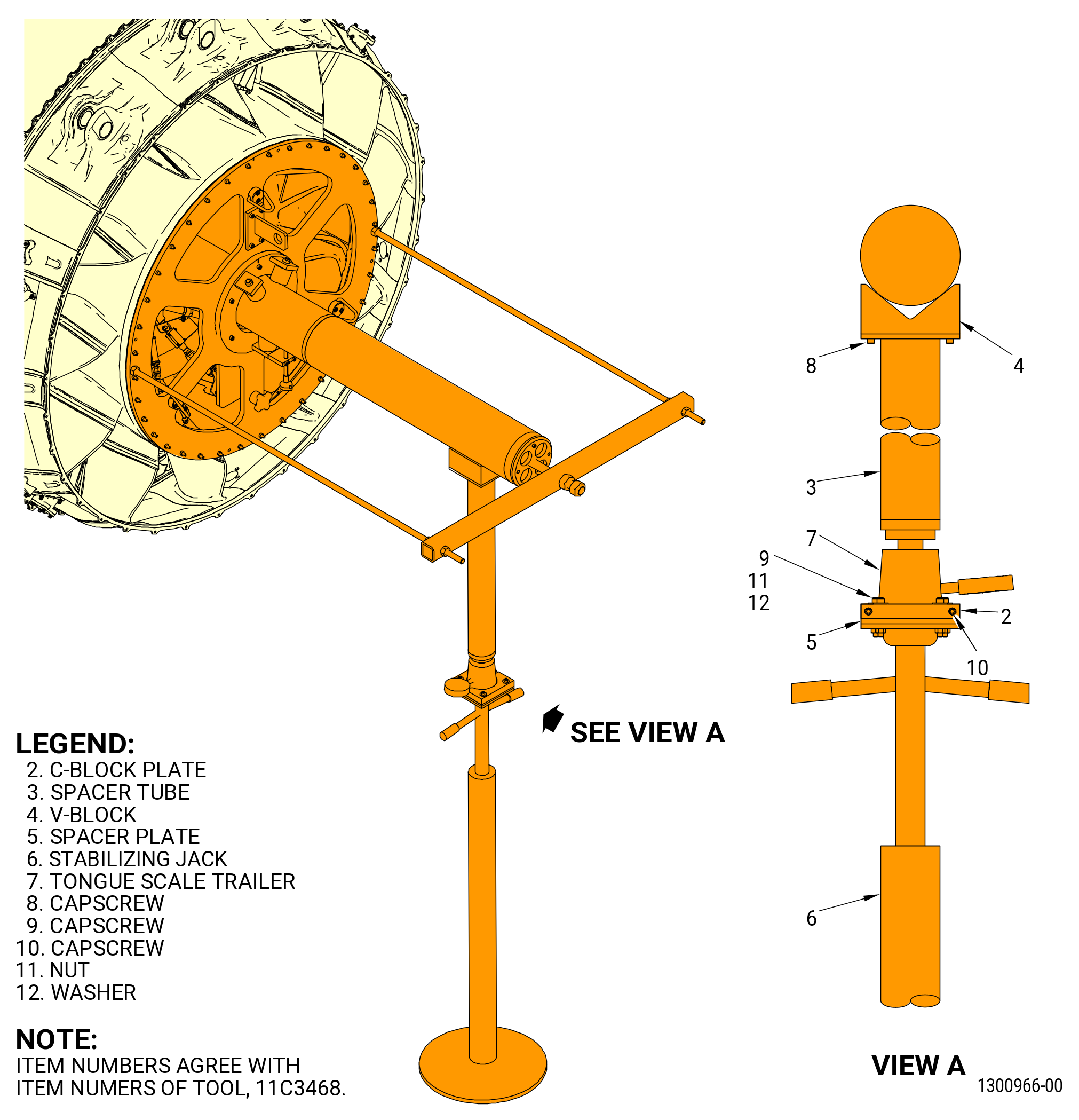
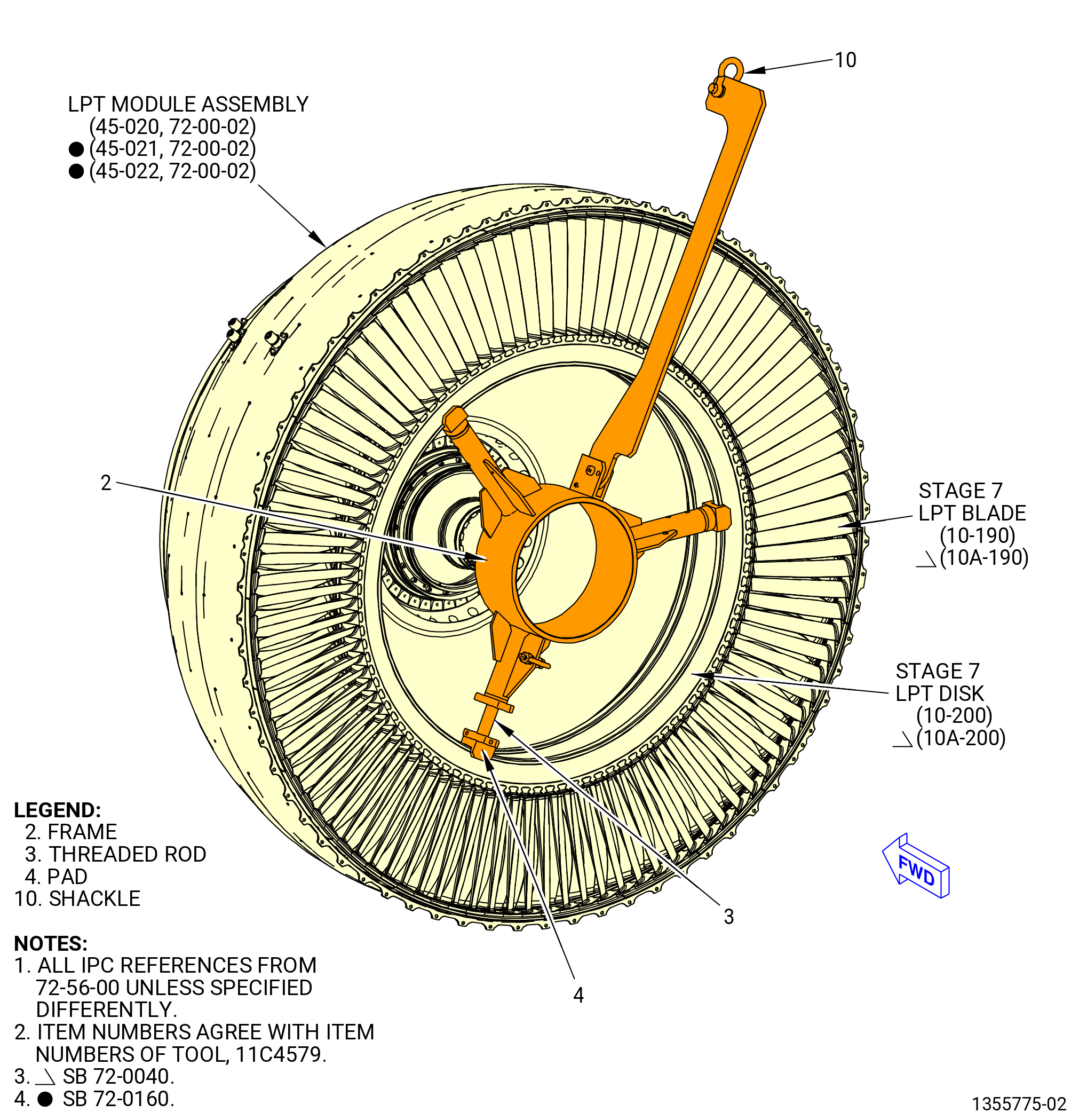
| (7) | Attach the 11C4579 lift fixture to the stage 7 LPT disk (10-200 , 72-56-00) (SIN 930B7) or (10A-200 , 72-56-00) (SIN 930B7). Refer to Figure 216 and do as follows: |
| (a) | Install a standard hook in the shackle (item 10). |
| (b) | Make sure that the minimum capacity of the slings is 750 lb. (340 kg). |
| (c) | Make sure that the position of the upper legs of the frame (item 2) are according to engine disk to adjust. |
| (d) | Make sure that adjustable lower leg of the frame (item 2) is completely retracted. |
| (e) | Move the tool to the working area. |
| (f) | Align circular hub of the frame (item 2) with the tube (item 3) of the 11C3467 TRF guide fixture. |
| (g) | Draw close to engine hardware avoiding to scrape the alignment tube of the 11C3467 TRF guide fixture and interference with the 11C3468 TRF pedestal set. |
| NOTE: |
|
| (h) | Lift the tool until the pads (item 4) touch the disk bore diameter. |
| (i) | Turn threaded rod (item 3) counter clockwise (CCW) until its painted mark align with the edge of the threaded insert of the frame (item 2). |
| NOTE: |
|
| NOTE: |
|
| (j) | Turn manually the nut (item 7) CW until it touches the lower leg of the frame (item 2) to avoid tool disadjustment. |
| (8) | Use a hoist with a suitable dynamometer to lift the stage 7 LPT disk with 150 lb. (68 kg). |
| Subtask 72-00-00-030-266 |
| (9) | Remove the remaining four nuts (10-180 , 72-56-00) (SIN 930K6) or (10A-180 , 72-56-00) (SIN 930K6) but keep the bolts (10-170 , 72-56-00) (SIN 930F6) or (10A-170 , 72-56-00) (SIN 930F6) in their position. |
| (10) | Carefully pull the stage 7 LPT disk (10-200 , 72-56-00) (SIN 930B7) or (10A-200 , 72-56-00) (SIN 930B7) aft away from the engine approximately 1.00 inch (25.4 mm). |
| (11) | Make sure that the stage 7 interstage seal (10-210 , 72-56-00) (SIN 930C7) or (10A-210 , 72-56-00) (SIN 930C7) is on the stage 7 LPT disk. If not, manually seat it in position. |
| (12) | Attach with two slave nuts and bolts. |
| (13) | Continue to remove the stage 7 LPT disk from the engine. |
| Subtask 72-00-00-030-277 |
| (14) | Alternative Procedure Available. Remove the stage 7 LPT disk as follows: |
| (a) | Move the stage 7 LPT disk (10-200 , 72-56-00) (SIN 930B7) or (10A-200 , 72-56-00) (SIN 930B7) aft to the 11C3468 TRF pedestal set. |
| (b) | Put the second 11C3468 TRF pedestal set forward of the stage 7 LPT disk (10-200 , 72-56-00) (SIN 930B7) or (10A-200 , 72-56-00) (SIN 930B7) and transfer the load of 470 lb. (213 kg) from the aft pedestal to the forward pedestal. |
| (c) | Remove the aft pedestal and continue to remove the stage 7 LPT disk. |
| Subtask 72-00-00-030-278 |
| (14).A. | Alternative Procedure. Remove the stage 7 LPT disk as follows: |
| (a) | Carefully lower and manually guide the stage 7 LPT disk (10-200 , 72-56-00) (SIN 930B7) or (10A-200 , 72-56-00) (SIN 930B7), aft side up, on an applicable surface covered with bubble wrap or equivalent, while in the 11C4579 lift fixture. |
| Subtask 72-00-00-030-279 |
| (15) | Attach the 11C3541 disk lift fixture and turn the stage 6 LPT disk (10-110 , 72-56-00) (SIN 930B6) or (10A-110 , 72-56-00) (SIN 930B6) to the horizontal position. |
| (16) | Carefully lower the stage 7 LPT disk (10-200 , 72-56-00) (SIN 930B7) or (10A-200 , 72-56-00) (SIN 930B7) aft side up on an applicable surface covered with bubble wrap or equivalent. |
| Subtask 72-00-00-030-272 |
| D. | Removal of the stage 7 LPT blades (10-190 , 72-56-00) (SIN 930A7) or (10A-190 , 72-56-00) (SIN 930A7). |
| WARNING: |
|
| CAUTION: |
|
| CAUTION: |
|
| (1) | Lift the stage 7 LPT disk (10-200 , 72-56-00) (SIN 930B7) or (10A-200 , 72-56-00) (SIN 930B7) with the aft side up. |
| (2) | Lower the stage 7 LPT disk so the stage 7 LPT blades are approximately 1.00 inch (25.4 mm) above the bubble wrap. |
| (3) | Carefully tap the stage 7 LPT blades out of the stage 7 LPT disk progressing in a CCW direction in increments of approximately 0.25 inch (6.4 mm) for each stage 7 LPT blade per revolution. Lift the stage 7 LPT disk sufficiently to let the stage 7 LPT blades to release from the stage 7 LPT disk. Use of a soft face mallet is allowed taking care not to cause damage to the blades. |
| (4) | Lift and turn the stage 7 LPT disk with the 11C3541 disk lift fixture to the forward side up. Place the stage 7 LPT disk on a suitable surface large enough to accommodate a bladed stage 7 LPT disk diameter in readiness for the stage 7 LPT blade installation. |
| CAUTION: |
|
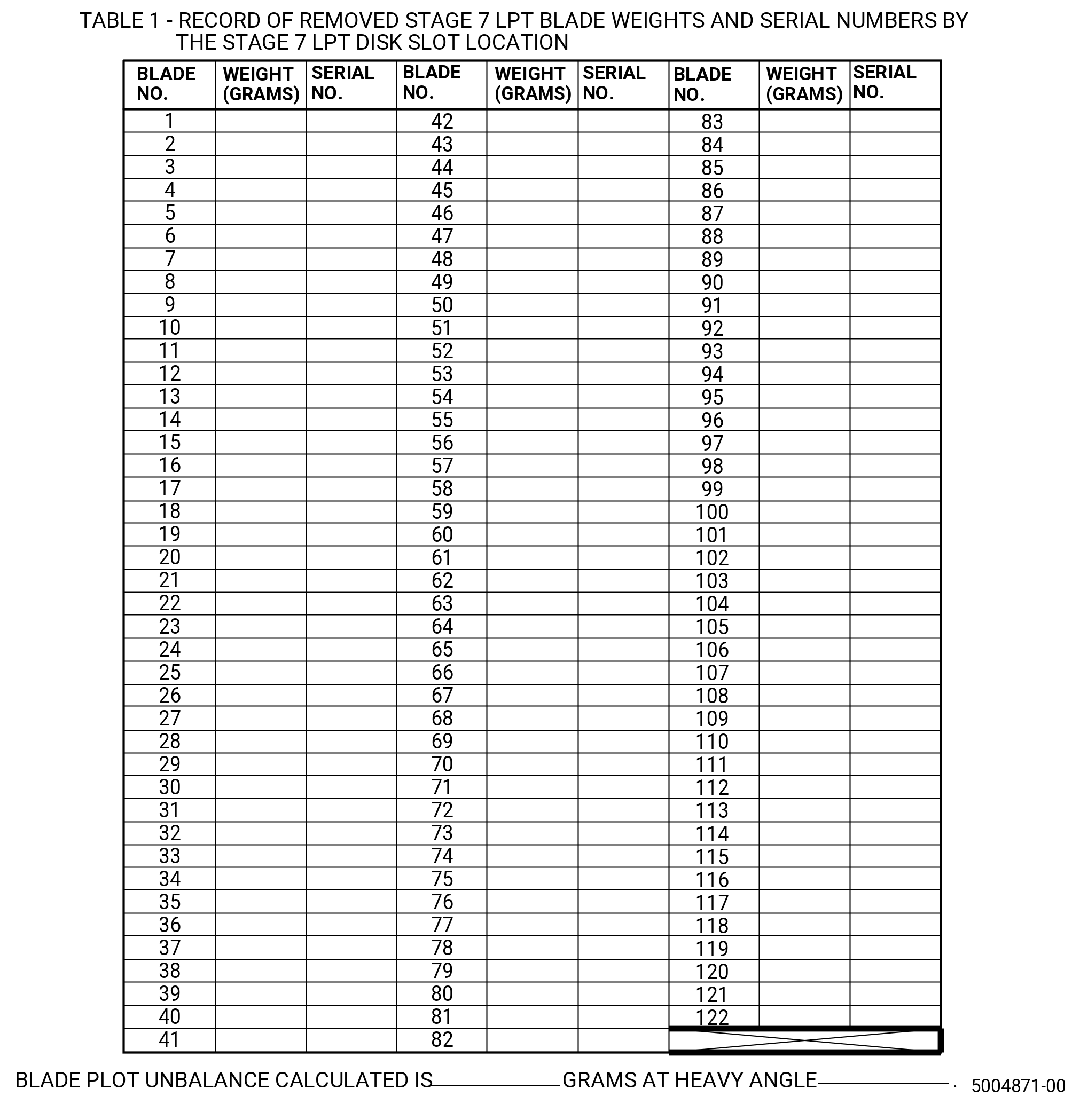
| (5) | Weigh each stage 7 LPT blade in grams to at least one decimal place and record stage 7 LPT blade position, serial number, and pan weight. If a stage 7 LPT blade has an inservice trim balance clip fitted to the outer platform, add the weight of the clip to the stage 7 LPT blade weight. |
| NOTE: |
|
| (6) | Calculate the unbalance magnitude and vector of the stage 7 LPT blade with the 9446M61 blade plot program. Record the results in Table 1. Refer to Figure 217 or Figure 217A. |
|
|
| Subtask 72-00-00-220-026 |
| (7) | Do an Inspection of all the blades for damage. Separate any blades that are damaged from those that are not. Refer to TASK 72-00-00-200-805 (72-00-00, INSPECTION 001). If any findings are noted, refer to AMM or TASK 72-00-00-800-804 (72-00-00, SPECIAL PROCEDURE 004) for limits. |
| (8) | Set aside the undamaged blades for later reassembly. |
| Subtask 72-00-00-220-027 |
| E. | All removed hardware is subject to GVI. Refer to TASK 72-00-00-200-805 (72-00-00, INSPECTION 001). If any findings are noted, refer to the applicable ESM CIR section 72-56-XX for serviceability criteria. |
| Subtask 72-00-00-430-001 |
| F. | Installation of the stage 7 LPT blades (10-190 , 72-56-00) (SIN 930A7) or (10A-190 , 72-56-00) (SIN 930A7) in the stage 7 LPT disk (10-200 , 72-56-00) (SIN 930B7) or (10A-200 , 72-56-00) (SIN 930B7). |
| CAUTION: |
|
| CAUTION: |
|
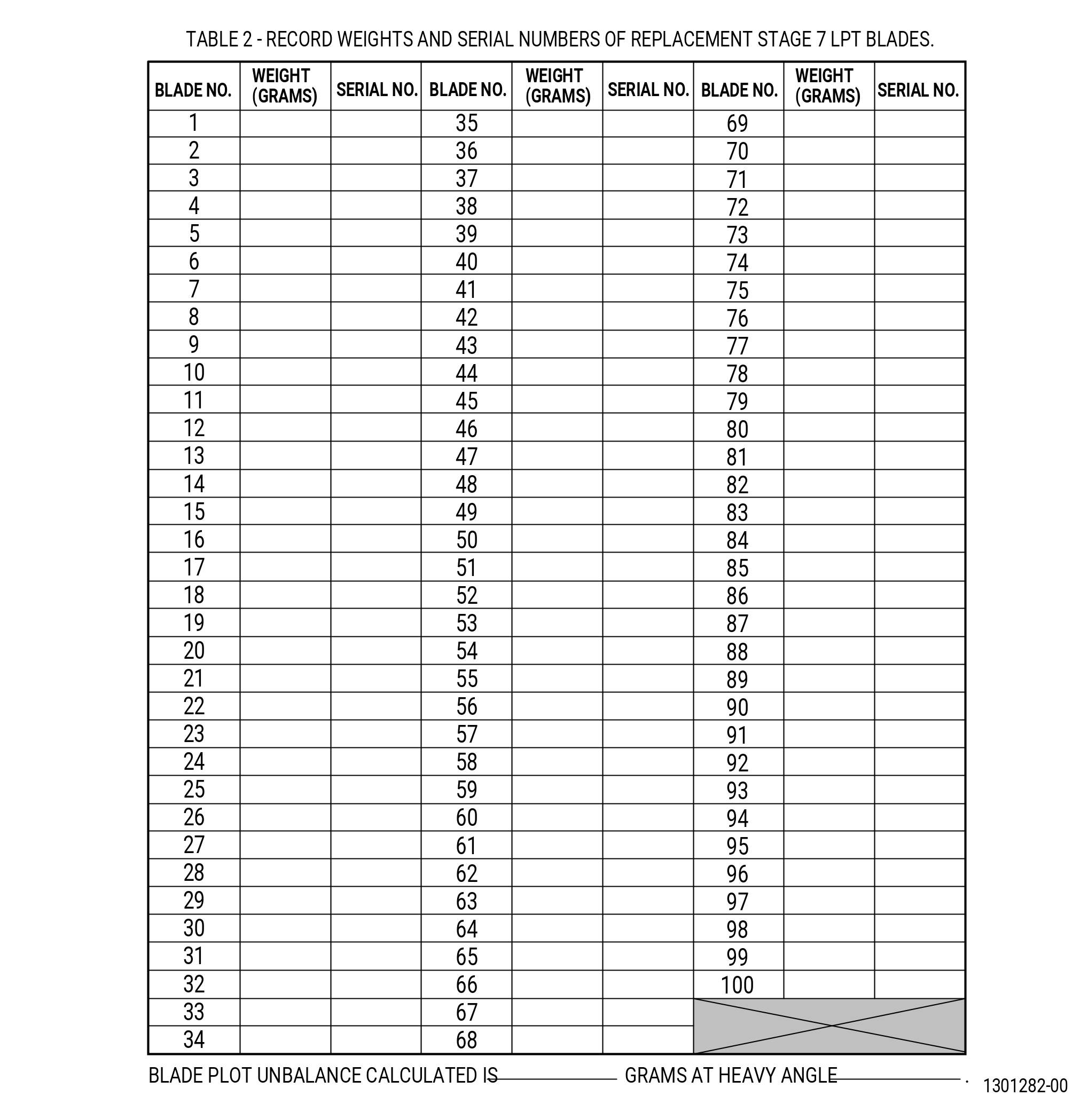
| (1) | Number and pan weigh each stage 7 LPT blade to at least one decimal place. Record weights and serial numbers in Table 2. Refer to Figure 218 or Figure 218A. |
| NOTE: |
|
|
|
| Subtask 72-00-00-430-004 |
| (2) | Distribute the stage 7 LPT blade weights with the 9446M61 blade plot program to match the weight mass and angle of the removed damaged stage 7 LPT blades as recorded in Table 1. Refer to Figure 217 or Figure 217A. |
| (3) | Make sure that the program distributes the new stage 7 LPT blades unbalance to within one gram and one degree of the removed stage 7 LPT blades. |
| WARNING: |
|
| CAUTION: |
|
| (4) | Use the 11C3541 disk lift fixture to lift the stage 7 LPT disk (10-200 , 72-56-00) (SIN 930B7) or (10A-200 , 72-56-00) (SIN 930B7) with the forward face up. |
| (5) | Use a C05-003 pen to transfer the 1 and 5 stage 7 LPT disk slots ID from the stage 7 LPT disk aft face to the forward face of the stage 7 LPT disk. Refer to TASK 70-16-02-350-017 (TEMPORARY MARKING). |
| (6) | Apply C02-033 soft petrolatum to the dovetails of the stage 7 LPT blades. Petrolatum can also be applied to the shroud interlocks to aid assembly. |
| CAUTION: |
|
| (7) | Use the results from the 9446M61 blade plot program distribution to install the stage 7 LPT blades correctly in the stage 7 LPT disk. Install the No. 1 stage 7 LPT blade dovetail approximately 0.250 inch (6.5 mm) in the 1 stage 7 LPT disk slot. A soft block of 1.00 inch (25.4 mm) can be used to support the stage 7 LPT blade airfoil until it rests in place and does not drop further in the stage 7 LPT disk slot. |
| Subtask 72-00-00-430-046 |
| * * * FOR 1B/P/G03.1B/P/G04 |
| * * * PRE SB 72-0040( Stage 7 LPT Blades for PIP Engines ) |
| CAUTION: |
|
| (8) | Install the stage 7 LPT blades (10-190 , 72-56-00) (SIN 930A7) as follows: |
| (a) | Install the stage 7 LPT blade No. 100 next to the stage 7 LPT blade No. 1 and support with a soft block if necessary. |
| (b) | Continue to install the stage 7 LPT blades No. 99, No. 98, etc., until the stage 7 LPT blade No. 2 is the last remaining stage 7 LPT blade to be installed. |
| (c) | Engage the stage 7 LPT blade tip shroud between the tip shrouds of the adjacent stage 7 LPT blades and then install the dovetail in the stage 7 LPT disk slot. |
| * * * FOR 1B/P/G03.1B/P/G04 |
| * * * END PRE SB 72-0040 |
| Subtask 72-00-00-430-047 |
| * * * FOR ALL |
| * * * SB 72-0040( Stage 7 LPT Blades for PIP/PIP1 Engines ) |
| CAUTION: |
|
| (8).A. | Install the stage 7 LPT blades (10A-190 , 72-56-00) (SIN 930A7) as follows: |
| (a) | Install the stage 7 LPT blade No. 122 next to the stage 7 LPT blade No. 1 and support with a soft block if necessary. |
| (b) | Continue to install the stage 7 LPT blades No. 121, No. 120, etc., until the stage 7 LPT blade No. 2 is the last remaining stage 7 LPT blade to be installed. |
| (c) | Engage the stage 7 LPT blade tip shroud between the tip shrouds of the adjacent stage 7 LPT blades and then install the dovetail in the stage 7 LPT disk slot. |
| * * * END SB 72-0040 |
| Subtask 72-00-00-430-048 |
| (9) | Remove any soft blocks of 1.00 inch (25.4 mm) that were used to support the stage 7 LPT blades. |
| (10) | Carefully tap the stage 7 LPT blades in the stage 7 LPT disk with a non-metallic tool on the dovetail (avoid hitting the angel wing), progressing in a CW direction in increments of approximately 0.250 inch (6.4 mm). Continue moving around the stage 7 LPT disk until each stage 7 LPT blade forward platform contacts the table surface. Lift the stage 7 LPT disk sufficiently to allow the stage 7 LPT blades to continue to be installed until they are fully installed in the stage 7 LPT disk. Use of a non-metallic drift on the blade dovetail is correct method taking care not to cause damage to the stage 7 LPT blades. |
| Subtask 72-00-00-220-335 |
| (11) | Do a visual inspection to make sure that the stage 7 LPT blades (10-190 , 72-56-00) (SIN 930A7) or (10A-190 , 72-56-00) (SIN 930A7) are installed in the correct slots of the stage 7 LPT disk (10-200 , 72-56-00) (SIN 930B7) or (10A-200 , 72-56-00) (SIN 930B7). |
| Subtask 72-00-00-430-011 |
| G. | Installation of the stage 7 LPT disk (10-200 , 72-56-00) (SIN 930B7) or (10A-200 , 72-56-00) (SIN 930B7). |
| CAUTION: |
|
| (1) | If the stage 7 LPT shrouds (10-230 , 72-56-00) (SIN 935BA) or (10A-230 , 72-56-00) (SIN 935BA) move away from the LPT A/O case (LPT case) (01-010 , 72-56-00) (SIN 935C1), (01-011 , 72-56-00) (SIN 935C1), or (01-012 , 72-56-00) (SIN 935C1), apply C01-027 adhesive to the aft outer surface of the stage 7 LPT shroud that touches the LPT case. |
| (2) | Make sure that the aft edge of the stage 7 shrouds do not extend past the aft flange of the LPT case. |
| (3) | Make sure that the stage 7 interstage seal (10-210 , 72-56-00) (SIN 930C7) or (10A-210 , 72-56-00) (SIN 930C7) alignment marks between the seal and stage 6 LPT disk (10-110 , 72-56-00) (SIN 930B6) or (10A-110 , 72-56-00) (SIN 930B6) are aligned. |
| (4) | Replace slave bolts with two new bolts. |
| WARNING: |
|
| (5) | Lift the stage 7 LPT disk with the 11C3541 disk lift fixture and install the 11C4579 lift fixture with a suitable dynamometer attached to a second hoist. Lift the stage 7 LPT disk with the 11C4579 lift fixture. Turn the stage 7 LPT disk to vertical and then remove the 11C3541 disk lift fixture with a two man lift. |
| (6) | Install the stage 7 LPT disk to the stage 7 interstage seal and stage 6 LPT disk. Refer to Figure 215. Move the stage 7 LPT disk on the guide tube (36) of the 11C3467 TRF guide fixture. Position a second 11C3468 TRF pedestal set to the aft end of the guide tube (36). Apply 470 lb. (213 kg) load on the guide tube with the aft pedestal. Remove the forward pedestal ensuring the aft pedestal remains with an 470 lb. (213 kg) load on the guide tube. |
| (7) | Carefully move the stage 7 LPT disk to within 2.00 inches (50.8 mm) of the stage 7 interstage seal and stage 6 LPT disk ensuring the alignment marks correlate. |
| (8) | Align the 1 stage 7 LPT disk position alignment mark of the stage 7 LPT disk to the stage 7 interstage seal and the stage 5 LPTR disk (10-020 , 72-56-00) (SIN 930B5) or (10A-020 , 72-56-00) (SIN 930B5) alignment marks. |
| NOTE: |
|
| CAUTION: |
|
| (9) | Carefully engage the stage 7 LPT disk to the stage 6 interstage seal. |
| (10) | Install the stage 7 LPT disk on the stage 6 LPT disk/stage 7 interstage seal as follows: |
| WARNING: |
|
| (a) | Apply C02-058 lubricant to the threads and friction bearing surfaces of the bolts (10-170 , 72-56-00) (SIN 930F6) or (10A-170 , 72-56-00) (SIN 930F6) and nuts (10-180 , 72-56-00) (SIN 930K6) or (10A-180 , 72-56-00) (SIN 930K6). Refer to Figure 215. |
| NOTE: |
|
| (b) | Install the new bolts (10-170 , 72-56-00) (SIN 930F6) or (10A-170 , 72-56-00) (SIN 930F6) through the stage 6 LPT disk, stage 7 interstage seal, and stage 7 LPT disk. |
| (c) | Install the new nuts (10-180 , 72-56-00) (SIN 930K6) or (10A-180 , 72-56-00) (SIN 930K6) on the bolts. |
| (d) | Torque ten of the nuts (10-180 , 72-56-00) (SIN 930K6) or (10A-180 , 72-56-00) (SIN 930K6) to 78-91 lb in. (8.8-10.3 N.m) at equally spaced locations around the circumference of the stage 7 LPT disk. |
| (e) | Torque all the nuts (10-180 , 72-56-00) (SIN 930K6) or (10A-180 , 72-56-00) (SIN 930K6) to 78-91 lb. in. (8.8-10.3 N.m) in a criss-cross pattern. |
| (f) | Make sure that all previously installed balance weights are refitted to their original position in relation to the stage 6 LPT disk. |
| Subtask 72-00-00-430-018 |
| H. | Install the TRF to the LPT case (01-010 , 72-56-00) (SIN 935C1), (01-011 , 72-56-00) (SIN 935C1), or (01-012 , 72-56-00) (SIN 935C1) as follows: |
| (1) | Install the 11C3464 TRF horizontal lift fixture to the TRF. Do not install bolts (item 9) on the forward side of the tool. Refer to Figure 213. |
| (2) | Attach a hoist with a dynamometer/hydroset attached to the 11C3464 TRF horizontal lift fixture and turn the TRF to the vertical position. |
| Subtask 72-00-00-220-028 |
| (3) | Do an inspection of the No. 5 roller bearing area of the TRF to make sure that there is no damage or foreign objects. |
| Subtask 72-00-00-430-020 |
| (4) | Remove protection wrap from the No. 5 roller bearing area, and inspect the No. 5 roller inner race and surrounding area of the aft cone shaft. Make sure there is no damage to the No. 5 roller inner race, surrounding hardware, and no foreign objects are present. |
| WARNING: |
|
| (5) | Liberally apply clean C02-019 engine oil or C02-023 engine oil to the 11C3467 TRF guide fixture guide tube (item 36). Refer to Figure 210. Position a second 11C3468 TRF pedestal set to the forward end of the guide tube (item 36). Apply 470 lb. (213 kg) load on the guide tube with the fwd pedestal. Remove the aft pedestal ensuring the fwd pedestal remains with a 470 lb. (213 kg) load. |
| (6) | Deleted. |
| (7) | Deleted. |
| (8) | Deleted. |
| Subtask 72-00-00-430-037 |
| WARNING: |
|
| (9) | Apply C02-058 lubricant to the aft flange of the stage 7 LPT shrouds (10-230 , 72-56-00) (SIN 935BA) or (10A-230 , 72-56-00) (SIN 935BA) in the LPT rotor/stator assembly (01-010 , 72-00-04) (SIN 93000) or (01-010A , 72-00-04) (SIN 93000) to make the installation of the TRF easier. |
| CAUTION: |
|
| (10) | Move the TRF in position aft of the guide tube (36) of the 11C3467 TRF guide fixture. Carefully align the dummy bearing of alignment ring (item 33) of the 11C3467 TRF guide fixture with the guide tube (item 36). Slowly move the TRF forward until the dummy bearing is engaged on the guide tube (item 36). |
| (11) | Make sure that the load of the dynamometer/hydroset is 600 lb (273 kg). |
| (12) | Continue to move the TRF forward, keeping the overhead crane well aligned with the TRF. Move forward until the TRF is within 1.00-2.00 inches (25.4-50.8 mm) of the 11C3468 TRF pedestal set. Remove the bearing protection wrap. Continually monitor the weight carried by the TRF hoist to keep within 600 lb (273 kg). Also make sure that the pedestal load remains at approximately 470 lb (213 kg). |
| (13) | Install the 11C3468 TRF pedestal set under the aft portion of guide tube at a position aft of the TRF. Adjust the aft pedestal upward to transition the 470 lb (213 kg) load from the forward pedestal to the aft pedestal. Continue adjustment until the forward pedestal carries no load and the aft pedestal carries an 800 lb load (363 kg). Continually check the overhead crane to make sure that 600 lb (273 kg) is maintained. Remove the forward pedestal. |
| (14) | Make sure that the load carried by the guide tube pedestal is 470 lb (213 kg) and the load carried by the over-head crane is 600 lb (273 kg). |
| (15) | Continue to move the TRF forward until there is approximately a 4.00 inches (101.6 mm) gap between the TRF and LPT stator case flanges. Make sure that the flanges are free of foreign material. |
| (16) | Slowly and carefully continue to move the TRF forward to engage the No. 5 bearing rollers on the inner race. At the same time, make sure that the stage 6 shrouds are in their proper position and not curled and in the flow path. This should take a very minimal amount of effort. Do not force the TRF in place. If any resistance is encountered, stop and identify the source of interference. |
| (17) | When the TRF and LPT stator case flange rabbets are at the engagement point, make sure that there is no interference between the TRF and the stage 7 shrouds. Make sure that the shrouds are still seated and under the leading edge of the TRF and against the LPT outer case. |
| (18) | Apply C02-058 lubricant to the TRF/LPT flange attaching bolts and nuts. |
| (19) | Install 15 bolts (01-050 , 72-00-04) (SIN 94020) and nuts (01-060 , 72-00-04) (SIN 94040) or (01-061 , 72-00-04) (SIN 94040) approximately equally spaced, then tighten gradually in a criss-cross pattern to evenly and squarely seat the TRF to the LPT stator case aft flange. Apply 75 percent of final torque on these fasteners to seat flanges. |
| (20) | Install the remaining bolts (01-050 , 72-00-04) (SIN 94020), nuts (01-060 , 72-00-04) (SIN 94040) or (01-061 , 72-00-04) (SIN 94040), and bracket hardware. Tighten the bolts (01-050 , 72-00-04) (SIN 94020). Refer to TASK 72-00-04-430-801 (72-00-04, ASSEMBLY 001, CONFIG 01) or TASK 72-00-04-430-802 (72-00-04, ASSEMBLY 001, CONFIG 02). |
| (21) | Deleted. |
| (22) | Remove the 11C3464 TRF horizontal lift fixture from the TRF. |
| (23) | Deleted. |
| (24) | Deleted. |
| (25) | Remove the 11C3467 TRF guide fixture from the TRF. For the 11C3467 TRF guide fixture remove the guide tube (item 3) first, then the alignment ring (item 2), the roller support (item 12), and finally the adapter (item 4) as separate components. |
| Subtask 72-00-00-220-029 |
| (26) | Do an inspection of the stage 7 LPT shrouds (10-230 , 72-56-00) (SIN 935BA) or (10A-230 , 72-56-00) (SIN 935BA), stage 7 LPT blades (10-190 , 72-56-00) (SIN 930A7) or (10A-190 , 72-56-00) (SIN 930A7), and LPT stator stage 7 nozzles (stage 7 LPT nozzles) (10-220 , 72-56-00) (SIN 935A7), (10-221 , 72-56-00) (SIN 935A7), or (10A-220 , 72-56-00) (SIN 935A7) as follows: |
| (a) | Make sure that all stage 7 LPT shrouds are correctly seated on the TRF. |
| (b) | Make sure that all stage 7 LPT nozzles are properly positioned/seated, and there is no damage to the stage 7 LPT blade outer shroud. |
| (c) | Check that the LPT system rotates freely in the normal engine operating direction. |
| Subtask 72-00-00-420-542 |
| (27) | Deleted. |
| (28) | Install the coupling nut (01545). Refer to TASK 72-00-04-420-801 (72-00-04, INSTALLATION 001) and Figure 210. |
| (29) | Install the No. 5 bearing locknut (01503). Refer to TASK 72-00-04-420-801 (72-00-04, INSTALLATION 001) and Figure 210. |
| Subtask 72-00-00-220-030 |
| (30) | Measure the drop from the aft end of the castellations of the No. 5 bearing locknut to the aft end of the castellations on the aft shaft. Record dimension. Refer to Figure 209. Compare to the previously recorded drop value. This is a reference dimension only and the two values should be equal within ± 0.015 inches (0.38 mm). |
| Subtask 72-00-00-420-545 |
| (31) | Install the locknut plate (01592) so that it captures the castellations of the aft shaft and the No. 5 bearing locknut (01503). Install retaining ring (01593) in the groove of the No. 5 bearing locknut. Make sure that the two tabs of the lock ring lock in place and the ring is fully seated. Refer to TASK 72-00-04-420-801 (72-00-04, INSTALLATION 001). |
| Subtask 72-00-00-220-336 |
| (32) | Measure and record dimension R from the aft face of the aft No. 5 bearing housing (01501) to the aft end of the LPT cone shaft (930D1). Refer to TASK 72-00-04-420-801 (72-00-04, INSTALLATION 001) and Figure 209. Compare to previously recorded value. They should be equal within ± 0.015 inches (0.38 mm). |
| Subtask 72-00-00-420-547 |
| (33) | Install the carbon seal (45-350 , 72-00-02) (SIN 01558) in the TRF. A flow check is not necessary. Refer to Figure 207 and TASK 72-00-04-420-801 (72-00-04, INSTALLATION 001). |
| Subtask 72-00-00-420-556 |
| * * * PRE SB 72-0039( Old Oil Nozzle Design ) |
| (34) | Install the oil nozzle (45-240 , 72-00-02), lube nozzle (01509), and C-sump cover (0150C). Refer to TASK 72-00-04-420-801 (72-00-04, INSTALLATION 001). |
| * * * END PRE SB 72-0039 |
| Subtask 72-00-00-420-557 |
| * * * SB 72-0039( New Oil Nozzle Design ) |
| (34).A. | Install the oil nozzle (45-241 , 72-00-02), lube nozzle (01509), and C-sump cover (0150C). Refer to TASK 72-00-04-420-801 (72-00-04, INSTALLATION 001). |
| * * * END SB 72-0039 |
| Subtask 72-00-00-420-559 |
| (35) | Deleted. |
| Subtask 72-00-00-420-560 |
| (35).A. | Deleted. |
| Subtask 72-00-00-420-558 |
| (36) | Replace the tubes (443A2, 443A3). Refer to TASK 72-00-04-420-801 (72-00-04, INSTALLATION 001). |
| (37) | At the 10:00 o'clock inner surface of the TRF, lightly tighten the outer B-nut end of the eductor air tube (61BA1). Install the ring seal (61BN0) and the coupling clamp (61BV1) at the lower end of the tube. Refer to TASK 72-00-04-420-801 (72-00-04, INSTALLATION 001). |
| (38) | At the 6:00 o'clock outer surface of the TRF, tighten the B-nut on the oil supply tube (20-130 , 79-22-10) (SIN 44304). Attach the bolts (20-020 , 79-22-10) (SIN 44320) on the cushioned clamps (20-050 , 79-22-10) (SIN 44380) just forward of the TRF to LPT flange. Refer to TASK 72-00-02-430-816 (72-00-02, ASSEMBLY 005 - CONFIG 01) or TASK 72-00-02-430-819 (72-00-02, ASSEMBLY 005 - CONFIG 02). |
| (39) | At the 5:00 o'clock outer surface of the TRF, tighten the B-nut on the tube (10-100 , 79-22-20) (SIN 45201). Install the bolts (10-180 , 79-22-20) (SIN 45220) to the three cushioned clamps (10-200 , 79-22-20) (SIN 45281) and (10-190 , 79-22-20) (SIN 45282) just forward of the TRF to LPT flange. Refer to TASK 72-00-02-430-816 (72-00-02, ASSEMBLY 005 - CONFIG 01) or TASK 72-00-02-430-819 (72-00-02, ASSEMBLY 005 - CONFIG 02). |
| (40) | At the 10:00 o'clock outer surface of the TRF, tighten the B-nut on the air tube (01-030 , 75-24-40) (SIN 61B01). Install the bolts (01-100 , 75-24-40) (SIN 61B22) to the loop clamps (01-200 , 75-24-40) (SIN 61B84) just forward of the TRF to LPT flange. Refer to TASK 72-00-02-430-816 (72-00-02, ASSEMBLY 005 - CONFIG 01) or TASK 72-00-02-430-819 (72-00-02, ASSEMBLY 005 - CONFIG 02). |
| (41) | The drain support bracket (35-200 , 72-00-02) (SIN 48910), two bolts (10-040 , 79-22-40) (SIN 48920) and two cushion loop clamps (10-050 , 79-22-40) (SIN 48980) and (10-060 , 79-22-40) (SIN 48981) can be reinstalled during installation of the primary nozzle. Install the remaining bolts to the drain support bracket. Install the auxiliary B-sump manifold (10-020 , 79-22-40) (SIN 48901) from the forward interfacing tube ends. Refer to TASK 72-00-02-430-816 (72-00-02, ASSEMBLY 005 - CONFIG 01) or TASK 72-00-02-430-819 (72-00-02, ASSEMBLY 005 - CONFIG 02). |
| (42) | The brackets (25010, 25011, 25012, 25014) can be reinstalled during the installation of the primary nozzle. |
| (43) | The C-sump tube bracket (45-400 , 72-00-02) (SIN 48710) and a cushion loop clamp (10-100 , 79-22-40) (SIN 48780) can be re-installed during the installation of the primary nozzle. Install the bolt (10-090 , 79-22-40) (SIN 48720) in the C-sump tube bracket. Install the C-sump drain manifold (10-080 , 79-22-40) (SIN 48700) to the TRF interfacing tube end. Refer to TASK 72-00-02-430-816 (72-00-02, ASSEMBLY 005 - CONFIG 01) or TASK 72-00-02-430-819 (72-00-02, ASSEMBLY 005 - CONFIG 02). |
| Subtask 72-00-00-760-183 |
| I. | Post maintenance test requirements. |
| (1) | Perform the following on wing tests: |
| (a) | Perform an engine test. Refer to the GENX-1B Boeing 787-8 AMM, 71-00-00, Test No. 8 - Untested Replacement Engine (B787-A-G71-00-00-17A-320A-A). |
| (2) | Deleted. |