| GENX-1B ENGINE MANUAL | Dated: 09/14/2023 | |
| EM 72-00-04 , INSTALLATION 001 | ||
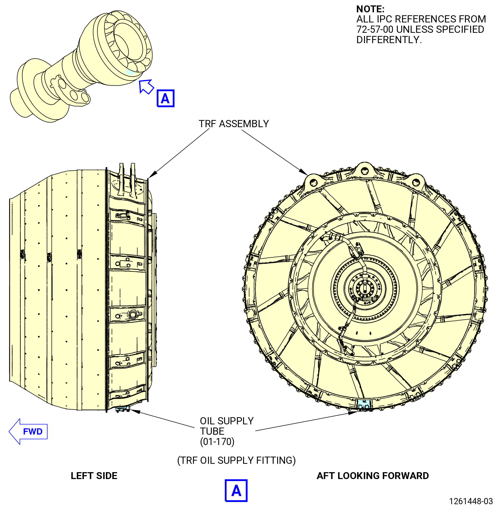
| LOW PRESSURE TURBINE MODULE ASSEMBLY - INSTALLATION 001 | ||
| GENX-1B ENGINE MANUAL | Dated: 09/14/2023 | |
| EM 72-00-04 , INSTALLATION 001 | ||
| LOW PRESSURE TURBINE MODULE ASSEMBLY - INSTALLATION 001 | ||
| * * * FOR ALL |
| TASK 72-00-04-420-801 |
| 1 . | General. |
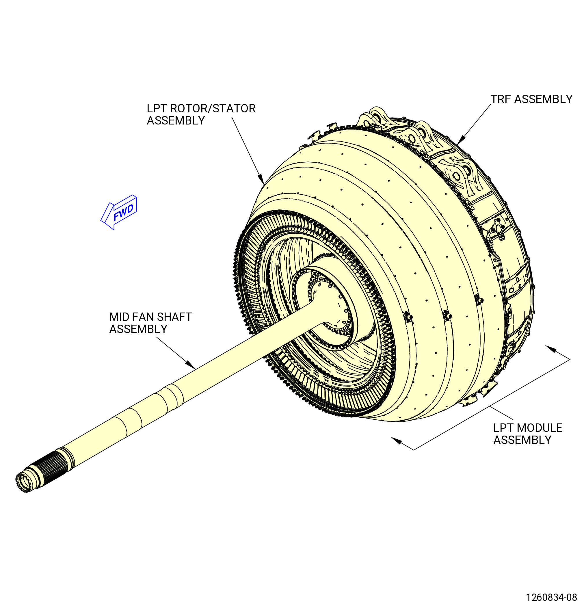
| A. | This procedure gives instructions to install the low pressure turbine (LPT) module assembly and mid fan shaft assembly to the propulsor module assembly (propulsor assembly). Refer to Figure 401. |
| Mid fan shaft assembly: |
| • |
|
| • |
|
| • |
|
| • |
|
| LPT module assembly: |
| • |
|
| • |
|
| • |
|
| • |
|
| • |
|
| • |
|
| • |
|
| • |
|
| Forward lock nut: |
| • |
|
| • |
|
| • |
|
| Spacer shim: |
| • |
|
| Propulsor assembly: |
| • |
|
| • |
|
| • |
|
| • |
|
| B. | Make sure that personnel read this procedure and know the step-by-step instructions and special tool use before the LPT module assembly is installed. |
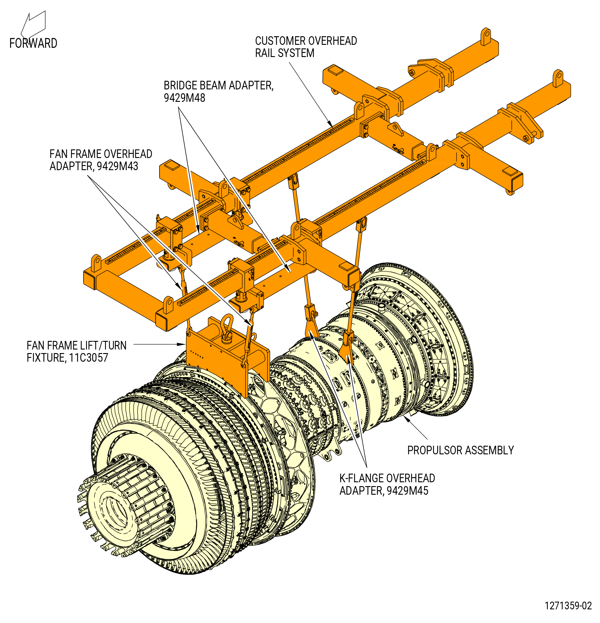
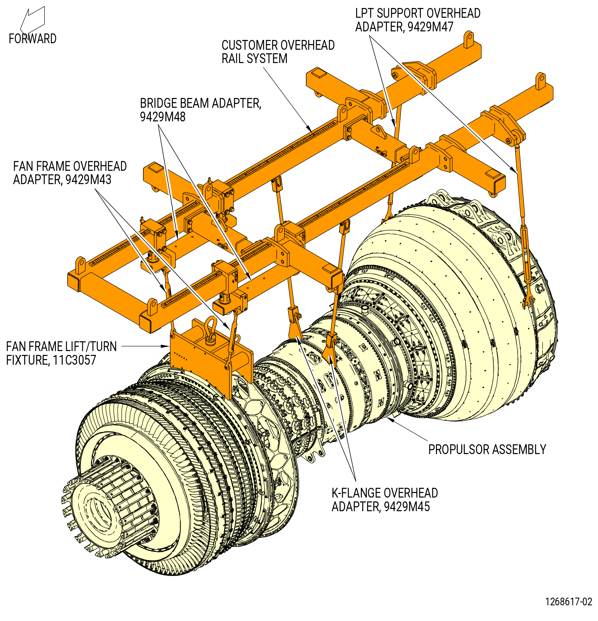
| C. | This procedure begins with the fan booster assembly (20-010 , 72-00-02) (SIN 80000) or (20-011 , 72-00-02) (SIN 80000) and the compressor module assembly (33-009 , 72-00-02) (SIN 00108) or (33-010 , 72-00-02) (SIN 00108) or (33-011 , 72-00-02) (SIN 00108) or (33-012 , 72-00-02) (SIN 00108) installed in the 11C3044 engine module adapter assembly attached to the customer overhead rail system, or in the 11C3281 pedestals set. Refer to Figure 402. |
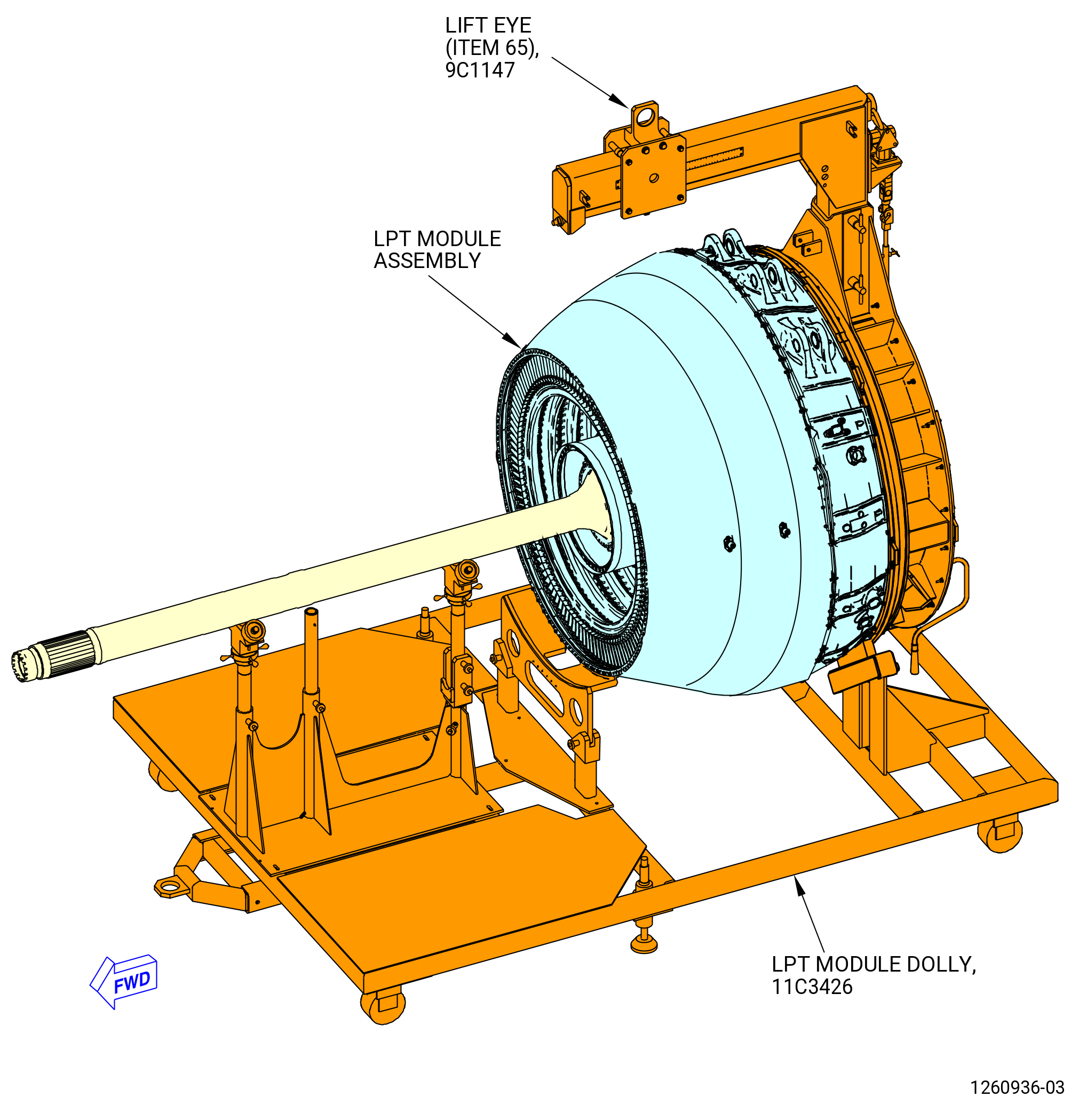
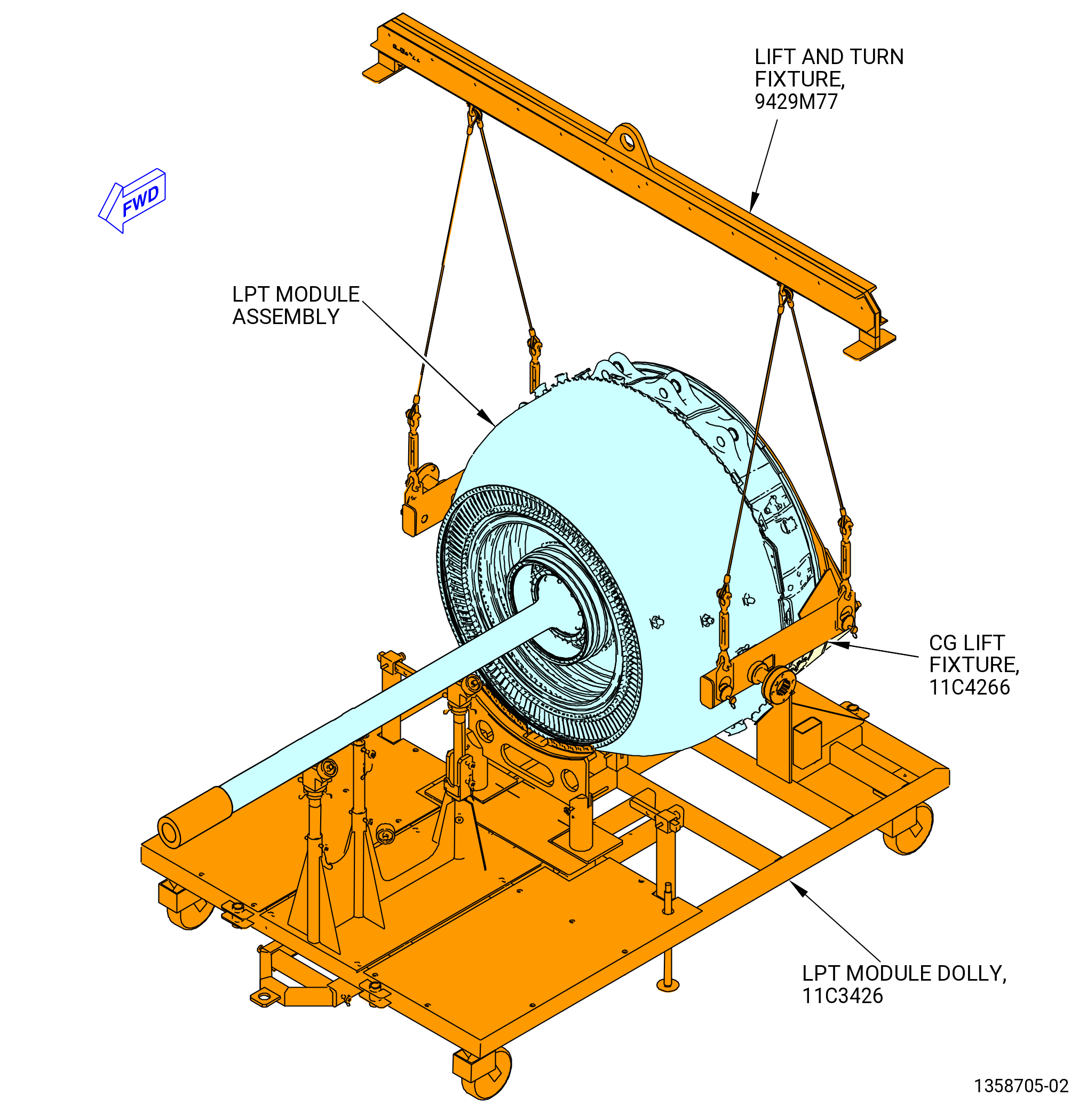
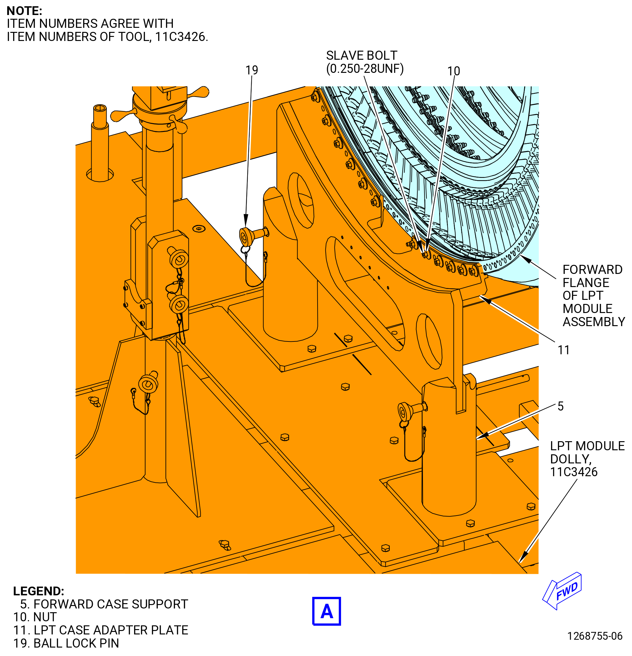
| D. | This procedure begins with the LPT module assembly installed on the 11C3426 LPT module dolly with the 11C3280 adapter set. Refer to Figure 403. |
| E. | This procedure begins with the 9C1147 VCG lift fixture or 11C4266 CG lift fixture and 11C3165 strongback fixture installed on the LPT module assembly. |
| F. | Install protective covers on spare assemblies only. |
| G. | Install all the bolts with the heads up and/or forward unless specified differently. |
| H. | Apply the lubricants to the threads and the friction surfaces only. |
| I. | Follow the instructions to safety parts with safety wire, safety cable, cotter pins, or tab washers. Refer to TASK 70-11-00-400-001 (FASTENER RETENTION PROCEDURES) . |
| WARNING: |
|
| WARNING: |
|
| WARNING: |
|
| J. | Before assembly, make sure that all rabbet and structural flange mating surfaces do not have foreign material and raised metal. If necessary, clean the parts with the C04-002 Stoddard solvent, C04-003 acetone, or C04-035 isopropyl alcohol. |
| K. | All clock positions are aft looking forward (ALF), unless specified differently. |
| L. | Make sure that there is no unwanted material in the assemblies of the LPT module assembly. |
| M. | Make sure that mating parts are serviceable and have no deterioration. |
| 2 . | Tools, Equipment, and Materials. |
| NOTE: |
|
| A. | Tools and Equipment. |
| (1) | Special Tools. |
| (2) | Standard Tools and Equipment. |
|
| (3) | Locally Manufactured Tools. None. |
| B. | Consumable Materials. |
|
| C. | Referenced Procedures. Refer to Engine Manual GEK 114119 unless instructed differently. |
|
| D. | Expendable Parts. |
|
| 3 . | Procedure. |
| Subtask 72-00-04-220-026 |
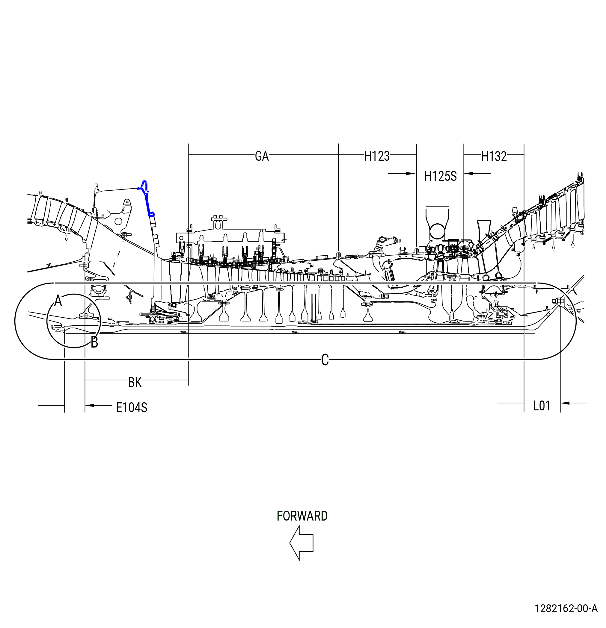
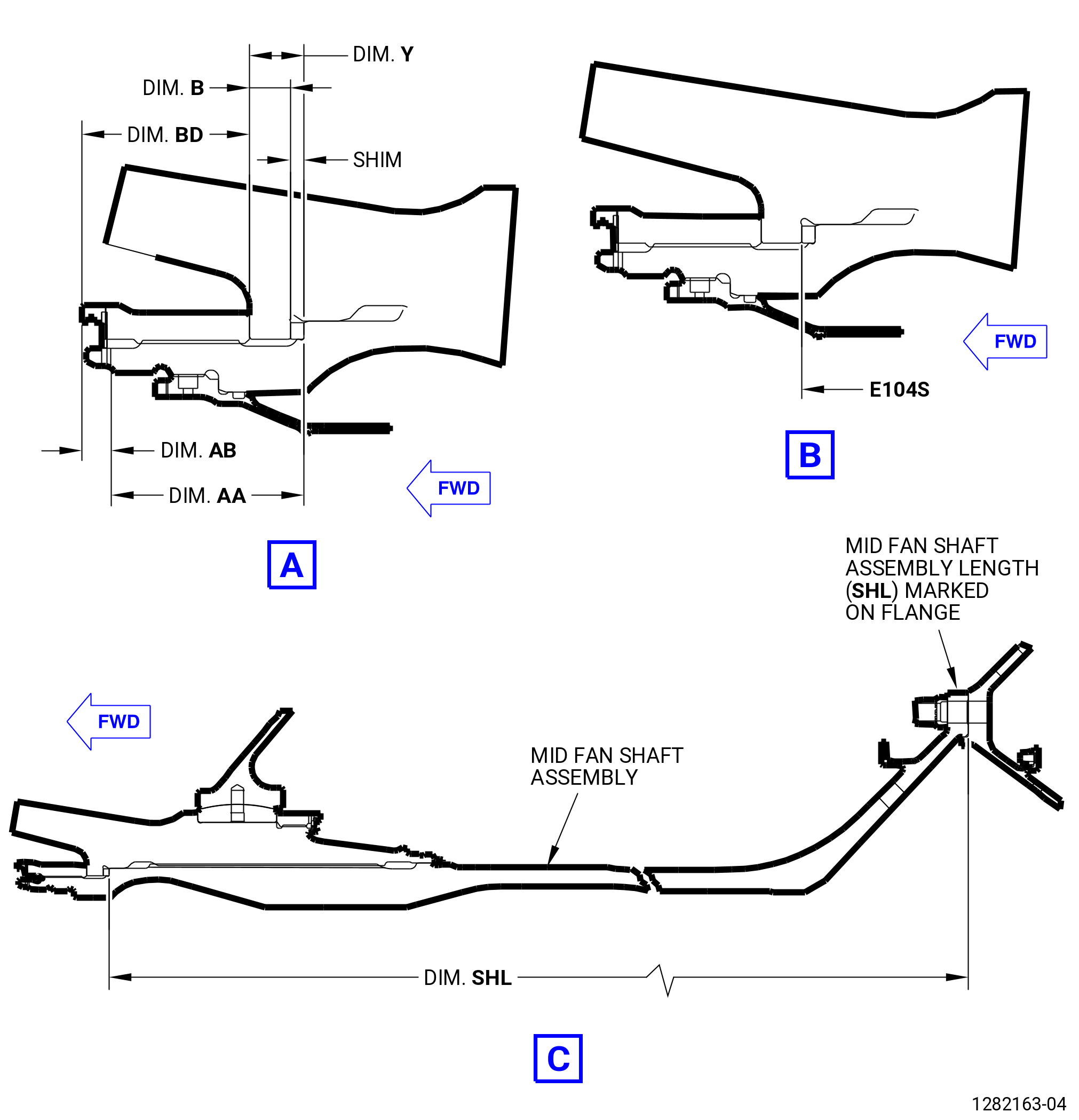
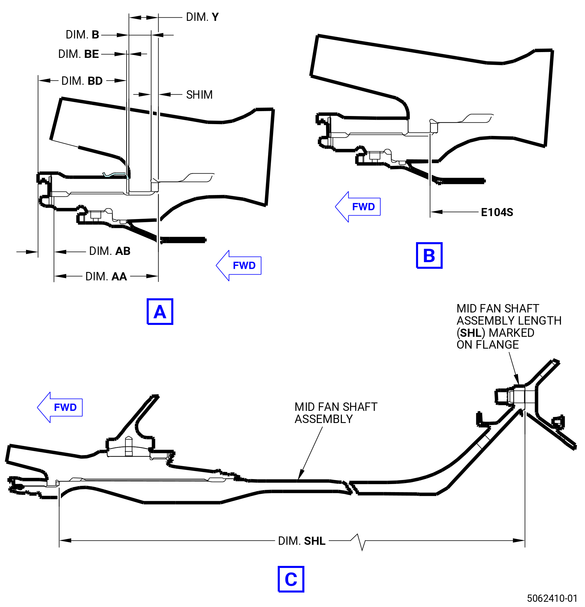
| A. | Alternative procedure available. Select and calculate the dimension necessary for the correct thickness of the adjust washer (shim) (20-360 , 72-00-02) (SIN 83070). Refer to Figure 404, Figure 405, and do as follows: |
| NOTE: |
|
| NOTE: |
|
| (1) | Record dimension E104S of the No. 2 bearing assembly (01200). Refer to TASK 72-24-00-440-801 (72-24-00, ASSEMBLY 001). |
| (2) | Record dimension BK of the fan hub frame (FHF) assembly (10-400 , 72-25-00) (SIN 84000), or (10-401 , 72-25-00) (SIN 84000), or (10-402 , 72-25-00) (SIN 84000). Refer to TASK 72-25-00-440-801 (72-25-00, ASSEMBLY 001). |
| (3) | Record dimension GA of the high pressure compressor (HPC) module assembly (33-009 , 72-00-02) (SIN 00108) or (33-010 , 72-00-02) (SIN 00108) or (33-011 , 72-00-02) (SIN 00108) or (33-012 , 72-00-02) (SIN 00108). Refer to TASK 72-30-00-440-802 (72-30-00, ASSEMBLY 002, CONFIG 01) or TASK 72-30-00-440-804 (72-30-00, ASSEMBLY 002, CONFIG 02). |
| (4) | Record dimension H123AVG of the combustor diffuser nozzle (CDN) assembly (33-019 , 72-00-02) (SIN 0010A) or (33-020 , 72-00-02) (SIN 0010A). Refer to TASK 72-41-00-440-801 (72-41-00, ASSEMBLY 001, CONFIG 01). |
| (5) | Record dimension H123AVG of the CDN assembly (33-021 , 72-00-02) (SIN 0010A) or (33-021B , 72-00-02) (SIN 0010A). Refer to TASK 72-41-00-440-802 (72-41-00, ASSEMBLY 001, CONFIG 02). |
| (6) | Record dimension H125S of the HPT stage 2 nozzle assembly (stage 2 nozzle assembly) (34-010 , 72-00-02) (SIN 17400) or (34-011 , 72-00-02) (SIN 17400) or (34-012 , 72-00-02) (SIN 17400). Refer to TASK 72-52-00-440-801 (72-52-00, ASSEMBLY 001, CONFIG 01) and TASK 72-52-00-440-802 (72-52-00, ASSEMBLY 001, CONFIG 02). |
| (7) | Record dimension H132 of the turbine center frame assembly (TCF assembly) (35-009 , 72-00-02) (SIN 92500) or (35-010 , 72-00-02) (SIN 92500) or (35-011 , 72-00-02) (SIN 92500) or (35-012 , 72-00-02) (SIN 92500) or (35-015 , 72-00-02) (SIN 92500). Refer to TASK 72-54-00-440-801 (72-54-00, ASSEMBLY 001, CONFIG 01) or TASK 72-54-00-440-804 (72-54-00, ASSEMBLY 001, CONFIG 02). |
| (8) | Record dimension L01 of the LPT rotor/stator assembly (01-010) (SIN 93000). Refer to TASK 72-56-00-440-801 (72-56-00, ASSEMBLY 001 CONFIG 01). |
| (9) | Record dimension L01 of the LPT rotor/stator assembly (01-010A) (SIN 93000). Refer to TASK 72-56-00-440-802 (72-56-00, ASSEMBLY 001, CONFIG 02). |
| (10) | Record dimension SHL of the mid fan shaft assembly. |
| NOTE: |
|
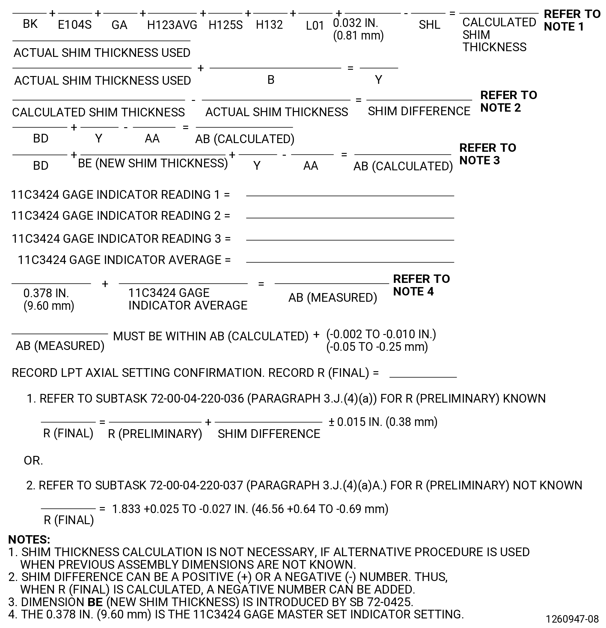
| (11) | Calculate the necessary thickness of the shim on the Record Sheet. Refer to Figure 405. |
| (12) | Find the actual shim that you will use. The available shims and thicknesses are as follows: |
| • |
|
| • |
|
| • |
|
| • |
|
| • |
|
| • |
|
| • |
|
| • |
|
| • |
|
| (13) | Measure and record dimensions AA, B, and BD before installing the LPT module assembly. Refer to Figure 404 and Figure 405. |
| (14) | For dimension BD refer to Subtask 72-00-04-420-122 (paragraph 3.I.). |
| Subtask 72-00-04-220-035 |
| A.A. | Alternative procedure. Select the initial shim (20-360 , 72-00-02) (SIN 83070). |
| (1) | If dimension R (final) was recorded before the removal of the LPT module and found to be outside the permitted limits, the original shim size can be adjusted accordingly until dimension R (final) is within limits when the LPT module is installed. Refer to Subtask 72-00-04-020-003 (72-00-04, REMOVAL 001). |
|
| Subtask 72-00-04-420-109 |
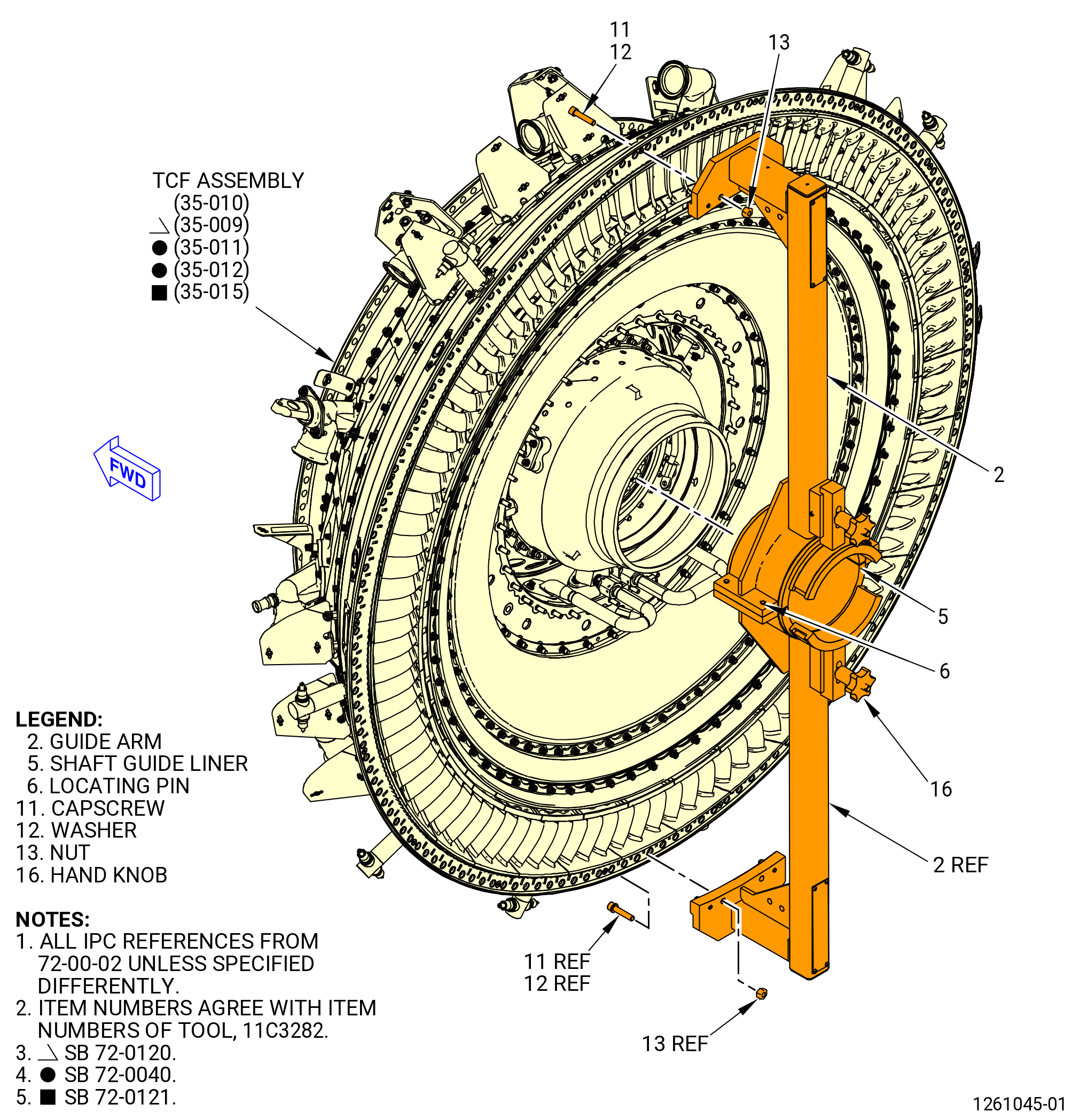
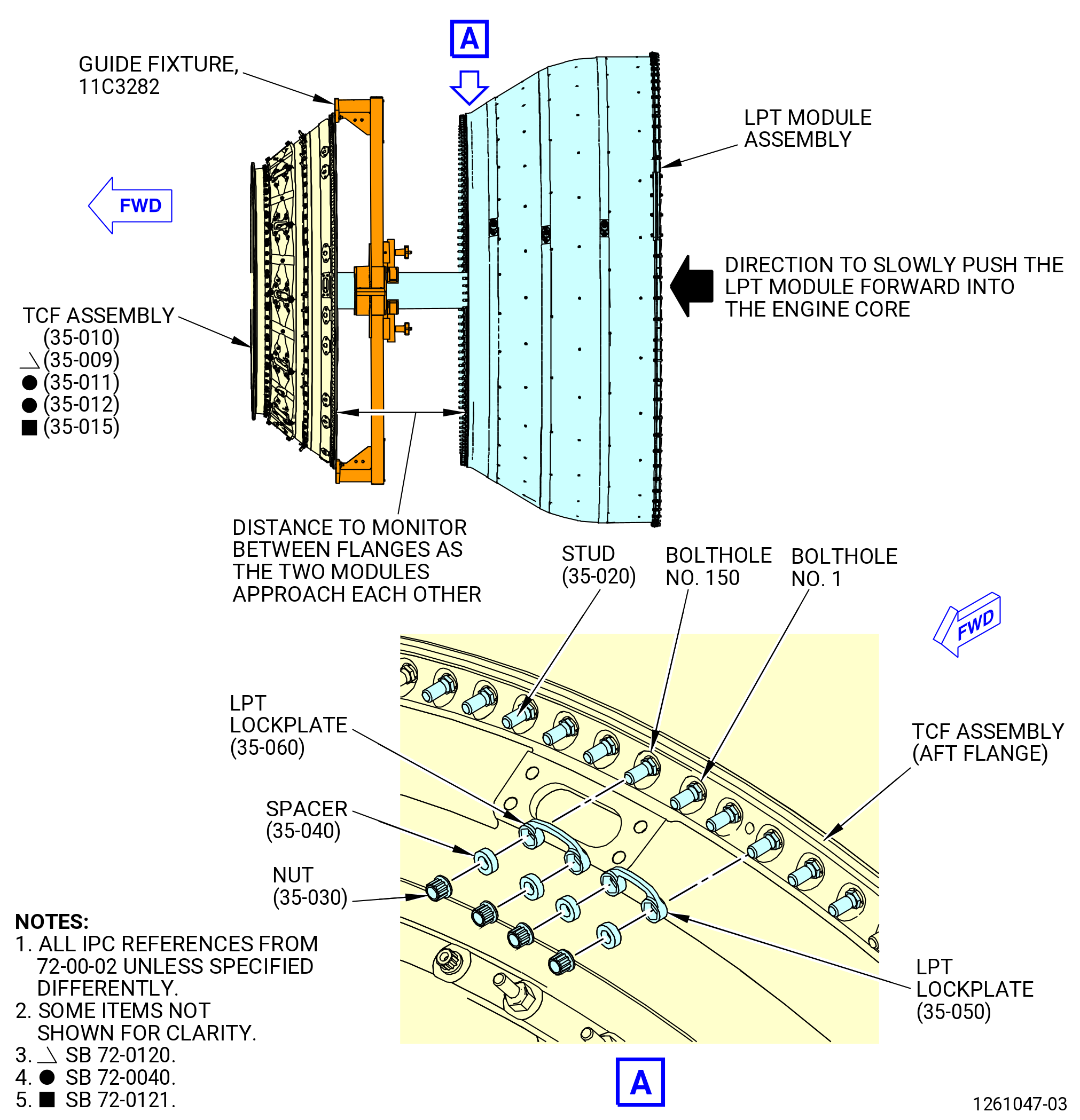
| B. | Install the bumpers (item 4) of the 9446M40 LPT alignment fixture and the 11C3282 guide fixture to the TCF assembly (35-009 , 72-00-02) (SIN 92500) or (35-010 , 72-00-02) (SIN 92500) or (35-011 , 72-00-02) (SIN 92500) or (35-012 , 72-00-02) (SIN 92500) or (35-015 , 72-00-02) (SIN 92500) aft flange. Refer to Figure 406, Figure 407, and do as follows: |
| (1) | Make sure that the TCF assembly aft flange boltholes are numbered. If necessary, use a C05-003 marking pen and put marks on the boltholes. |
| (a) | The 12:00 o'clock top vertical centerline bolthole is the No. 1 bolthole. |
| (b) | Put a mark at the No. 10 bolthole, aft looking forward in a counterclockwise (CCW) direction. |
| (c) | Put a mark at every 10th bolthole. There are 150 boltholes total. |
| (2) | Install the bumpers (item 4) of the 9446M40 LPT alignment fixture on the TCF assembly aft flange at the 12:00 and 6:00 o'clock positions. Refer to Figure 406 and do as follows: |
| NOTE: |
|
| (a) | Loosen the knob (item 9) on the locator block (item 2). |
| (b) | Put the locator block (item 2) on the TCF assembly aft flange in the bolthole seat and the bumper (item 4) aft. |
| (c) | Tighten the knob (item 9) to firmly attach the clamp block (item 3) to the TCF assembly flange. |
| (3) | Install one guide arm (item 2) approximately at the 10:30 o'clock position of the TCF assembly. |
| (a) | The pins on the guide arm bracket will fit into the No. 143 and No. 149 boltholes. |
| (b) | Attach the guide arm to the TCF assembly flange with two capscrews (item 11) at the No. 142 and No. 149 boltholes. Attach a capscrew (item 11) and washer (item 12) on the forward side of the TCF assembly flange and a nut (item 13) on the aft side of the guide arm. Hand-tighten the capscrews (item 11). |
| (4) | Install one guide arm (item 2) approximately at the 4:30 o'clock position on the TCF assembly as follows: |
| (a) | The pins on the guide arm bracket will fit into the No. 74 and No. 79 boltholes. |
| (b) | Attach the guide arm to the TCF assembly flange with two capscrews (item 11) at the No. 75 and No. 78 boltholes. Attach a capscrew (item 11) and washer (item 12) on the forward side of the TCF assembly flange and a nut (item 13) on the aft side of the guide arm. Hand-tighten the capscrews (item 11). |
| (5) | Make sure that the locating pins (item 6) and the holes are engaged between the guide arms (item 2). |
| (6) | Attach the guide arms (item 2) to the shaft guide liner (item 5) with the hand knobs (item 16). Make sure the shaft guide liner is aligned with the centerline of the opening on the aft side of the TCF assembly. |
| (7) | Tighten the nuts (item 15) and capscrews (item 13) fully against the TCF assembly flange. Do not torque the nuts. |
| Subtask 72-00-04-420-110 |
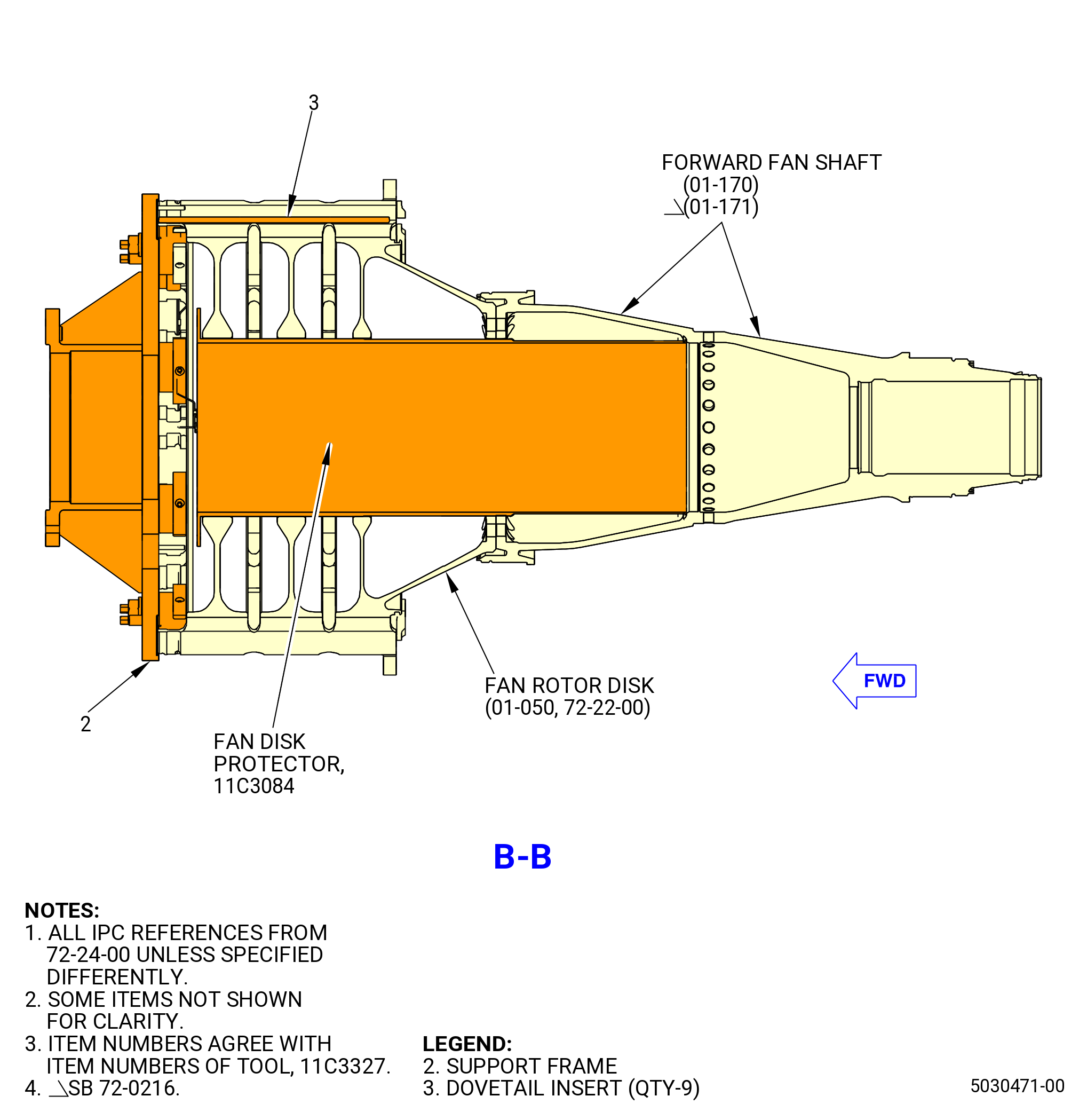
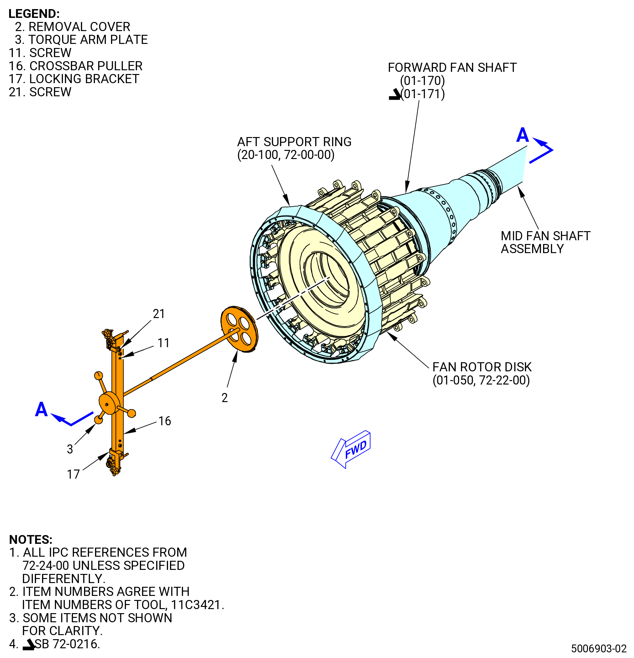
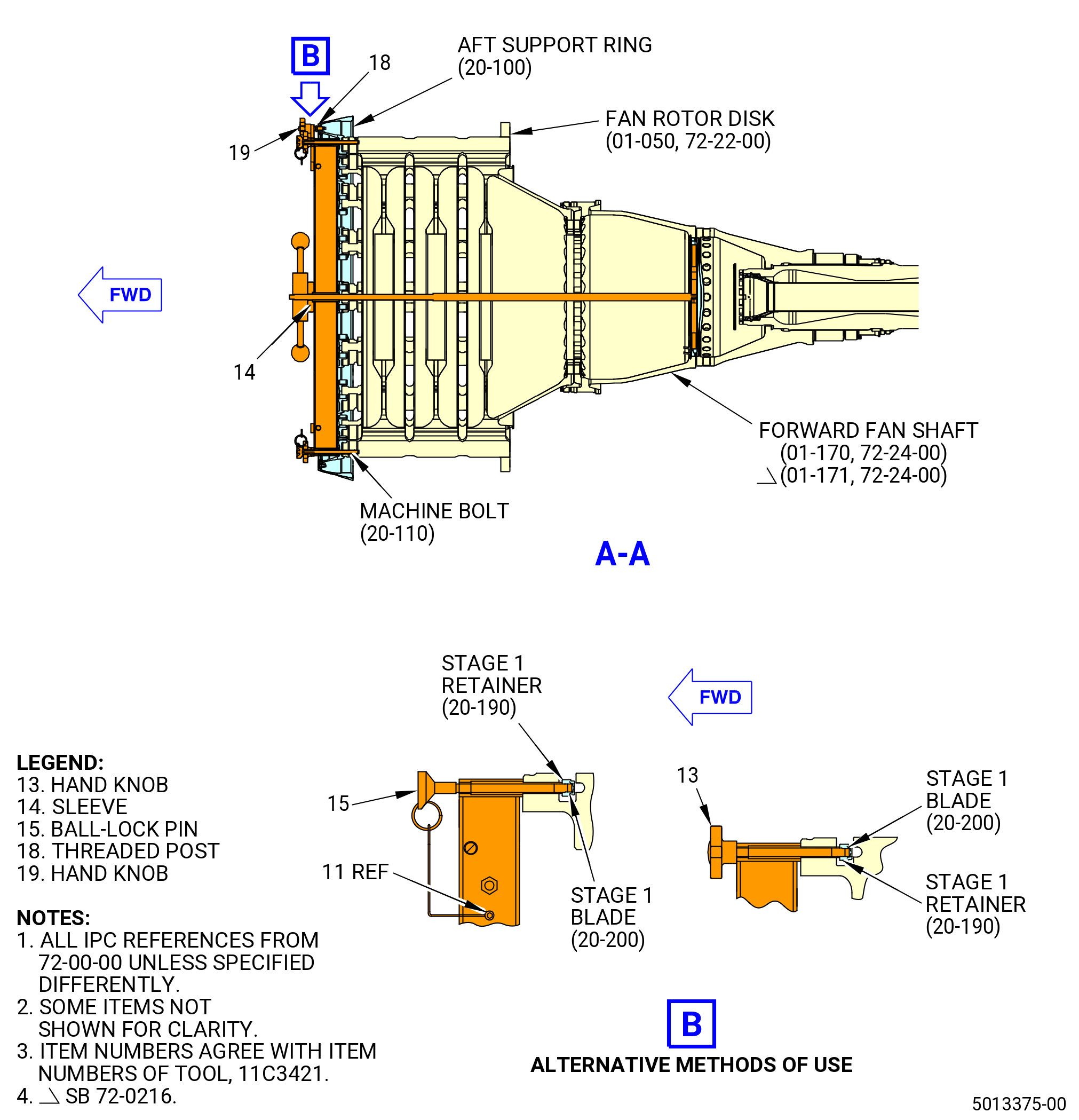
| C. | Alternative Procedure Available. Use this procedure when the fan booster assembly (20-010 , 72-00-02) (SIN 80000) or (20-011 , 72-00-02) (SIN 80000) has been installed to the fan hub module (25-010 , 72-00-02) (SIN 00102), or (25-011 , 72-00-02) (SIN 00102), or (25-012 , 72-00-02) (SIN 00102). Install the 11C3084 fan disk protector and the 11C3327 LPT mid-shaft guide fixture on the fan rotor disk (01-050 , 72-22-00) (SIN 830A0). Refer to Figure 408 and do as follows: |
| (1) | Prepare to install the 11C3327 LPT mid-shaft guide fixture on the fan rotor disk as follows: |
| CAUTION: |
|
| NOTE: |
|
| (a) | Make sure the slot on the rod foot (items 4 and 7) are in the LOCKED position or you can damage the fan rotor disk. If not, align as follows: |
| 1 | Loosen the nut (item 13) one turn and turn the 18 rod foot (items 4 and 7), align the slot to the UN-LOCKED position on the support frame (item 2). |
| 2 | Tighten the nut (item 13) one turn. |
| Subtask 72-00-04-420-111 |
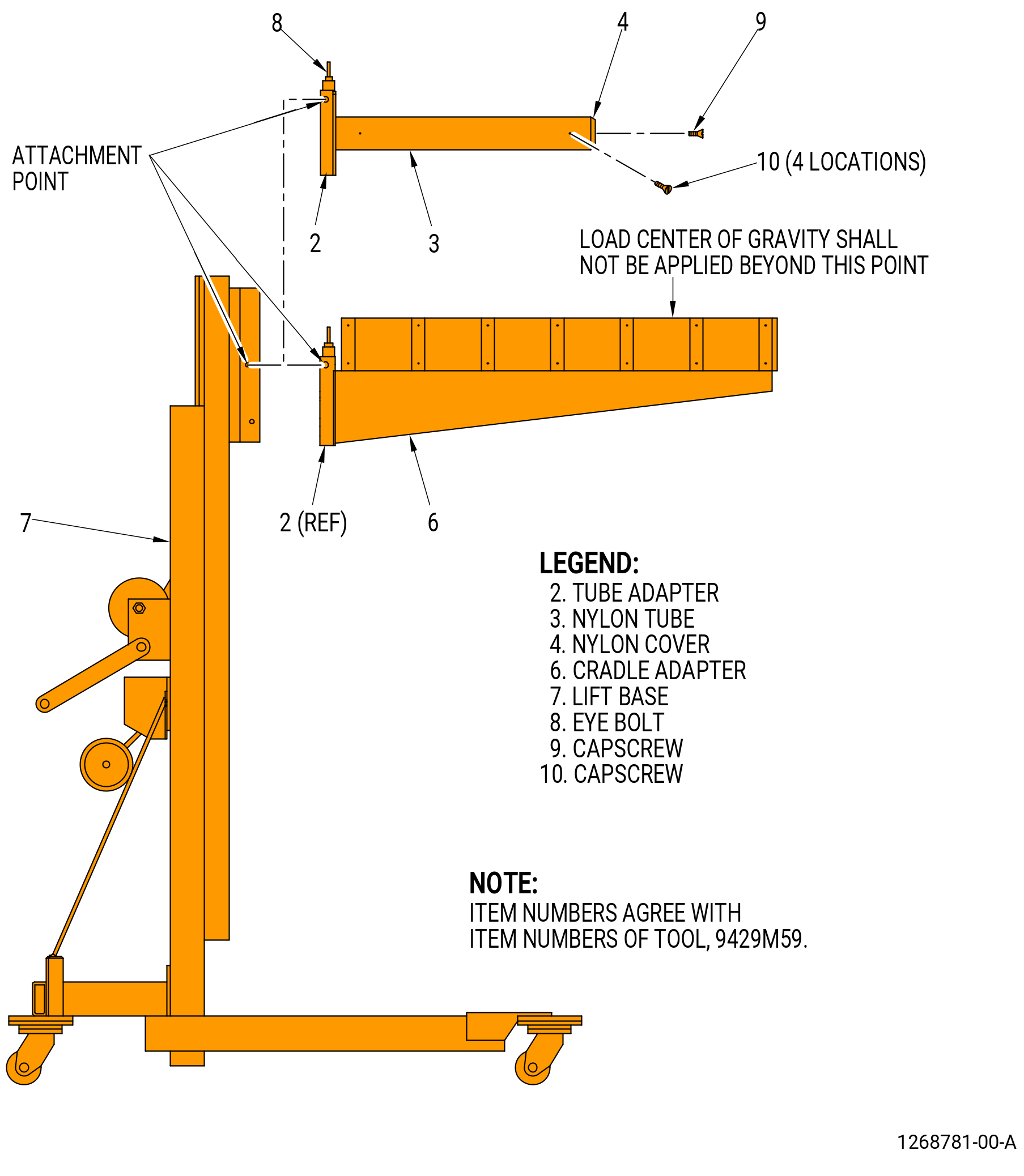
| (2) | Prepare to use the 9429M59 breach loader as follows. Refer to Figure 409. |
| NOTE: |
|
| (a) | Install the cradle adapter (item 6) as follows: |
| 1 | If necessary, remove the nylon adapter (item 3) from the tube adapter (item 2). |
| 2 | Attach an overhead hoist to the eye bolt (item 8) on the cradle adapter (item 6). |
| WARNING: |
|
| 3 | Lift the cradle adapter (item 6), install on the tube adapter (item 2) and safely attach. |
| (b) | Install the nylon tube (item 3) on the tube adapter (item 2) as follows: |
| 1 | Put the nylon tube (item 3) onto the tube adapter (item 2) and secure with capscrews (item 10) at four locations. |
| 2 | Put the nylon cover (item 4) on the tube adapter (item 2) and secure with the capscrew (item 9). |
| 3 | Lift the nylon tube (item 3) and install on the tube adapter (item 2) and safely attach. |
| (c) | Attach the tube adapter (item 2) to the lift base (item 7) with the lift base retaining pin. |
| CAUTION: |
|
| (d) | Operate the lift base (item 7) as instructed in the lift base manufacturer's instructions. |
| 1 | Make sure you lock the lift base (item 7) to prevent movement of the lift. |
| 2 | Do not lift a load unless there are a minimum of three wraps of cable around the winch drum of the lift base (item 7). |
| Subtask 72-00-04-420-112 |
| (3) | Put the 11C3084 fan disk protector in the support frame (item 2) of the 11C3327 LPT mid-shaft guide fixture. |
| WARNING: |
|
| CAUTION: |
|
| (4) | Lift the 11C3327 LPT mid-shaft guide fixture with the nylon tube (item 3) of the 9429M59 breach loader. |
| (5) | Install the 11C3327 LPT mid-shaft guide fixture in the fan rotor disk (830A0) as follows: |
| (a) | Lift the 11C3327 LPT mid-shaft guide fixture. |
| (b) | Carefully install the 11C3327 LPT mid-shaft guide fixture into the dovetail slots of the fan rotor disk. |
| (c) | Secure the support frame (item 2) to the fan rotor disk as follows: |
| 1 | Loosen the nuts (item 13) and turn the rod foot (items 4 and 7) to align the slot with the LOCKED mark on the support frame (item 2). Make sure the rod foot is attached to the fan rotor disk. |
| 2 | Tighten the nuts (item 13). |
| (6) | Make sure that the feet on the rod foot (items 4 and 7) at 18 locations are in the locked position. |
| (7) | Make sure that the rod foot (items 4 and 7) are in the locked position. |
| Subtask 72-00-04-420-113 |
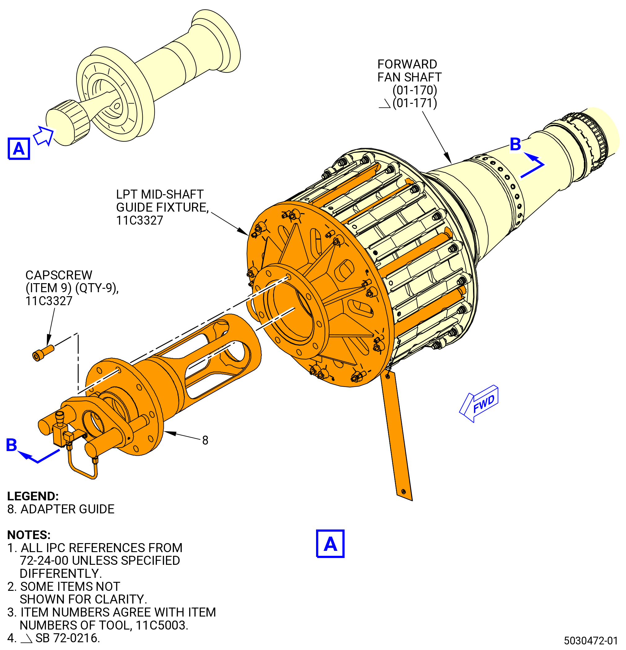
| (8) | Install the adapter guide (item 8) of the 11C5003 push/pull fixture in the 11C3327 LPT mid-shaft guide fixture. Refer to Figure 410 and do as follows: |
| CAUTION: |
|
| (a) | Lift the adapter guide (item 8) of the 11C5003 push/pull fixture with the nylon tube (item 3) of the 9429M59 breach loader. Refer to Figure 409. |
| (9) | Slide the adapter guide (item 8) of the 11C5003 push/pull fixture into the support frame (item 2) of the 11C3327 LPT mid-shaft guide fixture. Refer to Figure 410. |
| (10) | Safety the adapter guide (item 8) of the 11C5003 push/pull fixture with the capscrews (item 9) of the 11C3327 LPT mid-shaft guide fixture at nine locations. Tighten the capscrews. |
| Subtask 72-00-04-420-163 |
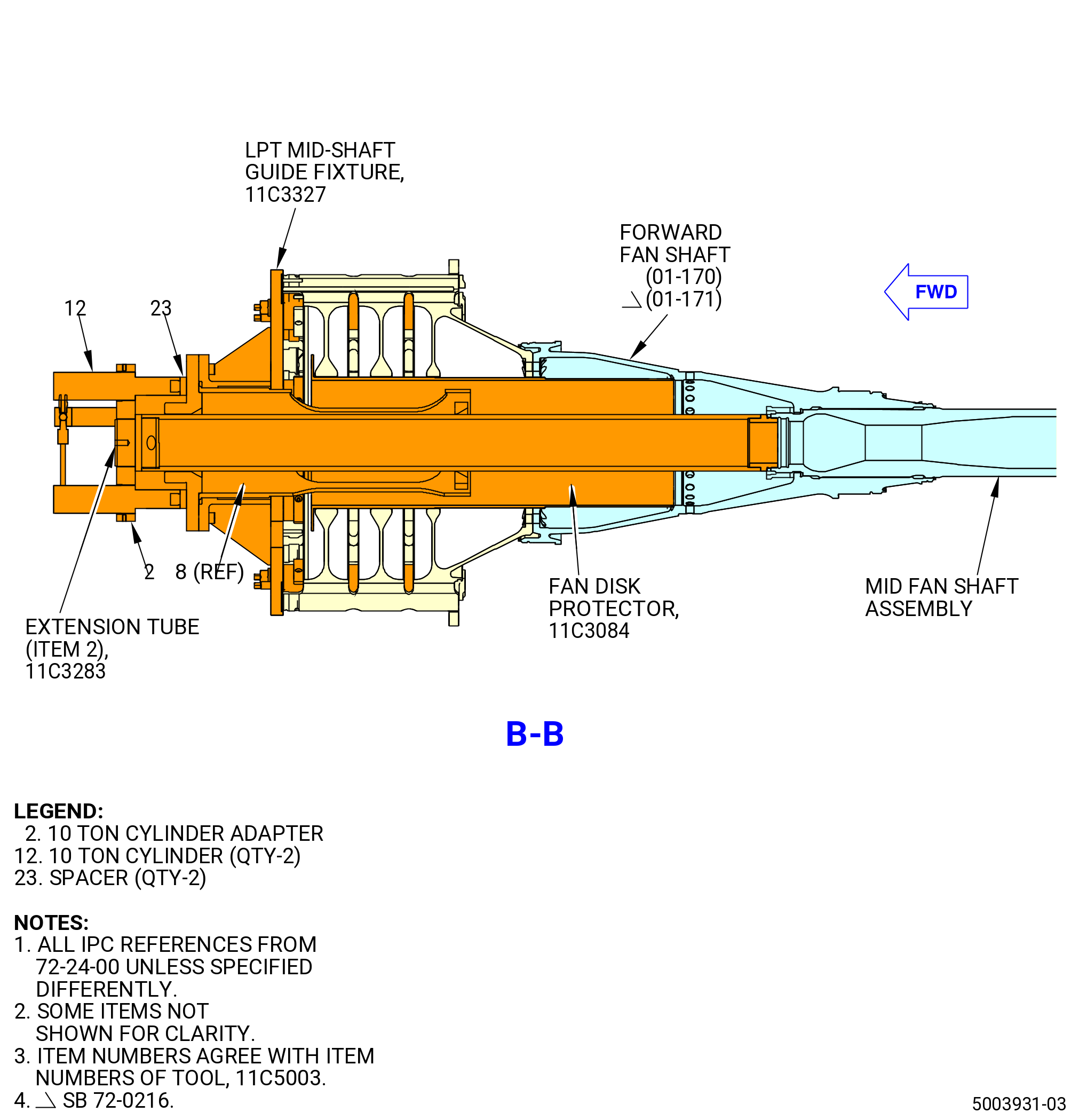
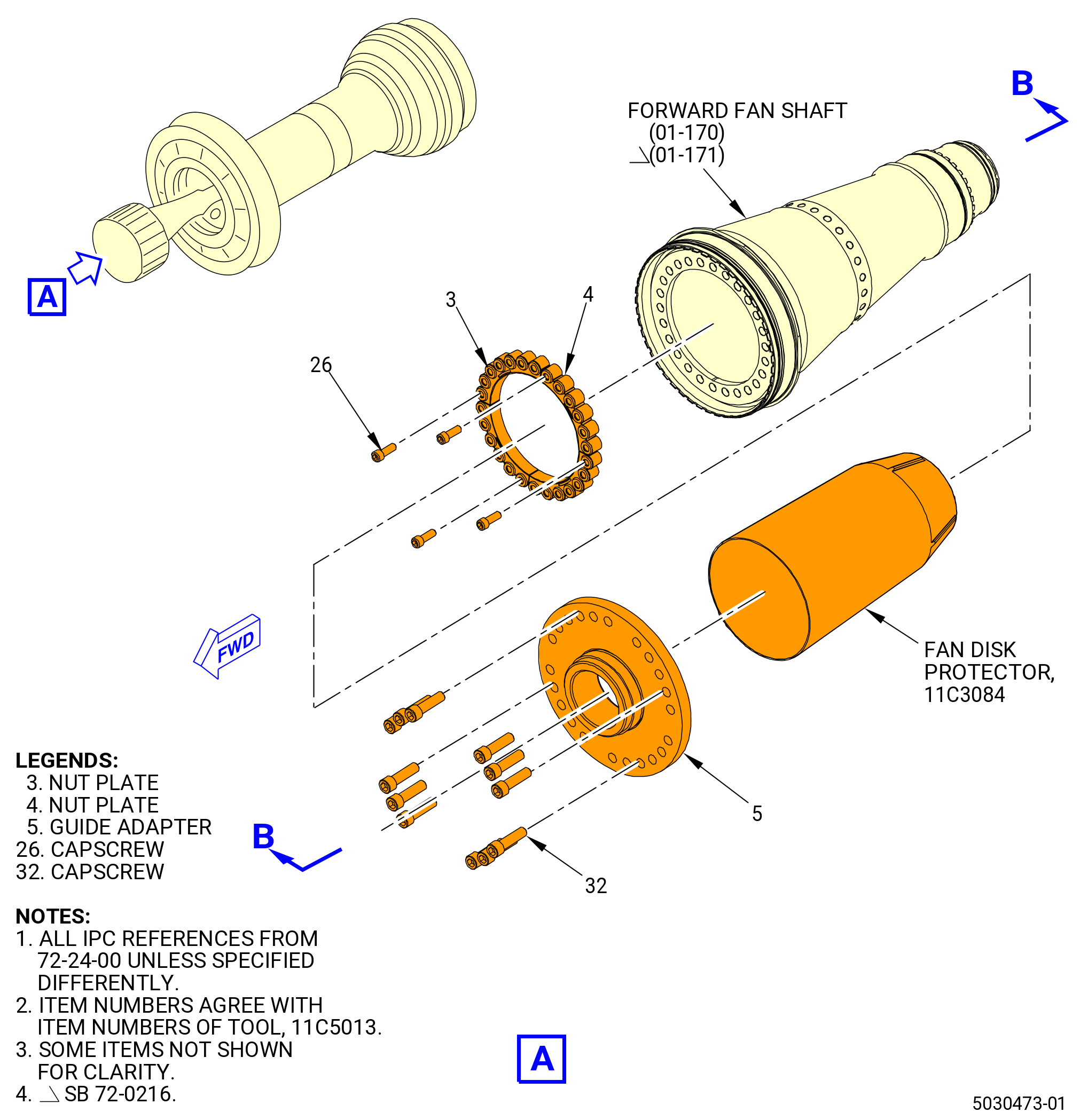
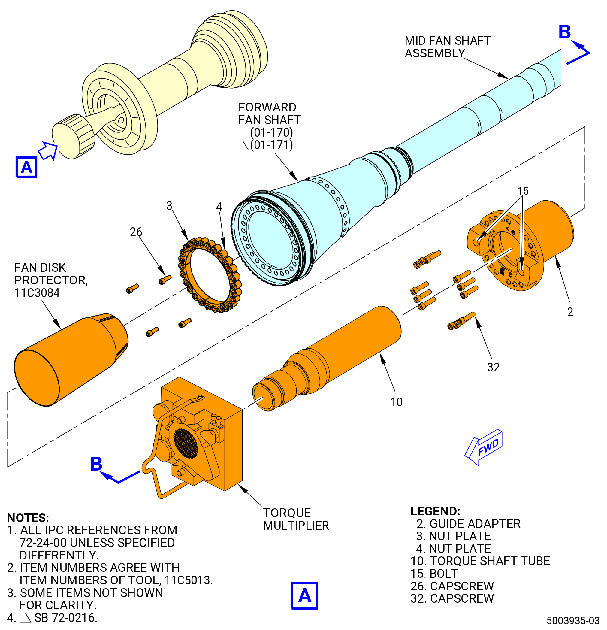
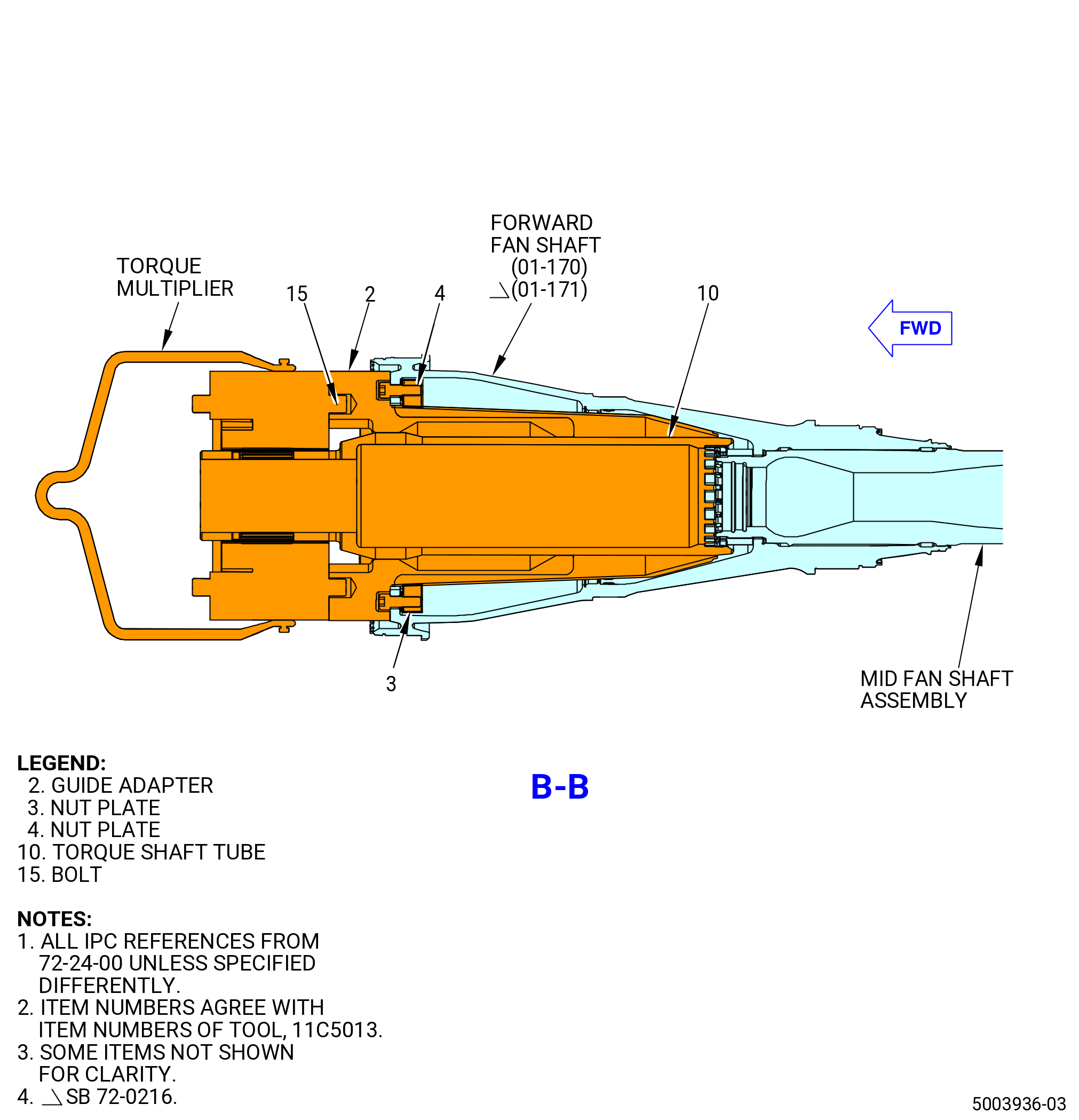
| C.A. | Alternative Procedure. Use this procedure when the fan booster assembly (20-010 , 72-00-02) (SIN 80000) or (20-011 , 72-00-02) (SIN 80000) has not been installed to the fan hub module (25-010 , 72-00-02) (SIN 00102), or (25-011 , 72-00-02) (SIN 00102), or (25-012 , 72-00-02) (SIN 00102). Install the 11C3084 fan disk protector and the 11C5013 installation/removal fixture to the forward fan shaft (01-170 , 72-24-00) (SIN 81002) or (01-171 , 72-24-00) (SIN 81002). Refer to Figure 411 and do as follows: |
| (1) | Install the 11C5013 installation/removal fixture as follows: |
| (a) | Install the two nut plates (item 3) and the two nut plates (item 4) of the 11C5013 installation/removal fixture to the aft side of the forward fan shaft forward flange with four 5/8 capscrews (item 26). Torque the capscrews to 100 ft lb. (140 Nm). |
| NOTE: |
|
| (b) | Install the protector (item 8) of the 11C3084 fan disk protector in the bore of the forward fan shaft (01-170 , 72-24-00) (SIN 81002) or (01-171 , 72-24-00) (SIN 81002). |
| WARNING: |
|
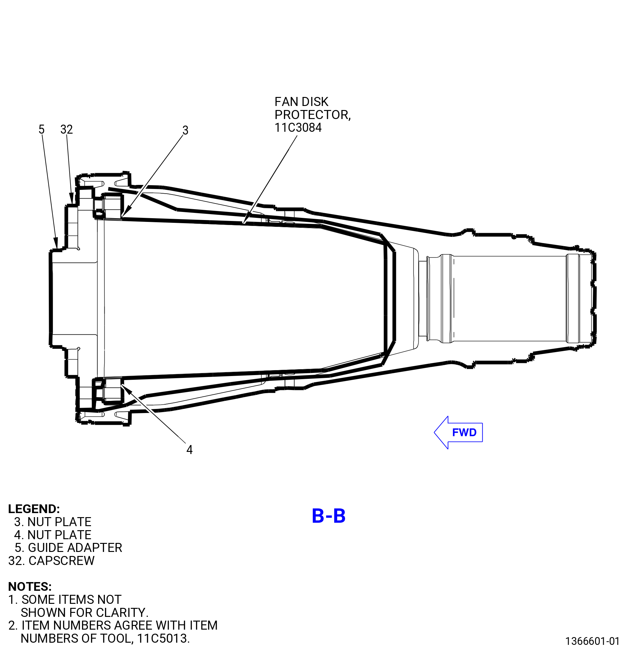
| (c) | Use a hoist and applicable nylon strap to install the guide adapter (item 5) of the 11C5013 installation/removal fixture on the forward side of the forward fan shaft forward flange with 12 capscrews (item 32). |
| (d) | Torque the cap screws (item 32) to 100 ft lb. (140 Nm). |
| Subtask 72-00-04-420-114 |
| D. | Alternative Procedure Available. Use this procedure when the fan booster assembly (20-010 , 72-00-02) (SIN 80000) or (20-011 , 72-00-02) (SIN 80000) has been installed to the fan hub module (25-010 , 72-00-02) (SIN 00102), or (25-011 , 72-00-02) (SIN 00102), or (25-012 , 72-00-02) (SIN 00102). Prepare the LPT module assembly for installation into the propulsor assembly as follows: |
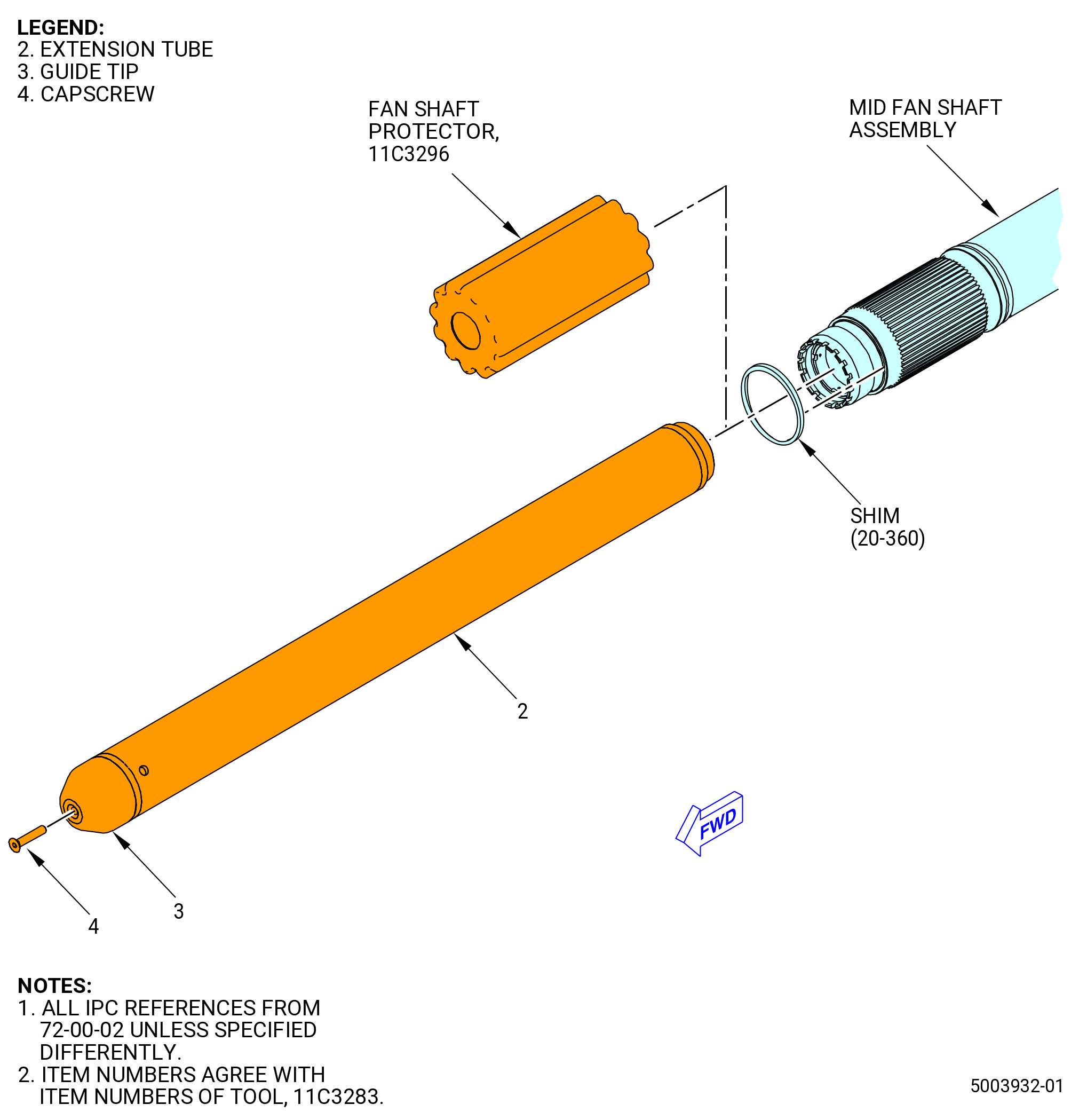
| (1) | Remove the 11C3296 fan shaft protector from the front of the mid fan shaft assembly. Refer to Figure 412 and Figure 414. |
| (2) | Put the shim (20-360 , 72-00-02) (SIN 83070) on the forward end of the mid fan shaft assembly. |
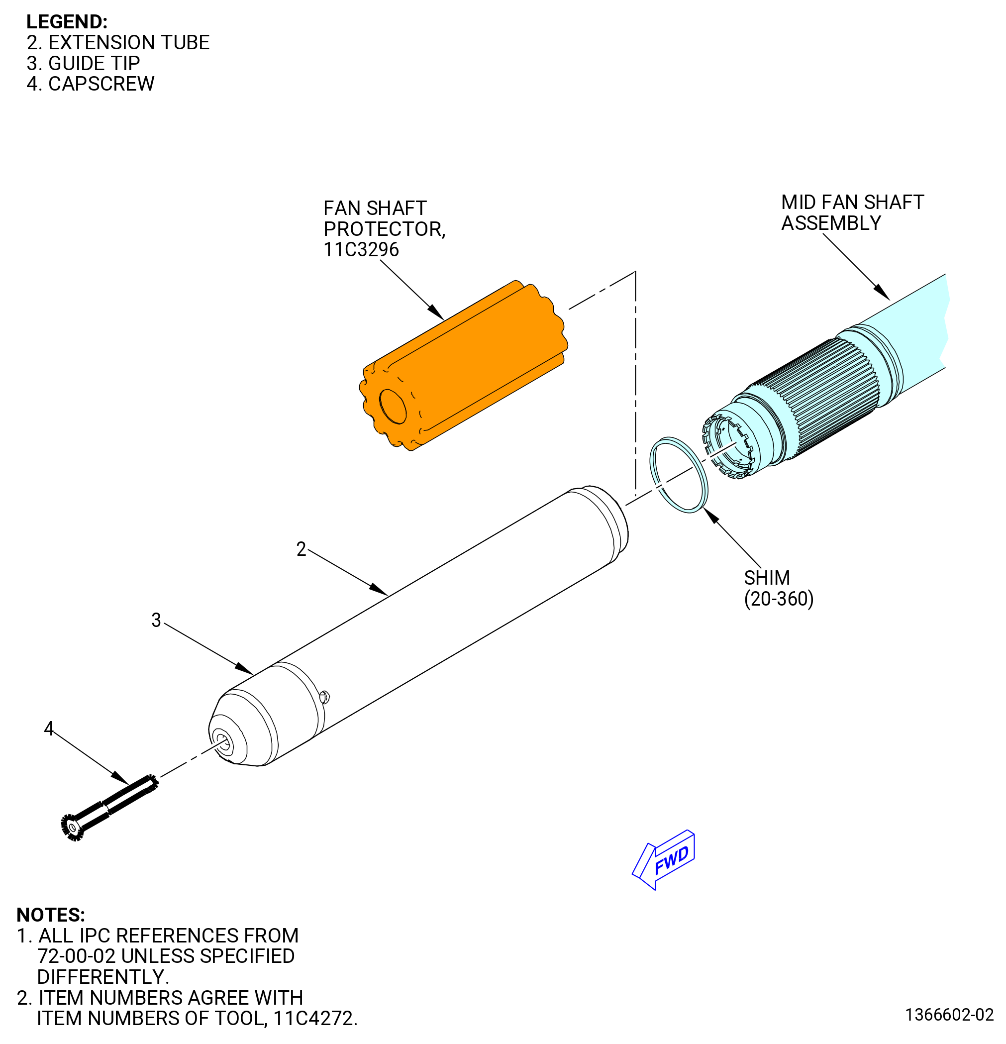
| (3) | Install the extension tube (item 2) of the 11C3283 extension fixture onto the mid fan shaft assembly of the LPT module assembly as follows: |
| WARNING: |
|
| (a) | Use a lift hoist with two lift straps to lift the extension tube (item 2). |
| (b) | Carefully align the threaded end of the extension tube (item 2) with the forward end of the mid fan shaft assembly by hand. |
| CAUTION: |
|
| (c) | Slowly rotate the extension tube (item 2) clockwise (CW) to engage the threads. |
| (d) | Tighten the extension tube (item 2) onto the mid fan shaft assembly. Make sure that the extension tube is fully on the mid fan shaft assembly. |
| (e) | Install the guide tip (item 3) on the extension tube (item 2) and secure with the capscrew (item 4). |
| WARNING: |
|
| (4) | Lubricate the splines of the mid fan shaft assembly with C02-019 engine oil or C02-023 engine oil. |
| (5) | Use a level to make sure the propulsor assembly is level at the TCF assembly aft flange. Make the necessary corrections to make the propulsor assembly level. |
| (6) | Do a visual inspection of the TCF assembly aft cavity and LPT forward cavity for foreign object damage (FOD) or damage. |
| (7) | Remove all protective caps or plugs from oil lines or the brush seal in the aft TCF assembly. |
| Subtask 72-00-04-420-164 |
| D.A. | Alternative Procedure. Use this procedure when the fan booster assembly (20-010 , 72-00-02) (SIN 80000) or (20-011 , 72-00-02) (SIN 80000) has not been installed to the fan hub module (25-010 , 72-00-02) (SIN 00102), or (25-011 , 72-00-02) (SIN 00102), or (25-012 , 72-00-02) (SIN 00102). Prepare the LPT module assembly for installation into the propulsor assembly as follows: |
| (1) | Remove the 11C3296 fan shaft protector from the front of the mid fan shaft assembly. Refer to Figure 413 and Figure 414. |
| (2) | Put the shim (20-360 , 72-00-02) (SIN 83070) on the forward end of the mid fan shaft assembly. |
| Subtask 72-00-04-160-005 |
| * * * SB 72-0114( Mid Fan Shaft with Molydag Lubricant Dry Film and Engine Oil Lubricant Assembly ) |
| (3) | Clean the 11C4272 extension fixture before installation on the mid fan shaft assembly (45-010A , 72-00-02) (SIN 81000) or (45-011A , 72-00-02) (SIN 81000) as follows: |
| WARNING: |
|
| CAUTION: |
|
| (a) | Clean all graphite grease from the 11C4272 extension fixture with a C10-182 cleaning cloth moist with C02-019 engine oil or C02-023 engine oil. |
| (b) | Continue the cleaning to remove all residual graphite grease from the 11C4272 extension fixture with a C10-182 cleaning cloth moist with C04-003 acetone . |
| (c) | Do a close visual inspection to make sure that all the graphite grease was removed to prevent contamination. |
| NOTE: |
|
| * * * END SB 72-0114 |
| Subtask 72-00-04-420-171 |
| (4) | Install the extension tube (item 2) of the 11C4272 extension fixture on the mid fan shaft assembly as follows: |
| WARNING: |
|
| (a) | Use a lift hoist with two lift straps to lift the extension tube (item 2). |
| (b) | Manually align the threaded end of the extension tube (item 2) with the forward end of the mid fan shaft assembly. |
| CAUTION: |
|
| (c) | Slowly turn the extension tube (item 2) CW to engage the threads. |
| (d) | Tighten the extension tube (item 2) onto the mid fan shaft assembly. Make sure that the extension tube is fully seated on the mid fan shaft assembly. |
| (e) | Install the guide tip (item 3) on the extension tube (item 2) and secure with the capscrew (item 4). |
| WARNING: |
|
| (5) | Lubricate the splines of the mid fan shaft assembly with C02-019 engine oil or C02-023 engine oil. |
| (6) | Use a level to make sure the propulsor assembly is level at the TCF assembly aft flange. Make the necessary corrections to make the propulsor assembly level. |
| (7) | Do a visual inspection of the TCF assembly aft cavity and LPT forward cavity for FOD or damage. |
| (8) | Remove all protective caps or plugs from oil lines in the aft TCF assembly. |
| Subtask 72-00-04-420-115 |
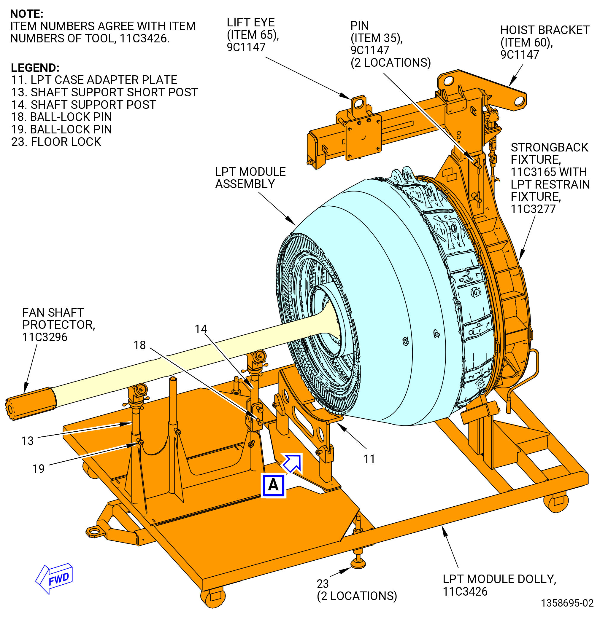
| E. | Alternative Procedure Available. Remove the LPT module assembly from the 11C3426 LPT module dolly. Refer to Figure 414 and do as follows: |
| (1) | Move the 11C3426 LPT module dolly and put the LPT module assembly directly behind the propulsor assembly. |
| (2) | Make sure that the LPT module assembly is aligned with the centerline of the propulsor assembly and below the middle center of the hoist. |
| CAUTION: |
|
| (3) | Put the floor locks (item 23) of the 11C3426 LPT module dolly against the floor. |
| (4) | Adjust the 9C1147 VCG lift fixture to approximately 9.25 inches (235.0 mm). |
| (5) | Attach the lift eye (item 65) of the 9C1147 VCG lift fixture to the load positioner. |
| CAUTION: |
|
| (6) | Put a torpedo level approximately in the middle of the mid fan shaft assembly and make sure that the LPT module assembly is level. |
| (7) | Extend the load positioner 3.0 inches (76 mm) down after you lift the LPT module assembly so you have sufficient lift clearance. |
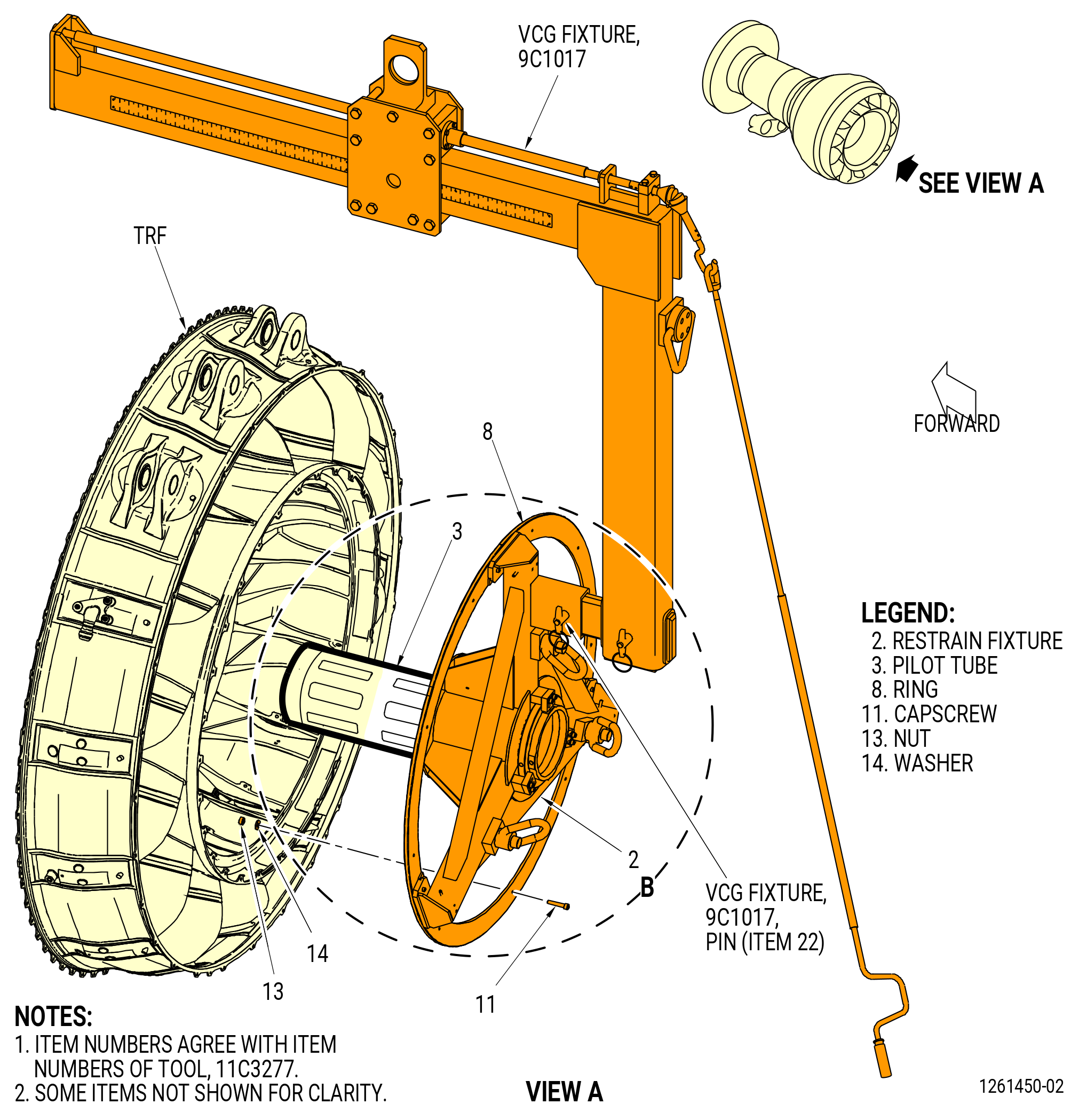
| (8) | Make sure that the 11C3277 LPT restrain fixture is correctly installed. Make sure that the adjusting nut (item 5) and the three stop blocks (item 7) are in the correct position. Refer to TASK 72-00-04-430-801 (72-00-04, ASSEMBLY 001, CONFIG 01) or TASK 72-00-04-430-802 (72-00-04, ASSEMBLY 001, CONFIG 02). |
| WARNING: |
|
| (9) | Apply a lift pressure to the LPT module assembly. |
| NOTE: |
|
| (10) | Remove the nuts (item 10) of the 11C3426 LPT module dolly from the slave bolts at 12 locations. Refer to Figure 414. |
| (11) | Lift the LPT module assembly from the 11C3426 LPT module dolly. |
| (12) | Extend the hydra-set down 3.00 inches (76.2 mm) to make room to lift up. |
| (13) | Use a level at approximately the middle of the mid fan shaft assembly to make sure that it is level and that the LPT module assembly is parallel to the TCF assembly. Make the necessary corrections to level the mid fan shaft assembly as follows: |
| CAUTION: |
|
| (a) | Use the overhead hoist to adjust the down height of the LPT module assembly. Do not use the hydra-set to adjust the LPT module assembly down. |
| (b) | Adjust the LPT module assembly with the 9C1147 VCG lift fixture to level the mid fan shaft assembly. |
| (c) | When you use the up handle, the LPT module assembly will move up 0.005 inch (0.13 mm) each time you use the up handle. |
| (14) | Make a record of the weight of the LPT module assembly. You will monitor the weight of the LPT module assembly on the load indicator when you install the LPT module assembly into the propulsor assembly. |
| NOTE: |
|
| Subtask 72-00-04-420-154 |
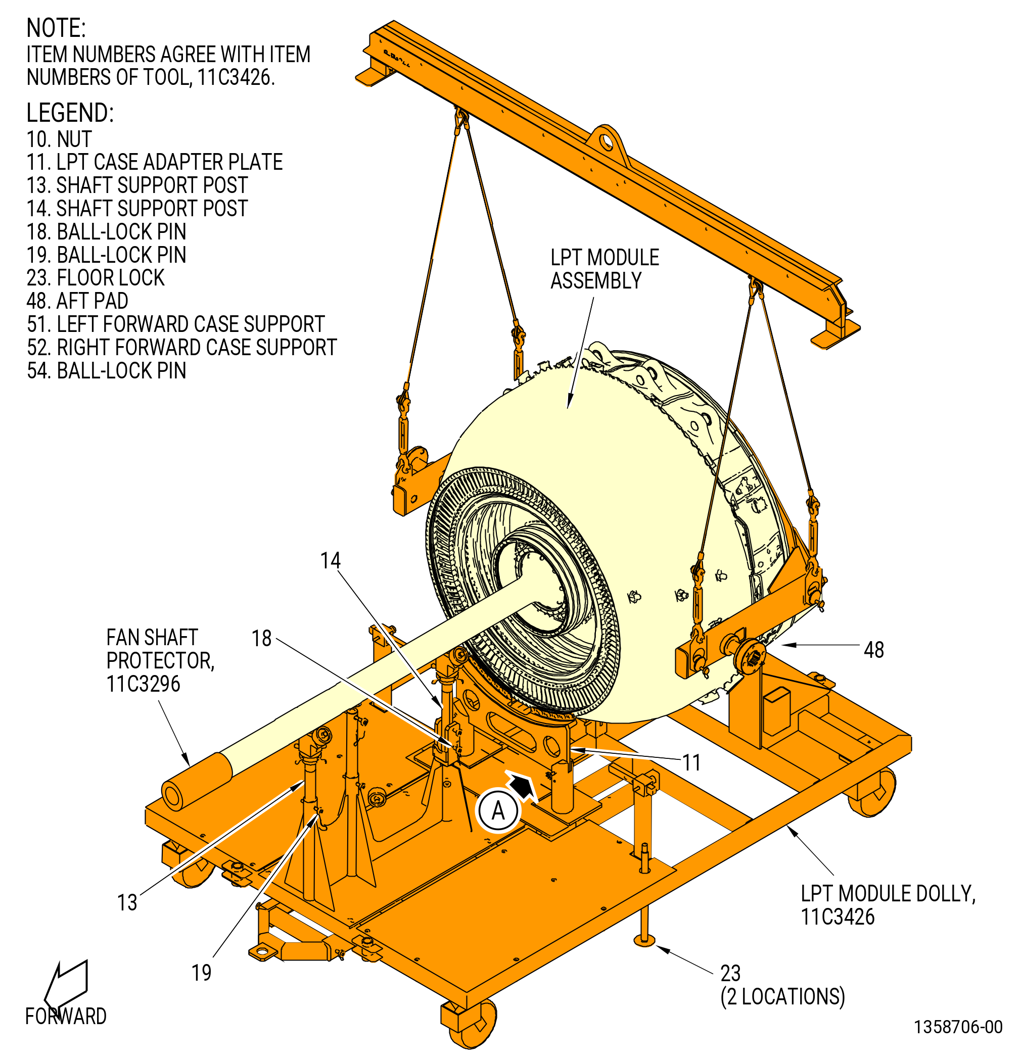
| E.A. | Alternative Procedure. Remove the LPT module assembly from the 11C3426 LPT module dolly. Refer to Figure 414 and do as follows: |
| (1) | Prepare the lift hoist as follows: |
| (a) | Install the load indicator to the overhead hoist. |
| (b) | Attach the hydra-set to the load indicator. The hydra-set gives movement in increments of 0.005 inch (0.13 mm). |
| (c) | Adjust the hydra-set down 3.0 inches (76 mm) to give room to lift the LPT module assembly and to give a full range of movement. |
| (2) | Move the 11C3426 LPT module dolly directly behind the propulsor assembly. Make sure the LPT module assembly is aligned with the centerline of the propulsor assembly and is centered below the overhead hoist. |
| CAUTION: |
|
| (3) | Put the floor locks (item 23) of the 11C3426 LPT module dolly against the floor to prevent movement and equipment damage. |
| (4) | Prepare the 9429M77 lift and turn fixture as follows: |
| (a) | Attach two wires (length: 51.2 inches (1300 mm)) of the9429M77 lift and turn fixture to the pivot trunnions located on the aft side of the 11C4266 CG lift fixture. |
| (b) | Attach two wires (length: 45.3 inches (1151 mm)) with the turnbuckle of the 9429M77 lift and turn fixture to the pivot trunnions located on the forward side of the 11C4266 CG lift fixture. |
| (c) | Use turnbuckle to initially adjust CG of the LPT module. |
| (5) | Install the hydra-set to the LPT module assembly as follows: |
| (a) | Attach the hydra-set to an overhead crane hook. |
| (b) | Attach the 9429M77 lift and turn fixture to the hydra-set. |
| (6) | Make sure the 11C3277 LPT restrain fixture is installed correctly. Refer to TASK 72-00-04-430-801 (72-00-04, ASSEMBLY 001, CONFIG 01) or TASK 72-00-04-430-802 (72-00-04, ASSEMBLY 001, CONFIG 02). |
| WARNING: |
|
| (7) | Apply a lift pressure to the LPT module assembly with the overhead hoist. The weight of the LPT module assembly is approximately 4025 lb (1826 kg). |
| NOTE: |
|
| (8) | Remove the ball-lock pins (item 54) of the 11C3426 LPT module dolly from the forward case supports (item 51) and (item 52). |
| (9) | Lift the LPT module assembly from the aft pads (item 48) with the LPT case adapter plate (item 11) attached to the LPT module assembly. |
| (10) | Remove the nuts (item 10) from the 0.250-28UNF slave bolts at 12 locations on the LPT case adapter plate (item 11), and use two people to remove the forward case supports (item 51) and (item 52). |
| (11) | Move the 11C3426 LPT module dolly away from the LPT module assembly. |
| (12) | Put a level on the mid fan shaft assembly to make sure that the LPT module assembly is level. |
| (13) | If necessary, adjust the center of gravity (CG) on the 9429M77 lift and turn fixture with the turnbuckles (item 28) on the forward hoists. |
| (14) | Make a record of the weight of the LPT module assembly. You will monitor the weight of the LPT module assembly on the load indicator when you install the LPT module assembly into the propulsor assembly. |
| CAUTION: |
|
| (15) | Use the overhead hoist to adjust the down height of the LPT module assembly in increments more than 0.10 inch (2.5 mm) and not the hydra-set to prevent damage to the LPT module assembly. |
| Subtask 72-00-04-420-195 |
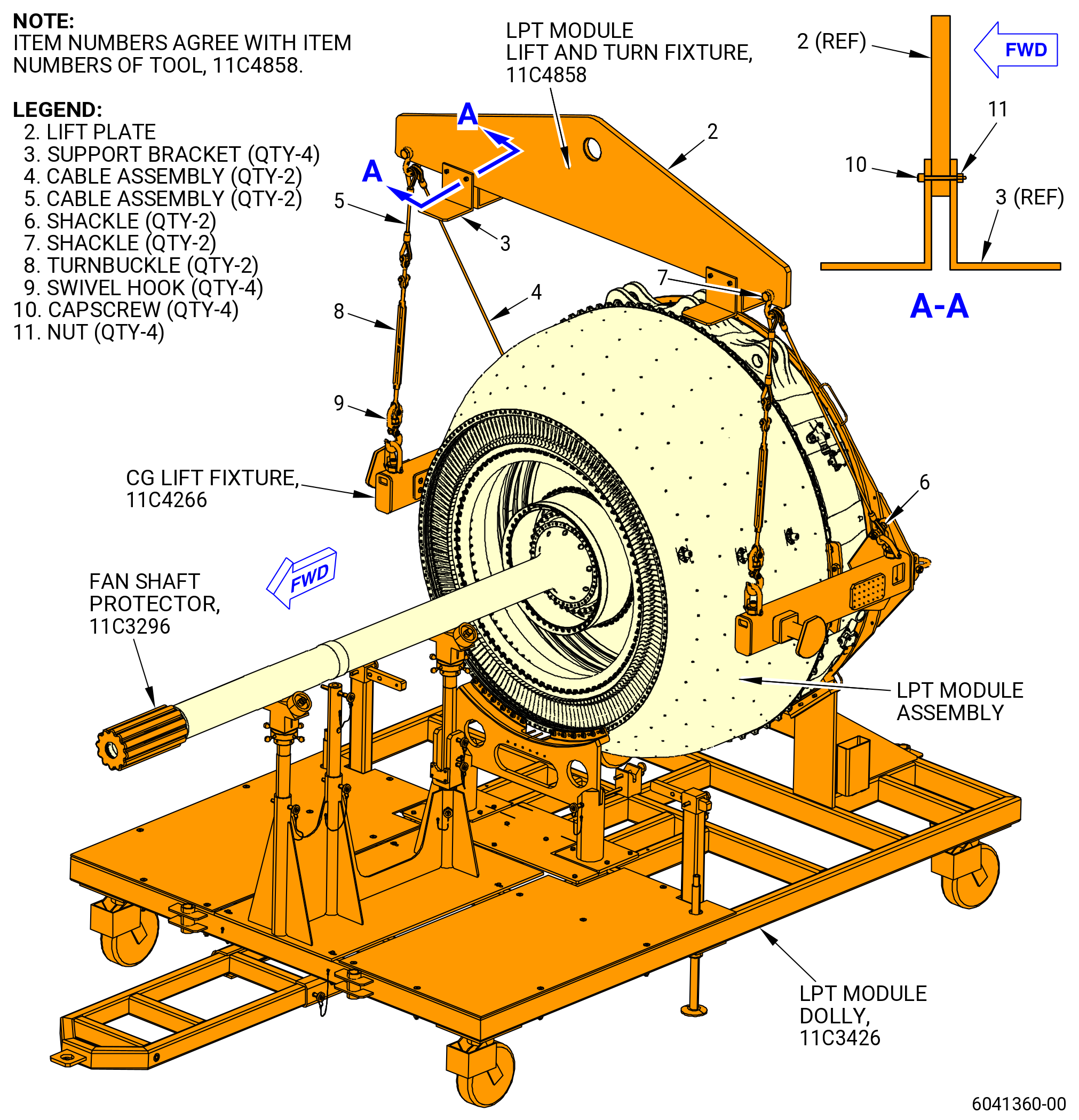
| E.B. | Alternate Procedure. Remove the LPT module assembly from the 11C3426 LPT module dolly. Refer to Figure 414 and do as follows: |
| (1) | Prepare the lift hoist and 11C4858 lift and turn fixture as follows: |
| (a) | Install the load indicator to the overhead hoist. |
| (b) | Attach the hydra-set to the load indicator. The hydra-set gives movement in increments of 0.005 inch (0.13 mm). |
| (c) | Adjust the hydra-set down 3.0 inches (76 mm) to give room to lift the LPT module assembly and to give full range of movement. |
| (d) | Attach 11C4858 lift and turn fixture lifting plate (item 2) to the hydra-set. |
| (e) | Prepare two long sling assemblies by assembling a shackle (item 6) and swivel hook (item 9) to the cable assembly (item 4). |
| (f) | Adjust the length of the two turnbuckles (item 8) to 20 inches (508 mm) between the bolt pin centers. |
| (g) | Prepare two short sling assemblies by assembling a shackle (item 6) and swivel hook (item 9) to one end of the turnbuckle (item 8) and the cable assembly (item 5) to the opposite end. |
| (h) | Connect each of the short and long sling assemblies to the lift plate (item 2) with shackle (item 7) on each side. |
| (2) | Move the 11C3426 LPT module dolly directly behind the propulsor assembly. Make sure the LPT module assembly is aligned with the centerline of the propulsor assembly and is centered below the overhead hoist. |
| CAUTION: |
|
| (3) | Put the floor locks (item 23) of the 11C3426 LPT module dolly against the floor to prevent movement and equipment damage. |
| (4) | Install the 11C4858 lift and turn fixture to the LPT module as follows: |
| (a) | Attach each cable assembly swivel hook (item 9) to the pivot trunnions located on the forward side of the 11C4266 CG lift fixture. |
| (b) | Attach each cable assembly swivel hook (item 9) to the pivot trunnions located on the aft side of the 11C4266 CG lift fixture. |
| (c) | Use the turnbuckles to initially adjust CG of the LPT module if necessary. |
| (5) | Make sure the 11C3277 LPT restrain fixture is installed correctly. Refer to TASK 72-00-04-430-801 (72-00-04, ASSEMBLY 001, CONFIG 01) or TASK 72-00-04-430-802 (72-00-04, ASSEMBLY 001, CONFIG 02). |
| WARNING: |
|
| (6) | Apply a lift pressure to the LPT module assembly with the overhead hoist. The weight of the LPT module assembly is approximately 4025 lb (1826 kg). |
| NOTE: |
|
| (7) | Remove the ball-lock pins (item 54) of the 11C3426 LPT module dolly from the forward case supports (item 51) and (item 52). |
| (8) | Lift the LPT module assembly from the aft pads (item 48) with the LPT case adapter plate (item 11) attached to the LPT module assembly. |
| (9) | Remove the nuts (item 10) from the 0.250-28UNF slave bolts at 12 locations on the LPT case adapter plate (item 11), and use two persons to remove forward case supports (item 51) and (item 52). |
| (10) | Move the 11C3426 LPT module dolly away from the LPT module assembly. |
| (11) | Put a level on the mid fan shaft assembly to make sure that the LPT module assembly is level. |
| (12) | If necessary, adjust the center of gravity (CG) on the 11C4858 lift and turn fixture with the turnbuckles (item 8) on the forward end of the 11C4266 CG lift fixture. |
| (13) | Make a record of the weight of the LPT module assembly. You will monitor the weight of the LPT module assembly on the load indicator when you install the LPT module assembly into the propulsor assembly. |
| CAUTION: |
|
| (14) | Use the overhead hoist to adjust the down height of the LPT module assembly in increments more than 0.10 inch (2.5 mm) and not the hydra-set to prevent damage to the LPT module assembly. |
| Subtask 72-00-04-420-116 |
| F. | Install the LPT module assembly into the propulsor assembly as follows: |
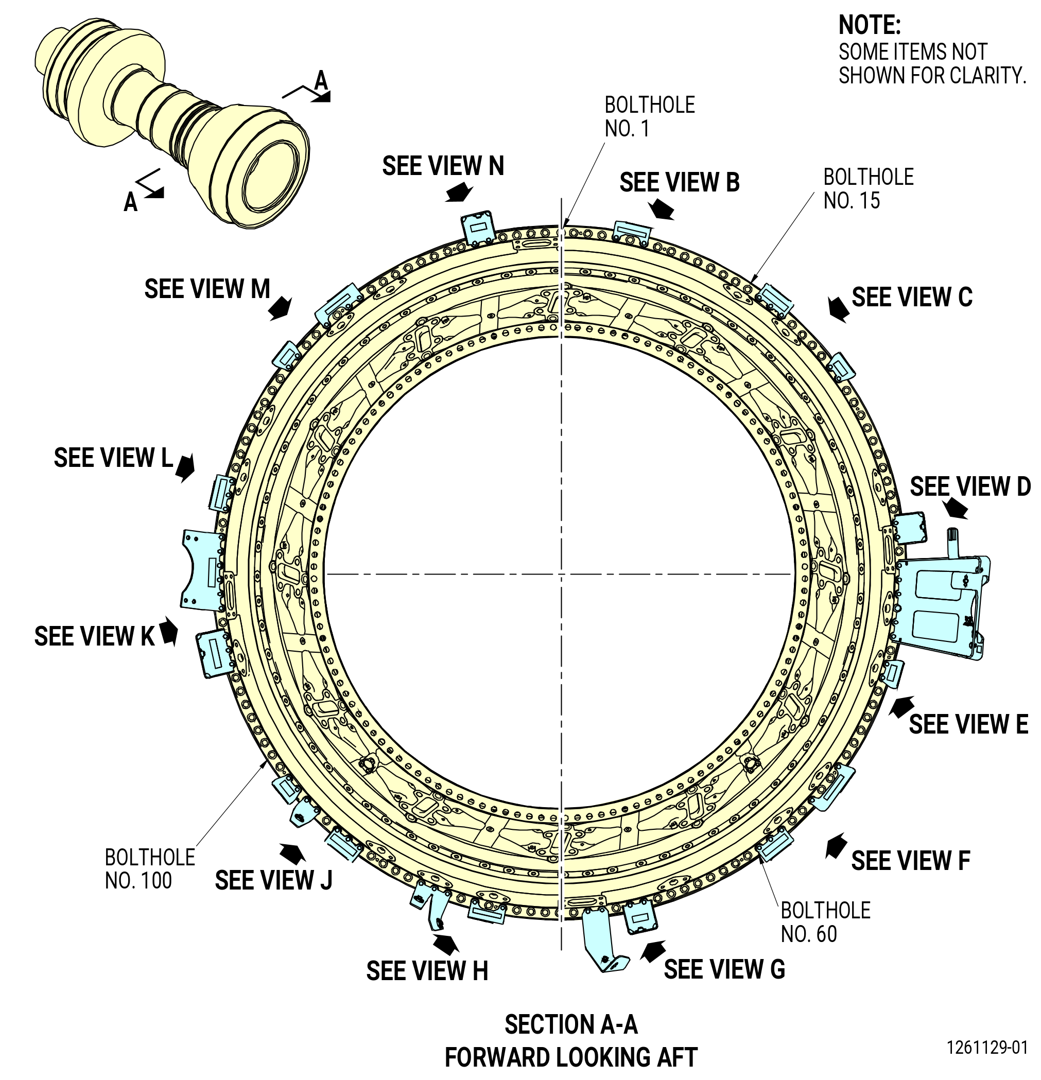
| (1) | Number the boltholes on the aft flange of the TCF assembly (35-009 , 72-00-02) (SIN 92500) or (35-010 , 72-00-02) (SIN 92500) or (35-011 , 72-00-02) (SIN 92500) or (35-012 , 72-00-02) (SIN 92500) or (35-015 , 72-00-02) (SIN 92500) from the 12:00 o'clock position, ALF. Use a C05-003 marking pen and number every 10 boltholes. Refer to Figure 415. |
| (2) | Install guide pins on the forward flange of the LPT module assembly at boltholes No. 25, 60, 95, and 134. |
| (3) | Install the studs (93520) on the forward flange of the LPT module assembly (ALF), except at boltholes No. 25, 60, 95, and 134 where the guide pins are installed. Tighten hand-tight until seated. |
| NOTE: |
|
| WARNING: |
|
| (4) | Deleted. |
| CAUTION: |
|
| NOTE: |
|
| NOTE: |
|
| (5) | Align the mid fan shaft assembly with the center of the 11C3282 guide fixture on the aft side of the TCF assembly. |
| (6) | Slowly push the LPT module assembly forward into the propulsor assembly. Monitor the space between the TCF assembly aft flange and the LPT module assembly forward flange. |
| (7) | When the space between the flanges is approximately 3 feet (914 mm), stop the LPT module assembly. |
| (8) | Remove the 11C3282 guide fixture as follows. Refer to Figure 407. |
| (a) | Remove the nuts (item 13), capscrews (item 11), and washers (item 12) that attach the guide arms (item 2) to the TCF assembly. |
| (b) | Remove the guide arms (item 2). |
| (c) | Make sure the weight of the LPT module assembly did not change more than plus or minus 50 lbs (22.7 kg). |
| (9) | Make sure that the mid fan shaft assembly is in the center of the No. 4 bearing stationary seal (15-060 , 72-54-00) (SIN 01407) as follows: |
| (a) | Use a 6.0 inch (152 mm) scale, and measure at four equally spaced locations, to make sure that the mid fan shaft assembly is in the center of the seal. All four measurements must be within 0.03125 inch (0.7938 mm) of each other. |
| (b) | If the measurements are not within the limits, adjust the LPT module assembly as necessary to put the mid fan shaft assembly in the center of the seal. |
| (10) | Slowly push the LPT module assembly forward into the propulsor assembly and monitor the space between the TCF assembly aft flange and the LPT forward flange. |
| (11) | When the distance between the flanges is approximately 6.50 inches (165.1 mm), do as follows: |
| (a) | Monitor the mid fan shaft assembly and the forward fan shaft (01-170 , 72-24-00) (SIN 81002) or (01-171 , 72-24-00) (SIN 81002) for a hard hit. |
| CAUTION: |
|
| (b) | If you feel a hard hit, slowly turn the forward fan shaft (01-170 , 72-24-00) (SIN 81002) or (01-171 , 72-24-00) (SIN 81002) to engage the splines. |
| (c) | Continue to install the LPT module assembly into the core module assembly. |
| Subtask 72-00-04-420-155 |
| (12) | Alternative Procedure Available. When the distance between the flanges is approximately 3.00 inches (76.2 mm), the bumpers (item 4) of the 9446M40 LPT alignment fixture will make contact with the LPT module assembly. Adjust as follows: |
| (a) | Measure the distance between the flanges around at the 12:00 and 6:00 o'clock positions. The difference must be within 0.100 in. (2.54 mm). |
| CAUTION: |
|
| (b) | If the difference is more than 0.100 in. (2.54), adjust the 9C1147 VCG lift fixture and do the inspection again. Make sure that the overhead hoist stays in the center above the shackle point of the 9C1147 VCG lift fixture. |
| (c) | Monitor the LPT module assembly for a change in weight. Make sure the weight of the LPT module assembly does not change by plus or minus 50 lbs (22.7 kg). |
| Subtask 72-00-04-420-156 |
| (12).A. | Alternative Procedure. When the distance between the flanges is approximately 3.00 inches (76.2 mm), the bumpers (item 4) of the 9446M40 LPT alignment fixture will make contact with the LPT module assembly. Adjust as follows: |
| (a) | Measure the distance between the flanges at the 12:00 and 6:00 o'clock positions. The difference must be within 0.100 in. (2.54 mm). |
| (b) | If the difference is more than 0.100 in. (2.54), adjust the center of gravity on the 9429M77 lift and turn fixture and do the inspection again. Make sure that the overhead hoist stays in the center above the shackle point of the 9429M77 lift and turn fixture. |
| (c) | Monitor the LPT module assembly for a change in weight. Make sure the weight of the LPT module assembly does not change by ±50 lb (23 kg). |
| Subtask 72-00-04-420-196 |
| (12).B. | Alternative Procedure. When the distance between the flanges is approximately 3.00 inches (76.2 mm), the bumpers (item 4) of the 9446M40 LPT alignment fixture will make contact with the LPT module assembly. Adjust as follows: |
| (a) | Measure the distance between the flanges at the 12:00 and 6:00 o'clock positions. The difference must be in 0.100 in. (2.54 mm). |
| (b) | If the difference is more than 0.100 in. (2.54), adjust the center of gravity on the 11C4858 lift and turn fixture and do the inspection again. Make sure that the overhead hoist stays in the center above the shackle point of the 11C4858 lift and turn fixture. |
| (c) | Monitor the LPT module assembly for a change in weight. Make sure the weight of the LPT module assembly does not change by ±50 lb (23 kg). |
| Subtask 72-00-04-420-157 |
| (13) | Remove the bumpers (item 4) of the 9446M40 LPT alignment fixture. |
| (14) | Remove the guide pins item (6) and install the studs (93520) at boltholes No. 25, 60, 95, and 134. Refer to Figure 415. |
| (15) | Continue to install the LPT module assembly into the core module assembly. |
| (16) | When you feel that the core module assembly and the LPT module assembly touch, do as follows: |
| (a) | Use a 6.00 inches (152.4 mm) scale and measure the distance between the flanges at the 3:00 o'clock and the 9:00 o'clock positions. Apply manual pressure to the core to make sure that the core module assembly and the LPT module assembly touch when you measure the distance. The distance between the flanges must not be more than 0.90 inch (22.9 mm). |
| (b) | If the difference between the two measurements is more than 0.90 inch (22.9 mm), do as follows: |
| 1 | Remove the LPT module assembly from the core module assembly. |
| Subtask 72-00-04-420-117 |
| (18) | Install the LPT module assembly into the core module assembly again. Refer to Subtask 72-00-04-420-116 (paragraph 3.F.(10) thru (16). |
| (19) | Make sure the LPT studs (93520) and the guide pins do not go in at angle in the TCF assembly aft flange boltholes. |
| Subtask 72-00-04-420-118 |
| G. | Alternative Procedure Available. Use this procedure when the fan booster assembly (20-010 , 72-00-02) (SIN 80000) or (20-011 , 72-00-02) (SIN 80000) has been installed to the fan hub module (25-010 , 72-00-02) (SIN 00102), or (25-011 , 72-00-02) (SIN 00102), or (25-012 , 72-00-02) (SIN 00102). Install the 11C5003 push/pull fixture to seat the LPT module assembly on the propulsor assembly and do as follows: |
| (1) | Remove the capscrew (item 4) of the 11C3283 extension fixture from the guide tip (item 3). Refer to Figure 412. |
| (2) | Remove the guide tip (item 3) from the extension tube (item 2). Use your hand and rotate the guide tip CCW to remove it from the extension tube (item 2). |
| (3) | Make sure that the extension tube (item 2) is fully seated to the mid fan shaft assembly. |
| (4) | Install the 11C5003 push/pull fixture to install the LPT module assembly. Refer to Figure 410 and do as follows: |
| (a) | Install the spacer (item 23) on the 10-ton cylinder adapter (item 2) at two locations. |
| (b) | Thread the 10-ton cylinder adapter (item 2) onto the extension tube (item 2) of the 11C3283 extension fixture. |
| (c) | Install the 10-ton cylinder (item 12) of the 11C5003 push/pull fixture at two locations on the 10-ton cylinder adapter (item 2). |
| (5) | Connect the hydraulic hand pump to the 10-ton cylinder (item 12). |
| (6) | Before you apply hydraulic pressure, use a 6.00 inches (152.4 mm) scale and measure the distance between the flanges at the 3:00 o'clock and the 9:00 o'clock positions. Apply manual pressure to the core to make sure that the core module assembly and the LPT module assembly touch when you measure the distance. The distance between the flanges must not be more than 0.90 inch (22.9 mm). |
| WARNING: |
|
| CAUTION: |
|
| CAUTION: |
|
| (7) | Operate the hydraulic hand pump in 1000 psig (6895 kPa gage) increments until the distance between the TCF assembly aft flange and LPT forward flange is approximately 0.060-0.080 inch (1.52-2.03 mm). Do a manual examination of all of the LPT studs (35-020 , 72-00-02) (SIN 93520) to make sure that they continue to move freely as you pull the LPT module assembly into position. |
| NOTE: |
|
| (8) | When the distance between the aft flange of the TCF assembly and the forward flange of the LPT module assembly is approximately 0.060-0.080 inch (1.52-2.03 mm), unlock the three stop blocks (item 7) of the 11C3277 LPT restrain fixture installed on the TRF assembly. Refer to Figure 416 and do as follows: |
| (a) | Loosen each set of two capscrews (item 12). |
| (b) | Slide the stop blocks (item 7) radially outward to the unlock position. |
| (c) | Tighten each set of capscrews (item 12) on the washer (item 15). |
| (9) | Apply hydraulic pressure in 1000 psig (6895 kPa gage) increments until the LPT is fully seated against the TCF assembly aft flange. Do a manual examination of all the LPT studs (35-020 , 72-00-02) (SIN 93520) to make sure that they continue to move freely as you pull the LPT module assembly into position. |
| (10) | It will be necessary to use 2000-8000 psig (13790-55158 kPa gage) to fully seat the LPT against the TCF assembly aft flange. |
| Subtask 72-00-04-420-165 |
| G.A. | Alternative Procedure. Use this procedure when the fan booster assembly (20-010 , 72-00-02) (SIN 80000) or (20-011 , 72-00-02) (SIN 80000) has not been installed to the fan hub module (25-010 , 72-00-02) (SIN 00102), or (25-011 , 72-00-02) (SIN 00102), or (25-012 , 72-00-02) (SIN 00102). Install the 11C5013 installation/removal fixture to seat the LPT module assembly on the propulsor assembly as follows: |
| (1) | Remove the capscrew (item 4) of the 11C4272 extension fixture from the guide tip (item 3). Refer to Figure 413. |
| (2) | Remove the guide tip (item 3) from the extension tube (item 2). |
| (3) | Manually turn the guide tip (item 3) CCW to remove it from the extension tube (item 2). |
| (4) | Make sure that the extension tube (item 2) is fully seated to the mid fan shaft assembly. |
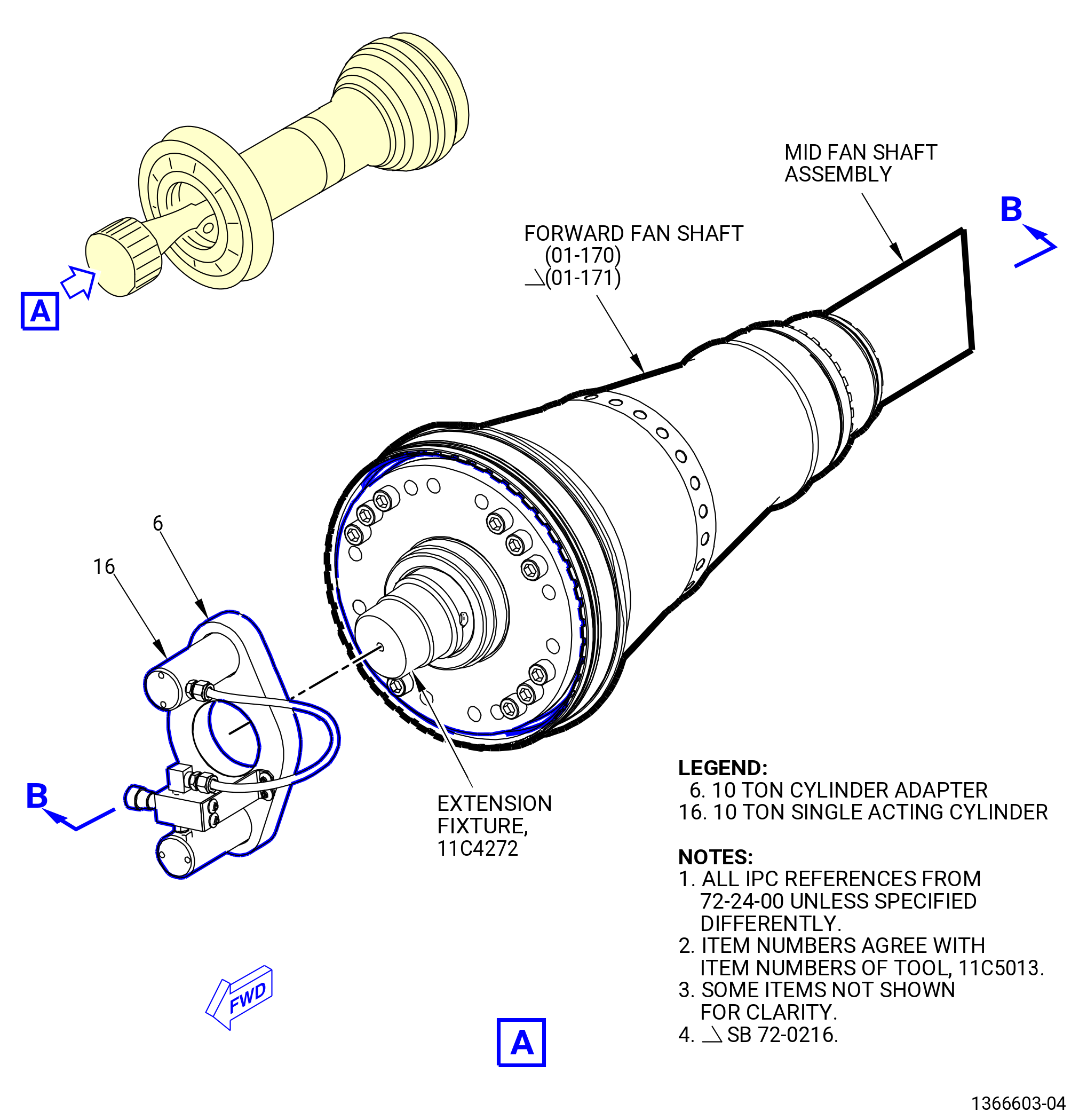
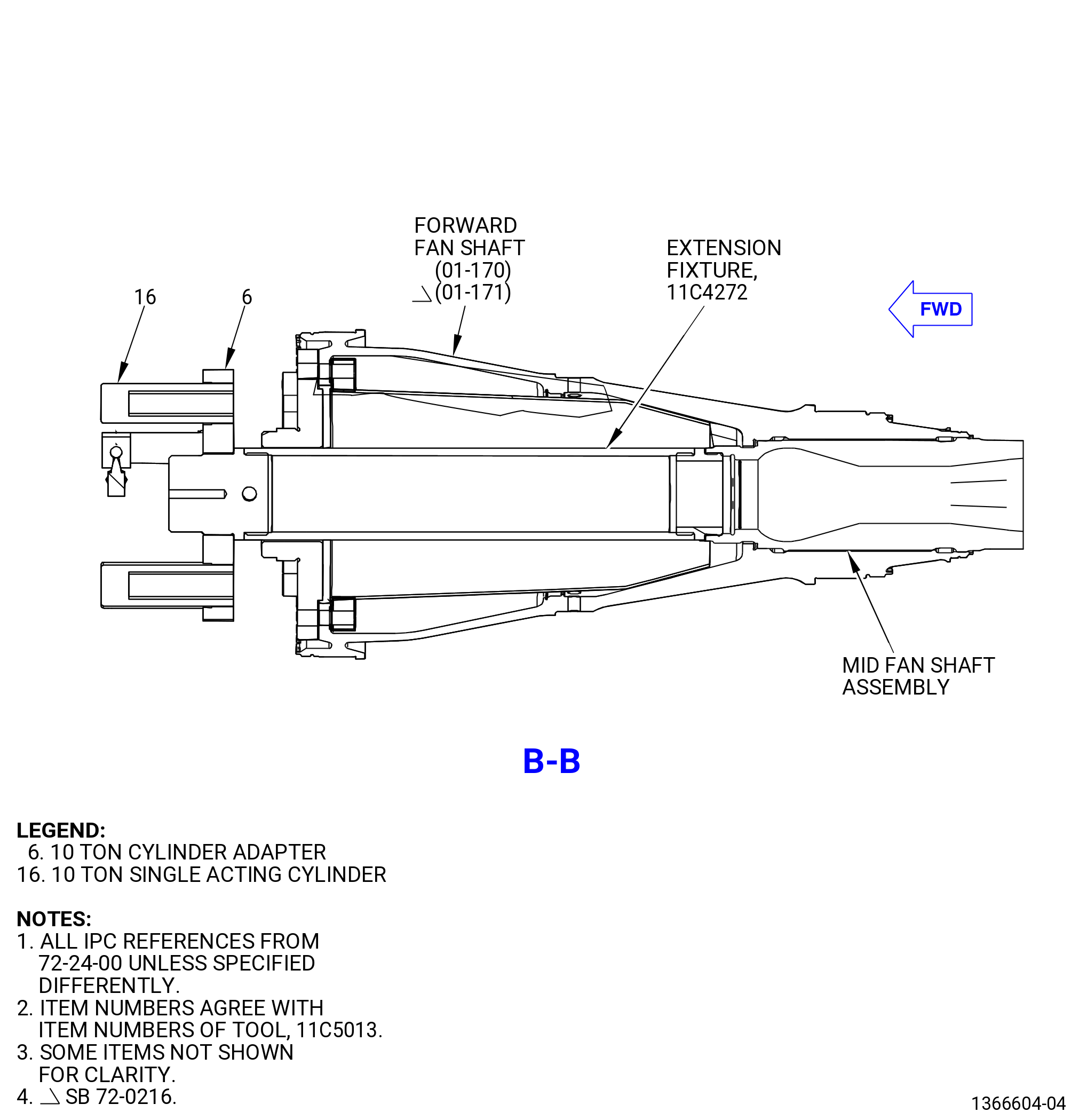
| (5) | Install the 11C5013 installation/removal fixture to install the LPT module assembly as follows. Refer to Figure 417. |
| (a) | Two people should manually thread the 10 ton cylinder adapter (item 6) and the 10 ton single acting cylinder (item 16) assembly to the forward end of the 11C4272 extension fixture. |
| (b) | Make sure that the 11C4272 extension fixture is fully locked and seated to the mid fan shaft assembly. |
| (c) | Make sure that the 10 ton cylinder adapter (item 6) is fully engaged to the 11C4272 extension fixture. |
| (6) | Connect the hydraulic hand pump to the 10 ton single acting cylinder (item 16). |
| (7) | Before applying hydraulic pressure, use a 6.00 inches (152.4 mm) scale and measure the distance between the flanges at the 3:00 o'clock and the 9:00 o'clock positions. |
| (8) | Apply manual pressure to the core to make sure that the core module assembly and the LPT module assembly touch when measuring the distance. The distance between the flanges must not be more than 0.90 inch (22.9 mm). |
| WARNING: |
|
| CAUTION: |
|
| CAUTION: |
|
| (9) | Operate the hydraulic hand pump in 1000 psig (6895 kPa gage) increments until the distance between the TCF assembly aft flange and LPT forward flange is approximately 0.060-0.080 inch (1.52-2.03 mm). |
| (10) | Do a manual examination of all of the LPT studs (93520) to make sure that they continue to move freely as pulling the LPT module assembly into position. |
| NOTE: |
|
| (11) | When the distance between the aft flange of the TCF assembly and the forward flange of the LPT module assembly is approximately 0.060-0.080 inch (1.52-2.03 mm), unlock the three stop blocks (item 7) of the 11C3277 LPT restrain fixture installed on the TRF assembly. Refer to Figure 416 and do as follows: |
| (a) | Loosen each set of two capscrews (item 12). |
| (b) | Move the stop blocks (item 7) radially outward to the unlock position. |
| (c) | Tighten each set of capscrews (item 12) on the washer (item 15). |
| (12) | Apply hydraulic pressure in 1000 psig (6895 kPa gage) increments until the LPT is fully seated against the TCF assembly aft flange. |
| (13) | Do a manual examination of all the LPT studs (93520) to make sure that they continue to move freely as pulling the LPT module assembly into position. |
| (14) | Apply 2000-8000 psig (13790-55158 kPa gage) to fully install the LPT against the TCF assembly aft flange. |
| Subtask 72-00-04-420-119 |
| H. | Attach the forward flange of the LPT module assembly to the aft flange of the TCF assembly (35-009 , 72-00-02) (SIN 92500) or (35-010 , 72-00-02) (SIN 92500) or (35-011 , 72-00-02) (SIN 92500) or (35-012 , 72-00-02) (SIN 92500) or (35-015 , 72-00-02) (SIN 92500) as follows: |
| (1) | Install the LPT lockplates (93580, 93581) on the LPT studs (93520) as follows. Refer to Figure 415. |
| WARNING: |
|
| CAUTION: |
|
| (a) | If not previously done, apply C02-058 graphite to the threads of the studs (93520). |
| NOTE: |
|
| (b) | Put the LPT lockplate (93581) on the two studs that span the No. 1 and 150 boltholes. Attach the lockplate with two nuts (93541) and two spacers (93571). |
| (c) | Put the lockplates (93580) on two studs (93520) on the forward side of the TCF and LPT module assembly flange. Example: Put a lockplate on the studs at boltholes No. 2 and 3, 4 and 5, and continue on to 148 and 149. |
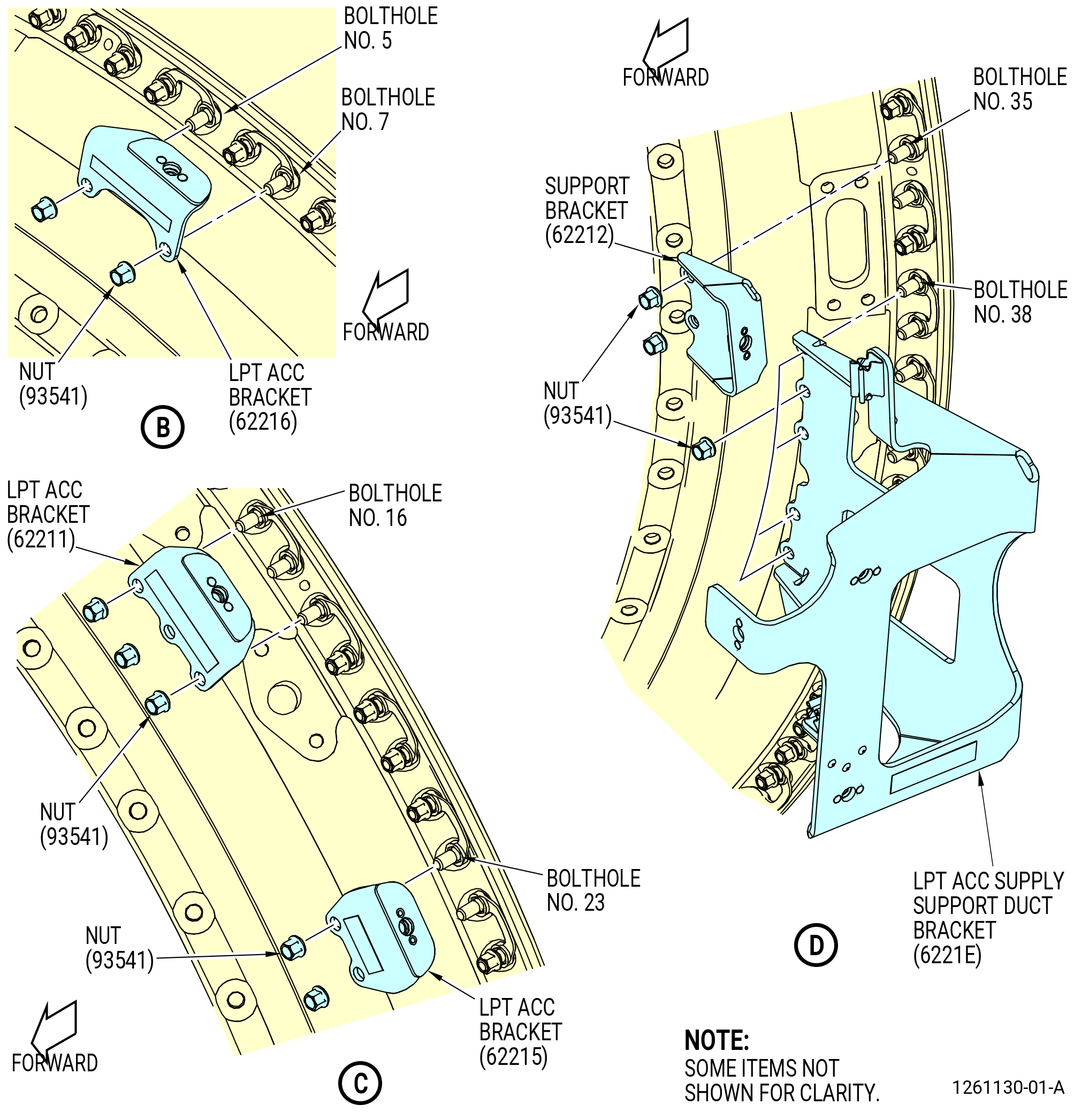
| (2) | Install the brackets on the TCF and the LPT module assembly flange as follows. Refer to Figure 418. |
| (a) | Install the support bracket (62212), tab pointing forward, at boltholes No. 35 and 36, with nuts (93541). |
| (b) | Install the LPT ACC supply support duct bracket (6221E), tab pointing forward, at boltholes No. 38-40, 42, and 43, with nuts (93541). |
| (c) | Install the support bracket (35-200 , 72-00-02) (SIN 48910) or (35-211 , 72-00-02) (SIN 48910), tab pointing forward, at boltholes No. 73 and 74, with nuts (35-030 , 72-00-02) (SIN 93541). |
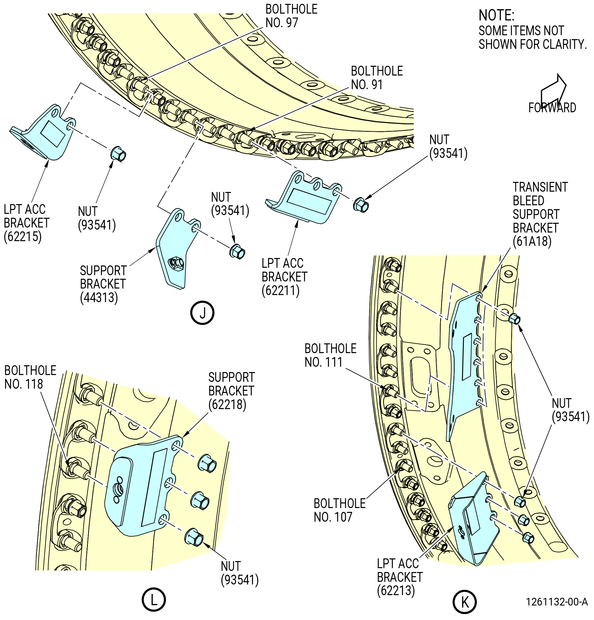
| (d) | Install the transient bleed support bracket (61A18), tab facing forward, at bolthole locations No. 111-116, with nuts (93541). |
| (3) | Install the nuts (93541) and the spacers (93571) on the studs (93520) at the non-bracket bolthole locations 2-4, 6, 8-15, 19-22, 25-34, 37, 41, 44, 47-52, 54, 55, 57, 58, 62-69, 72, 75-79, 81, 83, 87-90, 94, 99-106, 110, 117, 121-128, 131-132, 134, 137-144, 147-149. Tighten the nuts finger tight. |
| (4) | Torque the nuts (93541) in the following sequence: |
| (a) | Torque 15 nuts (93541) at bolthole locations No. 1, 11, 21, 31, 41, 51, 62, 72, 81, 94, 101, 110, 121, 131, and 141 in a criss-cross pattern to 80-95 lb in. (9.0-10.7 N.m) to pull the TCF and LPT flanges together. |
| (b) | Torque the nuts (93541) in a criss-cross pattern to 106-124 lb in. (12.0-14.0 N.m). |
| (5) | Release the hydraulic pressure applied to the 10 ton cylinder. Refer to Figure 410. |
| Subtask 72-00-04-420-166 |
| (6) | Alternative Procedure Available. Remove the 11C3283 extension fixture and 11C5003 push/pull fixture from the mid fan shaft assembly. Refer to Figure 412 and do as follows: |
| CAUTION: |
|
| (a) | Manually turn the extension tube (item 2) of the 11C3283 extension fixture CCW and remove it from the mid fan shaft assembly. Pull it forward, away from the engine. |
| (b) | Install the guide tip (item 3) on the front of the extension tube (item 2) and secure with the capscrew (item 4). |
| (c) | Remove the 11C5003 push/pull fixture from the 11C3327 LPT mid-shaft guide fixture. Refer to Figure 410. |
| (d) | Remove the 11C3277 LPT restrain fixture from the TRF. |
| Subtask 72-00-04-420-167 |
| (6).A. | Alternative Procedure. Remove the 11C4272 extension fixture and the 11C5013 installation/removal fixture from the mid fan shaft assembly. Refer to Figure 417 and do as follows: |
| CAUTION: |
|
| (a) | Remove the cylinder adapter (item 6) of the 11C5013 installation/removal fixture. |
| (b) | Manually turn the extension tube (item 2) of the 11C4272 extension fixture CCW and remove it from the mid fan shaft assembly. Pull it forward, away from the engine. |
| (c) | Install the guide tip (item 3) on the front of the extension tube (item 2) and secure with the capscrew (item 4). |
| (d) | Remove the 11C3277 LPT restrain fixture from the TRF as follows: |
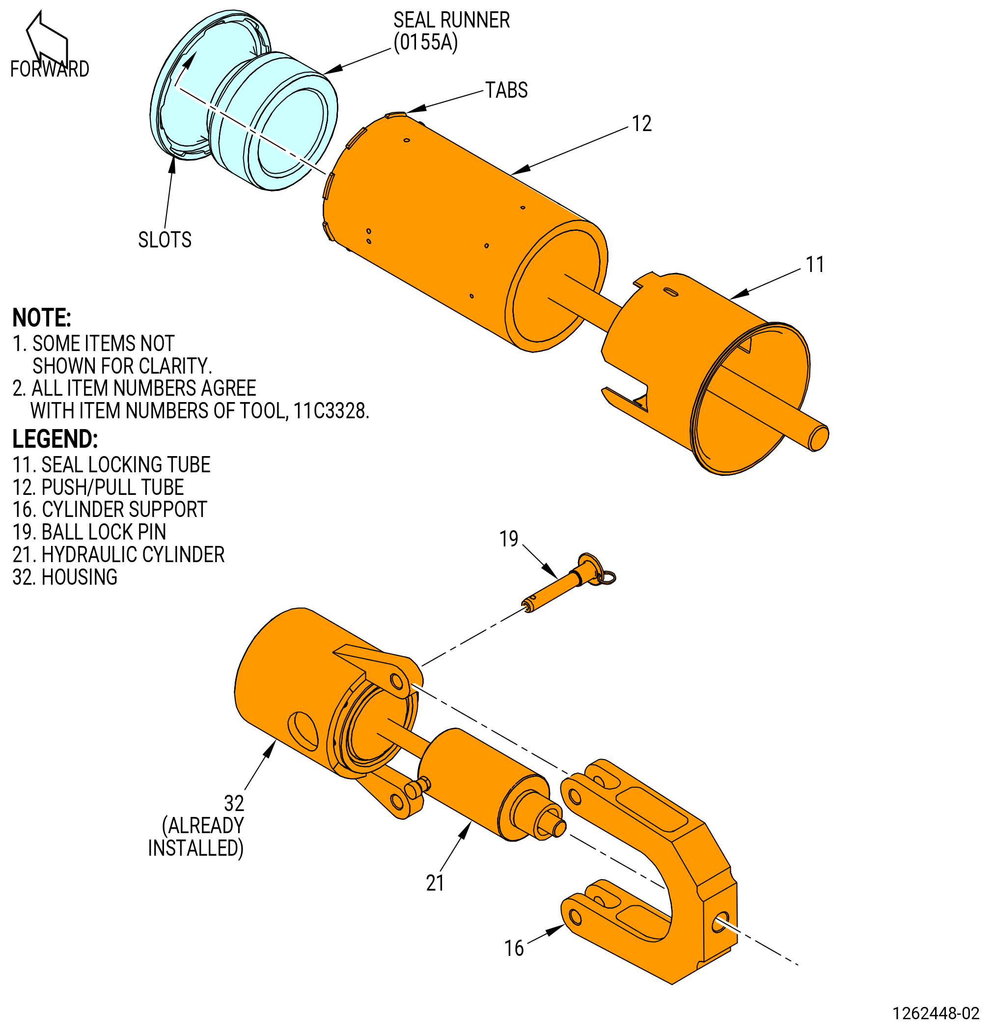
| 1 | Disengage the pilot tube (item 17) from the nut housing (item 19). |
| 2 | Remove the pilot tube (item 17) from the restrain fixture assembly (item 2). |
| 3 | Remove restrain fixture assembly (item 2). |
| 4 | Remove the nut housing (item 19) from the LPT module assembly. |
| Subtask 72-00-04-420-122 |
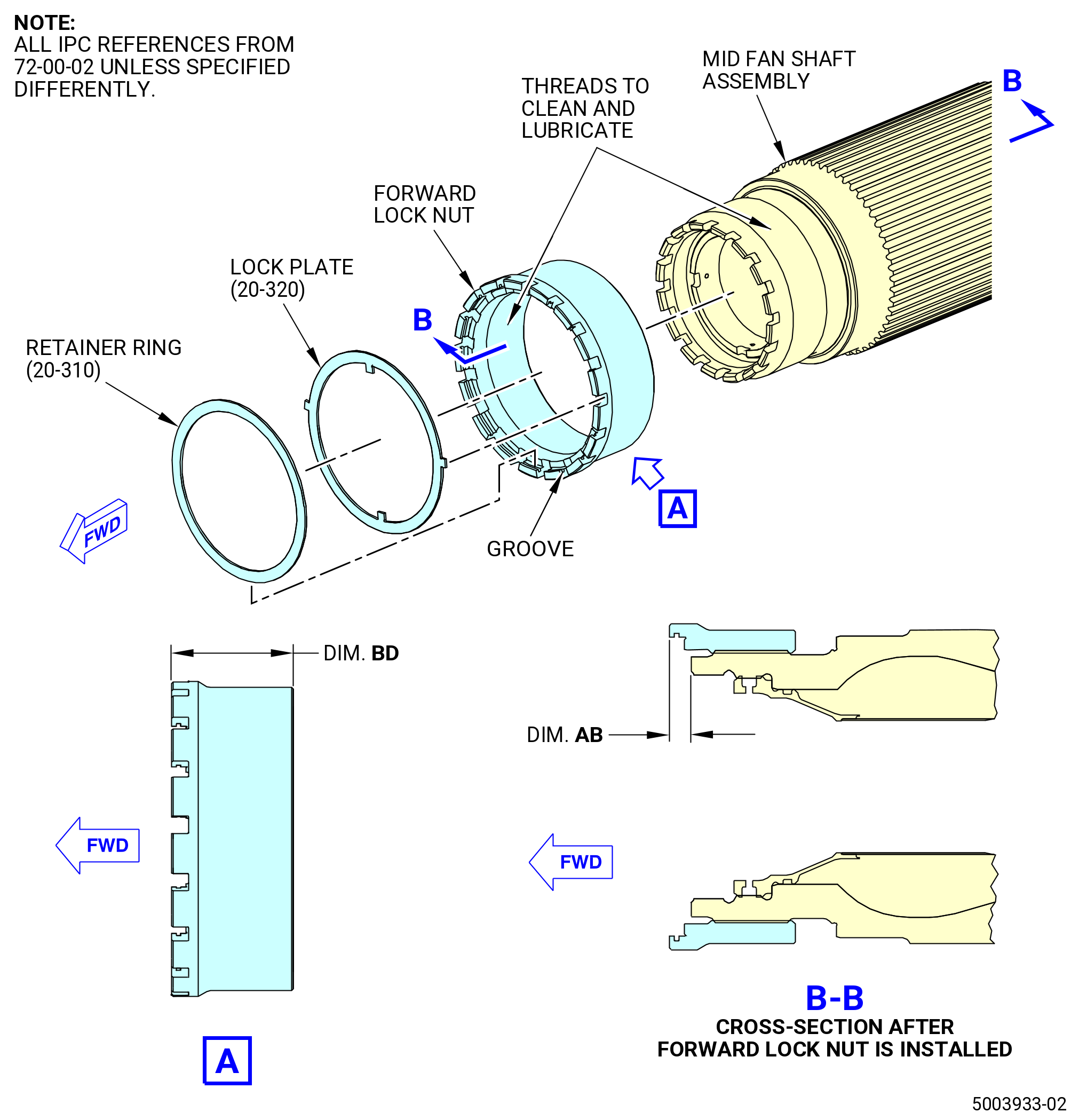
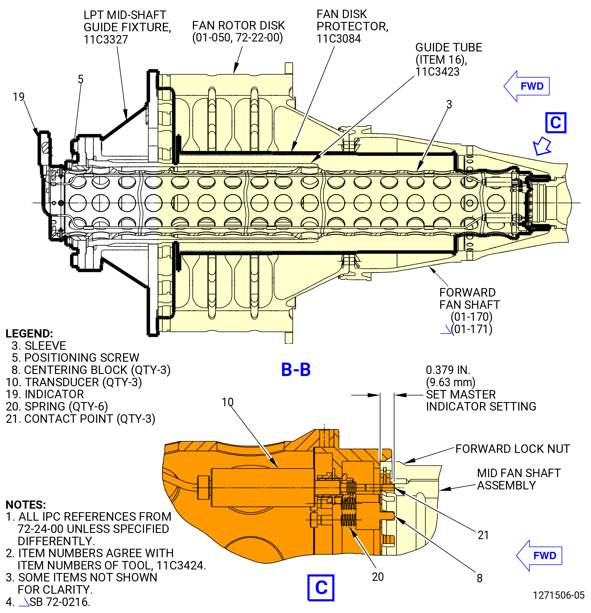
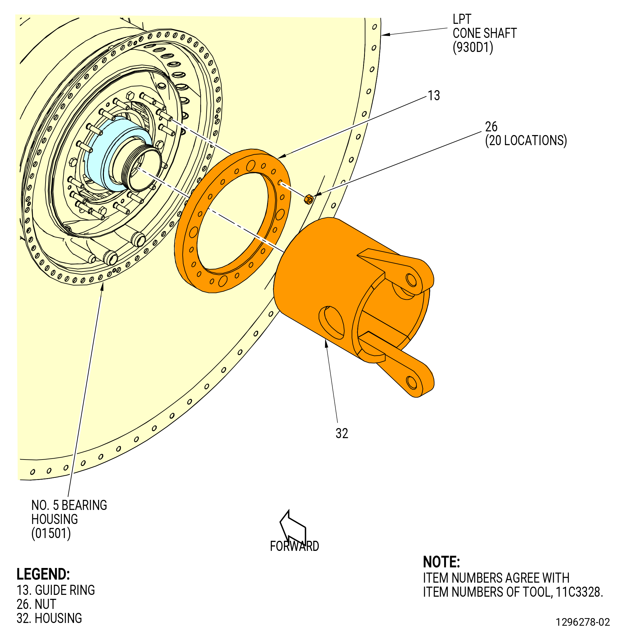
| I. | Install the forward lock nut onto the mid fan shaft assembly. Refer to Figure 419 and do as follows: |
| Subtask 72-00-04-420-174 |
| * * * SB 72-0114( Mid Fan Shaft with Molydag Lubricant Dry Film and Engine Oil Lubricant Assembly ) |
| (1) | Clean the mating surfaces of the mid fan shaft assembly (45-010A , 72-00-02) (SIN 81000) or (45-011A , 72-00-02) (SIN 81000) and the forward lock nut (20-330A , 72-00-02) (SIN 83006) or (20-331 , 72-00-02) (SIN 83006) as follows: |
| WARNING: |
|
| (a) | Use C04-003 acetone to clean the forward lock nut. |
| (b) | Use C04-003 acetone to clean the threads of the mid fan shaft assembly. |
| * * * END SB 72-0114 |
| Subtask 72-00-04-160-007 |
| * * * SB 72-0425( Introduction of New Forward Fan Shaft with Metallic Shim ) |
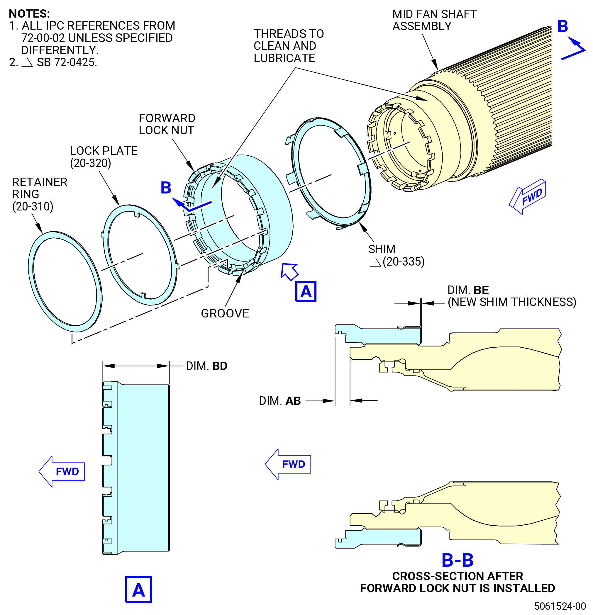
| (2) | Clean the shim (20-335 , 72-00-02) (SIN 81072) as follows: |
| WARNING: |
|
| (a) | Use C04-003 acetone to clean the shim. |
| * * * END SB 72-0425 |
| Subtask 72-00-04-420-175 |
| (3) | Measure dimension BD for the forward lock nut as follows: |
| (a) | Use a micrometer and measure the distance from the tops of the castellations of the nut to the aft face. |
| (b) | Measure Dimension BD at four equally-spaced locations. Record of the average Dimension BD. |
| Subtask 72-00-04-420-180 |
| * * * SB 72-0425( Introduction of New Forward Fan Shaft with Metallic Shim ) |
| (4) | Measure the dimension BE for the shim (20-335 , 72-00-02) (SIN 81072) as follows: |
| (a) | Use a micrometer and measure the thickness of the shim. |
| (b) | Measure the dimension BE at four equally-spaced locations. Record the average of dimension BE. |
| * * * END SB 72-0425 |
| Subtask 72-00-04-640-016 |
| (5) | Deleted. |
| Subtask 72-00-04-640-030 |
| * * * SB 72-0114( Mid Fan Shaft with Molydag Lubricant Dry Film and Engine Oil Lubricant Assembly ) |
| WARNING: |
|
| CAUTION: |
|
| (6) | Lubricate the threads of the mid fan shaft assembly (45-010A , 72-00-02) (SIN 81000) or (45-011A , 72-00-02) (SIN 81000) and the threads and aft face of the forward lock nut (20-330A , 72-00-02) (SIN 83006) or (20-331 , 72-00-02) (SIN 83006) with C02-019 engine oil or C02-023 engine oil. |
| * * * END SB 72-0114 |
| Subtask 72-00-04-420-181 |
| * * * SB 72-0425( Introduction of New Forward Fan Shaft with Metallic Shim ) |
| (7) | Put the shim (20-335 , 72-00-02) (SIN 81072) on the forward lock nut. |
| * * * END SB 72-0425 |
|
| Subtask 72-00-04-420-123 |
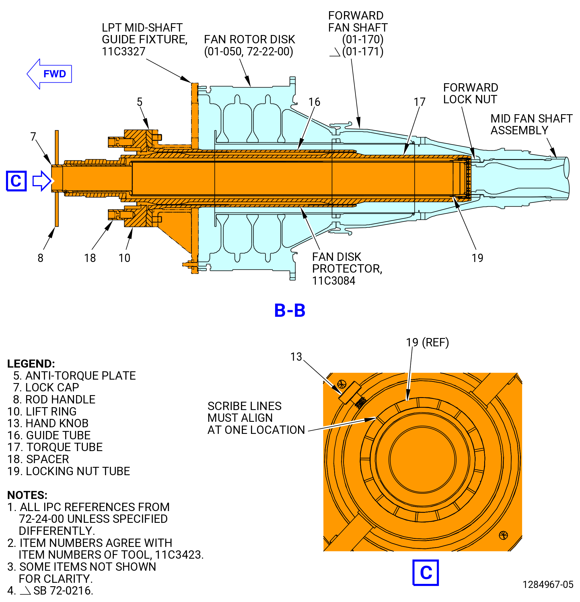
| (8) | Alternative Procedure Available. Use this procedure when the fan booster assembly (20-010 , 72-00-02) (SIN 80000) or (20-011 , 72-00-02) (SIN 80000) has been installed to the fan hub module (25-010 , 72-00-02) (SIN 00102), or (25-011 , 72-00-02) (SIN 00102), or (25-012 , 72-00-02) (SIN 00102). Install the 11C3423 coupling nut torque fixture. Refer to Figure 420 and do as follows: |
| Subtask 72-00-04-160-006 |
| * * * SB 72-0114( Mid Fan Shaft with Molydag Lubricant Dry Film and Engine Oil Lubricant Assembly ) |
| (a) | Clean the 11C3423 coupling nut torque fixture before the installation of the forward lock nut (20-330A , 72-00-02) (SIN 83006) or (20-331 , 72-00-02) (SIN 83006) as follows: |
| WARNING: |
|
| CAUTION: |
|
| 1 | Clean all graphite grease from the 11C3423 coupling nut torque fixture with a C10-182 cleaning cloth moist with C02-019 engine oil or C02-023 engine oil. |
| 2 | Continue the cleaning to remove all residual graphite grease from the 11C3423 coupling nut torque fixture with a C10-182 cleaning cloth moist with C04-003 acetone. |
| 3 | Do a close visual inspection to make sure that the cleaning removed all the graphite grease to prevent contamination. |
| NOTE: |
|
| * * * END SB 72-0114 |
| Subtask 72-00-04-420-172 |
| (b) | Put the guide tube (item 16) into the 11C3327 LPT mid-shaft guide fixture and secure with capscrews (item 14) of the 11C3423 coupling nut torque fixture at the 2:30 and 9:30 o'clock positions. |
| (c) | Put the anti-torque plate (item 5) onto the guide tube (item 16) at the 2:30 and 9:30 o'clock positions. |
| (d) | Secure the anti-torque plate (item 5) with the capscrews (item 14) at seven locations. |
| (e) | Set the torque tube (item 17) and the locking nut tube in a horizontal position. |
| (f) | Install the lift ring (item 10) onto the torque tube (item 17) and tighten the setscrews (item 11) into the slot of the torque tube. |
| (g) | Install the rod handles (item 8) onto the lock cap (item 7). |
| (h) | Put the lock cap (item 7) onto the locking nut tube (item 19). |
| Subtask 72-00-04-420-183 |
| * * * PRE SB 72-0425 |
| (i) | Install the forward lock nut into the torque tube (item 17). |
| * * * END PRE SB 72-0425 |
| Subtask 72-00-04-420-184 |
| * * * SB 72-0425( Introduction of New Forward Fan Shaft with Metallic Shim ) |
| (i).A. | Install the forward lock nut with the shim (20-335 , 72-00-02) (SIN 81072) on it, into the torque tube (item 17). |
| * * * END SB 72-0425 |
| Subtask 72-00-04-420-185 |
| (j) | Hold the torque tube (item 17) and rotate the lock cap (item 7) and the locking nut tube (item 19), in relation to the torque tube (item 17), to the locked position. |
| (k) | Make sure the plungers (items 13) lock into position in the torque tube (item 17). |
| (l) | Remove the two handles (item 8) from the lock cap. |
| WARNING: |
|
| CAUTION: |
|
| (m) | Lift the torque tube assemblies that contain items 17, 19, 7, and 10. Use the 9429M59 breach loader. Refer to Figure 409. |
| (n) | Insert the torque tube assemblies into the anti torque plate (item 5) and push aft. |
| (o) | Remove the 9429M59 breach loader. |
| (p) | Install the rod handles (item 8) onto the lock cap (item 7). |
| Subtask 72-00-04-420-186 |
| * * * PRE SB 72-0425 |
| CAUTION: |
|
| (q) | Turn the torque tube assemblies CW to thread the forward lock nut onto the mid fan shaft assembly. Refer to Figure 419. |
| * * * END PRE SB 72-0425 |
| Subtask 72-00-04-420-187 |
| * * * SB 72-0425( Introduction of New Forward Fan Shaft with Metallic Shim ) |
| CAUTION: |
|
| (q).A. | Turn the torque tube assemblies CW to thread the forward lock nut with the shim (20-335 , 72-00-02) (SIN 81072) on it, onto the mid fan shaft assembly. Refer to Figure 419. |
| * * * END SB 72-0425 |
| Subtask 72-00-04-420-182 |
| (r) | Make sure that the locking nut tube (item 19) of the 11C3423 coupling nut torque fixture turns freely. |
| (s) | Deleted. |
| (t) | Turn the lock cap handles (item 8) to finish threading on the coupling nut. |
| (u) | Retract the three plungers (item 13) to remove the lock cap (item 7). |
| (v) | Remove the lift ring (item 10). |
| (w) | Attach a hoist to the 8200torque multiplier and lift the torque multiplier. |
| (x) | Align the 8200torque multiplier with the torque tube (item 17) and engage the splines on the lift ring (item 10). |
| (y) | Turn the 8200torque multiplier slightly to find the pins of the torque multiplier with the forward end of the anti-torque plate (item 5). |
| Subtask 72-00-04-420-168 |
| (8).G. | Alternative Procedure. Use this procedure when the fan booster assembly (20-010 , 72-00-02) (SIN 80000) or (20-011 , 72-00-02) (SIN 80000) has not been installed to the fan hub module (25-010 , 72-00-02) (SIN 00102), or (25-011 , 72-00-02) (SIN 00102), or (25-012 , 72-00-02) (SIN 00102). Install the 11C5013 installation/removal fixture. Refer to Figure 421 and do as follows: |
| (a) | Remove the 22 capscrews (item 32) from the adapter guide (item 5). |
| (b) | Remove adapter guide (item 5) from the nut plates (item 3 and item 4). |
| WARNING: |
|
| (c) | Use a hoist and applicable nylon strap to install the guide adapter (item 2) of the 11C5013 installation/removal fixture on the forward side of the forward fan shaft (01-170 , 72-24-00) (SIN 81002) or (01-171 , 72-24-00) (SIN 81002) forward flange with 18 capscrews (item 32). |
| (d) | Torque the capscrews (item 32) to 100 ft lb. (140 Nm). |
| Subtask 72-00-04-420-188 |
| * * * PRE SB 72-0425 |
| (e) | Install the forward lock nut in the coupling nut wrench (item 10). |
| * * * END PRE SB 72-0425 |
| Subtask 72-00-04-420-189 |
| * * * SB 72-0425( Introduction of New Forward Fan Shaft with Metallic Shim ) |
| (e).A. | Install the forward lock nut with a shim (20-335 , 72-00-02) (SIN 81072) on it, in the coupling nut wrench (item 10). |
| * * * END SB 72-0425 |
| Subtask 72-00-04-420-190 |
| WARNING: |
|
| (f) | Use lift assistance and a two-legged sling to install the coupling nut wrench (item 10) into the guide adapter (item 2). |
| Subtask 72-00-04-420-191 |
| * * * PRE SB 72-0425 |
| CAUTION: |
|
| (g) | Turn the torque tube assemblies CW to turn the forward lock nut on the mid fan shaft assembly. |
| * * * END PRE SB 72-0425 |
| Subtask 72-00-04-420-192 |
| * * * SB 72-0425( Introduction of New Forward Fan Shaft with Metallic Shim ) |
| CAUTION: |
|
| (g).A. | Turn the torque tube assemblies CW to turn the forward lock nut with the shim (20-335 , 72-00-02) (SIN 81072) on it, on the mid fan shaft assembly. |
| * * * END SB 72-0425 |
| Subtask 72-00-04-420-193 |
| (h) | Unthread the lock bolts (item 15) from the adapter (item 2) while keeping them in place. |
| (i) | Attach a hoist to the torque multiplier and lift the torque multiplier. |
| (j) | Align the torque multiplier with the coupling nut wrench (item 10) and engage the splines on the coupling nut wrench (item 10). |
| (k) | Align and insert the reaction pins of the torque multiplier with the holes in adapter (item 2). |
| (l) | Attach firmly the reaction pins of the torque multiplier by tightening the locking bolts (item 15). |
| Subtask 72-00-04-420-124 |
| * * * SB 72-0114( Mid Fan Shaft with Molydag Lubricant Dry Film and Engine Oil Lubricant Assembly ) |
| (9) | Apply an initial torque of 1100 to 1260 lb ft (1491 to 1708 Nm) to the forward lock nut (20-330A , 72-00-02) (SIN 83006) or (20-331 , 72-00-02) (SIN 83006). |
| (10) | Do the final torque of the forward lock nut as follows: |
| CAUTION: |
|
| (a) | Torque the forward lock nut another 20 degrees past the initial torque. |
| (b) | Deleted. |
| NOTE: |
|
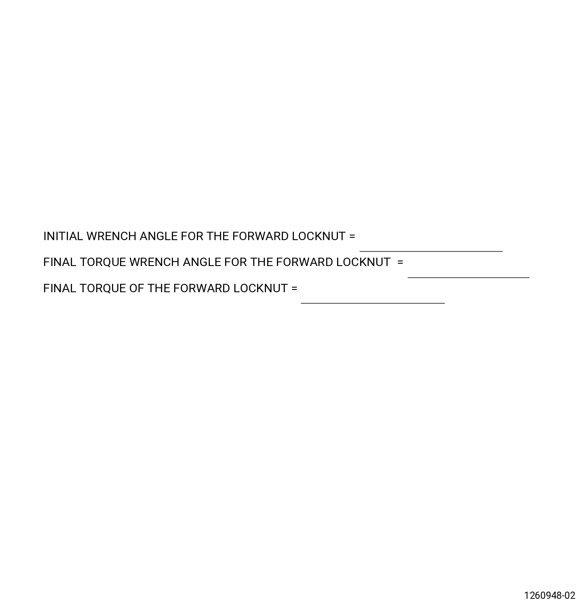
| (c) | Record the final torque value. Refer to Figure 422. |
| (d) | Record the final angle. |
| * * * END SB 72-0114 |
| Subtask 72-00-04-420-173 |
| WARNING: |
|
| (11) | Remove the 8200torque multiplier. |
| (12) | Attach the lift ring (item 10) to the torque tube (item 17) and tighten the setscrews (item 11). |
| Subtask 72-00-04-420-169 |
| (13) | Alternative Procedure Available. Remove the 11C3423 coupling nut torque fixture from the 11C3327 LPT mid-shaft guide fixture with the 9429M59 breach loader. Do not remove the tube guide (item 16) of the 11C3423 coupling nut torque fixture. |
| Subtask 72-00-04-420-170 |
| (13).A. | Alternative Procedure. Remove the coupling nut wrench (item 10) and the 11C5013 installation/removal fixture. |
| WARNING: |
|
| (a) | Use lift assistance and a two-legged sling to remove the coupling nut wrench from the 11C5013 installation/removal fixture. |
| (b) | Remove the 18 capscrews (item 32) that hold the adapter (item 2) to the nut plates. |
| (c) | Use lift assistance and a nylon sling to remove the adapter (item 2). |
| (d) | Remove the 4 capscrews (item 26) that hold the nut plates (item 3 and item 4) to the forward fan shaft. |
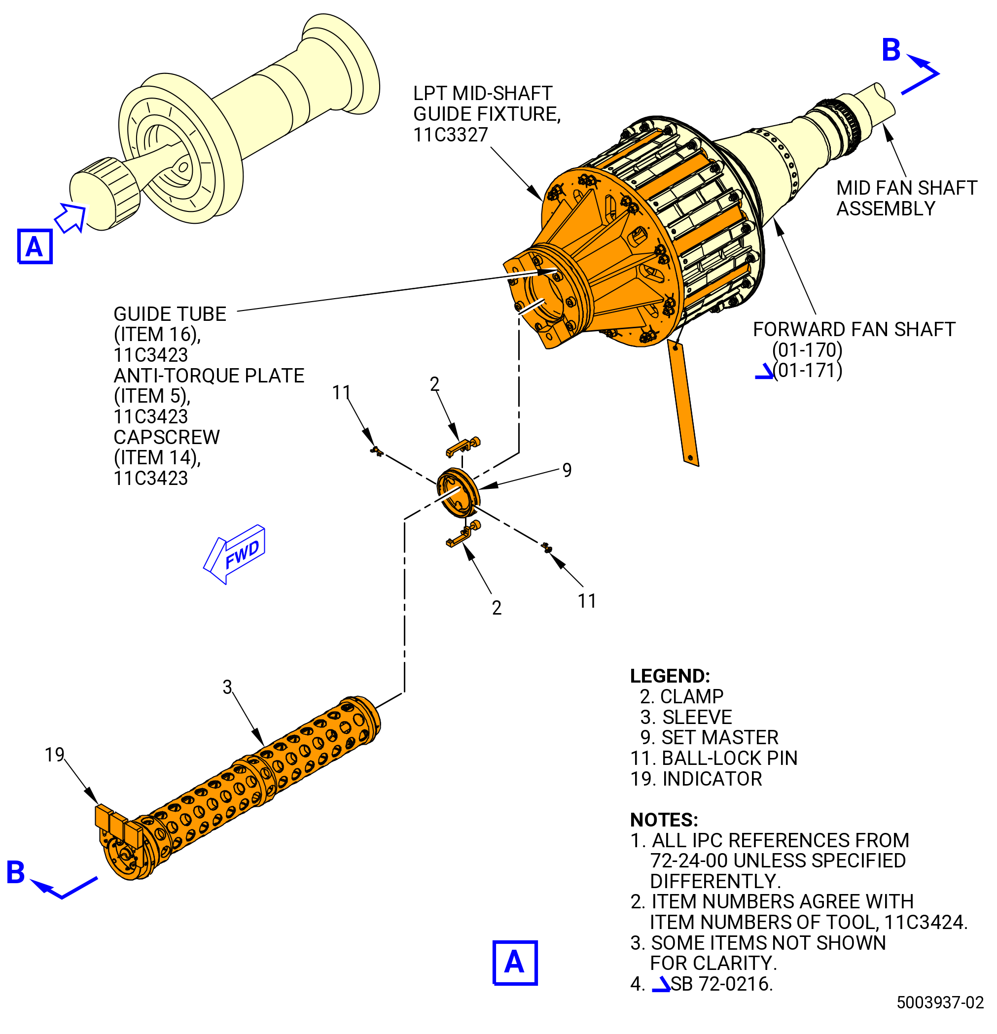
| Subtask 72-00-04-220-027 |
| (14) | Measure the mid fan shaft assembly distance to the forward lock nut. Refer to Figure 423 and do as follows: |
| (a) | Install the 11C3424 mid fan shaft gage in the tube guide (item 16) of the 11C3423 coupling nut torque fixture installed in the 11C3327 LPT mid-shaft guide fixture as follows: |
| 1 | Remove the ball lock pins (item 11) and the clamps (item 2) to separate the set master (item 9) from the aft end of the tool. |
| 2 | Verify the transducers (item 10) and the indicators (item 19) are functioning properly by turning the power on and pushing the tips through their range. |
| NOTE: |
|
| 3 | Zero the indicators by setting the gage into the set master (item 9) and aligning the centering block (item 8) with the hole in the bottom of the set master. The pins at 6:00 and 12:00 o'clock position must be in place. The clamps at the 3:00 and 9:00 o'clock position must be fully secured. |
| 4 | Zero the indicators while supporting the gage. The centerline of the gage should be vertical for an accurate setpoint. |
| 5 | Align the centering blocks (item 8) with the holes in the set master (item 9). |
| WARNING: |
|
| 6 | Use C04-035 isopropyl alcohol and clean the set master (item 9) aft surface where it will contact the forward lock nut. |
| 7 | Lift the sleeve (item 3) and put the aft end into the guide tube (item 16) of the 11C3423 coupling nut torque fixture. |
| CAUTION: |
|
| 8 | Slowly slide the sleeve (item 3) of the 11C3424 mid fan shaft gage aft. The diametrical clearance between the insert and the sleeve (item 3) decreases at the forward and aft ends of the insert to provide alignment and support. Extreme care must be taken not to force the tool. When a resistance is detected, stop sliding the sleeve aft. |
| 9 | The centering block (item 8) should be contacting the shaft. The spring force of the springs (item 20) behind the blocks should be detectable. Move the gage in and out about a tenth of an inch to get the feel of the springs. |
| 10 | Gently rotate the gage while applying light pressure so that the centering block will engage one of the slots of the shaft. A rotational resistance will be felt when the centering block (item 8) enters a slot. There is a slot every 22.5 degrees and you can rotate the gage in either direction. |
| 11 | Check a second time to ensure the alignment tab is engaged into a slot. The indicator points will read closer to zero when they are engaged into the slots if the gage is forward enough. |
| NOTE: |
|
| 12 | Engage the positioning screw (item 5) into the threads of the sleeve (item 3) of the 11C3424 mid fan shaft gage and tighten by hand. |
| (b) | Record the indications of the tranducers (item 10) as ABFINAL1, ABFINAL2, and ABFINAL3. The indicator (item 19) will give the dimension to the forward lock nut from the end of the mid fan shaft assembly. |
| NOTE: |
|
| (c) | Calculate the average of the readings and record as ABAVG. Refer to Figure 419. |
| (15) | Calculate for ABFINAL. If there is an error in the ABFINAL calculation, it may be necessary to remove the LPT module assembly to determine the cause of the error. Contact local assembly engineer for a recommended course of action if the ABFINAL calculation is not within tolerance. |
| Subtask 72-00-04-420-125 |
| (16) | Remove the positioning screw (item 5) and pull the sleeve (item 3) forward. |
| (17) | Install the set master (item 9) on the forward end of the sleeve (item 3). |
| (18) | Install the ball-lock pins (item 11) and the clamps (item 2). |
| (19) | Remove the 11C3424 mid fan shaft gage from the fan rotor disk (830A0) with the 9429M59 breach loader. |
| (20) | Remove the guide tube (item 16) of the 11C3423 coupling nut torque fixture from the fan rotor disk (830A0). |
| (21) | Remove the 11C3084 fan disk protector from the fan rotor disk (830A0). |
| (22) | Remove the 11C3327 LPT mid-shaft guide fixture from the fan rotor disk (830A0). |
| Subtask 72-00-04-220-028 |
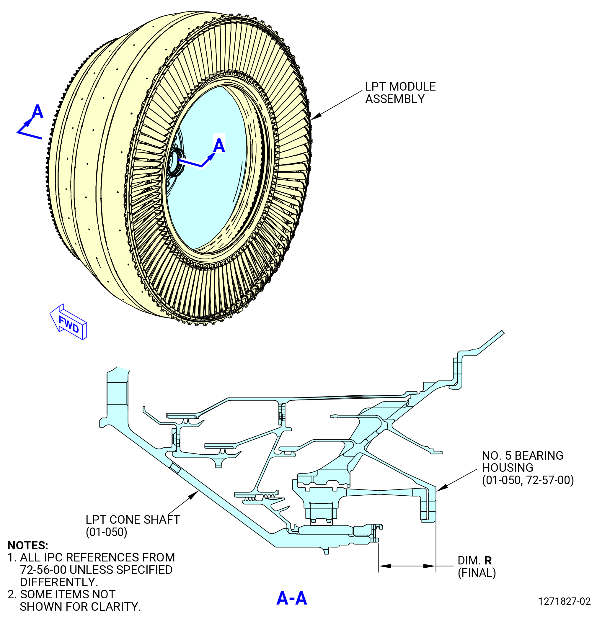
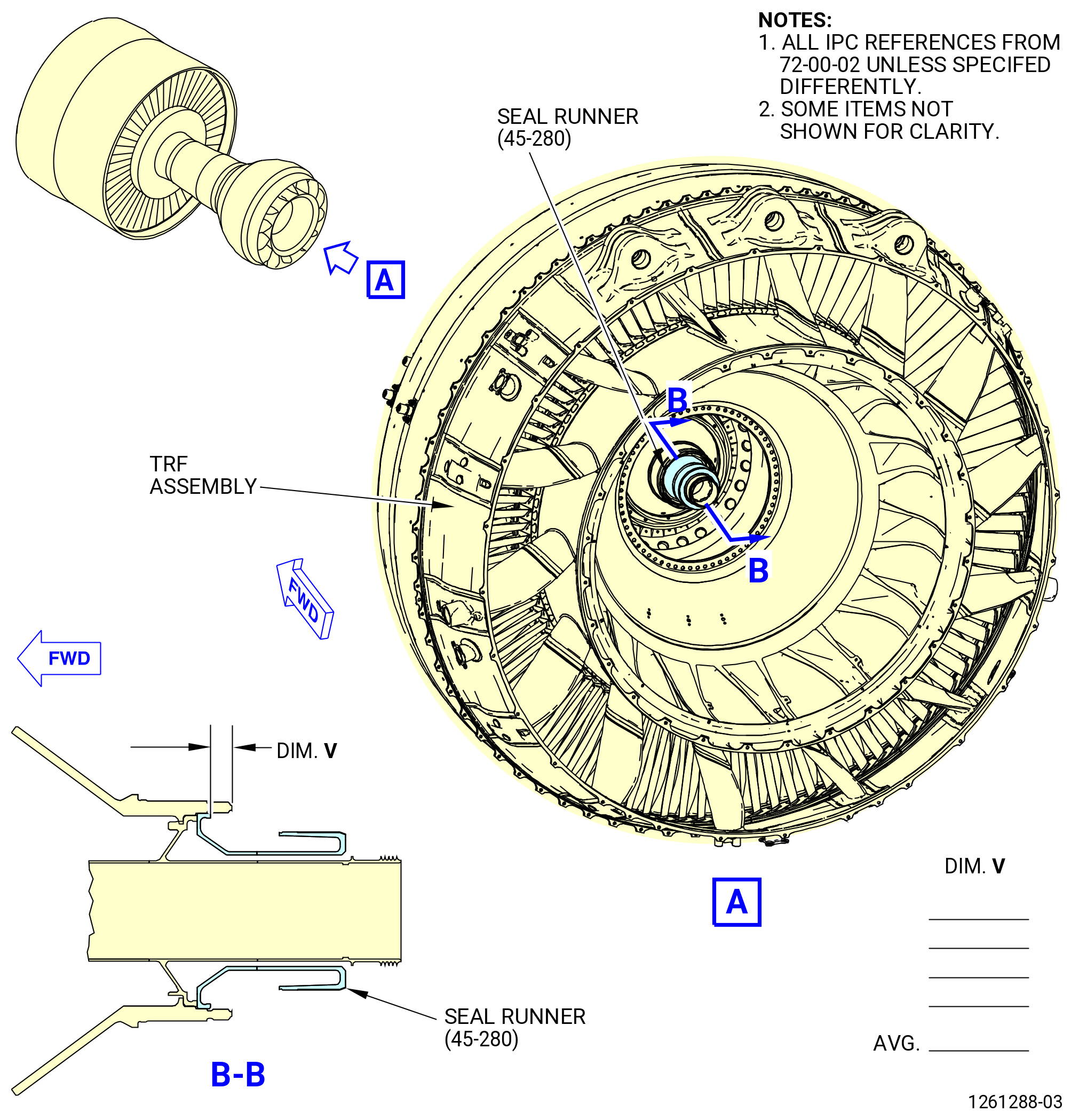
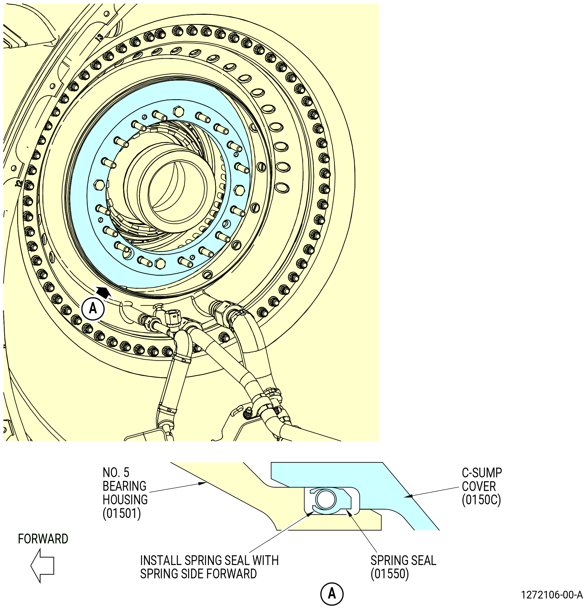
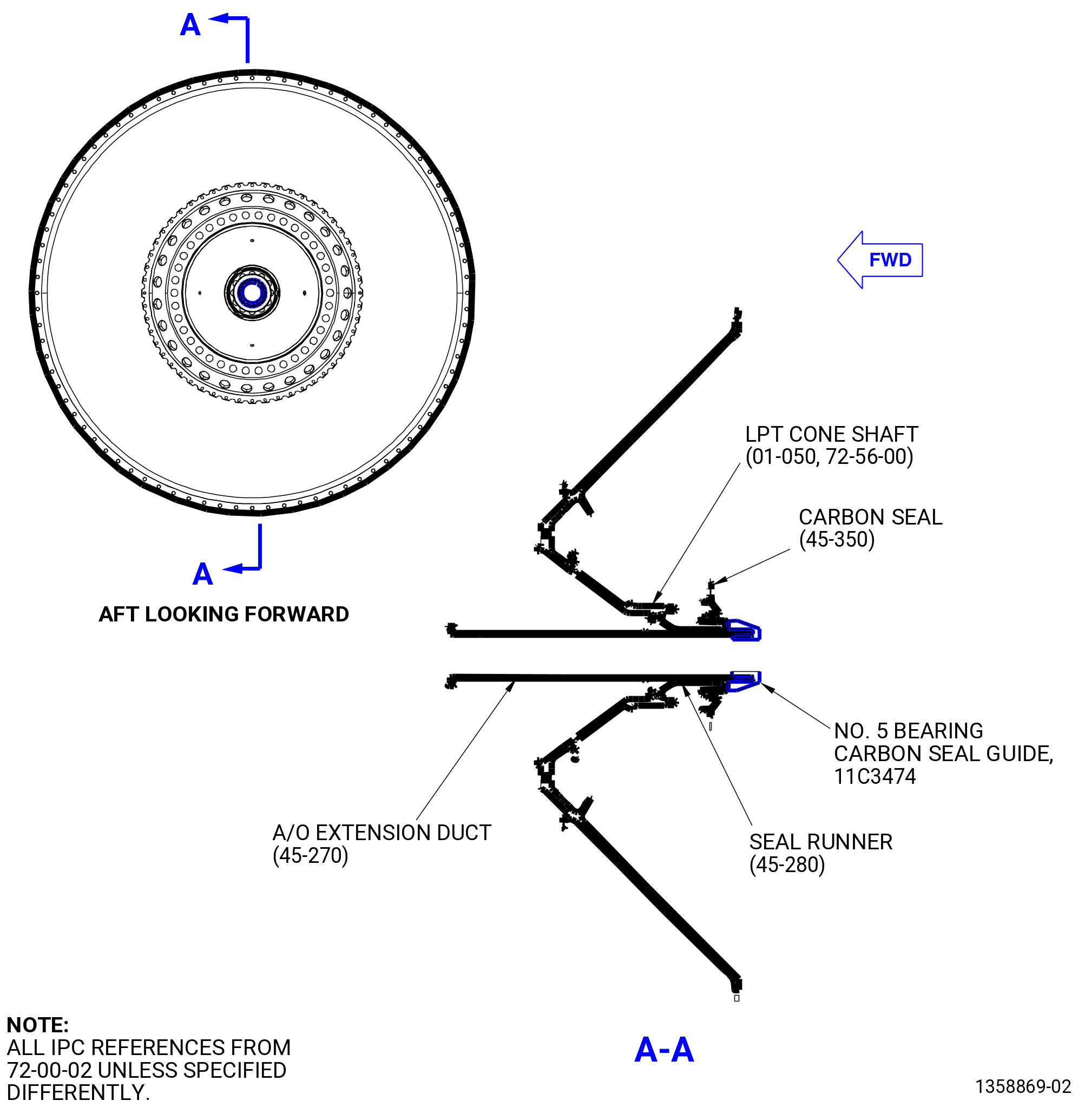
| J. | Measure the final Dimension R on the No. 5 bearing housing (01501) and the LPT cone shaft (930D1) as follows. Refer to Figure 424. |
| (1) | Measure at four equally spaced locations adjacent to the spacers on the aft flange of the No. 5 bearing housing (01501). |
| (2) | Measure from the aft face of the No. 5 bearing housing (01-050 , 72-57-00) (SIN 01501) to the aft inner diameter of the LPT cone shaft (01-050 , 72-56-00) (SIN 930D1). Refer to Figure 424. |
| (3) | Calculate the average of the four measurements and record it as dimension R (final) in the record table. Refer to Figure 405. |
| (4) | Use one of the procedures below to make sure that the LPT rotor is in the correct axial setting. |
| Subtask 72-00-04-220-036 |
| (a) | Alternative Procedure Available. If dimension R (preliminary) is known, calculate the difference between R (final) and the result of R (preliminary) and shim difference. The difference must be no more than plus or minus 0.015 inch (0.38 mm). Refer to Subtask 72-00-04-220-017 (72-00-04, ASSEMBLY 001, CONFIG 01) or Subtask 72-00-04-220-033 (72-00-04, ASSEMBLY 001, CONFIG 02). |
| 1 | Record the results in the record sheet. Refer to Figure 405. |
| Subtask 72-00-04-220-037 |
| (a).A. | Alternative Procedure. If dimension R (preliminary) is not known, dimension R (final) must be within 1.806 to 1.858 inches (45.88 to 47.19 mm). |
| 1 | Record the results in the record sheet. Refer to Figure 405. |
| Subtask 72-00-04-420-126 |
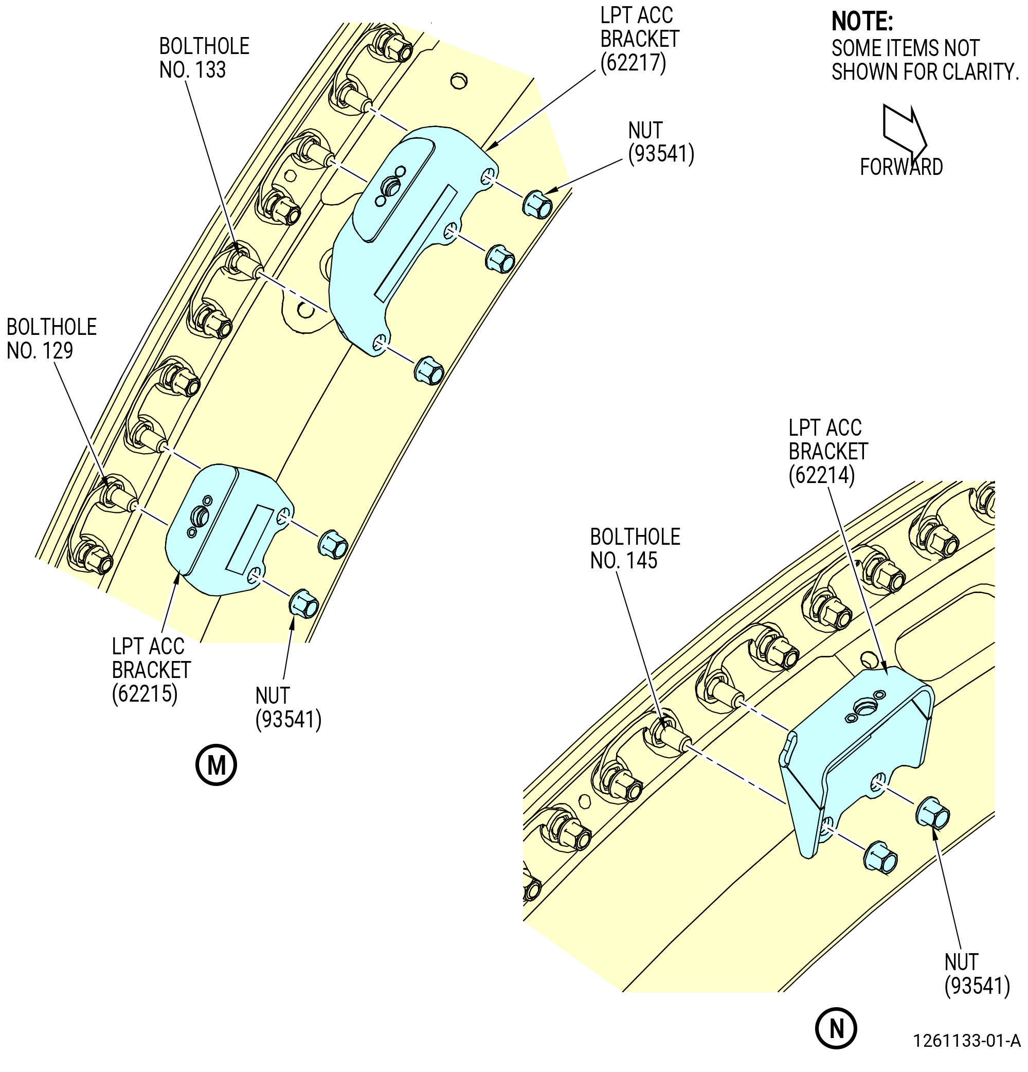
| K. | Install the brackets on the LPT module assembly forward flange and the TCF aft flange on the propulsor assembly as follows. Put the brackets on the forward side of the flange. Refer to Figure 418. |
| Subtask 72-00-04-640-017 |
| WARNING: |
|
| (1) | Lubricate the threads of 56 nuts (93541) with C02-019 engine oil or C02-023 engine oil. |
| Subtask 72-00-04-420-127 |
| (2) | Install the LPT ACC bracket (62216) at bolthole locations No. 5 and No. 7 with nuts (93541) the tab aft. |
| (3) | Install the LPT ACC bracket (62211) at bolthole locations No. 16 and No. 18 with nuts (93541) with the tab aft. |
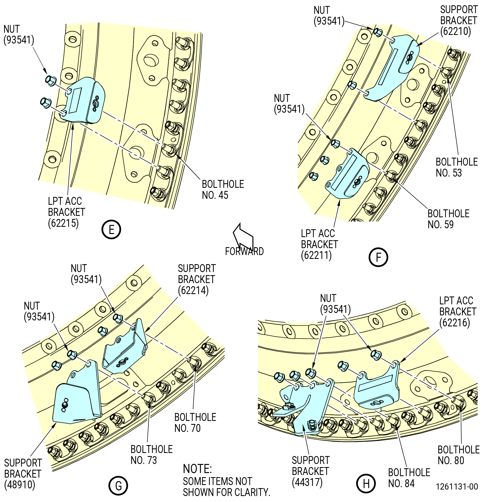
| (4) | Install the LPT ACC bracket (62215) at bolthole locations No. 23 and No. 24 with nuts (93541) with the tab aft. |
| (5) | Install the LPT ACC bracket (62215) at bolthole locations No. 45 and No. 46 with nuts (93541) with the tab aft. |
| (6) | Install the support bracket (66210) at bolthole locations No. 53 and No. 56 with nuts (93541) with the tab aft. |
| (7) | Install the LPT ACC bracket (66211) at bolthole locations No. 59-61 with three nuts (93541) with the tab aft. |
| (8) | Install the LPT ACC bracket (66214) at bolthole locations No. 70 and No. 71 with nuts (93541) with the tab forward. |
| (9) | Install the LPT ACC bracket (66216) at bolthole locations No. 80 and No. 82 with nuts (93541) with the tab aft. |
| (10) | Install the support bracket (44317) at bolthole locations No. 84-86 with nuts (93541) with the tab forward. |
| (11) | Install the LPT bracket (66211) at bolthole locations No. 91-93 with three nuts (93541) with the tab aft. |
| (12) | Install the support bracket (44313) at bolthole locations No. 95 and 96 with nuts (93541) with the tab forward. |
| (13) | Install the LPT bracket (62215) at bolthole locations No. 97 and No. 98 with nuts (93541) with the tab aft. |
| (14) | Install the LPT bracket (62213) at bolthole locations No. 107-109 with three nuts (93541) with the tab forward. |
| (15) | Install the support bracket (62218) at bolthole locations No. 118-120 with three nuts (93541) with the tab aft. |
| (16) | Install the LPT ACC bracket (62215) at bolthole locations No. 129 and No. 130 with nuts (93541) with the tab aft. |
| (17) | Install the LPT ACC bracket (62217) at bolthole locations No. 133, 135, and 136 with three nuts (93541) with the tab aft. |
| (18) | Install the LPT ACC bracket (62214) at bolthole locations No. 145 and No. 146 with nuts (93541) with the tab forward. |
| (19) | Torque the nuts (93541) at the TCF-LPT flange in a criss-cross pattern to 79-93 lb in. (8.9-10.5 N.m). |
| (20) | Torque the nuts (93541) again at the TCF-LPT flange in criss-cross pattern to 106-124 lb in. (12.0-14.0 N.m). |
| (21) | Torque the nuts (93541) at the TCF-LPT flange in circular pattern to 106-124 lb in. (12.0-14.0 N.m). |
| Subtask 72-00-04-420-128 |
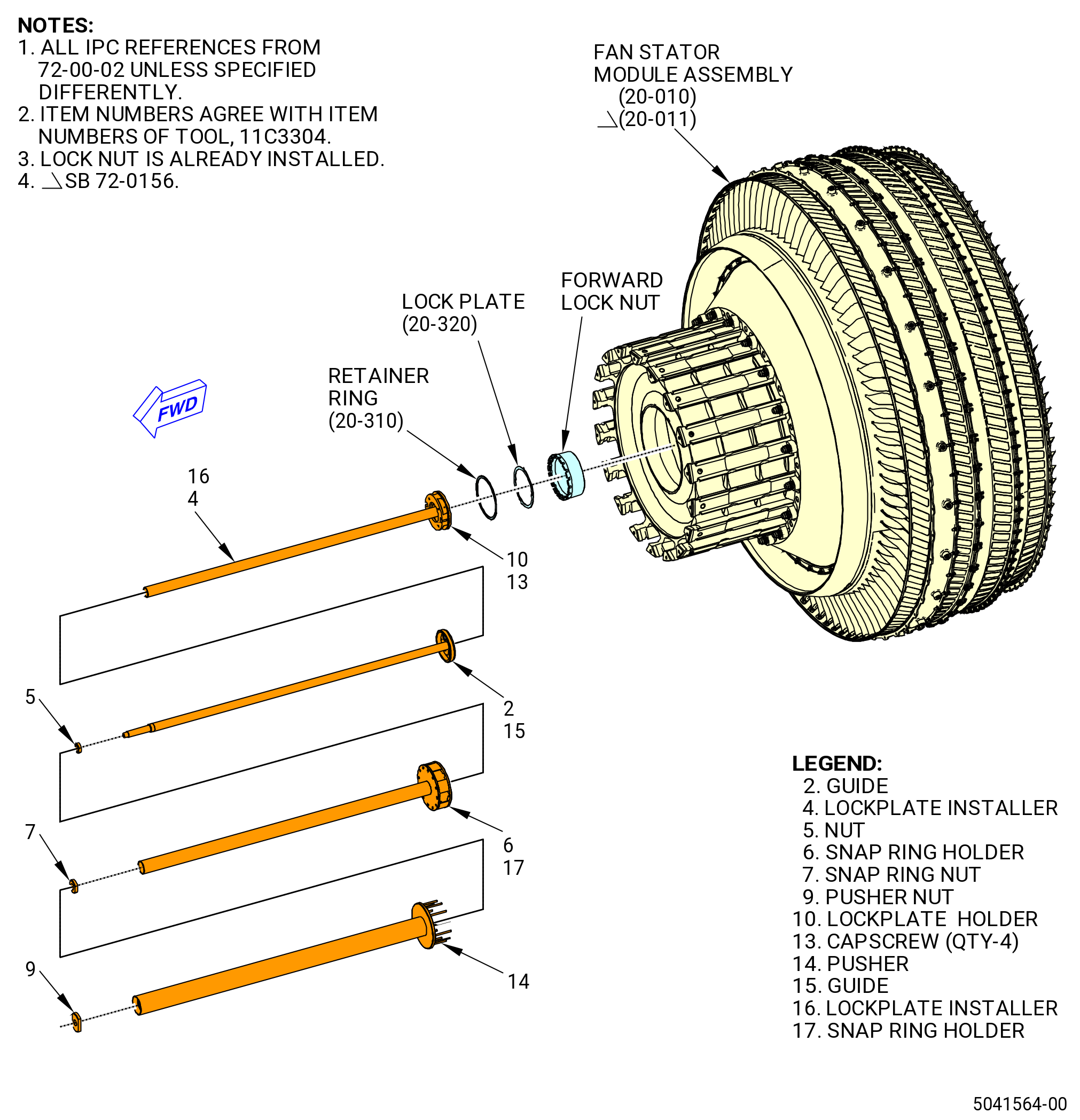
| L. | Install the lock plate (20-320 , 72-00-02) (SIN 83092) and the retainer ring (20-310 , 72-00-02) (SIN 83091) onto the forward lock nut. Refer to Figure 425 and do as follows: |
| (1) | Prepare the 11C3304 forward retainer fixture to install the lock plate (83092) and the retainer ring (83091) as follows: |
| NOTE: |
|
| (a) | Install the guide (item 2) or (item 15) of the 11C3304 forward retainer fixture through the fan rotor disk (01-050 , 72-22-00) (SIN 830A0) and into the forward end of the mid fan shaft assembly. |
| (b) | Turn the guide (item 2) or (item 15) into the inner threads of the mid fan shaft assembly and tighten it until the aft end of the guide (item 2) or (item 15) seats against the A/O vent center tube (center vent duct) (01-020 , 72-58-00) (SIN 810A1) in the mid fan shaft assembly. |
| (2) | Install the lock plate (20-320 , 72-00-02) (SIN 83092) onto the four tabs on the lockplate holder (item 10). The lockplate holder is attached to the lockplate installer (item 4) or (item 16) with the capscrews (item 13). |
| (3) | Install the lockplate installer (item 4) or (item 16), the lockplate holder (item 10), and the lock plate (20-320 , 72-00-02) (SIN 83092) over the guide (item 2) or (item 15). Align the outer diameter tabs with the castellations on the forward lock nut, and the inner diameter tabs with the castellations on the mid fan shaft. If necessary, rotate the lock plate in order to find the correct alignment. |
| (4) | Install the lockplate installer nut (nut) (item 5) on the forward threaded end of the guide (item 2) or (item 15) until the lockplate installer (item 4) or (item 16) and the lock plate (20-320 , 72-00-02) (SIN 83092) are against the forward lock nut. |
| (5) | Compress the retainer ring (20-310 , 72-00-02) (SIN 83091) outside diameter and put in the groove on the aft end of the snap ring holder (item 6) or (item 17). |
| (6) | Install the snap ring holder (item 6) or (item 17) onto the lockplate installer (item 4) or (item 16). |
| (7) | Thread the snap ring nut (item 7) onto the forward end of the guide (item 2) or (item 15) to seat the snap ring holder (item 6) or (item 17) against the forward end of the forward lock nut. |
| (8) | Install the snap ring pusher (pusher) (item 14) on the snap ring holder (item 6) or (item 17) as follows: |
| (a) | Align the pusher so the 12 pins on the aft end go through the 12 clearance holes in the snap ring holder (item 6) or (item 17). |
| (b) | Slide the pusher (item 14) aft until the threads on the guide (item 2) or (item 15) are visible. |
| (9) | Install the pusher nut (item 9) on the forward end of the guide (item 2) or (item 15). |
| (10) | Tighten the pusher nut (item 9) until the 12 pins push the retainer ring (20-310 , 72-00-02) (SIN 83091) out of the snap ring holder (item 6) or (item 17) groove and it expands into the groove in the forward end of the forward lock nut. |
| (11) | Make sure the lock plate (20-320 , 72-00-02) (SIN 83092) and retainer ring (20-310 , 72-00-02) (SIN 83091) are correctly installed and that they prevent the rotation of the forward lock nut. |
| (12) | Remove the 11C3304 forward retainer fixture. |
| (13) | Do a visual inspection of the fan shaft bore for FOD. |
| Subtask 72-00-04-420-129 |
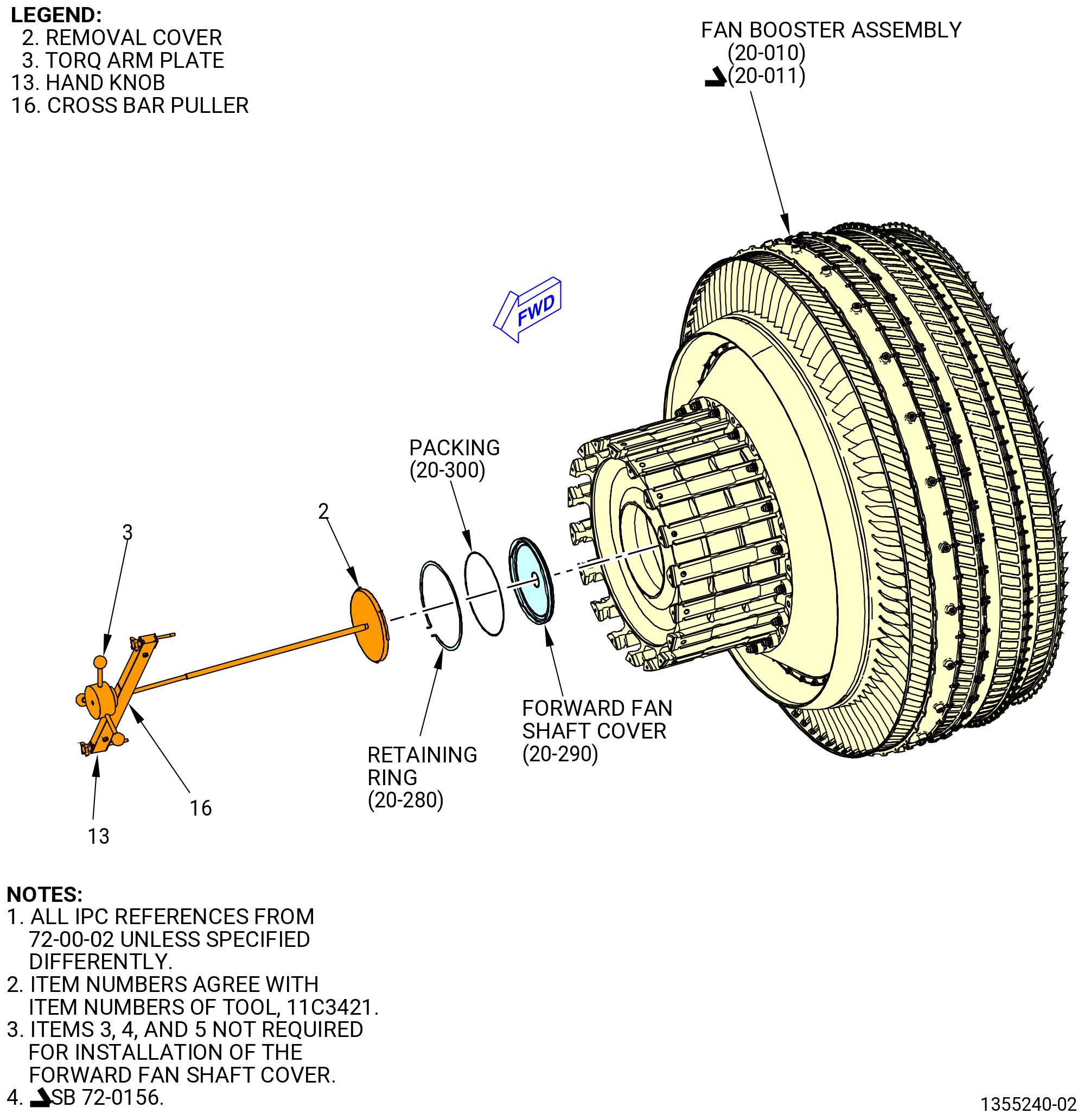
| M. | Install the forward fan shaft cover (20-290 , 72-00-02) (SIN 81003) in forward fan shaft of the fan stator module assembly (20-010 , 72-00-02) (SIN 80000) or (20-011 , 72-00-02) (SIN 80000). Refer to Figure 426 and do as follows: |
| NOTE: |
|
| Subtask 72-00-04-640-018 |
| (1) | Install the 11C3084 fan disk protector into the bore of the fan rotor disk (01-050 , 72-22-00) (SIN 830A0) and the forward fan shaft (01-170 , 72-24-00) (SIN 81002) or (01-171 , 72-24-00) (SIN 81002) or aft support ring (20-100 , 72-00-00) (SIN 8300A). Refer to Figure 427. |
| WARNING: |
|
| (2) | Lubricate the lead-in chamfer and inner diameter of the forward fan shaft with C02-019 engine oil or C02-023 engine oil. |
| (3) | Lubricate the packing (20-300 , 72-00-02) (SIN 81050) with C02-019 engine oil or C02-023 engine oil. |
| Subtask 72-00-04-420-130 |
| (4) | Install the packing (20-300 , 72-00-02) (SIN 81050) onto the outer groove of the fan shaft cover (81003). |
| CAUTION: |
|
| (5) | Install the fan shaft cover (81003) on the 11C3421 fan shaft cover fixture as follows: |
| NOTE: |
|
| (a) | Align the tabs on the fan shaft cover with the open slots on the removal cover (item 2). |
| (b) | Turn until the tabs touch the pins on the removal cover (item 2). |
| (6) | Lift the fan shaft cover (20-290 , 72-00-02) (SIN 81003) with the removal cover (item 2) and put the fan shaft cover in the fan stator module assembly (20-010 , 72-00-02) (SIN 80000) or (20-011 , 72-00-02) (SIN 80000). |
| (7) | Push on the center fan shaft cover (81003) with the 11C3421 fan shaft cover fixture to deflect and to install. |
| (8) | Use a shop light to do an inspection of the packing (20-300 , 72-00-02) (SIN 81050) to make sure that it is in the correct position. |
| (9) | Install the retaining ring (20-280 , 72-00-02) (SIN 81082) into the groove inside the bore of the forward fan shaft (01-170 , 72-24-00) (SIN 81002) or (01-171 , 72-24-00) (SIN 81002). Compress the retaining ring slightly and let it expand into the groove. |
| (10) | Remove the removal cover (item 2) from the forward fan shaft cover. |
| (11) | Remove the 11C3084 fan disk protector from the bore of the fan rotor disk and the forward fan shaft (01-170 , 72-24-00) (SIN 81002) or (01-171 , 72-24-00) (SIN 81002). |
| Subtask 72-00-04-420-131 |
| N. | Install the 9429M47 LPT support overhead adapter on the LPT module assembly. Refer to Figure 428 and do as follows: |
| NOTE: |
|
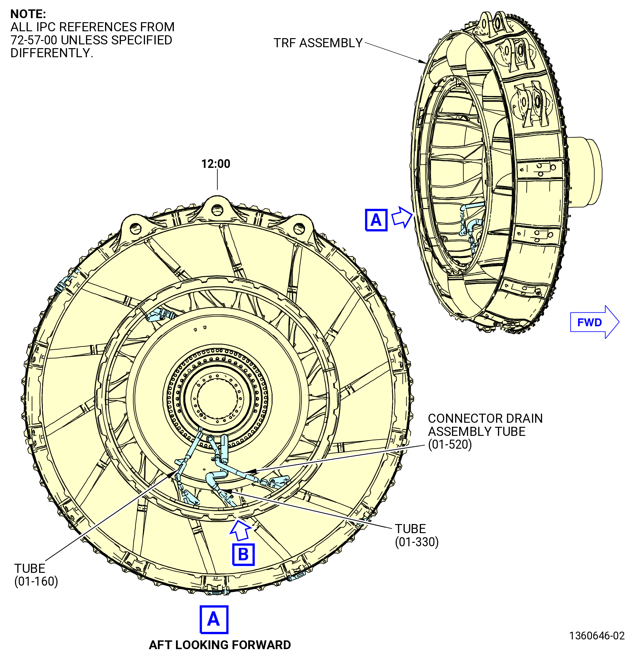
| (1) | If necessary, install the TRF bootstrap brackets (01-160) (SIN 941E1) to the LPT module assembly flanges of the TRF assembly at boltholes 16-19 and 60-63 (ALF). Refer to TASK 72-00-04-430-801 (72-00-04, ASSEMBLY 001, CONFIG 01) or TASK 72-00-04-430-802 (72-00-04, ASSEMBLY 001, CONFIG 02). |
| (2) | Put a level on the rear flange of the TRF assembly and level the propulsor assembly. |
| CAUTION: |
|
| (3) | Attach the hook of the 9429M47 LPT support overhead adapter to the customer overhead hanger assembly. |
| (4) | Adjust the turnbuckles upwards or downwards until the holes on the jaw end turnbuckle are aligned with the holes on the TRF bootstrap brackets (941E1). |
| (5) | Attach the hook of the 9429M47 LPT support overhead adapter to the TRF bootstrap brackets (941E1) with the adapter pins. |
| (6) | Adjust the turnbuckles to tighten the 9429M47 LPT support overhead adapter. |
| (7) | Remove the 9429M45 K-flange overhead adapter from the propulsor assembly. |
| Subtask 72-00-04-420-132 |
| (8) | Install the brackets on the extension case (10-080 , 72-30-00) (SIN 080AL) and the combustor case (01-079 , 72-41-00) (SIN 12001) or (01-080 , 72-41-00) (SIN 12001) flanges or the combustor case (01-230 , 72-41-00) (SIN 12001) or (01-230A , 72-41-00) (SIN 12001) flanges where the 9429M45 K-flange overhead adapter was removed. Refer to TASK 72-00-02-430-817 (72-00-02, ASSEMBLY 002, CONFIG 01) or TASK 72-00-02-430-820 (72-00-02, ASSEMBLY 002, CONFIG 02) and do as follows: |
| NOTE: |
|
| Subtask 72-00-04-640-019 |
| (a) | Lubricate all the threads and bearing surfaces of the bolts (12022) with C02-058 graphite. |
| Subtask 72-00-04-420-133 |
| (b) | Install the accelerometer cable bracket (34210) in boltholes 9-11 with the bolts (12022) and nuts (12040). Put the bracket on the forward side of the flanges. Tighten the nuts hand-tight. |
| Subtask 72-00-04-420-176 |
| * * * FOR 1B/P/G03.1B/P/G04.1B/P1/G01 |
| * * * PRE SB 72-0161( Propulsor Module - Non PIP2 Configuration ) |
| (c) | Install the support bracket (33-310 , 72-00-02) (SIN 6101V) in boltholes 123-126 with the bolts (33-070 , 72-00-02) (SIN 12022) and nuts (33-080 , 72-00-02) (SIN 12040). Put the bracket on the forward side of the flanges. Tighten the nuts hand-tight. |
| 1 | Attach the support bracket (33-310 , 72-00-02) (SIN 6101V) to the bracket (25-580 , 72-00-02) (SIN 6101Y) with bolts (33-300 , 72-00-02) (SIN 6102G). Tighten the bolts hand-tight. |
| NOTE: |
|
| * * * END PRE SB 72-0161 |
| Subtask 72-00-04-420-177 |
| * * * FOR ALL |
| (d) | Install the support bracket (34111) in boltholes 120 and 121 with the bolts (12022) and nuts (12040). Put the bracket on the aft side of the flanges. Tighten the nuts hand-tight. |
| Subtask 72-00-04-420-178 |
| * * * FOR 1B/P/G03.1B/P/G04.1B/P1/G01 |
| * * * PRE SB 72-0161( Propulsor Module - Non PIP2 Configuration ) |
| (e) | Install the tube control support bracket (33-100 , 72-00-02) (SIN 61010) in boltholes 129 and 130 with the bolts (33-070 , 72-00-02) (SIN 12022) and nuts (33-080 , 72-00-02) (SIN 12040). Put the bracket on the forward side of the flanges. Tighten the nuts hand-tight. |
| NOTE: |
|
| * * * END PRE SB 72-0161 |
| Subtask 72-00-04-420-179 |
| * * * FOR ALL |
| (f) | Install the bolts (12022) and nuts (12040) in any holes that remain. Tighten the nuts hand-tight. |
| (g) | Torque the nuts (12040) at equally spaced locations in a criss-cross pattern to 276-324 lb in. (31.2-36.6 N.m). |
| (h) | Torque the nuts (12040) at equally spaced locations in a criss-cross pattern to 368-432 lb in. (41.6-48.8 N.m). |
| (i) | Torque the bolts (6102G) to 106-124 lb in. (12.0-14.0 N.m). |
| Subtask 72-00-04-420-158 |
| CAUTION: |
|
| (11) | Alternative Procedure Available. Remove the 11C3165 strongback fixture from the TRF assembly on the aft end of the propulsor assembly. Refer to Figure 414. |
| Subtask 72-00-04-420-159 |
| CAUTION: |
|
| (11).D. | Alternative Procedure. Remove the 11C4266 CG lift fixture from the TRF assembly on the aft end of the propulsor assembly. Refer to Figure 403. |
| (a) | Install the machine bolts (bolts) (01-050) (SIN 94020) and (01-070) (SIN 94022) and self-locking nuts (nuts) (01-060) (SIN 94040) that were removed from the LPT module assembly/TRF assembly flanges during installation of the 11C4266 CG lift fixture as follows: |
| NOTE: |
|
| WARNING: |
|
| 1 | Apply C02-058 graphite to the threads and friction surfaces of the bolts and nuts. |
| a | Use the minimum quantity of lubricant necessary for the assembly. |
| b | Remove the remaining lubricant with a clean cloth. |
| 2 | Torque the bolts to 161-179 lb in. (18.2-20.2 N.m). |
| Subtask 72-00-04-420-135 |
| O. | Install the No. 5 bearing carbon seal runner (seal runner) (0155A) as follows: |
| CAUTION: |
|
| (1) | Measure dimension T at four equally-spaced locations. Make a record of the minimum and maximum dimensions. Wear C10-140 latex glove to prevent damage to the seal runner. Refer to Figure 429. |
| (2) | Install the guide ring (item 13) of the 11C3328 install/remove tool on the aft flange studs of the No. 5 bearing housing (01501) and attach it with the nuts (item 26) at 20 locations. Refer to Figure 430. |
| (3) | Install the housing (item 32) into the guide ring (item 13). Turn the housing (item 32) CW to thread into the LPT cone shaft (930D1). |
| WARNING: |
|
| WARNING: |
|
| CAUTION: |
|
| (4) | Decrease the temperature of the forward flange of the seal runner (0155A) as follows: |
| (a) | Put the seal runner forward end down on dry ice. |
| (b) | Keep the part on the dry ice for 20 minutes. |
| (5) | Install the 11C3328 install/remove tool on the seal runner as follows: |
| (a) | Align the tabs on the push/pull tube (item 12) with the slots in the seal runner. |
| (b) | Install the tabs of the push/pull tube (item 12) through the slots in the seal runner. Turn the push/pull tube 1/2 tooth to engage the seal runner. |
| (c) | Move the seal locking tube (item 11) forward and engage the tabs of the seal locking tubes with the slots in the seal runner. |
| (d) | Attach the hydraulic hand pump to the hydraulic cylinder (item 21) and fully retract the piston. Disconnect the hydraulic pump. |
| (6) | Install the seal runner (0155A) as follows: |
| (a) | Install the seal runner and 11C3328 install/remove tool through the bore of the housing (item 32) and on the LPT cone shaft (930D1). Refer to Figure 430. |
| (b) | Install the hydraulic cylinder (item 21) on the push/pull tube rod. Make sure the piston of the cylinder pushes aft as the pressure increases. |
| (c) | Attach the cylinder support (item 16) to the housing (item 32) with two ball lock pins (item 19). |
| WARNING: |
|
| CAUTION: |
|
| (7) | Attach the hydraulic hand pump and apply 2,000 psi (13789 kPa) hydraulic pressure to seat the seal runner. |
| NOTE: |
|
| (8) | Remove the seal runner tooling as follows: |
| (a) | Release the hydraulic pressure. Disconnect the hydraulic hand pump from the hydraulic cylinder. |
| (b) | Remove the two ball lock pins (item 19) and remove the cylinder support (item 16). |
| (c) | Remove the hydraulic cylinder (item 21) |
| (d) | Move the seal locking tube (item 11) aft and remove it. |
| (e) | Turn the push/pull tube (item 12) 1/2 tooth to align the tabs with the slots on the seal runner. Remove the push/pull tube. |
| (f) | Turn the housing (item 32) CCW (ALF) and remove it. |
| (g) | Loosen and remove the nuts (item 26) and remove the guide ring (item 13). |
| (9) | Remove the tape from the seal teeth at the aft end of the A/O extension duct (45-270 , 72-00-02) (SIN 810A8). |
| Subtask 72-00-04-220-031 |
| P. | Do a seating check of the seal runner (0155A) as follows: |
| (1) | Measure from the aft castellations of the LPT cone shaft to the aft side of the forward flange of the seal runner. Refer to Figure 431. |
| (2) | Measure Dimension V at four equally-spaced locations. Record the average Dimension V. |
| (3) | Calculate dimension V as follows: |
|
| (4) | Compare the calculated dimension V with the measured dimension V. The difference between the calculated and measured dimensions must be less than 0.002 inch (0.05 mm) |
| Subtask 72-00-04-420-136 |
| Q. | Install the carbon seal coupling nut (01545) as follows. Refer to Figure 432. |
| (1) | Prepare the carbon seal coupling nut (coupling nut) (01545) for installation as follows: |
| Subtask 72-00-04-160-003 |
| WARNING: |
|
| (a) | Clean the threads of the coupling nut (01545) and the LPT cone shaft (930D1). Clean the mating face of the coupling nut and the No. 5 bearing carbon seal runner. Use C04-035 isopropyl alcohol. |
| Subtask 72-00-04-640-020 |
| (b) | Apply C02-058 graphite to the threads of the coupling nut (01545) and the LPT cone shaft (930D1). |
| Subtask 72-00-04-420-137 |
| (2) | Install the locking inserts (01580) on the coupling nut (01545) at four locations. |
| (3) | Install the coupling nut (01545) on the LPT cone shaft (930D1). |
| Subtask 72-00-04-420-138 |
| (4) | Install the 11C3277 LPT restrain fixture as follows: |
| (a) | Attach the 9C1017 VCG fixture to the restrain fixture (item 2) of the 11C3277 LPT restrain fixture. Refer to Figure 433. |
| WARNING: |
|
| (b) | Attach a hoist to the 9C1017 VCG fixture and lift the restrain fixture (item 2). Adjust the center of gravity on the 9C1017 VCG fixture to keep the 11C3277 LPT restrain fixture level. |
| (c) | Attach the ring (item 8) to the turbine rear frame with nuts (item 13), washers (item 14), and cap screws (item 11) at nine equally-spaced locations. |
| Subtask 72-00-04-420-139 |
| (5) | Install the 11C5012 spanner nut torque fixture. Refer to Figure 434 and do as follows: |
| (a) | Install the 11C3288 carbon runner seal protector on the No. 5 bearing carbon seal runner (0155A). |
| (b) | Install the guide tube (item 18) of the 11C5012 spanner nut torque fixture into the bore of the restrain fixture (item 2) of the 11C3277 LPT restrain fixture. |
| (c) | Align the holes in the guide tube with the holes in the restrain fixture and attach the guide tube with six capscrews (item 15). Refer to Figure 434. |
| (d) | Install the anti-torque tube (item 3) of the 11C5012 spanner nut torque fixture and the torque tube (item 4) assembly in the aft end of the anti-torque hub (item 5). |
| (e) | Align the two holes in the flange of the anti-torque tube (item 3) with the threaded holes in the aft flange of the anti-torque hub (item 5). |
| (f) | Attach the anti-torque tube (item 3) to the anti-torque hub (item 5) with capscrews (item 10). |
| CAUTION: |
|
| (g) | Pull the torque tube (item 4) aft until it is against the aft stop ring (item 7). Make sure the torque tube (item 4) is against the aft stop ring (item 7). |
| CAUTION: |
|
| (h) | Lift the 11C5012 spanner nut torque fixture tube assembly with the 9429M59 breach loader and align it with the guide tube (item 18) of the 11C5012 spanner nut torque fixture. Refer to Figure 409. |
| (i) | Install the tube assembly into the guide tube (item 18). Move the tube assembly forward until the teeth on the forward end of the anti-torque tube (item 3) engage the slots in the aft end of the LPT cone shaft (01-050 , 72-56-00) (SIN 930D1). |
| (j) | Move the anti-torque hub (item 5) forward and align the holes in the anti-torque hub with the holes in the flange of the guide tube (item 18). |
| (k) | Attach the anti-torque hub (item 5) to the guide tube (item 2) with two ball-lock pins (item 8) at the 3:00 o'clock and 9:00 o'clock positions. |
| (l) | Install two capscrews (item 11) at the 12:00 o'clock and 6:00 o'clock positions. |
| Subtask 72-00-04-420-140 |
| (6) | Install the 8200torque multiplier on the 11C5012 spanner nut torque fixture. Refer to Figure 435 and do as follows: |
| CAUTION: |
|
| (a) | Loosen the two threaded pins (item 19) on the 11C5012 spanner nut torque fixture. |
| (b) | Install the 8200torque multiplier on the anti-torque hub (item 5) of the 11C5012 spanner nut torque fixture. |
| (c) | Push the 8200torque multiplier forward and slide onto the splines of the torque tube (item 4) of the 11C5012 spanner nut torque fixture. |
| (d) | Align the pins with the holes in the anti-torque hub (item 5) and seat the 8200torque multiplier against the anti-torque hub. |
| (e) | Tighten the two threaded pins (item 19) on the 11C5012 spanner nut torque fixture. |
| (7) | Torque the coupling nut (01545) to initial seat the coupling nut as follows: |
| NOTE: |
|
| CAUTION: |
|
| (a) | Rotate the handle on the torque multiplier to seat the coupling nut to 127 lb ft (172.2 N.m). |
| (b) | Break the torque on the coupling nut. Turn the nut a minimum of three turns. |
| (c) | Record the run-on torque as follows: |
| CAUTION: |
|
| 1 | Rotate the handle on the torque multiplier to seat the coupling nut to 127 lb ft (172.2 N.m). |
| 2 | Record the run-on torque of the coupling nut (01545). |
| 3 | If the run-on torque is not more than 23 lb ft (31.2 N.m), remove the coupling nut (01545) and replace the locking inserts (01580). |
| (8) | Calculate the final torque and apply a final torque of 600-727 lb ft (814-986 N.m) to the coupling nut (01545). Do not apply more than maximum torque of 727 lb ft (986 N.m). |
| (9) | Remove the 8200torque multiplier from the 11C5012 spanner nut torque fixture. |
| (10) | Remove the 11C5012 spanner nut torque fixture from the 11C3277 LPT restrain fixture as follows: |
| WARNING: |
|
| (a) | Loosen two threaded pins (item 19) and remove torque multiplier with the aid of appropriate lifting device. |
| (b) | Remove the anti-torque hub (item 5) from guide tube (item 18) by removing two ball-lock pins (item 8) and two bolts (item 11). |
| (c) | Use the 9429M59 breach loader or a two-legged sling to carefully remove the shaft assembly (items 3-8, item 10, item 13, item 14, item 19, and item 20) from guide tube (item 18). Make sure that certain tool is properly supported while withdrawing. |
| (d) | Remove the guide tube (item 18) of the 11C5012 spanner nut torque fixture from the 11C3277 LPT restrain fixture by removing six hex head capscrews (item 15) |
| Subtask 72-00-04-420-141 |
| R. | Install the No. 5 bearing locknut (01503), the retaining ring (01593), and the lockplate (01592) on the LPT cone shaft (930D1) as follows. Refer to Figure 432. |
| (1) | Prepare the No. 5 bearing locknut (01503) as follows: |
| Subtask 72-00-04-160-004 |
| WARNING: |
|
| (a) | Clean the threads and the seating surface of the No. 5 bearing locknut (01503) with C04-035 isopropyl alcohol. |
| (b) | Clean the threads of the LPT cone shaft (930D1) with C04-035 isopropyl alcohol. |
| Subtask 72-00-04-640-021 |
| (c) | Apply C02-058 graphite to the threads and the seating surface of the locknut (01503). |
| (d) | Apply C02-058 graphite to the threads of the LPT cone shaft (930D1). |
| Subtask 72-00-04-420-142 |
| (2) | Install the No. 5 bearing locknut (01503) on the LPT cone shaft (930D1) by hand. |
| (3) | Install the 11C3334 No. 5 bearing locknut torque fixture on the 11C3277 LPT restrain fixture as follows. Refer to Figure 435. |
| WARNING: |
|
| CAUTION: |
|
| (a) | Lift the 11C3334 No. 5 bearing locknut torque fixture with the cradle adapter (item 6) of the 9429M59 breach loader. Refer to Figure 409. |
| (b) | Insert the torque tube (item 2) of the 11C3334 No. 5 bearing locknut torque fixture smoothly into the 11C3277 LPT restrain fixture on the engine centerline. |
| (c) | Insert the anti-torque tube (item 3) of the 11C3334 No. 5 bearing locknut torque fixture smoothly into the torque tube (item 2) on the engine centerline. |
| Subtask 72-00-04-420-143 |
| (4) | Slide the torque tube (item 2) and the anti-torque tube (item 3) of the 11C3334 No. 5 bearing locknut torque fixture forward. |
| (5) | Turn to engage the tabs of the torque tube (item 2) in the tabs of the No. 5 bearing locknut (01503). |
| (6) | Turn to engage the tabs of the anti-torque tube (item 3) in the tabs of the LPT cone shaft (930D1). |
| WARNING: |
|
| (7) | Install the 8200torque multiplier over the splines of the anti-torque tube (item 3) of the 11C3334 No. 5 bearing locknut torque fixture. |
| (8) | Install the 9429M17 anti-torque plate onto the splines of the torque tube (item 2) of the 11C3334 No. 5 bearing locknut torque fixture. |
| (9) | Torque the No. 5 bearing locknut (01503) as follows: |
| NOTE: |
|
| (a) | Torque the locknut to 880 lb ft (1193.3 N.m). |
| CAUTION: |
|
| (b) | Check to see if a scribe line on the torque tube (item 2) of the 11C3334 No. 5 bearing locknut torque fixture is aligned with a scribe line on the anti-torque tube (item 3). If not, continue to torque the No. 5 bearing locknut (01503) until the scribe lines are aligned. Do not apply more than 1050 lb ft (1423.8 N.m) of torque. |
| (c) | Remove the 9429M17 anti-torque plate from the torque multiplier. |
| WARNING: |
|
| (d) | Remove the 8200torque multiplier. |
| (e) | Use a clean cloth to remove excess lubricant from the locknut. |
| (10) | Slide the torque tube (item 2) of the 11C3334 No. 5 bearing locknut torque fixture and the anti-torque tube (item 3) aft. |
| (11) | Record the torque value of the No. 5 bearing locknut (01503). |
| (12) | Install the No. 5 bearing lock plate (lockplate) (01592). Two tabs on the outside diameter of the lock plate will fit into castellations on the No. 5 bearing locknut (01503). Two tabs on the inner diameter of the lock plate will fit into castellations on the inner shaft. You may have to rotate the lock plate (01592) or try different positions for it to correctly align with the No. 5 bearing locknut (01503). Refer to Figure 432. |
| (13) | Install the retaining ring (01593) directly aft of the lockplate (01592). Compress the retaining ring radially inward and let it to expand into the groove inside the castellations of the No. 5 bearing locknut (01503). |
| WARNING: |
|
| CAUTION: |
|
| (14) | Remove the 11C3334 No. 5 bearing locknut torque fixture with the cradle adapter (item 6) of the 9429M59 breach loader. |
| (15) | Remove the 11C3277 LPT restrain fixture as follows: |
| (a) | Disengage the pilot tube (item 17) from the nut housing (item 19). |
| (b) | Remove the pilot tube (item 17) from the restrain fixture assembly (item 2). |
| (c) | Remove restrain fixture assembly (item 2). |
| (d) | Remove the nut housing (item 19) from the LPT module assembly. |
| Subtask 72-00-04-420-144 |
| CAUTION: |
|
| S. | Install the No. 5 bearing carbon seal (carbon seal) (45-350 , 72-00-02) (SIN 01558) in the TRF assembly. Refer to Figure 436 and do as follows: |
| Subtask 72-00-04-640-022 |
| WARNING: |
|
| (1) | Lubricate the preformed packing (45-340 , 72-00-02) (SIN 01551) with C02-019 engine oil or C02-023 engine oil. |
| (2) | Lubricate with C02-019 engine oil or C02-023 engine oil the chamfer of the TRF assembly where the preformed packing (45-340 , 72-00-02) (SIN 01551) will be installed. |
| Subtask 72-00-04-420-145 |
| (3) | Install the preformed packing (45-340 , 72-00-02) (SIN 01551) in the forward side of the carbon seal (01558). |
| (4) | Install the 11C3474 No. 5 bearing carbon seal guide on the A/O extension duct (45-270 , 72-00-02) (SIN 810A8). Refer to Figure 437. |
| CAUTION: |
|
| (5) | Install the carbon seal (45-350 , 72-00-02) (SIN 01558) in the TRF assembly. |
| (6) | Install the installation nuts (item 2) of the 11C4292 installation fixture at four equally spaced locations. |
| (7) | Tighten in a criss-cross pattern to seat the carbon seal (01558). |
| (8) | Remove the 11C4292 installation fixture. |
| (9) | Remove the 11C3474 No. 5 bearing carbon seal guide from the A/O extension duct (45-270 , 72-00-02) (SIN 810A8). |
| Subtask 72-00-04-780-005 |
| (10) | Do a flow check of the carbon seal (01558) as follows: |
| (a) | Install the cover cap (item 2) of the 11C3287 air flow test stand on the carbon seal. |
| (b) | Secure with nuts (item 4) at six locations. |
| WARNING: |
|
| (c) | Attach a supply of clean, dry, compressed air to a 9461M40 air flow test stand. Refer to Figure 438. |
| (d) | Connect the 9429M71 universal adapter kit to the connector (item 7) of the 11C3287 flow cover. |
| (e) | Attach the 9461M40 air flow test stand to the 9429M71 universal adapter kit. |
| (f) | Turn on the 9461M40 air flow test stand. |
| (g) | Allow 20 minutes for the 9461M40 air flow test stand to warm up. |
| (h) | Set the pressure to 8-10 psig (55.2-69.0 Kpa gage) across the carbon seal. The maximum air flow permitted is 0.22 SCFM (0.0001038284 cms). |
| (i) | When the test is completed, release the pressure from the 9461M36 test stand. |
| (j) | Disconnect the 9461M40 air flow test stand and 9429M71 universal adapter kit from the 11C3287 flow cover. |
|
|
| Subtask 72-00-04-420-146 |
| T. | Install the C-sump cover (0150C), the lube nozzle (01509), the oil nozzle (01510), and the eductor nozzle (45-130 , 72-00-02) (SIN 015K3) as follows. Refer to Figure 436. |
| (1) | Prepare to install the C-sump cover (0150C), the lube nozzle (01509), the oil nozzle (01510), and the eductor nozzle (45-130 , 72-00-02) (SIN 015K3) as follows: |
| Subtask 72-00-04-640-023 |
| WARNING: |
|
| (a) | Lubricate the ring seal (spring seal) (45-360 , 72-00-02) (SIN 01550) with C02-019 engine oil or C02-023 engine oil. |
| (b) | Lubricate the groove on the forward side of the C-sump cover (0150C) with C02-019 engine oil or C02-023 engine oil. |
| (c) | Lubricate the threads of the nuts (01544) with C02-058 graphite. |
| (d) | Lubricate the preformed packing (45-250 , 72-00-02) (SIN 0155B) with C02-019 engine oil or C02-023 engine oil. |
| (e) | Lubricate the oil nozzle (01510) with C02-019 engine oil or C02-023 engine oil. |
| (f) | Lubricate the preformed packing (45-230 , 72-00-02) (SIN 01555) with C02-019 engine oil or C02-023 engine oil. |
| (g) | Lubricate the lube nozzle (01509) with C02-019 engine oil or C02-023 engine oil. |
| (h) | Lubricate the threads of slabbed-head bolts (bolt) (91250) with C02-058 graphite. |
| (i) | Lubricate the threads of the bolts (015F1) with C02-058 graphite. |
| Subtask 72-00-04-420-147 |
| (2) | Install the C-sump cover (0150C) as follows: |
| CAUTION: |
|
| CAUTION: |
|
| (a) | Install the spring seal (45-360 , 72-00-02) (SIN 01550) into the groove of the No. 5 bearing housing (01501) with the spring side forward. Refer to Figure 436. |
| (b) | Remove the nuts (item 2) of the 11C4292 installation fixture at four locations that seat the carbon seal (01558). |
| (c) | Align the C-sump cover (0150C) with the lube nozzle holes and install it over the carbon seal (01558). |
| CAUTION: |
|
| (d) | Use a 0.001 inch (0.03 mm) shim to make sure that there is no clearance between the flange of the oil nozzle (01510) and the C-sump cover (0150C). |
| (e) | If a clearance is found, replace the oil nozzle (01510). |
| (f) | Install the nuts (01544) at 12 locations on the bolts (01522), and tighten hand-tight. Do not torque the nuts at this time. Do not install the nuts (01544) at four locations on either side of the location where you will install the connector supply tubes 2 and 3 (443A2, 443A3). |
| Subtask 72-00-04-420-160 |
| * * * PRE SB 72-0039( Old Oil Nozzle Design ) |
| (3) | Install the No. 5 bearing carbon seal oil nozzle (oil nozzle) (45-240 , 72-00-02) as follows: |
| (a) | Install the preformed packing (45-250 , 72-00-02) (SIN 0155B) on the forward side of the oil nozzle. |
| (b) | Install the oil nozzle over the studs of the C-sump cover (0150C) at approximately the 7:00 o'clock position AFT. |
| (c) | Attach the oil nozzle to the C-sump cover with two nuts (01544). Hand tighten the nuts. Do not torque the nuts at this time. |
| * * * END PRE SB 72-0039 |
| Subtask 72-00-04-420-161 |
| * * * SB 72-0039( New Oil Nozzle Design ) |
| (3).A. | Install the oil nozzle (45-241 , 72-00-02) as follows: |
| (a) | Install the preformed packing (45-250 , 72-00-02) (SIN 0155B) on the forward side of the oil nozzle. |
| (b) | Install the oil nozzle on the studs of the C-sump cover (0150C) at the 7:00 o'clock position ALF approximately. |
| (c) | Attach the oil nozzle to the C-sump cover with a nut (01544). Hand tighten the nut. Do not torque the nut at this time. |
| (d) | Install the nut (01544) on the remaining bolt (01522). Hand tighten the nut. Do not torque the nut at this time. |
| * * * END SB 72-0039 |
| Subtask 72-00-04-420-162 |
| (4) | Install the No. 5 bearing assembly oil nozzle (lube nozzle) (01509) as follows: |
| (a) | Install the preformed packing (45-230 , 72-00-02) (SIN 01555) on the forward side of the lube nozzle (01509). |
| (b) | Install the lube nozzle (01509) over the studs of the C-sump cover (0150C) at approximately the 5:00 o'clock position (aft looking forward). |
| (c) | Make sure that the oil jet holes of the lube nozzle are facing inward. |
| (d) | Attach the lube nozzle to the C-sump cover with two nuts (01544). Tighten the nuts hand-tight. |
| (5) | Torque the nuts (01544) at 16 locations in a criss-cross pattern to 202-238 lb in. (22.8-26.9 N.m). |
| (6) | Torque the nuts (01544) again at 16 locations in a criss-cross pattern to 203-238 lb in. (22.8-26.9 N.m). |
| (7) | Torque the nuts (01544) at 16 locations in a circular pattern to 203-238 lb in. (22.8-26.9 N.m). |
| WARNING: |
|
| (8) | Apply C02-058 graphite to the threads and friction surfaces of self-locking nuts (nuts) (45-380 , 72-00-02) (SIN 912K1) or (45-384 , 72-00-02) (SIN 912K1). |
| (9) | Install the slab-head bolt (bolt) (45-370 , 72-00-02) (SIN 912F0) with the push on nuts (45-480 , 72-00-02) (SIN 912K0) and the nuts (45-380 , 72-00-02) (SIN 912K1) or (45-384 , 72-00-02) (SIN 912K1) to the C-sump cover (45-210 , 72-00-02) (SIN 0150C) aft flange as follows: |
| NOTE: |
|
| (a) | Install the bolts (45-370 , 72-00-02) (SIN 912F0), the push on nuts (45-480 , 72-00-02) (SIN 912K0), and the nuts (45-380 , 72-00-02) (SIN 912K1) or (45-384 , 72-00-02) (SIN 912K1) at 12 locations on the aft flange of the C-sump cover. Make sure the boltheads are forward and the flats of the bolts face inward. |
| (b) | Do not tighten the nuts (45-380 , 72-00-02) (SIN 912K1) or (45-384 , 72-00-02) (SIN 912K1) on the bolts (45-370 , 72-00-02) (SIN 912F0) if they are present and they are not being shipped loose. |
| (10) | Install the eductor nozzle (45-130 , 72-00-02) (SIN 015K3) as follows: |
| NOTE: |
|
| (a) | Install the oil seal (45-140 , 72-00-02) (SIN 015K4) into the opening at the 12:00 o'clock position on the C-sump cover (0150C). |
| CAUTION: |
|
| (b) | Install the eductor nozzle in the oil seal and down through the C-sump cover and out the aft end. |
| (c) | Make sure that the eductor nozzle is installed with the nozzle pointing in the aft direction. Refer to Figure 439. |
| (d) | Attach the eductor nozzle to the C-sump cover with the bolts (015F1) at two locations. |
| (e) | Torque the bolts (015F1) to 106-124 lb in. (12.0-14.0 N.m). |
|
|
| Subtask 72-00-04-420-148 |
| U. | Install the aft sump tubes in the TRF assembly. Refer to Figure 440 and do as follows: |
| (1) | Install the bracket (61BE0) to the TRF assembly as follows: |
| (a) | Attach the bracket (61BE0) to the TRF assembly with two bolts (61BF0). |
| (b) | Torque the two bolts (61BF0) to 106-124 lb in. (12.0-14.0 N.m). |
| (c) | Attach bracket (61BE2) to bracket (61BE0) with two bolts (61BF4). Tighten the bolts hand-tight. |
| (2) | Install the eductor air tube (61BA1) as follows: |
| (a) | Connect the eductor air tube (45-030 , 72-00-02) (SIN 61BA1) to the TRF (01-010 , 72-57-00) (SIN 940A0) or (01-011 , 72-57-00) (SIN 940A0) strut No. 3 internal tube, CCW from the 12:00 o'clock position (aft looking forward). Tighten the B-nut hand-tight. |
| (b) | Install the ring seal (45-120 , 72-00-02) (SIN 61BN0) between the eductor air tube and the eductor nozzle (45-130 , 72-00-02) (SIN 015K3). |
| (c) | Install the coupling clamp (61BV1) around the eductor air tube and the eductor nozzle. Make sure the hinge is aligned so the nut is pointing in the 3:00 o'clock direction (aft looking forward). |
| (3) | Attach the eductor air tube (61BA1) to the bracket (61BE0) with a retaining strap (61BV0) and two bolts (61BF4). |
| (4) | Torque the connectors as follows: |
| (a) | Torque the B-nut on the eductor air tube (61BA1) as follows: |
| 1 | Torque the B-nut to 110-130 lb ft (149.7-175.7 N.m). |
| 2 | Loosen the B-nut and torque it again to 110-130 lb ft (149.7-175.7 N.m). |
| 3 | Re-apply torque to 110 to 130 lb ft (149.7 to 175.7 N.m). |
| (b) | Torque the nut on the clamp (61BV1) to 60-70 lb in. (6.8-7.9 N.m). |
| (c) | Torque the four bolts (61BF4) to 106-124 lb in. (12.0-14.0 N.m). |
| (5) | Install the connector supply tube 2 (supply tube 2) (45-160 , 72-00-02) (SIN 443A2) or (45-160A , 72-00-02) (SIN 443A2) and connector supply tube 3 (supply tube 3) (45-170 , 72-00-02) (SIN 443A3) as follows: |
| (a) | If the LPT module assembly was removed to make access easier to other areas of the engine, without an overhaul of the TRF assembly during the engine shop visit, make sure to do a check of the installation torque between the parts that follow. Refer to TASK 72-57-00-440-801 (72-57-00, ASSEMBLY 001). |
| • |
|
| • |
|
| • |
|
| • |
|
| (b) | Connect the B-nut of the A/O seal nozzle (oil nozzle) (45-241 , 72-00-02) (SIN 01510) at the 7:00 o'clock position to the supply tube 2 (45-160 , 72-00-02) (SIN 443A2). |
| (c) | Connect the B-nut of the supply tube 2 (45-160 , 72-00-02) (SIN 443A2) to the oil supply tube (01-160 , 72-57-00) (SIN 443A0). |
| (d) | Connect the B-nut of the supply tube 3 (45-170 , 72-00-02) (SIN 443A3) to the supply tube 2 (45-160 , 72-00-02) (SIN 443A2). |
| (e) | Connect the B-nut of the A/O No. 5 nozzle (lube nozzle) (45-220 , 72-00-02) (SIN 01509) at the 5:00 o'clock position to the supply tube 3 (45-170 , 72-00-02) (SIN 443A3). |
| (f) | Torque the B-nut of the oil nozzle (45-241 , 72-00-02) (SIN 01510) to the supply tube 2 (45-160 , 72-00-02) (SIN 443A2) as follows: |
| 1 | Torque the B-nut to 262 to 308 lb in. (29.6 to 34.8 Nm). |
| 2 | Loosen the B-nut and torque again to 262 to 308 lb in. (29.6 to 34.8 Nm). |
| 3 | Torque the B-nut again to 262 to 308 lb in. (29.6 to 34.8 Nm). |
| (g) | Torque the B-nut of the lube nozzle (45-220 , 72-00-02) (SIN 01509) to the supply tube 3 (45-170 , 72-00-02) (SIN 443A3) as follows: |
| 1 | Torque the B-nut to 262 to 308 lb in. (29.6 to 34.8 Nm). |
| 2 | Loosen the B-nut and torque again to 262 to 308 lb in. (29.6 to 34.8 Nm). |
| 3 | Torque the B-nut again to 262 to 308 lb in. (29.6 to 34.8 Nm). |
| (h) | Torque the B-nut of the supply tube 2 (45-160 , 72-00-02) (SIN 443A2) to the oil supply tube (01-160 , 72-57-00) (SIN 443A0) as follows: |
| 1 | Torque the B-nut to 262 to 308 lb in. (29.6 to 34.8 Nm). |
| 2 | Loosen the B-nut and torque again to 262 to 308 lb in. (29.6 to 34.8 Nm). |
| 3 | Torque the B-nut again to 262 to 308 lb in. (29.6 to 34.8 Nm). |
| NOTE: |
|
| Subtask 72-00-04-780-006 |
| WARNING: |
|
| (6) | Pressure check the aft oil supply system as follows: |
| (a) | Attach a supply of clean, dry compressed air to the oil supply tube (443A1) fitting at 6:00 o'clock on the TRF. Refer to Figure 442. |
| (b) | Apply and keep a minimum air pressure of 10 PSIG (69.0 Kpa gage) to the oil supply system. |
| (c) | Apply a leak detection fluid to the aft oil supply lines inside the TRF and on the three fittings on the tubes (443A1, 443A2). |
| (d) | When the test is completed, release the pressure and remove any test hoses from the aft oil supply system. |
| (e) | Deleted. |
| CAUTION: |
|
| (f) | Safety the B-nuts with C10-143 safety cable. Install the factory crimped end of the safety cable on the tube boss hole. Do not install the factory crimped end on the B-Nut side of the tube. |
| (7) | Flow check the aft oil supply system as follows: |
| (a) | Attach a supply of clean, dry, compressed air to the 9461M40 air flow test stand. Refer to Figure 438. |
| (b) | Connect the 9429M71 universal adapter kit to the oil supply tube (443A1) fitting at the 6:00 o'clock position on the TRF assembly. |
| (c) | Attach the 9461M40 air flow test stand to the 9429M71 universal adapter kit. |
| (d) | Apply and keep a pressure of 9.5-10.5 psig (65.5-72.4 kPa gage). The flow rate must be 1.9-4.3 SCFM (54-122 Lpm) at ambient conditions 50°F-100°F (10°C-38°C) and 14.2-15.2 psia. |
| (e) | When the test is completed, release the pressure from the 9461M40 air flow test stand. |
| (f) | Disconnect the 9461M40 air flow test stand and 9429M71 universal adapter kit from the TRF. |
| Subtask 72-00-04-420-149 |
| (8) | Install the insulation blankets (443W4, 443W5) on tube (443A3) as follows: |
| WARNING: |
|
| WARNING: |
|
| (a) | Deleted. |
| WARNING: |
|
| (b) | Deleted. |
| (c) | Deleted. |
| WARNING: |
|
| (d) | Deleted. |
| (e) | Install the insulation blanket (45-180 , 72-00-02) (SIN 443W4) to the top of the tube (45-170 , 72-00-02) (SIN 443A3). |
| (f) | Install the insulation blanket (45-190 , 72-00-02) (SIN 443W5) to the bottom of the tube (45-170 , 72-00-02) (SIN 443A3). |
| (g) | Attach the insulation blankets (443W4, 443W5) to the tube (443A3) with two tiedown straps (45-200 , 72-00-02) (SIN 443Y0). Fully tighten the tiedown straps. |
| (h) | Deleted. |
| (9) | Install the supply insulations (insulation blankets) (443W8, 443W9) on the tube (443A2) as follows. Refer to Figure 440. |
| WARNING: |
|
| WARNING: |
|
| (a) | Deleted. |
| WARNING: |
|
| (b) | Deleted. |
| (c) | Deleted. |
| WARNING: |
|
| (d) | Deleted. |
| (e) | Install the insulation blanket (45-460 , 72-00-02) (SIN 443W8) to the top of the tube (45-160 , 72-00-02) (SIN 443A2). |
| (f) | Install the insulation blanket (45-470 , 72-00-02) (SIN 443W9) to the bottom of tube (45-160 , 72-00-02) (SIN 443A2). |
| (g) | Attach the insulation blankets to the tube (443A2) with two tiedown straps (45-200 , 72-00-02) (SIN 443Y0). Fully tighten the tiedown straps. |
| (h) | Deleted. |
| (10) | Install the supply insulation blankets (insulation blankets) (443W0, 443W1, 443W2, 443W3) on the connector supply 1 assembly tube (tube) (443A0) as follows. Refer to Figure 441. |
| WARNING: |
|
| WARNING: |
|
| (a) | Deleted. |
| WARNING: |
|
| (b) | Deleted. |
| (c) | Deleted. |
| WARNING: |
|
| (d) | Deleted. |
| (e) | Install the insulation blankets (01-230 , 72-57-00) (SIN 443W0) and (01-250 , 72-57-00) (SIN 443W2) to the top of the tube (01-160 , 72-57-00) (SIN 443A0). |
| (f) | Install the insulation blankets (01-240 , 72-57-00) (SIN 443W1) and (01-260 , 72-57-00) (SIN 443W3) to the bottom of the tube (01-160 , 72-57-00) (SIN 443A0). |
| (g) | Attach the insulation blankets to the tube (443A0) with two tiedown straps (45-200 , 72-00-02) (SIN 443Y0). Fully tighten the tiedown straps. |
| (h) | Deleted. |
| (11) | Install the supply insulations (insulation blankets) (443W6, 443W7) on tube 443A0 as follows. Refer to Figure 441. |
| (a) | Install insulation blanket (443W6) to the top of the tube (443A0). |
| (b) | Install insulation blanket (443W7) to the bottom of the tube (443A0). |
| (c) | Attach the insulation blankets to the tube (443A0) with two tiedown straps (45-200 , 72-00-02) (SIN 443Y0). |
| (12) | Install the insulation scavenge blankets (insulation blankets) (452W0, 452W1, 452W2, 452W3) on the connector scavenge assembly tube (tube) (452A0) as follows. Refer to Figure 441. |
| WARNING: |
|
| WARNING: |
|
| (a) | Deleted. |
| WARNING: |
|
| (b) | Deleted. |
| (c) | Deleted. |
| WARNING: |
|
| (d) | Deleted. |
| (e) | Install the insulation blankets (01-370 , 72-57-00) (SIN 452W0) and (01-390 , 72-57-00) (SIN 452W2) to the top of the tube (01-330 , 72-57-00) (SIN 452A0). |
| (f) | Install the insulation blankets (01-380 , 72-57-00) (SIN 452W1) and (01-400 , 72-57-00) (SIN 452W3) to the bottom of the tube (01-330 , 72-57-00) (SIN 452A0). |
| (g) | Attach the insulation blankets to the tube (452A0) with two tiedown straps (452Y0). Fully tighten the tiedown straps. |
| (h) | Deleted. |