| GENX-1B ENGINE MANUAL | Dated: 12/11/2024 | |
| EM 72-54-00 , ASSEMBLY 001 | ||
| TURBINE CENTER FRAME MODULE - ASSEMBLY 001 CONFIGURATION 01 | ||
| GENX-1B ENGINE MANUAL | Dated: 12/11/2024 | |
| EM 72-54-00 , ASSEMBLY 001 | ||
| TURBINE CENTER FRAME MODULE - ASSEMBLY 001 CONFIGURATION 01 | ||
| * * * FOR 1B/P/G03.1B/P/G04.1B/P1/G01 |
| TASK 72-54-00-440-801 |
| 1 . | General. |
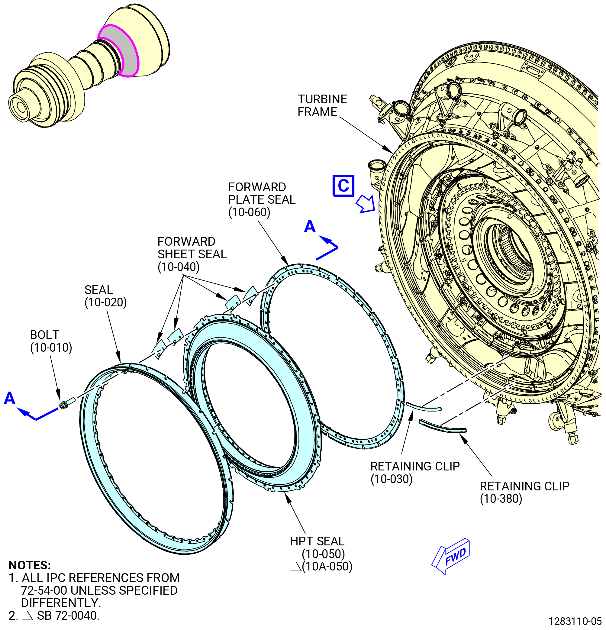
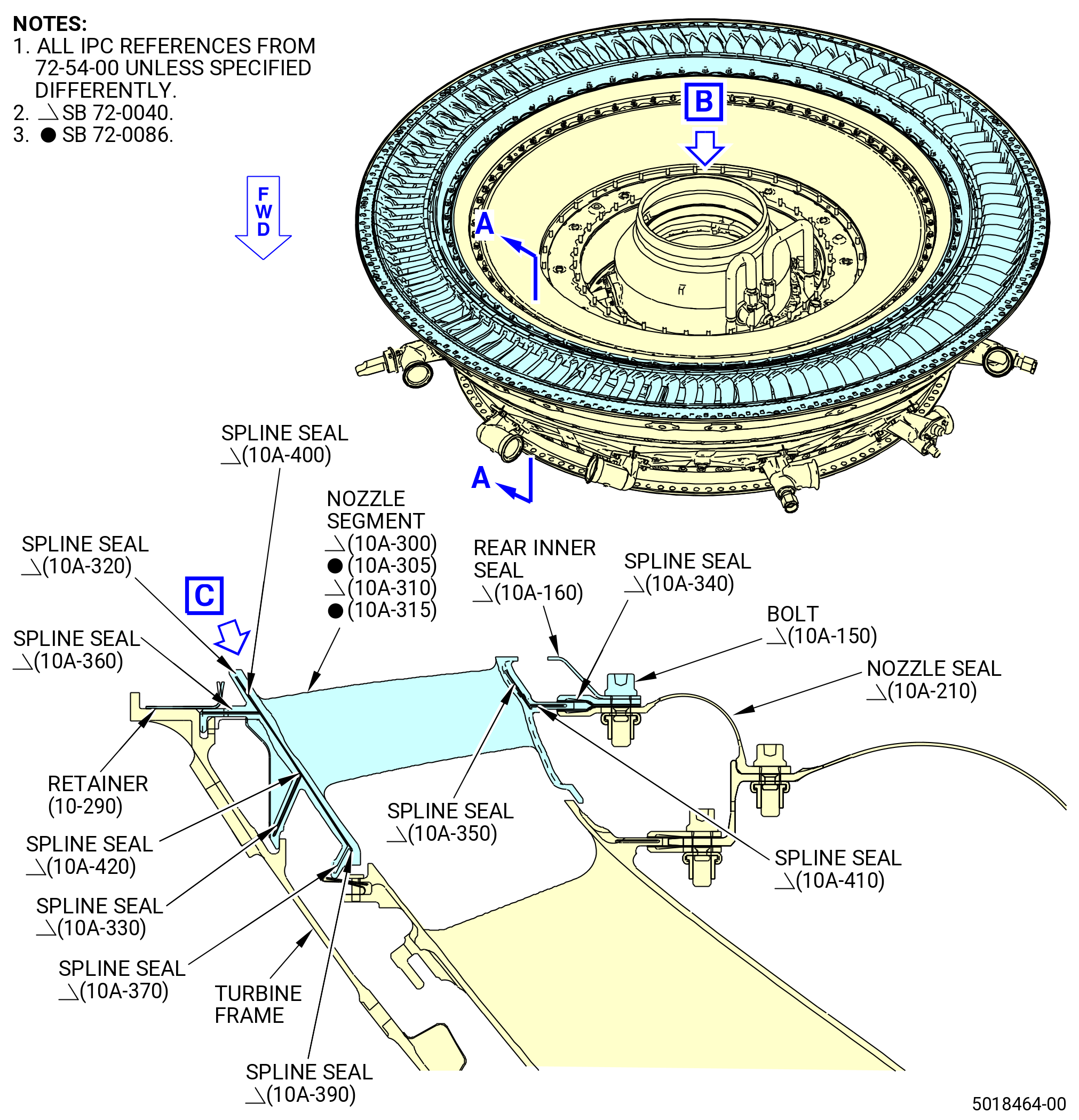
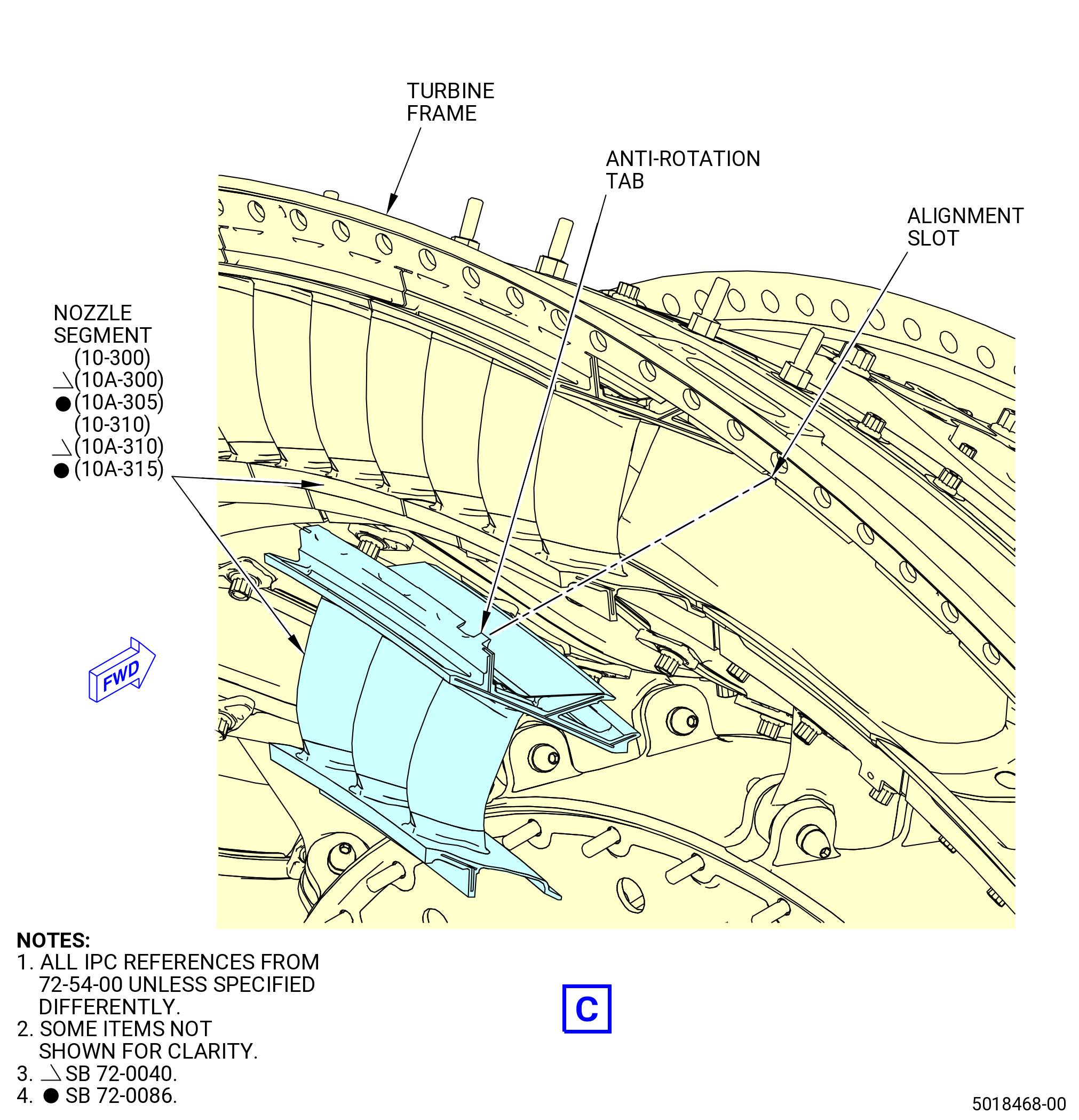
| A. | This procedure gives instructions to assemble the turbine center frame assembly (TCF). Refer to Figure 1001. |
| • |
|
| • |
|
| • |
|
| • |
|
| B. | This procedure starts with the turbine frame in the 9429M60 roll-over stand with the 11C4559 bracket set installed. |
| • |
|
| • |
|
| • |
|
| • |
|
| • |
|
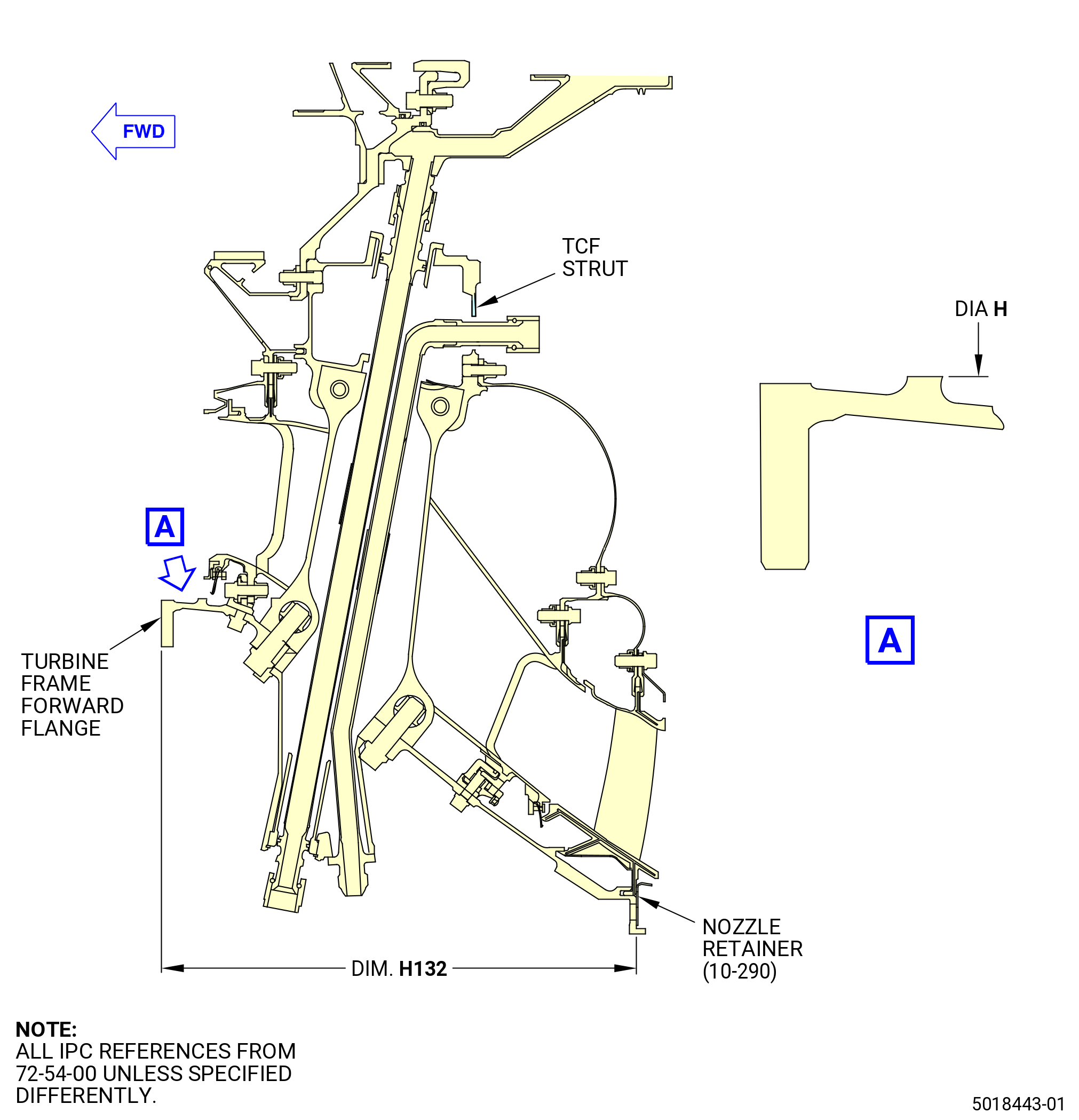
| C. | This procedure also includes the oil supply tube (01-620) (SIN 443B1) or (01-621) (SIN 443B1) or (01-621A) (SIN 443B1) or (01-621B) (SIN 443B1), air flow check, and No. 4 bearing sump pressure test in the No. 4 bearing support housing (15-150) (SIN 01403), oil tubes in the struts, and installation of the exhaust gas temperature (EGT) probes in the turbine frame. |
| D. | Install protective covers on the spare assemblies only. |
| E. | Install all bolts with the heads up and/or forward unless specified differently. |
| WARNING: |
|
| WARNING: |
|
| WARNING: |
|
| F. | Before installation, make sure that all rabbet and flange mating surfaces are free of foreign material and raised metal. Clean the flanges and threads of studs with C04-002 Stoddard solvent, C04-003 acetone, or C04-035 isopropyl alcohol. |
| G. | Keep a minimum clearance of 0.125 inch (3.18 mm) between each tube, tube-hose, and hose outside diameter (OD) and the adjacent hardware. |
| H. | All clock positions are aft looking forward (ALF), unless specified differently. |
| I. | You can use C02-058 lubricant on bearing (friction) surfaces and the threads of bolts that attach loop clamps for easier assembly. |
| NOTE: |
|
| J. | Loosely attach tubes, hoses, and manifolds to support hardware until the part or system is completely installed. Make sure that the installed tube, hose, manifold, or system is in the correct position before you torque the nuts, bolts, or tube fittings to the specified torque value. |
| K. | Make sure that you install new preformed packings. You cannot install used preformed packings. |
| WARNING: |
|
| L. | Apply C02-019 engine oil or C02-023 engine oil to preformed packings and lead-in chamfers. |
| M. | Be careful with the components of the No. 4 cylindrical roller bearing (No. 4 roller bearing) (15-090) (SIN 01400) or (15-091) (SIN 01400). The inner race of the No. 4 roller bearing is a loose part. Make sure that the inner race has the necessary protection for handling damage and corrosion. Refer to TASK 70-14-00-620-003 (HANDLING OF BEARINGS) and TASK 70-60-01-620-002 (PRESERVATION OF ANTIFRICTION BEARINGS) . |
| N. | Keep the roller bearing components (rollers, cages, inner races, and outer races) as a set by serial number. The roller bearing is a matched assembly. Do not mix serviceable roller bearing components with the components of different serial numbers. |
| O. | Follow the instructions to safety parts with safety wire, safety cable, cotter pins, or tab washers. Refer to TASK 70-11-00-400-001 (FASTENER RETENTION PROCEDURES) . |
| P. | The torque values given in this procedure are the actual torque to apply to the fastener. If a torque multiplier is used, do the necessary calculations to find the specified torque, the value that appears on the scale or dial of the torque wrench. Refer to TASK 70-51-00-400-004 (TIGHTENING PRACTICES AND TORQUE VALUES) . |
| 2 . | Tools, Equipment, and Materials. |
| NOTE: |
|
| A. | Tools and Equipment. |
| (1) | Special Tools. |
| (2) | Standard Tools and Equipment. |
|
| (3) | Locally Manufactured Tools. None. |
| B. | Consumable Materials. |
|
| C. | Referenced Procedures. |
|
| D. | Expendable Parts. |
|
|
|
| 3 . | Procedure. |
| Subtask 72-54-00-440-001 |
| A. | Remove the turbine frame from the 11C4559 bracket set and put it on an inspection table as follows: |
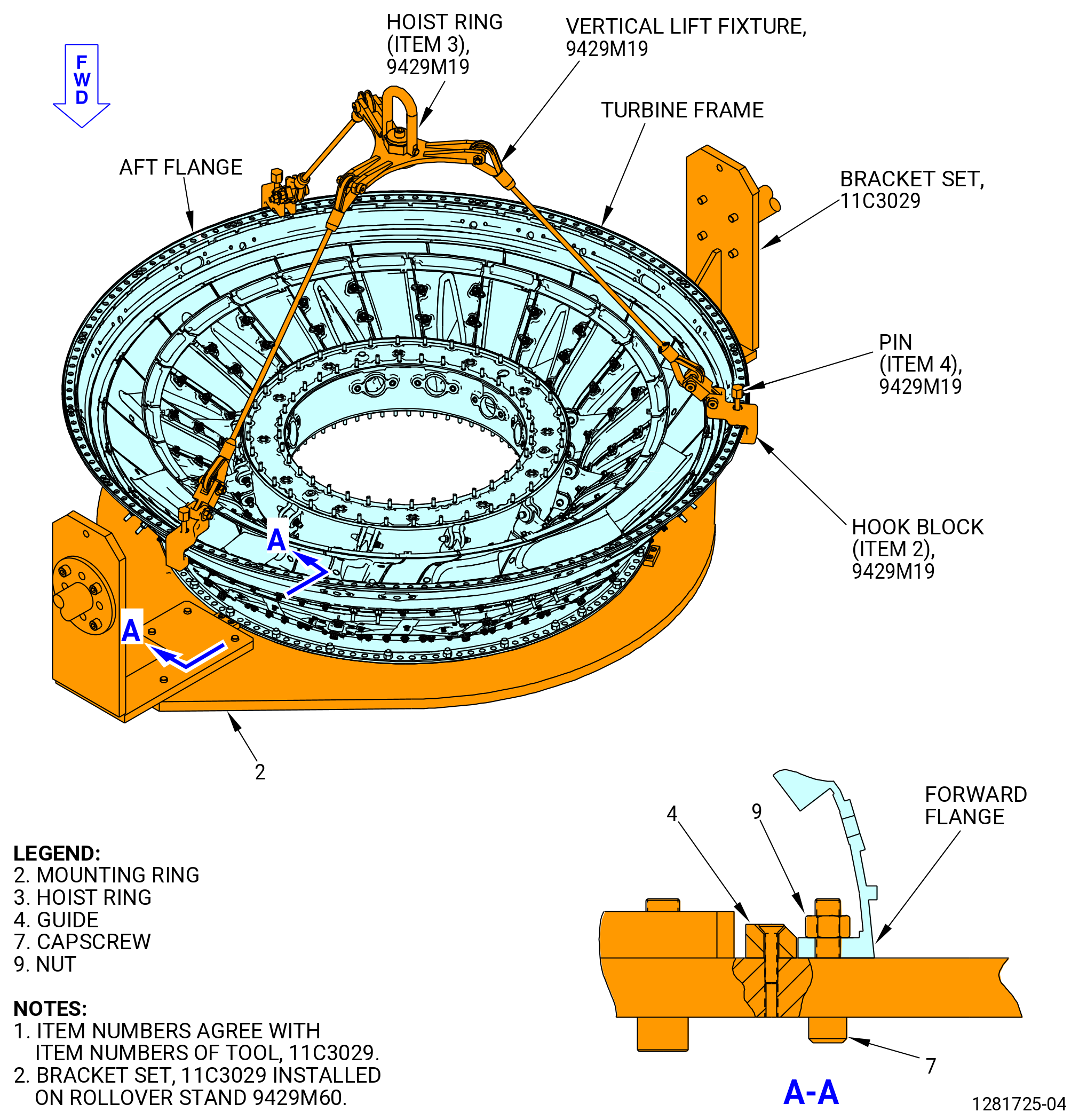
| (1) | Install the 9429M19 vertical lift fixture on the aft flange of the turbine frame as follows. Refer to Figure 1002. |
| (a) | Attach the hoist ring (item 13) to an overhead hoist. |
| (b) | Align the hook blocks (item 2) with the turbine frame boltholes at three equally spaced locations on the turbine frame aft flange. |
| (c) | Install the pins (item 4) to attach the hook blocks (item 2) to the turbine frame aft flange. |
| (d) | Make sure that the pins (item 4) are engaged in the turbine frame flange boltholes. |
| (2) | Move the turbine frame to an inspection table as follows. Refer to Figure 1002. |
| (a) | Remove the nuts (item 9) and capscrews (item 8) that attach the forward flange of the turbine frame to the 11C4559 bracket set. |
| WARNING: |
|
| (b) | Lift the turbine frame from the mounting ring (item 2) of the 11C4559 bracket set with the 9429M19 vertical lift fixture. |
| (c) | Put the turbine frame on an inspection table, supported by standard blocks at four locations, so the forward flange is raised from the table and accessible. |
| (3) | Remove the 9429M19 vertical lift fixture as follows. Refer to Figure 1002. |
| (a) | Remove the pins (item 4) from the hook blocks (item 2). |
| (b) | Remove the hook blocks (item 2) from the aft end of the turbine frame flange. |
| Subtask 72-54-00-220-001 |
| B. | Measure the turbine frame dimensions as follows: |
| (1) | Measure dimension H132 as follows. Refer to Figure 1003. |
| NOTE: |
|
| (a) | Measure dimension H132 at four equally spaced locations. |
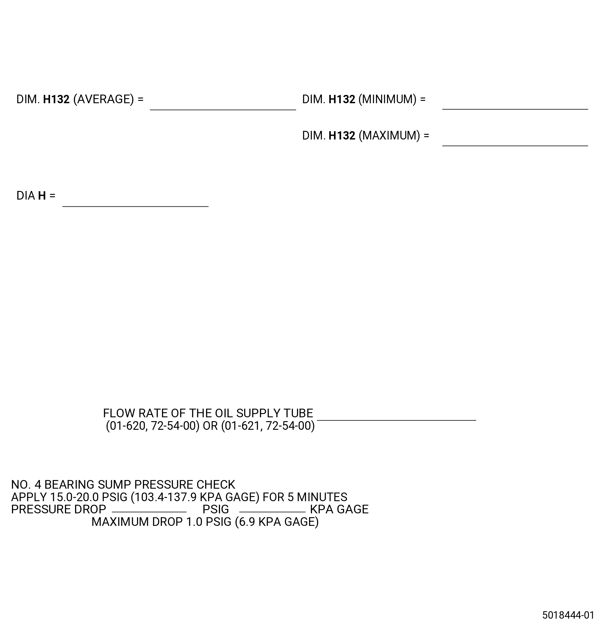
| (b) | Calculate the average dimension and record the value on the record sheet. Refer to Figure 1004. |
| (c) | Record the minimum and maximum dimension H132 from the four locations. |
| Subtask 72-54-00-220-051 |
| C. | Measure and record the turbine center frame assembly diameter H. Refer to Figure 1003. |
| Subtask 72-54-00-440-005 |
| D. | Move the turbine frame from the inspection table to the 11C4559 bracket set installed on the 9429M60 roll-over stand. Refer to Figure 1002 and do as follows: |
| (1) | Install the 9429M19 vertical lift fixture on the turbine frame. Refer to Figure 1002. |
| (a) | Attach the hoist ring (item 13) to an overhead hoist. |
| (b) | Align the hook blocks (item 2) with the turbine frame boltholes at three equally spaced locations on the turbine frame aft flange. |
| (c) | Install the pins (item 4) to attach the hook blocks (item 2) to the turbine frame aft flange. |
| (d) | Make sure that the pins (item 4) are engaged in the turbine frame flange boltholes. |
| WARNING: |
|
| (2) | Lift the turbine frame vertically from the inspection table. |
| (3) | If necessary, check the installation of the 9429M60 roll-over stand. |
| (4) | Install the turbine frame on the mounting ring (item 2) in the vertical position, forward end down, on the aft side of 11C4559 bracket set installed on the 9429M60 roll-over stand as follows: |
| (a) | Lift the turbine frame, forward flange down, and position the turbine frame on the mounting ring (item 2). |
| (b) | Align the top of the turbine frame with the TOP VERT mark on the mounting ring (item 2). |
| (c) | Put the turbine frame on the mounting ring (item 2) and make sure that the boltholes are aligned. |
| (d) | Install the capscrews (item 8) and nuts (item 9) and tighten the nuts to secure the turbine frame to the mounting ring (item 2). |
| (5) | Remove the 9429M19 vertical lift fixture from the aft flange of the turbine frame as follows: |
| (a) | Remove the pins (item 4) from the hook block (item 2). |
| (b) | Remove the hook block (item 2) from the aft end of the turbine frame flange. |
| Subtask 72-54-00-440-010 |
| E. | As necessary during this procedure, turn the turbine frame in the 9429M60 roll-over stand as follows: |
| CAUTION: |
|
| (1) | Make sure that the turbine frame is correctly installed in the 11C4559 bracket set on the 9429M60 roll-over stand before you turn the turbine frame. |
| CAUTION: |
|
| (2) | Make sure that the floor locks (item 69) of the 9429M60 roll-over stand touch the floor and support the weight of the roll-over stand. |
| (3) | Push the lever (item 24) of the 9429M60 roll-over stand to disengage the locating pin (item 23) to unlock the hand wheel (item 31). |
| (4) | Turn the hand wheel (item 31) until the TCF is in the correct position. |
| CAUTION: |
|
| (5) | Release the lever (item 24) and turn the hand wheel (item 31) back and forth until the locating pin (item 23) engages and locks the hand wheel (item 31). The hand wheel will lock in eight positions at 45-degrees increments. |
| (6) | Pull the lever (item 24) of the 9429M60 roll-over stand to engage the locating pin (item 23) and lock the hand wheel (item 31). |
| Subtask 72-54-00-440-011 |
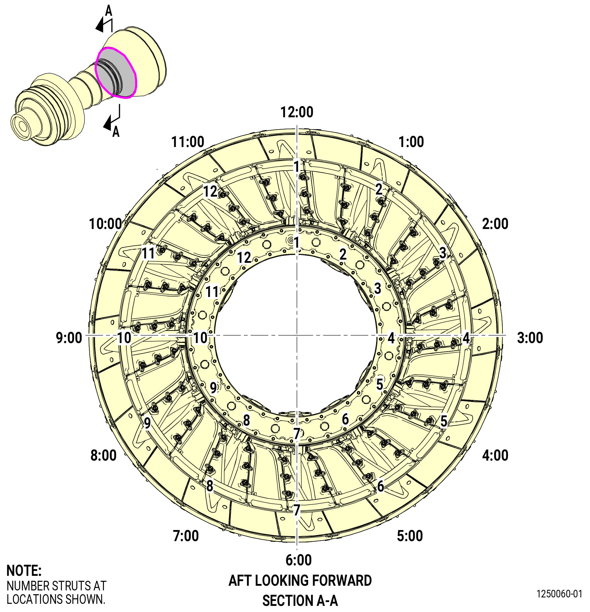
| F. | Use a C05-003 pen to number the struts of the turbine frame for easy reference during the installation of strut hardware. Refer to Figure 1005 and do as follows: |
| (1) | Put a mark to the strut at the top vertical centerline (TVCL) at strut No. 1. Put a mark of the strut number on the OD of the case and on the aft surface of the inner hub. |
| (2) | Turn the turbine frame as necessary to make marking areas easy to access. |
| (3) | Continue to put marks on the strut No. 2 thru 12 in a clockwise (CW) direction, ALF. |
| Subtask 72-54-00-440-129 |
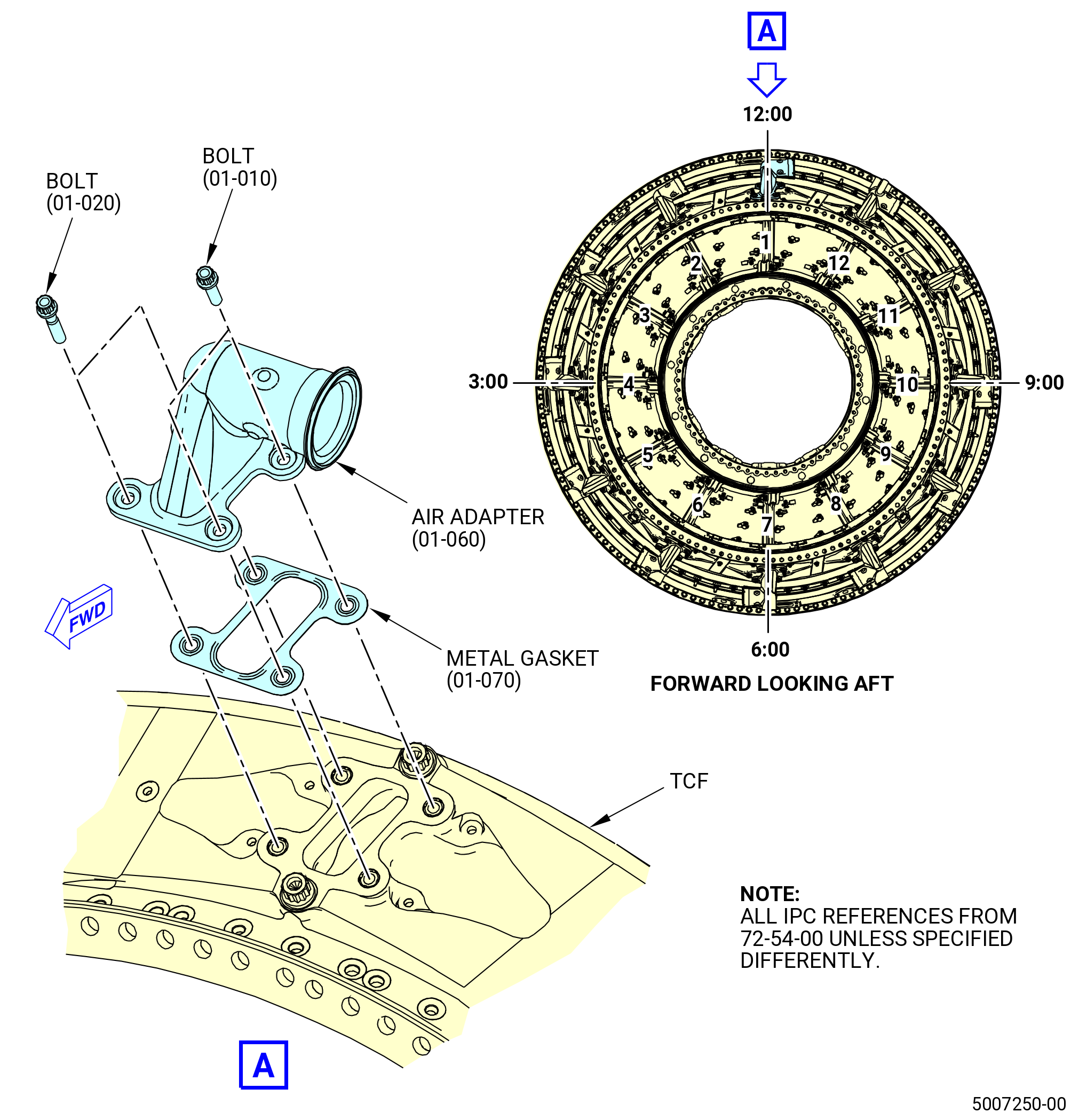
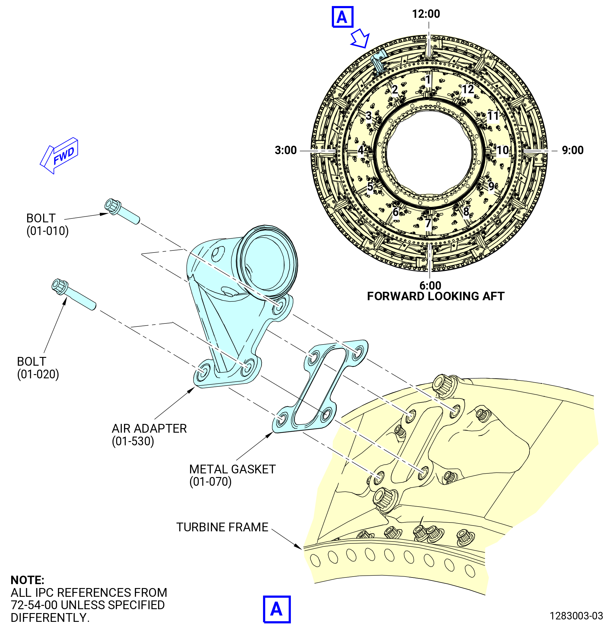
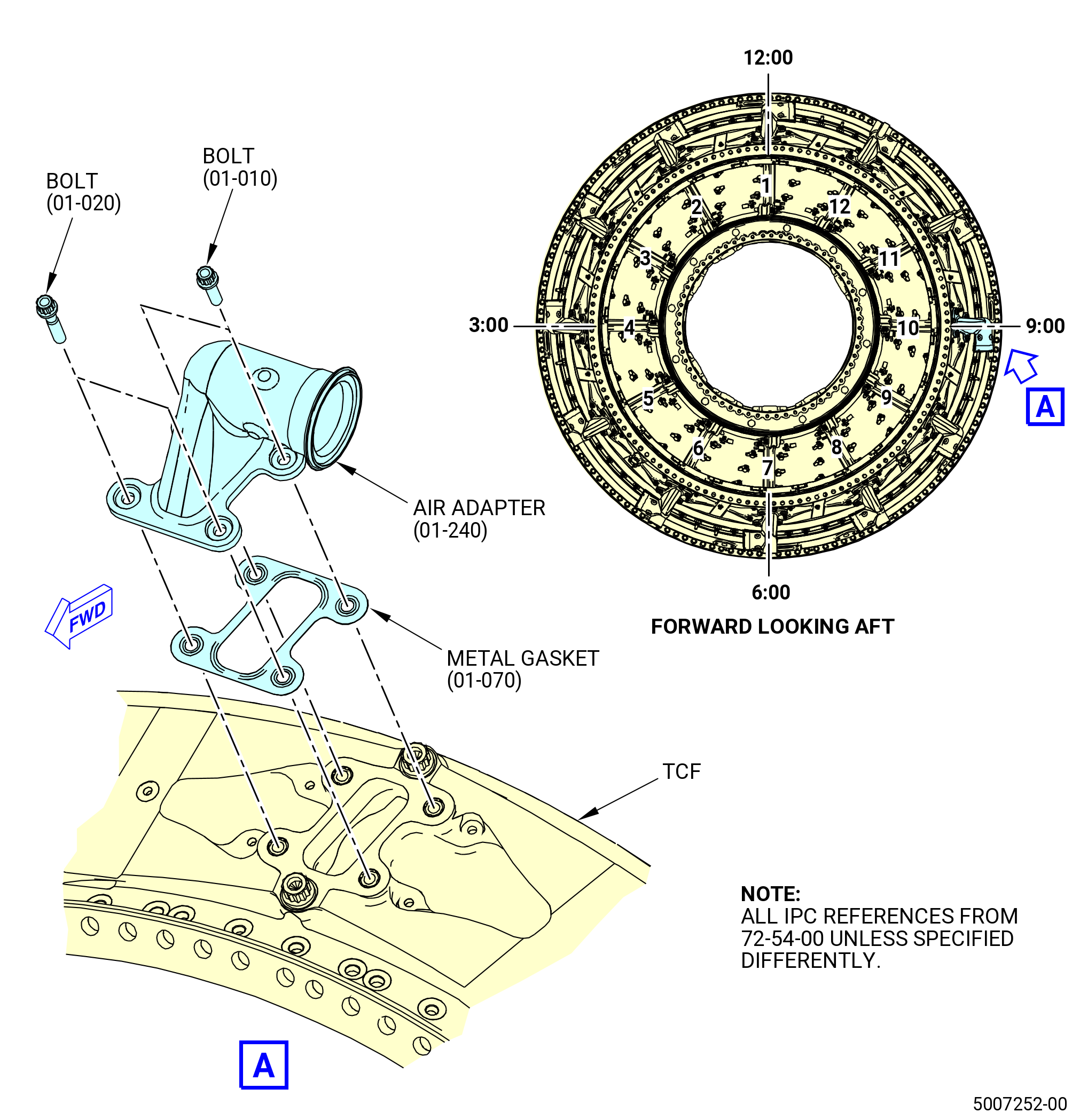
| G. | Install the air adapter (01-060) (SIN 9250B) on the turbine frame at strut No. 1 as follows: |
| WARNING: |
|
| (1) | Apply C02-058 lubricant to the threads and bearing (friction) surfaces of the machine bolts (bolts) (01-010) (SIN 92526) and (01-020) (SIN 92525). |
| (a) | Use a minimum quantity of C02-058 lubricant necessary for assembly. After assembly, remove the remaining lubricant with a clean C10-182 cloth. |
| (2) | Put the metal gasket (01-070) (SIN 92551) in position on the outer pad of the turbine frame strut. Make sure that the metal gasket is new and that the lifted surface is outboard. |
| CAUTION: |
|
| (3) | Put the air adapter in position on the metal gasket. |
| CAUTION: |
|
| (4) | Install the bolts (01-010) (SIN 92526) and (01-020) (SIN 92525) through the air adapter, metal gasket, and into the turbine frame. Hand-tighten the bolts. |
| Subtask 72-54-00-440-131 |
| H. | Install the air adapter (01-530) (SIN 9250E) on the turbine frame at strut No. 2. Refer to Figure 1007 and do as follows: |
| WARNING: |
|
| (1) | Apply C02-058 lubricant to the threads and bearing (friction) surfaces of the bolts (01-010) (SIN 92526) and (01-020) (SIN 92525). |
| (a) | Use a minimum quantity of C02-058 lubricant necessary for assembly. After assembly, remove the remaining lubricant with a clean C10-182 cloth. |
| (2) | Put the metal gasket (01-070) (SIN 92551) in position on the outer pad of the turbine frame strut. Make sure that the metal gasket is new and that the lifted surface is outboard. |
| CAUTION: |
|
| (3) | Put the air adapter in position on the metal gasket. |
| CAUTION: |
|
| (4) | Install the bolts (01-010) (SIN 92526) and (01-020) (SIN 92525) through the air adapter, metal gasket, and into the turbine frame. Hand-tighten the bolts. |
| Subtask 72-54-00-440-013 |
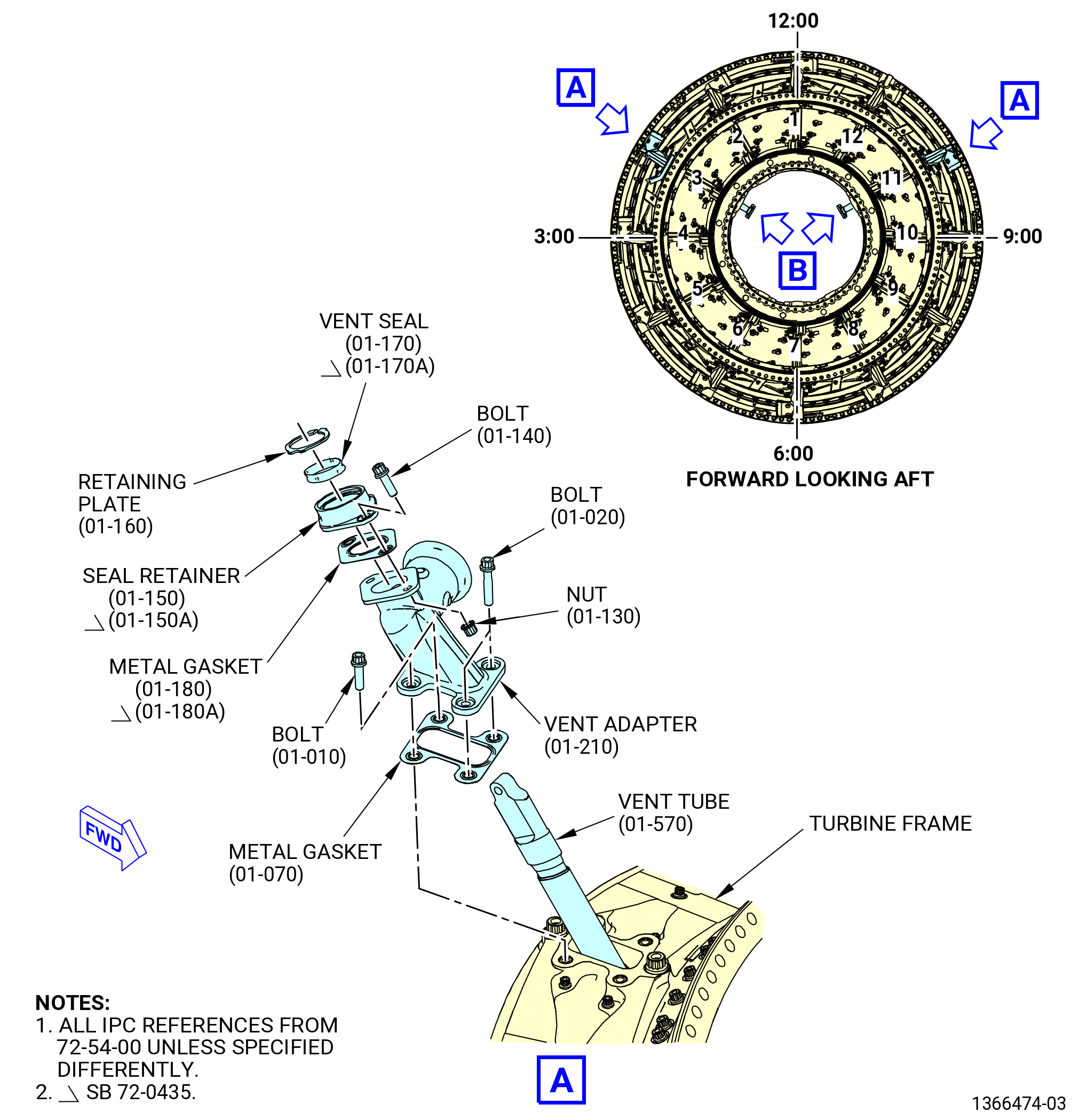
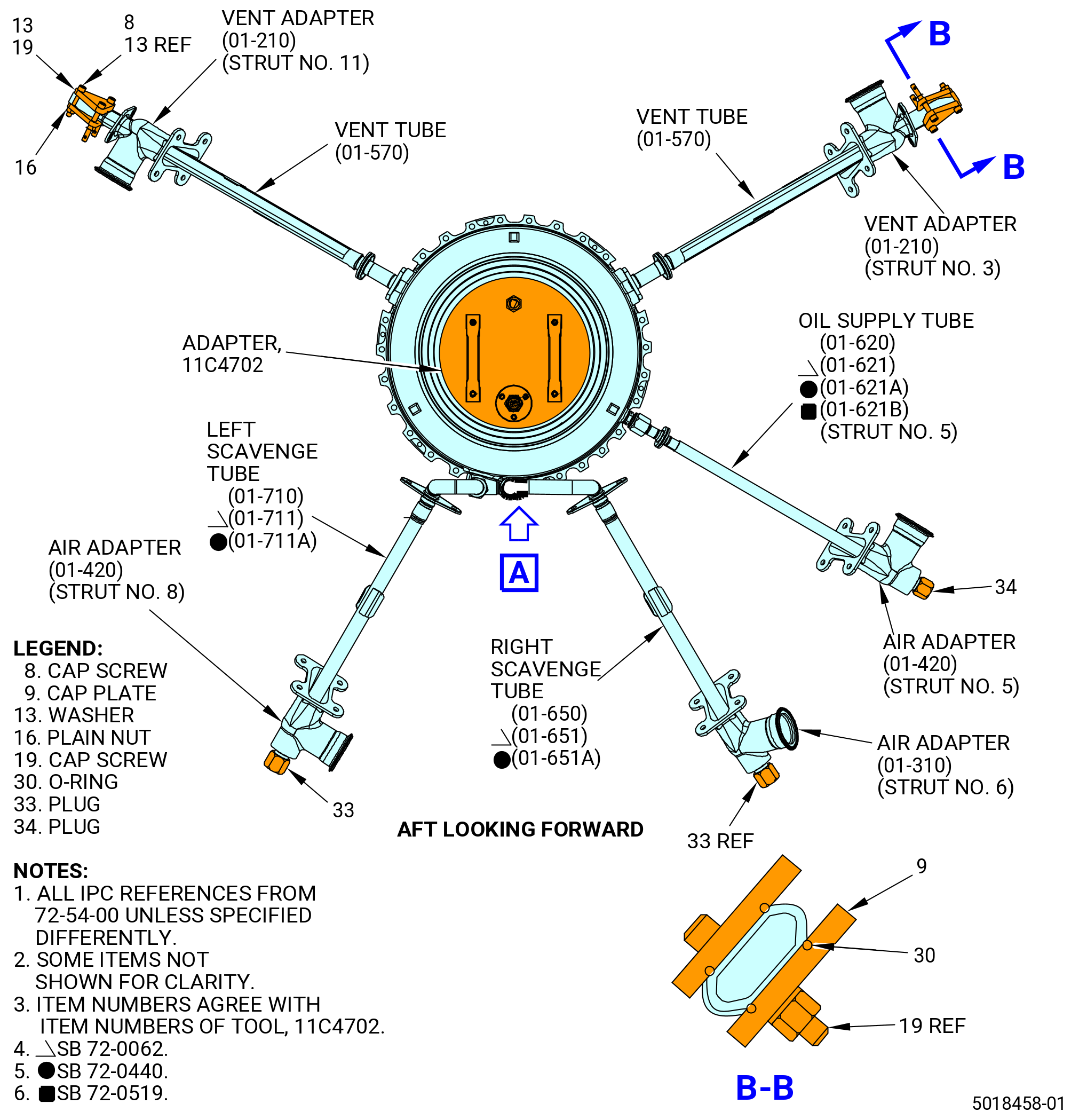
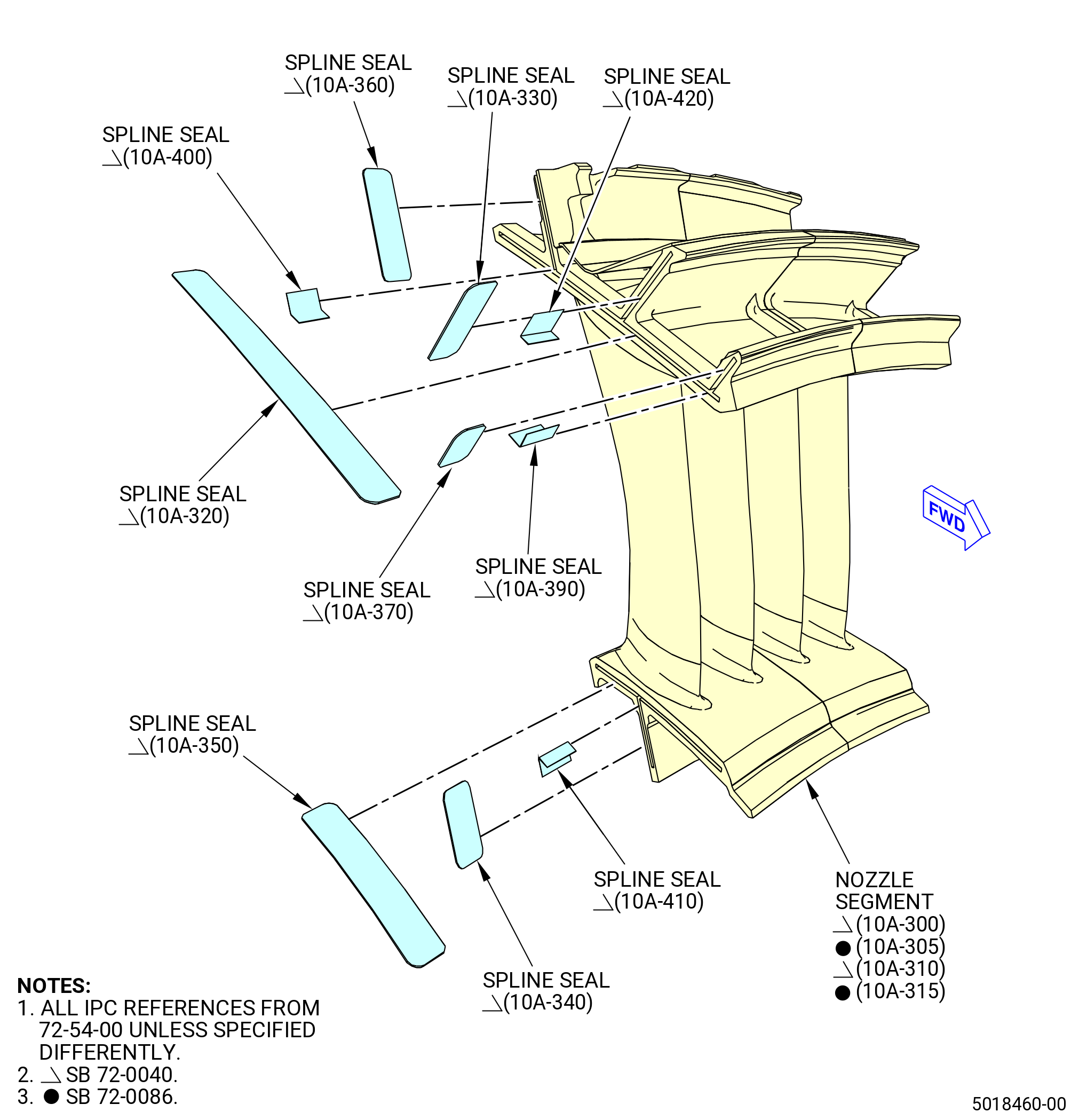
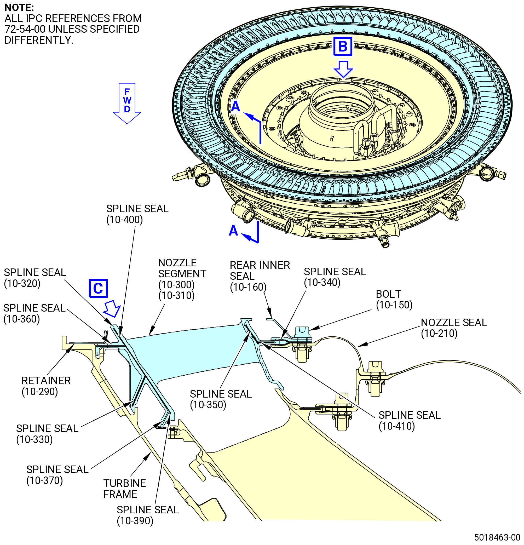
| I. | Install the vent adapter (01-210) (SIN 46107) and vent tube (01-570) (SIN 46104) on the turbine frame at struts No. 3 and 11. Refer to Figure 1008 and do as follows: |
| (1) | Attach the vent adapter to the turbine frame as follows: |
| WARNING: |
|
| (a) | Apply C02-058 lubricant to the threads and bearing (friction) surfaces of the bolts (01-010) (SIN 92526) and (01-020) (SIN 92525). |
| 1 | Use a minimum quantity of C02-058 lubricant necessary for assembly. After assembly, remove the remaining lubricant with a clean C10-182 cloth. |
| (b) | Put a metal gasket (01-070) (SIN 92551) in position on the outer pad of the turbine frame at struts No. 3 and 11. Make sure that the metal gasket is new and that the lifted surface is outboard. |
| (c) | Put the vent adapter in position on the metal gasket. |
| CAUTION: |
|
| (d) | Install the bolts through the vent adapter, metal gasket, and into the turbine frame. Hand-tighten the bolts. |
| Subtask 72-54-00-440-015 |
| (2) | Install the vent tube (01-570) (SIN 46104) in struts No. 3 and 11 of the turbine frame. Refer to Figure 1008 and do as follows: |
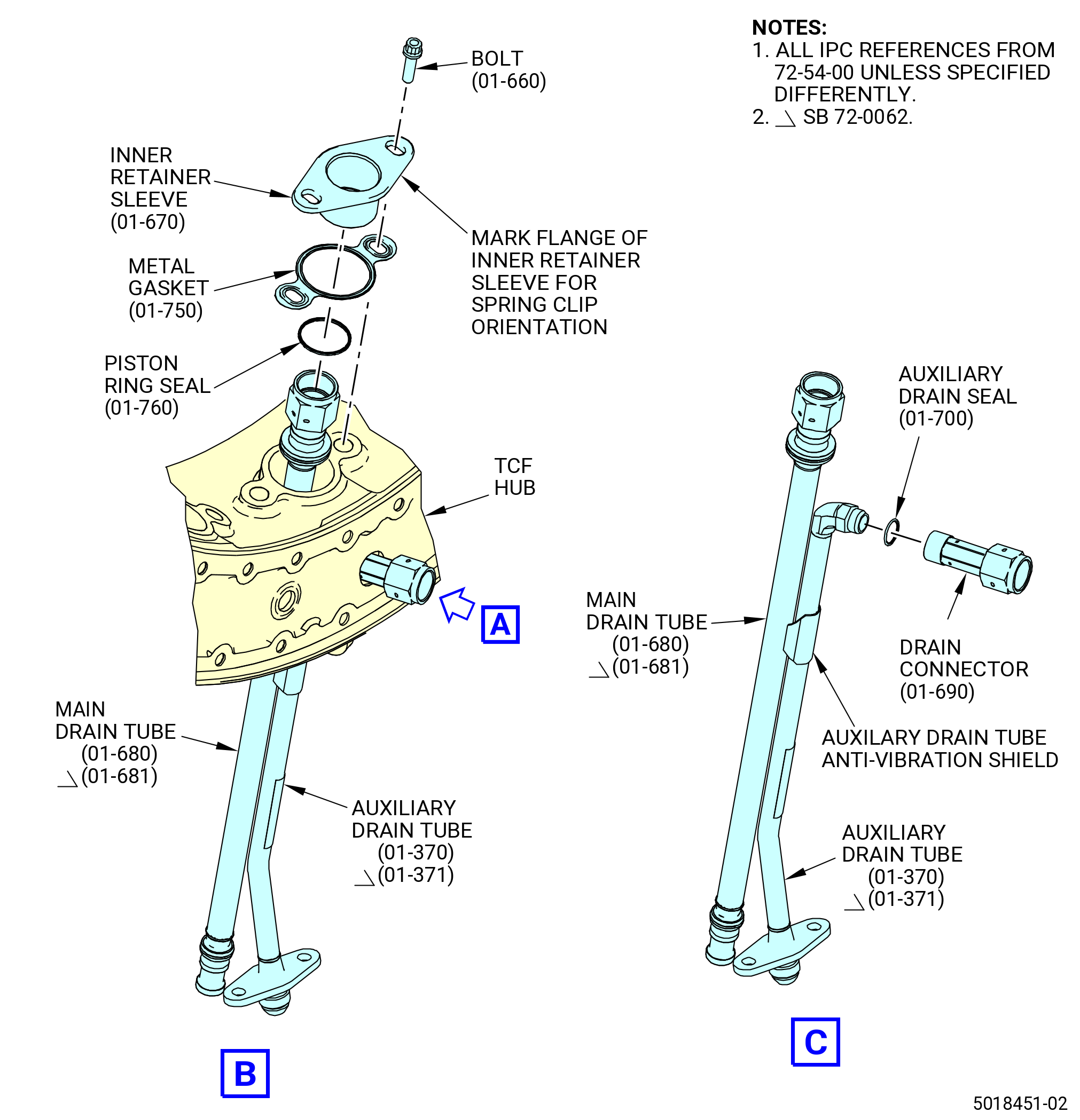
| (a) | Install the piston seal ring (01-600) (SIN 46155) and the inner retainer sleeve (inner retainer) (01-560) (SIN 46188) as follows: |
| WARNING: |
|
| 1 | Apply C02-019 engine oil or C02-023 engine oil to the piston ring seal. |
| 2 | Install the piston ring seal on the tube from the outboard end of the tube. |
| 3 | Push the piston ring seal down into the seal retainer ring groove on the inboard end of the tube. Spring open the piston ring seal a minimum amount to install on the fitting on the tube. |
| 4 | Install the inner retainer on the tube from the outboard end. |
| 5 | Push the inner retainer down to engage the piston ring seal. |
| 6 | Install a metal gasket (01-590) (SIN 461N1) on the inner retainer with the lifted surface facing outboard. |
| (b) | Attach the vent tube (01-570) (SIN 46104) to the turbine frame as follows: |
| 1 | Install the vent tube in struts No. 3 and 11 from the inboard side. |
| 2 | Make sure that the outboard end of the vent tube is through the hole in the vent adapter (01-210) (SIN 46107). Make sure that the hole in the end of the vent tube points toward to the top vertical centerline (TVCL). |
| WARNING: |
|
| 3 | Apply C02-058 lubricant to the threads and bearing (friction) surfaces of the bolts (01-550) (SIN 46120). |
| a | Use a minimum quantity of C02-058 lubricant necessary for assembly. After assembly, remove the remaining lubricant with a clean C10-182 cloth. |
| 4 | Install the bolts (01-550) (SIN 46120) through the inner retainer (01-560) (SIN 46188), metal gasket (01-590) (SIN 461N1), and into the turbine frame. Hand-tighten the bolts. |
| (c) | Install the vent seal (01-170) (SIN 46152) or (01-170A) (SIN 46152) and retaining plate (01-160) (SIN 46156) in the seal retainer (01-150) (SIN 46182) or (01-150A) (SIN 46182) as follows: |
| NOTE: |
|
| WARNING: |
|
| 1 | Apply C02-058 lubricant to the inside diameter and the outside diameter of the vent seal. |
| CAUTION: |
|
| 2 | Put the vent seal in the seal retainer with hand pressure only. Do not use hand tools to install the vent seal. If necessary, use 11C4729 adapter (PRE SB 72-0435) or 11C4613 adapter (SB 72-0435) to install the vent seal in the retainer. |
| CAUTION: |
|
| 3 | Put the retaining plate in the seal retainer. Position the retaining plate tabs in the opening first, then push the ring into the groove. |
| NOTE: |
|
| (d) | Install the seal retainer (01-150) (SIN 46182) or (01-150A) (SIN 46182) on the vent adapter (01-210) (SIN 46107) as follows: |
| NOTE: |
|
| 1 | Put a metal gasket (01-180) (SIN 461N2) or (01-180A) (SIN 461N2) on the seal retainer (01-150) (SIN 46182) or (01-150A) (SIN 46182). Make sure that the metal gasket is new and that the lifted surface is outboard. |
| 2 | Put the seal retainer and metal gasket on the vent adapter on the vent tube (01-570) (SIN 46104). |
| WARNING: |
|
| 3 | Apply C02-058 lubricant to the threads and bearing (friction) surfaces of the bolts (01-140) (SIN 46122) and self-locking nuts (nuts) (01-130) (SIN 46140). |
| a | Use a minimum quantity of C02-058 lubricant necessary for assembly. After assembly, remove the remaining lubricant with a clean C10-182 cloth. |
| 4 | Install bolts (01-140) (SIN 46122) and nuts (01-130) (SIN 46140) with the boltheads outboard. Hand-tighten the bolts. |
| Subtask 72-54-00-440-356 |
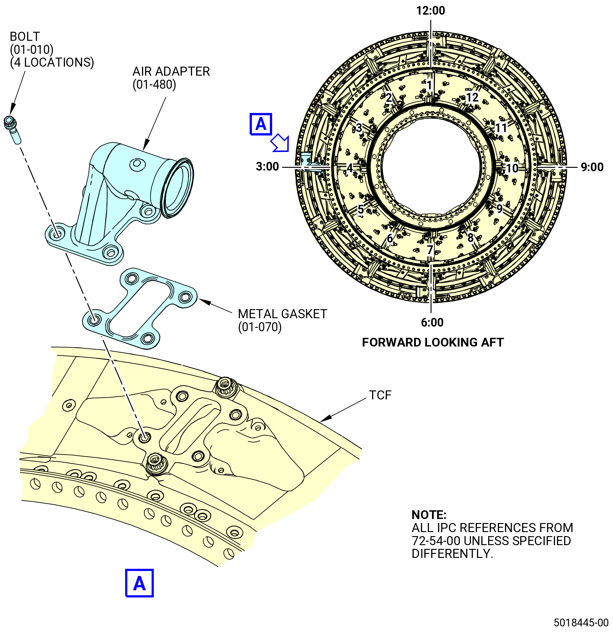
| J. | Install the air adapter (01-480) (SIN 9250G) to the turbine frame at strut No. 4. Refer to Figure 1009 and do as follows: |
| WARNING: |
|
| (1) | Apply C02-058 lubricant to the threads and bearing (friction) surfaces of the bolts (01-010) (SIN 92526). |
| (a) | Use a minimum quantity of C02-058 lubricant necessary for assembly. After assembly, remove the remaining lubricant with a clean C10-182 cloth. |
| (2) | Put the metal gasket (01-070) (SIN 92551) in position on the outer pad of the turbine frame strut. Make sure that the metal gasket is new and that the lifted surface is outboard. |
| CAUTION: |
|
| (3) | Put the air adapter in position on the metal gasket. |
| CAUTION: |
|
| (4) | Install bolts (01-010) (SIN 92526) through the air adapter, metal gasket, and into the turbine frame. Hand-tighten the bolts. |
| Subtask 72-54-00-440-016 |
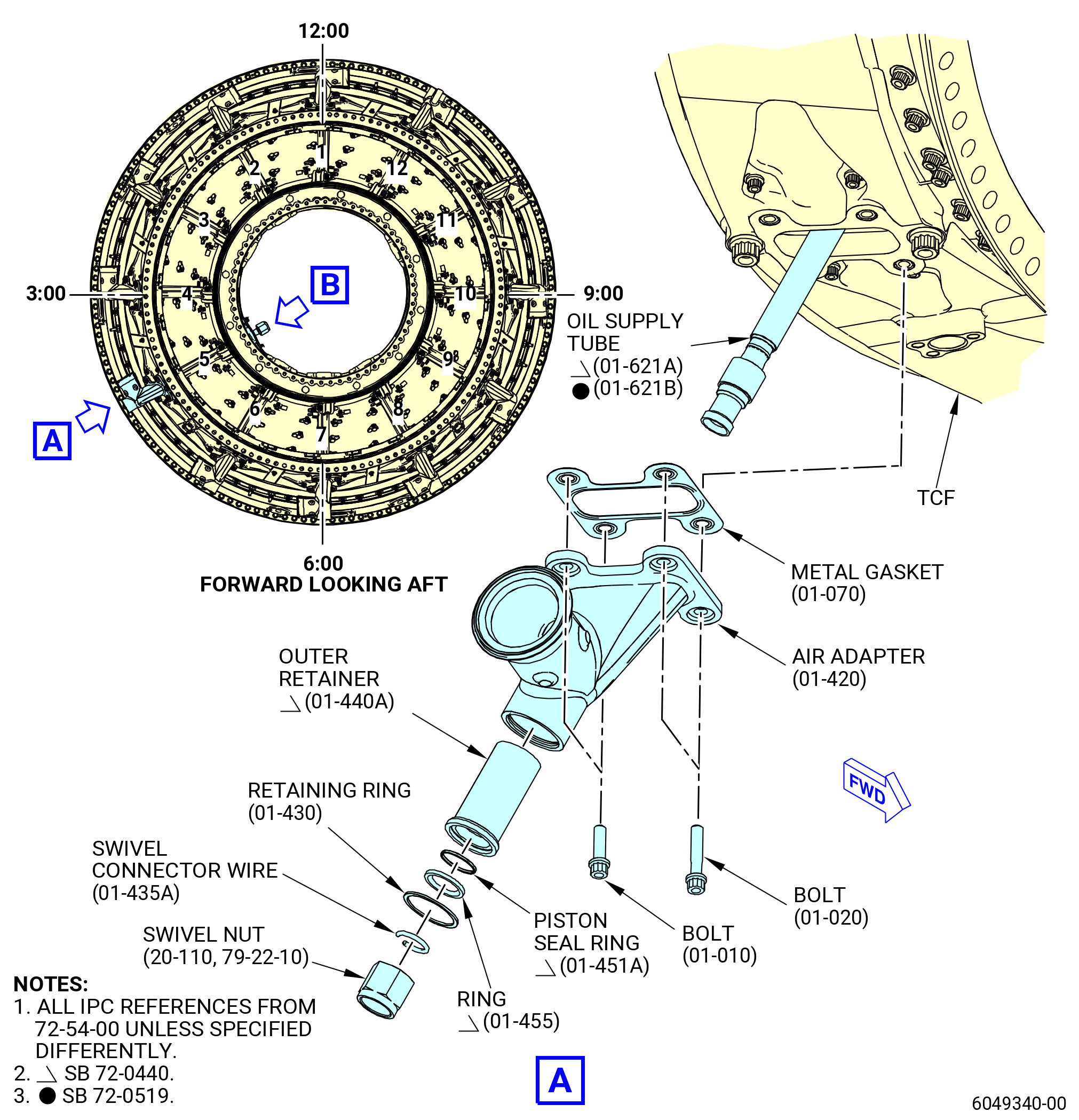
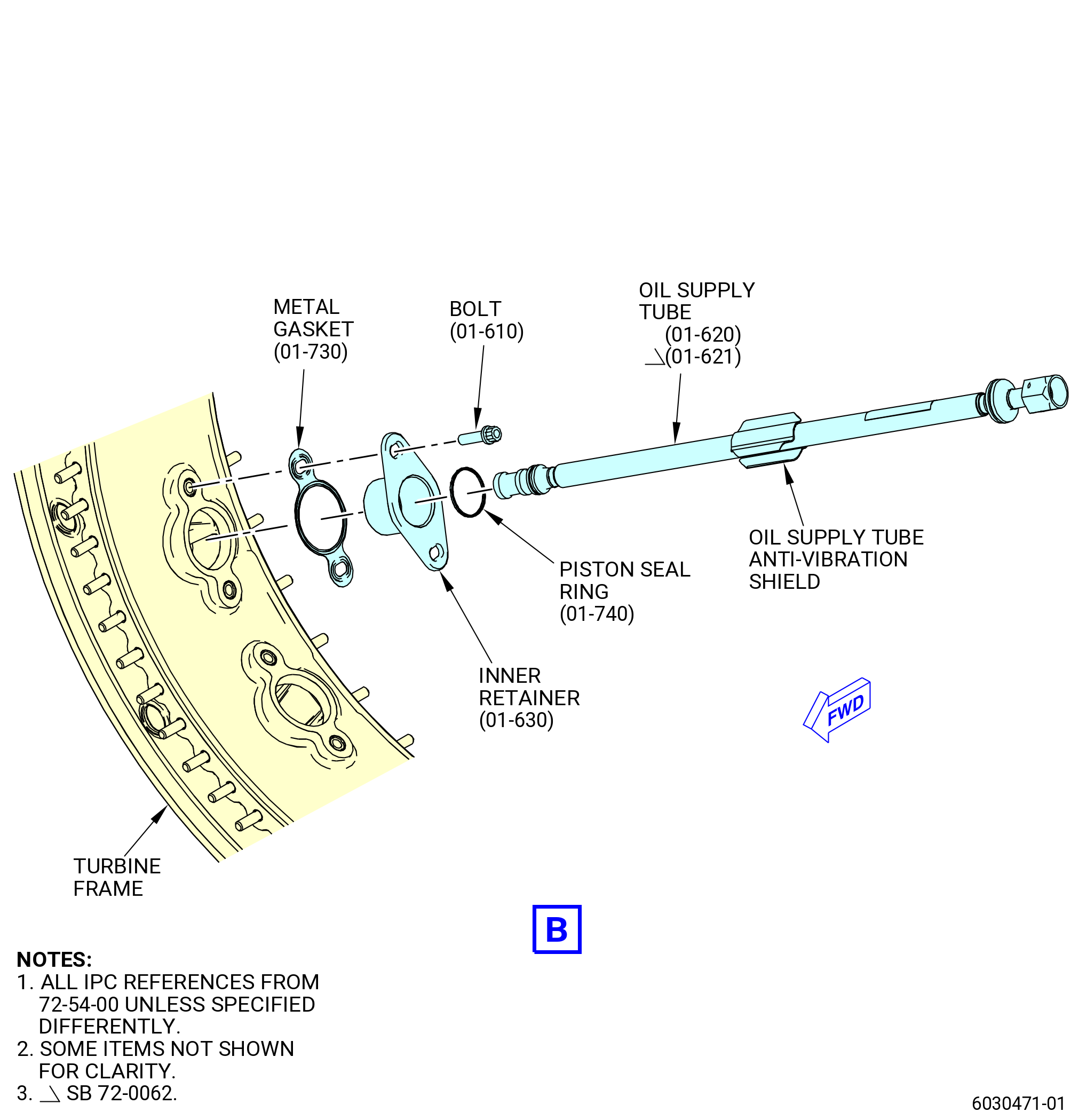
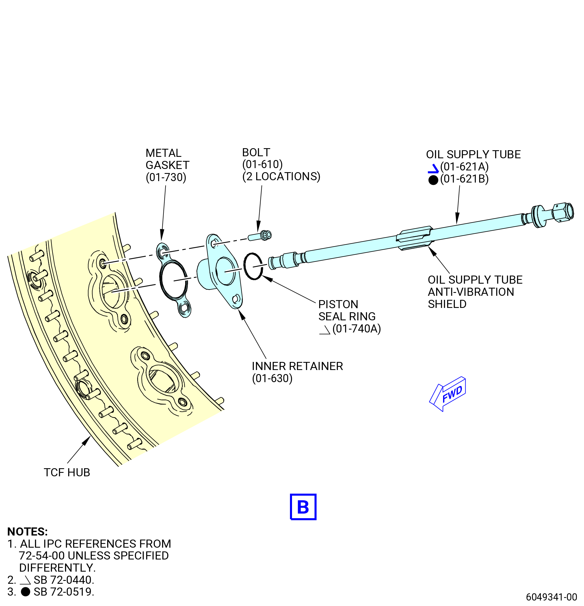
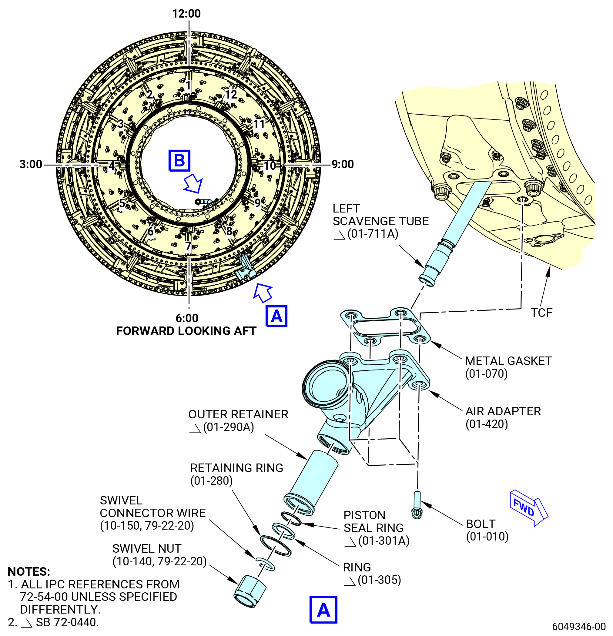
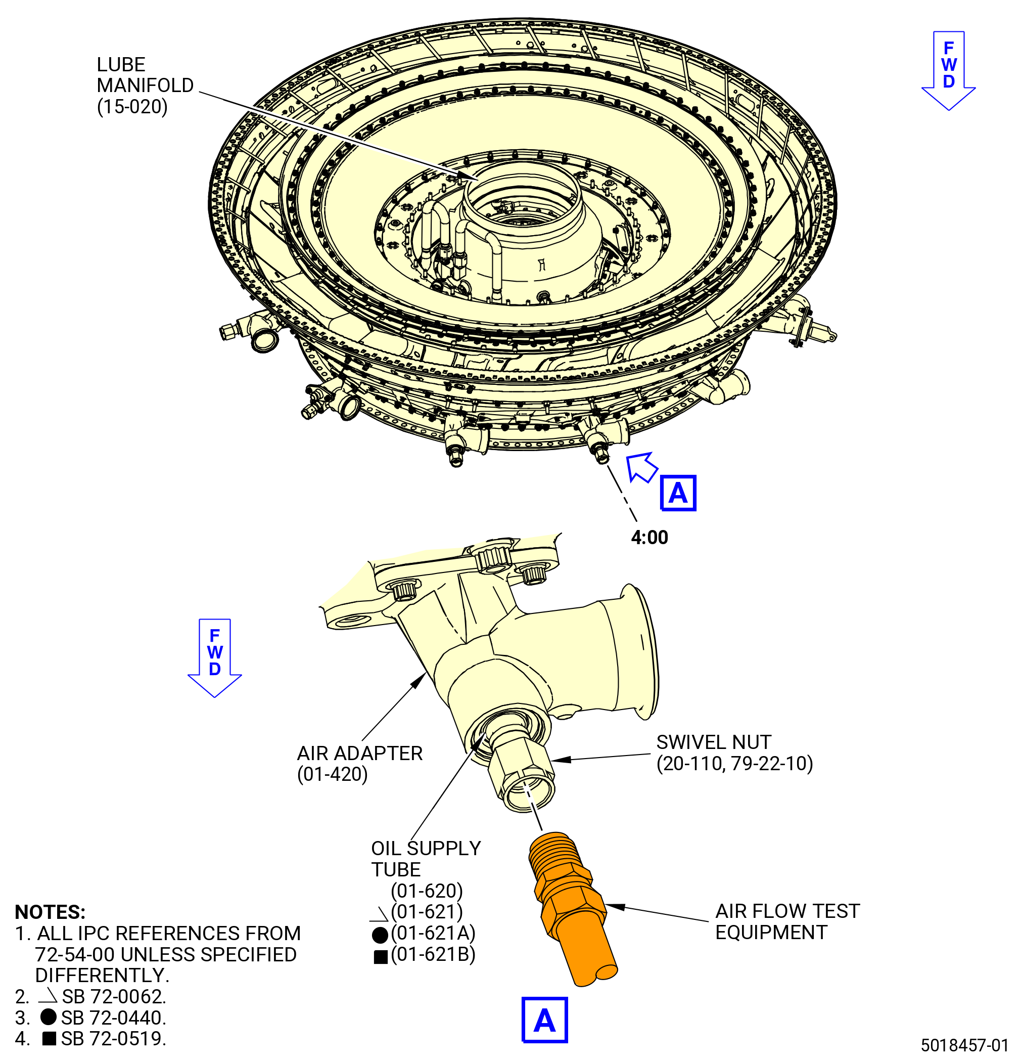
| K. | Install the air adapter (01-420) (SIN 92509) and oil supply tube (01-620) (SIN 443B1) or (01-621) (SIN 443B1) or (01-621A) (SIN 443B1) or (01-621B) (SIN 443B1) on the turbine frame at strut No. 5. Refer to Figure 1010 and do as follows: |
| NOTE: |
|
| (1) | Install the oil supply tube in the strut No. 5 on the turbine frame as follows: |
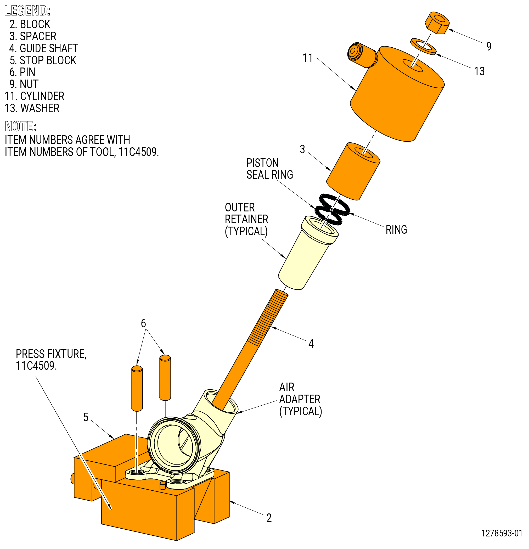
| (a) | Install the outer retainer (01-440) (SIN 443B3) or (01-440A) (SIN 443B3), retaining ring (01-430) (SIN 443V1), ring (01-455) (SIN 443N4), and piston seal ring (01-451A) (SIN 443N1) in the air adapter as follows: |
| 1 | Install guide shaft (item 4) into the block (item 2) of the 11C4509 press fixture and attach it with the nut (item 9). |
| 2 | Install the air adapter on the guide shaft (item 4) to seat it at the same angle as the air adapter mounting flange, so that the end of the air adapter points straight up. Put the air adapter mounting flange onto the block (item 2). Refer to Figure 1011. |
| 3 | Install pins (item 6) to align and secure the air adapter to the guide shaft (item 4). |
| 4 | Adjust the stop block (item 5) against the mounting flange of the air adapter. |
| 5 | Install the outer retainer on the guide shaft (item 4) and into the air adapter. |
| 6 | Install the spacer (item 3) over the guide shaft and on the outer retainer. |
| 7 | Install cylinder (item 11) above the guide shaft (item 4) and on the spacer (item 3). |
| 8 | Install washer (item 13) and nut (item 9) at the end of the guide shaft (item 4). Hand tighten the nut (item 9). |
| WARNING: |
|
| 9 | Apply 2500 psi (17250 kPa) of hydraulic pressure to the cylinder (item 11) and push the outer retainer into the air adapter. |
| Subtask 72-54-00-440-441 |
| * * * FOR |
| * * * PRE SB 72-0440 |
| 10 | Remove the spacer (item 3), nut (item 9), cylinder (item 11), and washer (item 13). |
| 11 | Install the new piston seal ring (01-451) (SIN 443N1) on the guide shaft and press it into the air adapter as applied in steps before. If necessary, apply engine oil. |
| 12 | Do a check for free movement of the piston ring. |
| * * * FOR |
| * * * END PRE SB 72-0440 |
| Subtask 72-54-00-440-442 |
| * * * FOR |
| * * * SB 72-0440 |
| 13 | Remove the spacer (item 3), nut (item 9), cylinder (item 11), and washer (item 13). |
| 14 | Install the new piston seal ring (01-451A) (SIN 443N1) and the ring (01A-455) (SIN 443N4) on the guide shaft and press it into the air adapter as applied in steps before. If necessary, apply engine oil. |
| NOTE: |
|
| 15 | Do a check for free movement of the piston ring. |
| * * * FOR |
| * * * END SB 72-0440 |
| Subtask 72-54-00-440-443 |
| 16 | Remove the air adapter from the fixture in reversed order. |
| 17 | Deleted. |
| WARNING: |
|
| 18 | Apply C02-019 engine oil or C02-023 engine oil to the retaining ring. |
| 19 | Press the retaining ring into the inside diameter groove of the air adapter. |
| 20 | Make sure that the retaining ring is correctly installed. |
| Subtask 72-54-00-440-018 |
| (b) | Install the piston seal ring (01-740) (SIN 443N0) or (01-740A) (SIN 443N0), inner retainer (01-630) (SIN 443B4), and metal gasket (01-730) (SIN 443N2) on the oil supply tube (01-620) (SIN 443B1) or (01-621) (SIN 443B1) or (01-621A) (SIN 443B1) or (01-621B) (SIN 443B1). Refer to Figure 1010 and do as follows: |
| WARNING: |
|
| 1 | Apply C02-019 engine oil or C02-023 engine oil to the piston ring seals. |
| 2 | Put the piston ring seal in the groove on the inboard end of the tube. |
| NOTE: |
|
| 3 | Install the inner retainer on the oil supply tube from the outboard end. |
| 4 | Push the inner retainer up to engage the piston ring seal. |
| 5 | Put a metal gasket on the inner retainer. Make sure that the metal gasket is new and that the raised surface is outboard. |
| (c) | Attach the oil supply tube (01-620) (SIN 443B1) or (01-621) (SIN 443B1) or (01-621A) (SIN 443B1) or (01-621B) (SIN 443B1), inner retainer (01-630) (SIN 443B4), and piston seal ring (01-450) (SIN 443N1) or (01-451) (SIN 443N1) or (01-451A) (SIN 443N1) to the turbine frame as follows: |
| 1 | Align the oil supply tube with the inboard opening of strut No. 5. |
| 2 | Make sure that the anti-vibration shield on the tube is turned so it will engage the inner surface of the strut. You cannot turn the tube after you install it in the strut. |
| Subtask 72-54-00-440-357 |
| CAUTION: |
|
| 3 | Install the oil supply tube (01-620) (SIN 443B1) or (01-621) (SIN 443B1) or (01-621A) (SIN 443B1) or (01-621B) (SIN 443B1) in strut No. 5 from the inboard side. Do not turn the tube after it is installed in the strut. |
| Subtask 72-54-00-440-358 |
| 3.A. | Deleted. |
| Subtask 72-54-00-440-359 |
| 4 | Local forming of the anti-vibration shield is permissible to facilitate assembly. In at least one location in the tube-lengthwise direction the full damper cross section (except chamfers) must remain unchanged. |
| 5 | Make sure that the outboard end of the oil supply tube is through the hole in the supply adapter. |
| WARNING: |
|
| 6 | Apply C02-058 lubricant to the threads and bearing (friction) surfaces of the bolts (01-610) (SIN 443F4). |
| a | Use a minimum quantity of C02-058 lubricant necessary for assembly. After assembly, remove the remaining lubricant with a clean C10-182 cloth. |
| 7 | Install the bolts through the inner retainer, with a new metal gasket (01-730) (SIN 443N2), and into the turbine frame. Hand-tighten the bolts. |
| Subtask 72-54-00-440-360 |
| WARNING: |
|
| 8 | Deleted. |
| Subtask 72-54-00-440-361 |
| 8.A. | Deleted. |
| Subtask 72-54-00-440-362 |
| * * * FOR |
| * * * PRE SB 72-0440 |
| 9 | Put the piston seal ring (01-450) (SIN 443N1) or (01-451) (SIN 443N1) in the groove on the outboard end of the oil supply tube (01-620) (SIN 443B1) or (01-621) (SIN 443B1). |
| * * * FOR |
| * * * END PRE SB 72-0440 |
| Subtask 72-54-00-440-444 |
| * * * FOR |
| * * * SB 72-0440 |
| 9.A. | Put the piston seal ring (01-451A) (SIN 443N1) in the groove on the outboard end of the oil supply tube (01-621A) (SIN 443B1) or (01-621B) (SIN 443B1). |
| * * * FOR |
| * * * END SB 72-0440 |
| Subtask 72-54-00-440-363 |
| 9.B. | Deleted. |
| Subtask 72-54-00-440-364 |
| (2) | Attach the air adapter (01-420) (SIN 92509) to the turbine frame at strut No. 5. Refer to Figure 1010 and do as follows: |
| WARNING: |
|
| (a) | Apply C02-058 lubricant to the threads and bearing (friction) surfaces of the bolts (01-010) (SIN 92526) and (01-020) (SIN 92525). |
| 1 | Use a minimum quantity of C02-058 lubricant necessary for assembly. After assembly, remove the remaining lubricant with a clean C10-182 cloth. |
| (b) | Put a metal gasket (01-070) (SIN 92551) in position on the outer pad of the turbine frame at strut No. 5. Make sure that the metal gasket is new and that the lifted surface is outboard. |
| CAUTION: |
|
| (c) | Put the air adapter in position on the metal gasket. |
| CAUTION: |
|
| (d) | Install the bolts (01-010) (SIN 92526) and (01-020) (SIN 92525) through the air adapter, metal gasket (01-070) (SIN 92551), and into the turbine frame. Hand-tighten the bolts. |
| (3) | Install the swivel nut (20-110 , 79-22-10) (SIN 443K1) on the outboard end of the oil supply tube (01-620) (SIN 443B1) or (01-621) (SIN 443B1) or (01-621A) (SIN 443B1) or (01-621B) (SIN 443B1) and attach it with the swivel connector wire (01-435) (SIN 443V2). Refer to Figure 1010 and do as follows: |
| (a) | Put the swivel nut on the outboard end of the tube so the inner diameter groove of the swivel nut is between the two raised diameters of the tube. |
| (b) | Install the swivel connector wire in the swivel nut (20-110 , 79-22-10) (SIN 443K1). |
| (c) | Tap the swivel connector wire through the small hole into the inner diameter of the swivel nut with a hammer. |
| (d) | Make sure that the swivel nut is secure on the end of the tube. |
| (e) | If the swivel nut is not secure, make sure that the swivel connector wire is installed correctly or not damaged. If necessary, replace the swivel connector wire. |
| Subtask 72-54-00-440-019 |
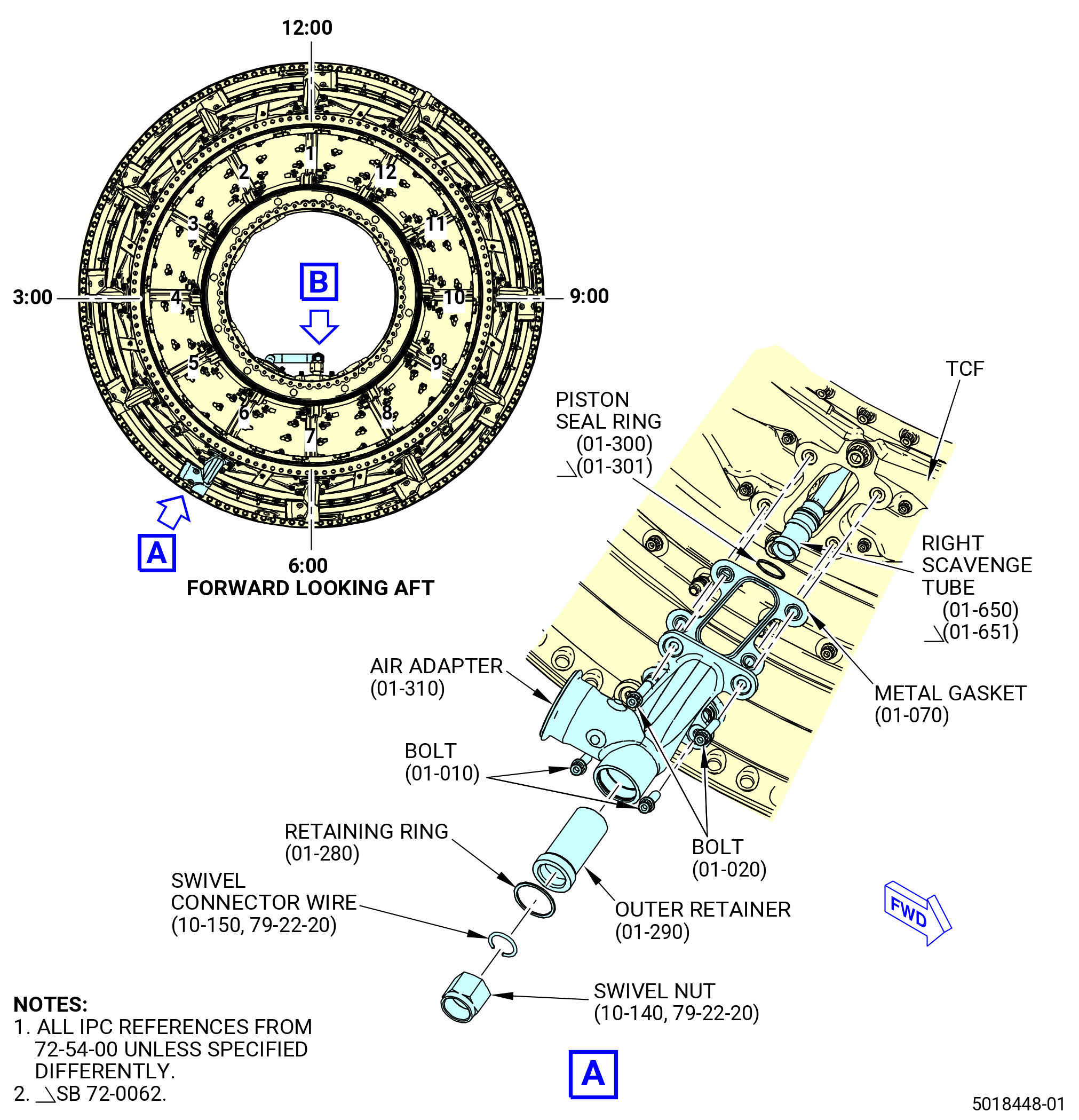
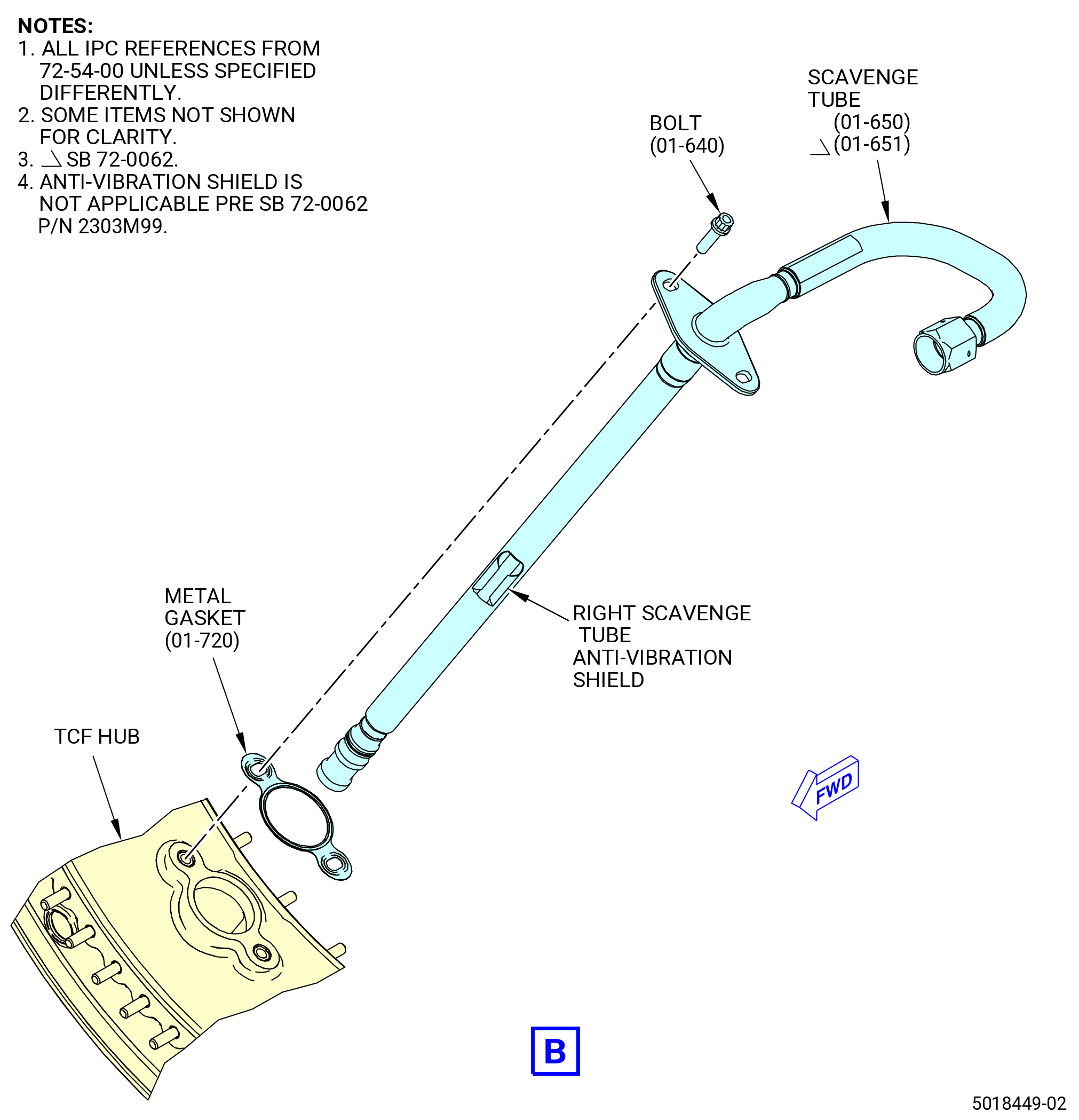
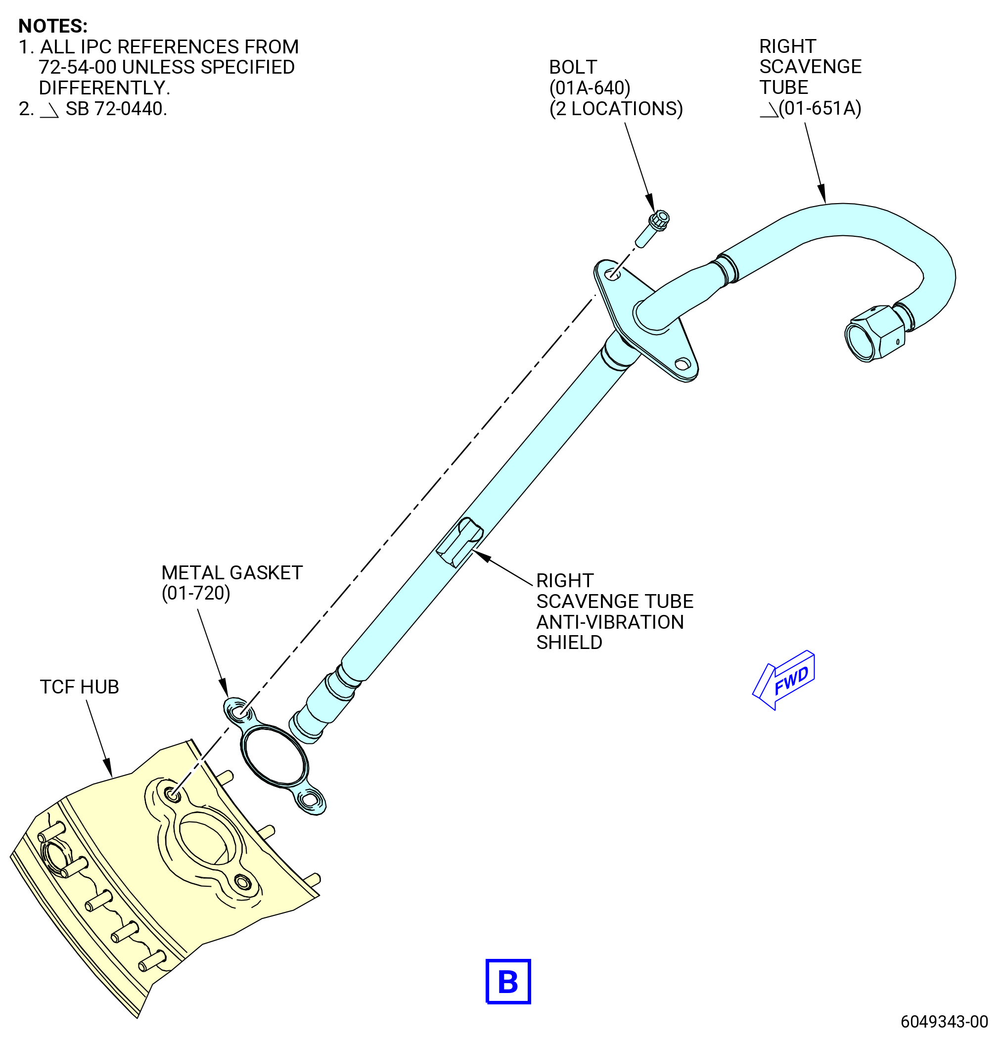
| L. | Install the air adapter (01-310) (SIN 9250C) and right scavenge tube (01-650) (SIN 454A2) or (01-651) (SIN 454A2) or (01-651A) (SIN 454A2) on the turbine frame at strut No. 6. Refer to Figure 1012 and do as follows: |
| NOTE: |
|
| (1) | Install the right scavenge tube (01-650) (SIN 454A2) or (01-651) (SIN 454A2) or (01-651A) (SIN 454A2) as follows: |
| (a) | Install the outer retainer (01-290) (SIN 454A0) or (01-290A) (SIN 454A0), retaining ring (01-280) (SIN 454V1), the ring (01-305) (SIN 454N3), and piston seal ring (01-301A) (SIN 454N0) in the air adapter as follows: |
| 1 | Install the guide shaft (item 4) into the block (item 2) of the 11C4509 press fixture and attach it with the nut (item 9). |
| 2 | Install the air adapter on the guide shaft (item 4) to seat it at the same angle as the air adapter mounting flange, so that the end of the air adapter points straight up. Refer to Figure 1011. |
| 3 | Install two pins (item 6) to align and attach the air adapter to guide shaft (item 4). |
| 4 | Adjust the stop block (item 5) against the mounting flange of the air adapter. |
| 5 | Install the outer retainer over the guide shaft (item 4) and into air adapter. |
| 6 | Install the spacer (item 3) over the guide shaft and on the outer retainer. |
| 7 | Install the cylinder (item 11) over the guide shaft (item 4) and on the spacer (item 3). |
| 8 | Install the washer (item 13) and nut (item 9) at the end of the guide shaft (item 4). Tight the nut hand-tight. |
| WARNING: |
|
| 9 | Apply 2500 psi (17250 kPa) of hydraulic pressure to the cylinder (item 11) and push the outer retainer into the air adapter. |
| Subtask 72-54-00-440-445 |
| * * * FOR |
| * * * PRE SB 72-0440 |
| 10 | Remove the spacer (item 3), nut (item 9), cylinder (item 11), and washer (item 13). |
| 11 | Install the new piston seal ring (01-301) (SIN 454N0) on the guide shaft and press it into the air adapter as applied in steps before. If necessary, apply engine oil. |
| 12 | Do a check for free movement of the piston ring. |
| * * * FOR |
| * * * END PRE SB 72-0440 |
| Subtask 72-54-00-440-446 |
| * * * FOR |
| * * * SB 72-0440 |
| 13 | Remove the spacer (item 3), nut (item 9), cylinder (item 11), and washer (item 13). |
| 14 | Install the new piston seal ring (01-301A) (SIN 454N0) and the ring (01-305) (SIN 454N3) on the guide shaft and press it into the air adapter as applied in steps before. If necessary, apply engine oil. |
| NOTE: |
|
| 15 | Do a check for free movement of the piston ring. |
| * * * FOR |
| * * * END SB 72-0440 |
| Subtask 72-54-00-440-447 |
| 16 | Remove the air adapter from the fixture in reversed order. |
| 17 | Deleted. |
| WARNING: |
|
| 18 | Apply C02-019 engine oil or C02-023 engine oil to the retaining ring. |
| 19 | Press the retaining ring into the inside diameter groove of the air adapter. |
| 20 | Make sure that the retaining ring (01-280) (SIN 454V1) is correctly installed. |
| (b) | Attach the right scavenge tube (01-650) (SIN 454A2) or (01-651) (SIN 454A2) or (01-651A) (SIN 454A2) to the turbine frame and do as follows: |
| 1 | Put a metal gasket (01-720) (SIN 454N1) on the right scavenge tube. Make sure that the metal gasket is new and that the lifted surface is outboard. |
| 2 | Align the right scavenge tube with the inboard opening of strut No. 6. |
| 3 | Make sure that the tube is turned so that the inboard opening points forward. You cannot turn the scavenge tube after you install it in the strut. |
| Subtask 72-54-00-440-365 |
| CAUTION: |
|
| 4 | Install the right scavenge tube (01-650) (SIN 454A2) or (01-651) (SIN 454A2) or (01-651A) (SIN 454A2) in strut No. 6 from the inboard side. Do not turn the tube after it is installed in the strut. |
| Subtask 72-54-00-440-366 |
| 4.A. | Deleted. |
| 5 | Local forming of the anti-vibration shield on the right scavenge tube (01-651) (SIN 454A2) is permissible to facilitate assembly. In at least one location in the tube-lengthwise direction the full damper cross section (except chamfers) must remain unchanged. |
| Subtask 72-54-00-440-367 |
| 6 | Make sure that the outboard end of the scavenge tube is through the hole in the air adapter. |
| WARNING: |
|
| 7 | Apply C02-058 lubricant to the threads and bearing (friction) surfaces of the bolts (01-640) (SIN 454F2) and scavenge tube B-nut. |
| a | Use a minimum quantity of C02-058 lubricant necessary for assembly. After assembly, remove the remaining lubricant with a clean C10-182 cloth. |
| 8 | Install the bolts through the scavenge tube, metal gasket and into the turbine frame. Hand-tighten the bolts. |
| Subtask 72-54-00-440-368 |
| WARNING: |
|
| (c) | Apply C02-019 engine oil or C02-023 engine oil to the piston seal ring (01-300) (SIN 454N0) or (01-301) (SIN 454N0). |
| Subtask 72-54-00-440-369 |
| (c).A. | Deleted. |
| Subtask 72-54-00-440-370 |
| (d) | Install the piston seal ring (01-300) (SIN 454N0) or (01-301) (SIN 454N0) or (01-301A) (SIN 454N0) in the groove on the outboard end of the right scavenge tube (01-650) (SIN 454A2) or (01-651) (SIN 454A2) or (01-651A) (SIN 454A2). |
| Subtask 72-54-00-440-371 |
| (d).A. | Deleted. |
| Subtask 72-54-00-440-022 |
| (2) | Attach the air adapter (01-310) (SIN 9250C) to the turbine frame at strut No. 6. Refer to Figure 1012 and do as follows: |
| WARNING: |
|
| (a) | Apply C02-058 lubricant to the threads and bearing (friction) surfaces of the bolts (01-010) (SIN 92526) and (01-020) (SIN 92525). |
| 1 | Use a minimum quantity of C02-058 lubricant necessary for assembly. After assembly, remove the remaining lubricant with a clean C10-182 cloth. |
| (b) | Put a metal gasket (01-070) (SIN 92551) in position on the outer pad of the turbine frame at strut No. 6. Make sure that the metal gasket is new and that the lifted surface is outboard. |
| CAUTION: |
|
| (c) | Put the air adapter in position on the metal gasket. |
| (d) | Make sure that the outboard end of the scavenge tube is through the hole in the air adapter. |
| CAUTION: |
|
| (e) | Install the bolts (01-010) (SIN 92526) and (01-020) (SIN 92525) through the air adapter, metal gasket (01-070) (SIN 92551), and into the turbine frame. Hand-tighten the bolts. |
| (3) | Install the swivel nut (10-140 , 79-22-20) (SIN 454K0) on the outboard end of the right scavenge tube (01-650) (SIN 454A2) or (01-651) (SIN 454A2) or (01-651A) (SIN 454A2) and attach it with the swivel connector wire (10-150 , 79-22-20) (SIN 454W1) and do as follows: |
| (a) | Put the swivel nut on the outboard end of the scavenge tube so the inner diameter groove of the swivel nut is between the two raised diameters of the oil supply tube. |
| (b) | Install the swivel connector wire (10-150 , 79-22-20) (SIN 454W1) in the swivel nut (10-140 , 79-22-20) (SIN 454K0). |
| (c) | Tap the swivel connector wire through the small hole into the inner diameter of the swivel nut with a hammer. |
| (d) | Make sure that the swivel nut is secure on the end of the tube. |
| (e) | If the swivel nut is not secure, make sure that the swivel connector wire is installed correctly or not damaged. If necessary, replace the swivel connector wire. |
| Subtask 72-54-00-440-023 |
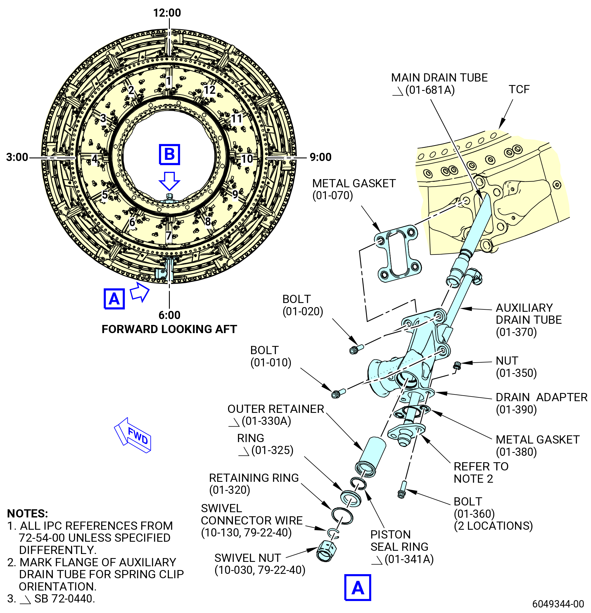
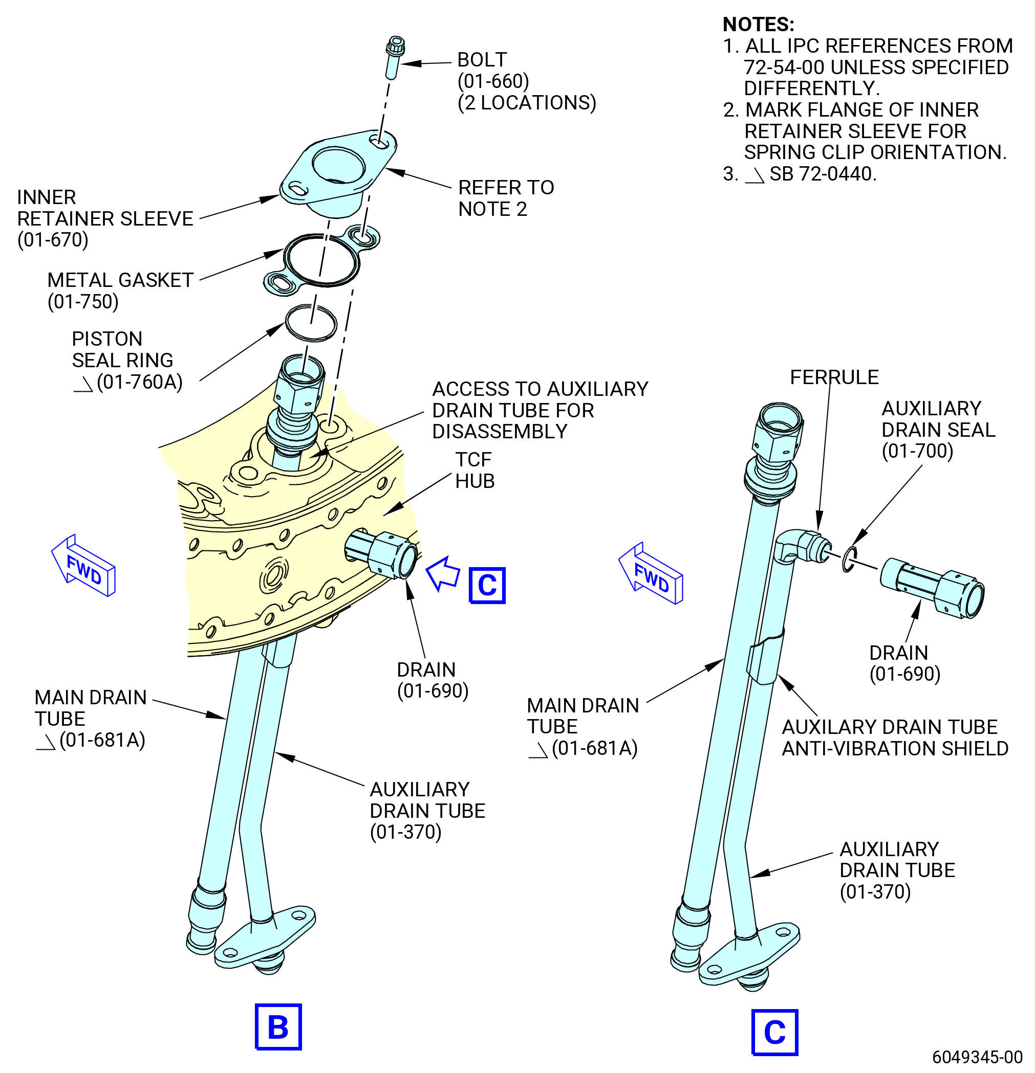
| M. | Install the drain adapter (01-390) (SIN 9250D), auxiliary drain tube (01-370) (SIN 489A1) or (01-371) (SIN 489A1), and main drain tube (01-680) (SIN 489A2) or (01-681) (SIN 489A2) or (01-681A) (SIN 489A2) on the turbine frame at strut No. 7 and do as follows: |
| NOTE: |
|
| (1) | Install the auxiliary drain tube, outer retainer (01-330) (SIN 489B3) or (01-330A) (SIN 489B3), retaining ring (01-320) (SIN 489V1), the ring (01-325) (SIN 489N5), and the piston seal ring (01-341A) (SIN 489N0) in the drain adapter. Refer to Figure 1013 and do as follows: |
| Subtask 72-54-00-440-372 |
| (a) | Deleted. |
| Subtask 72-54-00-440-373 |
| (a).A. | Deleted. |
| Subtask 72-54-00-440-374 |
| (b) | Deleted. |
| (c) | Deleted. |
| (d) | Install the outer retainer (01-330) (SIN 489B3) or (01-330A) (SIN 489B3), the retaining ring (01-320) (SIN 489V1), the ring (01-325) (SIN 489N5), and piston seal ring (01-341A) (SIN 489N0) in the drain adapter (01A-390) (SIN 9250D). Refer to Figure 1011 and do as follows: |
| 1 | Install the guide shaft (item 4) into the block (item 2) of the 11C4509 press fixture and attach it with the nut (item 9). |
| 2 | Install the drain adapter on the guide shaft (item 4) to seat it at the same angle as the air adapter mounting flange, to make sure that the end of the drain adapter points straight up. Put the drain adapter mounting flange onto the block (item 2). Refer to Figure 1011. |
| 3 | Install the pins (item 6) to align and attach the drain adapter to the guide shaft (item 4). |
| 4 | Adjust the stop block (item 5) against the mounting flange of the drain adapter. |
| 5 | Install the outer retainer over the guide shaft (item 4) and into the air adapter. |
| 6 | Install the spacer (item 3) over the guide shaft and on the outer retainer. |
| 7 | Install the cylinder (item 11) over the guide shaft (item 4) and on the spacer (item 3). |
| 8 | Install the washer (item 13) and nut (item 9) at the end of the guide shaft (item 4). Tighten the nut hand-tight. |
| WARNING: |
|
| 9 | Apply 2500 psi (17250 kPa) of hydraulic pressure to the cylinder (item 11) and push the outer retainer into the air adapter. |
| Subtask 72-54-00-440-448 |
| * * * FOR |
| * * * PRE SB 72-0440 |
| 10 | Remove the spacer (item 3), nut (item 9), cylinder (item 11), and washer (item 13). |
| 11 | Install the new piston seal ring (01-341) (SIN 489N0) on the guide shaft and press it into the drain adapter as applied in steps before. If necessary, apply engine oil. |
| 12 | Do a check for free movement of the piston ring. |
| * * * FOR |
| * * * END PRE SB 72-0440 |
| Subtask 72-54-00-440-449 |
| * * * FOR |
| * * * SB 72-0440 |
| 13 | Remove the spacer (item 3), nut (item 9), cylinder (item 11), and washer (item 13). |
| 14 | Install the new piston seal ring (01-341A) (SIN 489N0) and the ring (01A-325) (SIN 489N5) on the guide shaft and press it into the drain adapter as applied in steps before. If necessary, apply engine oil. |
| NOTE: |
|
| 15 | Do a check for free movement of the piston ring. |
| * * * FOR |
| * * * END SB 72-0440 |
| Subtask 72-54-00-440-450 |
| 16 | Remove the air adapter from the fixture in reversed order. |
| 17 | Deleted. |
| WARNING: |
|
| 18 | Apply C02-019 engine oil or C02-023 engine oil to the retaining ring. |
| 19 | Press the retaining ring into the inside diameter groove of the drain adapter. |
| 20 | Make sure that the retaining ring is correctly installed. |
| WARNING: |
|
| 21 | Apply C02-058 lubricant to the auxiliary drain seal (01-700) (SIN 489N2). |
| a | Use a minimum quantity of C02-058 lubricant necessary for assembly. After assembly, remove the remaining lubricant with a clean C10-182 cloth. |
| 22 | Install the auxiliary drain seal to the inboard end of the auxiliary drain tube and do as follows: |
| a | Put the metal gasket (01-380) (SIN 489N3) on the auxiliary drain tube. Make sure that the metal gasket is new and that the lifted surface is outboard. |
| b | Put a mark on the flange of the auxiliary drain tube with a C05-003 pen to show the location for spring clip orientation. |
| c | Install the auxiliary drain tube through the top of the drain adapter. |
| Subtask 72-54-00-440-024 |
| (2) | Attach the drain adapter (01-390) (SIN 9250D) and auxiliary drain tube (01-370) (SIN 489A1) or (01-371) (SIN 489A1) to the turbine frame at strut No. 7. Refer to Figure 1013 and do as follows: |
| WARNING: |
|
| (a) | Apply C02-058 lubricant to the threads and bearing (friction) surfaces of the bolts (01-010) (SIN 92526) and (01-020) (SIN 92525). |
| 1 | Use a minimum quantity of C02-058 lubricant necessary for assembly. After assembly, remove the remaining lubricant with a clean C10-182 cloth. |
| (b) | Put a metal gasket (01-070) (SIN 92551) in position on the outer pad of the turbine frame at strut No. 7. Make sure that the metal gasket is new and that the lifted surface is outboard. |
| (c) | Put the drain adapter and auxiliary drain tube in the turbine frame. Point the auxiliary drain tube so the tube goes straight into the turbine frame. The inboard end of the tube must point up (aft) and visible through the hole in the turbine frame hub at the 6:00 o'clock position (strut No. 7). |
| (d) | Local forming of the anti-vibration shield is permissible to facilitate assembly. In at least one location in the tube-lengthwise direction the full damper cross section (except chamfers) must remain unchanged. Additional forming of the anti-vibration shield is permissible to achieve a form which permits assembly of the main drain tube into the strut. In at least one location of the tube in lengthwise direction, the anti-vibration shield cross section (except chamfers) must be larger than an envelope check circle of 0.750 inch (19.05 mm). |
| CAUTION: |
|
| (e) | Put the air adapter on the metal gasket. |
| CAUTION: |
|
| (f) | Install the bolts (01-010) (SIN 92526) and (01-020) (SIN 92525) through the drain adapter, metal gasket (01-070) (SIN 92551), and into the turbine frame. Hand-tighten the bolts. |
| (g) | Attach the auxiliary drain tube to the drain adapter and do as follows: |
| WARNING: |
|
| 1 | Apply C02-058 lubricant to the threads and bearing (friction) surfaces of the bolts (01-360) (SIN 489F1) and nuts (01-350) (SIN 489K0). |
| a | Use a minimum quantity of C02-058 lubricant necessary for assembly. After assembly, remove the remaining lubricant with a clean C10-182 cloth. |
| 2 | Install the bolts through the auxiliary drain tube, metal gasket, and bolt flange of the drain adapter. |
| 3 | Attach the nuts to the bolts. |
| 4 | Do not torque the nuts. |
| (h) | Attach the drain (01-690) (SIN 489S0) to the auxiliary drain tube (01-370) (SIN 489A1) or (01-371) (SIN 489A1) and do as follows: |
| WARNING: |
|
| 1 | Apply C02-058 lubricant to the drain seal (01-700) (SIN 489N2). |
| CAUTION: |
|
| 2 | Install the auxiliary drain seal to the inboard end of the auxiliary drain tube. |
| WARNING: |
|
| 3 | Apply C02-058 lubricant to the threads of the drain. |
| a | Use a minimum quantity of lubricant necessary for assembly. After assembly, remove remaining lubricant with a clean C10-182 cloth. |
| 4 | Install the drain connector to the auxiliary drain tube that extends into the sump in the center frame of the turbine frame. |
| 5 | Hold the auxiliary drain tube at the internal hub wall of the turbine frame. |
| 6 | Torque the drain connector to 262 to 308 lb in. (29.6 to 34.8 Nm). |
| (3) | Install the main drain tube (01-680) (SIN 489A2) or (01-681) (SIN 489A2) or (01-681A) (SIN 489A2) to the turbine frame strut No. 7. Refer to Figure 1013 and do as follows: |
| WARNING: |
|
| (a) | Apply C02-019 engine oil or C02-023 engine oil to the piston seal ring (01-760) (SIN 489N1). |
| (b) | Put the piston seal ring on the main drain tube inner diameter end. Open the piston seal ring the minimum amount necessary to install. |
| (c) | Put the metal gasket (01-750) (SIN 48952) on the inner retainer (inner retainer) (01-670) (SIN 489B4). Make sure that the metal gasket is new and that the lifted surface is outboard. |
| (d) | Put a mark on the flange of the auxiliary drain tube with a C05-003 pen to show the location of the spring clip on the tube for orientation. |
| (e) | Move the main drain tube through the inner hub of the turbine frame and into the drain adapter. |
| (f) | Continue to move the main drain tube through strut No. 7 until the bolt flange on the inboard end of the main drain tube touches the turbine frame inner hub. |
| (g) | Move the auxiliary drain tube aft to pull the main drain tube into the drain adapter. |
| Subtask 72-54-00-440-375 |
| * * * FOR |
| * * * PRE SB 72-0440 |
| WARNING: |
|
| (h) | Apply C02-019 engine oil or C02-023 engine oil to the piston seal ring (01-340) (SIN 489N0) or (01-341) (SIN 489N0). |
| Subtask 72-54-00-440-376 |
| (h).A. | Deleted. |
| Subtask 72-54-00-440-377 |
| (i) | Put the piston seal ring (01-340) (SIN 489N0) or (01-341) (SIN 489N0) on the main drain tube (01-680) (SIN 489A2) or (01-681) (SIN 489A2) outer diameter end. Open the piston seal ring the minimum amount necessary to install. |
| * * * FOR |
| * * * END PRE SB 72-0440 |
| Subtask 72-54-00-440-378 |
| (i).A. | Deleted. |
| Subtask 72-54-00-440-379 |
| (j) | Attach the main drain tube to the inner hub of the turbine frame as follows: |
| WARNING: |
|
| 1 | Apply C02-058 lubricant to the threads and the bearing (friction) surfaces of the bolts (01-660) (SIN 489F0). |
| a | Use a minimum quantity of C02-058 lubricant necessary for assembly. After assembly, remove the remaining lubricant with a clean C10-182 cloth. |
| 2 | Install the bolts through the bolt flange of the inner retainer and the metal gasket. Tighten the bolts with your fingers. |
| (4) | Install the swivel nut (10-030 , 79-22-40) (SIN 489K1) on the outboard end of the main drain tube (01-680) (SIN 489A2) or (01-681) (SIN 489A2) or (01-681A) (SIN 489A2) and attach it with the swivel connector wire (10-130 , 79-22-40) (SIN 489W1) and do as follows: |
| (a) | Put the swivel nut on the outboard end of the main drain tube so the inner diameter groove of the swivel nut is between the two raised diameters of the tube. |
| (b) | Install the swivel connector wire in the swivel nut. |
| (c) | Tap the swivel connector wire through the small hole into the inner diameter of the swivel nut with a hammer. |
| (d) | Make sure that the swivel nut is secure on the end of the tube. |
| (e) | If the swivel nut is not secure, make sure the swivel connector wire is installed correctly or not damaged. If necessary, replace the swivel connector wire. |
| Subtask 72-54-00-440-029 |
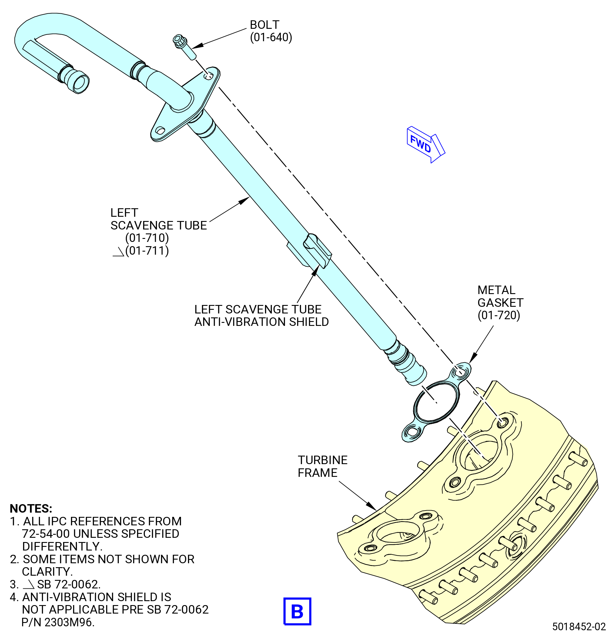
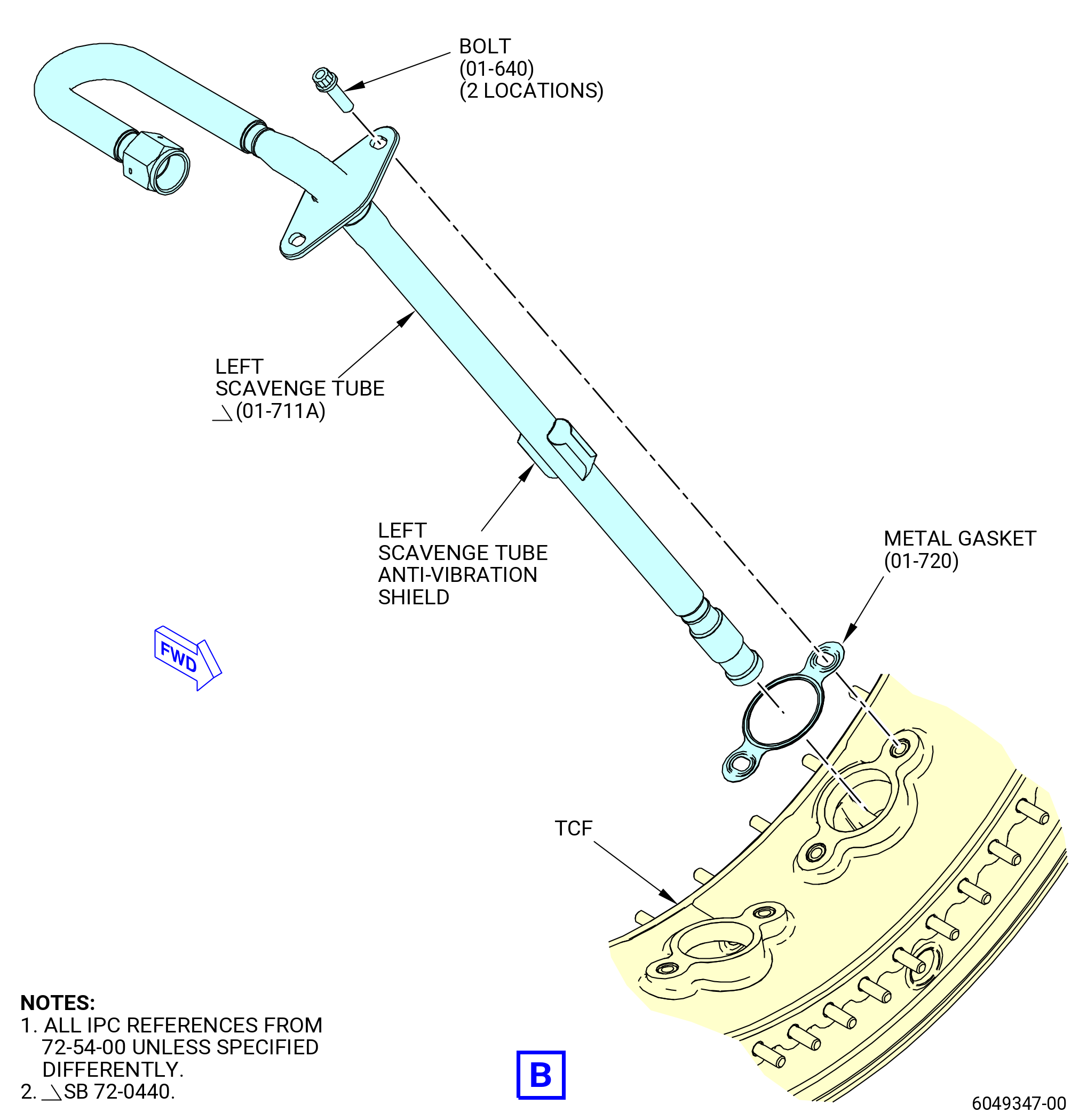
| N. | Install the drain adapter (01-420) (SIN 92509) and left scavenge tube (01-710) (SIN 454A1) or (01-711) (SIN 454A1) or (01-711A) (SIN 454A1) on the turbine frame at strut No. 8. Refer to Figure 1014 and do as follows: |
| NOTE: |
|
| (1) | Install the outer retainer (01-290) (SIN 454A0), retaining ring (01-280) (SIN 454V1), the ring (01-305) (SIN 454N3), and the piston seal ring (01-301A) (SIN 454N0) in the air adapter (01-420) (SIN 92509) and do as follows: |
| (a) | Install the guide rod into the base block of the 11C4509 press fixture and attach it with the hex nut. |
| (b) | Install the outer retainer and retaining ring in the air adapter as follows: |
| 1 | Install the guide shaft (item 4) into the block (item 2) of the 11C4509 press fixture and attach it with the nut (item 9). |
| 2 | Install the air adapter on the guide shaft (item 4) to seat it at the same angle as the air adapter mounting flange, to make sure that the end of the air adapter points straight up. Put the air adapter mounting flange onto the block (item 2). Refer to Figure 1011. |
| 3 | Install the pins (item 6) to align and secure the air adapter to guide shaft (item 4). |
| 4 | Adjust the stop block (item 5) against the mounting flange of the air adapter. |
| 5 | Install the outer retainer (01-290) (SIN 454A0) above the guide shaft (item 4) and into the air adapter. |
| 6 | Install the spacer (item 3) over the guide shaft and on the outer retainer. |
| 7 | Install the cylinder (item 11) over the guide shaft (item 4) and on the spacer (item 3). |
| 8 | Install the washer (item 13) and nut (item 9) at the end of the guide shaft (item 4). Tighten the nut hand-tight. |
| WARNING: |
|
| 9 | Apply 2500 psi (17237 kPa) of hydraulic pressure to the cylinder (item 11) and push the outer retainer (01-290) (SIN 454A0) into the air adapter (01-420) (SIN 92509). |
| Subtask 72-54-00-440-451 |
| * * * FOR |
| * * * PRE SB 72-0440 |
| 10 | Remove the spacer (item 3), nut (item 9), cylinder (item 11), and washer (item 13). |
| 11 | Install the new piston seal ring (01-301) (SIN 454N0) on the guide shaft and press it into the air adapter as applied in steps before. If necessary, apply engine oil. |
| 12 | Do a check for free movement of the piston ring. |
| * * * FOR |
| * * * END PRE SB 72-0440 |
| Subtask 72-54-00-440-452 |
| * * * FOR |
| * * * SB 72-0440 |
| 13 | Remove the spacer (item 3), nut (item 9), cylinder (item 11), and washer (item 13). |
| 14 | Install the new piston seal ring (01-301A) (SIN 454N0) and the ring (01A-305) (SIN 454N3) on the guide shaft and press it into the air adapter as applied in steps before. If necessary, apply engine oil. |
| NOTE: |
|
| 15 | Do a check for free movement of the piston ring. |
| * * * FOR |
| * * * END SB 72-0440 |
| Subtask 72-54-00-440-453 |
| 16 | Remove the air adapter from the fixture in reversed order. |
| 17 | Make sure that the retaining ring (01-280) (SIN 454V1) is correctly installed. |
| WARNING: |
|
| 18 | Apply C02-019 engine oil or C02-023 engine oil to the retaining ring. |
| 19 | Press the retaining ring into the inside diameter groove of the air adapter. |
| 20 | Make sure that the retaining ring is correctly installed. |
| Subtask 72-54-00-440-175 |
| (2) | Install the left scavenge tube (01-710) (SIN 454A1) or (01-711) (SIN 454A1) or (01-711A) (SIN 454A1) in the turbine frame strut No. 8 and do as follows: |
| Subtask 72-54-00-440-380 |
| * * * FOR |
| * * * PRE SB 72-0440 |
| WARNING: |
|
| (a) | Apply C02-019 engine oil or C02-023 engine oil to the piston seal ring (01-300) (SIN 454N0) or (01-301) (SIN 454N0). |
| Subtask 72-54-00-440-381 |
| (a).A. | Deleted. |
| Subtask 72-54-00-440-382 |
| (b) | Install the piston seal ring (01-300) (SIN 454N0) or (01-301) (SIN 454N0) in the groove on the outboard end of the left scavenge tube (01-710) (SIN 454A1) or (01-711) (SIN 454A1) or (01-711A) (SIN 454A1). |
| * * * FOR |
| * * * END PRE SB 72-0440 |
| Subtask 72-54-00-440-383 |
| (b).A. | Deleted. |
| Subtask 72-54-00-440-384 |
| (c) | Put a metal gasket (01-720) (SIN 454N1) on the left scavenge tube. Make sure that the metal gasket is new and that the lifted surface is outboard. |
| (d) | Install the left scavenge tube in strut No. 8 from the inboard side out through the air adapter. |
| (e) | Local forming of the anti-vibration shield on the left scavenge tube (01-711) (SIN 454A1) or (01-711A) (SIN 454A1) is permissible to facilitate assembly. In at least one location in the tube-lengthwise direction the full damper cross section (except chamfers) must remain unchanged. |
| (f) | Make sure that the outboard end of the scavenge tube is through the hole in the air adapter. |
| WARNING: |
|
| (g) | Apply C02-058 lubricant to the threads and bearing (friction) surfaces of the bolts (01-640) (SIN 454F2). |
| 1 | Use a minimum quantity of C02-058 lubricant necessary for assembly. After assembly, remove the remaining lubricant with a clean C10-182 cloth. |
| (h) | Attach the left scavenge tube to strut No. 8 with the bolts. |
| (i) | Do not torque the bolts. |
| (3) | Install the swivel nut (10-140 , 79-22-20) (SIN 454K0) on the outboard end of the left scavenge tube (01-710) (SIN 454A1) or (01-711) (SIN 454A1) or (01-711A) (SIN 454A1) and attach it with the swivel connector wire (10-150 , 79-22-20) (SIN 454W1) and do as follows: |
| (a) | Install the swivel connector wire in the swivel nut. |
| (b) | Put the swivel nut on the outboard end of the scavenge tube so the inner diameter groove of the swivel nut is between the two raised diameters of the tube. |
| (c) | Tap the swivel connector wire through the small hole into the inner diameter of the swivel nut with a hammer. |
| (d) | Make sure that the swivel nut is secure on the end of the tube. |
| (e) | If the swivel nut is not secure, make sure that the swivel connector wire is installed correctly or not damaged. If necessary, replace the swivel connector wire. |
| Subtask 72-54-00-440-030 |
| (4) | Attach the air adapter (01-420) (SIN 92509) to the turbine frame at strut No. 8. Refer to Figure 1014 and do as follows: |
| WARNING: |
|
| (a) | Apply C02-058 lubricant to the threads and bearing (friction) surfaces of the bolts (01-010) (SIN 92526). |
| 1 | Use a minimum quantity of C02-058 lubricant necessary for assembly. After assembly, remove the remaining lubricant with a clean C10-182 cloth. |
| (b) | Put a metal gasket (01-070) (SIN 92551) in position on the outer pad of the turbine frame at strut No. 8. Make sure that the metal gasket is new and that the lifted surface is outboard. |
| CAUTION: |
|
| (c) | Put the air adapter in position on the metal gasket (01-070) (SIN 92551). |
| (d) | Install the bolts (01-010) (SIN 92526) through the air adapter, metal gasket (01-070) (SIN 92551), and into the turbine frame. Hand-tighten the bolts. |
| Subtask 72-54-00-440-385 |
| O. | Install the air adapter (01-250) (SIN 92508) on the turbine frame at strut No. 9. Refer to Figure 1015 and do as follows: |
| WARNING: |
|
| (1) | Apply C02-058 lubricant to the threads and bearing (friction) surfaces of the bolts (01-015) (SIN 40A26) and (01-010) (SIN 92526). |
| (a) | Use a minimum quantity of C02-058 lubricant necessary for assembly. After assembly, remove the remaining lubricant with a clean C10-182 cloth. |
| (2) | Put the metal gasket (01-070) (SIN 92551) in position on the outer pad of the turbine frame strut. Make sure that the metal gasket is new and that the lifted surface is outboard. |
| CAUTION: |
|
| (3) | Put the air adapter in position on the metal gasket. |
| CAUTION: |
|
| (4) | Install the bolts (01-015) (SIN 40A26) and (01-010) (SIN 92526) through the air adapter, metal gasket, and into the turbine frame. Hand-tighten the bolts. |
| Subtask 72-54-00-440-189 |
| P. | Install the air adapter (01-240) (SIN 9250P) on the turbine frame at strut No. 10. Refer to Figure 1016 and do as follows: |
| WARNING: |
|
| (1) | Apply C02-058 lubricant to the threads and bearing (friction) surfaces of the bolts (01-010) (SIN 92526) and (01-020) (SIN 92525). |
| (a) | Use a minimum quantity of C02-058 lubricant necessary for assembly. After assembly, remove the remaining lubricant with a clean C10-182 cloth. |
| CAUTION: |
|
| (2) | Put the air adapter in position on the metal gasket (01-070) (SIN 92551). |
| CAUTION: |
|
| (3) | Install the bolts through the air adapter, metal gasket, and into the turbine frame. Tighten the bolts with your fingers. |
| (4) | Put the metal gasket in position on the outer pad of the turbine frame at strut No. 10. Make sure that the metal gasket is new and that the raised surface is outboard. |
| Subtask 72-54-00-440-037 |
| Q. | Install the air adapter (01-120) (SIN 9250A) on the turbine frame at strut No. 12. Refer to Figure 1018 and do as follows: |
| WARNING: |
|
| (1) | Apply C02-058 lubricant to the threads and bearing (friction) surfaces of the bolts (01-010) (SIN 92526) and (01-020) (SIN 92525). |
| (a) | Use a minimum quantity of C02-058 lubricant necessary for assembly. After assembly, remove the remaining lubricant with a clean C10-182 cloth. |
| (2) | Put a metal gasket (01-070) (SIN 92551) in position on the outer pad of the turbine frame at strut No. 12. Make sure that the metal gasket is new and that the raised surface is outboard. |
| (3) | Put the air adapter in position on the metal gasket (01-070) (SIN 92551). |
| CAUTION: |
|
| (4) | Install the bolts (01-010) (SIN 92526) and (01-020) (SIN 92525) through the air adapter, metal gasket (01-070) (SIN 92551), and into the turbine frame. Hand-tighten the bolts. |
| Subtask 72-54-00-440-396 |
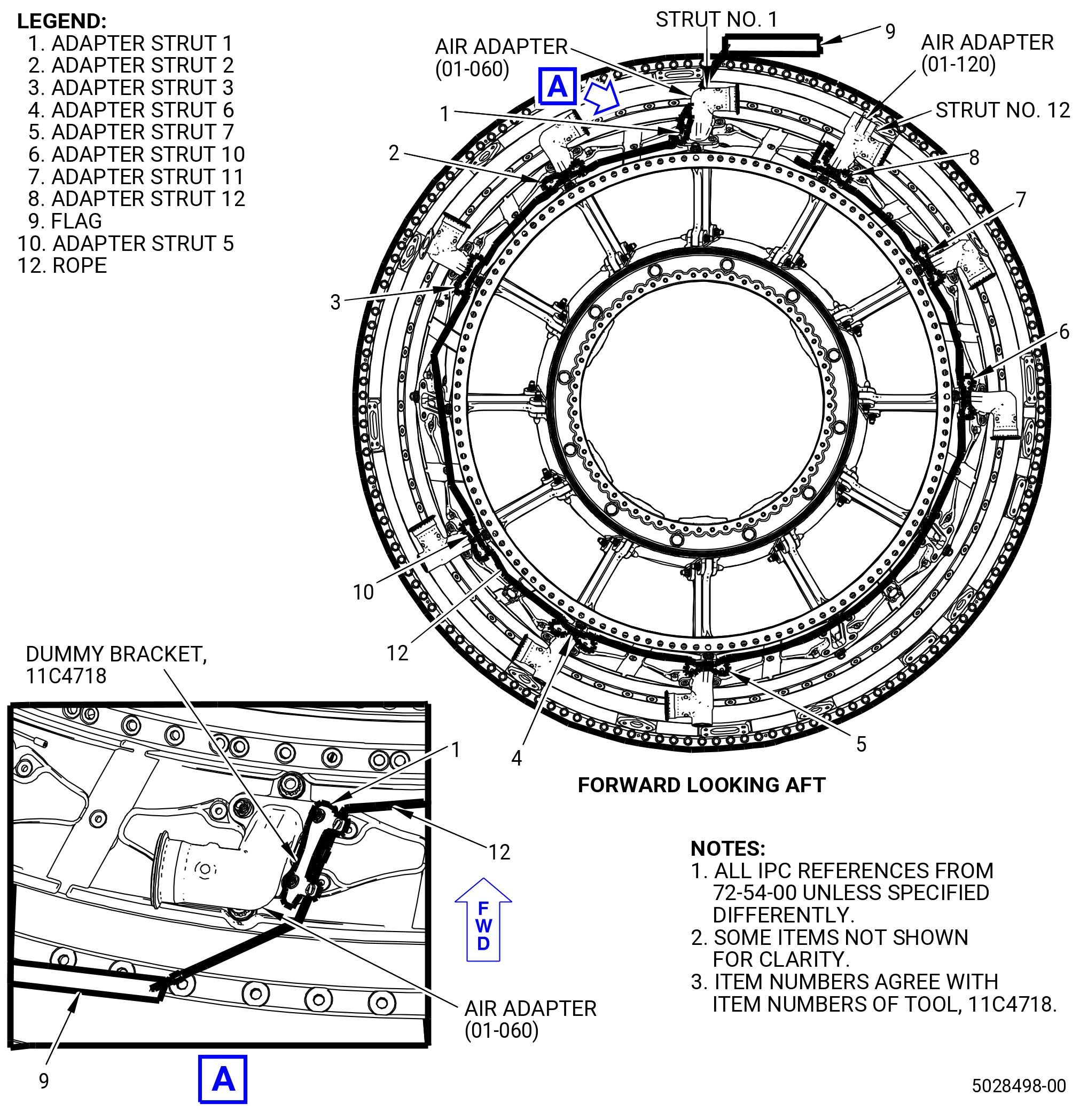
| R. | Put the 11C4718 dummy bracket at the corresponding air adapters. Refer to Figure 1017 and do as follows: |
| NOTE: |
|
| (1) | Put the TCF with the front flange up. |
| (2) | Start with the installation sequence at strut No. 1. |
| (3) | Install the adapter strut 1 (item 1) (the one with the red flag (item 9) attached) at the air adapter (01-060) (SIN 9250B) on strut No. 1 at the two forward looking bolts (01-020) (SIN 92525). |
| (4) | Put the rope (item 12) loosely counterclockwise (CCW) on the TCF with the adapters struts sitting on top of the air adapters. |
| (5) | The air adapters are loosely fixed by the rearwards bolts. |
| (6) | Install the adapter strut 12 (item 8) at the air adapter (01-120) (SIN 9250A) on strut No. 12 at the two forward looking bolts (01-020) (SIN 92525). |
| (7) | Continue to install the remaining adapter struts as follows: |
| (a) | Install the adapter strut 11 (item 7) at the vent adapter (01-210) (SIN 46107) on strut No. 11. |
| (b) | Install the adapter strut 10 (item 6) at the air adapter (01-240) (SIN 9250P) on strut No. 10. |
| (c) | Install the adapter strut 7 (item 5) at the drain adapter (01-390) (SIN 9250D) on strut No. 7. |
| (d) | Install the adapter strut 6 (item 4) at the air adapter (01-310) (SIN 9250C) on strut No. 6. |
| (e) | Install the adapter strut 5 (item 10) at the air adapter (01-420) (SIN 92509) on strut No. 5. |
| (f) | Install the adapter strut 3 (item 3) at the vent adapter (01-210) (SIN 46107) on strut No. 3. |
| (g) | Install the adapter strut 2 (item 2) at the ait adapter (01-530) (SIN 9250E) on strut No. 2. |
| Subtask 72-54-00-440-041 |
| CAUTION: |
|
| CAUTION: |
|
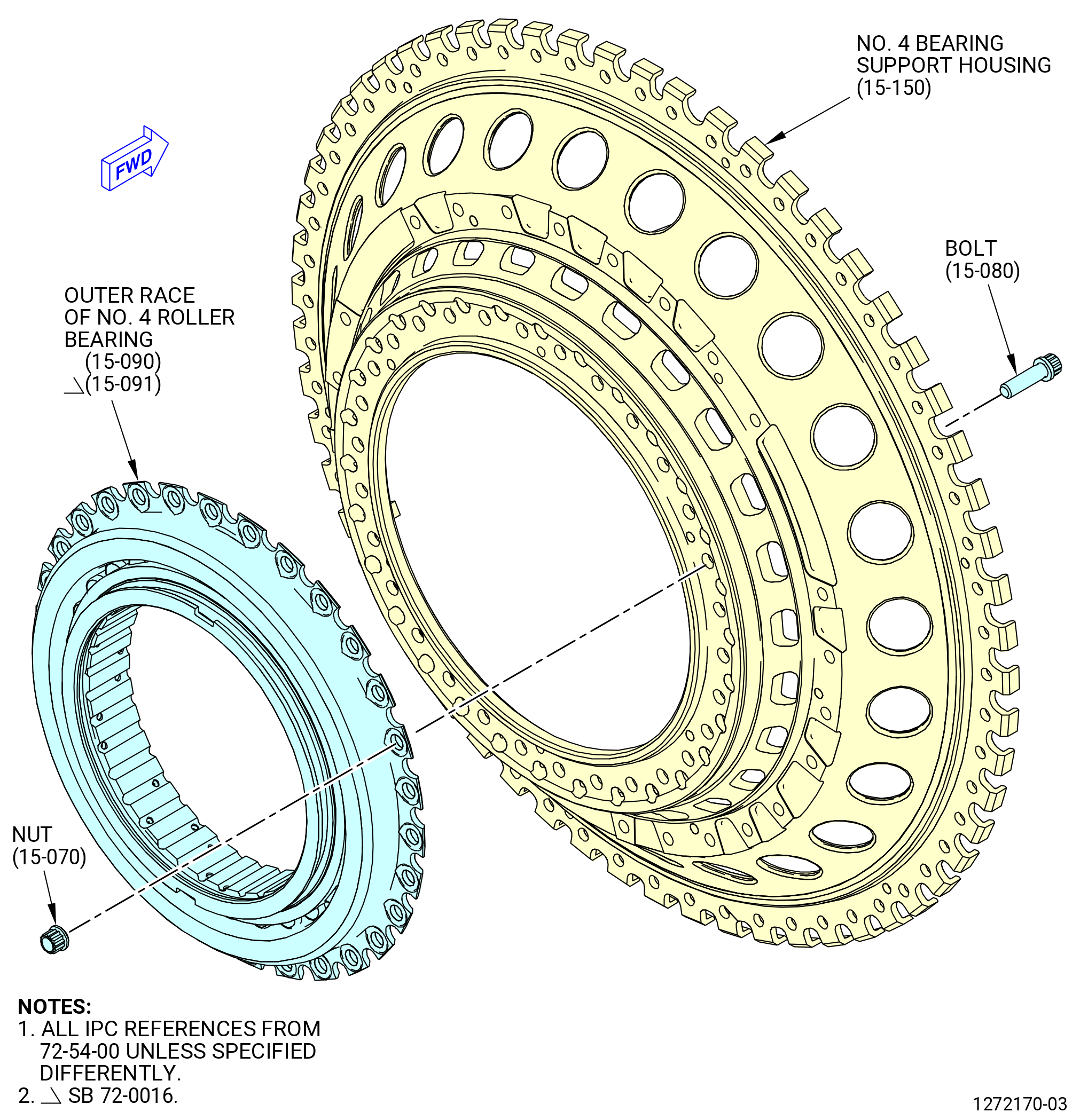
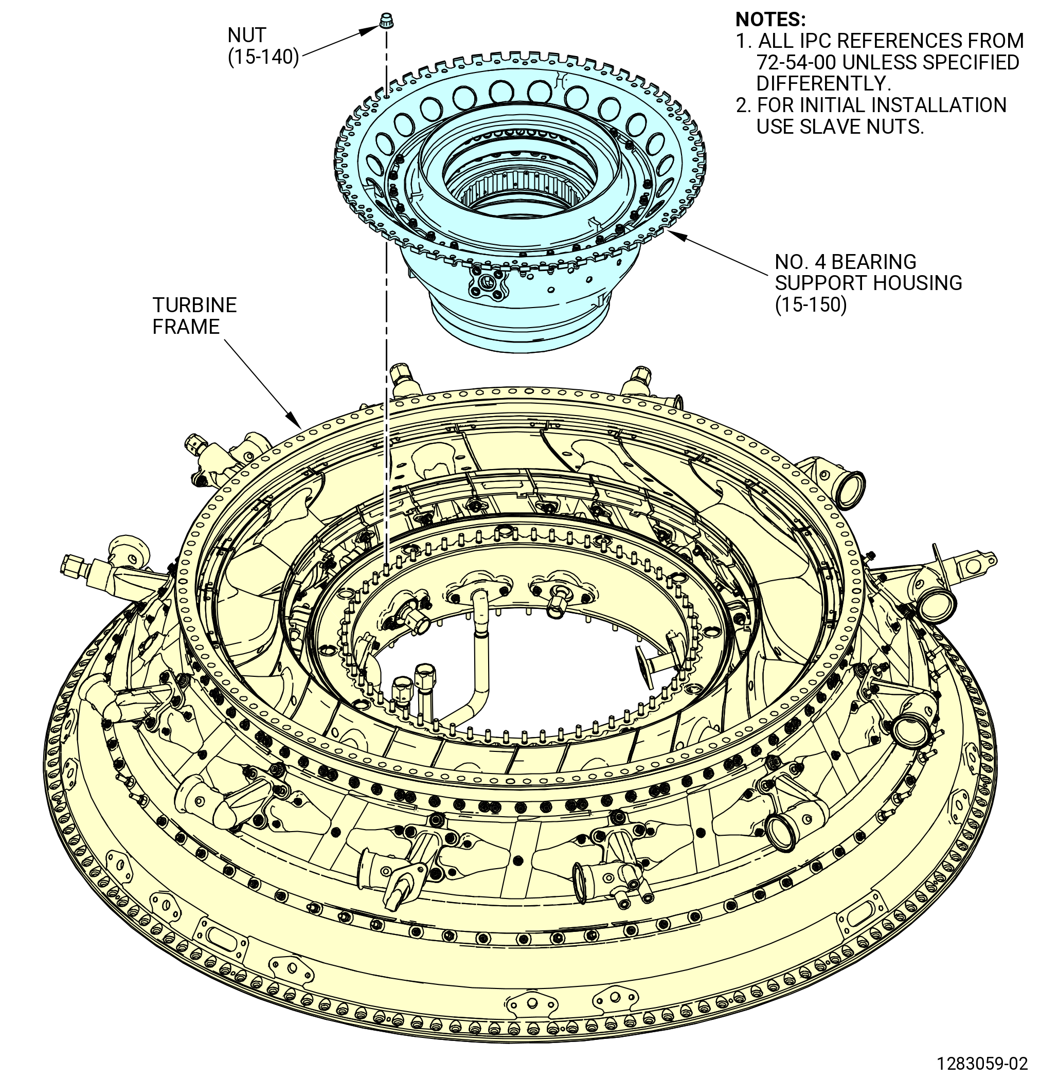
| S. | Install the outer race of the No. 4 roller bearing (15-090) (SIN 01400) or (15-091) (SIN 01400) in the No. 4 bearing support housing (15-150) (SIN 01403). Refer to Figure 1019 and do as follows: |
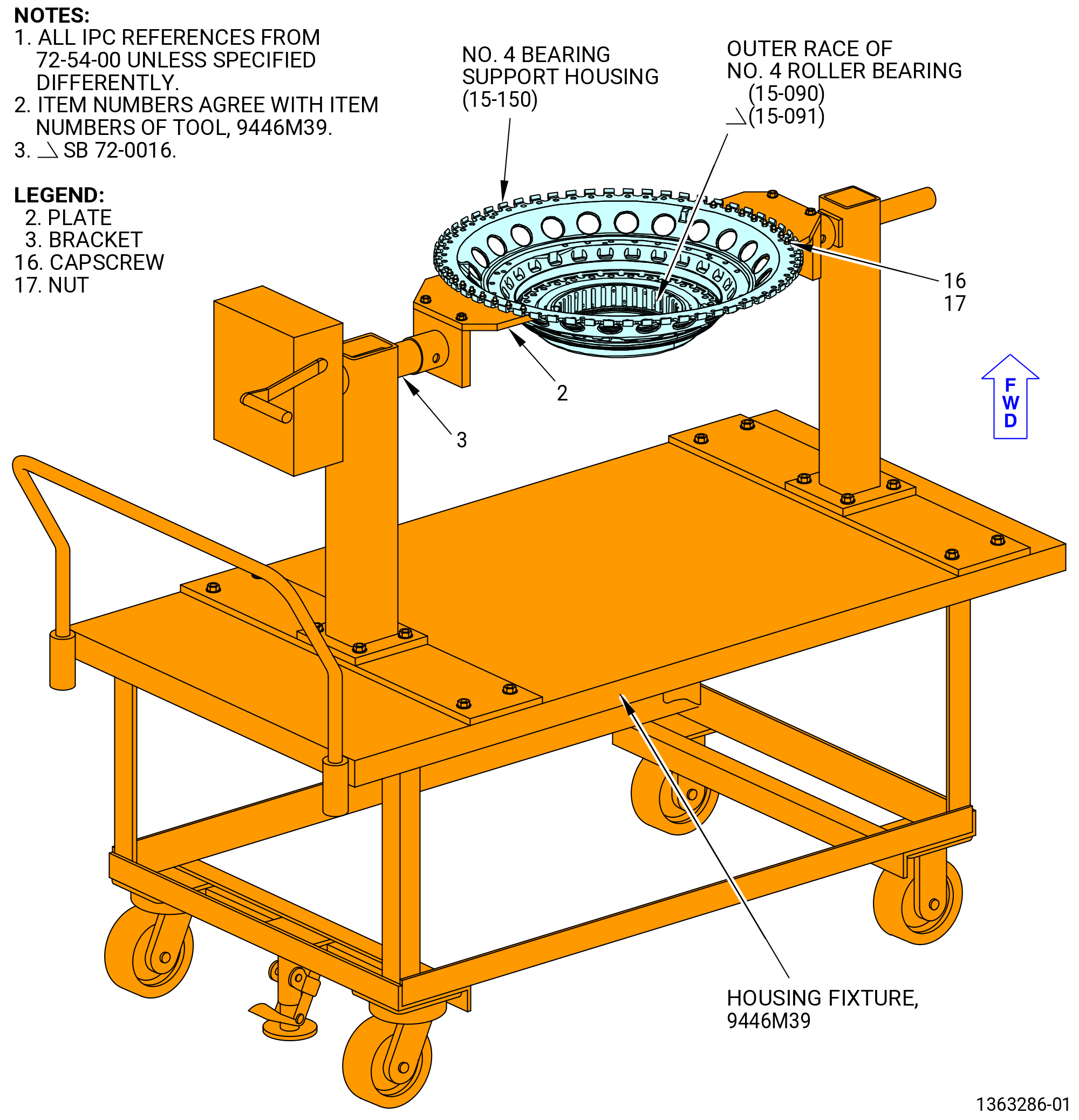
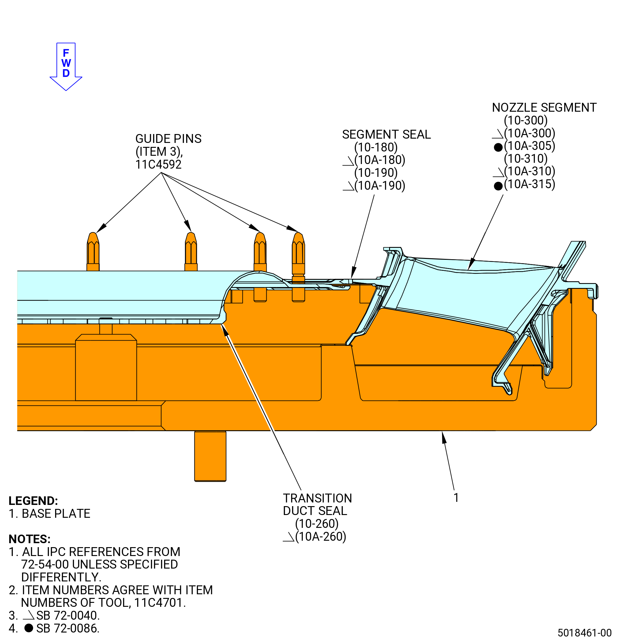
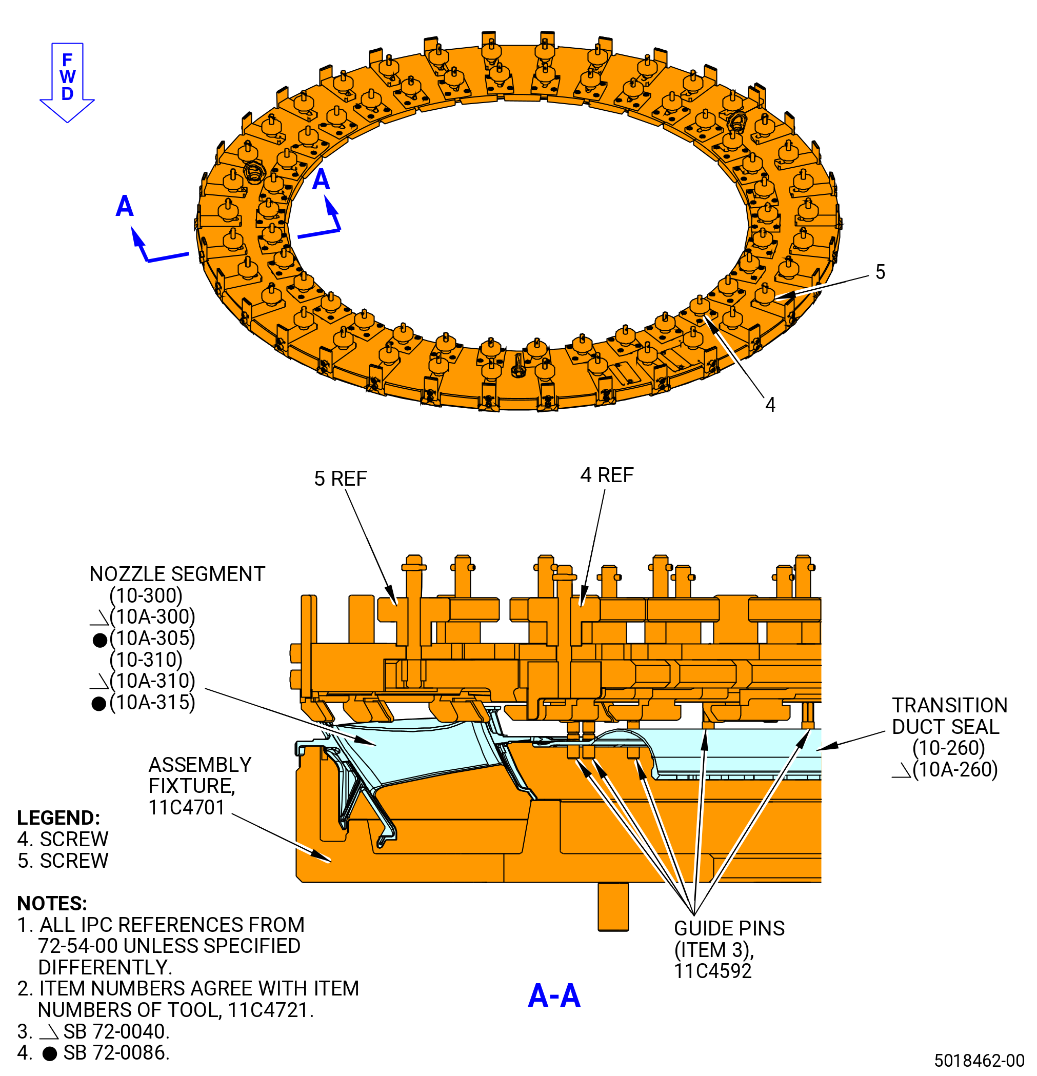
| (1) | Install the No. 4 bearing support housing in the 9446M39 housing fixture, attach it to the plates (item 2) with eight capscrews (item 16) and eight nuts (item 17). Refer to Figure 1020. |
| (2) | Inspect the No. 4 roller bearing outer race and No. 4 bearing support housing for raised material and foreign material. If necessary, clean or remove any raised material as follows: |
| WARNING: |
|
| WARNING: |
|
| WARNING: |
|
| (a) | If necessary, clean the No. 4 bearing outer race and the No. 4 bearing support housing with C04-002 Stoddard solvent, C04-003 acetone, or C04-035 isopropyl alcohol. |
| (b) | If necessary, remove any raised material. Refer to TASK 70-42-00-350-002 (BLENDING AND REMOVAL OF HIGH METAL PROCEDURES). |
| Subtask 72-54-00-440-042 |
| (3) | Carefully move the components of the No. 4 roller bearing (15-090) (SIN 01400) or (15-091) (SIN 01400). Refer to TASK 70-14-00-620-003 (HANDLING OF BEARINGS). |
| CAUTION: |
|
| (4) | Increase the temperature of the outer race to approximately 200°F (93°C). Use a temperature probe to make sure that the temperature of the outer race does not increase more than 350°F (177°C). |
| WARNING: |
|
| (5) | Install the outer race in the No. 4 bearing support housing as follows: |
| (a) | Put the No. 4 bearing support housing forward end down on a clean work surface. |
| (b) | Remove the outer race from the oven and put it on the aft flange of the No. 4 bearing support housing so that the mating surfaces rabbet engage. |
| (c) | Align the boltholes of the outer race flange with the boltholes in the aft flange of the No. 4 bearing support housing. |
| (d) | Hand press the outer race on the No. 4 bearing support housing. Tap with a rubber mallet as necessary to seat the outer race. |
| (e) | Make sure that the boltholes of the outer race align with the No. 4 bearing support housing. Use a 0.3125-24 UNJF-3A bolt to check alignment. |
| Subtask 72-54-00-220-003 |
| (6) | Make sure that the outer race is installed correctly in the No. 4 bearing support housing as follows: |
| (a) | Let the temperature of the outer race go back to ambient temperature. |
| (b) | Use a piece of 0.001 inch (0.03 mm) shim stock to check the gap between the flanges of the outer race and the No. 4 bearing support housing to make sure that it is seated. |
| (c) | Gaps 0.001 inch (0.03 mm) or greater are not permitted. |
| Subtask 72-54-00-440-043 |
| (7) | Attach the outer race to the No. 4 bearing support housing as follows: |
| (a) | Remove the slave nuts and bolts. |
| WARNING: |
|
| (b) | Apply C02-019 engine oil or C02-023 engine oil to the threads and bearing (friction) surfaces of the self-locking nuts (nuts) (15-070) (SIN 01444), bolts (15-080) (SIN 01424), and the contact surfaces of the aft face of the outer race of the No. 4 bearing support housing (15-150) (SIN 01403). |
| (c) | Install the bolts and the nuts to attach the outer race to the No. 4 bearing support housing. Make sure that the bolt heads are forward (down). |
| (d) | Torque eight equally spaced nuts, in a criss-cross pattern, to 175-205 lb in. (19.8-23.2 N.m). |
| (e) | Torque all of the nuts, in a criss-cross pattern, to 235-275 lb in. (26.5-31.1 N.m). |
| (f) | Torque all the nuts, in a circular pattern, to 235-275 lb in. (26.5-31.1 N.m). |
| Subtask 72-54-00-440-044 |
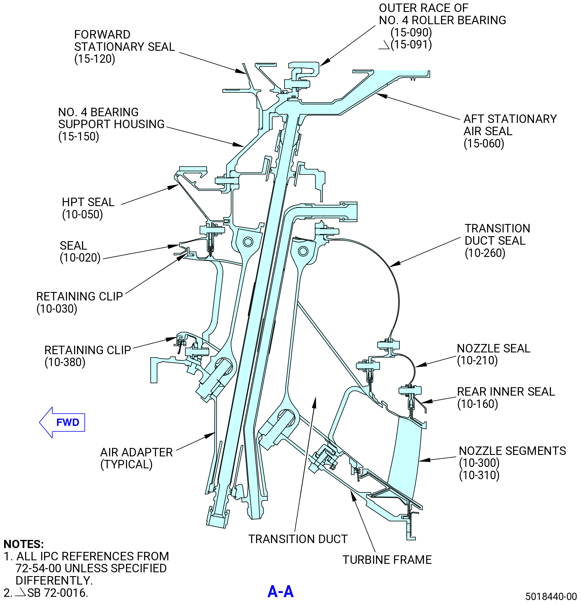
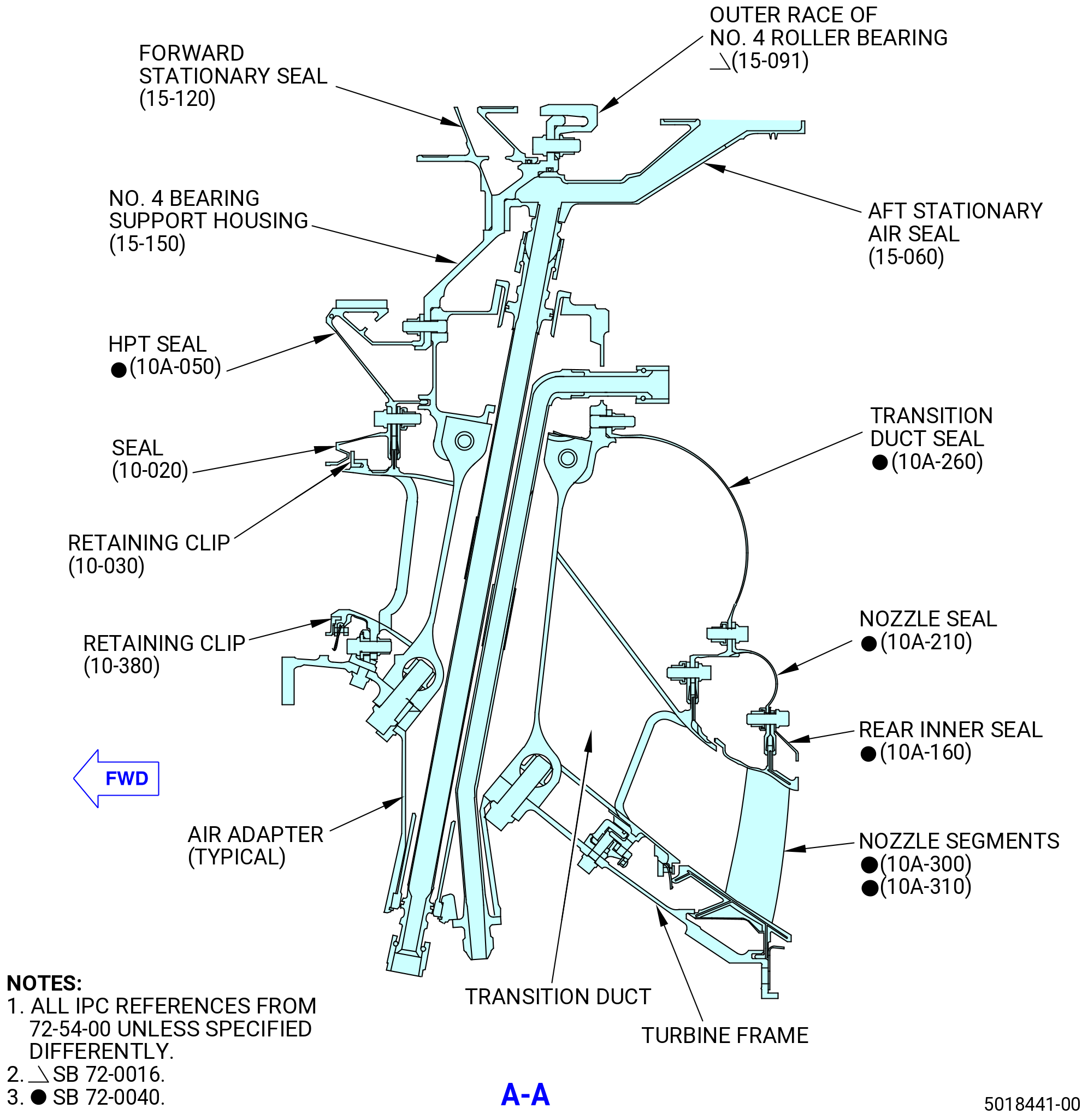
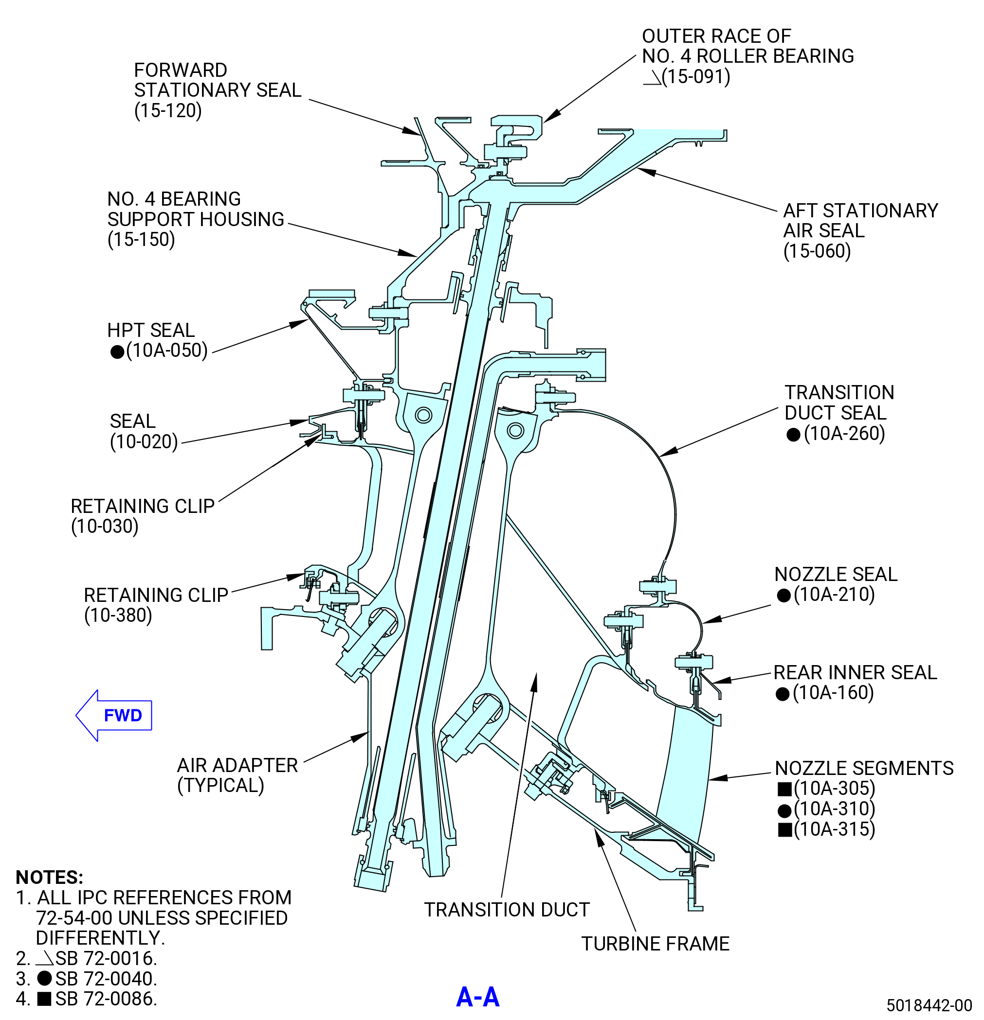
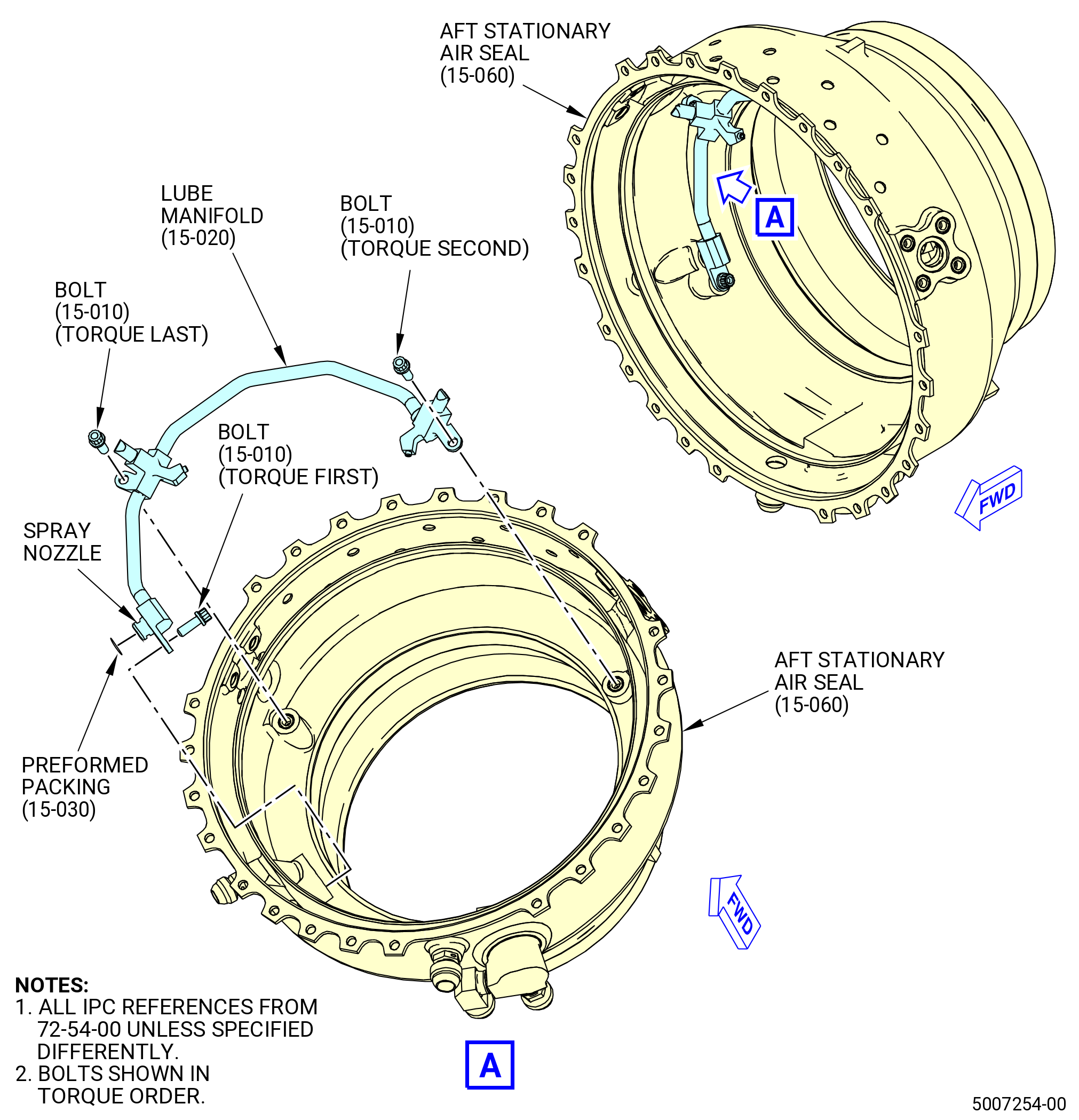
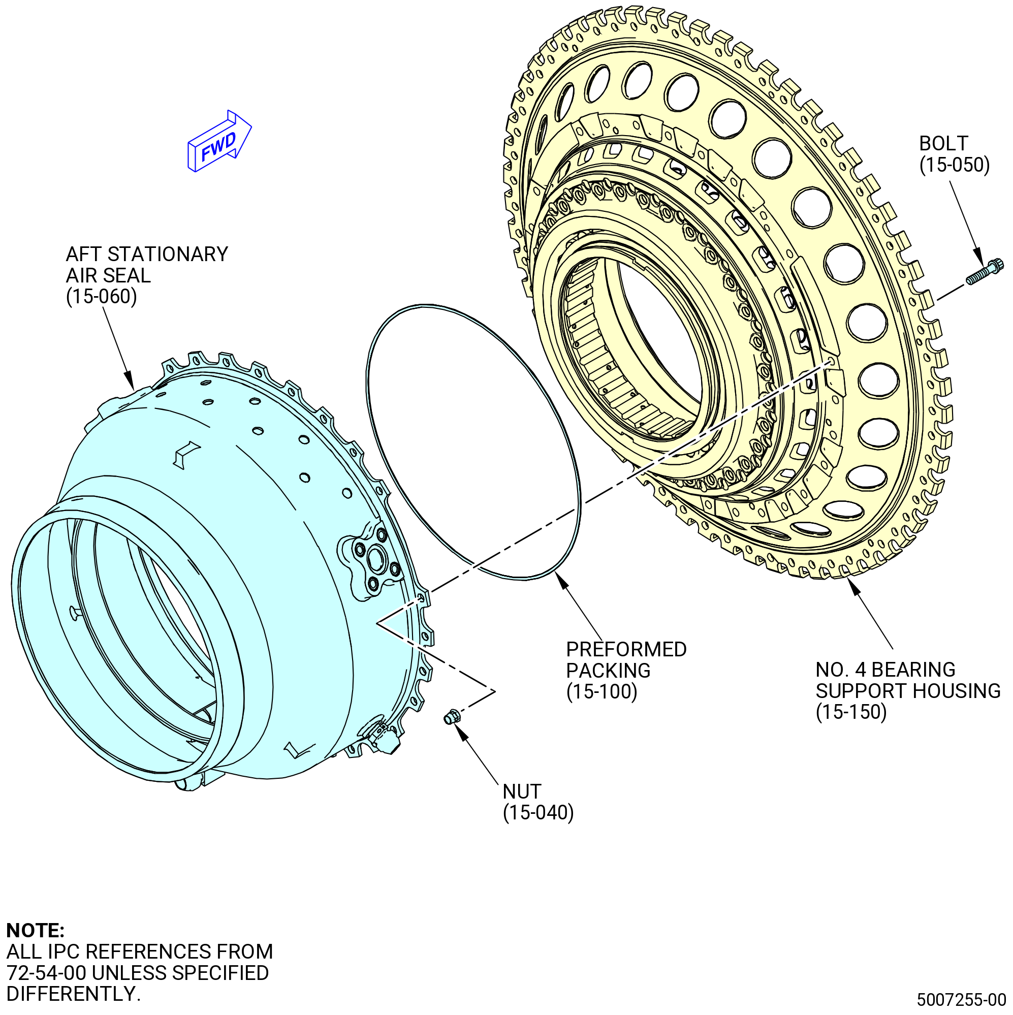
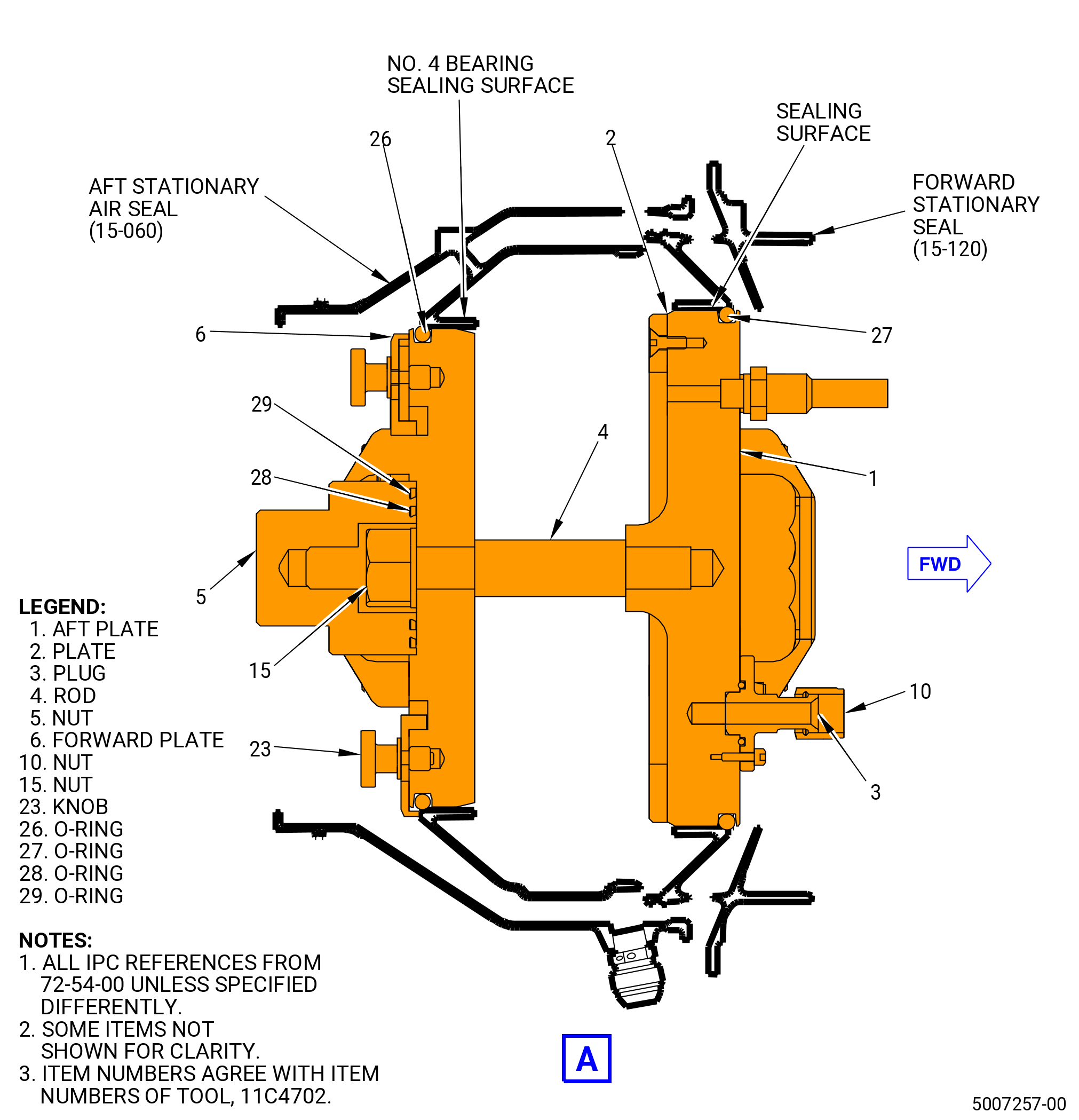
| T. | Install the No. 4 bearing lube manifold (lube manifold) (15-020) (SIN 0140A) in the aft No. 4 bearing stationary seal (aft stationary air seal) (15-060) (SIN 01407). Refer to Figure 1021 and do as follows: |
| Subtask 72-54-00-210-001 |
| CAUTION: |
|
| (1) | Do an inspection of the aft stationary air seal for raised material and foreign material. If necessary, clean or remove raised material as follows: |
| WARNING: |
|
| WARNING: |
|
| WARNING: |
|
| (a) | If necessary, clean the aft stationary air seal with C04-002 Stoddard solvent, C04-003 acetone, or C04-035 isopropyl alcohol. |
| (b) | If necessary, remove raised any material. Refer to TASK 70-42-00-350-002 (BLENDING AND REMOVAL OF HIGH METAL PROCEDURES). |
| Subtask 72-54-00-440-137 |
| WARNING: |
|
| (2) | Apply C02-019 engine oil or C02-023 engine oil to the preformed packing (15-030) (SIN 01452). |
| (3) | Install the preformed packing on the supply end of the lube manifold. |
| (4) | Put the lube manifold on the three machined pads inside the aft stationary air seal. The supply end of the lube manifold will engage the supply port of the aft stationary air seal. |
| WARNING: |
|
| (5) | Apply C02-058 lubricant to the threads and bearing (friction) surfaces of bolts (15-010) (SIN 01426). |
| (a) | Use a minimum quantity of C02-058 lubricant necessary for assembly. After assembly, remove the remaining lubricant with a clean C10-182 cloth. |
| (6) | Install the bolts (15-010) (SIN 01426) to attach the lube manifold to the aft stationary air seal. |
| (7) | Torque the bolts in the order shown in the Figure 1021 to 106-124 lb in. (12.0-14.0 N.m). |
| Subtask 72-54-00-440-046 |
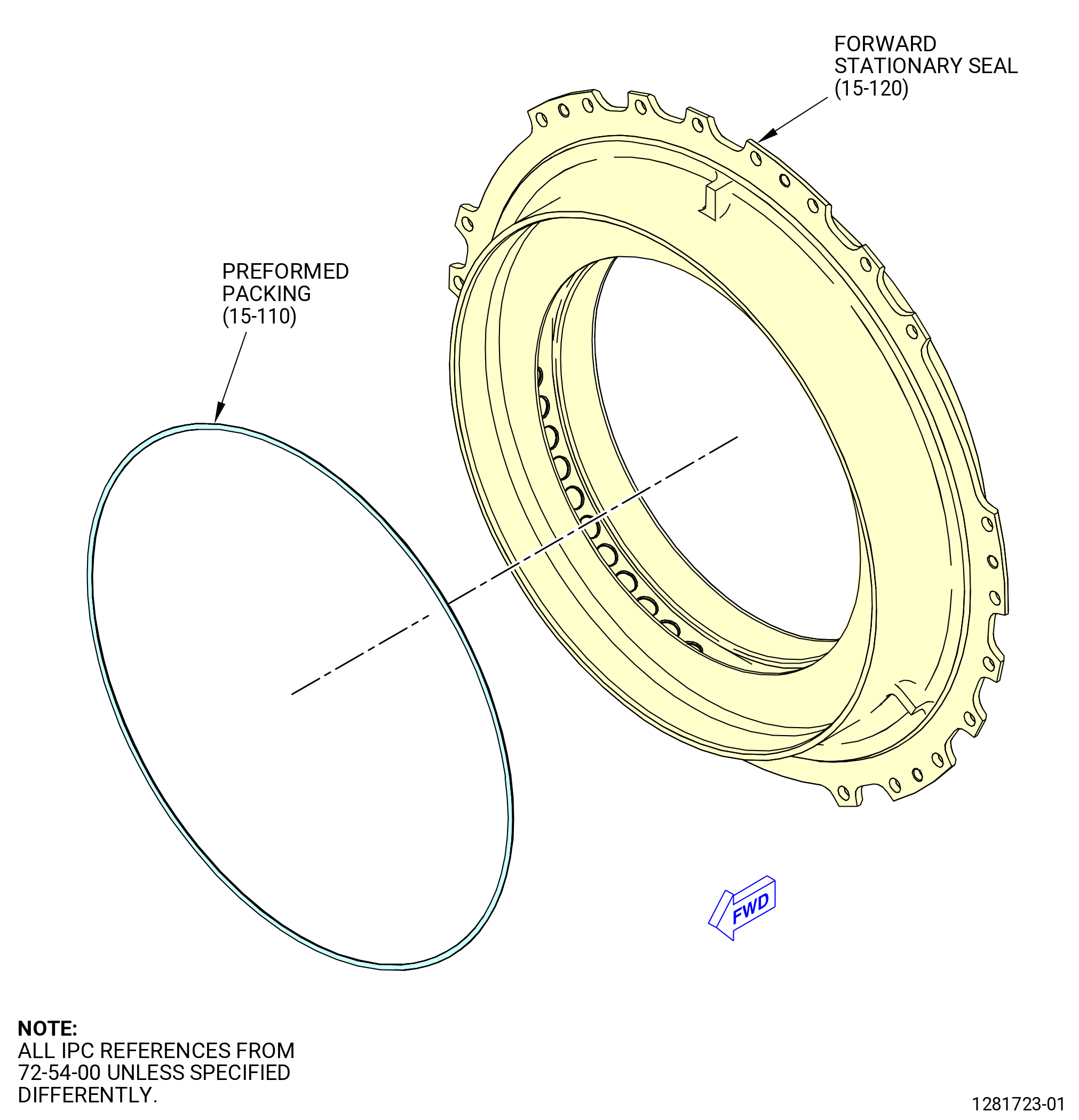
| U. | Install the forward No. 4 bearing stationary seal (forward stationary seal) (15-120) (SIN 0140E) and the aft stationary air seal (15-060) (SIN 01407) in the No. 4 bearing support housing (15-150) (SIN 01403). Refer to Figure 1022 and do as follows: |
| * * * FOR |
| * * * PRE SB 72-0496 |
| WARNING: |
|
| (1) | Apply C02-019 engine oil or C02-023 engine oil to a new preformed packing (15-110) (SIN 01451). |
| (2) | Put the preformed packing in the OD groove on the aft side of the forward stationary seal. |
| * * * FOR |
| * * * END PRE SB 72-0496 |
| * * * FOR |
| * * * SB 72-0496 |
| WARNING: |
|
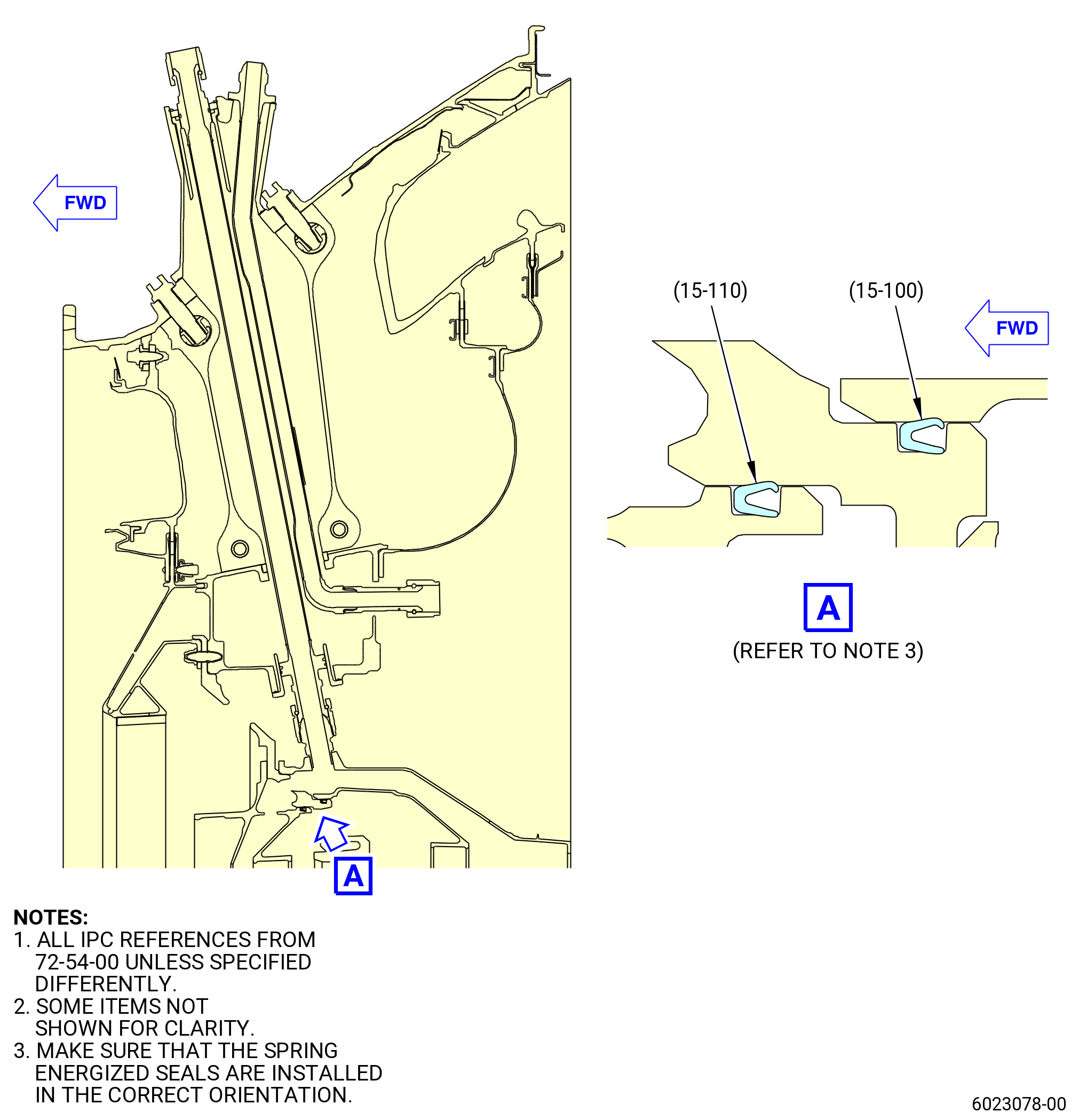
| (3) | Apply C02-019 engine oil or C02-023 engine oil to a new spring energized seal (15-110) (SIN 01451). Make sure that the spring energized seal is new. |
| CAUTION: |
|
| (4) | Refer to Figure 1022 for the correct orientation and then put the new spring energized seal (15-110) (SIN 01451) in the OD groove on the aft side of the forward stationary air seal and wait five minutes before proceeding with further assembly. |
| * * * FOR |
| * * * END SB 72-0496 |
| Subtask 72-54-00-440-047 |
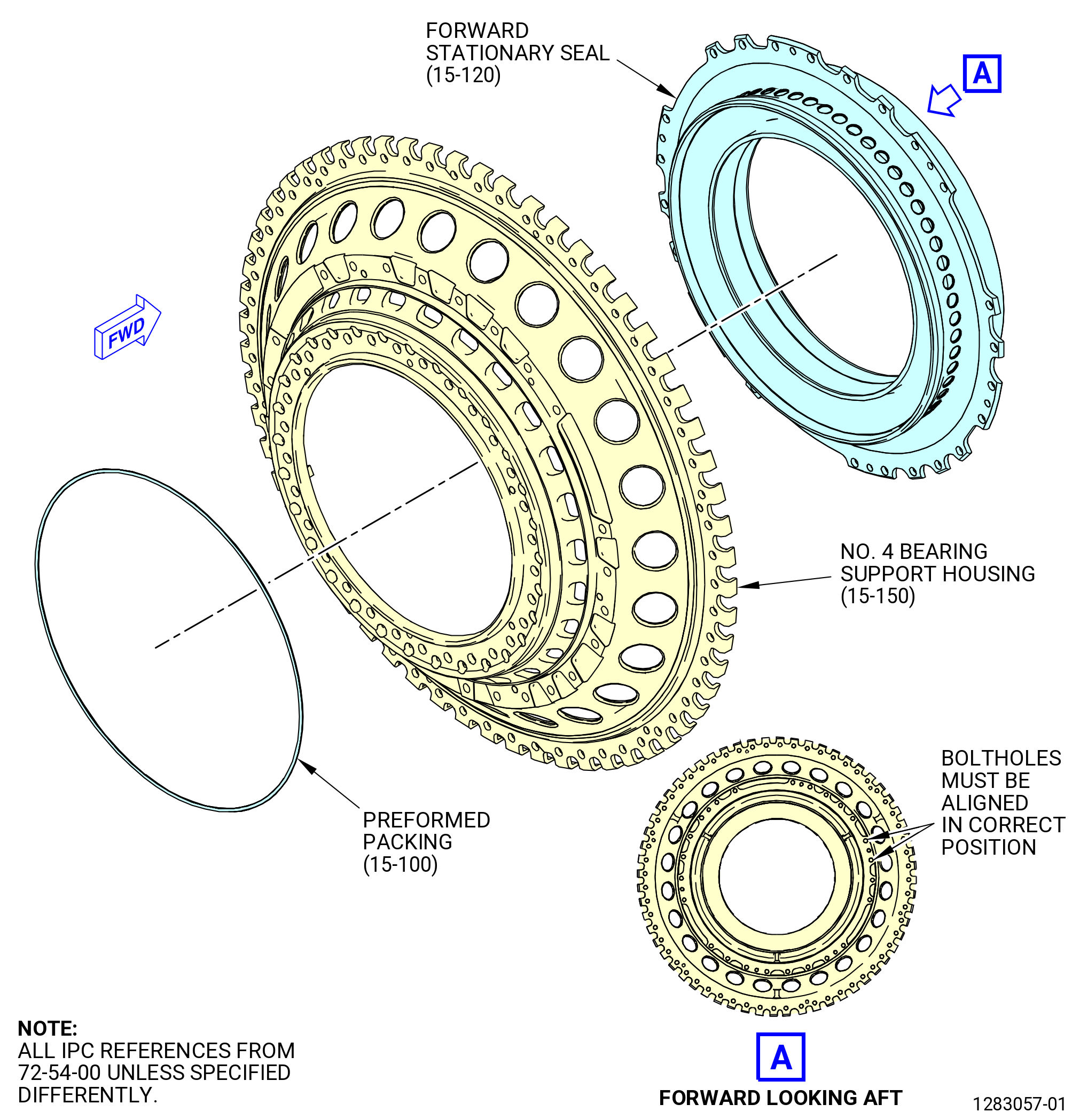
| (5) | Install the forward stationary seal (15-120) (SIN 0140E) in the No. 4 bearing support housing (15-150) (SIN 01403). Refer to Figure 1022 and do as follows: |
| (a) | Match mark the orientation of the forward stationary seal to the No. 4 bearing support housing as follows: |
| 1 | Put the forward stationary seal on the forward side of the No. 4 bearing support. The side of the forward stationary seal with the packing goes inside the No. 4 bearing support housing. |
| 2 | Align the boltholes in the forward stationary air seal with the boltholes in the No. 4 bearing support housing. |
| 3 | Use a C05-003 pen to match mark the orientation of the forward stationary air seal to the No. 4 bearing support housing. This will make orientation of parts easy during installation when parts are hot. |
| WARNING: |
|
| (b) | Apply C02-019 engine oil or C02-023 engine oil to the lead in chamfer of the No. 4 bearing support housing. |
| CAUTION: |
|
| (c) | Increase the temperature of the No. 4 bearing support housing to approximately 200°F (93°C). Use a temperature probe to make sure the temperature of the No. 4 bearing support housing does not increase more than 350°F (177°C). |
| (d) | Put the forward stationary air seal in the forward side of the No. 4 bearing support housing. The side of the forward stationary air seal with the packing goes inside the No. 4 bearing support housing. Align match marks and make sure that the boltholes on the forward stationary air seal are aligned with the boltholes in the No. 4 bearing support housing. |
| (e) | Hand press the forward stationary air seal on the No. 4 bearing support housing or tap with a rubber mallet to seat. |
| (f) | Let the temperature of the No. 4 bearing support housing go back to ambient temperature. |
| (6) | Install the aft stationary air seal (15-060) (SIN 01407) in the No. 4 bearing support housing (15-150) (SIN 01403) as follows: |
| * * * FOR |
| * * * PRE SB 72-0496 |
| WARNING: |
|
| (a) | Apply C02-019 engine oil or C02-023 engine oil to a new preformed packing (15-100) (SIN 01450). |
| (b) | Install the preformed packing in the aft outer groove of the No. 4 bearing support housing. |
| * * * FOR |
| * * * END PRE SB 72-0496 |
| * * * FOR |
| * * * SB 72-0496 |
| WARNING: |
|
| (c) | Apply C02-019 engine oil or C02-023 engine oil to a new the spring energized seal (15-100) (SIN 01450). Make sure that the spring energized seal is new. |
| CAUTION: |
|
| (d) | Refer to Figure 1022 for the correct orientation and then install the new spring energized seal (15-100) (SIN 01450) in the aft outer groove of the No. 4 bearing support housing and wait five minutes before proceeding with further assembly. |
| * * * FOR |
| * * * END SB 72-0496 |
| (e) | Match mark the orientation of the aft stationary air seal to the No. 4 bearing support housing as follows: |
| 1 | Put the aft stationary air seal on the aft side of the No. 4 bearing support housing. |
| 2 | Align the boltholes in the aft stationary air seal with the boltholes in the No. 4 bearing support housing. |
| 3 | Use a C05-003 pen to match mark the orientation of the aft stationary seal to the No. 4 bearing support housing. This will make orientation of parts easy during installation when parts are hot. |
| WARNING: |
|
| CAUTION: |
|
| (f) | Increase the temperature of the aft stationary air seal to approximately 160°F (71°C). Use a temperature probe to make sure that the temperature of the aft stationary air seal does not increase more than 350°F (177°C). |
| (g) | Install the aft stationary air seal on the No. 4 bearing support housing. Align match marks and make sure that the boltholes on the aft stationary air seal are aligned with the boltholes on the flange of the No. 4 bearing support housing. |
| (h) | Hand press the aft stationary air seal on the No. 4 bearing support housing or tap with a rubber mallet to seat. |
| (i) | Let the temperature of the No. 4 bearing support housing go back to ambient temperature. |
| WARNING: |
|
| (7) | Apply C02-019 engine oil or C02-023 engine oil to the threads and bearing (friction) surfaces of self-locking nuts (nuts) (15-040) (SIN 01441). |
| (8) | Install the bolts (15-050) (SIN 01421) through the forward stationary seal, No. 4 bearing support housing, and aft stationary air seal with boltheads forward. |
| (9) | Install nuts (15-040) (SIN 01441) on the bolts. |
| (10) | Torque eight equally spaced nuts in a criss-cross pattern to 78-92 lb in. (8.8-10.4 N.m). |
| (11) | Torque all the nuts in a criss-cross pattern to 106-124 lb in. (12.0-14.0 N.m). |
| (12) | Torque all the nuts in a circular pattern to 106-124 lb in. (12.0-14.0 N.m). |
| (13) | Deleted. |
| Subtask 72-54-00-440-054 |
| V. | Install the No. 4 bearing support housing (15-150) (SIN 01403) in the turbine frame. Refer to Figure 1026 and do as follows: |
| CAUTION: |
|
| (1) | Rotate the turbine frame installed on the 9429M60 roll-over stand to put the forward flange in the vertical position. Refer to Subtask 72-54-00-440-010 (paragraph 3.D.). |
| WARNING: |
|
| WARNING: |
|
| WARNING: |
|
| (2) | If necessary, clean the studs and mating flange on the forward side of the turbine frame with C04-002 Stoddard solvent, C04-003 acetone, or C04-035 isopropyl alcohol. |
| (3) | Loosen the bolts (01-640) (SIN 454F2) that attach the right scavenge tube (01-650) (SIN 454A2) or (01-651) (SIN 454A2) or (01-651A) (SIN 454A2) to strut No. 6 in the turbine frame. Refer to Figure 1012. |
| (4) | Loosen the bolts (01-640) (SIN 454F2) that attach the left scavenge tube (01-710) (SIN 454A1) or (01-711) (SIN 454A1) or (01-711A) (SIN 454A1) to strut No. 8 in the turbine frame. Refer to Figure 1014. |
| (5) | Push the tubes that are installed in strut No. 3, 5, 7, and 11 outboard to a position where they will not catch on the aft stationary air seal (15-060) (SIN 01407). Refer to Figure 1008 and Figure 1013. |
| WARNING: |
|
| (6) | Apply C02-058 lubricant to the threads of the B-nuts on the inboard end of tubes at strut No. 5, 6, 7, and 8. |
| NOTE: |
|
| CAUTION: |
|
| (7) | Position the No. 4 bearing support housing forward end up. |
| (8) | Loop nylon straps through the large holes in No. 4 bearing support housing 180 degrees apart and attach straps to a hoist. |
| WARNING: |
|
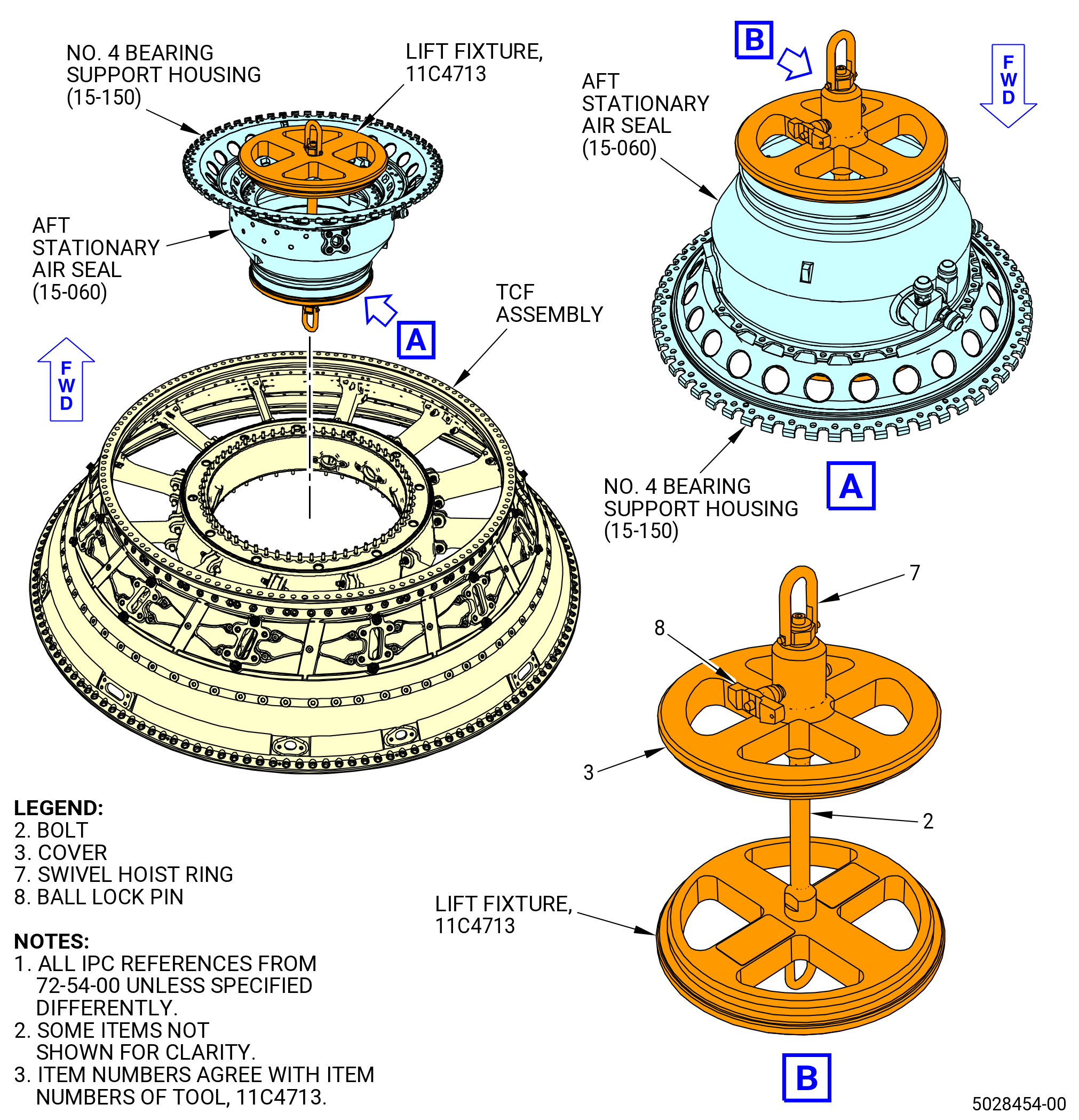
| (9) | Use an applicable hoist and sling to lift and move the 11C4713 lift fixture. |
| (10) | Disassemble the cover (item 3) and the swivel hoist ring (item 7) from the 11C4713 lift fixture. Refer to Figure 1023. |
| (11) | Turn the No. 4 bearing support housing in the 9446M39 housing fixture forward end up. |
| (12) | Put the 11C4713 lift fixture in the No. 4 bearing support housing forward end up. |
| (13) | Assemble the cover (item 3) and the swivel hoist ring (item 7) to the 11C4713 lift fixture. |
| (14) | Install the ball lock pin (item 8) to the bore hole of the cover (item 3) and the bolt (item 2). |
| (15) | Remove the No. 4 bearing support housing from the 9446M39 housing fixture. |
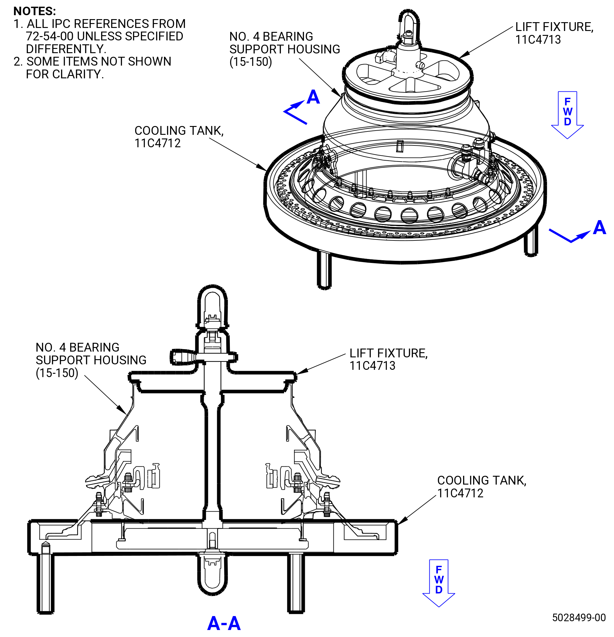
| (16) | Use an applicable hoist and sling to lift and move the No. 4 bearing support housing with the forward flange down to the 11C4712 cooling tank. Refer to Figure 1024. |
| WARNING: |
|
| WARNING: |
|
| (17) | Carefully fill an applicable quantity of liquid nitrogen into the channel of the 11C4712 cooling tank. |
| (18) | Carefully put the No. 4 bearing support with the large flange down in the 11C4712 cooling tank. |
| (19) | Make sure that no condensate appears on the No. 4 bearing outer race. |
| (20) | Decrease the temperature of the No. 4 bearing support housing until the temperature difference is 113ºF (45ºC). |
| (21) | Use an applicable hoist and sling to lift and move the No. 4 bearing support housing from the 11C4712 cooling tank above the TCF. |
| (22) | Align the TVCL and offset boltholes of the No. 4 bearing support housing and the turbine frame. |
| (23) | Carefully lower the No. 4 bearing support housing into the turbine frame. Make sure that the connections at strut No. 3, 5, 6, 7, 8, and 11 are aligned and out of the way so they are not damaged. |
| (24) | Remove the 11C4713 lift fixture from the No. 4 bearing support housing. |
| (25) | Install 0.250-28 UNJF-3B slave nuts at 12 equally spaced locations on the turbine frame studs. Do not use the self-locking nuts (nuts) (15-140) (SIN 93740) at this time. |
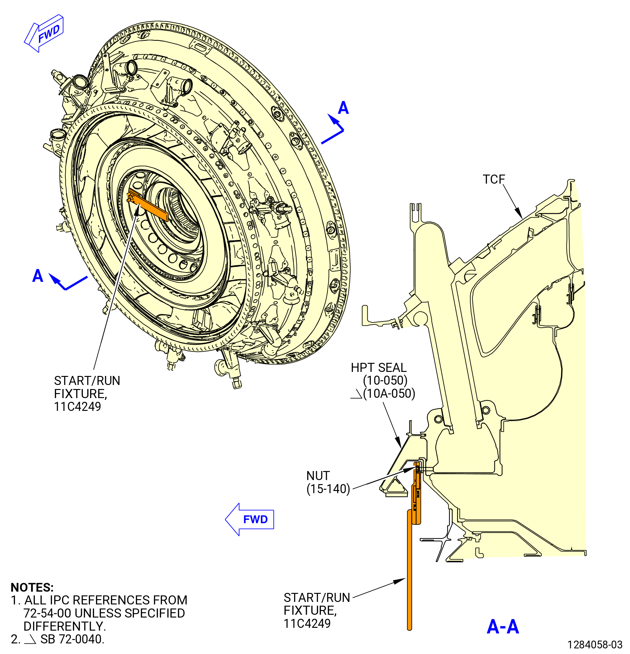
| (26) | Torque the slave nuts with the 11C4249 start/run fixture to 54-59 lb in. (6.1-6.7 N.m) in a criss-cross pattern. Refer to Figure 1025. |
| Subtask 72-54-00-220-004 |
| (27) | Make sure that the No. 4 bearing support housing is correctly installed on the turbine frame as follows: |
| (a) | Try to insert a piece of 0.001 inch (0.03 mm) shim stock between the mating flanges of the turbine frame and the No. 4 bearing support housing. |
| (b) | Gaps are not permitted. |
| Subtask 72-54-00-620-001 |
| (28) | Apply protection to the outer race of the No. 4 roller bearing (15-090) (SIN 01400) or (15-091) (SIN 01400). Refer to TASK 70-60-01-620-002 (PRESERVATION OF ANTIFRICTION BEARINGS). |
| Subtask 72-54-00-440-055 |
| CAUTION: |
|
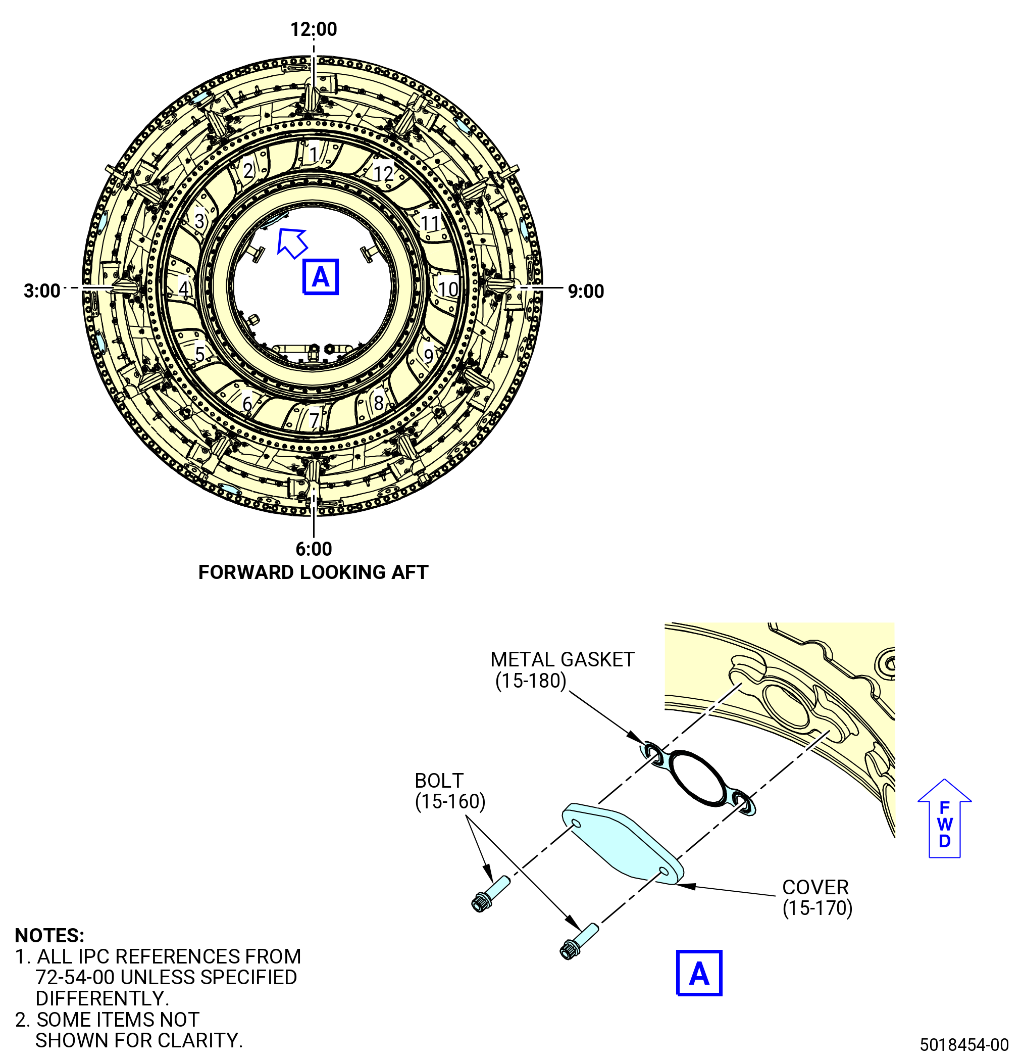
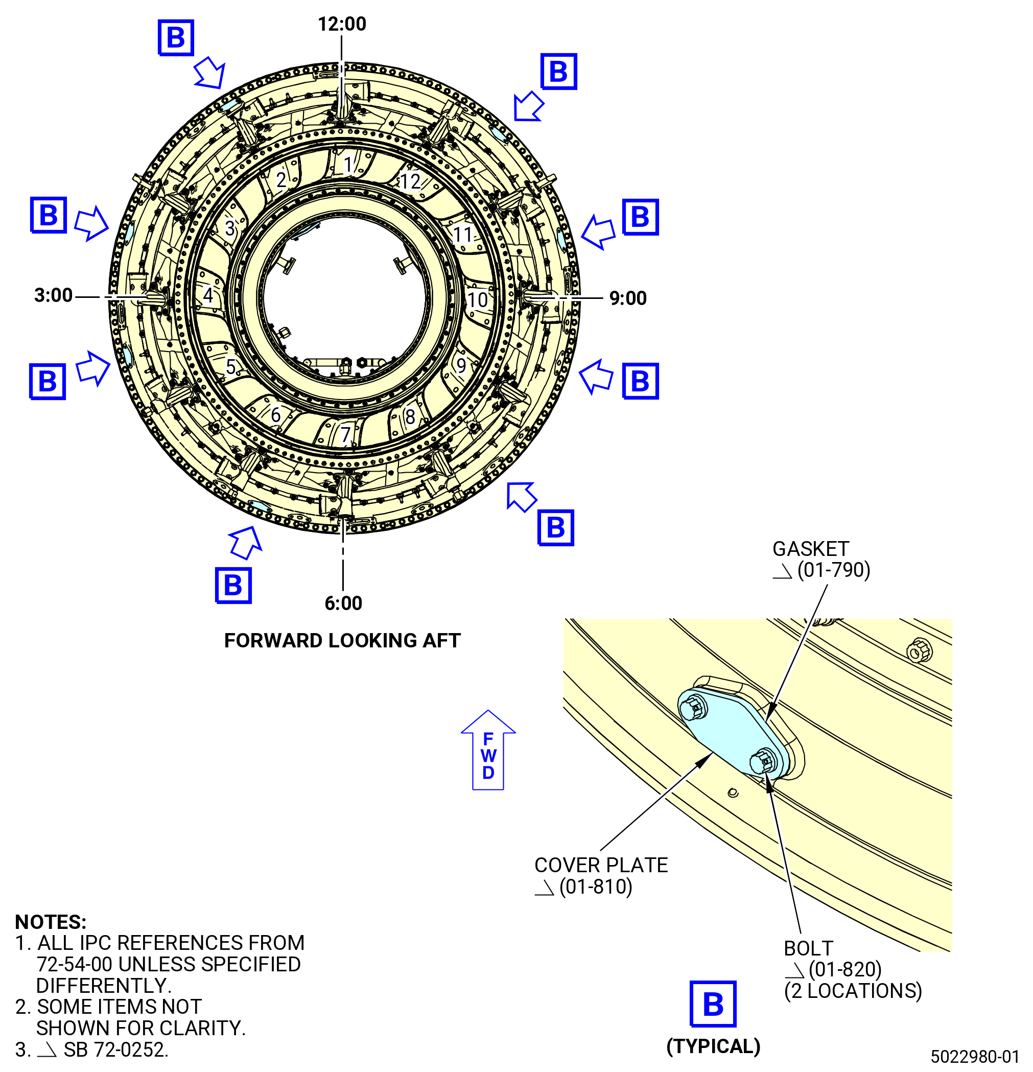
| W. | Turn the turbine frame in the 9429M60 roll-over stand to the horizontal position, TVCL up. Refer to Subtask 72-54-00-440-010 (paragraph 3.D.) and do as follows: |
| Subtask 72-54-00-440-196 |
| * * * FOR |
| * * * PRE SB 72-0077( Rake Capable Turbine Frame ) |
| NOTE: |
|
| (1) | Install the cover plate (15-170) (SIN 92561) and the metal gasket (15-180) (SIN 92552) with the bolts (15-160) (SIN 92522) on the inward side of the turbine frame (15-130) (SIN 925A0) on strut 2 position. Refer to Figure 1027. |
| NOTE: |
|
| CAUTION: |
|
| (2) | Torque the bolts to 106 to 124 lb in. (12.0 to 14.0 Nm). |
| NOTE: |
|
| (3) | Safety the bolts with C10-071 safety wire or C10-143 safety cable. Refer to TASK 70-11-00-400-001 (FASTENER RETENTION PROCEDURES). |
| * * * FOR |
| * * * END PRE SB 72-0077 |
| Subtask 72-54-00-440-391 |
| * * * FOR |
| * * * SB 72-0252( Rake Capable Turbine Frame ) |
| NOTE: |
|
| (4) | Install the eight cover plates (01-810) (SIN 60J00) and gaskets (01-790) (SIN 60J50) with the bolts (01-820) (SIN 60J20) on the case of the turbine frame (15-132A) (SIN 925A0). Refer to Figure 1027. |
| NOTE: |
|
| (5) | Torque the bolts to 106 to 124 lb in. (12.0 to 14.0 Nm). |
| (6) | Safety the bolts with C10-071 safety wire or C10-143 safety cable. Refer to TASK 70-11-00-400-001 (FASTENER RETENTION PROCEDURES). |
| * * * FOR |
| * * * END SB 72-0252 |
|
| Subtask 72-54-00-440-057 |
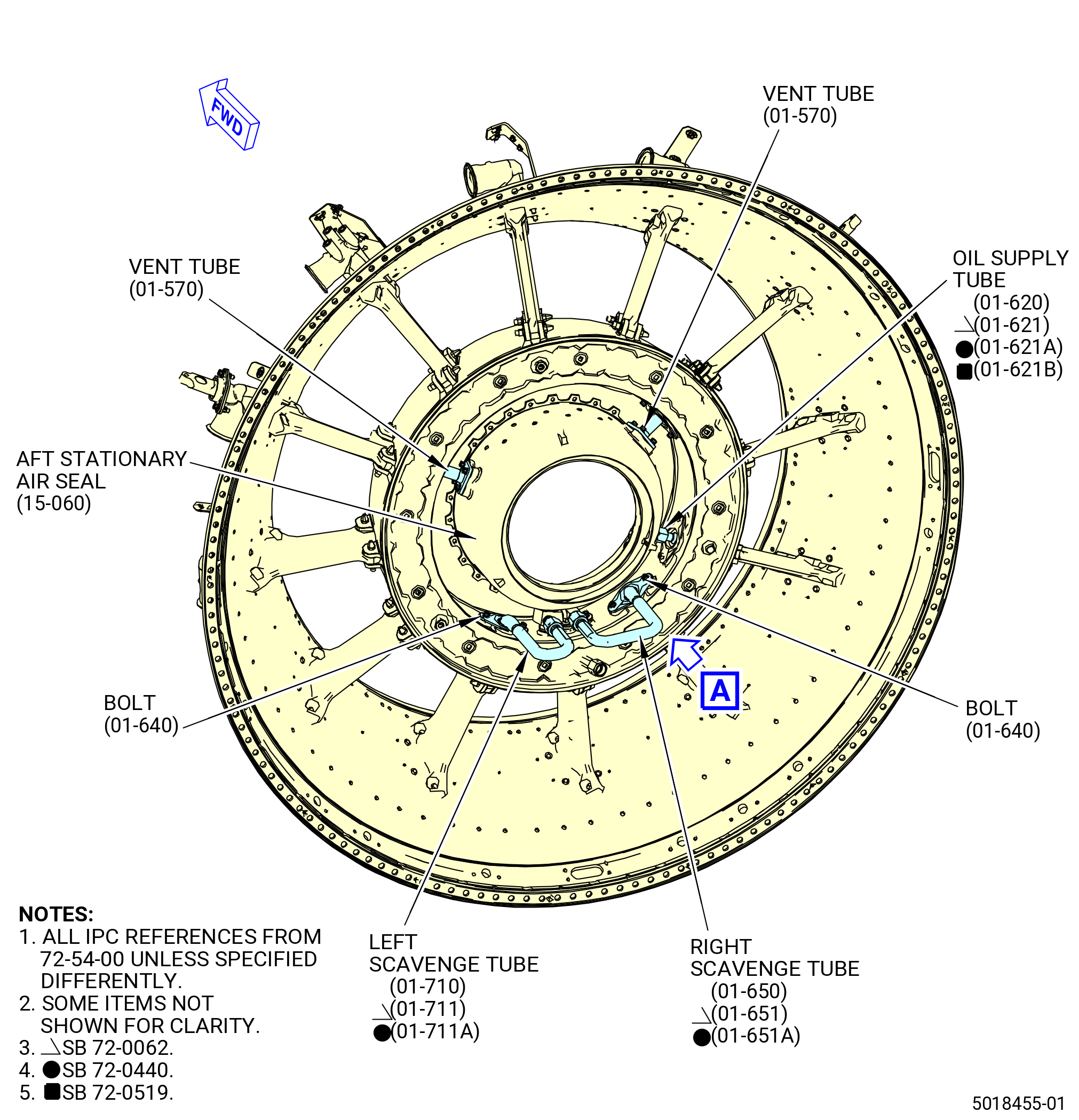
| X. | Connect the air and oil tubes in the sump area to the aft stationary air seal (15-060) (SIN 01407) and turbine frame inner hub as follows: |
| (1) | Connect the oil supply tube (01-620) (SIN 443B1) or (01-621) (SIN 443B1) or (01-621A) SIN (443B1) or (01-621B) (SIN 443B1) in strut No. 5 to the aft stationary air seal and turbine frame inboard side. Refer to Figure 1028 and do as follows: |
| (a) | Attach the inner B-nut of the tube to the tube connector on the aft stationary air seal. |
| CAUTION: |
|
| (b) | Triple torque the B-nut to 460-540 lb in. (52.0-61.0 N.m). Refer to TASK 70-51-00-400-004 (TIGHTENING PRACTICES AND TORQUE VALUES). |
| (c) | Safety the B-nut with C10-071 safety wire or C10-143 safety cable. |
| (d) | Put the inner retainer (01-630) (SIN 443B4) in the inboard side of the turbine frame and make sure that the piston seal ring (01-740) (SIN 443N0) is in the groove of the tube. |
| (e) | Align the inner retainer and the metal gasket (01-730) (SIN 443N2) with the boltholes in the inboard side of the turbine frame. |
| CAUTION: |
|
| (f) | Torque the bolts (01-610) (SIN 443F4) to 106-124 lb in. (12.0-14.0 N.m). |
| Subtask 72-54-00-440-177 |
| (2) | Connect the main drain tube (01-680) (SIN 489A2) or (01-681) (SIN 489A2) in strut No. 7 to the aft stationary air seal (15-060) (SIN 01407). Refer to Figure 1028 and do as follows: |
| (a) | Attach the inner B-nut of the main drain tube to the tube connector on the aft stationary air seal. |
| CAUTION: |
|
| (b) | Triple torque the B-nut to 55 to 65 lb ft. (74.9 to 88.0 Nm). Refer to TASK 70-51-00-400-004 (TIGHTENING PRACTICES AND TORQUE VALUES). |
| (c) | Safety the B-nut with C10-071 safety wire or C10-143 safety cable. |
| (d) | Put the inner retainer (01-670) (SIN 489B4) in the inboard side of the turbine frame and make sure that the piston seal ring (01-760) (SIN 489N1) is in the groove of the main drain tube. |
| (e) | Align the inner retainer (01-670) (SIN 489B4) and metal gasket (01-750) (SIN 48952) with the boltholes in the inboard side of the turbine frame. |
| CAUTION: |
|
| (f) | Torque the bolts (01-660) (SIN 489F0) to 106-124 lb in. (12.0-14.0 N.m). |
| (3) | Connect the tubes (01-570) (SIN 46104) to the aft stationary air seal (15-060) (SIN 01407) on the turbine frame at struts No. 3 and No. 11. Refer to Figure 1028, Figure 1029, and do as follows: |
| WARNING: |
|
| (a) | Apply C02-058 lubricant to the mating surfaces and the threads of the bolts (01-540) (SIN 46127). |
| 1 | Use a minimum quantity of C02-058 lubricant necessary for assembly. After assembly, remove the remaining lubricant with a clean C10-182 cloth. |
| (b) | Put a graphite seal (01-580) (SIN 443N6) in the aft stationary air seal at the struts No. 3 and 11. |
| (c) | Align the tube with the aft stationary air seal boltholes. |
| (d) | Put the bolts in the tube and the aft stationary air seal. |
| CAUTION: |
|
| (e) | Torque the bolts to 106-124 lb in. (12.0-14.0 N.m). |
| (f) | Make sure a metal gasket (01-590) (SIN 461N1) is installed on the inner sleeve (01-560) (SIN 46188) connected to the turbine frame on the inboard side. |
| CAUTION: |
|
| (g) | Torque the bolts (01-550) (SIN 46120) to 106-124 lb in. (12.0-14.0 N.m). |
| (h) | Attach the seal retainer (01-150) (SIN 46182) to the vent adapter (01-210) (SIN 46107) on the turbine frame outboard side as follows: |
| 1 | Attach the metal gasket (01-180) (SIN 461N2) to the vent adapter. |
| 2 | Attach the vent seal (01-170) (SIN 46152) to the seal retainer. |
| 3 | Attach the retaining plate (01-160) (SIN 46156) to the seal retainer. |
| 4 | Attach the seal retainer to the vent adapter with the nuts (01-130) (SIN 46140) and bolts (01-140) (SIN 46122). |
| (i) | Torque the nuts (01-130) (SIN 46140) to 106-124 lb in. (12.0-14.0 N.m). |
| Subtask 72-54-00-440-178 |
| (4) | Connect the right and left scavenge tubes (01-650) (SIN 454A2) or (01-651) (SIN 454A2) or (01-651A) (SIN 454A2) and (01-710) (SIN 454A1) or (01-711) (SIN 454A1) or (01-711A) (SIN 454A1) to the aft stationary air seal (15-060) (SIN 01407) at struts No. 6 and 8. Refer to Figure 1014, Figure 1028, and do as follows: |
| WARNING: |
|
| (a) | Apply C02-058 lubricant to the B-nut of the right scavenge tube (01-650) (SIN 454A2) or (01-651) (SIN 454A2) or (01-651A) (SIN 454A2). |
| (b) | Connect the right scavenge tube (01-650) (SIN 454A2) or (01-651) (SIN 454A2) or (01-651A) (SIN 454A2) in strut No. 6 to the tube connector on the aft stationary air seal. |
| CAUTION: |
|
| (c) | Triple torque the B-nut of the right scavenge tube (01-650) (SIN 454A2) or (01-651) (SIN 454A2) or (01-651A) (SIN 454A2) to 55 to 65 lb ft (75 to 88 Nm). Refer to TASK 70-51-00-400-004 (TIGHTENING PRACTICES AND TORQUE VALUES). |
| WARNING: |
|
| (d) | Apply C02-058 lubricant to the B-nut of the left scavenge tube (01-710) (SIN 454A1) or (01-711) (SIN 454A1) or (01-711A) (SIN 454A1). |
| (e) | Connect the left scavenge tube (01-710) (SIN 454A1) or (01-711) (SIN 454A1) or (01-711A) (SIN 454A1) in strut No. 8 to the tube connector on the aft stationary air seal. |
| CAUTION: |
|
| (f) | Triple torque the B-nut of the left scavenge tube (01-710) (SIN 454A1) or (01-711) (SIN 454A1) or (01-711A) (SIN 454A1) to 55 to 65 lb ft (75 to 88 Nm). Refer to TASK 70-51-00-400-004 (TIGHTENING PRACTICES AND TORQUE VALUES). |
| (g) | Safety the B-nuts of the right and left scavenge tubes (01-650) (SIN 454A2) or (01-651) (SIN 454A2) or (01-651A) (SIN 454A2) and (01-710) (SIN 454A1) or (01-711) (SIN 454A1) or (01-711A) (SIN 454A1) together with C10-071 safety wire or C10-143 safety cable. |
| (h) | Make sure that a metal gasket (01-720) (SIN 454N1) is installed under the right scavenge tube (01-650) (SIN 454A2) or (01-651) (SIN 454A2) or (01-651A) (SIN 454A2) flange that connects to the turbine frame. |
| CAUTION: |
|
| (i) | Torque the bolts (01-640) (SIN 454F2) that attach the scavenge tube to the turbine frame to 106-124 lb in. (12.0-14.0 N.m). |
| (j) | Make sure that a metal gasket (01-720) (SIN 454N1) is installed under the left scavenge tube (01-710) (SIN 454A1) or (01-711) (SIN 454A1) or (01-711A) (SIN 454A1) flange that connects to the turbine frame. |
| CAUTION: |
|
| (k) | Torque the bolts (01-640) (SIN 454F2) that attach the scavenge tube to the turbine frame to 106-124 lb in. (12.0-14.0 N.m). |
| Subtask 72-54-00-720-001 |
| Y. | Do an air flow check of the oil supply tube (01-620) (SIN 443B1) or (01-621) (SIN 443B1) or (01-621A) (SIN 443B1) or (01-621B) (SIN 443B1) at strut No. 5. Refer to Figure 1030, Figure 1031, and do as follows: |
| CAUTION: |
|
| (1) | Turn the turbine frame in the 9429M60 roll-over stand to the horizontal position. Refer to Subtask 72-54-00-440-010 (paragraph 3.D.). |
| (2) | Remove all protective material from the sump area. |
| CAUTION: |
|
| (3) | Connect a 0.750-16 UNJF-3B adapter fitting to the swivel nut (20-110 , 79-22-10) (SIN 443K1) on the tube at strut No. 5. Refer to Figure 1030 and do as follows: |
| (4) | Connect the 9461M40 test stand with the 9429M71 universal adapter kit to the adapter fitting. |
| (5) | Turn on the 9461M40 test stand and let it run for 15-20 minutes. Make sure that the air is filtered to remove water and other contaminants. |
| WARNING: |
|
| (6) | Operate the 9461M40 test stand at 9.5-10.5 psig (65.5-72.4 kPag). |
| (7) | Make sure that the air flow is 5.3-5.8 scfm (0.0025-0.0027 cms) at the openings of the lube manifold (15-020) (SIN 0140A). |
| (8) | Record the flow rate on the Record Sheet. Refer to Figure 1004. |
| (9) | Disconnect the 9461M40 test stand and adapter fittings from the swivel nut (20-110 , 79-22-10) (SIN 443K1) on the tube. |
| Subtask 72-54-00-440-180 |
| Z. | Do a pressure test of the No. 4 bearing sump area with the 11C4702 leak test set as follows: |
| (1) | Install the plugs (item 33 and 34) and the cap plates (item 9). Refer to Figure 1031 and do as follows: |
| (a) | Install the plug (item 34) on the oil supply tube (01-620) (SIN 443B1) or (01-621) (SIN 443B1) or (01-621A) (SIN 443B1) or (01-621B) (SIN 443B1) at strut No. 5. |
| (b) | Install the plug (item 33) on the right scavenge tube (01-650) (SIN 454A2) or (01-651) (SIN 454A2) or (01-651A) (SIN 454A2) at strut No. 6 and the left scavenge tube (01-710) (SIN 454A1) or (01-711) (SIN 454A1) or (01-711A) (SIN 454A1) at strut No. 8. |
| (c) | Install the plug (item 34) on the main drain tube (01-680) (SIN 489A2) or (01-681) (SIN 489A2) and the cap (item 35) on the auxiliary drain tube (01-370) (SIN 489A1) or (01-371) (SIN 489A1). |
| (d) | Make sure that the O-rings (item 30) are in the groove on each cap plate (item 9). |
| (e) | Install the cap plates (item 9) and O-rings (item 30) on the vent tubes (01-570) (SIN 46104) at struts No. 3 and 11. |
| (f) | Attach the cap plates (item 9) to the vent tubes (01-570) (SIN 46104) with cap screws (item 8), plain nuts (item 16), washers (item 13), and cap screws (item 19). |
| CAUTION: |
|
| (2) | Turn the turbine frame in the 9429M60 roll-over stand to the horizontal position, TVCL up. Refer to Subtask 72-54-00-440-010 (paragraph 3.D.) and do as follows: |
| Subtask 72-54-00-780-001 |
| (3) | Install the aft plate (item 1) of the 11C4702 leak test set and forward plate (item 6). Refer to Figure 1031 and do as follows: |
| (a) | Make sure that the forward plate (item 6) and aft plate (item 1) are prepared for installation as follows: |
| 1 | Make sure that the O-ring (item 27) is installed in the OD groove of the aft plate (item 1). |
| 2 | Install the rod (item 4) on the aft plate (item 1). |
| 3 | Make sure that the O-ring (item 26) is installed in the OD groove of the forward plate (item 6). |
| (b) | Align the aft plate (item 1) on the aft edge in the bore of the aft stationary air seal (15-060) (SIN 01407) and hold it in position. The aft plate (item 1) must be held in position until the nut (item 15) is installed. |
| (c) | Install the forward plate (item 6) as follows: |
| 1 | Align the forward plate (item 6) on the forward edge in the bore of the forward stationary seal (15-120) (SIN 0140E). Make sure that the rod (item 4) goes through the hole in the forward plate (item 6). |
| 2 | Install the nut (item 15) on the rod (item 4). |
| 3 | Install the nut (item 5) with the O-ring (item 28) and O-ring (item 29) on the forward plate (item 6). Hand-tighten the nut (item 5). |
| 4 | Move the plates (item 2) outboard and tighten the knobs (item 23). |
| Subtask 72-54-00-440-182 |
| (4) | Do the pressure test in the No. 4 bearing sump area as follows: |
| (a) | Connect a regulated air supply to the plug (item 3) and nut (item 10). Make sure that the air is filtered to remove water and other contaminants. |
| WARNING: |
|
| (b) | Pressurize the sump area to 15-20 psig (103.4-137.9 kPa gage). |
| (c) | Stop the regulated air supply. |
| (d) | Monitor the pressure gage and make sure that the decrease rate is no more than 1.0 psig (6.9 kPa gage) in 5 minutes. If the decrease rate is not in the limits, check for loose connections. Correct the leaks and do the pressure test again. |
| (5) | Remove the 11C4702 leak test set as follows: |
| (a) | Release the air pressure with the relief valve. |
| (b) | Disconnect the regulated air supply from the plug (item 3) and nut (item 10). |
| (c) | Remove the nut (item 15) from the rod (item 4) and the forward plate (item 6). |
| (d) | Remove the forward plate (item 6) from the rod (item 4). Make sure to hold the aft plate (item 1) in position. |
| (e) | Remove the aft plate (item 1) from the aft stationary air seal (15-060) (SIN 01407). |
| (f) | Deleted. |
| (g) | Remove the nut (item 5) with O-ring (item 28) and O-ring (item 29) from the forward plate (item 6). |
| (h) | Deleted. |
| (i) | Remove the plug (item 34) from the oil supply tube (01-620) (SIN 443B1) or (01-621) (SIN 443B1) or (01-621A) (SIN 443B1) or (01-621B) (SIN 443B1) at strut No. 5. |
| (j) | Remove the plug (item 33) from the right scavenge tube (01-650) (SIN 454A2) or (01-651) (SIN 454A2) or (01-651A) (SIN 454A2) at strut No. 6 and from the left scavenge tube (01-710) (SIN 454A1) or (01-711) (SIN 454A1) or (01-711A) (SIN 454A1) at strut No. 8. |
| (k) | Remove the cap screws (item 8), plain nuts (item 16), washers (item 13), cap screws (item 19), and the cap plates (item 9) from the vent tubes (01-570) (SIN 46104) at struts No. 3 and 11. Refer to Figure 1031. |
| (l) | Remove the plug (item 34) from the main drain tube (01-680) (SIN 489A2) or (01-681) (SIN 489A2) and the cap (item 35) from the auxiliary drain tube (01-370) (SIN 489A1) or (01-371) (SIN 489A1). |
| Subtask 72-54-00-440-064 |
| (6) | Apply protection to the outer race of No. 4 roller bearing (15-090) (SIN 01400) or (15-091) (SIN 01400) and the sump area. Refer to TASK 70-60-01-620-002 (PRESERVATION OF ANTIFRICTION BEARINGS). |
| (7) | Clean the oil residue from the outboard openings of the tubes in the turbine frame strut. Cover the tube openings. |
| Subtask 72-54-00-440-065 |
| CAUTION: |
|
| AA. | Turn the turbine frame in the 9429M60 roll-over stand to the vertical position, forward end up. Refer to Subtask 72-54-00-440-010 (paragraph 3.D.). |
| Subtask 72-54-00-440-141 |
| AB. | Install the forward plate seal (10-060) (SIN 92502), forward sheet seals (10-040) (SIN 92503), retaining clips (10-030) (SIN 925A2), and high pressure turbine (HPT) seal (10-050) (SIN 93700) or (10A-050) (SIN 93700) as follows: |
| CAUTION: |
|
| (1) | Put a mark to the TVCL and offset bolthole locations on the forward plate seal (10-060) (SIN 92502) and HPT seal (10-050) (SIN 93700) or (10A-050) (SIN 93700). Refer to Figure 1033 and do as follows: |
| WARNING: |
|
| (a) | Clean the forward plate seal (10-060) (SIN 92502) with C04-035 isopropyl alcohol. |
| (b) | Put the forward plate seal, lip facing up, on a clean work surface. |
| (c) | Visually identify or measure to determine the offset bolthole location on the forward plate seal. The offset hole in the forward plate seal is the No. 12 hole CW of the split line, forward looking aft (FLA) (lip facing up). |
| (d) | Put a mark to the TVCL and the offset bolthole of the forward plate seal with a C05-003 pen. |
| (e) | Position the HPT stator stationary seal, aft bolt flange facing down, on top of the forward plate seal. |
| (f) | Visually identify or measure to determine the offset bolthole location on the forward and aft flanges of the HPT stator stationary seal. |
| (g) | Put a mark to the TVCL and the offset bolthole of the HPT stator stationary seal with a C05-003 pen . |
| (h) | Align the TVCL and offset boltholes of the forward plate seal and the HPT stator stationary seal forward flange. Visual inspect and verify that the offset boltholes and all other boltholes are aligned. |
| Subtask 72-54-00-440-187 |
| (2) | Install the forward plate seal (10-060) (SIN 92502), lip pointing up (forward), on the forward side of the turbine frame. Refer to Figure 1033 and do as follows: |
| (a) | Move the forward plate seal split line apart and put one end under the turbine frame aft gang channel. |
| CAUTION: |
|
| (b) | With the forward plate seal slightly compressed, continue in a circumferential direction to put the forward plate seal under the turbine frame aft gang channel. |
| CAUTION: |
|
| (c) | Align the forward plate seal TVCL with the turbine frame TVCL. |
| (3) | Install the first layer of the forward sheet seals (10-040) (SIN 92503) on the forward plate seal (10-060) (SIN 92502) as follows: |
| (a) | Put the first forward sheet seal slot on the forward plate seal offset bolthole. |
| (b) | Put the forward sheet seals on the forward plate seal adjacent to each other. |
| (c) | Put the forward sheet seals with the slot hole and the bolthole in the same direction. |
| (4) | Install the second layer of the forward sheet seals (10-040) (SIN 92503) on top of the first layer as follows: |
| (a) | Reverse the forward sheet seals orientation of the second layer boltholes and slots. |
| (b) | Put the forward sheet seals on the forward plate seal adjacent to each other. |
| (c) | Put the first forward sheet seal slot on the forward plate seal bolthole. |
| (d) | Make sure that the space between the first and second layers of the forward sheet seals are offset. |
| (e) | Put the forward sheet seals with the slot hole and the bolthole in the same direction. |
| (5) | Put the 11C4592 guide pins through the forward sheet seals and into the forward plate seal. |
| (6) | Install the HPT seal (10-050) (SIN 93700) or (10A-050) (SIN 93700) on the turbine frame. Refer to Figure 1033 and do as follows: |
| CAUTION: |
|
| (a) | Make sure that the correct configuration of HPT seal (10-050) (SIN 93700) or (10A-050) (SIN 93700) is installed. Refer to Figure 1033. |
|
| (b) | Make sure the TVCL and the offset bolthole marks on the HPT stator stationary seal forward and aft flanges are still visible. If not, put a mark again. Refer to Subtask 72-54-00-440-159 (paragraph AC.(1)). |
| Subtask 72-54-00-440-406 |
| WARNING: |
|
| (c) | Alternative Procedure Available. Apply dry ice to the aft inner bolt flange of the HPT stator stationary seal for 20 minutes. |
| Subtask 72-54-00-440-407 |
| WARNING: |
|
| WARNING: |
|
| (c).A. | Alternative Procedure. Use liquid nitrogen on the inner flange of the HPT stator stationary seal to obtain 98°F (37°C) minimum temperature difference between assembling parts. |
| Subtask 72-54-00-440-408 |
| (d) | Remove the slave nuts from the No. 4 bearing support housing (15-150) (SIN 01403) and turbine frame. |
| (e) | Put the HPT stator stationary seal on the 11C4592 guide pins and align the offset boltholes in the forward flange of the HPT stator stationary seal and the forward plate seal. |
| (f) | After you started the guide pins into the HPT stator stationary seal, turn the HPT stator stationary seal to align the aft flange offset boltholes with the No. 4 bearing housing offset bolthole. Make sure that the cutouts of the HPT stator stationary seal are aligned with the tabs on the turbine frame. |
| (g) | Use a rubber mallet or slave nuts to seat the HPT stator stationary seal. |
| (h) | Install the slave nuts on the support studs of the turbine frame hand tight. |
| (i) | Let the HPT stator stationary seal go back to ambient temperature and loosen the nuts. |
| (j) | If necessary, install the slave nuts again and tighten until the housing is fully seated. |
| (k) | Tighten the slave nuts until a piece of 0.001 inch (0.03 mm) shim stock does not go between the mating flanges of the HPT stator stationary seal and the No. 4 bearing support housing at four equally spaced locations. |
| (l) | Remove the slave nuts. |
| WARNING: |
|
| (m) | Apply C02-058 lubricant to the threads of the nuts (15-140) (SIN 93740). |
| 1 | Use a minimum quantity of C02-058 lubricant necessary for assembly. After assembly, remove the remaining lubricant with a clean C10-182 cloth. |
| (n) | Put the nuts (15-140) (SIN 93740) on the No. 4 bearing housing and the turbine frame studs. |
| (o) | Torque 15 equally spaced nuts with the 11C4249 start/run fixture in a criss-cross pattern to 56 lb in. (6.3 N.m). |
| (p) | Torque all the nuts in a criss-cross pattern to 69-81 lb in. (7.8-9.2 N.m). |
| (q) | Torque all the nuts in a circular pattern to 69-81 lb in. (7.8-9.2 N.m). |
| (r) | Try to insert a piece of 0.001 inch (0.03 mm) shim stock between the mating flanges of the HPT seal (10-050) (SIN 93700) or (10A-050) (SIN 93700) and the No. 4 bearing support housing (15-150) (SIN 01403) at four equally spaced locations. |
| (s) | Gaps are not permitted. |
| (7) | Install the third layer of forward sheet seals (10-040) (SIN 92503) on the forward side of the HPT seal (10-050) (SIN 93700) or (10A-050) (SIN 93700). Refer to Figure 1033 and do as follows: |
| (a) | Put the first forward sheet seal on the HPT stator stationary seal forward flange with the slot on the offset bolthole. The forward sheet seal will rest on the 11C4592 guide pins. |
| (b) | Put the forward sheet seal on the HPT stator stationary seal adjacent to each other. |
| (c) | Put the forward sheet seal with the slot hole and the bolthole in the same direction. |
| (8) | Install the fourth layer forward sheet seals (10-040) (SIN 92503) on top of the third layer as follows: |
| (a) | Reverse the forward sheet seals orientation of the fourth layer bolt holes and slot holes. |
| (b) | Put the first forward sheet seal slot on the offset bolthole. |
| (c) | Continue to put the forward sheet seals adjacent to each other on top of the third layer. |
| (d) | Put the forward sheet seals with the slot hole and the bolthole in the same direction. |
| (e) | Make sure that the space between the first and second layers of the forward sheet seals are offset. |
| (9) | Install the seal (10-020) (SIN 92501) and the 12 transition duct inner retaining clips (retaining clips) (10-030) (SIN 925A2) on the turbine frame. Refer to Figure 1033 and do as follows: |
| (a) | Visually identify or measure to determine the offset bolthole location on the forward inner seal. |
| (b) | Put a mark to the TVCL and the offset boltholes of the forward inner seal with a C05-003 pen. |
| (c) | Align the offset bolthole on the forward inner seal with the offset bolthole on the HPT seal (10-050) (SIN 93700) or (10A-050) (SIN 93700) and put the forward inner seal on the 11C4592 guide pins on the HPT seal. |
| WARNING: |
|
| (d) | Lift the seal (10-020) (SIN 92501) and support it with blocks to get access to the forward edge of the inner rail of the flow path panels. The aft flange of the forward inner seal must be below the forward edge of the inner rail of the flow path panels. |
| WARNING: |
|
| (e) | Apply a small quantity of C10-109 wax or C10-154 beeswax or C01-037 adhesive on the retaining clips (10-030) (SIN 925A2) to make sure that they continue in place during the turn of the TCF module. |
| (f) | Put the retaining clips in the inner rail of the turbine frame between the anti-rotation tabs on the rail. |
| (g) | Use a rubber mallet and a nylon bar to install the retaining clips. |
| (h) | Make sure that there is equal space between the retaining clips. |
| (i) | Make sure that the anti-rotation tabs are visible between the retaining clips. |
| (j) | Remove the support blocks and make sure the offset bolthole on the seal (10-020) (SIN 92501) is aligned with the offset bolthole on the HPT seal (10-050) (SIN 93700) or (10A-050) (SIN 93700). |
| WARNING: |
|
| (k) | Apply C02-058 lubricant to the threads and mating surfaces of the bolts (10-010) (SIN 92523). |
| 1 | Use a minimum quantity of C02-058 lubricant necessary for assembly. After assembly, remove the remaining lubricant with a clean C10-182 cloth. |
| (l) | Remove the 11C4592 guide pins one at a time and install the bolts (10-010) (SIN 92523). |
| (m) | Torque 12 equally spaced bolts (10-010) (SIN 92523) in a criss-cross pattern to 56 lb in. (6.3 N.m). |
| (n) | Torque all the bolts in a criss-cross pattern to 69-81 lb in. (7.8-9.2 N.m). |
| (o) | Torque all the bolts in a circular pattern to 69-81 lb in. (7.8-9.2 N.m). |
| (10) | Install the transition duct outer retaining clip (retaining clip) (10-380) (SIN 925A1) on the turbine frame. Refer to Figure 1033 and do as follows: |
| WARNING: |
|
| (a) | Apply a small quantity of C10-109 wax or C10-154 beeswax or C01-037 adhesive on the retaining clips (10-380) (SIN 925A1) to make sure that they continue in place during the turn of the TCF module. |
| (b) | Put the outer retaining clip on the turbine frame forward flange with the gap at the TVCL. Use a rubber mallet to assist with the installation. |
| NOTE: |
|
| (c) | The gaps between the outer retaining clip must be visually centered on the fairings. |
| (d) | The turbine frame anti-rotation tabs must be visible after the outer retaining clips are installed. |
| Subtask 72-54-00-440-185 |
| CAUTION: |
|
| AC. | Turn the turbine frame in the 9429M60 roll-over stand to the vertical position, aft end up. Refer to Subtask 72-54-00-440-010 (paragraph 3.D.). |
| Subtask 72-54-00-440-148 |
| AD. | Install the backing plate (10-270) (SIN 9250H), segment seal (10-240) (SIN 92592), backing plate (10-230) (SIN 9250S), and transition duct seal (10-260) (SIN 9250F) or (10A-260) (SIN 9250F) on the turbine frame. Refer to Figure 1035 and do as follows: |
| (1) | Install the backing plate (10-270) (SIN 9250H) on the turbine frame as follows: |
| WARNING: |
|
| (a) | Clean the backing plate with C04-003 acetone, C04-035 isopropyl alcohol, or C04-002 Stoddard solvent. |
| (b) | Move the backing plate apart at the split line. |
| CAUTION: |
|
| (c) | With the backing plate slightly compressed, put one end under the aft gang channel of the turbine frame. The lip side of the backing plate is positioned up (aft). |
| (d) | Turn the backing plate until the split line is approximately at the 5:30 o'clock position ALF. |
| (e) | Put a mark on the location of the TVCL and the offset hole with a C05-003 pen. The offset hole will be the first hole counterclockwise (CCW) (ALF) from the small notch in the ID of the backing plate. Refer to Figure 1036. |
| (f) | Align the TVCL of the backing plate with the turbine frame (TVCL). |
|
| Subtask 72-54-00-440-150 |
| (2) | Install the first and second layers of the segment seals (10-240) (SIN 92592) on the backing plate (10-270) (SIN 9250H). Refer to Figure 1035 and do as follows: |
| (a) | Put the first layer of the mid segment seals on the backing plate with the slot over the offset bolthole. |
| NOTE: |
|
| (b) | Make a copy of the offset bolthole location from the backing plate to the segment seal. |
| (c) | Continue to put the segment seals adjacent to each other on the backing plate. |
| (d) | Put the segment seals with the slot hole and the bolthole in the same direction. |
| (3) | Install the second layer of the segment seals (10-240) (SIN 92592) on the first layer as follows: |
| (a) | Reverse the bolthole and slot orientation of the segment seals for the second layer. |
| (b) | Put the forward sheet seal of the second layer on the layer with the slot over the offset bolthole. |
| NOTE: |
|
| (c) | Transfer the offset bolthole location from the first layer of mid segment seals to the second layer. |
| (d) | Continue to put the segment seals adjacent to each other on top of the first layer. |
| (e) | Put the segment seals with the slot hole and the bolthole in the same direction. |
| (f) | Make sure that the space between the first and second layers of the forward sheet seals are offset. |
| (g) | Install a 11C4592 guide pin in the segment seals and the backing plate. |
| (4) | Install the transition duct seal (10-260) (SIN 9250F) or (10A-260) (SIN 9250F) on the turbine frame. Refer to Figure 1035 and do as follows: |
| (a) | Make sure that the transition duct seal mating surfaces are clean and there is no raised material. If necessary, clean and remove raised material as follows: |
| WARNING: |
|
| WARNING: |
|
| WARNING: |
|
| 1 | Clean the flanges and mating surfaces with C04-003 acetone, C04-002 Stoddard solvent, or C04-035 isopropyl alcohol. |
| 2 | If necessary, remove any raised material. Refer to TASK 70-42-00-350-002 (BLENDING AND REMOVAL OF HIGH METAL PROCEDURES). |
| (b) | Put a mark to the TVCL and the offset hole locations on all three flanges of the transition duct seal with a C05-003 pen as follows. Refer to Figure 1037. |
| 1 | Put a mark to the inner flange offset hole. The offset hole is CW from TVCL (ALF). |
| 2 | Put a mark to the mid flange offset hole. The offset hole is CCW from TVCL (ALF). |
| 3 | Put a mark to the outer flange offset hole. The offset hole is CCW from TVCL. |
| Subtask 72-54-00-440-398 |
| WARNING: |
|
| (c) | Alternative Procedure Available. Decrease the temperature of the inner flange on the transition duct seal with dry ice for approximately 30 minutes. |
| Subtask 72-54-00-440-399 |
| WARNING: |
|
| WARNING: |
|
| (c).A. | Alternative Procedure. Use liquid nitrogen on the inner flange of the transition duct seal to get 117°F (47°C) minimum temperature difference between assembling parts. |
| Subtask 72-54-00-440-400 |
| WARNING: |
|
| (d) | Apply C02-058 lubricant to the threads and mating surfaces of the 36 self-locking nuts (nuts) (10-250) (SIN 92545). |
| 1 | Use a minimum quantity of C02-058 lubricant necessary for assembly. After assembly, remove the remaining lubricant with a clean C10-182 cloth. |
| (e) | Put the transition duct seal on the 11C4592 guide pins and align the offset boltholes in the outer flange of the transition duct seal and the backing plate. |
| (f) | After you start the guide pins into the transition duct seal, turn the transition duct seal to align the inner flange offset bolthole with the offset stud in the turbine frame. Make sure the cutouts of the turbine frame transition duct seal align with the tabs on the turbine frame and seat the transition duct seal. |
| (g) | Transfer the offset bolthole location from the second layer of segment seals to the transition duct seal outer flange. |
| (h) | Install eight nuts equally spaced on the turbine frame studs. |
| (i) | Torque the eight nuts to 56 lb in. (6.3 N.m) in a criss-cross pattern. |
| (j) | Let the turbine frame transition duct seal go back to ambient temperature and loosen the nuts. |
| Subtask 72-54-00-440-392 |
| * * * FOR |
| * * * SB 72-0040 |
| (k) | Install the blank off plate (10A-430) (SIN 925S1) on the transition duct seal (10A-260) (SIN 9250F) at the top or TVCL position. |
| * * * FOR |
| * * * END SB 72-0040 |
| Subtask 72-54-00-440-393 |
| (l) | Put the remaining nuts (10-250) (SIN 92545) on the turbine frame studs. |
| (m) | Torque all the nuts in a criss-cross pattern to 69-81 lb in. (7.8-9.2 N.m). |
| (n) | Torque all the nuts in a circular pattern to 69-81 lb in. (7.8-9.2 N.m). |
| (5) | Install the third layer of the segment seals (10-240) (SIN 92592) on the transition duct seal. Refer to Figure 1035 and do as follows: |
| (a) | Put the first mid segment seal on the turbine frame transition duct seal with the slot over the offset bolthole. |
| NOTE: |
|
| (b) | Transfer the offset bolthole location from the turbine frame transition duct seal to the mid segment seal. |
| (c) | Continue to put the segment seals adjacent to each other on the transition duct seal. |
| (d) | Position the segment seals with the slot hole and the bolthole in the same direction. |
| (6) | Install the fourth layer of the segment seals (10-240) (SIN 92592) on the third layer. Refer to Figure 1035 and do as follows: |
| (a) | Reverse the bolthole and slot orientation of the segment seals for the fourth layer. |
| (b) | Put the first forward sheet seal of the fourth layer on the third layer with the slot over the offset bolthole. |
| NOTE: |
|
| (c) | Transfer the offset bolthole location from the third layer of segment seals to the fourth layer. |
| (d) | Continue to put the segment seals adjacent to each other on top of the third layer. |
| (e) | Put the segment seals with the slot hole and the bolthole in the same direction. |
| (f) | Make sure that the space between the first and second layers of the forward sheet seals are offset. |
| (7) | Install the backing plate (10-230) (SIN 9250S) on the transition duct seal (10-260) (SIN 9250F) or (10A-260) (SIN 9250F) as follows: |
| (a) | Put a mark on the location of the TVCL and the offset hole with a C05-003 pen. The offset hole will be the fourth hole CCW (ALF) from TVCL (ALF). Refer to Figure 1038. |
| (b) | Align the offset hole on the backing plate with the offset hole on the transition duct seal. The lipped side of the backing plate points down (forward). |
| WARNING: |
|
| (c) | Apply C02-058 lubricant to the threads and mating surfaces of the 72 bolts (10-220) (SIN 92527). |
| 1 | Use a minimum quantity of C02-058 lubricant necessary for assembly. After assembly, remove the remaining lubricant with a clean C10-182 cloth. |
| (d) | Remove the 11C4592 guide pins one at a time and install the 72 bolts in the outer flange of the turbine frame transition duct seal. |
| (e) | Torque 12 bolts in a criss-cross pattern to 56 lb in. (6.3 N.m). |
| (f) | Torque all the bolts in a criss-cross pattern to 69-81 lb in. (7.9-9.1 N.m). |
| (g) | Torque all the bolts in a circular pattern to 69-81 lb in. (7.9-9.1 N.m). |
| Subtask 72-54-00-440-154 |
| AE. | Alternative Procedure Available. Install the nozzle seal (10-210) (SIN 936B0) or (10A-210) (SIN 936B0) and the first and second layers of the segment seals (10-180) (SIN 936B3) or (10A-180) (SIN 936B3) and (10-190) (SIN 936B5) or (10A-190) (SIN 936B5) on the transition duct seal (10-260) (SIN 9250F) or (10A-260) (SIN 9250F) as follows: |
| (1) | Install the nozzle seal (10-210) (SIN 936B0) or (10A-210) (SIN 936B0) on the transition duct seal (10-260) (SIN 9250F) or (10A-260) (SIN 9250F). Refer to Figure 1035 and do as follows: |
| (a) | Make sure the nozzle seal mating surfaces are clean and there is no raised material. If necessary, clean and remove raised material as follows: |
| WARNING: |
|
| WARNING: |
|
| WARNING: |
|
| 1 | Clean the flanges and mating surfaces with C04-003 acetone, C04-002 Stoddard solvent, or C04-035 isopropyl alcohol. |
| 2 | If necessary, remove any raised material. Refer to TASK 70-42-00-350-002 (BLENDING AND REMOVAL OF HIGH METAL PROCEDURES). |
| WARNING: |
|
| (b) | Apply C02-058 lubricant to the threads and mating surfaces of the 72 bolts (10-200) (SIN 93620). |
| 1 | Use a minimum quantity of C02-058 lubricant necessary for assembly. After assembly, remove the remaining lubricant with a clean C10-182 cloth. |
| (c) | Put the nozzle seal on the transition duct seal (10-260) (SIN 9250F) or (10A-260) (SIN 9250F) outer flange. Make sure that the offset bolthole of the nozzle seal aligns with the offset bolthole of the transition duct seal. |
| (d) | Install the bolts in the nozzle seal inner flange. |
| (e) | Torque 18 bolts in a criss-cross pattern to 56 lb in. (6.3 N.m). |
| (f) | Torque all the bolts in a criss-cross pattern to 69-81 lb in. (7.8-9.2 N.m). |
| (g) | Torque all the bolts in a circular pattern to 69-81 lb in. (7.8-9.2 N.m). |
| (2) | Install the first layer of the segment seals (10-180) (SIN 936B3) or (10A-180) (SIN 936B3) on the nozzle seal (10-210) (SIN 936B0) or (10A-210) (SIN 936B0). Refer to Figure 1035 and do as follows: |
| (a) | Install the 11C4592 guide pins in the nozzle seal. |
| (b) | Put the segment seals (10-180) (SIN 936B3) or (10A-180) (SIN 936B3) adjacent to each other on the turbine frame nozzle seal with the OD forward. |
| (c) | Start this layer with the slot of the seal segment at the offset bolthole. |
| (d) | Make sure that the remaining segment seals (10-180) (SIN 936B3) or (10A-180) (SIN 936B3) are aligned and installed the same way. |
| (3) | Install the second layer of the segment seals (10-190) (SIN 936B5) or (10A-190) (SIN 936B5) on the first layer as follows: |
| (a) | Put the segment seals (10-190) (SIN 936B5) or (10A-190) (SIN 936B5) adjacent to each other on the aft segment seals (10-180) (SIN 936B3) or (10A-180) (SIN 936B3) with the OD forward. |
| (b) | Start this layer with the slot of the seal segment at the offset bolthole. |
| (c) | Make sure that the remaining segment seals (10-190) (SIN 936B5) or (10A-190) (SIN 936B5) are aligned and installed the same way. |
| (d) | Make sure that the space between the first and second layers do not align. |
| Subtask 72-54-00-440-157 |
| (4) | Install the low pressure turbine (LPT) stator nozzles (nozzle segments) (10-300) (SIN 936A1) and (10-310) (SIN 936A2) on the turbine frame. Refer to Figure 1039, Figure 1042, and do as follows: |
| WARNING: |
|
| (a) | Apply a small quantity of C10-154 beeswax or C10-109 wax or C01-033 petrolatum to the seal slots on either end of the nozzle segment. |
| NOTE: |
|
| (b) | Install the spline seals below on the nozzles segments as follows: |
| • |
|
| • |
|
| • |
|
| • |
|
| • |
|
| • |
|
| • |
|
| • |
|
| • |
|
| 1 | Refer to Figure 1039 for the correct locations of the spline seals. |
| 2 | Make sure that you install the spline seals on the same side of each nozzle segment. |
|
| Subtask 72-54-00-440-158 |
| (c) | Install the nozzle segments (10-300) (SIN 936A1) and (10-310) (SIN 936A2) on the turbine frame. Refer to Figure 1042 and do as follows: |
| 1 | Put a piece of yellow non-fiber tape on the convex side of the nozzle segment. |
| 2 | Use a C05-003 pen to put a “1” mark to the nozzle segments (10-300) (SIN 936A1) and a “2” mark to the nozzle segments (10-310) (SIN 936A2) to identify the location to install the nozzle segments. |
| 3 | Align the first nozzle segment (10-300) (SIN 936A1) immediately right of the top vertical centerline as follows: |
| a | Make sure that the inner flange of the nozzle segment is on the nozzle seal (10-210) (SIN 936B0). |
| b | Make sure that the channels on the forward side of the nozzle segment interface with the rail of the turbine frame case. |
| CAUTION: |
|
| c | Make sure all nozzles are correctly engaged with the TCF case. If the TCF outer circumferential rail can be seen from the aft side, then the nozzles are not located correctly. Refer to Figure 1043. |
| d | Make sure that the anti-rotation tab on the nozzle segment is engaged in the slot on the turbine frame case. Refer to Figure 1044. |
| 4 | Continue to align the nozzle segments as follows: |
| a | Refer to Figure 1042 for the correct location of each nozzle segment. |
| b | Make sure that the spline seals are engaged in the grooves on each side of the nozzle segments to connect all of the nozzle segments together. |
| c | Make sure that the spline seals are aligned correctly with the probe holes of the turbine frame. |
| d | Make sure that the anti-rotation tabs of the nozzle segments are engaged in the slots on the turbine frame case. Refer to Figure 1044. |
| 5 | Use a shim or small pick between the nozzle segments to make sure that the spline seals are installed and in the correct position. |
| Subtask 72-54-00-440-386 |
| * * * FOR |
| * * * SB 72-0040( Non-Rake Frame ) |
| (4).A. | Install the low pressure turbine (LPT) stator nozzles (nozzle segments) (10A-300) (SIN 936A1) and (10A-310) (SIN 936A2) on the turbine frame. Refer to Figure 1039, Figure 1042, and do as follows: |
| WARNING: |
|
| (a) | Apply a small quantity of C10-154 beeswax or C10-109 wax or C02-033 petrolatum to the seal slots on either end of the nozzle segment. |
| NOTE: |
|
| (b) | Install the spline seals below on the nozzles segments as follows: |
| • |
|
| • |
|
| • |
|
| • |
|
| • |
|
| • |
|
| • |
|
| • |
|
| • |
|
| • |
|
| 1 | Refer to Figure 1039 for the correct locations of the spline seals. |
| 2 | Make sure to install the spline seals on the same side of each nozzle segment. |
| (c) | Install the nozzle segments (10A-300) (SIN 936A1) and (10A-310) (SIN 936A2) on the turbine frame. Refer to Figure 1042 and do as follows: |
| 1 | Put a piece of yellow non-fiber tape on the convex side of the nozzle segment. |
| 2 | Use a C05-003 pen to put a “1” mark to the nozzle segments (10A-300) (SIN 936A1) and a “2” mark to the nozzle segments (10A-310) (SIN 936A2) to identify the location to install the nozzle segments. |
| 3 | Align the first nozzle segment (10A-300) (SIN 936A1) immediately right of the top vertical centerline as follows: |
| a | Make sure that the inner flange of the nozzle segment is on the nozzle seal (10A-210) (SIN 936B0). |
| b | Make sure that the channels on the forward side of the nozzle segment interface with the rail of the turbine frame case. |
| CAUTION: |
|
| c | Make sure all nozzles are correctly engaged with the TCF case. If the TCF outer circumferential rail can be seen from the aft side, then the nozzles are not located correctly. Refer to Figure 1043. |
| d | Make sure that the anti-rotation tab on the nozzle segment is engaged in the slot on the turbine frame case. Refer to Figure 1044. |
| (d) | Continue to align the nozzle segments as follows: |
| 1 | Refer to Figure 1042 for the correct location of each nozzle segment. |
| 2 | Make sure that the spline seals are engaged in the grooves on each side of the nozzle segments to connect all of the nozzle segments together. |
| 3 | Make sure that the spline seals are aligned correctly with the probe holes of the turbine frame. |
| 4 | Make sure that the anti-rotation tabs of the nozzle segments are engaged in the slots on the turbine frame case. Refer to Figure 1044. |
| (e) | Use a shim or small pick between the nozzle segments to make sure that the spline seals are installed and in the correct position. |
| * * * FOR |
| * * * END SB 72-0040( ) |
| Subtask 72-54-00-440-387 |
| * * * FOR |
| * * * SB 72-0040( Rake Capable Frame ) |
| (4).B. | Install the low pressure turbine (LPT) stator nozzles (nozzle segments) (10A-305) (SIN 936A1), (10A-310) (SIN 936A2), and (10A-315) (SIN 936A3) on the turbine frame. Refer to Figure 1039, Figure 1042, and do as follows: |
| WARNING: |
|
| (a) | Apply a small quantity of C10-154 beeswax or C10-109 wax or C02-033 petrolatum to the seal slots on either end of the nozzle segments. |
| NOTE: |
|
| (b) | Install the spline seals below on the nozzles segments as follows: |
| • |
|
| • |
|
| • |
|
| • |
|
| • |
|
| • |
|
| • |
|
| • |
|
| • |
|
| • |
|
| 1 | Refer to Figure 1039 for the correct locations of the spline seals. |
| 2 | Make sure to install the spline seals on the same side of each nozzle segment. |
| (c) | Install the nozzle segments (10A-305) (SIN 936A1), (10A-310) (SIN 936A2), and (10A-315) (SIN 936A3) on the turbine frame. Refer to Figure 1042 and do as follows: |
| 1 | Put a piece of yellow non-fiber tape on the convex side of the nozzle segment. |
| 2 | Use a C05-003 pen to put a “1” mark to the nozzle segments (10A-305) (SIN 936A1) and a “2” mark to the nozzle segments (10A-310) (SIN 936A2) and a “3” mark to the nozzle segments (10A-315) (SIN 936A3)to identify the location to install the nozzle segments. |
| 3 | Align the first nozzle segment (10A-300) (SIN 936A1) immediately right of the top vertical centerline as follows: |
| a | Make sure that the inner flange of the nozzle segment is on the nozzle seal (10A-210) (SIN 936B0). |
| b | Make sure that the channels on the forward side of the nozzle segment interface with the rail of the turbine frame case. |
| CAUTION: |
|
| c | Make sure all nozzles are correctly engaged with the TCF case. If the TCF outer circumferential rail can be seen from the aft side, then the nozzles are not located correctly. Refer to Figure 1043. |
| d | Make sure that the anti-rotation tab on the nozzle segment is engaged in the slot on the turbine frame case. Refer to Figure 1044. |
| (d) | Continue to align the nozzle segments as follows: |
| 1 | Refer to Figure 1042 for the correct location of each nozzle segment. |
| 2 | Make sure that the spline seals are engaged in the grooves on each side of the nozzle segments to connect all of the nozzle segments together. |
| 3 | Make sure that the spline seals are aligned correctly with the probe holes of the turbine frame. |
| 4 | Make sure that the anti-rotation tabs of the nozzle segments are engaged in the slots on the turbine frame case. Refer to Figure 1044. |
| (e) | Use a shim or small pick between the nozzle segments to make sure that the spline seals are installed and in the correct position. |
| * * * FOR |
| * * * END SB 72-0040( ) |
| Subtask 72-54-00-440-192 |
| AE.A. | Alternative Procedure. Use the 11C4701 assembly fixture and 11C4721 lifting fixture to install the LPT stator nozzles (nozzle segments), nozzle seal, and the first and second layers of the segment seals on the transition duct seal. |
| (1) | Install the nozzle seal on the 11C4701 assembly fixture as follows. Refer to Figure 1040. |
| (a) | Make sure that the nozzle seal (10-210) (SIN 936B0) or (10A-210) (SIN 936B0) mating surfaces are clean and there is no lifted material. If necessary, clean and remove the lifted material as follows: |
| WARNING: |
|
| 1 | Clean the flanges and mating surfaces with C04-003 acetone, C04-002 Stoddard solvent, or C04-035 isopropyl alcohol. |
| 2 | If necessary, remove the raised material. Refer to TASK 70-42-00-350-002 (BLENDING AND REMOVAL OF HIGH METAL PROCEDURES). |
| (b) | Install the nozzle seal (10-210) (SIN 936B0) or (10A-210) (SIN 936B0) on top of the 11C4701 assembly fixture. |
| (2) | Install the first layer of the segment seals (10-180) (SIN 936B3) or (10A-180) (SIN 936B3) on the nozzle seal as follows: |
| (a) | Install the 11C4592 guide pins in the nozzle seal (10-210) (SIN 936B0) or (10A-210) (SIN 936B0). |
| (b) | Put the segment seals (10-180) (SIN 936B3) or (10A-180) (SIN 936B3) adjacent to each other on the nozzle seal (10-210) (SIN 936B0) or (10A-210) (SIN 936B0) with the OD forward. |
| (c) | Start this layer with the slot of the segment seal (10-180) (SIN 936B3) or (10A-180) (SIN 936B3) at the offset bolthole. |
| (d) | Make sure to align and install the segment seals (10-180) (SIN 936B3) or (10A-180) (SIN 936B3) in the same way. |
| (3) | Install the second layer of the segment seals (10-190) (SIN 936B5) or (10A-190) (SIN 936B5) on the first layer as follows: |
| (a) | Put the segment seals (10-190) (SIN 936B5) or (10A-190) (SIN 936B5) adjacent to each other on the segment seals (10-180) (SIN 936B3) or (10A-180) (SIN 936B3) with the OD forward. |
| (b) | Start this layer with the slot of the segment seal (10-190) (SIN 936B5) or (10A-190) (SIN 936B5) at the offset bolthole. |
| (c) | Make sure to align and install the segment seals (10-190) (SIN 936B5) or (10A-190) (SIN 936B5) in the same way. |
| (d) | Make sure that the spaces between the first and second layers of the segment seal (10-180) (SIN 936B3) or (10A-180) (SIN 936B3) and (10-190) (SIN 936B5) or (10A-190) (SIN 936B5) do not align. |
| Subtask 72-54-00-440-194 |
| (4) | Install the nozzle segments on the 11C4701 assembly fixture as follows: |
| WARNING: |
|
| (a) | Apply a small quantity of C10-154 beeswax or C10-109 wax or C02-033 petrolatum to the seal slots on either end of the nozzle segments (10-300) (SIN 936A1) and (10-310) (SIN 936A2). |
| 1 | Use a minimum quantity of C10-154 beeswax or C10-109 wax or C02-033 petrolatum necessary for assembly. After the assembly, remove the remaining product with a clean C10-182 cloth. |
| (b) | Install the spline seals on the nozzles segments (10-300) (SIN 936A1) and (10-310) (SIN 936A2). Refer to Figure 1039 and do as follows: |
| • |
|
| • |
|
| • |
|
| • |
|
| • |
|
| • |
|
| • |
|
| • |
|
| • |
|
| 1 | Make sure that the spline seals are in the correct locations. Refer to Figure 1039. |
| 2 | Make sure that the spline seals are installed on the same side of each nozzle segment (10-300) (SIN 936A1) and (10-310) (SIN 936A2). |
| (c) | Put a piece of yellow non-fiber tape on the convex side of the nozzle segment. |
| (d) | Use a C05-003 pen to put a “1” mark to the nozzle segment (10-300) (SIN 936A1) and a “2” mark to the nozzle segment (10-310) (SIN 936A2) to identify the location where to install the nozzle segments. |
| (e) | Align the first nozzle segment (10-300) (SIN 936A1) immediately right of the TVCL of the 11C4701 assembly fixture. Refer to Figure 1040. |
| 1 | Make sure that the inner flange of the nozzle segment (10-300) (SIN 936A1) is on the nozzle seal (10-210) (SIN 936B0). |
| (f) | Continue to align the nozzle segments (10-300) (SIN 936A1) and (10-310) (SIN 936A2) as follows: |
| 1 | Make sure that each nozzle segment (10-300) (SIN 936A1) and (10-310) (SIN 936A2) are in the correct location. Refer to Figure 1042. |
| 2 | Make sure that the spline seals are engaged in the grooves on each side of the nozzle segments (10-300) (SIN 936A1) and (10-310) (SIN 936A2) to connect all of the nozzle segments together. |
| (g) | Use a shim between the nozzle segments to make sure that the spline seals are installed and in the correct position. |
| Subtask 72-54-00-440-388 |
| * * * FOR |
| * * * SB 72-0040( Non-Rake Frame ) |
| (4).A. | Install the nozzle segments on the 11C4701 assembly fixture as follows: |
| WARNING: |
|
| (a) | Apply a small quantity of C10-154 beeswax or C10-109 wax or C02-033 petrolatum to the seal slots on either end of the nozzle segments (10A-300) (SIN 936A1) and (10A-310) (SIN 936A2). |
| 1 | Use a minimum quantity of C10-154 beeswax or C10-109 wax or C02-033 petrolatum necessary for assembly. After the assembly, remove the remaining product with a clean C10-182 cloth. |
| (b) | Install the spline seals on the nozzles segments (10A-300) (SIN 936A1) and (10A-310) (SIN 936A2). Refer to Figure 1039 and do as follows: |
| • |
|
| • |
|
| • |
|
| • |
|
| • |
|
| • |
|
| • |
|
| • |
|
| • |
|
| • |
|
| 1 | Make sure that the spline seals are in the correct locations. Refer to Figure 1039. |
| 2 | Make sure that the spline seals are installed on the same side of each nozzle segment (10A-300) (SIN 936A1) and (10A-310) (SIN 936A2). |
| (c) | Put a piece of yellow non-fiber tape on the convex side of the nozzle segment. |
| (d) | Use a C05-003 pen to put a “1” mark to the nozzle segment (10A-300) (SIN 936A1) and a “2” mark to the nozzle segment (10A-310) (SIN 936A2) to identify the location where to install the nozzle segments. |
| (e) | Align the first nozzle segment (10A-300) (SIN 936A1) immediately right of the TVCL of the 11C4701 assembly fixture. Refer to Figure 1040. |
| 1 | Make sure that the inner flange of the nozzle segment (10A-300) (SIN 936A1) is on the nozzle seal (10-210) (SIN 936B0) or (10A-210) (SIN 936B0). |
| (f) | Continue to align the nozzle segments (10A-300) (SIN 936A1) and (10A-310) (SIN 936A2) as follows: |
| 1 | Make sure that each nozzle segment (10A-300) (SIN 936A1) and (10A-310) (SIN 936A2) are in the correct location. Refer to Figure 1042. |
| 2 | Make sure that the spline seals are engaged in the grooves on each side of the nozzle segments (10A-300) (SIN 936A1) and (10A-310) (SIN 936A2) to connect all of the nozzle segments together. |
| (g) | Use a shim between the nozzle segments to make sure that the spline seals are installed and in the correct position. |
| * * * FOR |
| * * * END SB 72-0040( ) |
| Subtask 72-54-00-440-389 |
| * * * FOR |
| * * * SB 72-0040( Rake Capable Frame ) |
| (4).B. | Install the nozzle segments on the 11C4701 assembly fixture as follows: |
| WARNING: |
|
| (a) | Apply a small quantity of C10-154 beeswax or C10-109 wax or C02-033 petrolatum to the seal slots on either end of the nozzle segments (10A-305) (SIN 936A1), (10A-310) (SIN 936A2), and (10A-315) (SIN 936A3). |
| 1 | Use a minimum quantity of C10-154 beeswax or C10-109 wax or C02-033 petrolatum necessary for assembly. After the assembly, remove the remaining product with a clean C10-182 cloth. |
| (b) | Install the spline seals on the nozzles segments (10A-300) (SIN 936A1), (10A-310) (SIN 936A2), and (10A-315) (SIN 936A3). Refer to Figure 1039 and do as follows: |
| • |
|
| • |
|
| • |
|
| • |
|
| • |
|
| • |
|
| • |
|
| • |
|
| • |
|
| • |
|
| 1 | Make sure that the spline seals are in the correct locations. Refer to Figure 1039. |
| 2 | Make sure that the spline seals are installed on the same side of each nozzle segment (10A-300) (SIN 936A1), (10A-310) (SIN 936A2), and (10A-315) (SIN 936A3). |
| (c) | Put a piece of yellow non-fiber tape on the convex side of the nozzle segment. |
| (d) | Use a C05-003 pen to put a “1” mark to the nozzle segment (10A-300) (SIN 936A1), a “2” mark to the nozzle segment (10A-310) (SIN 936A2), and a “3” mark to the nozzle segment (10A-315) (SIN 936A3) to identify the location where to install the nozzle segments. |
| (e) | Align the first nozzle segment (10A-300) (SIN 936A1) immediately right of the TVCL of the 11C4701 assembly fixture. Refer to Figure 1040. |
| 1 | Make sure that the inner flange of the nozzle segment (10A-300) (SIN 936A1) is on the nozzle seal (10-210) (SIN 936B0) or (10A-210) (SIN 936B0). |
| (f) | Continue to align the nozzle segments (10A-300) (SIN 936A1), (10A-310) (SIN 936A2), and (10A-315) (SIN 936A3) as follows: |
| 1 | Make sure that each nozzle segment (10A-300) (SIN 936A1) and (10A-310) (SIN 936A2) and (10A-315) (SIN 936A3) are in the correct location. Refer to Figure 1042. |
| 2 | Make sure that the spline seals are engaged in the grooves on each side of the nozzle segments (10A-300) (SIN 936A1), (10A-310) (SIN 936A2), and (10A-315) (SIN 936A3) to connect all of the nozzle segments together. |
| (g) | Use a shim between the nozzle segments to make sure that the spline seals are installed and in the correct position. |
| * * * FOR |
| * * * END SB 72-0040( Rake capable Frame ) |
| Subtask 72-54-00-440-390 |
| (5) | Install the 11C4721 lifting fixture on top of the nozzle segments. Refer to Figure 1041. |
| (a) | Tighten the 34 screws (item 4) and 34 screws (item 5) of the 11C4721 lifting fixture. |
| Subtask 72-54-00-440-195 |
| (6) | Install the nozzle segments and nozzle seal on the TCF assembly as follows: |
| WARNING: |
|
| (a) | Apply C02-058 lubricant to the threads and mating surfaces of the 72 bolts (10-200) (SIN 93620). |
| NOTE: |
|
| CAUTION: |
|
| (b) | Apply heat to the outer flange of the transition duct seal (10-260) (SIN 9250F) or (10A-260) (SIN 9250F). |
| (c) | Lower the 11C4721 lifting fixture until the nozzle segments and nozzle seal are seated on the TCF. |
| (d) | Make sure that the nozzle seal (10-210) (SIN 936B0) or (10A-210) (SIN 936B0) is correctly installed on the transition duct seal outer flange. |
| 1 | Make sure that the offset bolthole of the nozzle seal aligns with the offset bolthole of the transition duct seal (10-260) (SIN 9250F) or (10A-260) (SIN 9250F). |
| 2 | Make sure that the interface between the channels on the forward side of the nozzle segments and the rail of the TCF is correct. |
| 3 | Make sure that the anti-rotation tab on the nozzle segment is engaged in the slot on the TCF case. |
| 4 | Make sure that the spline seals are correctly aligned with the probe holes of the TCF. |
| (e) | Install the bolts (10-200) (SIN 93620) in the nozzle seal inner flange. |
| (f) | Torque 18 bolts (10-200) (SIN 93620) in a criss-cross pattern to 52-60 lb in. (5.9-6.8 N.m). |
| (g) | Torque all the bolts (10-200) (SIN 93620) in a criss-cross pattern to 69-81 lb in. (7.8-9.2 N.m). |
| (h) | Torque all the bolts (10-200) (SIN 93620) in a circular pattern to 69-81 lb in. (7.8-9.2 N.m). |
| (7) | Remove the 11C4721 lifting fixture from the nozzle segments as follows: |
| (a) | Loosen the 34 screws (item 4) and 34 screws (item 5) of the 11C4721 lifting fixture. |
| WARNING: |
|
| (b) | Lift the 11C4721 lifting fixture. |
|
|
| Subtask 72-54-00-440-159 |
| AF. | Install the third and fourth layer of the segment seals (10-180) (SIN 936B3) or (10A-180) (SIN 936B3) and (10-190) (SIN 936B5) or (10A-190) (SIN 936B5) on the turbine frame. Refer to Figure 1035 and do as follows: |
| (1) | Install the third layer of the segment seals (10-190) (SIN 936B5) or (10A-190) (SIN 936B5) on the nozzle seal (10-210) (SIN 936B0) or (10A-210) (SIN 936B0) as follows: |
| (a) | Put the segment seals (10-190) (SIN 936B5) or (10A-190) (SIN 936B5) adjacent to each other on the nozzle seal with the outer diameter aft. |
| (b) | Start this layer with the slot of the aft segment seal at the offset bolthole. |
| (c) | Make sure to align and install the aft segment seals (10-190) (SIN 936B5) or (10A-190) (SIN 936B5) the same way. |
| (2) | Install the fourth layer of the segment seals (10-180) (SIN 936B3) or (10A-180) (SIN 936B3) on the third layer as follows: |
| (a) | Put the segment seals (10-180) (SIN 936B3) or (10A-180) (SIN 936B3) adjacent to each other on the segment seals (10-190) (SIN 936B5) or (10A-190) (SIN 936B5) with the OD aft. |
| (b) | Begin this layer with the slot of the segment seal at the offset bolthole. |
| (c) | Make sure to align and install the segment seals (10-180) (SIN 936B3) or (10A-180) (SIN 936B3) the same. |
| (d) | Make sure that the space between the first and second layers do not align. |
| Subtask 72-54-00-440-095 |
| AG. | Install the backing plate (10-170) (SIN 936B2) or (10A-170) (SIN 936B2), inner rear seal (10-160) (SIN 936B4) or (10A-160) (SIN 936B4), and retainer (10-290) (SIN 936V0). Refer to Figure 1035 and do as follows: |
| (1) | Put the backing plate (10-170) (SIN 936B2) or (10A-170) (SIN 936B2), with the lifted surface aft (up), on the 11C4592 guide pins and align the offset boltholes with the backing plate and the nozzle seal. |
| (2) | Put the rear inner seal on the backing plate with the offset bolt holes aligned. |
| WARNING: |
|
| (3) | Apply C02-058 lubricant to the threads and bearing (friction) surfaces of the bolts (10-150) (SIN 936F0) or (10A-150) (SIN 936F0). |
| (a) | Use a minimum quantity of C02-058 lubricant necessary for assembly. After assembly, remove the remaining lubricant with a clean C10-182 cloth. |
| (4) | Attach the rear inner seal (10-160) (SIN 936B4) or (10A-160) (SIN 936B4) with the bolts (10-150) (SIN 936F0) or (10A-150) (SIN 936F0) as follows: |
| CAUTION: |
|
| (a) | Remove one pin (item 4) of the 11C4592 guide pins and install a bolt. |
| (b) | Continue to remove one pin (item 4) at a time and install a bolt, until all of the bolts are installed. |
| (c) | Torque 17 equally spaced bolts in a criss-cross pattern to 55 lb in. (6.2 N.m). |
| (d) | Torque all the bolts in a criss-cross pattern to 69-81 lb in. (7.8-9.2 N.m). |
| (e) | Torque all the bolts in a circular pattern to 69-81 lb in. (7.8-9.2 N.m). |
| Subtask 72-54-00-220-014 |
| (5) | Deleted. |
| Subtask 72-54-00-440-164 |
| (6) | Install the retainer (10-290) (SIN 936V0) on the turbine frame. Refer to Figure 1042 and do as follows: |
| WARNING: |
|
| (a) | Apply C02-058 lubricant to the threads and bearing (friction) surfaces of the 17 flush-head screws (screws) (10-280) (SIN 936F1). |
| 1 | Use a minimum quantity of C02-058 lubricant necessary for assembly. After assembly, remove the remaining lubricant with a clean C10-182 cloth. |
| (b) | Align the retainer on the turbine frame as follows: |
| 1 | Make sure that the threaded holes of the turbine frame aft flange are aligned with the chamfered holes in the retainer at 17 locations. |
| 2 | Make sure that the offset boltholes of the retainer and turbine frame aft flange align. |
| 3 | Make sure that the forward face of the retainer is flush against the aft flange of the turbine frame. |
| NOTE: |
|
| 4 | Make sure that the ID end of the retainer is engaged against the nozzle segments. |
| (c) | If the outer case aft flange boltholes and retainer boltholes are not aligned. Refer to Figure 1042 and do as follows: |
| 1 | It is permitted to rework the retainer boltholes by blending to achieve the alignment. |
| CAUTION: |
|
| 2 | If necessary remove nearby retaining screws and lift off the retainer for blending. |
| 3 | Blend the retainer boltholes to remove overlap. Refer to TASK 70-42-00-350-002 (BLENDING AND REMOVAL OF HIGH METAL PROCEDURES). Max radial length of blending is 0.040 inch (1.02 mm). |
| 4 | Remove blending reminders and do a visual inspection of the holes alignment. No sharp edges permitted. |
| (d) | Install the screws (10-280) (SIN 936F1) as follows: |
| 1 | Install the screws through the chamfered holes of the retainer and into the threaded holes of the turbine frame aft flange at 17 locations. |
| CAUTION: |
|
| 2 | Torque all of the screws, in a criss-cross pattern, to 23-27 lb in. (2.6-3.1 N.m). |
| 3 | Torque again all the screws, in a criss-cross pattern, to 23-27 lb in. (2.6-3.1 N.m). |
| 4 | Make sure that the heads of the screws are flush or below the surface of the retainer. |
| (7) | Deleted. |
| CAUTION: |
|
| (8) | Rotate the turbine frame installed on the 9429M60 roll-over stand to put the forward flange up as follows. Refer to Subtask 72-54-00-440-010 (paragraph 3.D.). |
| Subtask 72-54-00-220-008 |
| (9) | Deleted. |