| GENX-1B ENGINE MANUAL | Dated: 01/22/2024 | |
| EM 72-00-04 , ASSEMBLY 001 | ||
| LOW PRESSURE TURBINE MODULE ASSEMBLY - ASSEMBLY 001 - CONFIGURATION 02 | ||
| GENX-1B ENGINE MANUAL | Dated: 01/22/2024 | |
| EM 72-00-04 , ASSEMBLY 001 | ||
| LOW PRESSURE TURBINE MODULE ASSEMBLY - ASSEMBLY 001 - CONFIGURATION 02 | ||
| * * * FOR ALL PIP 2 |
| TASK 72-00-04-430-802 |
| 1 . | General. |
| A. | This procedure gives instructions to assemble the low pressure turbine (LPT) module assembly. Refer to Figure 1001. |
| LPT module assembly: |
| • |
|
| • |
|
| B. | This procedure starts with the LPT rotor/stator assembly (01-010A) (SIN 93000) installed on the 11C3506 LPT module transport/storage stand, the mid fan shaft assembly (45-011A , 72-00-02) (SIN 81000) installed on a 11C3605 mid fan shaft truck, and the turbine rear frame (TRF) assembly installed on a 9429M60 roll-over stand. |
| TRF assembly: |
| • |
|
| • |
|
| WARNING: |
|
| C. | Before installation, make sure that all rabbet and flange mating surfaces are free of foreign material and lifted metal. Clean with C04-002 Stoddard solvent, C04-003 acetone, C04-035 isopropyl alcohol, or 50-50 blend alcohol unless specified differently. |
| D. | Install protective covers on the spare assemblies only. |
| E. | Install all the bolts with the heads up and/or forward unless specific instructions are given. |
| F. | Apply the lubricants to the threads and the friction surfaces only. |
| 2 . | Tools, Equipment, and Materials. |
| NOTE: |
|
| A. | Tools and Equipment. |
| (1) | Special Tools. |
| (2) | Standard Tools and Equipment. |
|
| (3) | Locally Manufactured Tools. None. |
| B. | Consumable Materials. |
|
| C. | Referenced Procedures. |
|
| D. | Expendable Parts. |
|
| 3 . | Procedure. |
| Subtask 72-00-04-430-125 |
| A. | Prepare the LPT module assembly as follows: |
| CAUTION: |
|
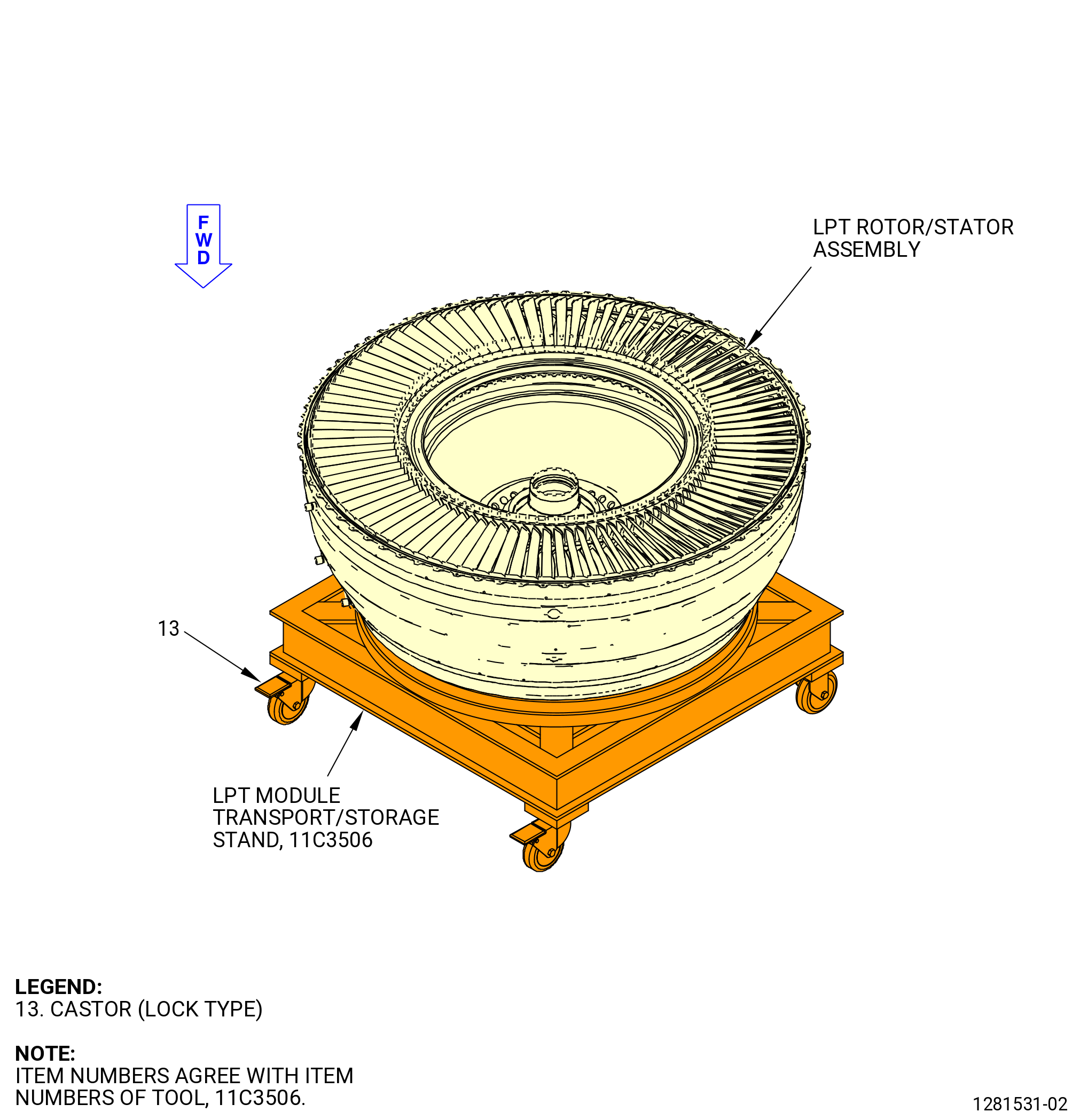
| (1) | Make sure that the locks on the casters (item 13) of the 11C3506 LPT module transport/storage stand, are in the locked position. Refer to Figure 1002. |
| CAUTION: |
|
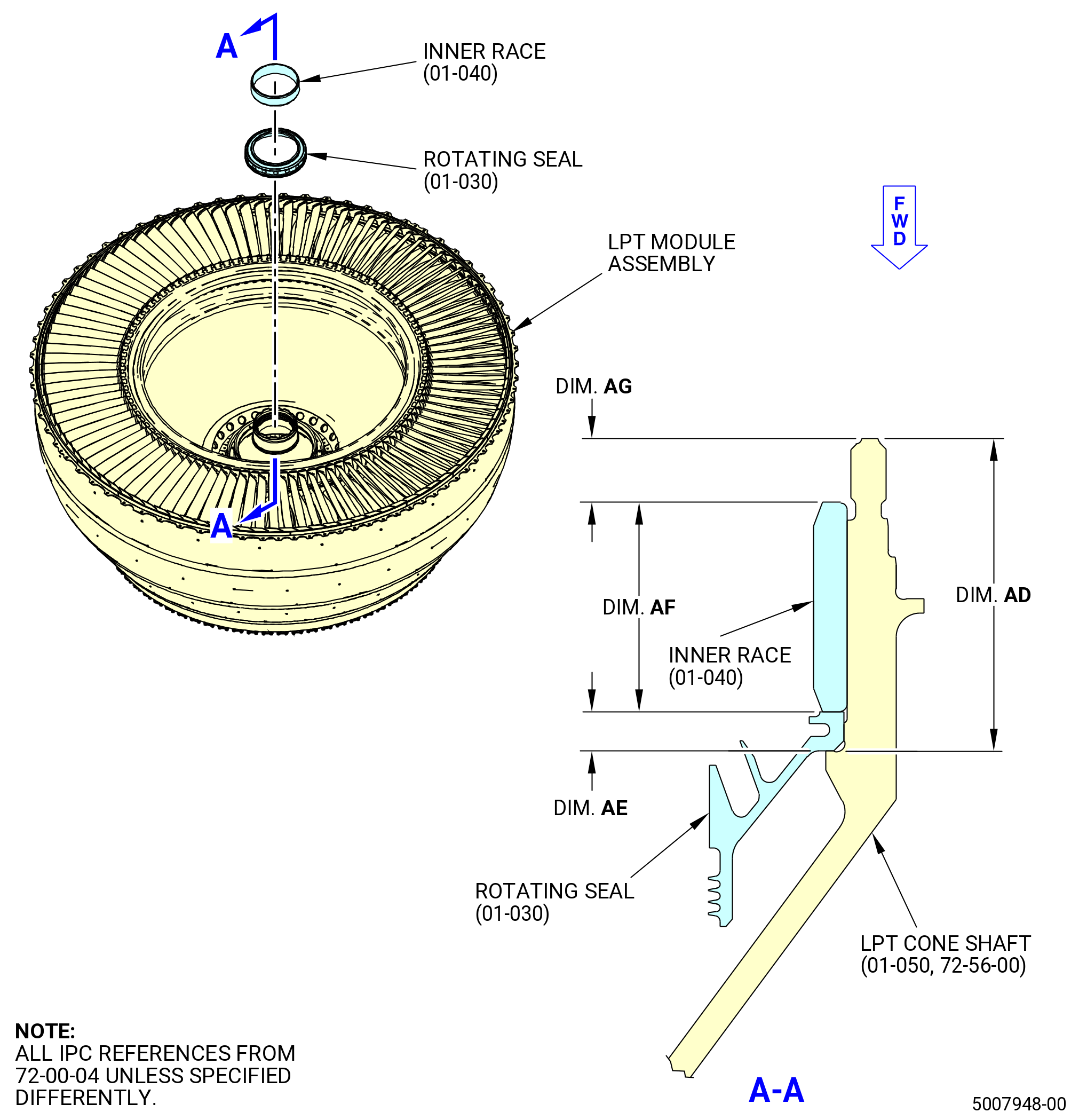
| (2) | Measure the thickness (dimension AE) at the inner bore of the No. 5 bearing inner rotating oil seal (rotating seal) (01-030) (SIN 01506) at four equally spaced locations. Wear C10-140 gloves to handle the No. 5 bearing inner race (inner race) (01-040) (SIN 01502). Refer to Figure 1003. |
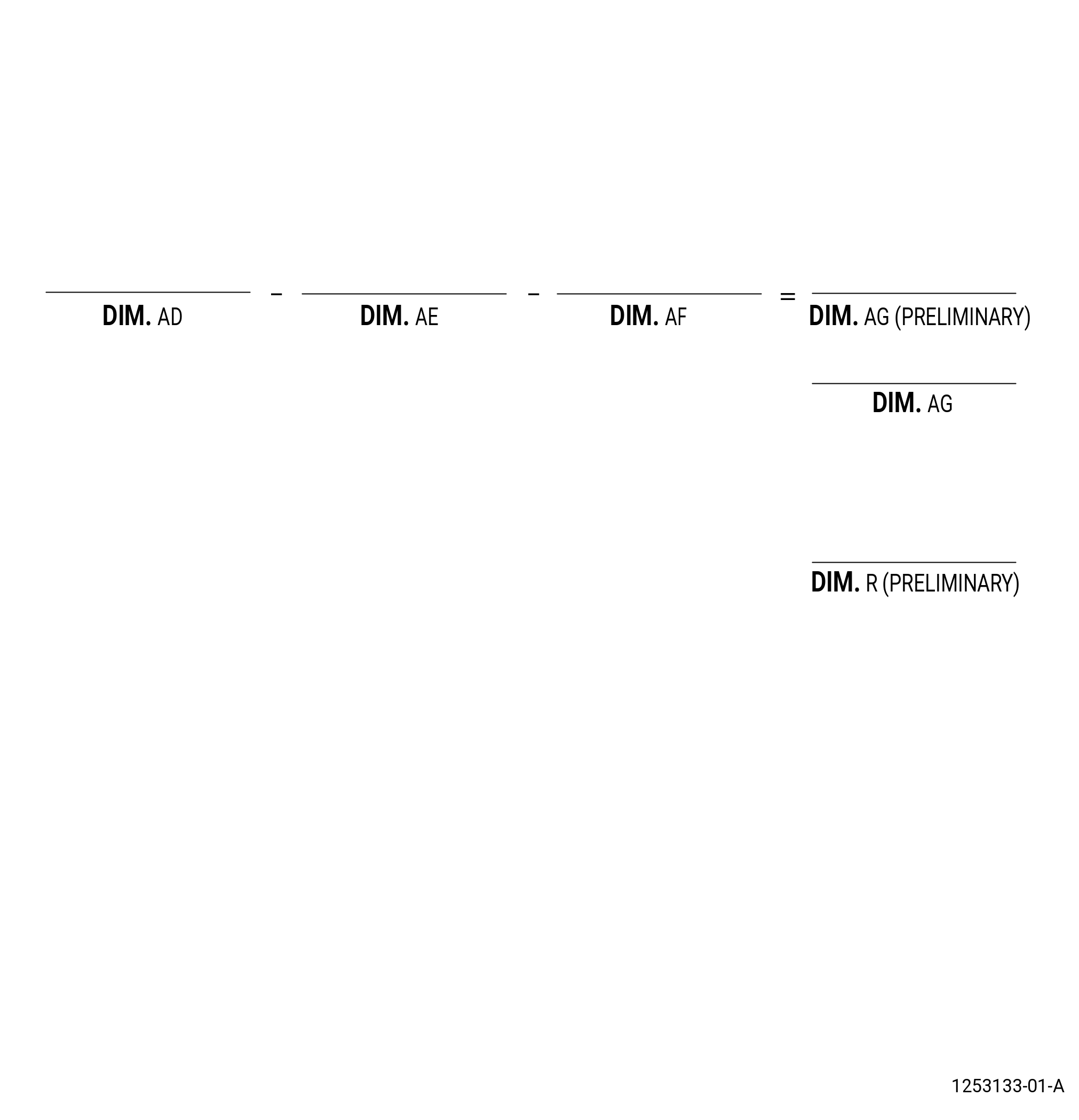
| (3) | Calculate the average of the four measurements and make a record of it as dimension AE on the record sheet. Refer to Figure 1004. |
| (4) | Measure the length (dimension AF) of the inner race at four equally spaced locations. |
| (5) | Calculate the average of the four measurements and make a record of it as dimension AF on the record sheet. |
| (6) | Measure the distance (dimension AD) from the mating surface of the rotating seal to the aft end of the LPT cone shaft (01-050 , 72-56-00) (SIN 930D1) at four equally spaced locations. Refer to Figure 1003. |
| (7) | Calculate the average of the four measurements and make a record of it as dimension AD on the record sheet. Refer to Figure 1004. |
| (8) | Calculate the preliminary dimension AG. Example: AD - AE - AF = ________ AG preliminary. |
| Subtask 72-00-04-430-126 |
| B. | Install the rotating seal (01-030) (SIN 01506) and the inner race (01-040) (SIN 01502) in the LPT module assembly as follows: |
| WARNING: |
|
| (1) | Put the rotating seal and inner race in an oven at 350°F (176.7°C) for 1 hour. |
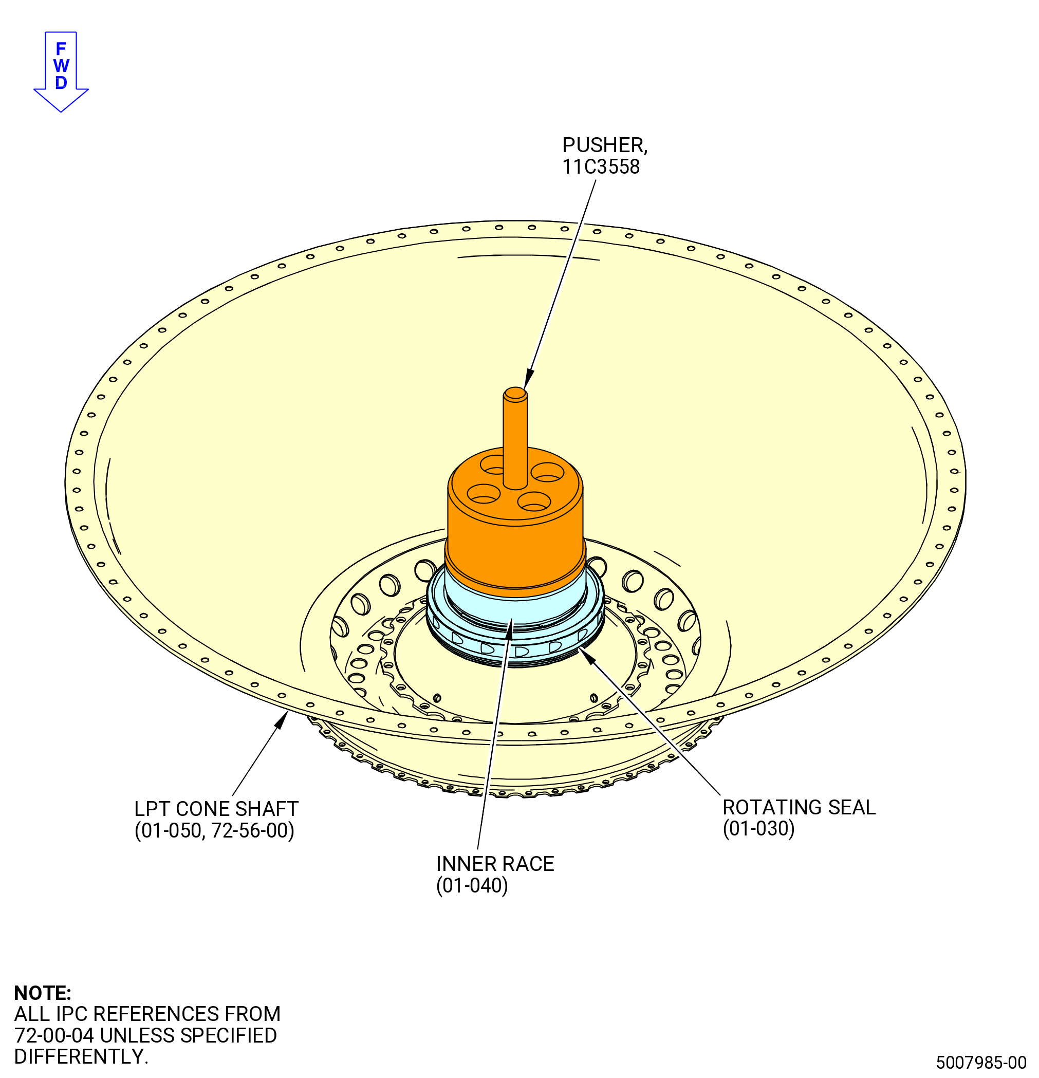
| (2) | Install the rotating seal and the inner race on the LPT cone shaft (01-050 , 72-56-00) (SIN 930D1) with the 11C3558 pusher. Refer to Figure 1005 and do as follows: |
| (a) | Apply heat to the rotating seal and the inner race. |
| (b) | Install the rotating seal and the inner race on the LPT cone shaft with the seal teeth forward. |
| (c) | Use the 11C3558 pusher to seat the rotating seal and the inner race on the LPT cone shaft. |
| (d) | Let the rotating seal to cool to room temperature. |
| (3) | Measure the distance (dimension AG) from the aft end of the LPT cone shaft to the aft end of the inner race. |
| (4) | Calculate the average of the four measurements and make a record of it as dimension AG on the record sheet. |
| (5) | Compare dimension AG to preliminary dimension AG. The difference between the preliminary dimension AG and the actual dimension AG must be within 0.0015 inch (0.038 mm). Example: Preliminary AG - Measured AG = ____________ |
| Subtask 72-00-04-430-127 |
| C. | Prepare the TRF assembly and the LPT rotor/stator assembly for assembly as follows: |
| CAUTION: |
|
| (1) | Lock the castors (item 13) of the 11C3506 LPT module transport/storage stand to prevent movement of the build stand. Make sure that the build stand is level. Refer to Figure 1002. |
| Subtask 72-00-04-640-032 |
| WARNING: |
|
| (2) | Apply the C02-050 preservation oil to the surfaces of the inner race (01-040) (SIN 01502) in the LPT rotor/stator assembly. |
| (3) | Apply C02-058 lubricant to the aft flange of the stage 7 LPT shrouds (10A-230 , 72-56-00) (SIN 935BA) in the LPT rotor/stator assembly to make the installation of the TRF assembly easier. |
| (4) | Apply the C02-050 preservation oil to the surfaces of the roller cylindrical No. 5 bearing (No. 5 roller bearing) (01-040 , 72-57-00) (SIN 01500) in the TRF assembly. |
| Subtask 72-00-04-430-128 |
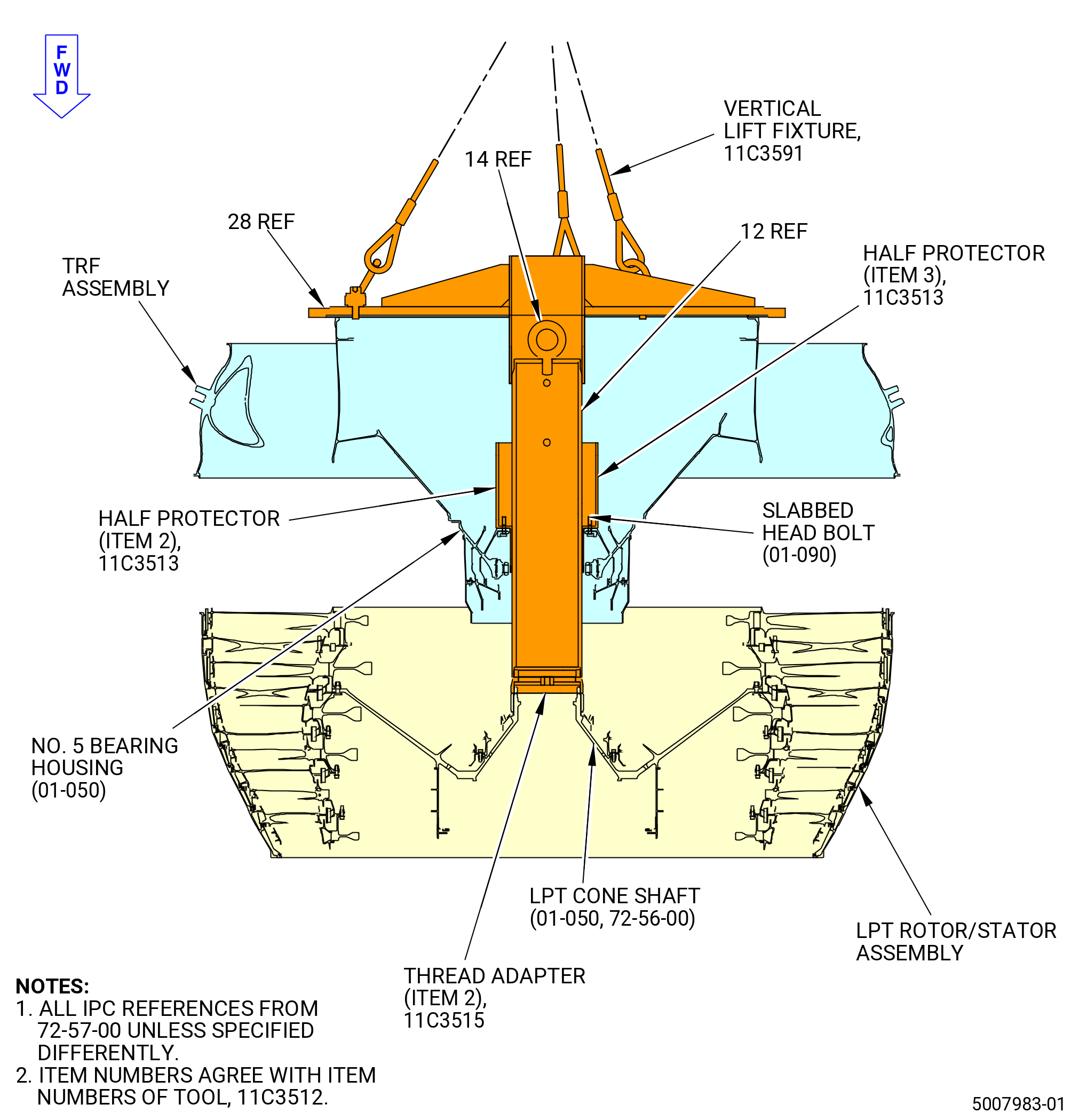
| (5) | Install the 11C3515 thread adapter on the aft end of the LPT cone shaft (01-050 , 72-56-00) (SIN 930D1). Refer to Figure 1006 and do as follows: |
| (a) | Install the thread adapter (item 2) on the aft threads of the LPT cone shaft. |
| (b) | Use a 0.50 inch (12.7 mm) square socket to tighten the thread adapter (item 2). |
| Subtask 72-00-04-430-129 |
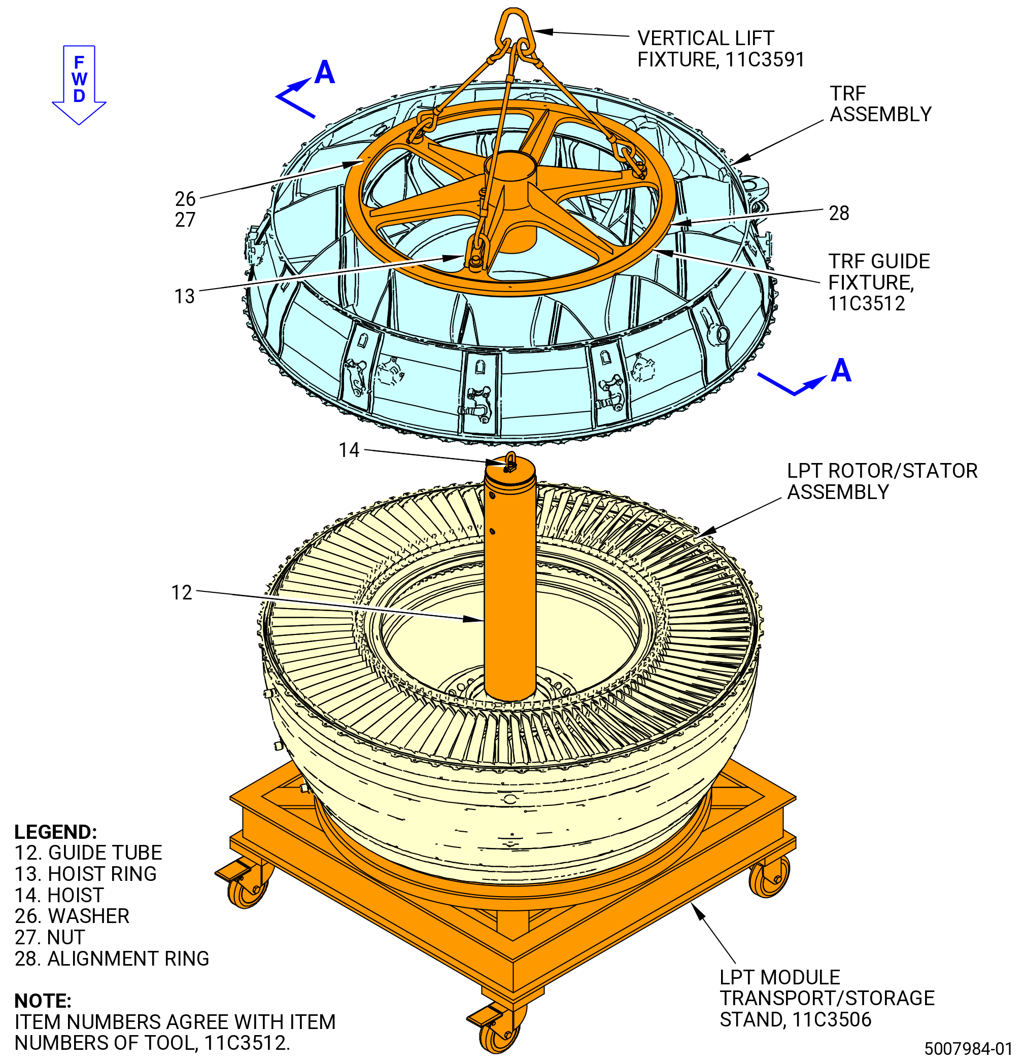
| (6) | Install the guide tube (item 12) of the 11C3512 TRF guide fixture onto the LPT cone shaft (01-050 , 72-56-00) (SIN 930D1) in the LPT rotor/stator assembly. Refer to Figure 1006 and do as follows: |
| WARNING: |
|
| (a) | Attach an overhead hoist to the hoist ring (item 14) on the guide tube (item 12) and lift the guide tube (item 12). |
| (b) | Lower the guide tube (item 12) into the LPT rotor/stator assembly until the forward end of the guide tube touches the 11C3515 thread adapter that is installed to the aft threads of the LPT cone shaft (01-050 , 72-56-00) (SIN 930D1). |
| (c) | Align the guide tube (item 12) of the 11C3512 TRF guide fixture and manually turn the guide tube (item 12) clockwise (CW) until the threads of the guide tube fully engage with the threads of the 11C3515 thread adapter. |
| (d) | Turn the guide tube 90 degrees counterclockwise (CCW). |
| (e) | Remove the hoist from the guide tube (item 12). |
| Subtask 72-00-04-430-168 |
| (7) | Install the 11C3513 No. 5 bearing protector. Refer to Figure 1006 and do as follows: |
| (a) | Put the half protectors (item 2 and item 3) on the aft inner flange of the No. 5 bearing support housing (No. 5 bearing housing) (01-050 , 72-57-00) (SIN 01501). |
| (b) | Align the holes in the half protectors (item 2 and item 3) of the 11C3513 No. 5 bearing protector and put the half protectors (item 2 and item 3) onto the slabbed head bolts (01-090 , 72-57-00) (SIN 01522). |
| Subtask 72-00-04-430-130 |
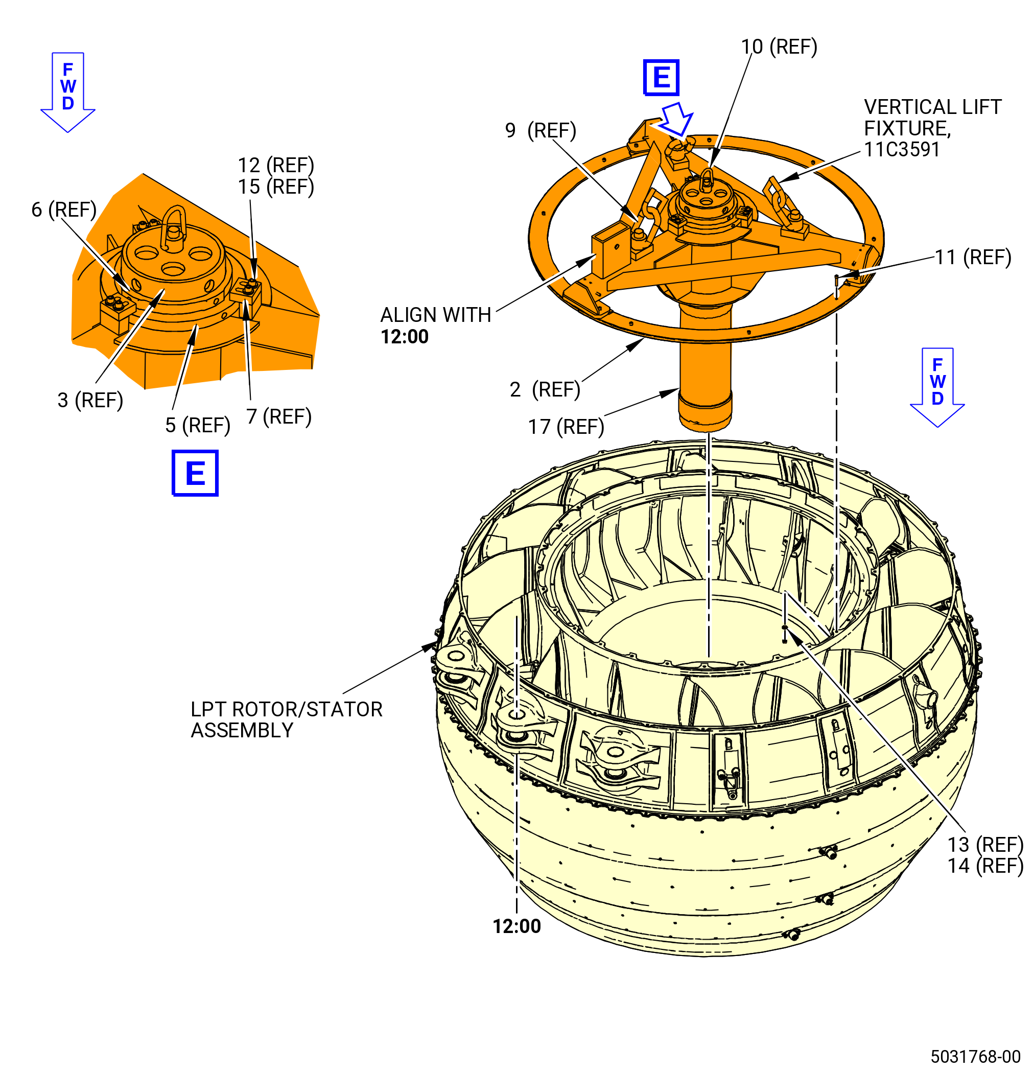
| (8) | Install the alignment ring (item 28) of the 11C3512 TRF guide fixture to the aft inner flange of the TRF assembly. Refer to Figure 1006, Figure 1007, and do as follows: |
| NOTE: |
|
| (a) | Attach the 11C3591 vertical lift fixture to the hoist rings (item 13) of the 11C3512 TRF guide fixture at three locations on the alignment ring (item 28). |
| (b) | Attach an over-head hoist to the 11C3591 vertical lift fixture. |
| WARNING: |
|
| (c) | Lift the alignment ring (item 28) of the 11C3512 TRF guide fixture and install it on the aft inner flange of the TRF assembly. |
| (d) | Make sure to align the TOP mark with the TVC of the TRF assembly. |
| (e) | Attach the alignment ring (item 28) to the TRF assembly with the nuts (item 27) and washers (item 26) and tighten the nuts. Put the washers (item 26) on the TRF flange. |
| (9) | Deleted. |
| Subtask 72-00-04-430-131 |
| D. | Install the TRF assembly on the LPT rotor/stator assembly as follows: |
| WARNING: |
|
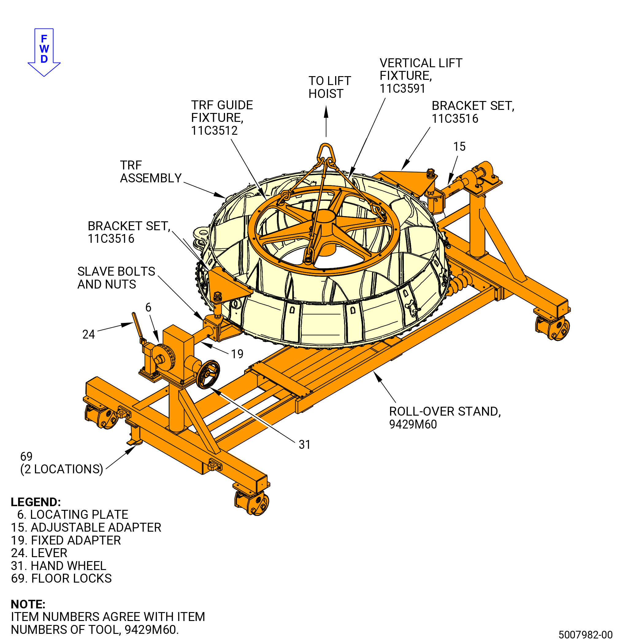
| (1) | Lift the TRF assembly on the 9429M60 roll-over stand to secure and hold the TRF. |
| (2) | Remove the 11C3516 bracket set from the 9429M60 roll-over stand. Refer to Figure 1007, Figure 1008, and do as follows: |
| CAUTION: |
|
| (a) | Make sure that the floor locks (item 69) of the 9429M60 roll-over stand are against the floor. If not, lower the floor locks and lock in place. |
| (b) | Make sure the lever (item 24) is outward to prevent the rotation of the hand wheel (item 31) and the locating plate (item 6). |
| (c) | Remove the slave bolts and nuts that attach the stationary bars (items 3 and 5) of the 11C3516 bracket set to the adjustable adapter (item 15) and the fixed adapter (item 19) of the 9429M60 roll-over stand. |
| WARNING: |
|
| (3) | Lift the TRF from the 9429M60 roll-over stand. |
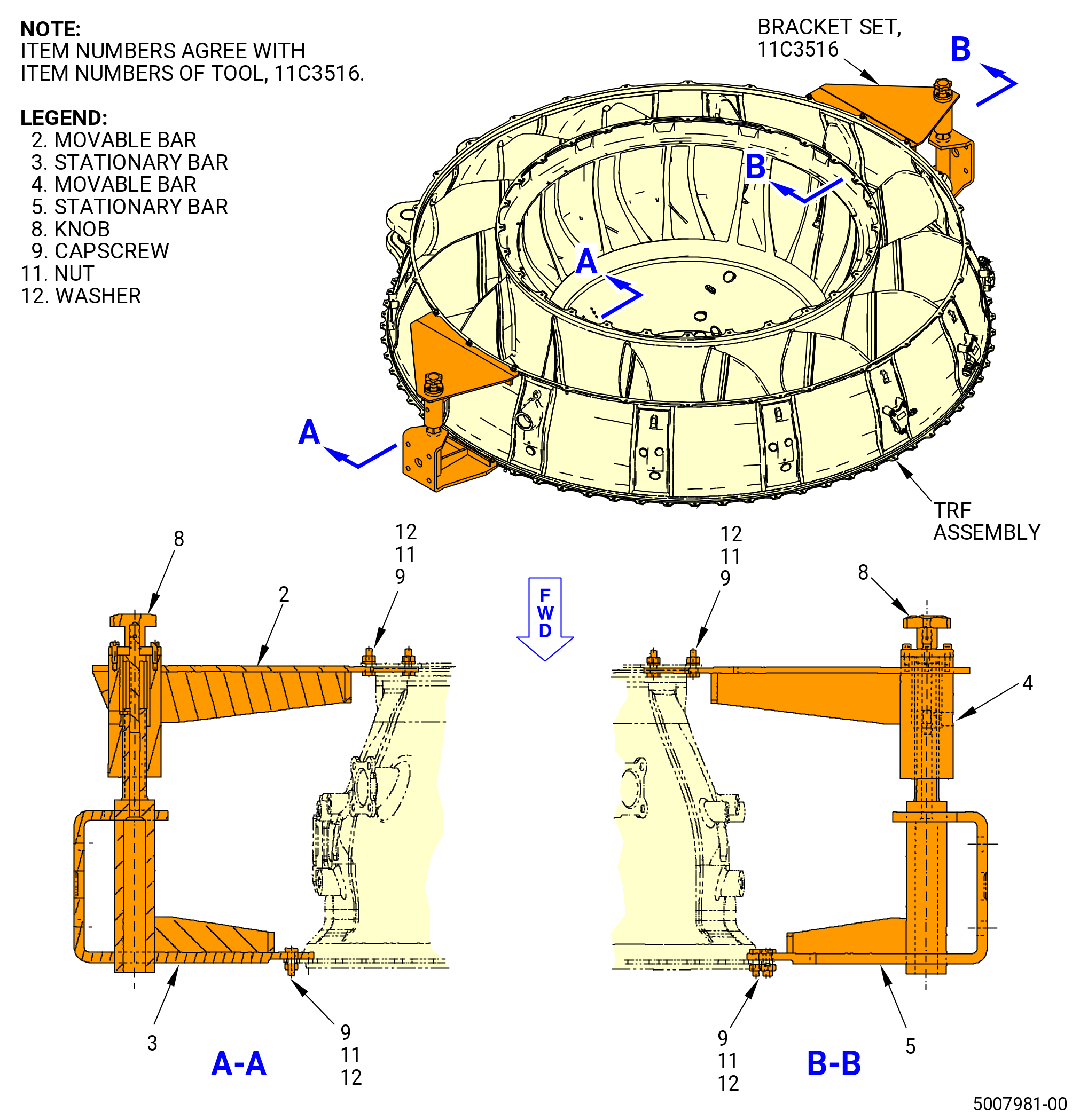
| (4) | Remove nuts (item 11), washers (item 12), and capscrews (item 9) from the movable bars (items 2 and 4) and stationary bars (items 3 and 5) of the 11C3516 bracket set. |
| (5) | Remove the 11C3516 bracket set from the TRF assembly. |
| WARNING: |
|
| (6) | Apply dry ice to the forward flange of the TRF assembly for 15 minutes. |
| (7) | Heat the aft flange of the LPT rotor/stator assembly with a heat gun for a maximum of 20 minutes. Refer to TASK 70-10-00-800-009 (ASSEMBLY AND DISASSEMBLY TECHNIQUES). |
| (8) | Align the top vertical centerline of the TRF with the top vertical centerline of the LPT rotor/stator assembly. |
| CAUTION: |
|
| (9) | Slowly lower the TRF onto the LPT rotor/stator assembly. The alignment ring (item 28) of the 11C3512 TRF guide fixture is installed onto the tube guide (item 12) to provide the correct alignment. Refer to Figure 1006. |
| (10) | Make sure that the aft flanges of the stage 7 shrouds (10A-230 , 72-56-00) (SIN 935BA) are installed correctly. The aft flanges of the stage 7 shrouds must be between the inner diameter of the aft flange of the LPT rotor/stator assembly and the forward flange of the TRF. |
| (11) | Make sure that the boltholes are aligned. |
| (12) | Remove the 11C3591 vertical lift fixture from the TRF. |
| (13) | Remove the 11C3512 TRF guide fixture from the TRF and the LPT rotor/stator assembly. |
| (14) | Remove the 11C3513 No. 5 bearing protector from the guide tube (item 12) of the 11C3512 TRF guide fixture. |
| (15) | Remove the 11C3515 from the LPT cone shaft. |
| Subtask 72-00-04-430-132 |
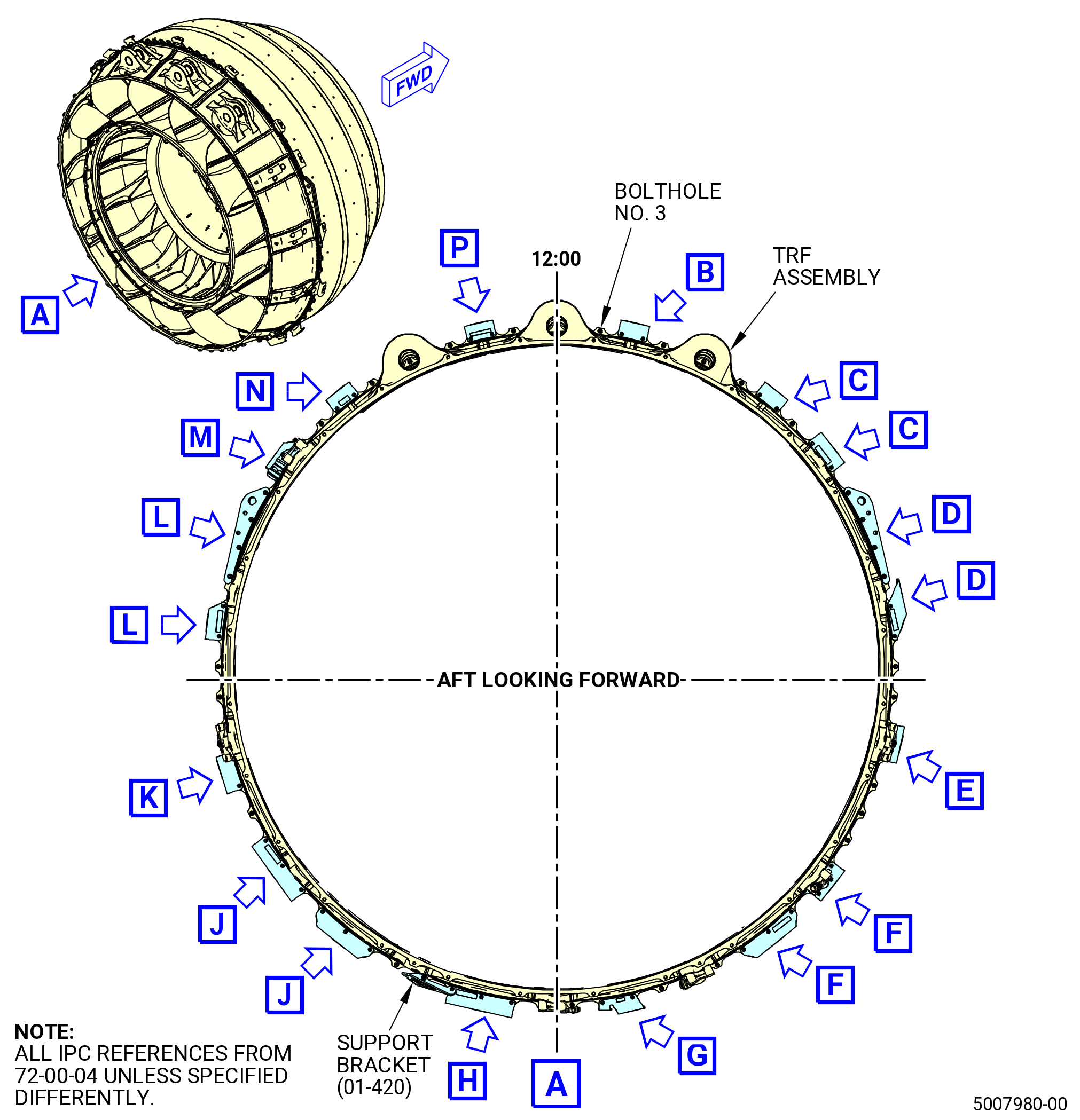
| E. | Attach the brackets, bolts, and nuts to the LPT rotor/stator assembly and TRF assembly flange. Refer to Figure 1009 and do as follows: |
| NOTE: |
|
| Subtask 72-00-04-640-033 |
| WARNING: |
|
| (1) | Apply C02-058 lubricant to the threads and friction surfaces of the nuts (01-061) (SIN 94040), bolts (01-050) (SIN 94020), and bolts (01-070) (SIN 94022). |
| (2) | Use the minimum quantity of lubricant necessary for the assembly. After assembly, remove with a clean cloth the remaining lubricant. |
| Subtask 72-00-04-430-133 |
| (3) | Install the bolts (01-050) (SIN 94020) and nuts (01-061) (SIN 94040) at boltholes No. 1-3, 6-10, 13, 22, 23, 26-28, 34-36, 39, 40, 45, 52, 55-57, 66, 69-73, 76, and 77 with the boltheads forward. Hand tighten the nuts. |
| (a) | Make sure that the nuts (01-061) (SIN 94040) are installed with the applicable SB 72-0040 bolts (01-050) (SIN 94020) and bolts (01-070) (SIN 94022). |
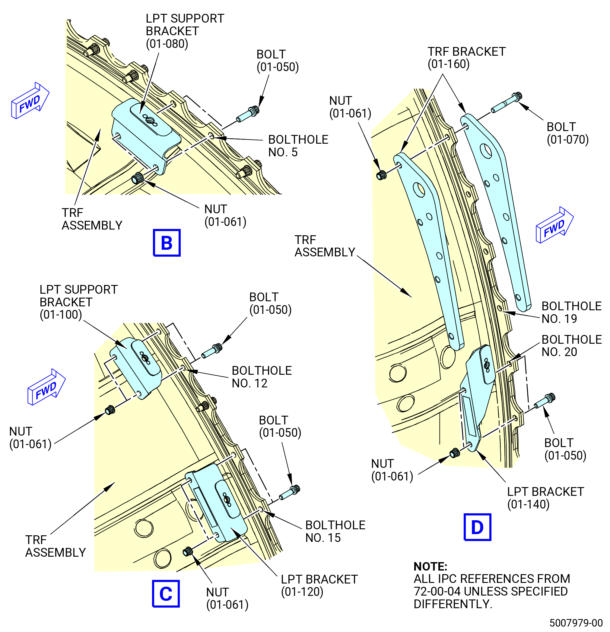
| (4) | Install the LPT support bracket at boltholes No. 4 and 5 as follows: |
| (a) | Put the bolts (01-050) (SIN 94020) on the LPT rotor/stator assembly flange with the boltheads forward. |
| (b) | Put the LPT support bracket (01-080) (SIN 6221K) and nuts (01-061) (SIN 94040) on the TRF assembly. Hand tighten the nuts. |
| (5) | Install the LPT support bracket at boltholes No. 11 and 12 as follows: |
| (a) | Put the bolts (01-050) (SIN 94020) on the LPT rotor/stator assembly flange with the boltheads forward. |
| (b) | Put the LPT support bracket (01-100) (SIN 6221L) and nuts (01-061) (SIN 94040) on the TRF assembly. Hand tighten the nuts. |
| (6) | Install the LPT bracket at boltholes No. 14 and 15 as follows: |
| (a) | Put the bolts (01-050) (SIN 94020) on the LPT rotor/stator assembly flange with the boltheads forward. |
| (b) | Put the LPT bracket (01-120) (SIN 6221M) and nuts (01-061) (SIN 94040) on the TRF assembly. Hand tighten the nuts. |
| (7) | Install the TRF bracket at boltholes No. 16-19 as follows: |
| (a) | Put the front half of the TRF bracket (01-160) (SIN 941E1) and bolts (01-070) (SIN 94022) on the LPT rotor/stator assembly flange with the boltheads forward. |
| (b) | Put the aft half of the TRF bracket (01-160) (SIN 941E1) and nuts (01-061) (SIN 94040) on the TRF assembly. Hand tighten the nuts. |
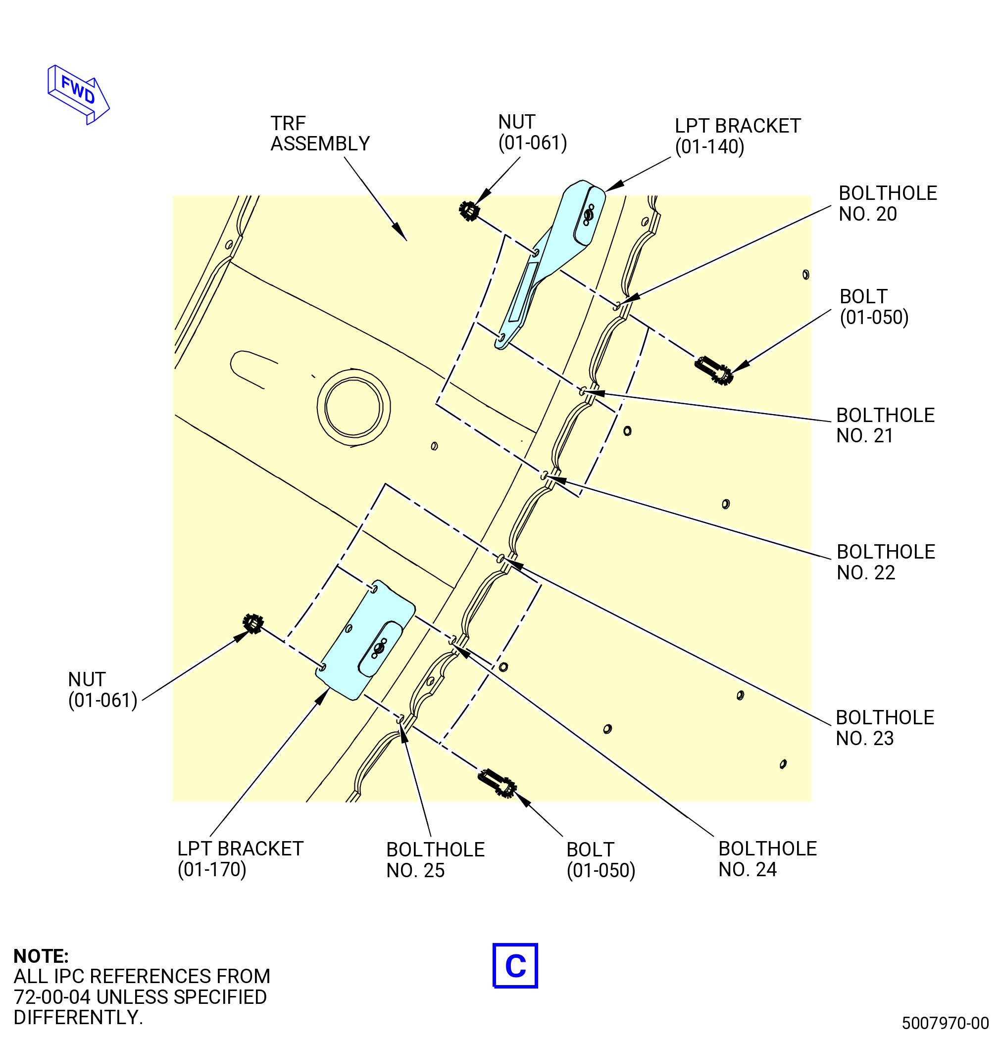
| (8) | Install the LPT bracket at boltholes No. 20 and 21 as follows: |
| (a) | Put the bolts (01-050) (SIN 94020) on the LPT rotor/stator assembly flange with the boltheads forward. |
| (b) | Put the LPT bracket (01-140) (SIN 6221W) and nuts (01-061) (SIN 94040) on the TRF assembly. Hand tighten the nuts. |
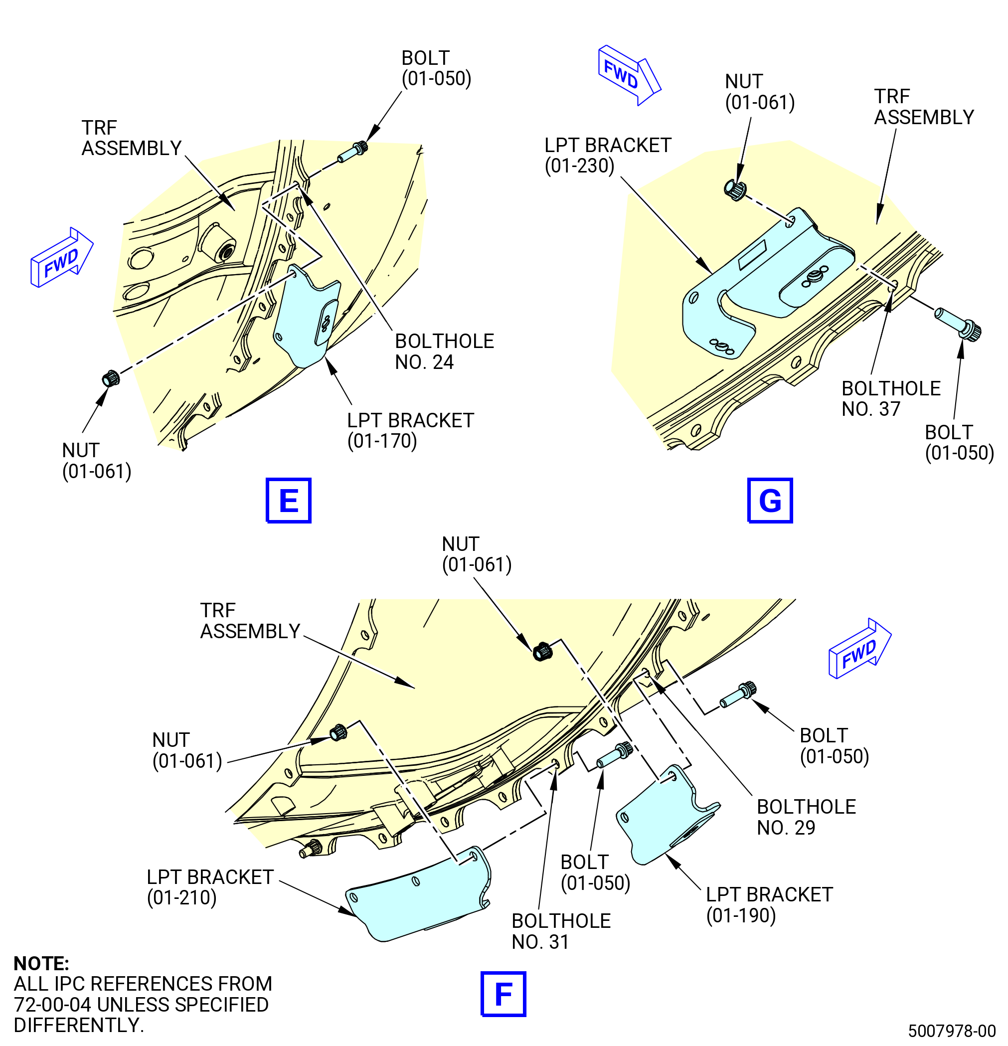
| (9) | Install the LPT bracket at boltholes No. 24 and 25 as follows: |
| (a) | Put the bolts (01-050) (SIN 94020) on the LPT rotor/stator assembly flange with the boltheads forward. |
| (b) | Put the LPT bracket (01-170) (SIN 6221Y) and nuts (01-061) (SIN 94040) on the TRF assembly. |
| (10) | Install the LPT bracket at boltholes No. 29 and 30 as follows: |
| (a) | Put the bolts (01-050) (SIN 94020) on the LPT rotor/stator assembly flange with the boltheads forward. |
| (b) | Put the LPT bracket (01-190) (SIN 6221N) and nuts (01-061) (SIN 94040) on the TRF assembly. Hand tighten the nuts. |
| (11) | Install the LPT bracket at boltholes No. 31-33 as follows: |
| (a) | Put the bolts (01-050) (SIN 94020) on the LPT rotor/stator assembly flange with the boltheads forward. |
| (b) | Put the LPT bracket (01-210) (SIN 6221A) and nuts (01-061) (SIN 94040) on the TRF assembly. Hand tighten the nuts. |
| (12) | Install the LPT bracket at boltholes No. 37 and 38 as follows: |
| (a) | Put the bolts (01-050) (SIN 94020) on the LPT rotor/stator assembly flange with the boltheads forward. |
| (b) | Put the LPT bracket (01-230) (SIN 62219) and nuts (01-061) (SIN 94040) on the TRF assembly. Hand tighten the nuts. |
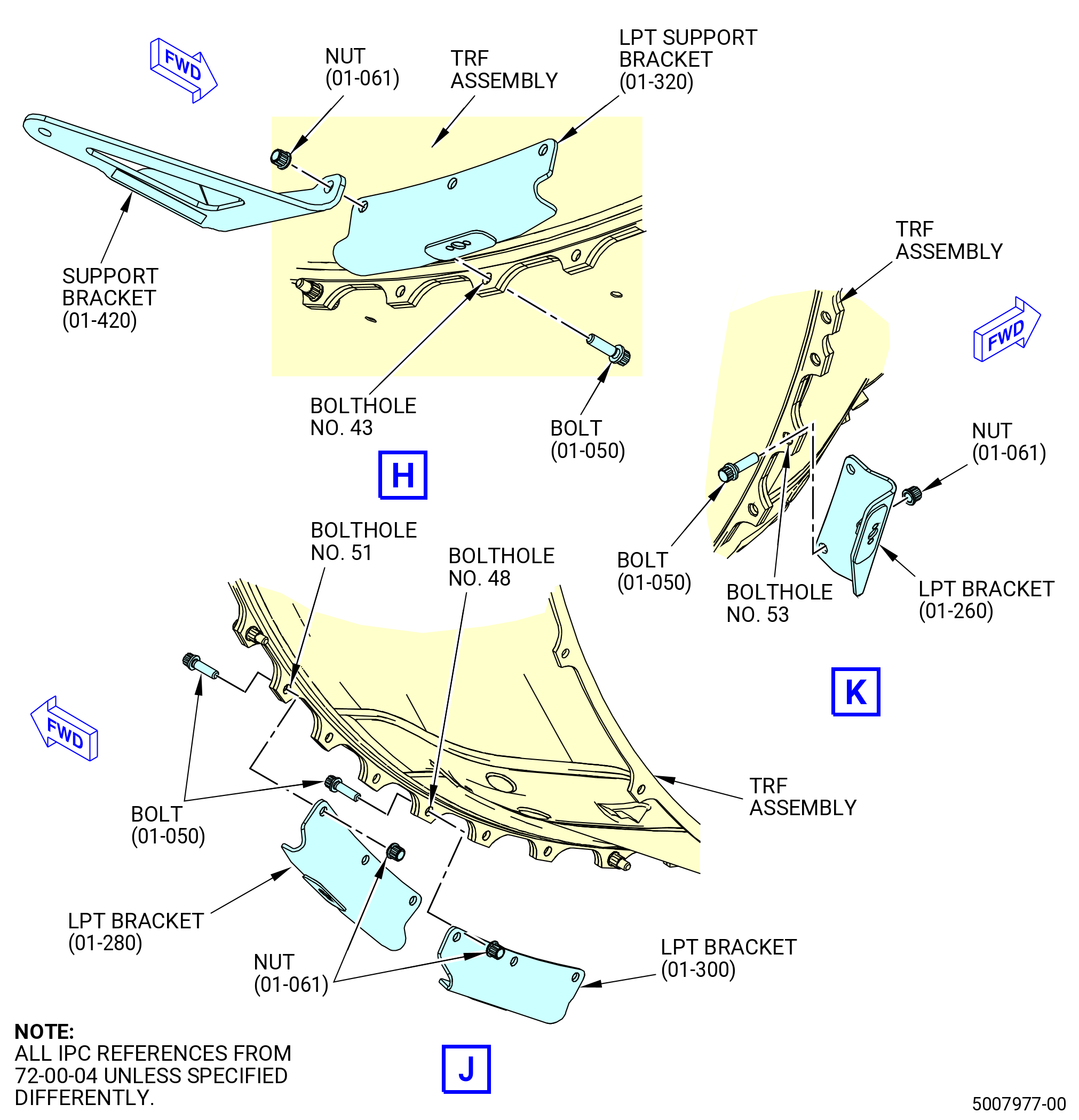
| (13) | Install the LPT support brackets at boltholes No. 41-44 as follows: |
| (a) | Put the bolts (01-050) (SIN 94020) on the LPT rotor/stator assembly flange with the boltheads forward. |
| (b) | Put the LPT support bracket (01-320) (SIN 6221V) at boltholes 41-43 and the LPT support bracket (01-420) (SIN 48713) at boltholes 43 and 44 and nuts (01-061) (SIN 94040) on the TRF assembly. Hand-tighten the nuts. |
| (14) | Install the LPT bracket at boltholes No. 46-48 as follows: |
| (a) | Put the bolts (01-050) (SIN 94020) on the LPT rotor/stator assembly flange with the boltheads forward. |
| (b) | Put the LPT bracket (01-300) (SIN 6221U) and nuts (01-061) (SIN 94040) on the TRF assembly. Hand tighten the nuts. |
| (15) | Install the LPT bracket at boltholes No. 49-51 as follows: |
| (a) | Put the bolts (01-050) (SIN 94020) on the LPT rotor/stator assembly flange with the boltheads forward. |
| (b) | Put the LPT bracket (01-280) (SIN 6221T) and nuts (01-061) (SIN 94040) on the TRF assembly. Hand tighten the nuts. |
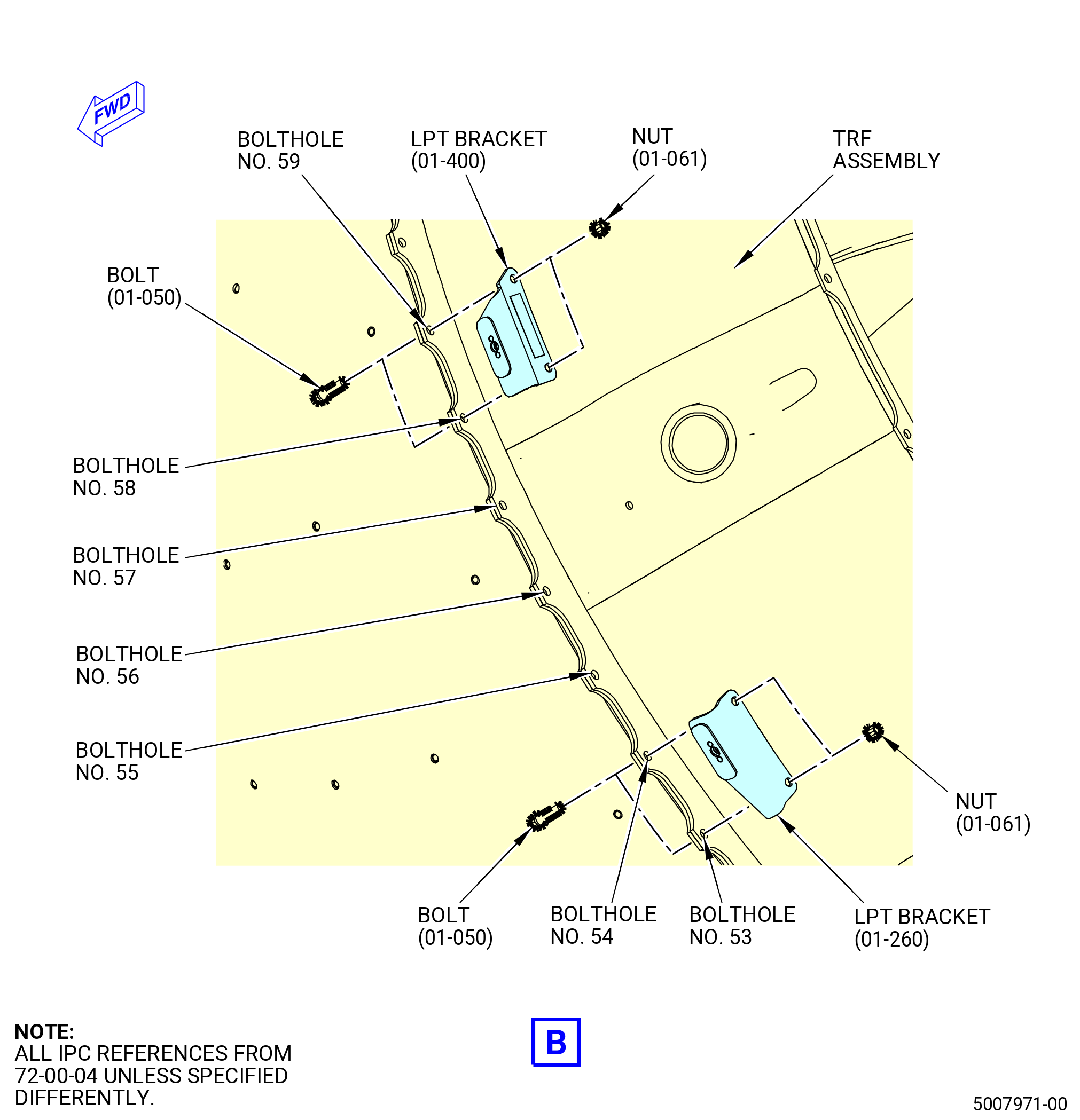
| (16) | Install the LPT bracket at boltholes No. 53 and 54 as follows: |
| (a) | Put the bolts (01-050) (SIN 94020) on the LPT rotor/stator assembly flange with the boltheads forward. |
| (b) | Put the LPT bracket (01-260) (SIN 6221H) and nuts (01-061) (SIN 94040) on the TRF assembly. Hand tighten the nuts. |
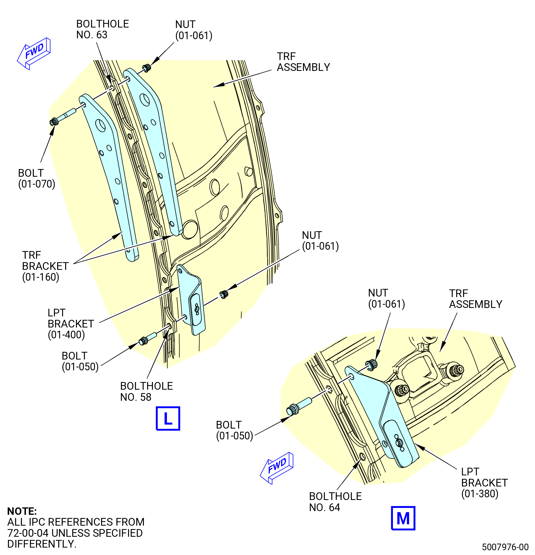
| (17) | Install the LPT bracket at boltholes No. 58 and 59 as follows: |
| (a) | Put the bolts (01-050) (SIN 94020) on the LPT rotor/stator assembly flange with the boltheads forward. |
| (b) | Put the LPT bracket (01-400) (SIN 6221J) and nuts (01-061) (SIN 94040) on the TRF assembly. Hand tighten the nuts. |
| (18) | Install the TRF bracket at boltholes No. 60-63 as follows: |
| (a) | Put the front half of the TRF bracket (01-160) (SIN 941E1) and the bolts (01-070) (SIN 94022) on the LPT rotor/stator assembly flange with the boltheads forward. |
| (b) | Put the aft half of the TRF bracket (01-160) (SIN 941E1) and nuts (01-061) (SIN 94040) on the TRF assembly. Hand tighten the nuts. |
| (19) | Install the LPT bracket at boltholes No. 64 and 65 as follows: |
| (a) | Put the bolts (01-050) (SIN 94020) on the LPT rotor/stator assembly flange with the boltheads forward. |
| (b) | Put the LPT bracket (01-380) (SIN 6221S) and nuts (01-061) (SIN 94040) on the TRF assembly. Hand tighten the nuts. |
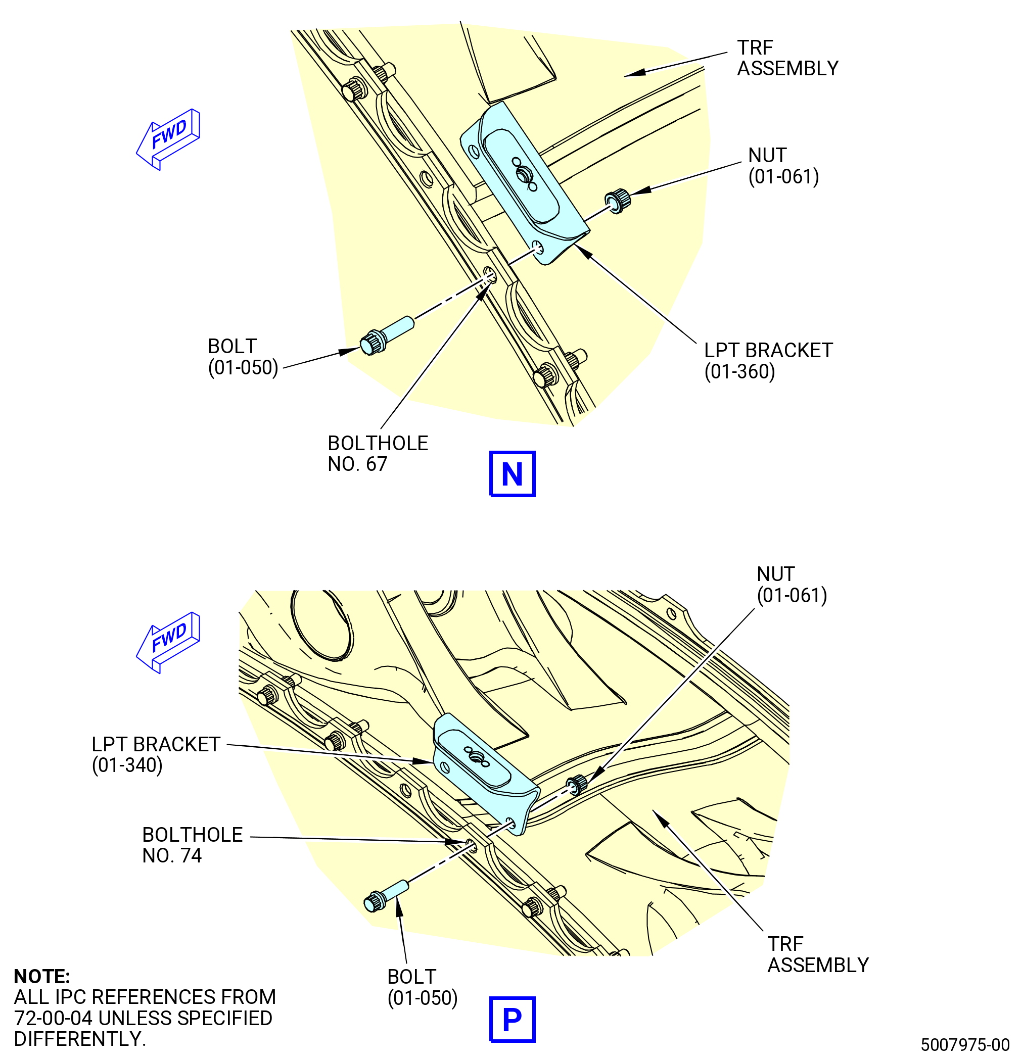
| (20) | Install the LPT bracket at boltholes No. 67 and 68 as follows: |
| (a) | Put the bolts (01-050) (SIN 94020) on the LPT rotor/stator assembly flange with the boltheads forward. |
| (b) | Put the LPT bracket (01-360) (SIN 6221R) and nuts (01-061) (SIN 94040) on the TRF assembly. Hand tighten the nuts. |
| (21) | Install the LPT bracket at boltholes No. 74 and 75 as follows: |
| (a) | Put the bolts (01-050) (SIN 94020) on the LPT rotor/stator assembly flange with the boltheads forward. |
| (b) | Put the LPT bracket (01-340) (SIN 6221P) and nuts (01-061) (SIN 94040) on the TRF assembly. Hand tighten the nuts. |
| (22) | Torque 16 equally spaced nuts (01-061) (SIN 94040) in a criss-cross pattern to 121-134 lb in. (13.7-15.1 N.m). |
| NOTE: |
|
| (23) | Torque the remaining nuts (01-061) (SIN 94040) in a criss-cross pattern to 121-134 lb in. (13.7-15.1 N.m). |
| (24) | Torque all the nuts (01-061) (SIN 94040) again in a criss-cross pattern to 161-179 lb in. (18.2-20.2 N.m). |
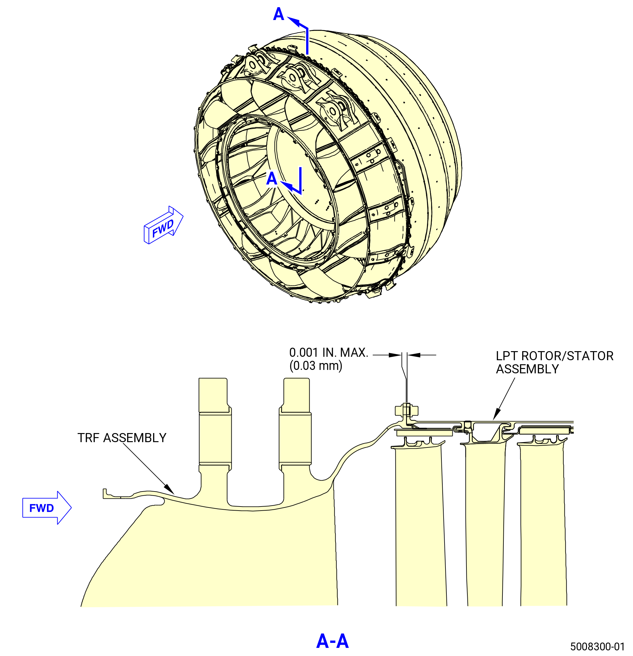
| (25) | Make sure that the flange of the LPT rotor/stator assembly is against the flange of the TRF assembly at each possible bolt. Use a 0.001 inch (0.03 mm) shim. No spaces are permitted. Refer to Figure 1010. |
| Subtask 72-00-04-220-033 |
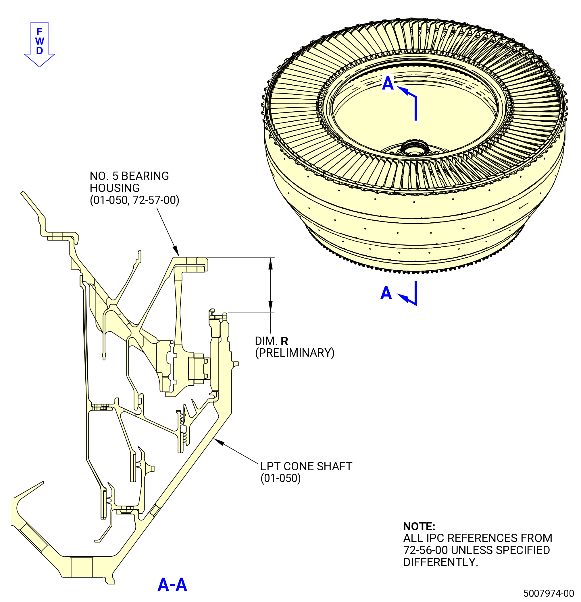
| F. | Measure the preliminary dimension R from the aft face of the No. 5 bearing housing (01-050 , 72-57-00) (SIN 01501) to the aft inner diameter of the LPT cone shaft (01-050 , 72-56-00) (SIN 930D1). Refer to Figure 1011 and do as follows: |
| (1) | Measure at four equally spaced locations adjacent to the spacers on the aft flange of the No. 5 bearing housing (01-050 , 72-57-00) (SIN 01501). |
| (2) | Measure from the aft face of the No. 5 bearing housing (01-050 , 72-57-00) (SIN 01501) to the aft inner diameter of the LPT cone shaft (01-050 , 72-56-00) (SIN 930D1). |
| (3) | Calculate the average of the four measurements and make a record of it as dimension R (preliminary) on the record sheet. Refer to Figure 1004. |
| Subtask 72-00-04-430-134 |
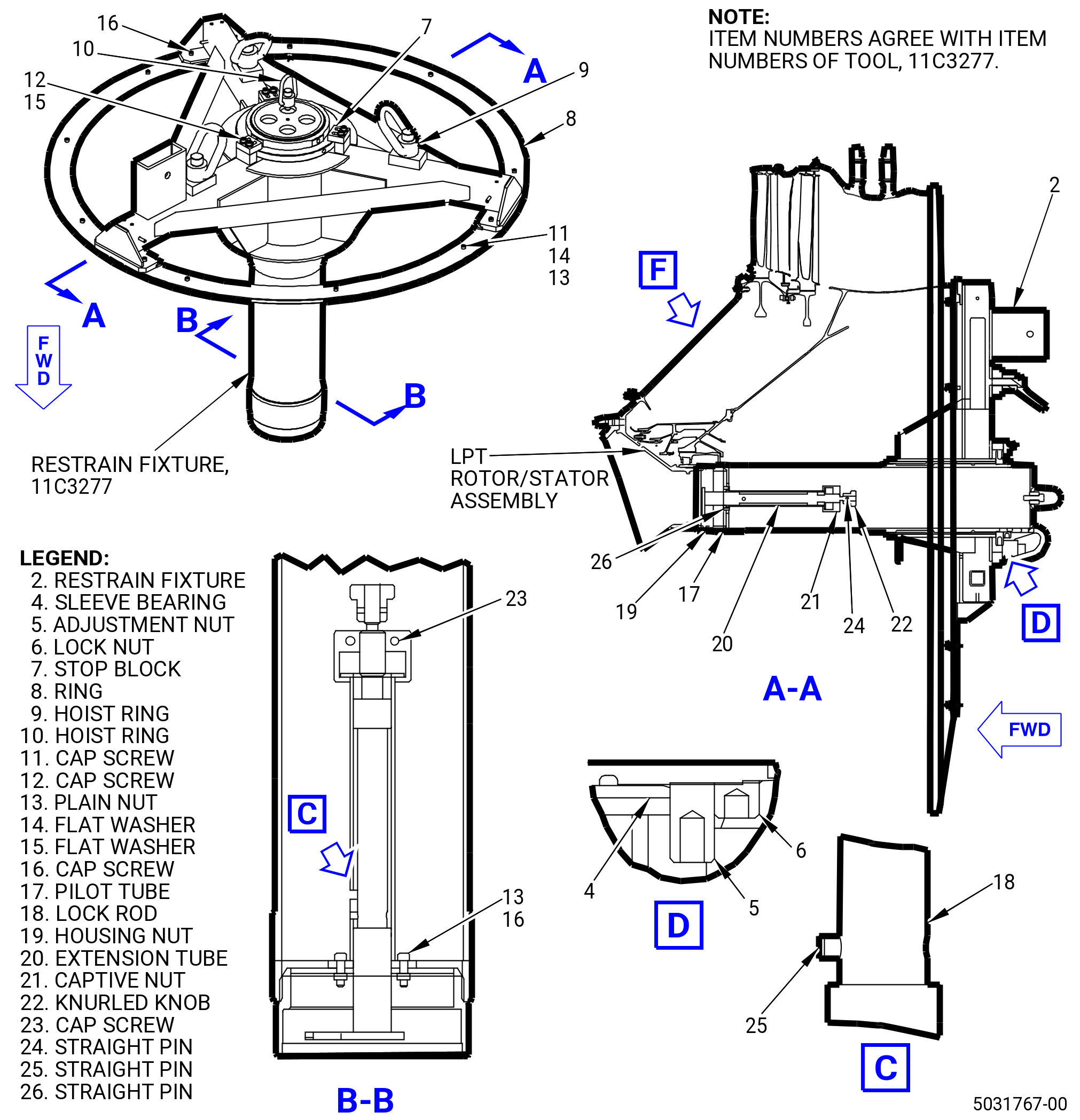
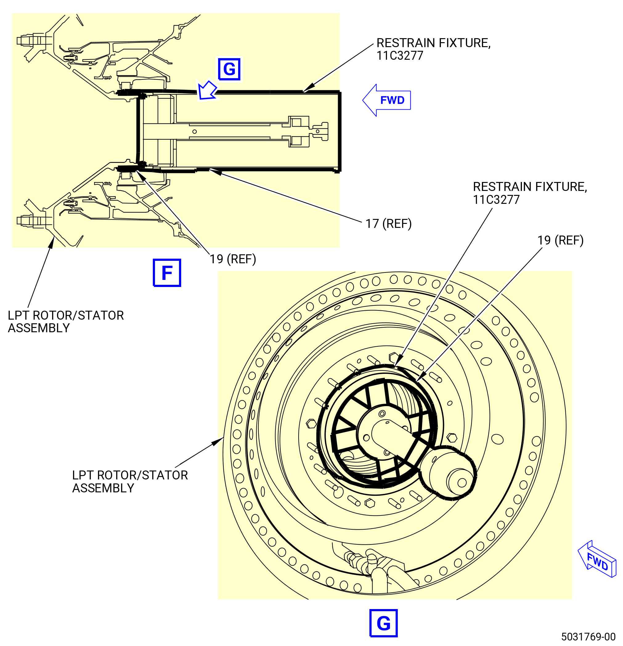
| G. | Install the 11C3277 restrain fixture on the LPT module assembly as follows: |
| (1) | Install the 11C3277 restrain fixture on the TRF assembly. Refer to Figure 1012 and do as follows: |
| (a) | Remove the pilot tube (item 17) and housing nut (item 19) from the restrain fixture (item 2) as follows: |
| 1 | Remove the capscrews (item 12) and washers (item 15). |
| 2 | Remove the stop blocks (item 7) from the restrain fixture (item 2). |
| 3 | Remove the pilot tube (item 17) and housing nut (item 19) from the restrain fixture (item 2). |
| 4 | Remove the lock nut (item 6) and the adjustment nut (item 5). |
| Subtask 72-00-04-110-002 |
| WARNING: |
|
| (b) | Clean the restrain fixture (item 2) where it will interface with the TRF with C04-035 isopropyl alcohol or a 50-50 blend of alcohol. |
| (c) | Clean the pilot tube (item 17) and housing nut (item 19) forward internal threads and where it will interface with the restrain fixture (item 2) with C04-035 isopropyl alcohol. |
| Subtask 72-00-04-430-135 |
| WARNING: |
|
| (2) | Disengage the housing nut (item 19) from the pilot tube (item 17). |
| (3) | Adjust the position of the captive nut (item 21) until locating the arrow mark with the hole marked in the thread of the lock rod (item 18). |
| (4) | Pull the knurled knob (item 22) and rotate it until locating the straight pin (item 24) in the “DISENGAGED” position. |
| (5) | Lift the housing nut (item 19) from the extension tube (item 20) and install it on the LPT cone shaft. Make sure that the housing nut (item 19) is fully threaded. |
| (6) | Pull the knurled knob (item 22) from “DISENGAGED”, turn and push it until the straight pin (item 24) clears the slot in the extension tube (item 20) and the lock rod (item 18) seats against the LPT cone shaft castellation. The fully engaged position is reached when the straight pin (item 24) is located on the “ENGAGED” mark. |
| (7) | If the lock rod (item 18) is not fully engaged, locate it in the “DISENGAGED” position and rotate the housing nut (item 19). |
| (8) | Repeat steps 5 and 6 as required until fully engaging the lock rod (item 18) with the LPT cone shaft castellation. |
| (9) | Turn the captive nut (item 21) to prevent axial displacement of the lock system. |
| WARNING: |
|
| (10) | Attach an overhead hoist to the 11C3591 vertical lift fixture. |
| (11) | Attach the 11C3591 vertical lift fixture to the hoist ring (item 9) of the 11C3277 restrain fixture at three locations. |
| (12) | Lift the 11C3277 restrain fixture and align the TOP VERTICAL CL mark on the restrain fixture (item 2) with the top vertical centerline (TVC) of the TRF. |
| (13) | Lower and attach the restrain fixture (item 2) to the TRF with the capscrews (item 11), washers (item 14), and nuts (item 13) at nine locations on the forward side of the TRF aft inner flange. |
| (14) | Tighten the nuts (item 13) to secure the restrain fixture (item 2) to the TRF aft inner flange. |
| (15) | Install the pilot tube (item 17) in the restrain fixture (item 2) until it seats on the external threads of the housing nut (item 19) as follows: |
| (a) | If necessary, loosen the adjustment nut (item 5) CCW to let the pilot tube (item 3) be installed in the restrain fixture (item 2). |
| Subtask 72-00-04-640-034 |
| WARNING: |
|
| (b) | Lubricate the pilot tube (item 17) where it interfaces with the restrain fixture (item 2) with C02-050 preservation oil. |
| Subtask 72-00-04-430-136 |
| WARNING: |
|
| (c) | Attach an overhead hoist to the hoist ring (item 10) and lift the pilot tube (item 17). |
| (d) | Slide it through the restrain fixture (item 2) until it seats on the external threads of the housing nut (item 19). |
| (e) | Thread the pilot tube (item 17) on the housing nut (item 19). |
| (f) | Install the adjustment nut (item 5) on the pilot tube (item 17) until it seats on the restrain fixture (item 2). |
| (g) | Install the lock nut (item 6) on the pilot tube (item 17) until it seats on the adjustment nut (item 5). |
| (h) | Install the stop blocks (item 7) at three locations on the restrain fixture (item 2) with the capscrews (item 12) and the washers (item 15) at six locations. |
| (i) | Push the stop blocks (item 7) in to secure the adjustment nut (item 5). Tighten the capscrews (item 12). |
| (16) | Put a waterproof cover on the inner race (01-040) (SIN 01502) area with approved tape. Refer to Figure 1004. |
| Subtask 72-00-04-430-137 |
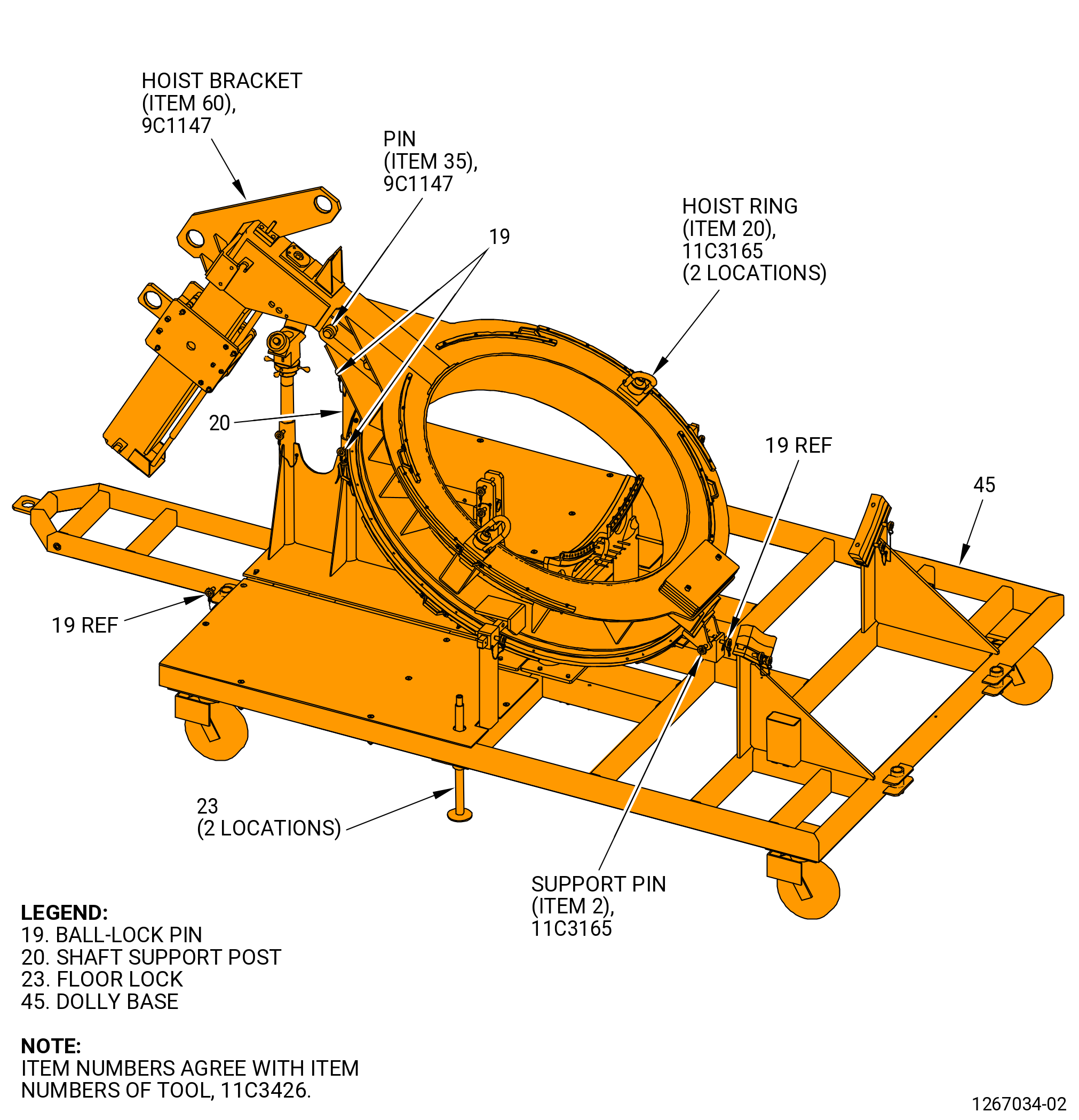
| (17) | Alternative Procedure Available. Remove the 11C3165 strongback fixture and the 9C1147 VCG lift fixture from the 11C3426 LPT module dolly. Refer to Figure 1013 and do as follows: |
| NOTE: |
|
| NOTE: |
|
| CAUTION: |
|
| (a) | Make sure that the floor locks (item 23) of the 11C3426 LPT module dolly are against the floor. If not, lower the floor locks (item 23) and lock in place. |
| (b) | Attach an overhead chain hoist to the hoist bracket (item 60) on the 9C1147 VCG lift fixture. |
| (c) | Attach a second overhead chain hoist to the hoist rings (item 10) of the 11C3165 strongback fixture at two locations. |
| WARNING: |
|
| (d) | Use the lift hoists to apply lift pressure to the 9C1147 VCG lift fixture and the 11C3165 strongback fixture. |
| (e) | Remove the ball-lock pin (item 19) of the 11C3426 LPT module dolly from the shaft support post (item 20) that secures the 11C3165 strongback fixture to the shaft support post (item 20). The 11C3165 strongback fixture can pivot in the strongback (item 2) support pin at the 6:00 o'clock position. |
| (f) | Remove the support pin from the 11C3165 strongback fixture at the 6:00 o'clock position. |
| (g) | Lift the 11C3165 strongback fixture and the 9C1147 VCG lift fixture from the 11C3426 LPT module dolly in the vertical position. |
| Subtask 72-00-04-430-138 |
| CAUTION: |
|
| (17).A. | Alternative Procedure. Prepare the 11C4266 CG lift fixture. |
| Subtask 72-00-04-430-139 |
| (18) | Alternative Procedure Available. Install the 11C3165 strongback fixture to the TRF assembly aft flange on the LPT module assembly as follows: |
| NOTE: |
|
| (a) | Remove the nuts (item 11), capscrews (item 14), and flange supports (items 3, 4, 5, and 6) from the flange of the 11C3165 strongback fixture. Refer to Figure 1014. |
| (b) | Align the TVCL of the strongback flange with the TVCL of the TRF. |
| (c) | Align the boltholes of the TRF aft outer flange with the strongback forward flange. |
| (d) | Attach the 11C3165 strongback fixture with the support flanges (items 3, 4, 5, and 6) to the TRF aft flange as follows: |
| 1 | Put the first support flange (item 3) on the forward side of the TRF flange at the 2:30-4:30 o'clock position, ALF. Secure with the capscrews (item 14) and nuts (item 11) at six locations. |
| 2 | Put the second support flange (item 3) on the forward side of the TRF flange at the 8:30-10:00 o'clock position ALF. Secure with the capscrews (item 14) and nuts (item 11) at six locations. |
| 3 | Put the support flange (item 4) on the forward side of the TRF flange at the 10:30-11:30 o'clock position ALF. Secure with the capscrews (item 14) and nuts (item 11) at four locations. |
| 4 | Put the support flange (item 5) on the forward side of the TRF flange at the 12:30-1:30 o'clock position ALF. Secure with the capscrews (item 14) and nuts (item 11) at four locations. |
| 5 | Put the support flange (item 6) on the forward side of the TRF flange at the 5:30-6:30 o'clock position ALF. Secure with the capscrews (item 14) and nuts (item 11) at four locations. |
| 6 | Torque the nuts (item 11) to 40-60 lb in. (4.5-6.8 N.m). |
| Subtask 72-00-04-430-140 |
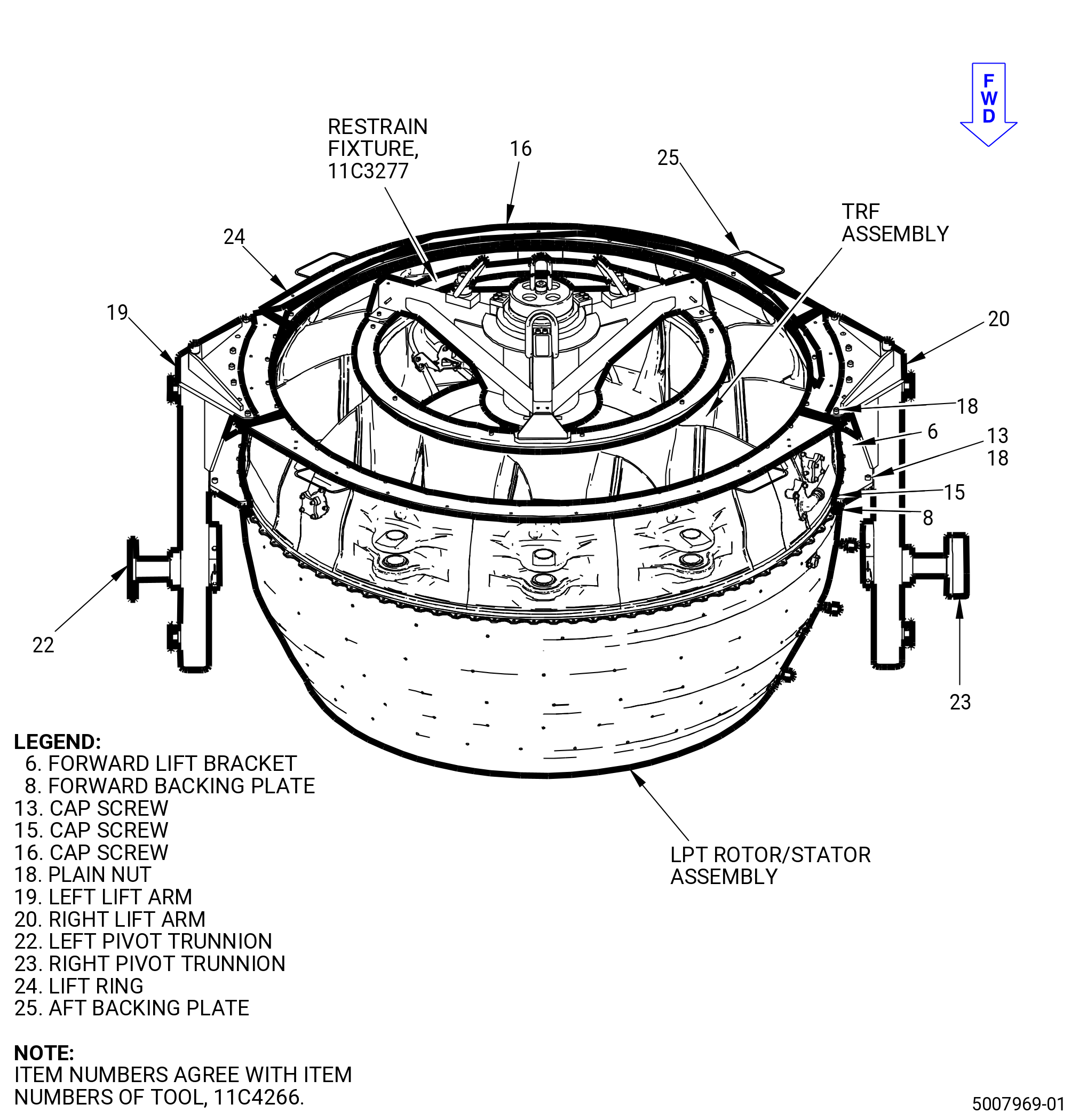
| (18).A. | Alternative Procedure. Install the 11C4266 CG lift fixture to the TRF assembly aft flange. Refer to Figure 1016 and do as follows: |
| WARNING: |
|
| WARNING: |
|
| (a) | Install the three 0.375-16 UNC-2B threaded lift eyes in the three equally spaced lift eye holes marked “TOOL LIFT ONLY” on the lift ring (item 24). |
| (b) | Use an overhead hoist and a three-legged sling with a minimum capacity of 4000 lb (1814 kg) each sling, to install the lift ring (item 24) on the aft outer flange of the TRF assembly and align the "TOP VERT" mark on the lift ring (item 24) with the top vertical mark of the TRF assembly. |
| NOTE: |
|
| (c) | Install the aft backing plate (item 25) in four equally spaced positions on the forward side of the aft outer flange of the TRF assembly. Use 28 cap screws (item 16) through the holes in the lift ring (item 24) and the aft outer flange of the TRF and into the threaded holes in the four aft backing plates (item 25). |
| (d) | Install the two lift arms (item 19 and 20) on the lift ring (item 24). Align the two lift ring (item 24) pins and the 10 lift ring (item 24) threaded rods with the holes in the lift arms (item 19 and 20). |
| (e) | Attach the 10 plain nuts (item 18) to the lift ring (item 24) threaded rods. |
| (f) | Remove the bolts (01-050) (SIN 94020) and LPT brackets (01-140) (SIN 6221W), (01-170) (SIN 6221Y), (01-260) (SIN 6221H), and (01-400) (SIN 6221J) from the flange of the LPT/TRF assembly at boltholes 20-25 (six bolts at the 3:00 o'clock position ALF) and boltholes 53-59 (seven bolts at the 9:00 o'clock position ALF) to give room for the forward lift brackets (item 6) and the forward backing plates (item 8) of the 11C4266 CG lift fixture. Refer to Figure 1015. |
| NOTE: |
|
| (g) | Attach the forward lift brackets (item 6) to each of the lift arms (item 19 and 20). Use two cap screws (item 13) and two plain nuts (item 18) in each forward lift bracket (item 6). |
| (h) | Use the ten cap screws (item 15) to attach the forward lift brackets (item 6) and the forward backing plates (item 8) to the flange of the LPT/TRF assembly. |
| (i) | Position the pivot trunnions (item 22 and 23) in the forward slot of the lift arms (item 19 and 20). |
| Subtask 72-00-04-430-141 |
| WARNING: |
|
| (19) | Alternative Procedure Available. Lift the LPT module assembly from the 11C3506 LPT module transport/storage stand. Refer to Figure 1002. |
| Subtask 72-00-04-430-142 |
| WARNING: |
|
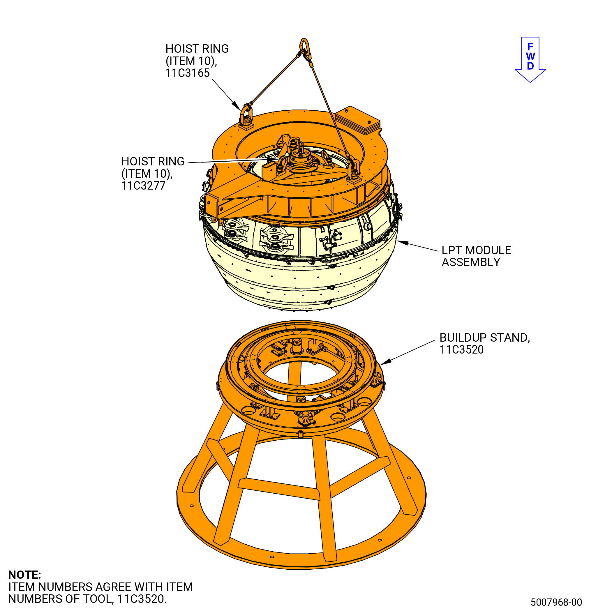
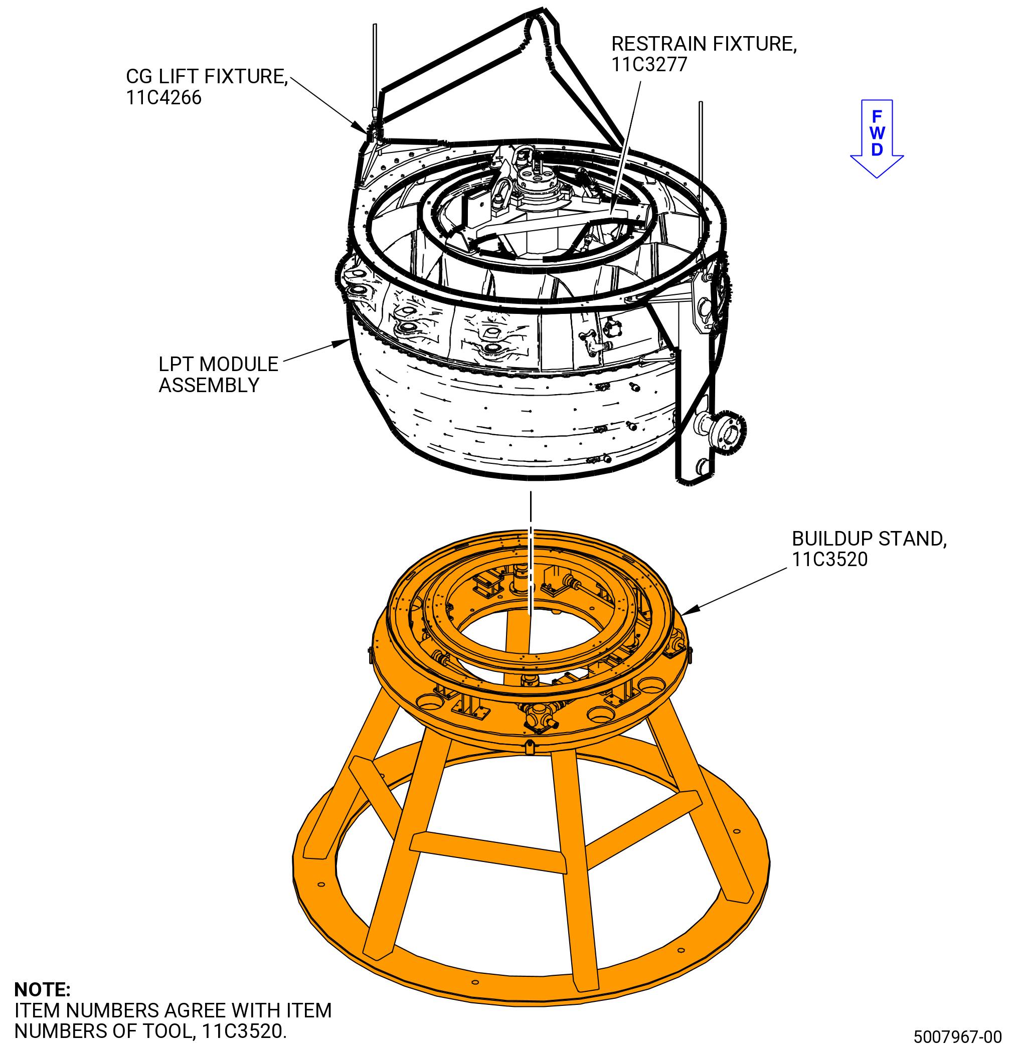
| (19).A. | Alternative Procedure. Lift the LPT module assembly from the 11C3520 buildup stand. Refer to TASK 72-56-00-440-802 (72-56-00, ASSEMBLY 001 - CONFIGURATION 02) and Figure 1017. |
| Subtask 72-00-04-430-143 |
| WARNING: |
|
| (20) | Alternative Procedure Available. Turn the LPT module assembly from the vertical position to the horizontal position with the 11C3165 strongback fixture and the 9C1147 VCG lift fixture. Refer to Figure 1018 and do as follows: |
| (a) | Use the two lift hoists to rotate the LPT module to the horizontal position. |
| (b) | Adjust the 9C1147 VCG lift fixture to correctly balance the LPT module assembly. |
| (c) | Remove the overhead chain hoist from the 11C3165 strongback fixture. |
| Subtask 72-00-04-430-144 |
| WARNING: |
|
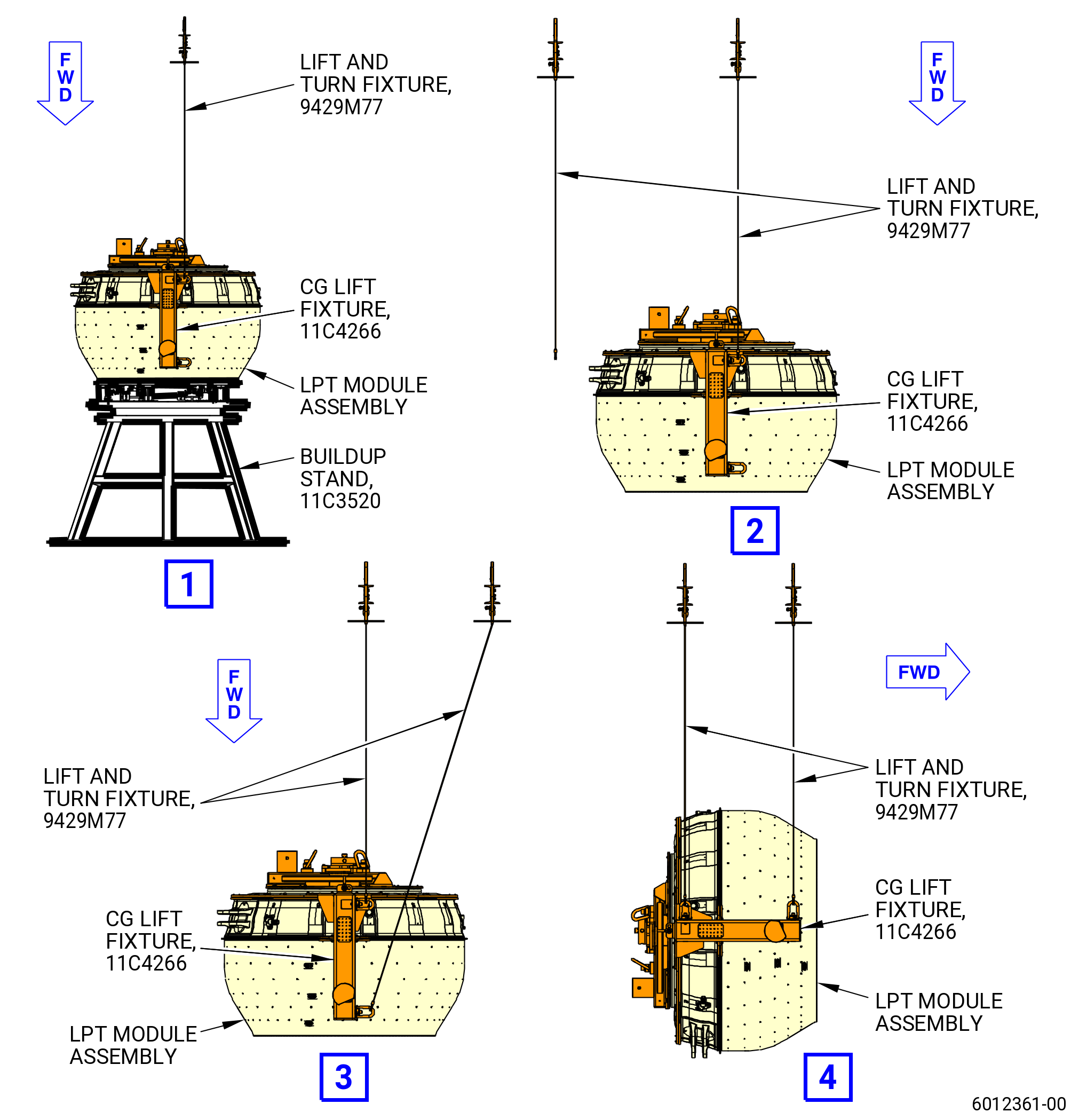
| (20).A. | Alternative Procedure. Turn the LPT module assembly from the vertical position to the horizontal position with the 11C4266 CG lift fixture. Refer to Figure 1019 and do as follows: |
| (a) | Prepare two cranes and two 9429M77 lift and turn fixtures modified for usage with tool 11C4266 CG lift fixture. |
| (b) | Attach the two shackles of the first 9429M77 lift and turn fixture long side slings to the aft shackles (aft side of the LPT module) of the 11C4266 CG lift fixture located at the right and left lift arms (items 19 and 20). |
| (c) | Lift the 9429M77 lift and turn fixture just the amount necessary to put the shackle to the lift position and put low tension on the sling to prevent a shift when turning the LPT module. |
| (d) | Attach the two shackles of the second 9429M77 lift and turn fixture long side slings to the front shackles (front side of the LPT module) of the 11C4266 CG lift fixture located at the right and left lift arms (items 19 and 20). |
| (e) | Lift the second 9429M77 lift and turn fixture to get the horizontal position of the LPT module. |
| Subtask 72-00-04-430-145 |
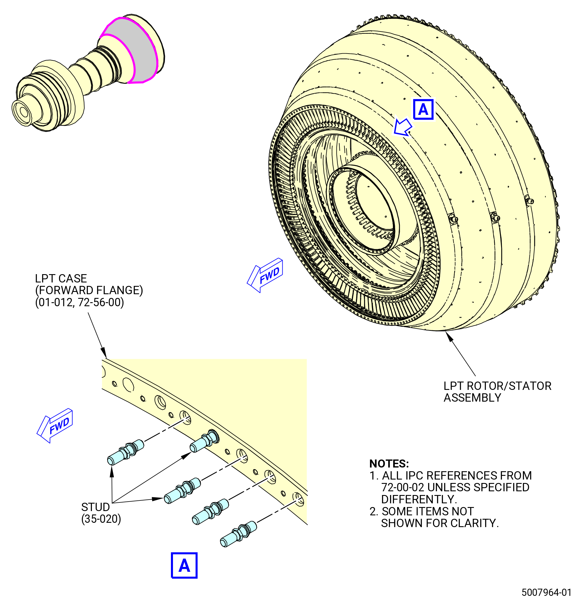
| (21) | Install the SPL free-running studs (studs) (35-020 , 72-00-02) (SIN 93520) on the LPT case (01-012 , 72-56-00) (SIN 935C1) forward flange. Refer to Figure 1020 and do as follows: |
| Subtask 72-00-04-640-035 |
| WARNING: |
|
| (a) | Lubricate the stud threads that are installed into the LPT case with C02-058 lubricant. Use the minimum quantity of lubricant necessary for the assembly. |
| Subtask 72-00-04-430-146 |
| (b) | Install the studs (35-020 , 72-00-02) (SIN 93520) in the LPT case (01-012 , 72-56-00) (SIN 935C1) forward flange at 150 locations. |
| (c) | Hand tighten the studs. |
| Subtask 72-00-04-430-147 |
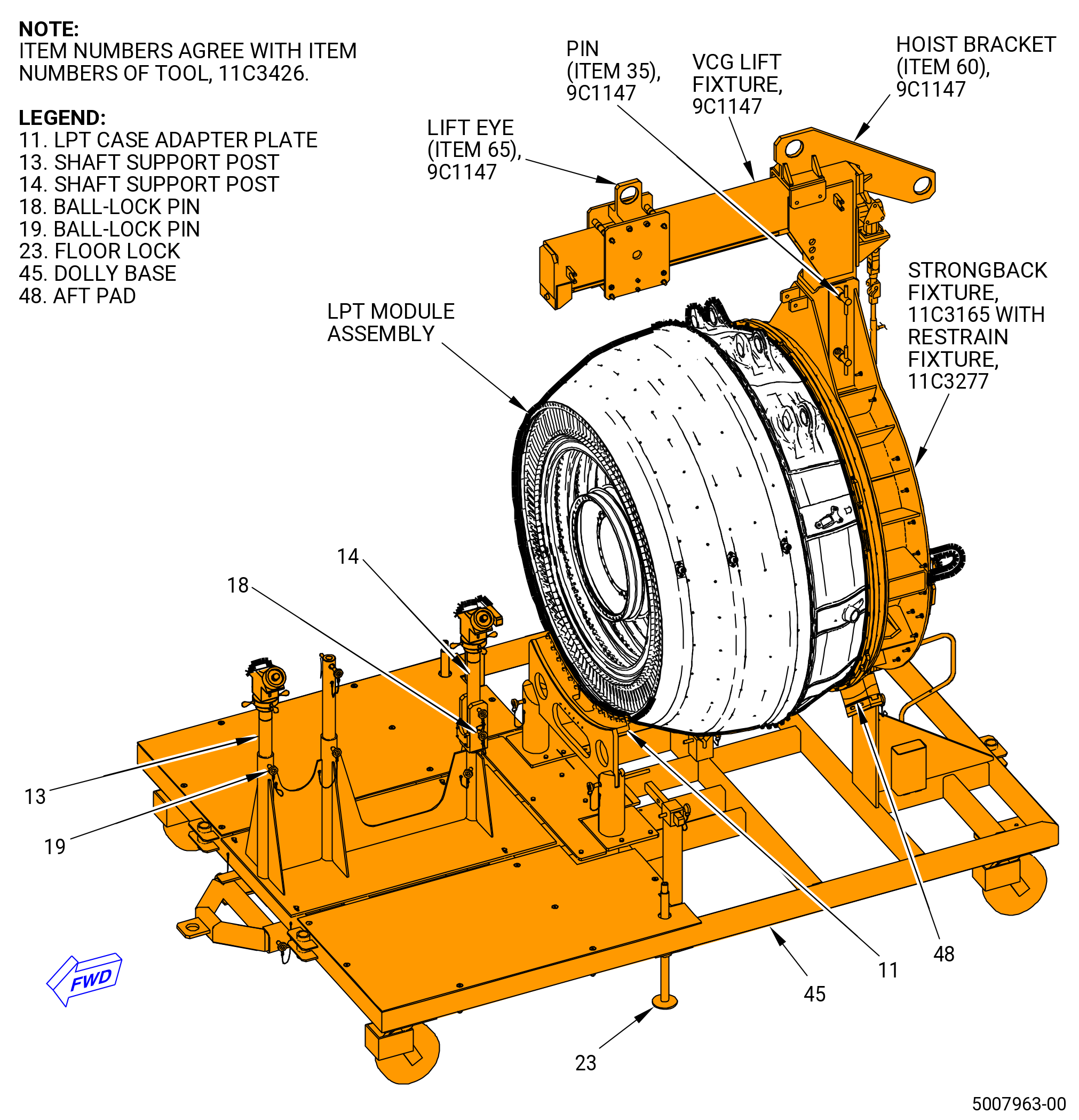
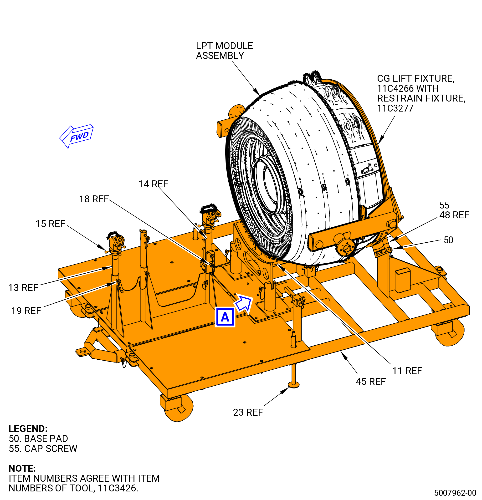
| (22) | Install the LPT module assembly on the 11C3426 LPT module dolly. Refer to Figure 1021 and do as follows: |
| CAUTION: |
|
| (a) | Make sure that the floor locks (item 23) are against the floor. If not, adjust the floor locks against the floor. |
| (b) | Make sure the shaft support posts (items 13 and 14) are in the vertical position and the ball-lock pins (item 19) are installed. |
| WARNING: |
|
| (c) | Install the aft pad (item 48) and the base pad (item 50) on each side with the two cap screws (item 55). |
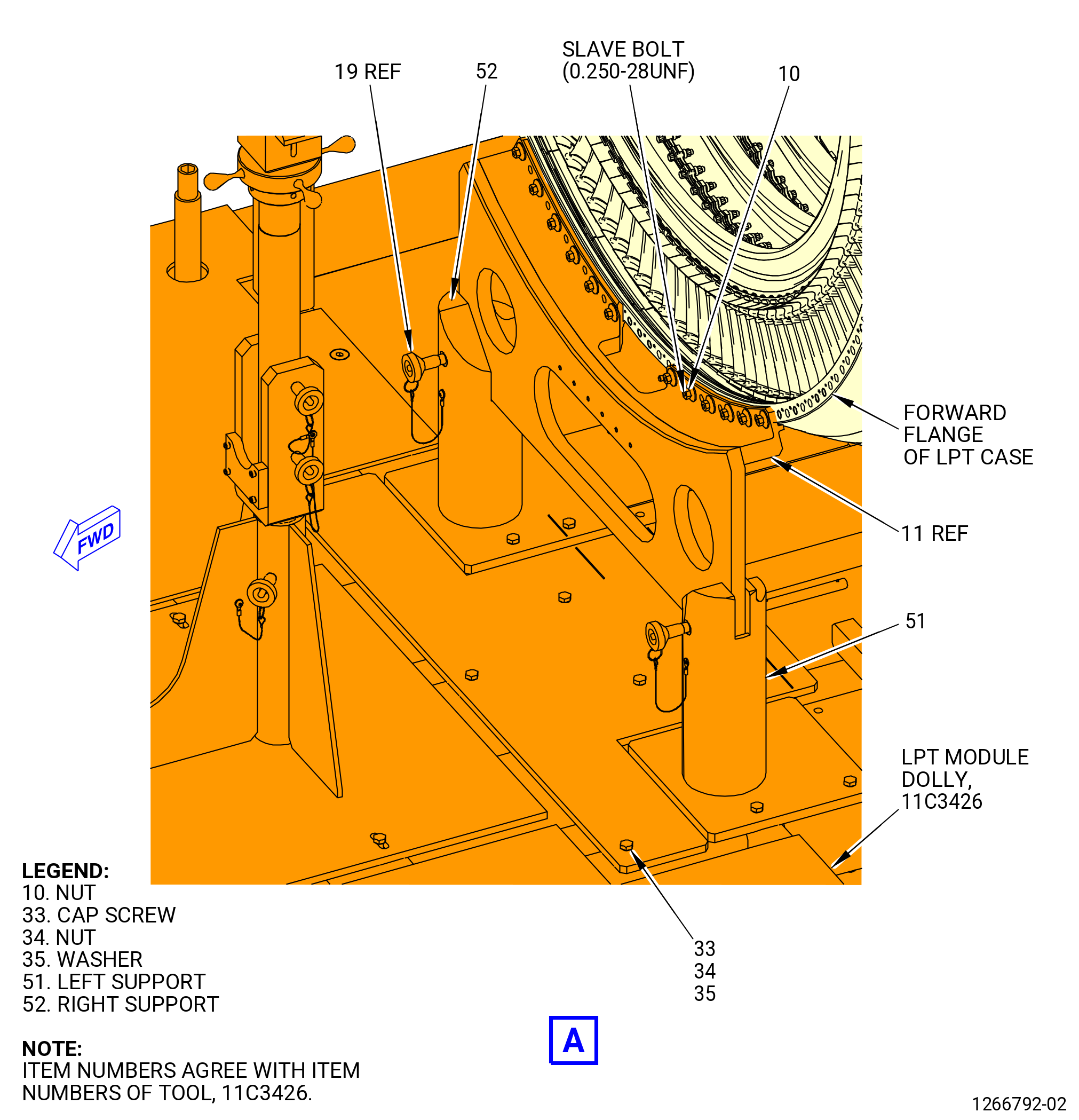
| (d) | Move the forward case left support (item 51) and the forward case right support (item 52) until the stamped arrows, with the word "ENGINE", match with the letters "GENX-1B" stamped on the plate. |
| (e) | Find the holes against the dolly base (item 45) and tighten with cap screw (item 33), nut (item 34), and flat washer (item 35). |
| (f) | Remove the two ball-lock pins (item 19) that attach the LPT case adapter plate (item 11) to the dolly base (item 45). Remove the LPT case adapter plate (item 11). |
| (g) | Remove the 12 nuts (item 10) from the LPT case adapter plate (item 11). If the nuts (item 10) are too tight, use a 7/16 inches wrench. |
| (h) | Install the LPT case adapter plate (item 11) on the LPT studs (35-020 , 72-00-02) (SIN 93520). Secure it with nuts (item 10) at 12 locations. Use a 7/16 inches wrench. |
| CAUTION: |
|
| (i) | Lower the LPT module assembly in the dolly base (item 45) until the mid fan shaft assembly is in the shaft support post (item 13) and shaft support post (item 14). Attach it with two ball-lock pins (item 19). |
| (j) | Use the support adjustment nuts (item 15) to adjust the height for the mid fan shaft. |
| Subtask 72-00-04-430-148 |
| CAUTION: |
|
| H. | Install the mid fan shaft assembly to the LPT module assembly. Refer to Figure 1023 and do as follows: |
| * * * PRE SB 72-0357 |
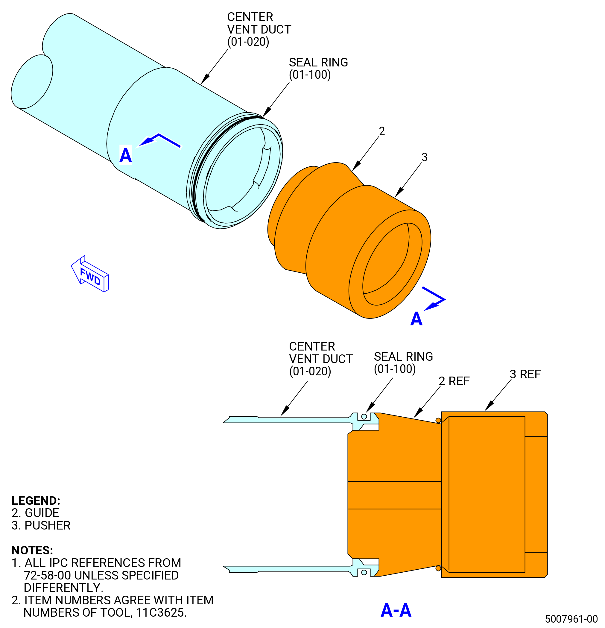
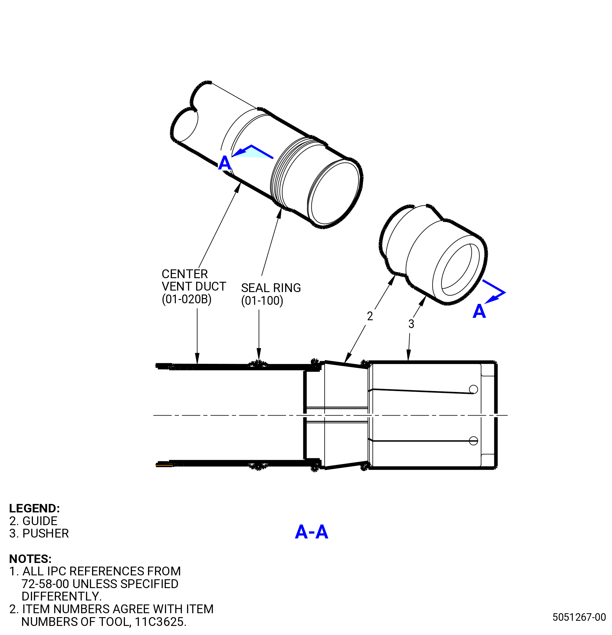
| (1) | Install the seal ring (01-100 , 72-58-00) (SIN 810N5) on the center vent duct (01-020 , 72-58-00) (SIN 810A1). Refer to Figure 1022 and do as follows: |
| WARNING: |
|
| (a) | Lubricate the inner face of the seal ring with C02-019 engine oil or C02-023 engine oil. |
| (b) | Lubricate the outer surface of the guide (item 2) of the 11C3625 seal pusher with C02-023 engine oil. |
| (c) | Put the seal ring on the rear end of the guide (item 2). The open side of the seal ring must face forward. |
| (d) | Carefully move the seal ring forward with the pusher (item 3) of the 11C3625 seal pusher. |
| (e) | The seal ring is expanded outward as the pusher (item 3) moves forward. At the forward end of the guide (item 2), the seal ring will get into the seal groove of the center vent duct. |
| NOTE: |
|
| (f) | Remove the guide (item 2) and the pusher (item 3) from the center vent duct. |
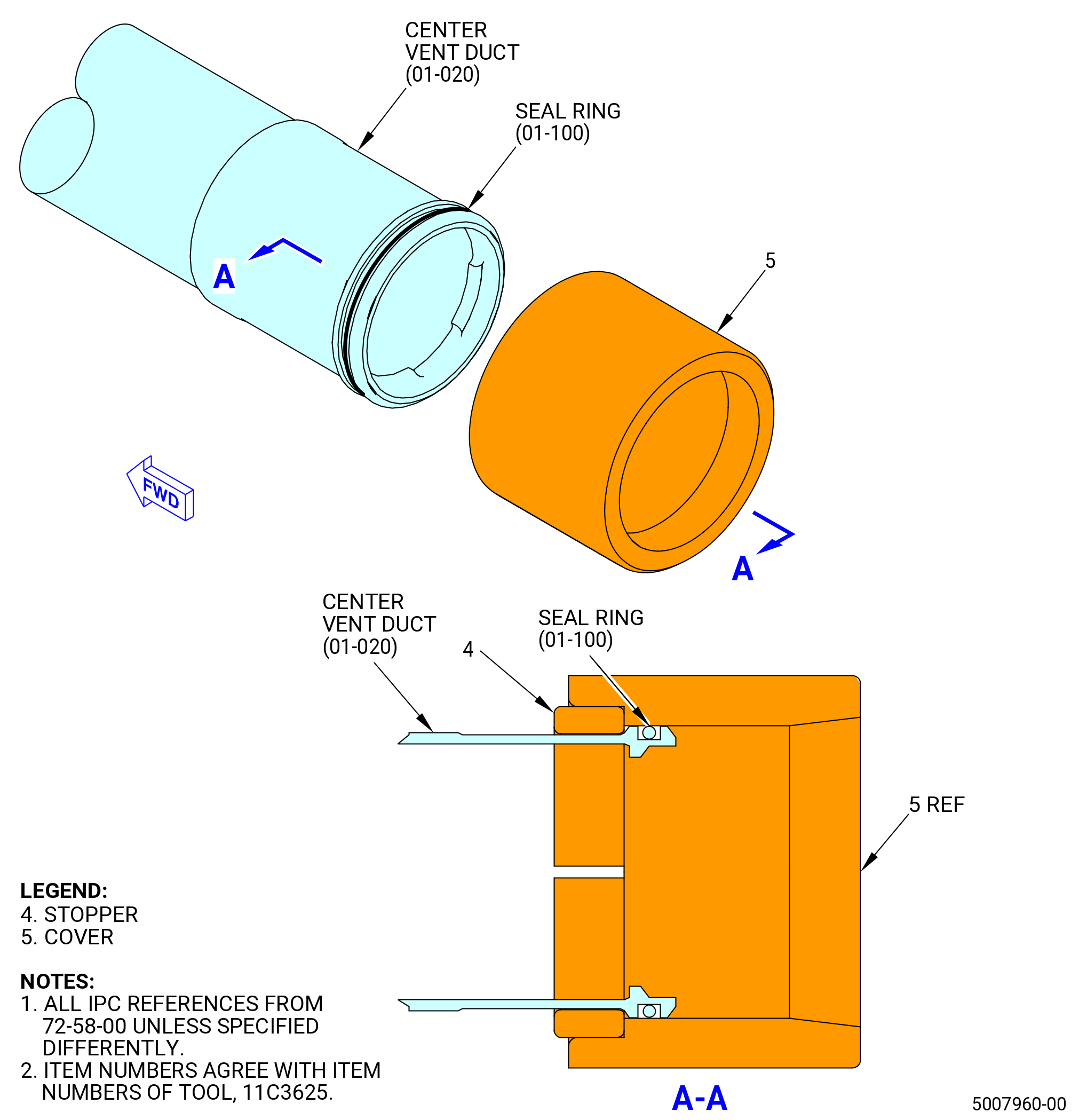
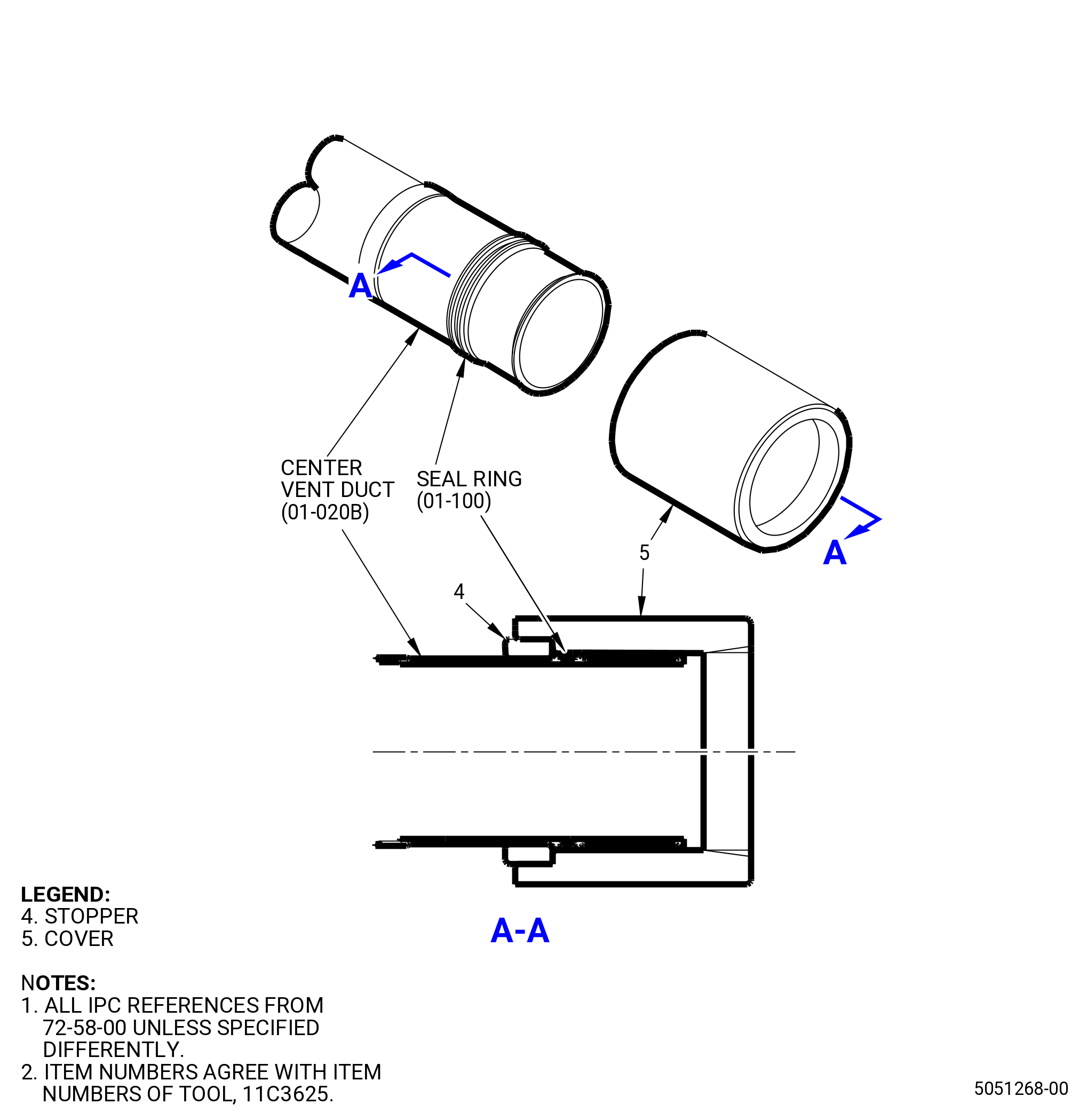
| (g) | Install two halves of the stopper (item 4) of the 11C3625 seal pusher on the center vent duct. |
| WARNING: |
|
| (h) | Lubricate the inner face of the cover (item 5) of the 11C3625 seal pusher with C02-023 engine oil. |
| (i) | Install the cover (item 5) on the seal ring. |
| (j) | Keep the cover (item 5) in place for a minimum 15 minutes. |
| (k) | Remove the cover (item 5) and stopper (item 4) from the center vent duct. |
| (l) | Make sure that the seal ring goes back to its initial size. Manually push the seal ring radially. No movement is permitted. |
| * * * END PRE SB 72-0357 |
| Subtask 72-00-04-430-165 |
| * * * SB 72-0357 |
| (1).A. | Install the seal ring (01-100 , 72-58-00) (SIN 810N5) on the center vent duct (01-020B , 72-58-00) (SIN 810A1). Refer to Figure 1022A and do as follows: |
| WARNING: |
|
| (a) | Lubricate the inner face of the seal ring with C02-019 engine oil or C02-023 engine oil. |
| (b) | Lubricate the outer surface of the guide (item 2) of the 11C3625 seal pusher with C02-023 engine oil. |
| (c) | Put the seal ring on the rear end of the guide (item 2). The open side of the seal ring must face forward. |
| (d) | Carefully move the seal ring forward with the pusher (item 3) of the 11C3625 seal pusher onto the center vent duct. |
| (e) | The seal ring is expanded outward as the pusher (item 3) moves forward. At the forward end of the guide (item 2), the seal ring will get onto the center vent duct. |
| NOTE: |
|
| (f) | Remove the guide (item 2) and the pusher (item 3) from the center vent duct. |
| (g) | Put a glove on your hand, and move the seal ring with your finger to install it into the seal groove of the center vent duct. |
| (h) | Install two halves of the stopper (item 4) of the 11C3625 seal pusher on the center vent duct. |
| WARNING: |
|
| (i) | Lubricate the inner face of the cover (item 5) of the 11C3625 seal pusher with C02-023 engine oil. |
| (j) | Install the cover (item 5) over the seal ring. |
| (k) | Keep the cover (item 5) in place for a minimum 15 minutes and let the installed seal ring go back to its initial size. |
| (l) | Remove the cover (item 5) and stopper (item 4) from the center vent duct. |
| (m) | Push the seal ring radially with your finger. Make sure that the seal ring does not move. The seal ring is back to its initial size when there is no movement. |
| * * * END SB 72-0357 |
| Subtask 72-00-04-640-036 |
| WARNING: |
|
| (2) | Clean all the mating surfaces of the LPT cone shaft (01-050 , 72-56-00) (SIN 930D1) and the mid fan shaft assembly with C04-002 Stoddard solvent or C04-307 dykem remover. |
| (3) | Clean the threads on the D-head LPT bolts (01-090 , 72-56-00) (SIN 93020) with C04-002 Stoddard solvent, C04-035 isopropyl alcohol, or a 50-50 blend of alcohol. |
| Subtask 72-00-04-430-149 |
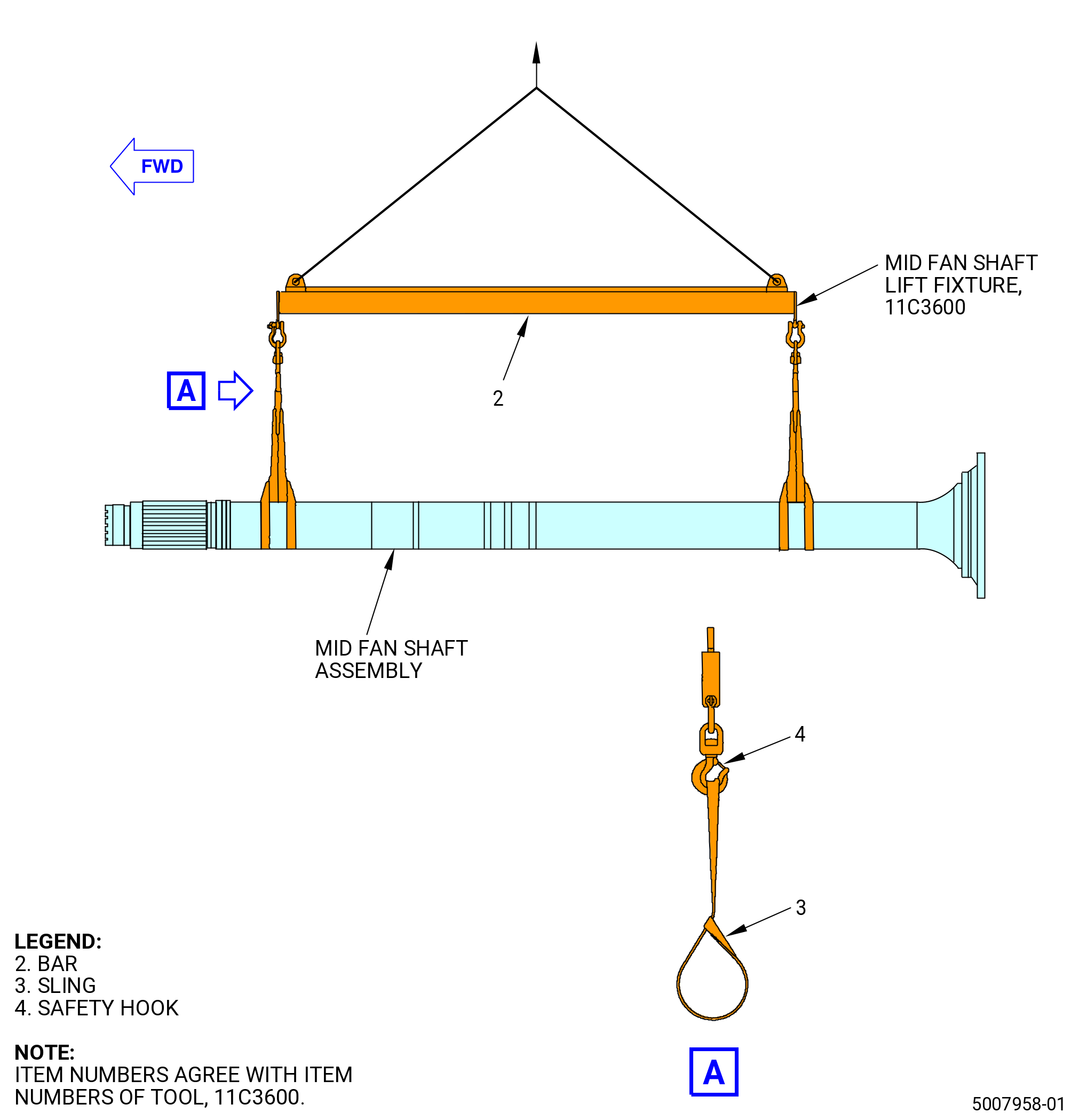
| (4) | Attach the 11C3600 mid fan shaft lift fixture to the mid fan shaft. Refer to Figure 1024 and do as follows: |
| NOTE: |
|
| (a) | Remove the slings (item 3) from the safety hooks (item 4). |
| (b) | Attach the slings (item 3) at two locations to the mid fan shaft assembly. Double the sling straps around the fan shaft assembly. |
| (c) | Attach an overhead hoist to the spreader bar (bar) (item 2) at two locations. |
| WARNING: |
|
| (d) | Lift the bar (item 2) with an overhead hoist and attach the slings (item 3) to the safety hooks (item 4). |
| (e) | Remove unwanted slack from the slings (item 3) with the overhead hoist. |
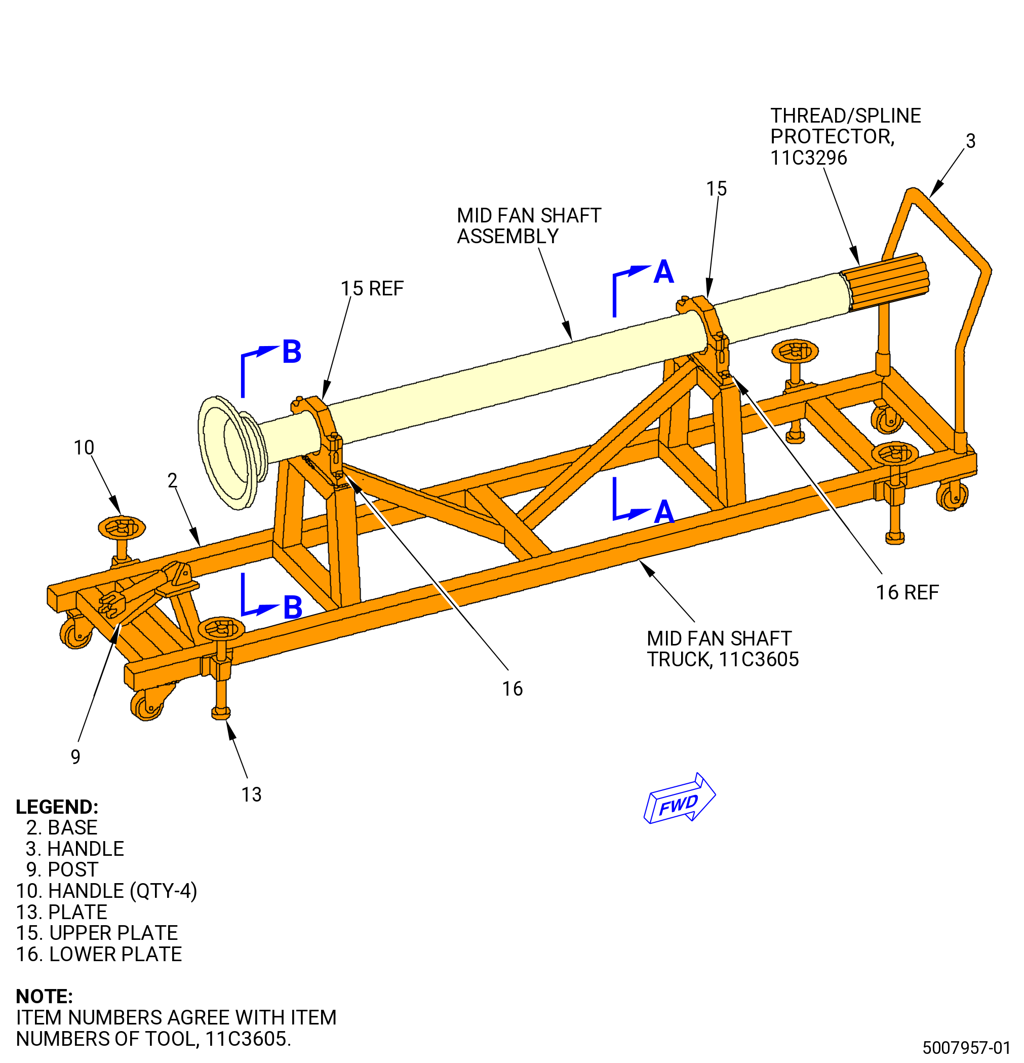
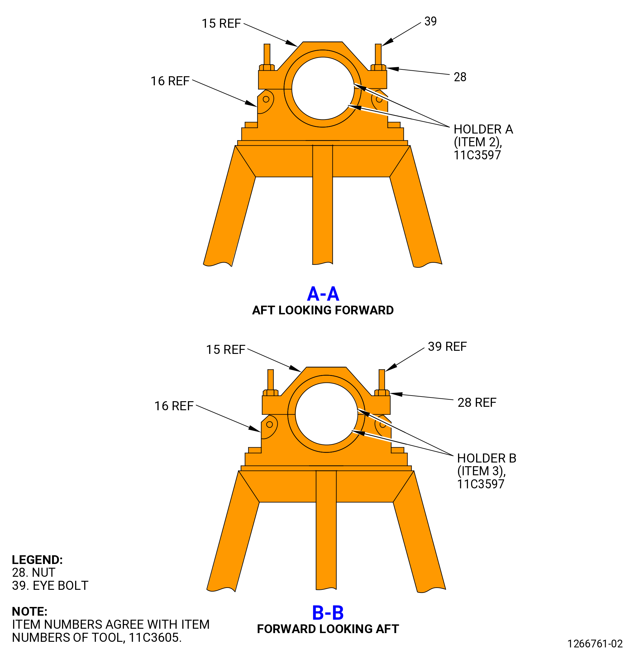
| (5) | Prepare the 11C3605 mid fan shaft truck for the mid fan shaft assembly. Refer to Figure 1025 and do as follows: |
| CAUTION: |
|
| (a) | Turn the handles (item 10) until the plates (item 13) are fully against the shop floor. |
| (b) | Make sure that the post (item 9) is lowered. If necessary, lower the post (item 9) away from the mid fan shaft. |
| Subtask 72-00-04-430-150 |
| WARNING: |
|
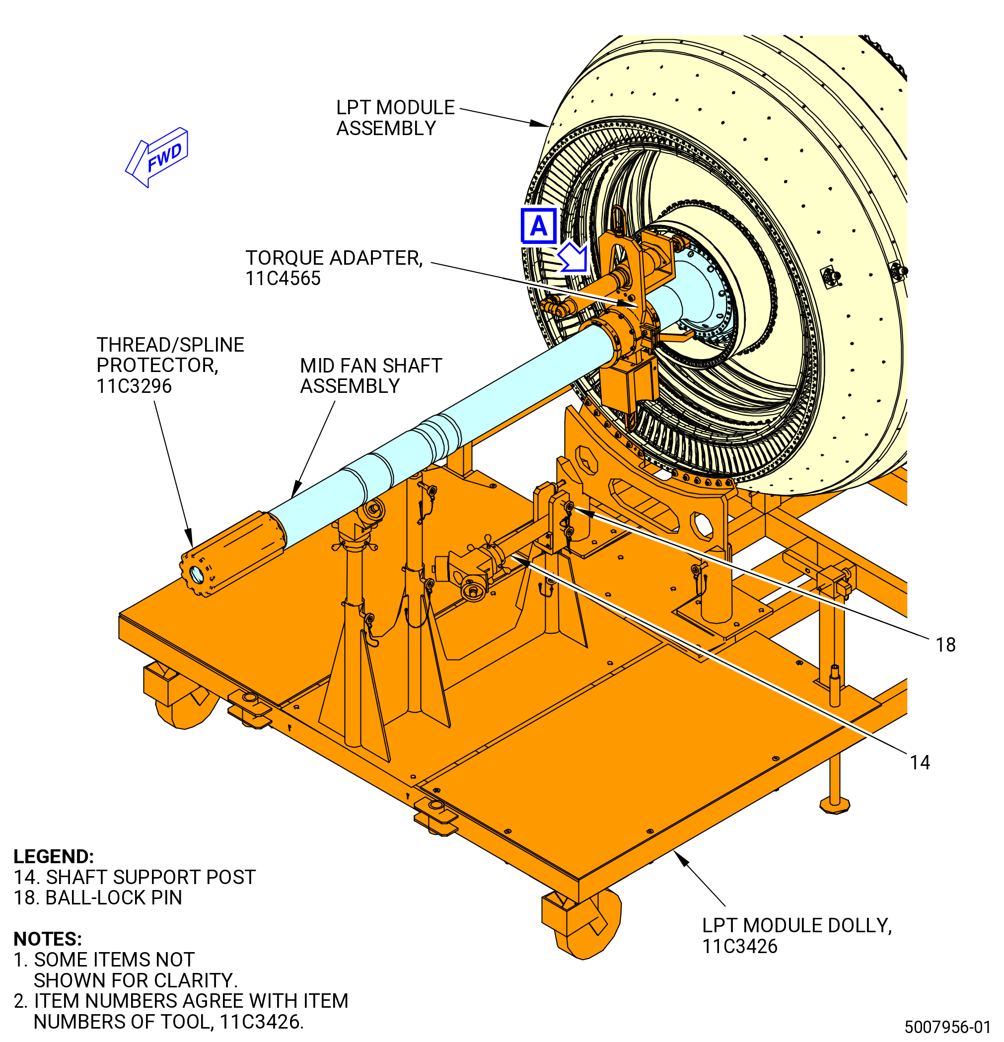
| (6) | Lift the mid fan shaft assembly from the 11C3605 mid fan shaft truck and put it in position on the 11C3426 LPT module dolly. Refer to Figure 1021. |
| (7) | Remove the 11C3600 mid fan shaft lift fixture from the mid fan shaft. |
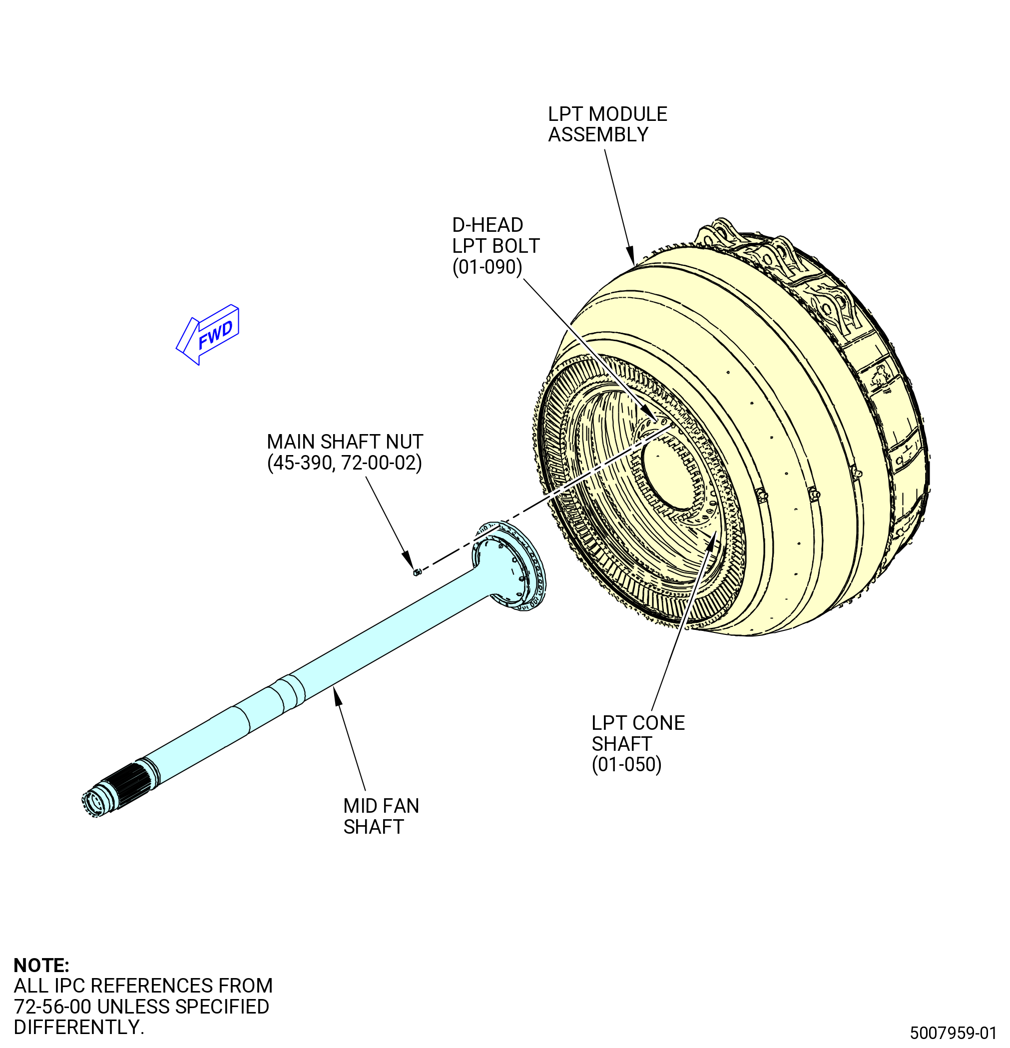
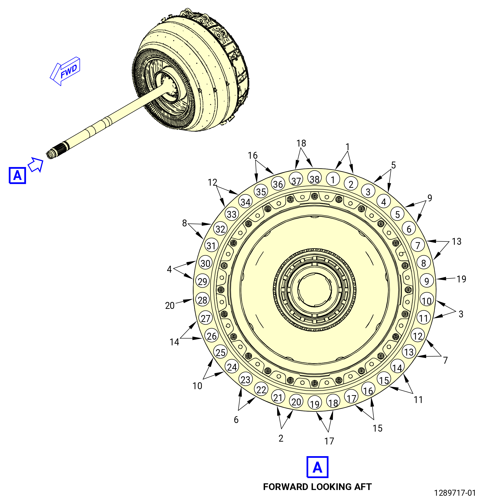
| (8) | Attach the mid fan shaft to the LPT module assembly. Install the main shaft nuts (45-390 , 72-00-02) (SIN 93040) on the LPT cone shaft (01-050 , 72-56-00) (SIN 930D1) D-head LPT bolts (01-090 , 72-56-00) (SIN 93020). Refer to Figure 1023 and do as follows: |
| (a) | Align the L mark on the mid fan shaft with the H mark on the LPT cone shaft (01-050 , 72-56-00) (SIN 930D1). |
| (b) | Move the mid fan shaft until it is against the LPT cone shaft (01-050 , 72-56-00) (SIN 930D1) and the boltholes are aligned. |
| (c) | Start at the 12:00 o'clock position and put a number at the bolt locations, 1-38, FLA, on the LPT cone shaft. Use a C05-003 marking pen. |
| (d) | Make sure the D-head LPT bolts (01-090 , 72-56-00) (SIN 93020) are properly seated on the aft side of the LPT cone shaft (01-050 , 72-56-00) (SIN 930D1) flange. |
| Subtask 72-00-04-640-037 |
| WARNING: |
|
| (e) | Apply C02-097 lubricant to the threads and washer surfaces of the slave nuts (item 7). |
| Subtask 72-00-04-430-151 |
| (f) | Install the slave nuts (item 7) of the 11C4565 torque adapter on the D-head LPT bolts (01-090 , 72-56-00) (SIN 93020) at the 12:00, 6:00, 3:00, and 9:00 o'clock positions in a four-point criss-cross pattern. Install a slave nut on the D-head LPT bolts at bolt positions 1, 3, 5, 7, 9, 11, 13, 15, 17, 19, 21, 23, 25, 27, 29, 31, 33, 35, and 37. Refer to Figure 1026. |
| CAUTION: |
|
| (g) | Make sure the D-head bolts (01-090 , 72-56-00) (SIN 93032) are properly seated on the aft side of the LPT cone shaft (01-050 , 72-56-00) (SIN 930D1) flange. |
| (h) | Torque the slave nuts (item 7) in a criss-cross pattern to 50 lb in. (5.6 N.m) at the 12:00, 3:00, 6:00, and 9:00 o'clock positions. |
| Subtask 72-00-04-640-038 |
| WARNING: |
|
| (i) | Apply C02-097 lubricant to the threads and washer surfaces of the main shaft nuts (45-390 , 72-00-02) (SIN 93040). Use the minimum quantity of lubricant necessary for the assembly. |
| (j) | Apply C02-097 lubricant to the threads of the D-head LPT bolts (01-090 , 72-56-00) (SIN 93020). Make sure that the threads are sufficiently lubricated. |
| Subtask 72-00-04-430-152 |
| (k) | Start at the 12:00 o'clock position, then move to the 6:00, 3:00, and 9:00 o'clock positions in a four-point criss-cross pattern. Install a new main shaft nut (45-390 , 72-00-02) (SIN 93040) on the D-head LPT bolts (01-090 , 72-56-00) (SIN 93020) at positions 2, 4, 6, 8, 10, 12, 14, 16, 18, 20, 22, 24, 26, 28, 30, 32, 34, 36, and 38 as follows: |
| 1 | Install new main shaft nuts on the D-head LPT bolts. |
| 2 | Torque the main shaft nuts (45-390 , 72-00-02) (SIN 93040) to 40 to 50 lb ft (54 to 68 Nm). |
| 3 | Continue in a four-point criss-cross pattern until all 19 D-head LPT bolts have a main shaft nut installed. |
| (l) | Start at the 12:00 o'clock position, then move to the 6:00, 3:00, and 9:00 o'clock positions in a four-point criss-cross pattern. Remove the 19 slave nuts and install a main shaft nut (45-390 , 72-00-02) (SIN 93040) on the D-head LPT bolts (01-090 , 72-56-00) (SIN 93020) as follows: |
| 1 | Remove the slave nuts (item 7) of the 11C4565 torque adapter from the D-head LPT bolts. |
| 2 | Install new main shaft nuts on the D-head LPT bolts. |
| 3 | Continue until all 19 slave nuts are replaced with a main shaft nut. |
| 4 | Torque the main shaft nuts in a four-point criss-cross pattern to 40 to 50 lb ft (54 to 68 Nm). |
| 5 | Torque the nuts to 40 to 50 lb ft (54 to 68 Nm) again, CW sequentially to make sure all nuts are torqued. |
| Subtask 72-00-04-430-153 |
| I. | Install the 11C4565 torque adapter on the mid fan shaft assembly as follows: |
| (1) | Pull the ball-lock pin (item 18) of the 11C3426 LPT module dolly from the shaft support post (item 14) and lower the shaft support post forward. Refer to Figure 1021. |
| Subtask 72-00-04-430-154 |
| CAUTION: |
|
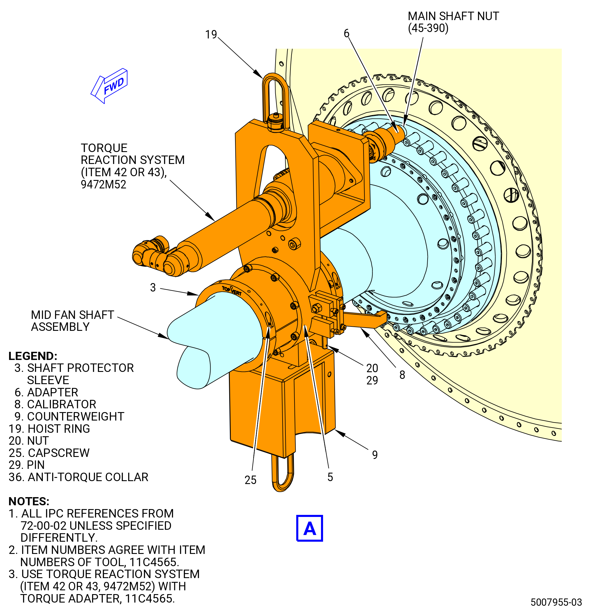
| (2) | Install the shaft protector sleeves (item 3) on the mid fan shaft. Refer to Figure 1027 and do as follows: |
| (a) | Remove the capscrews (item 25) from the shaft protector sleeves (item 3). |
| (b) | Put the shaft protector sleeves (item 3) on the mid fan shaft. |
| (c) | Secure the shaft protector sleeves (item 3) with the capscrews (item 25). |
| (d) | Use the calibrator (item 8) to put the shaft protector sleeves (item 3) at the correct distance from the mid fan shaft inner flange. |
| (e) | Attach the shaft protector sleeves together with the capscrews (item 25) and tighten the capscrews to prevent movement of the sleeves. |
| (3) | Install the 11C4565 torque adapter on the mid fan shaft on the shaft protector sleeves (item 3) as follows: |
| WARNING: |
|
| (a) | Attach an overhead hoist to the hoist ring (item 19) on the 11C4565 torque adapter. The counterweight (item 9) will be at the 6:00 o'clock position. |
| (b) | Carefully lift and put the anti-torque collar (item 36) on the mid fan shaft. |
| (c) | Attach firmly the anti-torque collar (item 36) with the pin (item 29). Tighten the nut (item 20). |
| (d) | Lower and remove the hoist from the hoist rings (item 19). |
| (e) | Install the adapter (item 6) on the torque reaction system (item 42 or item 43) of the 9472M52 torque reaction fixture. |
| (4) | Connect the 11C4565 torque adapter to the 9472M52 torque reaction fixture. |
| Subtask 72-00-04-430-155 |
| J. | Torque the main shaft nuts (45-390 , 72-00-02) (SIN 93040) with the 9472M52 torque reaction fixture as follows: |
| (1) | Make sure that the 11C4565 torque adapter and 9472M52 torque reaction fixture are calibrated before final torque to the main shaft nuts is applied. |
| CAUTION: |
|
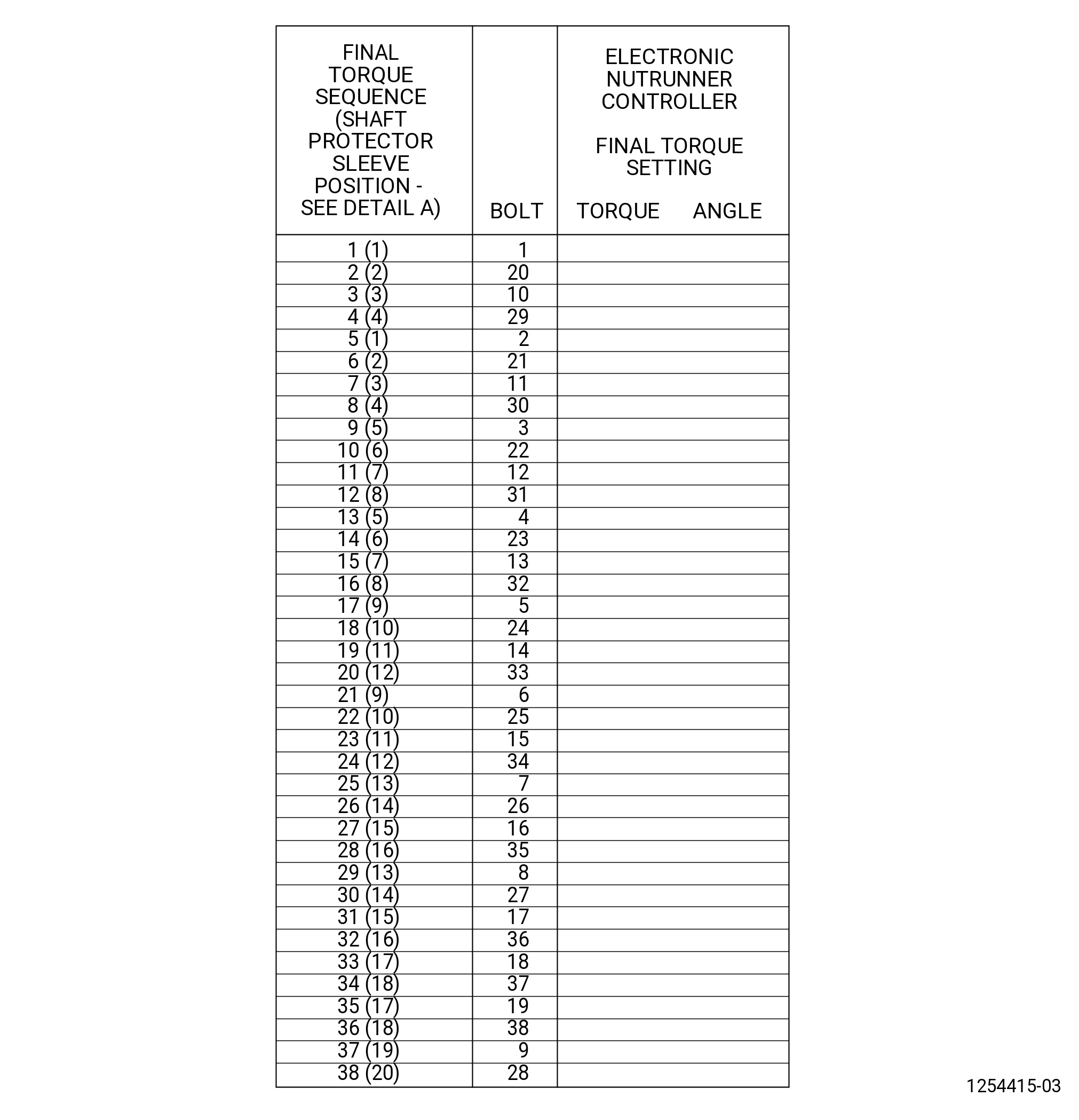
| (2) | Torque the main shaft nuts. Start at the No. 1 main shaft nut at the No. 1 position, then move to the No. 20 main shaft nut at the No. 2 position, and work in a four-point criss-cross pattern by the numbers on the torque record sheet. Refer to Figure 1028. |
| (3) | Make sure that the adapter (item 6) of the 11C4565 torque adapter is fully engaged on the main shaft nut (45-390 , 72-00-02) (SIN 93040). |
| (4) | Use the 9472M52 torque reaction fixture to torque the main shaft nuts (45-390 , 72-00-02) (SIN 93040) after they are torqued to 40 to 50 lb ft (54 to 68 Nm). |
| (5) | Use the 11C4565 torque adapter to apply torque and get an angle of 68-72 degrees. The torque value must be 176 to 250 lb ft (239 to 339 Nm). If not, replace the main shaft nuts (45-390 , 72-00-02) (SIN 93040). |
| (6) | Record the torque and the angle from the torque reaction system for the main shaft nut in the FINAL TORQUE SETTING column on the record sheet. Refer to Figure 1028. |
| (7) | Use a C05-003 marking pen and put a line through the bolt number on the LPT cone shaft (01-050 , 72-56-00) (SIN 930D1). |
| (8) | Move the torque reaction system (item 42 or item 43) forward and backward on the shaft protector sleeves until all the main shaft nuts are torqued in the correct sequence. Refer to Figure 1027 and Figure 1028. |
| Subtask 72-00-04-430-156 |
| K. | Use a 0.001 inch (0.03 mm) feeler stock as a no-go gage at a minimum of eight positions to make sure that the mid fan shaft assembly is against the LPT cone shaft (01-050 , 72-56-00) (SIN 930D1). Refer to Figure 1023. |
| Subtask 72-00-04-430-157 |
| WARNING: |
|
| L. | Remove the 11C4565 torque adapter and 9472M52 torque reaction fixture with an overhead hoist from the mid fan shaft assembly. Refer to Figure 1027. |
| Subtask 72-00-04-430-158 |
| WARNING: |
|
| M. | Remove the unwanted C02-097 lubricant from the main shaft nuts (45-390 , 72-00-02) (SIN 93040) and the D-head bolts (01-090 , 72-56-00) (SIN 93020) with C04-307 dykem remover. |
| Subtask 72-00-04-380-003 |
| WARNING: |
|
| N. | Apply a minimum of three coats of C03-039 coating to the bare surfaces around the main shaft nuts (45-390 , 72-00-02) (SIN 93040) on the forward face of the mid fan shaft assembly flange. Refer to TASK 70-43-05-380-005 (INORGANIC ALUMINUM PROTECTIVE COATING). |
| (1) | Do not paint all of the fan shaft forward face. Apply paint only to those areas that are not painted. Do not let the paint touch the LPT disks, brush seals, or other adjacent hardware. |
| Subtask 72-00-04-430-159 |
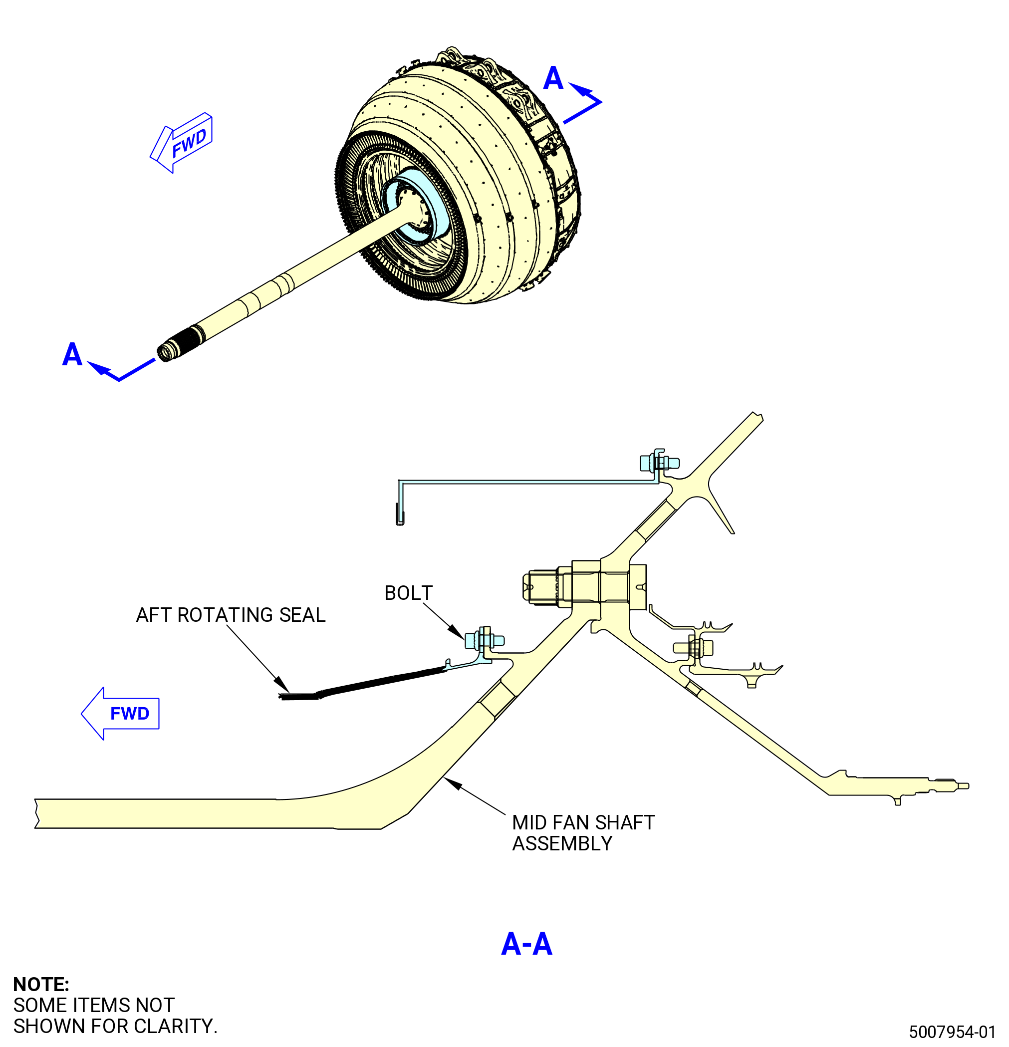
| O. | Install the No. 4 bearing aft rotating seal (aft rotating seal) (35-380 , 72-00-02) (SIN 01406) on the mid fan shaft assembly. Refer to Figure 1029 and do as follows: |
| Subtask 72-00-04-640-039 |
| WARNING: |
|
| (1) | Apply the C02-097 lubricant to the threads and washer surfaces of the bolts (35-390 , 72-00-02) (SIN 01423). Use the minimum quantity of lubricant necessary for the assembly. |
| Subtask 72-00-04-430-160 |
| WARNING: |
|
| (2) | Increase the temperature of the rabbet on the LPT cone shaft (01-050 , 72-56-00) (SIN 930D1) with a heat gun for 10 minutes. |
| (3) | Install the aft rotating seal (35-380 , 72-00-02) (SIN 01406) on the mid fan shaft assembly. |
| (4) | Install the bolts (35-390 , 72-00-02) (SIN 01423) through the aft rotating seal flange and the mid fan shaft flange with the bolthead forward. |
| (5) | Let the temperature of the LPT cone shaft flange and the aft rotating seal decrease to room temperature. |
| (6) | Tighten four or more of the bolts (35-390 , 72-00-02) (SIN 01423) at equally spaced locations to 85 lb in. (9.6 N.m). |
| (7) | Torque the bolts (35-390 , 72-00-02) (SIN 01423) 180 degrees from each other in a criss-cross pattern to 106-124 lb in. (12.0-14.0 N.m). |
| (8) | Torque the bolts (35-390 , 72-00-02) (SIN 01423) again 180 degrees from each other in a criss-cross pattern to 106-124 lb in. (12.0-14.0 N.m). |
| (9) | After assembly, remove remaining lubricant with a clean cloth. |
| Subtask 72-00-04-430-161 |
| P. | Install the 11C3296 thread/spline protector on the threaded area of the mid fan shaft assembly. Refer to Figure 1025. |
| Subtask 72-00-04-430-162 |
| Q. | Prepare the A/O extension duct (extension duct) (45-270 , 72-00-02) (SIN 810A8) for installation as follows: |
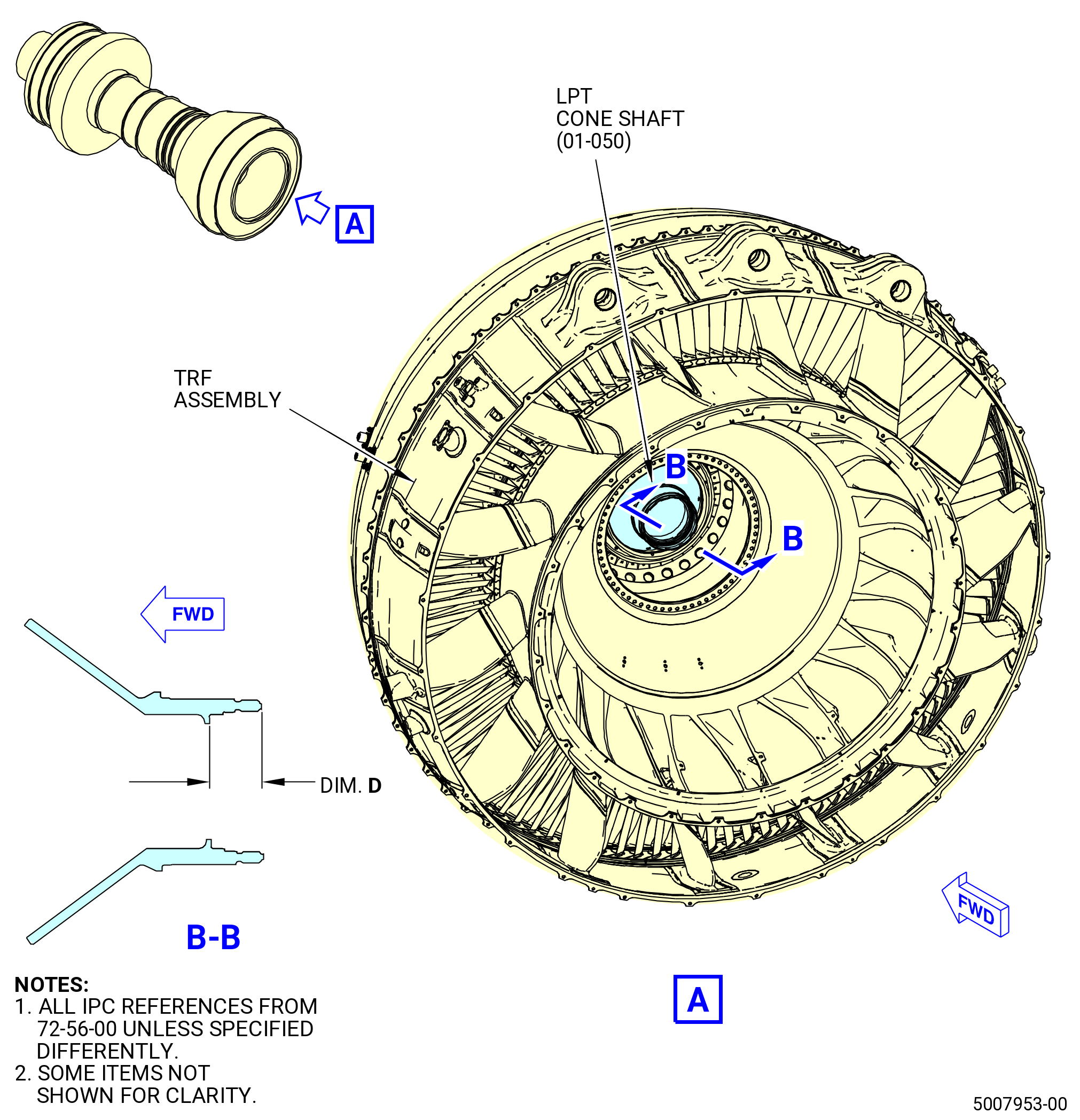
| (1) | Measure dimension D on the LPT cone shaft (01-050 , 72-56-00) (SIN 930D1). Refer to Figure 1030 and do as follows: |
| (a) | Measure from the aft side of the castellations of the LPT cone shaft to the aft side of the inner flange. |
| (b) | Measure dimension D at four equally-spaced locations and record the minimum and the maximum dimensions. Dimension D must be between 1.6065-1.6163 inches (40.805-41.054 mm). |
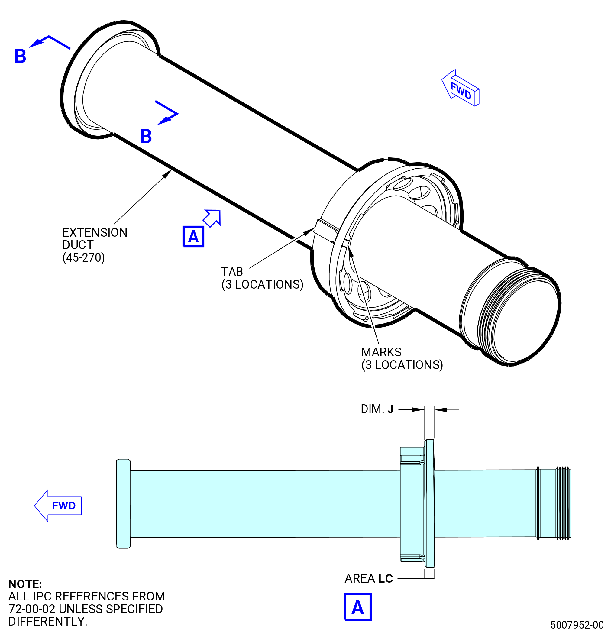
| (2) | Measure dimension J on the extension duct (45-270 , 72-00-02) (SIN 810A8) as follows: |
| (a) | Measure the thickness of the extension duct aft outer rail. Refer to Figure 1031. |
| (b) | Measure dimension J at four equally-spaced locations. Make a record of the minimum and maximum measurements. Dimension J must be between 0.3767-0.3862 inch (9.568-9.810 mm). |
| Subtask 72-00-04-430-163 |
| (3) | Apply C10-021 tape to the aft end of the extension duct to protect the seal teeth. |
| CAUTION: |
|
| (4) | Find the three tabs on the forward side of the aft flange of the extension duct (45-270 , 72-00-02) (SIN 810A8). |
| (5) | Use a C05-003 marking pen to put marks on the aft side of the aft flange of the extension duct (45-270 , 72-00-02) (SIN 810A8) so the position of the tabs are visible when the extension tube is installed into the LPT cone shaft (01-050 , 72-56-00) (SIN 930D1). |
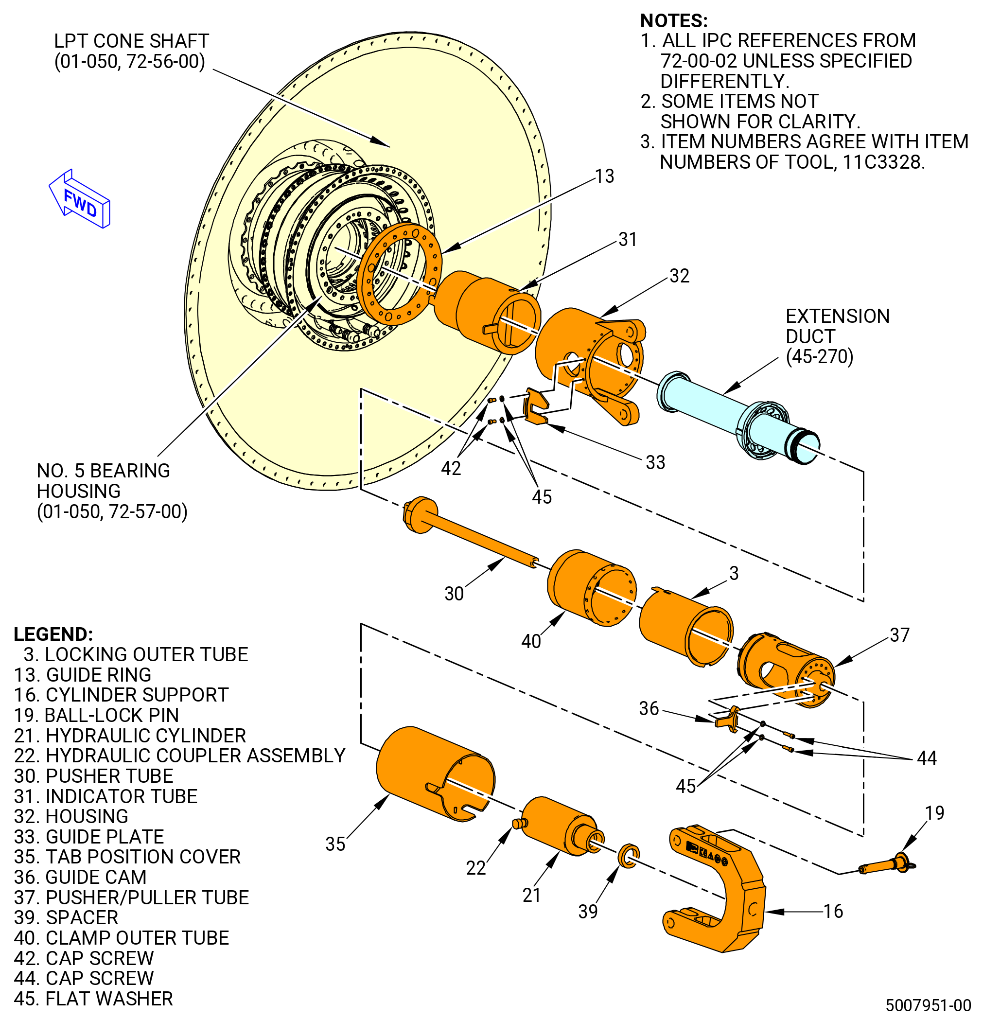
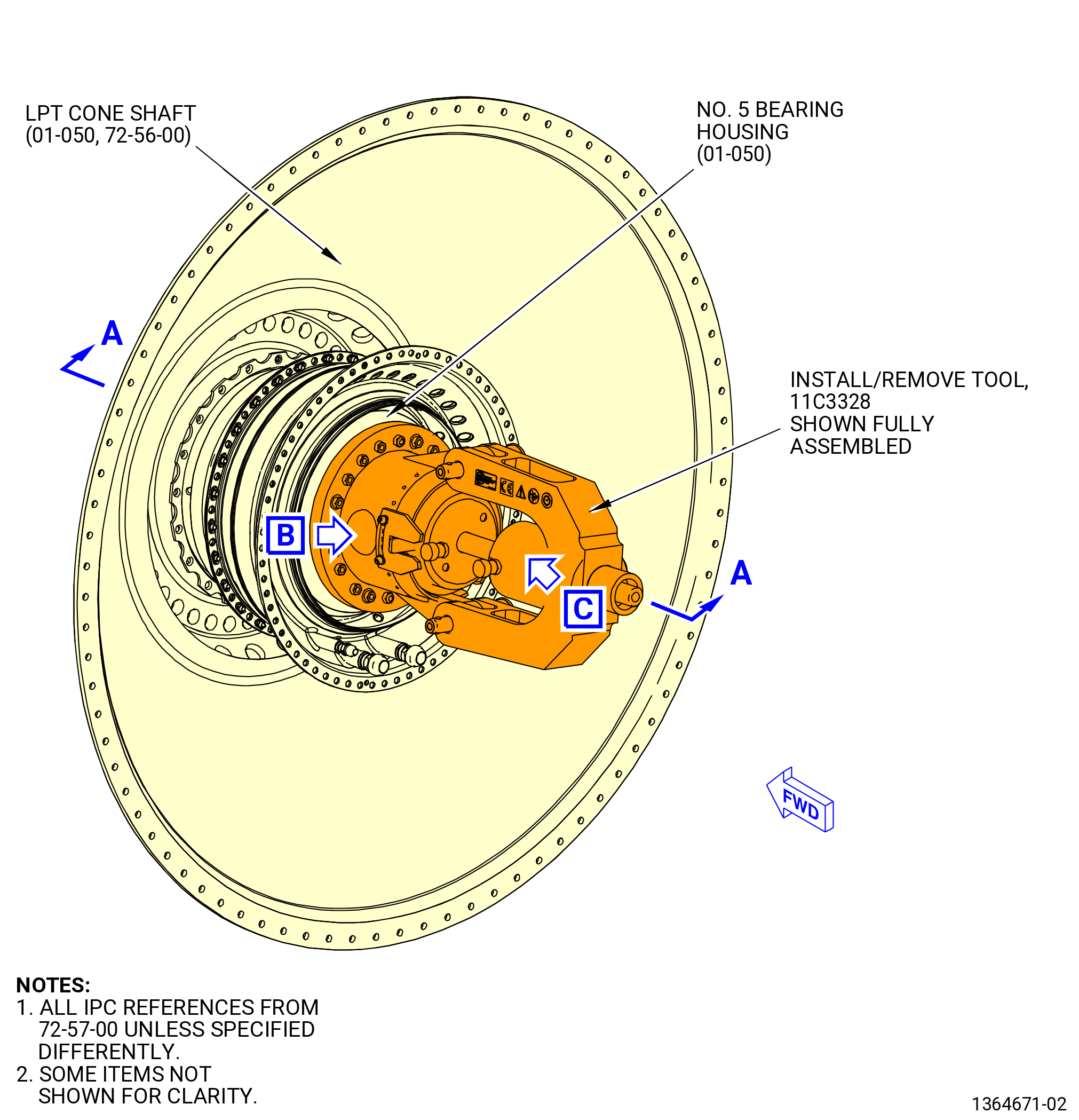
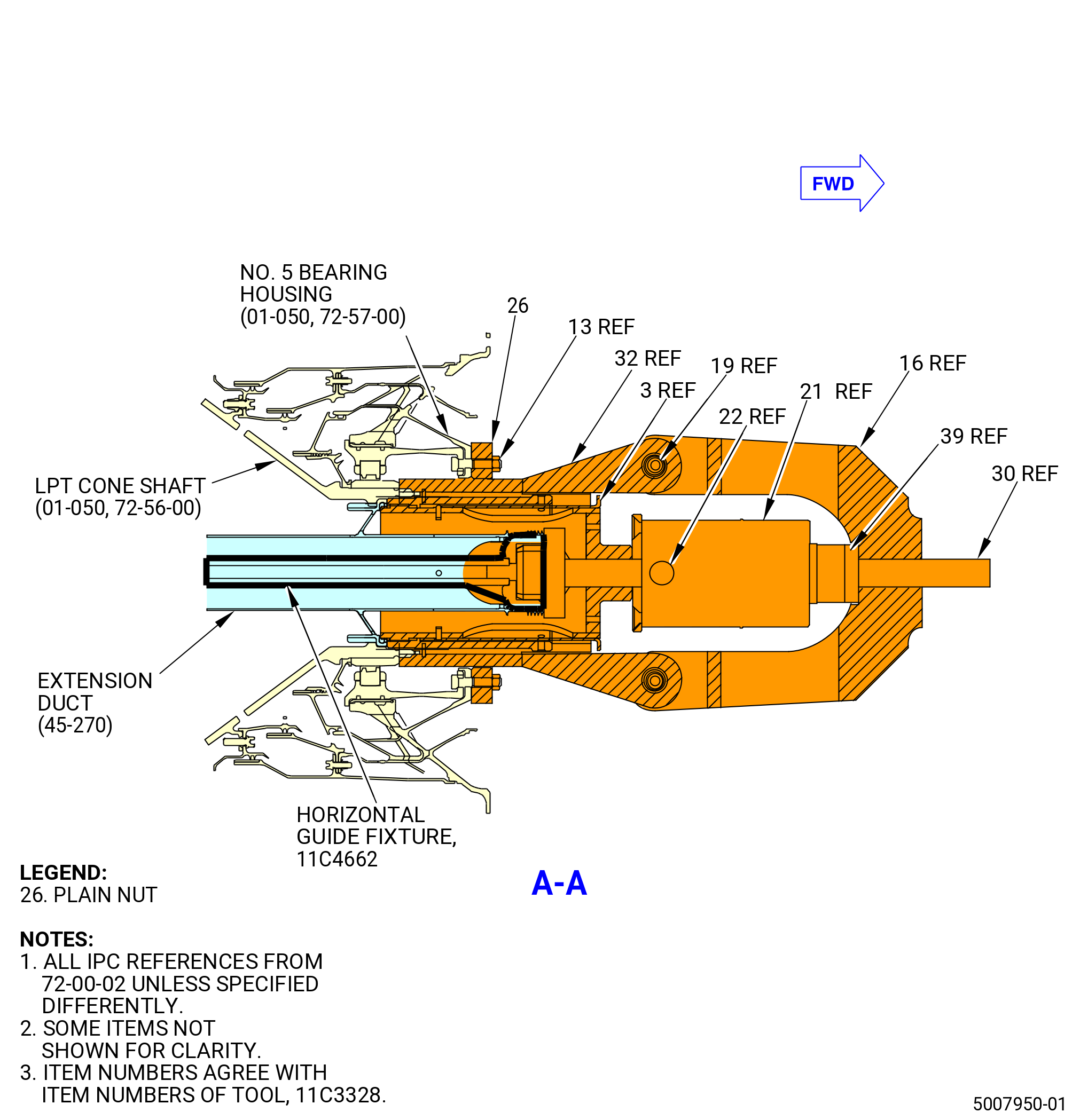
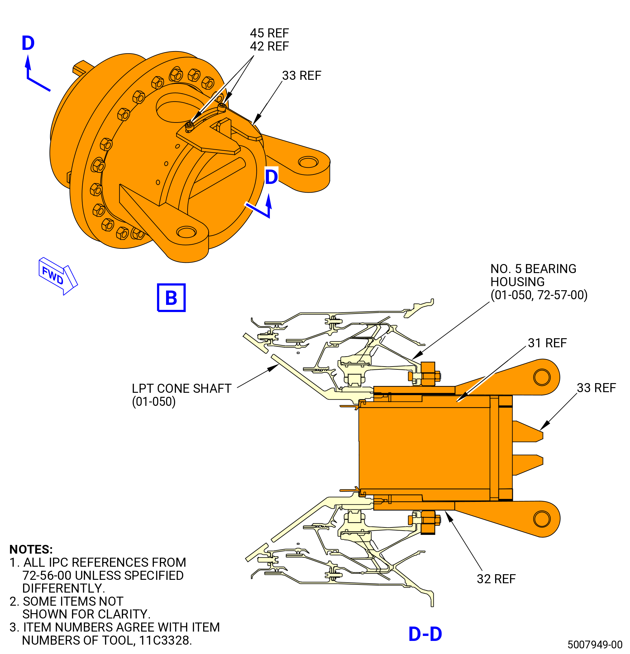
| (6) | Install the ring guide (item 13) of the 11C3328 install/remove tool on the studs of the No. 5 bearing aft flange. Attach with the plain nuts (item 26). Refer to Figure 1032. |
| (7) | Align the top vertical mark on the 11C3328 install/remove tool with the top vertical reference from the engine. |
| (8) | Install the housing (item 32) of the 11C3328 install/remove tool into the ring guide (item 13) and onto the LPT cone shaft (01-050 , 72-56-00) (SIN 930D1). Turn the housing CW ALF to engage the aft threads of the cone shaft. |
| (9) | Center one of the white scribe lines with one of the cutouts on the LPT cone shaft (01-050 , 72-56-00) (SIN 930D1). |
| WARNING: |
|
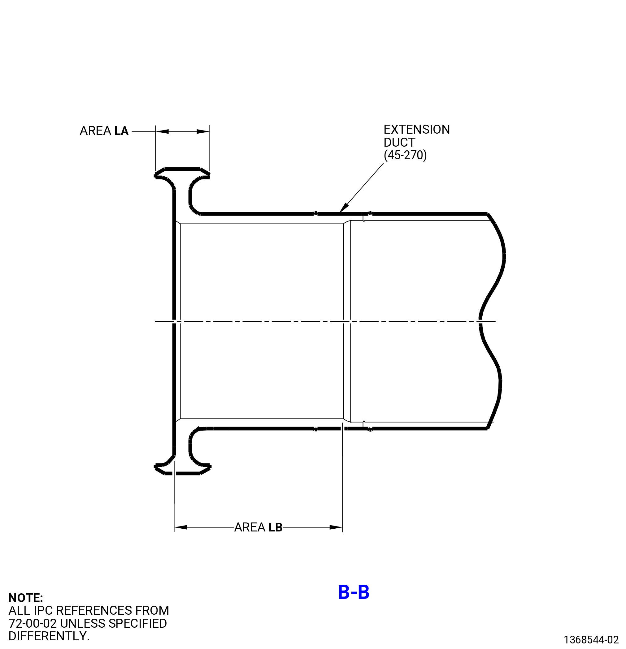
| (10) | Lubricate areas LA, LB, and LC of the extension duct with a light coat of C02-019 engine oil or C02-023 engine oil. |
| Subtask 72-00-04-430-164 |
| R. | Install the extension duct (45-270 , 72-00-02) (SIN 810A8) into the LPT cone shaft (01-050 , 72-56-00) (SIN 930D1) as follows: |
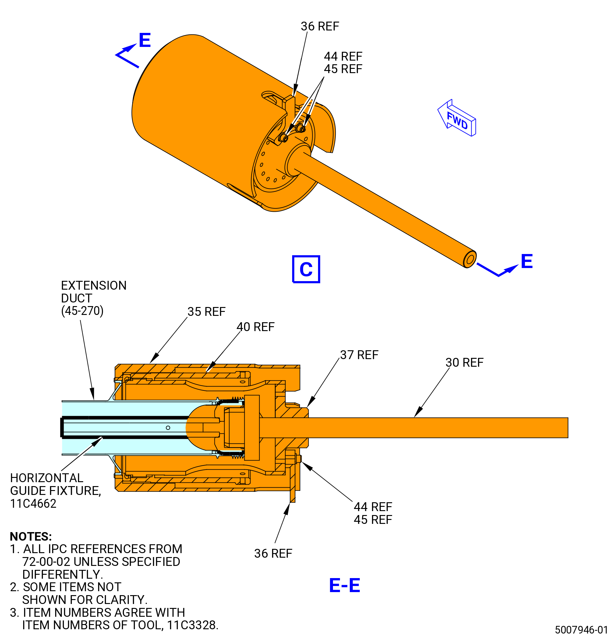
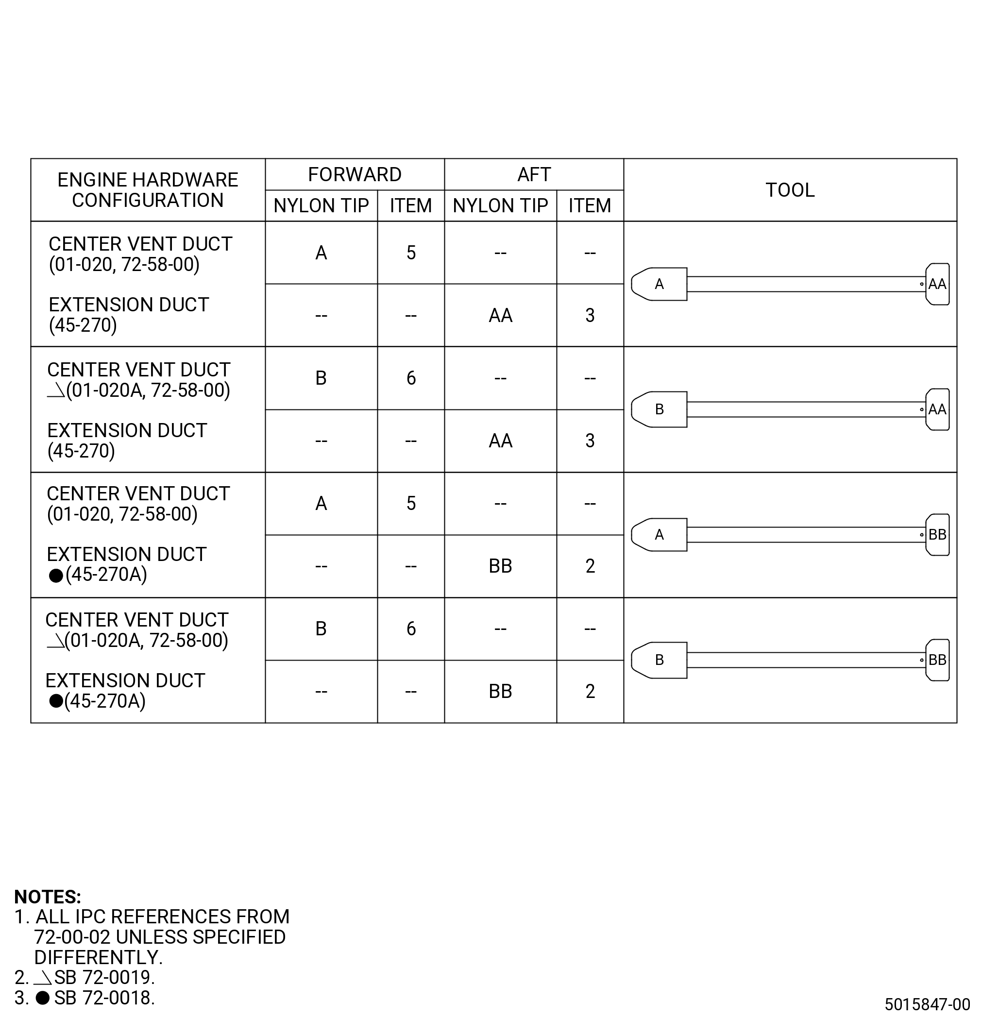
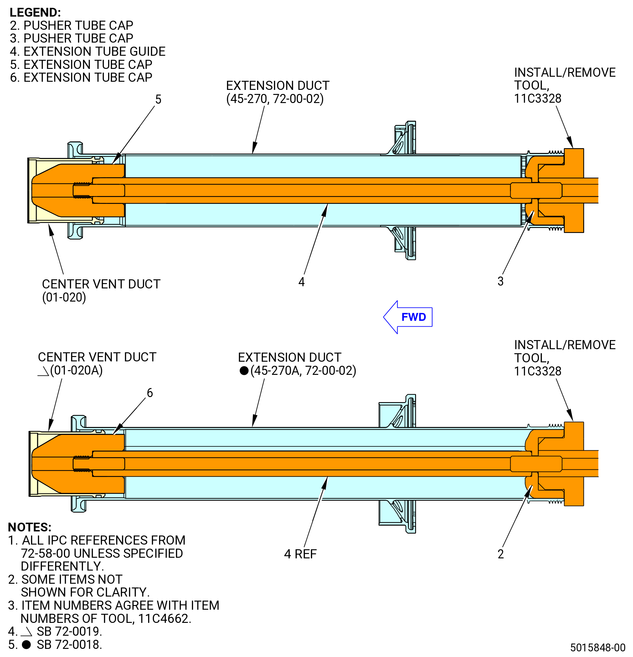
| (1) | Assemble the 11C4662 horizontal guide fixture attaching the corresponding forward and aft caps as applicable for the configuration of the extension duct and FMS CVT tube installed. Refer to Figure 1032, Figure 1033, and Figure 1034. |
| (2) | Assemble the 11C3328 install/remove tool. Refer to Figure 1032 and do as follows: |
| (a) | Install the indicator tube (item 31) and engage the forward leg of the item with one of the three slots of the LPT cone shaft (01-050 , 72-56-00) (SIN 930D1). If the aft leg of the indicator tube (item 31) interferes with the housing (item 32), remove it and use another cone shaft slot. |
| NOTE: |
|
| (b) | Attach the guide plate (item 33) to the housing (item 32) with cap screws (item 42) and flat washers (item 45). |
| (c) | Remove the indicator tube (item 31). |
| (d) | Insert the pusher tube (item 30) into the aft end of the extension duct and screw it onto the pusher tube cap (item 2) or pusher tube cap (item 3) of the 11C4662 horizontal guide fixture depending on the cap configuration needed. |
| (e) | Lift the outer clamp tube (item 40) of the 11C3328 install/remove tool, locking outer tube (item 3), and pusher/puller tube (item 37) and move them forward of the pusher tube (item 30). Put the tabs at the forward end of the pusher/puller tube (item 37) through the internal slots in the aft end of the extension duct. |
| (f) | Turn the pusher/puller tube (item 37) one-half tooth spacing and move the locking outer tube (item 3) forward. This will engage the two tabs on the forward end of the locking outer tube (item 3) between the corresponding slots in the extension duct. |
| (g) | Tighten the outer clamp tube (item 40) CW against the aft face of extension duct outer rail. |
| (h) | Align the tab position to mark the tab position cover (item 35) with tabs of the extension tube. |
| (i) | Insert the guide cam (item 36) into the slot in the aft end of the tab position cover (item 35). Attach the guide cam (item 36) to the pusher/puller tube (item 37) with the cap screws (item 44) and flat washers (item 45). |
| (j) | Remove the tab position cover (item 35). |
| (k) | Install the extension duct into the bore of the LPT cone shaft (01-050 , 72-56-00) (SIN 930D1). Align the guide cam (item 36) with the guide plate (item 33). Refer to Figure 1032. |
| (l) | Attach the hydraulic coupler assembly (item 22) to the hydraulic cylinder (item 21). |
| (m) | Install the hydraulic cylinder (item 21) on the pusher tube (item 30) with the piston facing aft. |
| (n) | Install the spacer (item 39) behind the hydraulic cylinder (item 21). |
| (o) | Install the cylinder support (item 16) on the housing (item 32) with two ball-lock pins (item 19). |
| (p) | Attach the hydraulic hand pump to the hydraulic coupler assembly (item 22) on the hydraulic cylinder (item 21). Fully close the piston. |
| WARNING: |
|
| CAUTION: |
|
| (q) | Apply pump pressure until the extension duct is fully seated. |
| (r) | Release the pressure from the hydraulic cylinder (item 21) until the piston is fully retracted. |
| (s) | Disconnect the hydraulic hand pump from the hydraulic cylinder (item 21). |
| (t) | Remove the ball-lock pins (item 19) at two locations and remove the cylinder support (item 16). |
| (u) | Remove the hydraulic cylinder (item 21). |
| (v) | Remove the guide plate (item 33). |
| (w) | Remove the guide cam (item 36). |
| (x) | Loosen the outer clamp tube (item 40). |
| (y) | Pull the outer locking tube (item 3) and turn the pusher/puller tube (item 37) one-half tooth spacing until it moves out. |
| (z) | Turn the housing (item 32) CCW and remove it. |
| (aa) | Remove the plain nuts (item 26) at 20 locations and the guide ring (item 13) from the studs on the No. 5 bearing housing (01-050 , 72-57-00) (SIN 01501) aft flange. |
| (ab) | Remove the C10-021 tape from the aft end of the extension duct. |
| (ac) | Disconnect and remove the 11C4662 horizontal guide fixture from the 11C3328 install/remove tool. |
| (ad) | Make sure to do a visual inspection of the center vent tube for telescoping, buckling, and/or other anomalies after installation of the extension duct. If there are discrepancies, contact Product Support Engineering for more details. |
| Subtask 72-00-04-220-034 |
| S. | Do a seating check of the extension duct (45-270 , 72-00-02) (SIN 810A8). Refer to Figure 1035 and do as follows: |
| (1) | Measure the distance from the aft end of the castellations of the LPT cone shaft to the aft face of the aft outer rail of the extension duct. |
| (2) | Measure dimension S at four equally-spaced locations. Record the minimum and maximum dimensions. |
| (3) | Calculate dimension S as follows: |
|
| (4) | Compare the calculated dimension S with the measured dimension S. The difference between the calculated and measured dimensions must be less than 0.002 inch (0.05 mm). |