| GENX-1B ENGINE MANUAL | Dated: 02/24/2025 | |
| EM 72-24-00 , ASSEMBLY 001 | ||
| NO. 2 BALL BEARING ASSEMBLY - ASSEMBLY 001 | ||
| GENX-1B ENGINE MANUAL | Dated: 02/24/2025 | |
| EM 72-24-00 , ASSEMBLY 001 | ||
| NO. 2 BALL BEARING ASSEMBLY - ASSEMBLY 001 | ||
| * * * FOR ALL |
| TASK 72-24-00-440-801 |
| 1 . | General. |
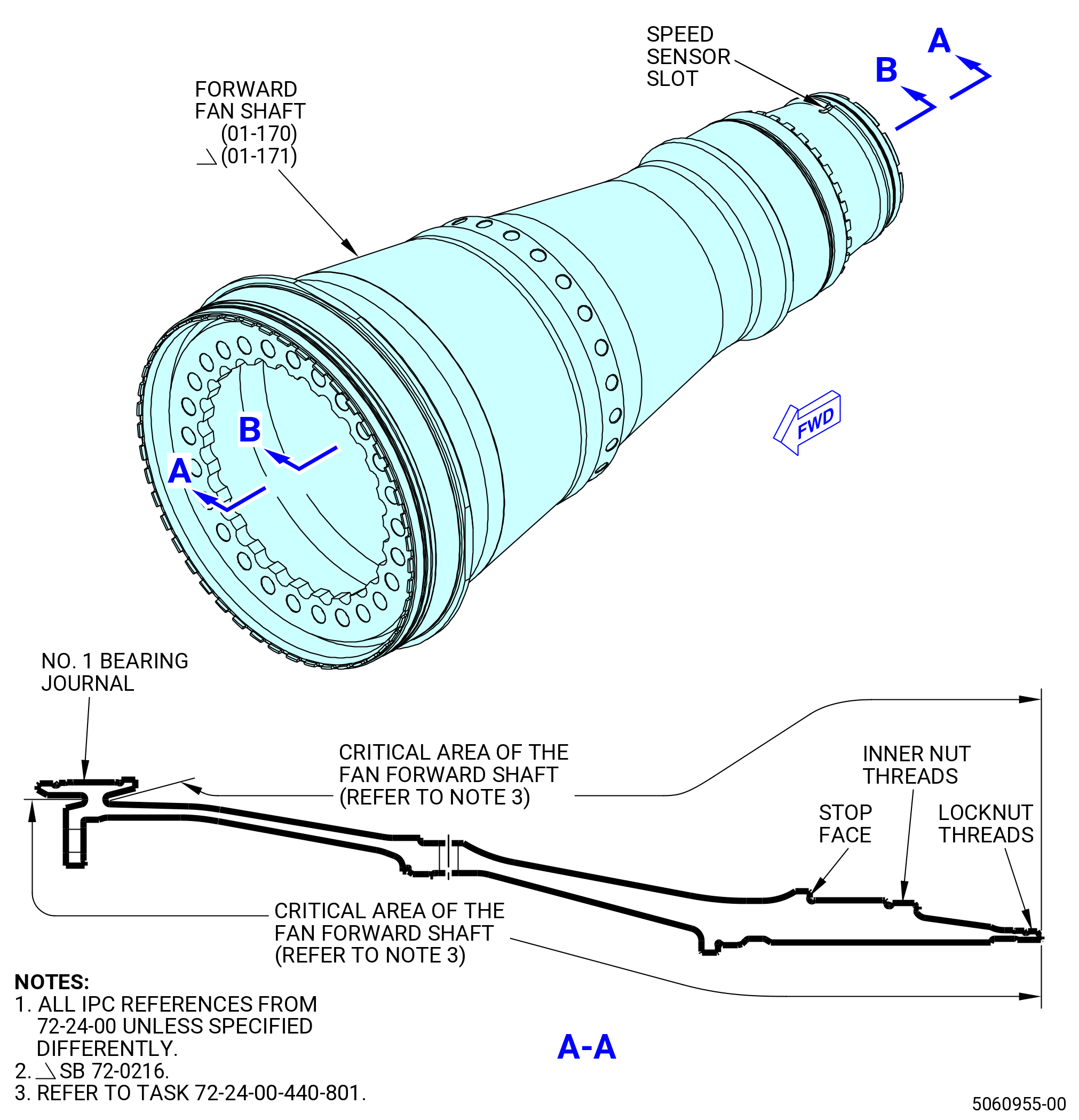
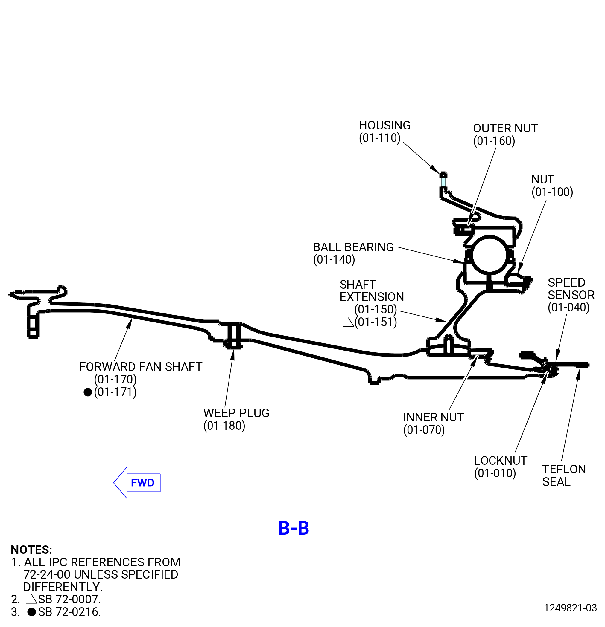
| A. | This procedure gives instructions to assemble the No. 2 ball bearing assembly (20-030 , 72-00-02) (SIN 01200). Refer to Figure 1001. |
| B. | All clock positions are aft looking forward (ALF), unless specified differently. |
| C. | Install protective covers on parts and assemblies when you do not work on them. |
| D. | Make sure that the surfaces of mating flanges and tools are clean and free of foreign material. Clean as follows: |
| WARNING: |
|
| WARNING: |
|
| WARNING: |
|
| (1) | Use C04-035 isopropyl alcohol, C04-002 Stoddard solvent, or a 50-50 blend of C04-035 isopropyl alcohol and C04-036 toluene to clean the surfaces of mating flanges and to clean the tools. Refer to TASK 70-21-23-110-053 (CLEANING METHOD NO. 23 - HAND-WIPE DEGREASING) . |
| E. | Make sure that you install new preformed packings. You cannot use old preformed packings again. |
| F. | Do not chill close fitting parts for ease of assembly. Heat parts that are difficult to assemble. Do not heat parts to more than 350°F (176.7°C), unless specified differently. If you heat parts during assembly, you must apply preservative oil again when the parts go back to ambient temperature. |
| G. | Bearings. |
| (1) | Be careful with the components of the No. 2 ball bearing assembly (20-030 , 72-00-02) (SIN 01200). Refer to TASK 70-14-00-620-003 (HANDLING OF BEARINGS) and TASK 70-60-01-620-002 (PRESERVATION OF ANTIFRICTION BEARINGS) . |
| (2) | Keep the ball bearing components (balls, cages, inner races, and outer races) as a set by serial number. The ball bearing is a matched assembly. Do not mix serviceable ball bearing components with the components of different serial numbers. |
| (3) | Do not touch the ball bearing components with bare hands. Wear Latex C10-140 gloves when you touch ball bearing components. |
| (4) | Do not touch the cage or balls of the No. 2 ball bearing assembly (20-030 , 72-00-02) (SIN 01200) with assembly/installation tools. |
| H. | This assembly contains critical areas of the shaft, that require caution and visual inspection during the assembly process, that are identified throughout this procedure. Refer to Figure 1001. |
| 2 . | Tools, Equipment, and Materials. |
| NOTE: |
|
| A. | Tools and Equipment. |
| (1) | Special Tools. |
| (2) | Standard Tools and Equipment. |
|
| (3) | Locally Manufactured Tools. None. |
| B. | Consumable Materials. |
|
| C. | Referenced Procedures. |
|
| D. | Expendable Parts. None. |
| 3 . | Procedure. |
| Subtask 72-24-00-440-123 |
| WARNING: |
|
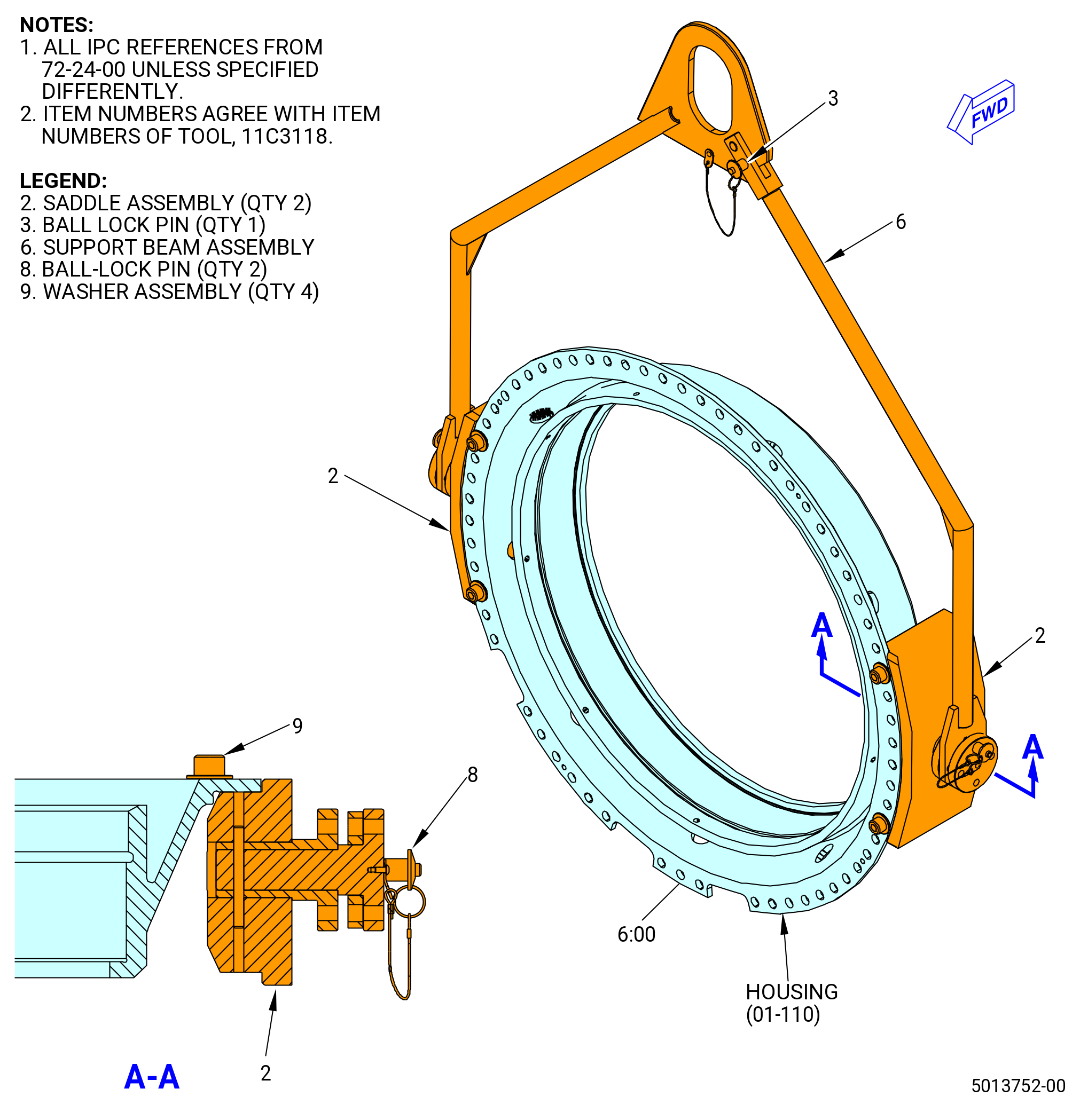
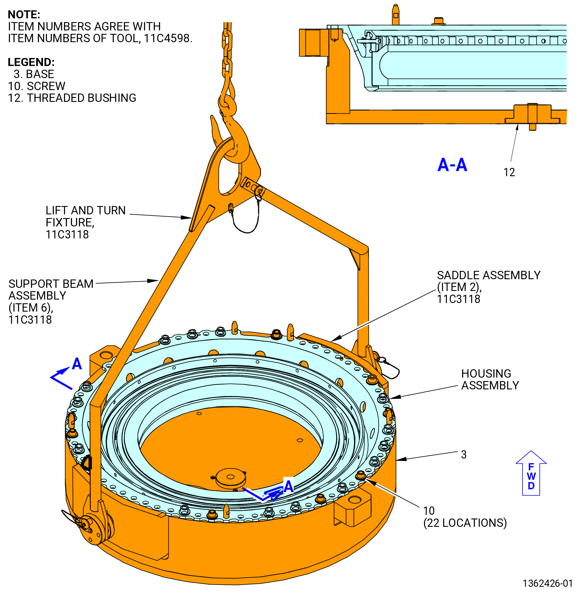
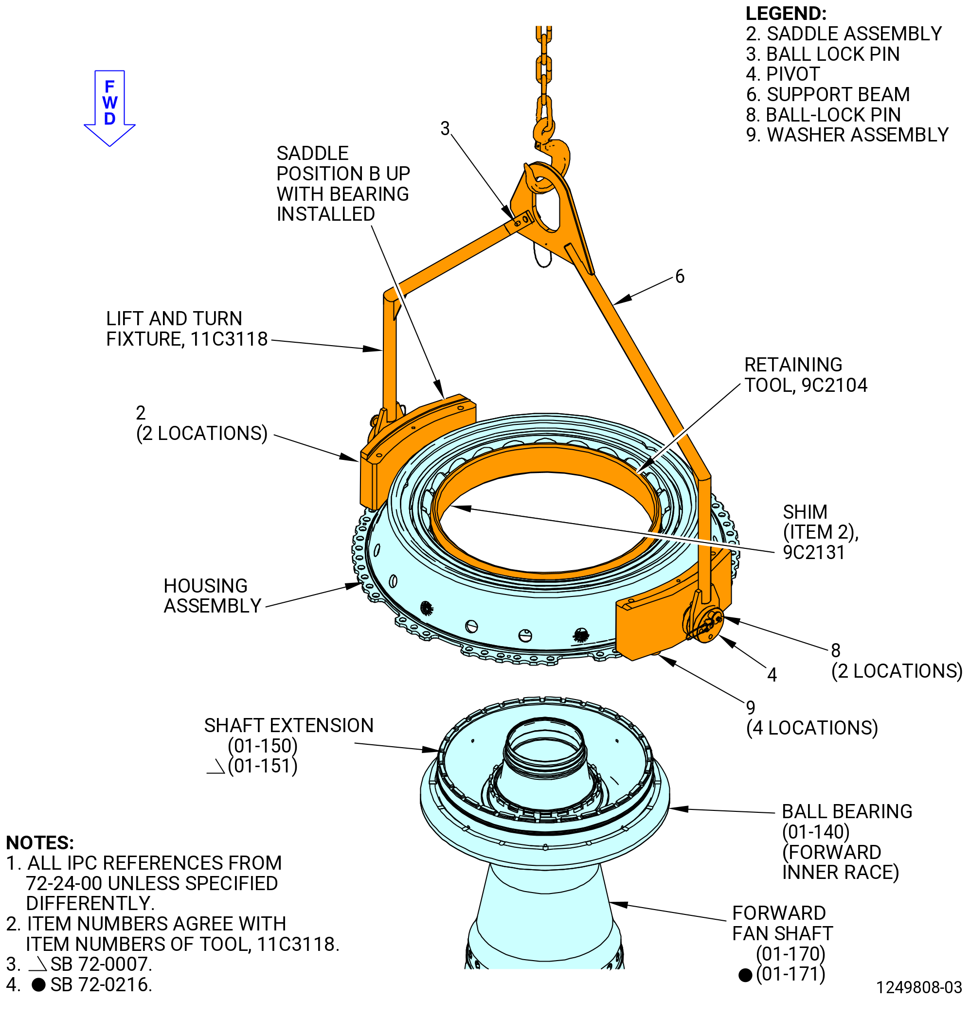
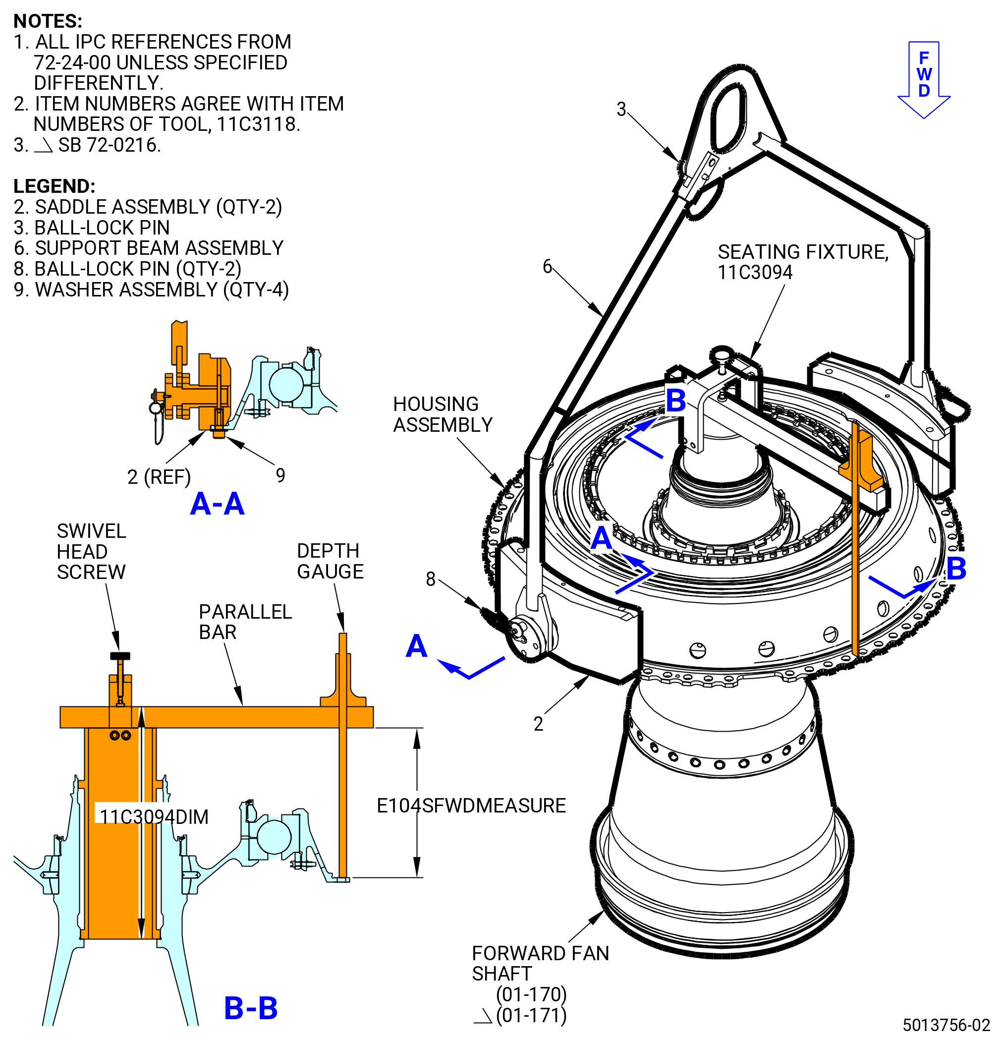
| A. | Lift the No. 2 bearing support housing (housing) (01-110) (SIN 01203) with the 11C3118 lift and turn fixture. Refer to Figure 1002, Figure 1003, and do as follows: |
| NOTE: |
|
| Subtask 72-24-00-440-124 |
| WARNING: |
|
| (1) | Use an overhead hoist to lift the 11C3118 lift and turn fixture. |
| (2) | Lower the 11C3118 lift and turn fixture into the correct position as follows: |
| (a) | Turn the saddle assemblies (item 2) to the correct position to handle the engine hardware. |
| NOTE: |
|
| (b) | Align the saddle assemblies (item 2) at the 3:00 and 9:00 o'clock positions of the housing flange. |
| NOTE: |
|
| (c) | Remove the ball lock pin (item 3) to unlock the support beam assembly (item 6). |
| (d) | Move the leg of the support beam assembly (item 6) out and lower the saddle assemblies (item 2) into position at the 3:00 and 9:00 o'clock positions on the housing flange OD. |
| (3) | Align the 11C3118 lift and turn fixture on the housing flange as follows: |
| (a) | Move the leg of the support beam assembly (item 6) in until the boltholes of the saddle assemblies (item 2) align with the boltholes of the housing flange at the 3:00 and 9:00 o'clock positions. |
| (b) | Attach each saddle assembly (item 2) to the housing flange with two washer assemblies (item 9). Install the first washer assembly in the 3:00 o'clock saddle assembly at bolthole No. 10 clockwise (CW) from the 6:00 o'clock position (FLA). Install the first washer assembly in the 9:00 o'clock saddle assembly at bolthole No. 12 counterclockwise (CCW) from the 6:00 o'clock position (FLA). |
| (c) | Install the ball lock pin (item 3) to lock the support beam (item 6) in position. |
| (d) | Make sure that the ball lock pins (item 8) are installed. |
| Subtask 72-24-00-440-008 |
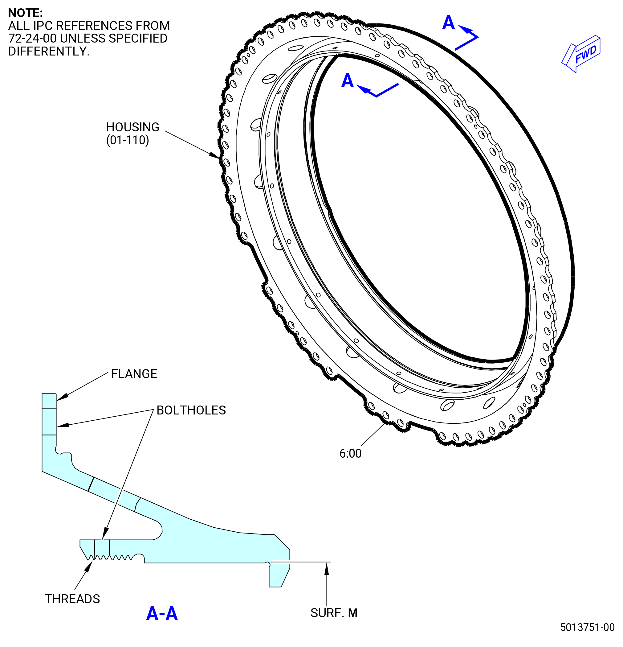
| B. | Install the housing (01-110) (SIN 01203) on the 11C4598 housing stand as follows: |
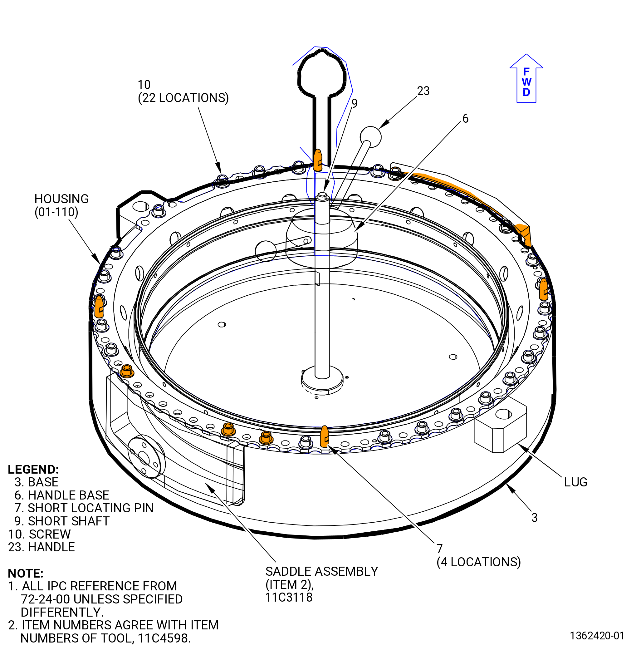
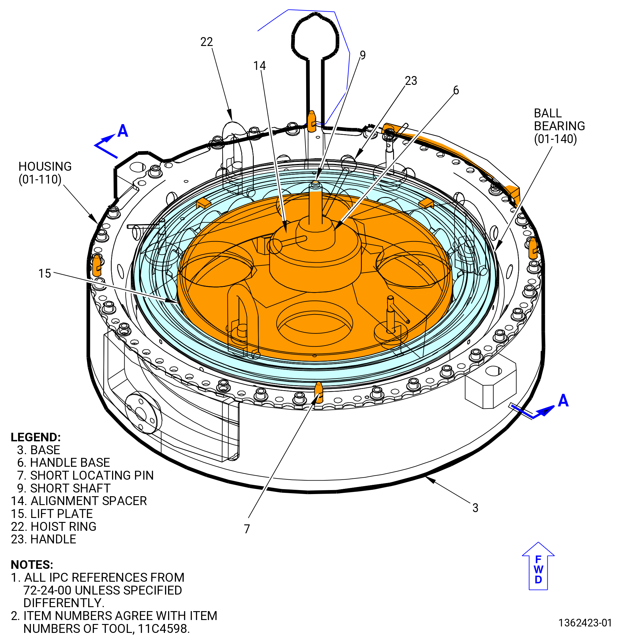
| (1) | If necessary, remove the handle base (item 6 and 23). Refer to Figure 1004. |
| (2) | Find the top vertical centerline of the housing. |
| NOTE: |
|
| Subtask 72-24-00-440-145 |
| WARNING: |
|
| (3) | Put the housing on the 11C4598 housing stand in the correct position as follows: |
| (a) | Remove the handle base (item 6 and 23) from the shaft of the housing stand. |
| (b) | If necessary, install the short shaft (item 9) in the base (item 3). |
| (c) | Align the bolthole at the top vertical centerline of the housing with the lug marked TOP VERT. |
| (d) | Make sure that the saddle assemblies (item 2) of the 11C3118 lift and turn fixture are aligned in the recesses of the base (item 3) of the 11C4598 housing stand. |
| (e) | Lower the housing to the base (item 3) and on the four short locating pins (item 7). |
| (f) | Make sure that the boltholes of the housing align with the boltholes of the base (item 3). |
| Subtask 72-24-00-440-146 |
| (4) | Remove the 11C3118 lift and turn fixture as follows. Refer to Figure 1003. |
| (a) | Remove the washer assemblies (item 9) that attach the saddle assemblies (item 2) to the housing. |
| (b) | Remove the ball lock pin (item 3) to unlock the support beam assembly (item 6). |
| (c) | Move the leg of the support beam assembly (item 6) out until you can remove the 11C3118 lift and turn fixture. |
| WARNING: |
|
| (d) | Lift the 11C3118 lift and turn fixture out of the way. |
| Subtask 72-24-00-440-147 |
| (5) | Attach the housing to the 11C4598 housing stand as follows. Refer to Figure 1004. |
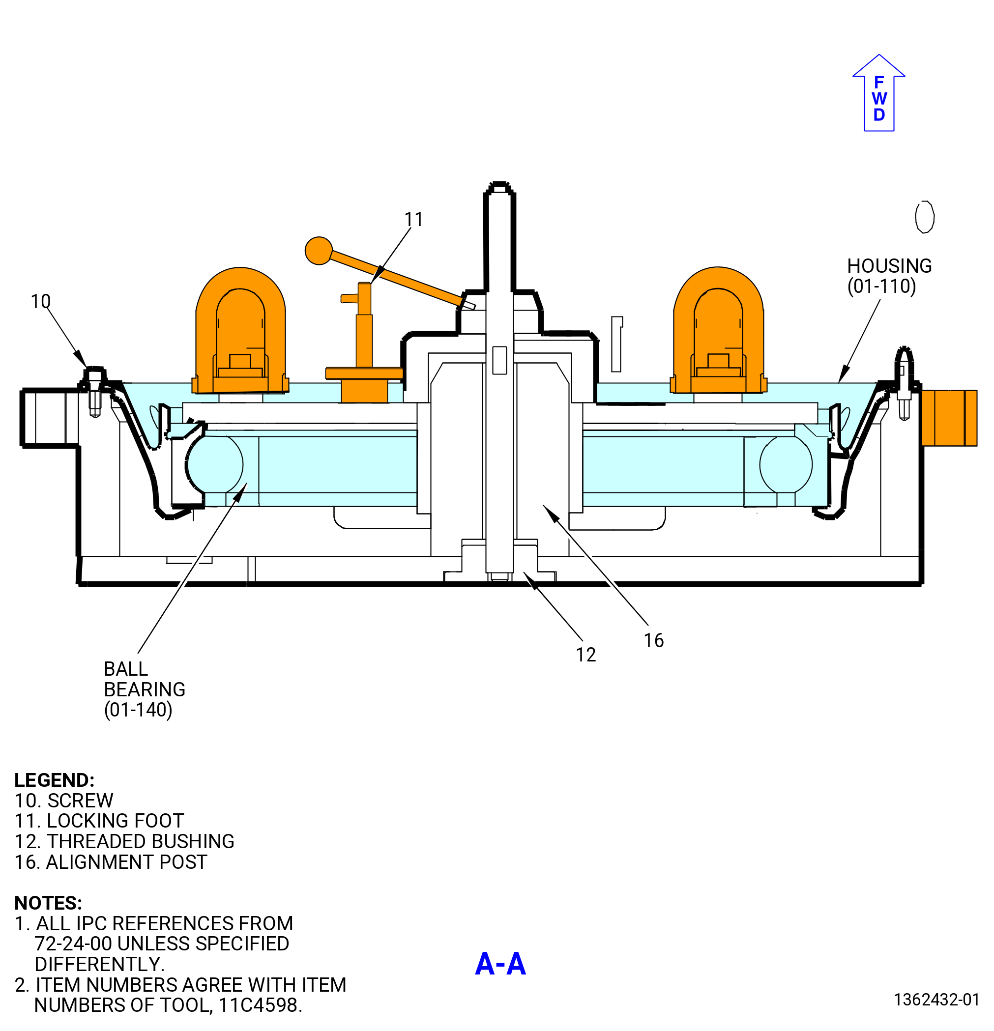
| (a) | Install the 22 screws (item 10) equally spaced in the boltholes of the flange to attach the housing to the base (item 3). |
| Subtask 72-24-00-440-012 |
| CAUTION: |
|
| CAUTION: |
|
| CAUTION: |
|
| CAUTION: |
|
| C. | Assemble the No. 2 thrust ball bearing (ball bearing) (01-140) (SIN 012A0) in the housing (01-110) (SIN 01203) as follows: |
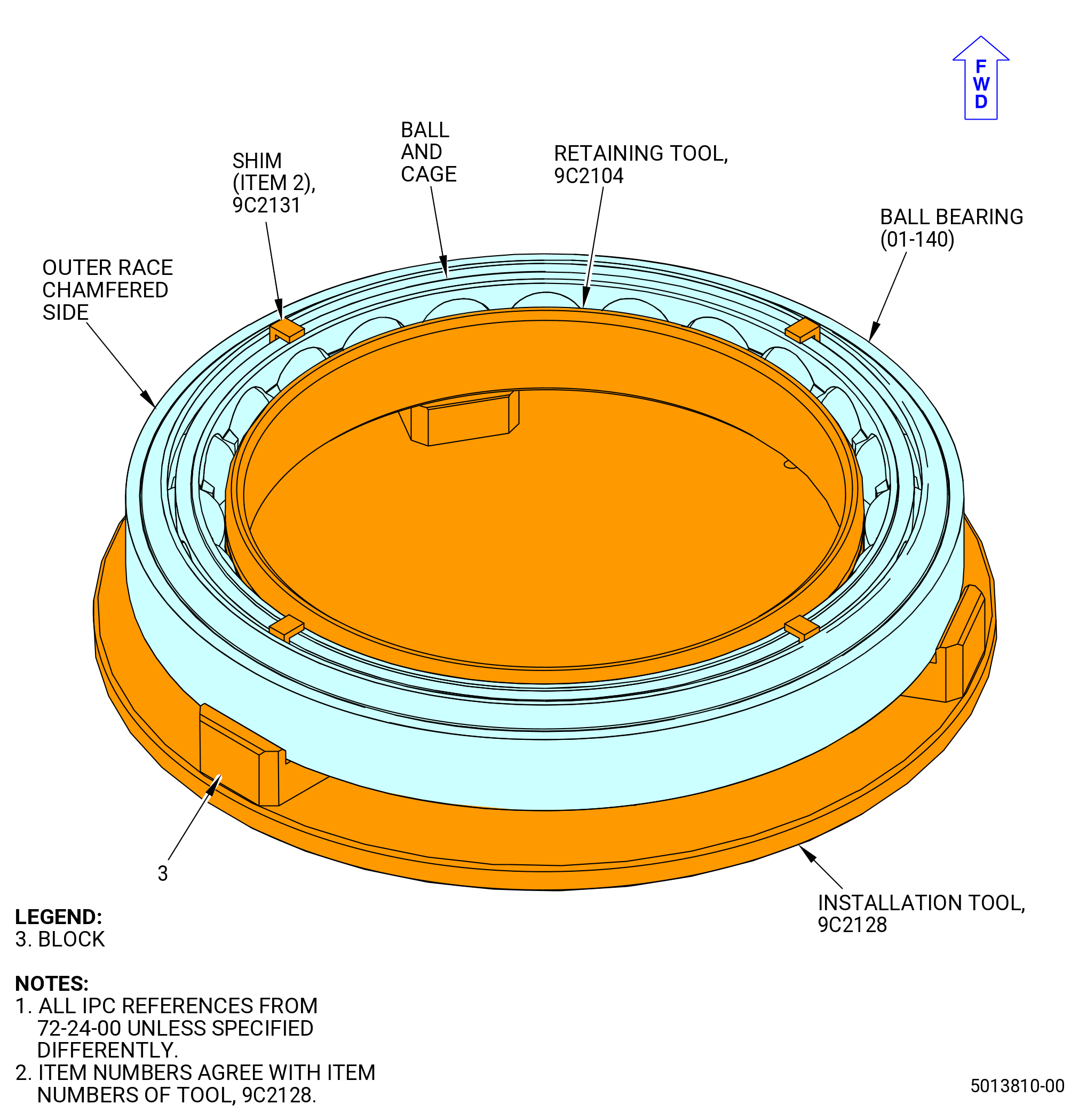
| (1) | Make sure the outer race has the chamfered side in the up position and put the outer race on the blocks (item 3) of the 9C2128 installation tool. Refer to Figure 1005. |
| Subtask 72-24-00-160-011 |
| WARNING: |
|
| (2) | After installing the outer race into the housing and before installing the cage and balls, do a last chance wipe of the outer race surfaces using new C10-182 wipers with clean C02-019 engine oil. |
| Subtask 72-24-00-440-159 |
| (3) | Install the ball bearing and cage into the outer race on the 9C2128 installation tool. |
| (4) | Remove the forward inner race and the aft inner race from the ball bearing. Refer to Figure 1006. |
| Subtask 72-24-00-440-014 |
| (5) | Install the 9C2104 retaining tool and the four shims (item 2) of the 9C2131 shim set to hold the balls and the cage in the correct position. Make sure that the shims (item 2) are at four equally spaced locations. Refer to Figure 1005. |
| NOTE: |
|
| Subtask 72-24-00-440-015 |
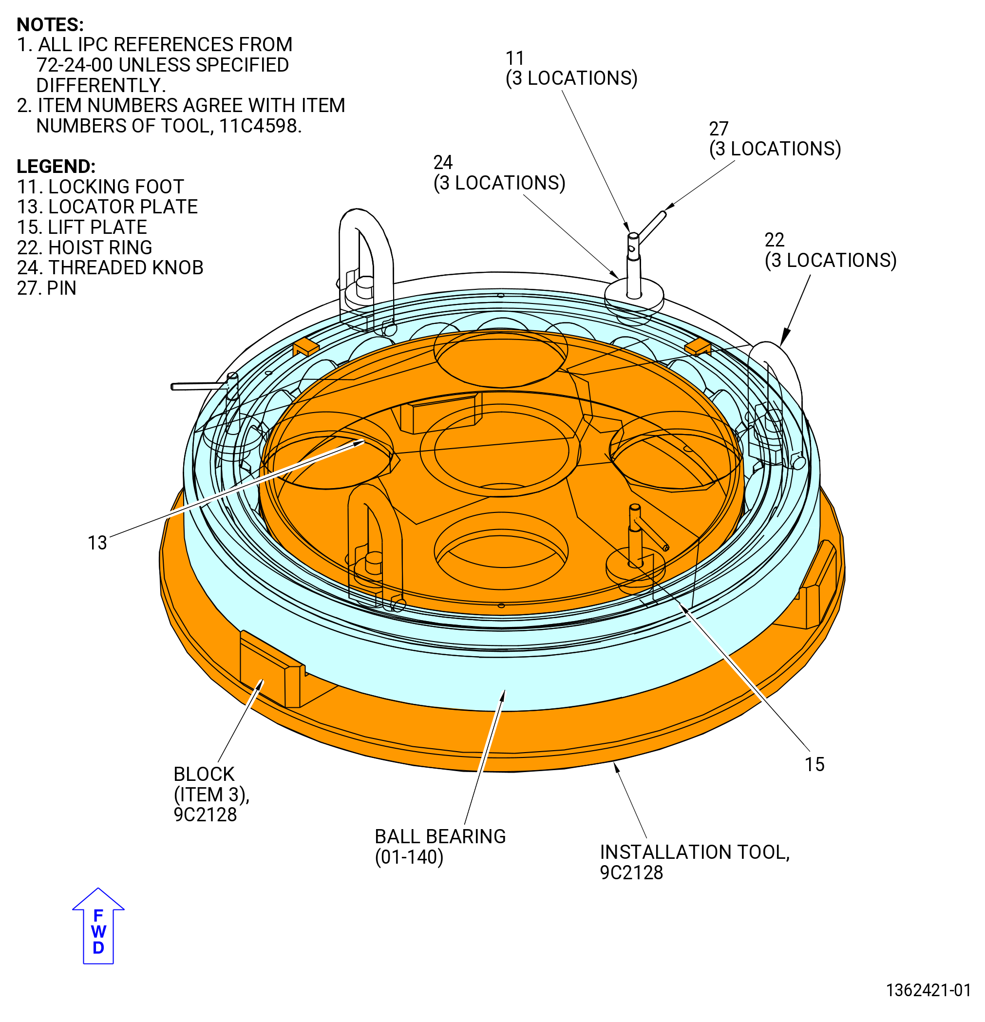
| (6) | Install the 11C4598 subassembly housing stand (items 11, 13, 15, 22, 24, 26, and 27) as follows. Refer to Figure 1007. |
| (a) | Attach three slings with a minimum capacity of 650 lb (295 kg) to the three hoist rings (item 22) of the 11C4598 subassembly housing stand (items 11, 13, 15, 22, 24, 26, and 27). |
| (b) | Put the 11C4598 subassembly housing stand (items 11, 13, 15, 22, 24, 26, and 27) above the No. 2 ball bearing outer race. |
| (c) | Turn the threaded knob (item 24) CCW until the protruding length of the looking foot (item 11) is sufficient to install the No. 2 ball bearing outer race. |
| (d) | Put the three pins (item 27) pointed to the “open” position marked on the lift plate (item 15). |
| NOTE: |
|
| (e) | Lower the 11C4598 subassembly housing stand (items 11, 13, 15, 22, 24, 26, and 27) into the No. 2 ball bearing outer race. |
| (f) | Make sure that the blocks (item 3) of the 9C2128 installation tool do not stop the movement of the locking foot (item 11). |
| (g) | Put the three pins (item 27) in the “close” position and turn the threaded knob (item 24) CW by hand to secure the No. 2 ball bearing outer race. |
| (h) | Make sure that the 9C2104 retaining tool is installed to hold the balls of the ball bearing in position. |
| WARNING: |
|
| (i) | Lift the ball bearing from the 9C2128 installation tool with the 11C4598 subassembly housing stand (items 11, 13, 15, 22, 24, 26, and 27). |
| Subtask 72-24-00-220-042 |
| (7) | Do a visual inspection of surface M on the housing to make sure that there is no raised metal. If there is raised metal on surface M, stop here and speak to your GEAE representative. Refer to Figure 1002. |
| Subtask 72-24-00-160-010 |
| WARNING: |
|
| WARNING: |
|
| (8) | Use C04-035 isopropyl alcohol or equivalent to clean surface M. Refer to TASK 72-24-00-440-801 (paragraph 1.D.(1)). |
| Subtask 72-24-00-370-001 |
| CAUTION: |
|
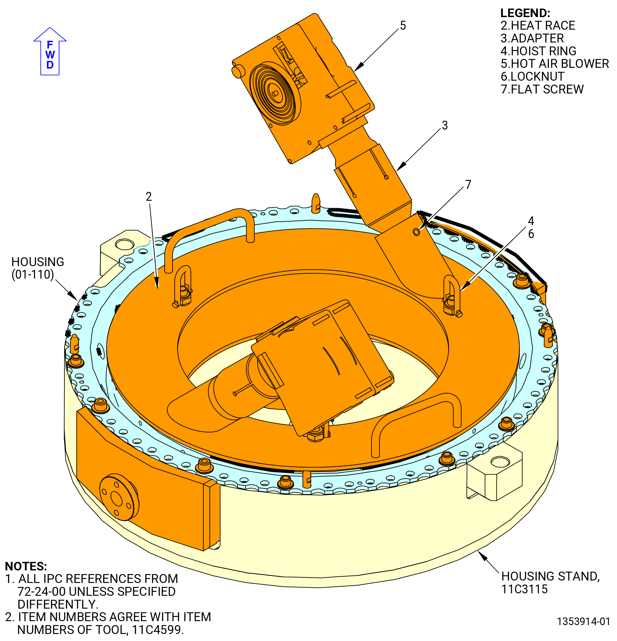
| (9) | Install the 11C4599 heat gun fixture into the housing (01-110) (SIN 01203). Refer to Figure 1008 and do as follows: |
| (a) | Install the heat race (item 2) into the housing. |
| (b) | Install the adapters (item 3) to the inclined sleeves welded to the heat race (item 2). |
| (c) | Attach the adapters (item 3) with the flat screws (item 7). |
| (d) | Install the hot air blowers (item 5) into the adapters (item 3). |
| (e) | Connect the two hot air blowers (item 5) to two separate 230 VAC single phase outputs. |
| WARNING: |
|
| CAUTION: |
|
| (f) | Set the hot air blowers (item 5) target temperature to 350 °F (176.7 °C). |
| (g) | Turn the hot air blowers (item 5) switch on. |
| (h) | Measure the temperature in the housing surface near the hot air blowers (item 5) at intervals with temperature indicators or devices from different suppliers, until getting the target temperature of 350 °F (176.7°C). |
| NOTE: |
|
| (i) | After getting the 350 °F (176.7°C) target temperature, turn the hot air blowers (item 5) switch off. |
| WARNING: |
|
| WARNING: |
|
| CAUTION: |
|
| (j) | Rotate heat race (item 2) as follows: |
| 1 | Hold the heat race (item 2) with the heat race welded handles. |
| 2 | Rotate the heat race (item 2) 90 degrees. |
| NOTE: |
|
| (k) | Turn the hot air blowers (item 5) switch on for 5 minutes and measure the temperature of the housing surface again. |
| (l) | Turn the hot air blowers (item 5) switch off. |
| WARNING: |
|
| (m) | Disconnect the hot air blowers (item 5) from the two separate 230 VAC single phase outputs. |
| WARNING: |
|
| (10) | Remove the 11C4599 heat gun fixture from the housing (01-110) (SIN 01203) as follows: |
| (a) | Connect the hoist rings (item 4) to an overhead hoist. Use straps as an alternative to slings to lift hot parts. |
| (b) | Lift the 11C4599 heat gun fixture from the housing. |
| (c) | Put the 11C4599 heat gun fixture in a restricted area for hot items. |
| Subtask 72-24-00-160-012 |
| WARNING: |
|
| (11) | Before the installation of the No. 2 bearing outer race into the housing, do a last chance wipe of the bearing OD and the housing ID with new C10-182 wipers and an approved solvent, such as a 50-50 blend of C04-014 denatured alcohol and C04-035 isopropyl alcohol, C04-002 Stoddard solvent, or C04-035 isopropyl alcohol. |
| Subtask 72-24-00-440-154 |
| (12) | Install the No. 2 ball bearing outer race in the 11C4598 housing stand with the 11C4598 subassembly housing stand (items 11, 13, 15, 22, 24, 26, and 27) as follows. Refer to Figure 1008. |
| NOTE: |
|
| (a) | Install the alignment post (item 16) on the base (item 3). |
| (b) | Put the No. 2 ball bearing outer race over the No. 2 bearing support housing by using the 11C4598 subassembly housing stand (items 11, 13, 15, 22, 24, 26, and 27). |
| NOTE: |
|
| (c) | Lower the No. 2 ball bearing outer race. |
| (d) | Remove the three slings and install the alignment spacer (item 14) on the short shaft (item 9). |
| (e) | Install the handle base (item 6 and 23) on the short shaft (item 9) and turn it CW until the No. 2 ball bearing outer race is installed on the No. 2 bearing support housing. |
| (f) | Turn out the handle base (item 6) from the short shaft (item 9). |
| (g) | Remove the alignment spacer (item 14). |
| (h) | Turn the threaded knob (item 24) CCW to release the No. 2 ball bearing outer race. |
| (i) | Point the three pins (item 27) to the “close” position. |
| Subtask 72-24-00-440-019 |
| CAUTION: |
|
| D. | Remove the 11C4598 subassembly housing stand (items 11, 13, 15, 22, 24, 26, and 27) as follows. Refer to Figure 1007. |
| (1) | put the three pins (item 27) pointed to the “open” position marked on the lift plate (item 15). |
| (2) | Install the three slings with a minimum capacity of 650 lb. (295 kg) on the three hoist rings (item 22). |
| WARNING: |
|
| (3) | Lift the 11C4598 subassembly housing stand (items 11, 13, 15, 22, 24, 26, and 27) from the ball bearing (01-140) (SIN 012A0). |
| Subtask 72-24-00-220-004 |
| E. | Do an inspection to check the seating of the outer race on the housing as follows: |
| (1) | Try to insert a piece of 0.001 inch (0.03 mm) shim stock between the outer race and the housing as follows: |
| (a) | Remove the bolts from the support and fixture. |
| (b) | Operate the hoist and lift the support and bearing with the 11C3118 lift and turn fixture. |
| (c) | Do the shim check from the aft side of (under) the support. |
| (2) | If there are gaps, do the steps that follow: |
| (a) | Remove the outer race with the 9C2101 installation tool. Refer to TASK 72-24-00-040-801 (72-24-00, DISASSEMBLY 001). |
| (b) | Install the outer race again. Refer to Subtask 72-24-00-440-012 (paragraph 3.C.) through Subtask 72-24-00-220-004 (paragraph 3.E.). |
| Subtask 72-24-00-440-022 |
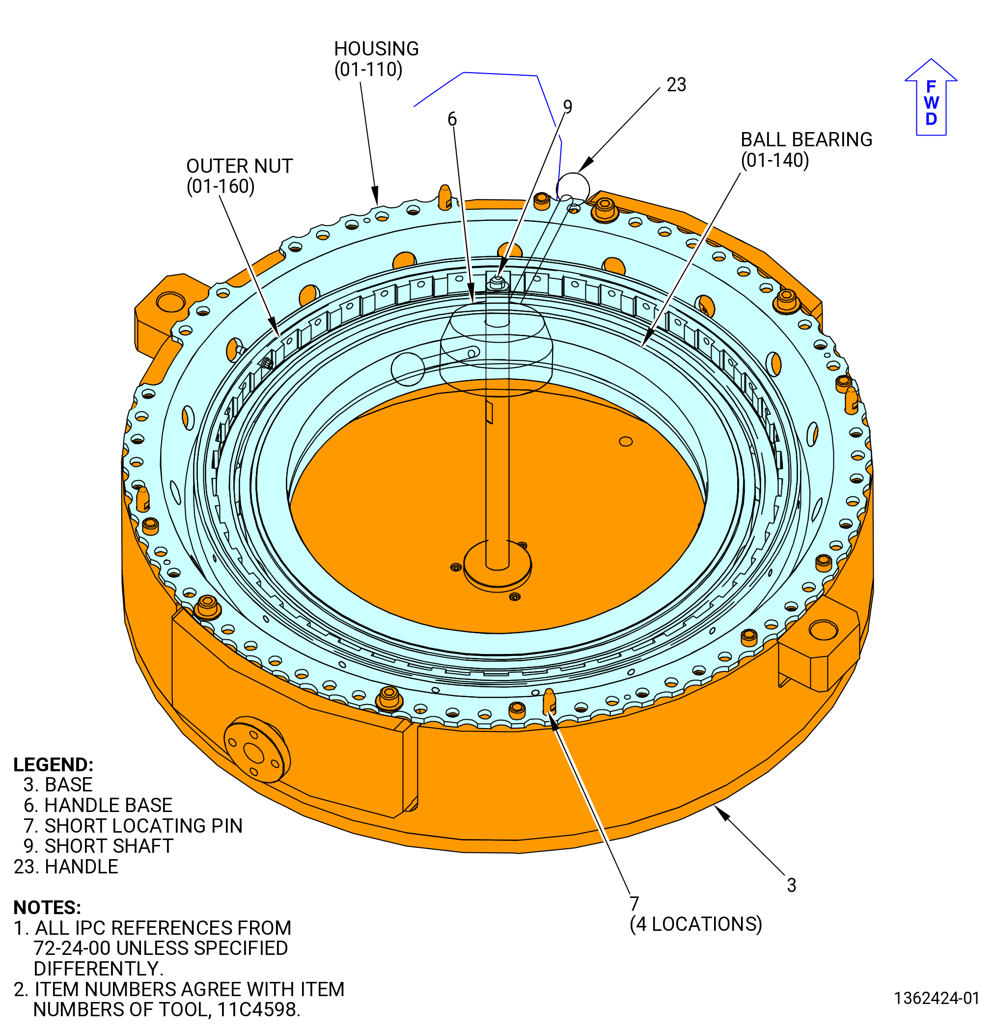
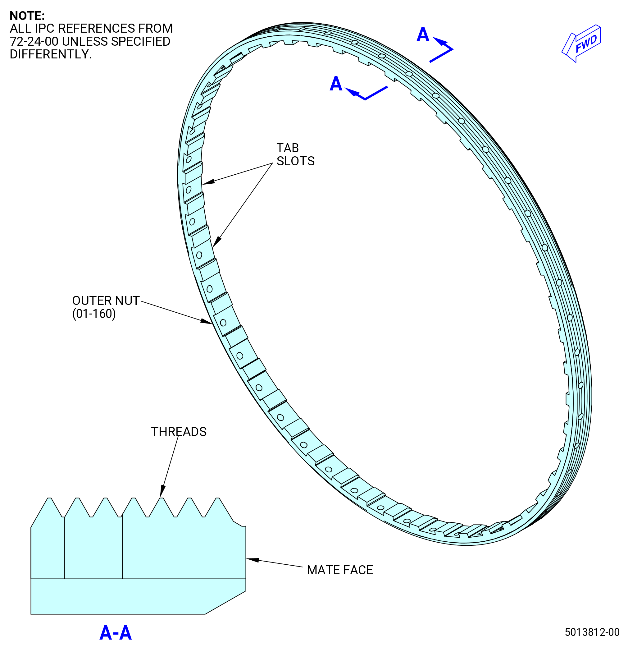
| F. | Install the outer plain round nut (outer nut) (01-160) (SIN 012K1) in the housing (01-110) (SIN 01203). Refer to Figure 1009 and do as follows: |
| (1) | Remove the short shaft (item 9) of the 11C4598 housing stand. |
| Subtask 72-24-00-160-002 |
| WARNING: |
|
| WARNING: |
|
| WARNING: |
|
| (2) | Use C04-035 isopropyl alcohol or equivalent to clean the outer nut (01-160) (SIN 012K1) and the housing (01-110) (SIN 01203). Refer to TASK 72-24-00-440-801 (paragraph 1.D.(1)) and do as follows: |
| (a) | Clean the threads and mate face of the outer nut. |
| (b) | Clean the mating threads of the housing. |
| Subtask 72-24-00-440-127 |
| WARNING: |
|
| (3) | Apply C02-019 engine oil or C02-023 engine oil to lubricate the outer nut and housing as follows. Refer to Figure 1009. |
| (a) | Lubricate the threads and mate face of the outer nut. |
| (b) | Lubricate the mating threads of the housing. |
| Subtask 72-24-00-440-132 |
| CAUTION: |
|
| (4) | Manually turn the outer nut (01-160) (SIN 012K1) CCW to install it in the housing (01-110) (SIN 01203). Make sure to turn the outer nut CCW. |
| NOTE: |
|
| NOTE: |
|
| Subtask 72-24-00-440-023 |
| (5) | Install the 11C3122 adapter as follows. Refer to Figure 1010. |
| Subtask 72-24-00-160-005 |
| WARNING: |
|
| (a) | Use C04-035 isopropyl alcohol to clean the 11C3122 adapter. |
| Subtask 72-24-00-440-133 |
| (b) | Install the splined shaft (item 5) and the ring gear (item 3) as follows: |
| WARNING: |
|
| 1 | Attach an overhead hoist to the eyebolt (item 8) on the splined shaft (item 5) to lift the ring gear (item 3). |
| 2 | Lower the ring gear (item 3) into the housing as follows: |
| a | Align the tabs on the ring gear (item 3) with the tab slots of the outer nut. Refer to Figure 1008. |
| b | Lower the ring gear (item 3) to the outer nut. Make sure that the tabs are engaged in the tab slots of the outer nut. |
| (c) | Install the base (item 15) as follows. Refer to Figure 1010. |
| WARNING: |
|
| 1 | Attach the four-piece sling to the four eyebolts (item 8) of the base (item 15) and to an overhead hoist. |
| 2 | Lift the base (item 15) and align it as follows: |
| a | Align the hole in the center of the base (item 15) with the splined shaft (item 5). |
| b | Align the legs of the base (item 15) with two lugs of the 11C4598 housing stand. |
| (d) | Install the torque multiplier as follows: |
| WARNING: |
|
| 1 | Align the splines of the torque multiplier with the splines of the splined shaft (item 5). |
| 2 | Align the legs of the torque multiplier with the two anti-torque holes on the base (item 15). |
| 3 | Install the torque multiplier on the base (item 15). |
| Subtask 72-24-00-440-024 |
| (6) | Torque the outer nut with the torque multiplier as follows: |
| (a) | Torque the outer nut to 10000 lb ft (13558 N.m). |
| (b) | Break the torque on the outer nut. |
| (c) | Torque the outer nut to 14000 lb ft (18981 N.m). |
| (7) | Remove the torque multiplier. |
| (8) | Remove the 11C3122 adapter. |
| Subtask 72-24-00-220-008 |
| (9) | Make sure that a hole on the outer nut aligns with a hole on the housing. |
| Subtask 72-24-00-440-025 |
| (10) | If necessary, torque the outer nut a sufficient amount to align the holes as follows: |
| (a) | Install the 11C3122 adapter and torque multiplier. Refer to subtask 72-24-00-440-023 (paragraph 3.F.(5)). |
| (b) | Increase the torque enough to align a hole on the outer nut with a hole on the housing. Do not torque more than a maximum torque of 15500 lb ft (21015 N.m). |
| NOTE: |
|
| (c) | Remove the torque multiplier . |
| (d) | Remove the 11C3122 adapter . |
| Subtask 72-24-00-440-026 |
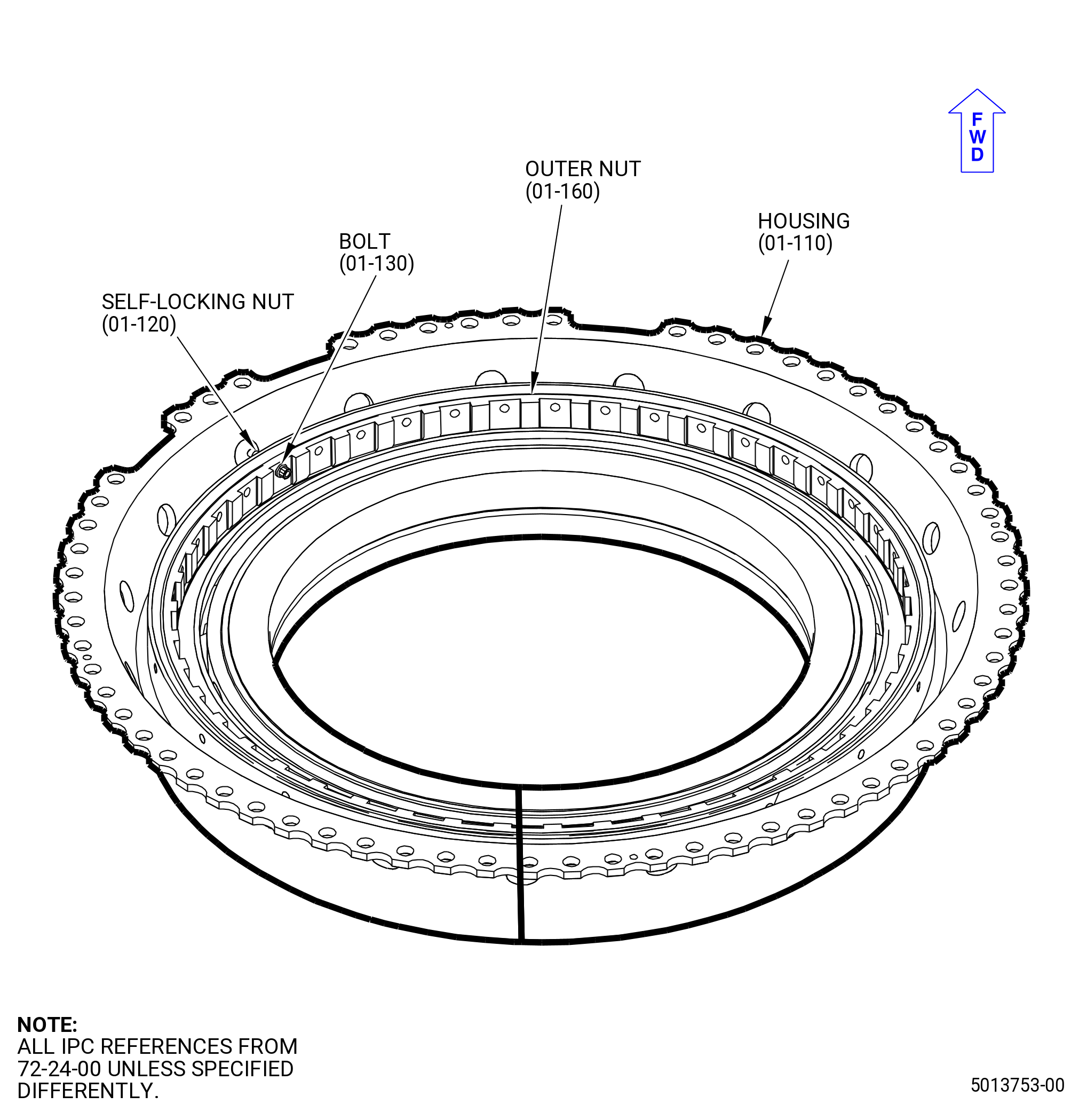
| (11) | Install the bolt (01-130) (SIN 012F1) and the self-locking nut (01-120) (SIN 012K2). Refer to Figure 1011 and do as follows: |
| WARNING: |
|
| (a) | Apply C02-019 engine oil or C02-023 engine oil to the threads of the self-locking nut. |
| (b) | Install the bolt through the outer nut and the housing, with the bolthead inboard. |
| (c) | Install the nut on the bolt. |
| (d) | Torque the self-locking nut to 106-124 lb in. (12.0-14.0 N.m). |
| Subtask 72-24-00-440-027 |
| (12) | Install the housing assembly in the 9C2106 container as follows: |
| NOTE: |
|
| (a) | Remove the screws (item 10) that attach the housing assembly to the 11C4598 housing stand. Refer to Figure 1012. |
| (b) | Install the 11C3118 lift and turn fixture. Refer to subtask 72-24-00-440-123 (paragraph 3.A.). |
| (c) | Lower the housing into the 9C2106 container. |
| (d) | Remove the 11C3118 lift and turn fixture. Refer to Subtask 72-24-00-440-146 (paragraph 3.B.(4)). |
| Subtask 72-24-00-620-002 |
| WARNING: |
|
| CAUTION: |
|
| (e) | Apply C02-050 preservation oil or C02-059 oil to the ball bearing (01-140) (SIN 012A0). |
| Subtask 72-24-00-440-134 |
| CAUTION: |
|
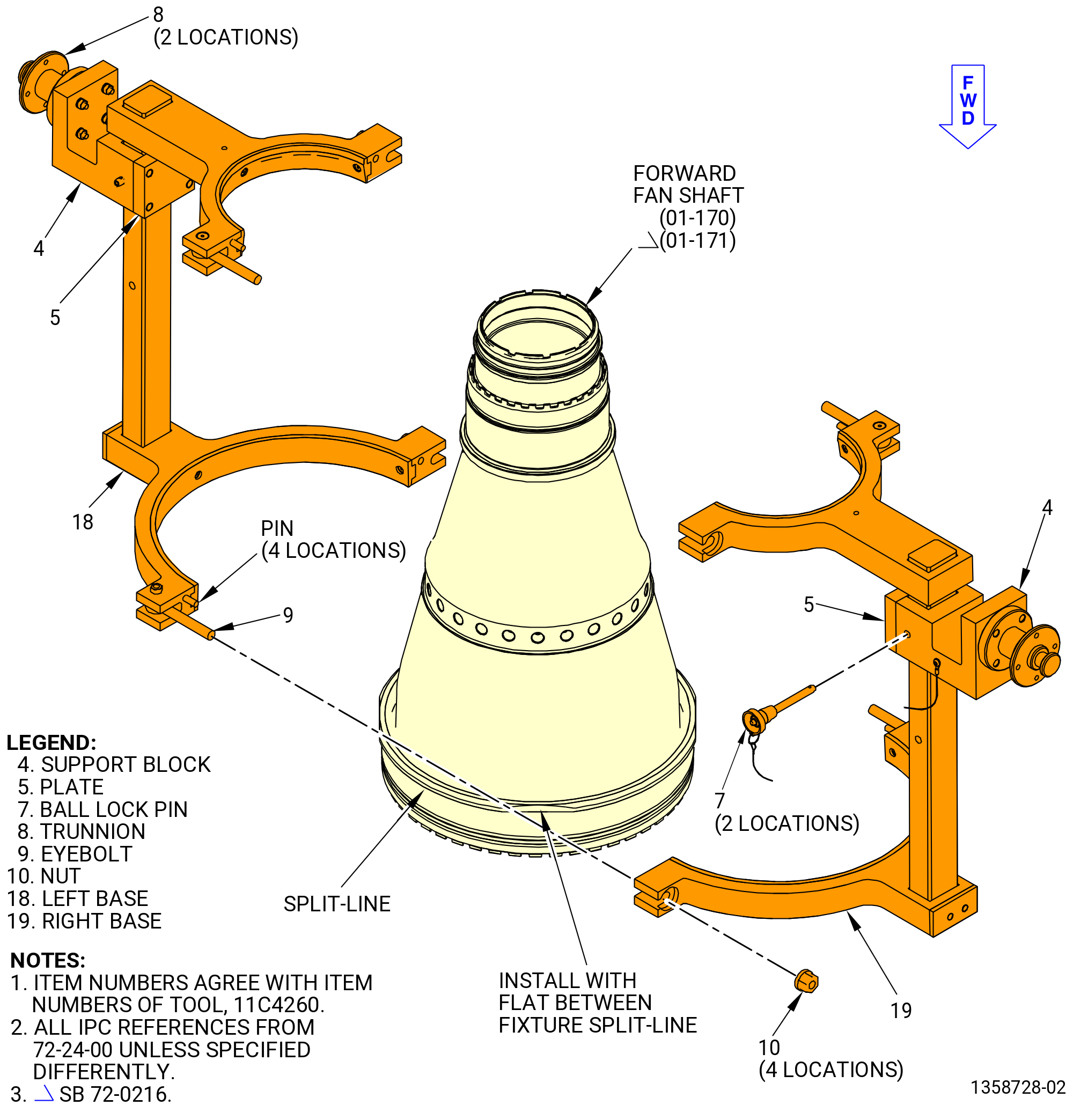
| G. | Install the 11C4260 lift/turn fixture on the forward fan shaft (01-170) (SIN 81002) or (01-171) (SIN 81002). Refer to Figure 1013 and do as follows: |
| WARNING: |
|
| (1) | If the forward fan shaft is installed in the 11C4260 lift/turn fixture and the 2C81801 holding fixture, use the hoist and remove the forward fan shaft and the 11C4260 lift/turn fixture from the 2C81801 holding fixture and install it on the 9401M62 adjustable stand. |
| WARNING: |
|
| (2) | Attach an overhead hoist with a lift sling to the left base (item 18) of the 11C4260 lift/turn fixture. |
| (3) | Put the left base (item 18) on the forward fan shaft (01-170) (SIN 81002) or (01-171) (SIN 81002). |
| (4) | Make sure to put the flats of the forward fan shaft between the split-line on the left base (item 18). Do not install the left base (item 18) split-line on the flat. |
| NOTE: |
|
| (5) | Attach an overhead hoist with a lift sling to the right base (item 19) and lift the right base (item 19). |
| (6) | Put the right base (item 19) on the forward fan shaft and align the pins with the alignment holes on the left base (item 18) and the right base (item 19). |
| (7) | Install the nut (item 10) on the eyebolt (item 9) and tighten the nuts (item 10) in a criss-cross pattern to attach the left base (item 18) and the right base (item 19) to the forward fan shaft (01-170) (SIN 81002) or (01-171) (SIN 81002) in an equal pattern. |
| Subtask 72-24-00-440-135 |
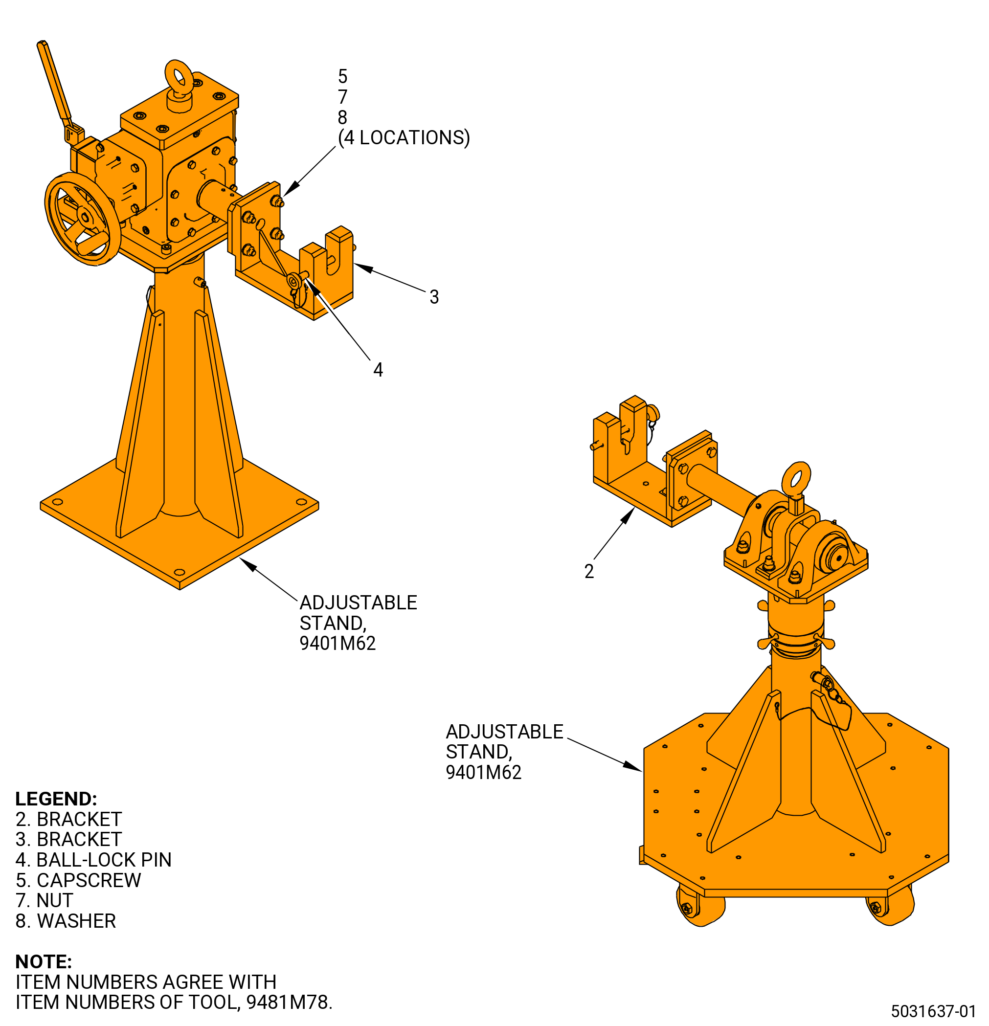
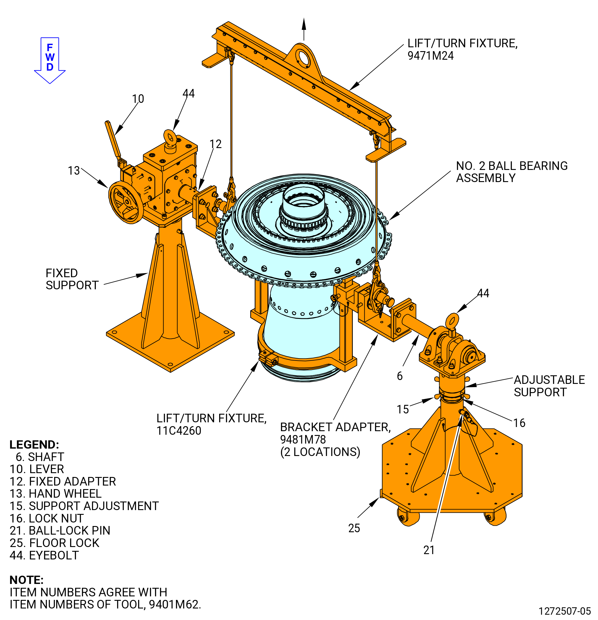
| H. | Install the 9481M78 bracket adapter on the 9401M62 adjustable stand. Refer to Figure 1014 and do as follows: |
| (1) | Put the bracket (item 3) on the stationary support of the 9401M62 adjustable stand. |
| (2) | Attach the bracket (item 3) with the capscrews (item 5), the washers (item 8), and the nuts (item 7) at four locations. Tighten the nuts (item 7). |
| (3) | Put the bracket (item 2) on the portable support of the 9401M62 adjustable stand. |
| (4) | Attach the bracket (item 3) with the capscrews (item 5), the washers (item 8), and the nuts (item 7) at four locations. Tighten the nuts (item 7). |
| (5) | Remove the ball-lock pins (item 4) from the brackets (item 2 and 3). |
| Subtask 72-24-00-440-136 |
| CAUTION: |
|
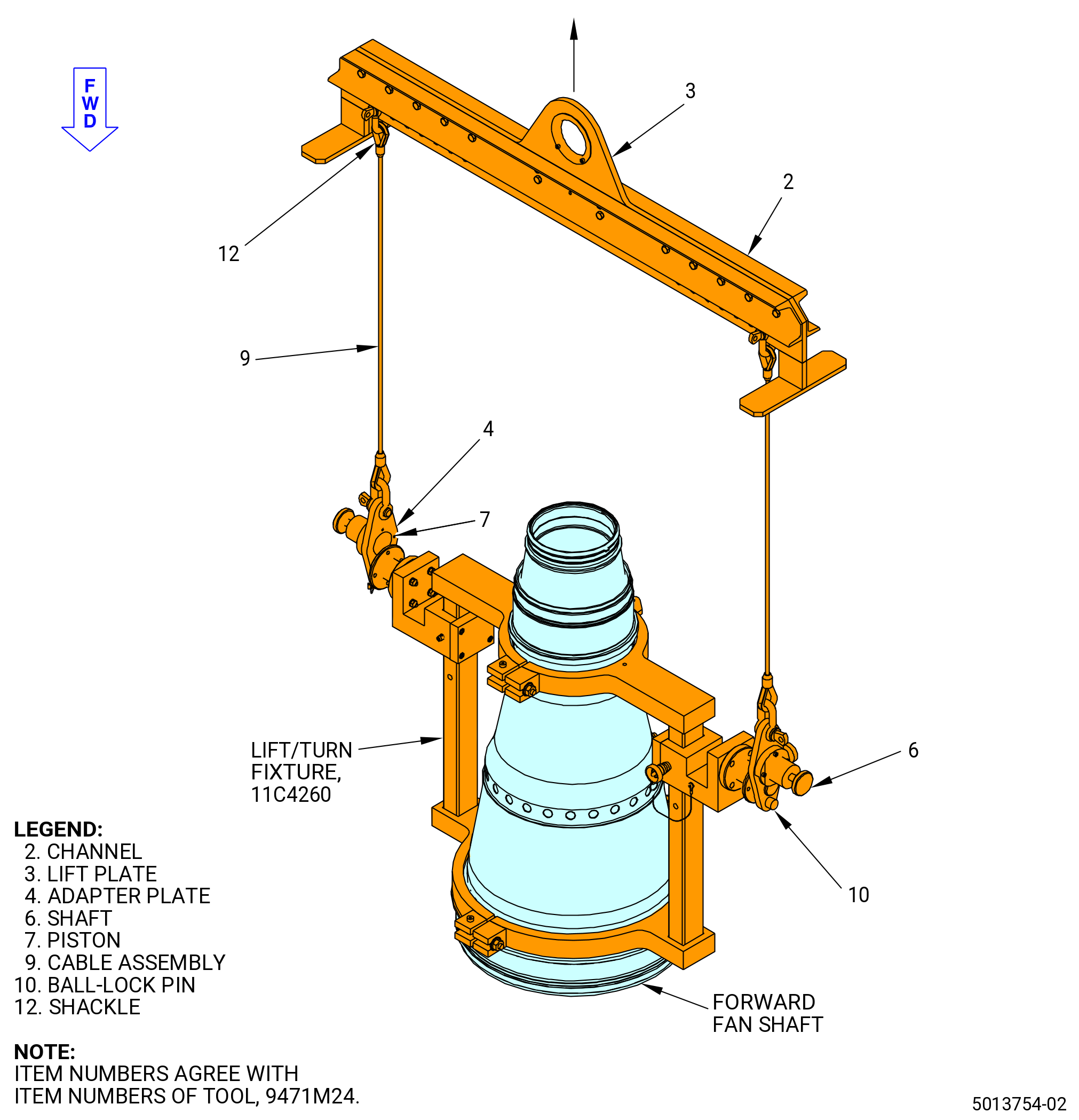
| I. | Attach the 9471M24 lift/turn fixture to the 11C4260 lift/turn fixture as follows. Refer to Figure 1015 and do as follows: |
| WARNING: |
|
| (1) | Attach the load scale to the overhead hoist. |
| (2) | Attach the lift plate (item 3) of the 9471M24 lift/turn fixture to the load scale. |
| (3) | Put the shackle (item 12) on the cable assembly (item 9) in the same numbered hole in the lift plate (item 3). Make sure that the cable assembly (item 9) is straight up from the 11C4260 lift/turn fixture. |
| (4) | Pull on the ball-lock pin (item 10) of the 9471M24 lift/turn fixture to permit the adapter plate (item 4) to be installed on the trunnion of the 11C4260 lift/turn fixture. |
| (5) | Install the ball-lock pin (item 10) of the 9471M24 lift/turn fixture in the adapter plate (item 4). |
| Subtask 72-24-00-160-013 |
| WARNING: |
|
| J. | Before the installation of the fan forward shaft on the adjustable stand, do a last chance wipe of the fan forward shaft and adjustable stand interfacing areas with new C10-182 wipers and an approved solvent, such as a 50-50 blend of C04-014 denatured alcohol and C04-035 isopropyl alcohol, C04-002 Stoddard solvent, or C04-035 isopropyl alcohol. |
| Subtask 72-24-00-440-137 |
| CAUTION: |
|
| K. | Install the forward fan shaft (01-170) (SIN 81002) or (01-171) (SIN 81002) on the 9401M62 adjustable stand. Refer to Figure 1016 and do as follows: |
| (6) | Make sure the ball-lock pins (item 21) are installed at two locations on the fixed and adjustable supports. If necessary, adjust height of supports as follows: |
| WARNING: |
|
| (a) | Attach an overhead hoist to the eyebolt (item 44) and apply a lift pressure to the support. |
| (b) | Lift the support to the necessary height and install the ball-lock pin (item 21). |
| (7) | Move the lever (item 10) to the outward position to lock the fixed adapter (item 12) rotate. |
| WARNING: |
|
| (8) | Lift the forward fan shaft in the 11C4260 lift/turn fixture. Refer to Figure 1015. |
| (9) | Lower and align the trunnions (item 8) with the slots on the 9481M78 bracket adapter at two locations. Refer to Figure 1016. |
| (a) | If necessary, loosen the locknut (item 16) of the 9401M62 adjustable stand and turn the support adjustment nut (item 15) to adjust the height of the shaft (item 6) on the portable support. Make sure that the forward fan shaft is level. |
| (b) | Tighten the locknut (item 16). |
| (10) | Install the ball-lock pin (item 4) of the 9481M78 bracket adapter in the bracket (item 2) to secure the trunnion (item 8) of the 11C4260 lift/turn fixture. Refer to Figure 1013 and Figure 1014. |
| (11) | Remove the 9471M24 lift/turn fixture from the trunnions (item 8) on the 11C4260 lift/turn fixture. |
| CAUTION: |
|
| (12) | Put the floor locks (item 25) of the 9401M62 adjustable stand down until they touch the floor. Refer to Figure 1016. |
| (13) | Use the hand wheel (item 13) to rotate the forward fan shaft to the horizontal position. |
| CAUTION: |
|
| (14) | Move the lever (item 10) to the outward position to prevent rotation of the forward fan shaft. |
| Subtask 72-24-00-440-128 |
| CAUTION: |
|
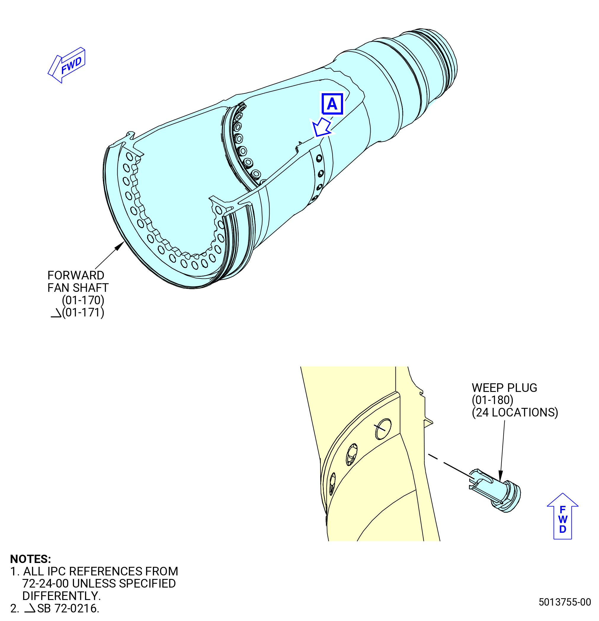
| L. | Install the fan shaft weep plugs (weep plugs) (01-180) (SIN 81090). Refer to Figure 1017 and do as follows: |
| Subtask 72-24-00-640-001 |
| WARNING: |
|
| (1) | Apply C02-019 engine oil or C02-023 engine oil to the weep plugs and the weep plug holes on the forward fan shaft. |
| Subtask 72-24-00-440-138 |
| (2) | Install the weep plugs through the holes on the ID of the shaft. Push the weep plugs until the retention feature is through the hole and locked on the OD of the shaft. |
| Subtask 72-24-00-160-014 |
| WARNING: |
|
| M. | Before the installation of the inner race onto the fan forward shaft, do a last chance wipe of the fan forward shaft seating area and seating fixture with new C10-182 wipers and an approved solvent, such as a 50-50 blend of C04-014 denatured alcohol and C04-035 isopropyl alcohol, C04-002 Stoddard solvent, or C04-035 isopropyl alcohol. |
| Subtask 72-24-00-440-050 |
| CAUTION: |
|
| CAUTION: |
|
| CAUTION: |
|
| CAUTION: |
|
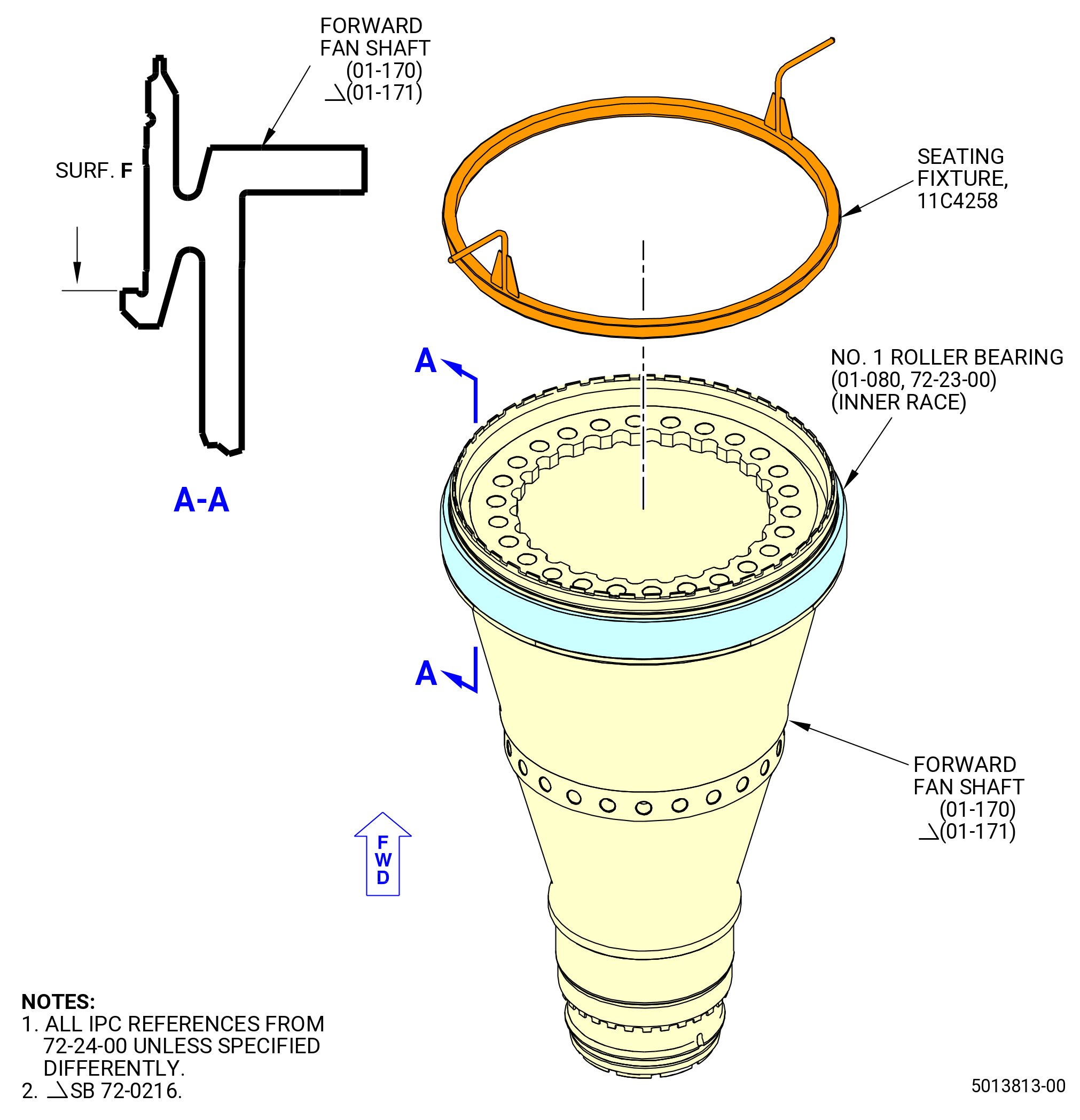
| N. | Install the inner race of the No. 1 cylindrical roller bearing (No. 1 roller bearing) (01-080 , 72-23-00) (SIN 011A0). Refer to Figure 1018 and do as follows: |
| Subtask 72-24-00-440-051 |
| (3) | Rotate the forward fan shaft in the 9401M62 adjustable stand to put the forward end in the up position. Refer to Figure 1016 and do as follows: |
| (a) | Move the lever (item 10) to the inward position. |
| (b) | Use the hand wheel (item 13) to rotate the forward fan shaft to put the forward end in the up position. |
| CAUTION: |
|
| (c) | Move the lever (item 10) to the outward position to prevent rotation of the forward fan shaft. |
| Subtask 72-24-00-160-006 |
| WARNING: |
|
| WARNING: |
|
| WARNING: |
|
| (4) | Use C04-035 isopropyl alcohol or equivalent to clean the No. 1 bearing journal. Refer to TASK 72-24-00-440-801 (paragraph 1.D.(1)). |
| Subtask 72-24-00-440-139 |
| WARNING: |
|
| (5) | Use the heater to increase the temperature of the inner race to maximum of 400°F (204.44°C). |
| (6) | Install the No. 1 roller bearing (01-080 , 72-23-00) (SIN 011A0) inner race on the forward end of the forward fan shaft (01-170) (SIN 81002) or (01-171) (SIN 81002). Make sure the serial number on the inner race is forward. |
| (7) | Thread the 11C4258 seating fixture onto the forward fan shaft and against the inner race of the No. 1 bearing. |
| (8) | Turn the 11C4258 seating fixture to tighten the seating fixture against the inner race and seat the inner race against surface F of the forward fan shaft. |
| (9) | Allow the inner race to cool to ambient temperature. |
| (10) | Remove the 11C4258 seating fixture from the forward fan shaft. |
| Subtask 72-24-00-220-009 |
| (11) | Make sure that the inner race is installed correctly as follows: |
| (a) | Try to insert a piece of 0.001 inch (0.03 mm) shim stock between the inner race and surface F. Refer to Figure 1018. |
| (b) | If there are gaps, do the steps that follow: |
| 1 | Remove the inner race with the 11C3125 puller. Refer to TASK 72-24-00-040-801 (72-24-00, DISASSEMBLY 001). |
| 2 | Install the inner race again. Refer to Subtask 72-24-00-440-050 (paragraph 3.L.(1)) through Subtask 72-24-00-440-050 (paragraph 3.L.(8)). |
| Subtask 72-24-00-620-003 |
| WARNING: |
|
| (12) | Apply C02-050 preservation oil or MIL-PRF-16173 corrosion preventive compound on the No. 1 roller bearing (01-080 , 72-23-00) (SIN 011A0) inner race. Do not apply more than the necessary amount of MIL-PRF-16173 corrosion preventive compound. Refer to TASK 70-60-01-620-002 (PRESERVATION OF ANTIFRICTION BEARINGS). |
| Subtask 72-24-00-440-059 |
| CAUTION: |
|
| CAUTION: |
|
| O. | Install the No. 2 bearing fan shaft extension assembly (shaft extension) (01-150) (SIN 81005) or (01-151) (SIN 81005) on the forward fan shaft (01-170) (SIN 81002) or (01-171) (SIN 81002). Refer to Figure 1016 and do as follows: |
| (1) | Rotate the forward fan shaft in the 9401M62 adjustable stand to put the aft end in the up position as follows: |
| (a) | Move the lever (item 10) to the inward position. |
| (b) | Use the hand wheel (item 13) to rotate the forward fan shaft to put the aft end in the up position. |
| CAUTION: |
|
| (c) | Move the lever (item 10) to the outward position to prevent rotation of the forward fan shaft. |
| Subtask 72-24-00-440-063 |
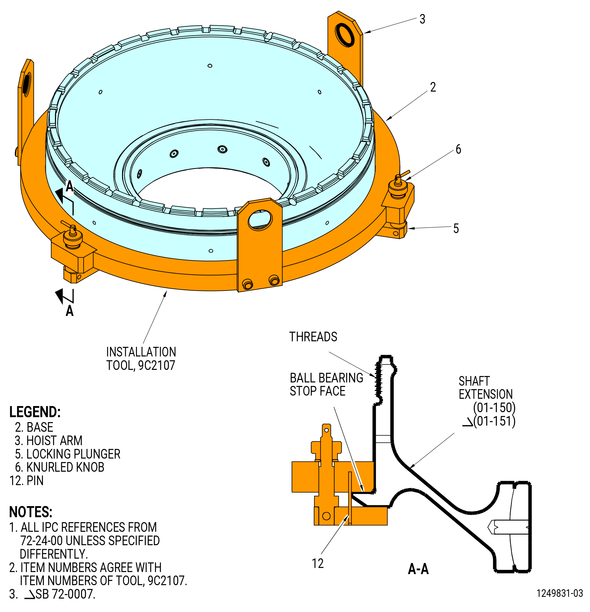
| (2) | Install the 9C2107 installation tool on the shaft extension (01-150) (SIN 81005) or (01-151) (SIN 81005). Refer to Figure 1019 and do as follows: |
| NOTE: |
|
| (a) | Loosen the knurled knobs (item 6) to unlock the locking plungers (item 5) and position the feet outward. |
| (b) | Pull the locking plungers (item 5) down to permit installation of the base (item 2) on the ball bearing stop face. |
| WARNING: |
|
| (c) | Attach a three-legged sling to the hoist arms (item 3) to lift the 9C2107 installation tool. |
| (d) | Align the pins (item 12) with the OD of the shaft extension. |
| (e) | Lower the 9C2107 installation tool to the shaft extension until the base (item 2) is on the ball bearing stop face. |
| (f) | Move the locking plungers (item 5) and engage the shaft extension. |
| (g) | Tighten the knurled knobs (item 6) to hold the shaft extension between the locking plungers (item 5) and the base (item 2). |
| (h) | Lift the shaft extension with the 9C2107 installation tool. |
| Subtask 72-24-00-440-064 |
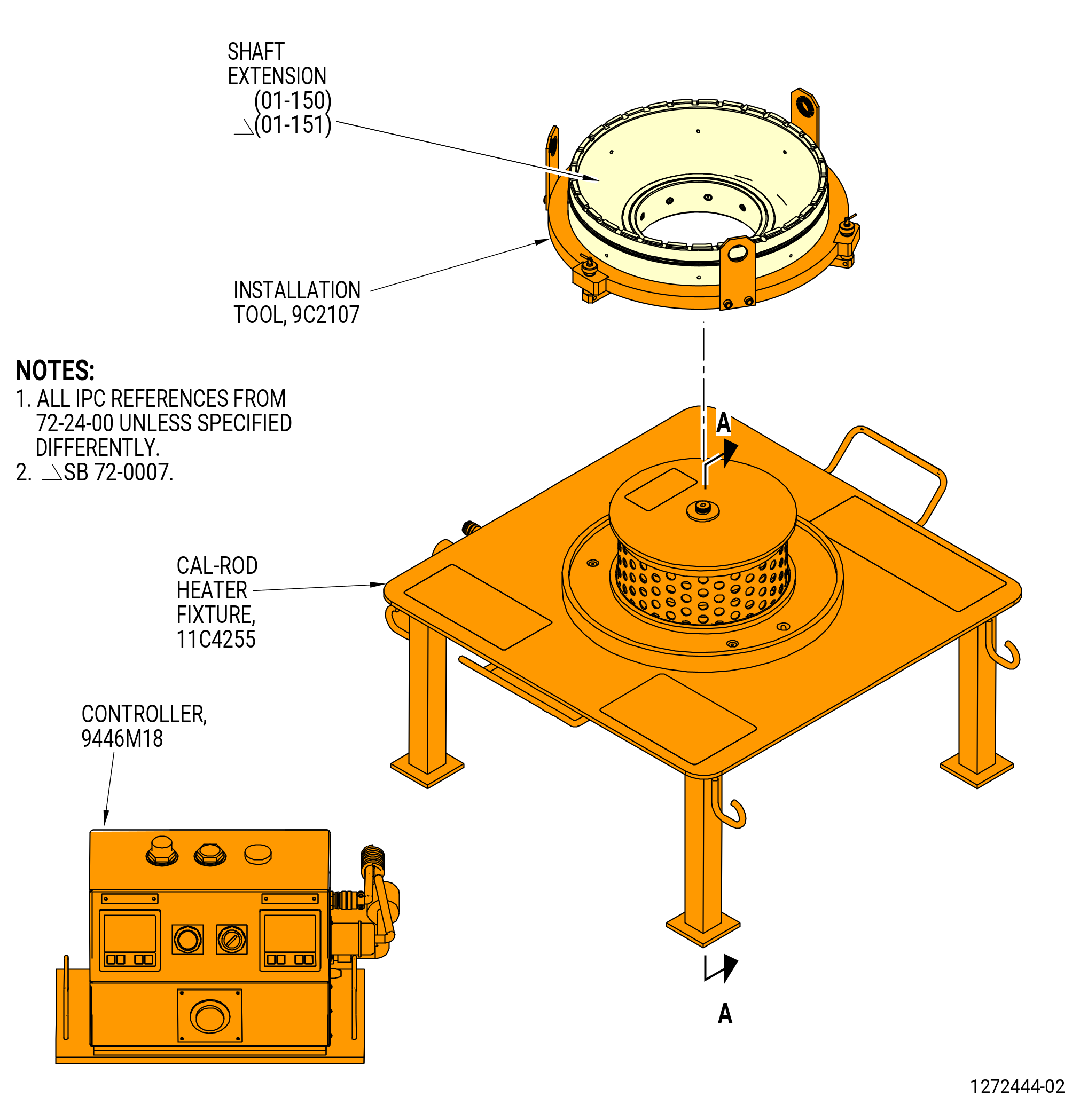
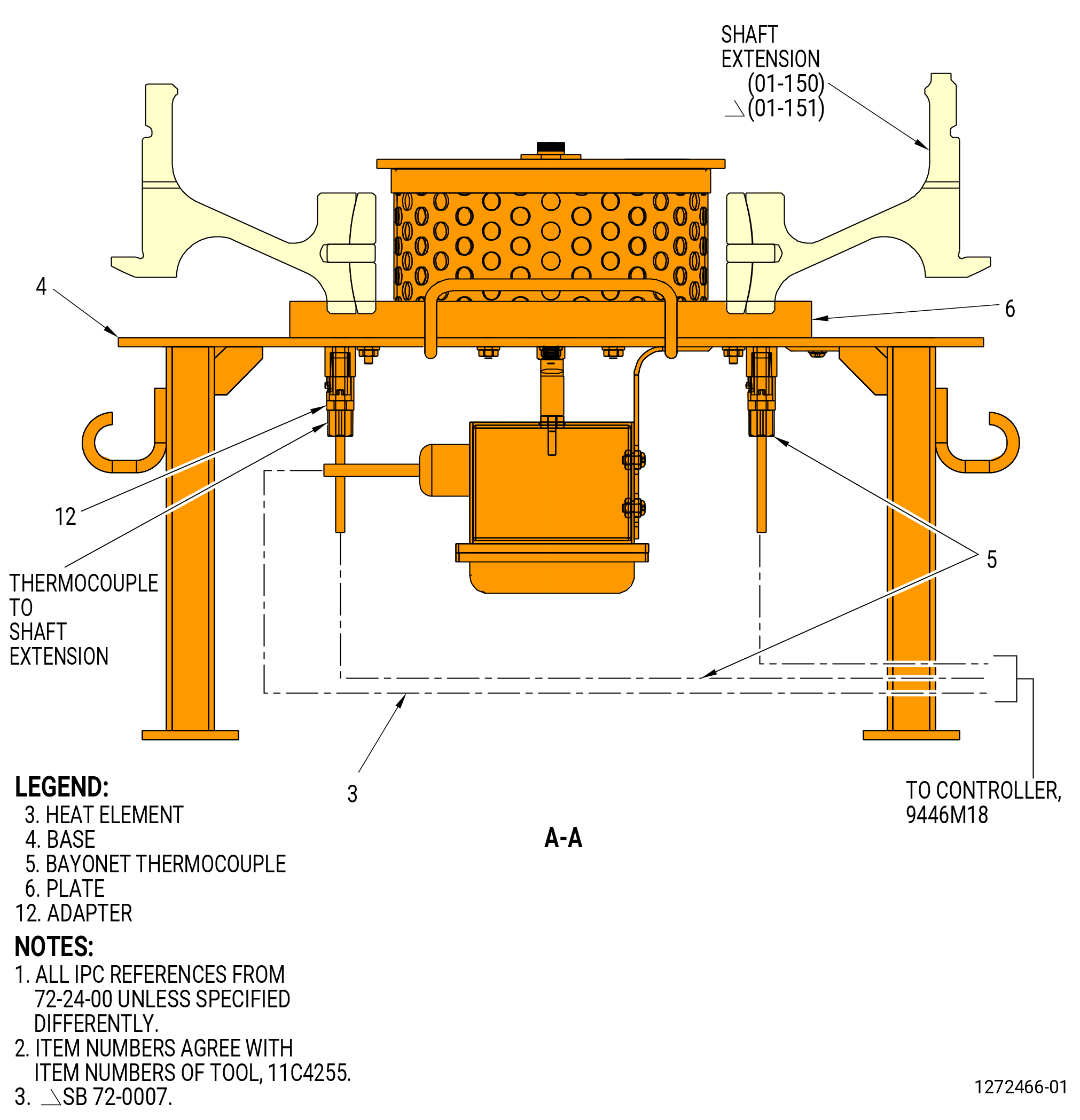
| (3) | Alternative Procedure Available. Install the shaft extension (01-150) (SIN 81005) or (01-151) (SIN 81005) on the 11C4255 cal-rod heater fixture. Refer to Figure 1020 and do as follows: |
| WARNING: |
|
| (a) | Make sure the power switch on the 9446M18 controller is in the OFF position. |
| (b) | Make sure the thermocouples (item 5) do not extend above the surface of the plate (item 6). |
| WARNING: |
|
| (c) | Lift the shaft extension installed in the 9C2107 installation tool. |
| (d) | Carefully lower the shaft extension onto the plate (item 6) of the 11C4255 cal-rod heater fixture. |
| (e) | Make sure the tip of the thermocouples (item 5) makes contact with the shaft extension. If not, loosen the thermocouple adapter (item 12) and adjust the thermocouple (item 5) until it touches the shaft extension. Tighten the thermocouple adapter (item 12). |
| (f) | Connect the power cord of the 11C4255 cal-rod heater fixture to the 9446M18 controller. |
| (g) | Connect the thermocouple connector plug of the 11C4255 cal-rod heater fixture to the 9446M18 controller. |
| (h) | Connect the 9446M18 controller to a 230 VAC, 50 Hz, single phase power source. |
| (i) | Turn on the 9446M18 controller . |
| Subtask 72-24-00-440-149 |
| WARNING: |
|
| CAUTION: |
|
| (3).A. | Alternative Procedure. Install the shaft extension (01-150) (SIN 81005) or (01-151) (SIN 81005) on an induction heater as follows: |
| (a) | Lift the shaft extension installed in the 9C2107 installation tool. |
| (b) | Carefully install the shaft extension on the induction heater. |
| (c) | Use a temperature probe to check the temperature of the inner race. |
| Subtask 72-24-00-440-150 |
| (4) | Increase the temperature of the shaft extension (01-150) (SIN 81005) or (01-151) (SIN 81005) to 250°F (121°C) maximum. |
| Subtask 72-24-00-440-065 |
| WARNING: |
|
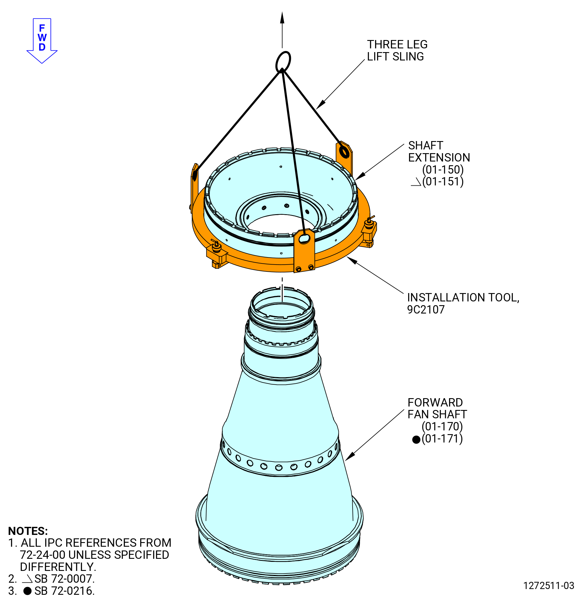
| (5) | After the shaft extension (01-150) (SIN 81005) or (01-151) (SIN 81005) reaches the correct temperature, install the shaft extension on the forward fan shaft (01-170) (SIN 81002) or (01-171) (SIN 81002). Refer to Figure 1021 and do as follows: |
| WARNING: |
|
| (a) | Lift the shaft extension installed in the 9C2107 installation tool from the 11C4255 cal-rod heater fixture. |
| (b) | Lower the shaft extension (01-150) (SIN 81005) or (01-151) (SIN 81005) onto the forward fan shaft (01-170) (SIN 81002) or (01-171) (SIN 81002). |
| WARNING: |
|
| (c) | Remove the 9C2107 installation tool as follows. Refer to Figure 1019. |
| 1 | Loosen the knurled knobs (item 6) that holds the shaft extension between the locking plungers (item 5) and the base (item 2). |
| 2 | Move the locking plungers (item 5) and disengage from the shaft extension. |
| 3 | Lift the 9C2107 installation tool from the shaft extension. |
| Subtask 72-24-00-440-140 |
| WARNING: |
|
| (6) | Carefully lift the 11C4259 seating fixture and install it on the forward fan shaft (01-170) (SIN 81002) or (01-171) (SIN 81002). Turn the 11C4259 seating fixture on the threads of the forward fan shaft. Refer to Figure 1022. |
| (7) | Use the rod (item 3) of the 11C4259 seating fixture and turn it in the CW direction to tighten the pusher tube (item 2) of the 11C4259 seating fixture against the shaft extension. |
| (8) | Let the shaft extension go back to ambient temperature. |
| (9) | Use the rod (item 3) of the 11C4259 seating fixture and turn it in the CCW direction to loosen the pusher tube (item 2) of the 11C4259 seating fixture from the shaft extension. |
| WARNING: |
|
| (10) | Carefully remove the 11C4259 seating fixture from the forward fan shaft. |
| Subtask 72-24-00-220-011 |
| (11) | Make sure that the shaft extension (01-150) (SIN 81005) or (01-151) (SIN 81005) is installed correctly. Refer to Figure 1001 and do as follows: |
| (a) | Try to insert a 0.001 inch (0.03 mm) shim stock between the stop face of the shaft and the shaft extension at four equally spaced locations. |
| (b) | If there is a gap more than 0.001 inch (0.03 mm), do the steps that follow: |
| 1 | Remove the shaft extension. Refer to TASK 72-24-00-040-801 (72-24-00, DISASSEMBLY 001). |
| 2 | Install the shaft extension again. Refer to subtask 72-24-00-440-059 (paragraph 3.M.(1)) through subtask 72-24-00-440-059 (paragraph 3.M.(9)). |
| Subtask 72-24-00-220-045 |
| (12) | Do a general visual inspection of the exposed surfaces of the forward fan shaft for nicks, dents, and scratches after the removal of tooling. Refer to TASK 72-00-24-200-801 (72-00-24, INSPECTION 001). |
| Subtask 72-24-00-440-126 |
| CAUTION: |
|
| P. | Install the plain round nut (inner nut) (01-070) (SIN 81040) on the forward fan shaft (01-170) (SIN 81002) or (01-171) (SIN 81002). Refer to Figure 1023 and do as follows: |
| Subtask 72-24-00-160-003 |
| WARNING: |
|
| WARNING: |
|
| WARNING: |
|
| (1) | Use C04-035 isopropyl alcohol or equivalent to clean the inner nut (01-070) (SIN 81040) and the forward fan shaft (01-170) (SIN 81002) or (01-171) (SIN 81002). Refer to TASK 72-24-00-440-801 (paragraph 1.D.(1)) and do as follows: |
| (a) | Clean the threads and mate face of the inner nut. |
| (b) | Clean the mating face of the shaft extension and the mating threads of the shaft. Refer to Figure 1001. |
| Subtask 72-24-00-640-002 |
| WARNING: |
|
| (2) | Apply C02-019 engine oil or C02-023 engine oil to lubricate the inner nut and shaft as follows: |
| (a) | Lubricate the threads and mate face of the inner nut. |
| (b) | Lubricate the mating threads of the shaft. |
| Subtask 72-24-00-440-071 |
| (3) | Manually thread the inner nut to the threads on the shaft. |
| Subtask 72-24-00-440-072 |
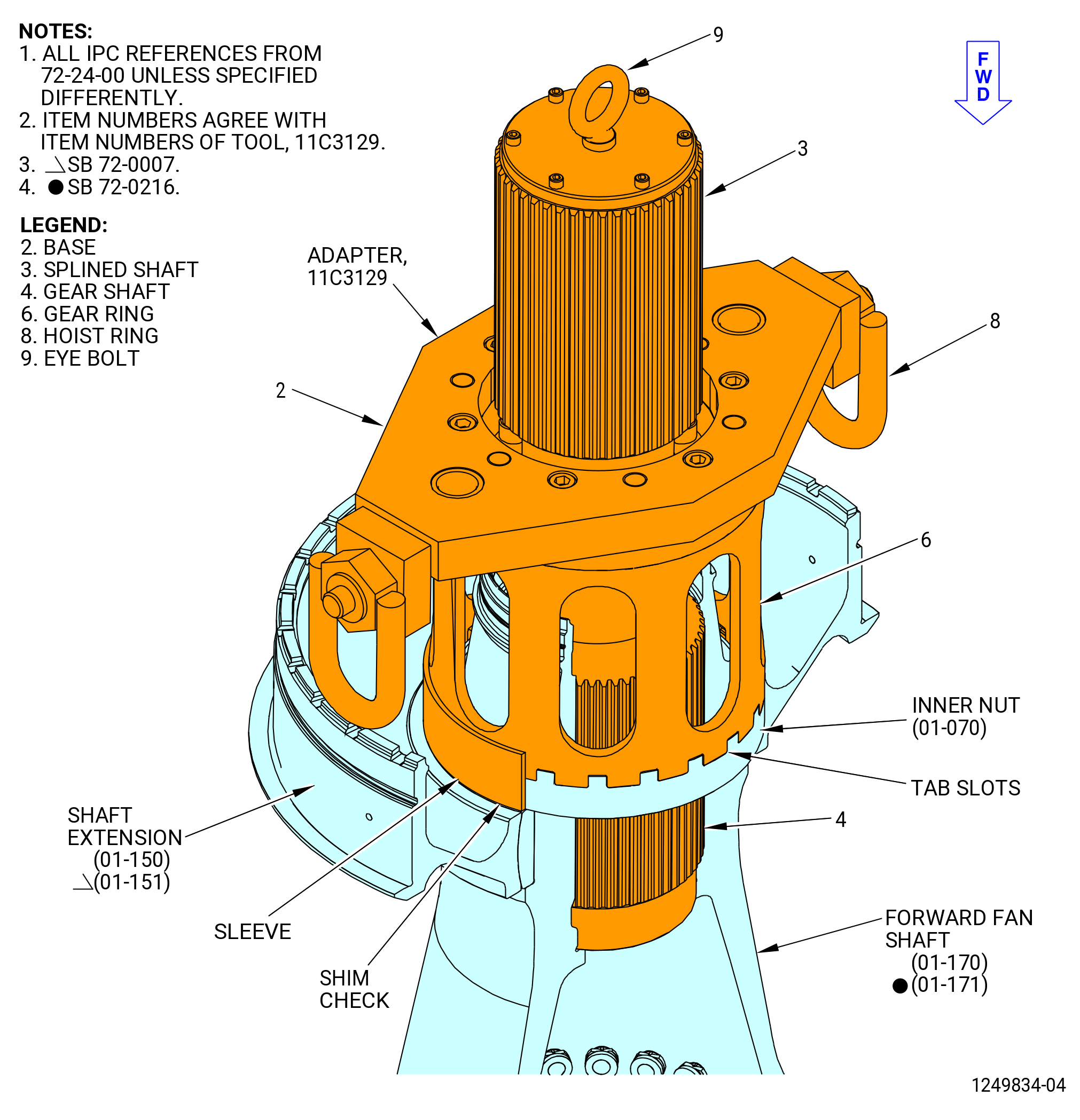
| (4) | Install the 11C3129 adapter as follows. Refer to Figure 1024. |
| (a) | Install the spline shaft (item 3) and the gear shaft (item 4) as follows: |
| WARNING: |
|
| 1 | Attach an overhead hoist to the eyebolt (item 9) to lift the spline shaft (item 3), with the gear shaft (item 4) attached. |
| 2 | Lower the spline shaft (item 3) and the gear shaft (item 4) into the shaft. |
| 3 | Make sure that the splines of the gear shaft (item 4) engage the splines of the shaft. |
| (b) | Install the base (item 2) and the gear ring (item 6) as follows: |
| NOTE: |
|
| WARNING: |
|
| 1 | Attach the three-piece sling to the two hoist rings (item 8) of the base (item 2) to an overhead hoist. |
| NOTE: |
|
| 2 | Lift the base (item 2), with the gear ring (item 6) attached, and align it as follows: |
| a | Align the hole in the center of the base (item 2) with the spline shaft (item 3). |
| b | Align the tabs of the gear ring (item 6) with the tab slots of the inner nut. Refer to Figure 1023. |
| Subtask 72-24-00-440-129 |
| (c) | Install the torque multiplier as follows. Refer to Figure 1024. |
| 1 | Attach a hoist to the torque multiplier. |
| WARNING: |
|
| 2 | Operate the hoist and align the splines of the torque multiplier with the splines of the spline shaft (item 3). |
| 3 | Align the legs of the torque multiplier with the holes in the base (item 2). |
| 4 | Operate the hoist and put the torque multiplier on the base (item 2). |
| Subtask 72-24-00-440-073 |
| (5) | Torque the inner nut with the torque multiplier as follows: |
| (a) | Torque the inner nut to 6000 lb ft (8135 N.m). |
| (b) | Break the torque on the inner nut. |
| (c) | Torque the inner nut to 3600 lb ft (4881 N.m). |
| (d) | Remove the torque multiplier . |
| (e) | Remove the 11C3129 adapter . |
| Subtask 72-24-00-220-044 |
| (6) | Make sure that the inner nut is installed correctly as follows: |
| (a) | Try to insert a piece of 0.001 inch (0.03 mm) shim stock between the shaft extension and the inner nut. |
| (b) | If there are gaps and the inner nut was not torqued to the maximum torque of 4800 lb ft (6508 N.m), correct as follows: |
| 1 | Deleted. |
| 2 | Install the 11C3129 adapter and the torque multiplier . Refer to Subtask 72-24-00-440-072 (paragraph 3.N.(4)). |
| 3 | Increase the torque a sufficient amount to remove the gap. Do not torque the inner nut to more than the maximum torque of 4800 lb ft (6508 N.m). |
| 4 | Try to insert a piece of 0.001 inch (0.03 mm) shim stock between the shaft and the inner nut. |
| 5 | If there are no gaps install the clips (81081) in the slots in the inner nut and the shaft. Refer to Subtask 72-24-00-440-130 (paragraph 3.N.(7)). |
| (c) | If there are gaps and the inner nut was torqued to the maximum torque of 4800 lb ft (6508 N.m), correct as follows: |
| 1 | Remove the inner nut with the 11C3129 adapter. Refer to TASK 72-24-00-040-801 (72-24-00, DISASSEMBLY 001). |
| 2 | Install the inner nut again. Refer to Subtask 72-24-00-440-071 (paragraph 3.N.(1)) through Subtask 72-24-00-440-071 (paragraph 3.N.(7)). |
| Subtask 72-24-00-440-130 |
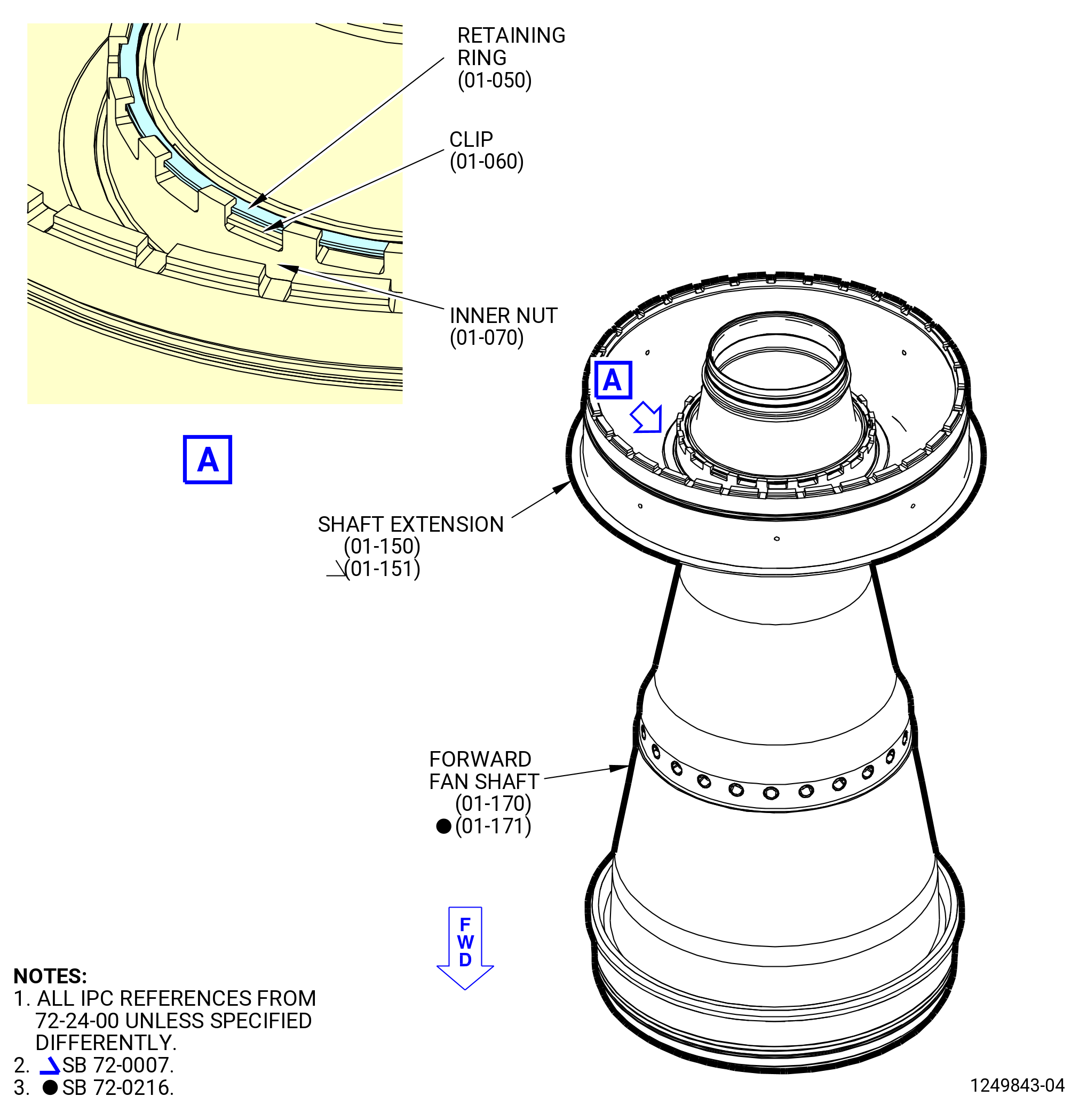
| (7) | Install the anti-rotation spring clips (clips) (01-060) (SIN 81081). Refer to Figure 1025 and do as follows: |
| (a) | Install one clip, convex side down (forward), where a slot of the inner nut aligns with a slot on the shaft. |
| (b) | Install the other clip, convex side down, 160 to 200 degrees opposite of the first clip. |
| CAUTION: |
|
| (c) | If the clips can not be installed, correct as follows: |
| 1 | Install the 11C3129 adapter and the torque multiplier . Refer to Subtask 72-24-00-440-072 (paragraph 3.N.(4)). |
| 2 | Increase the torque a sufficient amount to align a slot on the inner nut with a slot on the shaft. Do not torque the inner nut to more than the maximum torque of 4800 lb ft (6508 N.m). |
| 3 | Remove the torque multiplier . |
| 4 | Remove the 11C3129 adapter . |
| 5 | Install the clips in the slots. Refer to Subtask 72-24-00-440-130 (paragraph 3.N.(7)(a)) and Subtask 72-24-00-440-130 (paragraph 3.N.(7)(b)) . |
| Subtask 72-24-00-440-075 |
| (8) | Install the retaining ring (01-050) (SIN 01281) in the retaining ring groove on the inner nut (01-070) (SIN 81040). Refer to Figure 1025. |
| Subtask 72-24-00-220-046 |
| (9) | Do a general visual inspection of the exposed surfaces of the forward fan shaft, inner nut and anti-rotation spring clips for nicks, dents, and scratches after the removal of tooling. Refer to TASK 72-00-24-200-801 (72-00-24, INSPECTION 001). |
| Subtask 72-24-00-440-076 |
| CAUTION: |
|
| CAUTION: |
|
| CAUTION: |
|
| CAUTION: |
|
| Q. | Install the forward inner race of the ball bearing (01-140) (SIN 012A0) on the shaft extension (01-150) (SIN 81005) or (01-151) (SIN 81005) as follows: |
| Subtask 72-24-00-160-007 |
| WARNING: |
|
| WARNING: |
|
| WARNING: |
|
| (1) | Use C04-035 isopropyl alcohol or equivalent to clean the surfaces of mating flanges of the ball bearing (01-140) (SIN 012A0) forward inner race. Refer to TASK 72-24-00-440-801 (paragraph 1.D.(1)). |
| (2) | Clean the 11C4257 seating fixture threads and thrust ring (item 2) with C04-035 isopropyl alcohol or equivalent. Refer to TASK 72-24-00-440-801 (paragraph 1.D.(1)) and Figure 1026. |
| WARNING: |
|
| (3) | After installing the inner race onto the fan shaft extension, do a last chance wipe of the inner race surfaces using new C10-182 wipers with clean C02-019 engine oil. |
| Subtask 72-24-00-440-141 |
| WARNING: |
|
| (4) | Alternative Procedure Available. Use the heater to increase the temperature of the forward inner race of the ball bearing (01-140) (SIN 012A0) to 300°F (149°C). |
| Subtask 72-24-00-440-157 |
| WARNING: |
|
| (4).A. | Alternative Procedure. Use the induction heater to increase the temperature of the forward inner race of the ball bearing (01-140) (SIN 012A0) as follows: |
| (a) | Adjust the 11C4533 support ring to the center of the induction heater yoke and move it down until it is installed on the induction heater flat surface. |
| (b) | Adjust the forward inner race of the ball bearing to the center of the induction heater yoke and move it down until it is installed on the 11C4533 support ring. |
| (c) | Increase the temperature of the forward inner race of the ball bearing to 300°F (149°C). |
| Subtask 72-24-00-440-155 |
| WARNING: |
|
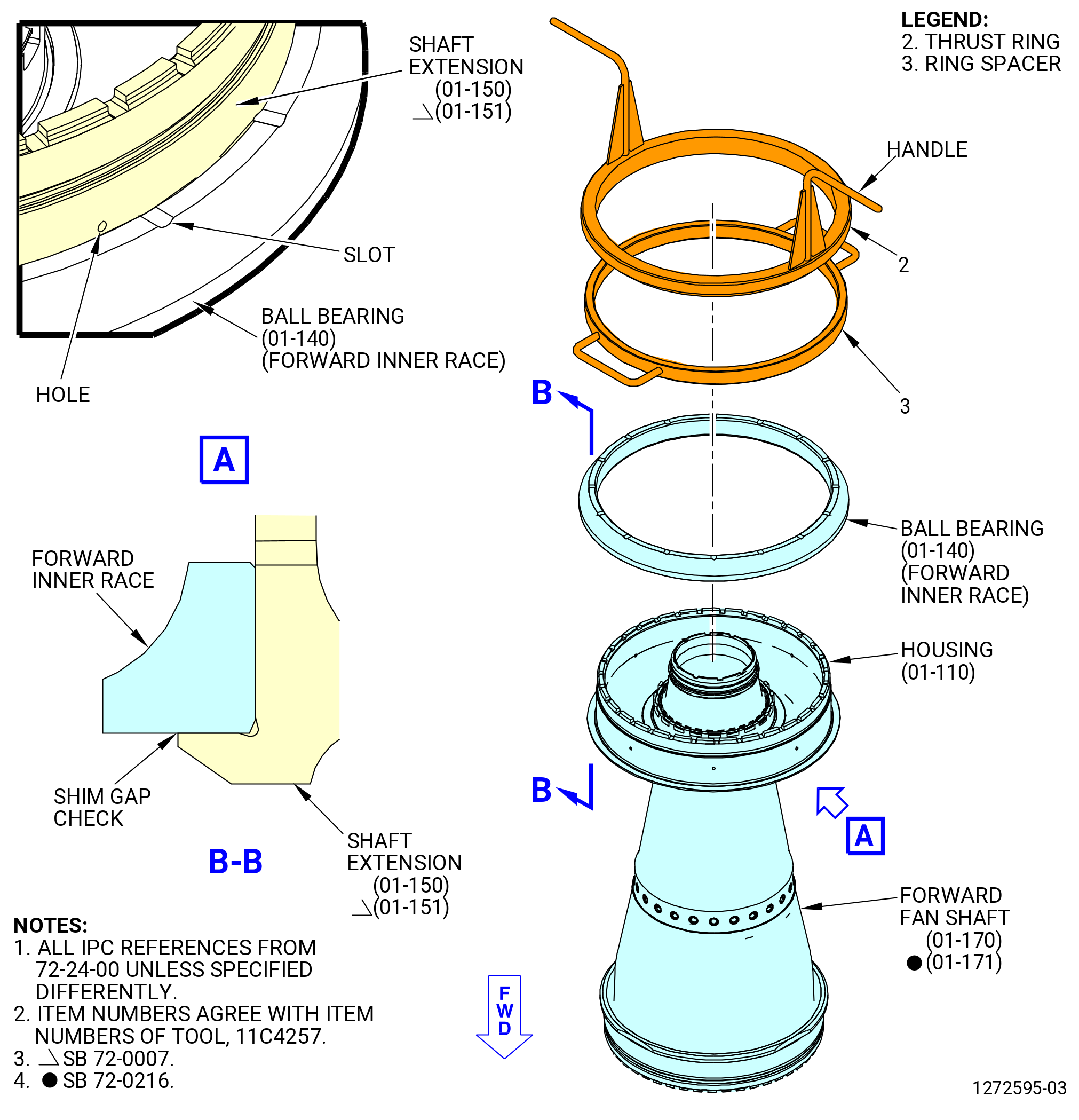
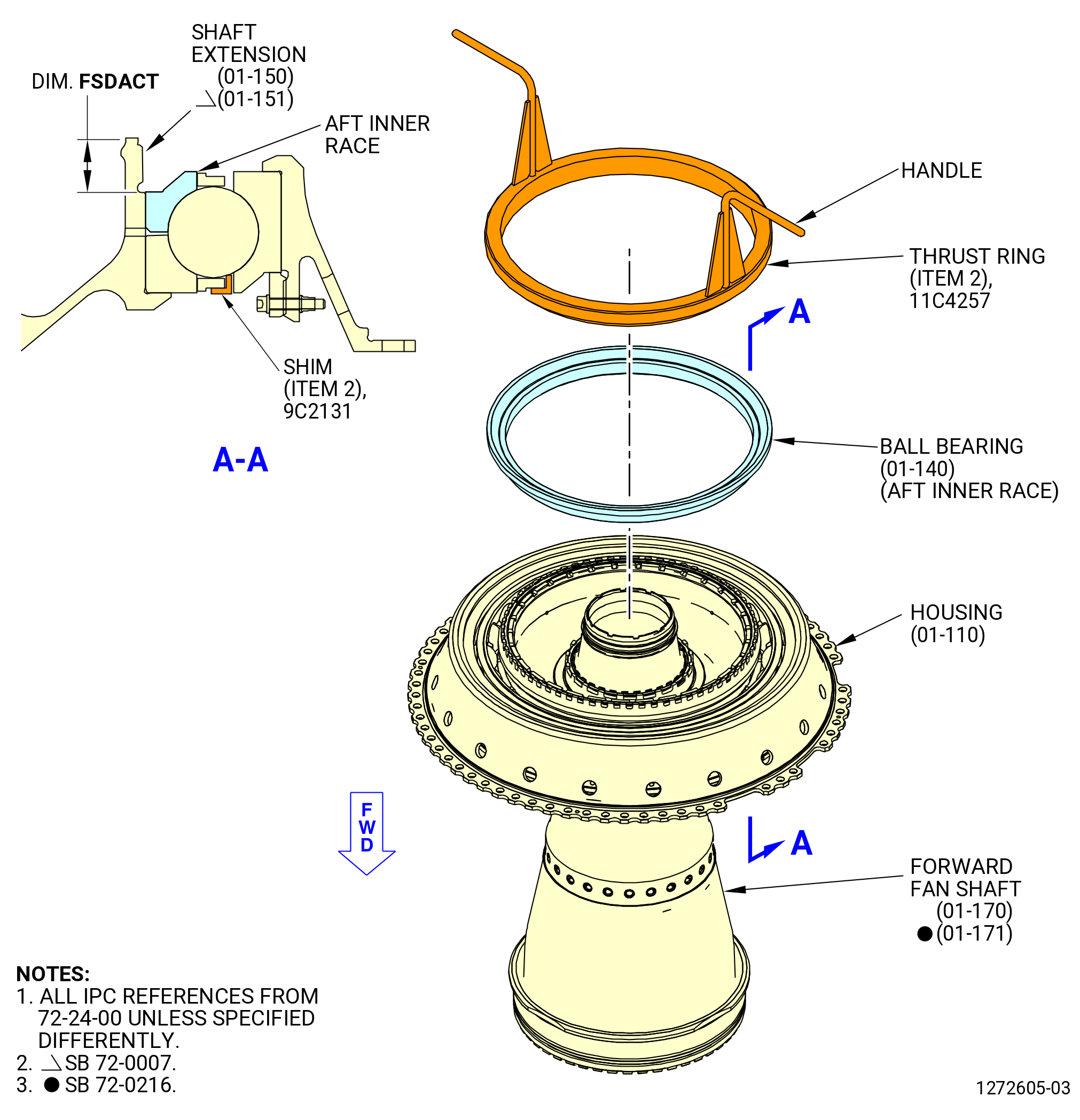
| (5) | Install the forward inner race of the ball bearing (01-140) (SIN 012A0) on the shaft extension (01-150) (SIN 81005) or (01-151) (SIN 81005) of the No. 2 bearing journal. Refer to Figure 1027. |
| (6) | Make sure the slots on the aft face of the forward inner race do not align with the holes on the shaft extension. |
| (7) | Put the ring spacer (item 3) of the 11C4257 seating fixture on the forward inner race. |
| (8) | Thread the thrust ring (item 2) onto the shaft extension (01-150) (SIN 81005) or (01-151) (SIN 81005). |
| (9) | Turn the handles on the 11C4257 seating fixture until the forward inner race is seated. Make sure there is no gap between the forward inner race and the shaft extension. |
| (10) | Allow the forward inner race to go back to ambient temperature. |
| (11) | Remove the spacer ring (item 2) and ring spacer (item 3) from the shaft extension. |
| Subtask 72-24-00-220-037 |
| (12) | Make sure that the forward inner race is installed correctly as follows: |
| (a) | Try to insert a piece of 0.001 inch (0.03 mm) shim stock between the shaft extension and the forward inner race. |
| (b) | If there are gaps, do the steps that follow: |
| 1 | Remove the forward inner race with the 11C3129 adapter. Refer to TASK 72-24-00-040-801 (72-24-00, DISASSEMBLY 001). |
| 2 | Install the forward inner race again. Refer to Subtask 72-24-00-440-076 (paragraph 3.O.(1)) through Subtask 72-24-00-440-141 (paragraph 3.O.(10)). |
| Subtask 72-24-00-220-038 |
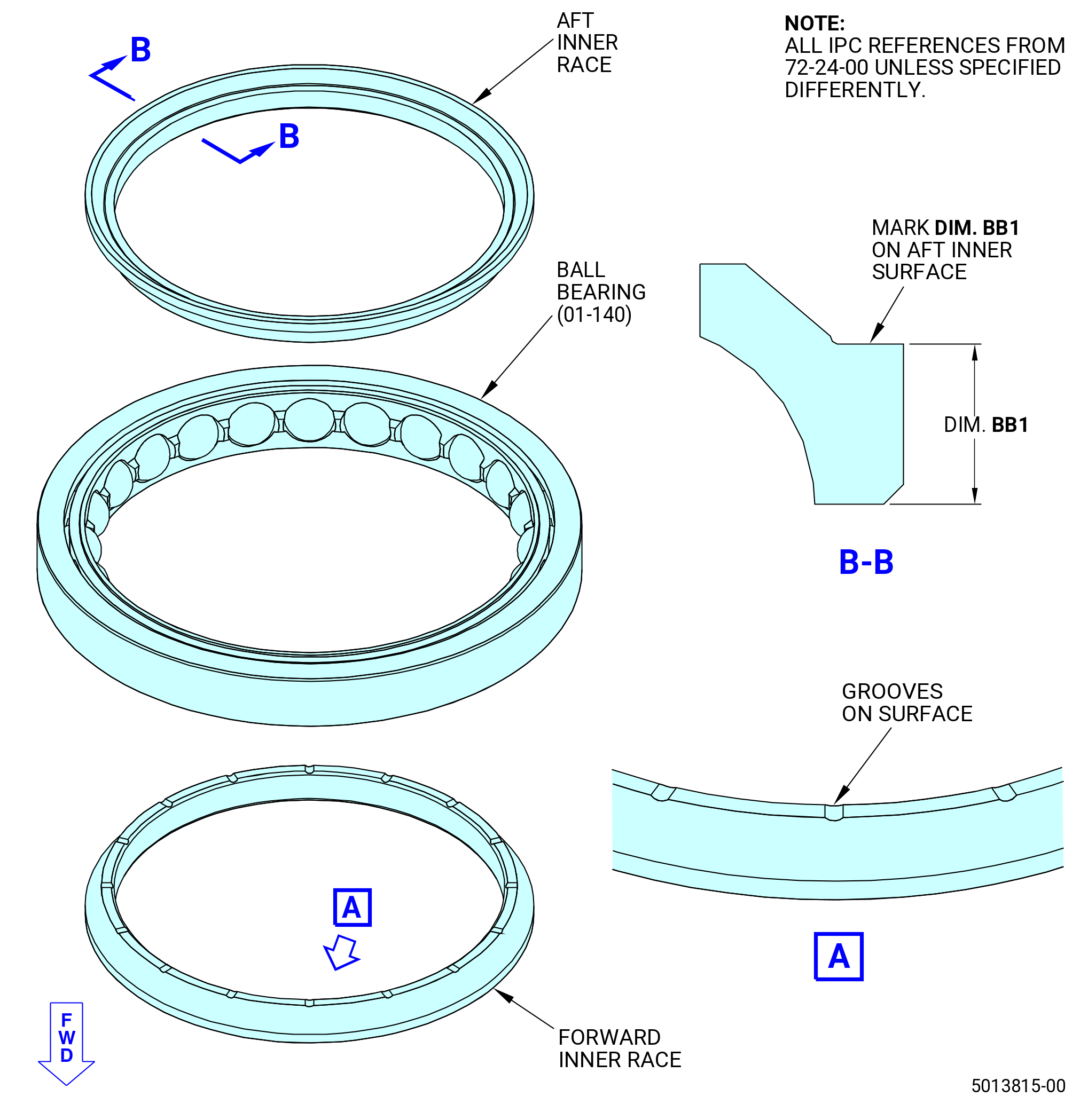
| (13) | Measure the dimensions that follow. Refer to Figure 1028. |
| NOTE: |
|
| (a) | Measure dimension BA1 from the aft face of the extension shaft to the aft face of the forward inner race at four equally spaced locations. |
| (b) | Calculate the average of the four measurements and record the result as Dimension BA1 on the record sheet. Figure 1028. |
| (c) | Measure Dimension BB1 on the aft inner race at four equally spaced locations. |
| (d) | Calculate the average of the four measurements and record the result as Dimension BB1 on the record sheet. Figure 1028. |
| (e) | Subtract dimension BB1 from dimension BA1 and record the result as calculated dimension FSDCAL. |
| Subtask 72-24-00-440-082 |
| CAUTION: |
|
| CAUTION: |
|
| CAUTION: |
|
| CAUTION: |
|
| R. | Install the housing assembly as follows: |
| NOTE: |
|
| Subtask 72-24-00-440-083 |
| (1) | Prepare to lift the housing assembly with the 11C3118 lift and turn fixture as follows. Refer to Figure 1029. |
| NOTE: |
|
| (a) | Make sure the ball-lock pins (item 8) are installed in the saddle assembly (item 2). |
| (b) | Make sure the ball-lock pin (item 3) is installed in the support beam (item 6). |
| (2) | Lift the housing assembly and turn the forward fan shaft with the forward end down as follows: |
| (a) | Make sure that the 9C2104 retaining tool and shims (item 2) of the 9C2131 shim set are correctly installed. |
| (b) | Remove the ball lock pins (item 8) of the 11C3118 lift and turn fixture from the pivots (item 4). |
| CAUTION: |
|
| (c) | Turn the housing assembly in the pivot (item 4) of the 11C3118 lift and turn fixture to put the housing assembly forward end down. |
| (d) | Install the ball-lock pins (item 8) in the pivot (item 4). |
| (3) | Lower the housing assembly onto the ball bearing (012A0) forward inner race. Make sure that the 9C2104 retaining tool does not touch the shaft extension and disengage. |
| NOTE: |
|
| (4) | Remove the 9C2104 retaining tool. |
| (5) | Remove the 11C3118 lift and turn fixture as follows: |
| (a) | Remove the washer assemblies (item 9) from the saddle |
| (b) | Remove the ball lock pin (item 3) to unlock the leg of the support beam assembly (item 6). |
| WARNING: |
|
| (c) | Move the support beam assembly (item 6) away from the housing assembly and remove the 11C3118 lift and turn fixture. |
| Subtask 72-24-00-440-084 |
| CAUTION: |
|
| CAUTION: |
|
| CAUTION: |
|
| CAUTION: |
|
| S. | Install the aft inner race of the ball bearing (01-140) (SIN 012A0) as follows: |
| Subtask 72-24-00-160-008 |
| WARNING: |
|
| WARNING: |
|
| WARNING: |
|
| (1) | Use C04-035 isopropyl alcohol or equivalent to clean the surfaces of mating flanges of the ball bearing (01-140) (SIN 012A0) aft inner race. Refer to TASK 72-24-00-440-801 (paragraph 1.D.(1)). |
| Subtask 72-24-00-440-085 |
| WARNING: |
|
| (2) | Alternative Procedure Available. Use the heater to increase the temperature of the aft inner race to 230°F (110°C) maximum. |
| Subtask 72-24-00-440-158 |
| WARNING: |
|
| (2).A. | Alternative Procedure. Use the induction heater to increase the temperature of the aft inner race of the ball bearing (01-140) (SIN 012A0) as follows: |
| (a) | Adjust the 11C4533 support ring to the center of the induction heater yoke and move it down until it is installed on the induction heater flat surface. |
| (b) | Adjust the aft inner race of the ball bearing to the center of the induction heater yoke and move it down until it is installed on the 11C4533 support ring. |
| (c) | Increase the temperature of the aft inner race of the ball bearing to 230°F (110°C). |
| Subtask 72-24-00-440-156 |
| (3) | Install the ball bearing (01-140) (SIN 012A0) aft inner ring in the housing (01-110) (SIN 01203). Refer to Figure 1030 and do as follows: |
| (a) | Align the mark on the aft face of the aft inner race with the mark on the shaft extension (01-150) (SIN 81005) or (01-151) (SIN 81005) and install the aft inner race on the No. 2 bearing journal on the extension shaft. |
| (b) | Turn the thrust ring (item 2) onto the shaft extension (01-150) (SIN 81005) or (01-151) (SIN 81005). |
| (c) | Turn the handles on the 11C4257 seating fixture until the aft inner race is seated. |
| (d) | Allow the forward inner race to go back to ambient temperature. |
| (4) | Remove the thrust ring (item 2) from the aft inner race. |
| Subtask 72-24-00-220-019 |
| T. | Do an inspection of dimension FSDACT as follows: |
| Subtask 72-24-00-220-020 |
| (1) | Measure dimension FSDACT on the shaft extension (01-150) (SIN 81005) or (01-151) (SIN 81005) as follows: |
| (a) | Measure dimension FSDACT at marked location on the extension shaft to the marked location on the aft face of the aft inner race. Refer to Figure 1030. |
| (b) | Record the result as dimension FSDACT. Refer to Figure 1028. |
| Subtask 72-24-00-220-022 |
| (2) | Compare dimension FSDACT to calculated dimension FSDCAL. Refer to Figure 1028. Dimension FSDACT is serviceable if: |
| • |
|
| Subtask 72-24-00-440-086 |
| (a) | Alternative Procedure Available. If dimension FSDACT is serviceable, refer to Subtask 72-24-00-440-088 (paragraph 3.S.) to continue this procedure. |
| Subtask 72-24-00-440-087 |
| (a).A. | Alternative Procedure. If dimension FSDACT is not serviceable, stop here. Speak to your GEAE representative. |
| Subtask 72-24-00-440-088 |
| CAUTION: |
|
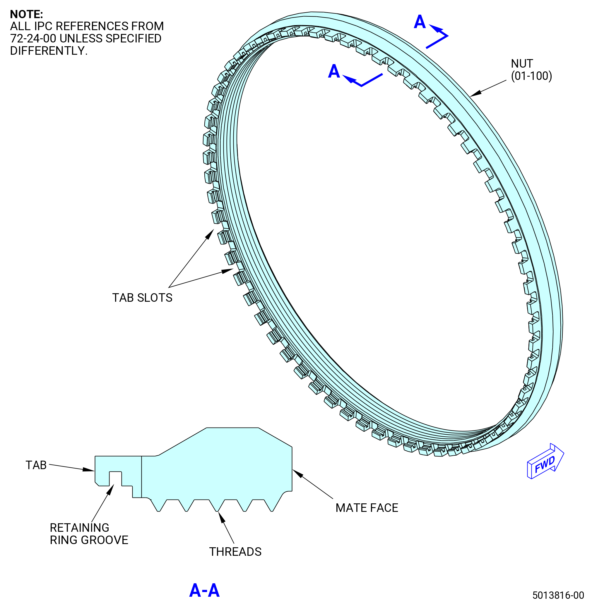
| U. | Install the nut (01-100) (SIN 012K0) on the shaft extension (01-150) (SIN 81005) or (01-151) (SIN 81005). Refer to Figure 1031 and do as follows: |
| Subtask 72-24-00-160-004 |
| WARNING: |
|
| WARNING: |
|
| WARNING: |
|
| (1) | Use C04-035 isopropyl alcohol or equivalent to clean the nut and shaft extension. Refer to TASK 72-24-00-440-801 (paragraph 1.D.(1)) and do as follows: |
| (a) | Clean the threads and mate face of the mid nut. Refer to Figure 1031. |
| (b) | Clean the mating threads of the shaft extension. Refer to Figure 1032. |
| Subtask 72-24-00-640-003 |
| (2) | Apply C02-058 lubricant to the mid nut and shaft extension as follows: |
| (a) | Lubricate the threads and mate face of the mid nut. |
| (b) | Lubricate the mating threads of the shaft extension. |
| Subtask 72-24-00-440-090 |
| (3) | Install the nut (01-100) (SIN 012K0) on the shaft extension (01-150) (SIN 81005) or (01-151) (SIN 81005). |
| (a) | Manually turn the mid nut on the threads on the shaft extension. |
| (4) | Install the 11C4583 adapter (or suitable equivalent tool) and torque multiplier as follows. Refer to Figure 1032. |
| NOTE: |
|
| (a) | Install the splined shaft (item 4) and the gear extension ring (item 5) as follows: |
| WARNING: |
|
| 1 | Attach an overhead hoist to the side-pull style hoist ring (item 11) to lift the splined shaft (item 4), with the gear extension ring (item 5) attached. |
| 2 | Lower the splined shaft (item 4) until the gear extension ring (item 5) engages the slots on the shaft extension. |
| (b) | Install the base (item 2) and the gear nut ring (item 3) as follows: |
| WARNING: |
|
| 1 | Attach the four-piece sling to the four side-pull style hoist rings (item 11) of the base (item 2) and to an overhead hoist. |
| 2 | Lift the base (item 2), with the gear nut ring (item 3) attached, and align it as follows: |
| a | Align the hole in the center of the base (item 2) with the splined shaft (item 4). |
| b | Align the tabs of the gear nut ring (item 3) with the tab slots of the mid nut. Refer to Figure 1031. |
| (c) | Install the torque multiplier as follows. Refer to Figure 1032. |
| WARNING: |
|
| 1 | Align the splines of the torque multiplier with the splines of the splined shaft (item 4). |
| 2 | Align the legs of the torque multiplier with the holes in the base (item 2). |
| 3 | Install the torque multiplier on the base (item 2). |
| 4 | Replace the standard graduated ring with the graduated ring (item 9). Align a graduation mark with the reference line on the torque multiplier. |
| 5 | Install the hoist ring (item 10) with the splined shaft (item 4). Align the notch with the reference line on the torque multiplier. |
| Subtask 72-24-00-440-091 |
| (5) | Torque the mid nut with the torque multiplier as follows: |
| (a) | Torque the mid nut to 10000 lb ft (13558 Nm). |
| (b) | Break the torque on the mid nut. |
| (c) | Torque the nut to 1000 lb ft (1356 Nm). |
| (d) | Set the angle mark on the torque multiplier to zero. |
| (e) | Increase the torque until the angle mark reads 35-41 degrees and to align the slot on nut with a slot on the shaft extension. Do not torque more than the maximum torque of 25000 lb ft (33895 Nm). The slots are aligned when the marks on the graduated rings (items 9 and 10) are aligned. |
| NOTE: |
|
| (6) | Remove the graduated rings (items 9 and 10). |
| WARNING: |
|
| (7) | Remove the torque multiplier with an overhead hoist. |
| (8) | Remove the remaining items of the 11C4583 adapter. |
| Subtask 72-24-00-440-092 |
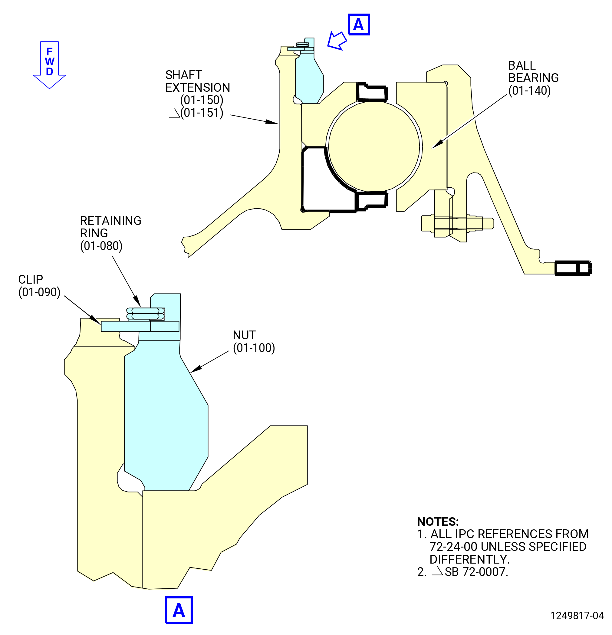
| (9) | Install the clips (01-090) (SIN 012W2). Refer to Figure 1033 and do as follows: |
| (a) | Install one clip, convex side down (forward), where a slot of the mid nut aligns with a slot on the shaft extension. |
| (b) | Install the other clip, convex side down, 174-186 degrees opposite of the first clip. |
| Subtask 72-24-00-220-043 |
| (c) | Do a visual inspection for the clips (01-090) (SIN 012W2) separation to make sure that the two clips are between 174-186 degrees opposite to each other. |
| Subtask 72-24-00-440-093 |
| (10) | Install the double turn and locked internal retaining ring (01-080) (SIN 01280) in the retaining ring groove on the nut. Refer to Figure 1031 and Figure 1033. |
| Subtask 72-24-00-220-047 |
| (11) | Do a general visual inspection of the exposed surfaces of the forward fan shaft for nicks, dents, and scratches after the removal of tooling. Refer to TASK 72-00-24-200-801 (72-00-24, INSPECTION 001). |
| Subtask 72-24-00-220-023 |
| CAUTION: |
|
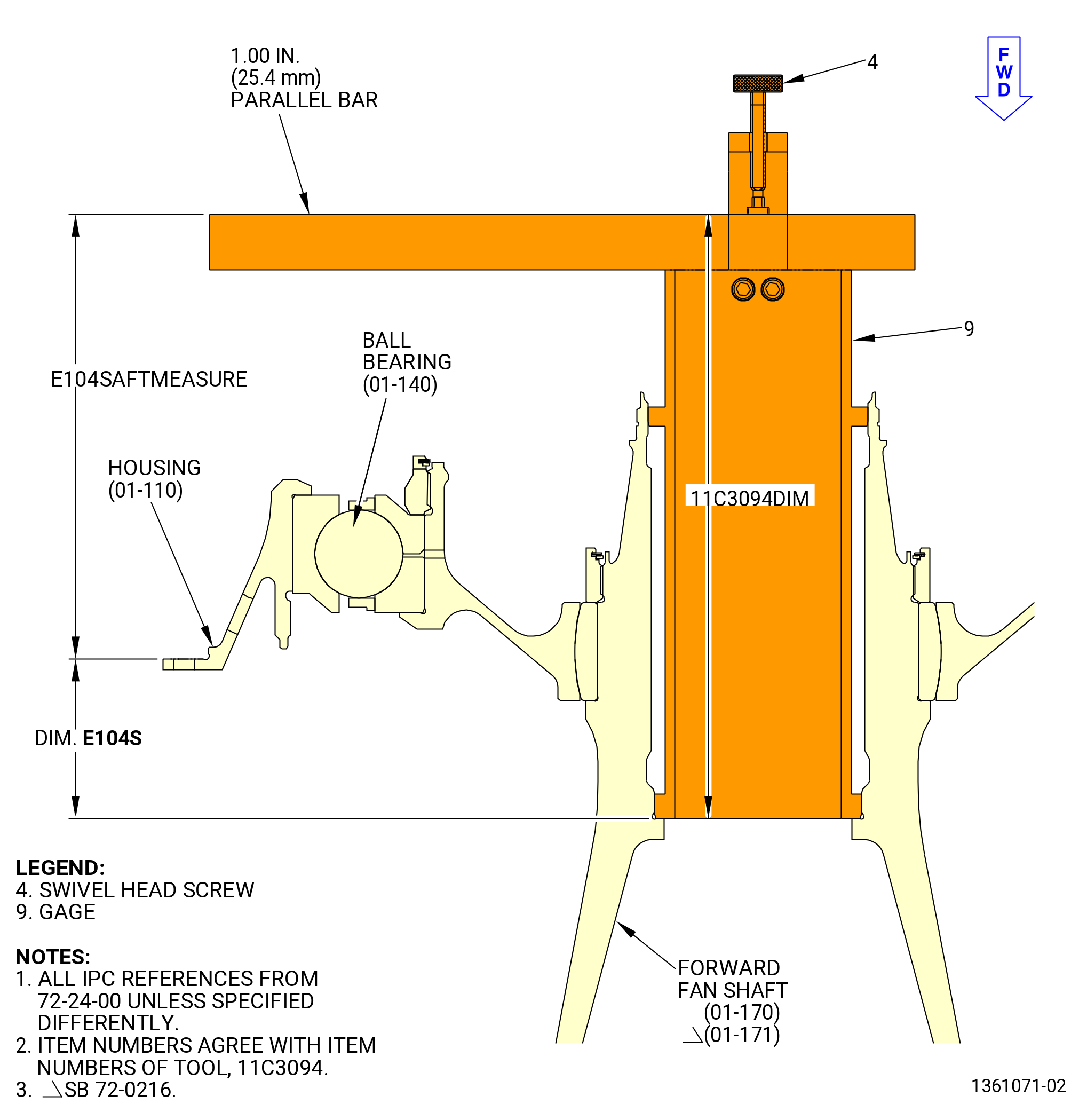
| V. | Measure the thrust load with the 11C3094 seating fixture as follows. Refer to Figure 1034. |
| Subtask 72-24-00-220-024 |
| (1) | Install the 11C3094 seating fixture in the shaft as follows: |
| WARNING: |
|
| (a) | Use an overhead hoist to lift the 11C3094 seating fixture. |
| (b) | Lower the gage (item 9) of the 11C3094 seating fixture into the aft end of the forward fan shaft bore. |
| (c) | Loosen the swivel head screw (item 4) and install a 1 inch (25.4 mm) parallel bar. |
| (d) | Tighten the swivel head screw (item 4). |
| Subtask 72-24-00-220-025 |
| (2) | Measure the ball bearing (01-140) (SIN 012A0) dimension E104SAFT pre-load dimensions as follows: |
| NOTE: |
|
| (a) | Turn the bearing four full turns. |
| NOTE: |
|
| (b) | Measure dimension E104SAFTMEASURE at four equally spaced locations. Refer to Figure 1034. |
| 1 | Use a depth gauge to measure from the top of the parallel bar to the aft flange of the housing (01-110) (SIN 01203) at four equally spaced locations. Refer to Figure 1034. |
| 2 | Locally determine dimension 11C3094DIM as the assembled 11C3094 and 1.00 parallel bar. |
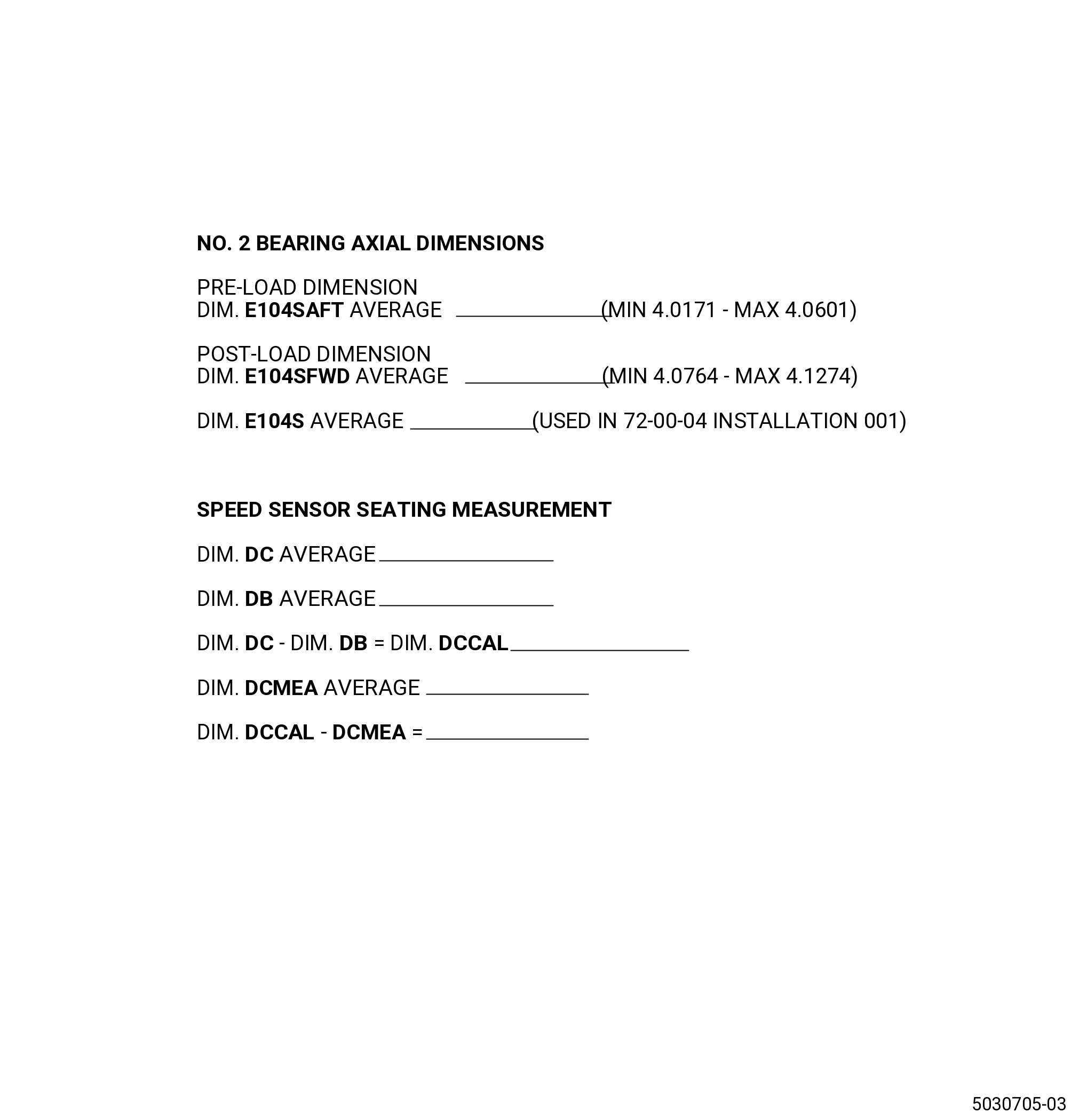
| (c) | E104SAFT = 11C3094DIM - E104SAFTMEASURE. Calculate the average of the four equally spaced measures taken. This value must be between 4.0171 - 4.0601 inch (102.035 - 103.126 mm). |
| (d) | Record the result as dimension E104SAFT on the Record Sheet in the pre-load column. Refer to Figure 1035. |
| Subtask 72-24-00-220-026 |
| (3) | Install the 11C3118 lift and turn fixture as follows. Refer to Figure 1036. |
| WARNING: |
|
| (a) | Attach the support beam (item 6) to an overhead hoist. |
| (b) | Remove the ball-lock pin (item 3) from the support beam assembly (item 6). |
| (c) | Carefully lower the saddle assembly (item 2) on the housing (01203). |
| (d) | Attach the saddle assembly (item 2) to the housing with the assembly washer (item 9). |
| (e) | Install the ball-lock pin (item 3) in the support beam assembly (item 6). |
| (f) | Remove the ball-lock pin (item 8). |
| CAUTION: |
|
| (g) | Apply a lift pressure to the ball bearing (01-140) (SIN 012A0) while the ball bearing and housing are installed in the 9401M62 adjustable stand. |
| Subtask 72-24-00-220-028 |
| (4) | Measure the post-load dimensions that follow: |
| (a) | Turn the bearing four full turns. |
| (b) | Measure dimension E104SFWDMEASURE at four equally-spaced locations. Refer to Figure 1036. |
| 1 | Use a depth gauge to measure from the top of the parallel bar to the aft flange of the housing (01-110) (SIN 01203) at four equally-spaced locations. |
| 2 | Locally determine dimension 11C3094DIM as the assembled 11C3094 and 1.00 parallel bar. |
| (c) | E104SFWD = 11C3094DIM - E104SFWDMEASURE. Calculate the average of the four equally-spaced measures taken. This value must be between 4.0764 - 4.1274 inch (103.541 - 104.835 mm). |
| (d) | Record the result as dimension E104SFWD on the Record Sheet in the post-load column. Refer to Figure 1035. |
| (e) | Calculate E104S as the average of 104SAFT and E104SFWD and record on the Record Sheet. Refer to Figure 1035. |
| Subtask 72-24-00-220-029 |
| (5) | Remove the 11C3118 lift and turn fixture as follows. Refer to Figure 1036. |
| (a) | Remove the washer assemblies (item 9) from the saddle assemblies (item 2). |
| (b) | Remove the ball lock pin (item 3) to unlock the support beam assembly (item 6). |
| (c) | Move the leg of the support beam assembly (item 6) away from the bearing housing assembly and remove the 11C3118 lift and turn fixture. |
| WARNING: |
|
| (d) | Lift the 11C3118 lift and turn fixture from the housing assembly. |
| (6) | Remove the 11C3094 seating fixture. |
| Subtask 72-24-00-220-048 |
| (7) | Do a general visual inspection of the exposed surfaces of the forward fan shaft for nicks, dents, and scratches after the removal of tooling. Refer to TASK 72-00-24-200-801 (72-00-24, INSPECTION 001). |
| Subtask 72-24-00-220-040 |
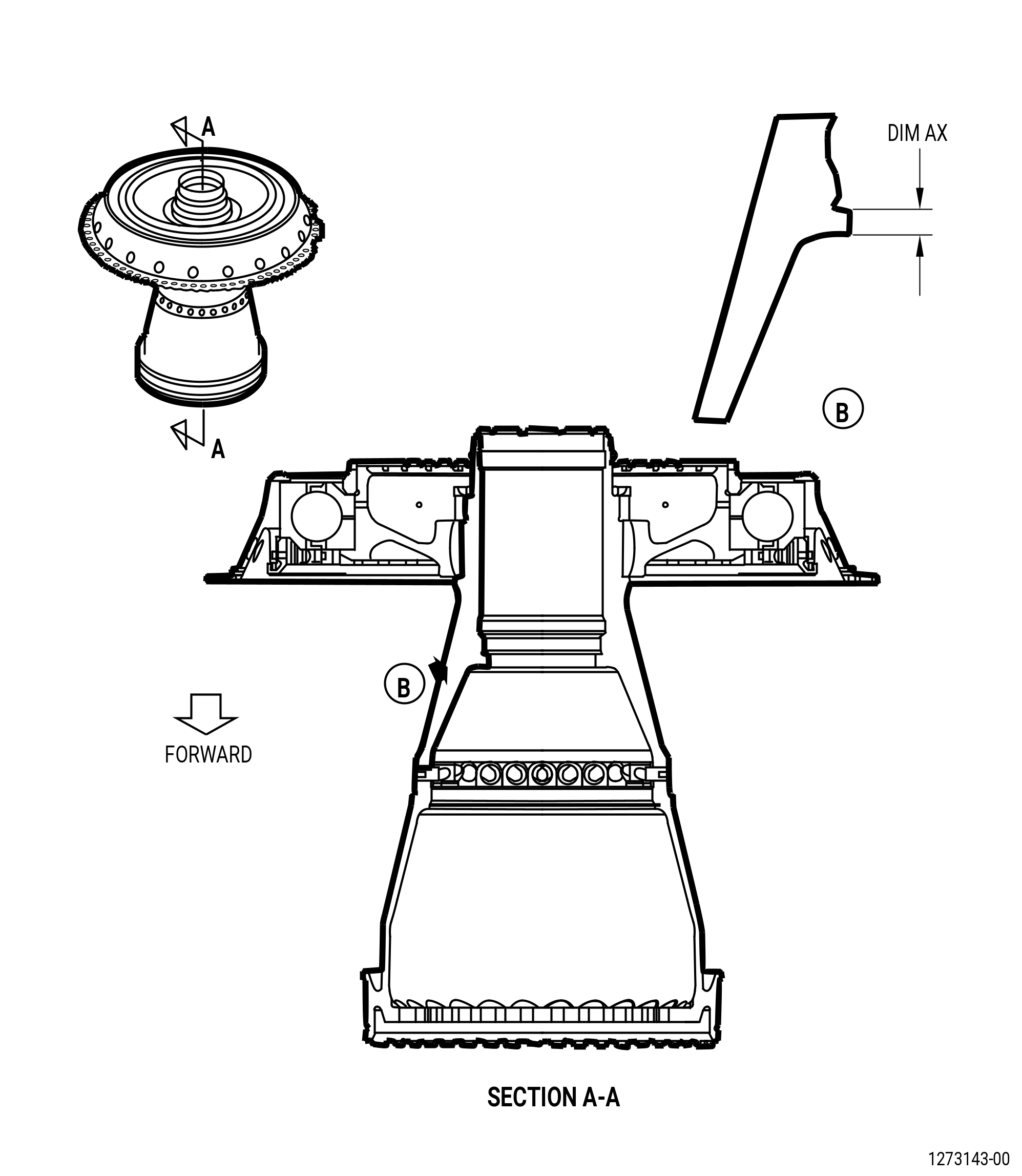
| W. | Measure dimension AX on the inside diameter of the forward fan shaft (01-170) (SIN 81002) or (01-171) (SIN 81002). Refer to Figure 1037 and do as follows: |
| (1) | Measure Dim. AX at four equally spaced locations. Dim. AX shall be 0.530-0.550 inch (13.46-13.97 mm). |
| (2) | Calculate the average and record as Dim. AX. |
| Subtask 72-24-00-440-094 |
| CAUTION: |
|
| X. | Install the fan speed sensor (speed sensor) (01-040) (SIN 012A1) on the forward fan shaft (01-170) (SIN 81002) or (01-171) (SIN 81002) as follows: |
| Subtask 72-24-00-100-001 |
| WARNING: |
|
| WARNING: |
|
| WARNING: |
|
| (1) | Use C04-035 isopropyl alcohol or equivalent to clean the surfaces of the speed sensor (01-040) (SIN 012A1). Refer to TASK 72-24-00-440-801 (paragraph 1.D.(1)). |
| (2) | Clean the forward fan shaft (01-170) (SIN 81002) or (01-171) (SIN 81002) where the speed sensor (01-040) (SIN 012A1) will be installed with C04-035 isopropyl alcohol or equivalent. Refer to TASK 72-24-00-440-801 (paragraph 1.D.(1)). |
| Subtask 72-24-00-220-030 |
| (3) | Measure the dimensions that follow: |
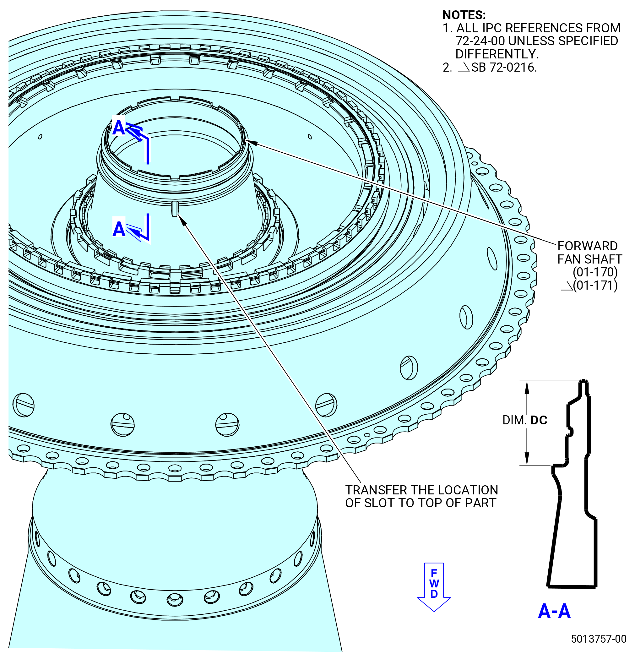
| (a) | Measure dimension DC on the shaft at four equally spaced locations. Refer to Figure 1038. |
| (b) | Use a C05-003 pen to mark each location on the aft face of the shaft. |
| (c) | Calculate the average dimension. |
| (d) | Record the result as dimension DC on the Record Sheet. Refer to Figure 1035. |
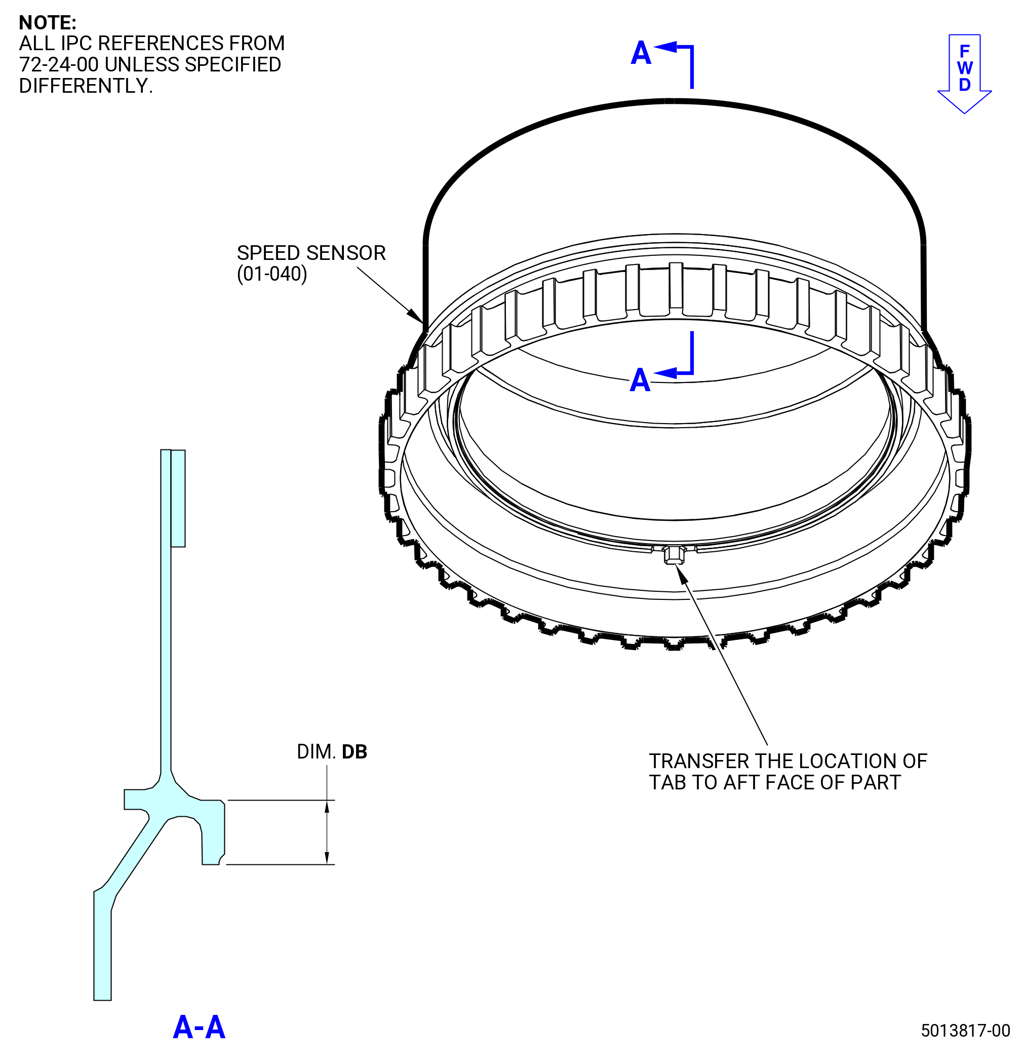
| (e) | Measure dimension DB on the speed sensor at four equally spaced locations. Refer to Figure 1039. |
| (f) | Calculate the average dimension. |
| (g) | Record the result as dimension DB on the Record Sheet. Refer to Figure 1035. |
| (h) | Subtract dimension DB from dimension DC and record the results as dimension DCCAL. |
| Subtask 72-24-00-440-125 |
| (4) | Find the tab on the ID of the speed sensor. |
| (5) | Use a C05-003 pen to mark the location of the tab on the aft face of the speed sensor. Refer to Figure 1039. |
| (6) | Find the slot for the speed sensor tab, located on the shaft. |
| (7) | Use a C05-003 pen to mark the location of the slot on the aft face of the shaft. Refer to Figure 1038. |
| Subtask 72-24-00-440-095 |
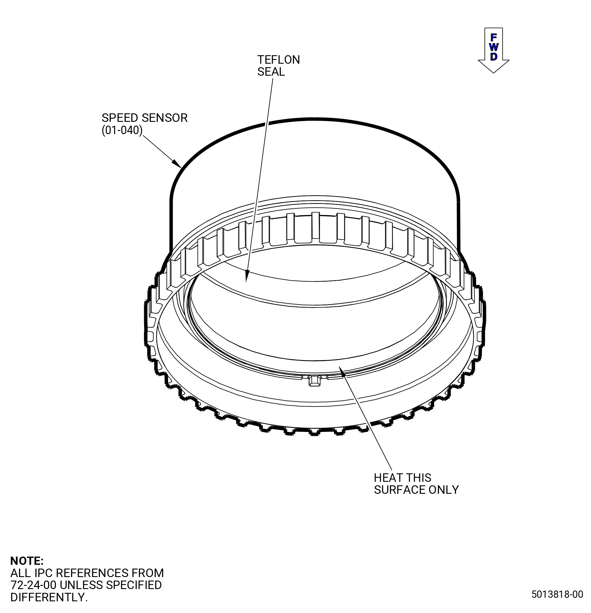
| (8) | Cover the Teflon seal of the speed sensor with foil to prevent damage during the heating process. Refer to Figure 1040. |
| CAUTION: |
|
| (9) | Use the heater at one-half power to increase the temperature of the speed sensor to 300°F (148.9°C). |
| Subtask 72-24-00-440-096 |
| (10) | Install the speed sensor on the shaft as follows: |
| WARNING: |
|
| (a) | Remove the foil from the Teflon seal of the speed sensor. |
| (b) | Align the tab (marked on aft face) of the speed sensor with the slot (marked on the aft face) of the shaft and install the speed sensor on the shaft. Refer to and Figure 1039. |
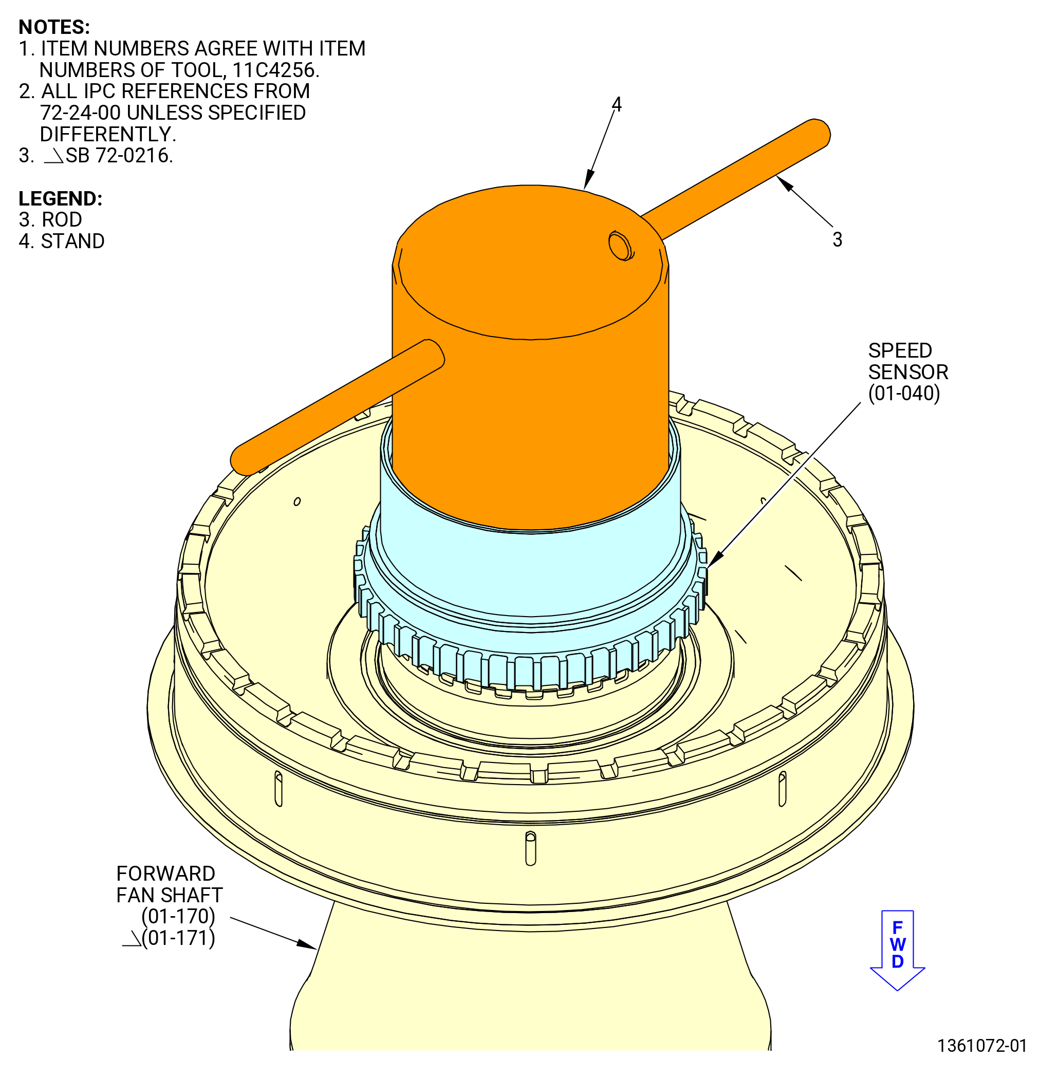
| (c) | Carefully install the stand (item 4) of the 11C4256 speed sensor seating fixture with the stand (item 4) against the aft surface of the speed sensor. Refer to Figure 1041. |
| (d) | Engage the threads of the stand (item 4) forward fan shaft threads. |
| (e) | Turn the rod (item 3) to tighten the stand (item 4) against the speed sensor. |
| (f) | Let the speed sensor go back to ambient temperature. |
| (g) | Remove the 11C4256 speed sensor seating fixture. |
| Subtask 72-24-00-220-049 |
| (11) | Do a general visual inspection of the exposed surfaces of the forward fan shaft for nicks, dents, and scratches after the removal of tooling. Refer to TASK 72-00-24-200-801 (72-00-24, INSPECTION 001). |
| Subtask 72-24-00-220-031 |
| Y. | Do an inspection of dimension DCMEA as follows: |
| Subtask 72-24-00-220-032 |
| (1) | Alternative Procedure Available. Measure dimension DCMEA on the forward fan shaft (01-170) (SIN 81002) or (01-171) (SIN 81002) and do as follows: |
| (a) | Refer to Subtask 72-24-00-220-024 (paragraph 3.V.(1)) to put the 11C3094 seating fixture in the assembly. |
| (b) | With a depth micrometer create a zero reading reference as the AFT face of the FFS. |
| (c) | Measure dimension DCMEA as the drop to the aft inner diameter of the speed sensor. Refer to Figure 1042. |
| (d) | Repeat steps (b) and (c) at four equally-spaced locations. |
| (e) | Calculate the average dimension. |
| (f) | Record the results as dimension DCMEA on the Record Sheet. Refer to Figure 1035. |
| Subtask 72-24-00-220-052 |
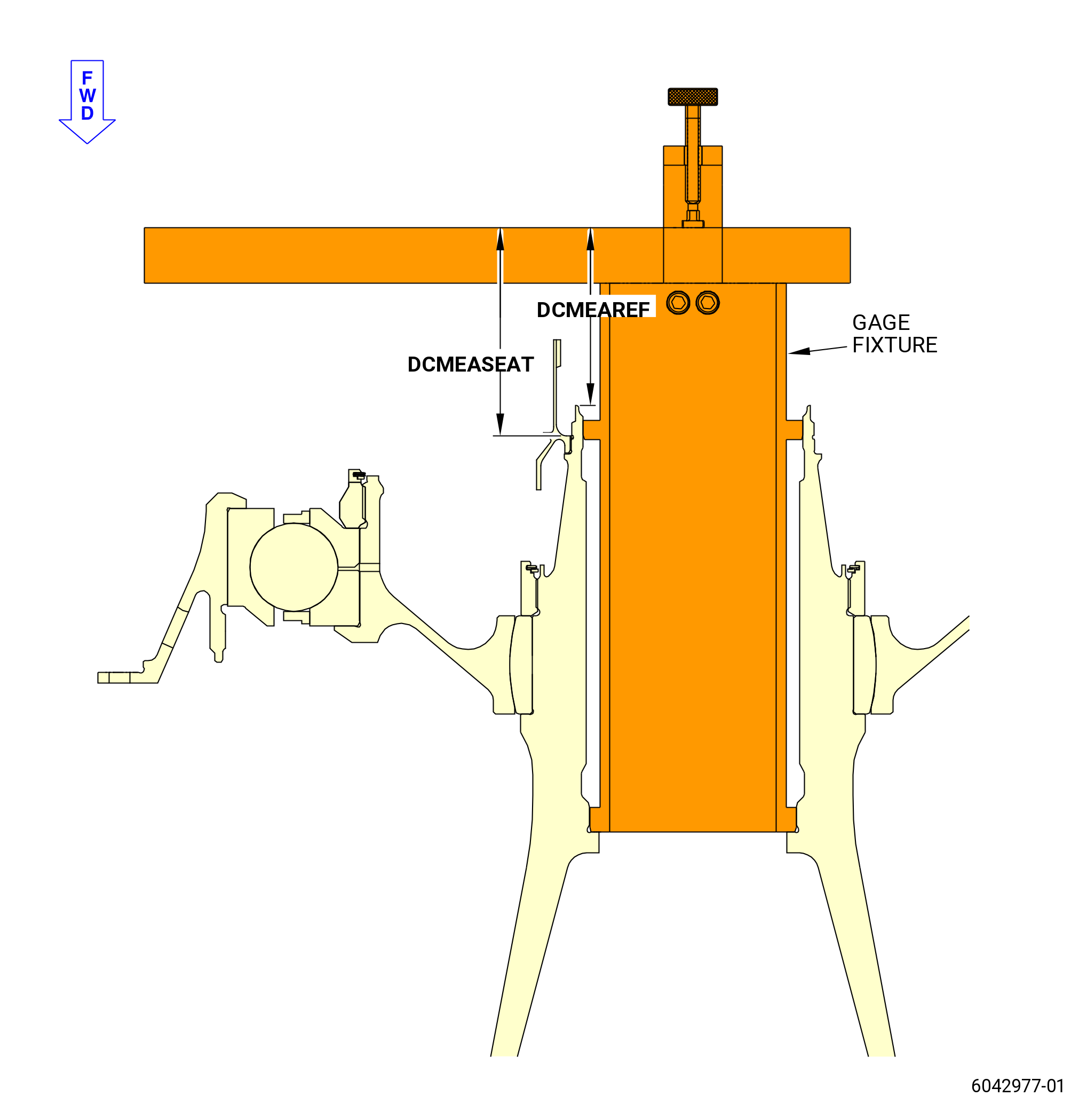
| (1).A. | Alternative Procedure. Measure dimension DCMEA on the forward fan shaft (01-170) (SIN 81002) or (01-171) (SIN 81002) as follows: |
| (a) | Refer to Subtask 72-24-00-220-024 (paragraph 3.V.(1)) to put the 11C3094 seating fixture in the assembly. |
| (b) | With a depth micrometer or similar gage measure drop to the AFT face of the FFS. Keep the value of this measure as DCMEAREF. Refer to Figure 1042. |
| (c) | Measure dimension DCMEASEAT as the drop to the aft inner diameter of the speed sensor. |
| (d) | Calculate DCMEA = DCMEASEAT - DCMEAREF |
| (e) | Repeat steps (b) through (d) at four equally spaced locations. |
| (f) | Calculate the average dimension DCMEA dimension with the four values determined in step (b) through (e). |
| (g) | Record the results as dimension DCMEA on the Record Sheet. Refer to Figure 1035. |
| Subtask 72-24-00-220-034 |
| (2) | Compare dimension DCMEA to dimension DCCAL on the Record Sheet. Refer to Figure 1035. Dimension DCMEA is serviceable if: |
| • |
|
| Subtask 72-24-00-440-097 |
| (a) | Alternative Procedure Available. If DCMEA to DCCAL comparison is serviceable to continue with module assembly. Refer to subtask 72-24-00-440-103 (paragraph 3.Z.). |
| Subtask 72-24-00-440-098 |
| (a).A. | Alternative Procedure. If DCMEA to DCCAL comparison is not serviceable stop here. Contact your GEAE representative. |
| Subtask 72-24-00-440-103 |
| CAUTION: |
|
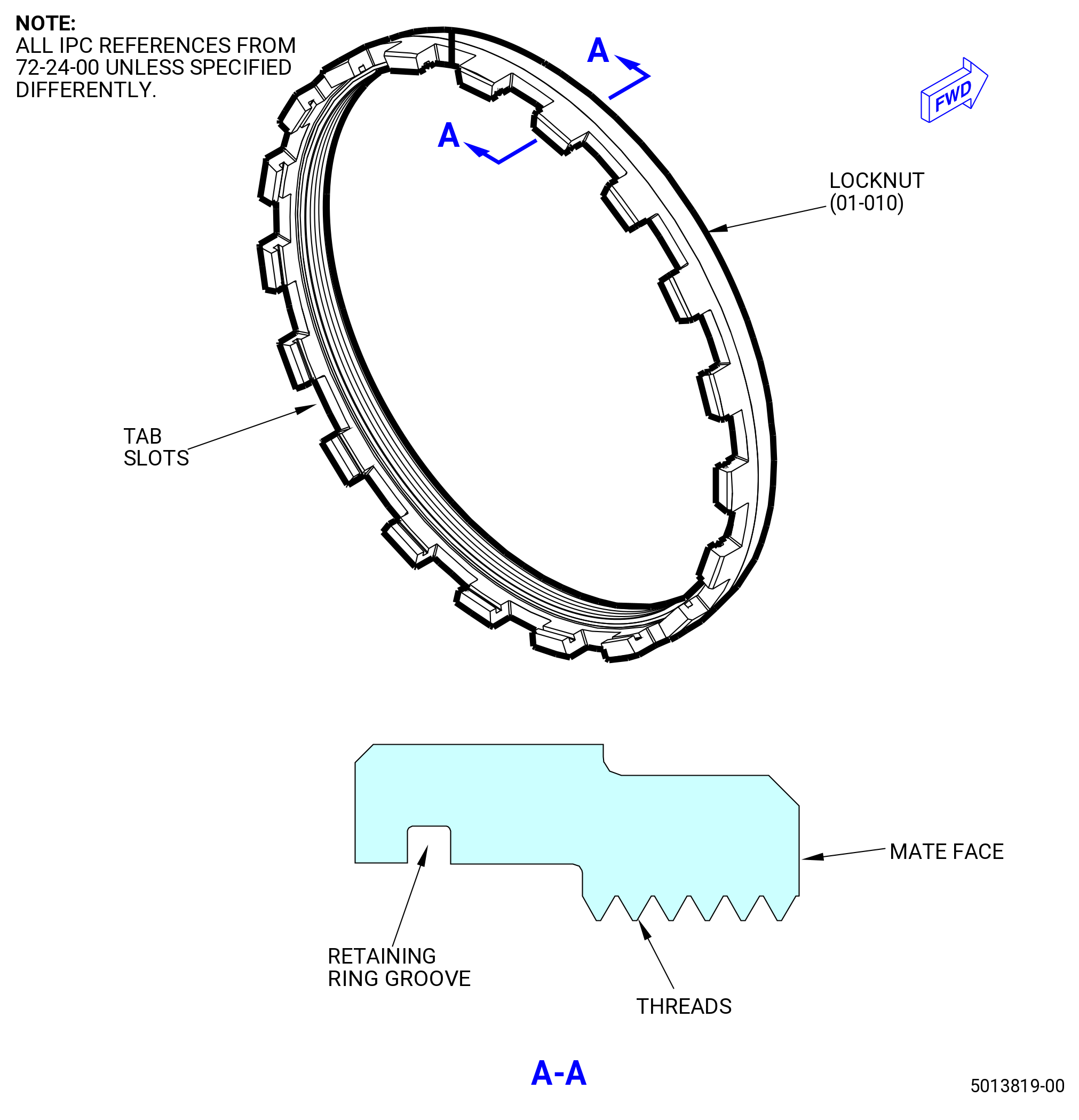
| Z. | Install the No. 2 bearing round nut (locknut) (01-010) (SIN 012A2) on the forward fan shaft (01-170) (SIN 81002) or (01-171) (SIN 81002). Refer to Figure 1043 and do as follows: |
| Subtask 72-24-00-160-009 |
| WARNING: |
|
| WARNING: |
|
| WARNING: |
|
| (1) | Use C04-035 isopropyl alcohol or equivalent to clean the surfaces of the locknut (01-010) (SIN 012A2) and the threads on the forward fan shaft (01-170) (SIN 81002) or (01-171) (SIN 81002). Refer to TASK 72-24-00-440-801 (paragraph 1.D.(1)). |
| Subtask 72-24-00-640-004 |
| WARNING: |
|
| (2) | Apply C02-019 engine oil or C02-023 engine oil to lubricate the locknut and the shaft as follows: |
| NOTE: |
|
| (a) | Lubricate the threads and mate face of the locknut. |
| (b) | Lubricate the mating threads of the shaft. |
| Subtask 72-24-00-440-142 |
| (3) | Manually thread the locknut to the threads on the shaft. |
| Subtask 72-24-00-440-105 |
| (4) | Torque the locknut (01-010) (SIN 012A2). Refer to Figure 1044 and do as follows: |
| (a) | Attach a hoist to the eye bolt (item 9) of the 11C3129 adapter. |
| (b) | Put the splined shaft (item 3) with the gear shaft (item 4) attached in the forward fan shaft. |
| (c) | Install the base (item 2) and the gear ring (item 7) as follows: |
| NOTE: |
|
| WARNING: |
|
| 1 | Attach the three-piece sling to the two hoist rings (item 8) of the base (item 2) and to an overhead hoist. |
| NOTE: |
|
| 2 | Lift the base (item 2), with the gear ring (item 7) attached, and align it as follows. Refer to and Figure 1044. |
| a | Align the hole in the center of the base (item 2) with the spline shaft (item 3). |
| b | Align the tabs of the gear ring (item 7) with the tab slots of the locknut. Refer to Figure 1043. |
| (d) | Install the torque multiplier as follows. Refer to Figure 1044. |
| WARNING: |
|
| 1 | Align the splines of the torque multiplier with the splines of the spline shaft (item 3). |
| 2 | Align the legs of the torque multiplier with the holes in the base (item 2). |
| 3 | Install the torque multiplier on the base (item 2). |
| 4 | Put one graduated ring (smaller ID) on the splines of the spline shaft (item 3). |
| 5 | Put one graduated ring (larger ID) on the torque multiplier. |
| (e) | Torque the locknut with the torque multiplier as follows: |
| 1 | Torque the locknut to 1000 lb ft (1356 N.m). |
| 2 | Break the torque on the locknut. |
| 3 | Torque the locknut again to 450 lb ft (610 N.m). |
| CAUTION: |
|
| 4 | Increase the torque a sufficient amount to a maximum torque of 850 lb ft (1152 N.m). |
| NOTE: |
|
| (f) | Remove the torque multiplier . |
| (g) | Remove the 11C3129 adapter . |
| Subtask 72-24-00-440-107 |
| (5) | Install the keyed ring (01-020) (SIN 012W1) and the double turn and locked internal retaining ring (01-030) (SIN 012W0). Refer to Figure 1045 and do as follows: |
| (a) | Align the internal tabs of the keyed ring with the slots on the shaft. |
| (b) | Align the external tabs of the keyed ring with the slots on the locknut. |
| (c) | Install the keyed ring. |
| (d) | Install the retaining ring (01-030) (SIN 012W0) in the groove of the locknut (01-010) (SIN 012A2) to lock the keyed ring in position. Make sure that the retaining ring is fully installed in the groove of the locknut. |
| (e) | If the keyed ring can not be installed, correct as follows: |
| 1 | Install the 11C3129 adapter and the torque multiplier . Refer to Subtask 72-24-00-440-105 (paragraph 3.X.(4)). |
| 2 | Increase the torque a sufficient amount to align a slot on the inner nut with a slot on the shaft. Do not torque the inner nut to more than the maximum torque of 850 lb ft (1152 N.m). |
| 3 | Remove the torque multiplier . |
| 4 | Remove the 11C3129 adapter . |
| 5 | Install the keyed ring in the slots. Refer to Subtask 72-24-00-440-107 (paragraph 3.X.(5)(a)) thru Subtask 72-24-00-440-107 (paragraph 3.X.(5)(c)) . |
| (6) | Install internal retaining ring in the retaining ring groove on the locknut to lock the keyed ring in position. Refer to Figure 1043 and Figure 1045. |
| Subtask 72-24-00-220-050 |
| (7) | Do a general visual inspection of the exposed surfaces of the forward fan shaft for nicks, dents, and scratches after the removal of tooling. Refer to TASK 72-00-24-200-801 (72-00-24, INSPECTION 001). |
| Subtask 72-24-00-620-004 |
| AA. | Do the preservation the No. 2 ball bearing assembly (20-030 , 72-00-02) (SIN 01200) and the inner race of the No. 1 roller bearing (01-080 , 72-23-00) (SIN 011A0) on the forward end of the forward fan shaft (01-170) (SIN 81002) or (01-171) (SIN 81002). Refer to TASK 70-60-01-620-002 (PRESERVATION OF ANTIFRICTION BEARINGS). |
| Subtask 72-24-00-440-108 |
| CAUTION: |
|
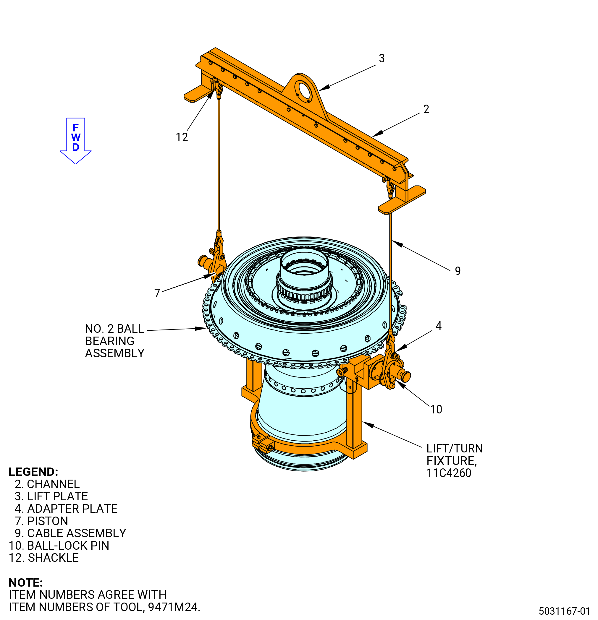
| AB. | Alternative Procedure Available. Attach the 9471M24 lift/turn fixture. Refer to Figure 1046 and as follows: |
| WARNING: |
|
| (1) | Attach an overhead hoist to the lift plate (item 3) of the 9471M24 lift/turn fixture. |
| (2) | Attach the cable assemblies (item 9) with the shackles (item 12) in the same number hole in the lift plate (item 3). Make sure the cable assemblies (item 9) are perpendicular to the lift plate (item 3) after connection to the 11C4260 lift/turn fixture. |
| (3) | Remove the ball lock pin (item 10), open the piston (item 7) and install the adapter plate (item 4) on the trunnion of the 11C4260 lift/turn fixture. |
| (4) | Install the ball lock pin (item 10) of the 9471M24 lift/turn fixture in the adapter plate (item 4). |
| Subtask 72-24-00-440-148 |
| CAUTION: |
|
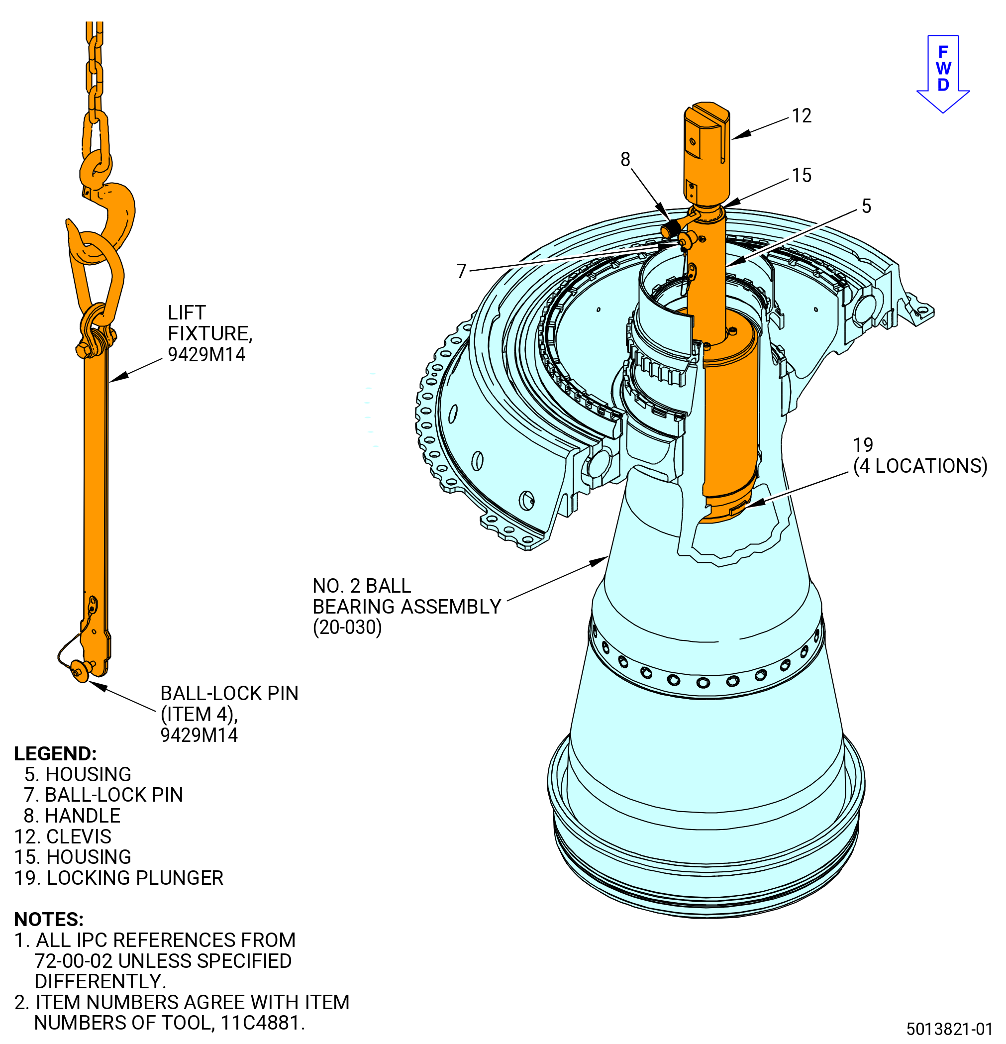
| AB.A. | Alternative Procedure. Install the 11C4881 handling fixture in the No. 2 ball bearing assembly (20-030 , 72-00-02) (SIN 01200). Refer to Figure 1047 and do as follows: |
| CAUTION: |
|
| (1) | Make sure that the ball-lock pin (item 7) is in the housing (item 5) hole marked UNLOCKED to retract the locking plunger (item 19). |
| WARNING: |
|
| (2) | Lower the 11C4881 handling fixture fully into the shaft. |
| (3) | Remove the ball-lock pin (item 7). |
| (4) | Turn the handle (item 8) until the hole in the housing (item 5) marked LOCKED is aligned with the hole in the inner housing (item 15) to engage the plungers (item 19). |
| (5) | Install the ball-lock pin (item 7). |
| WARNING: |
|
| (a) | Attach a hoist to lift the 9429M14 lift fixture. Refer to Figure 1047. |
| (b) | Align the 9429M14 lift fixture with the pinholes in the clevis (item 12) of the 11C4881 handling fixture. |
| (c) | Install the ball-lock pin (item 4) of the 9429M14 lift fixture to attach the 11C4881 handling fixture to the 9429M14 lift fixture. |
| Subtask 72-24-00-440-153 |
| CAUTION: |
|
| AC. | Install the No. 2 ball bearing assembly (20-030 , 72-00-02) (SIN 01200) on the 2C81801 holding fixture. Refer to Figure 1048 and do as follows: |
| (1) | If necessary, adjust the distance between the left upright (item 2) and right upright (item 3) to get the correct distance between the two trunnion blocks (item 15) as follows: |
| (a) | Turn the locking knob (item 14) CCW to loosen the left upright (item 2) from the right upright (item 3). |
| (b) | Turn the knob (item 6) CW or CCW to get the correct distance between the two trunnion blocks (item 15) |
| (c) | Turn the locking knob (item 14) CW to tighten the left upright (item 2) to the right upright (item 3). |
| (2) | Remove the two quick release pins (item 17), one from each trunnion block (item 15). |
| (3) | Install the No. 2 ball bearing assembly (20-030 , 72-00-02) (SIN 01200) with the 11C4260 lift/turn fixture in the 2C81801 holding fixture. Make sure that the 11C4260 lift/turn fixture attaches correctly in the two trunnion blocks (item 15). |
| (4) | Install two quick release pins (item 17), one through each front frame trunnion and in the trunnion blocks (item 15). |
| Subtask 72-24-00-220-051 |
| (5) | Do a general visual inspection of the exposed surfaces of the forward fan shaft for nicks, dents, and scratches after the removal of tooling. Refer to TASK 72-00-24-200-801 (72-00-24, INSPECTION 001). |
| Subtask 72-24-00-440-151 |
| AD. | Continue to install the No. 2 ball bearing assembly. Refer to TASK 72-00-24-420-802 (72-00-24, INSTALLATION 001). |