| GENX-1B ENGINE MANUAL | Dated: 04/30/2019 | |
| EM 72-30-00 , ASSEMBLY 002 | ||
| HIGH PRESSURE COMPRESSOR MODULE ASSEMBLY - ASSEMBLY 002 - CONFIGURATION 01 | ||
| GENX-1B ENGINE MANUAL | Dated: 04/30/2019 | |
| EM 72-30-00 , ASSEMBLY 002 | ||
| HIGH PRESSURE COMPRESSOR MODULE ASSEMBLY - ASSEMBLY 002 - CONFIGURATION 01 | ||
| * * * FOR 1B/P/G03.1B/P/G04.1B/P1/G01 |
| TASK 72-30-00-440-802 |
| 1 . | General. |
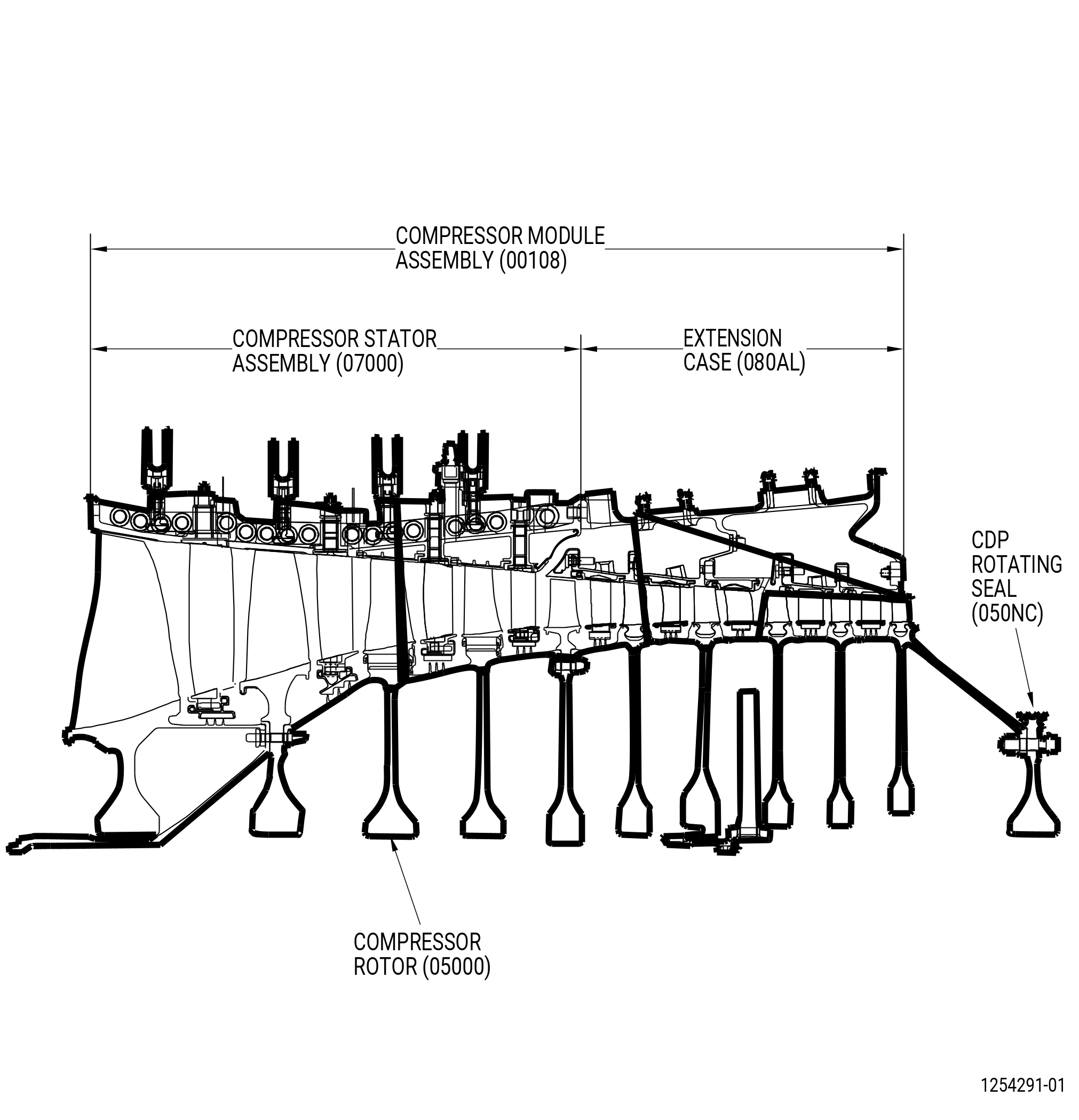
| A. | This procedure gives instructions to continue the assembly of the high pressure compressor (HPC) module assembly (HPC assembly) (00108). This procedure includes the assembly and rigging procedures for the variable stator vane (VSV) system. Make sure that the HPC assembly is at the equivalent build status of TASK 72-30-00-440-801 (72-30-00, ASSEMBLY 001) . Refer to Figure 1001. |
| B. | The HPC assembly is assumed to be installed on the 11C4279 core module buildup fixture or on the 11C3010 core module buildup fixture . |
| C. | All directions are aft looking forward (ALF), unless specified differently. |
| D. | This procedure gives instructions for VSV actuator system adjusting and rigging. There are two types of VSV torque shaft design. Do the correct procedure given to proper torque shaft linkage design installed on the engine. All rigging instructions for configuration 2 and configuration 3 are the same. |
| (1) | Shimmed, separable clevis torque shaft linkage. |
| • |
|
| (2) | Integral clevis torque shaft linkage. |
| • |
|
| • |
|
| E. | Follow the instructions to safety parts with safety wire, safety cable, cotter pins, or tab washers. Refer to TASK 70-11-00-400-001 (FASTENER RETENTION PROCEDURES) . |
| 2 . | Tools, Equipment, and Materials. |
| NOTE: |
|
| A. | Tools and Equipment. |
| (1) | Special Tools. |
| (2) | Standard Tools and Equipment. None. |
| (3) | Locally Manufactured Tools. None. |
| B. | Consumable Materials. |
|
| C. | Referenced Procedures. |
|
| D. | Expendable Parts. |
|
| 3 . | Procedure. |
| Subtask 72-30-00-220-002 |
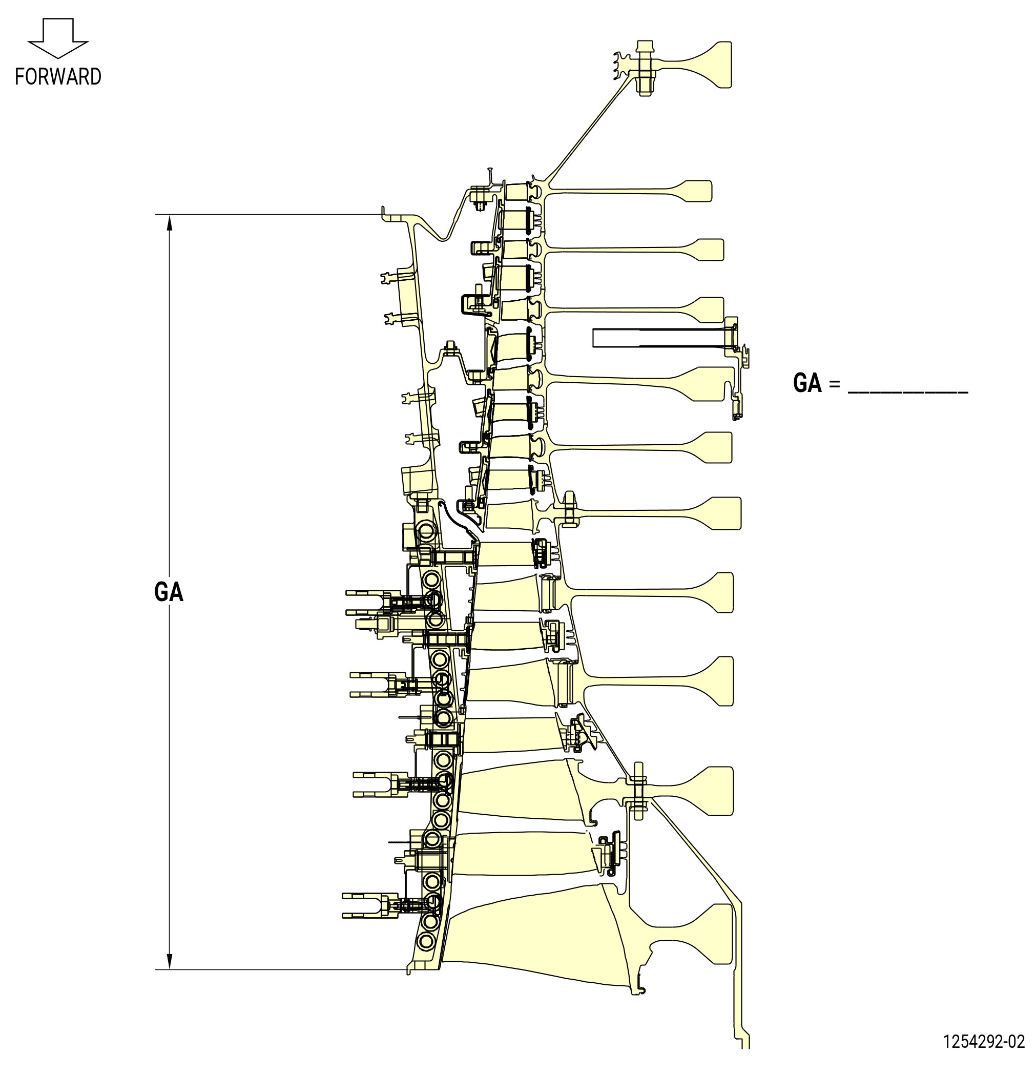
| A. | Measure the axial dimensions of the HPC assembly (00108) as follows. Refer to Figure 1002. |
| WARNING: |
|
| CAUTION: |
|
| (1) | Remove all special tools or lift fixtures that are attached to the compressor rear rotating seal (rear seal) (050NC). |
| (2) | Measure the HPC assembly length dimension GA and record the result. Refer to Figure 1002. |
| (3) | Make sure that the measured dimensions are in the limits that follow: |
| (a) | Dimension GA 29.542-29.560 inches (750.37-750.82 mm). |
| Subtask 72-30-00-440-145 |
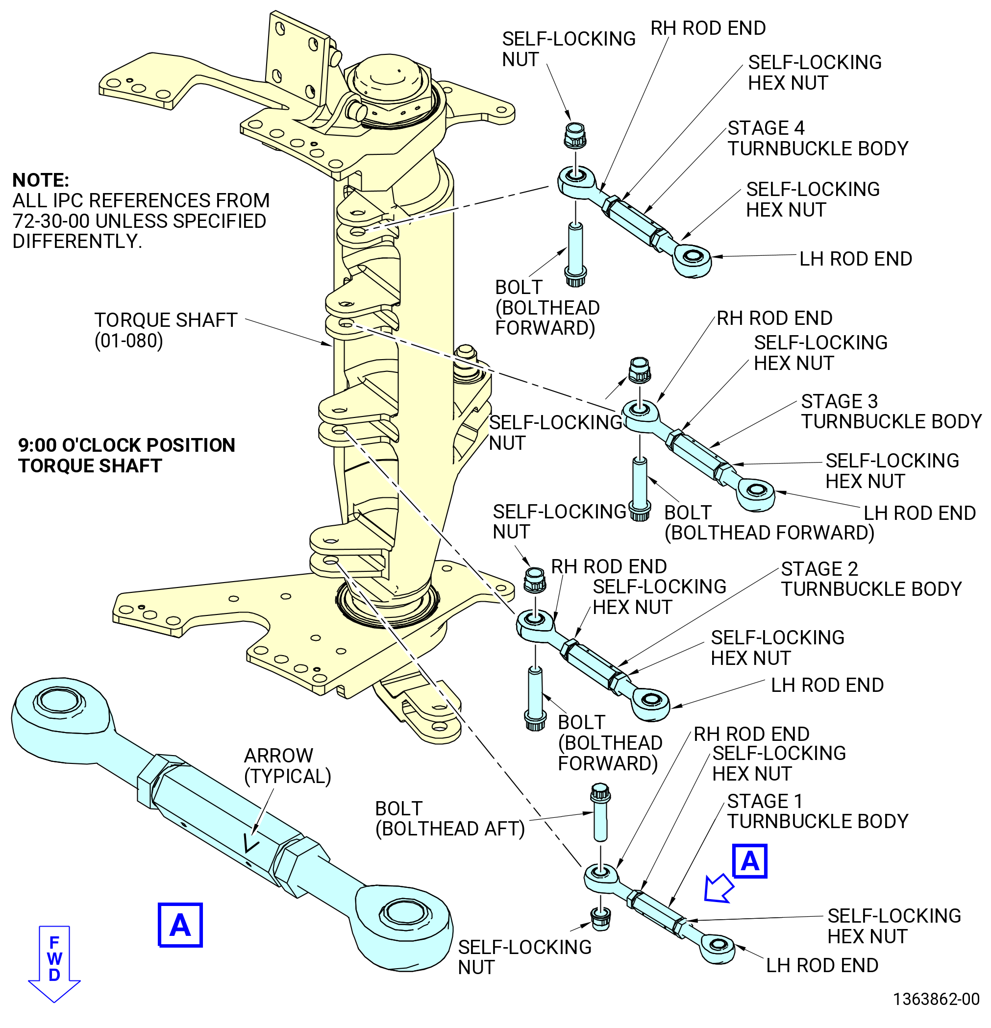
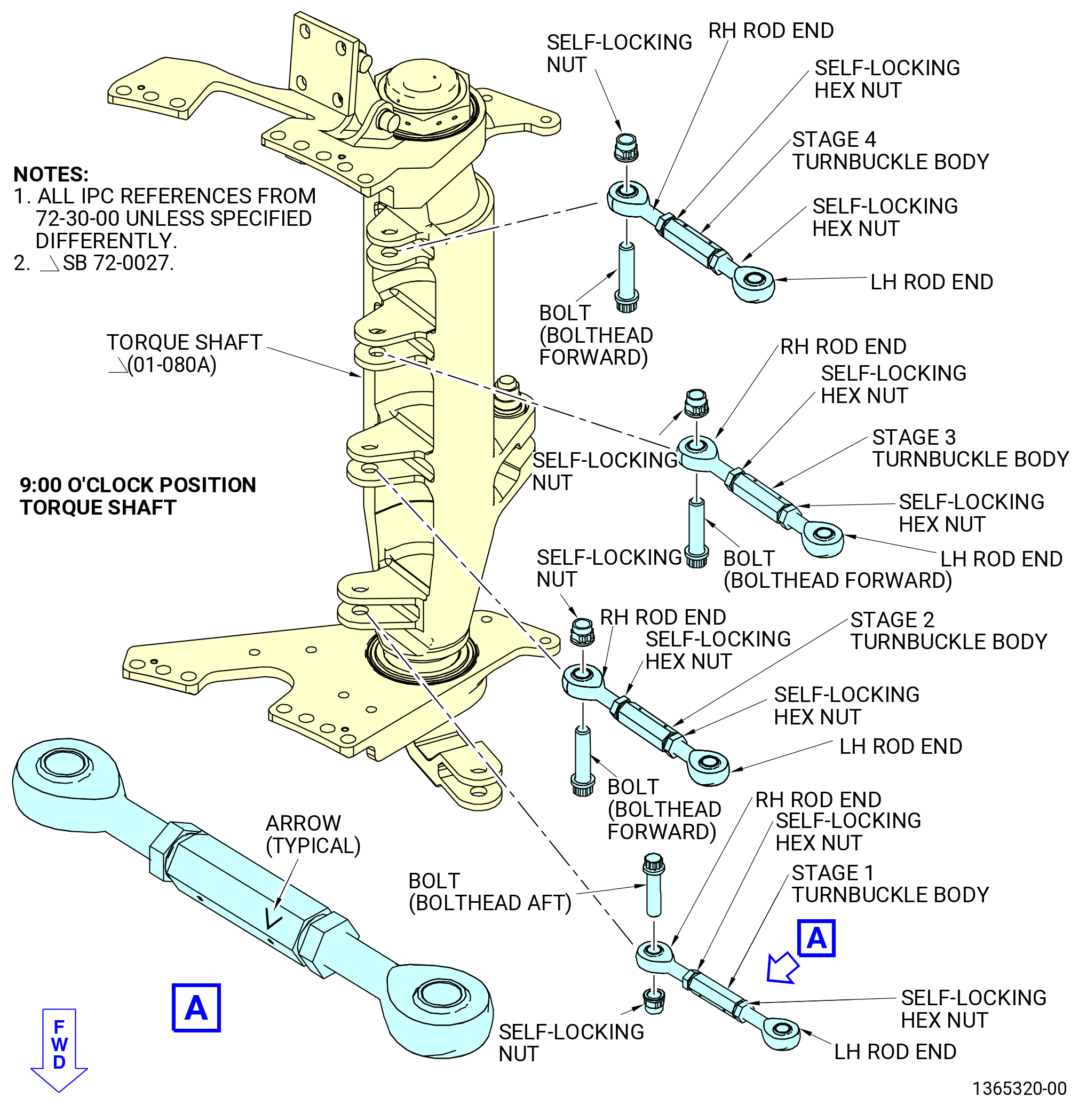
| B. | Install the turnbuckles on the torque shaft (01-079) (SIN 07501-2), (01-080) (SIN 07501-2), or (01-080A) (SIN 07501-2) at the 9:00 o'clock position as follows. Refer to Figure 1003. |
| NOTE: |
|
|
|
|
| Subtask 72-30-00-440-146 |
| CAUTION: |
|
| CAUTION: |
|
| (1) | Make sure that the side of the stage 1 turnbuckle body with the arrow is opposite the torque shaft (01-079) (SIN 07501-2), (01-080) (SIN 07501-2), or (01-080A) (SIN 07501-2). Install the RH rod end on the torque shaft. |
| (2) | Attach the stage 1 turnbuckle body on the torque shaft with an aft-facing bolt and a self-locking nut. |
| (3) | Torque the self-locking nut to 460-540 lb in. (52.0-61.0 N.m). |
| Subtask 72-30-00-440-147 |
| CAUTION: |
|
| CAUTION: |
|
| (4) | Make sure that the side of the stage 2 turnbuckle body with the arrow is opposite the torque shaft (01-079) (SIN 07501-2), (01-080) (SIN 07501-2), or (01-080A) (SIN 07501-2). Install the RH rod end on the torque shaft. |
| (5) | Attach the stage 2 turnbuckle body on the torque shaft with a forward-facing bolt and a self-locking nut. |
| (6) | Torque the self-locking nut to 460-540 lb in. (52.0-61.0 N.m). |
| Subtask 72-30-00-440-148 |
| CAUTION: |
|
| CAUTION: |
|
| (7) | Make sure that the side of the stage 3 turnbuckle body with the arrow is opposite the torque shaft (01-079) (SIN 07501-2), (01-080) (SIN 07501-2), or (01-080A) (SIN 07501-2). Install the RH rod end on the torque shaft. |
| (8) | Attach the stage 3 turnbuckle body on the torque shaft with a forward-facing bolt and a self-locking nut. |
| (9) | Torque the self-locking nut to 460-540 lb in. (52.0-61.0 N.m). |
| Subtask 72-30-00-440-277 |
| CAUTION: |
|
| CAUTION: |
|
| (10) | Make sure that the side of the stage 4 turnbuckle body with the arrow is opposite the torque shaft (01-079) (SIN 07501-2), (01-080) (SIN 07501-2), or (01-080A) (SIN 07501-2). Install the RH rod end on the torque shaft. |
| (11) | Attach the stage 4 turnbuckle body on the torque shaft with a forward-facing bolt and a self-locking nut. |
| (12) | Torque the self-locking nut to 460-540 lb in. (52.0-61.0 N.m). |
| Subtask 72-30-00-440-149 |
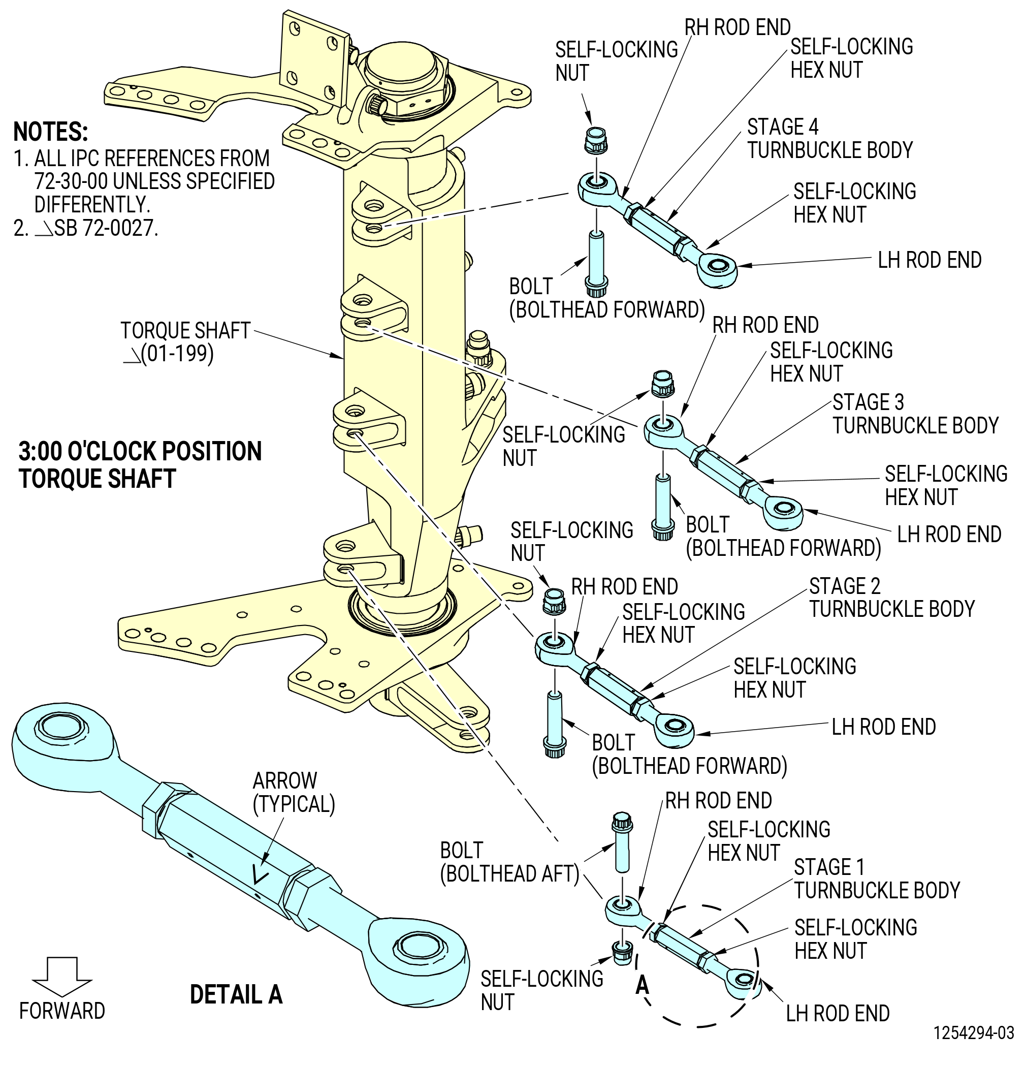
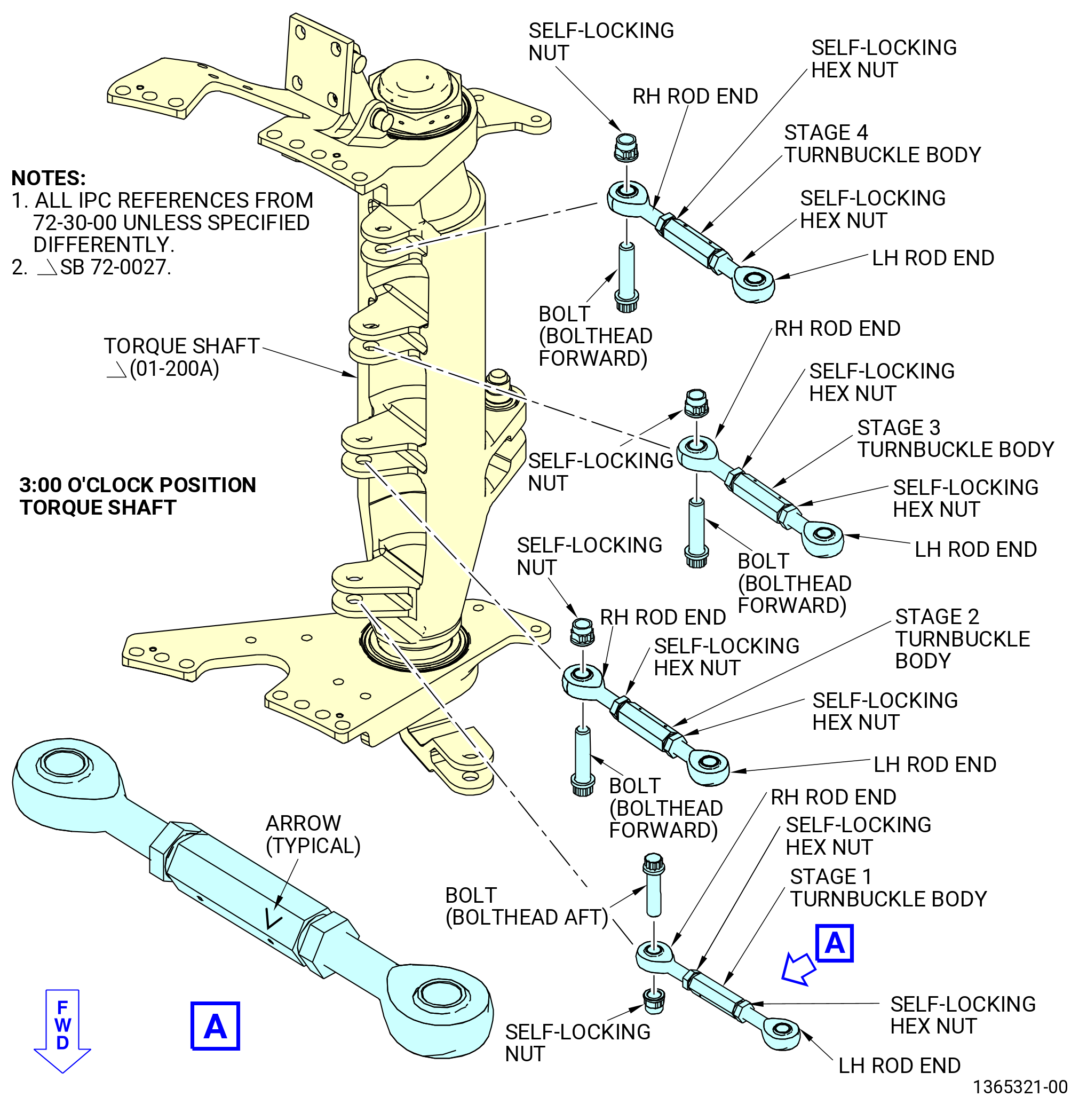
| C. | Install the turnbuckles on the torque shaft (01-199) (SIN 07500-2), (01-200) (SIN 07500-2), or (01-200A) (SIN 07500-2) at the 3:00 o'clock position as follows. Refer to Figure 1004. |
| NOTE: |
|
|
|
|
| Subtask 72-30-00-440-150 |
| CAUTION: |
|
| CAUTION: |
|
| (1) | Make sure that the side of the stage 1 turnbuckle body with the arrow is opposite the torque shaft (01-199) (SIN 07500-2), (01-200) (SIN 07500-2), or (01-200A) (SIN 07500-2). Install the RH rod end on the torque shaft. |
| (2) | Attach the stage 1 turnbuckle body on the torque shaft with an aft-facing bolt and a self-locking nut. |
| (3) | Torque the self-locking nut to 460-540 lb in. (52.0-61.0 N.m). |
| Subtask 72-30-00-440-151 |
| CAUTION: |
|
| CAUTION: |
|
| (4) | Make sure that the side of the stage 2 turnbuckle body with the arrow is opposite the torque shaft (01-199) (SIN 07500-2), (01-200) (SIN 07500-2), or (01-200A) (SIN 07500-2). Install the RH rod end on the torque shaft. |
| (5) | Attach the stage 2 turnbuckle body on the torque shaft with a forward-facing bolt and a self-locking nut. |
| (6) | Torque the self-locking nut to 460-540 lb in. (52.0-61.0 N.m). |
| Subtask 72-30-00-440-152 |
| CAUTION: |
|
| CAUTION: |
|
| (7) | Make sure that the side of the stage 3 turnbuckle body with the arrow is opposite the torque shaft (01-199) (SIN 07500-2), (01-200) (SIN 07500-2), or (01-200A) (SIN 07500-2). Install the RH rod end on the torque shaft. |
| (8) | Attach the stage 3 turnbuckle body on the torque shaft with a forward-facing bolt and a self-locking nut. |
| (9) | Torque the self-locking nut to 460-540 lb in. (52.0-61.0 N.m). |
| Subtask 72-30-00-440-278 |
| CAUTION: |
|
| CAUTION: |
|
| (10) | Make sure that the side of the stage 4 turnbuckle body with the arrow is opposite the torque shaft (01-199) (SIN 07500-2), (01-200) (SIN 07500-2), or (01-200A) (SIN 07500-2). Install the RH rod end on the torque shaft. |
| (11) | Attach the stage 4 turnbuckle body on the torque shaft with a forward-facing bolt and a self-locking nut. |
| (12) | Torque the self-locking nut to 460-540 lb in. (52.0-61.0 N.m). |
| Subtask 72-30-00-440-153 |
| D. | Install the compressor stator actuating ring bridges (bridges) as follows: |
| Subtask 72-30-00-440-154 |
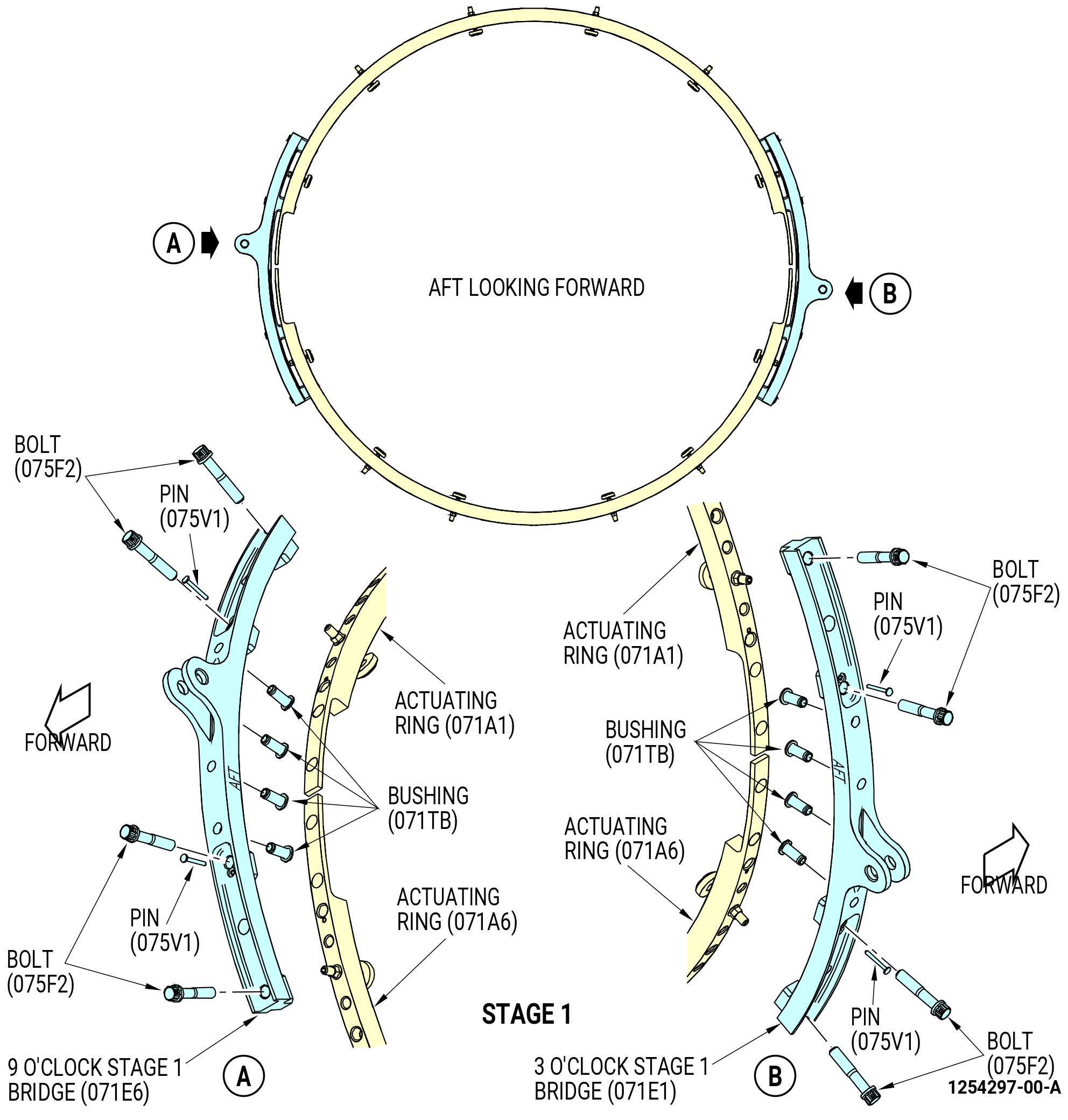
| (1) | Install the 9:00 o'clock stage 1 bridge (stage 1 bridge) (071E6) on the stage 1 actuating rings (071A1, 071A6) as follows. Refer to Figure 1005. |
| (a) | Make sure that the bushings (01-300) (SIN 071TB) are installed in the stage 1 bridge (071E6). |
| (b) | Make sure that the AFT mark on the 9:00 o'clock stage 1 bridge (071E6) points aft. |
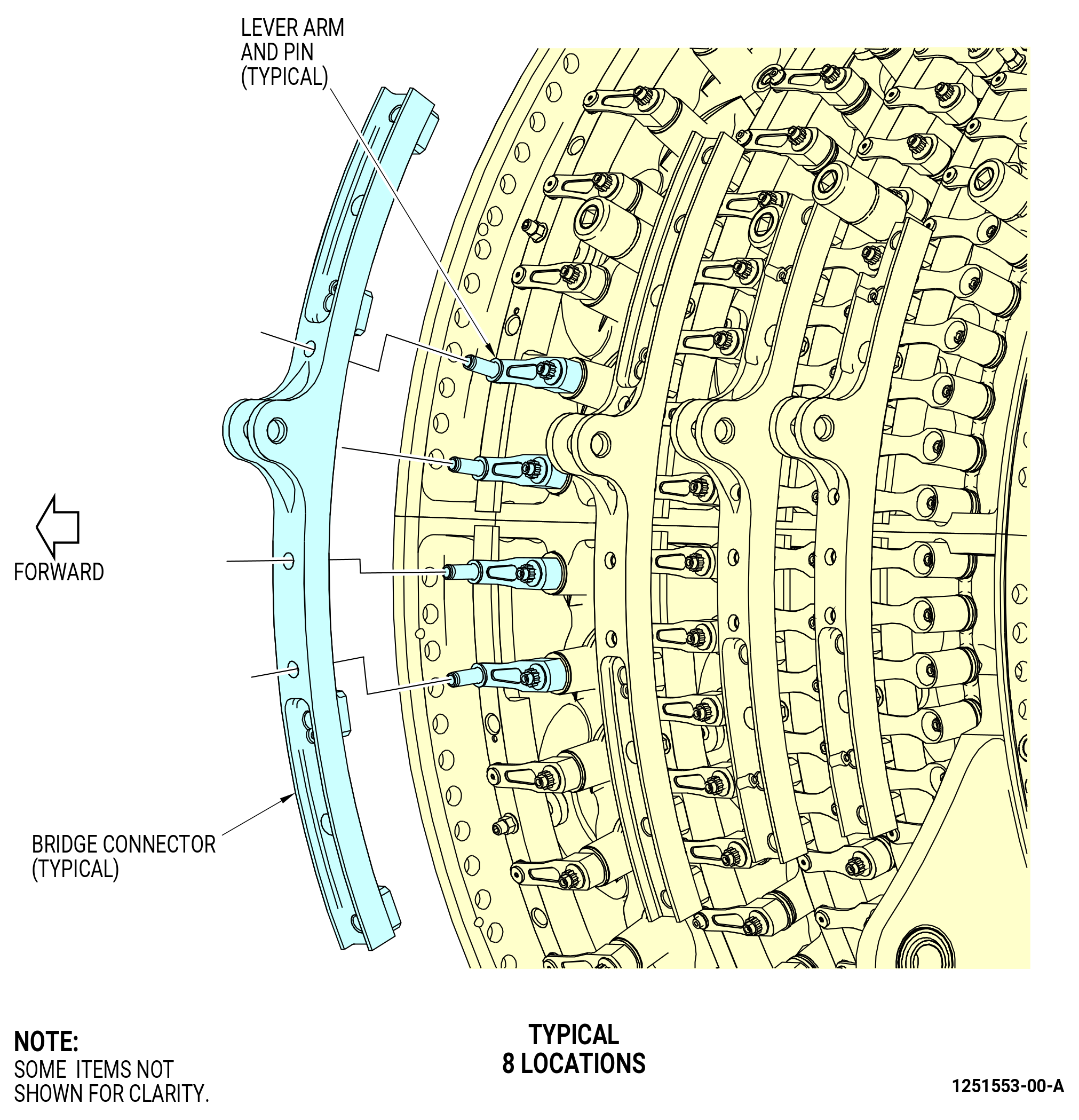
| (c) | Find the four stage 1 lever arms (071D6) that are between the stage 1 actuating rings (071A1, 071A6) and will insert directly into the stage 1 bridge (071E6). Use your fingers to align the four stage 1 lever arms (071D6) to match the holes in the 9:00 o'clock stage 1 bridge. Refer to Figure 1006. |
| (d) | Install the stage 1 bridge (071E6) on the four lever arms and the stage 1 actuating rings (071A1, 071A6). |
| (e) | Install two alignment pins (pin) (075V1) in the two holes on the stage 1 bridge (071E6). |
| (f) | Attach the stage 1 bridge (071E6) to the stage 1 actuating rings (071A1, 071A6) with four bolts (075F2). Tighten the bolts hand-tight. |
| Subtask 72-30-00-440-155 |
| (2) | Install the 3:00 o'clock stage 1 bridge (stage 1 bridge) (071E1) on the stage 1 actuating rings (071A1, 071A6) as follows. Refer to Figure 1005. |
| (a) | Make sure that the bushings (01-300) (SIN 071TB) are installed in the stage 1 bridge (071E1). |
| (b) | Make sure that the AFT mark on the stage 1 bridge (071E1) points aft. |
| (c) | Find the four stage 1 lever arms (071D6) that are between the stage 1 actuating rings (071A1, 071A6) and will insert directly into the stage 1 bridge (071E1). Use your fingers to align the four stage 1 lever arms (071D6) to match the holes in the stage 1 bridge. Refer to Figure 1006. |
| (d) | Install the stage 1 bridge (071E1) on the four lever arms and the stage 1 actuating rings (071A1, 071A6). |
| (e) | Install two alignment pins (pin) (075V1) in the two holes on the stage 1 bridge (071E1). |
| (f) | Attach the stage 1 bridge (071E1) to the stage 1 actuating rings with four bolts (075F2). Tighten the bolts hand-tight. |
| (3) | Torque the eight bolts (075F2) on the stage 1 bridges to 235-275 lb in. (26.6-31.1 N.m). |
| Subtask 72-30-00-210-012 |
| CAUTION: |
|
| (4) | Do a travel check of the stage 1 actuating rings (071A1, 071A6) as follows: |
| (a) | Use your hand to push the stage 1 bridges. Move the bridges fully in each direction with your hand. |
| (b) | Make sure that the actuating rings move the full distance that the case rub buttons permit. |
| (c) | Make sure that there is not binding or interference. |
| Subtask 72-30-00-820-013 |
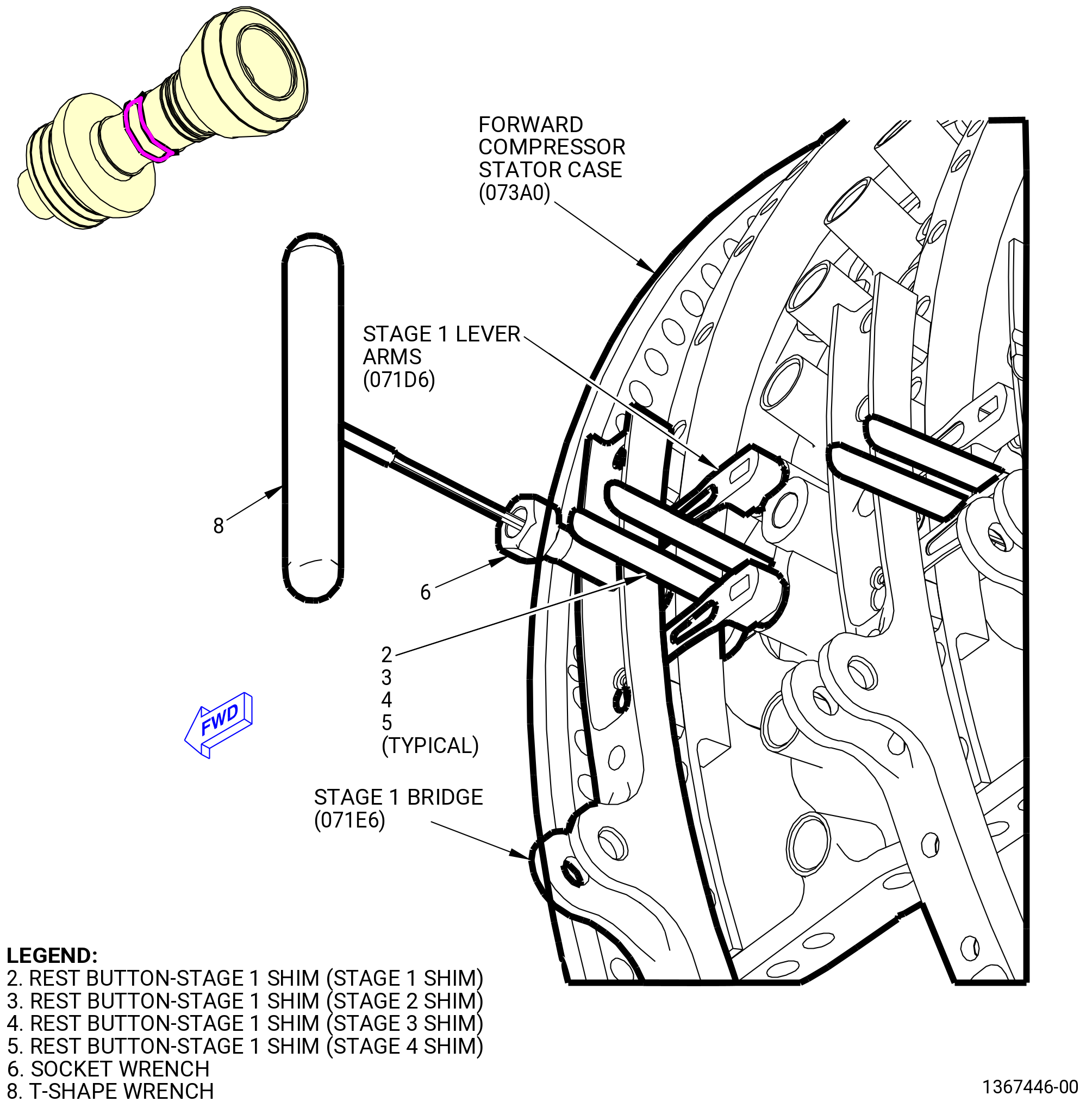
| (5) | If necessary, adjust the stage 1 VSV ring segment adjusting pad screws (071A1, 071A6) in with the 11C3343 gage set as follows. Refer to Figure 1007. |
| (a) | Engage the applicable stage 1 shim (item 2) of the 11C3343 gage set from the aft side of the actuation ring until the short leg of the shim is engaged between the VSV adjusting pad screws and the case. |
| NOTE: |
|
| (b) | Adjust the VSV adjusting pad screws in the ring segment with the T-shape wrench (item 8) of the 11C3343 gage set and the socket wrench (item 6) of the 11C3343 gage set. |
| (c) | Do Subtask 72-30-00-820-013 (paragraph 3.D.(5)(a)) thru (paragraph 3.D.(5)(b)) again to the other VSV adjusting pad screws on stage 1. |
| (d) | Remove the stage 1 shim (item 2) from the 11C3343 gage set. |
| Subtask 72-30-00-400-001 |
| (6) | Safety the bolts (075F2) with C10-143 safety cable. |
| Subtask 72-30-00-440-156 |
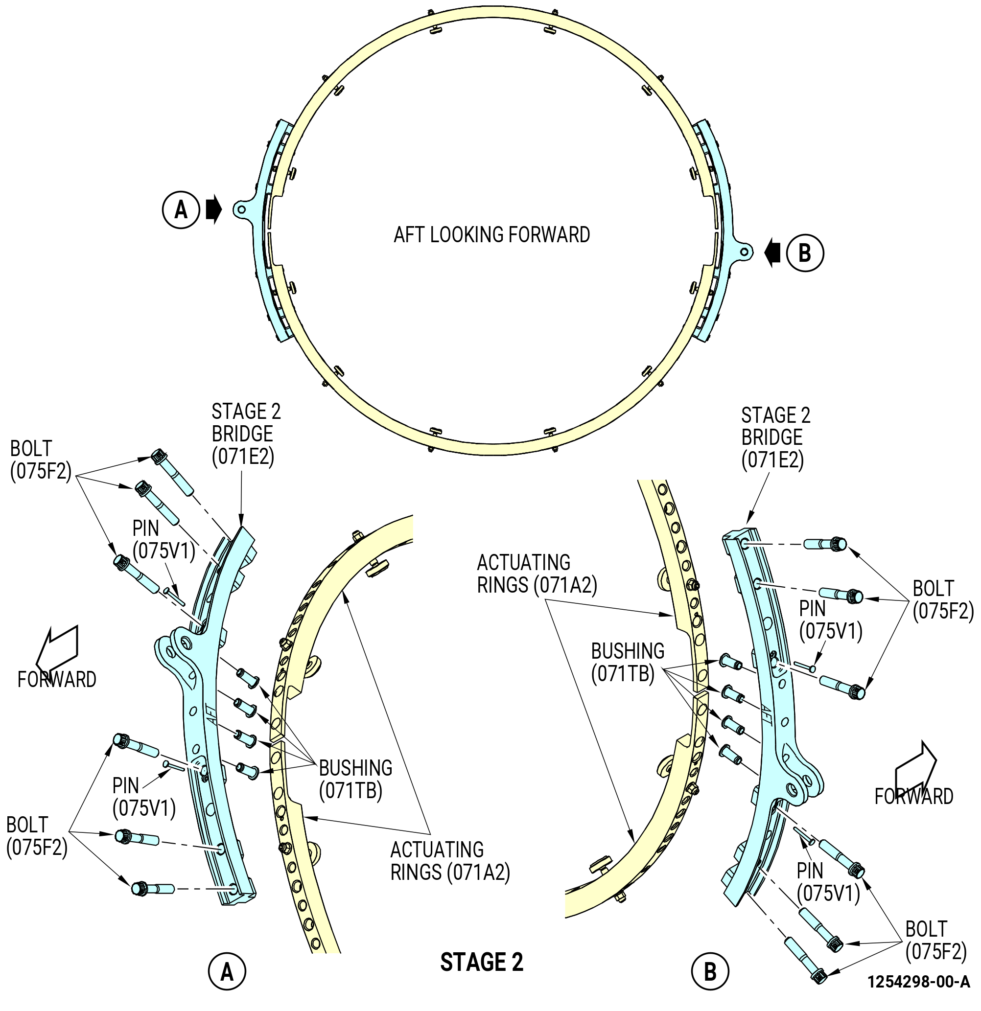
| (7) | Install the stage 2 bridge (071E2) at the 9:00 o'clock position on the stage 2 actuating rings (071A2) as follows. Refer to Figure 1008. |
| (a) | Make sure that the bushings (01-300) (SIN 071TB) are installed in the stage 2 bridge (071E2). |
| (b) | Make sure that the AFT mark on the stage 2 bridge (071E2) points aft. |
| (c) | Find the four stage 2 lever arms (071D7) that are between the stage 2 actuating rings (071A2) and will insert directly into the stage 2 bridge (071E2). Use your fingers to align the four stage 2 lever arms (071D7) to match the holes in the stage 2 bridge (071E2). Refer to Figure 1006. |
| (d) | Install the stage 2 bridge (071E2) on the four lever arms and the stage 2 actuating rings (071A2). |
| (e) | Install two alignment pins (pin) (075V1) in the two holes on the stage 2 bridge (071E2). |
| (f) | Attach the stage 2 bridge (071E2) to the stage 2 actuating rings (071A2) with six bolts (075F2). Tighten the bolts hand-tight. |
| Subtask 72-30-00-440-157 |
| (8) | Install the stage 2 bridge (071E2) at the 3:00 o'clock position on the stage 2 actuating rings (071A2) as follows. Refer to Figure 1008. |
| (a) | Make sure that the bushings (01-300) (SIN 071TB) are installed in the stage 2 bridge (071E2). |
| (b) | Make sure that the AFT mark on the stage 2 bridge points aft. |
| (c) | Find the four stage 2 lever arms (071D7) that are between the stage 2 actuating rings (071A2) and will insert directly into the stage 2 bridge (071E2). Use your fingers to align the four stage 2 lever arms (071D7) to match the holes in the stage 2 bridge (071E2). Refer to Figure 1006. |
| (d) | Install the stage 2 bridge (071E2) on the four lever arms and the stage 2 actuating rings (071A2). |
| (e) | Install two alignment pins (pin) (075V1) in the two holes on the stage 2 bridge (071E2). |
| (f) | Attach the stage 2 bridge (071E2) to the stage 2 actuating rings (071A2) with six bolts (075F2). Tighten the bolts hand-tight. |
| (9) | Torque the 12 bolts (075F2) on the stage 2 bridges (071E2) to 235-275 lb in. (26.6-31.1 N.m). |
| Subtask 72-30-00-210-013 |
| CAUTION: |
|
| (10) | Do a travel check of the stage 2 actuating rings (071A2) as follows: |
| (a) | Use your hand to push the lifted portion of the stage 2 bridges. Move the bridges fully in each direction with your hand. |
| (b) | Make sure that the actuating rings move the full distance that the case rub buttons will permit. |
| (c) | Make sure that there is not binding or interference. |
| Subtask 72-30-00-820-014 |
| (11) | If necessary, adjust the stage 2 VSV ring segment adjusting pad screws (071A2) in with the 11C3343 gage set as follows. Refer to Figure 1007. |
| (a) | Engage the applicable stage 2 shim (item 3) of the 11C3343 gage set from the aft side of the actuation ring until the short leg of the shim is engaged between the VSV adjusting pad screw and the case. |
| NOTE: |
|
| (b) | Adjust the VSV adjusting pad screws in the ring segment with the T-shape wrench (item 8) of the 11C3343 gage set and the socket wrench (item 6) of the 11C3343 gage set. |
| (c) | Do Subtask 72-30-00-820-014 (paragraph 3.D.(11)(a)) thru (paragraph 3.D.(11)(b)) again to the other VSV adjusting pad screws on stage 2. |
| (d) | Remove the stage 2 shim (item 3) from the 11C3343 gage set. |
| Subtask 72-30-00-400-002 |
| (12) | Safety the bolts (075F2) with C10-143 safety cable. |
| Subtask 72-30-00-440-158 |
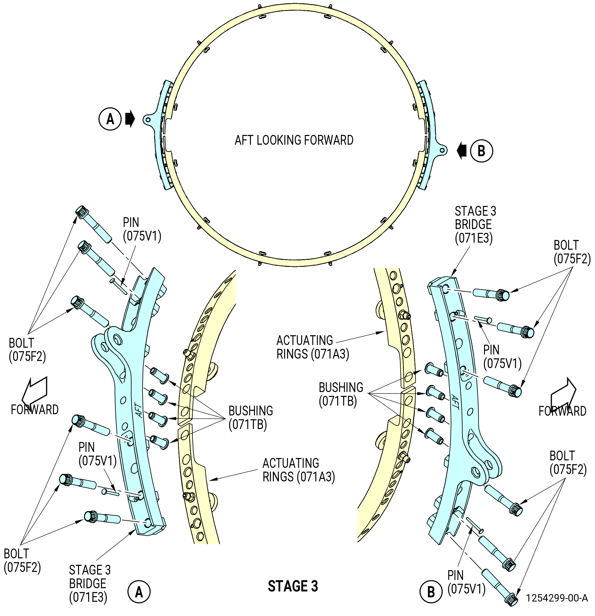
| (13) | Install the stage 3 bridge (071E3) at the 9:00 o'clock position on the stage 3 actuating rings (071A3) as follows. Refer to Figure 1009. |
| (a) | Make sure that the bushings (01-300) (SIN 071TB) are installed in the stage 3 bridge (071E3). |
| (b) | Make sure that the AFT mark on the stage 3 bridge points aft. |
| (c) | Find the four stage 3 lever arms (071D8) that are between the stage 3 actuating rings (071A3) and will insert directly into the stage 3 bridge (071E3). Use your fingers to align the four stage 3 lever arms (071D8) to match the holes in the stage 3 bridge (071E3). Refer to Figure 1006. |
| (d) | Install the stage 3 bridge (071E3) on the four lever arms and the stage 3 actuating rings (071A3). |
| (e) | Install two alignment pins (pins) (075V1) in the two holes on the stage 3 bridge (071E3). |
| (f) | Attach the stage 3 bridge (071E3) to the stage 3 actuating rings (071A3) with six bolts (075F2). Tighten the bolts hand-tight. |
| Subtask 72-30-00-440-159 |
| (14) | Install the stage 3 bridge (071E3) at the 3:00 o'clock position on the stage 3 actuating rings (071A3) as follows. Refer to Figure 1009. |
| (a) | Make sure that the bushings (01-300) (SIN 071TB) are installed in the stage 3 bridge (071E3). |
| (b) | Make sure that the AFT mark on the stage 3 bridge points aft. |
| (c) | Find the four stage 3 lever arms (071D8) that are between the stage 3 actuating rings (071A3) and will insert directly into the stage 3 bridge (071E3). Use your fingers to align the four stage 3 lever arms (071D8) to match the holes in the stage 3 bridge (071E3). Refer to Figure 1006. |
| (d) | Install the stage 3 bridge (071E3) on the four lever arms and the stage 3 actuating rings (071A3). |
| (e) | Install two alignment pins (pins) (075V1) in the two holes on the stage 3 bridge (071E3). |
| (f) | Attach the stage 3 bridge (071E3) to the stage 3 actuating rings (071A3) with six bolts (075F2). Tighten the bolts hand-tight. |
| (15) | Torque the 12 bolts (075F2) to 235-275 lb in. (26.6-31.1 N.m). |
| CAUTION: |
|
| (16) | Do a travel check of the stage 3 actuating rings (071A3) as follows: |
| (a) | Use your hand to push the lifted portion of the stage 3 bridges. Move the bridges fully in each direction with your hand. |
| (b) | Make sure that the actuating rings move the full distance that the case rub buttons will permit. |
| (c) | Make sure that there is not binding or interference. |
| Subtask 72-30-00-210-014 |
| CAUTION: |
|
| (17) | Do a travel check of the stage 3 actuating rings (071A3) as follows: |
| (a) | Use your hand to push the lifted portion of the stage 3 bridges. Move the bridges fully in each direction with your hand. |
| (b) | Make sure that the actuating rings move the full distance that the case rub buttons will permit. |
| (c) | Make sure that there is not binding or interference. |
| Subtask 72-30-00-820-015 |
| (18) | If necessary, adjust the stage 3 VSV ring segment adjusting pad screws (071A3) in with the 11C3343 gage set as follows. Refer to Figure 1007. |
| (a) | Engage the applicable stage 3 shim (item 2) of the 11C3343 gage set from the aft side of the actuation ring until the short leg of the shim is engaged between the VSV adjusting pad screw and the case. |
| NOTE: |
|
| (b) | Adjust the VSV adjusting pad screws in the ring segment with the T-shape wrench (item 8) of the 11C3343 gage set and the socket wrench (item 6) of the 11C3343 gage set. |
| (c) | Do Subtask 72-30-00-820-015 (paragraph 3.D.(18)(a)) thru (paragraph 3.D.(18)(b)) again to the other VSV adjusting pad screws on stage 3. |
| (d) | Remove the stage 3 shims (item 2) from the 11C3343 gage set. |
| Subtask 72-30-00-400-003 |
| (19) | Safety the bolts (075F2) with C10-143 safety cable. |
| Subtask 72-30-00-440-160 |
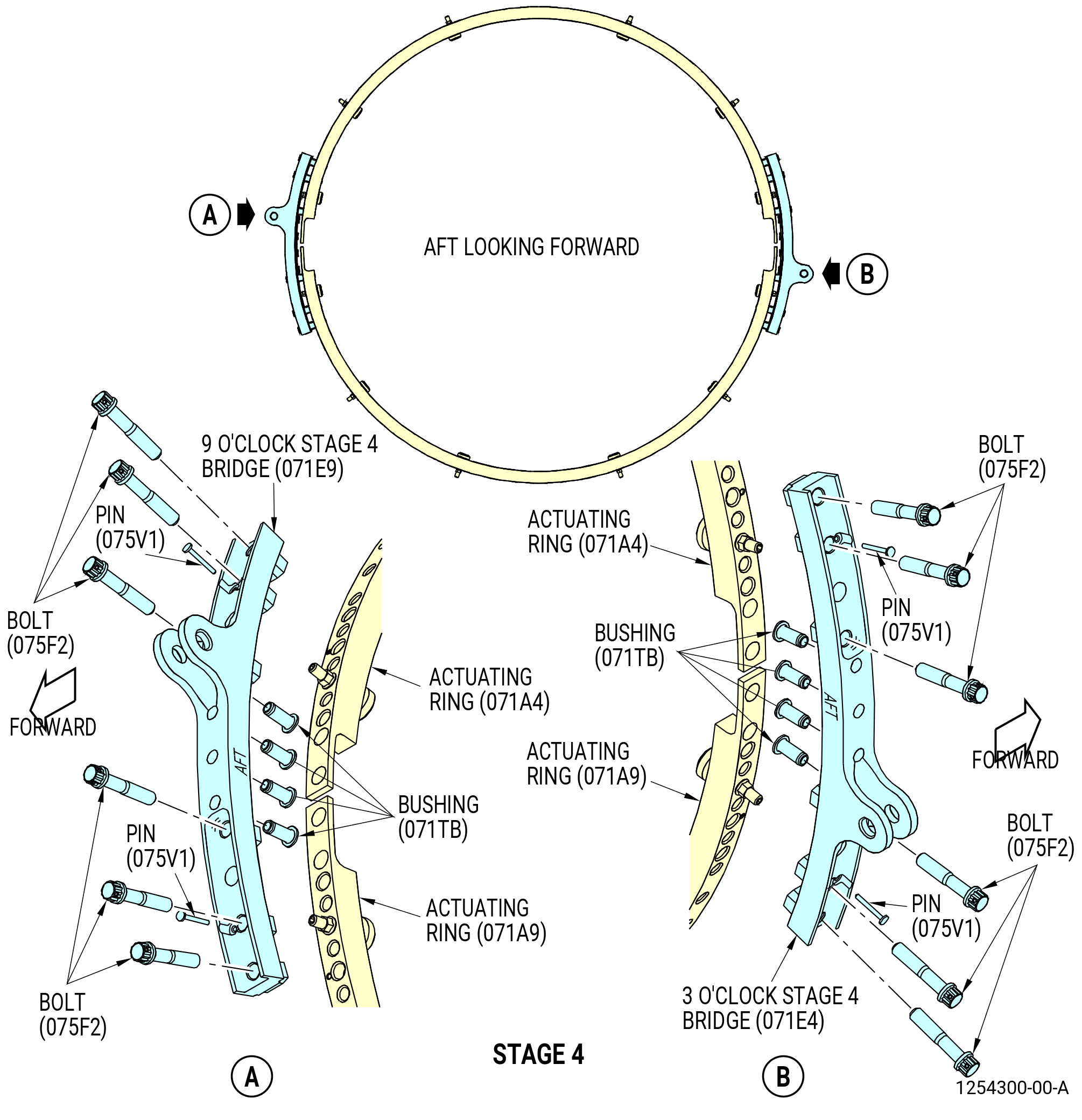
| (20) | Install the 9:00 o'clock stage 4 bridge (stage 4 bridge) (071E9) on the stage 4 actuating rings (071A4, 071A9) as follows. Refer to Figure 1010. |
| (a) | Make sure that the bushings (01-300) (SIN 071TB) are installed in the stage 4 bridge (071E9). |
| (b) | Make sure that the AFT mark on the stage 4 bridge points aft. |
| (c) | Find the four stage 4 lever arms (071D4) that are between the stage 4 actuating rings (071A4, 071A9) and will insert directly into the stage 4 bridge (071E9). Use your fingers to align the four stage 4 lever arms (071D4) to match the holes in the stage 4 bridge (071E9). Refer to Figure 1006. |
| (d) | Install the stage 4 bridge (071E9) on the four lever arms and the stage 4 actuating rings (071A4, 071A9). |
| (e) | Install two alignment pins (pin) (075V1) in the two holes on the stage 4 bridge (071E9). |
| (f) | Attach the stage 4 bridge (071E9) to the stage 4 actuating rings (071A4, 071A9) with six bolts (075F2). Tighten the bolts hand-tight. |
| Subtask 72-30-00-440-161 |
| (21) | Install the 3:00 o'clock stage 4 bridge (071E4) on the stage 4 actuating rings (071A4, 071A9) as follows. Refer to Figure 1010. |
| (a) | Make sure that the bushings (01-300) (SIN 071TB) are installed in the stage 4 bridge (071E4). |
| (b) | Make sure that the AFT mark on the stage 4 bridge points aft. |
| (c) | Find the four stage 4 lever arms (071D4) that are between the stage 4 actuating rings (071A4, 071A9) and will insert directly into the stage 4 bridge (071E4). Use your fingers to align the four stage 4 lever arms (071D4) to match the holes in the stage 4 bridge (071E4). Refer to Figure 1006. |
| (d) | Install the stage 4 bridge (071E4) on the four lever arms and the stage 4 actuating rings (071A4, 071A9). |
| (e) | Install two alignment pins (pin) (075V1) in the two holes on the stage 4 bridge (071E4). |
| (f) | Attach the stage 4 bridge (071E4) to the stage 4 actuating rings (071A4, 071A9) with six bolts (075F2). Tighten the bolts hand-tight. |
| (22) | Torque the 12 bolts (075F2) on the stage 4 bridges (071E4, 071E9) to 235-275 lb in. (26.6-31.1 N.m). |
| CAUTION: |
|
| (23) | Do a travel check of the stage 4 actuating rings (071A4, 071A9) as follows: |
| (a) | Use your hand to push the lifted portion of the stage 4 bridges. Move the bridges fully in each direction with your hand. |
| (b) | Make sure that the actuating rings move the full distance that the case rub buttons will permit. |
| (c) | Make sure that there is not binding or interference. |
| Subtask 72-30-00-210-015 |
| CAUTION: |
|
| (24) | Do a travel check of the stage 4 actuating rings (071A4, 071A9) as follows: |
| (a) | Use your hand to push the lifted portion of the stage 4 bridges. Move the bridges fully in each direction with your hand. |
| (b) | Make sure that the actuating rings move the full distance that the case rub buttons will permit. |
| (c) | Make sure that there is not binding or interference. |
| Subtask 72-30-00-820-016 |
| (25) | If necessary, adjust the stage 4 VSV ring segment adjusting pad screws (071A4) in with the 11C3343 gage set as follows. Refer to Figure 1007. |
| (a) | Engage the applicable stage 4 shim (item 2) of the 11C3343 gage set from the aft side of the actuation ring until the short leg of the shim is engaged between the VSV adjusting pad screw and the case. |
| NOTE: |
|
| (b) | Adjust the VSV adjusting pad screws in the ring segment with the T-shape wrench (item 8) of the 11C3343 gage set and the socket wrench (item 6) of the 11C3343 gage set. |
| (c) | Do Subtask 72-30-00-820-016 (paragraph 3.D.(25)(a)) thru (paragraph 3.D.(25)(b)) again to the other VSV adjusting pad screws on stage 4. |
| (d) | Remove the stage 4 shims (item 2) from the 11C3343 gage set. |
| Subtask 72-30-00-400-004 |
| (26) | Safety the bolts (075F2) with C10-143 safety cable. |
| Subtask 72-30-00-440-279 |
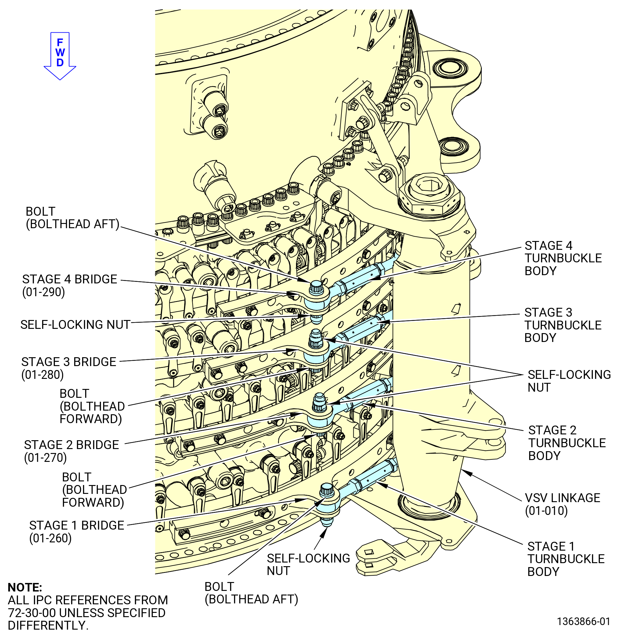
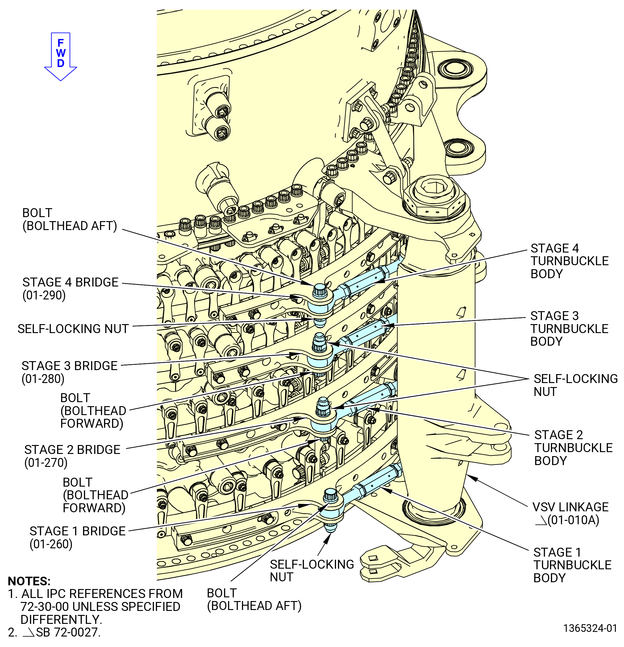
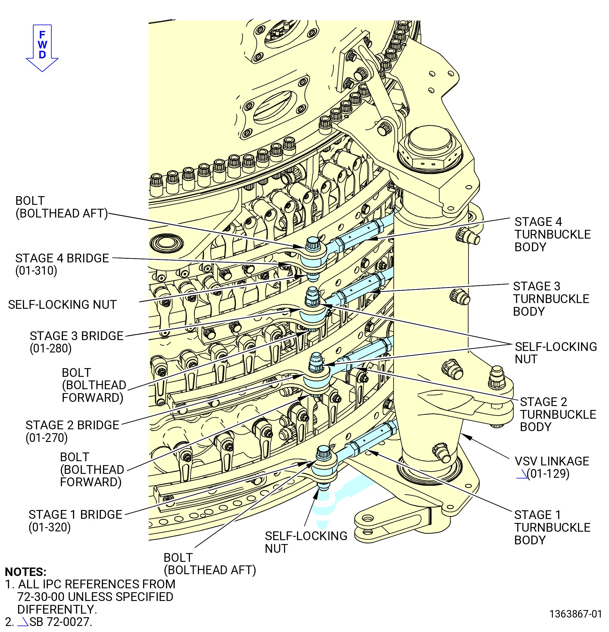
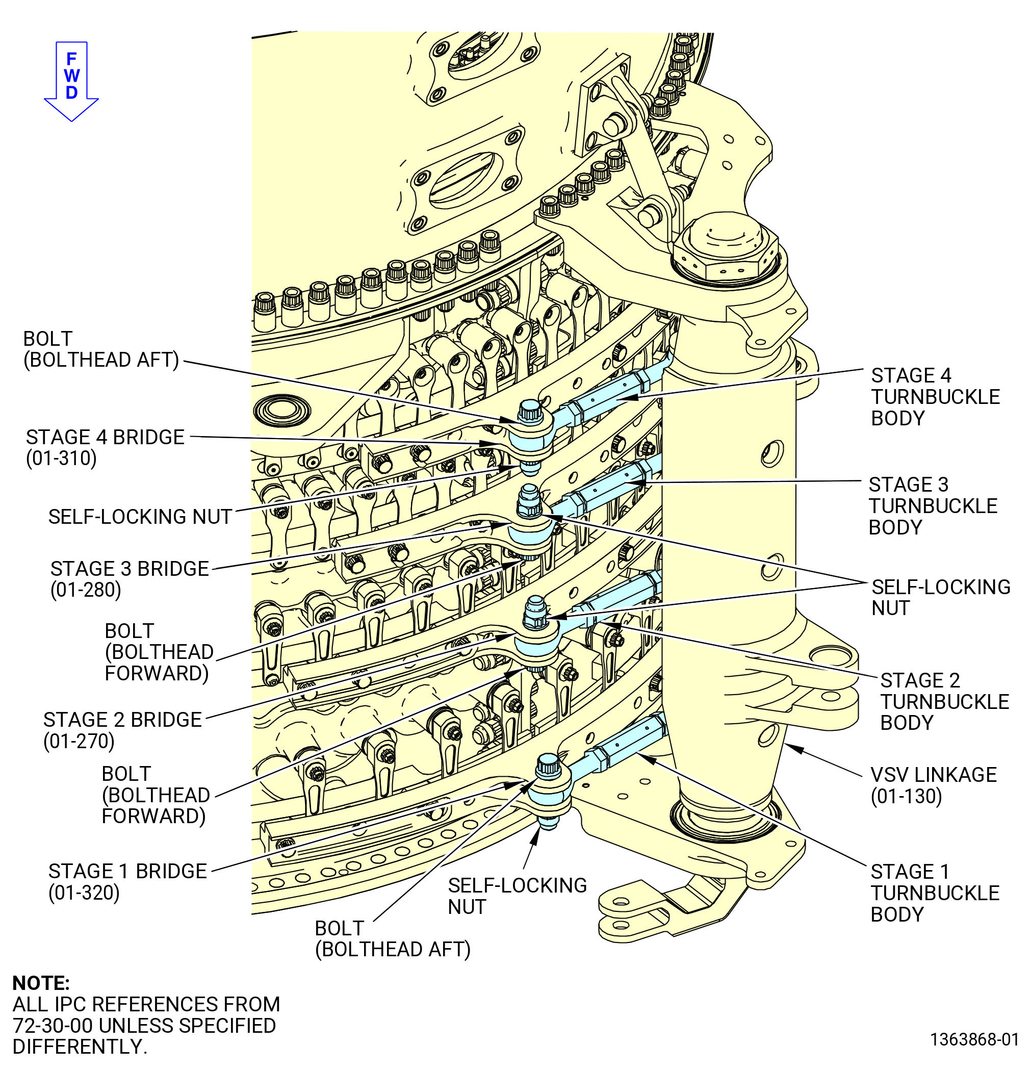
| E. | Attach the turnbuckles of the VSV torque shaft linkages (VSV linkages) (01-009) (SIN 07501), (01-010) (SIN 07501), or (01-010A) (SIN 07501) and (01-129) (SIN 07500), (01-130) (SIN 07500), or (01-130A) (SIN 07500) to the stage 1 thru stage 4 bridges as follows: |
| NOTE: |
|
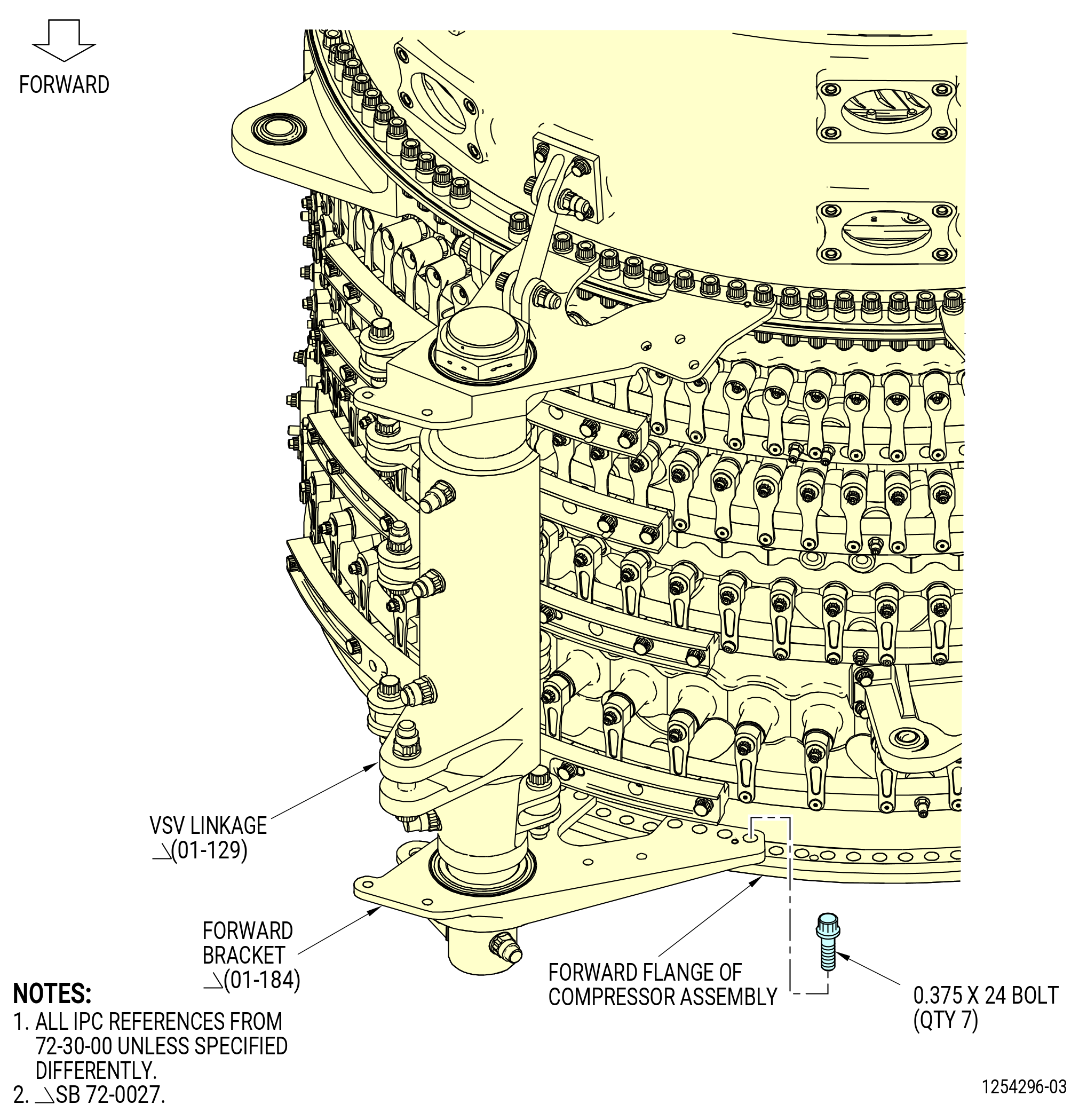
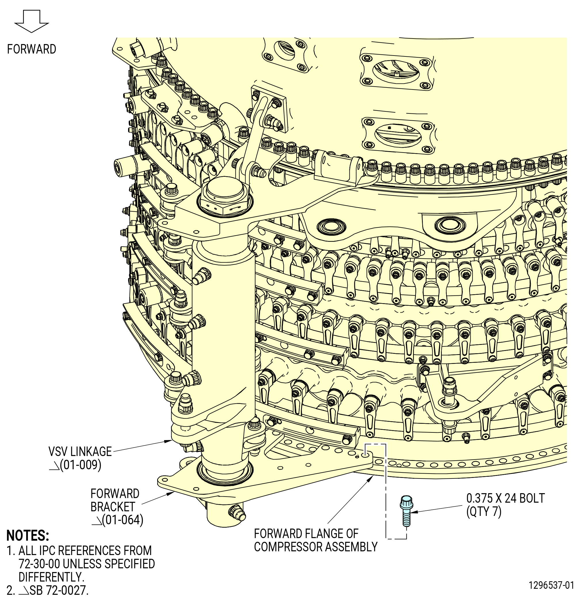
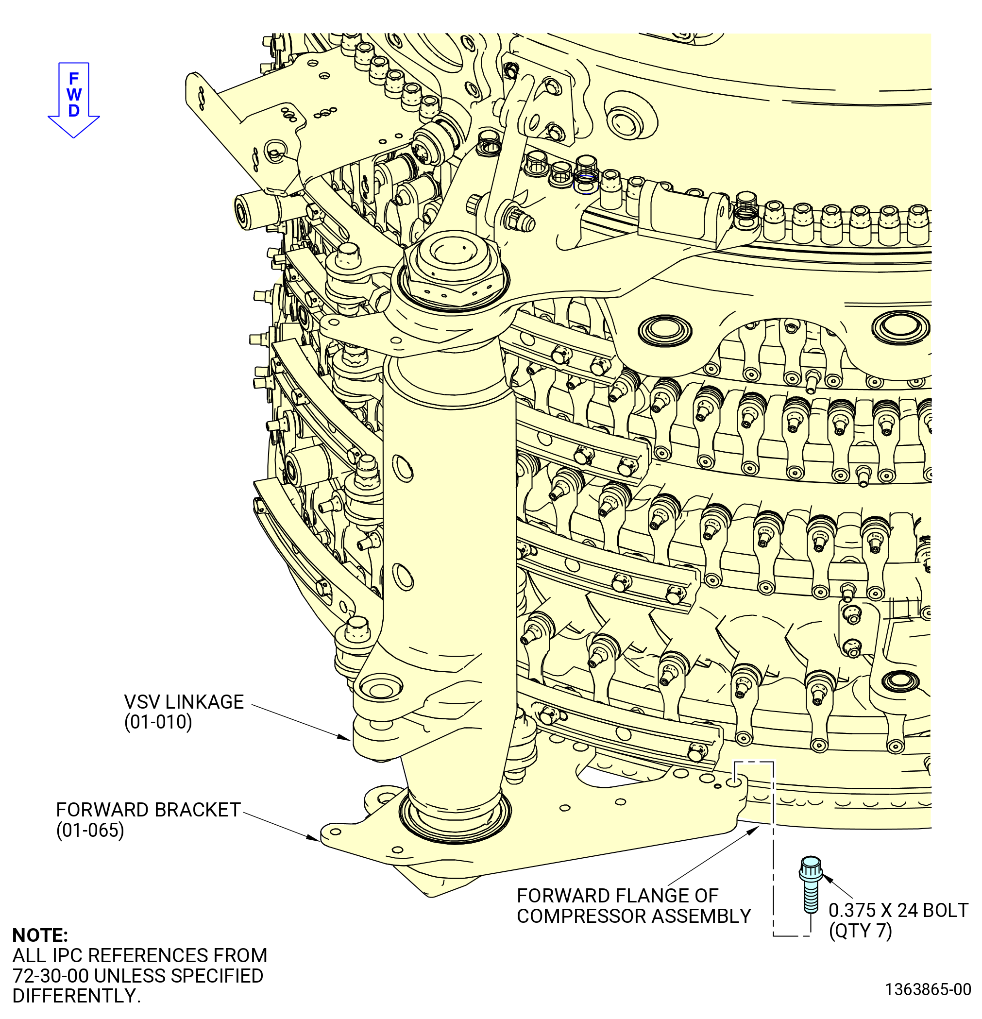
| (1) | Attach the forward brackets of the VSV linkages to the compressor stator assembly (07000) forward flange as follows. Refer to Figure 1011 and Figure 1012. |
| CAUTION: |
|
| (a) | Attach the forward bracket (01-184) (SIN 07500-3), (01-185) (SIN 07500-3), or (01-185A) (SIN 07500-3) to the forward flange of the compressor stator assembly at the 3:00 o'clock position (ALF) with seven 0.375-24 bolts. |
| (b) | Torque the bolts to 198-232 lb in. (22.4-26.2 N.m). |
| (c) | Attach the forward bracket (01-064) (SIN 07501-3), (01-065) (SIN 07501-3), or (01-065A) (SIN 07501-3) to the forward flange of the compressor stator assembly at the 9:00 o'clock position (ALF) with seven 0.375-24 bolts. |
| (d) | Torque the bolts to 198-232 lb in. (22.4-26.2 N.m). |
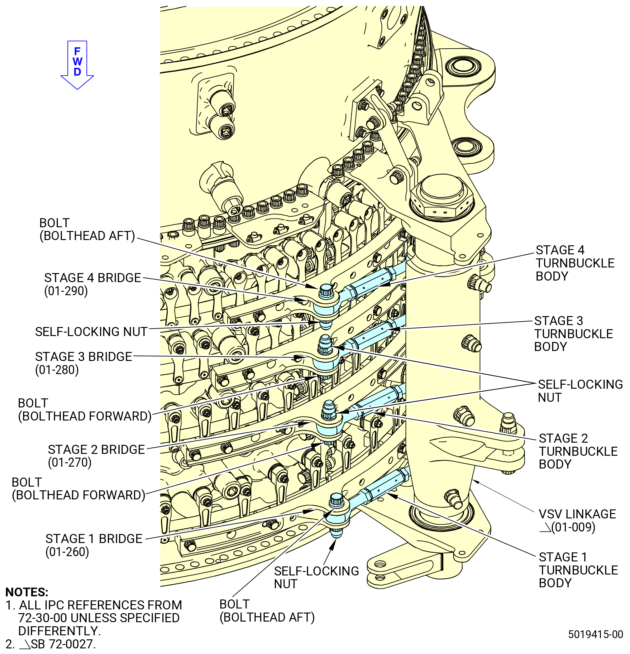
| (2) | Attach the stage 1 turnbuckles as follows. Refer to Figure 1013 and Figure 1014. |
| NOTE: |
|
| CAUTION: |
|
| (a) | Install the stage 1 turnbuckle into the stage 1 bridge (071E1) at the 9:00 o'clock position (aft looking forward). Attach the turnbuckle with an aft-facing bolt and self-locking nut. |
| (b) | Install the stage 1 turnbuckle into the stage 1 bridge (071E6) at the 3:00 o'clock position (aft looking forward). Attach the turnbuckle with an aft-facing bolt and self-locking nut. |
| (c) | Torque the two self-locking nuts to 460-540 lb in. (52.0-61.0 N.m). |
| (3) | Attach the stage 2 turnbuckles as follows: |
| NOTE: |
|
| (a) | Install the stage 2 turnbuckles on both the stage 2 bridges (071E2). Attach the turnbuckles with two forward-facing bolts and self-locking nuts. |
| (b) | Torque the self-locking nuts to 460-540 lb in. (52.0-61.0 N.m). |
| (4) | Attach the stage 3 turnbuckles as follows: |
| (a) | Install the stage 3 turnbuckles on both the stage 3 bridges (071E3). Attach the turnbuckles with two forward-facing bolts and self-locking nuts. |
| (b) | Torque the self-locking nuts to 460-540 lb in. (52.0-61.0 N.m). |
| (5) | Attach the stage 4 turnbuckles as follows: |
| NOTE: |
|
| (a) | Install the stage 4 turnbuckle into the stage 4 bridge (01-290) (SIN 071E9) at the 9:00 o'clock location (aft looking forward). Attach the turnbuckle with an aft-pointing bolt and a self-locking nut. |
| (b) | Install the stage 4 turnbuckle into the stage 4 bridge (01-310) (SIN 071E4) at the 3:00 o'clock location (aft looking forward). Attach the turnbuckle with an aft-pointing bolt and a self-locking nut. |
| (c) | Torque the self-locking nuts to 460-540 lb in. (52.0-61.0 N.m). |
|
|
|
|
|
|
|
|
|
|
|
|
| Subtask 72-30-00-440-163 |
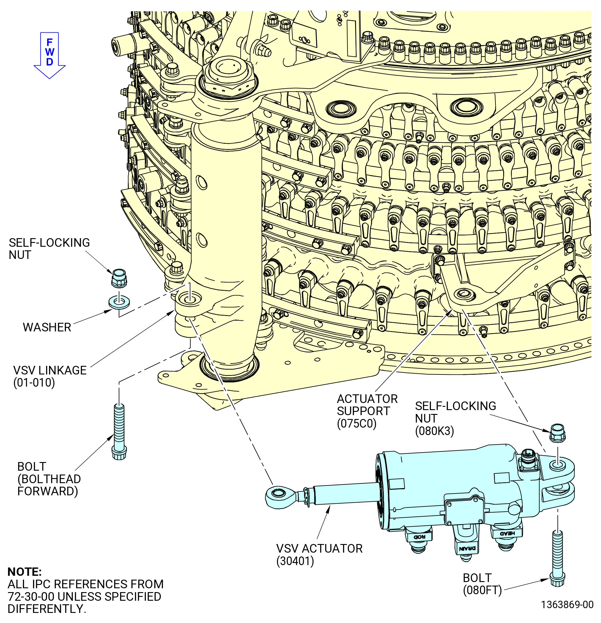
| F. | Install the VSV actuators (30400, 30401) as follows. Refer to Figure 1015 and Figure 1016. |
| (1) | Install the VSV actuator (30401) on the VSV linkage (01-009) (SIN 07501), (01-010) (SIN 07501), or (01-010A) and actuator support (075C0) at the 9:00 o'clock position as follows: |
| (a) | Make sure that the drain fittings are pointing forward and put the VSV actuator (30401) in the actuator support (075C0). Attach the VSV actuator to the actuator support with a bolt (080FT) and self-locking nut (080K3) and hand-tighten. |
| (b) | Torque the self-locking nut (080K3) on the VSV actuator to 350-410 lb in. (39.5-46.3 N.m). |
| (c) | Torque the self-locking nut (080K3) on the VSV actuator to 350-410 lb in. (39.5-46.3 N.m) again. |
| (d) | Remove the bolt and self-locking nut from the clevis on the VSV linkage and put the VSV actuator in the clevis. Attach the VSV actuator to the clevis of the VSV linkage with the bolt and the self-locking nut you removed. |
| (e) | Torque the removed self-locking nut on the VSV linkage to 662-778 lb in. (74.8-87.9 N.m). |
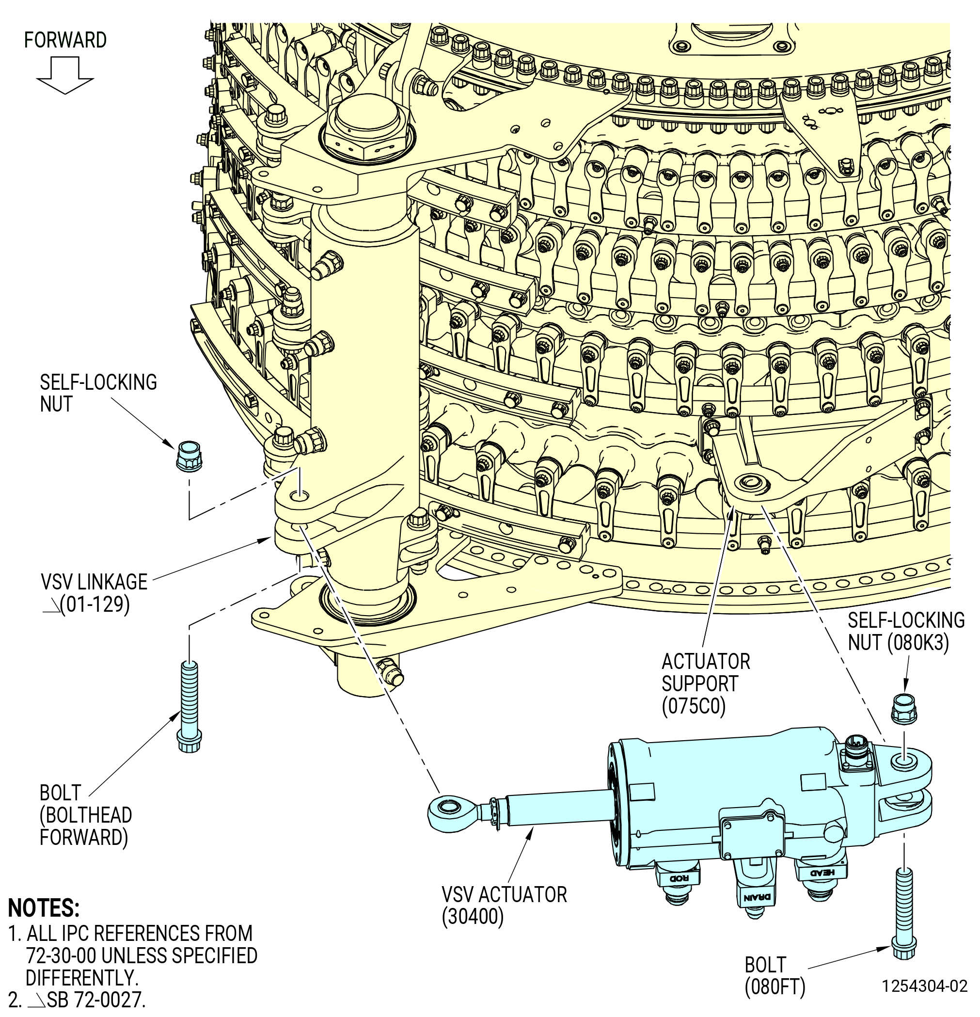
| (2) | Install the VSV actuator (30400) on the VSV linkage (01-129) (SIN 07500), (01-130) (SIN 07500), or (01-130A) (SIN 07500) and actuator support (075C0) at the 3:00 o'clock position as follows: |
| (a) | Make sure that the drain fittings are pointing forward and put the VSV actuator (30400) in the actuator support (075C0). Attach the VSV actuator to the actuator support with a bolt (080FT) and self-locking nut (080K3) and hand-tighten. |
| (b) | Torque the self-locking nut (080K3) on the VSV actuator to 350-410 lb in. (39.5-46.3 N.m). |
| (c) | Torque the self-locking nut (080K3) on the VSV actuator to 350-410 lb in. (39.5-46.3 N.m) again. |
| (d) | Remove the bolt (07500-18) and self-locking nut (07500-22) from the clevis on the VSV linkage and put the VSV actuator in the clevis. Attach the VSV actuator to the clevis of the VSV linkage with the bolt and the self-locking nut that you removed. |
| (e) | Torque the removed self-locking nut on the VSV linkage to 662-778 lb in. (74.8-87.9 N.m). |
|
|
|
|
|
|
| Subtask 72-30-00-210-034 |
| WARNING: |
|
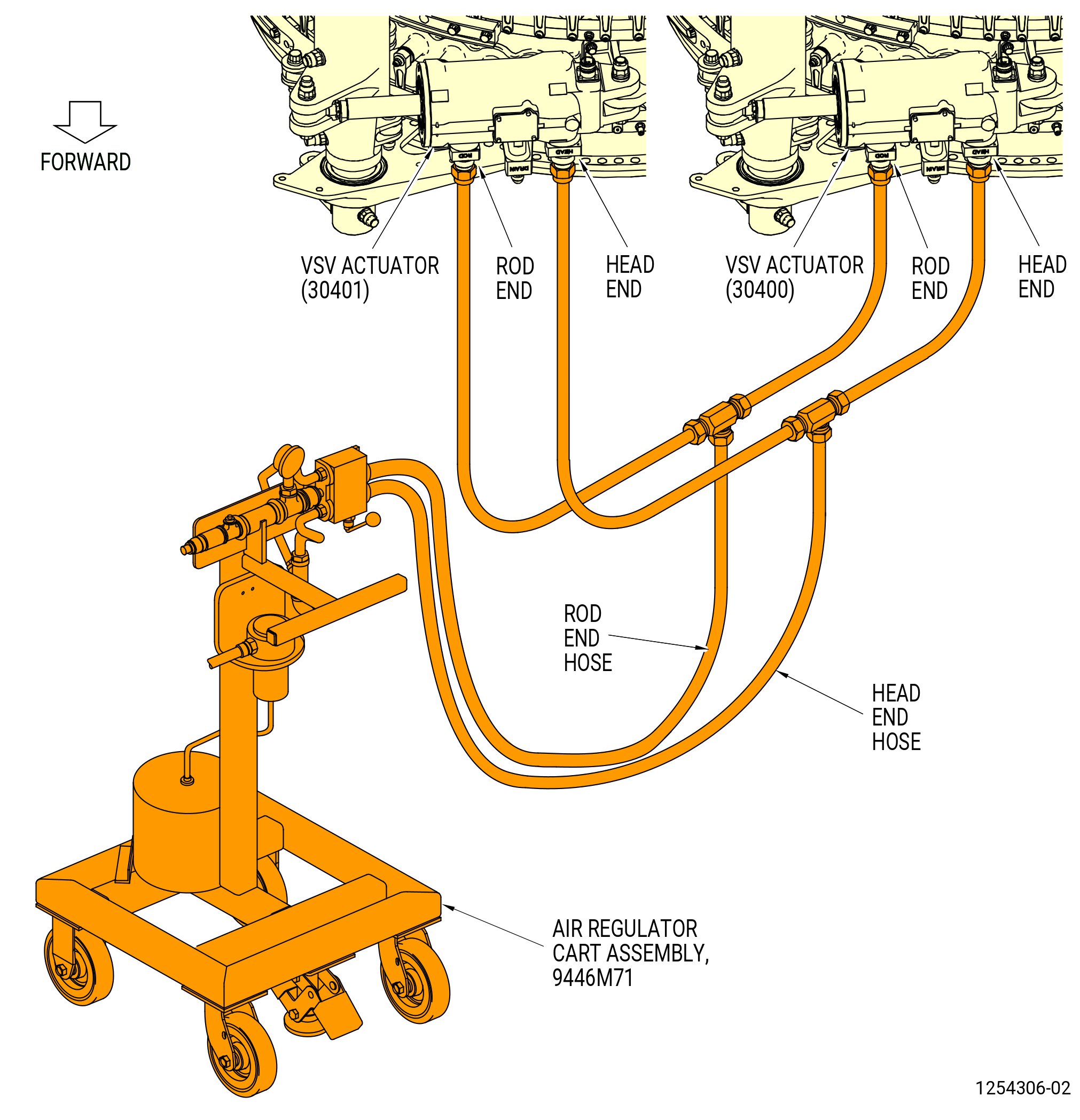
| G. | Alternative Procedure Available. Connect the rod and head hoses (item 3 and 4) of the 9446M71 air regulator cart assembly to the head and rod fittings on the VSV actuators (30400, 30401). Use nitrogen gas with the 9446M71 air regulator cart assembly. Refer to Figure 1017. |
| Subtask 72-30-00-210-035 |
| WARNING: |
|
| G.A. | Alternative Procedure. Connect the hoses between the head and rod fittings on the VSV actuators (30400, 30401) and the head and rod fittings on the 9461M39 hydraulic hand pump. Use C02-019 engine oil or C02-021 grade 1010 oil with the 9461M39 hydraulic hand pump. Refer to Figure 1018. |
| Subtask 72-30-00-820-002 |
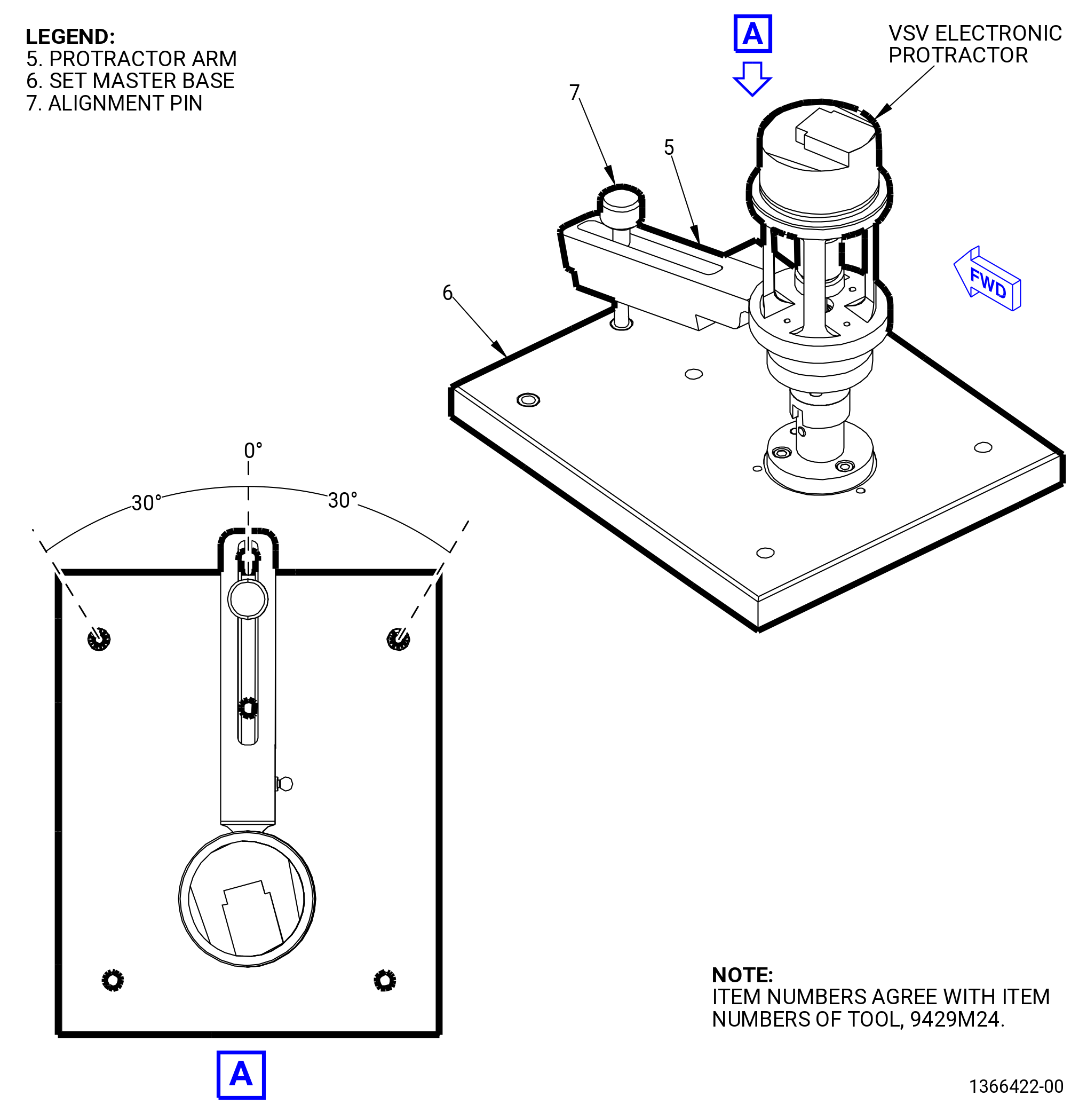
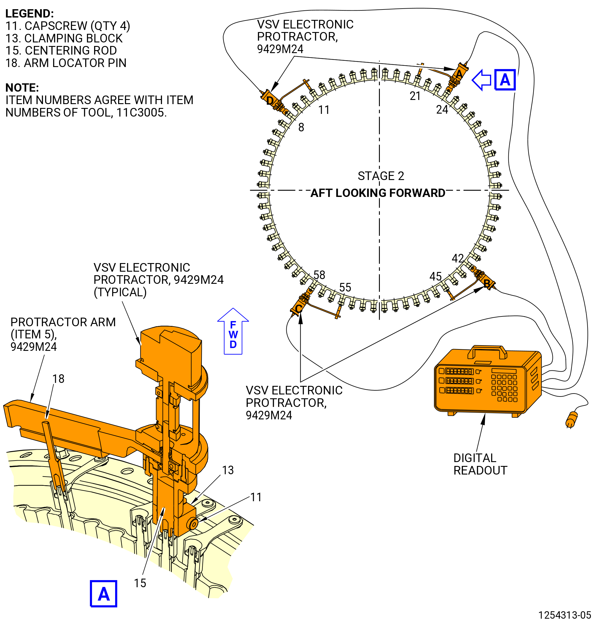
| H. | Calibrate the 9429M24 VSV electronic protractor A, B, C, and D with the 9429M24 VSV electronic protractor as follows: |
| (1) | Install the 9429M24 VSV electronic protractor A on the set master base (item 6) of the 9429M24 VSV electronic protractor. |
| (2) | Move the protractor arm (item 5) of the 9429M24 VSV electronic protractor to align with the zero mark on the set master base (item 6). |
| (3) | Install the alignment pin (item 7) through the protractor arm (item 5) and in the set master base (item 6) to keep the protractor arm (item 5) in position. Refer to Figure 1019. |
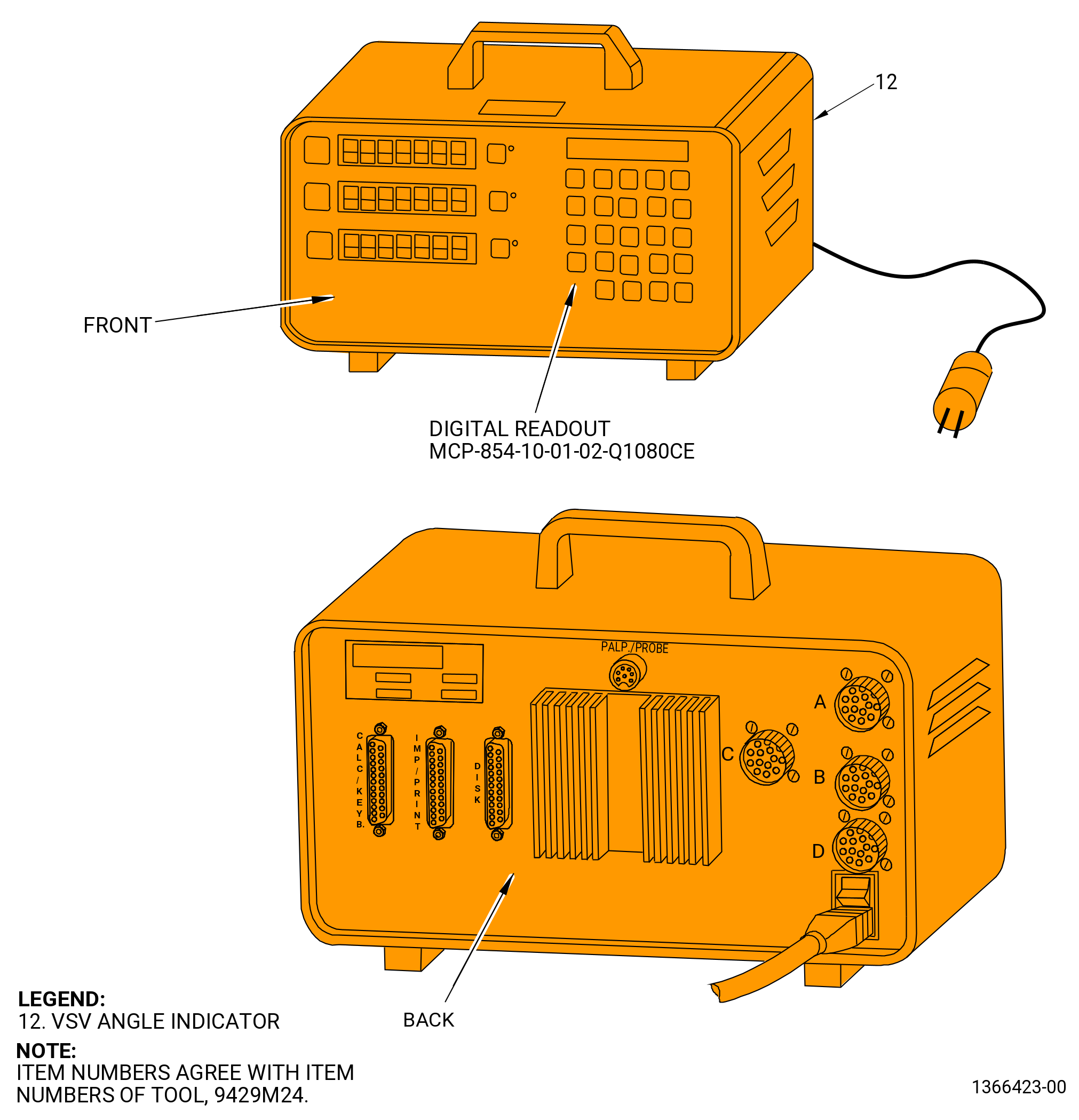
| (4) | Connect the 9429M24 VSV electronic protractor A electrical connector to the A channel connector on the back of the digital readout MCP-854-10-01-02-Q1080CE of the 9429M24 VSV electronic protractor . Refer to Figure 1020. |
| (5) | Press the zero button on the front of the digital readout. The sensor must read an angle of 00.0 degrees on the display. |
| (6) | Remove the alignment pin (item 7) and turn the protractor arm (item 5) clockwise (CW) to the right and stop at the 30-degrees mark on the set master base (item 6). |
| (7) | Install the set master alignment pin (item 7) through the protractor arm (item 5) and into the set master base (item 6) to keep the protractor arm (item 5) in position. |
| (8) | Read an angle of 30.0 degrees, plus or minus 0.2 degrees on the digital readout. |
| NOTE: |
|
| (9) | Remove the alignment pin (item 7) and turn the protractor arm (item 5) counterclockwise (CCW) to the left and stop at the zero mark on the set master base (item 6). Install the set master alignment pin (item 7) through the protractor arm (item 5) and into the set master base (item 6) to keep the protractor arm (item 5) in position. |
| (10) | Read an angle of 00.0 degrees on the digital readout. |
| (11) | Remove the alignment pin (item 7) and turn the protractor arm (item 5) CCW to the left and stop at the 30-degrees mark on the set master base (item 6). Install the set master alignment pin (item 7) through the protractor arm (item 5) and into the set master base (item 6) to keep the protractor arm in position. |
| (12) | Install the set master alignment pin (item 7) through the protractor arm (item 5) and into the set master base (item 6) to keep the protractor arm in position. |
| (13) | Read an angle of minus 30.0 degrees, plus or minus 0.2 degrees on the digital readout. |
| NOTE: |
|
| (14) | Do Subtask 72-30-00-820-002 (paragraph 3.H.(1)) thru Subtask 72-30-00-820-002 (paragraph 3.H.(13)) again for VSV electronic protractors B, C, and D with the digital readout channels B, C, and D. |
| (15) | Press the F button on the front of the digital readout unit to set channels A thru D. |
| NOTE: |
|
| Subtask 72-30-00-830-007 |
| I. | Do the VSV system rigging for shimmed, separable clevis torque shaft linkage. |
| • |
|
| NOTE: |
|
| Subtask 72-30-00-440-166 |
| (1) | Do a rigging of the VSV system stage 1 as follows: |
| (a) | Install the calibrated VSV electronic protractors on the stage 1 variable stator vanes as follows: |
| * * * PRE SB 72-0052( Heavier Stage 1 Lever Arms Design ) |
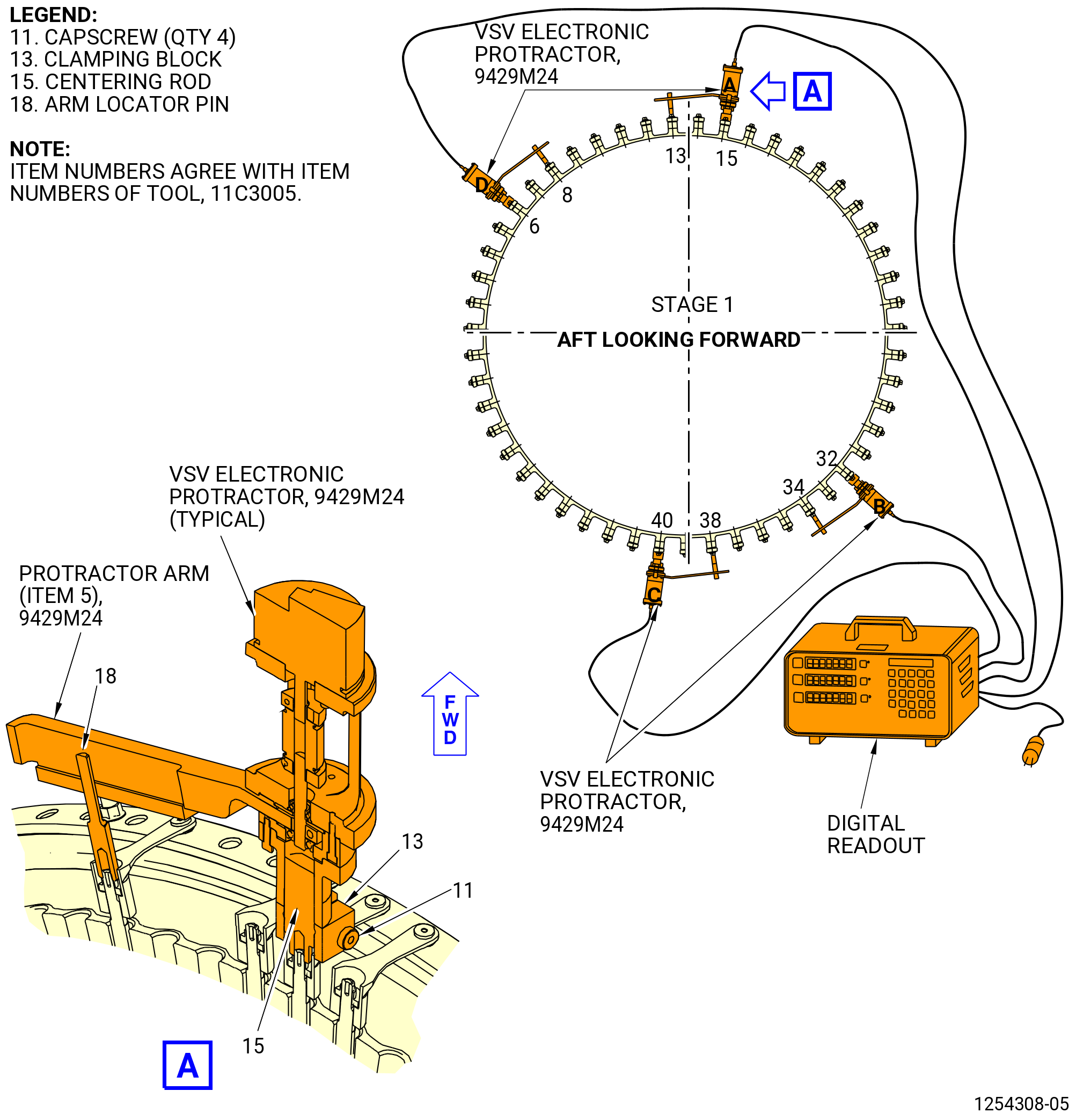
| 1 | Install the centering rod (item 15) of the 11C3005 adapter kit on the stage 1 lever arms (01-050 , 72-32-00) (SIN 071D1) at positions No. 6, 15, 32, and 40 in a CW direction ALF. Refer to Figure 1021. |
| NOTE: |
|
| * * * END PRE SB 72-0052 |
| Subtask 72-30-00-440-366 |
| * * * SB 72-0052( Lighter Stage 1 Lever Arms Design ) |
| 1.A. | Install the centering rod (item 15) of the 11C3005 adapter kit on the stage 1 lever arms (01-180 , 72-32-00) (SIN 071C0) at positions No. 6, 15, 32, and 40 in a CW direction ALF. Refer to Figure 1021. |
| NOTE: |
|
| NOTE: |
|
| * * * END SB 72-0052 |
| Subtask 72-30-00-440-367 |
| 2 | Make sure that the side of the clamping blocks (item 13) of the 11C3005 adapter kit with the channel are aligned with the stage 1 lever arms. |
| 3 | Install the stage 1 lever arms on the centering rods (item 15). Do not tighten the capscrews (item 11) on the clamping blocks (item 13) at this time. |
| 4 | Install the arm locator pin (item 18) on the stage 1 lever arms at positions No. 8, 13, 34, and 38 in a CW direction ALF. |
| Subtask 72-30-00-440-167 |
| CAUTION: |
|
| (b) | Install the VSV electronic protractors A, B, C, and D on the stage 1 lever arms at positions 6, 15, 32, and 40 respectively, as follows. Refer to Figure 1021. |
| 1 | Align the slot in the protractor arm (item 5) of the 9429M24 VSV electronic protractor with the arm locator pin (item 18) of the 11C3005 adapter kit. |
| 2 | Put the 9429M24 VSV electronic protractor on the centering rod (item 15) of the 11C3005 adapter kit along with the protractor arm (item 5) of the 9429M24 VSV electronic protractor above the arm locator pin (item 18) of the 11C3005 adapter kit. |
| 3 | Tighten the capscrews (item 11) on the clamping blocks (item 13) of the 11C3005 adapter kit. |
| 4 | Connect the electrical connector of each VSV electronic protractor to the correct channel receptacle on the back of the digital readout of the 9429M24 VSV electronic protractor. Refer to Figure 1020. |
| 5 | Press the F button on the front of the digital readout of the 9429M24 VSV electronic protractor to set the channels A thru D. |
| Subtask 72-30-00-440-281 |
| WARNING: |
|
| CAUTION: |
|
| (c) | Operate the VSV system as follows: |
| 1 | Slowly apply a pressure of 75-125 psig (517-862 kPa gage) maximum with the 9446M71 air regulator cart assembly or the 9461M39 hydraulic hand pump to operate the VSV system to the fully closed position. |
| 2 | Make sure that the movement is smooth and that there is no interference or binding of the turnbuckles against their mating clevises, and no interference or binding of other system components. Refer to Figure 1017 and Figure 1018. |
| 3 | Slowly apply a pressure of 75-125 psig (517-862 kPa gage) maximum with the 9446M71 air regulator cart assembly or the 9461M39 hydraulic hand pump to operate the VSV system to the fully open position. |
| 4 | Make sure that the movement is smooth and that there is no interference or binding of the turnbuckles against their mating clevises, and no interference or binding of other system components. |
| 5 | Slowly apply a pressure of 75-125 psig (517-862 kPa gage) maximum with the 9446M71 air regulator cart assembly or the 9461M39 hydraulic hand pump to operate the VSV system from the fully closed to open to the closed position, for four full cycles. |
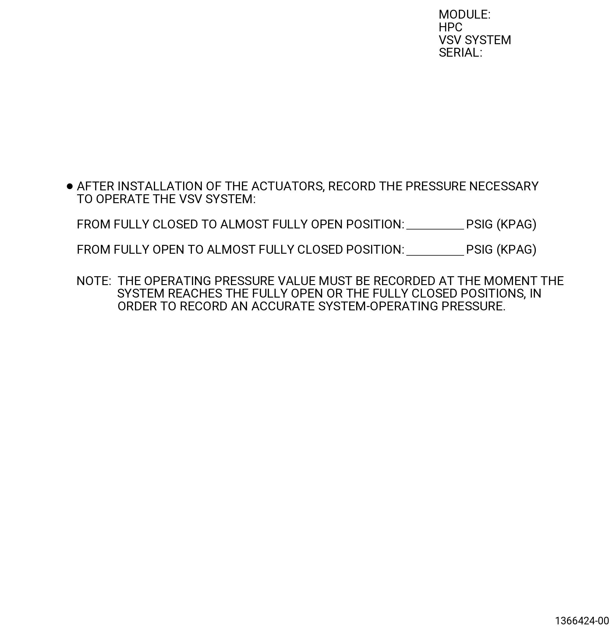
| 6 | Record the pressure necessary to operate the system on the VSV actuator pressure form. Refer to Figure 1022. |
| Subtask 72-30-00-210-008 |
| WARNING: |
|
| CAUTION: |
|
| (d) | Operate the VSV system to the fully open position as follows: |
| 1 | Slowly apply a pressure of 75-125 psig (517-862 kPa gage) maximum with the 9446M71 air regulator cart assembly or the 9461M39 hydraulic hand pump to operate the VSV system to the fully open position. |
| 2 | Do not release the pressure until the values are recorded. |
| (e) | Record the values of the four position sensors in the fully open position as follows: |
| NOTE: |
|
| 1 | Press the F button on the front of the digital readout of the 9429M24 VSV electronic protractor to set channels A thru D. |
| 2 | Record the value for each of the position sensors A, B, C, and D, and the average on the stage 1 vane assembly form. Refer to Figure 1023. |
| 3 | Release the pressure on the VSV system. |
| Subtask 72-30-00-440-282 |
| WARNING: |
|
| CAUTION: |
|
| (f) | Operate the VSV system to the fully closed position as follows: |
| 1 | Slowly apply a pressure of 75-125 psig (517-862 kPa gage) maximum with the 9446M71 air regulator cart assembly or the 9461M39 hydraulic hand pump to operate the VSV system to the fully closed position. |
| 2 | Do not release the pressure until the values are recorded. |
| Subtask 72-30-00-440-283 |
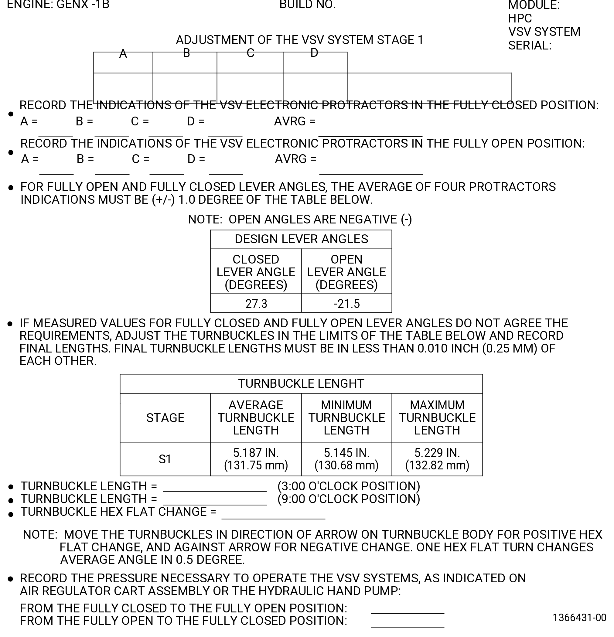
| (g) | Record the values of the four VSV electronic protractors in the fully closed position as follows: |
| NOTE: |
|
| 1 | Press the F button on the front of the digital readout of the 9429M24 VSV electronic protractor to set channels A thru D. |
| 2 | Record the value for each of the VSV electronic protractors A, B, C, and D, and the average on the stage 1 vane assembly form. |
| 3 | Record the pressure necessary to operate the system to fully closed position. |
| 4 | Release the pressure on the VSV system. |
| Subtask 72-30-00-440-284 |
| (h) | If the fully open and fully closed lever angle readings are not 1.0 degree or less of the values shown in Figure 1023 or if the lever angle travel is not in 0.5 degree or less of the values shown in Figure 1023, correct the VSV system as follows. |
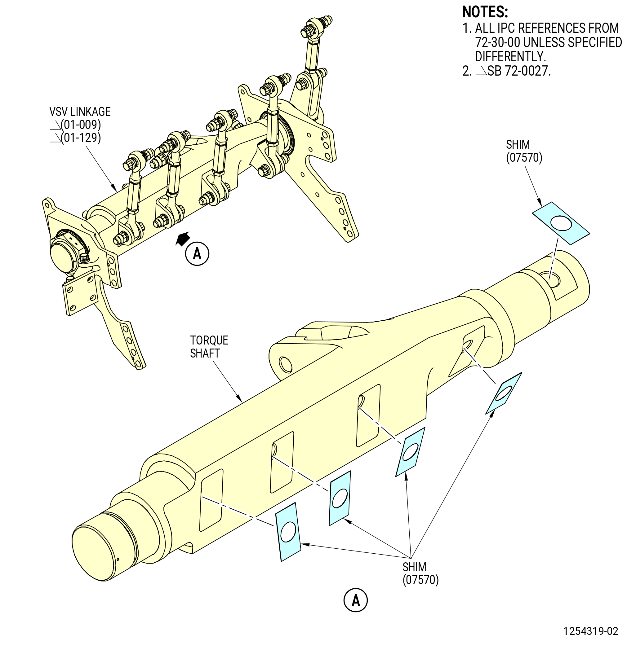
| 1 | If the travel is not in the limits, remove or add shims (07570) as follows. Refer to Figure 1025. |
| NOTE: |
|
| a | Remove the self-locking nut and bolt that attach the stage 1 turnbuckle to the shaft clevis. |
| b | Remove the self-locking nut that attaches the shaft clevis to the torque shaft. |
| c | Remove the shaft clevis from the torque shaft and remove or add shims as necessary. Adding one shim increases total travel angle and reduces average angle as shown in table. Refer to Table 1001. |
|
| d | If shims are removed or added from one of the torque shaft linkages at the 9:00 o'clock position, the same number of shims must be added or removed from the other torque shaft linkage at the 3:00 o'clock position. |
| e | Record each shim quantity change and final shim total in Figure 1023. |
| f | Attach the stage 1 turnbuckle to the shaft clevis with a bolt and self-locking nut. Torque the self-locking nut to 460-540 lb in. (52.0-61.0 N.m). |
| g | Install the shaft clevis in the torque shaft and attach it with a self-locking nut. Torque the self-locking nut to 552-648 lb in. (62.4-73.2 N.m). |
| 2 | If necessary, calculate the hex flat change as follows: |
| a | Add the average measured open angle to the average measured closed angle and divide by two. Do not ignore the negative sign of the average open angle. |
| b | Add the average design open angle to the average design closed angle and divide by two. Do not ignore the negative sign of the average open angle. |
| c | Find the difference between the two values calculated in the steps a and b (average measured - average design) and divide by 0.5. This will give the number of hex flats to turn the turnbuckle. Record the turnbuckle hex flat change on the stage 1 vane assembly form. Refer to Figure 1023. |
| d | The rotation of the turnbuckle bodies in the direction of the arrow decreases the average angle. The rotation of the turnbuckle bodies in the direction opposite the arrow increases the average angle. Average angle change is 0.5 degree for each hex flat turn. |
| NOTE: |
|
| 3 | If the measured VSV closed and open angles do not agree with the design VSV closed and open values on the stage 1 vane assembly form, adjust the stage 1 turnbuckles as follows. Refer to Figure 1025 and Figure 1026. |
| NOTE: |
|
| a | Remove the bolts and self-locking nuts that attach the turnbuckle to the stage 1 bridge (071E1, 071E6) and the VSV linkages (01-009) (SIN 07501), (01-010) (SIN 07501), or (01-010A) (SIN 07501), and (01-129) (SIN 07500), (01-130) (SIN 07500), or (01-130A) (SIN 07500). |
| NOTE: |
|
| NOTE: |
|
| b | Adjust the length of the turnbuckle with the 9429M53 turnbuckle gauging fixture as follows. Refer to Figure 1024. |
| c | Make sure that the accuracy of the 9429M53 turnbuckle gauging fixture is correct as follows: |
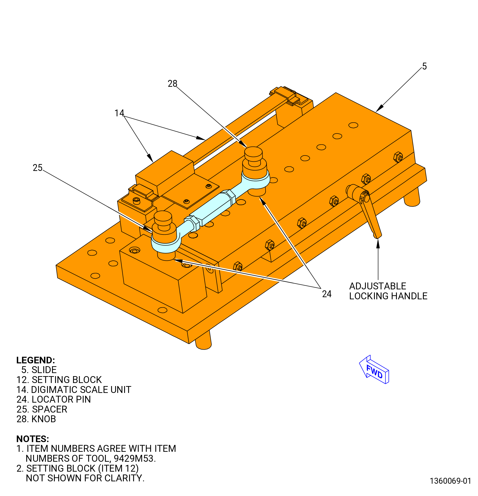
| (1) | Unlock the slide (item 5) with the adjustable locking handle. |
| (2) | Adjust the slide and install the setting block (item 12) on the locator pins (item 24). The slotted open end setting block must be engaged with the locator pin on the slide (item 5). |
| (3) | The digimatic scale unit (item 14) must read 5.000, plus or minus 0.001 inch (127.00 plus or minus 0.03 mm). If not, send the digimatic scale unit (item 14) to be calibrated. |
| (4) | With the setting block (item 12) installed on the two locator pins (24), lock the slide (item 5) and set the digimatic scale unit (item 14) to zero of the for the reference point. |
| (5) | Remove the setting block (item 12). |
| d | Unlock the slide (item 5) of the 9429M53 turnbuckle gauging fixture with the adjustable locking handle. |
| e | Put the turnbuckle in the 9429M53 turnbuckle gauging fixture as follows: |
| (1) | Place the holes of the two turnbuckle rod ends on the protruded bosses on the locator pins (item 24) and install the rods ends on the pins until they are on top of the two flat planes of the locator pins (item 24). |
| (2) | Install the two spacers (item 25) on the two protruded bosses of the locator pins (item 24), one on each boss until they are installed on the flat surfaces of the rod ends of the turnbuckles. |
| (3) | Install the two knobs (item 28) in the threaded holes on protruded bosses of the locator pins (item 24). Hand-tighten the knobs to keep the assembly without movement. |
| (4) | Loosen the self-locking nuts on the turnbuckle and turn the turnbuckle to the number of hex flats recorded on the stage 1 vane assembly form. |
| NOTE: |
|
| (5) | Follow the direction arrow to decrease the average angle, and turn against the arrow to increase the average angle. |
| NOTE: |
|
| (6) | Make sure that the turnbuckle body is centered between each rod end bearing. |
| (7) | Lock the slide (item 5) with the adjustable locking handle to keep the slide (item 5) without movement. |
| (8) | Make sure that the slide (item 5) is locked. Torque the jam nuts on each end of the turnbuckle to 235-275 lb in. (26.6-31.1 N.m). |
| (9) | Record the length of the turnbuckle. Refer to Figure 1027. |
| (10) | Remove the two knobs (item 28), two spacers (item 25) and the turnbuckle. |
| f | After all adjustments are made, operate the system from full open to full closed four times. Make sure that there is no binding or interference. |
| NOTE: |
|
| CAUTION: |
|
| g | Put the rod end bearing into the clevises on the stage 1 bridge (071E1, 071E6) and VSV linkage (01-009) (SIN 07501), (01-010) (SIN 07501), or (01-010A) (SIN 07501), and (01-129) (SIN 07500), (01-130) (SIN 07500), or (01-130A) (SIN 07500) with the direction arrow away from the VSV linkage. |
| NOTE: |
|
| h | Attach the rod end bearing to the stage 1 bridge and VSV linkage with the removed bolts and self-locking nuts. Put the boltheads aft. |
| i | Torque the self-locking nuts to 460-540 lb in. (52.0-61.0 N.m). |
| 4 | Adjust the other stage 1 turnbuckle. Refer to Subtask 72-30-00-440-284 (paragraph 3.I.(1)(h)) . |
| NOTE: |
|
| Subtask 72-30-00-440-368 |
| 5 | Do Subtask 72-30-00-440-281 (paragraph 3.I.(1)(c)) thru Subtask 72-30-00-440-283 (paragraph 3.I.(1)(g)) again to make sure that the system is in limits. This must be done each time the VSV system is adjusted. |
| 6 | Remove the VSV electronic protractors from the VSV system stage 1 as follows. Refer to Figure 1021. |
| a | Loosen the capscrews (item 11) on the clamping blocks (item 13) of the 11C3005 adapter kit. |
| b | Remove the VSV electronic protractors. |
| c | Remove the clamping blocks (item 13) of the 11C3005 adapter kit from the stage 1 lever arms. |
| d | Remove the centering rod (item 15) from the stage 1 lever arms. |
| e | Remove the arm locator pin (item 18) from the stage 1 lever arms. |
|
|
|
| Subtask 72-30-00-820-006 |
| (2) | Do a rigging of the VSV system stage 2 as follows: |
| (a) | Install the calibrated VSV electronic protractors on the stage 2 VSV as follows: |
| * * * PRE SB 72-0052( Heavier Stage 2 Lever Arms Design ) |
| 1 | Install the centering rod (item 15) of the 11C3005 adapter kit on the stage 2 lever arms (01-090 , 72-32-00) (SIN 071D2) at positions No. 8, 24, 42, and 58 in a CW direction ALF. Refer to Figure 1028. |
| NOTE: |
|
| * * * END PRE SB 72-0052 |
| Subtask 72-30-00-440-369 |
| * * * SB 72-0052( Lighter Stage 2 Lever Arms Design ) |
| 1.A. | Install the centering rod (item 15) of the 11C3005 adapter kit on the stage 2 lever arms (01-180 , 72-32-00) (SIN 071C0) at positions No. 8, 24, 42, and 58 in a CW direction ALF. Refer to Figure 1028. |
| NOTE: |
|
| NOTE: |
|
| * * * END SB 72-0052( ) |
| Subtask 72-30-00-440-370 |
| 2 | Make sure that the side of the clamping blocks (item 13) of the 11C3005 adapter kit with the channel are aligned with the stage 2 lever arms. |
| 3 | Install them on the centering rods. Do not tighten the capscrews (item 11) of the 11C3005 adapter kit on the clamping blocks (item 13) at this time. |
| 4 | Install the arm locator pin (item 18) of the 11C3005 adapter kit on the stage 2 lever arms at positions No. 11, 21, 45, and 55 in a CW direction ALF. |
| 5 | Install the VSV electronic protractors A, B, C, and D on the stage 2 lever arms at positions No. 8, 24, 42, and 58 respectively, as follows. Refer to Figure 1028. |
| a | Align the slot in the protractor arm (item 5) of the 9429M24 VSV electronic protractor with the arm locator pin (item 18) of the 11C3005 adapter kit. |
| b | Put the 9429M24 VSV electronic protractor on the centering rod (item 15) of the 11C3005 adapter kit along with the protractor arm (item 5) of the 9429M24 VSV electronic protractor above the arm locator pin (item 18) of the 11C3005 adapter kit. |
| c | Tighten the capscrews (item 11) on the clamping blocks (item 13) of the 11C3005 adapter kit. |
| d | Connect the electrical connector of each VSV electronic protractor to the correct channel receptacle on the back of the digital readout of the 9429M24 VSV electronic protractor. Refer to Figure 1020. |
| 6 | Press the F button on the front of the digital readout of the 9429M24 VSV electronic protractor to set the channels A thru D. |
| Subtask 72-30-00-440-243 |
| WARNING: |
|
| CAUTION: |
|
| (b) | Operate the VSV system as follows. Refer to Figure 1017 and Figure 1018. |
| 1 | Slowly apply a pressure of 75-125 psig (517-862 kPa gage) maximum with the 9446M71 air regulator cart assembly or the 9461M39 hydraulic hand pump to operate the VSV system to the fully closed position. |
| 2 | Make sure that the movement is smooth and that there is no interference or binding of the turnbuckles against their mating clevises, and no interference or binding of other system components. |
| 3 | Slowly apply a pressure of 75-125 psig (517-862 kPa gage) maximum with the 9446M71 air regulator cart assembly or the 9461M39 hydraulic hand pump to operate the VSV system to the fully open position. |
| 4 | Make sure that the movement is smooth and that there is no interference or binding of the turnbuckles against their mating clevises, and no interference or binding of other system components. |
| 5 | Slowly apply a pressure of 75-125 psig (517-862 kPa gage) maximum with the 9446M71 air regulator cart assembly or the 9461M39 hydraulic hand pump to operate the VSV system from the fully closed to open to the closed position, for four full cycles. |
| 6 | Record the pressure necessary to operate the system on the VSV actuator pressure form. Refer to Figure 1022. |
| Subtask 72-30-00-210-009 |
| WARNING: |
|
| CAUTION: |
|
| (c) | Operate the VSV system to the fully open position as follows: |
| 1 | Slowly apply a pressure of 75-125 psig (517-862 kPa gage) maximum with the 9446M71 air regulator cart assembly or the 9461M39 hydraulic hand pump. |
| 2 | Do not release the pressure until the values are recorded. |
| (d) | Record the values of the four position sensors in the fully open position as follows: |
| NOTE: |
|
| 1 | Press the F button on the front of the digital readout of the 9429M24 VSV electronic protractor to set channels A thru D. |
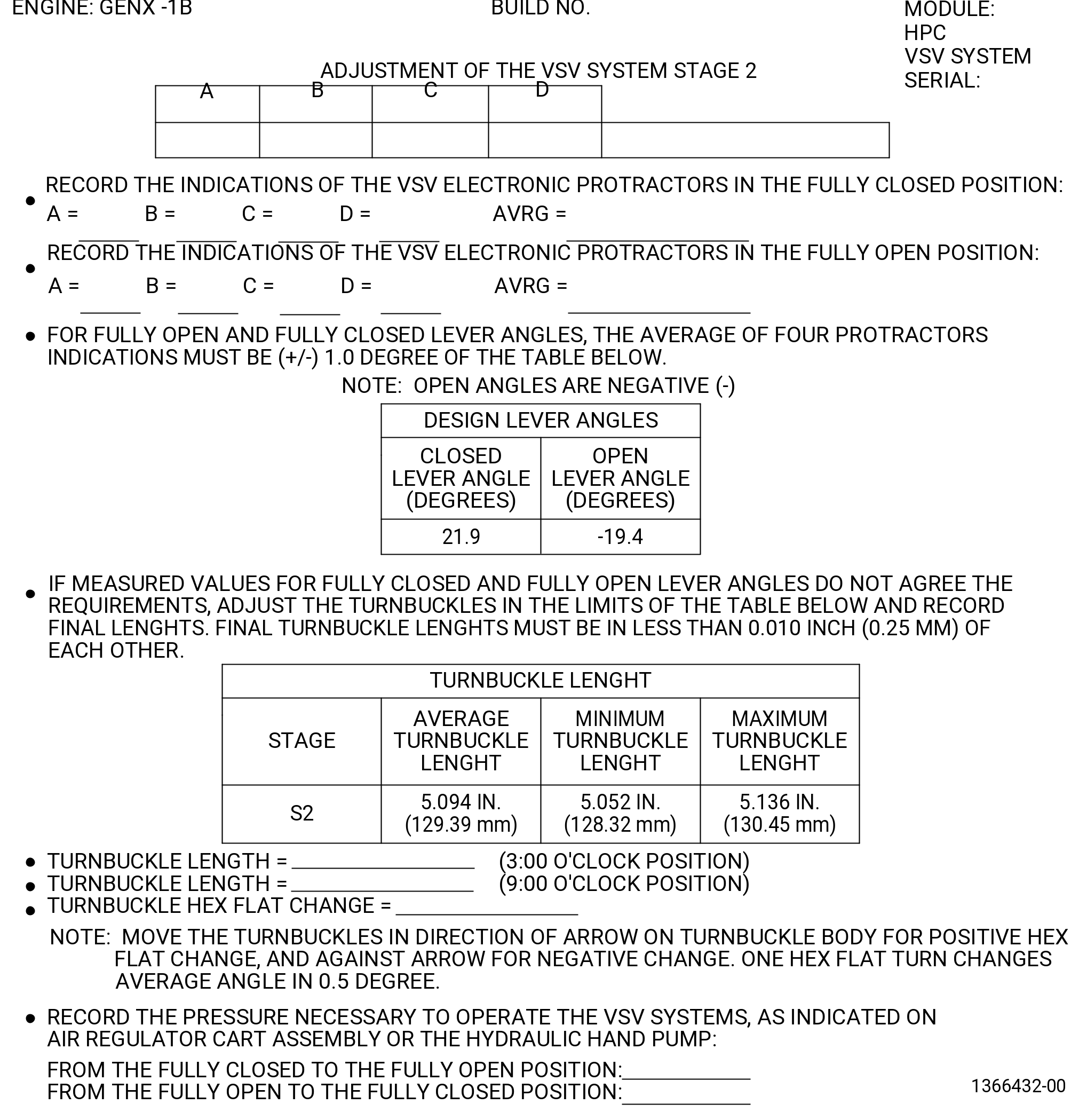
| 2 | Record the value for each of the VSV electronic protractors A, B, C, and D, and the average on the stage 2 vane assembly form. Refer to Figure 1027. |
| 3 | Release the pressure on the VSV system. |
| Subtask 72-30-00-440-290 |
| WARNING: |
|
| CAUTION: |
|
| (e) | Operate the VSV system to the fully closed position as follows: |
| 1 | Slowly apply pressure with the 9446M71 air regulator cart assembly or the 9461M39 hydraulic hand pump. |
| 2 | Do not release the pressure until the values are recorded. |
| Subtask 72-30-00-440-291 |
| (f) | Record the values of the four position sensors in the fully closed position as follows: |
| NOTE: |
|
| 1 | Press the F button on the front of the digital readout of the 9429M24 VSV electronic protractor to set channels A thru D. |
| 2 | Record the value for each of the VSV electronic protractors A, B, C, and D, and the average on the stage 2 vane assembly form. Refer to Figure 1027. |
| 3 | Release the pressure on the VSV system. |
| Subtask 72-30-00-440-292 |
| (g) | If the fully open and fully closed lever angle readings are not 1.0 degree or less or if the lever angle travel is not 0.5 degree or less of the values shown in Figure 1027, correct the VSV system. Refer to Subtask 72- 30-00-440-284 (paragraph 3.I.(1)(h)) and Figure 1027. |
| Subtask 72-30-00-440-371 |
| (h) | Do Subtask 72-30-00-440-243 (paragraph 3.I.(2)(b)) thru Subtask 72-30-00-440-291 (paragraph 3.I.(2)(f)) again to make sure that the system is in the limits. This must be done each time the VSV system is adjusted. |
| (i) | Remove the VSV electronic protractors from the VSV system stage 2 as follows. Refer to Figure 1028. |
| 1 | Loosen the capscrews (item 11) on the clamping blocks (item 13) of the 11C3005 adapter kit. |
| 2 | Remove the VSV electronic protractors. |
| 3 | Remove the clamping blocks (item 13) of the 11C3005 adapter kit from the stage 2 lever arms. |
| 4 | Remove the centering rod (item 15) from the stage 2 lever arms. |
| 5 | Remove the arm locator pin (item 18) from the stage 2 lever arms. |
| Subtask 72-30-00-820-007 |
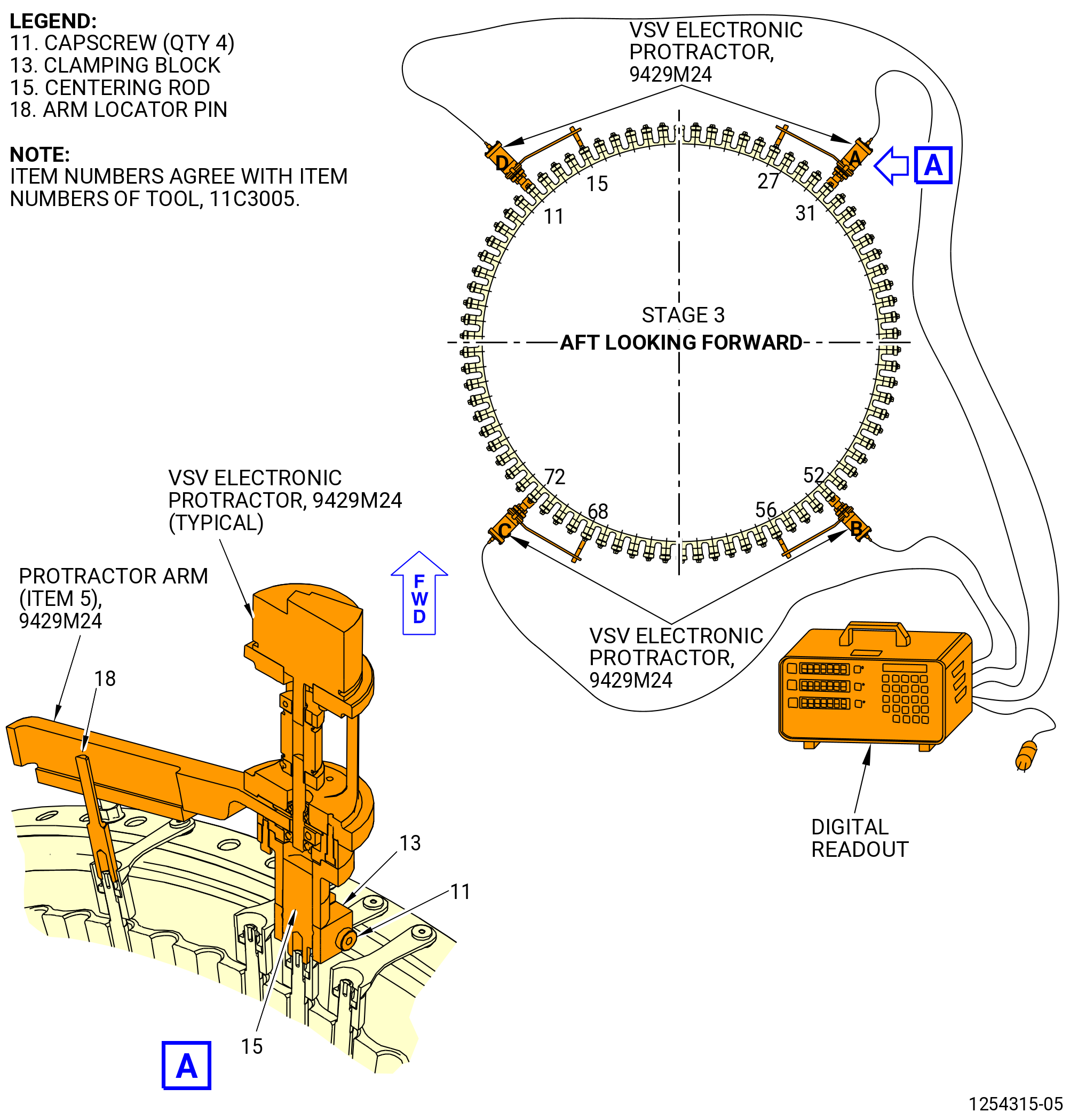
| (3) | Do a rigging of the VSV system stage 3. |
| (a) | Calibrate the VSV electronic protractors A, B, C, and D with the set master base (item 6) of the 9429M24 VSV electronic protractor. Refer to Subtask 72-30-00-820-002 (paragraph 3.H.). |
| Subtask 72-30-00-440-245 |
| (b) | Install the calibrated VSV electronic protractors on the stage 3 variable stator vanes as follows: |
| * * * PRE SB 72-0052( Heavier Stage 3 Lever Arms Design ) |
| 1 | Install the centering rod (item 15) of the 11C3005 adapter kit on the stage 3 lever arms (01-120 , 72-32-00) (SIN 071D3) at positions No. 11, 31, 52, and 72 in a CW direction ALF. Refer to Figure 1029. |
| NOTE: |
|
| * * * END PRE SB 72-0052 |
| Subtask 72-30-00-440-372 |
| * * * SB 72-0052( Lighter Stage 3 Lever Arms Design ) |
| 1.A. | Install the centering rod (item 15) of the 11C3005 adapter kit on the stage 3 lever arms (01-180 , 72-32-00) (SIN 071C0) at positions No. 11, 31, 52, and 72 in a CW direction ALF. Refer to Figure 1029. |
| NOTE: |
|
| NOTE: |
|
| * * * END SB 72-0052 |
| Subtask 72-30-00-440-373 |
| 2 | Make sure that the side of the clamping blocks (item 13) of the 11C3005 adapter kit with the channel are aligned with the stage 3 lever arms. |
| 3 | Install the stage 3 lever arms on the centering rods (item 15). Do not tighten the capscrews (item 11) on the clamping blocks (item 13) at this time. |
| 4 | Install the arm locator pin (item 18) on the stage 3 lever arms at positions No. 15, 27, 56, and 68 in a CW direction ALF. |
| Subtask 72-30-00-440-246 |
| CAUTION: |
|
| 5 | Install the VSV electronic protractors A, B, C, and D on the stage 3 lever arms at positions No. 11, 31, 52 and 72 respectively, as follows. Refer to Figure 1029. |
| a | Align the slot in the protractor arm (item 5) of the 9429M24 VSV electronic protractor with the arm locator pin (item 18) of the 11C3005 adapter kit. |
| b | Put the 9429M24 VSV electronic protractor on the centering rod (item 15) of the 11C3005 adapter kit along with the protractor arm (item 5) of the 9429M24 VSV electronic protractor above the arm locator pin (item 18) of the 11C3005 adapter kit. |
| c | Tighten the capscrews (item 11) on the clamping blocks (item 13) of the 11C3005 adapter kit. |
| d | Connect the electrical connector of each VSV electronic protractor to the correct channel receptacle on the back of the digital readout of the 9429M24 VSV electronic protractor. Refer to Figure 1017. |
| 6 | Press the F button on the front of the digital readout of the 9429M24 VSV electronic protractor to set the channels A thru D. |
| Subtask 72-30-00-440-250 |
| WARNING: |
|
| CAUTION: |
|
| (c) | Operate the VSV system as follows. Refer to Figure 1017 and Figure 1018. |
| 1 | Slowly apply a pressure of 75-125 psig (517-862 kPa gage) maximum with the 9446M71 air regulator cart assembly or the 9461M39 hydraulic hand pump to operate the VSV system to the fully closed position. |
| 2 | Make sure that the movement is smooth and that there is no interference or binding of the turnbuckles against their mating clevises, and no interference or binding of other system components. |
| 3 | Slowly apply a pressure of 75-125 psig (517-862 kPa gage) maximum with the 9446M71 air regulator cart assembly or the 9461M39 hydraulic hand pump to operate the VSV system to the fully open position. |
| 4 | Make sure that the movement is smooth and that there is no interference or binding of the turnbuckles against their mating clevises, and no interference or binding of other system components. |
| 5 | Slowly apply a pressure of 75-125 psig (517-862 kPa gage) maximum with the 9446M71 air regulator cart assembly or the 9461M39 hydraulic hand pump to operate the VSV system from the fully closed to open to the closed position, for four full cycles. |
| 6 | Record the pressure necessary to operate the system on the VSV actuator pressure form. Refer to Figure 1022. |
| Subtask 72-30-00-210-010 |
| WARNING: |
|
| CAUTION: |
|
| (d) | Operate the VSV system to the fully open position as follows: |
| 1 | Slowly apply a pressure of 75-125 psig (517-862 kPa gage) maximum with the 9446M71 air regulator cart assembly or the 9461M39 hydraulic hand pump. |
| 2 | Do not release the pressure until the values are recorded. |
| (e) | Record the values of the four position sensors in the fully open position as follows: |
| NOTE: |
|
| 1 | Press the F button on the front of the digital readout of the 9429M24 VSV electronic protractor to set channels A thru D. |
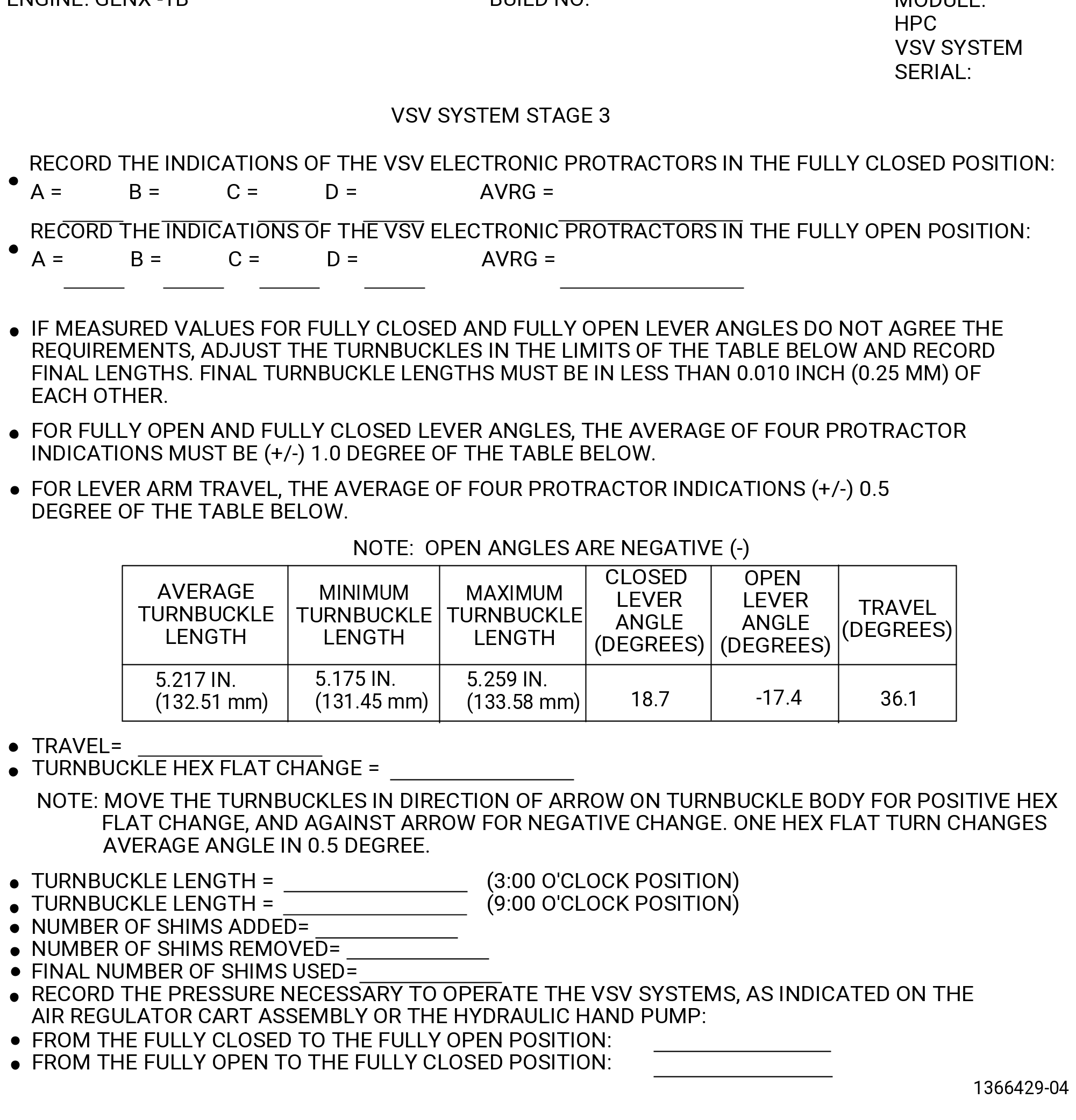
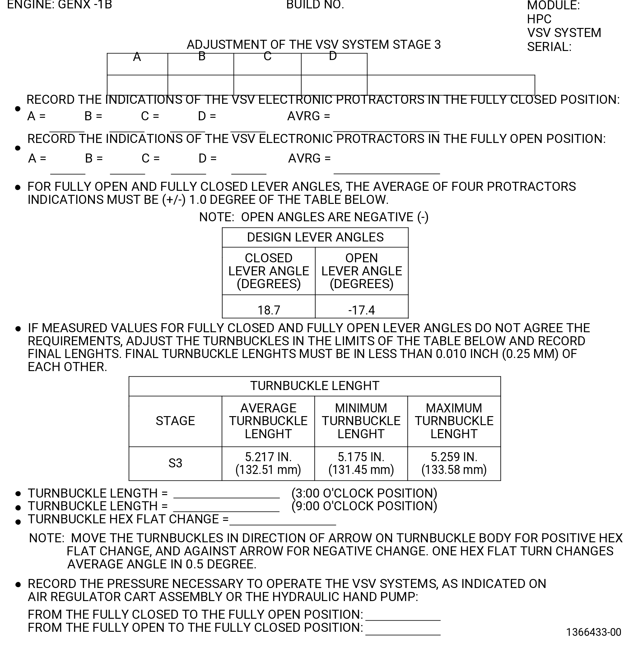
| 2 | Record the value for each of the VSV electronic protractors A, B, C, and D, and the average on the stage 3 vane assembly form. Refer to Figure 1030. |
| 3 | Release the pressure on the VSV system. |
| Subtask 72-30-00-440-251 |
| WARNING: |
|
| CAUTION: |
|
| (f) | Operate the VSV system to the fully closed position as follows: |
| 1 | Slowly apply pressure with the 9446M71 air regulator cart assembly or the 9461M39 hydraulic hand pump. |
| 2 | Do not release the pressure until the values are recorded. |
| Subtask 72-30-00-440-252 |
| (g) | Record the values of the four position sensors in the fully closed position as follows: |
| NOTE: |
|
| 1 | Press the F button on the front of the digital readout of the 9429M24 VSV electronic protractor to set channels A thru D. |
| 2 | Record the value for each of the VSV electronic protractors A, B, C, and D, and the average on the stage 3 vane assembly form. Refer to Figure 1030. |
| 3 | Release the pressure on the VSV system. |
| Subtask 72-30-00-440-253 |
| (h) | If the fully open and fully closed lever angle readings are not 1.0 degree or less or if the lever angle travel is not 0.5 degree or less of the values shown in Figure 1030, correct the VSV system. Refer to Subtask 72-30-00-440-284 (paragraph 3.I.(1)(h)) and Figure 1030. |
| Subtask 72-30-00-820-010 |
| (i) | Do Subtask 72-30-00-440-250 (paragraph 3.I.(3)(c)) thru Subtask 72-30-00-440-250 (paragraph 3.I.(3)(g)) again to make sure that the system is in the limits. This must be done each time the VSV system is adjusted. |
| (j) | Remove the VSV electronic protractors from the VSV system stage 3 as follows. Refer to Figure 1029. |
| 1 | Loosen the capscrews (item 11) on the clamping blocks (item 13) of the 11C3005 adapter kit. |
| 2 | Remove the VSV electronic protractors. |
| 3 | Remove the clamping blocks (item 13) of the 11C3005 adapter kit from the stage 3 lever arms. |
| 4 | Remove the centering rod (item 15) from the stage 3 lever arms. |
| 5 | Remove the arm locator pin (item 18) from the stage 3 lever arms. |
| Subtask 72-30-00-820-008 |
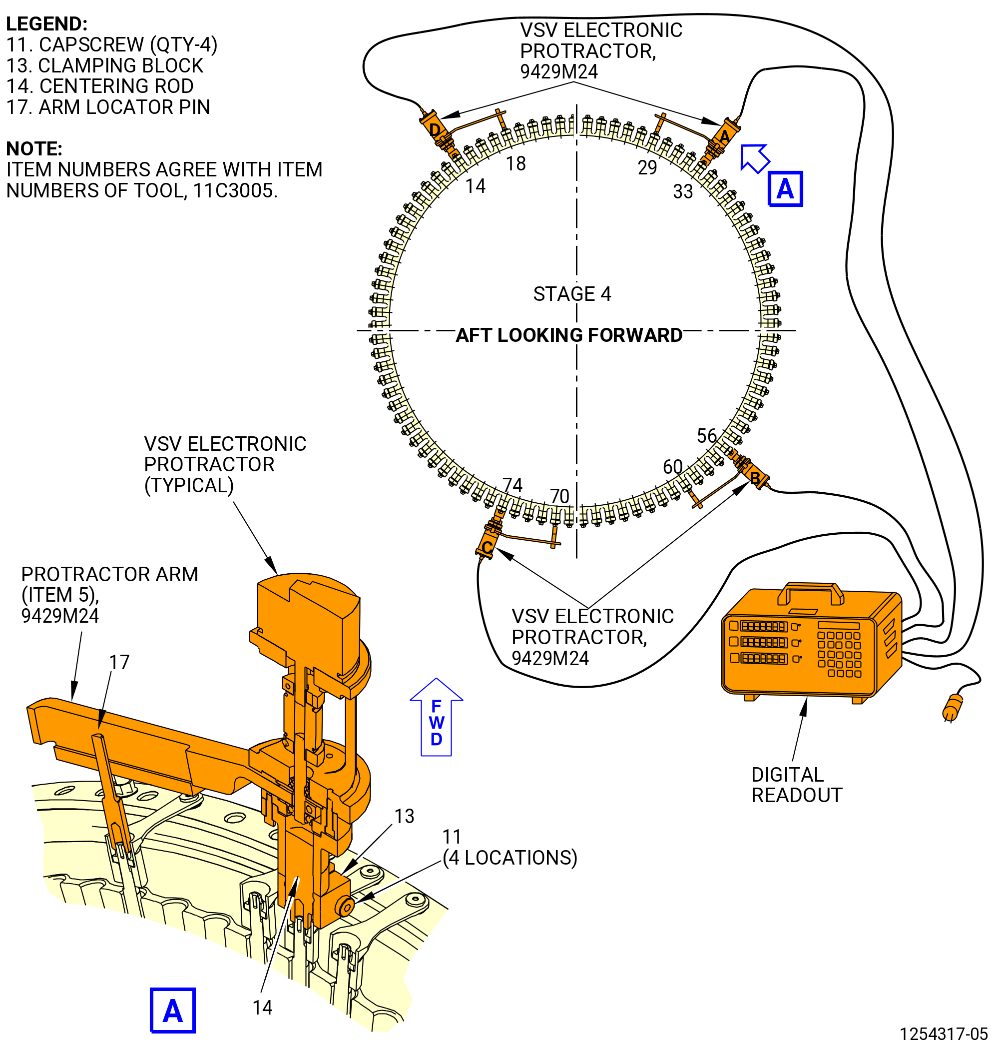
| (4) | Do a rigging of the VSV stage 4 as follows: |
| (a) | Calibrate the VSV electronic protractors A, B, C, and D, with the set master base (item 6) of the 9429M24 VSV electronic protractor. Refer to Subtask 72-30-00-820-002 (paragraph 3.H.). |
| Subtask 72-30-00-440-254 |
| (b) | Install the calibrated VSV electronic protractors on the stage 4 variable stator vanes as follows: |
| * * * PRE SB 72-0052( Heavier Stage 4 Lever Arms Design ) |
| 1 | Install the centering rod (item 14) of the 11C3005 adapter kit on the stage 4 lever arms (01-160 , 72-32-00) (SIN 071D4) at positions No. 14, 33, 56, and 74 in a CW direction ALF. Refer to Figure 1031. |
| NOTE: |
|
| * * * END PRE SB 72-0052 |
| Subtask 72-30-00-440-374 |
| * * * SB 72-0052( Lighter Stage 4 Lever Arms Design ) |
| 1.A. | Install the centering rod (item 14) of the 11C3005 adapter kit on the stage 4 lever arms (01-180 , 72-32-00) (SIN 071C0) at positions No. 14, 33, 56, and 74 in a CW direction ALF. Refer to Figure 1031. |
| NOTE: |
|
| NOTE: |
|
| * * * END SB 72-0052 |
| Subtask 72-30-00-440-375 |
| 2 | Make sure that the side of the clamping blocks (item 13) of the 11C3005 adapter kit with the channel are aligned with the stage 4 lever arms. |
| 3 | Install the stage 4 lever arms on the centering rods (item 14). Do not tighten the capscrews (item 11) on the clamping blocks (item 13) at this time. |
| 4 | Install the arm locator pin (item 17) on the stage 4 lever arms at positions No. 18, 29, 60, and 70 in a CW direction ALF. |
| Subtask 72-30-00-440-255 |
| CAUTION: |
|
| 5 | Install the VSV electronic protractors A, B, C, and D on the stage 4 lever arms at positions No. 14, 33, 56, and 74 respectively as follows. Refer to Figure 1031 and as follows: |
| a | Align the slot in the protractor arm (item 5) of the 9429M24 VSV electronic protractor with the arm locator pin (item 17) of the 11C3005 adapter kit. |
| b | Put the 9429M24 VSV electronic protractor on the centering rod (item 14) of the 11C3005 adapter kit along with the protractor arm (item 5) of the 9429M24 VSV electronic protractor above the arm locator pin (item 17) of the 11C3005 adapter kit. |
| c | Tighten the capscrews (item 11) on the clamping blocks (item 13) of the 11C3005 adapter kit. |
| d | Connect the electrical connector of each VSV electronic protractor to the correct channel receptacle on the back of the digital readout of the 9429M24 VSV electronic protractor. Refer to Figure 1020. |
| 6 | Press the F button on the front of the digital readout of the 9429M24 VSV electronic protractor to set the channels A thru D. |
| Subtask 72-30-00-440-259 |
| WARNING: |
|
| CAUTION: |
|
| (c) | Operate the VSV system as follows. Refer to Figure 1017, Figure 1018, and as follows: |
| 1 | Slowly apply a pressure of 75-125 psig (517-862 kPa gage) maximum with the 9446M71 air regulator cart assembly or the 9461M39 hydraulic hand pump to operate the VSV system to the fully closed position. |
| 2 | Make sure that the movement is smooth and that there is no interference or binding of the turnbuckles against their mating clevises, and no interference or binding of other system components. |
| 3 | Slowly apply a pressure of 75-125 psig (517-862 kPa gage) maximum with the 9446M71 air regulator cart assembly or the 9461M39 hydraulic hand pump to operate the VSV system to the fully open position. |
| 4 | Make sure that the movement is smooth and that there is no interference or binding of the turnbuckles against their mating clevises, and no interference or binding of other system components. |
| 5 | Slowly apply a pressure of 75-125 psig (517-862 kPa gage) maximum with the 9446M71 air regulator cart assembly or the 9461M39 hydraulic hand pump to operate the VSV system from the fully closed to open to the closed position, for four full cycles. |
| 6 | Record the pressure necessary to operate the system on the VSV actuator pressure form. Refer to Figure 1022. |
| Subtask 72-30-00-210-011 |
| WARNING: |
|
| CAUTION: |
|
| (d) | Operate the VSV system to the fully open position as follows: |
| 1 | Slowly apply a pressure of 75-125 psig (517-862 kPa gage) maximum with the 9446M71 air regulator cart assembly or the 9461M39 hydraulic hand pump. |
| 2 | Do not release the pressure until the values are recorded. |
| (e) | Record the values of the four position sensors in the fully open position as follows: |
| NOTE: |
|
| 1 | Press the F button on the front of the digital readout of the 9429M24 VSV electronic protractor to set channels A thru D. |
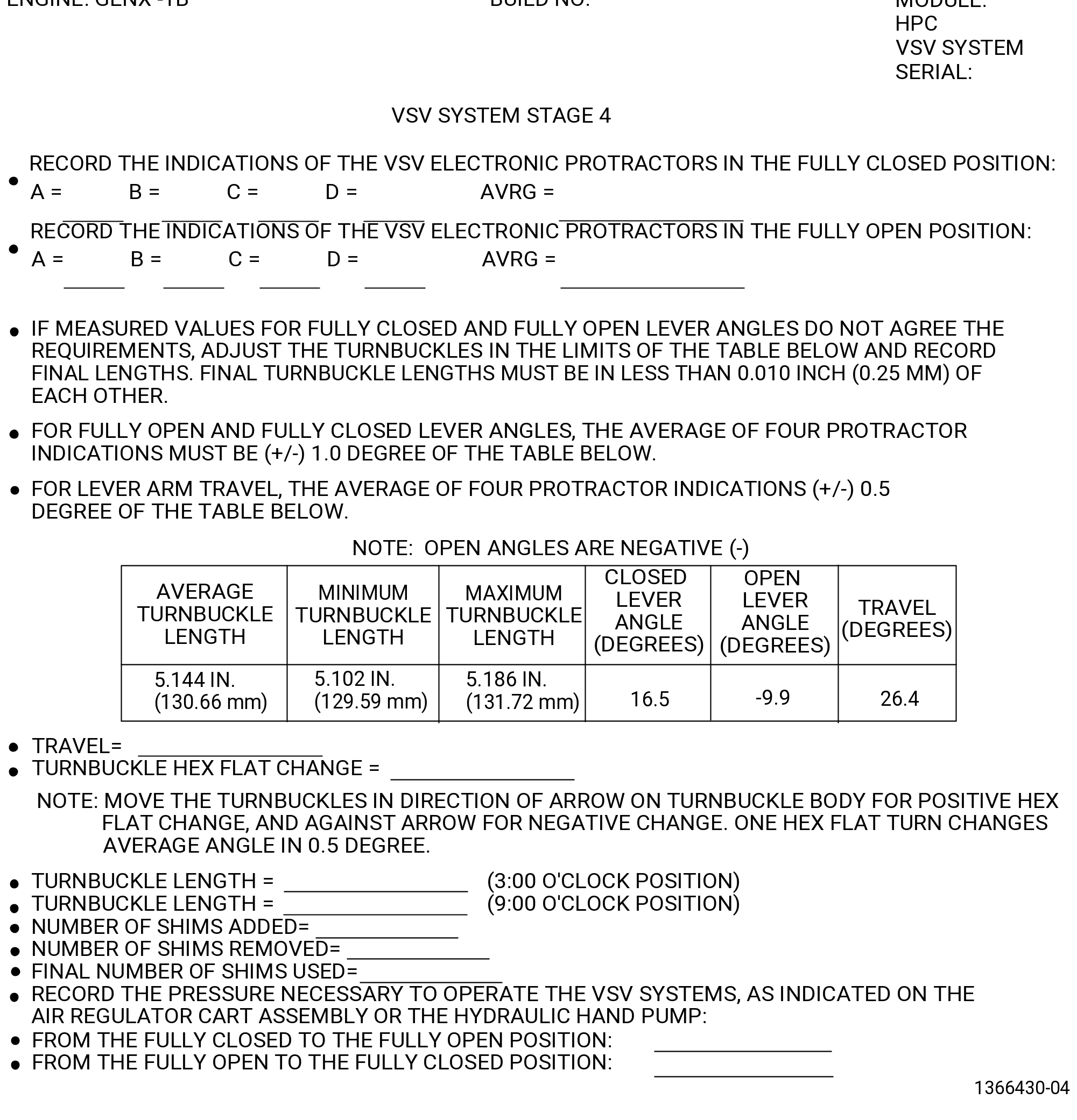
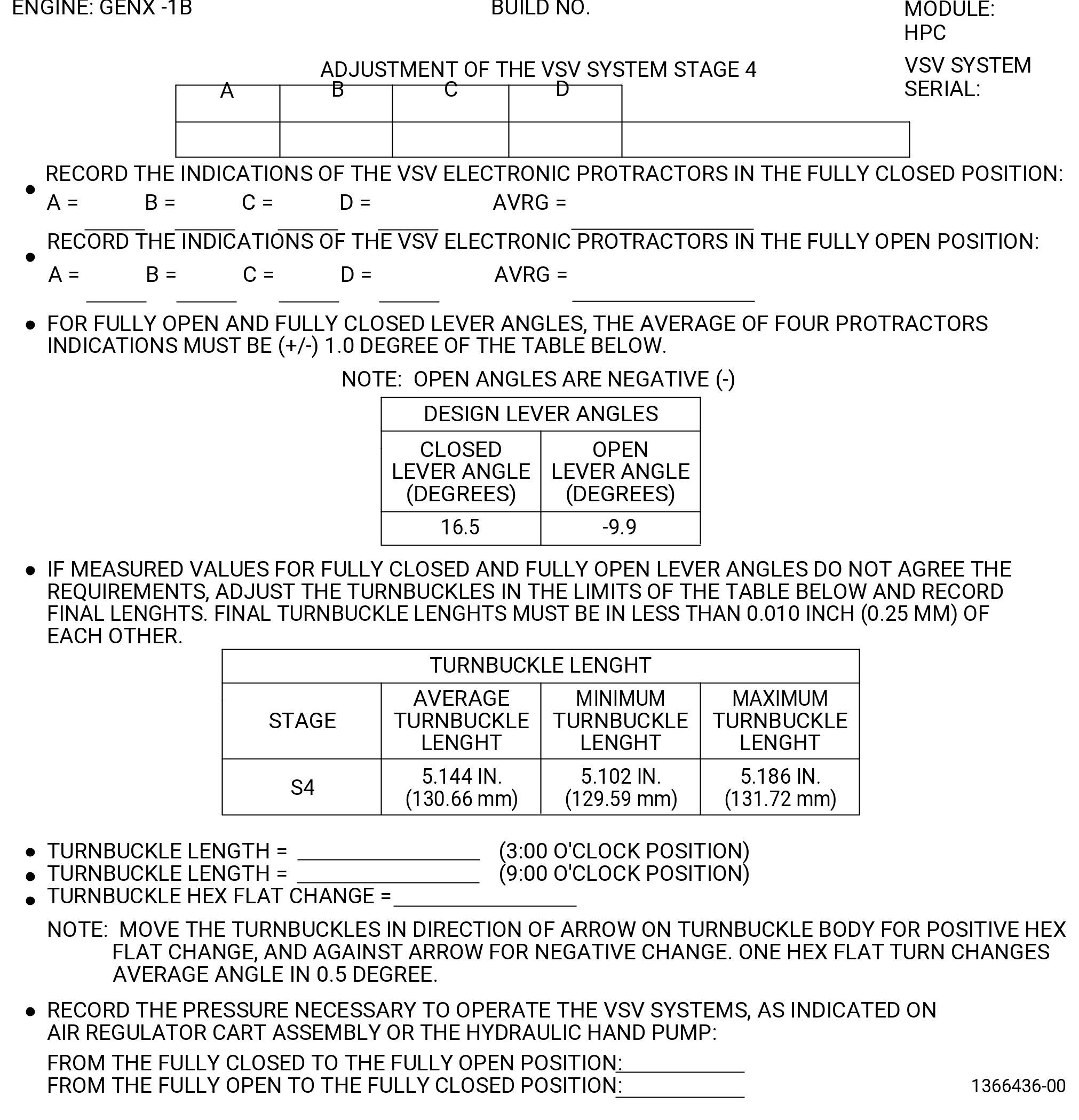
| 2 | Record the value for each of the VSV electronic protractors A, B, C, and D, and the average on the stage 3 vane assembly form. Refer to Figure 1032. |
| 3 | Release the pressure on the VSV system. |
| Subtask 72-30-00-440-293 |
| WARNING: |
|
| CAUTION: |
|
| (f) | Operate the VSV system to the fully closed position as follows: |
| 1 | Slowly apply pressure using the 9446M71 air regulator cart assembly or the 9461M39 hydraulic hand pump. |
| 2 | Do not release the pressure until the values are recorded. |
| Subtask 72-30-00-820-005 |
| (g) | Record the values of the four position sensors in the fully closed position as follows: |
| NOTE: |
|
| 1 | Press the F button on the front of the digital readout of the 9429M24 VSV electronic protractor to set channels A thru D. |
| 2 | Record the value for each of the VSV electronic protractors A, B, C, and D, and the average on the stage 4 vane assembly form. Refer to Figure 1032. |
| 3 | Release the pressure on the VSV system. |
| Subtask 72-30-00-440-260 |
| (h) | If the fully open and fully closed lever angle readings are not 1.0 degree or less or if the lever angle travel is not within 0.5 degree of the values shown in Figure 1032, correct the VSV system. Refer to Subtask 72- 30-00-440-284 (paragraph 3.I.(1)(h)) and Figure 1032. |
| Subtask 72-30-00-440-376 |
| (i) | Do Subtask 72-30-00-440-259 (paragraph 3.I.(4)(c)) thru Subtask 72-30-00-820-005 (paragraph 3.I.(4)(g)) again to make sure that the system is in the limits. This must be done each time the VSV system is adjusted. |
| (j) | Remove the VSV electronic protractors from the VSV system stage 4 as follows. Refer to Figure 1031. |
| 1 | Loosen the capscrews (item 11) on the clamping blocks (item 13) of the 11C3005 adapter kit. |
| 2 | Remove the VSV electronic protractors. |
| 3 | Remove the clamping blocks (item 13) of the 11C3005 adapter kit from the stage 4 lever arms. |
| 4 | Remove the centering rod (item 14) from the stage 4 lever arms. |
| 5 | Remove the arm locator pin (item 17) from the stage 4 lever arms. |
| Subtask 72-30-00-830-008 |
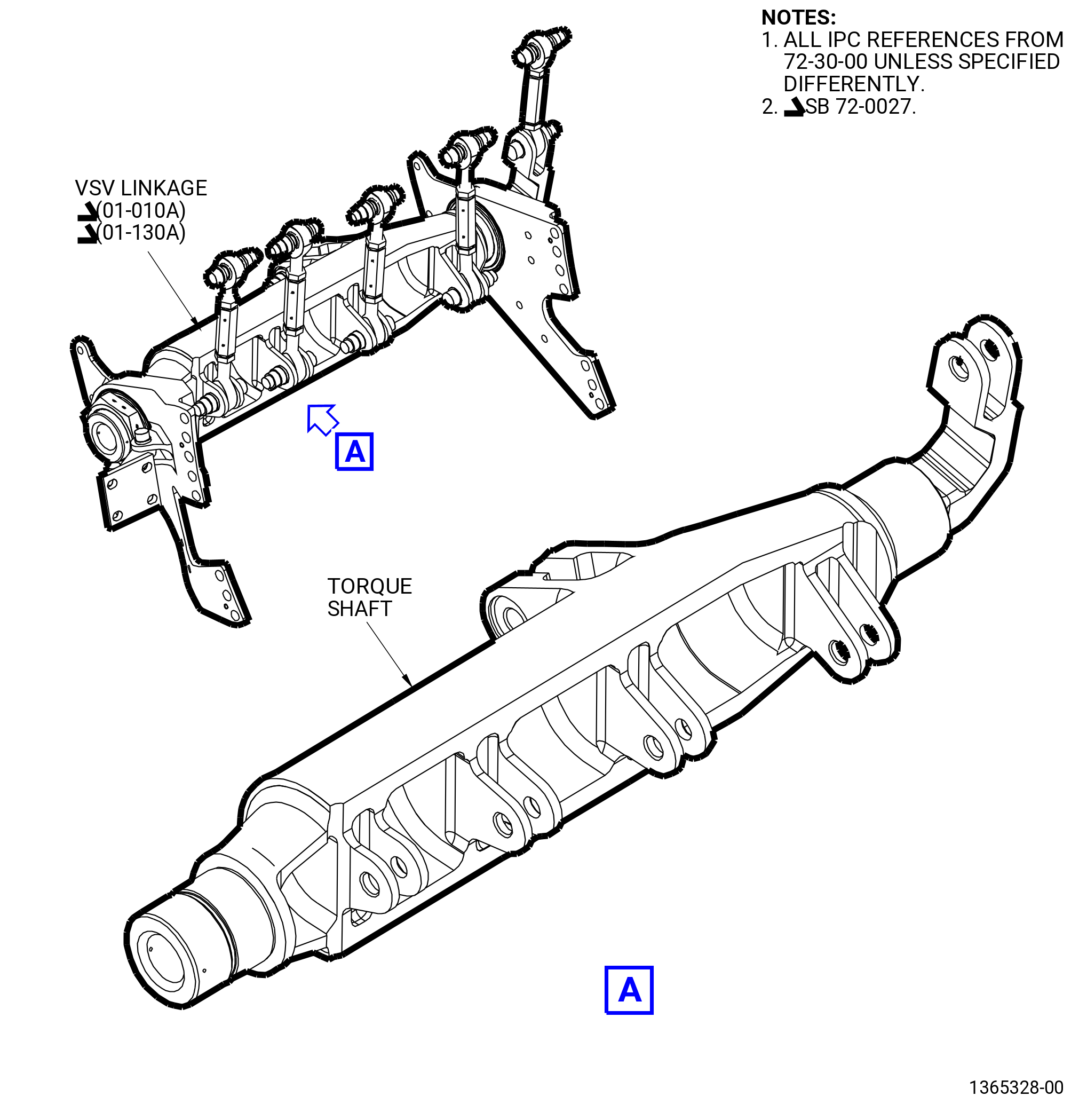
| J. | Do the VSV system rigging for integral clevis torque shaft linkage as follows: |
| • |
|
| • |
|
| NOTE: |
|
| Subtask 72-30-00-830-009 |
| (1) | Do a rigging of the VSV system stage 1 as follows: |
| (a) | Install the calibrated VSV electronic protractors on the stage 1 variable stator vanes as follows: |
| * * * PRE SB 72-0052( Heavier Stage 1 Lever Arms Design ) |
| 1 | Install the centering rod (item 15) of the 11C3005 adapter kit on the stage 1 lever arms (01-050 , 72-32-00) (SIN 071D1) at positions No. 6, 15, 32, and 40 in a CW direction ALF. Refer to Figure 1021. |
| NOTE: |
|
| * * * END PRE SB 72-0052 |
| Subtask 72-30-00-440-377 |
| * * * SB 72-0052( Lighter Stage 1 Lever Arms Design ) |
| 1.A. | Install the centering rod (item 15) of the 11C3005 adapter kit on the stage 1 lever arms (01-180 , 72-32-00) (SIN 071C0) at positions No. 6, 15, 32, and 40 in a CW direction ALF. Refer to Figure 1021. |
| NOTE: |
|
| NOTE: |
|
| * * * END SB 72-0052 |
| Subtask 72-30-00-440-378 |
| 2 | Make sure that the side of the clamping blocks (item 13) of the 11C3005 adapter kit with the channel are aligned with the stage 1 lever arms. |
| 3 | Install the stage 1 lever arms on the centering rods (item 15). Do not tighten the capscrews (item 11) on the clamping blocks (item 13) at this time. |
| 4 | Install the arm locator pin (item 18) on the stage 1 lever arms at positions No. 8, 13, 34, and 38 in a CW direction ALF. |
| CAUTION: |
|
| 5 | Install the VSV electronic protractors A, B, C, and D on the stage 1 lever arms at positions No. 6, 15, 32, and 40 respectively, as follows. Refer to Figure 1021. |
| a | Align the slot in the protractor arm (item 5) of the 9429M24 VSV electronic protractor with the arm locator pin (item 18) of the 11C3005 adapter kit. |
| b | Put the 9429M24 VSV electronic protractor on the centering rod (item 15) of the 11C3005 adapter kit along with the protractor arm (item 5) of the 9429M24 VSV electronic protractor above the arm locator pin (item 18) of the 11C3005 adapter kit. |
| c | Tighten the capscrews (item 11) on the clamping blocks (item 13) of the 11C3005 adapter kit. |
| d | Connect the electrical connector of each VSV electronic protractor to the correct channel receptacle on the back of the digital readout of the 9429M24 VSV electronic protractor. Refer to Figure 1020. |
| 6 | Press the F button on the front of the digital readout of the 9429M24 VSV electronic protractor to set the channels A thru D. |
| Subtask 72-30-00-440-379 |
| WARNING: |
|
| CAUTION: |
|
| (b) | Operate the VSV system as follows: |
| 1 | Slowly apply a pressure of 75-125 psig (517-862 kPa gage) maximum with the 9446M71 air regulator cart assembly or the 9461M39 hydraulic hand pump to operate the VSV system to the fully closed position. |
| 2 | Make sure that the movement is smooth and that there is no interference or binding of the turnbuckles against their mating clevises, and no interference or binding of other system components. Refer to Figure 1017 and Figure 1018. |
| 3 | Slowly apply a pressure of 75-125 psig (517-862 kPa gage) maximum with the 9446M71 air regulator cart assembly or the 9461M39 hydraulic hand pump to operate the VSV system to the fully open position. |
| 4 | Make sure that the movement is smooth and that there is no interference or binding of the turnbuckles against their mating clevises, and no interference or binding of other system components. |
| 5 | Slowly apply a pressure of 75-125 psig (517-862 kPa gage) maximum with the 9446M71 air regulator cart assembly or the 9461M39 hydraulic hand pump to operate the VSV system from the fully closed to open to the closed position, for four full cycles. |
| 6 | Record the pressure necessary to operate the system on the VSV actuator pressure form. Refer to Figure 1022. |
| Subtask 72-30-00-210-036 |
| WARNING: |
|
| CAUTION: |
|
| (c) | Operate the VSV system to the fully open position as follows: |
| 1 | Slowly apply a pressure of 75-125 psig (517-862 kPa gage) maximum with the 9446M71 air regulator cart assembly or the 9461M39 hydraulic hand pump to operate the VSV system to the fully open position. |
| 2 | Do not release the pressure until the values are recorded. |
| NOTE: |
|
| 3 | Record the values of the four position sensors in the fully open position as follows: |
| NOTE: |
|
| a | Press the F button on the front of the digital readout of the 9429M24 VSV electronic protractor to set channels A thru D. |
| b | Record the value for each of the position sensors A, B, C, and D, and the average on the stage 1 vane assembly form. The average of four resolvers must be more or less 1.0 degree of the design lever angles on the form. Refer to Figure 1033. |
| c | Record the pressure necessary to operate the system to fully open position. |
| d | Release the pressure on the VSV system. |
| Subtask 72-30-00-440-380 |
| WARNING: |
|
| CAUTION: |
|
| (d) | Operate the VSV system to the fully closed position as follows: |
| 1 | Slowly apply a pressure of 75-125 psig (517-862 kPa gage) maximum with the 9446M71 air regulator cart assembly or the 9461M39 hydraulic hand pump to operate the VSV system to the fully closed position. |
| 2 | Do not release the pressure until the values are recorded. |
| NOTE: |
|
| Subtask 72-30-00-440-381 |
| (e) | Record the values of the four VSV electronic protractors in the fully closed position as follows: |
| NOTE: |
|
| 1 | Press the F button on the front of the digital readout of the 9429M24 VSV electronic protractor to set channels A thru D. |
| 2 | Record the value for each of the VSV electronic protractors A, B, C, and D, and the average on the stage 1 vane assembly form. The average of four resolvers must be more or less 1.0 degree of the design lever angles on the form. |
| 3 | Record the pressure necessary to operate the system to fully closed position. |
| 4 | Release the pressure on the VSV system. |
| (f) | If the fully open and fully closed average readings are 1.0 degree or less of the values shown in Figure 1033, no more adjustment is needed. Continue with Subtask 72-30-00-440-383 (paragraph 3.J.(1)(j)). |
| Subtask 72-30-00-440-382 |
| (g) | If the fully open and fully closed average readings are in 1.0 degree or less of the values shown in Figure 1033, adjust the VSV system as follows: |
| 1 | Calculate the hex flat change for the stage 1 VSV system to find the amount required: |
| a | Calculate the hex flat change as follows: |
| (1) | Add the average measured open angle to the average measured closed angle and divide by two. Do not ignore the negative sign of the average open angle. |
| (2) | Add the average design open angle to the average design closed angle and divide by two. Do not ignore the negative sign of the average open angle. |
| (3) | Find the difference between the two values above and divide by 0.5. This will give the number of hex flats to turn the turnbuckle. Record the turnbuckle hex flat change on the stage 1 vane assembly form. Refer to Figure 1033. |
| NOTE: |
|
| NOTE: |
|
| Subtask 72-30-00-820-011 |
| (h) | Adjust the stage 1 turnbuckles as follows. Refer to Figure 1026. |
| NOTE: |
|
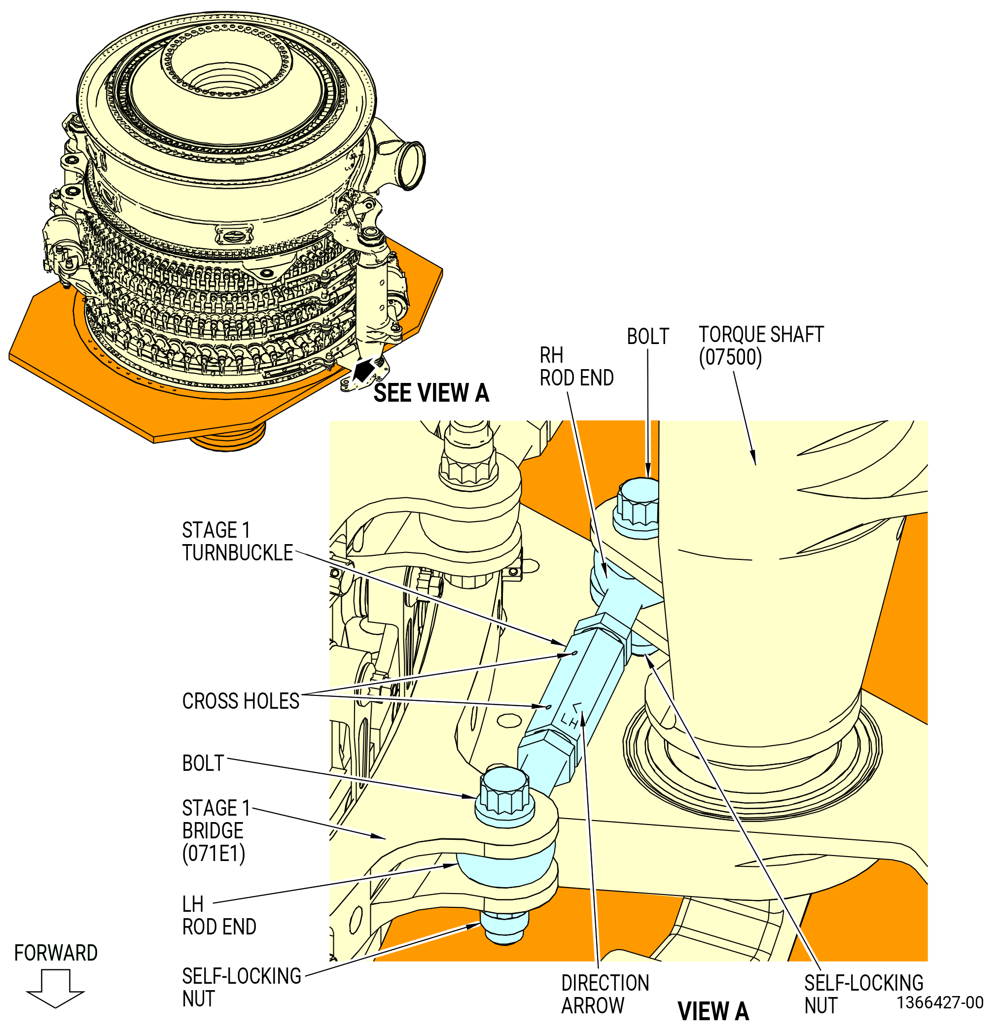
| 1 | Remove the bolt and self-locking nut that attach the turnbuckle to the stage 1 bridge (071E1, 071E6). |
| 2 | Loosen the self-locking nuts on the turnbuckle and turn the turnbuckle to the number of hex flats recorded on the stage 1 vane assembly form. Follow the direction arrow for a positive hex flat change, and turn it against the arrow for a negative hex flat change. |
| NOTE: |
|
| 3 | Tighten the self-locking hex nuts. Make sure that the rod end threads can be seen at the turnbuckle cross holes after all adjustments are made. |
| NOTE: |
|
| 4 | Make sure that the turnbuckle body is centered between each rod bearing. |
| 5 | Adjust the length of the turnbuckle with the 9429M53 turnbuckle gauging fixture as follows. Refer to Figure 1024. |
| a | Remove the bolts and self-locking nuts that attach the turnbuckle to the stage 1 bridge (071E1, 071E6) and the torque shaft (07500, 07501). |
| b | Remove the turnbuckle. |
| c | Make sure that the precision of the 9429M53 turnbuckle gauging fixture is correct as follows: |
| (1) | Unlock the slide (item 5) of the 9429M53 turnbuckle gauging fixture with the adjustable locking handle. |
| (2) | Adjust the slide (item 5) and install the setting block (item 12) of the 9429M53 turnbuckle gauging fixture on the locator pins (item 24) of the 9429M53 turnbuckle gauging fixture. |
| (3) | The digimatic scale unit (item 14) of the 9429M53 turnbuckle gauging fixture must read 5.000, plus or minus 0.001 inch (127.00 plus or minus 0.03 mm). If not, send the digimatic scale unit (item 14) to be calibrated. |
| (4) | Remove the setting block (item 12) of the 9429M53 turnbuckle gauging fixture. |
| d | Unlock the slide (item 5) of the 9429M53 turnbuckle gauging fixture with the adjustable locking handle. |
| e | Adjust the slide (item 5) of the 9429M53 turnbuckle gauging fixture to read 5.220, plus or minus 0.003 inch (132.59 plus or minus 0.08 mm). |
| f | Lock the slide (item 5) of the 9429M53 turnbuckle gauging fixture with the adjustable locking handle. |
| g | Put the turnbuckle in the 9429M53 turnbuckle gauging fixture as follows: |
| (1) | Loosen the two jam nuts. |
| (2) | Adjust the left-hand (LH) and right-hand (RH) rod ends to be in an equal distance between the turnbuckle body. |
| (3) | Make sure that the threads on the rod end can be seen in the turnbuckle body cross holes. If necessary, use C10-071 safety wire to make sure that the rod end threads are in the turnbuckle body cross holes. |
| (4) | Hold the rod ends to adjust the turnbuckle body to install the rod ends on the locator pins (item 24) of the 9429M53 turnbuckle gauging fixture. |
| (5) | Install the two spacers (item 25) on the two protruded bosses of the locator pins (item 24), one on each boss until they are installed on the flat surfaces of the rod ends of the turnbuckles. |
| (6) | Install the two knobs (item 28) in the threaded holes on protruded bosses of the locator pins (item 24). Hand-tighten the knobs (item 28) to keep the assembly without movement. |
| (7) | Hand-tighten the jam nuts against the turnbuckle body. |
| (8) | Make sure that the slide (item 5) is locked and torque the jam nuts on each end of the turnbuckle to 235-275 lb in. (26.6-31.1 N.m). |
| (9) | Remove the turnbuckle from the 9429M53 turnbuckle gauging fixture. |
| (10) | Record the length of the turnbuckle. |
| CAUTION: |
|
| h | Put the rod end bearing into the clevises on the stage 1 bridge (071E1, 071E6) and torque shaft (07500, 07501) so the direction arrow is away from the torque shaft. |
| NOTE: |
|
| i | Attach the rod end bearing to the stage 1 bridge and torque shaft with the bolts and self-locking nuts that are being removed. Put the boltheads aft. |
| j | Torque the self-locking nuts to 460-540 lb in. (52.0-61.0 N.m). |
| (i) | Adjust the other stage 1 turnbuckle. Refer to Subtask 72-30-00-820-011 (paragraph 3.J.(1)(h)). |
| NOTE: |
|
| Subtask 72-30-00-440-383 |
| (j) | Do Subtask 72-30-00-440-379 (paragraph 3.J.(1)(b)) thru Subtask 72-30-00-440-382 (paragraph 3.J.(1)(g)) again to make sure that the system is in limits. This must be done each time the VSV system is adjusted. |
| (k) | Remove the VSV electronic protractors from the stage 1 VSV system stage 1 as follows. Refer to Figure 1021. |
| 1 | Loosen the capscrews (item 11) on the clamping blocks (item 13) of the 11C3005 adapter kit. |
| 2 | Remove the VSV electronic protractors. |
| 3 | Remove the clamping blocks (item 13) of the 11C3005 adapter kit from the stage 1 lever arms. |
| 4 | Remove the centering rod (item 15) from the stage 1 lever arms. |
| 5 | Remove the arm locator pin (item 18) from the stage 1 lever arms. |
| (2) | Calibrate the VSV electronic protractors A, B, C, and D with the set-master base (item 6) of the 9429M24 VSV electronic protractor. Refer to Subtask 72-30-00-820-002 (paragraph 3.H.). |
| Subtask 72-30-00-830-010 |
| (3) | Do a rigging of the VSV system stage 2 as follows: |
| (a) | Install the calibrated VSV electronic protractors on the stage 2 variable stator vanes as follows: |
| * * * PRE SB 72-0052( Heavier Stage 2 Lever Arms Design ) |
| 1 | Install the centering rod (item 15) of the 11C3005 adapter kit on the stage 2 lever arms (01-090 , 72-32-00) (SIN 071D2) at positions No. 8, 24, 42, and 58 in a CW direction ALF. Refer to Figure 1028. |
| NOTE: |
|
| * * * END PRE SB 72-0052 |
| Subtask 72-30-00-440-384 |
| * * * SB 72-0052( Lighter Stage 2 Lever Arms Design ) |
| 1.A. | Install the centering rod (item 15) of the 11C3005 adapter kit on the stage 2 lever arms (01-180 , 72-32-00) (SIN 071C0) at positions No. 8, 24, 42, and 58 in a CW direction ALF. Refer to Figure 1028. |
| NOTE: |
|
| NOTE: |
|
| * * * END SB 72-0052 |
| Subtask 72-30-00-440-385 |
| 2 | Make sure that the side of the clamping blocks (item 13) of the 11C3005 adapter kit with the channel are aligned with the stage 2 lever arms. |
| 3 | Install the stage 2 lever arms on the centering rods (item 15). Do not tighten the capscrews (item 11) on the clamping blocks (item 13) at this time. |
| 4 | Install the arm locator pin (item 18) on the stage 2 lever arms at positions No. 11, 21, 45, and 55 in a CW direction ALF. |
| CAUTION: |
|
| 5 | Install the VSV electronic protractors A, B, C, and D on the stage 2 lever arms at positions No. 8, 24, 42, and 58 respectively, as follows. Refer to Figure 1028. |
| a | Align the slot in the protractor arm (item 5) of the 9429M24 VSV electronic protractor with the arm locator pin (item 18) of the 11C3005 adapter kit. |
| b | Put the 9429M24 VSV electronic protractor on the centering rod (item 15) of the 11C3005 adapter kit along with the protractor arm (item 5) of the 9429M24 VSV electronic protractor above the arm locator pin (item 18) of the 11C3005 adapter kit. |
| c | Tighten the capscrews (item 11) on the clamping blocks (item 13) of the 11C3005 adapter kit. |
| d | Connect the electrical connector of each VSV electronic protractor to the correct channel receptacle on the back of the digital readout of the 9429M24 VSV electronic protractor. Refer to Figure 1020. |
| 6 | Press the F button on the front of the digital readout of the 9429M24 VSV electronic protractor to set the channels A thru D. |
| Subtask 72-30-00-440-386 |
| WARNING: |
|
| CAUTION: |
|
| (b) | Operate the VSV system as follows: |
| 1 | Slowly apply a pressure of 75-125 psig (517-862 kPa gage) maximum with the 9446M71 air regulator cart assembly or the 9461M39 hydraulic hand pump to operate the VSV system to the fully closed position. |
| 2 | Make sure that the movement is smooth and that there is no interference or binding of the turnbuckles against their mating clevises, and no interference or binding of other system components. Refer to Figure 1017 and Figure 1018. |
| 3 | Slowly apply a pressure of 75-125 psig (517-862 kPa gage) maximum with the 9446M71 air regulator cart assembly or the 9461M39 hydraulic hand pump to operate the VSV system to the fully open position. |
| 4 | Make sure that the movement is smooth and that there is no interference or binding of the turnbuckles against their mating clevises, and no interference or binding of other system components. |
| 5 | Slowly apply a pressure of 75-125 psig (517-862 kPa gage) maximum with the 9446M71 air regulator cart assembly or the 9461M39 hydraulic hand pump to operate the VSV system from the fully closed to open to the closed position, for four full cycles. |
| 6 | Record the pressure necessary to operate the system on the VSV actuator pressure form. Refer to Figure 1022. |
| Subtask 72-30-00-210-037 |
| WARNING: |
|
| CAUTION: |
|
| (c) | Operate the VSV system to the fully open position as follows: |
| 1 | Slowly apply a pressure of 75-125 psig (517-862 kPa gage) maximum with the 9446M71 air regulator cart assembly or the 9461M39 hydraulic hand pump to operate the VSV system to the fully open position. |
| 2 | Do not release the pressure until the values are recorded. |
| NOTE: |
|
| 3 | Record the values of the four position sensors in the fully open position as follows: |
| NOTE: |
|
| a | Press the F button on the front of the digital readout of the 9429M24 VSV electronic protractor to set channels A thru D. |
| b | Record the value for each of the position sensors A, B, C, and D, and the average on the stage 1 vane assembly form. The average of four resolvers must be more or less 1.0 degree of the design lever angles on the form. Refer to Figure 1034. |
| c | Record the pressure necessary to operate the system to fully open position. |
| d | Release the pressure on the VSV system. |
| Subtask 72-30-00-440-387 |
| WARNING: |
|
| CAUTION: |
|
| (d) | Operate the VSV system to the fully closed position as follows: |
| 1 | Slowly apply a pressure of 75-125 psig (517-862 kPa gage) maximum with the 9446M71 air regulator cart assembly or the 9461M39 hydraulic hand pump to operate the VSV system to the fully closed position. |
| 2 | Do not release the pressure until the values are recorded. |
| NOTE: |
|
| Subtask 72-30-00-440-388 |
| (e) | Record the values of the four VSV electronic protractors in the fully closed position as follows: |
| NOTE: |
|
| 1 | Press the F button on the front of the digital readout of the 9429M24 VSV electronic protractor to set channels A thru D. |
| 2 | Record the value for each of the VSV electronic protractors A, B, C, and D, and the average on the stage 2 vane assembly form. The average of four resolvers must be more or less 1.0 degree of the design lever angles on the form. |
| 3 | Record the pressure necessary to operate the system to fully closed position. |
| 4 | Release the pressure on the VSV system. |
| (f) | If the fully open and fully closed average readings are in 1.0 degree or less of the values shown in Figure 1034, no more adjustment is needed. Continue with Subtask 72-30-00-820-012 (paragraph 3.J.(3)(h)). |
| Subtask 72-30-00-440-389 |
| (g) | If the fully open and fully closed average readings are not 1.0 degree or less of the values shown in Figure 1034, calculate the travel and hex flat change for the VSV system stage 2 to find the amount of adjustment required. Refer to Subtask 72-30-00-440-382 (paragraph 3.J.(1)(g)). |
| Subtask 72-30-00-820-012 |
| (h) | If the VSV values do not agree with the values on the stage 2 vane assembly form, adjust the 3:00 o'clock and 9:00 o'clock positions stage 2 turnbuckles. Refer to the stage 1 procedure in Subtask 72-30-00-820-011 (paragraph 3.J.(1)(h)) for stage 2. |
| (i) | Do Subtask 72-30-00-440-386 (paragraph 3.J.(3)(b) thru Subtask 72-30-00-440-389 (paragraph 3.J.(3)(g)) again to make sure that the system is in limits. This must be done each time the VSV system is adjusted. |
| (j) | Remove the VSV electronic protractors from the VSV system stage 2 as follows. Refer to Figure 1028. |
| 1 | Loosen the capscrews (item 11) on the clamping blocks (item 13) of the 11C3005 adapter kit. |
| 2 | Remove the VSV electronic protractors. |
| 3 | Remove the clamping blocks (item 13) of the 11C3005 adapter kit from the stage 2 lever arms. |
| 4 | Remove the centering rod (item 15) from the stage 2 lever arms. |
| 5 | Remove the arm locator pin (item 18) from the stage 2 lever arms. |
| (4) | Calibrate the VSV electronic protractors A, B, C, and D with the set master base (item 6) of the 9429M24 VSV electronic protractor. Refer to Subtask 72-30-00-820-002 (paragraph 3.H.). |
| Subtask 72-30-00-830-011 |
| (5) | Do a rigging of the VSV system stage 3 as follows: |
| (a) | Install the calibrated VSV electronic protractors on the stage 3 variable stator vanes as follows: |
| * * * PRE SB 72-0052( Heavier Stage 3 Lever Arms Design ) |
| 1 | Install the centering rod (item 15) of the 11C3005 adapter kit on the stage 3 lever arms (01-120 , 72-32-00) (SIN 071D3) at positions No. 11, 31, 52, and 72 in a CW direction ALF. Refer to Figure 1029. |
| NOTE: |
|
| * * * END PRE SB 72-0052 |
| Subtask 72-30-00-440-390 |
| * * * SB 72-0052( Lighter Stage 3 Lever Arms Design ) |
| 1.A. | Install the centering rod (item 15) of the 11C3005 adapter kit on the stage 3 lever arms (01-180 , 72-32-00) (SIN 071C0) at positions No. 11, 31, 52, and 72 in a CW direction ALF. Refer to Figure 1029. |
| NOTE: |
|
| NOTE: |
|
| * * * END SB 72-0052 |
| Subtask 72-30-00-440-391 |
| 2 | Make sure that the side of the clamping blocks (item 13) of the 11C3005 adapter kit with the channel are aligned with the stage 3 lever arms. |
| 3 | Install the stage 3 lever arms on the centering rods (item 15). Do not tighten the capscrews (item 11) on the clamping blocks (item 13) at this time. |
| 4 | Install the arm locator pin (item 18) on the stage 3 lever arms at positions No. 15, 27, 56, and 68 in a CW direction ALF. |
| CAUTION: |
|
| 5 | Install the VSV electronic protractors A, B, C, and D on the stage 3 lever arms at positions No. 11, 31, 52, and 72 respectively, as follows. Refer to Figure 1029. |
| a | Align the slot in the protractor arm (item 5) of the 9429M24 VSV electronic protractor with the arm locator pin (item 18) of the 11C3005 adapter kit. |
| b | Put the 9429M24 VSV electronic protractor on the centering rod (item 15) of the 11C3005 adapter kit along with the protractor arm (item 5) of the 9429M24 VSV electronic protractor above the arm locator pin (item 18) of the 11C3005 adapter kit. |
| c | Tighten the capscrews (item 11) on the clamping blocks (item 13) of the 11C3005 adapter kit. |
| d | Connect the electrical connector of each VSV electronic protractor to the correct channel receptacle on the back of the digital readout of the 9429M24 VSV electronic protractor. Refer to Figure 1020. |
| 6 | Press the F button on the front of the digital readout of the 9429M24 VSV electronic protractor to set the channels A thru D. |
| Subtask 72-30-00-440-392 |
| WARNING: |
|
| CAUTION: |
|
| (b) | Operate the VSV system as follows: |
| 1 | Slowly apply a pressure of 75-125 psig (517-862 kPa gage) maximum with the 9446M71 air regulator cart assembly or the 9461M39 hydraulic hand pump to operate the VSV system to the fully closed position. |
| 2 | Make sure that the movement is smooth and that there is no interference or binding of the turnbuckles against their mating clevises, and no interference or binding of other system components. Refer to Figure 1017 and Figure 1018. |
| 3 | Slowly apply a pressure of 75-125 psig (517-862 kPa gage) maximum with the 9446M71 air regulator cart assembly or the 9461M39 hydraulic hand pump to operate the VSV system to the fully open position. |
| 4 | Make sure that the movement is smooth and that there is no interference or binding of the turnbuckles against their mating clevises, and no interference or binding of other system components. |
| 5 | Slowly apply a pressure of 75-125 psig (517-862 kPa gage) maximum with the 9446M71 air regulator cart assembly or the 9461M39 hydraulic hand pump to operate the VSV system from the fully closed to open to the closed position, for four full cycles. |
| 6 | Record the pressure necessary to operate the system on the VSV actuator pressure form. Refer to Figure 1022. |
| Subtask 72-30-00-210-038 |
| WARNING: |
|
| CAUTION: |
|
| (c) | Operate the VSV system to the fully open position as follows: |
| 1 | Slowly apply a pressure of 75-125 psig (517-862 kPa gage) maximum with the 9446M71 air regulator cart assembly or the 9461M39 hydraulic hand pump to operate the VSV system to the fully open position. |
| 2 | Do not release the pressure until the values are recorded. |
| NOTE: |
|
| (d) | Record the values of the four VSV electronic protractors in the full open position as follows: |
| NOTE: |
|
| 1 | Press the F button on the front of the digital readout of the 9429M24 VSV electronic protractor to set channels A thru D. |
| 2 | Record the value for each of the VSV electronic protractors A, B, C, and D, and the average on the stage 3 vane assembly form. Refer to Figure 1035. |
| 3 | Record the pressure necessary to operate the system to fully open position. |
| 4 | Release the pressure on the VSV system. |
| Subtask 72-30-00-210-039 |
| WARNING: |
|
| CAUTION: |
|
| (e) | Operate the VSV system to the fully closed position as follows: |
| 1 | Slowly apply a pressure of 75-125 psig (517-862 kPa gage) maximum with the 9446M71 air regulator cart assembly or the 9461M39 hydraulic hand pump to operate the VSV system to the fully closed position. |
| 2 | Do not release the pressure until the values are recorded. |
| NOTE: |
|
| Subtask 72-30-00-210-040 |
| (f) | Record the values of the four VSV electronic protractors in the fully closed position as follows: |
| NOTE: |
|
| 1 | Press the F button on the front of the digital readout of the 9429M24 VSV electronic protractor to set channels A thru D. |
| 2 | Record the value for each of the VSV electronic protractors A, B, C, and D, and the average on the stage 3 vane assembly form. Refer to Figure 1035. |
| 3 | Record the pressure necessary to operate the system to fully closed position. |
| 4 | Release the pressure on the VSV system. |
| (g) | If the fully open and fully closed average readings are in 1.0 degree or less of the values shown in Figure 1035, no further adjustment or calculation is needed. Continue with Subtask 72-30-00-210-042 (paragraph 3.J.(5)(i)). |
| Subtask 72-30-00-210-041 |
| (h) | If the fully open and fully closed average readings are not 1.0 degree or less of the values shown in Figure 1035, calculate the travel and hex flat change for the stage 3 VSV system to find the amount of adjustment required. Continue with Subtask 72-30-00-440-382 (paragraph 3.J.(1)(g)). |
| Subtask 72-30-00-210-042 |
| (i) | If the VSV values do not agree with the values on the stage 3 vane assembly form, adjust the 3:00 o'clock position and 9:00 o'clock position stage 3 turnbuckles. Refer to the stage 1 procedure in Subtask 72-30-00-820-011 (paragraph 3.J.(1)(h)) for stage 3. |
| (j) | Do Subtask 72-30-00-440-392 (paragraph 3.J.(5)(b)) thru Subtask 72-30-00-210-041 (paragraph 3.J.(5)(h)) again to make sure that the system is in limits. This must be done each time the VSV system is adjusted. |
| (k) | Remove the VSV electronic protractors from the VSV system stage 3 as follows. Refer to Figure 1029. |
| 1 | Loosen the capscrews (item 11) on the clamping blocks (item 13) of the 11C3005 adapter kit. |
| 2 | Remove the VSV electronic protractors. |
| 3 | Remove the clamping blocks (item 13) of the 11C3005 adapter kit from the stage 3 lever arms. |
| 4 | Remove the centering rod (item 15) from the stage 3 lever arms. |
| 5 | Remove the arm locator pin (item 18) from the stage 3 lever arms. |
| (6) | Calibrate the VSV electronic protractors A, B, C, and D, with the set master base (item 6) of the 9429M24 VSV electronic protractor. Refer to Subtask 72-30-00-820-002 (paragraph 3.H.). |
| Subtask 72-30-00-830-012 |
| (7) | Do a rigging of the VSV system stage 4 as follows: |
| (a) | Install the calibrated VSV electronic protractors on the stage 4 variable stator vanes as follows: |
| * * * PRE SB 72-0052( Heavier Stage 4 Lever Arms Design ) |
| 1 | Install the centering rod (item 14) of the 11C3005 adapter kit on the stage 4 lever arms (01-160 , 72-32-00) (SIN 071D4) at positions No. 14, 33, 56, and 74 in a CW direction ALF. Refer to Figure 1031. |
| NOTE: |
|
| * * * END PRE SB 72-0052 |
| Subtask 72-30-00-440-393 |
| * * * SB 72-0052( Lighter Stage 4 Lever Arms Design ) |
| 1.A. | Install the centering rod (item 14) of the 11C3005 adapter kit on the stage 4 lever arms (01-180 , 72-32-00) (SIN 071C0) at positions No. 14, 33, 56, and 74 in a CW direction ALF. Refer to Figure 1031. |
| NOTE: |
|
| NOTE: |
|
| * * * END SB 72-0052 |
| Subtask 72-30-00-440-394 |
| 2 | Make sure that the side of the clamping blocks (item 13) of the 11C3005 adapter kit with the channel are aligned with the stage 4 lever arms. |
| 3 | Install the stage 4 lever arms on the centering rods (item 14). Do not tighten the capscrews (item 11) on the clamping blocks (item 13) at this time. |
| 4 | Install the arm locator pin (item 17) on the stage 4 lever arms at positions No. 18, 29, 60, and 70 in a CW direction ALF. |
| CAUTION: |
|
| 5 | Install the VSV electronic protractors A, B, C, and D on the stage 4 lever arms at positions No. 14, 33, 56, and 74 respectively, as follows. Refer to Figure 1031. |
| a | Align the slot in the protractor arm (item 5) of the 9429M24 VSV electronic protractor with the arm locator pin (item 17) of the 11C3005 adapter kit. |
| b | Put the 9429M24 VSV electronic protractor on the centering rod (item 14) of the 11C3005 adapter kit along with the protractor arm (item 5) of the 9429M24 VSV electronic protractor above the arm locator pin (item 17) of the 11C3005 adapter kit. |
| c | Tighten the capscrews (item 11) on the clamping blocks (item 13) of the 11C3005 adapter kit. |
| d | Connect the electrical connector of each VSV electronic protractor to the correct channel receptacle on the back of the digital readout of the 9429M24 VSV electronic protractor. Refer to Figure 1020. |
| 6 | Press the F button on the front of the digital readout of the 9429M24 VSV electronic protractor to set the channels A thru D. |
| Subtask 72-30-00-440-395 |
| WARNING: |
|
| CAUTION: |
|
| (b) | Operate the VSV system as follows: |
| 1 | Slowly apply a pressure of 75-125 psig (517-862 kPa gage) maximum with the 9446M71 air regulator cart assembly or the 9461M39 hydraulic hand pump to operate the VSV system to the fully closed position. |
| 2 | Make sure that the movement is smooth and that there is no interference or binding of the turnbuckles against their mating clevises, and no interference or binding of other system components. Refer to Figure 1017 and Figure 1018. |
| 3 | Slowly apply a pressure of 75-125 psig (517-862 kPa gage) maximum with the 9446M71 air regulator cart assembly or the 9461M39 hydraulic hand pump to operate the VSV system to the fully open position. |
| 4 | Make sure that the movement is smooth and that there is no interference or binding of the turnbuckles against their mating clevises, and no interference or binding of other system components. |
| 5 | Slowly apply a pressure of 75-125 psig (517-862 kPa gage) maximum with the 9446M71 air regulator cart assembly or the 9461M39 hydraulic hand pump to operate the VSV system from the fully closed to open to the closed position, for four full cycles. |
| 6 | Record the pressure necessary to operate the system on the VSV actuator pressure form. Refer to Figure 1022. |
| Subtask 72-30-00-210-043 |
| WARNING: |
|
| CAUTION: |
|
| (c) | Operate the VSV system to the fully open position as follows: |
| 1 | Slowly apply a pressure of 75-125 psig (517-862 kPa gage) maximum with the 9446M71 air regulator cart assembly or the 9461M39 hydraulic hand pump to operate the VSV system to the fully open position. |
| 2 | Do not release the pressure until the values are recorded. |
| NOTE: |
|
| (d) | Record the values of the four VSV electronic protractors in the full open position as follows: |
| NOTE: |
|
| 1 | Press the F button on the front of the digital readout of the 9429M24 VSV electronic protractor to set channels A thru D. |
| 2 | Record the value for each of the VSV electronic protractors A, B, C, and D, and the average on the stage 3 vane assembly form. Refer to Figure 1036. |
| 3 | Record the pressure necessary to operate the system to fully open position. |
| 4 | Release the pressure on the VSV system. |
| Subtask 72-30-00-210-044 |
| WARNING: |
|
| CAUTION: |
|
| (e) | Operate the VSV system to the fully closed position as follows: |
| 1 | Slowly apply a pressure of 75-125 psig (517-862 kPa gage) maximum with the 9446M71 air regulator cart assembly or the 9461M39 hydraulic hand pump to operate the VSV system to the fully closed position. |
| 2 | Do not release the pressure until the values are recorded. |
| NOTE: |
|
| Subtask 72-30-00-210-045 |
| (f) | Record the values of the four VSV electronic protractors in the fully closed position as follows: |
| NOTE: |
|
| 1 | Press the F button on the front of the digital readout of the 9429M24 VSV electronic protractor to set channels A thru D. |
| 2 | Record the value for each of the VSV electronic protractors A, B, C, and D, and the average on the stage 4 vane assembly form. Refer to Figure 1036. |
| 3 | Record the pressure necessary to operate the system to fully closed position. |
| 4 | Release the pressure on the VSV system. |
| (g) | If the fully open and fully closed average readings are in 1.0 degree or less of the values shown in Figure 1036, no further adjustment is needed. Continue with Subtask 72-30-00-210-047 (paragraph 3.J.(7)(i)). |
| Subtask 72-30-00-210-046 |
| (h) | If the fully open and fully closed average readings are not 1.0 degree or less of the values shown in Figure 1036, calculate the travel and hex flat change for the stage 4 VSV system to find the amount of adjustment required. Continue with Subtask 72-30-00-440-382 (paragraph 3.J.(1)(g))). |
| Subtask 72-30-00-210-047 |
| (i) | If the VSV values do not agree with the values on the stage 3 vane assembly form, adjust the 3:00 o'clock position and 9:00 o'clock position stage 3 turnbuckles. Refer to the stage 1 procedure in Subtask 72-30-00-820-011 (paragraph 3.J.(1)(h)) for stage 4. |
| (j) | Do Subtask 72-30-00-440-395 (paragraph 3.J.(7)(b)) thru Subtask 72-30-00-210-046 (paragraph 3.J.(7)(h)) again to make sure that the system is in limits. This must be done each time the VSV system is adjusted. |
| (k) | Remove the VSV electronic protractors from the VSV system stage 4 as follows. Refer to Figure 1031. |
| 1 | Loosen the capscrews (item 11) on the clamping blocks (item 13) of the 11C3005 adapter kit. |
| 2 | Remove the VSV electronic protractors. |
| 3 | Remove the clamping blocks (item 13) of the 11C3005 adapter kit from the stage 3 lever arms. |
| 4 | Remove the centering rod (item 15) from the stage 4 lever arms. |
| 5 | Remove the arm locator pin (item 17) from the stage 4 lever arms. |
| Subtask 72-30-00-510-001 |
| K. | If the HPC module is to be transported to another facility, put the module in the 11C4667 shipping container. Refer to Figure 1037 and do as follows: |
| (1) | Loosen the 12 swing clamp assemblies that secure the container cover (item 15) to the container base (item 14). |
| (2) | Remove the container cover (item 15) with a four-legged sling. |
| (3) | Loosen and retract the six lower clamp plates (item 5) on the lower base plate assembly (item 2) so that the lift assembly can be lifted out of storage position. |
| (4) | Use a two-legged sling to lift the upper base plate assembly (item 3), clamp plate assembly (item 4), hoist ring block (item 11), hoist ring (item 18) and turn over. |
| (5) | Loosen the screws (item 21) and remove the clamp plate assembly (item 4) from the upper base plate assembly (item 3). |
| (6) | Put the upper base plate assembly (item 3) on the aft end of the compressor module setting on the 11C3010 core module buildup fixture. |
| (7) | Attach the upper base plate assembly (item 3) to the stator case by sliding in the six upper clamp plates (item 6) over the aft flange and tighten the two flat washers (item 25) on each of the upper clamp plates (item 6). |
| (8) | Make sure that the pin on the upper clamp plate (item 6) is inserted in the hole of the upper base plate assembly (item 3) for proper clamp positioning/installation. |
| CAUTION: |
|
| (9) | Install the clamp plate assembly (item 4) and spacer (item 10) on the rotor with three sets of protector segments (item 7), bolt retainer segments (item 9), capscrews (item 23) and flat washers (item 25). |
| NOTE: |
|
| (10) | Adjust the location of the clamp plate assembly (item 4) by tighten/loosen the eight screws (item 21) to provide aft direction restraint and tighten/loosen the four square head half-dog point set screws (item 33) to provide forward direction restraint for the rotor. |
| NOTE: |
|
| (11) | Hold the protector segment (item 7) and bolt retainer segment (item 9) under the CDP seal and install two capscrews (item 23) through the clamp plate assembly (item 4), spacer (item 10), CDP seal and stage 6-10 spool aft flange and thread into the bolt retainer segment (item 9). |
| (12) | Repeat for other protector segments (item 7) and bolt retainer segments (item 9). |
| (13) | Unfasten the compressor module from the 11C3010 core module buildup fixture for its TDS. |
| WARNING: |
|
| (14) | Lift the module with a two-legged sling from the hoist ring (item 18). |
| (15) | Slide the forward shaft into the protective/centering sleeve (item 13) and the compress module onto the lower base plate assembly (item 2). |
| (16) | Align the split lines of the stator case with split line markings from the lower base plate assembly (item 2). |
| (17) | Slide the six lower clamp plates (item 5) into position on the forward flange of the case. |
| (18) | Make sure that the pin on the upper clamp plate (item 6) is inserted in the hole of the upper base plate assembly (item 3) for proper clamp positioning/installation |
| (19) | Tighten the two bolts in each of the lower clamp plates (item 5) to attach firmly the compressor module into place. |
| WARNING: |
|
| (20) | Lift the container cover (item 15) and set it on the container base (item 14). |
| (21) | Swing the 12 clamp assemblies (item 10) of the 9426M33P10 shipping container base up over the lip of the container cover (item 15). |
| (22) | Tighten the bolts in the clamp assemblies fastening the container cover (item 15) to the container base (item 14). |