| GENX-1B ENGINE MANUAL | Dated: 03/22/2023 | |
| EM 72-30-00 , ASSEMBLY 001 | ||
| HIGH PRESSURE COMPRESSOR MODULE ASSEMBLY - ASSEMBLY 001 - CONFIGURATION 01 | ||
| GENX-1B ENGINE MANUAL | Dated: 03/22/2023 | |
| EM 72-30-00 , ASSEMBLY 001 | ||
| HIGH PRESSURE COMPRESSOR MODULE ASSEMBLY - ASSEMBLY 001 - CONFIGURATION 01 | ||
| * * * FOR 1B/P/G03.1B/P/G04.1B/P1/G01 |
| TASK 72-30-00-440-801 |
| 1 . | General. |
| A. | This procedure gives instructions to assemble the high pressure compressor (HPC) module assembly (00108) thru the installation of the compressor stator assembly (07000). Refer to TASK 72-30-00-440-802 (72-30-00, ASSEMBLY 002) to continue the assembly of the HPC module assembly after you complete this procedure. |
| B. | This procedure starts with the HPC rotor assembly (05000) installed on the 11C3338 dolly or the 11C3352 shipping container. Refer to Figure 1001 or Figure 1002. |
| C. | Install all the bolts with the boltheads up and/or forward, unless specified differently. |
| D. | Apply lubricants to the threads and friction surfaces only. |
| E. | All directions are aft looking forward (ALF), unless specified differently. |
| 2 . | Tools, Equipment, and Materials. |
| NOTE: |
|
| A. | Tools and Equipment. |
| (1) | Special Tools. |
| (2) | Standard Tools and Equipment. |
|
| (3) | Locally Manufactured Tools. None. |
| B. | Consumable Materials. |
|
| C. | Referenced Procedures. |
|
| D. | Expendable Parts. |
|
| 3 . | Procedure. |
| Subtask 72-30-00-440-272 |
| A. | Install the No. 3 bearing rotating seal (seal) (03005) on the compressor rotor forward shaft (shaft) (050B5) as follows: |
| Subtask 72-30-00-160-003 |
| WARNING: |
|
| WARNING: |
|
| (1) | Use the C10-182 cleaning cloth wet with C04-035 isopropyl alcohol, C04-002 Stoddard solvent, or a 50-50 blend of C04-035 isopropyl alcohol and C04-228 denatured alcohol to clean the mating surfaces of the seal and the shaft. |
| Subtask 72-30-00-220-006 |
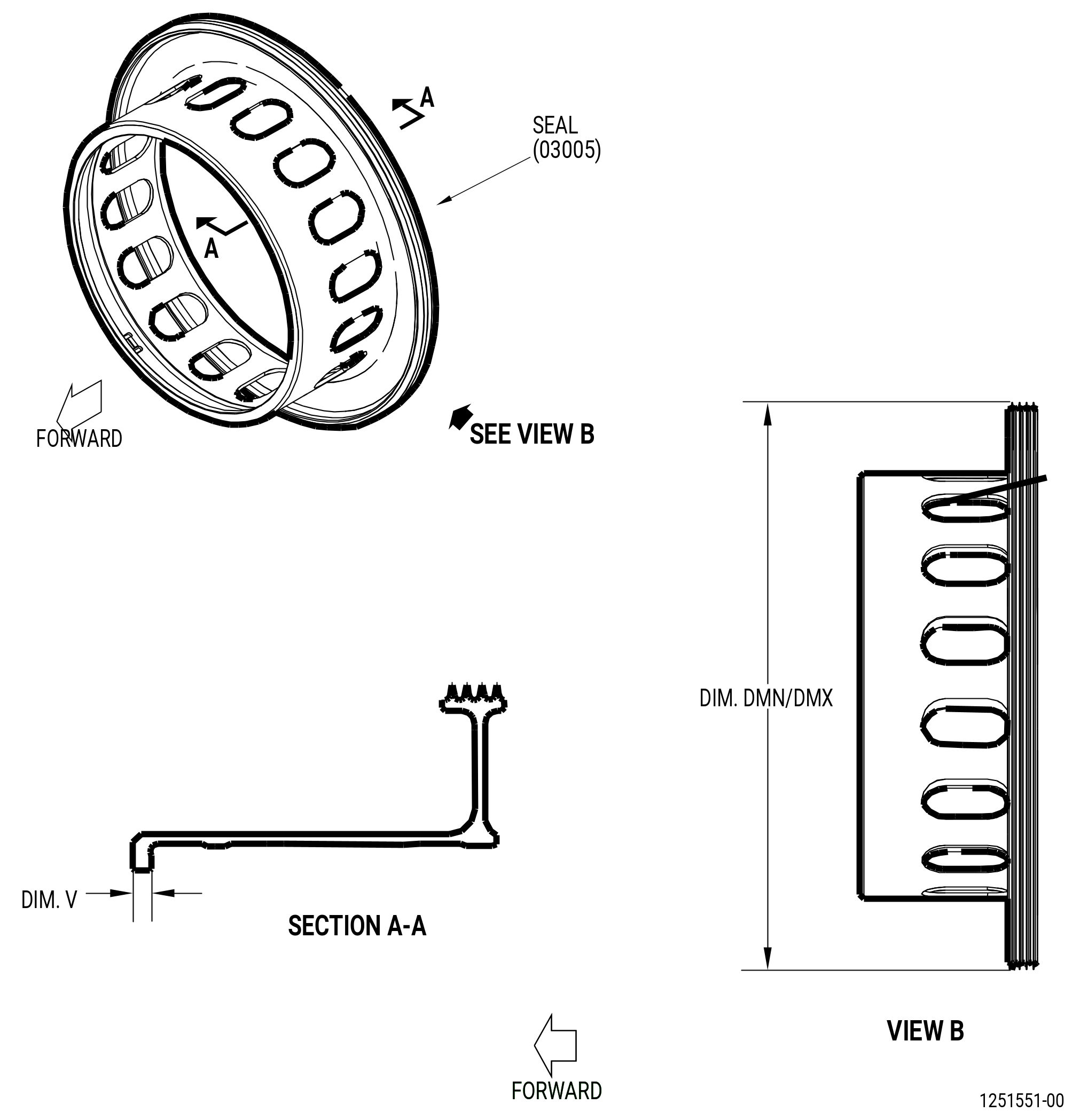
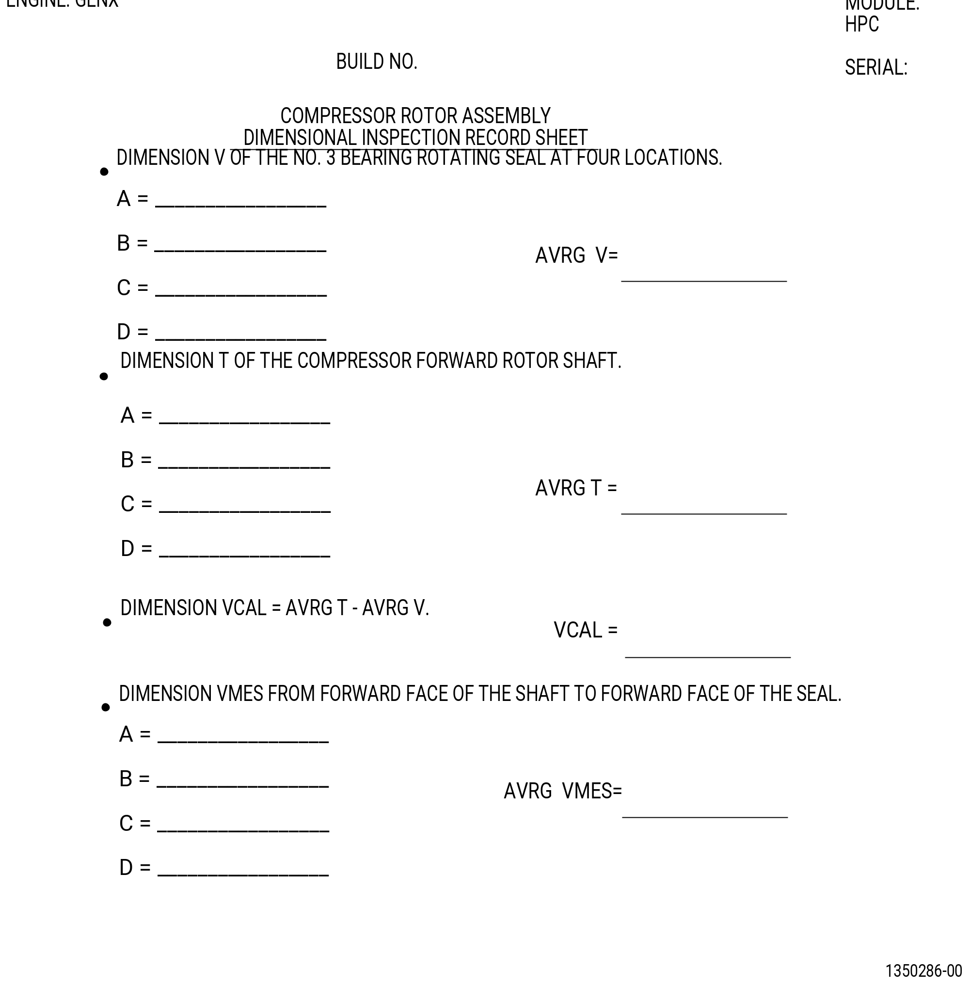
| (2) | Measure dimension V and dimension T as follows. Refer to Figure 1003, Figure 1004, and Figure 1005. |
| (a) | Measure dimension V at four locations on the forward flange of the seal. |
| (b) | Calculate the average dimension. |
| (c) | Record the result as dimension V on the record sheet. |
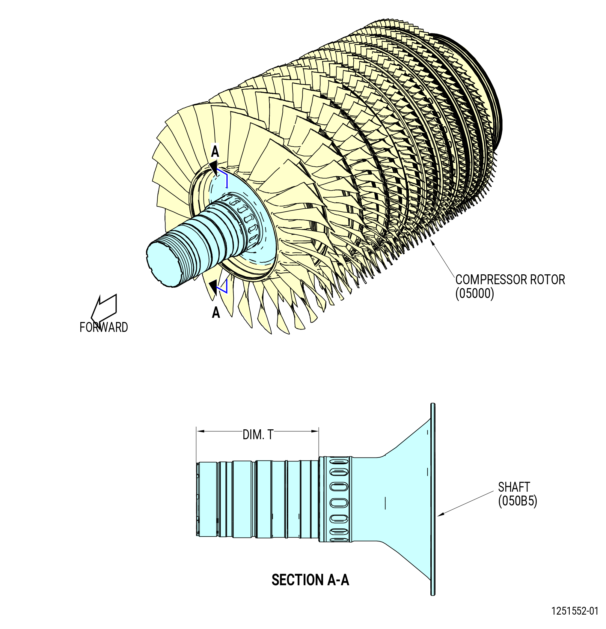
| (d) | Measure dimension T at four locations on the shaft. Do the measurement from the forward face of the shaft to the seal seating surface. |
| (e) | Calculate the average dimension. |
| (f) | Record the result as dimension T on the record sheet. |
| (g) | Subtract average dimension V from average dimension T and record the result as dimension VCAL. |
| Subtask 72-30-00-220-007 |
| (3) | Deleted. |
| Subtask 72-30-00-440-273 |
| (4) | Install the seal on the shaft as follows: |
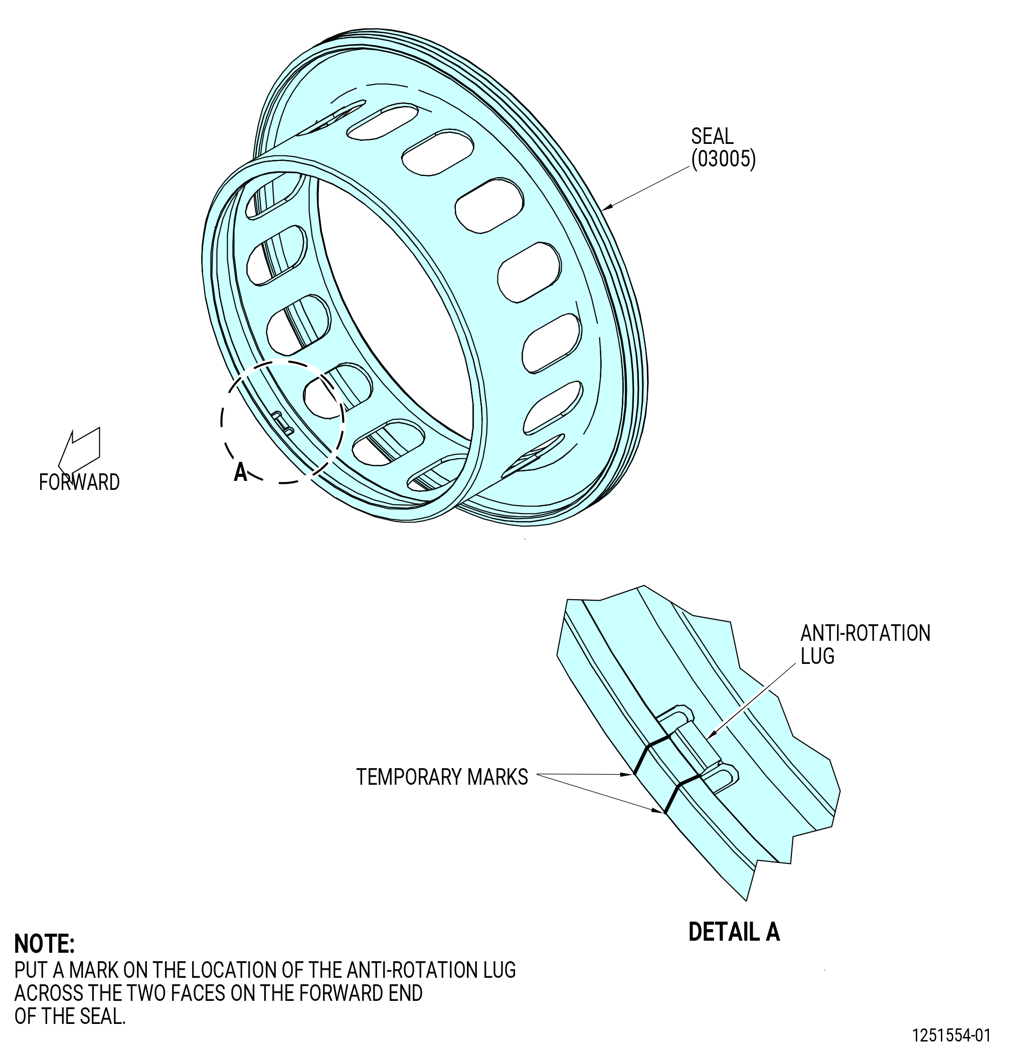
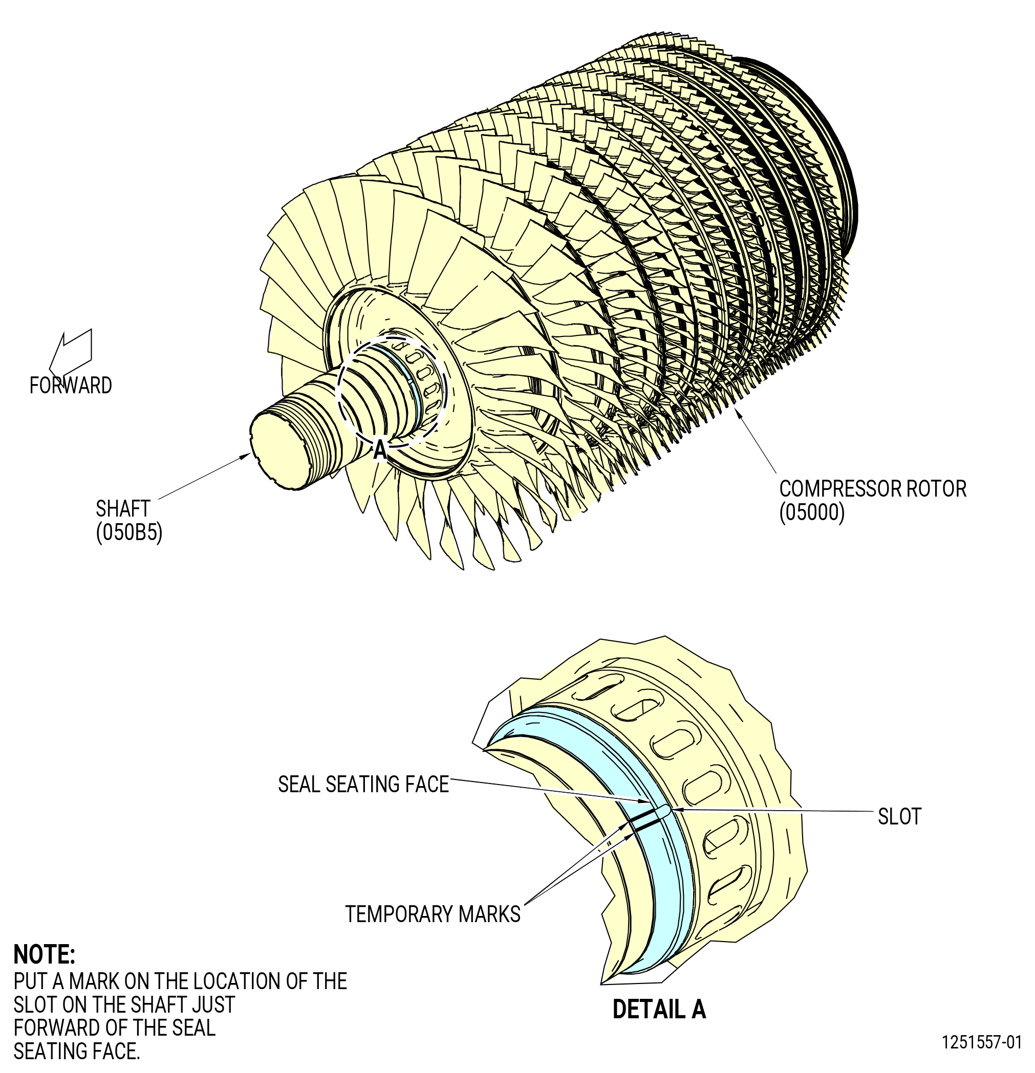
| (a) | Find the anti-rotation lug on the ID of the seal (03005). Refer to Figure 1006. |
| (b) | Use the C05-003 pen to put a mark on the location of the anti-rotation lug on the forward face of the seal. |
| (c) | Find the slot for the anti-rotation lug, located on the shaft (050B5). Refer to Figure 1007. |
| (d) | Use the C05-003 pen to put a mark on the location of the slot on the shaft diameter just forward of the seal seating face. |
| WARNING: |
|
| (e) | Use a heat gun and increase the temperature of the seal to 300°F (148.9°C). |
| (f) | Align the tab of the seal with the slot on the shaft and put the seal on the shaft. Refer to Figure 1008. |
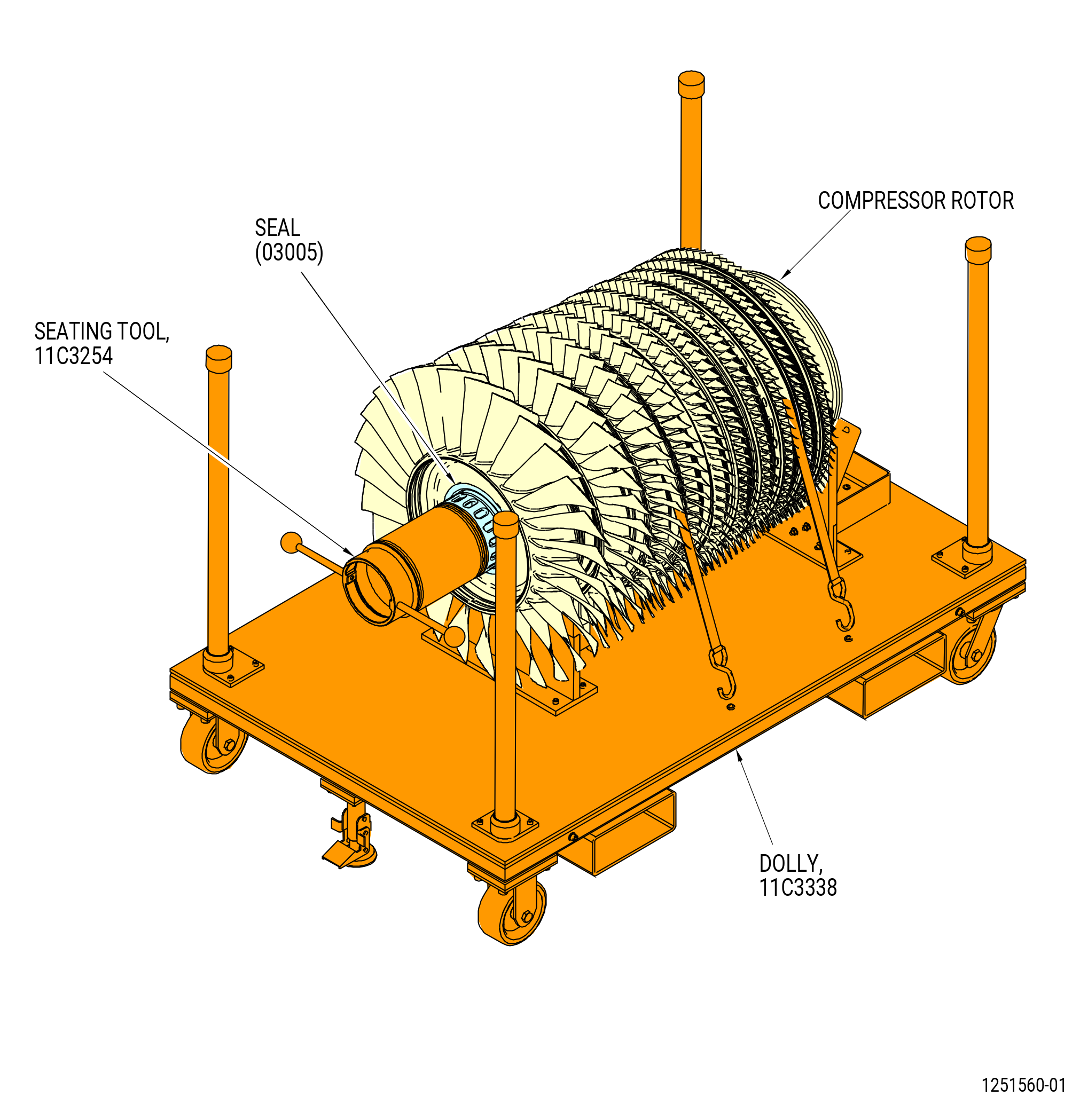
| (g) | Install the 11C3254 seating tool on the forward end of the shaft and tighten it against the seal. Refer to Figure 1009. |
| (h) | Let the temperature of the seal decrease to room temperature and remove the seating tool. |
| Subtask 72-30-00-220-008 |
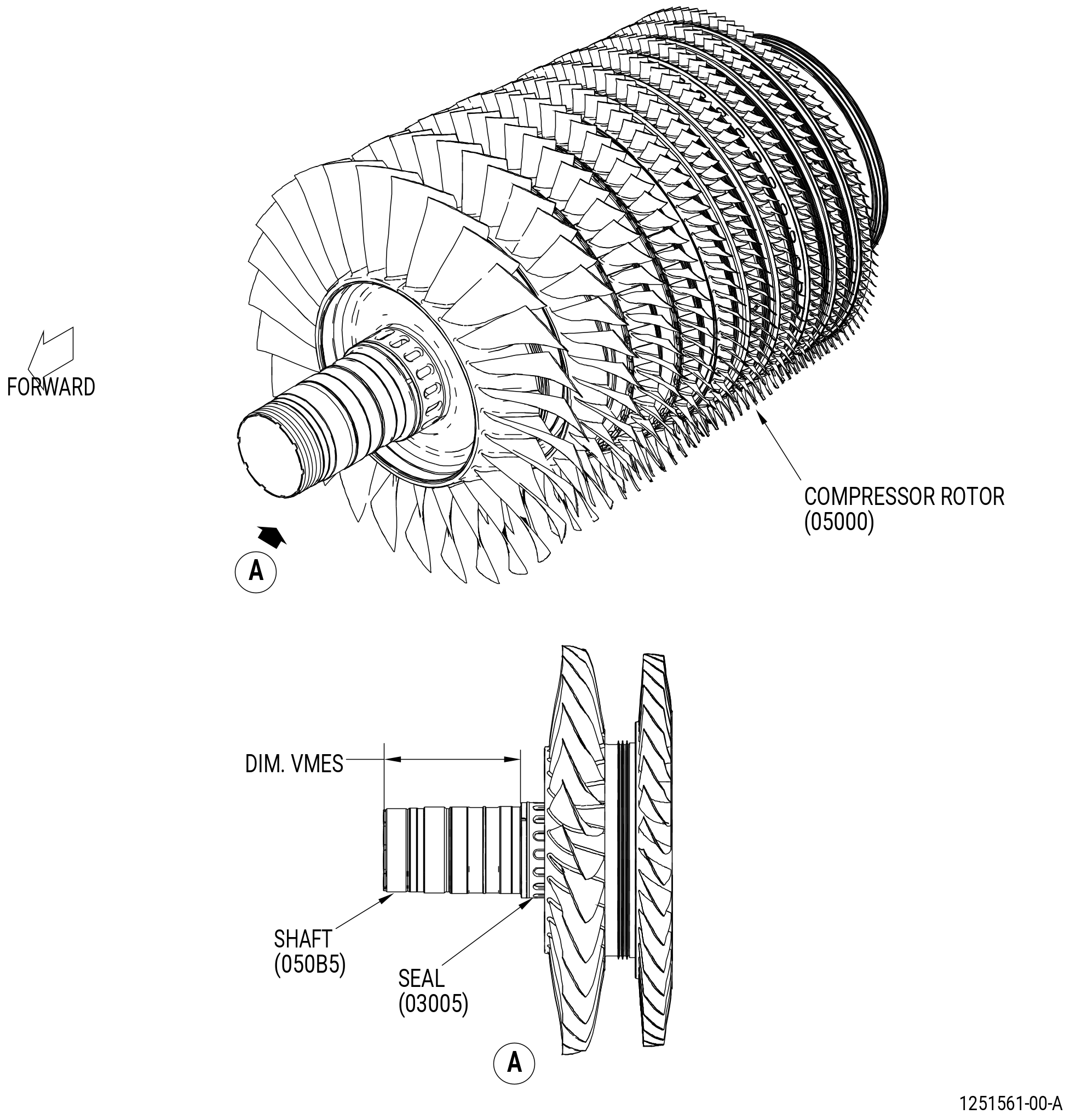
| (5) | Measure dimension VMES as follows. Refer to Figure 1010. |
| (a) | Measure from the forward face of the shaft to the forward face of the seal at four equally-spaced locations. |
| (b) | Calculate the average dimension. |
| (c) | Record this dimension as dimension VMES on the record sheet. Refer to Figure 1005. |
| (6) | Compare dimension VMES to dimension VCAL on the record sheet as follows: |
| (a) | Dimension VMES is serviceable if Dimension VMES = VCAL to 0.001 inch (0.03 mm) or less and do as follows: |
| 1 | If Dimension VMES is SERVICEABLE, continue with the HPC rotor assembly. |
| 2 | If Dimension VMES is NOT SERVICEABLE, stop here. Contact your GEAE representative. |
| Subtask 72-30-00-440-294 |
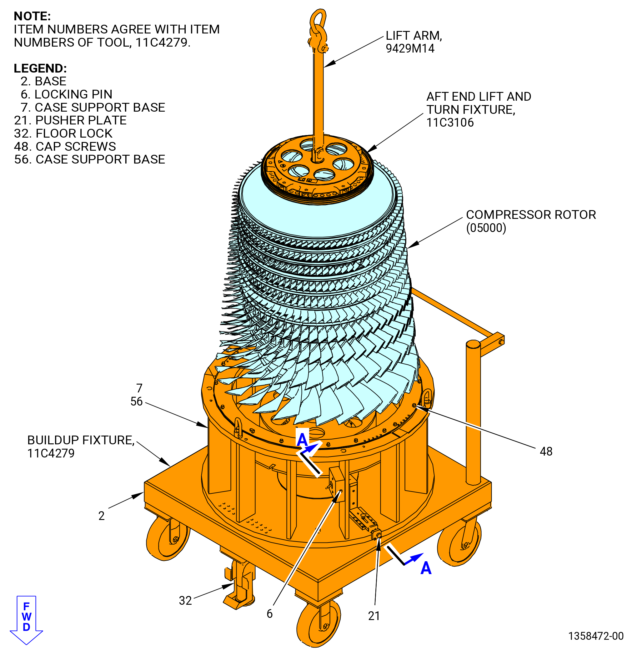
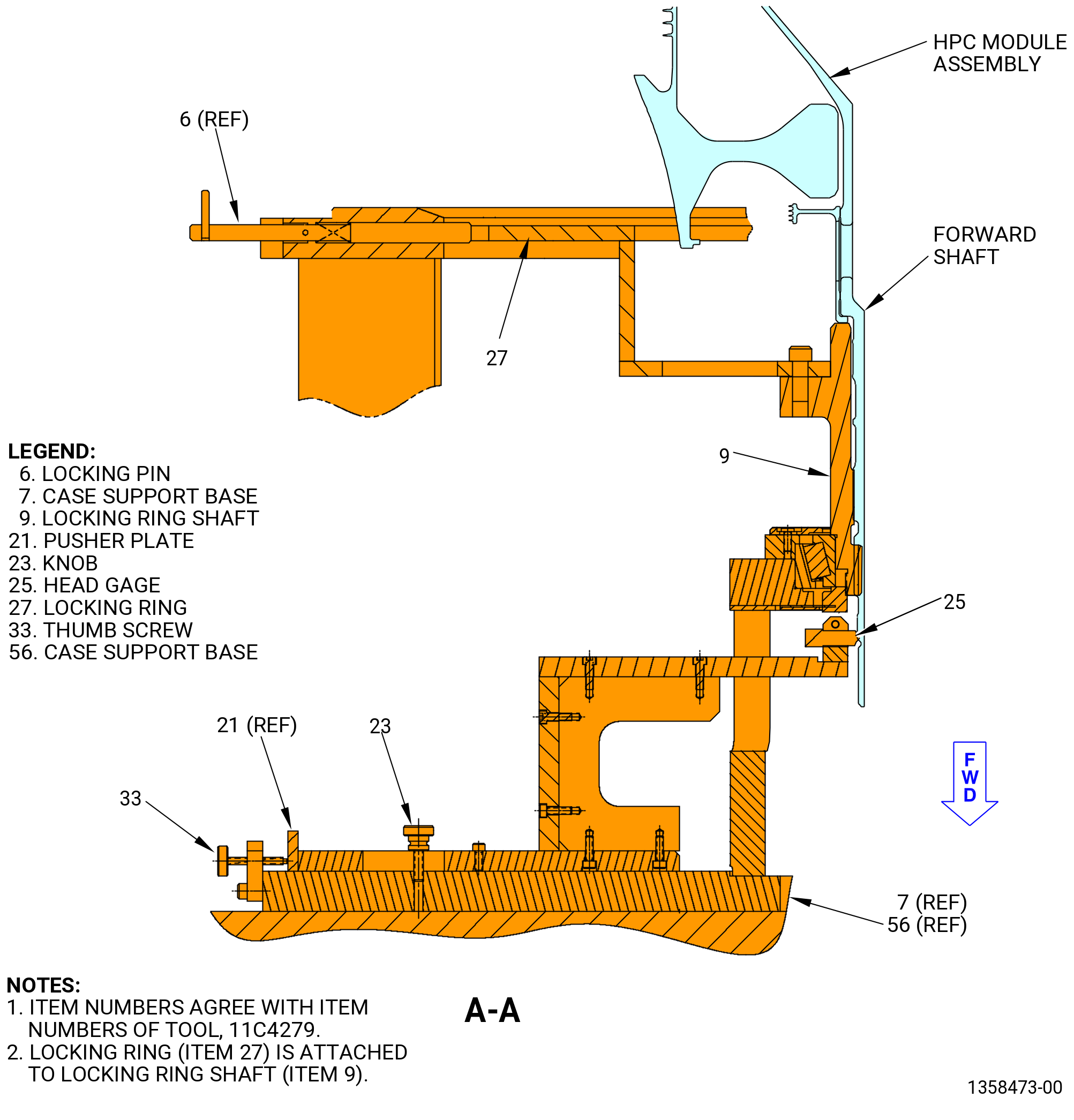
| B. | Alternative Procedure Available. Install the HPC rotor assembly (05000) on the 11C4279 buildup fixture as follows. Refer to Figure 1011. |
| (1) | Prepare the 11C4279 buildup fixture as follows: |
| CAUTION: |
|
| (a) | Make sure that the floor locks (item 32) touch the floor and remain locked to prevent movement of the buildup fixture. |
| (b) | Pull the locking pin (item 6) out at two locations and rotate clockwise (CW) or counterclockwise (CCW) to make sure it is in the unlocked position. |
| NOTE: |
|
| (c) | Turn the knob (item 23) to loosen it. |
| (d) | Turn the thumb screw (item 33) CCW. |
| (e) | Move the pusher plate (item 21) and the head gage (item 25) out. |
| (f) | Remove the capscrews (item 48) at 20 locations from the storage holes on the case support base (item 7, item 56). |
| (2) | Install the 11C4882 forward end lift and turn fixture on the shaft (01-780 , 72-31-00) (SIN 050B5). Refer to Figure 1012 and do as follows: |
| (a) | Put the 11C4882 forward end lift and turn fixture on the threads of the shaft. Hand-tighten the fixture only. |
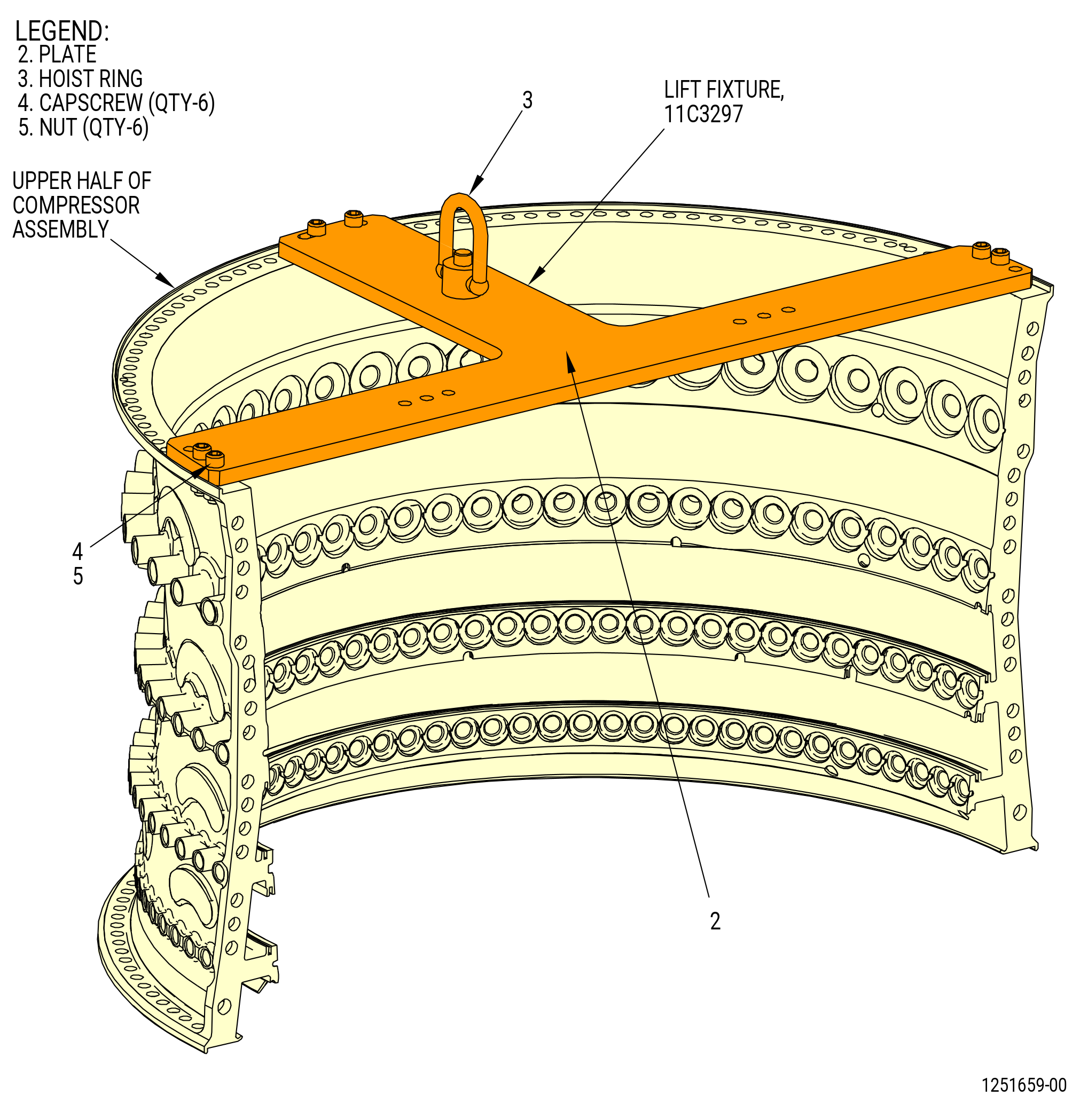
| (b) | Attach a hoist to the 9429M14 lift arm and attach it to the 11C4882 forward end lift and turn fixture with a ball-lock pin (item 5) of the 9429M14 lift arm. |
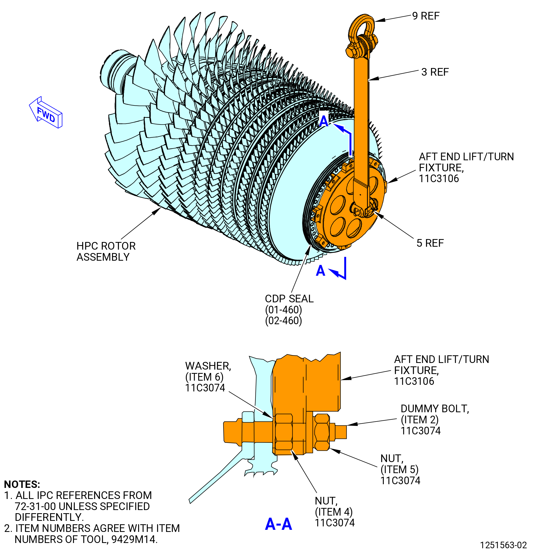
| (3) | Install the 11C3106 aft end lift and turn fixture on the CDP rotating seal (050NC) as follows. Refer to Figure 1013. |
| NOTE: |
|
| (a) | Put the 11C3106 aft end lift and turn fixture above eight nuts (item 4) of the 11C3074 tool kit and on the CDP rotating seal. |
| (b) | Attach the 11C3106 aft end lift and turn fixture to the CDP rotating seal with eight flange nuts (item 5) of the 11C3074 tool kit. Tighten the flange nuts in a criss-cross pattern. |
| (c) | Install one more 9429M14 lift arm on the 11C3106 aft end lift and turn fixture and attach it with a ball-lock pin (item 5) of the 9429M14 lift arm. |
| (d) | Attach one more hoist to the 9429M14 lift arm. |
| Subtask 72-30-00-440-297 |
| (4) | Install the HPC rotor assembly (05000) on the 11C4279 buildup fixture as follows: |
| (a) | Alternative Procedure Available. Remove the upper front clamp ring (item 29) and the upper rear clamping ring (item 42) of the 11C3338 dolly that attach the HPC rotor assembly to the dolly. Refer to Figure 1001. |
| Subtask 72-30-00-440-298 |
| (a).A. | Alternative Procedure. Remove the upper front clamp ring (item 27) and the upper rear clamping ring (item 38) of the 11C3352 shipping container that attach the HPC rotor assembly to the shipping container. Refer to Figure 1002. |
| Subtask 72-30-00-440-299 |
| WARNING: |
|
| (b) | Operate the two hoists and lift the HPC rotor assembly up and away from the dolly or the shipping container. |
| (c) | Turn the HPC rotor assembly as follows: |
| CAUTION: |
|
| 1 | Operate the two hoists to lift the aft end while you lower the forward end of the HPC rotor assembly. |
| 2 | Continue this procedure until the HPC rotor assembly is in the vertical position, forward end down. |
| 3 | Remove the 11C4882 forward end lift and turn fixture from the shaft (01-780, 72-31-00) (050B5). |
| WARNING: |
|
| (d) | Move the HPC rotor assembly above the 11C4279 buildup fixture. Refer to Figure 1011. |
| (e) | Make sure the teeth on the shaft (050B5) engage in the locking ring shaft (item 9) of the 11C4279 buildup fixture. If necessary, rotate the locking ring (item 27) and the locking ring shaft (item 9) to allow the teeth to engage. |
| (f) | Continue to lower the HPC rotor assembly onto the case support base (item 7, item 56). |
| (g) | Move the locking pin (item 6) forward to engage the locking ring (item 27). If necessary, rotate the HPC rotor to allow the locking pin (item 6) engage in the locking ring (item 27). |
| (h) | Move the pusher plate (item 21) inward to put the head gage (item 25) against the compressor rotor forward shaft. |
| (i) | Turn the thumb screw (item 33) CW until it touches the pusher plate (item 21). |
| (j) | Tighten the knob (item 23) to secure the pusher plate (item 21). |
| Subtask 72-30-00-440-002 |
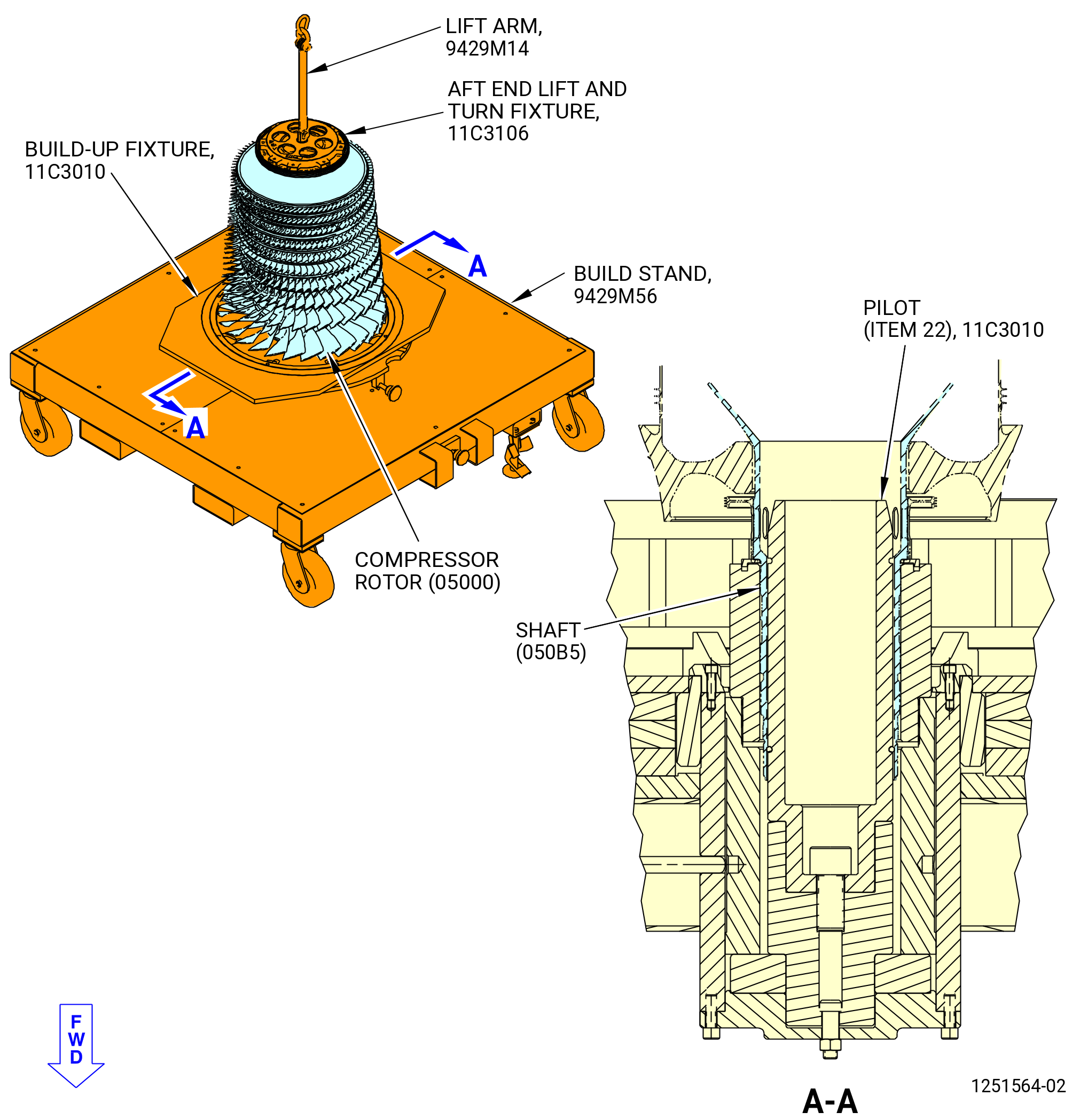
| B.A. | Alternative Procedure. Install the HPC rotor assembly (05000) on the 9429M56 build stand as follows: |
| NOTE: |
|
| Subtask 72-30-00-440-003 |
| (1) | Install the 11C4882 forward end lift and turn fixture on the shaft (01-780, 72-31-00) (SIN 050B5). Refer to Figure 1012 and do as follows: |
| (a) | Put the 11C4882 forward end lift and turn fixture on the threads of the shaft. Hand-tighten the fixture only. |
| (b) | Attach a hoist to the 9429M14 lift arm and attach it to the 11C4882 forward end lift and turn fixture with a ball-lock pin (item 5) of the 9429M14 lift arm. |
| Subtask 72-30-00-440-004 |
| (2) | Install the 11C3106 aft end lift and turn fixture on the CDP rotating seal (050NC) as follows. Refer to Figure 1013. |
| NOTE: |
|
| (a) | Put the 11C3106 aft end lift and turn fixture above eight nuts (item 4) of the 11C3074 tool kit and on the CDP rotating seal. |
| (b) | Attach the 11C3106 aft end lift and turn fixture to the CDP rotating seal with eight flange nuts (item 5) of the 11C3074 tool kit. Tighten the flange nuts in a criss-cross pattern. |
| (c) | Install one more 9429M14 lift arm on the 11C3106 aft end lift and turn fixture and attach it with a ball-lock pin (item 5) of the 9429M14 lift arm. |
| (d) | Attach one more hoist to the 9429M14 lift arm. |
| Subtask 72-30-00-440-005 |
| (3) | Install the HPC rotor assembly (05000) on the 9429M56 build stand as follows: |
| (a) | Alternative Procedure Available. Remove the upper front clamp ring (item 29) and the upper rear clamping ring (item 34) of the 11C3338 dolly that attach the HPC rotor assembly to the dolly. Refer to Figure 1001. |
| Subtask 72-30-00-440-296 |
| (a).A. | Remove the upper clamp ring (item 27) and the upper rear clamping ring (item 38) of the 11C3352 shipping container that attach the HPC rotor assembly to the shipping container. Refer to Figure 1002. |
| Subtask 72-30-00-440-006 |
| WARNING: |
|
| (b) | Operate the two hoists and lift the HPC rotor assembly up and away from the dolly or shipping container. |
| (c) | Turn the HPC rotor assembly as follows: |
| CAUTION: |
|
| 1 | Operate the two hoists to lift the aft end while you lower the forward end of the HPC rotor assembly. |
| 2 | Continue this procedure until the HPC rotor assembly is in the vertical position, forward end down. |
| 3 | Remove the 11C4882 lift and turn fixture from the shaft (01-780 , 72-31-00) (SIN 050B5). |
| Subtask 72-30-00-440-007 |
| WARNING: |
|
| (d) | Move the HPC rotor assembly above the 9429M56 build stand. |
| Subtask 72-30-00-440-008 |
| (e) | Align the ID of the shaft (050B5) with the pilot (item 22) of the 11C3010 build-up fixture and slowly lower the HPC rotor assembly on the 9429M56 build stand. Refer to Figure 1014. |
| (f) | Remove the 11C3106 aft end lift and turn fixture from the CDP rotating seal. |
| NOTE: |
|
| Subtask 72-30-00-440-295 |
| C. | Alternative Procedure Available. Install the two halves of the 11C3293 dummy stator on the 11C4279 buildup fixture as follows. Refer to Figure 1015. |
| (1) | Remove the threaded knobs (item 16) that attach the fitting fork (item 5) to the left arm (item 6) and right arm (item 7). |
| (2) | Remove the fitting fork (item 5). |
| WARNING: |
|
| (3) | Use a strap belt to lift the 11C3293 dummy stator. |
| (4) | Install one half (the table with the pivot (item 12)) of the 11C3293 dummy stator on the case support base (item 7, item 56) of 11C4279 buildup fixture. Refer to Figure 1011. |
| (5) | Install the second half (the table without the pivot (item 12)) of the 11C3293 dummy stator on the case support base (item 7, item 56) of 11C4279 buildup fixture. |
| (6) | Attach the 11C3293 dummy stator halves together with two capscrews (item 24), washers (items 26), and nuts (item 25) on each side. Refer to Figure 1015. |
| (7) | Attach the fitting fork (item 5) to the left arm (item 6) and right arm (item 7) with the threaded knobs (item 16). |
| Subtask 72-30-00-440-010 |
| C.A. | Alternative Procedure. Install the two halves of the 11C3293 dummy stator on the 11C3010 build-up fixture as follows. Refer to Figure 1015. |
| (1) | Remove the threaded knobs (item 16) that attach the fitting fork (item 5) to the left arm (item 6) and right arm (item 7). |
| (2) | Remove the fitting fork (item 5). |
| WARNING: |
|
| (3) | Use a strap belt to lift the 11C3293 dummy stator. |
| (4) | Install one half (the table with the pivot (item 12)) of the 11C3293 dummy stator on the table ring (item 21) of the 11C3010 build-up fixture. Make sure that the 12:00 o'clock position of the table is aligned with the TOP VERT mark on the table ring. |
| (5) | Install the second half (the table without the pivot (item 12)) of the 11C3293 dummy stator on the table ring (item 21) of the 11C3010 build-up fixture. |
| (6) | Attach the 11C3293 dummy stator halves together with two capscrews (item 24), washers (items 26), and nuts (item 25) on each side. |
| (7) | Attach the fitting fork (item 5) to the left arm (item 6) and right arm (item 7) with the threaded knobs (item 16). |
| Subtask 72-30-00-440-011 |
| D. | Install the stage 5 HPC vanes (stage 5 vane sectors) (084A0, 084AA) as follows: |
| (1) | Put the stage 5 HPC aft inner case (stage 5 aft case) (080AJ) on a clean work surface, forward side down. |
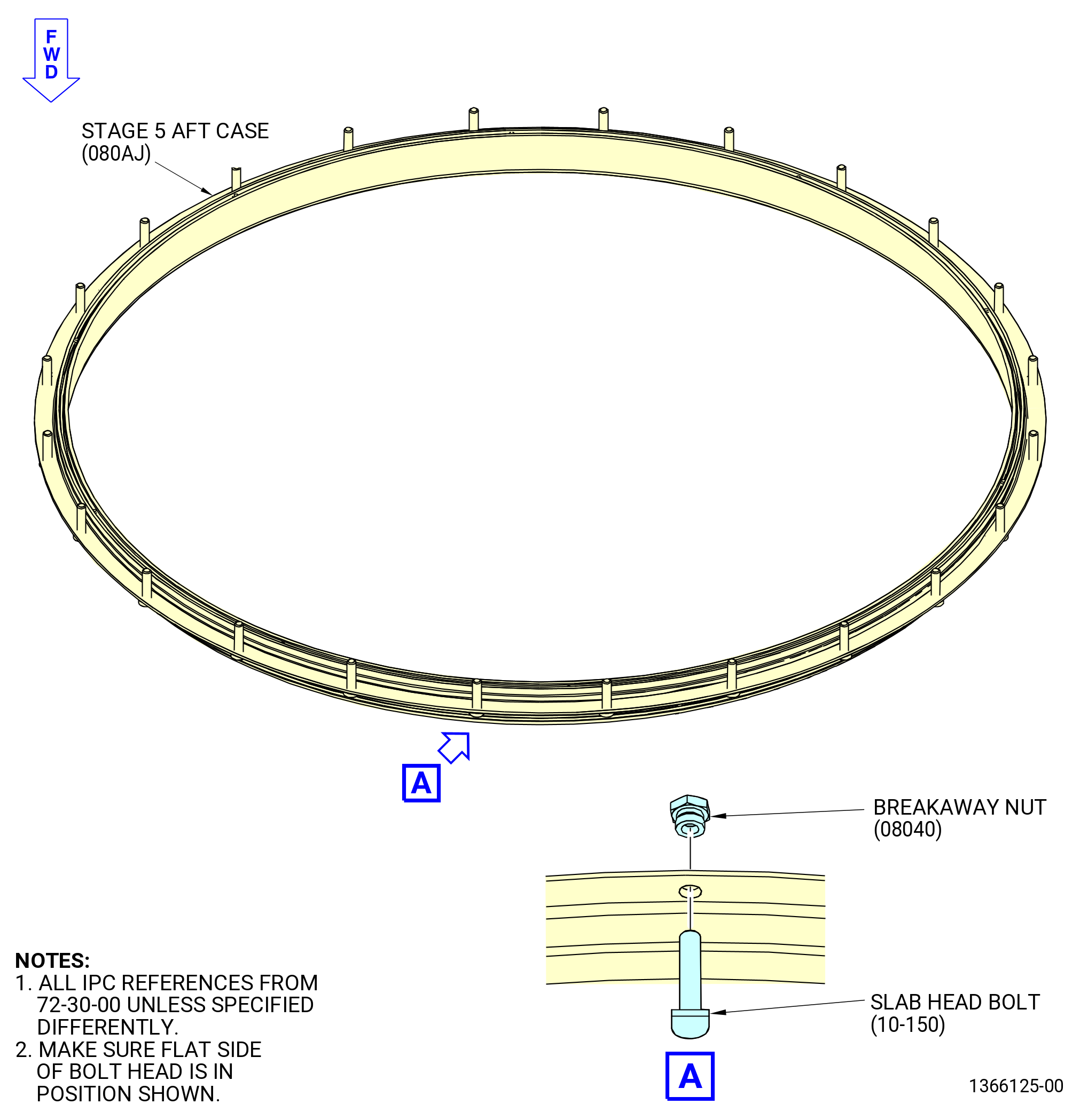
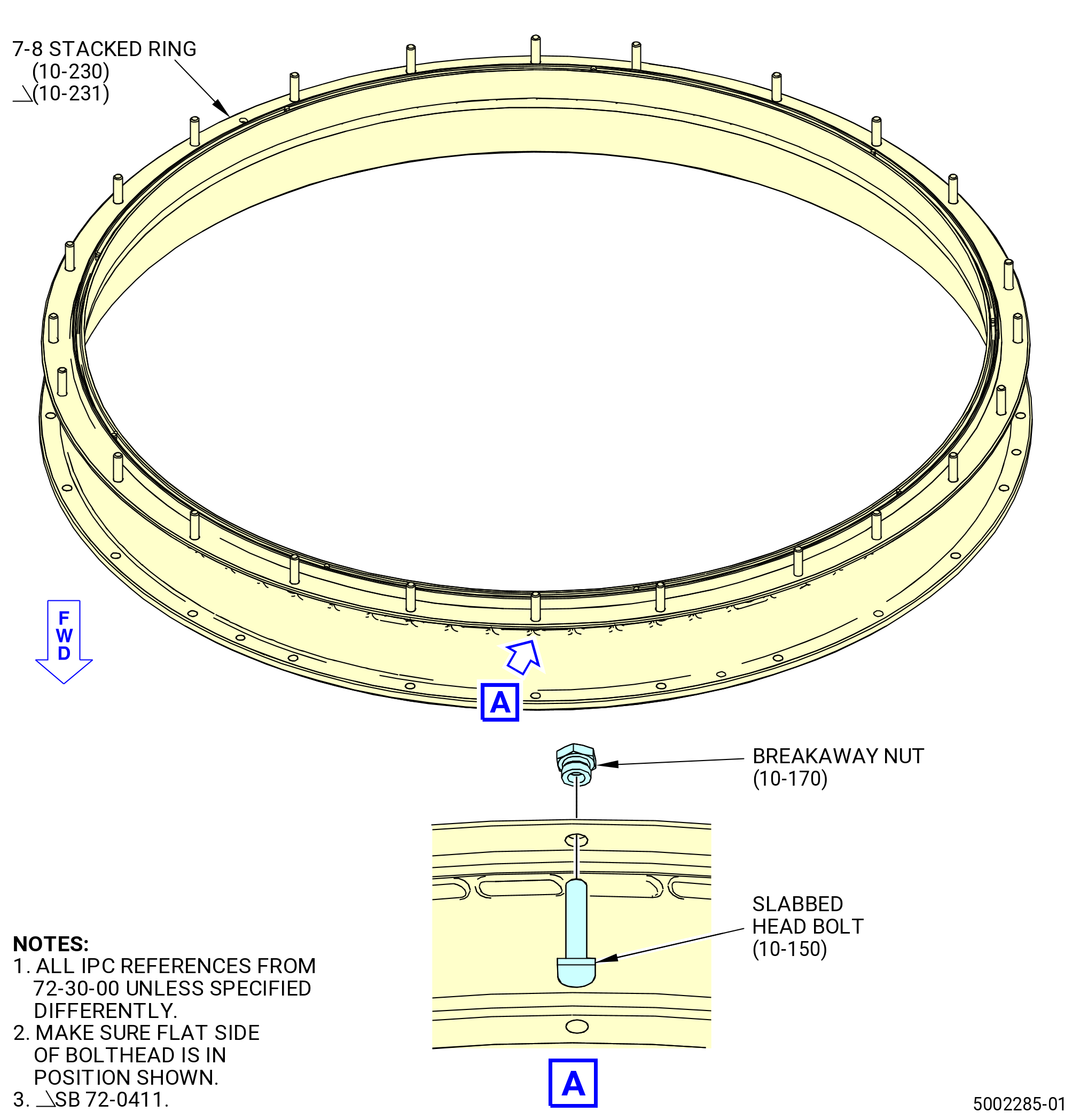
| (2) | Install 24 slab head bolts (10-150) (SIN 080F2) in the twenty-four 0.282 inch (7.16 mm) holes. Attach the slab head bolts to the stage 5 aft case with 24 breakaway nuts (10-170) (SIN 08040). Refer to Figure 1016 and Figure 1016A. |
| (3) | Make sure that the flat side of the slabbed head bolt (10-150) (SIN 080F2) is on the outer edge of the stage 5 aft case or a longer flat side of the slabbed head bolt (10-150A) (SIN 080F2) is on the outer edge of the stage 5 aft case. |
| Subtask 72-30-00-440-398 |
| * * * PRE SB 72-0109( Configuration 1 (10-170, 72-30-00) ) |
| (4) | Tighten the breakaway nuts (10-170) (SIN 08040) until the wrenching hex collars break off. |
| NOTE: |
|
| * * * END PRE SB 72-0109 |
| Subtask 72-30-00-440-399 |
| * * * SB 72-0109( Configuration 2 (10-170A, 72-30-00) ) |
| (4).A. | Tighten the breakaway nuts (10-170A) (SIN 08040) until the wrenching hex collars break off. |
| NOTE: |
|
| * * * END SB 72-0109 |
| Subtask 72-30-00-440-400 |
| * * * SB 72-0109( Configuration 3 (10-170B ,72-30-00) ) |
| (4).B. | Tighten the breakaway nuts (10-170B) (SIN 08040) until the wrenching hex collars break off. |
| NOTE: |
|
| * * * END SB 72-0109 |
| (5) | Make sure that the heads of the slabbed head bolts are correctly installed on the stage 5 aft case. |
| CAUTION: |
|
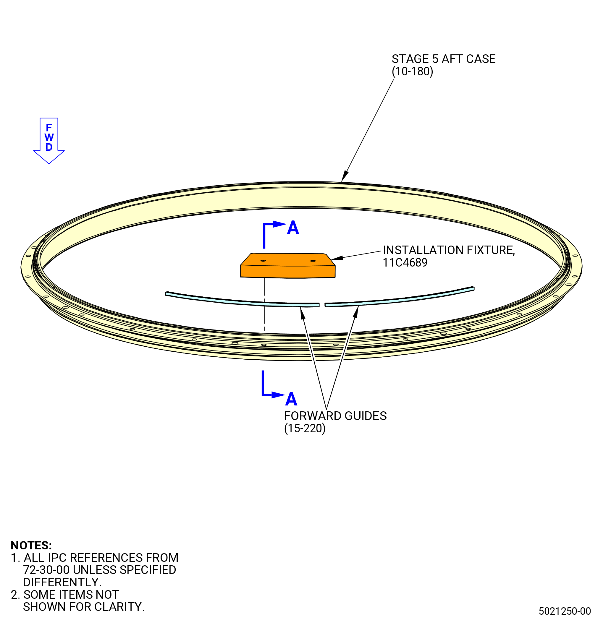
| (6) | Install 10 forward guides (15-220) (SIN 080T1) in the aft groove of the stage 5 aft case as follows: |
| WARNING: |
|
| (a) | Make sure that the mating flanges are clean of all unwanted material. If necessary, clean mating flanges with C04-035 isopropyl alcohol to remove unwanted material. |
| (b) | Install one guide in each of the sectors between the vane sector alignment pins located in the aft groove of the stage 5 aft case. Refer to Figure 1022. |
| (c) | Make sure that the forward guides do not overlap. |
| (d) | Make sure there is no damage to the forward guides. |
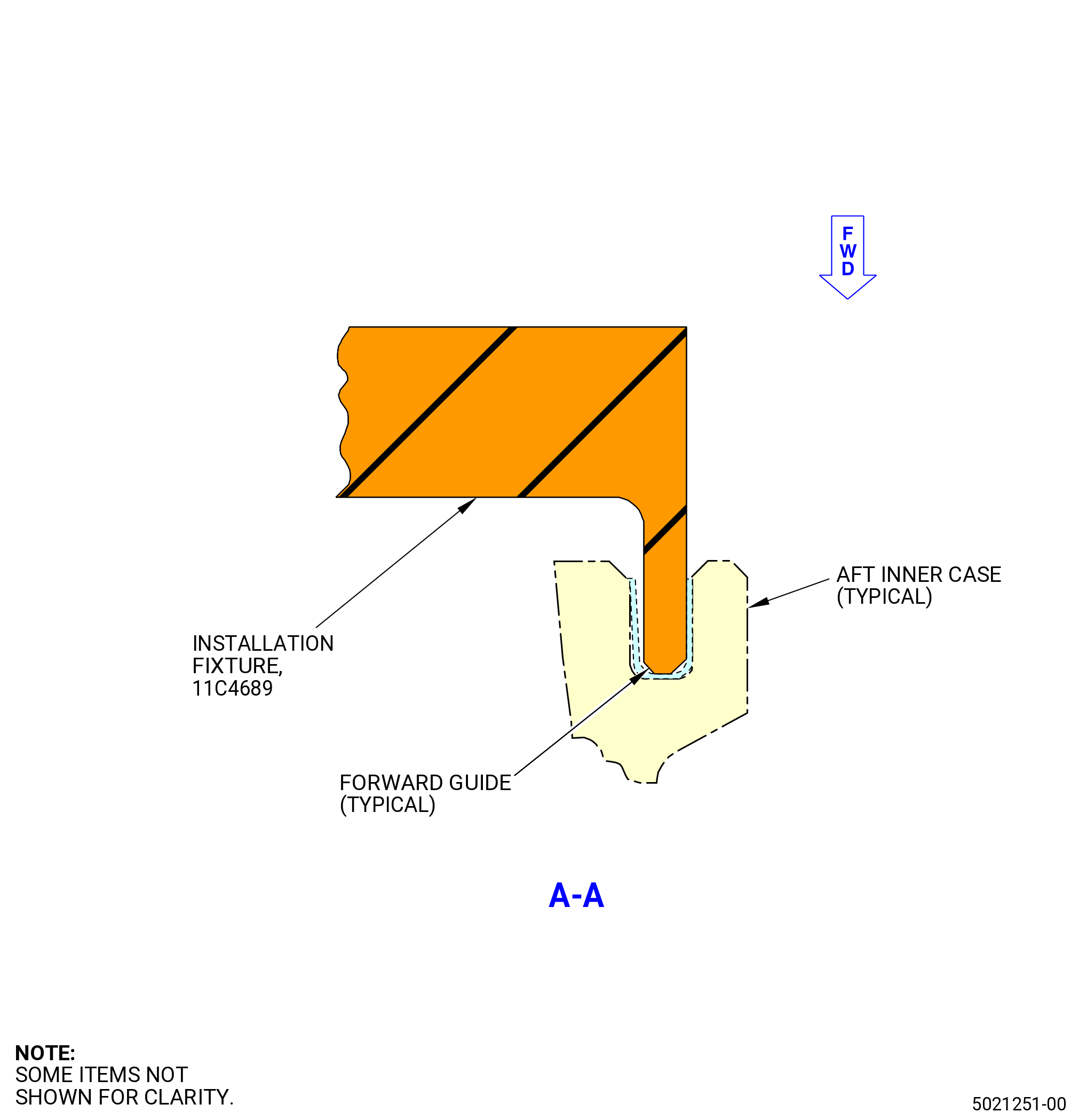
| (e) | Use the 11C4689 installation fixture to install the forward guides in the groove of the stage 5 aft case. |
| (7) | Deleted. |
| (8) | Find the top vertical centerline of the stage 5 aft case. Refer to Figure 1018. |
| NOTE: |
|
| (9) | Align the top vertical centerline of the stage 5 aft case with the TOP VERT mark on the case support base (item 7, item 56) of the 11C4279 buildup fixture or table ring (item 21) of the 11C3010 build-up fixture and put the stage 5 aft case on the dummy stator. |
| NOTE: |
|
|
|
| Subtask 72-30-00-440-013 |
| (10) | Install the stage 5 vane sectors (084A0, 084AA) on the stage 5 aft case (080AJ) as follows: |
| NOTE: |
|
| Subtask 72-30-00-440-014 |
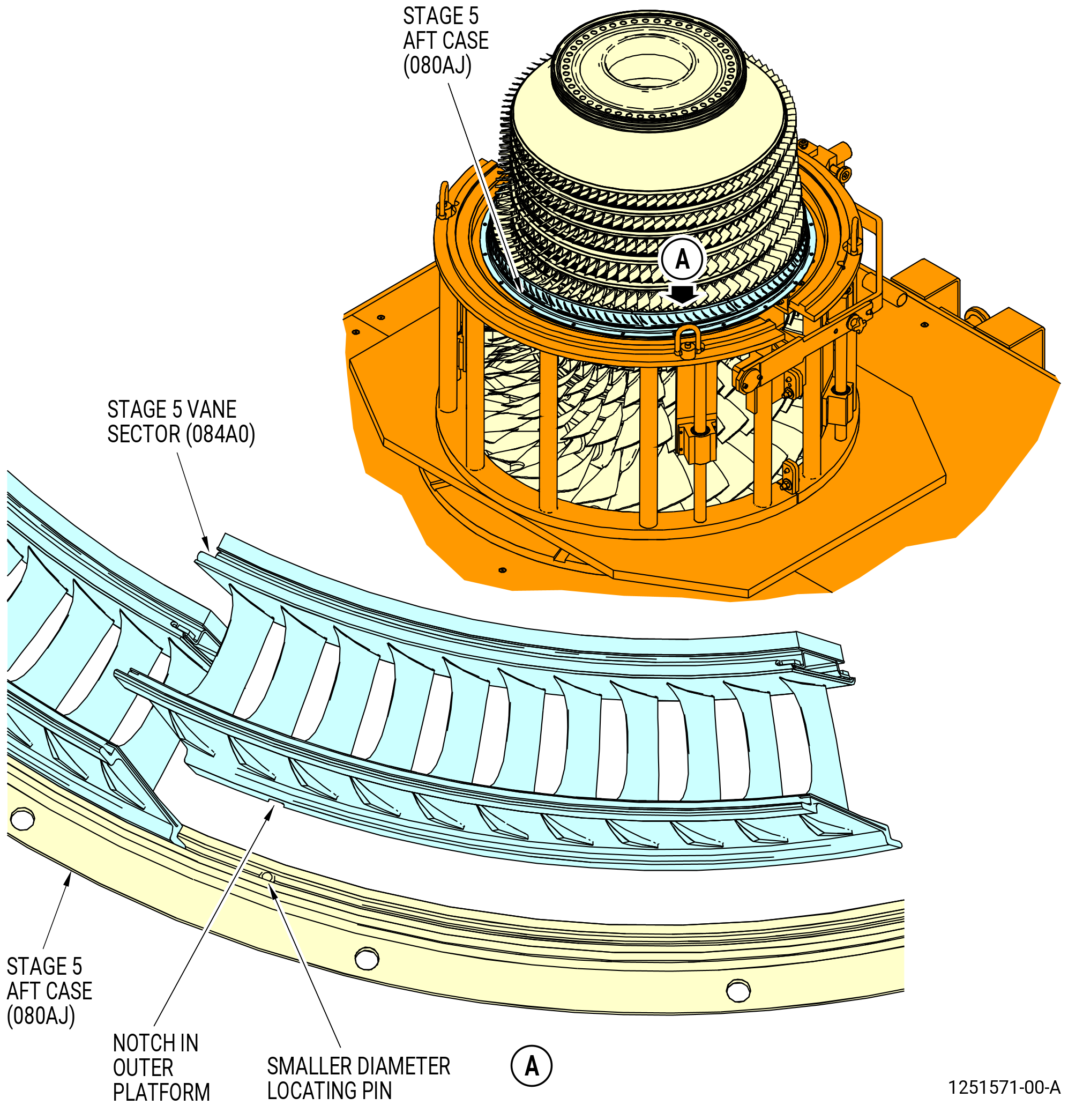
| (a) | Align the notch on the outer platform of the stage 5 vane sector (084AA) with the larger diameter pin on the stage 5 aft case at approximately the 9:00 o'clock position and install it on the case. Refer to Figure 1020. |
| NOTE: |
|
| (b) | Align the notch on the outer platform of the stage 5 vane sector (084A0) with the smaller diameter locating pins in the aft groove on the stage 5 aft case. Engage the notch of the stage 5 vane sectors with the smaller diameter pin and install the nine vane sectors one at a time. Refer to Figure 1019. |
| (c) | Make sure that the HPC rotor assembly (05000) rotates freely after the vane sectors are installed. Listen for a clicking noise caused by contact of misplaced guides with HPC blades. |
| CAUTION: |
|
| (d) | Use duckbill pliers to install 10 stage 5 spline seals (spline seals) (080N0) between the stage 5 vane sectors. Refer to Figure 1021. |
| Subtask 72-30-00-440-015 |
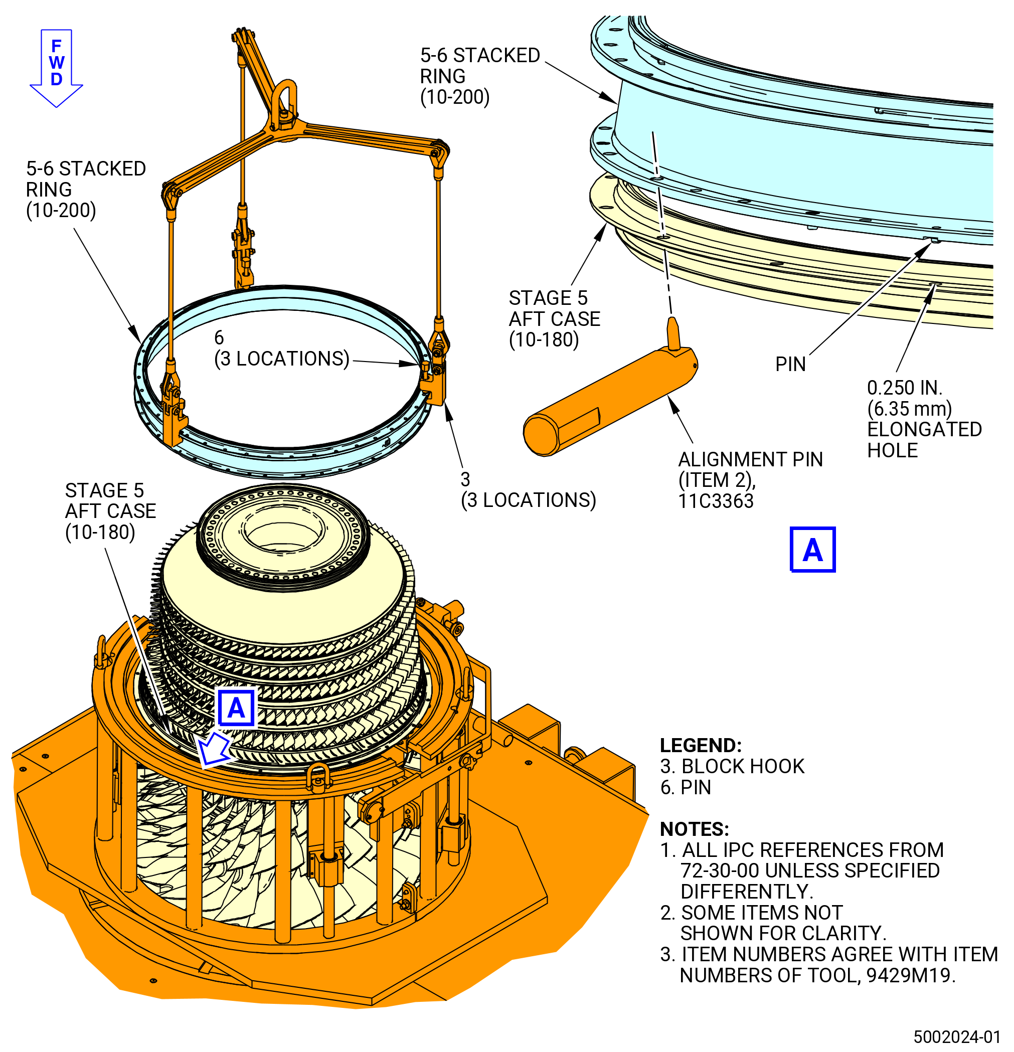
| (11) | Install the stage 5-6 aft case (5-6 stacked ring) (080AM) on the stage 5 aft case (080AJ) and above the outer platforms of the stage 5 vane sectors as follows: |
| (a) | Put the 5-6 stacked ring forward side down on a clean work surface as follows. Refer to Figure 1022. |
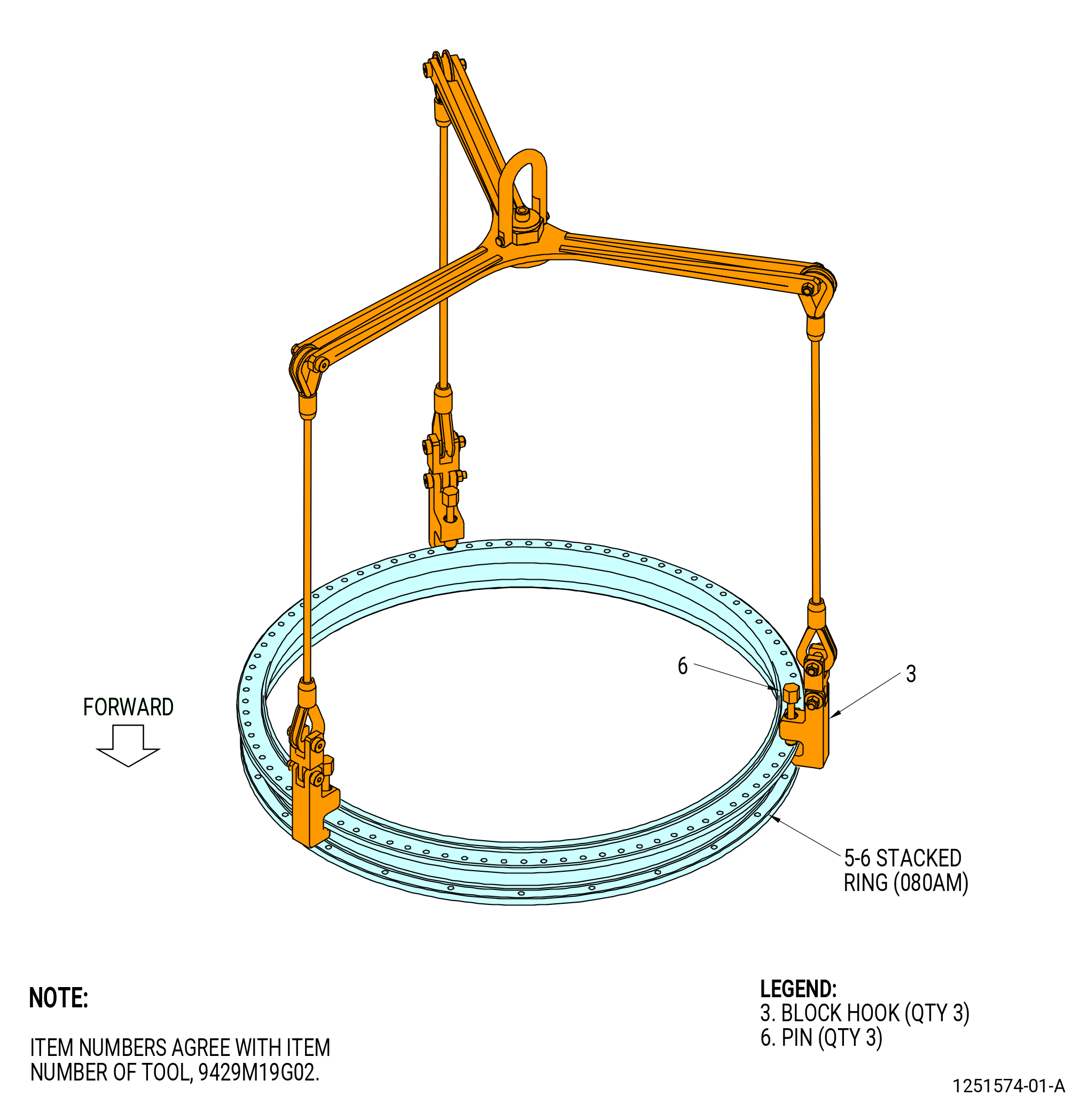
| 1 | Turn the pins (item 6) of the 9429M19G02 lift fixture counterclockwise (CCW) to permit installation of the three block hooks (item 3). |
| 2 | Put the three block hooks on the flange of the 5-6 stacked ring. |
| 3 | Tighten the pins (item 6) clockwise (CW) to attach the block hooks to the flange of the 5-6 stacked ring. |
| WARNING: |
|
| 4 | Lift the 5-6 stacked ring and put it on a clean work surface, forward side down. |
| 5 | Remove the 9429M19G02 lift fixture from the 5-6 stacked ring. |
| (b) | Install the 10 aft guides (15-210) (SIN 080T2) on the aft outer tangs of the stage 5 vane sectors (084AA, 084A0). Refer to Figure 1023 and do as follows: |
| NOTE: |
|
| NOTE: |
|
| 1 | If necessary, use the a rubber mallet to install the aft guides on the aft tang of the stage 5 vane sectors. |
| 2 | Make sure that the 10 aft guides are centered on the stage 5 vane sector gaps. |
| 3 | Make sure that the aft guides do not overlap. |
| 4 | Make sure there is no damage to the aft guides. |
| CAUTION: |
|
| (c) | Install the 10 forward guides (15-170) (SIN 080T3) in the aft groove of the 5-6 stacked ring. Refer to Figure 1023 and do as follows: |
| WARNING: |
|
| 1 | Make sure that the mating flanges are clean of all unwanted material. If necessary, clean mating flanges with C04-035 isopropyl alcohol to remove unwanted material. |
| 2 | Install one guide in each of the sectors between the vane sector alignment pins located in the aft groove of the stage 5-6 aft case. |
| 3 | Make sure that the forward guides do not overlap. |
| 4 | Make sure there is no damage to the forward guides. |
| 5 | Use the 11C4689 installation fixture to install the forward guides in the aft groove of the 5-6 stacked ring. |
| WARNING: |
|
| (d) | Make sure that the mating flanges are clean of all foreign material. If necessary, clean mating flanges with C04-035 isopropyl alcohol to remove foreign material. |
| CAUTION: |
|
| (e) | Install the 5-6 stacked ring on the stage 5 aft case as follows. Refer to Figure 1024. |
| 1 | Turn the pins (item 6) of the 9429M19G02 lift fixture CCW to install the three block hooks (item 3). |
| 2 | Put the three block hooks (item 3) on the flange of the 5-6 stacked ring. |
| 3 | Tighten the pins (item 6) CW to attach the block hooks to the aft flange of the 5-6 stacked ring. |
| 4 | Move the 5-6 stacked ring above the stage 5 aft case. |
| 5 | Make sure that the tops of the cases being assembled are aligned as flanges touch. |
| 6 | If necessary, use the 11C3363 alignment pin. |
| CAUTION: |
|
| 7 | If adjustment of the flanges is required to align the pin again after any contact, fully remove top stage 5-6 case to make sure that all wear guides are still correctly positioned on the aft tangs of the stage 5 stator vane segments. |
| 8 | Align the pin on the forward flange of the 5-6 stacked ring with the 0.250 inch (6.35 mm) elongated hole at the top vertical centerline of the stage 5 aft case. Lower the 5-6 stacked ring onto the stage 5 aft case and on the outer platforms of the stage 5 vane sectors. |
| 9 | Remove the lift fixture. |
| CAUTION: |
|
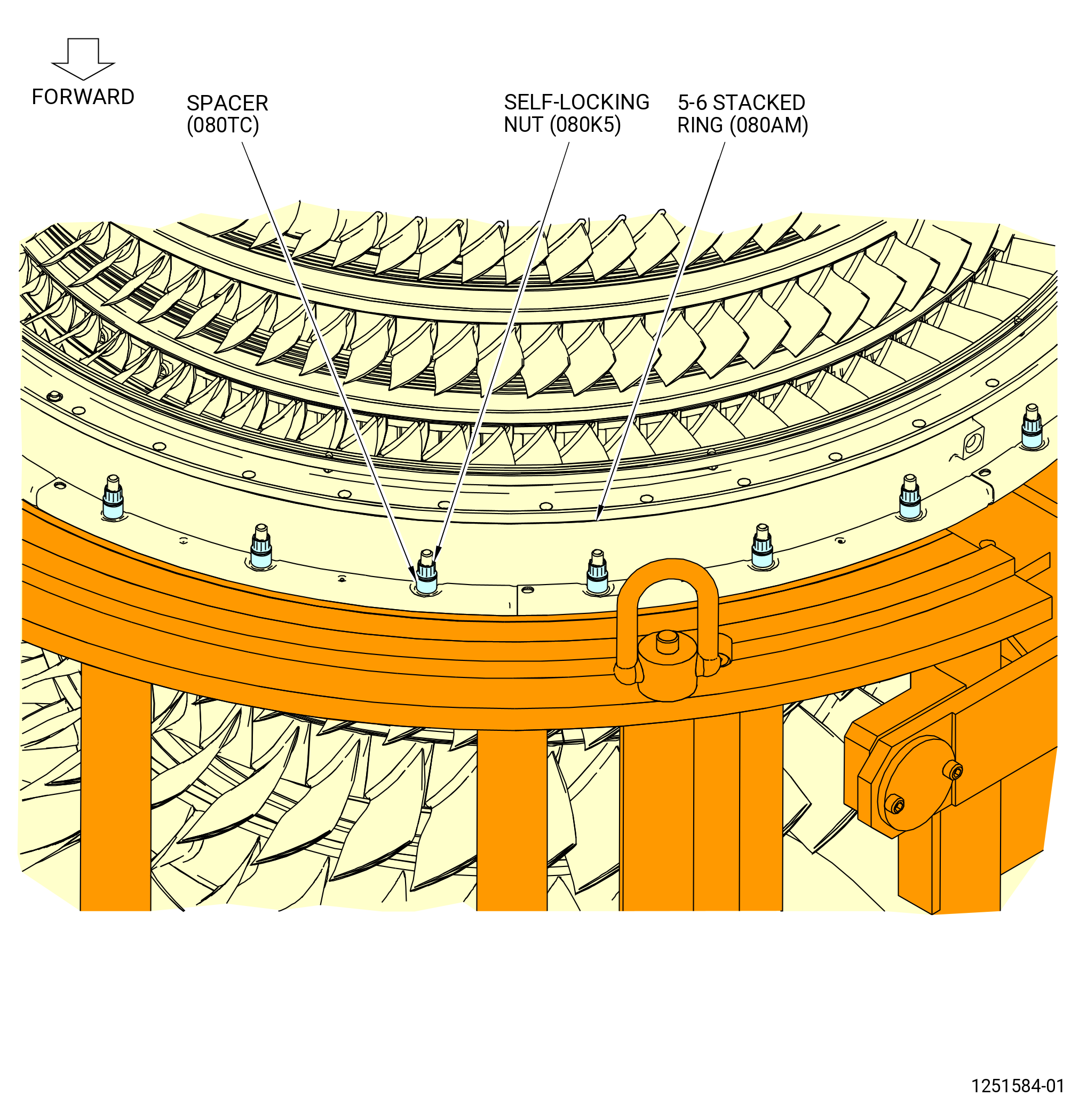
| (f) | Install the stage 5-6 stacked ring to the stage 5 aft case as follows. Refer to Figure 1026. |
| WARNING: |
|
| 1 | Apply C02-058 lubricant to the threads and friction surfaces of eight self-locking nuts (080K5). |
| 2 | Install the eight self-locking nuts (080K5) on the slab head bolts (10-150) (SIN 080F2) with spacers (080TC) equally spaced on the stage 5 aft case. |
| 3 | Torque the self-locking nuts to 94-109 lb in. (10.6-12.3 N.m) in a criss-cross pattern. |
| Subtask 72-30-00-220-013 |
| CAUTION: |
|
| 4 | Do a visual inspection of the aft guides (15-210) (SIN 080T2) for damage. Make sure the aft guides are not crushed, extruded, or have come loose. |
| Subtask 72-30-00-440-401 |
| 5 | Turn compressor rotor CCW to make sure that there are no misplaced guides. Misplaced guides will make a clicking noise when contacting with the HPC blades. |
| CAUTION: |
|
| 6 | Use a borescope to make sure that each wear guide is seated correctly. |
| 7 | Loosen the eight self-locking nuts (080K5) and spacers (080TC) on the flange of the 5-6 stacked ring (080AM) to remove the clamp on the flange joint. Do not remove the self-locking nuts from the flange. |
| Subtask 72-30-00-440-402 |
| (g) | Install the eight heat shields (080D1) on the 5-6 stacked ring as follows. Refer to Figure 1025 and Figure 1026. |
| WARNING: |
|
| 1 | Apply C02-058 lubricant to the threads and friction surfaces of eight bolts (080FS). |
| 2 | Put the eight heat shields on the flange of the 5-6 stacked ring and attach them with the eight bolts (080FS). |
| Subtask 72-30-00-440-396 |
| (h) | Attach the 5-6 stacked ring (080AM) to the stage 5 aft case (080AJ) as follows. Refer to Figure 1076. |
| WARNING: |
|
| 1 | Apply C02-058 lubricant to the threads and friction surfaces of 16 self-locking nuts (080K5). |
| 2 | Torque the eight first installed self-locking nuts to 94-109 lb in. (10.6-12.3 N.m) in a criss-cross pattern. |
| 3 | Torque the eight first self-locking nuts again to 124-146 lb in. (14.0-16.5 N.m) in a criss-cross pattern. |
| 4 | Install the remaining 16 self-locking nuts with spacers (080TC) on the slabbed head bolts (10-150) (SIN 080F2) or (10-150A) (SIN 080F2). |
| 5 | Torque all 24 self-locking nuts to 124-146 lb in. (14.0-16.5 N.m) in a criss-cross pattern. |
| 6 | Torque the eight heat shield bolts again to 32-38 lb in. (3.6-4.3 N.m) in a circle pattern. |
| 7 | Do a final torque to all 24 self-locking nuts to 124-146 lb in. (14.0-16.5 N.m) in a circle pattern. |
| Subtask 72-30-00-440-016 |
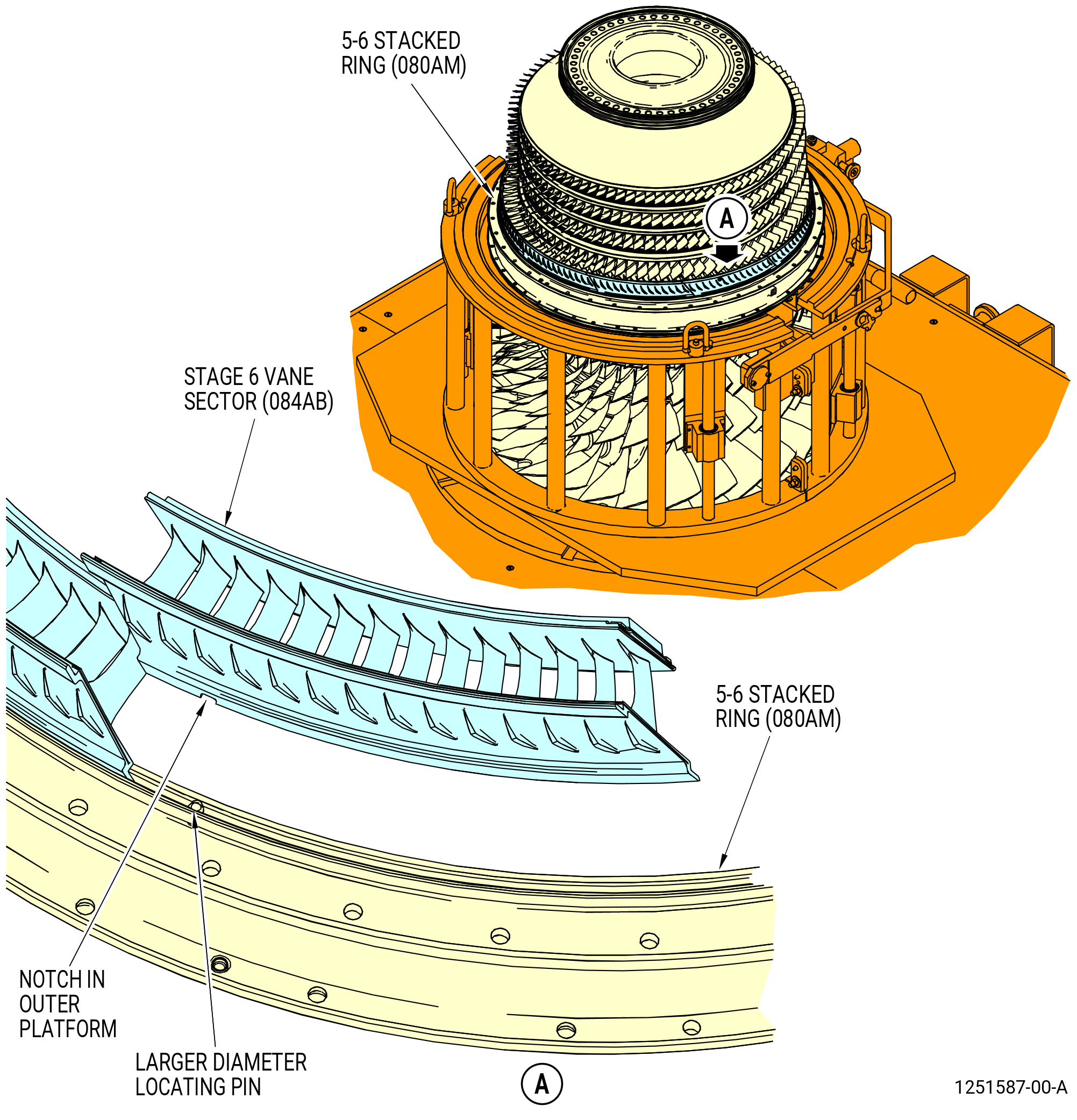
| E. | Install the stage 6 HPC vanes (stage 6 vane sectors) (084A1, 084AB) as follows: |
| NOTE: |
|
| (1) | Align the notch on the outer platform of the stage 6 vane sector (084AB) with the larger diameter pin on the 5-6 stacked ring at approximately the 10:00 o'clock position and install it on the ring. Refer to Figure 1028. |
| NOTE: |
|
| (2) | Align the notch on the outer platforms of the stage 6 vane sector (084A1) with the smaller diameter locating pins in the aft groove on the 5-6 stacked ring (080AM). |
| (3) | Engage the notch of the stage 6 vane sectors with the smaller diameter pin and install the nine vane sectors one at a time. Refer to Figure 1027. |
| (4) | Make sure that the HPC rotor assembly (05000) rotates freely after the vane sectors are installed. Listen for a clicking noise caused by contact of misplaced guides with HPC blades. |
| CAUTION: |
|
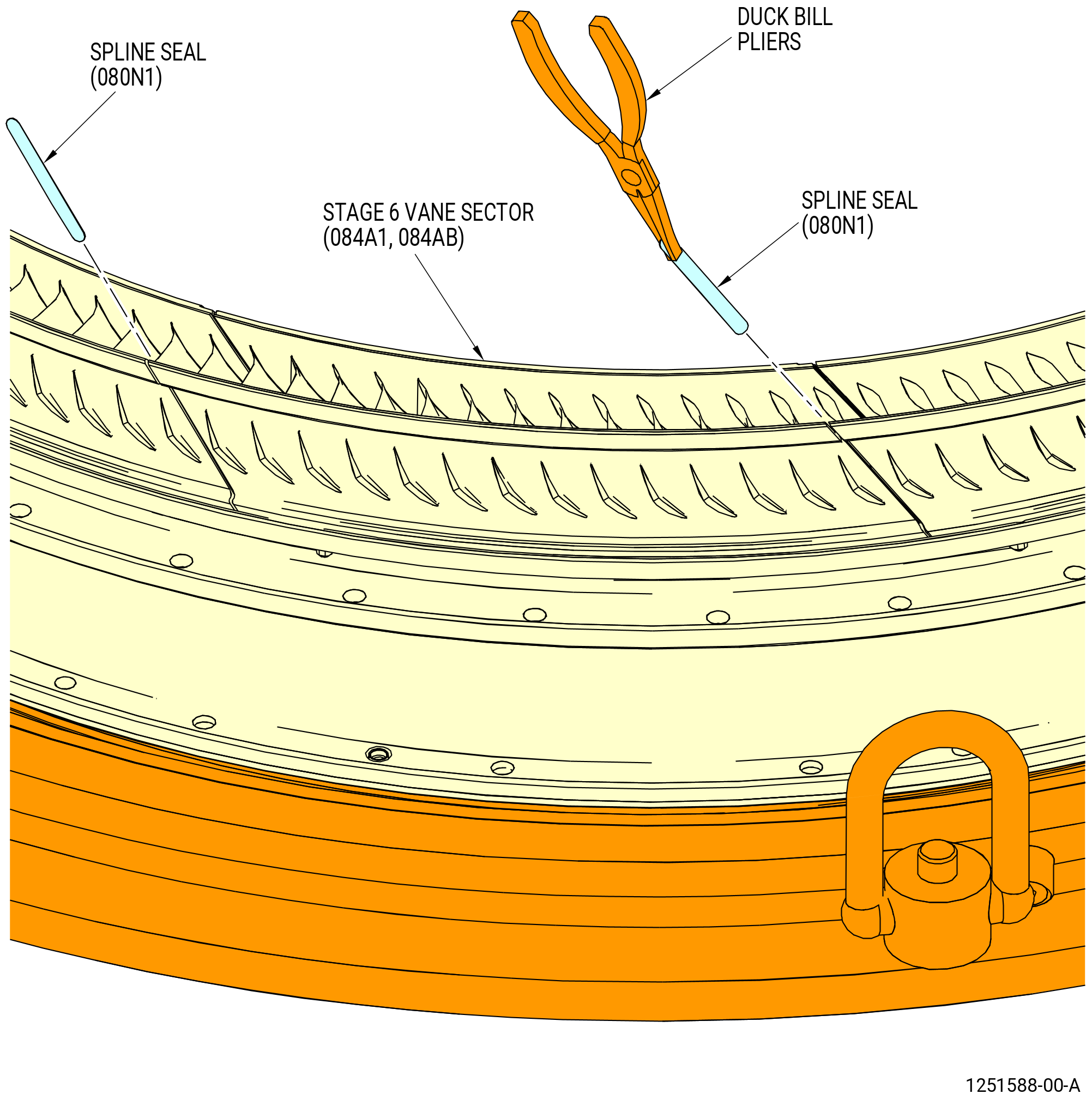
| (5) | Use duckbill pliers to install 10 stage 6 spline seals (spline seals) (080N1) between the stage 6 vane sectors. Refer to Figure 1029. |
| Subtask 72-30-00-440-017 |
| (6) | Install the stage 6-7 aft case (6-7 aft inner case) (080AR) on the 5-6 stacked ring and above the outer platforms of the stage 6 vane segments as follows: |
| (a) | Put the 6-7 aft inner case on a clean work surface as follows. Refer to Figure 1030. |
| 1 | Turn the pins (item 6) of the 9429M19G02 lift fixture CCW to permit installation of the three block hooks (item 3). |
| 2 | Put the three block hooks on the aft outer flange of the 6-7 aft inner case. |
| 3 | Tighten the pins (item 6) CW to attach the block hooks to the aft outer flange of the 6-7 aft inner case. |
| WARNING: |
|
| 4 | Lift the 6-7 aft inner case and put it on a clean work surface, forward side down. |
| 5 | Remove the 9429M19G02 lift fixture from the 6-7 aft inner case. |
| (b) | Install the 10 aft guides (15-160) (SIN 080T4) on the aft outer tangs of the stage 6 vane sectors (084A1, 084AB). Refer to Figure 1031. |
| 1 | Apply C10-109 wax to the aft guides. |
| 2 | If necessary, use a rubber mallet to install the aft guides on the aft outer tangs of the stage 6 vane sectors. |
| 3 | Make sure that the 10 aft guides are centered on the stage 6 vane sector gaps. |
| 4 | Make sure that the aft guides do not overlap. |
| 5 | Make sure there is no damage to the aft guides. |
| CAUTION: |
|
| (c) | Install the 11 forward guides (15-120) (SIN 080T5) in the aft groove of the 6-7 aft inner case. Refer to Figure 1031 and do as follows: |
| WARNING: |
|
| 1 | Make sure that the mating flanges are clean of all unwanted material. If necessary, clean mating flanges with C04-035 isopropyl alcohol to remove unwanted material. |
| 2 | Install one guide in each of the sectors between the vane sector alignment pins located in the aft groove of the stage 6-7 aft case. |
| 3 | Make sure that the aft guides do not overlap. |
| 4 | Make sure there is no damage to the aft guides. |
| 5 | Use the 11C4689 installation fixture to install the forward guides in the aft groove of the 6-7 inner case. |
| WARNING: |
|
| (d) | Make sure the mating flanges are clean of all foreign material. If necessary, clean mating flanges with C04-035 isopropyl alcohol to remove foreign material. |
| Subtask 72-30-00-440-649 |
| CAUTION: |
|
| (e) | Alternative Procedure Available. Install the 6-7 aft inner case on the stage 5-6 stacked ring and stage 6 vane sector outer platforms. Refer to Figure 1032 as follows: |
| 1 | Turn the pins (item 6) of the 9429M19G02 lift fixture CCW to permit installation of the three block hooks (item 3). |
| 2 | Put the three block hooks on the aft outer flange of the 6-7 aft inner case. |
| 3 | Tighten the pins (item 6) CW to attach the block hooks to the aft outer flange of the 6-7 aft inner case. |
| 4 | Move the 6-7 aft inner case above the 5-6 stacked ring. |
| 5 | Make sure that the tops of the cases being assembled are aligned as flanges touch. |
| 6 | If necessary, use the 11C3363 alignment pin. |
| CAUTION: |
|
| 7 | If adjustment of the flanges is necessary to align the pin again after any contact, fully remove the top stage 5-5 case to make sure that all wear guides are still correctly positioned on the aft tangs of the stage 5 stator vane segments. |
| 8 | Align the 0.250 inch (6.35 mm) elongated hole on the forward flange at the top vertical centerline with the pin on the aft flange of the 5-6 stacked ring. Lower the 6-7 aft inner case on the stage 5-6 stacked ring and above the outer platforms of the stage 6 vane sectors. |
| 9 | Remove the lift fixture. |
| Subtask 72-30-00-440-650 |
| CAUTION: |
|
| (e).A. | Alternative Procedure. Install the 6-7 aft inner case on the stage 5-6 stacked ring and stage 6 vane sector outer platforms. Refer to Figure 1032 as follows: |
| 1 | Turn the pins (item 6) of the 9429M19G02 lift fixture CCW to permit the installation of the three block hooks (item 3). |
| 2 | Put the three block hooks on the aft outer flange of the 6-7 aft inner case. |
| 3 | Tighten the pins (item 6) CW to attach the block hooks to the aft outer flange of the 6-7 aft inner case. |
| 4 | Move the 6-7 aft inner case above the 5-6 stacked ring. |
| 5 | Make sure that the tops of the cases being assembled are aligned as flanges touch. |
| 6 | If necessary, use the 11C3363 alignment pin. |
| 7 | Align 6-7 aft inner case and stage 5-6 stacked ring with 11C4688 alignment guides as follows: |
| a | Align the top vertical markings of the stage 6-7 case and the alignment stage 5-7 guide. |
| b | Insert the three pins of the alignment stage 5-7 guide through three holes of the stage 6-7 case forward flange. |
| c | Use the pins of the alignment stage 5-7 guide to align the cases before the flanges come in contact. |
| d | Make sure that the tops of the cases being assembled are aligned as flanges touch. |
| e | Remove the alignment stage 5-7 guide. |
| CAUTION: |
|
| 8 | If the adjustment of the flanges is necessary to align the pin again after any contact, fully remove the top stage 5-6 case to make sure that all wear guides are still correctly positioned on the aft tangs of the stage 5 stator vane segments. |
| 9 | Align the 0.250 inch (6.35 mm) elongated hole on the forward flange at the top vertical centerline with the pin on the aft flange of the 5-6 stacked ring. Lower the 6-7 aft inner case on the stage 5-6 stacked ring and above the outer platforms of the stage 6 vane sectors. |
| 10 | Remove the lift fixture. |
| Subtask 72-30-00-440-651 |
| CAUTION: |
|
| (f) | Install the 6-7 aft case on the 5-6 aft case (080AM) as follows: |
| WARNING: |
|
| 1 | Apply C02-058 lubricant to the threads and friction surfaces of eight self-locking nuts (080K5) and eight bolts (080F5). |
| 2 | Install the eight self-locking nuts and eight bolts equally spaced on the stage 6 flange (every 5th hole - bolt head forward). |
| 3 | Torque the self-locking nuts to 94-109 lb in. (10.6-12.3 N.m) in a criss-cross pattern. |
| Subtask 72-30-00-220-014 |
| CAUTION: |
|
| 4 | Do a visual inspection of the forward guides (080T5) for damage. Make sure the aft guides are not crushed, extruded, or have come loose. |
| Subtask 72-30-00-440-403 |
| 5 | Turn compressor rotor CCW to make sure that there are no misplaced guides. Misplaced guides will make a clicking noise when contacting with the HPC blades. |
| CAUTION: |
|
| 6 | Use a borescope to make sure that each wear guide is seated correctly. |
| 7 | Remove the eight self-locking nuts (080K5) and bolts (080F5) from the 5-6 stacked ring (080AM). |
| Subtask 72-30-00-440-404 |
| (g) | Install the eight HPC stage 6 heat shields (080D2) on the forward flange of the 6-7 aft inner case as follows. Refer to Figure 1033. |
| WARNING: |
|
| 1 | Apply C02-058 lubricant to the threads and friction surfaces of 30 bolts (080F5) and 30 self-locking nuts (080K5). |
| 2 | Attach the eight heat shields to the forward flange of the 6-7 aft inner case with the 10 bolts (080F5), boltheads forward, and 10 self-locking nuts (080K5) used to install the 6-7 aft inner case. |
| Subtask 72-30-00-440-397 |
| (h) | Attach the 6-7 stacked ring (080AR) to the 5-6 stacked ring (080AM) as follows. Refer to Figure 1032 and Figure 1033. |
| WARNING: |
|
| 1 | Apply C02-058 lubricant to the threads and friction surfaces of 40 self-locking nuts (080K5) and 40 bolts (080F5). |
| 2 | Install eight of the self-locking nuts and eight bolts equally spaced on the stage 6 flange (every 5th hole - bolthead forward). |
| 3 | Torque the eight self-locking nuts to 94-109 lb in. (10.6-12.3 N.m) in a criss-cross pattern. |
| 4 | Torque the eight self-locking nuts again to 124-146 lb in. (14.0-16.5 N.m) in a criss-cross pattern. |
| 5 | Install the remaining 32 self-locking nuts (080K5) and 32 bolts (080F5) into the remaining open locations of the stage 6-7 flange (bolthead forward). |
| 6 | Torque all 40 self-locking nuts to 124-146 lb in. (14.0-16.5 N.m) in a criss-cross pattern. |
| 7 | Do a final torque to all 40 self-locking nuts to 124-146 lb in. (14.0-16.5 N.m) in a circle pattern. |
| Subtask 72-30-00-440-018 |
| F. | Install the stage 7 HPC vanes (stage 7 vane sectors) (084A2, 084AC) as follows: |
| NOTE: |
|
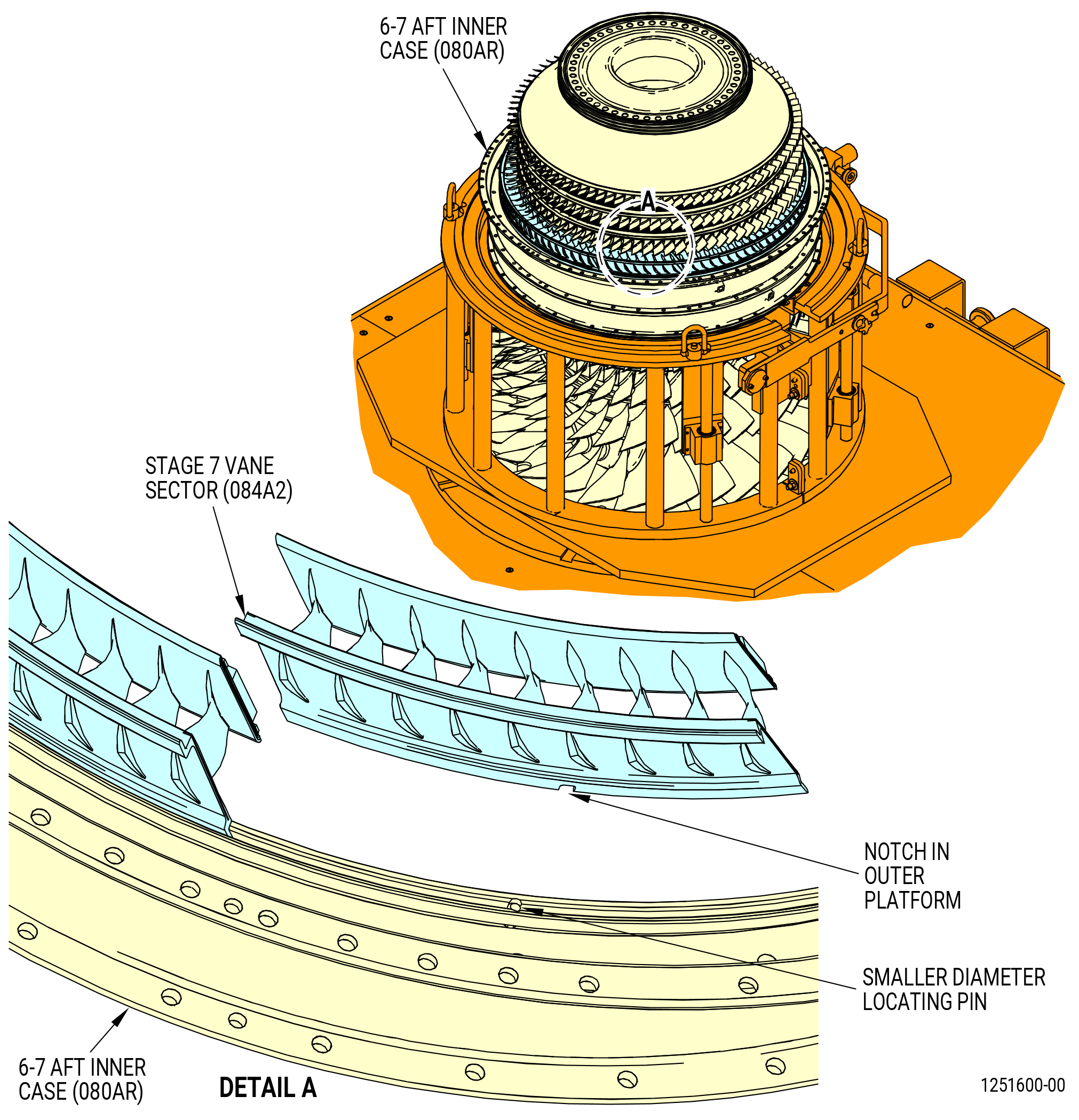
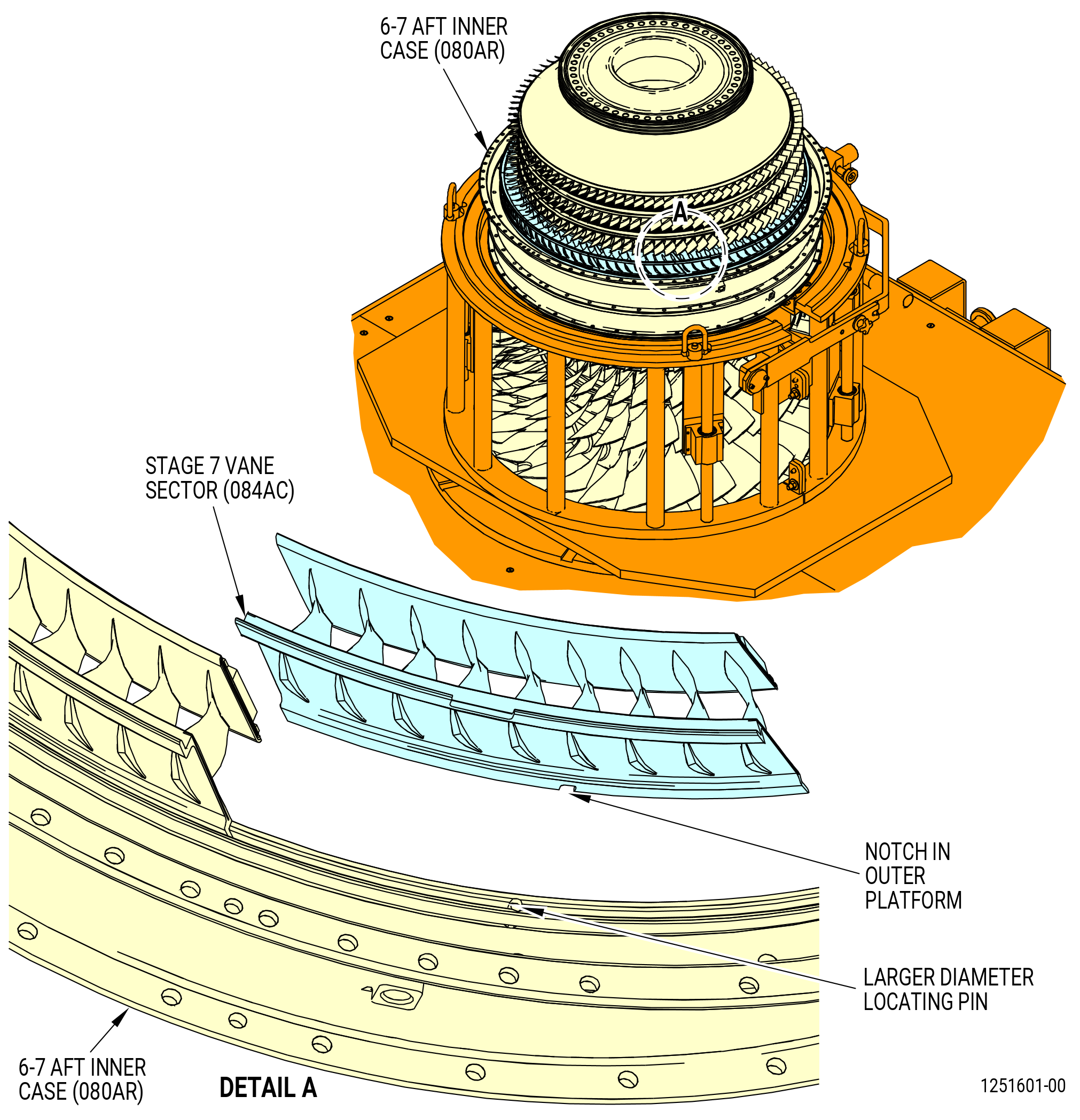
| (1) | Align the notch on the outer platform of the stage 7 vane sector (084AC) with the larger diameter pin on the 6-7 aft inner case at approximately the 10:00 o'clock position and install it on the 6-7 aft inner case. Refer to Figure 1035. |
| NOTE: |
|
| (2) | Align the notch on the outer platform of the stage 7 vane sector (084A2) with the smaller diameter locating pins in the aft groove on the 6-7 aft inner case (080AR). Engage the notch of the stage 7 vane sectors with the smaller diameter pin and install the 10 vane sectors one at a time. Refer to Figure 1034. |
| (3) | Make sure HPC rotor assembly (05000) rotates freely after vane sectors are installed. Listen for clicking noise caused by contact of misplaced guides with HPC blades. |
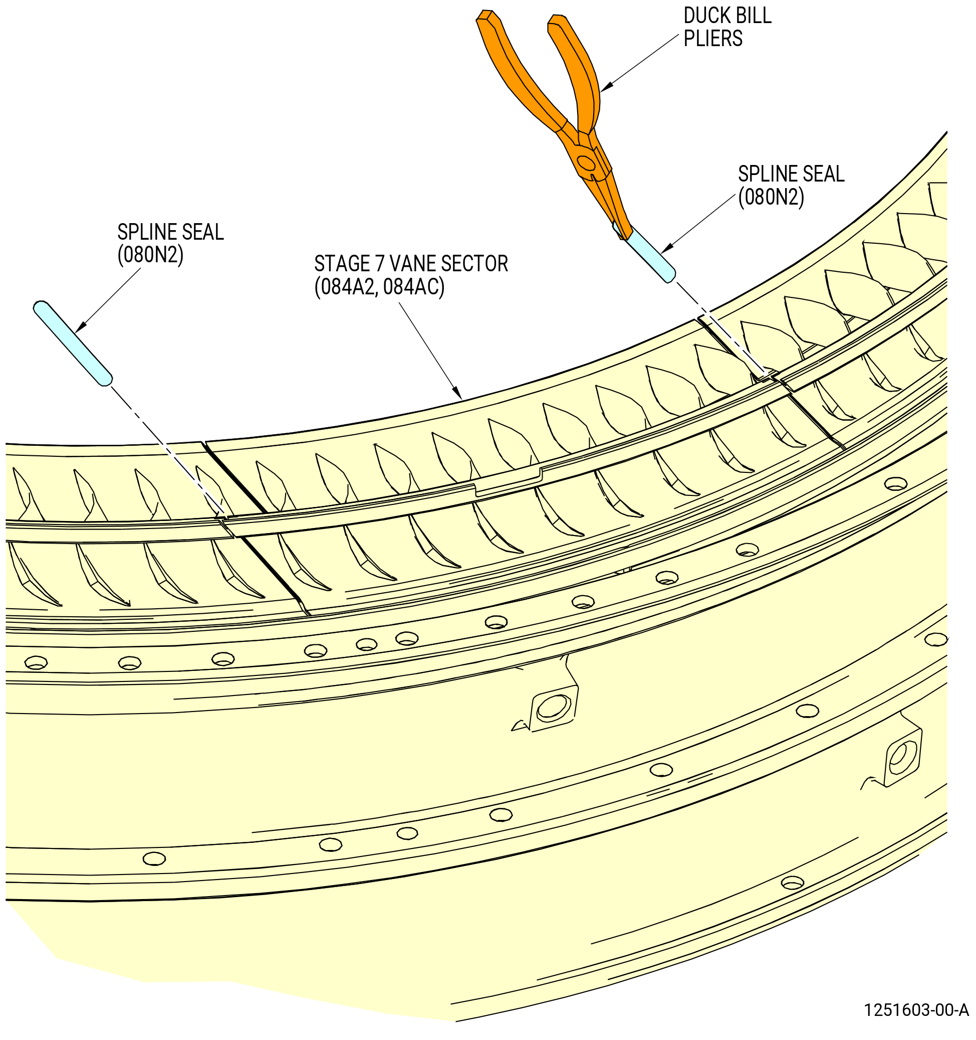
| (4) | Use duckbill pliers to install 11 stage 7 spline seals (spline seals) (080N2) between the stage 7 vane sectors. Refer to Figure 1036. |
| Subtask 72-30-00-440-019 |
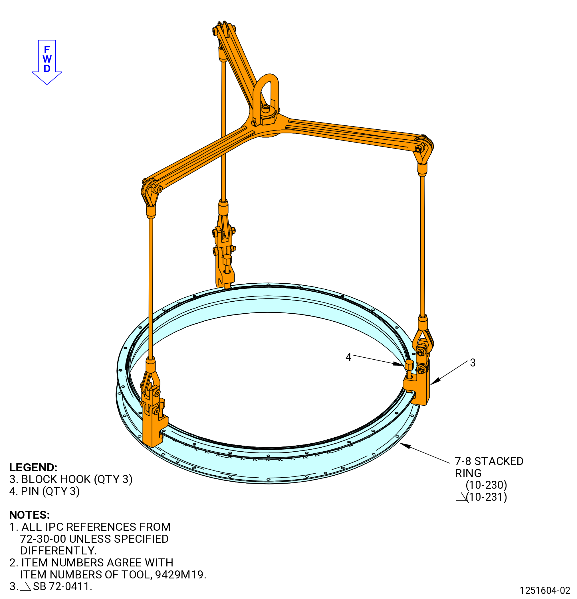
| (5) | Install the stage 7-8 aft case (7-8 stacked ring) (10-230) (SIN 080AS) or (10-231) (SIN 080AS) on the 6-7 aft inner case (10-220) (SIN 080AR) and above the outer platforms of the stage 7 vane segments as follows: |
| (a) | Put the 7-8 stacked ring on a clean work surface as follows. Refer to Figure 1037. |
| 1 | Turn the pins (item 6) of the 9429M19G02 lift fixture CCW to permit installation of the three block hooks (item 3). |
| 2 | Put the three block hooks on the aft outer flange of the 7-8 stacked ring. |
| 3 | Tighten the pins (item 6) CW to attach the block hooks to the aft outer flange of the 7-8 stacked ring. |
| WARNING: |
|
| 4 | Lift the 7-8 stacked ring and put it on a clean work surface, forward side down. |
| 5 | Remove the 9429M19G02 lift fixture from the 7-8 stacked ring. |
| (b) | Install the 11 aft guides (15-110) (SIN 080T6) on the aft outer tangs of the stage 7 vane sectors (084A2, 084AC). Refer to Figure 1038 and do as follows: |
| NOTE: |
|
| NOTE: |
|
| 1 | If necessary, use a rubber mallet, tapered nylon bar, and a mallet to install the aft guides on the aft outer tangs of the stages 7-8 vane sectors. |
| 2 | Make sure that the aft guides do not overlap. |
| 3 | Make sure there is no damage to the aft guides. |
| 4 | Make sure to start the installation of the aft guides on either side of the borescope hole of the stage 7 vane sectors (084A2, 084AC). |
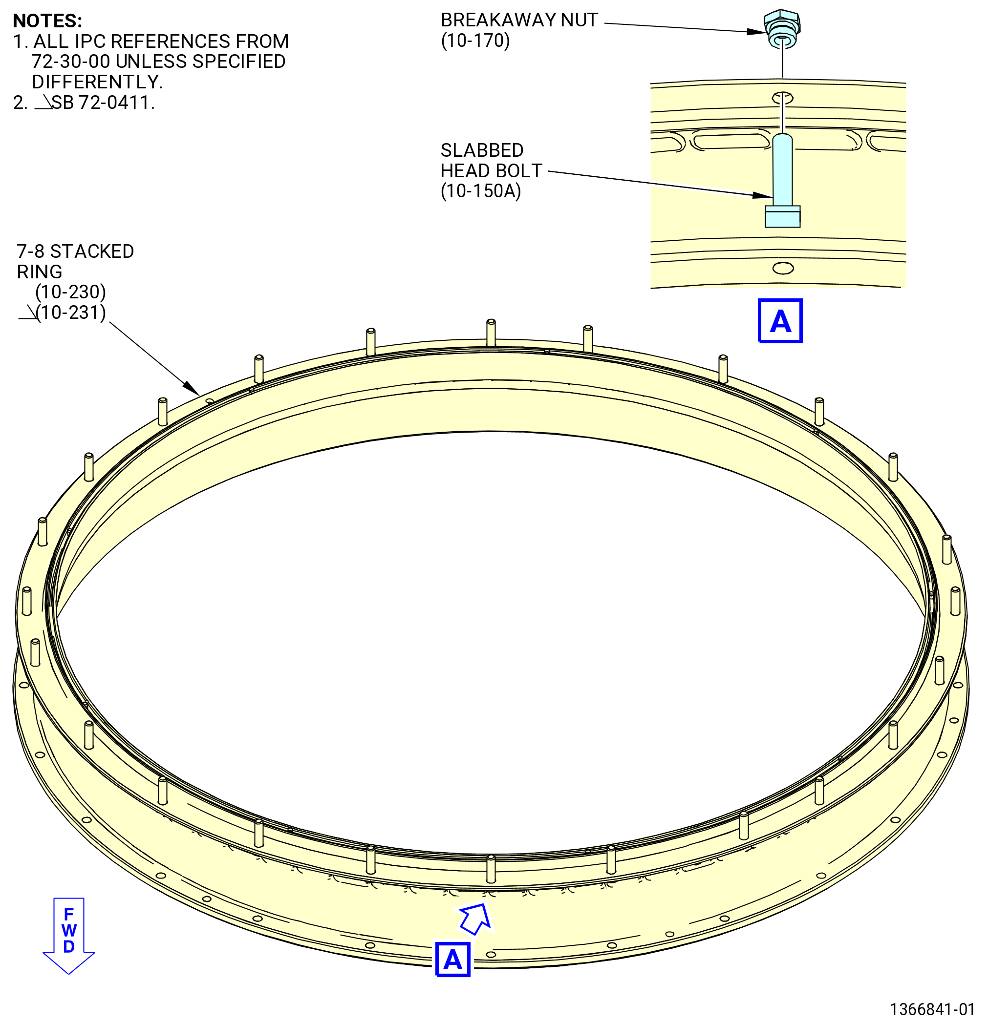
| (c) | Install 21 slab head bolts (10-150) (SIN 080F2) in the twenty-four 0.272 inch (6.91 mm) holes on the aft flange of the 7-8 stacked ring as follows. Refer to Figure 1039. |
| CAUTION: |
|
| 1 | Mark the bolthole and either side of the TVC on the 7-8 stacked ring to align the TVC with the 8-9 aft inner case (080CS). |
| WARNING: |
|
| 2 | Apply C02-058 lubricant to the threads and face surfaces of the 21 slab head bolts (10-150) (SIN 080F2) and 21 breakaway nuts (10-170) (SIN 08040). |
| 3 | Attach the slab head bolts (10-150) (SIN 080F2), boltheads forward, to the 7-8 stacked ring with 21 breakaway nuts (10-170) (SIN 08040). |
| Subtask 72-30-00-440-410 |
| * * * PRE SB 72-0109( Configuration 1 (10-170, 72-30-00) ) |
| 4 | Tighten the breakaway nuts (10-170) (SIN 08040) until the wrenching hex collars break off. |
| NOTE: |
|
| * * * END PRE SB 72-0109 |
| Subtask 72-30-00-440-411 |
| * * * SB 72-0109( Configuration 2 (10-170A, 72-30-00) ) |
| 4.A. | Tighten the breakaway nuts (10-170A) (SIN 08040) until the wrenching hex collars break off. |
| NOTE: |
|
| * * * END SB 72-0109 |
| Subtask 72-30-00-440-412 |
| * * * SB 72-0109( Configuration 3 (10-170B, 72-30-00) ) |
| 4.B. | Tighten the breakaway nuts (10-170B) (SIN 08040) until the wrenching hex collars break off. |
| NOTE: |
|
| * * * END SB 72-0109 |
| 5 | Make sure that the heads of the slabbed head bolts are correctly installed on the 7-8 stacked ring. |
| Subtask 72-30-00-440-413 |
| WARNING: |
|
| (d) | Make sure the mating flanges are clean of all foreign material. If necessary, clean mating flanges with C04-035 isopropyl alcohol to remove foreign material. |
| (e) | Install the nine forward guides (15-070) (SIN 080T7) in the aft groove of the 7-8 stacked ring. Refer to Figure 1038. |
| WARNING: |
|
| CAUTION: |
|
| 1 | Make sure that the mating flanges are clean of all unwanted material. If necessary, clean mating flanges with C04-035 isopropyl alcohol to remove unwanted material. |
| 2 | Install one guide in each of the sectors between the vane sector alignment pins located in the aft groove of the stage 7-8 aft case. |
| NOTE: |
|
| 3 | Make sure that the forward guides do not overlap. |
| 4 | Make sure there is no damage to the aft guides. |
| 5 | Use the 11C4689 installation fixture to install the forward guides in the aft groove of the 7-8 stacked ring. |
| Subtask 72-30-00-440-652 |
| CAUTION: |
|
| (f) | Alternative Procedure Available. Install the 7-8 stacked ring on the 6-7 aft inner case and stage 7 vane sector outer platforms. Refer to Figure 1040 as follows: |
| 1 | Turn the pins (item 6) of the 9429M19G02 lift fixture CCW to permit installation of the three block hooks (item 3). |
| 2 | Put the three block hooks on the aft outer flange of the 7-8 stacked ring. |
| 3 | Tighten the pins (item 6) CW to attach the block hooks to the aft outer flange of the 7-8 stacked ring. |
| 4 | Move the 7-8 stacked ring above the 6-7 aft inner case. |
| 5 | Make sure that the tops of cases being assembled are aligned as flanges touch. |
| 6 | If necessary, use the 11C3363 alignment pin. |
| CAUTION: |
|
| 7 | If adjustment of the flanges is necessary to align the pin again after any contact, fully remove the top stage 5-5 case to make sure that all wear guides are still correctly positioned on the aft tangs of the stage 5 stator vane segments. |
| 8 | Align the 0.250 inch (6.35 mm) elongated hole on the forward flange of the 7-8 stacked ring with the pin on the aft inner flange of the 6-7 aft inner case. Lower the 7-8 stacked ring on the stage 6-7 aft inner case and above the outer platforms of the stage 7 vane sectors. |
| 9 | Remove the lift fixture. |
| Subtask 72-30-00-440-653 |
| CAUTION: |
|
| (f).A. | Alternative Procedure. Install the 7-8 stacked ring on the 6-7 aft inner case and stage 7 vane sector outer platforms. Refer to Figure 1040 as follows: |
| 1 | Turn the pins (item 6) of the 9429M19G02 lift fixture CCW to permit the installation of the three block hooks (item 3). |
| 2 | Put the three block hooks on the aft outer flange of the 7-8 stacked ring. |
| 3 | Tighten the pins (item 6) CW to attach the block hooks to the aft outer flange of the 7-8 stacked ring. |
| 4 | Move the 7-8 stacked ring above the 6-7 aft inner case. |
| 5 | Make sure that the tops of cases being assembled are aligned as flanges touch. |
| 6 | If necessary, use the 11C3363 alignment pin. |
| 7 | Align 6-7 aft inner case and stage 7-8 stacked ring with 11C4688 alignment guides as follows: |
| a | Align the top vertical markings of the stage 7-8 ring and the alignment stage 6-8 guide. |
| b | Insert the three pins of the alignment stage 6-8 guide through three holes of the stage 7-8 ring forward flange. |
| c | Use the pins of the alignment stage 6-8 guide to align the cases before the flanges come in contact. |
| d | Make sure that the tops of the cases being assembled are aligned as flanges touch. |
| e | Remove the alignment stage 6-8 guide. |
| CAUTION: |
|
| 8 | If the adjustment of the flanges is necessary to align the pin again after any contact, fully remove the top stage 5-6 case to make sure that all wear guides are still correctly positioned on the aft tangs of the stage 5 stator vane segments. |
| 9 | Align the 0.250 inch (6.35 mm) elongated hole on the forward flange of the 7-8 stacked ring with the pin on the aft inner flange of the 6-7 aft inner case. Lower the 7-8 stacked ring on the stage 6-7 aft inner case and above the outer platforms of the stage 7 vane sectors. |
| 10 | Remove the lift fixture. |
| Subtask 72-30-00-440-654 |
| CAUTION: |
|
| (g) | Install four HPC stage 7 heat shields (heat shields) (080D3) on the forward flange of the 7-8 stacked ring. Make sure the curved surface of the heat shields face forward. Refer to Figure 1041. |
| (h) | Install the stage 7-8 aft case on the stage 6-7 aft case (080AR) as follows: |
| WARNING: |
|
| 1 | Apply C02-058 lubricant to the threads and friction surfaces of eight self-locking nuts (080K5) and eight bolts (080F5). |
| 2 | Install the eight self-locking nuts and eight bolts equally spaced on the stage 7 flange (every 3rd hole - bolthead aft). |
| 3 | Torque the self-locking nuts to 94-109 lb in. (10.6-12.3 N.m) in a criss-cross pattern. |
| Subtask 72-30-00-220-015 |
| CAUTION: |
|
| 4 | Do a visual inspection of the forward guides (15-070) (SIN 080T7) for damage. Make sure the aft guides are not crushed, extruded, or have come loose. |
| Subtask 72-30-00-440-405 |
| 5 | Turn compressor rotor CCW to make sure that there are no misplaced guides. Misplaced guides will make a clicking noise when contacting with the HPC blades. |
| CAUTION: |
|
| 6 | Use a borescope to make sure that each wear guide is seated correctly. |
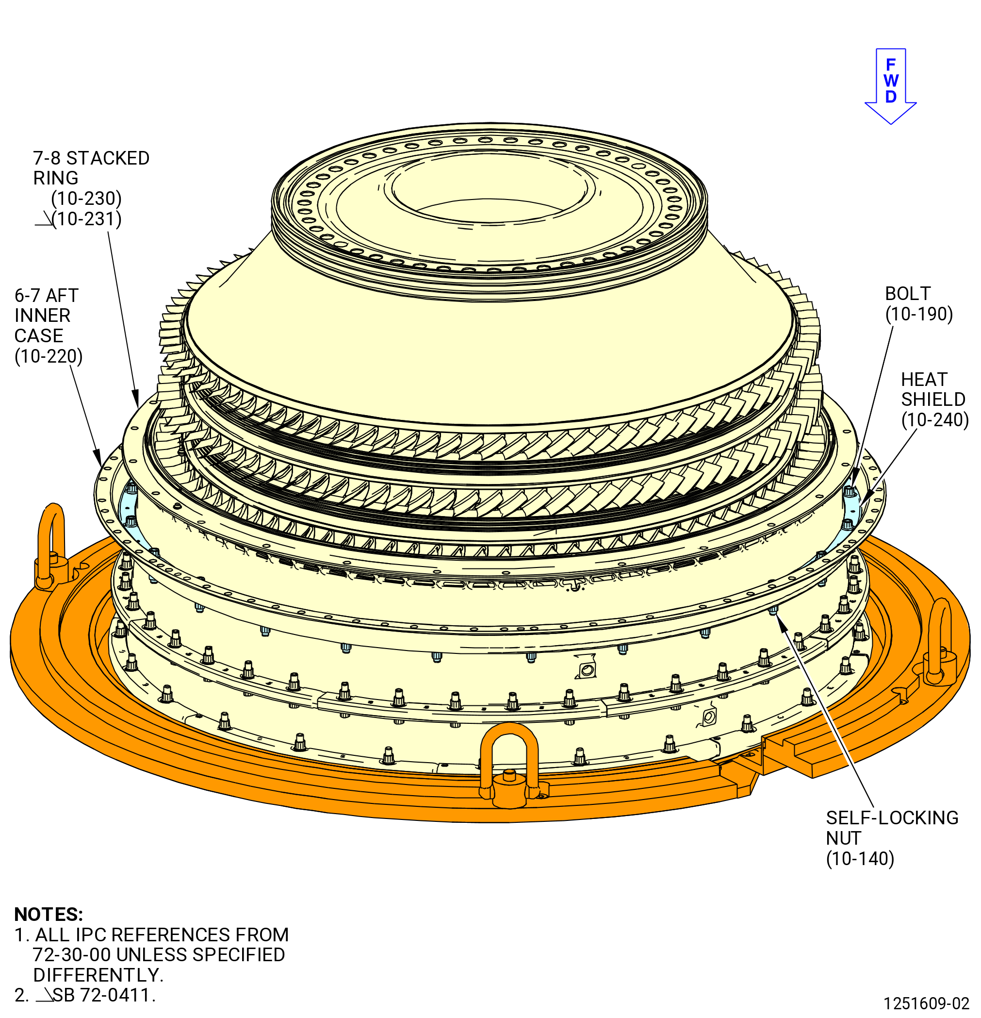
| 7 | Loosen the eight self-locking nuts (10-140) (SIN 080K5) and bolts (10-190) (SIN 080F5) on the flange of the 7-8 stacked ring (10-230) (SIN 080AS) or (10-231) (SIN 080AS) to remove the clamp on the flange joint. Do not remove the self-locking nuts from the flange. |
| Subtask 72-30-00-440-406 |
| (i) | Attach the 7-8 stacked ring (10-230) (SIN 080AS) or (10-231) (SIN 080AS) to the 6-7 stacked ring (10-220) (SIN 080AR) as follows. Refer to Figure 1040 and Figure 1041. |
| WARNING: |
|
| 1 | Apply C02-058 lubricant to the threads and friction surfaces of the remaining 16 self-locking nuts (080K5) and 16 bolts (080F5). |
| 2 | Install the remaining 16 self-locking nuts (080K5) and 16 bolts (080F5) into the remaining open locations of the stage 6-7 flange (bolthead aft). |
| 3 | Torque all 24 self-locking nuts to 124-146 lb in. (14.0-16.5 N.m) in a criss-cross pattern. |
| 4 | Do a final torque to all 24 self-locking nuts to 124-146 lb in. (14.0-16.5 N.m) in a circle pattern. |
|
|
| Subtask 72-30-00-440-020 |
| G. | Install the stage 8 HPC vane (stage 8 vane sectors) (084A3, 084AD) as follows: |
| NOTE: |
|
| (1) | Install the nine stage 8 spline seals (spline seals) (080NP) in the recess on the outer platforms of the stage 8 vane sectors. Refer to Figure 1042. |
| NOTE: |
|
| (2) | Align the notch on outer platform of the stage 8 vane sector (084AD) with the larger diameter pin on the 7-8 stacked ring at approximately the 11:00 o'clock position and install it on the 7-8 aft inner case. Refer to Figure 1043. |
| NOTE: |
|
| (3) | Align the notch on the outer platforms of the stage 8 vane sector (15-080) (SIN 084A3) with the smaller diameter locating pins in the aft groove on the 7-8 stacked ring (10-230) (SIN 080AS) or (10-231) (SIN 080AS). Engage the notch of the stage 8 vane sectors with the smaller diameter pin and install the eight vane sectors one at a time. Refer to Figure 1042. |
| NOTE: |
|
| (4) | Make sure the compressor rotor turns freely after vane sectors are installed. Listen for a clicking noise caused by contact of misplaced guides with HPC blades. |
| CAUTION: |
|
| (5) | Use duckbill pliers to install nine compressor stator spline seals (spline seals) (080NP) in the slots at the ends of the stage 8 vane sectors (084A3, 084AD). Refer to Figure 1043 and Figure 1044. |
| Subtask 72-30-00-440-021 |
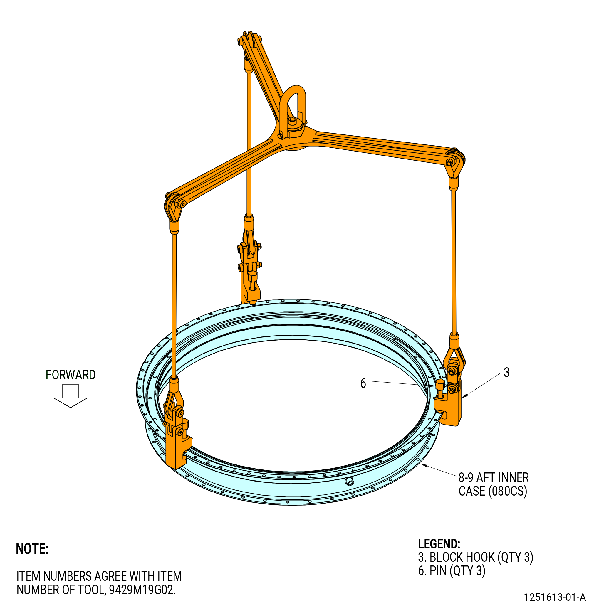
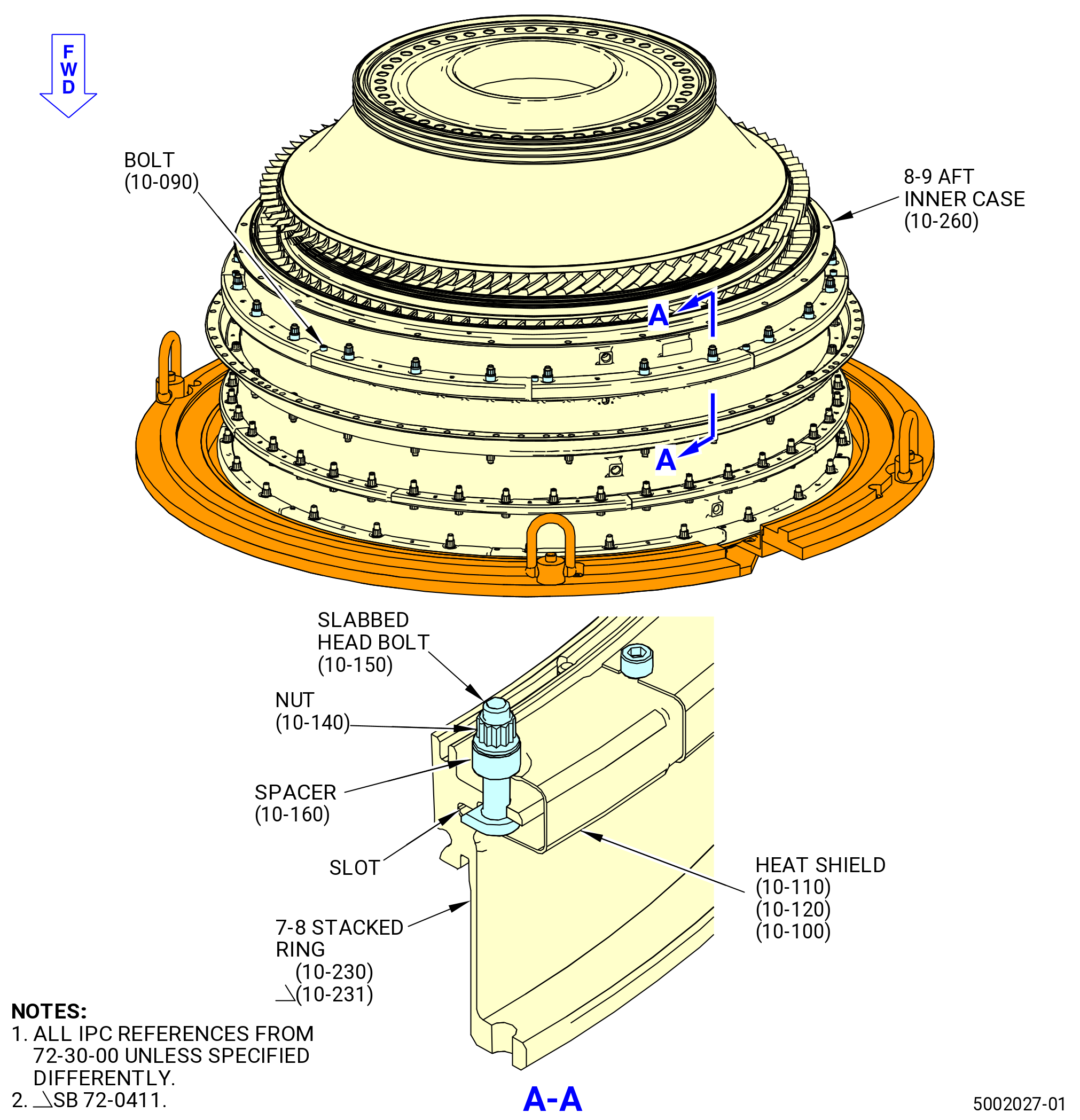
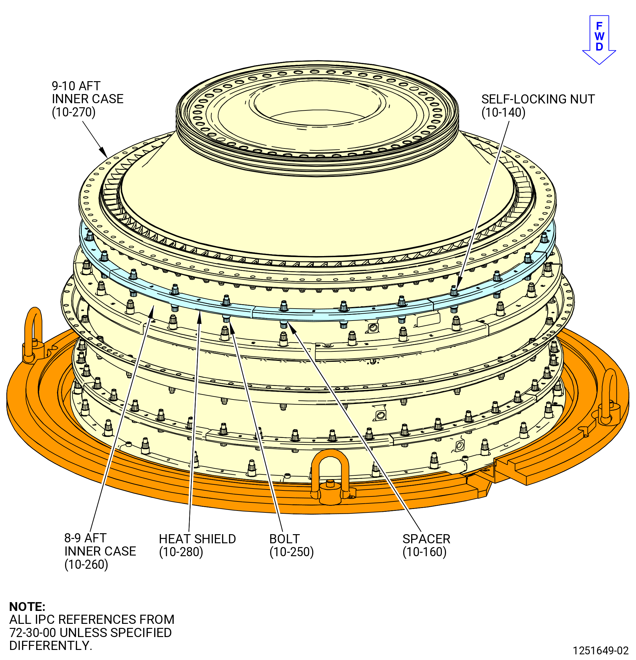
| (6) | Install the stage 8-9 aft case (8-9 aft inner case) (10-260) (SIN 080CS) on the 7-8 stacked ring (10-230) (SIN 080AS) or (10-231) (SIN 080AS) and above the outer platforms of the stage 8 vane segments as follows: |
| (a) | Put the 8-9 aft inner case on a clean work surface as follows. Refer to Figure 1044. |
| 1 | Turn the pins (item 6) of the 9429M19G02 lift fixture CCW to permit installation of the three block hooks (item 3). |
| 2 | Put the three block hooks on the aft flange of the 8-9 aft inner case. |
| 3 | Tighten the pins (item 6) CW to attach the block hooks to the aft flange of the 8-9 aft inner case. |
| WARNING: |
|
| 4 | Lift the 8-9 aft inner case and put it on a clean work surface, forward side down. |
| 5 | Remove the 9429M19G02 lift fixture from the 8-9 aft inner case. |
| CAUTION: |
|
| (b) | Install the nine aft guides (15-060) (SIN 080T8) on the aft outer tangs of the stage 8 vane sectors (084A3, 084AD). Refer to Figure 1044. |
| NOTE: |
|
| NOTE: |
|
| 1 | If necessary, use a rubber mallet to install the aft guides on the aft outer tangs of the stage 8 vane sectors. |
| 2 | Make sure that the nine aft guides are centered on the vane sector gaps. |
| 3 | Make sure that the aft guides do not overlap. |
| 4 | Make sure there is no damage to the aft guides. |
| (c) | Install three slab head bolts (10-150) (SIN 080F2) in the TVC holes 8-9 aft inner case and aft flange of the 7-8 stacked ring as follows: |
| CAUTION: |
|
| 1 | Apply C02-058 lubricant to the threads and face surfaces of the three slab head bolts (10-150) (SIN 080F2) and three breakaway nuts (10-170) (SIN 08040). |
| 2 | Attach the three slab head bolts (10-150) (SIN 080F2) to the TVC holes of the 8-9 aft inner case with three breakaway nuts (10-170) (SIN 08040). |
| Subtask 72-30-00-440-414 |
| * * * PRE SB 72-0109( Configuration 1 (10-170, 72-30-00) ) |
| 3 | Tighten the breakaway nuts (10-170) (SIN 08040) until the wrenching hex collars break off. |
| NOTE: |
|
| * * * END PRE SB 72-0109 |
| Subtask 72-30-00-440-415 |
| * * * SB 72-0109( Configuration 2 (10-170A, 72-30-00) ) |
| 3.A. | Tighten the breakaway nuts (10-170A) (SIN 08040) until the wrenching hex collars break off. |
| NOTE: |
|
| * * * END SB 72-0109 |
| Subtask 72-30-00-440-416 |
| * * * SB 72-0109( Configuration 3 (10-170B, 72-30-00) ) |
| 3.B. | Tighten the breakaway nuts (10-170B) (SIN 08040) until the wrenching hex collars break off. |
| NOTE: |
|
| * * * END SB 72-0109 |
| 4 | Make sure that the heads of the slabbed head bolts and the breakaway nuts (10-170) (SIN 08040) are correctly installed on the 8-9 aft inner case. |
| Subtask 72-30-00-440-417 |
| (d) | Install the nine forward guides (15-030) (SIN 080T9) in the aft groove of the 8-9 aft inner case. Refer to Figure 1044. |
| (e) | Install one guide in each of the sectors between the vane sector alignment pins located in the aft groove of the stage 8-9 aft case. |
| NOTE: |
|
| WARNING: |
|
| CAUTION: |
|
| 1 | Make sure that the mating flanges are clean of all unwanted material. If necessary, clean mating flanges with C04-035 isopropyl alcohol to remove unwanted material. |
| 2 | Install one guide in each of the sectors between the vane sector alignment pins located in the aft groove of the stage 8-9 aft case. |
| 3 | Make sure that the forward guides do not overlap. |
| 4 | Make sure there is no damage to the forward guides. |
| 5 | Use the 11C4689 installation fixture to install the forward guides in the aft groove of the stage 8-9 aft inner case, between the pins. |
| WARNING: |
|
| (f) | Make sure the mating flanges are clean of all foreign material. If necessary, clean mating flanges with C04-035 isopropyl alcohol to remove foreign material. |
| CAUTION: |
|
| (g) | Install the 8-9 aft inner case on the 7-8 stacked ring and stage 8 vane sector outer platforms as follows. Refer to Figure 1046. |
| 1 | Turn the pins (item 6) of the 9429M19G02 lift fixture CCW to permit installation of the three block hooks (item 3). |
| 2 | Put the three block hooks on the aft outer flange of the 8-9 aft inner case. |
| 3 | Tighten the pins (item 6) CW to attach the block hooks to the aft outer flange of the 8-9 aft inner case. |
| 4 | Move the 8-9 aft inner case above the 7-8 stacked ring. |
| 5 | Make sure that the tops of cases being assembled are aligned as flanges touch. |
| 6 | If necessary, use the 11C3363 alignment pin. |
| CAUTION: |
|
| 7 | If adjustment of the flanges is necessary to align the pin again after any contact, fully remove the top stage 5-5 case to make sure that all wear guides are still correctly positioned on the aft tangs of the stage 5 stator vane segments. |
| 8 | Find the mark on the circumferential bolt flange of the 8-9 aft inner case and align it with the 0.250 inch (6.35 mm) elongated hole on the aft flange of the 7-8 stacked ring. Lower the 8-9 aft inner case on the 7-8 stacked ring and above the outer platforms of the stage 8 vane sectors. |
| 9 | Remove the lift fixture. |
| CAUTION: |
|
| (h) | Install the stage 8-9 aft inner case on the 7-8 stacked ring (10-230) (SIN 080AS) or (10-231) (SIN 080AS) as follows: |
| CAUTION: |
|
| 1 | Apply C02-058 lubricant to the threads and friction surfaces of eight self-locking nuts (080K5). |
| 2 | Install the eight self-locking nuts with spacers (080TC) equally spaced on the slabbed head bolts (080F2). |
| 3 | Torque the self-locking nuts to 94-109 lb in. (10.6-12.3 N.m) in a criss-cross pattern. |
| Subtask 72-30-00-220-016 |
| CAUTION: |
|
| 4 | Do a visual inspection of the forward guides (15-070) (SIN 080T7) for damage. Make sure the aft guides are not crushed, extruded, or have come loose. |
| Subtask 72-30-00-440-407 |
| 5 | Turn compressor rotor CCW to make sure that there are no misplaced guides. Misplaced guides will make a clicking noise when contacting with the HPC blades. |
| CAUTION: |
|
| 6 | Use a borescope to make sure that each wear guide is seated correctly. |
| 7 | Loosen the eight self-locking nuts (080K5) and spacers (080TC) on the flange of the 8-9 stacked ring (080CS) to remove the clamp on the flange joint. Do not remove the self-locking nuts from the flange. |
| Subtask 72-30-00-440-408 |
| (i) | Install eight HPC stage 8 heat shields (heat shields) (080D5, 080D6, 080D7) on the flange of the 8-9 aft inner case and 7-8 stacked ring as follows. Refer to Figure 1047, Figure 1048, and Figure 1048A. |
| 1 | Find the mark on the circumferential bolt flange of the 8-9 aft inner case. |
| 2 | Use the mark as a guide and put the first heat shield (080D5) at this location. |
| 3 | Continue in a CW direction (ALF) and put heat shield (10-120) (SIN 080D6), heat shield (10-100) (SIN 080D7), heat shield (10-110) (SIN 080D5), heat shield (10-120) (SIN 080D6), heat shield (10-110) (SIN 080D5), heat shield (10-100) (SIN 080D7), and then heat shield (10-110) (SIN 080D5) on the flange. Make sure the heat shields are tight in the slot at the aft end of the 7-8 stacked ring (10-230) (SIN 080AS) or (10-231) (SIN 080AS). |
| WARNING: |
|
| 4 | Apply C02-058 lubricant to the threads and friction surfaces of eight bolts (080FS). |
| 5 | Attach the heat shields (080D5, 080D6, 080D7) to the flange of the 8-9 aft inner case with eight bolts (080FS). |
| 6 | Torque the eight bolts (080FS) to 32-38 lb in. (3.6-4.3 N.m) in a criss-cross pattern. |
| (j) | Attach the 8-9 aft inner case (10-260) (SIN 080CS) to the 7-8 stacked ring (10-230) (SIN 080AS) or (10-231) (SIN 080AS) as follows. Refer to Figure 1047, Figure 1048, and Figure 1048A. |
| WARNING: |
|
| 1 | Apply C02-058 lubricant to the threads and friction surfaces of the remaining 16 self-locking nuts (080K5). |
| 2 | Torque the first installed eight self-locking nuts to 94-109 lb in. (10.6-12.3 N.m) in a criss-cross pattern. |
| 3 | Torque the first eight self-locking nuts again to 124-146 lb in. (14.0-16.5 N.m) in a criss-cross pattern. |
| 4 | Install the remaining 16 self-locking nuts (080K5) with spacers (080TC) on the slabbed head bolts (10-150) (SIN 080F2) or slabbed head bolts (10-150A) (SIN 080F2). |
| 5 | Torque all 24 self-locking nuts to 124-146 lb in. (14.0-16.5 N.m) in a criss-cross pattern. |
| 6 | Do a final torque to all 24 self-locking nuts to 124-146 lb in. (14.0-16.5 N.m) in a circle pattern. |
| 7 | Do a final torque to the eight heat shield bolts (080FS) to 32-38 lb in. (3.6-4.3 N.m) in a circle pattern. |
|
|
| Subtask 72-30-00-440-022 |
| CAUTION: |
|
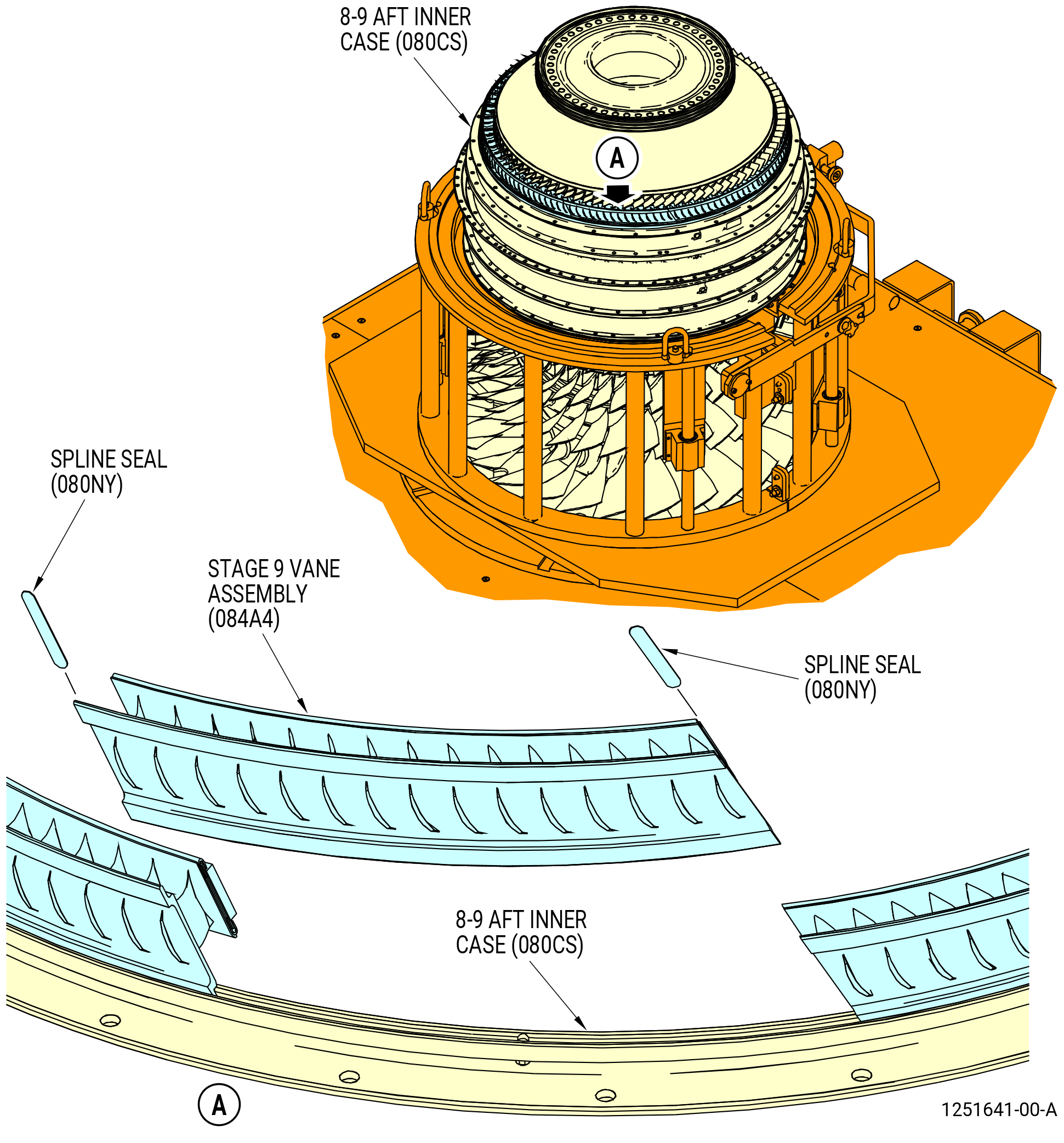
| H. | Install the nine stage 9 HPC vane (stage 9 vane assemblies) (084A4) as follows. Refer to Figure 1049. |
| (1) | Install the stage 9 vane assemblies on the 8-9 aft inner case (080CS) as follows: |
| (a) | Install the spline seals (080NY) in the recess on the outer platforms of the vane assemblies. |
| NOTE: |
|
| (b) | Align the notch in the outer platform of the stage 9 vane assemblies with the pin in the aft groove of the 8-9 aft inner case and install the stage 9 vane assemblies on the 8-9 aft inner case one at a time. |
| NOTE: |
|
| (c) | Make sure that the HPC rotor assembly (05000) turns freely. |
| (d) | Make sure that the nine spline seals are correctly installed between all stage 9 vane assemblies. |
| (2) | Make sure that the compressor rotor turns freely after the vane sectors are installed. Listen for a clicking noise caused by contact of misplaced guides with HPC blades. |
| Subtask 72-30-00-440-023 |
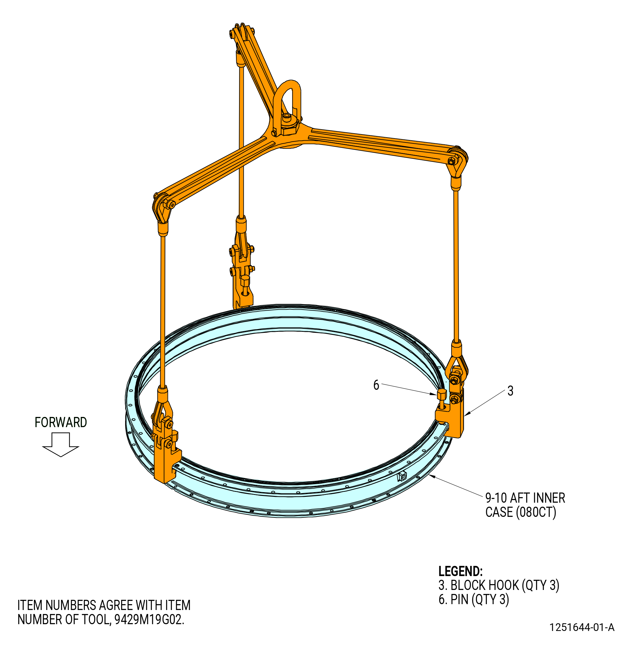
| (3) | Install the stage 9-10 case (9-10 aft inner case) (080CT) on the 8-9 aft inner case (080CS) and above the outer platforms of the stage 9 HPC vanes (stage 9 vane assemblies) (084A4) as follows: |
| (a) | Put the 9-10 aft inner case on a clean work surface as follows. Refer to Figure 1050. |
| 1 | Turn the pins (item 6) of the 9429M19G02 lift fixture CCW to permit installation of the three block hooks (item 3). |
| 2 | Put the three block hooks on the aft flange of the 9-10 aft inner case. |
| 3 | Tighten the pins (item 6) CW to attach the block hooks to the aft flange of the 9-10 aft inner case. |
| WARNING: |
|
| 4 | Lift the 9-10 aft inner case and put it on a clean work surface, forward side down. |
| 5 | Remove the 9429M19G02 lift fixture from the 9-10 aft inner case. |
| (b) | Install the nine aft guides (15-020) (SIN 080T0). Refer to Figure 1051 and do as follows: |
| NOTE: |
|
| NOTE: |
|
| 1 | Install the nine aft guides on the aft outer tangs of the stage 9 vane sectors. |
| 2 | If necessary, use a rubber mallet to install the aft guides on the outer tangs of the stage 9 vane sectors. |
| 3 | Make sure that the nine aft guides are centered on the vane sector gaps. |
| 4 | Make sure that the aft guides do not overlap. |
| 5 | Make sure there is no damage to the aft guides. |
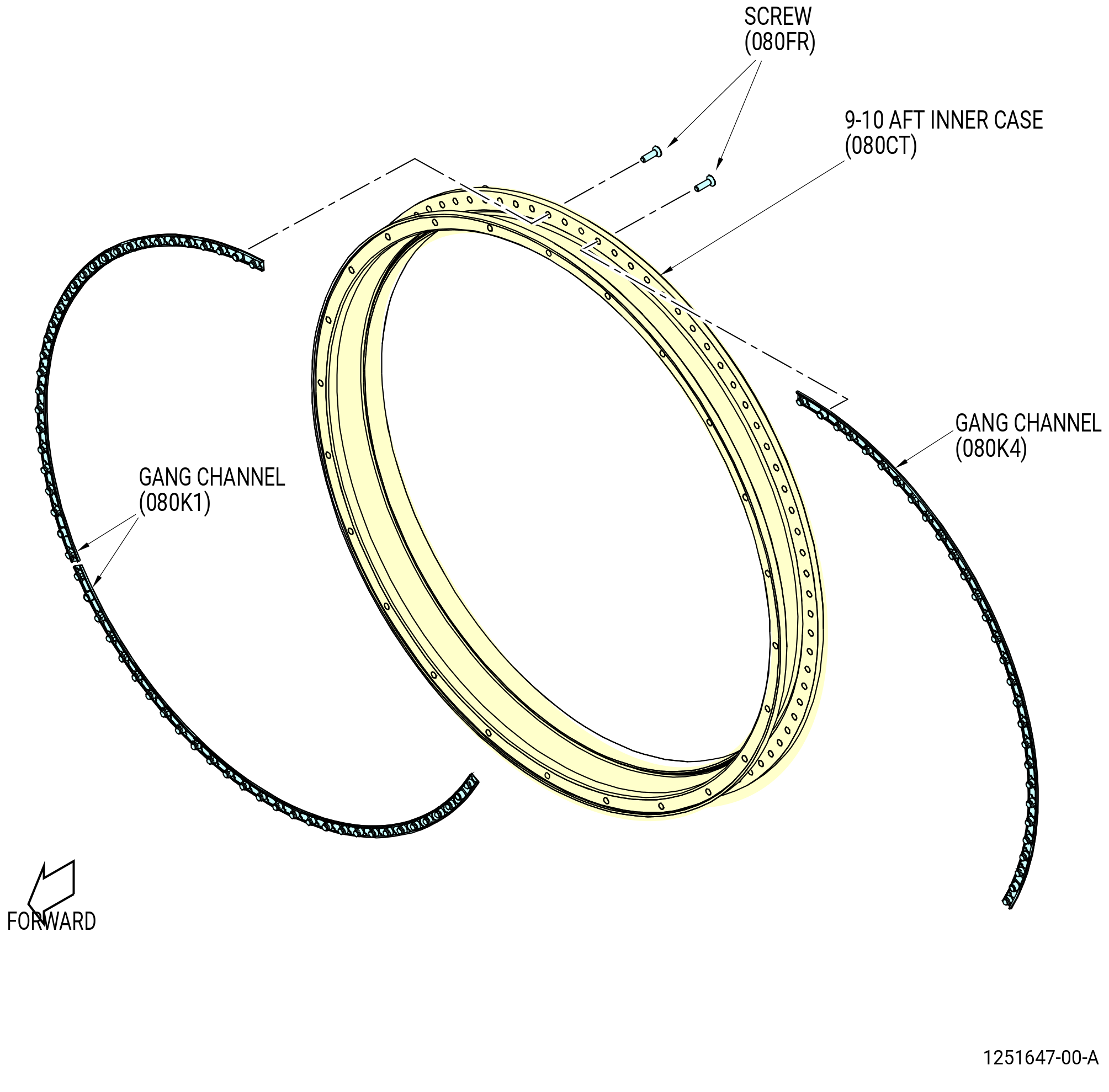
| (c) | Install three self-locking nut assemblies (gang channels) (080K1 QTY 2, and 080K4 QTY 1) as follows. Refer to Figure 1052. |
| 1 | Put the gang channels on the forward face of the aft flange of the 9-10 aft inner case. |
| WARNING: |
|
| 2 | Apply C02-058 lubricant to the threads and friction surfaces of nine screws (080FR). |
| 3 | Attach the three gang channels (080K1) with nine screws (080FR). |
| 4 | Torque the screws to 60-70 lb in. (6.8-7.9 N.m). |
| Subtask 72-30-00-440-655 |
| CAUTION: |
|
| (d) | Alternative Procedure Available. Install the 9-10 aft inner case on the 8-9 aft inner case and stage 9 vane assemblies outer platforms. Refer to Figure 1053 as follows: |
| 1 | Turn the pins (item 6) of the 9429M19G02 lift fixture CCW to permit installation of the three block hooks (item 3). |
| 2 | Put the three block hooks on the aft flange of the 9-10 aft inner case. |
| 3 | Tighten the pins (item 6) CW to attach the block hooks to the aft flange of the 9-10 aft inner case. |
| 4 | Move the 9-10 aft inner case above the 8-9 aft inner case. |
| 5 | Make sure that the tops of cases being assembled are aligned as flanges touch. |
| 6 | If necessary, use the 11C3363 alignment pin. |
| CAUTION: |
|
| 7 | If flanges require adjustment to align the pin again after any contact, fully remove top the stage 5-5 case to make sure that all wear guides are still correctly positioned on the aft tangs of the stage 5 stator vane segments. |
| 8 | Align the pin on the forward flange of the 9-10 aft inner case with the 0.250 inch (6.35 mm) elongated hole on the aft flange of the 8-9 aft inner case. Lower the 9-10 aft inner case on the 8-9 aft inner case and above the outer platforms of the stage 9 vane assemblies. |
| 9 | Remove the lift fixture. |
| Subtask 72-30-00-440-656 |
| CAUTION: |
|
| (d).A. | Alternative Procedure. Install the 9-10 aft inner case on the 8-9 aft inner case and stage 9 vane assemblies outer platforms. Refer to Figure 1053 as follows: |
| 1 | Turn the pins (item 6) of the 9429M19G02 lift fixture CCW to permit the installation of the three block hooks (item 3) |
| 2 | Put the three block hooks on the aft flange of the 9-10 aft inner case. |
| 3 | Tighten the pins (item 6) CW to attach the block hooks to the aft flange of the 9-10 aft inner case. |
| 4 | Move the 9-10 aft inner case above the 8-9 aft inner case. |
| 5 | Make sure that the tops of cases being assembled are aligned as flanges touch. |
| 6 | If necessary, use the 11C3363 alignment pin. |
| 7 | Align 8-9 aft inner case and stage 9-10 aft inner case with 11C4688 alignment guides as follows: |
| a | Align the top vertical markings of the stage 9-10 aft inner case and the alignment stage 8-10 guide. |
| b | Insert the three pins of the alignment stage 8-10 guide through three holes of the stage 9-10 aft inner case forward flange. |
| c | Use the pins of the alignment stage 8-10 guide to align the cases before the flanges come in contact. |
| d | Make sure that the tops of the cases being assembled are aligned as flanges touch. |
| e | Remove the alignment stage 8-10 guide. |
| CAUTION: |
|
| 8 | If adjustment of the flanges is necessary to align the pin again after any contact, fully remove top the stage 5-6 case to make sure that all wear guides are still correctly positioned on the aft tangs of the stage 5 stator vane segments. |
| 9 | Align the pin on the forward flange of the 9-10 aft inner case with the 0.250 inch (6.35 mm) elongated hole on the aft flange of the 8-9 aft inner case. Lower the 9-10 aft inner case on the 8-9 aft inner case and above the outer platforms of the stage 9 vane assemblies. |
| 10 | Remove the lift fixture. |
| Subtask 72-30-00-440-657 |
| CAUTION: |
|
| (e) | Install the stage 9-10 aft inner case on the stage 8-9 aft case (080CS) as follows: |
| WARNING: |
|
| 1 | Apply C02-058 lubricant to the threads and friction surfaces of eight machine bolts (bolts) (080F6) and eight self-locking nuts (080K5). |
| 2 | Install the eight bolts (080F6), boltheads forward, with eight spacers (080TC) and eight self-locking nuts (080K5) equally spaced in the 9-10 aft inner case and the 8-9 aft inner case mating flanges. |
| 3 | Tighten the eight self-locking nuts (080K5) to install the 9-10 aft inner case. Do not torque at this time. |
| Subtask 72-30-00-220-017 |
| CAUTION: |
|
| 4 | Do a visual inspection of the aft guides (15-020) (SIN 080T0) and forward guides (15-030) (SIN 080T9) for damage. Make sure the aft guides are not crushed, extruded, or have come loose. |
| 5 | Turn compressor rotor CCW to make sure that there are no misplaced guides. Misplaced guides will make a clicking noise when contacting with the HPC blades. |
| CAUTION: |
|
| 6 | Use a borescope to make sure that each wear guide is seated correctly. |
| 7 | Remove the eight self-locking nuts (080K5), bolts (080F6) and spacers (080TC) from the 9-10 stacked ring (080CT) |
| Subtask 72-30-00-440-409 |
| (f) | Install the eight heat shields (080D4) above the 9-10 aft inner case and the 8-9 aft inner case mating flanges. Make sure that the boltholes are aligned. Refer to Figure 1054. |
| (g) | Attach the 9-10 aft inner case (080CT) to the 8-9 aft inner case (080Cs) as follows. Refer to Figure 1053 and Figure 1054. |
| WARNING: |
|
| 1 | Apply C02-058 lubricant to the threads and friction surfaces of 24 self-locking nuts (080K5) and 24 bolts (080F6). |
| 2 | Install the eight self-locking nuts, eight bolts, and eight spacers again under the bolt heads equally spaced on the stage 9 flange (every 3rd hole - bolthead forward). |
| 3 | Torque the eight self-locking nuts to 94-109 lb in. (10.6-12.3 N.m) in a criss-cross pattern. |
| 4 | Torque the eight self-locking nuts again to 124-146 lb in. (14.0-16.5 N.m) in a criss-cross pattern. |
| 5 | Install the remaining 16 self-locking nuts (080K5), 16 bolts (080F6), and 16 spacers (080TC) under the boltheads into the remaining open locations of the stage 9-10 flange (bolthead forward). |
| 6 | Torque all 24 self-locking nuts to 124-146 lb in. (14.0-16.5 N.m) in a criss-cross pattern. |
| 7 | Do a final torque to all 24 self-locking nuts to 124-146 lb in. (14.0-16.5 N.m) in a circle pattern. |
| Subtask 72-30-00-440-024 |
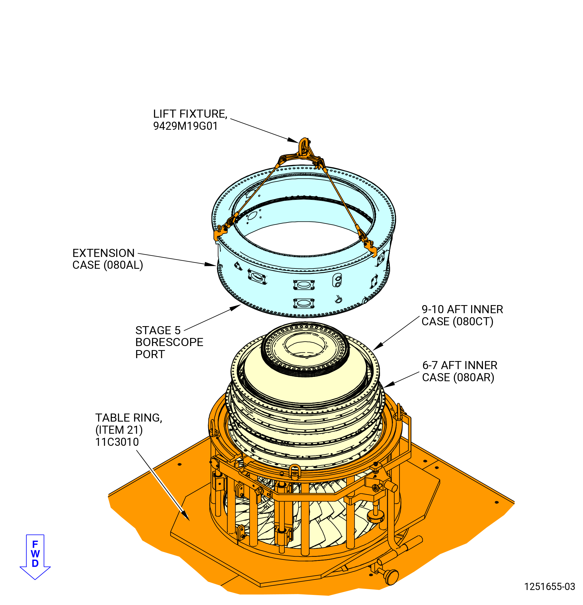
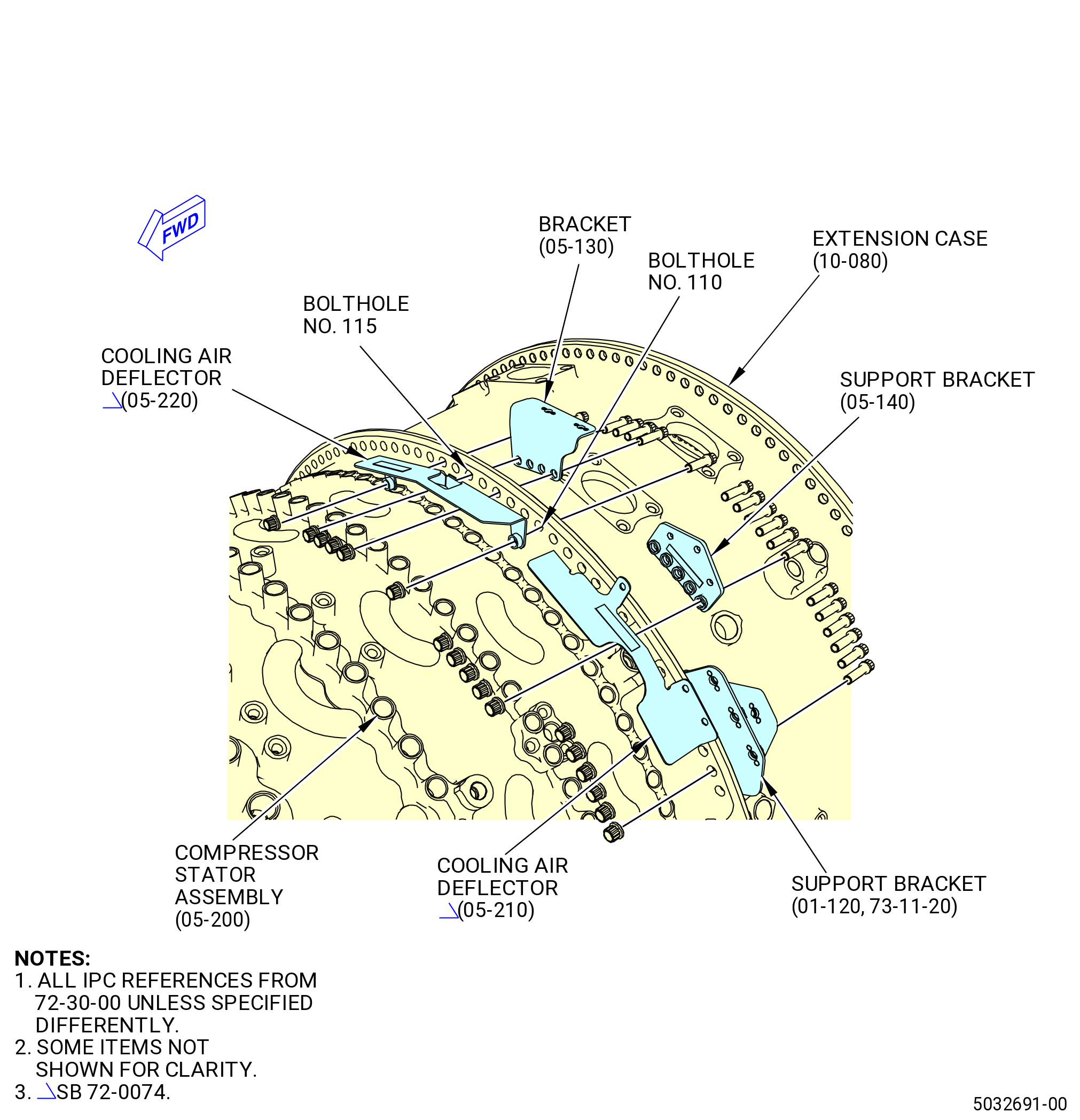
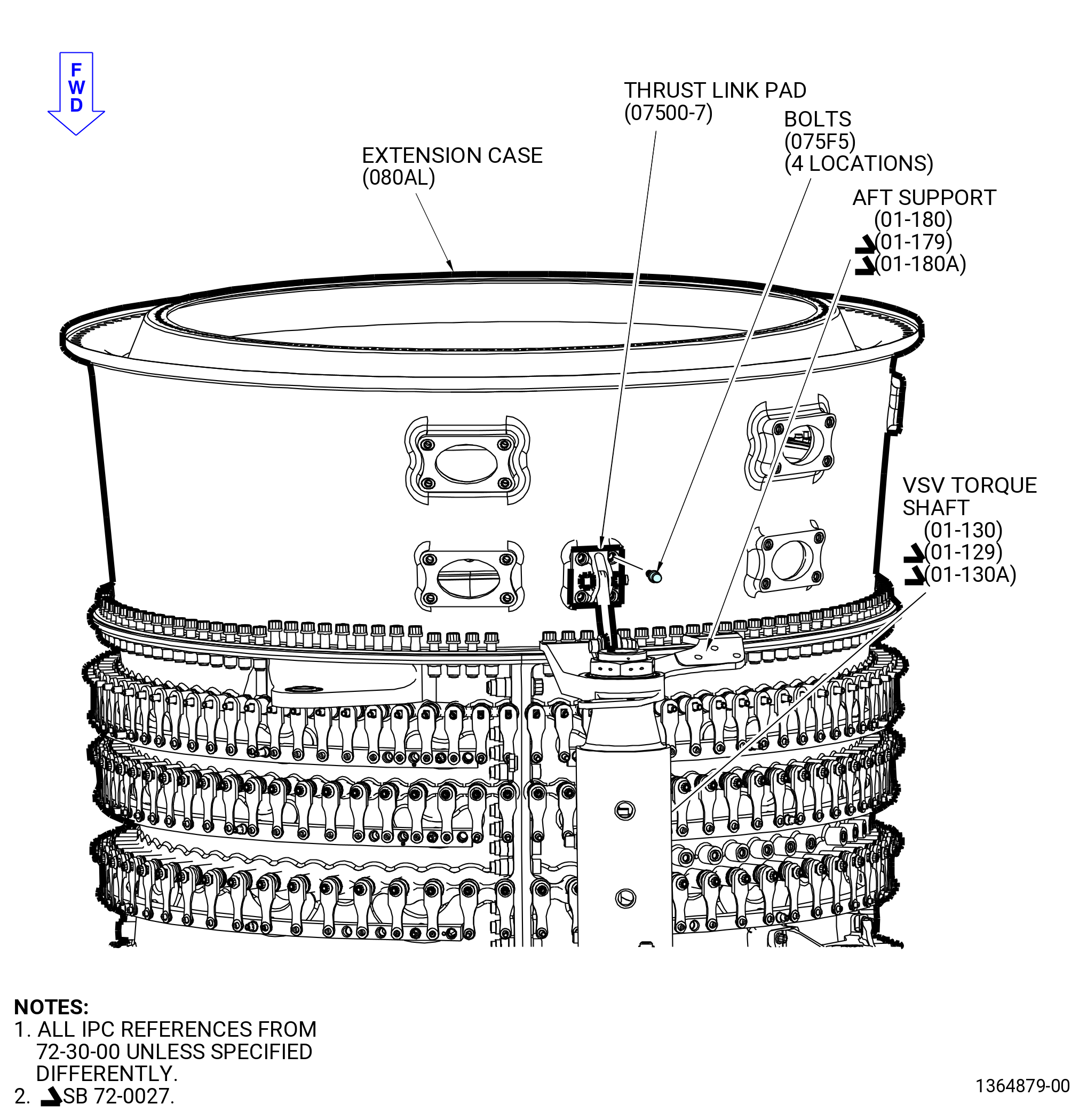
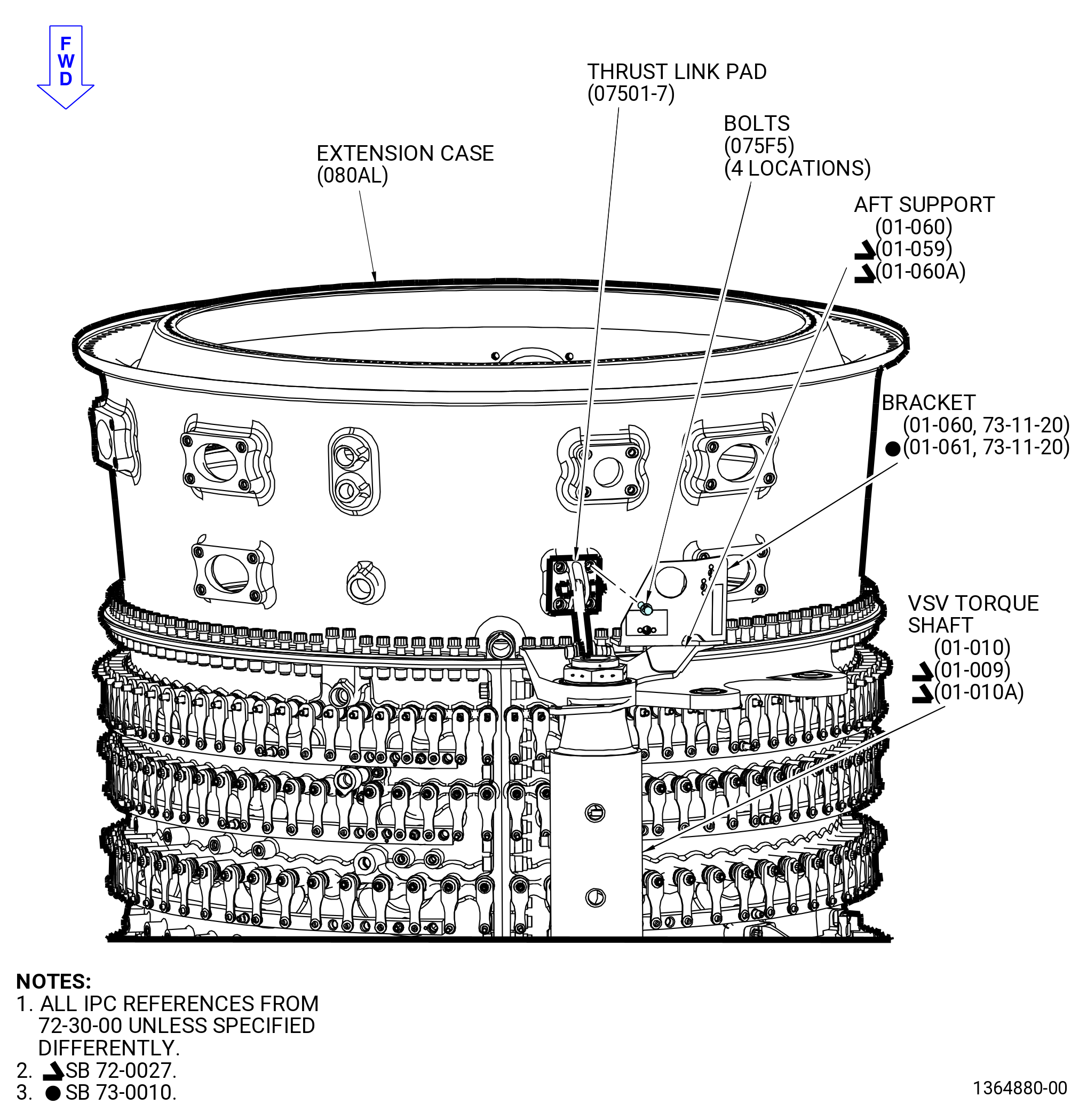
| I. | Install the HPC rear extension case (extension case) (080AL) on the 6-7 aft inner case (080AR), 9-10 aft inner case (080CT), and HPC rotor assembly (05000) as follows: |
| Subtask 72-30-00-440-025 |
| (4) | Prepare the extension case for installation as follows: |
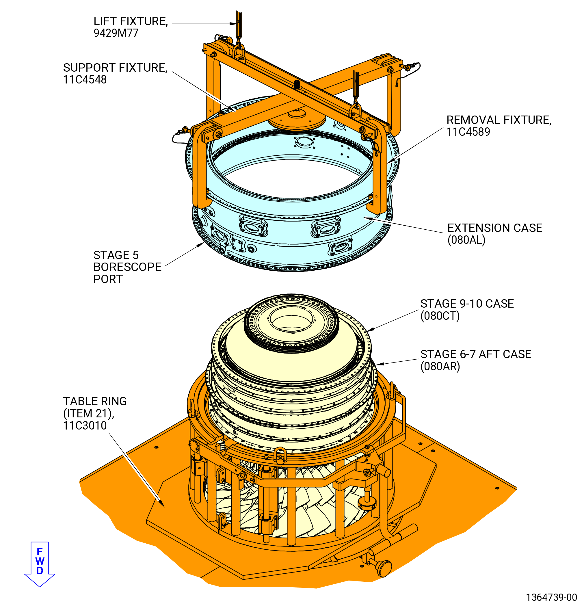
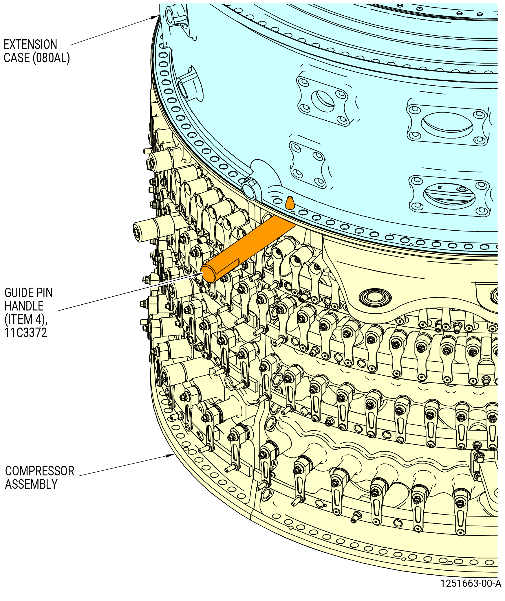
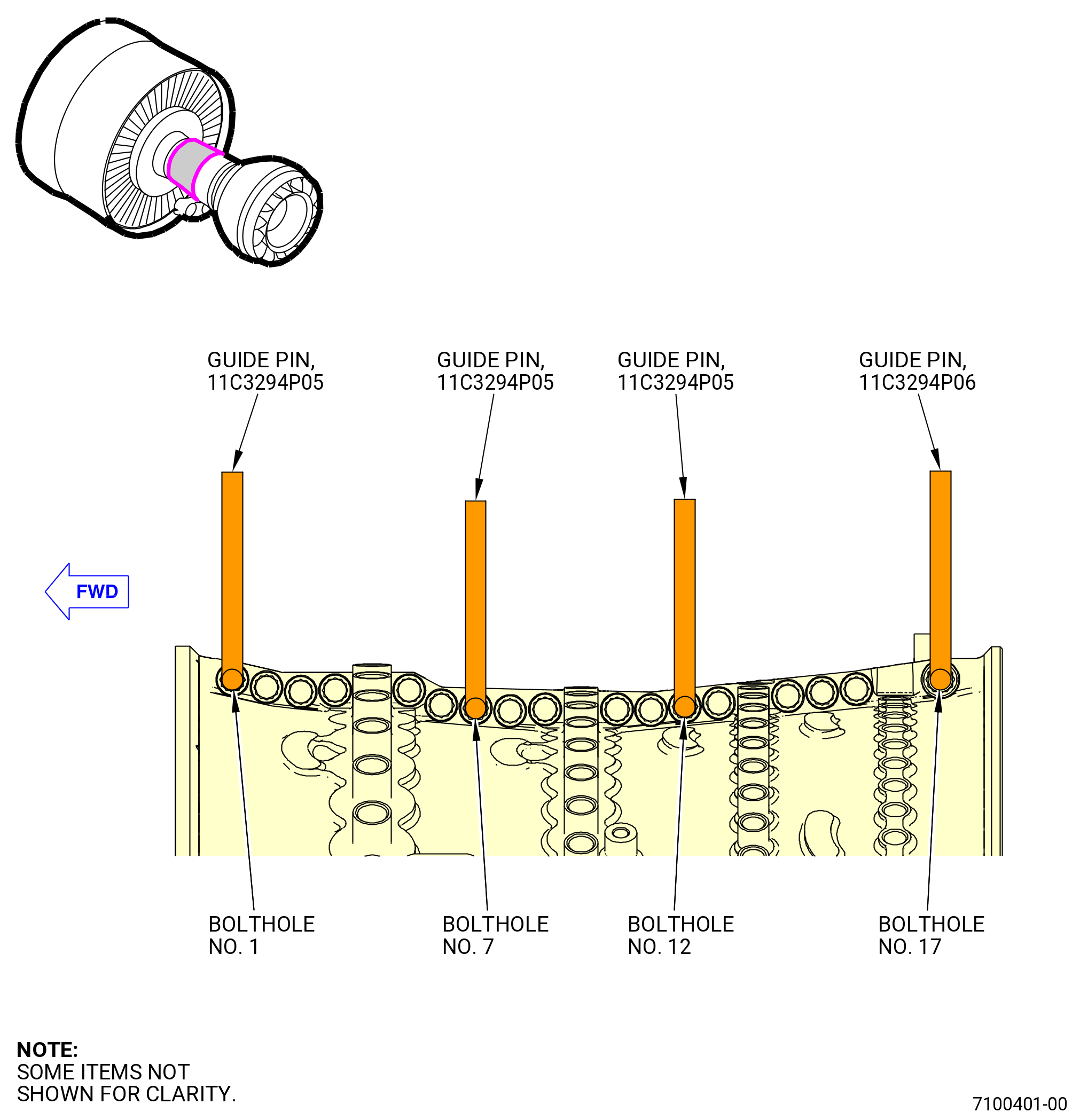
| (a) | Install three equally-spaced guide pins (item 2) of the 11C3372 guide pin set on the aft flange of the 9-10 aft inner case. Refer to Figure 1057. |
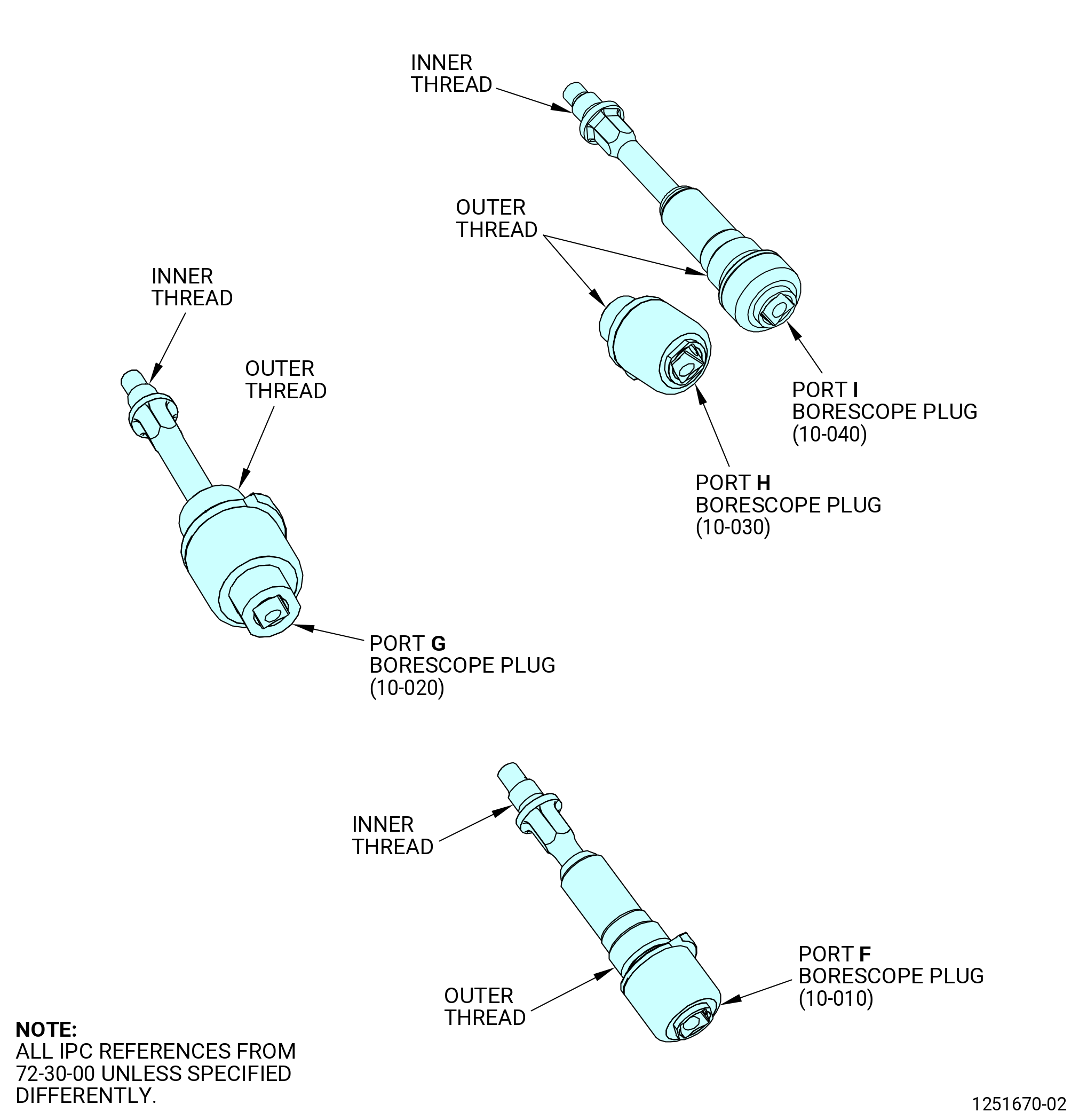
| (b) | Find the stage 5 borescope port on the extension case. |
| NOTE: |
|
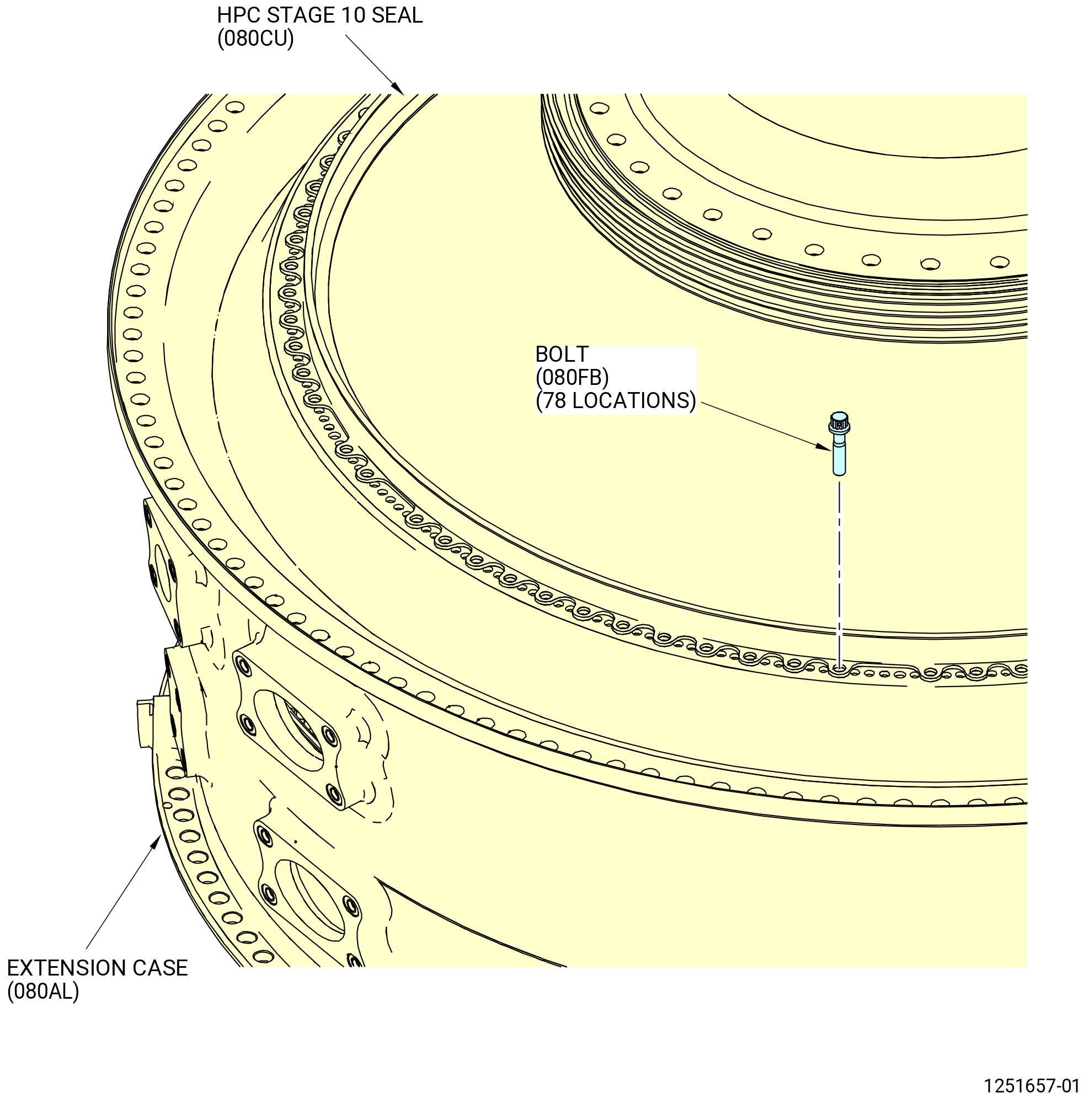
| (c) | Find the top vertical centerline of the HPC stage 10 seal (080CU). Refer to Figure 1058. |
| NOTE: |
|
| (d) | Align the top vertical centerline of the HPC stage 10 seal with the 12:00 o'clock position of the extension case at the inner aft bolt flange. |
| (e) | Make sure that the pin on the HPC stage 10 seal is aligned with the larger oval hole of the aft extension case and into pin hole of the stage 10 seal, between the slotted hole and a regular bolthole on the extension case. Refer to Figure 1058. |
| Subtask 72-30-00-440-329 |
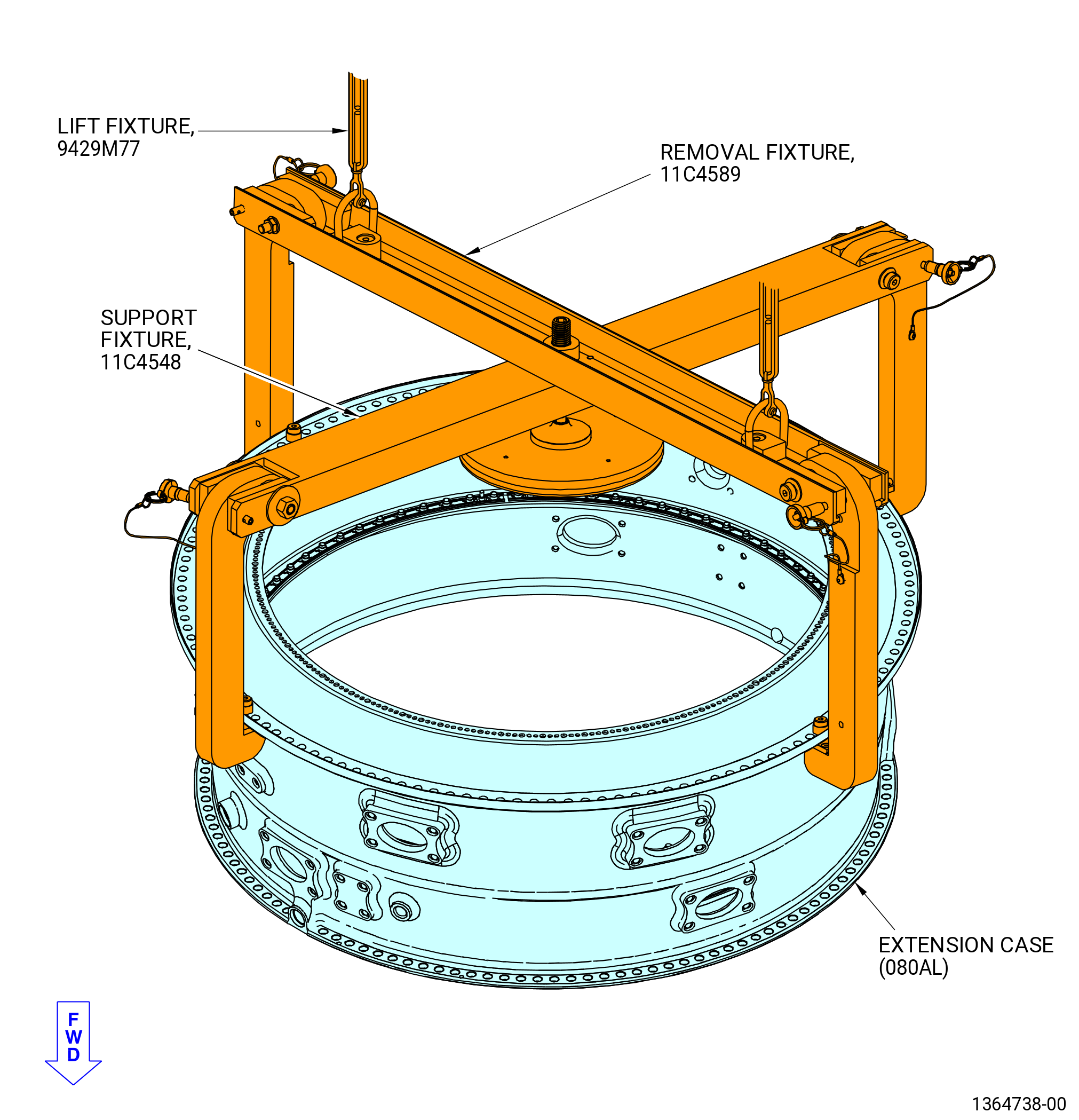
| (5) | Alternative Procedure Available. Install the 11C4548 support fixture and the 11C4589 removal fixture on the extension case (080AL) as follows. Refer to Figure 1059. |
| NOTE: |
|
| (a) | Remove the nut from the leveling fleet (item 8) of the 11C4548 support fixture. |
| (b) | Release the ball lock pin (item 7) of the 11C4548 support fixture and the ball lock pin (item 6) of the 11C4589 removal fixture from the beam subassemblies. |
| (c) | Move out the pivot arms (item 4) of the 11C4548 support fixture and the pivot arms (item 2) of the 11C4589 removal fixture and install the ball lock pin (item 7) of the 11C4548 support fixture and ball lock pin (item 6) of the 11C4589 removal fixture again to keep the open position. |
| (d) | Manually put the beam subassembly on the extension case. |
| (e) | Remove the ball lock pin (item 7) of the 11C4548 support fixture and the ball lock pin (item 6) of the 11C4589 removal fixture from the beam subassembly and move in the pivot arms (item 4) of the 11C4548 support fixture and the pivot arms (item 2) of the 11C4589 removal fixture to get the close position. |
| (f) | Make sure the pads (item 5) of the 11C4548 support fixture and pads (item 4) of the 11C4589 removal fixture are under the extension case aft flange forward side. Adjust the leveling feet (item 8) of the 11C4548 support fixture as necessary to let the installation of the pivot arms. |
| (g) | Align the holes of the pivot arms (item 4) of the 11C4548 support fixture and the holes of the pivot arms (item 2) of the 11C4589 removal fixture with the holes of the extension case aft flange. |
| (h) | Attach the pivot arms (item 4) of the 11C4548 support fixture and the pivot arms (item 2) of the 11C4589 removal fixture to the extension case aft flange with the spacers (item 6) and shoulder screws (item 13) of the 11C4548 support fixture and the spacers (item 5) and shoulder screws (item 12) of the 11C4589 removal fixture. |
| (i) | Put the ball lock pin (item 7) of the 11C4548 support fixture and the ball lock pin (item 6) of the 11C4589 removal fixture into its first position to make sure that there is hole alignment with the extension case aft flange. |
| Subtask 72-30-00-440-026 |
| CAUTION: |
|
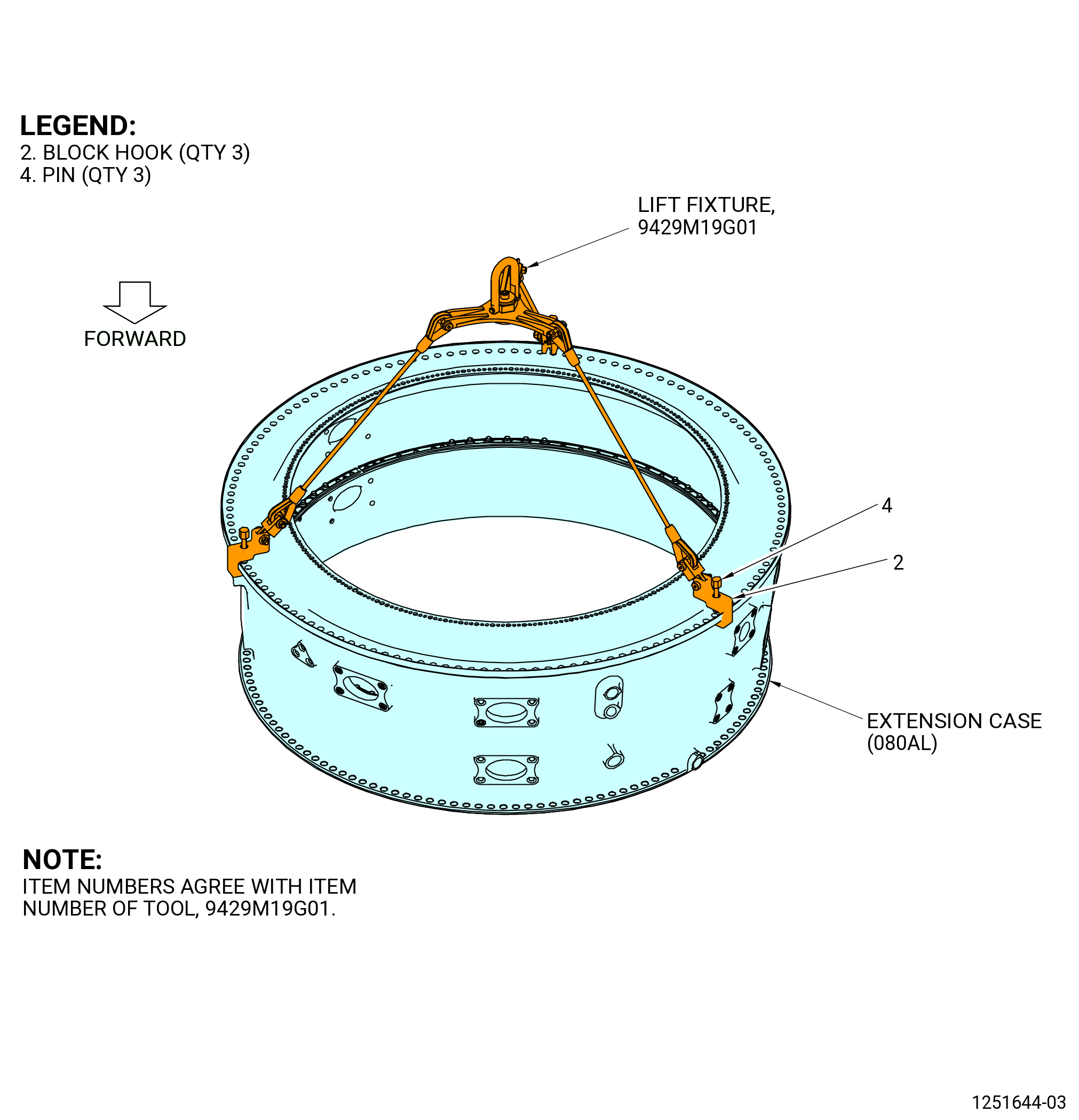
| (5).A. | Alternative Procedure. Install the 9429M19G01 lift fixture on the extension case (080AL) as follows. Refer to Figure 1060. |
| (a) | Turn the pins (item 4) of the 9429M19G01 lift fixture CCW to permit installation of the three block hooks (item 2). |
| (b) | Put the three block hooks (item 2) on the aft flange of extension case. |
| (c) | Tighten the pins (item 4) CW to attach the block hooks (item 2) to the aft flange of the extension case. |
| Subtask 72-30-00-440-330 |
| (6) | Alternative Procedure Available. Install the extension case (080AL) on the stage 6-7 aft case (080AR), stage 9-10 case (080CT), and HPC module assembly (00108) as follows. Refer to Figure 1061. |
| WARNING: |
|
| CAUTION: |
|
| (a) | Lift and move the extension case with the 11C4548 support fixture and the 11C4589 removal fixture above the stage 6-7 aft case, stage 9-10 case, and the HPC module assembly. |
| (b) | Put the extension case in the center above the HPC rotor assembly and align the top vertical center (TVC) of the stage 9-10 case with the offset boltholes at the 12:00 o'clock position of the extension case. |
| (c) | Make sure that the borescope ports of the extension case are aligned with the borescope ports on the stage 5-6 aft case (080AM), the stage 6-7 aft case, and the stage 8-9 aft case (080CS). |
| CAUTION: |
|
| (d) | Install the extension case on the outer bolt flanges of the stage 9-10 case as follows. Refer to Figure 1061, Figure 1062, and Figure 1065. |
| 1 | Make sure that the guide pins (item 2) in the aft outer flange of the stage 9-10 case are aligned with the boltholes of the aft inner flange of the extension case and lower the extension case. Refer to Figure 1057. |
| 2 | Continue to lower the extension case above the HPC module assembly and on the outer flanges of the stage 6-7 aft case and the stage 9-10 case. |
| 3 | Make sure that the HPC stage 10 seal (080CU) did not move and that all boltholes are aligned. |
| WARNING: |
|
| 4 | Apply C02-058 lubricant to the threads and friction surfaces of 78 machine bolts (bolts) (080FB). Refer to Figure 1063. |
| 5 | Attach the extension case to the stage 9-10 case with 75 bolts (080FB), boltheads aft. Hand-tighten the bolts. |
| 6 | Remove the three guide pins (item 3) of the 11C3372 guide pin set from the extension case. |
| 7 | Install three bolts (080FB), boltheads aft, where the guide pins were removed. Hand-tighten the bolts but do not set them on the flange. |
| 8 | Tighten the leveling feet (item 8) of the 11C4548 support fixture as necessary only to lock the extension case with the HPC module assembly. Do not over tighten the leveling feet nut (item 8). |
| 9 | Torque eight equally spaced bolts (080FB) to 94-109 lb in. (10.6-12.3 N.m) in a criss-cross pattern. |
| 10 | Loosen the same eigth bolts (080FB) until the bolts are not set on the flange. |
| 11 | Torque the same eight equally spaced bolts again (080FB) to 94-109 lb in. (10.6-12.3 N.m) in a criss-cross pattern. |
| 12 | Tighten the other 70 bolts until they are snug on the flange. |
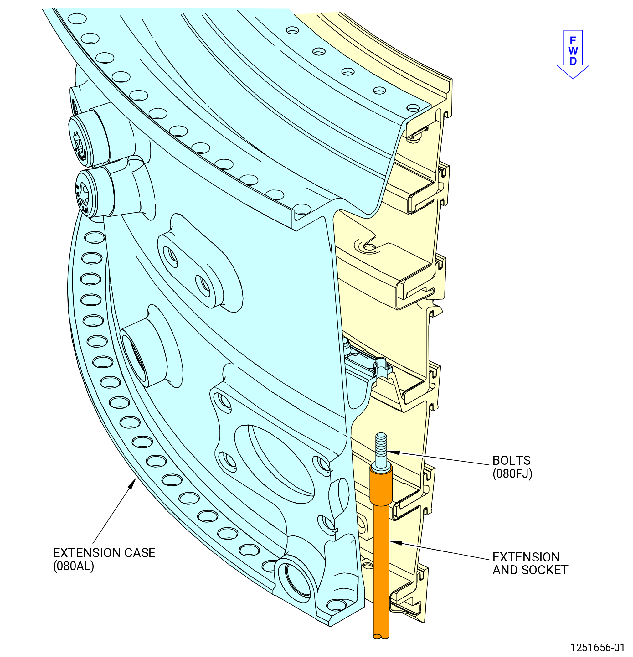
| (e) | Attach the extension case to the inner bolt flange of the stage 6-7 aft case as follows. Refer to Figure 1065. |
| WARNING: |
|
| 1 | Apply C02-058 lubricant to the threads and friction surfaces of 78 bolts (080FJ). |
| 2 | Install 78 bolts (080FJ), boltheads forward, to the stage 6-7 aft case and extension case. Do not torque the bolts (080FJ) at this time. Refer to Figure 1065. |
| 3 | Torque the eight equally spaced bolts (080FJ) to 138-162 lb in. (15.6-18.3 N.m) in a criss-cross pattern. |
| 4 | Loosen the same eight bolts (080FJ) until the bolts are not set on the flange. |
| 5 | Tighten the 78 bolts until they are snug on the flange. |
| 6 | Torque the eight original equally spaced bolts again (080FJ) to 138-162 lb in. (15.6-18.3 N.m) in a criss-cross pattern. |
| 7 | Torque the eight original equally spaced bolts (080FJ) to 184-216 lb in. (21.0-24.4 N.m) in a criss-cross pattern. |
| 8 | Torque the remaining 70 bolts (080FJ) to 184-216 lb in. (21.0-24.4 N.m) in a criss cross pattern. |
| 9 | Torque all 78 bolts again to 184-216 lb in. (21.0-24.4 N.m) in a circle pattern. |
| (f) | Finish installation of the extension case on the outer bolt flanges of the stage 9-10 case as follows: |
| 1 | Torque all 78 bolts (080FB) in the stage 9-10 aft inner case and extension case aft flange to 124-146 lb in. (14.0-16.5 N.m) in a criss-cross pattern. |
| 2 | Torque all 78 bolts (080FB) in the stage 9-10 aft inner case and extension case aft flange again to 124-146 lb in. (14.0-16.5 N.m) in a circle pattern. |
| Subtask 72-30-00-440-027 |
| (6).A. | Alternative Procedure. Install the extension case (080AL) on the stage 6-7 aft case (080AR), stage 9-10 case (080CT), and HPC rotor assembly (00108) as follows. Refer to Figure 1062. |
| WARNING: |
|
| CAUTION: |
|
| (a) | Lift and move the extension case with the 9429M19G01 lift fixture above the 6-7 aft inner case, 9-10 aft inner case, and the HPC rotor assembly. |
| (b) | Put the extension case in the center above the HPC rotor assembly and align the TVC of the 9-10 aft inner case with the offset boltholes located at the 12:00 o'clock position of the extension case. |
| (c) | Make sure that the borescope ports of the extension case are aligned with the borescope ports on the 5-6 stacked ring (080AM), the 6-7 aft inner case, and the 8-9 aft inner case (080CS). |
| (d) | Install the extension case on the outer bolt flanges of the 9-10 aft inner case as follows. Refer to Figure 1063. |
| 1 | Make sure that the guide pins (item 2) in the aft outer flange of the 9-10 aft inner case are aligned with the boltholes of the aft inner flange of the extension case and lower the extension case. Refer to Figure 1057. |
| WARNING: |
|
| 2 | Make sure the mating flanges are clean of all foreign material. If necessary, clean the mating flanges with C04-035 isopropyl alcohol to remove foreign material. |
| 3 | Continue to lower the extension case above the HPC rotor assembly and on the outer flanges of the 6-7 aft inner case and the 9-10 aft inner case. |
| 4 | Make sure that the HPC stage 10 seal did not move and that all boltholes are aligned. |
| 5 | Remove the 9429M19G01 lift fixture. |
| WARNING: |
|
| 6 | Apply C02-058 lubricant to the threads and friction surfaces of 78 bolts (080FB). |
| 7 | Attach the extension case to the 9-10 aft inner case with 75 machine bolts (bolt) (080FB), boltheads aft. Hand-tighten the bolts but do not set the boltheads on the flange. Refer to Figure 1063. |
| 8 | Remove the three guide pins (item 2) of the 11C3372 guide pin set from the 9-10 aft inner case. |
| 9 | Install three bolts (080FB), boltheads aft, where the guide pins were removed. Hand-tighten the bolts, but do not install the boltheads on the flange. |
| 10 | Torque eight equally spaced bolts (080FB) to 94-109 lb in. (10.6-12.3 N.m) in a criss-cross pattern. |
| 11 | Loosen the same eight bolts (080FB) until the bolts are not set on the flange. |
| 12 | Torque the same eight equally spaced bolts again (080FB) to 94-109 lb in. (10.6-12.3 N.m) in a criss-cross pattern. |
| 13 | Tighten the other 70 bolts until they are snug on the flange. |
| WARNING: |
|
| 14 | Apply C02-058 lubricant to the threads and friction surfaces of 78 bolts (080FJ). Refer to Figure 1065. |
| 15 | Install 78 bolts (080FJ) into the mid-flange of the extension case and the stage 6-7 aft inner case. Refer to Figure 1067. |
| 16 | Torque eight equally spaced bolts (080FJ) to 138-162 lb in. (15.6-18.3 N.m) in a criss-cross pattern. |
| 17 | Loosen the same eight bolts (080FJ) until the bolts are not set on the flange. |
| 18 | Tighten the 78 bolts until they are snug on the flange. |
| 19 | Torque eight first equally spaced bolts (080FJ) to 138-162 lb in. (15.6-18.3 N.m) in a criss-cross pattern. |
| 20 | Torque the remaining 70 bolts (080FJ) to 184-216 lb in. (21.0-24.4 N.m) in a criss-cross pattern. |
| 21 | Torque all 78 bolts again to 184-216 lb in. (21.0-24.4 N.m) in a circle pattern. |
| 22 | Torque all 78 bolts (080FB) in the stage 9-10 aft inner case and extension case aft flange to 124-146 lb in. (14.0-16.5 N.m) in a criss-cross pattern. |
| 23 | Torque all 78 bolts (080FB) in the stage 9-10 aft inner case and extension case aft flange again to 124-146 lb in. (14.0-16.5 N.m) in a circle pattern. |
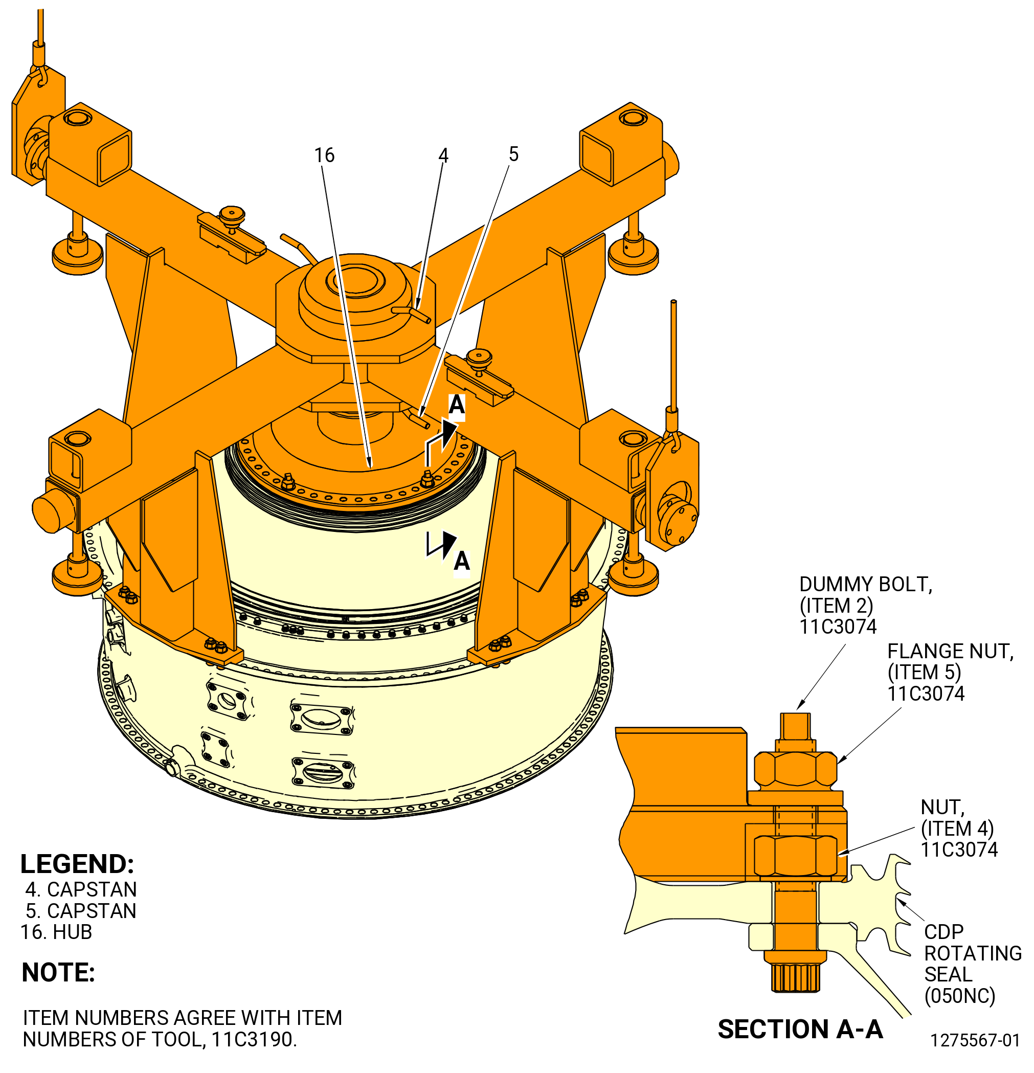
| (e) | Attach the 11C3190 extension case lift bar to the CDP rotating seal (050NC) as follows. Refer to Figure 1064. |
| 1 | Remove the 11C3074 tool kit except four dummy bolts (item 2), washers (item 6), and nuts (item 4) of the same 11C3074 tool kit and leave them equally spaced. |
| 2 | Turn the capstan (item 4) CCW to lower the hub (item 16) of the 11C3190 extension case lift bar on the CDP rotating seal. |
| 3 | Make sure that the boltholes in the hub (item 16) of the 11C3190 extension case lift bar are aligned with the boltholes of the extension case and that the hub (item 16) is fully installed. |
| 4 | Attach the hub (item 16) to the extension case with 16 cap screws (item 11), boltheads forward, washers (item 14), and nuts (item 12) of the 11C3190 extension case lift bar. |
| 5 | Lower the capstan (item 5) of the 11C3190 extension case lift bar until the hub makes contact with CDP rotating seal. Align boltholes with the four dummy bolts (item 2) of the 11C3074 tool kit. |
| 6 | Install four flange nuts (item 5) equally spaced on the dummy bolts (item 2) of the 11C3074 tool kit. |
| 7 | Torque the four dummy nuts (item 5) to 276-324 lb in. (31.2-36.6 N.m) in a criss-cross pattern. |
| (f) | Attach the extension case to the inner bolt flange of the 6-7 aft inner case as follows. Figure 1065. |
| WARNING: |
|
| 1 | Apply C02-058 lubricant to the threads and friction surfaces of 78 bolts (080FJ). |
| 2 | Install 75 bolts (080FJ), boltheads forward, to the 6-7 aft inner case and extension case. Do not torque the bolts (080FJ) at this time. |
| 3 | Remove the three guide pins (item 2) of the 11C3372 guide pin set from the 6-7 aft inner case and install three bolts (080FJ). Do not torque the bolts (080FJ) at this time. |
| 4 | Torque eight bolts (080FJ) to 138-162 lb in. (15.6-18.3 N.m) equally spaced in a criss-cross pattern. |
| 5 | Torque the 78 bolts (080FJ) to 184-216 lb in. (20.8-24.4 N.m) in a criss-cross pattern. |
| 6 | Torque the 78 bolts (080FJ) to 184-216 lb in. (20.8-24.4 N.m) in a circular pattern. |
| 7 | Torque eight bolts (080FB) to 92-108 lb in. (10.4-12.2 N.m) equally spaced in a criss-cross pattern. |
| 8 | Torque the 78 bolts (080FB) to 124-146 lb in. (14.0-16.5 N.m) in a criss-cross pattern. |
| 9 | Torque the 78 bolts (080FB) to 124-146 lb in. (14.0-16.5 N.m) in a circular pattern. |
| Subtask 72-30-00-440-028 |
| J. | Install the compressor stator assembly (compressor assembly) as follows: |
| WARNING: |
|
| (1) | Alternative Procedure Available. Remove the lifting hoist from the 11C4589 removal fixture. |
| Subtask 72-30-00-440-331 |
| WARNING: |
|
| (1).A. | Alternative Procedure. Remove the 9C2376 lift beam from the 11C3190 extension case lift bar. Refer to Figure 1060. |
| Subtask 72-30-00-440-332 |
| (2) | Remove the two halves of the 11C3293 dummy stator from case support base (item 7 and item 56) of the 11C4279 buildup fixture or the table ring (item 21) of the 11C3010 build-up fixture. Refer to Figure 1015. |
| Subtask 72-30-00-160-004 |
| WARNING: |
|
| WARNING: |
|
| (3) | Use the C10-182 cleaning cloth wet with C04-035 isopropyl alcohol, C04-002 Stoddard solvent, or a 50-50 blend of C04-035 isopropyl alcohol and C04-228 denatured alcohol to clean the forward flange of the extension case, the aft flange and horizontal flanges of the compressor assembly. |
| Subtask 72-30-00-440-029 |
| (4) | Install the compressor stator assembly as follows: |
| (a) | Install the 11C3297 lift fixture on the upper case half of the compressor assembly as follows. Refer to Figure 1066. |
| 1 | Put the plate (item 2) on the aft flange of the upper case half. |
| 2 | Align the boltholes of the plate (item 2) with the boltholes in the aft flange and attach the plate to the upper case half with six capscrews (item 4) and nuts (item 5). |
| WARNING: |
|
| (b) | Attach a hoist to the hoist ring (item 3). |
| (c) | Align the 12:00 o'clock position of the upper case half with the 12:00 o'clock position of the extension case and put the upper case half on the case support base (item 7, item 56) of the 11C4279 buildup fixture or the table ring (item 21) of the 11C3010 build-up fixture. Refer to Figure 1067. |
| (d) | Remove the plate (item 2) of the 11C3297 lift fixture from the upper case half. |
| (e) | Move the upper case half into the correct position. |
| NOTE: |
|
| (f) | Install the 11C3297 lift fixture on the lower case half of the compressor assembly as follows. Refer to Figure 1068. |
| 1 | Put the plate (item 2) on the aft flange of the lower case half. |
| 2 | Align the boltholes of the plate (item 2) with the boltholes in the aft flange and attach the plate to the lower case half with six capscrews (item 4) and nuts (item 5). |
| (g) | Attach a hoist to the hoist ring (item 3). |
| (h) | Align the 6:00 o'clock position of the lower case half with the 6:00 o'clock position of the extension case and put the lower case half on the case support base (item 7, item 56) of the 11C4279 buildup fixture or the table ring (item 21) of the 11C3010 build-up fixture. Refer to Figure 1069. |
| (i) | Remove the plate (item 2) of the 11C3297 lift fixture from the lower case half. |
| (j) | Move the lower case half into the correct position. |
| NOTE: |
|
| (k) | Make sure that the boltholes on the aft flange of the compressor assembly align with the boltholes on the forward flange of the extension case. If necessary, use the two guide pin handles (item 4) of the 11C3372 guide pin set to align the boltholes. Refer to Figure 1070. |
| NOTE: |
|
| Subtask 72-30-00-440-085 |
| (5) | Attach the compressor assembly to the extension case (080AL) as follows. Refer to Figure 1071, Figure 1071A, and Figure 1071B. |
| NOTE: |
|
| Subtask 72-30-00-440-276 |
| (a) | Use the C05-003 pen to put a mark on the bolthole numbers on the extension case forward flange. Mark the boltholes in a CW direction. |
| 1 | Start with bolthole No. 1 at the top vertical centerline, and mark every 10 boltholes. |
| NOTE: |
|
|
|
|
| Subtask 72-30-00-440-086 |
| WARNING: |
|
| (b) | Apply a thin layer of C02-097 lubricant to the threads and the pressure faces of two self-locking nuts (05-010) (SIN 080K2) or (05-011) (SIN 080K2) and the bolt (05-120) (SIN 080FE). |
| (c) | Install a bolt (080FE) with a spacer (05-030) (SIN 080TA) below the bolt, and self-locking nut (05-010) (SIN 080K2) or (05-011) (SIN 080K2) at bolthole No. 63. |
| 1 | Tighten the self-locking nut (05-010) (SIN 080K2) or (05-011) (SIN 080K2) until it is fully installed on the forward face of the compressor assembly aft flange. |
| (d) | Install a bolt (05-020) (SIN 080FC) with a spacer (05-030) (SIN 080TA) below the bolt, and a self-locking nut (05-010) (SIN 080K2) or (05-011) (SIN 080K2) at the bolthole No. 1. |
| 1 | Tighten the self-locking nut (05-010) (SIN 080K2) or (05-011) (SIN 080K2) until it is fully installed on the forward face of the compressor assembly aft flange. |
| Subtask 72-30-00-090-002 |
| (e) | Alternative Procedure Available. Remove the 11C4548 support fixture and the 11C4589 removal fixture from the extension case (080AL) as follows: |
| 1 | Loosen the leveling feet (item 8) of the 11C4548 support fixture to release the extension case and HPC module assembly. |
| 2 | Loosen and remove the spacers (item 6) and shoulder screws (item 13) of the 11C4548 support fixture and the spacers (item 5) and shoulder screws (item 12) of the 11C4589 removal fixture from the extension case. |
| 3 | Remove the ball lock pins (item 7) of the 11C4548 support fixture and ball lock pins (item 6) of the 11C4589 removal fixture and move out the pivot arms (item 4) of the 11C4548 support fixture and pivot arms (item 2) of the 11C4589 removal fixture. |
| 4 | Remove the 11C4548 support fixture and the 11C4589 removal fixture from the extension case. |
| Subtask 72-30-00-090-001 |
| (e).A. | Alternative Procedure. Remove the 11C3190 extension case lift bar from the extension case (080AL) as follows: |
| 1 | Loosen and remove the 11C3074 tool kit from the hub (item 16) and CDP rotating seal. |
| 2 | Loosen the capstans (item 4 and 5) to let the extension case rest on the compressor stator cases. |
| 3 | Tighten the capstans (item 4 and 5). |
| 4 | Make sure that there is not gap between the extension case and the compressor stator cases. |
| 5 | Loosen and removed the 16 nuts (item 12), washers (item 14), and cap screws (item 11) from the extension case |
| 6 | Remove the 11C3190 extension case lift bar. |
| 7 | Put a protective cover to the aft end of 11C3190 extension case lift bar. |
| Subtask 72-30-00-440-095 |
| (6) | Alternative Procedure Available. Attach the halves of the compressor stator assembly together as follows. Refer to Figure 1073 and Figure 1074. |
| WARNING: |
|
| (a) | Apply a thin layer of C02-097 lubricant to the threads and the pressure faces of two hex shear bolts (bolts) (05-190) (SIN 073G5) and two self-locking nuts (05-180) (SIN 073L3). |
| NOTE: |
|
| (b) | Install the bolts (05-190) (SIN 073G5) and self-locking nuts (05-180) (SIN 073L3) in bolthole No. 17 on the 3:00 and 9:00 o'clock horizontal flanges. |
| 1 | Tighten the two self-locking nuts (05-180) (SIN 073L3) at boltholes No. 17 until they are fully installed on the face of the flanges. |
| (c) | Apply a thin layer of C02-097 lubricant to the threads and the pressure faces of 10 hex shear bolts (bolts) (05-170) (SIN 073G3) and 10 self-locking nuts (05-160) (SIN 073L2). |
| (d) | Install five bolts (05-170) (SIN 073G3) and self-locking nuts (05-160) (SIN 073L2) with the boltheads facing the 12:00 o'clock position in boltholes No. 1, No. 4, No. 7, No. 12, and No. 15 on the 9:00 o'clock horizontal flange. Refer to Figure 1073. |
| Subtask 72-30-00-440-325 |
| * * * PRE SB 72-0078( Bolthead at Bolthole No. 15 Facing the 12:00 O'clock Position ) |
| (e) | Install five bolts (05-170) (SIN 073G3) and five self-locking nuts (05-160) (SIN 073L2) with the boltheads facing the 12:00 o'clock position in boltholes No. 1, No. 4, No. 7, No. 12, and No. 15 on the 3:00 o'clock horizontal flange. Refer to Figure 1074. |
| * * * END PRE SB 72-0078 |
| Subtask 72-30-00-440-326 |
| * * * SB 72-0078( Bolthead at Bolthole No. 15 Facing the 6:00 O'clock Position ) |
| (e).A. | Install five bolts (05-170) (SIN 073G3) and five self-locking nuts (05-160) (SIN 073L2) on the 3:00 o'clock horizontal flange as follows: |
| 1 | Install four bolts (05-170) (SIN 073G3) and four self-locking nuts (05-160) (SIN 073L2) with the boltheads facing the 12:00 o'clock position in boltholes No. 1, No. 4, No. 7, and No. 12. |
| 2 | Install one bolt (05-170) (SIN 073G3) and one self-locking nut (05-160) (SIN 073L2) with the bolthead facing the 6:00 o'clock position in bolthole No. 15. |
| * * * END SB 72-0078 |
| Subtask 72-30-00-440-327 |
| (f) | Tighten the 10 self-locking nuts (05-160) (SIN 073L2) until they are fully installed on the face of the flange. Tighten one self-locking nut from the 3:00 o'clock horizontal flange and then one self-locking nut from the 9:00 o'clock horizontal flange in the order that follows: bolthole No. 7, No. 12, No. 4, No. 15, and No. 1. |
| (g) | Apply a thin layer of C02-097 lubricant to the threads and the pressure faces of 22 bolts (05-170) (SIN 073G3) and 22 self-locking nuts (05-160) (SIN 073L2). |
| (h) | Install the 22 bolts (05-170) (SIN 073G3) and self-locking nuts (05-160) (SIN 073L2), boltheads facing the 12:00 o'clock position, in the remaining boltholes from No. 16 thru No. 1 on the 3:00 o'clock and 9:00 o'clock horizontal flanges. |
| (i) | Tighten the 22 self-locking nuts (05-160) (SIN 073L2) until they are fully installed on the face of the flange. Tighten one self-locking nut from the 3:00 o'clock horizontal flange and then one self-locking nut from the 9:00 o'clock horizontal flange from boltholes No. 16 thru No. 1. |
| Subtask 72-30-00-440-667 |
| (6).D. | Alternative Procedure. Attach the halves of the compressor stator assembly together. Refer to Figure 1073, Figure 1074 and do as follows: |
| WARNING: |
|
| (a) | Align horizontal split flanges at boltholes No. 17, No. 12, No. 7, and No. 1 with 11C3294 guide pins alternating flanges from aft to forward. Refer to Figure 1072. |
| NOTE: |
|
| CAUTION: |
|
| (b) | Apply a thin layer of C02-097 lubricant to the threads and the pressure faces of the 26 hex shear bolts (bolts) (05-170) (SIN 073G3) and 26 self-locking nuts (05-160) (SIN 073L2). |
| Subtask 72-30-00-440-668 |
| * * * PRE SB 72-0078( Bolthead at Bolthole No. 15 Facing the 12:00 o'Clock Position ) |
| (c) | Install bolts (05-170) (SIN 073G3) and self-locking nuts (05-160) (073L2) in horizontal split flanges boltholes No. 2 thru No. 6, No. 8 thru No. 11, and No. 13 thru No. 16 with the boltheads facing the 12:00 o'clock position. Refer to Figure 1074. |
| * * * END PRE SB 72-0078 |
| Subtask 72-30-00-440-669 |
| * * * SB 72-0078( Bolthead at Bolthole No. 15 Facing the 6:00 o'Clock Position ) |
| (d) | Install bolts (05-170) (SIN 073G3) and self-locking nuts (05-160) (SIN 073L2) in 3 o’clock position flange boltholes No. 2 thru No. 6, No. 8 thru No. 11, and No. 13, No. 14, No. 16 with the boltheads facing the 12:00 o'clock position. Refer to Figure 1074. |
| (e) | Install bolt (05-170) (SIN 073G3) and self-locking nut (05-160) (SIN 073L2) in 3 o’clock position flange bolthole No. 15 with the boltheads facing the 06:00 o'clock position. Refer to Figure 1074. |
| (f) | Install bolts (05-170) (SIN 073G3) and self-locking nuts (05-160) (SIN 073L2) in 9 o’clock position flange boltholes No. 2 thru No. 6, No. 8 thru No. 11, and No. 13 thru No. 16 with the boltheads facing the 12:00 o'clock position. Refer to Figure 1074. |
| * * * END SB 72-0078 |
| Subtask 72-30-00-440-670 |
| (g) | Tighten the self-locking nuts (05-160) (SIN 073L2) until they are fully installed on the face of the flange starting at aft side alternating flanges to the forward side. |
| (h) | Torque the self-locking nuts (05-160) (SIN 073L2) to 552 to 648 lb in. (62.4 to 73.2 Nm) starting at aft side alternating flanges to the forward side. |
| (i) | Apply a thin layer of C02-097 lubricant to the threads and the pressure faces of six bolts (05-170) (SIN 073G3), six self-locking nuts (05-160) (SIN 073L2), two hex shear bolts (bolts) (05-190) (SIN 073G5), and two self-locking nuts (05-180) (SIN 073L3). |
| (j) | Remove the 11C3294 guide pins and install bolts (05-170) (SIN 073G3) and self-locking nuts (05-160) (SIN 073L2) in boltholes No. 1, No. 7, and No. 12 with the boltheads facing the 12:00 o'clock position. Install bolts (05-190) (SIN 073G5) and self-locking nuts (05-180) (SIN 073L3) in bolthole No. 17 with the boltheads facing the 12:00 o'clock position. |
| (k) | Tighten self-locking nuts (05-160) (SIN 073L2) in boltholes No. 1, No. 7, and No. 12 until they are fully installed on the face of the flange. Tighten self-locking nut (05-180) (SIN 073L3) in bolthole No. 7 until they are fully installed on the face of the flange. |
| (l) | Torque the self-locking nuts (05-160) (SIN 073L2) in boltholes No. 1, No. 7, and No. 12 on both flanges to 552 to 648 lb in. (62.4 to 73.2 Nm). |
| (m) | Torque the self-locking nuts (05-180) (SIN 073L3) in bolthole No. 17 on both flanges to 828 to 972 lb in. (93.6 to 109.8 Nm). |
| (n) | Torque again the two self-locking nuts (05-180) (SIN 073L3) at bolthole No. 17 on the two flanges to 828 to 972 lb in. (93.6 to 109.8 Nm). |
| (o) | Torque again the 32 self-locking nuts (05-160) (SIN 073L2) in decreasing bolthole numbers from bolthole No. 16 to No. 1. Torque one bolthole on the 3:00 o'clock position flange and then one on the 9:00 o'clock position flange. Torque the bolts to 552 to 648 lb in. (62.4 to 73.2 Nm). |
| Subtask 72-30-00-440-671 |
| (7) | Torque the self-locking nuts on the 3:00 o'clock and 9:00 o'clock horizontal flanges as follows: |
| (a) | Torque the two self-locking nuts (05-180) (SIN 073L3) at bolthole No. 17 on the two flanges to 828-972 lb in. (93.6-109.8 N.m). |
| (b) | Torque the 32 self-locking nuts (05-160) (SIN 073L2) in decreasing bolthole numbers from bolthole No. 16 to No. 1. Torque one bolthole on the 3:00 o'clock flange and then one on the 9:00 o'clock flange. Torque the bolts to 552-648 lb in. (62.4-73.2 N.m). |
| (c) | Torque again the two self-locking nuts (05-180) (SIN 073L3) at bolthole No. 17 on the two flanges to 828-972 lb in. (93.6-109.8 N.m). |
| (d) | Torque again the 32 self-locking nuts (05-160) (SIN 073L2) in decreasing bolthole numbers from bolthole No. 16 to No. 1. Torque one bolthole on the 3:00 o'clock flange and then one on the 9:00 o'clock flange. Torque the bolts to 552-648 lb in. (62.4-73.2 N.m). |
|
|
|
|
| Subtask 72-30-00-440-300 |
| * * * SB 72-0027( VSV Torque Shaft Linkage Configuration 1 ) |
| * * * PRE SB 73-0010( FCOC Support Bracket with Hinge Block ) |
| (e) | Install the bolts (05-020) as follows: |
| WARNING: |
|
| 1 | Apply a thin layer of C02-097 lubricant to the threads and the pressure faces of 22 bolts (05-020) (SIN 080FC). |
| 2 | Install the 23 bolts (05-020) (SIN 080FC) with spacers (05-090) below the boltheads, at boltholes No. 36 thru No. 44, No. 73 thru No. 82, No. 87 thru No. 89, and No. 101. Hand-tighten the bolts. |
| 3 | Apply a thin layer of C02-097 lubricant to the threads and the pressure faces of 55 bolts (05-020) (SIN 080FC) and 55 self-locking nuts (05-010) (SIN 080K2) or (05-011) (SIN 080K2). |
| Subtask 72-30-00-440-635 |
| * * * PRE SB 72-0074( HPC Module Assembly without Cooling Air Deflectors ) |
| 4 | Install the 58 bolts (05-020) (SIN 080FC) with spacers (05-030) (SIN 080TA) below the boltheads and self-locking nuts (05-010) (SIN 080K2) or (05-011) (SIN 080K2) at boltholes No. 2 thru No. 4, No. 10, No. 11, No. 15 thru No. 20, No. 25 thru No. 27, No. 31 thru No. 35, No. 45 thru No. 56, No. 59 thru No. 62, No. 64 thru No. 72, No. 93, No. 100, No. 107 thru No. 113, and No. 118 thru No. 122. Hand-tighten the self-locking nuts. |
| * * * END PRE SB 72-0074 |
| Subtask 72-30-00-440-636 |
| * * * SB 72-0074( HPC Module Assembly with Cooling Air Deflectors ) |
| 4.A. | Install the 55 bolts (05-020) (SIN 080FC) with spacers (05-030) (SIN 080TA) below the boltheads and self-locking nuts (05-010) (SIN 080K2) or (05-011) (SIN 080K2) at boltholes No. 2 thru No. 4, No. 10, No. 11, No. 15 thru No. 20, No. 25 thru No. 27, No. 31 thru No. 35, No. 45 thru No. 56, No. 59 thru No. 62, No. 64 thru No. 72, No. 93, No. 100, No. 108, No. 109, No. 111 thru No. 113, and No. 118 thru No. 120, and No. 122. Hand-tighten the self-locking nuts. |
| * * * END SB 72-0074 |
| * * * END PRE SB 73-0010 |
| * * * END SB 72-0027 |
| Subtask 72-30-00-440-301 |
| * * * PRE SB 72-0027( VSV Torque Shaft Linkage Configuration 2 ) |
| * * * SB 73-0010( FCOC Support Bracket with Flat Wire Springs and Sliders ) |
| (e).C. | Install the bolts (05-020) (SIN 080FC) as follows: |
| WARNING: |
|
| 1 | Apply a thin layer of C02-097 lubricant to the threads and the pressure faces of 20 bolts (05-020) (SIN 080FC). |
| 2 | Install the 20 bolts (05-020) (SIN 080FC) with spacers (05-090) (SIN 080TB) below the boltheads, at boltholes No. 36 thru No. 44, No. 73 thru No. 82, and No. 101. Hand-tighten the bolts. |
| 3 | Apply a thin layer of C02-097 lubricant to the threads and the pressure faces of 53 bolts (05-020) (SIN 080FC) and 53 self-locking nuts (05-010) (SIN 080K2) or (05-011) (SIN 080K2). |
| Subtask 72-30-00-440-637 |
| * * * PRE SB 72-0074( HPC Module Assembly without Cooling Air Deflectors ) |
| 4 | Install the 56 bolts (05-020) (SIN 080FC) with spacers (05-030) (SIN 080TA), below the boltheads, and self-locking nuts (05-010) (SIN 080K2) or (05-011) (SIN 080K2) at boltholes No. 2 thru No. 4, No. 10, No. 11, No. 15 thru 20, No. 24 thru No. 26, No. 32 thru No. 35, No. 45 thru No. 56, No. 59 thru No. 62, No. 64 thru No. 72, No. 100, No. 107 thru No. 113, and No. 118 thru No. 122. Hand-tighten the self-locking nuts. |
| * * * END PRE SB 72-0074 |
| Subtask 72-30-00-440-638 |
| * * * SB 72-0074( HPC Module Assembly with Cooling Air Deflectors ) |
| 4.A. | Install the 53 bolts (05-020) (SIN 080FC) with spacers (05-030) (SIN 080TA), below the boltheads, and self-locking nuts (05-010) (SIN 080K2) or (05-011) (SIN 080K2) at boltholes No. 2 thru No. 4, No.10, No. 11, No. 15 thru 20, No. 24 thru No. 26, No. 32 thru No. 35, No. 45 thru No. 56, No. 59 thru No. 62, No. 64 thru No. 72, No. 100, No. 108, No. 109, No. 111 thru No. 113, and No. 118 thru No. 120, and No. 122. Hand-tighten the self-locking nuts. |
| * * * END SB 72-0074 |
| * * * END SB 73-0010 |
| * * * END PRE SB 72-0027 |
| Subtask 72-30-00-440-328 |
| * * * SB 72-0027( VSV Torque Shaft Linkage Configuration 3 ) |
| * * * SB 73-0010( FCOC Support Bracket with Flat Wire Springs and Sliders ) |
| (e).F. | Install bolts (05-020) (SIN 080FC) as follows: |
| WARNING: |
|
| 1 | Apply a thin layer of C02-097 lubricant to the threads and the pressure faces of 20 bolts (05-020) (SIN 080FC). |
| 2 | Install the 20 bolts (05-020) (SIN 080FC) with spacers (05-090) (SIN 080TB) below the boltheads, at boltholes No. 36 thru No. 44, No. 73 thru No. 82, and No. 101. Hand-tighten the bolts. |
| 3 | Apply a thin layer of C02-097 lubricant to the threads and the pressure faces of 53 bolts (05-020) (SIN 080FC) and 53 self-locking nuts (05-010) (SIN 080K2) or (05-011) (SIN 080K2). |
| Subtask 72-30-00-440-639 |
| * * * PRE SB 72-0074( HPC Module Assembly without Cooling Air Deflectors ) |
| 4 | Install the 56 bolts (05-020) (SIN 080FC) with spacers (05-030) (SIN 080TA), below the boltheads, and 56 self-locking nuts (05-010) (SIN 080K2) or (05-011) (SIN 080K2) at boltholes No. 2 thru No. 4, No. 10, No. 11, No. 15 thru 20, No. 24 thru No. 26, No. 32 thru No. 35, No. 45 thru No. 56, No. 59 thru No. 62, No. 64 thru No. 72, No. 100, No. 107 thru No. 113, and No. 118 thru No. 122. Hand-tighten the self-locking nuts. |
| * * * END PRE SB 72-0074 |
| Subtask 72-30-00-440-640 |
| * * * SB 72-0074( HPC Module Assembly with Cooling Air Deflectors ) |
| 4.A. | Install the 53 bolts (05-020) (SIN 080FC) with spacers (05-030) (SIN 080TA), below the boltheads, and 53 self-locking nuts (05-010) (SIN 080K2) or (05-011) (SIN 080K2) at boltholes No. 2 thru No. 4, No. 10, No. 11, No. 15 thru 20, No. 24 thru No. 26, No. 32 thru No. 35, No. 45 thru No. 56, No. 59 thru No. 62, No. 64 thru No. 72, No. 100, No. 108, No. 109, No. 111 thru No. 113, No. 118 thru No. 120, and No. 122. Hand-tighten the self-locking nuts. |
| * * * END SB 72-0074 |
| * * * END SB 73-0010 |
| * * * END SB 72-0027 |
| Subtask 72-30-00-440-087 |
| (f) | Attach the support bracket (bracket) (6101J) on the aft flange of the extension case (080AL) as follows: |
| WARNING: |
|
| 1 | Apply a thin layer of C02-097 lubricant to the threads and the pressure faces of five bolts (05-020) (SIN 080FC) and five self-locking nuts (05-010) (SIN 080K2) or (05-011) (SIN 080K2). |
| 2 | Attach the bracket with the five bolts (05-020) (SIN 080FC), boltheads aft, and five self-locking nuts (05-010) (SIN 080K2) or (05-011) (SIN 080K2) on the aft face of the extension case forward flange at boltholes No. 5 thru No. 9. |
| (g) | Attach the support bracket (bracket) (34512) on the aft flange of the extension case as follows: |
| WARNING: |
|
| 1 | Apply a thin layer of C02-097 lubricant to the threads and the pressure faces of three bolts (05-020) (SIN 080FC) and three self-locking nuts (05-010) (SIN 080K2) or (05-011) (SIN 080K2). |
| 2 | Attach the bracket, nutplates aft, with the three bolts (05-020) (SIN 080FC), boltheads aft, and three self-locking nuts (05-010) (SIN 080K2) or (05-011) (SIN 080K2) on the aft face of the extension case forward flange at boltholes No. 12 thru No. 14. |
| Subtask 72-30-00-440-308 |
| * * * SB 72-0027( VSV Torque Shaft Linkage Configuration 1 ) |
| (h) | Install the VSV torque shaft linkage (VSV torque shaft) (01-129) (SIN 07500) on the aft face of the extension case forward flange as follows: |
| 1 | Put the VSV torque shaft (01-129) (SIN 07500) on the aft face of the extension case forward flange and the aft face of the forward flange of the compressor assembly. |
| 2 | Align the dowel pins in the aft support (01-179) (SIN 07500-4) with the holes located near boltholes No. 21 and No. 30 on the aft face of the extension case forward flange. |
| 3 | Align the dowel pins in the forward support (01-184) (SIN 07500-3) with the holes on the aft face of the forward flange of the compressor assembly. |
| 4 | Make sure that the boltholes in the aft support (01-179) (SIN 07500-4) are aligned with boltholes No. 21 thru No. 24 and boltholes No. 28 thru No. 30 on the aft face of the extension case forward flange. |
| WARNING: |
|
| 5 | Apply a thin layer of C02-097 lubricant to the threads and the pressure faces of seven bolts (05-020) (SIN 080FC) and seven self-locking nuts (05-010) (SIN 080K2) or (05-011) (SIN 080K2). |
| 6 | Attach the aft support (01-179) (SIN 07500-4) with the seven bolts (05-020) (SIN 080FC), boltheads aft, and seven self-locking nuts (05-010) (SIN 080K2) or (05-011) (SIN 080K2) at boltholes No. 21 thru No. 24 and boltholes No. 28 thru No. 30. Hand-tighten the self-locking nuts. |
| NOTE: |
|
| * * * END SB 72-0027 |
| Subtask 72-30-00-440-309 |
| * * * PRE SB 72-0027( VSV Torque Shaft Linkage Configuration 2 ) |
| (h).A. | Install the VSV torque shaft linkage (VSV torque shaft) (01-130) (SIN 07500) on the extension case as follows: |
| 1 | Put the VSV torque shaft (01-130) (SIN 07500) on the aft face of the extension case forward flange and the aft face of the forward flange of the compressor assembly. |
| 2 | Align the dowel pins in the aft support (01-180) (SIN 07500-4) with the holes located near boltholes No. 21 and No. 31 on the aft face of the extension case forward flange. |
| 3 | Align the dowel pins in the forward support (01-185) (SIN 07500-3) with the holes on the aft face of the forward flange of the compressor assembly. |
| 4 | Make sure that the boltholes in the aft support (01-180) (SIN 07500-4) are aligned with boltholes No. 21 thru No. 23 and boltholes No. 27 thru No. 31 on the aft face of the extension case forward flange. |
| WARNING: |
|
| 5 | Apply a thin layer of C02-097 lubricant to the threads and the pressure faces of eight bolts (05-020) (SIN 080FC) and eight self-locking nuts (05-010) (SIN 080K2) or (05-011) (SIN 080K2). |
| 6 | Attach the aft support (01-180) (SIN 07500-4) with the eight bolts (05-020) (SIN 080FC), boltheads aft, and eight self-locking nuts (05-010) (SIN 080K2) or (05-011) (SIN 080K2) at boltholes No. 21 thru No. 23 and boltholes No. 27 thru No. 31. Hand-tighten the self-locking nuts. |
| * * * END PRE SB 72-0027 |
| Subtask 72-30-00-440-315 |
| * * * SB 72-0027( VSV Torque Shaft Linkage Configuration 3 ) |
| (h).B. | Install the VSV torque shaft linkage (VSV torque shaft) (01-130A) (SIN 07500) on the extension case as follows: |
| 1 | Put the VSV torque shaft (01-130A) (SIN 07500) on the aft face of the extension case forward flange and the aft face of the forward flange of the compressor assembly. |
| 2 | Align the dowel pins in the aft support (01-180A) (SIN 07500-4) with the holes located near boltholes No. 21 and No. 31 on the aft face of the extension case forward flange. |
| 3 | Align the dowel pins in the forward support (01-185A) (SIN 07500-3) with the holes on the aft face of the forward flange of the compressor assembly. |
| 4 | Make sure that the boltholes in the aft support (01-180A) (SIN 07500-4) are aligned with boltholes No. 21 thru No. 23 and boltholes No. 27 thru No. 31 on the aft face of the extension case forward flange. |
| WARNING: |
|
| 5 | Apply a thin layer of C02-097 lubricant to the threads and the pressure faces of eight bolts (05-020) (SIN 080FC) and eight self-locking nuts (05-010) (SIN 080K2) or (05-011) (SIN 080K2). |
| 6 | Attach the aft support (01-180A) (SIN 07500-4) with the eight bolts (05-020) (SIN 080FC), boltheads aft, and eight self-locking nuts (05-010) (SIN 080K2) or (05-011) (SIN 080K2). Hand-tighten the self-locking nuts. |
| * * * END SB 72-0027 |
| Subtask 72-30-00-440-310 |
| 7 | Attach the thrust link pad (07500-7) of VSV torque shaft to the extension case near the 3:00 o'clock horizontal flange as follows. Refer to Figure 1076. |
| WARNING: |
|
| a | Apply a thin layer of C02-058 lubricant to the threads and the pressure faces of four bolts (075F5). |
| b | Put the thrust link pad on the pad boss on the extension case and attach it with the four bolts (075F5). Hand-tighten the bolts (075F5). Do not torque at this time. |
| (i) | Attach the bracket (29914) on the aft flange of extension case as follows: |
| WARNING: |
|
| 1 | Apply a thin layer of C02-097 lubricant to the threads and the pressure faces of two bolts (05-020) (SIN 080FC) and two self-locking nuts (05-010) (SIN 080K2) or (05-011) (SIN 080K2). |
| 2 | Attach the bracket with the two bolts (05-020) (SIN 080FC), boltheads aft, and two self-locking nuts (05-010) (SIN 080K2) or (05-011) (SIN 080K2) on the aft face of the extension case forward flange at boltholes No. 57 and No. 58. Hand-tighten the self-locking nuts. |
| Subtask 72-30-00-440-311 |
| * * * SB 72-0027( VSV Torque Shaft Linkage Configuration 1 ) |
| (j) | Install the VSV torque shaft linkage (VSV torque shaft) (01-009) (SIN 07501) on the aft flange of extension case as follows: |
| 1 | Put the VSV torque shaft (01-009) (SIN 07501) on the aft face of the extension case forward flange and the aft face of the forward flange of the compressor assembly. |
| 2 | Align the dowel pins in the aft support (01-059) (SIN 07501-4) with the holes located near boltholes No. 83 and No. 92 on the aft face of the extension case forward flange. |
| 3 | Align the dowel pins in the forward support (01-064) (SIN 07501-3) with the holes on the aft face of the forward flange of the compressor assembly. |
| 4 | Make sure that the boltholes in the aft support (01-059) (SIN 07501-4) are aligned with boltholes No. 83 thru No. 86 and boltholes No. 90 thru No. 92 on the aft face of the extension case forward flange. |
| WARNING: |
|
| 5 | Apply a thin layer of C02-097 lubricant to the threads and the pressure faces of four bolts (05-020) (SIN 080FC) and three self-locking nuts (05-010) (SIN 080K2) or (05-011) (SIN 080K2). |
| 6 | Attach the aft support (01-059) (SIN 07500-4) with three bolts (05-020) (SIN 080FC), boltheads aft, and three self-locking nuts (05-010) (SIN 080K2) or (05-011) (SIN 080K2) at boltholes No. 90 thru No. 92, and one bolt (05-020) (SIN 080FC) with a spacer (05-030) (SIN 080TA) below the bolthead, at bolthole No. 83. Hand-tighten the self-locking nuts and the bolt. |
| Subtask 72-30-00-440-316 |
| * * * PRE SB 73-0010( FCOC Support Bracket with Hinge Block ) |
| 7 | Install the bracket (01-060 , 73-11-20) (SIN 42413) as follows: |
| a | Put the bracket (01-060 , 73-11-20) (SIN 42413) on the aft support (01-059) (SIN 07501-4) at boltholes No. 84 thru No. 86. |
| WARNING: |
|
| b | Apply a thin layer of C02-097 lubricant to the threads and the pressure faces of three bolts (05-020) (SIN 080FC). |
| c | Attach the bracket (01-060 , 73-11-20) (SIN 42413) with the three bolts (05-020) (SIN 080FC). Hand-tighten the bolts. |
| NOTE: |
|
| * * * END PRE SB 73-0010 |
| * * * END SB 72-0027 |
| Subtask 72-30-00-440-317 |
| * * * PRE SB 72-0027( VSV Torque Shaft Linkage Configuration 2 ) |
| (j).B. | Install the VSV torque shaft linkage (VSV torque shaft) (01-010) (SIN 07501) on the aft flange of extension case as follows: |
| 1 | Put the VSV torque shaft (01-010) (SIN 07501) on the aft face of the extension case forward flange and the aft face of the forward flange of the compressor assembly. |
| 2 | Align the dowel pins in the aft support (01-060) (SIN 07501-4) with the holes located near boltholes No. 83 and No. 93 on the aft face of the extension case forward flange. |
| 3 | Align the dowel pins in the forward support (01-065) (SIN 07501-3) with the holes on the aft face of the forward flange of the compressor assembly. |
| 4 | Make sure that the boltholes in the aft support (01-060) (SIN 07501-4) are aligned with boltholes No. 83 thru No. 85 and boltholes No. 89 thru No. 93 on the aft face of the extension case forward flange. |
| WARNING: |
|
| 5 | Apply a thin layer of C02-097 lubricant to the threads and the pressure faces of six bolts (05-020) (SIN 080FC) and four self-locking nuts (05-010) (SIN 080K2) or (05-011) (SIN 080K2). |
| 6 | Attach the aft support (01-060) (SIN 07500-4) with four bolts (05-020) (SIN 080FC), boltheads aft, and four self-locking nuts (05-010) (SIN 080K2) or (05-011) (SIN 080K2) at boltholes No. 90 thru No. 93, and two bolts (05-020) (SIN 080FC) with two spacers (05-030) (SIN 080TA), below the bolthead, at boltholes No. 83 and No. 89. Hand-tighten the self-locking nuts and bolts. |
| Subtask 72-30-00-440-318 |
| * * * PRE SB 73-0010( FCOC Support Bracket with Hinge Block ) |
| 7 | Install the FCOC pivot bracket (bracket) (01-060 , 73-11-20) (SIN 42413) as follows: |
| a | Put the bracket (01-060 , 73-11-20) (SIN 42413) on the aft support (01-060) (SIN 07501-4) at boltholes No. 84 thru No. 86. |
| WARNING: |
|
| b | Apply a thin layer of C02-097 lubricant to the threads and the pressure faces of three bolts (05-020) (SIN 080FC). |
| c | Attach the bracket (01-060 , 73-11-20) (SIN 42413) with two bolts (05-020) (SIN 080FC) at the boltholes No. 84 and No. 85 and one bolt (05-020) (SIN 080FC) and one spacer (05-030) (SIN 080TA) below the bracket, at the bolthole No. 86. Hand-tighten the bolts. |
| * * * END PRE 73-0010 |
| Subtask 72-30-00-440-319 |
| * * * SB 73-0010( FCOC Support Bracket with Flat Wire Springs and Sliders ) |
| 7.A. | Install the FCOC pivot bracket (bracket) (01-061 , 73-11-20) (SIN 42413) as follows: |
| a | Put the bracket (01-061 , 73-11-20) (SIN 42413) on the aft support (01-060) (SIN 07501-4) at boltholes No. 84 thru No. 88. |
| WARNING: |
|
| b | Apply a thin layer of C02-097 lubricant to the threads and the pressure faces of five bolts (05-020) (SIN 080FC). |
| c | Attach the bracket (01-061 , 73-11-20) (SIN 42413) with the five bolts (05-020) (SIN 080FC) at boltholes No. 84 thru No. 88. Hand-tighten the bolts. |
| * * * END SB 73-0010 |
| * * * END PRE SB 72-0027 |
| Subtask 72-30-00-440-320 |
| * * * SB 72-0027( VSV Torque Shaft Linkage Configuration 3 ) |
| (j).E. | Install the VSV torque shaft (01-010A) (SIN 07501) on the aft flange of extension case as follows: |
| 1 | Put the VSV torque shaft (01-010A) (SIN 07501) on the aft face of the extension case forward flange and the aft face of the forward flange of the compressor assembly. |
| 2 | Align the dowel pins in the aft support (01-060A) (SIN 07501-4) with the holes located near boltholes No. 83 and No. 93 on the aft face of the extension case forward flange. |
| 3 | Align the dowel pins in the forward support (01-065A) (SIN 07501-3) with the holes on the aft face of the forward flange of the compressor assembly. |
| 4 | Make sure that the boltholes in the aft support (01-060A) (SIN 07501-4) are aligned with boltholes No. 83 thru No. 85 and boltholes No. 89 thru No. 93 on the aft face of the extension case forward flange. |
| WARNING: |
|
| 5 | Apply a thin layer of C02-097 lubricant to the threads and the pressure faces of six bolts (05-020) (SIN 080FC) and four self-locking nuts (05-010) (SIN 080K2) or (05-011) (SIN 080K2). |
| 6 | Attach the aft support (01-060A) (SIN 07500-4) with four bolts (05-020) (SIN 080FC), boltheads aft, and four self-locking nuts (05-010) (SIN 080K2) or (05-011) (SIN 080K2) at the boltholes No. 90 thru No. 93, and two bolts (05-020) (SIN 080FC) with two spacers (05-030) (SIN 080TA), below the bolthead, at boltholes No. 83 and No. 89. Hand-tighten the self-locking nuts and bolts. |
| Subtask 72-30-00-440-321 |
| * * * PRE SB 73-0010( FCOC Support Bracket with Hinge Block ) |
| 7 | Install the bracket (01-060 , 73-11-20) (SIN 42413) as follows: |
| a | Put the bracket (01-060 , 73-11-20) (SIN 42413) on the aft support (01-060A) (SIN 07501-4) at boltholes No. 84 thru No. 86. |
| WARNING: |
|
| b | Apply a thin layer of C02-097 lubricant to the threads and the pressure faces of three bolts (05-020) (SIN 080FC). |
| c | Attach the bracket (01-060 , 73-11-20) (SIN 42413) with two bolts (05-020) (SIN 080FC) at boltholes No. 84 and No. 85, and one bolt (05-020) (SIN 080FC) and one spacer (05-030) (SIN 080TA) below the bracket, at bolthole No. 86. Hand-tighten the bolts. |
| * * * END PRE 73-0010 |
| Subtask 72-30-00-440-322 |
| * * * SB 73-0010( FCOC Support Bracket with Flat Wire Springs and Sliders ) |
| 7.A. | Install the bracket (01-061 , 73-11-20) (SIN 42413) as follows: |
| a | Put the bracket (01-061 , 73-11-20) (SIN 42413) on the aft support (01-060A) (SIN 07501-4) at boltholes No. 84 thru No. 88. |
| WARNING: |
|
| b | Apply a thin layer of C02-097 lubricant to the threads and the pressure faces of five bolts (05-020) (SIN 080FC). |
| c | Attach the bracket (01-061 , 73-11-20) (SIN 42413) with the five bolts (05-020) (SIN 080FC) at boltholes No. 84 thru No. 88. Hand-tighten the bolts. |
| * * * END SB 73-0010 |
| * * * END SB 72-0027 |
| Subtask 72-30-00-440-313 |
| (k) | Attach the thrust link pad (07501-7) of VSV torque shaft to the extension case near the 9:00 o'clock horizontal flange as follows. Refer to Figure 1077. |
| WARNING: |
|
| 1 | Apply a thin layer of C02-058 lubricant to the threads and the pressure faces of four bolts (075F5). |
| 2 | Put the thrust link pad on the pad boss on the extension case and attach it with the four bolts (075F5). Hand-tighten the bolts (075F5). Do not torque at this time. |
| Subtask 72-30-00-440-314 |
| * * * PRE SB 73-0010( FCOC Support Bracket with Hinge Block ) |
| (l) | Attach the bracket (01-120 , 73-11-20) (SIN 42411) on the forward flange of extension case as follows: |
| WARNING: |
|
| 1 | Apply a thin layer of C02-097 lubricant to the threads and the pressure faces of six bolts (05-150) (SIN 080FF) and six self-locking nuts (05-010) (SIN 080K2) or (05-011) (SIN 080K2). |
| 2 | Attach the bracket, nutplates aft, with the six bolts (05-150) (SIN 080FF), boltheads aft, and self-locking nuts (05-010) (SIN 080K2) or (05-011) (SIN 080K2) on the aft face of the extension case forward flange at boltholes No. 94 thru No. 99. Hand-tighten the self-locking nuts. |
| * * * END PRE SB 73-0010 |
| Subtask 72-30-00-440-323 |
| * * * SB 73-0010( FCOC Support Bracket with Flat Wire Springs and Sliders ) |
| (l).A. | Attach the bracket (01-121 , 73-11-20) (SIN 42411) on the forward flange of extension case as follows: |
| WARNING: |
|
| 1 | Apply a thin layer of C02-097 lubricant to the threads and the pressure faces of six bolts (05-020) (SIN 080FC) and six self-locking nuts (05-010) (SIN 080K2) or (05-011) (SIN 080K2). |
| 2 | Attach the bracket, nutplates aft, with the six bolts (05-020) (SIN 080FC), boltheads aft, and self-locking nuts (05-010) (SIN 080K2) or (05-011) (SIN 080K2) on the aft face of the extension case forward flange at boltholes No. 94 thru No. 99. Hand-tighten the self-locking nuts. |
| * * * END SB 73-0010 |
| Subtask 72-30-00-440-324 |
| (m) | Attach the bracket (05-140) (SIN 62118) on the forward flange of extension case as follows: |
| WARNING: |
|
| 1 | Apply a thin layer of C02-097 lubricant to the threads and the pressure faces of five bolts (05-020) (SIN 080FC) and four self-locking nuts (05-010) (SIN 080K2) or (05-011) (SIN 080K2). |
| 2 | Attach the bracket, nutplates aft, with a bolt (05-020) (SIN 080FC), bolthead aft, on the aft face of the extension case forward flange at bolthole No. 102. Hand-tighten the bolt. |
| 3 | Install the remaining four bolts (05-020) (SIN 080FC), boltheads aft, and self-locking nuts (05-010) (SIN 080K2) or (05-011) (SIN 080K2) on the aft face of the extension case forward flange at boltholes No. 103 thru No. 106. Hand-tighten the self-locking nuts. |
| (n) | Attach the bracket (05-130) (SIN 6101Y) on the forward flange of extension case as follows: |
| WARNING: |
|
| 1 | Apply a thin layer of C02-097 lubricant to the threads and the pressure faces of four bolts (05-020) (SIN 080FC) and four self-locking nuts (05-010) (SIN 080K2) or (05-011) (SIN 080K2). |
| Subtask 72-30-00-440-641 |
| * * * PRE SB 72-0074( HPC Module Assembly without Cooling Air Deflectors ) |
| 2 | Attach the bracket with the four bolts (05-020) (SIN 080FC), bolthead aft, and self-locking nuts (05-010) (SIN 080K2) or (05-011) (SIN 080K2) on the aft face of the extension case forward flange at bolthole No. 114 thru No. 117. Hand-tighten the self-locking nuts. |
| * * * END PRE SB 72-0074 |
| Subtask 72-30-00-440-642 |
| * * * SB 72-0074( HPC Module Assembly with Cooling Air Deflectors ) |
| 2.A. | Attach the bracket (05-130) (SIN 6101Y) with the four bolts (05-020) (SIN 080FC), bolthead aft, and self-locking nuts (05-010) (SIN 080K2) or (05-011) (SIN 080K2) on the aft face of the extension case forward flange at boltholes No. 114, No. 116, and No. 117. Hand-tighten the self-locking nuts. |
| * * * END SB 72-0074 |
| Subtask 72-30-00-440-643 |
| (o) | Attach the bracket (05-070) (SIN 34510) on the forward flange of extension case as follows: |
| WARNING: |
|
| 1 | Remove the bolt (05-020) (SIN 080FC) at bolthole No. 1 previously installed to seat the cases. |
| 2 | Apply a thin layer of C02-097 lubricant to the threads and the pressure faces of four bolts (05-020) (SIN 080FC) and four self-locking nuts (05-010) (SIN 080K2) or (05-011) (SIN 080K2). |
| 3 | Attach the bracket with the four bolts (05-020) (SIN 080FC), bolthead aft, and four self-locking nuts (05-010) (SIN 080K2) or (05-011) (SIN 080K2) on the aft face of the extension case forward flange at bolthole No. 1 and No. 123 thru No. 125. Hand-tighten the self-locking nuts. |
| Subtask 72-30-00-440-644 |
| * * * SB 72-0074( HPC Module Assembly with Cooling Air Deflectors ) |
| (p) | Install the cooling air deflector (05-210) (SIN 62B10) and cooling air deflector (05-220) (SIN 62B11). Refer to Figure 1075 and do as follows: |
| NOTE: |
|
| 1 | Attach the cooling air deflector (05-210) (SIN 62B10) to the forward flange of the compressor stator assembly (05-200) (SIN 07000) with a bolt (05-020) (SIN 080FC), spacer (05-030) (SIN 080TA) below the bolthead, and self-locking nut (05-010) (SIN 080K2) or (05-011) (SIN 080K2) at bolthole No. 107. |
| 2 | Attach the cooling air deflector (05-220) (SIN 62B11) to the forward flange of the compressor stator assembly (05-200) (SIN 07000) with three bolts (05-020) (SIN 080FC) and three self-locking nuts (05-010) (SIN 080K2) or (05-011) (SIN 080K2) at boltholes No. 110, No. 115, and No. 121. |
| * * * END SB 72-0074 |
| Subtask 72-30-00-440-096 |
| CAUTION: |
|
| (8) | Torque the self-locking nuts (05-010) (SIN 080K2) or (05-011) (SIN 080K2) on the compressor assembly to the extension case flanges as follows. Refer to Figure 1071, Figure 1071A, and Figure 1071B. |
| (a) | Torque the bolts (05-020) (SIN 080FC) at locations that do not have self-locking nuts (05-010) (SIN 080K2) or (05-011) (SIN 080K2). |
| (b) | Torque the self-locking nut (05-010) (SIN 080K2) or (05-011) (SIN 080K2) at the bolthole No. 63 to 276-324 lb in. (31.2-36.6 N.m). |
| (c) | Torque again the self-locking nut (05-010) (SIN 080K2) or (05-011) (SIN 080K2) at the bolthole No. 63 to 368-432 lb in. (41.6-48.8 N.m). |
| (d) | Torque 16 self-locking nuts (05-010) (SIN 080K2) or (05-011) (SIN 080K2) equally spaced to seat the extension case to 276-324 lb in. (31.2-36.6 N.m) in a criss-cross pattern. |
| (e) | Torque the 125 self-locking nuts (05-010) (SIN 080K2) or (05-011) (SIN 080K2) or bolts (05-020) (SIN 080FC) to 368-432 lb in. (41.6-48.8 N.m) in a criss-cross pattern. |
| (f) | Torque the 125 self-locking nuts (05-010) (SIN 080K2) or (05-011) (SIN 080K2) or bolts (05-020) (SIN 080FC) to 368-432 lb in. (41.6-48.8 N.m) in a circular pattern. |
| (g) | Torque the four bolts (075F5) on the thrust link pad (07500-7) at the 3:00 o'clock position to 106-124 lb in. (12.0-14.0 N.m). |
| (h) | Torque the four bolts (075F5) on the thrust link pad (07501-7) at the 9:00 o'clock position to 106-124 lb in. (12.0-14.0 N.m). |
| (i) | Torque the two self-locking nuts (07500-19) to attach the thrust link (07500-6) to 331-389 lb in. (37.4-44.0 N.m). |
| (j) | Torque the two self-locking nuts (07501-19) to attach the thrust link (07501-6) to 331-389 lb in. (37.4-44.0 N.m). |
| * * * SB 72-0074( HPC Module Assembly with Cooling Air Deflectors ) |
| Subtask 72-30-00-220-029 |
| K. | Do a visual inspection of the borescope plugs and ports. Refer to TASK 72-00-00-800-804 (72-00-00, SPECIAL PROCEDURE 004) (paragraph 5.A. and 5.B.). |
| Subtask 72-30-00-440-098 |
| L. | Install the borescope plugs in the ports F, G, H, and I as follows. Refer to Figure 1079 and Figure 1080. |
| (1) | Install the borescope plug (080AD) in the borescope port F as follows: |
| (a) | Make sure that the borescope port F in the extension case (080AL) is aligned with the borescope port F in the 5-6 stacked ring (080AM). |
| WARNING: |
|
| (b) | Apply C02-071 lubricant to the inner and outer threads of the borescope plug. |
| (c) | Install the inner part of the borescope plug through the borescope port F in the extension case and into the borescope port F of the 5-6 stacked ring. |
| (d) | Torque the inner part of the borescope plug to 81-95 lb in. (9.2-10.7 N.m). |
| (e) | Loosen the inner part of the borescope plug and torque to 23-27 lb in. (2.6-3.1 N.m). |
| (f) | Torque again the inner part of the borescope plug to 23-27 lb in. (2.6-3.1 N.m). |
| (g) | Compress the spring and tighten the outer part of the borescope plug in the borescope port F in the extension case. |
| (h) | Torque the outer part of the borescope plug to 81-95 lb in. (9.2-10.7 N.m). |
| (i) | Torque again the outer part of the borescope plug to 81-95 lb in. (9.2-10.7 N.m). |
| (j) | After the plug has been torqued, perform a visual inspection of the plug and make sure that the locking feature is fully engaged with the lug on the borescope boss. Also make sure that the head of the borescope plug is fully seated against the borescope boss. If one of the two conditions are not met, the ratcheting feature of the plug can be seized or locked. Apply a penetrating oil directly in between the locking ring and the head of the plug. Re-apply torque to the plug until the plug begins to rotate freely. Tighten the plug from 81 to 95 lb in (9.2 to 10.7 Nm). Do the visual inspection again before proceeding. If the conditions above cannot be met, replace the plug. Refer to Figure 1078. |
| (2) | Install the borescope plug (080AU) in the borescope port G as follows: |
| (a) | Make sure that the borescope port G in the extension case is aligned with the borescope port G in the 6-7 aft inner case (080AR). |
| WARNING: |
|
| (b) | Apply C02-071 lubricant to the inner and outer threads of the borescope plug. |
| (c) | Install the inner part of the borescope plug through the borescope port G in the extension case and into the borescope port G of the 6-7 aft inner case. |
| (d) | Torque the inner part of the borescope plug to 81-95 lb in. (9.2-10.7 N.m). |
| (e) | Loosen the inner part of the borescope plug and torque to 23-27 lb in. (2.6-3.1 N.m). |
| (f) | Torque again the inner part of the borescope plug to 23-27 lb in. (2.6-3.1 N.m). |
| (g) | Compress the spring and tighten the outer part of the borescope plug in the borescope port G in the extension case. |
| (h) | Torque the outer part of the borescope plug to 81-95 lb in. (9.2-10.7 N.m). |
| (i) | Torque again the outer part of the borescope plug to 81-95 lb in. (9.2-10.7 N.m). |
| (j) | After the plug has been torqued, perform a visual inspection of the plug and make sure that the locking feature is fully engaged with the lug on the borescope boss. Also make sure that the head of the borescope plug is fully seated against the borescope boss. If one of the two conditions are not met, the ratcheting feature of the plug can be seized or locked. Apply a penetrating oil directly in between the locking ring and the head of the plug. Re-apply torque to the plug until the plug begins to rotate freely. Tighten the plug from 81 to 95 lb in (9.2 to 10.7 Nm). Do the visual inspection again before proceeding. If the conditions above cannot be met, replace the plug. Refer to Figure 1078. |
| (3) | Install the borescope plug (080AW) in the borescope port H as follows: |
| WARNING: |
|
| (a) | Apply C02-071 lubricant to the threads of the borescope plug. |
| (b) | Install the borescope plug through the borescope port H in the extension case. |
| (c) | Torque the outer part of the borescope plug to 81-95 lb in. (9.2-10.7 N.m). |
| (d) | Torque again the outer part of the borescope plug to 81-95 lb in. (9.2-10.7 N.m). |
| (e) | After the plug has been torqued, perform a visual inspection of the plug and make sure that the locking feature is fully engaged with the lug on the borescope boss. Also make sure that the head of the borescope plug is fully seated against the borescope boss. If one of the two conditions are not met, the ratcheting feature of the plug can be seized or locked. Apply a penetrating oil directly in between the locking ring and the head of the plug. Re-apply torque to the plug until the plug begins to rotate freely. Tighten the plug from 81 to 95 lb in (9.2 to 10.7 Nm). Do the visual inspection again before proceeding. If the conditions above cannot be met, replace the plug. Refer to Figure 1078. |
| (4) | Install the borescope plug (080BA) in the borescope port I in the extension case as follows: |
| (a) | Make sure that the borescope port I in the extension case is aligned with the borescope port I in the 8-9 aft inner case (080CS). |
| WARNING: |
|
| (b) | Apply C02-071 lubricant to the inner and outer threads of the borescope plug. |
| (c) | Install the inner part of the borescope plug through the borescope port I in the extension case and into the borescope port I of the 8-9 aft inner case. |
| Subtask 72-30-00-440-647 |
| * * * PRE SB 72-0436( ) |
| (d) | Torque the inner part of the borescope plug to 81 to 95 lb in. (9.2 to 10.7 Nm). |
| (e) | Loosen the inner part of the borescope plug and torque to 23 to 27 lb in. (2.6 to 3.1 Nm). |
| (f) | Torque again the inner part of the borescope plug to 23 to 27 lb in. (2.6 to 3.1 Nm). |
| * * * END PRE SB 72-0436 |
| Subtask 72-30-00-440-648 |
| (g) | Compress the spring and tighten the outer part of the borescope plug in the borescope port I in the extension case. |
| (h) | Torque the outer part of the borescope plug to 81-95 lb in. (9.2-10.7 N.m). |
| (i) | Torque again the outer part of the borescope plug to 81-95 lb in. (9.2-10.7 N.m). |
| (j) | After the plug has been torqued, perform a visual inspection of the plug and make sure that the locking feature is fully engaged with the lug on the borescope boss. Also make sure that the head of the borescope plug is fully seated against the borescope boss. If one of the two conditions are not met, the ratcheting feature of the plug can be seized or locked. Apply a penetrating oil directly in between the locking ring and the head of the plug. Re-apply torque to the plug until the plug begins to rotate freely. Tighten the plug from 81 to 95 lb in (9.2 to 10.7 Nm). Do the visual inspection again before proceeding. If the conditions above cannot be met, replace the plug. Refer to Figure 1078. |
| Subtask 72-30-00-440-144 |
| M. | Continue to assemble the HPC module assembly. Refer to TASK 72-30-00-440-802 (72-30-00, ASSEMBLY 002). |
|
|