| GENX-1B ENGINE MANUAL | Dated: 09/05/2024 | |
| EM 72-25-00 , ASSEMBLY 001 | ||
| FAN HUB FRAME MODULE - ASSEMBLY 001 | ||
| GENX-1B ENGINE MANUAL | Dated: 09/05/2024 | |
| EM 72-25-00 , ASSEMBLY 001 | ||
| FAN HUB FRAME MODULE - ASSEMBLY 001 | ||
| * * * FOR ALL |
| TASK 72-25-00-440-801 |
| 1 . | General. |
| A. | This procedure gives instructions to assemble the fan hub module. Refer to Figure 1001. |
| • |
|
| • |
|
| • |
|
| The fan hub module contains: |
| • |
|
| • |
|
| • |
|
| The fan hub frame assembly contains: |
| • |
|
| • |
|
| • |
|
| B. | This procedure starts with the fan hub frame assembly installed in the 9429M60 roll-over stand or 11C4100 roll-over stand. |
| C. | Protective covers are to be installed on spare assemblies only. |
| D. | Install all the bolts with the heads up and/or forward unless specific instructions are given. |
| E. | Apply lubricants to threads and friction surfaces only. |
| F. | Performed packing is not reusable. New preformed packing must be installed. |
| G. | Chilling of close fitting parts for ease of assembly is not permitted. Use a heat gun when the parts are difficult to assemble. Do not heat the parts to over 266°F (130°C). Do not heat the parts for a long period of time or engine oil may dry and cause interference between parts. |
| WARNING: |
|
| WARNING: |
|
| H. | Clean the parts that have been exposed to casual contamination (sneezes, saliva, handling with bare hands, etc.) with the cleaning process specified for the hardware. Bearings packed in grease must be fully cleaned. Clean the parts with C04-002 stoddard solvent, C04-035 isopropyl alcohol, or a 50-50 blend of C04-035 isopropyl alcohol and C04-014 denatured alcohol then lubricate with C02-019 engine oil or C02-023 engine oil. |
| I. | Make an inspection of incorrectly installed hardware for damage after disassembly. |
| J. | Bearings. |
| (1) | Do not touch the No. 3 roller bearing (030A5) or the No. 3 ball bearing (030A7) with bare hands. Wear clean lint free C10-139 Gloves or latex C10-140 Gloves when you touch the bearing components. |
| (2) | Be careful with the components of the No. 3 roller bearing (030A5) and the No. 3 ball bearing (030A7). Refer to TASK 70-14-00-620-003 (HANDLING OF BEARINGS) and TASK 70-60-01-620-002 (PRESERVATION OF ANTIFRICTION BEARINGS) . |
| WARNING: |
|
| (3) | Bearings must have a thick layer of C02-019 engine oil or C02-023 engine oil applied and must be kept wrapped in plastic film until installed. |
| (4) | The bearing components are matched sets, so the inner and outer races have the same serial number. Make sure that the serial numbers are the same before you install a bearing so that the matched assemblies are installed. Keep a record of the bearing serial numbers. |
| K. | Torque. |
| (1) | Unless otherwise instructed, all fastener threads shall be lubricated with anti-seize compound before installation. |
| (2) | Torque values given are torque to the fastener. If a torque multiplier is used, input torque to the multiplier must be calculated. Final torque is to be applied at room temperature. Refer to TASK 70-51-00-400-004 (TIGHTENING PRACTICES AND TORQUE VALUES) . |
| L. | Follow the instructions to safety parts with a safety wire, safety cable, cotter pins, or tab washers. Refer to TASK 70-11-00-400-001 (FASTENER RETENTION PROCEDURES) . |
| 2 . | Tools, Equipment, and Materials. |
| NOTE: |
|
| A. | Tools and Equipment. |
| (1) | Special Tools. |
| (2) | Standard Tools and Equipment. None. |
| (3) | Locally Manufactured Tools. None. |
| B. | Consumable Materials. |
|
| C. | Referenced Procedures. |
|
| D. | Expendable Parts. |
|
| 3 . | Procedure. |
| Subtask 72-25-00-440-003 |
| A. | Record dimension BK or dimension PA as follows: |
| (1) | Find the stamp with the fan hub frame thickness, dimension BK or dimension PA on the aft side of the fan hub frame at the 12:00 o'clock position. Refer to Figure 1002. |
| (2) | Make a record of dimension BK or dimension PA on the record sheet. Refer to Figure 1003. |
| Subtask 72-25-00-710-002 |
| B. | Do an oil flow check of the damper housing (03001) as follows: |
| CAUTION: |
|
| (1) | Put the damper housing on a clean, flat work surface, forward end up. |
| WARNING: |
|
| (2) | Apply C02-019 engine oil or C02-023 engine oil to the two o-rings (item 3) and the o-rings of the plugs (item 4) of the 11C4113 flow check tool. |
| (3) | Install the plugs (item 4) in the ports of the damper housing. |
| (4) | Install the o-rings (item 3) in the piston ring grooves of the support (item 2). |
| (5) | Install the support (item 2) in the damper housing. |
| (6) | Connect an oil flow cart to the oil tube (item 6) of the 11C4113 flow check tool. Use C02-019 engine oil or C02-023 engine oil for the flow check. Make sure all oil circuit connections are correct. |
| WARNING: |
|
| CAUTION: |
|
| (7) | Do a flow check of the damper housing at a pressure of 95-105 psig (655-724 kPa). Use C02-019 engine oil or C02-023 engine oil at a temperature of 70 to 100°F (21 to 38°C). Collect and measure the oil that drains from the sump in 1 minute. Measure the amount of oil with a graduated cylinder. |
| (8) | Record the oil flow rate (M1) on the oil flow record sheet. The oil flow must be 0.26-0.36 gallons/minute (0.984-1.362 liters/minute). Refer to Figure 1003. |
| (9) | Release the pressure and disconnect the oil flow cart. |
| (10) | Use the 11C4016 extractor to remove the 11C4113 flow check tool from the damper housing as follows: |
| (a) | Put the ring (item 2) of the 11C4016 extractor on the work table. |
| (b) | Install the damper housing on the ring with the 11C4113 flow check tool mounted. |
| (c) | Put the plate (item 3) of the 11C4016 extractor on the 11C4113 flow check tool. |
| (d) | Push out the ring (item 3) of the 11C4016 extractor with the 11C4113 flow check tool from the damper housing with a rubber mallet. |
| (11) | Put the damper housing forward end up on a clean work surface. |
| (12) | Install the two piston rings (030W0) on the 11C4126 leakage check tool as follows: |
| (a) | Install the forward piston ring with the thinner tab on the piston ring end aft. |
| (b) | Install the aft piston ring with the thinner tab on the piston ring end forward. |
| (c) | Turn the aft piston ring to put the piston ring gap 180 degrees opposite of the forward piston ring gap. |
| CAUTION: |
|
| (13) | Carefully install the 11C4126 leakage check tool in the damper housing. Make sure not to damage the piston rings. |
| WARNING: |
|
| (14) | Connect an oil flow cart to the leakage check tool. Use C02-019 engine oil or C02-023 engine oil for the leakage check. Make sure all oil circuit connections are correct. |
| WARNING: |
|
| CAUTION: |
|
| (15) | Do a flow check of the damper housing at a pressure of 95-105 psig (655-724 kPa). Use C02-019 engine oil or C02-023 engine oil at a temperature of 70 to 100°F (21 to 38°C). Collect and measure the oil that drains from the sump in 1 minute. Measure the amount with a graduated cylinder. |
| (16) | Record the oil flow rate (Md) on the oil flow record sheet. Refer to Figure 1003. |
| (17) | Calculate the leakage rate (M3d) as follows: |
| (a) | Subtract the oil flow rate (M1) from the oil flow rate (Md) to calculate the leakage rate (M3d). |
| Md - M1 = M3d |
| (b) | Leakage rate must not be more than 0.05 gal/minute (0.189 liter/minute). |
| (c) | Record the leakage rate on the oil flow record sheet. |
| (18) | Release the pressure and disconnect the oil flow cart. |
| (19) | Use the 11C4016 extractor to remove the 11C4126 leakage check tool from the damper housing as follows: |
| (a) | Put the ring (item 2) of the 11C4016 extractor on the work table. |
| (b) | Install the damper housing on the ring with the 11C4126 leakage check tool mounted. |
| (c) | Put the plate (item 3) of the 11C4016 extractor on the 11C4126 leakage check tool. |
| (d) | Push out the ring (item 3) of the 11C4016 extractor with the 11C4126 leakage check tool from the damper housing with a rubber mallet. |
| (20) | Remove the piston rings (030W0) from the 11C4126 leakage check tool. |
| Subtask 72-25-00-440-063 |
| WARNING: |
|
| CAUTION: |
|
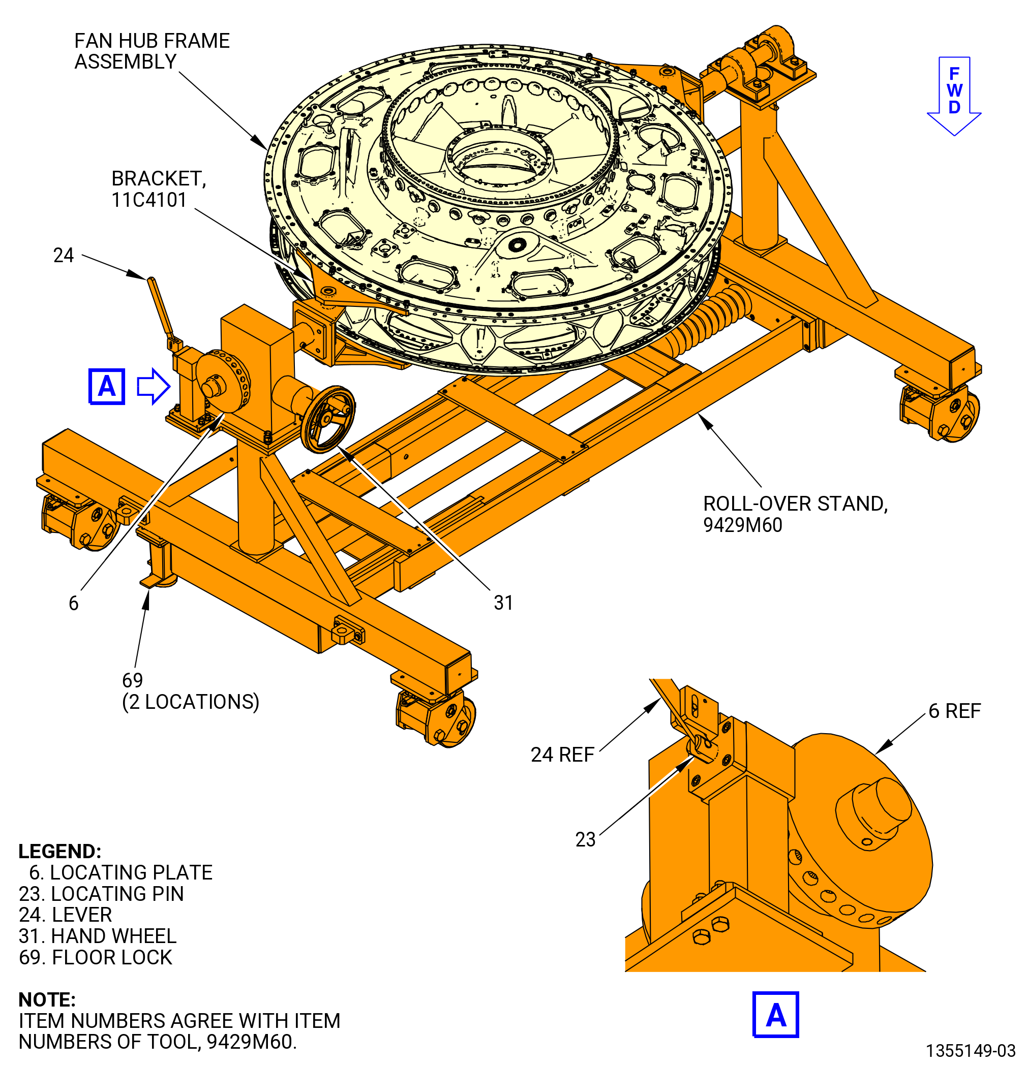
| C. | Alternative Procedure Available. Turn the fan hub frame assembly in the 9429M60 roll-over stand or 11C4100 roll-over stand to the vertical position, forward end down, as follows. Refer to Figure 1004. |
| CAUTION: |
|
| (1) | Engage the floor locks (item 69) of the 9429M60 roll-over stand or 11C4100 roll-over stand. |
| (2) | Move the lever (item 24) to unlock the hand wheel (item 31). |
| (3) | Turn the hand wheel (item 31) until the fan hub frame assembly is in the vertical position, forward end down. |
| CAUTION: |
|
| (4) | Move the lever (item 24) to engage the locating pin (item 23) into the locating plate (item 6) to lock the hand wheel (item 31). |
| Subtask 72-25-00-440-070 |
| WARNING: |
|
| CAUTION: |
|
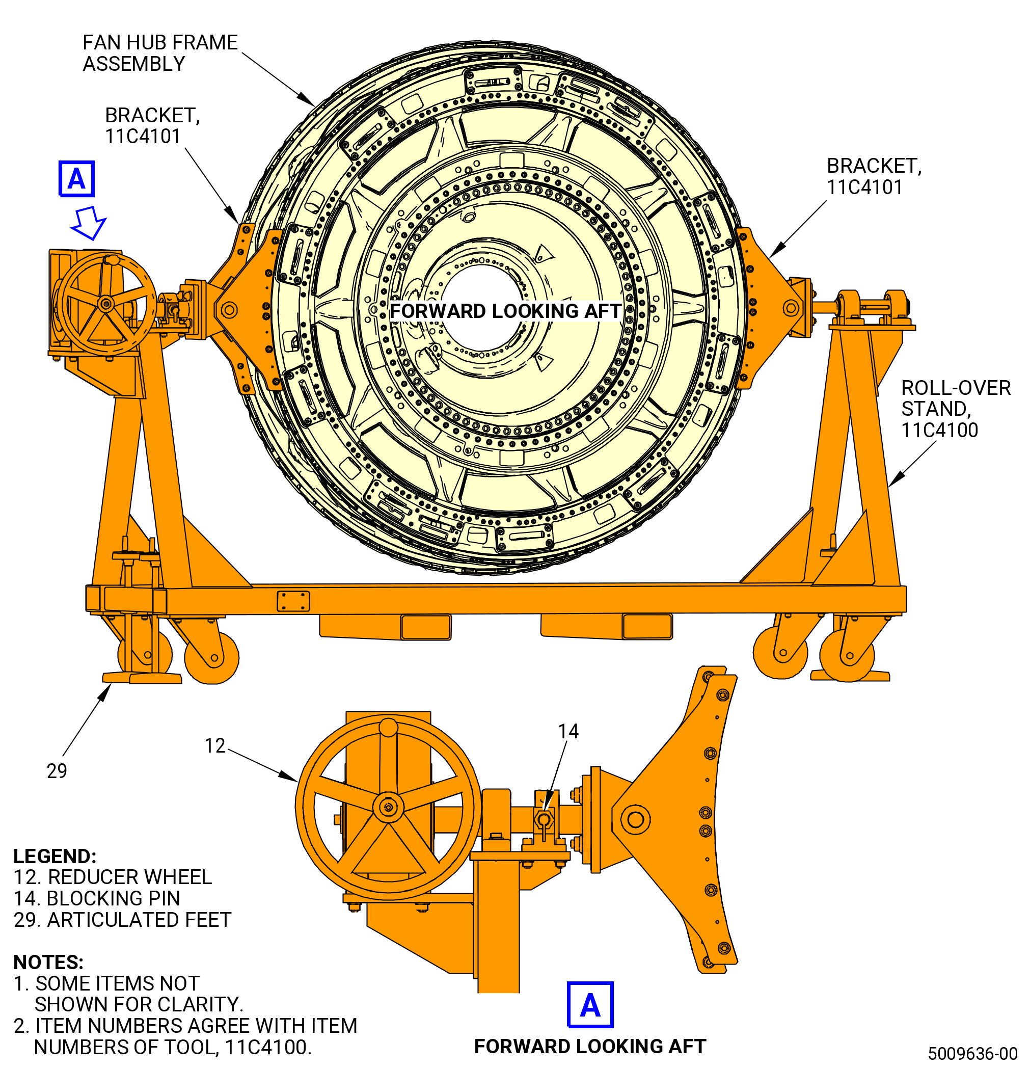
| C.A. | Alternative Procedure. Turn the fan hub frame assembly in the 11C4100 roll-over stand to the vertical position, forward end down, as follows. Refer to Figure 1005. |
| (1) | Engage the articulated feet (item 29) of the 11C4100 roll-over stand. |
| (2) | Remove the blocking pin (item 14) to unlock the reducer wheel (item 12). |
| (3) | Turn the reducer wheel (item 12) until the fan hub frame assembly is in the horizontal position, top vertical centerline up. |
| (4) | Insert the blocking pin (item 14) in the relevant hole to lock the support shaft. |
| Subtask 72-25-00-440-004 |
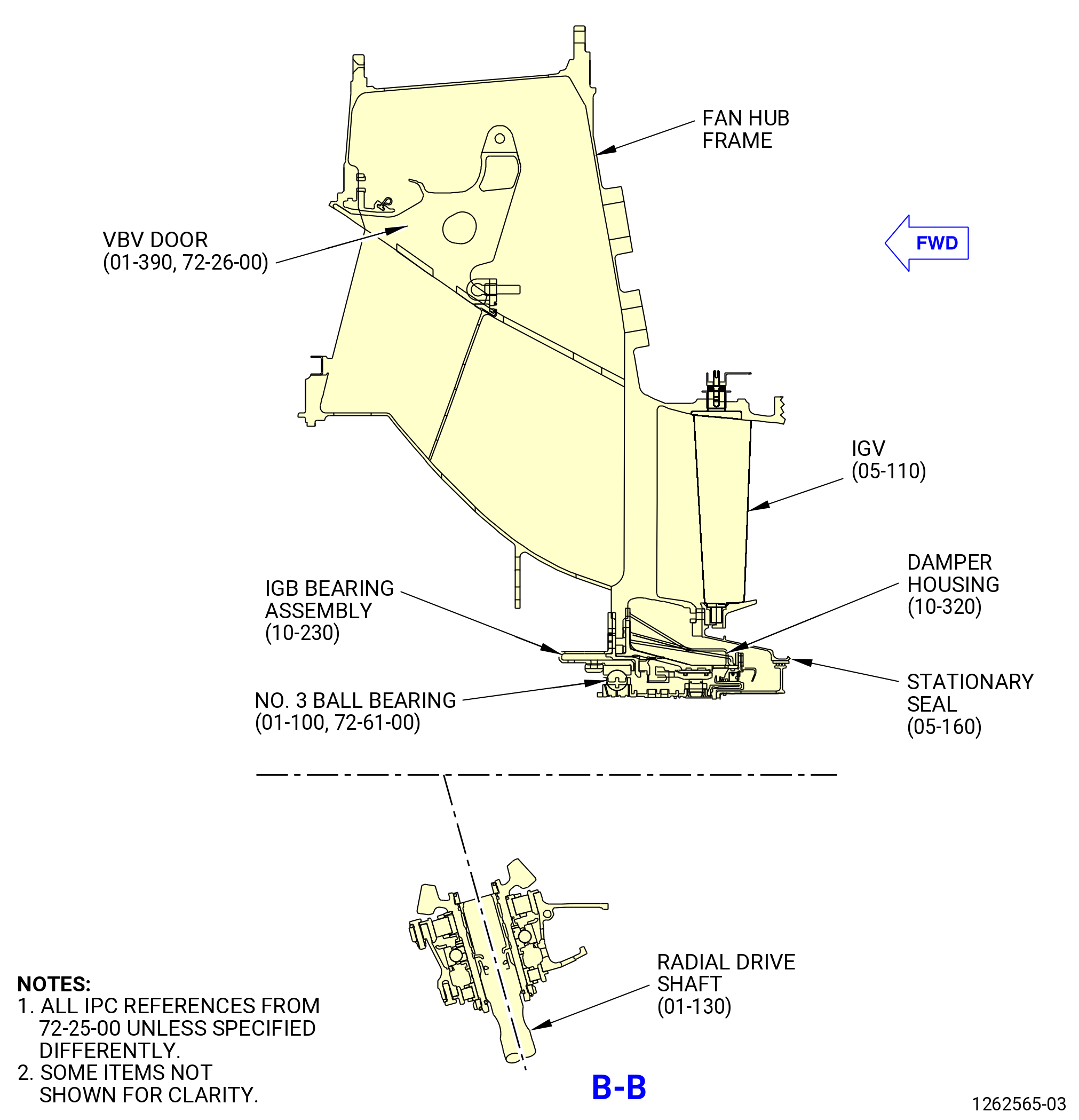
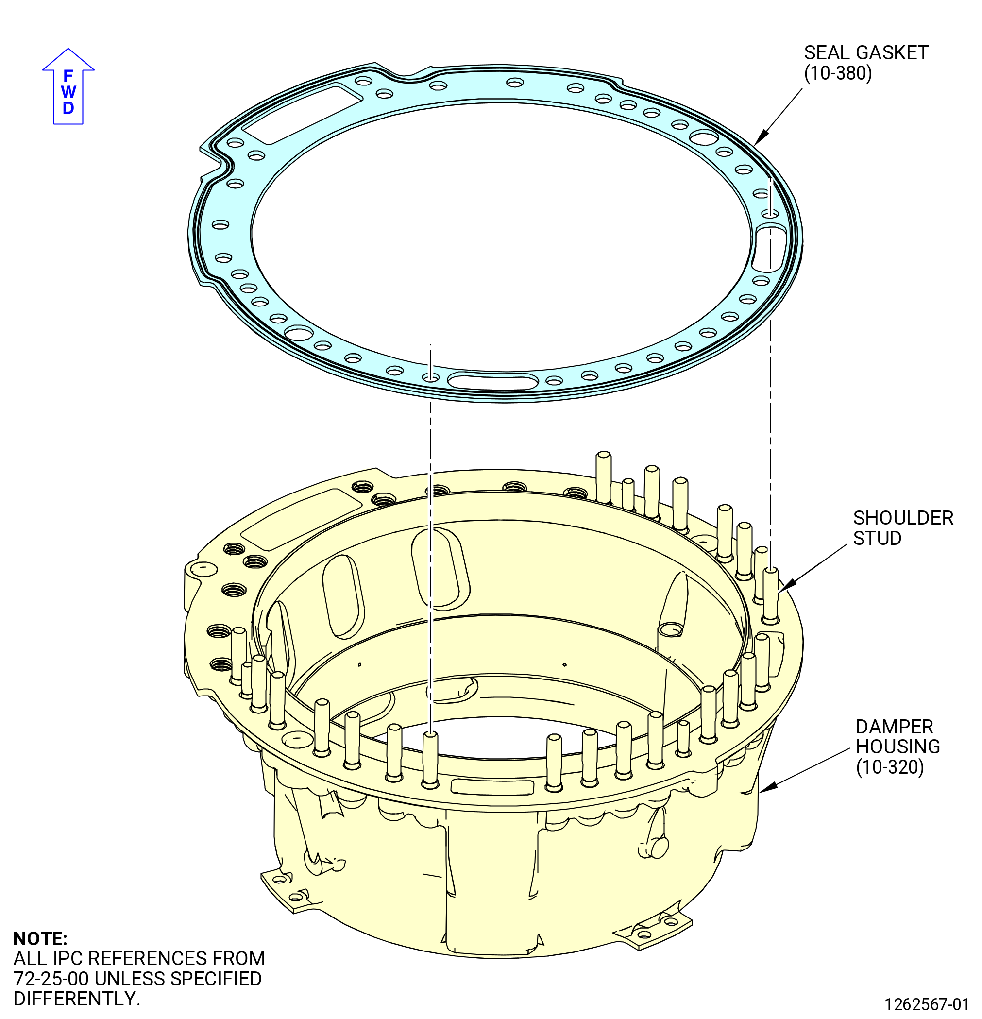
| D. | Install the damper housing (10-320) (SIN 03001) on the fan hub frame assembly as follows: |
| WARNING: |
|
| WARNING: |
|
| (1) | Clean the damper housing with a 50-50 blend of C04-014 denatured alcohol and C04-035 isopropyl alcohol, C04-002 Stoddard solvent, or C04-035 isopropyl alcohol as follows: |
| (a) | Clean the threads of the damper housing shoulder studs. |
| (b) | Clean the flange mating face of the damper housing. |
| (c) | Clean the flange mating faces of the fan hub frame assembly. |
| (2) | Install the damper housing and the mating surfaces of the nuts (03041) and nuts (item 3) of the 11C4112 seating ring. |
| WARNING: |
|
| (3) | Apply C02-019 engine oil or C02-023 engine oil to the threads and mating surfaces of the nuts (03041) and the nuts (item 3) of the 11C4112 seating ring. Refer to Figure 1007. |
| NOTE: |
|
| (4) | Apply C02-019 engine oil or C02-023 engine oil to the outside diameter (OD) of the damper housing (seal gasket) (03050) on both sides. |
| CAUTION: |
|
| (5) | Align the boltholes in the seal gasket (03050) with the shoulder studs in the damper housing. Refer to Figure 1006. |
| WARNING: |
|
| (6) | Increase the temperature of the fan hub frame assembly aft inner flange to 257°F (125.0°C). |
| (7) | Install the 11C4119 alignment pin in the fan hub frame assembly at the 5:30 o'clock position on the forward side. |
| (8) | Install the damper housing on the fan hub frame assembly from the aft side. Use the 11C4119 alignment pin to align the damper housing with the fan hub frame assembly. |
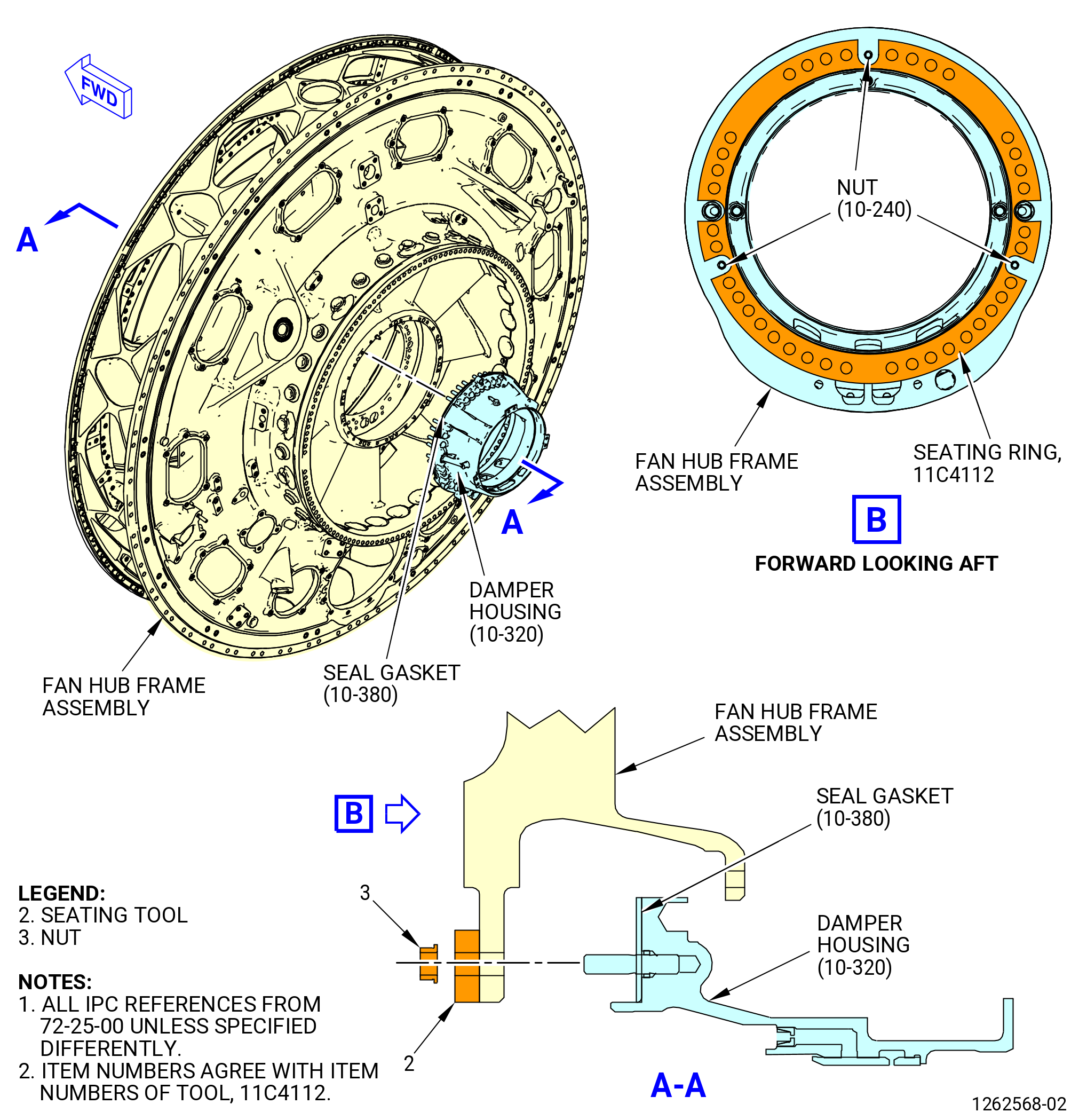
| (9) | Install the 11C4112 seating ring on the forward flange of the fan hub frame assembly as follows. Refer to Figure 1007. |
| (a) | Align the TOP POINT mark on the base (item 2) with the top vertical centerline of the fan hub frame assembly. |
| (b) | Install a minimum of four nuts (item 3) on the shoulder studs at equally spaced locations. |
| (c) | Torque the nuts (item 3) in a criss-cross pattern to 86 lb in. (9.7 N.m). |
| (d) | Torque the nuts in a criss-cross pattern (item 3) to 106-124 lb in. (12.0-14.0 N.m). |
| (10) | When the assembly is at room temperature, check the torque of the nuts (item 3) of the 11C4112 seating ring. |
| (11) | Install the nuts (03041) on the shoulder studs at the 12:00, 3:45, and 8:15 o'clock positions. Torque the nuts (03041) to 106-124 lb in. (12.0-14.0 N.m). |
| (12) | Do a shim check between the damper housing and the seal gasket (03050) to make sure the damper housing is fully installed. Use a 0.001 inch (0.03 mm) shim. |
| (13) | Remove the nuts (item 3) and remove the 11C4112 seating ring from the fan hub frame assembly. |
| (14) | Remove the 11C4119 alignment pin from the fan hub frame assembly. |
| Subtask 72-25-00-440-007 |
| CAUTION: |
|
| CAUTION: |
|
| E. | Install the inlet gearbox (IGB bearing assembly) (03000) as follows: |
| Subtask 72-25-00-160-001 |
| WARNING: |
|
| (1) | Before the installation of the IGB bearing assembly into the fan module, do a last chance wipe of the bore of the horizontal gearshaft using new C10-182 wipers with clean C02-019 engine oil. |
| Subtask 72-25-00-440-076 |
| (2) | Be careful with the components of the IGB bearing assembly. Refer to TASK 70-14-00-620-003 (HANDLING OF BEARINGS) and TASK 70-60-01-620-002 (PRESERVATION OF ANTIFRICTION BEARINGS). |
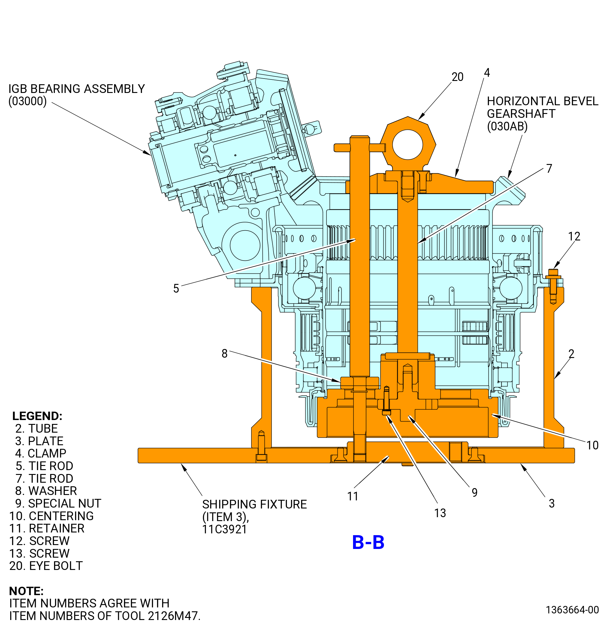
| (3) | If necessary, remove the IGB bearing assembly from the 11C3921 shipping fixture. Refer to Figure 1008. |
| WARNING: |
|
| (4) | Clean the mounting flange mating faces of the No. 3 cylindrical roller bearing (No. 3 bearing outer race) (01-130 , 72-61-00) (SIN 030A5), fan hub frame assembly, threads and mating surfaces of self-locking nuts (nuts) (10-200) (SIN 03040) with C04-035 isopropyl alcohol, C04-002 Stoddard solvent, or a 50-50 lend of C04-014 denatured alcohol and C04-035 isopropyl alcohol as follows: |
| WARNING: |
|
| CAUTION: |
|
| (5) | Apply a light coat of C02-019 engine oil or C02-023 engine oil to the piston rings (030W0) and the grooves in the No. 3 bearing outer race. |
| (6) | Apply C02-019 engine oil or C02-023 engine oil to the threads and mating surfaces of nuts (03040). Refer to Figure 1010. |
| (7) | Install a piston ring in the forward ring groove of the No. 3 bearing outer race. Install the piston ring with the thin tab on the piston ring ends aft. Refer to Figure 1009. |
| (8) | Install a piston ring in the aft ring groove of the No. 3 bearing outer race. Install the piston ring with the thin tab on the piston ring ends forward. |
| (9) | Make sure that the aft piston ring gap is 180 degrees opposite of the forward piston ring gap. |
| WARNING: |
|
| (10) | Apply C02-019 engine oil or C02-023 engine oil to the preformed packing (10-330) (SIN 03052). |
| (11) | Install the preformed packings (10-330) (SIN 03052) on the tubes (oil tubes) (030S0). |
| (12) | Install the oil tubes in the No. 3 bearing lube nozzles (030B0) on the IGB bearing assembly. |
| (13) | Turn the fan hub frame assembly in the 9429M60 roll-over stand or 11C4100 roll-over stand to the vertical position, forward end up, as follows. Refer to Subtask 72-25-00-440-063 (paragraph 3.C.). |
| (14) | Install the 11C4105 heating shroud on the forward flange of the fan hub frame assembly as follows: |
| (a) | Install the diffuser (item 3) of the 11C4105 heating shroud into the damper housing (03001) on the forward side of the fan hub frame assembly. |
| (b) | Tighten the nuts (item 4) to hold the 11C4105 heating shroud against the fan hub frame assembly. |
| WARNING: |
|
| CAUTION: |
|
| CAUTION: |
|
| (15) | Increase the temperature of the fan hub frame assembly forward flange to 302°F (150°C). |
| (16) | Install the 11C4110 bearing guide on the aft flange of the fan hub frame assembly as follows: |
| (a) | Install the central shaft (item 2) of the 11C4110 bearing guide into the aft flange of the fan hub frame assembly. |
| (b) | Make sure that the 11C4110 bearing guide is in the correct position. |
| (c) | Install the screws (item 6) into the aft flange of the fan hub frame assembly. |
| (d) | Install the pin (item 5) into the central shaft (item 2) to hold the 11C4110 bearing guide in the correct position. |
| (17) | Install the 11C4107 IGB lifting tool or 11C4129 lifting tool on the IGB bearing assembly. |
| (18) | Remove the hardware that attaches the IGB bearing assembly to the 2126M43 IGB support. Refer to Figure 1008. |
| WARNING: |
|
| (19) | Lift the IGB bearing assembly from the 2126M43 IGB support. |
| WARNING: |
|
| (20) | Apply dry ice to the No. 3 bearing outer race and piston rings for 10 minutes. |
| WARNING: |
|
| (21) | Lift the IGB bearing assembly and put it in position near the fan hub frame assembly. |
| WARNING: |
|
| (22) | Remove the 11C4105 heating shroud from the fan hub frame assembly. |
| WARNING: |
|
| (23) | Apply C02-019 engine oil or C02-023 engine oil to the piston rings (030W0) and the bores in the damper housing for the oil tubes. |
| CAUTION: |
|
| (24) | Put the IGB bearing assembly in position above the fan hub frame assembly and carefully install it on the forward flange of the fan hub frame assembly. Refer to Figure 1010. |
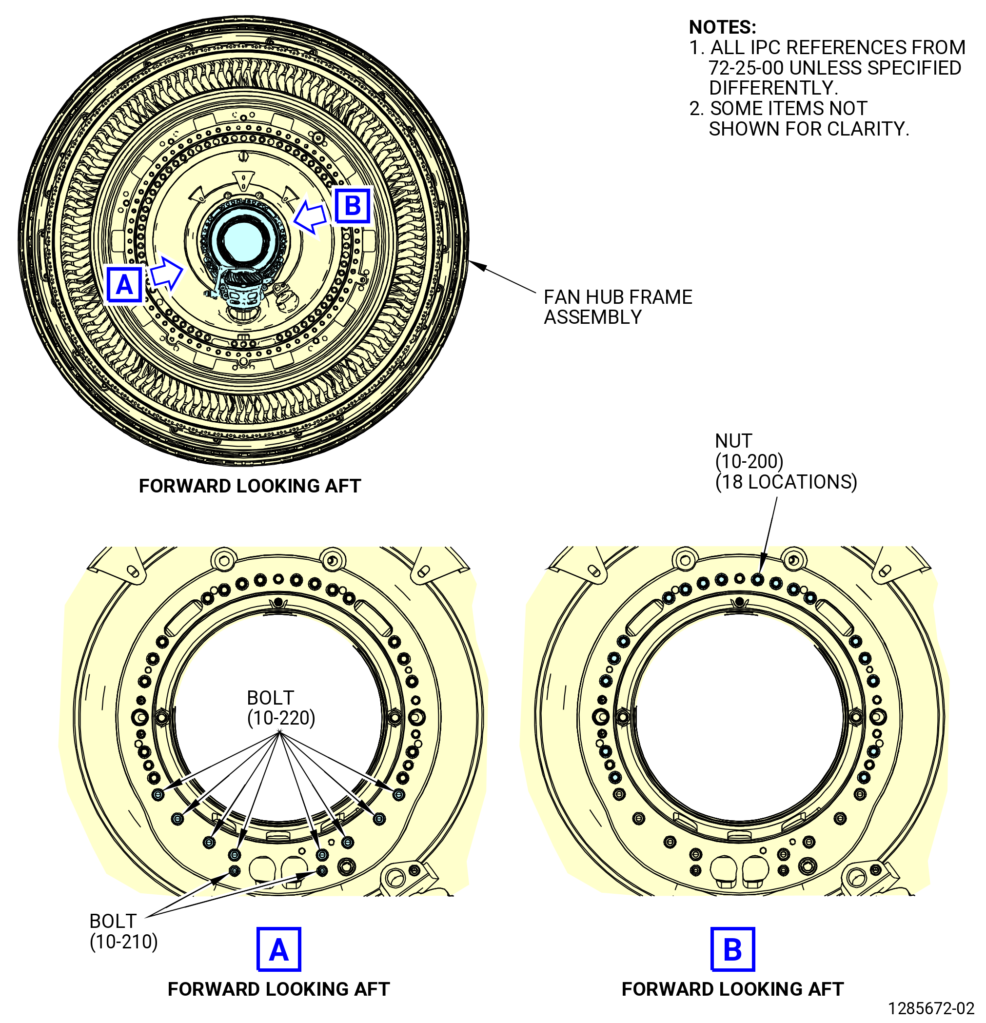
| (25) | Attach the IGB bearing assembly to the fan hub frame assembly with 18 nuts (03040). Do not install nuts (03040) above and below the oil inlet ports at the 3:00 and 9:00 o'clock positions. |
| (26) | Torque the nuts (03040) in a criss-cross pattern to 86 lb in. (9.7 N.m). |
| (27) | Remove the 11C4107 IGB lifting tool or 11C4129 lifting tool from the IGB bearing assembly. |
| (28) | Let the parts return to room temperature. |
| (29) | Torque the nuts (03040) to 106-124 lb in. (12.0-14.0 N.m). |
| (30) | Do a shim check to make sure the IGB bearing assembly housing and the No. 3 roller bearing outer race is fully against the forward flange of the fan hub frame assembly. Use a 0.001 inch (0.03 mm) shim. |
| WARNING: |
|
| (31) | Apply C02-019 engine oil or C02-023 engine oil to the threads and mating surfaces of machine bolts (bolts) (030F3) and machine bolts (bolts) (030F6). |
| (32) | Install the bolts (030F6) on the IGB bearing assembly. |
| (33) | Install the bolts (030F3) on the IGB bearing assembly. |
| (34) | Torque the bolts (030F3, 030F6) to 51-59 lb in. (5.8-6.7 N.m). |
| (35) | Remove the 11C4110 bearing guide from the fan hub frame assembly. |
| Subtask 72-25-00-220-013 |
| F. | Do a dimensional check of the IGB bearing assembly (10-230) (SIN 03000) as follows: |
| (1) | Turn the fan hub frame assembly in the 9429M60 roll-over stand or 11C4100 roll-over stand to the vertical position, forward end down, as follows. Refer to Subtask 72-25-00-440-063 (paragraph 3.C.). |
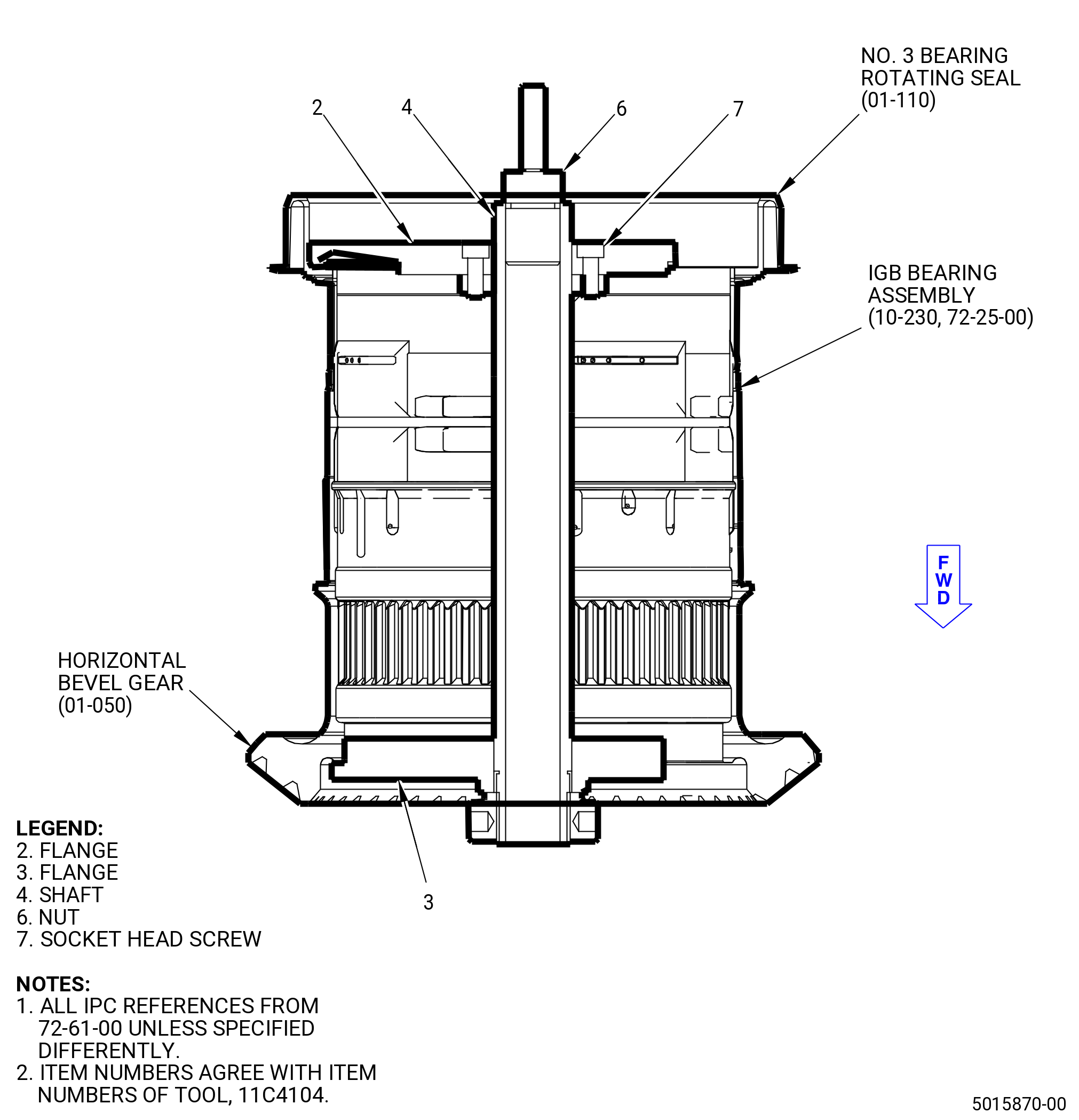
| (2) | Install the 11C4104 restraining tool. Refer to Figure 1011 and do as follows: |
| (a) | Install the shaft (item 4) and flange (item 3) on the forward side of the IGB bearing assembly. Engage the tabs on the flange (item 3) with the forward face on the inside diameter (ID) of the horizontal bevel gear. |
| (b) | Install the flange (item 2) on the shaft (item 4) and the aft side of the IGB bearing assembly (10-230) (SIN 03000). Engage the tabs on the flange (item 2) with the No. 3 bearing rotating seal (01-110 , 72-61-00) (SIN 03003). |
| (c) | Attach the flange (item 2) to the shaft (item 4) with socket head screws (item 7). |
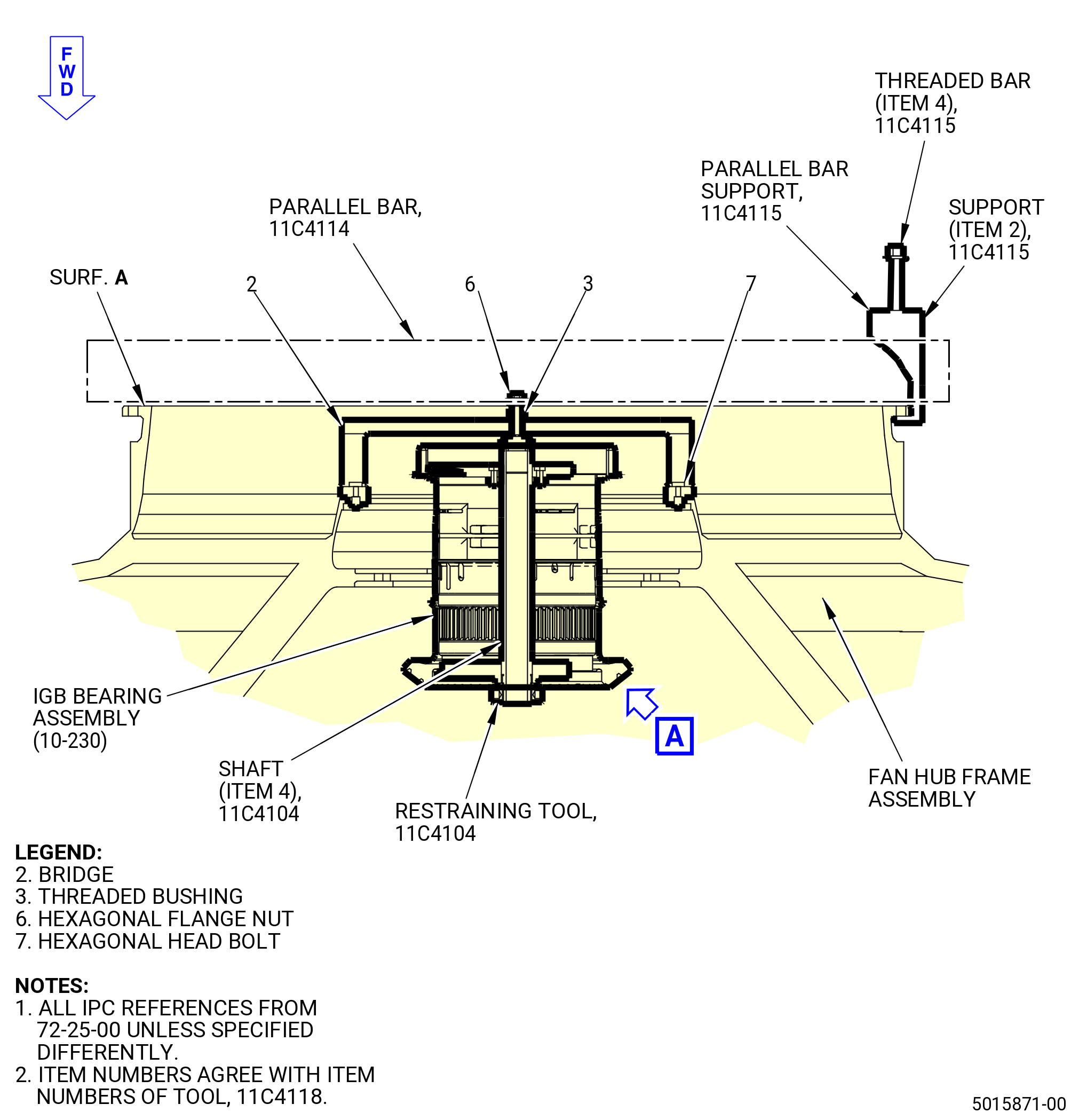
| (3) | Install the 11C4118 load apply tool as follows: |
| (a) | Install the bridge (item 2) of the 11C4118 load apply tool on the inner aft flange of the fan hub frame assembly at the 3:00 and 9:00 o'clock positions. |
| (b) | Attach the bridge (item 2) to the fan hub frame assembly with hex head bolts (item 7). |
| (4) | Install the 11C4114 parallel bar as follows: |
| (a) | Put the 11C4114 parallel bar across the middle aft flange (surface A) of the fan hub frame assembly. |
| (b) | Install the 11C4115 parallel bar support on one end of the 11C4114 parallel bar. |
| (c) | Engage the support (item 2) with the fan hub frame assembly flange and tighten the threaded bar (item 4) to hold the 11C4114 parallel bar against the fan hub frame assembly. |
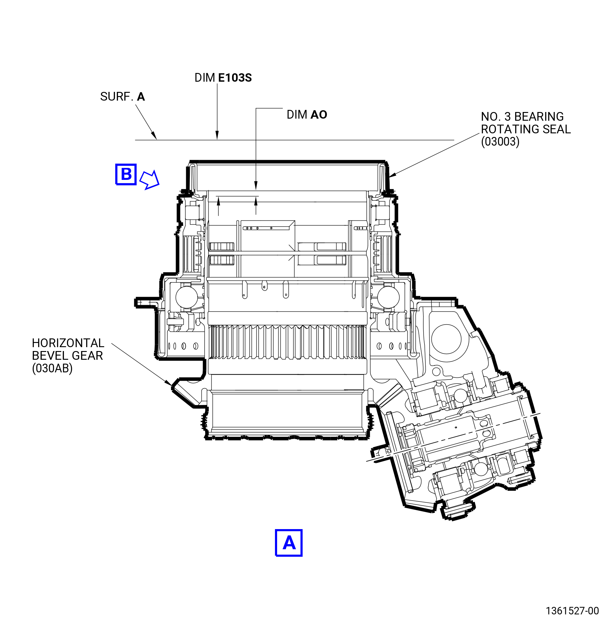
| (5) | Measure and record dimension E103S as follows. Refer to Figure 1012. |
| (a) | Install the threaded bushing (item 3) of the 11C4118 load apply tool on the shaft (item 4) of the 11C4104 restraining tool. Tighten the threaded bushing (item 3) to 10.1 lb in. (1.14 Nm) to apply a load of 100 lbs (444.82 N). |
| (b) | Measure the distance from surface A of the fan hub frame assembly to the aft face of the No. 3 bearing rotating seal. Measure at four equally spaced locations. |
| (c) | Record the measurements as E103S MAX on the record sheet. Refer to Figure 1003. |
| (d) | Calculate and record the average measurement E103S MAX. The dimension must be 2.862-2.893 inches (72.69-73.48 mm). |
| (e) | Remove the threaded bushing (item 3) of the 11C4118 load apply tool from the shaft (item 4) of the 11C4104 restraining tool. |
| (f) | Install the nut (item 6) of the 11C4118 load apply tool on the shaft (item 4) of the 11C4104 restraining tool. Tighten the nut (item 6) to 10.1 lb in. (1.14 Nm) to apply a load of 100 lbs (444.82 N). |
| (g) | Measure the distance from surface A of the fan hub frame assembly to the aft face of the No. 3 bearing rotating seal. Measure at four equally spaced locations. |
| (h) | Record the measurements as E103S MIN on the record sheet. Refer to Figure 1003. |
| (i) | Calculate and record the average measurement E103S MIN. The dimension must be 2.862-2.893 inches (72.69-73.48 mm). |
| (6) | Remove the 11C4115 parallel bar support and the 11C4114 parallel bar. |
| (7) | Remove the 11C4118 load apply tool. |
| (8) | Remove the 11C4104 restraining tool. |
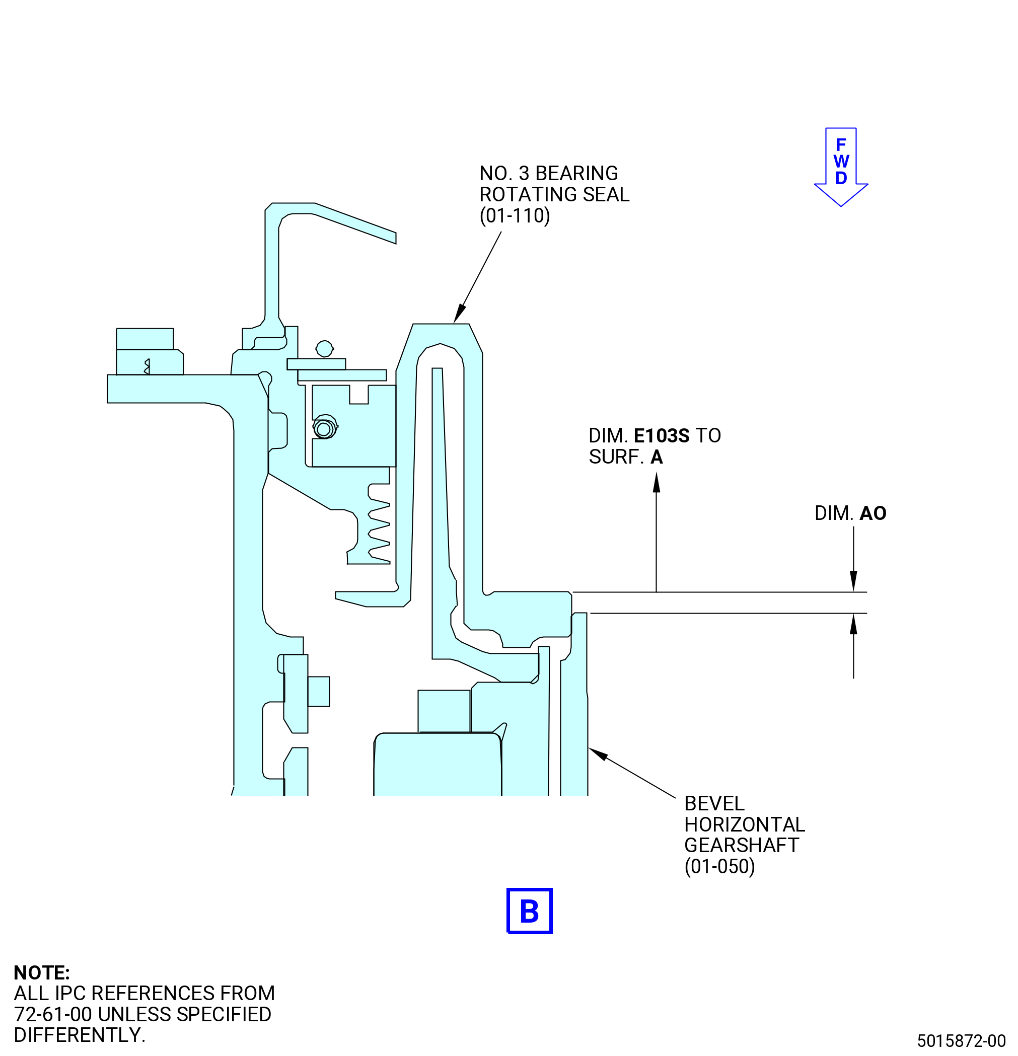
| (9) | If a part of the IGB bearing assembly (10-230) (SIN 03000) is replaced (such as the No. 3 bearing rotating seal, (01-110 , 72-61-00) (SIN 03003)) or dimension AO is not available from the IGB build / assembly records (refer to TASK 72-61-00-440-801 (72-61-00, ASSEMBLY 001) (Subtask 72-61-00-440-087)) then measure and record dimension AO. Refer to Figure 1012 and do as follows: |
| (a) | Measure and record dimension AO from the aft face of the horizontal bevel gear, to the aft face of the No. 3 bearing rotating seal, at four equally-spaced locations. Compare the measurements to the limits below. Refer to Figure 1003. |
| Minimum serviceable limit: |
|
| • |
|
| • |
|
| Repair method: |
|
| Subtask 72-25-00-440-015 |
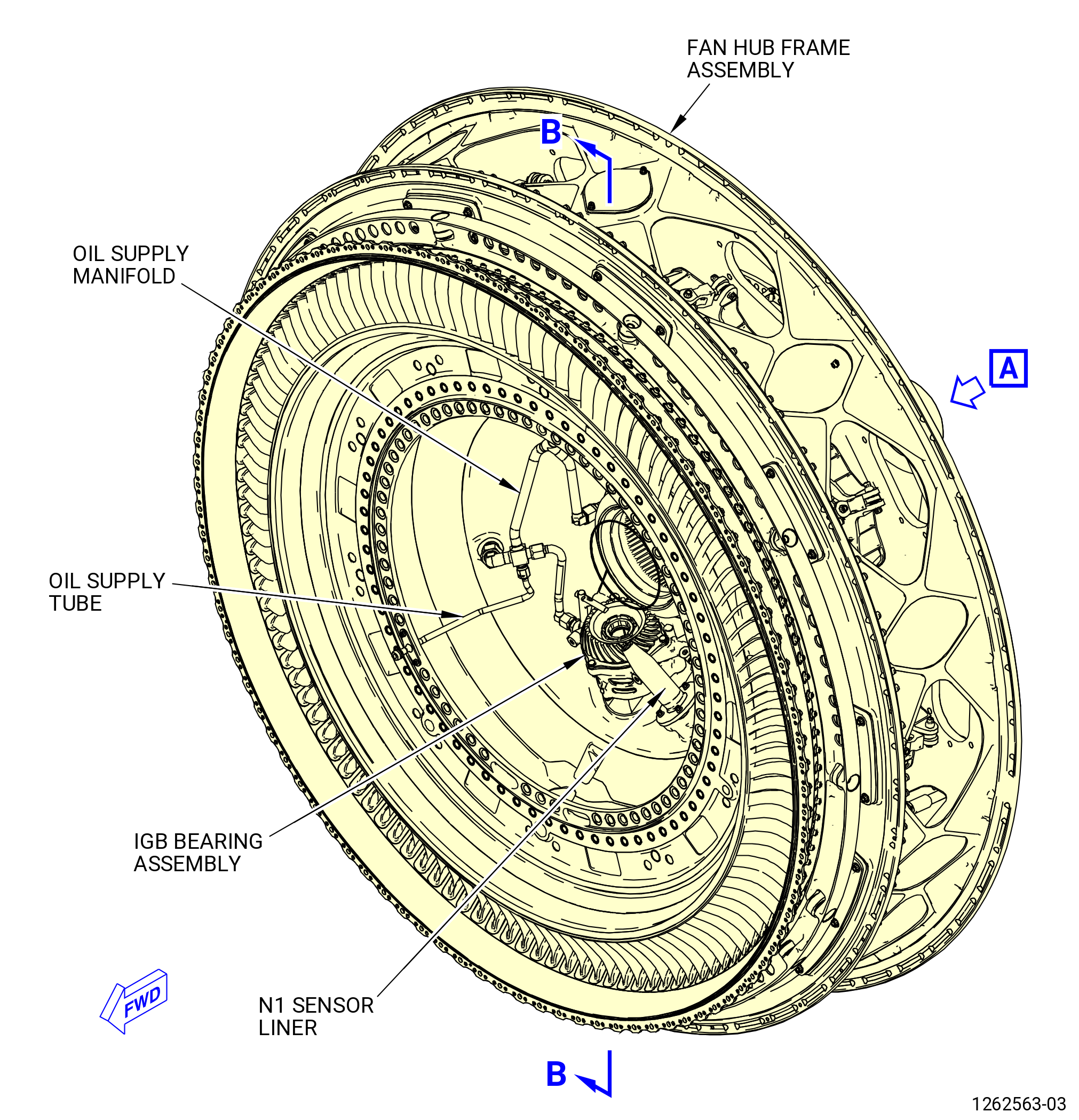
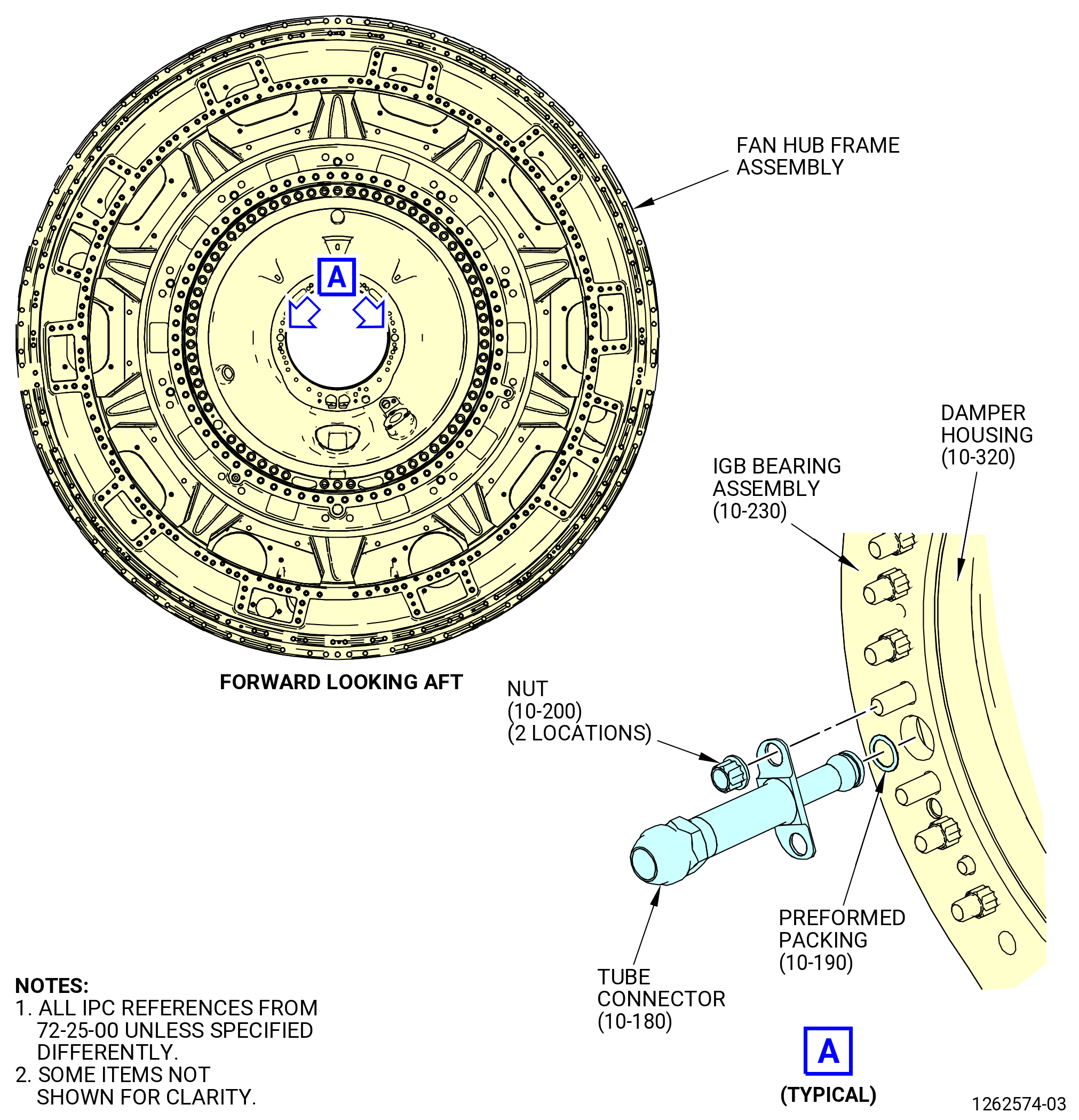
| G. | Install the oil supply tubes (tube connectors) (10-180) (SIN 442B1). Refer to Figure 1013 and do as follows: |
| (1) | Turn the fan hub frame assembly in the 9429M60 roll-over stand or 11C4100 roll-over stand to the vertical position, forward end up, as follows. Refer to Subtask 72-25-00-440-063 (paragraph 3.C.). |
| WARNING: |
|
| (2) | Apply a thin layer of C02-019 engine oil or C02-023 engine oil to the preformed packing (10-190) (SIN 442N2). |
| (3) | Apply C02-019 engine oil or C02-023 engine oil to the chamfers of the preformed packing grooves on the tube connectors. |
| (4) | Apply C02-019 engine oil or C02-023 engine oil to the threads and the mating surfaces of four nuts (03040). |
| NOTE: |
|
| (5) | Install a preformed packing (10-190) (SIN 442N2) into the groove of each tube connector. |
| (6) | Install the end of a tube connector in each of the ports at the 3:00 and 9:00 o'clock positions of the fan hub frame assembly. |
| (7) | Install the nuts (03040) to the studs of the damper housing (03001) to attach the tube connectors against the flange of the IGB bearing assembly (03000). |
| (8) | Torque the nuts (03040) to 106-124 lb in. (12.0-14.0 N.m). |
| Subtask 72-25-00-710-004 |
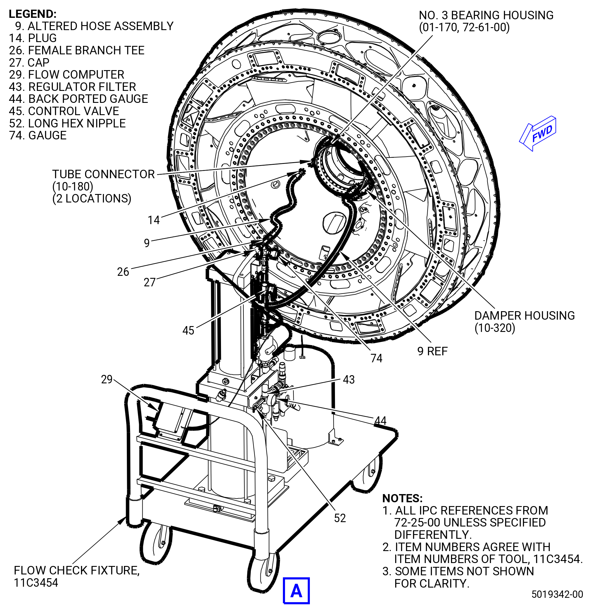
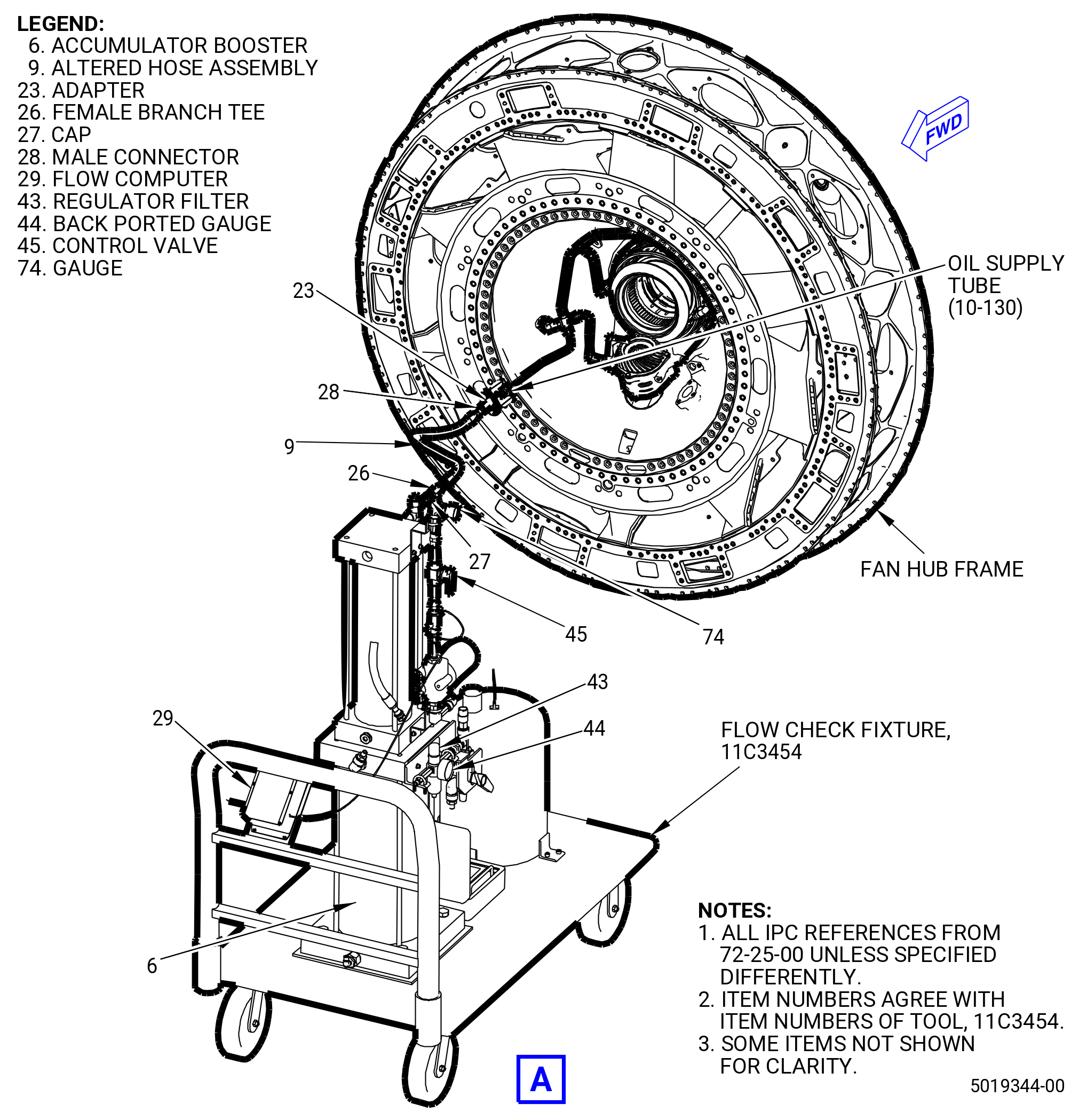
| H. | Connect the 11C3454 flow check fixture to the tube connectors (10-180) (SIN 442B1) and do a dual feed test. Refer to Figure 1014 and do as follows: |
| NOTE: |
|
| NOTE: |
|
| (1) | Turn the fan hub frame assembly in the 11C4100 roll-over stand or 9429M60 roll-over stand to the vertical position, forward end up. Refer to Subtask 72-25-00-440-063 (paragraph 3.C.). |
| (2) | Put a container below the fan hub frame assembly to collect oil released during the oil flow test. |
| (3) | Remove the cap (item 27) from the female branch tee (item 26) on top of cylinder. |
| NOTE: |
|
| (4) | Attach the second altered hose assembly (item 9) to the female branch tee (item 26). |
| (5) | Remove all plugs (item 14) from the altered hose assemblies (item 9). |
| (6) | Attach the two altered hose assemblies (item 9) to the tube connectors (10-180) (SIN 442B1) in the No. 3 bearing housing (01-170 , 72-61-00) (SIN 030A6). |
| (7) | Turn the control valve (item 45) to the OFF position. |
| (8) | Install the shop air to the long hex nipple (item 52). |
| (9) | Switch the flow computer (item 29) power to ON. |
| NOTE: |
|
| WARNING: |
|
| (10) | Adjust the regulator filter (item 43) to cause an oil pressure of 98-102 psig (676-703 kPa gage) as read by back ported gauge (item 44). |
| NOTE: |
|
| (11) | Open the control valve (item 45) to start the flow through the tube connectors (10-180) (SIN 442B1). |
| WARNING: |
|
| (12) | Adjust the regulator filter (item 43) to keep the pressure at 95-105 psig (655-724 kPa gage). |
| (13) | Look for oil flow through the bearing damper. |
| (14) | Record the flow rate from the flow computer (item 29). |
| (15) | When the test is completed, turn off the air supply to the system or set the regulator filter (item 43) to zero. |
| (16) | Turn off the flow computer (item 29). |
| (17) | Close the control valve (item 45). |
| (18) | Disconnect the air line from the 11C3454 flow check fixture. |
| (19) | Disconnect the 11C3454 flow check fixture from the tubes connectors (10-180) (SIN 442B1). |
| Subtask 72-25-00-440-016 |
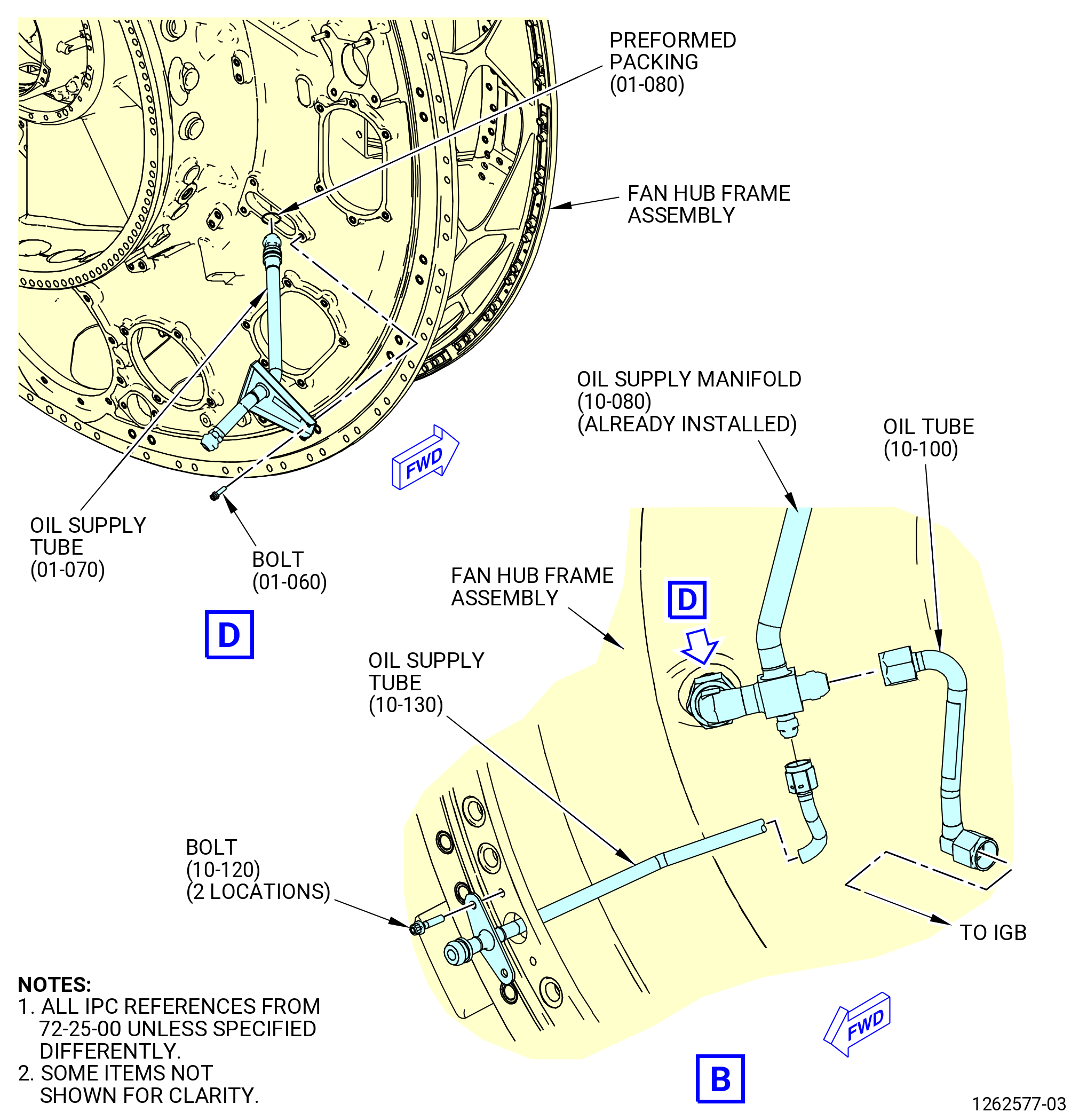
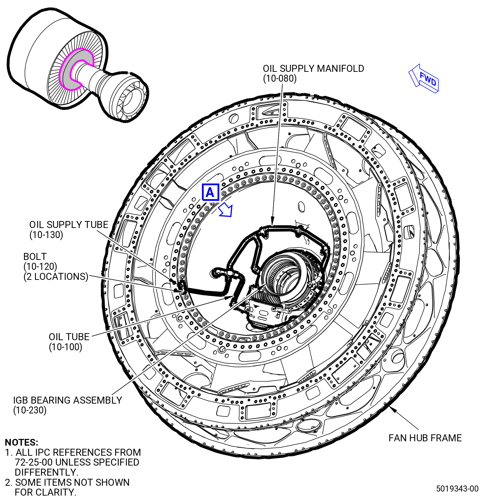
| I. | Install the oil supply tube (01-070) (SIN 442A0) in the fan hub frame assembly. Refer to Figure 1015 and do as follows: |
| WARNING: |
|
| (1) | Apply C02-019 engine oil or C02-023 engine oil to the preformed packing (01-080) (SIN 442N4). |
| (2) | Apply C02-019 engine oil or C02-023 engine oil to the lead-in chamfers of the preformed packing grooves in the oil supply tube. |
| (3) | Apply C02-019 engine oil or C02-023 engine oil to the threads of the machine bolts (bolts) (442F2). |
| NOTE: |
|
| (4) | Install the preformed packing (01-080) (SIN 442N4) on the oil supply tube. |
| (5) | Install the oil supply tube through the lube supply port of the fan hub frame assembly. The port is at the 3:30 o'clock position aft looking forward (ALF). |
| (6) | Attach the oil supply tube to the fan hub frame assembly with the bolts (442F2). |
| (7) | Torque the bolts to 106-124 lb in. (12.0-14.0 N.m). |
| Subtask 72-25-00-440-017 |
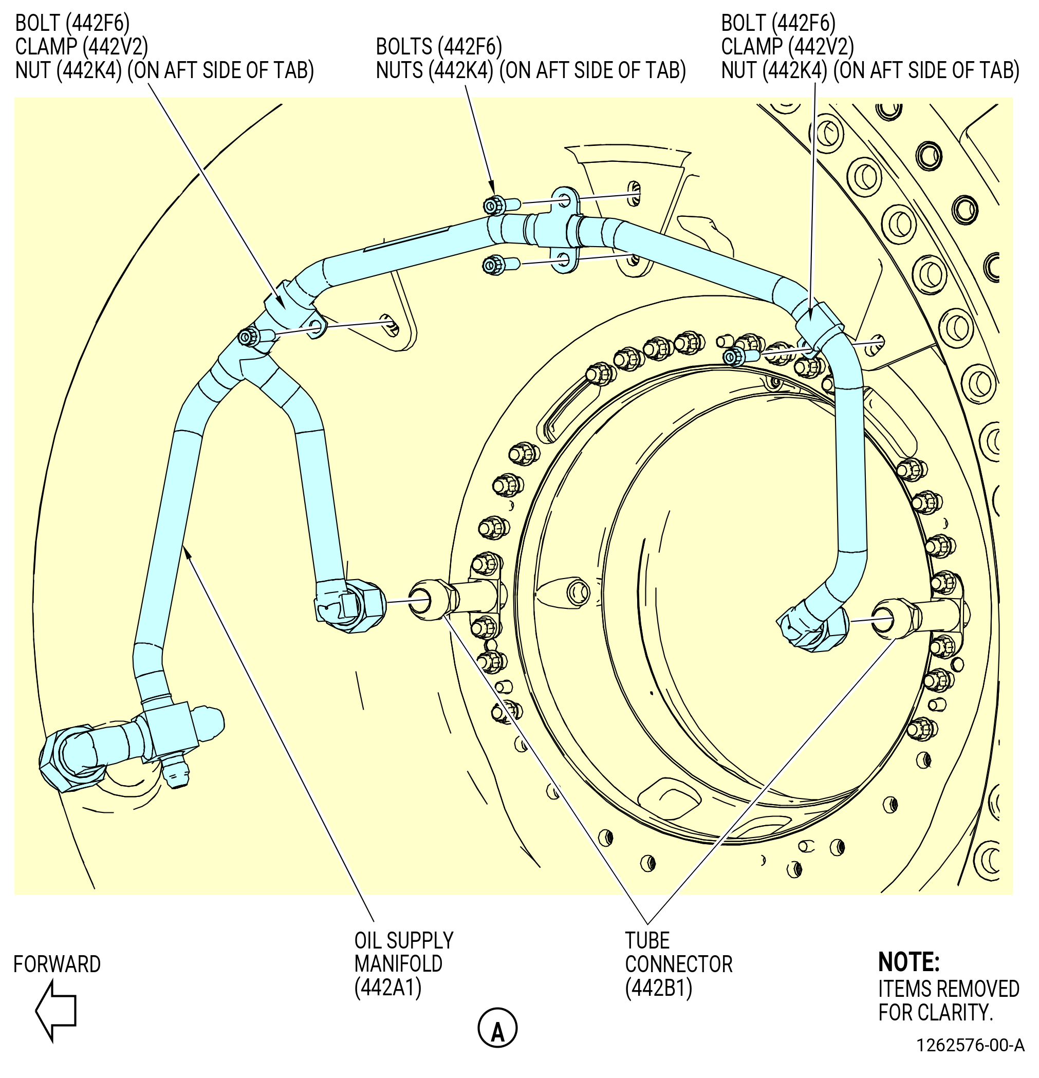
| J. | Install the oil supply manifold (442A1) as follows. Refer to Figure 1015. |
| (1) | Put the cushion loop clamps (clamps) (442V2) on the oil supply manifold at two locations. |
| WARNING: |
|
| (2) | Apply C02-019 engine oil or C02-023 engine oil to the threads and mating surfaces of the oil supply tube (442A0) and the tube connectors (442B1). |
| (3) | Loosely connect the oil supply manifold to the oil supply tube at the 8:30 o'clock position, forward looking aft (FLA). Tighten the connector hand-tight. |
| (4) | Loosely connect the oil supply manifold to the tube connectors at the 3:00 and 9:00 o'clock positions. Tighten the connectors hand-tight. |
| (5) | Make sure that the oil supply manifold and clamps are set so that the minimum amount of strain is on the tubes. |
| (6) | Triple torque the B-nuts on the oil supply manifold to the tube connectors to 55-65 lb ft (75-88 N.m). Refer to TASK 70-51-00-400-004 (TIGHTENING PRACTICES AND TORQUE VALUES). |
| (7) | Triple torque the B-nut on the oil supply manifold at the oil supply tube to 78-92 lb ft (106-125 N.m). Refer to TASK 70-51-00-400-004 (TIGHTENING PRACTICES AND TORQUE VALUES). |
| (8) | Attach the clamps (10-090) (SIN 442V2) on the oil supply manifold to the fan hub frame assembly with machine bolts (bolts) (10-060) (SIN 442F6) and self-locking nuts (nuts) (10-070) (SIN 442K4). |
| (9) | Attach the oil supply manifold to the fan hub frame assembly with bolts (442F6) and nuts (442K4). |
| (10) | Torque the bolts (442F6) to 106-124 lb in. (12.0-14.0 N.m). |
| Subtask 72-25-00-440-064 |
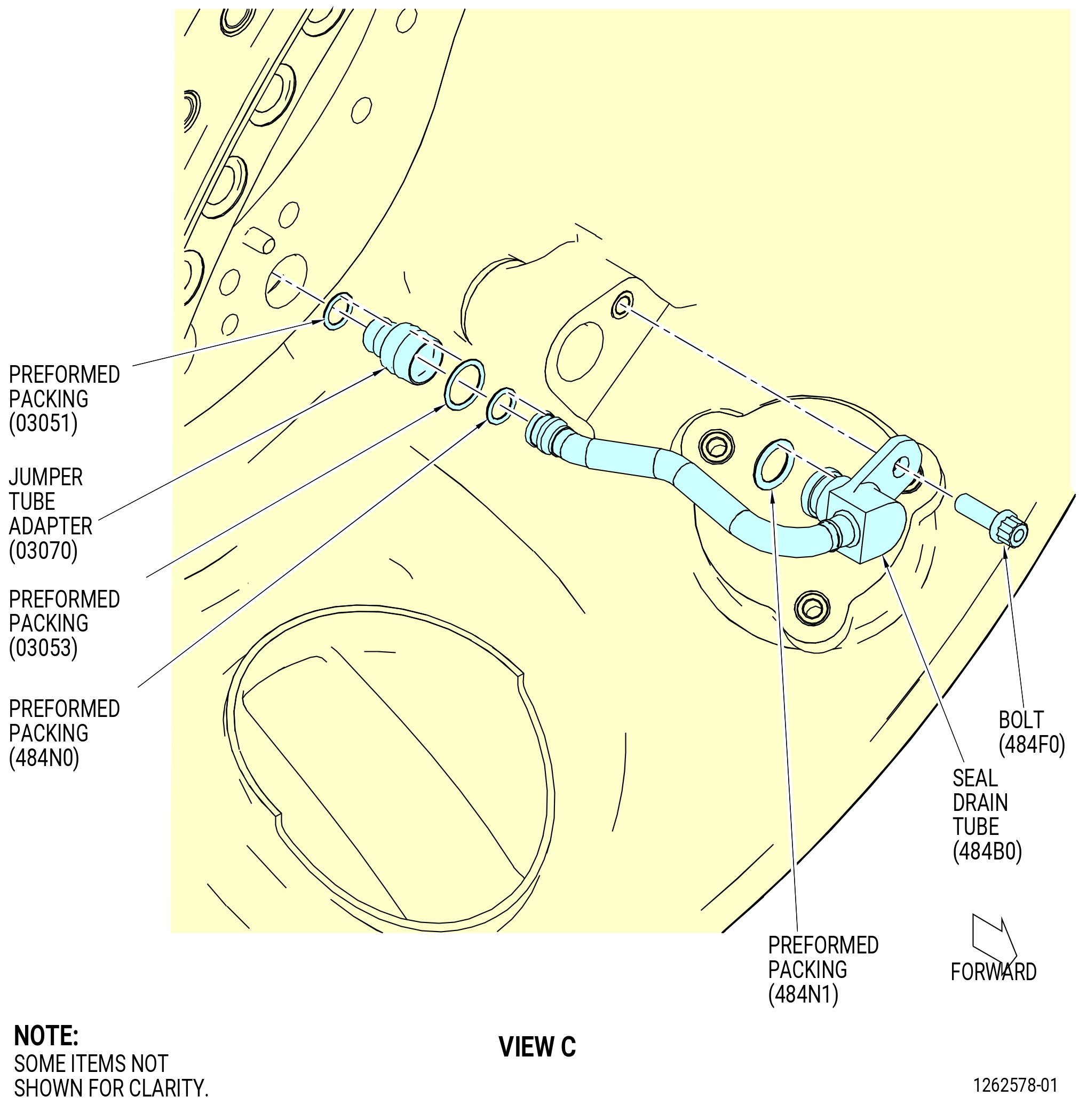
| K. | Install the adapter (jumper tube adapter) (03070) and seal drain tube (484B0) as follows. Refer to Figure 1015. |
| WARNING: |
|
| (1) | Apply C02-019 engine oil or C02-023 engine oil to the preformed packings (10-350) (SIN 03051) and (10-370) (SIN 03053). |
| (2) | Install the preformed packings (10-350) (SIN 03051) and (10-370) (SIN 03053) on the jumper tube adapter. |
| (3) | Install the small end of the jumper tube adapter into the inboard side of the fan hub frame assembly at the 5:30 o'clock position. |
| (4) | Apply C02-019 engine oil or C02-023 engine oil to the preformed packings (10-160) (SIN 484N1) and (10-170) (SIN 484N0). |
| (5) | Install the preformed packing (10-170) (SIN 484N0) to the aft end of the seal drain tube. |
| (6) | Install the preformed packing (10-160) (SIN 484N1) to the forward end of the seal drain tube. |
| (7) | Apply C02-019 engine oil or C02-023 engine oil to the washer face of the bolt (484F0). |
| (8) | Install the aft end of the seal drain tube in the jumper tube adapter in the inboard side of the fan hub frame assembly. |
| (9) | Install the forward end of the seal drain tube (484B0) into the fan hub frame assembly and attach with the machine bolt (bolt) (484F0). |
| (10) | Torque the bolt (484F0) to 106-124 lb in. (12.0-14.0 N.m). |
| Subtask 72-25-00-710-005 |
| L. | Connect the 113454 flow check fixture to the oil supply tube (10-130) (SIN 442A4) and do a single feed test. Refer to Figure 1016 and do as follows: |
| NOTE: |
|
| NOTE: |
|
| (1) | Turn the fan hub frame assembly in the 11C4100 roll-over stand or 9429M60 roll-over stand to the vertical position, forward end up. Refer to Subtask 72-25-00-440-063 (paragraph 3.C.). |
| (2) | Put a container below the fan hub frame assembly to collect oil released during the oil flow test. |
| (3) | Loose two bolts (10-120) (SIN 442F5) from the oil supply tube (10-130) (SIN 442A4). |
| (4) | Install the adapter (item 23) on the oil supply tube (10-130) (SIN 442A4). |
| (5) | Install the male connector (item 28) into the adapter (item 23) and attach it to the altered hose assembly (item 9). |
| (6) | If a second altered hose assembly (item 9) is attached to the female branch tee (item 26), remove the altered hose assembly (item 9) and install a cap (item 27) on the female branch tee (item 26). |
| (7) | Switch the flow computer (item 29) power to ON. |
| WARNING: |
|
| WARNING: |
|
| (8) | Adjust the regulator filter (item 43) to cause an oil pressure of 98-102 psig (676-703 kPa gage) as read by back ported gauge (item 44). If the pressure indications are not consistent, do a double check on the gauge (item 74). |
| WARNING: |
|
| NOTE: |
|
| (9) | Open the control valve (item 45) to start the flow through the bearing supply tubes and adjust the regulator filter (item 43) to keep the pressure at 95-105 psig (655-724 kPa gage). |
| (10) | Look for oil flow through the bearing damper. Record the flow rate from the flow computer (item 29). |
| (11) | When the test is completed, turn off the air supply to the system or set the regulator filter (item 43) to zero and turn off the flow computer (item 29). |
| (12) | Close the control valve (item 45). |
| (13) | Disconnect the air line from the 11C3454 flow check fixture. |
| (14) | Disconnect the 11C3454 flow check fixture from the oil supply tube (10-130) (SIN 442A4). |
| Subtask 72-25-00-710-003 |
| M. | Do an oil flow check of the IGB bearing assembly (03000) as follows: |
| NOTE: |
|
| (1) | Install the 11C4116 nozzle plug tool as follows: |
| CAUTION: |
|
| (a) | Turn the threaded bars (item 11) on the 11C4116 nozzle plug tool counterclockwise (CCW) to the retract position. |
| (b) | Install the guide (item 12) into the IGB bevel gear from the aft side of the IGB bearing assembly. Engage the drive with two of the oil slots on the bevel gear. |
| (c) | Install the 11C4116 nozzle plug tool on the guide (item 12). |
| (d) | Turn the fixture to align the holes on the mating flange with the holes in the damper housing (03001). |
| (e) | Torque the nut (item 23) on the 11C4116 nozzle plug tool to 50 lb in. (5.6 N.m). Torque the remaining five screws (item 19) to 50 lb in. (5.6 N.m). |
| CAUTION: |
|
| (f) | Turn the threaded bars (item 11) clockwise (CW) to engage the plugs with the oil nozzles in the IGB bearing assembly. Turn the threaded bars to apply sufficient pressure to seal the oil nozzles. Do not tighten the threaded bars too much. |
| (2) | Install the 11C4128 oil check test protection on the forward flange of the fan hub frame assembly. Attach the 11C4128 oil check test protection with the screws (item 5). |
| (3) | Install plugs (items 4 and 5) of the 11C4111 oil/air supply tube on the open ports of the oil supply manifold (442A1). |
| (4) | Connect the tube (item 3) of the 11C4111 oil/air supply tube to the oil supply tube (442A0). |
| WARNING: |
|
| (5) | Pressurize the oil supply tube with nitrogen gas at a pressure of 145-203 psig (1000-1400 kPa) to seat the piston rings (10-390) (SIN 030W0). |
| NOTE: |
|
| (6) | Connect the tube (item 3) of the 11C4111 oil/air supply tube to an oil supply. |
| (7) | Turn the fan hub frame assembly in the 9429M60 roll-over stand or 11C4100 roll-over stand to the vertical position, forward end down, as follows. Refer to Subtask 72-25-00-440-063 (paragraph 3.C.). |
| WARNING: |
|
| (8) | Flow check the IGB bearing assembly at a pressure of 95-105 psig (655-724 kPa). Use C02-019 engine oil or C02-023 engine oil at a temperature of 70-100°F (21-38°C). Collect and measure the oil that drains from the sump in 1 minute. Measure the amount with a graduated cylinder. |
| (9) | Measure and record the flow rate (M2). Refer to Figure 1003. |
| (10) | Calculate the leakage rate (M3) as follow: |
| (a) | Subtract the oil flow rate (M1) from the oil flow rate M2 to calculate the leakage rate (M3). |
|
| (b) | Leakage rate must not be more than 0.05 gallons/minute (0.189 liters/minute). |
| Subtask 72-25-00-720-001 |
| N. | Do an air flow check of the sump as follows: |
| (1) | Remove the plugs (items 4 and 5) and tube (item 3) of the 11C4111 oil/air supply tube and the 11C4116 nozzle plug tool. |
| WARNING: |
|
| WARNING: |
|
| (2) | Clean the IGB bearing assembly sump with a 50-50 blend of C04-014 denatured alcohol and C04-035 isopropyl alcohol, C04-002 Stoddard solvent, or C04-035 isopropyl alcohol as follows: |
| WARNING: |
|
| (3) | Blow clean, dry shop air through the oil supply tube (442A0) to remove any remaining solvent or contaminants. |
| WARNING: |
|
| (4) | Apply C02-019 engine oil or C02-023 engine oil to the threads and mating surfaces of the oil tube (442B2). |
| (5) | Connect the oil tube (442B2) to the fitting on the oil supply manifold (442A1) and the tube nipple (030S1) on the IGB bearing assembly (03000) at the 6:30 o'clock position, FLA. |
| (6) | Triple torque the B-nuts on the oil tube at the oil supply manifold and tube nipple to 460-540 lb in. (52.0-61.0 N.m). Refer to TASK 70-51-00-400-004 (TIGHTENING PRACTICES AND TORQUE VALUES). |
| (7) | Install the plugs (items 4 and 5) of the 11C4111 oil/air supply tube on the open ports of the oil supply manifold. |
| (8) | Apply an inlet pressure of dry, filtered air to the oil tube at 9.5-10.5 psig (65.5-72.4 kPa gage). |
| (9) | Measure and record the air flow as M4 on the record sheet. The air flow rate limits are 16.53-18.06 scfm (468.1-511.4 Lpm). Refer to Figure 1003. |
| (10) | Remove the plugs (items 4 and 5) of the 11C4111 oil/air supply tube. |
| (11) | Remove the 11C4128 oil check test protection from the forward flange of the fan hub frame assembly. |
| Subtask 72-25-00-440-065 |
| O. | Install the oil supply tube (10-130) (SIN 442A4) to the fan hub frame assembly. Refer to Figure 1015 and do as follows: |
| WARNING: |
|
| (1) | Apply C02-019 engine oil or C02-023 engine oil to the threads and mating surfaces of the oil supply tube. |
| (2) | Install the oil supply tube in the fan hub frame assembly at the 8:00 o'clock position, FLA. |
| (3) | Connect the end of the oil supply tube to the fitting on the oil supply manifold (442A1). Tighten the connectors hand tight. |
| (4) | Attach the oil supply tube to the fan hub frame assembly with the machine bolts (bolts) (442F5) and self-locking nuts (nuts) (44240). Tighten the bolts (442F5) hand tight. |
| (5) | Triple torque the B-nuts on the oil supply tube at the oil supply manifold to 262-308 lb in. (29.6-34.8 N.m). Refer to TASK 70-51-00-400-004 (TIGHTENING PRACTICES AND TORQUE VALUES). |
| (6) | Torque the bolts (442F5) to 51-59 lb in. (5.8-6.7 N.m). |
| Subtask 72-25-00-440-020 |
| CAUTION: |
|
| CAUTION: |
|
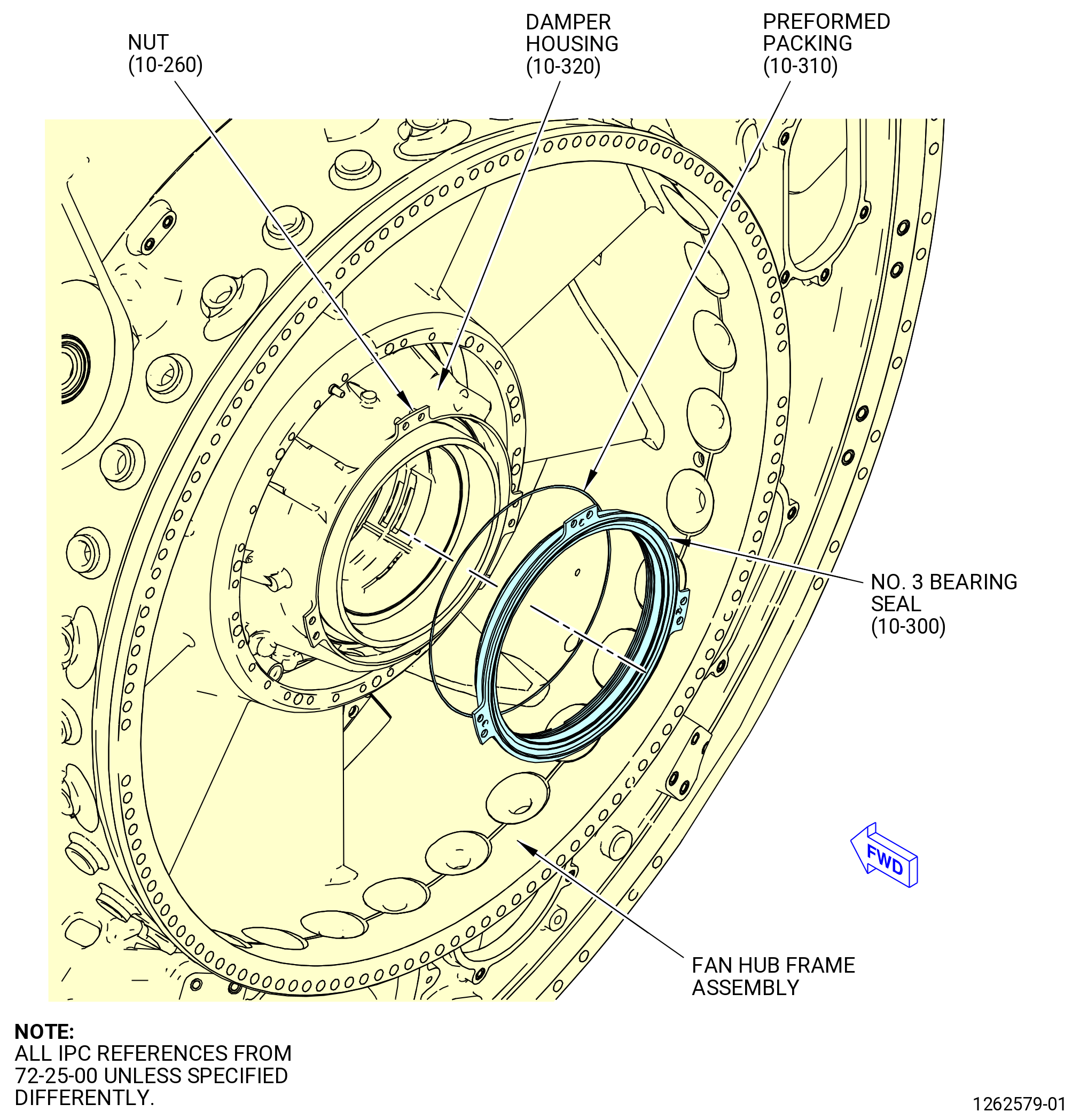
| P. | Install the No. 3 bearing stationary seal (No. 3 bearing seal) (10-300) (SIN 03080) to the aft side of the fan hub frame assembly at the damper housing (10-320) (SIN 03001). Refer to Figure 1017 and do as follows: |
| (1) | Turn the fan hub frame assembly in the 9429M60 roll-over stand or 11C4100 roll-over stand to the vertical position, forward end down, as follows. Refer to Subtask 72-25-00-440-063 (paragraph 3.C.). |
| WARNING: |
|
| (2) | Clean all parts, tools, and work surfaces with C04-002 Stoddard solvent. |
| (3) | Install the 11C4104 restraining tool as follows: |
| (a) | Install the shaft (item 4) and flange (item 3) on the forward side of the IGB bearing assembly (03000). Engage the tabs on the flange (item 3) with the forward face on the ID of the horizontal bevel gear. |
| (b) | Install the flange (item 2) on the shaft (item 4) and the aft side of the IGB bearing assembly. Engage the tabs on the flange (item 2) with the No. 3 bearing rotating seal. |
| (c) | Attach the flange (item 2) to the shaft (item 4) with screws (item 7). |
| (4) | Install the ramp (item 2) and the guide (item 3) of the 11C4121 carbon seal ramp tool on the No. 3 bearing rotating seal (03003) and the 11C4104 restraining tool. |
| (5) | Attach the guide (item 3) to the 11C4104 restraining tool with the bushing (item 6) and nut (item 8) of the 11C4121 carbon seal ramp tool. |
| WARNING: |
|
| (6) | Apply C02-019 engine oil or C02-023 engine oil to the preformed packing (10-310) (SIN 03054). |
| (7) | Install the preformed packing (10-310) (SIN 03054) on the No. 3 bearing stationary seal. Refer to Figure 1017. |
| CAUTION: |
|
| (8) | Carefully install the No. 3 bearing stationary seal on the ramp (item 2) of the 11C4121 carbon seal ramp tool. Put the No. 3 bearing stationary seal on the ramp (item 2) only. Do not try to push the No. 3 bearing stationary seal on the No. 3 bearing rotating seal manually. |
| (9) | Align the puller (item 5) with the guide pins (item 7) and threaded studs (item 4) of the 11C4121 carbon seal ramp tool and install the puller (item 5) on the guide (item 3). Carefully align the puller (item 5) with the No. 3 bearing stationary seal and put it in position next to the No. 3 bearing stationary seal. |
| (10) | Install the two special nuts (item 9) on the threaded studs (item 4). Tighten the special nuts (item 9) until they touch the puller (item 5). |
| (11) | Turn the two special nuts (item 9) the same amount at the same time to push the No. 3 bearing stationary seal on the No. 3 bearing rotating seal. |
| (12) | Attach the No. 3 bearing stationary seal to the damper housing with three slave bolts and nuts. Install the slave bolts in the left hand hole at each of the three mounting tabs. |
| (13) | Remove the 11C4121 carbon seal ramp tool. |
| (14) | Remove the 11C4104 restraining tool. |
| Subtask 72-25-00-720-002 |
| CAUTION: |
|
| Q. | Do an air flow check of the No. 3 bearing stationary seal (03080) as follows: |
| WARNING: |
|
| (1) | Clean the 11C4122 carbon seal flow check tool with C04-002 Stoddard solvent. |
| WARNING: |
|
| (2) | Apply C02-019 engine oil or C02-023 engine oil to the o-rings (items 3 and 4) on the flow check body (item 2). |
| (3) | Install the flow check body (item 2) on the damper housing (03001) and attach with screws (item 5), washers (item 6), and nuts (item 7). |
| (4) | Tighten the nuts (item 7) to 115 lb in. (13.0 N.m). |
| WARNING: |
|
| (5) | Apply an inlet pressure of dry, filtered air to the fitting (item 8) at 9.5-10.5 psig (65.5-72.4 kPa gage). |
| (6) | Measure and record the inlet pressure as P5 and the air flow as M5 on the record sheet. The air flow rate limits must not be more than 1.2 scfm (34 Lpm) at 70°F (21°C). Refer to Figure 1010. |
| (7) | Remove the 11C4122 carbon seal flow check tool. |
| Subtask 72-25-00-440-066 |
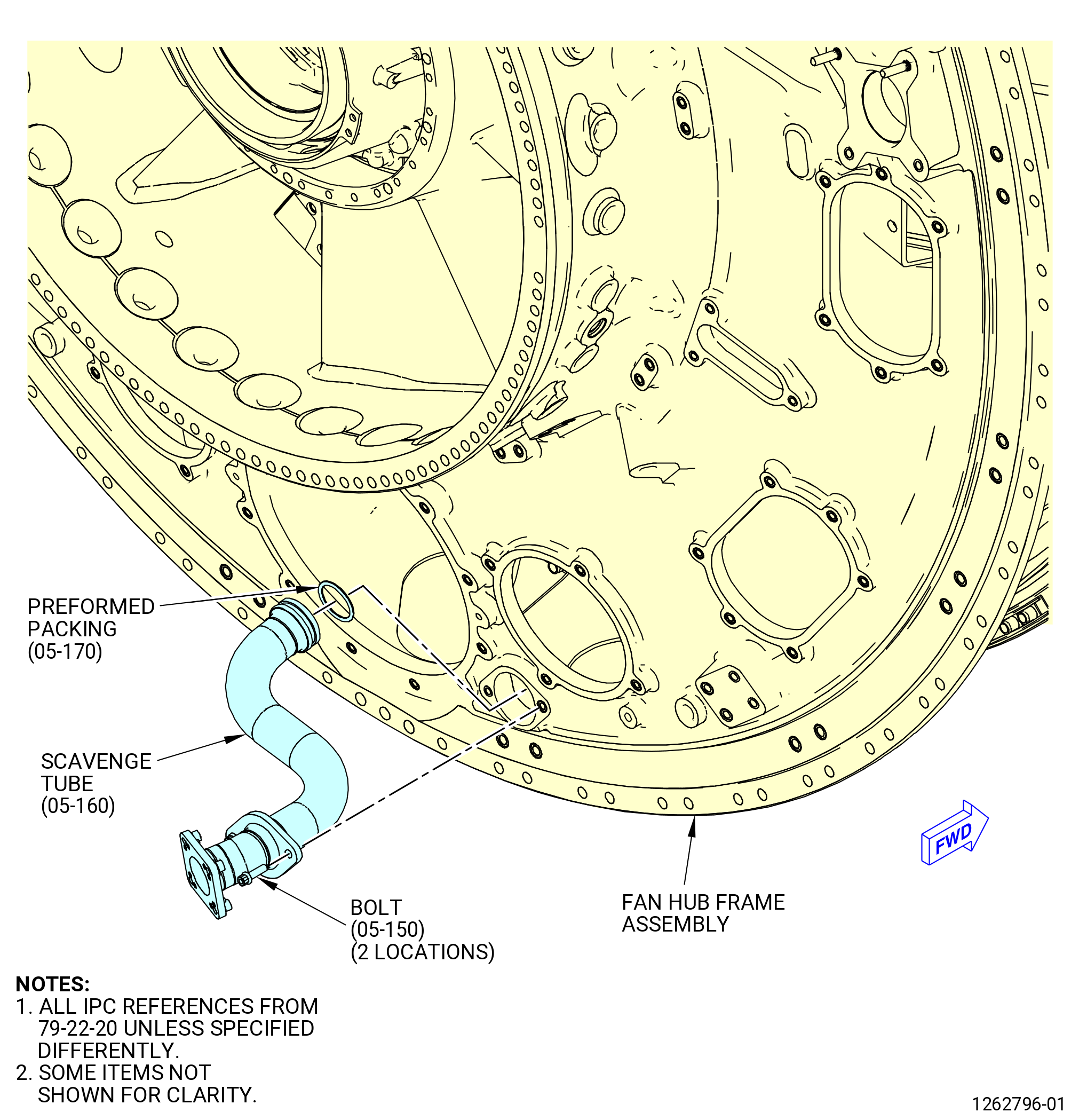
| R. | Install the oil scavenge tube (scavenge tube) (05-160 , 79-22-20) (SIN 451A1) into the fan hub frame assembly. Refer to Figure 1018 and do as follows: |
| WARNING: |
|
| (1) | Apply C02-019 engine oil or C02-023 engine oil to the performed packing (05-170 , 79-22-20) (SIN 451N1) and the lead-in chamfer of the scavenge tube. |
| (2) | Install the performed packings (05-170 , 79-22-20) (SIN 451N1) to the packing grooves in the scavenge tube. |
| (3) | Apply C02-058 graphite to the washer surface and the threads of the machine bolts (bolts) (451F0). |
| NOTE: |
|
| (4) | Install the scavenge tube in the strut on the aft side of the fan hub frame assembly at the 6:00 o'clock position. |
| (5) | Attach the scavenge tube to the fan hub frame assembly with bolts (451F0). |
| (6) | Torque the bolts to 106-124 lb in. (12.0-14.0 N.m). |
| Subtask 72-25-00-440-067 |
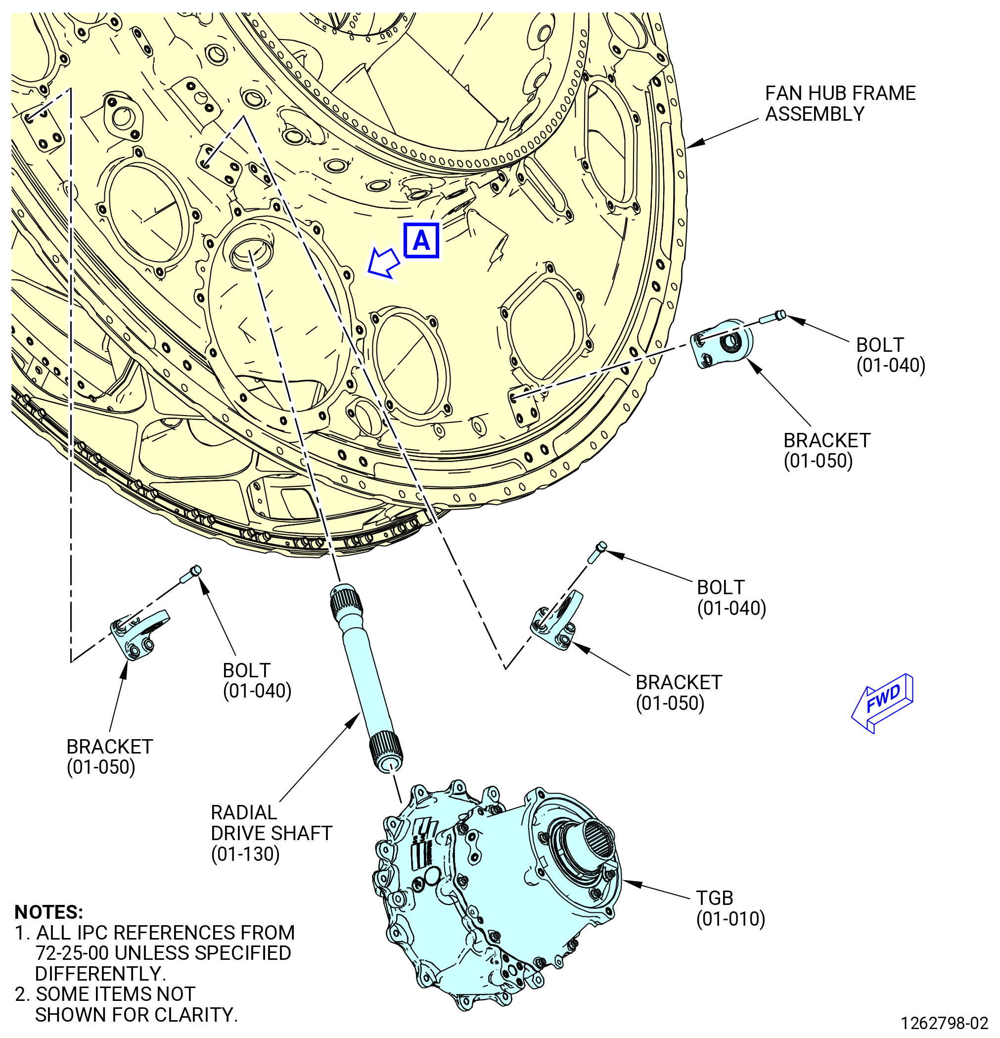
| S. | Install the radial shaft (radial drive shaft) (01-130) (SIN 03100) in the fan hub frame assembly. Refer to Figure 1019 and do as follows: |
| WARNING: |
|
| (1) | Apply C02-019 engine oil or C02-023 engine oil to the splines of the radial drive shaft. |
| (2) | Install the radial drive shaft in the fan hub frame assembly opening at the 6:00 o'clock position aft looking forward. Engage the splines of the reduced radius end of the radial drive shaft into the splines of the IGB bearing assembly (03000). |
| Subtask 72-25-00-440-068 |
| T. | Install the transfer gearbox (TGB) (01-010) (SIN 03200) in the fan hub frame assembly. Refer to Figure 1019 and do as follows: |
| (1) | Alternative Procedure Available. Install the 11C4106 TGB lifting tool on the TGB as follows. Refer to Figure 1020. |
| (a) | Align the welded assembly (item 2) with the boltholes on the aft side of the TGB. |
| (b) | Attach the welded assembly (item 2) to the TGB with capscrews (item 4) |
| Subtask 72-25-00-440-072 |
| (1).A. | Alternative Procedure. Install the 11C3235 TGB lifting tool on the TGB as follows. Refer to Figure 1021. |
| (a) | Align the lift fixture (item 2) with the boltholes on the aft side of the TGB. |
| (b) | Attach the lift fixture (item 2) to the TGB with capscrews (item 3). |
| (c) | Tighten the capscrews (item 3) to 60-180 lb in. (6.8-20.3 N.m). |
| Subtask 72-25-00-440-073 |
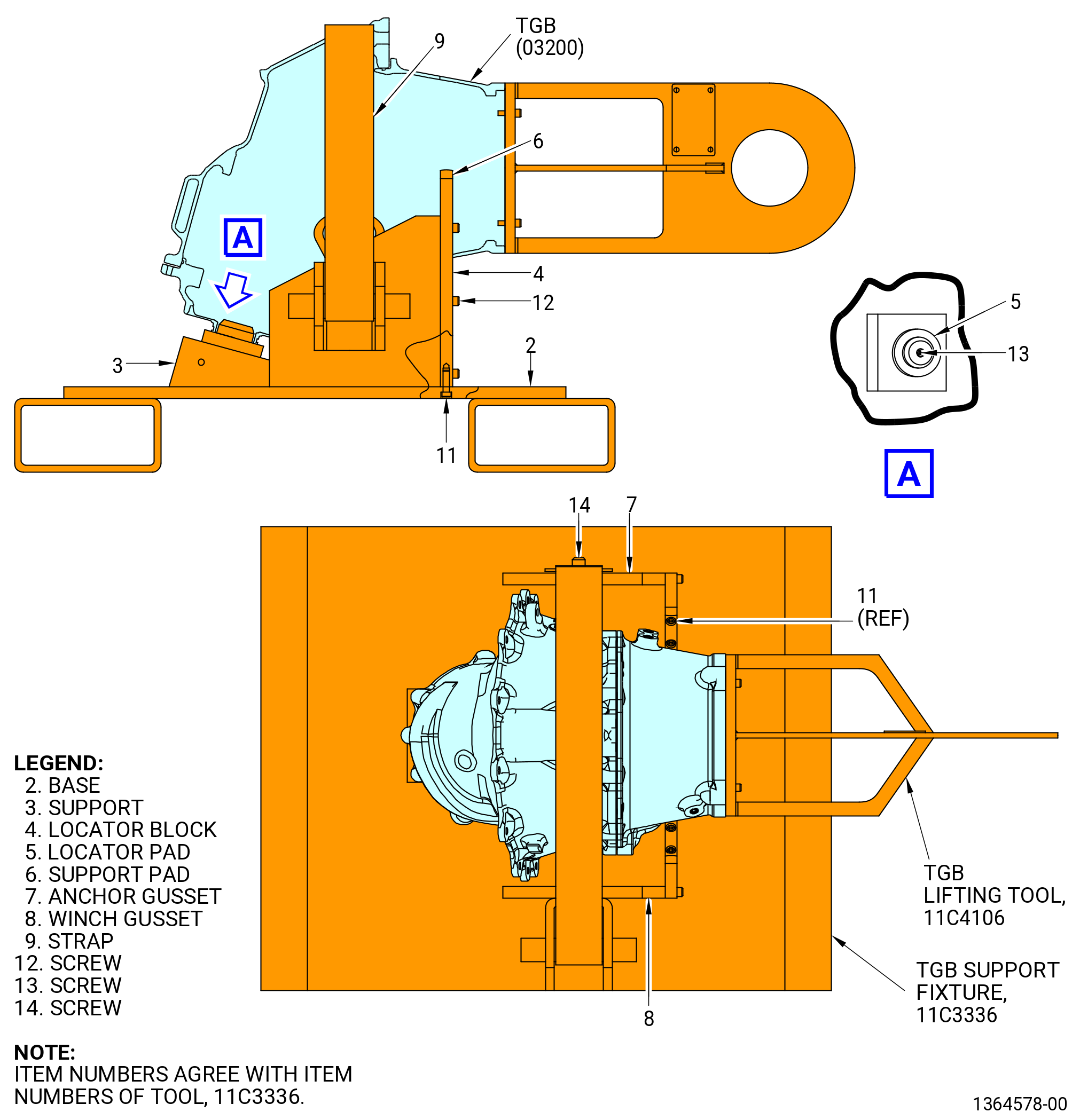
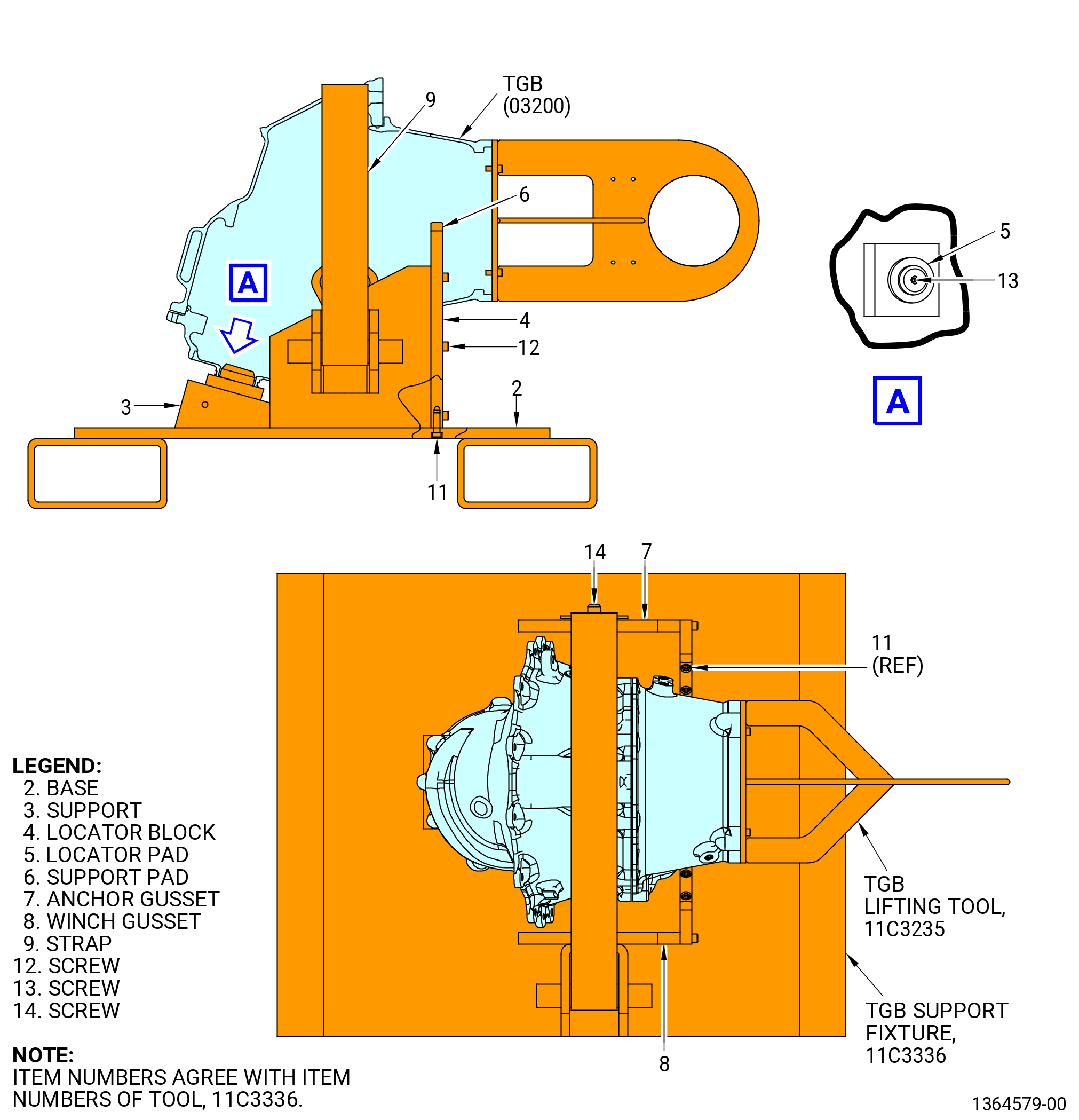
| (2) | Alternative Procedure Available. Remove the TGB from the 11C3336 TGB support fixture as follows. Refer to Figure 1022. |
| WARNING: |
|
| (a) | Attach a hoist to the welded assembly (item 2) of the 11C4106 TGB lifting tool. |
| (b) | Loosen the winch bar of the 11C3336 TGB support fixture that attaches the strap (item 9). |
| (c) | Lift the TGB (03200) from the 11C3336 TGB support fixture. |
| Subtask 72-25-00-440-074 |
| (2).A. | Alternative Procedure. Remove the TGB from the 11C3336 TGB support fixture as follows. Refer to Figure 1023. |
| WARNING: |
|
| (a) | Attach a hoist to the lift fixture (item 2) of the 11C3235 TGB lifting tool. |
| (b) | Loosen the winch bar of the 11C3336 TGB support fixture that attaches the strap (item 9). |
| (c) | Lift the TGB (03200) from the 11C3336 TGB support fixture. |
| Subtask 72-25-00-440-075 |
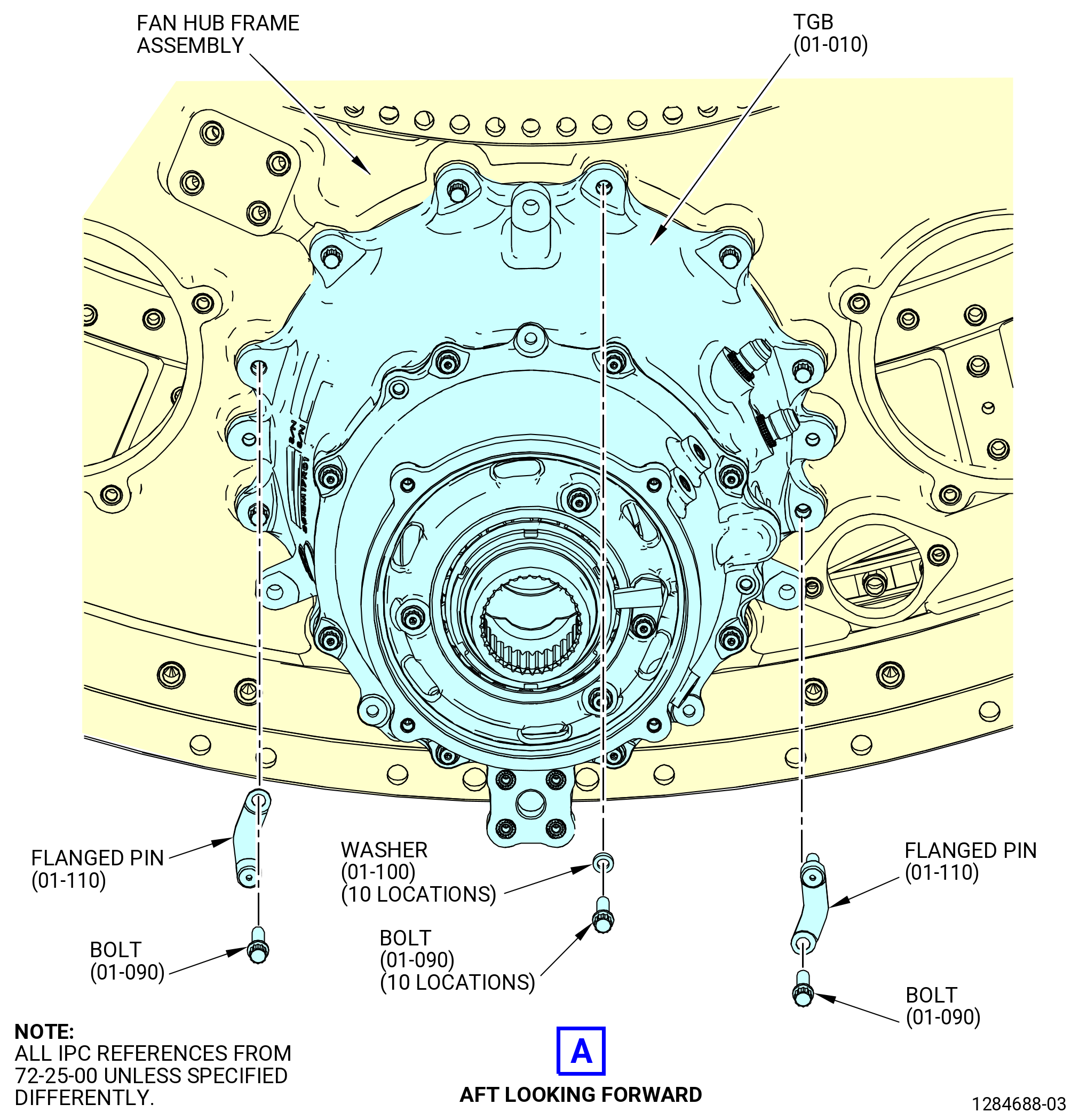
| (3) | Put the TGB in position on the fan hub frame assembly at the 6:00 o'clock position and engage the splines of the TGB with the splines of the radial drive shaft. Push the TGB against the fan hub frame assembly. |
| (4) | Attach the TGB to the fan hub frame assembly as follows: |
| (a) | Apply C02-058 graphite to the threads and washer surfaces of the bolts (03221). |
| NOTE: |
|
| (b) | Install the flanged pins (03220) through the flange of the TGB and into the inserts on the fan hub frame assembly at the 3:00 and 9:00 o'clock positions of the TGB. |
| (c) | Attach the flanged pins (03220) with machine bolts (bolts) (03221). |
| (d) | Install the bolts (03221) and washers (03230) in the remaining holes in the flange at 10 locations. |
| (e) | Torque the bolts (03221) in a criss-cross pattern to 106-124 lb in. (12.0-14.0 N.m). |
| (5) | Remove the 11C4106 TGB lifting tool or the 11C3235 TGB lifting tool from the TGB. |
| (6) | Make sure that the TGB is fully installed against the fan hub frame assembly. Use a 0.001 inch (0.03 mm) shim between the flanges of the TGB and fan hub frame assembly. |
| (7) | Install three axial link brackets (brackets) (03814) on the fan hub frame assembly. Attach the brackets with machine bolts (bolts) (0382B). |
| (8) | Torque the bolts (0382B) to 175-205 lb in. (19.8-23.2 N.m). |
| Subtask 72-25-00-440-069 |
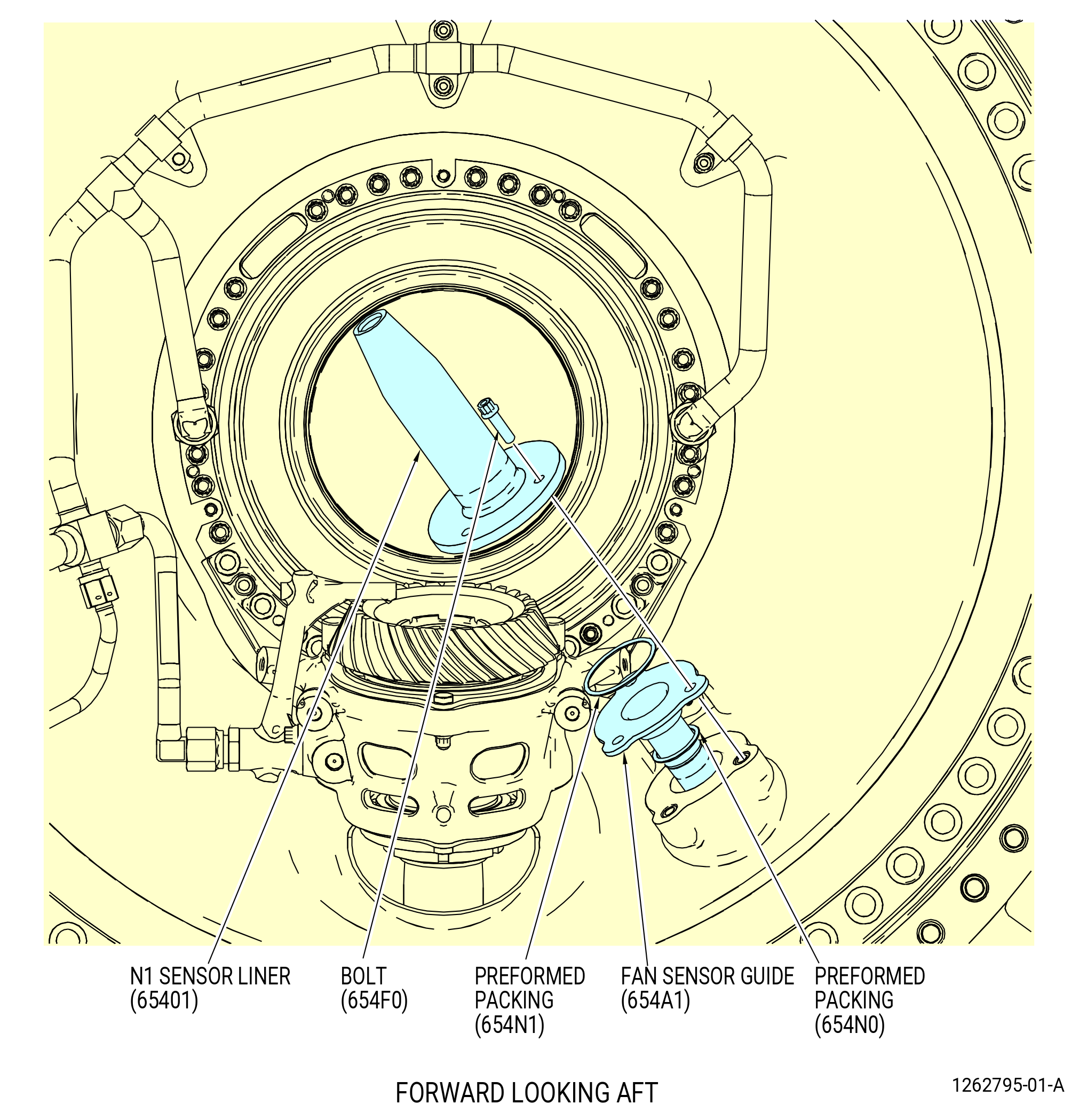
| U. | Install the fan speed sensor guide (fan sensor guide) (10-040) (SIN 654A1) and the N1 sensor liner (10-020) (SIN 65401) to the fan hub frame assembly. Refer to Figure 1024 and do as follows: |
| (1) | Turn the fan hub frame assembly in the 9429M60 roll-over stand or 11C4100 roll-over stand to the vertical position, forward end up, as follows. Refer to Subtask 72-25-00-440-063 (paragraph 3.C.). |
| WARNING: |
|
| (2) | Clean the flange mating faces of the fan sensor guide, the N1 sensor liner, and the fan hub frame assembly port at the 3:30 o'clock position, FLA, with C04-002 Stoddard solvent. |
| WARNING: |
|
| CAUTION: |
|
| (3) | Apply C02-019 engine oil or C02-023 engine oil to the threads and washer surfaces of the machine bolts (bolts) (654F0). |
| NOTE: |
|
| CAUTION: |
|
| (4) | Apply C02-019 engine oil or C02-023 engine oil to the preformed packings (10-030) (SIN 654N1) and (10-050) (SIN 654N0) and to the lead in groove of the fan sensor guide. |
| (5) | Install the preformed packing (10-050) (SIN 654N0) in the groove of the fan sensor guide. |
| (6) | Install the sensor guide into fan frame port and align the boltholes. |
| (7) | Install the performed packing (10-030) (SIN 654N1) in the groove on the flange on the N1 sensor liner. |
| (8) | Install the N1 sensor liner over the fan sensor guide and align the boltholes. |
| (9) | Attach the N1 sensor liner and sensor guide to the fan hub frame assembly with the bolts (654F0). Torque the bolts (654F0) to 16-124 lb in. (12.0-14.0 N.m). |
| Subtask 72-25-00-220-014 |
| (10) | Make sure that the N1 sensor liner and fan sensor guide are fully installed with a 0.001 inch (0.03 mm) shim. |
| Subtask 72-25-00-720-004 |
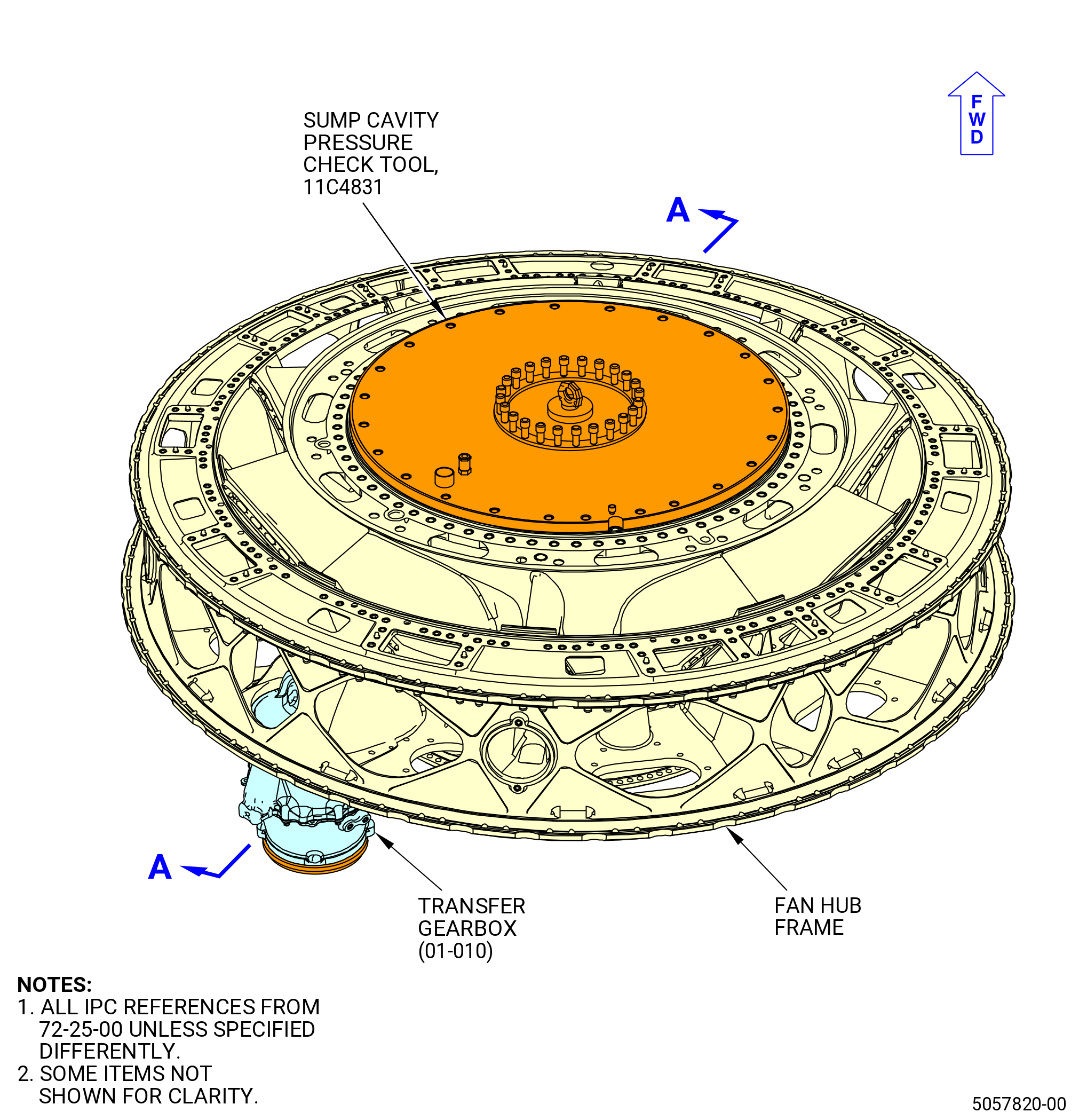
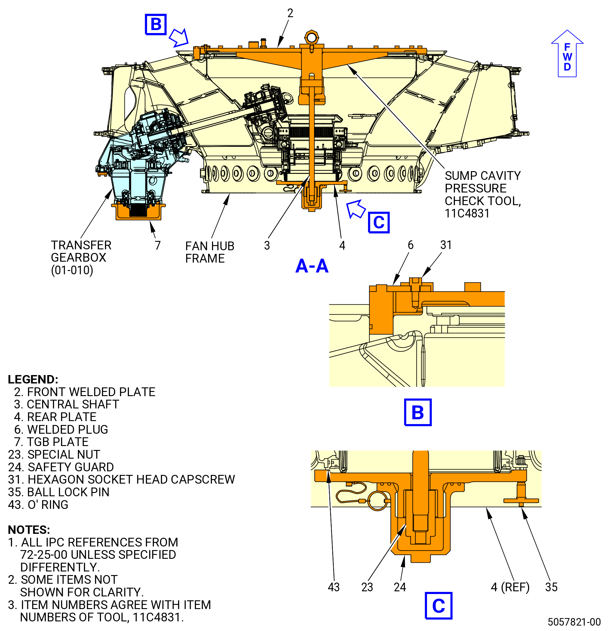
| V. | Do a sump cavity pressure check. Refer to Figure 1025 and do as follows: |
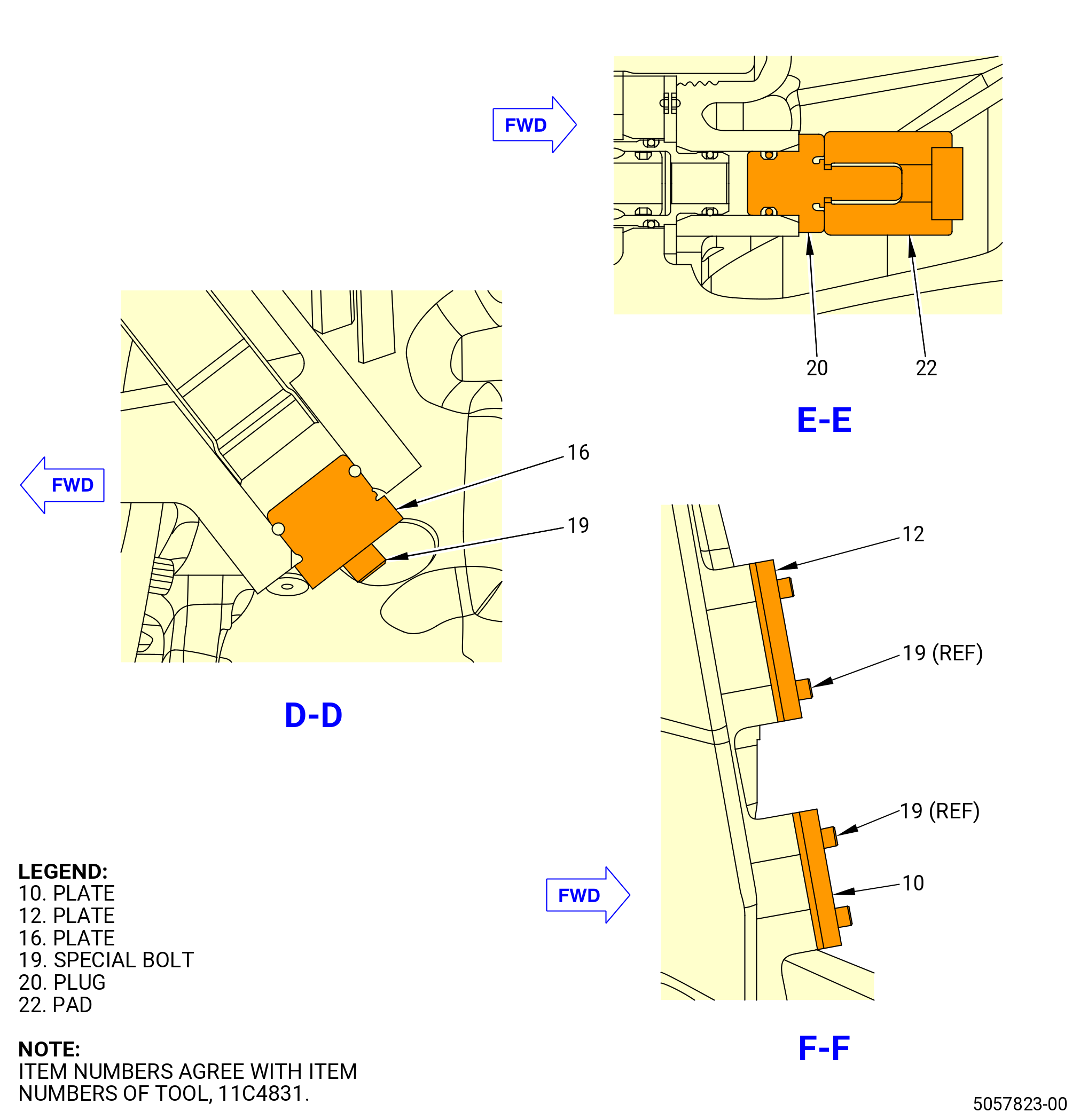
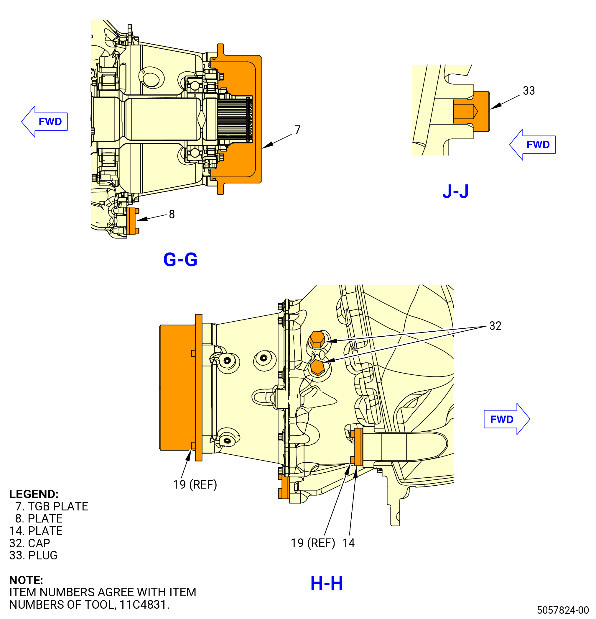
| (1) | Install the 11C4831 sump cavity pressure check tool to seal the sump cavity as follows: |
| (a) | Install the front welded plate (item 2) assembly on the forward flange of the fan hub frame assembly. Attach the front welded plate with bolts (item 27) at 24 equally-spaced locations. |
| (b) | Install the welded plug (item 6) in the drain hole at the 6:00 o'clock position on the fan hub frame assembly. Attach the welded plug (item 6) with the screw (item 31). |
| (c) | Install the rear plate (item 4) on the aft flange of the damper housing (10-320) (SIN 03001). Install the rear plate with the o-ring (item 43) onto the central shaft (item 3) installed on the front welded plate (item 2). Insert the ball lock pins (item 35) through the holes in rear plate (item 4) and in the flange of the damper housing (10-320) (SIN 03001). |
| (d) | Install the special nut (item 23) on the central shaft (item 3). Torque the special nut to 152 lb in. (17.2 Nm). |
| (e) | Install the safety guard (item 24) onto the rear plate (item 4). Torque the safety guard to 437 lb in. (49.3 Nm). |
| (f) | Install a plug in the damper housing drain port at the 6:30 o'clock position on the damper housing (10-320) (SIN 03001). |
| (g) | Install the plate (item 10) on the fan hub frame assembly vent pad at the 12:00 o'clock position. Attach the plate with screws (item 19). |
| (h) | Install the plate (item 12) on the fan hub frame assembly vent pad at the 12:00 o'clock position. Attach the plate with screws (item 19). |
| (i) | Install the TGB plate (item 7) on the aft flange of the TGB (01-010) (SIN 03200). Attach the plate with screws (item 19). |
| (j) | Install the caps (item 32) on the ports on the TGB (01-010) (SIN 03200). |
| (k) | Install the plate (item 8) on the TGB scavenge pad at the 6:00 o'clock position on the TGB (01-010) (SIN 03200). Attach the plate with screws (item 19). |
| (l) | Install the plate (item 14) on the scavenge tube (05-160 , 79-22-20) (SIN 451A1). Attach the plate with screws (item 19). |
| (m) | Install the plate (item 16) on the N1 sensor pad at the 7:00 o'clock position of the fan hub frame assembly. Attach the plate with screws (item 19). |
| (n) | Install the plug (item 33) on the tube nipple at the 7:00 o'clock position of the fan hub frame assembly. |
| WARNING: |
|
| (2) | Apply an inlet pressure of dry, filtered air to the oil supply tube (01-070) (SIN 442A0) at 14.5-15.5 psig (100.0-106.9 kPa gage). |
| (3) | Measure and record the maximum pressure after 3 minutes. The maximum pressure drop permitted is 0.5 psig (3.4 kPa). Refer to Figure 1003. |
| (4) | Remove the 11C4831 sump cavity pressure check tool and the remaining caps and plugs. |
| Subtask 72-25-00-440-060 |
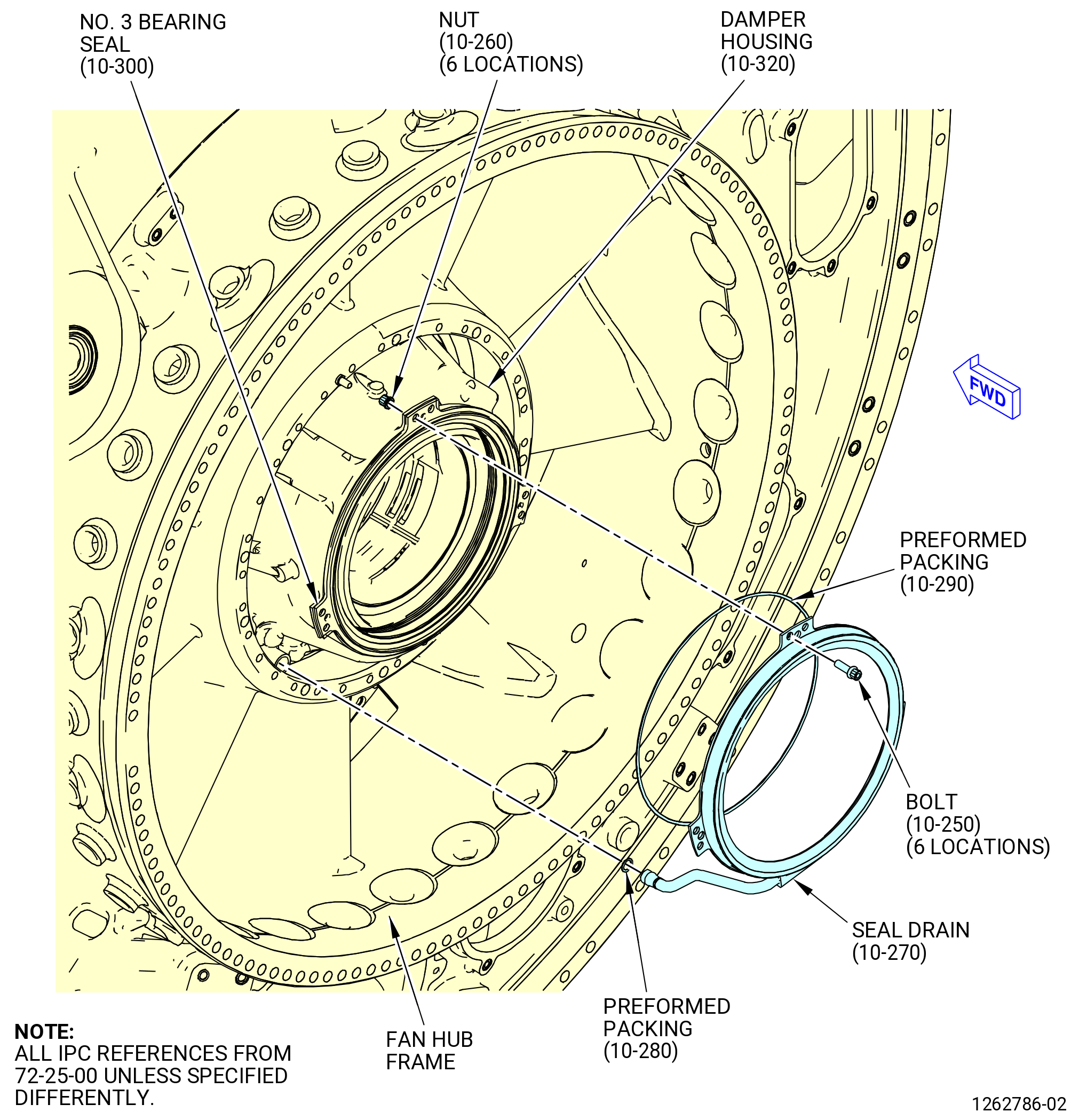
| W. | Install the No. 3 deflector (seal drain) (10-270) (SIN 030AA) to the aft side of the fan hub frame assembly at the No. 3 bearing seal (10-300) (SIN 03080). Refer to Figure 1026 and do as follows: |
| (1) | Turn the fan hub frame assembly in the 9429M60 roll-over stand or 11C4100 roll-over stand to the vertical position, forward end down, as follows. Refer to Subtask 72-25-00-440-063 (paragraph 3.C.). |
| WARNING: |
|
| (2) | Apply C02-019 engine oil or C02-023 engine oil to the preformed packings (10-280) (SIN 030N6) and (10-290) (SIN 030N0). |
| (3) | Install the performed packing (10-290) (SIN 030N0) in the groove on the No. 3 bearing seal. |
| (4) | Install the performed packing (10-280) (SIN 030N6) in the groove on the aft end of the tube of the seal drain. |
| (5) | Install the seal drain on the No. 3 bearing seal. |
| (6) | Make sure that the tube of the seal drain is correctly connected to the jumper tube adapter (03070) in the fan hub frame assembly on the forward side. |
| (7) | Attach the seal drain with machine bolts (bolts) (030F1) and self-locking nuts (nuts) (030K4). |
| (8) | Torque the bolts (030F1) to 106-124 lb in. (12.0-14.0 N.m). |
| Subtask 72-25-00-440-021 |
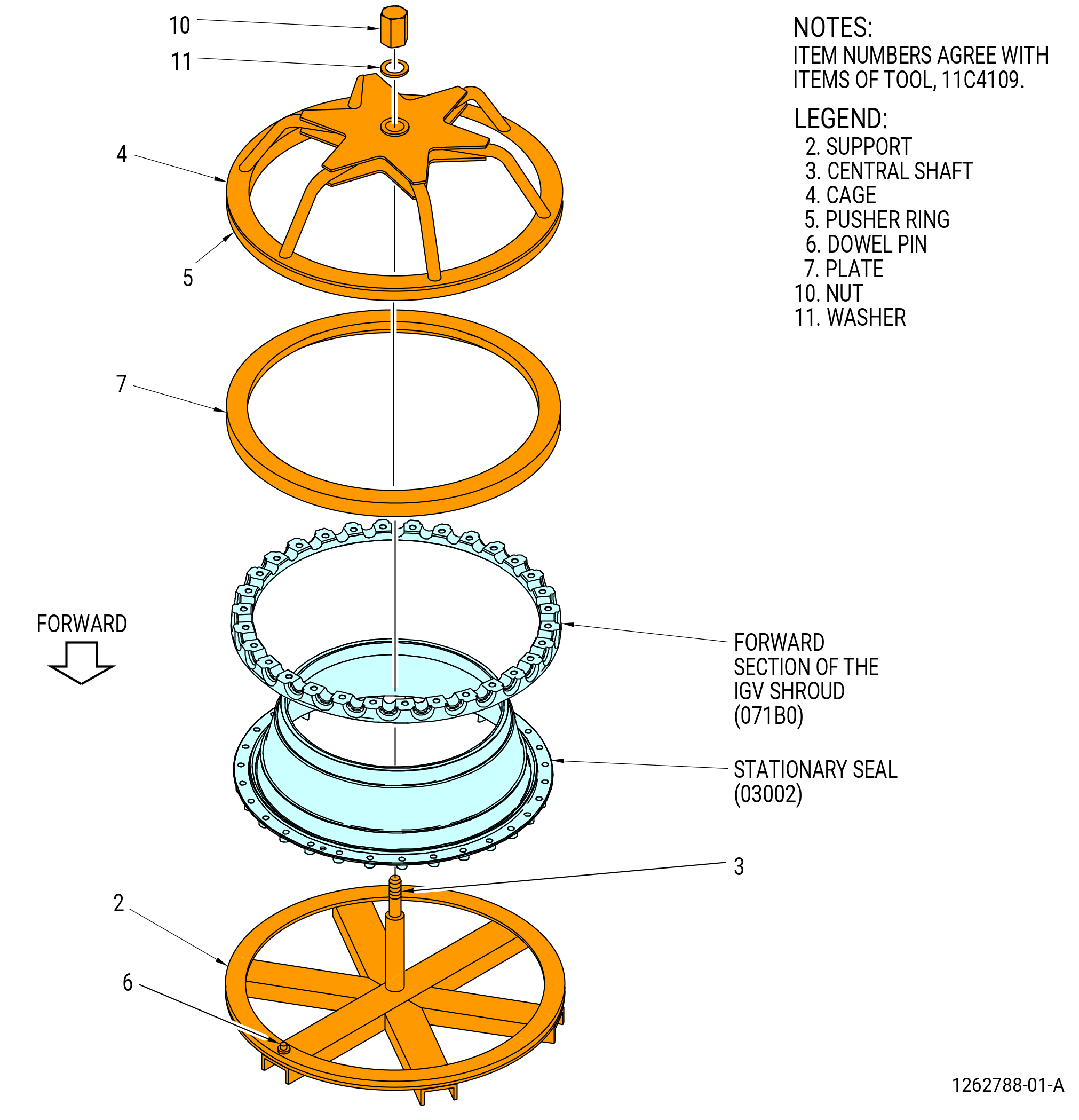
| X. | Assemble the forward section of the IGV shroud (071B0) to the No. 3 bearing stationary seal (stationary seal) (03002) with the 11C4109 IGV seating/removal tool as follows: |
| (1) | Make sure that the forward section of the IGV shroud and aft section of the IGV shroud are a matched set. Both parts are machined as a set for the IGV shroud. Refer to Figure 1027. |
| (2) | Install the pusher ring (item 5) of the 11C4109 IGV seating/removal tool on the cage (item 4). Refer to Figure 1028. |
| (3) | Install the stationary seal on the support (item 2) with the forward flange down. Align the dowel pin (item 6) with the hole in the stationary seal. |
| WARNING: |
|
| (4) | Increase the temperature of the stationary seal forward flange to 122°F (50.0°C). |
| (5) | Lower the forward section of the IGV shroud to the stationary seal and align the dowel pin (item 6) with the alignment hole in the IGV shroud forward section. |
| (6) | Put the plate (item 7) on the forward section of the IGV shroud. |
| (7) | Install the cage (item 4) on the central shaft (item 3) and the IGV shroud. |
| (8) | Install the washer (item 11) and the hex nut (item 10) on the central shaft (item 3). |
| (9) | Torque the hex nut (item 10) to 50 lb in. (5.6 N.m) to fully install the forward section of the IGV shroud on the stationary seal. |
| (10) | Let the parts return to ambient temperature. |
| (11) | Remove the hex nut (item 10), washer (item 11), cage (item 4), and plate (item 7). |
| Subtask 72-25-00-440-022 |
| Y. | Install the seal/shroud assembly on the fan hub frame assembly as follows: |
| NOTE: |
|
| WARNING: |
|
| (1) | Clean the mating flange surfaces of the fan hub frame with C04-002 Stoddard solvent. |
| (2) | Install the 11C4123 heating shroud to the forward flange of the fan hub frame assembly with the cap screws (item 5). Refer to Figure 1029. |
| WARNING: |
|
| (3) | Increase the temperature of the forward flange of the fan hub frame to 194°F (90.0°C) with the 11C4123 heating shroud. |
| WARNING: |
|
| (4) | Remove the seal/shroud assembly from the support (item 2) of the 11C4109 IGV seating/removal tool and put it in position on the fan hub frame assembly. |
| (5) | Remove the 11C4123 heating shroud from the forward flange of the fan hub frame assembly. |
| (6) | Align the seal/shroud assembly with the alignment pin in the fan hub frame. Refer to Figure 1030. |
| (7) | Attach the seal/shroud assembly with four slave bolts and washers at equally spaced locations and tighten. |
| (8) | Let the parts return to ambient temperature. |
| (9) | Remove the slave bolts. |
| (10) | Make sure that the stationary seal is fully installed. Use a 0.001 inch (0.03 mm) shim between the stationary seal and the fan hub frame assembly. |
| Subtask 72-25-00-440-023 |
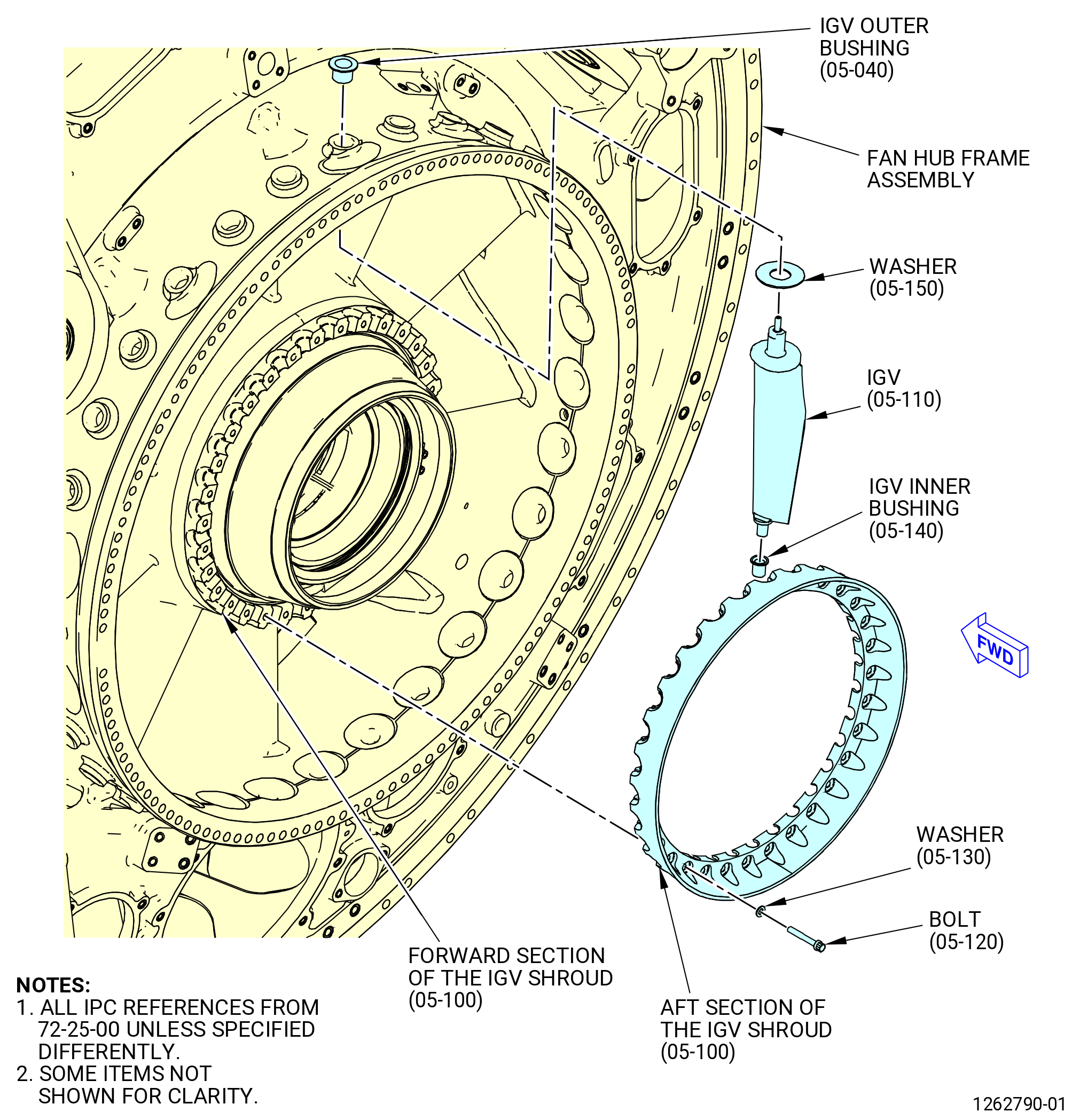
| Z. | Install the inlet guide vanes (IGVs) (05-110) (SIN 072A0) into the fan hub frame assembly. Refer to Figure 1031 and do as follows: |
| (1) | Install an IGV shoulder washer (washer) (05-150) (SIN 071J2) on the outboard trunnion of one IGV. |
| (2) | Install an IGV inner bushing (05-140) (SIN 071T5) on the inboard trunnion of the IGV. |
| (3) | Install the outboard trunnion of the IGV through the fan hub frame assembly. |
| (4) | Put the inboard trunnion with the IGV inner bushing in the slot of the forward IGV shroud (071B0). Make sure that the FWD mark on the IGV is forward. |
| (5) | Install the IGV outer bushing (05-040) (SIN 071T0) through the fan hub frame assembly and on the outer IGV trunnion. The bushing must be fully against the fan hub frame assembly. |
| (6) | Do Subtask 72-25-00-440-023 (paragraph 3.X.(1)) thru Subtask 72-25-00-440-023 (paragraph 3.X.(5)) for the remaining 30 IGVs. |
| (7) | Make sure that the vane surfaces of the IGVs do not touch the fan hub frame assembly in normal angular displacement (rotation of the airfoil). |
| (8) | Put the aft section of the IGV shroud against the forward section of the IGV shroud. |
| (9) | Make sure that the IGV inner trunnions and the IGV inner bushings (05-140) (SIN 071T5) are correctly installed in the IGV shroud. |
| (10) | Attach the IGV shroud and the stationary seal (03002) to the fan hub frame assembly with washers (071J3) and machine bolts (bolts) (071F0). |
| (11) | Torque the bolts in a criss-cross pattern to 106-124 lb in. (12.0-14.0 N.m). |
| Subtask 72-25-00-440-025 |
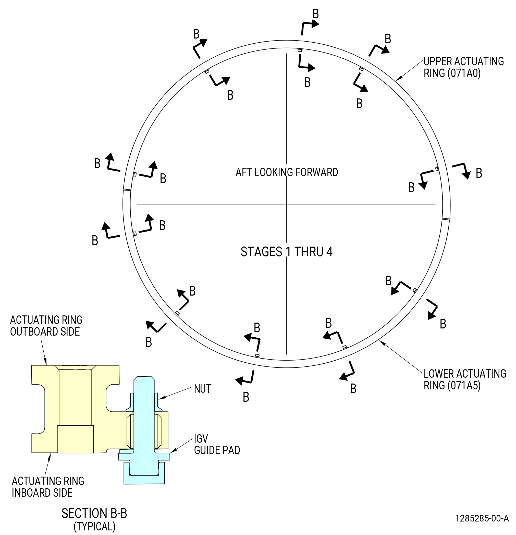
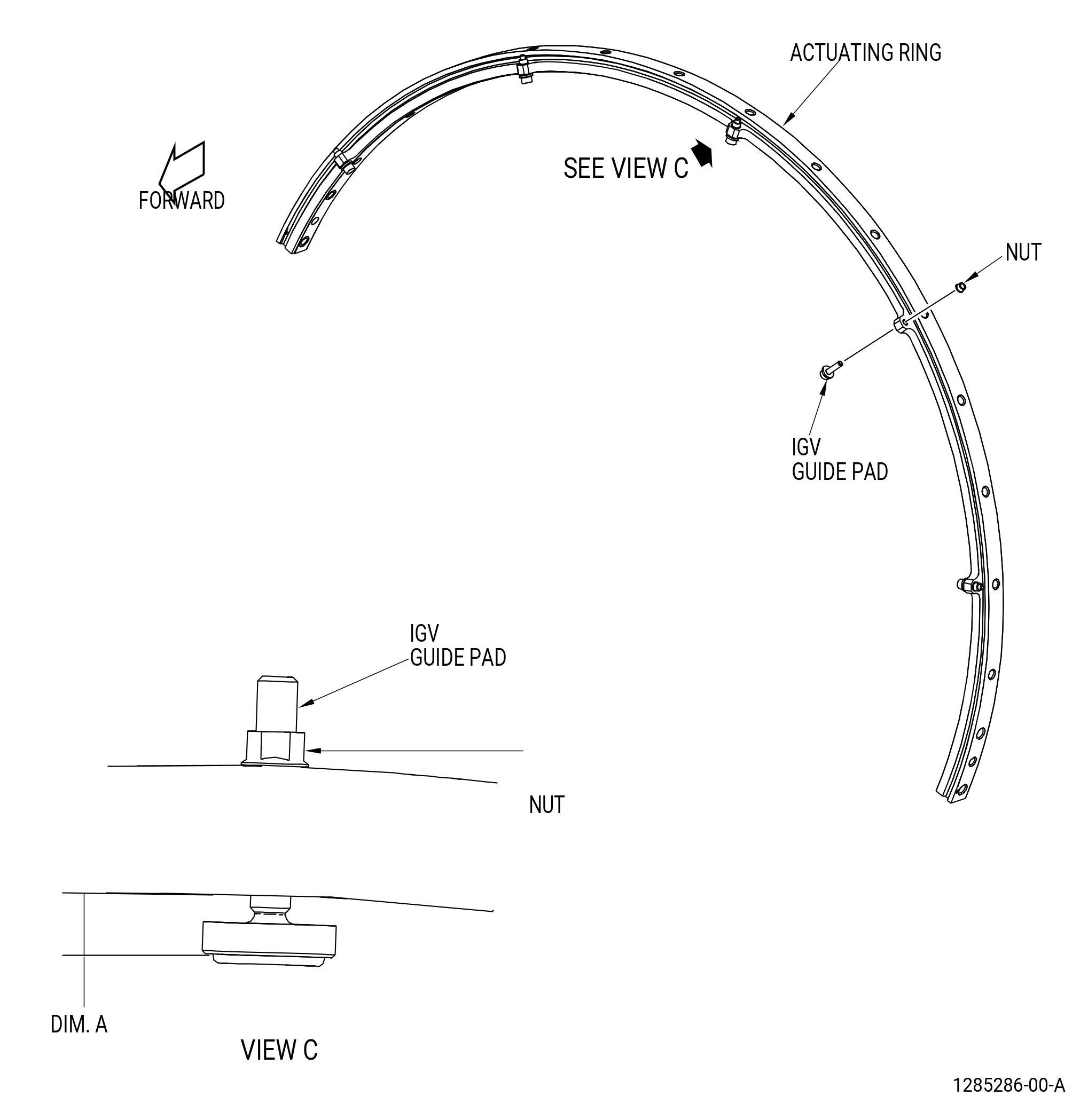
| AA. | Install the IGV adjusting pad screws and the IGV guide pads to the upper and lower IGV actuation rings (071A0, 071A5) as follows. Refer to Figure 1032. |
| (1) | From the inboard side of the actuating ring, install the threaded end of the IGV guide pads into the actuating ring. Turn the IGV guide pad CW in the actuating ring until it turns freely. |
| NOTE: |
|
| NOTE: |
|
| (2) | Install the nut on the IGV guide pad on the outboard side of the actuating ring. |
| (3) | Adjust the IGV guide pads in the actuating ring to dimension A as follows. Turn the IGV guide pad CCW to increase dimension A and CW to decrease dimension A. |
| (a) | Dimension A: 0.323-0.333 inch (8.20-8.46 mm). |
| (4) | Hold the threaded end of the IGV guide pads with a hex-head wrench and torque the nut to 60.0-70.0 lb in. (6.78-7.91 N.m). |
| NOTE: |
|
| Subtask 72-25-00-440-026 |
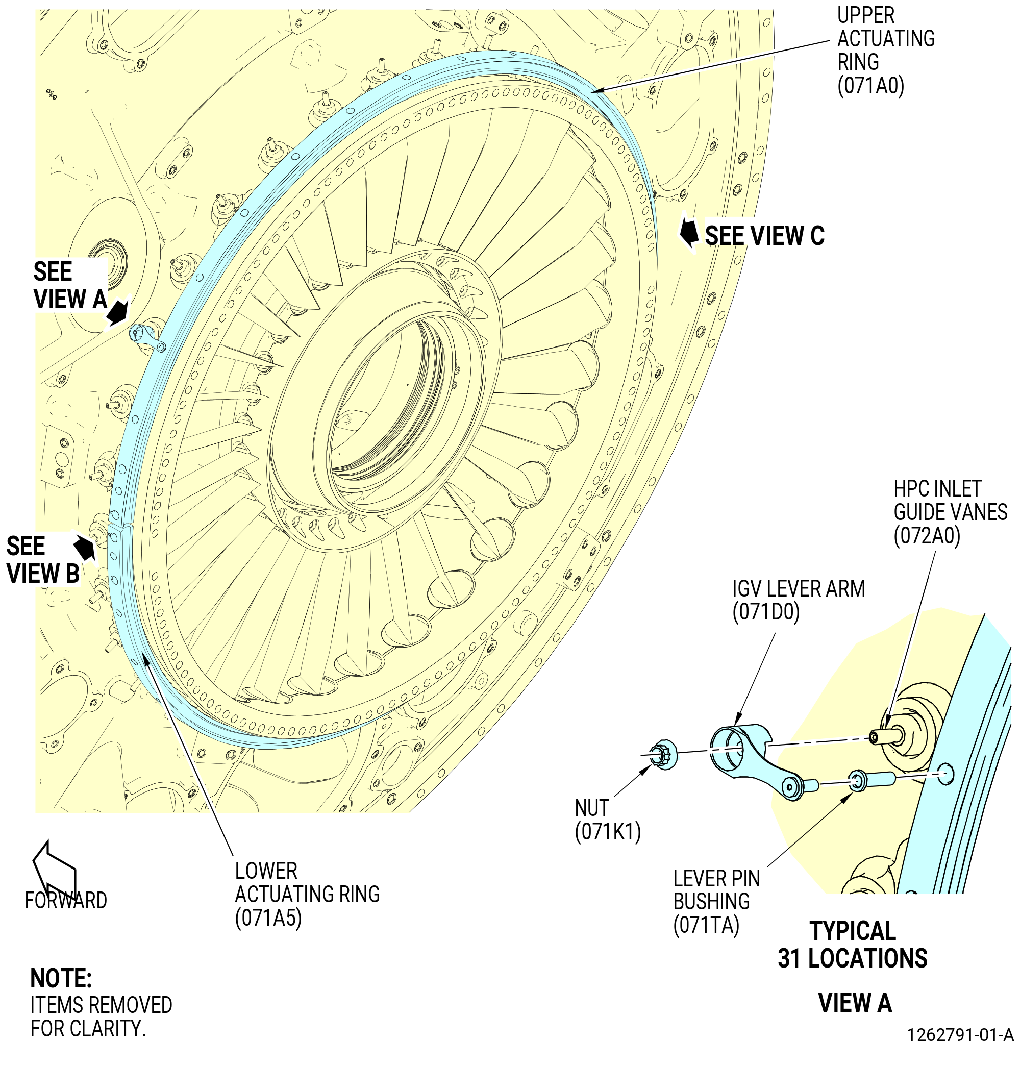
| AB. | Install the actuating ring (05-080) (SIN 071A0) on the fan hub frame assembly. Refer to Figure 1033 and do as follows: |
| (1) | Install the lever pin bushings (05-030) (SIN 071TA) in their correct locations in the actuating ring. |
| (2) | Put the actuating ring on the fan hub frame assembly. Make sure that the AFT UPPER IGV mark on the upper actuating ring is aft. |
| (3) | Align the upper actuating ring on the fan hub frame assembly so that the last hole on the right side of the upper actuating ring (ALF) is immediately below the 3:00 o'clock position on the fan hub frame assembly. |
| Subtask 72-25-00-440-027 |
| AC. | Install the IGV lever (IGV lever arms) (071D0) on the upper actuating ring (071A0) and IGVs (072A0) as follows: |
| (1) | Make sure that the IGV outer bushings (05-040) (SIN 071T0) are installed in the fan hub frame assembly at each IGV. |
| (2) | Install an IGV lever arm on each of the IGV outer trunnion studs. Engage the pin of the IGV lever arm in the lever pin bushing (05-030) (SIN 071TA) installed in the upper actuating ring. Make sure that the IGV lever arm is correctly installed with the IGV trunnion and the upper actuating ring. |
| (3) | Install the nut vanes (nuts) (071K1) on the IGV stud. |
| (4) | Torque the nuts to 51-59 lb in. (5.8-6.7 N.m). |
| Subtask 72-25-00-440-028 |
| AD. | Install the ring segment (lower actuating ring) (05-090) (SIN 071A5) on the fan hub frame assembly as follows. |
| (1) | Install the lever pin bushings (05-030) (SIN 071TA) in lever pin holes in the actuating ring. |
| (2) | Put the lower actuating ring on the fun hub frame assembly. Make sure that the AFT LOWER IGV mark on the lower actuating ring is aft. |
| (3) | Align the lower actuating ring on the fan hub frame assembly so that the last hole on the left side of the lower actuating ring (ALF) is immediately above 9:00 o'clock position on the fan hub frame assembly. |
| Subtask 72-25-00-440-029 |
| AE. | Install the IGV lever arms (071D0) one at a time to each IGV (072A0) and lower actuating ring (071A5) as follows: |
| (1) | Make sure that the IGV outer bushings (05-040) (SIN 071T0) are installed in the fan hub frame assembly at each IGV. |
| (2) | Install an IGV arm to the IGV trunnion stud and in the level pin bushing (05-030) (SIN 071TA) of the actuating ring. Make sure that the IGV arm is installed with the IGV trunnion and the actuating ring. |
| (3) | Install the nuts (071K1) on the IGV stud. |
| (4) | Torque the nuts to 51-59 lb in. (5.8-6.7 N.m). |
| Subtask 72-25-00-440-030 |
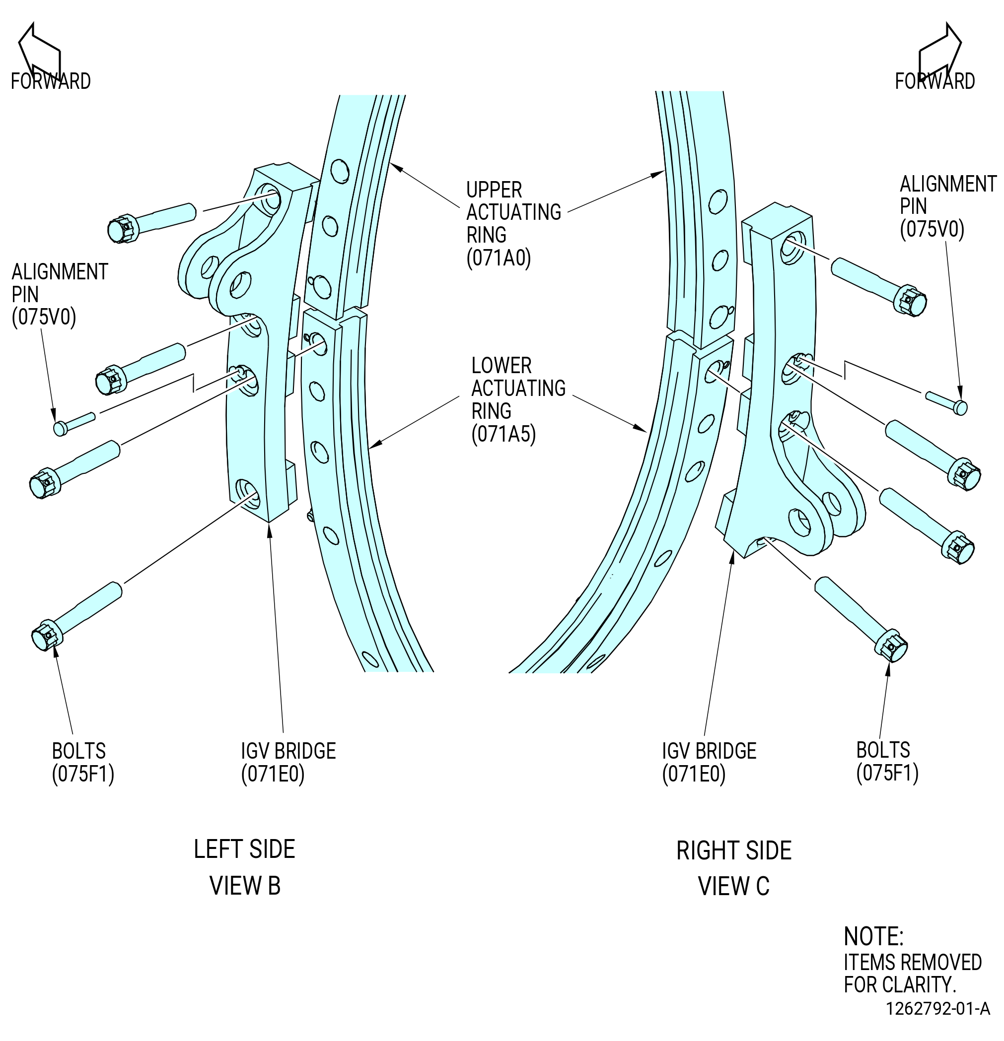
| AF. | Install the IGV bridges (071E0) on the upper and lower actuating rings (071A0, 071A5) as follows: |
| WARNING: |
|
| (1) | Apply C02-019 engine oil or C02-023 engine oil to the threads and washer surfaces of the machine bolts (bolts) (075F1). |
| (2) | Install the alignment pins (075V0) in the IGV bridges. |
| (3) | Install an IGV bridge at the 9:00 o'clock position on the upper and lower actuating rings. Align the alignment pins (075V0) with the holes in the upper and lower actuating rings. Make sure the AFT mark on the IGV bridge is aft. |
| (4) | Attach the IGV bridge with bolts (075F1). |
| (5) | Install an IGV bridge (071E0) at the 3:00 o'clock position on the upper and lower actuating rings (071A0, 071A5). Align the alignment pins (075V0) with the holes in the upper and lower actuating rings. Make sure the AFT mark on the IGV bridge is aft. |
| (6) | Attach the IGV bridge with bolts (075F1). |
| (7) | Torque the bolts (075F1) to 235-275 lb in. (26.6-31.1 N.m). |
| (8) | Make sure that the IGVs are installed in the correct position and that they can be manually move. |
| (9) | Use the 11C4125 IGV angle check tool to make sure the IGVs move to the fully open and fully closed positions. |
| (10) | Safety the bolts (075F1) with C10-071 safety wire or C10-143 safety cable. |
| Subtask 72-25-00-430-001 |
| AG. | Measure and record the rub button gap at 10 locations between the upper actuating ring (05-080) (SIN 071A0), lower actuating ring (05-090) (SIN 071A5), the fan hub frame. Refer to Figure 1034 and do as follows: |
| (1) | Move the upper/lower actuating rings (071A0, 071A5) to the zero nominal position. |
| (2) | Measure and record the initial upper/lower actuating ring rub button gap at 10 locations. |
| (3) | Put a 0.007 inch (0.18 mm) shim on the fan hub frame case under the rub buttons at 10 locations. Use tape to hold in position. |
| (4) | If necessary, move the upper/lower actuating rings to an offset position to adjust the rub buttons. |
| (5) | Loosen the nut on the upper/lower actuating rings. |
| (6) | Adjust the actuating ring rub button gap to 0.004-0.010 inch (0.10-0.25 mm). |
| (7) | Torque the rub button nut to 60-70 lb in. (6.8-7.9 N.m). |
| (8) | Remove the 0.007 inch (0.18 mm) shim and tape, if necessary, from the fan hub frame case under the rub buttons. |
| (9) | Measure and record the rub button gap at 10 locations on the upper/lower actuating rings. Make sure the rub button gap is 0.004-0.010 inch (0.10-0.25 mm). |