| GENX-1B ENGINE MANUAL | Dated: 05/29/2024 | |
| EM 72-61-00 , ASSEMBLY 001 | ||
| NO. 3 BALL BEARING AND INLET GEARBOX ASSEMBLY - ASSEMBLY 001 | ||
| GENX-1B ENGINE MANUAL | Dated: 05/29/2024 | |
| EM 72-61-00 , ASSEMBLY 001 | ||
| NO. 3 BALL BEARING AND INLET GEARBOX ASSEMBLY - ASSEMBLY 001 | ||
| * * * FOR ALL |
| TASK 72-61-00-440-801 |
| 1 . | General. |
| A. | This procedure gives instructions to assemble the No. 3 ball bearing (030A7) and inlet gearbox (IGB) assembly (03000). |
| (1) | Assembly of the No. 3 ball bearing and No. 3 bearing housing of the IGB assembly must be done in a clean area (preferably a special room). |
| (2) | Before the parts are removed from the packaging, make sure that the sealed wrapping is not damaged. |
| (3) | Make sure that all the tools are clean before you use them. |
| B. | Install protective covers on the parts and assemblies when not working on them. Keep protective covers on all seal teeth when the covers do not prevent assembly work. |
| C. | Install all the bolts with the heads up and forward unless specific instructions are given. |
| CAUTION: |
|
| D. | Chilling of close fitting parts for ease of assembly is not permitted. Use a hot air gun when the parts are difficult to assemble. Do not heat the parts to more than 273ºF (134ºC). |
| WARNING: |
|
| WARNING: |
|
| E. | Clean parts that were exposed to casual contamination (sneezes, saliva, or handling with bare hands) with the cleaning process specified for the hardware. Bearings packed in grease must be fully cleaned. Clean the parts with C04-002 stoddard solvent, C04-035 isopropyl alcohol, or a 50-50 blend of C04-035 isopropyl alcohol and C04-014 denatured alcohol then lubricate with C02-019 engine oil or C02-023 engine oil. |
| F. | Do an inspection of incorrectly installed hardware for damage after disassembly. |
| G. | Bearings. |
| (1) | Use clean, lint-free C10-139 cotton gloves, C10-140 gloves, or C10-064 protective hand cream when you handle the bearings. |
| (2) | Bearings must have a thick layer of engine oil applied and must be kept wrapped in plastic film until their installation. |
| CAUTION: |
|
| (3) | All bearings in the IGB assembly are matched assemblies, inner and outer races have the same serial number. Examine the serial numbers before a bearing is installed to make sure matched assemblies are installed. |
| (4) | It is recommended to keep a record of bearing serial numbers. |
| H. | Torque. |
| WARNING: |
|
| (1) | Unless otherwise specified, all fastener threads must be lubricated with C02-019 engine oil or C02-023 engine oil before installation. Refer to TASK 70-51-00-400-004 (TIGHTENING PRACTICES AND TORQUE VALUES) . |
| (2) | Torque values given are torqued to the fastener. If a torque multiplier is used, input torque to the multiplier must be calculated. Final torque must be applied at room temperature. |
| (3) | If the run-on requirements are not satisfied, the parts must be replaced. |
| 2 . | Tools, Equipment, and Materials. |
| NOTE: |
|
| A. | Tools and Equipment. |
| (1) | Special Tools. |
| (2) | Standard Tools and Equipment. |
|
| (3) | Locally Manufactured Tools. None. |
| B. | Consumable Materials. |
|
| C. | Referenced Procedures. None. |
| D. | Expendable Parts. |
|
| 3 . | Procedure. |
| Subtask 72-61-00-440-090 |
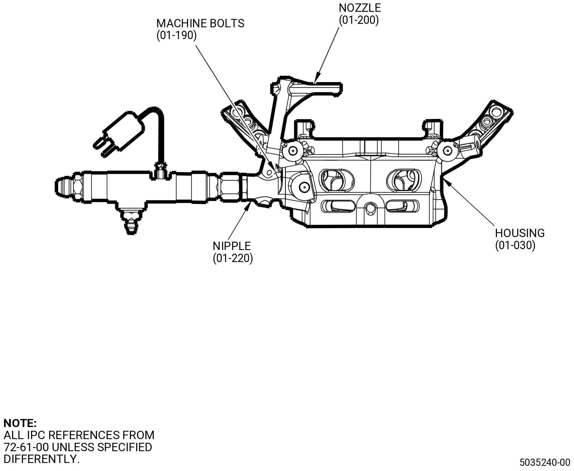
| A. | Install the oil nozzle (01-200) (SIN 030B1) in the housing (01-030) (SIN 030A1) as follows: |
| WARNING: |
|
| (1) | Apply C02-019 engine oil or C02-023 engine oil to the new preformed packing (01-230) (SIN 030N1) and to the bolts (01-190) (SIN 030F5). |
| (2) | Install the preformed packing (01-230) (SIN 030N1) onto the oil nozzle (01-200) (SIN 030B1). |
| (3) | Install the oil nozzle (01-200) (SIN 030B1) in the housing (01-030) (SIN 030A1). |
| (4) | Attach the oil nozzle (01-200) (SIN 030B1) to the housing (01-030) (SIN 030A1) with two bolts (01-190) (SIN 030F5). |
| (5) | Make sure that the run-on torque is between 7 lb in. (0.79 Nm) to 30 lb in. (3.39 Nm) for a new bolt or between 3.5 lb in. (0.40 Nm) to 30 lb in. (3.39 Nm) for a used bolt. Torque the bolts to 108.6 to 127.4 lb in. (12.3 to 14.3 Nm). |
| WARNING: |
|
| (6) | Apply C02-019 engine oil or C02-023 engine oil to the new preformed packing (01-210) (SIN 030N4). |
| (7) | Install the preformed packing (01-210) (SIN 030N4) onto the tube nipple (01-220) (SIN 030S1). |
| (8) | Install the tube nipple (01-220) (SIN 030S1) in the oil nozzle (01-200) (SIN 030B1). |
| (9) | Torque the nipple (01-220) (SIN 030S1) to 218.5 to 256.5 lb in. ( 24.7 to 28.9 Nm). |
| Subtask 72-61-00-710-002 |
| B. | Do a flow-check of the IGB housing (01-030) (SIN 030A1) as follows: |
| (1) | Install the 2126M42 connector on the nipple (01-220) (SIN 030S1). Refer to Figure 1001. |
| (2) | Connect the oil supply hose to the 2126M42 connector. |
| (3) | Put the IGB casing on a support fixture in the flow stand facility. |
| WARNING: |
|
| (4) | Supply the C02-019 engine oil or C02-023 engine oil at 79.1-80.5 psig (545-555 kPa gage) and at 95 to 106°F (35 to 41°C). |
| (5) | Make sure that there is a satisfactory lube flow and a steady stream of oil from the six oil jets in the IGB casing. |
| (6) | Record the total oil flow in 1 minute. Make sure that the total oil flow is 4.623-5.442 gallons per minute (17.5-20.6 liters per minute). |
| (7) | If the flow-check is satisfactory, disconnect the oil supply hose and connector from the nipple on the IGB casing. |
| (8) | Let the remaining oil drain from the IGB casing. |
| (9) | Remove the two machine bolts (01-190) (SIN 030F5) and the nozzle (01-200) (SIN 030B1) from the IGB housing (01-030) (SIN 030A1). |
| Subtask 72-61-00-440-001 |
| C. | Assemble the No. 3 ball bearing (030A7) and inlet gearbox (IGB) assembly (03000) as follows: |
| (1) | Install the No. 3 bearing housing (030A6), aft end down, on the 2126M24 assembly base. |
| (2) | Install the outer race of the No. 3 ball bearing (030A7) in the 2126M23 pusher . Lock the ball bearing in the pusher. |
| WARNING: |
|
| (3) | Locally increase the temperature of the No. 3 bearing housing (01-170) (SIN 030A6) to a maximum of 154 to 162ºF (68 to 72ºC). |
| (4) | Install the outer race of the No. 3 ball bearing (030A7) in the No. 3 bearing housing (030A6). Push the pusher until the outer race of the No. 3 ball bearing is correctly installed on the housing. Use an arbor press or equivalent. |
| (5) | Apply a load of 9594-10188 lb (42680-45320 N). |
| (6) | Let the No. 3 bearing housing (030A6) go back to room temperature. Make sure that the outer race of the No. 3 ball bearing (030A7) is correctly installed in the housing. |
| (7) | Apply a load of 9594-10188 lb (42680-45320 N) again. |
| (8) | Unlock the outer race of the No. 3 ball bearing (030A7) and remove the 2126M23 pusher. |
| (9) | Remove the No. 3 bearing housing (030A6) assembly from the 2126M24 assembly base. |
| (10) | Do a shim check to make sure that the outer race of the No. 3 ball bearing (030A7) is correctly installed in the No. 3 bearing housing (030A6) as follows: |
| (a) | Use a 0.001 inch (0.03 mm) shim stock. |
| (b) | Make sure that the shim stock cannot go between the outer race of the No. 3 ball bearing and the No. 3 bearing housing. |
| (c) | Do the shim check at three equally spaced locations. |
| (11) | Install the No. 3 bearing housing (030A6) assembly on the 9479M90 antirotation base. |
| (12) | Install the plain round nut (030A8) in the housing. |
| (13) | Use the 9479M91 special wrench and torque the nut to 1750-2500 lb ft. (2373-3390 Nm). |
| (14) | Make sure that a hole in the No. 3 bearing housing (030A6) is aligned with a hole in the plain round nut (030A8). |
| (15) | Remove the 9479M91 special wrench from the No. 3 bearing housing (030A6). |
| (16) | Remove the No. 3 bearing housing (030A6) assembly from the 9479M90 antirotation base. |
| WARNING: |
|
| (17) | Apply C02-019 engine oil or C02-023 engine oil to bolt (030F2) and to the nut (030K2). |
| (18) | Find the hole in the No. 3 bearing housing (030A6) that is aligned with a hole in the plain round nut (030A8) and install the bolt (030F2) and the nut (030K2) with the bolt head out. |
| (19) | Make sure that the run-on torque is between 7 lb in. (0.79 Nm) to 30 lb in. (3.39 Nm) for a new nut or between 3.5 lb in. (0.40 Nm) to 30 lb in. (3.39 Nm) for a used nut. |
| (20) | Torque the nut to 108.6 to 127.4 lb in. (12.3 to 14.4 Nm). |
| (21) | Install the 9479M89 mandrel on the 9479M85 antirotation base. |
| (22) | Use C10-140 gloves and install the forward inner race of the No. 3 ball bearing (030A7) on the 9479M89 mandrel, with the bearing mating surface up. |
| (23) | Install the No. 3 bearing housing (030A6) assembly on the 9479M89 mandrel, forward end down. |
| (24) | Install the balls of the No. 3 ball bearing (030A7) in the No. 3 bearing housing (030A6). |
| (25) | Use C10-140 gloves and install the aft inner race of the No. 3 ball bearing (030A7), with the bearing mating surface down. |
| (26) | Use the special clamp and the nut of the 9479M89 mandrel to lock the No. 3 ball bearing (030A7) in the mandrel. |
| (27) | Remove the mandrel and the No. 3 ball bearing (030A7) assembly from the 9479M85 antirotation base. |
| (28) | Put the mandrel and the No. 3 ball bearing (030A7) assembly on a clean work surface. |
| Subtask 72-61-00-240-001 |
| D. | Calculate the dimensions of shim (01-090) (SIN 030T0) and shim (01-330) (SIN 030T1) as follows: |
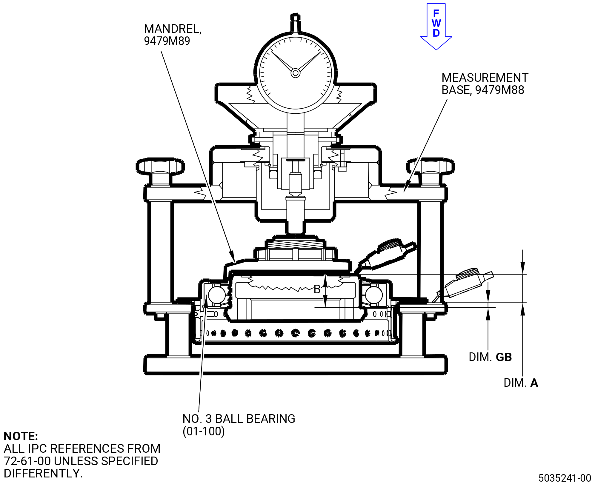
| (1) | Put the 9479M89 mandrel with the No. 3 ball bearing (030A7) assembly installed forward end down, on the 9479M88 measurement base. |
| (2) | Apply a load between 60 and 74 lb (270 and 330 N) to the 9479M89 mandrel. |
| (3) | Rotate the ball bearing (030A7) before you do the measurement. |
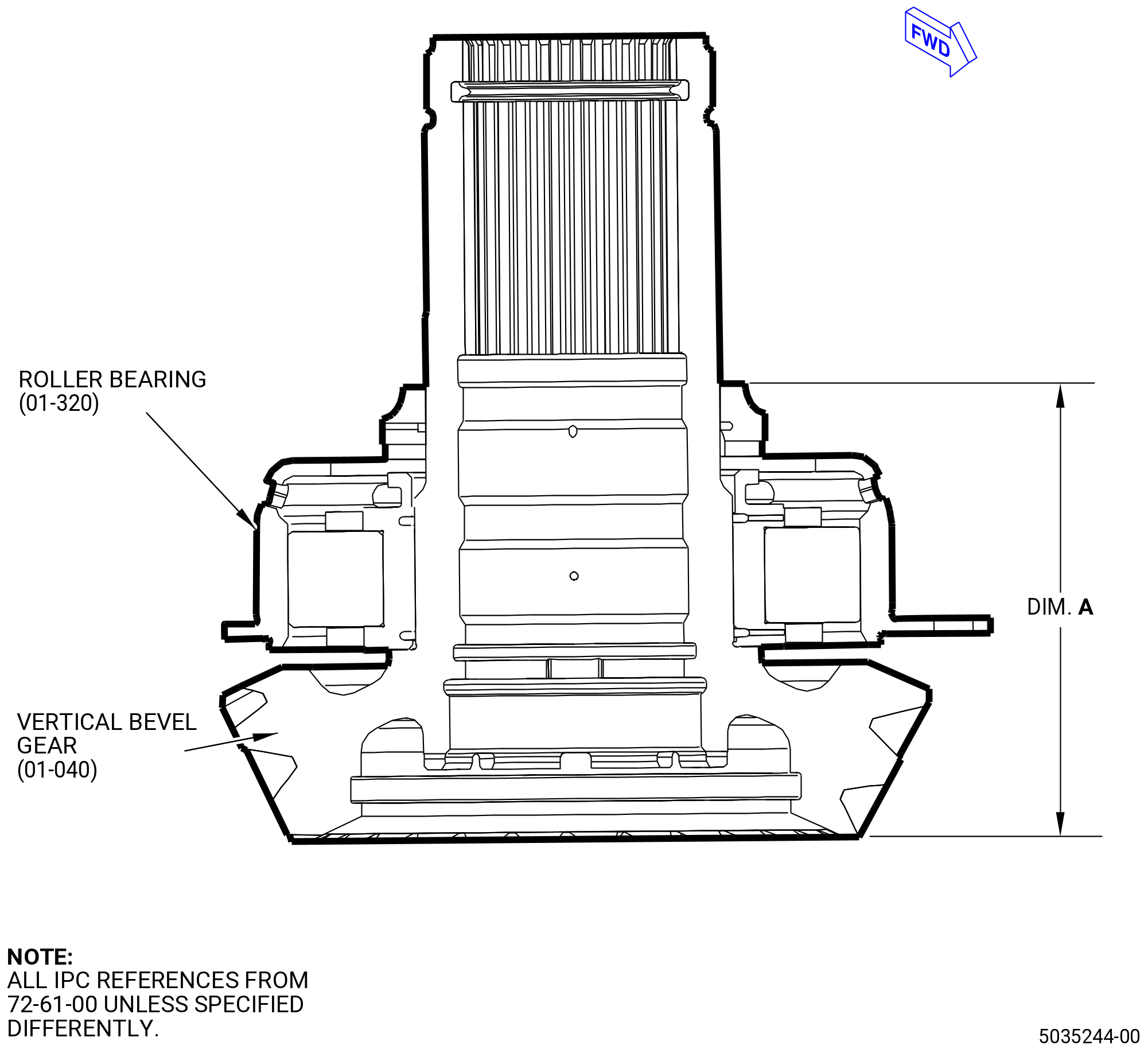
| (4) | Measure and record dimension A. |
| (5) | Read and record dimension B marked on the mandrel. |
| (6) | Calculate dimension GB. Refer to Figure 1002 and as follows: |
| (a) | GB = B - A. |
| (7) | Record dimension GB. |
| (8) | Remove the 9479M89 mandrel with the No. 3 ball bearing (030A7) assembly installed on the 9479M88 measurement base. |
| (9) | Read and record dimension MD2 of the IGB housing (030A1). |
| (10) | Read and record dimension MDG marked on the horizontal bevel gearshaft (01-050) (SIN 030AB). |
| (11) | Calculate the dimension SPC as follows: SPC plus or minus 0.025 (0.00098 inch) = MD2 - MDG - GB. |
| (12) | Record the dimension SPC. This dimension is the thickness required for the shim (01-090) (SIN 030T0). |
| (a) | Adjust the thickness of the one-piece shim as follows: |
| WARNING: |
|
| 1 | Grind the one-piece shim (01-090) (SIN 030T0) until the thickness is in the tolerance limits of dimension SPC. |
| 2 | Make sure that the shim surfaces are parallel within 0.0006 inch (0.015 mm). |
| 3 | Make sure that the surface finish is 32 microinches (0.8 micrometers) or better. |
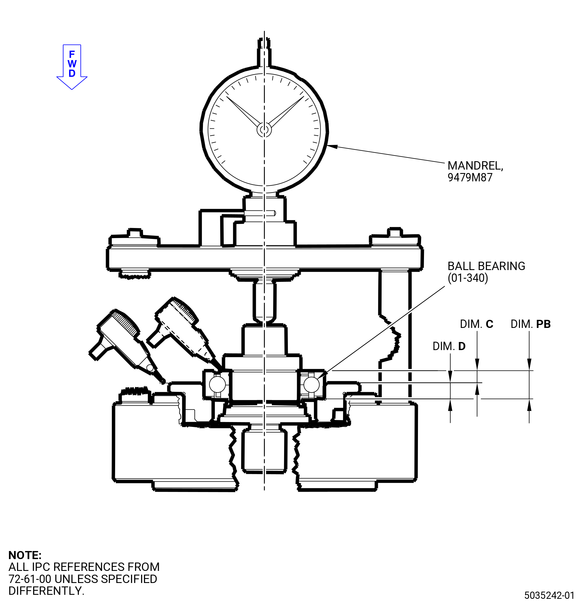
| (13) | Install the inner race of the ball bearing (030A2) in the 9479M87 mandrel. |
| (14) | Install the 9479M87 mandrel in the 9479M86 measurement base. |
| (15) | Apply a load between 30 and 37 lb (135 and 165 N) to the 9479M87 mandrel. |
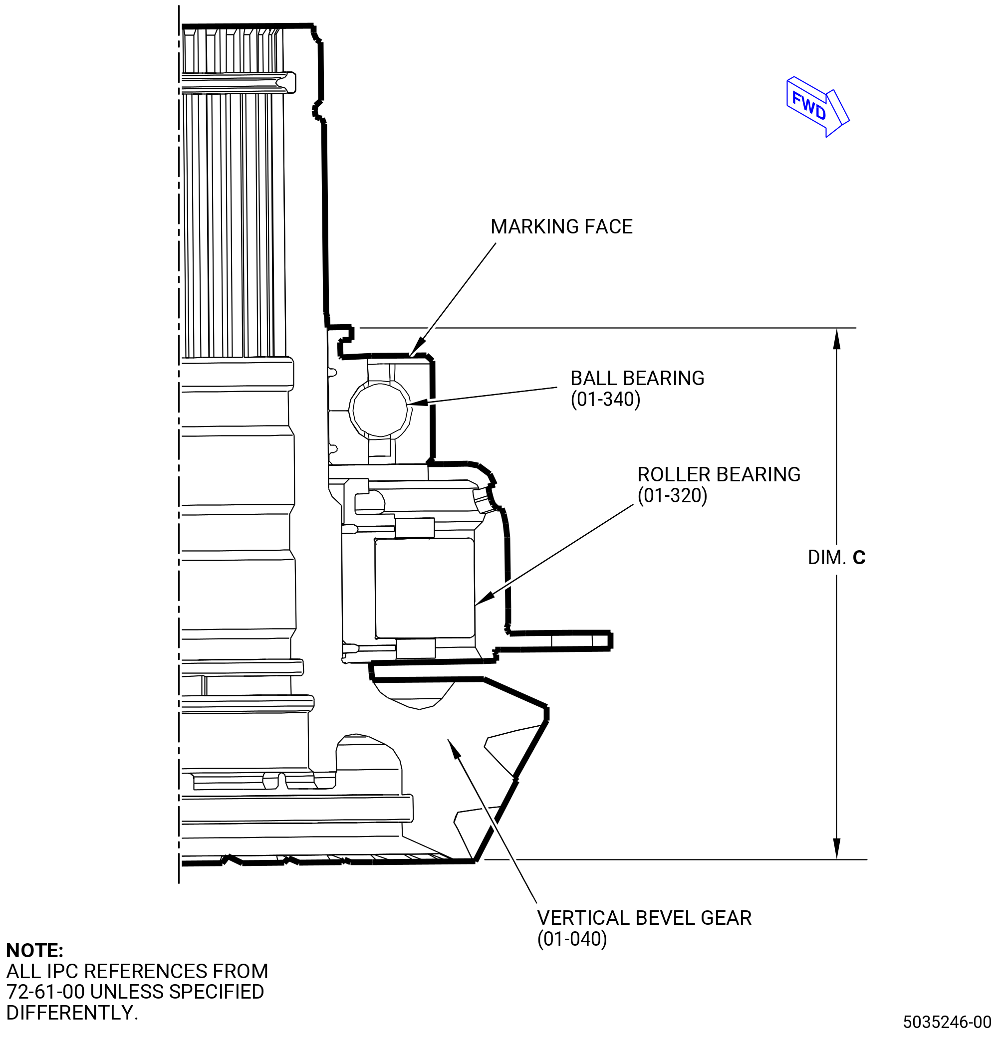
| (16) | Measure and record dimension C. |
| (17) | Read and record dimension D marked on the mandrel. Refer to Figure 1003. |
| (a) | Deleted. |
| (18) | Calculate dimension PB as follows: PB = C + D. |
| (19) | Record dimension PB. |
| (20) | Remove the mandrel from the 9479M86 measurement base. |
| (21) | Read and record dimension MD1 of the IGB housing (030A1). |
| (22) | Read and record dimension MDP = 5.7374 inches (145.730 mm) marked on the vertical bevel gear (030AC). |
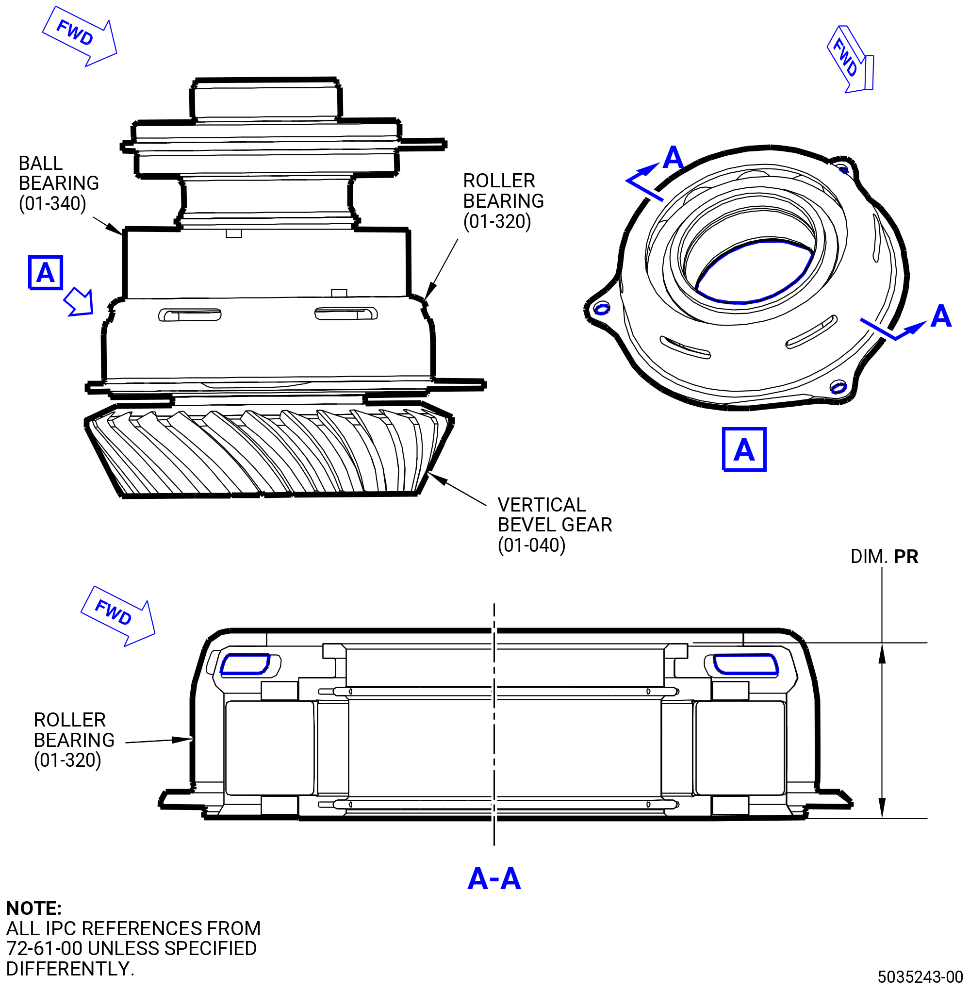
| (23) | Measure and record dimension PR of the roller bearing (01-320) (SIN 030A3). Refer to Figure 1004. |
| (24) | Calculate dimension SPP as follows: |
| (a) | SPP plus or minus 0.00098 inch (0.025 mm) = MD1 - MDP - PR - PB. |
| (25) | Record dimension SPP. This dimension is the thickness required for the shim (01-330) (SIN 030T1). |
| (a) | Adjust the thickness of the one-piece shim as follows: |
| WARNING: |
|
| 1 | Grind the one-piece shim (01-330) (SIN 030T1) until the thickness is in the tolerance limits of dimension SPP. |
| 2 | Make sure that the shim surfaces are parallel within 0.0006 inch (0.01 mm). |
| 3 | Make sure that the surface finish is 32 microinches (0.8 micrometers) or better. |
| Subtask 72-61-00-440-066 |
| E. | Install the roller bearing (030A3) on the vertical bevel gear (030AC) as follows: |
| (1) | Install the vertical bevel gear (030AC) on the 9479M76 assembly base. |
| WARNING: |
|
| (2) | Put the inner race of the roller bearing (01-320) (SIN 030A3) in an oven or locally increase the temperature to 258 to 273ºF (126 to 134ºC). |
| WARNING: |
|
| (3) | Apply C02-019 engine oil or C02-023 engine oil to the roller bearing journal of the vertical bevel gear (030AC) and to the inside diameter (ID) of the inner race of the roller bearing (030A3). |
| (4) | Install the inner race of the roller bearing (030A3) on the vertical bevel gear (030AC). |
| (5) | Put the 9479M77 pusher on the vertical bevel gear (030AC) and push the pusher until the inner race of the roller bearing (030A3) touches the shoulder of the vertical bevel gear (030AC). Use an arbor press or equivalent. |
| (6) | Apply a load of 9594-10188 lb (42680-45320 N). |
| (7) | Let the inner race of the roller bearing (030A3) go back to room temperature. Make sure that the inner race is correctly installed on the gearshaft. |
| (8) | Apply a load of 9594-10188 lb (42680-45320 N) again. |
| (9) | Remove the 9479M77 pusher from the vertical bevel gear (030AC). |
| (10) | Do a shim check to make sure that the inner race of the roller bearing (030A3) is correctly installed on the vertical bevel gear (030AC) as follows: |
| (a) | Use a 0.001 inch (0.03 mm) shim stock. |
| (b) | Make sure that the shim stock cannot go between the inner race of the roller bearing and the vertical bevel gear. |
| (c) | Do the shim check at three equally spaced locations. |
| WARNING: |
|
| (11) | Deleted. |
| WARNING: |
|
| (12) | Deleted. |
| (13) | Install the correct size shim (01-330) (SIN 030T1) on the vertical bevel gear (01-040) (SIN 030AC). |
| (14) | Install the outer race of the roller bearing (01-320) (SIN 030A3) on the vertical bevel gear (01-040) (SIN 030AC). |
| Subtask 72-61-00-440-067 |
| F. | Install the ball bearing (030A2) on the vertical bevel gear (030AC) as follows: |
| WARNING: |
|
| (1) | Put the upper inner race of the ball bearing (01-340) (SIN 030A2) into an oven or locally increase the temperature to 258 to 273ºF (126 to 134ºC). |
| WARNING: |
|
| (2) | Apply C02-019 engine oil or C02-023 engine oil to the ball bearing journal of the vertical bevel gear (030AC) and to the ID of the upper inner race of the ball bearing (030A2). |
| (3) | Install the upper inner race of the ball bearing (030A2) on the vertical bevel gear (030AC). |
| (4) | Put the 9479M77 pusher on the vertical bevel gear (030AC) and push the pusher until the upper inner race of the ball bearing (030A2) touches the roller bearing (030A3). Use an arbor press or equivalent. |
| (5) | Apply a load of 6324-6715 lb (28130-29870 N). |
| (6) | Let the upper inner race of the ball bearing (030A2) go back to room temperature. Make sure that the upper inner race of the ball bearing (030A2) is correctly installed on the vertical bevel gear (030AC). |
| (7) | Apply a load of 6324-6715 lb (28130-29870 N) again. |
| (8) | Remove the 9479M77 pusher from the vertical bevel gear (01-040) (SIN 030AC). |
| (9) | Measure and record dimension A. Refer to Figure 1005. |
| (10) | Install the outer race of the ball bearing (01-340) (SIN 030A2) on the vertical bevel gear (01-040) (SIN 030AC). Marking face up. |
| (11) | Measure and record dimension B of the lower inner race of the ball bearing (01-340) (SIN 030A2). Refer to Figure 1006. |
| WARNING: |
|
| (12) | Put the lower inner race of the ball bearing (01-340) (SIN 030A2) into an oven or locally increase the temperature to 258 to 273ºF (126 to 134ºC). |
| WARNING: |
|
| (13) | Apply C02-019 engine oil or C02-023 engine oil to the ball bearing journal of the vertical bevel gear (030AC) and to the ID of the lower inner race of the ball bearing (030A2). |
| (14) | Install the lower inner race of the ball bearing (030A2) on the vertical bevel gear (030AC). |
| (15) | Put the 9479M77 pusher on the vertical bevel gear (030AC) and push the pusher until the lower inner race of the ball bearing (030A2) is completely installed on the vertical bevel gear (030AC). Use an arbor press or equivalent. |
| (16) | Apply a load of 6324-6715 lb (28130-29870 N). |
| (17) | Let the lower inner race of the ball bearing (030A2) go back to room temperature. Make sure that the lower inner race is correctly installed on vertical bevel gear (030AC). |
| (18) | Apply a load of 6324-6715 lb (28130-29870 N) again. |
| (19) | Measure and record dimension C. Refer to Figure 1007. |
| (20) | Make sure that A + B = C plus or minus 0.0006 inch (0.015 mm). |
| Subtask 72-61-00-440-068 |
| G. | Install the spacer (030AJ) on the vertical bevel gear (030AC) as follows: |
| WARNING: |
|
| (1) | Put the spacer (01-270) (SIN 030AJ) in an oven or locally increase the temperature to 258 to 273ºF (126 to 134ºC). |
| WARNING: |
|
| (2) | Apply C02-019 engine oil or C02-023 engine oil to the ID of the spacer and the mating surface of the vertical bevel gear (030AC). |
| (3) | Install the spacer (030AJ) on the vertical bevel gear (030AC). |
| (4) | Put the 9479M77 pusher on the vertical bevel gear (030AC) and push the pusher until the spacer (030AJ) touches the ball bearing (030A2). Use an arbor press or equivalent. |
| (5) | Apply a load of 218-232 lb (970-1032 N). |
| (6) | Let the spacer go back to room temperature. Make sure that the spacer is correctly installed on the vertical bevel gear (030AC). |
| (7) | Apply a load of 218-232 lb (970-1032 N) again. |
| (8) | Remove the 9479M77 pusher from the vertical bevel gear (030AC). |
| (9) | Do a shim check to make sure that the spacer (030AJ) is correctly installed on the vertical bevel gear (030AC) as follows: |
| (a) | Use a 0.001 inch (0.03 mm) shim stock. |
| (b) | Make sure that the shim stock cannot go between the spacer (030AJ) and the inner race of the ball bearing (030A2). |
| (c) | Do the shim check at three equally spaced locations. |
| Subtask 72-61-00-440-069 |
| H. | Install the roller bearing (030AK) on the vertical bevel gear (030AC) as follows: |
| WARNING: |
|
| (1) | Put the inner race of the roller bearing (01-260) (SIN 030AK) into an oven or locally increase the temperature to 258 to 273ºF (126 to 134ºC). |
| WARNING: |
|
| (2) | Apply C02-019 engine oil or C02-023 engine oil to the ball bearing journal of the vertical bevel gear (030AC) and to the ID of the inner race of the roller bearing (030AK). |
| (3) | Install the inner race of the roller bearing (01-260) (SIN 030AK) on the vertical bevel gear (01-040) (SIN 030AC). Marking face UP. |
| (4) | Put the 9479M78 pusher on the vertical bevel gear (030AC) and push the pusher until the inner race of the roller bearing (030AK) is completely installed on the vertical bevel gear (030AC). Use an arbor press or equivalent. |
| (5) | Apply a load of 6324-6715 lb (28130-29870 N). |
| (6) | Let the inner race of the roller bearing (030AK) go back to room temperature. Make sure that the inner race is correctly installed to the gearshaft. |
| (7) | Apply a load of 6324-6715 lb (28130-29870 N) again. |
| (8) | Remove the 9479M78 pusher from the radial bevel gearshaft. |
| (9) | Do a shim check to make sure that the inner race of the roller bearing (030AK) is correctly installed on the vertical bevel gear (030AC) as follows: |
| (a) | Use a 0.001 inch (0.03 mm) shim stock. |
| (b) | Make sure that the shim stock cannot go between the inner race of the roller bearing (030AK) and the spacer (030AJ). |
| (c) | Do the shim check at three equally spaced locations. |
| Subtask 72-61-00-440-070 |
| I. | Install the locknut (030A4) on the vertical bevel gear (030AC) as follows: |
| (1) | Remove the vertical bevel gear (030AC) from the 9479M76 assembly base and install it in the 9479M81 antirotation base. Use the tie rod to lock the gearshaft. |
| WARNING: |
|
| (2) | Apply C02-019 engine oil or C02-023 engine oil to the threads of the vertical bevel gear (030AC) and to the ID of the locknut (030A4). |
| (3) | Install the lock nut (01-250) (SIN 030A4) with the vespel insert away from bearing, on the vertical bevel gear (01-040) (SIN 030AC). |
| (4) | Put the 9479M84 special wrench on the lock nut (01-250) (SIN 030A4) and turn the wrench until the lock nut vespel insert is fully in contact with the thread of the vertical bevel gear (01-040) (SIN 030AC). |
| (5) | Turn the wrench and record the run-on torque. |
| (6) | Make sure that the run-on torque is more than 22.1 lb ft. (30 Nm). Total torque given by the sum of the run-on torque (recorded during assembly) plus 173 to 180 lb ft. (235 to 245 Nm). |
| (7) | Total torque must not be more than 221 lb ft. (300 Nm). |
| (8) | Remove the 9479M84 special wrench from the vertical bevel gear (030AC). |
| (9) | Remove the vertical bevel gear (030AC) from the 9479M81 antirotation base. |
| Subtask 72-61-00-440-071 |
| J. | Install the outer race of the roller bearing (030AK) in the IGB housing (030A1) as follows: |
| WARNING: |
|
| (1) | Put the outer race of the roller bearing (01-260) (SIN 030AK) in an oven or locally increase the temperature to 154 to 162ºF (68 to 72ºC). |
| WARNING: |
|
| (2) | Apply C02-019 engine oil or C02-023 engine oil to the ID of the outer race of the roller bearing (030A4) and the mating surface of the IGB housing (030A1). |
| (3) | Install the outer race of the roller bearing (030AK) in the IGB housing (030A1). |
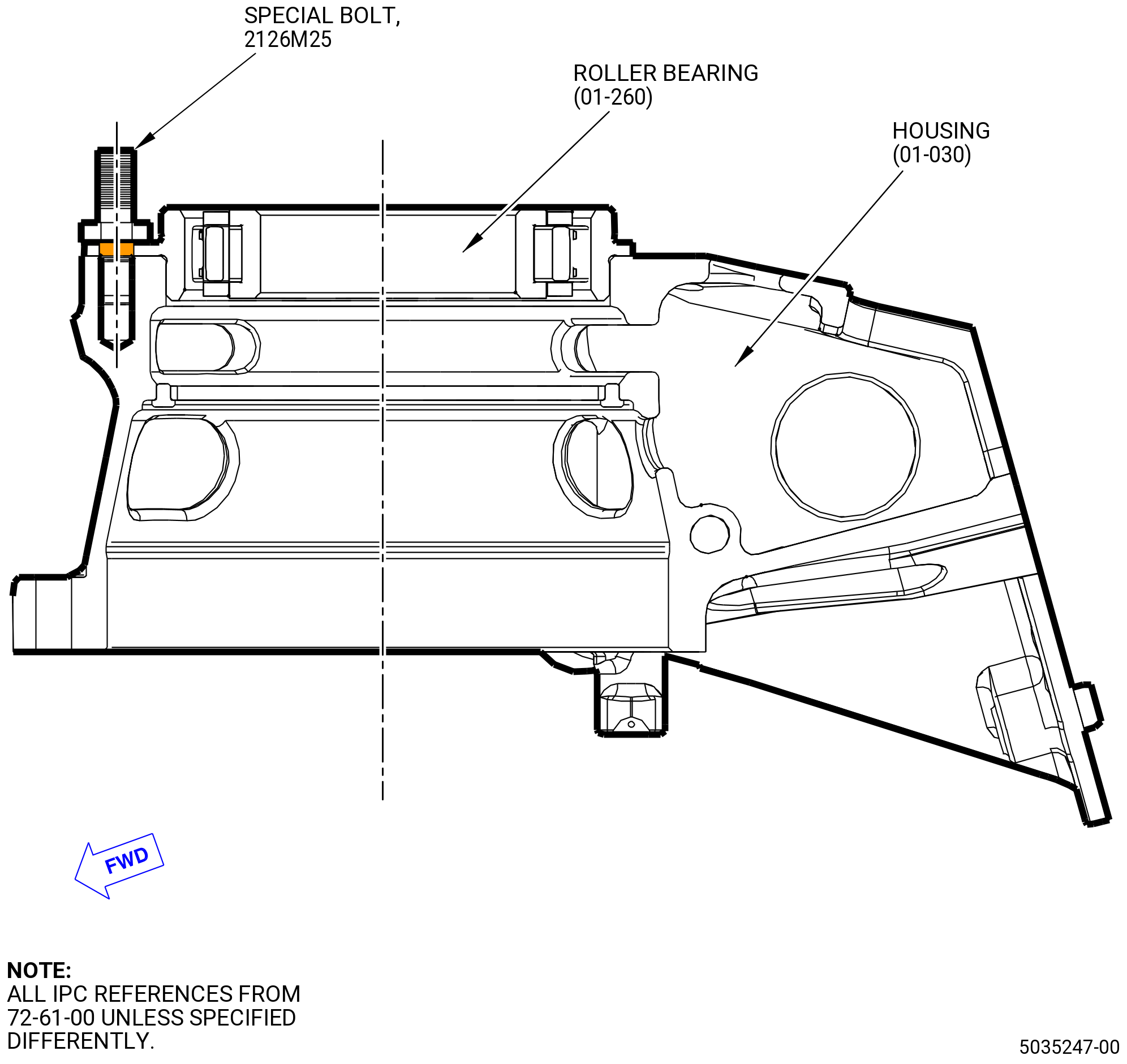
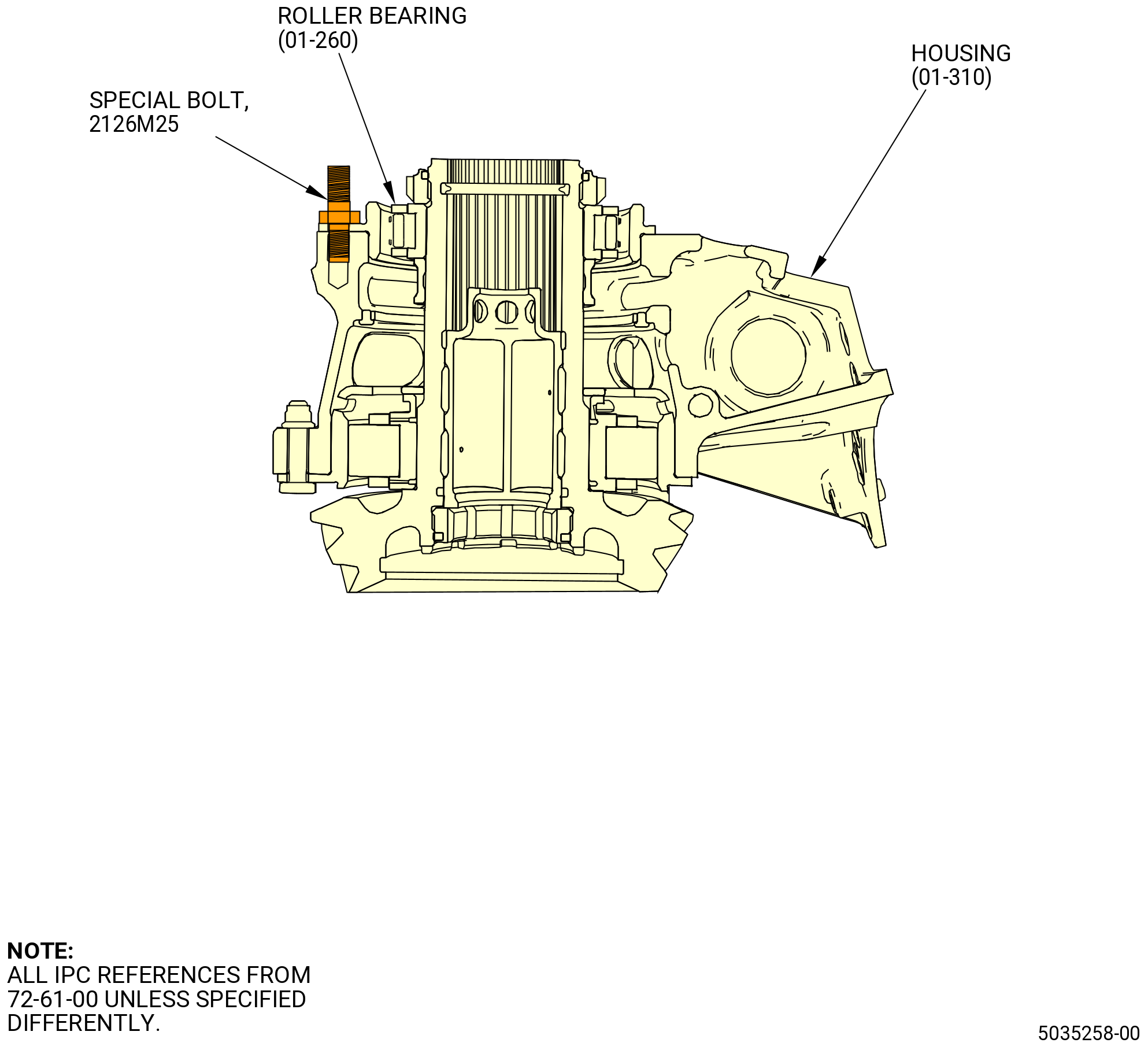
| (4) | Install the 2126M25 special bolts to attach the outer race of the roller bearing (01-260) (SIN 030AK) to the IGB housing (01-030) (SIN 030A1). Refer to Figure 1008. |
| (5) | Torque the special nut to 108.6 to 127.4 lb in. (12.3 to 14.4 Nm). |
| Subtask 72-61-00-440-072 |
| K. | Install the vertical bevel gear (030AC) assembly in the IGB housing (030A1) as follows: |
| (1) | Read the dimension BL marked on the vertical bevel gear (030AC) and record it as dimension BLP. |
| NOTE: |
|
| WARNING: |
|
| (2) | Put IGB housing (01-030) (SIN 030A1) in an oven or locally increase the temperature to 154 to 162ºF (68 to 72ºC). |
| (3) | Put the IGB housing (030A1) with the outer race of the roller bearing (030AK) down on a clean work surface. |
| WARNING: |
|
| (4) | Apply C02-019 engine oil or C02-023 engine oil to the ID of the outer race of the roller bearing (030AK) in the mating surface of the IGB housing (030A1). |
| (5) | Install the vertical bevel gear (01-040) (SIN 030AC) in the IGB housing (01-030) (SIN 030A1). Make sure that the two slots in the outer race of the ball bearing (01-340) (SIN 030A2) engage the two pins in the IGB housing (01-030) (SIN 030A1). |
| WARNING: |
|
| (6) | Apply C02-019 engine oil or C02-023 engine oil to three bolts (030F7). |
| (7) | Install the bolts (030F7) and the nuts (030K0) that attach the roller bearing (030A3) to the IGB housing (030A1). |
| (8) | Make sure that the run-on torque is between 7 lb in. (0.79 Nm) to 30 lb in. (3.39 Nm) for a new nut or between 3.5 lb in. (0.40 Nm) to 30 lb in. (3.39 Nm) for a used nut. |
| (9) | Torque the nut to 108.6 to 127.4 lb in. (12.3 to 14.3 Nm). |
| Subtask 72-61-00-440-073 |
| L. | Install the shim (01-090) (SIN 030T0) and the No. 3 ball bearing (030A7) on the horizontal bevel gear (030AB) as follows: |
| (1) | Install the horizontal bevel gear (030AB), forward end down on the 2126M19 assembly base. |
| (2) | Read the dimension BL marked on the horizontal bevel gearshaft (030AB) and record it as dimension BLC. |
| NOTE: |
|
| WARNING: |
|
| (3) | Put the correct size shim (01-090) (SIN 030T0) in an oven or locally increase the temperature to 154 to 162ºF (68 to 72ºC). |
| WARNING: |
|
| (4) | Apply C02-019 engine oil or C02-023 engine oil to the ID of the shim (01-090) (SIN 030T0) and the mating surface of the horizontal bevel gear (030AB). |
| (5) | Install the shim (01-090) (SIN 030T0) on the horizontal bevel gear (030AB). |
| (6) | Put the forward inner race of the No. 3 ball bearing (01-100) (SIN 030A7) in an oven or locally increase the temperature to 258 to 273ºF (126 to 134ºC). |
| WARNING: |
|
| (7) | Apply C02-019 engine oil or C02-023 engine oil to the ID of the forward inner race of the No. 3 ball bearing (030A7) and the mating surface of the horizontal bevel gear (030AB). |
| (8) | Install the forward inner race of the No. 3 ball bearing (030A7) on the horizontal bevel gear (030AB), with the bearing mating surface up. |
| (9) | Put the 2126M17 pusher on the horizontal bevel gear (030AB) and push the pusher until the forward inner race of the ball bearing (030A7) touches the shim. Use an arbor press or equivalent. |
| (10) | Apply a load of 9594-10188 lb (42680-45320 N). |
| (11) | Let the inner race of the ball bearing go back to room temperature. Make sure that the inner race is correctly installed to the horizontal bevel gear (030AB). |
| (12) | Apply a load of 9594-10188 lb (42680-45320 N) again. |
| (13) | Remove the 2126M17 pusher from the horizontal bevel gear (030AB). |
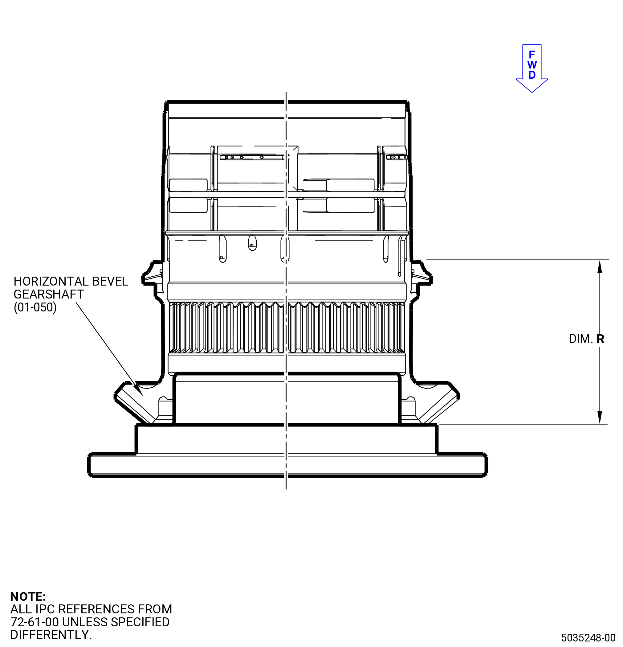
| (14) | Measure and record the dimension R. Refer to Figure 1009. |
| (15) | Install the No. 3 bearing housing (030A6) assembly and the cage and balls of the No. 3 ball bearing (030A7) in the horizontal bevel gear (030AB). |
| NOTE: |
|
| (16) | Measure and record dimension S of the aft inner race of the No. 3 ball bearing (01-100) (SIN 030A7). Refer to Figure 1010. |
| WARNING: |
|
| (17) | Put the aft inner race of the No. 3 ball bearing (01-100) (SIN 030A7) in an oven or locally increase the temperature to 258 to 273ºF (126 to 134ºC). |
| WARNING: |
|
| (18) | Apply C02-019 engine oil or C02-023 engine oil to the No. 3 ball bearing journal of the horizontal bevel gear (030AB) and to the ID of the aft inner race of the No. 3 ball bearing (030A7). |
| (19) | Install the aft inner race of the No. 3 ball bearing (030A7) on the horizontal bevel gear (030AB). |
| (20) | Put the 2126M17 pusher on the horizontal bevel gear (030AB) and push the pusher until the aft inner race of the No. 3 ball bearing (030A7) is completely installed on the horizontal bevel gear (030AB). Use an arbor press or equivalent. |
| (21) | Apply a load of 9594-10188 lb (42680-45320 N). |
| (22) | Let the aft inner race of the No. 3 ball bearing (030A7) go back to room temperature. Make sure that the aft inner race of the No. 3 ball bearing (030A7) is correctly installed to the horizontal bevel gear (030AB). |
| (23) | Apply a load of 9594-10188 lb (42680-45320 N) again. |
| (24) | Remove the 2126M17 pusher from the horizontal bevel gear (030AB). |
| (25) | Measure and record the dimension T. Refer to Figure 1011. |
| (26) | Make sure that R + S = T plus or minus 0.0006 inch (0.015 mm). |
| Subtask 72-61-00-440-074 |
| M. | Install the distributor (030A9) on the horizontal bevel gear (030AB) as follows: |
| WARNING: |
|
| (1) | Put the distributor (01-180) (SIN 030A9) in an oven or locally increase the temperature to 258 to 273ºF (126 to 134ºC). |
| WARNING: |
|
| (2) | Apply C02-019 engine oil or C02-023 engine oil to the ID of the distributor (030A9) and to the mating surface on the horizontal bevel gear (030AB). |
| (3) | Install the distributor (030A9) on the horizontal bevel gear (030AB). Make sure that the two tabs on the distributor engage the two slots on the horizontal bevel gear (030AB). |
| (4) | Install the 2126M18 pusher on the horizontal bevel gear (030AB) and push the pusher until the distributor (030A9) is completely installed on the horizontal bevel gear (030AB). Use an arbor press or equivalent. |
| (5) | Apply a load of 2425-2575 lb (10787-11454 N). |
| (6) | Let the distributor go back to room temperature. Make sure that the distributor is correctly installed to the horizontal bevel gear (030AB). |
| (7) | Apply a load of 2425-2575 lb (10787-11454 N) again. |
| (8) | Remove the 2126M18 pusher from the horizontal bevel gear (030AB). |
| (9) | Do a shim check to make sure that the distributor (030A9) is correctly installed on the horizontal bevel gear (030AB) as follows: |
| (a) | Use a 0.001 inch (0.03 mm) shim stock. |
| (b) | Make sure that the shim stock cannot go between the distributor (030A9) and the aft inner race of the No. 3 ball bearing (030A7). |
| (c) | Do the shim check at three equally spaced locations. |
| Subtask 72-61-00-440-075 |
| N. | Install the inner race of the roller bearing (030A5) on the horizontal bevel gear (030AB) as follows: |
| WARNING: |
|
| (1) | Use C10-140 gloves and put the inner race of the roller bearing (01-130) (SIN 030A5) in an oven or locally increase the temperature to 258 to 273ºF (126 to 134ºC). |
| WARNING: |
|
| (2) | Apply C02-019 engine oil or C02-023 engine oil to the ID of the roller bearing (030A5) and to the mating surface of the horizontal bevel gear (030AB). |
| (3) | Put the inner race of the roller bearing (030A5) on the 2126M18 pusher. |
| (4) | Put the 2126M18 pusher and the inner race of the roller bearing (030A5) on the horizontal bevel gear (030AB) and push the pusher until the inner race of the roller bearing is completely installed on the horizontal bevel gear (030AB). Use an arbor press or equivalent. |
| (5) | Apply a load of 9594-10188 lb (42680-45320 N). |
| (6) | Let the inner race of the roller bearing go back to room temperature. Make sure that the inner race is correctly installed on the horizontal bevel gear (030AB). |
| (7) | Apply a load of 9594-10188 lb (42680-45320 N) again. |
| (8) | Do a shim check to make sure that the roller bearing (030A5) is correctly installed on the horizontal bevel gear (030AB) as follows: |
| (a) | Use a 0.001 inch (0.03 mm) shim stock. |
| (b) | Make sure that the shim stock cannot go between the inner race of the roller bearing (030A5) and the distributor (030A9). |
| (c) | Do the shim check at three equally spaced locations. |
| Subtask 72-61-00-440-076 |
| O. | Install the four bolts (03022) in the outer race of the roller bearing (030A5) as follows: |
| (1) | Use C10-140 gloves and put the outer race of the cylindrical roller bearing on a clean work surface. |
| WARNING: |
|
| (2) | Apply C02-019 engine oil or C02-023 engine oil to the four bolts (03022). |
| (3) | Locate the four bolt holes in the ID flange of the outer race of the roller bearing (030A5) that have recessed surfaces. |
| (4) | Put the bolts in the recessed bolt holes of the outer race and press in position. |
| Subtask 72-61-00-440-077 |
| P. | Install the outer race of the roller bearing (030A5) on the 2126M13 assembly stand as follows: |
| (1) | Use C10-140 gloves and put the two bolts (030F4) in the outer race of the cylindrical roller bearing (030A5). Install the two bolts at position 1 and 2 with the threaded part pointing up. |
| (2) | Install the outer race in the 2126M13 assembly stand. |
| Subtask 72-61-00-440-078 |
| Q. | Install the horizontal bevel gear (030AB) in the outer race of the roller bearing (030A5) as follows: |
| (1) | Put the 9479M94 shaft on the 2126M22 special bench. |
| WARNING: |
|
| (2) | Put bevel horizontal bevel gearshaft (01-050) (SIN 030AB) in an oven and increase the temperature to 258 to 273ºF (126 to 134ºC). |
| (3) | Remove the horizontal bevel gear (030AB) from the oven and install the shim of the 2126M21 enerpac retaining and the 2126M21 enerpac retaining in the horizontal bevel gear (030AB). |
| (4) | Install the horizontal bevel gear (030AB) on the 9479M94 shaft. |
| (5) | Install the 2126M20 pusher , the enerpac hydraulic cylinder, and the locking nut of the 2126M21 enerpac retaining. |
| (6) | Operate with the hydraulic cylinder to install the horizontal bevel gearshaft (01-050) (SIN 030AB) in the 9479M94 shaft. Refer to Figure 1012. |
| (7) | Let the horizontal bevel gearshaft go back to room temperature. Make sure that the horizontal bevel gear (030AB) is correctly installed to the mandrel. |
| (8) | Do a shim check to make sure that the cylindrical roller bearing (030A5) is correctly installed on the 9479M94 shaft as follows: |
| (a) | Use a 0.001 inch (0.03 mm) shim stock. |
| (b) | Make sure that the shim stock cannot go between the cylindrical roller bearing (030A5) and the 9479M94 shaft. |
| (c) | Do the shim check at three equally spaced locations. |
| (9) | Remove the enerpac hydraulic cylinder, 2126M20 pusher, 2126M21 enerpac retaining, and the shim from the gearshaft. |
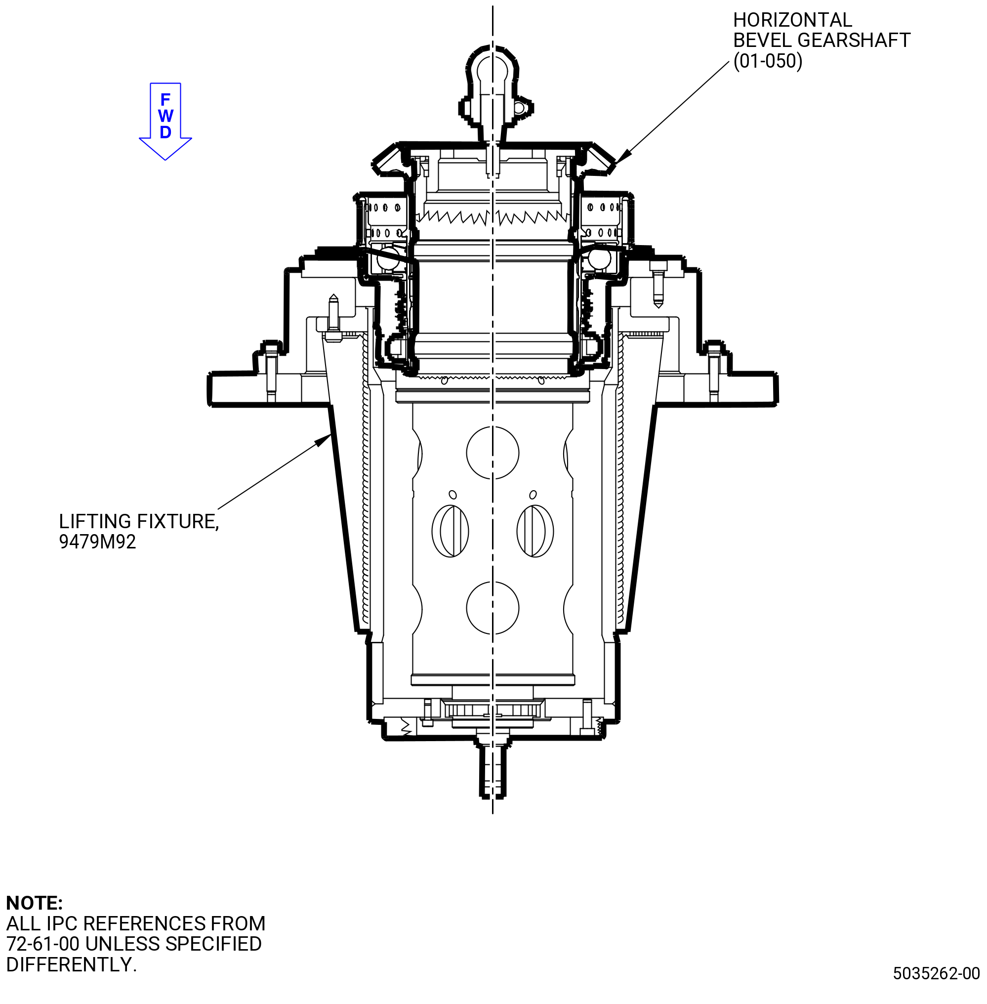
| (10) | Install the shim of the 9479M94 shaft and 9479M92 lifting fixture in the horizontal bevel gearshaft (030AB). Use the 9479M93 special wrench to tighten the handling gear in the gearshaft. |
| (11) | Install an eyebolt in the handling gear of the 9479M92 lifting fixture. |
| (12) | Lift the horizontal bevel gearshaft (01-050) (SIN 030AB) and the 9479M94 shaft from the 2126M22 special bench. |
| (13) | Move the horizontal bevel gearshaft (01-050) (SIN 030AB) and the 9479M94 shaft and put them on the 2126M13 assembly stand. |
| NOTE: |
|
| (14) | Align the two bolts (030F4) installed in the outer race of the cylindrical roller bearing (030A5) with the holes near the tabs on the flange of the No. 3 bearing housing (030A6). |
| (15) | Slowly lower the gearshaft until it is fulling installed in the outer race of the cylindrical roller bearing (030A5). |
| (16) | Install two knobs of the 2126M13 assembly stand inlet GBX on the bolts (030F4). |
| (17) | Remove the eyebolt from the handling gear of the 9479M92 lifting fixture. |
| (18) | Attach the flange of the No. 3 bearing housing (030A6) to the 2126M13 assembly stand. Use bolts and washers of the 2126M13 assembly stand. |
| NOTE: |
|
| (19) | Remove the two knobs of the 2126M13 assembly stand from the bolts (030F4). |
| Subtask 72-61-00-440-079 |
| R. | Assemble the horizontal bevel gear (030AB) and the vertical bevel gear (030AC) as follows: |
| (1) | Deleted. |
| (2) | Install the vertical bevel gear (030AC) and the IGB housing (030A1) on the flange of the No. 3 bearing housing (030A6). Use the two pins on the casing as a guide. |
| (3) | Install the two nuts (01-010) (SIN 030K3) on the bolts (01-020) (SIN 030F4). Tighten the nuts. |
| (4) | Torque the nut to 108.6-127.4 lb in (12.3-14.3 Nm). |
| (5) | Attach the IGB housing (030A1) to the 2126M13 assembly stand inlet GBX. Use the four bolts and washers of the 2126M13 assembly stand inlet GBX. |
| Subtask 72-61-00-440-080 |
| S. | Prepare for the circumferential backlash: |
| (1) | Install the following tools on the vertical bevel gear (030AC). |
| (a) | 9479M99 mandrel. |
| (b) | 2126M25 special bolt. |
| (c) | 2126M12 special device. |
| (d) | 2126M11 special device. |
| (e) | 2126M10 dynamometer support. |
| (f) | 2126M16 radial gearshaft dynamometer support. |
| (g) | 9479M97 special device. |
| (h) | 9479M96 handle. |
| (2) | Install the following tools on the horizontal bevel gear (030AB). |
| (a) | 2126M14 dynamometer support. |
| (b) | 2126M15 horizontal gearshaft dynamometer support. |
| Subtask 72-61-00-440-081 |
| T. | Do the circumferential backlash check of the gear teeth at run condition as follows: |
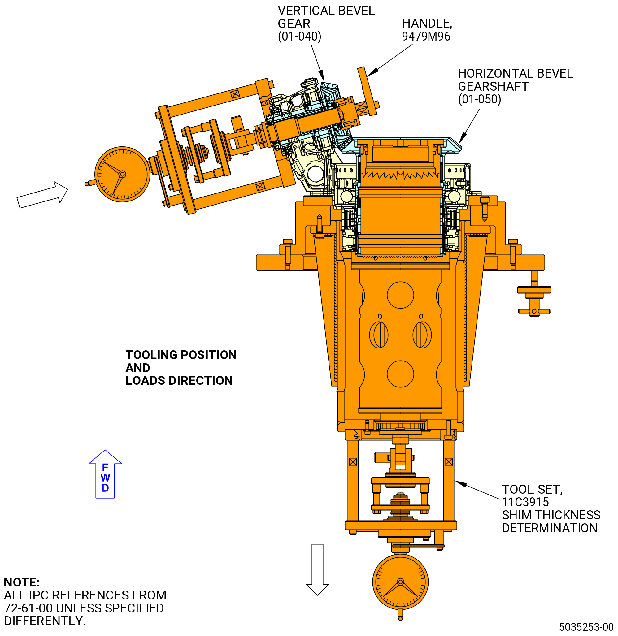
| (1) | Rotate the IGB assembly to have horizontal bevel gearshaft (01-050) (SIN 030AB) axis vertically placed with cone apex positioned in the lower direction. Refer to Figure 1013. |
| (2) | Use the 9479M96 handle to rotate the vertical bevel gear (030AC) first clockwise (CW) (not less than 20 turns) and then counterclockwise (CCW). |
| (3) | Adjust to zero the dial indicator on both dynamometers. |
| (4) | Remove the 9479M96 handle and the 9479M97 special device from the vertical bevel gear (030AC) and install the backlash check lever 9479M98 special device. |
| (5) | Use the locking K and lock the 9479M94 shaft. |
| (6) | Operate the adjusting screw on the dynamometer and apply a load between 450 and 550 N (101 and 124 lb) on the horizontal bevel gear (030AB) in the direction of the IGB. |
| (7) | Operate the adjusting screw on the dynamometer and apply a load between 135 and 165 N (30 and 37 lb) on the vertical bevel gear (030AC) in the direction opposite the IGB. |
| (8) | Install a standard comparator on the horizontal bevel gear (030AB). Turn CW the backlash check lever 9479M98 special device lever installed on the vertical bevel gear (030AC) and set to zero the dial gage of the comparator. |
| (9) | Turn the backlash check lever special device CCW and read the value on the dial gage. |
| (10) | Record the value (measured) of the backlash at run as BLMR. |
| (11) | Calculate the circumferential backlash at run condition (BLTR) as follows: |
| NOTE: |
|
| (12) | BLTR = (BLP + BLC) x 1.4146. |
| (13) | Make sure that BLMR = BLRT plus or minus 0.0047 inch (0.119 mm). |
| (14) | Operate the adjusting screw on the dynamometer and release the load of the two gearshafts. |
| (15) | Remove the backlash check lever 9479M98 special device from the radial bevel gearshaft. |
| Subtask 72-61-00-440-082 |
| U. | Do the circumferential backlash of the gear teeth at starter condition as follows: |
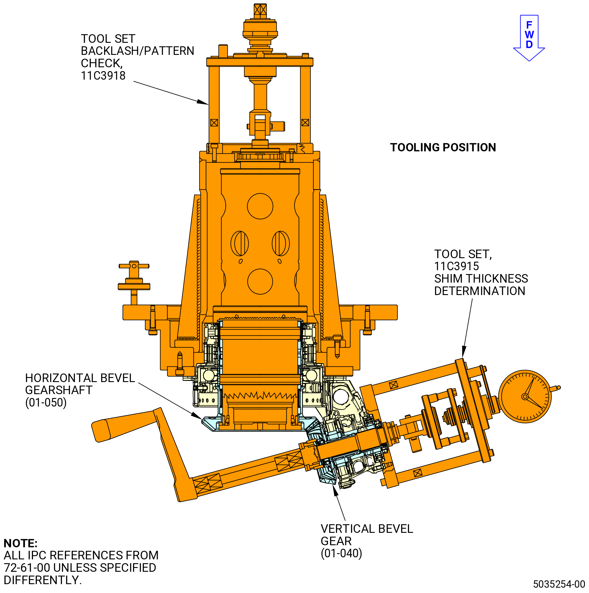
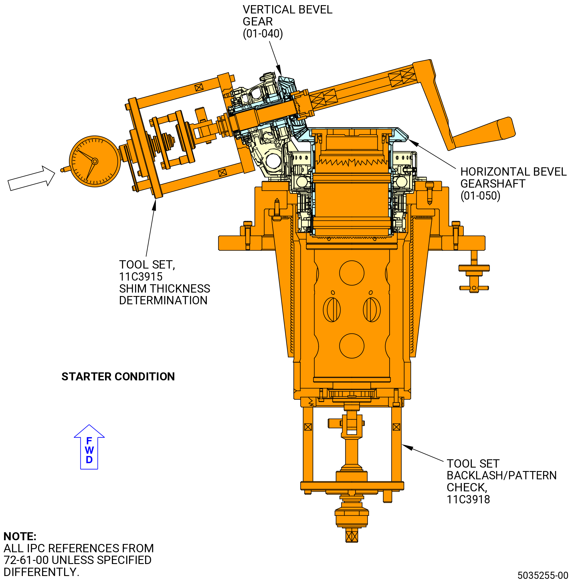
| (1) | Rotate the IGB assembly to have horizontal bevel gear (01-050) (SIN 030AB) axis vertically placed with cone apex positioned in the upper direction. Refer to Figure 1014. |
| (2) | Install the 9479M96 handle and the 9479M97 special device on the vertical bevel gear (030AC) again. |
| (3) | Use the 9479M96 handle to rotate the vertical bevel gear (030AC) first CW (not less than 20 turns) and then CCW. |
| (4) | Remove the 9479M96 handle and the 9479M97 special device from the vertical bevel gear (030AC). |
| (5) | Install the backlash check lever 9479M98 special device on the vertical bevel gear (030AC). |
| (6) | Operate the adjusting screw on the dynamometer and apply a load between 450 and 550 N (101 and 124 lb) on the horizontal bevel gear (030AB) in the direction opposite the IGB. |
| (7) | Operate the adjusting screw on the dynamometer and apply a load between 135 and 165 N (30 and 37 lb) on the vertical bevel gear (030AC) in the direction of the IGB. |
| (8) | Install a standard comparator on the horizontal bevel gear (030AB). Turn CW the backlash check lever 9479M98 special device installed on the vertical bevel gear (030AC) and set to zero the dial gage of the comparator. |
| (9) | Turn the backlash check lever CCW and read the value on the dial gage. |
| (10) | Record the value (measured) of the backlash at the starter condition as BLMS. |
| (11) | Calculate the circumferential backlash at the starter condition (BLTS) as follows: |
| NOTE: |
|
| (12) | BLTR = (BLP + BLC) x 1.4146. |
| (13) | BLTS = BLTR + 0.0042 in. (0.108 mm). |
| (14) | Make sure that BLMS = BLTS plus or minus 0.0059 inch (0.150 mm). |
| (15) | Operate the adjusting screw on the dynamometer and release the load of the two gearshafts. |
| (16) | Use the locking K and unlock the 9479M94 shaft. |
| (17) | Remove the 2126M15 horizontal gearshaft dynamometer support and 9479M98 special device from the horizontal bevel gear (030AB). |
| (18) | Keep the remaining tools in place for the contact check. |
| Subtask 72-61-00-440-083 |
| V. | Do the contact check of the gear teeth as follows: |
| (1) | If the original bevel gearshafts will be used again, that have wear on the start side of the teeth that can be felt with a 0.030 inch (0.76 mm) radius scribe, but identified as serviceable by OEM or OEM approved facility, refer to TASK 72-61-40-200-801 (72-61-40, INSPECTION 001) they must be maintained as a set and re-installed with the original IGB housing (01-030) (SIN 030A1). In this case do the gear teeth contact patterns check on the run side only. |
| (2) | If you use the original bevel gearshafts again that have no wear on the start side of the teeth and they are maintained as a set and re-installed with the original IGB housing (01-130) (SIN 030A1), do the gear teeth contact patterns check on run side only. |
| (3) | Deleted. |
| (4) | Install the 2126M14 dynamometer support and 9479M95 clutch support on the horizontal bevel gear (030AB). |
| (5) | Install the 9479M96 handle and the 9479M97 special device on the vertical bevel gear (030AC). |
| (6) | Calibrate the clutch between 265 to 310 lb in. (30 to 35 Nm). Use a standard torque wrench. |
| (7) | Do the contact check at run condition as follows: |
| (a) | Rotate the IGB assembly to have horizontal bevel gearshaft (01-050) (SIN 030AB) axis vertically placed with cone apex positioned in the lower direction. Refer to Figure 1015. |
| WARNING: |
|
| (b) | Apply C05-001 compound or C05-123 gear marking on both sides of the bevel gearshaft teeth. |
| (c) | Turn the 9479M96 handle CCW (not less than 20 turns) until the teeth of the vertical bevel gear (030AC) touch the teeth of the horizontal bevel gear (030AB). |
| (8) | Apply a load between 135 and 165 N (30 and 37 lb) on the vertical bevel gear (030AC) in the direction of the IGB. |
| (9) | Calibrate the clutch between 265 to 310 lb in. (30 to 35 Nm) Use a standard torque wrench. |
| (10) | Do the contact check at starter condition as follows: |
| (a) | Rotate the IGB assembly to have horizontal bevel gearshaft (01-050) (SIN 030AB) axis vertically placed with cone apex positioned in the upper direction. Refer to Figure 1016. |
| (b) | Turn the 9479M96 handle CW (not less than 20 turns) until the teeth of the vertical bevel gear (030AC) touch the teeth of the horizontal bevel gear (030AB). |
| (11) | Remove all the tools installed to do the backlash check. |
| (12) | Remove the two nuts (030K3). |
| (13) | Remove the four bolts and washers of the 2126M13 assembly stand. |
| (14) | Remove the vertical bevel gear (030AC) and the IGB housing (030A1) from the flange of the housing (030AM). |
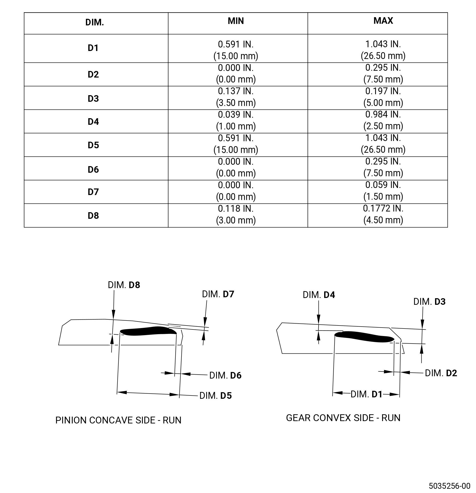
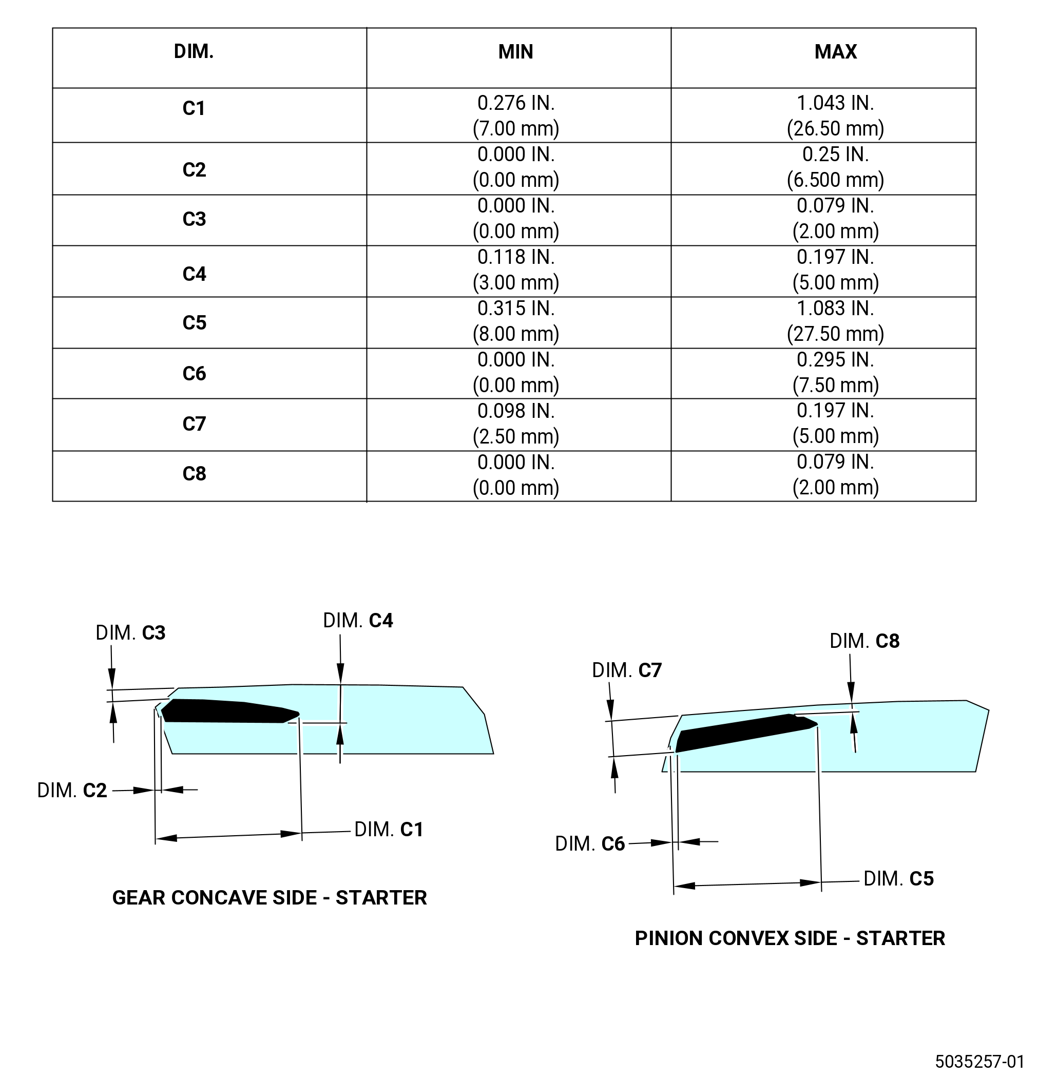
| (15) | Examine the contact pattern on the convex side and on the concave side of the teeth of the vertical bevel gear (01-040) (SIN 030AC) and the horizontal bevel gearshaft. Refer to Figure 1017 and Figure 1018. |
| (16) | If the contact pattern is outside the dimensions required, increase or decrease the thickness of the shim (01-090) (SIN 030T0) and the shim (01-330) (SIN 030T1) until the contact pattern is in the required dimension. |
| (17) | Do the circumferential backlash checks again if the shims thickness was changed. |
| (18) | Remove the C05-001 compound from the teeth of the gearshafts. Use a soft brush. |
| Subtask 72-61-00-110-002 |
| WARNING: |
|
| (19) | Clean the radial and horizontal gearshaft teeth to remove the C05-001 compound or C05-123 gear marking. Refer to TASK 70-21-23-110-053 (CLEANING METHOD NO. 23 - HAND-WIPE DEGREASING). |
| Subtask 72-61-00-440-084 |
| W. | Install the RDS oil duct (030N3) in the vertical bevel gear (030AC) as follows: |
| (1) | Remove the vertical bevel gear (01-040) (SIN 030AC) and the IGB housing (01-030) (SIN 030A1) from the flange of the No. 3 bearing housing (01-170) (SIN 030A6). |
| (2) | Remove the 2126M25 special bolts which attach the outer race of the roller bearing (01-260) (SIN 030AK) to the IGB housing (01-030) (SIN 030A1). Refer to Figure 1019. |
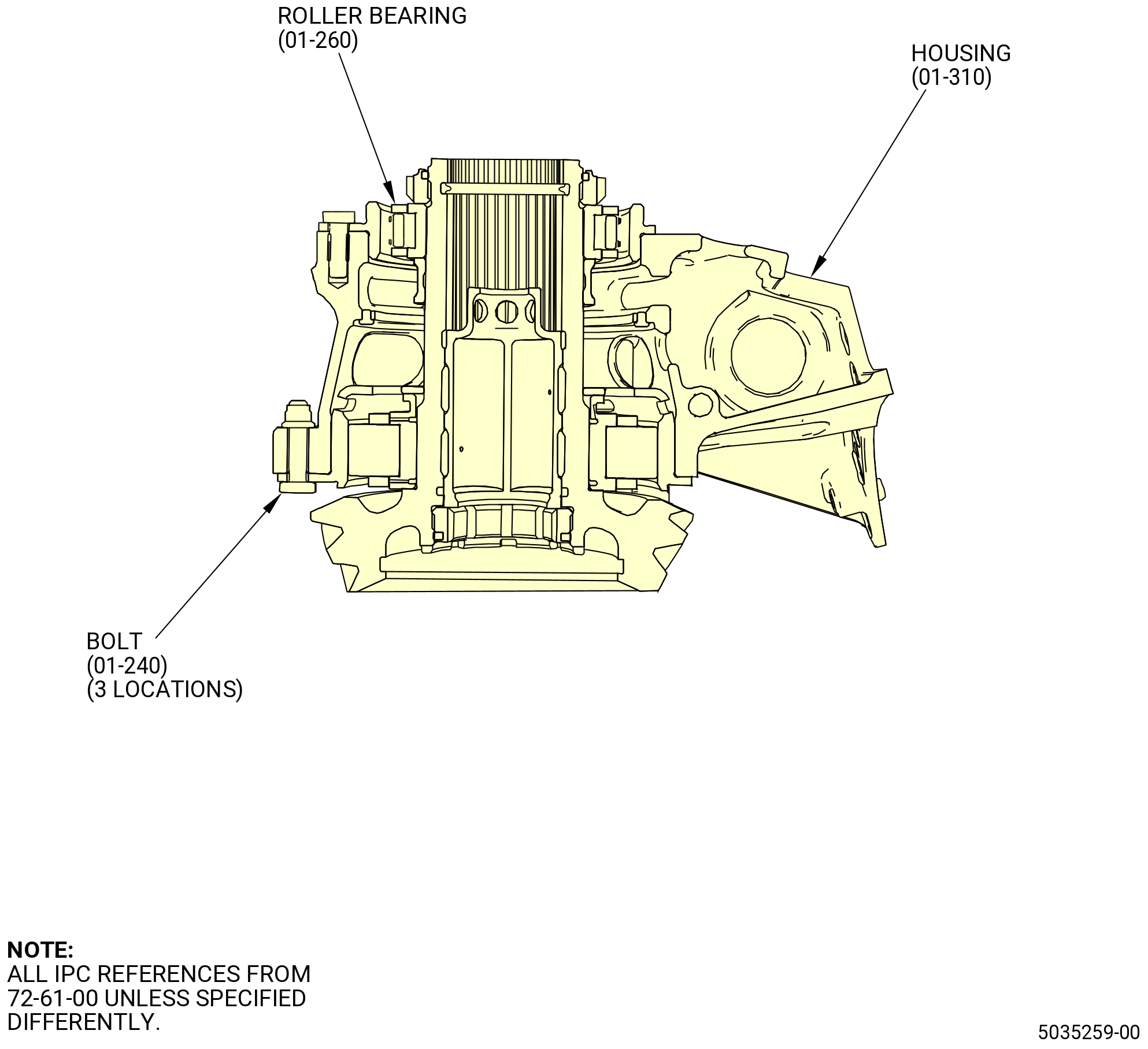
| (3) | Install the tree bolts (01-240) (SIN 030F0) which attach the outer race of the roller bearing (01-260) (SIN 030AK) to the IGB housing (01-030) (SIN 030A1). Refer to Figure 1020. |
| (4) | Make sure that the run-on torque is between 7 lb in. (0.79 Nm) to 30 lb in. (3.39 Nm) for a new bolt or between 3.5 lb in. (0.40 Nm) to 30 lb in. (3.39 Nm) for a used bolt. |
| (5) | Torque the bolts to 108.6 to 127.4 lb in. (12.3 to 14.3 Nm). |
| (6) | Install the vertical bevel gear (030AC) and the IGB housing (030A1) on the 9479M79 assembly base. |
| WARNING: |
|
| (7) | Deleted. |
| WARNING: |
|
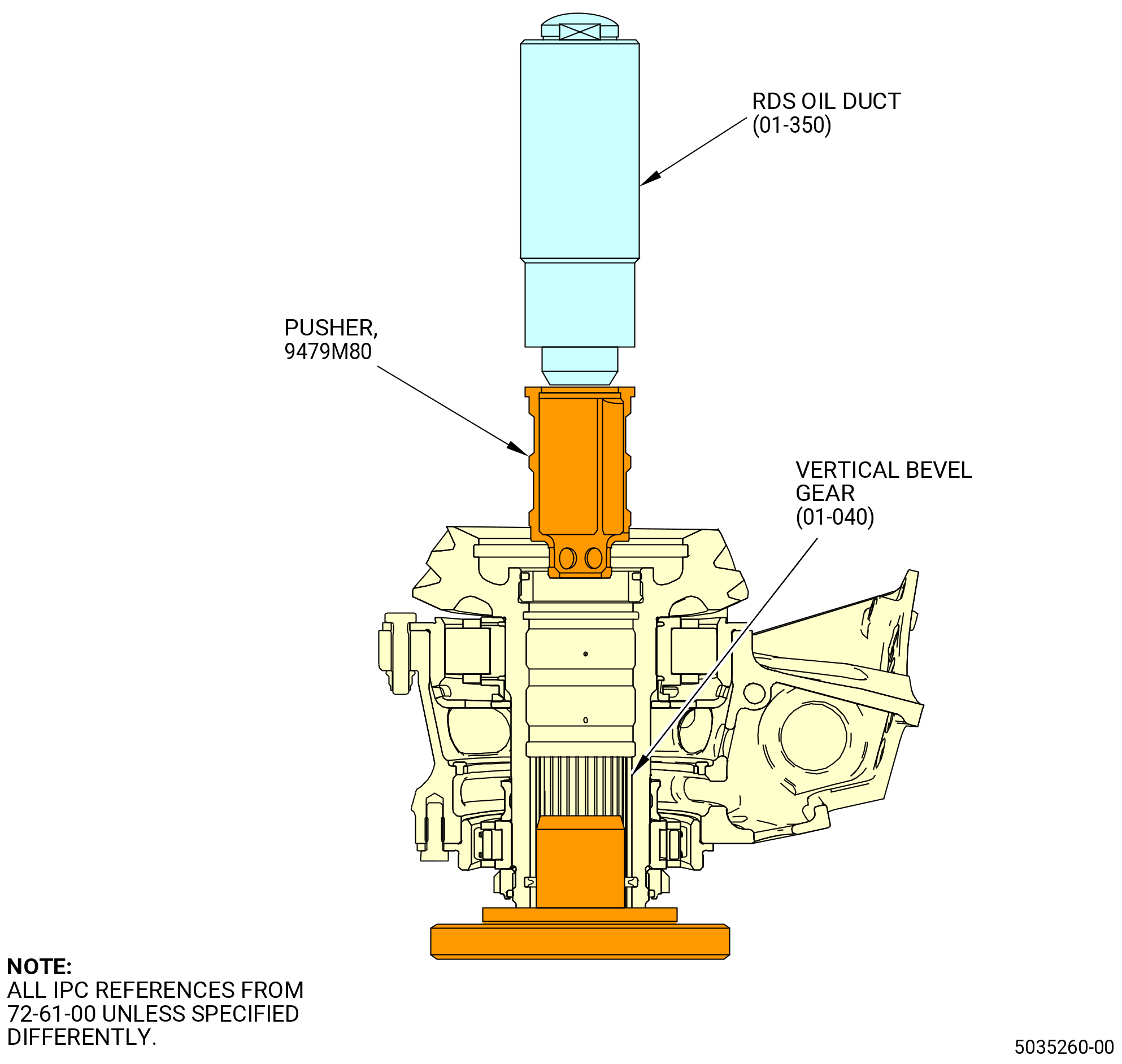
| (8) | Apply C02-019 engine oil or C02-023 engine oil to the RDS oil duct (030N3) and to the grooves in the shaft of the vertical bevel gear (030AC). |
| (9) | Use the 9479M80 pusher and install the RDS oil duct (01-350) (SIN 030N3) in the vertical bevel gear (01-040) (SIN 030AC). Refer to Figure 1021. |
| (10) | Remove the IGB housing (030A1) and the gearshaft assembly from the 9479M79 assembly base. |
| (11) | Install IGB housing (030A1) and the gearshaft assembly on the 9479M82 antirotation base. |
| WARNING: |
|
| (12) | Apply C02-019 engine oil or C02-023 engine oil to the locknut (030AM) and to the threads on the vertical bevel gear (030AC). |
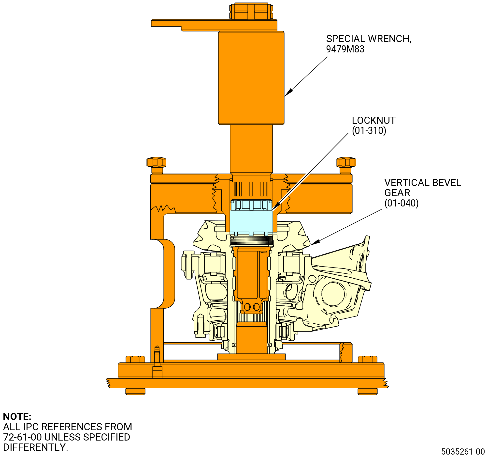
| (13) | Install the lock nut (01-310) (SIN 030AM) with the vespel insert away from oil distributor on the vertical bevel gear (01-040) (SIN 030AC). Put the 9479M83 special wrench on the lock nut (01-310) (SIN 030AM) and turn the wrench until the lock nut vespel insert is fully in contact with the thread of the vertical bevel gear (01-040) (SIN 030AC). Refer to Figure 1022. |
| (14) | Turn the wrench and record the run-on torque. |
| (15) | Make sure that the run-on torque of the lock nut (01-310) (SIN 030AM) is between 26 to 140 lb ft (35 to 190 Nm). |
| (16) | Read and record the run-on torque as value A. |
| (17) | Calculate value B necessary to torque the lock nut (030AB) as follows: |
| CAUTION: |
|
| (a) | Value B = 140-150 Nm (103-111 lb ft.) + A. |
| (18) | Torque the locknut (030AB) to the calculated value B. |
| Subtask 72-61-00-440-085 |
| X. | Install the oil nozzle (030B1) in the IGB housing (030A1) as follows: |
| WARNING: |
|
| (1) | Apply C02-019 engine oil or C02-023 engine oil to the new preformed packing (01-230) (SIN 030N1) and to the bolts (030F5). |
| (2) | Install the preformed packing (01-230) (SIN 030N1) on the oil nozzle (030B1). |
| (3) | Install the oil nozzle (030B1) in the IGB housing (030A1). |
| (4) | Attach the oil nozzle (030B1) to the IGB housing (030A1) with the two bolts (030F5). |
| (5) | Make sure that the run-on torque is between 7 lb in. (0.79 Nm) to 30 lb in. (3.39 Nm) for a new bolt or between 3.5 lb in. (0.40 Nm) to 30 lb in. (3.39 Nm) for a used bolt. |
| (6) | Torque the nut to 108.6 to 127.4 lb in (12.3 to 14.3 Nm). |
| WARNING: |
|
| (7) | Deleted. |
| (8) | Deleted. |
| (9) | Deleted. |
| (10) | Deleted. |
| Subtask 72-61-00-440-086 |
| Y. | Remove the 9479M94 shaft from the horizontal bevel gear (030AB) as follows: |
| (1) | Remove the bolts and the washers that attach the flange of the No. 3 bearing housing (030A6) to the 2126M13 assembly stand. |
| (2) | Install the two knobs on the two bolts (030F4) at positions 1 and 2 and tighten the knobs. |
| (3) | Install the eyebolt on the 9479M92 lifting fixture installed in the horizontal bevel gearshaft (01-050) (SIN 030AB). Refer to Figure 1023. |
| (4) | Lift the horizontal bevel gear (030AB) and the 9479M94 shaft from the 2126M13 assembly stand and put the assembly on the 2126M22 special bench. |
| (5) | Remove the eyebolt from the 9479M92 lifting fixture. |
| (6) | Remove the 9479M92 lifting fixture from the horizontal bevel gear (030AB). Use the 9479M93 special wrench. |
| (7) | Remove the shim of the 9479M92 lifting fixture. |
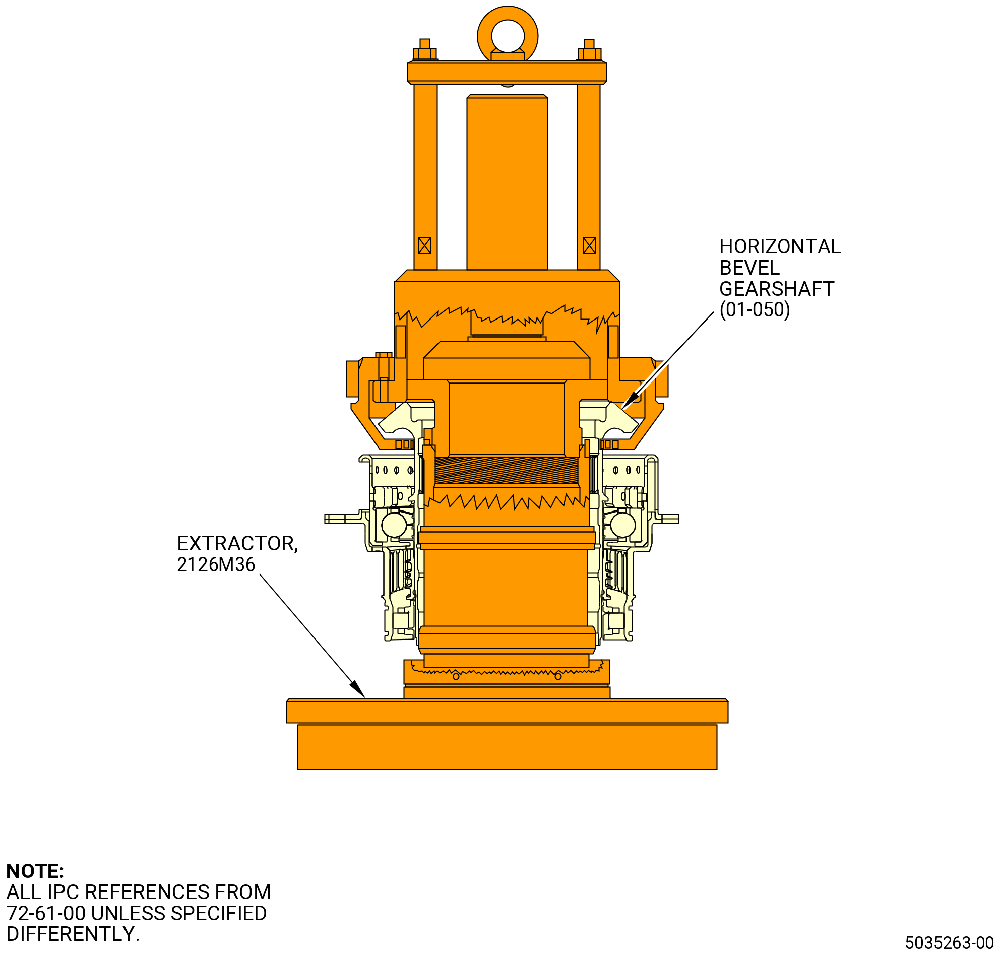
| (8) | Install the hydraulic cylinder Enerpac and the 2126M36 extractor on the horizontal bevel gearshaft and remove the shaft from the horizontal bevel gearshaft. Refer to Figure 1024. |
| (9) | Remove the horizontal bevel gearshaft from the 2126M22 special bench. |
| Subtask 72-61-00-440-087 |
| Z. | Complete the assembly of the horizontal bevel gearshaft (030AB) as follows: |
| (1) | Install the horizontal bevel gear (030AB) on the 2126M19 assembly base. |
| WARNING: |
|
| (2) | Put the oil distributor (01-120) (SIN 03004) in an oven or locally increase the temperature to 258 to 273ºF (126 to 134ºC). |
| WARNING: |
|
| (3) | Apply C02-019 engine oil or C02-023 engine oil to the ID of the oil distributor (03004) and the mating surface of the horizontal bevel gear (030AB). |
| (4) | Install the oil distributor (03004) on the horizontal bevel gear (030AB). |
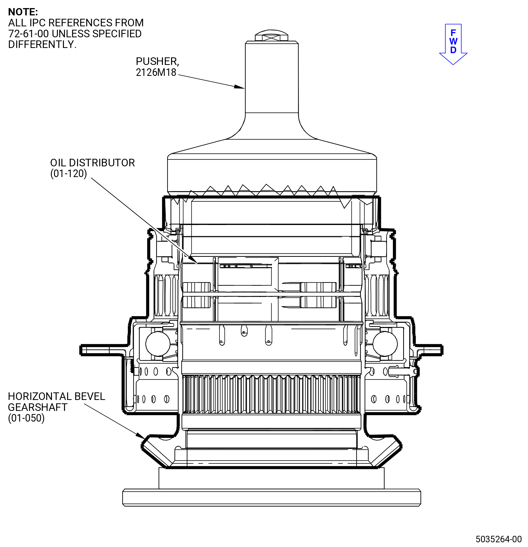
| (5) | Put the 2126M18 pusher on the oil distributor (01-120) (SIN 03004) and push the pusher until the oil distributor is fully installed on the horizontal bevel gear (01-050) (SIN 030AB). Use an arbor press or equivalent. Refer to Figure 1025. |
| (6) | Apply a load of 218-232 lb (970-1030 N). |
| (7) | Let the oil distributor (03004) go back to room temperature. Make sure that the oil distributor (03004) is correctly installed to the horizontal bevel gear (030AB). |
| (8) | Apply a load of 218-232 lb (970-1030 N) again. |
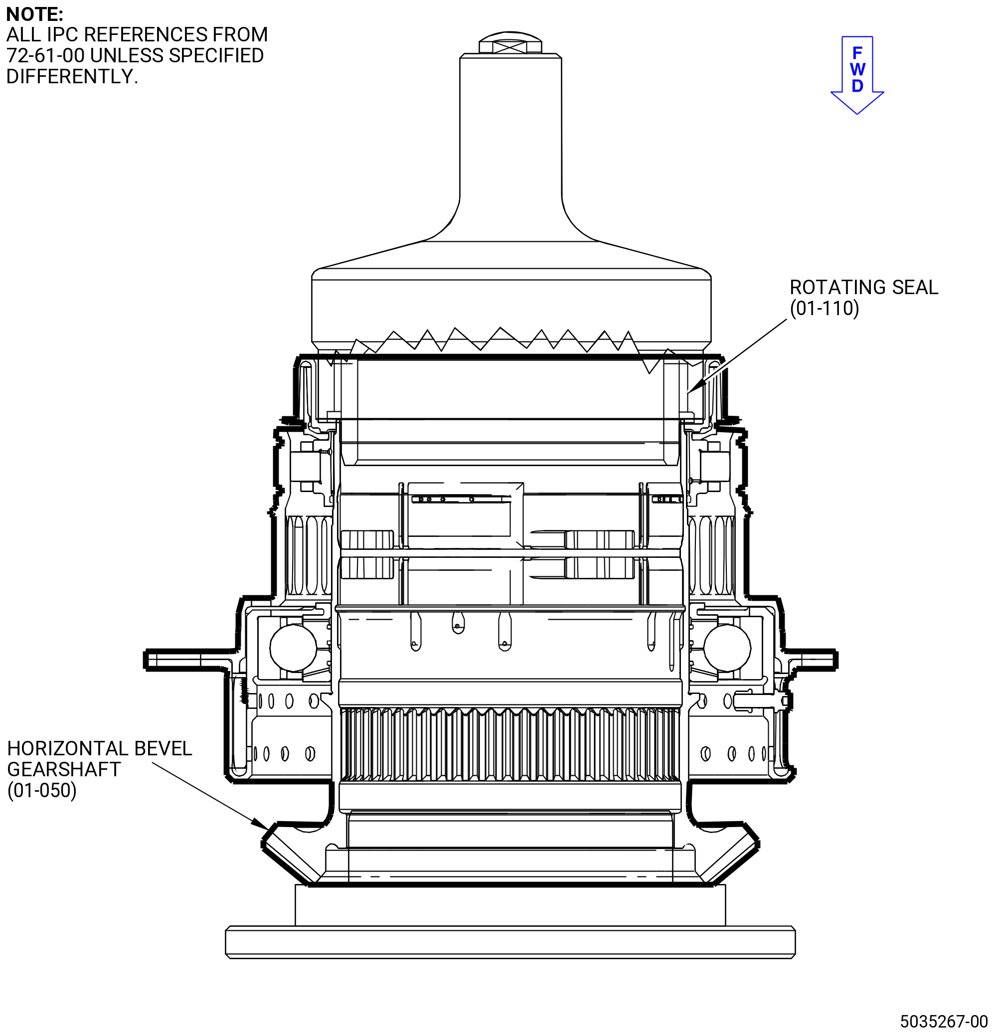
| (9) | Put the rotating seal (01-110) (SIN 03003) in an oven or locally increase the temperature to 258 to 273ºF (126 to 134ºC). |
| WARNING: |
|
| (10) | Apply C02-019 engine oil or C02-023 engine oil to the mating surface of the oil distributor (03004). |
| (11) | Install the rotating seal (03003) on the oil distributor (03004). |
| (12) | Put the 2126M18 pusher on the rotating seal (01-110) (SIN 03003) and push the pusher until the rotating seal is fully installed on the oil distributor (01-120) (SIN 03004). Use an arbor press or equivalent. Refer to Figure 1026. |
| (13) | Apply a load of 218-232 lb (970-1030 N). |
| (14) | Let the rotating seal (03003) go back to room temperature. Make sure that the rotating seal is correctly installed to the oil distributor (03004). |
| (15) | Apply a load of 218-232 lb (970-1030 N). |
| NOTE: |
|
| WARNING: |
|
| (16) | Apply C02-019 engine oil or C02-023 engine oil to the four nuts (030K1) and to the four bolts (03022). |
| (17) | Install the two lube nozzles (030B0) on the four bolts (03022). |
| (18) | Install the four nuts (030K1) that attach the lube nozzles (030B0) to the outer race of the No. 3 roller bearing (030A5). |
| (19) | Make sure that the run-on torque is between 7 lb in. (0.79 Nm) to 30 lb in. (3.39 Nm) for a new nut or between 3.5 lb in. (0.40 Nm) to 30 lb in. (3.39 Nm) for a used nut. |
| (20) | Torque the nut to 108.6 to 127.4 lb in (12.3 to 14.3 Nm). |
| (21) | Remove the horizontal bevel gear (030AB) from the 2126M19 assembly base. |
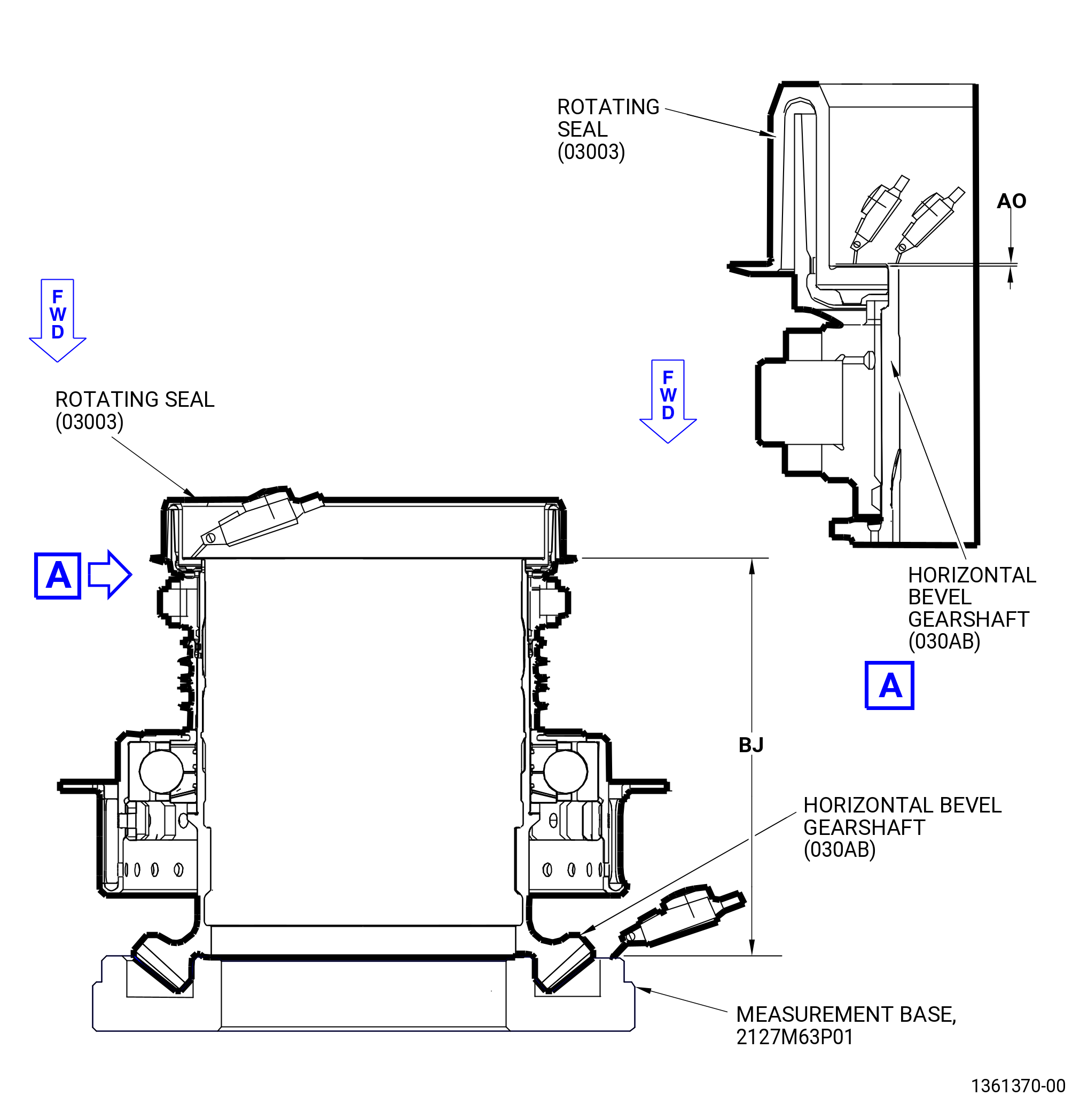
| (22) | Take and record the dimensions BJ and AO as follows. Refer to Figure 1027. |
| (a) | Put the horizontal bevel gearshaft (030AB) on the 2127M63 measurement base. |
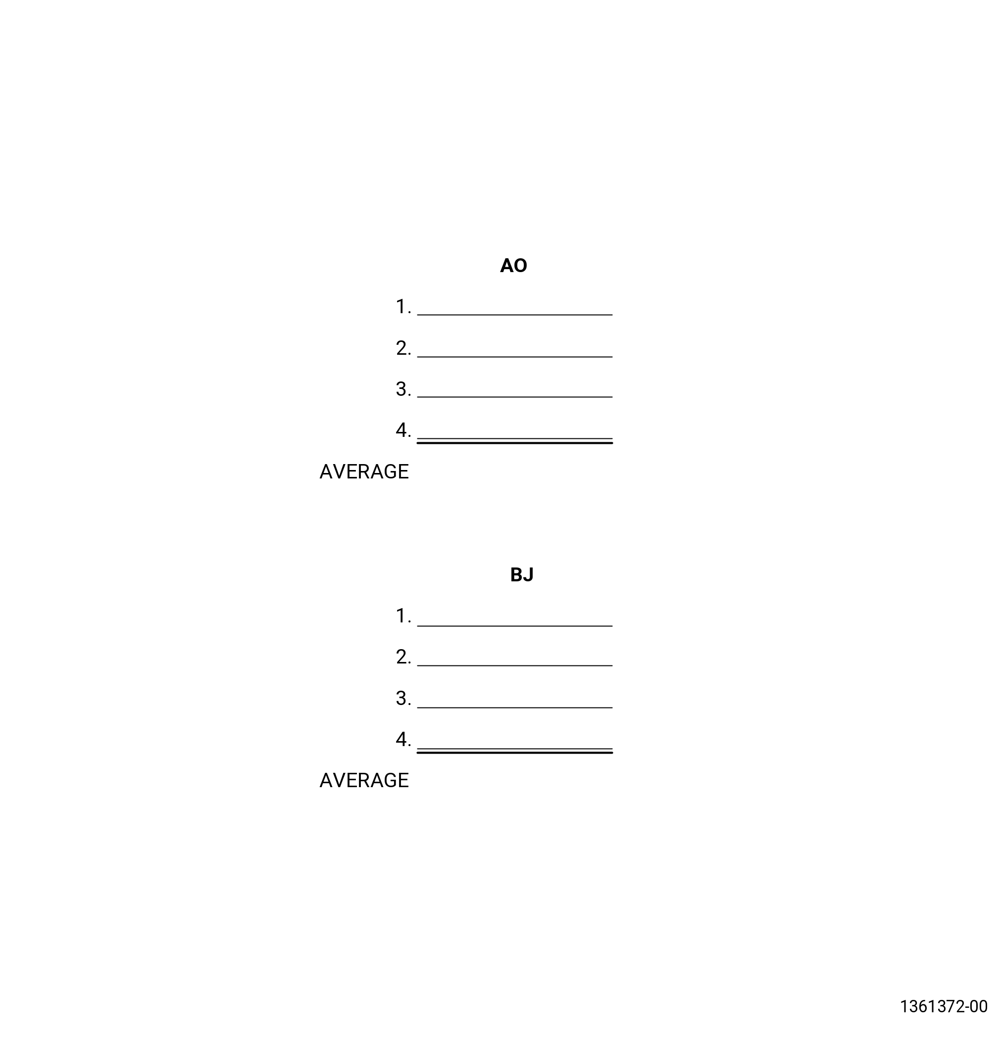
| (b) | Measure dimension AO as follows: |
| 1 | Measure from the face of the gearshaft to the aft face of the rotating seal (03003) in four places and record the four values. |
| 2 | The difference between maximum and minimum of the four values must not be more than 0.004 inch (0.10 mm). |
| 3 | Calculate and record the average value for dimension AO. |
| 4 | The average value of dimension AO must be -0.030940 to 0.033149 inch (-0.78600 to 0.84200 mm). |
| (c) | Measure dimension BJ as follows: |
| 1 | Measure from the front face of the gearshaft to the aft face of the rotating seal (03003) at four places and record the four values. |
| 2 | Calculate and record the average value for dimension BJ. |
| 3 | The average value of dimension BJ must be 7.9405 to 7.9847 inches (201.689 to 202.811 mm). |
| Subtask 72-61-00-440-088 |
| AA. | Assemble the IGB as follows: |
| (1) | Put the radial bevel gearshaft and the horizontal bevel gearshaft on an applicable work surface. |
| (2) | Deleted. |
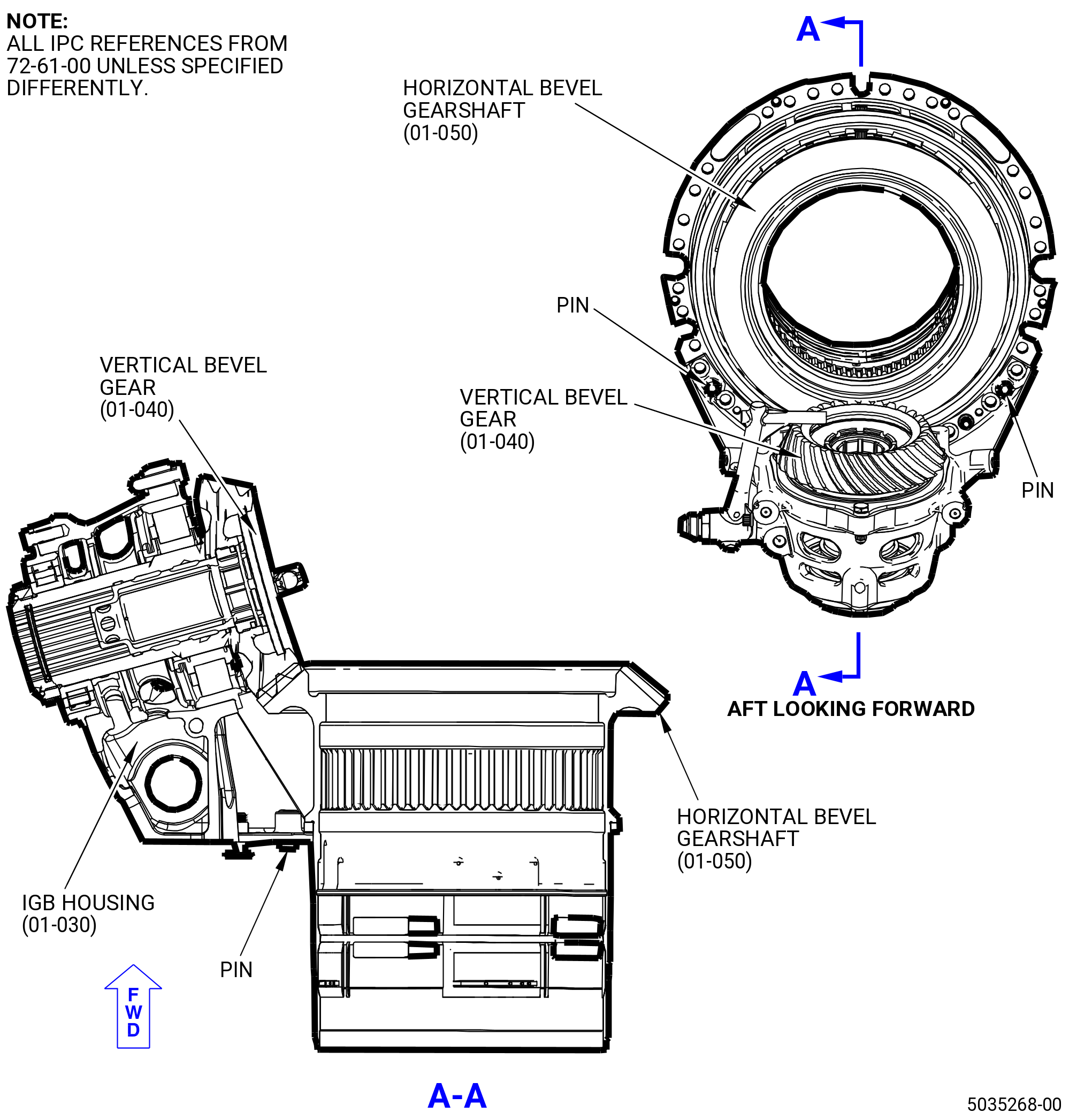
| (3) | Install the vertical bevel gear (01-040) (SIN 30AC) and the IGB housing (01-030) (SIN 030A1) on the flange of the housing (01-310) (SIN 030AM). Use the two pins on the casing as a guide. Refer to Figure 1028. |
| (4) | Remove the two knobs from the two bolts (01-020) (SIN 030F4) at positions 1 and 2. |
| WARNING: |
|
| (5) | Apply C02-019 engine oil or C02-023 engine oil to the nuts (030K3) and to the bolts (030F4). |
| (6) | Install the two nuts (030K3) on the bolts (030F4) and tighten the nuts. |
| (7) | Make sure that the run-on torque is between 7 lb in. (0.79 Nm) to 30 lb in. (3.39 Nm) for a new nut or between 3.5 lb in. (0.40 Nm)to 30 lb in. (3.39 Nm) for a used nut. |
| (8) | Torque the bolts to 108.6 to 127.4 lb in (12.3 to 14.3 Nm). |
| (9) | Deleted. |
| Subtask 72-61-00-440-089 |
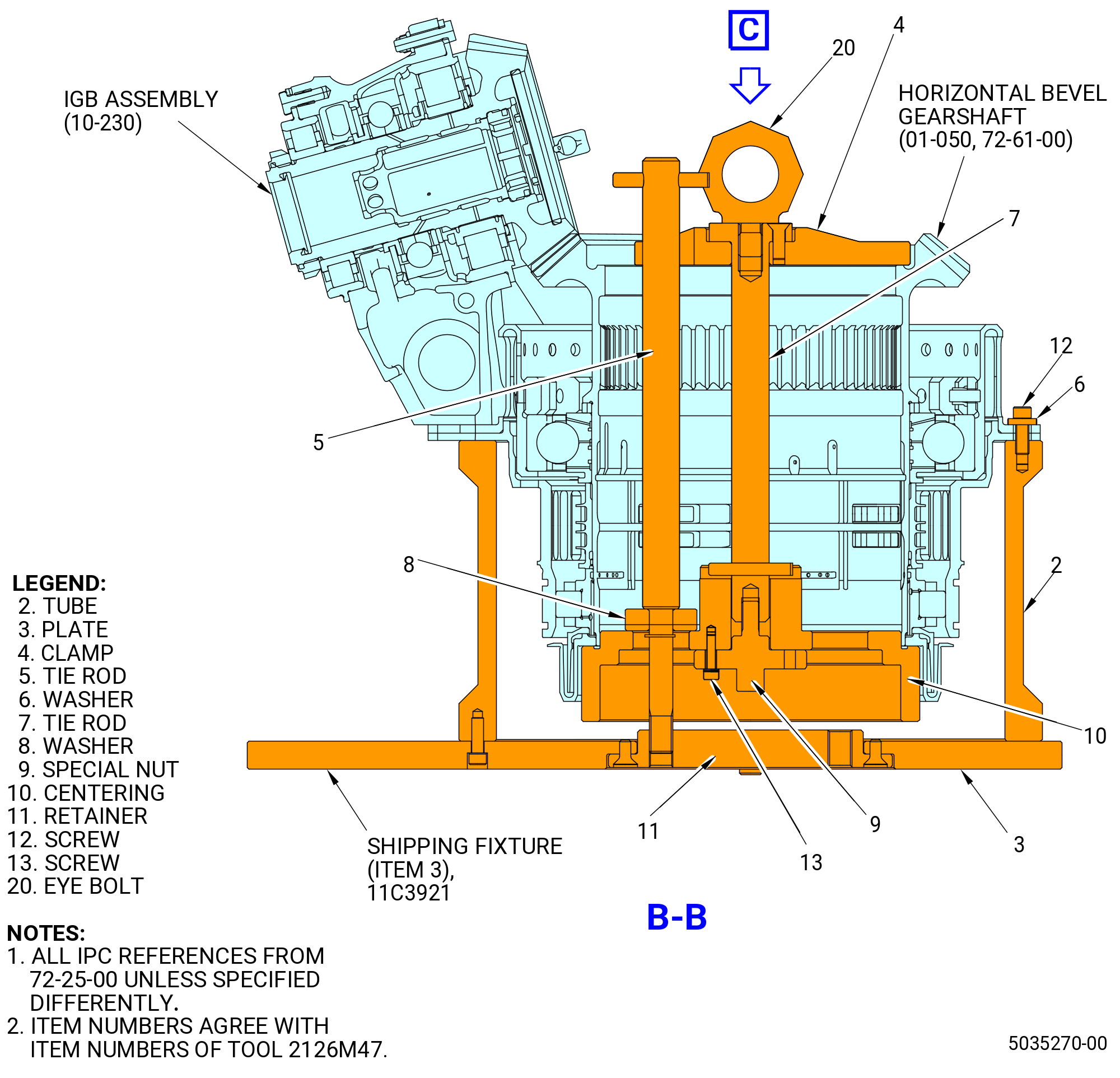
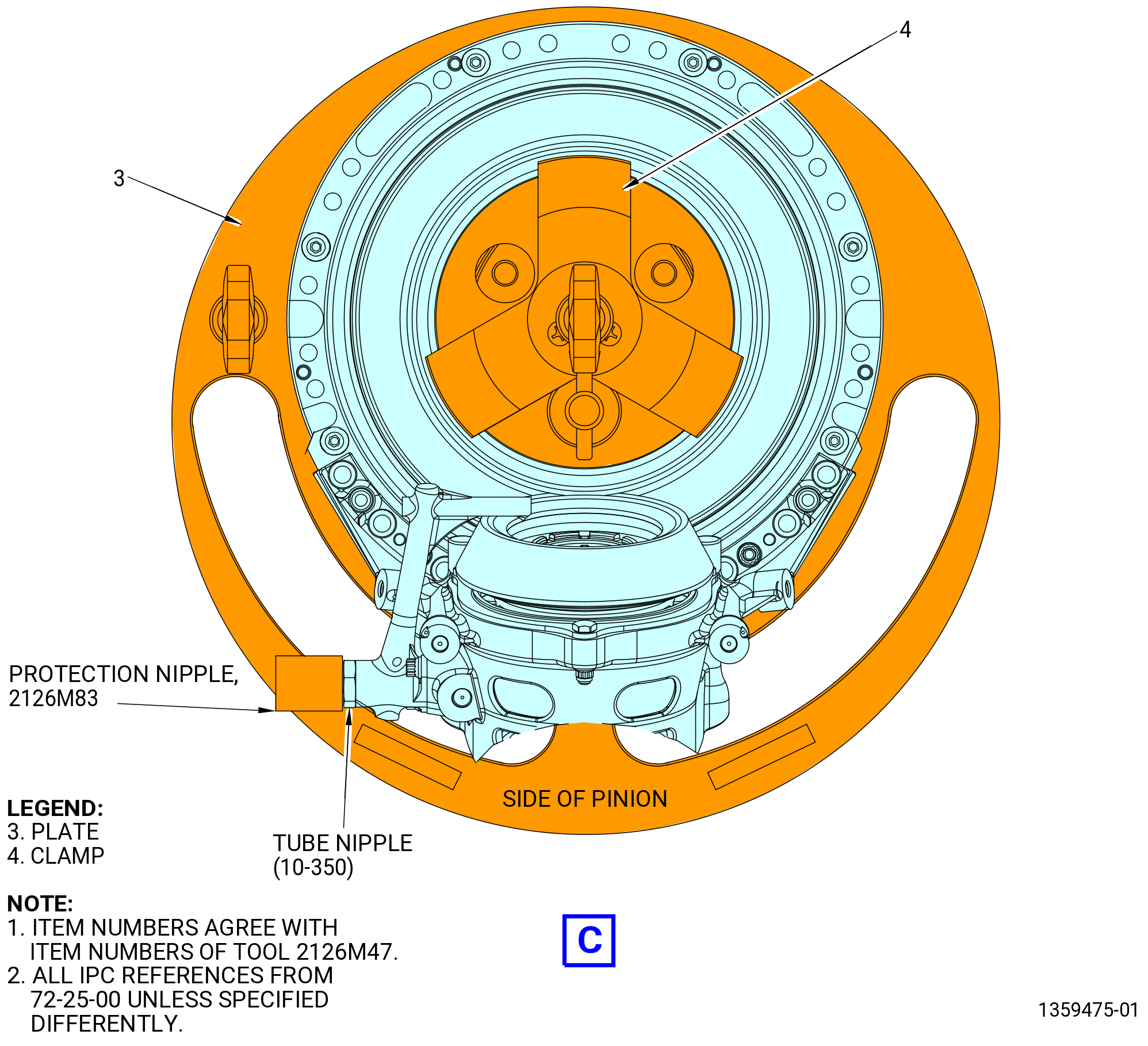
| AB. | Install the No. 3 ball bearing (030A7) and inlet gearbox (IGB) assembly (03000) (IGB assembly) on the 11C3921 shipping fixture as follows. Refer to Figure 1029. |
| (1) | Install the centering (item 10) on the horizontal bevel gearshaft (030AB). Install the tie rod (item 7) and the clamp (item 4) on the horizontal bevel gearshaft. Attach the tie rod to the centering with the special nut (item 9) and screw (item 13). |
| (2) | Attach an overhead hoist to the eyebolt (item 20). Lift the clamp/tie rod/centering assembly and IGB assembly and align above the tube (item 2). |
| (3) | Lower the clamp/tie rod/centering assembly and IGB assembly inside the tube (item 2). Align the boltholes in the IGB assembly flange with the boltholes in the tube. |
| (4) | Attach the IGB assembly to the tube with six screws (item 12) and six washers (item 6). |
| (5) | Torque the six screws (item 12) to 44.3 lb in. (5 N.m). |
| (6) | Install the tie rod (item 5) through the IGB assembly. Insert the tie rod through one of the six holes in the centering (item 10) and into the hole in the retainer (item 11). Make sure the washer (item 8) fits securely in the centering hole. |
| (7) | Attach the 2126M83 protection nipple to the tube nipple (01-220) (SIN 030S1) of the IGB assembly. |