| GEnx-1B SERVICE BULLETIN - 72-0156 R11 | Revised: 02/21/2022 | |
| SB 72-0156 R11 ENGINE - General (72-00-00) - GEnx-1B Pre-PIP2 Fan Module Upgrade to GEnx-1B/P2 | Issued: 11/05/2013 | |
| GEnx-1B SERVICE BULLETIN - 72-0156 R11 | Revised: 02/21/2022 | |
| SB 72-0156 R11 ENGINE - General (72-00-00) - GEnx-1B Pre-PIP2 Fan Module Upgrade to GEnx-1B/P2 | Issued: 11/05/2013 | |
| GE Designated: -CONFIDENTIAL- | |
| The information contained in this document is GE proprietary information and is disclosed in confidence. It is the property of GE and shall not be used, disclosed to others or reproduced without the express written consent of GE, including, but without limitation, it is not to be used in the creation, manufacture, development, or derivation of any repairs, modifications, spare parts, designs, or configuration changes or to obtain FAA or any other government or regulatory approval to do so. If consent is given for reproduction in whole or in part, this notice and the notice set forth on each page of this document shall appear in any such reproduction in whole or part. | |
| This technical data is considered subject to the Export Administration Regulations (EAR) pursuant to 15 CFR Parts 730-774. Transfer of this data by any means to a Non-U.S. Person, whether in the United States or abroad, without the proper U.S. Government authorization (e.g., License, exemption, NLR, etc.), is strictly prohibited. | |
| Copyright (2022) General Electric Company, U.S.A. |
| TRANSMITTAL INFORMATION |
| REVISION 11 TO SERVICE BULLETIN 72-0156 |
| Revision 11 is issued to update paragraph 2., MATERIAL INFORMATION. |
| Revision 10 was issued March 06, 2020. Revision 9 was issued November 29, 2018. Revision 8 was issued June 14, 2018. Revision 7 was issued March 08, 2018. Revision 6 was issued March 24, 2017. Revision 5 was issued October 07, 2016. Revision 4 was issued June 29, 2016. Revision 3 was issued November 03, 2015. Revision 2 was issued July 21, 2014. Revision 1 was issued May 27, 2014. The original was issued November 05, 2013. Revision bars in the left margin identify changes. |
| 1. | PLANNING INFORMATION |
| A. | Effectivity |
| * * * FOR GEnx-1B64, -1B67, -1B70, -1B64/P1, -1B67/P1, -1B70/P1, -1B70/75/P1, -1B64/P2, -1B67/P2, -1B70/P2, -1B70C/P1, -1B70C/P2, -1B70/75/P2, -1B74/75/P1, -1B74/75/P2, -1B76/P2, -1B76A/P2 |
| This Service Bulletin is applicable to these GEnx-1B engines: |
| • |
|
| This Service Bulletin has been introduced in production to these GEnx-1B engines: |
| • |
|
| These serial numbers are the best available data. |
| B. | Description |
| This Service Bulletin releases the GEnx-1B/P2 new hardware names and part numbers (P/N) information to the Engine Illustrated Parts Catalog (EIPC). This Service Bulletin also provides instructions and the Service Bulletins used to convert the fan module from a GEnx-1BXX/G03, GEnx-1BXX/G04 and GEnx-1BXX/P1G01 to the GEnx-1BXX/P2G01 configuration. |
| Revision 5 of this Service Bulletin released new assembly fan hub frames P/N 10090494 and P/N 10090496 for rework as an alternate part number for the PIP2 upgrade. |
| Revision 6 of this Service Bulletin releases a new fan stator module assembly P/N 2305M15G12. |
| Also, revision 6 of this Service Bulletin releases a new aft fan case upgrade kit P/N 739L116G01. |
| Revision 7 of this Service Bulletin removes the fan hub frame (FHF) polish requirement, as it is no longer needed for PIP2 engines. |
| Also, revision 7 of this Service Bulletin updates the booster blade and outlet guide vane (OGV) part numbers to the latest type design and adds the pre-PIP parts to the configuration chart to allow their use on PIP2 engines. |
| Revision 8 of this Service Bulletin updates the configuration of the electrical harnesses. |
| Revision 9 of this Service Bulletin includes the new alternate machine bolt part number now available and also removes the PS25 sense tube design that is no longer in use. |
| Revision 10 of this Service Bulletin updates the OGVs to the latest type design. |
| C. | Compliance |
| Category 7 |
| GE recommends that you do this Service Bulletin at customer's convenience or option. |
| Impact F |
| Implement as deemed necessary per the Service Bulletin Category. |
| NOTE: |
|
| D. | Concurrent Requirements |
| Do the GEnx-1B S/B 72-0358 when you do this Service Bulletin. |
| Do the GEnx-1B S/B 73-0063 when you do this Service Bulletin. |
| Do the GEnx-1B S/B 79-0018 when you do this Service Bulletin. |
| E. | Reason |
| (1) | Objective: |
| To introduce the new GEnx-1B/PIP2 engine model and associated new parts to the EIPC and provide configuration conversion instructions. |
| (2) | Condition: |
| The GEnx-1B/P2 model includes upgrades to improve performance and durability. |
| (3) | Cause: |
| Product improvement. |
| (4) | Improvement: |
| This Service Bulletin introduces the GEnx-1B/P2 configuration which improves fuel efficiency of the GEnx-1B engine. Depending on engine operating characteristics and configuration, this Service Bulletin can improve specific fuel consumption (SFC) of the GEnx-1B and GEnx-1B/P1 engines. |
| (5) | Substantiation: |
| Substantiation is by analysis and test. |
| F. | Approval |
| The data contained in this Service Bulletin has been reviewed by the FAA or authorized entity representing the FAA and the repair(s) and modification(s) herein comply with the applicable Aviation Regulations and are APPROVED for installation in the model(s) listed in this Service Bulletin. |
| G. | Manpower |
| The man hours required to accomplish this service bulletin are equivalent to the time required to perform a full performance restoration workscope. |
| H. | Weight and Balance |
| Refer to GEnx-1B S/B 72-0154, ENGINE - General (72-00-00) - GEnx-1B/P2 Hardware Release (Collector Bulletin) for the final weight and balance information. |
| I. | References (Use the latest version of these documents) |
| GEK 112851, GEnx-1B Engine Manual (EM) |
| GEK 112862, GEnx-1B Cleaning, Inspection, and Repair Manual (CIR) |
| GEK 112864, GEnx-1B Engine Illustrated Parts Catalog (EIPC) |
| GEK 9250, Commercial Engine Standard Practices Manual (SPM) |
| GEnx-1B S/B 72-0021, ENGINE - General (72-00-00) - Spare Parts Release for GEnx-1B Engines |
| GEnx-1B S/B 72-0031, ENGINE - Outlet Guide Vanes and Fairings (72-21-00) - Upper OGV Pylon, Lower OGV Pylon, and OGVs Replacement |
| GEnx-1B S/B 72-0034, ENGINE - Fan Stator Assembly (72-21-00) - Vapor Barrier Replacement |
| GEnx-1B S/B 72-0038, ENGINE - Fan Stator Module Assembly (72-00-01) - Fan Case Brackets Replacement |
| GEnx-1B S/B 72-0039, ENGINE - General (72-00-00) - Spare Parts Release for GEnx-1B Engines |
| GEnx-1B S/B 72-0047, ENGINE - Fan Stator Assembly (72-21-00) - Introduction of New Upper Seal Retainer |
| GEnx-1B S/B 72-0050, ENGINE - Cowl Support Rings (72-00-02) - Introduction of New Cowl Supports |
| GEnx-1B S/B 72-0056, ENGINE - Fan Stator Module Assembly (72-00-01) - Introduction of EMU Support Brackets |
| GEnx-1B S/B 72-0069, ENGINE - Fan Booster Assembly (72-22-00) - Introduction of New Booster Spool and Stage 2, Stage 3, and Stage 4 Blades for Clearance Improvements |
| GEnx-1B S/B 72-0087, ENGINE - Outlet Guide Vanes and Fairings (72-21-00) - OGV Bolts and Washers Change |
| GEnx-1B S/B 72-0105, ENGINE - General (72-00-00) - Spare Parts Release for GEnx-1B Engines |
| GEnx-1B S/B 72-0125, ENGINE - Fan Hub Module Assembly - Inlet Gearbox and Tubes (72-25-00) - Incorporation of New Fan Hub Frame Bolts |
| GEnx-1B S/B 72-0137, ENGINE - General (72-00-00) - Spare Parts Release for GEnx-1B Engines |
| GEnx-1B S/B 72-0169, ENGINE - General (72-00-00) - Spare Parts Release for GEnx-1B Engines |
| GEnx-1B S/B 72-0173, ENGINE - General (72-00-00) - Spare Parts Release for GEnx-1B Engines |
| GEnx-1B S/B 72-0187, ENGINE - General (72-00-00) - Spare Parts Release for GEnx-1B Engines |
| Deleted |
| GEnx-1B S/B 72-0228, ENGINE - Fan Stator Assembly (72-21-00) - Upper and Lower Firewalls Rework |
| GEnx-1B S/B 72-0250, ENGINE - Outlet Guide Vanes and Fairings (72-21-00) - Introduction of New OGV Fairing Screw |
| GEnx-1B S/B 72-0281, ENGINE - Fan Stator Assembly (72-21-00) - Fan Stator Assembly Upgrade to PIP2 Configuration |
| GEnx-1B S/B 72-0290, ENGINE - General (72-00-00) - Elimination of Oil Supply Temperature Sensor and CC Temperature Sensor |
| GEnx-1B S/B 72-0317, ENGINE - Fan Stator Module Assembly (72-00-01) - Introduction of New Fan Stator Module Assembly |
| GEnx-1B S/B 72-0358, ENGINE - Fan Stator Assembly (72-21-00) - Fan Case B-Flange Fasteners Clarification |
| GEnx-1B S/B 72-0384, ENGINE - Fan Stator Assembly (72-21-00) - Introduction of New Forward Containment Fan Case |
| GEnx-1B S/B 72-0386, ENGINE - General (72-00-00) - Spare Parts Release for GEnx-1B Engines |
| GEnx-1B S/B 72-0406, ENGINE - P2 Fan Booster Assembly (72-22-00) - Introduction of New Stage 2-5 Blades for GEnx-1B/P2 Fan Booster Assembly |
| GEnx-1B S/B 72-0417, ENGINE - P2 Outlet Guide Vanes and Fairings (72-21-00) - Introduction of New Nominal OGV, Type 1 through Type 6 OGVs, and Lower OGV Fan Pylon |
| GEnx-1B S/B 72-0422, ENGINE - Fan Booster Assembly (72-22-00) - Introduction of New Bolts for Vane Assemblies |
| Deleted |
| GEnx-1B S/B 73-0012, ENGINE FUEL AND CONTROL - W34 and W35 Harnesses (73-21-66) - Introduction of Harness Cushion Loop Clamp P/N J1432P04 to Improve Support |
| GEnx-1B S/B 73-0063, ENGINE FUEL AND CONTROL - General (73-00-00) - GEnx-1B Electrical Harnesses Bonding Rework |
| GEnx-1B S/B 75-0035, AIR - PS25 Pressure Sense Tubes (75-42-15) - Removal of the PS25 Sense Tube and P25 Hose Tube from the Fan Case Module Assembly |
| GEnx-1B S/B 79-0003, OIL - Oil Tank Scavenge Tube (79-22-20) - Introduction of New Oil Scavenge Tube and Support Bracket |
| GEnx-1B S/B 79-0018, OIL - Fuel/Oil Heat Exchanger (79-21-00) - Improved Main Fuel/Oil Heat Exchanger with Indicating Capability |
| Repair Document (RD) 835-380 (P1 or higher), Fan Stator Assembly - Mid-Outer Acoustic Liners - Alteration - Bushing Replacement for Upgrade to PIP Configuration |
| NOTE: |
|
| J. | Publications Affected |
| GEK 112851, GEnx-1B Engine Manual (EM) |
| GEK 112862, GEnx-1B Cleaning, Inspection, and Repair Manual (CIR) |
| GEK 112864, GEnx-1B Engine Illustrated Parts Catalog (EIPC) |
| K. | Interchangeability |
| Qualified interchangeability. Refer to paragraph 1.D., Concurrent Requirements for other required Service Bulletins. |
| It is permitted to intermix any fan hub modules P/N 2305M30G06 and P/N 2305M30G07 with any fan hub frames P/N 2305M31G14 and P/N 2305M31G15. |
| The fan stator module assembly P/N 2305M15G10 or P/N 2305M15G11 is interchangeable with the fan stator module assembly P/N 2305M15G12 as a set. The fan stator module assembly P/N 2305M15G12 includes the support bracket P/N 2426M14G01, tube house P/N 2422M72G01, oil return tube P/N 2380M17G01, and electrical bracket P/N 2375M60G01. Refer to the pre-GEnx-1B S/B 72-0290 configuration. |
| The PS25 pressure sense tube P/N 2409M96G01 and air P25 hose tubes P/N 2365M41P01 and P/N 2365M41P02 are interchangeable as a set and is to be removed during this upgrade. Refer to GEnx-1B S/B 75-0035. |
| L. | Software Accomplishment Summary |
| Not applicable. |
| 2. | MATERIAL INFORMATION |
| A. | Material - Price and Availability |
| (1) | Parts necessary to do this Service Bulletin: |
|
||||||||||||||||||||||||||||||||||||||||||||||||||||||||||||||||||||||||||||||||||||||||||||||||||||||||||||||||||||||||||||||||||||||||||||||||||||||||||||||||||||
| OR SIGNIFICANT ITEM NUMBER |
|
|||||||||||||||||||||||||||||||||||||||||||||||||||||||||||||||||||||||||||||||||||||||||||||||||||||||||||||||||||||||||||||||||||||||||||||||||||||||||||||||||||||||||||||||||||||||||||||||||||||||||||||||||||||||||||||||||||||||||||||||||||||||||||||||||||||||||||||||||||||||||||||||||||||||||||||||||||||||||||||||||||||||||||||||||||||||||||||||||||||||||||||||||||||||||||||||||||||||||||||||||||||||||||||||||||||||||||||||||||||||||||||||||||||||||||||||||||||||||||||||||||||||||||||||||||||||||||||||||||||||||||||||||||||||||||||||||||||||||||||||||||||||||||||||||||||||||||||||||||||||||||||||||||||||||||||||||||||||||||||||||||||||||||||||||||||||||||||||||||||||||||||||||||||||||||||||||
|
||||||||||||||||||||||||||||||||||||||||||||||||||
| OR SIGNIFICANT ITEM NUMBER |
|
|
|||||||||||||||||||||||||||||||||||||||||||||||||||||||||||||||||||||||||||||||||||||||
| OR SIGNIFICANT ITEM NUMBER |
|
|
| OR SIGNIFICANT ITEM NUMBER |
|
|
| OR SIGNIFICANT ITEM NUMBER |
|
|
||||||||||||||||||||||||||||||||||||||||||||||||||||||||||||||||||||||||||||||||||||||||||||||||||||||||||||||||||||||||||||||||||||||||||||||||||||||||||||||||||||
| OR SIGNIFICANT ITEM NUMBER |
|
|||||||||||||||||||||||||||||||||||||||||||||||||||||||||||||||||||||||||||||||||||||||||||||||||||||||||||||||||||||||||||||||||||||||||||||||||||||||||||||||||||||||||||||||||||||||||||||||||||||||||||||||||||||||||||||||||||||||||||||||||||||||||||||||||||||||||||||||||||||||||||||||||||||||||||||||||||||||||||||||||||||||||||||||||||||||||||||||||||||||||||||||||||||||||||||||||||||||||||||||||||||||||||||||||||||||||||||||||||||||||||||||||||||||||||||||||||||||||||||||||||||||||||||||||||||||||||||||||||||||||||||||||||||||||||||||||||||||||||||||||||||||||||||||||||||||||||||||||||||||||||||||||||||||||||||||||||||||||||||||||||||||||||||||||||||||||||||||||||||||||||||||||||||||||||||||||
|
||||||||||||||||||||||||||||||||||||||||||||||||||
| OR SIGNIFICANT ITEM NUMBER |
|
|
|||||||||||||||||||||||||||||||||||||||||||||||||||||||||||||||||||||||||||||||||||||||
| OR SIGNIFICANT ITEM NUMBER |
|
|
| OR SIGNIFICANT ITEM NUMBER |
|
|
| OR SIGNIFICANT ITEM NUMBER |
|
| * Part not supplied by GE engine services distribution L.L.C. Procure through local purchase. |
| ** SIN list is for reference only. Refer to the GENX-1B EIPC for the latest configuration. |
| NP= Not Provisioned. |
| (2) | Other Spare Parts: |
|
| (3) | Consumables: |
|
| B. | Industry Support Information |
| None. |
| C. | Configuration Chart |
|
| Operation Codes AD=Add RE=Replace RM=Remains RI=Reidentify RW=Rework QTC=Quantity Change |
| Change Codes 1=One-way interchangeable. 2=Two-way interchangeable. 5=Qualified interchangeability. Refer to paragraph 1.K., Interchangeability. |
| Support Codes A=Old parts will no longer be supplied. B=Old parts will be supplied until all old parts are sold. D=Old parts will be supplied for engines that have not been changed by this Service Bulletin. E=Old parts will be supplied, and can be used at other engine locations. |
| D. | Parts Disposition |
| Parts Disposition is described in each concurrent Service Bulletin listed in paragraph 1.D., Concurrent Requirements. Parts removed in the course of complying with this Service Bulletin, which are not reinstalled or reworked for reinstallation, may be retained by GE to support needs of the GEnx-1B configurations prior to the GEnx-1B/P2 configuration. |
| E. | Tooling - Price and Availability |
| None. |
| 3. | ACCOMPLISHMENT INSTRUCTIONS |
| A. | Removal of the Fan Stator Module Assembly |
| (1) | Remove the fan stator module assembly. Refer to the GEnx-1B EM, 72-00-01, REMOVAL 001, CONFIG 01. |
| (2) | Disassemble the fan stator module assembly. Refer to the GEnx-1B EM, 72-00-01, DISASSEMBLY 001. |
| (3) | Disassemble the fan stator assembly. Refer to the GEnx-1B EM, 72-21-00, DISASSEMBLY 001, CONFIG 01 and GEnx-1B EM, 72-21-00, DISASSEMBLY 002, CONFIG 01. |
| NOTE: |
|
|
|||||||||||||||||||||||||||||||||||||||||||||||||||
| (4) | Rework the aft fan stator case assembly P/N 2305M18G07 or P/N 2305M18G08 to P/N 2447M18G02. Refer to the GEnx-1B S/B 72-0281. |
| (5) | Rework the forward containment fan case P/N 2264M12G03 or P/N 2264M12G04. Refer to the GEnx-1B S/B 72-0281. |
| (6) | Rework the mid outer acoustic liner from P/N 2382M47G01 to P/N 2382M47G02. Refer to RD 835-380. |
| (7) | Rework and reidentify the electrical harnesses. Refer to GEnx-1B S/B 73-0063. |
| B. | Removal of the Fan Booster Assembly |
| (1) | Remove the fan booster assembly. Refer to the GEnx-1B EM, 72-00-22, REMOVAL 001. |
| (2) | Continue with the disassembly of the fan booster assembly (SIN 80000). Refer to the GEnx-1B EM, 72-22-00, DISASSEMBLY 001, CONFIG 01. |
| C. | Removal of the FHF Module Assembly |
| (1) | To get access to Fan Hub Frame (FHF) module assembly, refer to the GEnx-1B EM, 72-00-02, DISASSEMBLY 006. |
| (2) | Disassemble the FHF module assembly. Refer to the GEnx-1B EM, 72-25-00, DISASSEMBLY 001. |
| (3) | Continue with the disassembly of the FHF assembly. Refer to the GEnx-1B EM, 72-26-00 DISASSEMBLY 001. |
| D. | Deleted |
| E. | Upper Firewall and Lower Firewall Rework Procedure |
| (1) | Rework the upper firewall and lower firewall. Refer to the GEnx-1B S/B 72-0228. |
| (2) | Remark on the upper firewall and lower firewall as follows: |
| (a) | Make a line thru the current part number group "G03". The maximum depth of the mark is 0.001-0.004 inch (0.03-0.10 mm). Keep legibility of the initial part number. Refer to the GE SPM, 70-16-04, VIBRO-PEEN MARKING. |
| (b) | Write "G04" above or below the lined out number. the maximum depth of the mark is 0.001-0.004 inch (0.03-0.10 mm). Keep legibility of the initial part number. Refer to the SPM, 70-16-04, VIBRO-PEEN MARKING. |
| F. | Installation of the Fan Stator Module |
| (1) | Assemble the new fan stator module assembly P/N 2305M15G11. Refer to the GEnx-1B EM, 72-00-01, ASSEMBLY 001 and do as follows: |
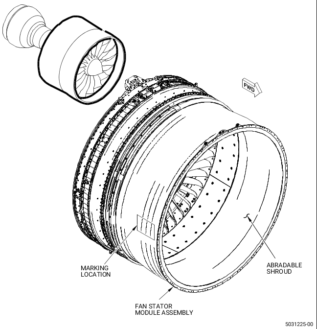
| (a) | Identify the fan case with Complied with SB 72-0317 in a 3X3 inches label at the 9:00 o'clock position forward looking aft (Figure 1). Refer to the SPM, 70-16-09, PERMANENT INK MARKING STANDARD PRACTICE - EPOXY COATED INK MARKING. |
| (2) | If you use a new or reworked aft fan stator case assembly P/N 2447M18G02, do as follows: |
| (a) | Assemble the reworked fan stator assembly P/N 2447M18G02. Refer to the GEnx-1B EM, 72-21-00, ASSEMBLY 001, CONFIG 02 and GEnx-1B EM, 72-21-00, ASSEMBLY 002, CONFIG 02. |
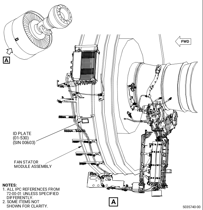
| (b) | Get a new identification (ID) plate (01-530, 72-00-01) (SIN 00603) and reidentify it with P/N 2305M15G12 and the serial number listed on the aft fan case (01-021, 72-21-00) (SIN 84100). Refer to the SPM, 70-16-05, METAL STAMP MARKING. |
| WARNING: |
|
| (c) | Install a new ID plate (01-530, 72-00-01) (SIN 00603) with C04-035 isopropyl alcohol to activate the adhesive of the ID plate (01-530) (SIN 00603). Refer to Figure 2. |
| (d) | Install the new fan stator module assembly. Refer to the GEnx-1B EM, 72-00-01, INSTALLATION 001, CONFIG 02. |
| (e) | Identify the fan case with Complied with SB 72-0317 in a 3X3 inches label at the 9:00 o'clock position forward looking aft (Figure 1). Refer to the SPM, 70-16-09, PERMANENT INK MARKING STANDARD PRACTICE - EPOXY COATED INK MARKING. |
| G. | Installation of the Fan Booster Assembly |
| (1) | Assemble the new fan booster assembly. Refer to the GEnx-1B EM, 72-22-00, ASSEMBLY 001, CONFIG 02. |
| (2) | Install the new fan booster assembly. Refer to the GEnx-1B EM, 72-00-22, INSTALLATION 001. |
| H. | Installation of the FHF Module Assembly |
| (1) | Assemble the new FHF assembly. Refer to the GEnx-1B EM, 72-26-00, ASSEMBLY 001. |
| (2) | Assemble the new FHF module assembly. Refer to the GEnx-1B EM, 72-25-00, ASSEMBLY 001. |
| (3) | Continue with the assembly of the engine propulsor. Refer to the GEnx-1B EM, 72-00-02, ASSEMBLY 001. |
| I. | Optional Rework Procedure |
| (1) | Rework the fan stator module assembly P/N 2305M15G10 or P/N 2305M15G11 to P/N 2305M15G12 as follows: |
| (a) | Remove the hardware that follow from the existing fan stator module P/N 2305M15G04/G05/G06/G08 and set aside: |
| 1 | Remove the temperature sensor (01-010, 79-34-10) (SIN 40800). Refer to the GEnx-1B EM, 72-00-01, DISASSEMBLY 001. |
| 2 | Remove the support bracket (05-580, 72-00-01) (SIN 44010). Refer to the GEnx-1B EM, 72-00-01, DISASSEMBLY 001. |
| 3 | Remove the electrical bracket (07-530, 72-00-01) (SIN 6711S). Refer to the GEnx-1B EM, 72-21-00, DISASSEMBLY 001. |
| 4 | Remove the tube hose (05-040, 79-22-10) (SIN 44900). Refer to the GEnx-1B EM, 72-00-01, DISASSEMBLY 001. |
| 5 | Remove the oil return tube (01-090, 79-22-20) (SIN 45302). Refer to the GEnx-1B EM, 72-00-01, DISASSEMBLY 001. |
| 6 | Remove the P-clamps (05-110, 79-22-10) (SIN 44980). Refer to the GEnx-1B EM, 72-00-01, DISASSEMBLY 001. |
| 7 | Remove the double head hexagon machine bolts (05-090, 79-22-10) (SIN 44921) and the bolts (05-100) (SIN 44923). Refer to the GEnx-1B EM, 72-00-01, DISASSEMBLY 001. |
| (b) | Remove the hardware that follow from the fan stator module assembly P/N 2305M15G10 or P/N 2305M15G11: |
| 1 | Remove the support bracket (05-580A, 72-00-01) (SIN 44010). Refer to the GEnx-1B EM, 72-00-01, DISASSEMBLY 001. |
| 2 | Remove the electrical bracket (07-530A, 72-00-01) (SIN 6711S). Refer to the GEnx-1B EM, 72-21-00, DISASSEMBLY 001. |
| 3 | Remove the tube hose (05-040A, 79-22-10) (SIN 44900). Refer to the GEnx-1B EM, 72-00-01, DISASSEMBLY 001. |
| 4 | Remove the oil return tube (01-090A, 79-22-20) (SIN 45302). Refer to the GEnx-1B EM, 72-00-01, DISASSEMBLY 001. |
| 5 | Remove the P-clamps (05-110A, 79-22-10) (SIN 44980). Refer to the GEnx-1B EM, 72-00-01, DISASSEMBLY 001. |
| 6 | Remove the bolts (05-100A, 79-22-10) (SIN 44923). Refer to the GEnx-1B EM, 72-00-01, DISASSEMBLY 001 and keep them for future use. |
| (2) | Install the hardware that follow onto the fan stator module assembly P/N 2305M15G10 or P/N 2305M15G11 as follows: |
| (a) | Install the support bracket (05-580, 72-00-01) (SIN 44010). Refer to the GEnx-1B EM, 72-00-01, ASSEMBLY 001, Subtask 72-00-01-430-407 through Subtask 72-00-01-430-408. |
| (b) | Install the temperature sensor (01-010, 79-34-10) (SIN 40800) and attach it firmly with the double head hexagon machine bolts (05-090, 79-22-10) (SIN 44921). Refer to the GEnx-1B EM, 72-00-01, ASSEMBLY 001, Subtask 72-00-01-430-487. |
| (c) | Install the tube hose (05-040, 79-22-10) (SIN 44900) and attach it firmly with the P-clamps (05-110A, 79-22-10) (SIN 44980) and bolts (05-100) (SIN 44923). Refer to the GEnx-1B EM, 72-00-01, ASSEMBLY 001, Subtask 72-00-01-640-067, Subtask 72-00-01-430-575, and Subtask 72-00-01-430-486 through Subtask 72-00-01-430-487. |
| (d) | Install the oil return tube (01-090, 79-22-20) (SIN 45302). Refer to the GEnx-1B EM, 72-00-01, ASSEMBLY 001, Subtask 72-00-01-430-498 through Subtask 72-00-01-430-500. |
| (e) | Install the electrical bracket (07-530, 72-00-01) (SIN 6711S). Refer to the GEnx-1B EM, 72-21-00, ASSEMBLY 002, Subtask 72-21-00-440-693 through Subtask 72-21-00-440-694. |
| (3) | Reidentify the fan stator module assembly from P/N 2305M15G10 or P/N 2305M15G11 to P/N 2305M15G12 as follows: |
| (a) | Remove the existing ID plate (01-530, 72-00-01) (SIN 00603) from the fan stator module assembly P/N 2305M15G10 or P/N 2305M15G11. |
| (b) | Clean the fan case (01-021, 72-21-00) (SIN 84100) area from where the plate was removed. Refer to the GEnx-1B CIR, 72-21-02, CLEANING 001. |
| WARNING: |
|
| (c) | Apply C03-006 Alodine to the fan case (01-021, 72-21-00) (SIN 84100) area and let it dry. Refer to the SPM, 70-43-07, CHEMICAL TOUCH-UP SURFACE REFINISHING PROCESS FOR ALUMINUM. |
| (d) | Get a new ID plate (01-530, 72-00-01) (SIN 00603) and reidentify it with P/N 2305M15G12 and the serial number listed on the current ID plate (01-530) (SIN 00603). Refer to the SPM, 70-16-05, METAL STAMP MARKING. |
| WARNING: |
|
| (e) | Install a new ID plate (01-530, 72-00-01) (SIN 00603) with C04-035 isopropyl alcohol to activate the adhesive of the ID plate (01-530) (SIN 00603). Refer to Figure 2. |