| GEnx-1B SERVICE BULLETIN - 79-0018 R06 | Revised: 12/19/2022 | |
| SB 79-0018 R06 OIL - Fuel/Oil Heat Exchanger (79-21-00) - Improved Main Fuel/Oil Heat Exchanger with Indicating Capability | Issued: 06/16/2014 | |
| GEnx-1B SERVICE BULLETIN - 79-0018 R06 | Revised: 12/19/2022 | |
| SB 79-0018 R06 OIL - Fuel/Oil Heat Exchanger (79-21-00) - Improved Main Fuel/Oil Heat Exchanger with Indicating Capability | Issued: 06/16/2014 | |
| GE Designated: -CONFIDENTIAL- | |
| The information contained in this document is GE proprietary information and is disclosed in confidence. It is the property of GE and shall not be used, disclosed to others or reproduced without the express written consent of GE, including, but without limitation, it is not to be used in the creation, manufacture, development, or derivation of any repairs, modifications, spare parts, designs, or configuration changes or to obtain FAA or any other government or regulatory approval to do so. If consent is given for reproduction in whole or in part, this notice and the notice set forth on each page of this document shall appear in any such reproduction in whole or part. | |
| This technical data is considered subject to the Export Administration Regulations (EAR) pursuant to 15 CFR Parts 730-774. Transfer of this data by any means to a Non-U.S. Person, whether in the United States or abroad, without the proper U.S. Government authorization (e.g., License, exemption, NLR, etc.), is strictly prohibited. | |
| Copyright (2022) General Electric Company, U.S.A. |
| TRANSMITTAL INFORMATION |
| REVISION 6 TO SERVICE BULLETIN 79-0018 |
| Revision 6 is issued to update paragraphs 1., PLANNING INFORMATION and 2., MATERIAL INFORMATION. |
| Revision 5 was issued September 01, 2016. Revision 4 was issued June 18, 2015. Revision 3 was issued March 06, 2015. Revision 2 was issued December 11, 2014. Revision 1 was issued August 19, 2014. The original was issued June 16, 2014. Revision bars in the left margin identify changes. |
| 1. | PLANNING INFORMATION |
| A. | Effectivity |
| * * * FOR GEnx-1B64, -1B64/P1, -1B64/P2, -1B67, -1B67/P1, -1B67/P2, -1B70, -1B70/75/P1, -1B70/75/P2, -1B70/P1, -1B70/P2, -1B70C/P1, -1B70C/P2, -1B74/75/P1, -1B74/75/P2, -1B76/P2, -1B76A/P2 |
| This Service Bulletin has been introduced in production to these GEnx-1B engines: |
| • |
|
| Deleted. |
| These serial numbers are the best available data. |
| B. | Description |
| This Service Bulletin introduces a new fuel/oil heat exchanger, VIN 8103-024 (P/N 2550M15P04) and its preferred alternative fuel/oil heat exchanger VIN 8103-023 (P/N 2550M15P03), which have features that provide flight deck indication for heavy fuel contamination at the fuel/oil heat exchanger, as well as defining all of the new hardware to permit procurement to support the field retrofit program. |
| Revision 5 of this Service Bulletin introduces a new fuel/oil heat exchanger VIN 8103-024 (P/N 2550M15P04). |
| Revision 6 of this Service Bulletin revises the change code for pressure sensor VIN 516983-1 (P/N 2621M76P01) to one-way interchangeable based on field experience and a high failure rate of the old pressure sensor VIN 508486-1 (P/N 2125M60P01) installed at the main fuel oil heat exchanger. |
| C. | Compliance |
| Category 2 |
| GE recommends this Service Bulletin to be done no later than April 30, 2017 for Federal Aviation Administration (FAA) operators and December 31, 2016 for all other operators. |
| Impact B |
| This recommendation is to address a condition that may result in an Increased Rate of In-Flight Shutdowns (IFSD), Take-Off Aborts (TOA), Air Turn Backs (ATB) or Diversions (DIV). |
| NOTE: |
|
| This Service Bulletin is offered to improve the reliability or performance of your GE product, or to help prevent the occurrence of the event or condition described in this Service Bulletin. If the operator elects not to participate in the bulletin, that decision will be taken into consideration by GE in evaluating future product performance issues that may arise in the operators fleet. |
| D. | Concurrent Requirements |
| Do GEnx-1B S/B 73-0011 before you do this Service Bulletin. |
| Do GEnx-1B S/B 73-0030 before you do this Service Bulletin. |
| NOTE: |
|
| E. | Reason |
| (1) | Objective: |
| To introduce a new fuel/oil heat exchanger configuration with support for flight deck indication. |
| (2) | Condition: |
| The original configuration of the heat exchanger did not have features to provide indications to a flight crew of a heavy fuel contamination condition which could affect fuel flow performance through the heat exchanger. |
| (3) | Cause: |
| Requirements for flight deck indication occurred after original engine certification. |
| (4) | Improvement: |
| The new design provides improvements to add a pressure sensor, supporting electronic engine control (EEC) system harnesses and includes design changes which reduce the weight of the fuel/oil heat exchanger. EEC Software version B175 or later enables display and fault messaging for the new sensor. |
| (5) | Substantiation: |
| Substantiation is by comparative analysis, analysis, and test. |
| F. | Approval |
| The data contained in this Service Bulletin has been reviewed by the appropriate governmental authority and the repair(s) and modification(s) herein comply with the applicable Aviation Regulations and are APPROVED for installation in the model(s) listed in this Service Bulletin. |
| G. | Manpower |
| After you get access to the core area, you will need approximately 12.0 man-hours for each engine or component. |
| H. | Weight and Balance |
| The complete compliance with this Service Bulletin decreases weight by 5.35 lb (2.43 kg). |
| I. | References (Use the latest version of these documents) |
| GEnx-1B Boeing 787 Aircraft Maintenance Manual (AMM) |
| GEK 9250, Commercial Engine Standard Practices Manual (SPM) |
| GEK 112851, GEnx-1B Engine Manual (EM) |
| GEK 112862, GEnx-1B Cleaning, Inspection, and Repair Manual (CIR) |
| GEK 112864, GEnx-1B Engine Illustrated Parts Catalog (EIPC) |
| GEnx-1B S/B 73-0011, ENGINE FUEL AND CONTROL - Flow Splitting Valve (73-21-30) - Fuel Accumulator Hardware Release |
| GEnx-1B S/B 73-0030, ENGINE FUEL AND CONTROL - Electronic Engine Control (73-21-20) - Release of EEC Software Version B175 |
| GEnx-1B S/B 73-0039, ENGINE FUEL AND CONTROL - General (73-00-00) - Introduction of Alternate Pressure Sensor |
| GEnx-1B S/B 73-0043, ENGINE FUEL AND CONTROL - General (73-00-00) - Introduction of New Pressure Sensor |
| GEnx-1B S/B 79-0020, OIL - Fuel/Oil Heat Exchanger (79-21-00) - Fuel/Oil Heat Exchanger Transfer Tube Improvement |
| GEnx-1B S/B 79-0031, OIL - Fuel/Oil Heat Exchanger (79-21-00) - Introduction of New Fuel/Oil Heat Exchanger with Improved Fuel Valve Guide |
| NOTE: |
|
| J. | Publications Affected |
| GEnx-1B Boeing 787 Aircraft Maintenance Manual (AMM) |
| GEK 112851, GEnx-1B Engine Manual (EM) |
| GEK 112862, GEnx-1B Cleaning, Inspection, and Repair Manual (CIR) |
| GEK 112864, GEnx-1B Engine Illustrated Parts Catalog (EIPC) |
| K. | Interchangeability |
| The proposed hardware must be introduced in complete engine sets, mixing the details of the proposed and superseded hardware on the same engine is not permitted. |
| L. | Software Accomplishment Summary |
| Install EEC Software Version B175 or a later version as specified in GEnx-1B S/B 73-0030. |
| 2. | MATERIAL INFORMATION |
| A. | Material - Price and Availability |
| (1) | Parts necessary to do this Service Bulletin: |
|
||||||||||||||||||||||||||||||||||||||||||||||||||||||||||||||||||||||||||||||||||||||||||||||||||||||||||||||||||||||||||||||||||||||||||||||||||||||||||||||||||||||||||||||||||||||||||||||||||||||||||||||||||||||||||||||||||||||||||||||||||||||||||||||||||||||||||||||||||||||||||||||||||||||||||||||||||||||||||||||||||||||||||||||||||||||||||||||||||||||||||||||||||||||||||||||||||||||||||||||||||||||||||||||||||||||||||||||||||||||||||||||||||||||||||||||||||||||||||||||||||||||||||||||||||||||||||||||||||||||||||||||||||||||||||||||||||||||||||||||||||||||||||||||||||||||||||||||||||||||||||||||||||||||||||||||||||||||||||||||||||||||||||||||||||||||||||||||||||||||||||||||||||||||||||||||||||||||||||||||||||||||||||||||||||||||||
| *Part not supplied by GE Engine Services Distribution L.L.C. Procure through local purchase. |
| **Part not supplied by GE Engine Services Distribution L.L.C. Procure through: |
| Unison Industries L.L.C. Elano Division 2455 Dayton-Xenia Rd. Dayton, Ohio 45434-7199 U.S.A. |
| ***Part not supplied by GE Engine Services Distribution L.L.C. Procure through: |
| Unison Industries Inc. 7575 Baymeadows Way Jacksonville, Florida 32256-8514 U.S.A. |
| ****Part not supplied by GE Engine Services Distribution L.L.C. Procure through: |
| Woodward Governor Co. 5001 North Second Street P.O. Box 7001 Rockford, Illinois 61125-7001 U.S.A. |
| NP=Not Provisioned |
| Deleted. |
| NOTE: |
|
| (2) | Other Spare Parts: |
|
|||||||||||||||||||||||||||||||||||||||||||||||||||||||||||||||||||||||||||||||||||||||||||||||||||||||||||||||||||||||||||||||||||||||
| NOTE: |
|
| (3) | Consumables: |
|
| B. | Industry Support Information |
| Contact your GE Customer Service Manager (CSM) for Details. |
| C. | Configuration Chart |
|
| Operation Codes AD=Add DE=Delete RE=Replace RM=Remains RW=Rework QTC=Quantity Change |
| Change Codes 1=One-way interchangeable. 2=Two-way interchangeable. 5=Qualified interchangeability. Refer to paragraph 1.K., Interchangeability. |
| Support Codes A=Old parts will no longer be supplied. B=Old parts will be supplied until all old parts are sold. E=Old parts will be supplied, and can be used at other engine locations. |
| D. | Parts Disposition |
| Standard hardware can be used in other locations. All other hardware that cannot be used in other applications should be terminated. |
| E. | Tooling - Price and Availability |
| None. |
| 3. | ACCOMPLISHMENT INSTRUCTIONS |
| A. | General |
| (1) | Before starting these procedures, read the assembly and disassembly techniques section. Refer to the SPM, 70-10-00, ASSEMBLY AND DISASSEMBLY TECHNIQUES. |
| (2) | Do a general visual inspection of the engine parts that are exposed during maintenance and all the engine parts that will be reinstalled. |
| (3) | Prepare the engine and the aircraft for maintenance. Refer to the GEnx-1B Boeing 787 AMM, TASK B787-A-G79-21-01-00A-520A-A step B. |
| WARNING: |
|
| (4) | Unless specified differently, lubricate the threads and washer faces of bolts, screws, studs, or nuts with C02-058 lubricant before installation. After installation, remove unwanted lubricant with a C10-182 cleaning cloth. |
| B. | Removal of the Old Fuel/Oil Heat Exchanger |
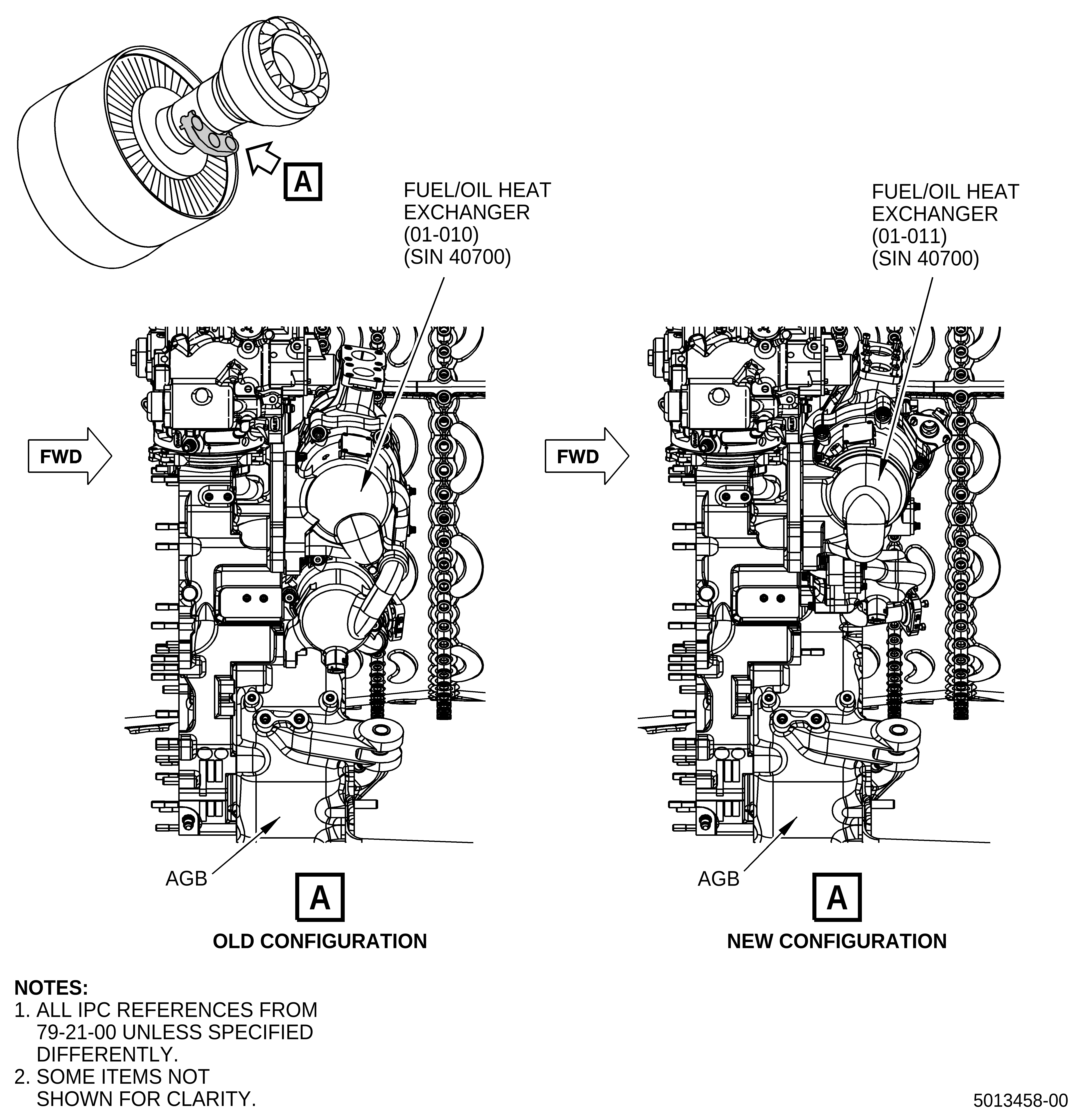
| (1) | Remove the old fuel/oil heat exchanger (01-010, 79-21-00) (SIN 40700). Refer to Figure 1 and do as follows: |
| (a) | Drain the fuel supply system at the main fuel pump. Refer to the GEnx-1B Boeing 787 AMM, TASK DMC-B787-A-G73-11-01-00A-520A-A step (2). |
| (b) | Remove the old fuel/oil heat exchanger (01-010, 79-21-00) (SIN 40700). Refer to the GEnx-1B Boeing 787 AMM, TASK DMC-B787-AG79-21-01-00A-520A-A. |
| (c) | Keep all removed hardware. Used packings and seals will be replaced. |
| C. | Replacement of the Supporting Brackets |
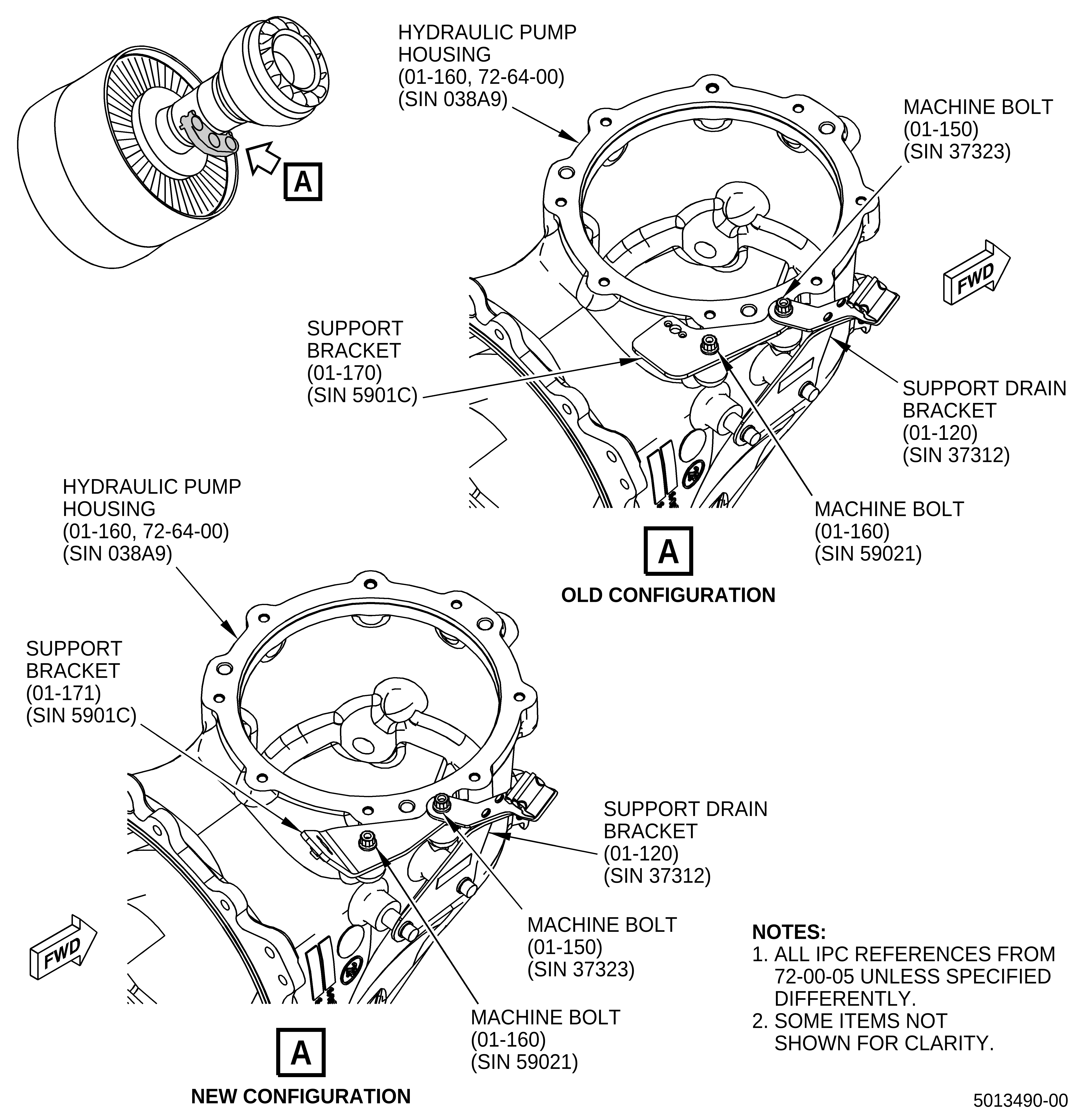
| (1) | Replace the support bracket (01-170, 72-00-05) (SIN 5901C). Refer to Figure 2, Sheet 1 and do as follows: |
| (a) | Remove the machine bolt (01-160, 72-00-05) (SIN 59021) that holds the support bracket (01-170) (SIN 5901C) to the hydraulic pump housing (01-160, 72-64-00) (SIN 038A9). |
| (b) | Remove the machine bolt (01-150, 72-00-05) (SIN 37323) that holds the support bracket (01-170) (SIN 5901C) and support drain bracket (01-120) (SIN 37312) to the hydraulic pump housing (01-160, 72-64-00) (SIN 038A9). |
| (c) | Remove the support bracket (01-170, 72-00-05) (SIN 5901C) from the engine. |
| (d) | Install the new support bracket (01-171) (SIN 5901C) onto the hydraulic pump housing (01-160, 72-64-00) (SIN 038A9) mounting bosses and between the support drain bracket (01-120, 72-00-05) (SIN 37312) and hydraulic pump housing (01-160, 72-64-00) (SIN 038A9) with the boltholes aligned. |
| WARNING: |
|
| (e) | Lubricate the threads of machine bolts (01-150, 72-00-05) (SIN 37323) and (01-160) (SIN 59021) with C02-058 lubricant. |
| (f) | Make sure that the boltholes are aligned and install the machine bolt (01-150) (SIN 37323) through the support drain bracket (01-120) (SIN 37312) and the new support bracket (01-171) (SIN 5901C) and thread it into the hydraulic pump housing (01-160, 72-64-00) (SIN 038A9) boss hand-tight only. |
| (g) | Make sure that the boltholes are aligned and install the machine bolt (01-160, 72-00-05) (SIN 59021) through the new support bracket (01-171) (SIN 5901C) and thread it into the hydraulic pump housing (01-160, 72-64-00) (SIN 038A9) boss hand-tight only. |
| (h) | Torque the machine bolts (01-150, 72-00-05) (SIN 37323) and (01-160) (SIN 59021) to 106-124 lb in. (12.0-14.0 N.m). |
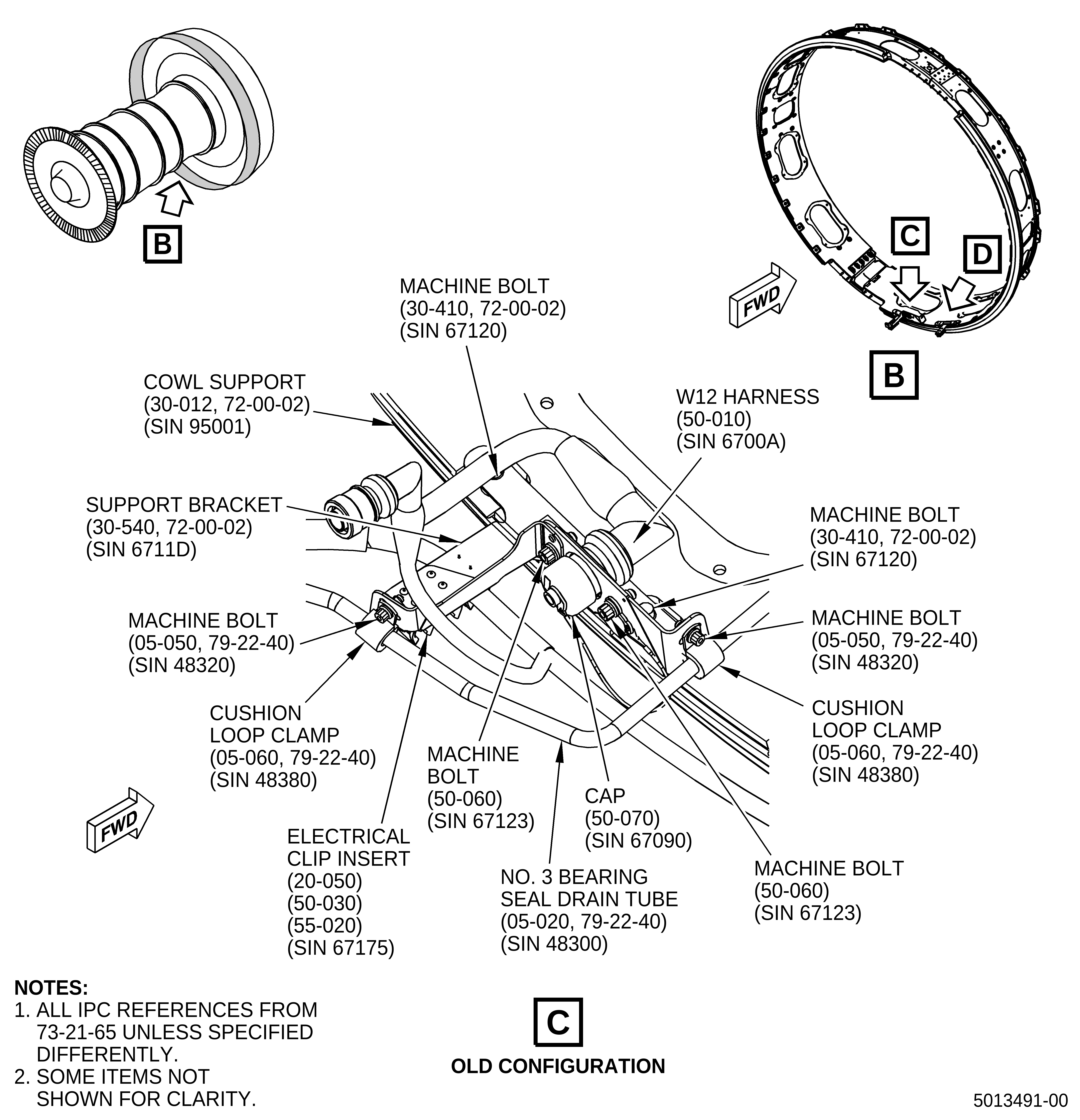
| (2) | Replace the support bracket (30-540, 72-00-02) (SIN 6711D). Refer to Figure 2, Sheet 2, Sheet 3, and do as follows: |
| (a) | Remove any harness leads from the spring clips on the support bracket (30-540, 72-00-02) (SIN 6711D). |
| (b) | Remove three electrical clip inserts (20-050, 73-21-65), (55-020), and (50-030) (SIN 67175) from the support bracket (30-540, 72-00-02) (SIN 6711D), keep two electrical clip inserts (20-050, 73-21-65) and (55-020) (SIN 67175) for reinstallation on the new support bracket (30-541, 72-00-02) (SIN 6711D). |
| (c) | Remove and keep the two machine bolts (05-050, 79-22-40) (SIN 48320) and the two cushion loop clamps (05-060) (SIN 48380) that attach the No. 3 bearing seal drain tube (05-020) (SIN 48300) to the support bracket (30-540, 72-00-02) (SIN 6711D). |
| (d) | Remove the two machine bolts (50-060, 73-21-65) (SIN 67123) that attach the cap (50-070) (SIN 67090) to the support bracket (30-540, 72-00-02) (SIN 6711D) and remove the cap (50-070, 73-21-65) (SIN 67090) from the harness socket. |
| (e) | Remove the W12 harness (50-010) (SIN 6700A) from the harness socket on the support bracket (30-540, 72-00-02) (SIN 6711D). |
| (f) | Remove the two machine bolts (30-410) (SIN 67120) that attach the support bracket (30-540) (SIN 6711D) to the cowl support (30-012) (SIN 95001) and remove the support bracket (30-540) (SIN 6711D) from the engine. |
| WARNING: |
|
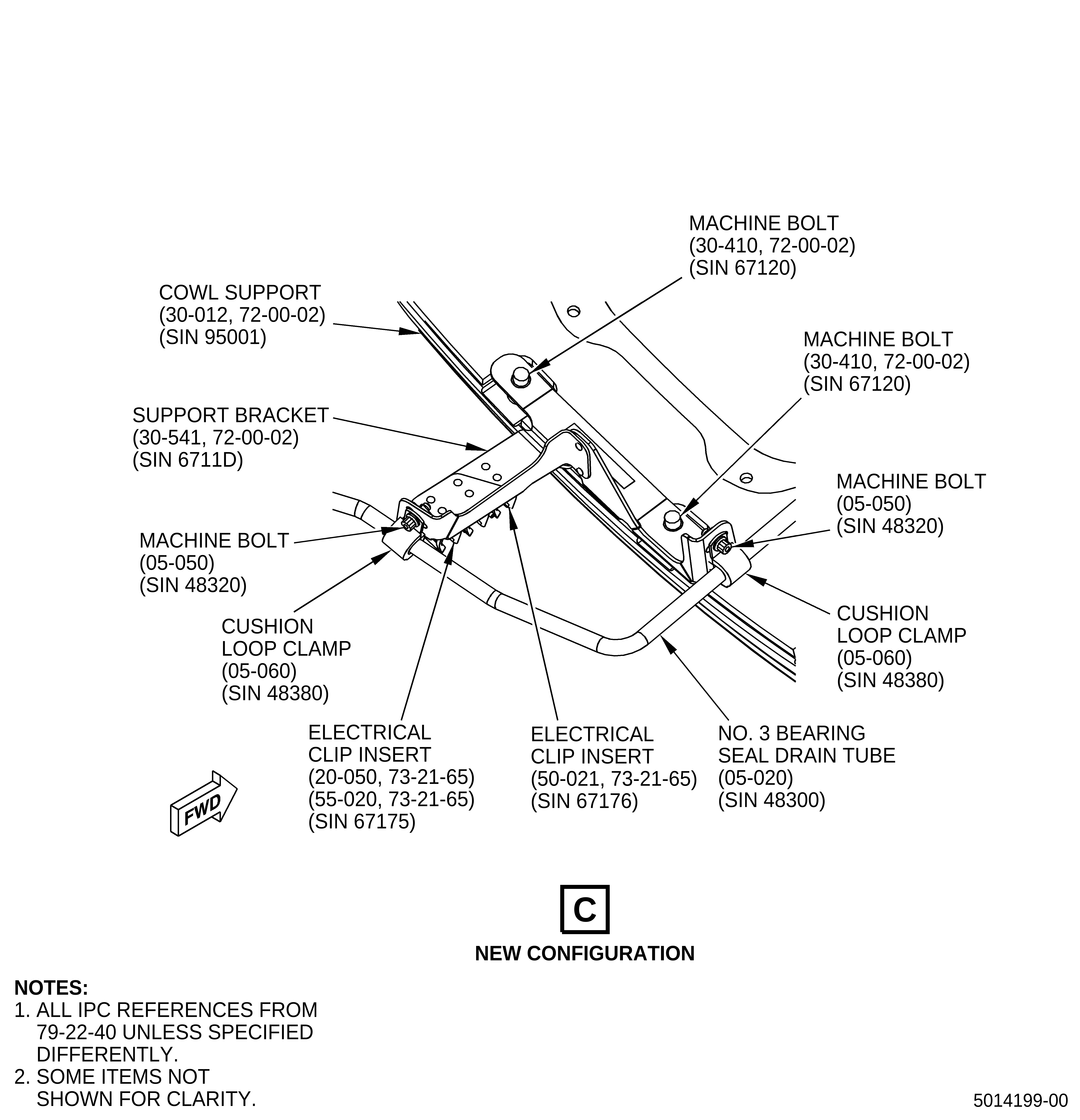
| (g) | Apply C03-100 primer to the surface of the new support bracket (30-541) (SIN 6711D). |
| (h) | Put the new support bracket (30-541) (SIN 6711D) on the cowl support (30-012) (SIN 95001) with boltholes aligned. |
| (i) | Install the two machine bolts (30-410) (SIN 67120) and torque them to 106-124 lb in. (12.0-14.0 N.m). |
| (j) | Install the two machine bolts (05-050, 79-22-40) (SIN 48320) and the two cushion loop clamps (05-060) (SIN 48380) that attach the No. 3 bearing seal drain tube (05-020) (SIN 48300) to the new support bracket (30-541, 72-00-02) (SIN 6711D) and torque them to 32-38 lb in. (3.6-4.3 N.m). |
| (k) | Use a clean C10-182 cleaning cloth to remove the unwanted C03-100 primer. |
| (l) | Install two electrical clip inserts (20-050, 73-21-65) and (55-020) (SIN 67175) and one new electrical clip insert (50-021) (SIN 67176) on the new support bracket (30-541, 72-00-02) (SIN 6711D). |
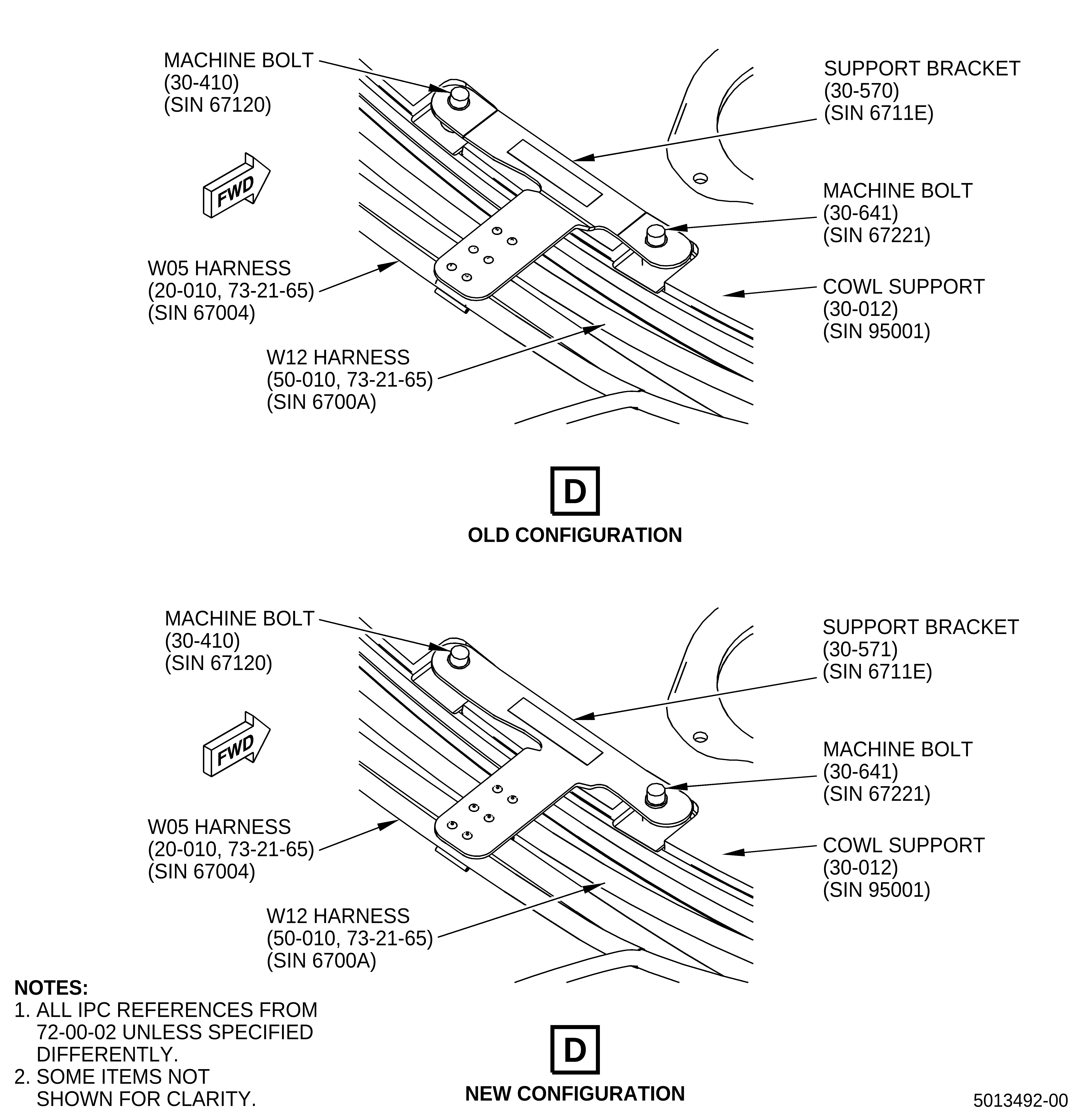
| (3) | Replace support bracket (30-570, 72-00-02) (SIN 6711E) from the 5:30 o'clock position aft looking forward (ALF) on the cowl support (30-012) (SIN 95001). Refer to Figure 2, Sheet 4 and do as follows: |
| (a) | Remove unwanted harness leads from the spring clips on the support bracket (30-570, 72-00-02) (SIN 6711E). |
| (b) | Remove the two machine bolts (30-410) (SIN 67120) and (30-641) (SIN 67221) that attach the support bracket (30-570) (SIN 6711E) to the cowl support (30-012) (SIN 95001) and remove the support bracket (30-570) (SIN 6711E) from the engine. |
| WARNING: |
|
| (c) | Apply C03-100 primer to the surface on the new support bracket (30-571) (SIN 6711E). |
| (d) | Put the new support bracket (30-571) (SIN 6711E) onto the cowl support (30-012) (SIN 95001) and install the two machine bolts (30-410) (SIN 67120) and (30-641) (SIN 67221). Torque the two machine bolts to 106-124 lb in. (12.0-14.0 N.m). |
| (e) | Remove the unwanted C03-100 primer. |
| (f) | Install the W05 harness (20-010, 73-21-65) (SIN 67004) into the spring clip. |
| NOTE: |
|
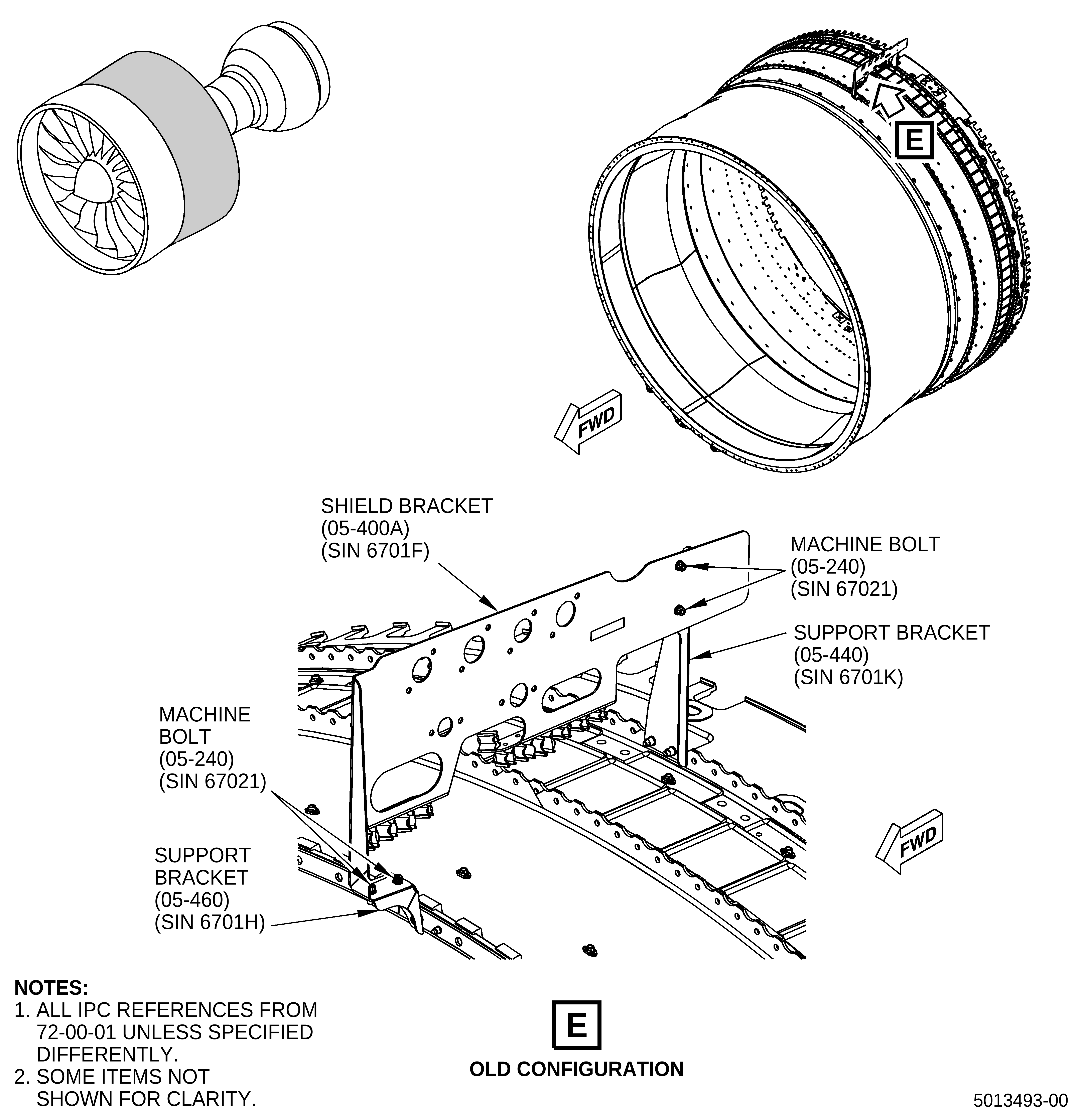
| (4) | Replace shield bracket (05-400A, 72-00-01) (SIN 6701F). Refer to Figure 2, Sheet 5, Sheet 6, and do as follows: |
| CAUTION: |
|
| (a) | Use soft-jawed pliers to disconnect the harness leads from shield bracket (05-400A, 72-00-01) (SIN 6701F): |
| • |
|
| • |
|
| • |
|
| • |
|
| • |
|
| • |
|
| • |
|
| • |
|
| (b) | Remove the machine bolts (35-060), (40-060), (45-020), (50-050), and (55-040) (SIN 67021) (two for each harness lead) that attach the harness leads to the shield bracket (05-400A, 72-00-01) (SIN 6701F). |
| (c) | Remove the harness leads from shield bracket (05-400A) (SIN 6701F). |
| (d) | Apply protective covers to the exposed harness connections. |
| (e) | Remove the two machine bolts (05-240) (SIN 67021) that attach the shield bracket (05-400A) (SIN 6701F) to the support bracket (05-460) (SIN 6701H). |
| (f) | Remove the two machine bolts (05-240) (SIN 67021) that attach the shield bracket (05-400A) (SIN 6701F) to the support bracket (05-440) (SIN 6701K). |
| (g) | Remove the old shield bracket (05-400A) (SIN 6701F) from the engine. |
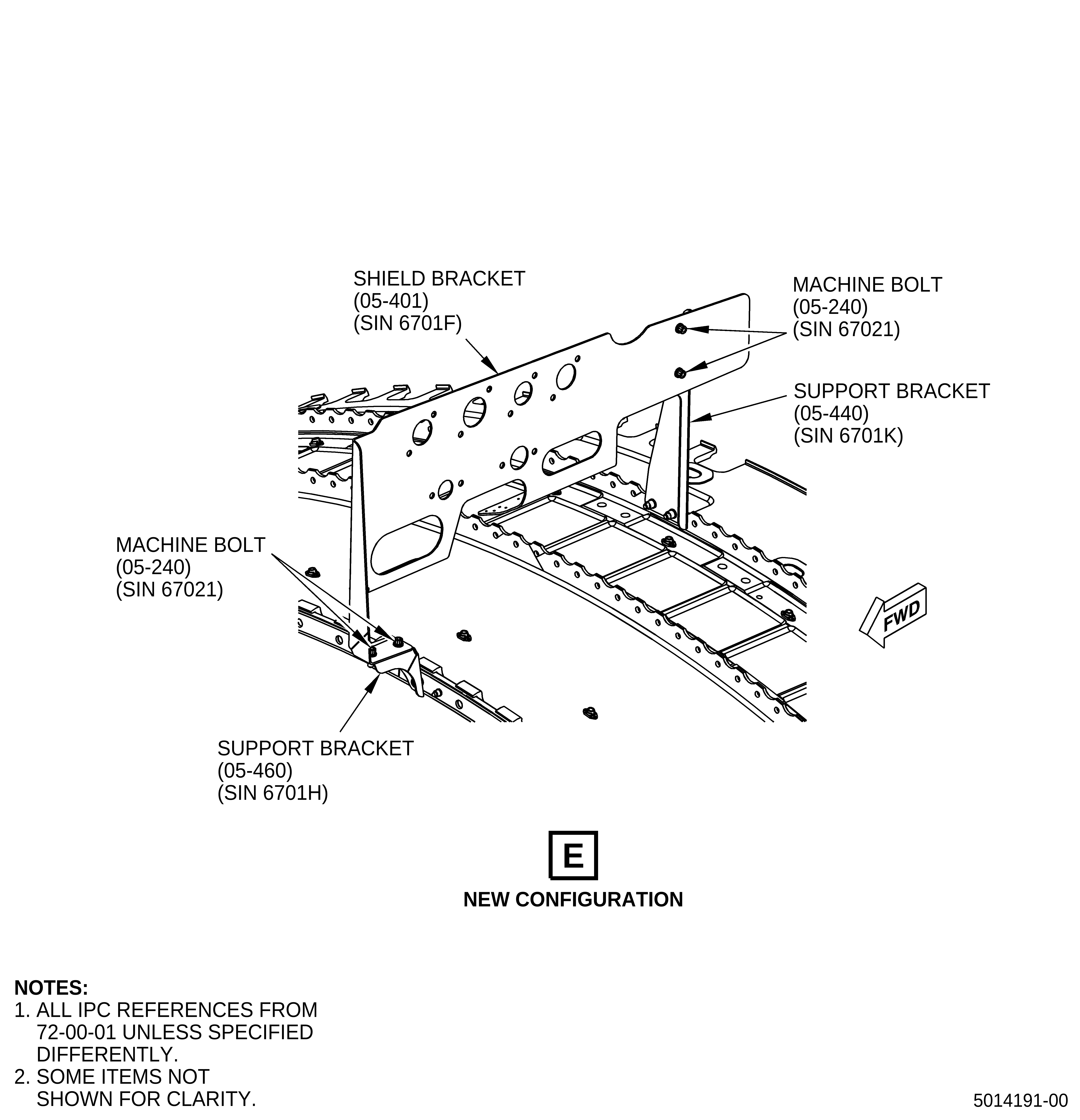
| (h) | Put the new shield bracket (05-401) (SIN 6701F) onto the support brackets (05-460) (SIN 6701H) and (05-440) (SIN 6701K). |
| (i) | Insert two machine bolts (05-240) (SIN 67021) through the new shield bracket (05-401) (SIN 6701F) and thread them into the nut plates on the support bracket (05-440) (SIN 6701K) hand-tight only. |
| (j) | Insert two machine bolts (05-240) (SIN 67021) through the new shield bracket (05-401) (SIN 6701F) and thread them into the nut plates on the support bracket (05-460) (SIN 6701H) hand-tight only. |
| (k) | Torque the four machine bolts (05-240) (SIN 67021) that attach the shield bracket (05-401) (SIN 6701F) to the support brackets (05-440) (SIN 6701K) and (05-460) (SIN 6701H) to 106-124 lb in. (12.0-14.0 N.m). |
| (l) | Install the harness leads to the shield bracket (05-401) (SIN 6701F) and attach them with machine bolts (35-060), (40-060), (45-020), (50-050), and (55-040) (SIN 67021) (two for each harness lead). Torque the machine bolts to 106-124 lb in. (12.0-14.0 N.m). |
| CAUTION: |
|
| (m) | Use soft-jawed pliers to connect the harness leads below to the shield bracket (05-401) (SIN 6701F): |
| • |
|
| • |
|
| • |
|
| • |
|
| • |
|
| • |
|
| NOTE: |
|
| D. | Installation of the New Pressure Sensor |
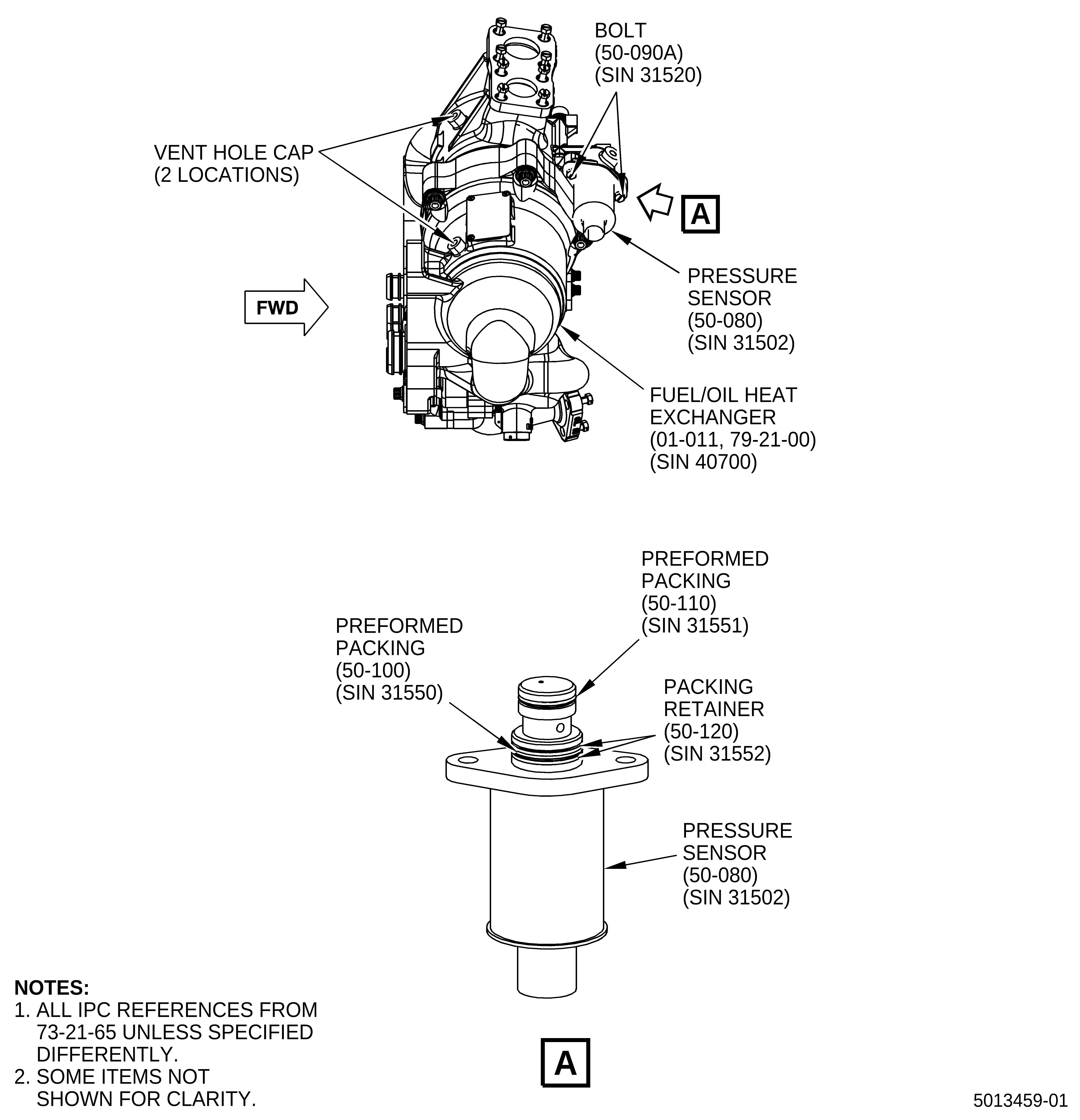
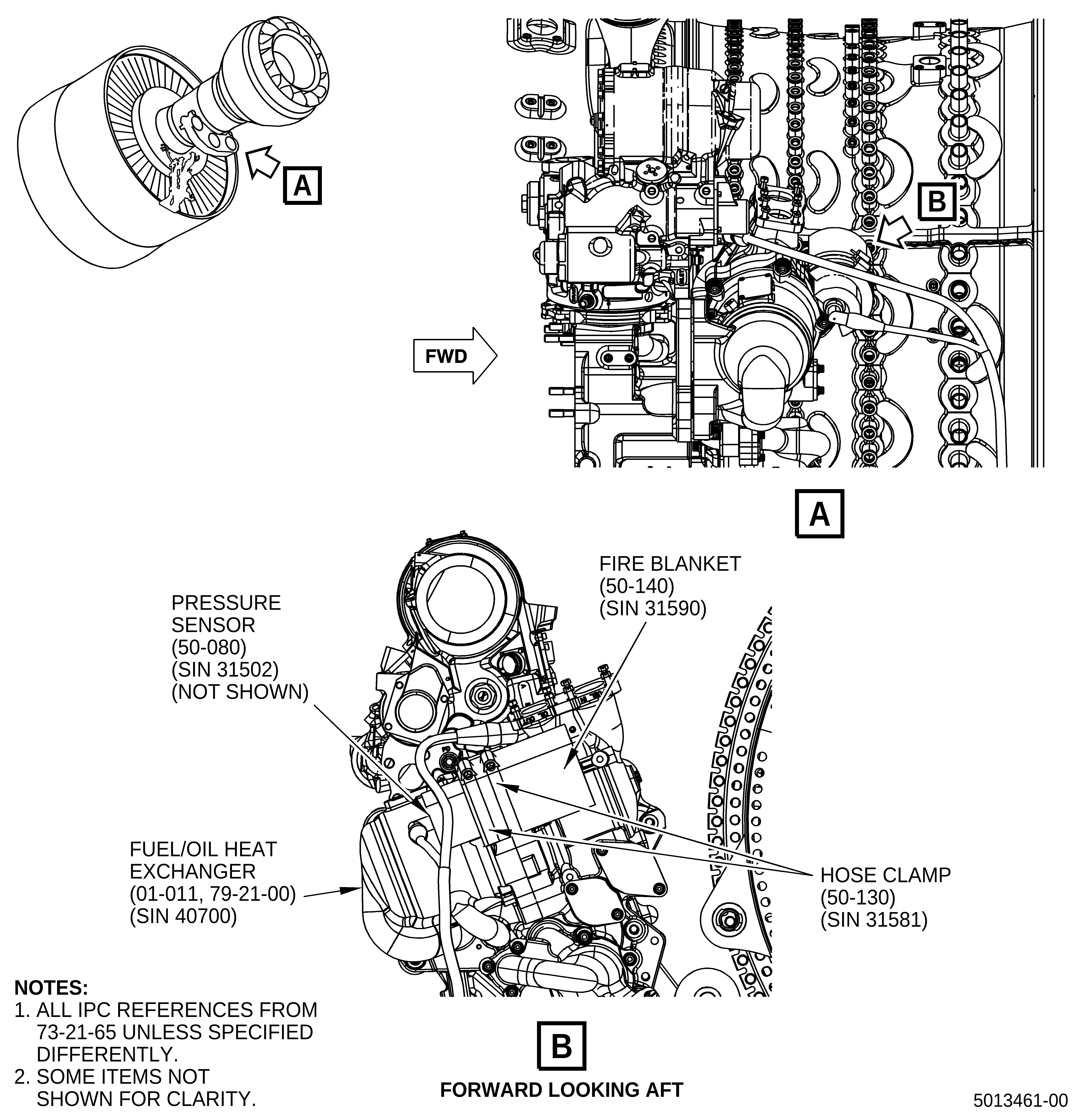
| (1) | Install the pressure sensor (50-080, 73-21-65) (SIN 31502). Refer to Figure 3 and do as follows: |
| (a) | Prepare the pressure sensor (50-080) (SIN 31502) for installation: |
| WARNING: |
|
| 1 | Apply C02-019 engine oil or C02-023 engine oil to the preformed packings (50-100) (SIN 31550), (50-110) (SIN 31551), and packing retainers (50-120) (SIN 31552). |
| 2 | Install one preformed packing (50-110) (SIN 31551) and two packing retainers (50-120) (SIN 31552). Refer to the GEnx-1B Boeing 787 AMM, TASK B787-A-G70-00-04-00A-720A-A. |
| 3 | Install one preformed packing (50-100) (SIN 31550). |
| (b) | Install the pressure sensor (50-080) (SIN 31502) on the new fuel/oil heat exchanger (01-011, 79-21-00) (SIN 40700) with the boltholes aligned. |
| (c) | Attach the pressure sensor (50-080, 73-21-65) (SIN 31502) to the new fuel/oil heat exchanger (01-011, 79-21-00) (SIN 40700) with two double hexagon head machine bolts (bolts) (50-090A, 73-21-65) (SIN 31520). Torque the bolts to 106-124 lb in. (12.0-14.0 N.m). |
| E. | Installation of the New Fuel/Oil Heat Exchanger |
| (1) | Install the new fuel/oil heat exchanger (01-011, 79-21-00) (SIN 40700). Refer to Figure 1 and do as follows: |
| (a) | Remove two vent hole caps. Refer to Figure 3. |
| (b) | Install the new fuel/oil heat exchanger (01-011, 79-21-00) (SIN 40700). Refer to the GEnx-1B Boeing 787 AMM, TASK B787-A-G79-21-01-00A-720A-A and do as follows: |
| NOTE: |
|
| 1 | Install the tubing. Refer to the GEnx-1B EM, 72-00-05, Subtask 72-00-05-430-022 and do as follows: |
| a | Put the new bracket (10-430, 79-22-10) (SIN 5901D) on the top of the tube hose (10-010) (SIN 44800) flange before the tubing is attached. Refer to Figure 4. |
| 2 | Leave the protective cap on the electrical connector for the pressure sensor (50-080, 73-21-65) (SIN 31502). Refer to Figure 3. |
| NOTE: |
|
| NOTE: |
|
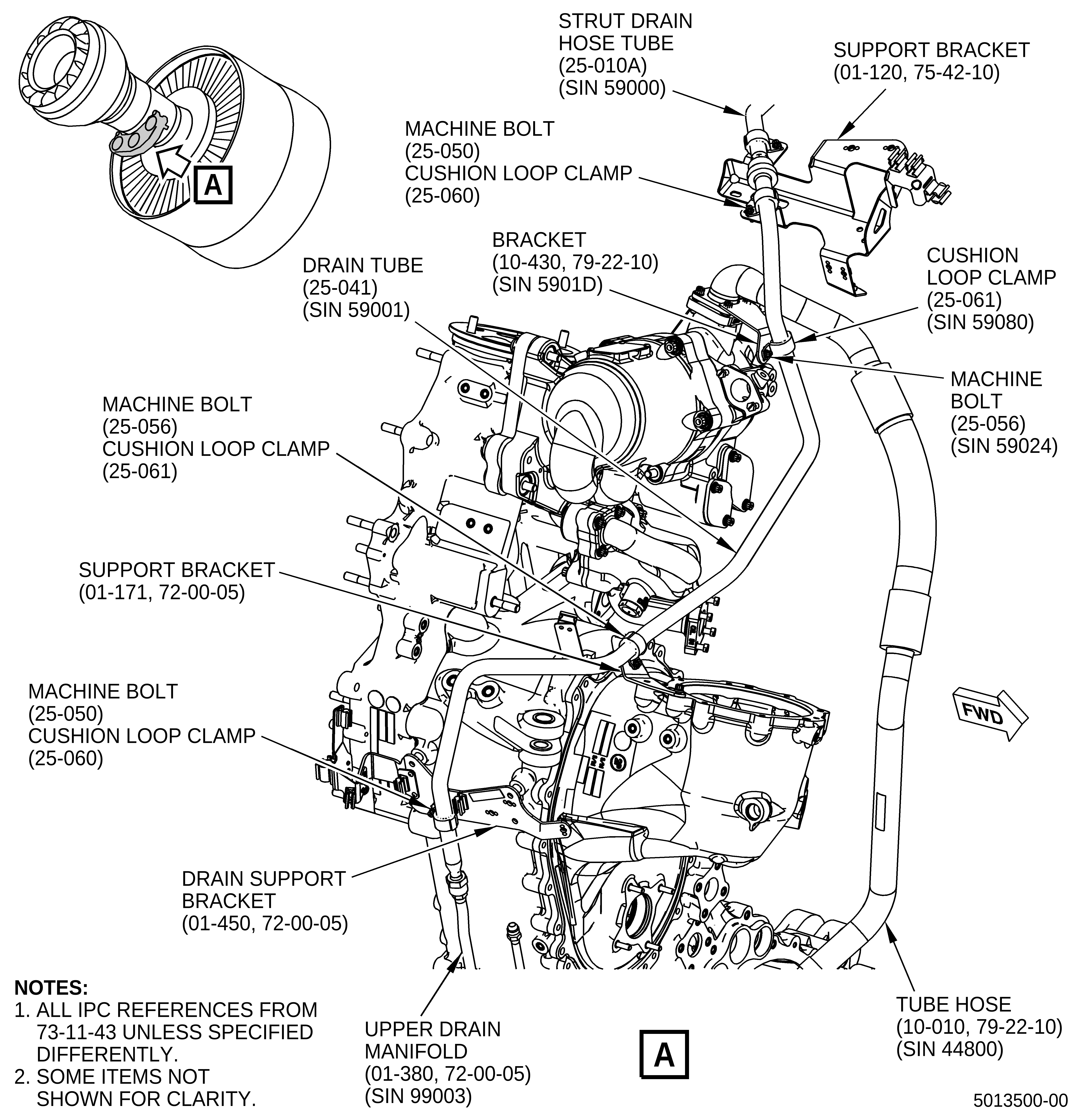
| (2) | Install the new drain tube (25-041, 73-11-43) (SIN 59001). Refer to Figure 4 and do as follows: |
| (a) | Remove the protective caps and make sure that the tubes are clear from any obstruction. |
| (b) | Put the new drain tube (25-041) (SIN 59001) onto the strut drain hose tube (25-010A) (SIN 59000) and upper drain manifold (01-380, 72-00-05) (SIN 99003). Thread the B-nut fittings hand-tight to seat the tubes. |
| (c) | Install one machine bolt (25-050, 73-11-43) (SIN 59020) and one cushion loop clamp (25-060) (SIN 59080) to attach the new drain tube (25-041) (SIN 59001) to the support bracket (01-120, 75-42-10) (SIN 53012) hand-tight only. |
| (d) | Install one machine bolt (25-056, 73-11-43) (SIN 59024) and one cushion loop clamp (25-061) (SIN 59080) to attach the new drain tube (25-041) (SIN 59001) to the new bracket (10-430, 79-22-10) (SIN 5901D) hand-tight only. |
| (e) | Install one machine bolt (25-056, 73-11-43) (SIN 59024) and one cushion loop clamp (25-061) (SIN 59080) to attach the new drain tube (25-041) (SIN 59001) to the new support bracket (01-171, 72-00-05) (SIN 5901C) hand-tight only. |
| (f) | Install one machine bolt (25-050, 73-11-43) (SIN 59020) and one cushion loop clamp (25-060) (SIN 59080) to attach the new drain tube (25-041) (SIN 59001) to the bracket (01-450, 72-00-05) (SIN 37010) hand-tight only. |
| CAUTION: |
|
| (g) | Torque the B-Nut fitting that attaches the new drain tube (25-041, 73-11-43) (SIN 59001) to the strut drain hose tube (25-010A) (SIN 59000) to 78-92 lb ft (106-125 N.m). |
| (h) | Torque the B-Nut fitting that attaches the new drain tube (25-041) (SIN 59001) to the upper drain manifold (01-380, 72-00-05) (SIN 99003) to 460-540 lb in. (52.0-61.0 N.m). |
| (i) | Torque two machine bolts (25-050, 73-11-43) (SIN 59020) and two machine bolts (25-056) (SIN 59024) to 32-38 lb in. (3.6-4.3 N.m). |
| F. | Lower Bifurcation Wiring Harness Replacement |
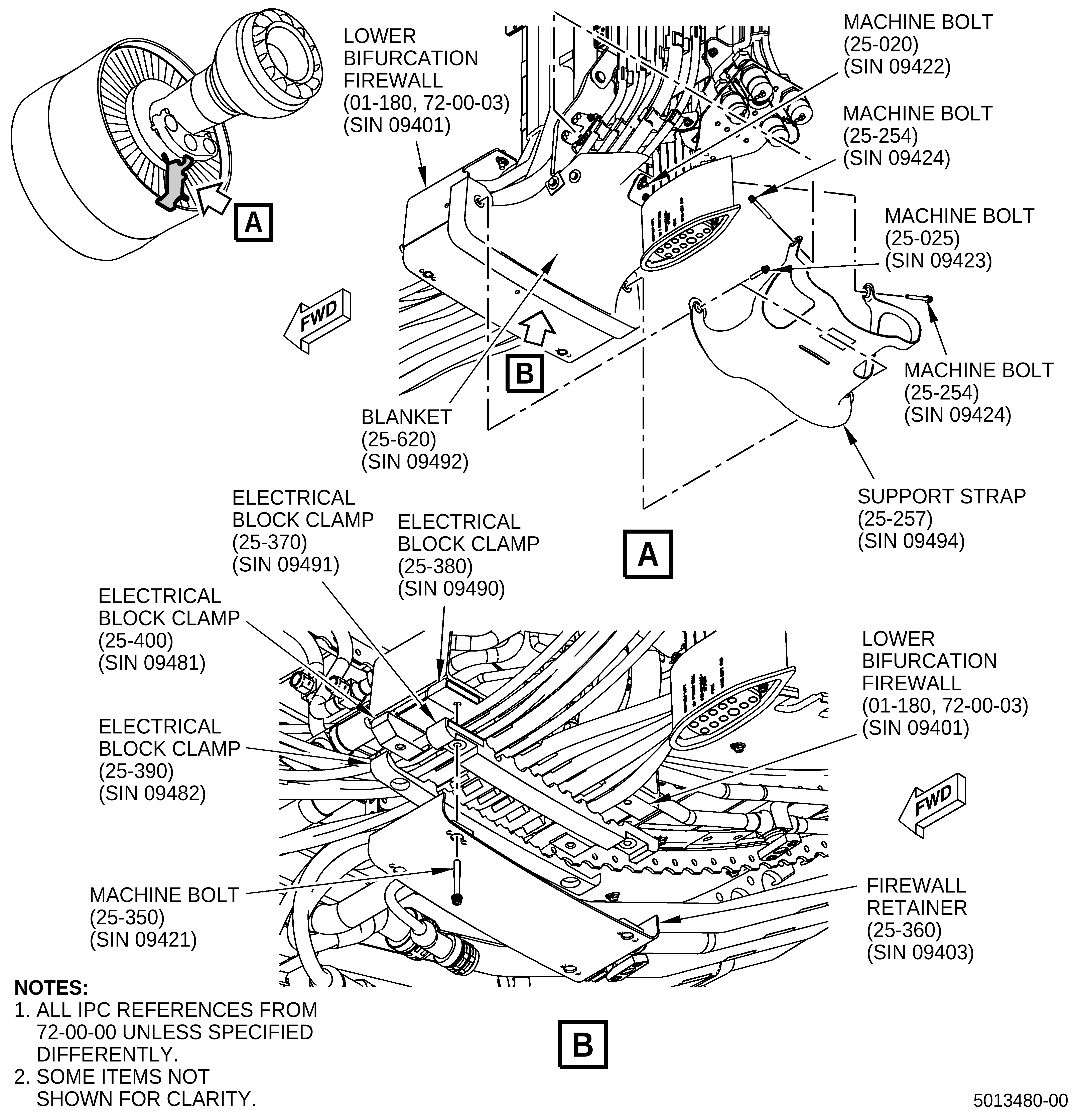
| (1) | Prepare lower bifurcation for wiring harness replacement. Refer to Figure 5 and do as follows: |
| (a) | Remove two machine bolts (25-254, 72-00-00) (SIN 09424). |
| (b) | Remove two machine bolts (25-025) (SIN 09423). |
| (c) | Remove one machine bolt (25-020) (SIN 09422) and support strap (25-257) (SIN 09494) from the engine. |
| (d) | Cut and remove the C10-071 safety wire from three places. |
| (e) | Remove the blanket (25-620) (SIN 09492) from the engine. |
| (f) | Keep all parts for later reinstallation in this procedure. |
| (g) | Remove four machine bolts (25-350) (SIN 09421) that attach the firewall retainer (25-360) (SIN 09403) to the lower bifurcation firewall (01-180, 72-00-03) (SIN 09401). |
| (h) | Remove the firewall retainer (25-360, 72-00-00) (SIN 09403) from the engine. |
| (i) | Remove the electrical block clamps (25-390) (SIN 09482), (25-370) (SIN 09491), (25-400) (SIN 09481), and (25-380) (SIN 09490). |
| G. | Replacement of the W12 Harness |
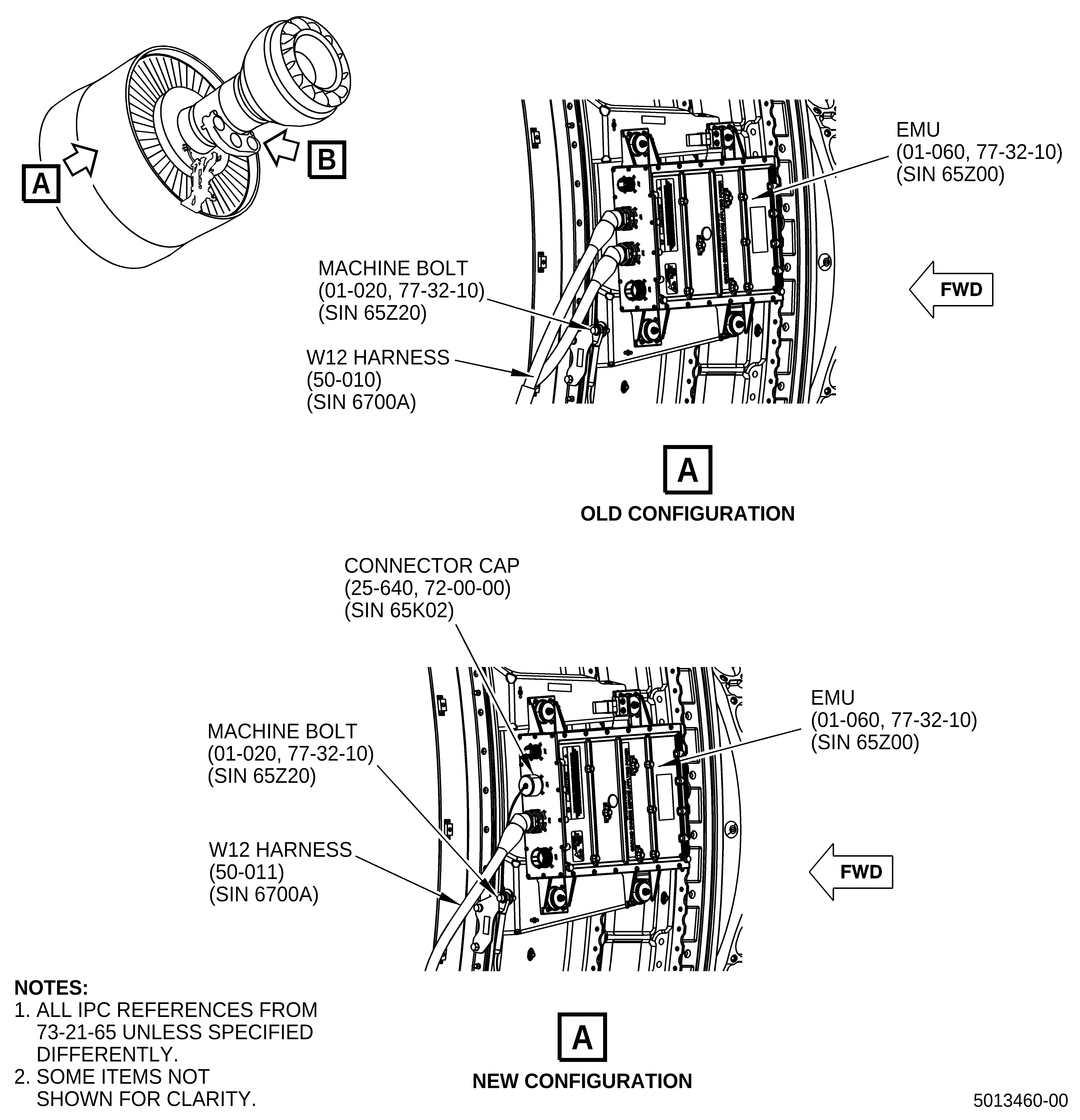
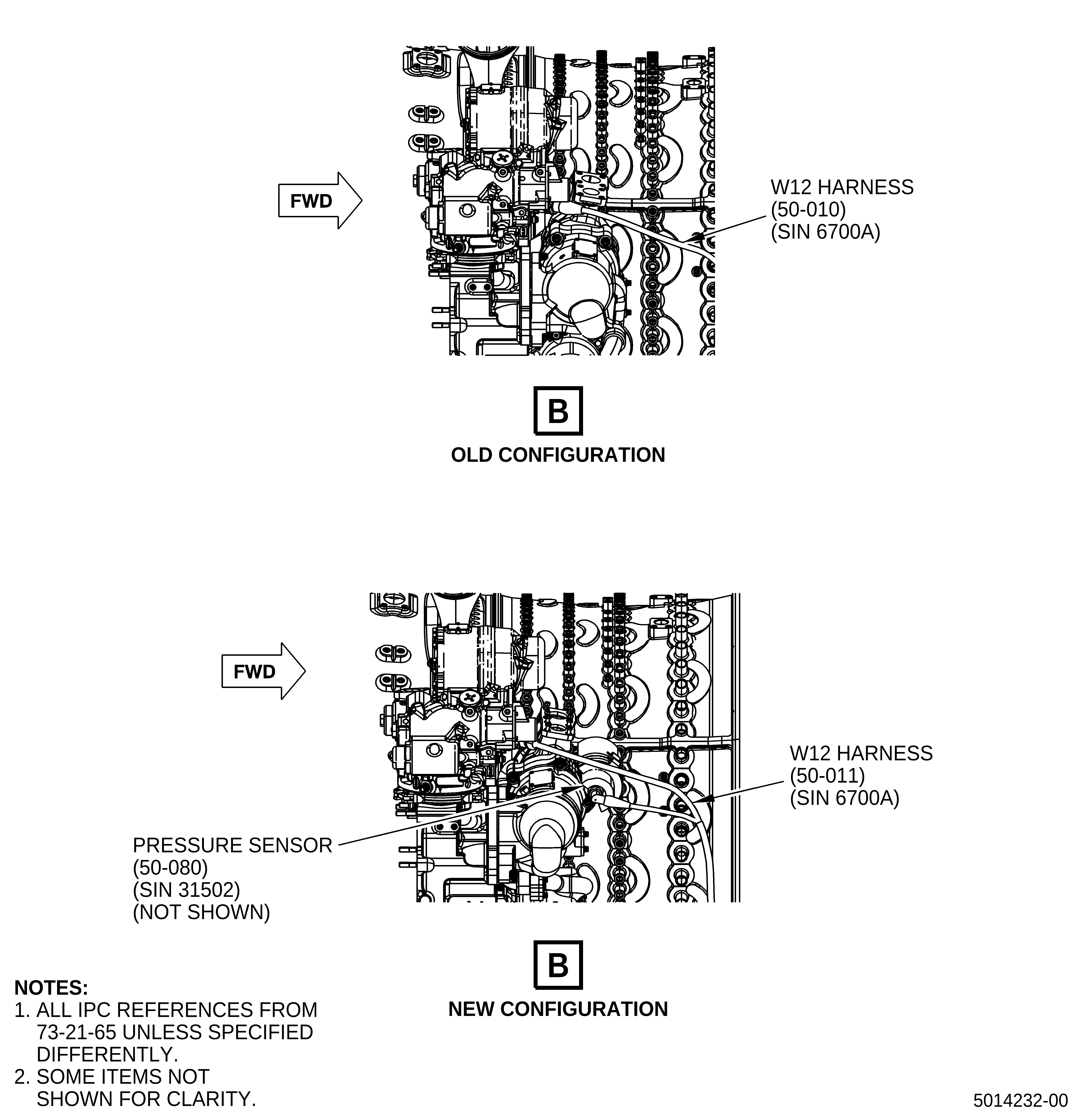
| (1) | Replace the old W12 harness (50-010, 73-21-65) (SIN 6700A). Refer to Figure 6 and do as follows: |
| (a) | Remove the W12 harness (50-010, 73-21-65) (SIN 6700A). Refer to the GEnx-1B Boeing 787 AMM, TASK B787-A-G73- 22-01-00A-520A-A. |
| (b) | Install the new W12 harness (50-011, 73-21-65) (SIN 6700A). Refer to the GEnx-1B Boeing 787 AMM, TASK B787-A-G73-22-01-00A-720A-A with the exception that there is an additional harness lead that connects to the pressure sensor (50-080, 73-21-65) (SIN 31502) and one less lead at the engine monitoring unit (EMU) (01-060, 77-32-10) (SIN 65Z00) connection. |
| H. | Installation of the Connector Cap |
| (1) | Install the new connector cap (25-640, 72-00-00) (SIN 65K02). Refer to Figure 6 and do as follows: |
| (a) | Use soft jaw pliers to install the connector cap (25-640, 72-00-00) (SIN 65K02) to the empty plug where the old W12 harness (50-011, 73-21-65) (SIN 6700A) second harness lead was connected to the EMU (01-060, 77-32-10) (SIN 65Z00). |
| (b) | Remove one machine bolt (01-020) (SIN 65Z20) and install the connector cap (25-640, 72-00-00) (SIN 65K02) and lanyard onto machine bolt (01-020, 77-32-10) (SIN 65Z20). |
| (c) | Install the machine bolt (01-020) (SIN 65Z20) again, with the lanyard installed, and torque to it 106-124 lb in. (12.0-14.0 N.m). |
| I. | Installation of the Insulation Blanket |
| (1) | Install the delta pressure sensor thermal insulation blanket (fire blanket) (50-140, 73-21-65) (SIN 31590). Refer to Figure 7 and do as follows: |
| (a) | Install the fire blanket (50-140, 73-21-65) (SIN 31590) onto the pressure sensor (50-080) (SIN 31502) with the overlapped section wrapped around the pressure sensor. |
| (b) | Make sure the fire blanket (50-140) (SIN 31590) covers both the pressure sensor (50-080) (SIN 31502) and the pressure sensor mounting pad on the fuel/oil heat exchanger (01-011, 79-21-00) (SIN 40700). |
| (c) | Use two hose clamps (50-130, 73-21-65) (SIN 31581) to attach the fire blanket (50-140) (SIN 31590) to the pressure sensor (50-080) (SIN 31502). Torque the hose clamps to 32-38 lb in. (3.6-4.3 N.m). |
| J. | Replacement of the W13 Harness |
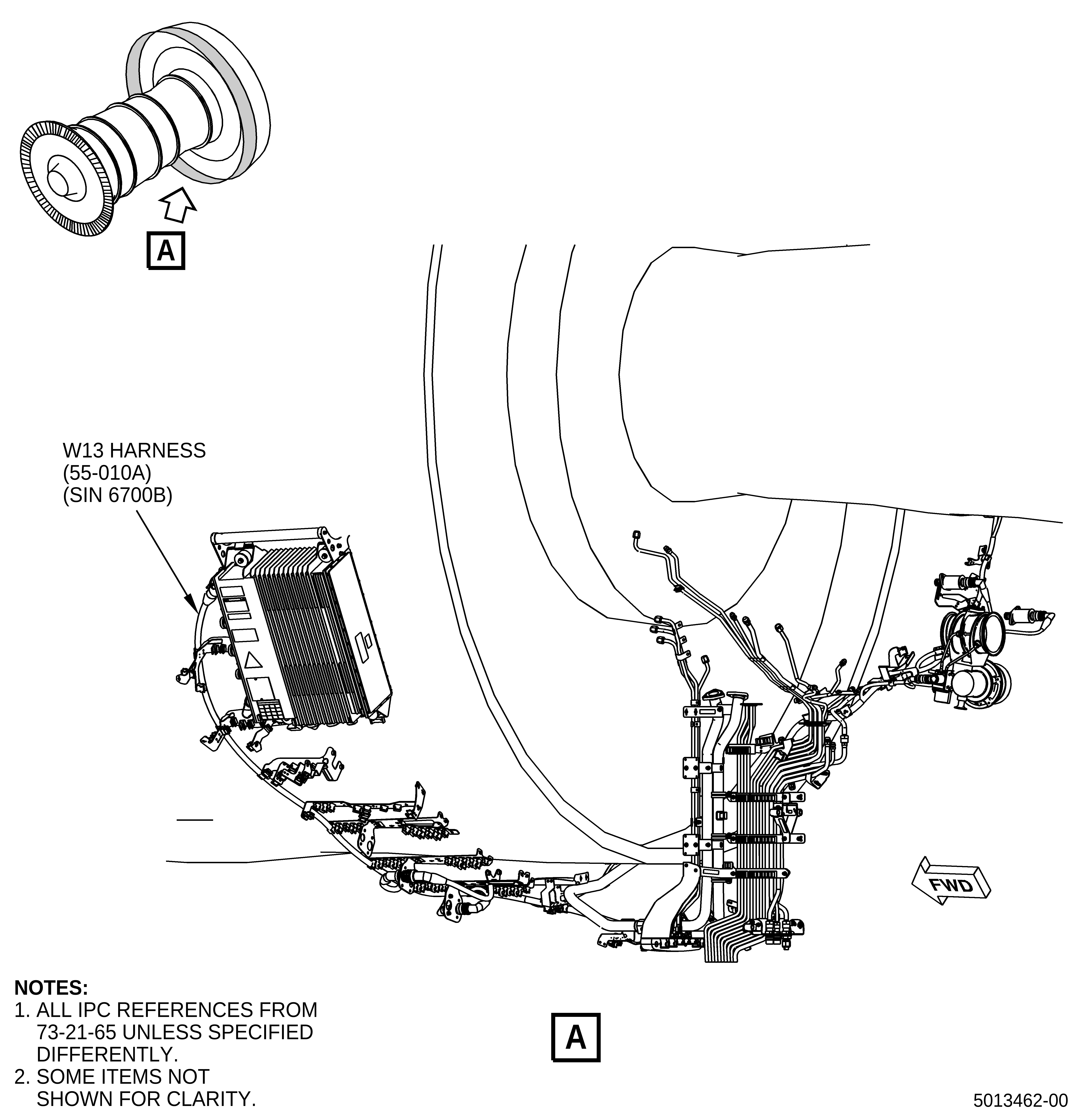
| (1) | Replace the old W13 harness (55-010A, 73-21-65) (SIN 6700B). Refer to Figure 8 and do as follows: |
| (a) | Remove the old W13 harness (55-010A, 73-21-65) (SIN 6700B). Refer to the GEnx-1B Boeing 787 AMM, TASK B787-A-G73-22-01-00A-520A-A. |
| CAUTION: |
|
| (b) | Install the new W13 harness (55-011, 73-21-65) (SIN 6700B). Refer to the GEnx-1B Boeing 787 AMM, TASK B787-A-G73-22-01-00A-720A-A. |
| (c) | Tighten the P133 connector with soft jawed pliers until there is no further rotation of the connector knurled ring. |
| K. | Reassembly of the Lower Bifurcation Assembly |
| (1) | Assemble the lower bifurcation assembly again. Refer to Figure 5 and do as follows: |
| (a) | Attach engine harnesses in the electrical block clamps (25-400, 72-00-00) (SIN 09481) and (25-380) (SIN 09490). |
| (b) | Install the electrical block clamps (25-390) (SIN 09482) and (25-370) (SIN 09491). |
| (c) | Install the firewall retainer (25-360) (SIN 09403) onto electrical block clamps (25-390) (SIN 09482) and (25-370) (SIN 09491). |
| (d) | Install four machine bolts (25-350) (SIN 09421) through the firewall retainer (25-360) (SIN 09403) and electrical block clamps (25-390) (SIN 09482) and (25-370) (SIN 09491) and thread them into the nut plates on the lower bifurcation firewall (01-180, 72-00-03) (SIN 09401). |
| (e) | Torque the four machine bolts (25-350, 72-00-00) (SIN 09421) to 106-124 lb in. (12.0-14.0 N.m). |
| (f) | Put the blanket (25-620) (SIN 09492) in position. |
| (g) | Install one machine bolt (25-020) (SIN 09422) and torque it to 32-38 lb in. (3.6-4.3 N.m). |
| (h) | Pull the blanket (25-620) (SIN 09492) tight around the electrical harnesses and firmly attach it with C10-071 safety wire or C10-143 safety cable. |
| (i) | Install the support strap (25-257) (SIN 09494) around the blanket (25-620) (SIN 09492) with bolthole grommets aligned with the boltholes where the machine bolts (25-254) (SIN 09424) and (25-025) (SIN 09423) were removed from. |
| (j) | Insert two machine bolts (25-025) (SIN 09423) through the support strap (25-257) (SIN 09494) and the blanket (25-620) (SIN 09492) and thread them into the nut plates on the lower bifurcation firewall (01-180, 72-00-03) (SIN 09401) hand-tight only. |
| (k) | Insert two machine bolts (25-254, 72-00-00) (SIN 09424) through the support strap (25-257) (SIN 09494) and thread them into the nut plates on the support bracket (25-270) (SIN 67115) on the left side and on the support bracket (25-300) (SIN 67116) on the right side. Torque the machine bolts (25-254) (SIN 09424) and (25-025) (SIN 09423) to 32-38 lb in. (3.6-4.3 N.m). |
| L. | Reprogram Configuration Box |
| CAUTION: |
|
| (1) | Connect the PMAT 2000 and reprogram only the monitoring configuration of the configuration box (01-010, 73-21-55) (SIN 65M00). Refer to Table 1 below and the GEnx-1B Boeing 787 AMM, TASK B787-A-G73-21-07-00A-752A-A. |
|
| NOTE: |
|
| M. | Post-Maintenance Operational Checks |
| (1) | Obey the AMM Power Plant Test Reference Table - Standard Practices requirements for main fuel/oil heat exchanger replacement. Refer to the GEnx-1B Boeing 787 AMM, TASK B787-A-G71-00-00-09A-950A-A Table 1. |