| GENX-1B ENGINE MANUAL | Dated: 09/24/2024 | |
| EM 72-00-02 , ASSEMBLY 002 | ||
| PROPULSOR ASSEMBLY - ASSEMBLY 002 - CONFIGURATION 01 | ||
| GENX-1B ENGINE MANUAL | Dated: 09/24/2024 | |
| EM 72-00-02 , ASSEMBLY 002 | ||
| PROPULSOR ASSEMBLY - ASSEMBLY 002 - CONFIGURATION 01 | ||
| * * * FOR 1B/P/G03.1B/P/G04.1B/P1/G01 |
| TASK 72-00-02-430-817 |
| 1 . | General. |
| A. | This procedure gives instructions to continue the assembly of the propulsor module assembly (propulsor assembly) (30-020 , 72-00-00) (SIN 0010C). This procedure installs the high pressure turbine (HPT) module on the high pressure compressor (HPC) module. The HPT module buildup includes the turbine center frame (TCF) (35-010) (SIN 92500), the HPT rotor assembly (34-020) (SIN 15000), the HPT stage 2 nozzle (stage 2 nozzle) (34-010) (SIN 17400), and the combustor diffuser nozzle (CDN) assembly (33-019) (SIN 0010A) or (33-020) (SIN 0010A). |
| CAUTION: |
|
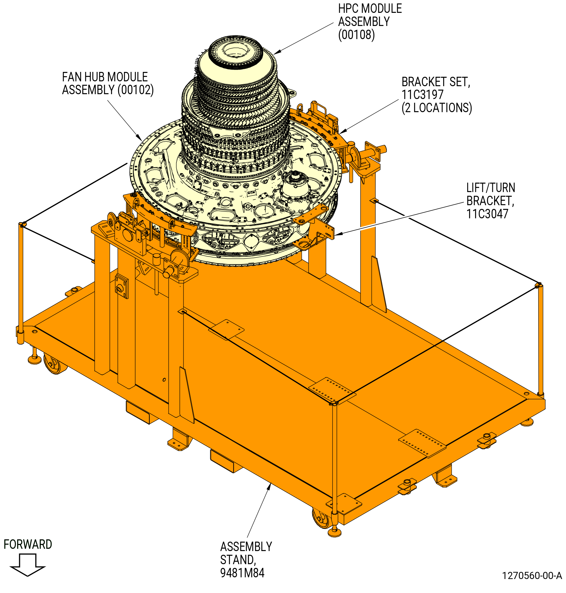
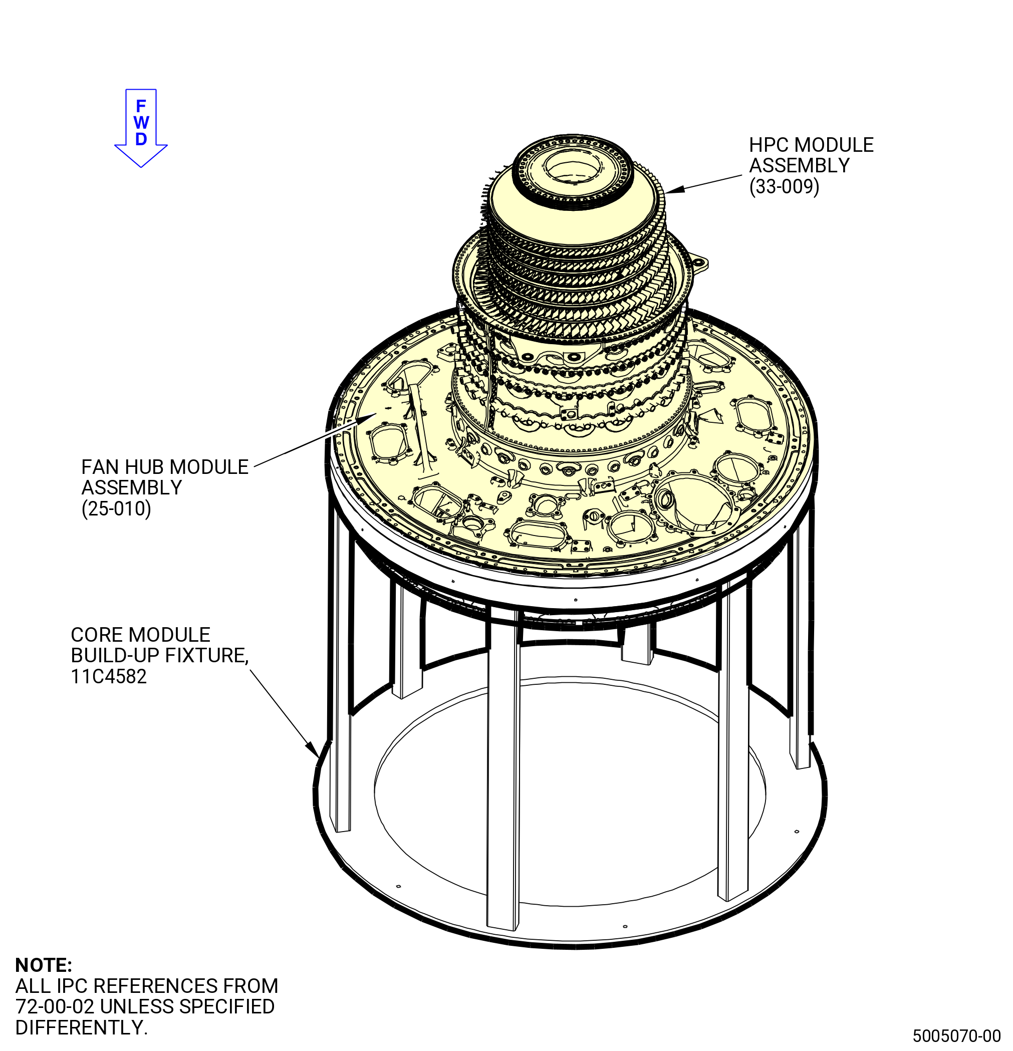
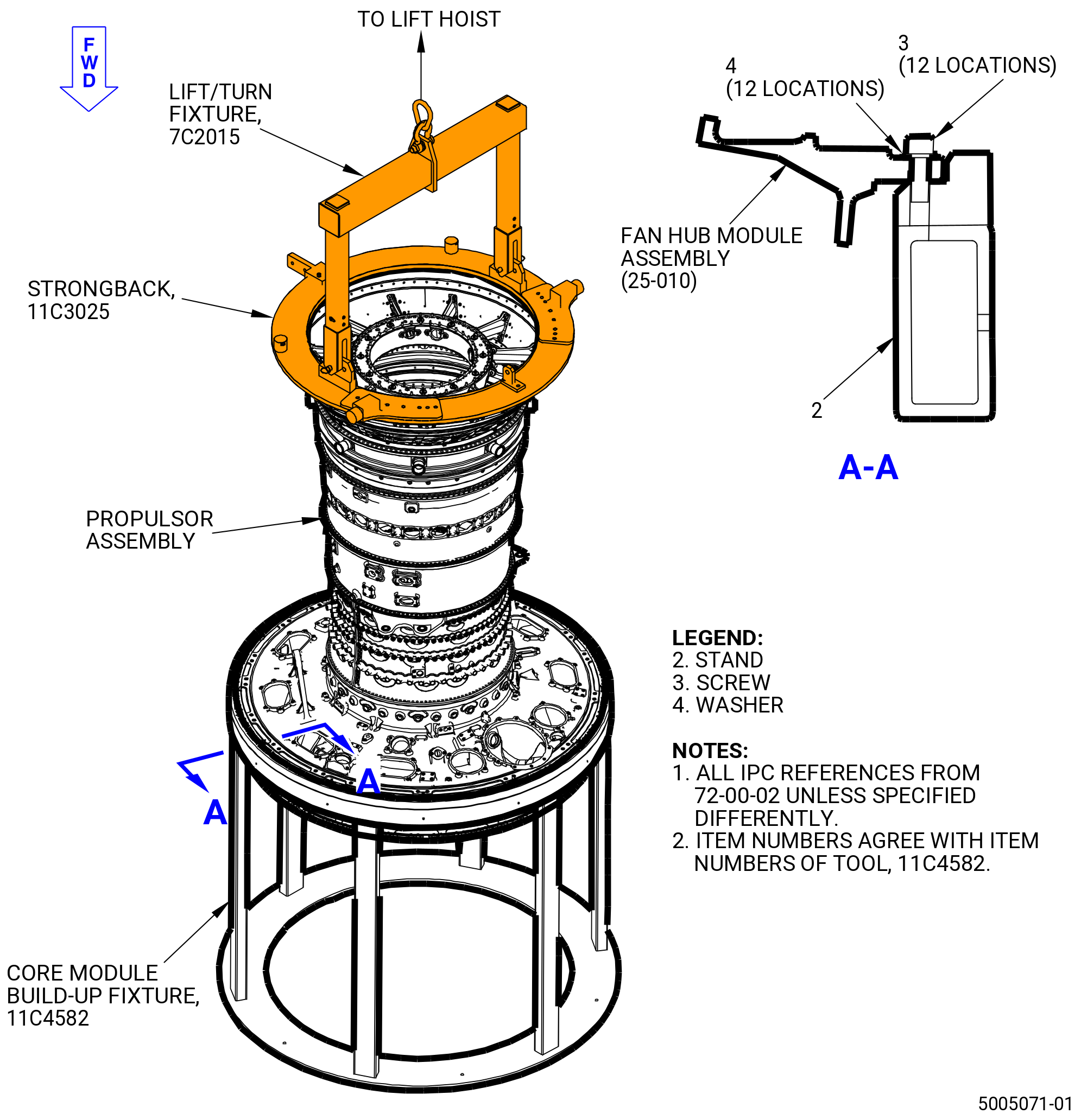
| B. | This procedure starts with the propulsor assembly in the vertical position on the 9481M84 assembly stand or 11C4582 core module build-up fixture at the equivalent build status of TASK 72-00-02-430-801 (72-00-02, ASSEMBLY 001). Refer to Figure 1001. |
| C. | Make sure that there is no foreign material in the assemblies and modules of the propulsor assembly. |
| D. | Do an inspection of the HPT rotor assembly (34-020) (SIN 15000) forward flange and the CDN assembly (33-019) (SIN 0010A) or (33-020) (SIN 0010A) aft flange for foreign material. Refer to TASK 72-00-02-200-801 (72-00-02, INSPECTION 001 ). |
| E. | Make sure that the mating parts are serviceable and have no deterioration. |
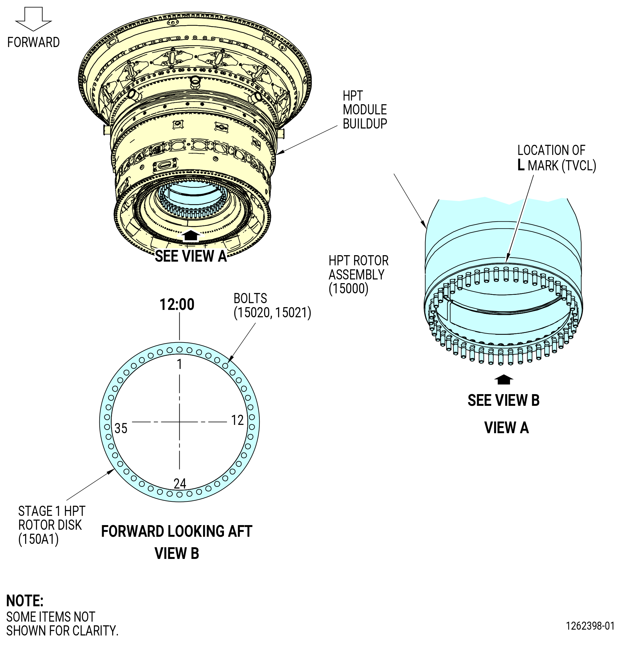
| F. | Make sure that you can see the L mark on the inside diameter of the HPT rotor. If not, use a C05-003 pen to add the L mark on the inside diameter of the HPT rotor (15000). Refer to Figure 1003. |
| G. | Make sure that the HPT rotor parts are in the correct position. |
| H. | Do an inspection to the parts for physical damage. |
| I. | Make sure that all the bolts (15020, 15021) are installed on the HPT rotor assembly forward flange and do not have thread damage. |
| J. | Make sure that the nuts (34-260) (SIN 15040) that you use have not been on an engine that was operated. |
| K. | Read this procedure and know the instructions and special tools before you install the assemblies and modules of the propulsor assembly. |
| L. | Install all bolts with the heads up or forward, unless specified differently. |
| M. | Clock positions are aft-looking-forward (ALF), unless specified differently. |
| WARNING: |
|
| WARNING: |
|
| WARNING: |
|
| N. | Make sure that the mating flanges are clean and free from damage as follows: |
| (1) | Make sure that the forward flanges of the CDN assembly (33-019) (SIN 0010A) or (33-020) (SIN 0010A), and the HPT rotor assembly (34-020) (SIN 15000) are clean and without nicks or raised metal. If not, clean the flanges with C04-002 Stoddard solvent, C04-003 acetone, or C04-035 isopropyl alcohol. |
| (2) | Make sure that the aft mateface of the CDP seal (050NC) and the HPC aft extension case (080AL) aft flanges are clean and free from nicks or raised metal. If not, clean the flanges with C04-002 Stoddard solvent, C04-035 isopropyl alcohol, or a 50-50 blend of C04-035 isopropyl alcohol and C04-228 denatured alcohol to clean the aft mateface surface of the CDP rotating seal. |
| O. | This assembly contains shafts that are very important. Critical areas of the shafts that require caution and a visual inspection during the assembly procedure, are identified throughout this procedure. Refer to Figure 1002. |
| P. | Make sure that the condition of the stationary CDP seal honeycomb (01-168 , 72-41-00) (SIN 08001) as either previous engine run or pre-grooved according to TASK 72-41-20-300-811 (72-41-20, REPAIR 010) before the HPT module build-up is installed onto an engine run rotating CDP seal (01-460 , 72-31-00) (SIN 050NC). Rotating CDP seal teeth must be restored to piece part serviceability in order to properly break in new stationary CDP seal honeycomb. |
| 2 . | Tools, Equipment, and Materials. |
| NOTE: |
|
| A. | Tools and Equipment. |
| (1) | Special Tools. |
| (2) | Standard Tools and Equipment. |
|
| (3) | Locally Manufactured Tools. None. |
| B. | Consumable Materials. |
|
| C. | Referenced Procedures. |
|
| D. | Expendable Parts. |
|
| 3 . | Procedure. |
| Subtask 72-00-02-430-711 |
| A. | Install the 11C3055 rotor lock on the aft end of the TCF assembly (35-009) (SIN 92500), (35-010) (SIN 92500), (35-011) (SIN 92500), (35-012) (SIN 92500), or (35-015) (SIN 92500). Refer to TASK 72-50-00-430-801 (72-50-00, ASSEMBLY 001). |
| WARNING: |
|
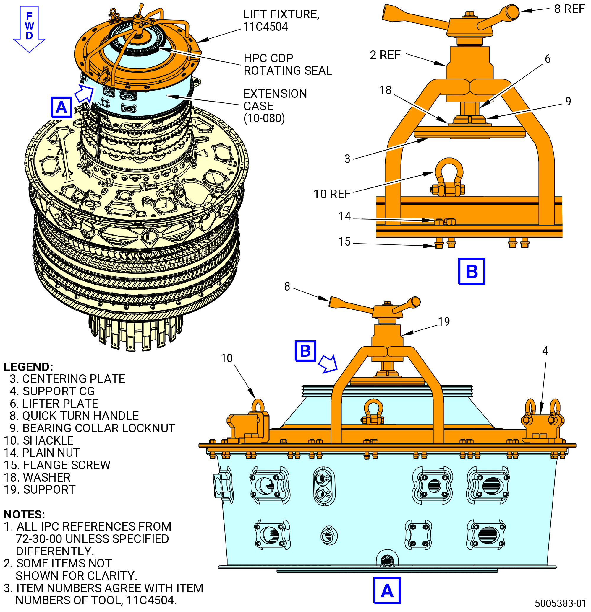
| (1) | Use a three-point vertical multi-leg sling and hooks with a minimum of 5000 lb (2268 kg) rated load and a minimum of 36.00 inches (914.4 mm) leg length to lift the 11C4504 lift fixture and put it above the extension case (10-080 , 72-30-00) (SIN 080AL). Refer to Figure 1004 and do as follows: |
| (a) | Turn the quick turn handle (item 8) to make sure that the centering plate (item 3) is fully retracted. |
| (b) | Remove the 24 flange screws (item 15) and plain nuts (item 14) from the 11C4504 lift fixture. |
| (c) | Put the 11C4504 lift fixture on the plate of the support (item 19) that is installed on the HPC extension case flange. |
| (d) | Align the hole pattern on the 11C4504 lift fixture and the extension case flange at the 12:00 o'clock position. |
| (e) | Install the 24 flange screws (item 15) and plain nuts (item 14) on the extension case to secure the 11C4504 lift fixture, but do not tighten them. |
| (f) | Tighten the 24 flange screws (item 15) and plain nuts (item 14) at the 12:00 o'clock position on the extension case. |
| (g) | Tighten the 24 flange screws (item 15) and plain nuts (item 14) at the 06:00 o'clock position on the extension case. |
| CAUTION: |
|
| (h) | Tighten the remaining flange screws (item 15) and plain nuts (item 14) in a criss-cross pattern. |
| (i) | Turn the bearing collar locknut (item 9) one-half turn CCW to let the centering plate (item 3) to float. |
| (j) | Use the quick turn handle (item 8) to vertically adjust the centering plate (item 3) until the plate face enters the inner diameter and it gets installed into the HPC CDP rotating seal. |
| NOTE: |
|
| NOTE: |
|
| CAUTION: |
|
| (k) | Turn the bearing collar locknut (item 9) CW against the washer (item 18) and lifter plate (item 6) to make sure that the hardware does not move. |
| (l) | Use the internal shackle (item 10) to lift the engine hardware assembly without the gearbox and the external shackle (item 10) to lift the engine hardware with the gearbox. |
| NOTE: |
|
| WARNING: |
|
| (m) | Use three-point vertical multi-leg sling to carefully lift and move the assembly to the necessary location. |
| (2) | Remove the 11C4504 lift fixture from the extension case. |
| Subtask 72-00-02-430-712 |
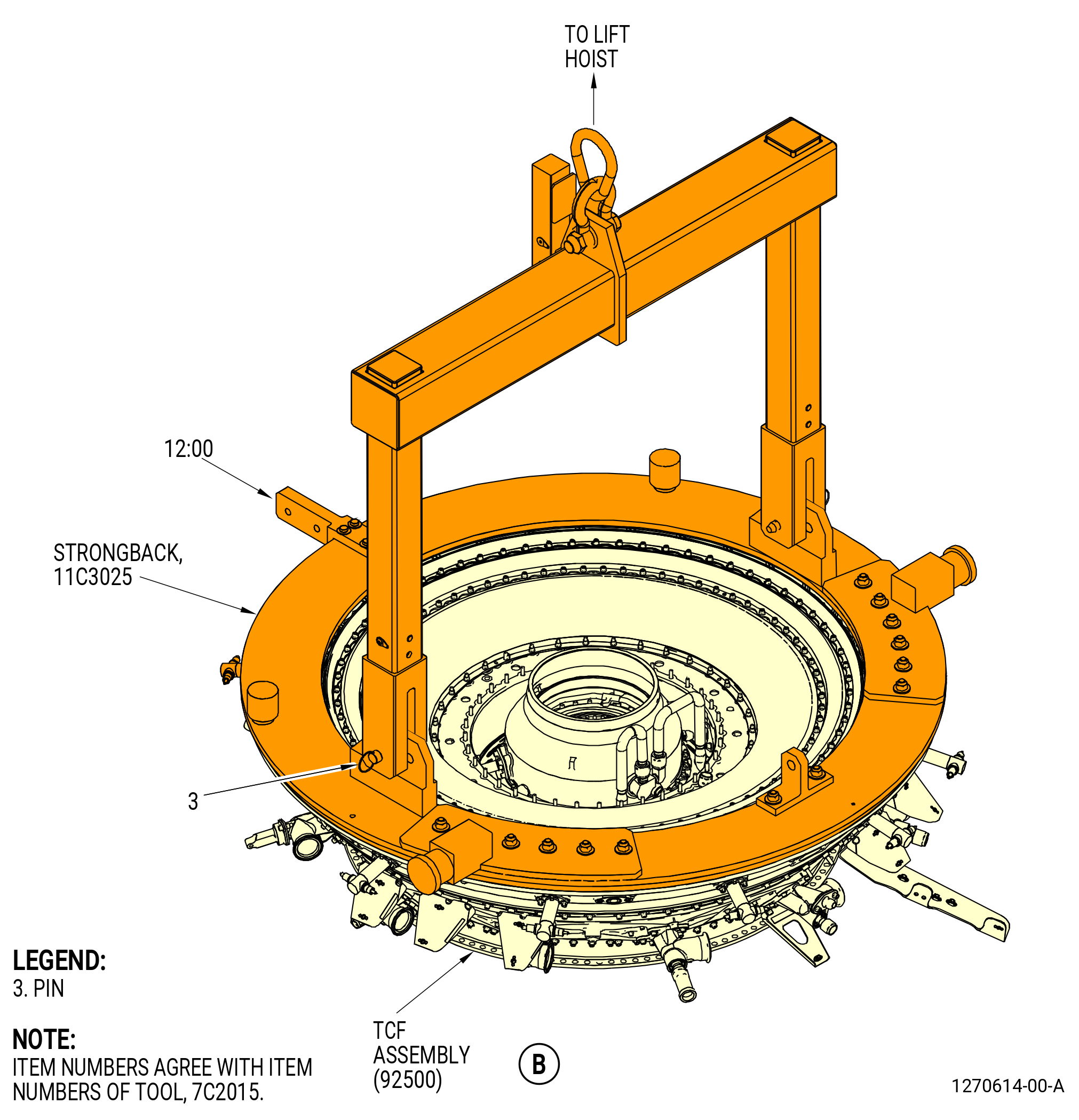
| B. | Install the 11C3025 strongback on the aft end of the TCF assembly (35-009) (SIN 92500), (35-010) (SIN 92500), (35-011) (SIN 92500), (35-012) (SIN 92500), or (35-015) (SIN 92500). Refer to TASK 72-50-00-430-801 (72-50-00, ASSEMBLY 001). The 7C2015 lift/turn fixture is attached to the 11C3025 strongback to lift the HPT module buildup. |
| Subtask 72-00-02-220-092 |
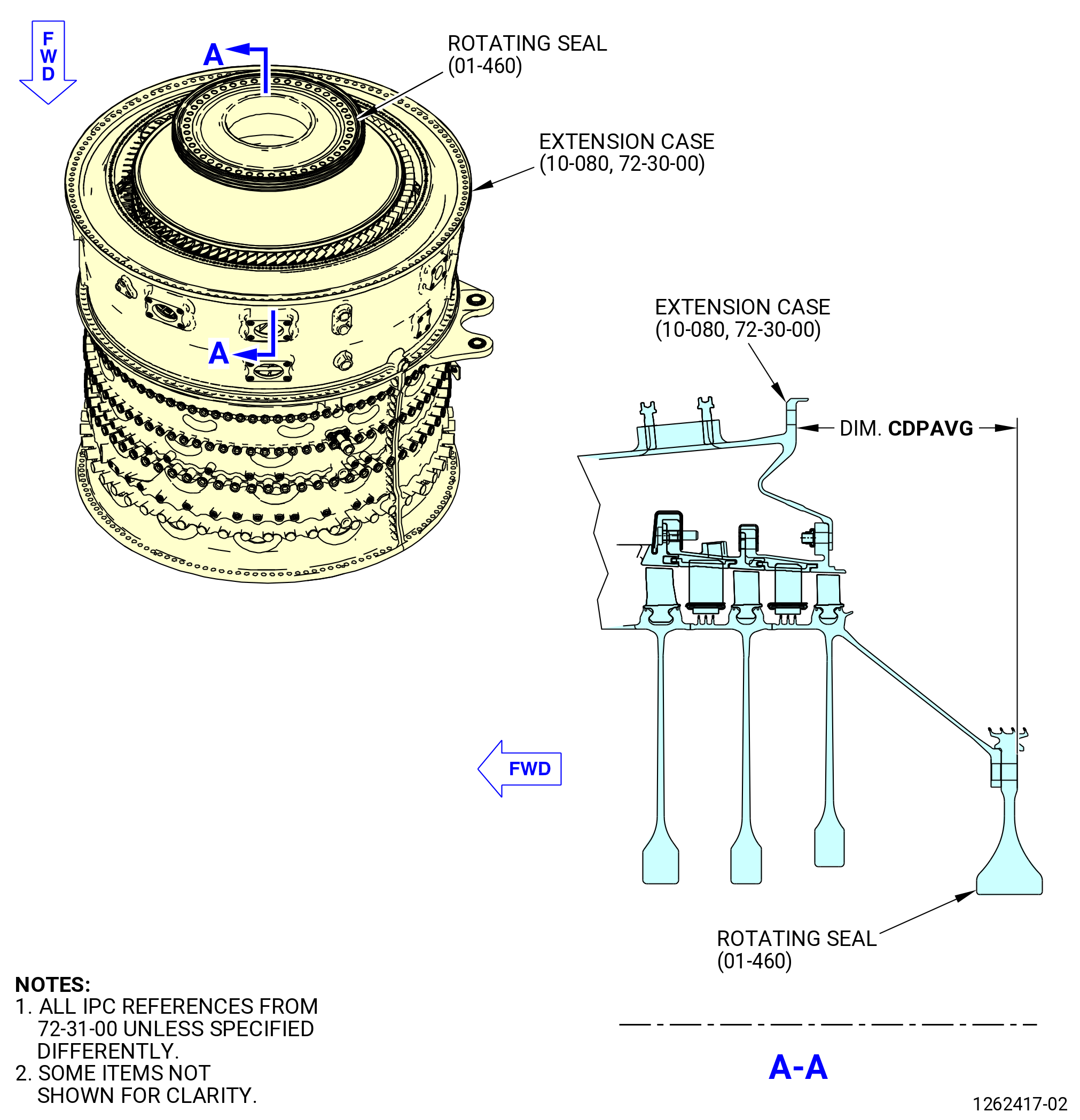
| C. | Measure from aft face of the rotating seal (050NC) to the HPC aft flange at four equally spaced locations. Record as CDPAVG. Refer to Figure 1005. |
| NOTE: |
|
| NOTE: |
|
| Subtask 72-00-02-220-093 |
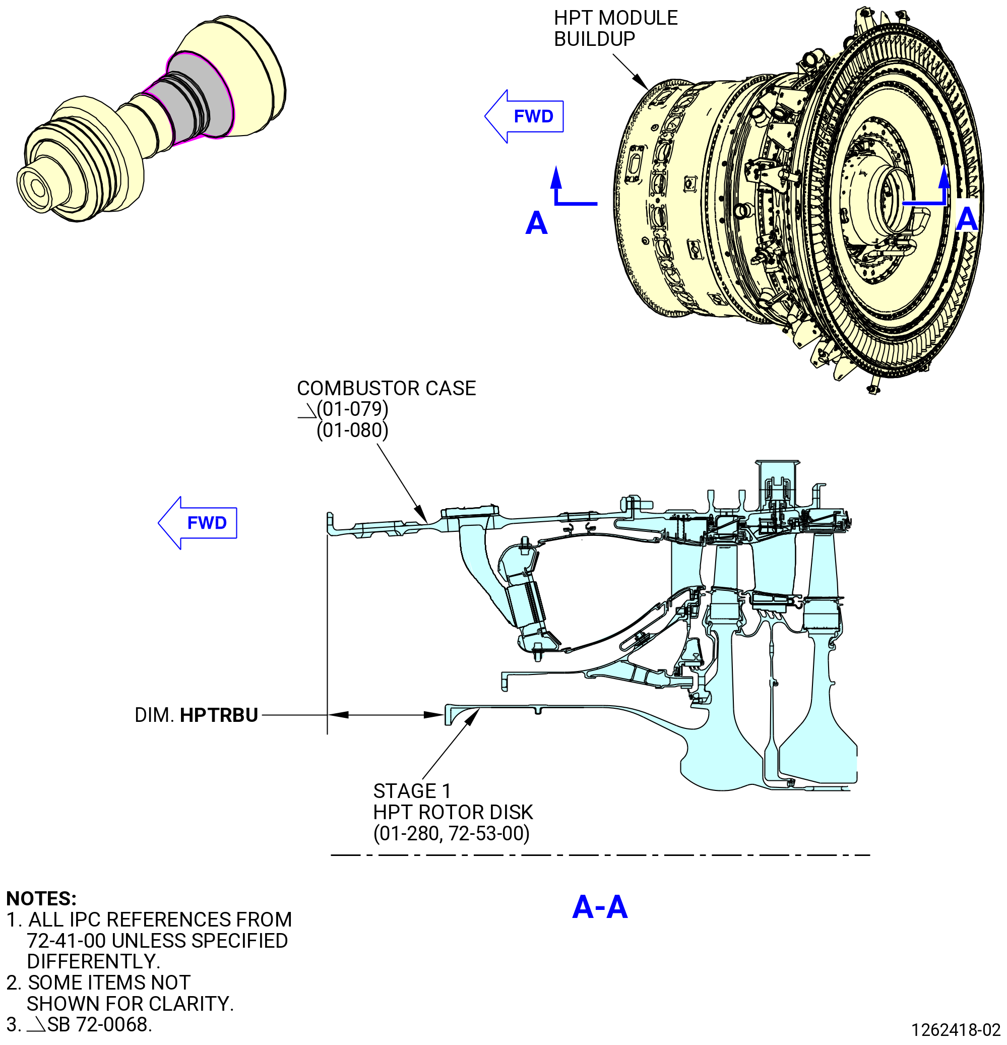
| D. | Measure and calculate the dimension from the forward flange of the CDN assembly (33-019) (SIN 0010A) or (33-020) (SIN 0010A) to the forward face on the HPT module buildup. Refer to Figure 1006. |
| WARNING: |
|
| (1) | Lift up the HPT module buildup with the 7C2015 lift/turn fixture attached to the 11C3025 strongback. |
| (2) | Measure from the forward flange of the CDN to the forward face of the HPT rotor shaft in four equally spaced locations. |
| (3) | Calculate the average dimension for HPTRBU. |
| Subtask 72-00-02-430-713 |
| E. | Calculate the HPT rotor forward position (HPTRPOS) as follows: |
| (1) | CDPAVG minus HPTRBU = HPTRPOS |
| (2) | The HPTRPOS measurement must be 0.060-0.080 inch (1.52-2.03 mm). |
| (3) | Record the HPT rotor forward position as HPTRPOS. |
| Subtask 72-00-02-431-054 |
| NOTE: |
|
| (4) | Alternative Procedure Available. Install the HPT module on the CDN. Refer to TASK 72-50-00-430-801 (72-50-00, ASSEMBLY 001) (paragraph 3.Q.) and (paragraph 3.G.). If the combustion case is assembled to HPC extension case do the HPTRPOS calculation as follows: |
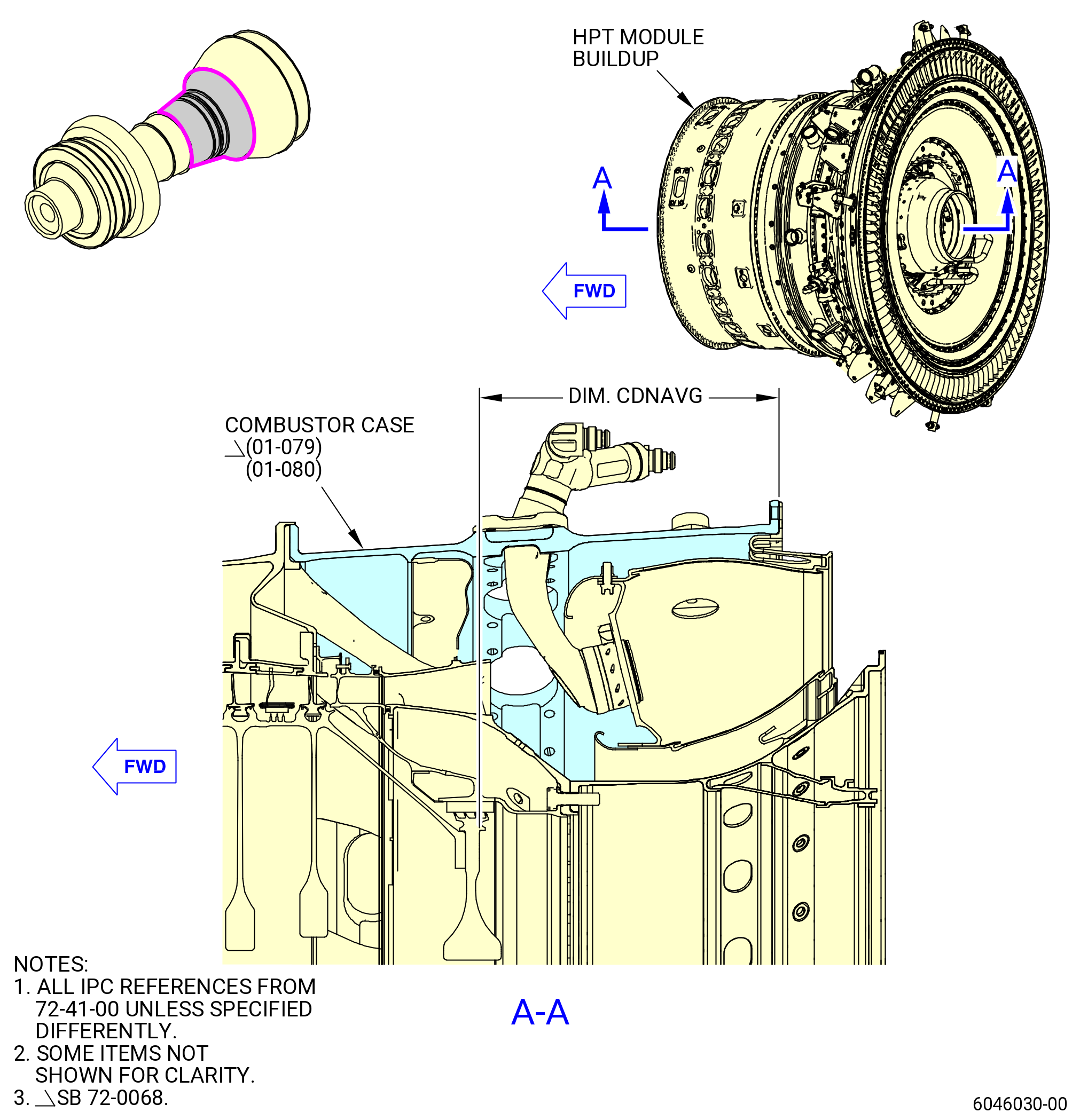
| (a) | Measure the CDNAVG from the aft face of the rotating seal (01-460 , 72-31-00) (SIN 050NC) to the aft flange surface of the combustor on the propulsor. Refer to Figure 1007. |
| 1 | Measure from the aft face of the rotating seal (01-460 , 72-31-00) (SIN 050NC) to the aft flange surface of the combustor at four equally-spaced locations. |
| 2 | Calculate the average dimension for CDNAVG. |
| 3 | Record as CDNAVG. |
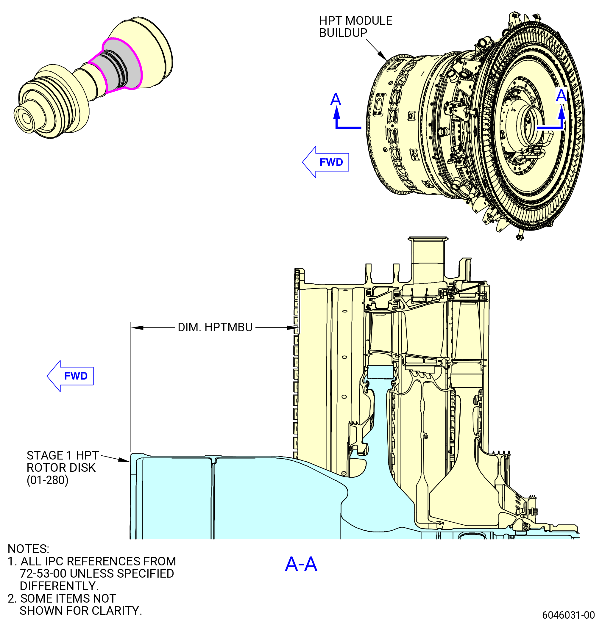
| (b) | Measure the HPTMBU dimension from the forward flange surface of the HPT case (01-490 , 72-52-00) (SIN 174B0) to the forward face of the stage 1 HPT rotor disk (01-280 , 72-53-00) (SIN 150A1) on the HPT module buildup. Refer to Figure 1008 and do as follows: |
| WARNING: |
|
| 1 | Lift up the HPT module buildup with the 7C2015 lift/turn fixture attached to the 11C3025 strongback. |
| 2 | Measure from the forward flange surface of the HPT case to the forward face of the stage 1 HPT rotor disk in four equally-spaced locations. |
| 3 | Calculate the average dimension for HPTMBU. |
| 4 | Record as HPTMBU. |
| (c) | Calculate the HPT rotor forward position (HPTRPOS) as follows: |
| 1 | HPTMBU minus CDNAVG = HPTRPOS |
| 2 | The HPTRPOS must be 0.060-0.080 inch (1.52-2.03 mm). |
| 3 | Record the HPT rotor forward position as HPTRPOS. |
| Subtask 72-00-02-640-030 |
| WARNING: |
|
| CAUTION: |
|
| F. | Lubricate the bolts (01-010 , 72-53-00) (SIN 15020) and (01-020 , 72-53-00) (SIN 15021) threads with C02-058 graphite. Make sure that the V-groove on the bolt threads has lubricant applied. Remove unwanted lubricant. No lubricant is permitted on the face of the HPT stage 1 disk. |
| Subtask 72-00-02-430-715 |
| G. | Make sure that the 11C3133 lock fixture is installed on the transfer gearbox (TGB) (03200). Refer to TASK 72-00-02-430-801 (72-00-02, ASSEMBLY 001) to install the lock fixture. |
| Subtask 72-00-02-430-716 |
| H. | Make sure that the air duct (34-310) (SIN 05002) is installed in the propulsor assembly. If not, refer to TASK 72-00-02-430-801 (72-00-02, ASSEMBLY 001, CONFIG 01) or TASK 72-00-02-430-821 (72-00-02, ASSEMBLY 001, CONFIG 02) to install the air duct. |
| Subtask 72-00-02-430-719 |
| I. | Put the HPT module buildup, HPT rotor assembly (15000) forward flange in dry ice as follows: |
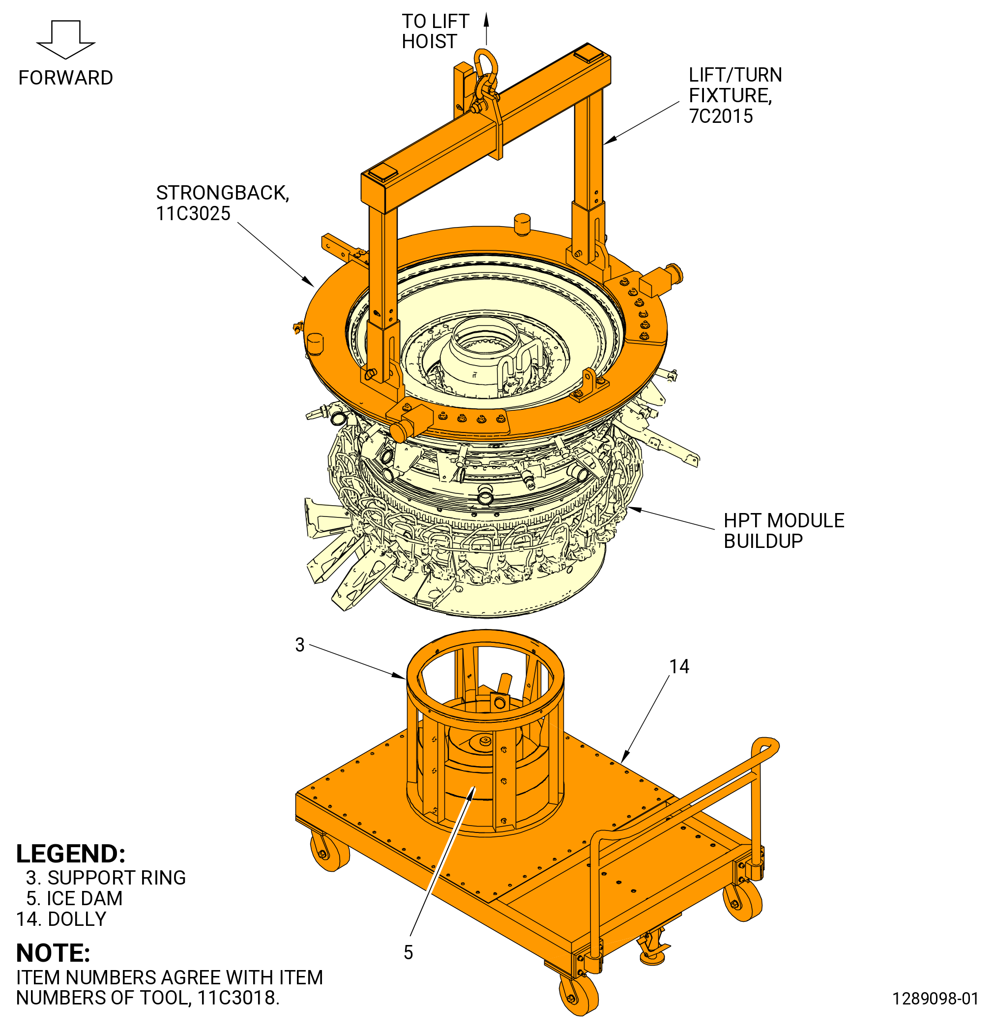
| (1) | Alternative Procedure Available. Put the ice dam (item 5) of the 11C3018 vertical support fixture in the position to hold dry ice. Refer to Figure 1010. |
| WARNING: |
|
| (a) | Put dry ice in the ice dam (item 5) of the 11C3018 vertical support fixture. |
| WARNING: |
|
| (b) | Lift the HPT module buildup and lower the HPT rotor assembly forward rotor seal (150A3) on the support ring (item 3) of the 11C3018 vertical support fixture. The HPT rotor assembly forward flange will be in the dry ice. Leave the HPT rotor assembly forward flange in the dry ice for 30 minutes. |
| (c) | Lift the HPT module buildup from 11C3018 vertical support fixture and the dry ice. |
| Subtask 72-00-02-430-786 |
| WARNING: |
|
| WARNING: |
|
| (1).A. | Alternative Procedure. Put the ice dam (item 5) of the 11C3018 vertical support fixture in the position to hold liquid nitrogen. Refer to Figure 1010. |
| WARNING: |
|
| (a) | Put liquid nitrogen in the ice dam (item 5) of the 11C3018 vertical support fixture. |
| WARNING: |
|
| (b) | Lift the HPT module buildup and lower the HPT rotor assembly forward rotor seal (150A3) on the support ring (item 3) of the 11C3018 vertical support fixture. The HPT rotor assembly forward flange will be in the liquid nitrogen. Leave the HPT rotor assembly forward flange in the liquid nitrogen until the liquid nitrogen is evaporated. |
| (c) | Lift the HPT module buildup from the 11C3018 vertical support fixture and liquid nitrogen. |
| Subtask 72-00-02-430-717 |
| CAUTION: |
|
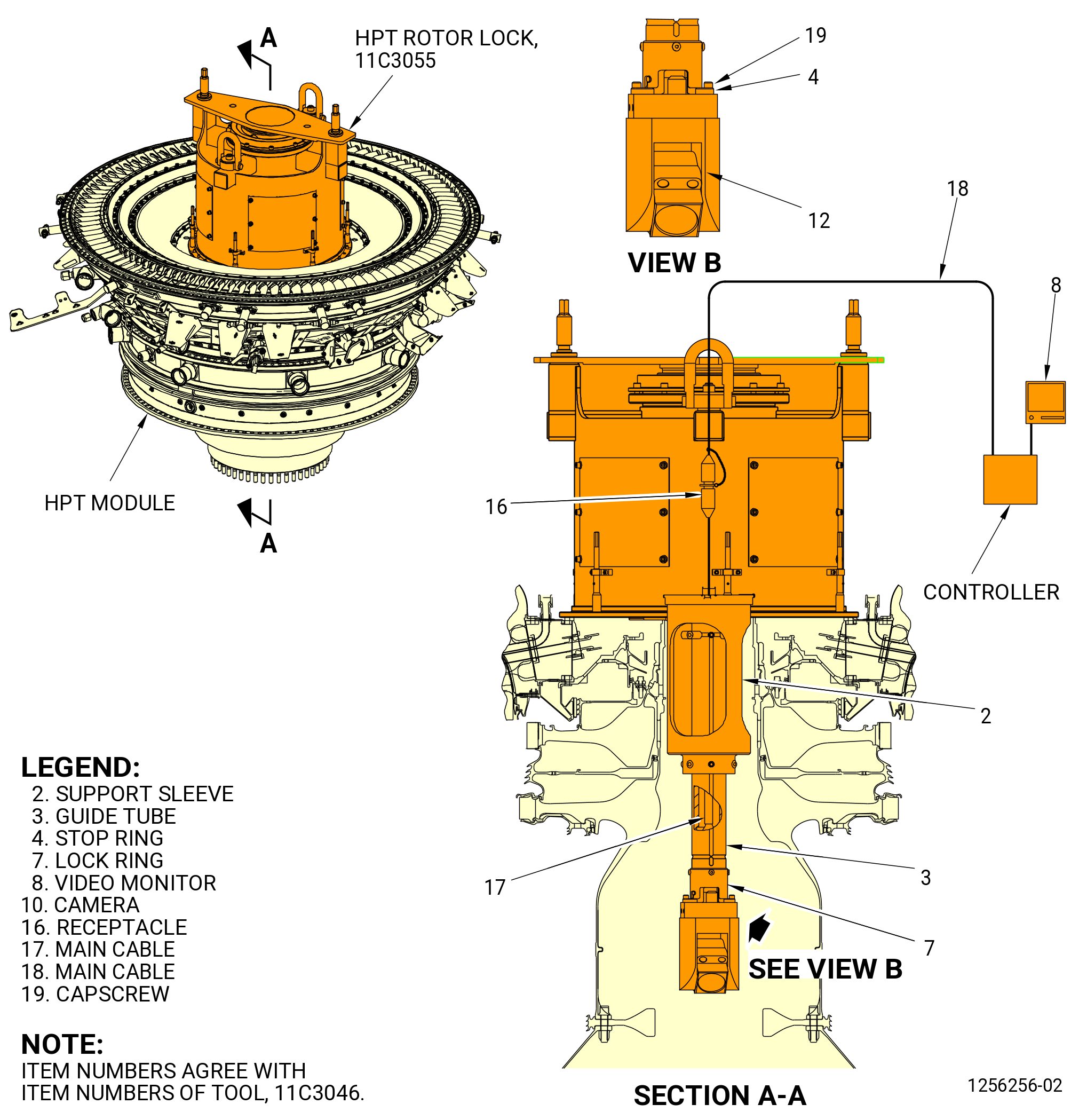
| J. | Alternative Procedure Available. Prepare the 11C3046 camera kit in the HPT rotor assembly (15000) as follows. Refer to Figure 1009. |
| (1) | Put the 11C3046 camera kit on the aft end of the HPT rotor assembly as follows: |
| (a) | Put the support sleeve (item 2) on the aft end of the HPT rotor assembly. The tabs on the support sleeve (item 2) will fit in the castellated ridge of the HPT rotor assembly. |
| Subtask 72-00-02-430-718 |
| (2) | Install the 11C3046 camera kit as follows: |
| (a) | Put the cable assembly through the threaded tube of the 11C3055 rotor lock. |
| (b) | Attach the main cable (item 17) to the receptacle (item 16). |
| (c) | Attach the main cable (item 18) to the receptacle (item 16). |
| (d) | Put the main cable (item 17) through the guide tube (item 3). |
| (e) | Attach the camera (item 10) to the lock ring (item 7) with the stop ring (item 4) and capscrews (item 19). |
| (f) | Attach the camera (item 10) and lock ring (item 7) assembly to the guide tube (item 3). |
| (g) | Attach the main cable (item 18) to the controller. |
| (h) | Set the video monitor (item 8) switch to operate on 110 VAC or 220 VAC 50/60 Hz electrical power. |
| (i) | Connect the video monitor (item 8) to the electrical power source. |
| Subtask 72-00-02-430-781 |
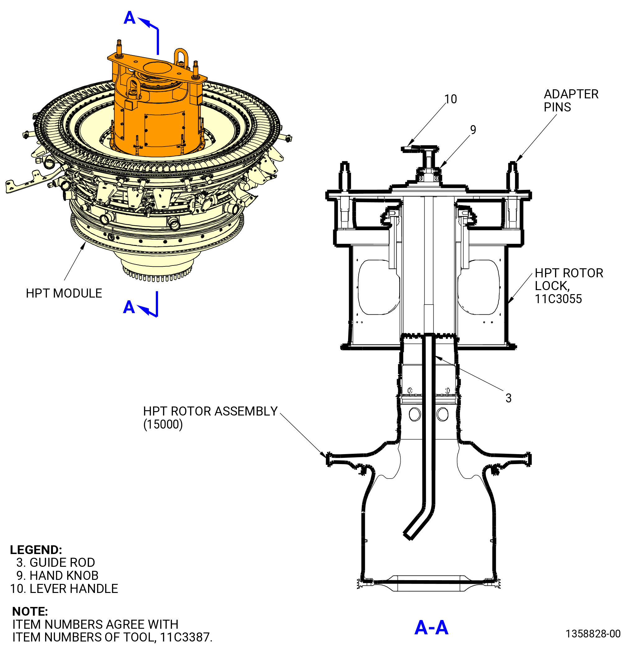
| J.A. | Alternative Procedure. Install the 11C3387 borescope guide in the HPT rotor assembly (15000) as follows. Refer to Figure 1009. |
| (1) | Put the 11C3387 borescope guide on the 11C3055 HPT rotor lock and secure with adapter pins. |
| (2) | Install the borescope in the guide rod (item 3) of the borescope guide. |
| (3) | Loosen two hand knobs (item 9) and use lever handle (item 10) to rotate the guide rod (item 3). |
| Subtask 72-00-02-430-720 |
| CAUTION: |
|
| K. | Install the HPT module build-up onto the propulsor assembly as follows. Refer to Figure 1011. |
| (1) | Make sure that the TVCL offset holes are marked on the CDN assembly (33-019) (SIN 0010A) or (33-020) (SIN 0010A) forward flange. If not, put a mark on the TVCL offset holes on the CDN forward flange with a C05-003 pen. |
| WARNING: |
|
| CAUTION: |
|
| (2) | Align the TVCL marks and slowly lower the HPT module build-up onto the propulsor assembly. Make sure that the HPT rotor radial seals engage in the correct position in the honeycomb of the propulsor assembly. |
| (3) | Make sure that the letter “T” is marked on the CDN forward flange and HPC aft flange with a C05-003 pen. |
| (4) | Make sure that the air duct (05002) is installed. |
| (5) | Use the 11C3046 camera kit or borescope with the 11C3387 borescope guide to align the L mark on the stage 1 HPT rotor disk (150A1) with the H mark on the HPC rotor (05000). |
| (6) | Lower the HPT module build-up onto the propulsor assembly until there is only a small gap between the HPC flange on the propulsor and the HPT rotor bolts (01-010 , 72-53-00) (SIN 15020), (01-020 , 72-53-00) (SIN 15021). |
| (7) | Carefully turn the HPT rotor assembly (15000) to allow the bolts (15020, 15021) to drop into the flange boltholes. |
| (8) | Lower the HPT module buildup until it seats on the propulsor assembly. |
| (9) | Use the 11C3046 camera kit or borescope with the 11C3387 borescope guide to view the inside diameter of the flanges as follows: |
| (a) | Make sure that the flanges touch and there are no gaps. |
| CAUTION: |
|
| (b) | Make sure that the high runout (H) and the low runout (L) marks are aligned. If not, the engine will not operate correctly. |
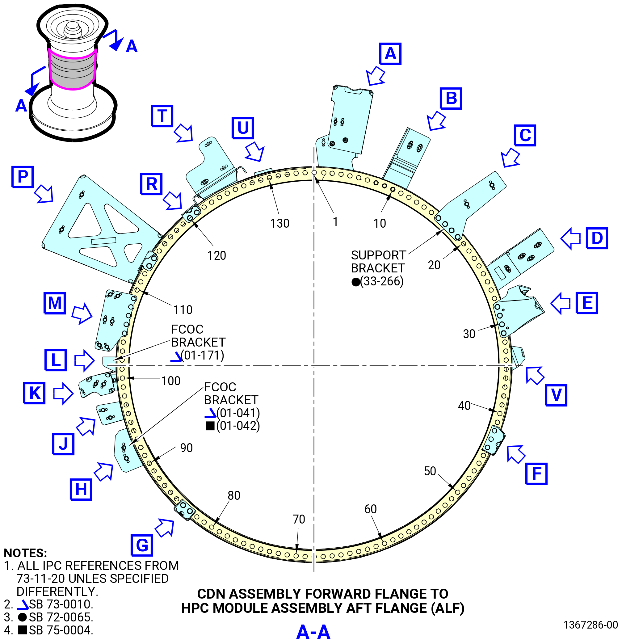
| (10) | Number the boltholes locations in increments of 10 with a C05-003 pen on the forward flange of the CDN assembly. Begin at the TVCL with bolthole No. 1 in a clockwise (CW) direction (ALF). |
| Subtask 72-00-02-640-031 |
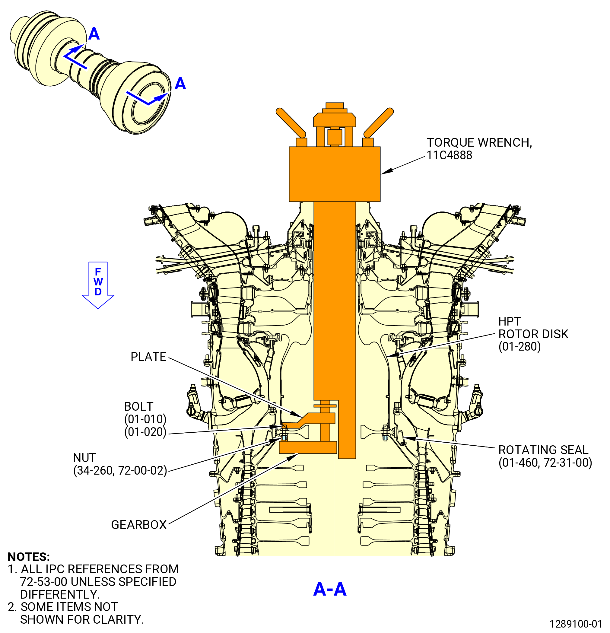
| (11) | Lubricate the threads and mating faces of the 46 bolts (15020) and 46 nuts (34-260) (SIN 15040) with C02-058 graphite. Refer to Figure 1012. |
| Subtask 72-00-02-430-721 |
| (12) | Install the bolts in boltholes 4, 15, 27, 37, 47, 57, 67, 77, 87, 98, 110, 119, and 131 on the extension case (10-080 , 72-30-00) (SIN 080AL) aft flange and the CDN assembly (33-019) (SIN 0010A) or (33-020) (SIN 0010A) forward flange. Make sure that the boltheads are forward. Tighten the nuts. Do not torque at this time. |
| (13) | Use the 11C3046 camera kit to view the inside diameter of the HPT rotor assembly (15000) and the rotating seal (050NC). Make sure that the flanges touch and there are no gaps. |
| Subtask 72-00-02-430-722 |
| (14) | Alternative Procedure Available. Remove the 11C3046 camera kit. Refer to Figure 1009. |
| (a) | Turn off the power and disconnect the video monitor (item 8) from the electrical power source. |
| (b) | Disconnect the main cable (item 18). |
| (c) | Disconnect the camera (item 10) and lock ring (item 7) assembly from the guide tube (item 3). |
| (d) | Disconnect the main cable (item 18) from the receptacle (item 16). |
| (e) | Disconnect the main cable (item 17) from the receptacle (item 16). |
| (f) | Remove the 11C3046 camera kit. |
| Subtask 72-00-02-430-779 |
| (14).A. | Alternative Procedure. Remove borescope and the 11C3387 borescope guide from the HPT rotor assembly (15000). Refer to Figure 1009. |
| Subtask 72-00-02-430-780 |
| (15) | Remove the 11C3055 HPT rotor lock from the aft end of the HPT rotor assembly (15000). Refer to TASK 72-50-00-030-801 (72-50-00, Disassembly 001). |
| (16) | Make sure that no tooling or foreign material is inside the HPT rotor assembly (34-020) (SIN 15000) and the propulsor assembly. |
| (a) | Move the air duct (05002) forward until the 11C4888 torque wrench can be installed. |
| Subtask 72-00-02-430-771 |
| (b) | Install the 11C4888 torque wrench into the HPT rotor assembly. Refer to Figure 1012 and do as follows: |
| 1 | Put the sliding gearbox inside the 11C4888 torque wrench until the gearbox can slide. |
| CAUTION: |
|
| 2 | Put the 11C4888 torque wrench into the HPT rotor assembly. Make sure that the index ring handle is in line with the 1-1 slot on the HPT rotor assembly. |
| 3 | Use a C05-003 pen and make a 1-1 mark on the inside of the HPT rotor assembly. |
| 4 | Connect the sensor cable to the 11C4888 torque wrench. |
| Subtask 72-00-02-430-723 |
| (17) | Install the self-locking nuts (nuts) (34-260) (SIN 15040) on the bolts (01-010 , 72-53-00) (SIN 15020), (01-020 , 72-53-00) (SIN 15021) in the HPT rotor assembly (34-020) (SIN 15000) and the propulsor assembly. The bolts (01-010 , 72-53-00) (SIN 15020), (01-020 , 72-53-00) (SIN 15021) are installed in the aft side of the HPT rotor disk (01-280 , 72-53-00) (SIN 150A1) forward flange with the boltheads aft. The self-locking nuts are installed on the forward side of the rotating seal (01-460 , 72-31-00) (SIN 050NC) aft flange as follows. Refer to Figure 1012. |
| CAUTION: |
|
| (a) | If you drop a self-locking nut into the propulsor assembly, record that you found the self-locking nut to make sure that all the self-locking nuts were installed. |
| (b) | Install the 46 nuts (34-260) (SIN 15040) on the bolts (15020, 15021) and torque according to the instructions on the 11C4888 torque wrench computer. |
| (c) | Torque the self-locking nut to 200 lb in. (22.6 N.m). |
| (d) | Loosen the self-locking nut one full turn. |
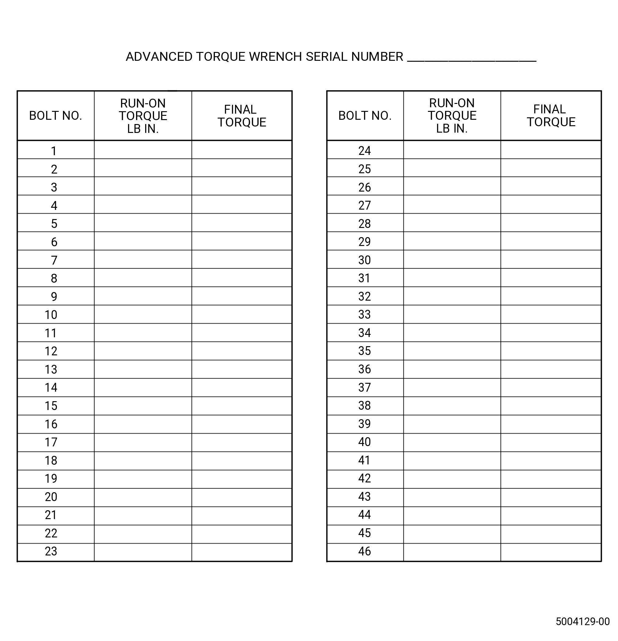
| (e) | Tighten the self-locking nut one-half turn and record the run-on torque and make sure the run-on torque is 15-100 lb in. (1.7-11.3 N.m). |
| (f) | If the run-on torque is not in limits, loosen the self-locking nut one full turn and do the run-on torque again. Record the run-on torque. Refer to Figure 1013. |
| NOTE: |
|
| (g) | Loosen the self-locking nut a minimum of one full turn, and torque the self-locking nut to 70.0 lb in. (7.91 N.m) plus the run-on torque. |
| (h) | Set the 11C4888 torque wrench to read zero degrees. |
| (i) | Turn the self-locking nut 54-58 degrees in a CW direction to tighten and as follows: |
| 1 | Make sure that the maximum torque is not more than 850 lb in. (96.0 N.m). |
| 2 | If the angle or torque is more than the maximum limit, remove and discard the associated bolt and nut. |
| 3 | Replace with a new bolt and nut. |
| (j) | Disconnect the sensor cable from the 11C4888 torque wrench. |
| (k) | Remove the 11C4888 torque wrench from the HPT rotor assembly. |
| (18) | Do an inspection of CDP bolts and nuts as follows. Make sure you can see 2 to 2-1/2 bolt threads that extend above the nut. If not, find the cause and replace the bolt and nut. |
| Subtask 72-00-02-430-782 |
| (a) | Alternative Procedures Available. Use a mirror and a light to do the inspection. |
| Subtask 72-00-02-430-783 |
| (a).A. | Alternative Procedure. Install the 11C3046 camera kit. Refer to Subtask 72-00-02-430-717 (paragraph 3.J.). |
| 1 | After inspection remove the camera kit. Refer to Subtask 72-00-02-430-722 (paragraph 3.K.(14)). |
| Subtask 72-00-02-430-784 |
| (a).B. | Alternative Procedure. Install 11C3387 borescope guide, and use borescope. Refer to Subtask 72-00-02-430-781 (paragraph 3.J.A.). |
| 1 | After inspection remove borescope and the 11C3387 borescope guide from the HPT rotor assembly (15000). Refer to Subtask 72-00-02-430-779 (paragraph 3.K.(14)A.) and Figure 1009. |
| Subtask 72-00-02-430-785 |
| (19) | Remove the 9C1276 bore protector from the stage 10 bore of the stages 6-10 compressor rotor spool (compressor rotor spool) (050AR). |
| Subtask 72-00-02-210-025 |
| (20) | Do a visual inspection of the HPC rotor (05000) and the HPT rotor (15000) as follows: |
| (a) | Make sure that the balance bolts (15021) are in the correct position on the HPT rotor. |
| (b) | Make sure that there is no tooling or foreign material inside the propulsor assembly. |
| (c) | Check the joint where the HPC rotor (05000) aft end mates to the HPT rotor forward end. Make sure that they are aligned correctly. |
| (d) | Do a general visual inspection of the exposed surfaces of HPT rotor stage 1 disk for nicks, dents, and scratches after the removal of tooling. Refer to TASK 72-00-53-200-802 (72-00-53, INSPECTION 001). |
| Subtask 72-00-02-480-004 |
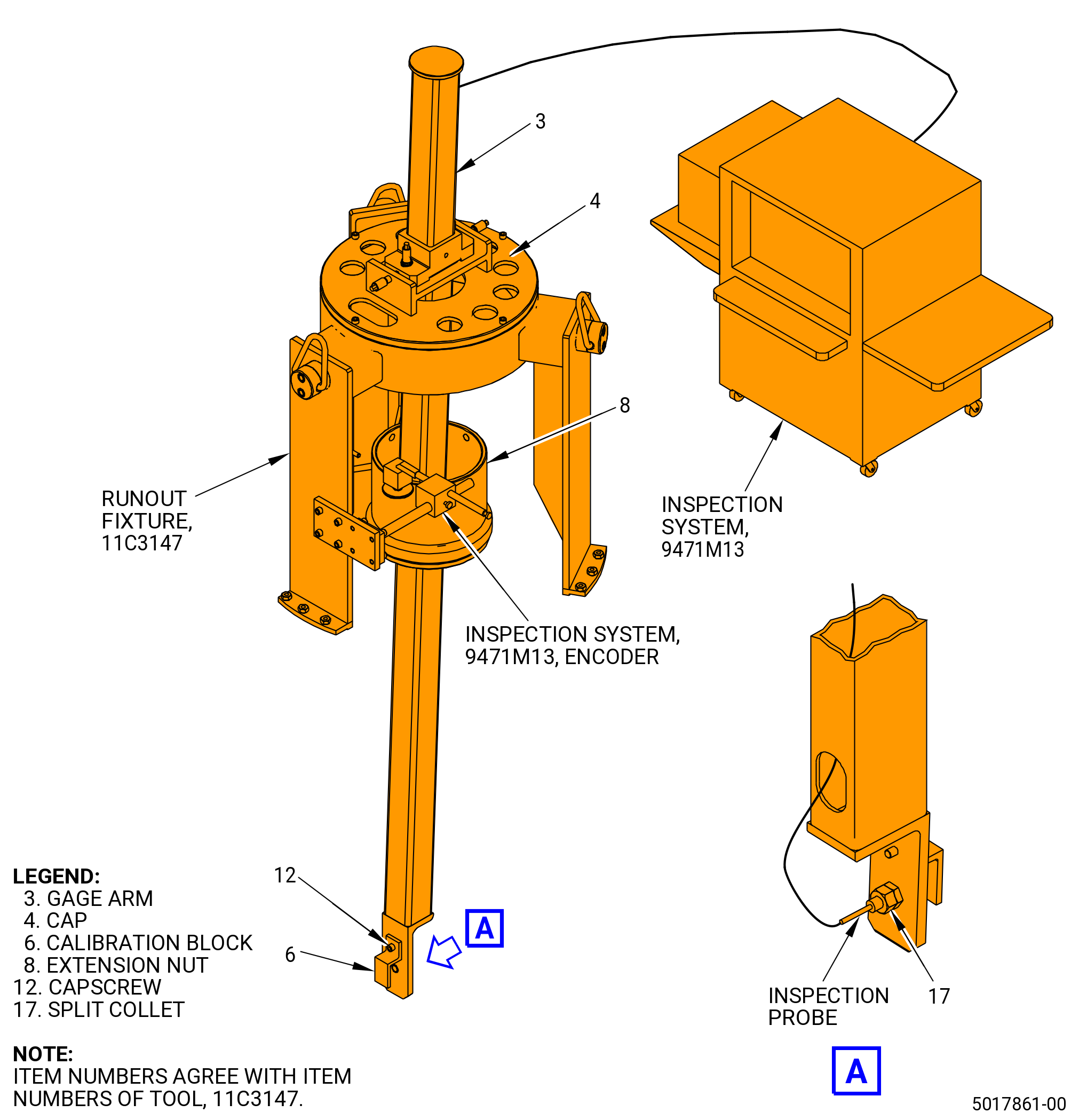
| L. | Calibrate the inspection probe of the 9471M13 inspection system as follows: |
| (1) | Install the calibration block (item 6) of the 11C3147 runout fixture on the end of the gage arm (item 3) with capscrews (item 12). Refer to Figure 1014. |
| (2) | Install the inspection probe in the split collet (item 17). Adjust the probe to the center of the mechanical movement. |
| (3) | Put the inspection probe electrical lead into the hole in the gage arm (item 3), through the length of the gage arm, and out the hole in the aft end of the gage arm. |
| (4) | Connect the inspection probe to the 9471M13 inspection system. |
| (5) | Turn on the 9471M13 inspection system electrical power. |
| (6) | Start the 9471M13 inspection system as follows: |
| (a) | At the SELECT ENGINE SCREEN, select GEnx-1B then NEXT. |
| (b) | At the SELECT A PARAMETER FILE screen, select NX1BCDP.PRM, then OPEN. |
| (c) | At the main page, select GAGE. |
| Subtask 72-00-02-820-005 |
| (7) | Adjust the inspection probe in the split collet (item 17) as near to zero (0.0000) as possible. |
| (8) | Check the calibration response with a 0.001, 0.002, and 0.003 inch (0.025, 0.051, and 0.076 mm) gage between the probe head and the calibration block. The probe must read within 0.0005 inch (0.013 mm). Do the check a second and a third time to make sure that the indication is within limit. |
| (9) | Remove the capscrews (item 17) and the calibration block (item 6) from the gage arm (item 3). |
| NOTE: |
|
| Subtask 72-00-02-430-724 |
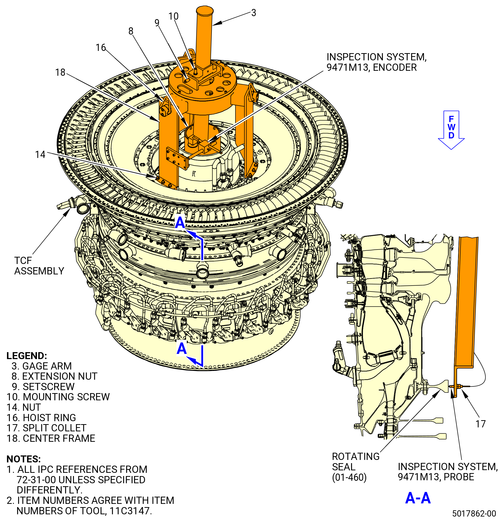
| M. | Install the 11C3147 runout fixture on the TCF assembly (35-009) (SIN 92500), (35-010) (SIN 92500), (35-011) (SIN 92500), (35-012) (SIN 92500), or (35-015) (SIN 92500). Refer to Figure 1015 and do as follows: |
| (1) | Examine the 11C3147 runout fixture for damage, foreign material, and high metal on the mating flange. |
| (2) | Clean the extension nut (item 8) with a clean, lint-free C10-182 cloth. |
| (3) | Locate the two castellations marked 1 on the outer surface on the aft end of the stage 1 HPT rotor disk (150A1) outer surface. |
| (4) | Transfer the number 1-1 to the inside diameter of the stage 1 HPT rotor disk (150A1) with a C05-003 pen. |
| NOTE: |
|
| CAUTION: |
|
| (5) | Install the extension nut (item 8) on the stage 1 HPT rotor disk (150A1). Tighten the extension nut. Do not use excessive force to tighten the extension nut. |
| (6) | Rotate the knob (item 24) of the 11C3147 runout fixture CW to move the spring loaded cam roller (item 25) outward. Tighten the knob (item 24) to hold in this position and allow the cam roller to be installed over the extension nut (item 8). |
| WARNING: |
|
| (7) | Attach an overhead hoist to the hoist rings (item 16) on the 11C3147 runout fixture. |
| (8) | Lift the 11C3147 runout fixture and align the TOP VERT mark on the cap (item 4) with the TVCL on the propulsor assembly. |
| (9) | Put the center frame (item 18) on the TCF assembly aft flange and attach with nuts (item 14). |
| Subtask 72-00-02-430-725 |
| CAUTION: |
|
| N. | Measure the stage 1 HPT rotor disk (150A1) rotating seal (050NC) for runout as follows: |
| CAUTION: |
|
| (1) | Put the gage arm (item 3) of the 11C3147 runout fixture through the cap (item 4). Do not allow the inspection system probe to touch the stage 1 HPT rotor disk (150A1) and the extension nut (item 8) or the inspection probe can be damaged. Refer to Figure 1015. |
| (2) | Attach the gage arm (item 3) to the cap (item 4) with the mounting screws (item 10). Tighten the setscrew (item 9) and the mounting screws (item 10) to prevent movement of the gage arm (item 3). |
| (3) | Install the encoder wheel of the 9471M13 inspection system on the extension nut (item 8). The encoder wheel will rotate with the rotor. |
| (4) | Rotate the knob (item 24) counterclockwise (CCW) to move the spring loaded cam roller (item 25) inward and apply a radial force on the rotor. |
| (5) | Align the inspection probe on the gage arm (item 3) to the rotating seal (050NC) and adjust the setscrews (item 9) to read as close as possible to 0.0000 inch. Tighten the mounting screws (item 10). |
| (6) | Make sure that the 11C3133 lock fixture is installed on the transfer gearbox (TGB) (03200). Refer to TASK 72-00-02-430-801 (72-00-02, ASSEMBLY 001) to install the lock fixture. |
| (7) | Start the 9471M13 inspection system as follows: |
| (a) | At the SELECT ENGINE screen, select GEnx-1B then NEXT. |
| (b) | At the SELECT A PARAMETER FILE screen, select NX1BCDP.PRM, then OPEN. |
| (c) | At the main page, select GAGE. |
| (8) | On the 9471M13 inspection system screen, select MEASURE. |
| (9) | When the screen prompts for a new run, select YES. |
| (10) | Enter the engine serial number, then select OK. |
| (11) | Enter the operator ID, then select OK. |
| (12) | When the screen displays the message POSITION THE ROTOR TO A REFERENCE POSITION, rotate the HPT rotor to the number 1 marked on the stage 1 HPT rotor disk (150A1) and select OK or press ENTER to set the zero degrees reference for the measurement. Mark the exact point where the rotor starts. Do not select OK or press ENTER until the measurement is complete. |
| (13) | Put a square drive in the 11C3133 lock fixture and slowly rotate the rotor three times CCW (ALF). |
| (14) | Stop the rotor with the inspection probe at the 1-1 mark in the exact same place the rotation started. Select OK on the 9471M13 inspection system screen. |
| (15) | Slowly rotate the rotor one revolution CCW (ALF) and stop at the 1-1 mark and select OK. Avoid any change in speed when the rotor rotates. |
| (16) | Print the plot of the measurement. |
| (17) | If the encoder verification fails, the inspection system will ask you if you want to try again, select YES. Stop at the exact same place you started the measurement. |
| (18) | Turn the rotor CCW (ALF). The inspection system will display the measurement. If the measurement is more than 0.002 inch (0.051 mm) full indicator reading (FIR), check to make sure that the setup is correct and measure again. |
| (19) | If the measurement is less than 0.002 inch (0.05 mm) full indicator reading (FIR), the kink check is good. |
| (20) | Deleted. |
| (21) | If the measurement is more than 0.002 inch (0.05 mm) FIR, reseat the stage 1 HPT rotor disk (150A1) on the rotating seal (050NC). Refer to Subtask 72-00-02-430-720 (paragraph 3.K.). |
| CAUTION: |
|
| NOTE: |
|
| (22) | If the measurement is correct, select START, then SHUTDOWN, on the 9471M13 inspection system. |
| (23) | Remove the gage arm (item 3) of the 11C3147 runout fixture from the propulsor. Do not allow the inspection system probe to touch the stage 1 HPT rotor disk (150A1) and the extension nut (item 8) or the inspection probe can be damaged. |
| (24) | Remove the encoder of the 9471M13 inspection system from the center frame (item 18). |
| (25) | Remove the center frame (item 18) of the 11C3147 runout fixture from the TCF assembly (35-009) (SIN 92500), (35-010) (SIN 92500), (35-011) (SIN 92500), (35-012) (SIN 92500), or (35-015) (SIN 92500). |
| (26) | Remove the extension nut (item 8) from the stage 1 HPT rotor disk (150A1). |
| (27) | Remove the 11C3133 lock fixture from the TGB (03200). |
| (28) | Record the measurement as COREFIR. |
| Subtask 72-00-02-220-109 |
| (29) | Do a general visual inspection of the exposed surfaces of HPT rotor stage 1 disk for nicks, dents, and scratches after the removal of tooling. Refer to TASK 72-00-53-200-802 (72-00-53, INSPECTION 001). |
| Subtask 72-00-02-430-726 |
| O. | Deleted. |
| Subtask 72-00-02-430-727 |
| (1) | Deleted. |
| Subtask 72-00-02-430-728 |
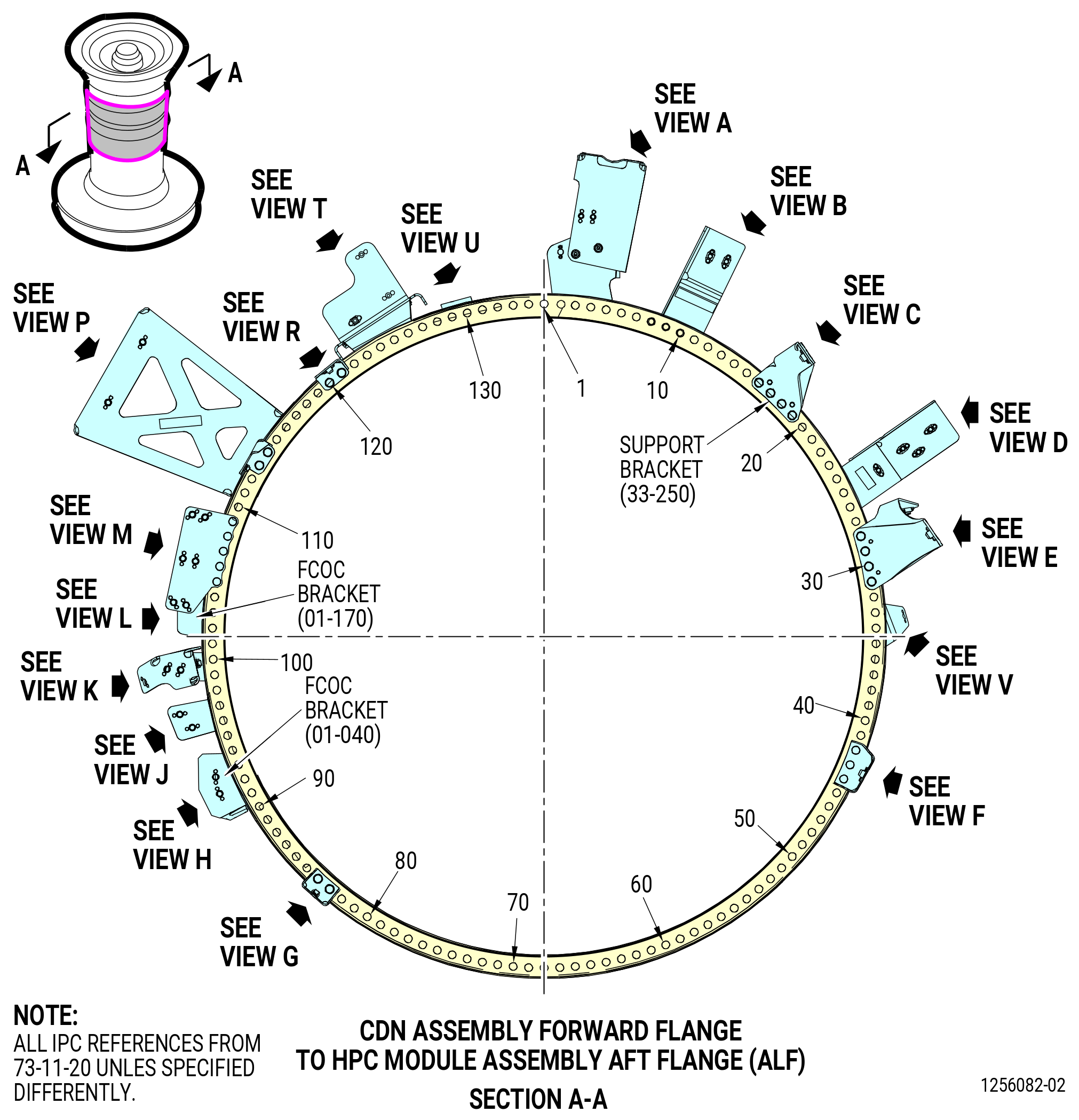
| P. | Install the brackets on the CDN assembly (33-019) (SIN 0010A) or (33-020) (SIN 0010A) forward flange and the propulsor assembly aft flange as follows. Put the boltheads on the forward side of the flange unless instructed differently. |
| (1) | Make sure that the TVCL offset holes are marked on the CDN assembly forward flange. If not, put a mark on the bolthole locations in increments of 10 with a C05-003 pen on the forward flange of the CDN assembly. Start at the TVCL with bolthole No. 1 in a CW direction (ALF). |
| Subtask 72-00-02-640-032 |
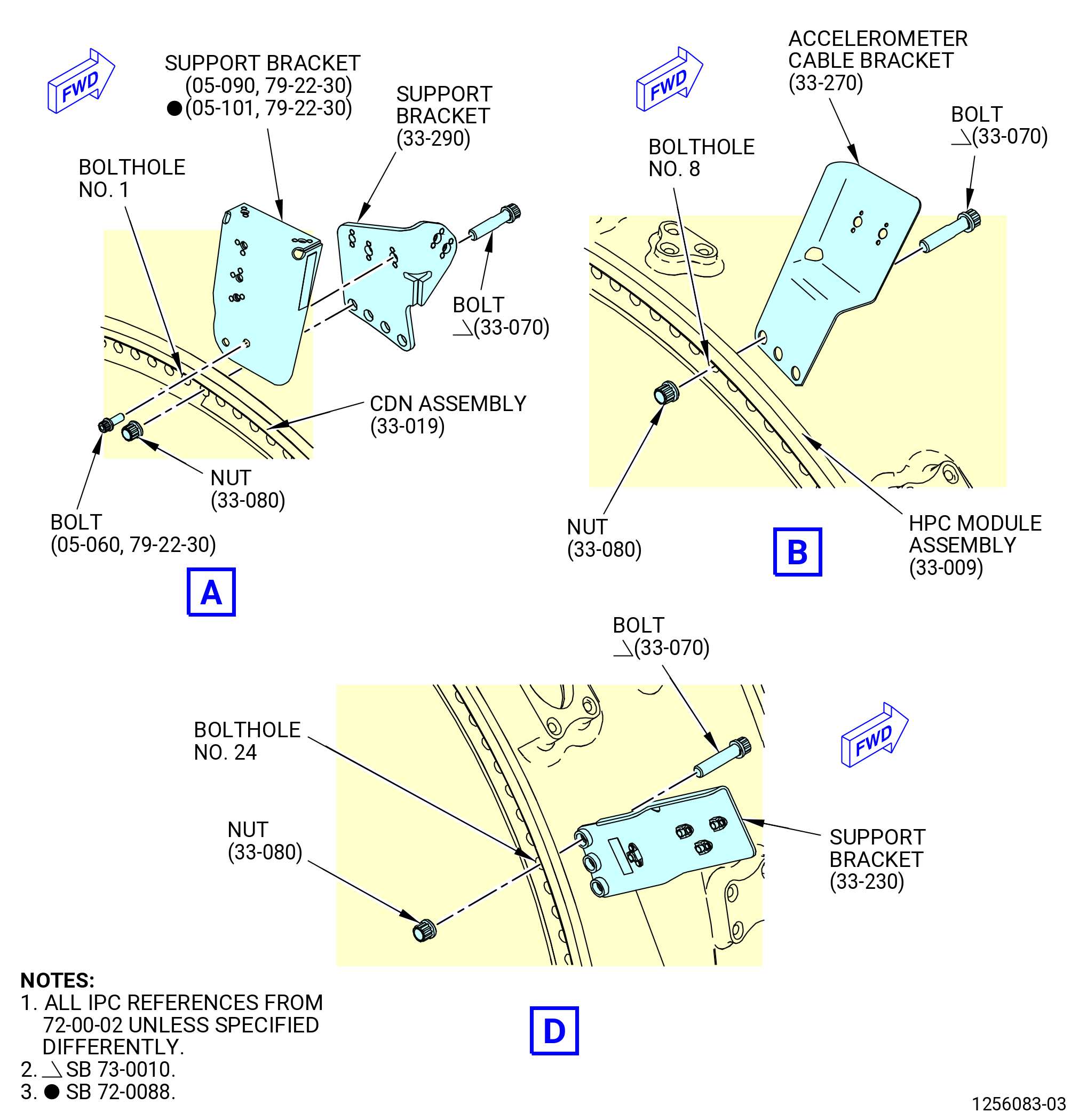
| (a) | Apply C02-058 graphite to the mating surfaces and threads on the bolts (33-060) (SIN 12021) and (33-070) (SIN 12022) or (33-060B) (SIN 12021) and (33-070B) (SIN 12022) and bolts (33-050) (SIN 12020). Do not lubricate the bolts (05-060 , 79-22-30) (SIN 46126), (01-080 , 75-24-40) (SIN 61B21). |
| Subtask 72-00-02-430-729 |
| (b) | Install the tube oil brackets (support brackets) (05-090 , 79-22-30) (SIN 46110) or (05-101 , 79-22-30) (SIN 46110) and (33-290) (SIN 6101K). Refer to Figure 1017 and do as follows: |
| 1 | Attach the support bracket (6101K) in boltholes No. 2, 3, 4, and 5 on the forward side of the flange with bolts (33-070) (SIN 12022) or (33-070B) (SIN 12022) and self-locking nuts (12040). Hand-tighten the self-locking nuts (12040). |
| 2 | Attach the support bracket (05-090 , 79-22-30) (SIN 46110) or (05-101 , 79-22-30) (SIN 46110) to the support bracket (33-290) (SIN 6101K) with the bolts (05-060 , 79-22-30) (SIN 46126). |
| 3 | Torque the bolts to 106-124 lb in. (12.0-14.0 N.m). |
| (c) | Install the accelerometer cable bracket (34210) in boltholes No. 9, 10, and 11 on the forward side of the flange with bolts (33-070) (SIN 12022) or (33-070B) (SIN 12022) and self-locking nuts (12040). |
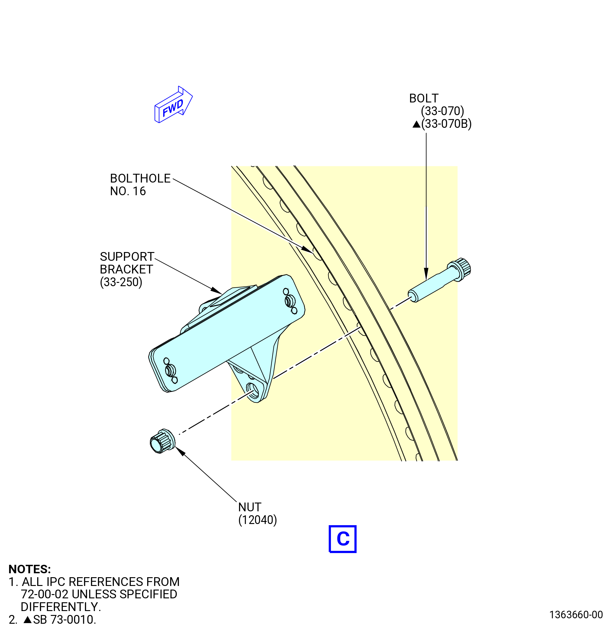
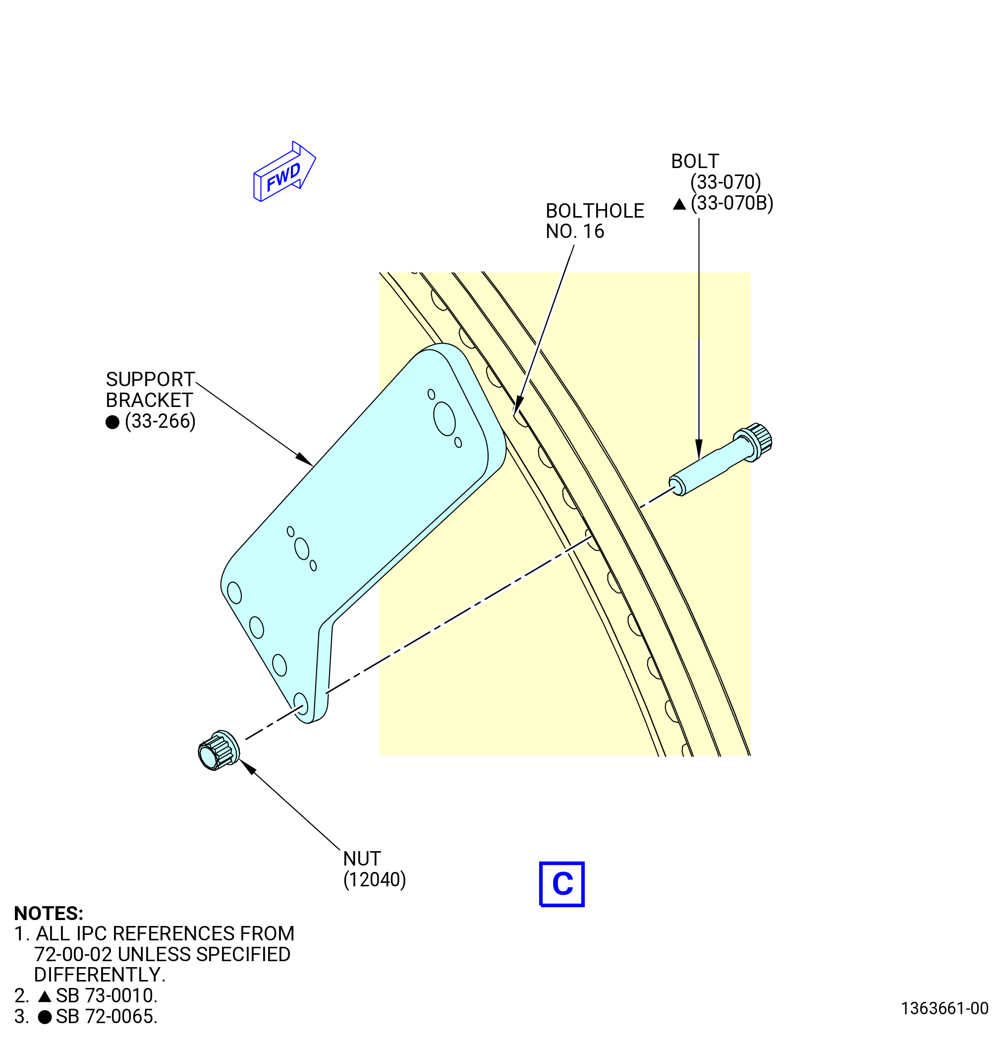
| (d) | Install the support bracket (33-250) (SIN 61A10) or (33-266) (SIN 61A10) in boltholes No. 16, 17, 18, and 19 on the aft side of the flange with bolts (33-070) (SIN 12022) or (33-070B) (SIN 12022) and self-locking nuts (12040). Hand-tighten the self-locking nuts. |
| (e) | Install the support bracket (38410) in boltholes No. 24, 25, and 26 on the forward side of the flange with bolts (33-070) (SIN 12022) or (33-070B) (SIN 12022) and self-locking nuts (12040). Hand-tighten the self-locking nuts. |
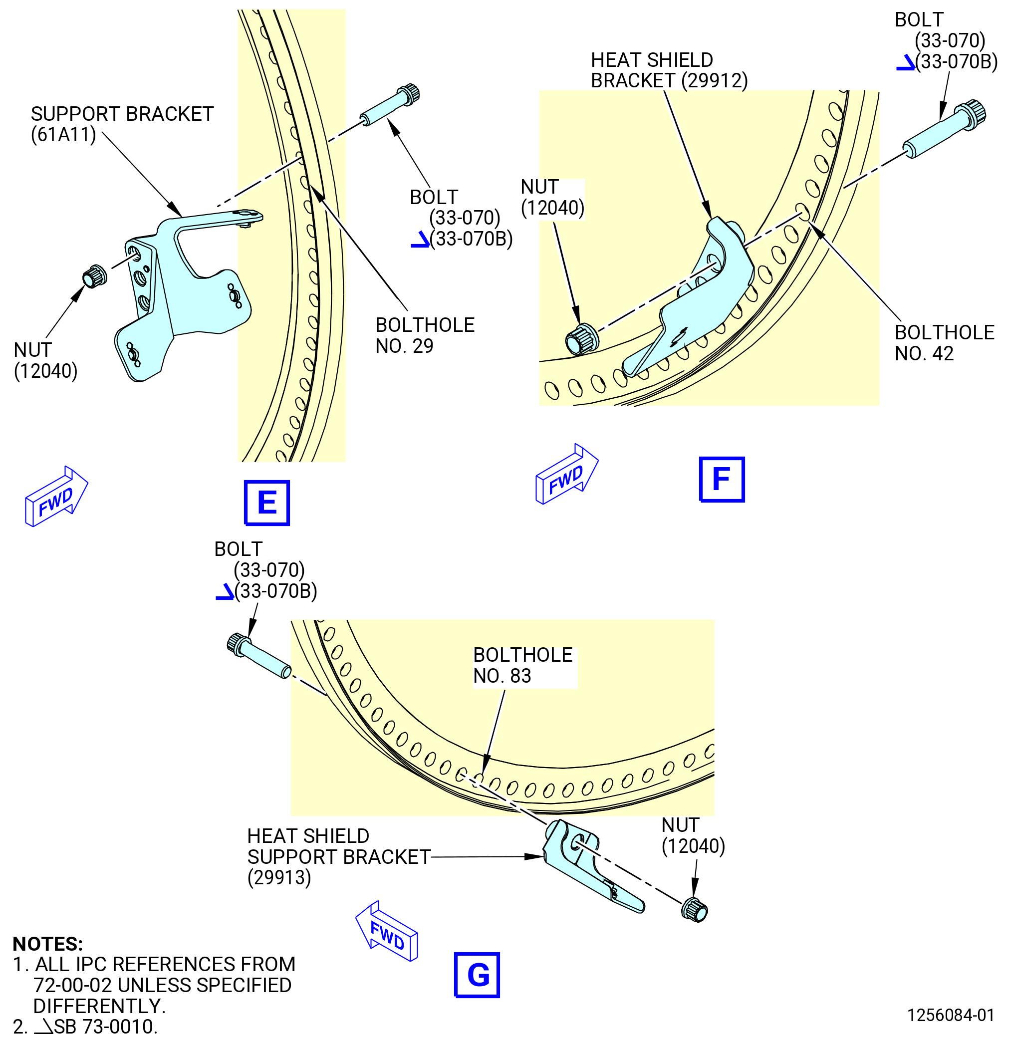
| (f) | Install the support bracket (61A11) in boltholes No. 28, 29, 30, and 31 on the aft side of the flange with bolts (33-070) (SIN 12022) or (33-070B) (SIN 12022) and self-locking nuts (12040). Hand-tighten the self-locking nuts. |
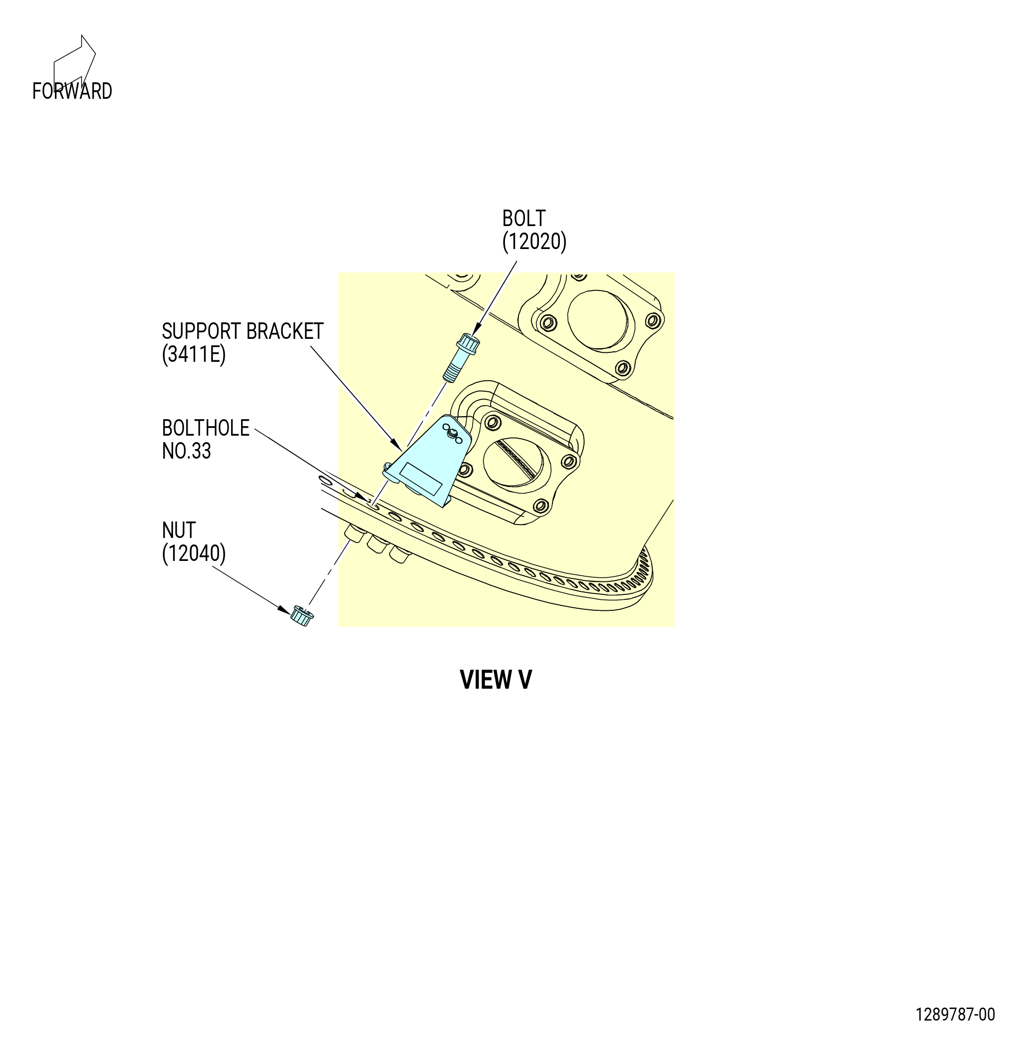
| (g) | Install the bracket (3411E) in boltholes No. 33, 34, and 35 on the forward side of the flange with bolts (33-070) (SIN 12022) or (33-070B) (SIN 12022) and self-locking nuts (12040). |
| (h) | Install the heatshield support bracket (29912) in boltholes No. 42, 43, and 44 on the aft side of the flange with bolts (12020) and self-locking nuts (12040). Hand-tighten the self-locking nuts. |
| (i) | Install the heatshield support bracket (29913) in boltholes No. 83 and 84 on the aft side of the flange with bolts (33-070) (SIN 12022) or (33-070B) (SIN 12022) and self-locking nuts (12040). Hand-tighten the self-locking nuts. |
| Subtask 72-00-02-430-793 |
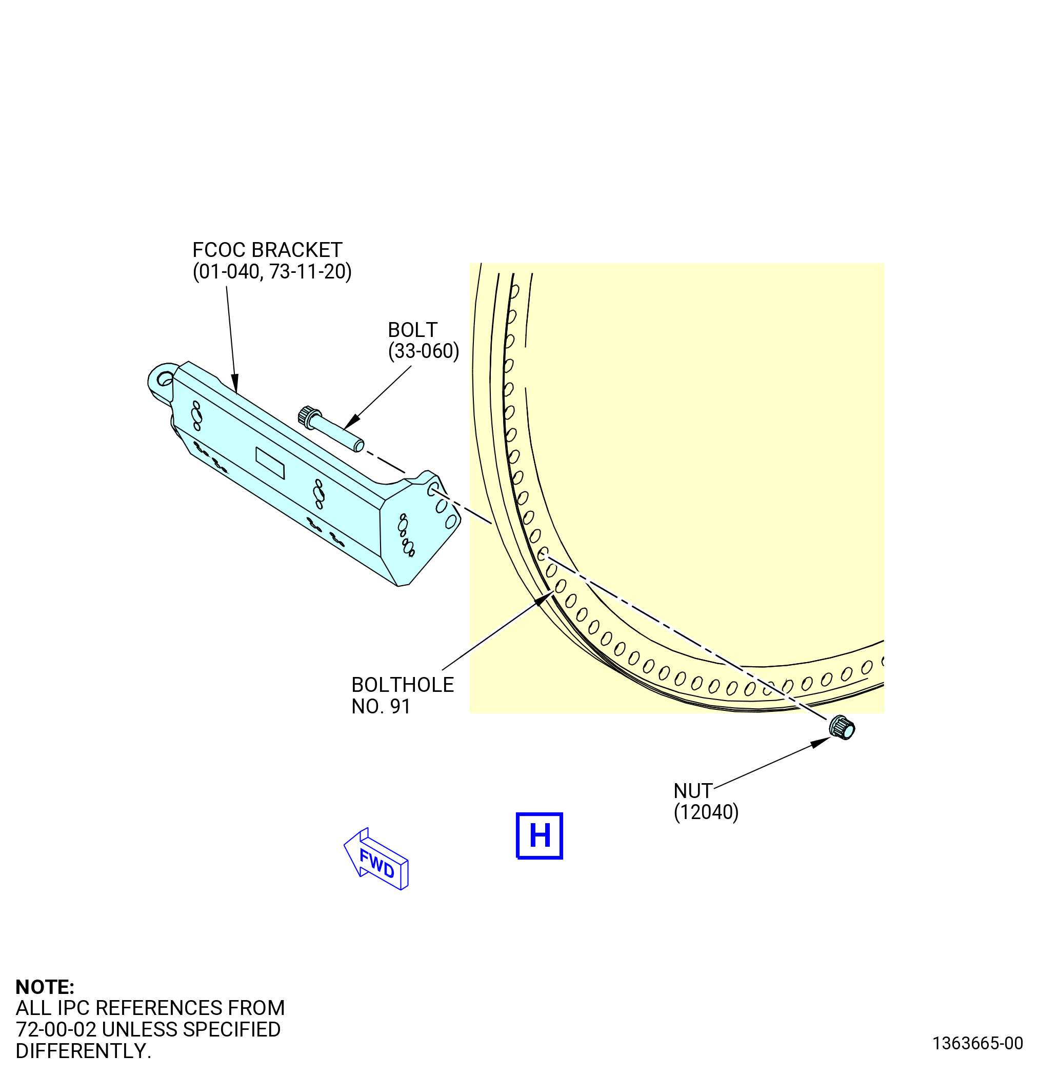
| * * * PRE SB 73-0010( FCOC Support Bracket with Hinge Block ) |
| (j) | Install the fuel cooled oil cooler (FCOC) bracket (01-040 , 73-11-20) (SIN 42412) in boltholes No. 91, 92, and 93 on the forward side of the flange with bolts (33-060) (SIN 12021) and self-locking nuts (12040). Hand-tighten the self-locking nuts (12040). |
| * * * END PRE SB 73-0010 |
| Subtask 72-00-02-430-794 |
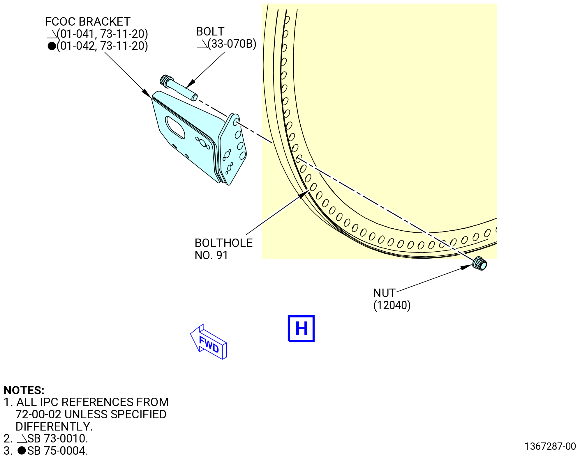
| * * * SB 73-0010( FCOC Support Bracket with Flat Wire Springs and Sliders ) |
| (j).A. | Install the fuel cooled oil cooler (FCOC) bracket (01-041 , 73-11-20) (SIN 42412) or (01-042 , 73-11-20) (SIN 42412) in boltholes No. 91, 92, 93, and 94 on the forward side of the flange with bolts (33-070B) (SIN 12022) and self-locking nuts (12040). Hand-tighten the self-locking nuts (12040). |
| * * * END SB 73-0010 |
| Subtask 72-00-02-430-868 |
| (j).B. | Deleted. |
| Subtask 72-00-02-430-795 |
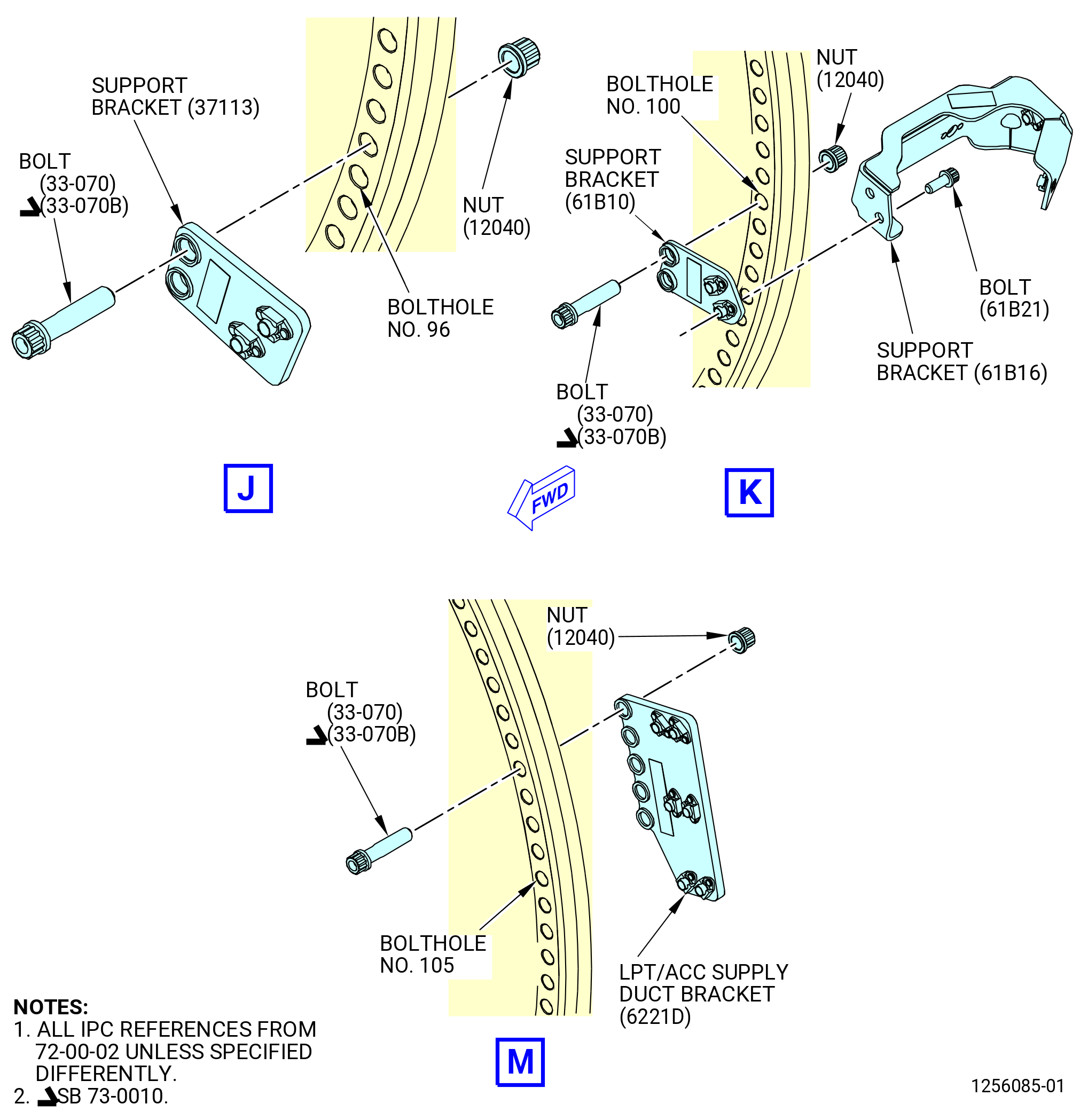
| (k) | Install the bracket (37113) in boltholes No. 96 and 97 on the forward side of the flange with bolts (33-070) (SIN 12022) or (33-070B) (SIN 12022) and self-locking nuts (12040). Hand-tighten the self-locking nuts (12040). |
| (l) | Install the support brackets (61B10, 61B16) as follows: |
| 1 | Attach the support bracket (61B10) in boltholes No. 99 and 100 on the forward side of the flange with bolts (33-070) (SIN 12022) or (33-070B) (SIN 12022) and self-locking nuts (12040). Hand-tighten the self-locking nuts (12040). |
| 2 | Attach the support bracket (61B16) to the support bracket (61B10) with bolts (61B22). |
| 3 | Torque the bolts to 106-124 lb in. (12.0-14.0 N.m). |
| Subtask 72-00-02-430-796 |
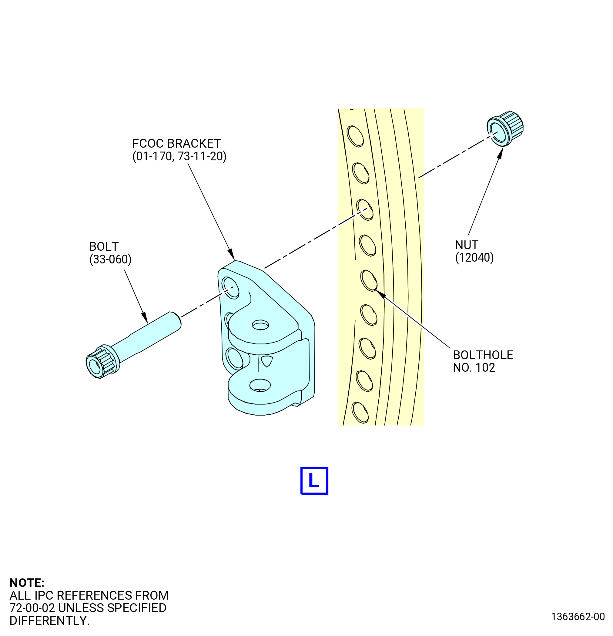
| * * * PRE SB 73-0010( FCOC Support Bracket with Hinge Block ) |
| (m) | Install the FCOC bracket (01-170 , 73-11-20) (SIN 42410) in boltholes No. 102, 103, and 104 on the forward side of the flange with bolts (33-060) (SIN 12021) and self-locking nuts (12040). Hand-tighten the self-locking nuts (12040). |
| * * * END PRE SB 73-0010 |
| Subtask 72-00-02-430-797 |
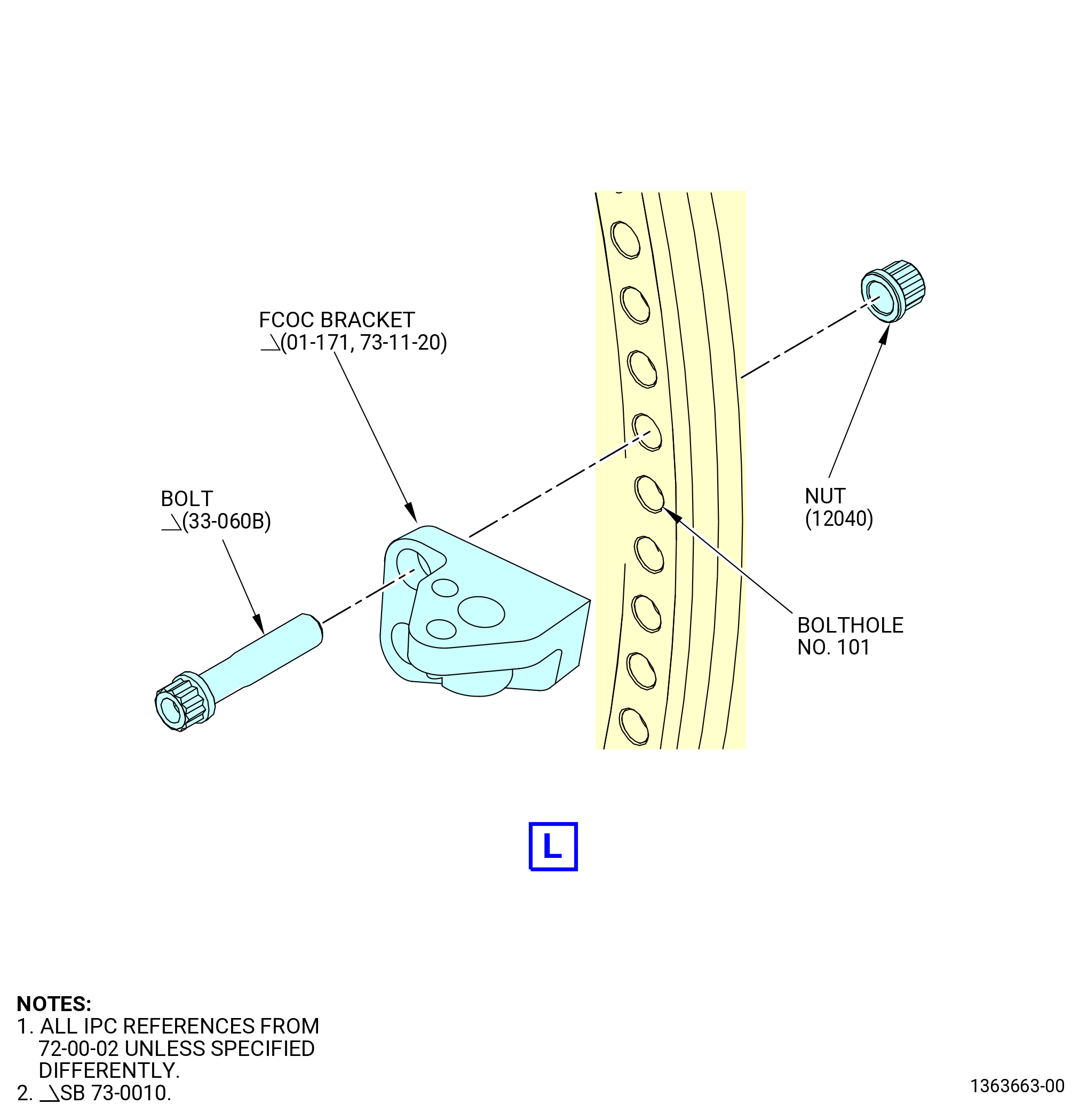
| * * * SB 73-0010( FCOC Support Bracket with Flat Wire Springs and Sliders ) |
| (m).A. | Install the FCOC bracket (01-171 , 73-11-20) (SIN 42410) in boltholes No. 101 and 102 on the forward side of the flange with bolts (33-060B) (SIN 12021) and self-locking nuts (12040). Hand-tighten the self-locking nuts (12040). |
| * * * END SB 73-0010 |
| Subtask 72-00-02-430-798 |
| (n) | Install the LPT/ACC supply duct support bracket (LPT/ACC supply duct bracket) (6221D) in boltholes No. 105, 106, 107, 108, and 109 on the aft side of the flange with bolts (33-070) (SIN 12022) or (33-070B) (SIN 12022) and self-locking nuts (12040). Hand-tighten the self-locking nuts. |
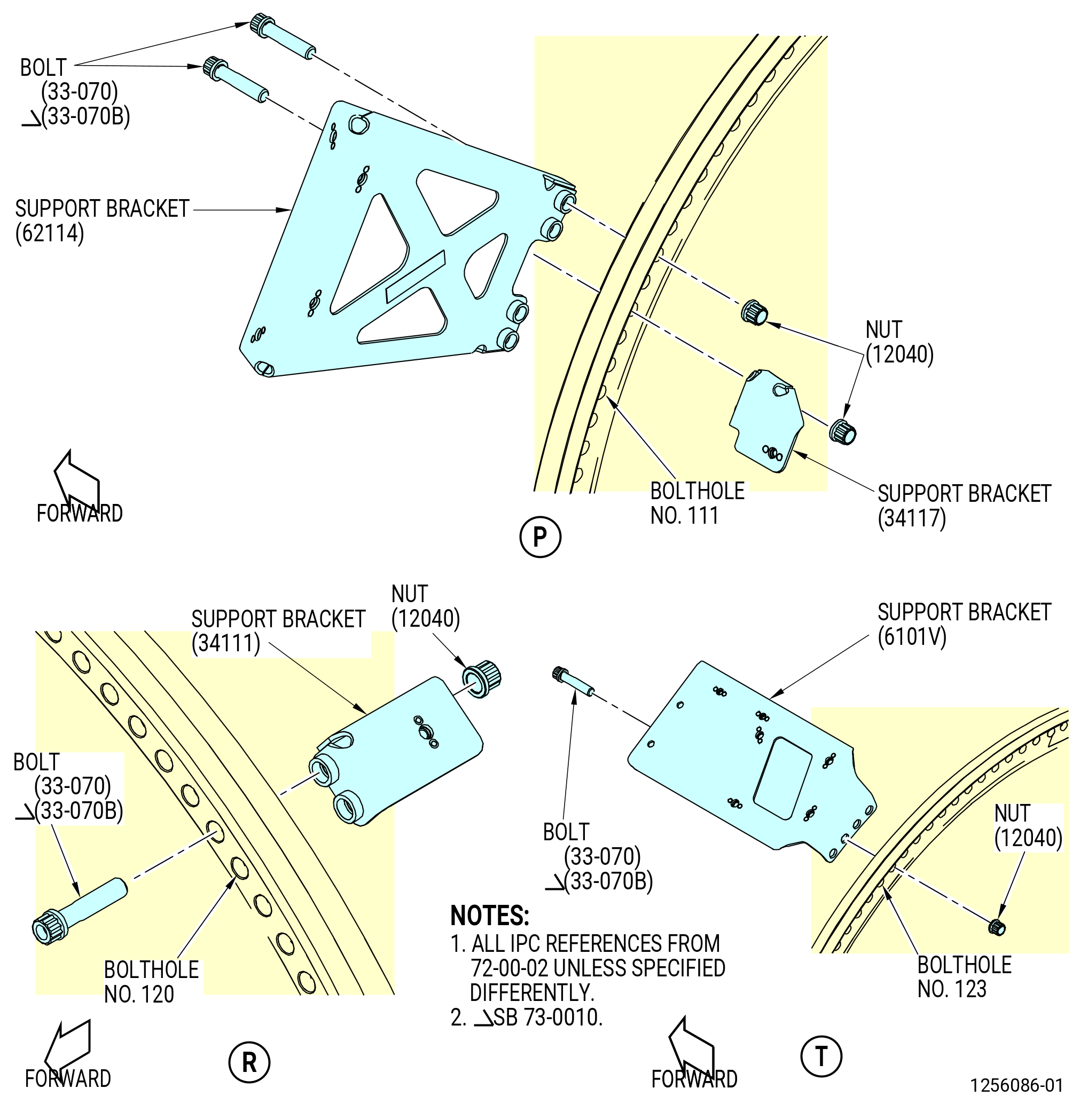
| (o) | Install the support brackets (62114, 34117) as follows: |
| 1 | Attach the support bracket (62114) in boltholes No. 111, 112, 115, and 116 on the forward side of the flange with bolts (33-070) (SIN 12022) or (33-070B) (SIN 12022) and self-locking nuts (12040). Hand-tighten the self-locking nuts (12040). |
| 2 | Attach the support bracket (34117) in boltholes No. 113 and 114 on the aft side of the flange with bolts (33-070) (SIN 12022) or (33-070B) (SIN 12022) and self-locking nuts (12040). Hand-tighten the self-locking nuts. |
| (p) | Install the support bracket (34111) in boltholes No. 120 and 121 on the aft side of the flange with bolts (33-070) (SIN 12022) or (33-070B) (SIN 12022) and self-locking nuts (12040). Hand-tighten the self-locking nuts (12040). |
| (q) | Install the support bracket (6101V) in boltholes No. 123, 124, 125, and 126 on the forward side of the flange with bolts (33-070) (SIN 12022) or (33-070B) (SIN 12022) and self-locking nuts (12040). Hand-tighten the self-locking nuts (12040). |
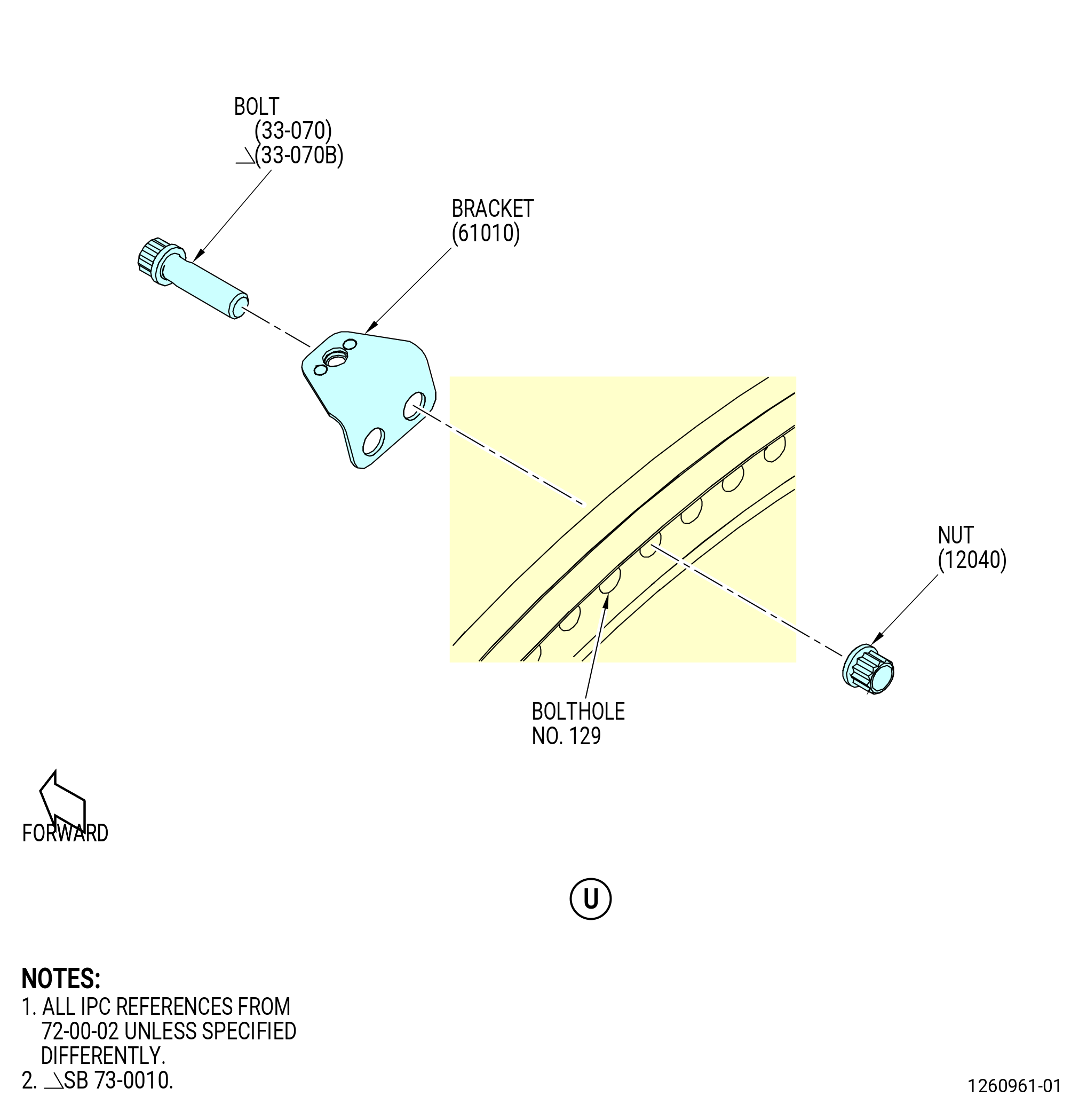
| NOTE: |
|
| (r) | Install the tube control support bracket (61010) in boltholes No. 129 and 130 on the forward side of the flange with bolts (33-070) (SIN 12022) or (33-070B) (SIN 12022) and self-locking nuts (12040). Hand-tighten the self-locking nuts (12040). |
| Subtask 72-00-02-430-799 |
| * * * PRE SB 73-0010( FCOC Support Bracket with Hinge Block ) |
| (s) | Install the bolts (12020) and self-locking nuts (12040) in boltholes No. 1, 6, 7, 8, 12, 13, 14, 15, 20, 21, 22, 23, 27, 32, 36, 37, 38, 39, 40, 41, 45, 46, 47, 48, 49, 50, 51, 52, 53, 54, 55, 56, 57, 58, 59, 60, 61, 62, 63, 64, 65, 66, 67, 68, 69, 70, 71, 72, 73, 74, 75, 76, 77, 78, 79, 80, 81, 82, 85, 86, 87, 88, 89, 90, 94, 95, 98, 101, 110, 117, 118, 119, 122, 127, 128, 131, 132, 133, and 134 with the boltheads forward. |
| * * * END PRE SB 73-0010 |
| Subtask 72-00-02-430-800 |
| * * * SB 73-0010( FCOC Support Bracket with Flat Wire Springs and Sliders ) |
| (s).A. | Install the bolts (12020) and self-locking nuts (12040) in boltholes No. 1, 6, 7, 8, 12, 13, 14, 15, 20, 21, 22, 23, 27, 32, 36, 37, 38, 39, 40, 41, 45, 46, 47, 48, 49, 50, 51, 52, 53, 54, 55, 56, 57, 58, 59, 60, 61, 62, 63, 64, 65, 66, 67, 68, 69, 70, 71, 72, 73, 74, 75, 76, 77, 78, 79, 80, 81, 82, 85, 86, 87, 88, 89, 90, 95, 98, 103, 104, 110, 117, 118, 119, 122, 127, 128, 131, 132, 133, and 134 with the boltheads forward. |
| * * * END SB 73-0010 |
| Subtask 72-00-02-430-801 |
| (t) | Torque the self-locking nuts (12040) as follows: |
| 1 | Torque a minimum of 14 self-locking nuts (12040) in a criss-cross pattern to 276-324 lb in. (31.4-36.6 N.m) at four equally spaced locations to seat the flanges. |
| 2 | Make sure that there is no gap between the flanges. Use a 0.001 inch (0.03 mm) gage to check the gap between the flanges. |
| 3 | Torque the 14 self-locking nuts (12040) in a criss-cross pattern to 368-432 lb in. (41.6-48.8 N.m). |
| 4 | Torque the 14 self-locking nuts (12040) in a circumferential pattern to 368-432 lb in. (41.6-48.8 N.m). |
| (u) | If necessary, remove the 7C2015 lift/turn fixture. Refer to TASK 72-50-00-030-801 (72-50-00, DISASSEMBLY 001). |
| (v) | If necessary, remove the 11C3055 rotor lock. Refer to TASK 72-50-00-030-801 (72-50-00, DISASSEMBLY 001). |
|
|
|
|
|
|
| Subtask 72-00-02-430-730 |
| * * * PRE SB 73-0010( FCOC Support Bracket with Hinge Block ) |
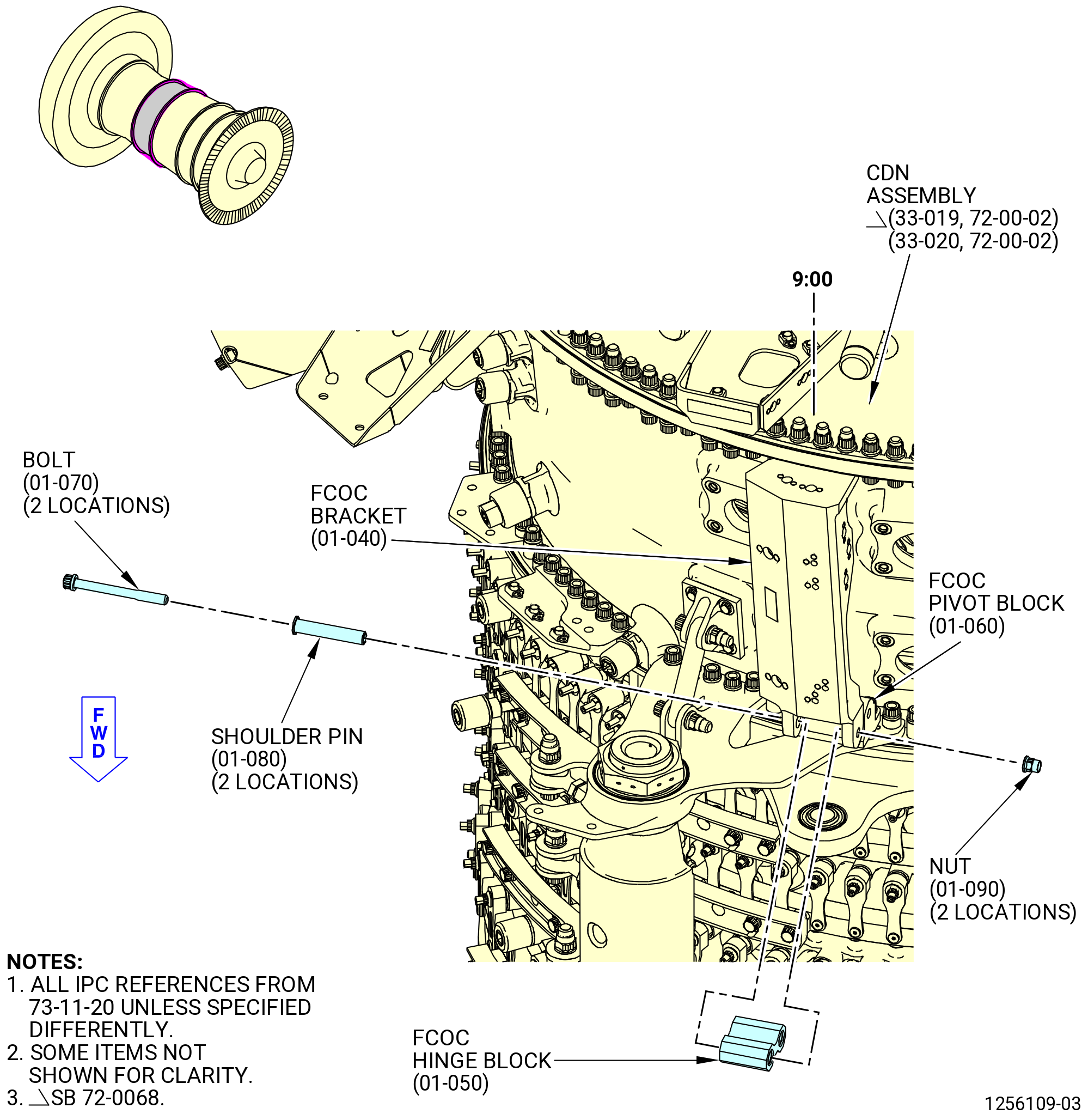
| (2) | Connect the FCOC bracket (01-040 , 73-11-20) (SIN 42412) to the FCOC pivot block (01-060 , 73-11-20) (SIN 42413) as follows. Refer to Figure 1018. |
| (a) | Put the FCOC hinge block (01-050 , 73-11-20) (SIN 4241B) in the FCOC bracket (01-040 , 73-11-20) (SIN 42412) and FCOC pivot block (01-060 , 73-11-20) (SIN 42413). |
| (b) | Install the bolts (01-070 , 73-11-20) (SIN 42423) with shoulder pins (01-080 , 73-11-20) (SIN 42471) and self-locking nuts (01-090 , 73-11-20) (SIN 42441). Put the bolthead up on the propulsor buildup. |
| NOTE: |
|
| (c) | Torque the self-locking nuts to 106-124 lb in. (12.0-14.0 N.m). |
| NOTE: |
|
| * * * END PRE SB 73-0010 |
| Subtask 72-00-02-430-802 |
| * * * SB 73-0010( FCOC Support Bracket with Flat Wire Springs and Sliders ) |
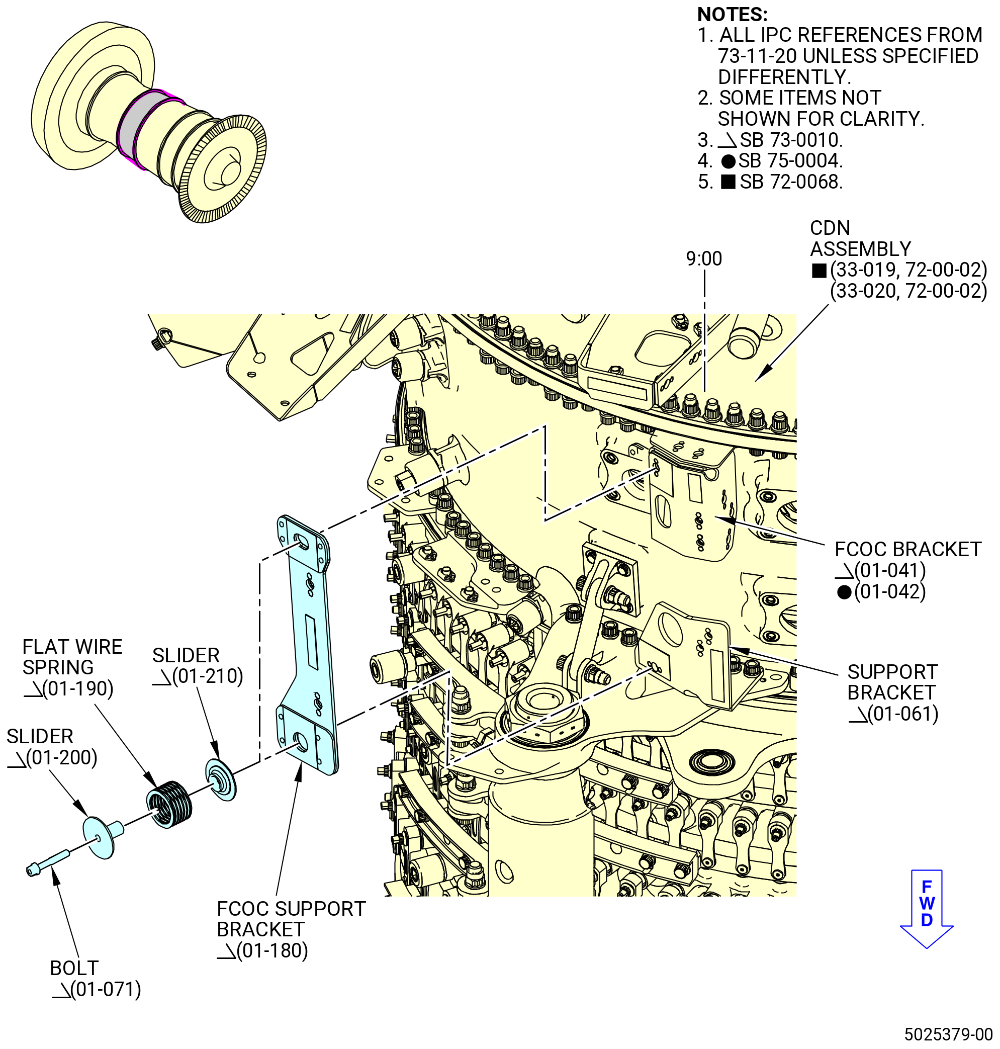
| (2).A. | Install the FCOC support bracket (01-180 , 73-11-20) (SIN 42415) as follows. Refer to Figure 1018A. |
| (a) | Attach the FCOC support bracket (01-180 , 73-11-20) (SIN 42415) to the support bracket (01-061 , 73-11-20) (SIN 42413) and FCOC bracket (01-041 , 73-11-20) (SIN 42412) or (01-042 , 73-11-20) (SIN 42412) with two bolts (01-071 , 73-11-20) (SIN 42423), flat wire springs (01-190 , 73-11-20) (SIN 42490), and sliders (01-200 , 73-11-20) (SIN 42491) and (01-210 , 73-11-20) (SIN 42492). |
| (b) | Torque the bolts (01-071 , 73-11-20) (SIN 42423) to 106-124 lb in. (12.0-14.0 N.m). |
| NOTE: |
|
| * * * END SB 73-0010 |
| Subtask 72-00-02-430-803 |
| (3) | Connect the support bracket (33-130) (SIN 62114) on the CDN Assembly (33-019) (SIN 0010A) or (33-020) (SIN 0010A) to the LPT ACC bracket (01-210 , 73-11-30) (SIN 62116) with the bolts (33-090) (SIN 62123). Torque the bolts (33-090) (SIN 62123) to 106 to 124 lb in. (12.0 to 14.0 Nm). Refer to Figure 1019. |
| (4) | Make sure that the brackets on CDN assembly and propulsor assembly flanges are installed in the correct locations. |
|
|
| Subtask 72-00-02-640-034 |
| Q. | Deleted. |
| Subtask 72-00-02-430-741 |
| (1) | Deleted. |
| Subtask 72-00-02-220-107 |
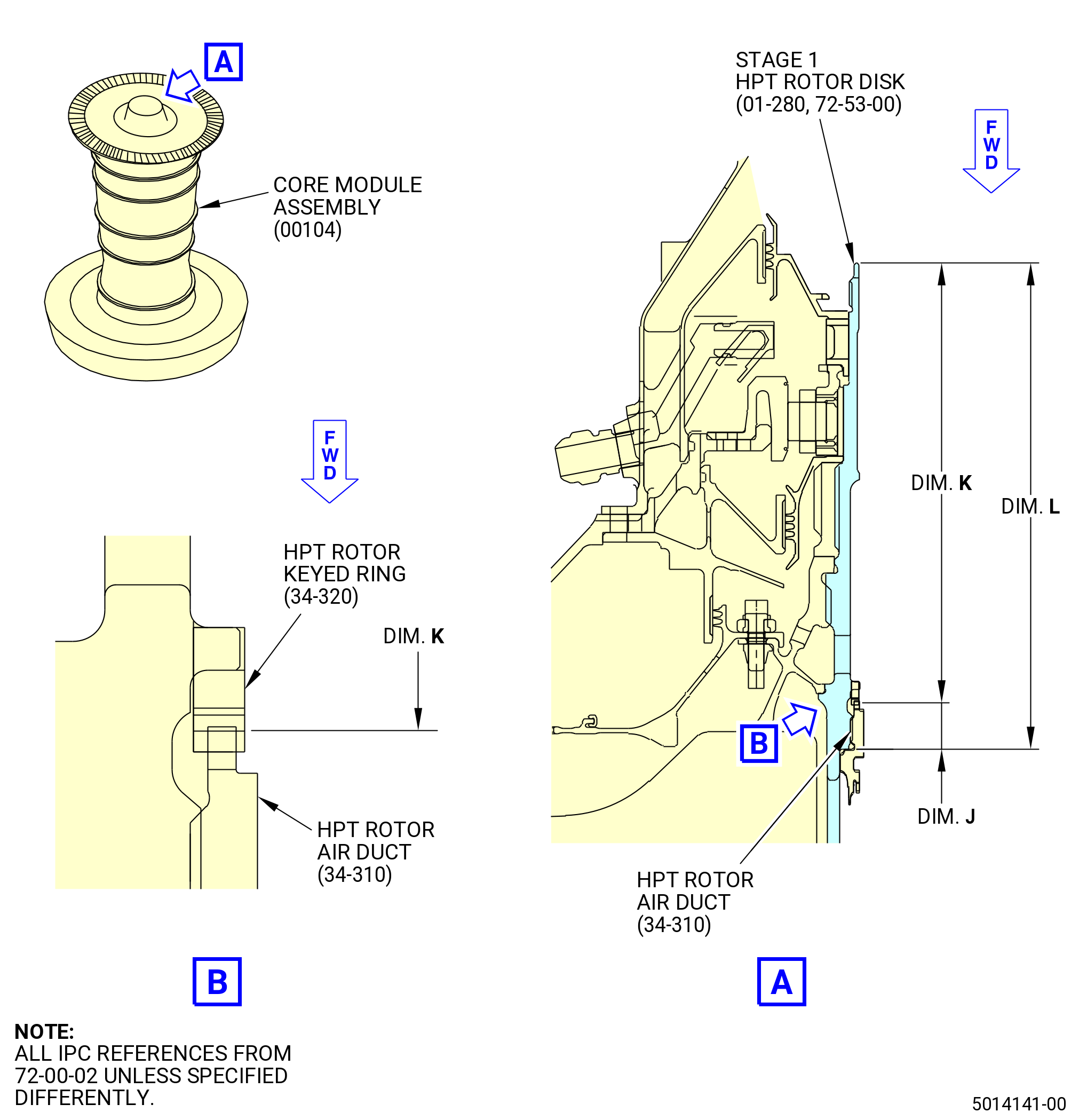
| R. | Measure and record dimensions J and L on the HPT rotor air duct (34-310) (SIN 05002) and the stage 1 HPT rotor disk (01-280 , 72-53-00) (SIN 150A1) as follows: |
| (1) | Get dimension J. Refer to TASK 72-00-02-430-801 (72-00-02, ASSEMBLY 001, CONFIG 01). |
| (2) | Measure dimension L. Refer to Figure 1020. |
| (3) | Record measured dimension L on the record sheet. Refer to Figure 1021. |
| (4) | Calculate dimension K (calculated) as follows: |
| • |
|
| (5) | Record dimension K (calculated) on the record sheet. Refer to Figure 1021. |
| Subtask 72-00-02-430-977 |
| CAUTION: |
|
| S. | Install the HPT rotor air duct (34-310) (SIN 05002) in the stage 1 HPT rotor disk (01-280 , 72-53-00) (SIN 150A1) as follows: |
| Subtask 72-00-02-640-053 |
| WARNING: |
|
| (1) | Apply C02-058 graphite to the mating surfaces and threads of the stage 1 HPT rotor disk (01-280 , 72-53-00) (SIN 150A1). Make sure that the thread roots have lubricant applied. |
| Subtask 72-00-02-430-978 |
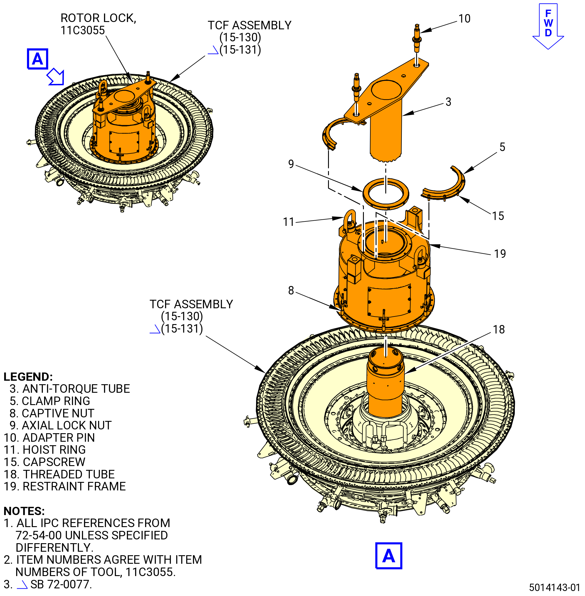
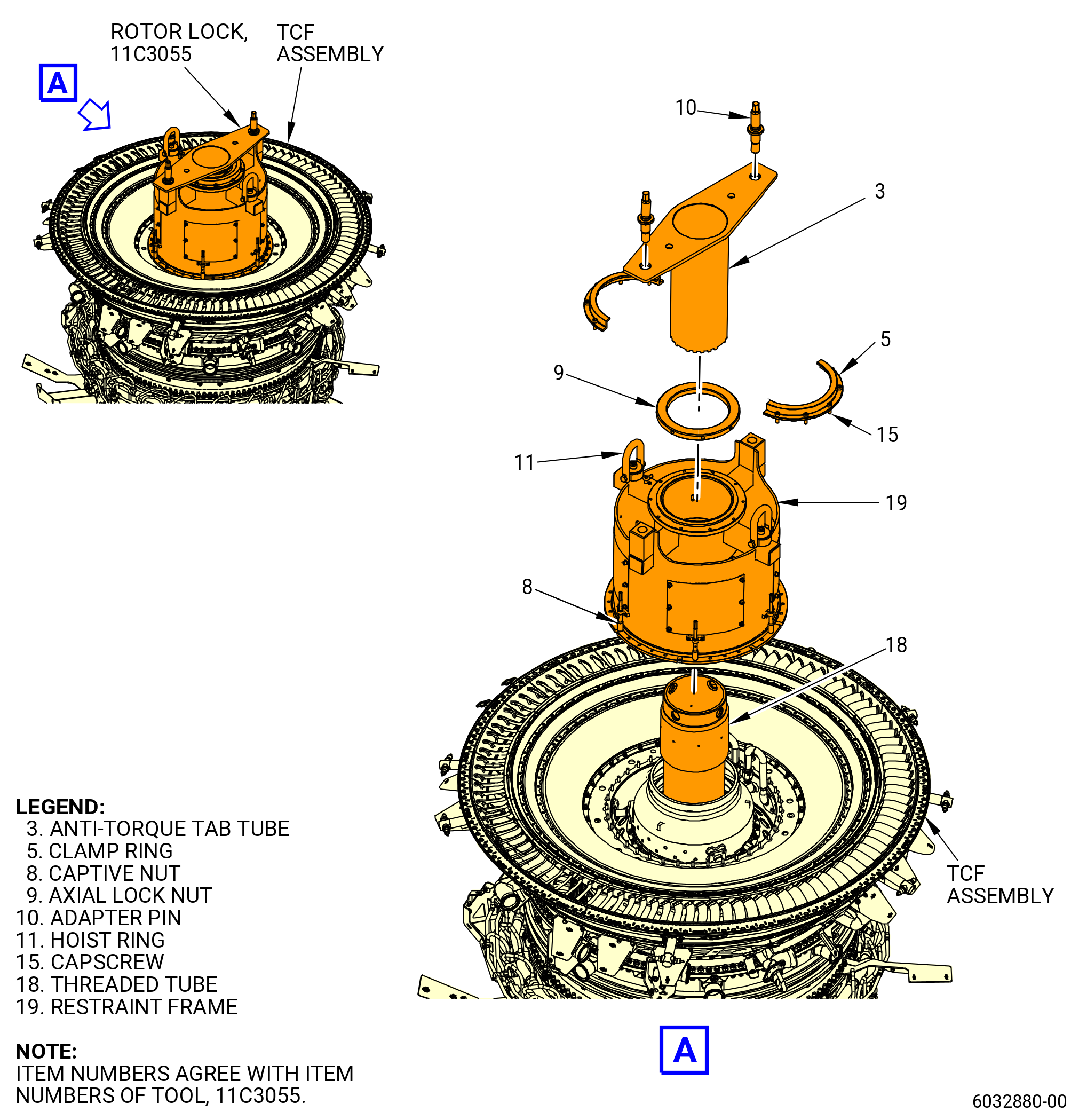
| (2) | Install the 11C3055 rotor lock on the aft end of the TCF assembly (15-130 , 72-54-00) (SIN 925A0) or (15-131 , 72-54-00) (SIN 925A0). Refer to Figure 1022 and do as follows: |
| (3) | Install the threaded tube (item 18) as follows: |
| (a) | Put a leverage bar through the 1.00 inch (25.4 mm) diameter holes at the aft end of the threaded tube (item 18). |
| (b) | Thread the forward end of the threaded tube (item 18) into the aft end of the stage 1 HPT rotor disk (01-280 , 72-53-00) (SIN 150A1). |
| (c) | Remove the leverage bar from threaded tube (item 18). |
| (4) | Attach an approved overhead hoist to the hoist rings (item 11) on the restraint frame (item 19). |
| WARNING: |
|
| (5) | Lift the 11C3055 rotor lock and install it on the TCF assembly (15-130 , 72-54-00) (SIN 925A0) or (15-131 , 72-54-00) (SIN 925A0). Align the holes on the restraint ring of the restraint frame (item 19) with the studs on the TCF assembly. |
| (6) | Install the captive nuts (item 8) equally spaced on the studs of the TCF assembly (15-130 , 72-54-00) (SIN 925A0) or (15-131 , 72-54-00) (SIN 925A0). |
| (7) | Torque the captive nuts (item 8) to 120.0 lb in. (13.56 N.m). |
| (8) | Remove the overhead hoist from the hoist rings (item 11). |
| (9) | Put the anti-torque tube (item 3) in the threaded tube (item 18) until the slots engage in the stage 1 HPT rotor disk (01-280 , 72-53-00) (SIN 150A1). |
| (10) | Put the adapter pins (item 10) in the anti-torque tube (item 3) and thread it into the restraint frame (item 19). Make sure that there is a 0.125 inch (3.18 mm) gap between the anti-torque tube (item 3) and the restraint frame (item 19) when the adapter pins (item 10) are installed. |
| (11) | Tighten the axial lock nut (item 9) with a spanner wrench. |
| (12) | Keep a clearance of approximately 0.010 inch (0.25 mm) between the axial lock nut (item 9) and the restraint frame (item 19). Use a shim stock or other measurement method to make sure of the proper size of the clearance. |
| (13) | Install the two segments of the clamp ring (item 5) to the restraint frame (item 19) with ten capscrews (item 15). |
| (14) | Torque the capscrews (item 15) to 120.0 lb in. (13.56 N.m). |
| Subtask 72-00-02-430-979 |
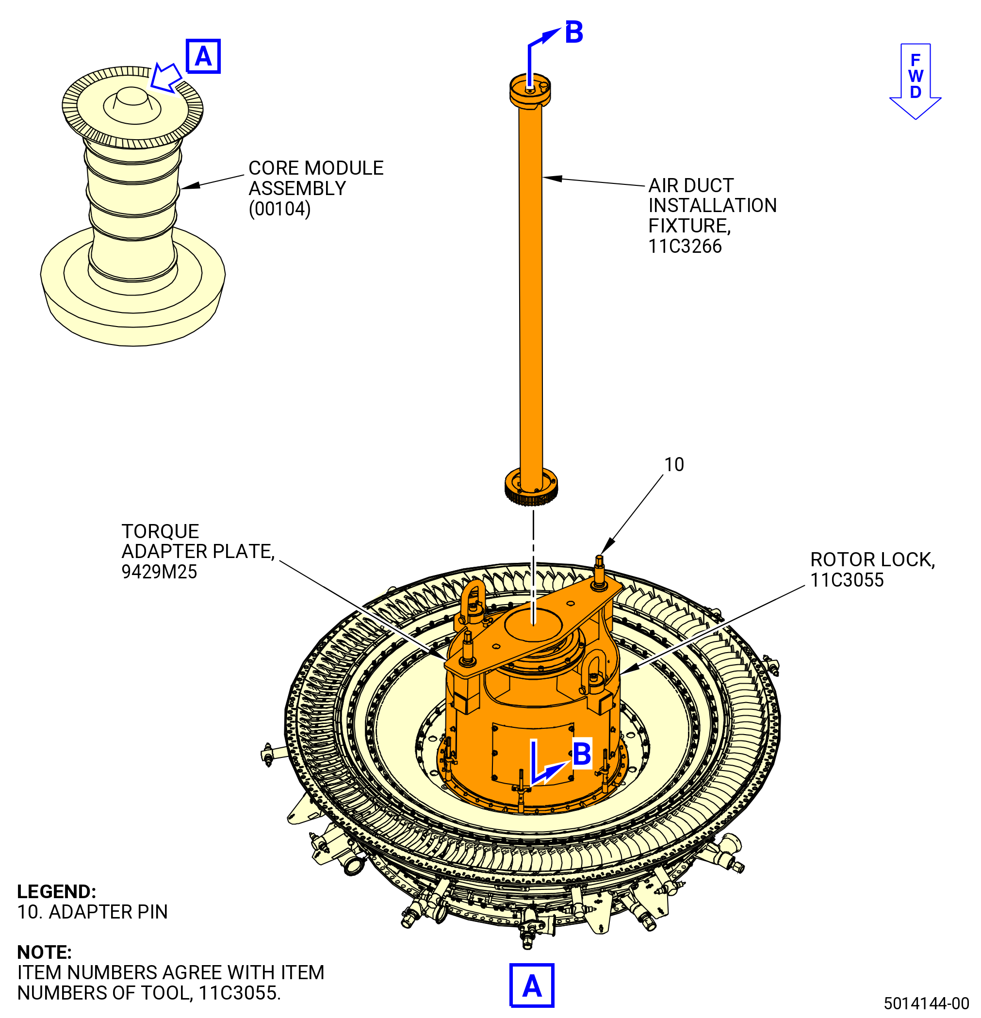
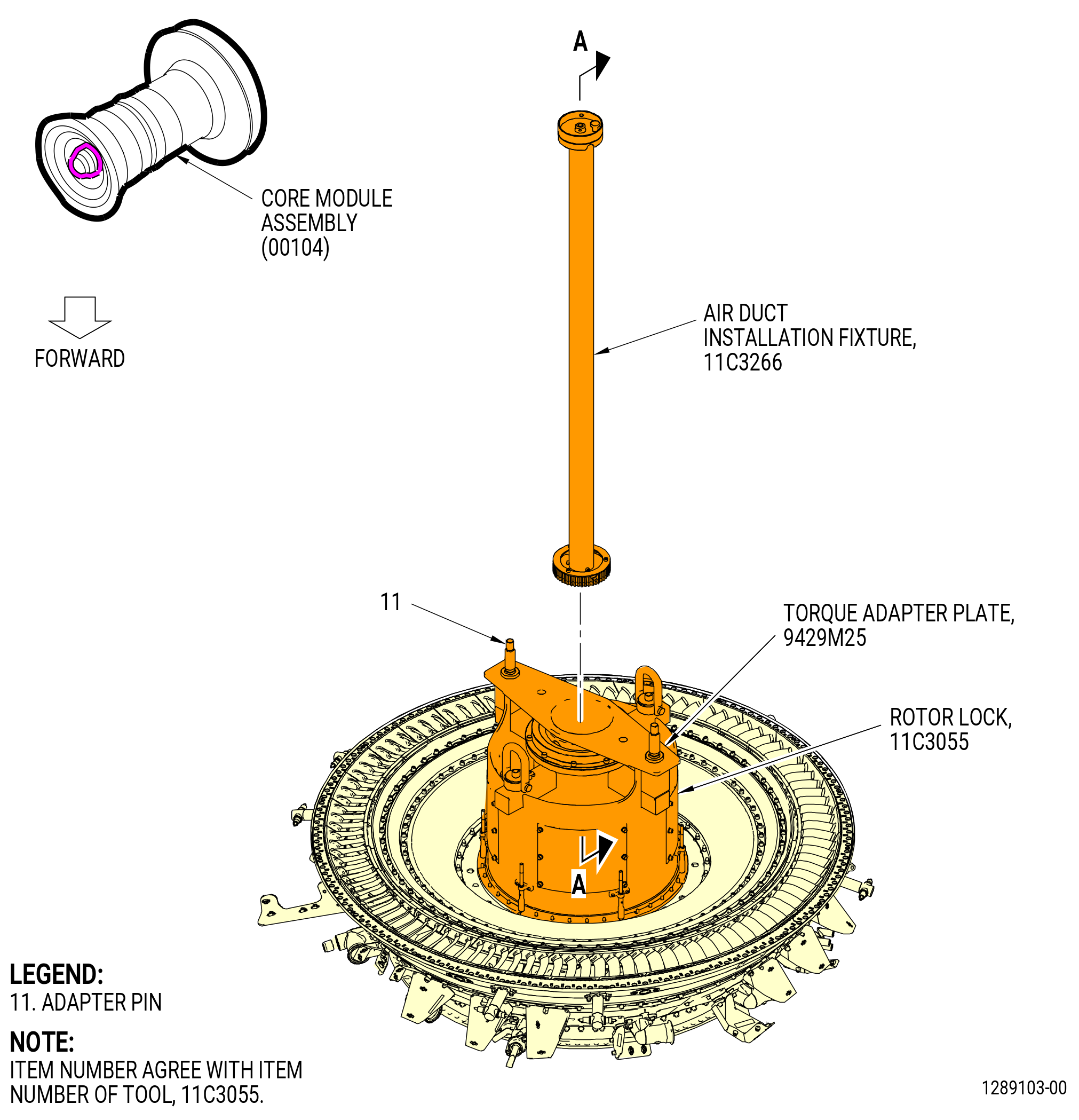
| (15) | Put the 9429M25 torque adapter plate on the 11C3055 rotor lock and attach firmly with the adapter pins (item 10). Refer to Figure 1023. |
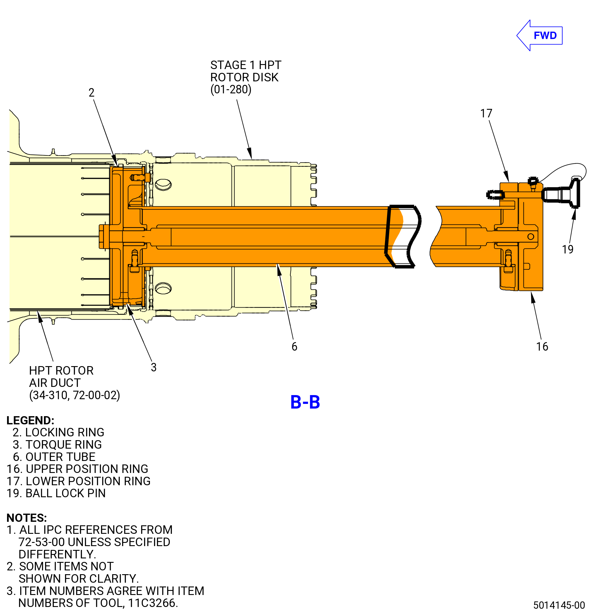
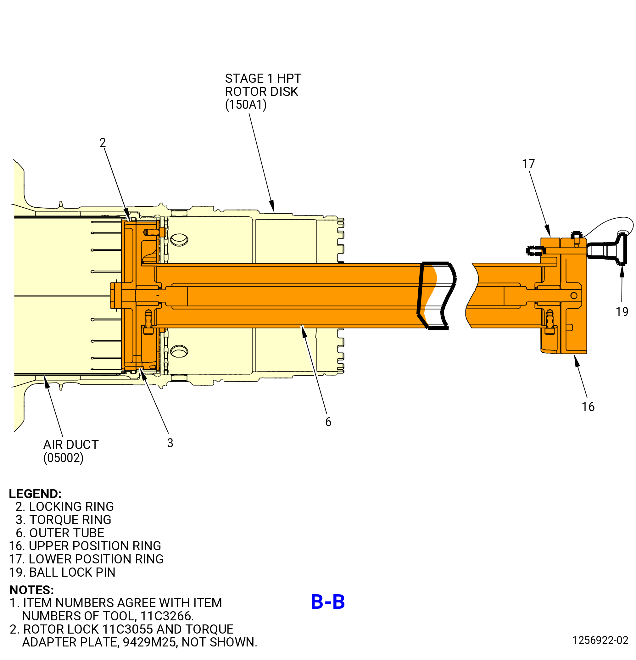
| (16) | Install the HPT rotor air duct (34-310) (SIN 05002) in the stage 1 HPT rotor disk (01-280 , 72-53-00) (SIN 150A1) with the 11C3266 air duct installation fixture as follows: |
| (a) | Turn the lower position ring (item 17), in relation to the upper position ring (item 16), until the teeth in the locking ring (item 2) and the torque ring (item 3) are aligned. |
| (b) | Make sure that the ball lock pin (item 19) is in the slot of the UNLOCKED position. |
| CAUTION: |
|
| (c) | Put the fixture in the center so the teeth of the fixture is in the teeth of the HPT rotor air duct (34-310) (SIN 05002). The 11C3266 air duct installation fixture must be held very tightly at all times to prevent movement that could damage the propulsor assembly. |
| NOTE: |
|
| (d) | Remove the ball lock pin (item 19) and turn the lower position ring (item 17), in relation to the upper position ring (item 16), until the locking ring (item 2) is in the LOCKED position. Make sure that the ball lock pin (item 19) must be in the slot of the LOCKED position. |
| NOTE: |
|
| (e) | Move the HPT rotor air duct (34-310) (SIN 05002) aft with the fixture. |
| (f) | Hold the 11C3266 air duct installation fixture very tightly and move the outer tube (item 6) to align the outer threads on the HPT rotor air duct (34-310) (SIN 05002) with the inner threads of the stage 1 HPT rotor disk (01-280 , 72-53-00) (SIN 150A1) aft shaft. |
| (g) | Manually turn the fixture in a CCW direction to thread the HPT rotor air duct (34-310) (SIN 05002) into the stage 1 HPT rotor disk (01-280 , 72-53-00) (SIN 150A1). |
| (h) | Turn the HPT rotor air duct a minimum of two turns, until it bottoms out in the disk. |
| (i) | Remove the ball lock pin (item 19). |
| (j) | Turn the lower position ring (item 17) to disengage the splines from the HPT rotor air duct. |
| (k) | Remove the 11C3266 air duct installation fixture. |
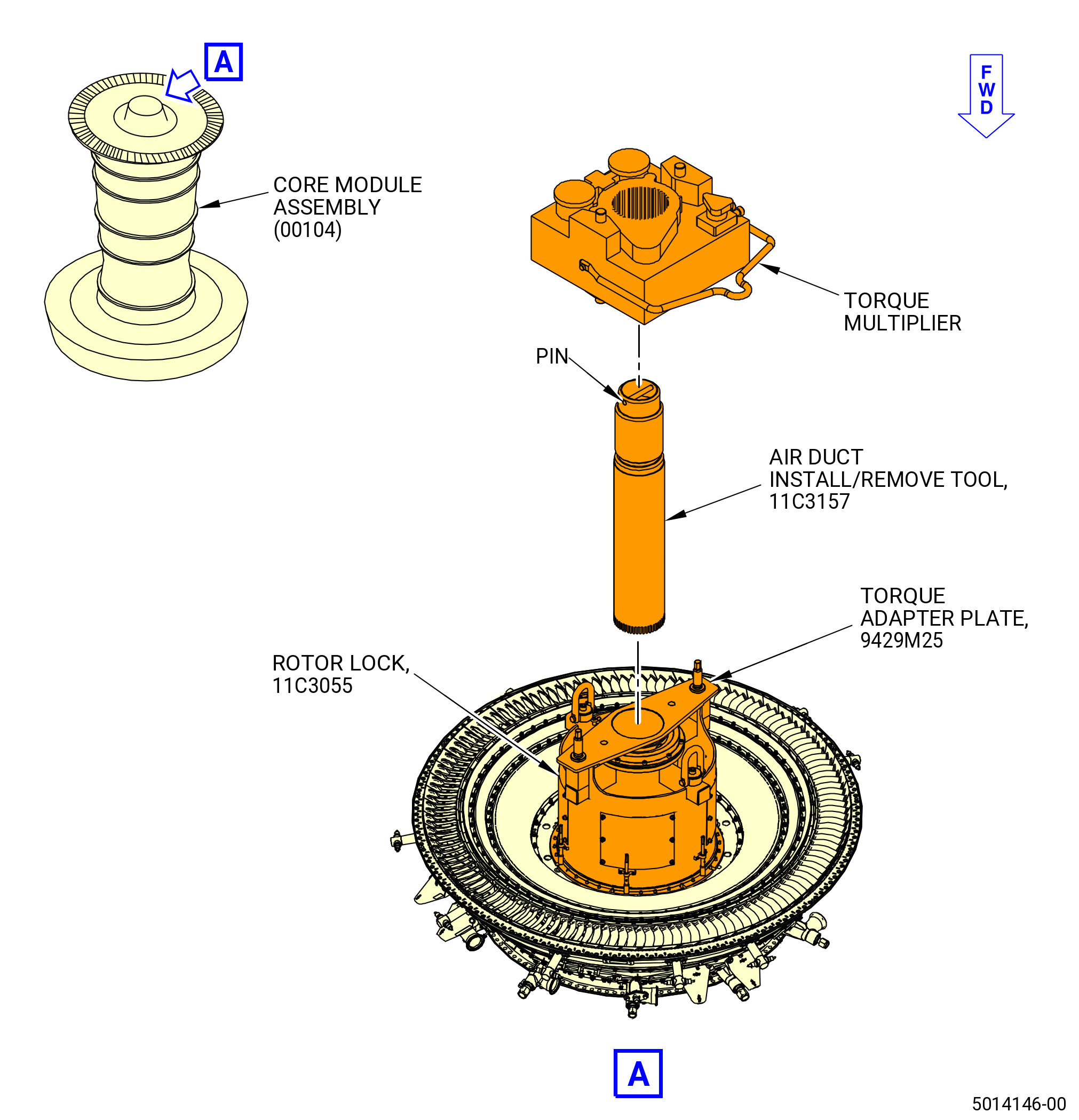
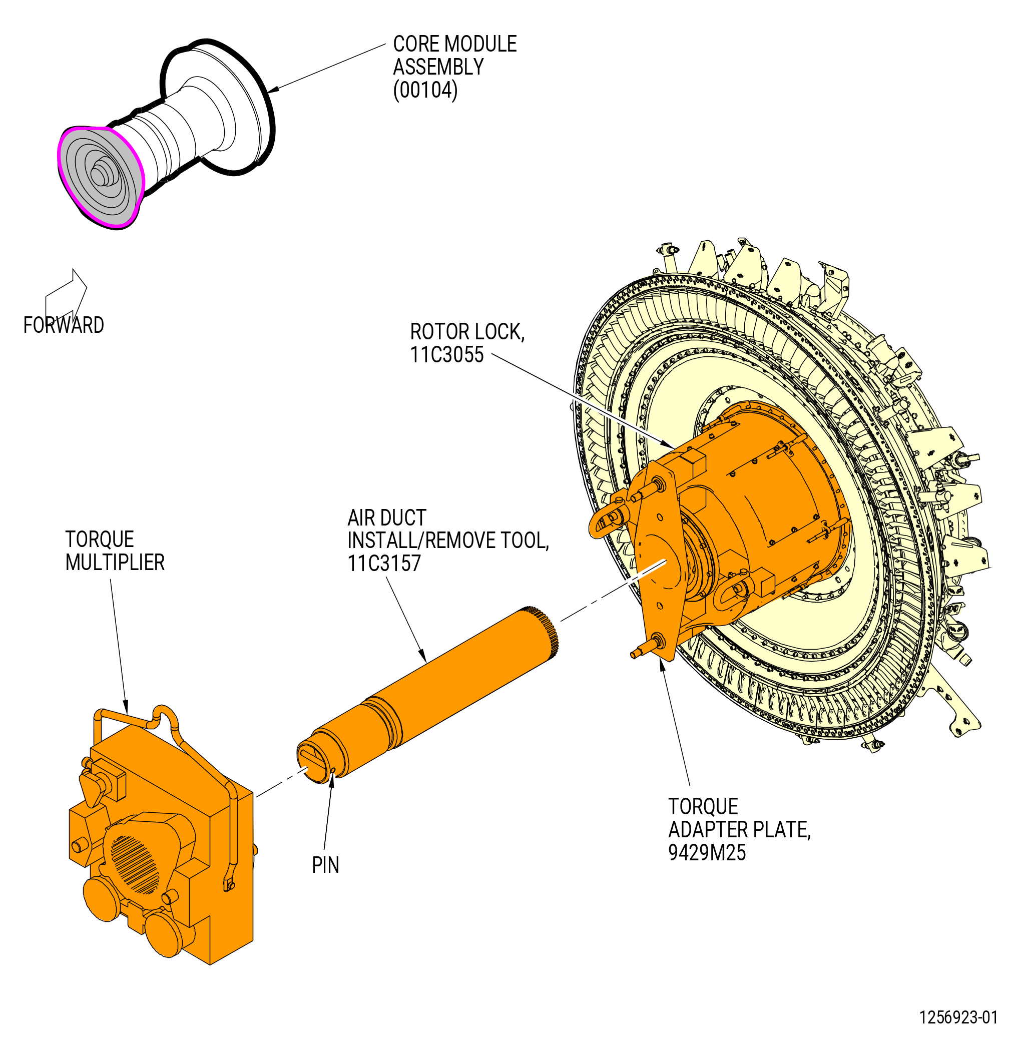
| (17) | Install the 11C3157 air duct install/remove tool. Refer to Figure 1024 and do as follows: |
| (a) | Clean the tool with a clean, lint-free cloth. |
| (b) | Attach an overhead hoist to the pin on the aft end of the tool. |
| WARNING: |
|
| (c) | Lift the tool and put the forward end in the 9429M25 torque adapter plate and the 11C3055 rotor lock. |
| (d) | Center the tool and engage the splines in the HPT rotor air duct (34-310) (SIN 05002). |
| (18) | Torque the HPT rotor air duct (34-310) (SIN 05002) as follows: |
| (a) | Use a driver and turn the HPT rotor air duct CCW three complete turns to find the run-on torque. |
| (b) | Make sure that the run-on torque is 0-50 lb ft (0-68 N.m). If the run-on torque is more than 50 lb ft (68 N.m), remove the HPT rotor air duct and find the problem. |
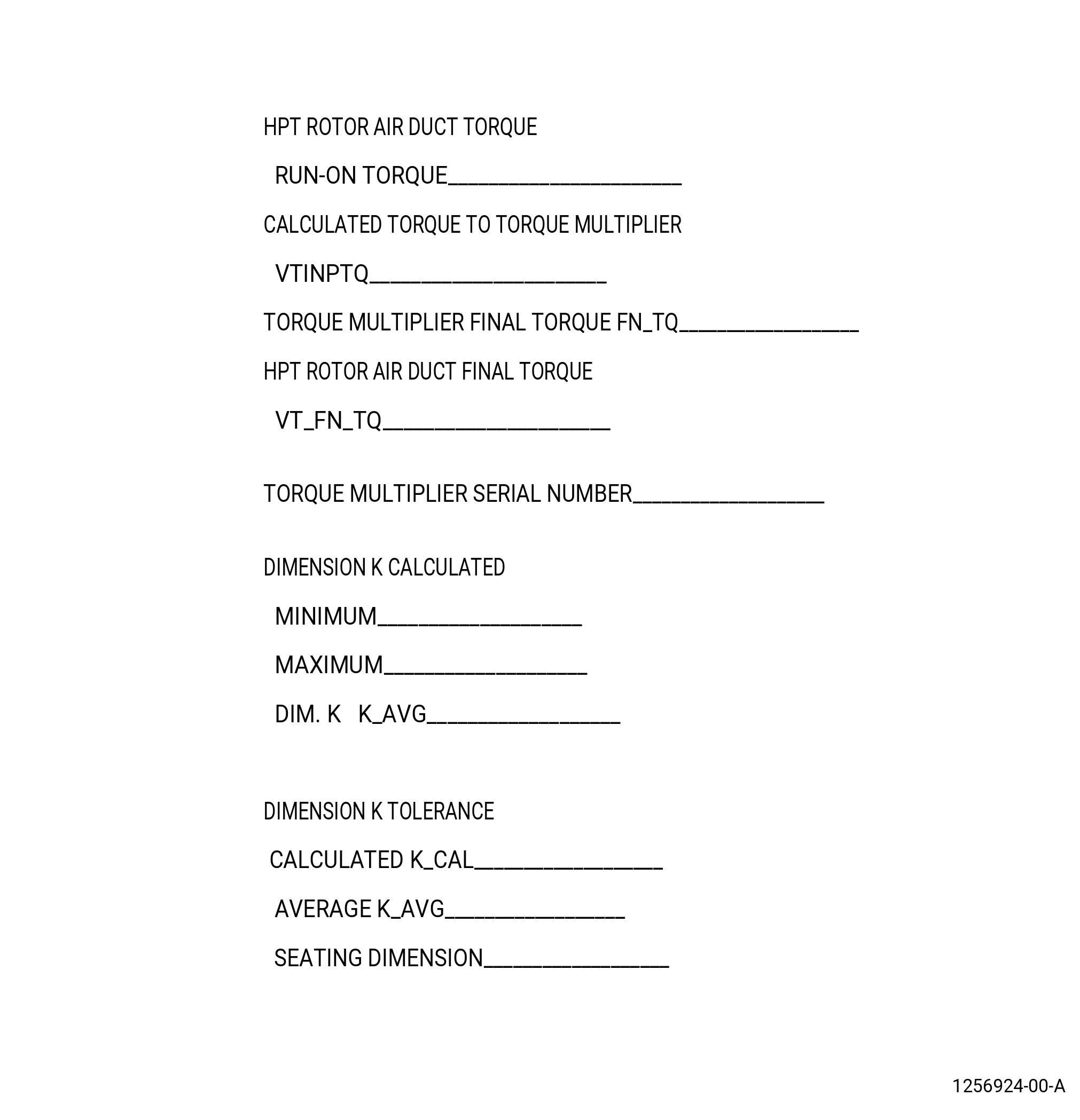
| (c) | Record the run-on torque as VTROTQ. Refer to Figure 1021. |
| (d) | Install the torque multiplier on the 11C3157 air duct install/remove tool, record the serial number of the torque multiplier, and set the torque multiplier to apply torque in the CCW direction. |
| (e) | Calculate the torque to be applied to the torque multiplier and record as VTINPTO. This adds the run-on torque to 500 lb ft (678 N.m). |
| (f) | Record the final torque applied to the torque multiplier as FN_TQ. Refer to Figure 1021. |
| (g) | Record the torque applied to the HPT rotor air duct (34-310) (SIN 05002) as VT_FN_TQ. |
| Subtask 72-00-02-430-980 |
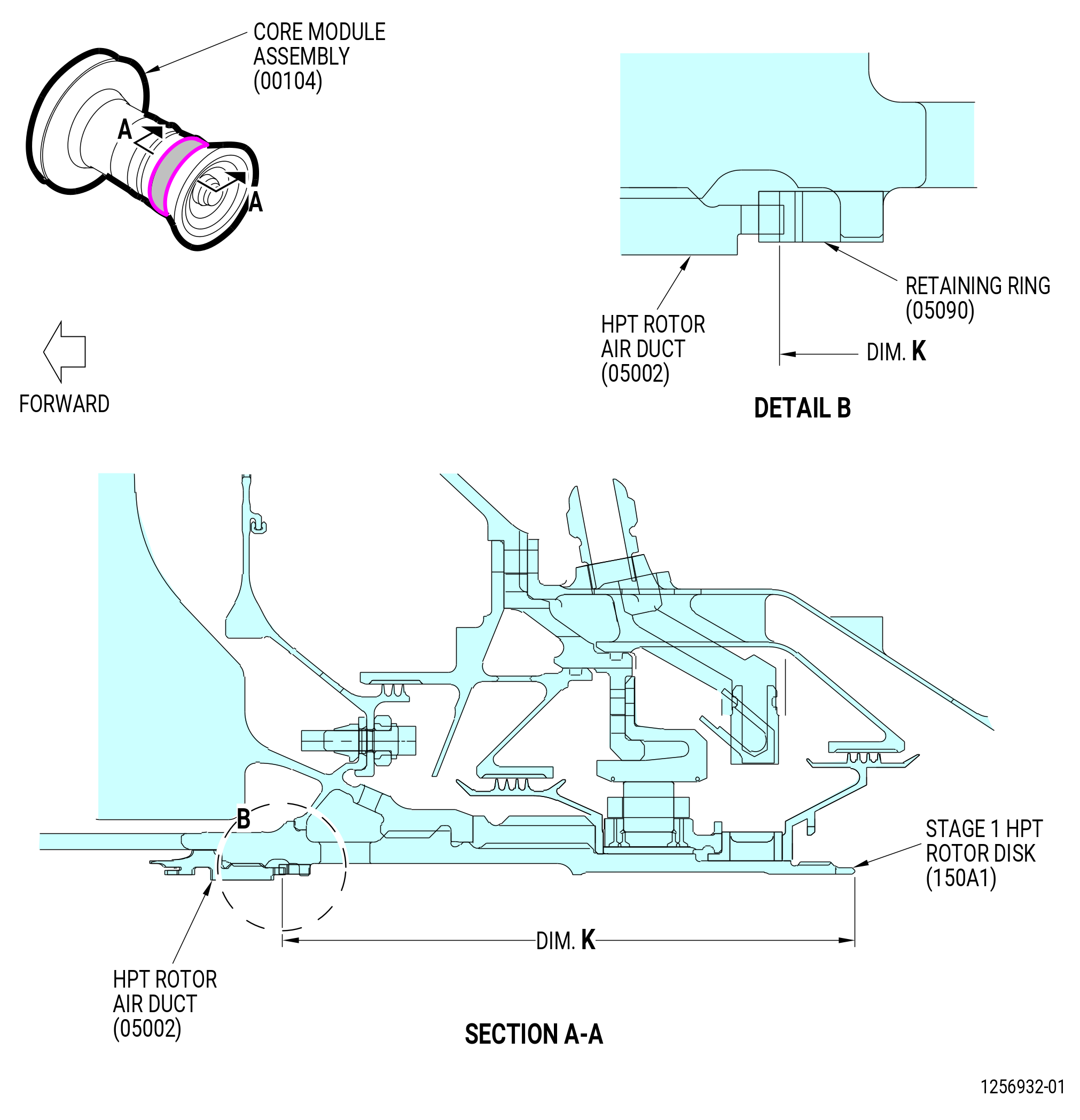
| (19) | Measure dimension K on the HPT rotor air duct (34-310) (SIN 05002) and the stage 1 HPT rotor disk (01-280 , 72-53-00) (SIN 150A1). Refer to Figure 1020 and do as follows: |
| (a) | Get the calculated seating drop for dimension K (calculated) on the record sheet. Refer to Figure 1021. |
| (b) | Measure dimension K at four equally-spaced locations. |
| (c) | Record the minimum and the maximum values for dimension K and calculate the average. Record the average on the record sheet as K_AVG. |
| (d) | Compare the calculated dimension K to the actual dimension K. The tolerance for the seating of the HPT rotor air duct (34-310) (SIN 05002) must be plus or minus 0.003 inch (plus or minus 0.08 mm). |
| (e) | If not in tolerance, continue to torque the HPT rotor air duct (34-310) (SIN 05002) as follows: |
| 1 | Torque the HPT rotor air duct (34-310) (SIN 05002) in increments of 400 lb ft (542 N.m). The maximum torque permitted is 1200 lb ft (1627 N.m). |
| 2 | If the maximum torque is applied and the HPT rotor air duct (34-310) (SIN 05002) seating drop is not plus or minus 0.003 inch (plus or minus 0.08 mm), remove the HPT rotor air duct from the stage 1 HPT rotor disk (01-280 , 72-53-00) (SIN 150A1). Determine the cause of the error, inspect, and install. |
| (20) | Remove the torque multiplier. |
| (21) | Remove the adapter pins (item 10) of the 11C3055 rotor lock and remove the 9429M25 torque adapter plate. |
| (22) | Remove the 11C3055 rotor lock. |
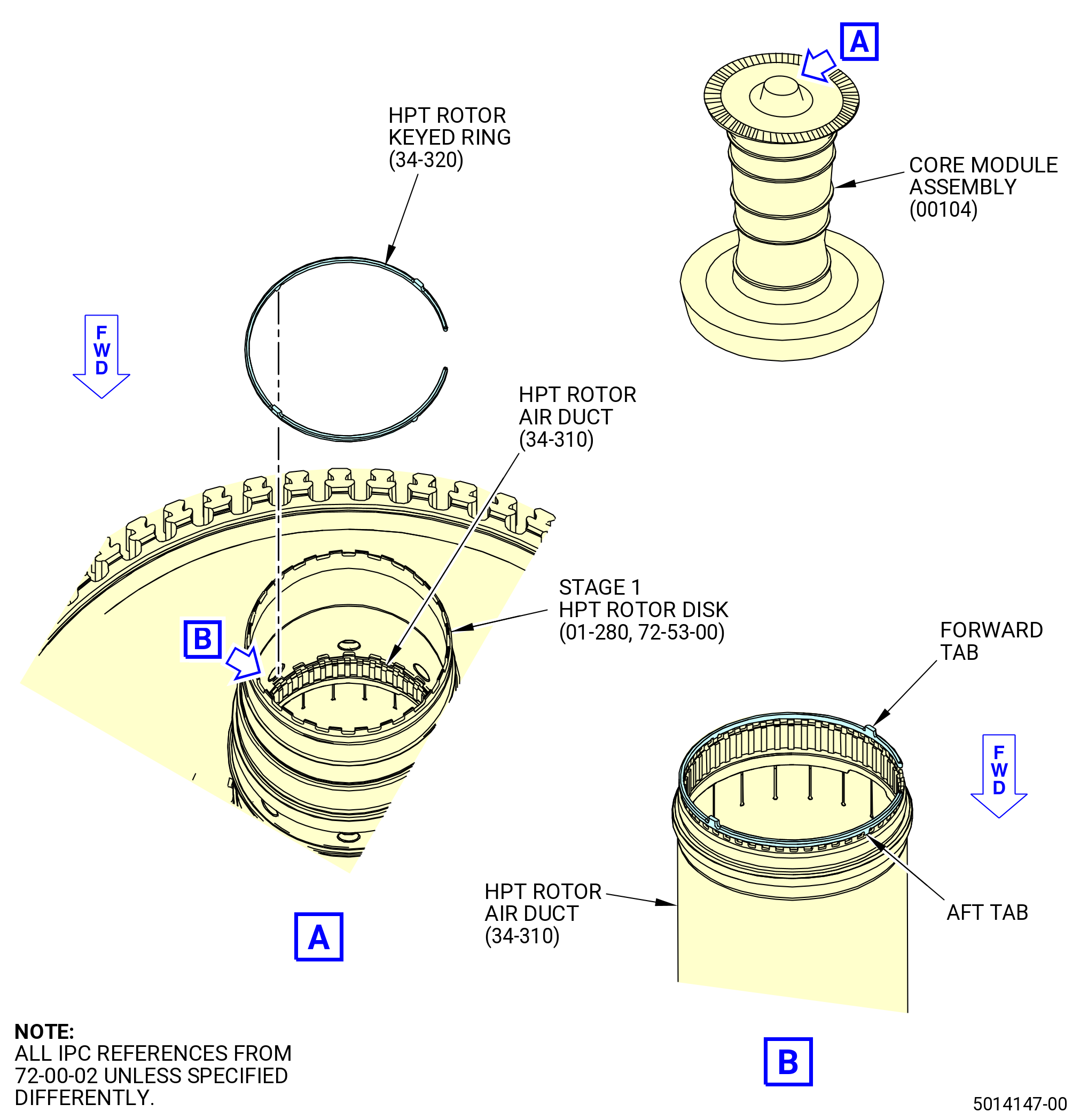
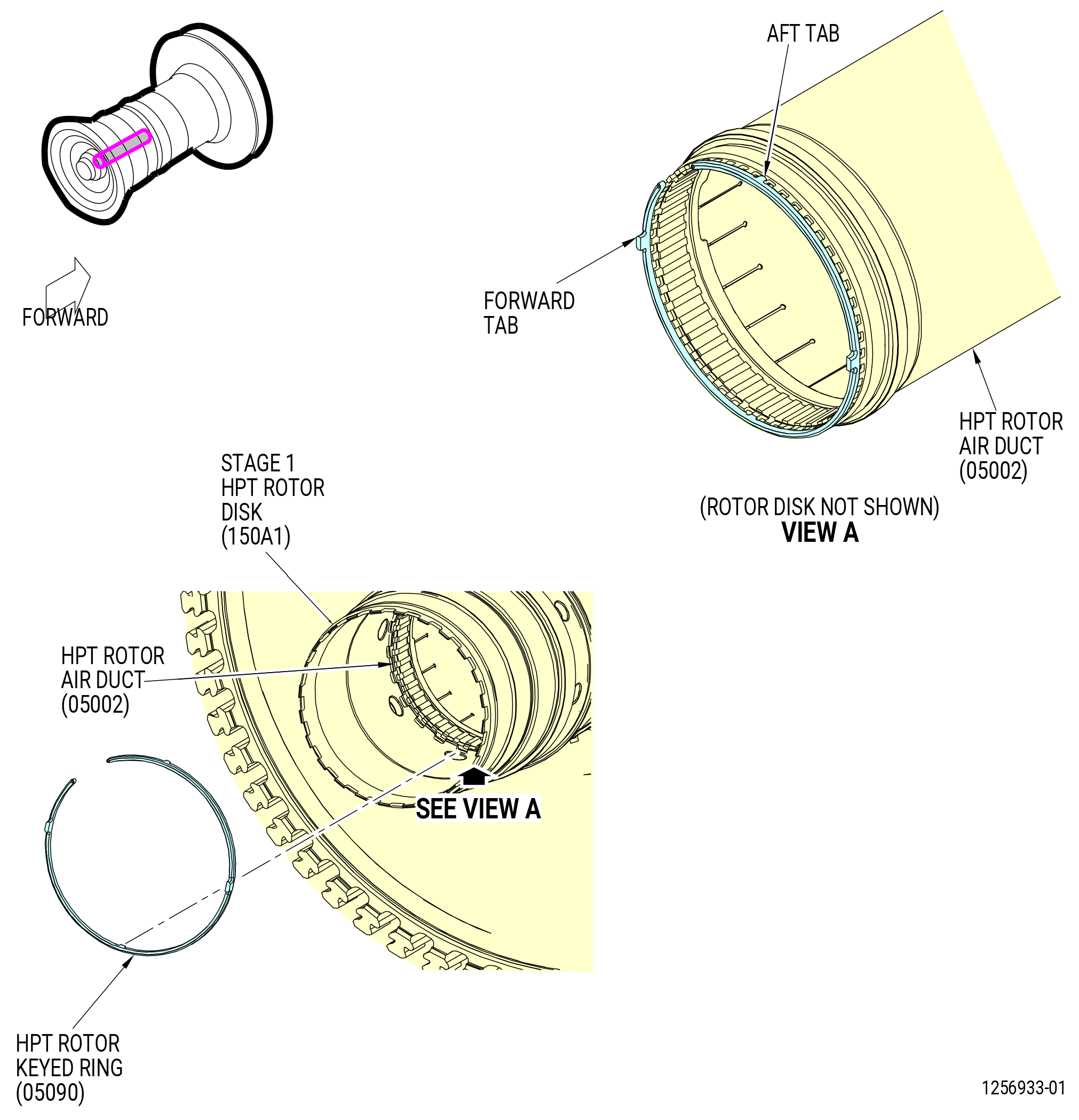
| (23) | Install the HPT rotor keyed ring (34-320) (SIN 05090) in the groove between the HPT rotor air duct (34-310) (SIN 05002) and the stage 1 HPT rotor disk (01-280 , 72-53-00) (SIN 150A1) with the tabs on the ring forward. |
| NOTE: |
|
| (24) | Make sure that the aft tabs (chamfered end) are in the slots of the rotor disk and that the forward tabs are in the castellations of the HPT rotor air duct. Refer to Figure 1025. |
| Subtask 72-00-02-220-110 |
| (25) | Do a general visual inspection of the exposed surfaces of HPT rotor stage 1 disk for nicks, dents, and scratches after the removal of tooling. Refer to TASK 72-00-53-200-802 (72-00-53, INSPECTION 001). |
| Subtask 72-00-02-430-731 |
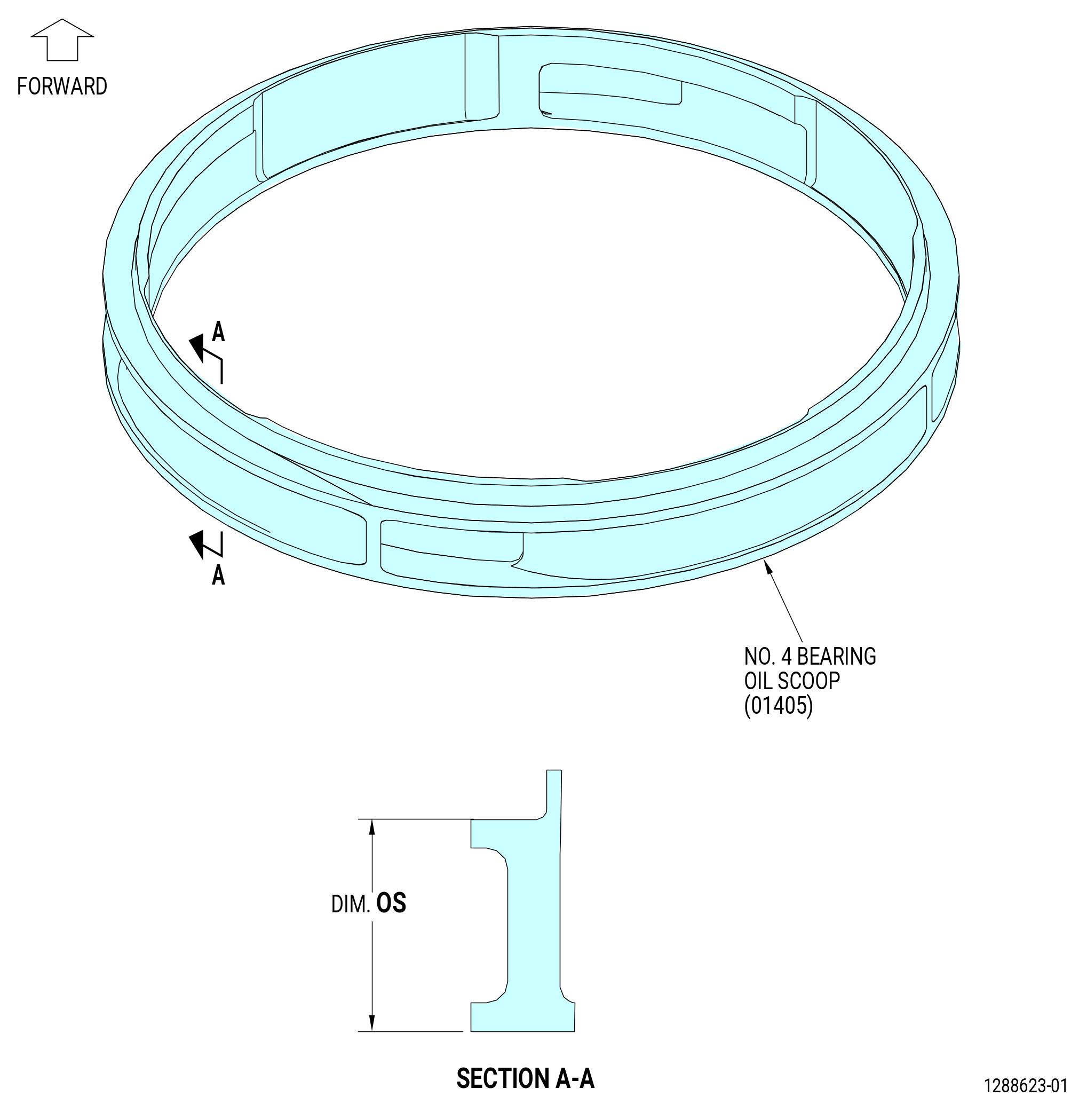
| T. | Install the No. 4 bearing oil radial scoop (No. 4 bearing oil scoop) (01405) and the No. 4 bearing air and oil rotating seal (No. 4 bearing rotating seal) (01408) on the stage 1 HPT rotor disk (150A1) as follows: |
| (1) | Measure dimension OS for the No. 4 bearing oil scoop (01405) as follows. Refer to Figure 1026. |
| (a) | Measure the dimension OS at four equally spaced locations. |
| (b) | Record the minimum value and the maximum value for dimension OS on the Record Sheet. Refer to Figure 1027. |
| (c) | The tolerance for dimension OS is 0.739-0.749 inch (18.77-19.02 mm). |
| (d) | If dimension OS is not in tolerance, replace the No. 4 bearing oil scoop (01405). |
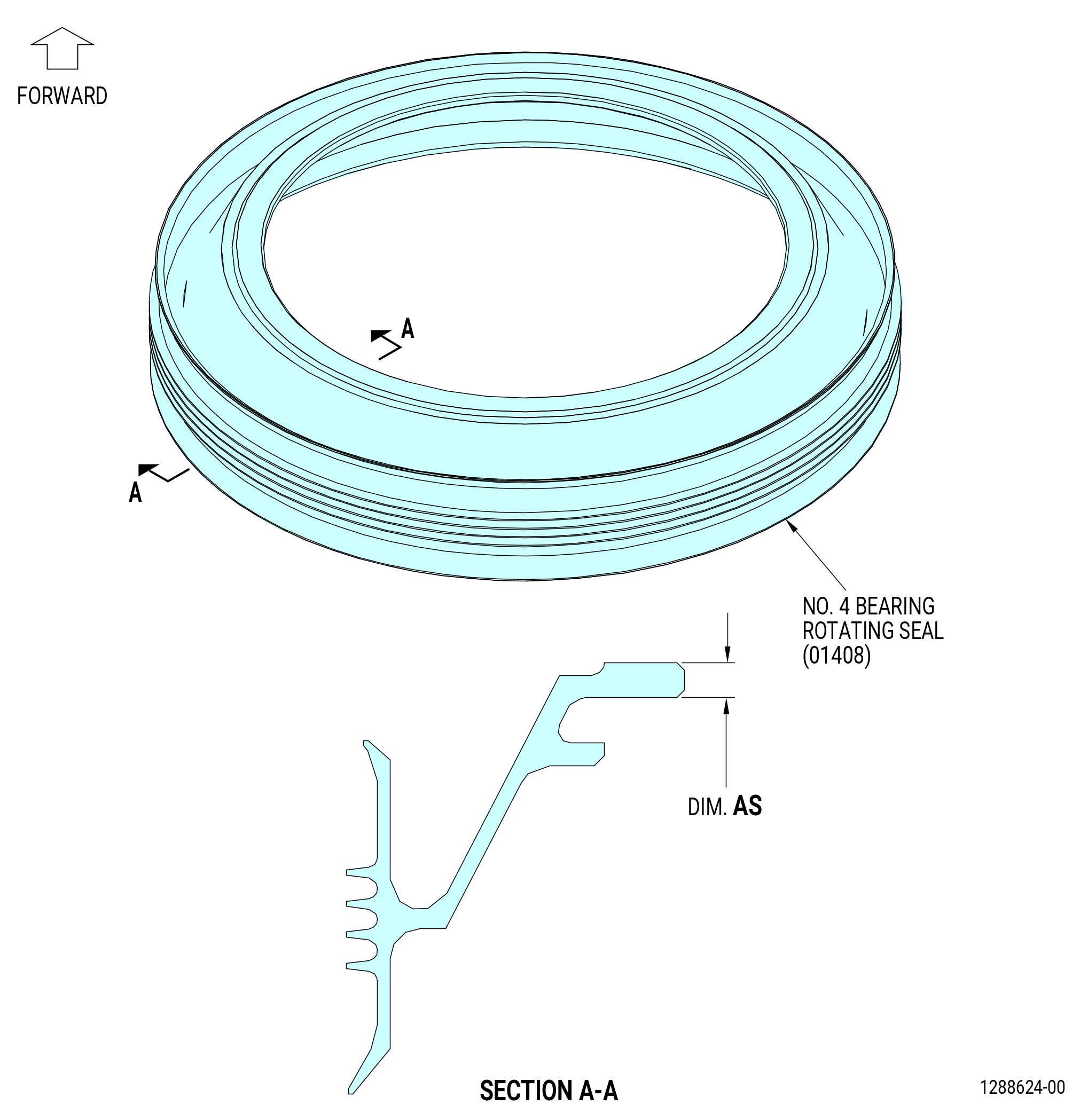
| (2) | Measure dimension AS for the No. 4 bearing rotating seal (01408) as follows. Refer to Figure 1028. |
| (a) | Measure the dimension AS at four equally spaced locations. |
| (b) | Record the minimum value and the maximum value for dimension AS on the Record Sheet. Refer to Figure 1027. |
| (c) | The tolerance for dimension AS is 0.138-0.140 inch (3.51-3.56 mm). If dimension AS is not in tolerance, replace the No. 4 bearing rotating seal (01408). |
| Subtask 72-00-02-370-001 |
| WARNING: |
|
| (3) | Heat the No. 4 bearing oil scoop (35-410) (SIN 01405) and the No. 4 bearing rotating seal (35-400) (SIN 01408) to a temperature range of 300 to 350°F (149 to 177°C). Use a temperature probe to make sure that the No. 4 bearing oil scoop and the No. 4 bearing rotating seal temperature is 300 to 350°F (149 to 177°C). |
| NOTE: |
|
| Subtask 72-00-02-500-003 |
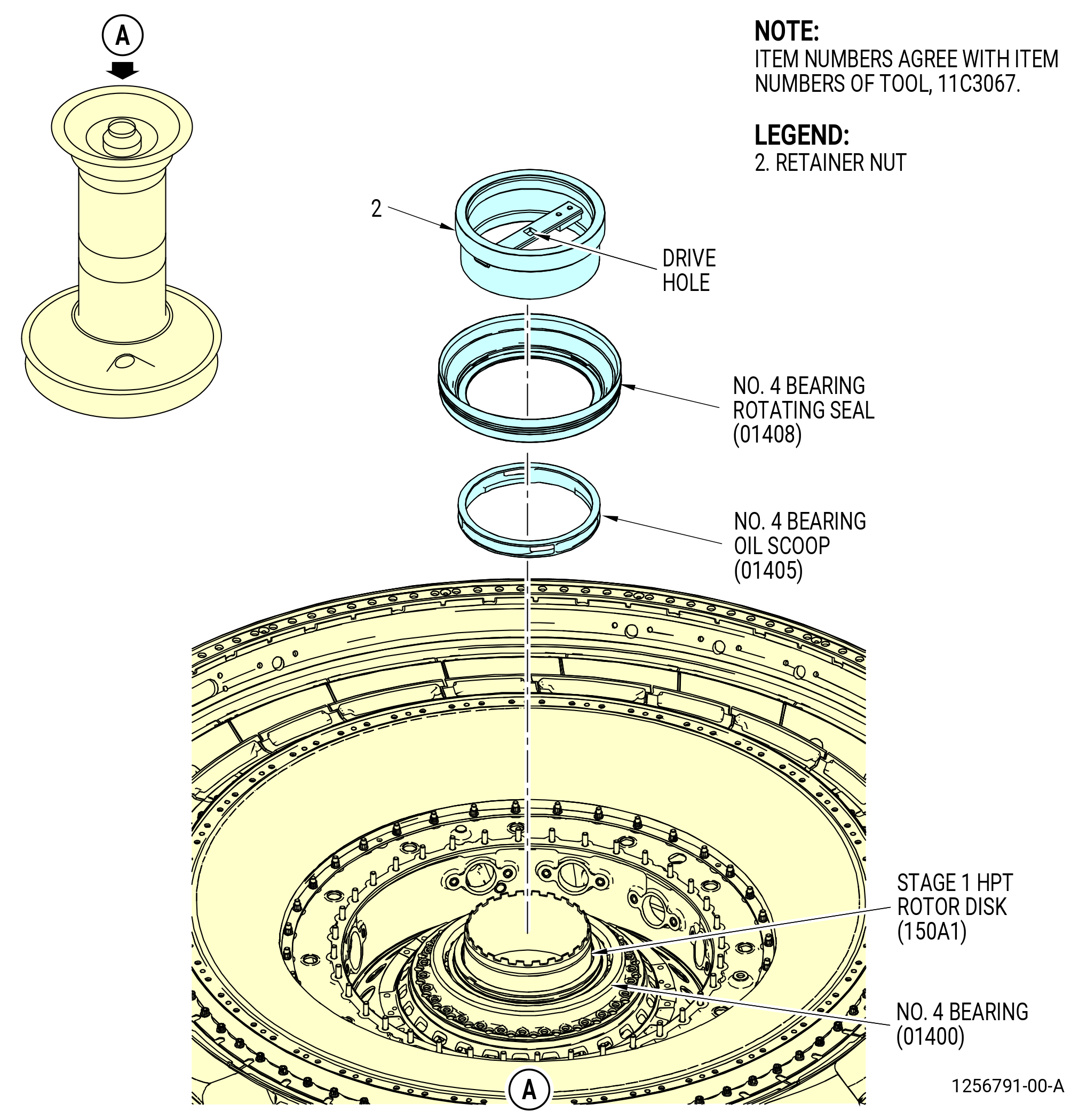
| (4) | Install No. 4 bearing oil scoop (01405) and the No. 4 bearing rotating seal (01408) on the stage 1 HPT rotor disk (150A1) as follows: |
| CAUTION: |
|
| (a) | Inspect the mating surface of the retainer nut (item 2) of the 11C3067 retainer fixture for high metal. |
| WARNING: |
|
| (b) | Put the No. 4 bearing oil scoop (01405) on the stage 1 HPT rotor disk (150A1) with the flat side aft. Refer to Figure 1029. |
| (c) | Put the No. 4 bearing rotating seal (01408) on the stage 1 HPT rotor disk (150A1). |
| (d) | Install the 11C3067 retainer fixture on the No. 4 bearing rotating seal (01408) with the end marked USE FOR RETAINING AFT SEAL on the rotating seal. Rotate the fixture CW to install. Refer to Figure 1030. |
| (e) | If the No. 4 bearing oil scoop (01405) and No. 4 bearing rotating seal (01408) are not fully seated, the retainer nut (item 2) has to be removed, inspected, and re-seated. |
| (f) | If the No. 4 bearing oil scoop (01405) and No. 4 bearing rotating seal (01408) are fully seated continue the installation process. |
| (g) | Tighten the 11C3067 retainer fixture to seat the No. 4 bearing oil scoop (01405) and the No. 4 bearing rotating seal (01408). Use a 0.5 inch (12.7 mm) drive in the drive hole to tighten the fixture. Make sure that the oil scoop and seal are seated. |
| (h) | Allow the 11C3067 retainer fixture to cool to room temperature. |
| (i) | Remove the 11C3067 retainer fixture from the stage 1 HPT rotor disk (150A1). |
| (5) | Measure the seating dimension ASACT for the No. 4 bearing oil scoop (01405) and the No. 4 bearing rotating seal (01408) as follows. Refer to Figure 1031. |
| (a) | Measure the seating dimension ASACT at four equally spaced locations. |
| (b) | Record the minimum value and the maximum value for dimension ASACT on the Record Sheet. Refer to Figure 1027. |
| (c) | The tolerance for dimension ASACT is 0.7507-0.7977 inch (19.068-20.261 mm). |
| Subtask 72-00-02-431-052 |
| U. | Install the 11C3055 rotor lock on the aft end of the turbine center frame assembly (35-009) (SIN 92500), (35-010) (SIN 92500), (35-011) (SIN 92500), (35-012) (SIN 92500), or (35-015) (SIN 92500). Refer to Figure 1032 and do as follows: |
| (1) | Install the threaded tube (item 18) as follows: |
| (a) | Put a leverage bar through the 1.00 inch (25.4 mm) diameter holes at the aft end of the threaded tube (item 18). |
| (b) | Thread the forward end of the threaded tube (item 18) into the aft end of the stage 1 HPT rotor disk (01-280 , 72-53-00) (SIN 150A1) or (02-280 , 72-53-00) (SIN 150A1). |
| (c) | Remove the leverage bar from the threaded tube (item 18). |
| (2) | Attach a lift strap to the hoist rings (item 11) on the restraint frame (item 19). |
| (3) | Use an overhead hoist to lift the 11C3055 rotor lock and align the holes on the restraint ring of the restraint frame (item 19) with the studs on the turbine frame assembly. Lower the HPT rotor lock to the turbine frame assembly. |
| (4) | Install the captive nuts (item 8) equally-spaced on the studs of the turbine frame assembly. |
| (5) | Torque the captive nuts (item 8) to 10 lb ft (13.56 Nm). |
| (6) | Remove the lift strap and overhead hoist from the hoist rings (item 11). |
| (7) | Install the axial lock nut (item 9) on the aft end of the threaded tube (item 18), but do not tighten. |
| (8) | Put the anti-torque tube (item 3) in the threaded tube (item 18) and engage the slots in the stage 1 HPT rotor disk (01-280 , 72-53-00) (SIN 150A1) or (02-280 , 72-53-00) (SIN 150A1). |
| (9) | Put the adapter pin (item 10) in the anti-torque tube (item 3) and thread into the restraint frame (item 19). There must be a 0.125 inch (3.18 mm) gap between the anti-torque tube (item 3) and the restraint frame (item 19) when the adapter pins (item 10) are installed. |
| (10) | Tighten the axial locknut (item 9) with a spanner wrench. |
| (11) | Install the two segments of the clamp ring (item 5) to the restraint frame (item 19) with 10 capscrews (item 15). |
| (12) | Torque the capscrews (item 15) to 120 lb in (13.56 Nm). |
| Subtask 72-00-02-430-732 |
| V. | Alternative Procedure Available. Rotate the propulsor assembly to the horizontal position in the 9481M84 assembly stand. Refer to Figure 1033 and do as follows: |
| CAUTION: |
|
| (1) | If the 9481M84 assembly stand was moved, lower the floor locks (item 4) until they touch the floor. Make sure that the assembly stand does not move. |
| (2) | Make sure that all of the bolts that attach the 11C3197 bracket set to the fan hub module (00102) are installed tightly. Refer to Figure 1001. |
| (3) | Attach an overhead hoist to the 7C2015 lift/turn fixture. |
| (4) | Lift and attach the 7C2015 lift/turn fixture to the 11C3025 strongback on the aft end of the propulsor assembly. |
| WARNING: |
|
| CAUTION: |
|
| (5) | Apply lift pressure to the 7C2015 lift/turn fixture. |
| CAUTION: |
|
| (6) | Move the support (item 5) of the 9481M84 assembly stand to the location where the aft end of the propulsor will be turned to the horizontal position. Do not torque the capscrews (item 29) that attach the support (item 5) to the frame until the alignment to the 11C3025 strongback is done. |
| (7) | Remove the ball-lock pins (items 12 and 17) of the 9481M84 assembly stand that attach the 11C3197 bracket set to the propulsor assembly. |
| (8) | Carefully rotate the propulsor assembly to the horizontal position. |
| (9) | Attach the support (item 5) of the 9481M84 assembly stand to the 11C3025 strongback with the ball-lock pin (item 11). |
| (10) | Secure the propulsor assembly to the 9481M84 assembly stand in the horizontal position. |
| Subtask 72-00-02-430-866 |
| V.A. | Alternative Procedure. Rotate the propulsor assembly to the horizontal position from the 11C4582 core module build-up fixture into the pedestals. Refer to Figure 1033A and do as follows: |
| WARNING: |
|
| CAUTION: |
|
| (1) | Lift and attach the 7C2015 lift/turn fixture to the 11C3025 strongback on the aft end of the propulsor assembly. |
| (2) | Attach an overhead hoist to the 7C2015 lift/turn fixture. |
| (3) | Loosen the 12 screws (item 3) and washers (item 4) that attach the 11C4582 core module build-up fixture to the fan hub module assembly. |
| (4) | Apply lift pressure to the 7C2015 lift/turn fixture. |
| (5) | Lift the propulsor free from the 11C4582 core module build-up fixture. |
| (6) | Attach the 11C4430 bracket set to the fan hub frame (10-400 , 72-25-00) (SIN 84000). |
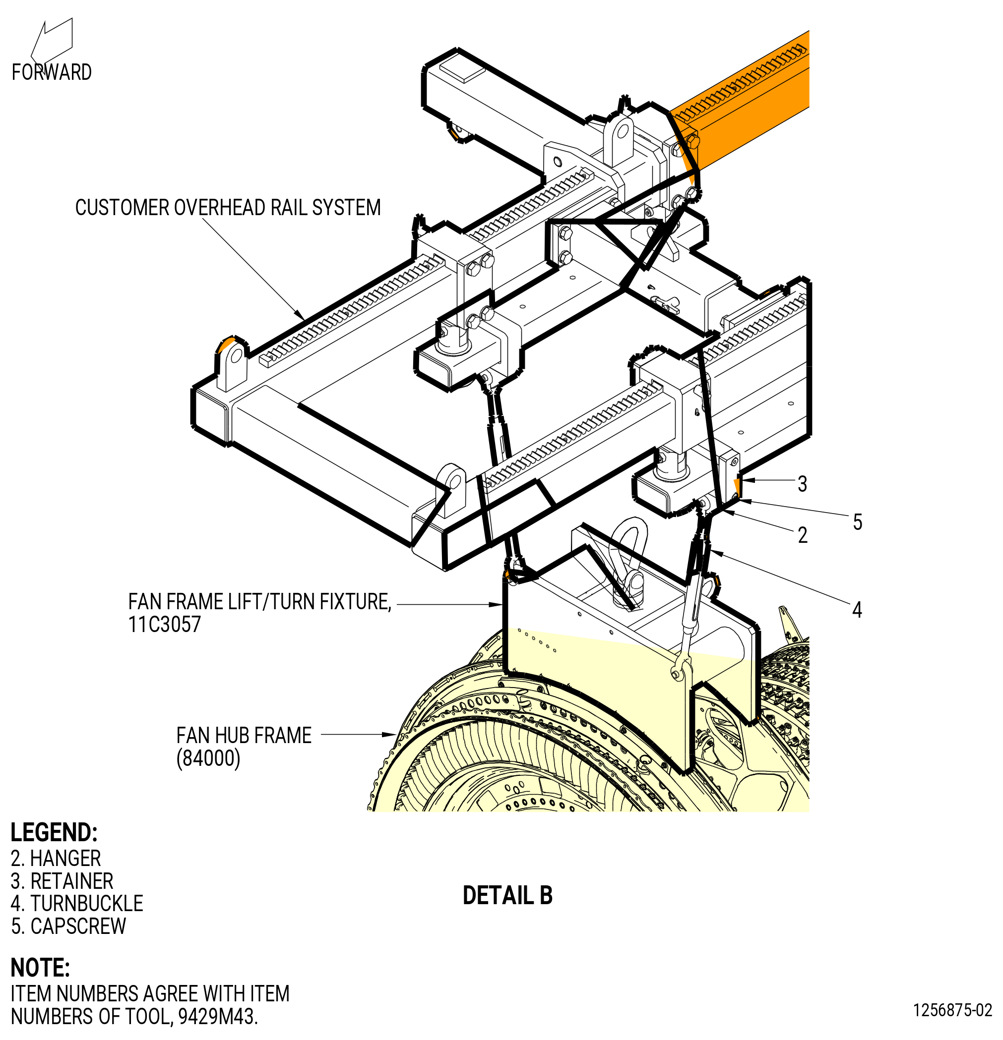
| (7) | Install the 11C3057 fan frame lift/turn fixture and attach an overhead hoist to it. |
| (8) | Lift the 11C3057 fan frame lift/turn fixture to rotate the propulsor. |
| (9) | Lower the 11C3025 strongback . |
| (10) | Lower the propulsor into the 11C3281 pedestals. |
| Subtask 72-00-02-430-733 |
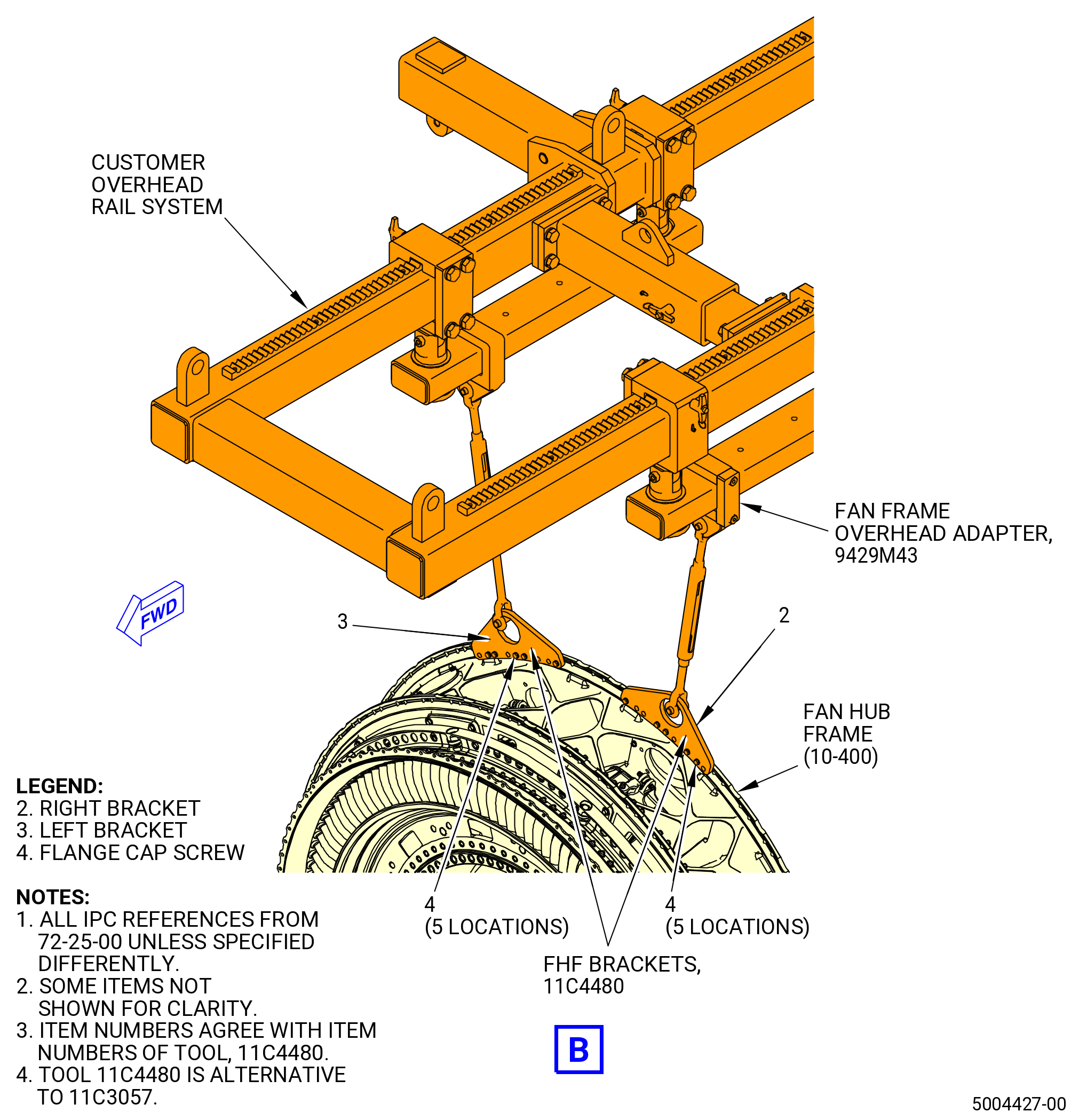
| W. | Install the propulsor assembly on the 11C3044 engine module adapter assembly. The 11C3044 engine module adapter assembly includes the 9429M43 fan frame overhead adapter, the 9429M45 K-flange overhead adapter, the 9429M46 TCF overhead adapter, and the 9429M48 bridge beam adapter. Refer to Figure 1034. |
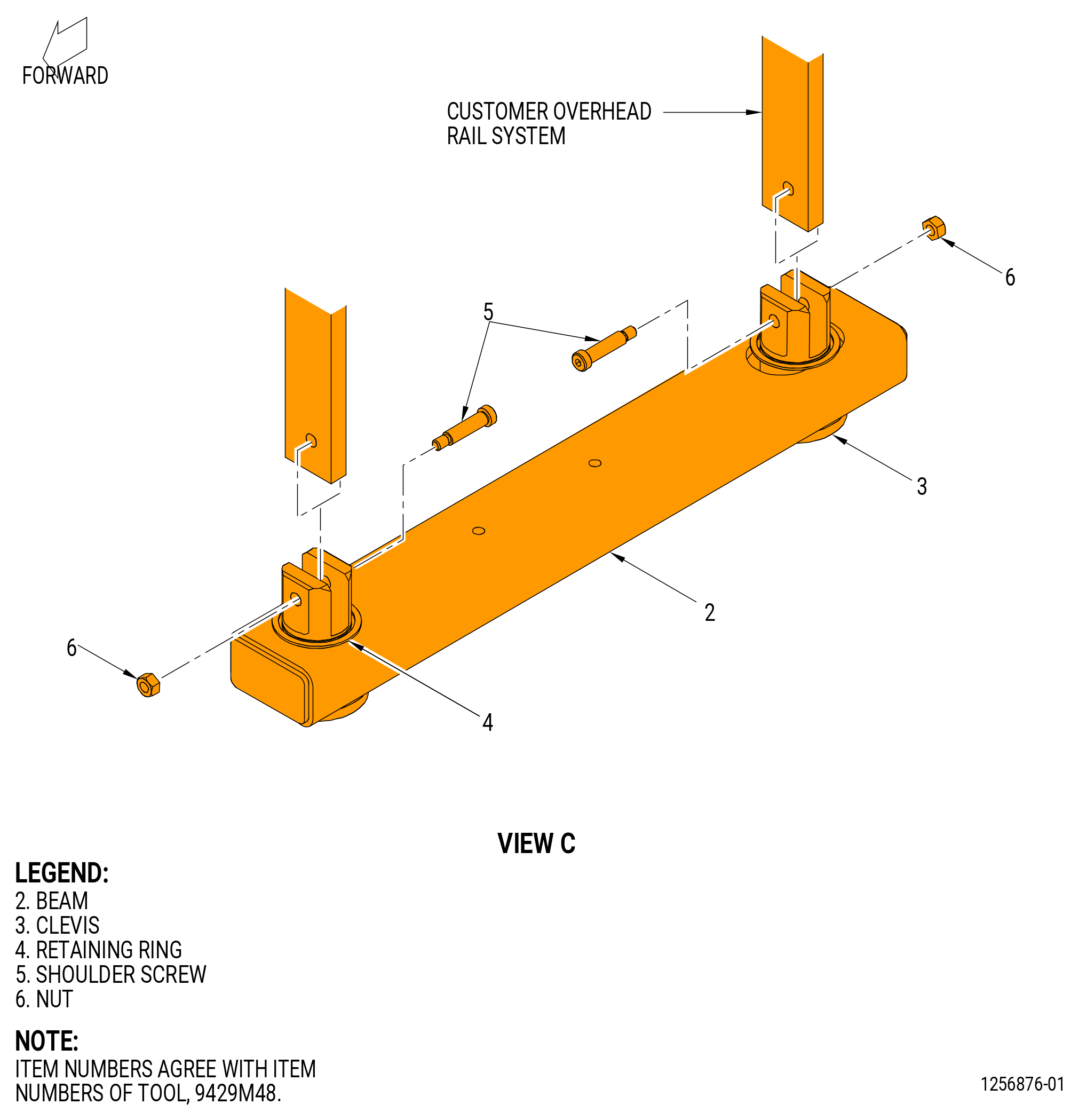
| (1) | Install the 9429M48 bridge beam adapter to the left/right track of the customer overhead rail system as follows: |
| (a) | Put the clevis (item 3) in the hole of the beam (item 2). |
| (b) | Put the retaining ring (item 4) around the groove in the clevis (item 3). |
| (c) | Align the holes of the clevis (item 3) with the customer overhead rail system and secure with shoulder screw (item 5) and nuts (item 6). |
| (2) | Install the 9429M43 fan frame overhead adapter on the 9429M48 bridge beam adapter as follows: |
| (a) | Put the hangers (item 2) of the 9429M43 fan frame overhead adapter on the 9429M48 bridge beam adapter with the open end outward. |
| (b) | Attach the retainers (item 3) with the capscrews (item 5). Do not tighten the capscrew until the customer overhead rail system is aligned to the propulsor assembly. |
| (c) | Attach the turnbuckles (item 4) to the retainers (item 2) with the turnbuckle screw, nut, and cotter pin. |
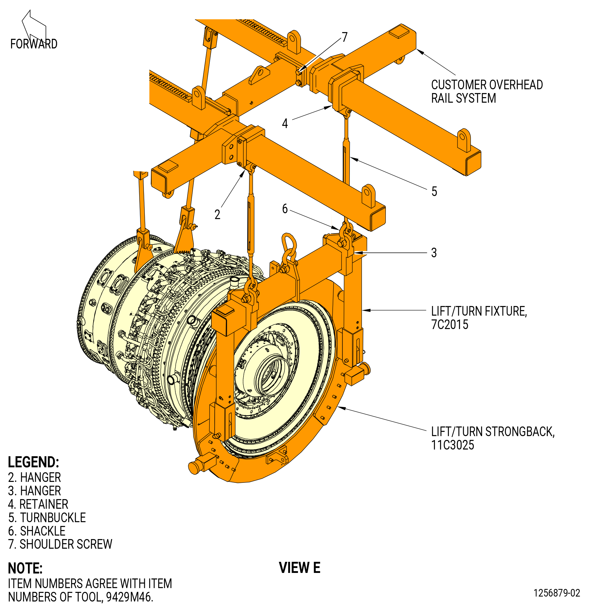
| (3) | Install the 9429M46 TCF overhead adapter as follows: |
| (a) | Put the hanger (item 2) on the customer overhead rail system with the open end of the hook outward. |
| (b) | Attach the retainer (item 4) with the shoulder screw (item 7). Do not tighten the shoulder screw until the customer overhead rail system is aligned to the propulsor assembly. |
| (c) | Attach the turnbuckles (item 5) to the hanger (item 2) with the screw, nut, and cotter pin on the turnbuckle. |
| (d) | Attach the shackles (item 6) to the turnbuckles (item 5) with the bolt, nut, and cotter pin on the shackle. |
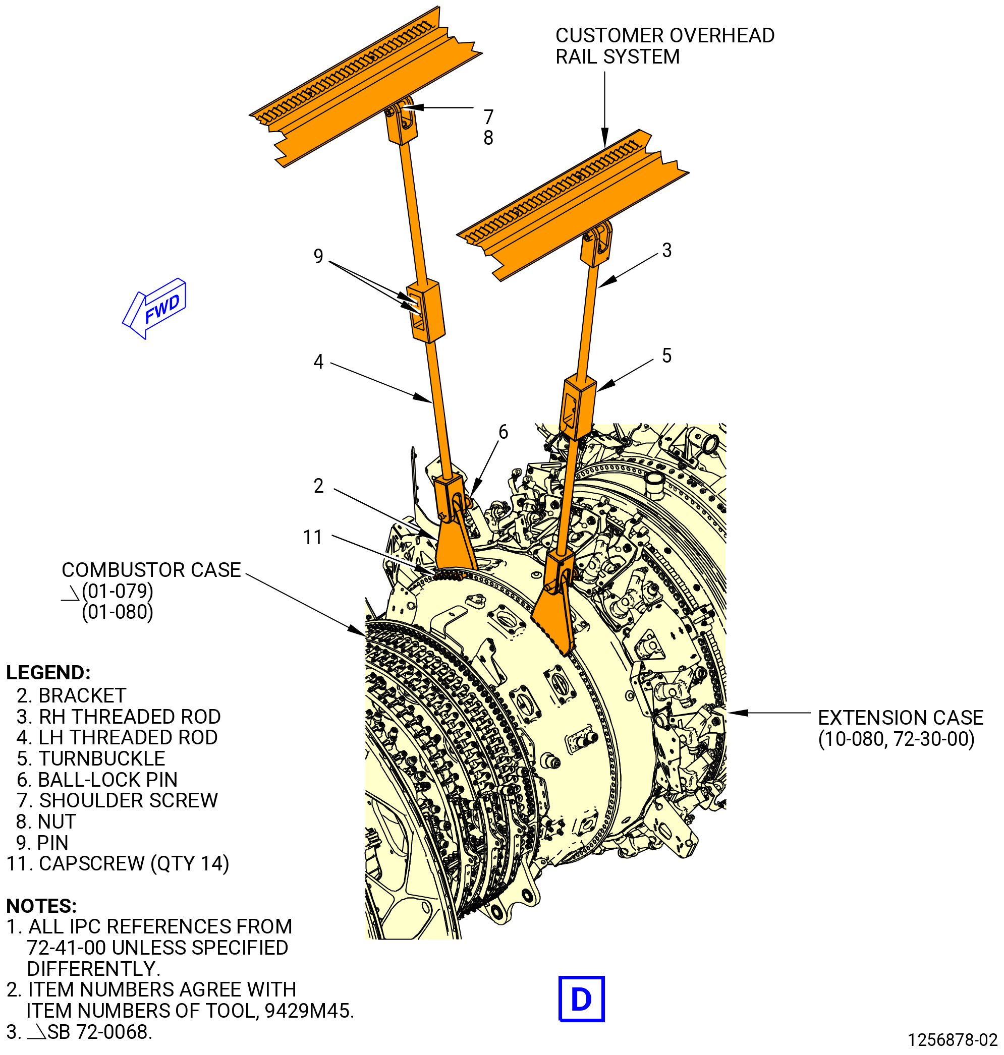
| (4) | Install the 9429M45 K-flange overhead adapter as follows: |
| (a) | Thread the RH threaded rod (item 3) and the LH threaded rod (item 4) into the turnbuckle (item 5) and secure with pins (item 9). |
| (b) | Attach the right threaded rods (item 3) to the customer overhead rail system on the left/right side with the shoulder screws (item 7) and the nut (item 8). |
| (c) | Attach the right (ALF) bracket (item 2) to the aft flange of the combustor case (01-079 , 72-41-00) (SIN 12001) or (01-080 , 72-41-00) (SIN 12001) with capscrews (item 11) in the boltholes No. 8, 9, 10, 11, 12, 13, and 14 from the TVCL on the propulsor assembly. |
| (d) | Attach the left (ALF) bracket (item 2) to the forward flange of the extension case (10-080 , 72-30-00) (SIN 080AL) with capscrews (item 11) in the boltholes No. 122, 123, 124, 125, 126, 127, and 128 from TVCL on the propulsor assembly. |
| (e) | Torque the capscrews (item 11) to 200 lb in (22.6 N.m). |
| (5) | Install the 11C3057 fan frame lift/turn fixture on the fan hub frame (84000) forward and aft flanges as follows: |
| (a) | Align the fan frame lift/turn fixture the TVCL of the propulsor assembly. |
| (b) | Put the bracket (item 7) on the forward side of the fan hub frame (84000) flanges. |
| (c) | Attach the bracket (item 7) with capscrews (item 10), (item 12), and flat washers (item 11). Tighten the capscrews. |
| Subtask 72-00-02-430-863 |
| (5).A. | Attach the 11C4480 FHF brackets to the fan hub frame (10-400 , 72-25-00) (SIN 84000). Refer to Figure 1034 and do as follows: |
| (a) | Remove the flange cap screw (item 4) from the storage locations on the brackets (item 2 and 3). |
| (b) | Put the left bracket (item 3) on fan hub frame flange at the 11 o’clock position, from the aft end of the fan hub frame looking forward, and attach the left bracket (item 3) with five flange cap screws (item 4). |
| (c) | Tighten the flange cap screws (item 4) to secure the left bracket (item 3). |
| (d) | Put the right bracket (item 2) on fan hub frame flange at the 1 o’clock position, from the aft end of the fan hub frame looking forward, and attach the right bracket (item 2) with five flange cap screws (item 4). |
| (e) | Tighten the flange cap screws (item 4) to secure the right bracket (item 2). |
| Subtask 72-00-02-430-864 |
| (6) | Install the 7C2015 lift/turn fixture to the aft end of the propulsor as follows: |
| (a) | Attach an overhead hoist to the 7C2015 lift/turn fixture. |
| (b) | Put the 7C2015 lift/turn fixture on the 11C3025 strongback and attach with pins (item 3) at two locations. |
| Subtask 72-00-02-430-734 |
| CAUTION: |
|
| (7) | Check the 11C3044 engine module adapter assembly and the 9481M84 assembly stand as follows: |
| CAUTION: |
|
| (a) | Make sure the levelizing jacks (item 34) of the 9481M84 assembly stand touch the floor. |
| (b) | Make sure the 9481M84 assembly stand stand is level. |
| (c) | Check the 11C3044 engine module adapter assembly turnbuckles and shackles for bending, cracks, hole elongation, and missing parts. |
| (d) | Check the 11C3044 engine module adapter assembly turnbuckles to make sure that there are threads visible in the turnbuckle. |
| (e) | Check all hook attachments for cracks, bending, and thread or tube elongation. |
| (f) | Make sure that the hook swivel locks are not missing. |
| (g) | Make sure that the pin joints to spreader bar and shoulder links have a shoulder bolt installed. |
| Subtask 72-00-02-430-735 |
| (8) | Install the propulsor assembly to the overhead support assembly as follows. Refer to Figure 1034. |
| (a) | Locate and lower the overhead support assembly over the 9481M84 assembly stand. |
| (b) | Attach the turnbuckles (item 4) of the 9429M43 fan frame overhead adapter to the 11C3057 fan frame lift/turn fixture or 11C4480 FHF brackets with the screw, nut, and cotter pin of the turnbuckle. |
| (c) | Attach the turnbuckle (item 4) of the 9429M45 K-flange overhead adapter to the brackets (item 2) with the ball-lock pins (item 6). The brackets (item 2) are installed on the extension case (10-080 , 72-30-00) (SIN 080AL) and the combustor case (01-079 , 72-41-00) (SIN 12001) or (01-080 , 72-41-00) (SIN 12001). Adjust the turnbuckles (item 4) to align the pin holes. |
| (d) | Attach the shackles (item 6) of the 9429M46 TCF overhead adapter to the 7C2015 lift/turn fixture with the bolt, nut, and cotter pin of the shackle. |
| Subtask 72-00-02-430-774 |
| WARNING: |
|
| (9) | If necessary, remove the 7C2015 lift/turn fixture. Refer to TASK 72-50-00-030-801 (72-50-00, DISASSEMBLY 001). |
| CAUTION: |
|
| (10) | If necessary, remove the 11C3025 strongback . Refer to TASK 72-50-00-030-801 (72-50-00, DISASSEMBLY 001). |
| Subtask 72-00-02-220-094 |
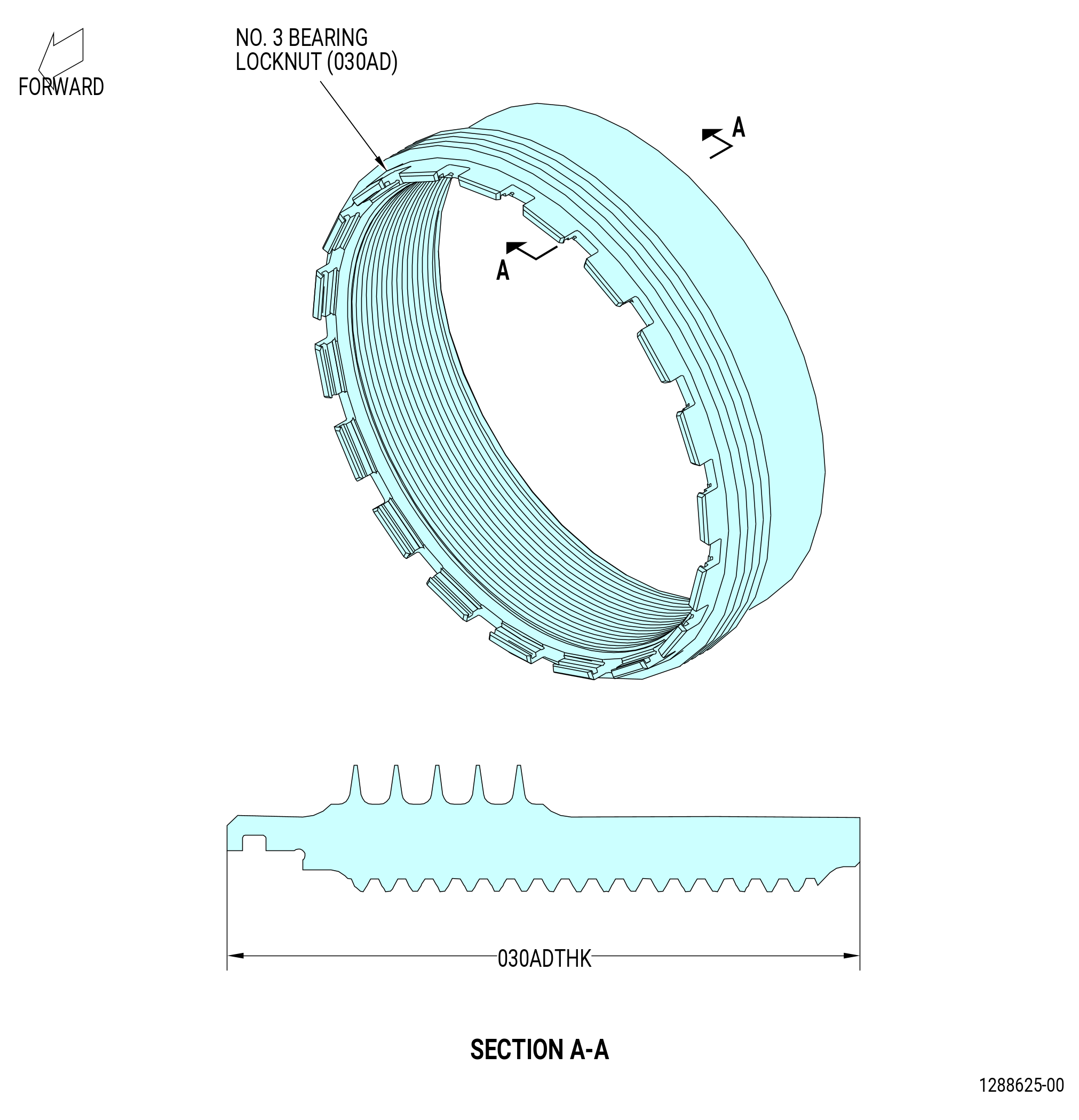
| X. | Install the No. 3 bearing locknut (locknut) (030AD) on the forward compressor rotor shaft (050B5) as follows: |
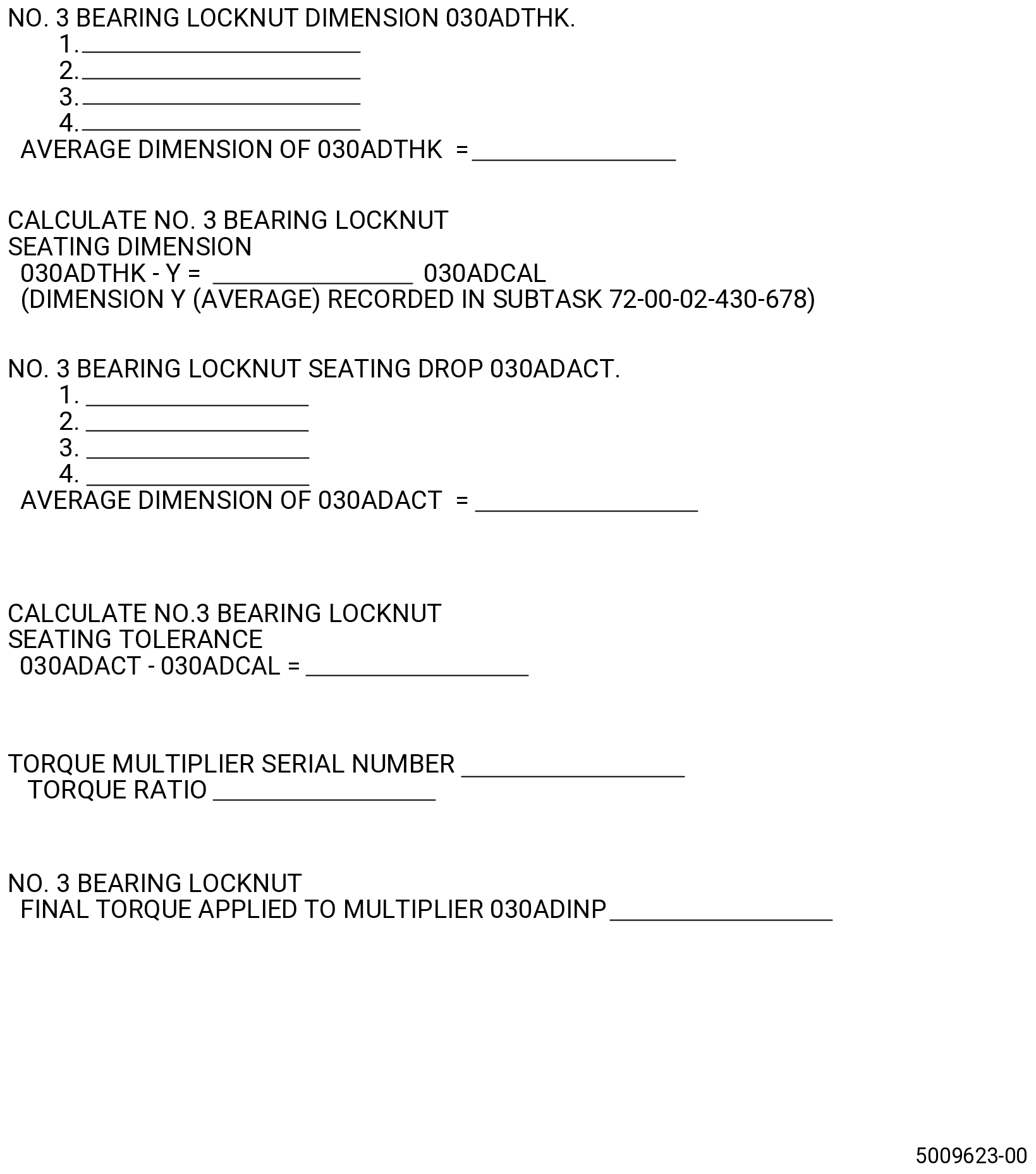
| (1) | Measure the locknut (030AD) dimension 030ADTHK as follows. Refer to Figure 1035. |
| (a) | Measure the dimension 030ADTHK at four equally spaced locations. |
| (b) | Record the average value for dimension 030ADTHK on the Record Sheet. Refer to Figure 1036. |
| (c) | The tolerance for dimension 030ADTHK is 1.9315-1.9395 inches (49.062-49.262 mm). If dimension 030ADTHK is not in tolerance, replace the locknut (20-080) (SIN 030AD). |
| Subtask 72-00-02-640-033 |
| WARNING: |
|
| (2) | Apply C02-019 engine oil or C02-023 engine oil to the mating surfaces and threads on the locknut (030AD). |
| Subtask 72-00-02-430-736 |
| CAUTION: |
|
| (3) | Put the locknut (030AD) on the forward compressor rotor shaft (050B5). Make sure that you do not cross-thread the locknut. Tighten the self-locking nut by hand. |
| Subtask 72-00-02-430-737 |
| (4) | Deleted |
| Subtask 72-00-02-430-738 |
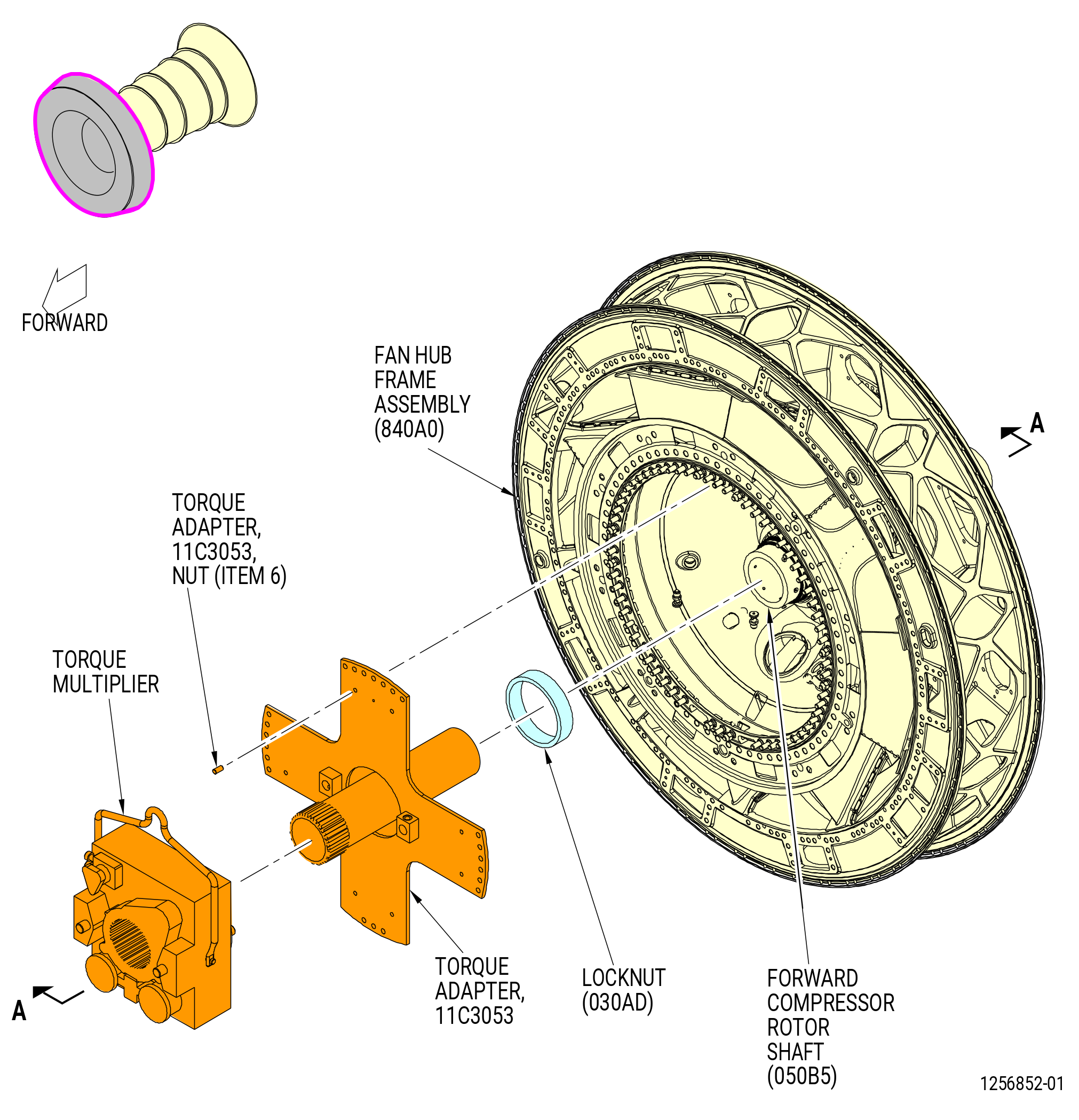
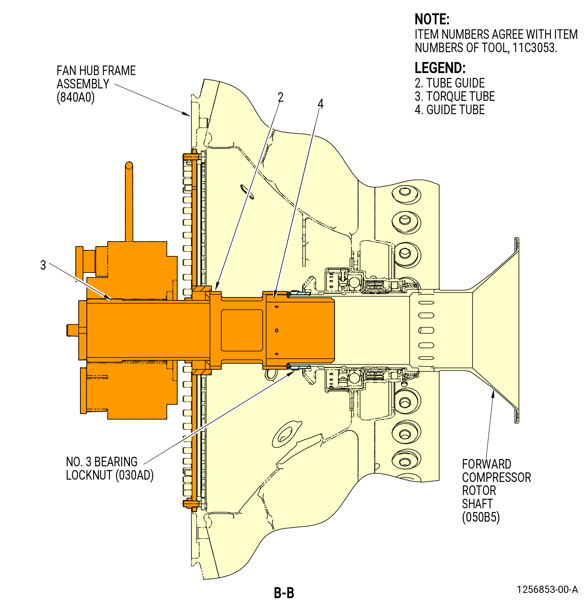
| (5) | Install the 11C3053 torque adapter on the fan hub frame assembly (840A0) as follows. Refer to Figure 1037. |
| (a) | Clean the 11C3053 torque adapter with a clean, lint-free C10-182 cloth. |
| (b) | Put the guide tube (item 4) in the bore of the forward compressor rotor shaft (050B5). |
| (c) | Attach the tube guide (item 2) to the fan hub frame assembly (840A0) with the nuts (item 6). |
| (d) | Put the torque tube (item 3) in the tube guide (item 2) and side forward into the guide tube (item 4). |
| (e) | Slide the torque tube (item 3) aft and engage with the castellations on the locknut (030AD). |
| (6) | Install the torque multiplier on the torque tube (item 3). Set the torque multiplier to apply torque. |
| Subtask 72-00-02-430-739 |
| (7) | Torque the locknut (030AD) on the forward compressor rotor shaft (050B5) as follows. Refer to Figure 1037. |
| (a) | Torque the locknut to 1300 lb ft (1763 N.m). |
| (b) | Set the torque multiplier to break, and decrease the torque value to zero. |
| (c) | Set the torque multiplier to apply torque, and torque the locknut to 650 lb ft (881 N.m). |
| CAUTION: |
|
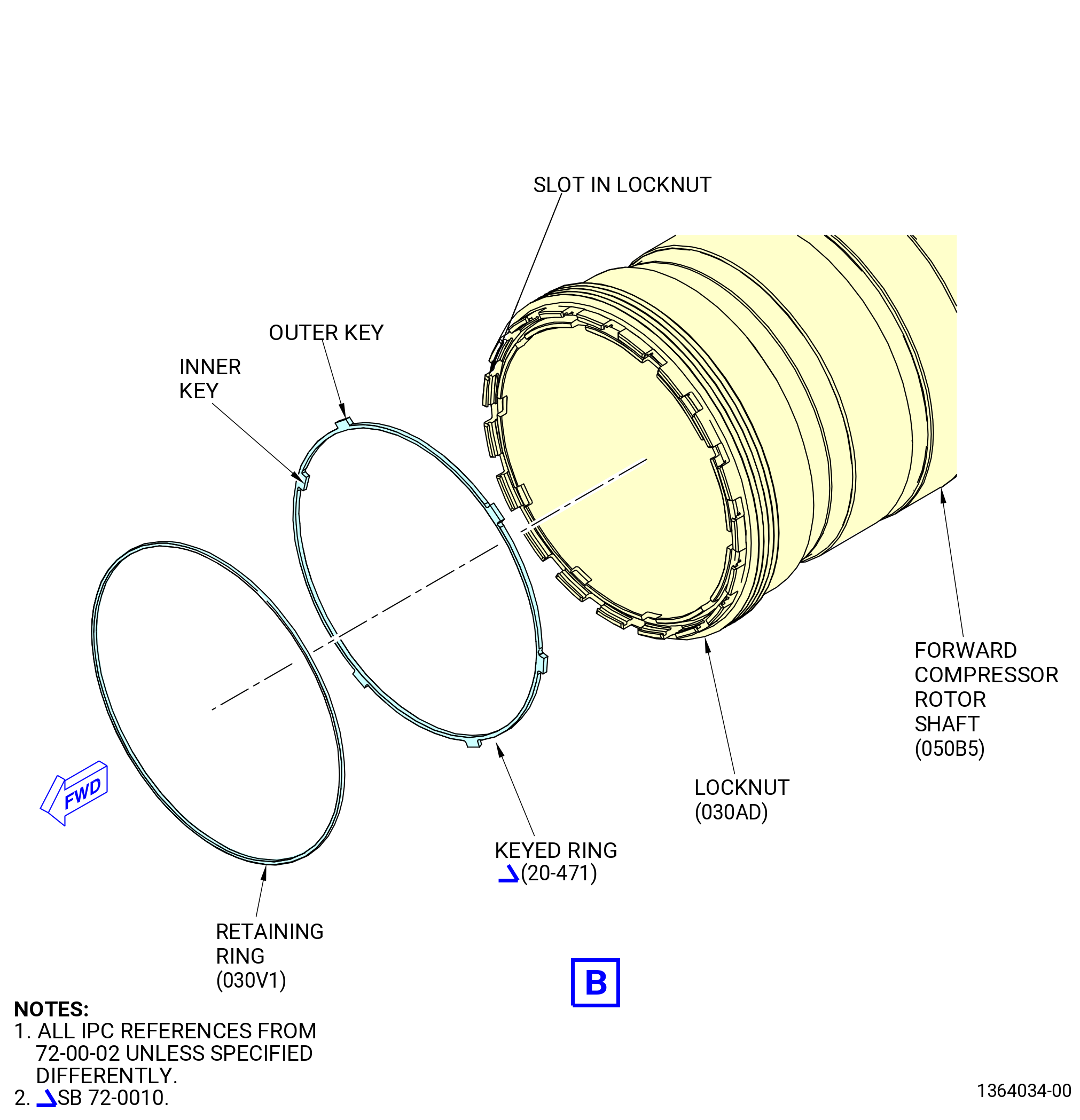
| (d) | Check the slot alignment of the locknut, forward compressor rotor shaft (050B5), and keyed ring (20-470) (SIN 030AL) or (20-471) (SIN 030AL). If the inner/outer keys are not aligned correctly, continue to apply torque to the locknut until the keys on the keyed ring are aligned correctly. The maximum torque is 900 lb ft (1220 N.m). |
| (e) | Record the final torque applied to the locknut on the Record Sheet. Refer to Figure 1036. |
| (f) | Remove the torque multiplier, the torque tube (item 3) and the guide tube (item 4) of the 11C3053 torque adapter. |
| Subtask 72-00-02-220-095 |
| (8) | Calculate the locknut (20-080) (SIN 030AD) seating dimension 030ADCAL (030ADTHK - Y). Refer to Figure 1036. |
| (9) | Measure and calculate the seating drop of the locknut (030AD) as follows. Refer to Figure 1038. |
| (a) | Measure the dimension 030ADACT at four equally spaced locations from the forward face of the locknut (030AD) to the forward end of the compressor rotor shaft (050B5). |
| (b) | Record the average value for dimension 030ADACT on the Record Sheet. Refer to Figure 1036. |
| (c) | The tolerance for dimension 030ADACT is 0.0795-0.1175 inch (2.019-2.984 mm). |
| (d) | Calculate the seating drop tolerance for the locknut (20-080) (SIN 030AD) (030ADACT - 030ADCAL). The negative tolerance for the seating drop difference is -0.001 to -0.009 inch (-0.03 to -0.23 mm). |
| (10) | If the seating dimension is not within tolerance, remove the locknut (20-080) (SIN 030AD) and reinstall. Refer to Subtask 72-00-02-220-094 (paragraph 3.W.(1)) thru Subtask 72-00-02-430-739 (paragraph 3.W.(7)). |
| Subtask 72-00-02-430-740 |
| (11) | Install the keyed ring (20-470) (SIN 030AL) or (20-471) (SIN 030AL) and the retaining ring (030V1) as follows. Refer to Figure 1038. |
| (a) | Install the keyed ring in the locknut. |
| NOTE: |
|
| (b) | Install the retainer ring (030V1) in the slot of the locknut. |
| (c) | Make sure that the retainer ring (030V1) is seated. |
|
|
| Subtask 72-00-02-430-742 |
| (12) | Put the 9429M25 torque adapter plate on the 11C3055 rotor lock and secure with adapter pins (item 11). Refer to Figure 1039. |
| (13) | Install the HPT rotor air duct (05002) in the stage 1 HPT rotor disk (150A1) with the 11C3266 air duct installation fixture as follows: |
| (a) | Turn the lower position ring (item 17), in relation to the upper position ring (item 16), until the teeth in the locking ring (item 2) and the torque ring (item 3) are aligned. The ball lock pin (item 19) must be in the slot of the UNLOCKED position. |
| CAUTION: |
|
| (b) | Put the fixture in the center for the teeth of the fixture will be in the teeth of the air duct (05002). You must hold the 11C3266 air duct installation fixture very tightly at all times to prevent movement that could damage the propulsor assembly. |
| NOTE: |
|
| (c) | Remove the ball lock pin (item 19) and rotate the lower position ring (item 17), in relation to the upper position ring (item 16), until the locking ring (item 2) is in the locked position. The ball lock pin (item 19) must be in the slot of the LOCKED position. |
| (d) | Move the HPT rotor air duct (05002) aft with the 11C3266 air duct installation fixture. |
| (e) | Hold the 11C3266 air duct installation fixture very tightly and move the outer tube (item 6) to align the outer threads on the air duct with the inner threads of the stage 1 HPT rotor disk (150A1) aft shaft. |
| (f) | Rotate the fixture by hand in a CCW direction to thread the HPT rotor air duct (05002) into the stage 1 HPT rotor disk (150A1). Turn the air duct until it bottoms out in the disk. The air duct shall be turned a minimum of two turns. |
| (g) | Remove the ball lock pin (item 19). |
| (h) | Turn the lower position ring (item 17) to disengage the splines from the air duct. |
| (i) | Remove the 11C3266 air duct installation fixture. |
| (14) | Install the 11C3157 air duct install/remove tool as follows. Refer to Figure 1040. |
| (a) | Clean the tool with a clean, lint-free C10-182 cloth. |
| WARNING: |
|
| (b) | Use an overhead hoist with an approved lift strap attached to the 9/16 inch (14 mm) pin on the aft end of the tool to assist when you lift the tool. |
| (c) | Lift the tool and put the forward end in the 9429M25 torque adapter plate and the 11C3055 rotor lock. |
| (d) | Center the tool and engage the splines in the HPT rotor air duct (05002). |
| (15) | Torque the HPT rotor air duct (05002) as follows: |
| (a) | Install the torque multiplier on the 11C3157 air duct install/remove tool. Record the serial number of the torque multiplier. Set the torque multiplier to apply torque in the CCW direction. |
| (b) | Make sure that the HPT rotor air duct (05002) is seated against HPT shaft. |
| (c) | Install a torque wrench on the torque multiplier and turn the air duct CCW three complete turns to find the run-on torque. |
| (d) | The run-on torque shall be 0-50 lb ft (0-67.8 N.m). If the run-on torque is more than 50 lb ft (67.8 N.m), disassemble and find the problem. |
| (e) | Record the run-on torque as VTROTQ. Refer to Figure 1041. |
| (f) | Calculate the torque to be applied to the torque multiplier and record as VTINPTO. This adds the run-on torque to 500 lb ft (678 N.m). |
| (g) | Torque the HPT rotor air duct (05002). |
| (h) | Record the final torque applied to the torque multiplier as FN_TQ. |
| (i) | Record the torque applied to the HPT rotor air duct (05002) as VT_FN_TQ. |
| (16) | Remove the torque multiplier. |
| (17) | Remove the adapter pins (item 10) of the 11C3055 rotor lock to remove the 9429M25 torque adapter plate. |
| (18) | Remove the 11C3055 rotor lock. Refer to TASK 72-50-00-030-801 (72-50-00, DISASSEMBLY 001). |
| Subtask 72-00-02-430-743 |
| (19) | Measure dimension K on the HPT rotor air duct (05002) and the stage 1 HPT rotor disk (150A1) as follows. Refer to Figure 1042. |
| (a) | Obtain the calculated seating drop for dimension K and record on the Record Sheet. Refer to Figure 1041. |
| (b) | Measure dimension K at four equally spaced locations. |
| (c) | Record the minimum and the maximum values for dimension K and calculate the average. Record the average on the Record Sheet as K_AVG. |
| (d) | The tolerance for the seating of the HPT rotor air duct must be ±0.003 inch (0.08 mm). |
| (e) | If not in tolerance, continue to torque the HPT rotor air duct as follows: |
| 1 | Torque the HPT rotor air duct (05002) in increments of 400 ft lb (4800 N.m). The maximum torque permitted is 1200 lb ft (16272 N.m). Refer to TASK 72-00-02-430-801 (72-00-02, ASSEMBLY 001). |
| 2 | If the maximum torqued is applied and the HPT rotor air duct seating drop is not ±0.003 inch (0.08 mm), remove the air duct from the stage 1 HPT rotor disk to determine the cause of the error, inspect, and install. |
| (20) | Install the HPT rotor keyed ring (05090) in the groove between the HPT rotor air duct (05002) and the stage 1 HPT rotor disk (150A1) with the tabs on the ring forward. Make sure that the aft tabs (chamfered end) are in the slots of the rotor disk. Make sure that the forward tabs are in the castellations of the air duct. Refer to Figure 1043. |
| Subtask 72-00-02-430-744 |
| Y. | Continue to assemble the propulsor assembly. Refer to TASK 72-00-02-430-814 (72-00-02, ASSEMBLY 003). |