| GENX-1B ENGINE MANUAL | Dated: 08/24/2023 | |
| EM 72-00-02 , ASSEMBLY 003 | ||
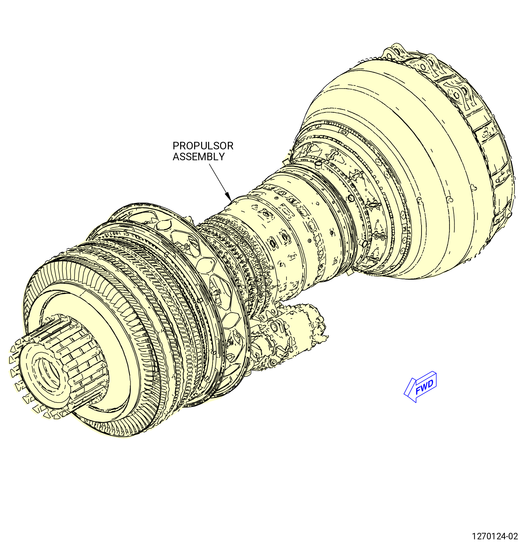
| PROPULSOR ASSEMBLY - ASSEMBLY 003 | ||
| GENX-1B ENGINE MANUAL | Dated: 08/24/2023 | |
| EM 72-00-02 , ASSEMBLY 003 | ||
| PROPULSOR ASSEMBLY - ASSEMBLY 003 | ||
| * * * FOR ALL |
| TASK 72-00-02-430-814 |
| 1 . | General. |
| A. | This procedure gives instructions to continue the assembly of the propulsor module assembly (propulsor assembly). Refer to Figure 1001. |
| • |
|
| • |
|
| • |
|
| • |
|
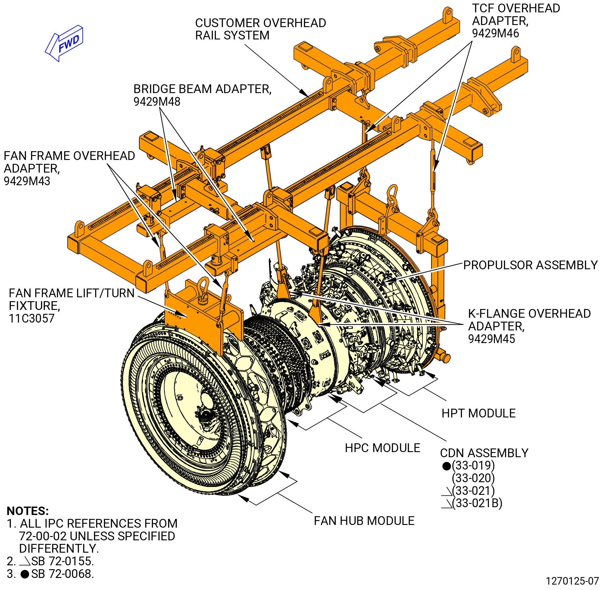
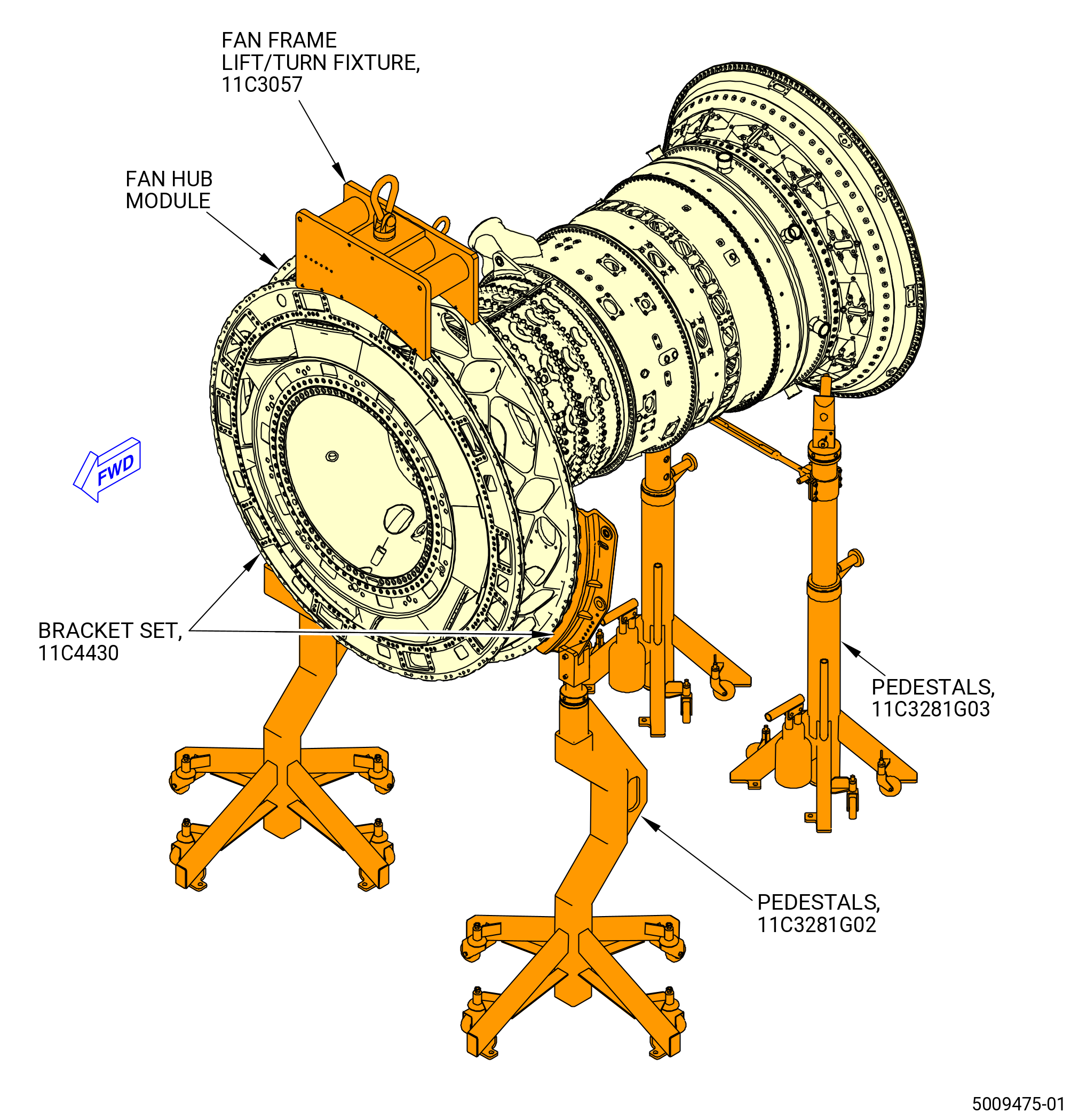
| B. | This procedure starts with the fan hub module (25-010) (SIN 00102), or (25-011) (SIN 00102), or (25-012) (SIN 00102), high pressure compressor (HPC) module (33-009) (SIN 00108) or (33-010) (SIN 00108) or (33-011) (SIN 00108) or (33-012) (SIN 00108), combustor diffuser nozzle (CDN) assembly (33-019) (SIN 0010A), or (33-020) (SIN 0010A), or (33-021) (SIN 0010A), or (33-021B) (SIN 0010A), and high pressure turbine (HPT) module in the horizontal position, installed in the 11C3044 adapter assembly, attached to the customer overhead rail system, or supported by the 11C3281 pedestals. Refer to Figure 1002 and Figure 1003. |
| NOTE: |
|
| C. | Follow the instructions to safety parts with a safety wire, safety cable, cotter pins, or tab washers. Refer to TASK 70-11-00-400-001 (FASTENER RETENTION PROCEDURES) . |
| 2 . | Tools, Equipment, and Materials. |
| NOTE: |
|
| A. | Tools and Equipment. |
| (1) | Special Tools. |
| (2) | Standard Tools and Equipment. |
|
| (3) | Locally Manufactured Tools. None. |
| B. | Consumable Materials. |
|
| C. | Referenced Procedures. |
|
| D. | Expendable Parts. |
|
| * * * FOR ALL |
| 3 . | Procedure. |
| Subtask 72-00-02-420-031 |
| * * * FOR ALL |
| A. | Install the No. 2 bearing assembly (20-030). Refer to TASK 72-00-24-420-802 (72-00-24, Installation 001). |
| Subtask 72-00-02-420-032 |
| * * * FOR ALL |
| B. | Install the No. 1 bearing assembly (20-020). Refer to TASK 72-00-23-420-801 (72-00-23, Installation 001). |
| Subtask 72-00-02-420-033 |
| * * * FOR ALL |
| C. | Install the fan booster assembly (20-010) (SIN 80000) or (20-011) (SIN 80000). Refer to TASK 72-00-22-420-801 (72-00-22, Installation 001). |
| Subtask 72-00-02-110-001 |
| * * * FOR ALL |
| D. | Install the No. 4 bearing nut (35-420) (SIN 01402) on the stage 1 HPT rotor (01-280 , 72-53-00) (SIN 150A1) or (02-280 , 72-53-00) (SIN 150A1). Refer to Figure 1004 and do as follows: |
| WARNING: |
|
| WARNING: |
|
| (1) | Use C04-035 isopropyl alcohol, C04-002 Stoddard solvent, or C04-231 solvent to clean the threads and mating faces of the No. 4 bearing nut (35-420) (SIN 01402), the threads of the stage 1 HPT rotor disk (01-280 , 72-53-00) (SIN 150A1) or (02-280 , 72-53-00) (SIN 150A1), and the mating faces of the rotating air seal (35-400) (SIN 01408). |
| Subtask 72-00-02-640-026 |
| * * * FOR ALL |
| WARNING: |
|
| (2) | Apply C02-058 lubricant to the threads and mating faces of the No. 4 bearing nut (35-420) (SIN 01402). |
| Subtask 72-00-02-430-700 |
| * * * FOR ALL |
| NOTE: |
|
| (3) | Carefully thread the No. 4 bearing nut on the aft shaft of the stage 1 HPT rotor disk (01-280 , 72-53-00) (SIN 150A1) or (02-280 , 72-53-00) (SIN 150A1). |
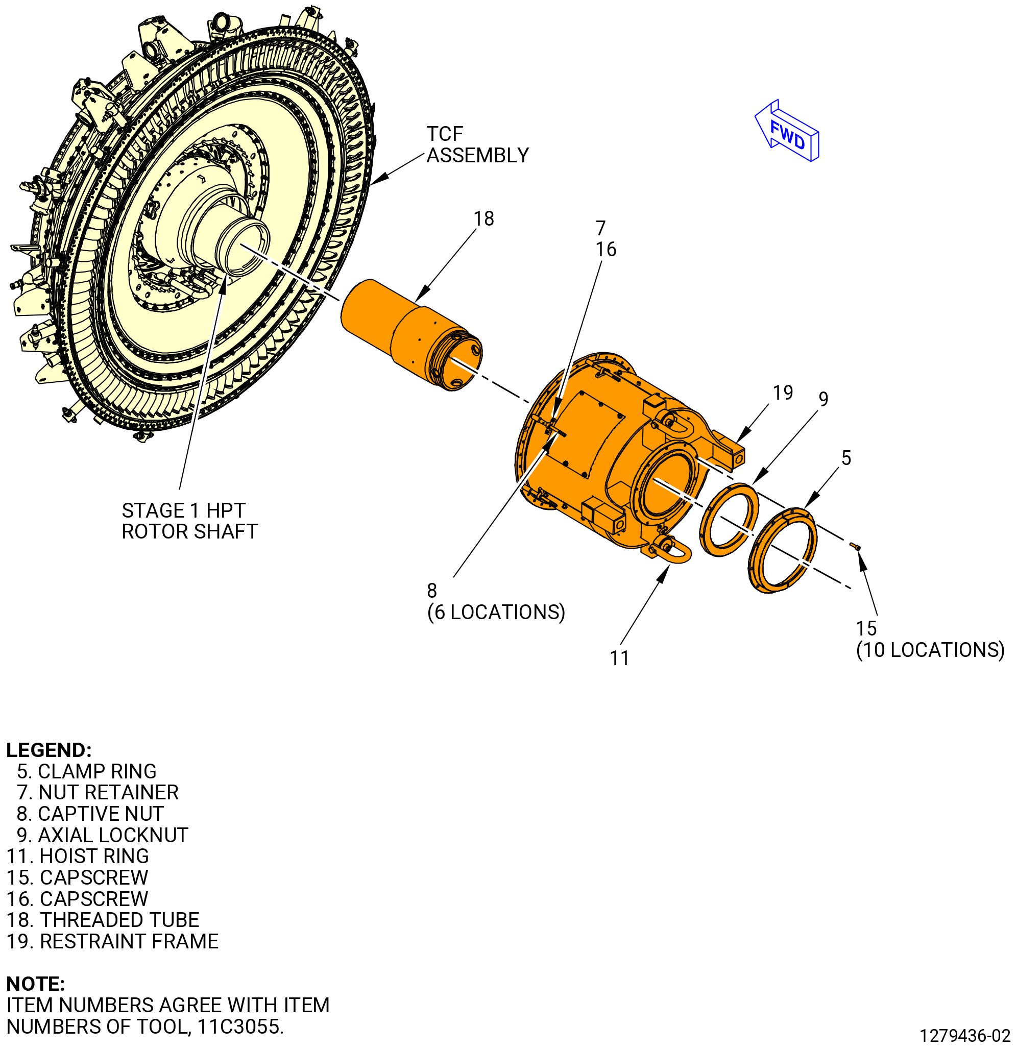
| (4) | Install the 11C3055 rotor lock as follows. Refer to Figure 1005. |
| (a) | Put a leverage bar through the 1.0 inch (25 mm) diameter holes at the aft end of the threaded tube (item 18). |
| (b) | Thread the forward end of the threaded tube (item 18) into the aft end of the stage 1 HPT rotor disk. |
| (c) | Remove the leverage bar from the threaded tube (item 18). |
| (d) | Attach an approved overhead hoist to the hoist ring (item 11) on the restraint frame (item 19). |
| WARNING: |
|
| (e) | Lift the 11C3055 rotor lock and adjust the restraint frame (item 19) to the center with the aft end of the threaded tube (item 18). |
| (f) | Align the holes on the restraint frame (item 19) with the studs on the TCF assembly. |
| (g) | Remove the overhead hoist from the hoist ring (item 11). |
| (h) | Install the captive nuts (item 8) equally spaced on the studs of the TCF assembly. |
| (i) | Torque the captive nuts (item 8) in a criss-cross pattern to 10 lb ft (13.56 N.m). |
| (j) | Install the captive nut retainers (nut retainer) (item 7) above the captive nuts (item 8) and secure to the restraint fixture (item 2) with the capscrews (item 16). |
| (k) | Install the axial locknut (item 9) to the aft end of the threaded tube (item 18). Do not tighten. |
| (l) | Put the anti-torque tube (item 3) in the inner side of the threaded tube (item 18) until the slots engage in the stage 1 HPT rotor disk. |
| (m) | Put the adapter pins (item 10) in the anti-torque tube (item 3) and thread into the restraint frame (item 19). There must be a 0.125 inch (3.18 mm) gap between the anti-torque tube (item 3) and the restraint frame (item 19) when the adapter pins (item 10) are installed. |
| (n) | Tighten the axial locknut (item 9) with a spanner wrench. |
| (o) | Attach the two segments of the clamp ring (item 5) to the restraint frame (item 19) with the capscrews (item 15). |
| (p) | Torque the capscrews (item 15) to 120 lb in. (13.56 N.m). |
| Subtask 72-00-02-430-701 |
| * * * FOR ALL |
| (5) | Install the 9429M25 torque adapter plate on the 11C3055 rotor lock and secure. Refer to Figure 1006. |
| (6) | Install the 11C3144 torque adapter on the 11C3055 rotor lock as follows. |
| WARNING: |
|
| (a) | Use an overhead hoist with a lift sling to lift the torque adapter (item 3) and the anti-torque adapter (item 4) and put with the castellations forward in the anti-torque tab tube (item 3) of the 11C3055 rotor lock. |
| (b) | Rotate the torque adapter (item 3) and the anti-torque adapter (item 4) of the 11C3144 torque adapter to align the castellations with the No. 4 bearing inner race spanner nut and the stage 1 HPT rotor disk. |
| (7) | Install the torque multiplier on the anti-torque tab tube (item 3) of the 11C3055 rotor lock and secure with the adapter pin (item 10) of the 11C3055 rotor lock. |
| WARNING: |
|
| (8) | Attach an overhead hoist with a lift sling to the anti-torque arm (item 2) of the 11C3144 torque adapter and lift the anti-torque arm. |
| (9) | Align the anti-torque arm (item 2) to the 9429M25 torque adapter plate and engage the tabs with the slots of the anti-torque tube (item 4). |
| (10) | Attach the anti-torque arm (item 2) of the 11C3144 torque adapter with the ball-lock pin (item 6). |
| (11) | Torque the No. 4 bearing nut as follows: |
| (a) | Use the torque multiplier to torque the No. 4 bearing nut to 1280 lb. ft. (1735 N.m). |
| (b) | Use the torque multiplier to break and decrease the torque until the No. 4 bearing nut is unloaded. |
| (c) | Use the torque multiplier to re-torque the No. 4 bearing nut to 1140 lb. ft (1546 N.m). |
| (12) | Remove the 11C3144 torque adapter, the torque multiplier, and the 9429M25 torque adapter plate. |
| WARNING: |
|
| CAUTION: |
|
| (13) | Remove the 11C3055 rotor lock. |
| (14) | Use a 0.001 inch (0.03 mm) feeler stock as a no-go gage to make sure that the No. 4 bearing nut is fully seated on the rotating seal (35-400). |
| (15) | Remove excess lubricant from the No. 4 bearing nut and the rotating seal. |
| Subtask 72-00-02-430-702 |
| * * * FOR ALL |
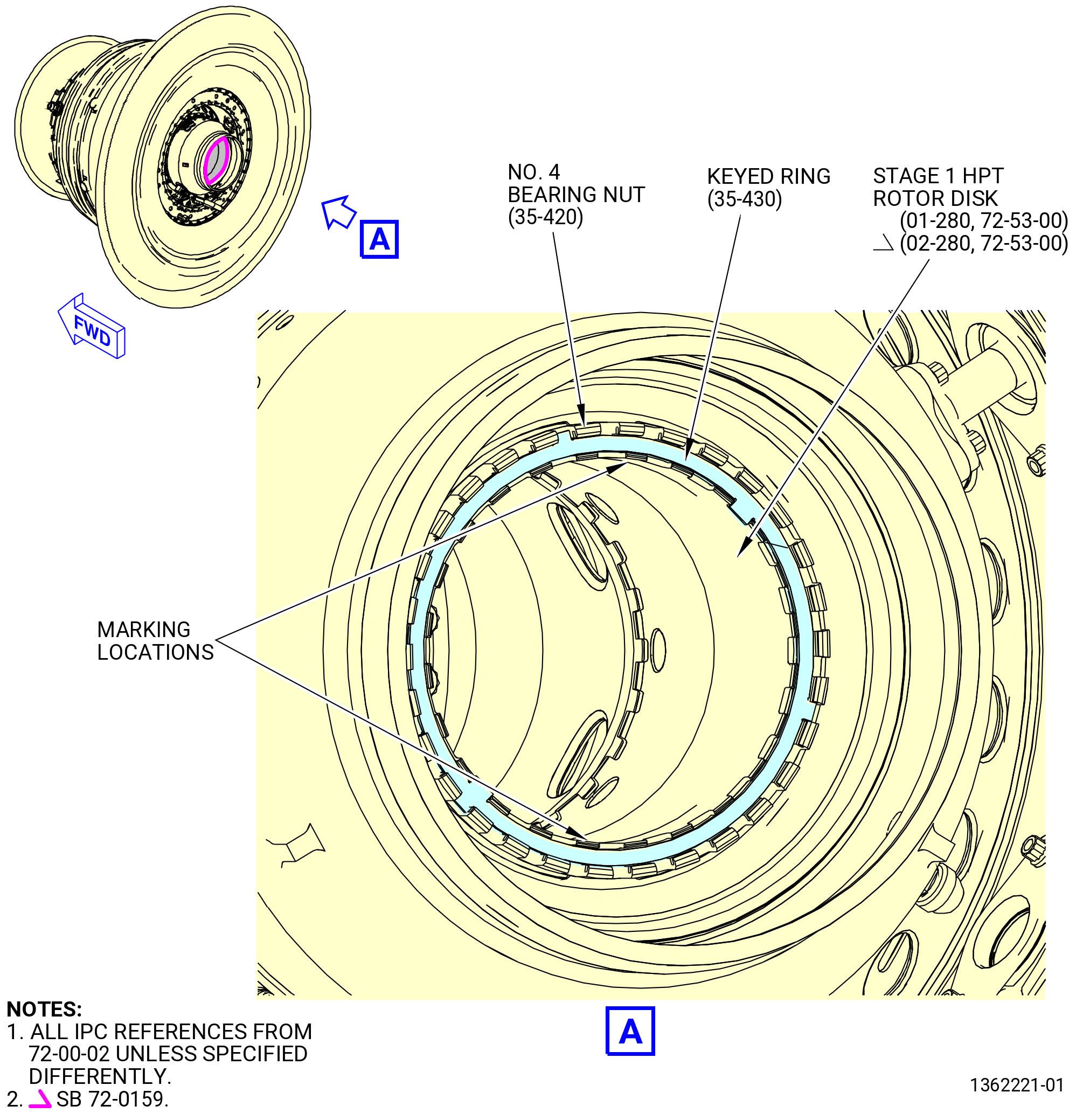
| (16) | Put matching marks on the keyed ring (35-430) as follows. Refer to Figure 1007. |
| (a) | Temporarily install the keyed ring as follows: |
| 1 | Engage the tabs of the keyed ring with the slot in the No. 4 bearing nut and the slots in the stage 1 HPT rotor disk (01-280 , 72-53-00) (SIN 150A1) or (02-280 , 72-53-00) (SIN 150A1). |
| CAUTION: |
|
| 2 | If necessary, turn the No. 4 bearing nut clockwise (CW) until the tabs engage. Reinstall the 11C3055 rotor lock, the 9429M25 torque adapter plate, the 11C3055 rotor lock, the 11C3144 torque adapter, and torque the No. 4 bearing nut. Refer to Subtask 72-00-02-430-700 (paragraph 3.D.(4)) thru Subtask 72-00-02-430-701 (paragraph 3.D.(14)). Do not torque more than 1360 lb. ft (1844 N.m). |
| Subtask 72-00-02-210-023 |
| * * * FOR ALL |
| (b) | Use the C05-003 pen to put a mark on the two inner slots of the stage 1 HPT rotor disk (01-280 , 72-53-00) (SIN 150A1) or (02-280 , 72-53-00) (SIN 150A1), where the two inner tabs of the keyed ring are installed. |
| NOTE: |
|
| Subtask 72-00-02-430-703 |
| * * * FOR ALL |
| (c) | Remove the keyed ring. |
| Subtask 72-00-02-430-704 |
| * * * FOR ALL |
| E. | Install the heatshield (34-300) (SIN 15002) in the stage 1 HPT rotor (34-020) (SIN 15000) or (34-021) (SIN 15000). Refer to Figure 1009 and do as follows: |
| WARNING: |
|
| (1) | Use C04-035 isopropyl alcohol to clean the heatshield. |
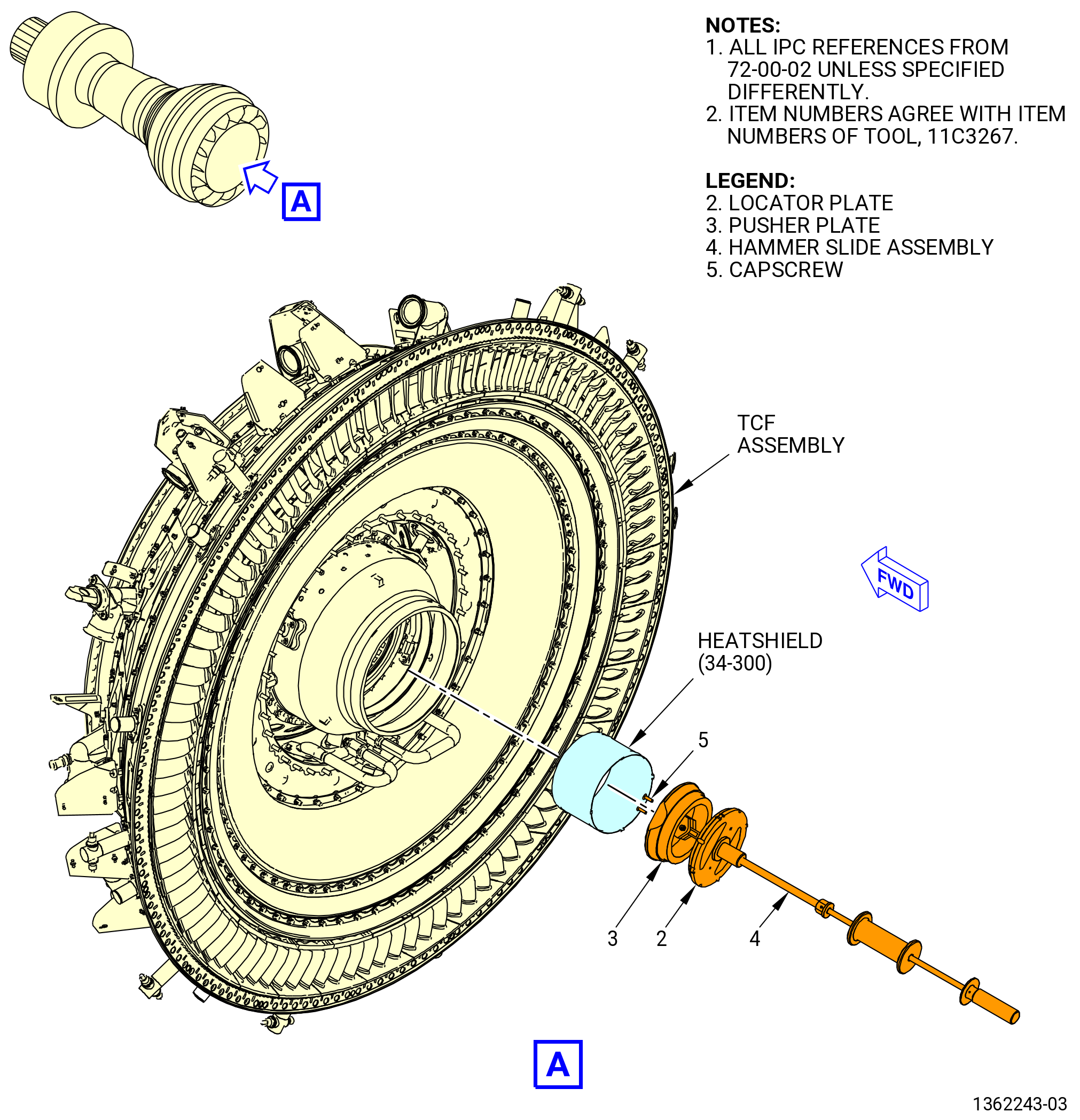
| (2) | Install the heatshield (34-300) (SIN 15002) on the 11C3267 heatshield install/remove fixture. Refer to Figure 1008 and Figure 1009 and as follows: |
| (a) | Align the locator plate (item 2) with the high pressure turbine rotor heatshield. |
| (b) | Rotate the locator plate (item 2) 60 degrees and insert it in the inside diameter of the heatshield until it passes through the forward end. |
| (c) | Align with “TOP VERT” mark. |
| CAUTION: |
|
| (d) | Adjust the pusher plate (item 3) with the locator plug of the hammer slide assembly (item 4) by aligning the rabbets in the aft end and the tabs of the heatshield with the slots in the pusher plate (item 3). |
| WARNING: |
|
| CAUTION: |
|
| (3) | Put dry ice on the heatshield for a minimum of 20 minutes. |
| WARNING: |
|
| (4) | Use a heat gun to increase the temperature of the aft shaft of the stage 1 HPT rotor disk (01-280 , 72-53-00) (SIN 150A1) or (02-280 , 72-53-00) (SIN 150A1) to a maximum of 250°F (121°C) for 20 minutes. |
| (5) | Install the heatshield (34-300) (SIN 15002) on the aft shaft of the stage 1 HPT rotor disk (01-280 , 72-53-00) (SIN 150A1) or (02-280 , 72-53-00) (SIN 150A1) as follows: |
| CAUTION: |
|
| (a) | Lower the 11C3267 heatshield install/remove fixture and the heatshield (34-300) (SIN 15002) into the HPT shaft. Adjust the pusher plate (item 3) position with the locator plug of the hammer slide assembly (item 4) by aligning the rabbets in the aft end and the tabs of the heatshield with the slots in the pusher plate (item 3). |
| (b) | Make sure that the heatshield tabs are aligned with the markers at the two inner slots of the stage 1 HPT rotor disk (01-280 , 72-53-00) (SIN 150A1) or (02-280 , 72-53-00) (SIN 150A1). |
| (c) | Actuate the hammer slide assembly (item 4) as many times as required to install the heatshield. |
| (6) | Remove the 11C3267 heatshield install/remove fixture from the heatshield (34-300). |
| Subtask 72-00-02-430-705 |
| * * * FOR ALL |
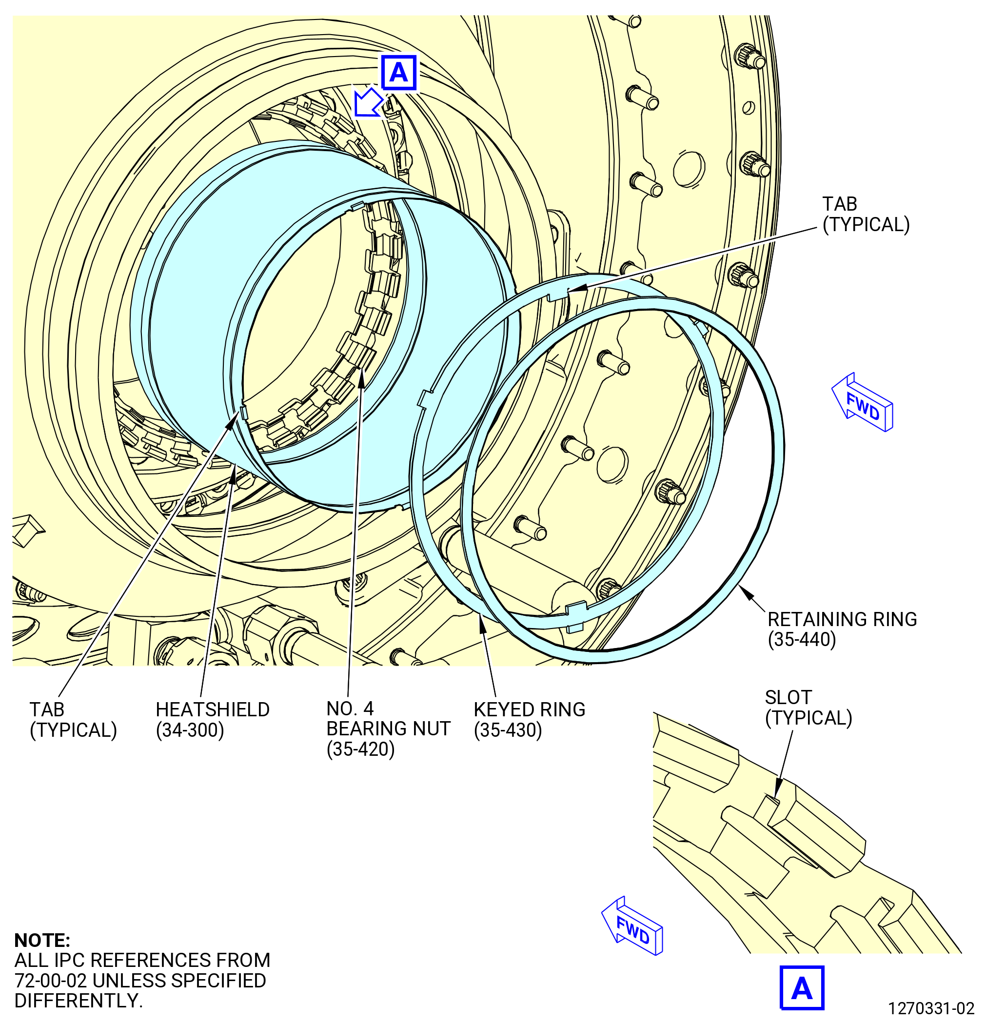
| F. | Install the keyed ring (35-430) and retaining ring (35-440) as follows. Refer to Figure 1009. |
| (1) | Install the keyed ring on the same slots where you put the mark before. Make sure that the tabs on the keyed ring are above the tabs on the heatshield (34-300) (SIN 15002) to fully hold the heatshield. |
| (2) | Install the retaining ring into the slots of the No. 4 bearing nut (35-420) as follows: |
| (a) | Start at a mid point between one of the tabs of the keyed ring and move one end of the retaining ring (35-440) on the slots. |
| CAUTION: |
|
| (b) | Continue to move the retaining ring (35-440) until it is fully engaged in the slots of the No. 4 bearing nut. |
| Subtask 72-00-02-640-047 |
| * * * FOR ALL |
| G. | Install the forward brush seal (35-340) (SIN 93702) and retainer (35-350) (SIN 93703) on the seal support (35-320) (SIN 93701) as follows. Refer to Figure 1011. |
| WARNING: |
|
| (1) | Put the seal support (35-320) on a workbench and clean mating surfaces with C04-035 isopropyl alcohol. |
| WARNING: |
|
| (2) | Apply C02-058 lubricant to the nuts (35-370) (SIN 93742). |
| Subtask 72-00-02-430-844 |
| * * * FOR ALL |
| WARNING: |
|
| WARNING: |
|
| (3) | Put dry ice on the forward brush seal (35-340) (SIN 93702) for approximately 30 minutes. |
| CAUTION: |
|
| CAUTION: |
|
| (4) | Align the stop tab of a new forward brush seal (35-340) facing aft with the match marks at the 12:00 o'clock position on the seal support, and install the forward brush seal in the seal support. |
| (5) | Use a 0.005 inch (0.13 mm) shim to make sure that the forward brush seal is fully seated on the seal support. |
| (6) | Attach the forward brush seal and retainer to the seal support with the bolts (35-360) (SIN 93722) and nuts (35-370) (SIN 93742). Make sure that the boltheads are forward. |
| (7) | Torque the nuts (35-370) in a criss-cross pattern to 105-124 lb in. (11.9-14.0 N.m). |
| (8) | Torque the nuts (35-370) again in a circular pattern to 105-124 lb in. (11.9-14.0 N.m). |
| (9) | Put a piece of protective cardboard on the forward brush seal support and attach with C01-119 tape. |
| Subtask 72-00-02-430-706 |
| * * * FOR ALL |
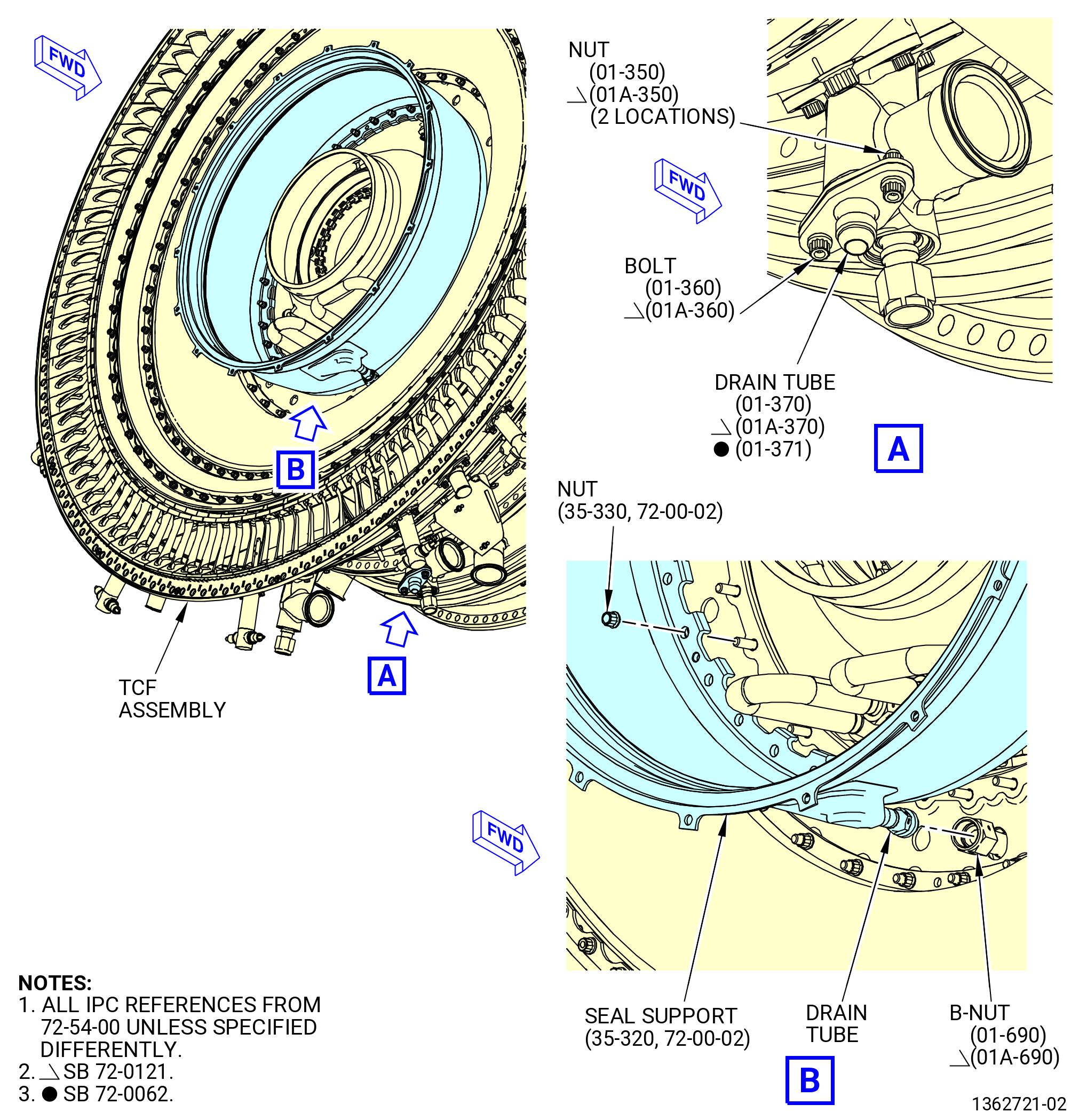
| H. | Install the seal support (35-320) (SIN 93701) on the TCF assembly as follows: |
| (1) | Loosen the nuts (01-350 , 72-54-00) (SIN 489K0) or (01A-350 , 72-54-00) (SIN 489K0) that attach the drain tube (01-370 , 72-54-00) (SIN 489A1) or (01-371 , 72-54-00) (SIN 489A1) or (01A-370 , 72-54-00) (SIN 489A1) to the drain adapter on the outside diameter of the TCF case at the 6:00 o’clock position. Refer to Figure 1010. |
| NOTE: |
|
| (2) | Align the drain tube of the seal support with the B-nut on the TCF and seat the seal support. |
| Subtask 72-00-02-640-027 |
| * * * FOR ALL |
| WARNING: |
|
| (3) | Apply C02-058 lubricant to the nuts (35-330). Refer to Figure 1011. |
| Subtask 72-00-02-430-707 |
| * * * FOR ALL |
| (4) | Attach the seal support to the TCF assembly with the nuts. |
| (5) | Finger-tighten the nuts. |
| Subtask 72-00-02-640-028 |
| * * * FOR ALL |
| (6) | Apply a small quantity of C02-058 lubricant to the threads and friction surfaces of the fittings on the B-nut. |
| Subtask 72-00-02-430-708 |
| * * * FOR ALL |
| (7) | Triple torque the B-nut of the drain (01-690 , 72-54-00) (SIN 489S0) or (01A-690 , 72-54-00) (SIN 489S0) to 460 to 540 lb in. (52.0 to 61.0 Nm). Refer to TASK 70-51-00-400-004 (TIGHTENING PRACTICES AND TORQUE VALUES). |
| CAUTION: |
|
| (8) | Safety the B-nut and nipple of the seal support with C10-071 safety wire. |
| (9) | Torque the nuts (01-350 , 72-54-00) (SIN 489K0) or (01A-350 , 72-54-00) (SIN 489K0) at the TCF air adapter to 105-124 lb in. (11.9-14.0 N.m). |
| (10) | Torque the nuts (35-330) in a criss-cross pattern to 69-81 lb in. (7.8-9.2 N.m). |
| (11) | Torque the nuts (35-330) again in a circular pattern to 69-81 lb in. (7.8-9.2 N.m). |
| Subtask 72-00-02-420-034 |
| * * * FOR ALL |
| I. | Install the low pressure turbine (LPT) module assembly (45-020) (SIN 00105) or (45-021) (SIN 00105) or (45-022) (SIN 00105). Refer to TASK 72-00-04-420-801 (72-00-04, Installation 001). |
| Subtask 72-00-02-430-710 |
| * * * FOR ALL |
| J. | Continue to assemble the propulsor assembly. Refer to TASK 72-00-02-430-815 (72-00-02, ASSEMBLY 004 - CONFIG 01) or TASK 72-00-02-430-822 (72-00-02, ASSEMBLY 004 - CONFIG 02). |