| GENX-1B ENGINE MANUAL | Dated: 03/07/2025 | |
| EM 72-00-23 , INSTALLATION 001 | ||
| NO. 1 BEARING ASSEMBLY - INSTALLATION 001 | ||
| GENX-1B ENGINE MANUAL | Dated: 03/07/2025 | |
| EM 72-00-23 , INSTALLATION 001 | ||
| NO. 1 BEARING ASSEMBLY - INSTALLATION 001 | ||
| * * * FOR ALL |
| TASK 72-00-23-420-801 |
| 1 . | General. |
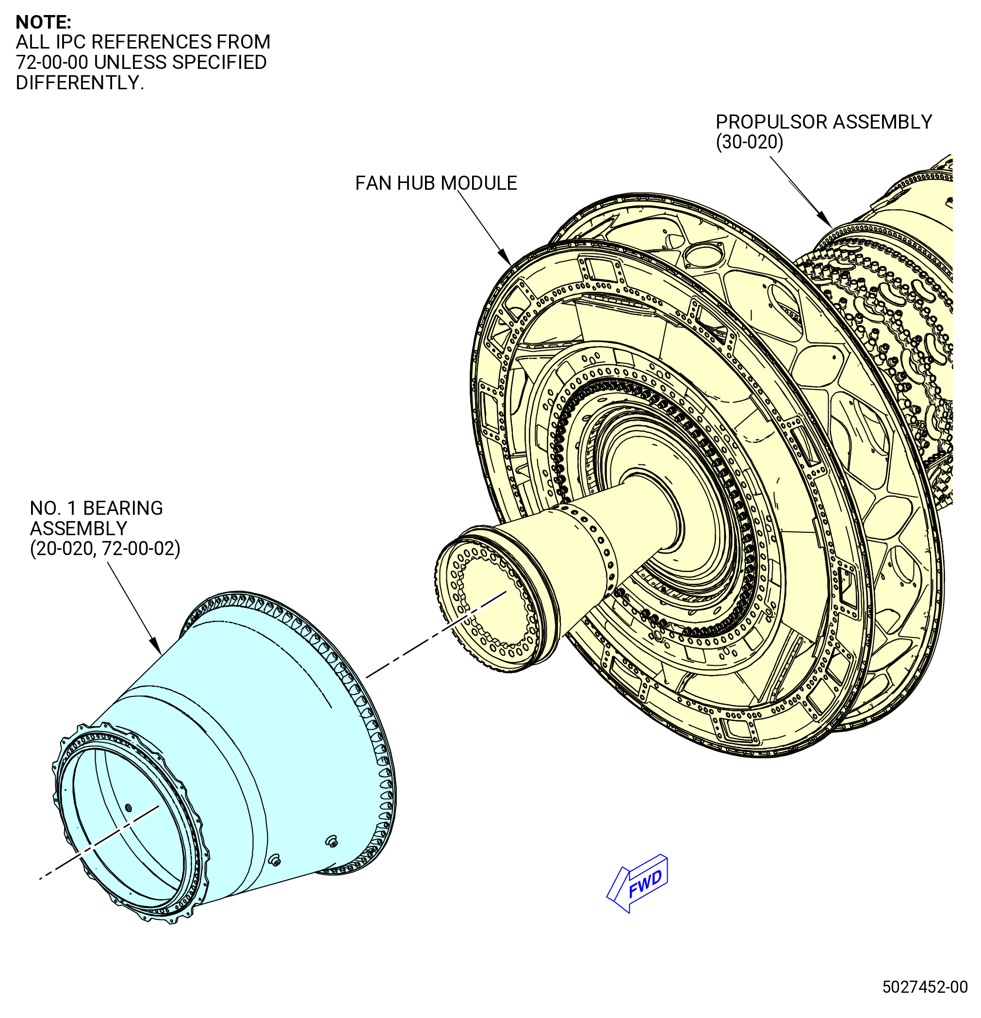
| A. | This procedure gives instructions to install the No. 1 bearing assembly (01100). Refer to Figure 401. |
| B. | This procedure starts with the fan hub module, the high pressure compressor (HPC) assembly, and the high pressure turbine module (HPT module) assembled in the horizontal position and installed on pedestals or installed in the 11C3044 adapter assembly, attached to the customer overhead rail system. This procedure must be completed after the No. 2 bearing assembly is installed on the fan hub module. If necessary, refer to TASK 72-00-24-420-802 (72-00-24, INSTALLATION 001) . |
| • |
|
| • |
|
| • |
|
| The fan hub module contains: |
| • |
|
| • |
|
| • |
|
| C. | The No. 1 bearing assembly (01100) is in a storage stand. |
| D. | Make sure that personnel read this procedure and know the step-by-step instructions and special tool usage before they install the No. 1 bearing assembly. |
| E. | Make sure that there is no foreign material in the engine or on the engine parts. |
| F. | Make sure that all parts are serviceable before they are installed. |
| G. | Make sure that the No. 1 bearing assembly, the HPC assembly, and the HPT module, and assembled engine have the correct support at all times to prevent injury to personnel or damage to engine parts. |
| WARNING: |
|
| WARNING: |
|
| H. | Make sure that all mating surfaces are clean before you assemble the parts. If necessary, clean the parts with C04-002 Stoddard solvent, C04-035 isopropyl alcohol, or a 50-50 blend of C04-014 denatured alcohol and C04-035 isopropyl alcohol. |
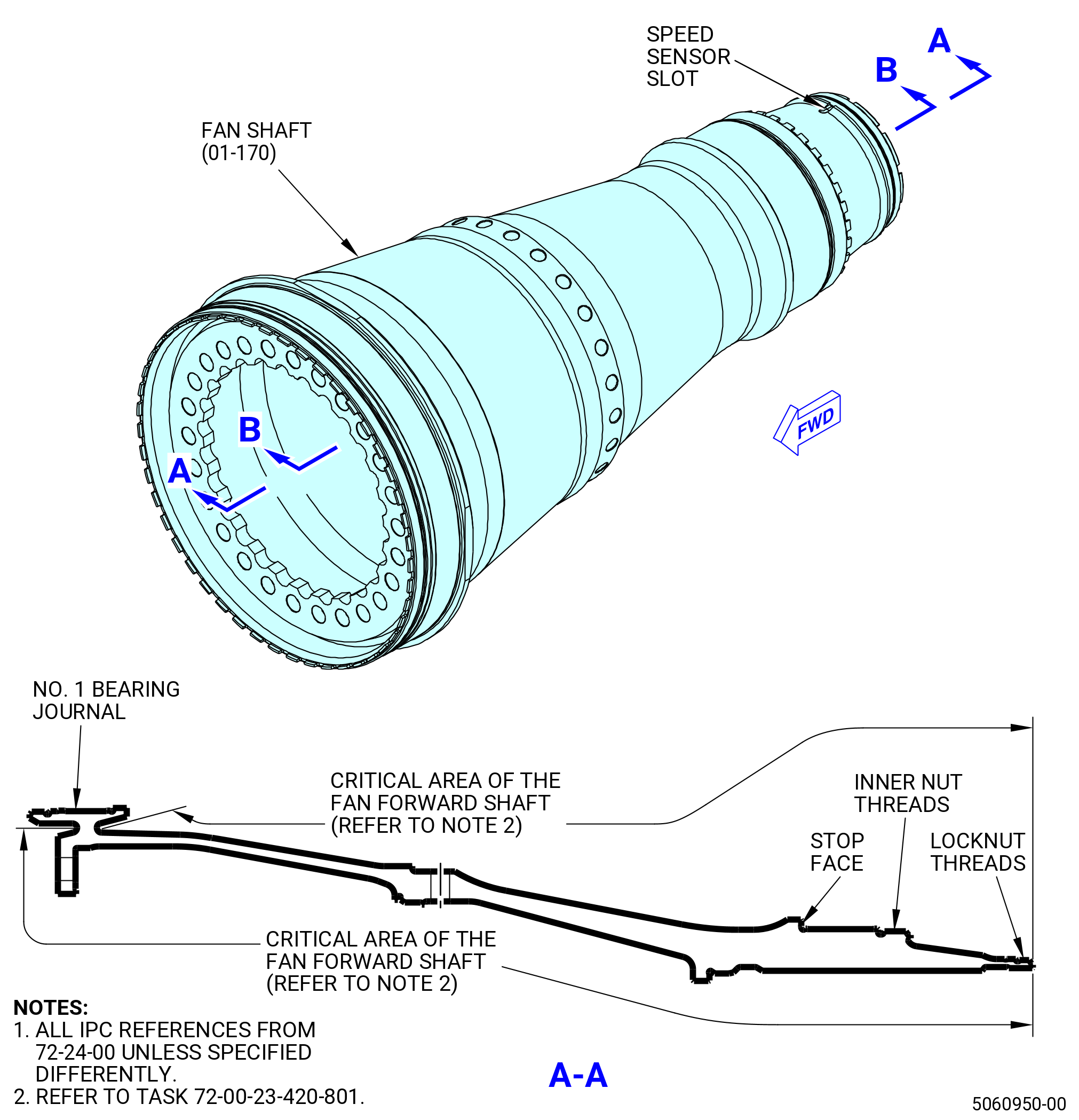
| I. | This assembly contains critical areas of the shaft, that require caution and visual inspection during the assembly process, that are identified throughout this procedure. Refer to Figure 402. |
| 2 . | Tools, Equipment, and Materials. |
| NOTE: |
|
| A. | Tools and Equipment. |
| (1) | Special Tools. |
| (2) | Standard Tools and Equipment. |
|
| (3) | Locally Manufactured Tools. None. |
| B. | Consumable Materials. |
|
| C. | Referenced Procedures. |
|
| D. | Expendable Parts. |
|
| 3 . | Procedure. |
| Subtask 72-00-23-420-001 |
| CAUTION: |
|
| A. | Prepare the fan hub frame (FHF) and No. 2 bearing assembly (20-030 , 72-00-02) (SIN 01200) to receive the No. 1 bearing assembly (20-020 , 72-00-02) (SIN 01100) as follows. |
| (1) | Make sure that the areas that follow are free from foreign material and high metal: |
| • |
|
| • |
|
| WARNING: |
|
| (2) | If necessary, clean the threaded end or the mating flange with a 50-50 blend of C04-014 denatured alcohol and C04-035 isopropyl alcohol. |
| (3) | Locate the 11C3289 No. 1 bearing guide. Use your hand and carefully thread the No. 1 bearing guide on the forward fan shaft of the fan hub module. Refer to Figure 403. |
| WARNING: |
|
| CAUTION: |
|
| (4) | Apply a light coat of C02-019 engine oil or C02-023 engine oil to the exposed area of the No. 1 bearing inner race (bearing) (011A0), and the outer surface of the 11C3289 No. 1 bearing guide. |
| (5) | Install the guide pins (item 2) of the 9C2352 guide pins in boltholes of the forward flange of the fan hub frame (FHF) at equally-spaced locations. |
| NOTE: |
|
| WARNING: |
|
| (6) | Lubricate the No. 1 bearing aft seal gasket (aft seal gasket) (84050) with C02-023 engine oil. |
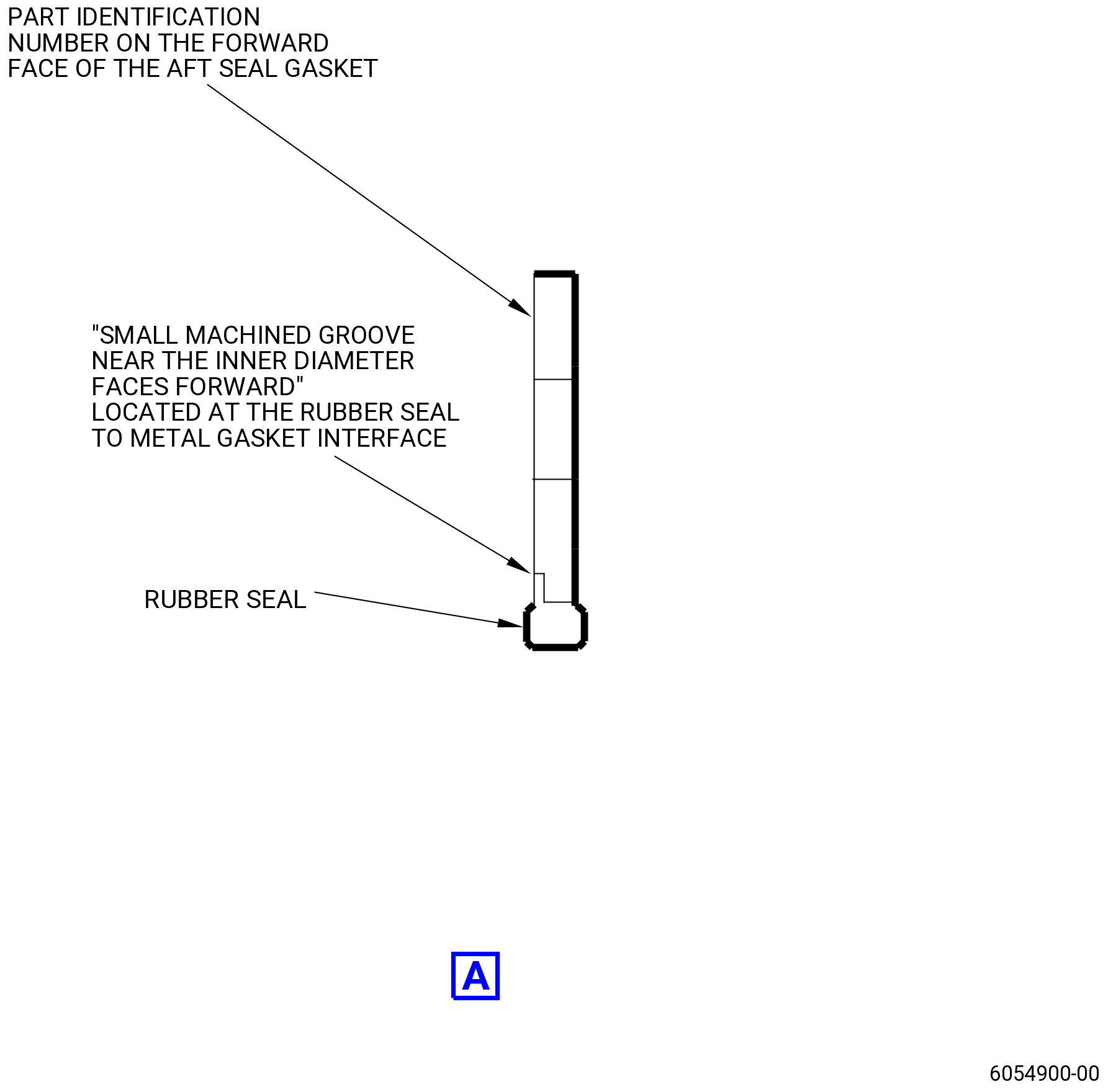
| (7) | Make sure the aft seal gasket (20-260 , 72-00-02) (SIN 84050) is correctly aligned for installation. The side of the aft seal gasket with a small machined groove near the inner diameter points forward (the part identification number is also on the forward face). Make sure the notches in the aft seal gasket are aligned with the tube holes in the fan hub module. |
| (8) | Install the aft seal gasket over the guide pins and on the FHF flange. |
| Subtask 72-00-23-220-004 |
| (9) | Do a general visual inspection of the exposed surfaces of the forward fan shaft for nicks, dents and scratches, after the removal of tooling. Refer to TASK 72-00-24-200-801 (72-00-24, INSPECTION 001) and Figure 402. |
| Subtask 72-00-23-420-003 |
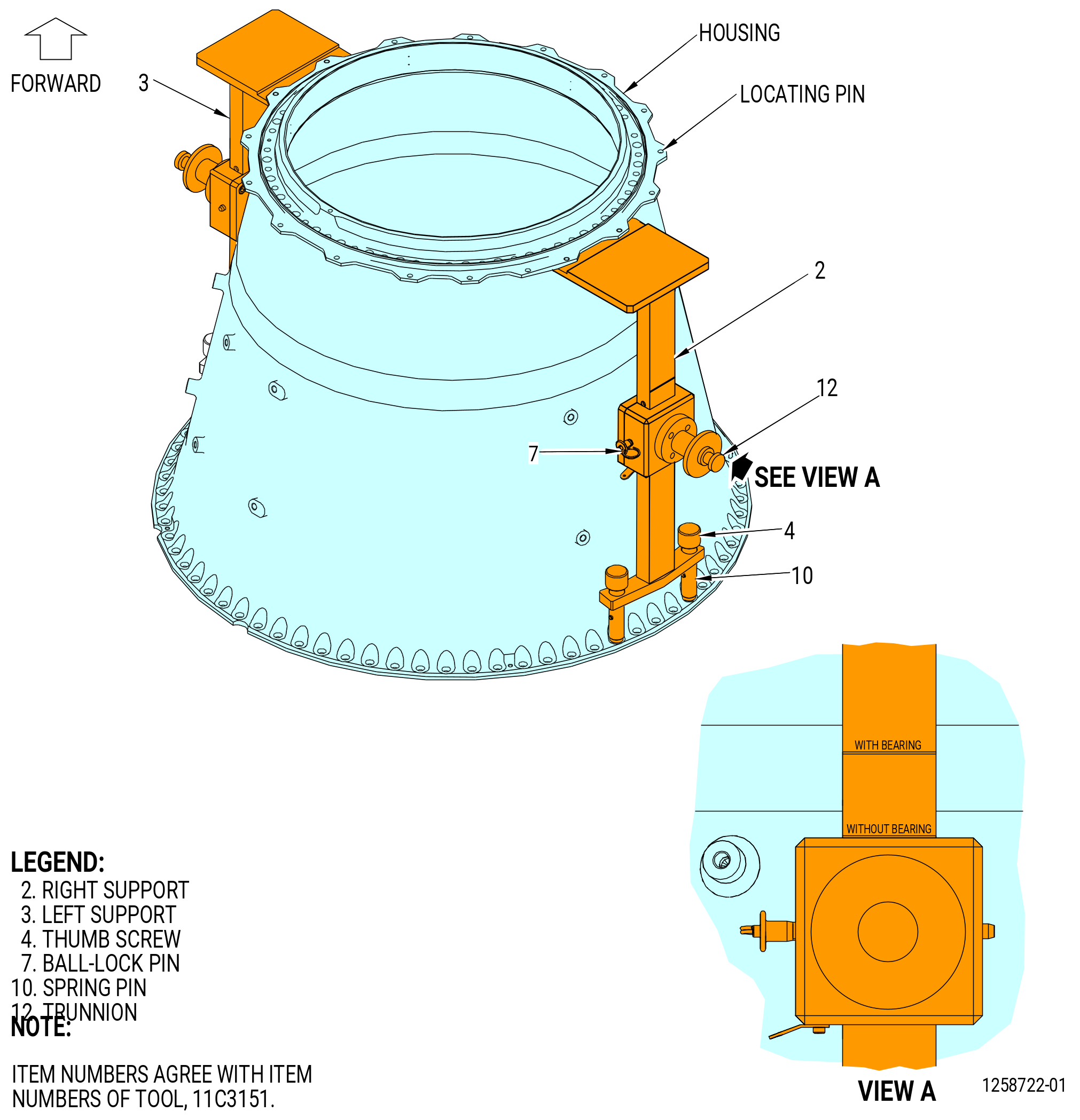
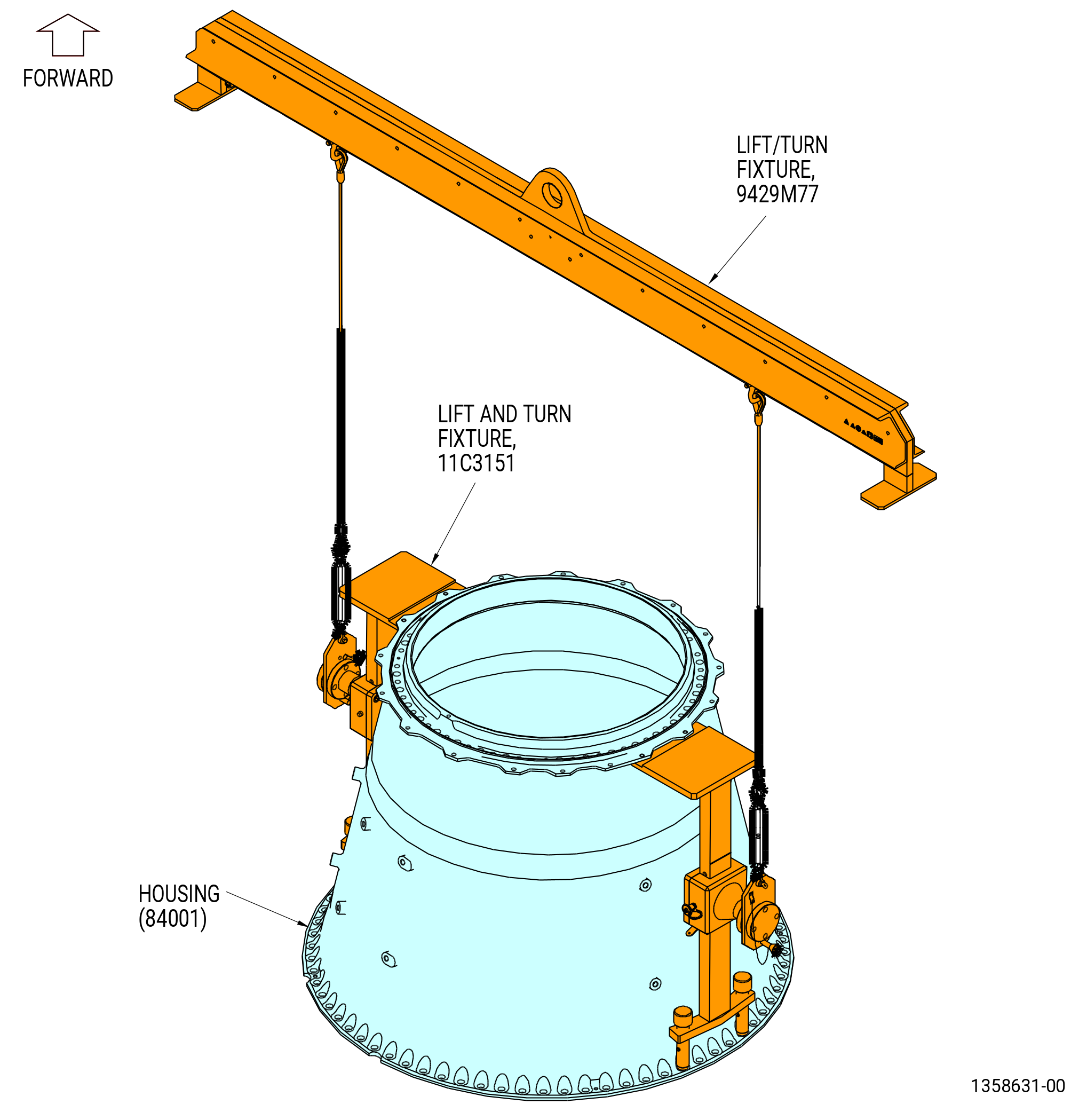
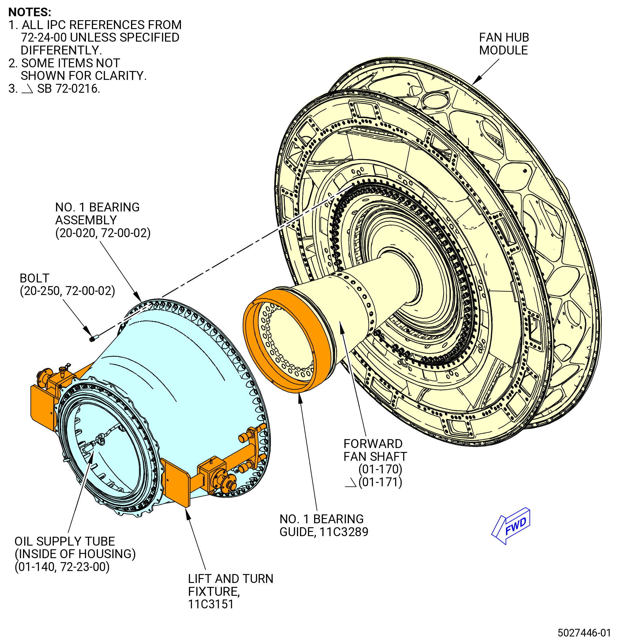
| B. | If necessary, install the 11C3151 lift and turn fixture and the 9429M77 lift/turn fixture on the No. 1 bearing assembly (00110) as follows. Refer to Figure 404. |
| (1) | Put the left support (item 3) at the 3:00 o'clock position forward looking aft (FLA) and the right support (item 2) at the 9:00 o'clock position FLA on the housing, between the forward and aft flanges. |
| NOTE: |
|
| (2) | Align the locating pins of each support with the forward flange boltholes of the No. 1 bearing support housing (housing) (84001). |
| (3) | Tighten the thumb screw (item 4) of each support to engage the spring pin (item 10) in the aft flange boltholes of the housing. |
| CAUTION: |
|
| (4) | Make sure that the trunnions (item 12) of the 11C3151 lift and turn fixture are aligned with the scribe line WITHOUT BEARING on each support (item 2 and item 3). If necessary adjust the trunnions (item 12) as follows: |
| (a) | Remove the ball-lock pin (item 7) from the right/left support brackets (items 2 and 3). |
| (b) | To lift the housing without the bearing installed, adjust the trunnion to the scribe line marked WITHOUT BEARING on the right/left support brackets (items 2 and 3). |
| (c) | To lift the housing with the bearing installed, adjust the trunnion to the scribe line marked WITH BEARING on the right/left support brackets (items 2 and 3). |
| (d) | Install the ball-lock pin (item 7) in the right/left support brackets (items 2 and 3). |
| WARNING: |
|
| (5) | Attach an overhead hoist to the 9429M77 lift/turn fixture. |
| (6) | Attach the 9429M77 lift/turn fixture to the 11C3151 lift and turn fixture as follows: |
| (a) | Attach the hoist assemblies (item 24) to the lift bar (item 23) with the shackles (item 27). Make sure each hoist assembly is the same number of holes from the centerline of the lift bar to keep the 9429M77 lift/turn fixture balanced. Make sure the hoist assemblies are perpendicular to the lift bar after they are connected to the trunnions of the 11C3151 lift/turn fixture. |
| (b) | Attach the lock plate adapters (item 13) to the hoist assemblies (item 24) with the turnbuckle (item 28). |
| (c) | Open the latch (item 14) and install the lock plate adapters (item 13) on the trunnions of the 11C3151 lift/turn fixture. |
| (d) | Close the latch (item 14) on the trunnions of the 11C3151 lift/turn fixture and insert the release pin (item 19) through the trunnion and the lock plate adapters (item 13). |
| CAUTION: |
|
| (7) | Make sure that the trunnions (item 12) of the 11C3151 lift and turn fixture are aligned with the scribe line WITH BEARING on each of the support brackets (item 2 and item 3). If necessary, adjust the trunnions (item 12) as follows: |
| (a) | Remove the ball-lock pin (item 7) from the left/right support brackets (items 2 and 3). |
| (b) | To lift the housing without the bearing installed, adjust the trunnion to the scribe line WITHOUT BEARING on the left/right support brackets (items 2 and 3). |
| (c) | To lift the housing with the bearing installed, adjust the trunnion to the scribe line WITH BEARING on the left/right support brackets (items 2 and 3). |
| (d) | Install the ball-lock pin (item 7) in the left/right support brackets (items 2 and 3). |
| Subtask 72-00-23-420-004 |
| C. | Prepare the No. 1 bearing assembly (01100) for installation as follows: |
| CAUTION: |
|
| CAUTION: |
|
| (1) | Make sure that the serial numbers on the inner and outer races of the No. 1 bearing assembly are a matched set. The inner race is installed on the forward fan shaft (01-170 , 72-24-00) (SIN 81002) or (01-171 , 72-24-00) (SIN 81002) of the No. 2 bearing assembly (20-030 , 72-00-02) (SIN 01200). Refer to Figure 403. |
| WARNING: |
|
| WARNING: |
|
| (2) | Clean the mating surfaces of the bearing (011A0) with C04-002 Stoddard solvent, or a 50-50 blend of C04-014 denatured alcohol and C04-035 isopropyl alcohol. Make sure that the surfaces have no foreign material and no high metal. |
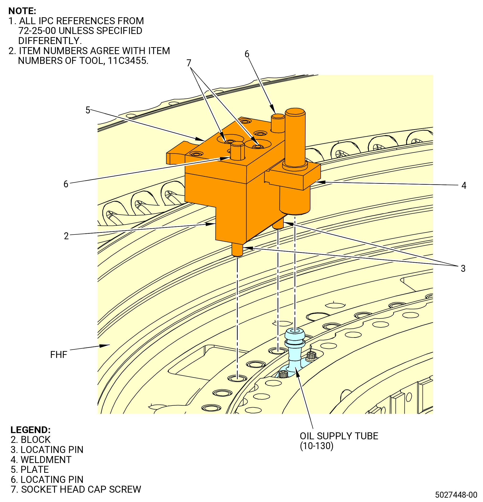
| (3) | Use the 11C3455 alignment fixture to do a check of the alignment between the male end of the oil supply tube (442A4) and the female end of the oil supply tube (442A2) as follows. Refer to Figure 405. |
| (a) | Put the 11C3455 alignment fixture on the FHF. |
| (b) | Make sure that the female end of the weldment (item 4) is correctly installed on the male end of the oil supply tube (442A4). |
| (c) | Make sure that the locating pins (item 3) in the block (item 2) engage with the threaded inserts in the FHF. |
| (d) | Tighten two socket head cap screws (item 7) in the plate (item 5) to lock the weldment (item 4) in place. |
| (e) | Remove the alignment fixture from the FHF. |
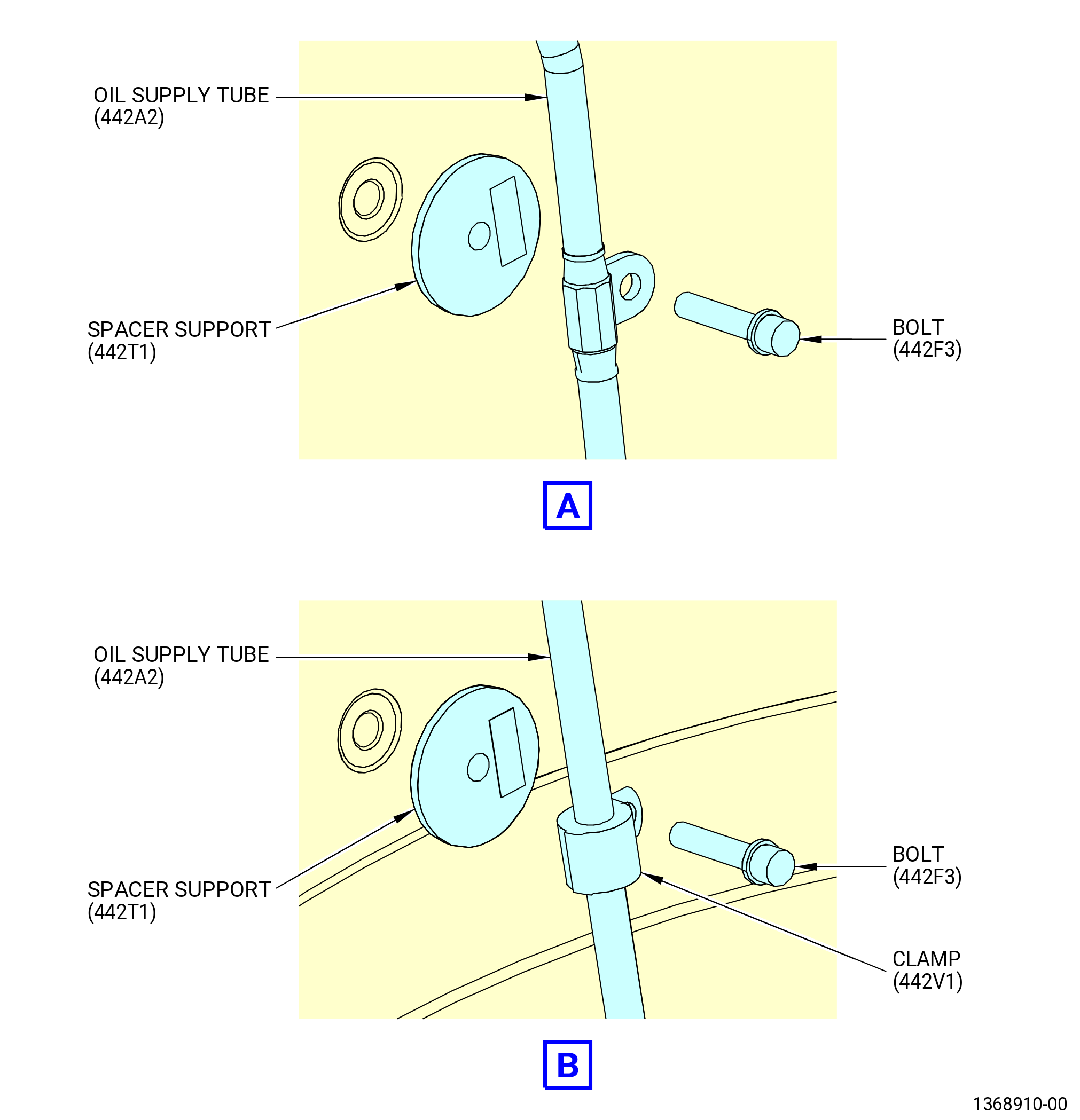
| (f) | Loosen two bolts (442F3) to release the oil supply tube (442A2). |
| CAUTION: |
|
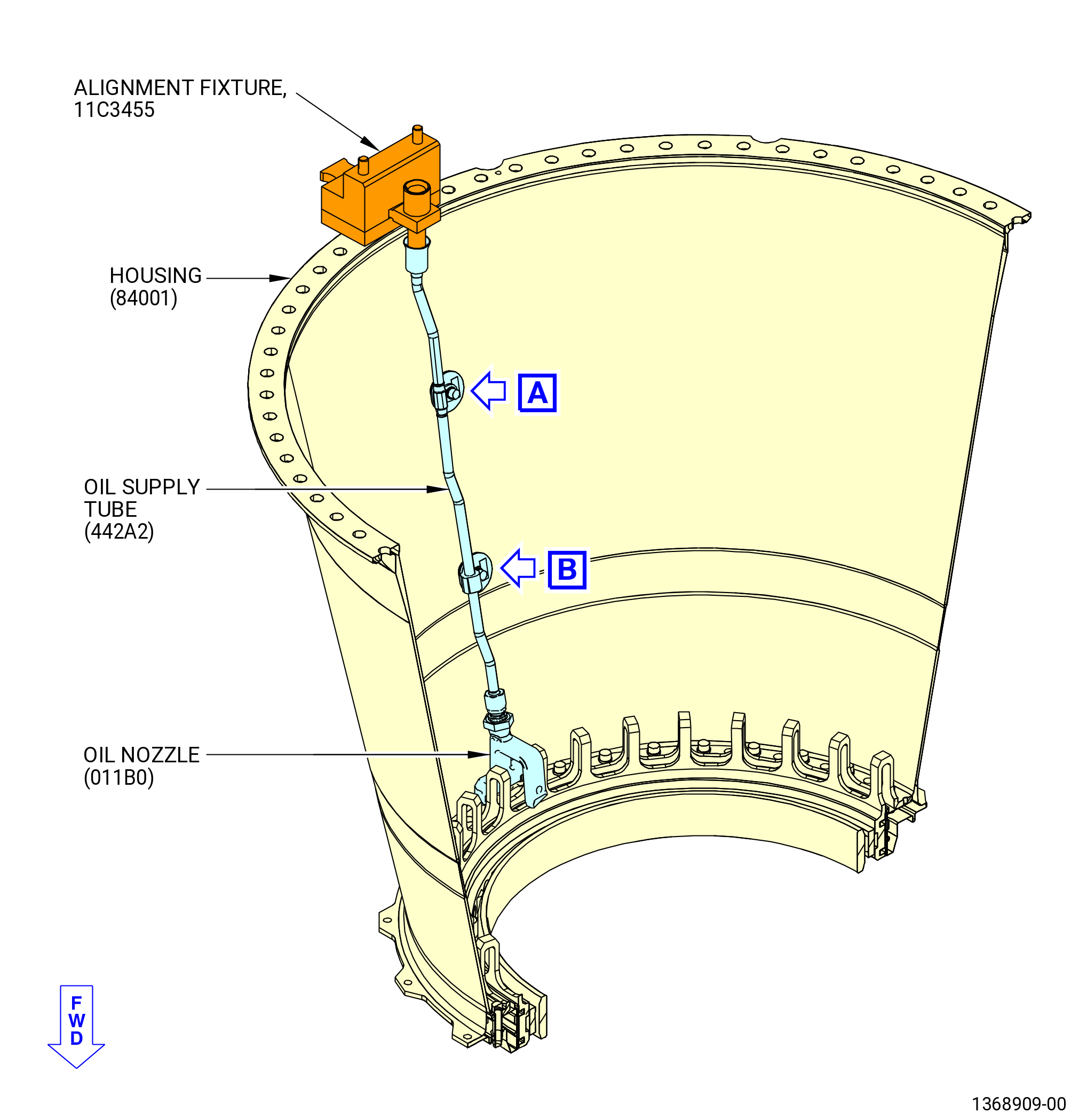
| (g) | Put the 11C3455 alignment fixture on the housing (84001). |
| (h) | Make sure that the male end of the weldment (item 4) engages the female end of the oil supply tube (442A2) |
| (i) | Make sure that the locating pins (item 6) in the block (item 2) engage the clearance holes in the housing (84001). |
| (j) | Torque two bolts (442F3) to 60-70 lb in. (6.8-7.9 N.m) to attach the oil supply tube (442A2) in place. |
| (k) | Remove the alignment fixture from the housing (84001). |
| Subtask 72-00-23-420-024 |
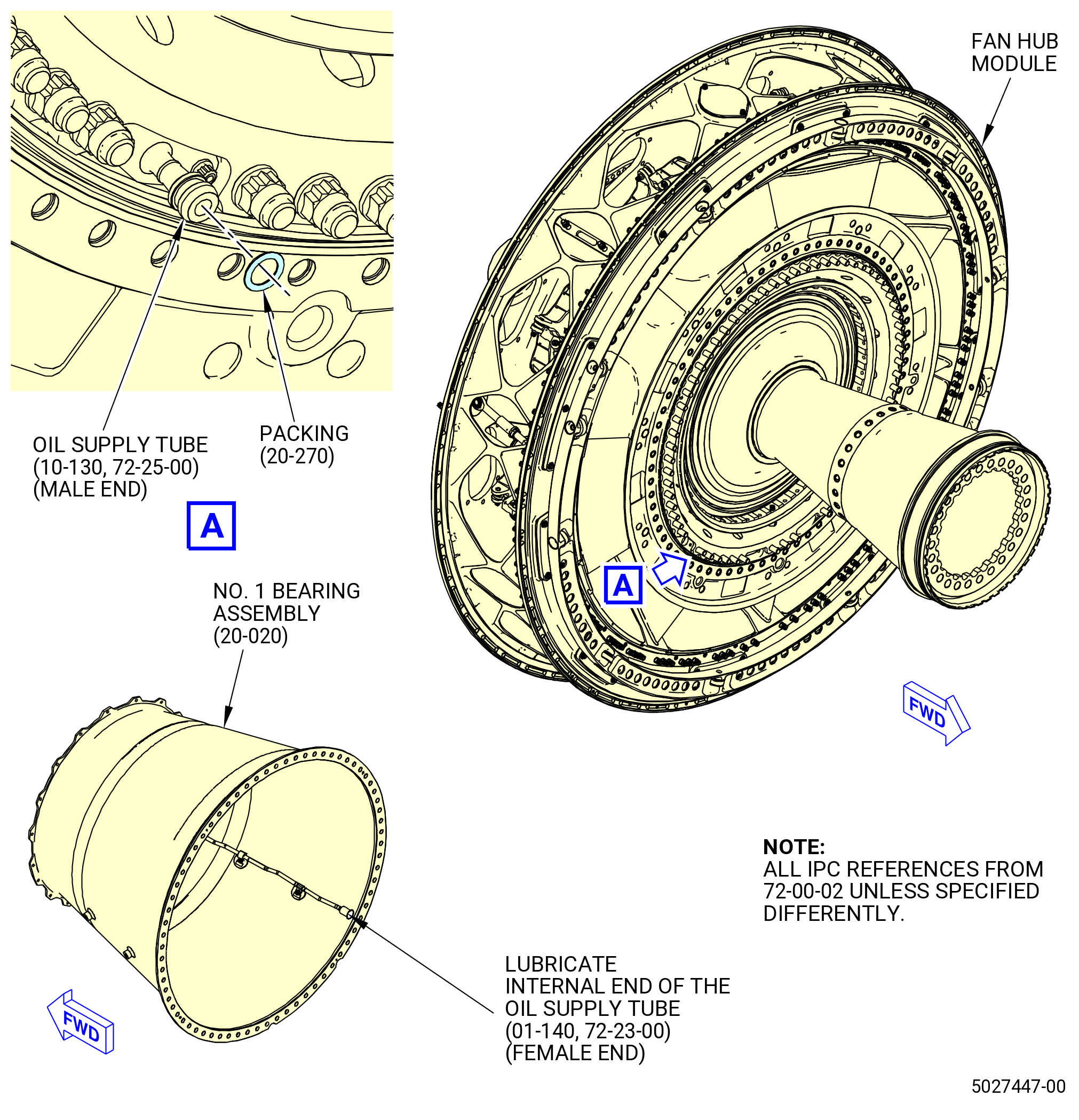
| D. | Install the packing (20-270 , 72-00-02) (SIN 442N0) for the No. 1 bearing lube system as follows. Refer to Figure 406. |
| WARNING: |
|
| (1) | Find the oil supply tube (10-130 , 72-25-00) (SIN 442A4) approximately at the 8 o'clock position FLA on the FHF. Lubricate the packing with C02-019 engine oil or C02-023 engine oil and install it on the oil supply tube. |
| (2) | Lubricate the inside chamfer on the aft end of the oil supply tube (442A2) inside of the No. 1 bearing assembly (01100) with C02-023 engine oil. |
| Subtask 72-00-23-420-005 |
| E. | Install the No. 1 bearing assembly (01100) as follows. Refer to Figure 407. |
| WARNING: |
|
| (1) | If necessary, use a C10-054 heat gun to heat the aft flange of the No. 1 bearing assembly (01100) to a maximum temperature of 250°F (121°C) to help attach it to the forward flange of the fan hub module. |
| WARNING: |
|
| (2) | Use a hoist and lift the No. 1 bearing assembly (20-020 , 72-00-02) (SIN 01100) and set it to the horizontal position. Align it in front of the fan hub module and the forward fan shaft (01-170 , 72-24-00) (SIN 81002) or (01-171 , 72-24-00) (SIN 81002). |
| (3) | Use visual indicators to make sure that the No. 1 bearing assembly is in alignment with the fan hub module as follows: |
| • |
|
| • |
|
| (4) | Push the No. 1 bearing assembly AFT and over the 9C2352 guide pins and against the aft seal gasket (84050). Make sure that the oil supply tube (442A2) inside the No. 1 bearing assembly makes contact with the oil supply tube (442A4) on the fan hub module. |
| Subtask 72-00-23-420-006 |
| CAUTION: |
|
| F. | Attach the No. 1 bearing assembly (01100) as follows. Refer to Figure 407. |
| (1) | Apply C02-058 lubricant to the threads and friction surfaces of 70 bolts (84020). |
| WARNING: |
|
| (2) | If the aft flange of the No. 1 bearing assembly was heated, wear thermal gloves while you install and tighten the bolts. |
| (3) | Attach the No. 1 bearing assembly to the fan hub module with the bolts (20-250 , 72-00-02) (SIN 84020) in the open boltholes on the aft flange of the No. 1 bearing assembly. Tighten the bolts but do not torque them. |
| (4) | Remove the 9C2352 guide pins from the fan hub module. |
| (5) | Remove the 9429M77 lift/turn fixture from the 11C3151 lift and turn fixture. |
| (6) | Remove the 11C3151 lift and turn fixture from the No. 1 bearing assembly. |
| (7) | Install the remaining bolts (84020) in the No. 1 bearing assembly aft flange. Tighten the bolts but do not torque them. |
| (8) | Use your hand to smoothly un-thread the 11C3289 No. 1 bearing guide from the forward fan shaft (01-170 , 72-24-00) (SIN 81002) or (01-171 , 72-24-00) (SIN 81002). |
| Subtask 72-00-23-420-007 |
| (1) | If the aft flange of the No. 1 bearing assembly was heated, let the temperature of the No. 1 bearing assembly decrease to ambient temperature. |
| (2) | Torque every 8th equally-spaced bolt (84020) in a criss-cross pattern to 430-502 lb in. (48.6-56.7 N.m). |
| (3) | Torque all bolts (84020) in a criss-cross pattern to a final torque of 552-648 lb in. (62.4-73.2 N.m). |
| Subtask 72-00-23-220-005 |
| (4) | Do a general visual inspection of the exposed surfaces of the forward fan shaft for nicks, dents and scratches, after the removal of tooling. Refer to TASK 72-00-24-200-801 (72-00-24, INSPECTION 001) and Figure 402 |
| Subtask 72-00-23-420-008 |
| CAUTION: |
|
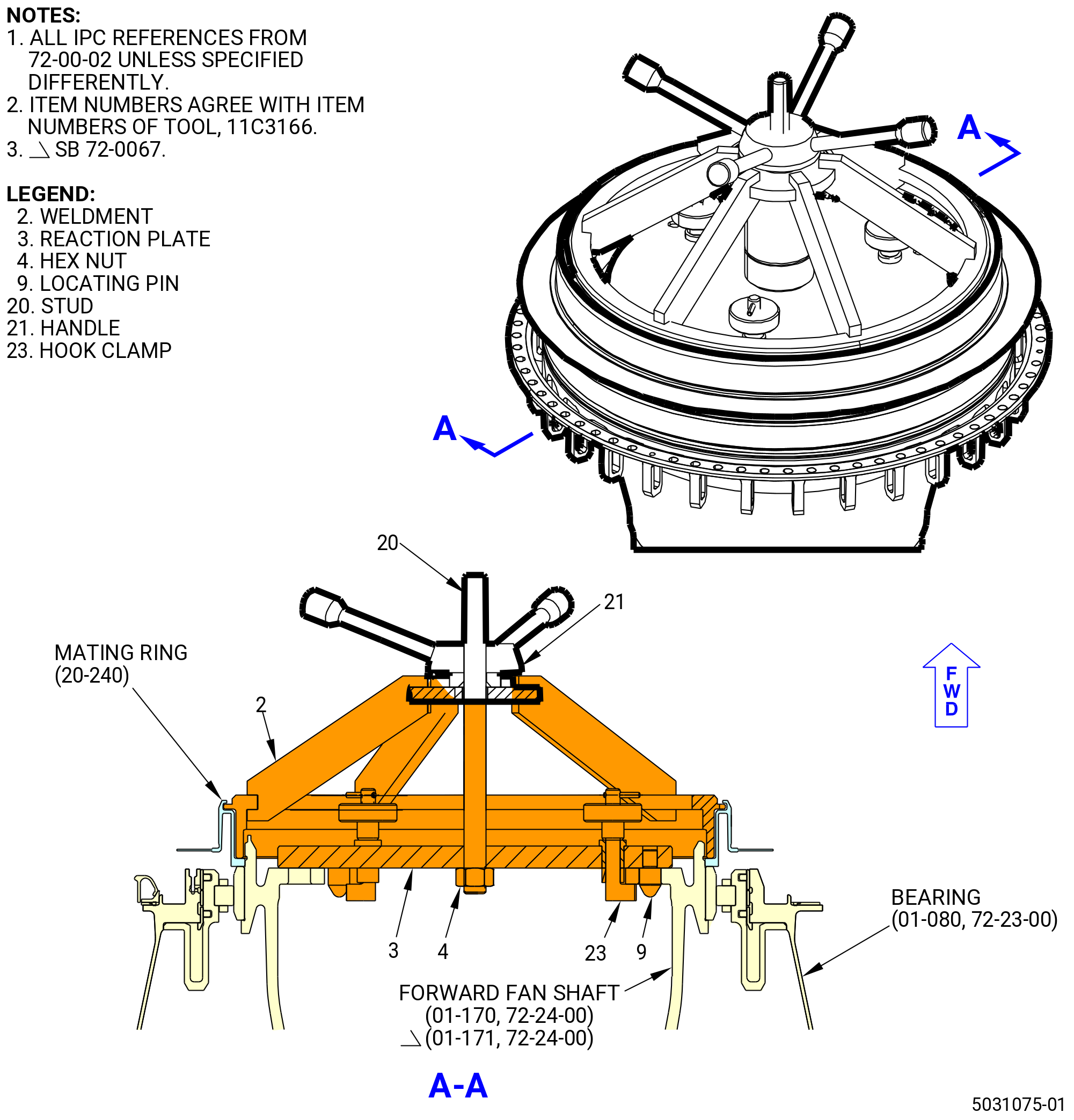
| G. | Install the No. 1 bearing seal mating ring (mating ring) (011A5) as follows. Refer to Figure 408. |
| WARNING: |
|
| (1) | Increase the temperature of the mating ring in an oven to 300 to 350°F (149 to 177°C). |
| (2) | Install the reaction plate (item 3) of the 11C3166 install seal fixture on the forward fan shaft (01-170 , 72-24-00) (SIN 81002) or (01-171 , 72-24-00) (SIN 81002) and tighten the hook clamps (item 23) to attach it. |
| (3) | Put the heated mating ring on the forward end of the forward fan shaft and seat it against the bearing (011A0). Make sure that the carbon segments of the No. 1 bearing carbon seal (carbon seal) (011A7) are larger in diameter than the sealing surface of the heated mating ring. |
| (4) | Install the weldment (item 2) as follows: |
| (a) | Align the slots in the outside lip of the frame with the inside diameter tabs of the mating ring. |
| (b) | Push the frame fully against the mating ring and rotate approximately 30 degrees to engage the tabs on the frame. |
| (c) | Install the stud (item 20) through the frame and attach it to the reaction plate (item 3) with the hex nut (item 4). |
| (d) | Screw on the handle (item 21) down the stud (item 20) until the handle connects against the weldment (item 2). |
| (5) | Turn the handle (item 21) to push the reaction plate (item 3) and seat the mating ring against the bearing. |
| (6) | Let the temperature of the mating ring decrease to ambient temperature and release the handle (item 21) pressure. Remove the 11C3166 install seal fixture. |
| (7) | Make sure that the mating ring is fully seated. Try to insert a 0.001 inch (0.03 mm) shim between the mating ring and the bearing inner race. Refer to Figure 409. |
| Subtask 72-00-23-220-006 |
| (8) | Do a general visual inspection of the exposed surfaces of the forward fan shaft for nicks, dents and scratches, after the removal of tooling. Refer to TASK 72-00-24-200-801 (72-00-24, INSPECTION 001) and Figure 402. |
| Subtask 72-00-23-420-009 |
| CAUTION: |
|
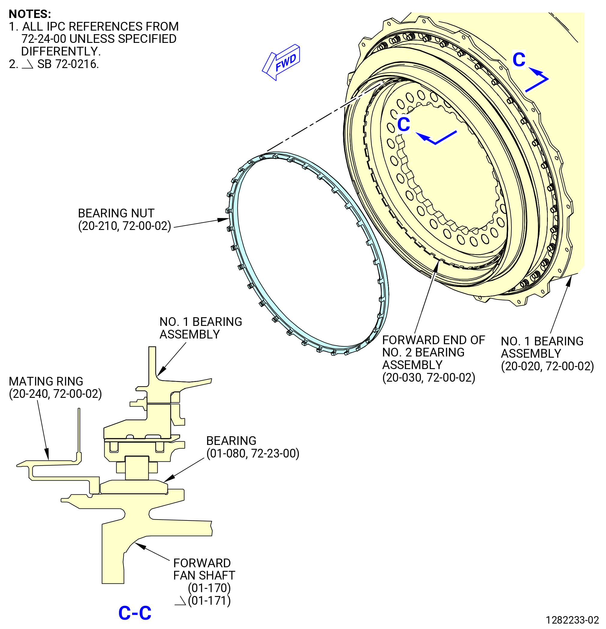
| H. | Install the No. 1 bearing nut (bearing nut) (011A1) as follows. Refer to Figure 409. |
| WARNING: |
|
| (1) | Use a 50-50 blend of C04-014 denatured alcohol and C04-035 isopropyl alcohol to clean the threads on the forward end of the No. 2 bearing assembly (01200) and the bearing nut. |
| (2) | Coat the threads and the mating face of the bearing nut and the threads on the forward end of the No. 2 bearing assembly with C02-058 lubricant. |
| (3) | Use your hand to smoothly thread the bearing nut on the forward end of the No. 2 bearing assembly as far as possible. |
| (4) | Install the 11C3204 torque adapter on the bearing nut as follows. Refer to Figure 410. |
| (a) | Align the locating pins on the support plate (item 3) of the 11C3204 torque adapter with the holes in the forward fan shaft (01-170 , 72-24-00) (SIN 81002) or (01-171 , 72-24-00) (SIN 81002). |
| (b) | Turn the knurled knob (item 18) and attach the support plate (item 3) with three clamps (item 4). |
| (c) | Assemble the base (item 6) on the studs (item 11) of the split ring (item 7). Turn the base until it engages the wrench slots of the bearing nut. Attach the base to the split ring with two nuts (item 12). |
| (d) | Install a torque multiplier over the spline shaft (item 8) and turn until the pins on the torque multiplier engage the bushings on the base (item 6). |
| (5) | Use the torque multiplier to torque the bearing nut (011A1) to 5100 lb ft. (6914.7 N.m). |
| (6) | Loosen the bearing nut to break the torque and then re-torque to 1700 lb ft. (2304.9 N.m). |
| (7) | Increase the torque as required to allow installation of the spring clips. The final torque must not be more than 2800 lb ft. (3796.3 N.m). |
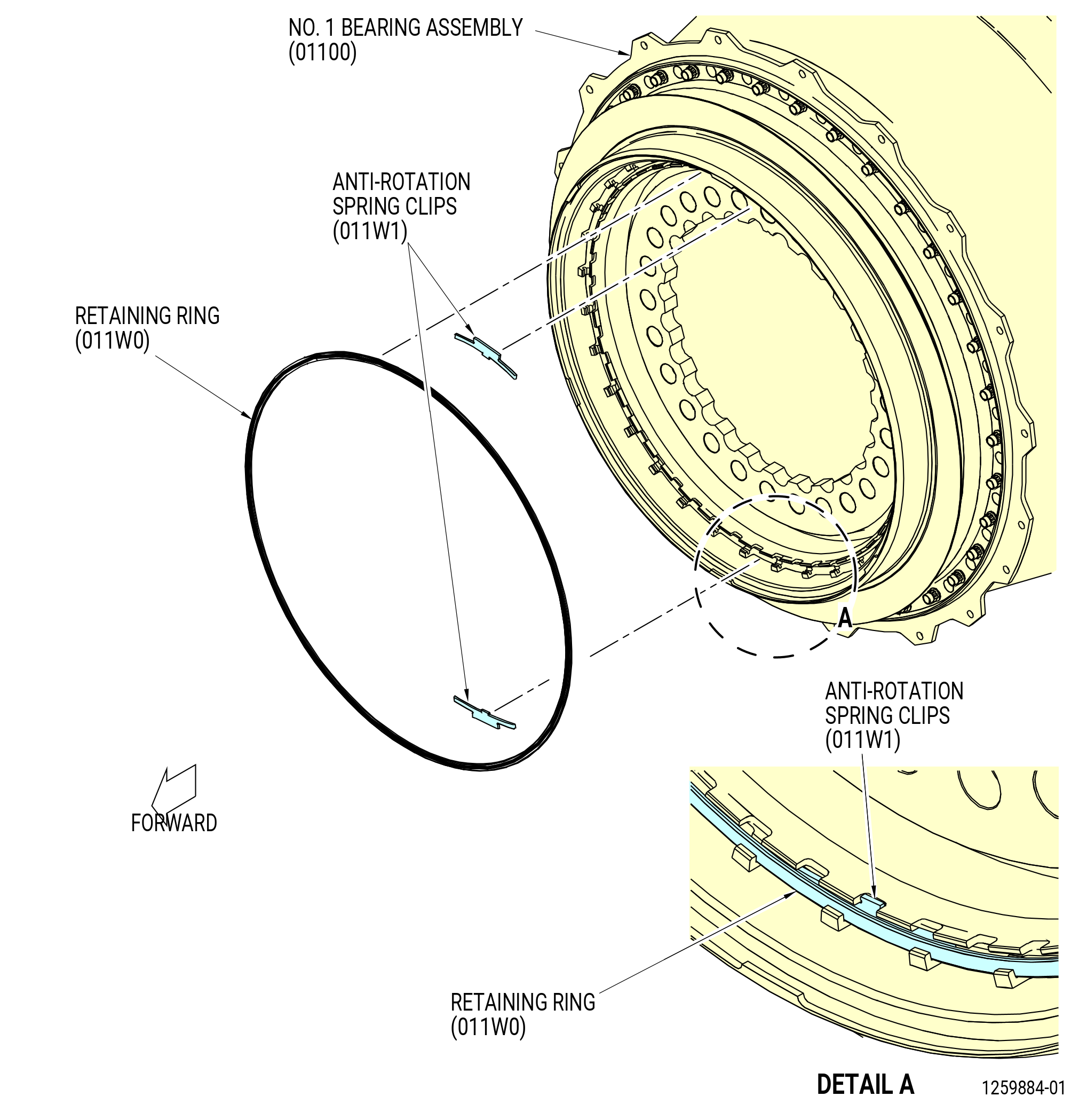
| (8) | Install the anti-rotation spring clips (spring clips) (011W1) as follows. Refer to Figure 411. |
| CAUTION: |
|
| (a) | Install two spring clips, 180 degrees apart and engage the castellations in the bearing nut (011A1). |
| (b) | Install the retaining ring (011W0) inside the bearing nut (011A1) to secure the spring clips. |
| (9) | Remove the 11C3204 torque adapter as follows: |
| (a) | Loosen the two nuts (item 12) that attach the split ring (item 7) to the base (item 6). Remove the base (item 6). |
| (b) | Turn the knurled knob (item 18) and disengage the three clamps (item 4) that attach the support plate (item 3) to the forward fan shaft. Remove the support plate (item 3). |
| Subtask 72-00-23-220-007 |
| (10) | Do a general visual inspection of the exposed surfaces of the forward fan shaft for nicks, dents and scratches, after the removal of tooling. Refer to TASK 72-00-24-200-801 (72-00-24, INSPECTION 001) and Figure 402. |
| Subtask 72-00-23-420-010 |
| * * * PRE SB 79-0006( Scavenge Oil Tube with One Cushioned Loop Clamp ) |
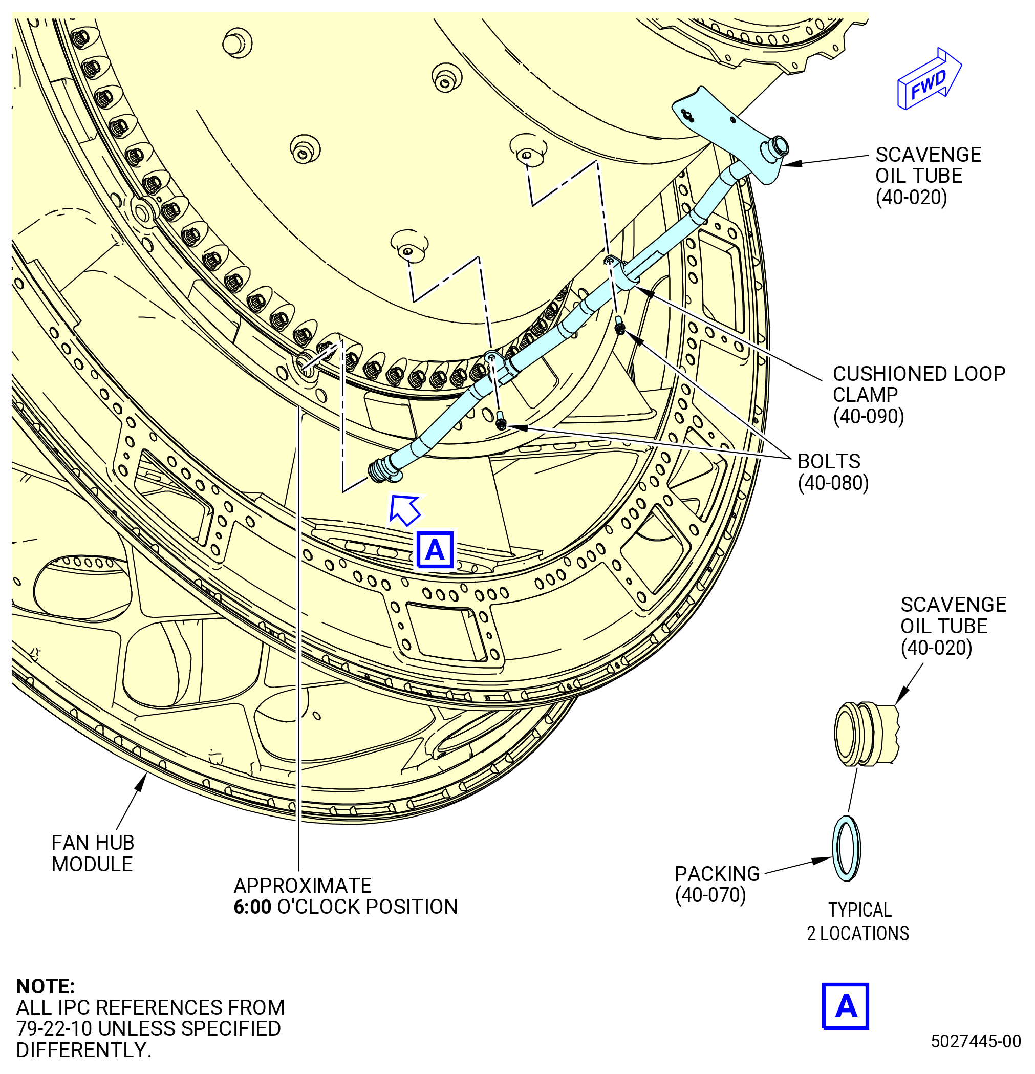
| I. | Install the scavenge oil tube (40-020 , 79-22-10) (SIN 451A0) as follows. Refer to Figure 412. |
| WARNING: |
|
| (1) | Use C02-019 engine oil or C02-023 engine oil to lubricate two packings (40-070 , 79-22-10) (SIN 451N0) and the internal chamfers on the two ends of the scavenge oil tube. Install one packing on each end of the scavenge oil tube. |
| (2) | Insert the aft end of the scavenge oil tube into the fan hub module approximately at the 6:00 o'clock position FLA with bolts and clamps. |
| (3) | Attach the center section of the scavenge oil tube to the housing (84001) with two bolts (451F1) and a scavenge loop clamp (40-090 , 79-22-10) (SIN 451V0). Let the forward end of the scavenge oil tube loose at this time. |
| (4) | Torque the bolt (451F1) installed in the scavenge loop clamp (40-090 , 79-22-10) (SIN 451V0) to 60-70 lb in. (6.8-7.9 N.m). |
| (5) | Torque the remaining bolt (451F1) to 106-124 lb in. (12.0-14.0 N.m). |
| * * * END PRE SB 79-0006 |
| Subtask 72-00-23-420-025 |
| * * * SB 79-0006( Scavenge Oil Tube with Two Cushioned Loop Clamps ) |
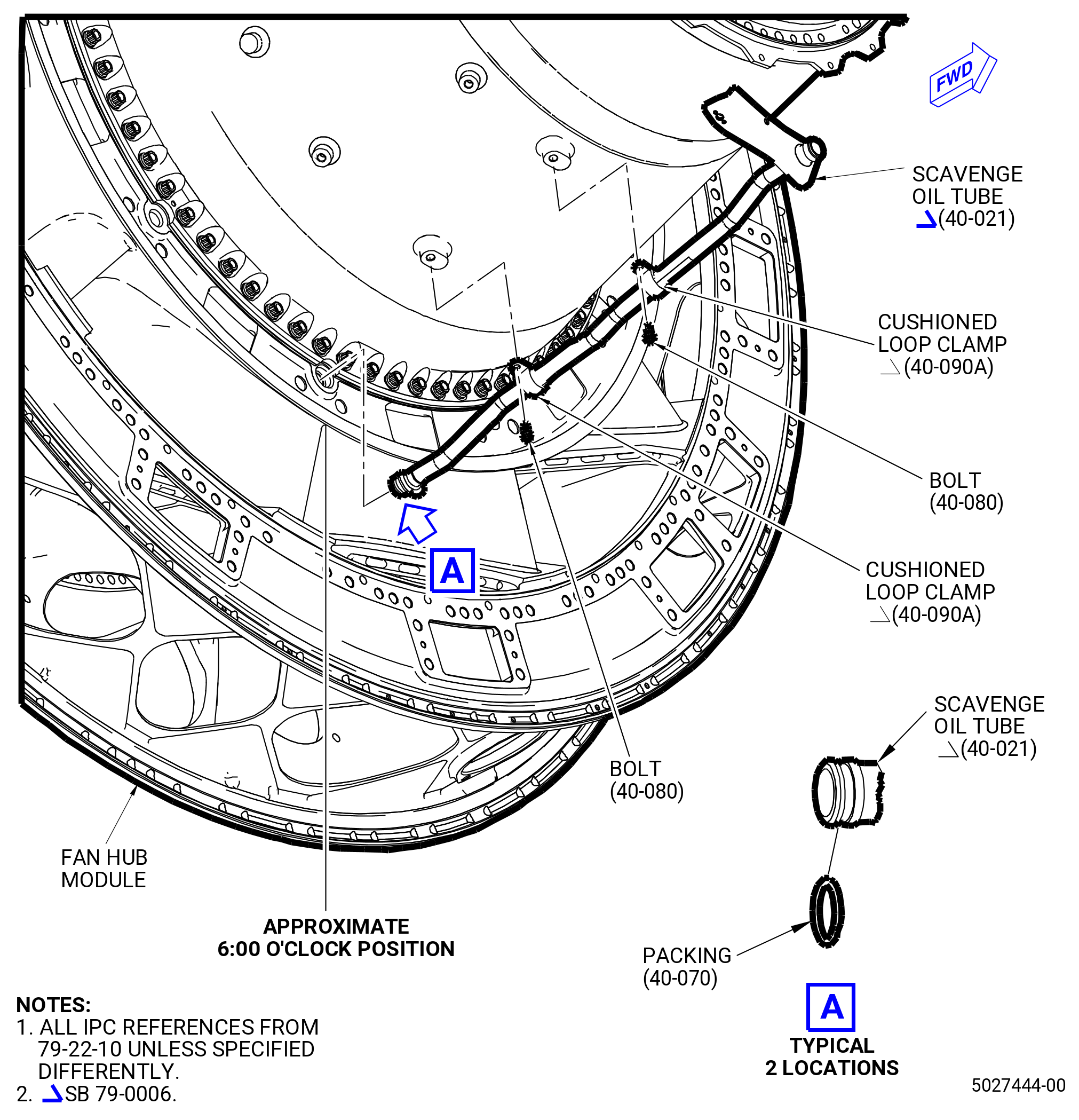
| I.A. | Install the scavenge oil tube (40-021 , 79-22-10) (SIN 451A0) as follows. Refer to Figure 412A. |
| WARNING: |
|
| (1) | Use C02-019 engine oil or C02-023 engine oil to lubricate two packings (40-070 , 79-22-10) (SIN 451N0) and the internal chamfers on the two ends of the scavenge oil tube. Install one packing on each end of the scavenge oil tube. |
| (2) | Insert the aft end of the scavenge oil tube into the fan hub module approximately at the 6:00 o'clock position FLA. |
| (3) | Attach the center section of the scavenge oil tube to the housing (84001) with two bolts (451F1) and two scavenge loop clamp (40-090A , 79-22-10) (SIN 451V0). Let the forward end of the scavenge oil tube loose at this time. |
| (4) | Torque the bolts (451F1) installed in the scavenge loop clamps (40-090A , 79-22-10) (SIN 451V0) to 60-70 lb in. (6.8-7.9 N.m). |
| * * * END SB 79-0006 |
|
|
| Subtask 72-00-23-420-019 |
| CAUTION: |
|
| J. | Install the No. 1 bearing carbon seal support (seal support) (011A3) as follows. Refer to Figure 413. |
| WARNING: |
|
| (1) | Use C02-019 engine oil or C02-023 engine oil to lubricate the packing (20-180 , 72-00-02) (SIN 011N3). Install the packing into the groove on the aft side of the outer surface of the carbon seal (011A7). |
| WARNING: |
|
| (2) | Use a parts oven to heat the seal support to a maximum of 250°F (121°C). |
| NOTE: |
|
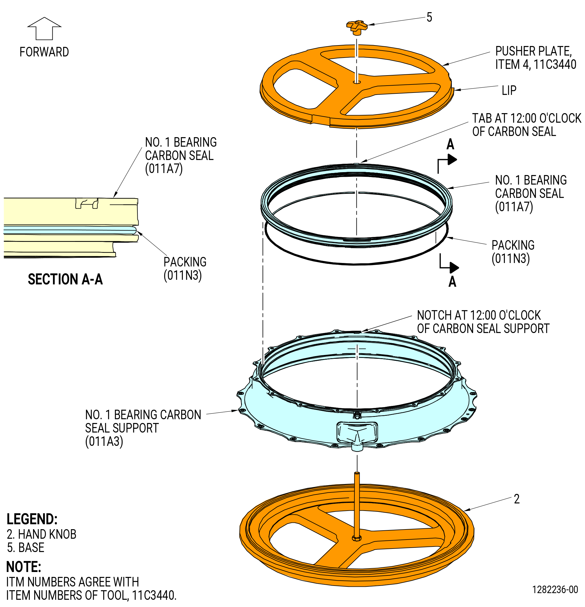
| (3) | Install the carbon seal into the seal support with the 11C3440 carbon seal fixture as follows: |
| (a) | Put the seal support aft end down (larger diameter down) into the base (item 2) of the 11C3440 carbon seal fixture. |
| (b) | Put the carbon seal on top of the seal support. |
| (c) | Make sure that the tab at 12:00 o'clock on the carbon seal is aligned with the notch at 12:00 o'clock on the seal support. |
| (d) | Install the pusher plate (item 4) lip side down on top of the carbon seal. |
| (e) | Thread the hand knob (item 5) on the fixture base stud and tighten it against the pusher plate until the carbon seal is seated on the seal support. |
| (f) | Remove the hand knob and pusher plate from the seal support and remove the seal support assembly from the base of the seal fixture. |
| WARNING: |
|
| (g) | Apply C02-019 engine oil or C02-023 engine oil to the inner diameter surface of the carbon seal (011A7). |
| (h) | If the carbon seal assembly is used or overhauled, make sure the carbon seal is free to move when the segments are lightly pushed. Make sure that they return to their original position. |
| WARNING: |
|
| (i) | If the segments do not return to their original position, clean the carbon seal assembly with C04-002 Stoddard solvent. Refer to TASK 72-23-04-100-801 (72-23-04, CLEANING 001). |
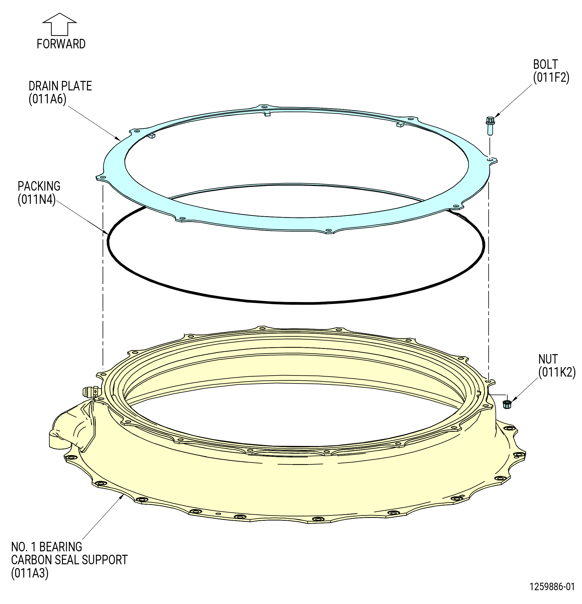
| (4) | Install the No. 1 bearing seal drain (drain plate) (011A6) as follows. Refer to Figure 414. |
| (a) | Install the packing (20-160 , 72-00-02) (SIN 011N4) onto the seal support. |
| (b) | Align the eight holes in the drain plate with eight of the 16 holes on the seal support. |
| (c) | Attach the drain plate with eight bolts (011F2) and nuts (011K2), boltheads pointing forward. |
| (d) | Torque the nuts (011K2) in a criss-cross pattern to 106-124 lb in. (12.0-14.0 N.m). |
| (e) | Torque again the nuts (011K2) in a circular pattern to 106-124 lb in. (12.0-14.0 N.m). |
| (5) | Install the seal support to the engine as follows. Refer to Figure 415. |
| NOTE: |
|
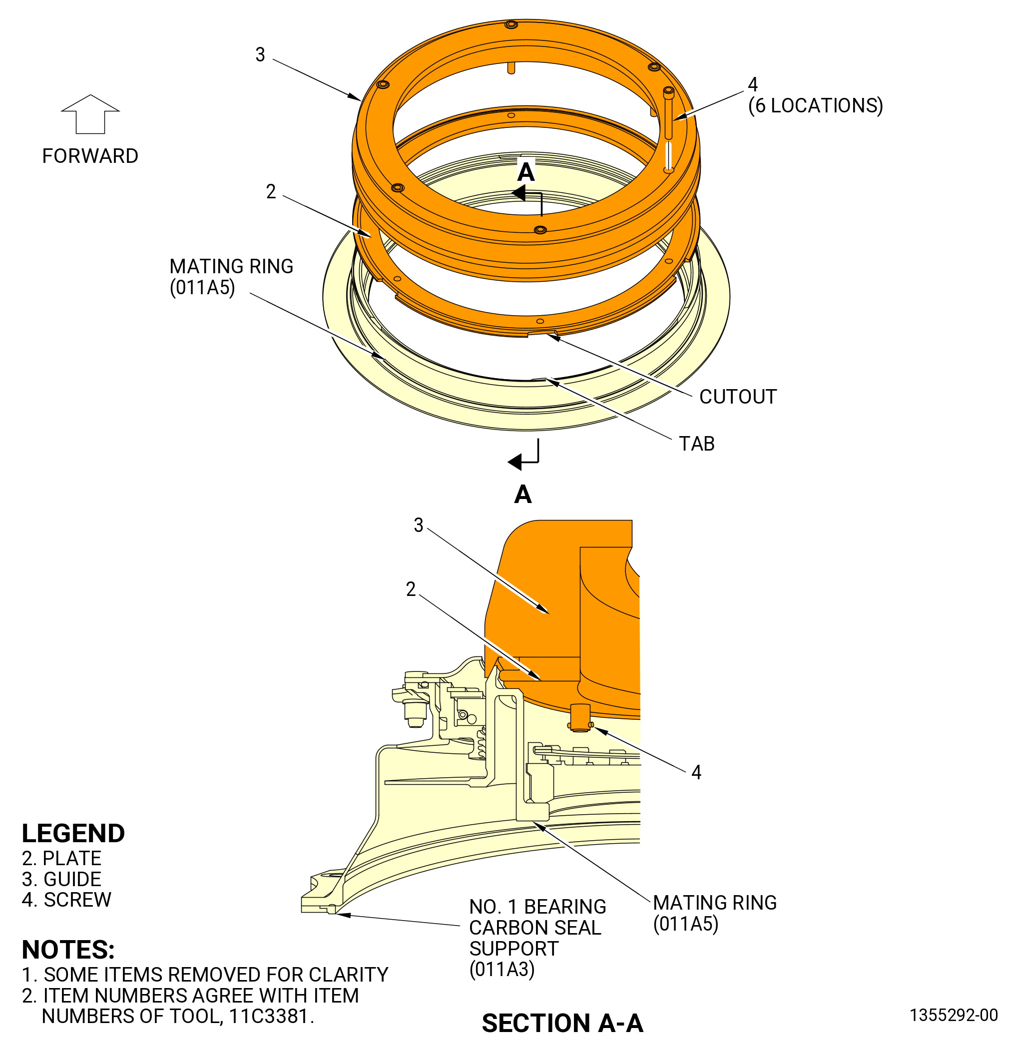
| (a) | Install the 11C3381 seal guide onto the forward end of the mating ring (011A5). Refer to Figure 416. |
| 1 | Align the six cutouts in the plate (item 2) with the six tabs on the mating ring. |
| NOTE: |
|
| 2 | Push down and engage the clamp ring lip into the mating ring grove and rotate approximately 30 degrees in either direction to lock the oil seal tabs between the nylon guide and clamp ring. |
| 3 | Secure in place with the six screws (item 4). |
| WARNING: |
|
| 4 | Apply C02-019 engine oil or C02-023 engine oil to the carbon seal running surface of the mating ring (011A5), and the outer surface of the 11C3381 seal guide. |
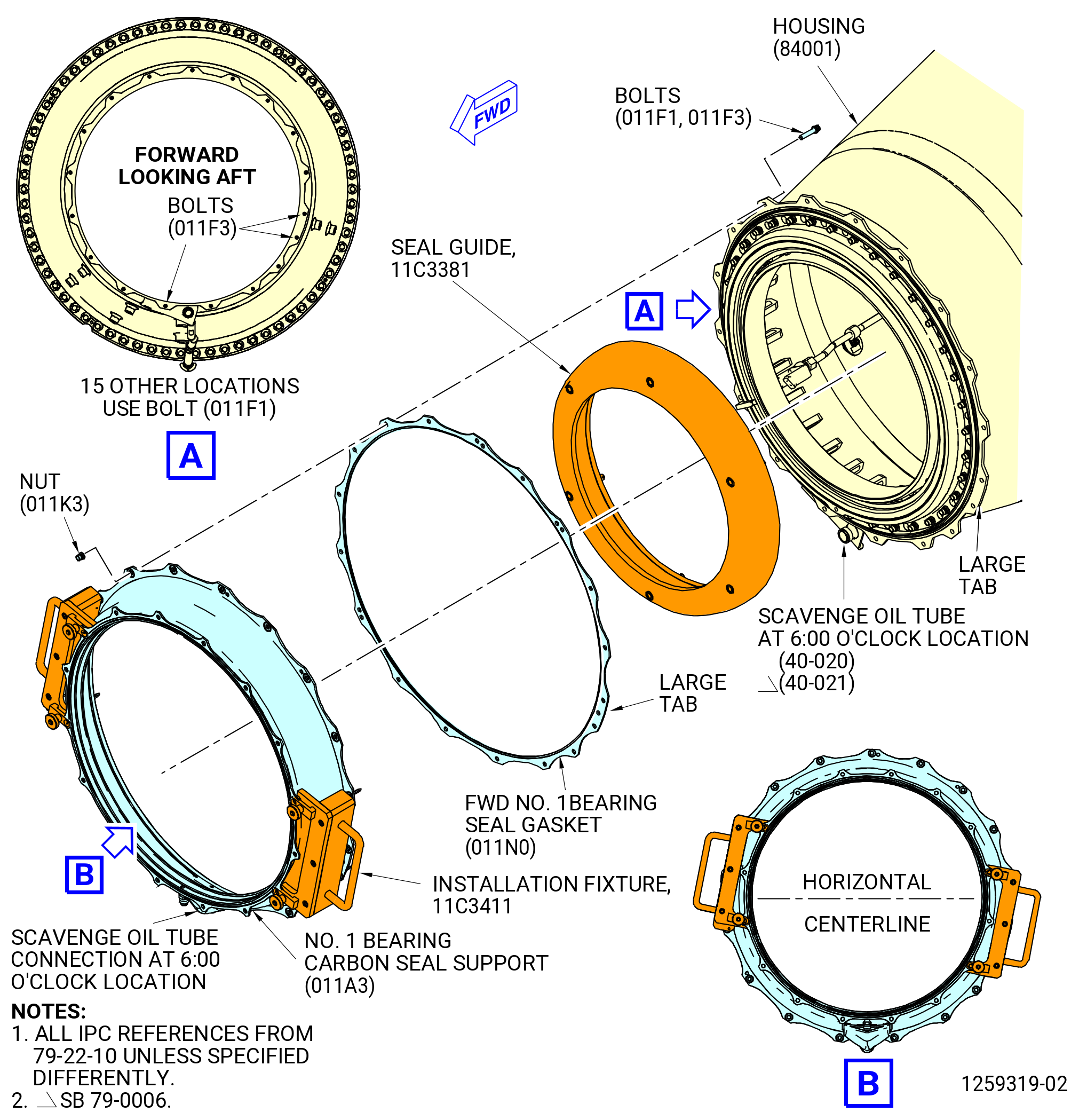
| (b) | Attach the 11C3411 installation fixture to the seal support. |
| NOTE: |
|
| WARNING: |
|
| CAUTION: |
|
| (c) | Use heat tape to heat only the aft flange of the seal support to 150-250°F (66-121°C). |
| (d) | Align the large tab on the FWD No. 1 bearing seal gasket (seal gasket) (011N0) with the large tab on the No. 1 bearing housing and put the seal gasket (011N0) over the forward outer diameter of the housing (84001). |
| (e) | Hold the handles of the 11C3411 installation fixture and align the scavenge tube at the 6:00 o'clock position on the seal support assembly with the scavenge oil tube (40-020 , 79-22-10) (SIN 451A0) or (40-021 , 79-22-10) (SIN 451A0) at the 6:00 o'clock position on the housing. |
| CAUTION: |
|
| (f) | Push the handles on the 11C3411 installation fixture to install the seal support assembly on the housing (84001) and fully seat it. |
| (6) | Attach the seal support assembly to the housing as follows: |
| (a) | Install two bolts (011F3) on the large tab and one bolt (011F3) at the 6:15 o'clock position of the seal support assembly. Install the remaining 15 bolts (011F1) and 18 nuts (011K3), boltheads aft. Hand tighten the bolts. |
| (b) | Remove the 11C3411 installation fixture from the seal support and install the remaining bolts (011F1 or O11F3), boltheads pointing aft. Hand tighten the bolts. |
| (c) | Torque the nuts (011K3) in a criss-cross pattern to 106-124 lb in. (12.0-14.0 N.m). |
| (d) | Torque the nuts (011K3) in a circular pattern to 106-124 lb in. (12.0-14.0 N.m). |
| (e) | Loosen the six screws (item 4) and remove the 11C3381 seal guide from the forward end of the mating ring. |
| Subtask 72-00-23-220-008 |
| (7) | Do a general visual inspection of the exposed surfaces of the forward fan shaft for nicks, dents and scratches, after the removal of tooling. Refer to TASK 72-00-24-200-801 (72-00-24, INSPECTION 001) and Figure 402. |
| Subtask 72-00-23-780-001 |
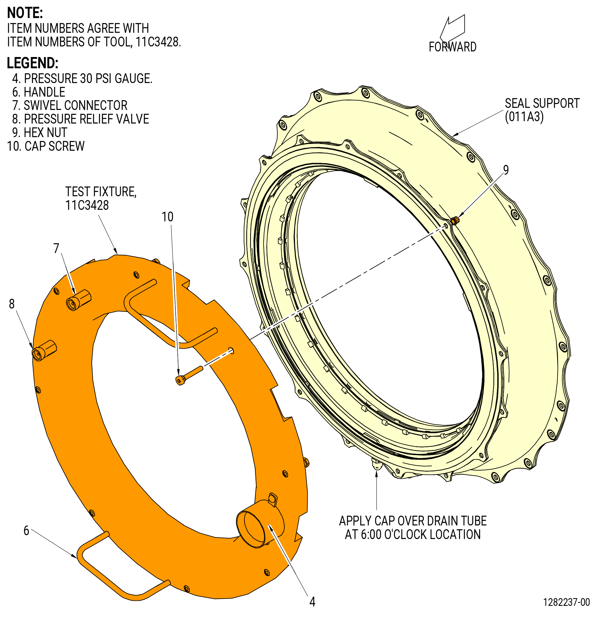
| K. | Do a flow check of the No. 1 bearing carbon seal as follows. Refer to Figure 417. |
| (1) | Install the 11C3428 test fixture on the carbon seal and on the seal drain at the 6:00 o'clock position. |
| (2) | Attach the test fixture with eight nuts (item 9) and capscrews (item 10) and install a cap onto the drain at the 6:00 o'clock position. |
| (3) | Attach an air line to the swivel fitting on the 11C3428 test fixture. |
| (4) | Pressurize the cavity to 9.5-10.5 psig (65.5-72.3 kPa). The flow must not be more than 2.5 SCFM (70.7 liters/minute). |
| (5) | If carbon seal does not seat, lightly tap the forward face of the 11C3428 test fixture with a nylon faced mallet. |
| (6) | Release the pressure from the 11C3428 test fixture and remove the cap from the drain. |
| (7) | Remove the eight nuts (item 9) and capscrews (item 10) and remove the 11C3428 test fixture from the carbon seal. |
| Subtask 72-00-23-420-022 |
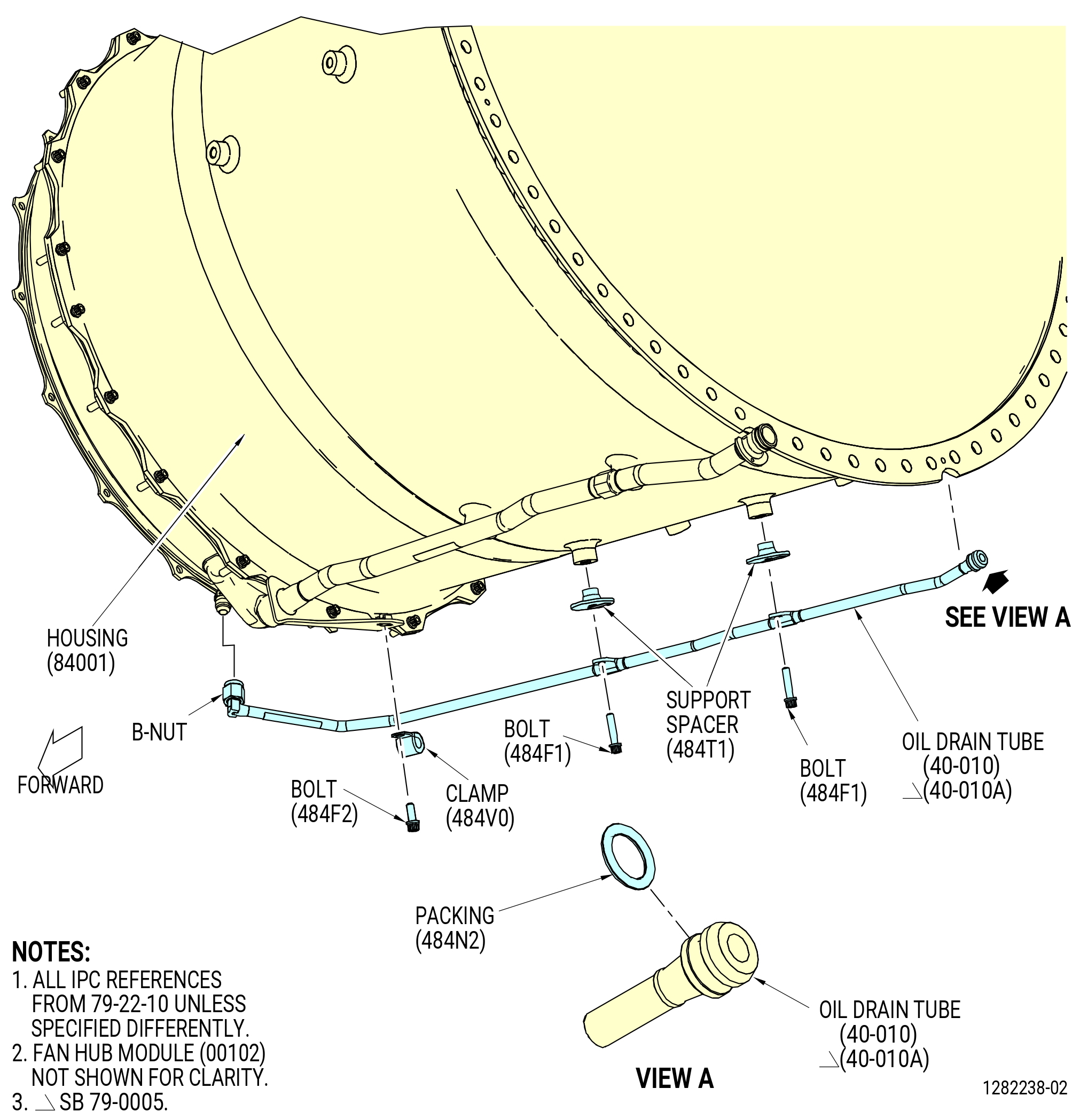
| L. | Install the oil drain tube (40-010 , 79-22-10) (SIN 484A0) or (40-010A , 79-22-10) (SIN 484A0) on the outside of the housing (84001) as follows. Refer to Figure 418. |
| WARNING: |
|
| (1) | Lubricate the packing (40-100 , 79-22-10) (SIN 484N2) with C02-019 engine oil or C02-023 engine oil and install to the end of the oil drain tube. |
| (2) | Lubricate the tube hole in the fan hub module with C02-019 engine oil or C02-023 engine oil and insert the aft end of the oil drain tube into the tube hole in the fan hub module approximately at the 7:00 o'clock position FLA. |
| (3) | Attach the oil drain tube on the fan hub module and housing as follows: |
| (a) | Attach the oil drain tube to the housing with two support spacers (484T1) and two bolts (484F1). |
| (b) | Attach the oil drain tube to the bracket on the scavenge oil tube with a bolt (484F2) and clamp (484V0). |
| (c) | Attach the B-nut at the forward end of the oil drain tube to the carbon seal support. |
| (4) | Torque the bolt (484F2) to 60-70 lb in. (6.8-7.9 N.m). |
| (5) | Torque the two bolts (484F1) to 110-120 lb in. (12.4-13.5 N.m). |
| (6) | Torque B-nut per the following steps: |
| (a) | Torque the B-nut to 265-305 lb in. (29.9-34.4 N.m). |
| (b) | Un-torque the B-nut until the B-nut is loose and then re-apply torque to 265-305 lb in. (29.9-34.4 N.m). |
| (c) | Re-apply a final torque of 265-305 lb in, (29.9-34.4 N.m) to the B-nut. |
| Subtask 72-00-23-420-026 |
| * * * SB 79-0005( Oil Drain Tube B-nut with Lock-Wire Holes ) |
| (7) | Safety the B-nut with C10-071 safety wire or C10-143 safety cable. |
| NOTE: |
|
| * * * END SB 79-0005 |
| Subtask 72-00-23-420-011 |
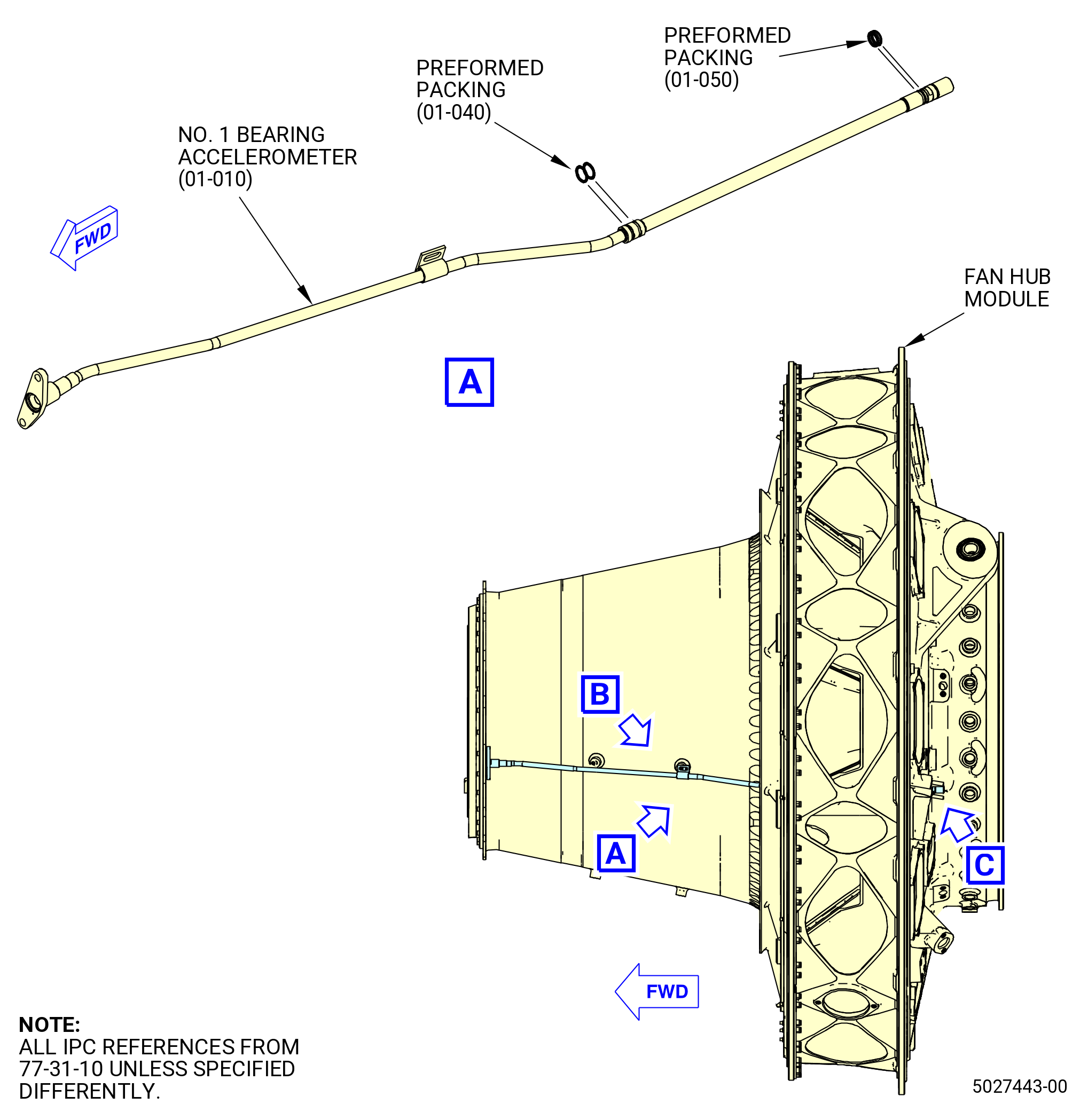
| M. | Install the No. 1 bearing accelerometer (66A00) as follows. Refer to Figure 419. |
| WARNING: |
|
| CAUTION: |
|
| (1) | Lubricate the two preformed packings (01-040 , 77-31-10) (SIN 66A50) and the two preformed packings (01-050 , 77-31-10) (SIN 66A51) with C02-019 engine oil or C02-023 engine oil. Install the preformed packings on the accelerometer. |
| (2) | Remove two previously installed bolts (011F3) at approximately 3:30 o'clock position FLA from the carbon seal support and the No. 1 bearing support flange. |
| (3) | Route the accelerometer through the fan hub module and loosely attach it to the forward flange of the No. 1 bearing support flange with two bolts. |
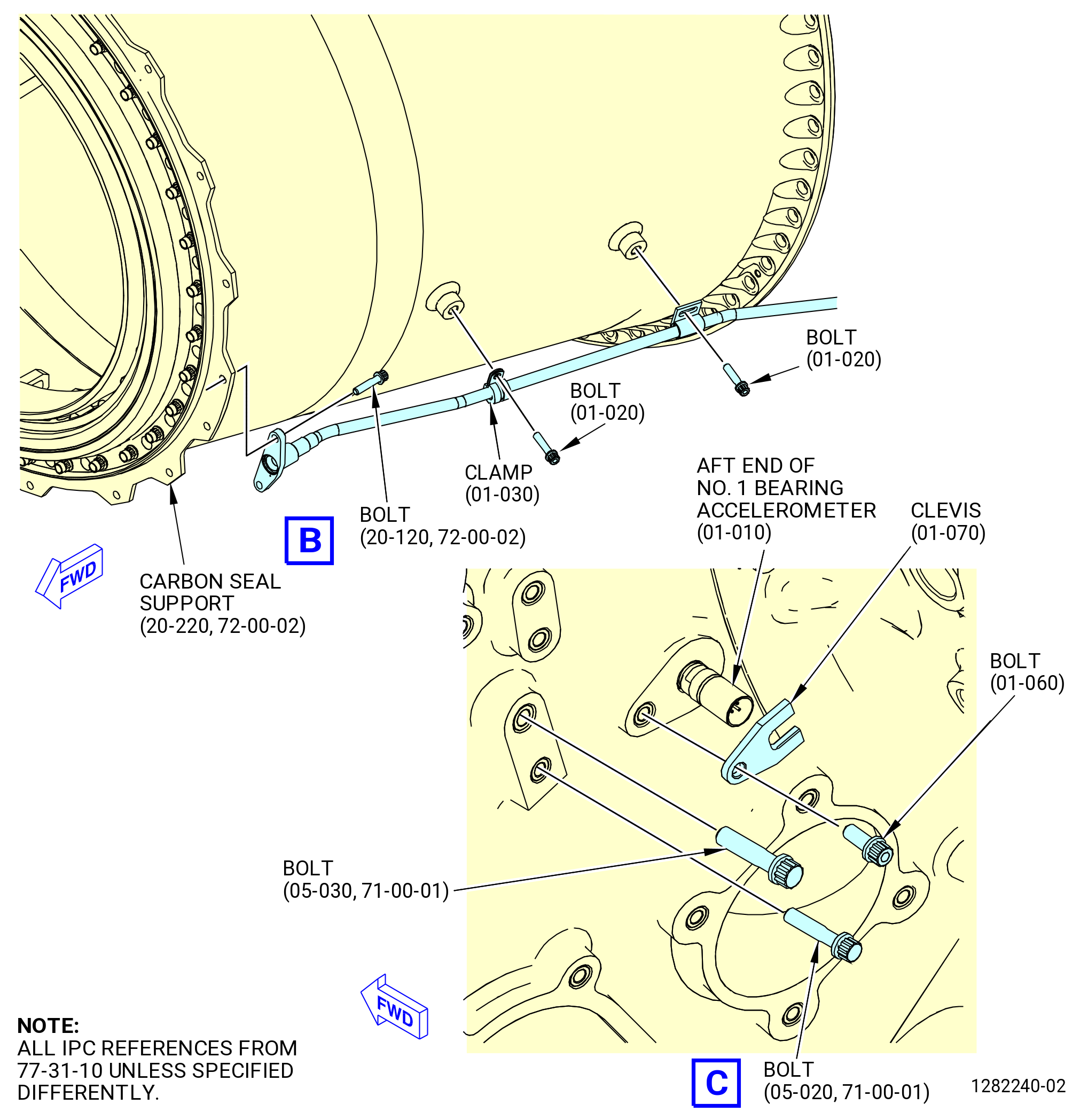
| (4) | Attach the aft end of the accelerometer to the fan hub module with a clevis (66A81) and a bolt (66A21). |
| Subtask 72-00-23-420-027 |
| * * * FOR 1B/P/G03.1B/P/G04.1B/P1/G01 |
| * * * PRE SB 72-0161( Installation of the Bearing Accelerometer - Non-PIP 2 Configuration ) |
| (5) | Attach the center section of the accelerometer to the housing (01-010 , 72-23-00) (SIN 84001) with a clamp (01-030 , 77-31-10) (SIN 66A80) and two bolts (01-020 , 77-31-10) (SIN 66A20). |
| NOTE: |
|
| * * * END PRE SB 72-0161 |
| Subtask 72-00-23-420-028 |
| * * * FOR ALL PIP 2 |
| * * * SB 72-0161( Installation of the Bearing Accelerometer - PIP 2 Configuration ) |
| (5).A. | Attach the center section of the accelerometer to the housing (01-010 , 72-23-00) (SIN 84001) with a clamp (01-030 , 77-31-10) (SIN 66A80) and bolts (01-021 , 77-31-10) (SIN 66A20) and (01-080 , 77-31-10) (SIN 66A27). |
| NOTE: |
|
| * * * END SB 72-0161 |
| Subtask 72-00-23-420-029 |
| * * * FOR ALL |
| (6) | Torque the two bolts (011F3) at the forward end of the accelerometer to 106-124 lb in. (12.0-14.0 N.m). |
| (7) | Torque the bolt (66A21) at the aft end of the accelerometer to 106-124 lb in. (12.0-14.0 N.m). |
| Subtask 72-00-23-420-030 |
| * * * FOR 1B/P/G03.1B/P/G04.1B/P1/G01 |
| * * * PRE SB 72-0161( Installation of the Bearing Accelerometer - Non-PIP 2 Configuration ) |
| (8) | Torque the two bolts (01-020 , 77-31-10) (SIN 66A20) in the center of the accelerometer as follows: |
| (a) | Torque the bolt (01-020 , 77-31-10) (SIN 66A20) installed in the clamp (01-030 , 77-31-10) (SIN 66A80) to 60-70 lb in. (6.8-7.9 N.m). |
| (b) | Torque the remaining bolt (01-020 , 77-31-10) (SIN 66A20) to 106-124 lb in. (12.0-14.0 N.m). |
| * * * END PRE SB 72-0161 |
| Subtask 72-00-23-420-031 |
| * * * FOR ALL PIP 2 |
| * * * SB 72-0161( Installation of the Bearing Accelerometer - PIP 2 Configuration ) |
| (8).A. | Torque the bolts (01-021 , 77-31-10) (SIN 66A20) and (01-080 , 77-31-10) (SIN 66A27) in the center of the accelerometer as follows: |
| (a) | Torque the bolt (01-080 , 77-31-10) (SIN 66A27) installed in the clamp (01-030 , 77-31-10) (SIN 66A80) to 60-70 lb in. (6.8-7.9 N.m). |
| (b) | Torque the remaining bolt (01-021 , 77-31-10) (SIN 66A20) to 106-124 lb in. (12.0-14.0 N.m). |
| * * * END SB 72-0161 |
| Subtask 72-00-23-420-032 |
| * * * FOR ALL |
| (9) | Make sure that the preformed packings (01-040 , 77-31-10) (SIN 66A50) are not pinched or protruded. |
|
|
| Subtask 72-00-23-420-020 |
| * * * FOR 1B/P/G03.1B/P/G04.1B/P1/G01 |
| * * * PRE SB 72-0161( Installation of the Bearing Accelerometer - Non-PIP 2 Configuration ) |
| N. | Install the bolts (05-020 , 71-00-01) (SIN 66A22) and (05-030 , 71-00-01) (SIN 66A23). Refer to Figure 419 and do as follows: |
| (1) | Install the bolts (05-020 , 71-00-01) (SIN 66A22) and (05-030 , 71-00-01) (SIN 66A23) to the port on the aft side of the fan hub module. |
| (2) | Torque the bolt (05-020 , 71-00-01) (SIN 66A22) to 106 to 124 lb in. (12.0 to 14.0 Nm). |
| (3) | Torque the bolt (05-030 , 71-00-01) (SIN 66A23) to 175 to 205 lb in. (19.8 to 23.2 Nm). |
| * * * END PRE SB 72-0161 |
| Subtask 72-00-23-420-033 |
| * * * FOR ALL PIP 2 |
| * * * SB 72-0161( Installation of the Bearing Accelerometer - PIP 2 Configuration ) |
| N.A. | Install the bolts (25-560 , 72-00-02) (SIN 66A22) and (25-570 , 72-00-02) (SIN 66A23). Refer to Figure 419 and do as follows: |
| (1) | Install the bolts (25-560 , 72-00-02) (SIN 66A22) and (25-570 , 72-00-02) (SIN 66A23) to the port on the aft side of the fan hub module. |
| (2) | Torque the bolt (25-560 , 72-00-02) (SIN 66A22) to 106 to 124 lb in. (12.0 to 14.0 Nm). |
| (3) | Torque the bolt (25-570 , 72-00-02) (SIN 66A23) to 175 to 205 lb in. (19.8 to 23.2 Nm). |
| * * * END SB 72-0161 ( ) |
| Subtask 72-00-23-420-023 |
| * * * FOR ALL |
| O. | Continue to assemble the engine. To install the fan booster module. Refer to TASK 72-00-22-420-801 (72-00-22, Installation 001). |