| GENX-1B ENGINE MANUAL | Dated: 12/11/2024 | |
| EM 72-00-02 , ASSEMBLY 004 | ||
| PROPULSOR ASSEMBLY - ASSEMBLY 004 - CONFIGURATION 01 | ||
| GENX-1B ENGINE MANUAL | Dated: 12/11/2024 | |
| EM 72-00-02 , ASSEMBLY 004 | ||
| PROPULSOR ASSEMBLY - ASSEMBLY 004 - CONFIGURATION 01 | ||
| * * * FOR 1B/P/G03.1B/P/G04.1B/P1/G01 |
| TASK 72-00-02-430-815 |
| 1 . | General. |
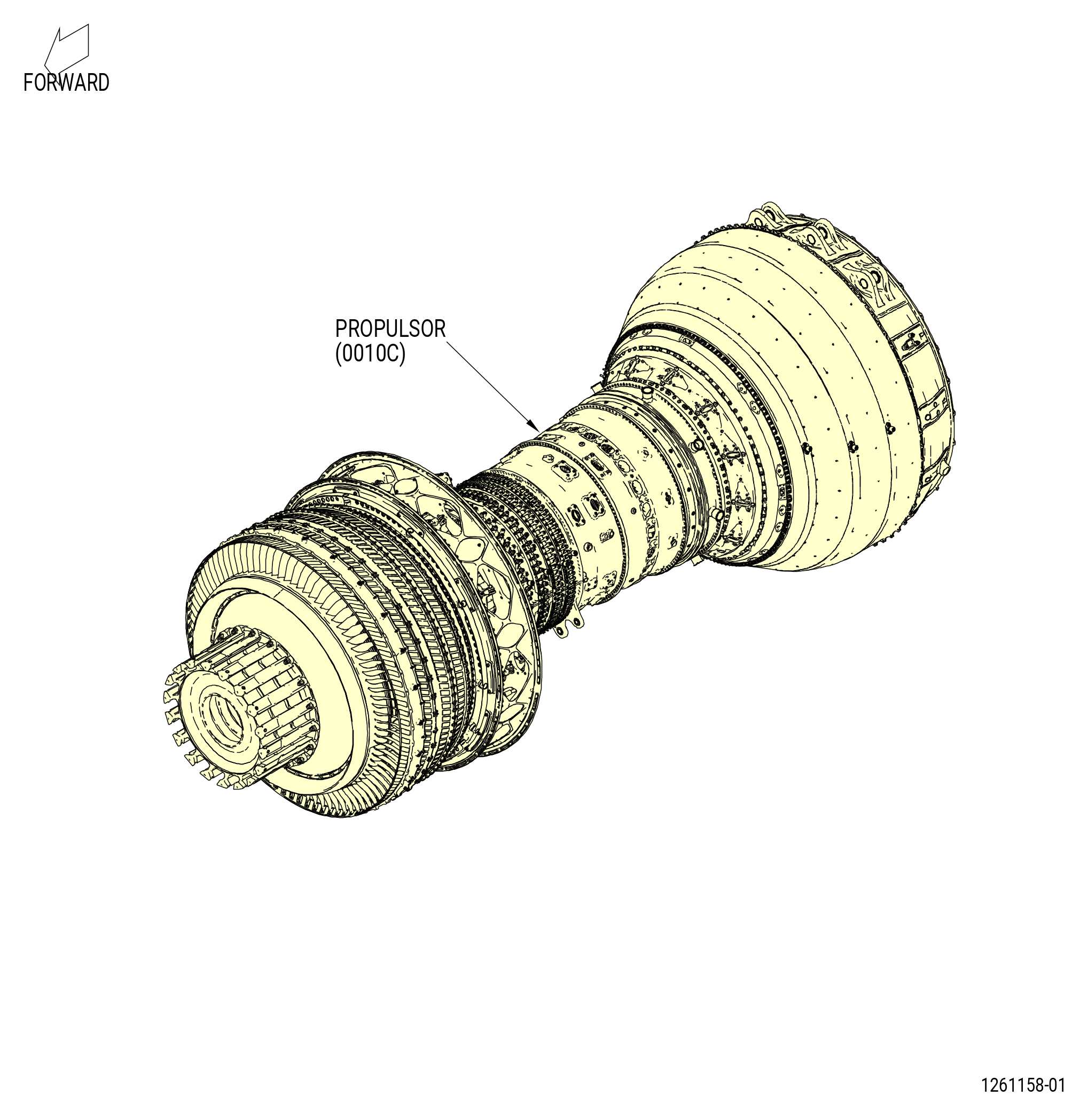
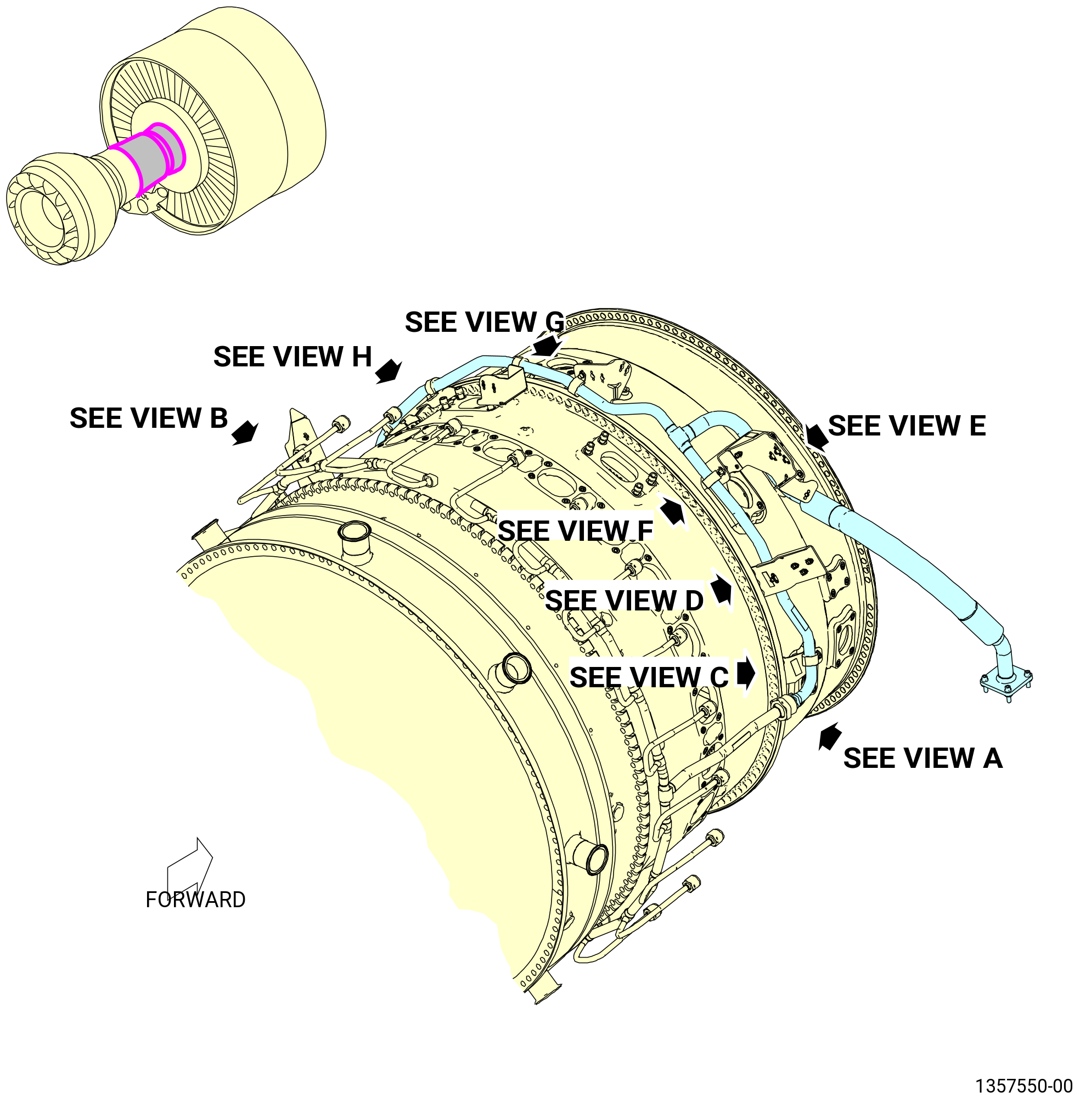
| A. | This procedure gives instructions to continue the assembly of the external configuration of the propulsor assembly (propulsor) (0010C). Refer to Figure 1001. |
| B. | This procedure begins with the propulsor (30-020 , 72-00-00) (SIN 0010C) in the horizontal position, installed in the 11C3044 adapter assembly, attached to the customer overhead rail system, or supported by the 11C3281 pedestal set, at the equivalent build status of TASK 72-00-02-430-814 (72-00-02, ASSEMBLY 003) . |
| C. | Make sure that personnel read this procedure and know the step-by-step instructions and special tool usage before they assemble the engine assembly. |
| D. | Make sure that the engine assembly and the parts that you install have the correct support at all times to prevent injury to personnel or damage to engine parts. |
| E. | Cleanliness is extremely important. Put protection on machined surfaces. Wrap precision parts. Put caps or plugs on/in all openings and connections. |
| F. | It is important that all engine parts be kept free of corrosion. All instructions which provide special handling requirements for engine components must be followed. |
| G. | Deviations are not permitted for clearances or torque values. Refer to the standard practices manual for assembly and disassembly techniques and for tightening practices and torque values. |
| H. | Clearance limits give the applicable dimensional relationship between mating parts. They are not used for routine dimensional inspection of individual parts at the time of assembly. Except where called out for assembly, the clearances shown are for reference only. |
| I. | Unless otherwise specified, install all bolts with the heads forward or from the top. |
| J. | Unless otherwise specified, lubricate the threads and washer faces of bolts, screws, studs or nuts with C02-058 lubricant before installation. After installation, remove unwanted lubricant with a clean, lint-free cloth. |
| WARNING: |
|
| WARNING: |
|
| K. | Clean the parts before assembly with a 50-50 blend alcohol, C04-002 Stoddard solvent, C04-035 isopropyl alcohol. |
| L. | The torque values given in this procedure are the actual torque to apply to the fastener. If a torque multiplier is used, do the necessary calculations to find the specified torque, the value that appears on the scale or dial of the torque wrench. Refer to TASK 70-51-00-400-004 (TIGHTENING PRACTICES AND TORQUE VALUES) . |
| M. | Follow the instructions to safety parts with a safety wire, safety cable, cotter pins, or tab washers. Refer to TASK 70-11-00-400-001 (FASTENER RETENTION PROCEDURES) . |
| 2 . | Tools, Equipment, and Materials. |
| NOTE: |
|
| A. | Tools and Equipment. |
| (1) | Special Tools. |
| (2) | Standard Tools and Equipment. |
|
| (3) | Locally Manufactured Tools. None. |
| B. | Consumable Materials. |
|
| C. | Referenced Procedures. |
|
| D. | Expendable Parts. |
|
| 3 . | Procedure. |
| Subtask 72-00-02-440-181 |
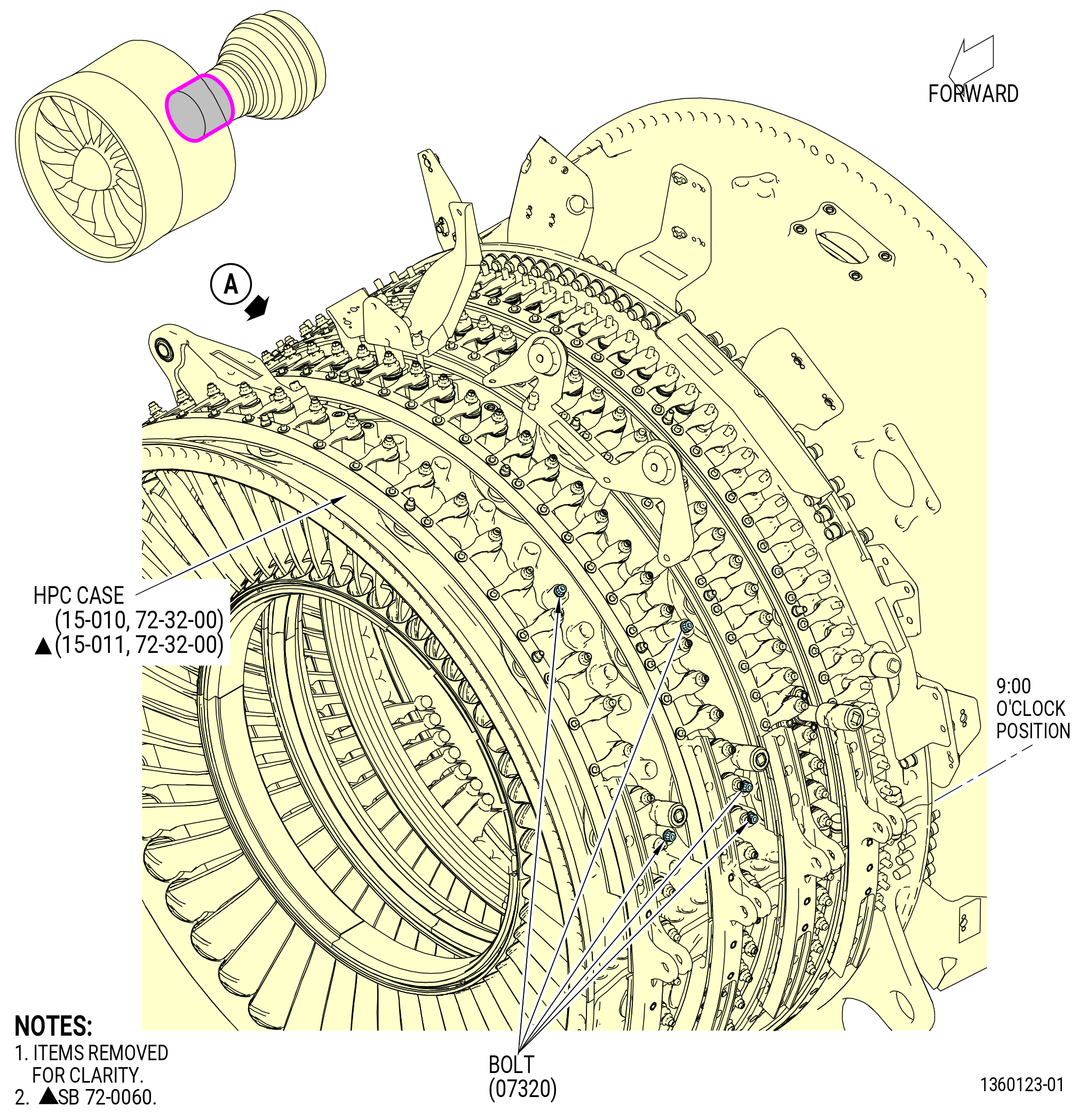
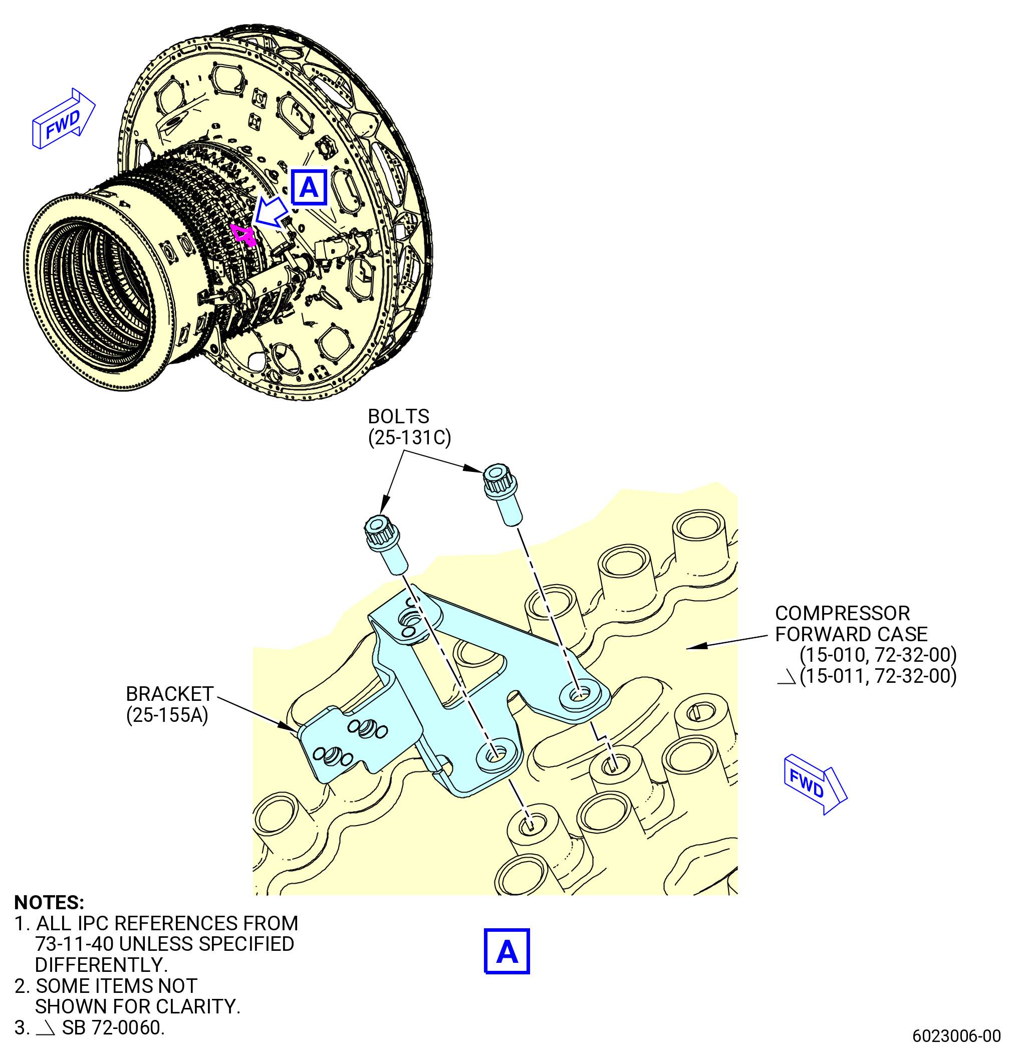
| A. | Install the compressor plug bolts (bolts) (07320) on the HPC stator forward case assembly (HPC case) (15-010 , 72-32-00) or (15-011 , 72-32-00) (SIN 073A0) as follows. Refer to Figure 1002. |
| (1) | Find the bolthole locations on the left side of the HPC case (ALF). There are two locations on the HPC case between stages 1 and 2 at bosses 2 and 7 clockwise (CW) from the 9:00 o'clock horizontal flange, and three locations on the HPC case between stages 2 and 3 at bosses 1 thru 3 CW from the 9:00 o'clock horizontal flange. |
| (2) | Install the bolts (07320) on the HPC case at the five locations. |
| (3) | Find the botlthole locations on the right side of the HPC case (ALF). The bolthole locations are between stages 2 and 3 at bosses 1 thru 3, 6, 7, 9, and 12 counterclockwise (CCW) from the 3:00 o'clock horizontal flange. |
| (4) | Install the bolts (07320) on the HPC case at the seven locations. |
| (5) | Torque all the bolts (07320) to 106-124 lb in. (12.0-14.0 Nm). |
| Subtask 72-00-02-440-111 |
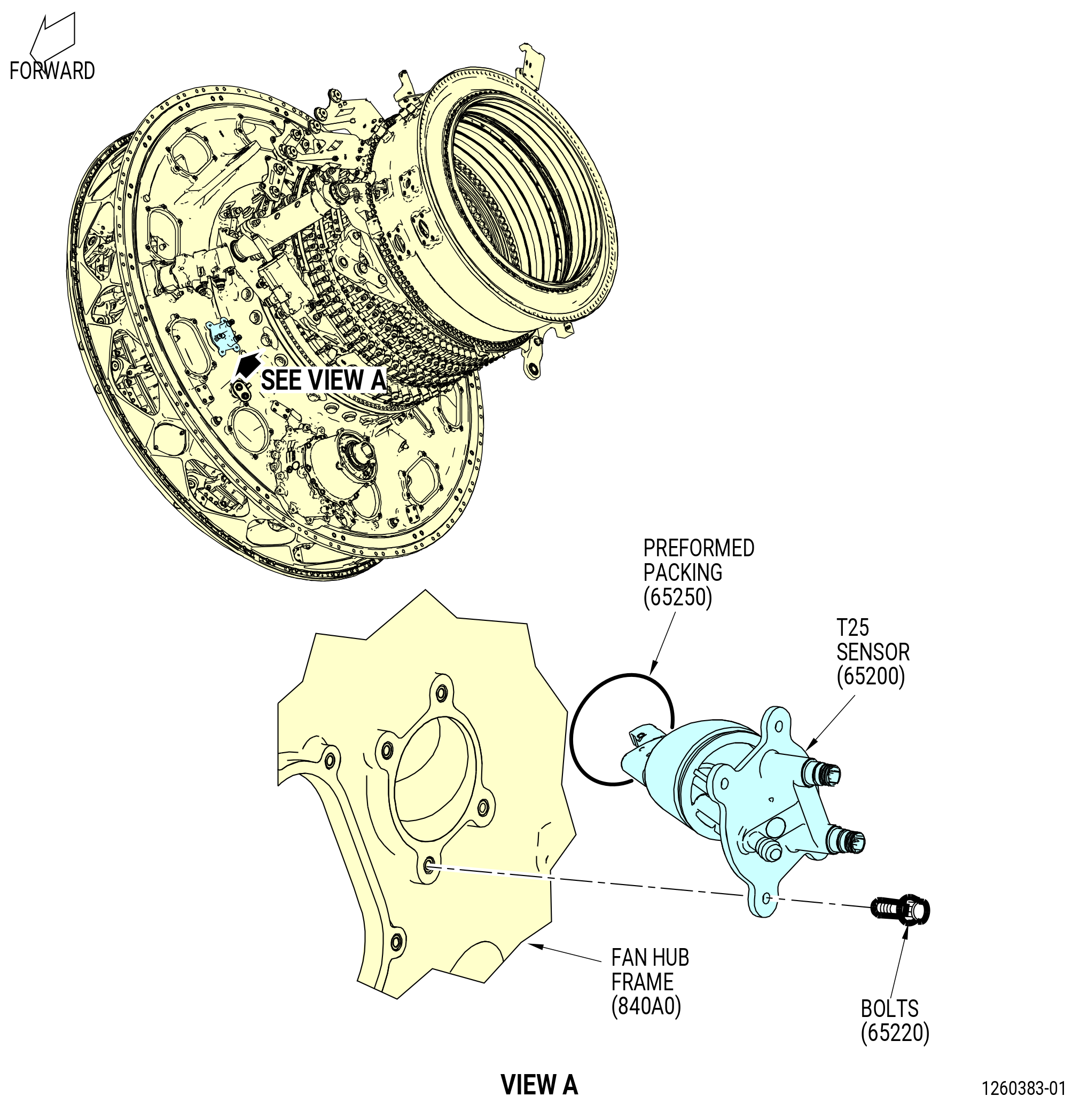
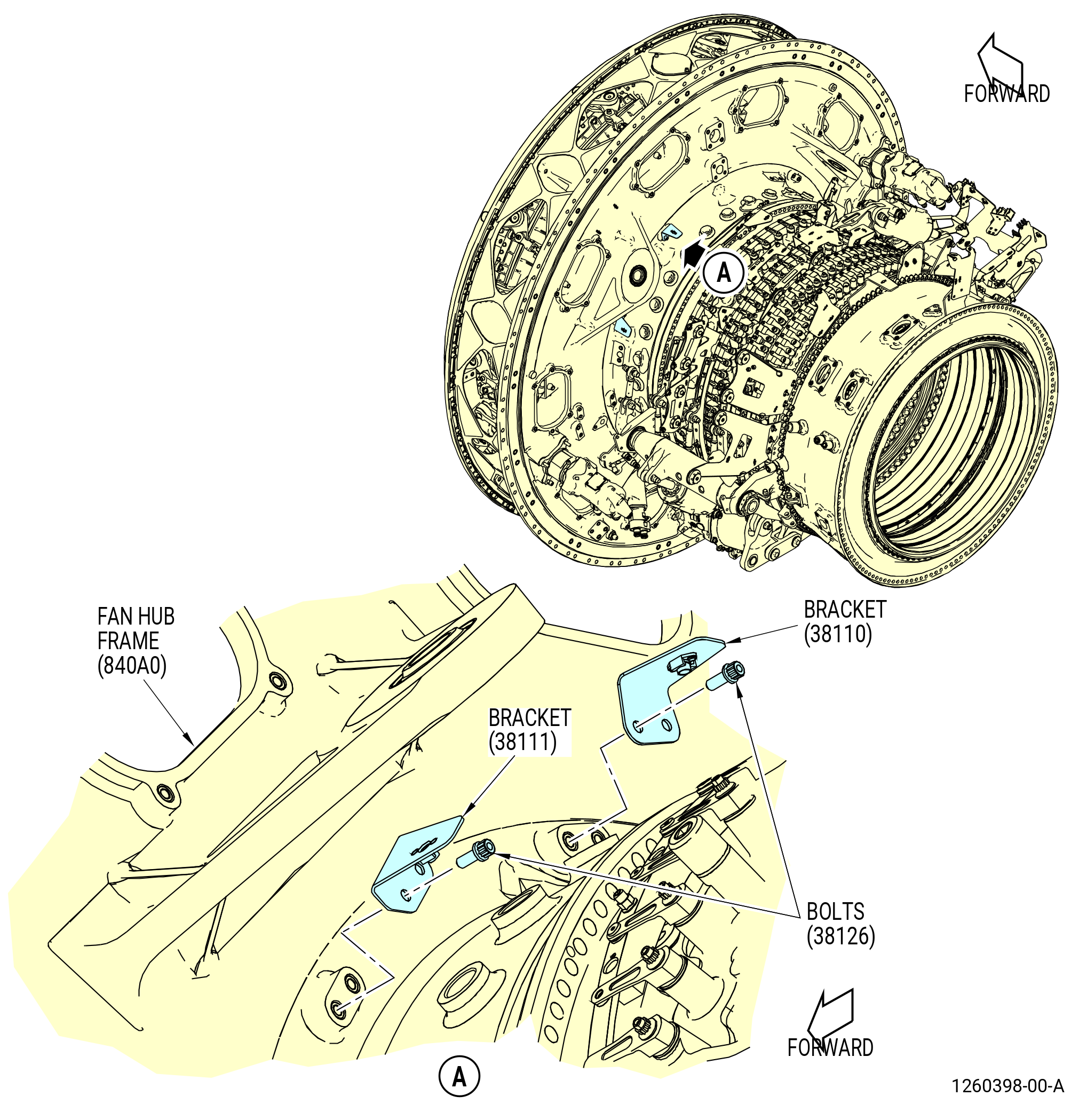
| B. | Install the T25 sensor (65200) as follows. Refer to Figure 1003. |
| WARNING: |
|
| (1) | Apply C02-019 engine oil or C02-023 engine oil to the new preformed packing (01-030 , 73-21-50) (SIN 65250). |
| (2) | Put the preformed packing (01-030 , 73-21-50) (SIN 65250) on the T25 sensor. |
| (3) | Put the T25 sensor, in the port in the fan hub frame (840A0) at the 8:00 o'clock position. |
| (4) | Attach the T25 sensor to the fan hub frame with the bolts (65220). |
| (5) | Torque the bolts to 106-124 lb in. (12.0-14.0 Nm). |
| Subtask 72-00-02-440-112 |
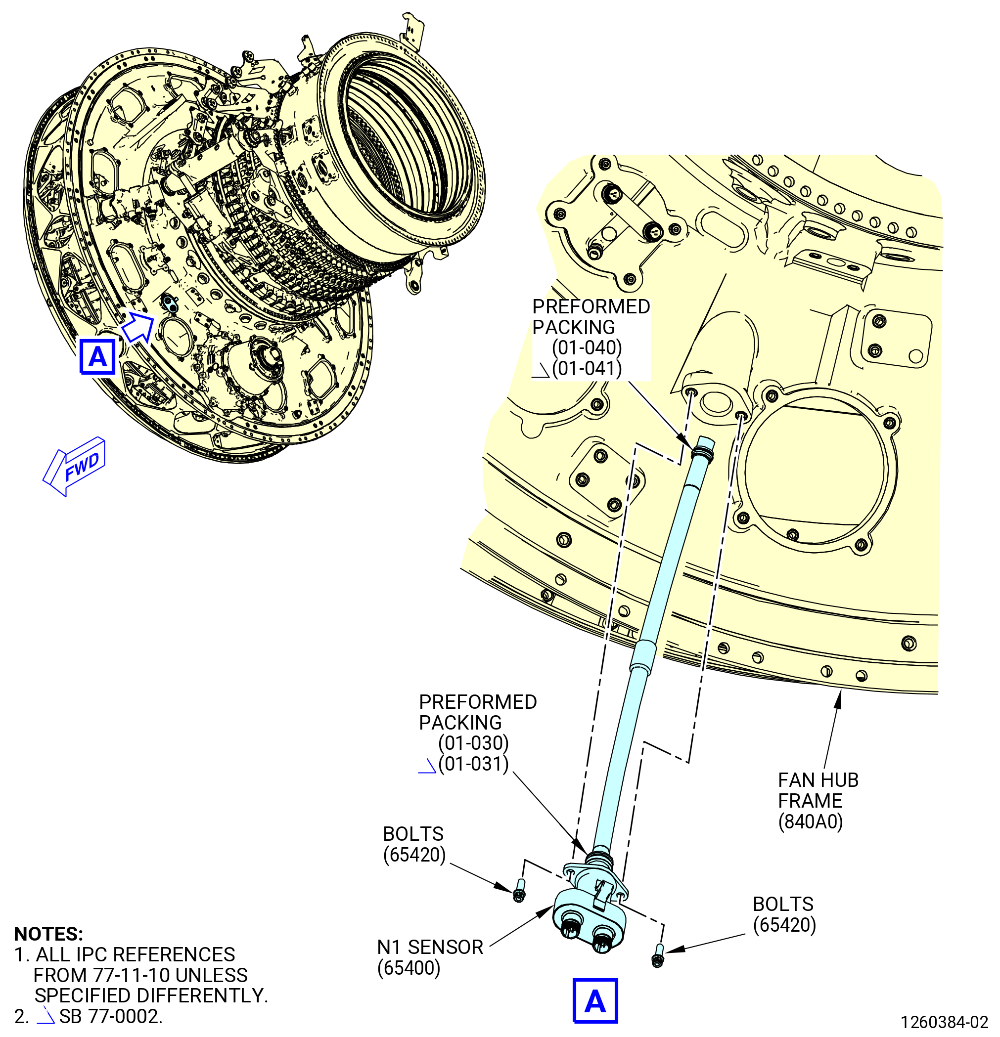
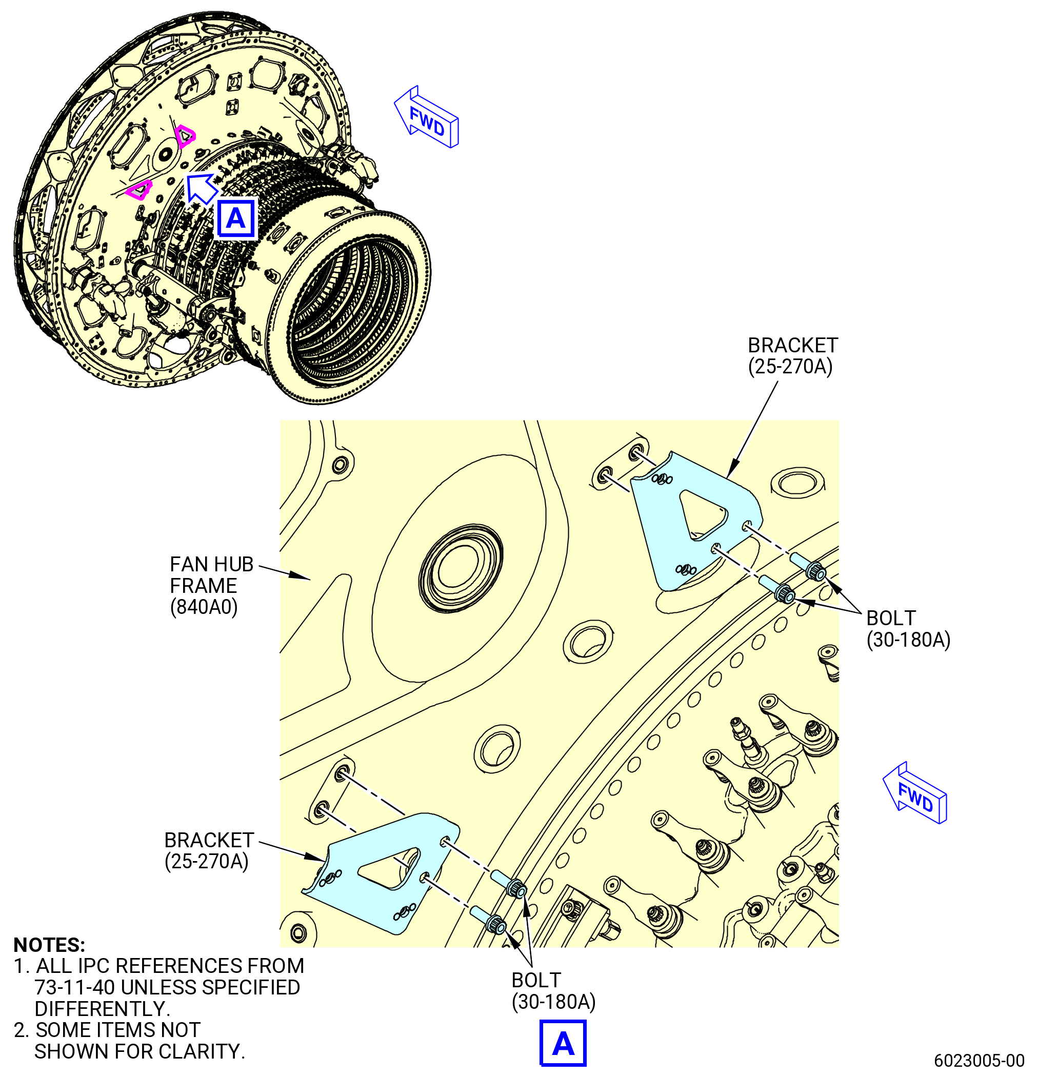
| C. | Install the N1 sensor (65400) as follows. Refer to Figure 1004. |
| WARNING: |
|
| (1) | Apply C02-019 engine oil or C02-023 engine oil to the preformed packing (01-030 , 77-11-10) (SIN 65450) or (01-031 , 77-11-10) (SIN 65450) and preformed packing (01-040 , 77-11-10) (SIN 65451) or (01-041 , 77-11-10) (SIN 65451). |
| (2) | Put the preformed packing (01-030 , 77-11-10) (SIN 65450) or (01-031 , 77-11-10) (SIN 65450) and preformed packing (01-040 , 77-11-10) (SIN 65451) or (01-041 , 77-11-10) (SIN 65451) on the N1 sensor. |
| (3) | Put the N1 sensor in the port in the fan hub frame (840A0) at the 7:00 o'clock position. |
| (4) | Attach the N1 sensor to the fan hub frame with the bolts (65420). |
| (5) | Torque the bolts to 106-124 lb in. (12.0-14.0 Nm). |
| Subtask 72-00-02-440-113 |
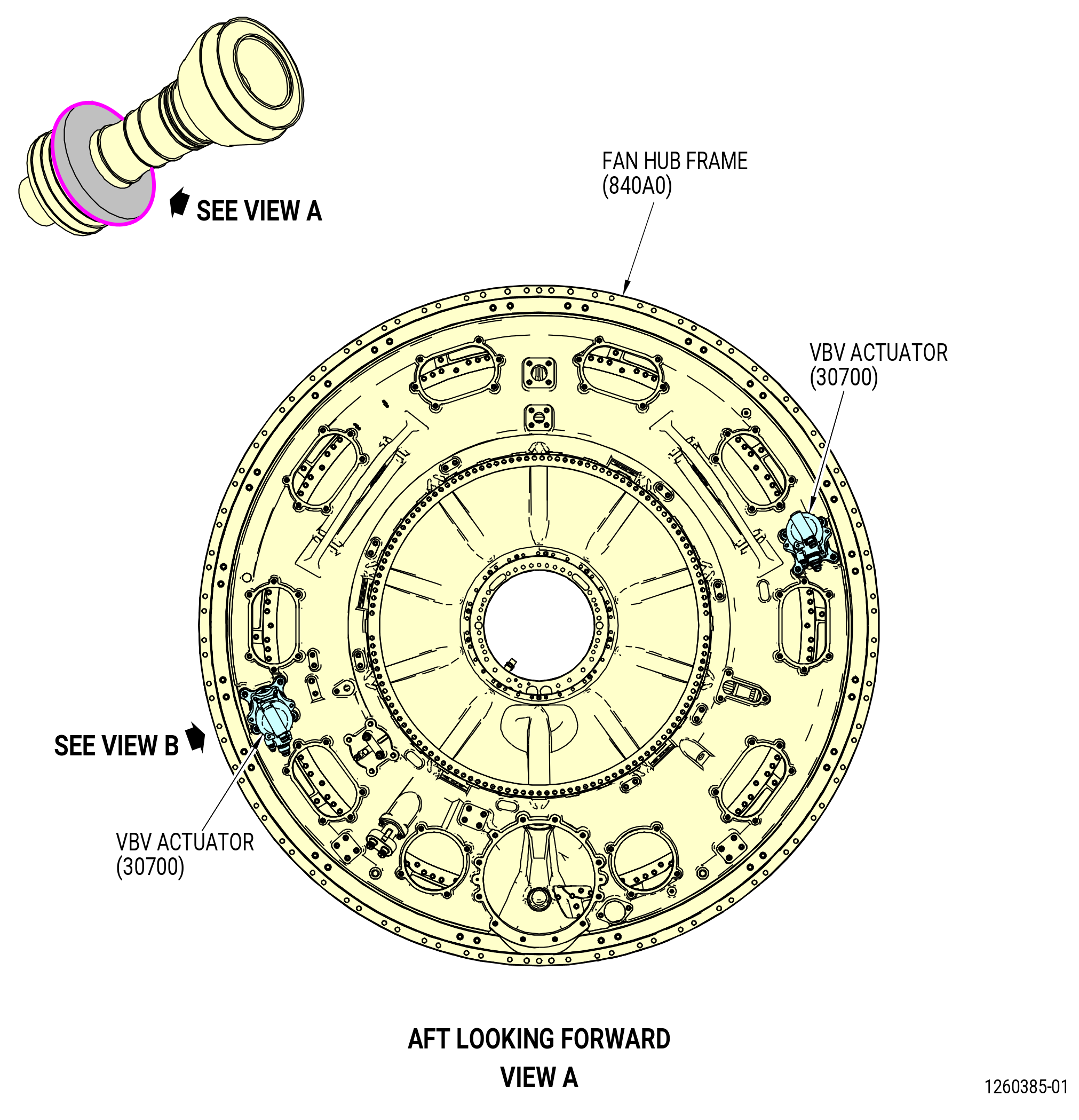
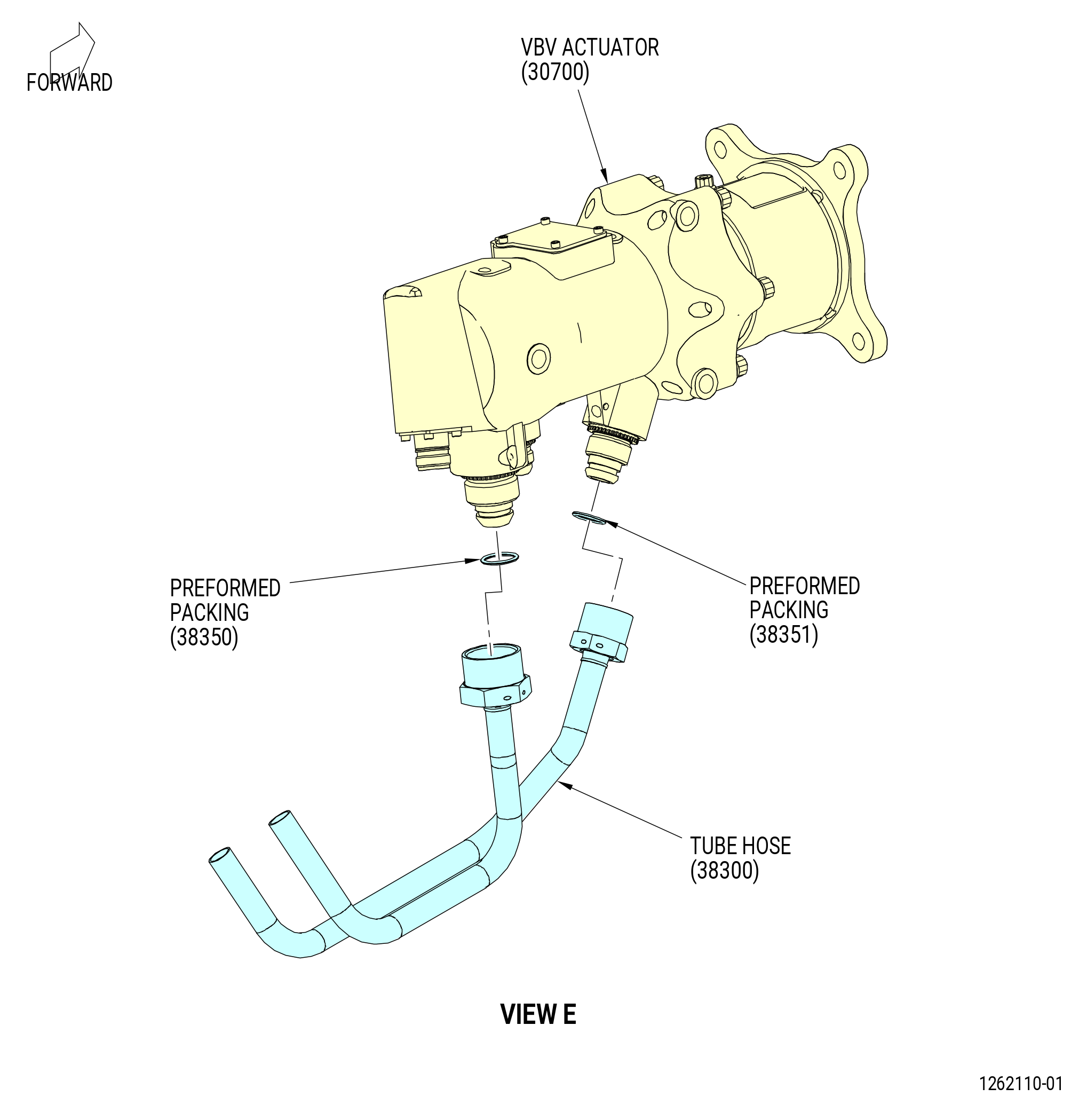
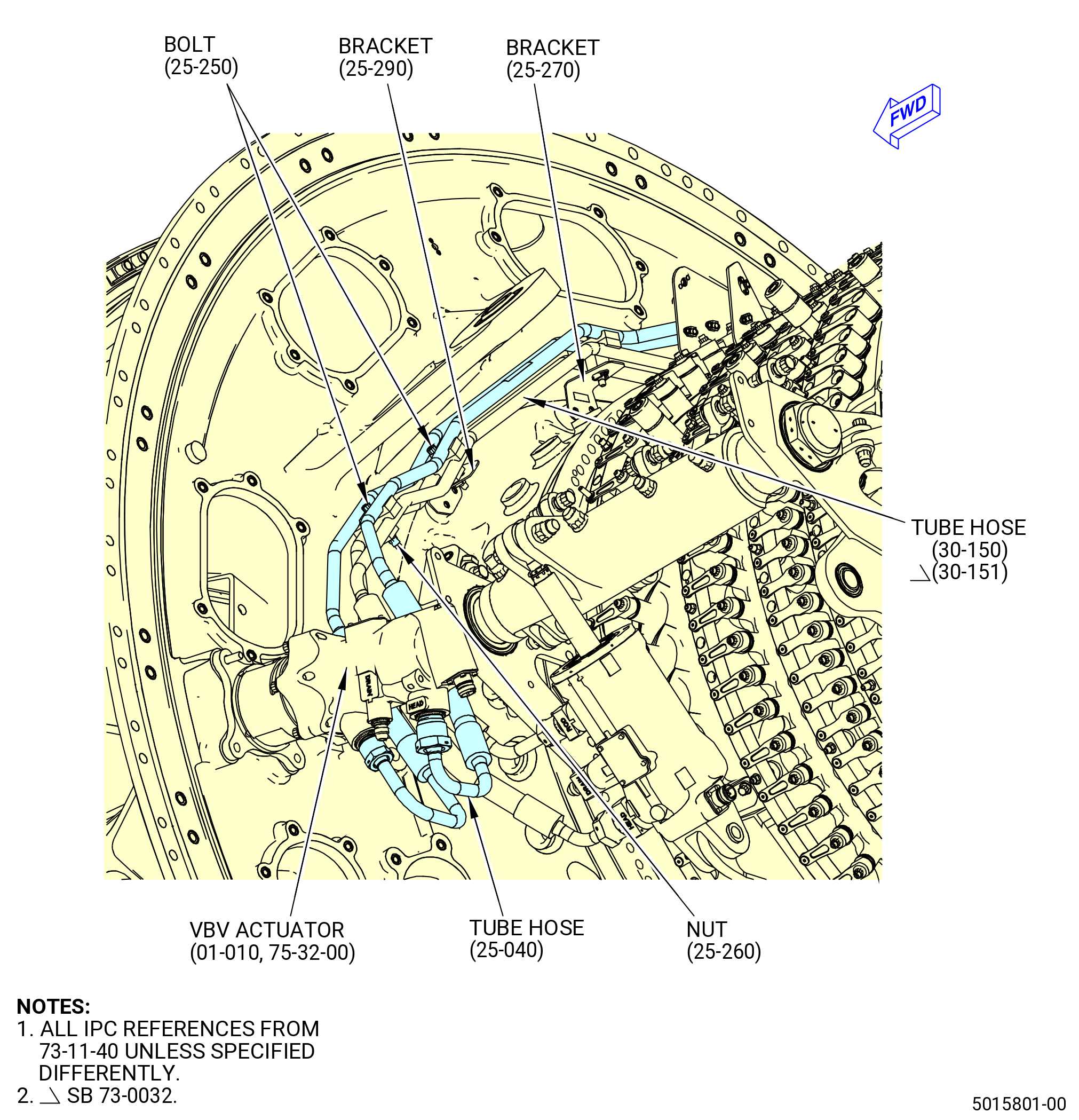
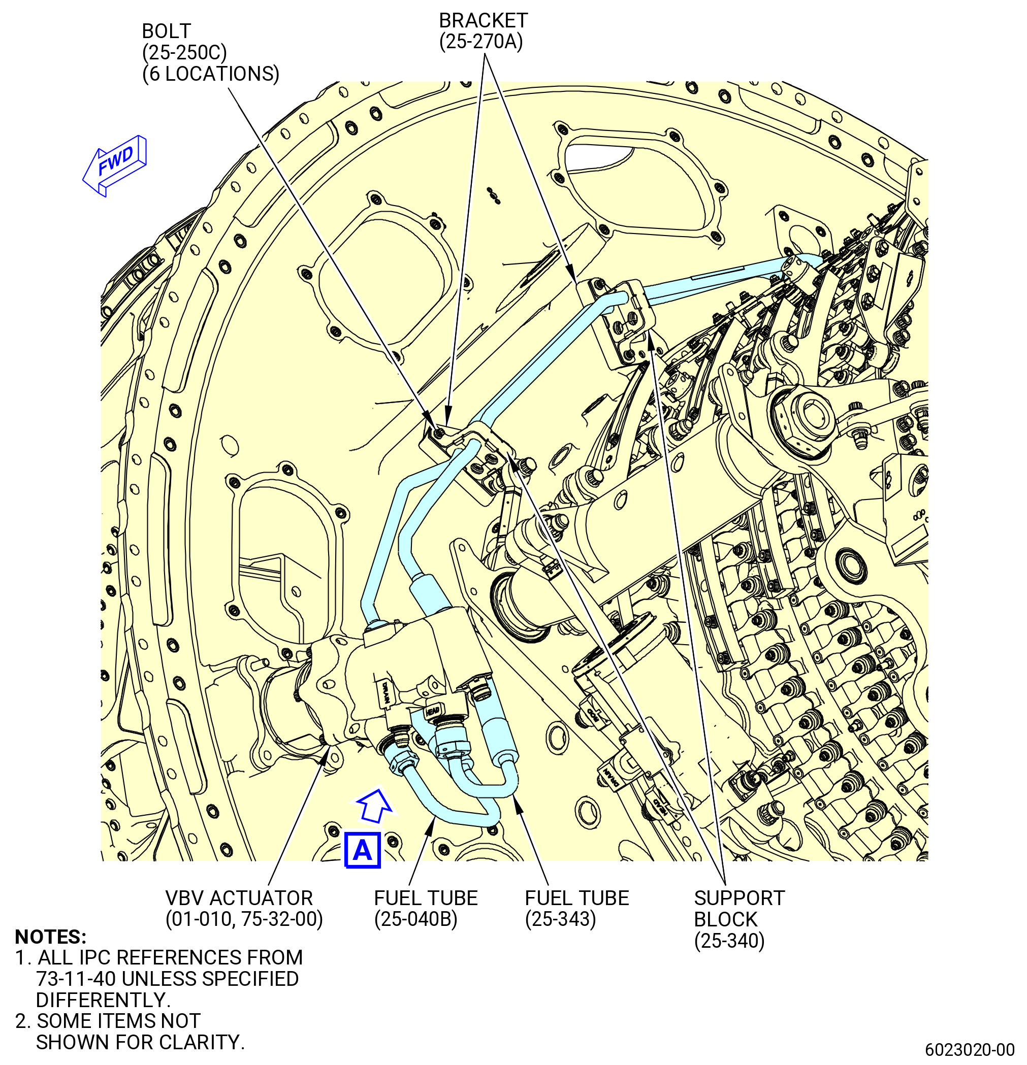
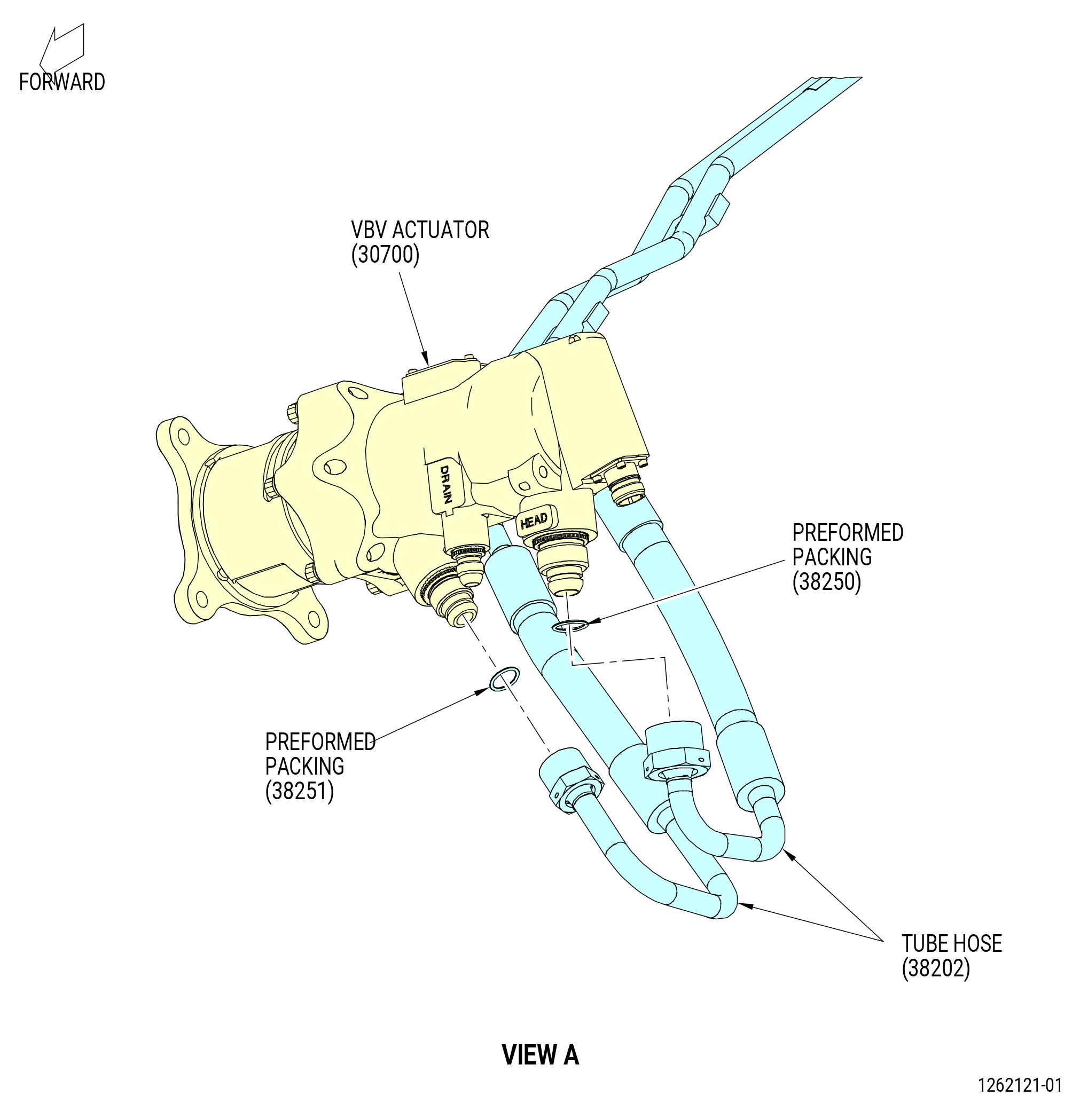
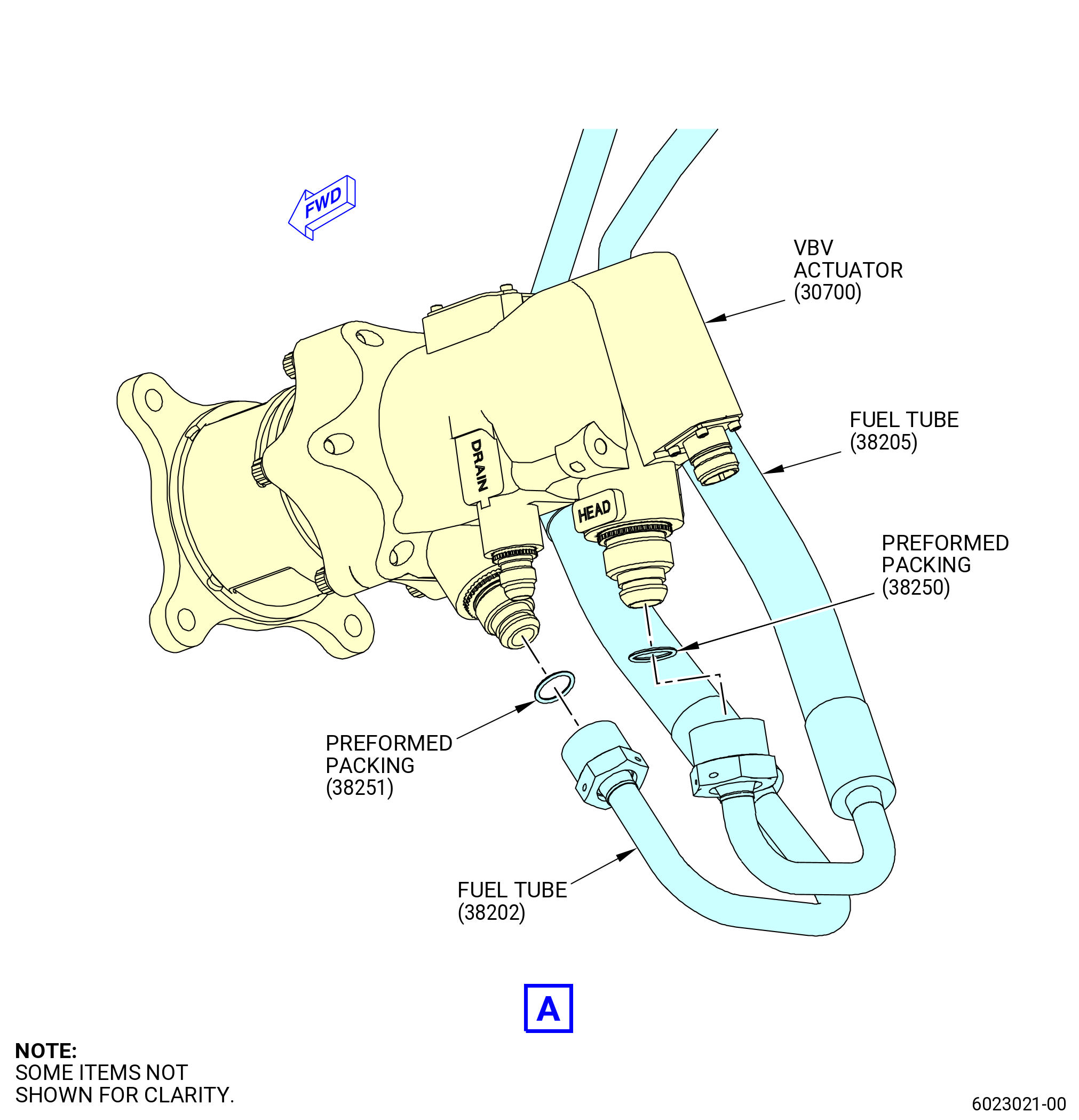
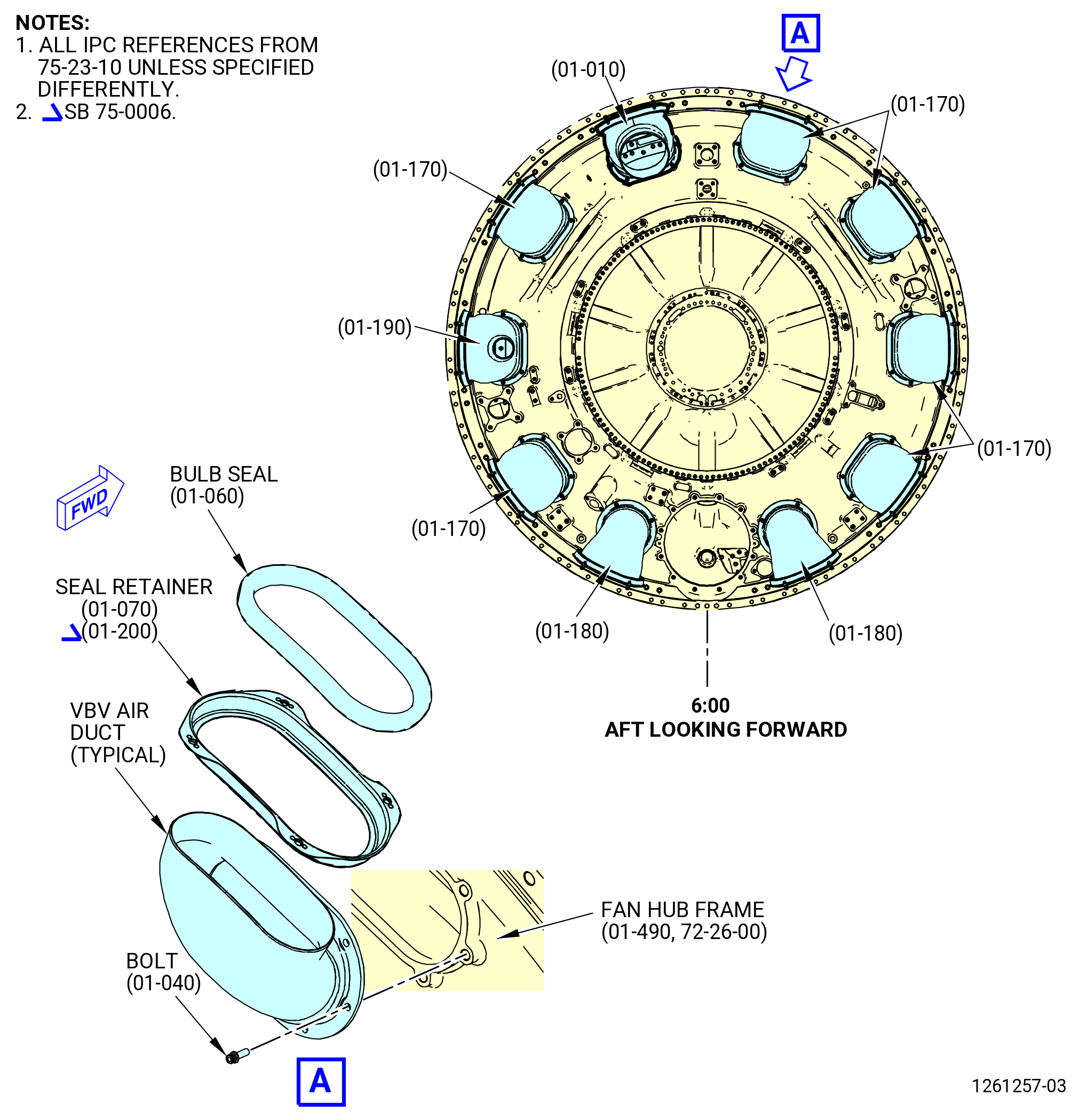
| D. | Install the variable bypass valve (VBV) actuators (30700) on the fan hub frame (840A0) as follows. Refer to Figure 1005. |
| (1) | Install the VBV actuators on the fan hub frame at the 8:30 o'clock and 2:30 o'clock positions as follows: |
| (a) | Loosen, but do not remove, the access window bolt on the VBV actuators and turn the VBV clevis access window to the open position. |
| (b) | Align the clevis so the bolthead of the bolt (30720) points radially outward from the engine centerline when it is installed. |
| NOTE: |
|
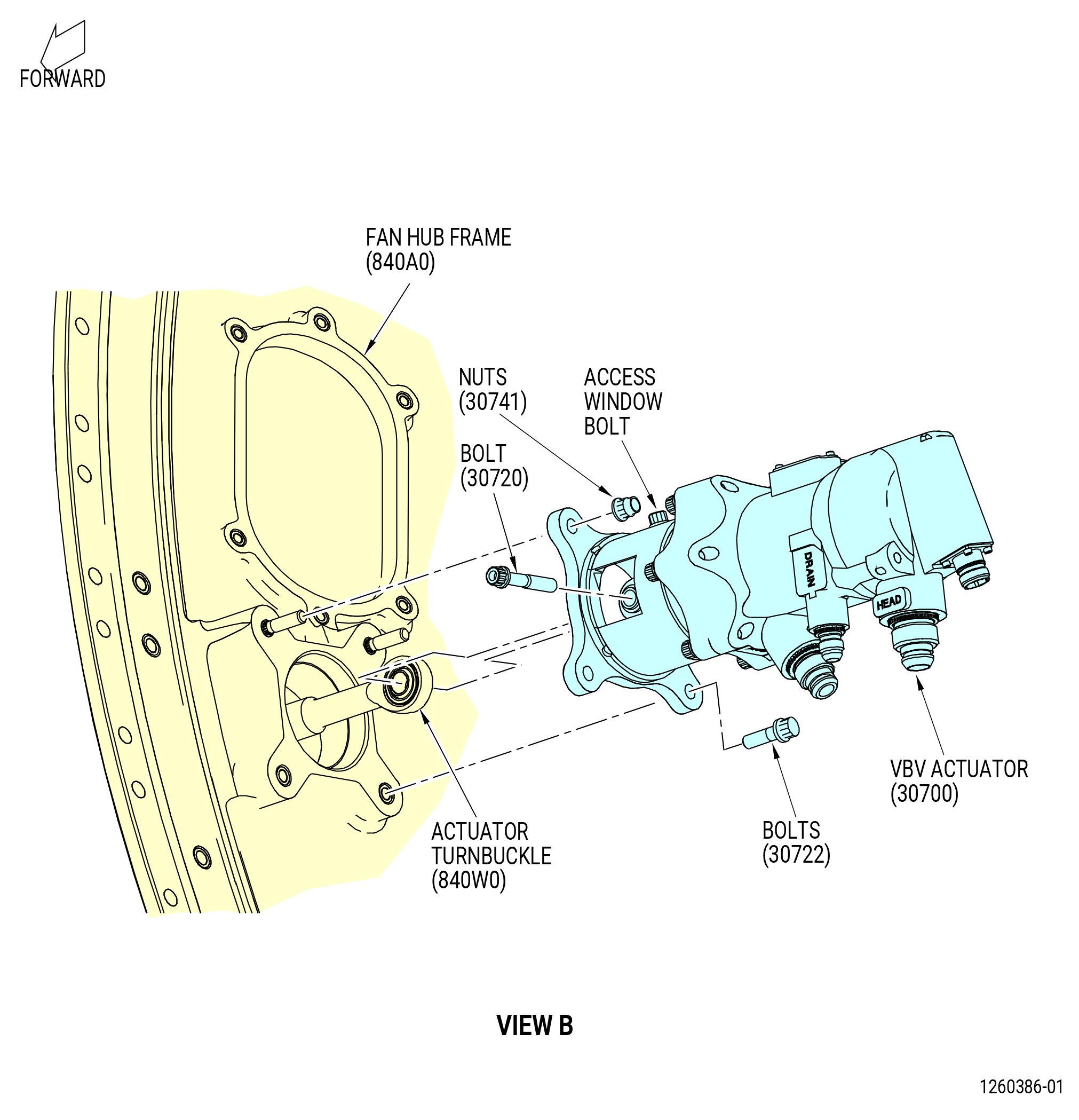
| (c) | Install the VBV actuator at each position on the fan hub frame as follows: |
| 1 | Align the VBV actuator clevis with the rod end of the actuator turnbuckle (840W0). |
| 2 | Put the VBV actuator in position on the studs on the mounting pad on the fan hub frame. |
| 3 | Install the rod end of the actuator turnbuckle (840W0) in the VBV actuator clevis and align the holes. |
| 4 | Install the bolt (30720) through the VBV actuator clevis and actuator turnbuckle rod end with the bolt head pointed away from the centerline of the engine. |
| 5 | Torque the bolt (30720) to 106-124 lb in. (12.0-14.0 Nm). |
| 6 | Install the bolts (30722) in the lower mount boltholes to attach the VBV actuator to the fan hub frame pad. Torque the bolts to 235-275 lb in. (26.6-31.1 N.m). |
| 7 | Install nuts (30741) on the studs in the upper mount boltholes. Torque the nuts to 235-275 lb in. (26.6-31.1 N.m). |
| (d) | Turn the VBV clevis window to the closed position. |
| (e) | Torque the access window bolt to 74-86 lb in. (8.4-9.7 N.m). |
| Subtask 72-00-02-440-114 |
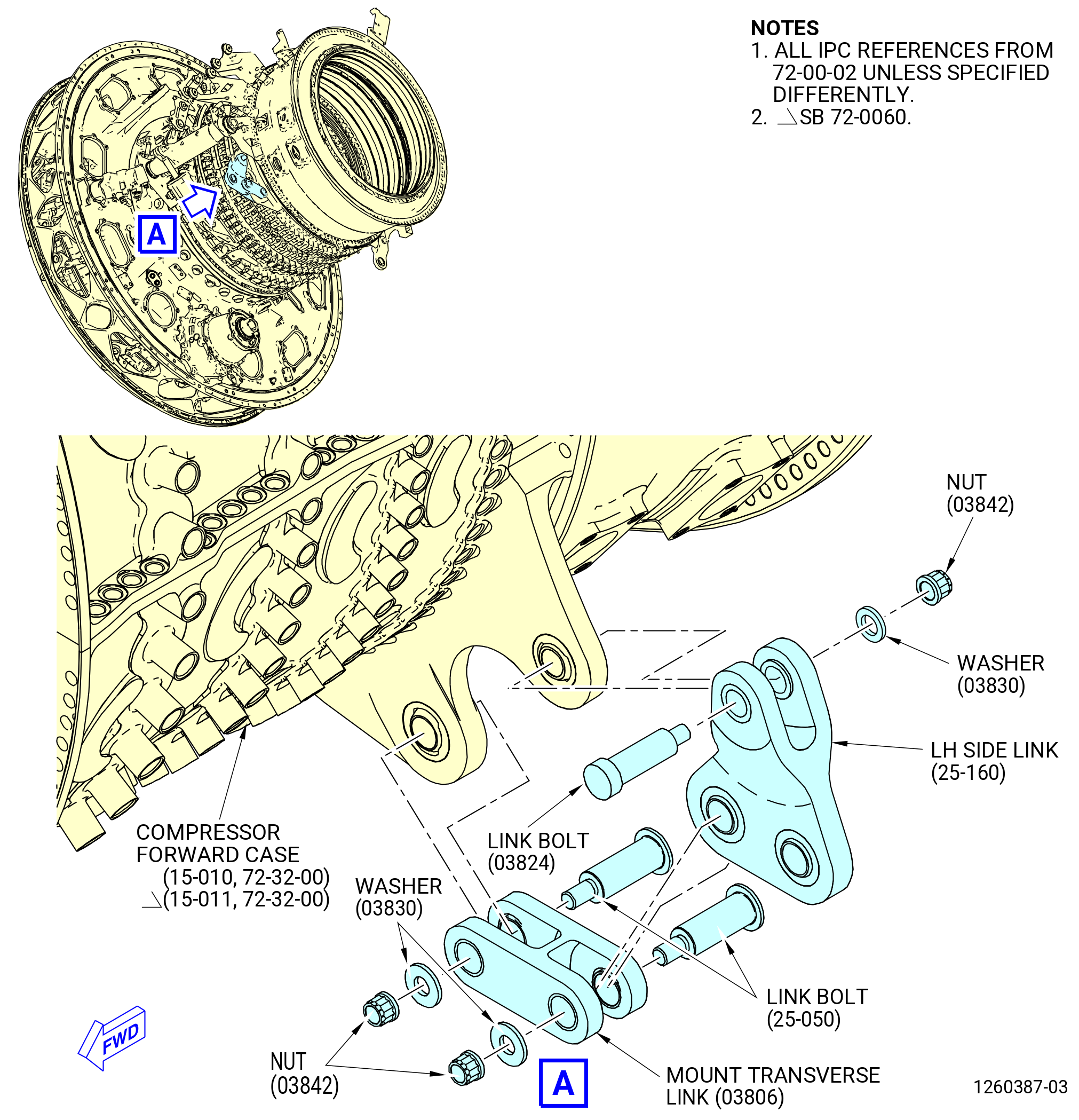
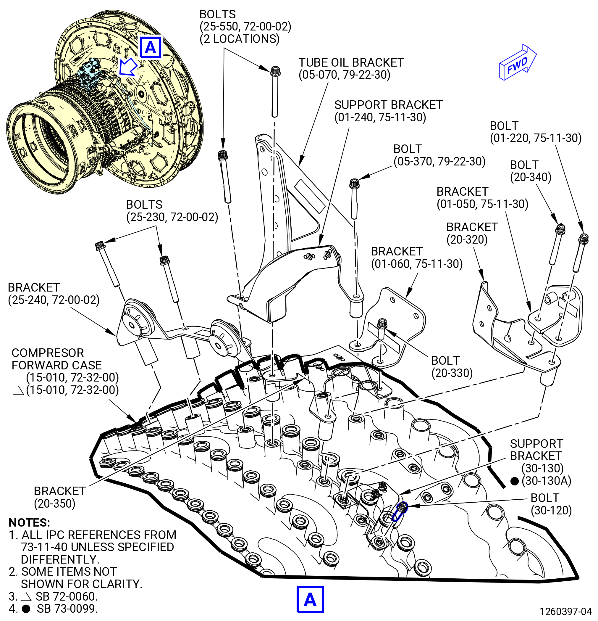
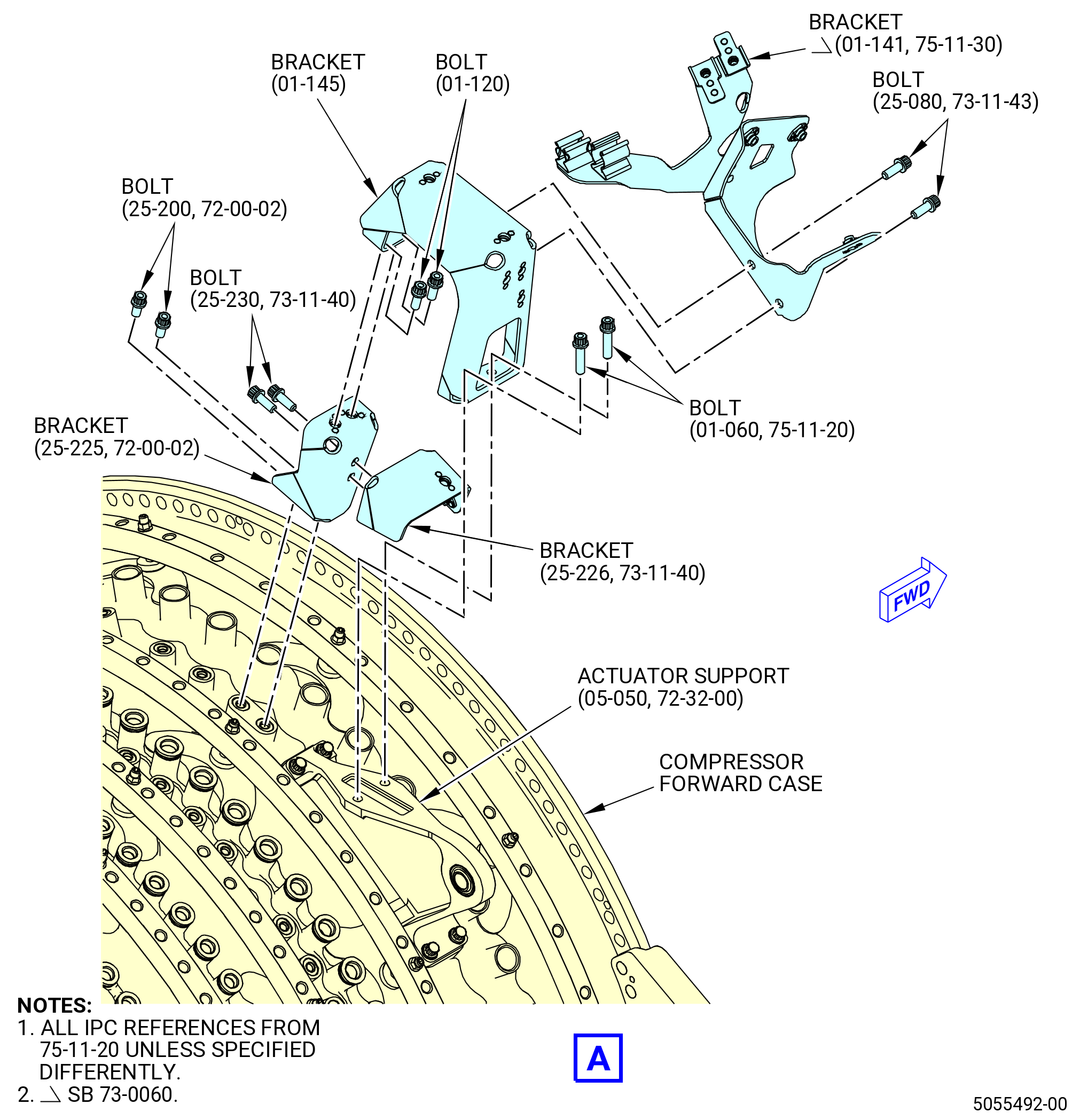
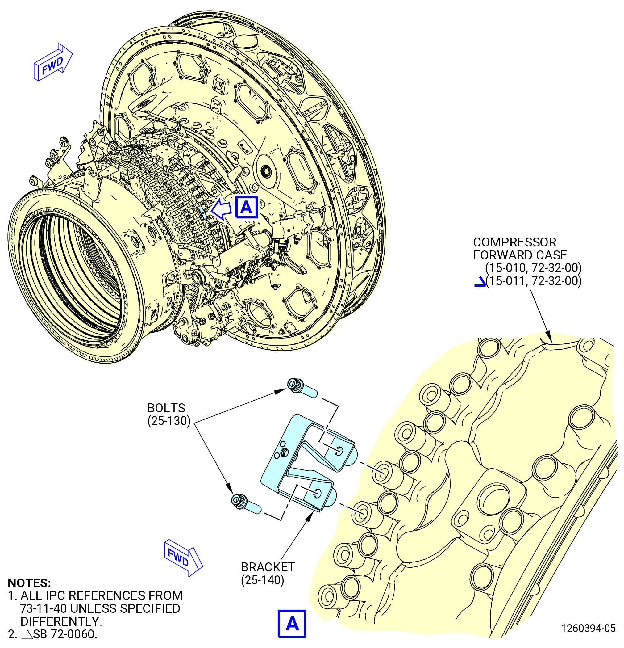
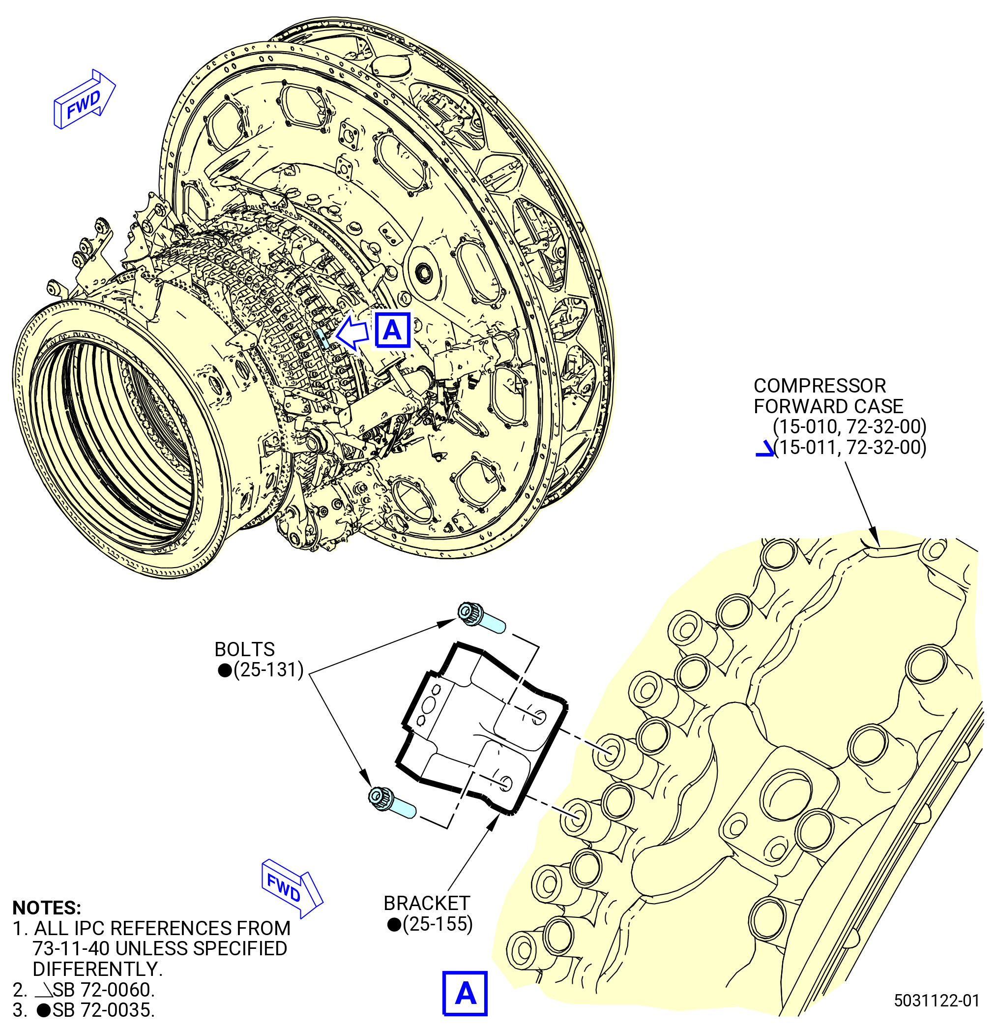
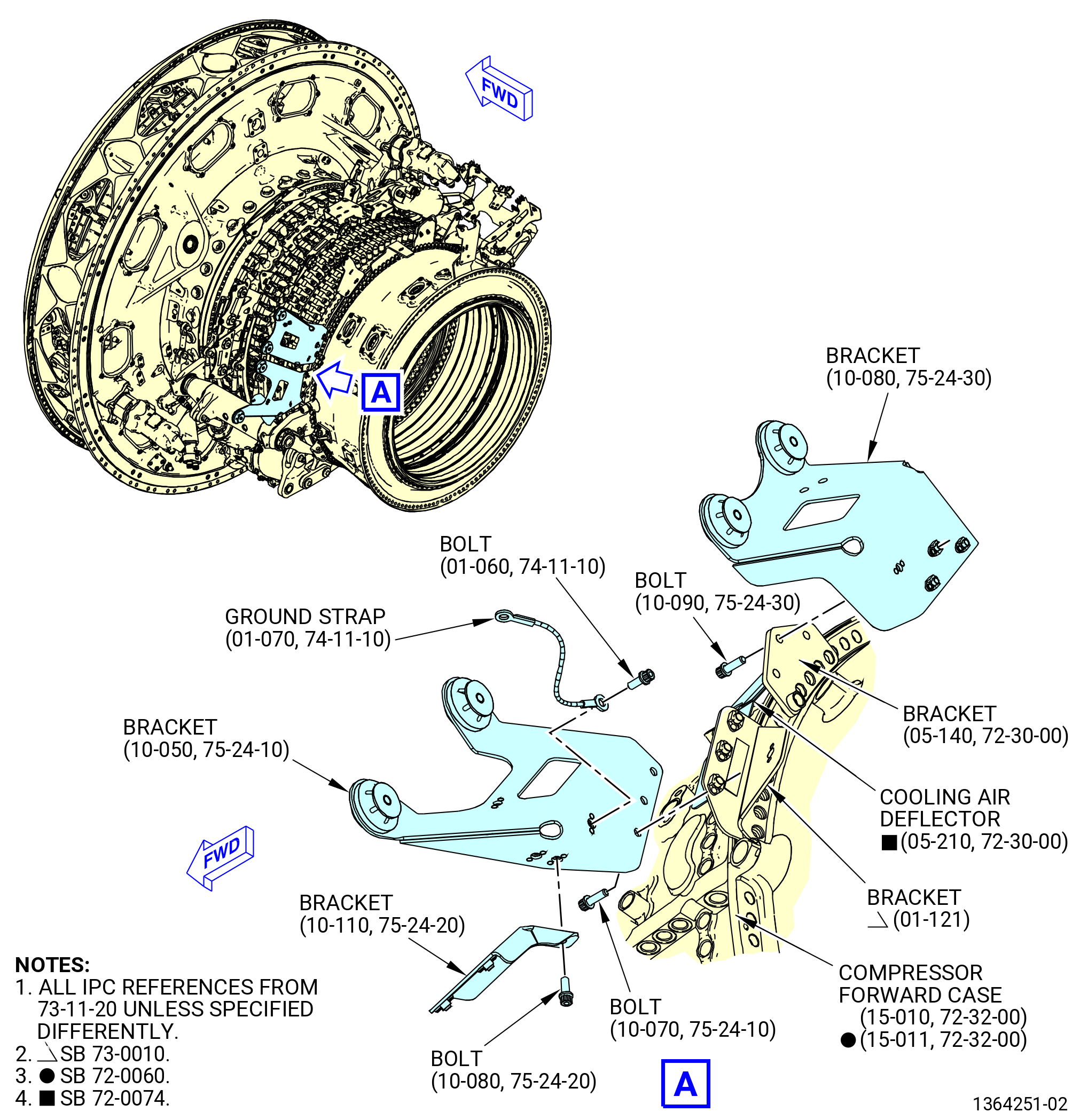
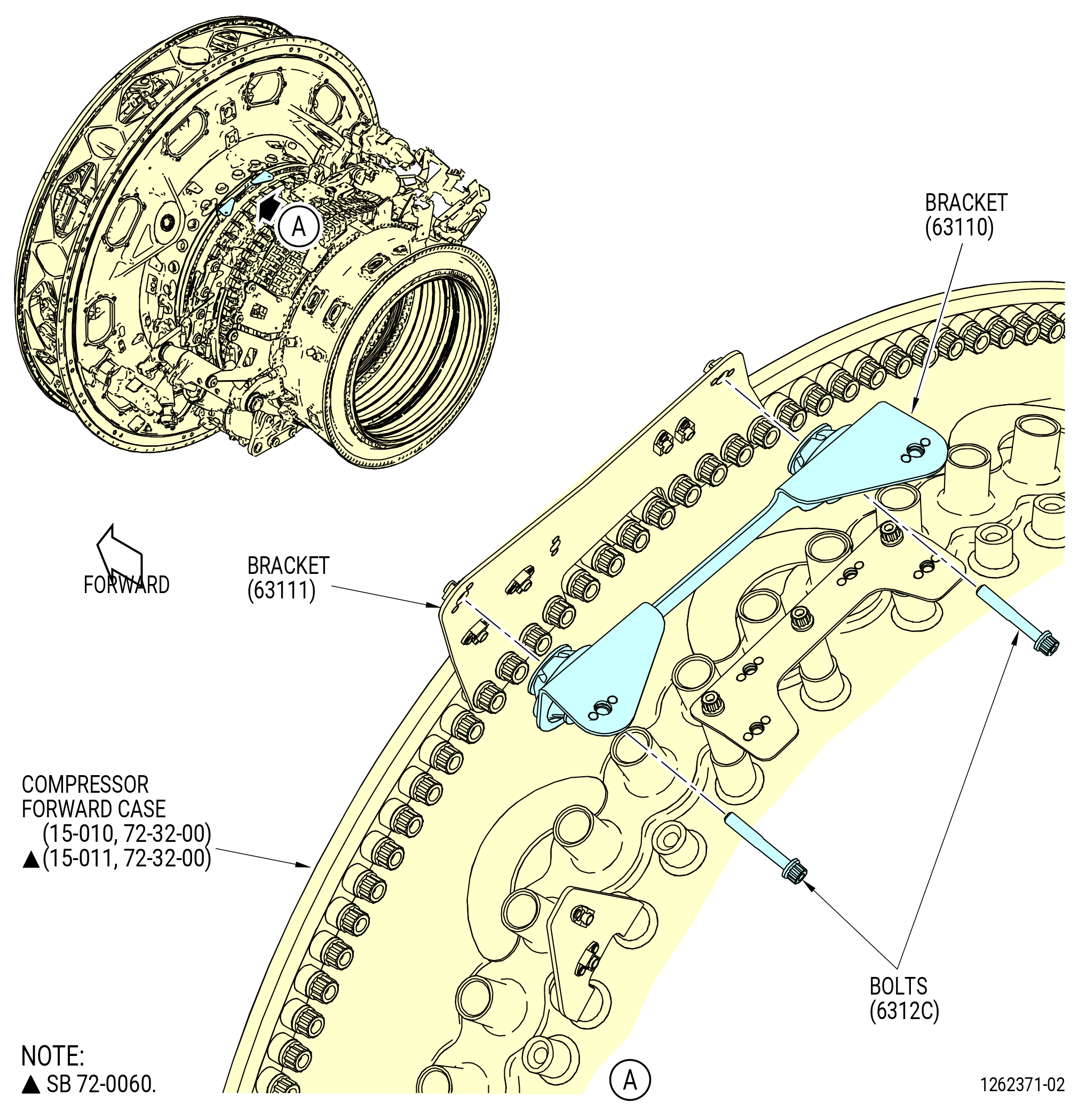
| E. | Install the brackets on the high pressure compressor (HPC) stator case (compressor forward case) (15-010 , 72-32-00) or (15-011 , 72-32-00) (SIN 073A0) and the fan hub frame (840A0) as follows. Refer to Figure 1006. |
| * * * PRE SB 72-0044( Left Hand Vertical Link with Spherical Bearings ) |
| (1) | Install the LH side link (25-160) (SIN 03801) as follows: |
| WARNING: |
|
| (a) | Apply C02-071 anti-seize to the threads of link LH axe (link bolt) (03824) and link LH axe (link bolt) (25-050) (SIN 03828). |
| (b) | Put the LH side link (25-160) (SIN 03801) on the compressor forward case at the 8:00 o'clock position. |
| (c) | Attach the LH side link (25-160) (SIN 03801) with the link bolt (03824), washer (03830), and self-locking nut (nut) (03842). |
| (d) | Install the mount transverse link (03806) on the LH side link (25-160) (SIN 03801) and on the compressor forward case. |
| (e) | Attach the mount transverse link with link bolts (25-050) (SIN 03828), washers (03830), and nuts (03842). |
| (f) | Torque the nuts (03842) to 552-648 lb in. (62.4-73.2 N.m). |
| * * * END PRE SB 72-0044 |
| Subtask 72-00-02-440-233 |
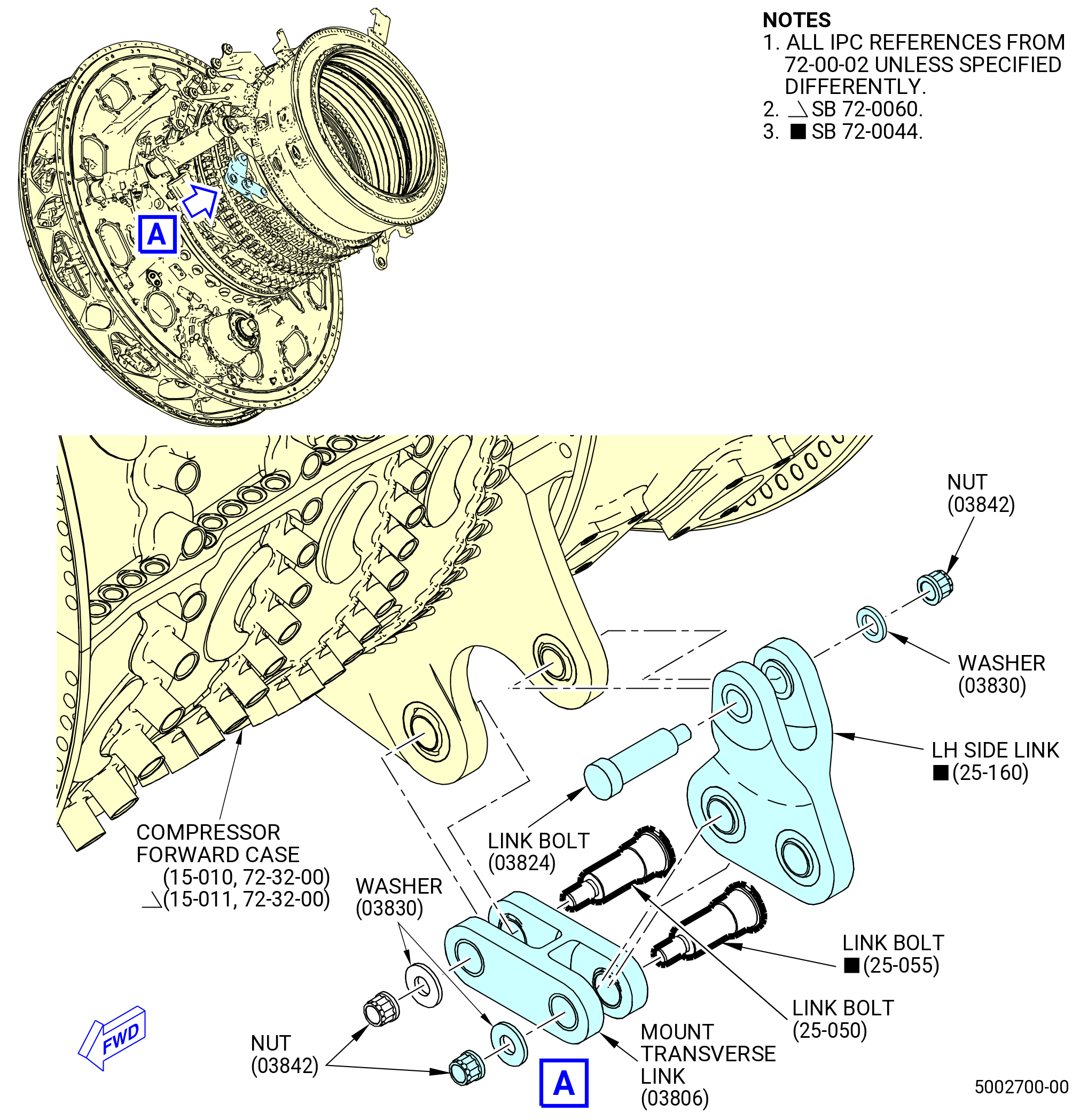
| * * * SB 72-0044( Left Hand Vertical Link with Spherical Bearing and Bushing ) |
| (1).A. | Install the LH side link (25-160) (SIN 03801) as follows: |
| WARNING: |
|
| (a) | Apply C02-071 anti-seize to the threads of link bolt (03824), link bolt (25-050) (SIN 03828) and link LH axe (link bolt) (25-055) (SIN 0382D). |
| (b) | Put the LH side link (25-160) (SIN 03801) on the compressor forward case at the 8:00 o'clock position. |
| (c) | Attach the LH side link (25-160) (SIN 03801) with the link bolt (03824), washer (03830), and nut (03842). |
| (d) | Install the mount transverse link (03806) on the LH side link (25-160) (SIN 03801) and on the compressor forward case. |
| (e) | Attach the mount transverse link with link bolt (25-050) (SIN 03828), link bolt (25-055) (SIN 0382D), washers (03830), and nuts (03842). |
| (f) | Torque the nuts (03842) to 552-648 lb in. (62.4-73.2 N.m). |
| * * * END SB 72-0044 |
| Subtask 72-00-02-440-234 |
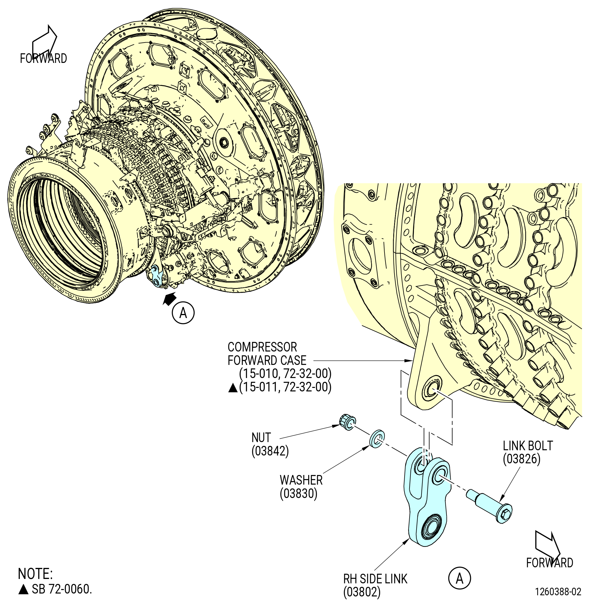
| (2) | Install the RH side link (03802) as follows: |
| (a) | Apply C02-071 anti-seize to the threads of the link bolt (03826). |
| (b) | Put the RH side link (03802) on the compressor forward case (15-010 , 72-32-00) or (15-011 , 72-32-00) (SIN 073A0) at the 4:00 o'clock position. |
| (c) | Attach the bracket with the link bolt (03826), washer (03830), and nut (03842). |
| (d) | Torque the nut (03842) to 552-648 lb in. (62.4-73.2 N.m). |
|
|
| Subtask 72-00-02-440-115 |
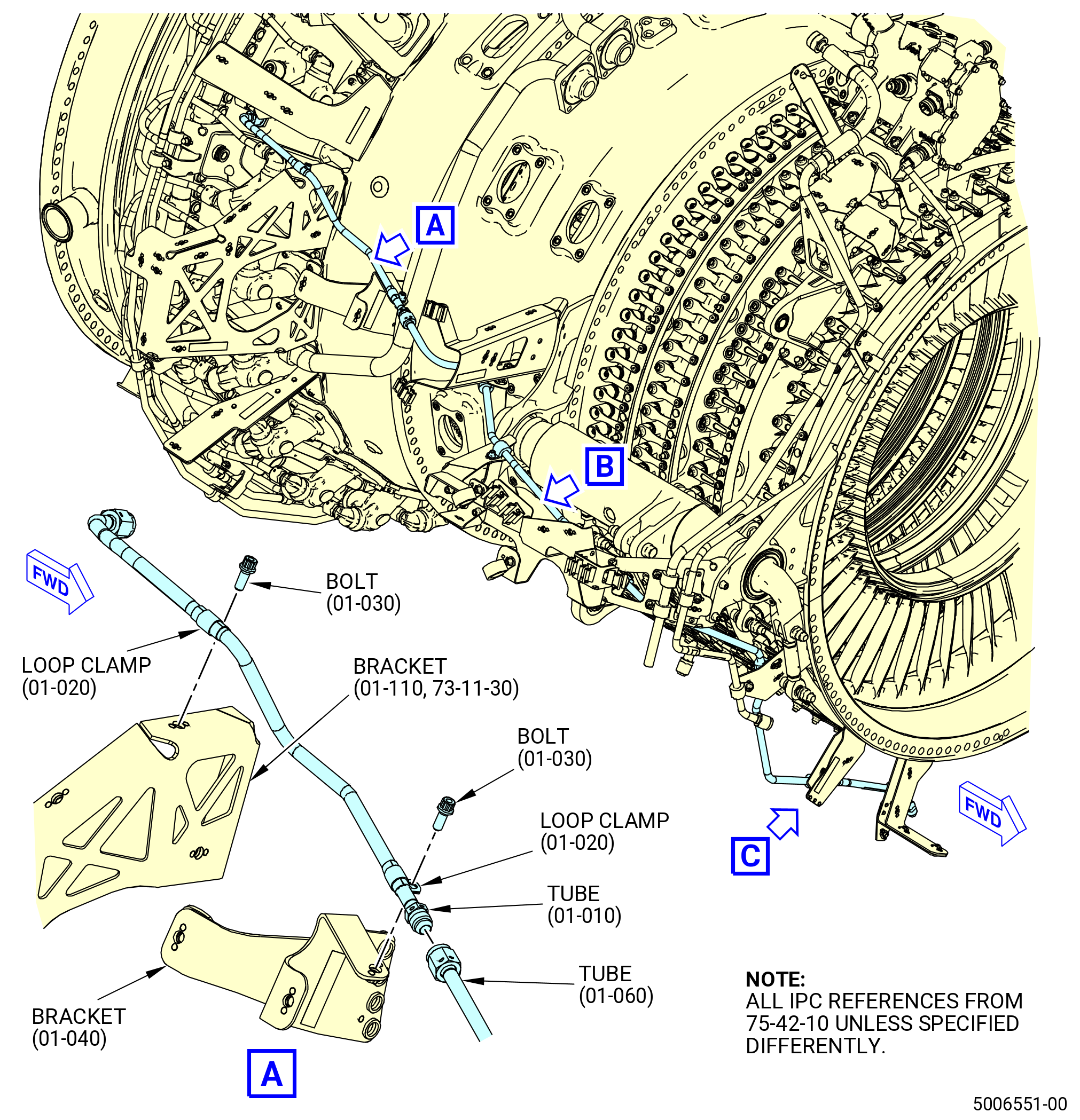
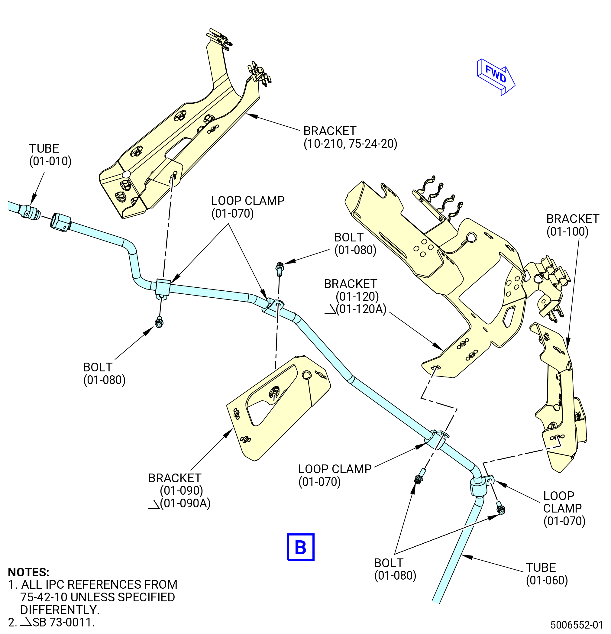
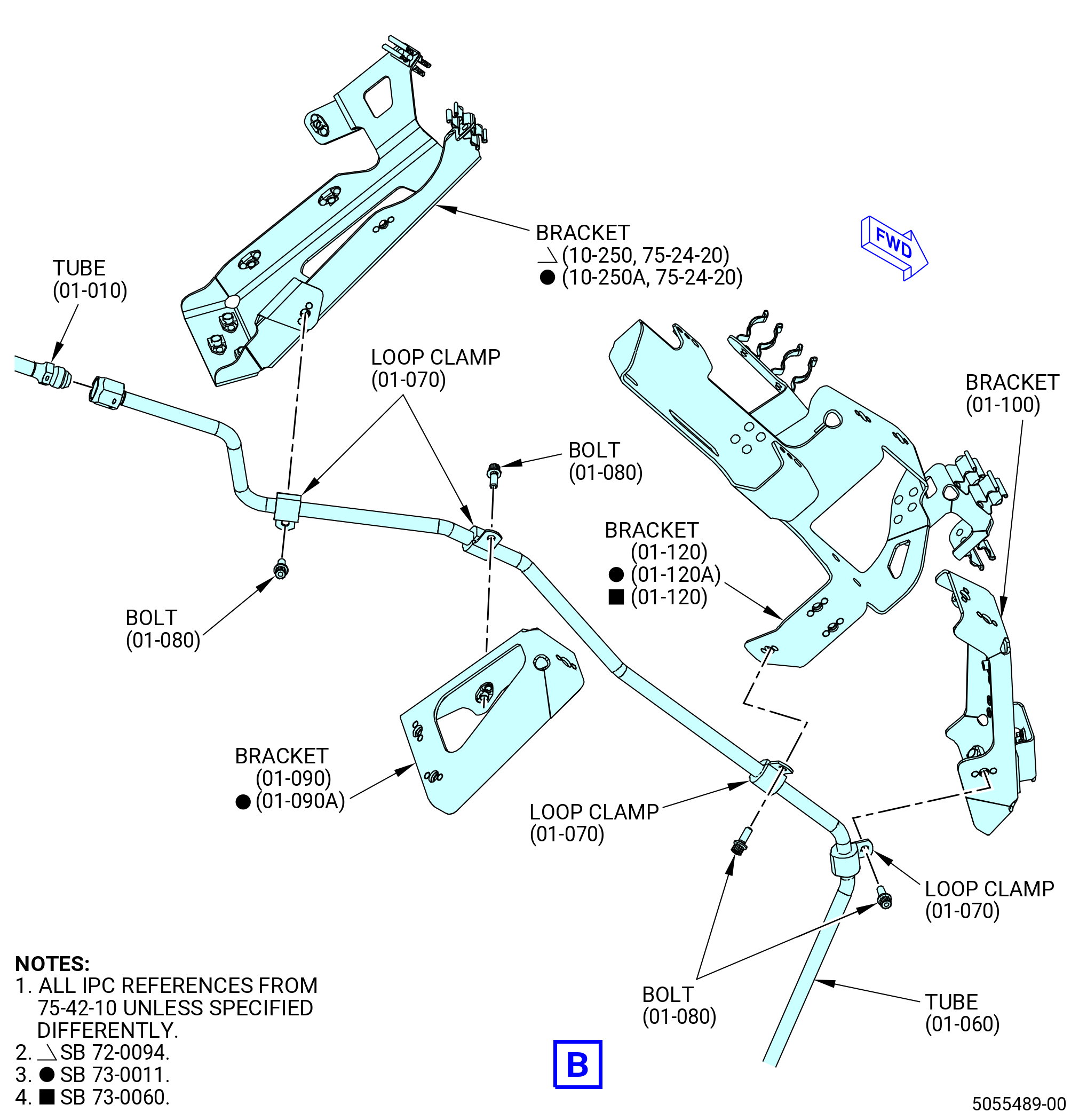
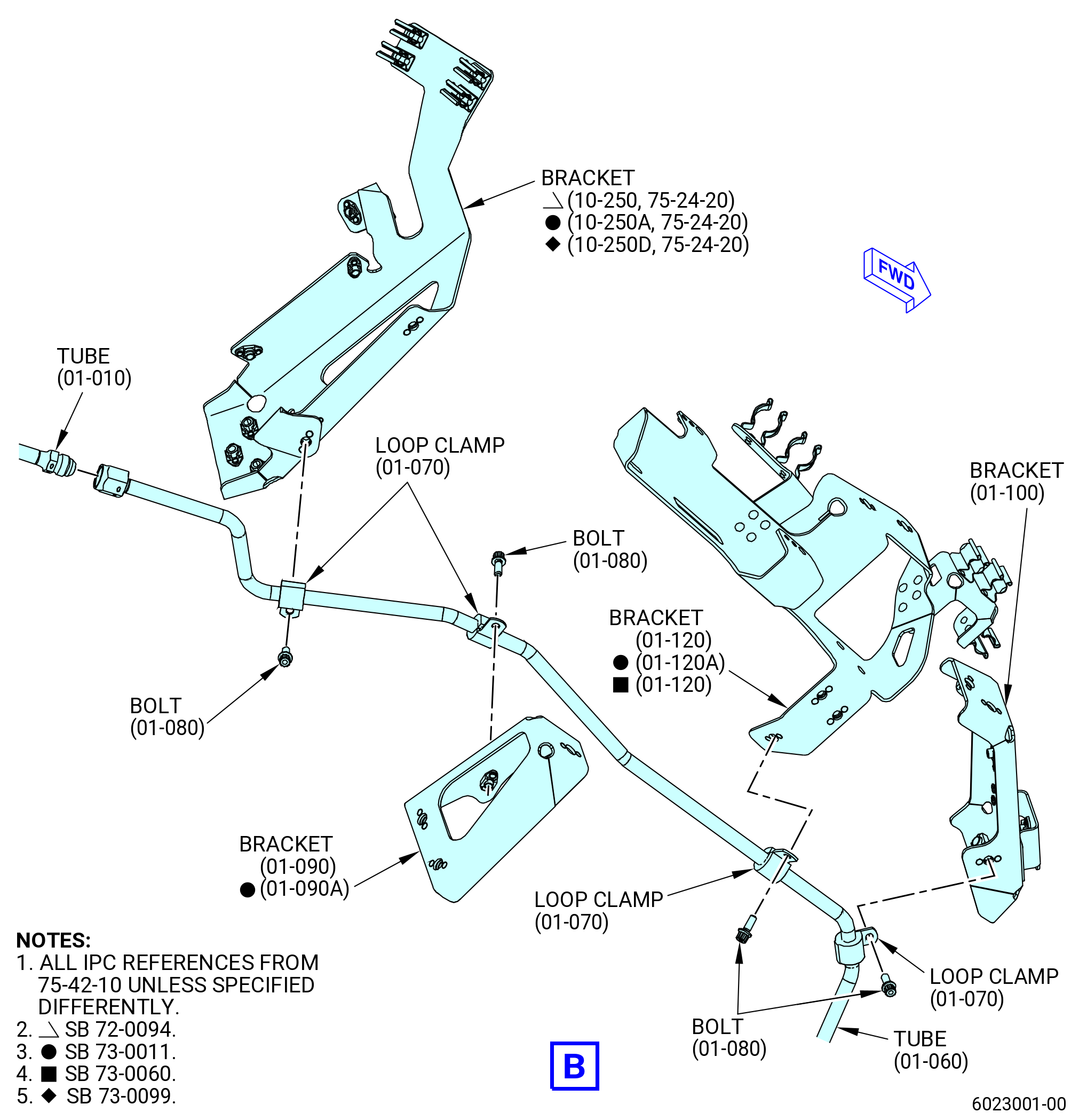
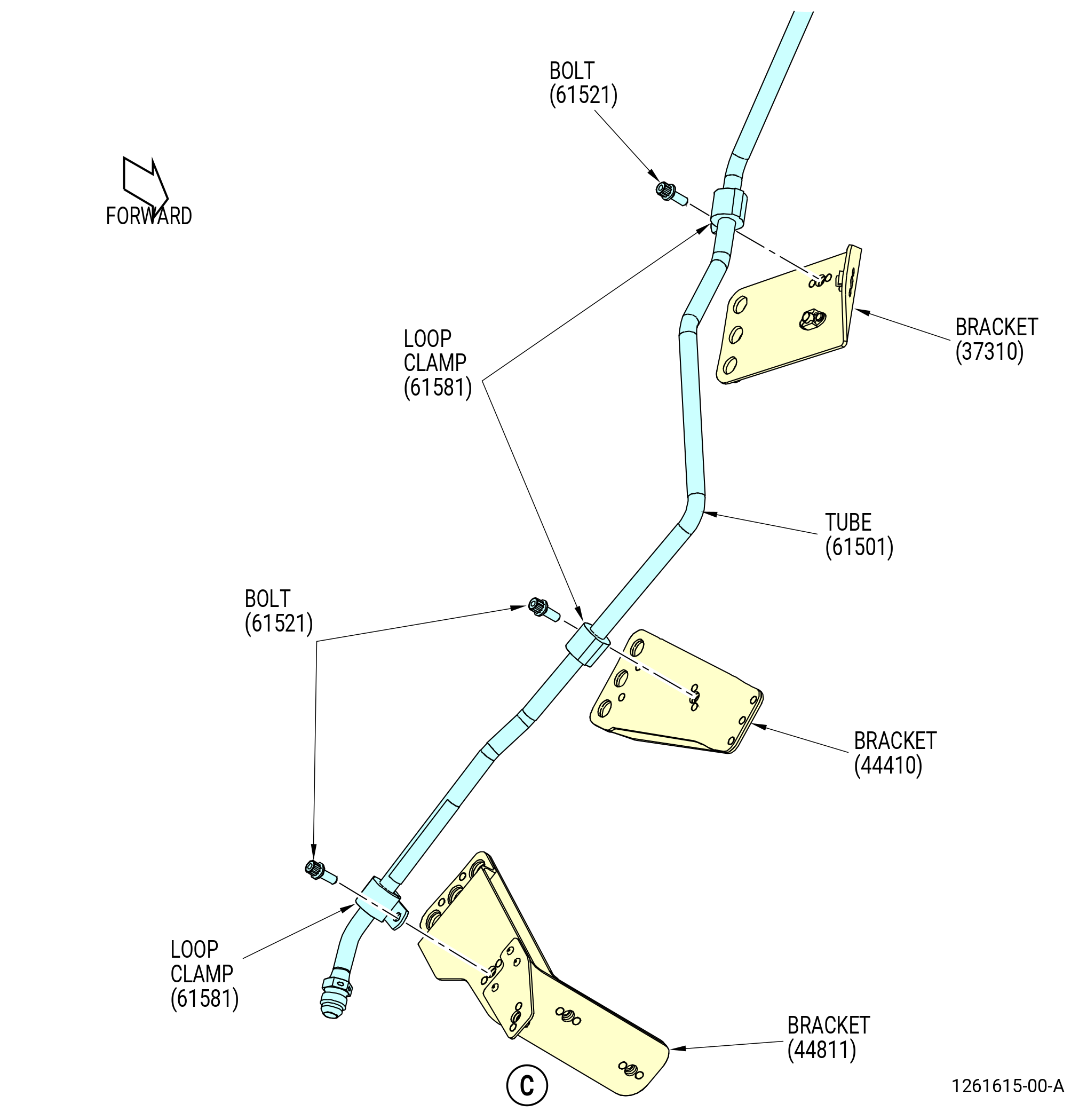
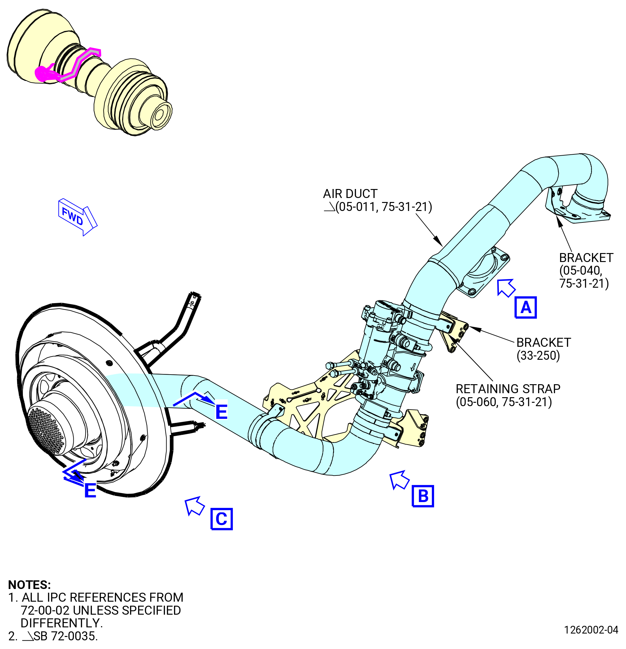
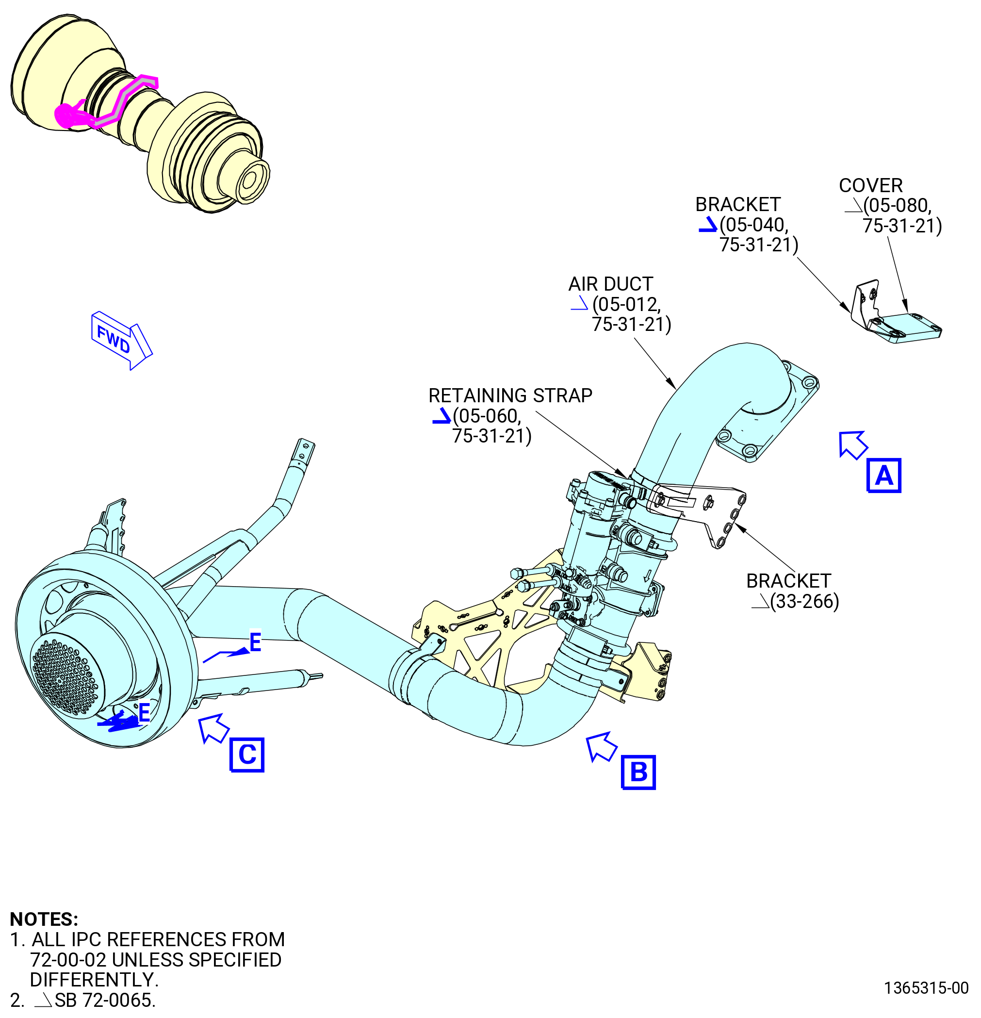
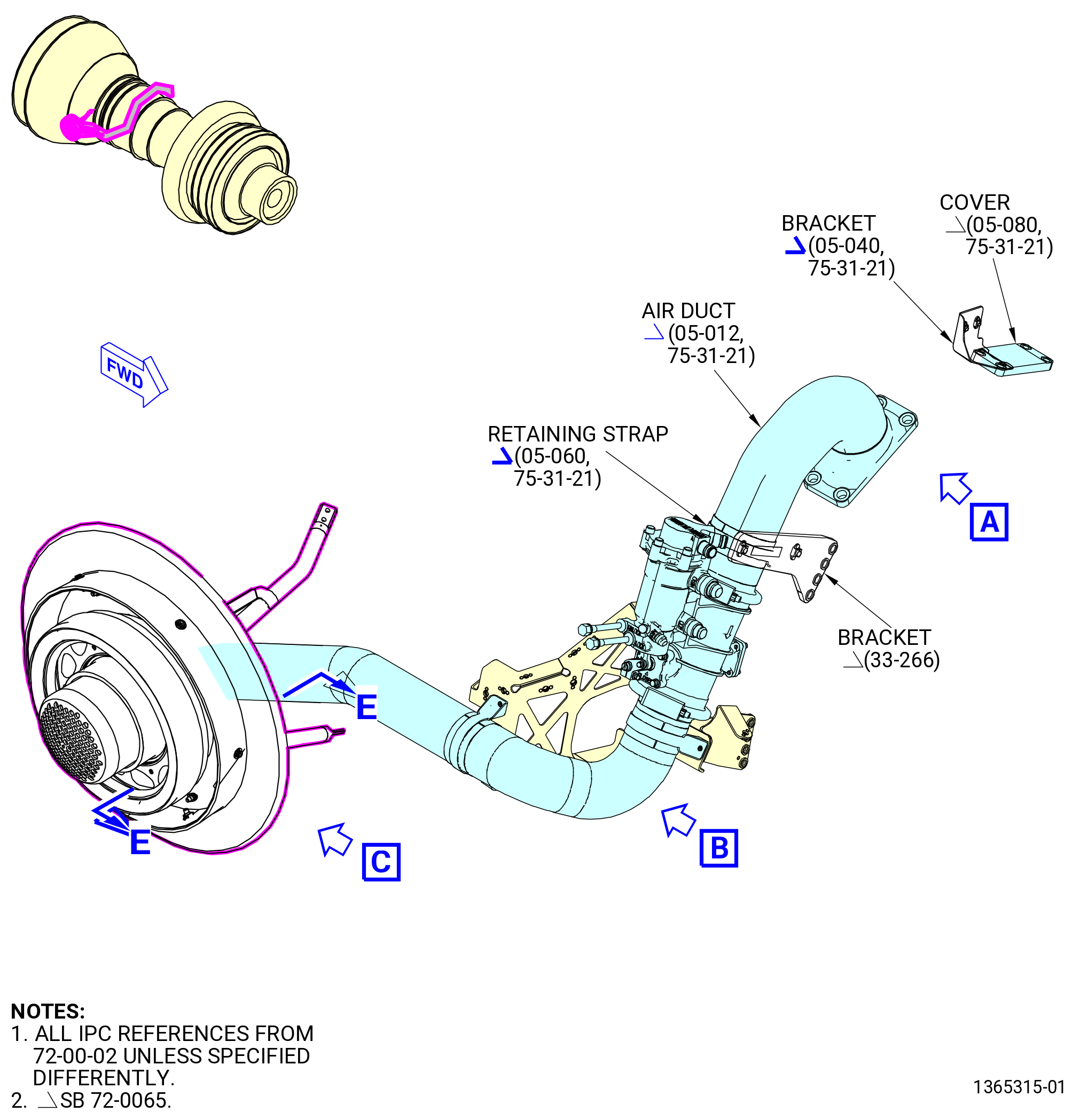
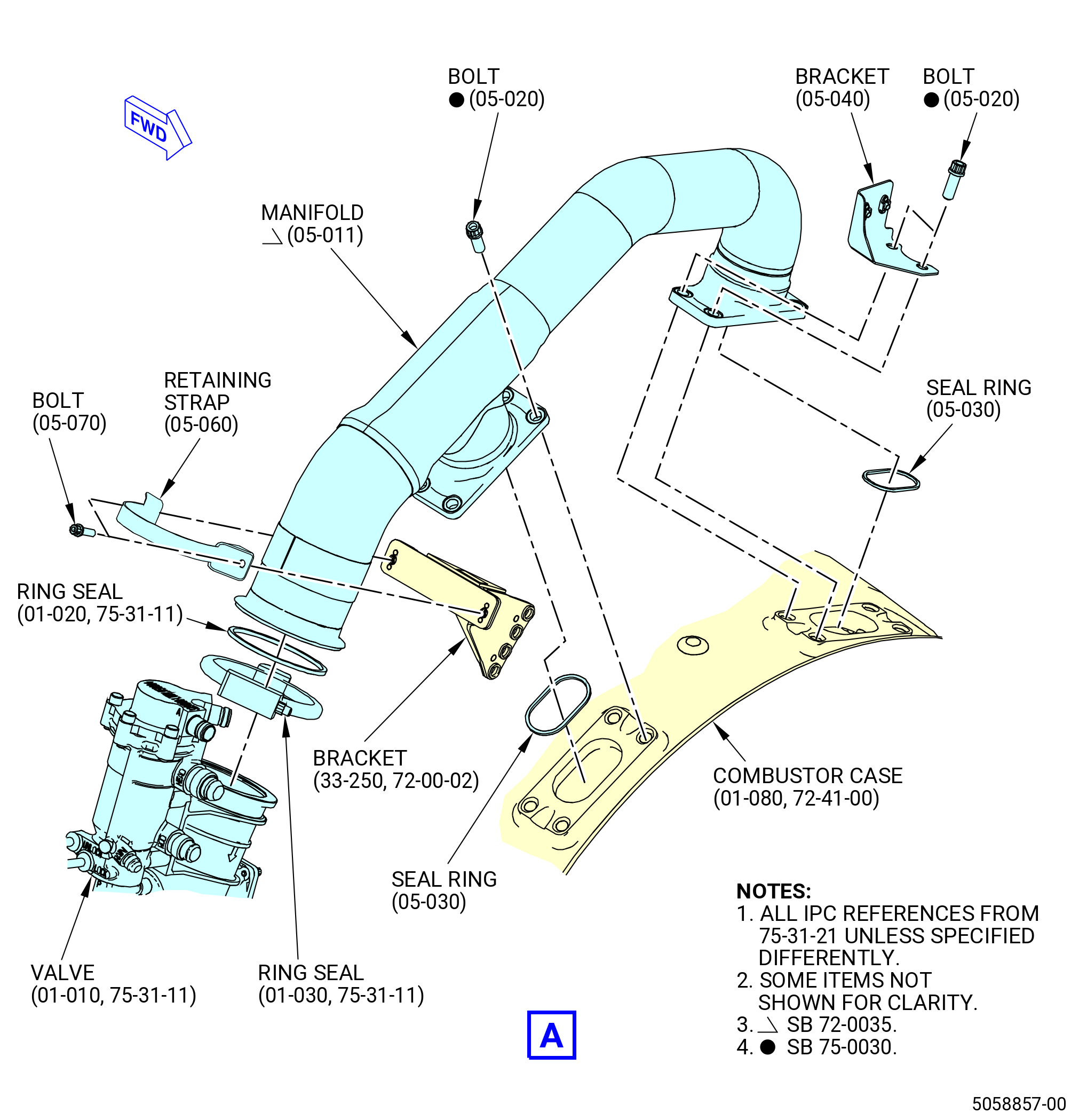
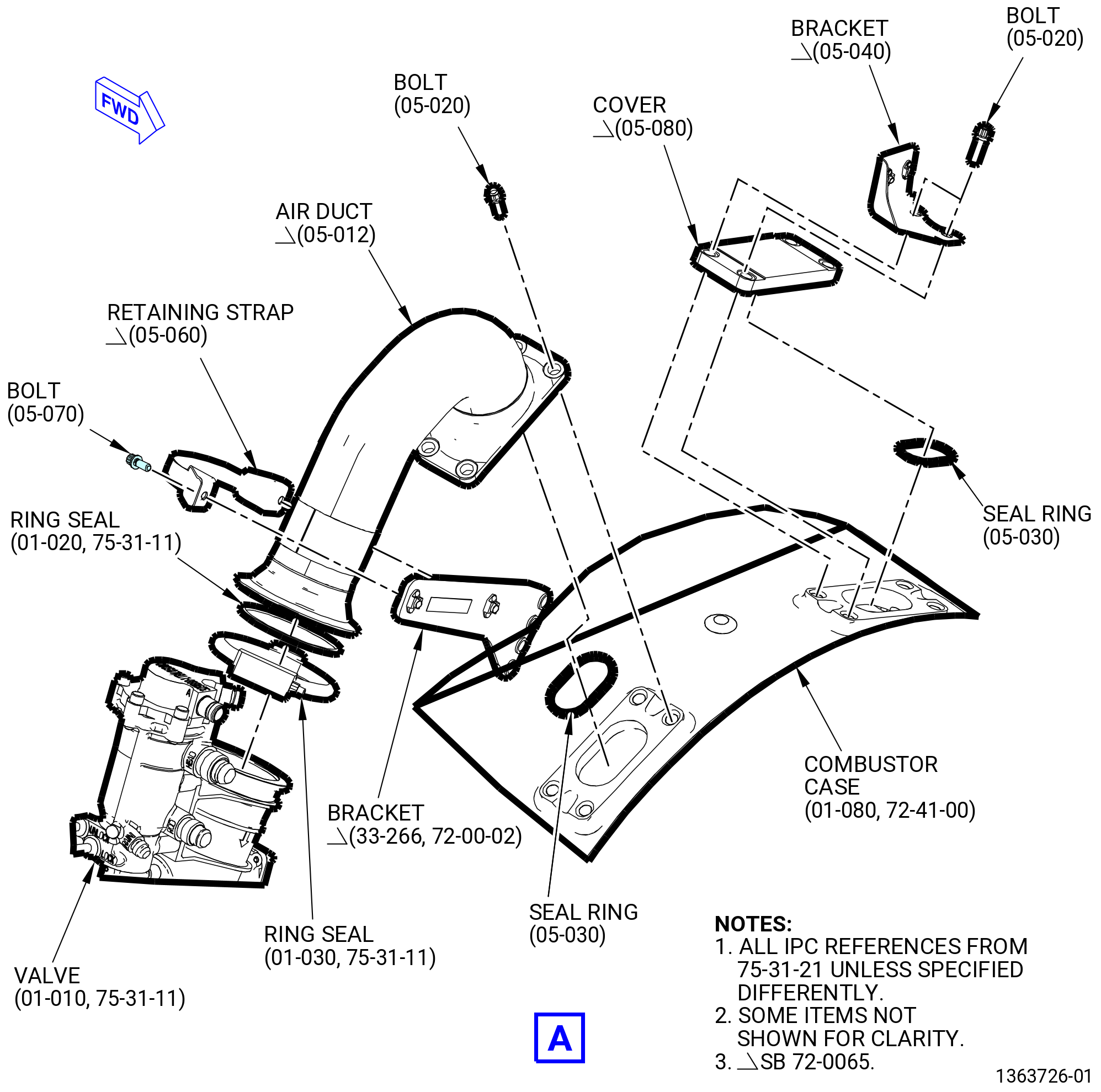
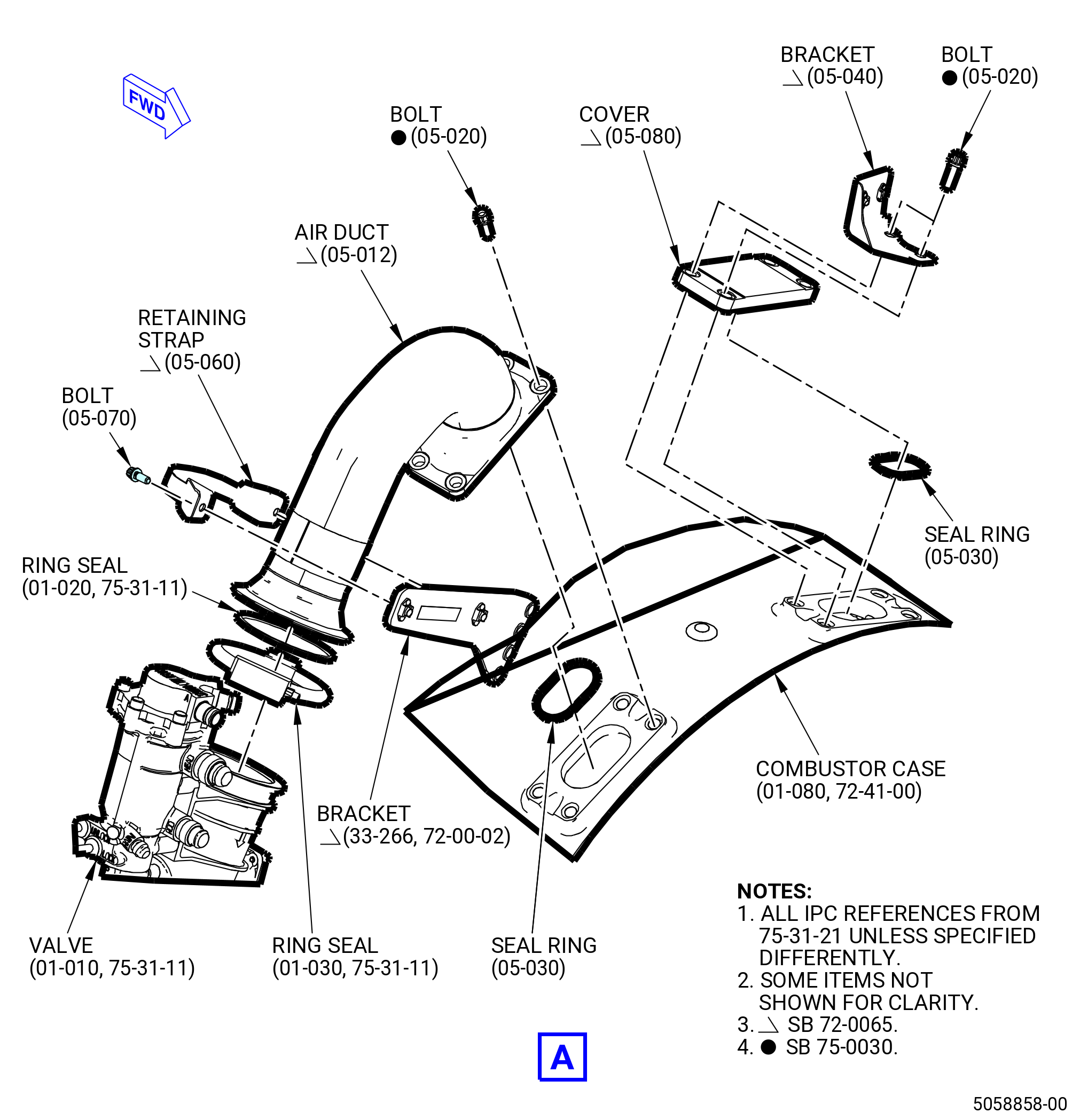
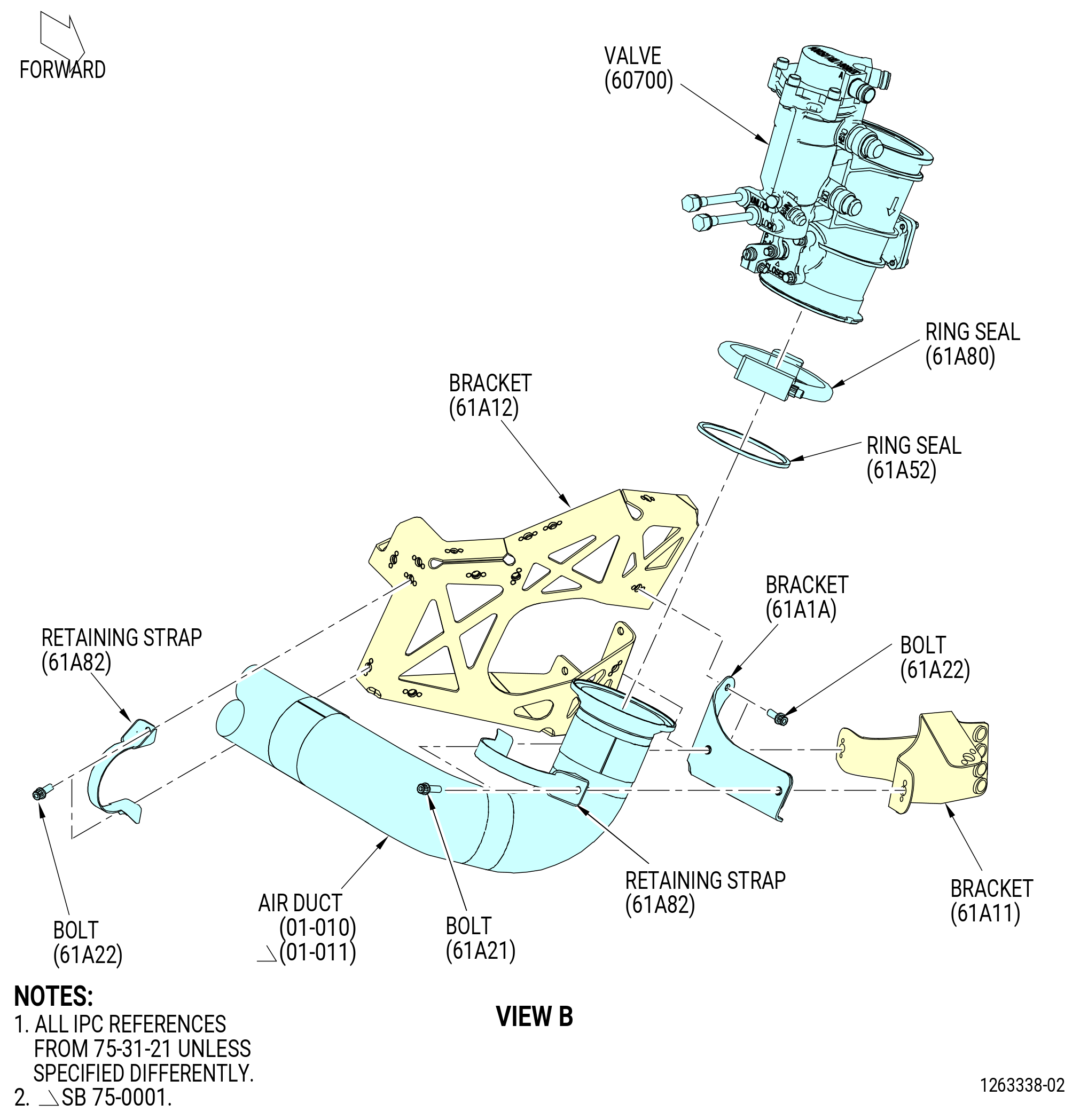
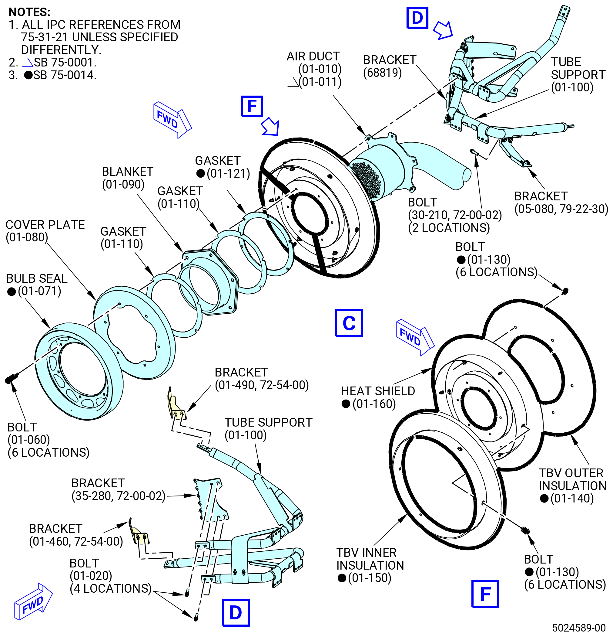
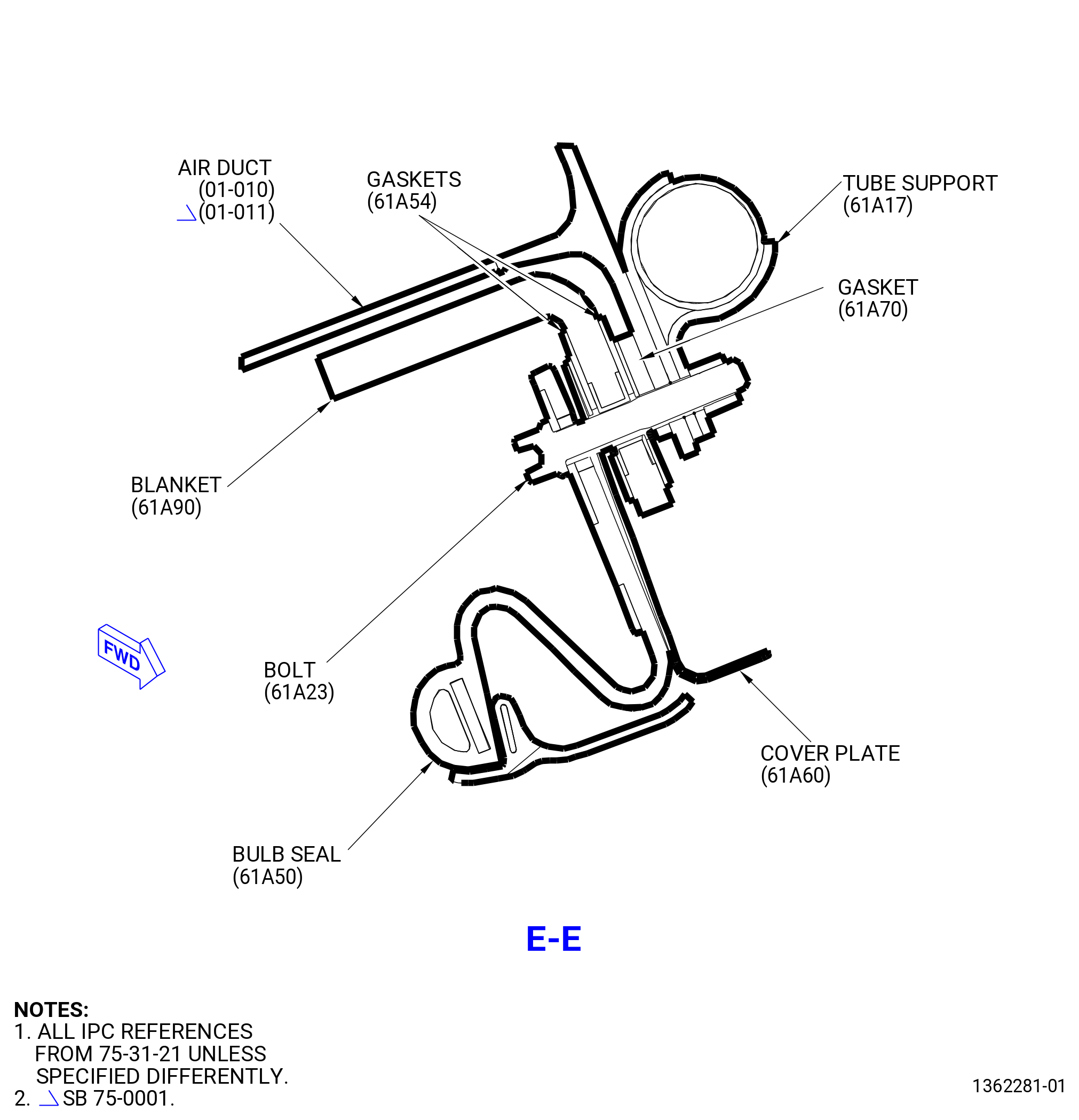
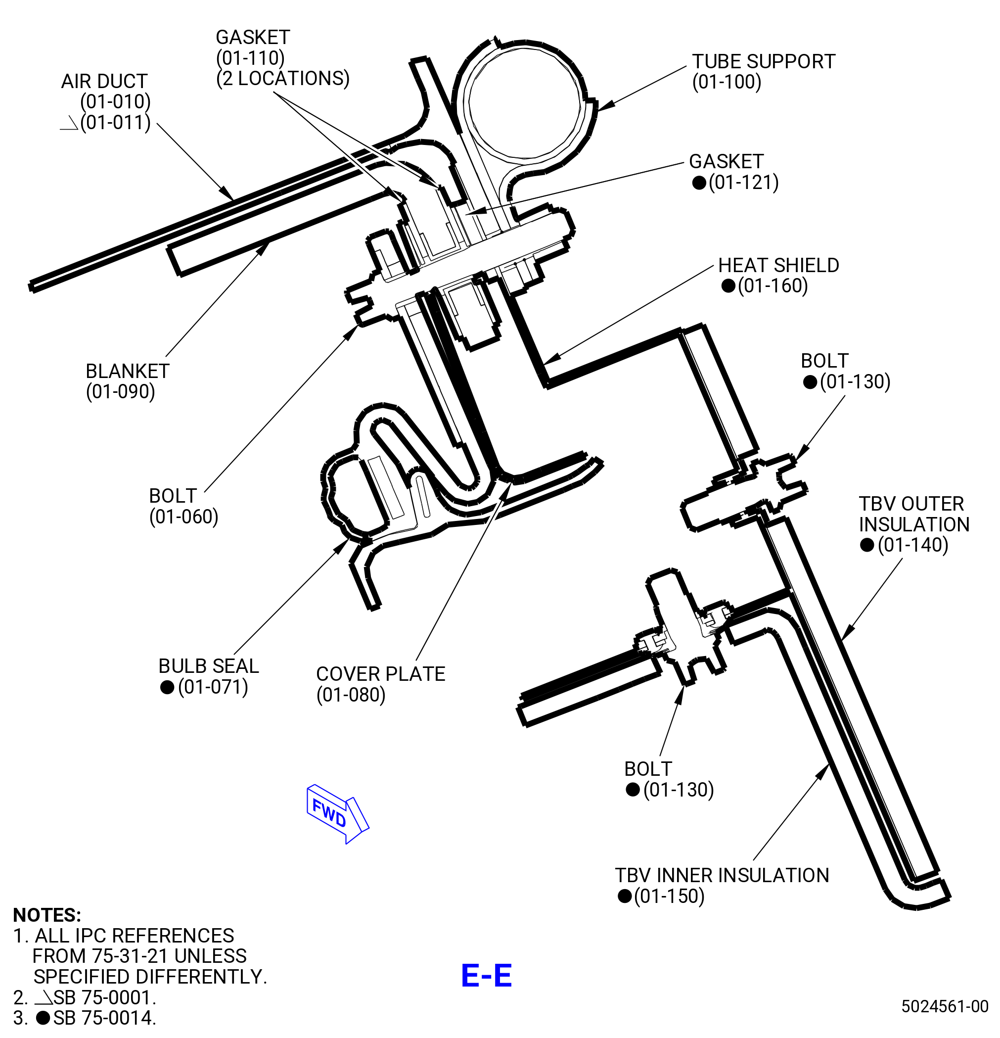
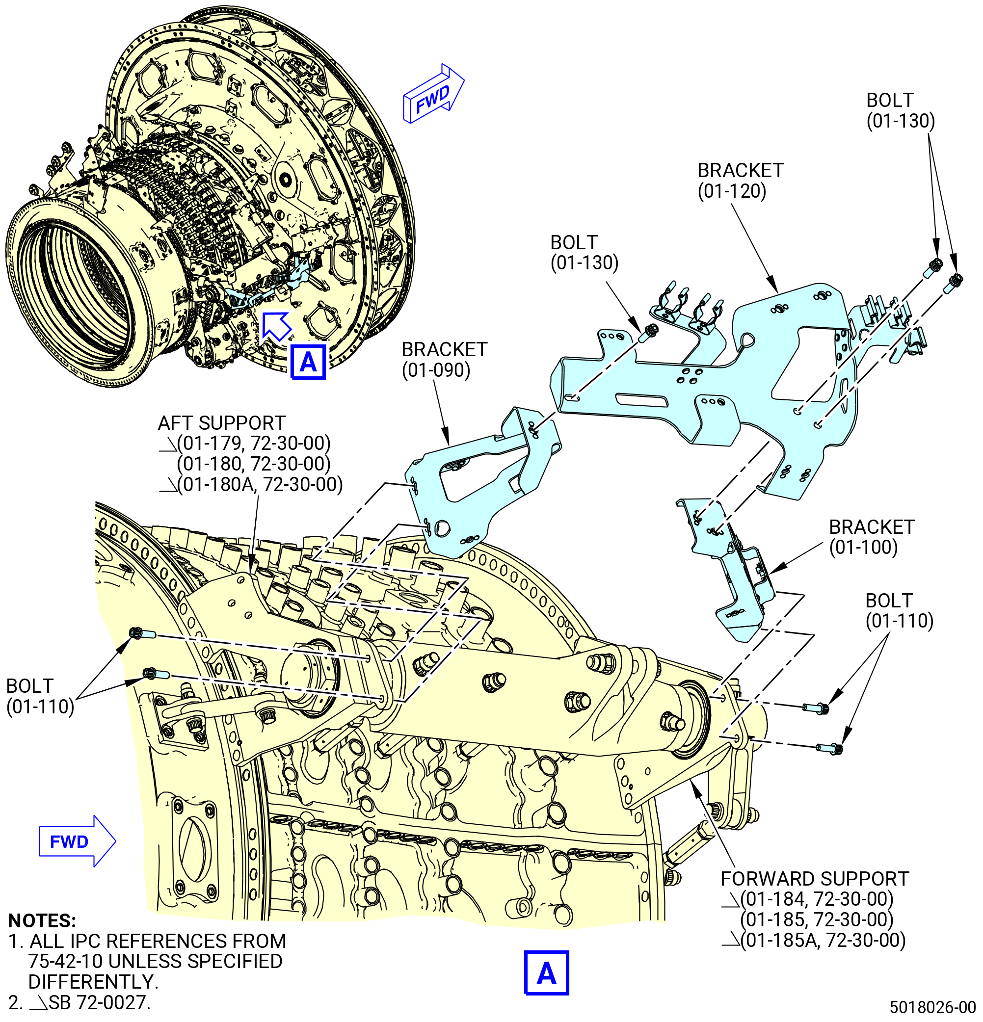
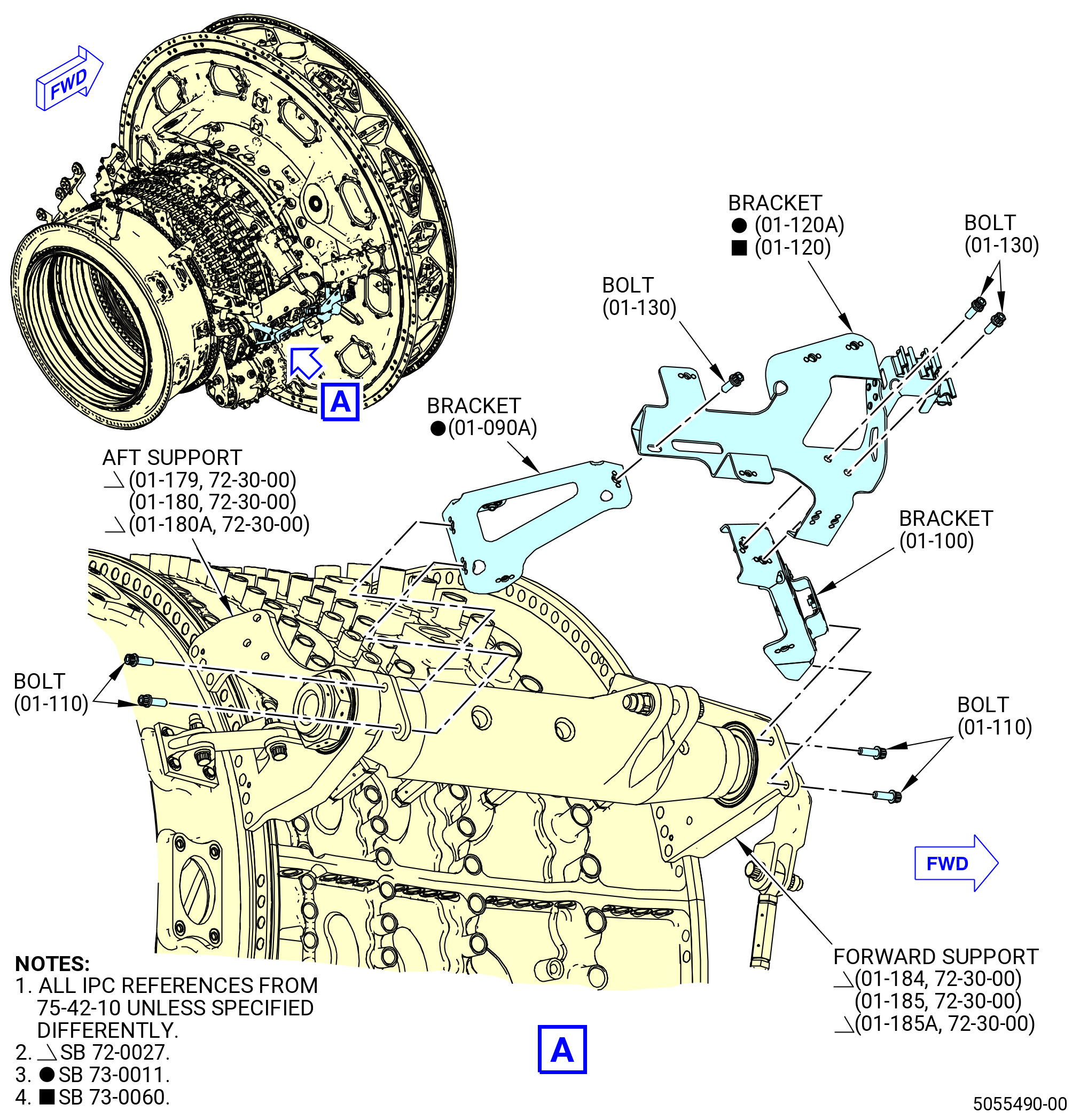
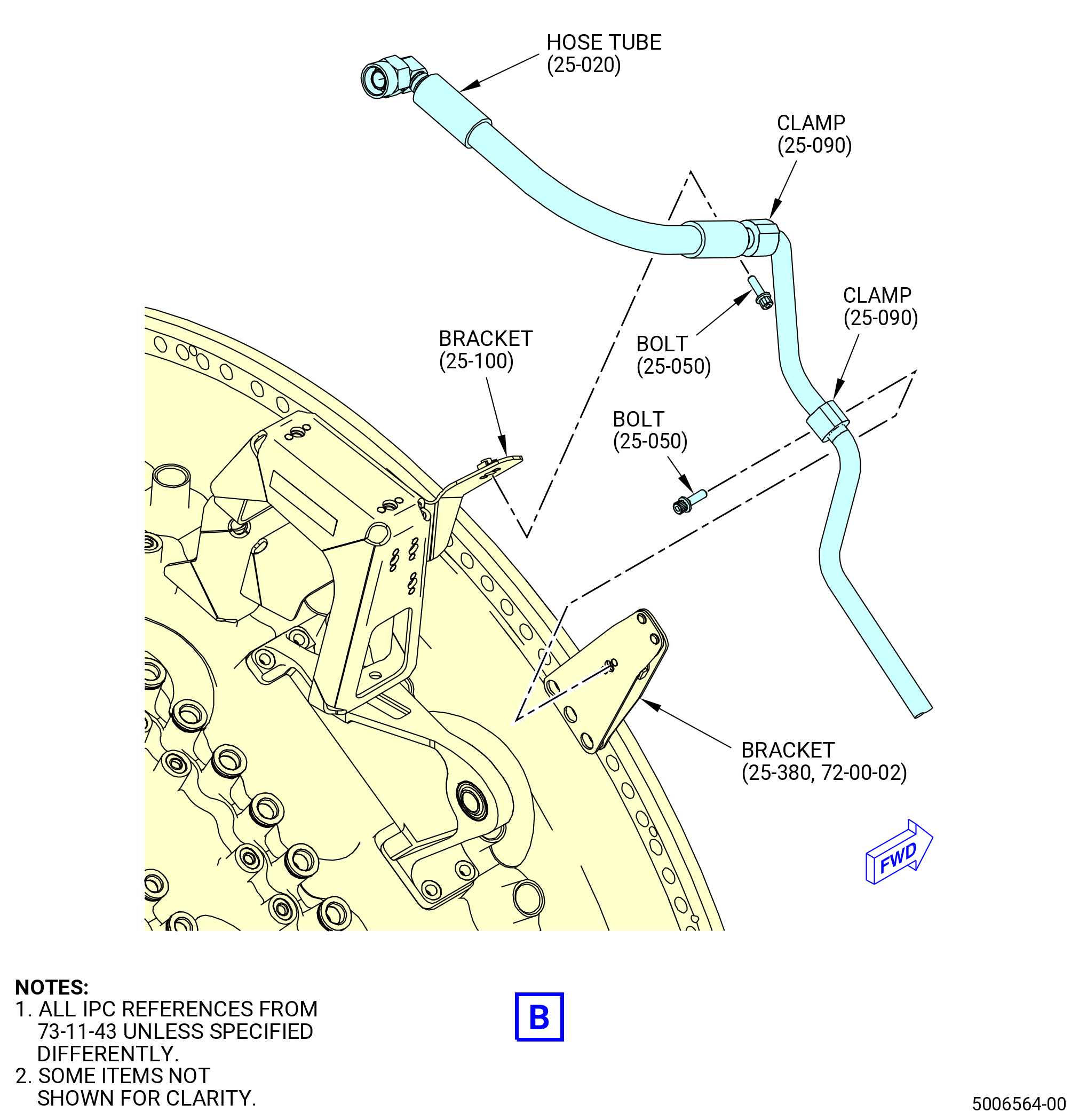
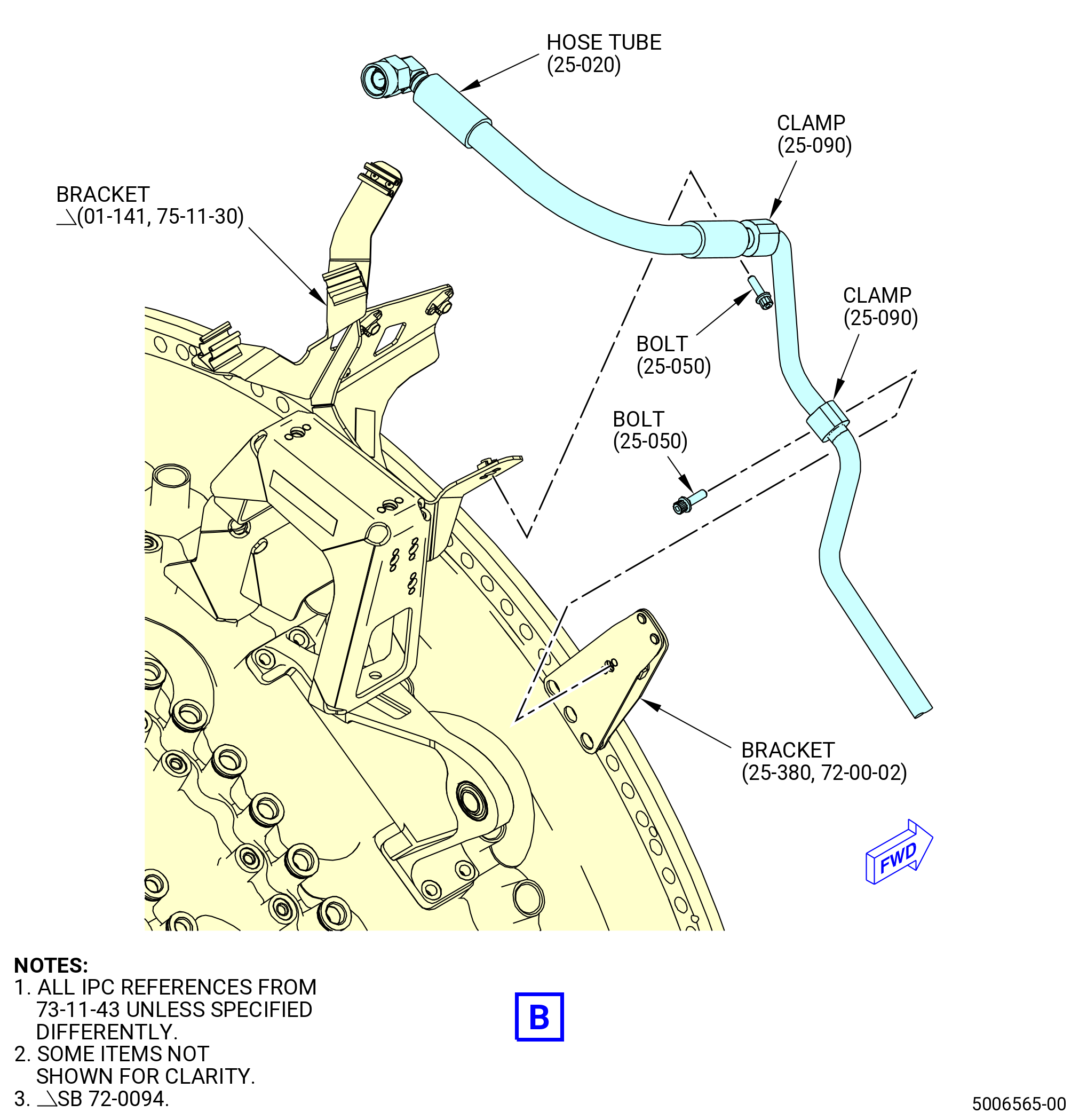
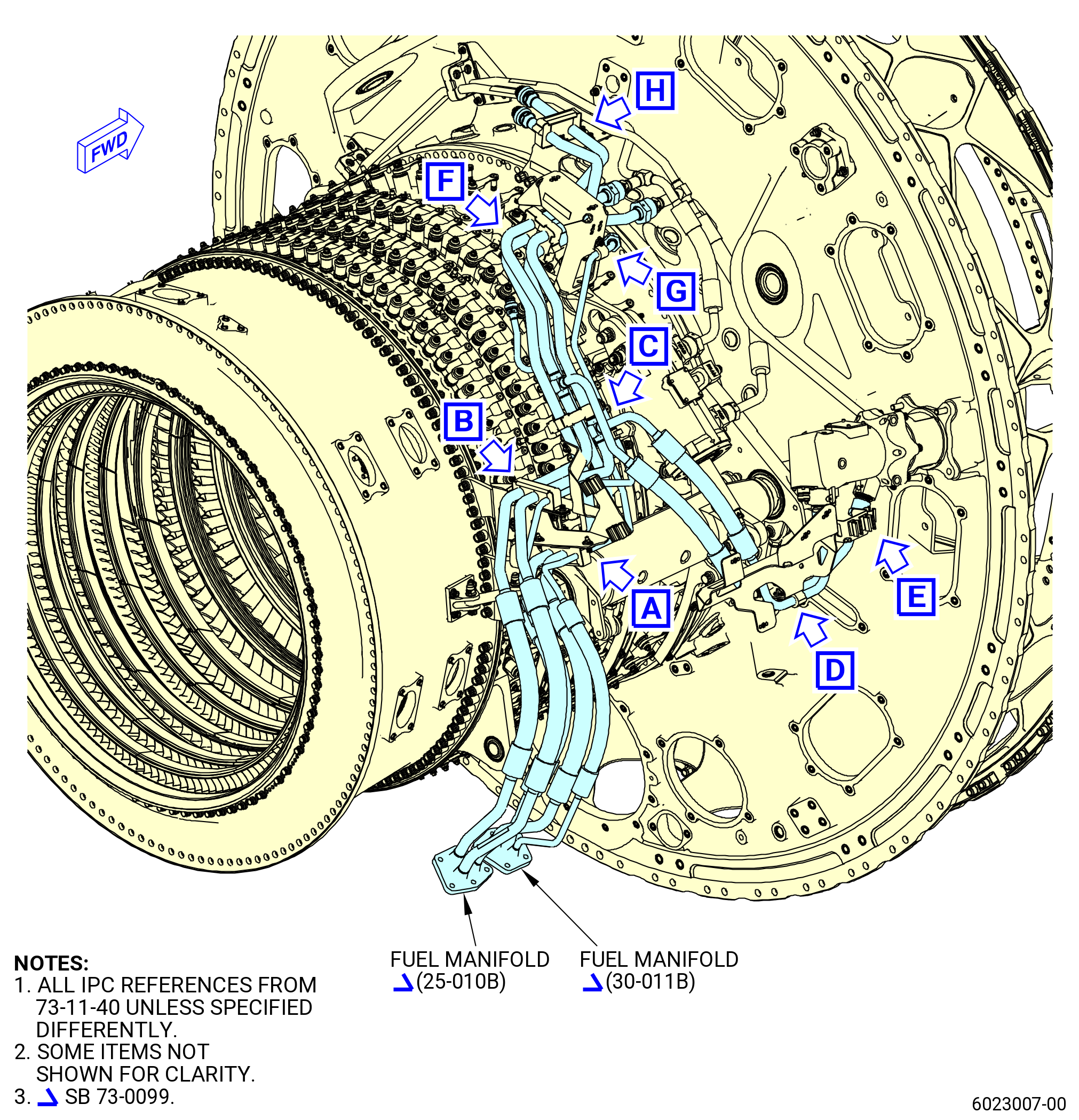
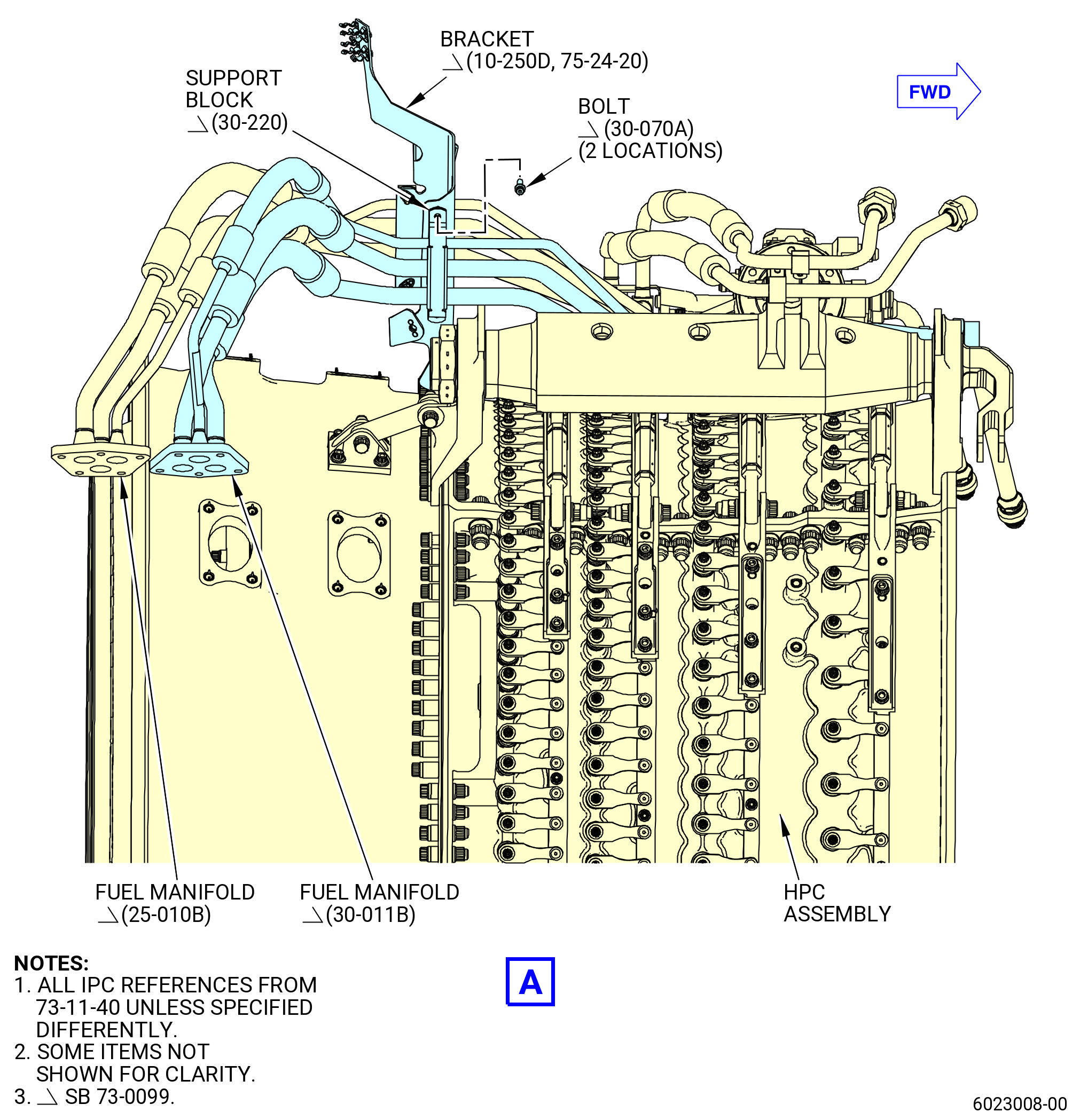
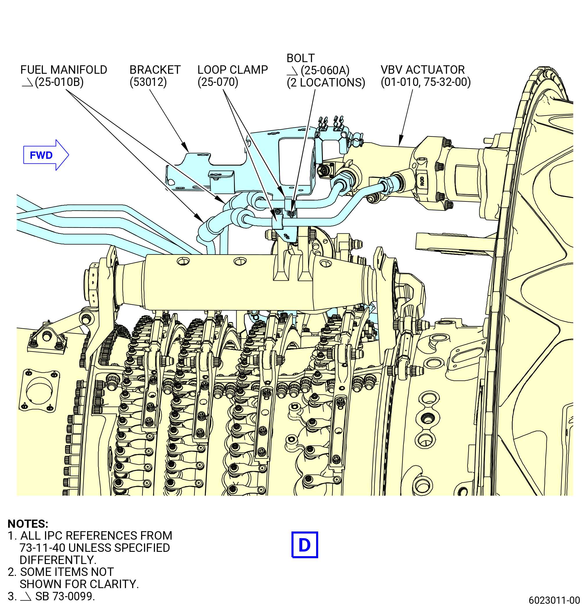
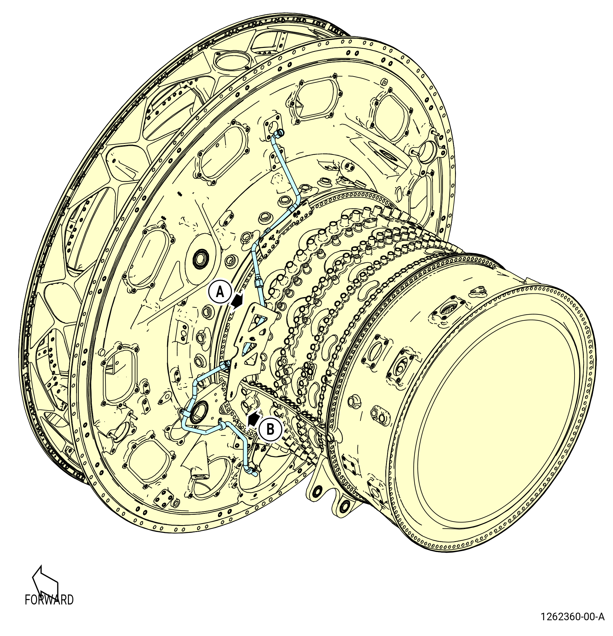
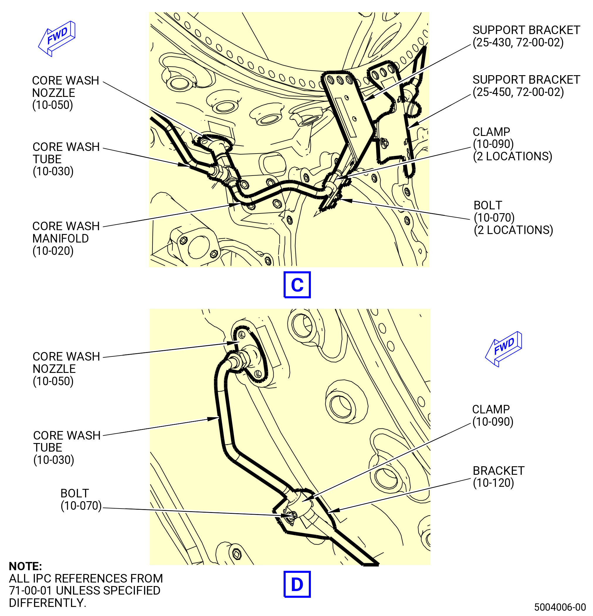
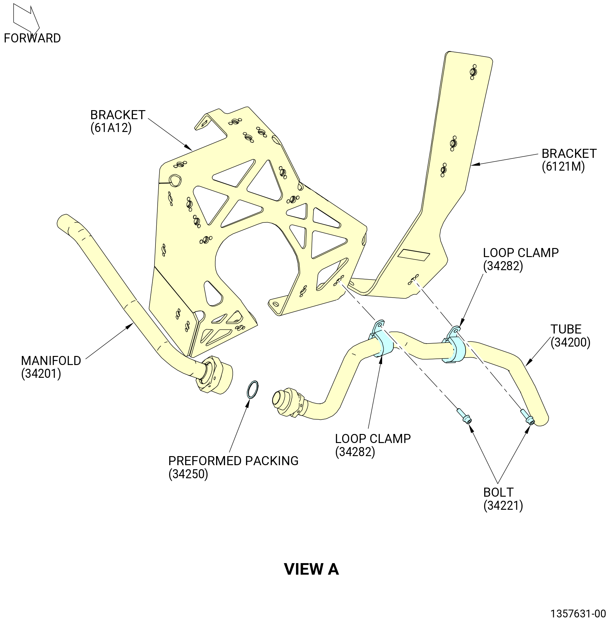
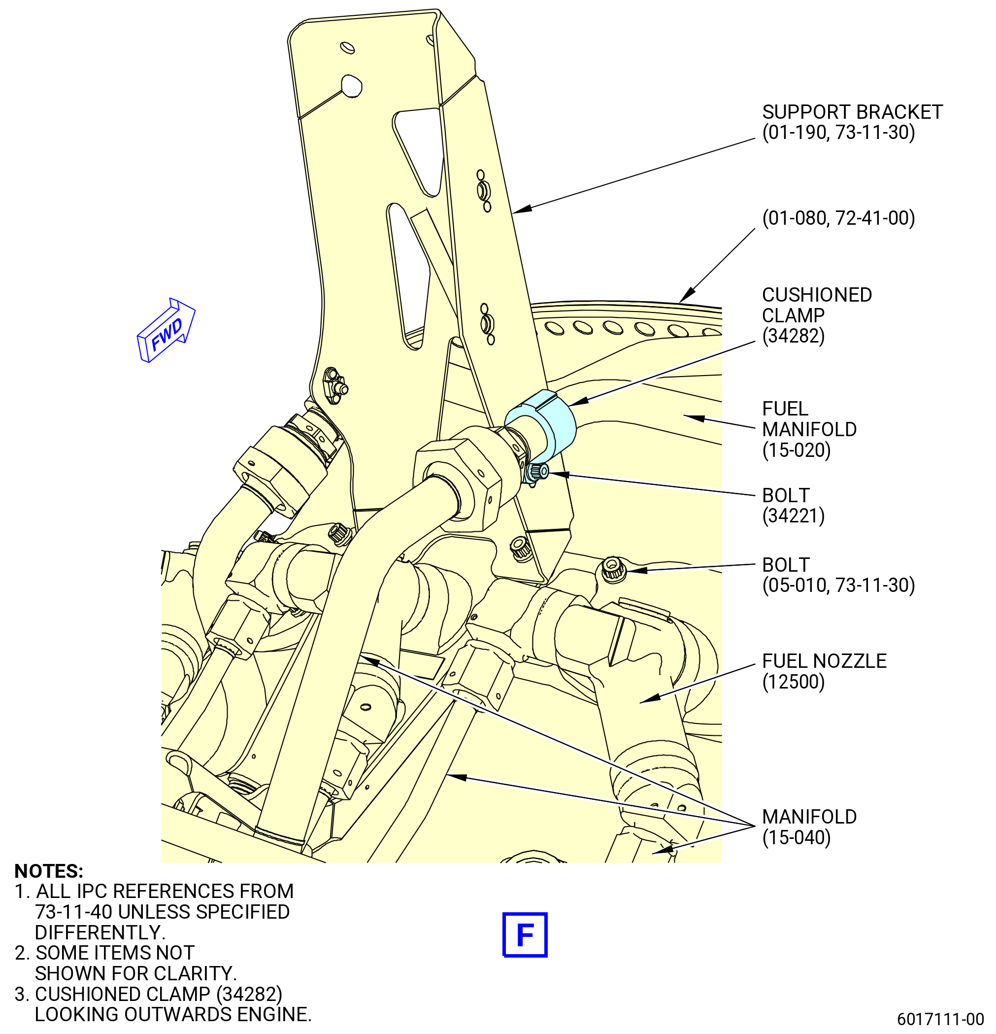
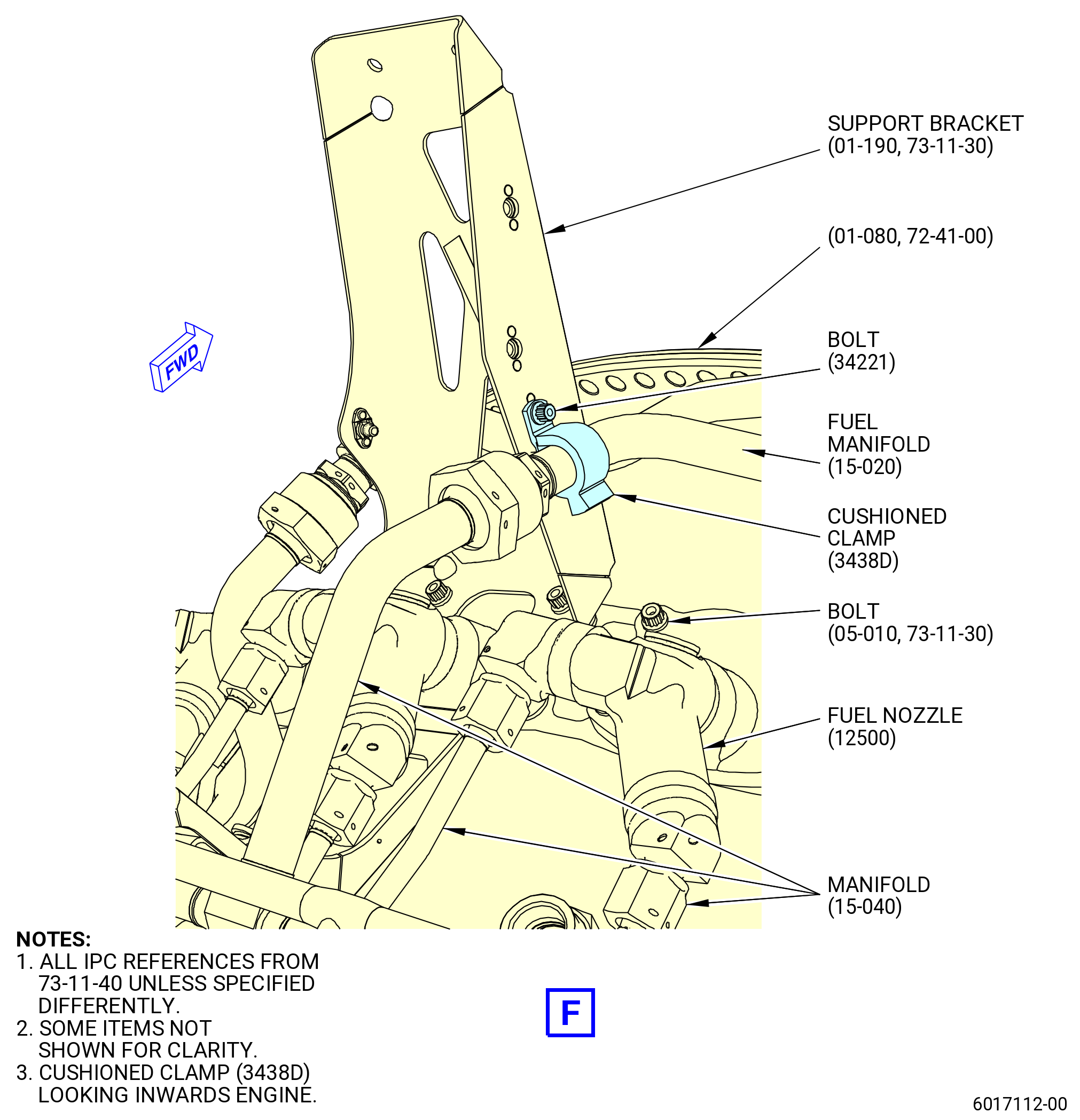
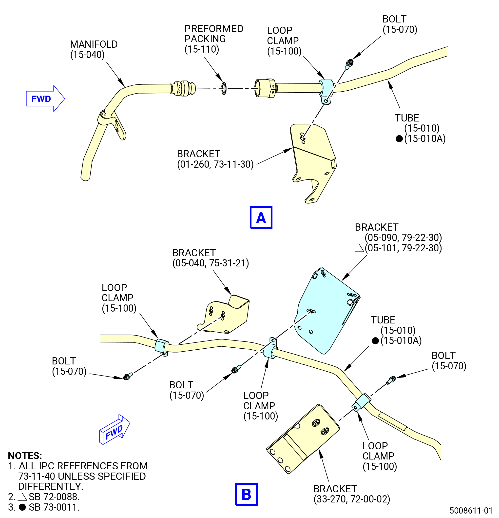
| F. | Install the PS3 air tubes (tubes) (61500) and (61501) as follows. Refer to Figure 1007. |
| (1) | Install the tube (01-010 , 75-42-10) (SIN 61500) on the combustor case (01-080 , 72-41-00) (SIN 12001) at the 2:30 o'clock position. |
| (2) | Attach the tube (61500) to the bracket (61A12) with a loop clamp (61582) and a bolt (61522). |
| (3) | Attach the tube (61500) to the bracket (61A11) with a loop clamp (61582) and a bolt (61522). |
| (4) | Connect the tube (61501) to the tube (61500). |
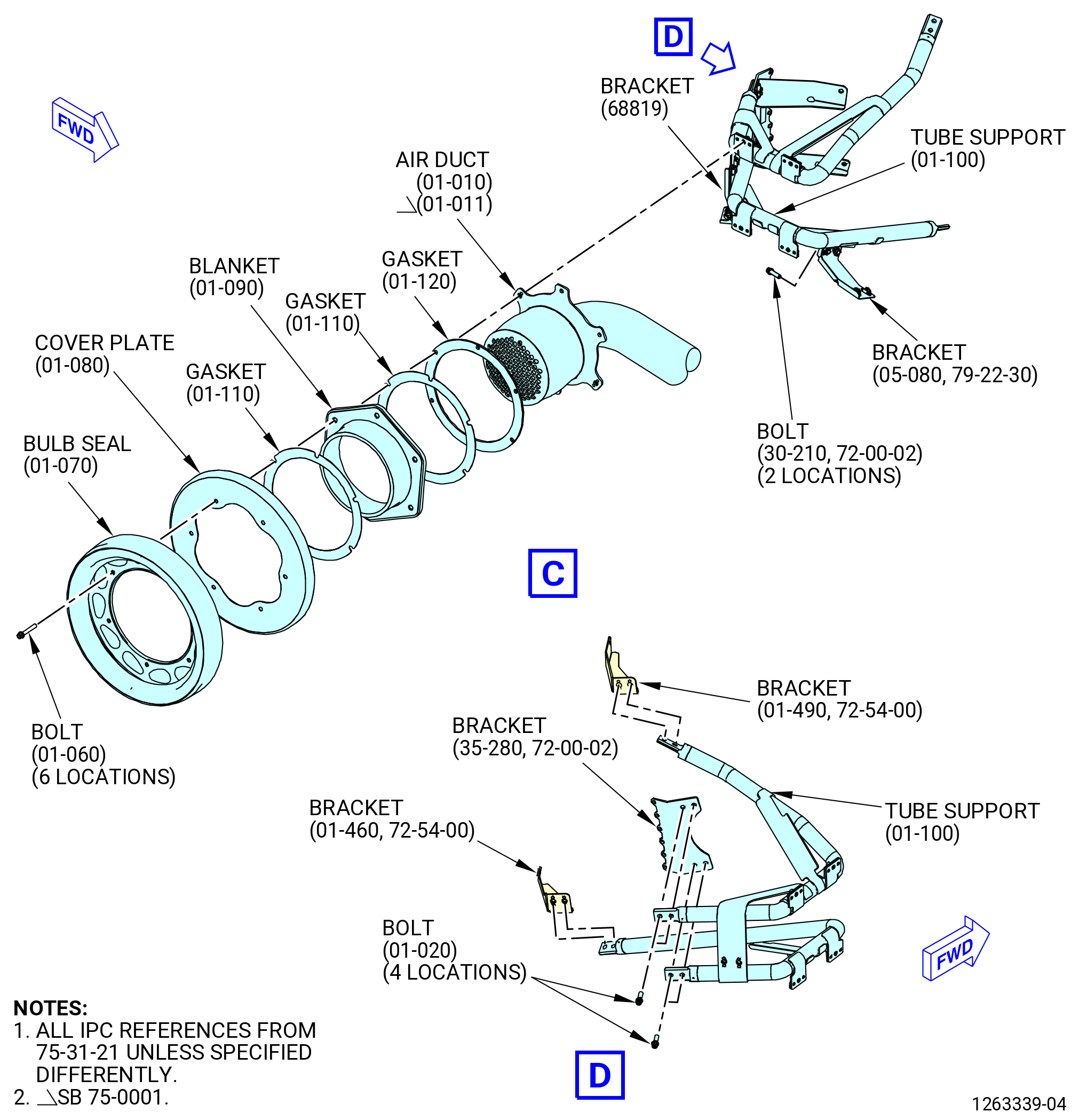
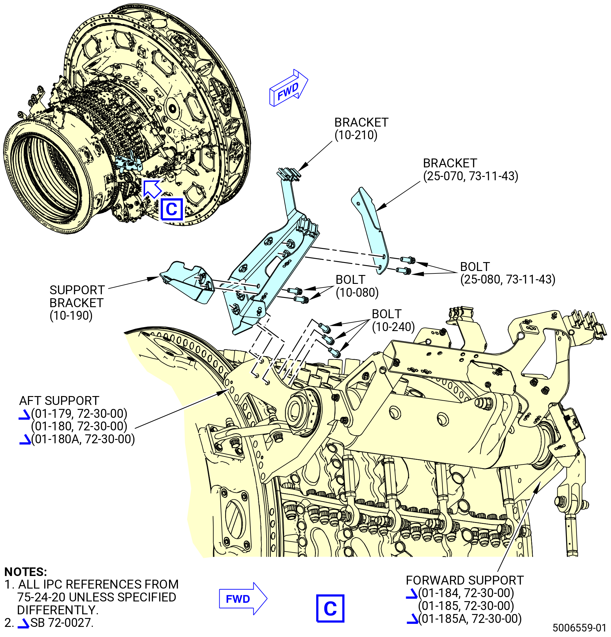
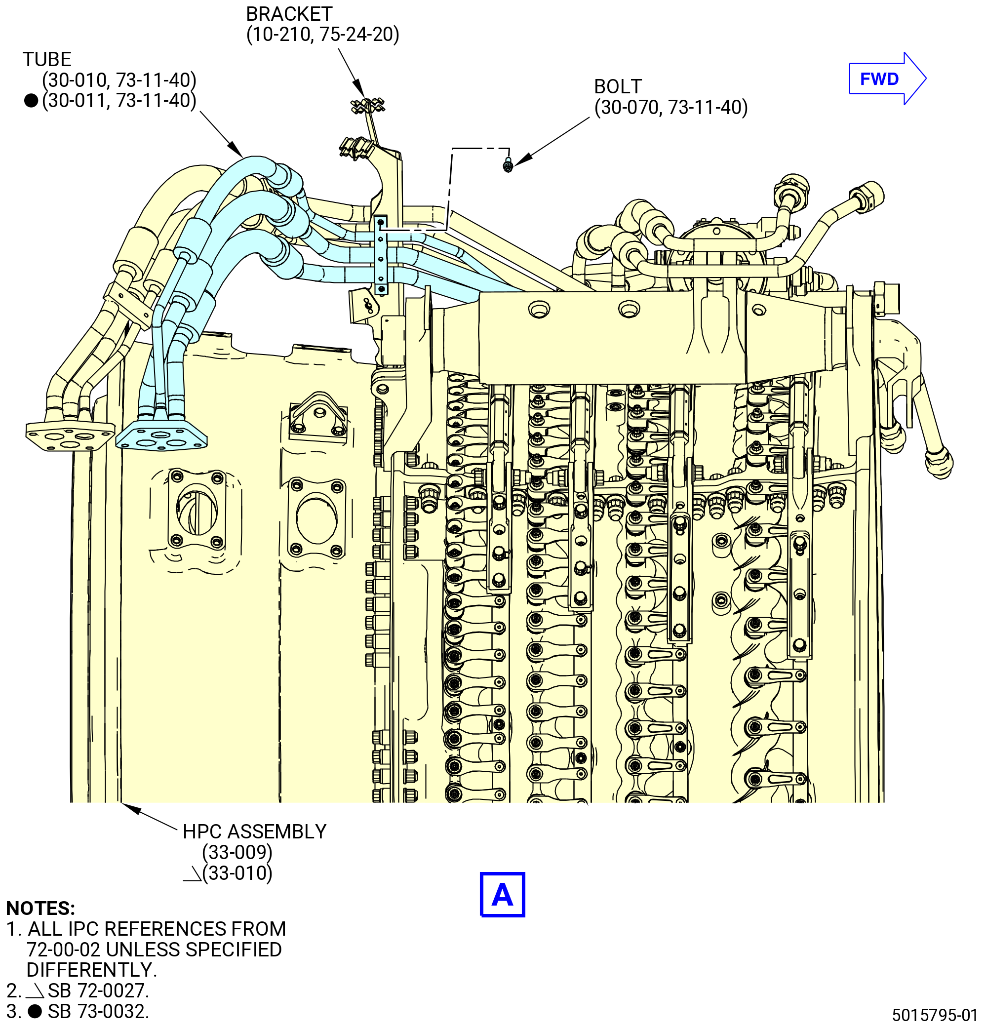
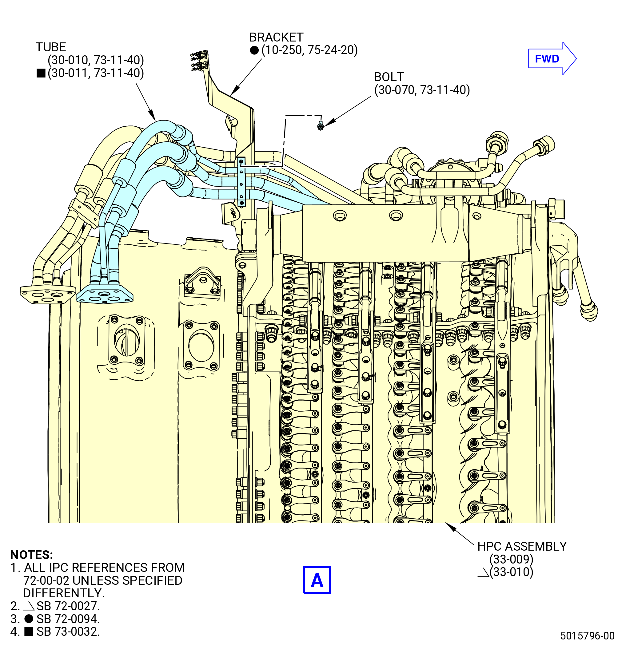
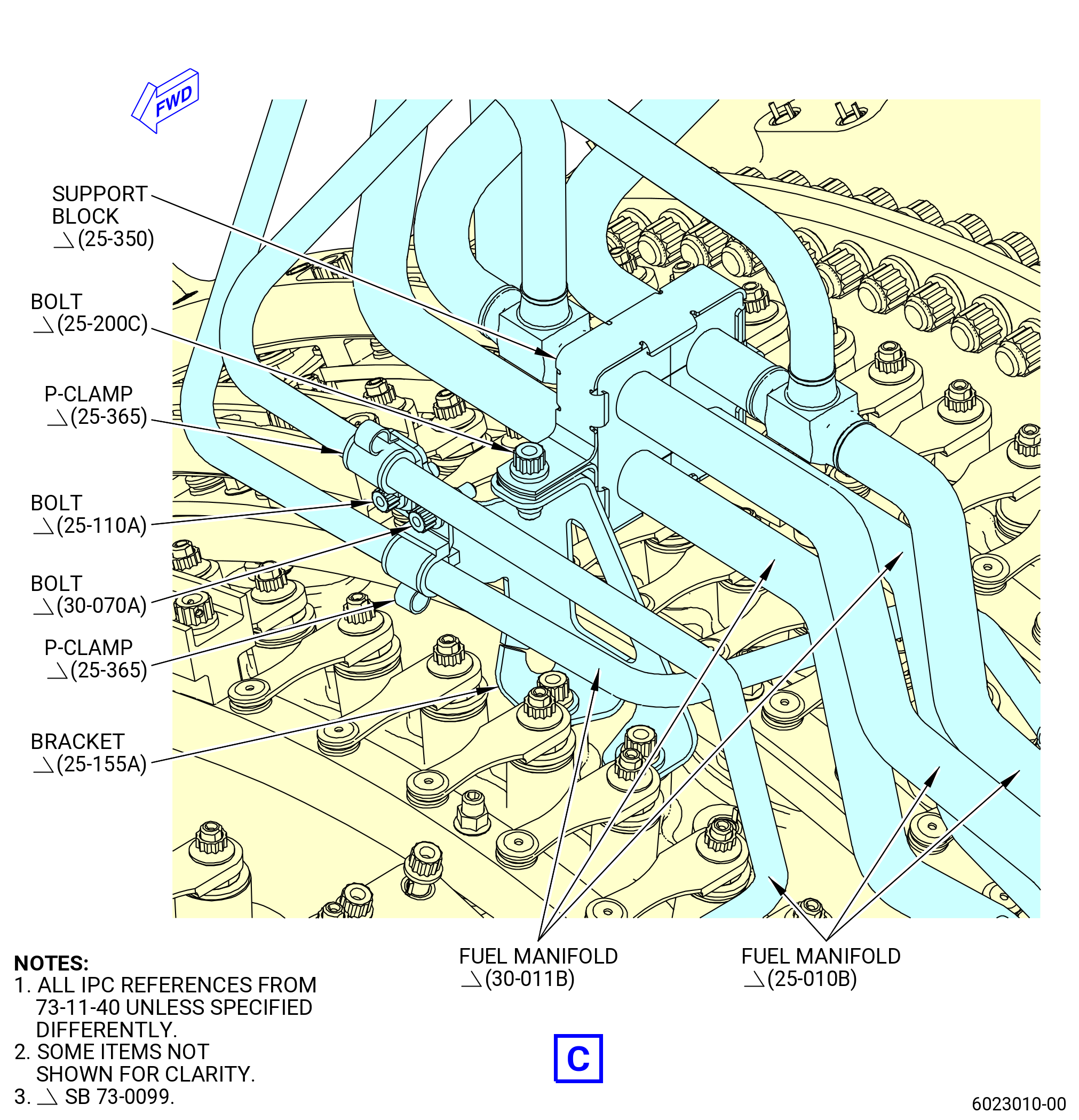
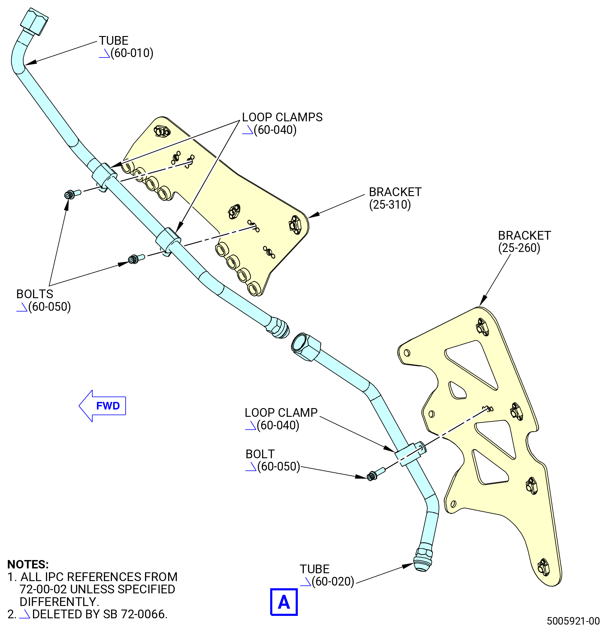
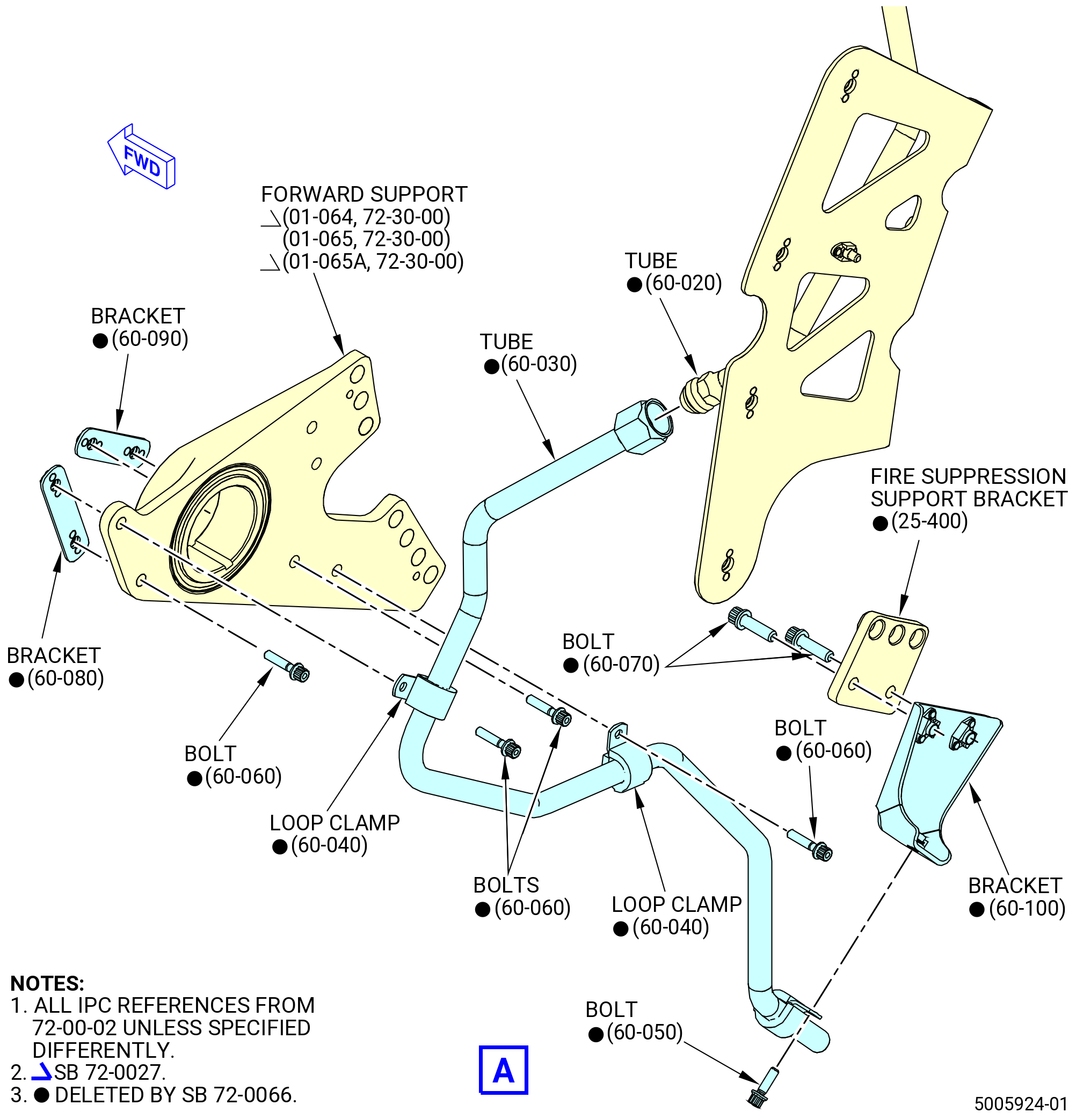
| (5) | Attach the tube (01-060 , 75-42-10) (SIN 61501) to the VSV/VBV bracket (bracket) (10-210 , 75-24-20) (SIN 38116), VSV support bracket (bracket) (10-250 , 75-24-20) (SIN 38116) or VSV support bracket (bracket) (10-250D, 75-24-20) (SIN 38116) with a cushion loop clamp (loop clamp) (01-070 , 75-42-10) (SIN 61581) and a machine bolt (bolt) (01-080 , 75-42-10) (SIN 61521). Install the loop clamp with the loop up. |
| (6) | Attach the tube (01-060 , 75-42-10) (SIN 61501) to the support bracket (bracket) (01-090 , 75-42-10) (SIN 53010) or (01-090A , 75-42-10) (SIN 53010) with a loop clamp (01-070 , 75-42-10) (SIN 61581) and a bolt (01-080 , 75-42-10) (SIN 61521). Install the loop clamp with the loop inboard and down. |
| (7) | Deleted. |
| (8) | Attach the tube (01-060 , 75-42-10) (SIN 61501) to the support bracket (bracket) (01-120 , 75-42-10) (SIN 53012) or (01-120A , 75-42-10) (SIN 53012) with a loop clamp (01-070 , 75-42-10) (SIN 61581) and a bolt (01-080 , 75-42-10) (SIN 61521). Install the loop clamp with the loop up. |
| (9) | Attach the tube (61501) to the bracket (53011) with a loop clamp (61581) and a bolt (61521). Install the loop clamp with the loop down. |
| (10) | Attach the tube (61501) to the bracket (37310) with a loop clamp (61581) and a bolt (61521). Install the loop clamp with the loop down. |
| (11) | Attach the tube (61501) to the bracket (44410) with a loop clamp (61581) and a bolt (61521). Install the loop clamp with the loop up. |
| (12) | Attach the tube (61501) to the bracket (44811) with a loop clamp (61581) and a bolt (61521). Install the cushioned clamp with the loop down. |
| (13) | Torque the B-nut on the tube (61500) as follows: |
| (a) | Torque the B-nut to 262-308 lb in. (29.6-34.8 N.m). |
| (b) | Loosen the B-nut until the B-nut is loose and then apply torque again to 262-308 lb in. (29.6-34.8 N.m). |
| (c) | Apply a final torque of 262-308 lb in. (29.6-34.8 N.m) to the B-nut. |
| (14) | Torque the B-nut on tube (61501) as follows: |
| (a) | Torque the B-nut to 262-308 lb in. (29.6-34.8 N.m). |
| (b) | Loosen the B-nut until the B-nut is loose and then apply torque again to 262-308 lb in. (29.6-34.8 N.m). |
| (c) | Apply a final torque of 262-308 lb in. (29.6-34.8 N.m) to the B-nut. |
| (15) | Safety the B-nut with C10-071 safety wire or C10-143 safety cable. |
| (16) | Torque the bolts (61522) to 60-70 lb in. (6.8-7.9 N.m). Make sure that the loop clamps do not get twisted when the bolts are torqued. |
| (17) | Torque the bolts (61521) to 32-38 lb in. (3.6-4.3 N.m). Make sure that the loop clamps do not get twisted when the bolts are torqued. |
|
|
| Subtask 72-00-02-440-116 |
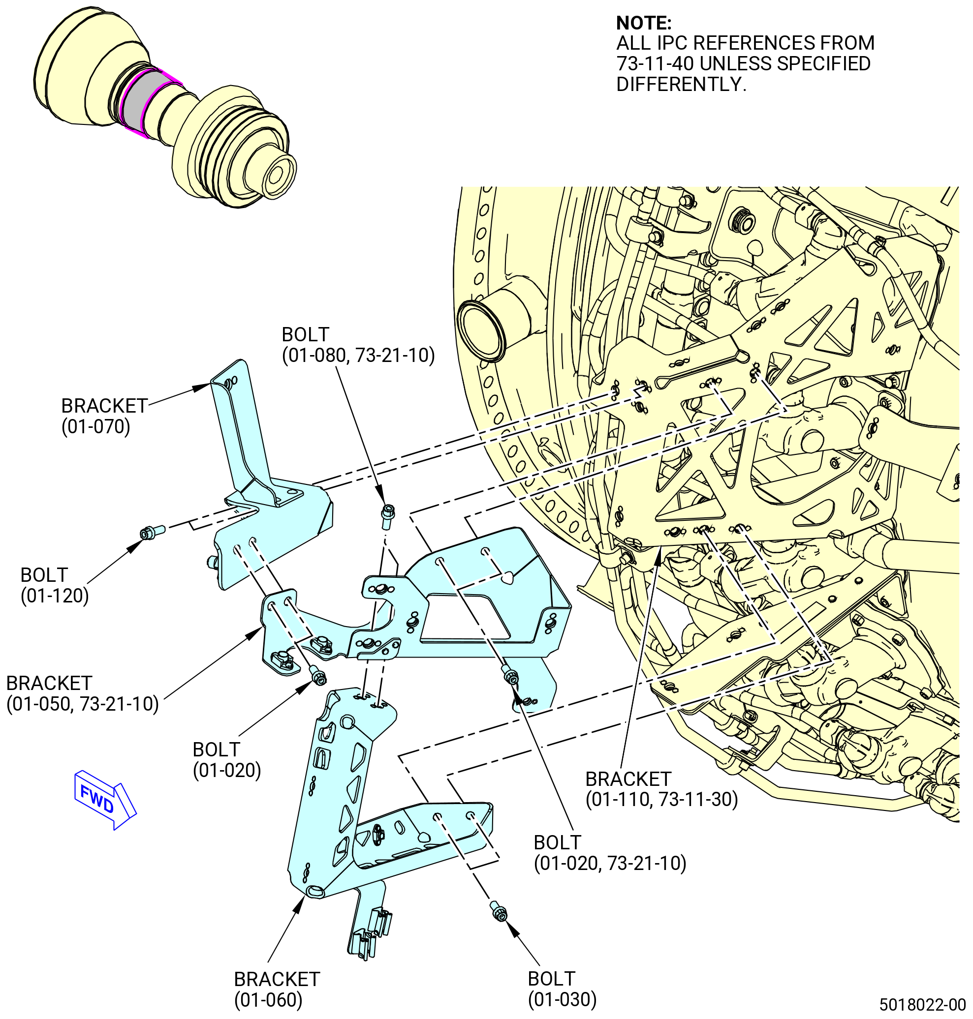
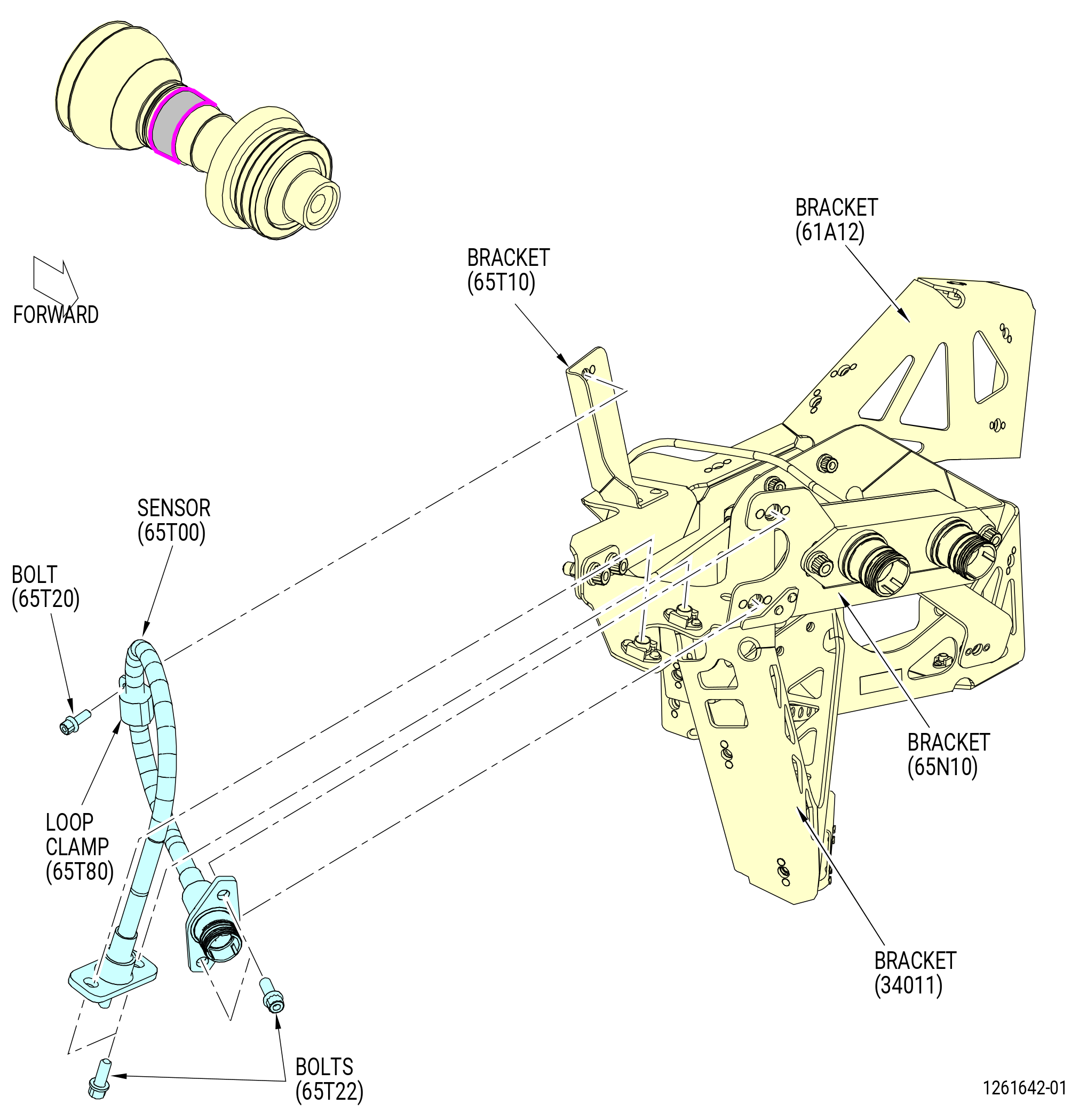
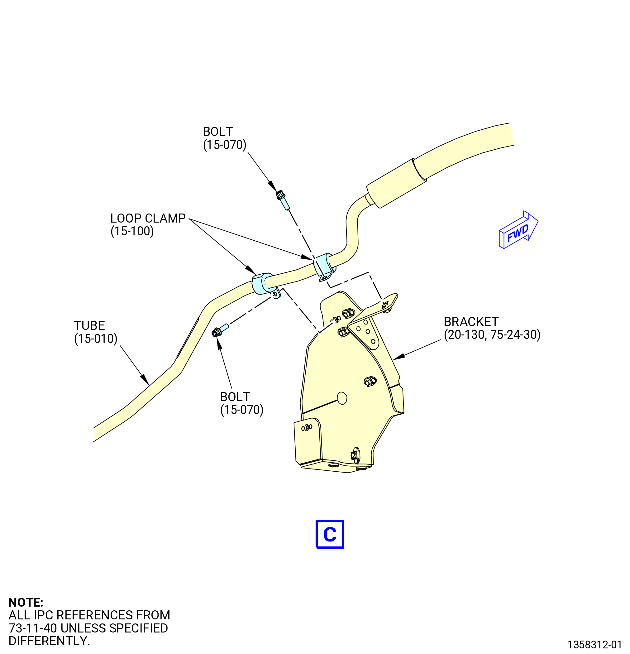
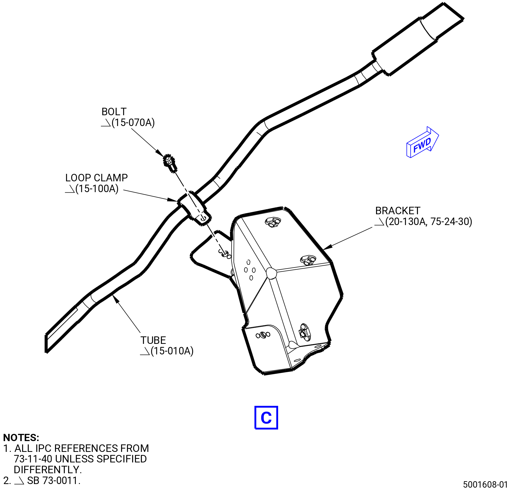
| G. | Install the T3 sensor (65N00) as follows. Refer to Figure 1008. |
| (1) | Install the bracket (34011) as follows: |
| (a) | Put the bracket (34011) in position on the bracket (61A12). |
| (b) | Attach the bracket with bolts (34020). |
| (c) | Torque the bolts to 106-124 lb in. (12.0-14.0 N.m). |
| (2) | Install the bracket (65N10) as follows: |
| (a) | Put the bracket (65N10) in position on the bracket (34011) and the bracket (61A12). |
| (b) | Attach the bracket (65N10) with bolts (65N22) and bolts (34020). |
| (c) | Torque the bolts (65N22) to 106-124 lb in. (12.0-14.0 N.m). |
| (d) | Torque the bolts (34020) to 106-124 lb in. (12.0-14.0 N.m). |
| (3) | Install the bracket (65T10) as follows: |
| (a) | Put the bracket (65T10) in position on the bracket (65N10) and the bracket (61A12). |
| (b) | Attach the bracket (01-070 , 73-11-40) (SIN 65T10) with bolts (01-020 , 73-11-40) (SIN 65N22) and bolts (01-120 , 73-11-40) (SIN 65T22). |
| (c) | Torque the bolts (65N22) to 106-124 lb in. (12.0-14.0 N.m). |
| (d) | Torque the bolts (01-120 , 73-11-40) (SIN 65T22) to 106-124 lb in. (12.0-14.0 N.m). |
| WARNING: |
|
| (4) | Apply C02-058 lubricant to the threads of the B-nut on the T3 sensor (65N00) |
| (5) | Connect the B-nut of the T3 sensor to the T3 insert (01-060 , 73-21-10) (SIN 65N70) of the combustor case (01-080 , 72-41-00) (SIN 12001). |
| (6) | Put the T3 sensor on the bracket (65N10). Attach the T3 sensor with bolts (65N22). |
| (7) | Attach the T3 sensor to the bracket (61A12) with loop clamps (65N80) and bolts (65N21). |
| (8) | Torque the B-nut of the T3 sensor to 262-308 lb in. (29.6-34.8 N.m) |
| (9) | Safety the B-nut with C10-071 safety wire or C10-143 safety cable. |
| (10) | Torque the bolts (65N22) on the T3 sensor to 106-124 lb in. (12.0-14.0 N.m). |
| (11) | Torque the bolts (01-030 , 73-21-10) (SIN 65N21) to 32-38 lb in. (3.6-4.3 N.m). |
| Subtask 72-00-02-440-117 |
| H. | Install the core compartment temperature sensor (sensor) (65T00) as follows. Refer to Figure 1008. |
| (1) | Put the sensor in position on the bracket (65N10) |
| (2) | Attach with bolts (65T22). |
| (3) | Attach the sensor to the bracket (65T10) with a loop clamp (65T80) and a bolt (65T20). |
| (4) | Torque the bolts (65T22) to 106-124 lb in. (12.0-14.0 N.m). |
| (5) | Torque the bolts (65T20) to 32-38 lb in. (3.6-4.3 N.m). |
| Subtask 72-00-02-440-118 |
| I. | Install the sump eductor as follows: |
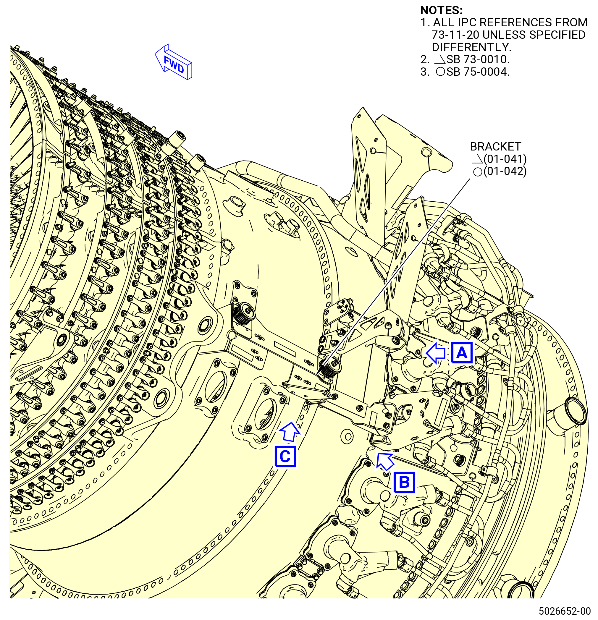
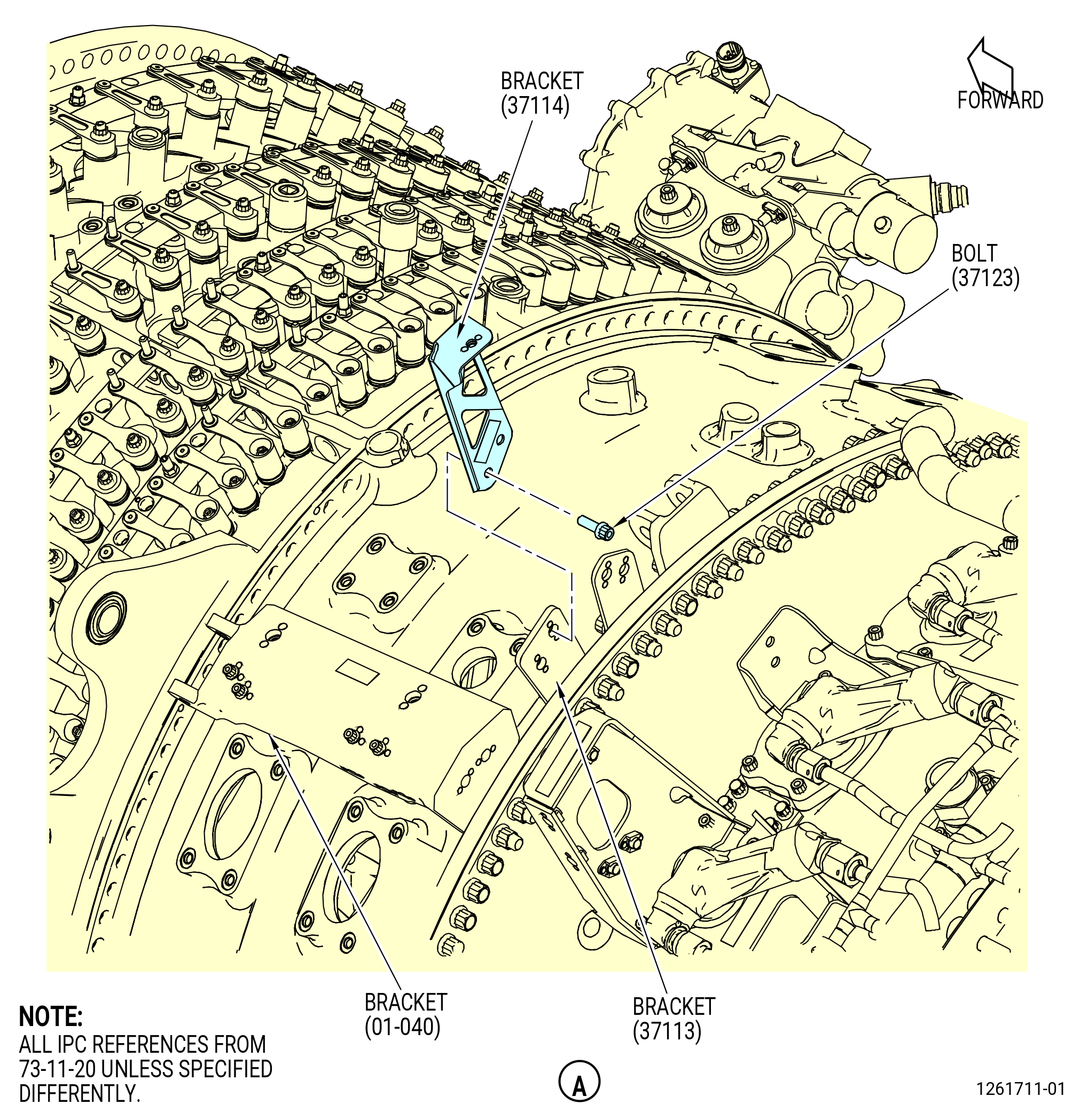
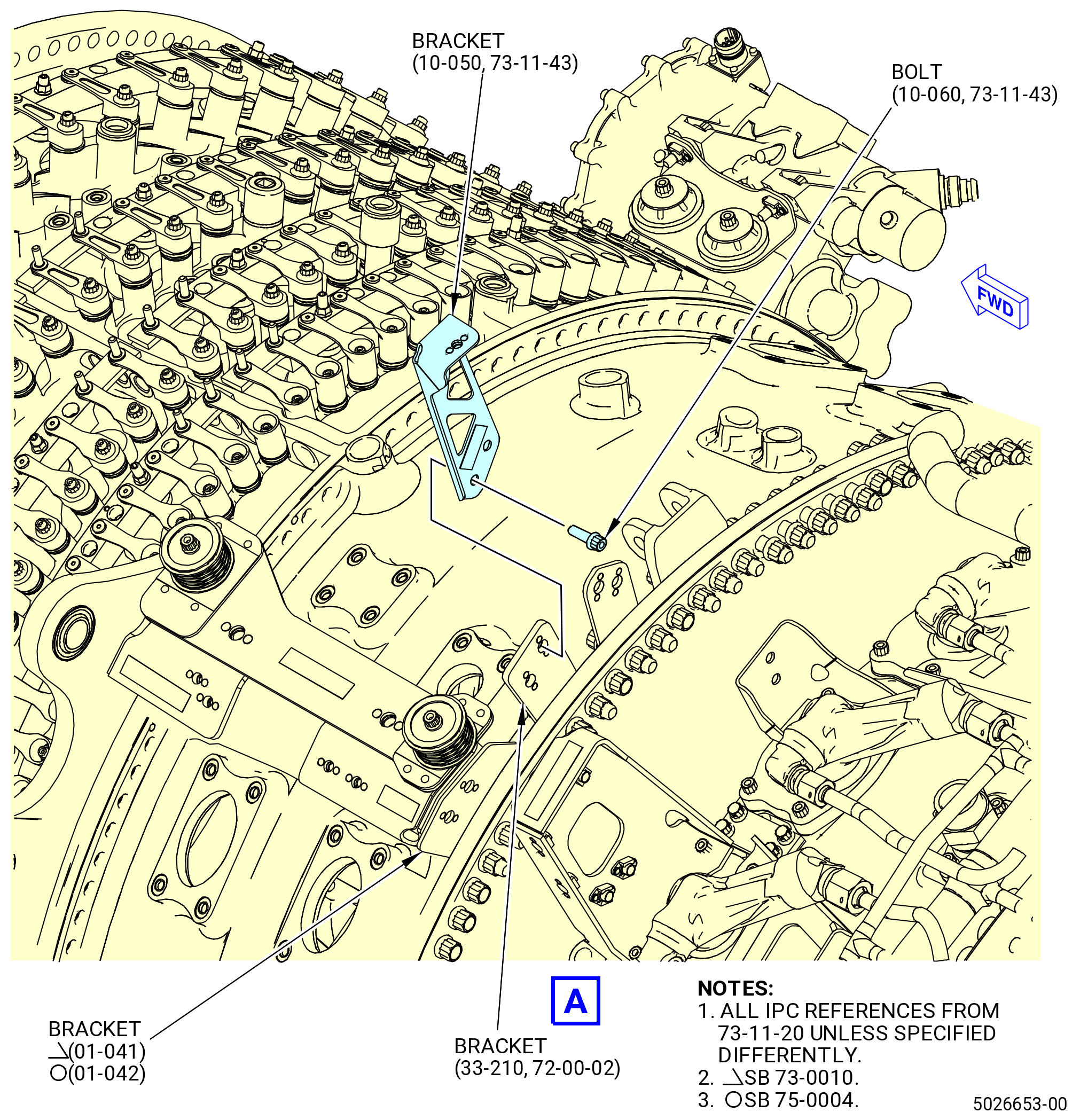
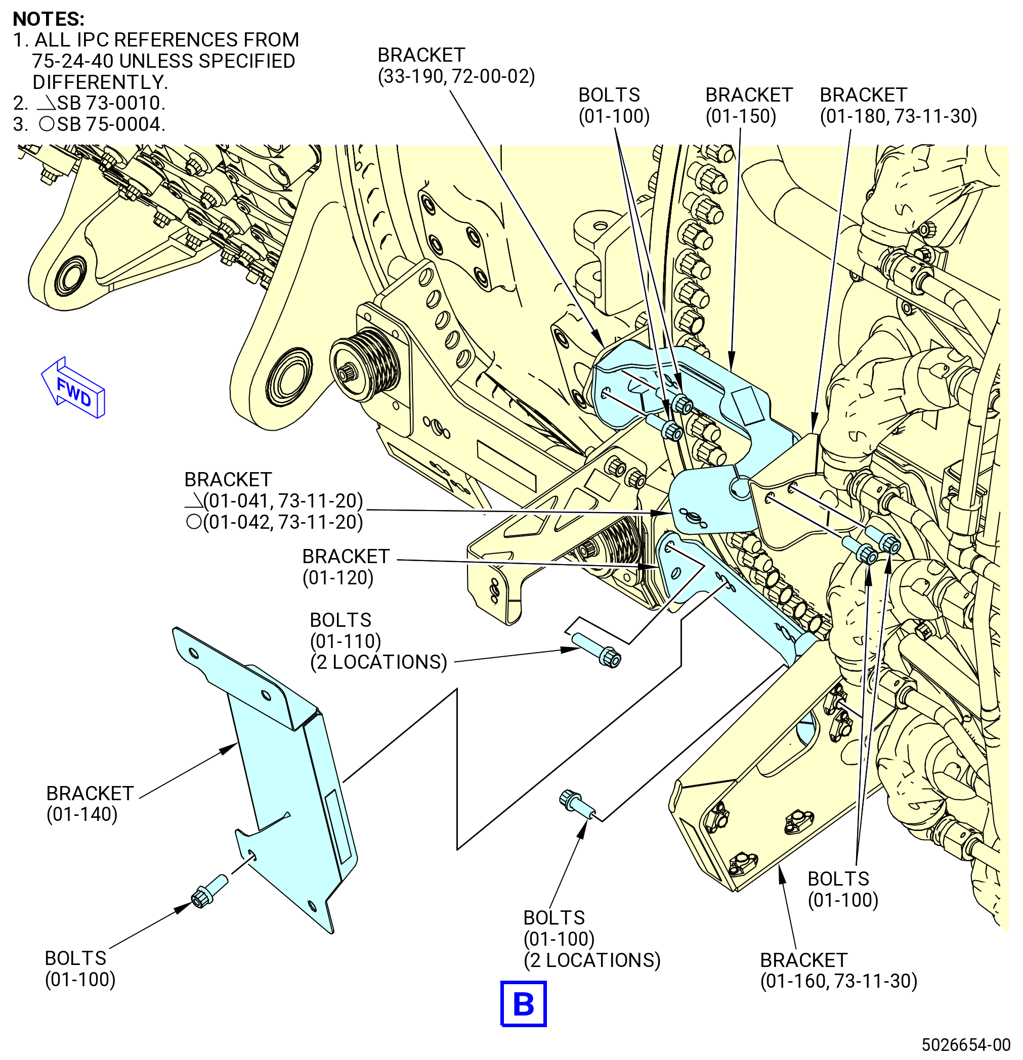
| (1) | Install the sump eductor brackets on the combustor case (01-080 , 72-41-00) (SIN 12001). Refer to Figure 1009 and do as follows: |
| (a) | Install the bracket (37114) to the aft side of the bracket (37113). Attach the bracket with bolts (37123). |
| (b) | Torque the bolts (37123) to 106-124 lb in. (12.0-14.0 N.m). |
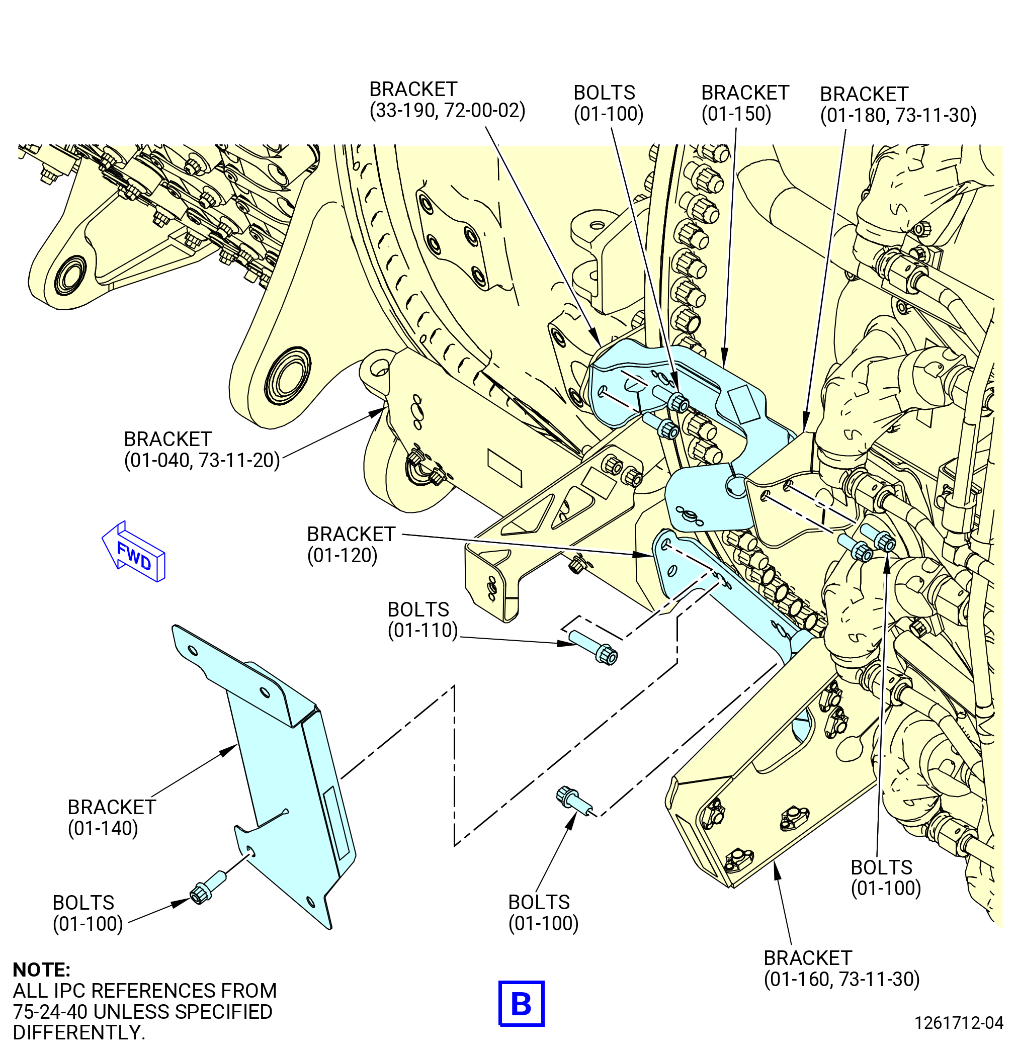
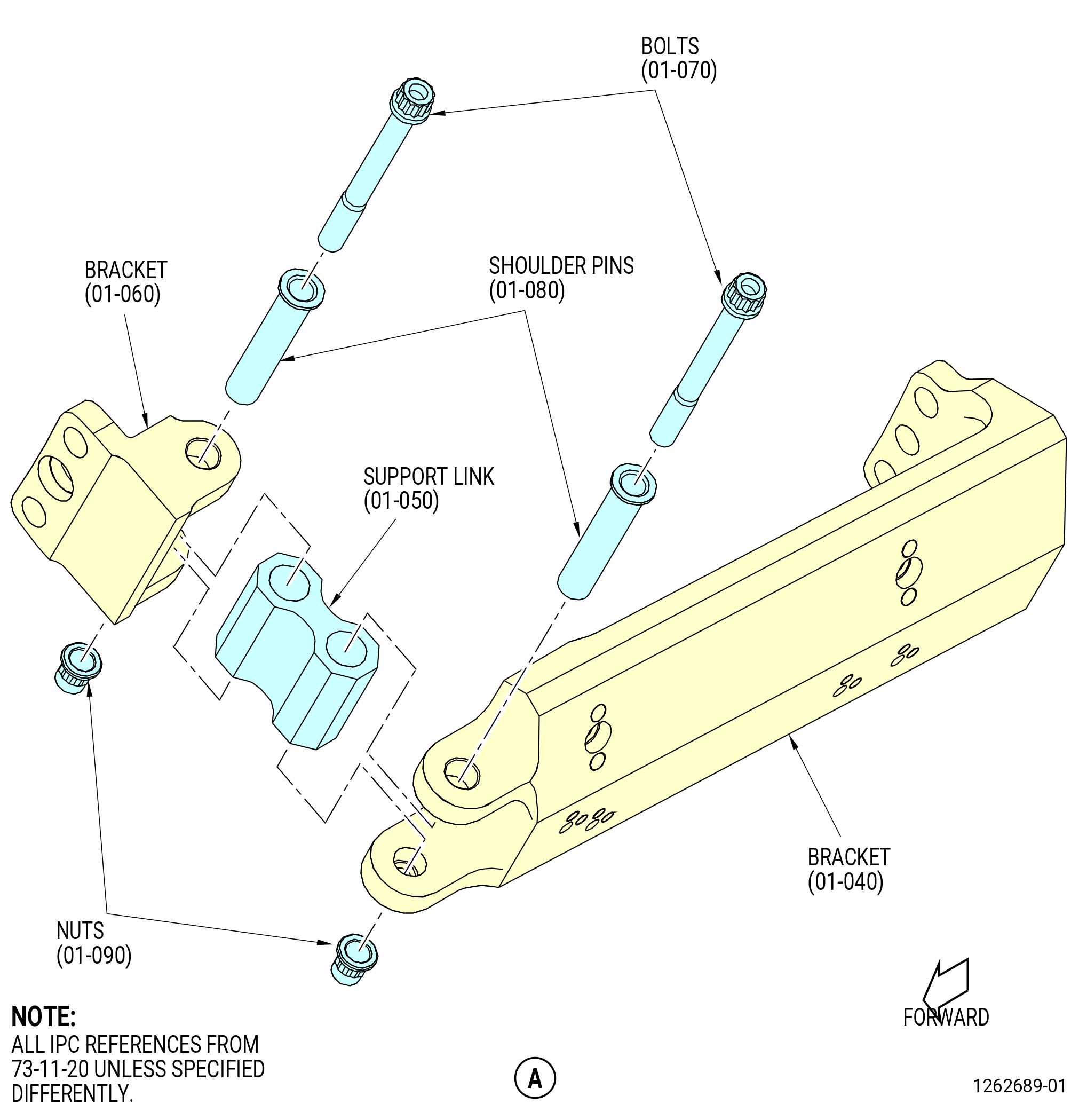
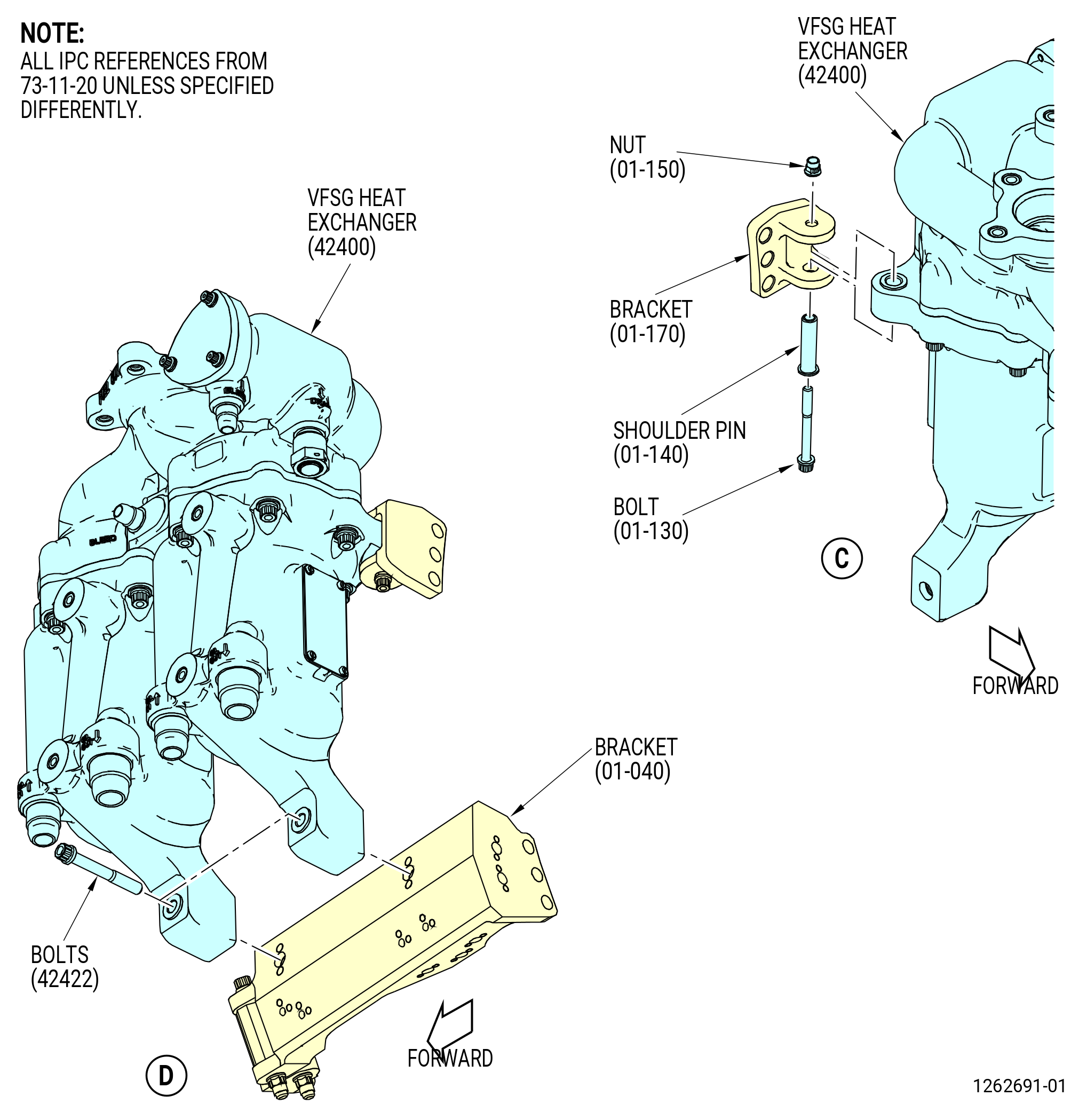
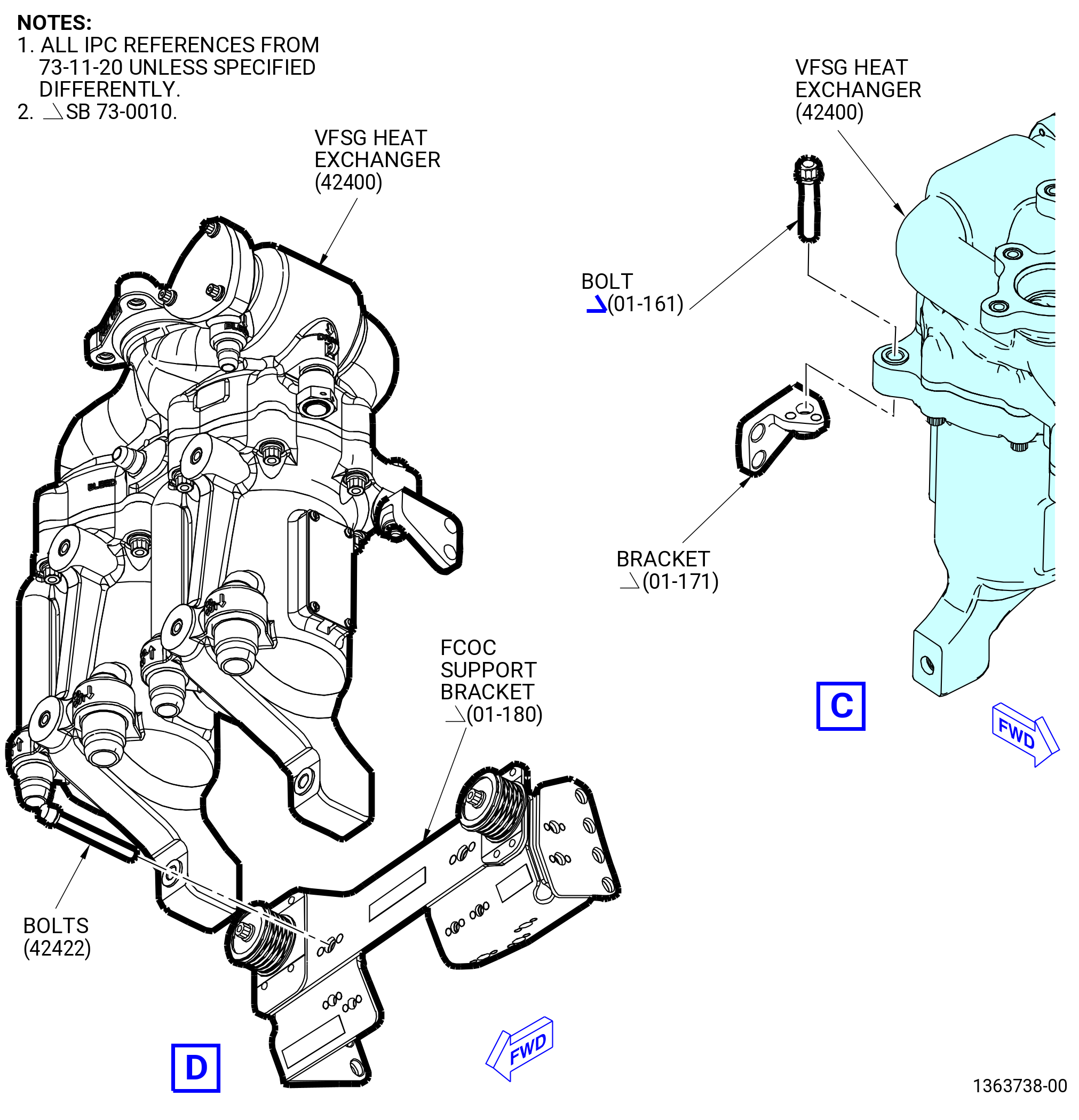
| (c) | Install the bracket (01-120 , 75-24-40) (SIN 61B11) on the bracket (01-160 , 73-11-30) (SIN 6111A). Attach the bracket with bolts (01-100 , 75-24-40) (SIN 61B22). |
| (d) | Attach the bracket (01-120 , 75-24-40) (SIN 61B11) to the FCOC modification bracket (bracket) (01-040 , 73-11-20) (SIN 42412), (01-041 , 73-11-20) (SIN 42412), or (01-042 , 73-11-20) (SIN 42412) with bolts (01-110 , 75-24-40) (SIN 61B24). |
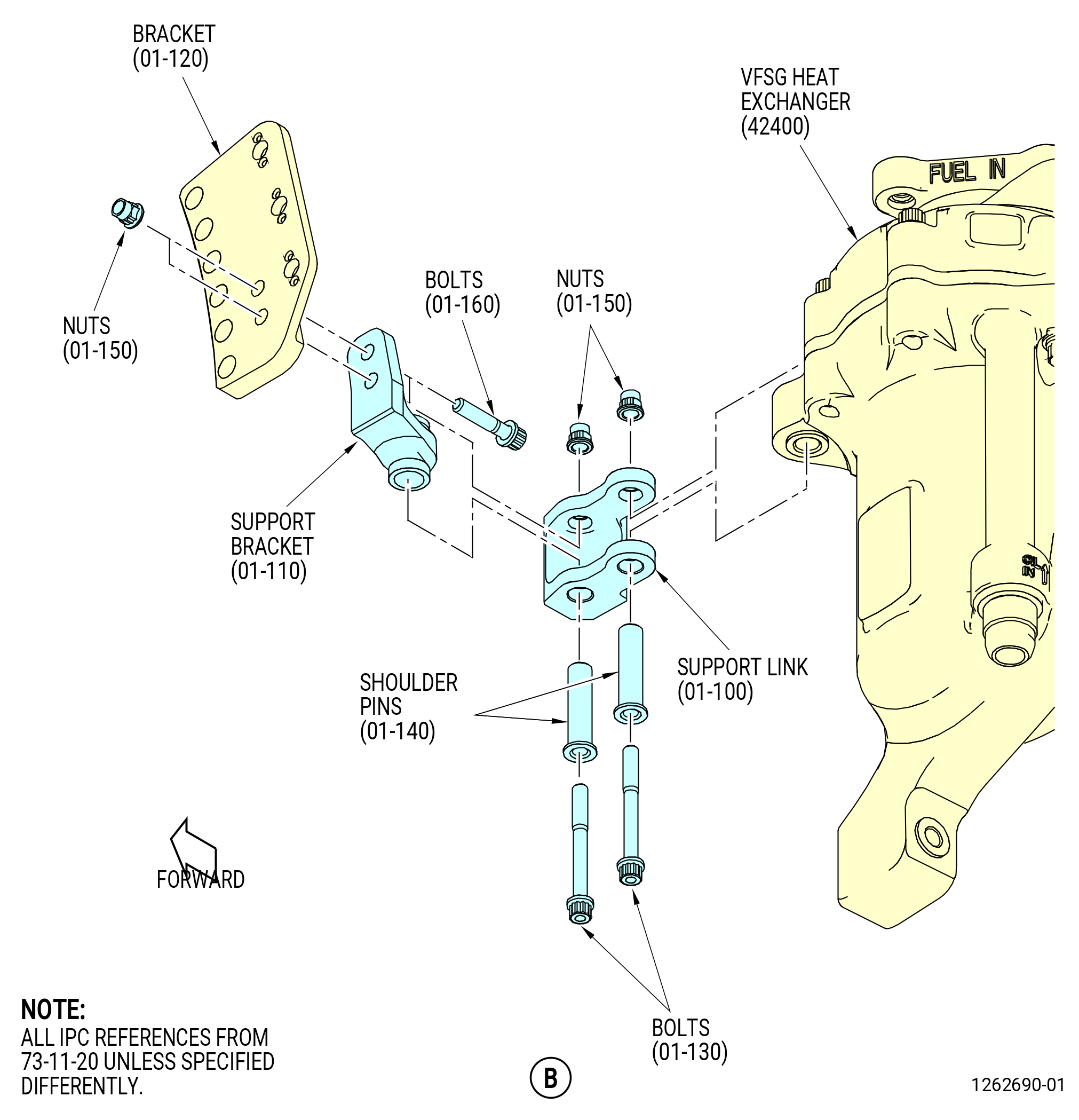
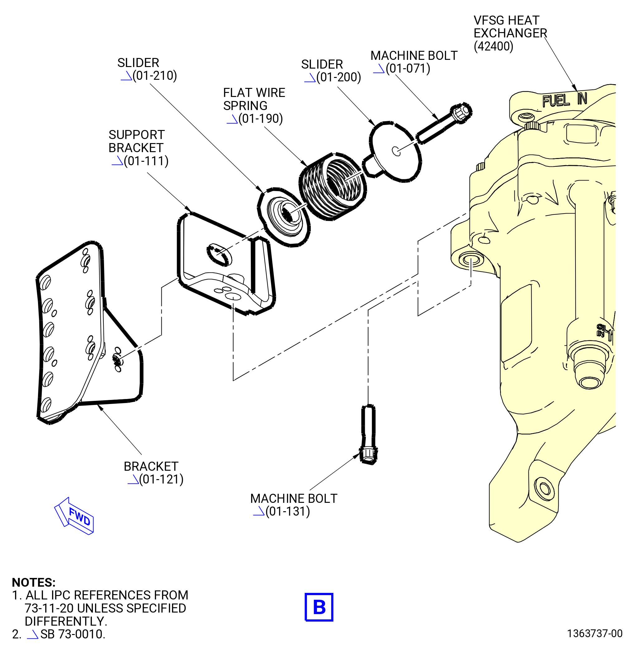
| (e) | Install the bracket (01-150 , 75-24-40) (SIN 61B16) on the bracket (01-180 , 73-11-30) (SIN 61B18). Attach the bracket with bolts (01-100 , 75-24-40) (SIN 61B22). |
| (f) | Attach the bracket (01-150 , 75-24-40) (SIN 61B16) to the bracket (33-190) (SIN 61B10) with bolts (01-100 , 75-24-40) (SIN 61B22). |
| (g) | Torque the bolts (01-100 , 75-24-40) (SIN 61B22) to 106 to 124 lb in. (12.0 to 14.0 Nm). |
| (h) | Install the bracket (01-140 , 75-24-40) (SIN 61B14) on the bracket (01-150 , 75-24-40) (SIN 61B16) and the bracket (01-120 , 75-24-40) (SIN 61B11). Attach the bracket with bolts (01-100 , 75-24-40) (SIN 61B22). Do not tighten the bolts at this time. |
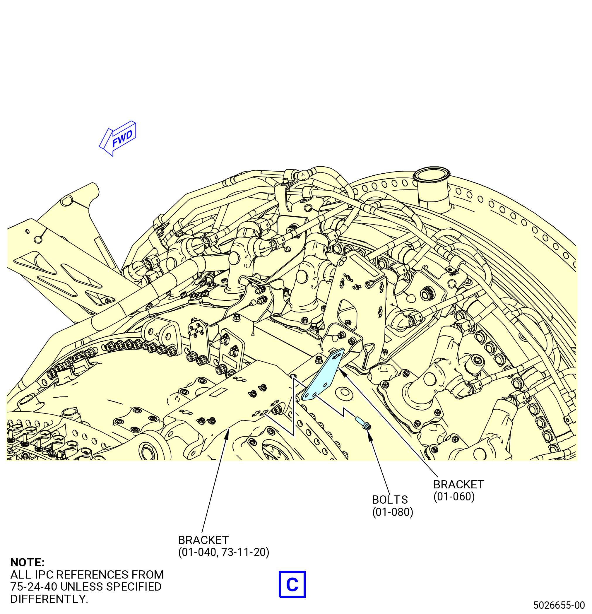
| * * * PRE SB 75-0004( Air Tube with Three One-to-One Bends ) |
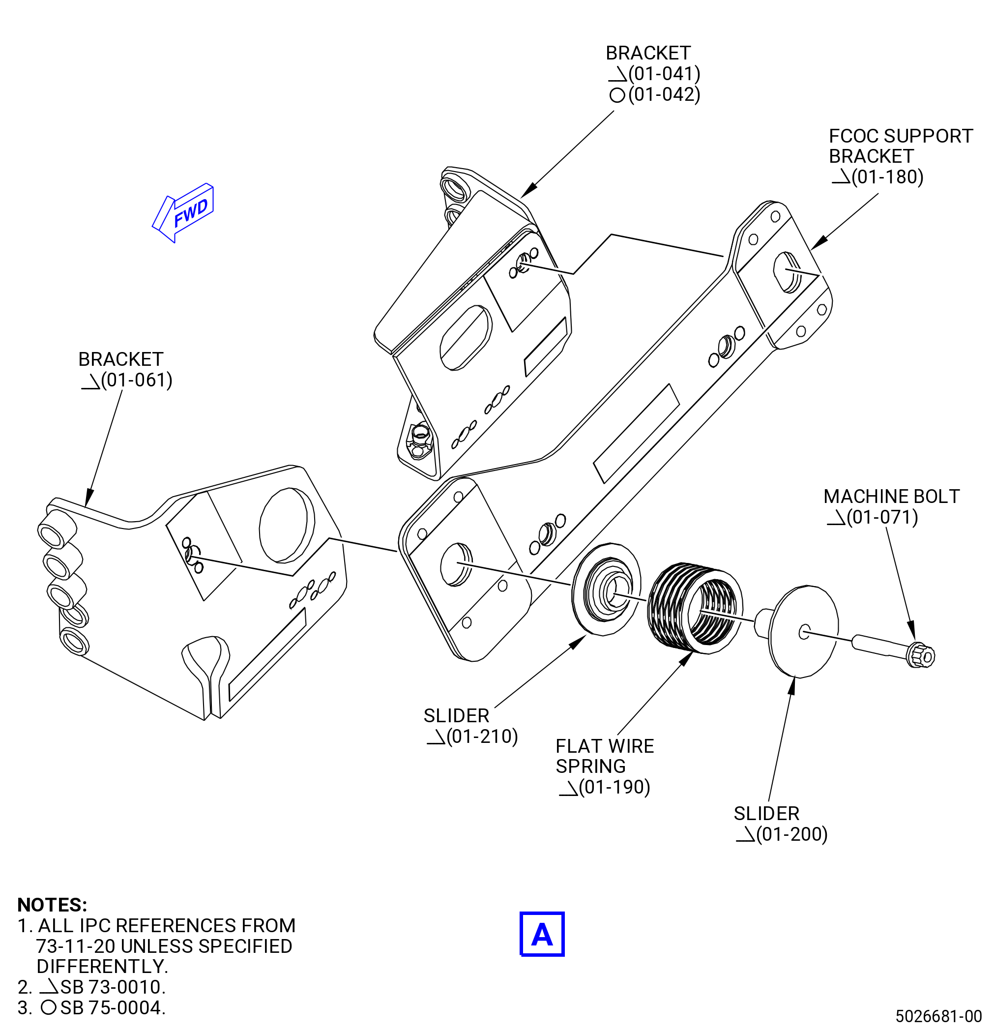
| (i) | Install the bracket (01-060 , 75-24-40) (SIN 61B17) on the bracket (01-040 , 73-11-20) (SIN 42412) or (01-041 , 73-11-20) (SIN 42412). Attach the bracket (01-060 , 75-24-40) (SIN 61B17) with bolts (01-080 , 75-24-40) (SIN 61B21). |
| * * * END PRE SB 75-0004 |
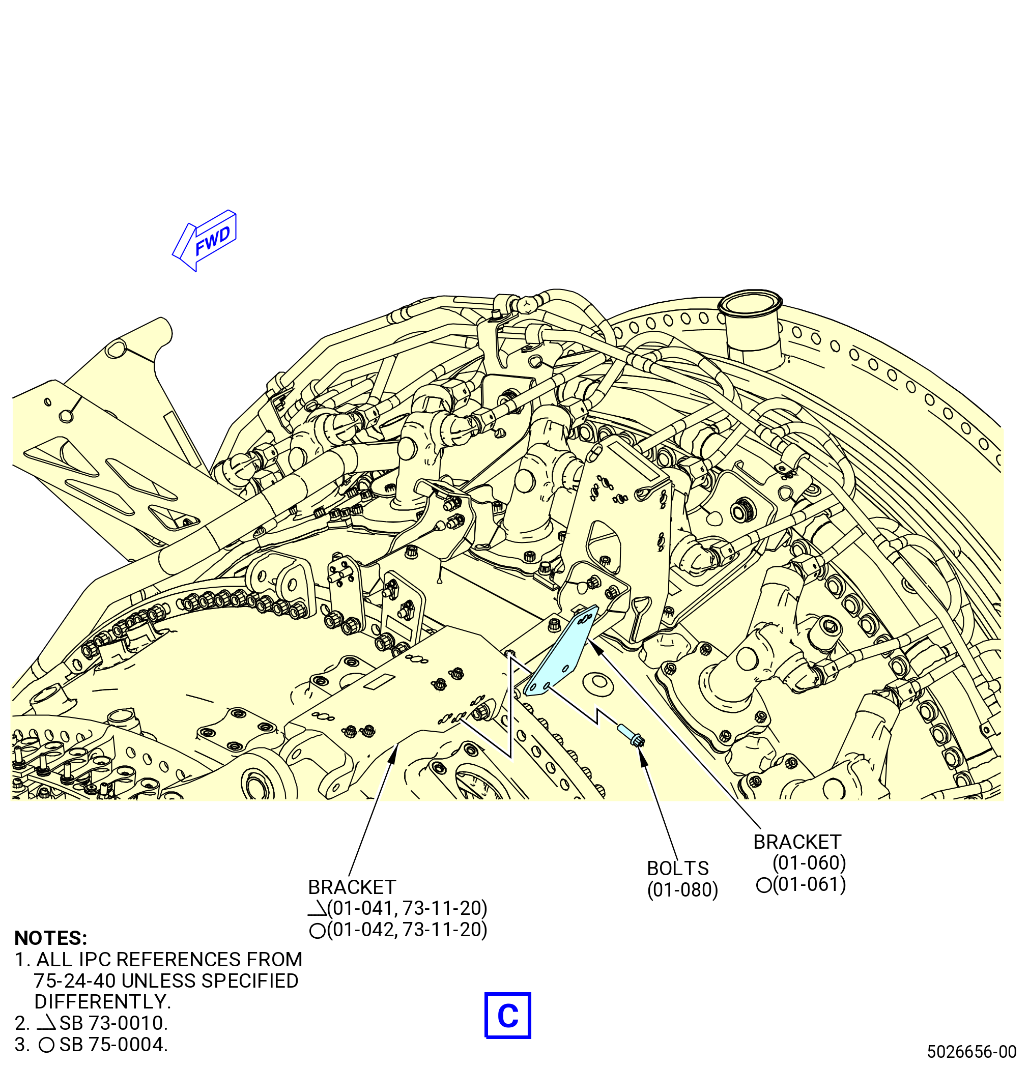
| * * * SB 75-0004( New Air Tube Design ) |
| (i).A. | Install the bracket (01-061 , 75-24-40) (SIN 61B17) on the bracket (01-042 , 73-11-20) (SIN 42412). Attach the bracket (01-061 , 75-24-40) (SIN 61B17) with bolts (01-080 , 75-24-40) (SIN 61B21). |
| 1 | Deleted. |
| * * * END SB 75-0004 |
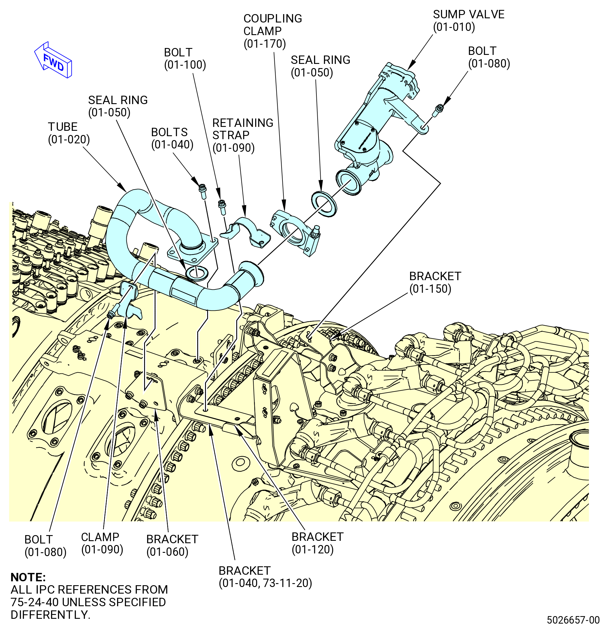
| (j) | Torque the bolts (61B21) to 106-124 lb in. (12.0-14.0 N.m). |
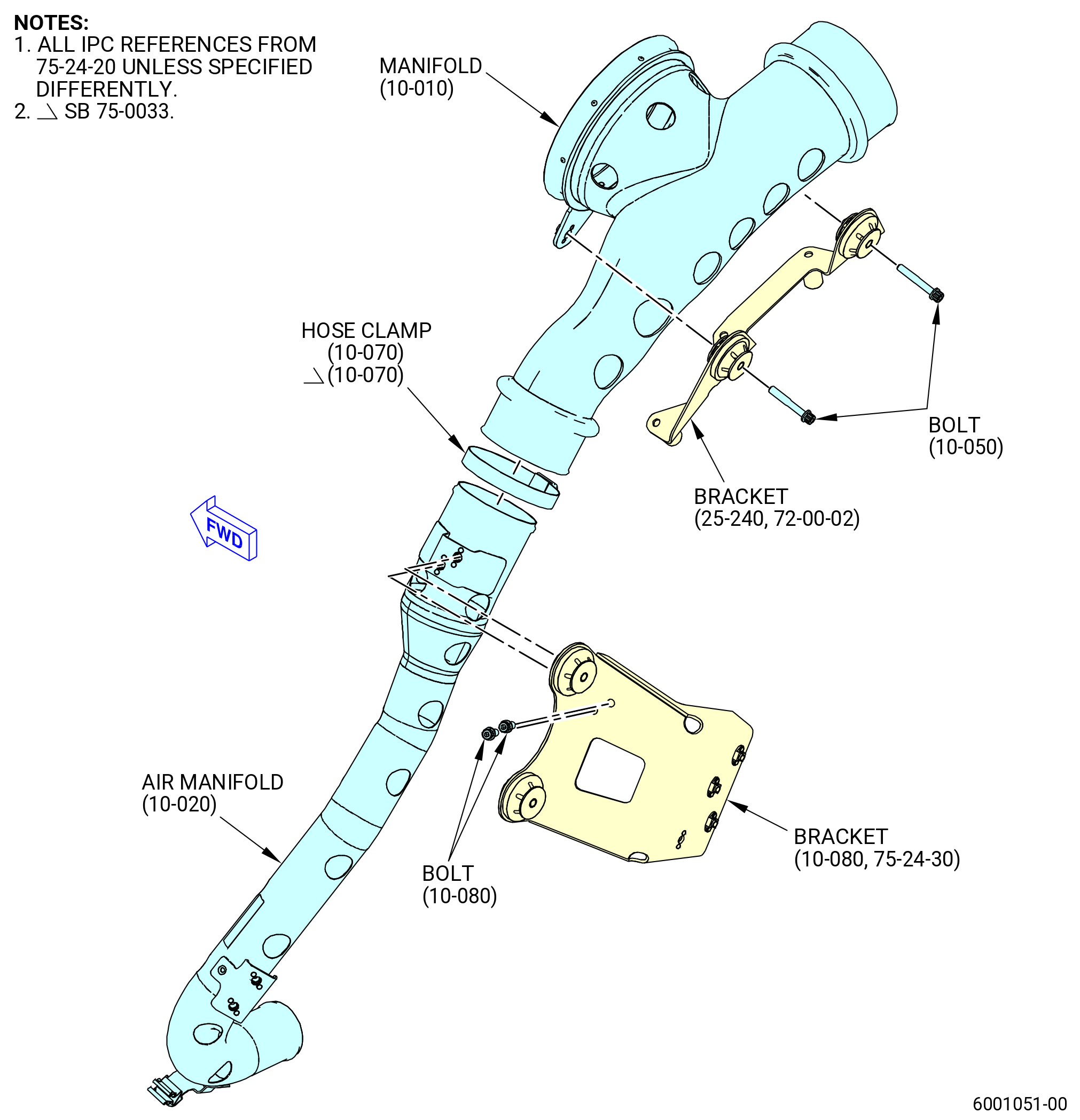
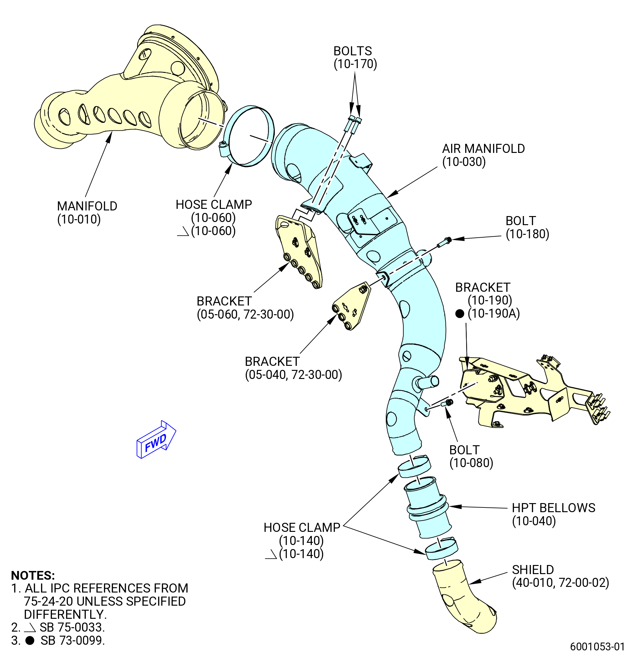
| (2) | Install a seal ring (01-050 , 75-24-40) (SIN 61B50) on the end of the air-eductor tube (tube) (01-020 , 75-24-40) (SIN 61B00) or (01-021 , 75-24-40) (SIN 61B00). |
| (3) | Install the tube (01-020 , 75-24-40) (SIN 61B00) or (01-021 , 75-24-40) (SIN 61B00) on the extension case (10-080 , 72-30-00) (SIN 080AL) at the 9:00 o'clock position. Attach the tube with bolts (01-040 , 75-24-40) (SIN 61B20). |
| (3).A. | Deleted. |
| Subtask 72-00-02-440-512 |
| * * * PRE SB 75-0004( Air Tube with Three One-to-One Bends ) |
| (4) | Attach the tube (01-020 , 75-24-40) (SIN 61B00) or (01-021 , 75-24-40) (SIN 61B00) to the bracket (01-060, 75-24-40) (SIN 61B17) with a retaining strap (01-090, 72-24-40) (SIN 61B80) and bolts (01-080, 75-24-40) (SIN 61B21). |
| * * * END PRE SB 75-0004 |
| Subtask 72-00-02-440-513 |
| * * * SB 75-0004( New Air Tube Design ) |
| (4).A. | Attach the tube (01-021 , 75-24-40) (SIN 61B00) to the bracket (01-061 , 75-24-40) (SIN 61B17) with a retaining strap (01-090 , 72-24-40) (SIN 61B80) and bolts (01-080 , 75-24-40) (SIN 61B21). |
| * * * END SB 75-0004 |
| Subtask 72-00-02-440-514 |
| (5) | Attach the tube (01-020 , 75-24-40) (SIN 61B00) or (01-021 , 75-24-40) (SIN 61B00) to the bracket (01-120 , 75-24-40) (SIN 61B11) with a retaining strap (01-090 , 75-24-40) (SIN 61B80). Attach it with the bolts (01-100 , 75-24-40) (SIN 61B22) that were previously installed. |
| (6) | Torque the bolts (61B20) to 106-124 lb in. (12.0-14.0 N.m) in a criss-cross pattern. |
| (7) | Torque the bolts (01-080 , 75-24-40) (SIN 61B21) and bolts (01-100 , 75-24-40) (SIN 61B22) to 106 to 124 lb in. (12.0 to 14.0 Nm). |
| (8) | Install a seal ring (01-050 , 75-24-40) (SIN 61B50) on the end of the sump valve (60100). |
| (9) | Connect the sump valve (01-010 , 75-24-40) (SIN 60100) to the tube (01-020 , 75-24-40) (SIN 61B00) or (01-021 , 75-24-40) (SIN 61B00) with a coupling clamp (01-170 , 75-24-40) (SIN 61B82). Install the coupling clamp with the hinge forward and the nut outboard. |
| (10) | Attach the sump valve (60100) to the bracket (61B16) with a bolt (61B21). |
| (11) | Torque the bolt (61B21) to 106-124 lb in. (12.0-14.0 N.m). |
| (12) | Torque the coupling clamp (61B82) to 60-70 lb in. (6.8-7.9 N.m). |
|
|
|
|
|
|
|
|
|
|
| Subtask 72-00-02-440-216 |
| CAUTION: |
|
| CAUTION: |
|
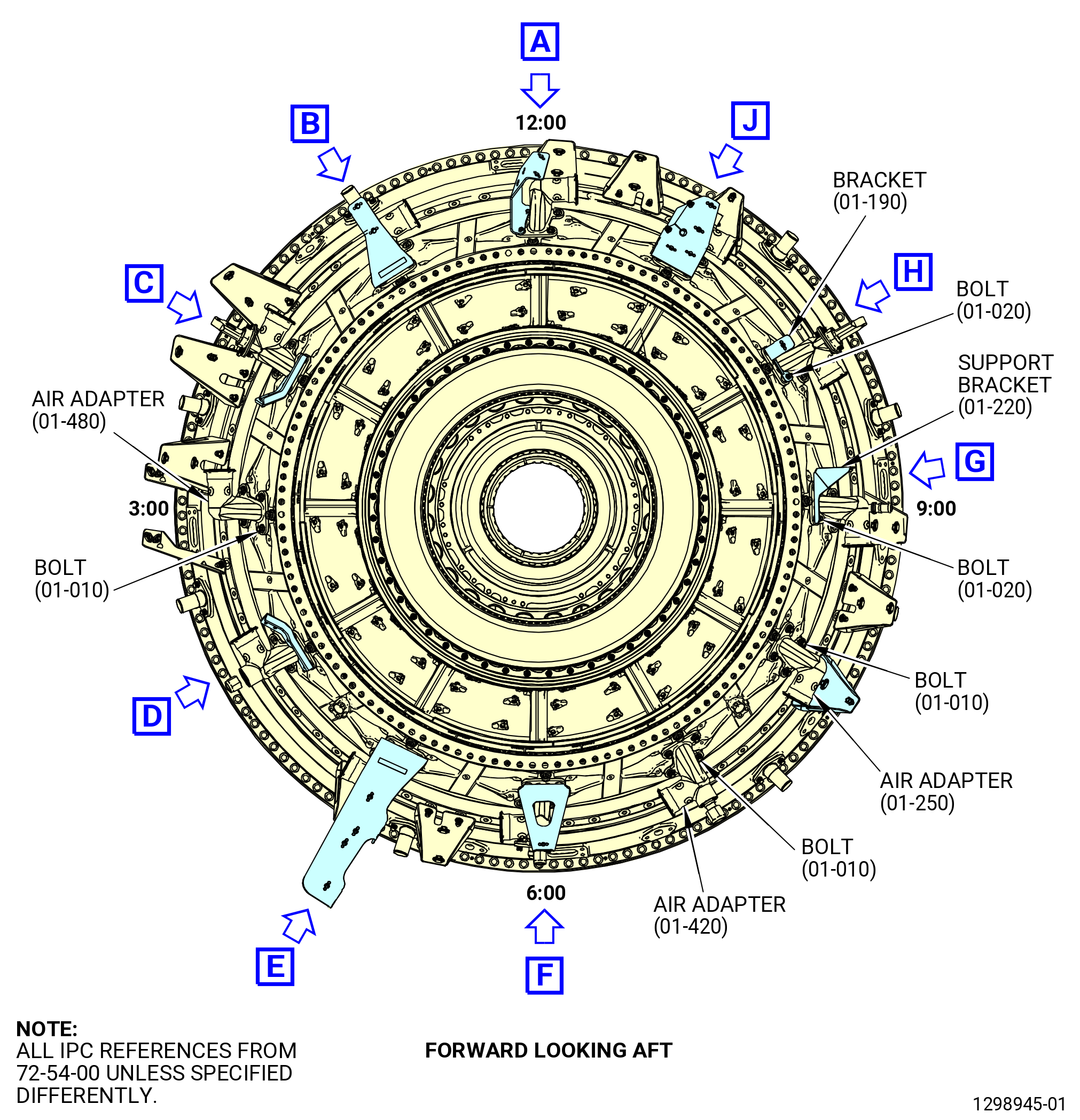
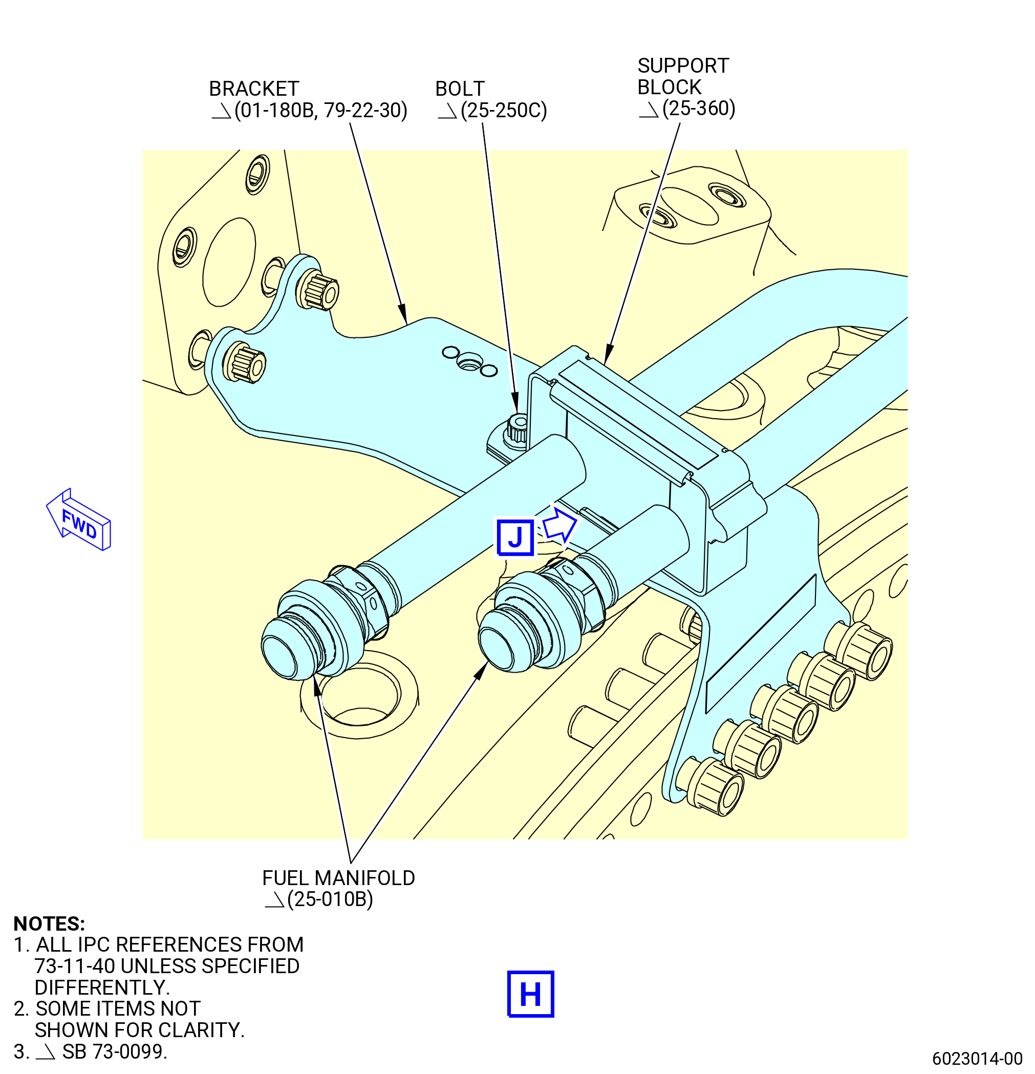
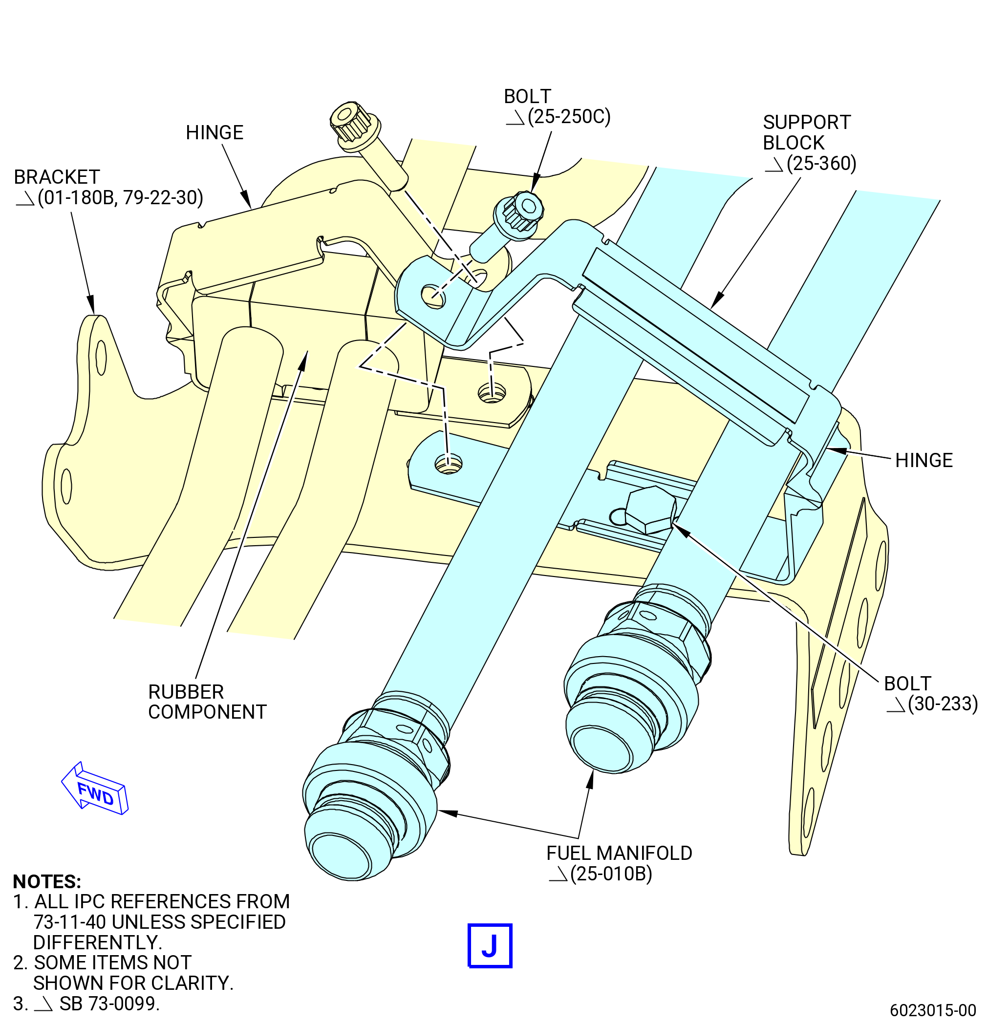
| J. | Install the support brackets (bracket) (01-040 , 72-54-00) (SIN 46111), (01-510 , 72-54-00) (SIN 46118), (01-490 , 72-54-00) (SIN 61A16), (01-460 , 72-54-00) (SIN 61A14), (01-260 , 72-54-00) (SIN 45210), (01-400 , 72-54-00) (SIN 45411), (01-220 , 72-54-00) (SIN 65512), (01-190 , 72-54-00) (SIN 65513), (01-100 , 72-54-00) (SIN 46114), (01-080 , 72-54-00) (SIN 46115) on the turbine center frame (TCF) assembly and torque the air/vent tubes and all air adapters. Refer to Figure 1010 and do as follows: |
| NOTE: |
|
| CAUTION: |
|
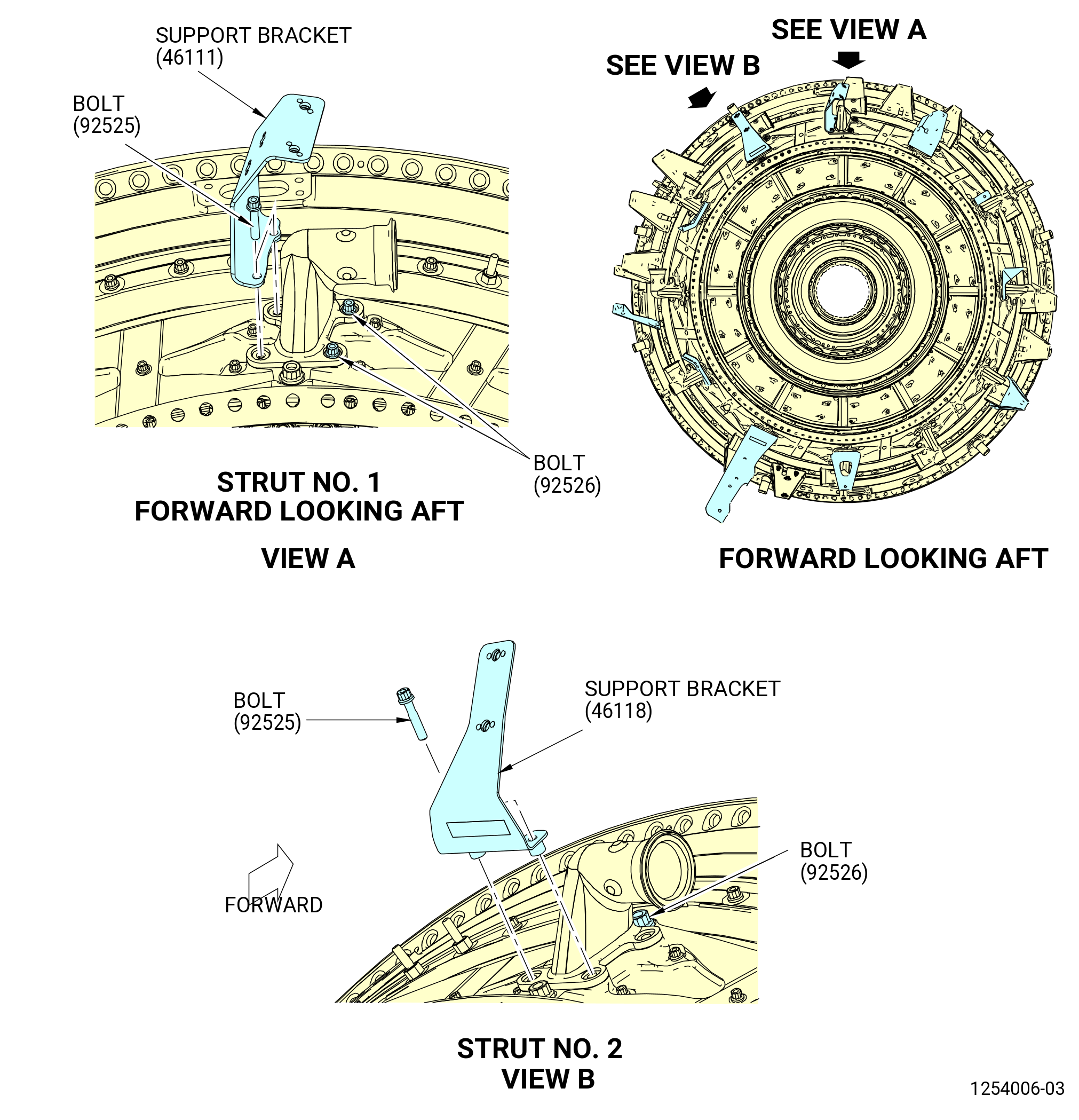
| (1) | Attach the support bracket (01-040 , 72-54-00) (SIN 46111) to the TCF assembly at the 12:00 o'clock position (strut No. 1) as follows: |
| (a) | Remove the two bolts (92525) from the air adapter (9250B). |
| (b) | Attach the support bracket (46111) to the air adapter with bolts (92525) at the bottom boltholes. |
| (c) | Torque the four bolts (01-020 , 72-54-00) (SIN 92525) and (01-010 , 72-54-00) (SIN 92526) that attach the air adapter in a criss-cross pattern to 106 to 124 lb in. (12.0 to 14.0 Nm). |
| (d) | Re-torque again all bolts in a criss-cross pattern to 106 to 124 lb in. (12.0 to 14.0 Nm). |
| (2) | Attach the support bracket (01-510 , 72-54-00) (SIN 46118) to the TCF assembly at the 1:00 o'clock position (strut No. 2) as follows: |
| (a) | Remove the two bolts (92525) from the air adapter (9250E). |
| (b) | Attach the support bracket (46118) to the air adapter with bolts (92525) at the bottom boltholes. |
| (c) | Torque the four bolts (01-020 , 72-54-00) (SIN 92525) and (01-010 , 72-54-00) (SIN 92526) that attach the air adapter in a criss-cross pattern to 106 to 124 lb in. (12.0 to 14.0 Nm). |
| (d) | Re-torque again all bolts in a criss-cross pattern to 106 to 124 lb in. (12.0 to 14.0 Nm). |
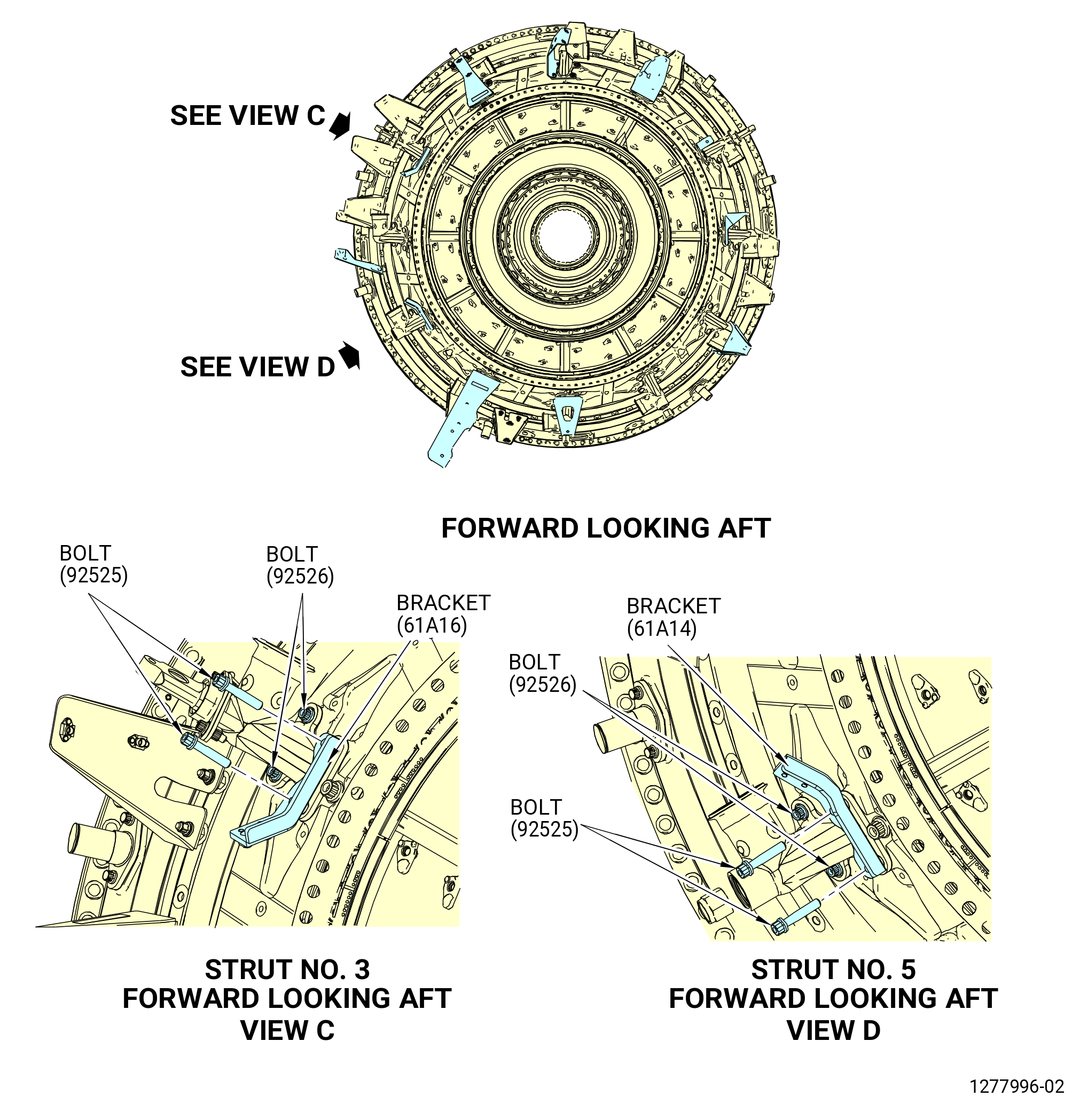
| (3) | Attach the support bracket (01-490 , 72-54-00) (SIN 61A16) to the TCF assembly at the 2:00 o'clock position (strut No. 3) as follows: |
| (a) | Remove the two bottom bolts (92525) from the vent adapter (46107). |
| (b) | Attach the support bracket (61A16) to the vent adapter with the two bolts (92525). |
| (c) | Torque the four bolts (01-020 , 72-54-00) (SIN 92525) and (01-010 , 72-54-00) (SIN 92526) that attach the air adapter in a criss-cross pattern to 106 to 124 lb in. (12.0 to 14.0 Nm). |
| (d) | Re-torque again all bolts in a criss-cross pattern to 106 to 124 lb in. (12.0 to 14.0 Nm). |
| (e) | Torque the two nuts (46140) that attach the seal retainer (46182) to the vent adapter (46107) to 106-124 lb in. (12.0 to 14.0 N.m). |
| (4) | Torque the four bolts (01-010 , 72-54-00) (SIN 92526) that attach the air adapter (01-480 , 72-54-00) (SIN 9250G) to the TCF assembly at the 3:00 o'clock position (strut No. 4) as follows: |
| (a) | Torque the four bolts (01-010 , 72-54-00) (SIN 92526) that attach the air adapter in a criss-cross pattern to 106 to 124 lb in. (12.0 to 14.0 Nm). |
| (b) | Re-torque again all bolts in a criss cross pattern to 106 to 124 ln in. (12.0 to 14.0 Nm). |
| (5) | Attach the support bracket (01-460 , 72-54-00) (SIN 61A14) to the TCF assembly at the 4:00 o'clock position (strut No. 5) as follows: |
| (a) | Remove the two bottom bolts (92525) from the air adapter (92509). |
| (b) | Attach the support bracket (61A16) to the air adapter with the two bolts (92525). |
| (c) | Torque the four bolts (01-020 , 72-54-00) (SIN 92525) and (01-010 , 72-54-00) (SIN 92526) that attach the air adapter in a criss-cross pattern to 106 to 124 lb in. (12.0 to 14.0 Nm). |
| (d) | Re-torque again all bolts in a criss-cross pattern to 106 to 124 lb in. (12.0 to 14.0 Nm). |
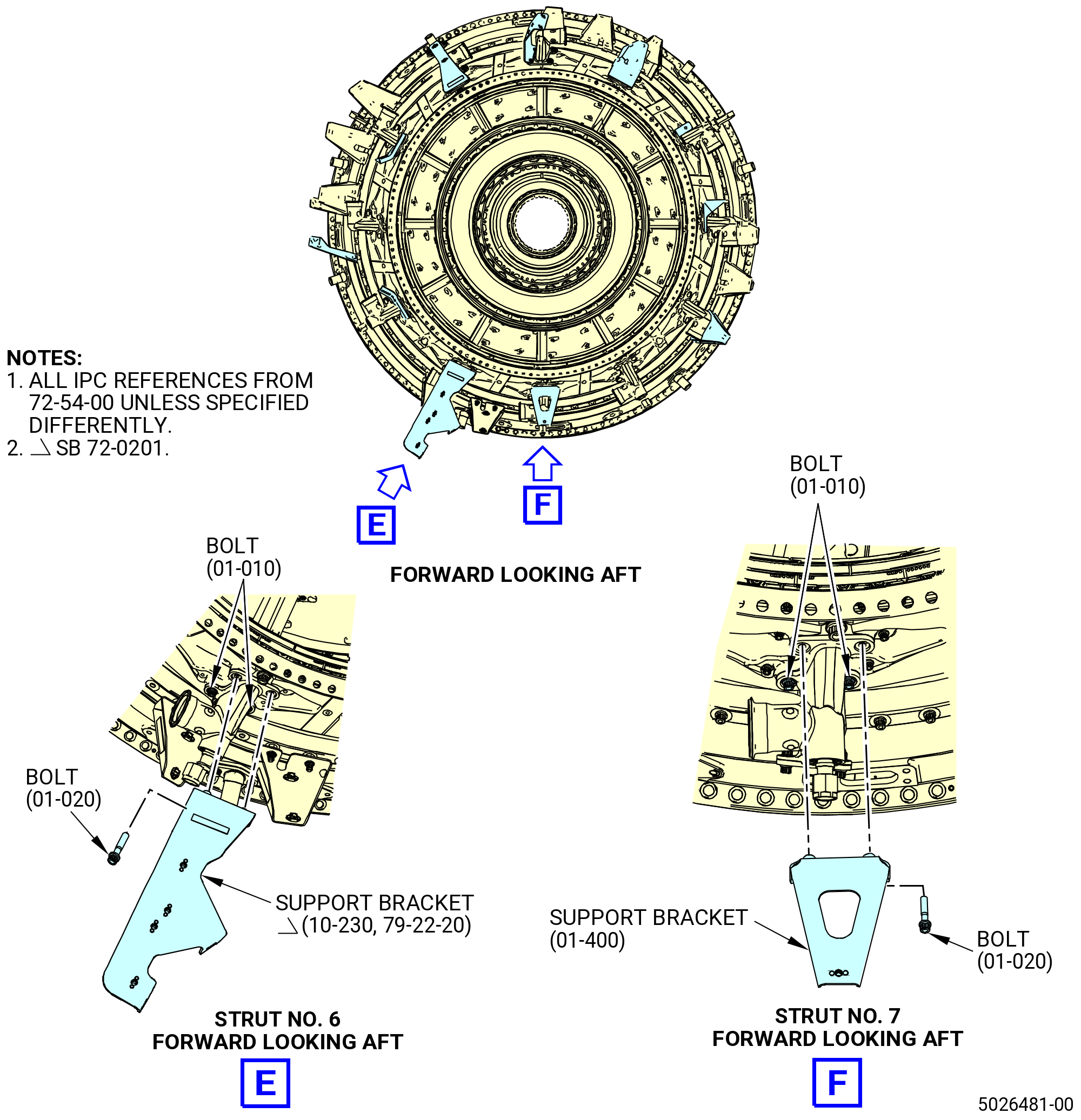
| (6) | Attach the support bracket (01-260 , 72-54-00) (SIN 45210) or (10-230 , 79-22-20) (SIN 45210) to the TCF assembly at the 5:00 o'clock position (strut No. 6) as follows: |
| (a) | Remove the two bottom bolts (92525) from the air adapter (9250C). |
| (b) | Attach the support bracket (01-260 , 72-54-00) (SIN 45210) or (10-230 , 79-22-20) (SIN 45210) to the air adapter with the two bolts (01-020 , 72-54-00) (SIN 92525). |
| (c) | Torque the four bolts (01-020 , 72-54-00) (SIN 92525) and (01-010 , 72-54-00) (SIN 92526) that attach the air adapter in a criss-cross pattern to 106 to 124 lb in. (12.0 to 14.0 Nm). |
| (d) | Re-torque again all bolts in a criss-cross pattern to 106 to 124 lb in. (12.0 to 14.0 Nm). |
| (7) | Attach the support bracket (01-400 , 72-54-00) (SIN 45411) to the TCF assembly at the 6:00 o'clock position (strut No. 7) as follows: |
| (a) | Remove the two bottom bolts (92525) from the air adapter (9250D). |
| (b) | Attach the support bracket (45411) to the air adapter with the two bolts (92525). |
| (c) | Torque the four bolts (01-020 , 72-54-00) (SIN 92525) and (01-010 , 72-54-20) (SIN 92526) that attach the air adapter in a criss-cross pattern to 106 to 124 lb in. (12.0 to 14.0 Nm). |
| (d) | Re-torque again all bolts in a criss-cross to 106 to 124 lb in. (12.0 to 14.0 Nm). |
| (8) | Torque the four bolts (01-010 , 72-54-00) (SIN 92526) that attach the air adapter (01-310 , 72-54-00) (SIN 9250C) to the TCF assembly at the 7:00 o'clock position (strut No. 8) as follows: |
| (a) | Torque the four bolts (01-010 , 72-54-00) (SIN 92526) that attach the air adapter in a criss-cross pattern to 106 to 124 lb in. (12.0 to 14.0 Nm). |
| (b) | Re-torque again all bolts in a criss-cross pattern to 106 to 124 lb in. (12.0 to 14.0 Nm). |
| (9) | Torque the four bolts (01-010 , 72-54-00) (SIN 92526) that attach air adapter (01-310 , 72-54-00) (SIN 92508) to the TCF assembly at the 8:00 o'clock position (strut No. 9) as follows: |
| (a) | Torque the four bolts (01-010 , 72-54-00) (SIN 92526) that attach the air adapter in a criss-cross pattern to 106 to 124 lb in. (12.0 to 14.0 Nm). |
| (b) | Re-torque again all bolts in a criss-cross pattern to 106 to 124 lb in. (12.0 to 14.0 Nm). |
| (10) | Attach the support bracket (01-220 , 72-54-00) (SIN 65512) to the TCF assembly at the 9:00 o'clock position (strut No. 10) as follows: |
| (a) | Remove the two bottom bolts (01-020 , 72-54-00) (SIN 92525) from the air adapter (01-240 , 72-54-00) (SIN 9250P). |
| (b) | Attach the support bracket (01-220 , 72-54-00) (SIN 65512) to the air adapter with the two bolts (01-020 , 72-54-00) (SIN 92525). |
| (c) | Torque the four bolts (01-020 , 72-54-00) (SIN 92525) and (01-010 , 72-54-00) (SIN 92526) that attach the air adapter in a criss-cross pattern to 106 to 124 lb in. (12.0 to 14.0 Nm). |
| (d) | Re-torque again all bolts in a criss-cross pattern to 106 to 124 lb in. (12.0 to 14.0 Nm). |
| (11) | Attach the bracket (01-190 , 72-54-00) (SIN 65513) to the TCF assembly at the 10:00 o'clock position (strut No. 11) as follows: |
| (a) | Remove the two bottom bolts (92525) from the vent adapter (46107). |
| (b) | Attach the bracket (01-190 , 72-54-00) (SIN 65513) to the vent adapter with two bolts (01-020 , 72-54-00) (SIN 92525). |
| (c) | Torque the four bolts (01-020 , 72-54-00) (SIN 92525) and (01-010 , 72-54-00) (SIN 92526) that attach the air adapter in a criss-cross pattern to 106 to 124 lb in. (12.0 to 14.0 Nm). |
| (d) | Re-torque again all bolts in a criss-cross pattern to 106 to 124 lb in. (12.0 to 14.0 Nm). |
| (e) | Torque the two nuts (46140) that attach the seal retainer (46182) to the vent adapter to 106-124 lb in. (12.0-14.0 N.m). |
| (12) | Attach the support bracket (46114, 46115) to the TCF at the 11:00 o'clock position (strut No. 12) as follows: |
| (a) | Remove the top left bolt (92526) and bottom two bolts (92525) from the air adapter (9250A). |
| (b) | Attach the support bracket (46114) to the air adapter with one bolt (92526) at the top left bolthole. |
| (c) | Attach the support bracket (46115) to the air adapter with two bolts (92525) at the bottom boltholes. |
| (d) | Attach the support bracket (46115) to the support bracket (46114) with two bolts (46128). |
| (e) | Torque the bolts (01-030 , 72-54-00) (SIN 46128) to 106 to 124 lb in. (12.0 to 14.0 Nm). |
| (f) | Torque the four bolts (01-020 , 72-54-00) (SIN 92525) and (01-010 , 72-54-00) (SIN 92526) that attach the air adapter in a criss-cross pattern to 106 to 124 lb in. (12.0 to 14.0 Nm). |
| (g) | Re-torque again all bolts in a criss-cross pattern to 106 to 124 lb in. (12.0 to 14.0 Nm). |
|
|
|
|
| Subtask 72-54-00-440-217 |
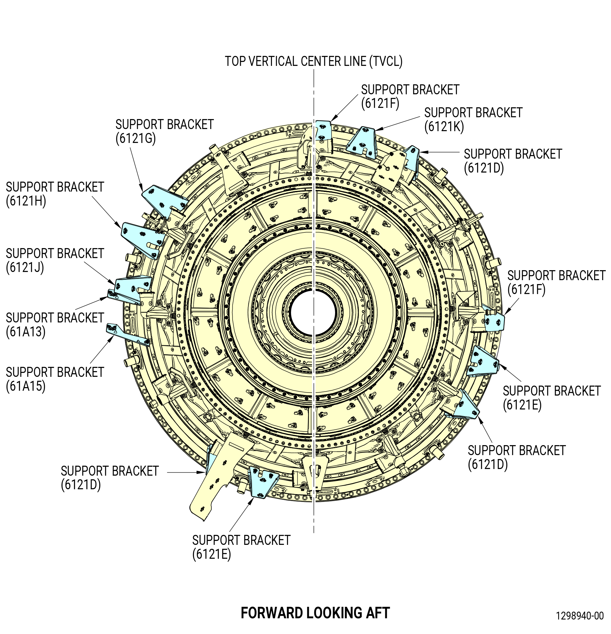
| K. | Install the fourth and seventh stage air manifolds support brackets (support brackets) on the TCF assembly (15-130 , 72-54-00) (SIN 925A0) center studs as follows. Refer to Figure 1011. |
| (1) | Put marks on the TCF assembly center studs with a C05-003 pen. Use numbers for easy reference during installation of brackets. |
| (a) | Put a mark on the stud at TVCL as stud No. 1. |
| (b) | Continue to number the remaining studs clockwise, ALF. |
| (2) | Put the fourth and seventh stage air support brackets on the TCF assembly as follows: |
| (a) | Put each support bracket on the TCF assembly with the flat mounting surface pointing aft. Do not torque the nuts. |
| (b) | Put the support bracket (6121F) on the No. 1 and 72 studs and attach with washer (61230) and nut (61241). |
| (c) | Put the support bracket (6121G) on the No. 11 and 12 studs and attach with washer (61230) and nut (61241). |
| (d) | Put the support bracket (6121H) on the No. 14 and 15 studs and attach with washer (61230) and nut (61241). |
| (e) | Put the support bracket (61A13) on the No. 18 stud. Put the support bracket (6121J) on the No. 17 and 18 studs, over the support bracket (61A13), and attach with washer (61230) and nut (61241). |
| (f) | Put the support bracket (61A15) on the No. 21 stud and attach with washer (61A30) and nut (61A40). |
| (g) | Put the support bracket (6121D) on the No. 30 and 31 studs and attach with washer (61230) and nut (61241). |
| (h) | Put the support bracket (6121E) on the No. 33 and 34 studs and attach with washer (61230) and nut (61241). |
| (i) | Put the support bracket (6121D) on the No. 48 and 49 studs and attach with washer (61230) and nut (61241). |
| (j) | Put the support bracket (6121E) on the No. 51 and 52 studs and attach with washer (61230) and nut (61241). |
| (k) | Put the support bracket (6121F) on the No. 54 and 55 studs and attach with washer (61230) and nut (61241). |
| (l) | Put the support bracket (6121D) on the No. 66 and 67 studs and attach with washer (61230) and nut (61241). |
| (m) | Put the support bracket (6121K) on the No. 69 and 70 studs and attach with washer (61230) and nut (61241). |
| Subtask 72-00-02-440-475 |
| * * * FOR 1B/P/G04.1B/P1/G01 |
| * * * SB 72-0040( Non-Rake TCF Frame ) |
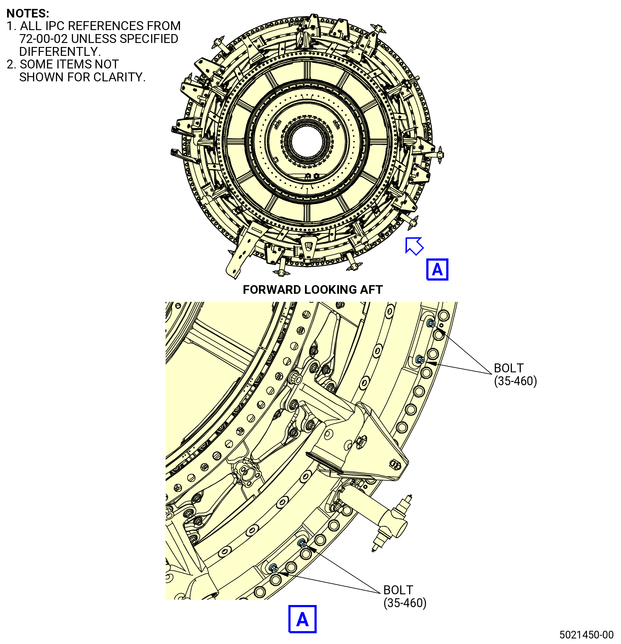
| L. | Install four bolts (35-460) (SIN 925F2) on the TCF case. Refer to Figure 1012 and do as follows: |
| NOTE: |
|
| WARNING: |
|
| (1) | Apply C02-058 lubricant to the threads of the bolts. |
| (2) | Install the bolts on the TCF case at two locations. |
| (3) | Torque all four bolts (35-460) (SIN 925F2) 106 to 124 lb in. (12.0 to 14.0 Nm). |
| (4) | Safety the bolts with C10-071 safety wire or C10-143 safety cable. Refer to TASK 70-11-00-400-001 (FASTENER RETENTION PROCEDURES). |
| * * * END SB 72-0040 |
| * * * FOR 1B/P/G04.1B/P1/G01 |
| Subtask 72-00-02-440-218 |
| * * * FOR 1B/P/G03.1B/P/G04.1B/P1/G01 |
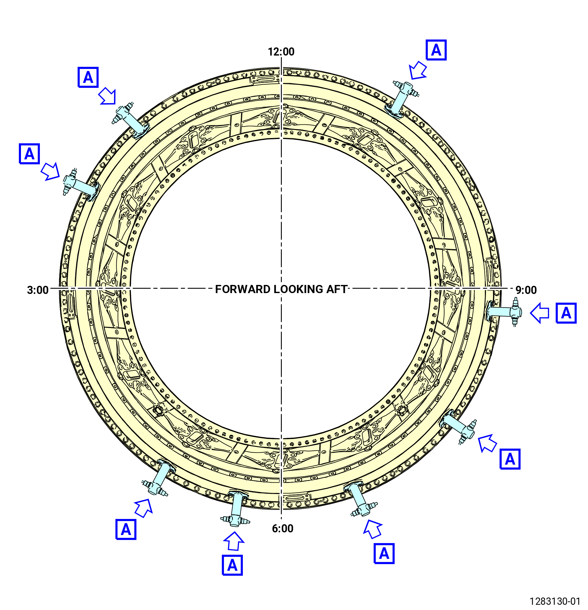
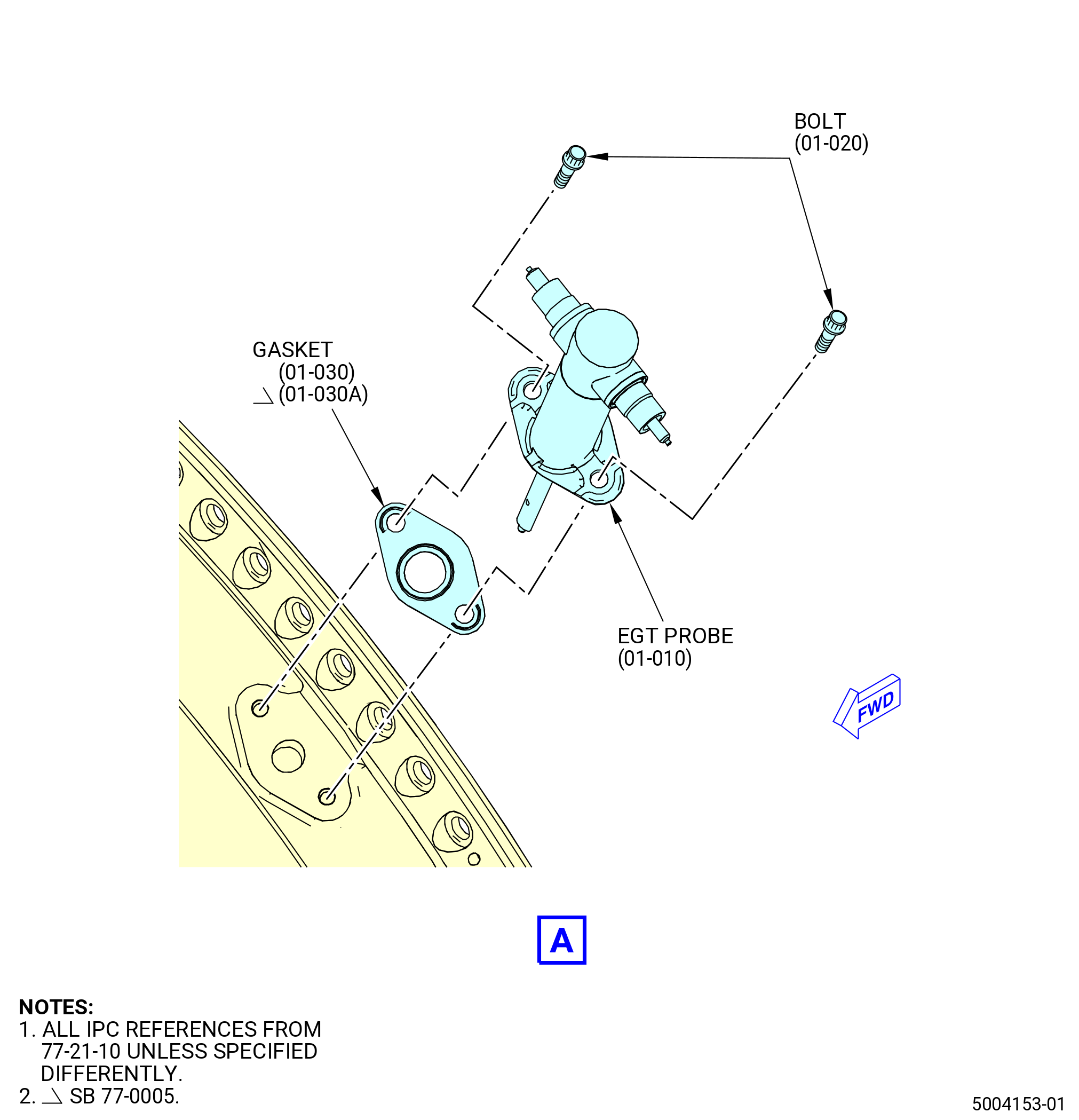
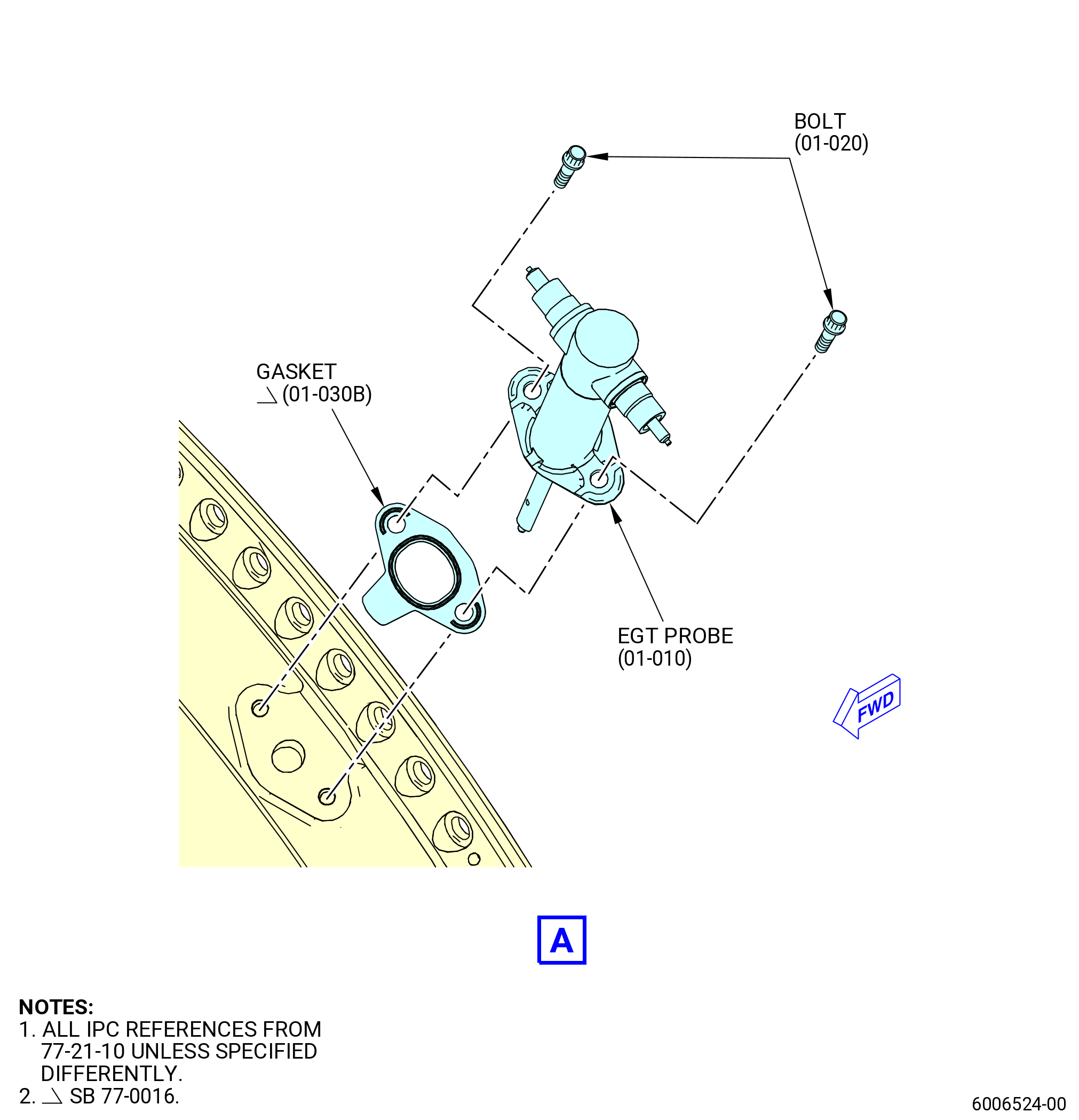
| M. | Install the exhaust gas temperature (EGT) probes (01-010 , 77-21-10) (SIN 69800) on the TCF assembly (35-009) (SIN 92500), (35-010) (SIN 92500), (35-011) (SIN 92500), (35-012) (SIN 92500), or (35-015) (SIN 92500). Refer to Figure 1013, Figure 1014, and do as follows: |
| (1) | Install the eight EGT probes on the turbine frame at the 1:00, 3:30, 4:30, 5:30, 6:30, 7:30, 9:30, and 10:30 o'clock positions FLA as follows: |
| CAUTION: |
|
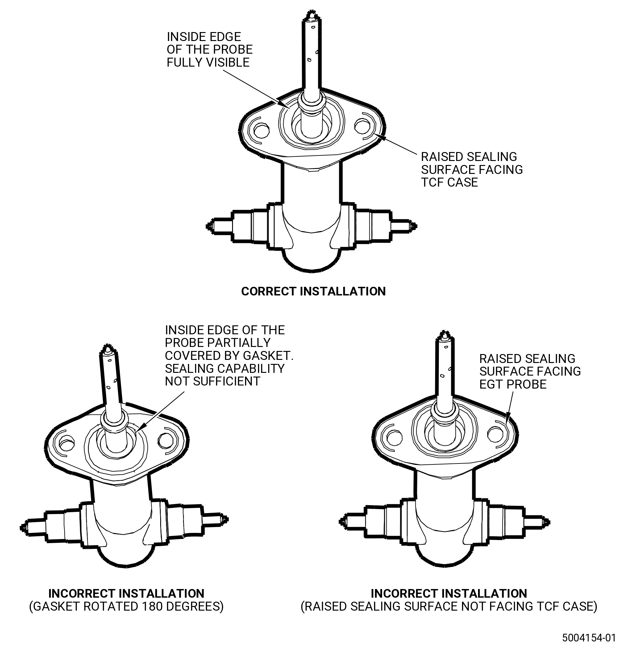
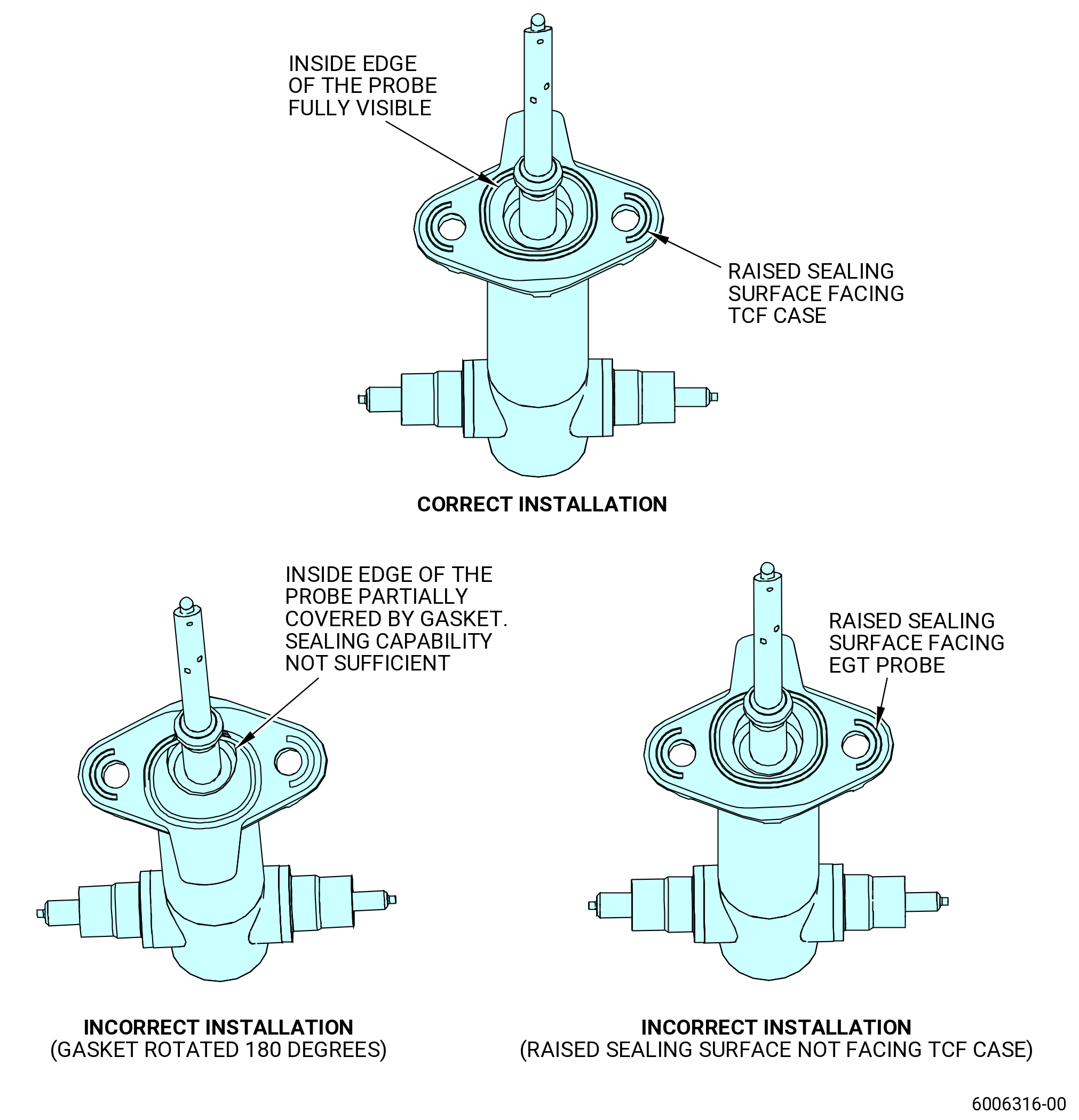
| (a) | Put a new gasket (01-030 , 77-21-10) (SIN 69850) under the EGT probe. |
| (b) | Make sure that the raised sealing surface of the gasket is facing the TCF case and it is in the correct position and not turned 180 degrees. The gasket must give full sealing capability around the EGT probe to avoid leaks of hot air from the probe hole. |
| (c) | Put the EGT probe and gasket on the turbine frame port. |
| WARNING: |
|
| (d) | Apply C02-071 anti-seize to the threads of the machine bolts (bolts) (01-020 , 77-21-10) (SIN 69823). |
| (e) | Install the bolts (69823) to attach the EGT probe and gasket to the turbine frame. |
| (f) | Continue to install the remaining EGT probes. |
| (g) | Torque the bolts to 106-124 lb in. (12.0-14.0 N.m). |
| (h) | Safety the bolts (69823) with C10-071 safety wire or C10-143 safety cable. |
|
|
|
|
| Subtask 72-00-02-440-119 |
| * * * PRE SB 75-0003( HPTACC without Brackets Reduction ) |
| * * * PRE SB 75-0029( Old HPT Air Manifolds Connector ) |
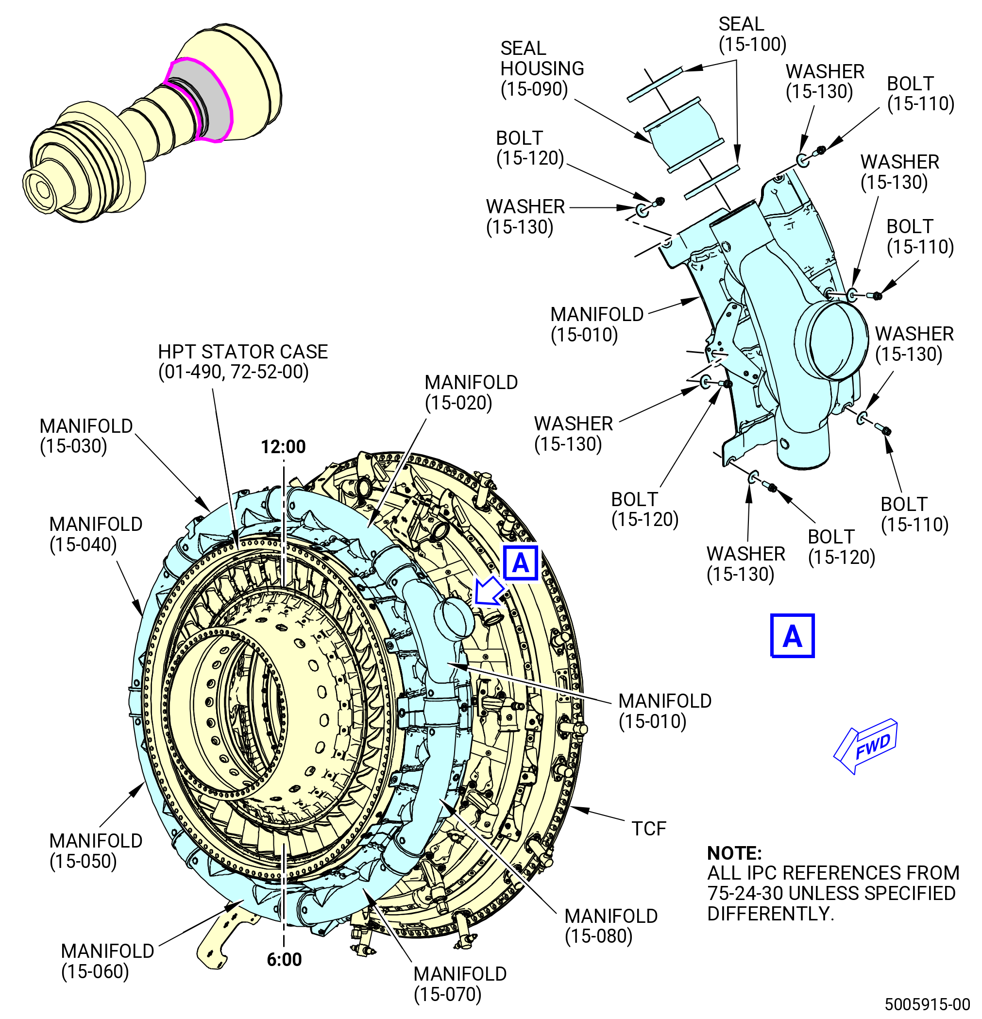
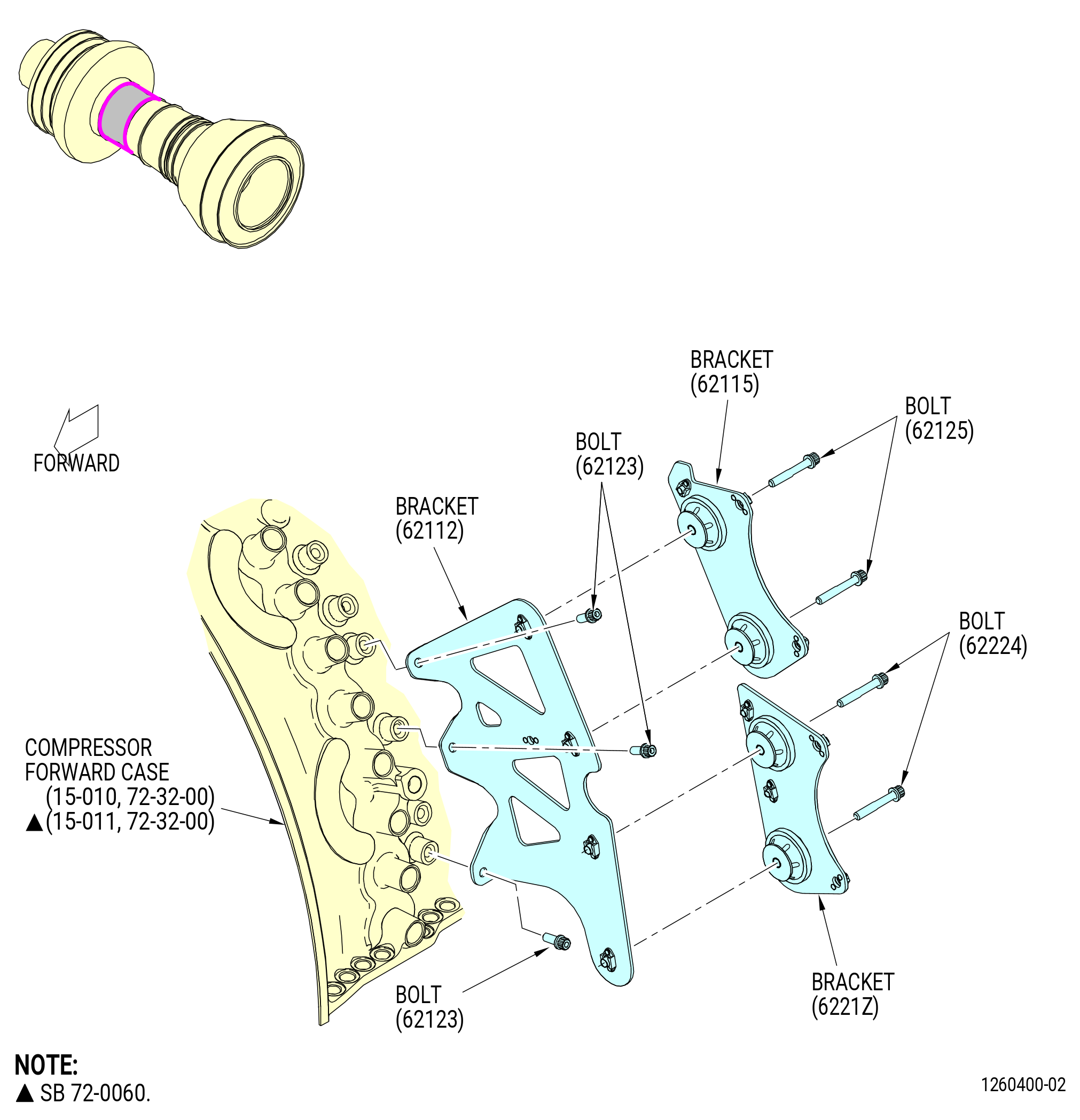
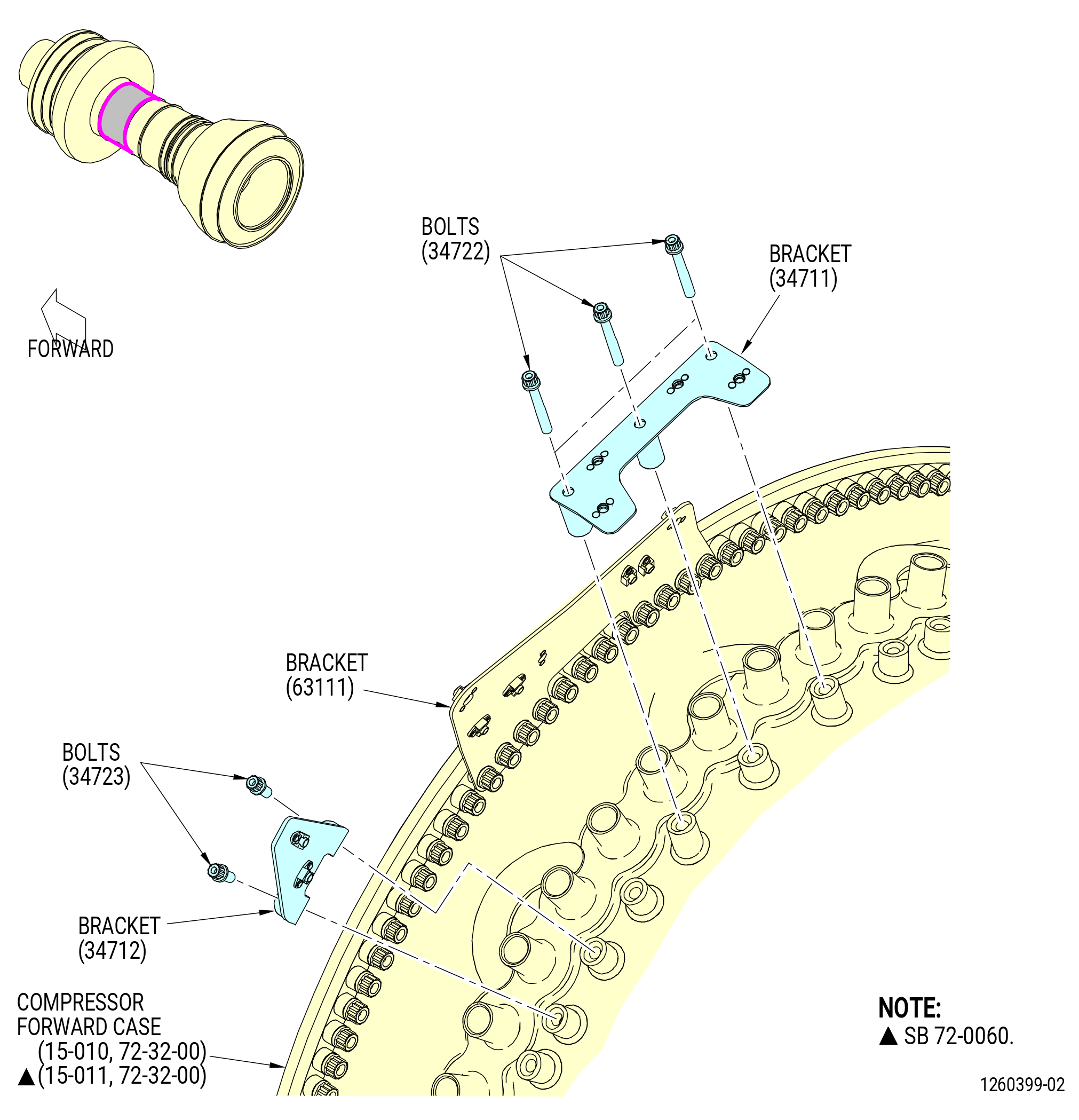
| N. | Install the high pressure turbine (HPT) active clearance control (ACC) manifolds. Refer to Figure 1015 and do as follows: |
| (1) | Install an air duct seal (seal) (15-100 , 75-24-30) (SIN 62151) in each end of the seal housings (15-090 , 75-24-30) (SIN 62109). |
| (2) | Install the manifolds: |
| • |
|
| • |
|
| • |
|
| • |
|
| • |
|
| • |
|
| • |
|
| • |
|
| (a) | Install a seal housing (15-090 , 75-24-30) (SIN 62109) at the 12:00 o'clock position, aft looking forward (ALF) on the manifold (15-030 , 75-24-30) (SIN 6210A). Push the seal housing fully onto the manifold tube. Make sure not to damage the seal (15-100 , 75-24-30) (SIN 62151). |
| (b) | Install the manifold (15-030 , 75-24-30) (SIN 6210A) at the 1:00 o'clock position (ALF) on the HPT stator case (01-490 , 72-52-00) (SIN 174B0). |
| (c) | Attach the forward end of the manifold with one bolt (15-120 , 75-24-30) (SIN 62123) and one washer (15-130 , 75-24-30) (SIN 62130) at the center bolthole. Hand tighten the bolt. |
| (d) | Attach the aft end of the manifold with one bolt (15-110 , 75-24-30) (SIN 62122) and one washer (15-130 , 75-24-30) (SIN 62130) at the center bolthole. Hand tighten the bolt. |
| (e) | Install the remaining manifolds on the HPT stator case. Make sure that the manifold (15-010 , 75-24-30) (SIN 6210G) is installed at the 10:00 o'clock position ALF. |
| (3) | When all the manifolds are installed, carefully move the seal housings (15-090 , 75-24-30) (SIN 62109) in a CW direction to connect the adjacent manifold. Be careful not to damage the seal (15-100 , 75-24-30) (SIN 62151). |
| (4) | Install the remaining bolts (15-120 , 75-24-30) (SIN 62123) and washers (15-130 , 75-24-30) (SIN 62130) in the forward end of the manifolds. |
| (5) | Install the remaining bolts (15-110 , 75-24-30) (SIN 62122) and washers (15-130 , 75-24-30) (SIN 62130) in the aft end of the manifolds. |
| (6) | Torque the bolts (15-120 , 75-24-30) (SIN 62123) and (15-110 , 75-24-30) (SIN 62122) to 106-124 lb in. (12.0-14.0 N.m). |
| * * * END PRE SB 75-0003 |
| * * * END PRE SB 75-0029 |
| Subtask 72-00-02-440-617 |
| * * * SB 75-0029( HPT Air Manifolds Connector Improvement ) |
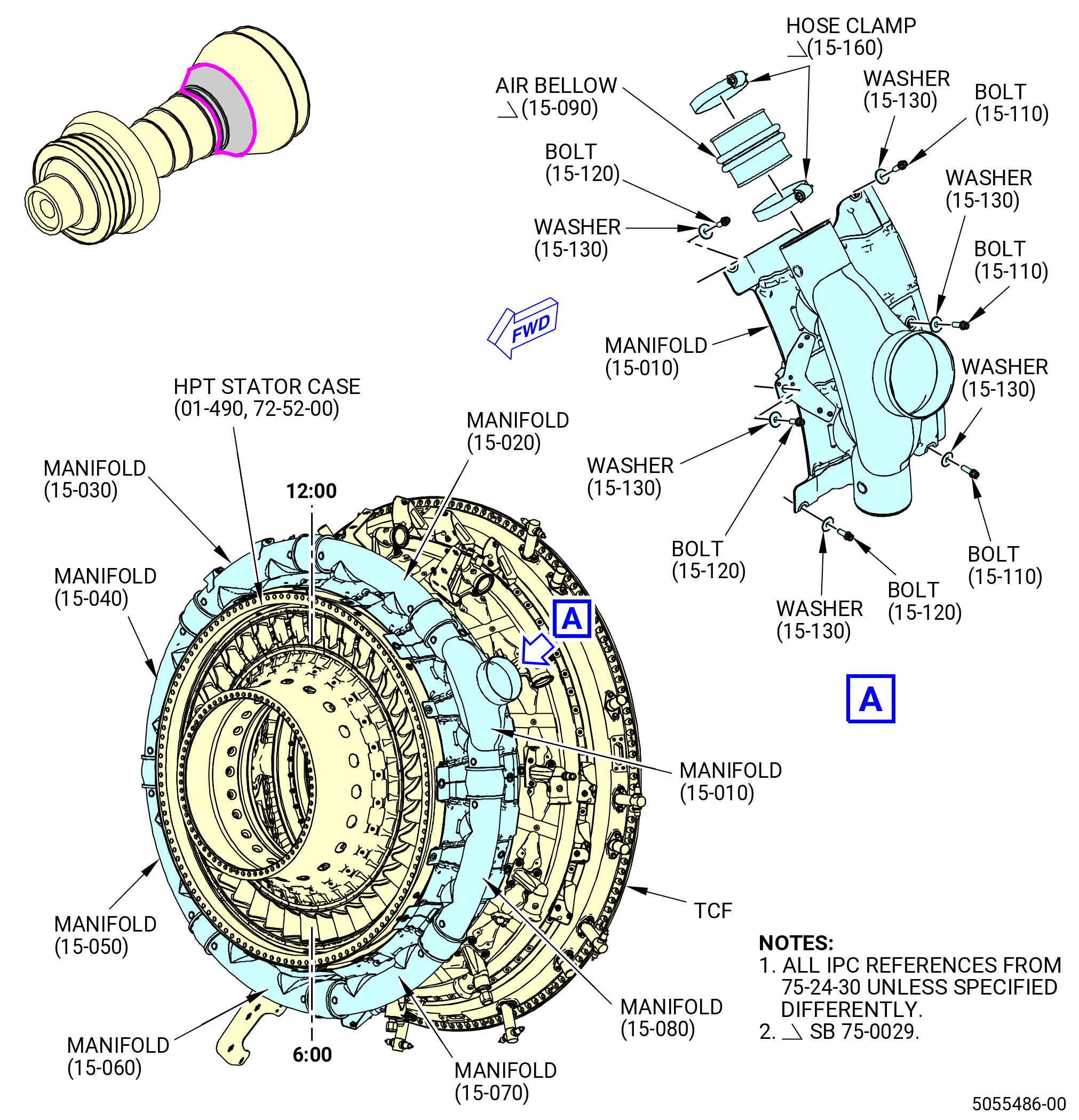
| N.A. | Install the high pressure turbine (HPT) active clearance control (ACC) manifolds. Refer to Figure 1015 and do as follows: |
| (1) | Install a low pressure hose clamp (hose clamp) (15-160 , 75-24-30) (SIN 62188) in each end of the LPT ACC air bellows (air bellows) (15-090 , 75-24-30) (SIN 62109). |
| (2) | Install the HPT air manifolds (15-030 , 75-24-30) (SIN 6210A), (15-040 , 75-24-30) (SIN 6210B), (15-050 , 75-24-30) (SIN 6210C), (15-060 , 75-24-30) (SIN 6210D), (15-070 , 75-24-30) (SIN 6210E), (15-080 , 75-24-30) (SIN 6210F), (15-010 , 75-24-30) (SIN 6210G), (15-020 , 75-24-30) (SIN 6210H), and do as follows: |
| (a) | Install one new air bellow (15-090 , 75-24-30) (SIN 62109) at the 12:00 o'clock position ALF on the HPT air manifold (15-030 , 75-24-30) (SIN 6210A). Push the air bellows (15-090 , 75-24-30) (SIN 62109) fully onto the HPT air manifold (15-030 , 75-24-30) (SIN 6210A) tube and attach firmly with a new hose clamp (15-160 , 75-24-30) (SIN 62188). |
| (b) | Install the HPT air manifold (15-030 , 75-24-30) (SIN 6210A) at the 1:00 o'clock position ALF on the HPT stator case (01-490 , 72-52-00) (SIN 174B0). |
| (c) | Attach the forward end of the HPT air manifold (15-030 , 75-24-30) (SIN 6210A) with one machine bolt (bolt) (15-120 , 75-24-30) (SIN 62123) and one retaining washer (washer) (15-130 , 75-24-30) (SIN 62130) at the center bolthole. Hand-tighten the bolt (15-120 , 75-24-30) (SIN 62123). |
| (d) | Attach the aft end of the HPT air manifold (15-030 , 75-24-30) (SIN 6210A) with one bolt (15-110 , 75-24-30) (SIN 62122) and one washer (15-130 , 75-24-30) (SIN 62130) at the center bolthole. Hand-tighten the bolt (15-110 , 75-24-30) (SIN 62122). |
| (e) | Install the remaining HPT air manifolds on the HPT stator case (01-490 , 72-52-00) (SIN 174B0). Make sure that the HPT air manifold (15-010 , 75-24-30) (SIN 6210G) is installed at the 10:00 o'clock position ALF. |
| (f) | When all the HPT air manifolds are installed, carefully move the air bellows (15-090 , 75-24-30) (SIN 62109) in a CW direction to connect the adjacent HPT air manifold. |
| (g) | Install the remaining bolts (15-120 , 75-24-30) (SIN 62123) and washers (15-130 , 75-24-30) (SIN 62130) in the forward end of the HPT air manifolds. |
| (h) | Install the remaining bolts (15-110 , 75-24-30) (SIN 62122) and the washers (15-130 , 75-24-30) (SIN 62130) in the aft end of the HPT air manifolds. |
| (i) | Torque the bolts (15-120 , 75-24-30) (SIN 62123) and (15-110 , 75-24-30) (SIN 62122) to 106 to 124 lb in. (11.9 to 14.0 Nm). |
| (3) | Torque the hose clamps (15-160 , 75-24-30) (SIN 62188) as follows: |
| (a) | Torque the hose clamps (15-160 , 75-24-30) (SIN 62188) to 18 to 22 lb in. (2.0 to 2.4 Nm) and do as follows: |
| CAUTION: |
|
| 1 | Remove the excessive length of the hose clamp (15-160 , 75-24-30) (SIN 62188) tab to expose a maximum material length of 1.00 inch (25.4 mm) beyond the screw housing. No burrs are permitted. |
| WARNING: |
|
| (b) | Apply C01-007 silicone elastomer RTV on the screw and cylinder of the hose clamp (15-160 , 75-24-30) (SIN 62188) as follows: |
| 1 | Clean the surface with C04-002 Stoddard solvent or C04-035 isopropyl alcohol. |
| 2 | Apply C01-007 silicone elastomer RTV on the screw of the hose clamp (15-160 , 75-24-30) (SIN 62188) to prevent further movement of the hose clamp (15-160 , 75-24-30) (SIN 62188) and air bellows (15-090 , 75-24-30) (SIN 62109). Make sure to only apply on the area of interest and not on the surrounding hardware. |
| * * * END SB 75-0029 |
| Subtask 72-00-02-440-276 |
| * * * SB 75-0003( HPTACC with Brackets Reduction ) |
| * * * PRE SB 75-0029( Old HPT Air Manifolds Connector ) |
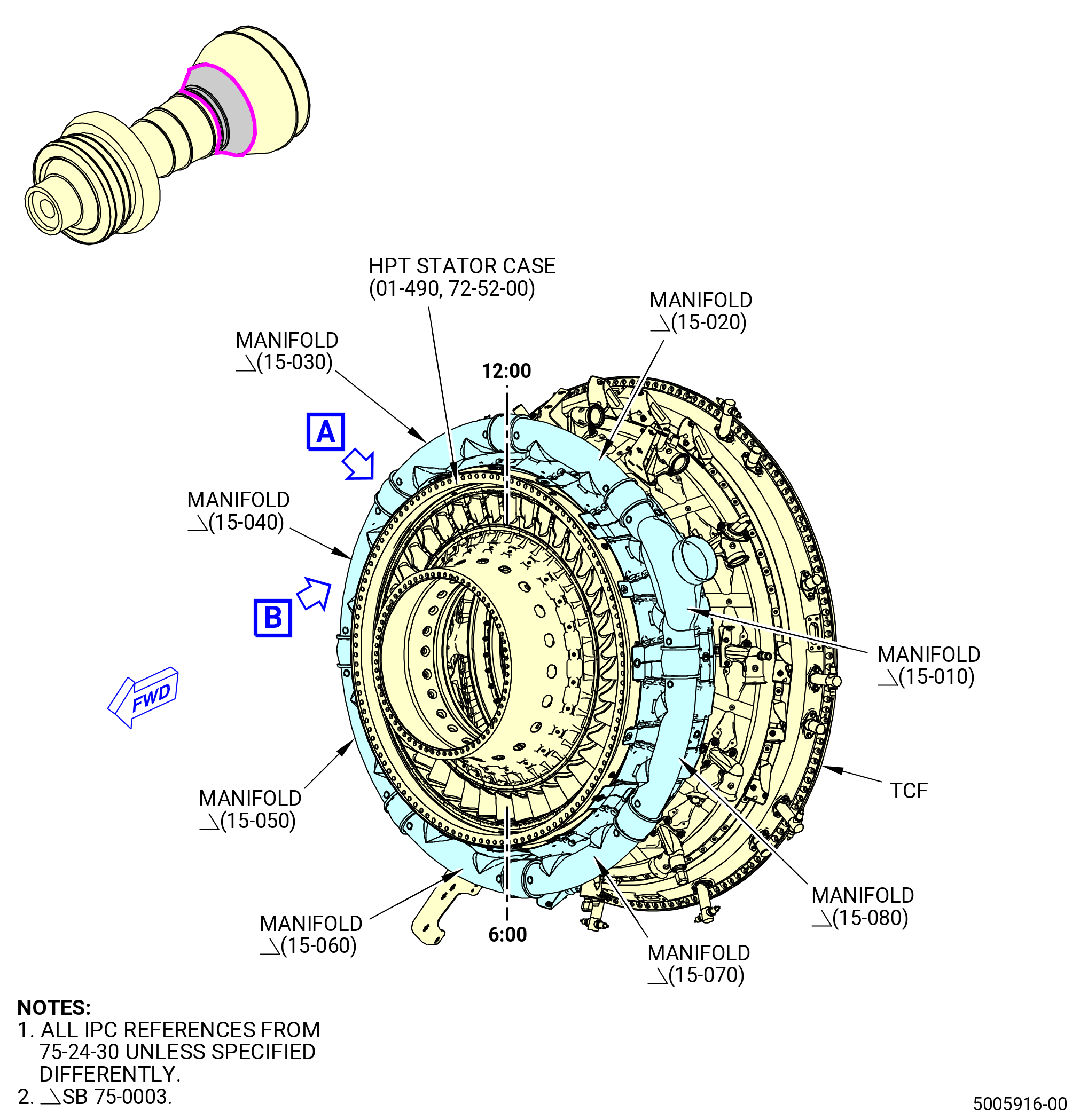
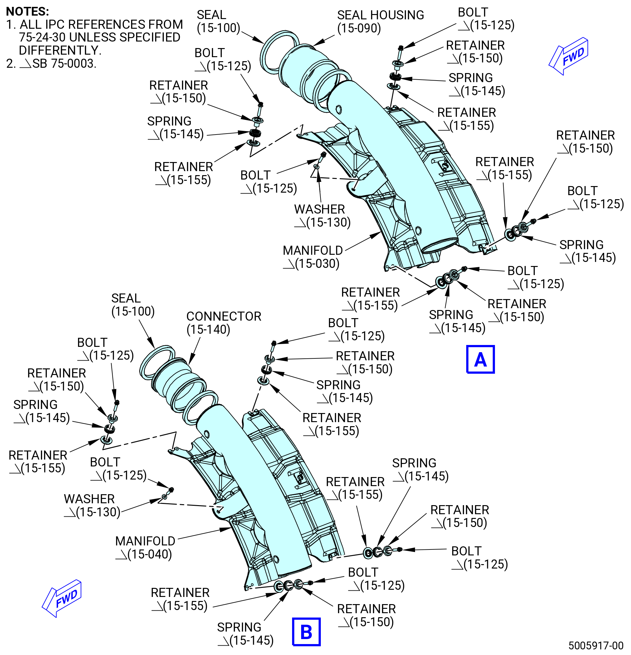
| N.B. | Install the HPT ACC manifolds. Refer to Figure 1015A and do as follows: |
| WARNING: |
|
| (1) | Apply C02-008 lubricant inside the grooves of the seal housings (15-090 , 75-24-30) (SIN 62109) and (15-140 , 75-24-30) (SIN 6210J). |
| (2) | Install a seal (15-100 , 75-24-30) (SIN 62151) in each end of the seal housing (15-140 , 75-24-30) (SIN 6210J). |
| CAUTION: |
|
| (3) | Install the seal housing (15-140 , 75-24-30) (SIN 6210J) on the CW end of the manifold (15-040 , 75-24-30) (SIN 6210B). Push the connector as far as possible onto the manifold (15-040 , 75-24-30) (SIN 6210B). |
| (4) | Put the manifold (15-040 , 75-24-30) (SIN 6210B) on the HPT stator case (01-490 , 72-52-00) (SIN 174B0) at the 2 o'clock position ALF. |
| (5) | Install one machine bolt (bolt) (15-125 , 75-24-30) (SIN 62126) and the washer (15-130 , 75-24-30) (SIN 62130) at the forward center bolthole and attach the manifold (15-040 , 75-24-30) (SIN 6210B) to the HPT manifold bracket (bracket) (34-370) (SIN 6211E). |
| (6) | Install the flat wire spring (spring) (15-145 , 75-24-30) (SIN 62190) between the retainers (15-150 , 75-24-30) (SIN 62191) and (15-155 , 75-24-30) (SIN 62192). |
| (7) | Install one bolt (15-125 , 75-24-30) (SIN 62126), retainers (15-150 , 75-24-30) (SIN 62191) and (15-155 , 75-24-30) (SIN 62192), and spring (15-145 , 75-24-30) (SIN 62190) at the forward corner boltholes and attach the manifold (15-040 , 75-24-30) (SIN 6210B) to the HPT manifold bracket (bracket) (34-360) (SIN 6211D). |
| (8) | Install the remaining manifolds: |
| • |
|
| • |
|
| • |
|
| • |
|
| • |
|
| • |
|
| • |
|
| (a) | Install a seal (15-100 , 75-24-30) (SIN 62151) in each end of the seal housing (15-090 , 75-24-30) (SIN 62109). |
| CAUTION: |
|
| (b) | Install the seal housing (15-090 , 75-24-30) (SIN 62109) on the CW end of the manifold (15-050 , 75-24-30) (SIN 6210C). Push the seal housing (15-090 , 75-24-30) (SIN 62109) as far as possible onto the manifold (15-050 , 75-24-30) (SIN 6210C). |
| (c) | Put the manifold (15-050 , 75-24-30) (SIN 6210C) on the HPT stator case at the 4:00 o'clock position ALF. |
| (d) | Install one bolt (15-125 , 75-24-30) (SIN 62126) and the washer (15-130 , 75-24-30) (SIN 62130) at the forward center bolthole and attach the manifold (15-050 , 75-24-30) (SIN 6210C) to the bracket (34-091) (SIN 6211B). |
| (e) | Install the spring (15-145 , 75-24-30) (SIN 62190) between the retainers (15-150 , 75-24-30) (SIN 62191) and (15-155 , 75-24-30) (SIN 62192). |
| (f) | Install one bolt (15-125 , 75-24-30) (SIN 62126), the retainers (15-150 , 75-24-30) (SIN 62191) and (15-155 , 75-24-30) (SIN 62192), and the spring (15-145 , 75-24-30) (SIN 62190) at the forward center bolthole and attach the manifold (15-050 , 75-24-30) (SIN 6210C) to the bracket (34-111) (SIN 6211A). |
| (g) | Install the remaining manifolds. Do Subtask 72-00-02-440-276 (paragraph 3.N.B.(8)(a)) thru Subtask 72-00-02-440-276 (paragraph 3.N.B.(8)(f)) again. |
| (9) | When all the manifolds are installed, carefully move the seal housings (15-090 , 75-24-30) (SIN 62109) and (15-140 , 75-24-30) (SIN 6210J) in a CW direction to connect the adjacent manifold. Make sure not to damage the seal (15-100 , 75-24-30) (SIN 62151). |
| (10) | Install the remaining spring (15-145 , 75-24-30) (SIN 62190) between the retainers (15-150 , 75-24-30) (SIN 62191) and (15-155 , 75-24-30) (SIN 62192). |
| (11) | Install one bolt (15-125 , 75-24-30) (SIN 62126), the retainers (15-150 , 75-24-30) (SIN 62191) and (15-155 , 75-24-30) (SIN 62192), and the spring (15-145 , 75-24-30) (SIN 62190) at the AFT corner boltholes on the manifolds and attach the manifolds to the brackets (34-221) (SIN 62111) and (34-241) (SIN 62110). |
| (12) | Torque the bolts (15-125 , 75-24-30) (SIN 62126) to 51-59 lb in. (5.7-6.7 N.m). |
| * * * END SB 75-0003 |
| * * * END SB 75-0029 |
| Subtask 72-00-02-440-628 |
| * * * SB 75-0029( HPT Air Manifolds Connector Improvement ) |
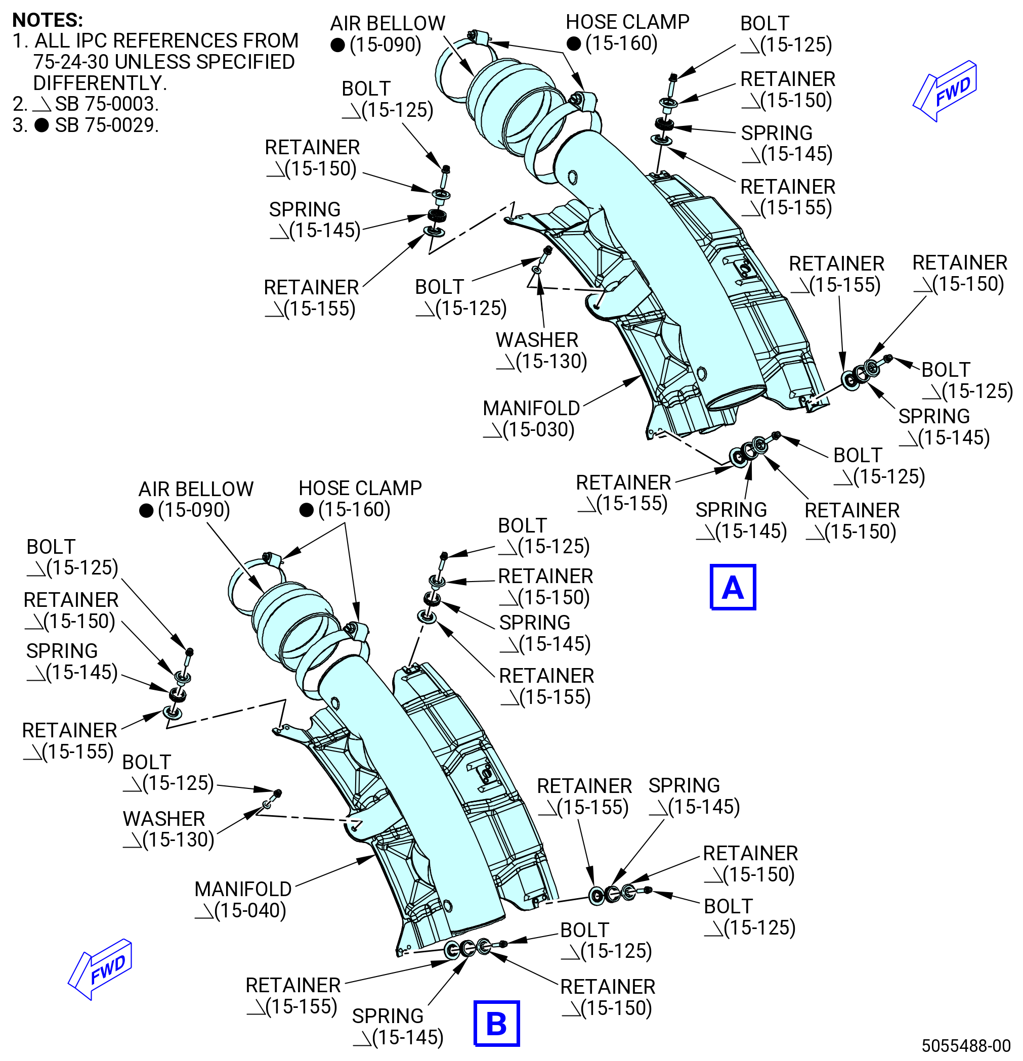
| N.C. | Install the HPT ACC manifolds. Refer to Figure 1015A and do as follows: |
| WARNING: |
|
| (1) | Apply C02-008 lubricant inside the grooves of the air bellows (15-090 , 75-24-30) (SIN 62109). |
| (2) | Install one new air bellow (15-090 , 75-24-30) (SIN 62109) on the CW end of the HPT air manifold (15-040 , 75-24-30) (SIN 6210B). Push the air bellows (15-090 , 75-24-30) (SIN 62109) fully onto the HPT air manifold (15-040 , 75-24-30) (SIN 6210B) tube and attach firmly with a new hose clamp (15-160 , 75-24-30) (SIN 62188). |
| (3) | Put the HPT air manifold (15-040 , 75-24-30) (SIN 6210B) on the HPT stator case (01-490 , 72-52-00) (SIN 174B0) at the 2:00 o'clock position ALF. |
| (4) | Install one machine bolt (bolt) (15-125 , 75-24-30) (SIN 62126) and one flat washer (washer) (15-130 , 75-24-30) (SIN 62130) at the forward center bolthole and attach the HPT air manifold (15-040 , 75-24-30) (SIN 6210B) to the HPT manifold bracket (bracket) (34-370) (SIN 6211E). |
| (5) | Install the flat wire spring (spring) (15-145 , 75-24-30) (SIN 62190) between the retainers (15-150 , 75-24-30) (SIN 62191) and (15-155 , 75-24-30) (SIN 62192). |
| (6) | Install one bolt (15-125 , 75-24-30) (SIN 62126), the retainers (15-150 , 75-24-30) (SIN 62191) and (15-155 , 75-24-30) (SIN 62192), and the spring (15-145 , 75-24-30) (SIN 62190) at each forward corner bolthole and attach the HPT air manifold (15-040 , 75-24-30) (SIN 6210B) to the HPT manifold brackets (34-360) (SIN 6211D). |
| (7) | Install the remaining HPT air manifolds (15-030 , 75-24-30) (SIN 6210A), (15-050 , 75-24-30) (SIN 6210C), (15-060 , 75-24-30) (SIN 6210D), (15-070 , 75-24-30) (SIN 6210E), (15-080 , 75-24-30) (SIN 6210F), (15-010 , 75-24-30) (SIN 6210G), (15-020 , 75-24-30) (SIN 6210H), and do as follows: |
| Subtask 72-00-02-440-630 |
| (a) | Install one new air bellow (15-090 , 75-24-30) (SIN 62109) on the CW end of the HPT air manifold (15-050 , 75-24-30) (SIN 6210C). Push the air bellows (15-090 , 75-24-30) (SIN 62109) fully onto the HPT air manifold (15-050 , 75-24-30) (SIN 6210C) tube and attach firmly with a new hose clamp (15-160 , 75-24-30) (SIN 62188). |
| (b) | Put the HPT air manifold (15-050 , 75-24-30) (SIN 6210C) on the HPT stator case (01-490 , 72-52-00) (SIN 174B0) at the 4:00 o'clock position ALF. |
| (c) | Install one bolt (15-125 , 75-24-30) (SIN 62126) and one washer (15-130 , 75-24-30) (SIN 62130) at the forward center bolthole and attach the HPT air manifold (15-050 , 75-24-30) (SIN 6210C) to the bracket (34-091) (SIN 6211B). |
| (d) | Install the spring (15-145 , 75-24-30) (SIN 62190) between the retainers (15-150 , 75-24-30) (SIN 62191) and (15-155 , 75-24-30) (SIN 62192). |
| (e) | Install one bolt (15-125 , 75-24-30) (SIN 62126), the retainers (15-150 , 75-24-30) (SIN 62191) and (15-155 , 75-24-30) (SIN 62192), and the spring (15-145 , 75-24-30) (SIN 62190) at each forward corner bolthole and attach the HPT air manifold (15-050 , 75-24-30) (SIN 6210C) to the bracket (34-111) (SIN 6211A). |
| Subtask 72-00-02-440-629 |
| (f) | Install the remaining HPT air manifolds at their correct positions. Do Subtask 72-00-02-440-630 (paragraph 3.N.C.(7)(a)) thru Subtask 72-00-02-440-630 (paragraph 3.N.C.(7)(e)) again. |
| (g) | Install the HPT air manifolds (15-060 , 75-24-30) (SIN 6210D), (15-070 , 75-24-30) (SIN 6210E), (15-080 , 75-24-30) (SIN 6210F), (15-010 , 75-24-30) (SIN 6210G), and do as follows: |
| 1 | Install one bolt (15-125 , 75-24-30) (SIN 62126), the retainers (15-150 , 75-24-30) (SIN 62191) and (15-155 , 75-24-30), and the spring (15-145 , 75-24-30) (SIN 62190) at each forward corner bolthole and attach the HPT air manifolds (15-060 , 75-24-30) (SIN 6210D), (15-070 , 75-24-30) (SIN 6210E), (15-080 , 75-24-30) (SIN 6210F), and (15-010 , 75-24-30) (SIN 6210G) to the brackets (34-111) (SIN 6211A). |
| (h) | Install the HPT air manifold (15-020 , 75-24-30) (SIN 6210H) and do as follows: |
| 1 | Install one bolt (15-125 , 75-24-30) (SIN 62126), the retainers (15-150 , 75-24-30) (SIN 62191) and (15-155 , 75-24-30) (SIN 62192), and the spring (15-145 , 75-24-30) (SIN 62190) at each forward corner bolthole and attach the HPT air manifold (15-020 , 75-24-30) (SIN 6210H) to the brackets (34-111) (SIN 6211A) and (34-071) (SIN 62119). |
| (i) | Install the HPT air manifold (15-030 , 75-24-30) (SIN 6210A) and do as follows: |
| 1 | Install one bolt (15-125 , 75-24-30) (SIN 62126), the retainers (15-150 , 75-24-30) (SIN 62191) and (15-155 , 75-24-30) (SIN 62192), and the spring (15-145 , 75-24-30) (SIN 62190) at each forward corner bolthole and attach the HPT air manifold (15-030A) to the brackets (34-360) (SIN 6211D) and (34-071) (SIN 62119). |
| (8) | When all the HPT air manifolds are installed, carefully move the air bellows (15-090 , 75-24-30) (SIN 62109) in a CW direction to connect the adjacent HPT air manifold. |
| (9) | Install the remaining spring (15-145 , 75-24-30) (SIN 62190) between the retainers (15-150 , 75-24-30) (SIN 62191) and (15-155 , 75-24-30) (SIN 62192). |
| (10) | Install one bolt (15-125 , 75-24-30) (SIN 62126), the retainers (15-150 , 75-24-30) (SIN 62191) and (15-155 , 75-24-30) (SIN 62192), and the spring (15-145 , 75-24-30) (SIN 62190) at the aft corner boltholes on the HPT air manifolds and attach the HPT air manifolds to the bracket (34-221) (SIN 62111) and the support brackets (34-241) (SIN 62110). |
| (11) | Torque the bolts (15-125 , 75-24-30) (SIN 62126) to 51 to 59 lb in. (5.7 to 6.6 Nm). |
| (12) | Torque the hose clamps (15-160 , 75-24-30) (SIN 62188) as follows: |
| (a) | Torque the hose clamps (15-160 , 75-24-30) (SIN 62188) to 18 to 22 lb in. (2.0 to 2.4 Nm) and do as follows: |
| CAUTION: |
|
| 1 | Remove the excessive length of the hose clamp (15-160 , 75-24-30) (SIN 62188) tab to expose a maximum material length of 1.00 inch (25.4 mm) beyond the screw housing. No burrs are permitted. |
| WARNING: |
|
| (b) | Apply C01-007 silicone elastomer RTV on the screw and cylinder of the hose clamp (15-160 , 75-24-30) (SIN 62188) as follows: |
| 1 | Clean the surface with C04-002 Stoddard solvent or C04-035 isopropyl alcohol. |
| 2 | Apply C01-007 silicone elastomer RTV on the screw of the hose clamp (15-160 , 75-24-30) (SIN 62188) to prevent further movement of the hose clamp (15-160 , 75-24-30) (SIN 62188) and air bellows (15-090 , 75-24-30) (SIN 62109). Make sure to only apply on the area of interest and not on the surrounding hardware. |
| * * * END SB 75-0029 |
|
| Subtask 72-00-02-440-177 |
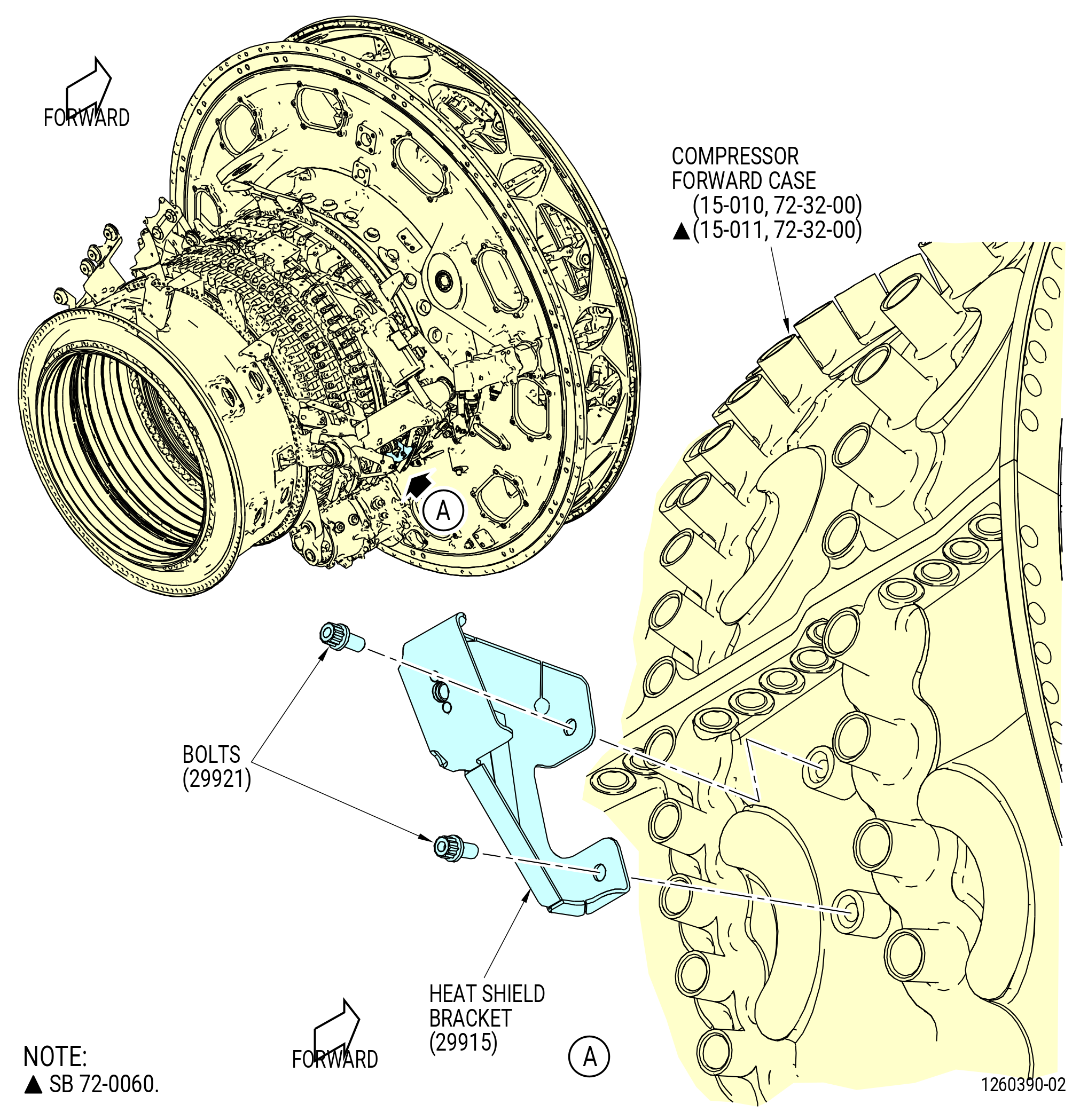
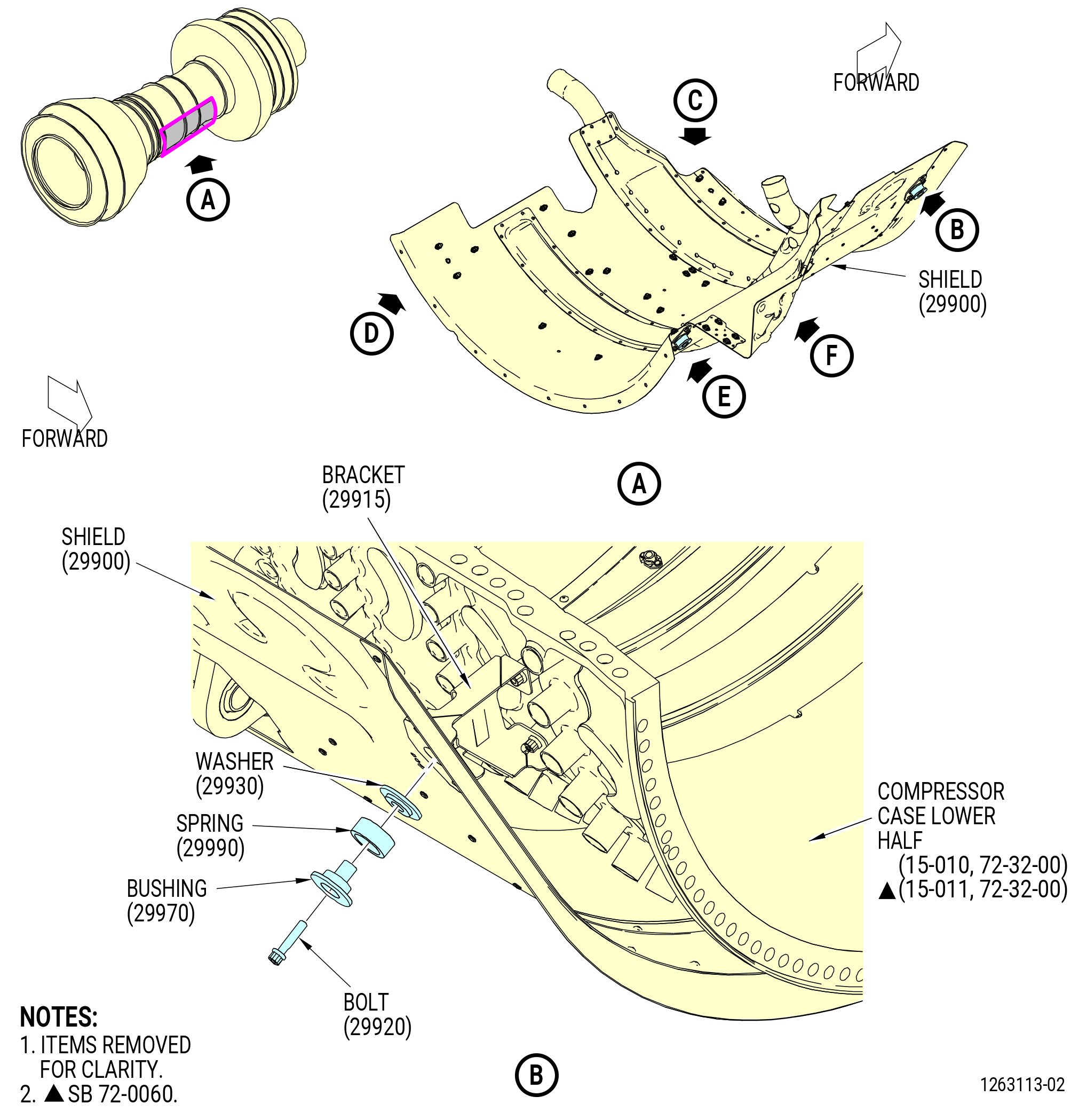
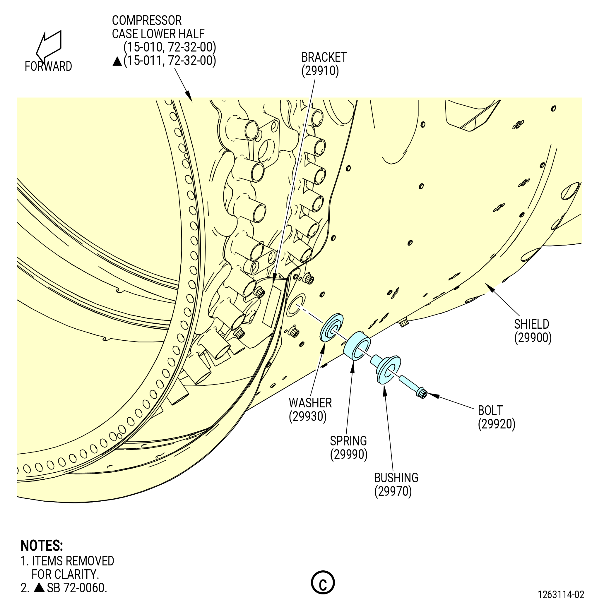
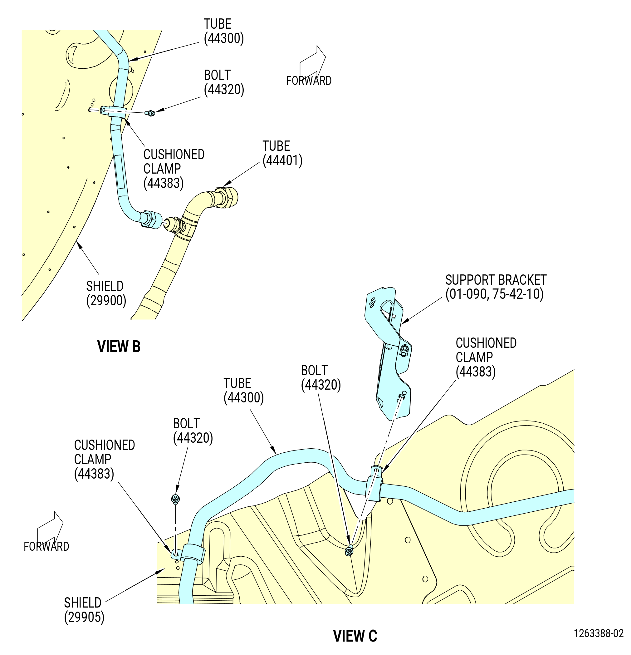
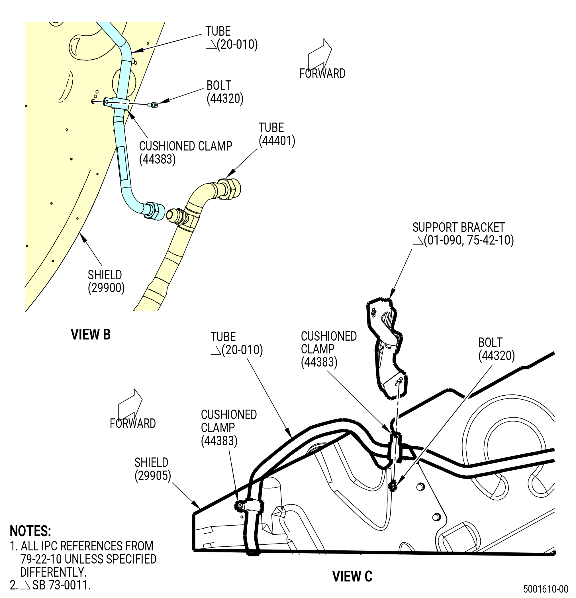
| O. | Install the heat shield (shield) (29900) as follows. Refer to Figure 1016. |
| (1) | Install the heat shield bracket (29910) as follows: |
| (a) | Put the heat shield bracket (bracket) (29910) on the compressor forward case (15-010 , 72-32-00) or (15-011 , 72-32-00) (SIN 073A0). Align the bracket with the two bolt pads between the stage 1 and 2 bosses at the 6:30 o'clock position. |
| (b) | Attach the bracket with bolts (29921). |
| (c) | Torque the bolts (29921) to 106-124 lb in. (12.0-14.0 N.m). |
| (2) | Install the heat shield bracket (29915) as follows: |
| (a) | Put the heat shield bracket (bracket) (29915) on the compressor forward case (15-010 , 72-32-00) or (15-011 , 72-32-00) (SIN 073A0). Align the bracket with the two bolt pads between the stage 1 and 2 bosses at the 3:30 o'clock position. |
| (b) | Attach the bracket with bolts (29921). |
| (c) | Torque the bolts (29921) to 106-124 lb in. (12.0-14.0 N.m). |
| (3) | Install the heat shield at the 6:00 o'clock position of the HPC assembly (33-009) (SIN 00108) or (33-010) (SIN 00108). Attach the heat shield to the bracket (29914) with a bolt (29921). |
| (4) | Attach the heat shield to the bracket (29910) with a bolt (29920), dampening bushing (bushing ) (29970), retainer (spring) (29990), and friction washer (washer) (29930). |
| (5) | Attach the heat shield to the bracket (29912) with a bolt (29920), bushing (29970), spring (29990), and washer (29930). |
| (6) | Attach the heat shield to the bracket (29913) with a bolt (29920), bushing (29970), spring (29990), and washer (29930). |
| (7) | Attach the heat shield to the bracket (29915) with a bolt (29920), bushing (29970), spring (29990), and washer (29930). |
| (8) | Torque the bolt (29921) to 106-124 lb in. (12.0-14.0 N.m). |
| (9) | Torque the bolts (29920) to 106-124 lb in. (12.0-14.0 N.m). Make sure that the bolts are in the center of the heat shield holes at each location. |
| Subtask 72-00-02-440-178 |
| * * * PRE SB 79-0014( Non-Optimized VFSG Cooling System ) |
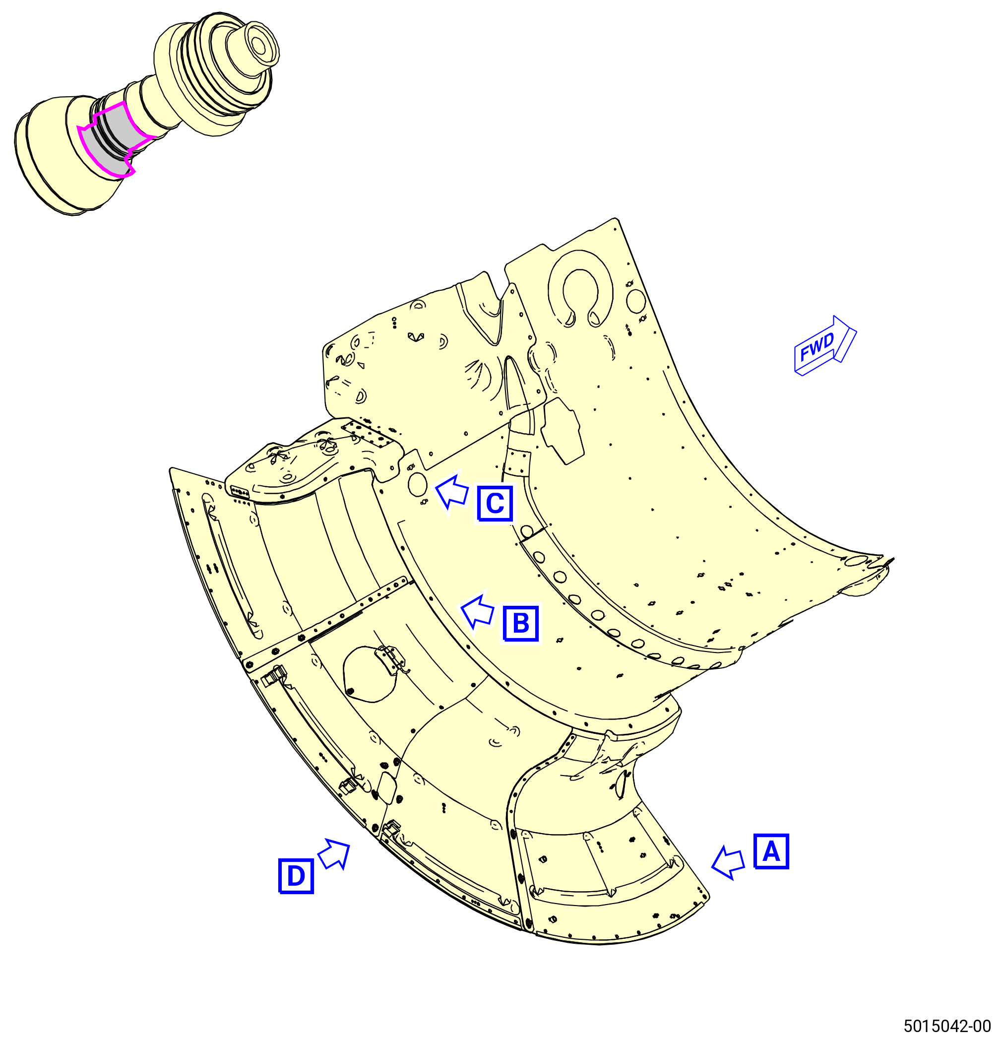
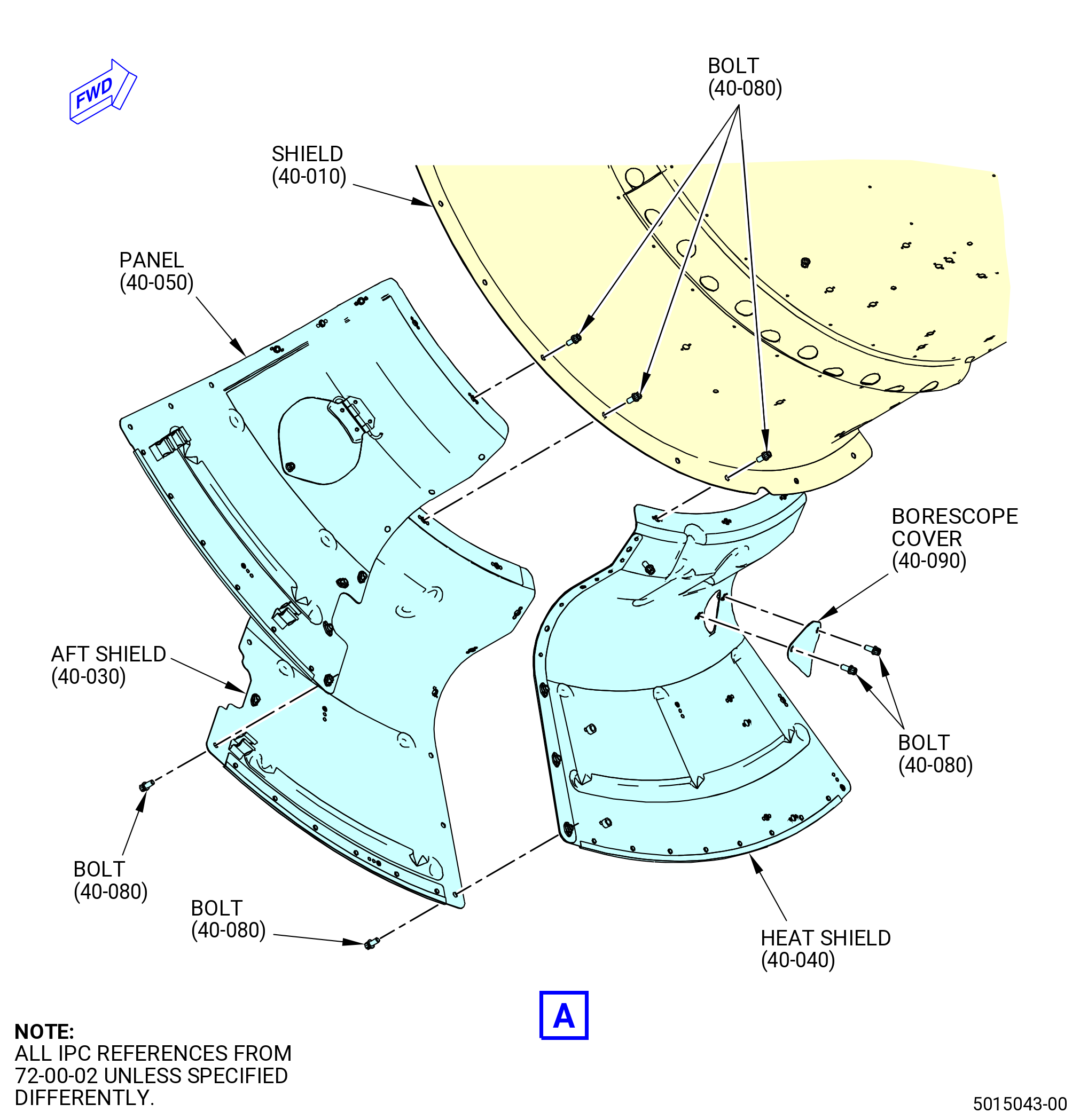
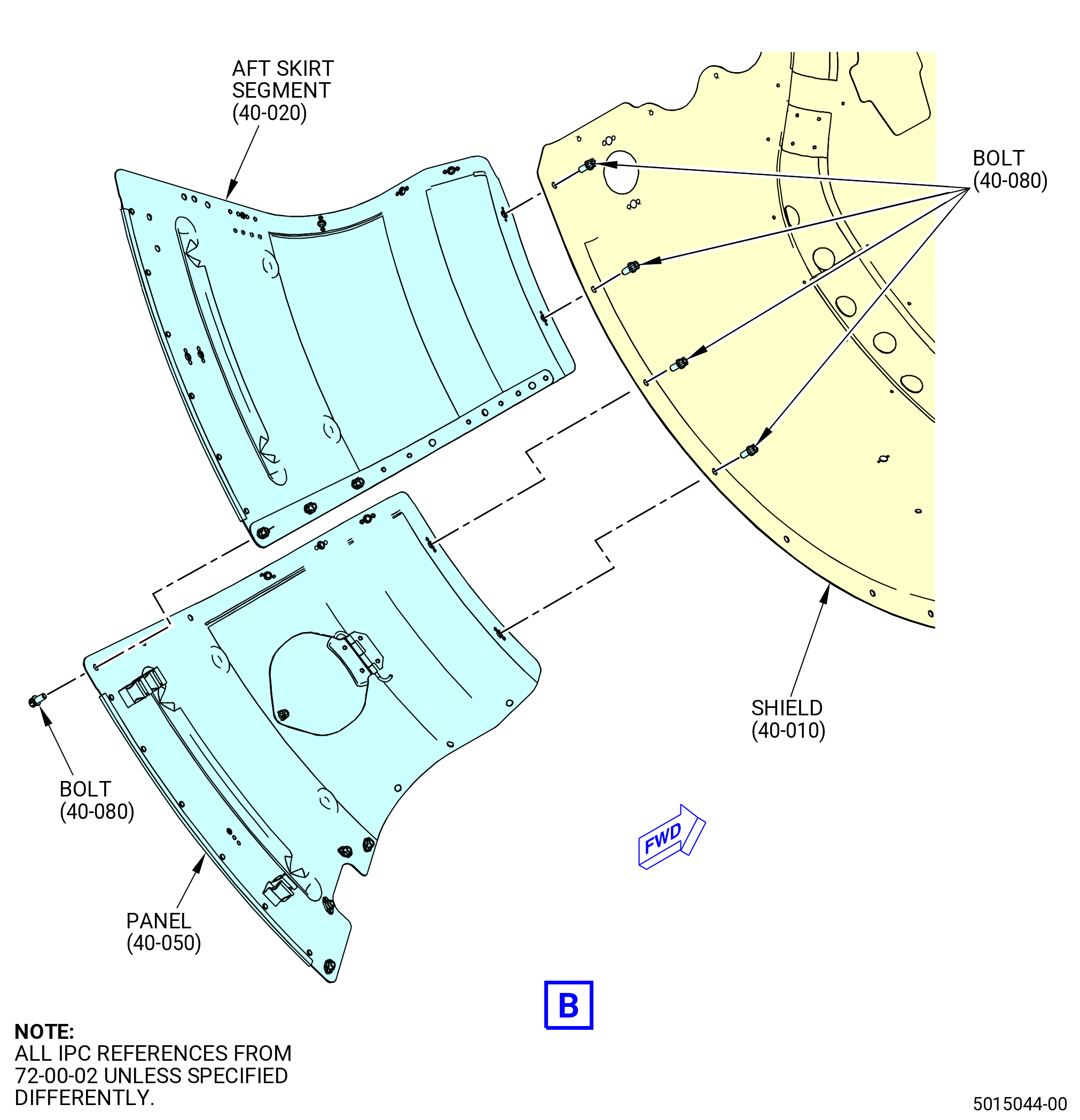
| P. | Install the heat shield aft skirt segments as follows. Refer to Figure 1017. |
| (1) | Install the aft skirt segment (29901) on the shield (29900) at the 7:30 o'clock position (FLA). Attach the aft skirt segment with bolts (29921). |
| (2) | Install the aft skirt segment (heat shield) (29903) on the shield (29900) at the 4:30 o'clock position (FLA). Attach the aft skirt segment with bolts (29921). |
| (3) | Install the aft skirt segment (panel) (29904) on the shield (29900) at the 6:30 o'clock position (FLA). Attach the aft skirt segment with bolts (29921). |
| (4) | Install the aft shield (29902) on the shield (29900) at the 5:30 o'clock position (FLA). Attach the aft skirt segment with bolts (29921). |
| (5) | Torque the bolts (29921) to 106-124 lb in. (12.0-14.0 N.m). |
| (6) | Install the 4th and 7th stage cover heat shield (shield) (29905) at the 8:30 o'clock position (FLA). Attach with bolts (29921). |
| (7) | Install the 4th and 7th stage cover heat shield extension (panel) (29907) on the shield (29900) at the 8:00 o'clock position (FLA). Attach with bolts (29921). |
| (8) | Torque the bolts (29921) to 106-124 lb in. (12.0-14.0 N.m). |
| (9) | Install the borescope cover (29906) on the aft skirt segment (29903) with bolts (29921). |
| (10) | Torque the bolts (29921) to 106-124 lb in. (12.0-14.0 N.m). |
| * * * END PRE SB 79-0014 |
| Subtask 72-00-02-440-605 |
| * * * PRE SB 72-0308( Scavenge Oil Tube and Hose without Support Bracket ) |
| (11) | Install the seal retainer (40-100) (SIN 29980) and seal retainer (40-110) (SIN 29981) on the aft shield (40-030) (SIN 29902) and panel (40-050) (SIN 29904). Attach with bolts (40-080) (SIN 29921). |
| * * * END PRE SB 72-0308 |
| Subtask 72-00-02-440-594 |
| * * * SB 72-0308( Scavenge Oil Tube and Hose with Support Bracket ) |
| (11).A. | Install the seal retainer (40-100) (SIN 29980), seal retainer (40-110) (SIN 29981), and support scavenge tube bracket (support bracket) (40-085) (SIN 4541C). Refer to Figure 1017 and do as follows: |
| (a) | Install the seal retainer (40-100) (SIN 29980) and seal retainer (40-110) (SIN 29981) on the aft shield (40-030) (SIN 29902) and panel (40-050) (SIN 29904). |
| (b) | Install the support bracket (40-085) (SIN 4541C). |
| WARNING: |
|
| (c) | Apply C02-038 lubricant or C02-077 lubricant to the threads and friction surfaces of machine bolts (bolts) (40-081) (SIN 29927). |
| (d) | Attach the seal retainers (40-100) (SIN 29980) and (40-110) (SIN 29981) and support bracket (40-085) (SIN 4541C) with bolts (40-081) (SIN 29927). Do not torque at this time. |
| * * * END SB 72-0308 |
| Subtask 72-00-02-440-595 |
| * * * PRE SB 72-0308( Scavenge Oil Tube and Hose without Support Bracket ) |
| (12) | Torque the bolts (40-080) (SIN 29921) to 106 to 124 lb in. (12.0 to 14.0 Nm). |
| * * * END PRE SB 72-0308 |
| Subtask 72-00-02-440-596 |
| * * * SB 72-0308( Scavenge Oil Tube and Hose with Support Bracket ) |
| (12).A. | Torque the bolts (40-081) (SIN 29927) to 106 to 124 lb in. (12.0 to 14.0 Nm). |
| * * * END SB 72-0308( ) |
| Subtask 72-00-02-440-452 |
| * * * SB 79-0014( Optimized VFSG Cooling System ) |
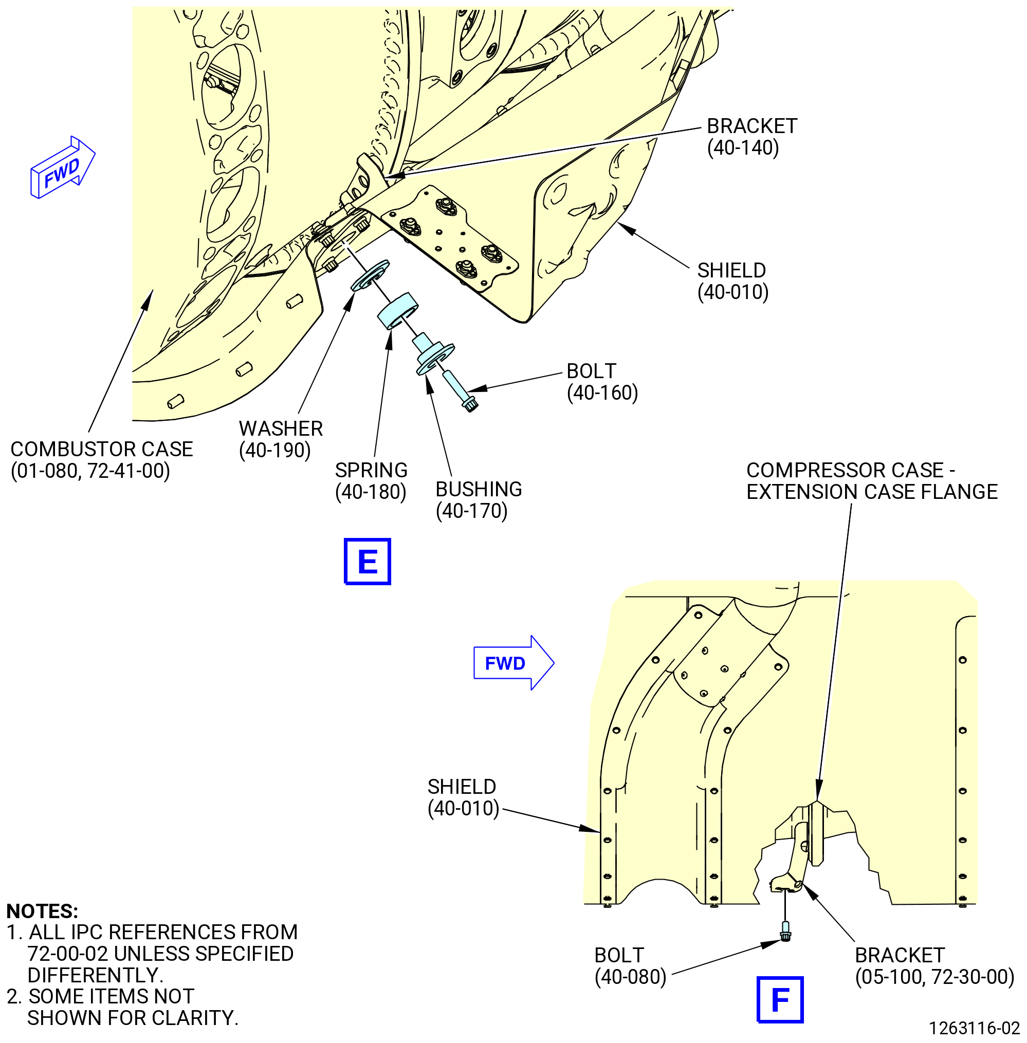
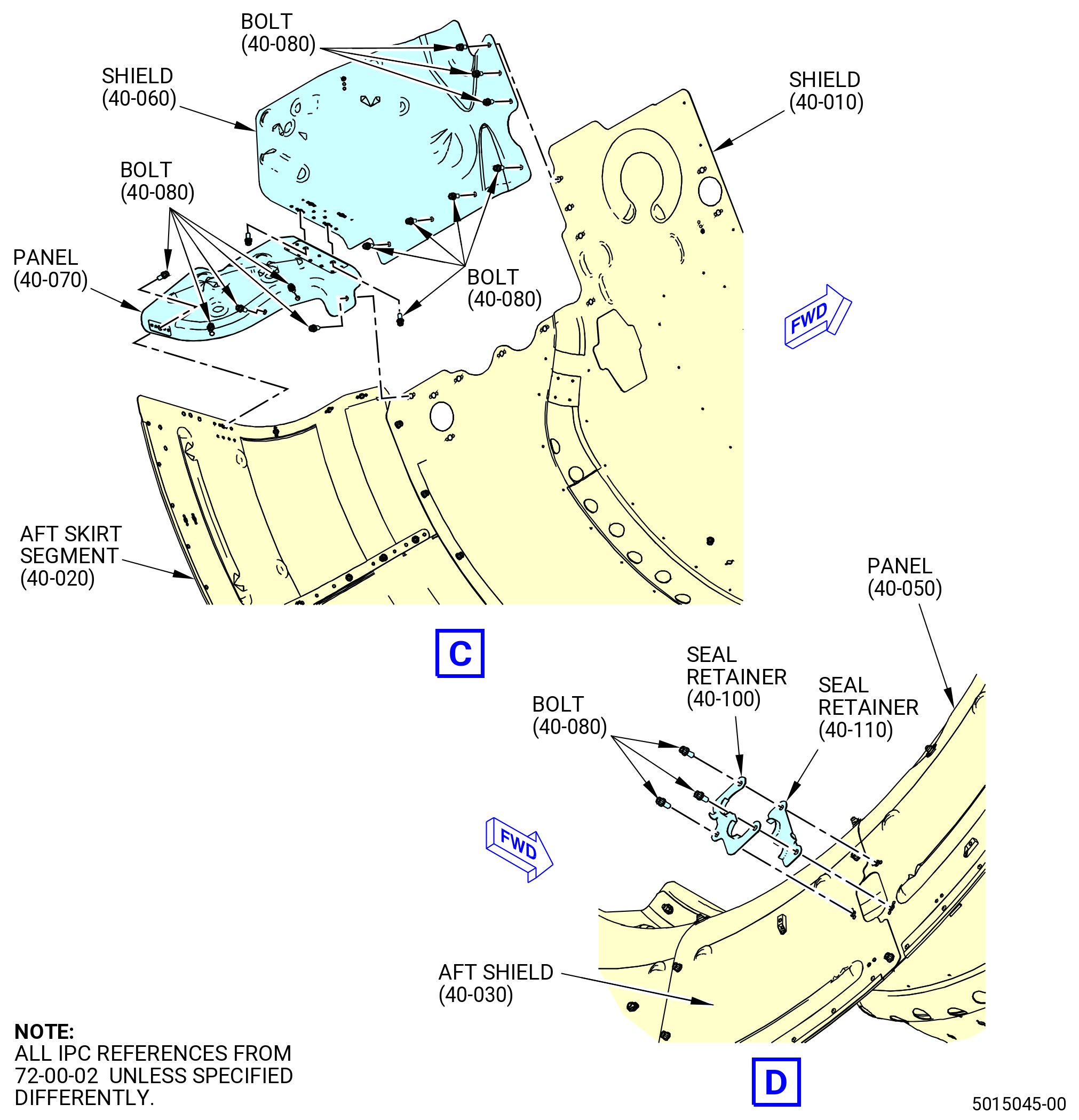
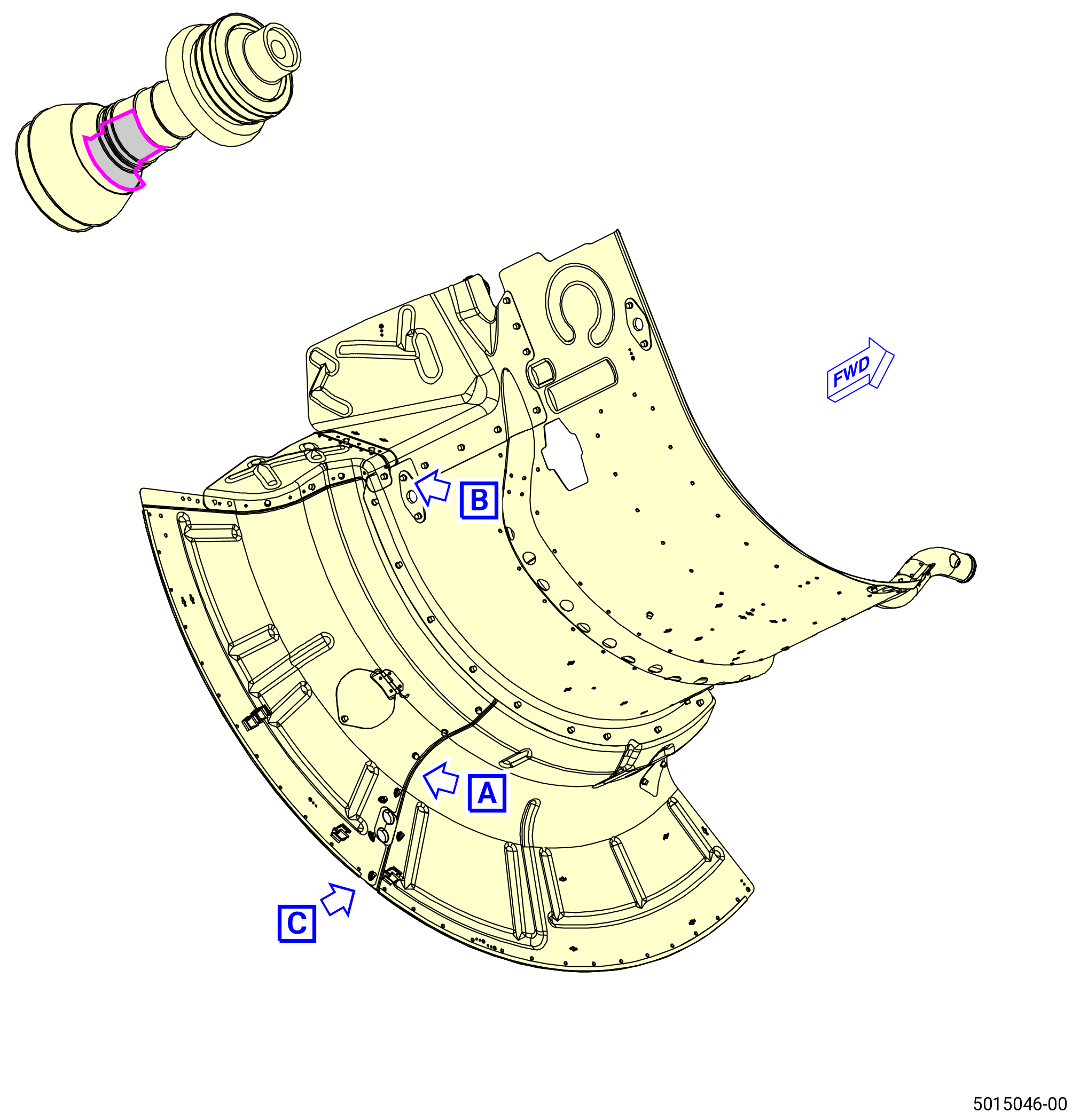
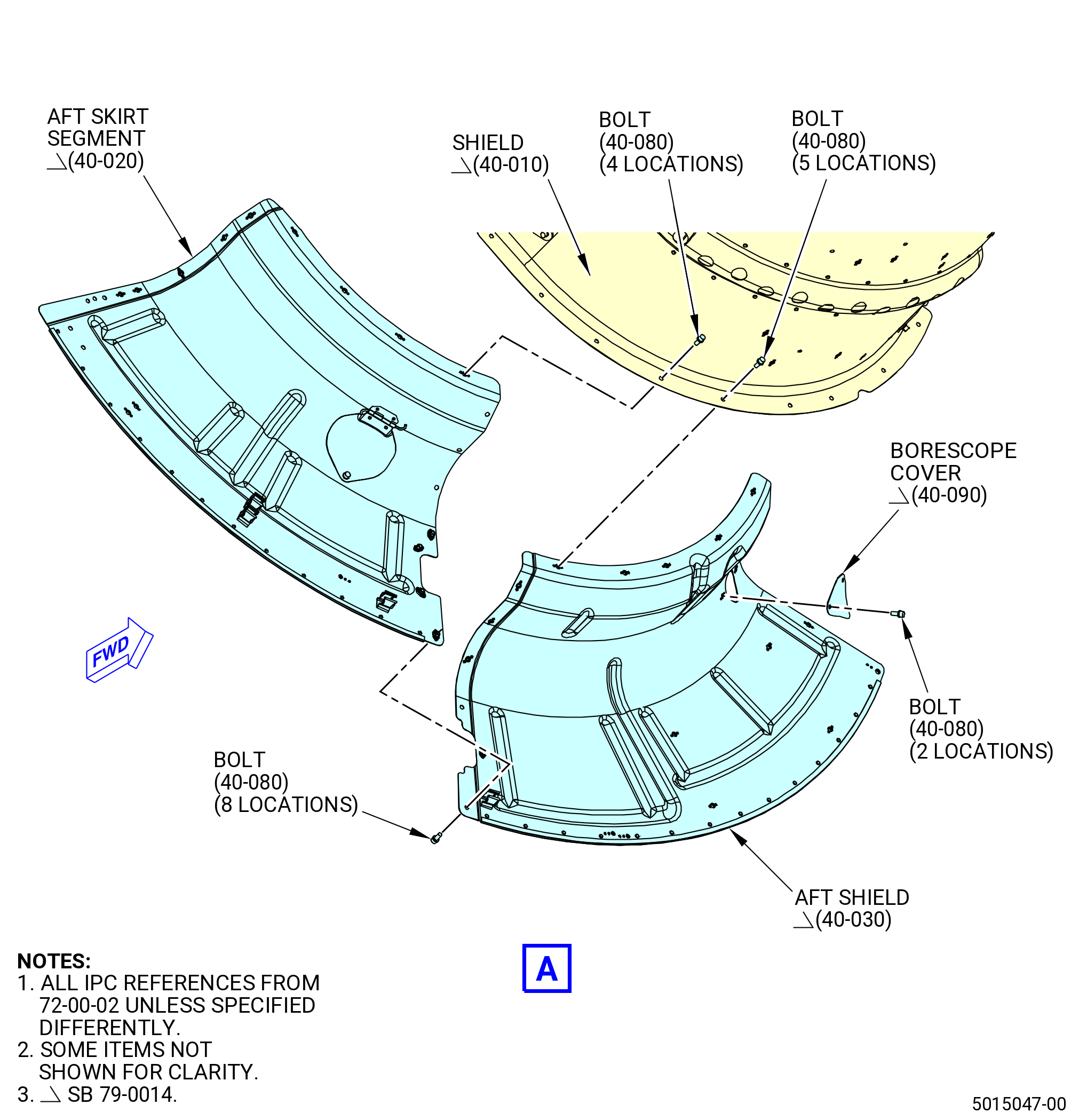
| P.A. | Install the heat shield aft skirt segments. Refer to Figure 1017A and do as follows: |
| (1) | Install the aft skirt segment (40-020) (SIN 29901) on the shield (40-010) (SIN 29900) at the 7:30 o'clock position (FLA). Attach the aft skirt segment with bolts (40-080) (SIN 29921). |
| (2) | Install the aft shield (40-030) (SIN 29902) on the shield (40-010) (SIN 29900) at the 5:30 o'clock position (FLA). Attach the aft skirt segment with bolts (40-080) (SIN 29921). |
| (3) | Attach the aft shield (40-030) (SIN 29902) to the aft skirt segment (40-020) (SIN 29901) with bolts (40-080) (SIN 29921). |
| (4) | Torque the bolts (40-080) (SIN 29921) to 106-124 lb in. (12.0-14.0 N.m). |
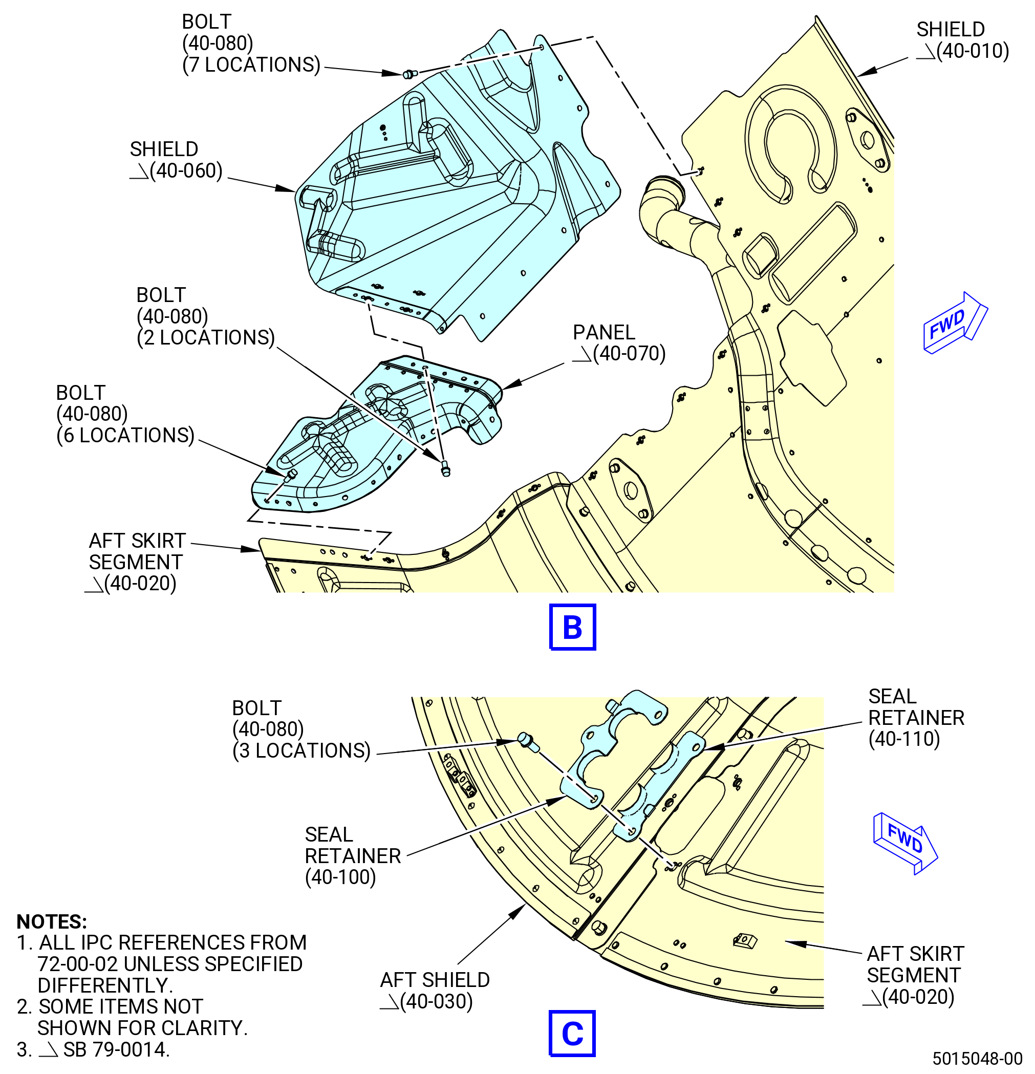
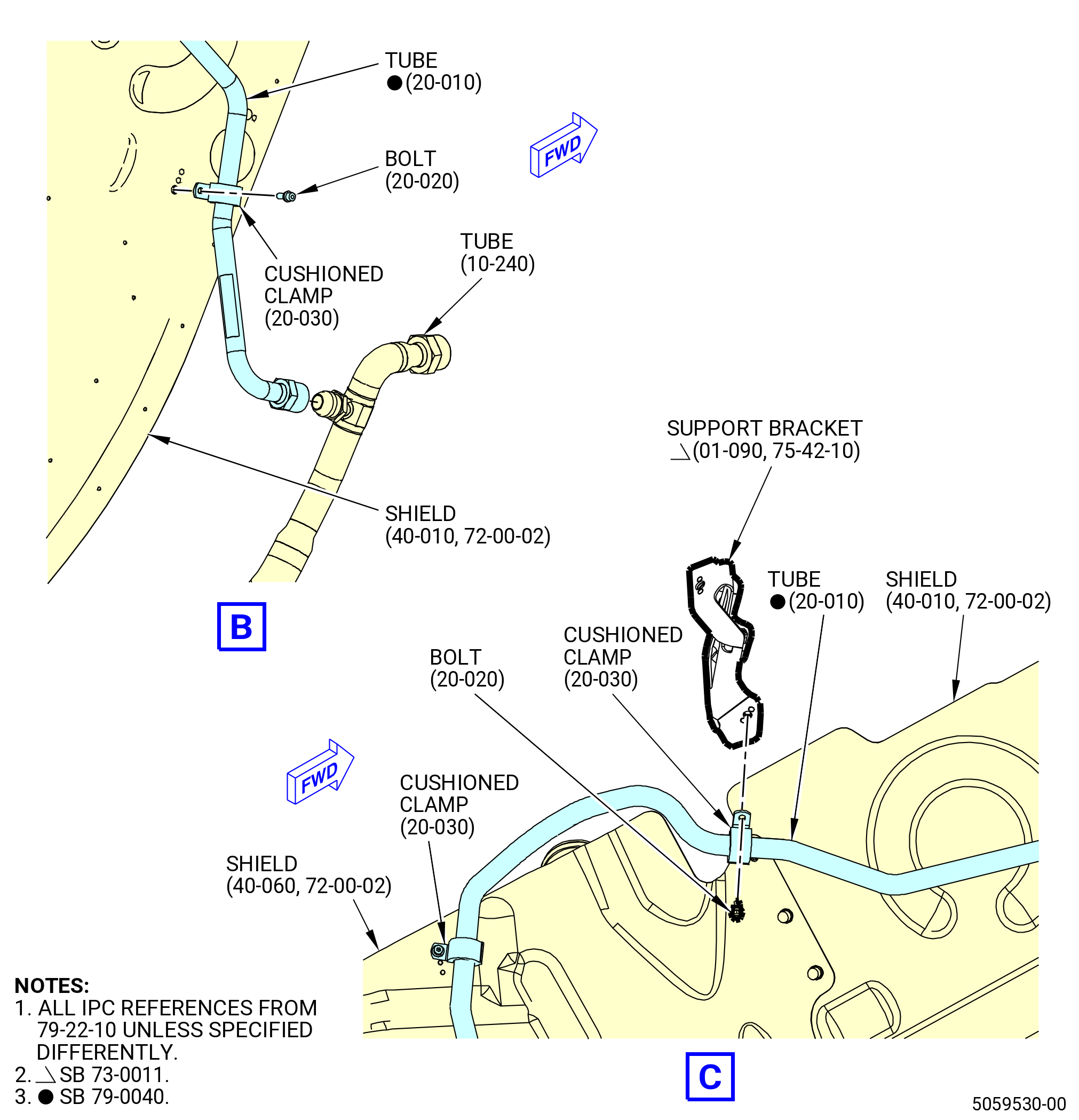
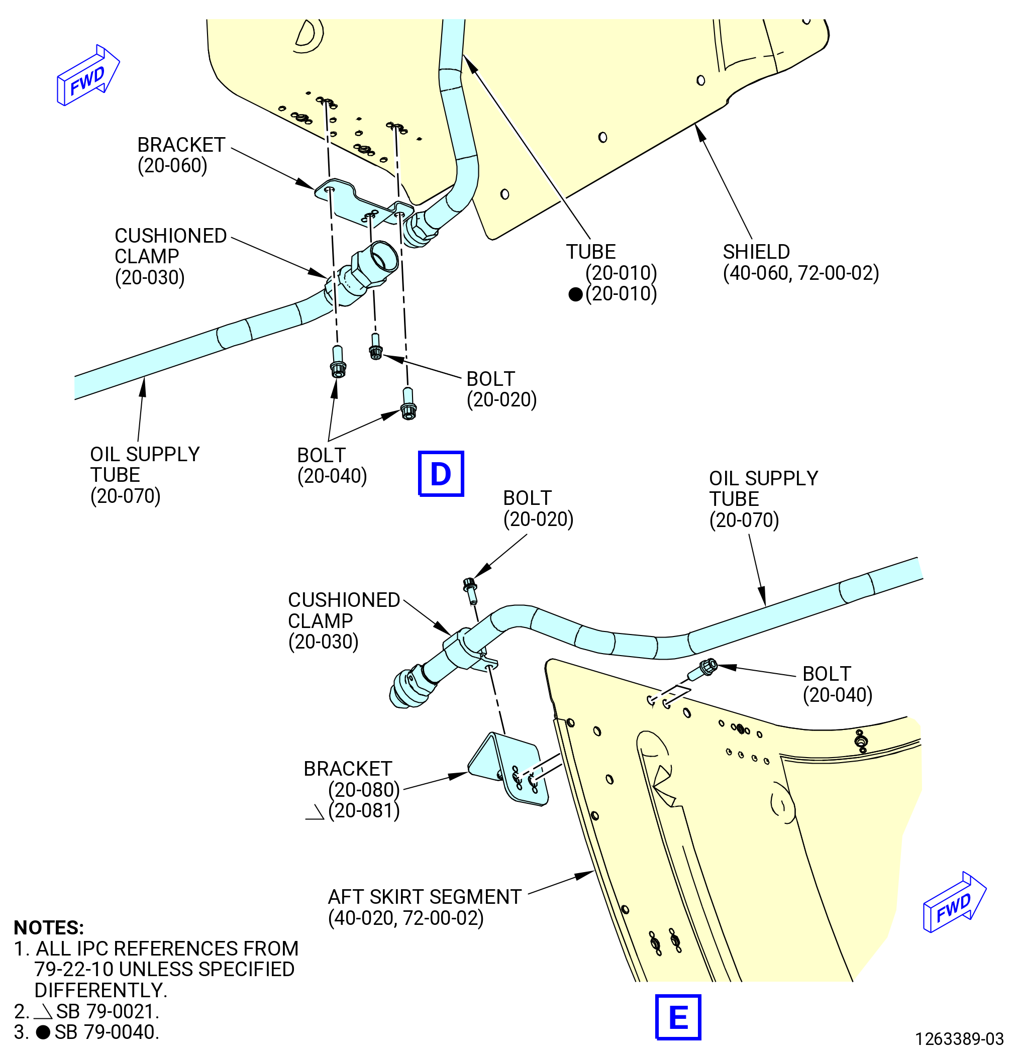
| (5) | Install the shield (40-060) (SIN 29905) on the shield (40-010) (SIN 29900) at the 8:30 o'clock position (FLA). Attach it with bolts (40-080) (SIN 29921). |
| (6) | Install the panel (40-070) (SIN 29907) on the shield (40-010) (SIN 29900), shield (40-060) (SIN 29905), and aft skirt segment (40-020) (SIN 29901) at the 8:00 o'clock position (FLA). Attach it with bolts (40-080) (SIN 29921). |
| (7) | Torque the bolts (40-080) (SIN 29921) to 106-124 lb in. (12.0-14.0 N.m). |
| (8) | Install the borescope cover (40-090) (SIN 29906) on the aft shield (40-030) (SIN 29902) with bolts (40-080) (SIN 29921). |
| (9) | Torque the bolts (40-080) (SIN 29921) to 106-124 lb in. (12.0-14.0 N.m). |
| * * * END SB 79-0014 |
| Subtask 72-00-02-440-606 |
| * * * PRE SB 72-0308( Scavenge Oil Tube and Hose without Support Bracket ) |
| (10) | Install the seal retainer (40-100) (SIN 29980) and seal retainer (40-110) (SIN 29981) on the aft shield (40-030) (SIN 29902) and aft skirt segment (40-020) (SIN 29901). Attach it with bolts (40-080) (SIN 29921). |
| * * * END PRE SB 72-0308 |
| Subtask 72-00-02-440-597 |
| * * * SB 72-0308( Scavenge Oil Tube and Hose with Support Bracket ) |
| (10).A. | Install the seal retainer (40-100) (SIN 29980), seal retainer (40-110) (SIN 29981), and support bracket (40-085) (SIN 4541C). Refer to Figure 1017A and do as follows: |
| (a) | Install the seal retainer (40-100) (SIN 29980) and seal retainer (40-110) (SIN 29981) on the aft shield (40-030) (SIN 29902) and aft skirt segment (40-020) (SIN 29901). |
| (b) | Install the support bracket (40-085) (SIN 4541C). |
| WARNING: |
|
| (c) | Apply C02-038 lubricant or C02-077 lubricant to the threads and friction surfaces of bolts (40-081) (SIN 29927). |
| (d) | Attach the seal retainers (40-100) (SIN 29980) and (40-110) (SIN 29981) and support bracket (40-085) (SIN 4541C) with bolts (40-081) (SIN 29927). Do not torque at this time. |
| * * * END SB 72-0308( ) |
| Subtask 72-00-02-440-598 |
| * * * PRE SB 72-0308( Scavenge Oil Tube and Hose without Support Bracket ) |
| (11) | Torque the bolts (40-080) (SIN 29921) to 106 to 124 lb in. (12.0 to 14.0 Nm). |
| * * * END PRE SB 72-0308 |
| Subtask 72-00-02-440-599 |
| * * * SB 72-0308( Scavenge Oil Tube and Hose with Support Bracket ) |
| (11).A. | Torque the bolts (40-081) (SIN 29927) to 106 to 124 lb in. (12.0 to 14.0 Nm). |
| * * * END SB 72-0308 |
|
|
|
|
|
| Subtask 72-00-02-440-179 |
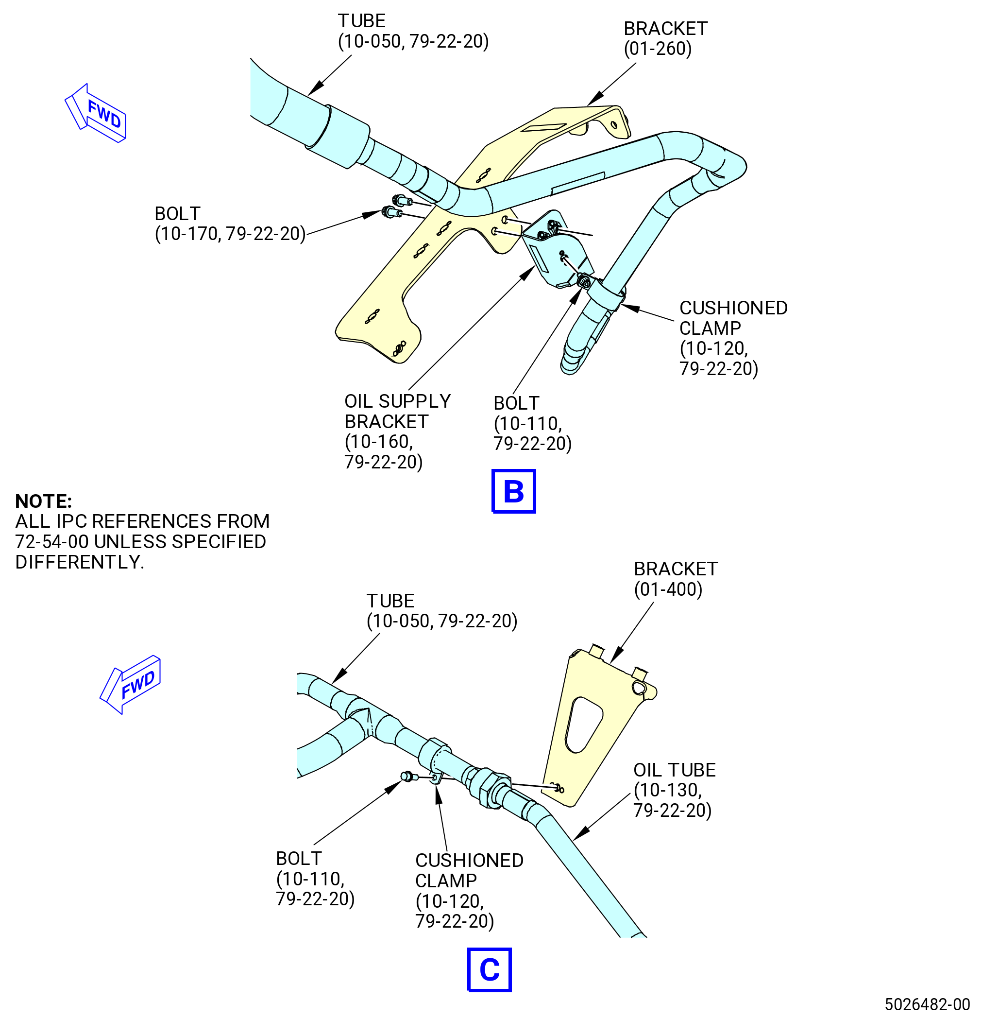
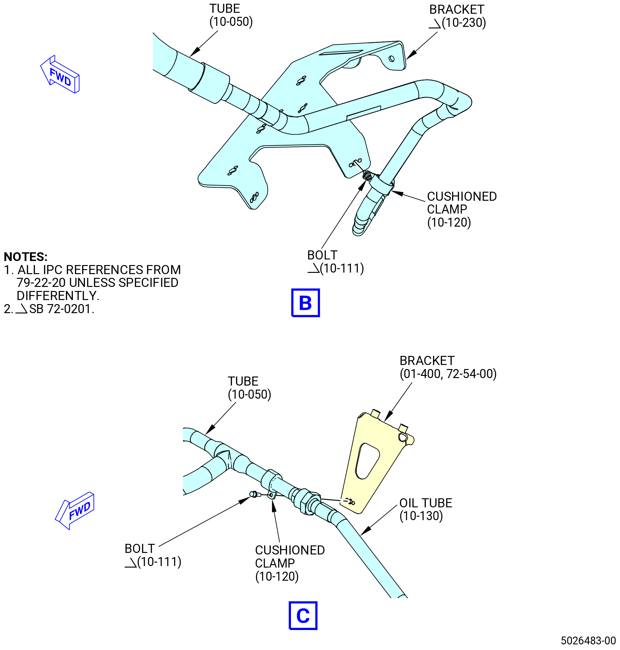
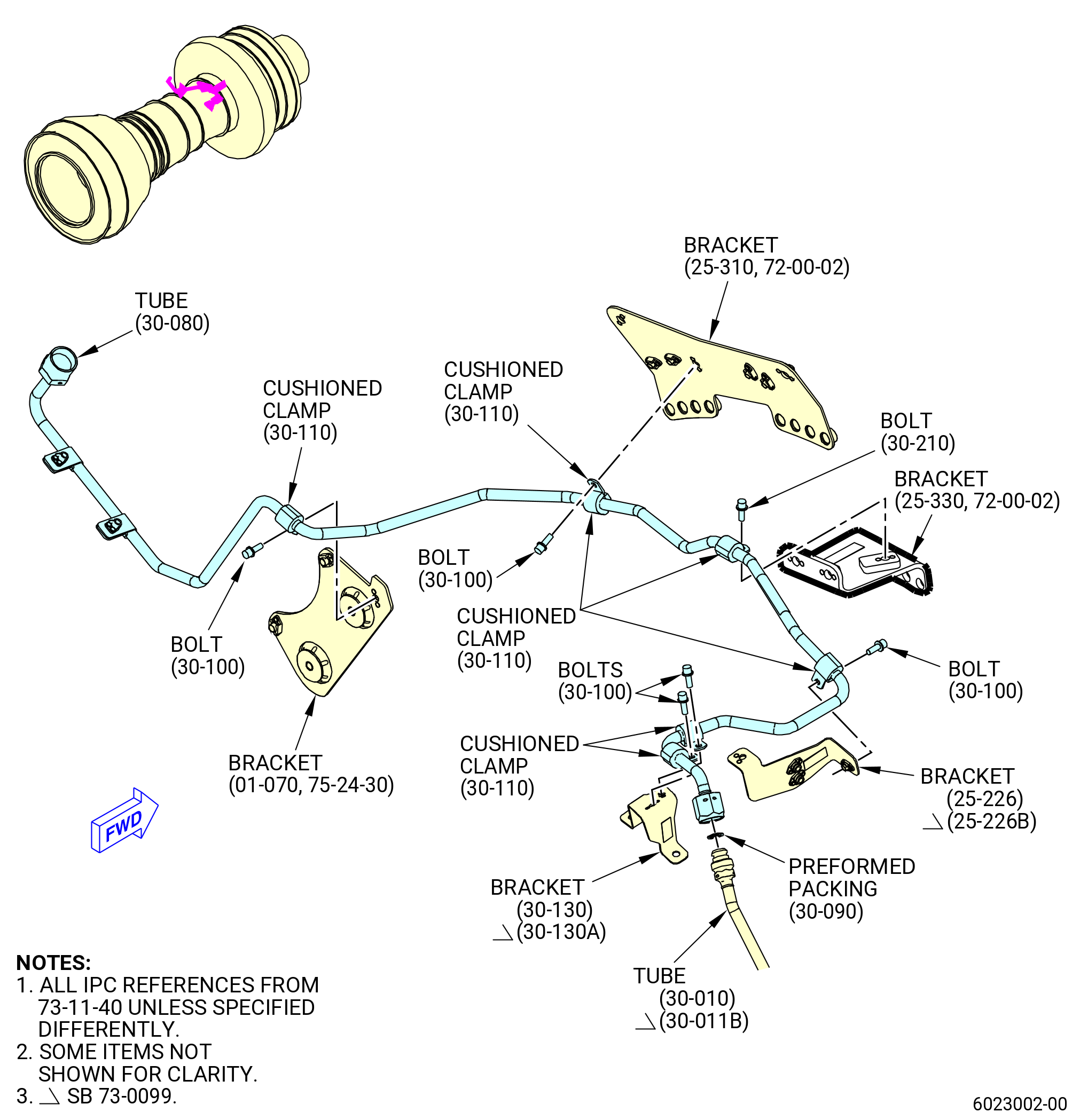
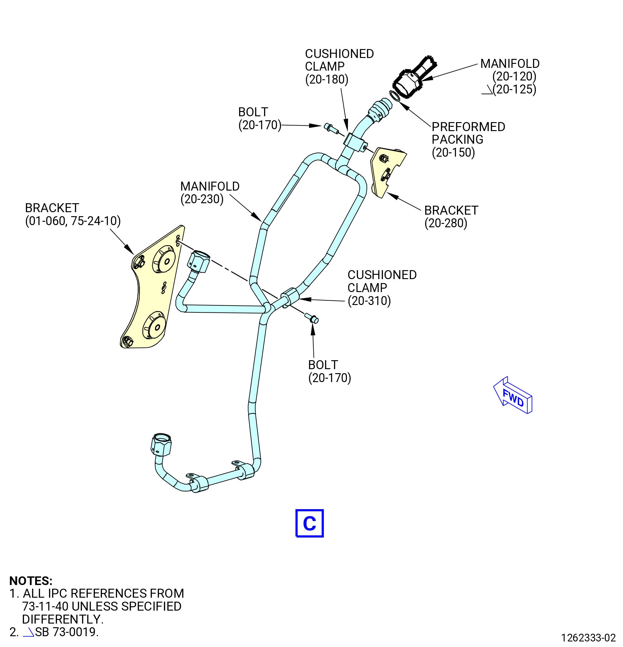
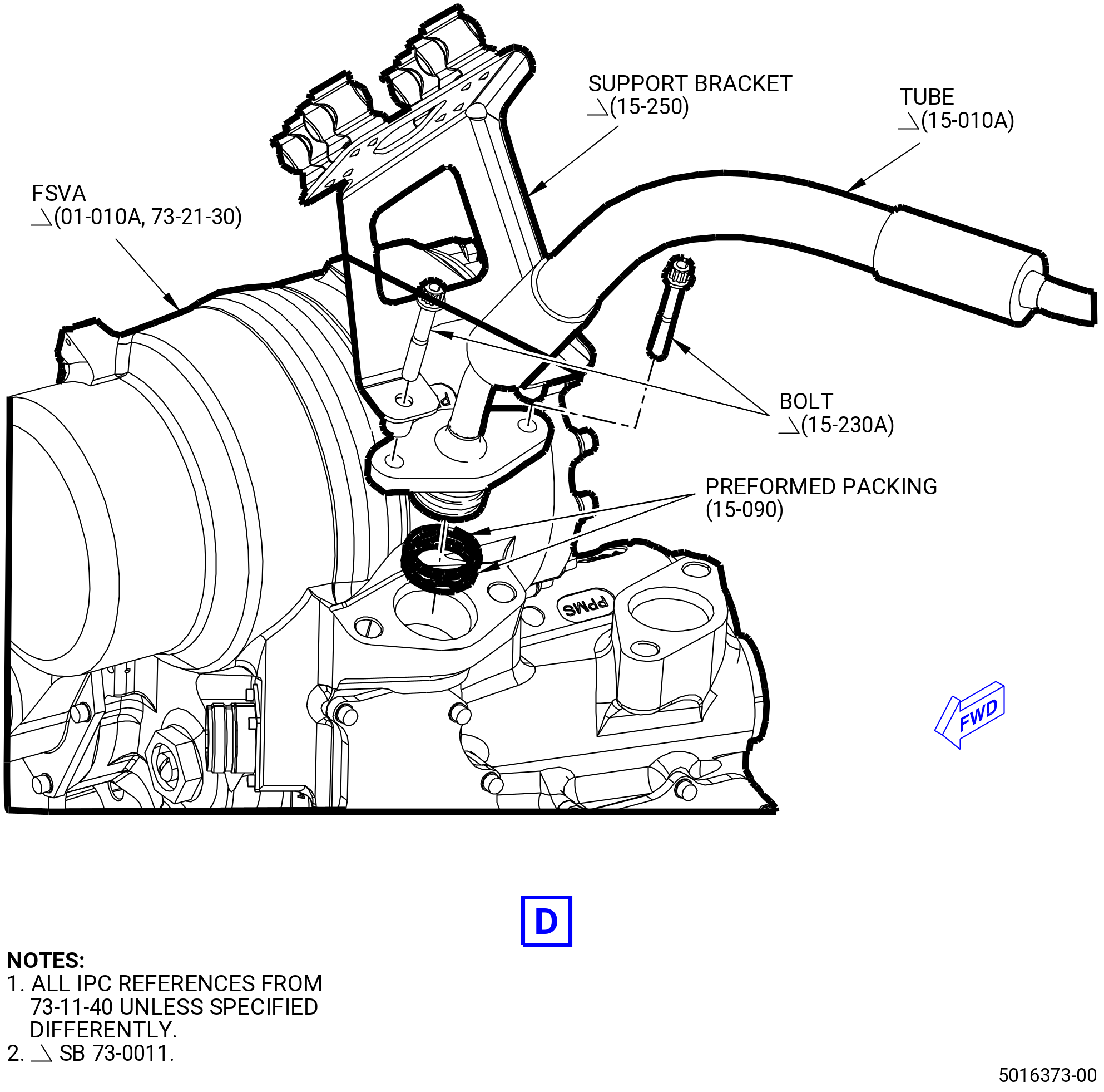
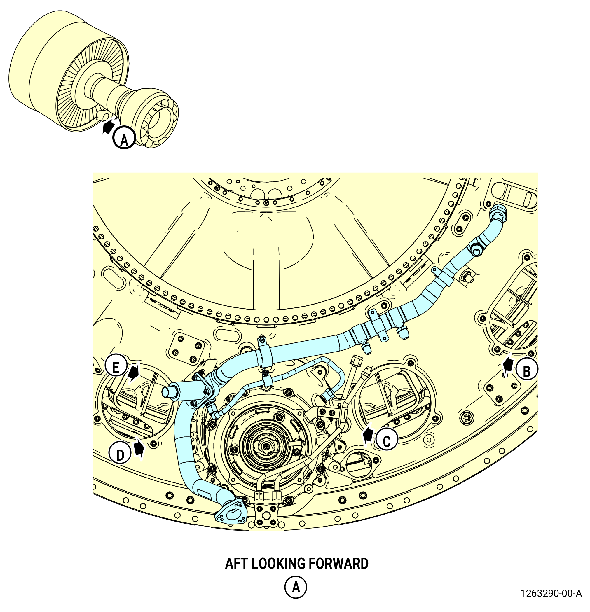
| Q. | Install the turbine center frame (TCF) frame scavenge system. Refer to Figure 1018 and do as follows: |
| (1) | Put the scavenge oil tube and hose (tube) (45401) in position on the bottom of the TCF. |
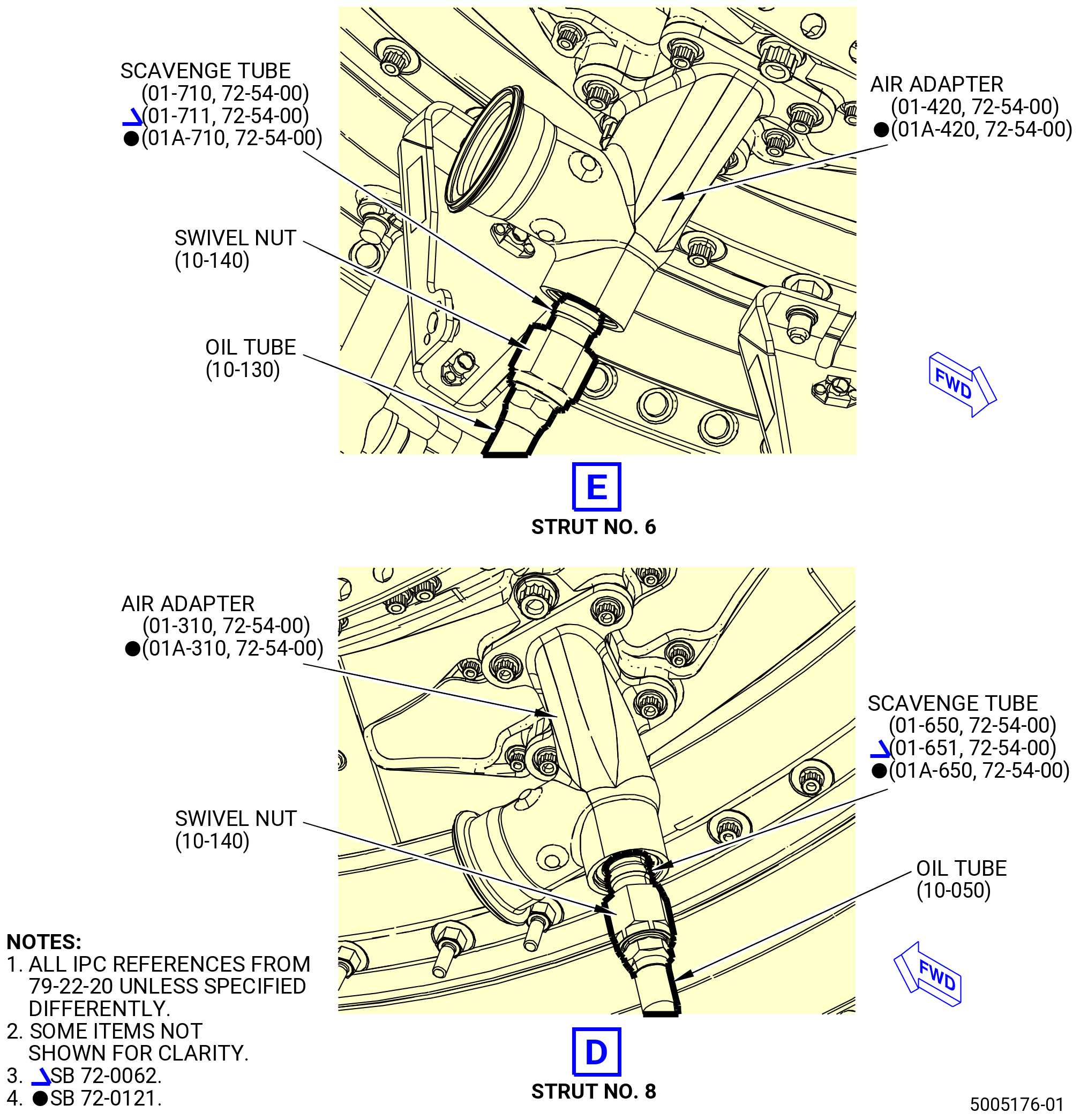
| (2) | Connect the B-nut of the scavenge tube (01-650 , 72-54-00) (SIN 454A2) or (01-651 , 72-54-00) (SIN 454A2) or (01A-650 , 72-54-00) (SIN 454A2) to the tube (10-050 , 79-22-20) (SIN 45401). |
| (3) | Put the B-sump scavenge oil tube (oil tube) (45402) at the 6:00 o'clock position on the B-nut connection of the TCF. |
| (4) | Connect the B-nut of the scavenge tube (01-710 , 72-54-00) (SIN 454A1) or (01-711 , 72-54-00) (SIN 454A1) or (01A-710 , 72-54-00) (SIN 454A1) to the oil tube (10-130 , 79-22-20) (SIN 45402). Connect the B-nut of the oil tube to the tube (10-050 , 79-22-20) (SIN 45401). |
| Subtask 72-00-02-440-507 |
| * * * PRE SB 72-0201( Support Bracket without Clearance Fix ) |
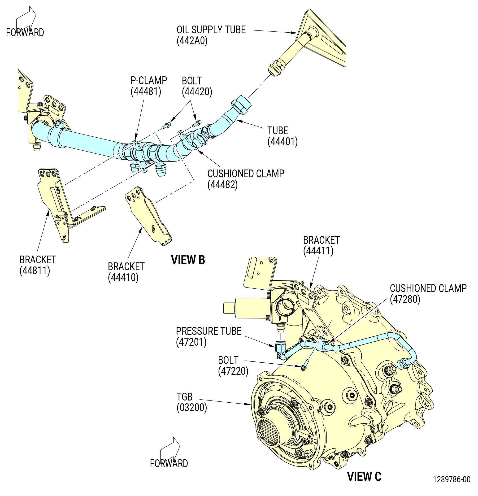
| (5) | Attach the tube (10-050 , 79-22-20) (SIN 45401) to the oil supply bracket (10-160 , 79-22-20) (SIN 45410) as follows: |
| (a) | Attach the oil supply bracket (10-160 , 79-22-20) (SIN 45410) to the bracket (01-260 , 72-54-00) (SIN 45210) with bolts (10-170 , 79-22-20) (SIN 45420). |
| (b) | Attach the tube to the oil supply bracket (10-160 , 79-22-20) (SIN 45410) with a cushioned loop clamp (cushioned clamp) (10-120 , 79-22-20) (SIN 45480) and a bolt (10-110 , 79-22-20) (SIN 45422). |
| * * * END PRE SB 72-0201( ) |
| Subtask 72-00-02-440-508 |
| * * * SB 72-0201( Support Bracket with Clearance Fix ) |
| (5).A. | Attach the tube (10-050 , 79-22-20) (SIN 45401) to the bracket (10-230 , 79-22-20) (SIN 45210) with a cushioned clamp (10-120 , 79-22-20) (SIN 45480) and a bolt (10-111 , 79-22-20) (SIN 45422). |
| * * * END SB 72-0201 |
| Subtask 72-00-02-440-509 |
| (6) | Attach the tube (10-050 , 79-22-20) (SIN 45401) to the bracket (01-400 , 72-54-00) (SIN 45411) with a cushioned clamp (10-120 , 79-22-20) (SIN 45480) and a bolt (10-110 , 79-22-20) (SIN 45422) or (10-111 , 79-22-20) (SIN 45422). |
| (7) | Torque the B-nut on the tube (10-050 , 79-22-20) (SIN 45401) to the scavenge tube (01-650 , 72-54-00) (SIN 454A2) or (01-651 , 72-54-00) (SIN 454A2) or (01A-650 , 72-54-00) (SIN 454A2) as follows: |
| (a) | Torque the B-nut to 55-65 lb ft (75-88 N.m). |
| (b) | Loosen the B-nut and torque again to 55-65 lb ft (75-88 N.m). |
| (c) | Apply a final torque of 55-65 lb ft (75-88 N.m). |
| (8) | Torque the B-nut on the oil tube (10-130 , 79-22-20) (SIN 45402) to the scavenge tube (01-710 , 72-54-00) (SIN 454A1) or (01-711 , 72-54-00) (SIN 454A1) or (01A-710 , 72-54-00) (SIN 454A1) as follows: |
| (a) | Torque the B-nut to 55-65 lb ft (75-88 N.m). |
| (b) | Loosen the B-nut and torque again to 55-65 lb ft (75-88 N.m). |
| (c) | Apply a final torque of 55-65 lb ft (75-88 N.m). |
| (9) | Torque the B-nut on the tube (45401) to the oil tube (45402) as follows: |
| (a) | Torque the B-nut to 78-92 lb ft (106-125 N.m). |
| (b) | Loosen the B-nut and torque again to 78-92 lb ft (106-125 N.m). |
| (c) | Apply a final torque of 78-92 lb ft (106-125 N.m). |
| Subtask 72-00-02-440-510 |
| * * * PRE SB 72-0201( Support Bracket without Clearance Fix ) |
| (10) | Torque the bolts (10-170 , 79-22-20) (SIN 45420) to 106 to 124 lb in. (12.0 to 14.0 Nm). |
| NOTE: |
|
| * * * END PRE SB 72-0201 |
| Subtask 72-00-02-440-511 |
| (11) | Torque the bolts (10-110 , 79-22-20) (SIN 45422) or (10-111 , 79-22-20) (SIN 45422) to 60 to 70 lb in. (6.8 to 7.9 Nm). |
| Subtask 72-00-02-440-247 |
| * * * SB 72-0048( TCF/TRF Drain System with Adapter Cap Deflectors ) |
| (12) | Install the four adapter cap deflectors (deflectors) (10-210 , 79-22-20) (SIN 9259B) at the struts No. 6 and 8 as follows: |
| NOTE: |
|
| (a) | Install two deflectors around the swivel nut (10-140 , 79-22-20) (SIN 454K0) and air adapter (01-310 , 72-54-00) (SIN 9250C) or (01A-310 , 72-54-00) (SIN 9250C) at the strut No. 6. |
| (b) | Make sure that the corners of the swivel nut wrenching feature edges do not line up with the space between the two deflectors. |
| (c) | Install two deflectors around the swivel nut and air adapter (01-420 , 72-54-00) (SIN 92509) or (01A-420 , 72-54-00) (SIN 92509) at the strut No. 8. |
| (d) | Make sure that the corners of the swivel nut wrenching feature edges do not line up with the space between the two deflectors. |
| (e) | Attach the deflectors with one hose clamp (10-220 , 79-22-20) (SIN 9258A) or (10-221 , 79-22-20) (SIN 9258E) at the struts No. 6 and No. 8. |
| (f) | Torque the hose clamps to 32-38 lb in. (3.6-4.3 N.m). |
| (g) | Remove any excess in length of the hose clamps so no more than 1.00 inch (25.4 mm) is exposed between the hose clamps and the screws. No burrs are permitted. |
| * * * END SB 72-0048 |
|
|
|
|
| Subtask 72-00-02-440-120 |
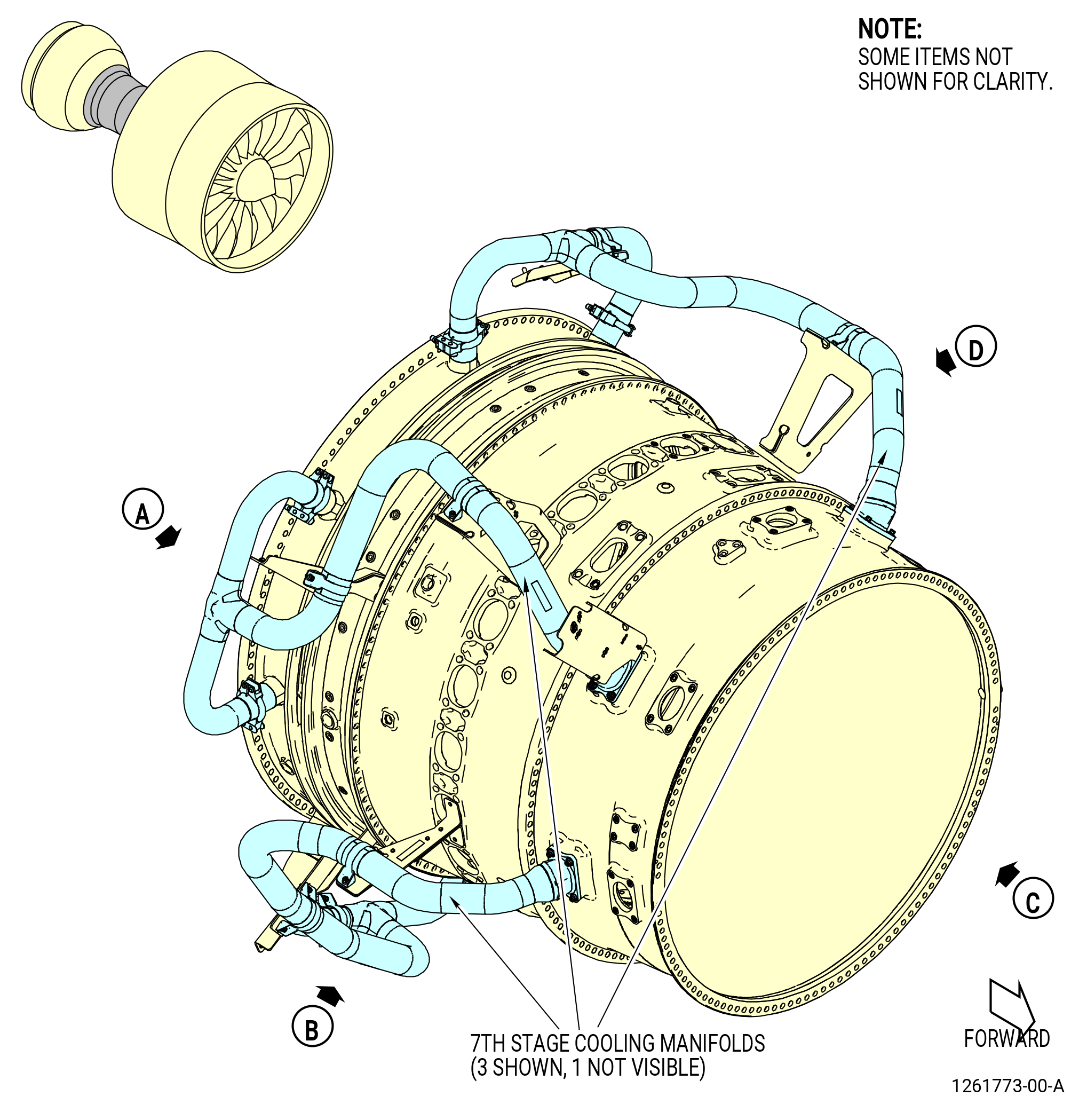
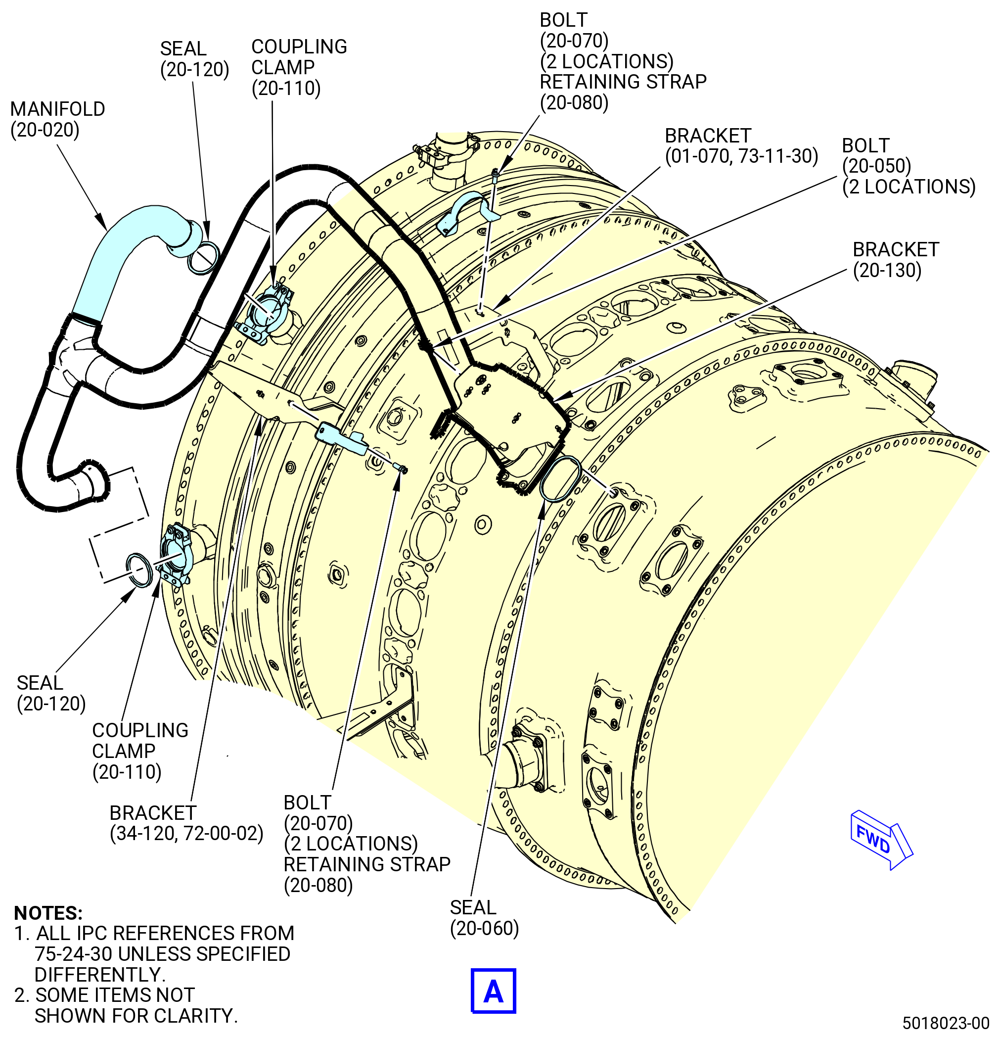
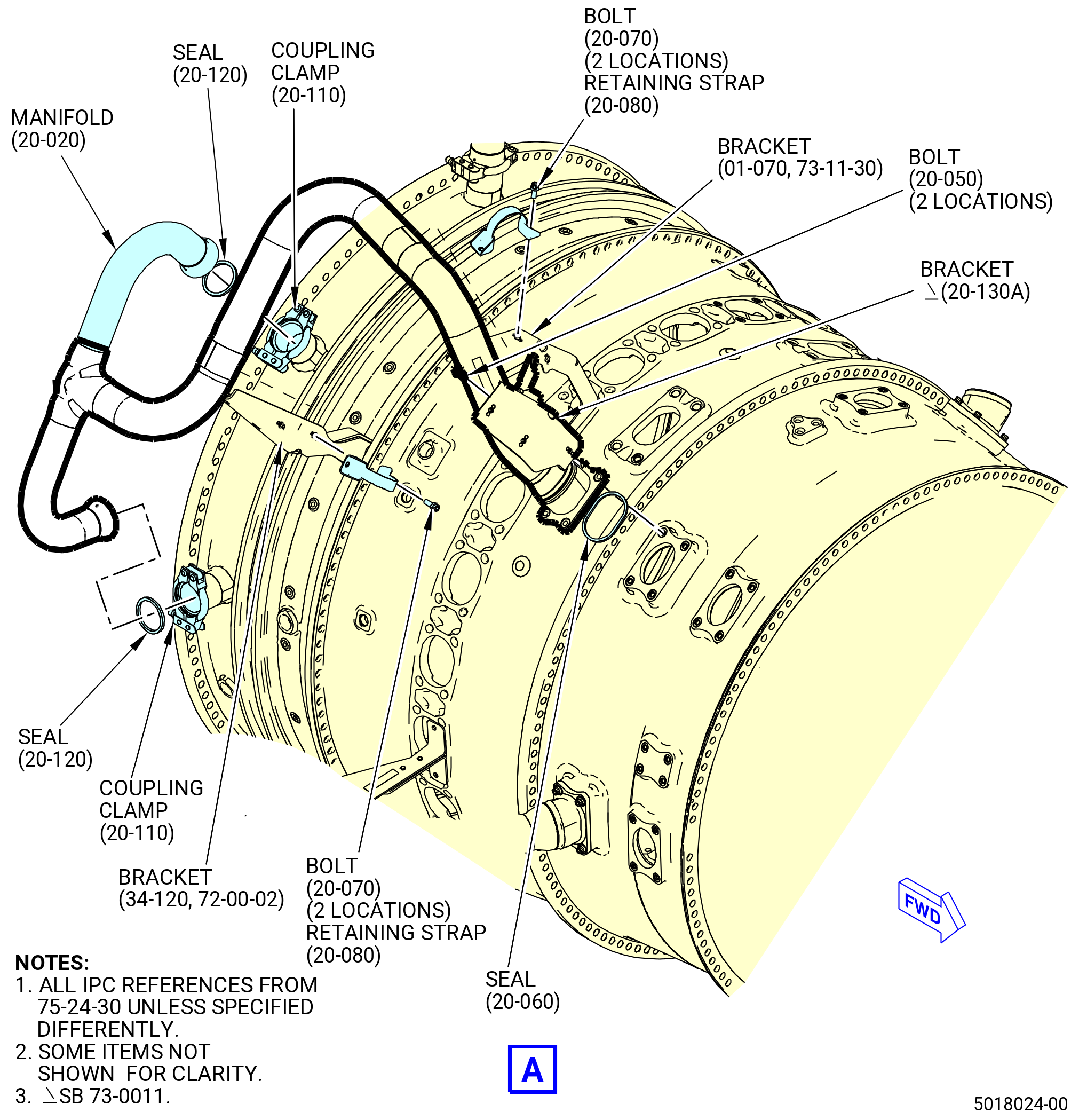
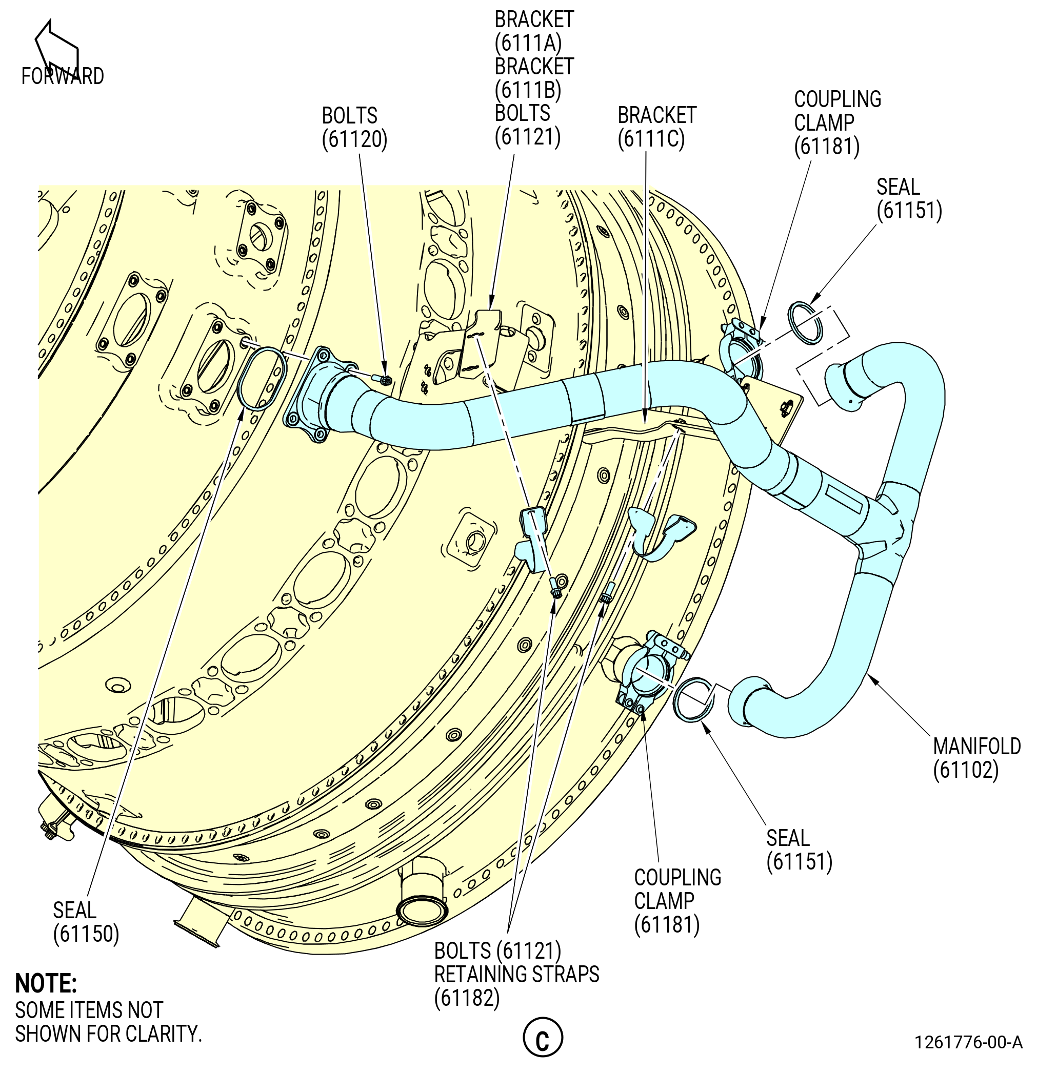
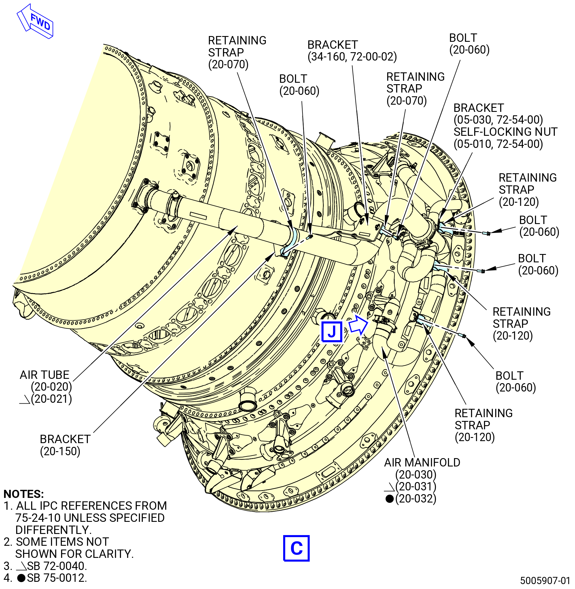
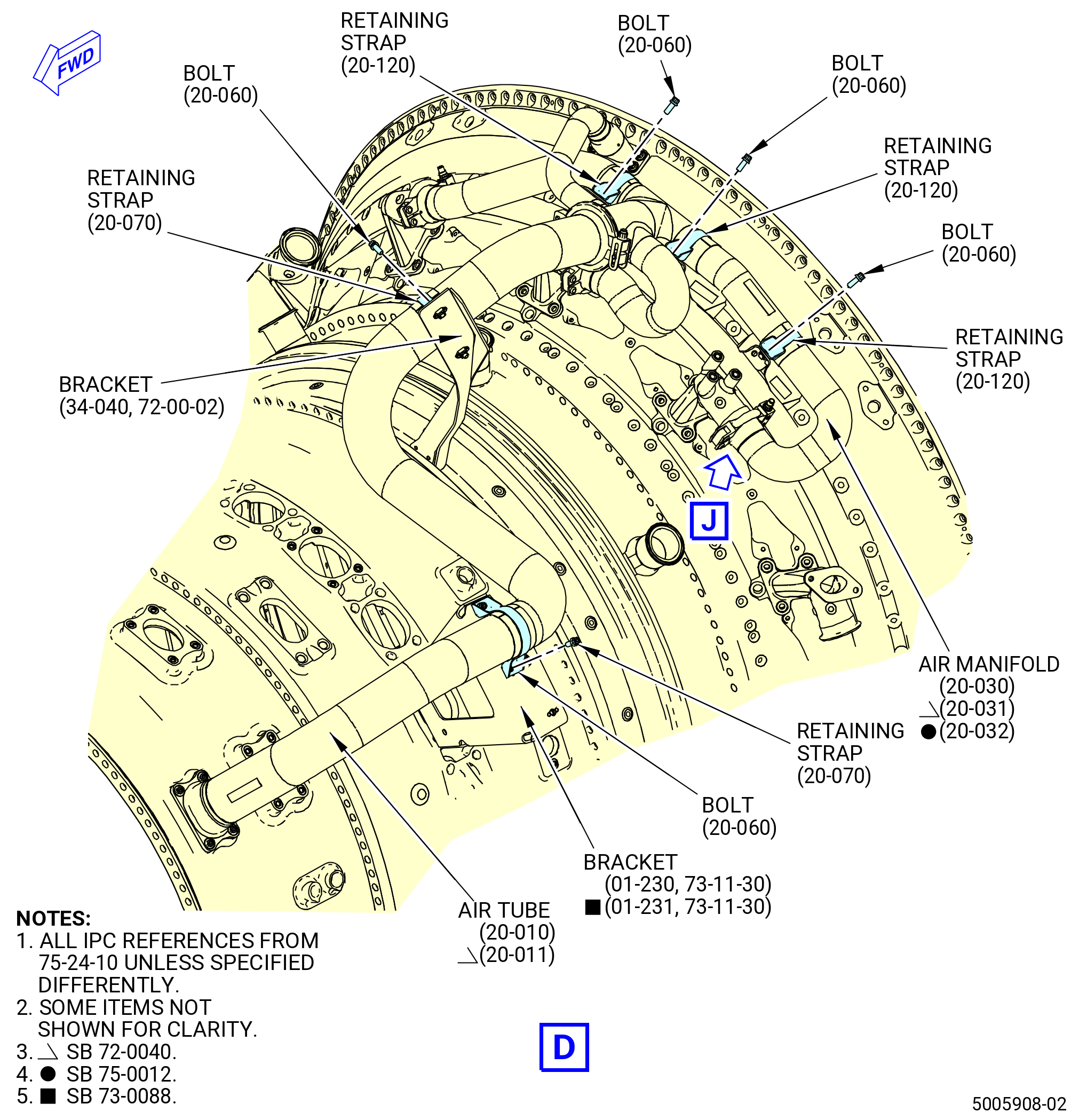
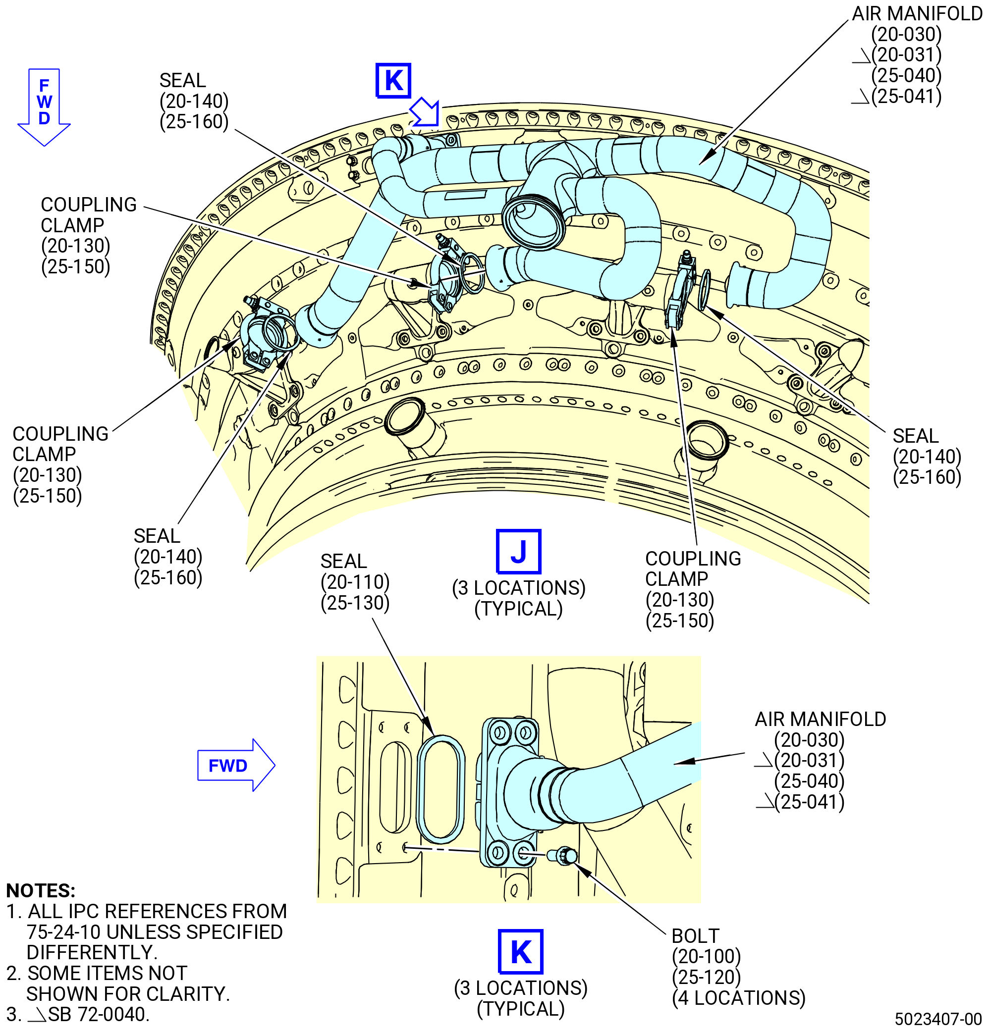
| R. | Install the stage 7 HPT cooling manifolds (manifolds) as follows. Refer to Figure 1019. |
| (1) | Install the manifold (61100) at the 12:00-3:00 o'clock position as follows: |
| (a) | Install a metal seal ring (seal) (61150) on the forward end of the manifold (61100). |
| WARNING: |
|
| (b) | Install two seal rings (seals) (61151) on the aft ends of the manifold (61100). |
| NOTE: |
|
| (c) | Install the forward end of the manifold on the extension case (080AL) and the aft ends on the HPT stator case (174B0). |
| (d) | Attach the aft ends with coupling clamps (61181). Install the coupling clamps with the nut towards the 6:00 o'clock position and pointed aft. |
| WARNING: |
|
| (e) | Lubricate the threads of the four machine bolts (20-050 , 75-24-30) (SIN 61120) with C02-058 lubricant. |
| (f) | Attach the forward end with two bolts (61120) in the boltholes near the 3:00 o'clock position. |
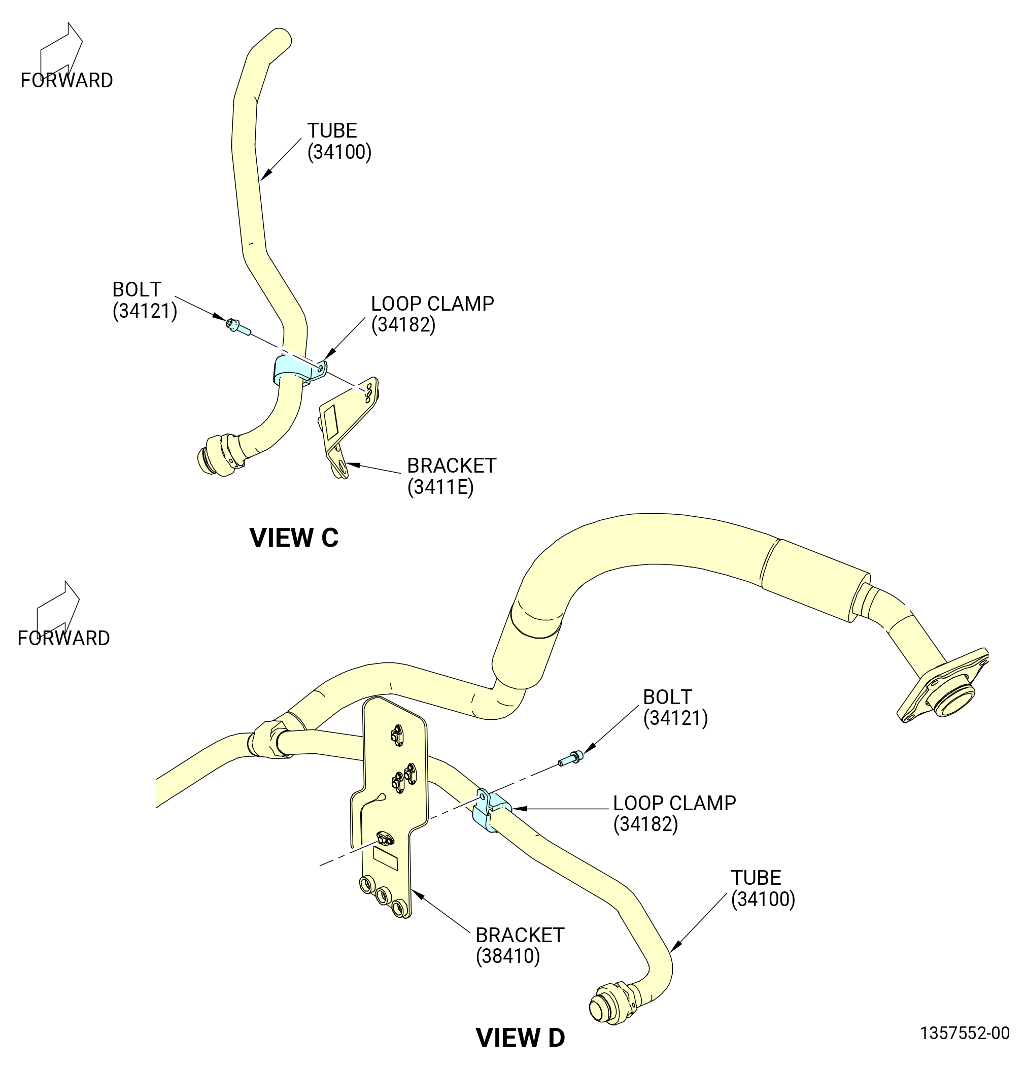
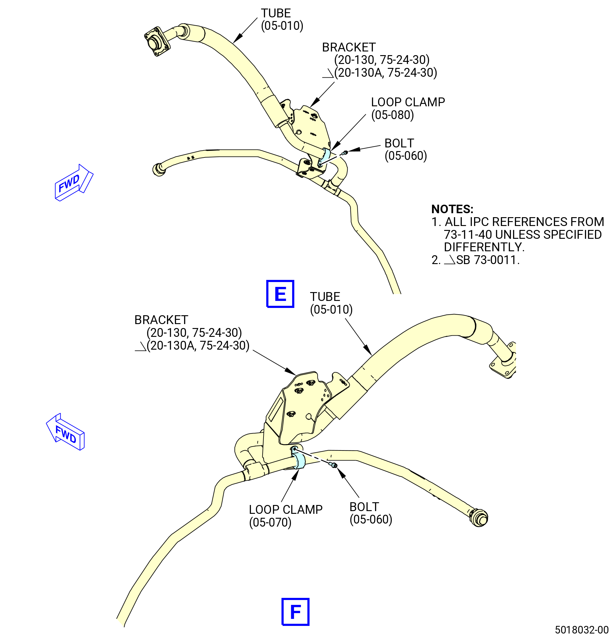
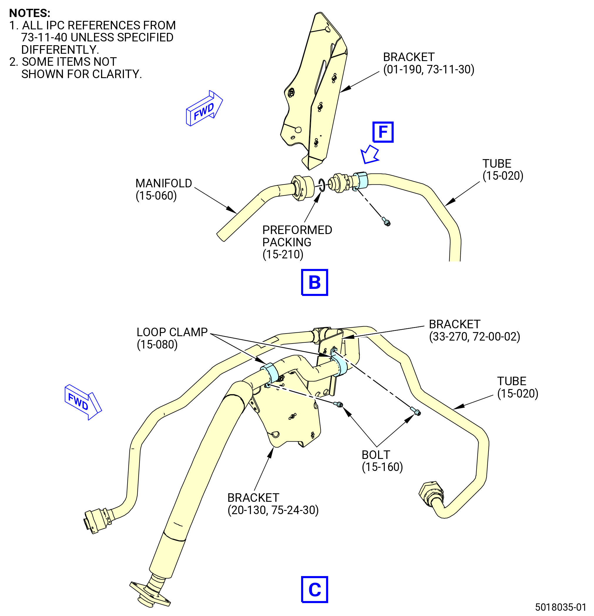
| (g) | Put the support bracket (bracket) (20-130 , 75-24-30) (SIN 34114) or (20-130A , 75-24-30) (SIN 34114) on the forward end of the manifold. Align the boltholes in the bracket with the boltholes in the manifold near the 12:00 o'clock position. Attach with two bolts (20-050 , 75-24-30) (SIN 61120). |
| (h) | Attach the manifold to the bracket (61110) with a retaining strap (61182) and bolts (61121). |
| (i) | Attach the manifold to the bracket (61111) with a retaining strap (61182) and bolts (61121). |
| (j) | Torque the bolts (61120) in a criss-cross pattern to 106-124 lb in. (12.0-14.0 N.m). |
| (k) | Lightly tap the coupling clamps (61181) with a soft mallet while the coupling clamps are torqued to 60-70 lb in. (6.8-7.9 N.m). |
| (l) | Torque the bolts (61121) to 106-124 lb in. (12.0-14.0 N.m). |
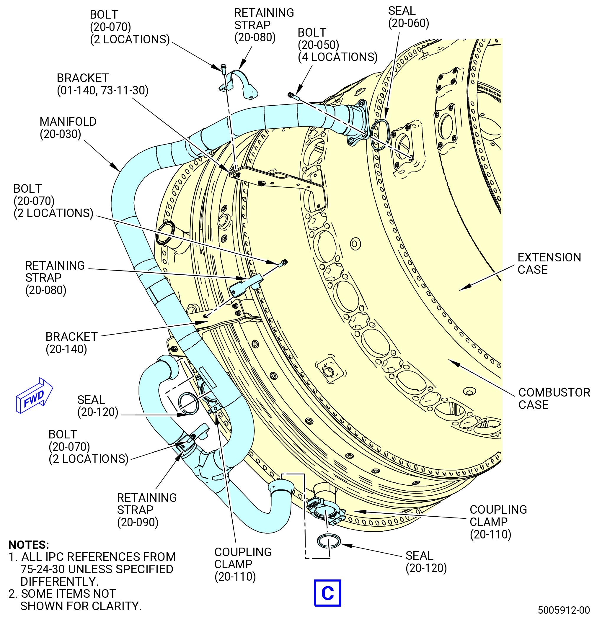
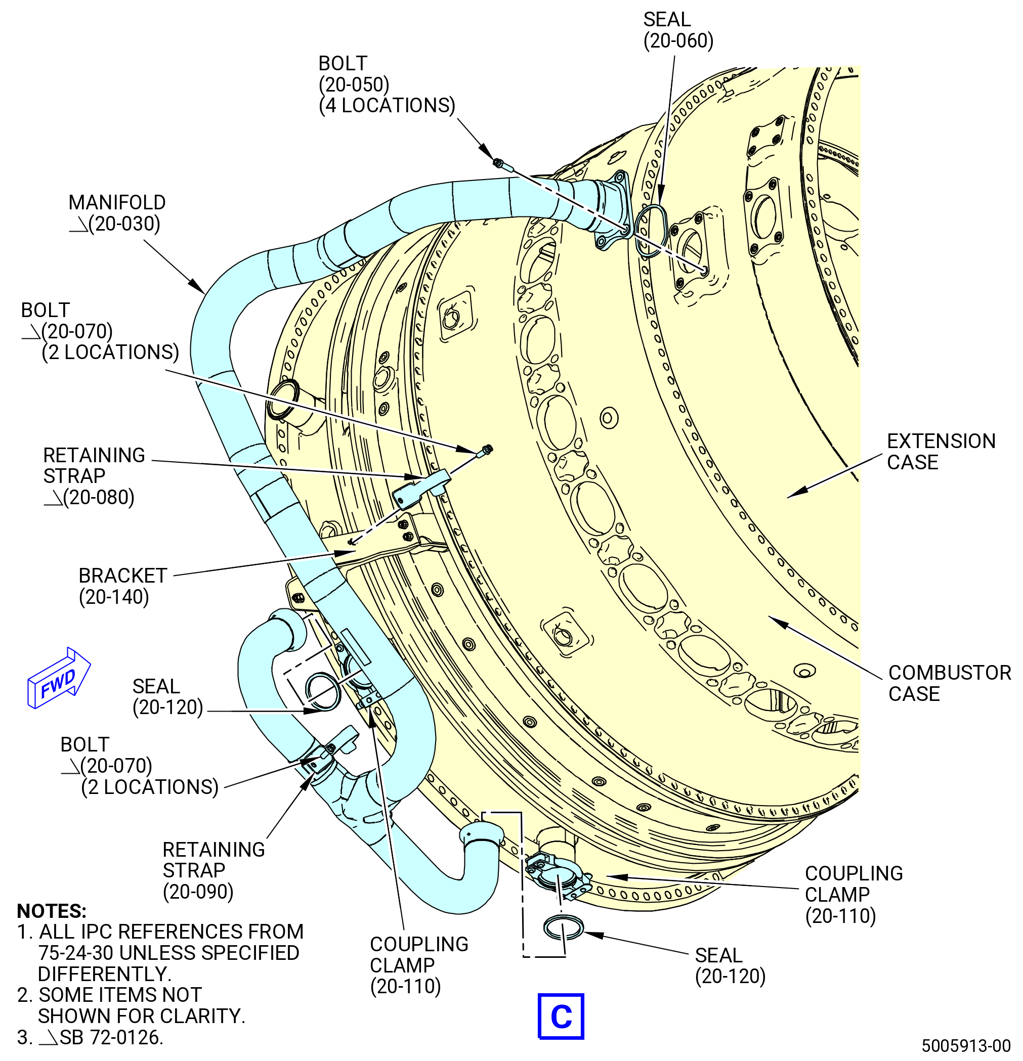
| (2) | Install the manifold (61101) at the 4:00-6:00 o'clock position as follows: |
| WARNING: |
|
| (a) | Install the seal (61150) on the forward end of the manifold (61101). |
| NOTE: |
|
| WARNING: |
|
| (b) | Install two seals (61151) on the aft ends of the manifold (61101). |
| NOTE: |
|
| (c) | Install the forward end of the manifold on the extension case (080AL) and the aft ends on the HPT stator case. |
| (d) | Attach the aft ends with coupling clamps (61181). Install the coupling clamps with the nut towards the 6:00 o'clock position and pointed aft. |
| WARNING: |
|
| (e) | Lubricate the threads of the four machine bolts (20-050 , 75-24-30) (SIN 61120) with C02-058 lubricant. |
| (f) | Attach the forward end with four bolts (61120). |
| Subtask 72-00-02-440-284 |
| * * * PRE SB 72-0126( Installation of Manifold without Bracket Deletion ) |
| (g) | Attach the manifold (20-030 , 75-24-30) (SIN 61101) to the bracket (01-140 , 73-11-30) (SIN 61114) with a retaining strap (20-080 , 75-24-30) (SIN 61182) and bolts (20-070 , 75-24-30) (SIN 61121). |
| NOTE: |
|
| * * * END PRE SB 72-0126( ) |
| Subtask 72-00-02-440-285 |
| (h) | Attach the manifold to the bracket (61117) with a retaining strap (61182) and bolts (61121). |
| (i) | Attach the manifold to the bracket (01-260 , 72-54-00) (SIN 45210) or (10-230 , 79-22-20) (SIN 45210) with a retaining strap (20-090 , 75-24-30) (SIN 61183) and bolts (20-070 , 75-24-30) (SIN 61121). |
| (j) | Torque the bolts (61120) in a criss-cross pattern to 106-124 lb in. (12.0-14.0 N.m). |
| (k) | Torque the coupling clamps (61181) to 60-70 lb in. (6.8-7.9 N.m). |
| (l) | Torque the bolts (61121) to 106-124 lb in. (12.0-14.0 N.m). |
| (3) | Install the manifold (61102) at the 7:30-9:00 o'clock position as follows: |
| (a) | Attach the bracket (6111B) to the bracket (6111A) with bolts (61121). Torque the bolts to 106-124 lb in. (12.0-14.0 N.m). |
| WARNING: |
|
| (b) | Install the seal (61150) on the forward end of the manifold (61102). |
| NOTE: |
|
| WARNING: |
|
| (c) | Install two seals (61151) on the aft ends of the manifold (61102). |
| NOTE: |
|
| (d) | Install the forward end of the manifold on the extension case (080AL) and the aft ends on the HPT stator case. |
| (e) | Attach the aft ends with coupling clamps (61181). Install the coupling clamps with the nut pointed at the 6:00 o'clock position and aft. |
| WARNING: |
|
| (f) | Lubricate the threads of the four machine bolts (20-050 , 75-24-30) (SIN 61120) with C02-058 lubricant. |
| (g) | Attach the forward end with four bolts (61120). |
| (h) | Attach the manifold to the bracket (6111B) with a retaining strap (61182) and bolts (61121). |
| (i) | Attach the manifold to the bracket (6111C) with a retaining strap (61182) and bolts (61121). |
| (j) | Torque the bolts (61120) in a criss-cross pattern to 106-124 lb in. (12.0-14.0 N.m). |
| (k) | Lightly tap the coupling clamps (61181) with a soft mallet while the coupling clamps are torqued to 60-70 lb in. (6.8-7.9 N.m). |
| (l) | Torque the bolts (61121) to 106-124 lb in. (12.0-14.0 N.m). |
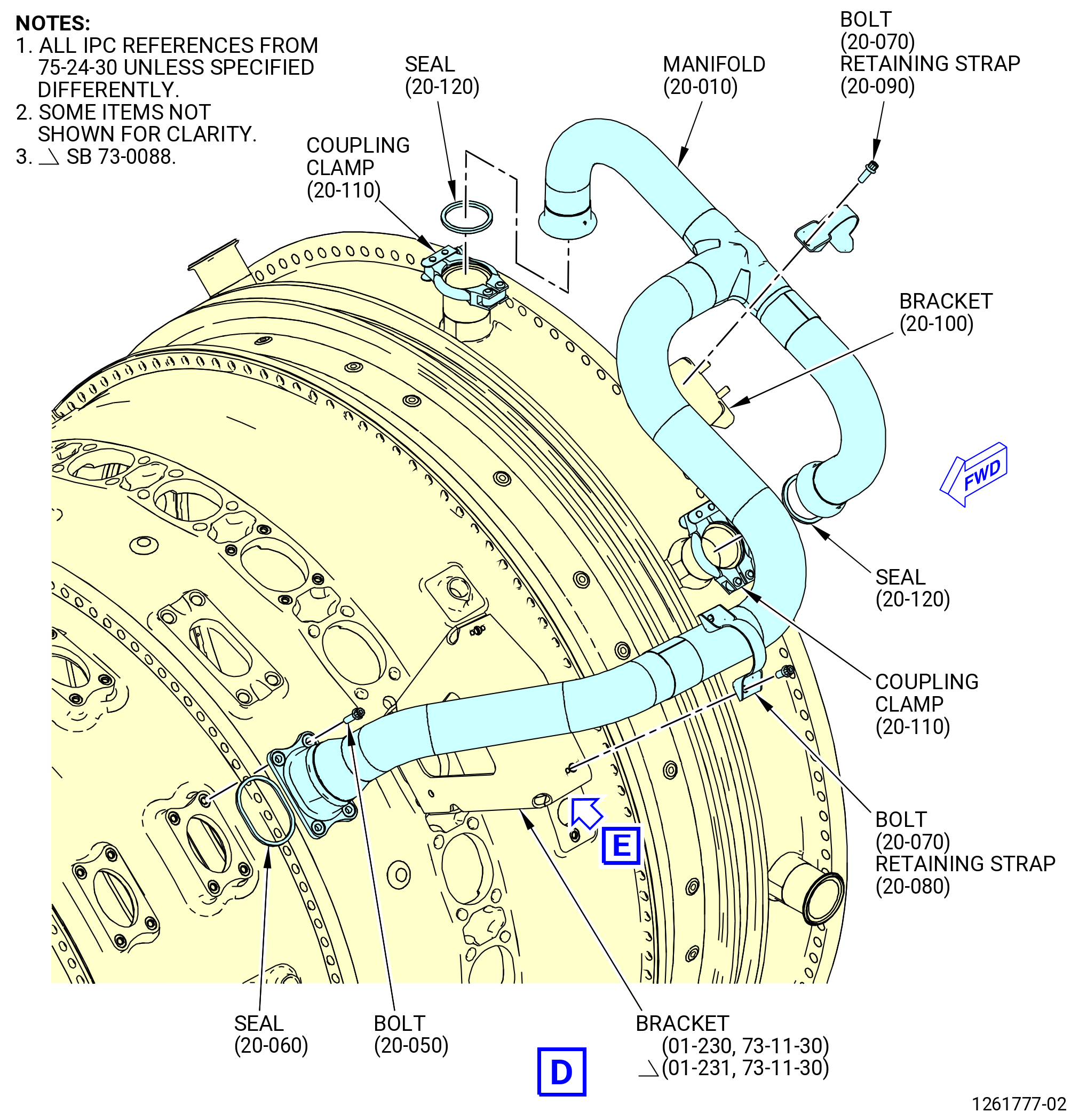
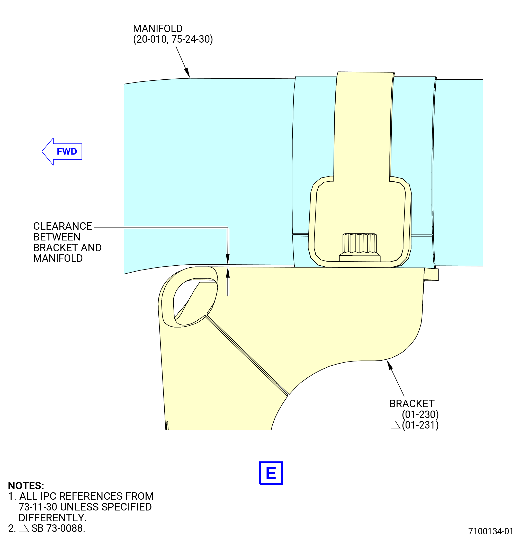
| (4) | Install the manifold (20-010 , 75-24-30) (SIN 61103) at the 10:30-12:00 o'clock position as follows: |
| WARNING: |
|
| (a) | Install the seal (20-060 , 75-24-30) (SIN 61150) on the forward end of the manifold (20-010 , 75-24-30) (SIN 61103). |
| NOTE: |
|
| WARNING: |
|
| (b) | Install two seals (20-120 , 75-24-30) (SIN 61151) on the aft ends of the manifold (20-010 , 75-24-30) (SIN 61103). |
| NOTE: |
|
| (c) | Install the forward end of the manifold on the extension case (080AL) and the aft ends on the HPT stator case. |
| (d) | Attach the aft ends with coupling clamps (61181). Install the coupling clamps with the nut pointed at the 6:00 o'clock position and aft. |
| WARNING: |
|
| (e) | Lubricate the threads of the four machine bolts (20-050 , 75-24-30) (SIN 61120) with C02-058 lubricant. |
| (f) | Attach the forward end with four bolts (61120). |
| (g) | Attach the manifold to the bracket (01-230 , 73-11-30) (SIN 61112) or (01-231 , 73-11-30) (SIN 61112) with a retaining strap (20-080 , 75-24-30) (SIN 61182) and bolts (20-070 , 75-24-30) (SIN 61121). |
| (h) | Attach the manifold to the bracket (61113) with a retaining strap (61183) and bolts (61121). |
| (i) | Torque the bolts (61120) in a criss-cross pattern to 106-124 lb in. (12.0-14.0 N.m). |
| (j) | Lightly tap the coupling clamps (61181) with a soft mallet while the coupling clamps are torqued to 60-70 lb in. (6.8-7.9 N.m). |
| CAUTION: |
|
| (k) | Torque the bolts (61121) to 106-124 lb in. (12.0-14.0 N.m). |
|
|
|
|
| Subtask 72-00-02-440-121 |
| * * * FOR 1B/P/G03.1B/P/G04 |
| * * * PRE SB 72-0040( Stage 4 Manifold for PIP Engines ) |
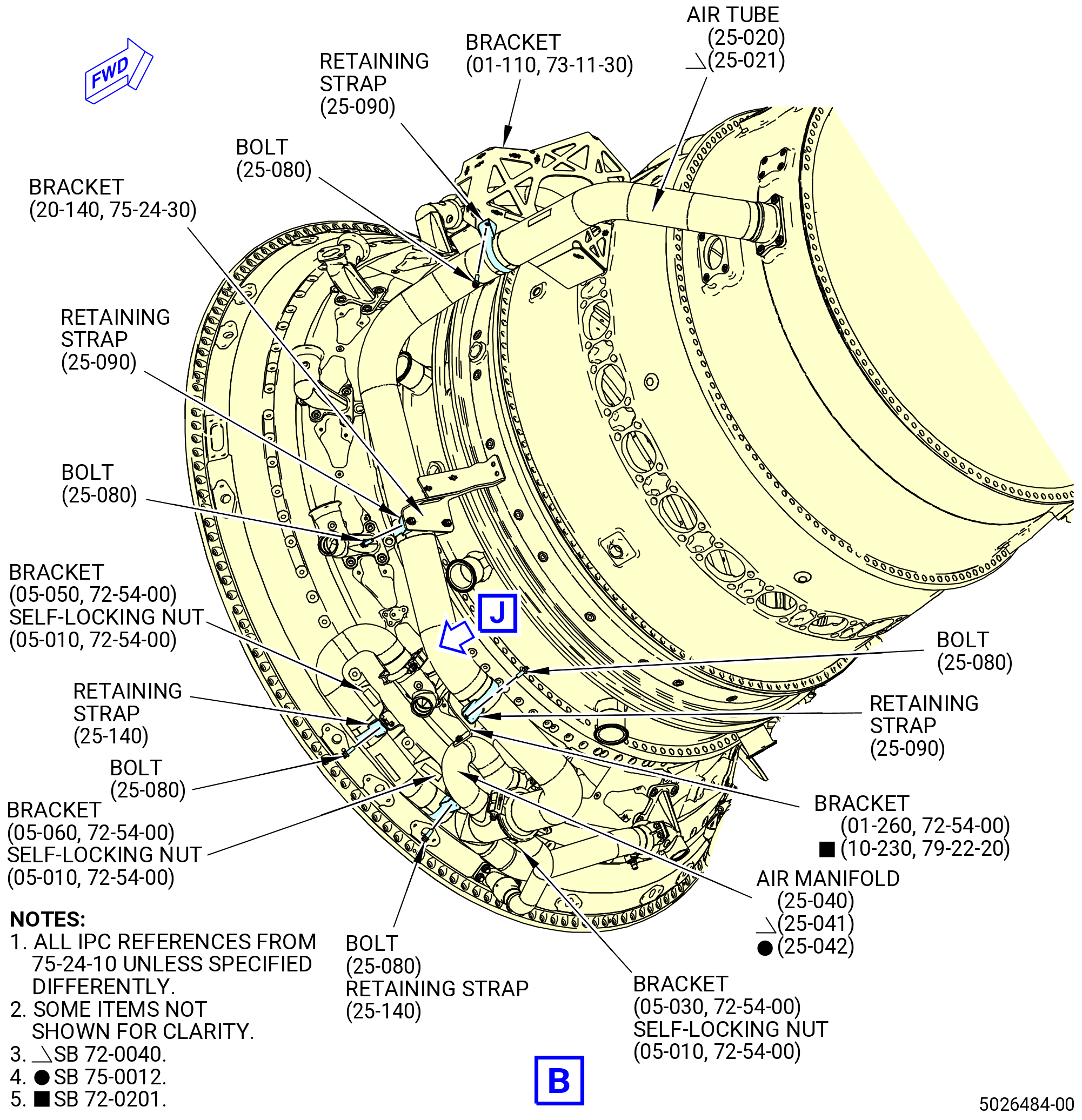
| S. | Install the stage 4 cooling manifolds. Refer to Figure 1020 and do as follows: |
| (1) | Install the stage 4 air tube (air tube) (25-010 , 75-24-10) (SIN 61200) on the upper right side as follows: |
| WARNING: |
|
| (a) | Install a metal seal ring (seal ring) (25-070 , 75-24-10) (SIN 61250) on the forward end of the air tube (25-010 , 75-24-10) (SIN 61200). |
| NOTE: |
|
| WARNING: |
|
| (b) | Install a ring seal (seal) (25-100 , 75-24-10) (SIN 61254) on the aft end of the air tube (25-010 , 75-24-10) (SIN 61200). |
| NOTE: |
|
| (c) | Put the air tube in position on the extension case (080AL). Put brackets (38411) in position on both sides of the air tube flange. |
| WARNING: |
|
| (d) | Lubricate the threads of the four machine bolts (25-050 , 75-24-10) (SIN 61220) with C02-058 lubricant. |
| (e) | Attach the air tube and the brackets to the extension case with bolts (61220). |
| (f) | Attach the air tube to the bracket (6121M) with a retaining strap (61283) and bolts (61222). |
| (g) | Attach the air tube to the bracket (61111) with a retaining strap (61283) and bolts (61222). |
| WARNING: |
|
| (h) | Install the seal rings (seals) (25-160 , 75-24-10) (SIN 61252) on the forward end of the stage 4 air manifold (air manifold) (25-030 , 75-24-10) (SIN 61204). |
| NOTE: |
|
| WARNING: |
|
| (i) | Install a seal (25-130 , 75-24-10) (SIN 61251) on the aft end of the air manifold (25-030 , 75-24-10) (SIN 61204). |
| NOTE: |
|
| (j) | Install the air manifold (25-030 , 75-24-10) (SIN 61204) on the TCF assembly (35-009) (SIN 92500), (35-010) (SIN 92500), (35-011) (SIN 92500), (35-012) (SIN 92500), or (35-015) (SIN 92500). Attach the aft end of the air manifold with bolts (25-120 , 75-24-10) (SIN 61221). |
| (k) | Attach the forward end of the air manifold with coupling clamps (61282). Install the coupling clamps with the nut aft and outboard. |
| (l) | Connect the air tube (25-010 , 75-24-10) (SIN 61200) to the air manifold (25-030 , 75-24-10) (SIN 61204) with a seal ring (25-110 , 75-24-10) (SIN 6128A). Install the seal ring with the nut to the right outboard side. |
| (m) | Attach the aft end of the air manifold to the bracket (05-120 , 72-54-00) (SIN 6121G) with retaining straps (25-140 , 75-24-10) (SIN 6128B) and bolts (25-080 , 75-24-10) (SIN 61222). |
| (n) | Attach the aft end of the air manifold to the bracket (6121H) with retaining straps (6128B) and bolts (61222). |
| (o) | Attach the aft end of the air manifold to the bracket (6121J) with retaining straps (6128B) and bolts (61222). |
| (p) | Torque the bolts (61221) to 106-124 lb in. (12.0-14.0 N.m). |
| (q) | Safety the bolts with C10-071 safety wire or C10-143 safety cable. |
| (r) | Torque the coupling clamps (61282) to 60-70 lb in. (6.8-7.9 N.m). |
| (s) | Torque the self-locking nuts (61241) previously installed on the brackets (6121G, 6121H, 6121J) to 106-124 lb in. (12.0-14.0 N.m). |
| (t) | Torque the bolts (61222) on the retaining straps to 106-124 lb in. (12.0-14.0 N.m). |
| (u) | Torque the bolts (61220) to 106-124 lb in. (12.0-14.0 N.m). |
| (v) | Torque the seal ring (6128A) to 106-124 lb in. (12.0-14.0 N.m). |
| Subtask 72-00-02-440-277 |
| * * * FOR 1B/P/G03.1B/P/G04 |
| (2) | Install the stage 4 air tube (air tube) (25-020 , 75-24-10) (SIN 61201) on the lower right side as follows: |
| WARNING: |
|
| (a) | Install a seal ring (25-070 , 75-24-10) (SIN 61250) on the forward end of the air tube (25-020 , 75-24-10) (SIN 61201) |
| NOTE: |
|
| WARNING: |
|
| (b) | Install a seal (25-100 , 75-24-10) (SIN 61254) on the aft end of the air tube (25-020 , 75-24-10) (SIN 61201). |
| NOTE: |
|
| (c) | Put the air tube in position on the extension case. |
| (d) | Attach the air tube to the extension case with bolts (61220). |
| (e) | Attach the air tube to the bracket (61A12) with a retaining strap (61283) and bolts (61222). |
| (f) | Attach the air tube to the bracket (61117) with a retaining strap (61283) and bolts (61222). |
| (g) | Attach the air tube to the bracket (01-260 , 72-54-00) (SIN 45210) or (10-230 , 79-22-20) (SIN 45210) with a retaining strap (25-090 , 75-24-10) (SIN 61283) and bolts (25-080 , 75-24-10) (SIN 61222). |
| WARNING: |
|
| (h) | Install the seals (25-160 , 75-24-10) (SIN 61252) on the forward end of the air manifold (25-040 , 75-24-10) (SIN 61205). |
| NOTE: |
|
| WARNING: |
|
| (i) | Install a seal (25-130 , 75-24-10) (SIN 61251) on the aft end of the air manifold (25-040 , 75-24-10) (SIN 61205). |
| NOTE: |
|
| (j) | Install the air manifold (25-040 , 75-24-10) (SIN 61205) on the TCF. Attach the aft end of the air manifold with bolts (25-120 , 75-24-10) (SIN 61221). |
| (k) | Attach the forward end of the air manifold with coupling clamps (61282). Install the coupling clamps with the nut aft and outboard. |
| (l) | Connect the air tube (25-020 , 75-24-10) (SIN 61201) to the air manifold (25-040 , 75-24-10) (SIN 61205) with a seal ring (25-110 , 75-24-10) (SIN 6128A). Install the seal ring with the nut to the right outboard side. |
| (m) | Attach the aft end of the air manifold to the bracket (6121D) with a retaining strap (6128B) and bolts (61222). |
| (n) | Attach the aft end of the air manifold to the bracket (6121E) with a retaining strap (6128B) and bolts (61222). |
| (o) | Attach the aft end of the air manifold to the bracket (6121F) with a retaining strap (6128B) and bolts (61222). |
| (p) | Torque the bolts (61221) to 106-124 lb in. (12.0-14.0 N.m). |
| (q) | Safety the bolts with C10-071 safety wire or C10-143 safety cable. |
| (r) | Torque the coupling clamps (61282) to 60-70 lb in. (6.8-7.9 N.m). |
| (s) | Torque the self-locking nuts (61241) previously installed on the brackets (6121D, 6121E, 6121F) to 106-124 lb in. (12.0-14.0 N.m). |
| (t) | Torque the bolts (61222) on the retaining straps to 106-124 lb in. (12.0-14.0 N.m). |
| (u) | Torque the bolts (61220) to 106-124 lb in. (12.0-14.0 N.m). |
| (v) | Lightly tap the seal ring (6128A) with a soft mallet while the seal ring is torqued to 106-124 lb in. (12.0-14.0 N.m). |
| Subtask 72-00-02-440-278 |
| * * * FOR 1B/P/G03.1B/P/G04 |
| (3) | Install the stage 4 air tube (air tube) (20-020 , 75-24-10) (SIN 61202) on the lower left side as follows: |
| WARNING: |
|
| (a) | Install a seal ring (20-050 , 75-24-10) (SIN 61250) on the forward end of the air tube (20-020 , 75-24-10) (SIN 61202). |
| NOTE: |
|
| (b) | Install a seal (20-080 , 75-24-10) (SIN 61254) on the aft end of the air tube (20-020 , 75-24-10) (SIN 61202). |
| NOTE: |
|
| (c) | Put the air tube in position on the extension case. |
| (d) | Attach the air tube to the extension case with bolts (61220). |
| (e) | Attach the air tube to the bracket (6121C) with retaining straps (61283) and bolts (61222). |
| (f) | Attach the air tube to the bracket (6111C) with retaining straps (61283) and bolts (61222). |
| WARNING: |
|
| (g) | Install the seals (20-140 , 75-24-10) (SIN 61252) on the forward end of the air manifold (20-030 , 75-24-10) (SIN 61205). |
| NOTE: |
|
| WARNING: |
|
| (h) | Install a seal (20-110 , 75-24-10) (SIN 61251) on the aft end of the air manifold (20-030 , 75-24-10) (SIN 61205). |
| NOTE: |
|
| (i) | Install the air manifold (20-030 , 75-24-10) (SIN 61205) on the TCF. Attach the aft end of the air manifold with bolts (20-100 , 75-24-10) (SIN 61221). |
| (j) | Attach the forward end of the air manifold with coupling clamps (61282). Install the coupling clamps with the nut aft and outboard. |
| (k) | Connect the air tube (20-020 , 75-24-10) (SIN 61202) to the air manifold (20-030 , 75-24-10) (SIN 61205) with a seal ring (20-090 , 75-24-10) (SIN 6128A). Install the seal ring with the nut on the right outboard side. |
| (l) | Attach the aft end of the air manifold to the bracket (6121D) with retaining straps (6128B) and bolts (61222). |
| (m) | Attach the aft end of the air manifold to the bracket (6121E) with retaining straps (6128B) and bolts (61222). |
| (n) | Attach the aft end of the air manifold to the bracket (6121F) with retaining straps (6128B) and bolts (61222). |
| (o) | Torque the bolts (61221) to 106-124 lb in. (12.0-14.0 N.m). |
| (p) | Safety the bolts with C10-071 safety wire or C10-143 safety cable. |
| (q) | Lightly tap the coupling clamps (61282) with a soft mallet while the coupling clamps are torqued to 60-70 lb in. (6.8-7.9 N.m). |
| (r) | Torque the self-locking nuts (61241) previously installed on the brackets (6121D, 6121E, 6121F) to 106-124 lb in. (12.0-14.0 N.m). |
| (s) | Torque the bolts (61222) on the retaining straps to 106-124 lb in. (12.0-14.0 N.m). |
| (t) | Torque the bolts (61220) to 106-124 lb in. (12.0-14.0 N.m). |
| (u) | Torque the seal ring (6128A) to 106-124 lb in. (12.0-14.0 N.m). |
| Subtask 72-00-02-440-279 |
| * * * FOR 1B/P/G03.1B/P/G04 |
| (4) | Install the stage 4 air tube (air tube) (20-010 , 75-24-10) (SIN 61203) on the upper left side as follows: |
| WARNING: |
|
| (a) | Install a seal ring (20-050 , 75-24-10) (SIN 61250) on the forward end of the air tube (20-010 , 75-24-10) (SIN 61203). |
| NOTE: |
|
| WARNING: |
|
| (b) | Install a seal (20-080 , 75-24-10) (SIN 61254) on the aft end of the air tube (20-010 , 75-24-10) (SIN 61203). |
| NOTE: |
|
| (c) | Put the air tube in position on the extension case. |
| (d) | Attach the air tube to the extension case with bolts (61220). |
| (e) | Attach the air tube to the bracket (01-230 , 73-11-30) (SIN 61112) or (01-231 , 73-11-30) (SIN 61112) with a retaining strap (25-090 , 75-24-10) (SIN 61283) and bolts (25-080 , 75-24-10) (SIN 61222). |
| (f) | Attach the air tube to the bracket (6121N) with a retaining strap (61283) and bolts (61222). |
| WARNING: |
|
| (g) | Install the seals (61252) on the forward end of the air manifold (61205). |
| NOTE: |
|
| WARNING: |
|
| (h) | Install a seal (20-110 , 75-24-10) (SIN 61251) on the aft end of the air manifold (20-030 , 75-24-10) (SIN 61205). |
| NOTE: |
|
| (i) | Install the air manifold (20-030 , 75-24-10) (SIN 61205) on the TCF. Attach the aft end of the air manifold with bolts (20-100 , 75-24-10) (SIN 61221). |
| (j) | Attach the forward end of the air manifold with coupling clamps (61282). Install the coupling clamps with the nut aft and outboard. |
| (k) | Connect the air tube (20-010 , 75-24-10) (SIN 61203) to the air manifold (20-030 , 75-24-10) (SIN 61205) with a seal ring (20-090 , 75-24-10) (SIN 6128A). Install the seal ring with the nut to the right outboard side. |
| (l) | Attach the aft end of the air manifold to the bracket (6121D) with the retaining strap (6128B) and bolts (61222). |
| (m) | Attach the aft end of the air manifold to the bracket (6121K) with the retaining strap (6128B) and bolts (61222). |
| (n) | Attach the aft end of the air manifold to the bracket (6121F) with the retaining strap (6128B) and bolts (61222). |
| (o) | Torque the bolts (61221) to 106-124 lb in. (12.0-14.0 N.m). |
| (p) | Safety the bolts with C10-071 safety wire or C10-143 safety cable. |
| (q) | Torque the coupling clamps (61282) to 60-70 lb in. (6.8-7.9 N.m). |
| (r) | Torque the self-locking nuts (61241) previously installed on the brackets (6121D, 6121K, 6121F) to 106-124 lb in. (12.0-14.0 N.m). |
| (s) | Torque the bolts (61222) on the retaining straps to 106-124 lb in. (12.0-14.0 N.m). |
| (t) | Torque the bolts (61220) to 106-124 lb in. (12.0-14.0 N.m). |
| (u) | Torque the seal ring (6128A) to 106-124 lb in. (12.0-14.0 N.m). |
| * * * FOR 1B/P/G03.1B/P/G04 |
| * * * END PRE SB 72-0040 |
| Subtask 72-00-02-440-280 |
| * * * FOR 1B/P/G03.1B/P/G04.1B/P1/G01 |
| * * * SB 72-0040( Stage 4 Manifold for PIP and PIP1 Engines ) |
| S.A. | Install the stage 4 cooling manifolds. Refer to Figure 1020 and do as follows: |
| (1) | Install the air tube (25-011 , 75-24-10) (SIN 61200) on the upper right side as follows: |
| WARNING: |
|
| (a) | Install a metal seal ring (seal ring) (25-070 , 75-24-10) (SIN 61250) on the forward end of the air tube (25-011 , 75-24-10) (SIN 61200). |
| NOTE: |
|
| WARNING: |
|
| (b) | Install a ring seal (seal) (25-100 , 75-24-10) (SIN 61254) on the aft end of the air tube (25-011 , 75-24-10) (SIN 61200). |
| NOTE: |
|
| (c) | Put the air tube in position on the extension case (10-080 , 72-30-00) (SIN 080AL). Put the brackets (25-060 , 75-24-10) (SIN 38411) in position on both sides of the air tube flange. |
| (d) | Attach the air tube and the brackets to the extension case with bolts (25-050 , 75-24-10) (SIN 61220). |
| (e) | Attach the air tube to the bracket (01-090 , 73-11-30) (SIN 6121M) with a retaining strap (25-090 , 75-24-10) (SIN 61283) and bolts (25-080 , 75-24-10) (SIN 61222). |
| (f) | Attach the air tube to the bracket (34-120) (SIN 61111) with a retaining strap (25-090 , 75-24-10) (SIN 61283) and bolts (25-080 , 75-24-10) (SIN 61222). |
| WARNING: |
|
| (g) | Install the seal rings (seals) (25-160 , 75-24-10) (SIN 61252) on the forward end of the stage 4 air manifold (air manifold) (25-031 , 75-24-10) (SIN 61204). |
| NOTE: |
|
| WARNING: |
|
| (h) | Install a seal (25-130 , 75-24-10) (SIN 61251) on the aft end of the air manifold (25-031 , 75-24-10) (SIN 61204). |
| NOTE: |
|
| (i) | Install the air manifold (25-031 , 75-24-10) (SIN 61204) on the TCF assembly (35-009) (SIN 92500), (35-010) (SIN 92500), (35-011) (SIN 92500), (35-012) (SIN 92500), or (35-015) (SIN 92500). Attach the aft end of the air manifold with bolts (25-120 , 75-24-10) (SIN 61221). |
| (j) | Attach the forward end of the air manifold with coupling clamps (25-150 , 75-24-10) (SIN 61282). Install the coupling clamps with the nut aft and outboard. |
| (k) | Connect the air tube (25-011 , 75-24-10) (SIN 61200) to the air manifold (25-031 , 75-24-10) (SIN 61204) with a seal ring (25-110 , 75-24-10) (SIN 6128A). Install the seal ring with the nut to the right outboard side. |
| (l) | Attach the aft end of the air manifold to the bracket (05-120 , 72-54-00) (SIN 6121G) with retaining straps (25-140 , 75-24-10) (SIN 6128B) and bolts (25-080 , 75-24-10) (SIN 61222). |
| (m) | Attach the aft end of the air manifold to the bracket (05-110 , 72-54-00) (SIN 6121H) with retaining straps (25-140 , 75-24-10) (SIN 6128B) and bolts (25-080 , 75-24-10) (SIN 61222). |
| (n) | Attach the aft end of the air manifold to the bracket (05-100 , 72-54-00) (SIN 6121J) with retaining straps (25-140 , 75-24-10) (SIN 6128B) and bolts (25-080 , 75-24-10) (SIN 61222). |
| (o) | Torque the bolts (25-120 , 75-24-10) (SIN 61221) to 106-124 lb in. (12.0-14.0 N.m). |
| (p) | Safety the bolts with C10-071 safety wire or C10-143 safety cable. |
| (q) | Torque the coupling clamps (25-150 , 75-24-10) (SIN 61282) to 60-70 lb in. (6.8-7.9 N.m). |
| (r) | Torque the self-locking nuts (05-010 , 72-54-00) (SIN 61241) previously installed on the brackets (05-120 , 72-54-00) (SIN 6121G), (05-110 , 72-54-00) (SIN 6121H), and (05-100 , 72-54-00) (SIN 6121J) to 106-124 lb in. (12.0-14.0 N.m). |
| (s) | Torque the bolts (25-080 , 75-24-10) (SIN 61222) on the retaining straps to 106-124 lb in. (12.0-14.0 N.m). |
| (t) | Torque the bolts (25-050 , 75-24-10) (SIN 61220) to 106-124 lb in. (12.0-14.0 N.m). |
| (u) | Torque the seal ring (25-110 , 75-24-10) (SIN 6128A) to 106-124 lb in. (12.0-14.0 N.m). |
| Subtask 72-00-02-440-281 |
| * * * PRE SB 75-0012 |
| (2) | Install the air tube (25-021 , 75-24-10) (SIN 61201) on the lower right side as follows: |
| WARNING: |
|
| (a) | Install a seal ring (25-070 , 75-24-10) (SIN 61250) on the forward end of the air tube (25-021 , 75-24-10) (SIN 61201). |
| NOTE: |
|
| WARNING: |
|
| (b) | Install a seal (25-100 , 75-24-10) (SIN 61254) on the aft end of the air tube (25-021 , 75-24-10) (SIN 61201). |
| NOTE: |
|
| (c) | Put the air tube in position on the extension case. |
| (d) | Attach the air tube to the extension case with bolts (25-050 , 75-24-10) (SIN 61220). |
| (e) | Attach the air tube to the bracket (01-110 , 73-11-30) (SIN 61A12) with a retaining strap (25-090 , 75-24-10) (SIN 61283) and bolts (25-080 , 75-24-10) (SIN 61222). |
| (f) | Attach the air tube to the bracket (20-140 , 75-24-30) (SIN 61117) with a retaining strap (25-090 , 75-24-10) (SIN 61283) and bolts (25-080 , 75-24-10) (SIN 61222). |
| (g) | Attach the air tube to the bracket (01-260 , 72-54-00) (SIN 45210) or (10-230 , 79-22-20) (SIN 45210) with a retaining strap (25-090 , 75-24-10) (SIN 61283) and bolts (25-080 , 75-24-10) (SIN 61222). |
| WARNING: |
|
| (h) | Install the seals (25-160 , 75-24-10) (SIN 61252) on the forward end of the air manifold (25-041 , 75-24-10) (SIN 61205). |
| NOTE: |
|
| WARNING: |
|
| (i) | Install a seal (25-130 , 75-24-10) (SIN 61251) on the aft end of the air manifold (25-041 , 75-24-10) (SIN 61205) |
| NOTE: |
|
| (j) | Install the air manifold (25-041 , 75-24-10) (SIN 61205) on the TCF. Attach the aft end of the air manifold with bolts (25-120 , 75-24-10) (SIN 61221). |
| (k) | Attach the forward end of the air manifold with coupling clamps (25-150 , 75-24-10) (SIN 61282). Install the coupling clamps with the nut aft and outboard. |
| (l) | Connect the air tube (25-021 , 75-24-10) (SIN 61201) to the air manifold (25-041 , 75-24-10) (SIN 61205) with a seal ring (25-110 , 75-24-10) (SIN 6128A). Install the seal ring with the nut to the right outboard side. |
| (m) | Attach the aft end of the air manifold to the bracket (05-050 , 72-54-00) (SIN 6121D) with a retaining strap (25-140 , 75-24-10) (SIN 6128B) and bolts (25-080 , 75-24-10) (SIN 61222). |
| (n) | Attach the aft end of the air manifold to the bracket (05-060 , 72-54-00) (SIN 6121E) with a retaining strap (25-140 , 75-24-10) (SIN 6128B) and bolts (25-080 , 75-24-10) (SIN 61222). |
| (o) | Attach the aft end of the air manifold to the bracket (05-030 , 72-54-00) (SIN 6121F) with a retaining strap (25-140 , 75-24-10) (SIN 6128B) and bolts (25-080 , 75-24-10) (SIN 61222). |
| (p) | Torque the bolts (25-120 , 75-24-10) (SIN 61221) to 106-124 lb in. (12.0-14.0 N.m). |
| (q) | Safety the bolts with C10-071 safety wire or C10-143 safety cable. |
| (r) | Torque the coupling clamps (25-150 , 75-24-10) (SIN 61282) to 60-70 lb in. (6.8-7.9 N.m). |
| (s) | Torque the self-locking nuts (05-010 , 72-54-00) (SIN 61241) previously installed on the brackets (05-050 , 72-54-00) (SIN 6121D), (05-060 , 72-54-00) (SIN 6121E), and (05-030 , 72-54-00) (SIN 6121F) to 106-124 lb in. (12.0-14.0 N.m). |
| (t) | Torque the bolts (25-080 , 75-24-10) (SIN 61222) on the retaining straps to 106-124 lb in. (12.0-14.0 N.m). |
| (u) | Torque the bolts (25-050 , 75-24-10) (SIN 61220) to 106-124 lb in. (12.0-14.0 N.m). |
| (v) | Lightly tap the seal ring (25-110 , 75-24-10) (SIN 6128A) with a soft mallet while the seal ring is torqued to 106-124 lb in. (12.0-14.0 N.m). |
| * * * END PRE SB 75-0012 |
| Subtask 72-00-02-440-488 |
| * * * SB 75-0012( New Air Manifolds with Coupling Clamp ) |
| (2).A. | Install the air tube (25-021 , 75-24-10) (SIN 61201) on the lower right side as follows: |
| WARNING: |
|
| (a) | Install a seal ring (25-070 , 75-24-10) (SIN 61250) on the forward end of the air tube. |
| NOTE: |
|
| WARNING: |
|
| (b) | Install a seal (25-100 , 75-24-10) (SIN 61254) on the aft end of the air tube. |
| NOTE: |
|
| (c) | Put the air tube in position on the extension case. |
| (d) | Attach the air tube to the extension case with bolts (25-050 , 75-24-10) (SIN 61220). |
| (e) | Attach the air tube to the bracket (01-110 , 73-11-30) (SIN 61A12) with a retaining strap (25-090 , 75-24-10) (SIN 61283) and bolts (25-080 , 75-24-10) (SIN 61222). |
| (f) | Attach the air tube to the bracket (20-140 , 75-24-30) (SIN 61117) with a retaining strap (25-090 , 75-24-10) (SIN 61283) and bolts (25-080 , 75-24-10) (SIN 61222). |
| (g) | Attach the air tube to the bracket (01-260 , 72-54-00) (SIN 45210) with a retaining strap (25-090 , 75-24-10) (SIN 61283) and bolts (25-080 , 75-24-10) (SIN 61222). |
| WARNING: |
|
| (h) | Install the seals (25-160 , 75-24-10) (SIN 61252) on the forward end of the air manifold (25-042 , 75-24-10) (SIN 61205). |
| NOTE: |
|
| (i) | Install the ring seal (seal) (25-180 , 75-24-10) (SIN 61258) into the forward side of the air manifold (25-170 , 75-24-10) (SIN 6120F). |
| (j) | Install a seal (25-130 , 75-24-10) (SIN 61251) on the aft end of the air manifold (25-170 , 75-24-10) (SIN 6120F). |
| (k) | Install the air manifold (25-170 , 75-24-10) (SIN 6120F) on the TCF. Attach the aft end of the air manifold (25-170 , 75-24-10) (SIN 6120F) with bolts (25-120 , 75-24-10) (SIN 61221). |
| (l) | Connect the air manifold (25-042 , 75-24-10) (SIN 61205) to the air manifold (25-170 , 75-24-10) (SIN 6120F). |
| (m) | Attach the forward end of the air manifold (25-170 , 75-24-10) (SIN 6120F) with the coupling clamp (clamp) (25-190 , 75-24-10) (SIN 6128G). Install the clamp (25-190 , 75-24-10) (SIN 6128G) with the nut aft and outboard. |
| (n) | Attach the aft end of the air manifold (25-042 , 75-24-10) (SIN 61205) to the bracket (05-050 , 72-54-00) (SIN 6121D) with a retaining strap (25-140 , 75-24-10) (SIN 6128B) and bolts (25-080 , 75-24-10) (SIN 61222). |
| (o) | Attach the aft end of the air manifold (25-042 , 75-24-10) (SIN 61205) to the bracket (05-060 , 72-54-00) (SIN 6121E) with a retaining strap (25-140 , 75-24-10) (SIN 6128B) and bolts (25-080 , 75-24-10) (SIN 61222). |
| (p) | Attach the aft end of the air manifold (25-042 , 75-24-10) (SIN 61205) to the bracket (05-030 , 72-54-00) (SIN 6121F) with a retaining strap (25-140 , 75-24-10) (SIN 6128B) and bolts (25-080 , 75-24-10) (SIN 61222). |
| (q) | Torque the bolts (25-120 , 75-24-10) (SIN 61221) to 106 to 124 lb in. (12.0 to 14.0 Nm). |
| (r) | Safety the bolts (25-120 , 75-24-10) (SIN 61221) with C10-071 safety wire or C10-143 safety cable. |
| (s) | Torque the coupling clamps (25-150 , 75-24-10) (SIN 61282) to 60 to 70 lb in. (6.8 to 7.9 Nm). |
| (t) | Torque the self-locking nuts (05-010 , 72-54-00) (SIN 61241) previously installed on the brackets (05-050 , 72-54-00) (SIN 6121D), (05-060 , 72-54-00) (SIN 6121E), and (05-030 , 72-54-00) (SIN 6121F) to 106 to 124 lb in. (12.0 to 14.0 Nm). |
| (u) | Torque the bolts (25-080 , 75-24-10) (SIN 61222) on the retaining straps to 106 to 124 lb in. (12.0 to 14.0 Nm). |
| (v) | Torque the bolts (25-050 , 75-24-10) (SIN 61220) to 106 to 124 lb in. (12.0 to 14.0 Nm). |
| (w) | Lightly tap the seal ring (25-110 , 75-24-10) (SIN 6128A) with a soft mallet while the seal ring is torqued to 106 to 124 lb in. (12.0 to 14.0 Nm). |
| * * * END SB 75-0012 |
| Subtask 72-00-02-440-282 |
| * * * PRE SB 75-0012 |
| (3) | Install the stage 4 air manifold (air manifold) (20-021 , 75-24-10) (SIN 61202) on the lower left side as follows: |
| WARNING: |
|
| (a) | Install a seal ring (20-050 , 75-24-10) (SIN 61250) on the forward end of the air manifold (20-021 , 75-24-10) (SIN 61202). |
| NOTE: |
|
| WARNING: |
|
| (b) | Install a seal (20-080 , 75-24-10) (SIN 61254) on the aft end of the air manifold (20-021 , 75-24-10) (SIN 61202). |
| NOTE: |
|
| (c) | Put the air manifold in position on the extension case. |
| (d) | Attach the air manifold to the extension case with bolts (20-040 , 75-24-10) (SIN 61220). |
| (e) | Attach the air manifold to the bracket (20-150 , 75-24-10) (SIN 6121C) with retaining straps (20-070 , 75-24-10) (SIN 61283) and bolts (20-060 , 75-24-10) (SIN 61222). |
| (f) | Attach the air manifold to the bracket (34-160) (SIN 6111C) with retaining straps (20-070 , 75-24-10) (SIN 61283) and bolts (20-060 , 75-24-10) (SIN 61222). |
| WARNING: |
|
| (g) | Install the seals (20-140 , 75-24-10) (SIN 61252) on the forward end of the air manifold (20-031 , 75-24-10) (SIN 61205). |
| NOTE: |
|
| WARNING: |
|
| (h) | Install a seal (20-110 , 75-24-10) (SIN 61251) on the aft end of the air manifold (20-031 , 75-24-10) (SIN 61205). |
| NOTE: |
|
| (i) | Install the air manifold (20-031 , 75-24-10) (SIN 61205) on the TCF. Attach the aft end of the air manifold with bolts (20-100 , 75-24-10) (SIN 61221). |
| (j) | Attach the forward end of the air manifold with coupling clamps (20-130 , 75-24-10) (SIN 61282). Install the coupling clamps with the nut aft and outboard. |
| (k) | Connect the air manifold (20-021 , 75-24-10) (SIN 61202) to the air manifold (20-031 , 75-24-10) (SIN 61205) with a seal ring (20-090 , 75-24-10) (SIN 6128A). Install the seal ring with the nut on the right outboard side. |
| (l) | Attach the aft end of the air manifold (20-031 , 75-24-10) (SIN 61205) to the bracket (05-050 , 72-54-00) (SIN 6121D) with retaining straps (20-120 , 75-24-10) (SIN 6128B) and bolts (20-060 , 75-24-10) (SIN 61222). |
| (m) | Attach the aft end of the air manifold (20-031 , 75-24-10) (SIN 61205) to the bracket (05-060 , 72-54-00) (SIN 6121E) with retaining straps (20-120 , 75-24-10) (SIN 6128B) and bolts (20-060 , 75-24-10) (SIN 61222). |
| (n) | Attach the aft end of the air manifold (20-031 , 75-24-10) (SIN 61205) to the bracket (05-030 , 72-54-00) (SIN 6121F) with retaining straps (20-120 , 75-24-10) (SIN 6128B) and bolts (20-060 , 75-24-10) (SIN 61222). |
| (o) | Torque the bolts (20-100 , 75-24-10) (SIN 61221) to 106-124 lb in. (12.0-14.0 N.m). |
| (p) | Safety the bolts with C10-071 safety wire or C10-143 safety cable. |
| (q) | Lightly tap the coupling clamps (20-130 , 75-24-10) (SIN 61282) with a soft mallet while the coupling clamps are torqued to 60-70 lb in. (6.8-7.9 N.m). |
| (r) | Torque the self-locking nuts (05-010 , 72-54-00) (SIN 61241) previously installed on the brackets (05-050 , 72-54-00) (SIN 6121D), (05-060 , 72-54-00) (SIN 6121E), and (05-030 , 72-54-00) (SIN 6121F) to 106-124 lb in. (12.0-14.0 N.m). |
| (s) | Torque the bolts (20-060 , 75-24-10) (SIN 61222) on the retaining straps to 106-124 lb in. (12.0-14.0 N.m). |
| (t) | Torque the bolts (20-040 , 75-24-10) (SIN 61220) to 106-124 lb in. (12.0-14.0 N.m). |
| (u) | Torque the seal ring (20-090 , 75-24-10) (SIN 6128A) to 106-124 lb in. (12.0-14.0 N.m). |
| * * * END PRE SB 75-0012 |
| Subtask 72-00-02-440-489 |
| * * * SB 75-0012( New Air Manifolds with Coupling Clamp ) |
| (3).A. | Install the air manifold (20-021 , 75-24-10) (SIN 61202) on the lower left side as follows: |
| WARNING: |
|
| (a) | Install a seal ring (20-050 , 75-24-10) (SIN 61250) on the forward end of the air manifold. |
| NOTE: |
|
| WARNING: |
|
| (b) | Install a seal (20-080 , 75-24-10) (SIN 61254) on the aft end of the air manifold. |
| NOTE: |
|
| (c) | Put the air manifold in position on the extension case. |
| (d) | Attach the air manifold to the extension case with bolts (20-040 , 75-24-10) (SIN 61220). |
| (e) | Attach the air manifold to the bracket (20-150 , 75-24-10) (SIN 6121C) with retaining straps (20-070 , 75-24-10) (SIN 61283) and bolts (20-060 , 75-24-10) (SIN 61222). |
| (f) | Attach the air manifold to the bracket (34-160) (SIN 6111C) with retaining straps (20-070 , 75-24-10) (SIN 61283) and bolts (20-060 , 75-24-10) (SIN 61222). |
| WARNING: |
|
| (g) | Install the seals (20-140 , 75-24-10) (SIN 61252) on the forward end of the air manifold (20-032 , 75-24-10) (SIN 61205). |
| NOTE: |
|
| (h) | Install the seal (20-170 , 75-24-10) (SIN 61258) into the forward side of the air manifold (20-160 , 75-24-10) (SIN 6120F). |
| (i) | Install a seal (20-110 , 75-24-10) (SIN 61251) on the aft end of the air manifold (20-160 , 75-24-10) (SIN 6120F). |
| (j) | Install the air manifold (20-160 , 75-24-10) (SIN 6120F) on the TCF. Attach the aft end of the air manifold (20-160 , 75-24-10) (SIN 6120F) with bolts (20-100 , 75-24-10) (SIN 61221). |
| (k) | Connect the air manifold (20-032 , 75-24-10) (SIN 61205) to the air manifold (20-160 , 75-24-10) (SIN 6120F). |
| (l) | Attach the forward end of the air manifold (20-160 , 75-24-10) (SIN 6120F) with the clamp (20-180 , 75-24-10) (SIN 6128G). Install the clamp (20-180 , 75-24-10) (SIN 6128G) with the nut aft and outboard. |
| (m) | Connect the air manifold to the air manifold (20-032 , 75-24-10) (SIN 61205) with a seal ring (20-090 , 75-24-10) (SIN 6128A). Install the seal ring (20-090 , 75-24-10) (SIN 6128A) with the nut on the right outboard side. |
| (n) | Attach the aft end of the air manifold (20-032 , 75-24-10) (SIN 61205) to the bracket (05-050 , 72-54-00) (SIN 6121D) with retaining straps (20-120 , 75-24-10) (SIN 6128B) and bolts (20-060 , 75-24-10) (SIN 61222). |
| (o) | Attach the aft end of the air manifold (20-032 , 75-24-10) (SIN 61205) to the bracket (05-060 , 72-54-00) (SIN 6121E) with retaining straps (20-120 , 75-24-10) (SIN 6128B) and bolts (20-060 , 75-24-10) (SIN 61222). |
| (p) | Attach the aft end of the air manifold (20-032 , 75-24-10) (SIN 61205) to the bracket (05-030 , 72-54-00) (SIN 6121F) with retaining straps (20-120 , 75-24-10) (SIN 6128B) and bolts (20-060 , 75-24-10) (SIN 61222). |
| (q) | Torque the bolts (20-100 , 75-24-10) (SIN 61221) to 106 to 124 lb in. (12.0 to 14.0 Nm). |
| (r) | Safety the bolts (20-100 , 75-24-10) (SIN 61221) with C10-071 safety wire or C10-143 safety cable. |
| (s) | Lightly tap the coupling clamps (20-130 , 75-24-10) (SIN 61282) with a soft mallet while the coupling clamps are torqued to 60 to 70 lb in. (6.8 to 7.9 Nm). |
| (t) | Torque the self-locking nuts (05-010 , 72-54-00) (SIN 61241) previously installed on the brackets (05-050 , 72-54-00) (SIN 6121D), (05-060 , 72-54-00) (SIN 6121E), and (05-030 , 72-54-00) (SIN 6121F) to 106 to 124 lb in. (12.0 to 14.0 Nm). |
| (u) | Torque the bolts (20-060 , 75-24-10) (SIN 61222) on the retaining straps to 106 to 124 lb in. (12.0 to 14.0 Nm). |
| (v) | Torque the bolts (20-040 , 75-24-10) (SIN 61220) to 106 to 124 lb in. (12.0 to 14.0 Nm). |
| (w) | Torque the seal ring (20-090 , 75-24-10) (SIN 6128A) to 106 to 124 lb in. (12.0 to 14.0 Nm). |
| * * * END SB 75-0012 |
| Subtask 72-00-02-440-283 |
| * * * PRE SB 75-0012 |
| (4) | Install the air tube (20-011 , 75-24-10) (SIN 61203) on the upper left side as follows: |
| WARNING: |
|
| (a) | Install a seal ring (20-050 , 75-24-10) (SIN 61250) on the forward end of the air tube (20-011 , 75-24-10) (SIN 61203). |
| NOTE: |
|
| WARNING: |
|
| (b) | Install a seal (20-080 , 75-24-10) (SIN 61254) on the aft end of the air tube (20-011 , 75-24-10) (SIN 61203). |
| NOTE: |
|
| (c) | Put the air tube in position on the extension case. |
| (d) | Attach the air tube to the extension case with bolts (20-040 , 75-24-10) (SIN 61220). |
| (e) | Attach the air tube to the bracket (01-230 , 73-11-30) (SIN 61112) or (01-231 , 73-11-30) (SIN 61112) with a retaining strap (20-070 , 75-24-10) (SIN 61283) and bolts (20-060 , 75-24-10) (SIN 61222). |
| (f) | Attach the air tube to the bracket (34-040) (SIN 6121N) with a retaining strap (20-070 , 75-24-10) (SIN 61283) and bolts (20-060 , 75-24-10) (SIN 61222). |
| WARNING: |
|
| (g) | Install the seals (20-140 , 75-24-10) (SIN 61252) on the forward end of the air manifold (20-031 , 75-24-10) (SIN 61205). |
| NOTE: |
|
| WARNING: |
|
| (h) | Install a seal (20-110 , 75-24-10) (SIN 61251) on the aft end of the air manifold (20-031 , 75-24-10) (SIN 61205). |
| NOTE: |
|
| (i) | Install the air manifold (20-031 , 75-24-10) (SIN 61205) on the TCF. Attach the aft end of the air manifold with bolts (20-100 , 75-24-10) (SIN 61221). |
| (j) | Attach the forward end of the air manifold with coupling clamps (20-130 , 75-24-10) (SIN 61282). Install the coupling clamps with the nut aft and outboard. |
| (k) | Connect the air tube (20-011 , 75-24-10) (SIN 61203) to the air manifold (20-031 , 75-24-10) (SIN 61205) with a seal ring (20-090 , 75-24-10) (SIN 6128A). Install the seal ring with the nut to the right outboard side. |
| (l) | Attach the aft end of the air manifold to the bracket (05-050 , 72-54-00) (SIN 6121D) with the retaining strap (20-120 , 75-24-10) (SIN 6128B) and bolts (20-060 , 75-24-10) (SIN 61222). |
| (m) | Attach the aft end of the air manifold to the bracket (05-040 , 72-54-00) (SIN 6121K) with the retaining strap (20-120 , 75-24-10) (SIN 6128B) and bolts (20-060 , 75-24-10) (SIN 61222). |
| (n) | Attach the aft end of the air manifold to the bracket (05-030 , 72-54-00) (SIN 6121F) with the retaining strap (20-120 , 75-24-10) (SIN 6128B) and bolts (20-060 , 75-24-10) (SIN 61222). |
| (o) | Torque the bolts (20-100 , 75-24-10) (SIN 61221) to 106-124 lb in. (12.0-14.0 N.m). |
| (p) | Safety the bolts with C10-071 safety wire or C10-143 safety cable. |
| (q) | Torque the coupling clamps (20-130 , 75-24-10) (SIN 61282) to 60-70 lb in. (6.8-7.9 N.m). |
| (r) | Torque the self-locking nuts (05-010 , 72-54-00) (SIN 61241) previously installed on the brackets (05-050 , 72-54-00) (SIN 6121D), (05-040 , 72-54-00) (SIN 6121K), and (05-030 , 72-54-00) (SIN 6121F) to 106-124 lb in. (12.0-14.0 N.m). |
| (s) | Torque the bolts (20-060 , 75-24-10) (SIN 61222) on the retaining straps to 106-124 lb in. (12.0-14.0 N.m). |
| (t) | Torque the bolts (20-040 , 75-24-10) (SIN 61220) to 106-124 lb in. (12.0-14.0 N.m). |
| (u) | Torque the seal ring (20-090 , 75-24-10) (SIN 6128A) to 106-124 lb in. (12.0-14.0 N.m). |
| * * * END PRE SB 75-0012 |
| Subtask 72-00-02-440-490 |
| * * * SB 75-0012( New Air Manifolds with Coupling Clamp ) |
| (4).A. | Install the air tube (20-011 , 75-24-10) (SIN 61203) on the upper left side as follows: |
| WARNING: |
|
| (a) | Install a seal ring (20-050 , 75-24-10) (SIN 61250) on the forward end of the air tube. |
| NOTE: |
|
| WARNING: |
|
| (b) | Install a seal (20-080 , 75-24-10) (SIN 61254) on the aft end of the air tube. |
| NOTE: |
|
| (c) | Put the air tube in position on the extension case. |
| (d) | Attach the air tube to the extension case with bolts (20-040 , 75-24-10) (SIN 61220). |
| (e) | Attach the air tube to the bracket (01-230 , 73-11-30) (SIN 61112) or (01-231 , 73-11-30) (SIN 61112) with a retaining strap (20-070 , 75-24-10) (SIN 61283) and bolts (20-060 , 75-24-10) (SIN 61222). |
| (f) | Attach the air tube to the bracket (34-040) (SIN 6121N) with a retaining strap (20-070 , 75-24-10) (SIN 61283) and bolts (20-060 , 75-24-10) (SIN 61222). |
| WARNING: |
|
| (g) | Install the seals (20-140 , 75-24-10) (SIN 61252) on the forward end of the air manifold (20-032 , 75-24-10) (SIN 61205). |
| NOTE: |
|
| (h) | Install the seal (20-170 , 75-24-10) (SIN 61258) into the forward side of the air manifold (20-160 , 75-24-10) (SIN 6120F). |
| (i) | Install a seal (20-110 , 75-24-10) (SIN 61251) on the aft end of the air manifold (20-160 , 75-24-10) (SIN 6120F). |
| (j) | Install the air manifold (20-160 , 75-24-10) (SIN 6120F) on the TCF. Attach the aft end of the air manifold (20-160 , 75-24-10) (SIN 6120F) with bolts (20-100 , 75-24-10) (SIN 61221). |
| (k) | Connect the air manifold (20-032 , 75-24-10) (SIN 61205) to the air manifold (20-160 , 75-24-10) (SIN 6120F). |
| (l) | Attach the forward end of the air manifold (20-160 , 75-24-10) (SIN 6120F) with the clamp (20-180 , 75-24-10) (SIN 6128G). Install the clamp (20-180 , 75-24-10) (SIN 6128G) with the nut aft and outboard. |
| (m) | Connect the air tube to the air manifold (20-032 , 75-24-10) (SIN 61205) with a seal ring (20-090 , 75-24-10) (SIN 6128A). Install the seal ring (20-090 , 75-24-10) (SIN 6128A) with the nut to the right outboard side. |
| (n) | Attach the aft end of the air manifold to the bracket (05-050 , 72-54-00) (SIN 6121D) with the retaining strap (20-120 , 75-24-10) (SIN 6128B) and bolts (20-060 , 75-24-10) (SIN 61222). |
| (o) | Attach the aft end of the air manifold to the bracket (05-040 , 72-54-00) (SIN 6121K) with the retaining strap (20-120 , 75-24-10) (SIN 6128B) and bolts (20-060 , 75-24-10) (SIN 61222). |
| (p) | Attach the aft end of the air manifold to the bracket (05-030 , 72-54-00) (SIN 6121F) with the retaining strap (20-120 , 75-24-10) (SIN 6128B) and bolts (20-060 , 75-24-10) (SIN 61222). |
| (q) | Torque the bolts (20-100 , 75-24-10) (SIN 61221) to 106 to 124 lb in. (12.0 to 14.0 Nm). |
| (r) | Safety the bolts (20-100 , 75-24-10) (SIN 61221) with C10-071 safety wire or C10-143 safety cable. |
| (s) | Torque the coupling clamps (20-130 , 75-24-10) (SIN 61282) to 60 to 70 lb in. (6.8 to 7.9 Nm). |
| (t) | Torque the self-locking nuts (05-010 , 72-54-00) (SIN 61241) previously installed on the brackets (05-050 , 72-54-00) (SIN 6121D), (05-040 , 72-54-00) (SIN 6121K), and (05-030 , 72-54-00) (SIN 6121F) to 106 to 124 lb in. (12.0 to 14.0 Nm). |
| (u) | Torque the bolts (20-060 , 75-24-10) (SIN 61222) on the retaining straps to 106 to 124 lb in. (12.0 to 14.0 Nm). |
| (v) | Torque the bolts (20-040 , 75-24-10) (SIN 61220) to 106 to 124 lb in. (12.0 to 14.0 Nm). |
| (w) | Torque the seal ring (20-090 , 75-24-10) (SIN 6128A) to 106 to 124 lb in. (12.0 to 14.0 Nm). |
| * * * END SB 72-0040 |
| * * * END SB 75-0012 |
|
|
| Subtask 72-00-02-440-122 |
| T. | Install the transient bleed system as follows. Refer to Figure 1021. |
| WARNING: |
|
| (1) | Install two seal rings (05-030 , 75-31-21) (SIN 61A51) on the transient bleed air manifold (manifold) (05-011 , 75-31-21) (SIN 61A00) or transient bleed air duct (air duct) (05-012 , 75-31-21) (SIN 61A00). |
| NOTE: |
|
| Subtask 72-00-02-440-191 |
| * * * SB 72-0035( Two-Ports TBV Duct ) |
| (2) | Install the manifold (05-011 , 75-31-21) (SIN 61A00) on the combustor case (01-080 , 72-41-00) (SIN 12001) as follows: |
| (a) | Put the manifold in position at the 12:00 o'clock and 1:00 o'clock ports on the combustor case. |
| (b) | Put the support bracket (bracket) (05-040 , 75-31-21) (SIN 34112) on the manifold flange at the 12:00 o'clock position. Align the holes in the bracket with the holes on the right side of the flange. |
| WARNING: |
|
| CAUTION: |
|
| (c) | Apply C02-097 lubricant or optionallyC02-058 lubricant to the threads and friction surfaces of the machine bolts (bolts) (05-020 , 75-31-21) (SIN 61A20). |
| (d) | Attach the manifold and the bracket (05-040 , 75-31-21) (SIN 34112) to the combustor case with the bolts (05-020 , 75-31-21) (SIN 61A20). |
| (e) | Attach the manifold to the bracket (33-250) (SIN 61A10) with a retaining strap (05-060 , 75-31-21) (SIN 61A81) and bolts (61A21). |
| NOTE: |
|
| * * * END SB 72-0035 |
| Subtask 72-00-02-440-192 |
| * * * SB 72-0065( One-Port TBV Duct ) |
| (2).A. | Install the air duct (05-012 , 75-31-21) (SIN 61A00) on the combustor case (01-080 , 72-41-00) (SIN 12001) as follows: |
| (a) | Put the air duct in position at the 1:00 o'clock port on the combustor case. |
| WARNING: |
|
| CAUTION: |
|
| (b) | Apply C02-097 lubricant or optionally C02-058 lubricant to the threads and friction surfaces of the machine bolts (bolts) (05-020 , 75-31-21) (SIN 61A20). |
| (c) | Attach the air duct to the combustor case with the bolts (05-020 , 75-31-21) (SIN 61A20). Hand-tighten the bolts. |
| (d) | Attach the air duct to the bracket (33-266) (SIN 61A10) with a retaining strap (05-060 , 75-31-21) (SIN 61A81) and bolts (61A21). Hand-tighten the bolts (61A21). |
| * * * END SB 72-0065 |
| Subtask 72-00-02-440-193 |
| * * * SB 72-0065( One-Port TBV Duct ) |
| (3) | Install the compressor discharge pressure (CDP) port cover (cover) (05-080 , 75-31-21) (SIN 61A61) as follows: |
| (a) | Put the cover in position at the 12:00 o'clock port on the combustor case (01-080 , 72-41-00) (SIN 12001). |
| (b) | Install the fuel manifold bracket (bracket) (05-040 , 75-31-21) (SIN 34112) on the cover. Align the holes of the bracket with the holes on the right side of the cover. |
| (c) | Attach the cover and the bracket to the combustor case with the bolts (05-020 , 75-31-21) (SIN 61A20). Hand-tighten the bolts. |
| NOTE: |
|
| * * * END SB 72-0065 |
| Subtask 72-00-02-440-194 |
| (4) | Install the transient bleed valve (valve) (60700) as follows: |
| (a) | Install a ring seal (01-020 , 75-31-11) (SIN 61A52) on the manifold (05-011 , 75-31-21) (SIN 61A00) or air duct (05-012 , 75-31-21) (SIN 61A00). |
| (b) | Put the valve in position on the manifold (05-011 , 75-31-21) (SIN 61A00) or air duct (05-012 , 75-31-21) (SIN 61A00) with the lock/unlock rods pointed outboard and perpendicular to the combustor case. |
| (c) | Attach the valve to the manifold (05-011 , 75-31-21) (SIN 61A00) or air duct (05-012 , 75-31-21) (SIN 61A00) with a ring seal (61A80). Install the ring seal with the nut outboard and pointed forward. |
| (5) | Install the bracket (61A1A) on the bracket (61A12). Attach the bracket (61A1A) with bolts (61A22). Torque the bolts to 106-124 lb in. (12.0-14.0 N.m). |
| WARNING: |
|
| (6) | Install a ring seal (01-020 , 75-31-11) (SIN 61A52) on the transient bleed air duct (air duct) (01-010 , 75-31-21) (SIN 61A01) or (01-011 , 75-31-21) (SIN 61A01). |
| NOTE: |
|
| (7) | Attach the air duct to the valve with a ring seal (61A80). Install the ring seal with the nut outboard and pointed forward. |
| (8) | Attach the air duct to the bracket (61A1A) and the bracket (61A11) with a retaining strap (61A82) and bolts (61A21). |
| (9) | Attach the air duct (01-010 , 75-31-21) (SIN 61A01) or (01-011 , 75-31-21) (SIN 61A01) to the bracket (61A12) with a retaining strap (61A82) and bolts (61A22). |
| (10) | Install the tube support (61A17) on the bracket (61A18), the bracket (61A14), and the bracket (61A16). Attach tube support with bolts (61A21). |
| Subtask 72-00-02-440-497 |
| * * * PRE SB 75-0014( Air Duct Connection without the Heat Shield Assembly ) |
| (11) | Install the bulb seal (01-070 , 75-31-21) (SIN 61A50) as follows: |
| (a) | Install the gasket (01-120 , 75-31-21) (SIN 61A70), one gasket (01-110 , 75-31-21) (SIN 61A54), and insulation blanket (blanket) (01-090 , 75-31-21) (SIN 61A90) on the air duct. |
| (b) | Install the second gasket (01-110 , 75-31-21) (SIN 61A54) and the cover plate (01-080 , 75-31-21) (SIN 61A60) on the blanket (01-090 , 75-31-21) (SIN 61A90). |
| (c) | Install the bulb seal on the cover plate (01-080 , 75-31-21) (SIN 61A60). Attach the bulb seal, cover plate, gasket (01-110 , 75-31-21) (SIN 61A54), blanket (01-090 , 75-31-21) (SIN 61A90), and gaskets (01-110 , 75-31-21) (SIN 61A54), and (01-120 , 75-31-21) (SIN 61A70) to the air duct and to the tube support with bolts (01-060 , 75-31-21) (SIN 61A23). |
| * * * END PRE SB 75-0014 |
| Subtask 72-00-02-440-498 |
| * * * SB 75-0014( Introduction of Heat Shield Assembly ) |
| (11).A. | Install the bulb seal (01-071 , 75-31-21) (SIN 61A50) as follows: |
| (a) | Align the radial boltholes to install the heat shield (01-160 , 75-31-21) (SIN 61A08) into the TBV inner insulation (01-150 , 75-31-21) (SIN 61A94) and attach with six bolts (01-130 , 75-31-21) (SIN 61A87). |
| (b) | Align the six axial boltholes to install the TBV outer insulation (01-140 , 75-31-21) (SIN 61A93) on the heat shield (01-160 , 75-31-21) (SIN 61A08) and attach with six bolts (01-130 , 75-31-21) (SIN 61A87). |
| (c) | Torque the 12 bolts (01-130 , 75-31-21) (SIN 61A87) to 106 to 124 lb in. (11.9 to 14.0 Nm). |
| (d) | Install this heat shield assembly on the air duct. Align the boltholes. |
| (e) | Install the gasket (01-121 , 75-31-21) (SIN 61A70), one gasket (01-110 , 75-31-21) (SIN 61A54), and the blanket (01-090 , 75-31-21) (SIN 61A90) on the air duct and the heat shield assembly. Align the boltholes. |
| (f) | Install the second gasket (01-110 , 75-31-21) (SIN 61A54), and the cover plate (01-080 , 75-31-21) (SIN 61A60) on the blanket (01-090 , 75-31-21) (SIN 61A90). Align the boltholes. |
| (g) | Install the bulb seal on the cover plate (01-080 , 75-31-21) (SIN 61A60) and attach to the air duct with two bolts (01-060 , 75-31-21) (SIN 61A23). |
| (h) | Install the other four bolts (01-060 , 75-31-21) (SIN 61A23) and attach to the tube support. |
| * * * END SB 75-0014 |
| Subtask 72-00-02-440-499 |
| (12) | Torque the bolts (05-020 , 75-31-21) (SIN 61A20) at the 12:00 o'clock position in a criss-cross pattern to 368 to 432 lb in. (41.6 to 48.8 Nm). |
| (13) | Torque the bolts (05-020 , 75-31-21) (SIN 61A20) at the 1:00 o'clock position in a criss-cross pattern to 368 to 432 lb in. (41.6 to 48.8 Nm). |
| (14) | Torque the ring seals (61A80) to 106-124 lb in. (12.0-14.0 N.m). |
| (15) | Torque the bolts (61A21) on the tube support to 106-124 lb in. (12.0-14.0 N.m). |
| (16) | Torque the bolts (01-060 , 75-31-21) (SIN 61A23) on the bulb seal to 106 to 124 lb in. (11.9 to 14.0 Nm). |
| (17) | Torque the bolts (61A21) and bolts (61A22) on the retaining strap (05-060 , 75-31-21) (SIN 61A81) and retaining straps (61A82) to 106-124 lb in. (12.0-14.0 N.m). |
| (18) | Install the bracket (6881D) on the tube support. Attach with two bolts (68820). Torque the bolts to 106-124 lb in. (12.0-14.0 N.m). |
| (19) | Install the bracket (68819) on the tube support. Attach with two bolts (68820). Torque the bolts to 106-124 lb in. (12.0-14.0 N.m). |
|
|
|
|
| Subtask 72-00-02-440-123 |
| U. | Install the A-sump vent tube as follows. Refer to Figure 1022. |
| WARNING: |
|
| (1) | Apply C02-019 engine oil or C02-023 engine oil to the flange gasket (01-170 , 79-22-30) (SIN 46051). |
| (2) | Install the seal flange gasket on the lower port of the fan hub frame (840A0) at the 12:00 o'clock position. |
| (3) | Install the tank vent oil tube (vent tube) (01-150 , 79-22-30) (SIN 46005) or (01-151 , 79-22-30) (SIN 46005) on the lower port of the fan hub frame. Attach the vent tube with bolts (01-160 , 79-22-30) (SIN 46022) in the upper two holes. |
| * * * PRE SB 73-0099( Introduction of New Fuel-Hydraulic Lines ) |
| (4) | Install the bracket (01-180 , 79-22-30) (SIN 38117) on the lower two holes of the vent tube flange. Attach the bracket to the vent tube with bolts (01-160 , 79-22-30) (SIN 46022) in the lower two holes. |
| * * * END PRE SB 73-0099( Introduction of New Fuel-Hydraulic Lines ) |
| * * * SB 73-0099( Introduction of New Fuel-Hydraulic Lines ) |
| (5) | Install the bracket (01-180B, 79-22-30) (SIN 38117) on the lower two holes of the vent tube flange. Attach the bracket to the vent tube with bolts (01-160, 79-22-30) (SIN 46022) in the lower two holes. |
| * * * END SB 73-0099( Introduction of New Fuel-Hydraulic Lines ) |
| (6) | Torque the bolts (01-160 , 79-22-30) (SIN 46022) in a criss-cross pattern to 106-124 lb in. (12.0-14.0 N.m). |
| Subtask 72-00-02-440-124 |
| V. | Install the fuel hydraulic system as follows. Refer to Figure 1023. |
| (1) | Install the bracket (62112), the bracket (62115), and the bracket (6221Z) as follows: |
| (a) | Put the bracket (62112) in position on the compressor forward case (15-010 , 72-32-00) or (15-011 , 72-32-00) (SIN 073A0) at the 9:45 o'clock position between variable stator vane (VSV) stages 1 and 2. |
| (b) | Attach the bracket (62112) with bolts (62123). |
| (c) | Torque the bolts to 106-124 lb in. (12.0-14.0 N.m). |
| (d) | Attach the bracket (62115) to the bracket (62112) with bolts (62125). |
| (e) | Torque the bolts to 106-124 lb in. (12.0-14.0 N.m). |
| (f) | Attach the bracket (6221Z) to the bracket (62112) with bolts (62224). |
| (g) | Torque the bolts to 106-124 lb in. (12.0-14.0 N.m). |
| (2) | Install the bracket (34712) as follows: |
| (a) | Put the bracket (34712) in position on the compressor forward case at the 10:30 o'clock position between VSV stages 1 and 2. |
| (b) | Attach the bracket (34712) with bolts (34723). |
| (c) | Torque the bolts to 106-124 lb in. (12.0-14.0 N.m). |
| (3) | Install the bracket (34711) as follows: |
| (a) | Put the bracket (34711) in position on the compressor forward case at the 11:30 o'clock position between VSV stages 1 and 2. |
| (b) | Attach the bracket (34711) with bolts (34722) |
| (c) | Torque the bolts to 106-124 lb in. (12.0-14.0 N.m). |
| (4) | Install the TBV-CCCV-PHS hose fuel manifold (hose manifold) (38400) as follows: |
| WARNING: |
|
| (a) | Apply C02-019 engine oil or C02-023 engine oil to new preformed packings (20-070 , 73-11-40) (SIN 38450) and (20-080 , 73-11-40) (SIN 38451). |
| (b) | Install the preformed packing (20-080 , 73-11-40) (SIN 38451) on the upper fitting (head end) of the valve (60700). |
| (c) | Install the preformed packing (20-070 , 73-11-40) (SIN 38450) on the lower fitting (rod end) of the valve. |
| (d) | Put the house manifold in position on top of the propulsor (0010C). |
| (e) | Connect the B-nuts of the hose manifold to the valve. |
| (f) | Attach the hose manifold to the bracket (38410) with cushioned loop clamps (cushioned clamp) (38481) and bolts (38420). |
| (g) | Attach the hose manifold to the bracket (38411) with a cushioned clamp (38481) and a bolt (38420). |
| (h) | Attach the hose manifold to the bracket (6101J) with a cushioned clamp (38481) and a bolt (38422). |
| (i) | Attach the hose manifold to the bracket (38410) with a cushioned clamp (38480) and a bolt (38420). |
| (j) | Attach the hose manifold to the bracket (38411) with a cushioned clamp (38480) and a bolt (38420). |
| (k) | Attach the hose manifold to the bracket (6101J) with a cushioned clamp (38480) and a bolt (38422). |
| (l) | Torque the B-nut on the upper fitting (head end) of the valve as follows: |
| 1 | Torque the B-nut to 78-92 lb ft (106-125 N.m). |
| 2 | Loosen the B-nut until the B-nut is loose and then apply torque again to 78-92 lb ft (106-125 N.m). |
| 3 | Apply a final torque of 78-92 lb ft (106-125 N.m) to the B-nut. |
| (m) | Torque the B-nut on the lower fitting (rod end) of the valve as follows: |
| 1 | Torque the B-nut to 55-65 lb ft (75-88 N.m). |
| 2 | Loosen the B-nut until the B-nut is loose and then apply torque again to 55-65 lb ft (75-88 N.m). |
| 3 | Apply a final torque of 55-65 lb ft (75-88 N.m) to the B-nut. |
| (n) | Safety the B-nuts with C10-071 safety wire or C10-143 safety cable. |
| (o) | Torque the bolts (38420) and the bolts (38422) to 32-38 lb in. (3.6-4.3 N.m) |
| (5) | Install the HPT-ACC valve fuel tube (tube) (38000) as follows: |
| WARNING: |
|
| (a) | Apply C02-019 engine oil or C02-023 engine oil to a preformed packing (30-090 , 73-11-40) (SIN 38153). |
| (b) | Install the preformed packing (30-090 , 73-11-40) (SIN 38153) on the VSV HPT fuel hose manifold (tube) (30-010 , 73-11-40) (SIN 38100), (30-011 , 73-11-40) (SIN 38100), or (30-011B, 73-11-40) (SIN 38100). |
| (c) | Connect the tube (30-080 , 73-11-40) (SIN 38000) to the tube (30-010 , 73-11-40) (SIN 38100), (30-011 , 73-11-40) (SIN 38100), or (30-011B, 73-11-40) (SIN 38100). |
| (d) | Attach the tube (38000) to the bracket (38113) with cushioned loop clamps (cushioned clamp) (38080) and bolts (38020). |
| (e) | Attach the tube (30-080 , 73-11-40) (SIN 38000) to the support bracket (bracket) (25-210 , 73-11-40) (SIN 38119), (25-226 , 73-11-40) (SIN 38119), or (25-226B, 73-11-40) (SIN 38119) with a cushioned clamp (30-110 , 73-11-40) (SIN 38080) and a bolt (30-100 , 73-11-40) (SIN 38020). |
| (f) | Attach the tube (30-080 , 73-11-40) (SIN 38000) to the bracket (25-330) (SIN 63711) with a cushioned clamp (30-110 , 73-11-40) (SIN 38080) and a bolt (30-210 , 73-11-40) (SIN 38023). |
| (g) | Attach the tube (38000) to the bracket (63111) with a cushioned clamp (38080) and a bolt (38020). |
| (h) | Attach the tube (38000) to the bracket (62115) with a cushioned clamp (38080) and a bolt (38020). |
| (i) | Attach the tube (SIN 38000) to the bracket (SIN 38010) with two cushioned clamps (SIN 38080) and two bolts (SIN 38020). |
| (j) | Torque the B-nut on the tube (38000) as follows: |
| 1 | Torque the B-nut to 460-540 lb in. (52-61 N.m). |
| 2 | Loosen the B-nut until the B-nut is loose and then apply torque again to 460-540 lb in. (52-61 N.m). |
| 3 | Apply a final torque of 460-540 lb in. (52-61 N.m) to the B-nut. |
| (k) | Safety the B-nut with C10-071 safety wire or C10-143 safety cable. |
| (l) | Torque the bolts (38020) to 32-38 lb in. (3.6-4.3 N.m) |
| (6) | Install the LPT-ACC valve fuel tube (tube) (38501) as follows: |
| WARNING: |
|
| (a) | Apply C02-019 engine oil or C02-023 engine oil to a preformed packing (25-190 , 73-11-40) (SIN 38551). |
| (b) | Install the preformed packing (25-190 , 73-11-40) (SIN 38551) on the tube (38501). |
| (c) | Connect the tube (38501) to the tube hose (38300). |
| (d) | Attach the tube (38501) to the bracket (38510) with cushioned loop clamps (cushioned clamps) (38580) and bolts (38520). |
| (e) | Attach the tube (38501) to the bracket (63111) with cushioned clamps (38580) and bolts (38520). |
| (f) | Attach the tube (38501) to the bracket (34712) with a cushioned clamp (38580) and a bolt (38520). |
| (g) | Attach the tube (38501) to the bracket (6211Z) with a cushioned clamp (38580) and a bolt (38520). |
| (h) | Torque the B-nut on the hose tube (38300) as follows: |
| 1 | Torque the B-nut to 460-540 lb in. (52-61 N.m). |
| 2 | Loosen the B-nut until the B-nut is loose and then apply torque again to 460-540 lb in. (52-61 N.m). |
| 3 | Apply a final torque of 460-540 lb in. (52-61 N.m) to the B-nut. |
| (i) | Safety the B-nut to the tube (38501) with C10-071 safety wire or C10-143 safety cable. |
| (j) | Torque the bolts (38520) to 32-38 lb in. (3.6-4.3 N.m). |
| Subtask 72-00-02-440-574 |
| * * * PRE SB 73-0019( Old Manifold Configuration ) |
| (7) | Install the PHS hose manifold (manifold) (20-120 , 73-11-40) (SIN 34700), the LPT and HPT ACC valve fuel manifold (manifold) (20-230 , 73-11-40) (SIN 34701), and the CCC valve head end tube and hose (tube hose) (20-130 , 73-11-40) (SIN 38C00) as follows: |
| WARNING: |
|
| (a) | Apply C02-019 engine oil or C02-023 engine oil to preformed packings (20-150 , 73-11-40) (SIN 34750). |
| (b) | Install a preformed packing (20-150 , 73-11-40) (SIN 34750) on the manifold (20-120 , 73-11-40) (SIN 34700). |
| (c) | Install a preformed packing (20-150 , 73-11-40) (SIN 34750) on the manifold (34701). |
| (d) | Connect the manifold (20-120 , 73-11-40) (SIN 34700) to the hose manifold (20-010 , 73-11-40) (SIN 38400). |
| (e) | Attach the manifold (20-120 , 73-11-40) (SIN 34700) to the bracket (20-250 , 73-11-40) (SIN 34711) with two cushioned loop clamps (cushioned clamp) (20-180 , 73-11-40) (SIN 34780) and bolts (20-170 , 73-11-40) (SIN 34721). |
| (f) | Attach the manifold (20-120 , 73-11-40) (SIN 34700) to the anti-ice support bracket (bracket) (20-350 , 73-11-40) (SIN 30211) with a cushioned clamp (20-180 , 73-11-40) (SIN 34780) and a bolt (20-170 , 73-11-40) (SIN 34721). |
| (g) | Connect the manifold (20-230 , 73-11-40) (SIN 34701) to the manifold (20-120 , 73-11-40) (SIN 34700). |
| (h) | Attach the manifold (34701) to the bracket (34712) with a cushioned clamp (34780) and a bolt (34721). |
| (i) | Attach the manifold (34701) to the bracket (6221Z) with a cushioned clamp (34781) and a bolt (34721). |
| (j) | Attach the fuel manifold (34701) to the tabs on the tube (38000) and the tabs on the tube (38501) with cushioned clamps (34781) and bolts (34720). |
| (k) | Torque the B-nut on the hose manifold (38400) as follows: |
| 1 | Torque the B-nut to 55-65 lb ft (75-88 N.m). |
| 2 | Loosen the B-nut until the B-nut is loose and then apply torque again to 55-65 lb ft (75-88 N.m). |
| 3 | Apply a final torque of 55-65 lb ft (75-88 N.m) to the B-nut. |
| (l) | Torque the B-nut on the manifold (20-120 , 73-11-40) (SIN 34700) as follows: |
| 1 | Torque the B-nut to 460 to 540 lb in. (52.0 to 61.0 Nm). |
| 2 | Loosen the B-nut until the B-nut is loose and then apply torque again to 460 to 540 lb in. (52.0 to 61.0 Nm). |
| 3 | Apply a final torque of 460 to 540 lb in. (52.0 to 61.0 Nm) to the B-nut. |
| (m) | Safety the B-nut on the hose manifold (20-010 , 73-11-40) (SIN 38400) and the hose manifold (20-120 , 73-11-40) (SIN 34700) with C10-071 safety wire or C10-143 safety cable. |
| (n) | Torque the bolts (34721) to 32-38 lb in. (3.6-4.3 N.m). |
| (o) | Torque the bolts (34720) to 32-38 lb in. (3.6-4.3 N.m). |
| WARNING: |
|
| (p) | Apply C02-019 engine oil or C02-023 engine oil to preformed packings (20-160 , 73-11-40) (SIN 38C51). |
| (q) | Install a preformed packing (20-160 , 73-11-40) (SIN 38C51) on the tube hose (20-130 , 73-11-40) (SIN 38C00). |
| (r) | Connect the tube hose (20-130 , 73-11-40) (SIN 38C00) to the hose manifold (20-010 , 73-11-40) (SIN 38400). |
| (s) | Attach the tube hose (20-130 , 73-11-40) (SIN 38C00) to the bracket (20-250 , 73-11-40) (SIN 34711) with two cushioned loop clamps (cushioned clamp) (20-200 , 73-11-40) (SIN 38C80) and bolts (20-190 , 73-11-40) (SIN 38C20). |
| (t) | Attach the tube hose manifold (20-130 , 73-11-40) (SIN 38C00) to the bracket (20-350 , 73-11-40) (SIN 30211) with a cushioned clamp (20-200 , 73-11-40) (SIN 38C80) and a bolt (20-190 , 73-11-40) (SIN 38C20). |
| (u) | Torque the B-nut on the hose manifold (38400) as follows: |
| 1 | Torque the B-nut to 460-540 lb in. (52.0-61.0 N.m). |
| 2 | Loosen the B-nut until the B-nut is loose and then apply torque again to 460-540 lb in. (52.0-61.0 N.m). |
| 3 | Apply a final torque of 460-540 lb in. (52.0-61.0 N.m) to the B-nut. |
| (v) | Safety the B-nut on the hose manifold (38400) with C10-071 safety wire or C10-143 safety cable. |
| (w) | Torque the bolts (38C20) to 32-38 lb in. (3.6-4.3 N.m). |
| * * * END PRE SB 73-0019 |
| Subtask 72-00-02-440-575 |
| * * * SB 73-0019( New Manifold Configuration ) |
| (7).A. | Install the fuel manifold (20-125 , 73-11-40) (SIN 34703), fuel tube (20-120 , 73-11-40) (SIN 34700), fuel tube (20-135 , 73-11-40) (SIN 38C02), and fuel tube (20-130 , 73-11-40) (SIN 38C00) as follows: |
| WARNING: |
|
| (a) | Apply C02-019 engine oil or C02-023 engine oil to the preformed packings (20-150 , 73-11-40) (SIN 34750) and preformed packings (20-210 , 73-11-40) (SIN 34751). |
| (b) | Install a preformed packing (20-150 , 73-11-40) (SIN 34750) on the fuel manifold (20-125 , 73-11-40) (SIN 34703). |
| (c) | Install a preformed packing (20-150 , 73-11-40) (SIN 34750) on the manifold (20-230 , 73-11-40) (SIN 34701). |
| (d) | Connect the fuel manifold (20-125 , 73-11-40) (SIN 34703) to the hose manifold (20-010 , 73-11-40) (SIN 38400). |
| (e) | Attach the fuel manifold (20-125 , 73-11-40) (SIN 34703) to the bracket (20-250 , 73-11-40) (SIN 34711) with two cushioned clamps (20-180 , 73-11-40) (SIN 34780) and bolts (20-170 , 73-11-40) (SIN 34721). |
| (f) | Attach the fuel manifold (20-125 , 73-11-40) (SIN 34703) to the bracket (20-350 , 73-11-40) (SIN 30211) with a cushioned clamp (20-180 , 73-11-40) (SIN 34780) and bolt (20-170 , 73-11-40) (SIN 34721). |
| (g) | Connect the manifold (20-230 , 73-11-40) (SIN 34701) to the fuel manifold (20-125 , 73-11-40) (SIN 34703). |
| (h) | Attach the manifold (20-230 , 73-11-40) (SIN 34701) to the bracket (20-280 , 73-11-40) (SIN 34712) with a cushioned clamp (20-180 , 73-11-40) (SIN 34780) and bolt (20-170 , 73-11-40) (SIN 34721). |
| (i) | Attach the manifold (20-230 , 73-11-40) (SIN 34701) to the bracket (01-060 , 75-24-10) (SIN 6221Z) with a cushioned clamp (20-310 , 73-11-40) (SIN 34781) and bolt (20-170 , 73-11-40) (SIN 34721). |
| (j) | Attach the fuel manifold (20-230 , 73-11-40) (SIN 34701) to the two tabs on the tube (30-080 , 73-11-40) (SIN 38000) and the two tabs on the tube (25-050 , 73-11-40) (SIN 38501) with cushioned clamps (20-310 , 73-11-40) (SIN 34781) and bolts (20-300 , 73-11-40) (SIN 34720). |
| (k) | Install a preformed packing (20-210 , 73-11-40) (SIN 34751) on the fuel tube (20-125 , 73-11-40) (SIN 34703). |
| (l) | Connect the fuel manifold (20-125 , 73-11-40) (SIN 34703) to the fuel tube (20-120 , 73-11-40) (SIN 34700). |
| (m) | Torque the B-nut on the hose manifold (20-010 , 73-11-40) (SIN 38400) as follows: |
| 1 | Torque the B-nut to 55 to 65 lb ft (75 to 88 Nm). |
| 2 | Loosen the B-nut and then torque again to 55 to 65 lb ft (75 to 88 Nm). |
| 3 | Apply a final torque of 55 to 65 lb ft (75 to 88 Nm) to the B-nut. |
| (n) | Torque the B-nut on the fuel tube (20-120 , 73-11-40) (SIN 34700) as follows: |
| 1 | Torque the B-nut to 38 to 44 lb ft (52 to 60 Nm). |
| 2 | Loosen the B-nut and then torque again to 38 to 44 lb ft (52 to 60 Nm). |
| 3 | Apply a final torque of 38 to 44 lb ft (52 to 60 Nm) to the B-nut. |
| (o) | Torque the B-nut on the fuel manifold (20-125 , 73-11-40) (SIN 34703) as follows: |
| 1 | Torque the B-nut to 55 to 65 lb ft (75 to 88 Nm). |
| 2 | Loosen the B-nut and then torque again to 55 to 65 lb ft (75 to 88 Nm). |
| 3 | Apply a final torque of 55 to 65 lb ft (75 to 88 Nm) to the B-nut. |
| (p) | Safety the B-nut on the hose manifold (20-010 , 73-11-40) (SIN 38400), fuel manifold (20-125 , 73-11-40) (SIN 34703) and fuel tube (20-120 , 73-11-40) (SIN 34700) with C10-071 safety wire or C10-143 safety cable. |
| (q) | Torque the bolts (20-170 , 73-11-40) (SIN 34721) to 32 to 38 lb in. (3.6 to 4.3 Nm). |
| (r) | Torque the bolts (20-300 , 73-11-40) (SIN 34720) to 32 to 38 lb in. (3.6 to 4.3 Nm). |
| WARNING: |
|
| (s) | Apply C02-019 engine oil or C02-023 engine oil to preformed packings (20-160 , 73-11-40) (SIN 38C51). |
| (t) | Install preformed packings (20-160 , 73-11-40) (SIN 38C51) on the fuel tube (20-135 , 73-11-40) (SIN 38C02). |
| (u) | Connect the fuel tube (20-135 , 73-11-40) (SIN 38C02) to the hose manifold (20-010 , 73-11-40) (SIN 38400). |
| (v) | Attach the fuel tube (20-135 , 73-11-40) (SIN 38C02) to the bracket (20-250 , 73-11-40) (SIN 34711) with two cushioned clamps (20-200 , 73-11-40) (SIN 38C80) and bolts (20-190 , 73-11-40) (SIN 38C20). |
| (w) | Attach the fuel tube (20-135 , 73-11-40) (SIN 38C02) to the bracket (20-350 , 73-11-40) (SIN 30211) with a cushioned clamp (20-200 , 73-11-40) (SIN 38C80) and bolt (20-190 , 73-11-40) (SIN 38C20). |
| (x) | Connect the fuel tube (20-135 , 73-11-40) (SIN 38C02) to the fuel tube (20-130 , 73-11-40) (SIN 38C00). |
| (y) | Torque the B-nut on the hose manifold (20-010 , 73-11-40) (SIN 38400) as follows: |
| 1 | Torque the B-nut to 460 to 540 lb in. (52.0 to 61.0 Nm). |
| 2 | Loosen the B-nut until the B-nut is loose and then apply torque again to 460 to 540 lb in. (52.0 to 61.0 Nm). |
| 3 | Apply a final torque of 460 to 540 lb in. (52.0 to 61.0 Nm) to the B-nut. |
| (z) | Torque the B-nut on the fuel tube (20-130 , 73-11-40) (SIN 38C00) as follows: |
| 1 | Torque the B-nut to 460 to 540 lb in. (52.0 to 61.0 Nm). |
| 2 | Loosen the B-nut and then torque again to 460 to 540 lb in. (52.0 to 61.0 Nm). |
| 3 | Apply a final torque of 460 to 540 lb in. (52.0 to 61.0 Nm) to the B-nut. |
| (aa) | Safety the B-nut on the hose manifold (20-010 , 73-11-40) (SIN 38400) and fuel tube (20-130 , 73-11-40) (SIN 38C00) with C10-071 safety wire or C10-143 safety cable. |
| (ab) | Torque the bolts (20-190 , 73-11-40) (SIN 38C20) to 32 to 38 lb in. (3.6 to 4.3 Nm). |
| * * * END SB 73-0019 |
|
|
|
|
| Subtask 72-00-02-440-125 |
| W. | Install the bracket (25-240) (SIN 63112), support bracket (01-240 , 75-11-30) (SIN 63718), tube oil bracket (05-070 , 79-22-30) (SIN 4611A), bracket (01-060 , 75-11-30) (SIN 63712), bracket (20-350 , 73-11-40) (SIN 30211), bracket (01-050 , 75-11-30) (SIN 63710), support bracket (30-130 , 73-11-40) (SIN 38010), or (30-130A, 73-11-40) (SIN 38010), and bracket (20-320 , 73-11-40) (SIN 63116) on the compressor forward case (15-010 , 72-32-00) (SIN 073A0) or (15-011 , 72-32-00) (SIN 073A0). Refer to Figure 1024 and do as follows: |
| (1) | Put the bracket (20-350 , 73-11-40) (SIN 30211) in position on the compressor forward case (15-010 , 72-32-00) or (15-011 , 72-32-00) (SIN 073A0) at the 12:15 o'clock position. |
| (2) | Put the bracket (25-240) (SIN 63112) on the left aft bolthole, ALF, of the bracket (20-350 , 73-11-40) (SIN 30211). |
| WARNING: |
|
| (3) | Apply C02-019 engine oil or C02-023 engine oil to the two machine bolts (bolts) (25-230) (SIN 6312A). |
| (4) | Attach it with the two bolts (25-230) (SIN 6312A) at the left side, ALF, of the bracket (25-240) (SIN 63112). Do not tighten at this time. |
| (5) | Put the bracket (01-060 , 75-11-30) (SIN 63712) on the two forward boltholes, ALF, of the bracket (20-350 , 73-11-40) (SIN 30211). |
| WARNING: |
|
| (6) | Apply C02-019 engine oil or C02-023 engine oil to the machine bolt (bolt) (20-330 , 73-11-40) (SIN 30220). |
| (7) | Attach the bracket (01-060 , 75-11-30) (SIN 63712) with one bolt (20-330 , 73-11-40) (SIN 30220) at the right bolthole, ALF. Do not tighten at this time. |
| (8) | Put the tube oil bracket (05-070 , 79-22-30) (SIN 4611A) at the left boltholes, ALF, of the bracket (20-350 , 73-11-40) (SIN 30211). |
| WARNING: |
|
| (9) | Apply C02-019 engine oil or C02-023 engine oil to one machine bolt (bolt) (05-370 , 79-22-30) (SIN 30224). |
| (10) | Attach it with the bolt (05-370 , 79-22-30) (SIN 30224) at the forward bolthole, ALF, of the oil bracket (05-070 , 79-22-30) (SIN 4611A). Do not tighten at this time. |
| (11) | Put the support bracket (01-240 , 75-11-30) (SIN 63718) on the two aft boltholes, ALF, of the tube oil bracket (05-070 , 79-22-30) (SIN 4611A). |
| WARNING: |
|
| (12) | Apply C02-019 engine oil or C02-023 engine oil to two machine bolts (bolts) (25-550) (SIN 4612D). |
| (13) | Attach the support bracket (01-240 , 75-11-30) (SIN 63718) with the two bolts (25-550) (SIN 4612D). Do not tighten at this time. |
| * * * PRE SB 73-0099( Introduction of New Fuel-Hydraulic Lines ) |
| (14) | Put the support bracket (30-130 , 73-11-40) (SIN 38010) on the compressor forward case (15-010 , 72-32-00) (SIN 073A0) or (15-011 , 72-32-00) (SIN 073A0) at the 12:45 o’clock position. |
| WARNING: |
|
| (15) | Apply C02-019 engine oil or C02-023 engine oil to the double hexagonal head machine bolt (bolt) (30-120 , 73-11-40) (SIN 38021). |
| (16) | Attach the support bracket (30-130 , 73-11-40) (SIN 38010) with the bolt (30-120 , 73-11-40) (SIN 38021) at the right bolthole, ALF. Do not tighten at this time. |
| (17) | Put the bracket (20-320 , 73-11-40) (SIN 63116) on the left bolthole, ALF, of support bracket (30-130 , 73-11-40) (SIN 38010) and right aft bolthole, ALF, of the bracket (20-350 , 73-11-40) (SIN 30211). |
| * * * END PRE SB 73-0099( Introduction of New Fuel-Hydraulic Lines ) |
| * * * SB 73-0099( Introduction of New Fuel-Hydraulic Lines ) |
| (18) | Put the support bracket (30-130A, 73-11-40) (SIN 38010) on the compressor forward case (15-010, 72-32-00) (SIN 073A0) or (15-011, 72-32-00) (SIN 073A0) at the 12:45 o'clock position. |
| WARNING: |
|
| (19) | Apply C02-019 engine oil or C02-023 engine oil to the double hexagonal head machine bolt (bolt) (30-120, 73-11-40) (SIN 38021). |
| (20) | Attach the support bracket (30-130A, 73-11-40) (SIN 38010) with the bolt (30-120, 73-11-40) (SIN 38021) at the right bolthole, ALF. Do not tighten at this time. |
| (21) | Put the bracket (20-320, 73-11-40) (SIN 63116) on the left bolthole, ALF, of support bracket (30-130A, 73-11-40) (SIN 38010) and right aft bolthole, ALF, of the bracket (20-350, 73-11-40) (SIN 30211). |
| * * * END SB 73-0099( Introduction of New Fuel-Hydraulic Lines ) |
| (22) | Put the bracket (01-050 , 75-11-30) (SIN 63710) on the bracket (20-320 , 73-11-40) (SIN 63116). |
| WARNING: |
|
| (23) | Apply C02-019 engine oil or C02-023 engine oil to one machine bolt (bolt) (20-340 , 73-11-40) (SIN 30223). |
| (24) | Attach bracket (20-320 , 73-11-40) (SIN 63116) and (01-050 , 75-11-30) (SIN 63710) with the bolt (20-340 , 73-11-40) (SIN 30223) at the left bolthole, ALF, and one machine bolt (bolt) (01-220 , 75-11-30) (SIN 38022). Do not tighten at this time. |
| (25) | Torque the bolts (25-230) (SIN 6312A), (20-330 , 73-11-40) (SIN 30220), (05-370 , 79-22-30) (SIN 30224), (25-550) (SIN 4612D), (30-120 , 73-11-40) (SIN 38021), (20-340 , 73-11-40) (SIN 30223), and (01-220 , 75-11-30) (SIN 38022) to 106 to 124 lb in. (12.0 to 14.0 Nm). |
| (26) | Install the bracket (01-090 , 75-42-10) (SIN 53010) or (01-090A , 75-42-10) (SIN 53010), bracket (01-100 , 75-42-10) (SIN 53011), and bracket (01-120 , 75-42-10) (SIN 53012) or (01-120A , 75-42-10) (SIN 53012). Refer to Figure 1026 and do as follows: |
| (a) | Put the bracket (01-090 , 75-42-10) (SIN 53010) or (01-090A , 75-42-10) (SIN 53010) on the aft support (01-179 , 72-30-00) (SIN 07500-4) or (01-180 , 72-30-00) (SIN 07500-4) or (01-180A , 72-30-00) (SIN 07500-4) at the 3:00 o'clock position. |
| (b) | Attach the support bracket with bolts (53022). |
| (c) | Put the bracket (01-100 , 75-42-10) (SIN 53011) on the forward support (01-184 , 72-30-00) (SIN 07500-3) or (01-185 , 72-30-00) (SIN 07500-3) or (01-185A , 72-30-00) (SIN 07500-3) at the 3:00 o'clock position. |
| (d) | Attach the support bracket with bolts (53022). |
| (e) | Torque the bolts (53022) to 106-124 lb in. (12.0-14.0 N.m). |
| (f) | Put the bracket (01-120 , 75-42-10) (SIN 53012) or (01-120A , 75-42-10) (SIN 53012) on the bracket (01-090 , 75-42-10) (SIN 53010) or (01-090A , 75-42-10) (SIN 53010) and the bracket (01-100 , 75-42-10) (SIN 53011). |
| (g) | Attach the support bracket with bolts (53023). |
| (h) | Torque the bolts (53023) to 106-124 lb in. (12.0-14.0 N.m). |
| (27) | Install two machine bolts (bolt) (07320) on the compressor forward case (15-010 , 72-32-00) or (15-011 , 72-32-00) (SIN 073A0) open holes between stage 1 and stage 2 at holes No. 2 and No. 7 CW from the 9:00 o'clock position. |
| (28) | Install three bolts (07320) on the compressor forward case (15-010 , 72-32-00) or (15-011 , 72-32-00) (SIN 073A0) open holes between stage 2 and stage 3 at holes No. 1-3 CW from the 9:00 o'clock position. |
| (29) | Install seven bolts (07320) on the compressor forward case (15-010 , 72-32-00) or (15-011 , 72-32-00) (SIN 073A0) open holes between stage 2 and stage 3 at holes No. 1, 2, 3, 6, 7, 9, and 12 CCW from the 3:00 o'clock position. |
| (30) | Torque the 12 bolts (07320) to 106-124 lb in. (12.0-14.0 N.m). |
| Subtask 72-00-02-440-294 |
| * * * PRE SB 72-0094( Old Bracketry Configuration for the Engine Anti-Ice System ) |
| (31) | Install the bracket (10-210 , 75-24-20) (SIN 38116), support bracket (bracket) (25-070 , 73-11-43) (SIN 59010), and support bracket (10-190 , 75-24-20) (SIN 6311E) as follows: |
| NOTE: |
|
| (a) | Put the bracket (10-210 , 75-24-20) (SIN 38116) on the aft support (01-179 , 72-30-00) (SIN 07500-4), (01-180 , 72-30-00) (SIN 07500-4), or (01-180A , 72-30-00) (SIN 07500-4). |
| (b) | Attach the bracket with bolts (38121). |
| (c) | Torque the bolts (38121) to 106 to 124 lb in. (12.0 to 14.0 Nm). |
| (d) | Put the bracket (25-070 , 73-11-43) (SIN 59010) on the forward side of the bracket (10-210 , 75-24-20) (SIN 38116). |
| (e) | Attach the bracket (25-070 , 73-11-43) (SIN 59010) to the bracket (10-210 , 75-24-20) (SIN 38116) with machine bolts (bolts) (25-080 , 73-11-43) (SIN 59021). |
| (f) | Torque the bolts (25-080 , 73-11-43) (SIN 59021) to 106 to 124 lb in. (12.0 to 14.0 Nm). |
| (g) | Put the support bracket (6311E) on the aft side of the VSV support bracket. |
| (h) | Attach the support bracket (6311E) with two bolts (63122). |
| (i) | Torque the two bolts (63122) to 106 to 124 lb in. (12.0 to 14.0 Nm). |
| * * * END PRE SB 72-0094 |
| Subtask 72-00-02-440-224 |
| * * * PRE SB 73-0011( Engines without Fuel Vapor Accumulator ) |
| (32) | Install the bracket (10-250 , 75-24-20) (SIN 38116), support bracket (10-190 , 75-24-20) (SIN 6311E), or (10-190A,75-24-20) (SIN 6311E), and as follows: |
| (a) | Put the bracket (SIN 38116) on the aft support (01-179 , 72-30-00) (SIN 07500-4) or (01-180 , 72-30-00) (SIN 07500-4) or (01-180A , 72-30-00) (SIN 07500-4). |
| (b) | Attach the bracket (SIN 38116) with bolts (38121). |
| (c) | Torque the bolts (38121) to 106 to 124 lb in. (12.0 to 14.0 Nm). |
| (d) | Deleted. |
| (e) | Deleted. |
| (f) | Put the support bracket (6311E) on the aft side of the VSV-VBV bracket. |
| (g) | Attach the support bracket (6311E) with bolts (63122). |
| (h) | Torque the bolts (10-080 , 75-24-20) (SIN 63122) to 106 to 124 lb in. (12.0 to 14.0 Nm). |
| * * * END PRE SB 73-0011 |
| Subtask 72-00-02-440-225 |
| * * * SB 73-0011( Engines with Fuel Vapor Accumulator ) |
| (32).A. | Install the VSV support bracket (10-250A , 75-24-20) (SIN 38116) and the support bracket (10-190 , 75-24-20) (SIN 6311E) as follows: |
| (a) | Put the VSV support bracket on the VSV torque shaft linkage (01-130 , 72-30-00) (SIN 07500). |
| (b) | Attach the VSV support bracket with three bolts (38121). |
| (c) | Torque the three bolts (38121) to 106-124 lb in. (12.0-14.0 Nm). |
| (d) | Put the support bracket (6311E) on the aft side of the VSV support bracket. |
| (e) | Attach the support bracket (6311E) with two bolts (63122). |
| (f) | Torque the two bolts (63122) to 106-124 lb in. (12.0-14.0 Nm). |
| * * * END SB 73-0011 |
| Subtask 72-00-02-440-681 |
| * * * SB 73-0099( Introduction of New Fuel-Hydraulic Lines ) |
| (33) | Install the VSV support bracket (10-250D, 75-24-20) (SIN 38116) and the support bracket (10-190A, 75-24-20) (SIN 6311E). |
| NOTE: |
|
| (a) | Put the VSV support bracket (10-250D, 75-24-20) (SIN 38116) on the VSV torque shaft linkage (01-130 , 72-30-00) (SIN 07500). |
| (b) | Attach the VSV support bracket with three bolts (SIN 38121). |
| (c) | Torque the three bolts (38121) to 106 to 124 lb in. (12.0 to 14.0 Nm). |
| (d) | Put the support bracket (10-190A, 75-24-20) (6311E) on the aft side of the VSV support bracket. |
| (e) | Attach the support bracket (10-190A, 75-24-20) (SIN 6311E) with two bolts (SIN 63122). |
| (f) | Torque the two bolts (SIN 63122) to 106 to 124 lb in. (12.0 to 14.0 Nm). |
| * * * END SB 73-0099( Introduction of New Fuel-Hydraulic Lines ) |
| Subtask 72-00-02-440-226 |
| (34) | Deleted. |
|
|
|
|
| Subtask 72-00-02-440-126 |
| * * * PRE SB 72-0094( Old Bracketry Configuration for the Engine Anti-Ice System ) |
| X. | Install brackets on the compressor forward case between VSV stages No. 1 and No. 2. Refer to Figure 1027 and do as follows: |
| (1) | Put the bracket (25-210) (SIN 38118) in position on the compressor forward case (15-010 , 72-32-00) (SIN 073A0) or (15-011 , 72-32-00) (SIN 073A0) at the 12:30 o'clock position between VSV stages No. 1 and No. 2. |
| (2) | Attach the bracket (25-210) (SIN 38118) with machine bolts (bolts) (25-200) (SIN 38129). |
| (3) | Torque the bolts (25-200) (SIN 38129) to 106-124 lb in. (12.0-14.0 Nm). |
| (4) | Attach the bracket (25-210 , 73-11-40) (SIN 38119) to the bracket (25-210) (SIN 38118) with machine bolts (bolts) (25-230 , 73-11-40) (SIN 38126). |
| (5) | Torque the bolts (25-230 , 73-11-40) (SIN 38126) to 106-124 lb in. (12.0-14.0 Nm). |
| (6) | Put the core FWD EAI support bracket (bracket) (01-140 , 75-11-20) (SIN 6101B) in position on the bracket (25-210) (SIN 38118) and the actuator support (05-050 , 72-32-00) (SIN 075C0). |
| (7) | Attach the bracket (01-140 , 75-11-20) (SIN 6101B) to the bracket (25-210) (SIN 38118) with machine bolts (bolts) (01-120 , 75-11-20) (SIN 6102J). |
| (8) | Attach the bracket (01-140 , 75-11-20) (SIN 6101B) to the actuator support (05-050 , 72-32-00) (SIN 075C0) with machine bolts (bolts) (01-060 , 75-11-20) (SIN 6102E) and self-locking nuts (nuts) (01-150 , 75-11-20) (SIN 61040). |
| (9) | Torque the bolts (01-060 , 75-11-20) (SIN 6102E) and the bolts (01-120 , 75-11-20) (SIN 6102J) to 106-124 lb in. (12.0-14.0 Nm). |
| (10) | Attach the bracket (01-130 , 75-11-30) (SIN 63717) and the support bracket (bracket) (25-100 , 73-11-43) (SIN 59013) to the bracket (01-140 , 75-11-20) (SIN 6101B) with bolts (25-080 , 73-11-43) (SIN 59021). |
| (11) | Torque the bolts (25-080 , 73-11-43) (SIN 59021) to 106-124 lb in. ( 12.0-14.0 Nm). |
| (12) | Attach the bracket (05-080 , 73-21-66) (SIN 6881V) to the bracket (01-140 , 75-11-20) (SIN 6101B) with machine bolts (bolts) (05-090 , 73-21-66) (SIN 6882H). |
| (13) | Torque the bolts (05-090 , 73-21-66) (SIN 6882H) and the bolts (01-120 , 75-11-20) (SIN 6102J) to 106-124 lb in. (12.0-14.0 Nm). |
| * * * END PRE SB 72-0094 |
| Subtask 72-00-02-440-297 |
| * * * SB 72-0094( New Bracketry Configuration for the Engine Anti-Ice System ) |
| X.A. | Install brackets on the compressor forward case between VSV stages No. 1 and No. 2. Refer to Figure 1027 and do as follows: |
| (1) | Put the bracket (25-225) (SIN 38118) in position on the compressor forward case (15-010 , 72-32-00) (SIN 073A0) or (15-011 , 72-32-00) (SIN 073A0) at the 12:30 o'clock position between VSV stages No. 1 and No. 2. |
| (2) | Attach the bracket (25-225) (SIN 38118) with bolts (25-200) (SIN 38129). |
| (3) | Torque the bolts (25-200) (SIN 38129) to 106-124 lb in. (12.0-14.0 Nm). |
| * * * PRE SB 73-0099( Introduction of New Fuel-Hydraulic Lines ) |
| (4) | Attach the bracket (25-226 , 73-11-40) (SIN 38119) to the bracket (25-225) (SIN 38118) with bolts (25-230 , 73-11-40) (SIN 38126). |
| * * * END PRE SB 73-0099( Introduction of New Fuel-Hydraulic Lines ) |
| * * * SB 73-0099( Introduction of New Fuel-Hydraulic Lines ) |
| (5) | Attach the bracket (25-226B, 73-11-40) (SIN 38119) to the bracket (25-225) (SIN 38118) with bolts (25-230C, 73-11-40) (SIN 38126). |
| * * * END SB 73-0099( Introduction of New Fuel-Hydraulic Lines ) |
| (6) | Torque the bolts (25-230 , 73-11-40) (SIN 38126) or (25-230C, 73-11-40) (SIN 38126) to 106 to 124 lb in. (12.0 to 14.0 Nm). |
| (7) | Put the core FWD EAI support bracket (bracket) (01-145 , 75-11-20) (SIN 6101B) in position on the bracket (25-225) (SIN 38118) and the actuator support (05-050 , 72-32-00) (SIN 075C0). |
| (8) | Attach the bracket (01-145 , 75-11-20) (SIN 6101B) to the bracket (25-225) (SIN 38118) with bolts (01-120 , 75-11-20) (SIN 6102J). |
| (9) | Attach the bracket (01-145 , 75-11-20) (SIN 6101B) to the actuator support (05-050 , 72-32-00) (SIN 075C0) with bolts (01-060 , 75-11-20) (SIN 6102E) and nuts (01-150 , 75-11-20) (SIN 61040). |
| (10) | Torque the bolts (01-060 , 75-11-20) (SIN 6102E) and the bolts (01-120 , 75-11-20) (SIN 6102J) to 106 to 124 lb in. (12.0 to 14.0 Nm). |
| (11) | Attach the bracket (01-141 , 75-11-30) (SIN 63717) to the bracket (01-145 , 75-11-20) (SIN 6101B) with bolts (25-080 , 73-11-43) (SIN 59021). |
| (12) | Torque the bolts (25-080 , 73-11-43) (SIN 59021) to 106 to 124 lb in. (12.0 to 14.0 Nm). |
| * * * END SB 72-0094 |
| Subtask 72-00-02-440-298 |
| Y. | Install the forward drain assembly hose tube (hose tube) (25-020 , 73-11-43) (SIN 59002). Refer to Figure 1027 and do as follows: |
| (1) | Attach the hose tube (25-020 , 73-11-43) (SIN 59002) to the bracket (25-100 , 73-11-43) (SIN 59013) or (01-141 , 75-11-30) (SIN 63717) with a cushion loop clamp (clamp) (25-090 , 73-11-43) (SIN 59082) and a machine bolt (bolt) (25-050 , 73-11-43) (SIN 59020). |
| (2) | Attach the hose tube to the bracket (25-380) (SIN 59014) with a clamp (25-090 , 73-11-43) (SIN 59082) and a bolt (25-050 , 73-11-43) (SIN 59020). |
| (3) | Attach the hose tube to the bracket (01-100 , 75-42-10) (SIN 53011) with a clamp (25-090 , 73-11-43) (SIN 59082) and a bolt (25-050 , 73-11-43) (SIN 59020). |
| (4) | Torque the bolts (25-050 , 73-11-43) (SIN 59020) to 32-38 lb in. (3.6-4.3 Nm). Make sure that the clamps are not twisted when the bolts are torqued. |
|
|
|
|
| Subtask 72-00-02-440-127 |
| * * * PRE SB 73-0099( Introduction of New Fuel-Hydraulic Lines ) |
| Z. | Install the tube (30-010 , 73-11-40) (SIN 38100) or (30-011 , 73-11-40) (SIN 38100) and the LPT fuel hose VBV manifold (tube hose) (25-010 , 73-11-40) (SIN 38300). Refer to Figure 1028 and do as follows: |
| (1) | Install the support bracket (25-270, 73-11-40) (SIN 38110) as follows: |
| (a) | Put the support bracket (25-270, 73-11-40) (SIN 38110) in position on the aft face of the fan hub frame (SIN 840A0) at the 11:00 o'clock position. |
| (b) | Attach the support bracket (25-270, 73-11-40) (SIN 38110) with bolts (25-230, 73-11-40) (SIN 38126). |
| (c) | Torque the bolts (25-230, 73-11-40) (SIN 38126) to 106 to 124 lb in. (12.0 to 14.0 Nm). |
| (2) | Install the bracket (25-290,73-11-40) (SIN 38111) as follows: |
| (a) | Put the bracket (25-290, 73-11-40) (SIN 38111) in position on the aft face of the fan hub frame (SIN 840A0) at the 9:45 o'clock position. |
| (b) | Attach the support bracket (25-290, 73-11-40) (SIN 38111) with bolts (25-230, 73-11-40) (SIN 38126). |
| (c) | Torque the bolts (25-230, 73-11-40) (SIN 38126) to 106 to 124 lb in. (12.0 to 14.0 Nm). |
| (3) | Install the bracket (25-140 , 73-11-40)(SIN 38112) or (25-155 , 73-11-40) (SIN 38112). Refer to Figure 1010 and do as follows: |
| (a) | Put the bracket (25-140 , 73-11-40) (SIN 38112) or (25-155 , 73-11-40) (SIN 38112) in position on the compressor forward case (15-010 , 72-32-00) or (15-011 , 72-32-00) (SIN 073A0) at the 1:45 o'clock position between VSV stages 2 and 3. |
| Subtask 72-00-02-380-004 |
| WARNING: |
|
| (b) | Apply C02-038 lubricant or C02-077 lubricant to the threads and friction surfaces of machine bolts (bolts) (25-130 , 73-11-40) (SIN 38123) or (25-131 , 73-11-40) (SIN 38123). |
| Subtask 72-00-02-440-567 |
| (c) | Attach the bracket (25-140 , 73-11-40) (SIN 38112) or (25-155 , 73-11-40) (SIN 38112) with bolts (25-130 , 73-11-40) (SIN 38123) or (25-131 , 73-11-40) (SIN 38123). |
| (d) | Torque the bolts (25-130 , 73-11-40) (SIN 38123) or (25-131 , 73-11-40) (SIN 38123) to 106 to 124 lb in. (12.0 to 14.0 Nm). |
| (4) | Install the tube (30-010 , 73-11-40) (SIN 38100) or (30-011 , 73-11-40) (SIN 38100) as follows: |
| (a) | Put the tube (30-010 , 73-11-40) (SIN 38100) or (30-011 , 73-11-40) (SIN 38100) in position on top of the propulsor (30-020 , 72-00-00) (SIN 0010C). |
| (b) | Attach the tube (30-010 , 73-11-40) (SIN 38100) or (30-011 , 73-11-40) (SIN 38100) to the bracket (10-210 , 75-24-20) (SIN 38116) or (10-250 , 75-24-20) (SIN 38116) with double hexagonal head machine bolts (bolts) (30-070 , 73-11-40) (SIN 38120). |
| (5) | Install the tube hose (38300) as follows: |
| (a) | Put the tube hose (38300) in position on top of the propulsor (0010C). |
| (b) | Attach the tube hose (38300) with bolts (38320). |
| (c) | Attach the tube (30-010 , 73-11-40) (SIN 38100) or (30-011 , 73-11-40) (SIN 38100) and tube hose (25-010 , 73-11-40) (SIN 38300) to the bracket (25-140 , 73-11-40) (SIN 38112) or (25-155 , 73-11-40) (SIN 38112) with a machine bolt (bolt) (25-120 , 73-11-40) (SIN 38124) or (25-121 , 73-11-40) (SIN 38124). |
| (d) | Attach the tube (30-010 , 73-11-40) (SIN 38100) or (30-011 , 73-11-40) (SIN 38100) and tube hose (25-010 , 73-11-40) (SIN 38300) to the bracket (25-210 , 73-11-40) (SIN 38119) or (25-226 , 73-11-40) (SIN 38119) with a machine bolt (bolt) (25-200 , 73-11-40) (SIN 38125). |
| (e) | Attach the tube hose (38300) to the bracket (38117) with cushioned clamps (38381) and bolts (38322). |
| (f) | Attach the tube hose (25-010 , 73-11-40) (SIN 38300) to the bracket (01-140 , 75-11-20) (SIN 6101B) or (01-145 , 75-11-20) (SIN 6101B) with a cushioned loop clamp (25-160 , 73-11-40) (SIN 38382) and a bolt (25-060 , 73-11-40) (SIN 38322). |
| (6) | Connect the tube hose (38300) to the right side VBV actuator (30700) as follows: |
| WARNING: |
|
| (a) | Apply C02-019 engine oil or C02-023 engine oil to new preformed packings (25-090 , 73-11-40) (SIN 38350) and (25-100 , 73-11-40) (SIN 38351). |
| (b) | Install the preformed packing (25-090 , 73-11-40) (SIN 38350) on the aft fitting (head end) of the VBV actuator (30700). |
| (c) | Install the preformed packing (25-100 , 73-11-40) (SIN 38351) on the forward fitting (rod end) of the VBV actuator. |
| (d) | Connect the B-nuts to the VBV actuator. Tighten by hand. |
| (e) | Attach the tube hose (25-010 , 73-11-40) (SIN 38300) to the bracket (01-120 , 75-42-10) (SIN 53012) or (01-120A , 75-42-10) (SIN 53012) with cushioned loop clamps (loop clamps) (25-070 , 73-11-40) (SIN 38380) and bolts (25-060 , 73-11-40) (SIN 38322). |
| (f) | Torque the B-nut on the aft end (head end) of the VBV actuator as follows: |
| 1 | Torque the B-nut to 78-92 lb ft. (52.0-61.0 Nm). |
| 2 | Loosen the B-nut until the B-nut is loose and then apply torque again to 78-92 lb ft. (52.0-61.0 Nm). |
| 3 | Apply final torque of 78-92 lb ft. (52.0-61.0 Nm) to the B-nut. |
| (g) | Torque the B-nut on the forward end (rod end) of the VBV actuator as follows: |
| 1 | Torque the B-nut to 55-65 lb ft. (75-88 Nm). |
| 2 | Loosen the B-nut until the B-nut is loose and then apply torque again to 55-65 lb ft. (75-88 Nm). |
| 3 | Apply final torque of 55-65 lb ft. (75-88 Nm) to the B-nut. |
| (h) | Safety the B-nuts with C10-071 safety wire or C10-143 safety cable. |
| (i) | Torque the bolts (38322) to 32-38 lb in. (3.6-4.3 Nm). |
| (7) | Torque the bolts (30-070 , 73-11-40) (SIN 38120) that attach fuel tube assemblies to the bracket (10-210 , 75-24-20) (SIN 38116) or (10-250 , 75-24-20) (SIN 38116) to 106-124 lb in. (12.0-14.0 Nm). |
| (8) | Torque the bolts (25-110 , 73-11-40) (SIN 38320) that attach fuel tube assemblies to the bracket (10-210 , 75-24-20) (SIN 38116) or (10-250 , 75-24-20) (SIN 38116) to 51-59 lb in. (5.8-6.7 Nm). |
| (9) | Torque the bolt (25-200 , 73-11-40) (SIN 38125) that attaches the tube hose (25-010 , 73-11-40) (SIN 38300) to the bracket (25-210 , 73-11-40) (SIN 38119) or (25-226 , 73-11-40) (SIN 38119) to 106-124 lb in. (12.0-14.0 Nm). |
| (10) | Torque the bolt (25-120 , 73-11-40) (SIN 38124) or (25-121 , 73-11-40) (SIN 38124) to 106 to 124 lb in. (12.0 to 14.0 Nm). |
| (11) | Torque the bolts (38322) that attaches the tube hose (38300) to the bracket (38117) to 32-38 lb in. (3.6-4.3 Nm). Make sure that the loop clamps do not get twisted. |
| * * * END PRE SB 73-0099( Introduction of New Fuel-Hydraulic Lines ) |
| Subtask 72-00-02-440-682 |
| * * * SB 73-0099( Introduction of New Fuel-Hydraulic Lines ) |
| AA. | Install the tube (30-011B , 73-11-40) (SIN 38100) and the LPT fuel hose VBV manifold (tube hose) (25-010B , 73-11-40) (SIN 38300). Refer to Figure 1028 and do as follows: |
| (1) | Install the support brackets (25-270A , 73-11-40) (SIN 38110) as follows: |
| (a) | Put the support brackets (25-270A , 73-11-40) (SIN 38110) in position on the aft face of the fan hub frame (01-491 , 72-26-00) (SIN 840A0) or (01-492 , 72-26-00) (SIN 840A0) at the 11:00 and 9:45 o'clock positions. |
| (b) | Attach the support brackets (25-270A , 73-11-40) (SIN 38110) with bolts (30-180A , 73-11-40) (SIN 38128). |
| (c) | Torque the bolts (30-180A , 73-11-40) (SIN 38128) to 106 to 124 lb in. (12.0 to 14.0 Nm). |
| (2) | Install the bracket (25-155A , 73-11-40) (SIN 38112). Refer to Figure 1028 and do as follows: |
| (a) | Put the bracket (25-155A , 73-11-40) (SIN 38112) in position on the compressor forward case (15-010 , 72-32-00) or (15-011 , 72-32-00) (SIN 073A0) at the 1:45 o'clock position between VSV stages 2 and 3. |
| (b) | Attach the bracket (25-155A , 73-11-40) (SIN 38112) with bolts (25-131C , 73-11-40) (SIN 38123). |
| (c) | Torque the bolts (25-131C , 73-11-40) (SIN 38123) to 106 to 124 lb in. (12.0 to 14.0 Nm). |
| (3) | Install the tube (30-011B , 73-11-40) (SIN 38100) as follows: |
| (a) | Put the tube (30-011B , 73-11-40) (SIN 38100) in position on top of the propulsor. |
| WARNING: |
|
| (b) | Use C02-019 engine oil or C02-023 engine oil to lubricate only the seating surfaces of the bolts (30-070A , 73-11-40) (SIN 38120) for the support block (30-220 , 73-11-40) (SIN 38183). Do not apply lubricant to the threads. |
| (c) | Put the tube (30-011B , 73-11-40) (SIN 38100) in the support block (30-220 , 73-11-40) (SIN 38183) and attach them to the bracket (10-250D , 75-24-20) (SIN 38116) with bolts (30-070A , 73-11-40) (SIN 38120). Do not torque the bolts at this time. |
| (d) | Attach the tube (30-011B , 73-11-40) (SIN 38100) to the bracket (25-155A , 73-11-40) (SIN 38112) with a cushioned loop clamp (25-365 , 73-11-40) (SIN 38188) and a bolt (30-070A , 73-11-40) (SIN 38120). Hand-tighten the bolt. |
| (4) | Install the tube hose (25-010B , 73-11-40) (SIN 38300) as follows: |
| (a) | Put the tube hose (25-010B , 73-11-40) (SIN 38300) in position on top of the propulsor (30-020 , 72-00-00) (SIN 0010C). |
| WARNING: |
|
| (b) | Use C02-019 engine oil or C02-023 engine oil to lubricate only the seating surfaces of the bolts (25-110A , 73-11-40) (SIN 38320), and (25-250C , 73-11-40) (SIN 38122) for the support blocks (30-220 , 73-11-40) (SIN 38183) and (25-360 , 73-11-40) (SIN 38383). Do not apply lubricant to the threads. |
| (c) | Put the tube (25-010B , 73-11-40) (SIN 38300) in the support block (30-220 , 73-11-40) (SIN 38183) and attach them to the bracket (10-250D , 75-24-20) (SIN 38116) with bolts (25-110A , 73-11-40) (SIN 38320). Do not torque the bolts at this time. |
| (d) | Install the support block (25-360 , 73-11-40) (SIN 38383) as follows: |
| 1 | Remove the rubber component from the support block (25-360 , 73-11-40) (SIN 38383), temporarily. |
| 2 | Put the hinge of the support block (25-360 , 73-11-40) (SIN 38383) on the bracket (01-180B , 79-22-30) (SIN 38117). |
| 3 | Attach the hinge of the support block (25-360 , 73-11-40) (SIN 38383) to the bracket (01-180B , 79-22-30) (SIN 38117) with the a bolt (30-233 , 73-11-40) (SIN 3812B). |
| 4 | Make sure that the hinge boltholes of the support block (25-360 , 73-11-40) (SIN 38383) are aligned with the bracket (01-180B , 79-22-30) (SIN 38117) boltholes at each location. |
| 5 | Torque the bolt (30-233 , 73-11-40) (SIN 3812B) to 51 to 59 lb in. (5.8 to 6.7 Nm). |
| NOTE: |
|
| 6 | Put the rubber component in position on the hinge of the support block (25-360 , 73-11-40) (SIN 38383). |
| 7 | Put the tube hose (25-010B , 73-11-40) (SIN 38300) in the rubber component of the support block (25-360 , 73-11-40) (SIN 38383). |
| 8 | Close the support block (25-360 , 73-11-40) (SIN 38383) and attach it to the bracket (01-180B , 79-22-30) (SIN 38117) with a machine bolt (25-250C , 73-11-40) (SIN 38122). Do not torque the bolt at this time. |
| (e) | Attach the tube hose (25-010B , 73-11-40) (SIN 38300) to the bracket (25-155A , 73-11-40) (SIN 38112) with a cushioned loop clamp (25-365 , 73-11-40) (SIN 38188) and a bolt (25-110A , 73-11-40) (SIN 38320). Hand-tighten the bolt. |
| (f) | Attach the tube hose (25-010B , 73-11-40) (SIN 38300) to the bracket (01-145 , 75-11-20) (SIN 6101B) with a cushioned loop clamp (25-160 , 73-11-40) (SIN 38382) and a bolt (25-060A , 73-11-40) (SIN 38322). Hand-tighten the bolt. |
| (5) | Put the tube hose (25-010B , 73-11-40) (SIN 38300) and the tube (30-011B , 73-11-40) (SIN 38100) in the support block (25-350 , 73-11-40) (SIN 38186) and attach them to bracket (25-155A , 73-11-40) (SIN 38112) with a machine bolt (25-200C , 73-11-40) (SIN 38125). Do not torque the bolts at this time. |
| (6) | Put the tube hose (25-010B , 73-11-40) (SIN 38300) and the tube (30-011B , 73-11-40) (SIN 38100) in the support block (25-350 , 73-11-40) (SIN 38186) and attach them to the bracket (25-226B , 73-11-40) (SIN 38119) with a machine bolt (25-200C , 73-11-40) (SIN 38125). Do not torque the bolts at this time. |
| (7) | Connect the tube hose (25-010B , 73-11-40) (SIN 38300) to the right side VBV actuator (01-010 , 72-32-00) (SIN 30700) as follows: |
| WARNING: |
|
| (a) | Apply C02-019 engine oil or C02-023 engine oil to the new preformed packings (25-090 , 73-11-40) (SIN 38350) and (25-100 , 73-11-40) (SIN 38351). |
| (b) | Install the preformed packing (25-090 , 73-11-40) (SIN 38350) on the aft fitting (head end) of the VBV actuator (01-010 , 72-32-00) (SIN 30700). |
| (c) | Install the preformed packing (25-100 , 73-11-40) (SIN 38351) on the forward fitting (rod end) of the VBV actuator. |
| (d) | Connect the tube hose (25-010B , 73-11-40) (SIN 38300), hand-tighten the B-nuts to the VBV actuator. |
| (e) | Attach the tube hose (25-010B , 73-11-40) (SIN 38300) to the bracket (01-120 , 75-42-10) (SIN 53012) or (01-120A , 75-42-10) (SIN 53012) with cushioned loop clamps (loop clamps) (25-070 , 73-11-40) (SIN 38380) and bolts (25-060A , 73-11-40) (SIN 38322). |
| (f) | Torque the B-nut on the aft end (head end) of the VBV actuator as follows: |
| 1 | Torque the B-nut to 78 to 92 lb ft. (52.0 to 61.0 Nm). |
| 2 | Loosen the B-nut until the B-nut is loose and then apply torque again to 78 to 92 lb ft. (52.0 to 61.0 Nm). |
| 3 | Apply final torque of 78 to 92 lb ft. (52.0 to 61.0 Nm) to the B-nut. |
| (g) | Torque the B-nut on the forward end (rod end) of the VBV actuator as follows: |
| 1 | Torque the B-nut to 55 to 65 lb ft. (75 to 88 Nm). |
| 2 | Loosen the B-nut until the B-nut is loose and then apply torque again to 55 to 65 lb ft. (75 to 88 Nm). |
| 3 | Apply final torque of 55 to 65 lb ft. (75 to 88 Nm) to the B-nut. |
| (h) | Safety the B-nuts with C10-071 safety wire or C10-143 safety cable. |
| (8) | Torque the bolts (25-060A , 73-11-40) (SIN 38322) that attach fuel tube (25-010B , 73-11-40) (SIN 38300) assemblies to the bracket (01-120 , 75-42-10) (SIN 53012) or (01-120A , 75-42-10) (SIN 53012) and the bracket (01-145 , 75-11-20) (SIN 6101B). |
| (9) | Torque the bolts (30-070A , 73-11-40) (SIN 38120) that attach fuel tube (30-011B , 73-11-40) (SIN 38100) assemblies to the bracket (10-250D , 75-24-20) (SIN 38116) and the bracket (25-155A , 73-11-40) (SIN 38112) to 51 to 59 lb in. (5.8 to 6.7 Nm). |
| (10) | Torque the bolts (25-110A , 73-11-40) (SIN 38320) that attach fuel tube (25-010B , 73-11-40) (SIN 38300) assemblies to the bracket (10-250D , 75-24-20) (SIN 38116) and the bracket (25-155A , 73-11-40) (SIN 38112) to 51 to 59 lb in. (5.8 to 6.7 Nm). |
| (11) | Torque the bolts (25-200C , 73-11-40) (SIN 38125) that attach the support blocks (25-350 , 73-11-40) (SIN 38186) to the bracket (25-155A , 73-11-40) (SIN 38112) and the bracket (25-226B , 73-11-40) (SIN 38119) to 106 to 124 lb in. (12.0 to 14.0 Nm). |
| (12) | Torque the bolt (25-250C , 73-11-40) (SIN 38122) that attaches support block (25-360 , 73-11-40) (SIN 38383) to support bracket (01-180B , 79-22-30) (SIN 38117) to 51 to 59 lb in. (5.8 to 6.7 Nm). |
| Subtask 72-00-02-440-684 |
| AB. | Functional check inspection of engine fuel hydraulic lines assembly. |
| (1) | After the completion of all assembly steps in Subtask 72-00-02-440-682 (paragraph 3.AA.), do an inspection on each support block assembled with fuel manifold and tubes to VBV and LPT ACC valve and fuel manifold and tubes to VSV and HPT ACC valve. Refer to Figure 1029. |
| (a) | Make sure that the clearance between the tube hose (25-010B , 73-11-40) (SIN 38300) OD and support block (25-360 , 73-11-40) (SIN 38383) metal sheet tab is 0.039 inch (0.99 mm) or greater. Refer to Figure 1030 (Block 4), dimensions Ax, Ay-Upper, Ay-Lower, Bx, By-Upper and By-Lower. If adjustment is required, loosen the subject support block bracket and tighten the bolts to achieve the limits between tube OD and metal sheet tab of support bracket. |
| (b) | Make sure that the clearance between the tube hose (25-010B , 73-11-40) (SIN 38300) OD, tube (30-011B , 73-11-40) (SIN 38100) OD and support block (25-350 , 73-11-40) (SIN 38186) metal sheet tab attached to bracket (25-226B , 73-11-40) (SIN 38119) is 0.060 inch (1.52 mm) or greater. Refer to Figure 1031 (Block 5), dimensions Ax, Ay, Bx, By, Cx, Cy, Dx and Dy. Loosen the subject support block bracket and tighten the bolts to achieve the limits between tube OD and metal sheet tab of support bracket. |
| (c) | Make sure that the clearance between the tube hose (25-010B , 73-11-40) (SIN 38300) OD, tube (30-011B , 73-11-40) (SIN 38100) OD and support block (25-350 , 73-11-40) (SIN 38186) metal sheet tab attached to bracket (25-155A , 73-11-40) (SIN 38112) is 0.081 inch (2.06 mm) or greater. Refer to Figure 1031 (Block 6), dimensions Ax, Ay, Bx, By, Cx, Cy, Dx and Dy. If adjustment is required, loosen the subject support block bracket and tighten the bolts to achieve the limits between tube OD and metal sheet tab of support bracket. |
| (d) | Make sure that the solid portion of rubber is positioned on the direction of tube pressure and clearance between tube (30-011B , 73-11-40) (SIN 38100) OD and support block (30-220 , 73-11-40) (SIN 38183) metal sheet tab is 0.054 inch (1.37 mm) or greater. Refer to Figure 1032 (Block 7), dimensions Ax, Ay-Upper, Ay-Lower, By-Upper, By-Lower, Cx, Cy-Upper and Cy-Lower. If adjustment is required, loosen the subject support block bracket and tighten the bolts to achieve the limits between tube OD and metal sheet tab of support bracket. |
| (e) | Make sure that the solid portion of rubber is positioned on the direction of tube pressure and clearance between tube (25-010B , 73-11-40) (SIN 38300) OD and support block (30-220 , 73-11-40) (SIN 38183) metal sheet tab is 0.061 inch (1.55 mm) or greater. Refer to Figure 1032 (Block 8), dimensions Ax, Ay-Upper, Ay-Lower, By-Upper, By-Lower, Cx, Cy-Upper and Cy-Lower. If adjustment is required, loosen the subject support block bracket and tighten the bolts to achieve the limits between tube OD and metal sheet tab of support bracket. |
| (f) | If after the adjustment of the block, clearance is still outside of limits, loosen the assembly, refer to GEnx-1B EM, TASK 72-00-02-030-803 (72-00-02, DISASSEMBLY 003) and assemble it again, refer to GEnx-1B EM, TASK 72-00-02-430-801 (72-00-02, ASSEMBLY 001 CONFIG 01) and TASK 72-00-02-430-821 (72-00-02, ASSEMBLY 001 CONFIG 02), TASK 72-00-02-430-815 (72-00-02 ASSEMBLY 004 CONFIG 01) and TASK 72-00-02-430-822 (72-00-02, ASSEMBLY 004 CONFIG 02), TASK 72-00-02-430-816 (72-00-02, ASSEMBLY 005 CONFIG 01) and TASK 72-00-02-430-819 (72-00-02 ASSEMBLY 005 CONFIG 02), and TASK 72-00-05-420-801 (72-00-05, INSTALLATION 001). |
| * * * END SB 73-0099( Introduction of New Fuel-Hydraulic Lines ) |
|
|
|
|
|
|
|
|
|
|
|
|
|
|
| Subtask 72-00-02-440-128 |
| * * * PRE SB 73-0099( Introduction of New Fuel-Hydraulic Lines ) |
| AC. | Install the VSV fuel hose manifold (tube hose) (30-150 , 73-11-40) (SIN 38102) or (30-151 , 73-11-40) (SIN 38102) and the VBV fuel hose manifold (tube hose) (25-040 , 73-11-40) (SIN 38202) as follows: |
| (1) | Install the tube hose (30-150 , 73-11-40) (SIN 38102) or (30-151 , 73-11-40) (SIN 38102). Refer to Figure 1035 and do as follows: |
| WARNING: |
|
| (a) | Apply C02-019 engine oil or C02-023 engine oil to new preformed packings (30-170 , 73-11-40) (SIN 38150) and (30-160 , 73-11-40) (SIN 38151). |
| (b) | Install a preformed packing (30-170 , 73-11-40) (SIN 38150) on the rod end fitting of each VSV actuator (30400, 30401). |
| (c) | Install a preformed packing (30-160 , 73-11-40) (SIN 38151) on the head end fitting of each VSV actuator (30400, 30401). |
| (d) | Install the preformed packings (30-160 , 73-11-40) (38151) on the nipple fittings of the tube hose (30-150 , 73-11-40) (SIN 38102) or (30-151 , 73-11-40) (SIN 38102). |
| (e) | Put the tube hose (30-150 , 73-11-40) (SIN 38102) or (30-151 , 73-11-40) (SIN 38102) at the 12:30 o'clock position on the propulsor (30-020 , 72-00-00) (SIN 0010C). |
| (f) | Connect the tube hose (30-150 , 73-11-40) (SIN 38102) or (30-151 , 73-11-40) (SIN 38102) to the right side VSV actuator (01-010 , 75-32-10) (SIN 30400). |
| (g) | Connect the tube hose (30-150 , 73-11-40) (SIN 38102) or (30-151 , 73-11-40) (SIN 38102) to the tube (30-010 , 73-11-40) (SIN 38100) or (30-011 , 73-11-40) (SIN 38100). |
| (h) | Attach the tube hose (30-150 , 73-11-40) (SIN 38102) or (30-151 , 73-11-40) (SIN 38102) to the bracket (01-180 , 79-22-30) (SIN 38117) with cushioned loop clamps (loop clamps) (30-190 , 73-11-40) (SIN 38180) and bolts (30-180 , 73-11-40) (SIN 38128). |
| (i) | Connect the tube hose (30-150 , 73-11-40) (SIN 38102) or (30-151 , 73-11-40) (SIN 38102) to the left side VSV actuator (01-020 , 75-32-10) (SIN 30401). |
| (2) | Install the tube hose (38202) as follows. Refer to Figure 1036. |
| WARNING: |
|
| (a) | Apply C02-019 engine oil or C02-023 engine oil to preformed packings (25-090 , 73-11-40) (SIN 38350). |
| (b) | Install the preformed packings (25-090 , 73-11-40) (SIN 38350) on the end fittings of the tube hose (38300). |
| (c) | Apply C02-019 engine oil or C02-023 engine oil to a preformed packing (25-320 , 73-11-40) (SIN 38250) and to a preformed packing (25-330 , 73-11-40) (SIN 38251). |
| (d) | Install the preformed packing (25-320 , 73-11-40) (SIN 38250) on the aft fitting (head end) of the VBV actuator (30700). |
| (e) | Install the preformed packing (25-330 , 73-11-40) (SIN 38251) on the forward fitting (rod end) of the VBV actuator (30700). |
| (f) | Put the tube hose (38202) at the 11:30 o'clock position on the propulsor (0010C). |
| (g) | Connect the tube hose (38202) to the VBV manifold (38300). |
| (h) | Connect the tube hose (38202) to the head end and rod end fittings on the VBV actuator (30700). |
| (3) | Attach the tube hose (25-040 , 73-11-40) (SIN 38202) to the tube hose (30-150 , 73-11-40) (SIN 38102) or (30-151 , 73-11-40) (SIN 38102) and to the bracket (25-270 , 73-11-40) (SIN 38110) with a bolt (25-250 , 73-11-40) (SIN 38122). |
| (4) | Attach the tube hose (25-040 , 73-11-40) (SIN 38202) to the tube hose (30-150 , 73-11-40) (SIN 38102) or (30-151 , 73-11-40) (SIN 38102) and to the bracket (25-290 , 73-11-40) (SIN 38111) with a bolt (25-250 , 73-11-40) (SIN 38122). |
| (5) | Attach the tube hose (25-040 , 73-11-40) (SIN 38202) to the tube hose (30-150 , 73-11-40) (SIN 38102) or (30-151 , 73-11-40) (SIN 38102) with a bolt (25-250 , 73-11-40) (38122) and self-locking nut (nut) (25-260 , 73-11-40) (SIN 38140). |
| (6) | Torque the B-nut on the upper end (head end) of the right side VSV actuator (30400) as follows: |
| (a) | Torque the B-nut to 78-92 lb ft. (106-125 Nm). |
| (b) | Loosen the B-nut until the B-nut is loose and then apply torque again to 78-92 lb ft. (106-125 Nm). |
| (c) | Apply final torque of 78-92 lb ft. (106-125 Nm) to the B-nut. |
| (7) | Torque the B-nut on the lower end (rod end) of the right side VSV actuator (30400) as follows: |
| (a) | Torque the B-nut to 55-65 lb ft. (75-88 Nm). |
| (b) | Loosen the B-nut until the B-nut is loose and then apply torque again to 55-65 lb ft. (75-88 Nm). |
| (c) | Apply final torque of 55-65 lb ft. (75-88 Nm) to the B-nut. |
| (8) | Torque the B-nut on the lower end (head end) of the left side VSV actuator (SIN 30401) as follows: |
| (a) | Torque the B-nut to 78-92 lb ft. (106-125 Nm). |
| (b) | Loosen the B-nut until the B-nut is loose and then apply torque again to 78-92 lb ft. (106-125 Nm). |
| (c) | Apply final torque of 78-92 lb ft. (106-125 Nm) to the B-nut. |
| (9) | Torque the B-nut on the upper end (rod end) of the left side VSV actuator (SIN 30401) as follows: |
| (a) | Torque the B-nut to 55-65 lb ft. (75-88 Nm). |
| (b) | Loosen the B-nut until the B-nut is loose and then apply torque again to 55-65 lb ft. (75-88 Nm). |
| (c) | Apply final torque of 55-65 lb ft. (75-88 Nm) to the B-nut. |
| (10) | Torque the B-nuts that connect the tube hose (30-150 , 73-11-40) (SIN 38102) or (30-151 , 73-11-40) (SIN 38102) to the tube (30-010 , 73-11-40) (SIN 38100) or (30-011 , 73-11-40) (SIN 38100) as follows: |
| (a) | Torque the B-nuts to 78-92 lb ft. (106-125 Nm). |
| (b) | Loosen the B-nuts until the B-nuts are loose and then torque again to 78-92 lb ft. (106-125 Nm). |
| (c) | Apply a final torque of 78-92 lb ft. (106-125 Nm). |
| (11) | Safety the B-nuts with C10-071 safety wire or C10-143 safety cable. |
| (12) | Torque the B-nuts that connect the VBV hose manifold (38202) to the VBV manifold (38300) as follows: |
| (a) | Torque the B-nuts to 78-92 lb ft. (106-125 Nm). |
| (b) | Loosen the B-nuts until the B-nuts are loose and then torque again to 78-92 lb ft. (106-125 Nm). |
| (c) | Apply a final torque of 78-92 lb ft. (106-125 Nm). |
| (13) | Safety the B-nuts with C10-071 safety wire or C10-143 safety cable. |
| (14) | Torque the B-nut on the aft end (head end) of the VBV actuator to 78-92 lb ft. (106-125 Nm). |
| (15) | Torque the B-nut on the forward end (rod end) of the VBV actuator as follows: |
| (a) | Torque the B-nut to 55-65 lb ft. (75-88 Nm). |
| (b) | Loosen the B-nut until the B-nut is loose and then apply torque again to 55-65 lb ft. (75-88 Nm). |
| (c) | Apply final torque of 55-65 lb ft. (75-88 Nm). |
| (16) | Safety the B-nuts with C10-071 safety wire or C10-143 safety cable. |
| (17) | Torque the bolts (38122) and the nut (38140) to 106-124 lb in. (12.0-14.0 Nm). |
| * * * END PRE SB 73-0099( Introduction of New Fuel-Hydraulic Lines ) |
| Subtask 72-00-02-440-683 |
| * * * SB 73-0099( Introduction of New Fuel-Hydraulic Lines ) |
| AD. | Install the fuel tube (30-151B , 73-11-40) (SIN 38102), fuel tube (30-153 , 73-11-40) (SIN 38103), fuel tube (25-040B , 73-11-40) (SIN 38202) and fuel tube (25-343 , 73-11-40) (SIN 38205) as follows: |
| (1) | Install the fuel tube (30-151B, 73-11-40) (SIN 38102). Refer to Figure 1029 and do as follows: |
| WARNING: |
|
| (a) | Apply C02-019 engine oil or C02-023 engine oil to new preformed packings (30-170 , 73-11-40) (SIN 38150). |
| (b) | Install a preformed packing (30-170 , 73-11-40) (SIN 38150) on the rod end fitting of each VSV actuator (30400, 30401). |
| (c) | Install a preformed packing (30-160 , 73-11-40) (SIN 38151) on the nipple fitting of the fuel tube (30-151B, 73-11-40) (SIN 38102). |
| (d) | Put the fuel tube (30-151B, 73-11-40) (SIN 38102) at the 12:30 o'clock position on the propulsor (30-020 , 72-00-00) (SIN 0010C). |
| (e) | Connect the fuel tube (30-151B, 73-11-40) (SIN 38102) to the right side VSV actuator (01-010 , 75-32-10) (SIN 30400). |
| (f) | Connect the fuel tube (30-151B, 73-11-40) (SIN 38102) to the fuel manifold (30-011B, 73-11-40) (SIN 38100). |
| (g) | Connect the fuel tube (30-151B, 73-11-40) (SIN 38102) to the left side VSV actuator (01-020 , 75-32-10) (SIN 30401). |
| (2) | Install the fuel tube (30-153, 73-11-40) (SIN 38103). Refer to Figure 1029 and do as follows: |
| WARNING: |
|
| (a) | Apply C02-019 engine oil or C02-023 engine oil to new preformed packings (30-160 , 73-11-40) (SIN 38151). |
| (b) | Install a preformed packing (30-160 , 73-11-40) (SIN 38151) on the head end fitting of each VSV actuator (30400, 30401). |
| (c) | Install a preformed packings (30-160 , 73-11-40) (38151) on the nipple fitting of the fuel tube (30-153, 73-11-40) (SIN 38103). |
| (d) | Put the fuel tubes (30-153, 73-11-40) (SIN 38103) at the 12:30 o'clock position on the propulsor (30-020 , 72-00-00) (SIN 0010C). |
| (e) | Connect the fuel tube (30-153, 73-11-40) (SIN 38103) to the right side VSV actuator (01-010 , 75-32-10) (SIN 30400). |
| (f) | Connect the fuel tube (30-153, 73-11-40) (SIN 38103) to the fuel manifold (30-011B, 73-11-40) (SIN 38100). |
| (g) | Connect the fuel tube (30-153, 73-11-40) (SIN 38103) to the left side VSV actuator (01-020 , 75-32-10) (SIN 30401). |
| WARNING: |
|
| (3) | Use C02-019 engine oil or C02-023 engine oil to lubricate only the seating surfaces of the bolt (25-250C, 73-11-40) (SIN 38122) for the support block (30-230, 73-11-40) (SIN 38187). Do not apply lubricant to the threads. |
| (4) | Install the support block (30-230, 73-11-40) (SIN 38187) as follows: |
| (a) | Remove the rubber component from support block (30-230, 73-11-40) (SIN 38187), temporarily. |
| (b) | Put the hinge of the support block (30-230, 73-11-40) (SIN 38187) on the bracket (01-180B, 79-22-30) (SIN 38117). |
| (c) | Attach the hinge of the support block (30-230 , 73-11-40) (SIN 38187) to the bracket (01-180B , 79-22-30) (SIN 38117) with a bolt (30-233 , 73-11-40) (SIN 3812B). |
| (d) | Make sure that the hinge boltholes of the support block (30-230, 73-11-40) (SIN 38187) are aligned with the bracket (01-180B, 79-22-30) (SIN 38117) boltholes at each location. |
| (e) | Torque the bolt (30-233, 73-11-40) (SIN 3812B) to 51 to 59 lb in. (5.8 to 6.7 Nm). |
| NOTE: |
|
| (f) | Put the rubber component in position on the hinge of the support block (30-230, 73-11-40) (SIN 38187). |
| (g) | Put the tube hose (25-010B, 73-11-40) (SIN 38300) in the rubber component of the support block (30-230, 73-11-40) (SIN 38187). |
| (h) | Close the support block (30-230, 73-11-40) (SIN 38187) and attach it to the bracket (01-180B, 79-22-30) (SIN 38117) with a machine bolt (25-250C, 73-11-40) (SIN 38122). Do not torque the bolt at this time. |
| (5) | Install the fuel tube (25-040B, 73-11-40) (SIN 38202) as follows: |
| WARNING: |
|
| (a) | Apply C02-019 engine oil or C02-023 engine oil to new preformed packing (25-090 , 73-11-40) (SIN 38350). |
| (b) | Install the preformed packing (25-090 , 73-11-40) (SIN 38350) on the end fitting of the tube hose (25-010B, 73-11-40) (SIN 38300). |
| (c) | Apply C02-019 engine oil or C02-023 engine oil to the preformed packing (25-330 , 73-11-40) (SIN 38251). |
| (d) | Install the preformed packing (25-330 , 73-11-40) (SIN 38251) on the forward fitting (rod end) of the VBV actuator (30700). |
| (e) | Put the fuel tube (25-040B, 73-11-40) (SIN 38202) at the 11:30 o'clock position on the propulsor (SIN 0010C). |
| (f) | Connect the fuel tube (25-040B, 73-11-40) (SIN 38202) to the VBV manifold (25-010B, 73-11-40) (SIN 38300). |
| (g) | Connect the fuel tube (25-040B, 73-11-40) (SIN 38202) to the rod end fitting on the VBV actuator (30700). |
| (6) | Install the fuel tube (25-343, 73-11-40) (SIN 38205) as follows: |
| WARNING: |
|
| (a) | Apply C02-019 engine oil or C02-023 engine oil to new preformed packing (25-090 , 73-11-40) (SIN 38350). |
| (b) | Install the preformed packing (25-090 , 73-11-40) (SIN 38350) on the end fitting of the tube hose (25-010B, 73-11-40) (SIN 38300). |
| (c) | Apply C02-019 engine oil or C02-023 engine oil to the preformed packing (25-320 , 73-11-40) (SIN 38250). |
| (d) | Install the preformed packing (25-320 , 73-11-40) (SIN 38250) on the aft fitting (head end) of the VBV actuator (30700). |
| (e) | Put the fuel tube (25-343, 73-11-40) (SIN 38205) at the 11:30 o'clock position on the propulsor (SIN 0010C). |
| (f) | Connect the fuel tube (25-343, 73-11-40) (SIN 38205) to the VBV manifold (25-010B, 73-11-40) (SIN 38300). |
| (g) | Connect the fuel tube (25-343, 73-11-40) (SIN 38205) to the head end fitting on the VBV actuator (30700). |
| WARNING: |
|
| (7) | Use C02-019 engine oil or C02-023 engine oil to lubricate only the seating surfaces of the bolts (25-250C, 73-11-40) (SIN 38122) for the support blocks (25-340, 73-11-40) (SIN 38184). Do not apply lubricant to the threads. |
| (8) | Put the fuel tubes (30-151B, 73-11-40) (SIN 38102), (30-153, 73-11-40) (SIN 38103), (25-040B, 73-11-40) (SIN 38202), (25-343, 73-11-40) (SIN 38205) in the support blocks (25-340, 73-11-40) (SIN 38184) and attach them to brackets (25-270, 73-11-40) (SIN 38110) with machine bolts (25-250C) (SIN 38122). Do not torque the bolts at this time. |
| (9) | Torque the B-nut on the upper end (head end) of the right side VSV actuator (SIN 30400) as follows: |
| (a) | Torque the B-nut to 78 to 92 lb ft. (106 to 125 Nm). |
| (b) | Loosen the B-nut until the B-nut is loose and then apply torque again to 78 to 92 lb ft. (106 to 125 Nm). |
| (c) | Apply final torque of 78 to 92 lb ft. (106 to 125 Nm) to the B-nut. |
| (10) | Torque the B-nut on the lower end (rod end) of the right side VSV actuator (SIN 30400) as follows: |
| (a) | Torque the B-nut to 55 to 65 lb ft. (75 to 88 Nm). |
| (b) | Loosen the B-nut until the B-nut is loose and then apply torque again to 55 to 65 lb ft. (75 to 88 Nm). |
| (c) | Apply final torque of 55 to 65 lb ft. (75 to 88 Nm) to the B-nut. |
| (11) | Torque the B-nut on the lower end (head end) of the left side VSV actuator (SIN 30401) as follows: |
| (a) | Torque the B-nut to 78 to 92 lb ft. (106 to 125 Nm). |
| (b) | Loosen the B-nut until the B-nut is loose and then apply torque again to 78 to 92 lb ft. (106 to 125 Nm). |
| (c) | Apply final torque of 78 to 92 lb ft. (106 to 125 Nm) to the B-nut. |
| (12) | Torque the B-nut on the upper end (rod end) of the left side VSV actuator (SIN 30401) as follows: |
| (a) | Torque the B-nut to 55 to 65 lb ft. (75 to 88 Nm). |
| (b) | Loosen the B-nut until the B-nut is loose and then apply torque again to 55 to 65 lb ft. (75 to 88 Nm). |
| (c) | Apply final torque of 55 to 65 lb ft. (75 to 88 Nm) to the B-nut. |
| (13) | Torque the B-nuts that connect the fuel tubes (30-151B, 73-11-40) (SIN 38102) and (30-153, 73-11-40) (SIN 38103) to the fuel manifold (30-011B, 73-11-40) (SIN 38100) as follows: |
| (a) | Torque the B-nuts to 78 to 92 lb ft. (106 to 125 Nm). |
| (b) | Loosen the B-nuts until the B-nuts are loose and then torque again to 78 to 92 lb ft. (106 to 125 Nm). |
| (c) | Apply a final torque of 78 to 92 lb ft. (106 to 125 Nm). |
| (14) | Safety the B-nuts with C10-071 safety wire or C10-143 safety cable. |
| (15) | Torque the B-nuts that connect the fuel tubes (25-040B, 73-11-40) (SIN 38202) and (25-343, 73-11-40) (SIN 38205) to the fuel manifold (25-010B, 73-11-40) (SIN 38300) as follows: |
| (a) | Torque the B-nuts to 78 to 92 lb ft. (106 to 125 Nm). |
| (b) | Loosen the B-nuts until the B-nuts are loose and then torque again to 78 to 92 lb ft. (106 to 125 Nm). |
| (c) | Apply a final torque of 78 to 92 lb ft. (106 to 125 Nm). |
| (16) | Safety the B-nuts with C10-071 safety wire or C10-143 safety cable. |
| (17) | Torque the B-nut on the aft end (head end) of the VBV actuator (SIN 30700) to 78 to 92 lb ft. (106 to 125 Nm). |
| (18) | Torque the B-nut on the forward end (rod end) of the VBV actuator (SIN 30700) as follows: |
| (a) | Torque the B-nut to 55 to 65 lb ft. (75 to 88 Nm). |
| (b) | Loosen the B-nut until the B-nut is loose and then apply torque again to 55 to 65 lb ft. (75 to 88 Nm). |
| (c) | Apply final torque of 55 to 65 lb ft. (75 to 88 Nm). |
| (19) | Safety the B-nuts with C10-071 safety wire or C10-143 safety cable. |
| (20) | Torque the bolts (25-250C, 73-11-40) (SIN 38122) to 51 to 59 lb in. (5.7 to 6.7 Nm). |
| * * * END SB 73-0099( Introduction of New Fuel-Hydraulic Lines ) |
| Subtask 72-00-02-440-685 |
| AE. | Functional check inspection of engine fuel hydraulic lines assembly. |
| (1) | After the completion of all assembly steps in Subtask 72-00-02-440-683 (paragraph 3.AC.), do an inspection on each support block assembled with fuel manifold and tubes to VBV and LPT ACC valve and fuel manifold and tubes to VSV and HPT ACC valve. Refer to Figure 1029. |
| (a) | Make sure that the clearance between fuel tubes (30-151B , 73-11-40) (SIN 38102) OD, (30-153 , 73-11-40) (SIN 38103) OD, (25-040B , 73-11-40) (SIN 38202) OD, (25-343 , 73-11-40) (SIN 38205) OD and support block (25-340 , 73-11-40) (SIN 38184) metal sheet tab attached to bracket (25-270 , 73-11-40) (SIN 38110) is 0.038 inch (0.96 mm) or greater. Refer to Figure 1033 (Block 1), dimensions Ax, Ay, Bx, By, Cx, Cy, Dx, Dy. If adjustment is required, loosen the subject support block bracket and tighten the bolts to achieve the limits between tube OD and metal sheet tab of support bracket. |
| (b) | Make sure that the clearance between fuel tubes (30-151B , 73-11-40) (SIN 38102) OD, (30-153 , 73-11-40) (SIN 38103) OD, (25-040B , 73-11-40) (SIN 38202) OD, (25-343 , 73-11-40) (SIN 38205) OD and support block (25-340 , 73-11-40) (SIN 38184) metal sheet tab is 0.032 inch (0.81 mm) or greater. Refer to Figure 1033 (Block 2), dimensions Ax, Ay, Bx, By, Cx, Cy, Dx, Dy. If adjustment is required, loosen the subject support block bracket and tighten the bolts to achieve the limits between tube OD and metal sheet tab of support bracket. |
| (c) | Make sure that the clearance between tube hose (25-010B , 73-11-40) (SIN 38300) OD and support block (30-230 , 73-11-40) (SIN 38187) metal sheet tab is 0.065 inch (1.65 mm) or greater. Refer to Figure 1034 (Block 3), dimensions Ax, Ay-Upper, Ay-Lower, Bx, By-Upper and By-Lower. If adjustment is required, loosen the subject support block bracket and tighten the bolts to achieve the limits between tube OD and metal sheet tab of support bracket. |
| (d) | If after adjustment of the block, clearance is still outside of limits, loosen the assembly, refer to GEnx-1B EM, TASK 72-00-02-030-803 (72-00-02, DISASSEMBLY 003) and assemble it again, refer to GEnx-1B EM, TASK 72-00-02-430-801 (72-00-02, ASSEMBLY 001 CONFIG 01) and TASK 72-00-02-430-821 (72-00-02, ASSEMBLY 001 CONFIG 02), TASK 72-00-02-430-815 (72-00-02 ASSEMBLY 004 CONFIG 01) and TASK 72-00-02-430-822 (72-00-02, ASSEMBLY 004 CONFIG 02), TASK 72-00-02-430-816 (72-00-02, ASSEMBLY 005 CONFIG 01) and TASK 72-00-02-430-819 (72-00-02 ASSEMBLY 005 CONFIG 02), and TASK 72-00-05-420-801 (72-00-05, INSTALLATION 001). |
|
|
|
|
|
|
|
|
|
|
|
|
|
| Subtask 72-00-02-440-129 |
| * * * PRE SB 72-0066( Fire Extinguishing System with Fire Suppression Tubes ) |
| AF. | Install the propulsor fire suppression tubes as follows. Refer to Figure 1037. |
| NOTE: |
|
| (1) | Put the fire suppression tube (tube) (60-010) (SIN 99301) in position on the left side of the engine. |
| (2) | Attach the tube (60-010) (SIN 99301) to the bracket (25-310) (SIN 63111) with cushioned loop clamps (loop clamp) (60-040) (SIN 99387) and bolts (60-050) (SIN 99325). |
| (3) | Torque the bolts (60-050) (SIN 99385) to 32-38 lb in. (3.6-4.3 Nm). |
| (4) | Connect the tube (60-020) (SIN 99303) to the tube (60-010) (SIN 99301). |
| (5) | Attach the tube (60-020) (SIN 99303) to the bracket (25-260) (SIN 62112) with a loop clamp (60-040) (SIN 99387) and a bolt (60-050) (SIN 99325). |
| (6) | Connect the fire suppression tube (tube) (60-030) (SIN 99304) to the tube (60-020) (SIN 99303). |
| (7) | Install the fire suppression support bracket (bracket) (60-090) (SIN 9901C) to the forward support (01-064 , 72-30-00) (SIN 07501-3) or (01-065 , 72-30-00) (SIN 07501-3) or (01-065 , 72-30-00) (SIN 07501-3) with a bolt (60-060) (SIN 99324). |
| (8) | Install the bracket (60-080) (SIN 99019) to the forward support (01-064 , 72-30-00) (SIN 07501-3) or (01-065 , 72-30-00) (SIN 07501-3) or (01-065 , 72-30-00) (SIN 07501-3) with a bolt (60-060) (SIN 99324). |
| (9) | Attach the tube (60-030) (SIN 99304) to forward support (01-064 , 72-30-00) (SIN 07501-3) or (01-065 , 72-30-00) (SIN 07501-3) or (01-065 , 72-30-00) (SIN 07501-3) and brackets (60-090) (SIN 9901C) and (60-080) (SIN 99019) with loop clamps (60-040) (SIN 99387) and bolts (60-060) (SIN 99324). |
| (10) | Attach the fire suppression support bracket (bracket) (60-100) (SIN 99018) to the fire suppression support bracket (25-400) (SIN 9931C) with bolts (60-070) (SIN 99326). |
| (11) | Torque the bolts (60-070) (SIN 99326) to 106-124 lb in. (12.0-14.0 Nm). |
| (12) | Attach the tube (60-030) (SIN 99304) to the bracket (60-100) (SIN 99018) with a loop clamp (60-040) (SIN 99387) and a bolt (60-050) (SIN 99325). |
| (13) | Torque the B-nut on the tube (60-020) (SIN 99303) to 460-540 lb in. (52.0-61.0 Nm). |
| (14) | Torque the B-nut on the tube (60-030) (SIN 99304) to 460-540 lb in. (52.0-61.0 Nm). |
| (15) | Torque the bolts (60-050) (SIN 99325) to 32-38 lb in. (3.6-4.3 Nm). |
| (16) | Torque the bolts (60-060) (SIN 99324) to 32-38 lb in. (3.6-4.3 Nm). |
| * * * END PRE SB 72-0066 |
|
|
| Subtask 72-00-02-440-243 |
| * * * SB 72-0083( Installation of the New Core Wash System ) |
| AG. | Install the core wash manifolds and core wash tube on the fan hub frame. Refer to Figure 1038 and do as follows: |
| (1) | Install the core wash manifold (10-040 , 71-00-01) (SIN 78004) as follows: |
| (a) | Put three cushioned loop clamps (clamp) (10-090 , 71-00-01) (SIN 78081) around the core wash manifold (10-040 , 71-00-01) (SIN 78004). |
| 1 | Put the first and second clamps in a CW direction, with the tab forward and outward. |
| 2 | Put the third clamp with the tab forward and inward. |
| (b) | Connect the core wash manifold (10-040 , 71-00-01) (SIN 78004) to the core wash nozzles (10-050 , 71-00-01) (SIN 78005) located at the 1:00 o’clock and 4:30 o’clock positions ALF on the fan hub frame (01-490 , 72-26-00) (SIN 840A0). |
| (c) | Hand tighten the B-nuts. |
| (2) | Install the core wash manifold (10-020 , 71-00-01) (SIN 78002) as follows: |
| (a) | Put three clamps (10-090 , 71-00-01) (SIN 78081) around the core wash manifold (10-020 , 71-00-01) (SIN 78002). |
| 1 | Put the first clamp in a CW direction, with the tab forward and inward. |
| 2 | Put the two remaining clamps with the tab forward and upward. |
| (b) | Connect the core wash manifold (10-020 , 71-00-01) (SIN 78002) to the core wash nozzle (10-050 , 71-00-01) (SIN 78005) located at the 7:00 o’clock position ALF on the fan hub frame. |
| (c) | Connect the core wash manifold (10-020 , 71-00-01) (SIN 78002) to the core wash manifold (10-040 , 71-00-01) (SIN 78004). |
| (d) | Hand tighten the B-nuts. |
| (3) | Install the core wash tube (10-030 , 71-00-01) (SIN 78003) as follows: |
| (a) | Put a clamp (10-090 , 71-00-01) (SIN 78081) around the core wash tube (10-030 , 71-00-01) (SIN 78003) with the tab forward and upward. |
| (b) | Connect the core wash tube (10-030 , 71-00-01) (SIN 78003) to the core wash nozzle (10-050 , 71-00-01) (SIN 78005) located at the 9:30 o’clock position ALF on the fan hub frame. |
| (c) | Connect the core wash manifold (10-020 , 71-00-01) (SIN 78002) to the core wash tube (10-030 , 71-00-01) (SIN 78003). |
| (d) | Hand tighten the B-nuts. |
| (4) | Attach the core wash tube and manifolds to the support brackets on the fan hub frame with the clamps (10-090 , 71-00-01) (SIN 78081) and machine bolts (bolts) (10-070 , 71-00-01) (SIN 78021) as follows: |
| (a) | Attach the clamps (10-090 , 71-00-01) (SIN 78081) of the core wash manifold (10-040 , 71-00-01) (SIN 78004) to the support bracket (bracket) (10-120 , 71-00-01) (SIN 78011) located at the 1:30 o’clock and 3:00 o’clock positions, and to the support bracket (bracket) (10-110 , 71-00-01) (SIN 78010) located at the 4:00 o’clock position. |
| 1 | Hand tighten the bolts (10-070 , 71-00-01) (SIN 78021). |
| (b) | Attach the first clamp CW of the core wash manifold (10-020 , 71-00-01) (SIN 78002) to the support bracket (bracket) (10-060 , 71-00-01) (SIN 78012) located at the 5:00 o’clock position. |
| 1 | Hand tighten the bolt (10-070 , 71-00-01) (SIN 78021). |
| (c) | Attach the clamp of the core wash tube (10-030 , 71-00-01) (SIN 78003) to the bracket (10-120 , 71-00-01) (SIN 78011) located at the 8:30 o’clock position. |
| 1 | Hand tighten the bolt (10-070 , 71-00-01) (SIN 78021). |
| (5) | Attach the two remaining clamps of the core wash manifold (10-020 , 71-00-01) (SIN 78002) to the support brackets (25-450) (SIN 44411) and (25-430) (SIN 44413) with machine bolts (bolts) (25-190) (SIN 78023). |
| (6) | Torque the B-nuts to 262-308 lb in. (29.6-34.8 Nm). |
| (7) | Torque the five bolts (10-070 , 71-00-01) (SIN 78021) to 32-38 lb in. (3.6-4.3 Nm). |
| (8) | Torque the two bolts (25-190) (SIN 78023) to 51-59 lb in. (5.8-6.7 Nm). |
| * * * END SB 72-0083 |
|
|
|
| Subtask 72-00-02-440-130 |
| AH. | Install the VBV air ducts as follows. Refer to Figure 1039. |
| (1) | Install a VBV air duct (62000) at the 1:00 o'clock position on the fan hub frame (840A0). |
| (2) | Attach the VBV air duct with six bolts (62020). Tighten the bolts by hand. |
| CAUTION: |
|
| (3) | Install a seal retainer (01-070 , 75-23-10) (SIN 62010) on the VBV air duct. |
| (4) | Make sure that the seal retainer is installed correctly or the retainer boltholes will not be aligned with the cowl support. |
| (5) | Install a bulb seal (62050) in the seal retainer. |
| (6) | Cover the open port of the VBV air duct with C10-021 tape. |
| (7) | Install a VBV air duct (62000) at the 2:00 o'clock position on the fan hub frame (840A0). |
| (8) | Attach the VBV air duct with six bolts (62020). Tighten the bolts by hand. |
| CAUTION: |
|
| (9) | Install a seal retainer (01-070 , 75-23-10) (SIN 62010) on the VBV air duct. |
| (10) | Make sure that the seal retainer is installed correctly or the retainer boltholes will not be aligned with the cowl support. |
| (11) | Install a bulb seal (62050) in the seal retainer. |
| (12) | Cover the open port of the VBV air duct with C10-021 tape. |
| (13) | Install a VBV air duct (62000) at the 3:00 o'clock position on the fan hub frame (840A0). |
| (14) | Attach the VBV air duct with six bolts (62020). Tighten the bolts by hand. |
| CAUTION: |
|
| (15) | Install a seal retainer (01-070 , 75-23-10) (SIN 62010) on the VBV air duct. |
| (16) | Make sure that the seal retainer is installed correctly or the retainer boltholes will not be aligned with the cowl support. |
| (17) | Install a bulb seal (62050) in the seal retainer. |
| (18) | Cover the open port of the VBV air duct with C10-021 tape. |
| (19) | Install a VBV air duct (62000) at the 4:00 o'clock position on the fan hub frame (840A0). |
| (20) | Attach the VBV air duct with six bolts (62020). Tighten the bolts by hand. |
| CAUTION: |
|
| (21) | Install a seal retainer (01-070 , 75-23-10) (SIN 62010) on the VBV air duct. |
| (22) | Make sure that the seal retainer is installed correctly or the retainer boltholes will not be aligned with the cowl support. |
| (23) | Install a bulb seal (62050) in the seal retainer. |
| (24) | Cover the open port of the VBV air duct with C10-021 tape. |
| (25) | Install a VBV air duct (62001) at the 5:00 o'clock position on the fan hub frame (840A0). |
| (26) | Attach the VBV air duct with four bolts (62020). Tighten the bolts by hand. |
| Subtask 72-00-02-440-244 |
| * * * PRE SB 75-0006( Installation of VBV Air Ducts with Two Different Kinds of Seal Retainers ) |
| CAUTION: |
|
| (27) | Install a seal retainer (01-200 , 75-23-10) (SIN 62011) on the VBV air duct at the 5:00 o'clock position. |
| * * * END PRE SB 75-0006 |
| Subtask 72-00-02-440-245 |
| * * * SB 75-0006( Installation of VBV Air Ducts with One Kind of Seal Retainers ) |
| CAUTION: |
|
| (28) | Install a seal retainer (01-070 , 75-23-10) (SIN 62010) on the VBV air duct at the 5:00 o'clock position. |
| * * * END SB 75-0006 |
| Subtask 72-00-02-440-246 |
| (29) | Make sure that the seal retainer is installed correctly or the retainer boltholes will not be aligned with the cowl support. |
| (30) | Install a bulb seal (62050) in the seal retainer. |
| (31) | Cover the open port of the VBV air duct with C10-021 tape. |
| (32) | Install a VBV air duct (62001) at the 7:00 o'clock position on the fan hub frame (840A0). |
| (33) | Attach the VBV air duct with four bolts (62020). Tighten the bolts by hand. |
| CAUTION: |
|
| (34) | Install a seal retainer (01-070 , 75-23-10) (SIN 62010) on the VBV air duct. |
| (35) | Make sure that the seal retainer is installed correctly or the retainer boltholes will not be aligned with the cowl support. |
| (36) | Install a bulb seal (62050) in the seal retainer. |
| (37) | Cover the open port of the VBV air duct with C10-021 tape. |
| (38) | Install a VBV air duct (62000) at the 8:00 o'clock position on the fan hub frame (840A0). |
| (39) | Attach the VBV air duct with six bolts (62020). Tighten the bolts by hand. |
| CAUTION: |
|
| (40) | Install a seal retainer (01-070 , 75-23-10) (SIN 62010) on the VBV air duct. |
| (41) | Make sure that the seal retainer is installed correctly or the retainer boltholes will not be aligned with the cowl support. |
| (42) | Install a bulb seal (62050) in the seal retainer. |
| (43) | Cover the open port of the VBV air duct with C10-021 tape. |
| (44) | Install a VBV air duct (62003) at the 9:00 o'clock position on the fan hub frame (840A0). |
| (45) | Attach the VBV air duct with six bolts (62020). Tighten the bolts by hand. |
| CAUTION: |
|
| (46) | Install a seal retainer (01-070 , 75-23-10) (SIN 62010) on the VBV air duct. |
| (47) | Make sure that the seal retainer is installed correctly or the retainer boltholes will not be aligned with the cowl support. |
| (48) | Install a bulb seal (62050) in the seal retainer. |
| (49) | Cover the open port of the VBV air duct with C10-021 tape. |
| (50) | Install a VBV air duct (62000) at the 10:00 o'clock position on the fan hub frame (840A0). |
| (51) | Attach the VBV air duct with six bolts (62020). Tighten the bolts by hand. |
| CAUTION: |
|
| (52) | Install a seal retainer (01-070 , 75-23-10) (SIN 62010) on the VBV air duct. |
| (53) | Make sure that the seal retainer is installed correctly or the retainer boltholes will not be aligned with the cowl support. |
| (54) | Install a bulb seal (62050) in the seal retainer. |
| (55) | Cover the open port of the VBV air duct with C10-021 tape. |
| (56) | Install a VBV air duct (62002) at the 11:00 o'clock position on the fan hub frame (840A0). |
| (57) | Attach the VBV air duct with six bolts (62020). Tighten the bolts by hand. |
| CAUTION: |
|
| (58) | Install a seal retainer (01-070 , 75-23-10) (SIN 62010) on the VBV air duct. |
| (59) | Make sure that the seal retainer is installed correctly or the retainer boltholes will not be aligned with the cowl support. |
| (60) | Install a bulb seal (62050) in the seal retainer. |
| (61) | Cover the open port of the VBV air duct with C10-021 tape. |
| (62) | Torque the bolts (62020) to 106-124 lb in. (12.0-14.0 Nm). |
| Subtask 72-00-02-440-131 |
| AI. | Install the core compartment cooling valve (CCC valve) as follows. Refer to Figure 1040. |
| (1) | Install the bracket (6221G) and the bracket (63115) as follows: |
| Subtask 72-00-02-440-570 |
| * * * PRE SB 72-0074( HPC Module Assembly without Cooling Air Deflectors ) |
| (a) | Put the bracket (10-050 , 75-24-10) (SIN 6221G) in position on the support bracket (bracket) (01-120, 73-11-20) (SIN 42411) or (01-121, 73-11-20) (SIN 42411) installed on the compressor forward case (15-010, 72-32-00) or (15-011, 72-32-00) (SIN 073A0) at the 9:15 o'clock position. |
| * * * END PRE SB 72-0074( ) |
| Subtask 72-00-02-440-571 |
| * * * SB 72-0074( HPC Module Assembly with Cooling Air Deflectors ) |
| (a).A. | Put the bracket (10-050 , 75-24-10) (SIN 6221G) in position on the bracket (01-120, 73-11-20) (SIN 42411) or (01-121, 73-11-20) (SIN 42411) and cooling air deflector (05-210, 72-30-00) (SIN 62B10) installed on the compressor forward case (15-010, 72-32-00) or (15-011, 72-32-00) (SIN 073A0) at the 9:15 o'clock position. |
| * * * END SB 72-0074 |
| Subtask 72-00-02-440-568 |
| (b) | Attach the bracket (6221G) with bolts (62222). |
| (c) | Attach the ground strap (65880) to the bracket (6221G) with a bolt (65824). |
| (d) | Torque the bolts to 106-124 lb in. (12.0-14.0 Nm). |
| (e) | Attach the bracket (10-110 , 75-24-20) (SIN 63115) to the bracket (10-050 , 75-24-10) (SIN 6221G) with bolts (10-080 , 75-24-20) (SIN 63122). |
| (f) | Torque the bolts to 106-124 lb in. (12.0-14.0 Nm). |
| (2) | Install the bracket (62113) as follows: |
| Subtask 72-00-02-440-572 |
| * * * PRE SB 72-0074( HPC Module Assembly without Cooling Air Deflectors ) |
| (a) | Put the bracket (10-080 , 75-24-30) (SIN 62113) in position on the bracket (05-140 , 72-30-00) (SIN 62118) installed on the compressor forward case (15-010, 72-32-00) or (15-011, 72-32-00) (SIN 073A0) at the 10:00 o'clock position. |
| * * * END PRE SB 72-0074 |
| Subtask 72-00-02-440-573 |
| * * * SB 72-0074( HPC Module Assembly with Cooling Air Deflectors ) |
| (a).A. | Put the bracket (10-080 , 75-24-30) (SIN 62113) in position on the cooling air deflector (05-210, 72-30-00) (SIN 62B10) and bracket (05-140 , 72-30-00) (SIN 62118) installed on the compressor forward case (15-010, 72-32-00) or (15-011, 72-32-00) (SIN 073A0) at the 10:00 o'clock position. |
| * * * END SB 72-0074 |
| Subtask 72-00-02-440-569 |
| (b) | Attach the bracket (62113) with bolts (62122). |
| (c) | Torque the bolts to 106-124 lb in. (12.0-14.0 Nm). |
| (3) | Install the bracket (63110) as follows: |
| (a) | Put the bracket (63110) in position on the bracket (63111) installed on the compressor forward case (15-010 , 72-32-00) or (15-011 , 72-32-00) (SIN 073A0) forward flange at the 11:00 o'clock position. |
| (b) | Attach the bracket (63110) with bolts (6312C) |
| (c) | Torque the bolts to 106-124 lb in. (12.0-14.0 Nm). |
| (4) | Install the flexible air manifold (manifold) (63107) as follows: |
| (a) | Put the manifold (63107) in position on the bracket (63112). |
| (b) | Attach the manifold with bolts (6312C). |
| (5) | Install the CCC air manifold (air manifold) (63100) as follows: |
| (a) | Put a hose clamp (10-070 , 75-24-20) (SIN 63186) over the manifold (10-010 , 75-24-20) (SIN 63107). Install the hose clamp with the nut assembly down and forward. |
| (b) | Put two hose clamps (10-140 , 75-24-20) (SIN 63181) on the HPT bellows (10-040 , 75-24-20) (SIN 63103). |
| (c) | Install the HPT bellows (10-040 , 75-24-20) (SIN 63103) on the end of the air manifold (10-020 , 75-24-20) (SIN 63100) with the hose clamp (10-140 , 75-24-20) (SIN 63181). Do not torque the hose clamp at this time. |
| (d) | Connect the air manifold (10-020 , 75-24-20) (SIN 63100) to the manifold (10-010 , 75-24-20) (SIN 63107) with hose clamp (10-070 , 75-24-20) (SIN 63186) and the HPT bellows (10-040 , 75-24-20) (SIN 63103) to the shield (40-010) (SIN 29900) with the hose clamp (10-140 , 75-24-20) (SIN 63181). Do not torque the hose clamp at this time. |
| (e) | Make sure to put the air manifold (10-020 , 75-24-20) (SIN 63100) in position on the bracket. |
| (f) | Attach the air manifold to the bracket (62113) with bolts (63122). |
| (g) | Attach the air manifold (63100) to the bracket (63115) with a clamp (63184) and bolts (63124). |
| (h) | Torque the bolts (63124) to 60-70 lb in. (6.8-7.9 Nm). |
| (i) | Install the bracket (67219) on the air manifold (63100). Attach with bolts (67224). |
| (j) | Torque the bolts (67224) to 106-124 lb in. (12.0-14.0 Nm). |
| (k) | Torque the hose clamp (10-070 , 75-24-20) (SIN 63186) to 32 to 38 lb in. (3.6 to 4.3 Nm). |
| (l) | Torque the bolts (63122) to 106-124 lb in. (12.0-14.0 Nm). |
| (m) | Deleted. |
| (6) | Install the CCC air manifold (air manifold) (63101) as follows: |
| (a) | Deleted. |
| (b) | Put two hose clamps (10-140 , 75-24-20) (SIN 63181) on the HPT bellows (10-040 , 75-24-20) (SIN 63103). |
| (c) | Install the HPT bellows (10-040 , 75-24-20) (SIN 63103) on the end of the air manifold (10-030 , 75-24-20) (SIN 63101) with the hose clamp (10-140 , 75-24-20) (SIN 63181). Do not torque the hose clamp at this time. |
| (d) | Put a hose clamp (10-060 , 75-24-20) (SIN 63182) over the manifold (10-010 , 75-24-20) (SIN 63107). Install the hose clamp with the nut assembly up and aft. |
| (e) | Connect the air manifold (10-030 , 75-24-20) (SIN 63101) to the manifold (10-010 , 75-24-20) (SIN 63107) with the hose clamp (10-060 , 75-24-20) (SIN 63182) and the HPT bellows (10-040 , 75-24-20) (SIN 63103) to the shield (40-010) (SIN 29900) with the hose clamp (10-140 , 75-24-20) (SIN 63181). Do not torque the hose clamp at this time. |
| (f) | Attach the air manifold (63101) to the bracket (34512) with a bolt (63125). |
| (g) | Attach the air manifold (63101) to the bracket (6311E) with a bolt (63122). |
| (h) | Deleted. |
| (i) | Attach the air manifold to the bracket (6101J) with bolts (6102G). |
| (j) | Torque the hose clamp to 32-38 lb in. (3.6-4.3 Nm). |
| (k) | Torque the bolts (6102G) to 106-124 lb in. (12.0-14.0 Nm). |
| (l) | Torque the bolt (63125) to 106-124 lb in. (12.0-14.0 Nm). |
| (m) | Torque the bolt (63122) to 106-124 lb in. (12.0-14.0 Nm). |
| (n) | Deleted. |
| (7) | Install the CCC valve (60300) as follows: |
| (a) | Install a V-band clamp (63188) over the manifold (63107). Install the clamp with the nut assembly at the 3:00 o'clock position (ALF) and up. |
| (b) | Put the CCC valve (60300) in position on the bracket (63110). Attach the CCC valve with bolts (63125) and washers (63130). |
| (c) | Install the V-band clamp (63188) over the CCC valve (60300) and over the manifold (63107). |
| (d) | Install the flexible joint (01-090 , 75-23-10) (SIN 63102) and the hose clamps (01-080 , 75-23-10) (SIN 63180) on the CCC valve (01-010 , 75-24-20) (SIN 60300) and the VBV air duct (01-010 , 75-23-10) (SIN 62002). Install the hose clamps with the nut assembly at the 9:00 o'clock position ALF and up. |
| (e) | Torque the bolts (63125) to 106-124 lb in. (12.0-14.0 Nm). |
| (f) | Torque the V-band clamp (63188) to 106-124 lb in. (12.0-14.0 Nm). |
| (g) | Torque the bolts (6312C) to 106-124 lb in. (12.0-14.0 Nm). |
| (h) | Torque the hose clamps (01-080 , 75-23-10) (SIN 63180) and (10-140 , 75-24-20) (SIN 63181) to 32 to 38 lb in. (3.6 to 4.3 Nm). |
| WARNING: |
|
| (8) | Apply C02-019 engine oil or C02-023 engine oil to the new preformed packings (20-210 , 73-11-40) (SIN 34751) and (20-220 , 73-11-40) (SIN 38C50). |
| (9) | Install the preformed packing (20-210 , 73-11-40) (SIN 34751) on the forward fitting (rod) of the CCC valve (60300). |
| (10) | Install the preformed packing (20-220 , 73-11-40) (SIN 38C50) on the aft fitting (head) of the CCC valve (60300). |
| (11) | Connect the B-nut of manifold (20-120 , 73-11-40) (SIN 34700) to the forward fitting (rod) of the CCC valve. |
| (a) | Torque the B-nut on the hose manifold (20-120 , 73-11-40) (SIN 34700) as follows: |
| 1 | Torque the B-nut to 460-540 lb in. (52.0-61.0 Nm). |
| 2 | Loosen the B-nut until the B-nut is loose and then apply torque again to 460-540 lb in. (52.0-61.0 Nm). |
| 3 | Apply a final torque of 460-540 lb in. (52.0-61.0 Nm) to the B-nut. |
| (12) | Connect the B-nut of the tube (20-130 , 73-11-40) (SIN 38C00) to the aft fitting (head) of the CCC valve. |
| (a) | Torque the B-nut on the tube (20-130 , 73-11-40) (SIN 38C00) as follows: |
| 1 | Torque the B-nut to 662-778 lb in. (74.8-87.9 Nm). |
| 2 | Loosen the B-nut until the B-nut is loose and then apply torque again to 662-778 lb in. (74.8-87.9 Nm). |
| 3 | Apply a final torque of 662-778 lb in. (74.8-87.9 Nm) to the B-nut. |
| (13) | Safety the B-nuts with C10-071 safety wire or C10-143 safety cable. |
|
| Subtask 72-00-02-440-132 |
| AJ. | Install the fuel supply hose tube (tube) (05-010 , 73-11-40) (SIN 34100) as follows. Refer to Figure 1041. |
| WARNING: |
|
| (1) | Apply C02-008 petroleum jelly, C02-019 engine oil, or C02-023 engine oil to the preformed packings (34150). |
| (2) | Put the preformed packings (34150) on the tube. |
| (3) | Connect the B-nut of the fuel manifold (34101) to the tube. |
| (4) | Connect the B-nut of the fuel manifold (34102) to the tube. |
| (5) | Attach the tube to the bracket (6221B) with a loop clamp (34182) and bolts (34121). |
| (6) | Attach the tube to the bracket (3411E) with a loop clamp (34182) and bolts (34121). |
| (7) | Attach the tube to the bracket (38410) with a loop clamp (34182) and bolts (34121). |
| (8) | Attach the tube to the bracket (20-130 , 75-24-30) (SIN 34114) or (20-130A , 75-24-30) (SIN 34114) with a cushion loop clamp (loop clamp) (05-080 , 73-11-40) (SIN 34183) and bolts (05-060 , 73-11-40) (SIN 34121). |
| (9) | Attach the tube to the bracket (20-130 , 75-24-30) (SIN 34114) or (20-130A , 75-24-30) (SIN 34114) with a cushion loop clamp (loop clamp) (05-070 , 73-11-40) (SIN 34182) and bolts (05-060 , 73-11-40) (SIN 34121). |
| (10) | Attach the tube to the bracket (6101K) with a loop clamp (34182) and bolts (34122). |
| (11) | Attach the tube to the bracket (05-040 , 75-31-21) (SIN 34112) with a loop clamp (34182) and bolts (34121). |
| (12) | Attach the tube to the bracket (34111) with a loop clamp (34182) and bolts (34121). |
| (13) | Attach the tube to the bracket (34117) with a loop clamp (34182) and bolts (34121). |
| CAUTION: |
|
| (14) | Torque the B-nut of the fuel manifold (34101) as follows: |
| (a) | Torque the B-nut to 110-130 lb ft (149-176 Nm). |
| (b) | Loosen the B-nut and torque again to 110-130 lb ft (149-176 Nm). |
| (c) | Apply a final torque of 110-130 lb ft (149-176 Nm) to the B-nut. |
| CAUTION: |
|
| (15) | Torque the B-nut of the fuel manifold (34102) as follows: |
| (a) | Torque the B-nut to 110-130 lb ft (149-176 Nm). |
| (b) | Loosen the B-nut and torque again to 110-130 lb ft (149-176 Nm). |
| (c) | Apply a final torque of 110-130 lb ft (149-176 Nm) to the B-nut. |
| (16) | Safety the B-nuts with C10-071 safety wire or C10-143 safety cable assembly. |
| (17) | Torque the bolts (34121) to 32-38 lb in. (3.6-4.3 Nm). |
| (18) | Torque the bolt (34122) to 32-38 lb in. (3.6-4.3 Nm). |
| Subtask 72-00-02-440-133 |
| * * * PRE SB 73-0010( FCOC Support Bracket with Hinge Block ) |
| AK. | Install the variable frequency starter generator (VFSG) fuel/oil heat exchanger (VFSG heat exchanger) (42400) as follows. Refer to Figure 1042. |
| (1) | Install the support link (01-050 , 73-11-20) (SIN 4241B) on the support bracket (bracket) (01-060 , 73-11-20) (SIN 42413). |
| (2) | Attach the support link with a machine bolt (bolt) (01-070 , 73-11-20) (SIN 42423), shoulder pin (01-080 , 73-11-20) (SIN 42471), and self-locking nut (nut) (01-090 , 73-11-20) (SIN 42441). |
| (3) | Install the support link (01-050 , 73-11-20) (SIN 4241B) on the FCOC modification bracket (bracket) (01-040 , 73-11-20) (SIN 42412). |
| (4) | Attach the support link with a bolt (01-070 , 73-11-20) (SIN 42423), shoulder pin (01-080 , 73-11-20) (SIN 42471), and nut (01-090 , 73-11-20) (SIN 42441). |
| (5) | Install support bracket (01-110 , 73-11-20) (SIN 42414) on the bracket (01-120 , 73-11-20) (SIN 42411) that is installed on the compressor forward case (15-010 , 72-32-00) or (15-011 , 72-32-00) (SIN 073A0) at the 9:15 o'clock position. |
| (6) | Attach the support bracket (01-110 , 73-11-20) (SIN 42414) with machine bolts (bolts) (01-160 , 73-11-20) (SIN 42421) and self-locking nuts (nuts) (01-150 , 73-11-20) (SIN 42440). |
| (7) | Torque the nuts (01-150 , 73-11-20) (SIN 42440) to 106-124 lb in. (12.0-14.0 Nm). |
| (8) | Install the support link (01-100 , 73-11-20) (SIN 4241A) on the VFSG heat exchanger (42400). |
| (9) | Attach the support link with a machine bolt (bolt) (01-130 , 73-11-20) (SIN 42420), shoulder pin (01-140 , 73-11-20) (SIN 42470), and nut (01-150 , 73-11-20) (SIN 42440). Install the bolt (01-130 , 73-11-20) (SIN 42420) with the head down. |
| (10) | Put the VFSG heat exchanger (42400) in position on the propulsor assembly at the 9:00 o'clock position. |
| (11) | Attach the VFSG heat exchanger (42400) to the bracket (01-040 , 73-11-20) (SIN 42412) with machine bolts (bolts) (42422). |
| (12) | Attach the support link (01-100 , 73-11-20) (SIN 4241A) installed on the VFSG heat exchanger to the support bracket (01-110 , 73-11-20) (SIN 42414) with a bolt (01-130 , 73-11-20) (SIN 42420), shoulder pin (01-140 , 73-11-20) (SIN 42470), and nut (01-150 , 73-11-20) (SIN 42440). Install the bolt (01-130 , 73-11-20) (SIN 42420) with the head down. |
| (13) | Attach the VFSG heat exchanger (42400) to the FCOC bracket (bracket) (01-170 , 73-11-20) (SIN 42410) with a bolt (01-130 , 73-11-20) (SIN 42470), shoulder pin (01-140 , 73-11-20) (SIN 42470), and nut (01-150 , 73-11-20) (SIN 42440). Install the bolt (01-130 , 73-11-20) (SIN 42420) with the head down. |
| (14) | Torque the bolts (42422) to 175-205 lb in. (19.8-23.2 Nm). |
| (15) | Torque the nuts (01-090 , 73-11-20) (SIN 42441) and (01-150 , 73-11-20) (SIN 42440) to 106-124 lb in. (12.0-14.0 Nm). |
| NOTE: |
|
| * * * END PRE SB 73-0010 |
| Subtask 72-00-02-440-195 |
| * * * SB 73-0010( FCOC Support Bracket with Flat Wire Springs and Sliders ) |
| AK.A. | Install the VFSG heat exchanger (42400) as follows. Refer to Figure 1042. |
| (1) | Attach the FCOC support bracket (01-180 , 73-11-20) (SIN 42415) to the support bracket (bracket) (01-061 , 73-11-20) (SIN 42413) and bracket (01-041 , 73-11-20) (SIN 42412) or (01-042 , 73-11-20) (SIN 42412) with two machine bolts (01-071 , 73-11-20) (SIN 42423), flat wire springs (01-190 , 73-11-20) (SIN 42490), and sliders (01-200 , 73-11-20) (SIN 42491) and (01-210 , 73-11-20) (SIN 42492). |
| (2) | Torque the machine bolts (01-071 , 73-11-20) (SIN 42423) to 106-124 lb in. (12.0-14.0 Nm). |
| (3) | Install the support bracket (01-111 , 73-11-20) (SIN 42414) on the bracket (01-121 , 73-11-20) (SIN 42411) that is installed on the compressor forward case (15-010 , 72-32-00) or (15-011 , 72-32-00) (SIN 073A0) at the 9:15 o'clock position. |
| (4) | Attach the support bracket (01-111 , 73-11-20) (SIN 42414) with the sliders (01-200 , 73-11-20) (SIN 42491) and (01-210 , 73-11-20) (SIN 42492), flat wire spring (01-190 , 73-11-20) (SIN 42490), and machine bolt (01-071 , 73-11-20) (SIN 42423). |
| (5) | Torque the machine bolt (01-071 , 73-11-20) (SIN 42423) to 106-124 lb in. (12.0-14.0 Nm). |
| (6) | Put the VFSG heat exchanger (42400) in position on the propulsor assembly at the 9:00 o'clock position. |
| (7) | Attach the VFSG heat exchanger to the FCOC support bracket (01-180 , 73-11-20) (SIN 42415) with two bolts (42422). |
| (8) | Attach the VFSG heat exchanger to the support bracket (01-111 , 73-11-20) (SIN 42414) with a machine bolt (01-131 , 73-11-20) (SIN 42420). |
| (9) | Attach the VFSG heat exchanger to the support bracket (01-171 , 73-11-20) (SIN 42410) with a machine bolt (01-161 , 73-11-20) (SIN 42421). |
| (10) | Torque the bolts (42422) to 175-205 lb in. (19.8-23.2 Nm). |
| (11) | Torque the machine bolts (01-131 , 73-11-20) (SIN 42420) and (01-161 , 73-11-20) (SIN 42421) to 368-432 lb in. (41.6-48.8 Nm). |
| NOTE: |
|
| * * * END SB 73-0010 |
|
|
|
|
|
|
| Subtask 72-00-02-440-134 |
| AL. | Install the VFSG heat exchanger fuel system as follows. Refer to Figure 1043. |
| (1) | Install the support bracket (34511) as follows: |
| (a) | Put the bracket (34511) in position on the bracket (34512) installed at the 1:15 o'clock position on the compressor forward case (15-010 , 72-32-00) or (15-011 , 72-32-00) (SIN 073A0). |
| (b) | Attach the bracket (34511) with bolts (34527). |
| (c) | Torque the bolts (34527) to 106-124 lb in. (12.0-14.0 Nm). |
| (2) | Install the FCOC fuel return hose manifold (return manifold) (34500) as follows: |
| WARNING: |
|
| (a) | Apply C02-019 engine oil or C02-023 engine oil to the new gasket (01-110 , 73-11-41) (SIN 34551) and to the gasket (01-040 , 73-11-41) (SIN 34550). |
| (b) | Apply C02-019 engine oil or C02-023 engine oil to the new preformed packings (01-120 , 73-11-41) (SIN 34553). |
| (c) | Put the return manifold (01-010 , 73-11-41) (SIN 34500) in position on the propulsor assembly at the VFSG heat exchanger (01-010 , 73-11-20) (SIN 42400) and the fuel/oil heat exchanger (01-010 , 79-21-00) (SIN 40700) or (01-011 , 79-21-00) (SIN 40700) or (01-012 , 79-21-00) (SIN 40700). |
| (d) | Install a preformed packing (01-120 , 73-11-41) (SIN 34553) and a gasket (01-110 , 73-11-41) (SIN 34551) on the return manifold (34500). |
| (e) | Attach the return manifold (34500) to the FUEL OUT port on the VFSG heat exchanger (42400) with bolts (34524). |
| (f) | Install a gasket (01-040 , 73-11-41) (SIN 34550) on the return manifold (01-010 , 73-11-41) (SIN 34500). |
| (g) | Attach the return manifold (01-010 , 73-11-41) (SIN 34500) to the FUEL IN port of the fuel/oil heat exchanger (01-010 , 79-21-00) (SIN 40700) or (01-011 , 79-21-00) (SIN 40700) or (01-012 , 79-21-00) (SIN 40700) with bolts (01-030 , 73-11-41) (SIN 34522). |
| (h) | Attach the return manifold to the bracket (6101Y) with a clamp (34580) and bolts (34520). |
| (i) | Attach the return manifold to the bracket (34511) with a clamp (34580) and bolts (34520). |
| (3) | Install the FCOC fuel cooling inlet hose tube (inlet tube) (34501) as follows: |
| WARNING: |
|
| (a) | Apply C02-019 engine oil or C02-023 engine oil to the new gasket (01-110 , 73-11-41) (SIN 34551). |
| (b) | Apply C02-019 engine oil or C02-023 engine oil to the new preformed packing (01-120 , 73-11-41) (SIN 34553). |
| (c) | Put the inlet tube (34501) in position on the propulsor assembly (00104) at the VFSG heat exchanger (42400). |
| (d) | Install the preformed packing (01-120 , 73-11-41) (SIN 34553) and the gasket (01-110 , 73-11-41) (SIN 34551) on the inlet tube (34501). |
| (e) | Attach the inlet tube (34501) to the FUEL IN port on the VFSG heat exchanger (42400) with bolts (34524). |
| (f) | Attach the inlet tube to the bracket (6101V) with a clamp (34580) and bolts (34520). |
| (g) | Attach the inlet tube to the bracket (20-130 , 75-24-30) (SIN 34114) or (20-130A , 75-24-30) (SIN 34114) with a clamp (01-060 , 73-11-41) (SIN 34580) and bolts (01-050 , 73-11-41) (SIN 34520). |
| (h) | Attach the inlet tube (34501) and the return manifold (34500) to the bracket (34510) with a clamp (34580) and a bolt (34523). |
| (4) | Torque the bolts (34524) in a criss-cross pattern to 106-124 lb in. (12.0-14.0 Nm). |
| (5) | Torque the bolts (34522) in a criss-cross pattern to 106-124 lb in. (12.0-14.0 Nm). |
| (6) | Torque the bolts (01-050 , 73-11-41) (SIN 34520) and bolt (34523) to 51 to 59 lb in. (5.8 to 6.7 Nm). |
| Subtask 72-00-02-440-135 |
| AM. | Install the tubes (15-020 , 73-11-40) (SIN 34200) and (15-010 , 73-11-40) (SIN 34300) or (15-010A , 73-11-40) (SIN 34300). Refer to Figure 1044 and do as follows: |
| (1) | Install the fuel signal tube hose (tube) (15-020 , 73-11-40) (SIN 34200) as follows: |
| WARNING: |
|
| (a) | Apply C02-033 petrolatum, C02-019 engine oil, or C02-023 engine oil to the preformed packings (15-210 , 73-11-40) (SIN 34250). |
| (b) | Put the preformed packings (15-210 , 73-11-40) (SIN 34250) on the inner right side fuel signal manifold (manifold) (34201) and inner left side fuel signal manifold (manifold) (34202). |
| (c) | Connect the B-nut of the tube to the manifold (34201). |
| (d) | Connect the B-nut of the tube to the manifold (34202). |
| (e) | Attach the tube to the bracket (61A12) with a loop clamp (34282) and a bolt (34221). |
| (f) | Attach the tube to the bracket (6121M) with a loop clamp (34282) and a bolt (34221). |
| Subtask 72-00-02-440-665 |
| * * * PRE SB 73-0095 |
| (g) | Attach the tube to the bracket (6221B) with a loop clamp (34282) and a bolt (34221). |
| * * * END PRE SB 73-0095 |
| Subtask 72-00-02-440-666 |
| * * * SB 73-0095 |
| (g).A. | Attach the tube to the bracket (SIN 6221B) with a loop clamp (SIN 3438D) and a bolt (SIN 34221). |
| * * * END SB 73-0095 |
| Subtask 72-00-02-440-459 |
| * * * PRE SB 73-0011( Engines without Fuel Vapor Accumulator ) |
| (h) | Attach the tube (15-020 , 73-11-40) (SIN 34200) to the bracket (20-130 , 75-24-30) (SIN 34114) with a loop clamp (15-080 , 73-11-40) (SIN 34283) and a bolt (15-160 , 73-11-40) (SIN 34221). |
| NOTE: |
|
| * * * END PRE SB 73-0011 |
| Subtask 72-00-02-440-460 |
| (i) | Attach the tube to the bracket (34210) with a loop clamp (34283) and a bolt (34221). |
| (j) | Attach the tube to the bracket (34113) with a loop clamp (34282) and a bolt (34221). |
| (k) | Attach the tube to the bracket (05-040 , 75-31-21) (SIN 34112) with a loop clamp (34282) and a bolt (34221). |
| (l) | Attach the tube to the bracket (34116) with a loop clamp (34282) and a bolt (34221). |
| (m) | Attach the tube to the bracket (62116) with a loop clamp (34282) and a bolt (34221). |
| (n) | Torque the B-nut on the manifold (34201) as follows: |
| 1 | Torque the B-nut to 110-130 lb ft (149-176 Nm). |
| 2 | Loosen the B-nut and torque again to 110-130 lb ft (149-176 Nm). |
| 3 | Apply a final torque of 110-130 lb ft (149-176 Nm) to the B-nut. |
| (o) | Torque the B-nut on the manifold (34202) as follows: |
| 1 | Torque the B-nut to 110-130 lb ft (149-176 Nm). |
| 2 | Loosen the B-nut and torque again to 110-130 lb ft (149-176 Nm). |
| 3 | Apply a final torque of 110-130 lb ft (149-176 Nm) to the B-nut. |
| (p) | Safety the B-nuts with C10-071 safety wire or C10-143 safety cable assembly. |
| (q) | Torque the bolts (34221) to 32-38 lb in. (3.6-4.3 Nm). Make sure that the loop clamps do not get twisted. |
| Subtask 72-00-02-440-222 |
| * * * PRE SB 73-0011( Engines without Fuel Vapor Accumulator ) |
| (2) | Install the signal fuel tube hose (tube) (15-010 , 73-11-40) (SIN 34300). Refer to Figure 1045 and do as follows: |
| WARNING: |
|
| (a) | Apply C02-033 petrolatum, C02-019 engine oil, or C02-023 engine oil to the preformed packings (15-090 , 73-11-40) (SIN 34351) and (15-110 , 73-11-40) (SIN 34350). |
| (b) | Install the preformed packing (15-110 , 73-11-40) (SIN 34350) on the outer left side fuel signal manifold (manifold) (15-040 , 73-11-40) (SIN 34302). |
| (c) | Install the two preformed packings (15-090 , 73-11-40) (SIN 34351) on the tube (15-010 , 73-11-40) (SIN 34300). |
| (d) | Connect the B-nut on the tube to the manifold (15-040 , 73-11-40) (SIN 34302). |
| (e) | Attach the tube to the bracket (01-260 , 73-11-30) (SIN 34116) with a cushioned loop clamp (loop clamp) (15-100 , 73-11-40) (SIN 34381) and a machine bolt (bolt) (15-070 , 73-11-40) (SIN 34321). |
| (f) | Attach the tube to the bracket (05-040 , 75-31-21) (SIN 34112) with a loop clamp (15-100 , 73-11-40) (SIN 34381) and a bolt (15-070 , 73-11-40) (SIN 34321). |
| (g) | Attach the tube to the tube oil bracket (bracket) (05-090 , 79-22-30) (SIN 46110) or (05-101 , 79-22-30) (SIN 46110) with a loop clamp (15-100 , 73-11-40) (SIN 34381) and a bolt (15-070 , 73-11-40) (SIN 34321). |
| (h) | Attach the tube to the bracket (33-270) (SIN 34210) with a loop clamp (15-100 , 73-11-40) (SIN 34381) and a bolt (15-070 , 73-11-40) (SIN 34321). |
| (i) | Attach the tube to the bracket (20-130 , 75-24-30) (SIN 34114) with two loop clamps (15-100 , 73-11-40) (SIN 34381) and bolts (15-070 , 73-11-40) (SIN 34321). |
| (j) | Install the tube to the flow splitting valve (FSV) (01-010 , 73-21-30) (SIN 31700) with two machine bolts (bolts) (15-230 , 73-11-40) (SIN 34322). |
| (k) | Torque the bolts 15-230 , 73-11-40) (SIN 34322) to 106-124 lb in. (12.0-14.0 Nm). |
| (l) | Torque the B-nut on the tube as follows: |
| 1 | Torque the B-nut to 55-65 lb ft (75-88 Nm). |
| 2 | Loosen the B-nut and torque again to 55-65 lb ft (75-88 Nm). |
| 3 | Apply a final torque of 55-65 lb ft (75-88 Nm) to the B-nut. |
| (m) | Safety the B-nuts with C10-071 safety wire or C10-143 safety cable. |
| (n) | Torque the bolts (34321) to 32-38 lb in. (3.6-4.3 Nm). Make sure that the loop clamps do not get twisted. |
| (o) | Attach the temp sensor (65T01) with bolts (65T23). Torque the bolts to 106-124 lb in. (12.0-14.0 Nm). |
| * * * END PRE SB 73-0011 |
| Subtask 72-00-02-440-223 |
| * * * SB 73-0011( Engines with Fuel Vapor Accumulator ) |
| (2).A. | Install the signal fuel tube hose (tube) (15-010A , 73-11-40) (SIN 34300). Refer to Figure 1045 and do as follows: |
| WARNING: |
|
| (a) | Apply C02-033 petrolatum, C02-019 engine oil, or C02-023 engine oil to the preformed packings (15-090 , 73-11-40) (SIN 34351) and (15-110 , 73-11-40) (SIN 34350). |
| (b) | Install the preformed packing (15-110 , 73-11-40) (SIN 34350) on the manifold (15-040 , 73-11-40) (SIN 34302). |
| (c) | Install the two preformed packings (15-090 , 73-11-40) (SIN 34351) on the tube (15-010A , 73-11-40) (SIN 34300). |
| (d) | Connect the B-nut on the tube to the manifold (15-040 , 73-11-40) (SIN 34302). |
| (e) | Attach the tube to the bracket (01-260 , 73-11-30) (SIN 34116) with a loop clamp (15-100A , 73-11-40) (SIN 34381) and a bolt (15-070A , 73-11-40) (SIN 34321). |
| (f) | Attach the tube to the aft face of bracket (05-040A , 75-31-21) (SIN 34112) with a loop clamp (15-100A , 73-11-40) (SIN 34381) and a bolt (15-070A , 73-11-40) (SIN 34321). |
| (g) | Attach the tube to the bracket (05-090 , 79-22-30) (SIN 46110) or (05-101 , 79-22-30) (SIN 46110) with a loop clamp (15-100A , 73-11-40) (SIN 34381) and a bolt (15-070A , 73-11-40) (SIN 34321). |
| (h) | Attach the tube to the bracket (33-270) (SIN 34210) with a loop clamp (15-100A , 73-11-40) (SIN 34381) and a bolt (15-070A , 73-11-40) (SIN 34321). |
| (i) | Attach the tube to the bracket (20-130A , 75-24-30) (SIN 34114) with a loop clamp (15-100A , 73-11-40) (SIN 34381) and a bolt (15-070A , 73-11-40) (SIN 34321). |
| (j) | Install the support bracket (15-250 , 73-11-40) (SIN 6881Y) on top of the tube (15-010A , 73-11-40) (SIN 34300) mounting flange. |
| (k) | Install two machine bolts (bolts) (15-230A , 73-11-40) (SIN 34322) thru the support bracket (15-250 , 73-11-40) (SIN 6881Y) and tube flange boltholes and put them into the FSVA (01-010A , 73-21-30) (SIN 31700). |
| (l) | Torque the bolts (15-230A , 73-11-40) (SIN 34322) to 106-124 lb in. (12.0-14.0 Nm). |
| (m) | Torque the B-nut on the tube as follows: |
| 1 | Torque the B-nut to 55-65 lb ft (75-88 Nm). |
| 2 | Loosen the B-nut and torque it again to 55-65 lb ft (75-88 Nm). |
| 3 | Apply a final torque of 55-65 lb ft (75-88 Nm) to the B-nut. |
| (n) | Safety the B-nuts with C10-071 safety wire or C10-143 safety cable. |
| (o) | Torque the bolts (15-070A , 73-11-40) (SIN 34321) to 32-38 lb in. (3.6-4.3 Nm). Make sure that the loop clamps do not get twisted. |
| * * * END SB 73-0011 |
|
|
|
|
|
|
|
|
|
|
| Subtask 72-00-02-440-139 |
| AN. | Install the fan hub frame lube supply as follows. Refer to Figure 1046. |
| (1) | Install the oil supply tube (tube) (44401) on the fan hub frame as follows: |
| (a) | Put the tube (44401) at the 5:00 o'clock position on the fan hub frame. |
| (b) | Connect the tube (44401) to the oil supply tube (442A0). |
| (c) | Attach the tube to the bracket (44410) with a cushioned loop clamp (cushioned clamp) (44482) and a bolt (44420). |
| (d) | Attach the tube to the bracket (44811) with a P-clamp (44481) and bolts (44420). |
| (e) | Attach the tube to the bracket (44411) with a P-clamp (44481) and bolts (44420). |
| (f) | Torque the bolts (44420) to 32-38 lb in. (3.6-4.3 Nm). |
| (g) | Torque the B-nut to 78-92 lb ft (106-125 Nm). |
| (2) | Attach the bracket (44414) to the bracket (44413) with bolts (44421). |
| (3) | Torque the bolts (44421) to 106-124 lb in. (12.0-14.0 Nm). |
| (4) | Install the oil pressure differential pressure transducer (oil pressure sensor) (40501) as follows: |
| (a) | Install a seal gasket (gasket) (01-070 , 79-32-10) (SIN 40553) on the oil supply tube (44401). |
| (b) | Install the oil pressure sensor (40501) on the tube (44401). |
| (c) | Attach the oil pressure sensor to the tube with bolts (40521). |
| (d) | Torque the bolts (40521) to 106-124 lb in. (12.0-14.0 Nm). |
| (5) | Install the transfer gearbox (TGB) sump pressure tube (pressure tube) (47201) as follows: |
| (a) | Connect the pressure tube (47201) to the tube (44401) and the TGB. |
| (b) | Attach the pressure tube to the bracket (44411) with a cushioned loop clamp (cushioned clamp) (47280) and a bolt (47220). |
| (c) | Torque the two B-nuts on the pressure tube (47201) as follows: |
| 1 | Torque the two B-nuts on the pressure tube (47201) to 262-308 lb in. (29.6-34.8 Nm). |
| 2 | Loosen the two B-nuts until the B-nuts are loose and then apply torque again to 262-308 lb in. (29.6-34.8 Nm). |
| 3 | Make sure that the two B-nuts on the pressure tube (47201) are torqued to 262-308 lb in. (29.6-34.8 Nm). |
| (d) | Torque the bolt (47220) to 32-38 lb in. (3.6-4.3 Nm). |
| Subtask 72-00-02-440-140 |
| AO. | Install the turbine center frame/turbine rear frame lube supply as follows. Refer to Figure 1047. |
| (1) | Install the oil supply tube (tube) (20-010 , 79-22-10) (SIN 44300) as follows: |
| (a) | Put the tube (20-010 , 79-22-10) (SIN 44300) on the compressor module at the 5:00 o'clock position. |
| (b) | Connect the tube (20-010 , 79-22-10) (SIN 44300) to the tube (44401). |
| (c) | Attach the tube (20-010 , 79-22-10) (SIN 44300) to the shield (29900) with a cushioned clamp (44383) and bolt (44320). |
| (d) | Attach the tube (20-010 , 79-22-10) (SIN 44300) to the bracket (01-090 , 75-42-10) (SIN 53010) or (01-090A , 75-42-10) (SIN 53010) with a cushioned clamp (20-030 , 79-22-10) (SIN 44383) and bolt (20-020 , 79-22-10) (44320). |
| (e) | Attach the tube (44300) to the shield (29905) with a cushioned clamp (44383) and bolt (44320). |
| (f) | Torque the bolts (44321) to 106-124 lb in. (12.0-14.0 Nm). |
| (g) | Torque the bolts (44320) to 32-38 lb in. (3.6-4.3 Nm). |
| (h) | Torque the B-nut on the tube (44300) as follows: |
| 1 | Torque the B-nut to 662-778 lb in. (74.8-87.9 Nm). |
| 2 | Loosen the B-nut and torque again to 662-778 lb in. (74.8-87.9 Nm). |
| 3 | Apply a final torque of 662-778 lb in. (74.8-87.9 Nm) to the B-nut. |
| (2) | Install the oil supply tube (44301) as follows: |
| (a) | Attach the bracket (44315) to the shield (29905) with bolts (44321). |
| (b) | Attach the support bracket (bracket) (20-080 , 79-22-10) (SIN 44312) or (20-081 , 79-22-10) (SIN 44312) to the aft skirt segment (40-020) (SIN 29901) with bolts (20-040 , 79-22-10) (SIN 44321). |
| (c) | Torque the bolts (44321) to 106-124 lb in. (12.0-14.0 Nm). |
| (d) | Connect the oil supply tube (44301) to the tube (44300). |
| (e) | Attach the oil supply tube (44301) to the bracket (44315) with a cushioned clamp (44383) and a bolt (44320). |
| (f) | Attach the oil supply tube (20-070 , 79-22-10) (SIN 44301) to the bracket (20-080 , 79-22-10) (SIN 44312) or (20-081 , 79-22-10) (SIN 44312) with a cushioned clamp (20-030 , 79-22-10) (SIN 44383) and a bolt (20-020 , 79-22-10) (SIN 44320). |
| (g) | Torque the bolts (44320) to 32-38 lb in. (3.6-4.3 Nm). |
| (h) | Torque the B-nut on the tube (44301) as follows: |
| 1 | Torque the B-nut to 662-778 lb in. (74.8-87.9 Nm). |
| 2 | Loosen the B-nut and torque again to 662-778 lb in. (74.8-87.9 Nm). |
| 3 | Apply a final torque of 662-778 lb in. (74.8-87.9 Nm) to the B-nut. |
| Subtask 72-00-02-440-141 |
| AP. | Continue the assembly of the external configuration of the propulsor (0010C). Refer to TASK 72-00-02-430-816 (72-00-02, ASSEMBLY 005). |
|
|