| GENX-1B ENGINE MANUAL | Dated: 10/06/2023 | |
| EM 72-00-02 , DISASSEMBLY 003 | ||
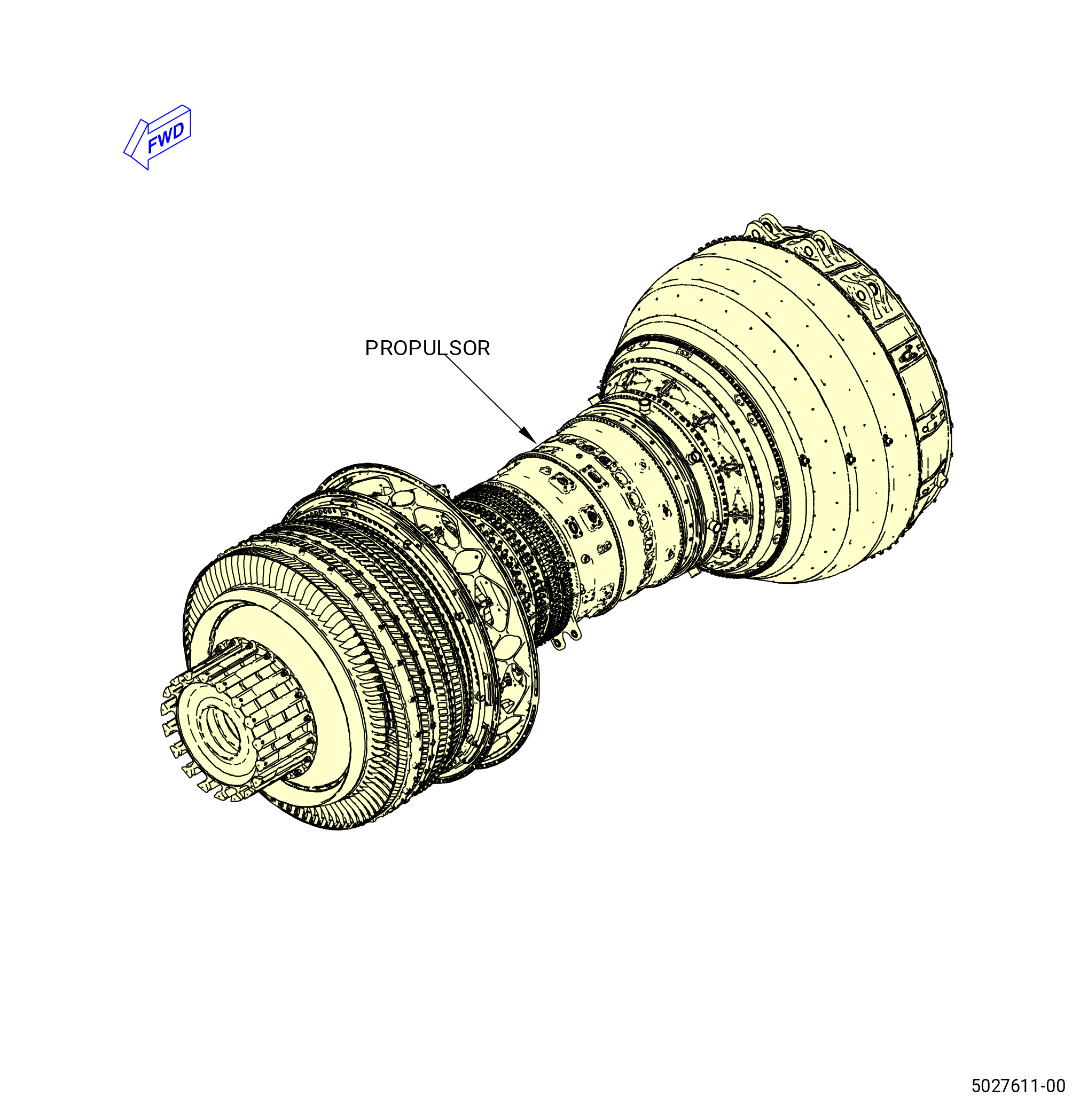
| PROPULSOR ASSEMBLY - DISASSEMBLY 003 | ||
| GENX-1B ENGINE MANUAL | Dated: 10/06/2023 | |
| EM 72-00-02 , DISASSEMBLY 003 | ||
| PROPULSOR ASSEMBLY - DISASSEMBLY 003 | ||
| * * * FOR ALL |
| TASK 72-00-02-030-803 |
| 1 . | General. |
| A. | This procedure gives instructions to continue the disassembly of the propulsor module assembly (propulsor). This procedure includes removal of external configuration hardware and separation of the engine into modules. Refer to Figure 501. |
| B. | This procedure begins with the propulsor in the horizontal position. The propulsor can be installed in the 11C3044 adapter assembly, or attached to a customer overhead rail system, or supported by the 11C3281 pedestals, at the equivalent disassembly status of TASK 72-00-02-030-802 (72-00-02, DISASSEMBLY 002 - CONFIG 01) or TASK 72-00-02-030-808 (72-00-02, DISASSEMBLY 002 - CONFIG 02) . |
| • |
|
| • |
|
| • |
|
| • |
|
| C. | The modules removed can have external hardware that will be removed at the module disassembly level. |
| D. | Make sure that personnel read the assembly and disassembly techniques section. Refer to TASK 70-10-00-800-009 (ASSEMBLY AND DISASSEMBLY TECHNIQUES) . |
| E. | Install protective covers/plugs on tubes and hoses to prevent damage and contamination. |
| F. | Make sure that personnel obey all site safety and environmental controls or personal injury can occur. |
| 2 . | Tools, Equipment, and Materials. |
| NOTE: |
|
| A. | Tools and Equipment. |
| (1) | Special Tools. |
| (2) | Standard Tools and Equipment. |
|
| (3) | Locally Manufactured Tools. None. |
| B. | Consumable Materials. None. |
| C. | Referenced Procedures. |
|
| D. | Expendable Parts. None. |
| 3 . | Procedure. |
| Subtask 72-00-02-030-369 |
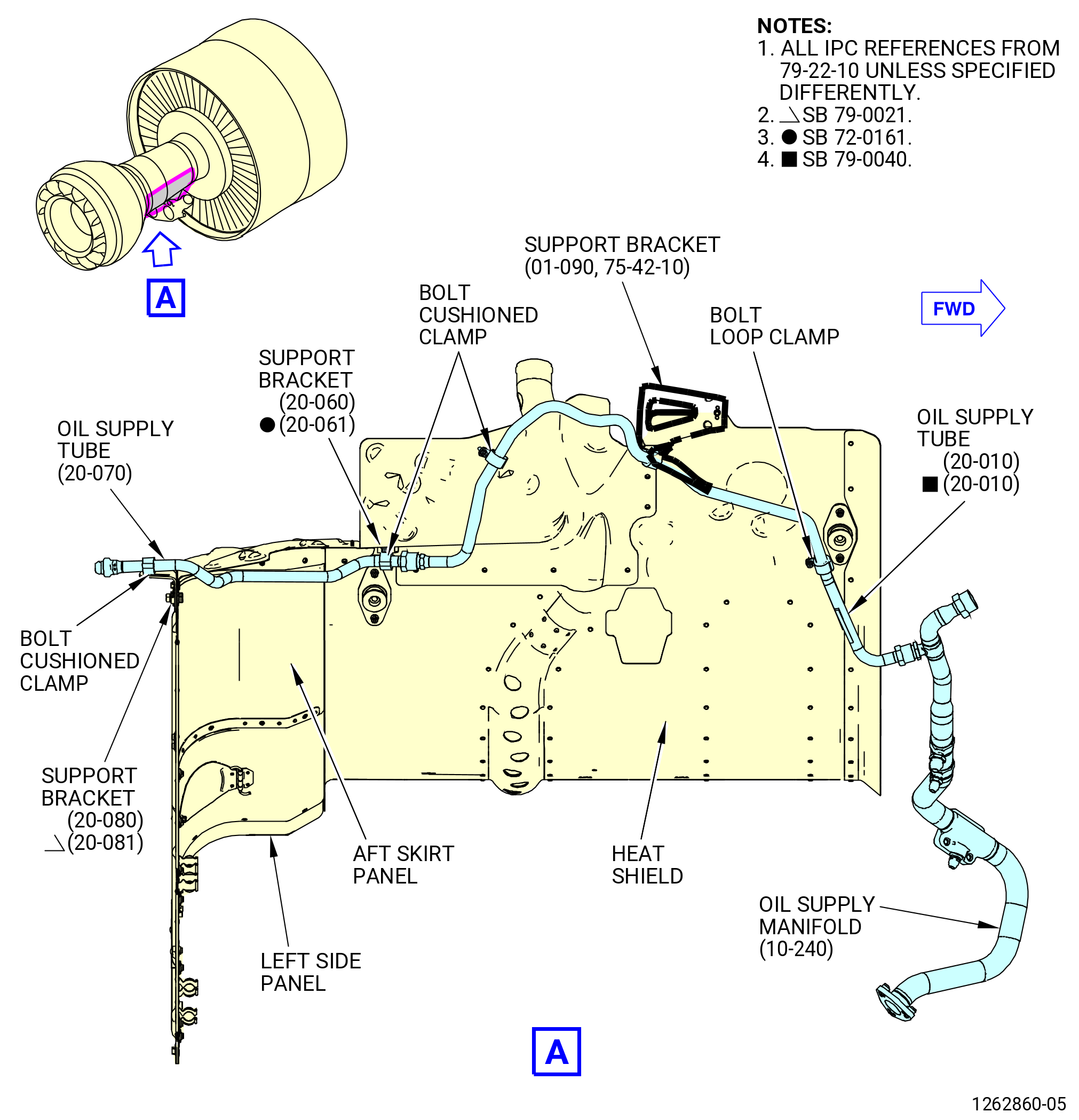
| A. | Remove the oil supply tube (20-010 , 79-22-10) (SIN 44300), oil supply manifold (10-240 , 79-22-10) (SIN 44401), and the oil supply tube (20-070 , 79-22-10) (SIN 44301) from the heat shield at the 5:00 o'clock position as follows. Refer to Figure 502. |
| (1) | Disconnect the coupling nut that attaches the oil supply tube (20-010 , 79-22-10) (SIN 44300) to the oil supply manifold (10-240 , 79-22-10) (SIN 44401) and remove the oil supply manifold. |
| (2) | Disconnect the coupling nut on the oil supply tube (20-070 , 79-22-10) (44301) that attaches the oil supply tube to the oil supply tube (20-010 , 79-22-10) (SIN 44300). |
| (3) | Remove the bolt and cushioned clamp that attaches the oil supply tube (20-010 , 79-22-10) (SIN 44300) to the support bracket (01-090 , 75-42-10) (SIN 53010). |
| (4) | Remove the bolts and cushioned clamps that attach the oil supply tube (20-010 , 79-22-10) (SIN 44300) to the heat shield and remove the oil supply tube. |
| (5) | Remove the bolt and cushioned clamp that attaches the oil supply tube (20-070 , 79-22-10) (SIN 44301) to the support bracket (20-080 , 79-22-10) (SIN 44312) or (20-081 , 79-22-10) (SIN 44312) on the aft skirt panel. |
| (6) | Remove the bolt and cushioned clamp that attaches the oil supply tube (20-070 , 79-22-10) (SIN 44301) to the support bracket (20-060 , 79-22-10) (SIN 44315) or (20-061 , 79-22-10) (SIN 44315) on the heat shield and remove the oil supply tube. |
| Subtask 72-00-02-030-370 |
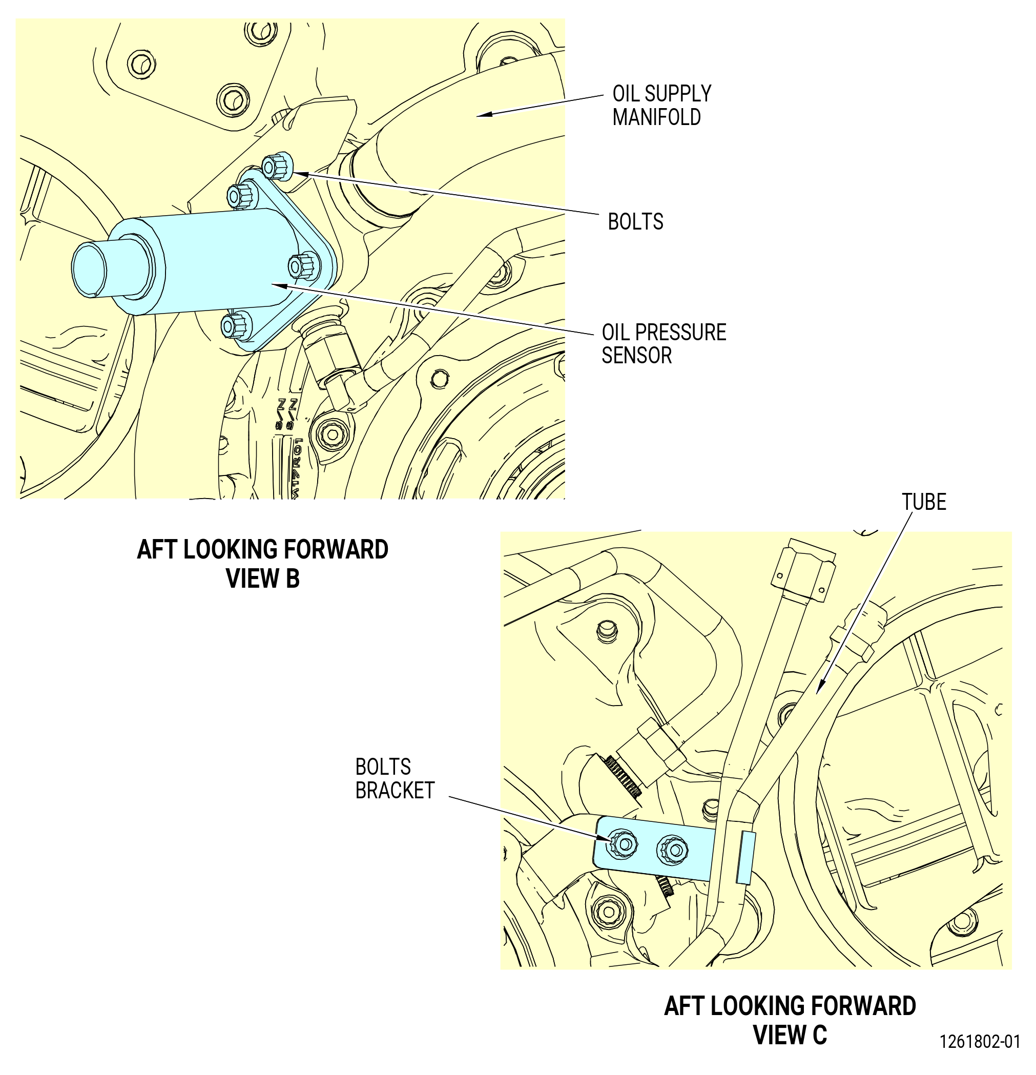
| B. | Remove the fan hub frame (FHF) and transfer gear box (TGB) oil supply tubes as follows. Refer to Figure 503. |
| (1) | Remove the bolts that attach the bracket from the TGB to the oil supply tube. |
| (2) | Remove the bracket and the oil supply tube. |
| (3) | Remove the oil supply tube coupling nuts from the oil supply manifold and the TGB. |
| (4) | Loosen the bolt from the cushioned clamp on the oil supply tube and remove the cushioned clamp. |
| (5) | Remove the oil supply tube. |
| (6) | Remove the three bolts that attach the oil pressure sensor to the oil supply manifold as follows: |
| (a) | Remove and discard the gasket (01-070 , 79-32-10) (SIN 40553) from the oil pressure sensor. |
| (b) | Put the oil pressure sensor in a plastic bag. |
| (c) | Put a cover on the oil pressure sensor flange. |
| (7) | Remove the bolts that attach the bracket to the oil supply manifold and remove the bracket from the oil supply manifold. |
| (8) | Remove the bolts from the cushioned clamps on the oil supply manifold and remove the clamps. |
| (9) | Remove the oil supply manifold. |
| Subtask 72-00-02-030-371 |
| * * * PRE SB 79-0014( Aft Skirt Segment Heat Shields ) |
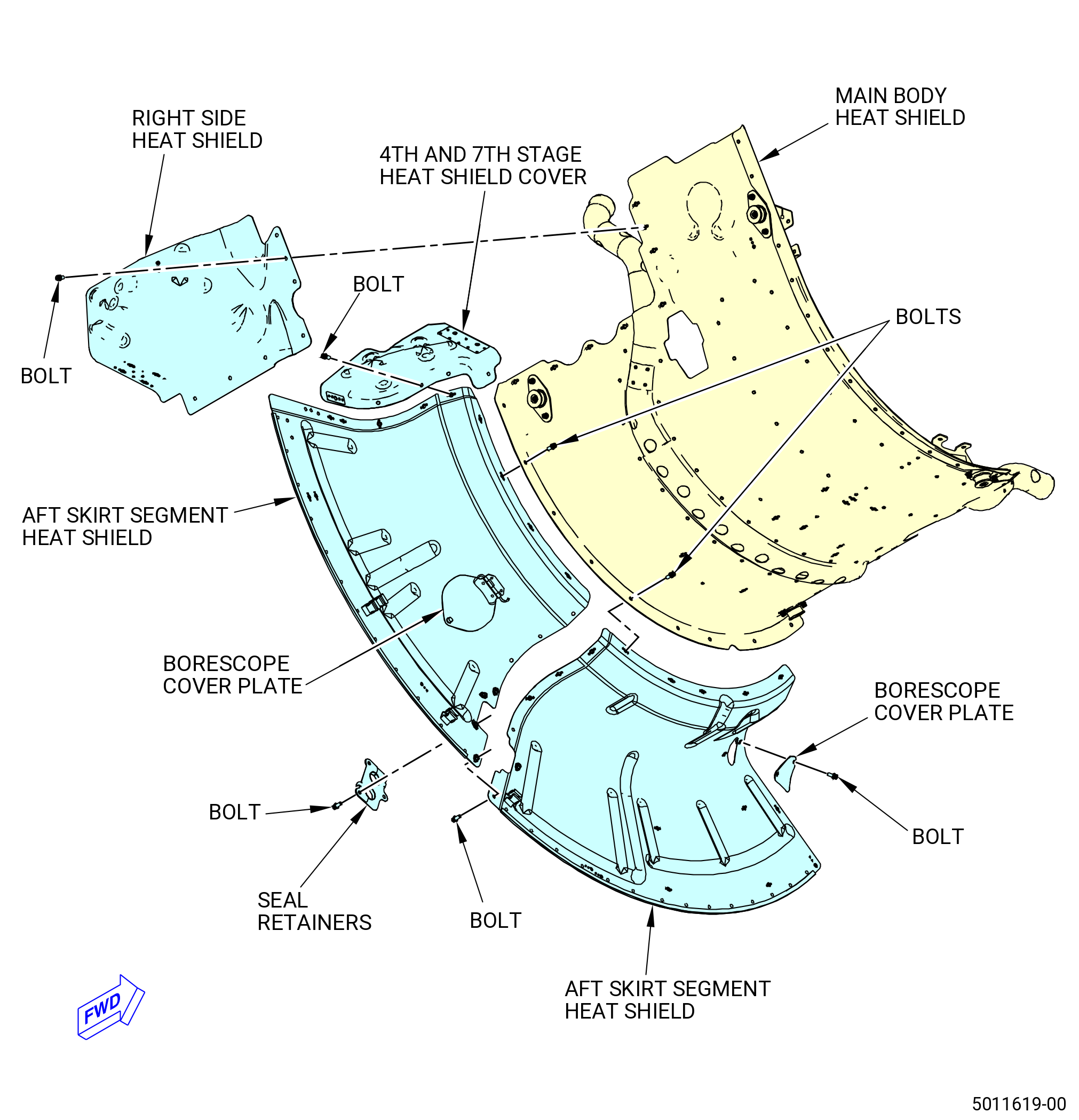
| C. | Remove the aft skirt and heat shields. Refer to Figure 504 and do as follows: |
| (1) | Remove the bolts that attach the borescope cover plates to the aft skirt segment heat shields at the 4:30 and 6:30 o'clock positions. Remove the borescope cover plates. |
| (2) | Remove the 4th and 7th stage shield cover and right side heat shield from the main body heat shield as follows: |
| (a) | Remove the bolts that attach the 4th and 7th stage heat shield cover to the right side heat shield. |
| (b) | Remove the bolts that attach the 4th and 7th stage heat shield cover to the main body heat shield and aft skirt segment heat shield. |
| (c) | Remove the 4th and 7th stage heat shield cover. |
| (d) | Remove the bolts that attach the right side heat shield to the main body heat shield. |
| (e) | Remove the right side heat shield. |
| (3) | Remove the left and right aft skirt segment heat shields from the main body heat shield as follows: |
| (a) | Remove the bolts that attach the left and right aft skirt segment heat shields to the main body heat shield and middle aft skirt segment heat shields. |
| (b) | Remove the left and right aft skirt segment heat shields. |
| (4) | Remove the middle aft skirt segment heat shields from the main body heat shield as follows: |
| Subtask 72-00-02-030-707 |
| * * * PRE SB 72-0308( Scavenge Oil Tube and Hose without Support Bracket ) |
| (a) | Remove the bolts that attach the seal retainers to the middle aft skirt segment heat shields. |
| * * * END PRE SB 72-0308 |
| Subtask 72-00-02-030-708 |
| * * * SB 72-0308( Scavenge Oil Tube and Hose with Support Bracket ) |
| (a).A. | Remove the bolts that attach the seal retainers and support scavenge tube bracket (support bracket) to the middle aft skirt segment heat shields. |
| * * * END SB 72-0308 |
| Subtask 72-00-02-030-709 |
| * * * PRE SB 72-0308( Scavenge Oil Tube and Hose without Support Bracket ) |
| (b) | Remove the seal retainers. |
| * * * END PRE SB 72-0308 |
| Subtask 72-00-02-030-710 |
| * * * SB 72-0308( Scavenge Oil Tube and Hose with Support Bracket ) |
| (b).A. | Remove the seal retainers and support bracket. |
| * * * END SB 72-0308 |
| Subtask 72-00-02-030-716 |
| (c) | Remove the bolts that attach the middle aft skirt segment heat shields together. |
| (d) | Remove the bolts that attach the middle aft skirt segment heat shields to the main body heat shield. |
| (e) | Remove the middle aft skirt segment heat shields. |
| * * * END PRE SB 79-0014 |
| Subtask 72-00-02-030-614 |
| * * * SB 79-0014( New Aft Skirt Segment Heat Shields ) |
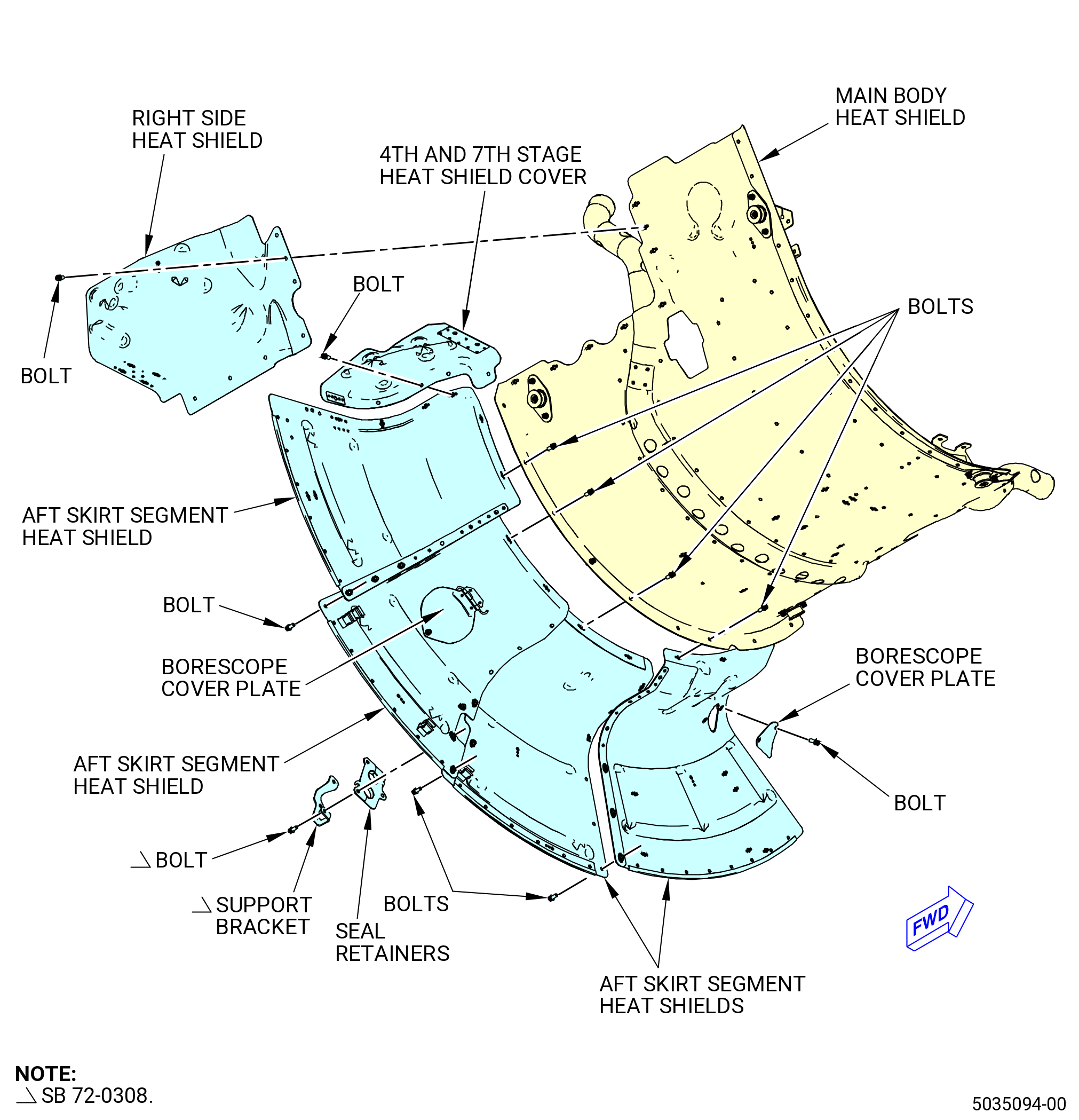
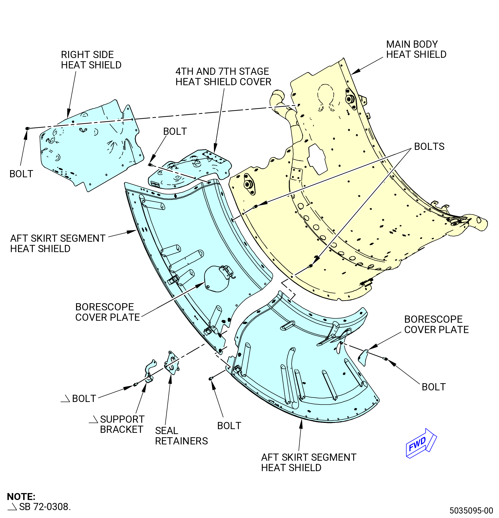
| C.A. | Remove the aft skirt and heat shields. Refer to Figure 504A and do as follows: |
| (1) | Remove the bolts that attach the borescope cover plates to the aft skirt segment heat shields at the 4:30 and 6:30 o'clock positions. Remove the borescope cover plates. |
| (2) | Remove the 4th and 7th stage heat shield cover and right side heat shield from the main body heat shield as follows: |
| (a) | Remove the bolts that attach the 4th and 7th stage heat shield cover to the right side heat shield. |
| (b) | Remove the bolts that attach the 4th and 7th stage heat shield cover to the main body heat shield and aft skirt segment heat shield. |
| (c) | Remove the 4th and 7th stage heat shield cover. |
| (d) | Remove the bolts that attach the right side heat shield to the main body heat shield. |
| (e) | Remove the right side heat shield. |
| (3) | Remove the aft skirt segment heat shields from the main body heat shield as follows: |
| Subtask 72-00-02-030-711 |
| * * * PRE SB 72-0308( Scavenge Oil Tube and Hose without Support Bracket ) |
| (a) | Remove the bolts that attach the retainer seals to the aft skirt segment heat shields. |
| * * * END PRE SB 72-0308 |
| Subtask 72-00-02-030-712 |
| * * * SB 72-0308( Scavenge Oil Tube and Hose with Support Bracket ) |
| (a).A. | Remove the bolts that attach the seal retainers and support bracket to the middle aft skirt segment heat shields. |
| * * * END SB 72-0308 |
| Subtask 72-00-02-030-713 |
| * * * PRE SB 72-0308( Scavenge Oil Tube and Hose without Support Bracket ) |
| (b) | Remove the seal retainers. |
| * * * END PRE SB 72-0308 |
| Subtask 72-00-02-030-714 |
| * * * SB 72-0308( Scavenge Oil Tube and Hose with Support Bracket ) |
| (b).A. | Remove the seal retainers and support bracket. |
| * * * END SB 72-0308 |
| Subtask 72-00-02-030-717 |
| (c) | Remove the bolts that attach the aft skirt segment heat shields together. |
| (d) | Remove the bolts that attach the aft skirt segment heat shields to the main body heat shield. |
| (e) | Remove the aft skirt segment heat shields. |
| * * * END SB 79-0014 |
| Subtask 72-00-02-030-372 |
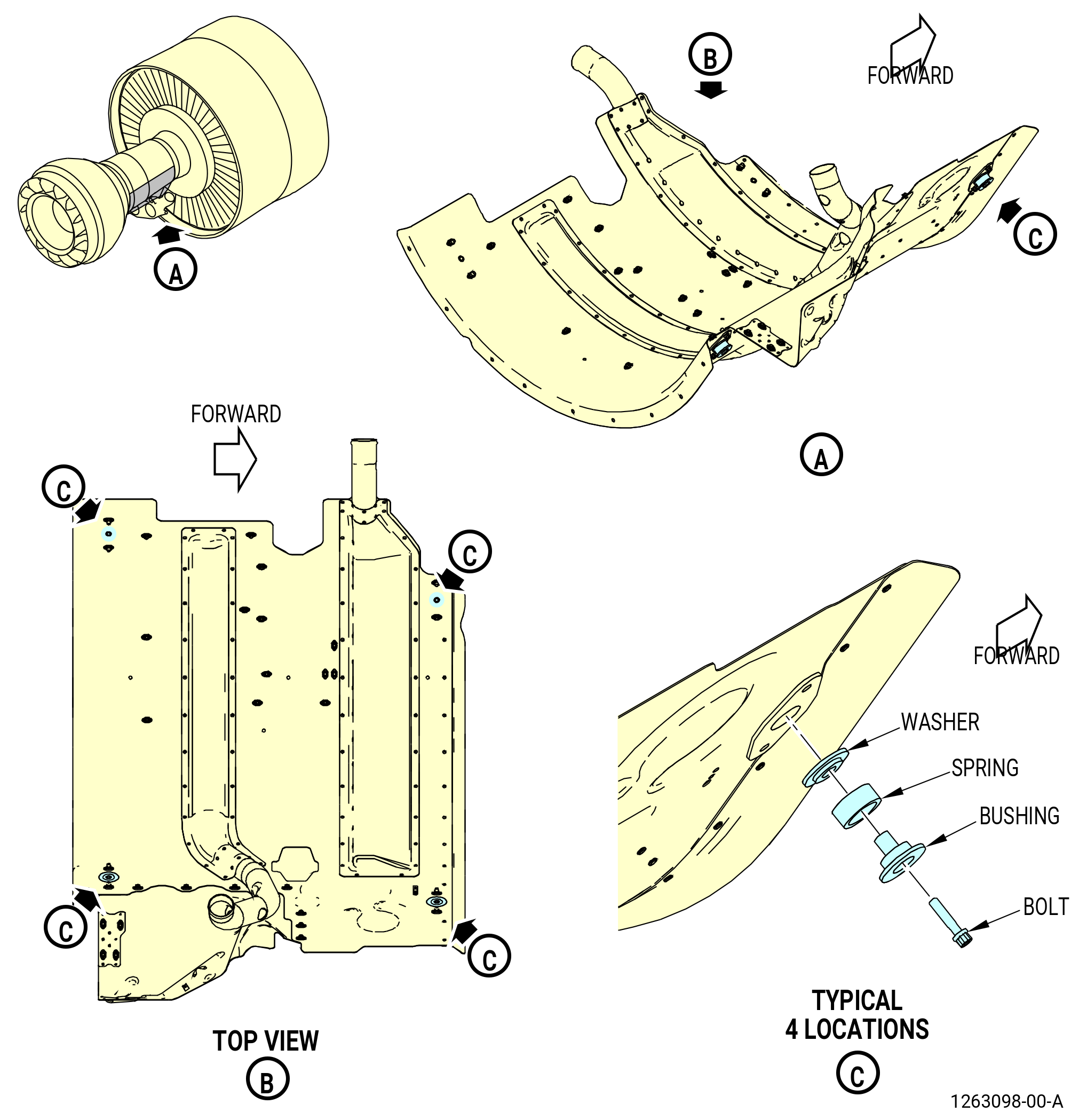
| D. | Remove the heat shield as follows. Refer to Figure 505. |
| (1) | Remove the bolt from the center of the heat shield. |
| (2) | Remove the bolt, bushing, spring, and washer from the bottom right corner of the heat shield. |
| (3) | Remove the bolt, bushing, spring, and washer from the top right corner of the heat shield. |
| (4) | Remove the bolt, bushing, spring, and washer from the bottom left corner of the heat shield. |
| (5) | Remove the bolt, bushing, spring, and washer from the top left corner of the heat shield. |
| (6) | Remove the heat shield. |
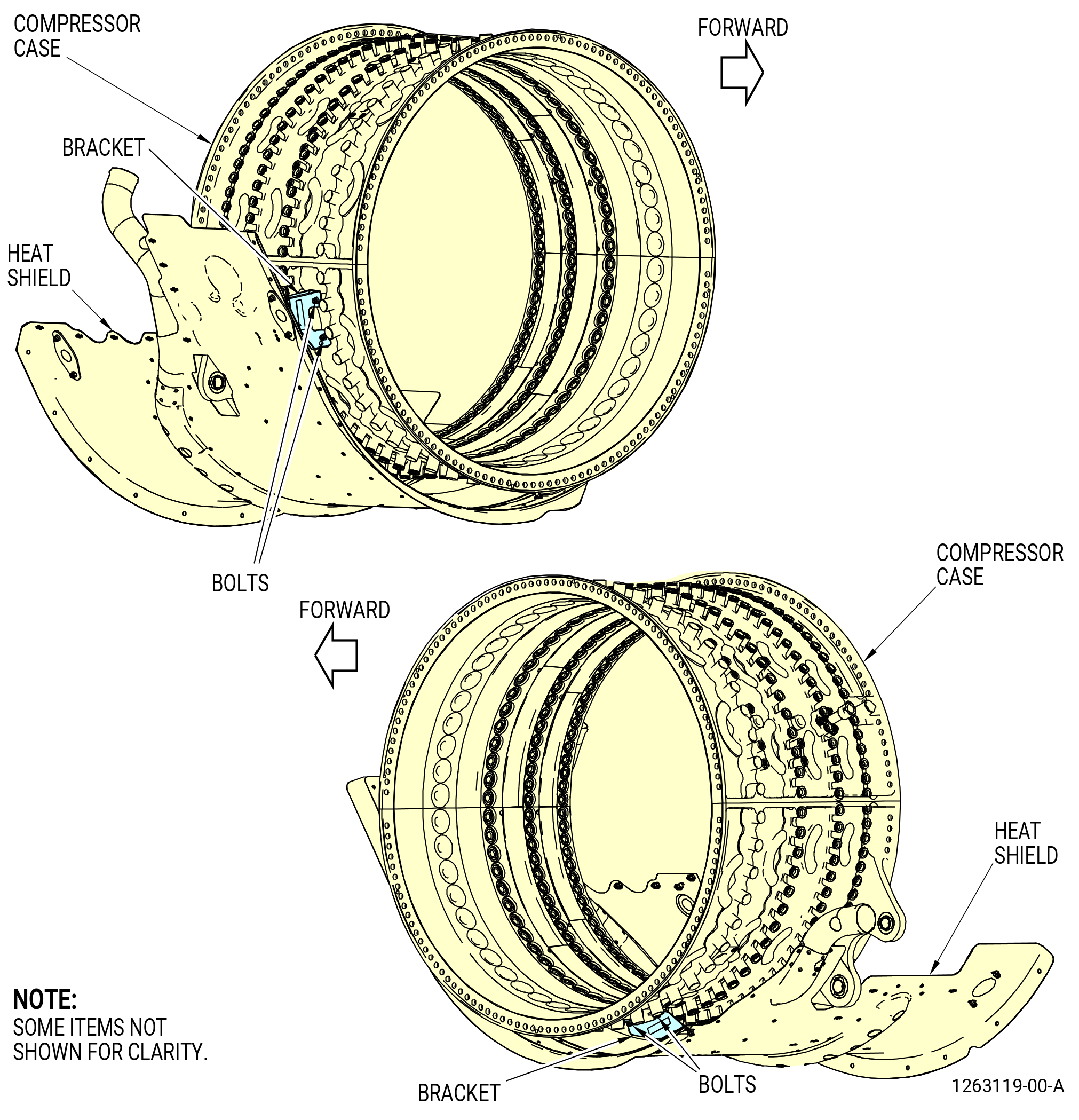
| (7) | Remove the bracket from the high pressure compressor (HPC) case between bosses 1 and 2 clockwise (CW) from the 3:00 o'clock position on the horizontal flange as follows: |
| (a) | Remove the two bolts from the bracket and remove the bracket. |
| (8) | Remove the bracket from the HPC case between bosses 1 and 2 CW from the 9:00 o'clock position on the horizontal flange as follows: |
| (a) | Remove the two bolts from the bracket and remove the bracket. |
| Subtask 72-00-02-030-373 |
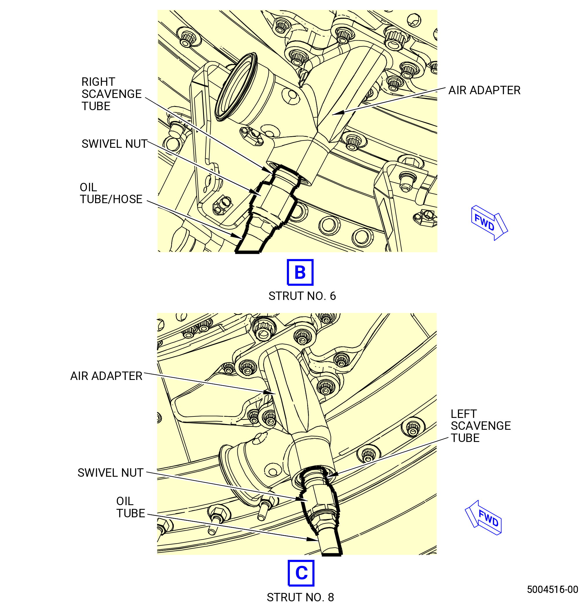
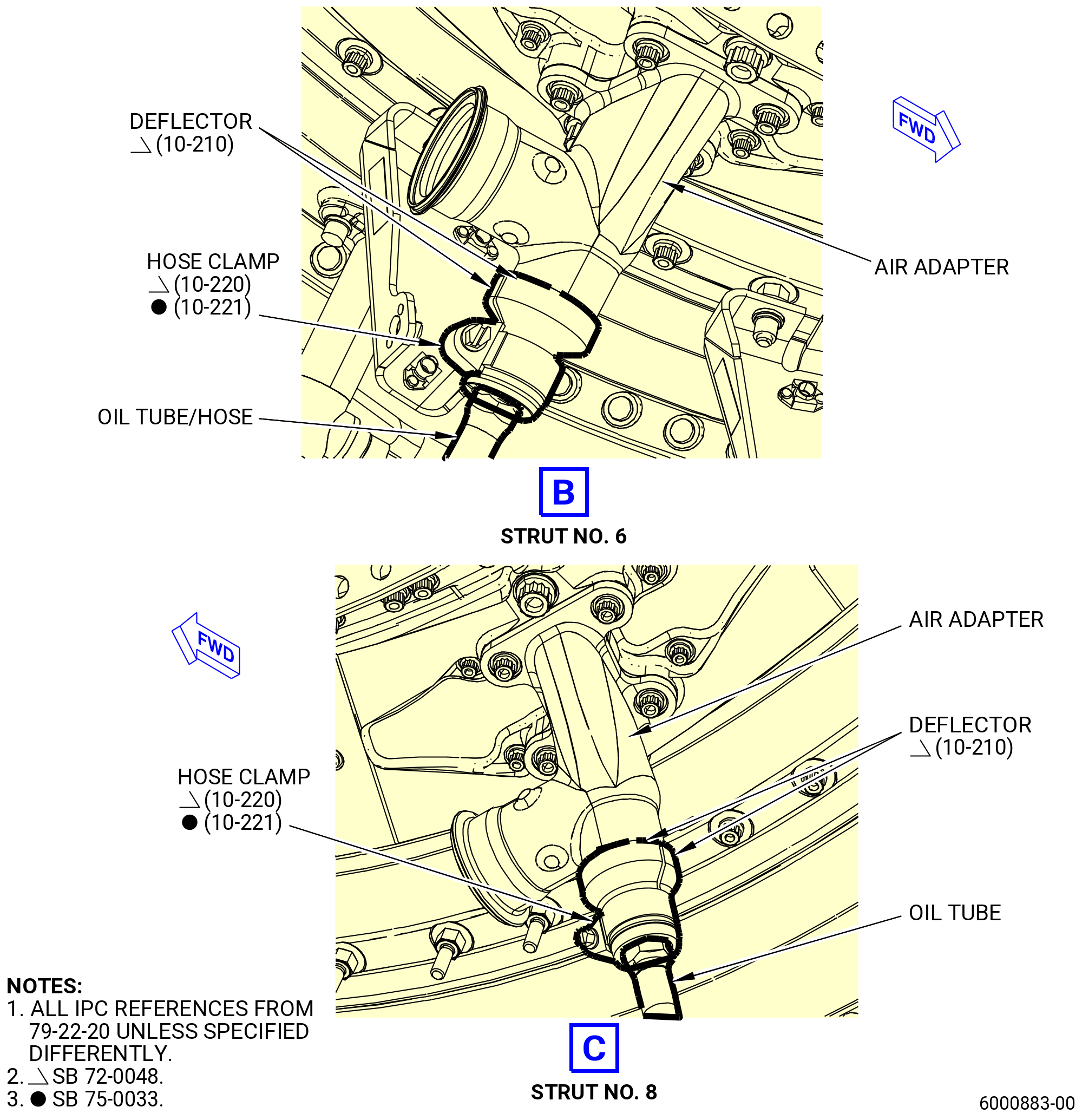
| E. | Remove the scavenge oil tube/hose as follows. Refer to Figure 506. |
| (1) | Remove the bolts that attach the oil tube/hose flange to the accessory gearbox (AGB). |
| (2) | Remove the bolts from the support bracket. |
| Subtask 72-00-02-030-531 |
| * * * SB 72-0048( Scavenge Oil Tube/Hose with Adapter Cap Deflectors ) |
| (3) | Remove the adapter cap deflectors (deflectors) (10-210 , 79-22-20) (SIN 9259B) at the struts No. 6 and No. 8 as follows: |
| NOTE: |
|
| (a) | Remove the two hose clamps (10-220 , 79-22-20) (SIN 9258A) or (10-221 , 79-22-20) (SIN 9258E) that attach the four deflectors. |
| (b) | Remove the four deflectors from the swivel nuts and air adapters. |
| * * * END SB 72-0048 |
| Subtask 72-00-02-030-532 |
| (4) | Disconnect the oil tube/hose coupling nut from the scavenge tube and remove the oil tube/hose. |
|
|
| Subtask 72-00-02-030-374 |
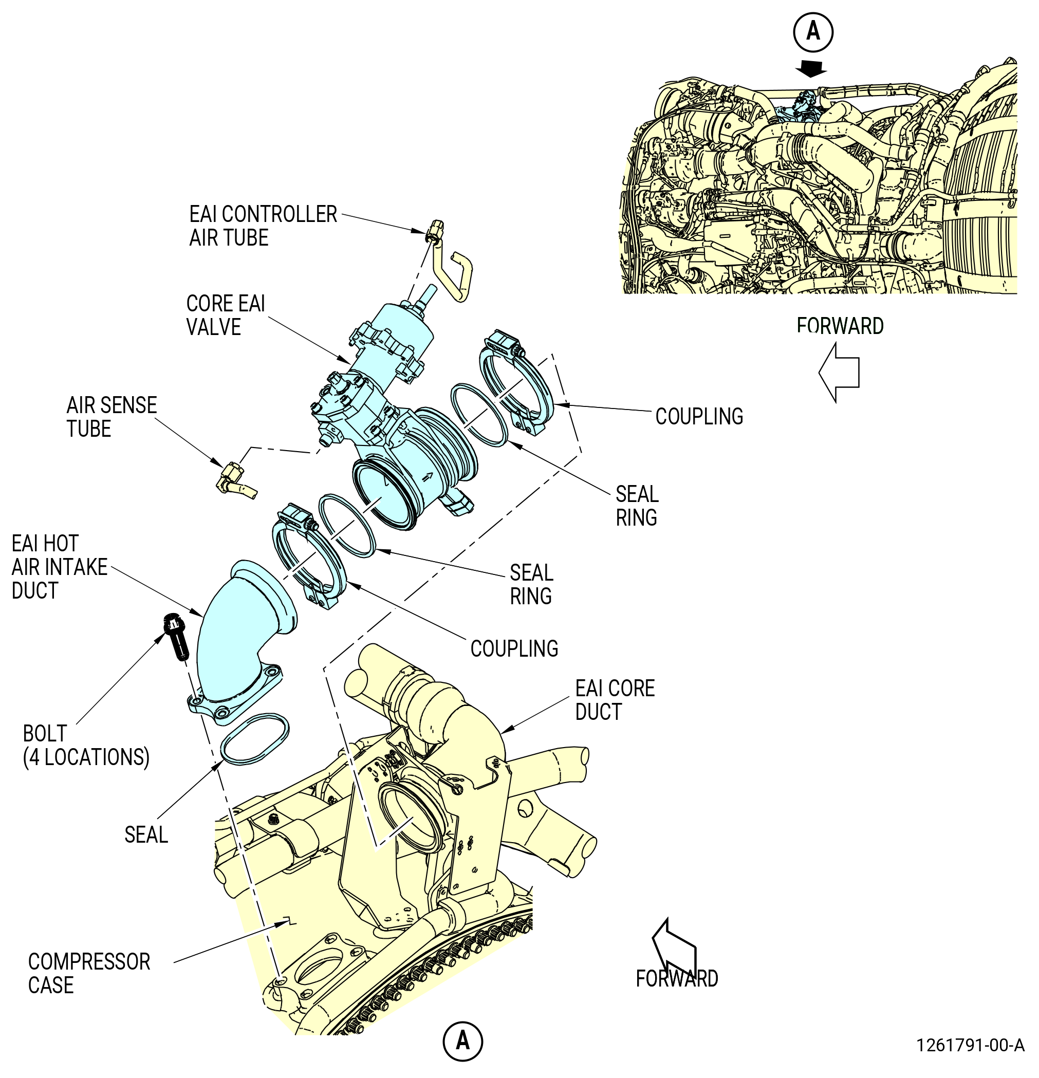
| F. | Remove the engine anti-ice (EAI) valve, tubes and air duct as follows. Refer to Figure 507. |
| (1) | Remove the EAI valve as follows: |
| (a) | Disconnect the coupling nut that attaches the tube to the EAI valve. |
| (b) | Remove the two coupling clamps from the EAI valve. Remove the ring seal from both sides of the EAI valve. |
| 1 | Remove the EAI valve. |
| 2 | Install protective caps/plugs on the drain ducts and the EAI valve fittings and openings. |
| (2) | Remove the EAI air duct (air duct) as follows. |
| (a) | Remove the two bolts that attach the air duct to the bracket at the 12:15 o'clock position. |
| (b) | Remove the two bolts that attach the air duct to the bracket at the 12:45 o'clock position. |
| (c) | Remove the two bolts that attach the air duct to the bracket at the 12:45 o'clock position. |
| 1 | Remove the air duct valve. |
| 2 | Install protective caps/plugs on the drain ducts and the air duct and openings. |
| Subtask 72-00-02-030-375 |
| * * * PRE SB 73-0011( Engines without Fuel Vapor Accumulator ) |
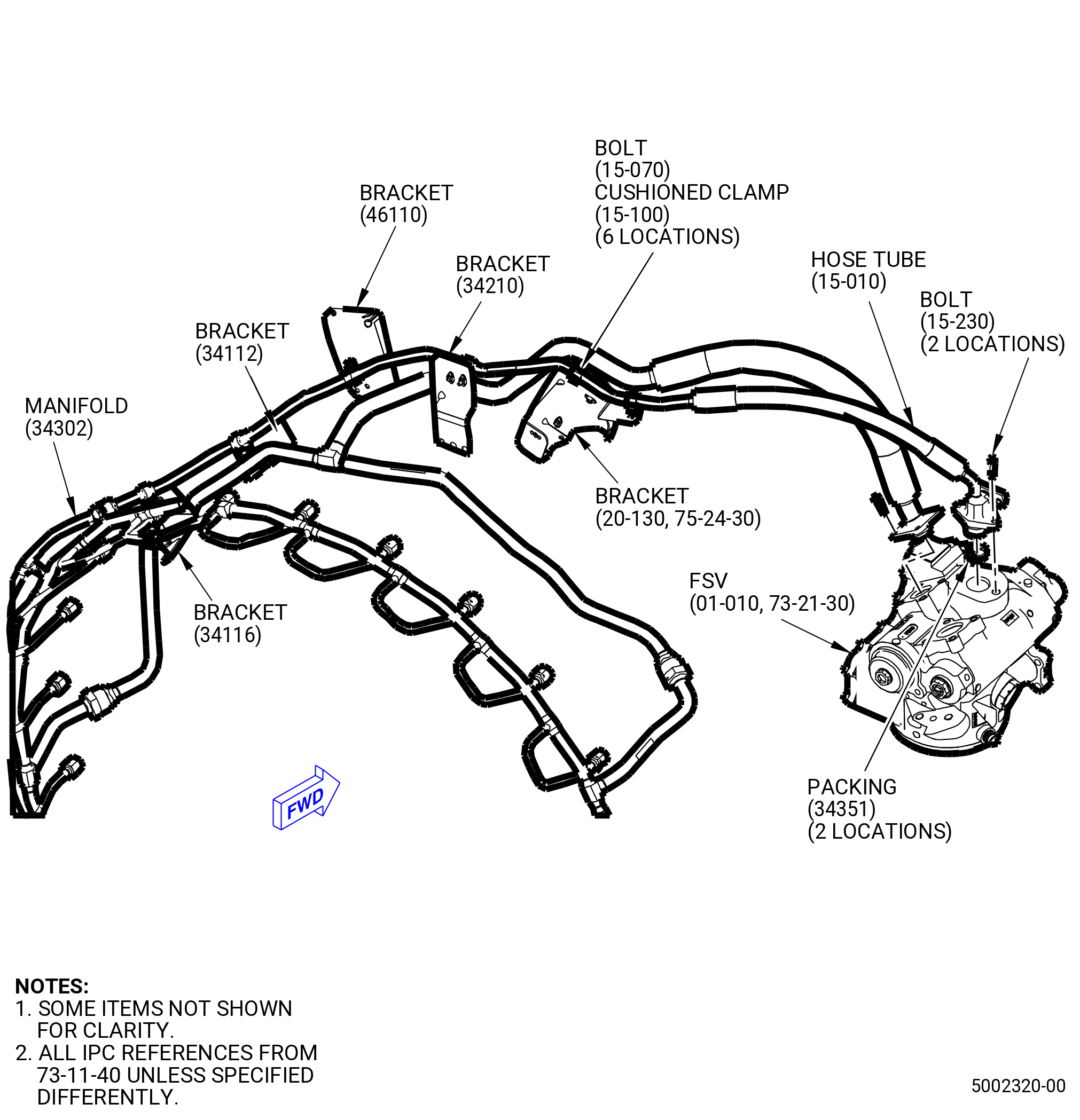
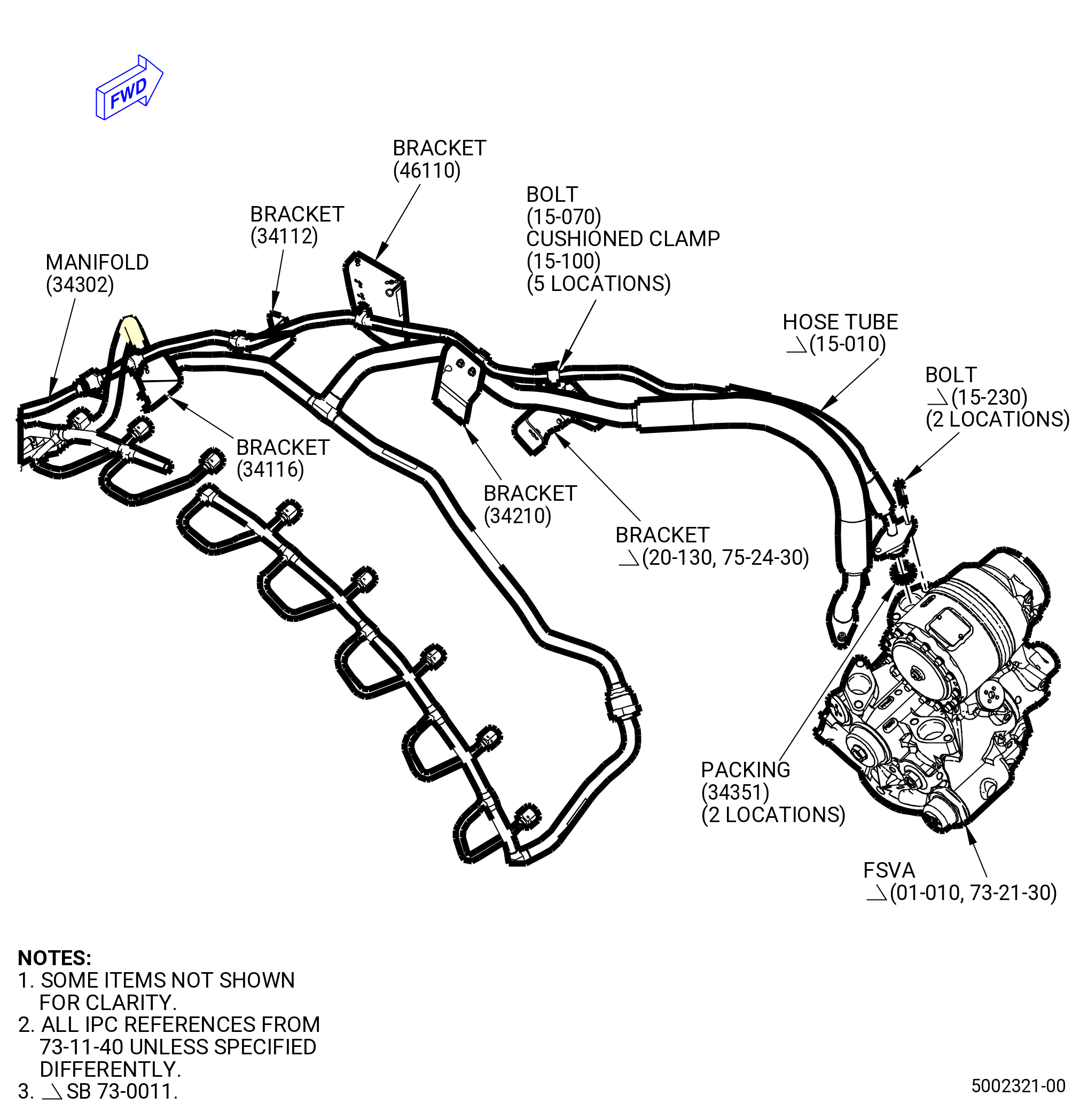
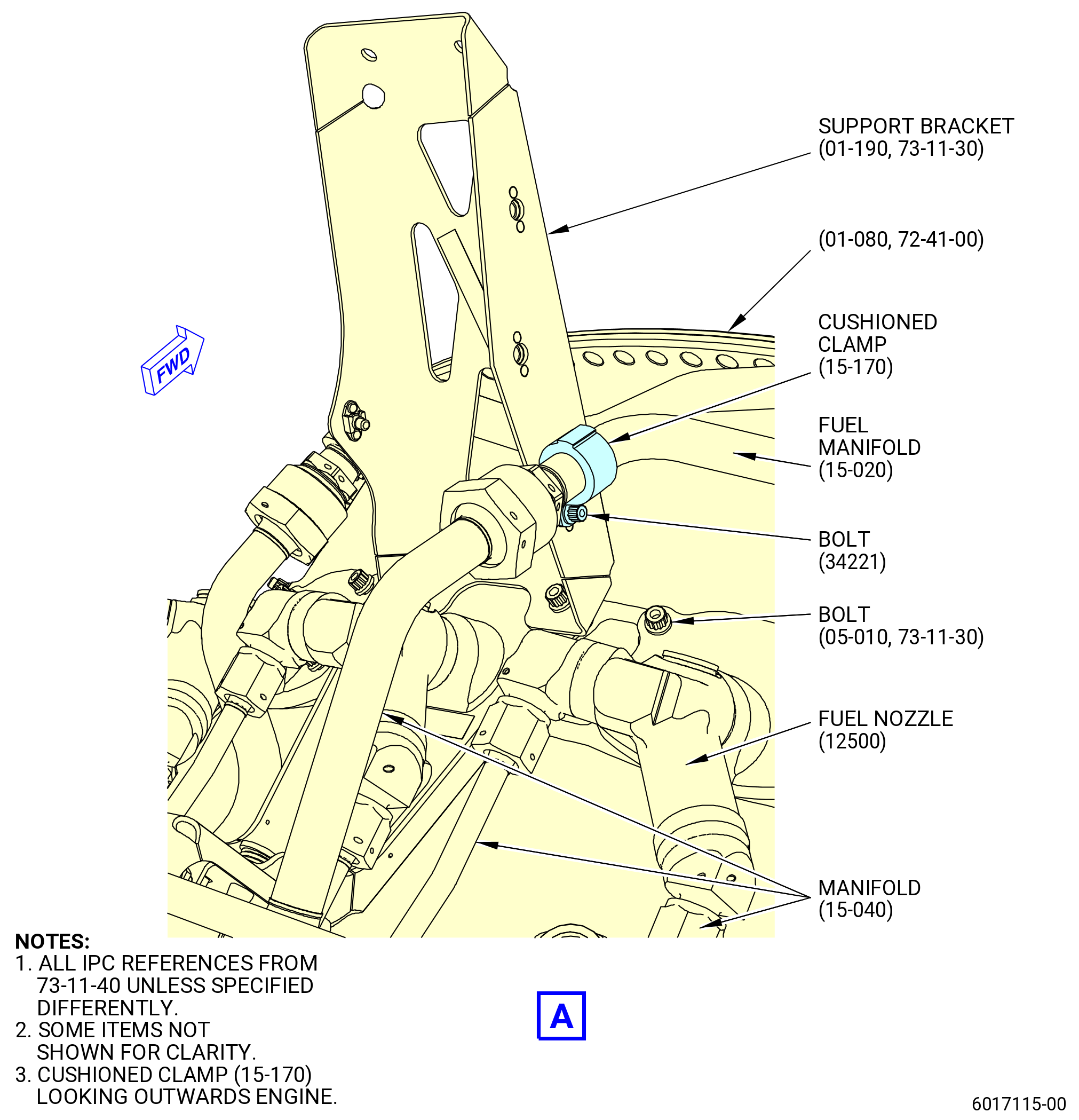
| G. | Remove the fuel signal hose tubes (hose tubes) (15-020 , 73-11-40) (SIN 34200) and (15-010 , 73-11-40) (SIN 34300) as follows. Refer to Figure 508. |
| (1) | Disconnect the coupling nut that connects the hose tube (15-010 , 73-11-40) (SIN 34300) to the fuel manifold (SIN 34302). |
| (2) | Remove the two bolts (15-230 , 73-11-40) (SIN 34322) that attach the hose tube (15-010 , 73-11-40) (SIN 34300) to the flow splitting valve (FSV) (01-010 , 73-21-30) (SIN 31700). |
| (3) | Remove the six bolts (15-070 , 73-11-40) (SIN 34321) and cushioned clamps (15-100 , 73-11-40) (SIN 34381) from the hose tube (15-010 , 73-11-40) (SIN 34300) and remove the hose tube. |
| (4) | Remove and discard the two preformed packings (15-090 , 73-11-40) (SIN 34351) from the hose tube. |
| (5) | Disconnect the couplings nuts that connect the hose tube (15-020 , 73-11-40) (SIN 34200) to the fuel manifolds (SIN 34201) and (SIN 34202). |
| (6) | Remove the four bolts (15-220 , 73-11-40) (SIN 34222) that attach the hose tube (15-020 , 73-11-40) (SIN 34200) to the FSV (01-010 , 73-21-30) (SIN 31700). |
| Subtask 72-00-02-030-781 |
| * * * PRE SB 73-0095 |
| (7) | Remove the nine bolts (15-160 , 73-11-40) (SIN 34221), cushioned clamps (15-080 , 73-11-40) (SIN 34283) and cushioned clamps (15-170 , 73-11-40) (SIN 34282) from the hose tube (15-020 , 73-11-40) (SIN 34200) and remove the hose tube. |
| * * * END PRE SB 73-0095 |
| Subtask 72-00-02-030-782 |
| * * * SB 73-0095 |
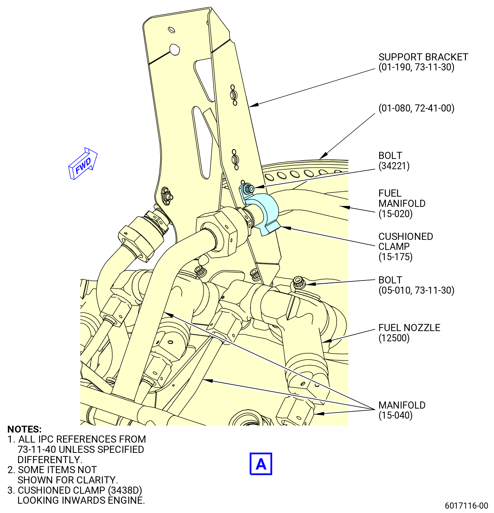
| (7).A. | Remove the nine bolts (15-160 , 73-11-40) (SIN 34221), cushioned clamps (15-080 , 73-11-40) (SIN 34283), cushioned clamps (15-170 , 73-11-40) (SIN 34282) and cushioned clamp (15-175 , 73-11-40) (SIN 3438D) from the hose tube (15-020 , 73-11-40) (SIN 34200) and remove the hose tube. |
| * * * END SB 73-0095 |
| Subtask 72-00-02-030-783 |
| (8) | Remove and discard the preformed packing (15-120 , 73-11-40) (SIN 34252), preformed packings (15-210 , 73-11-40) (SIN 34250), and gasket (15-150 , 73-11-40) (SIN 34251) from the hose tube. |
| * * * END PRE SB 73-0011 |
| Subtask 72-00-02-030-518 |
| * * * SB 73-0011( Engines with Fuel Vapor Accumulator ) |
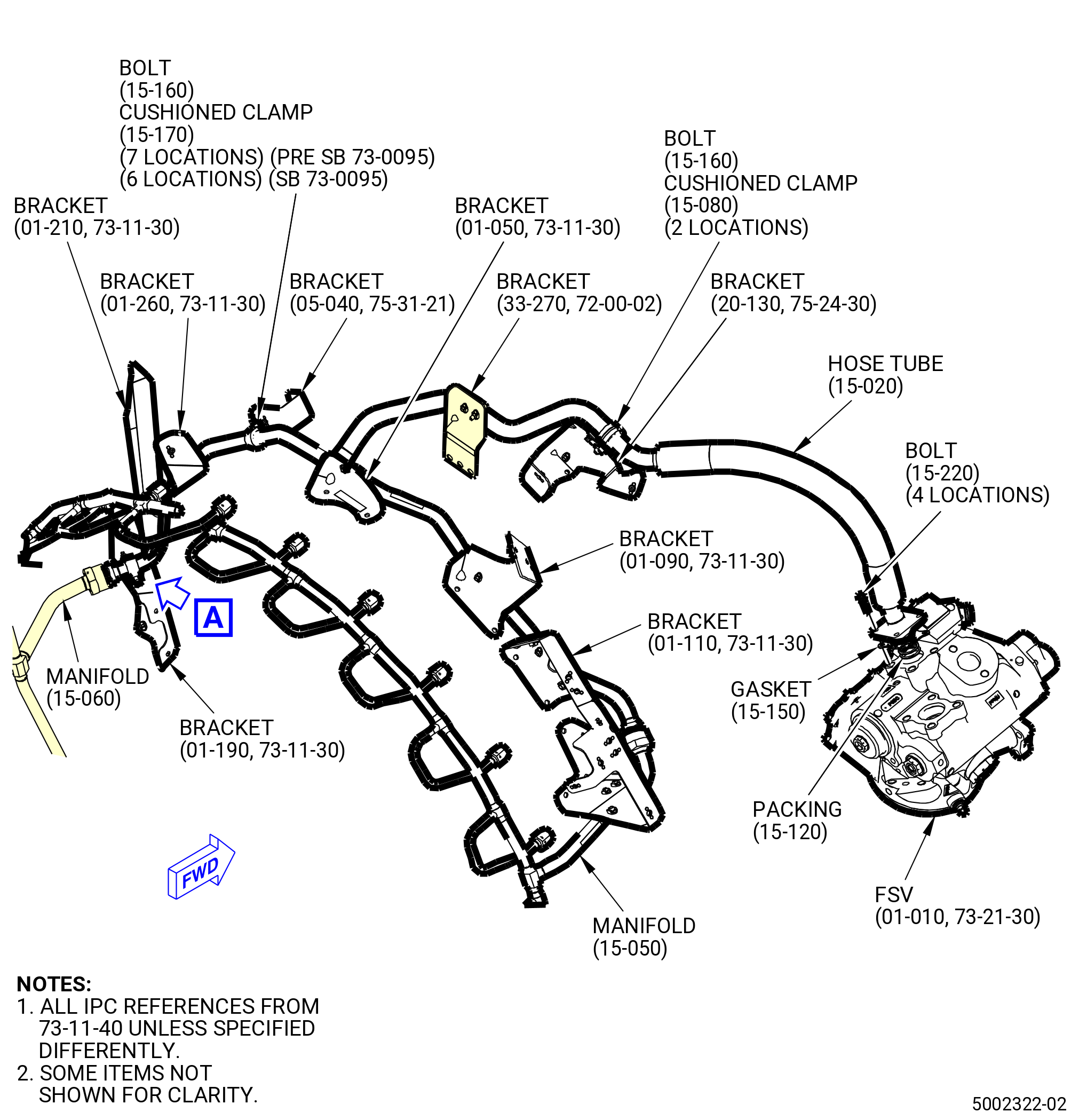
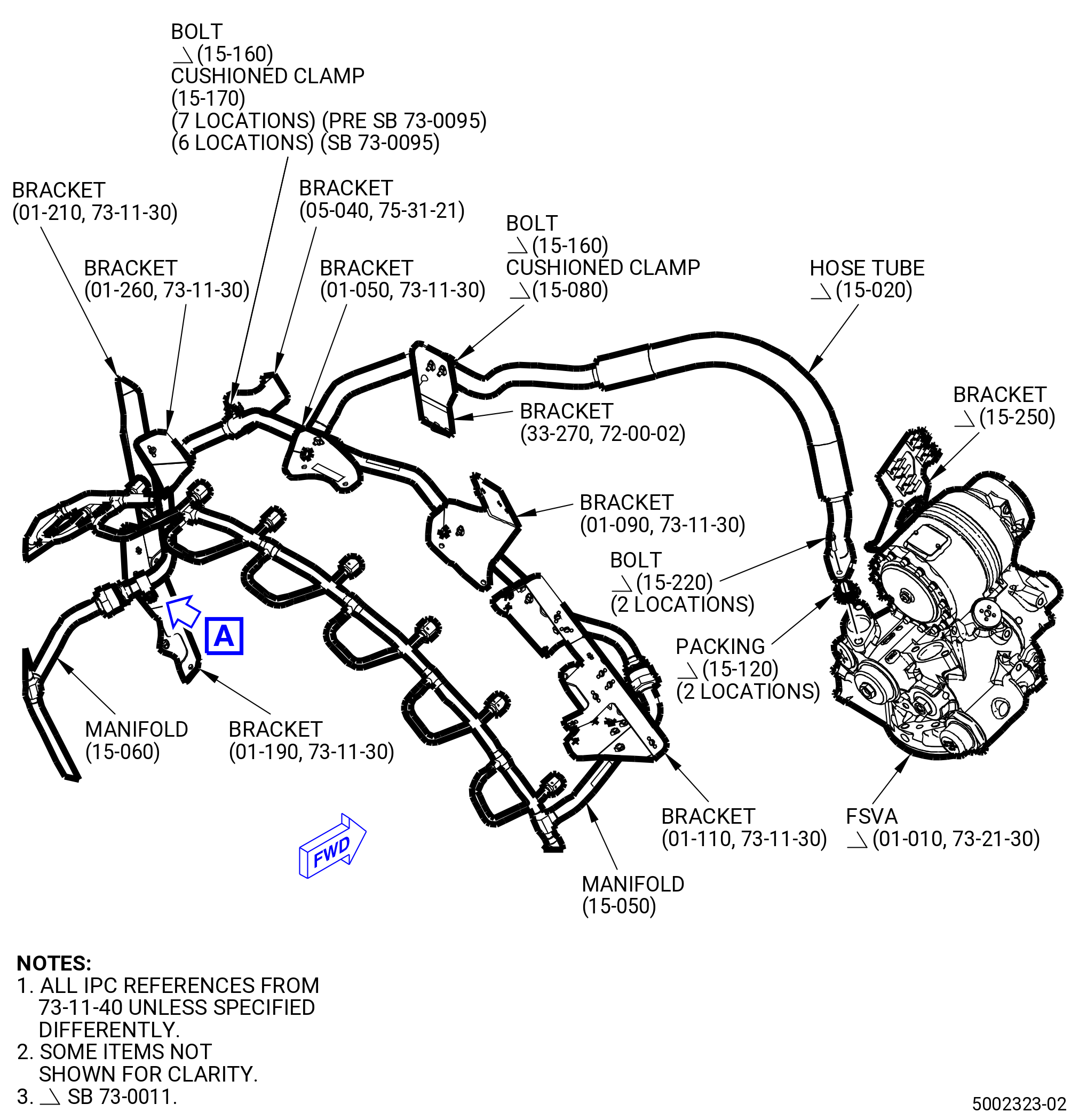
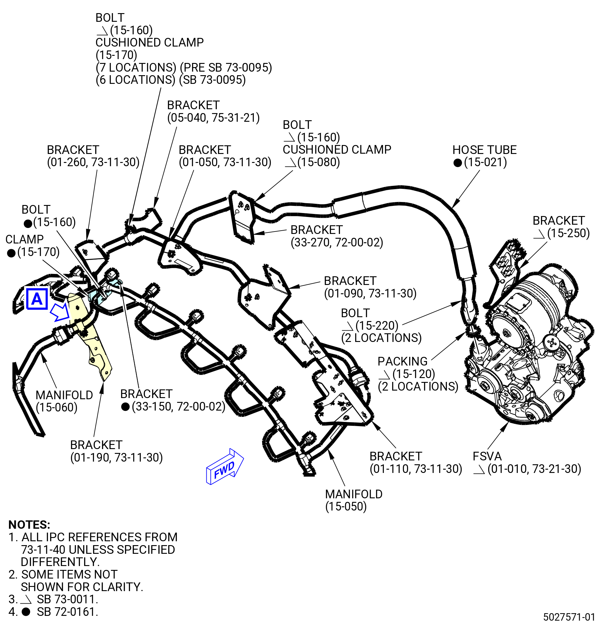
| G.A. | Remove the fuel signal hose tubes (hose tubes) (15-020 , 73-11-40) (SIN 34200) or (15-021 , 73-11-40) (SIN 34200) and (15-010 , 73-11-40) (SIN 34300). Refer to Figure 508 and do as follows: |
| (1) | Disconnect the coupling nut that connects the hose tube (15-010 , 73-11-40) (SIN 34300) to the fuel manifold (SIN 34302). |
| (2) | Remove the bolts (15-230 , 73-11-40) (SIN 34322) that attach the hose tube (15-010 , 73-11-40) (SIN 34300) and bracket (15-250 , 73-11-40) (SIN 6881Y) to the flow splitting valve accumulator (FSVA) (01-010 , 73-21-30) (SIN 31700). |
| (3) | Remove the five bolts (15-070 , 73-11-40) (SIN 34321) and cushioned clamps (15-100 , 73-11-40) (SIN 34381) from the hose tube (15-010 , 73-11-40) (SIN 34300) and remove the hose tube. |
| (4) | Remove and discard the preformed packings (15-090 , 73-11-40) (SIN 34351) from the hose tube. |
| (5) | Disconnect the couplings nuts that connect the hose tube (15-020 , 73-11-40) (SIN 34200) or (15-021 , 73-11-40) (SIN 34200) to the fuel manifolds (15-050 , 73-11-40) (SIN 34201) and (15-060 , 73-11-40) (SIN 34202). |
| (6) | Remove the two bolts (15-220 , 73-11-40) (SIN 34222) that attach the hose tube (15-020 , 73-11-40) (SIN 34200) or (15-021 , 73-11-40) (SIN 34200) to the FSVA (01-010 , 73-21-30) (SIN 31700). |
| Subtask 72-00-02-030-784 |
| * * * PRE SB 73-0095 |
| (7) | Remove the eight bolts (15-160 , 73-11-40) (SIN 34221) and cushioned clamps (15-170 , 73-11-40) (SIN 34282) from the hose tube (15-020 , 73-11-40) (SIN 34200) or (15-021 , 73-11-40) (SIN 34200) and remove the hose tube. |
| * * * END PRE SB 73-0095 |
| Subtask 72-00-02-030-785 |
| * * * SB 73-0095 |
| (7).A. | Remove the eight bolts (15-160 , 73-11-40) (SIN 34221), cushioned clamps (15-170 , 73-11-40) (SIN 34282) and cushioned clamp (15-175 , 73-11-40) (SIN 3438D) from the hose tube (15-020 , 73-11-40) (SIN 34200) or (15-021 , 73-11-40) and remove the hose tube. |
| * * * END SB 73-0095 |
| Subtask 72-00-02-030-786 |
| (8) | Remove and discard the preformed packing (15-120 , 73-11-40) (SIN 34252) and (15-210 , 73-11-40) (SIN 34250), and gasket (15-150 , 73-11-40) (SIN 34251) from the hose tube. |
| * * * END SB 73-0011 |
|
|
|
| Subtask 72-00-02-030-688 |
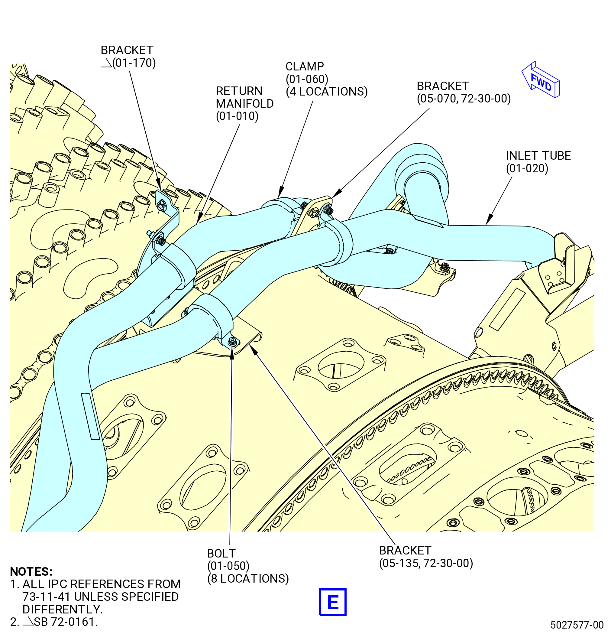
| H. | Remove the VFSG heat exchanger (01-010 , 73-11-20) (SIN 42400) fuel system. Refer to Figure 509 and do as follows: |
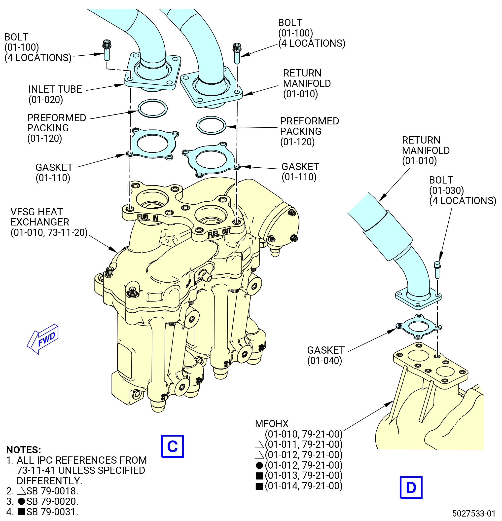
| (1) | Remove the FCOC fuel cooling inlet hose tube (inlet tube) (01-020 , 73-11-41) (SIN 34501) as follows: |
| (a) | Remove the bolts (01-050 , 73-11-41) (SIN 34520) and clamps (01-060 , 73-11-41) (SIN 34580) that attach the inlet tube to the brackets (05-135 , 72-30-00) (SIN 34514) and (05-070 , 72-30-00) (SIN 34510). |
| (b) | Remove the bolts (01-100 , 73-11-41) (SIN 34524) that attach the inlet tube to the VFSG FUEL IN port. Remove and discard gasket (01-110 , 73-11-41) (SIN 34551) and packing (01-120 , 73-11-41) (SIN 34553). |
| (2) | Remove the FCOC fuel return hose manifold (return manifold) (01-010 , 73-11-41) (SIN 34500) as follows: |
| (a) | Remove the bolts (01-050 , 73-11-41) (SIN 34520) and clamps (01-060 , 73-11-41) (SIN 34580) that attach the return manifold to the brackets (01-080 , 73-11-41) (SIN 34511) and (05-070 , 72-30-00) (SIN 34510). |
| (b) | Remove the bolts (01-100 , 73-11-41) (SIN 34524) that attach the return manifold to the FUEL OUT port on the VFSG heat exchanger. Remove and discard gasket (01-110 , 73-11-41) (SIN 34551) and packing (01-120 , 73-11-41) (SIN 34553). |
| (c) | Remove the bolts (01-030 , 73-11-41) (SIN 34522) that attach the return manifold to the FUEL IN port on the fuel/oil heat exchanger (MFOHX) (01-010 , 79-21-00) (SIN 40700) or (01-011 , 79-21-00) (SIN 40700) or (01-012 , 79-21-00) (SIN 40700) or (01-013 , 79-21-00) (SIN 40700) or (01-014 , 79-21-00) (SIN 40700). Remove and discard the gasket (01-040 , 73-11-41) (SIN 34550). |
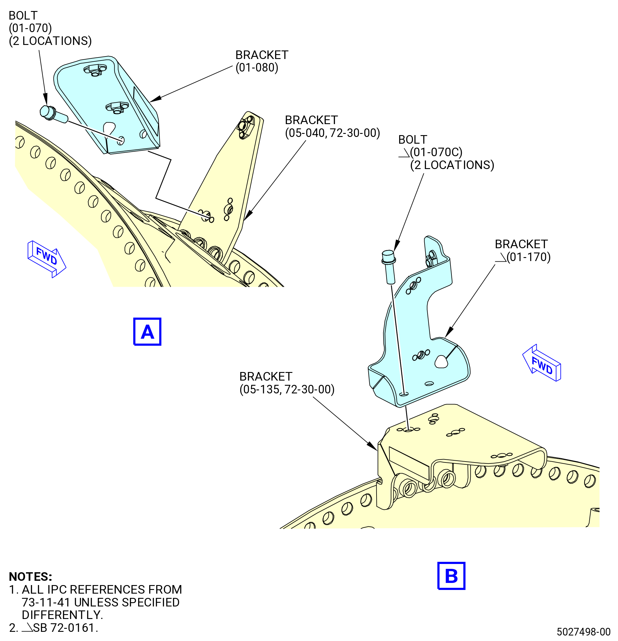
| (3) | Remove the bolts (01-070 , 73-11-41) (SIN 34527) that attach the support bracket (bracket) (01-080 , 73-11-41) (SIN 34511) to the bracket (05-040 , 72-30-00) (SIN 34512). Remove the bracket (01-080 , 73-11-41) (SIN 34511). |
| Subtask 72-00-02-030-689 |
| * * * FOR ALL PIP 2 |
| * * * SB 72-0161( Propulsor Module - PIP2 Configuration) ) |
| (4) | Remove the bolts (01-050 , 73-11-41) (SIN 34520) and clamp (01-060 , 73-11-41) (SIN 34580) that attach the return manifold to the brackets (01-170 , 73-11-41) (SIN 34513). |
| (5) | Remove the bolts (01-070C , 73-11-41) (SIN 34527) that attach the fuel bracket (bracket) (01-170 , 73-11-41) (SIN 34513) to the bracket (05-135 , 72-30-00) (SIN 34514). Remove the bracket (01-170 , 73-11-41) (SIN 34513). |
| NOTE: |
|
| * * * END SB 72-0161 |
| Subtask 72-00-02-030-430 |
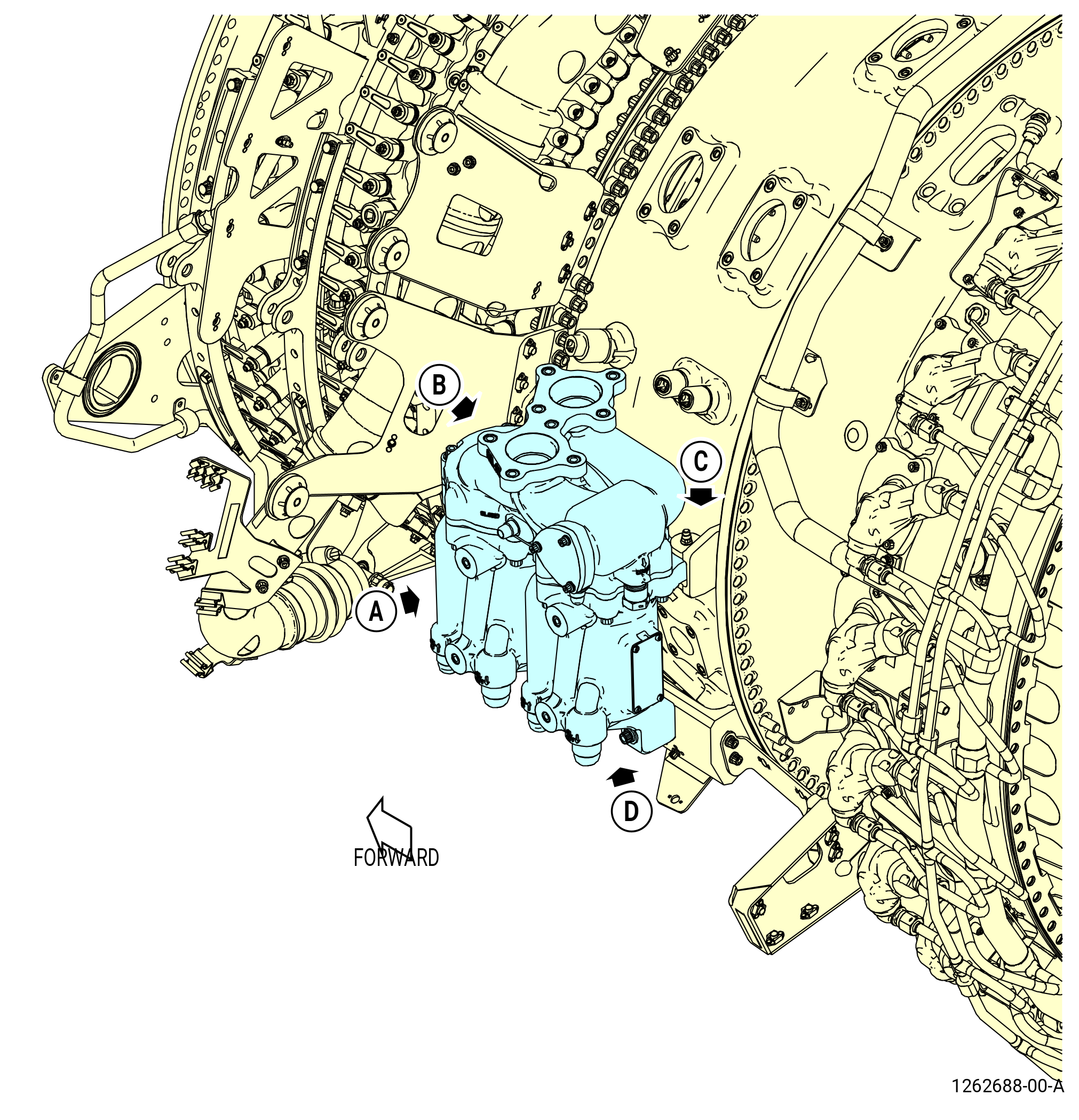
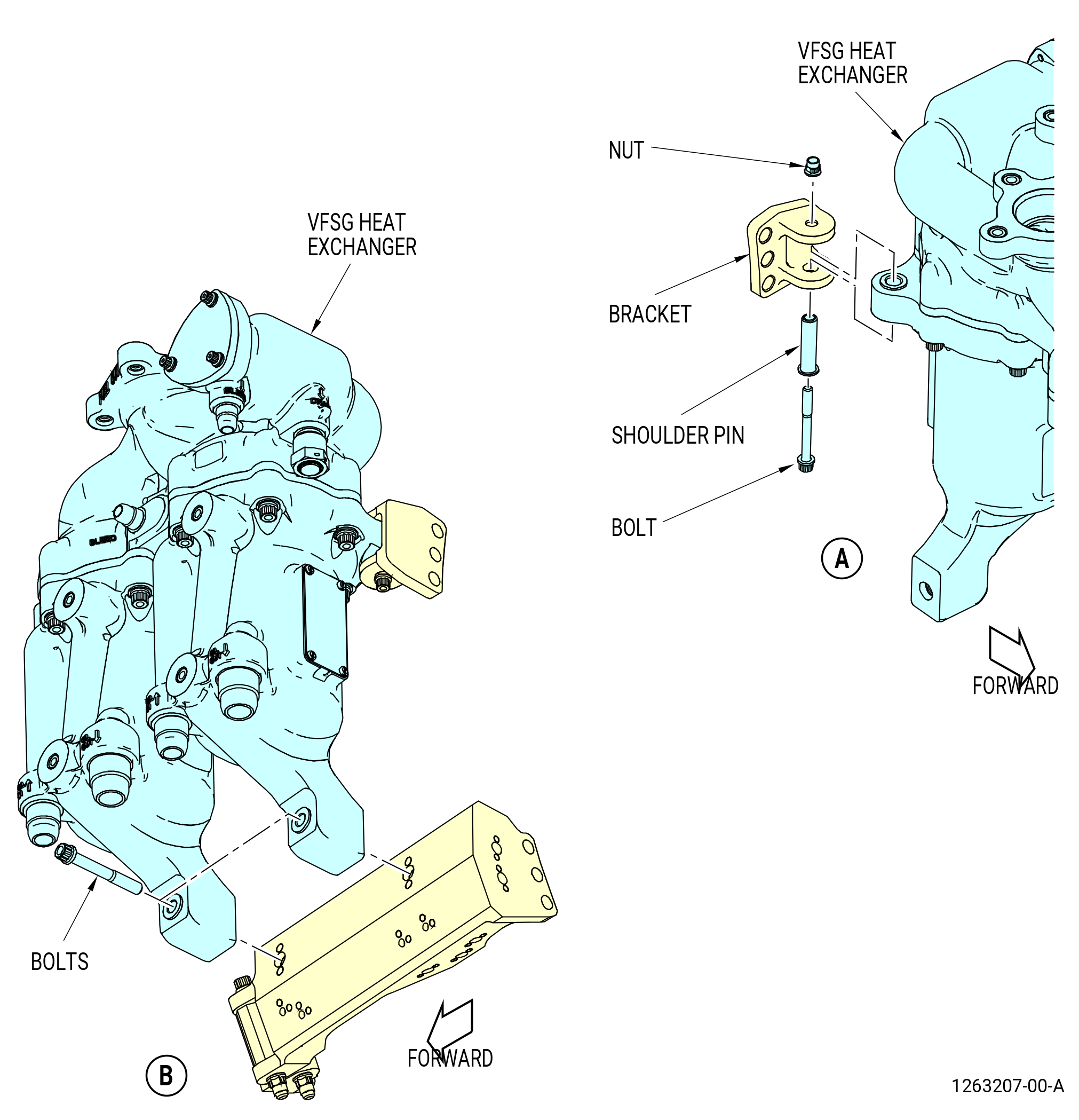
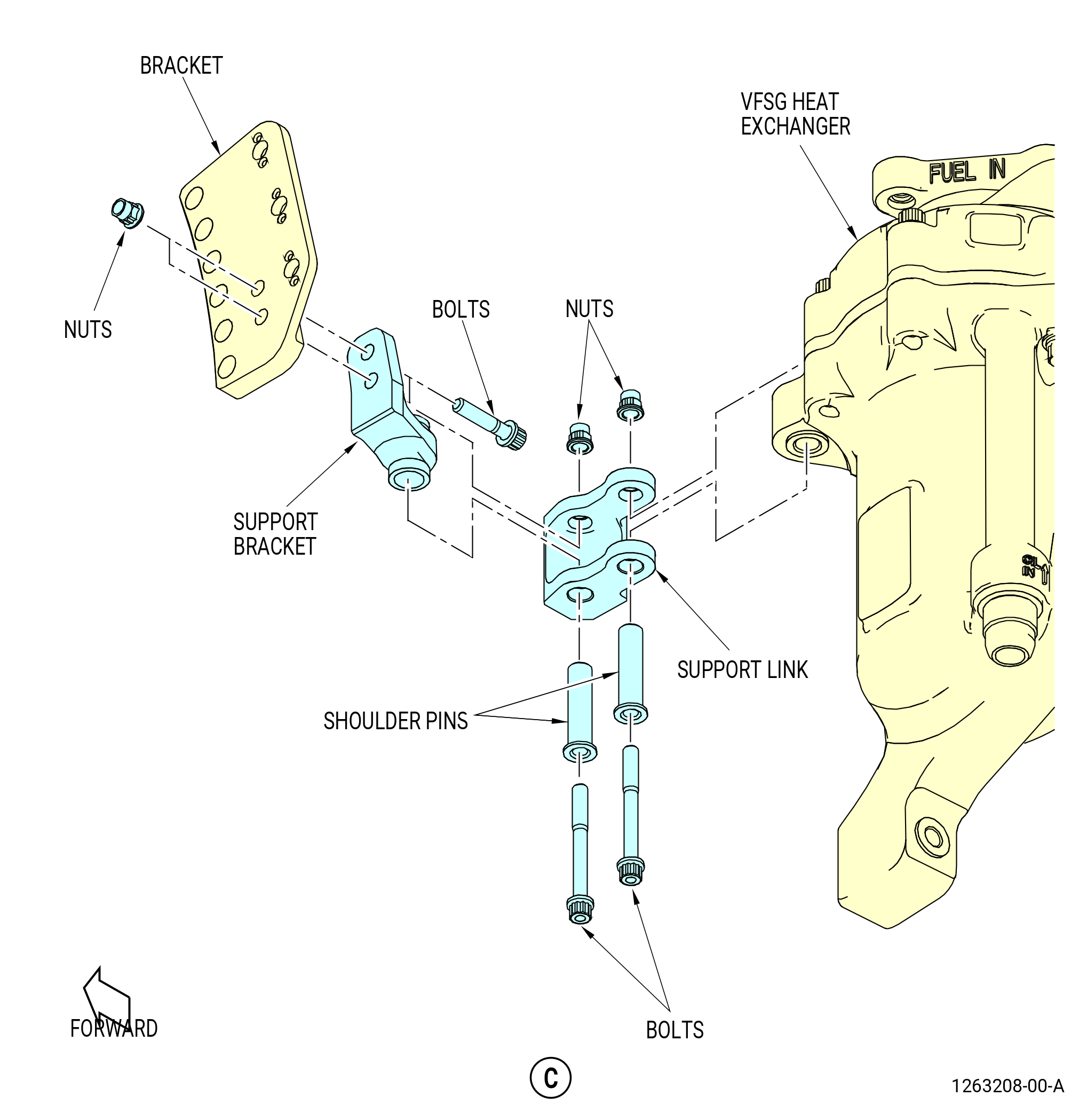
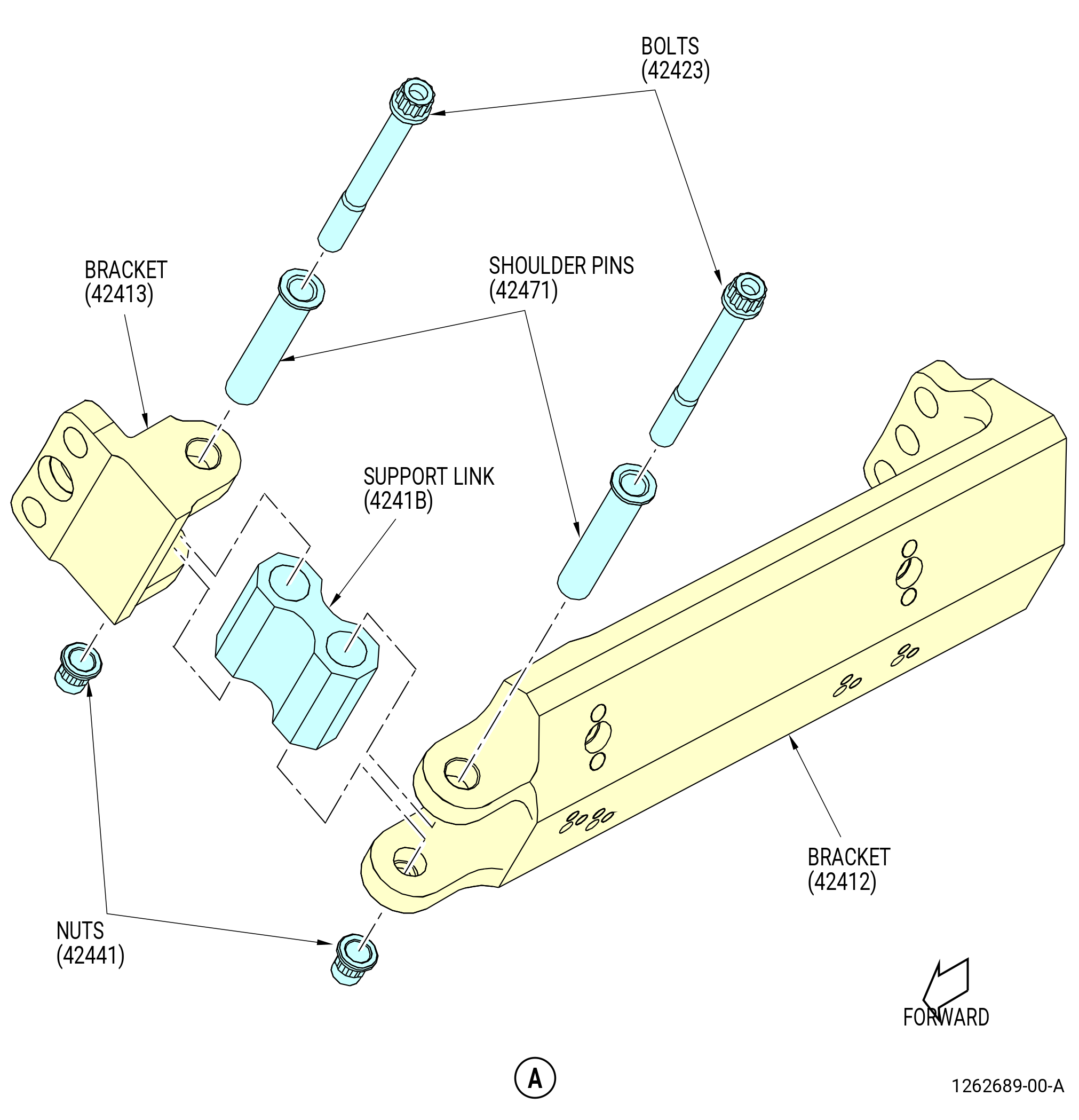
| I. | Remove the variable frequency starter generator (VFSG) heat exchanger as follows. Refer to Figure 510. |
| (1) | Remove the nuts and bolts that attach the VFSG heat exchanger to the bracket. |
| (2) | Remove the nut and shoulder pin that attach the support link to VFSG heat exchanger and the support bracket. |
| (3) | Remove the support link from the VFSG heat exchanger. |
| (4) | Remove the VFSG heat exchanger from the propulsor module. |
| (5) | Loosen the nuts and remove the bolts that attach the support bracket from the bracket that is installed on the HPC compressor stator case at the 9:15 o'clock position. |
| (6) | Remove the nut and bolt that attach the support link to the bracket. |
| (7) | Remove the nut from the shoulder pin that attaches the support link to the bracket. |
| Subtask 72-00-02-030-377 |
| * * * PRE SB 73-0011( Engines without Fuel Vapor Accumulator ) |
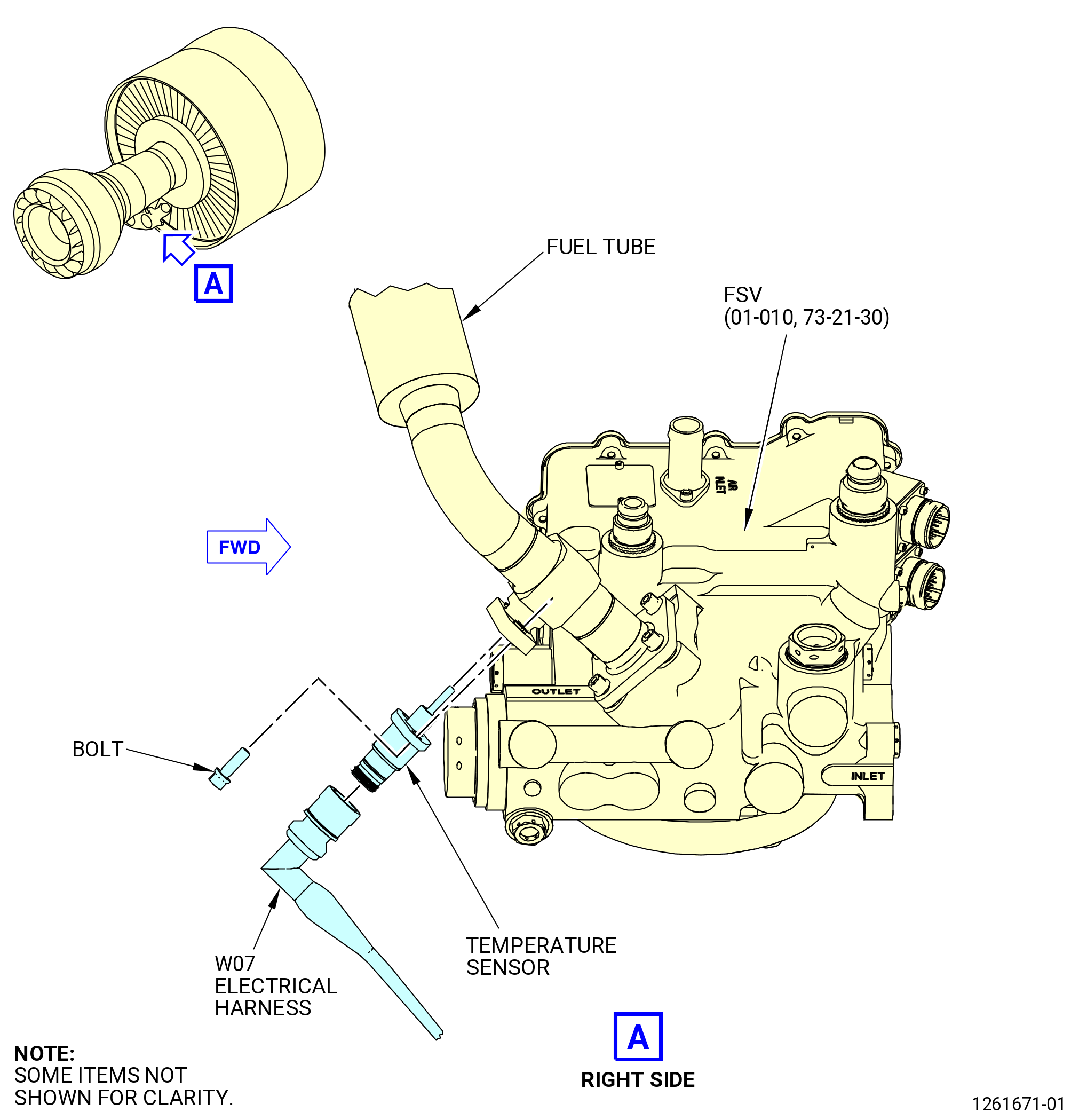
| J. | Remove the temperature sensor from the FSV (01-010 , 73-21-30) (SIN 31700) fuel tube as follows. Refer to Figure 511. |
| NOTE: |
|
| (1) | Remove the two bolts from the temperature sensor. |
| (2) | Pull the temperature sensor out of the flange. |
| (3) | Remove and discard the preformed packing from the temperature sensor. |
| (4) | Put the temperature sensor in a plastic bag. |
| (5) | Install protective covers on the fuel tube opening. |
| * * * END PRE SB 73-0011 |
|
| Subtask 72-00-02-030-378 |
| NOTE: |
|
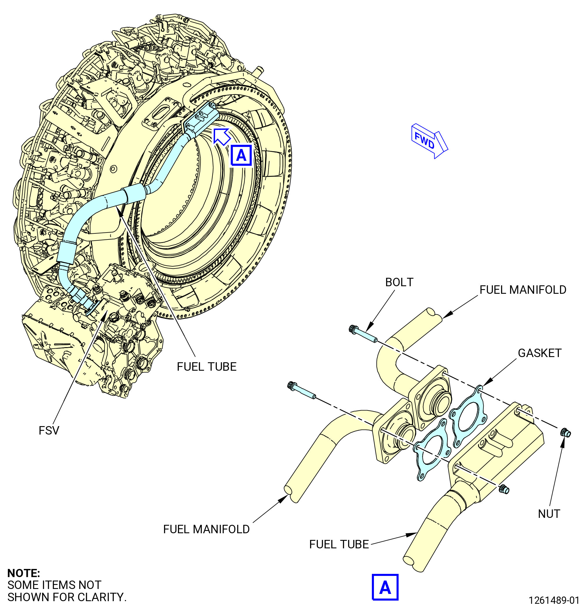
| K. | Remove the fuel tube/hoses (tube) from the fuel manifolds and the fuel metering unit (FMU) near the 3:30 o'clock position as follows. Refer to Figure 512. |
| (1) | Disconnect the coupling nuts that attach the fuel manifolds to the fuel tube. |
| (2) | Remove the bolts that attach the tubes to the FSV or FSVA and do as follows: |
| (a) | Remove the tubes and discard the gaskets (05-050 , 73-11-40) (SIN 34151). |
| (3) | Remove the bolts and the cushioned clamps that attach the fuel manifolds to the outer fuel brackets and the fuel manifold brackets on the compressor diffuser assembly flange. |
| (4) | Remove the fuel tubes and discard the gaskets. |
| Subtask 72-00-02-030-379 |
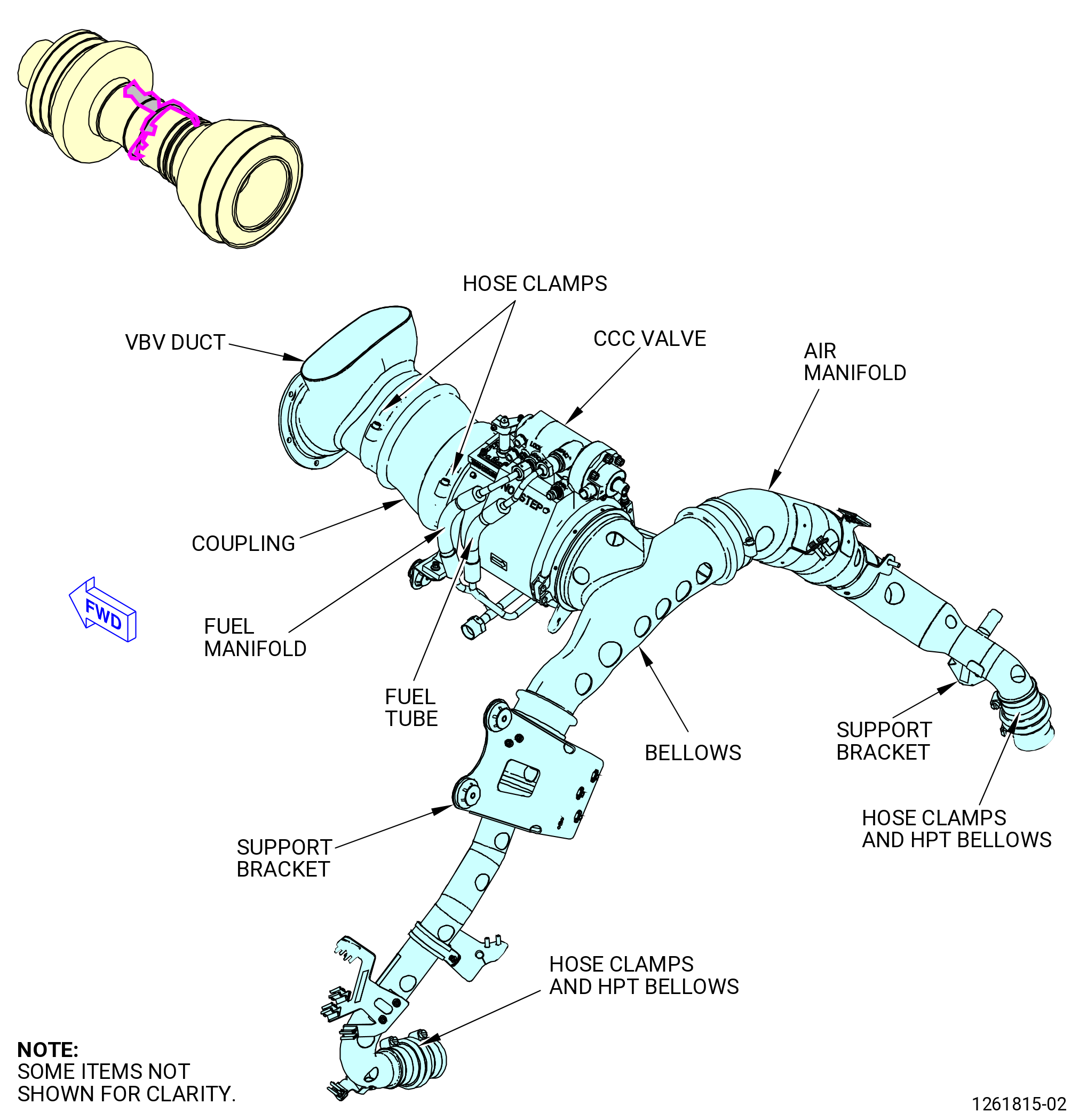
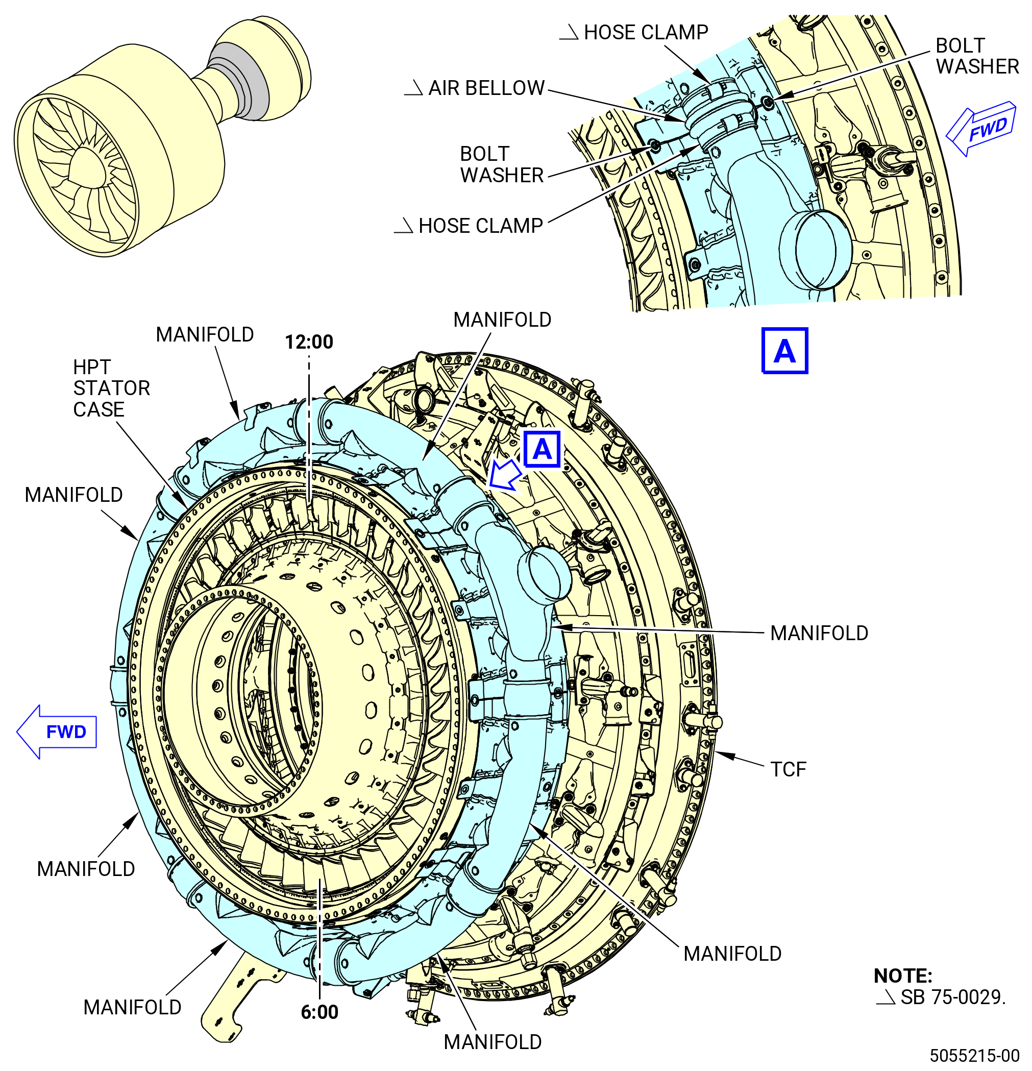
| L. | Remove the core compartment cooling (CCC) valve air system as follows. Refer to Figure 513. |
| (1) | Remove the flexible joints from the CCC valve air system as follows: |
| (a) | Remove the hose clamps that attach each end of the flexible joints. |
| (b) | Carefully disconnect the flexible joint from the air duct and the valve tube adapter and remove the flexible joint. |
| (c) | Carefully disconnect the flexible joint from the valve stub tube and the air distribution manifold, remove the flexible joint, and do as follows: |
| 1 | Install protective covers on the air duct opening. |
| 2 | Remove the variable bypass valve (VBV) air duct from the engine. |
| 3 | Wrap the flexible joints or put them in a bag for protection. |
| (2) | Remove the CCC valve, high pressure turbine (HPT) bellows, and the bellows tube as an assembly as follows: |
| (a) | Remove the bolt on the coupling on the bellows on the aft side of the CCC valve. |
| (b) | Remove the coupling and seal ring and discard the seal ring. |
| (c) | Remove the bolt on the coupling on the HPT bellows on the forward side of the CCC valve. |
| (d) | Remove the coupling and seal ring and discard the seal ring. |
| (e) | Disassemble the assembly as follows: |
| 1 | Remove the CCC valve and put it on a clean work surface. |
| 2 | Install protective covers on the HPT bellows, the CCC valve, and the bellows openings. |
| (3) | Remove the air distribution manifold (manifold) at the 11:30 o'clock position on the compressor as follows: |
| (a) | Remove the bolts that attach the manifold to the brackets on the HPC forward case assembly/extension case flanges, remove the manifold, and do as follows: |
| 1 | Wrap the manifold or put it in a bag for protection. |
| Subtask 72-00-02-030-380 |
| * * * PRE SB 72-0066( Fire Extinguishing System with Fire Suppression Tubes ) |
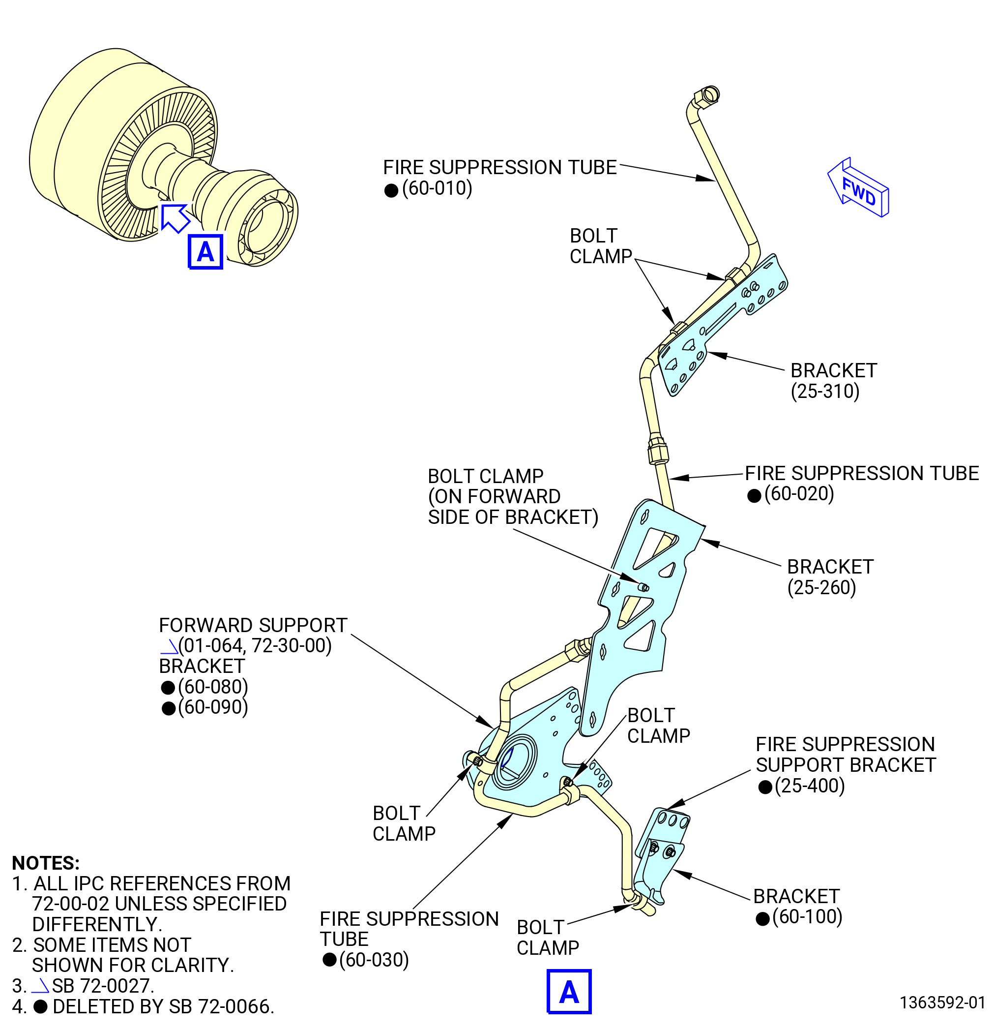
| M. | Remove the propulsor fire suppression tubes. Refer to Figure 514 and do as follows: |
| NOTE: |
|
| (1) | Loosen the coupling nut on the fire suppression tube (60-030) (SIN 99304) that attaches it to the fire suppression tube (60-020) (SIN 99303). |
| (2) | Loosen the coupling nut on the fire suppression tube (60-020) (SIN 99303) that attaches it to the fire suppression tube (60-010) (SIN 99301). |
| (3) | Remove the bolt and cushioned clamp that attach the fire suppression tube (60-030) (SIN 99304) to the fire suppression support bracket (bracket) (60-100) (SIN 99018). |
| (4) | Remove the bolt and cushioned clamps that attach the fire suppression tube (60-030) (SIN 99304) to the forward support (01-064 , 72-30-00) (SIN 07501-3), (01-065 , 72-30-00) (SIN 07501-3), or (01-065 , 72-30-00) (SIN 07501-3) and fire suppression support brackets (brackets) (60-080) (SIN 99019) and (60-090) (SIN 9901C). |
| (5) | Remove the bolt and cushioned clamp that attach the fire suppression tube (60-020) (SIN 99303) to the bracket (25-260) (SIN 62112). |
| (6) | Remove the bolts and cushioned clamp that attach the fire suppression tube (60-010) (SIN 99301) to the bracket (25-310) (SIN 63111). |
| (7) | Remove the fire suppression tubes (60-010) (SIN 99301), (60-020) (SIN 99303), and (60-030) (SIN 99304) from the engine. |
| (8) | Remove the bolts that attach the bracket (60-100) (SIN 99018) to the tube support bracket (fire suppression support bracket) (25-400) (SIN 9931C). |
| (9) | Remove the bolts that attach the fire suppression support bracket (25-400) (SIN 9931C) to the engine. |
| (10) | Remove the bolts that attach the brackets (60-080) (SIN 99019) and (60-090) (SIN 9901C) to the forward support (01-064 , 72-30-00) (SIN 07501-3), (01-065 , 72-30-00) (SIN 07501-3), or (01-065 , 72-30-00) (SIN 07501-3). |
| (11) | Remove the bolts that attach the forward support (01-064 , 72-30-00) (SIN 07501-3) or (01-065 , 72-30-00) (SIN 07501-3) or (01-065A , 72-30-00) (SIN 07501-3) to the engine. |
| (12) | Remove the bolts that attach the bracket (25-260) (SIN 62112) to the engine. |
| (13) | Remove the bolts that attach the bracket (25-310) (SIN 63111) to the engine. |
| * * * END PRE SB 72-0066 |
|
| Subtask 72-00-02-030-381 |
| N. | Remove the HPT active clearance control (ACC) valve fuel drain system as follows. Refer to Figure 515. |
| (1) | Remove the HPT ACC valve drain manifold (manifold) as follows: |
| (a) | Disconnect the manifold coupling nut from the drain fitting on the ACC valve. |
| (b) | Remove the bolts and the loop clamps that attach the manifold to the bracket at the 8:45 o'clock position and the bracket assembly at the 8:30 o'clock position. |
| (c) | Remove the manifold. |
| (2) | Remove the drain tube as follows: |
| (a) | Remove the bolts and the loop clamps that attach the drain tube to the brackets at the 7:30 and 6:30 o'clock positions and remove the drain tube. |
| Subtask 72-00-02-030-384 |
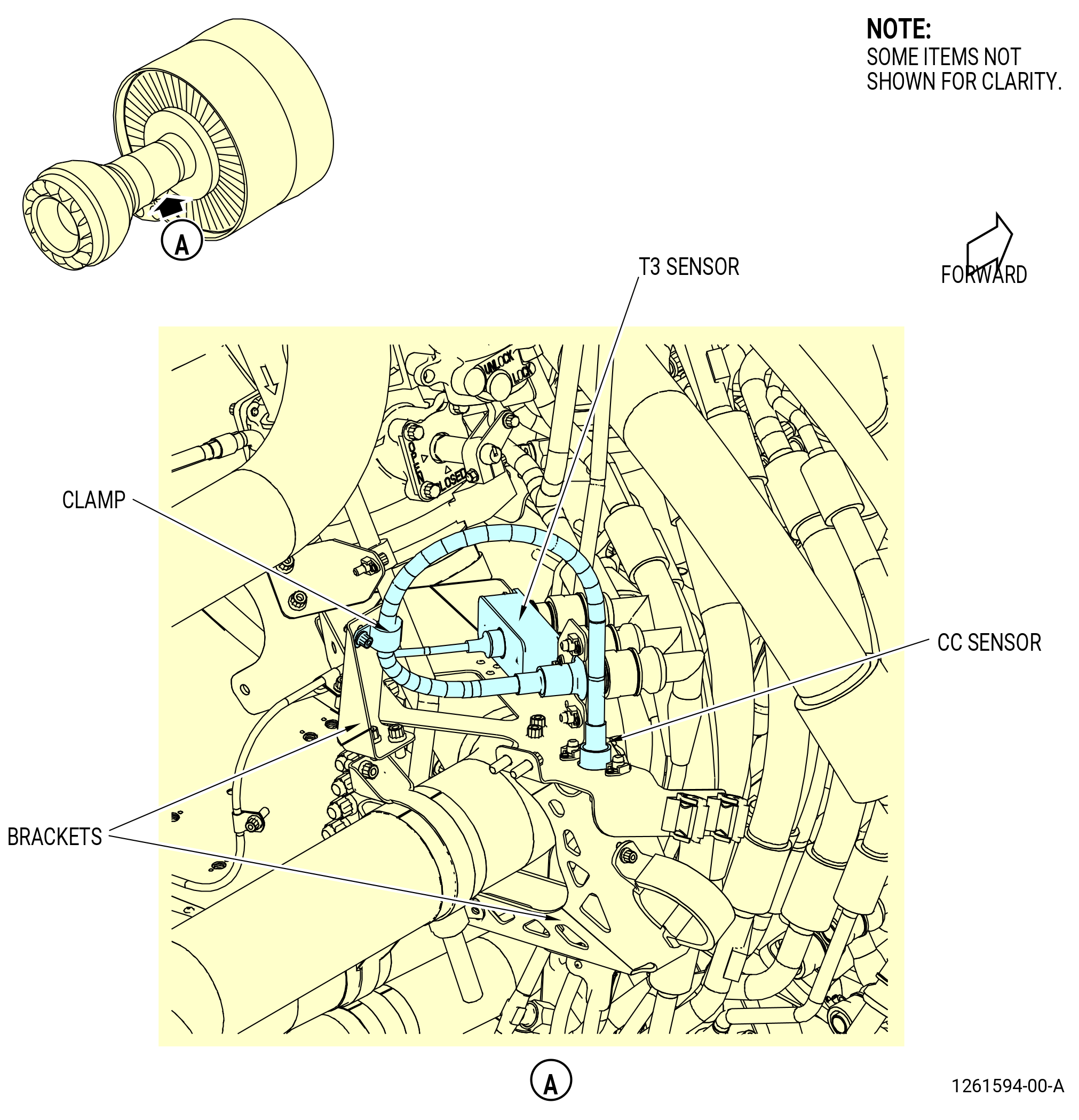
| * * * PRE SB 72-0290( Engines with Temperature Sensor ) |
| O. | Remove the core compartment temperature sensor (CC sensor) and T3 sensor from the 4:00 o'clock position of the compressor case as follows. Refer to Figure 516. |
| * * * END PRE SB 72-0290 |
| Subtask 72-00-02-030-742 |
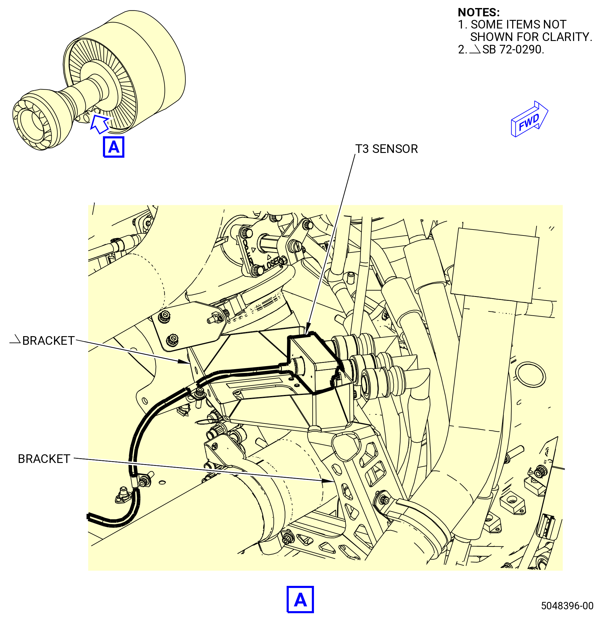
| * * * SB 72-0290( Engines without Temperature Sensor ) |
| O.A. | Remove the T3 sensor from the 4:00 o'clock position of the compressor case. Refer to Figure 516A and do as follows: |
| * * * END SB 72-0290 |
| Subtask 72-00-02-030-743 |
| * * * PRE SB 72-0290( Engines with Temperature Sensor ) |
| (1) | Remove the CC sensor as follows: |
| NOTE: |
|
| (a) | Remove the bolt and cushioned clamp that attach the CC sensor to the bracket. |
| (b) | Remove the bolts that attach the CC sensor to the bracket and remove the CC sensor. |
| * * * END PRE SB 72-0290 |
| Subtask 72-00-02-030-744 |
| (2) | Remove the T3 sensor as follows. |
| (a) | Remove the bolts that attach the T3 sensor to the compressor case. |
| (b) | Remove the bolt, nut, and cushioned clamp that attach the T3 sensor tube to the bracket assembly. |
| (c) | Remove the bolts and washers that attach the T3 sensor sending unit to the bracket assembly. |
| (d) | Remove the bolts and washers that attach the T3 sensor tube to the bracket assembly and the PS3 bracket. |
| (e) | Remove the T3 sensor and discard the gasket seal. |
|
| Subtask 72-00-02-030-385 |
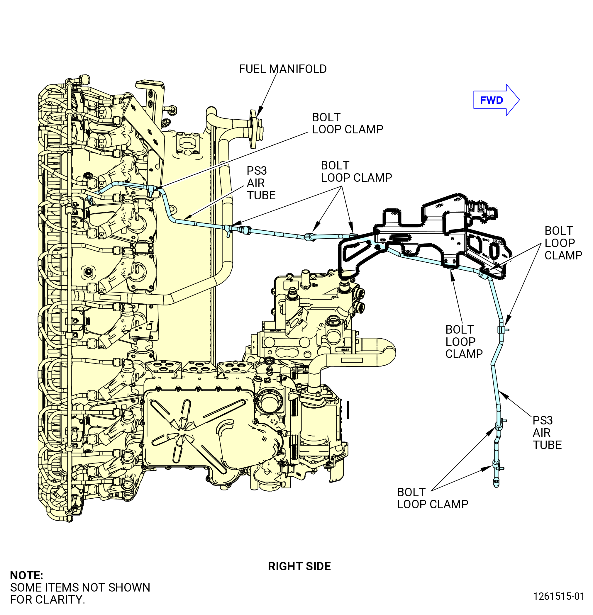
| P. | Remove the PS3 air tube from the propulsor as follows. Refer to Figure 517. |
| (1) | Disconnect the coupling nut on the PS3 air tube (from above) that is attached to the fitting on the top end of the PS3 air tube near the 4:30 o'clock position at the HPC forward case assembly flange. |
| (2) | Remove the bolts and the cushioned clamps that attach the PS3 air tube to the bracket and the sense bracket at the 4:30 o'clock position. |
| (3) | Remove the PS3 air tube. |
| Subtask 72-00-02-030-386 |
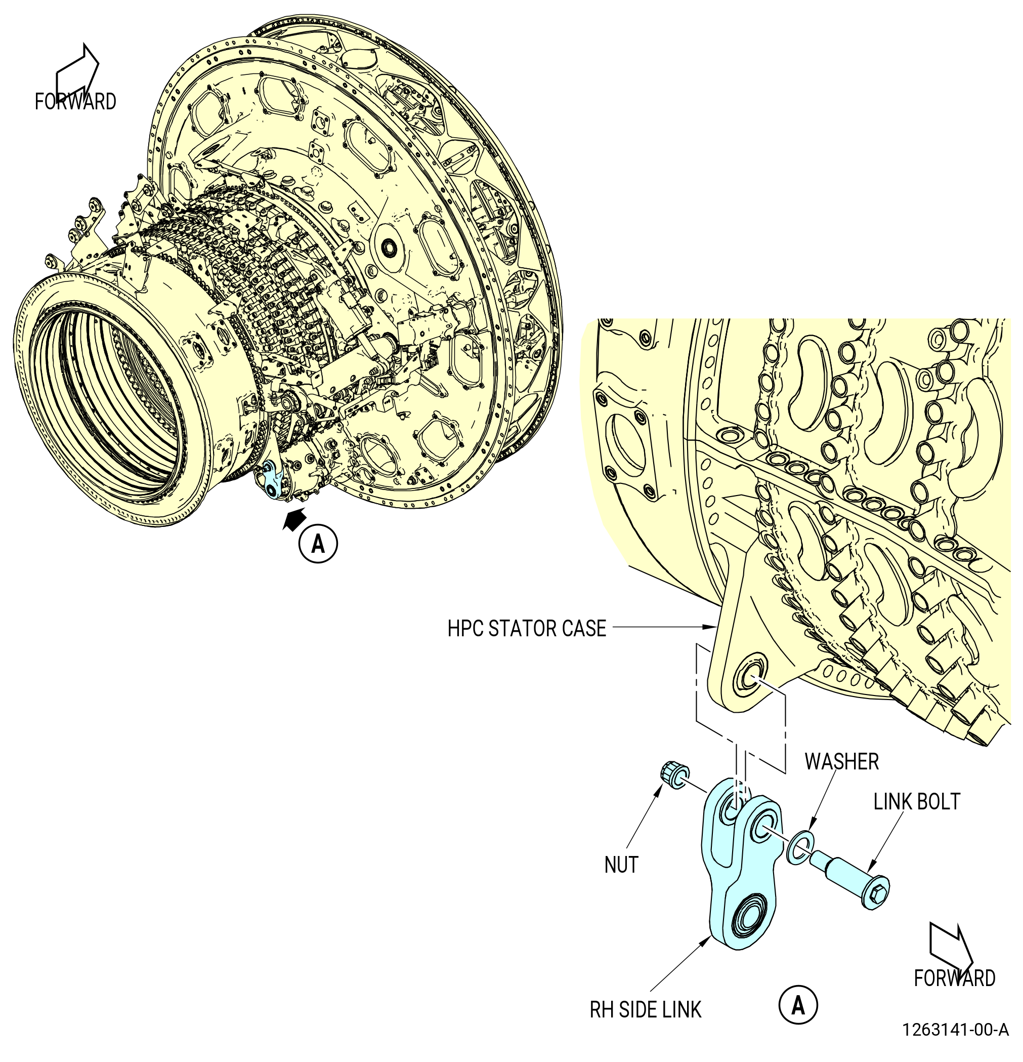
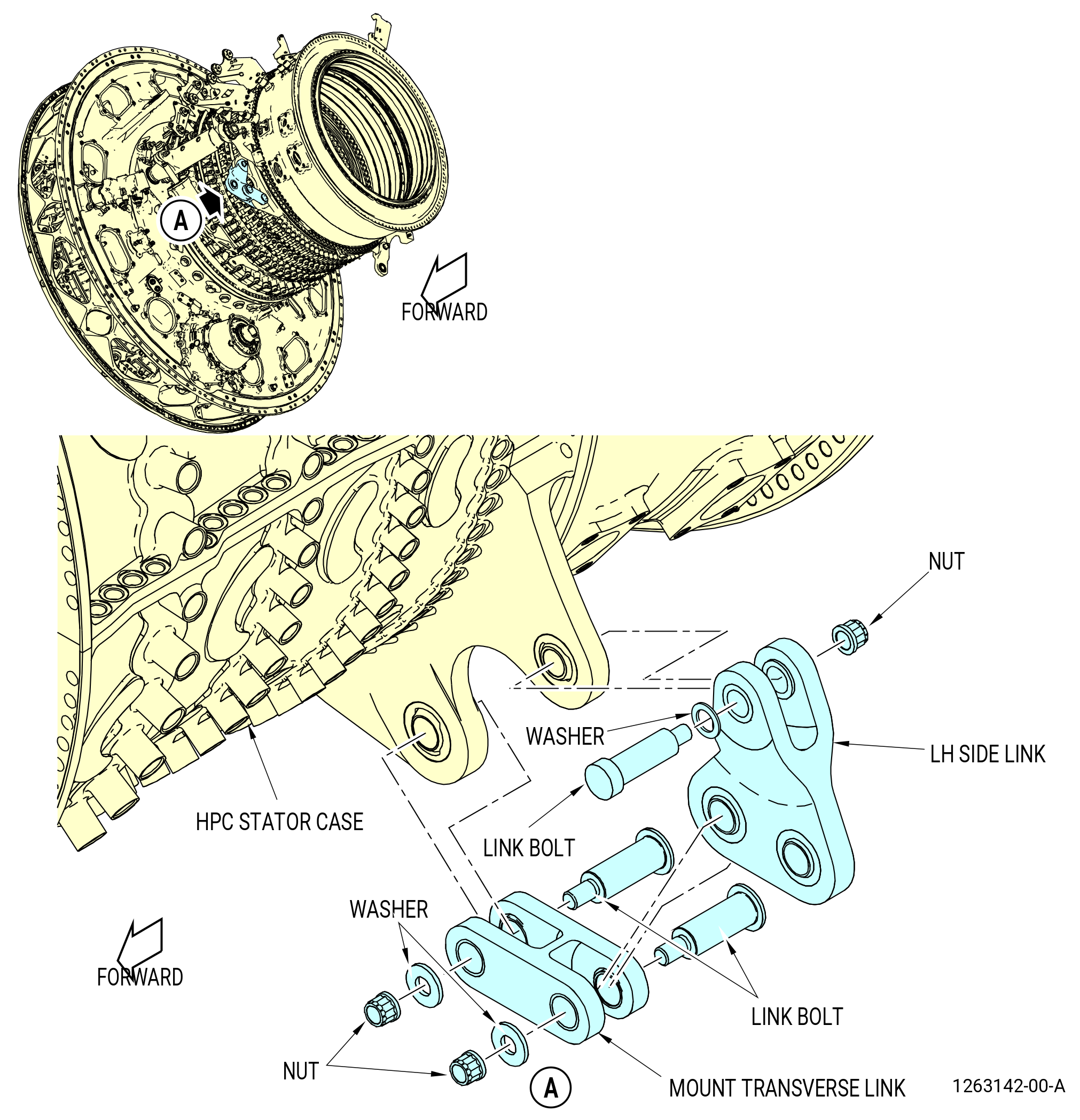
| Q. | Remove the AGB mount brackets on the HPC case as follows. Refer to Figure 518. |
| (1) | Remove the right side link bracket as follows: |
| (a) | Remove the bolt from the right side link bracket at the 4:00 o'clock position on the HPC stator case. |
| (b) | Remove the washer and bolt from the bracket and remove the bracket. |
| (2) | Remove the left side link bracket as follows: |
| (a) | Remove the nuts from the mount transverse link. |
| (b) | Remove the washers and bolts from the mount transfer link and remove the mount transverse link from the 8:00 o'clock position on the HPC stator case. |
| (c) | Remove the self-locking nut from the link bolt on the left side link bracket. |
| (d) | Remove the link bolt and washer from the left side link bracket and remove the link bracket. |
| * * * PRE SB 73-0099( Introduction of New Fuel-Hydraulic Lines ) |
| Subtask 72-00-02-030-387 |
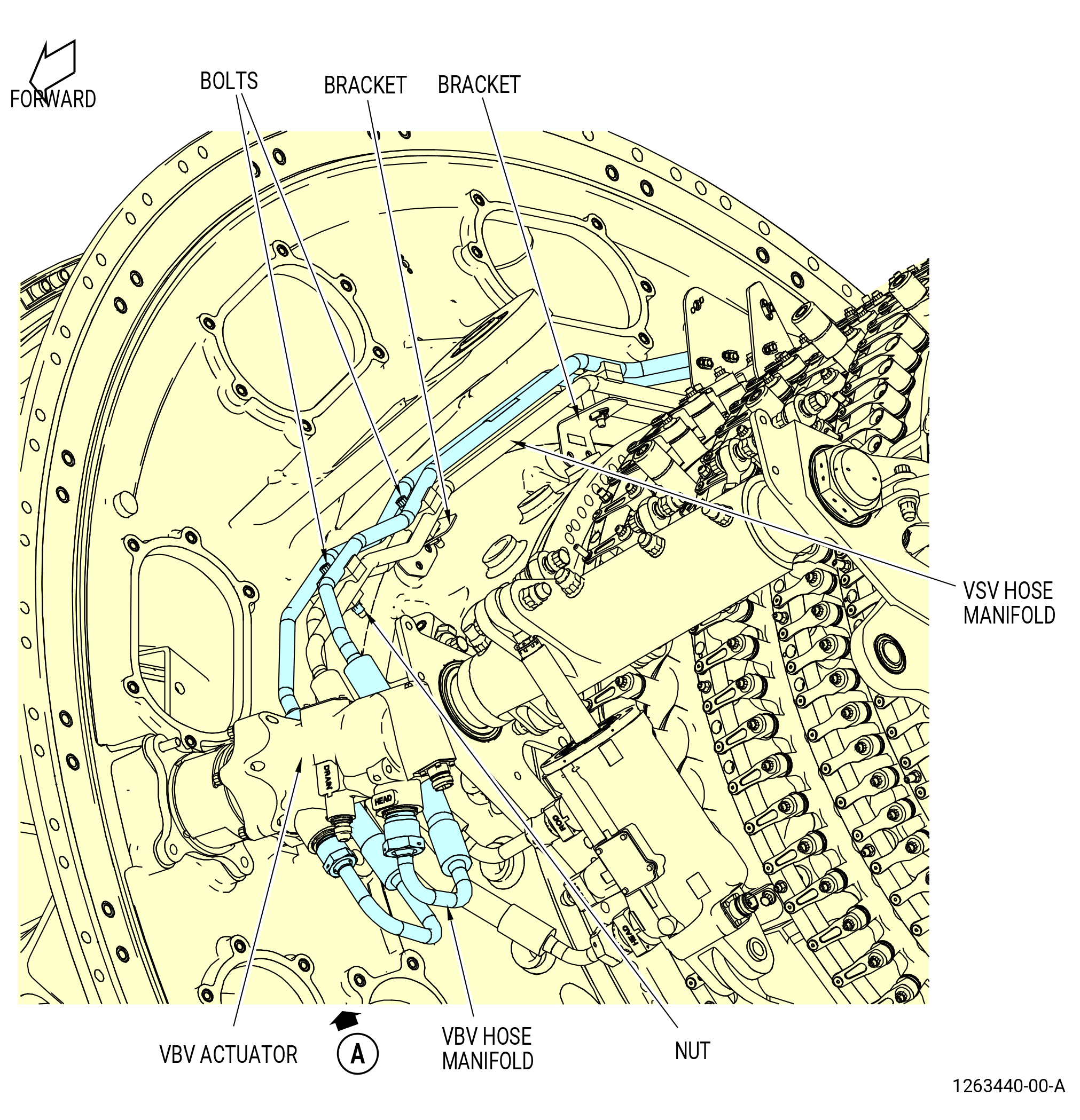
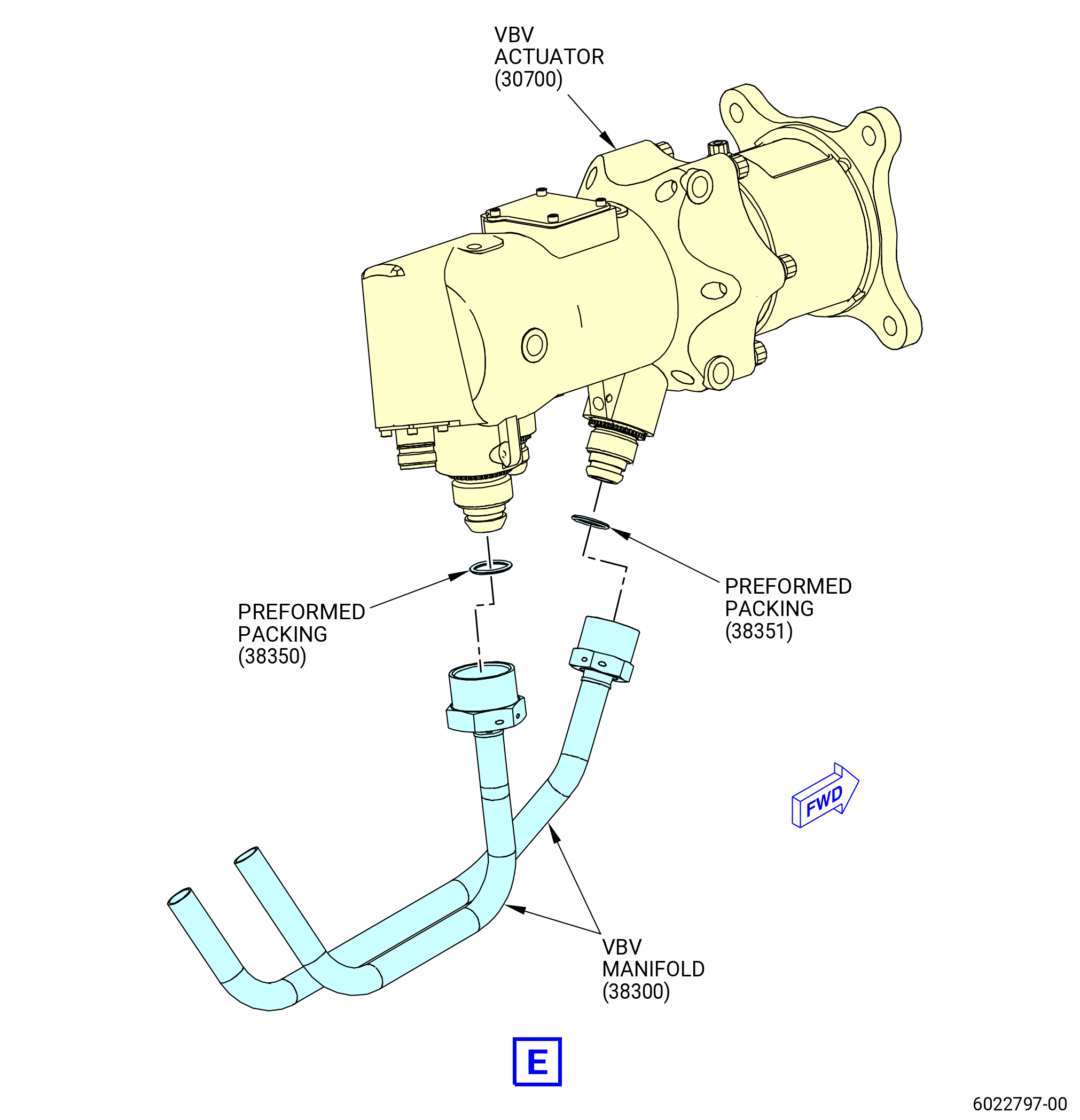
| R. | Remove the VBV fuel hose manifold (VBV hose manifold) (25-040 , 73-11-40) (SIN 38202) and the fuel VSV hose manifold (VSV hose manifold) (30-150 , 73-11-40) (SIN 38102) or (30-151 , 73-11-40) (SIN 38102) as follows: |
| (1) | Remove the VBV hose manifold as follows. Refer to Figure 519. |
| (a) | Disconnect the coupling nuts that attach the VBV hose manifold to the VBV actuator. |
| (b) | Disconnect the coupling nuts that attach the VBV hose manifold (38202) to the VBV manifold (38300). |
| (c) | Remove the bolts that attach the VBV hose manifold and the VSV hose manifold to the brackets. |
| (d) | Remove the bolt and nut that attach the VBV hose manifold to the VSV hose manifold and remove the VBV hose manifold |
| (e) | Remove and discard the preformed packing (25-090 , 73-11-40) (SIN 38350) from the VBV manifold (38300) end fittings. |
| (f) | Remove and discard the preformed packings (25-320 , 73-11-40) (SIN 38250) and (25-330 , 73-11-40) (SIN 38251) from the VBV actuator. |
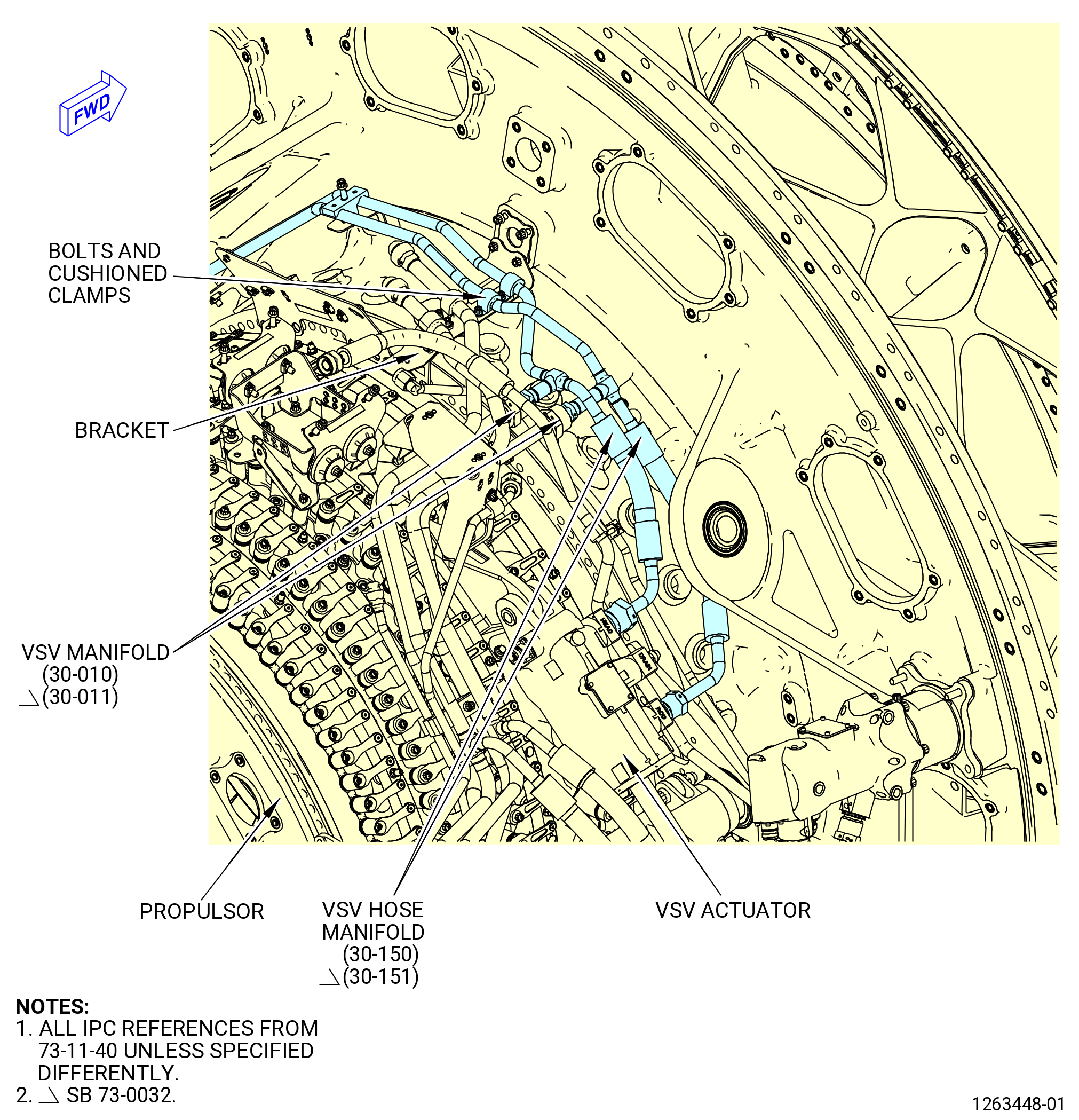
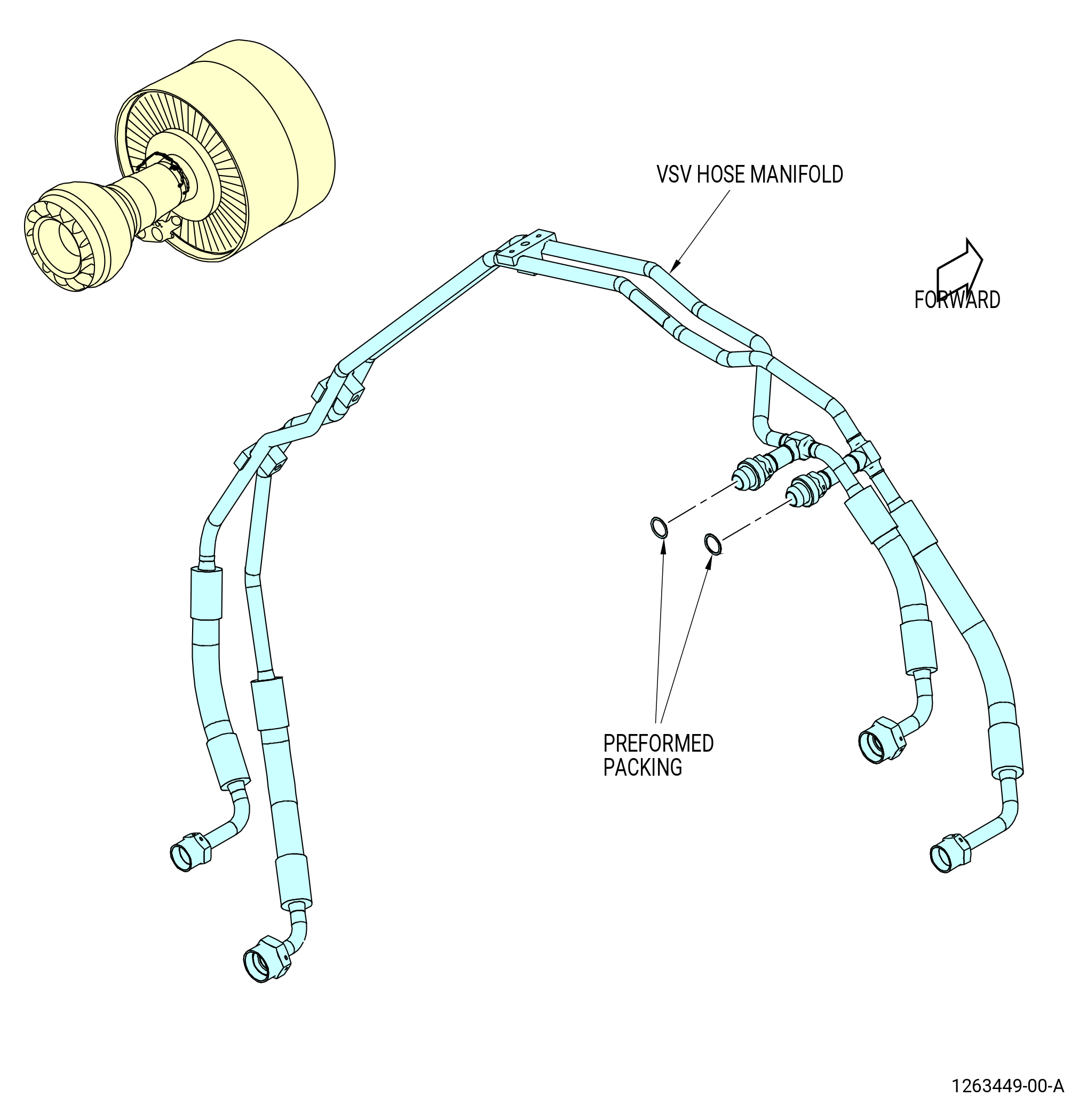
| (2) | Remove the VSV hose manifold as follows. Refer to Figure 520. |
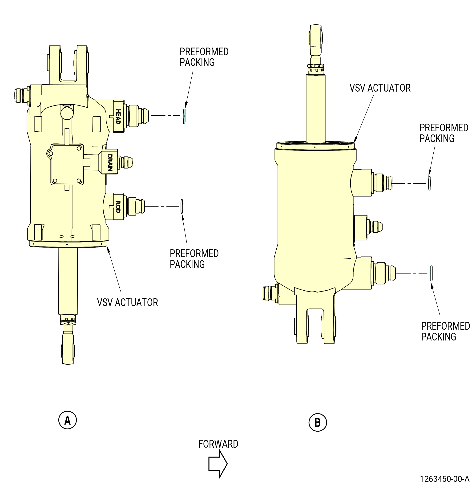
| (a) | Disconnect the coupling nuts of the VSV hose manifold from the left side VSV actuator. |
| (b) | Disconnect the coupling nuts of the VSV hose manifold from the right side VSV actuator. |
| (c) | Loosen and remove the bolts and clamps that attach the VSV hose manifold to the bracket. |
| (d) | Disconnect the VSV hose manifold (30-150 , 73-11-40) (SIN 38102) or (30-151 , 73-11-40) (SIN 38102) from the fuel HPT hose VSV manifold (VSV manifold) (30-010 , 73-11-40) (SIN 38100) or (30-011 , 73-11-40) (SIN 38100). |
| (e) | Remove the VSV hose manifold from the 12:30 o'clock position of the propulsor. |
| (f) | Remove and discard the preformed packings (30-160 , 73-11-40) (SIN 38151) from the nipple fittings of the VSV fuel hose manifold. |
| (g) | Remove and discard the preformed packings (30-160 , 73-11-40) (SIN 38151) and (30-170 , 73-11-40) (SIN 38150) on each VSV actuator. |
| * * * END PRE SB 73-0099( Introduction of New Fuel-Hydraulic Lines ) |
| Subtask 72-00-02-030-787 |
| * * * FOR ALL.ALL |
| * * * SB 73-0099( Introduction of New Fuel-Hydraulic Lines ) |
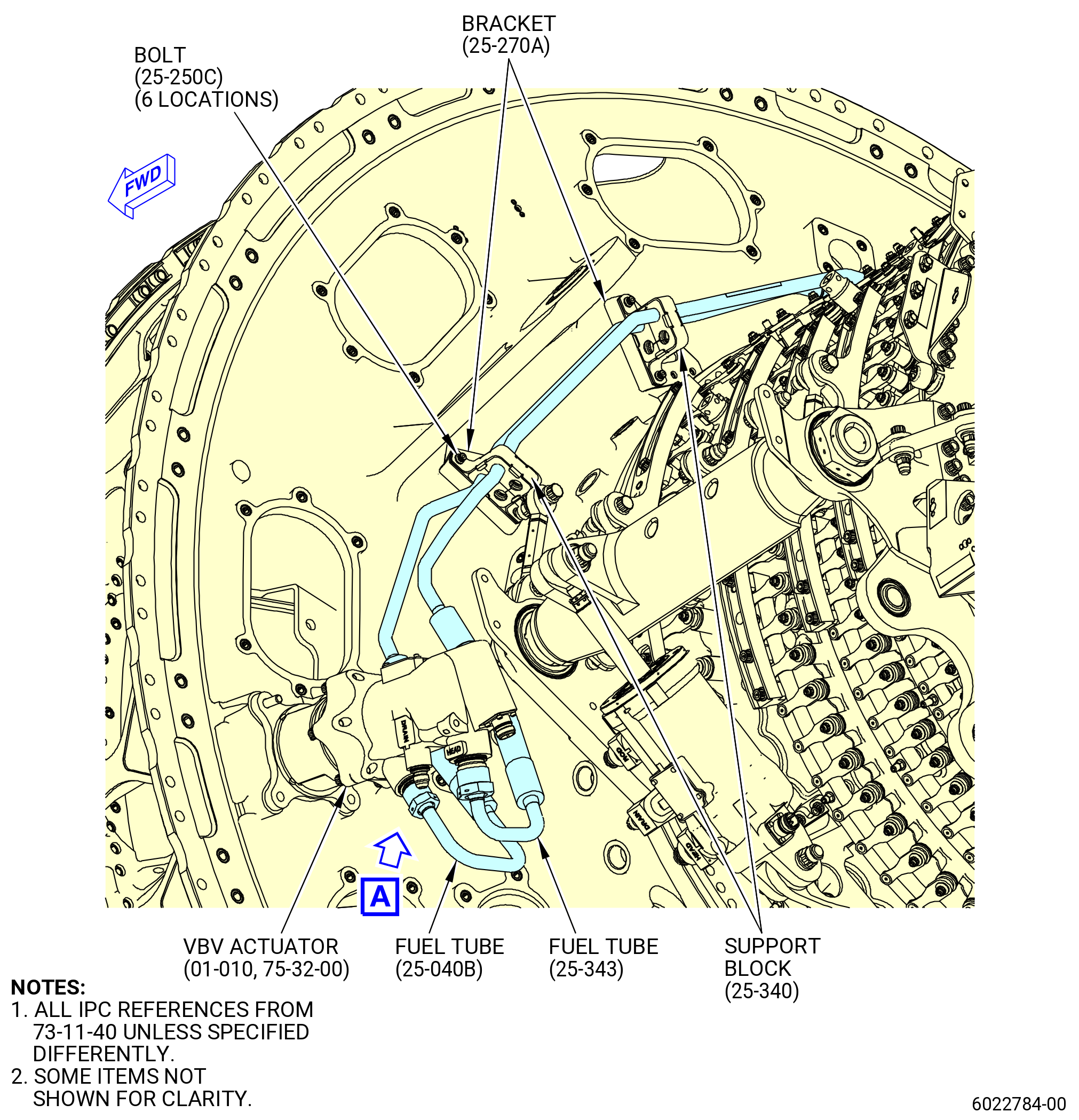
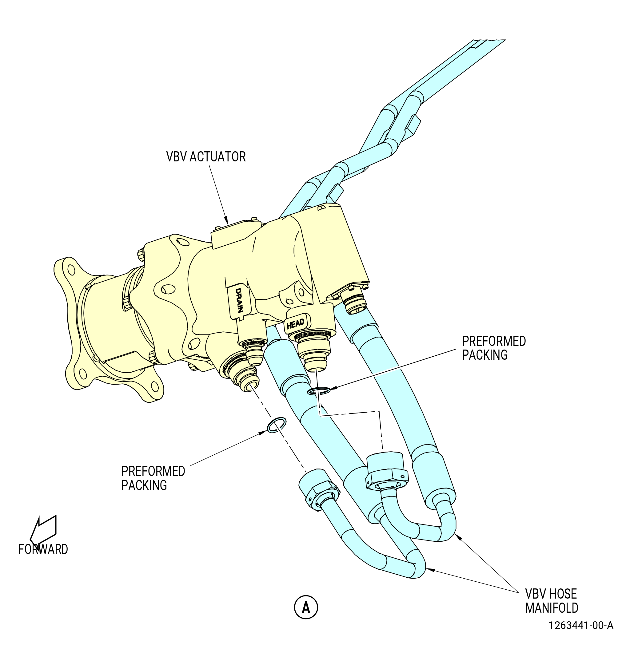
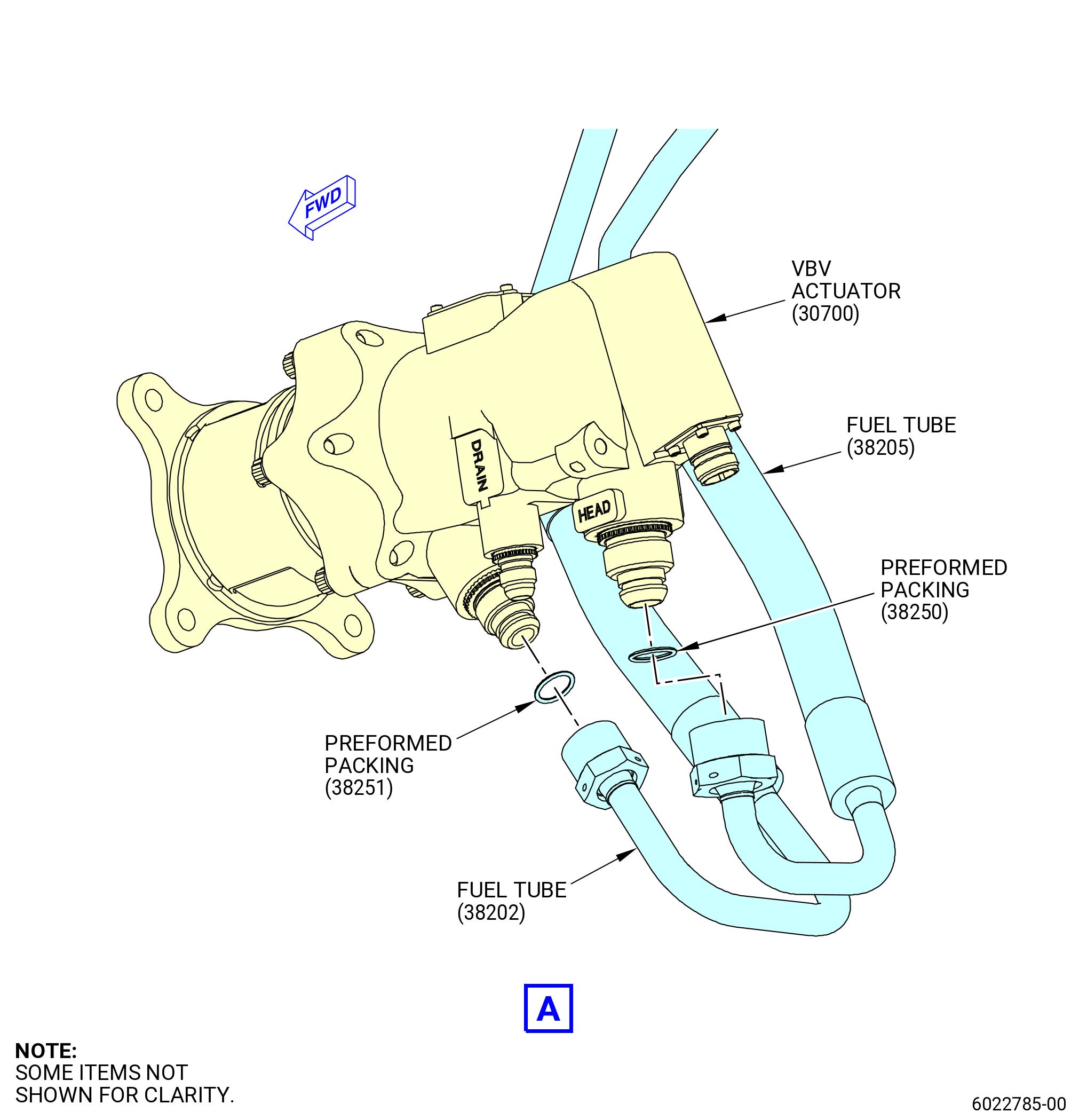
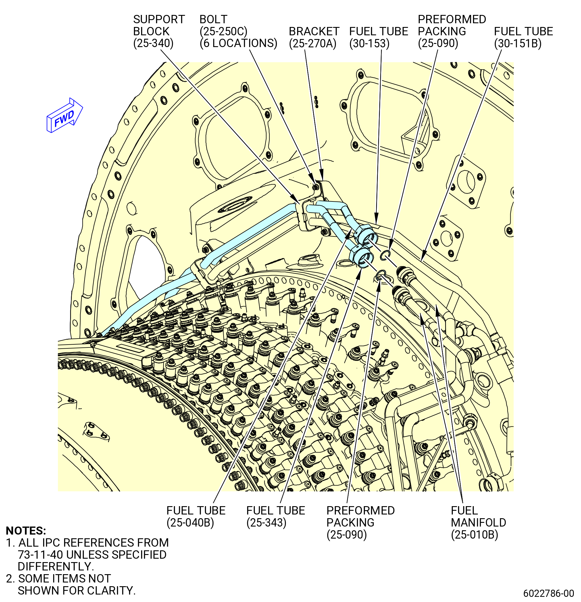
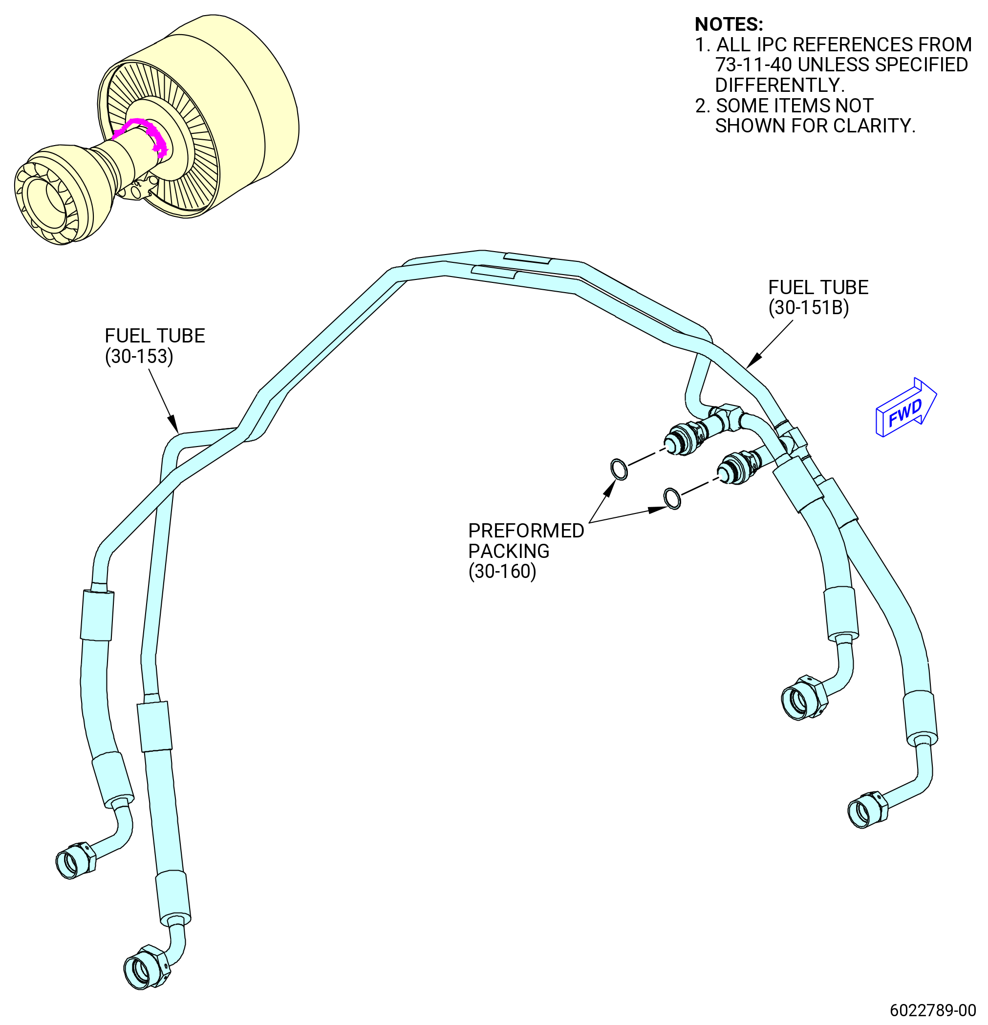
| S. | Remove the fuel tube (25-040B, 73-11-40) (SIN 38202), fuel tube (25-343, 73-11-40) (SIN 38205), fuel tube (30-151B, 73-11-40) (SIN 38102) and fuel tube (30-153, 73-11-40) (SIN 38103) as follows: |
| (1) | Disconnect the coupling nuts that attach the fuel tubes (25-040B, 73-11-40) (SIN 38202) and (25-343, 73-11-40) (SIN 38205) to the VBV actuator (SIN 30700). |
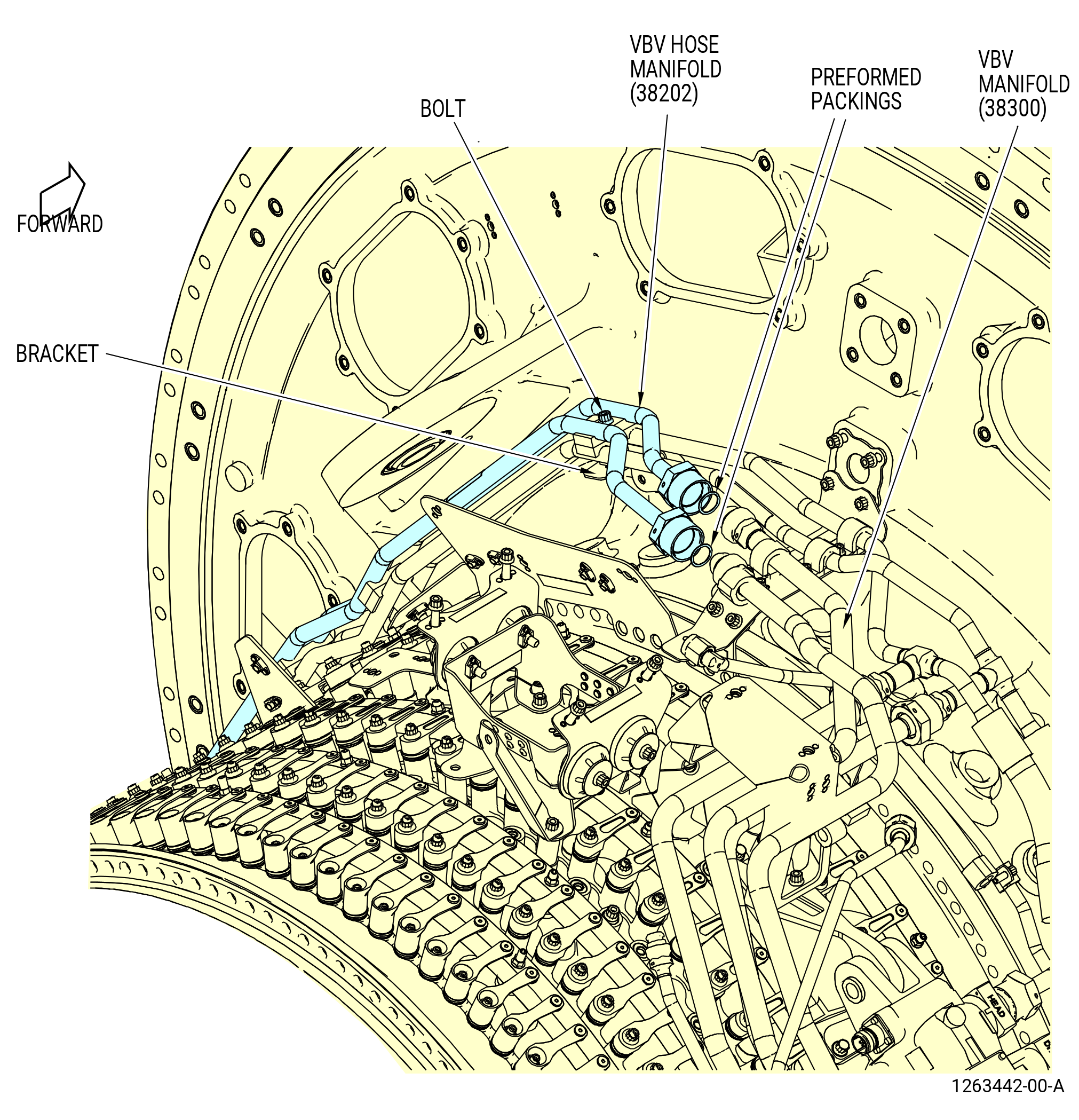
| (2) | Disconnect the coupling nuts that attach the fuel tubes (25-040B, 73-11-40) (SIN 38202) and (25-343, 73-11-40) (SIN 38205) to the fuel hose VBV manifold (tube hose) (25-010B, 73-11-40) (SIN 38300). |
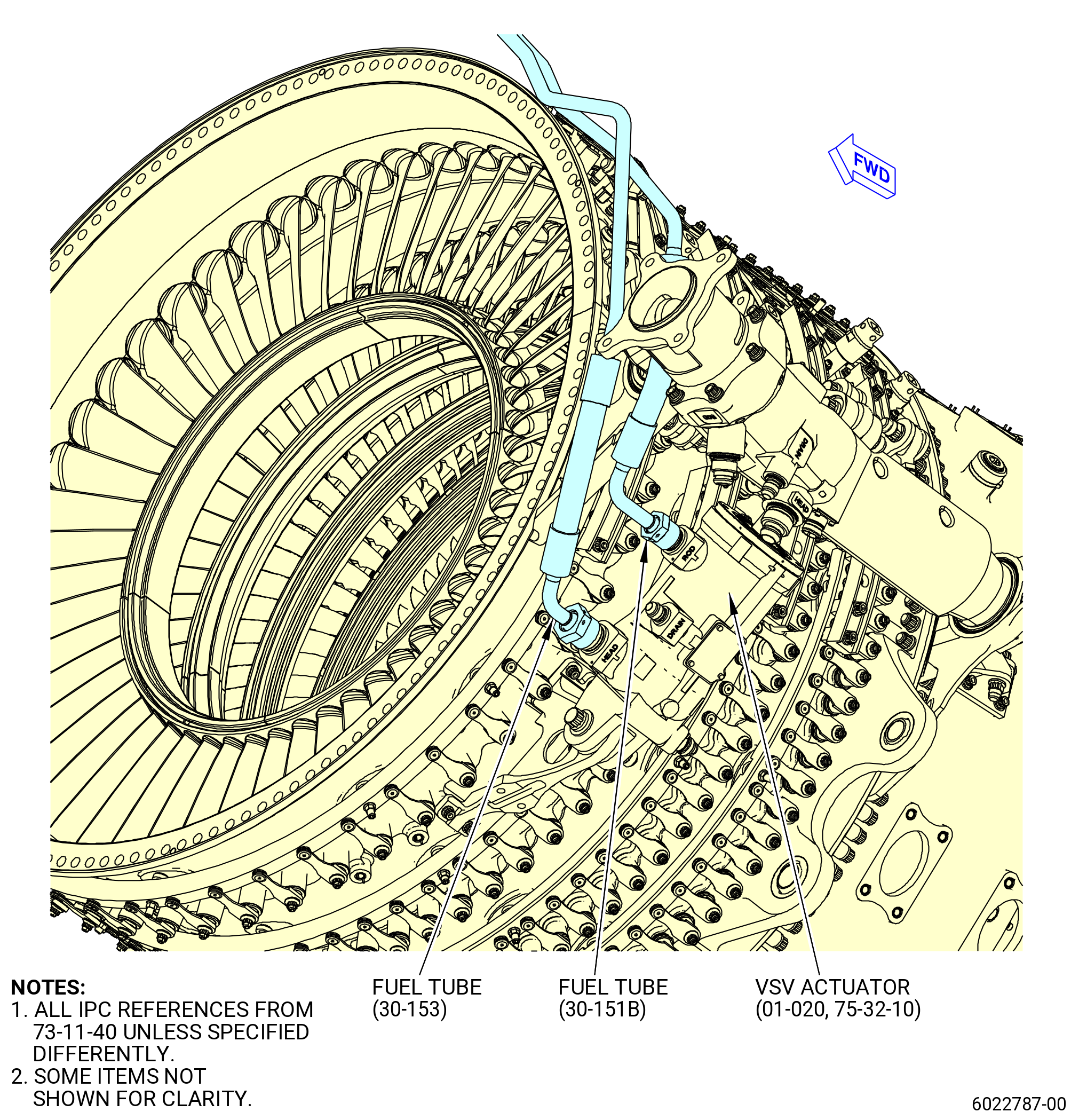
| (3) | Disconnect the coupling nuts of the fuel tubes (30-151B, 73-11-40) (SIN 38102) and (30-153, 73-11-40) (SIN 38103) from the left side VSV actuator (SIN 30401). |
| (4) | Disconnect the coupling nuts of the fuel tubes (30-151B, 73-11-40) (SIN 38102) and (30-153, 73-11-40) (SIN 38103) from the right side VSV actuator (SIN 30400). |
| (5) | Disconnect the fuel tubes (30-151B, 73-11-40) (SIN 38102) and (30-153, 73-11-40) (SIN 38103) from the fuel HPT hose VSV manifold (VSV manifold) (30-011B, 73-11-40) (SIN 38100). |
| (6) | Remove the bolts (25-250C, 73-11-40) (SIN 38122) that attach the support blocks (25-340, 73-11-40) (SIN 38184) to the brackets (25-270A, 73-11-40) (SIN 38110) and remove the fuel tubes (25-040, 73-11-40) (SIN 38202) and (25-343, 73-11-40) (SIN 38205). |
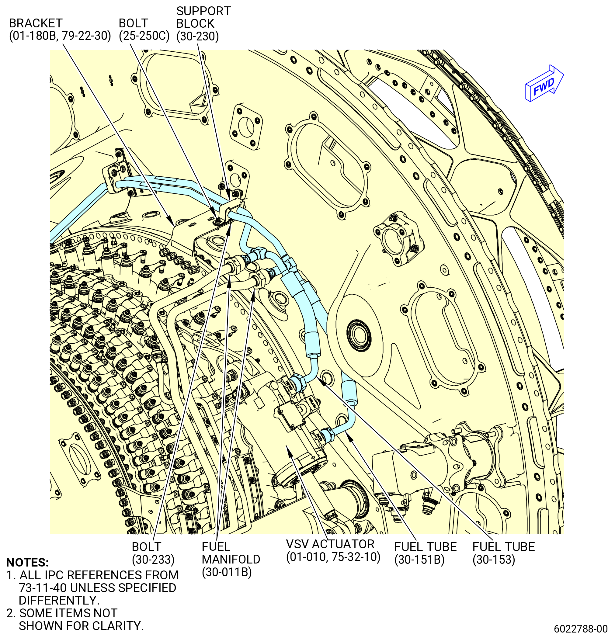
| (7) | Remove the bolt (25-250C, 73-11-40) (SIN 38122) that attaches the support block (30-230, 73-11-40) (SIN 38187) to the bracket (01-180B, 79-22-30) (SIN 38117) and remove the fuel tubes (30-151B, 73-11-40) (SIN 38102) and (30-153, 73-11-40) (SIN 38103). |
| (8) | Remove the bolt (30-233, 73-11-40) (SIN 3812B) and remove the support block (30-230, 73-11-40) (SIN 38187) from the bracket (01-180B, 79-22-30) (SIN 38117). |
| (9) | Remove and discard the preformed packing (25-090 , 73-11-40) (SIN 38350) from the VBV manifold (25-010B, 73-11-40) end fittings. |
| (10) | Remove and discard the preformed packings (25-320 , 73-11-40) (SIN 38250) and (25-330 , 73-11-40) (SIN 38251) from the VBV actuator (SIN 30700). |
| (11) | Remove and discard the preformed packings (30-160 , 73-11-40) (SIN 38151) from the nipple fittings of the fuel tubes (30-151B, 73-11-40) (SIN 38102) and (30-153, 73-11-40) (SIN 38103). |
| (12) | Remove and discard the preformed packings (30-160 , 73-11-40) (SIN 38151) and (30-170 , 73-11-40) (SIN 38150) on each VSV actuator (SIN 30400) and (SIN 30401). |
|
|
|
|
|
|
|
|
|
|
|
|
| * * * PRE SB 73-0099( Introduction of New Fuel-Hydraulic Lines ) |
| Subtask 72-00-02-030-388 |
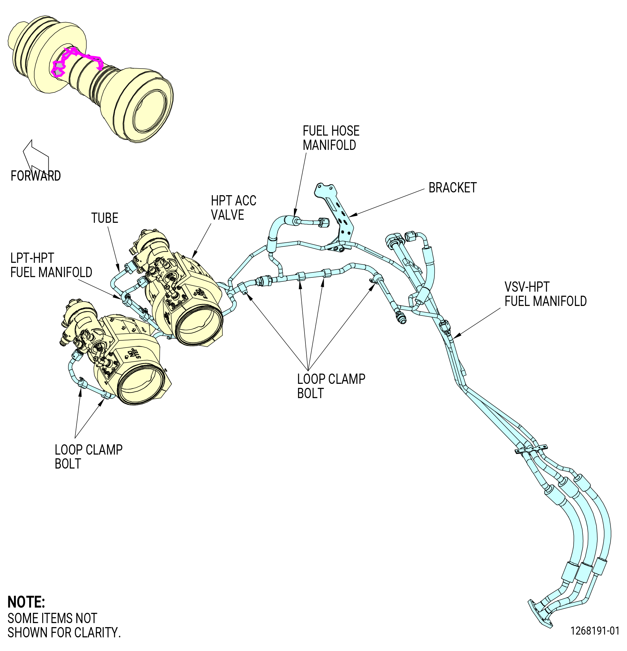
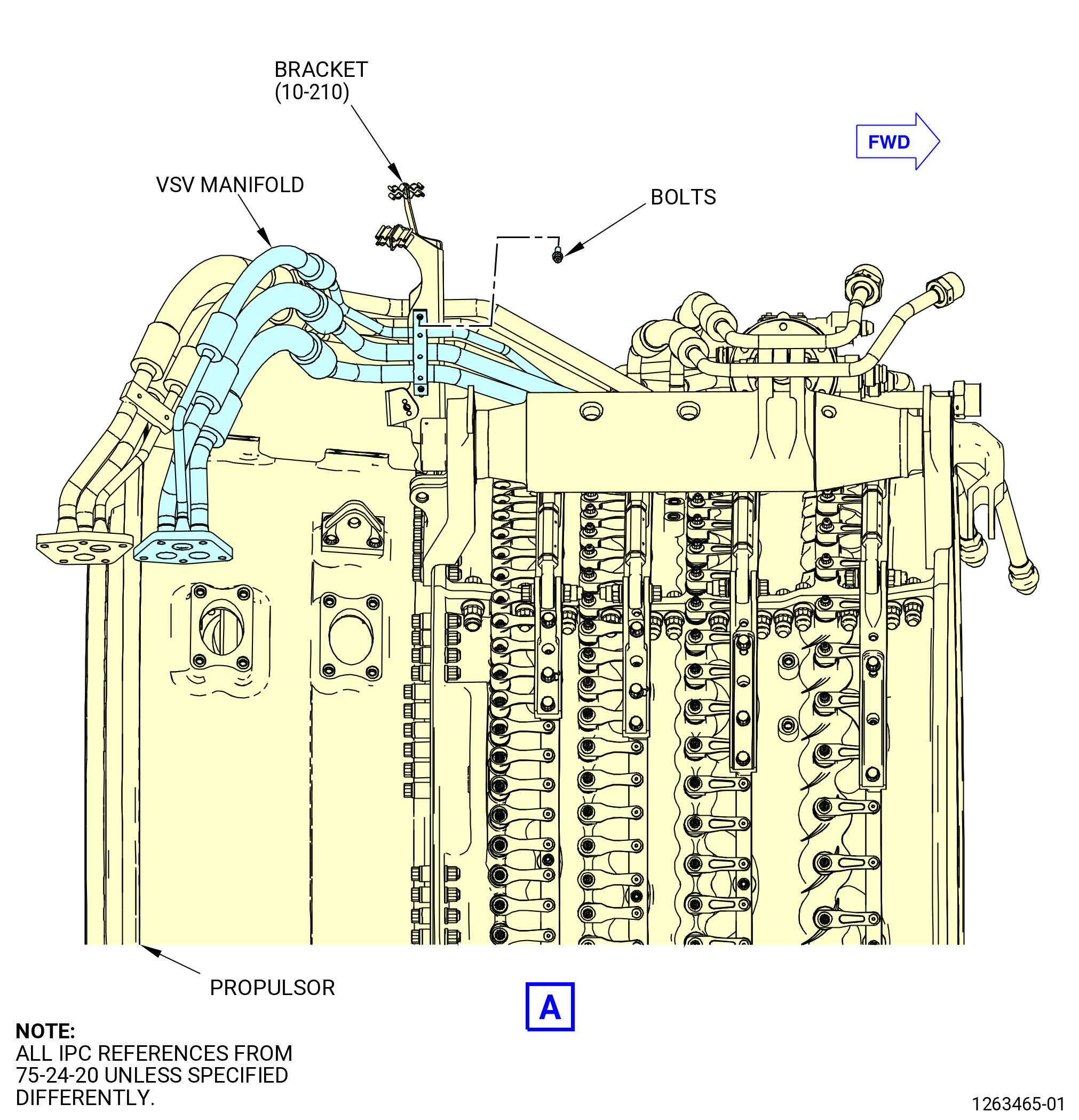
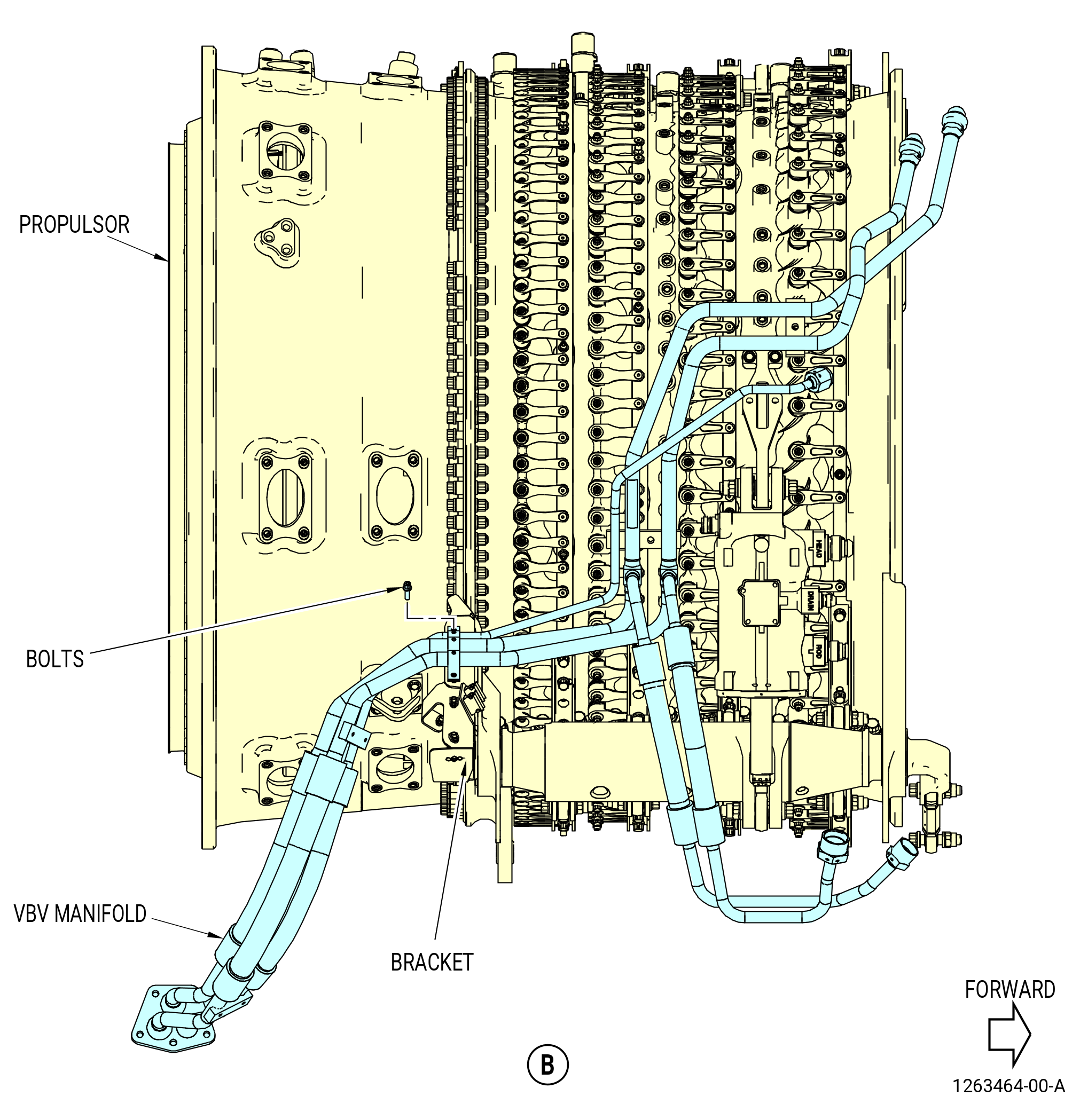
| T. | Remove the VSV-HPT fuel hose manifold (VSV manifold) and the VBV-LPT fuel hose manifold (VBV manifold) as follows. Refer to Figure 521. |
| (1) | Remove the VBV manifold from the right side VBV actuator as follows: |
| (a) | Disconnect the coupling nuts from the VBV actuator. |
| (b) | Remove and discard the preformed packings (25-090 , 73-11-40) (SIN 38350) and (25-100 , 73-11-40) (SIN 38351) from the VBV actuator. |
| (c) | Remove the bolts and cushioned clamps that attach the VBV manifold to the brackets. |
| (d) | Remove the VBV manifold from the top of the propulsor module. |
| (2) | Remove the VSV manifold as follows: |
| (a) | Remove the bolts and cushioned clamps that attach the VSV manifold to the bracket. |
| (b) | Remove the bolts that attach the VSV manifold to the bracket. |
| (c) | Remove the VSV manifold from the top of the propulsor. |
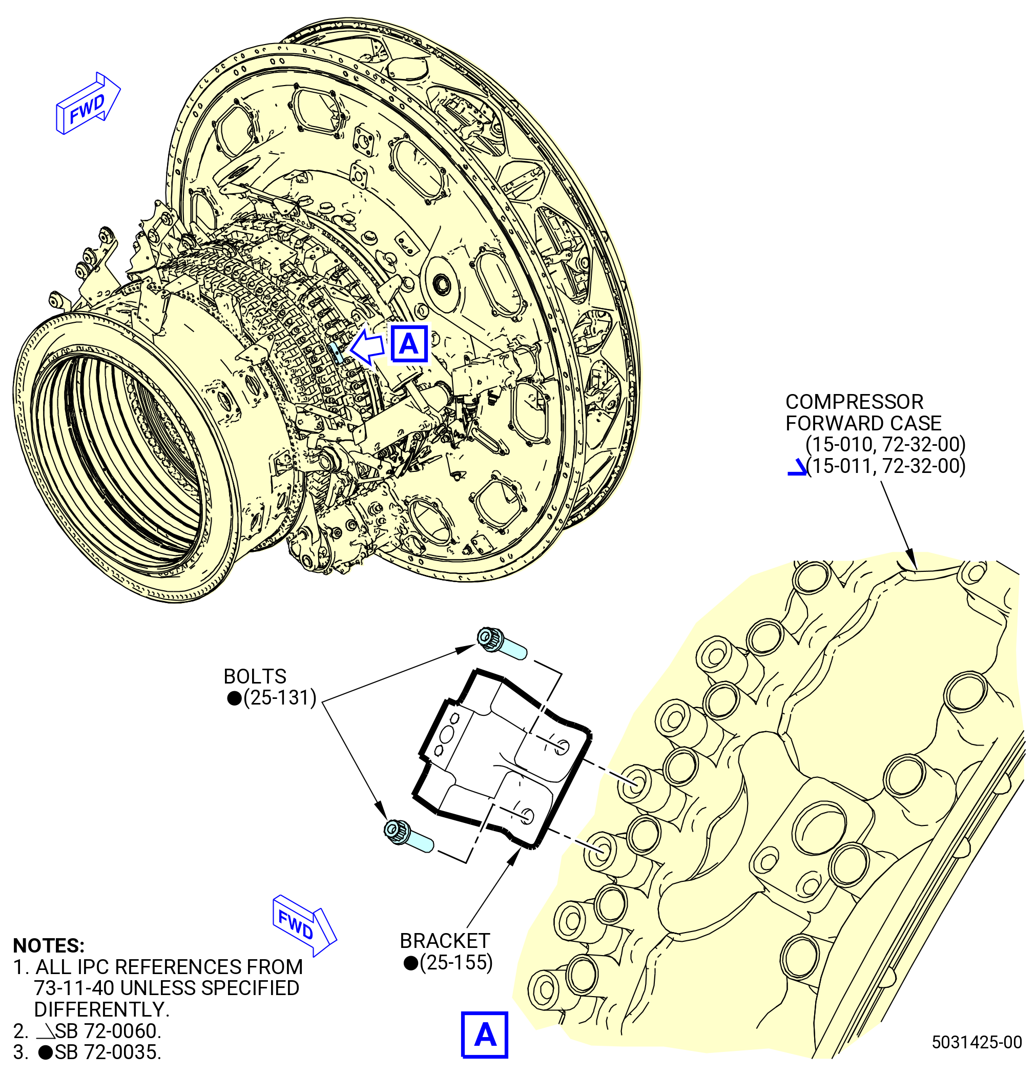
| (3) | Remove the manifold brackets as follows: |
| (a) | Remove the bolts that attach the bracket (25-140 , 73-11-40) (SIN 38112) or (25-155 , 73-11-40) (SIN 38112) to the HPC stator case, between VSV stages 2 and 3, at the 1:45 o'clock position. |
| (b) | Remove the bolts that attach the bracket (38111) to the aft face of the FHF, at the 9:45 o'clock position. |
| (c) | Remove the bolts that attach the support bracket (38110) to the aft face of the FHF at the 11:00 o'clock position. |
| * * * END PRE SB 73-0099( Introduction of New Fuel-Hydraulic Lines ) |
| Subtask 72-00-02-030-788 |
| * * * FOR ALL.ALL |
| * * * SB 73-0099( Introduction of New Fuel-Hydraulic Lines ) |
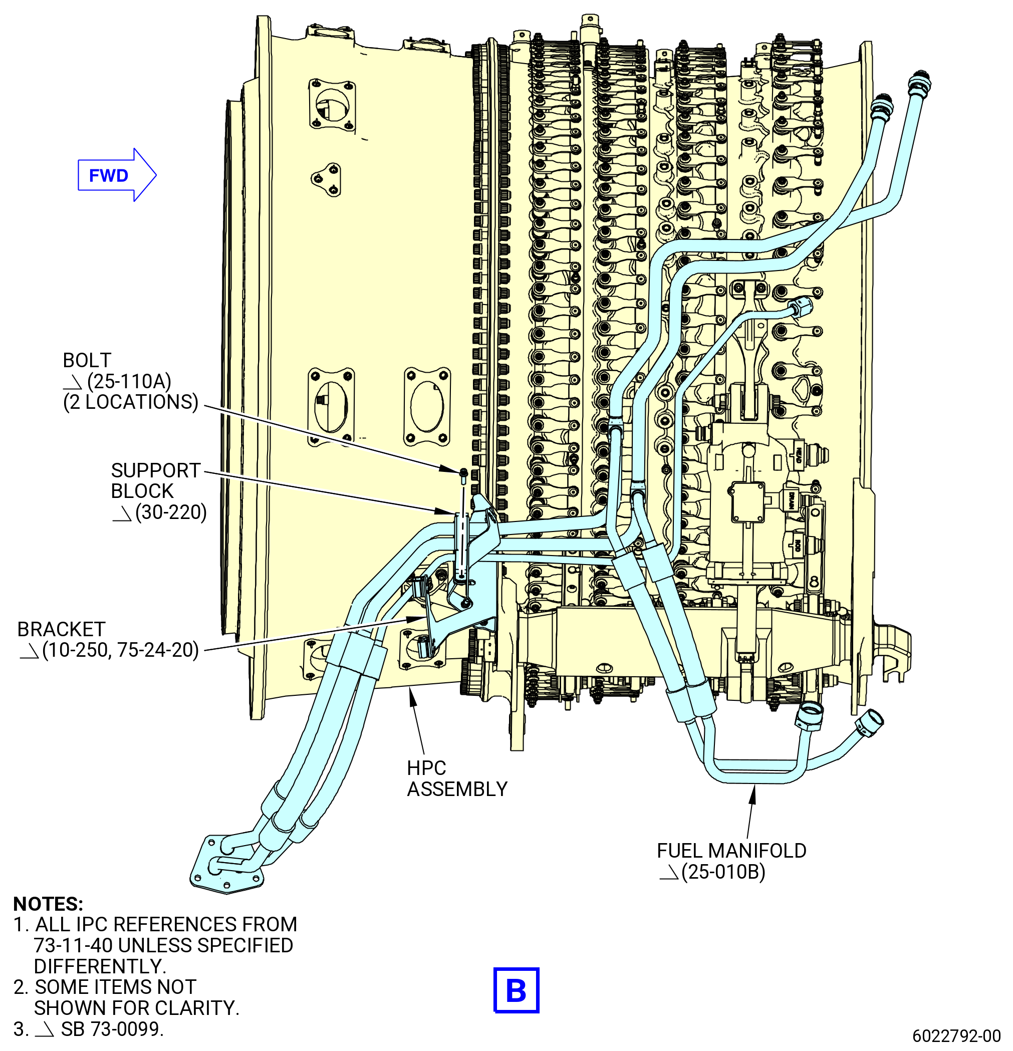
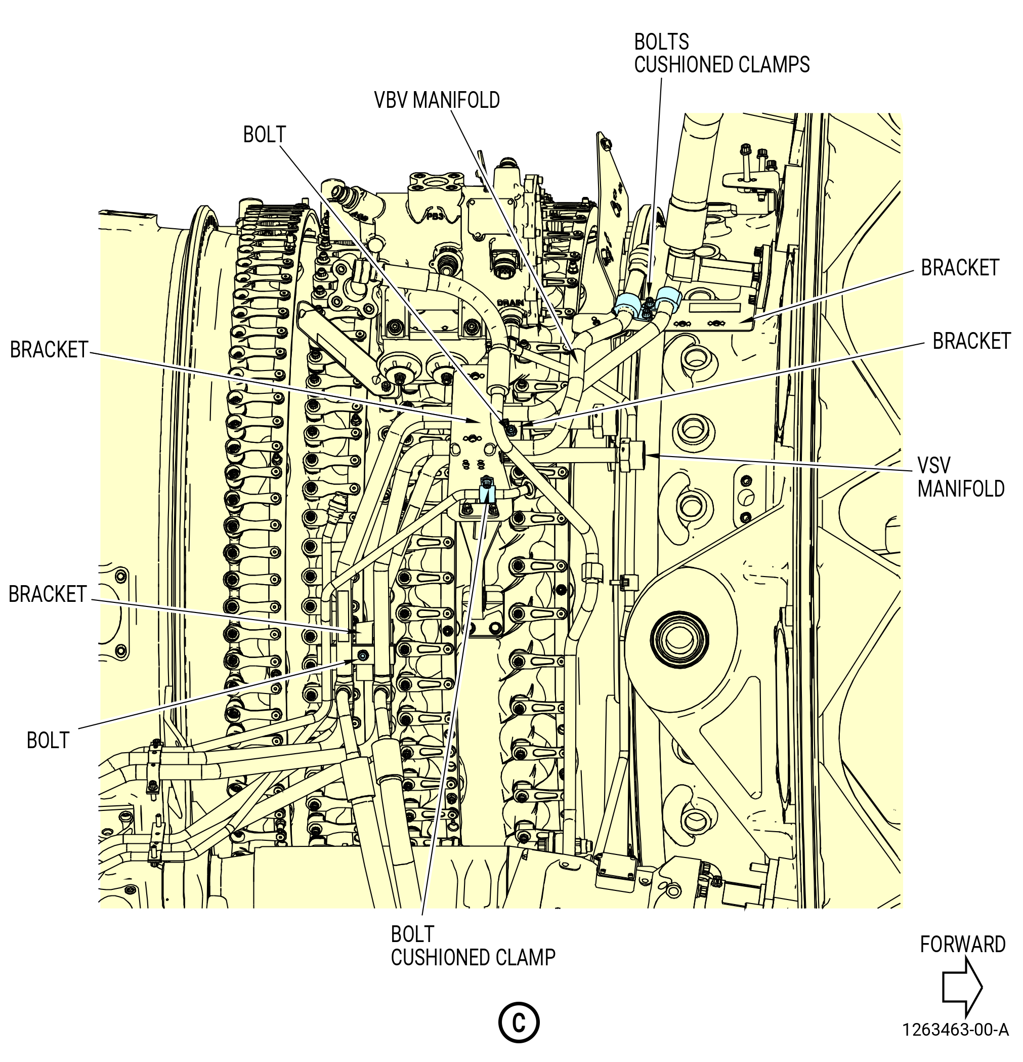
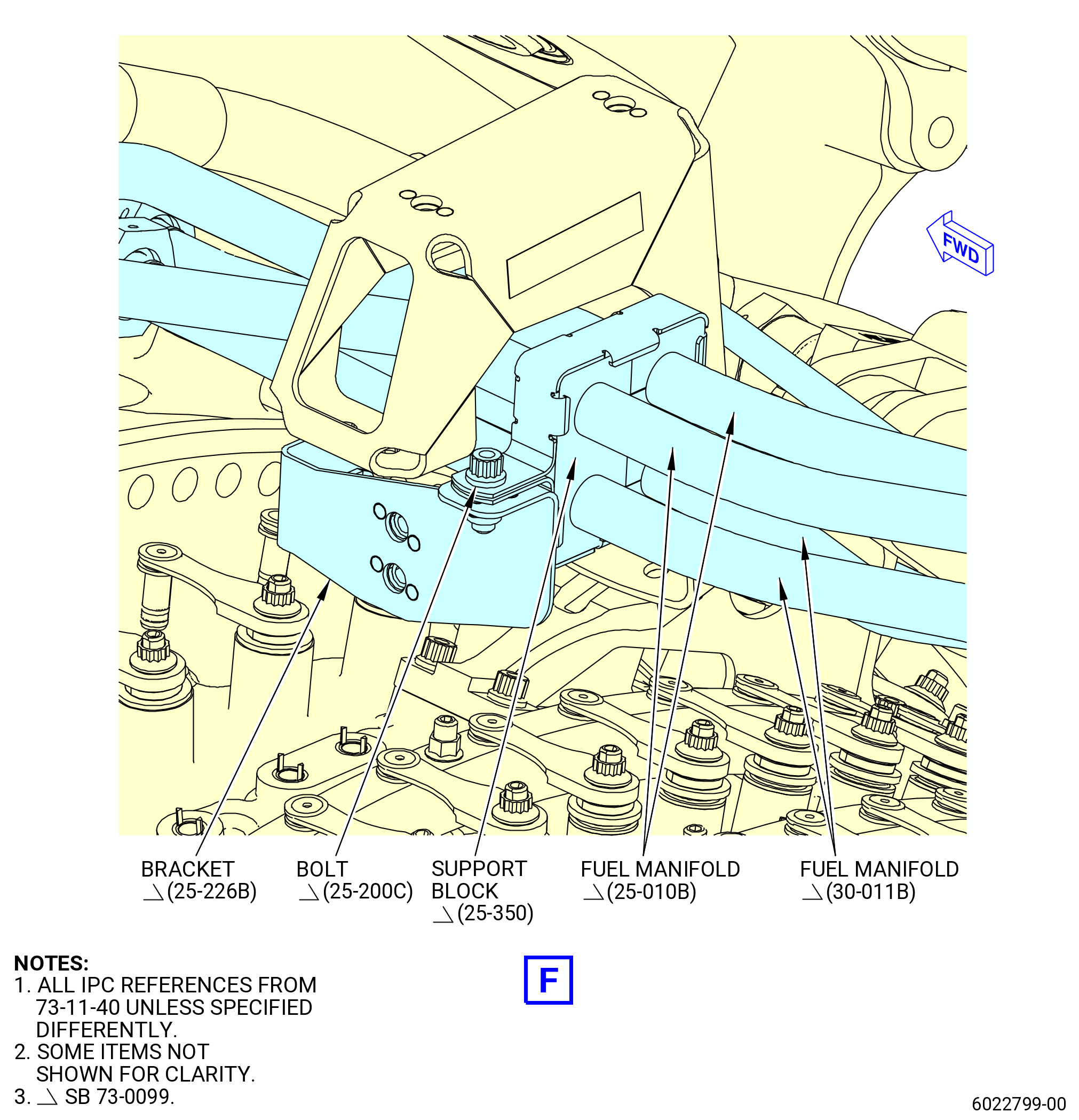
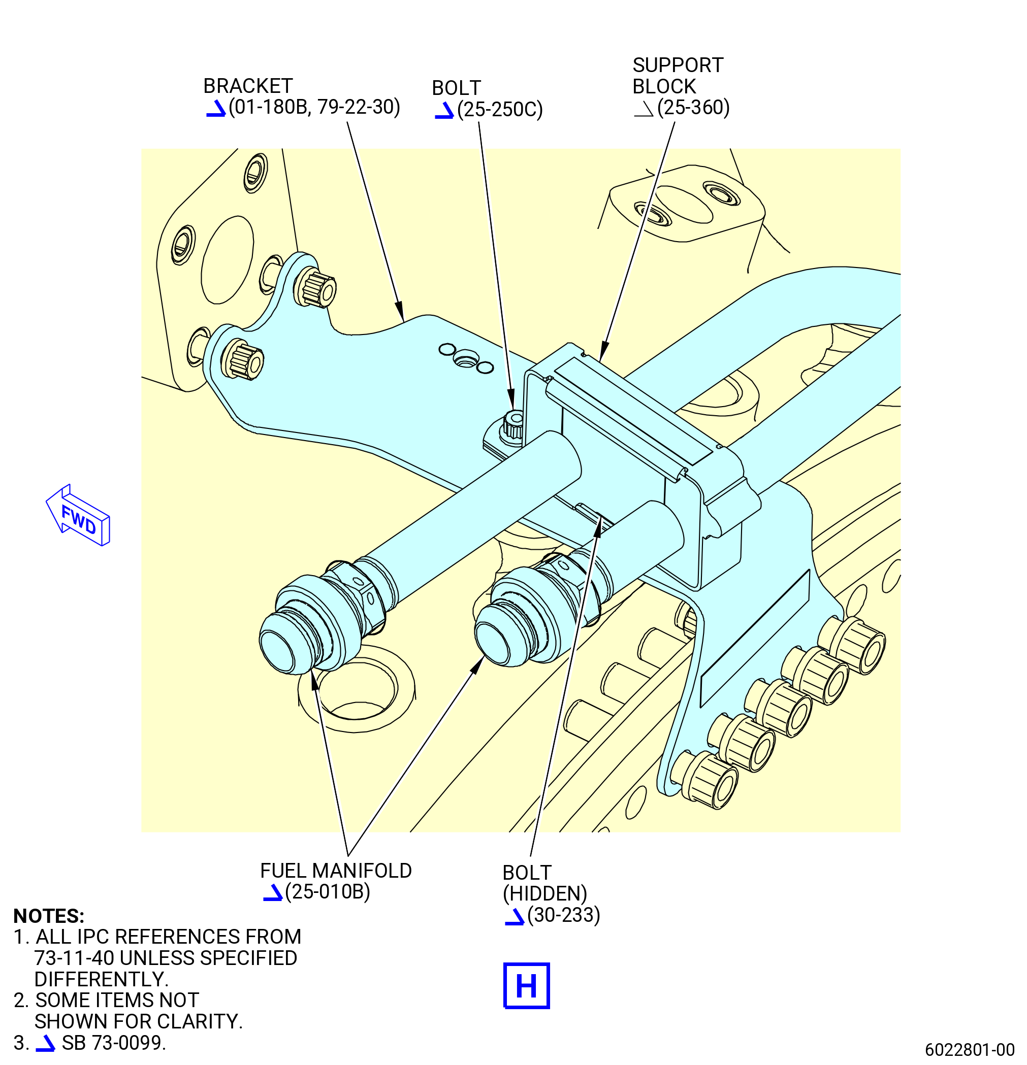
| U. | Remove the VSV-HPT fuel hose manifold (VSV manifold) (30-011B, 73-11-40) (SIN 38100) and the VBV-LPT fuel hose manifold (VBV manifold) (25-010B, 73-11-40) (SIN 38300) as follows: |
| (1) | Remove the bolts, clamps and support blocks that attach the VBV manifold (25-010B, 73-11-40) (SIN 38300) to the manifold brackets as follows: |
| (a) | Disconnect the coupling nuts from the VBV actuator (SIN 30700). |
| (b) | Remove and discard the preformed packings (25-090 , 73-11-40) (SIN 38350) and (25-100 , 73-11-40) (SIN 38351) from the VBV actuator (SIN 30700). |
| (c) | Remove the bolts (25-060A, 73-11-40) (SIN 38322) and cushioned clamps (25-070 , 73-11-40) (SIN 38380) that attach the VBV manifold (25-010B, 73-11-40) (SIN 38300) to the bracket (01-120 , 75-42-10) (SIN 53012) or (01-120A , 75-42-10) (SIN 53012). |
| (d) | Remove the bolt (25-060A, 73-11-40) (SIN 38322) and cushioned clamp (25-160 , 73-11-40) (SIN 38382) that attach the VBV manifold (25-010B, 73-11-40) (SIN 38300) to the bracket (01-145 , 75-11-20) (SIN 6101B). |
| (e) | Remove the bolt (25-110A, 73-11-40) (SIN 38320) and cushioned clamp (25-365, 73-11-40) (SIN 38188) that attach the VBV manifold (25-010B, 73-11-40) (SIN 38300) to the bracket (25-155A, 73-11-40) (SIN 38112). |
| (f) | Remove the bolt (25-250C, 73-11-40) (SIN 38122) and the bolt (30-233, 73-11-40) (SIN 3812B) that attach the support block (25-360, 73-11-40) (SIN 38383) to the bracket (01-180B, 79-22-30) (SIN 38117). |
| (g) | Remove the bolts (25-110A, 73-11-40) (SIN 38320) and the support block that attach the VBV manifold (25-010B, 73-11-40) (SIN 38300) to the bracket (10-250D, 75-24-20) (SIN 38116). |
| (2) | Remove the bolts, clamp and support block that attach the VSV manifold (30-011B, 73-11-40) (SIN 38100) to the manifold brackets as follows: |
| (a) | Remove the bolt (30-070A, 73-11-40) (SIN 38120) and the cushioned clamp (25-365, 73-11-40) (SIN 38188) that attach the VSV manifold (30-011B, 73-11-40) (SIN 38100) to the bracket (25-155A, 73-11-40) (SIN 38112). |
| (b) | Remove the bolts (30-070A, 73-11-40) (SIN 38120) and the support block that attach VSV manifold (30-011B, 73-11-40) (SIN 38100) to the bracket (10-250D, 75-24-20) (SIN 38116). |
| (3) | Remove the support blocks (25-350, 73-11-40) (SIN 38186) from the VSV manifold (30-011B, 73-11-40) (SIN 38100) and the VBV manifold (25-010B, 73-11-40) (SIN 38300) as follows: |
| (a) | Remove the bolt (25-200C, 73-11-40) (SIN 38125) that attach the support block (25-350, 73-11-40) (SIN 38186) to the bracket (25-226B, 73-11-40) (SIN 38119). |
| (b) | Remove the bolt (25-200C, 73-11-40) (SIN 38125) that attach the support block (25-350, 73-11-40) (SIN 38186) to the bracket (25-155A, 73-11-40) (SIN 38112). |
| (c) | Open and remove the support blocks (25-350, 73-11-40) (SIN 38186). |
| (4) | Remove the VSV manifold (30-011B, 73-11-40) (SIN 38100) from the top of the propulsor module. |
| (5) | Remove the VBV manifold (25-010B, 73-11-40) (SIN 38300) from the top of the propulsor module. |
| (6) | Remove the manifold brackets as follows: |
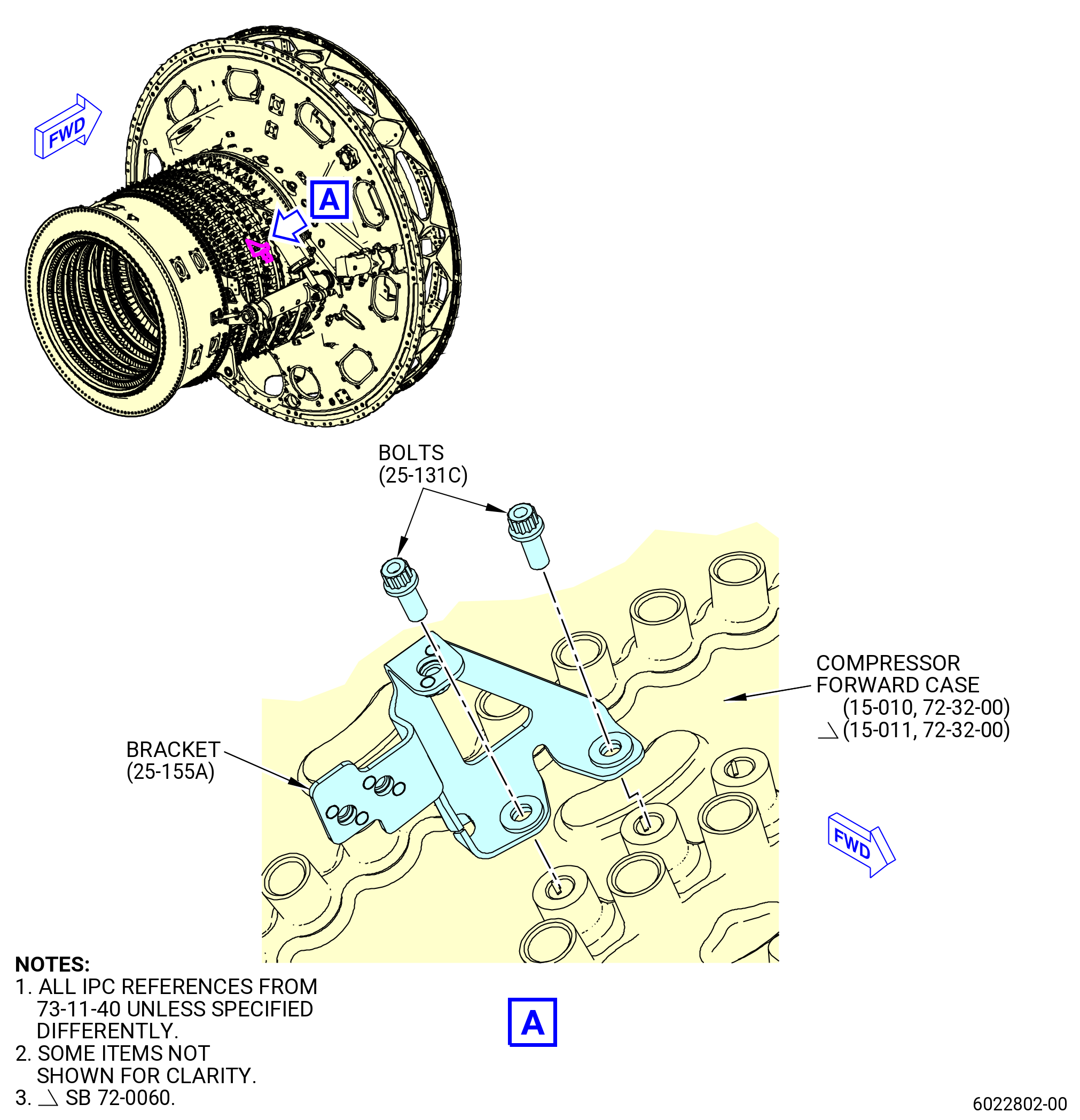
| (a) | Remove the bolts (25-131C, 73-11-40) (SIN 38123) that attach the bracket (25-155A, 73-11-40) (SIN 38112) to the HPC stator case (SIN 073A0), between VSV stages 2 and 3, at the 1:45 o'clock position. |
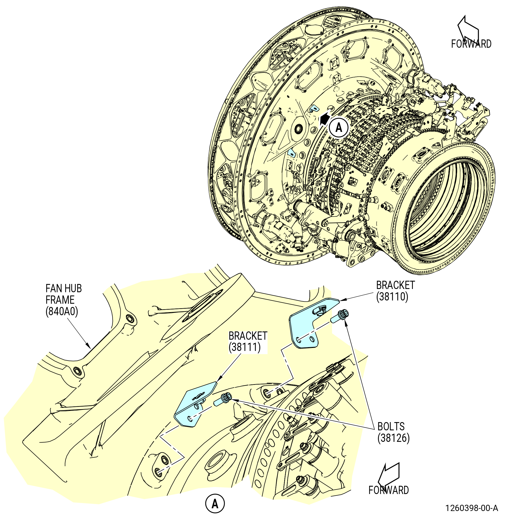
| (b) | Remove the bolts (30-180A, 73-11-40) (SIN 38128) that attach the brackets (25-270A, 73-11-40) (SIN 38110) to the aft face of the FHF (SIN 840A0), at the 9:45 and 11:00 o'clock positions. |
|
|
|
|
|
|
|
|
|
|
|
|
|
|
|
| Subtask 72-00-02-030-389 |
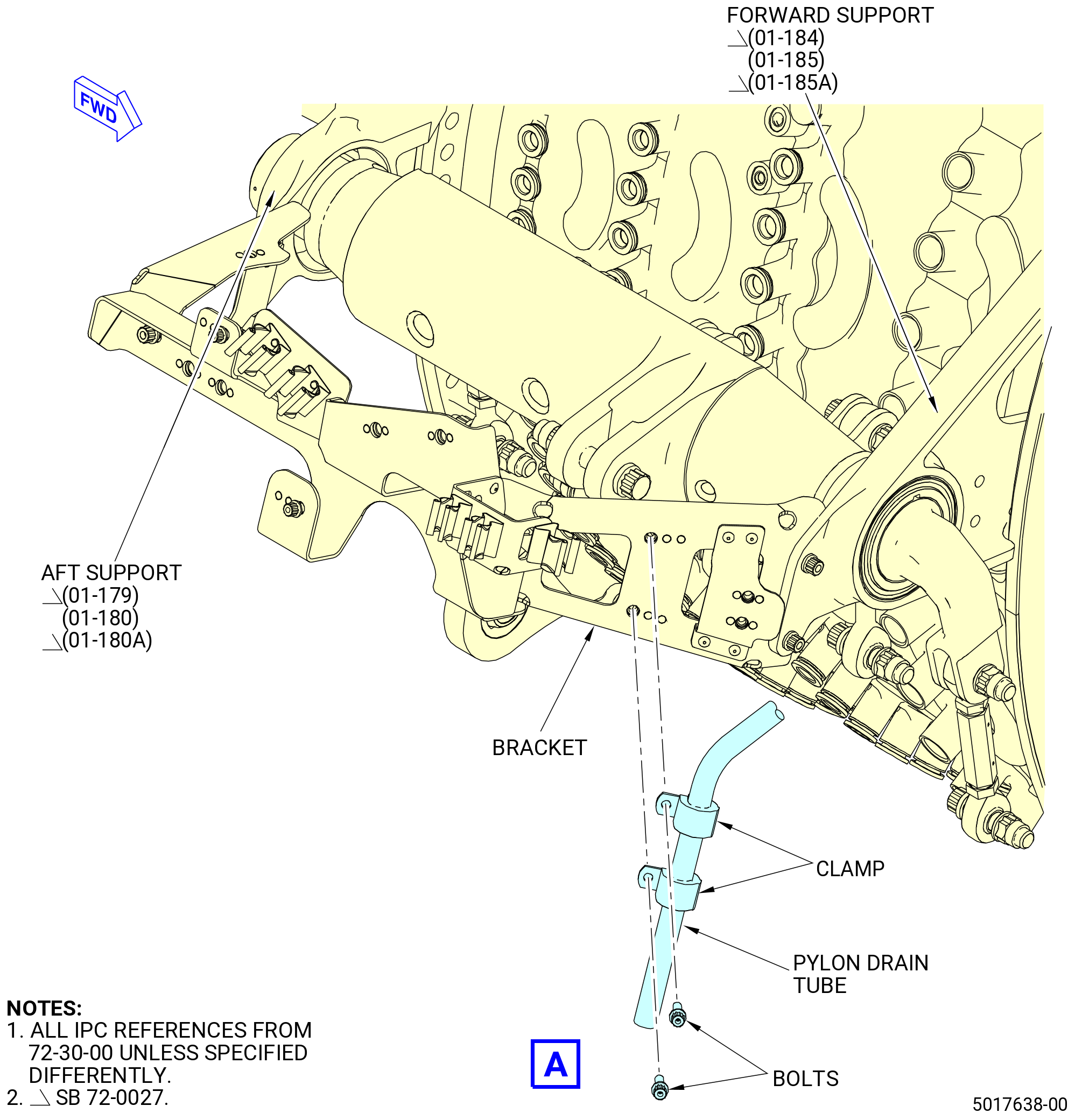
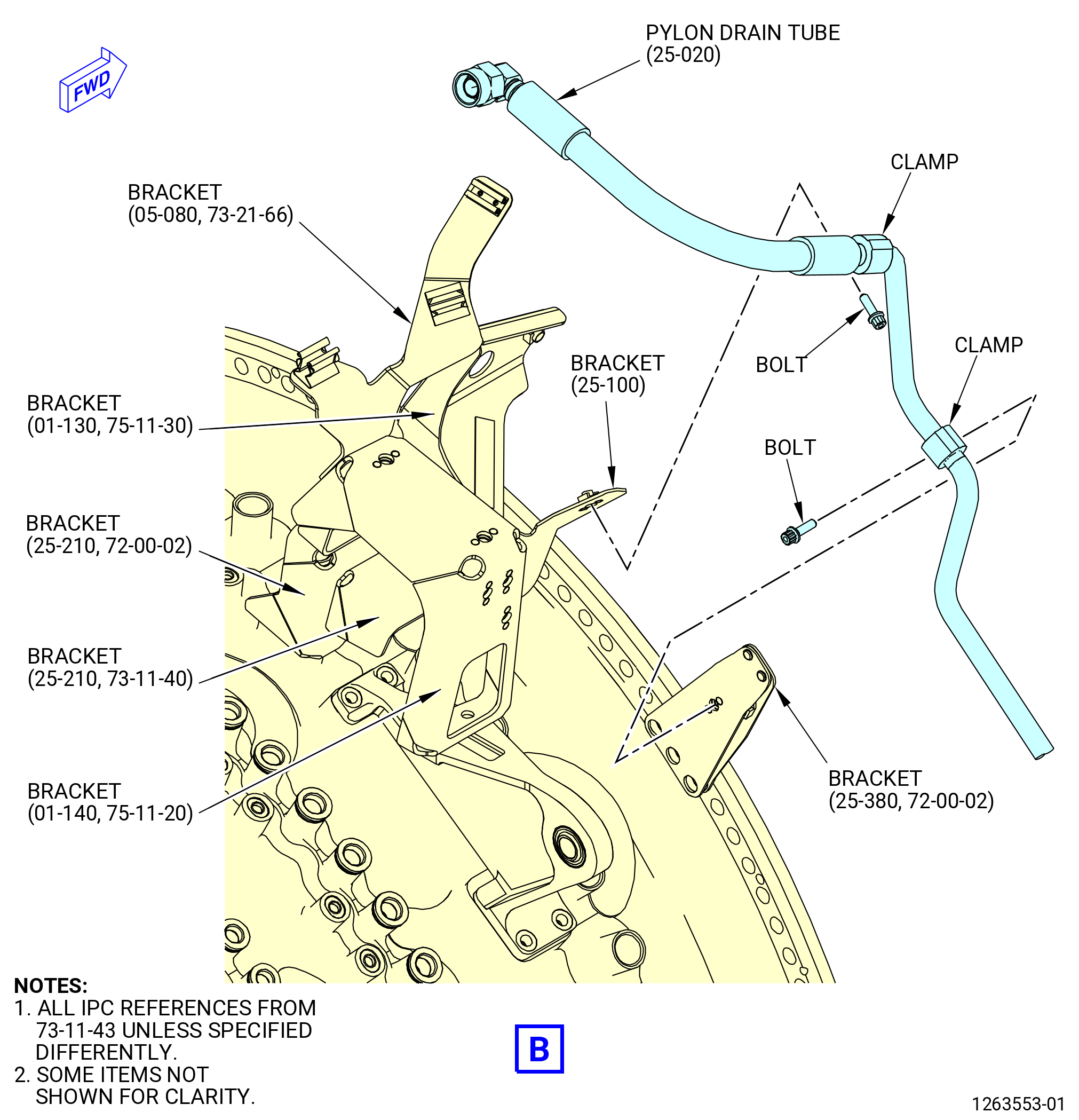
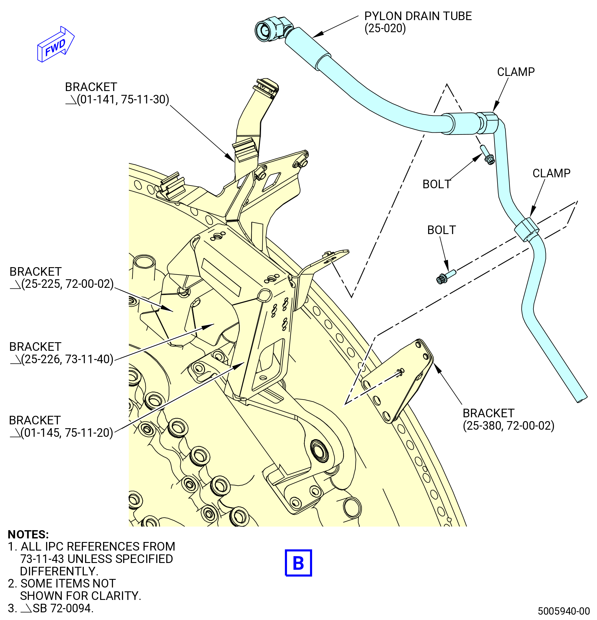
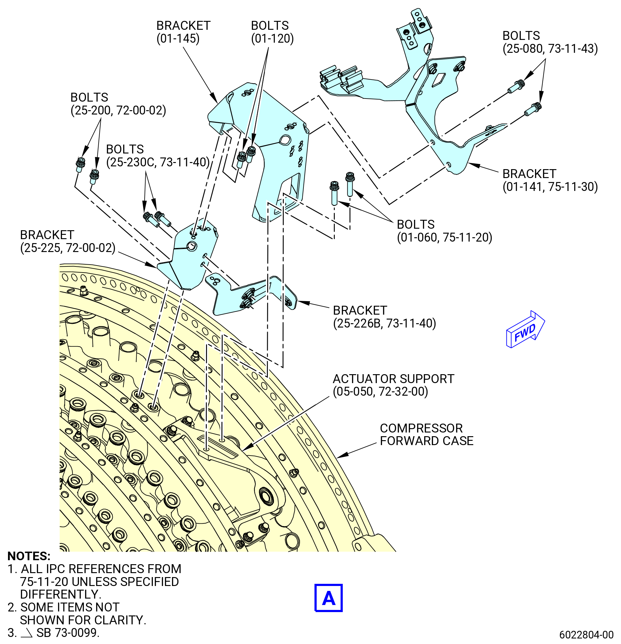
| V. | Remove the pylon drain tube (25-020 , 73-11-43) (SIN 59002) and the support brackets. Refer to Figure 522, Figure 524, and do as follows: |
| (1) | Remove the four bolts (25-050 , 73-11-43) (SIN 59020) and cushioned clamps (25-090 , 73-11-43) (SIN 59082) that attach the pylon drain tube (25-020 , 73-11-43) (SIN 59002) to the bracket (01-100 , 75-42-10) (SIN 53011), bracket (25-380) (SIN 59014), and bracket (25-100 , 73-11-43) (SIN 59013) (SIN 59013) or (01-130 , 75-11-30) (SIN 63717). Remove the pylon drain tube (SIN 59002). |
| Subtask 72-00-02-030-789 |
| * * * FOR ALL.ALL |
| * * * PRE SB 72-0094( Old Bracketry Configuration for the Engine Anti-Ice System ) |
| (2) | Remove the bolts (25-080, 73-11-43) (SIN 59021) that attach the bracket (SIN 59013) and bracket (SIN 63717) to the bracket (SIN 6101B). Remove bracket (SIN 59013) and bracket (SIN 63717). |
| * * * END PRE SB 72-0094 |
| Subtask 72-00-02-030-790 |
| * * * SB 72-0094( New Bracketry Configuration for the Engine Anti-Ice System ) |
| (2) | Remove the bolts (25-080, 73-11-43) (SIN 59021) that attach the bracket (SIN 63717) to the bracket (SIN 6101B). Remove the bracket (SIN 63717). |
| * * * END SB 72-0094 |
| Subtask 72-00-02-030-791 |
| * * * FOR ALL.ALL |
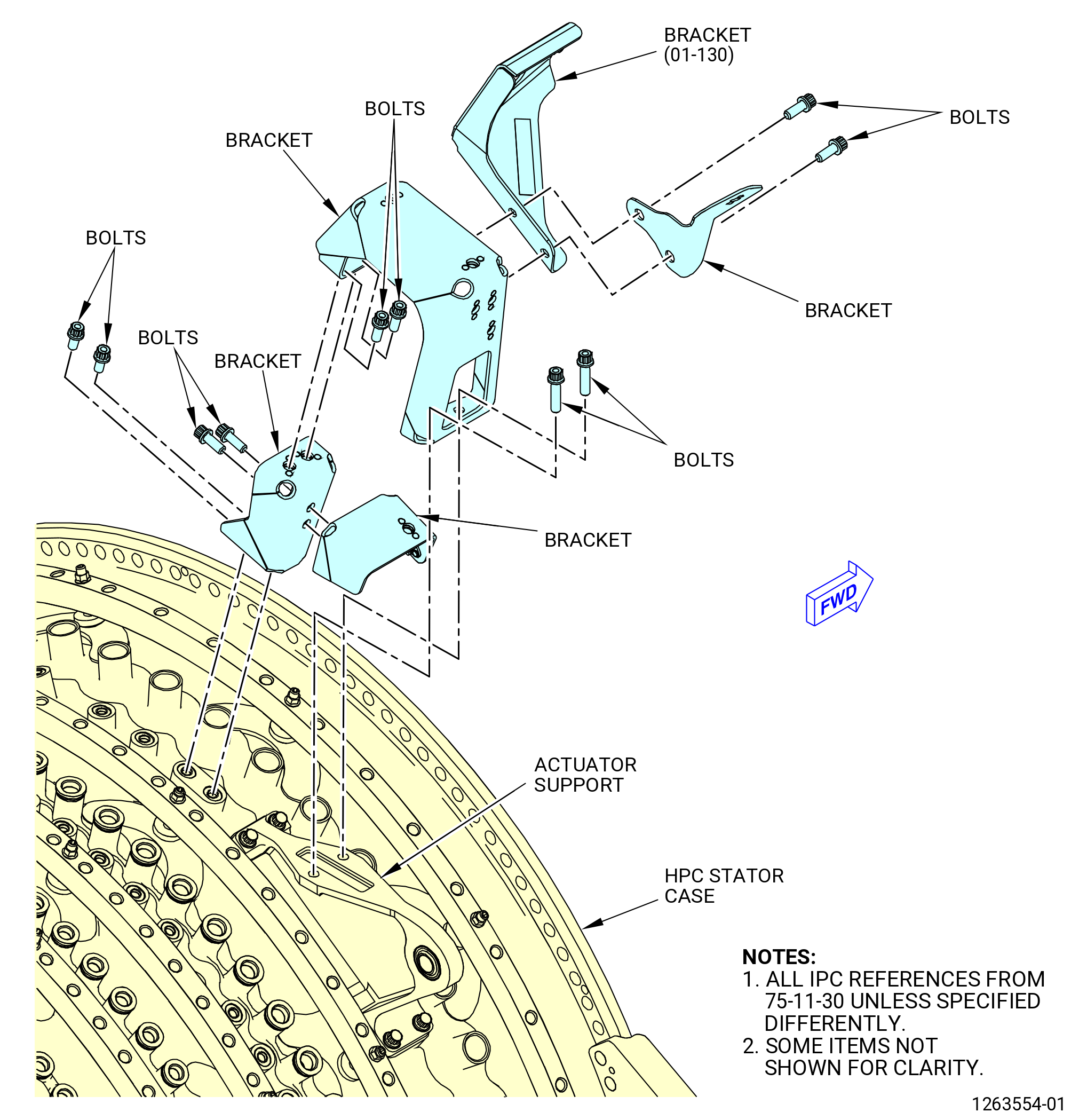
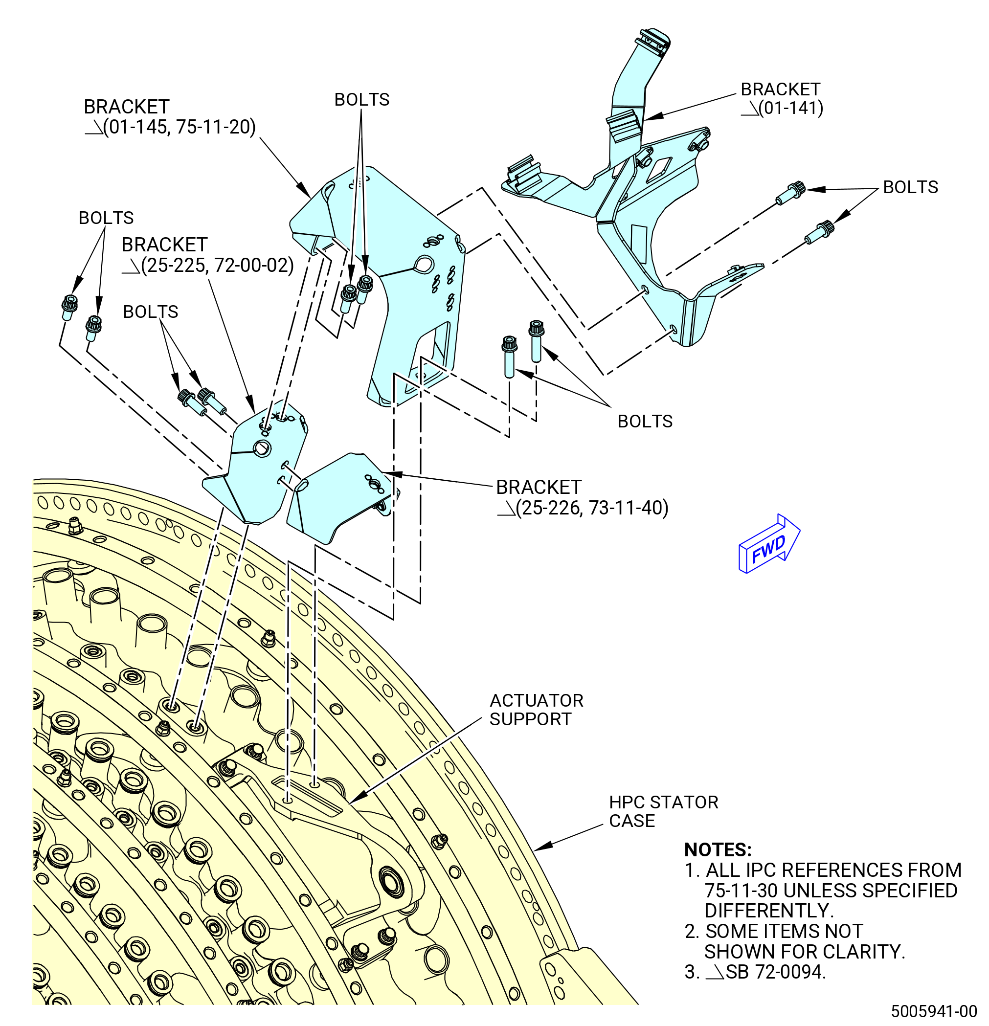
| (3) | Loosen and remove the bolts (SIN 6102E) that attach the support bracket (SIN 6101B) to the actuator support (SIN 075C0). Remove the support bracket (SIN 6101B). |
| Subtask 72-00-02-030-792 |
| * * * FOR ALL.ALL |
| * * * PRE SB 73-0099( Introduction of New Fuel-Hydraulic Lines ) |
| (4) | Remove the bolts (25-230, 73-11-40) (SIN 38126) that attach the bracket (25-210, 73-11-40) (SIN 38119) or (25-226, 73-11-40) (SIN 38119) to the bracket (25-210, 73-11-40) (SIN 38118) or (25-225, 73-11-40) (SIN 38118)attached to the HPC stator case. Remove the bracket (SIN 38119). |
| * * * END PRE SB 73-0099( Introduction of New Fuel-Hydraulic Lines ) |
| Subtask 72-00-02-030-793 |
| * * * FOR ALL.ALL |
| * * * SB 73-0099( Introduction of New Fuel-Hydraulic Lines ) |
| (4) | Remove the bolts (25-230C, 73-11-40) (SIN 38126) that attach the bracket (25-226B, 73-11-40) (SIN 38119) to the bracket (25-210, 73-11-40) (SIN 38118) or (25-225, 73-11-40) (SIN 38118) attached to the HPC stator case. Remove the bracket (SIN 38119). |
| * * * END SB 73-0099( Introduction of New Fuel-Hydraulic Lines ) |
| Subtask 72-00-02-030-794 |
| * * * FOR ALL.ALL |
| (5) | Remove the bolts (25-200, 73-11-40) (SIN 38129) and remove the bracket (25-210, 73-11-40) (SIN 38118) or (25-225, 73-11-40) (SIN 38118). |
|
|
|
|
|
|
|
|
| Subtask 72-00-02-030-390 |
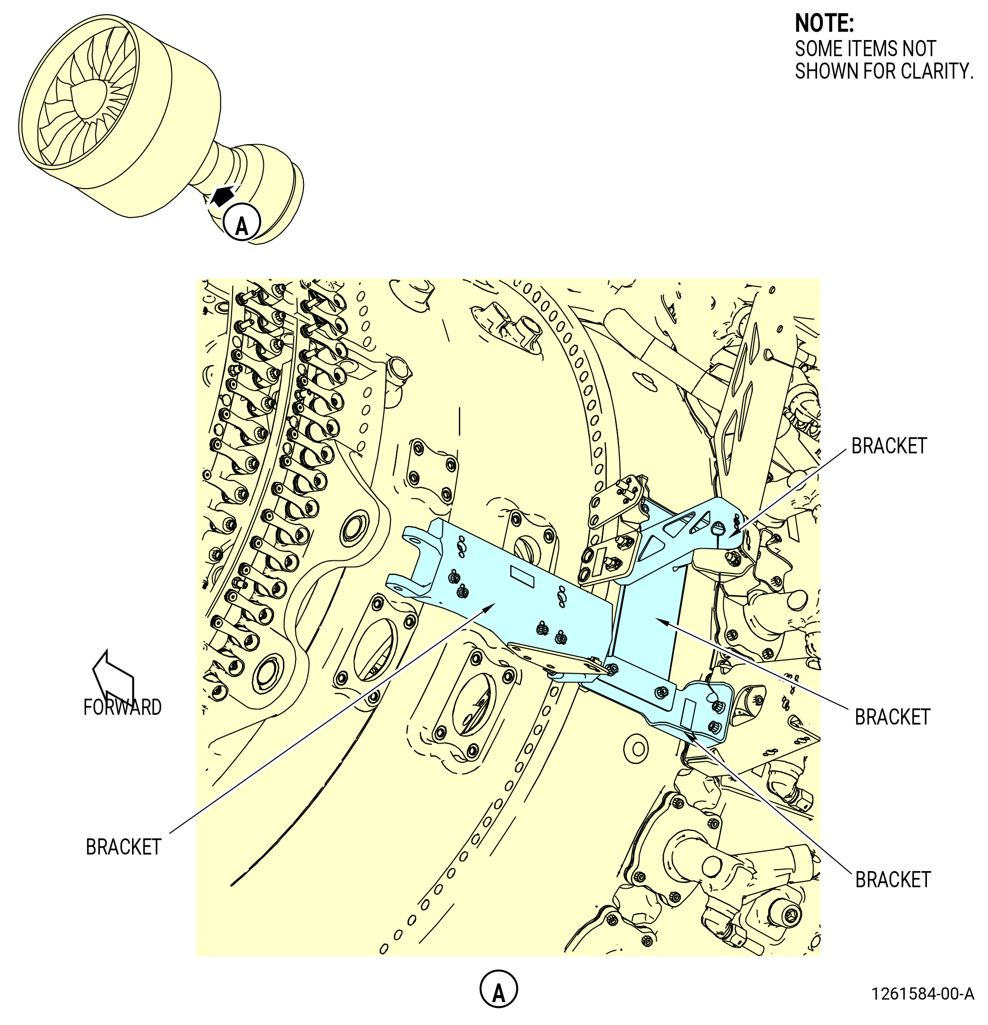
| W. | Remove the brackets as follows: |
| (1) | Deleted. |
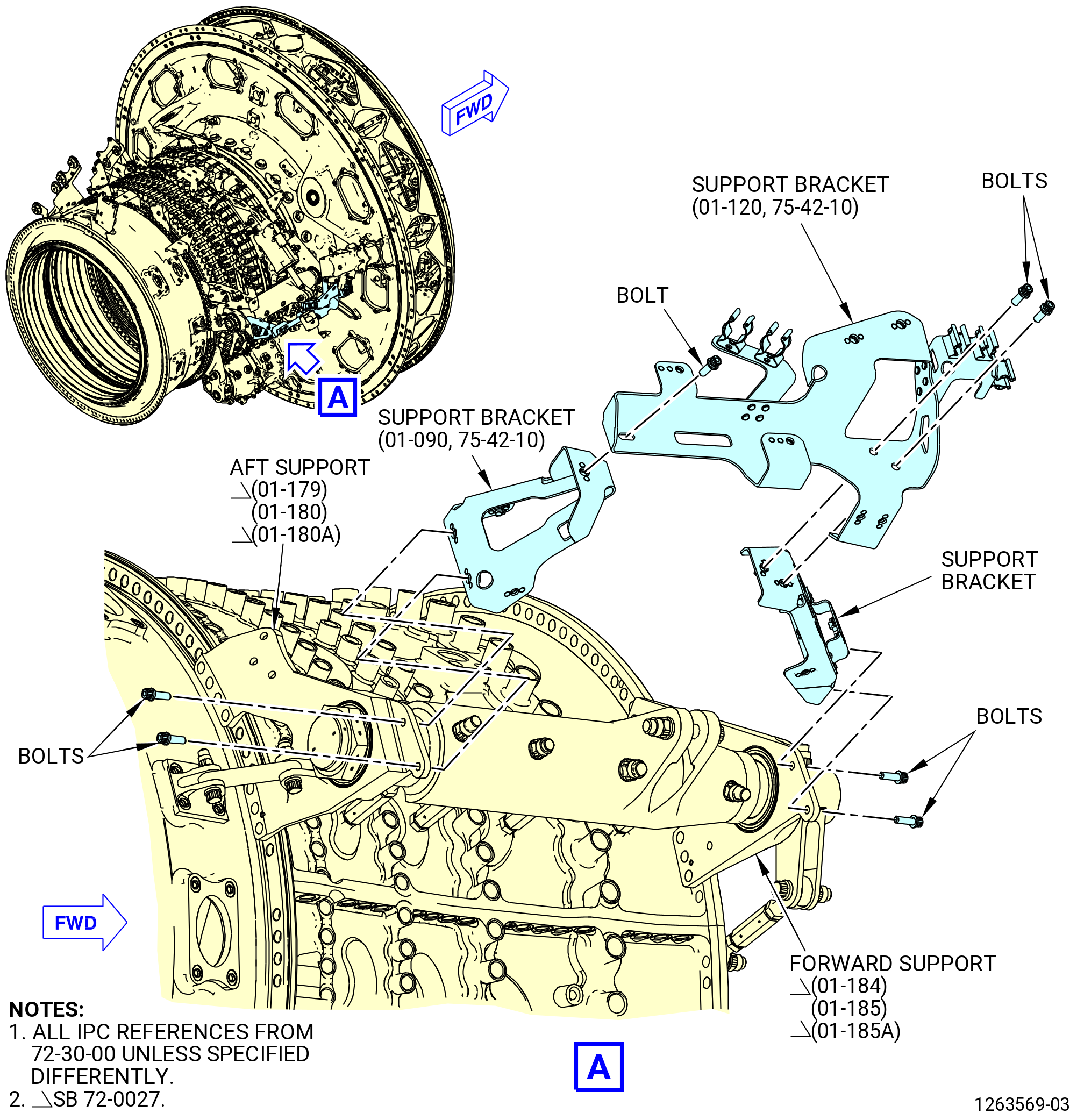
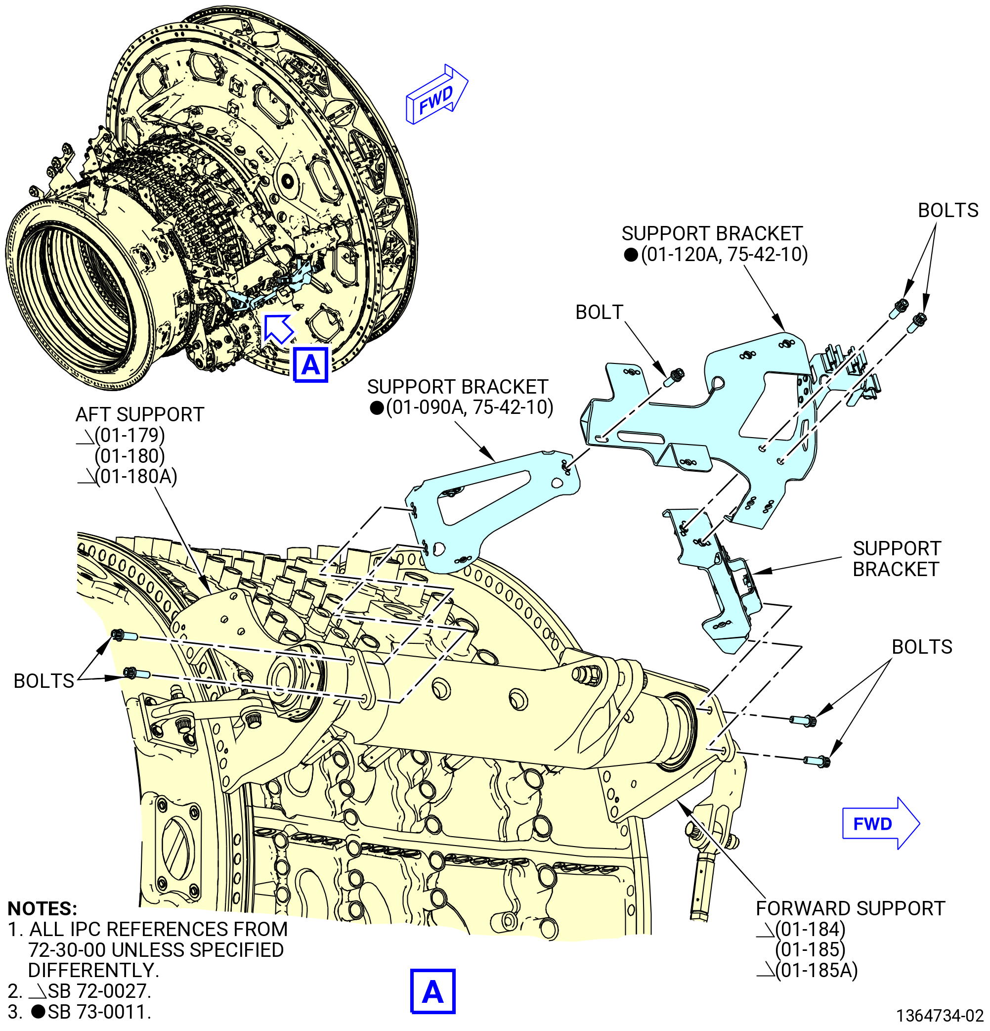
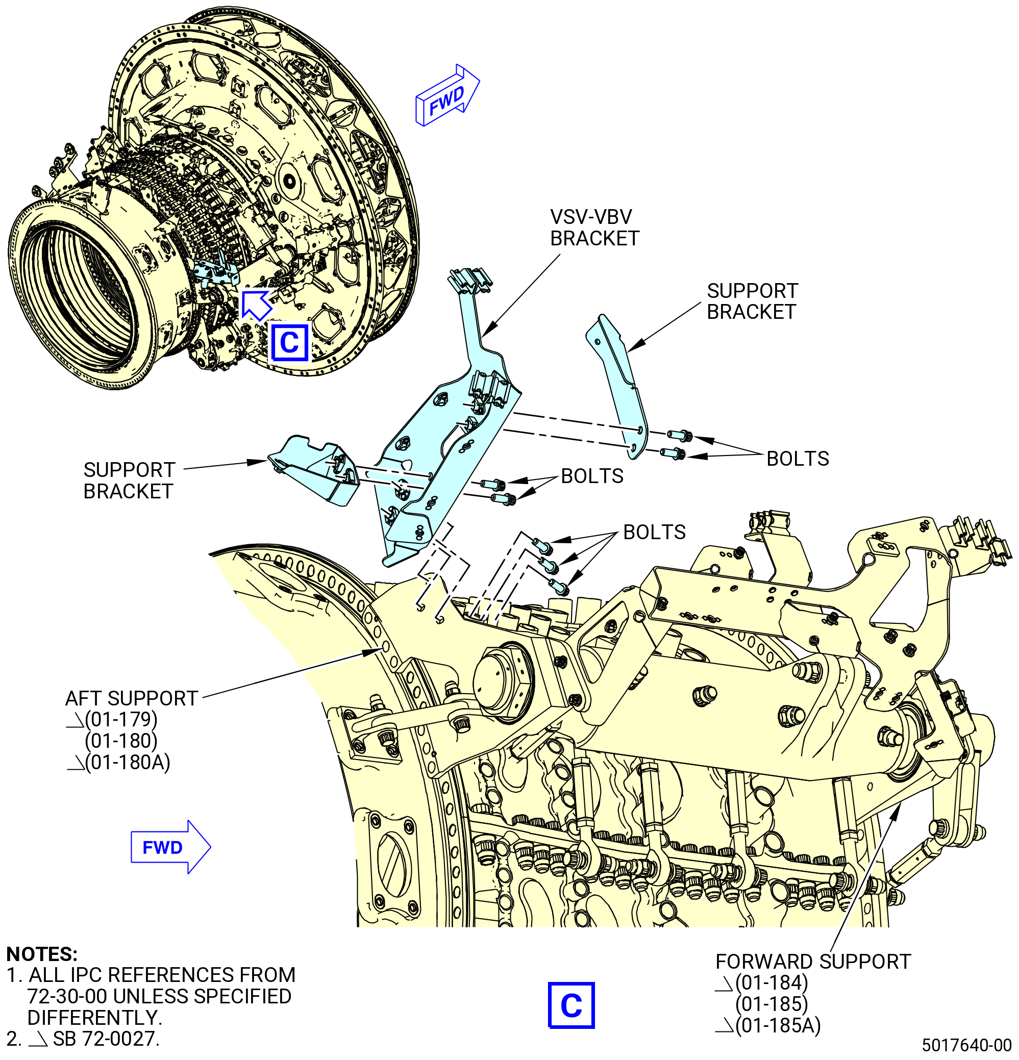
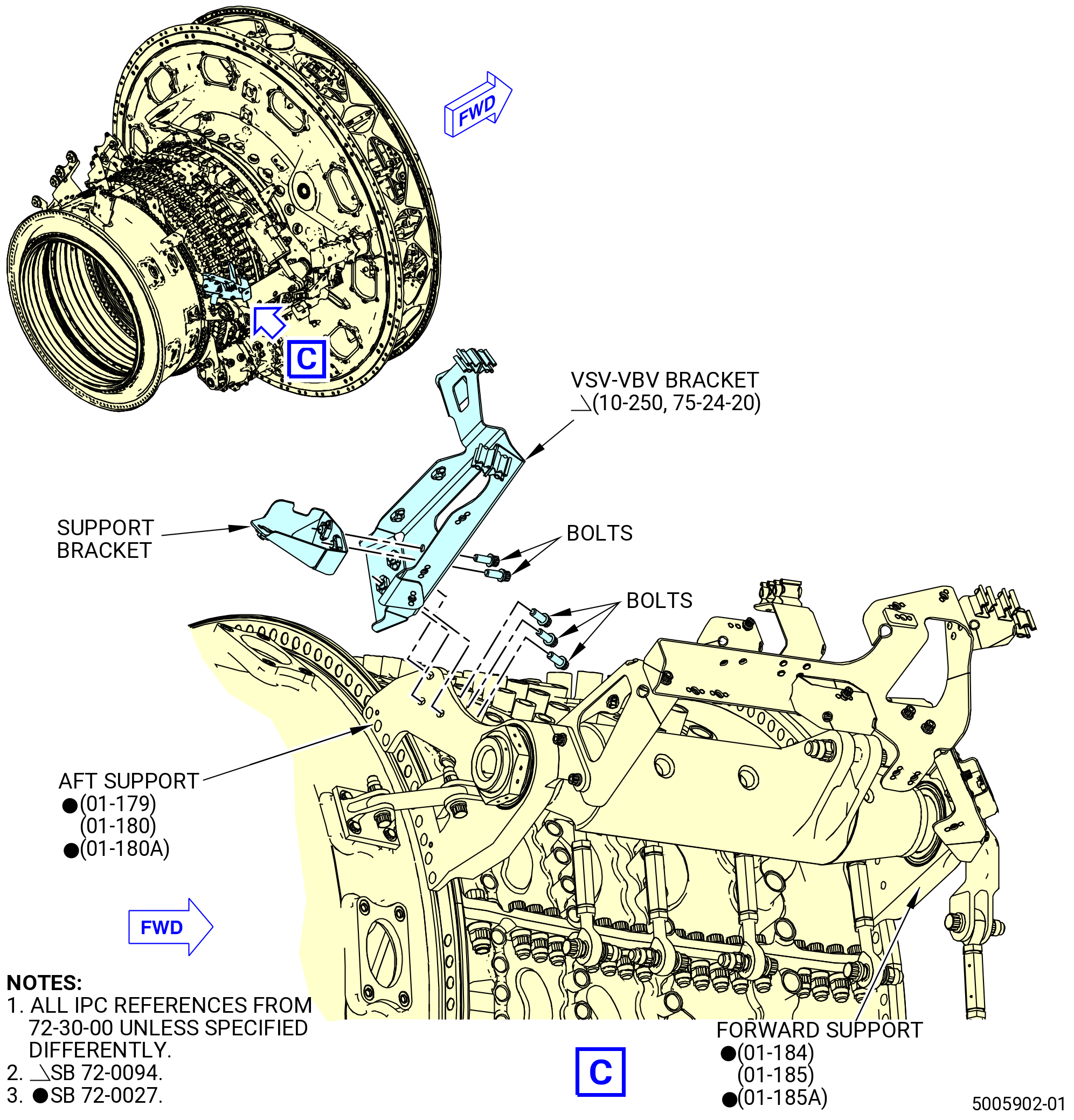
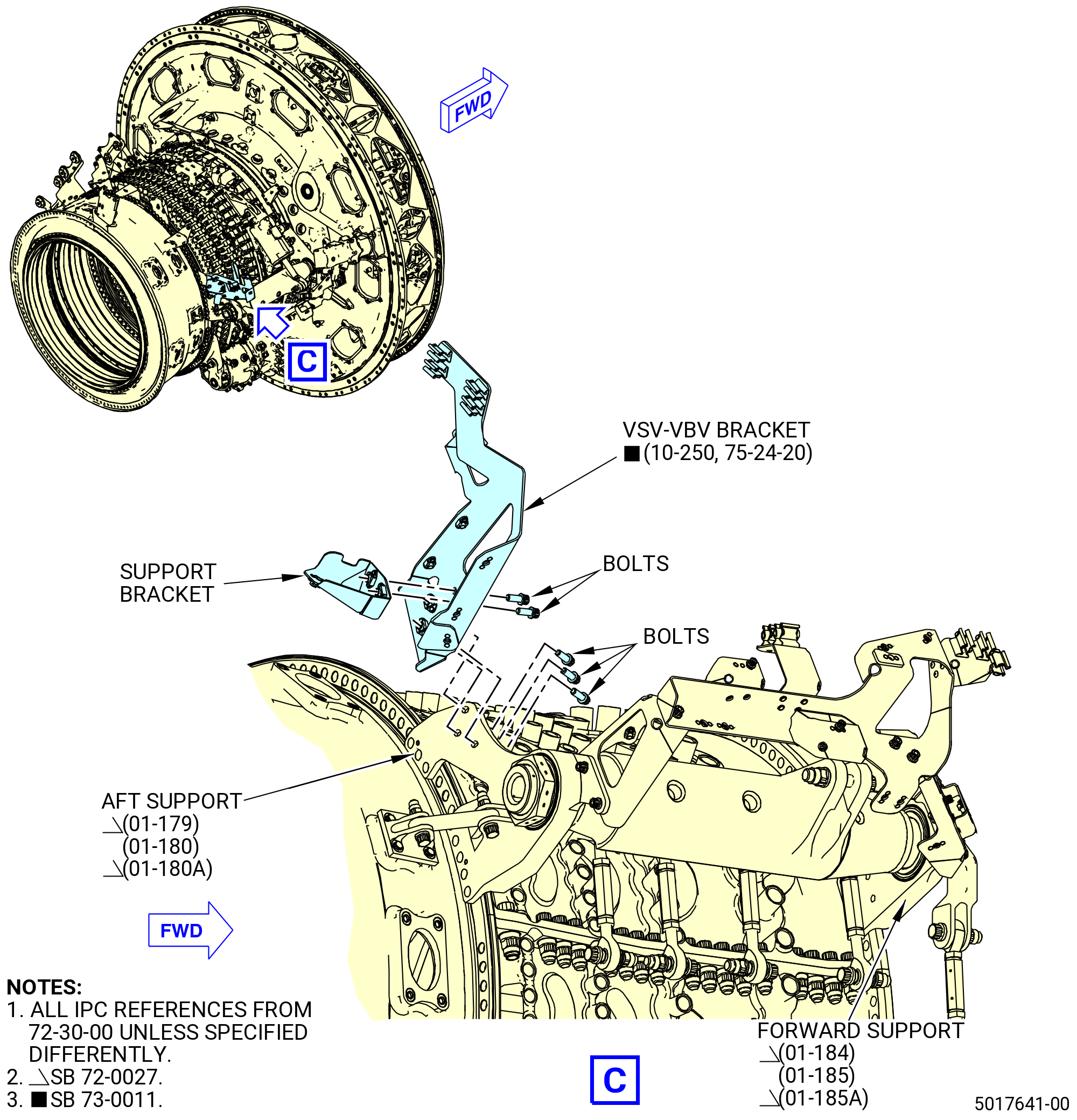
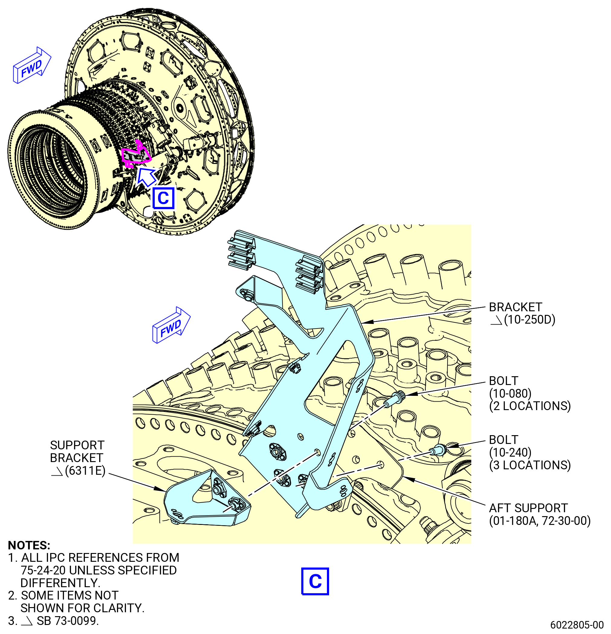
| (2) | Remove the VSV-VBV bracket and support brackets as follows. Refer to Figure 523. |
| (a) | Remove the bolts that attach the support bracket to the aft side of the VSV-VBV bracket and remove the support bracket. |
| (b) | If installed, remove the bolts that attach the support bracket to the forward side of the VSV-VBV bracket and remove the support bracket. |
| (c) | Remove the bolts that attach the VSV-VBV bracket to the aft support (01-179 , 72-30-00) (SIN 07500-4) or (01-180 , 72-30-00) (SIN 07500-4) or (01-180A , 72-30-00) (SIN 07500-4) and remove the support bracket. |
| (3) | Remove the two strut drain support brackets as follows: |
| (a) | Remove the bolts that attach the bracket to the support bracket and remove the support bracket. |
| (b) | Remove the bolts that attach the bracket to the support bracket and remove the support bracket. |
| (4) | Remove the three support brackets from the aft support (01-179 , 72-30-00) (SIN 07500-4) or (01-180 , 72-30-00) (SIN 07500-4) or (01-180A , 72-30-00) (SIN 07500-4) as follows: |
| (a) | Remove the bolts that attach the support bracket to the two support brackets and remove the support bracket. |
| (b) | Remove the bolts that attach the support bracket to the forward support (01-184 , 72-30-00) (SIN 07500-3) or (01-185 , 72-30-00) (SIN 07500-3) or (01-185A , 72-30-00) (SIN 07500-3) and remove the support bracket. |
| (c) | Remove the bolts that attach the support bracket to the aft support (01-179 , 72-30-00) (SIN 07500-4) or (01-180 , 72-30-00) (SIN 07500-4) or (01-180A , 72-30-00) (SIN 07500-4). |
| (5) | Deleted. |
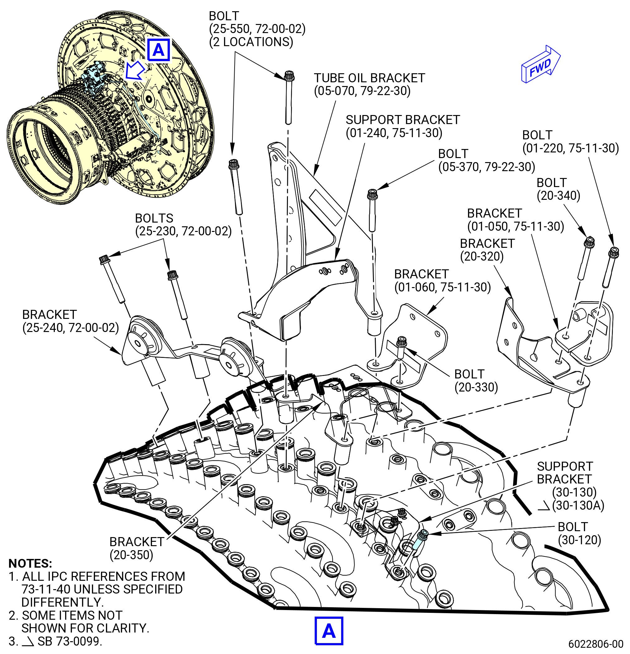
| (6) | Remove the nacelle anti-ice valve (01-010 , 75-11-30) (SIN 63700) bracketry. Refer to Figure 523 and do as follows: |
| (a) | Remove the machine bolts (bolts) (25-550) (SIN 4612D) that attach the support bracket (01-240 , 75-11-30) (SIN 63718), tube oil bracket (05-070 , 79-22-30) (SIN 4611A), anti-ice support bracket (20-350 , 73-11-40) (SIN 30211), and bracket (25-240) (SIN 63112) to the compressor forward case (15-010 , 72-32-00) (SIN 073A0). |
| (b) | Remove the support bracket (01-240 , 75-11-30) (SIN 63718). |
| (c) | Remove the machine bolt (bolt) (05-370 , 79-22-30) (SIN 30224) that attach the tube oil bracket (05-070 , 79-22-30) (SIN 4611A) and bracket (01-060 , 75-11-30) (SIN 63712) to the compressor forward case (15-010 , 72-32-00) (SIN 073A0). |
| (d) | Remove the tube oil bracket (05-070 , 79-22-30) (SIN 4611A). |
| (e) | Remove the two machine bolts (bolts) (25-230) (SIN 6312A) that attach the bracket (25-240) (SIN 63112) to the compressor forward case (15-010 , 72-32-00) (SIN 073A0). |
| (f) | Remove bracket (25-240) (SIN 63112). |
| (g) | Remove the machine bolt (bolt) (20-340 , 73-11-40) (SIN 30223) that attach the bracket (01-050 , 75-11-30) (SIN 63710), bracket (20-320 , 73-11-40) (SIN 63116), anti-ice support bracket (20-350 , 73-11-40) (SIN 30211) to the compressor forward case (15-010 , 72-32-00) (SIN 073A0). |
| (h) | Remove the machine bolt (bolt) (01-220 , 75-11-30) (SIN 38022) that attach the bracket (01-050 , 75-11-30) (SIN 63710), bracket (20-320 , 73-11-40) (SIN 63116), and support bracket (30-130 , 73-11-40) (SIN 38010) or (30-130A , 73-11-40) (SIN 38010) to the compressor forward case (15-010 , 72-32-00) (SIN 073A0). |
| (i) | Remove the bracket (01-050 , 75-11-30) (SIN 63710). |
| (j) | Remove the bracket (20-320 , 73-11-40) (SIN 63116). |
| (k) | Remove the double hexagonal head machine bolt (bolt) (30-120 , 73-11-40) (SIN 38021) that attach the support bracket (30-130 , 73-11-40) (SIN 38010) or (30-130A, 73-11-40) (SIN 38010) to the compressor forward case (15-010 , 72-32-00) (SIN 073A0). |
| (l) | Remove the support bracket (30-130 , 73-11-40) (SIN 38010) or (30-130A , 73-11-40) (SIN 38010). |
| (m) | Remove the machine bolt (bolt) (20-330 , 73-11-40) (SIN 30220) that attach the bracket (01-060 , 75-11-30) (SIN 63712) and anti-ice support bracket (20-350 , 73-11-40) (SIN 30211) to the compressor forward case (15-010 , 72-32-00) (SIN 073A0). |
| (n) | Remove the bracket (01-060 , 75-11-30) (SIN 63712) and anti-ice support bracket (20-350 , 73-11-40) (SIN 30211). |
| Subtask 72-00-02-030-391 |
| * * * FOR 1B/P/G03.1B/P/G04.1B/P1/G01 |
| * * * PRE SB 73-0019( Old Manifold Configuration ) |
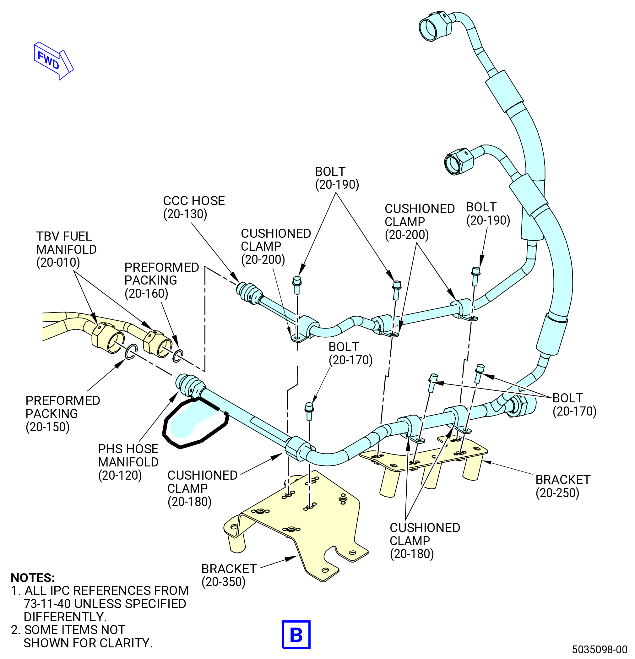
| X. | Remove the fuel hydraulic system as follows. Refer to Figure 526. |
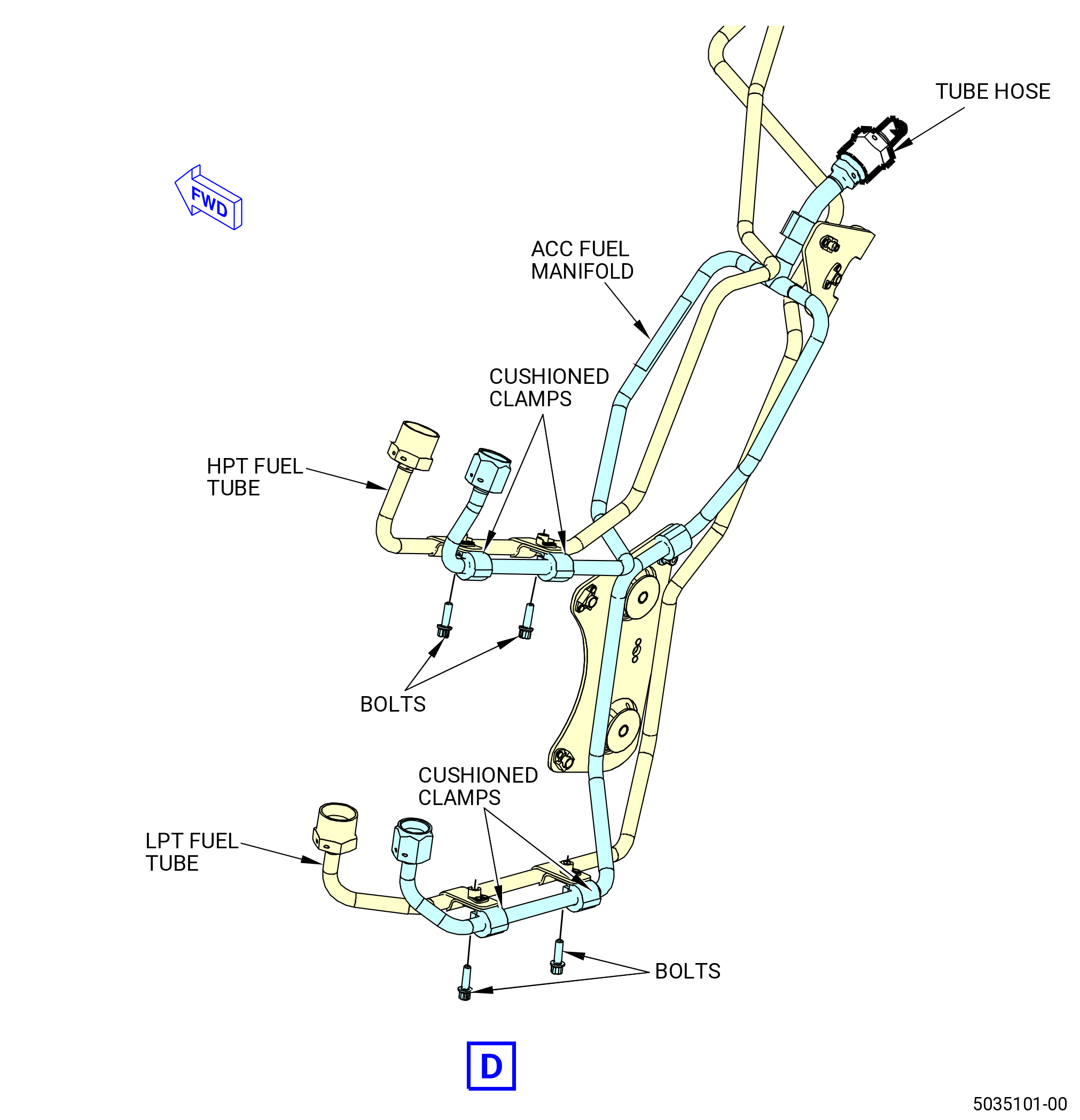
| (1) | Remove the core compartment fuel tube (PHS hose manifold) (20-120 , 73-11-40) (SIN 34700), LPT and HPT ACC fuel manifold valve (ACC fuel manifold) (20-230 , 73-11-40) (SIN 34701), and core compartment fuel tube (CCC hose) (20-130 , 73-11-40) (SIN 38C00) as follows: |
| (a) | Remove the CCC hose as follows: |
| 1 | Remove the bolts and the cushioned clamps that attach the CCC hose to the brackets. |
| 2 | Disconnect the CCC hose from the TBV-CCCV-PHS hose fuel manifold (TBV fuel manifold). |
| 3 | Remove and discard the preformed packing (20-160 , 73-11-40) (SIN 38C51) from the CCC hose. |
| (b) | Remove the PHS hose manifold as follows: |
| 1 | Remove the bolts and the cushioned clamps that attach the PHS hose manifold to the brackets. |
| 2 | Disconnect the coupling nut that attaches the PHS hose manifold to the TBV fuel manifold. |
| 3 | Disconnect the coupling nut that attaches the PHS hose manifold to the ACC fuel manifold. |
| 4 | Remove and discard the preformed packing (20-150 , 73-11-40) (SIN 34750) from the PHS hose manifold. |
| (c) | Remove the ACC fuel manifold as follows: |
| 1 | Remove the bolts that attach the ACC fuel manifold to the tabs on the fuel tubes. |
| 2 | Remove the bolts and the cushioned clamps that attach the ACC fuel manifold to the brackets. |
| 3 | Remove and discard the preformed packing (20-150 , 73-11-40) (SIN 34750) from the ACC fuel manifold. |
| (d) | Remove the LPT-ACC valve fuel tube (LPT fuel tube) as follows: |
| 1 | Remove the bolts and the cushioned clamps that attach the LPT fuel tube to the brackets. |
| 2 | Disconnect the coupling nut that attaches the LPT fuel tube to the VBV manifold. |
| 3 | Remove and discard the preformed packing (25-190 , 73-11-40) (SIN 38551) from the LPT fuel tube. |
| (e) | Remove the HPT-ACC valve fuel tube (HPT fuel tube) as follows: |
| 1 | Remove the bolts and the cushioned clamps that attach the HPT fuel tube to the brackets. |
| 2 | Disconnect the coupling nut that attaches the HPT fuel tube to the VSV manifold. |
| 3 | Remove and discard the preformed packing (30-090 , 73-11-40) (SIN 38153) from the VSV manifold. |
| (f) | Remove the TBV fuel manifold as follows: |
| 1 | Remove the bolts and the cushioned clamps that attach the fuel manifold to the brackets. |
| 2 | Disconnect the coupling nuts that attach the fuel manifold to the transient bleed valve. |
| 3 | Remove and discard the preformed packings (20-070 , 73-11-40) (SIN 38450) and (20-080 , 73-11-40) (SIN 38451) from the transient bleed valve. |
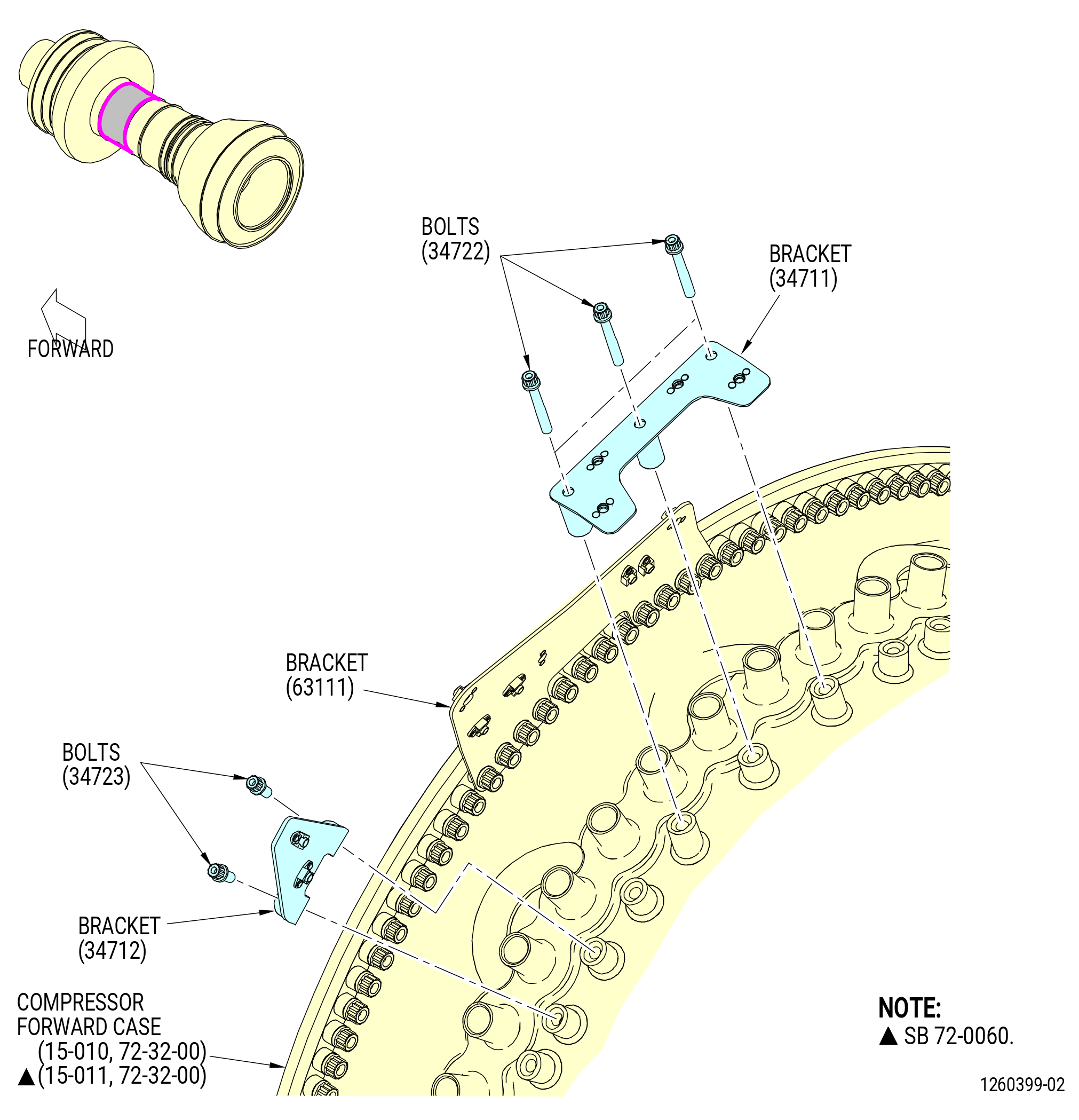
| (g) | Remove the bolts that attach bracket (34711) to the HPC stator case at the 11:30 o'clock position. |
| (h) | Remove the bolts that attach bracket (34712) to the HPC stator case at the 10:30 o'clock position. |
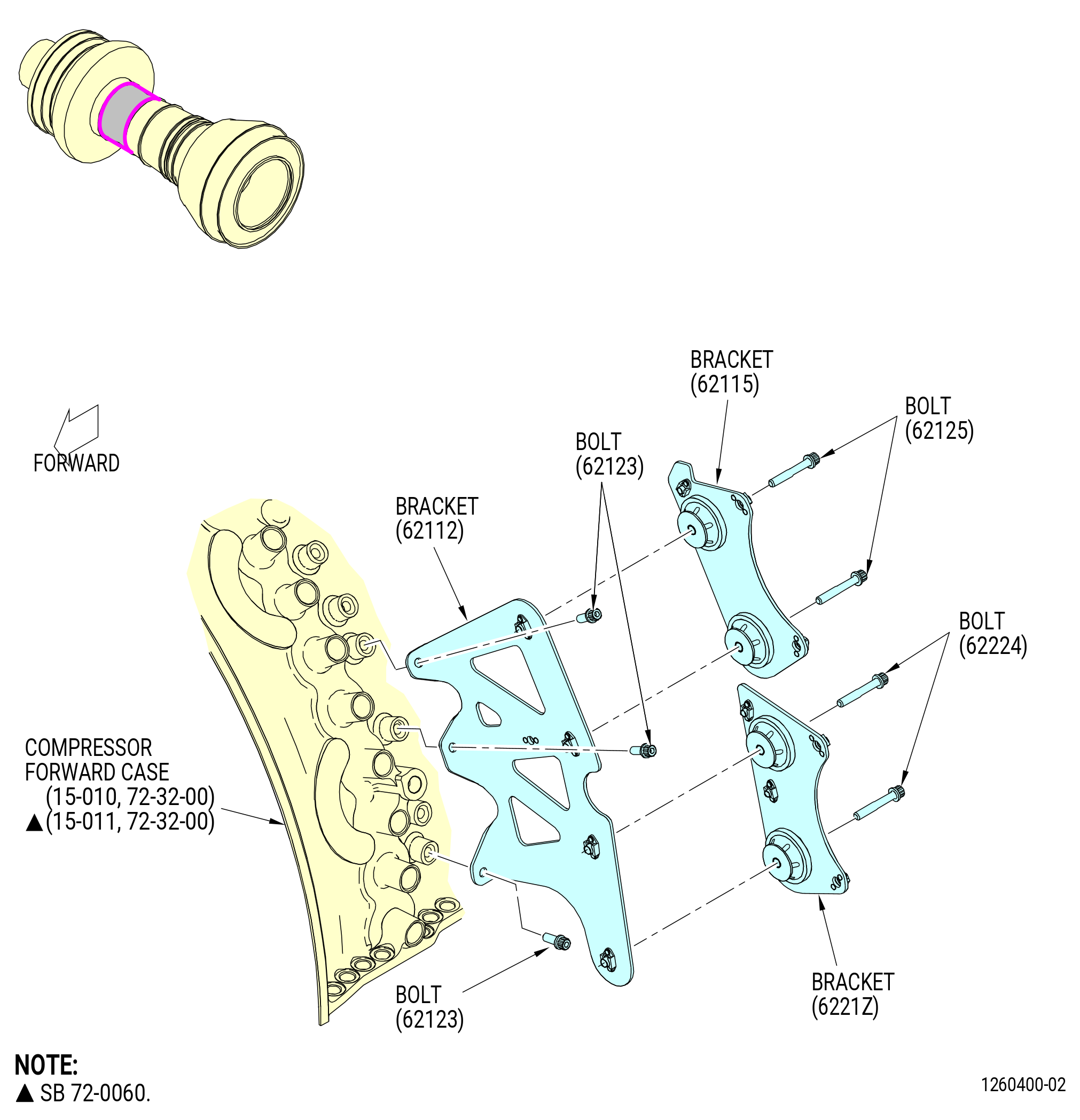
| (i) | Remove the bolts that attach bracket (62115) and bracket (6221Z) to bracket (62112) at the 9:45 o'clock position. |
| (j) | Remove the bolts that attach bracket (62112) to the HPC stator case. |
| * * * END PRE SB 73-0019 |
| * * * FOR ALL |
| * * * SB 73-0019( New Manifold Configuration ) |
| Subtask 72-00-02-030-723 |
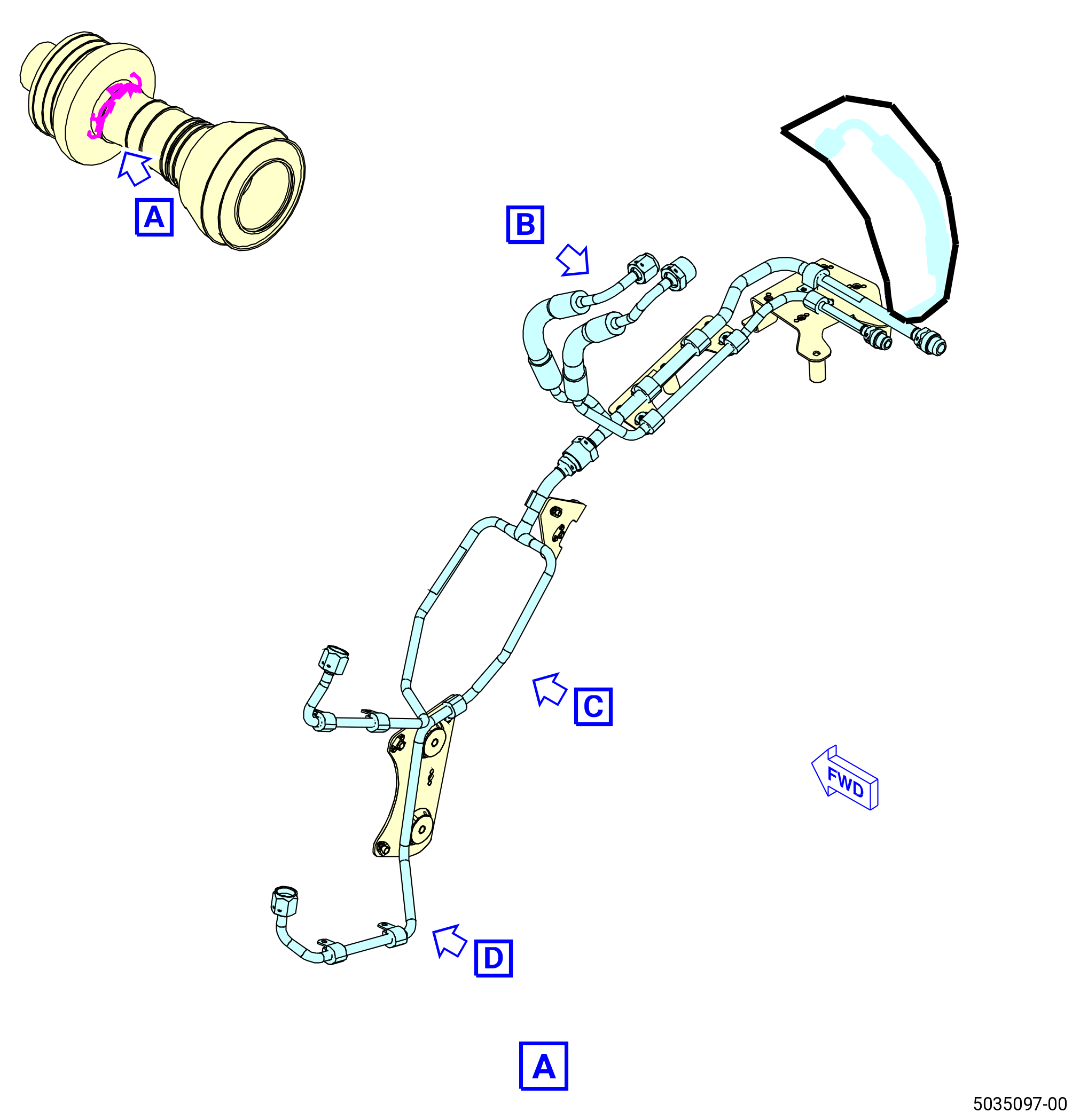
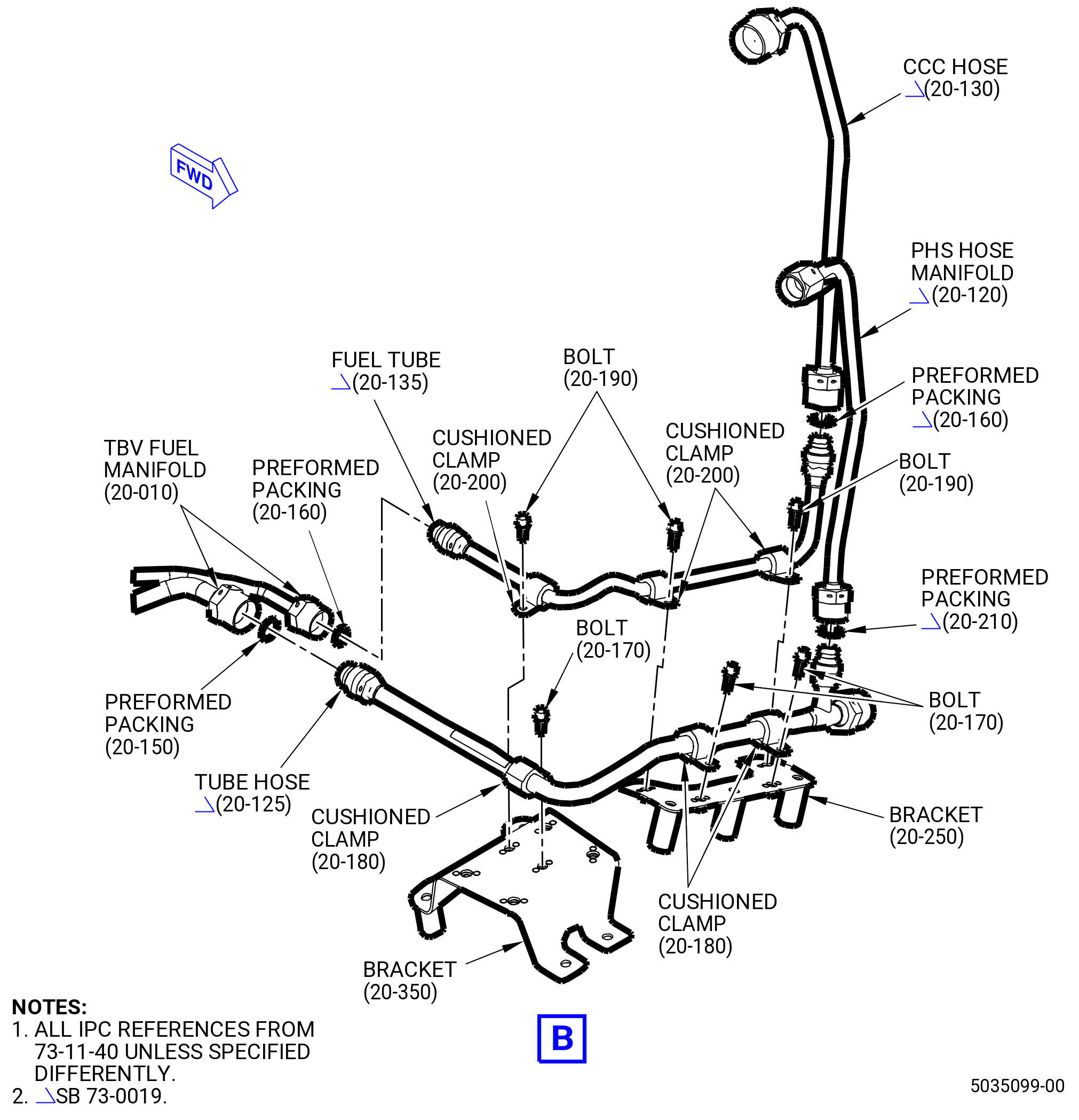
| X.A. | Remove the fuel hydraulic system as follows. Refer to Figure 526. |
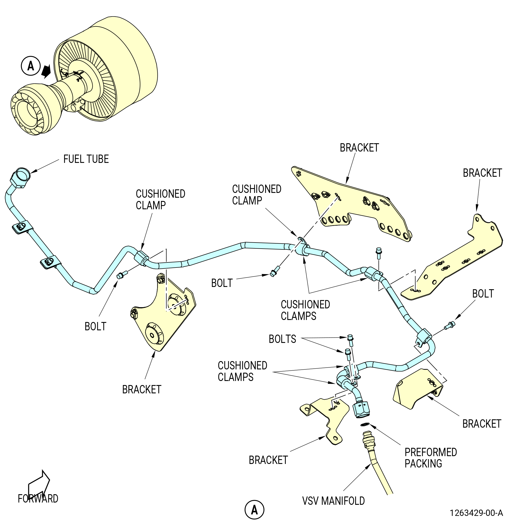
| (1) | Remove the PHS hose manifold (20-120 , 73-11-40) (SIN 34700), ACC fuel manifold (20-230 , 73-11-40) (SIN 34701), CCC hose (20-130 , 73-11-40) (SIN 38C00), core compartment cooling rod fuel manifold (tube hose) (20-125 , 73-11-40) (SIN 34703), and core compartment cooling valve fuel tube (fuel tube) (20-135 , 73-11-40) (SIN 38C02) as follows: |
| (a) | Remove the CCC hose as follows: |
| 1 | Disconnect the CCC hose tube from the fuel tube. |
| (b) | Remove the fuel tube as follows: |
| 1 | Remove the double hexagonal head machine bolt (bolt) (20-190 , 73-11-40) (SIN 38C20) and cushion loop-clamp (cushioned clamp) (20-200 , 73-11-40) (SIN 38C80) that attach the CCC hose to the anti-ice support bracket (bracket) (20-350 , 73-11-40) (SIN 30211). |
| 2 | Remove the two bolts (20-190 , 73-11-40) (SIN 38C20) and cushioned clamps (20-200 , 73-11-40) (SIN 38C80) that attach the fuel tube to the tube support bracket (bracket) (20-250 , 73-11-40) (SIN 34711). |
| 3 | Disconnect the CCC hose from the TBV CCCV fuel manifold PHS hose (TBV fuel manifold) (20-010 , 73-11-40) (SIN 38400). |
| 4 | Remove and discard the preformed packings (20-160 , 73-11-40) (SIN 38C51). |
| (c) | Remove the PHS hose manifold as follows: |
| 1 | Disconnect the PHS tube manifold from the tube hose. |
| (d) | Remove the tube hose as follows: |
| 1 | Remove the two bolts (20-170 , 73-11-40) (SIN 34721) and cushioned clamps (20-180 , 73-11-40) (SIN 34780) that attach the tube hose to the tube support bracket (bracket) (20-250 , 73-11-40) (SIN 34711). |
| 2 | Remove the bolt (20-170 , 73-11-40) (SIN 34721) and cushioned clamp (20-180 , 73-11-40) (SIN 34780). |
| 3 | Disconnect the tube hose from the TBV fuel manifold. |
| 4 | Disconnect the tube hose from the ACC fuel manifold. |
| 5 | Remove and discard the preformed packings (20-210 , 73-11-40) (SIN 34751) and (20-150 , 73-11-40) (SIN 34750). |
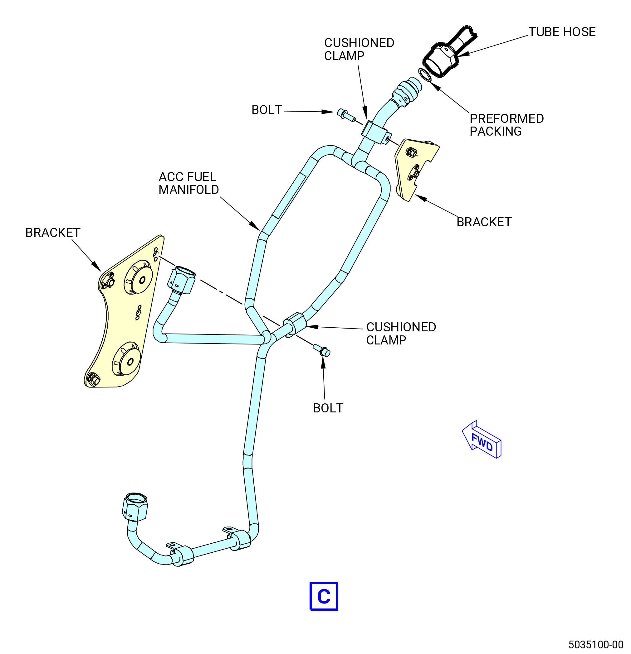
| (e) | Remove the ACC fuel manifold as follows: |
| 1 | Remove the bolts that attach the ACC fuel manifold to the tabs on the fuel tubes. |
| 2 | Remove the bolts and the cushioned clamps that attach the ACC fuel manifold to the brackets. |
| 3 | Remove and discard the preformed packing (20-150 , 73-11-40) (SIN 34750) from the ACC fuel manifold. |
| (f) | Remove the LPT-ACC valve fuel tube (LPT fuel tube) as follows: |
| 1 | Remove the bolts and the cushioned clamps that attach the LPT fuel tube to the brackets. |
| 2 | Disconnect the coupling nut that attaches the LPT fuel tube to the VBV manifold. |
| 3 | Remove and discard the preformed packing (25-190 , 73-11-40) (SIN 38551) from the LPT fuel tube. |
| (g) | Remove the HPT-ACC valve fuel tube (HPT fuel tube) as follows: |
| 1 | Remove the bolts and the cushioned clamps that attach the HPT fuel tube to the brackets. |
| 2 | Disconnect the coupling nut that attaches the HPT fuel tube to the VSV manifold. |
| 3 | Remove and discard the preformed packing (30-090 , 73-11-40) (SIN 38153) from the VSV manifold. |
| (h) | Remove the TBV fuel manifold as follows: |
| 1 | Remove the bolts and the cushioned clamps that attach the fuel manifold to the brackets. |
| 2 | Disconnect the coupling nuts that attach the fuel manifold to the transient bleed valve. |
| 3 | Remove and discard the preformed packings (20-070 , 73-11-40) (SIN 38450) and (20-080 , 73-11-40) (SIN 38451) from the transient bleed valve. |
| (i) | Remove the bolts that attach bracket (20-250 , 73-11-40) (SIN 34711) to the HPC stator case at the 11:30 o'clock position. |
| (j) | Remove the bolts that attach bracket (20-280 , 73-11-40) (SIN 34712) to the HPC stator case at the 10:30 o'clock position. |
| (k) | Remove the bolts that attach bracket (01-070 , 75-24-30) (SIN 62115) and bracket (01-060 , 75-24-10) (SIN 6221Z) to bracket (25-260) (SIN 62112) at the 9:45 o'clock position. |
| (l) | Remove the bolts that attach bracket (25-260) (SIN 62112) to the HPC stator case. |
| * * * END SB 73-0019 |
|
|
| Subtask 72-00-02-030-392 |
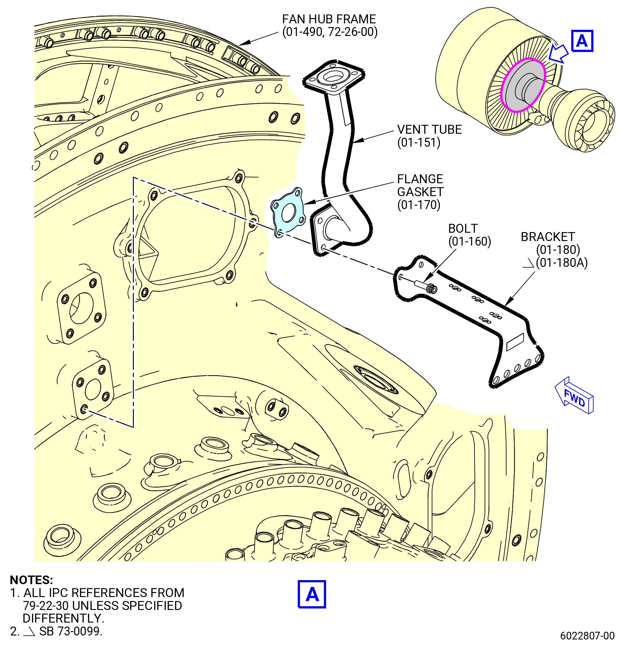
| Y. | Remove the A-sump vent tube as follows. Refer to Figure 527. |
| (1) | Remove the bolts (01-160 , 79-22-30) (SIN 46022) that attaches the bracket (01-180 , 79-22-30) (SIN 38117) or (01-180B, 79-22-30) (SIN 38117) on the tank vent oil tube (vent tube) (01-150 , 79-22-30) (SIN 46005) or (01-151 , 79-22-30) (SIN 46005). |
| (2) | Remove the remaining two bolts (01-160 , 79-22-30) (SIN 46022) from the vent tube (SIN 46005). |
| (3) | Remove the vent tube (SIN 46005) and flange gasket (01-170 , 79-22-30) (SIN 46051) from the aft side of the FHF (SIN (840A0) and discard the flange gasket. |
| Subtask 72-00-02-030-456 |
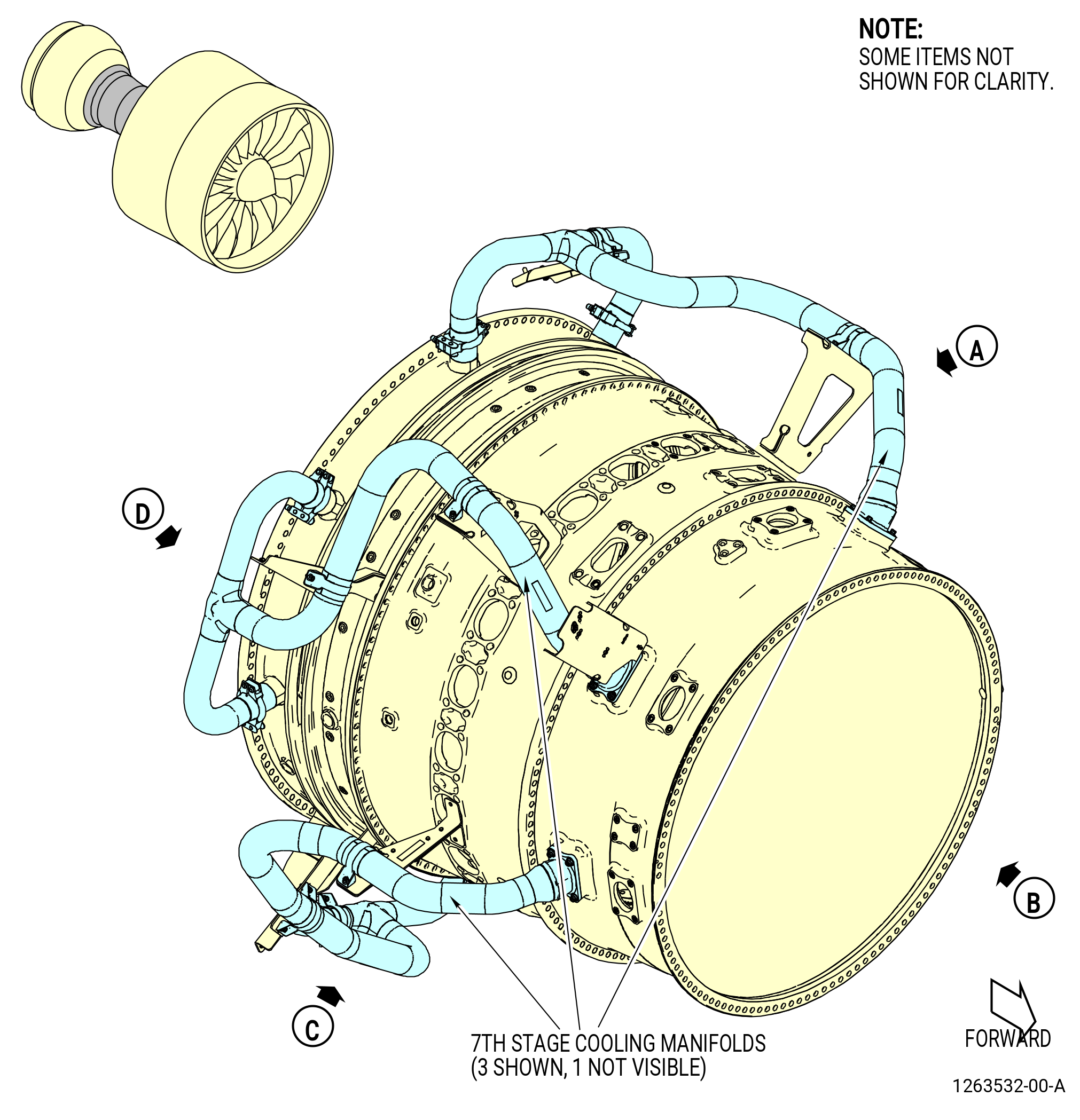
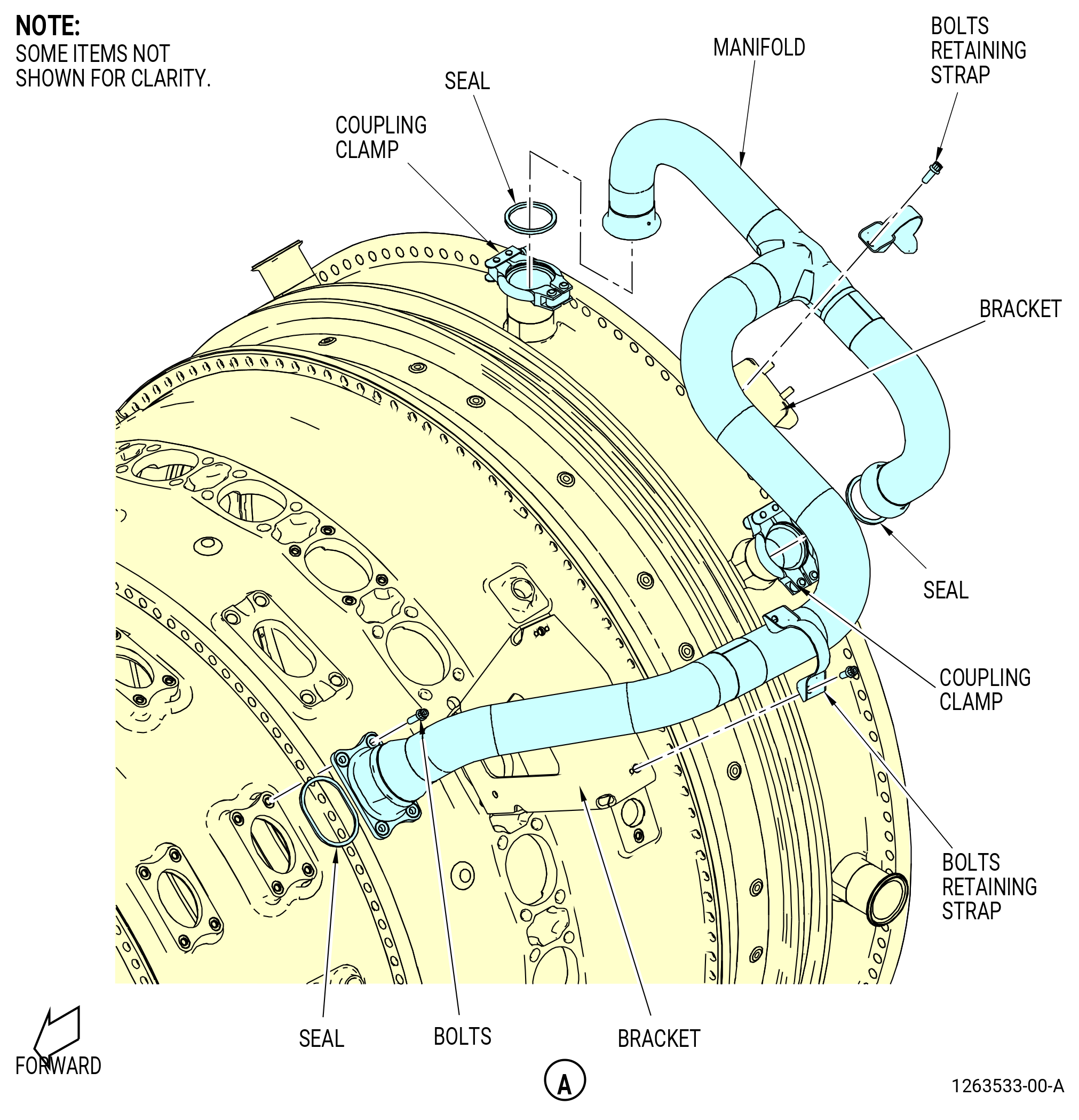
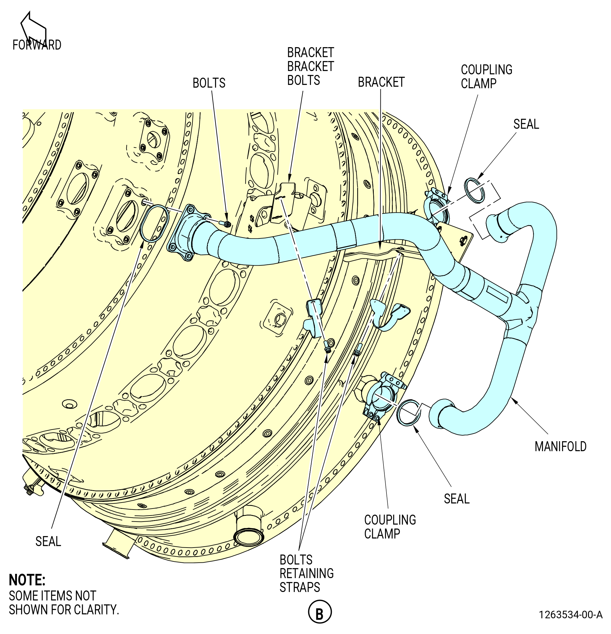
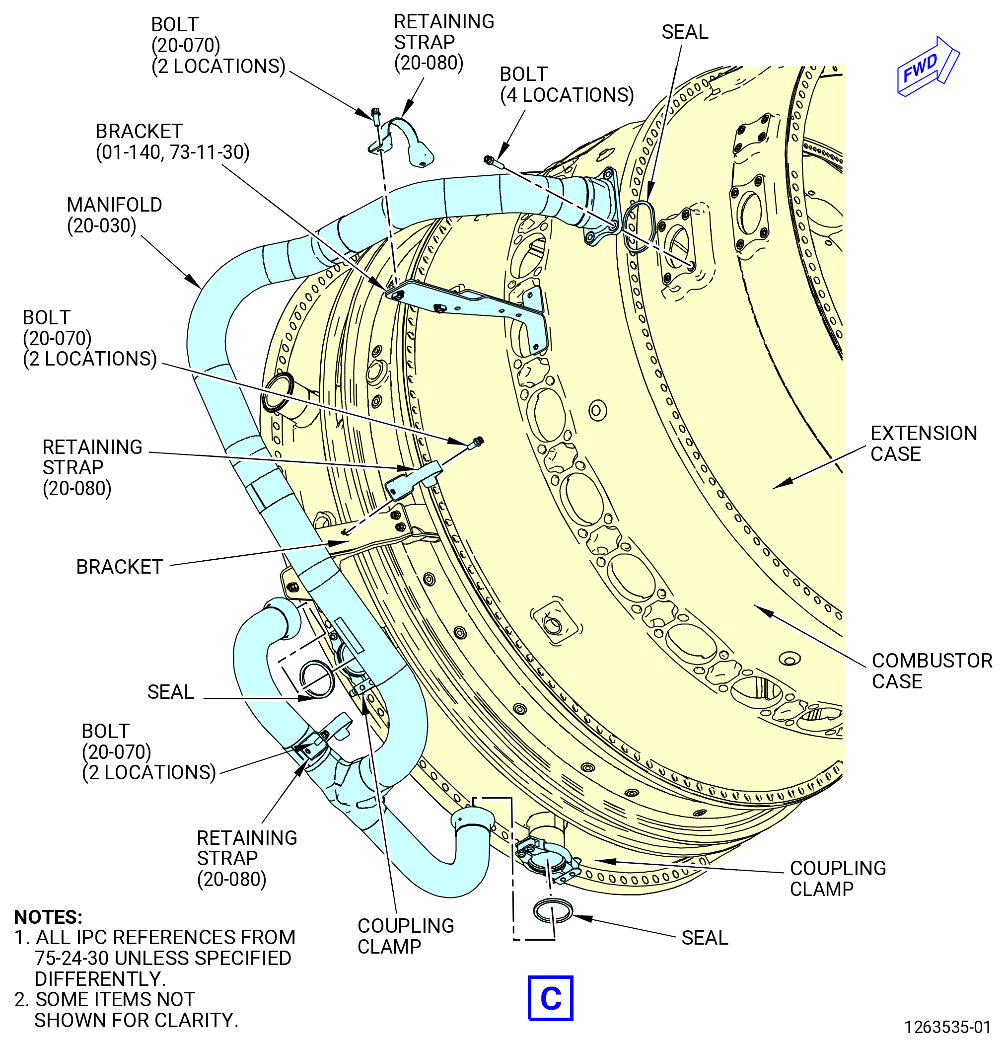
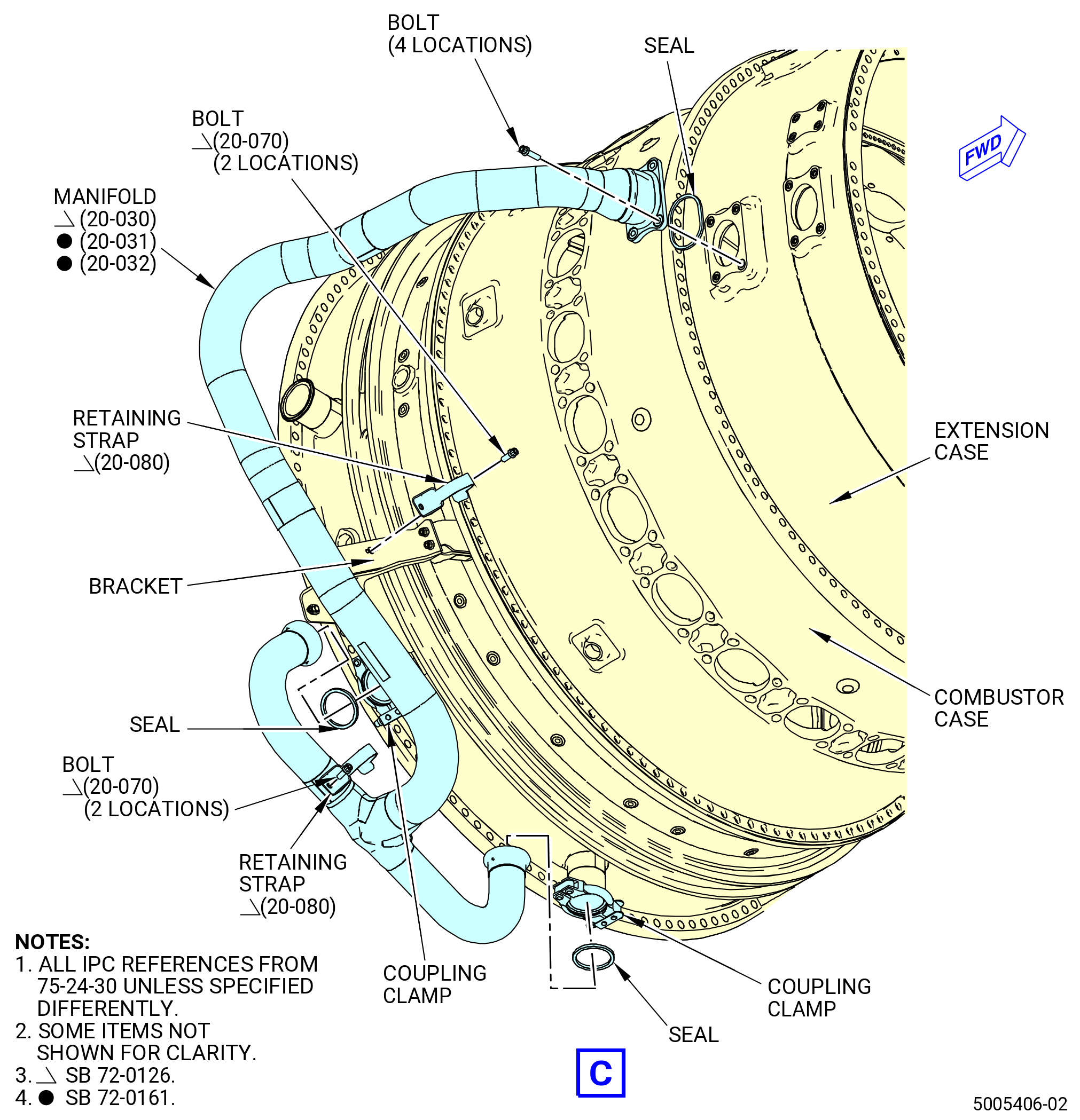
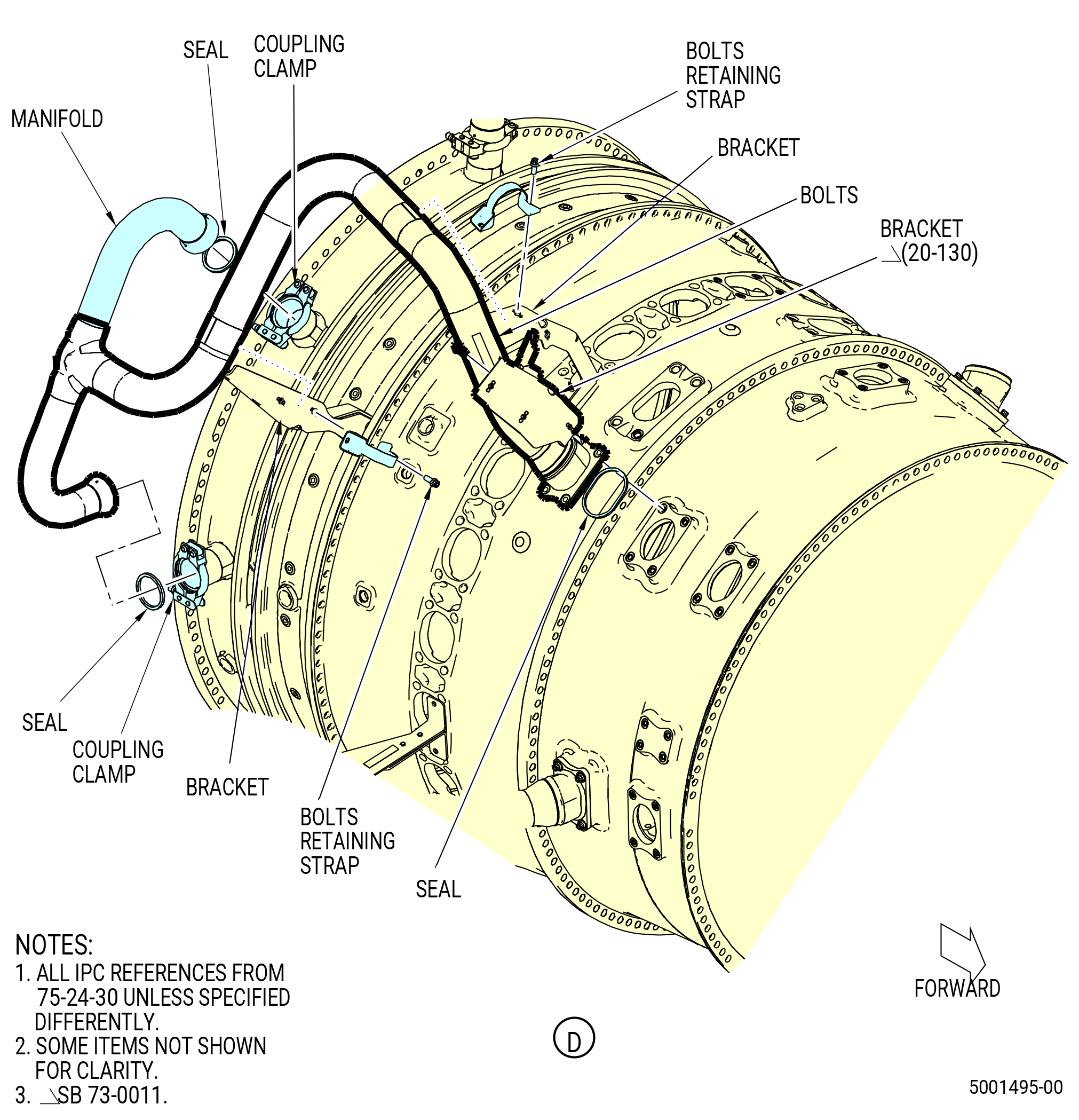
| Z. | Remove the stage 7 HPT cooling manifolds (manifolds) as follows. Refer to Figure 528. |
| (1) | Remove the manifold from the 10:30-12:00 o'clock position as follows: |
| (a) | Remove the bolts and the retaining straps that attach the manifold to the brackets. |
| (b) | Remove the four bolts that attach the forward end of the manifold to the extension case as follows: |
| 1 | Remove the bracket (20-130 , 75-24-30) (SIN 34114) from the manifold at the 12:00-3:00 o'clock position. |
| 2 | Remove and discard the metal ring seal (20-060 , 75-24-30) (SIN 61150) from the forward end of the manifold. |
| (c) | Remove the coupling clamps that attach the aft end of the manifold to the HPT stator case as follows: |
| 1 | Remove and discard the two seal rings (20-120 , 75-24-30) (SIN 61151) from the aft ends of the manifold. |
| (d) | Remove the manifold. |
| (2) | Do this procedure again to remove the remaining manifolds. |
|
|
|
|
| Subtask 72-00-02-030-393 |
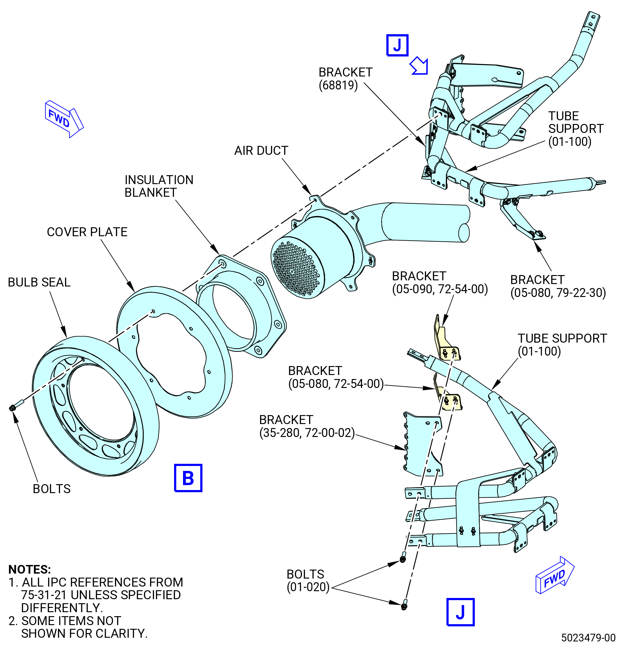
| AA. | Remove the transient bleed system as follows. Refer to Figure 529. |
| (1) | Remove the two bolts that attach the bracket (SIN 68819) to the transient bleed tube support (tube support) (01-100 , 75-31-21) (SIN 61A17). |
| (2) | Remove the two bolts that attach the bracket (05-080 , 79-22-30) (SIN 6881D) to the tube support (01-100 , 75-31-21) (SIN 61A17). |
| Subtask 72-00-02-030-668 |
| * * * PRE SB 75-0014( Air Duct without Heat Shield Assembly ) |
| (3) | Remove the bulb seal as follows: |
| (a) | Remove the six bolts that attach the bulb seal, the cover plate, and the insulation blanket to the air duct and to the tube support. |
| * * * END PRE SB 75-0014 |
| Subtask 72-00-02-030-669 |
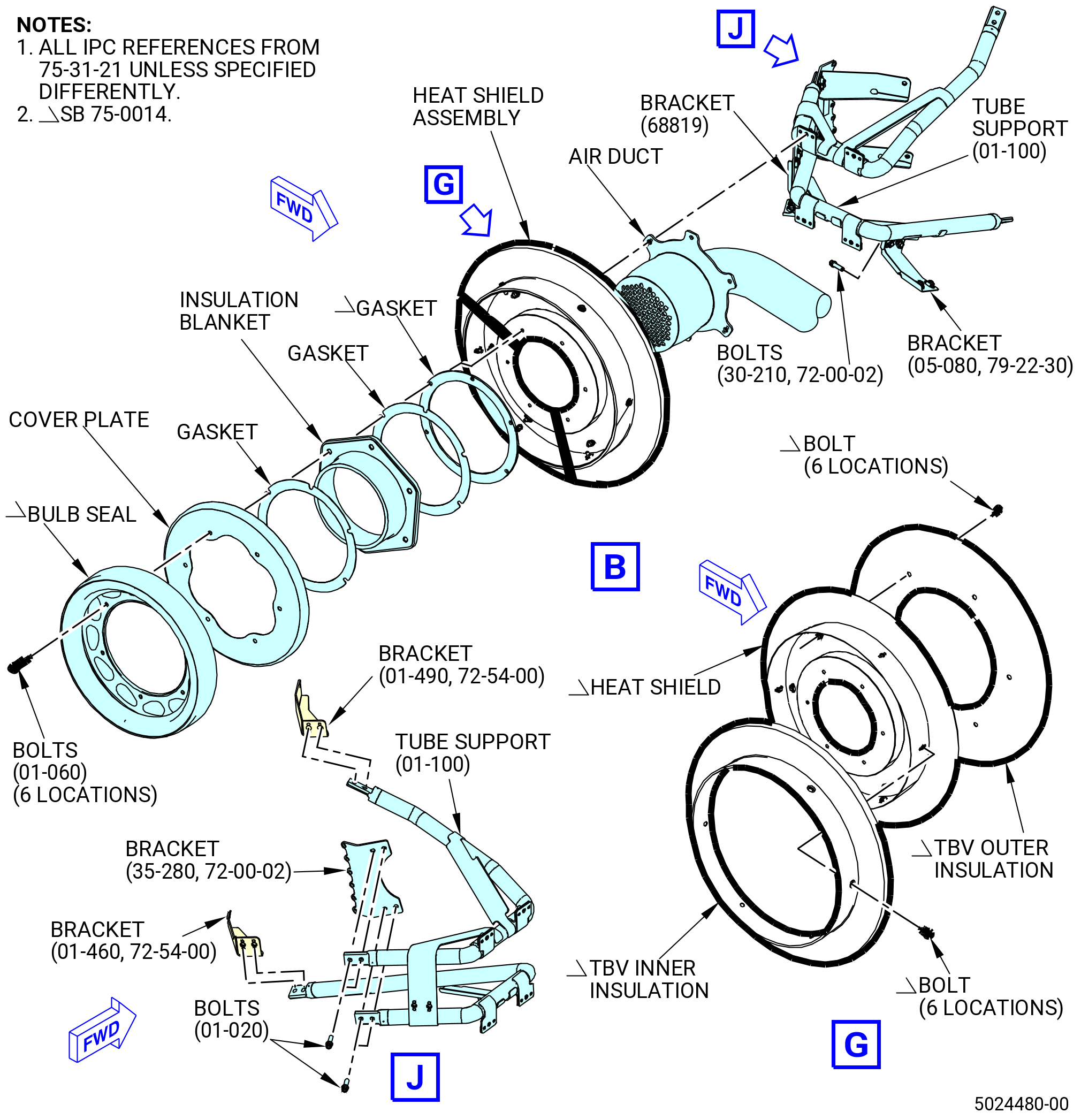
| * * * SB 75-0014( Air Duct with Heat Shield Assembly ) |
| (3).A. | Remove the bulb seal as follows: |
| (a) | Remove the six bolts that attach the bulb seal, the cover plate, the insulation blanket, and the heat shield assembly to the air duct and to the tube support. |
| (b) | Remove the 12 bolts that attach the TBV inner insulation and the TBV outer insulation to the heat shield. |
| * * * END SB 75-0014 |
| Subtask 72-00-02-030-670 |
| (4) | Remove the bolts that attach bracket (61A17) to bracket (61A18), bracket (61A13), and bracket (61A15). |
| (5) | Remove the bolts and the retaining straps that attach the air duct to the brackets. |
| (6) | Loosen the bolt on the V-band clamp that attaches the air duct to the transient bleed valve and remove the V-band clamp and the ring seal (01-020 , 75-31-11) (SIN 61A52). |
| (7) | Loosen the bolt on the V-band clamp that attaches the manifold to the transient bleed valve and remove the V-band clamp and the ring seal (01-020 , 75-31-11) (SIN 61A52). |
| (8) | Remove the transient bleed valve. |
| Subtask 72-00-02-030-494 |
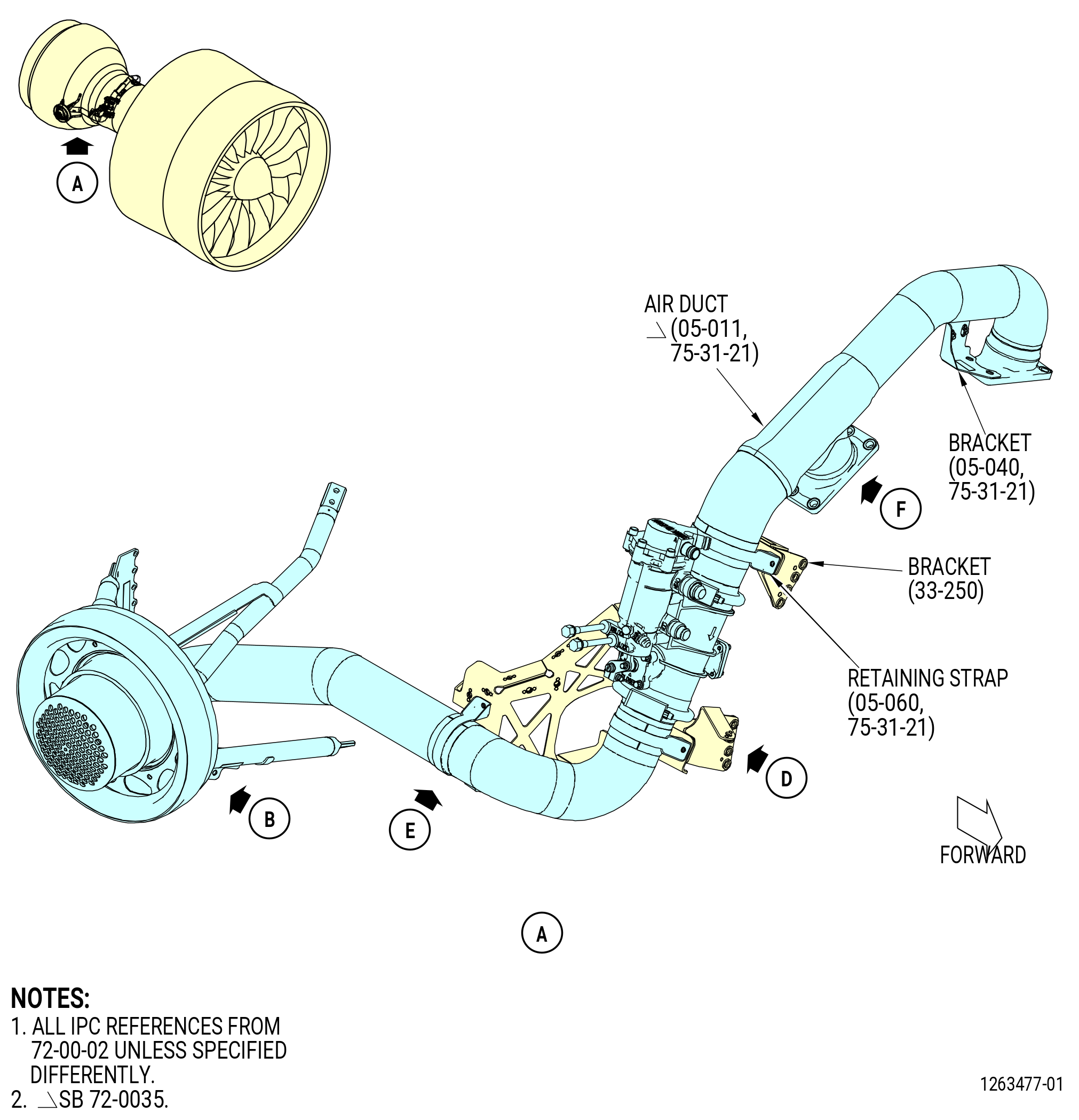
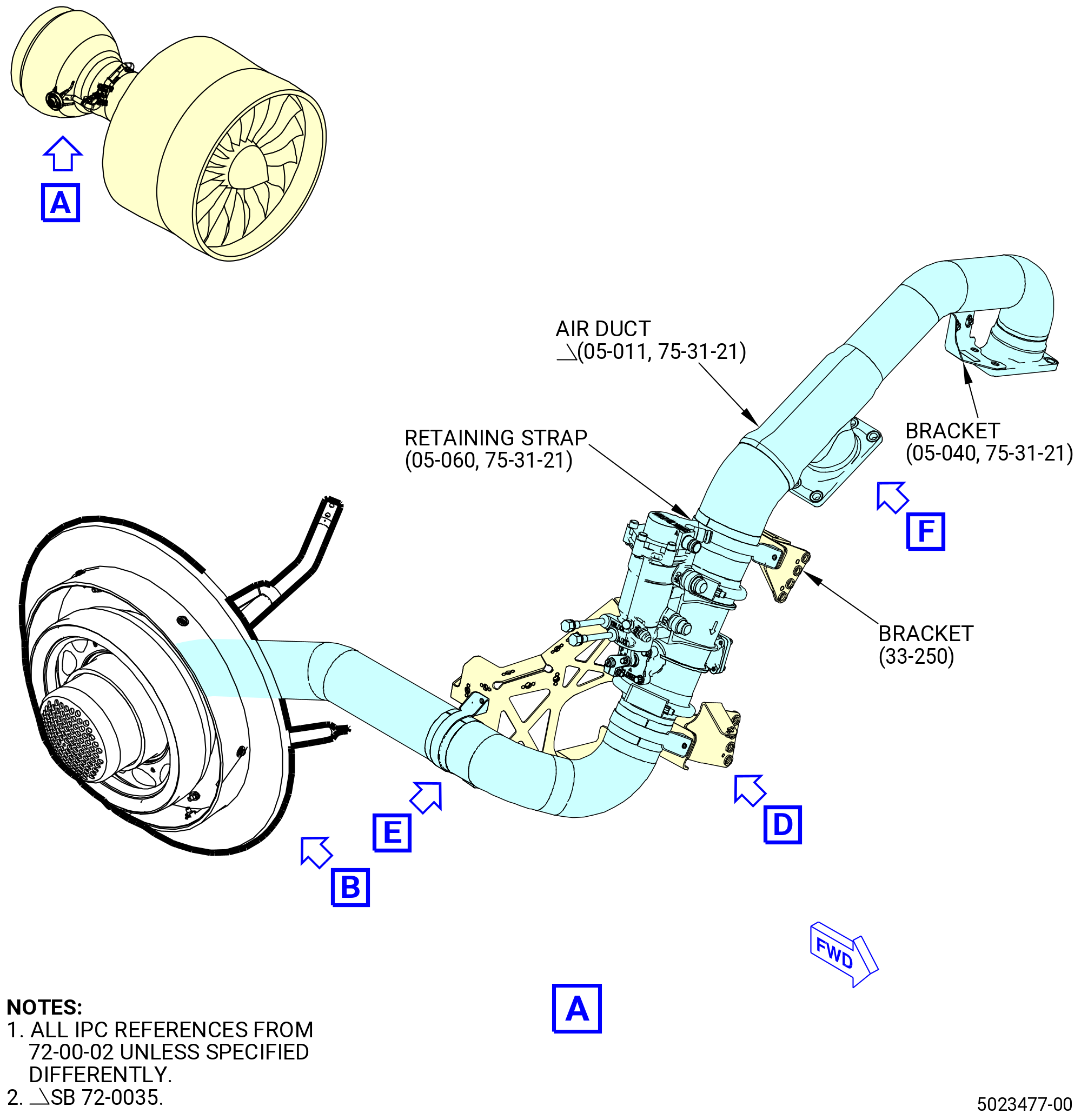
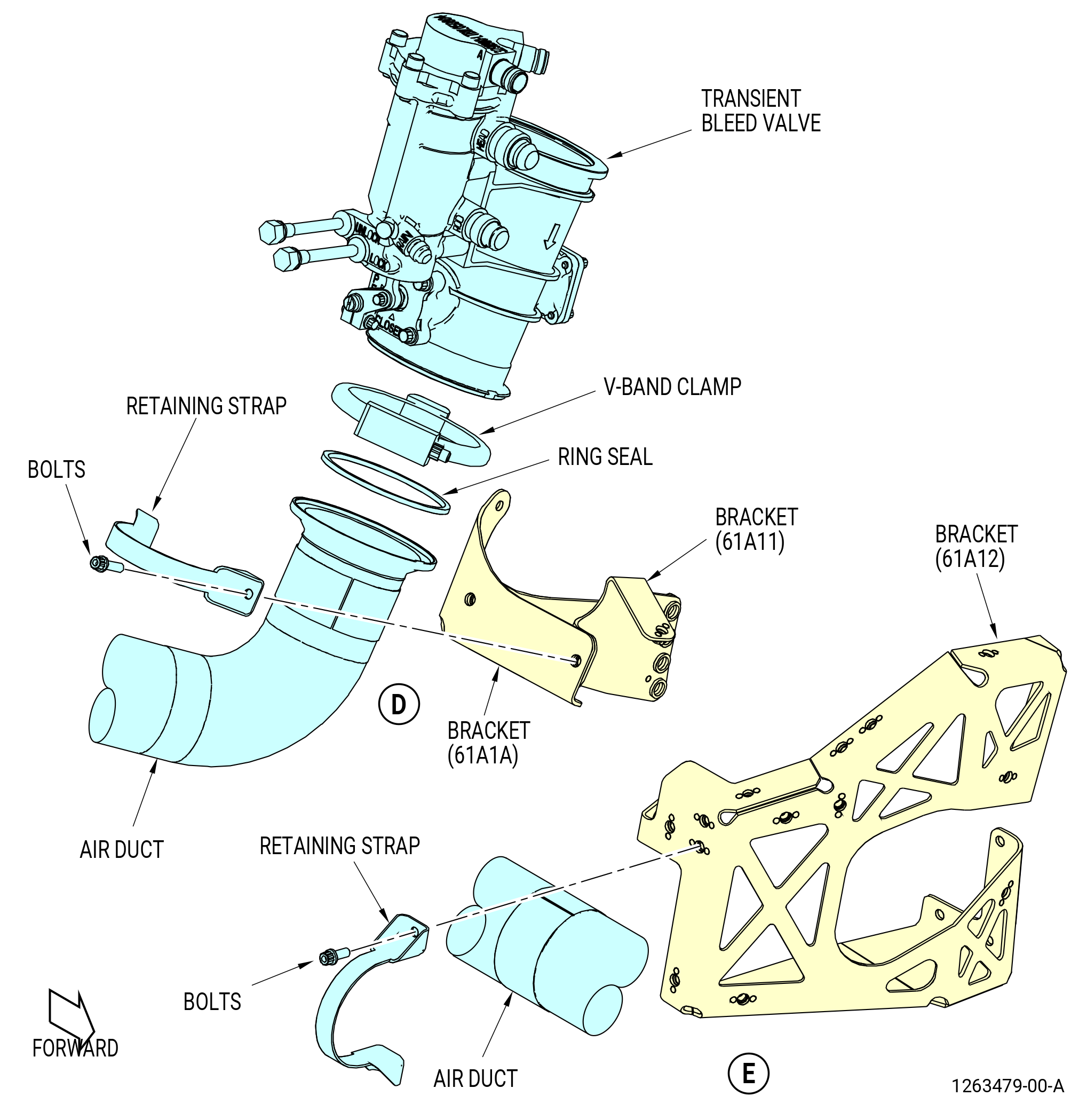
| * * * SB 72-0035( Two-Ports TBV Duct ) |
| (9) | Remove the transient bleed air manifold (manifold) (05-011 , 75-31-21) (SIN 61A00) as follows: |
| (a) | Remove the bolts (61A21) and retaining strap (05-060 , 75-31-21) (SIN 61A81) that attach the manifold to the bracket (33-250) (SIN 61A10). |
| (b) | Remove the bolts (05-020 , 75-31-20) (SIN 61A20) that attach the manifold to the combustor case. |
| (c) | Remove the manifold, support bracket (bracket) (05-040 , 75-31-21) (SIN 34112), and seal rings (61A51) from the combustor case. Discard the seal rings (05-030 , 75-31-21) (SIN 61A51). |
| NOTE: |
|
| * * * END SB 72-0035 |
| Subtask 72-00-02-030-495 |
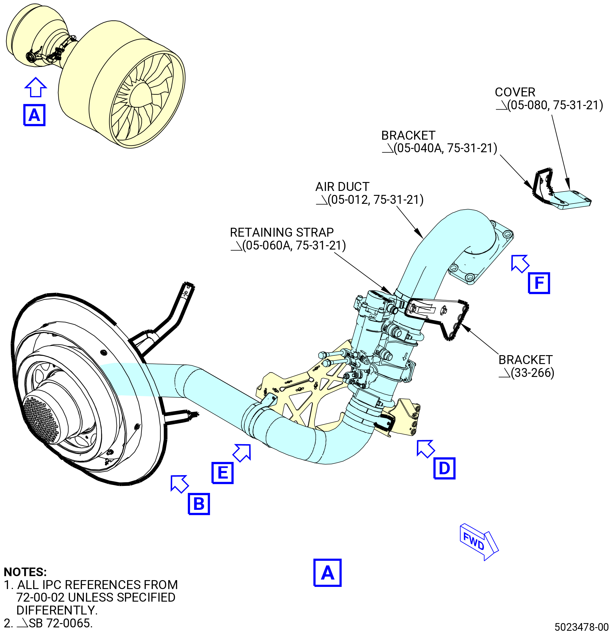
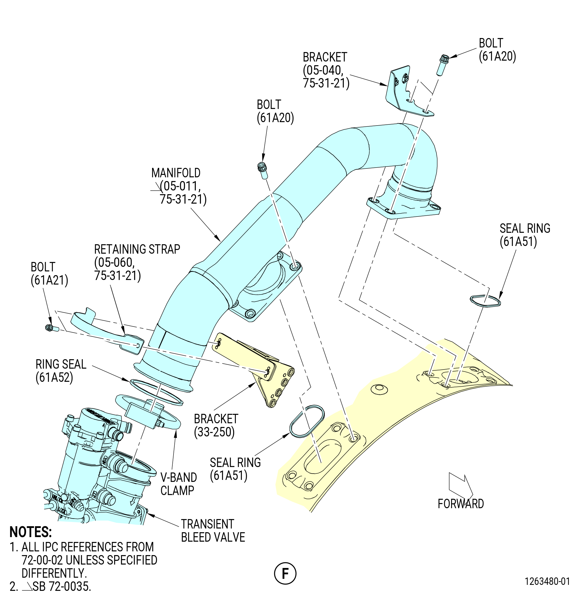
| * * * SB 72-0065( One-Port TBV Duct ) |
| (9).A. | Remove the transient bleed air duct (air duct) (05-012 , 75-31-21) (SIN 61A00) as follows: |
| (a) | Remove the bolts (61A21) and retaining strap (05-060A , 75-31-21) (SIN 61A81) that attach the air duct to the transient bleed air bracket (bracket) (33-266) (SIN 61A10). |
| (b) | Remove the bolts (05-020 , 75-31-20) (SIN 61A20) that attach the air duct to the combustor case. |
| (c) | Remove the air duct and seal ring (05-030 , 75-31-21) (SIN 61A51) from the combustor case. Discard the seal ring (05-030 , 75-31-21) (SIN 61A51). |
| * * * END SB 72-0065 |
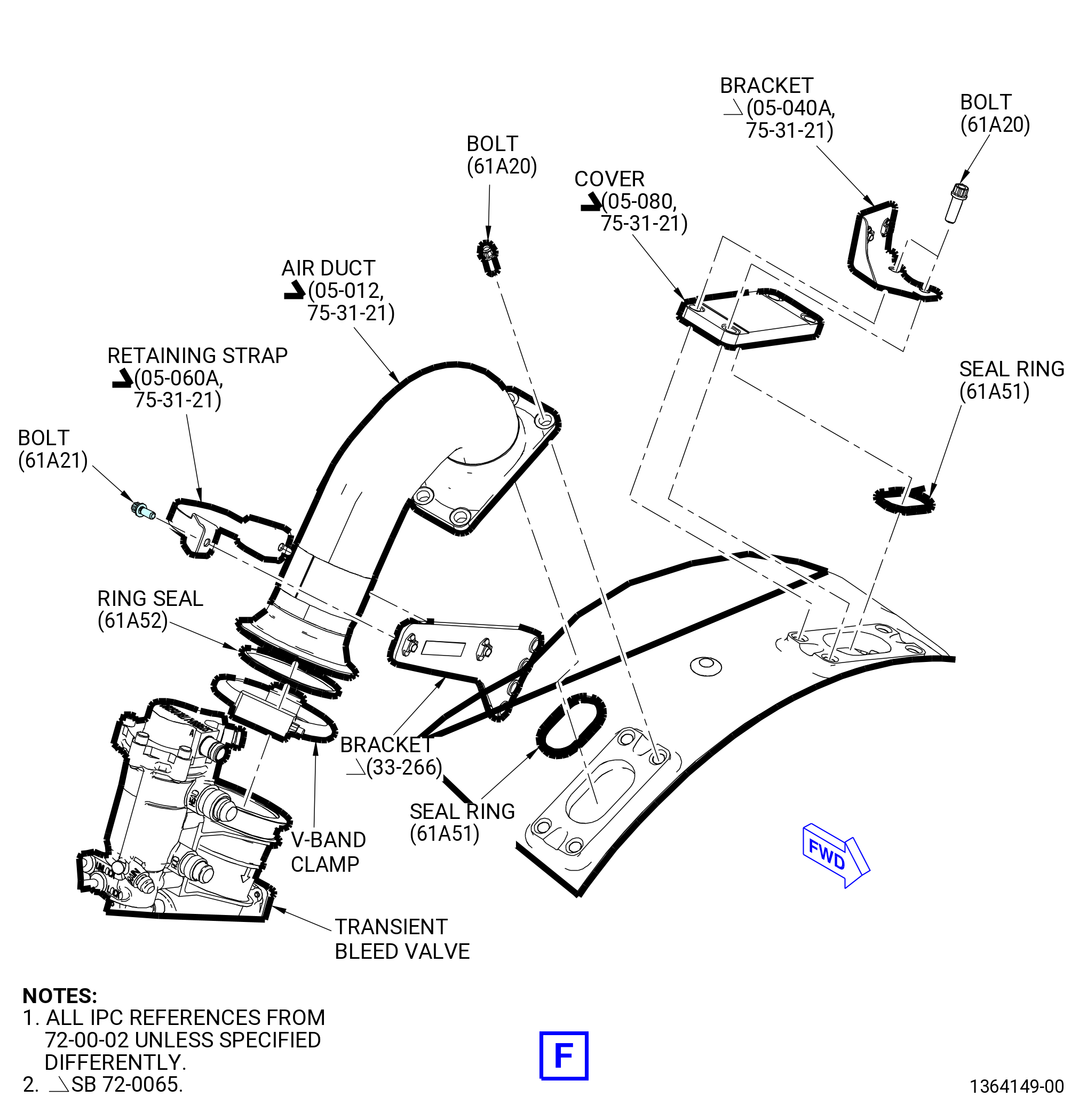
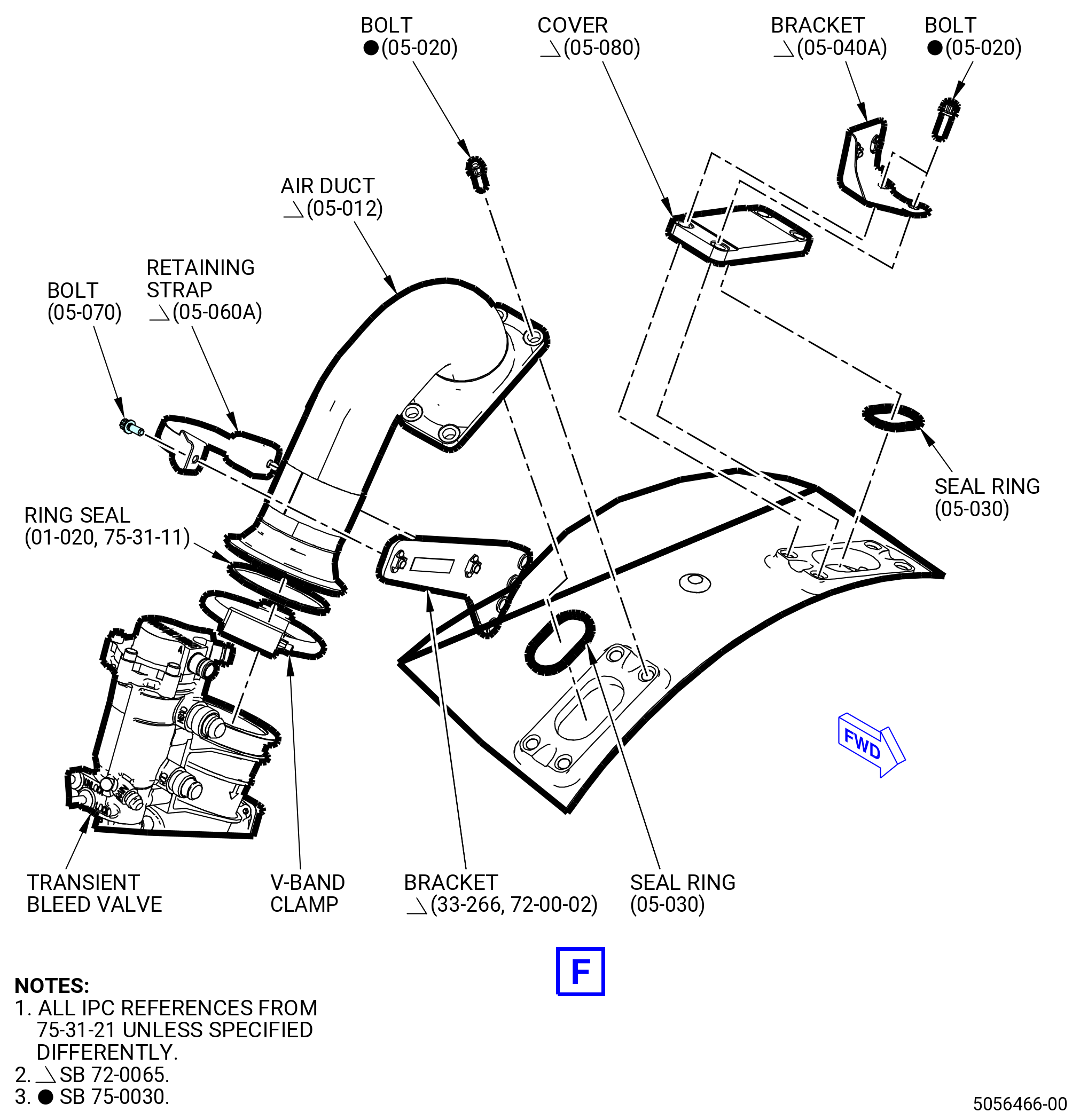
| Subtask 72-00-02-030-496 |
| * * * SB 72-0065( One-Port TBV Duct ) |
| (10) | Remove the compressor discharge pressure (CDP) port cover (cover) (05-080 , 75-31-21) (SIN 61A61) as follows: |
| (a) | Remove the bolts (05-020 , 75-31-20) (SIN 61A20) that attach the fuel manifold bracket (bracket) (05-040A , 75-31-21) (SIN 34112) and cover to the combustor case. |
| (b) | Remove the bracket, cover, and seal ring (05-030 , 75-31-21) (SIN 61A51) from the combustor case. Discard the seal ring (05-030 , 75-31-21) (SIN 61A51). |
| NOTE: |
|
| * * * END SB 72-0065 |
|
|
| Subtask 72-00-02-030-394 |
| * * * PRE SB 75-0012( Air Manifolds without Coupling Clamp ) |
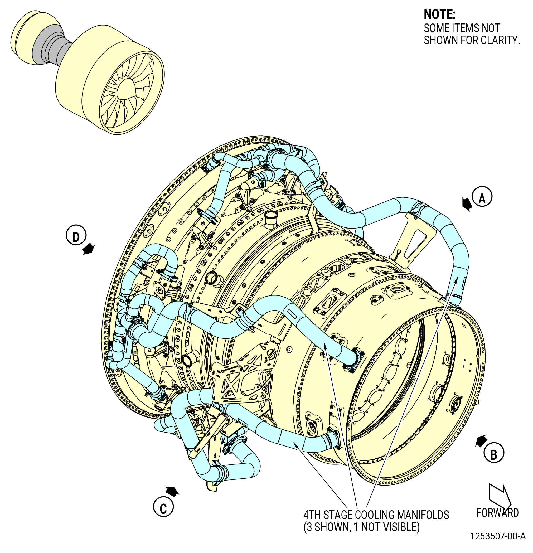
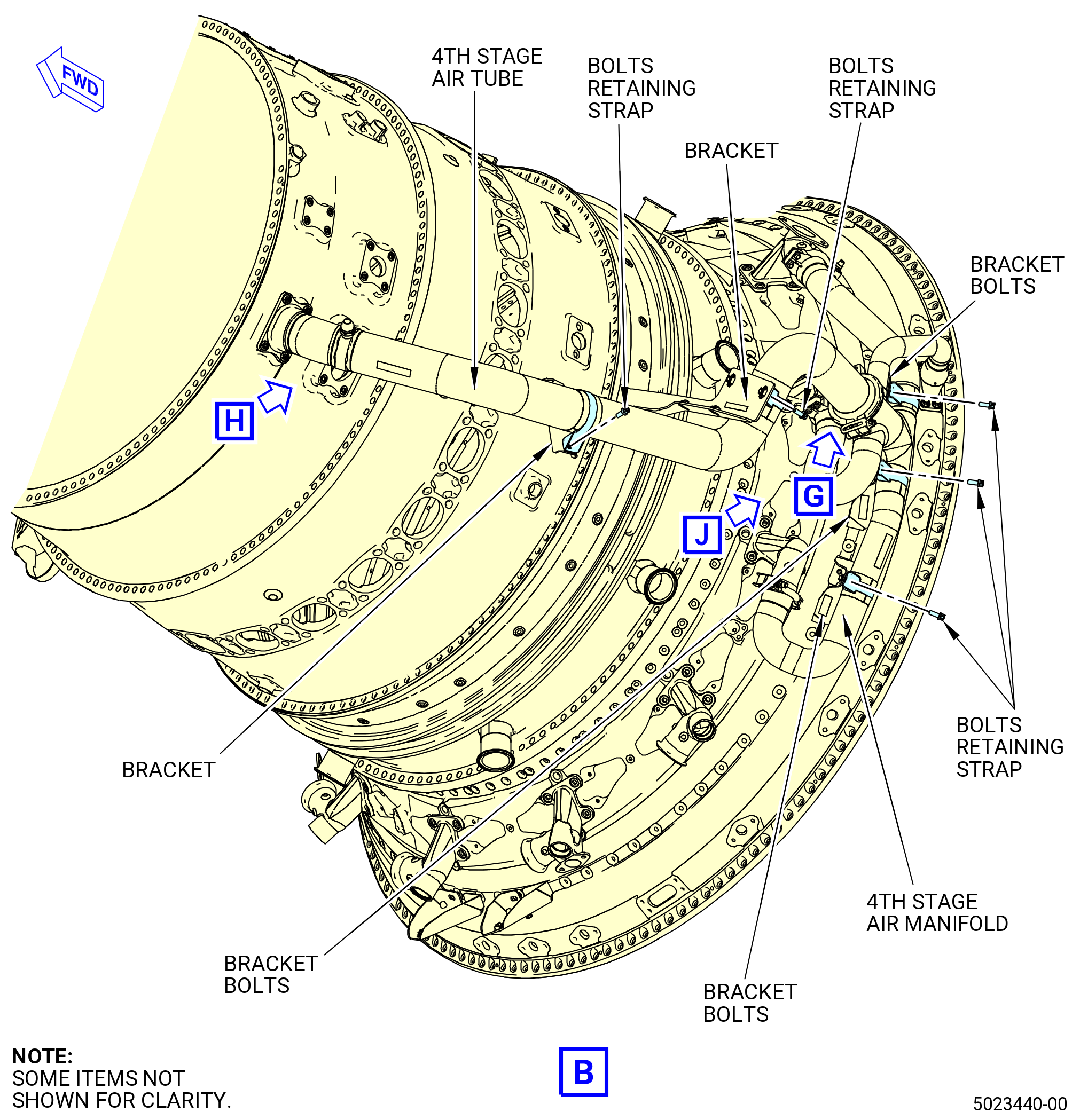
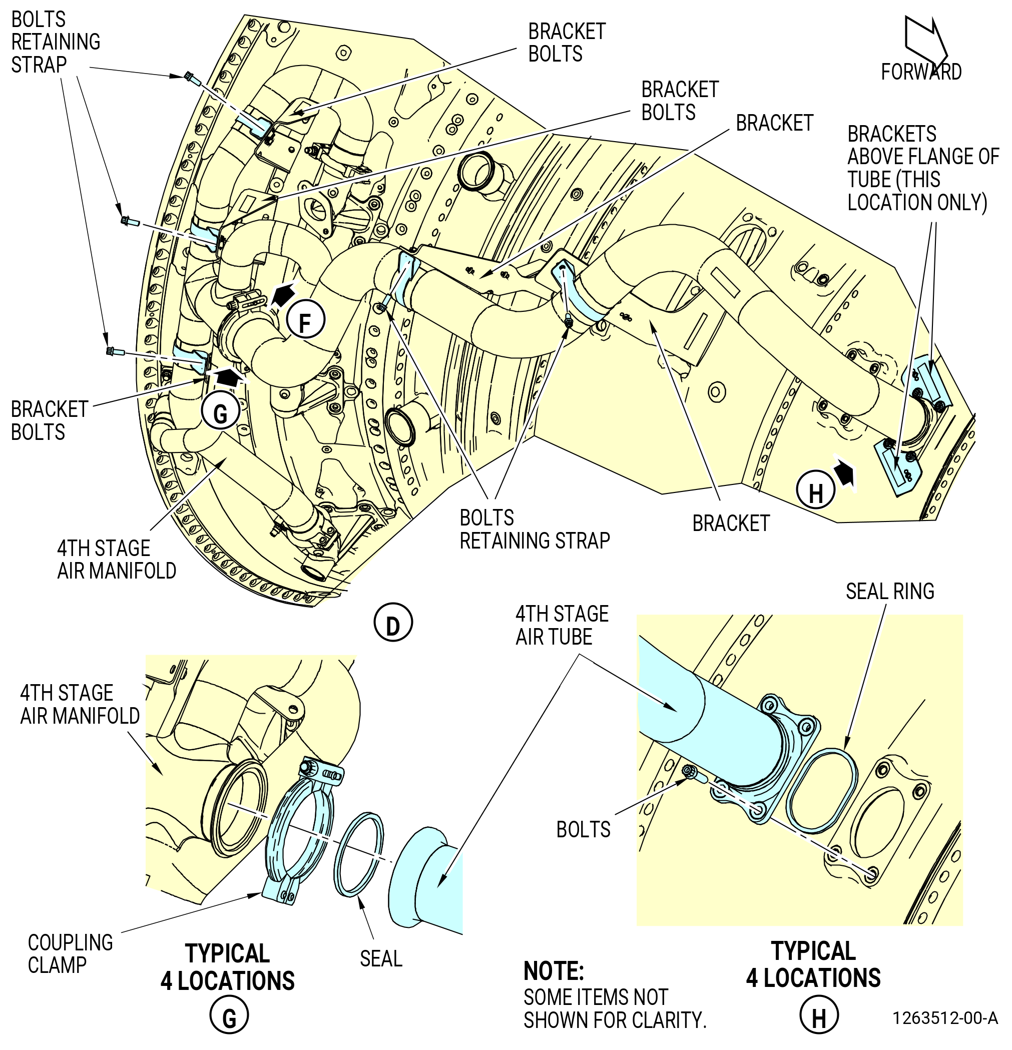
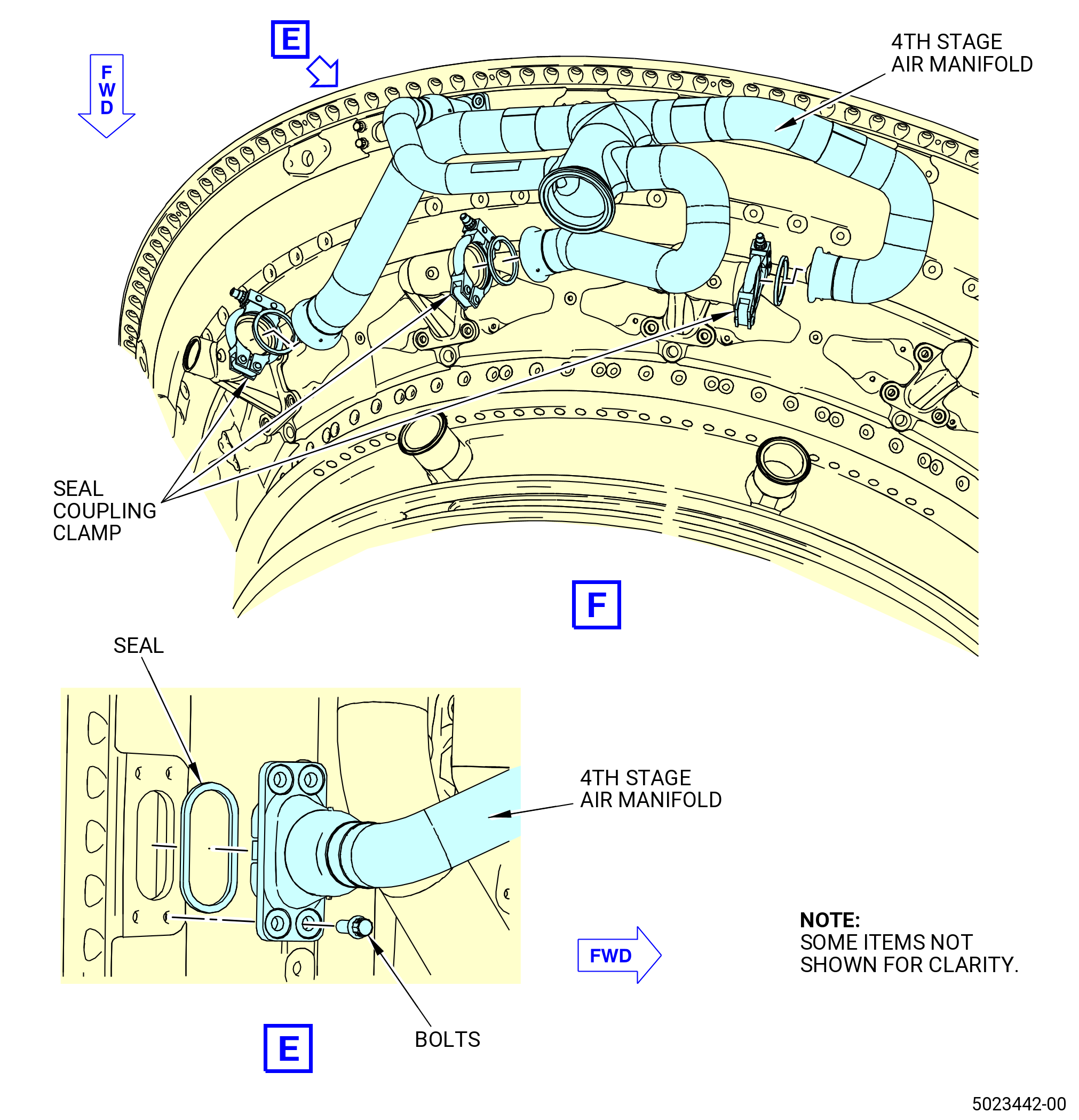
| AB. | Remove the 4th stage air manifolds from the lower left side as follows. Refer to Figure 530. |
| (1) | Remove the bolts and the retaining straps that attach the aft end of the 4th stage air manifold to the brackets. |
| (2) | Loosen the nut on the V-band clamp that attaches the 4th stage air tube to the 4th stage air manifold and remove the V-band clamp. |
| (3) | Remove the nuts on the coupling clamps that attach to the forward end of the 4th stage air manifold then remove and discard the seals (20-080 , 75-24-10) (SIN 61254) and (20-140 , 75-24-10) (SIN 61252). |
| (4) | Remove the bolts that attach the aft end of the 4th stage air manifold to the turbine center frame assembly (TCF assembly), then remove and discard the seal ring (25-130 , 75-24-10) (SIN 61251). |
| (5) | Remove the bolts and the retaining straps that attach the 4th stage air tube to the brackets. |
| (6) | Remove the air tube from the extension case. |
| (7) | Do this procedure again to remove the remaining stage 4 cooling manifolds. |
| * * * END PRE SB 75-0012 |
| Subtask 72-00-02-030-671 |
| * * * SB 75-0012( New Air Manifold with Coupling Clamp ) |
| AB.A. | Remove the 4th stage air manifolds at four locations. Refer to Figure 530 and do as follows: |
| (1) | Remove the bolts and the retaining straps that attach the aft end of the 4th stage air manifold to the brackets. |
| (2) | Loosen the nut on the coupling clamps that attach the 4th stage air tubes to the 4th stage air manifold and remove the coupling clamps. |
| (3) | Remove the nuts on the coupling clamps that attach to the forward end of the 4th stage air manifold then remove and discard the seals (20-080 , 75-24-10) (SIN 61254) and (25-100 , 75-24-10) (SIN 61254). |
| (4) | Remove the 4th stage air manifold from the upper right side as follows: |
| (a) | Remove the bolts that attach the aft end of the 4th stage air manifold to the TCF assembly. |
| (b) | Remove and discard the seal ring (25-130 , 75-24-10) (SIN 61251). |
| (5) | Remove the remaining 4th stage air manifolds as follows: |
| (a) | Loosen the nut on the coupling clamps that attach the 4th stage air manifolds with air manifolds and remove the coupling clamps. |
| (b) | Remove and discard the seal rings (20-170 , 75-24-10) (SIN 61258) and (25-180 , 75-24-10) (SIN 61258). |
| (c) | Remove the bolts that attach the aft end of the air manifolds to the TCF assembly. |
| (d) | Remove and discard seal rings (20-110 , 75-24-10) (SIN 61251) and (25-130 , 75-24-10) (SIN 61251). |
| (6) | Remove the bolts and the retaining straps that attach the 4th stage air tubes to the brackets. |
| (7) | Remove the 4th stage air manifolds from the extension case. |
| * * * END SB 75-0012 |
|
|
| Subtask 72-00-02-030-441 |
| AC. | Remove the HPT ACC System (manifolds) as follows. Refer to Figure 531. |
| (1) | Remove the bolt and washer from the aft end of the manifold on both ends of the manifold. |
| (2) | Remove the bolt and washer from the forward end of the manifold on both ends of the manifold. |
| Subtask 72-00-02-030-745 |
| * * * FOR ALL.ALL |
| * * * PRE SB 75-0029( Old HPT Air Manifolds Connector ) |
| (3) | Remove the two seal housings and the air-duct seals (seal) (15-100 , 75-24-30) (SIN 62151). |
| * * * END PRE SB 75-0029 |
| Subtask 72-00-02-030-746 |
| * * * FOR ALL.ALL |
| * * * SB 75-0029( HPT Air Manifolds Connector Improvement ) |
| (3).A. | Remove the two LPT ACC air bellows (air bellows) (15-090 , 75-24-30) (SIN 62109) and the low pressure clamps (hose clamps) (15-160 , 75-24-30) (SIN 62188). |
| * * * END SB 75-0029 |
| Subtask 72-00-02-030-747 |
| * * * FOR ALL.ALL |
| (4) | Do this procedure again to remove the remaining manifolds. |
|
|
| Subtask 72-00-02-040-191 |
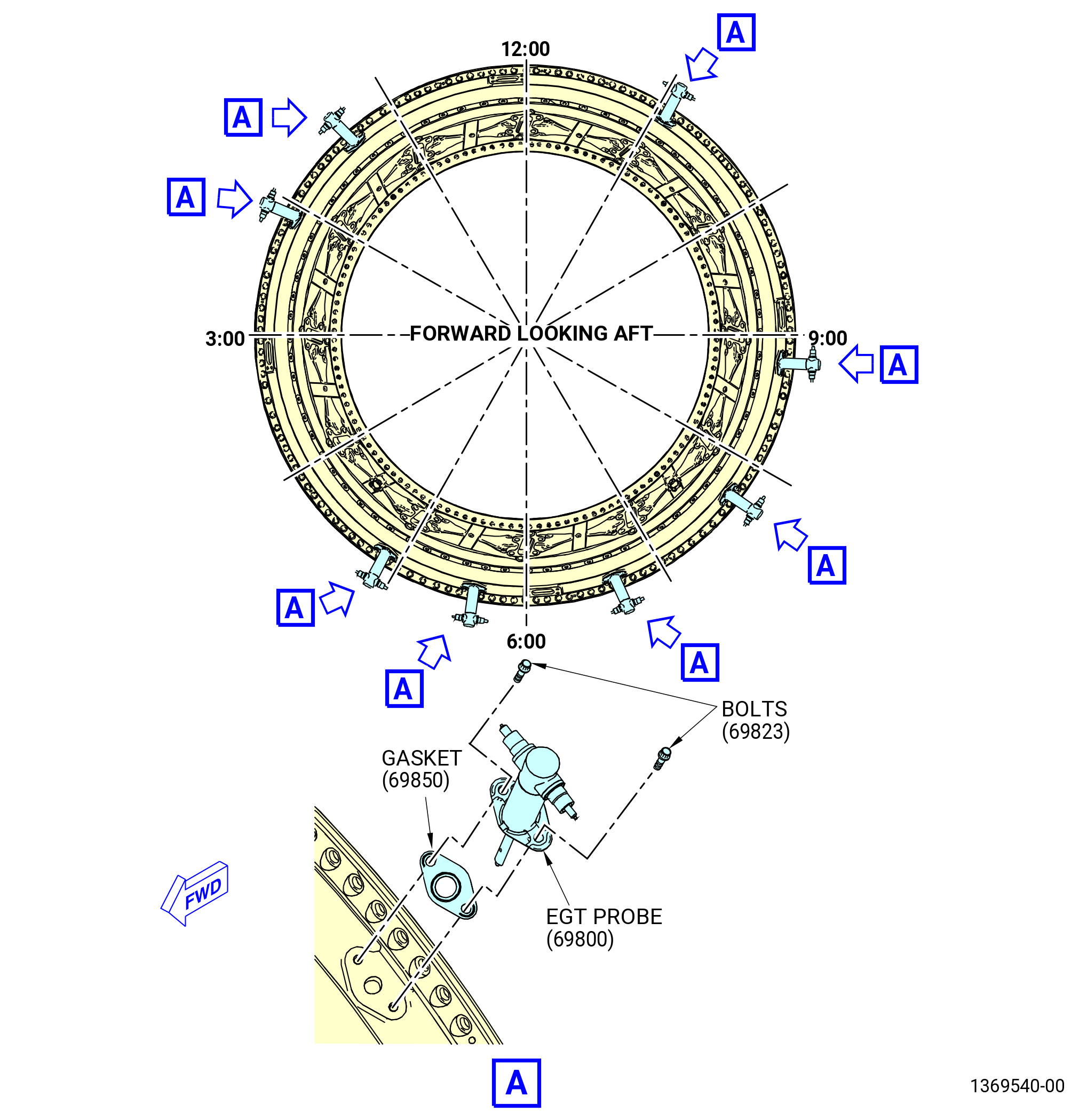
| AD. | Remove the exhaust gas temperature (EGT) probes (01-010 , 77-21-10) (SIN 69800) from the TCF assembly. Refer to Figure 532 and do as follows: |
| (1) | Remove the eight EGT probes from the TCF assembly at the 1:00, 3:30, 4:30, 5:30, 6:30, 7:30, 9:30, and 10:30 o'clock positions aft looking forward (ALF) as follows: |
| (a) | Remove the bolts (69823) that attach the EGT probes to the TCF assembly. |
| (b) | Remove the eight EGT probes from the TCF assembly. Remove and discard the gaskets (01-030 , 77-21-10) (SIN 69850). |
| Subtask 72-00-02-040-196 |
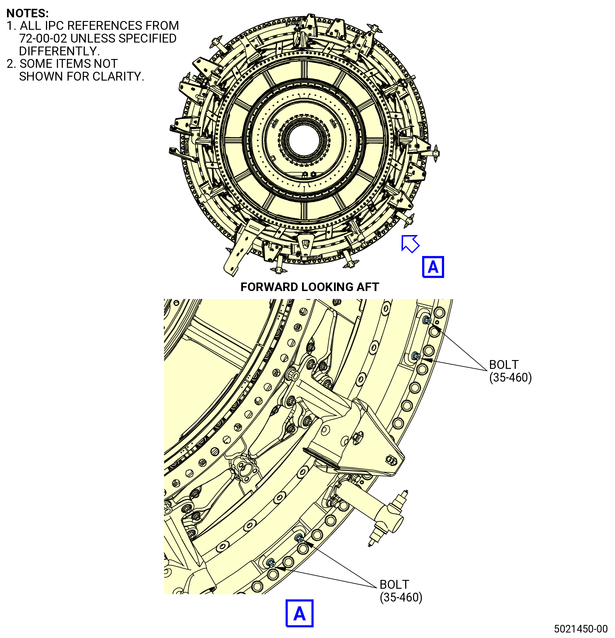
| * * * FOR 1B/P/G04.1B/P1/G01.ALL PIP 2 |
| AE. | Remove four bolts (35-460) (SIN 925F2) from the TCF case. Refer to Figure 533. |
| NOTE: |
|
| Subtask 72-00-02-040-192 |
| * * * FOR ALL |
| AF. | Remove the support brackets (6121D, 6121E, 6121F, 6121G, 6121H, 6121I, 6121J, 6121K) that attach the air manifolds (61204, 61205) to the TCF assembly as follows. Refer to Figure 534. |
| (1) | Remove the self-locking nuts (61241) and washers (61230) that attach the support brackets (6121D, 6121F, 6121K) at the 12:00 o'clock position to the TCF assembly. |
| (2) | Remove the self-locking nuts (61241) and washers (61230) that attach the support brackets (6121J, 6121H, 6121G) at the 3:00 o'clock position to the TCF assembly. |
| (3) | Remove the self-locking nuts (61241) and washers (61230) that attach the support brackets (6121D, 6121E) at the 6:00 o'clock position to the TCF assembly. |
| (4) | Remove the self-locking nuts (61241) and washers (61230) that attach the support brackets (6121D, 6121E, 6121F) at the 9:00 o'clock position to the TCF assembly. |
| (5) | Remove the support brackets from the TCF assembly. |
| Subtask 72-00-02-030-436 |
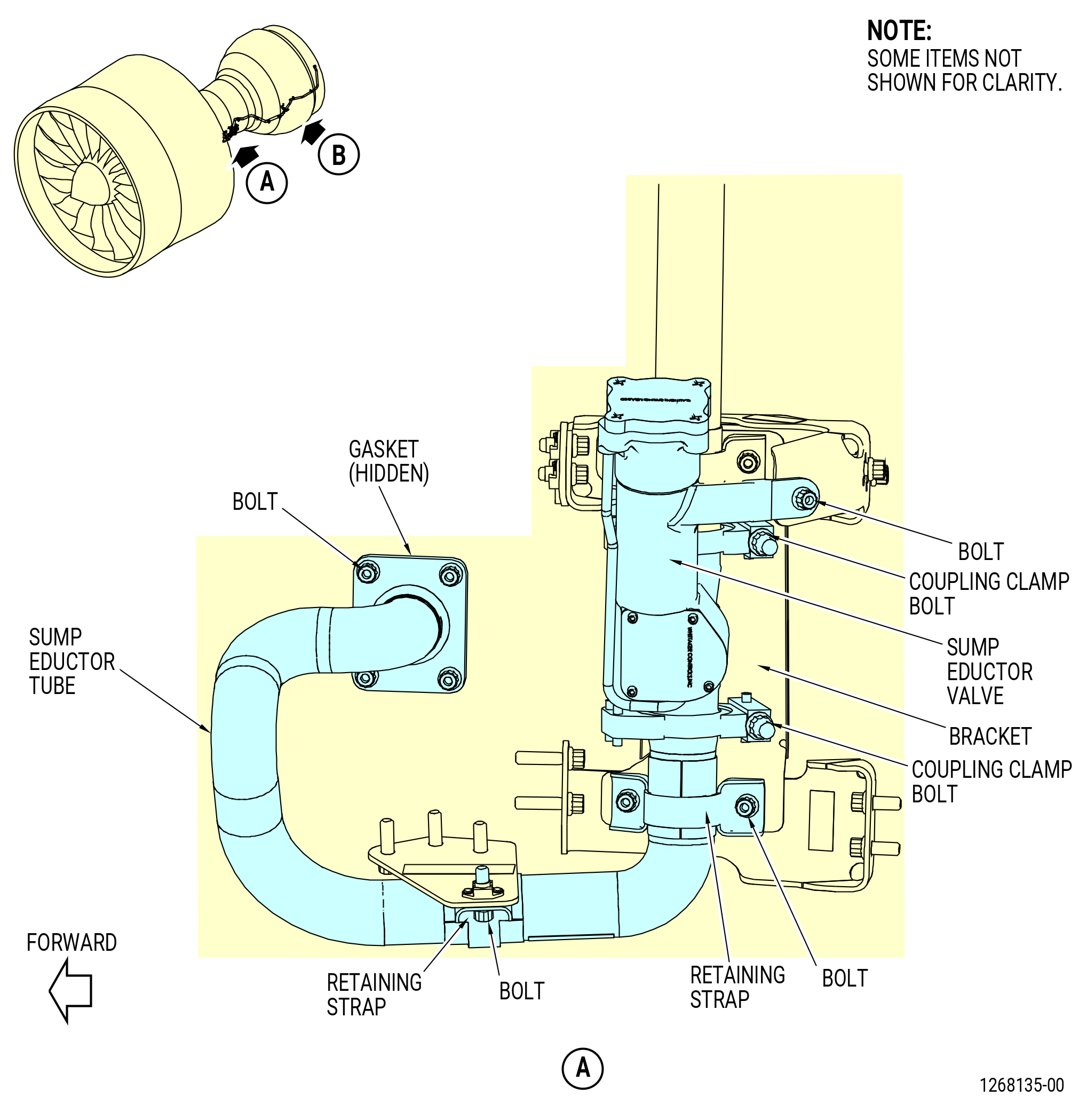
| AG. | Remove the sump eductor air tubes and sump eductor valve from the left side of the LPT and the HPT as follows. Refer to Figure 535. |
| (1) | Remove the sump eductor valve near the 9:30 o'clock position as follows: |
| (a) | Remove the bolts and the retaining straps that attach the sump eductor air tube and the air manifold to the support bracket. |
| (b) | Remove the coupling clamps at each end of the sump eductor valve. |
| (c) | Remove the bolt that attaches the tab on the sump eductor valve to the support bracket. |
| (d) | Remove the sump eductor valve and the ring seal (01-050 , 75-24-40) (SIN 61B50) from the engine and discard the seals. |
| (2) | Remove the sump eductor tube as follows: |
| (a) | Remove the coupling clamp that attaches the sump eductor tube on the HPT to the sump eductor air tube from the LPT. |
| (b) | Remove the four bolts that attach the sump eductor tube to the extension case then remove and discard the ring seal (01-050 , 75-24-40) (SIN 61B50). |
| (c) | Remove the bolt and the loop clamp that attach the eductor tube to the support bracket as follows: |
| 1 | Remove the sump eductor air tube from the engine. |
| 2 | Discard the ring seal (01-050 , 75-24-40) (SIN 61B50). |
| (d) | Remove the sump eductor tube from the engine. |
| (3) | Remove the aft sump eductor air tube (air tube) as follows: |
| (a) | Loosen and remove the coupling nut from the turbine rear frame. |
| (b) | Remove the bolts from the restraining strap and remove the restraining strap. |
| (c) | Remove the bolts from the clamps that attach the air tube to the LPT ACC manifold. |
| (d) | Remove the air tube from the engine. |
| Subtask 72-00-02-030-437 |
| AH. | Remove the support brackets from the LPT and the HPT as follows. Refer to Figure 536. |
| (1) | Remove the support bracket from the HPT case at the 8:50 o'clock position as follows: |
| (a) | Remove the bolts that attach the support brackets to the support bracket. |
| (b) | Remove the bolts that attach the eductor support bracket to the support bracket on the HPT/TCF flanges near the 8:30 o'clock position. |
| (2) | Remove the support bracket from the support bracket on the HPT/TCF flanges at the 8:50 o'clock position as follows: |
| (a) | Remove the bolts that attach the support bracket to the support bracket. |
| (3) | Remove the support bracket from the HPT case near the 8:00 o'clock position as follows: |
| (a) | Remove the bolts that attach the support bracket to the LPT case. |
| Subtask 72-00-02-030-396 |
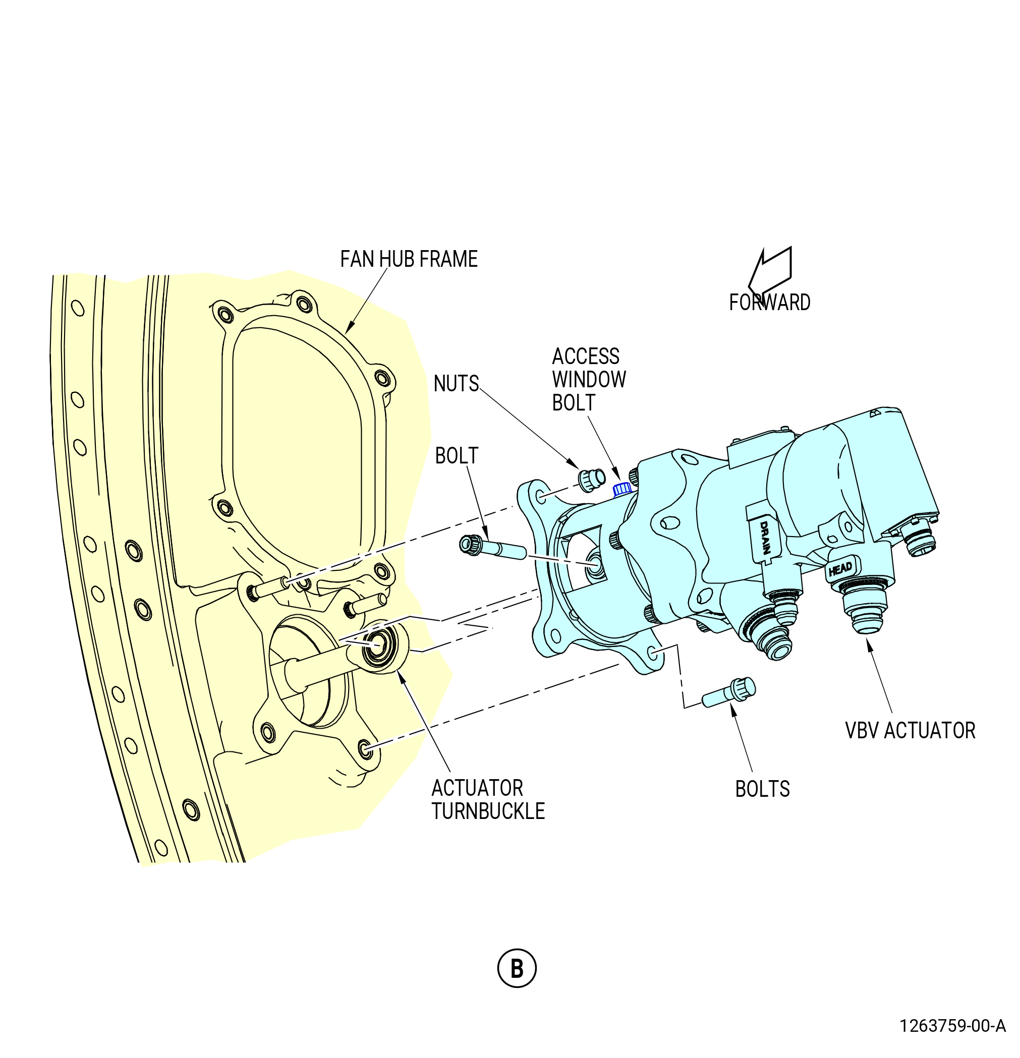
| AI. | Remove the VBV actuators from the 8:30 and 2:30 o'clock positions on the FHF as follows. Refer to Figure 537. |
| (1) | Loosen, but do not remove, the bolt on the VBV clevis window. |
| (2) | Turn the VBV clevis window to the open position. |
| (3) | Remove the bolt that attaches the VBV actuator clevis to the VBV actuator turnbuckle rod end. |
| (4) | Remove the two nuts from the upper mount flange. |
| (5) | Remove the two bolts from the lower VBV actuator mount flange. |
| (6) | Remove the VBV actuator from the FHF and put caps and plugs on all VBV actuator ports and openings. |
| Subtask 72-00-02-030-397 |
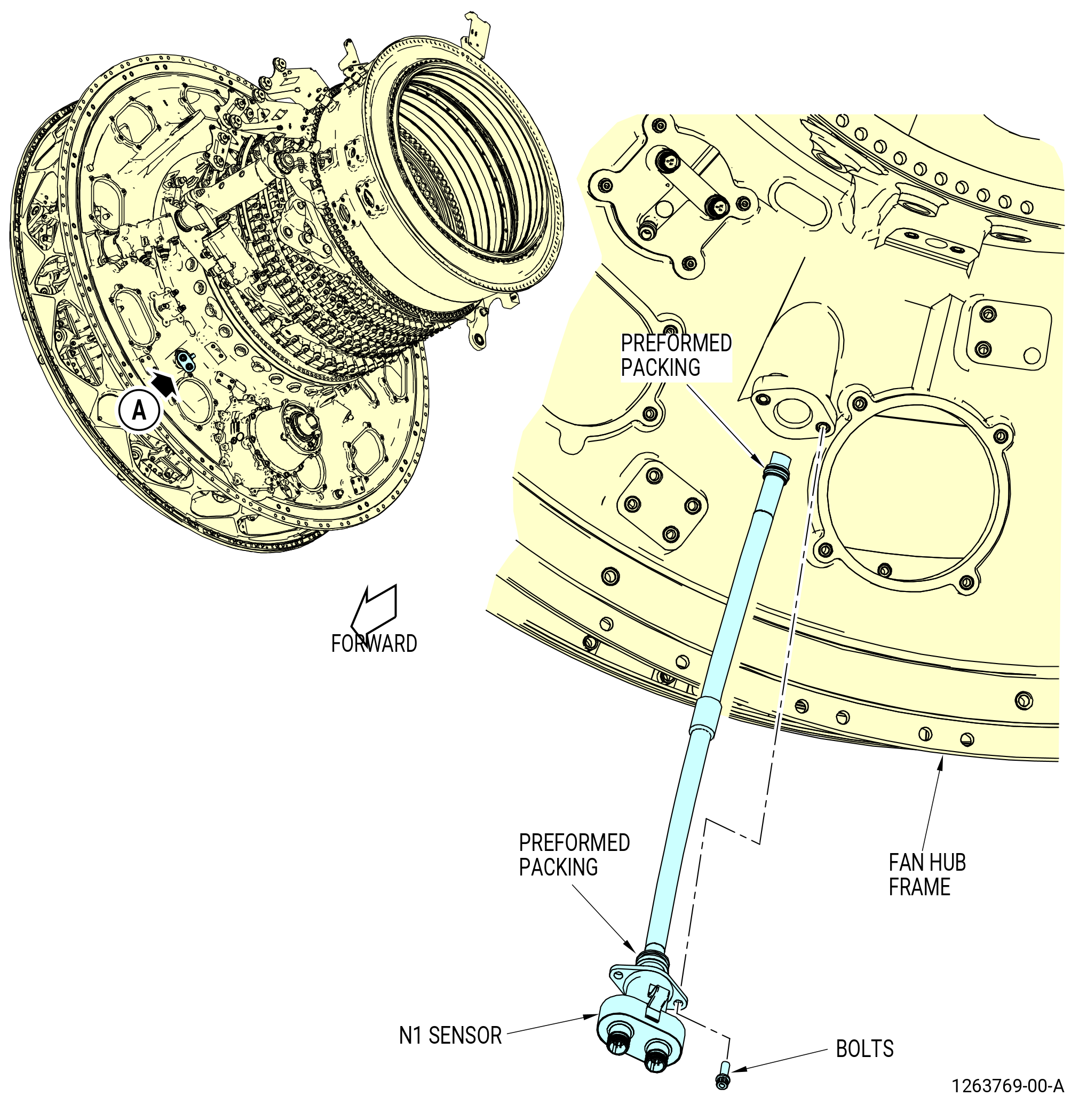
| AJ. | Remove the N1 speed sensor from the FHF as follows. Refer to Figure 538. |
| (1) | Remove the bolts that attach the N1 speed sensor to the FHF. |
| (2) | Remove the N1 speed sensor from the FHF as follows: |
| (a) | Remove and discard the two preformed packings (01-030 , 77-11-10) (SIN 65450) or (01-031 , 77-11-10) (SIN 65450) and (01-040 , 77-11-10) (SIN 65451) or (01-041 , 77-11-10) (SIN 65451). |
| (b) | Put caps and plugs on all N1 speed sensor openings. |
| Subtask 72-00-02-030-398 |
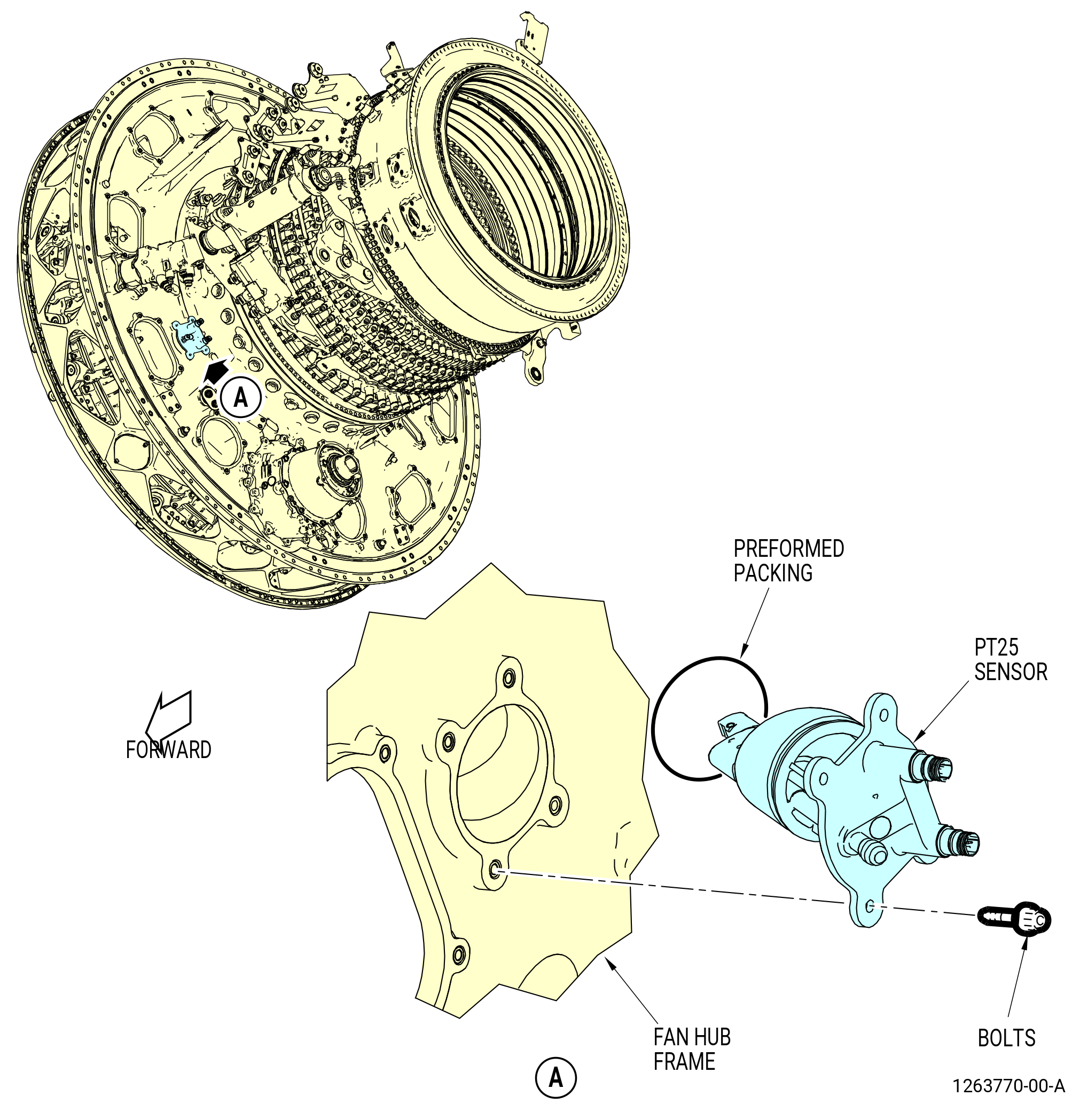
| AK. | Remove the PT25 sensor from the port in the FHF at the 8:00 o'clock position as follows. Refer to Figure 539. |
| (1) | Remove the bolts that attach the PT25 sensor to the FHF. |
| (2) | Remove the PT25 sensor. |
| (3) | Remove and discard the preformed packing (01-030 , 73-21-50) (SIN 65250). |
| Subtask 72-00-02-030-446 |
| AL. | Continue the disassembly of the propulsor. Refer to TASK 72-00-02-030-804 (72-00-02, DISASSEMBLY 004). |
| Subtask 72-00-02-030-479 |
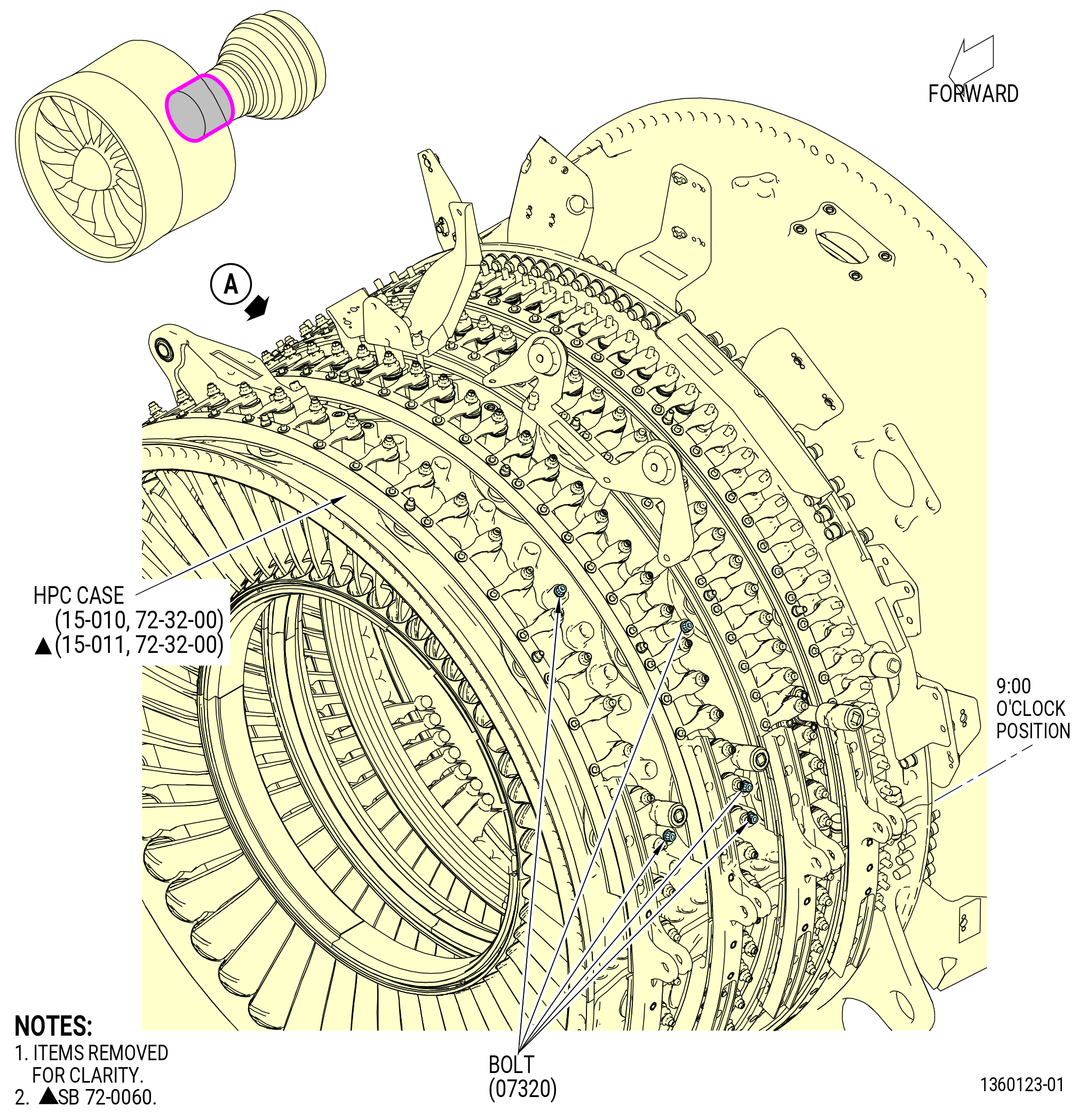
| AM. | Remove the compressor plug bolts (bolts) (07320) from the HPC stator case (15-010 , 72-32-00) or (15-011 , 72-32-00) (SIN 073A0) as follows. Refer to Figure 540. |
| (1) | Remove the seven bolts (07320) from the right side of the HPC stator case. Locations are between stages 2 and 3 at bosses 1 thru 3, 6, 7, 9, and 12 counterclockwise (CCW) from the 3:00 o'clock horizontal flange. |
| (2) | Remove the five bolts (07320) from the left side of the HPC stator case. There are two locations are between stages 1 and 2 at bosses 2 and 7 and three location between stages 2 and 3 at bosses 1 thru 3 clockwise (CW) from the 9:00 o'clock horizontal flange. |