| GENX-1B ENGINE MANUAL | Dated: 06/15/2021 | |
| EM 72-00-02 , DISASSEMBLY 002 | ||
| PROPULSOR ASSEMBLY - DISASSEMBLY 002 - CONFIGURATION 01 | ||
| GENX-1B ENGINE MANUAL | Dated: 06/15/2021 | |
| EM 72-00-02 , DISASSEMBLY 002 | ||
| PROPULSOR ASSEMBLY - DISASSEMBLY 002 - CONFIGURATION 01 | ||
| * * * FOR 1B/P/G03.1B/P/G04.1B/P1/G01 |
| TASK 72-00-02-030-802 |
| 1 . | General. |
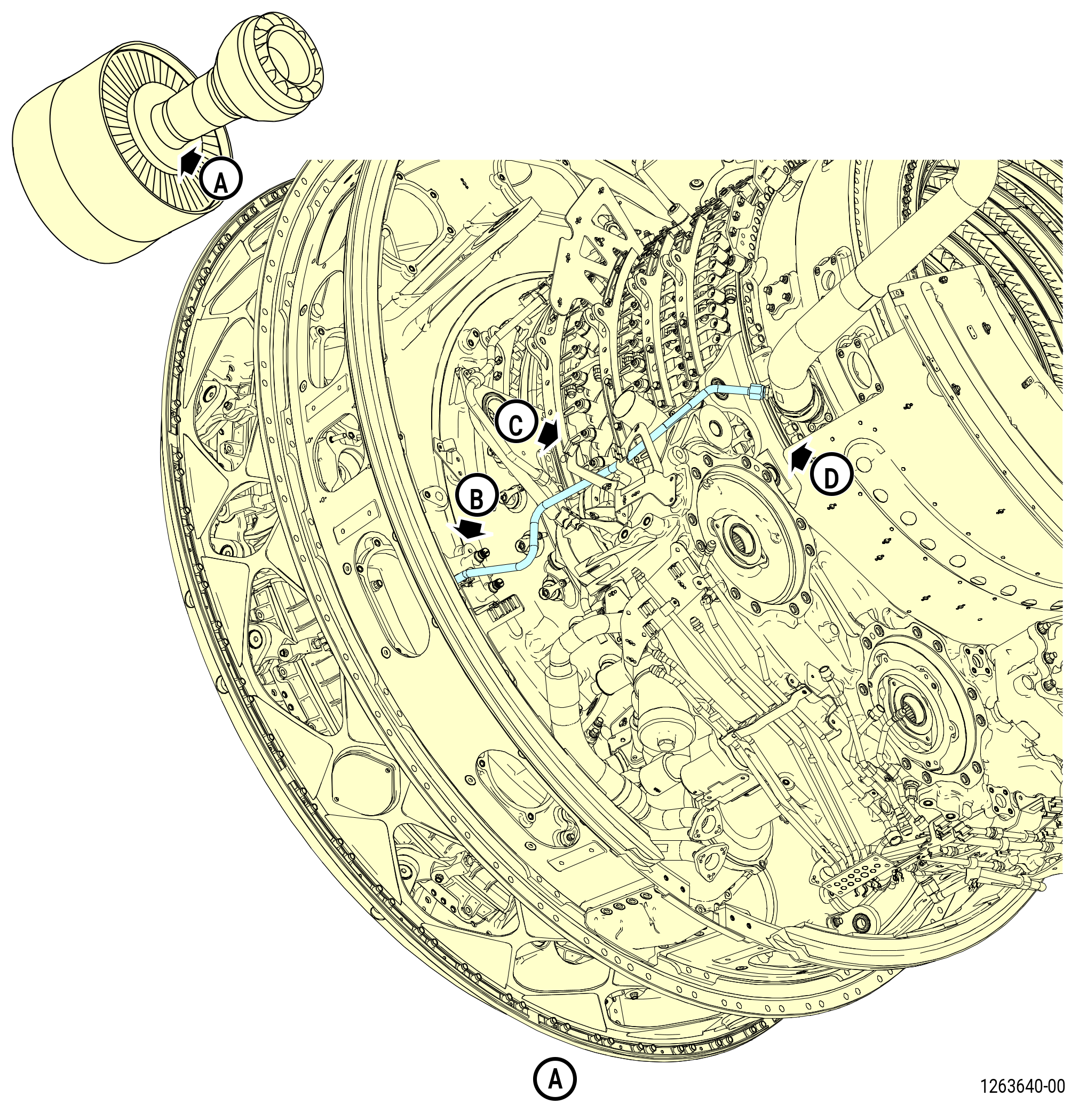
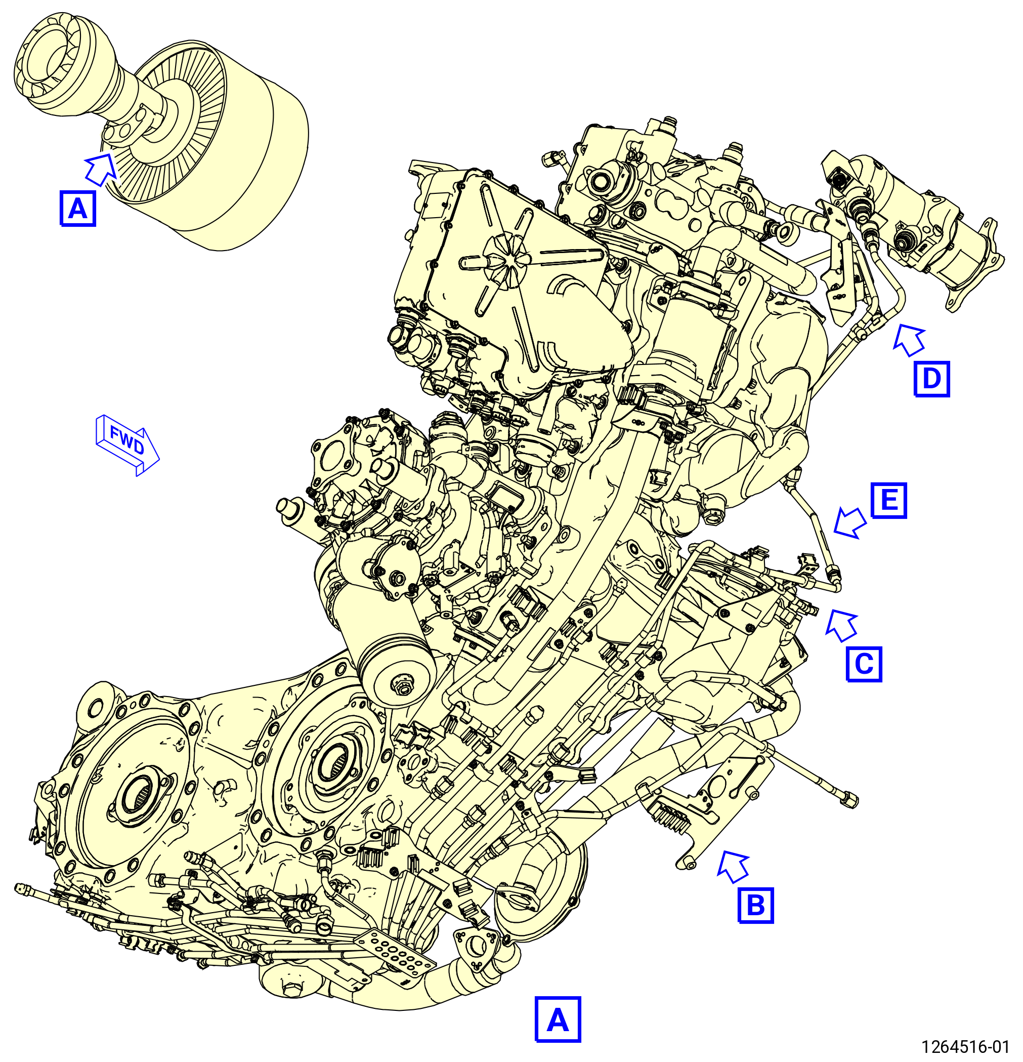
| A. | This procedure gives instructions to continue the disassembly of the propulsor. This procedure removes the external configuration hardware. Refer to Figure 501. |
| B. | This procedure starts with the propulsor module assembly (propulsor) (30-020 , 72-00-00) (SIN 0010C) in the horizontal position. The propulsor can be installed in the 11C3044 engine module adapter assembly, attached to the customer overhead rail system, or supported by the 11C3281 pedestals, at the equivalent disassembly status of TASK 72-00-02-030-801 (72-00-02, DISASSEMBLY 001) . |
| C. | Modules that you remove can have external hardware that you will remove at the module disassembly level. |
| D. | Before you do this procedure, read the Assembly and Disassembly Techniques section. Refer to TASK 70-10-00-800-009 (ASSEMBLY AND DISASSEMBLY TECHNIQUES) . |
| E. | Install protective covers/plugs on tubes and hoses to prevent damage and contamination. |
| F. | Make sure that you obey all site safety and environmental controls or personal injury can occur. |
| 2 . | Tools, Equipment, and Materials. |
| NOTE: |
|
| A. | Tools and Equipment. |
| (1) | Special Tools. |
| (2) | Standard Tools and Equipment. |
|
| (3) | Locally Manufactured Tools. None. |
| B. | Consumable Materials. |
|
| C. | Referenced Procedures. |
|
| D. | Expendable Parts. None. |
| 3 . | Procedure. |
| Subtask 72-00-02-030-472 |
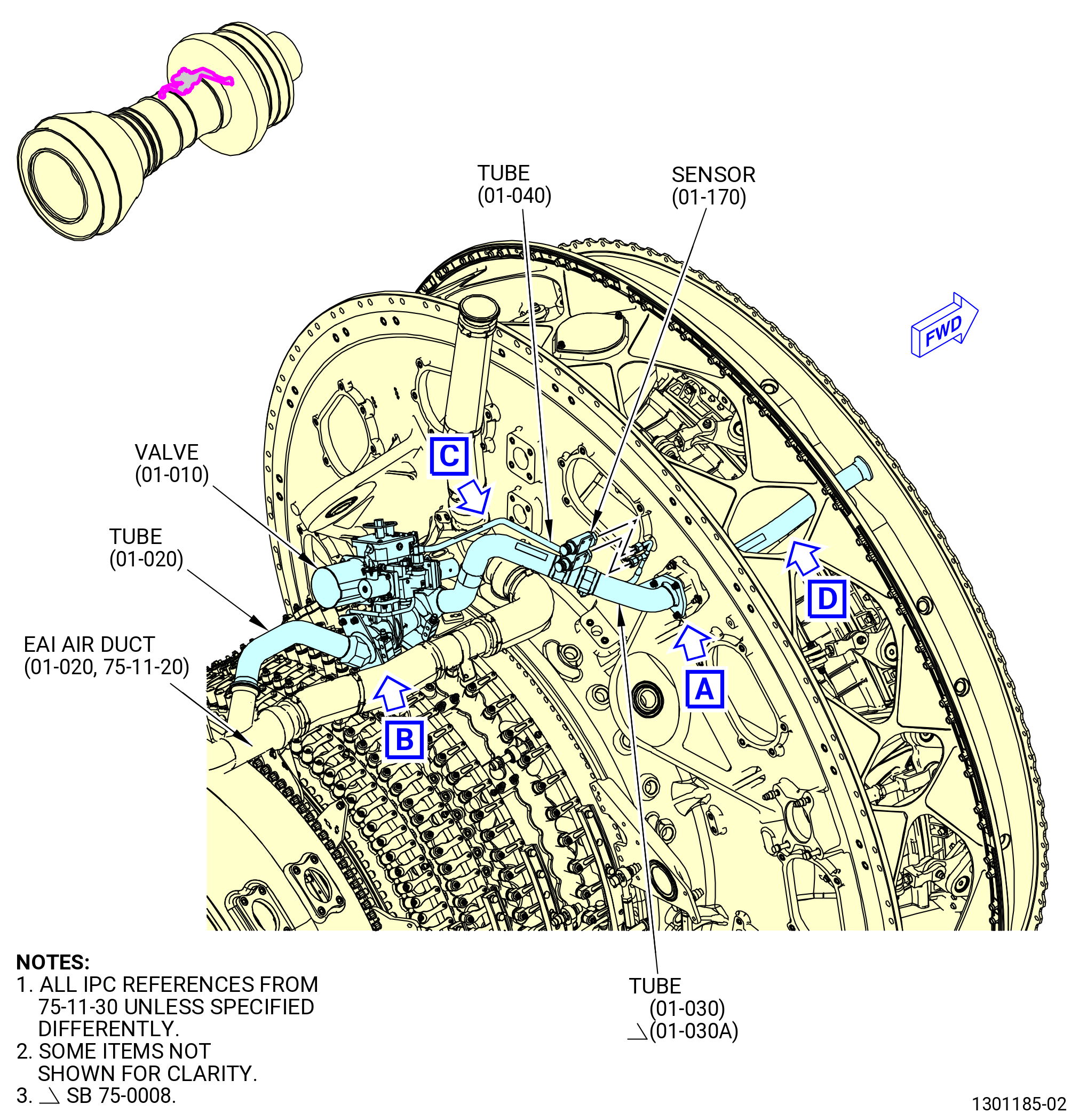
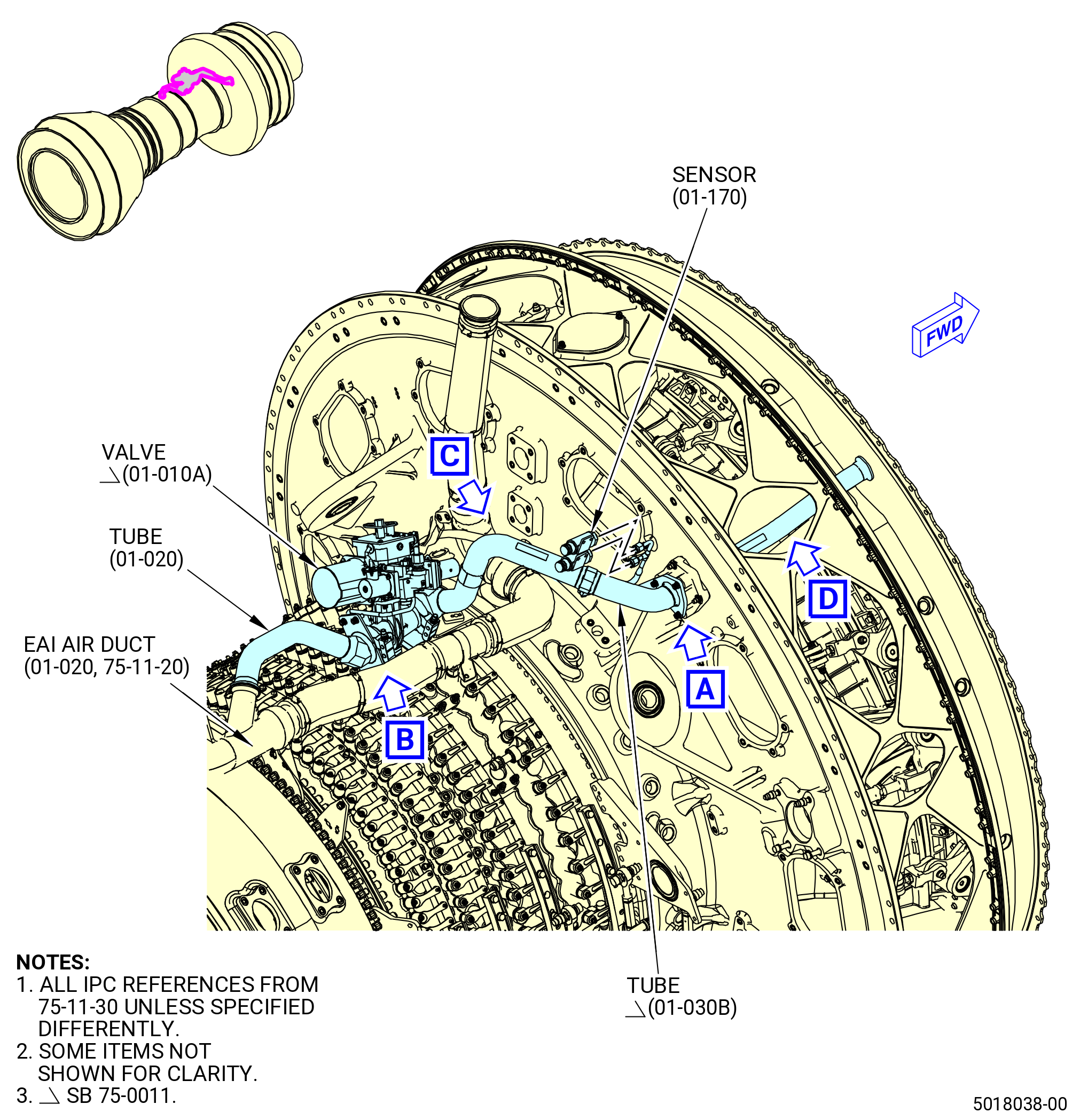
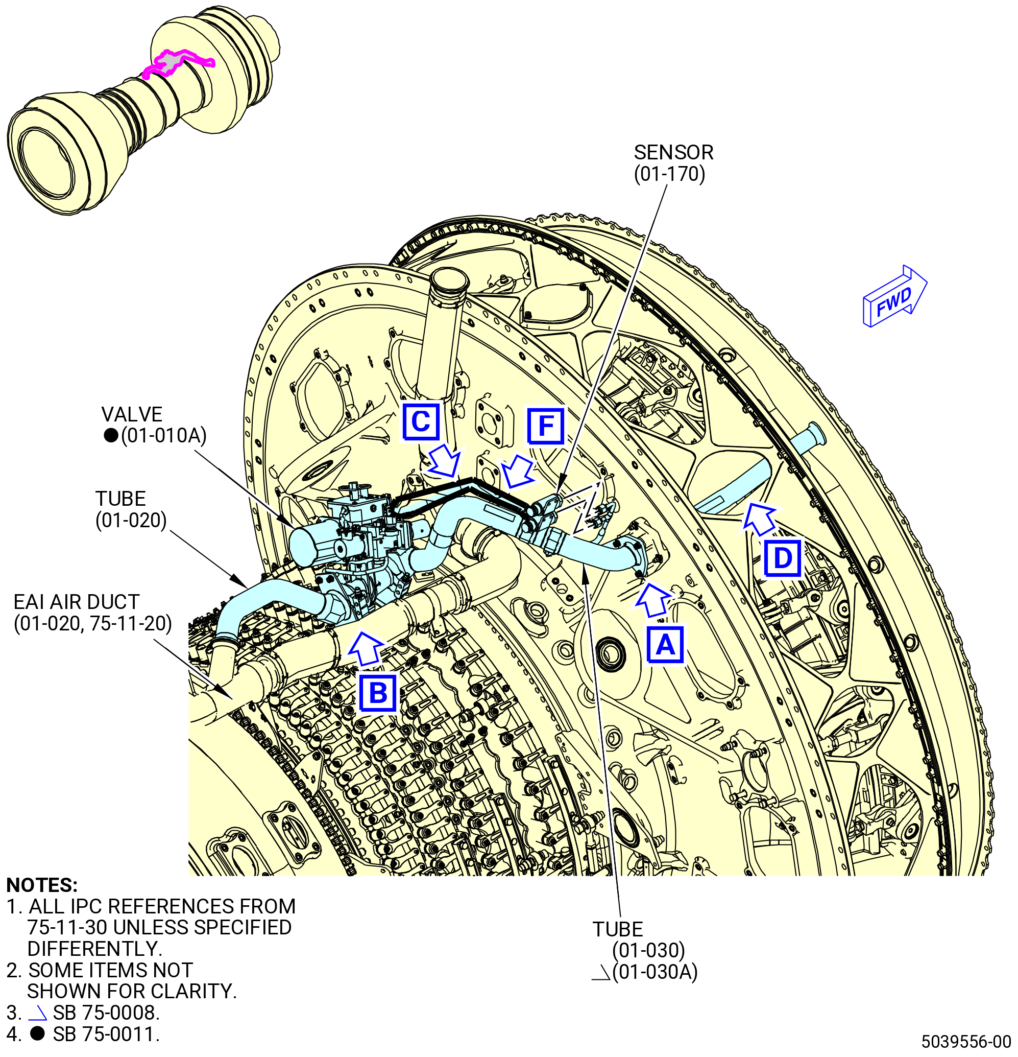
| A. | Remove the booster anti-ice system as follows. Refer to Figure 502. |
| Subtask 72-00-02-030-755 |
| * * * PRE SB 75-0032( Two Separate Single-Channel Sensors ) |
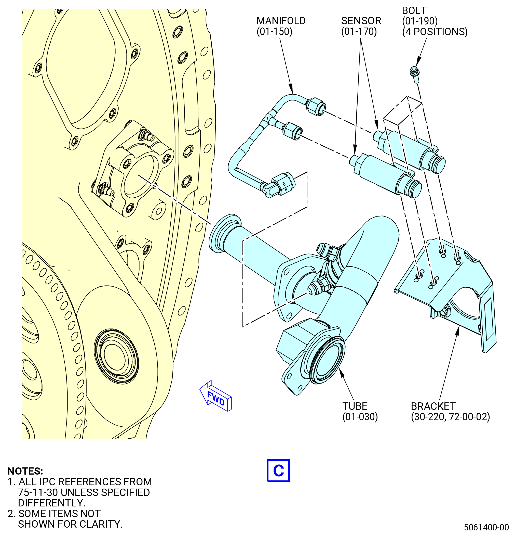
| (1) | Remove the manifold (01-150 , 75-11-30) (SIN 63709) as follows: |
| (a) | Remove the manifold (01-150 , 75-11-30) (SIN 63709) from the sensors (01-170 , 75-11-30) (SIN 63701) at two locations. |
| (b) | Remove the manifold (01-150 , 75-11-30) (SIN 63709) from the tube (01-030 , 75-11-30) (SIN 63703) or (01-030A , 75-11-30) (SIN 63703). |
| * * * END PRE SB 75-0032 |
| Subtask 72-00-02-030-756 |
| * * * SB 75-0032( One Dual-Channel Sensor ) |
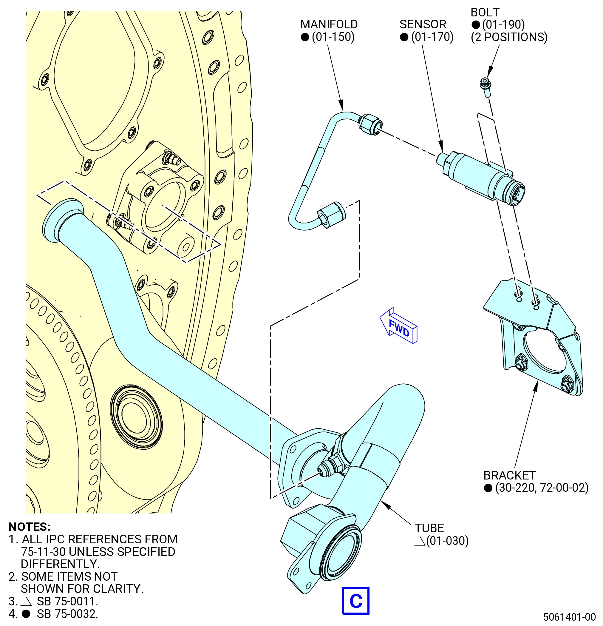
| (1).A. | Remove the manifold (01-150 , 75-11-30) (SIN 63709) as follows: |
| (a) | Remove the manifold (01-150 , 75-11-30) (SIN 63709) from the sensor (01-170 , 75-11-30) (SIN 63701) at one location. |
| (b) | Remove the manifold (01-150 , 75-11-30) (SIN 63709) from the tube (01-030B , 75-11-30) (SIN 63703) or (01-030C , 75-11-30) (SIN 63703). |
| * * * END SB 75-0032 |
| Subtask 72-00-02-030-757 |
| * * * PRE SB 75-0032( Two Separate Single-Channel Sensors ) |
| (2) | Remove the sensors (01-170 , 75-11-30) (SIN 63701) as follows: |
| (a) | Remove the four bolts (01-190 , 75-11-30) (SIN 63725) that attach the sensors (01-170 , 75-11-30) (SIN 63701) to the bracket (30-220) (SIN 63715). |
| * * * END PRE SB 75-0032 |
| Subtask 72-00-02-030-758 |
| * * * SB 75-0032( One Dual-Channel Sensor ) |
| (2).A. | Remove the sensor (01-170 , 75-11-30) (SIN 63701) as follows: |
| (a) | Remove the two bolts (01-190 , 75-11-30) (SIN 63725) that attach the sensor (01-170 , 75-11-30) (SIN 63701) to the bracket (30-220) (63715). |
| * * * END SB 75-0032 |
| Subtask 72-00-02-030-759 |
| * * * PRE SB 75-0020( Two Tubes Configuration ) |
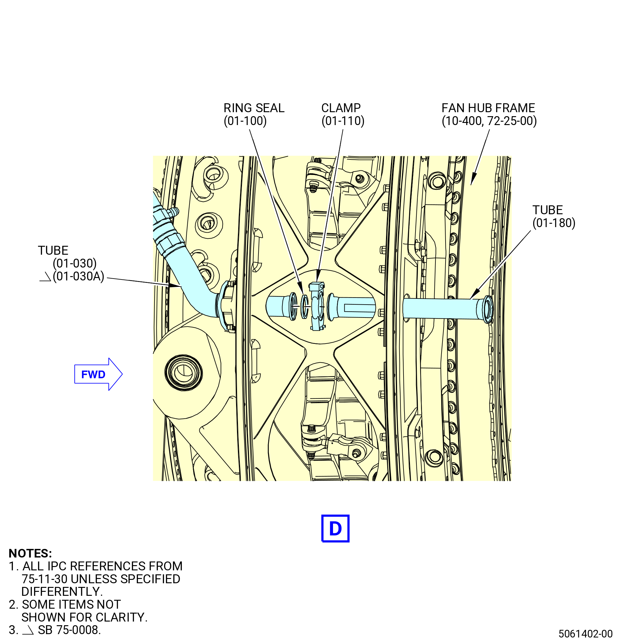
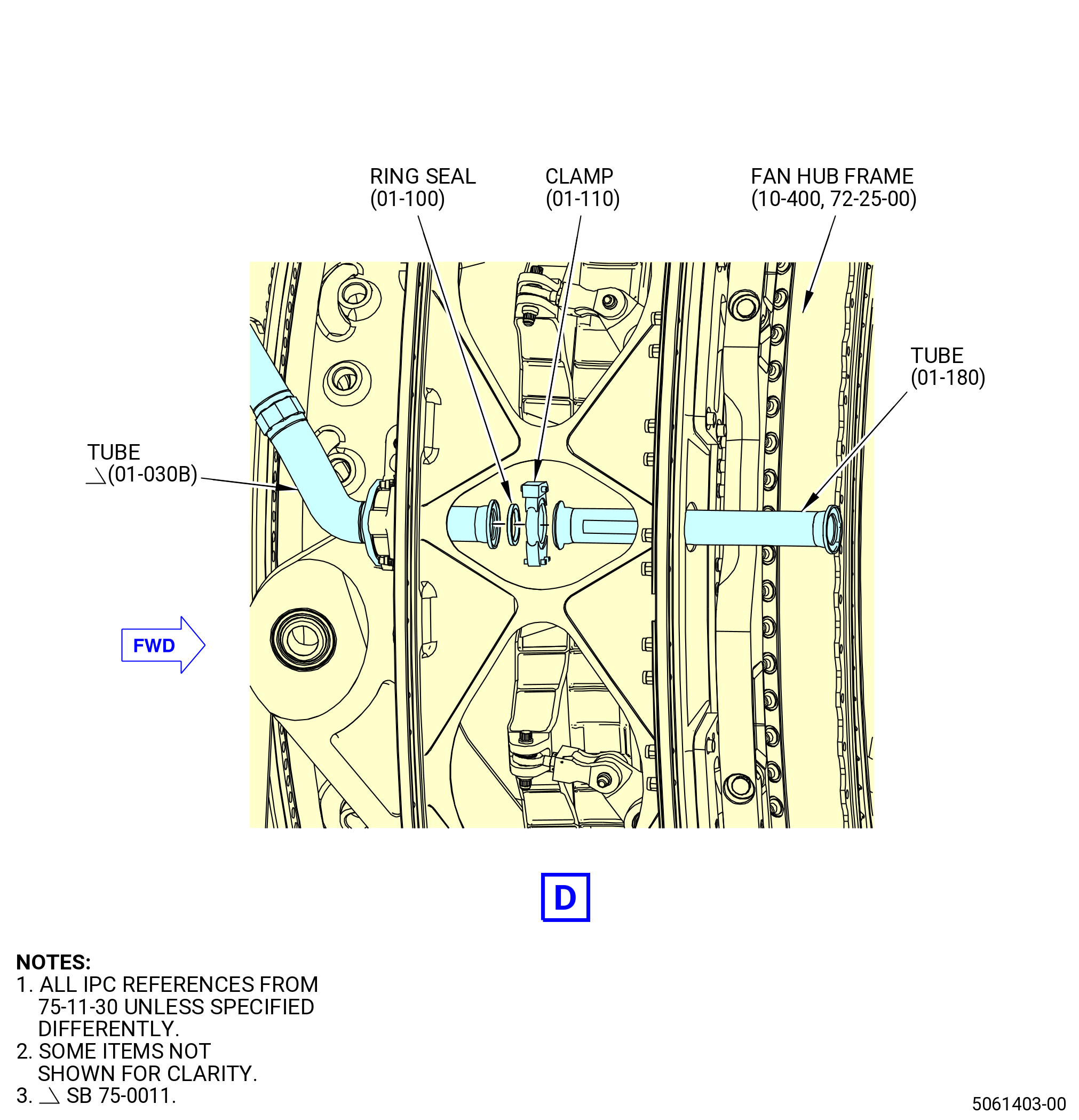
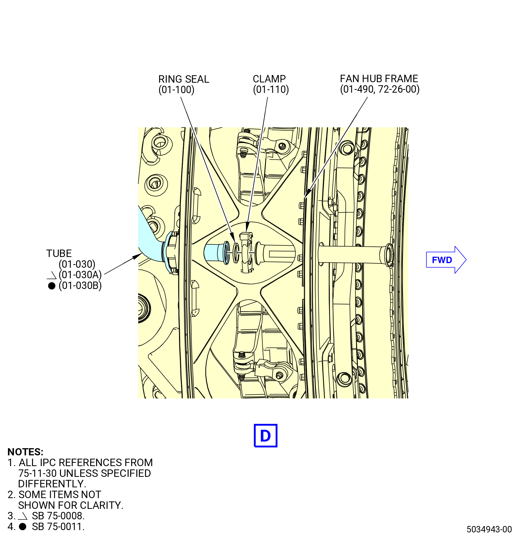
| (3) | Remove the BAI air tube (tube) (63704) as follows: |
| NOTE: |
|
| (a) | Remove the coupling clamp (clamp) (01-110 , 75-11-30) (SIN 63780) that connects the tube (01-180 , 75-11-30) (SIN 63704) to the tube (01-030 , 75-11-30) (SIN 63703) or (01-030A , 75-11-30) (SIN 63703) or (01-030B , 75-11-30) (SIN 63703). |
| (b) | Remove the tube (63704) from the fan hub frame (84000). |
| (c) | Remove the ring seal (63750). |
| (d) | Put protective caps or protective covers on the tube (63704). |
| * * * END PRE SB 75-0020 |
| Subtask 72-00-02-030-621 |
| * * * PRE SB 75-0020( Two Tubes Configuration ) |
| * * * PRE SB 75-0011( Nacelle Valve with Manual Lock Open Feature ) |
| * * * PRE SB 75-0027( BAI Configuration with BAI Air Sense Tube ) |
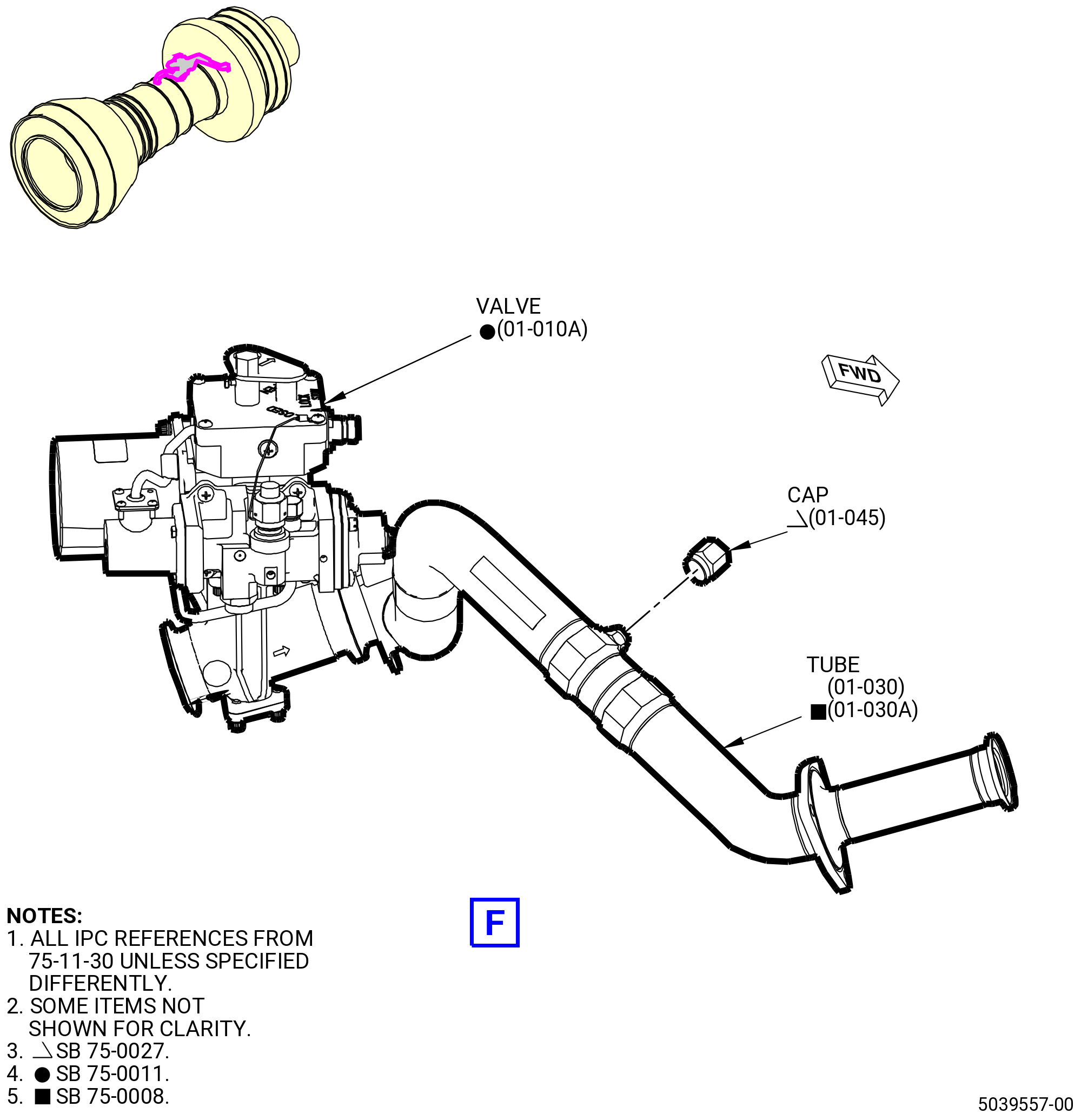
| (4) | Remove the BAI air sense tube (tube) (01-040 , 75-11-30) (SIN 63708) as follows: |
| NOTE: |
|
| NOTE: |
|
| (a) | Disconnect the tube (01-040 , 75-11-30) (SIN 63708) from the nacelle valve (valve) (01-010 , 75-11-30) (SIN 63700). |
| (b) | Disconnect the tube (01-040 , 75-11-30) (SIN 63708) from the tube (01-030 , 75-11-30) (SIN 63703) or (01-030A , 75-11-30) (SIN 63703). |
| (c) | Remove the tube (01-040 , 75-11-30) (SIN 63708). |
| * * * END PRE SB 75-0027 |
| * * * END PRE SB 75-0011 |
| Subtask 72-00-02-030-741 |
| * * * SB 75-0011( Nacelle Valve without Manual Lock Open Feature ) |
| * * * SB 75-0027( BAI Configuration without BAI Air Sense Tube ) |
| (4).A. | Remove the cap assembly tube (cap) (01-045 , 75-11-30) (SIN 63762) from the tube (01-030 , 75-11-30) (SIN 63703) or (01-030A , 75-11-30)) (SIN 63703). |
| NOTE: |
|
| NOTE: |
|
| NOTE: |
|
| * * * END SB 75-0027 |
| * * * END SB 75-0011 |
| * * * END PRE SB 75-0020 |
| Subtask 72-00-02-030-622 |
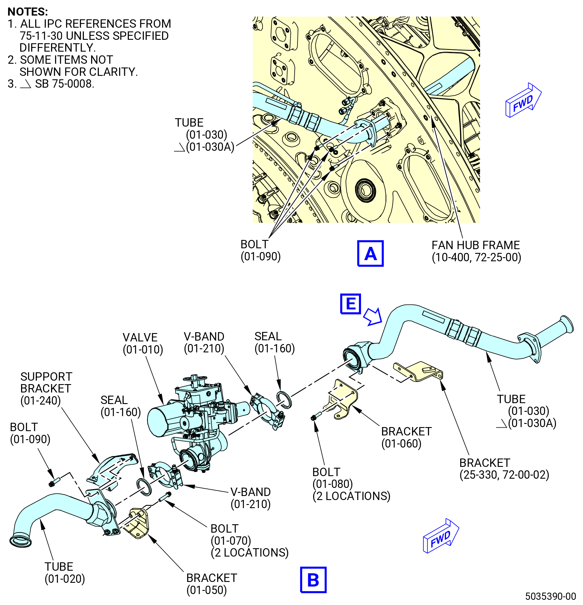
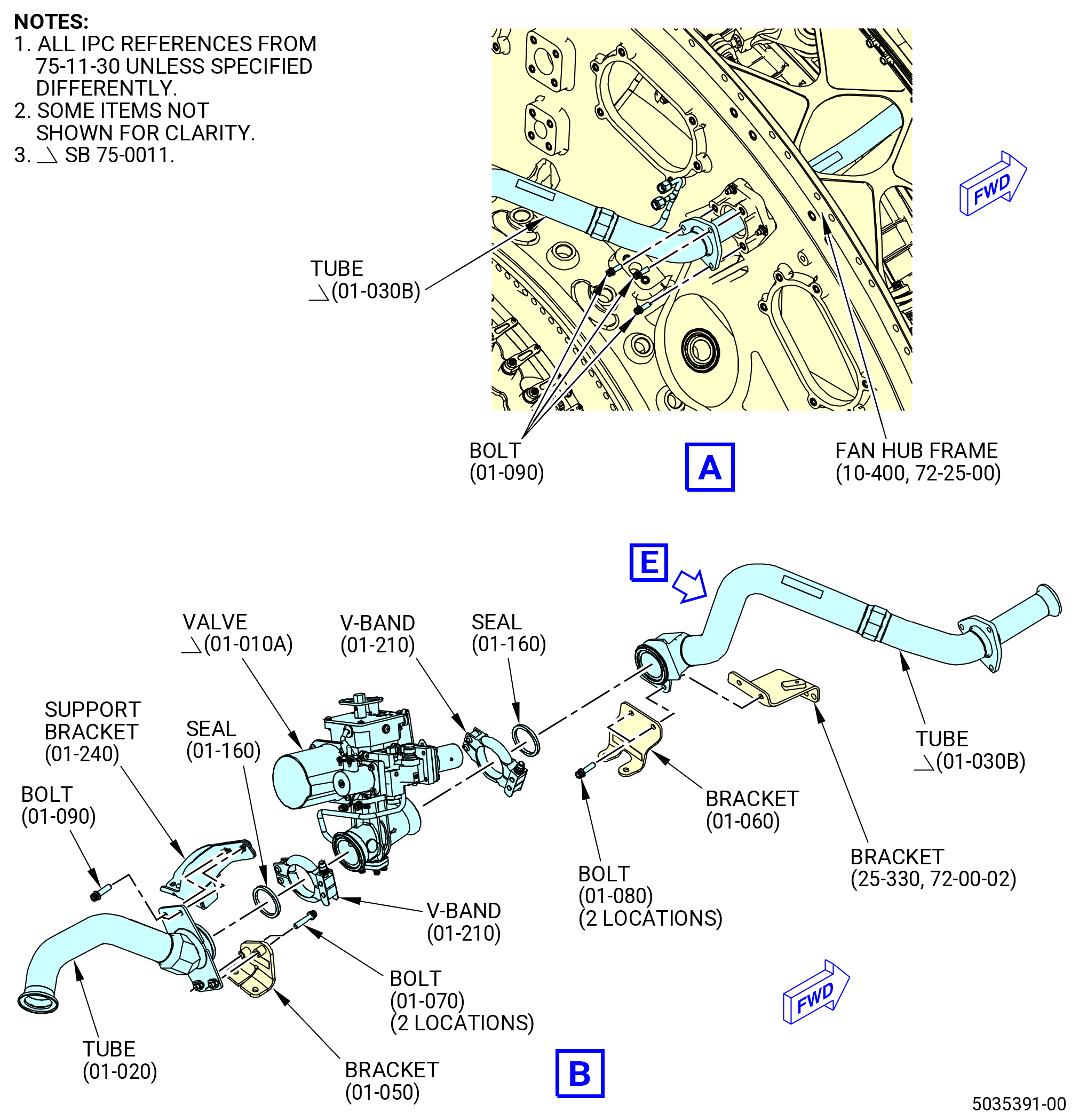
| (5) | Remove the tube (63702) as follows: |
| (a) | Remove the V-band (63784) from the tube (63702). |
| (b) | Remove the machine bolts (bolt) (63722) from the bracket (63710). |
| (c) | Remove the two machine bolts (bolts) (01-090 , 75-11-30) (SIN 63724) that attach the tube (01-020 , 75-11-30) (SIN 63702) to the support bracket (01-240 , 75-11-30) (SIN 63718). |
| (d) | Remove the tube (63702). |
| (e) | Remove the seal (63753). |
| (f) | Put protective caps or protective covers on the tube (63702). |
| (6) | Remove the valve as follows: |
| (a) | Remove the V-band (01-210 , 75-11-30) (SIN 63784) from the valve and tube (01-030 , 75-11-30) (SIN 63703) or (01-030A , 75-11-30) (SIN 63703), or (01-030B , 75-11-30) (SIN 63703), or (01-030C , 75-11-30) (SIN 63703). |
| (b) | Remove the valve. |
| (c) | Remove the seal (63753). |
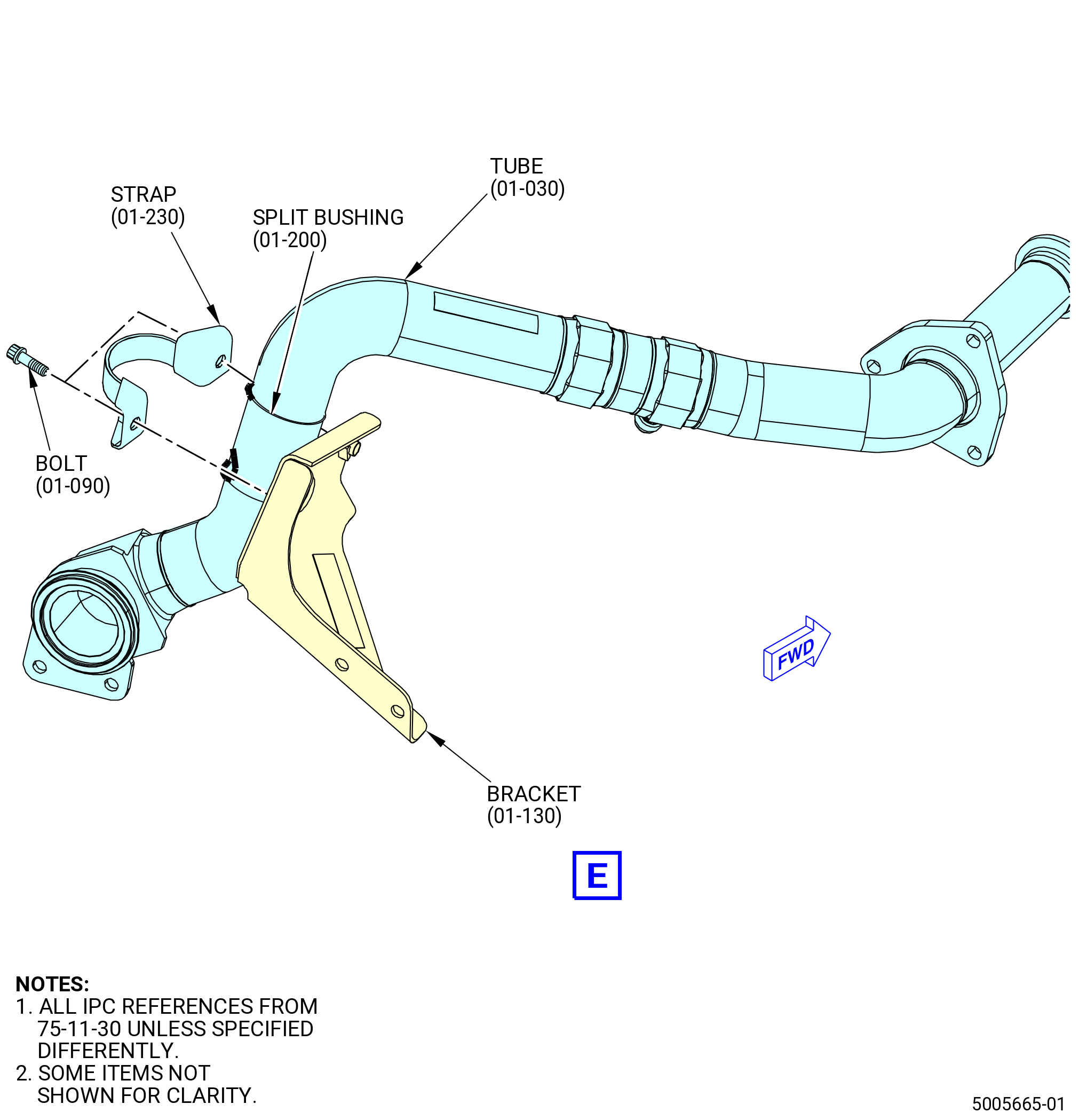
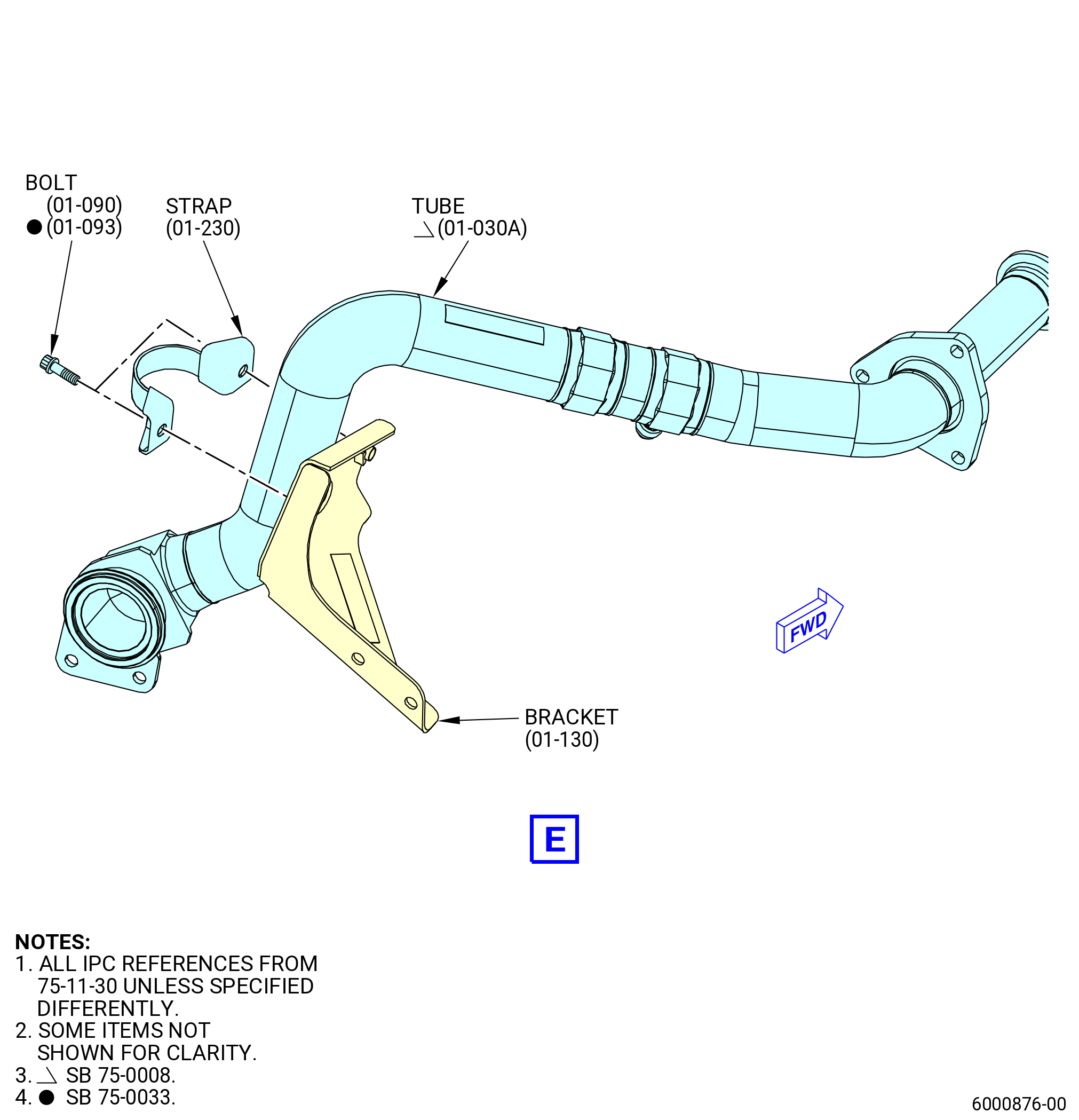
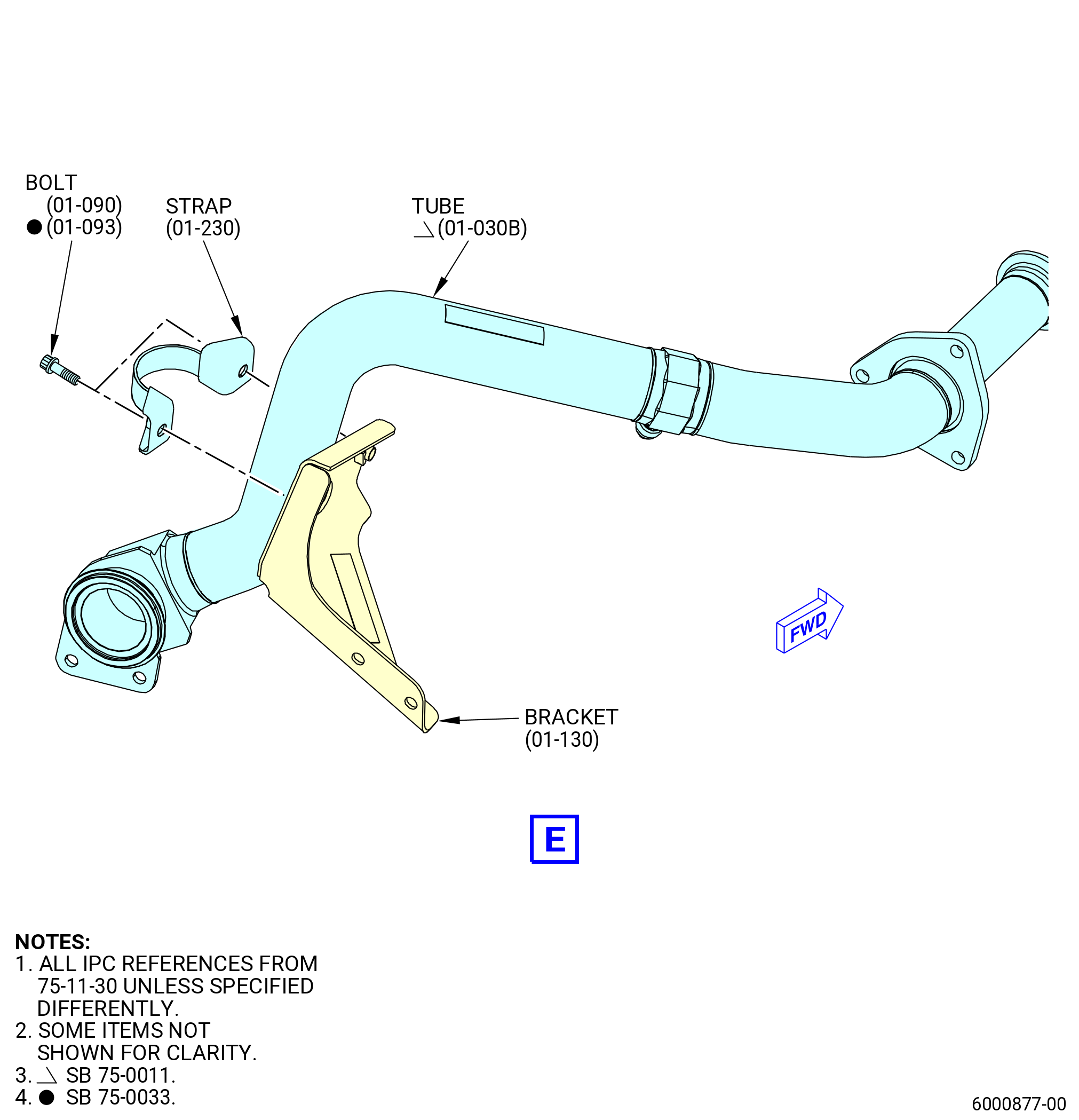
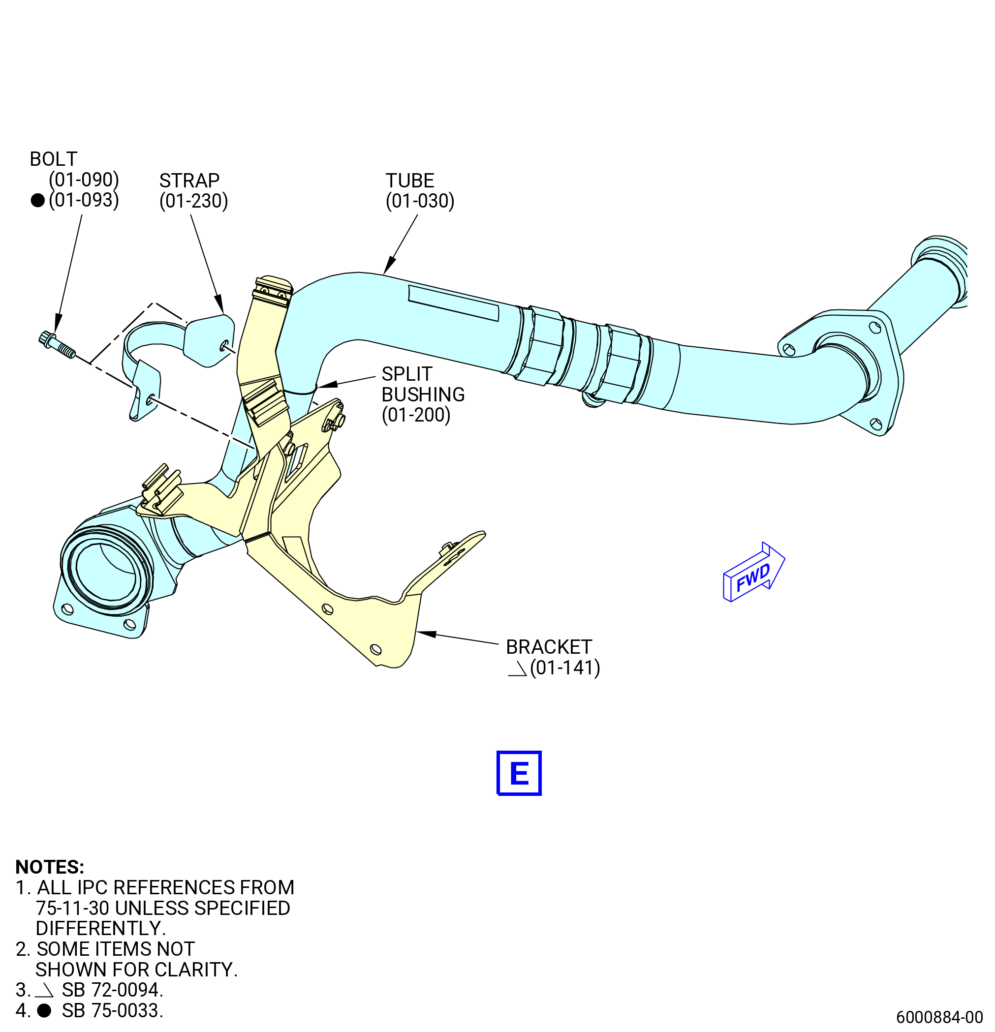
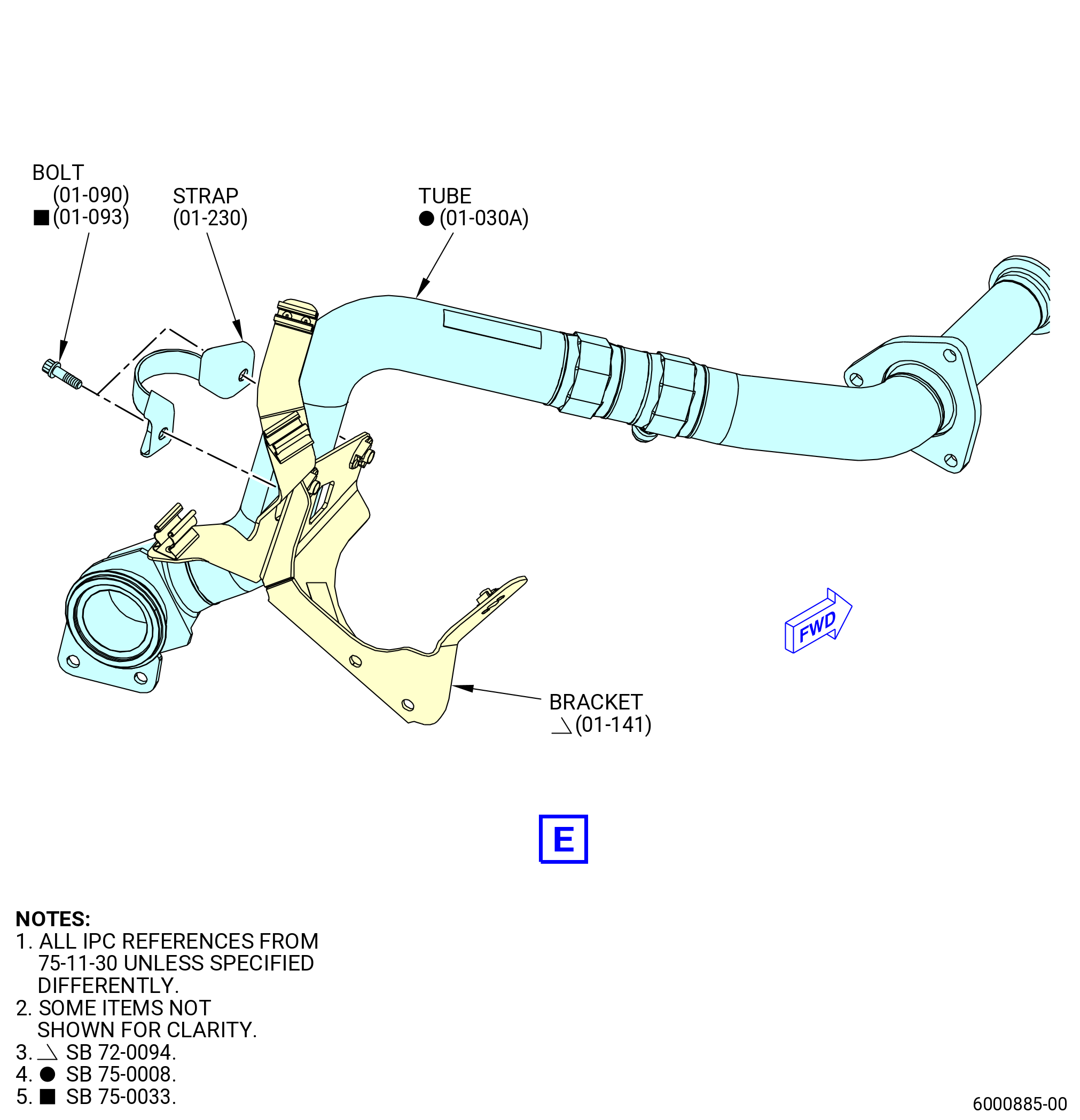
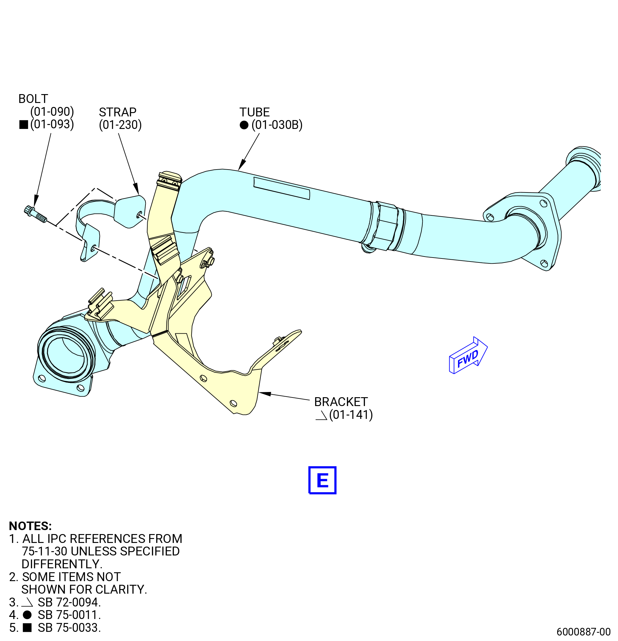
| (7) | Remove the tube (01-030 , 75-11-30) (SIN 63703) or (01-030A , 75-11-30) (SIN 63703) or (01-030B , 75-11-30) (SIN 63703), or (01-030C , 75-11-30) (SIN 63703) as follows: |
| (a) | Remove the bolts (01-080 , 75-11-30) (SIN 63723) that attach the tube (01-030 , 75-11-30) (SIN 63703) or (01-030A , 75-11-30) (SIN 63703) or (01-030B , 75-11-30) (SIN 63703), or (01-030C , 75-11-30) (SIN 63703) to the support brackets (bracket) (25-330) (SIN 63711) and (01-060 , 75-11-30) (SIN 63712). |
| Subtask 72-00-02-030-615 |
| * * * PRE SB 75-0008( Removal of the Tube with Separate Wear Sleeve ) |
| (b) | Remove the bolts (01-090 , 75-11-30) (SIN 63724), retaining strap (strap) (01-230 , 75-11-30) (SIN 6378B), and split bushing (01-200 , 75-11-30) (SIN 63770) that attach the tube (01-030 , 75-11-30) (SIN 63703) to the bracket (01-130 , 75-11-30) (SIN 63717) or (01-141 , 75-11-30) (SIN 63717). |
| * * * END PRE SB 75-0008 |
| Subtask 72-00-02-030-616 |
| * * * SB 75-0008( Removal of the Tube with Integrated Wear Sleeve ) |
| (b).A. | Remove the bolts (01-090 , 75-11-30) (SIN 63724) or (01-093 , 75-11-30) (SIN 6372C) and the strap (01-230 , 75-11-30) (SIN 6378B) that attach the tube (01-030A , 75-11-30) (SIN 63703), (01-030B , 75-11-30) (SIN 63703), or (01-030C , 75-11-30) (SIN 63703) to the bracket (01-130 , 75-11-30) (SIN 63717) or (01-141 , 75-11-30) (SIN 63717). |
| * * * END SB 75-0008 |
| Subtask 72-00-02-030-617 |
| (c) | Remove the bolts (01-090 , 75-11-30) (SIN 63724) that attach the tube (01-030 , 75-11-30) (SIN 63703) or (01-030A , 75-11-30) (SIN 63703) or (01-030B , 75-11-30) (SIN 63703), or (01-030C , 75-11-30) (SIN 63703) to the fan hub frame. |
| (d) | Remove the tube (01-030 , 75-11-30) (SIN 63703) or (01-030A , 75-11-30) (SIN 63703) or (01-030B , 75-11-30) (SIN 63703), or (01-030C , 75-11-30) (SIN 63703). |
| (e) | Put protective caps or protective covers on the tube (01-030 , 75-11-30) (SIN 63703) or (01-030A , 75-11-30) (SIN 63703) or (01-030B , 75-11-30) (SIN 63703), or (01-030C , 75-11-30) (SIN 63703). |
|
|
|
|
|
|
|
|
|
| Subtask 72-00-02-030-462 |
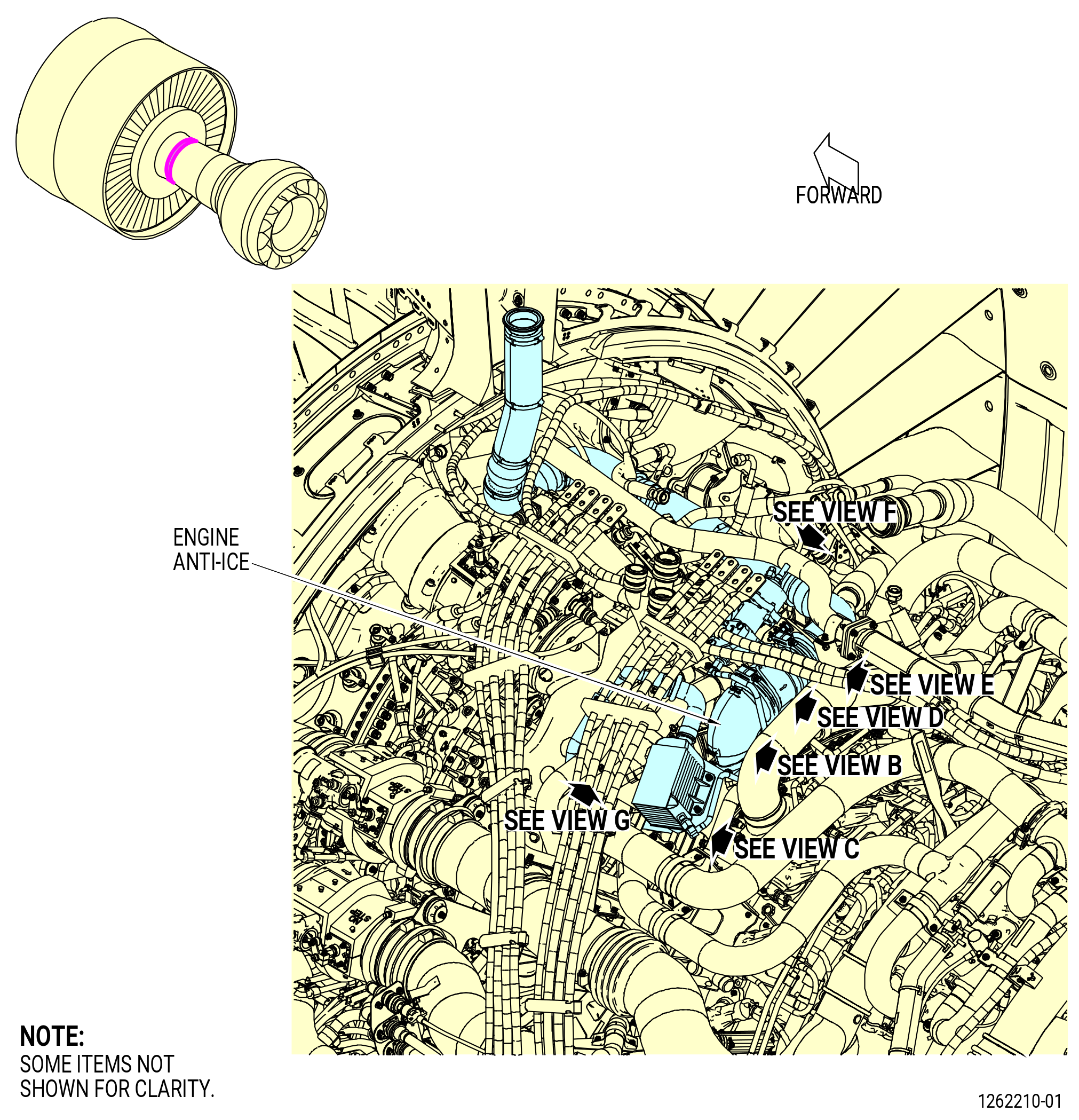
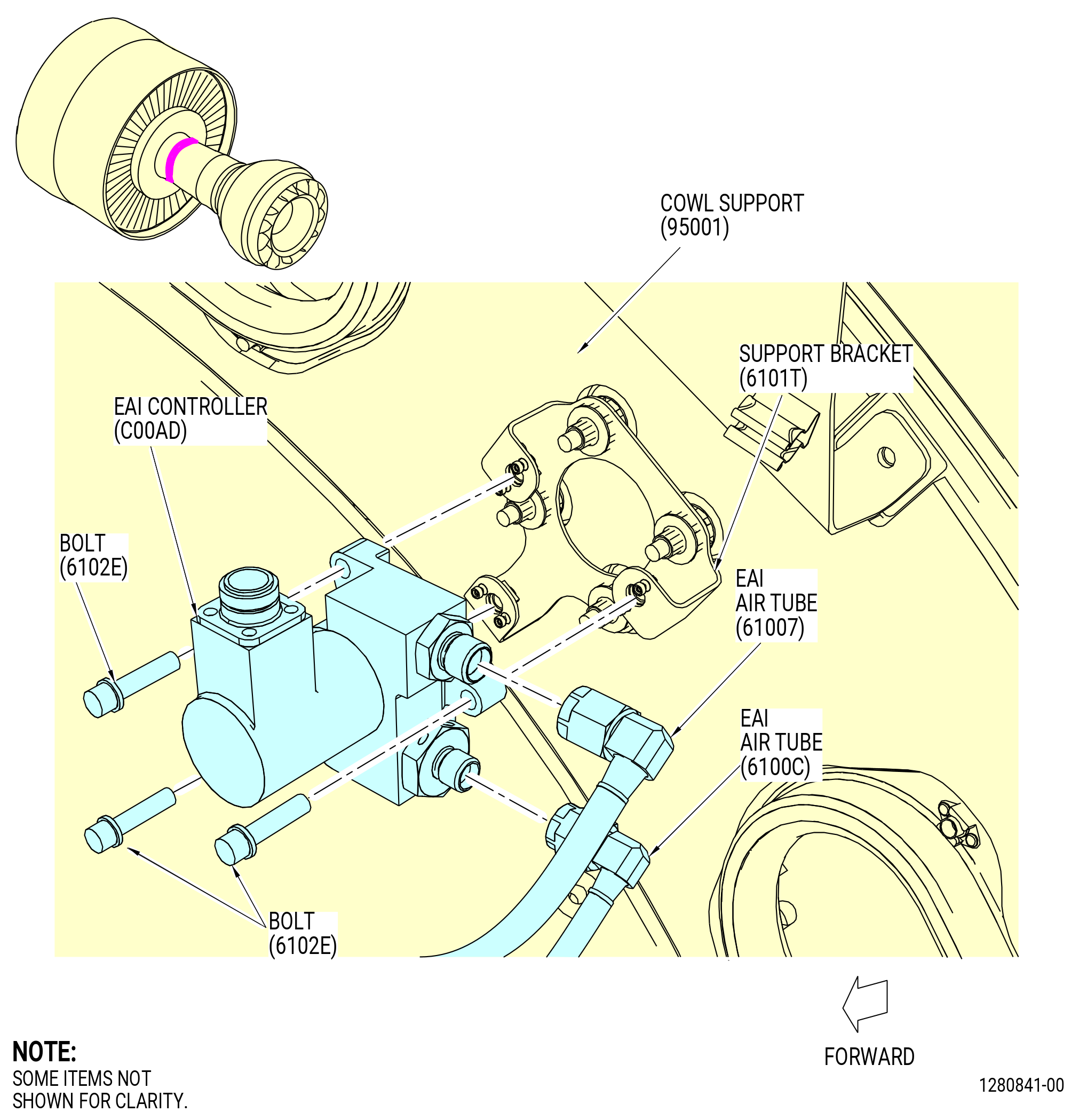
| B. | Remove the engine anti-icing (EAI) controller (C00AD) as follows. Refer to Figure 503. |
| (1) | Disconnect the B-nut of the EAI controller air tube (EAI air tube) (6100C) from the port on the forward side of the EAI controller. |
| (2) | Disconnect the B-nut of the EAI controller air tube (EAI air tube) (61007) from the port on the aft side of the EAI controller. |
| (3) | Remove the three bolts (6102E), and the EAI controller from the support bracket (6101T). |
| (4) | Put protective caps or protective covers on the air tubes, the harness connector, and EAI controller fittings. |
| Subtask 72-00-02-030-463 |
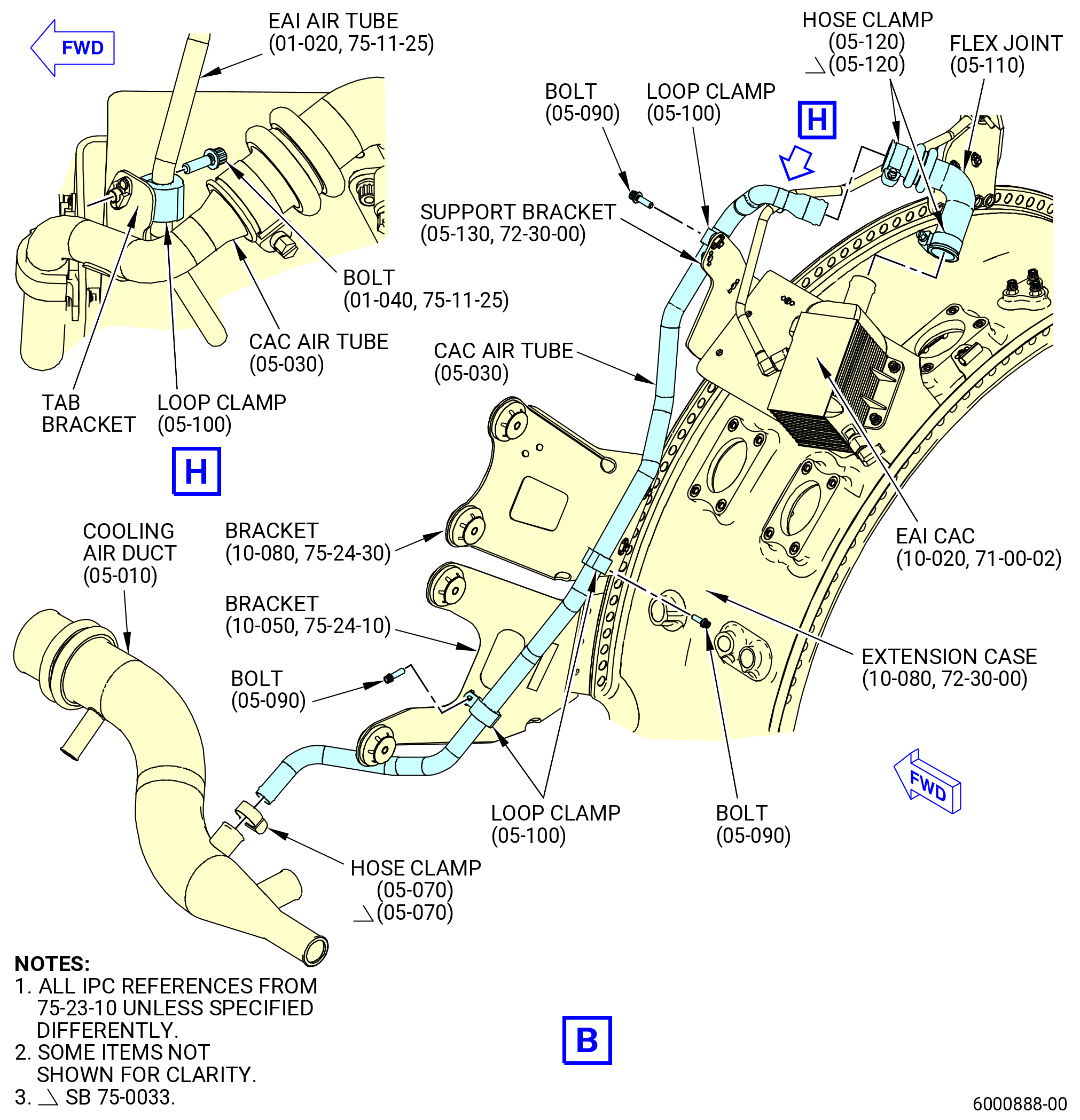
| C. | Remove the controller air cooler (CAC) air tube (6100A) as follows. Refer to Figure 504. |
| (1) | Remove bolt (6102S) and loop clamp (61088) from the tab bracket of the CAC air tube (6100A). |
| (2) | Remove bolt (6102H) and loop clamp (61088) from the support bracket (6101Y). |
| (3) | Remove bolt (6102H) and loop clamp (61088) from the bracket (62113). |
| (4) | Remove bolt (6102H) and loop clamp (61088) from the bracket (6221G). |
| (5) | Remove the hose clamps (05-120 , 75-23-10) (SIN 61089) and the flex joint (05-110 , 75-23-10) (SIN 6109E), from the CAC. |
| (6) | Remove the hose clamp (05-070 , 75-23-10) (SIN 62581) and the cooling air tube (05-030 , 75-23-10) (SIN 6100A) from the cooling air duct (05-010 , 75-23-10) (SIN 62504). |
| (7) | Put protective caps or protective covers on the cooling air tube, the flex joint, and the EAI CAC (C00AC). |
| Subtask 72-00-02-030-464 |
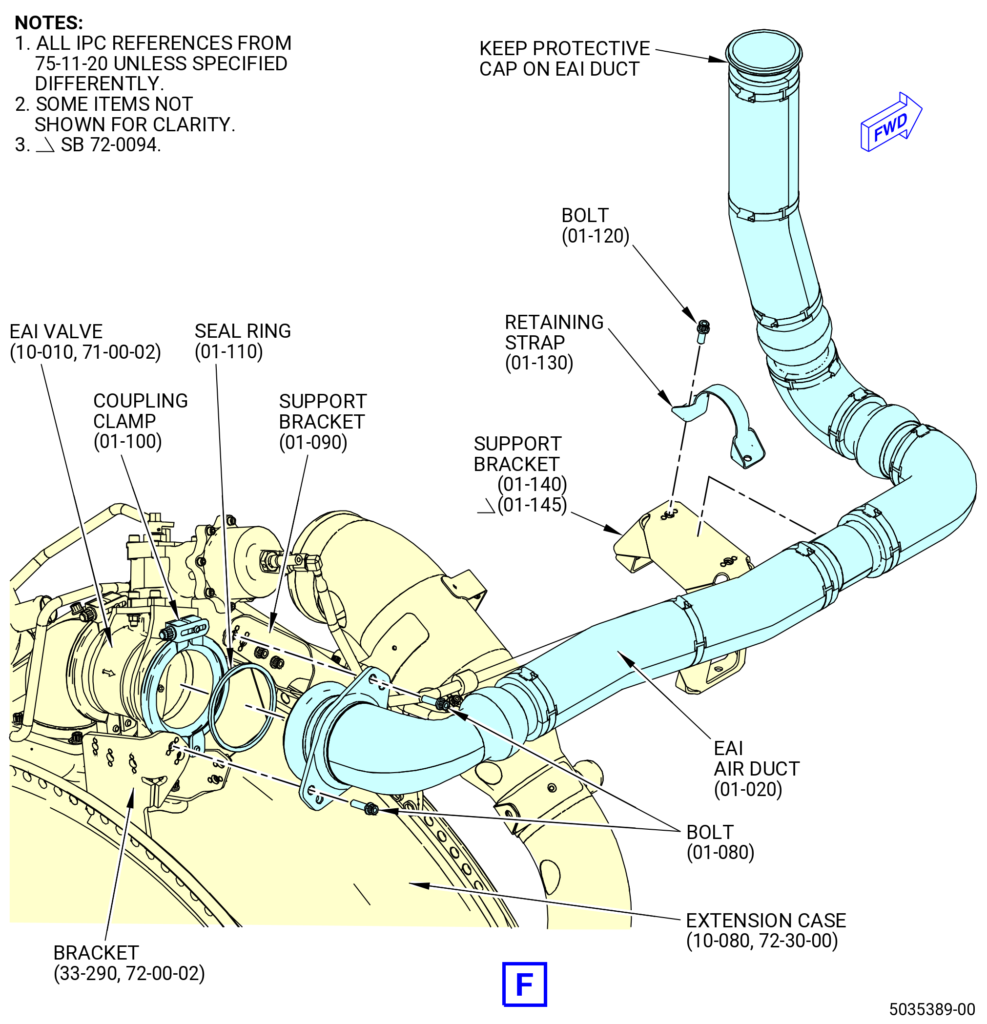
| D. | Remove the EAI core forward valve insulated air duct (EAI air duct) (61002) as follows. Refer to Figure 505. |
| (1) | Remove the four bolts (6102G) from the support brackets (6101N, 6101K). |
| (2) | Remove the two bolts (01-120 , 75-11-20) (SIN 6102J) and retaining strap (01-130 , 75-11-20) (SIN 6108C) from the support bracket (01-140 , 75-11-20) (SIN 6101B) or (01-145 , 75-11-20) (SIN 6101B). |
| (3) | Remove the coupling clamp (6108H) and one seal ring (61059) from the EAI air duct. |
| (4) | Remove the EAI air duct from the air tube (61004). |
| (5) | Put protective caps or protective covers on the EAI air duct. |
| Subtask 72-00-02-030-465 |
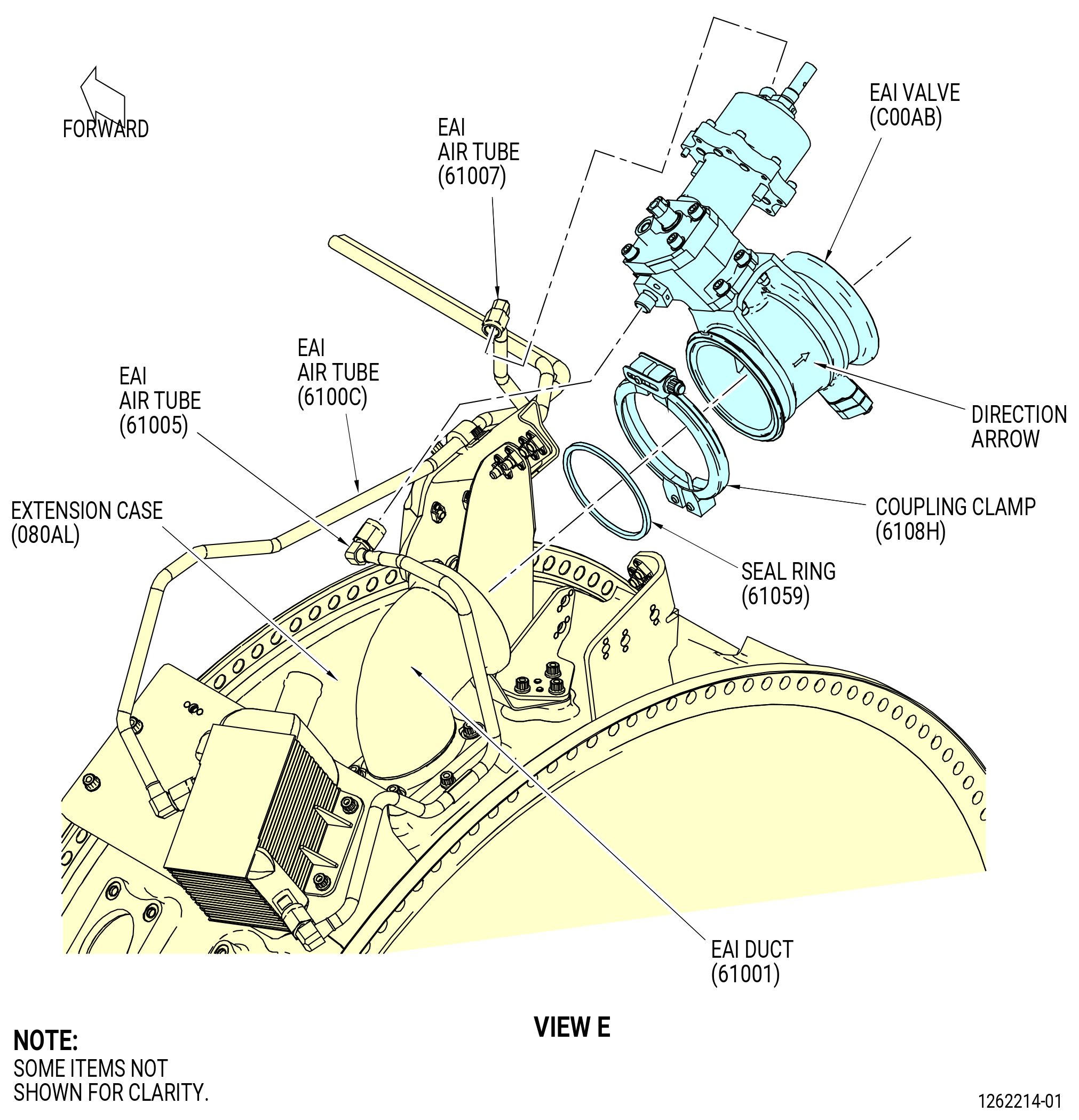
| E. | Remove the EAI valve (C00AB) as follows. Refer to Figure 506. |
| (1) | Disconnect the B-nut of the EAI air tube (61007) from the EAI valve. |
| (2) | Disconnect the B-nut of the EAI controller air tube (EAI air tube) (61005) from the EAI valve. |
| (3) | Remove the coupling clamp (6108H) and one seal ring (61059) from the EAI valve. |
| (4) | Remove the EAI valve from the EAI duct (61001). |
| (5) | Install protective caps or protective covers on the EAI valve and the EAI duct. |
| Subtask 72-00-02-030-466 |
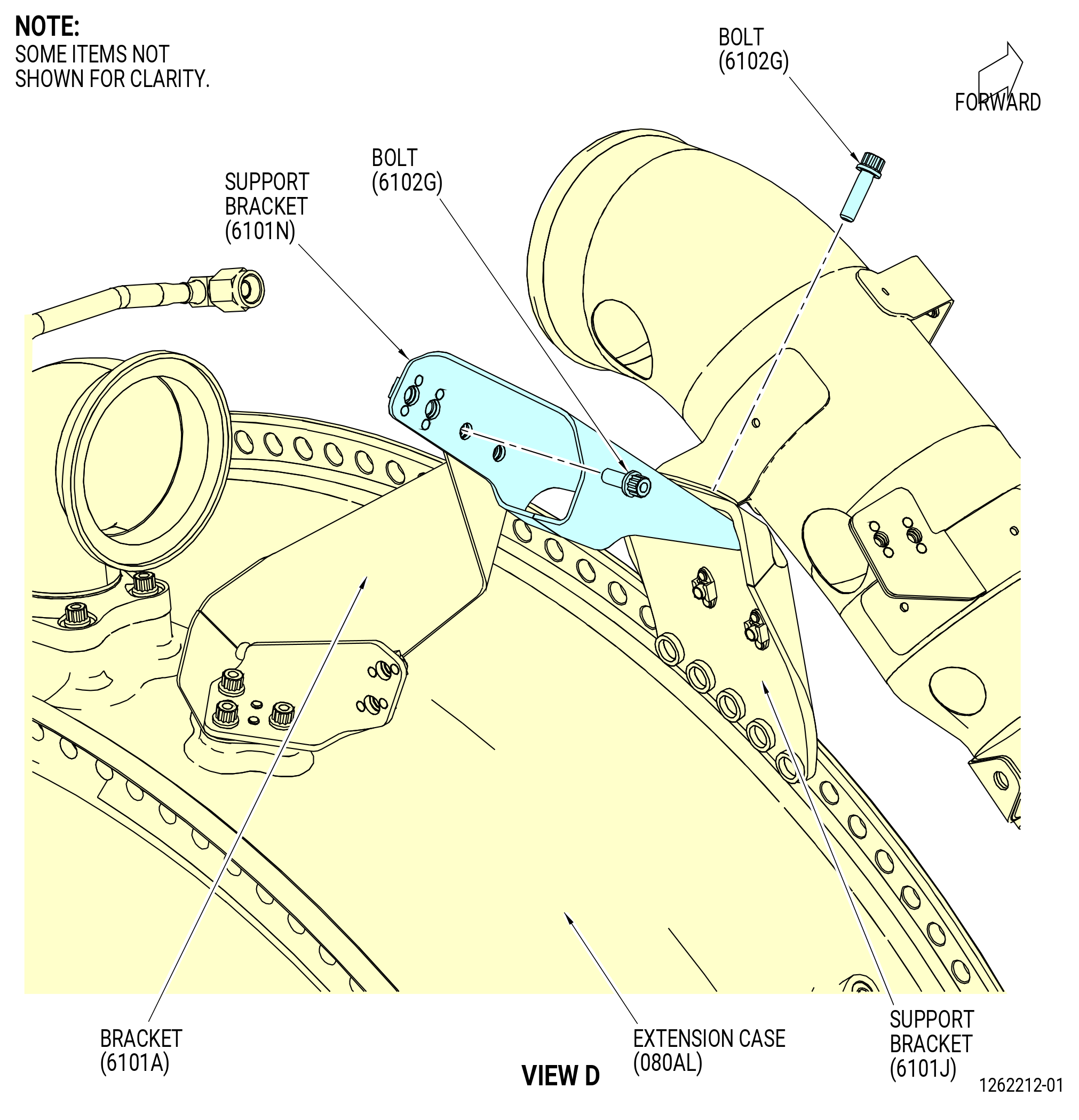
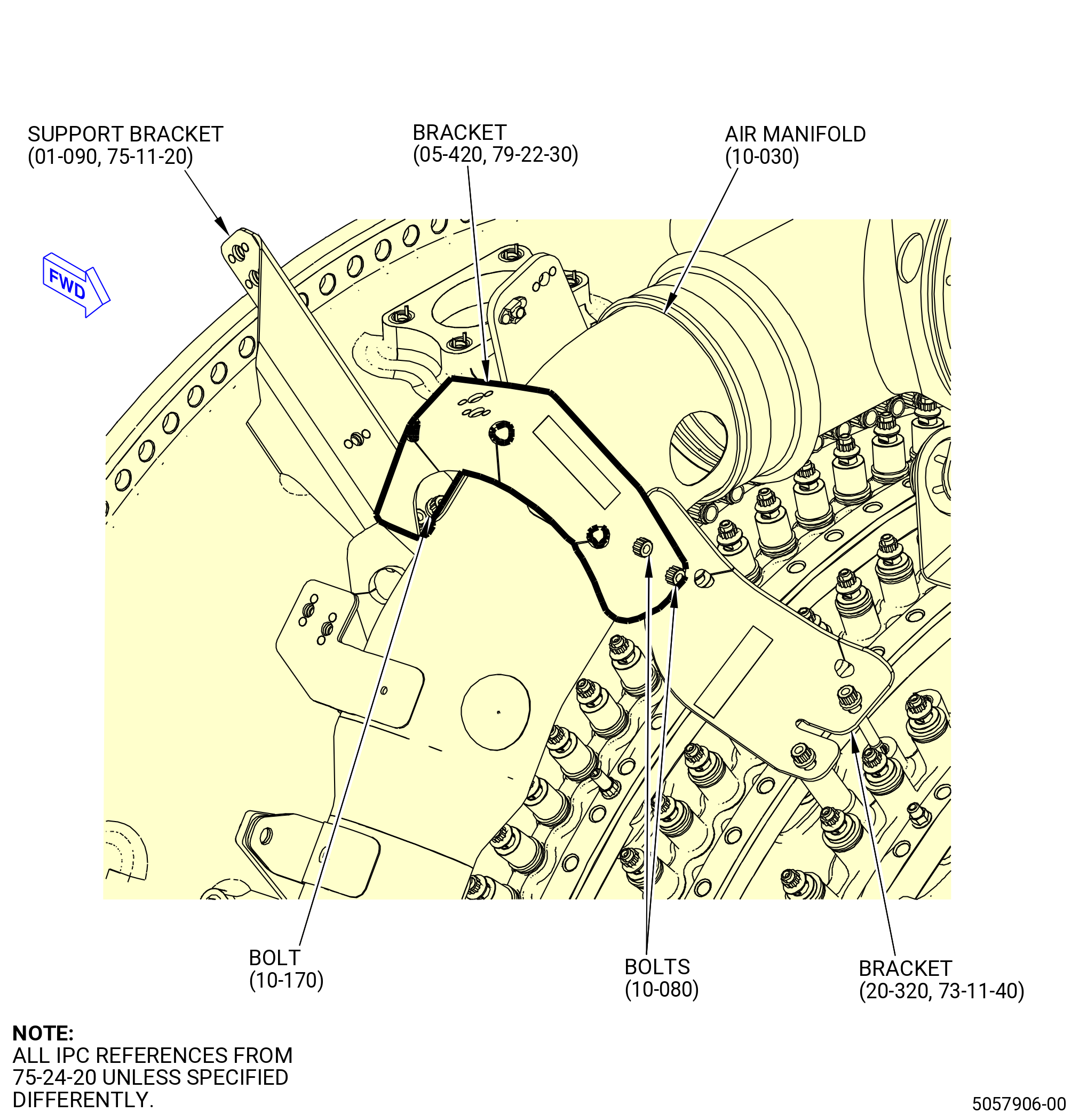
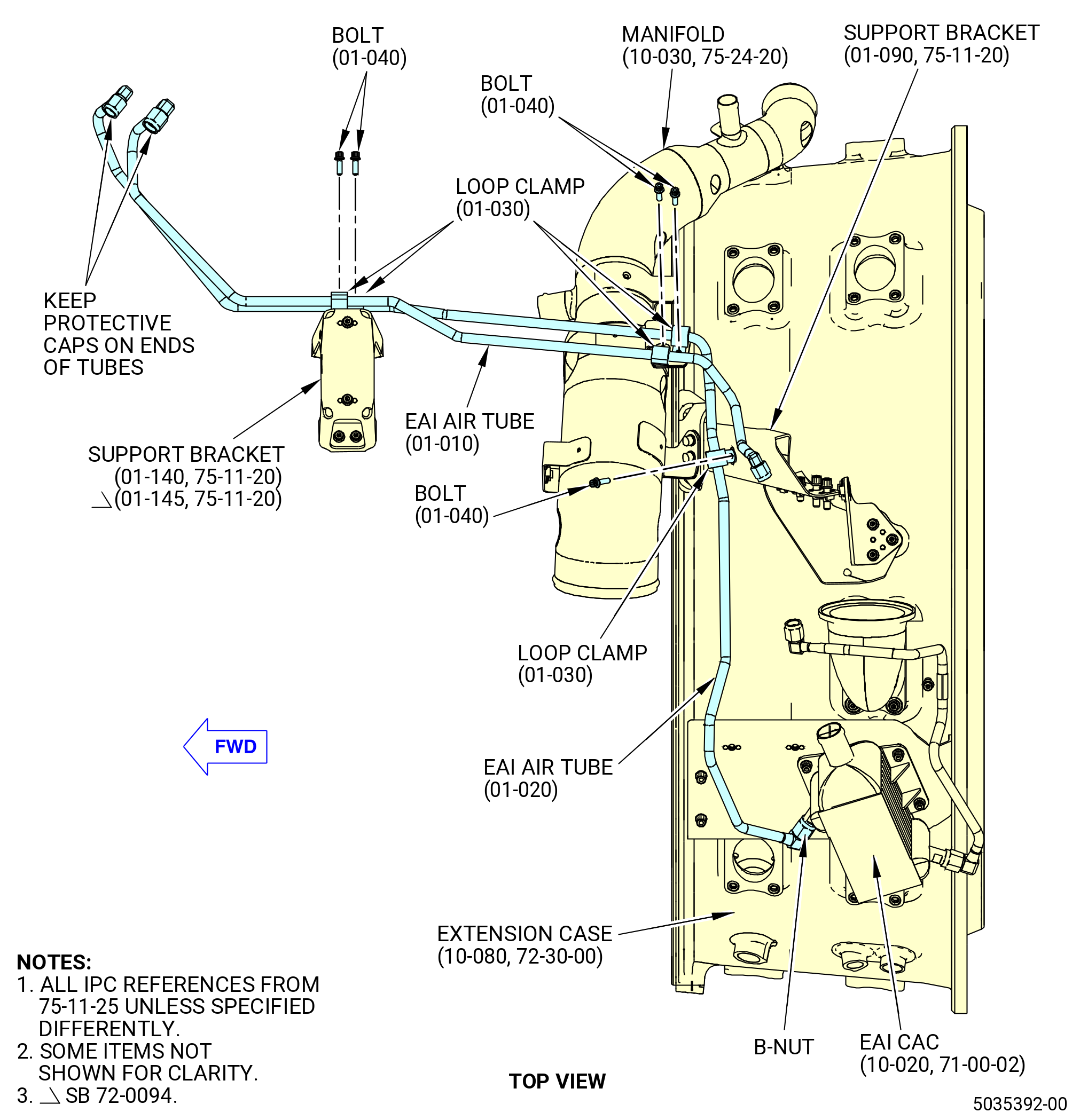
| F. | Remove the support bracket (01-090 , 75-11-20) (SIN 6101N) and two EAI air tubes (01-010 , 75-11-25) (SIN 61007) and (01-020 , 75-11-25) (SIN 6100C) as follows. Refer to Figure 507 and Figure 508. |
| (1) | Disconnect the B-nut of the EAI air tube (01-020 , 75-11-25) (SIN 6100C) from the EAI CAC. |
| (2) | Remove bolts (01-040 , 75-11-25) (SIN 6102S) and loop clamps (01-030 , 75-11-25) (SIN 61082) from the brackets (01-090 , 75-11-20) (SIN 6101N), (01-140 , 75-11-20) (SIN 6101B), or (01-145 , 75-11-20) (SIN 6101B) and the EAI air tubes. |
| (3) | Remove the bolts (01-080 , 75-11-20) (SIN 6102G) and the bracket (01-090 , 75-11-20) (SIN 6101N) from the brackets (33-030) (SIN 6101A) and (05-060 , 72-30-00) (SIN 6101J). |
| (4) | Remove the bolts (10-080 , 75-24-20) (SIN 63122) and bolts (10-170 , 75-24-20) (SIN 6102G) from the bracket (05-420 , 79-22-30) (SIN 4611D) and the CCC air manifold (10-030 , 75-24-20) (SIN 63101). Remove the bracket (05-420 , 79-22-30) (SIN 4611D). |
| (5) | Remove the EAI air tube (01-010 , 75-11-25) (SIN 61007) and the EAI air tube (01-020 , 75-11-25) (SIN 6100C). |
| (6) | Put protective caps or protective covers on the EAI valve and the EAI duct (01-010 , 75-11-20) (SIN 61001). |
| Subtask 72-00-02-030-467 |
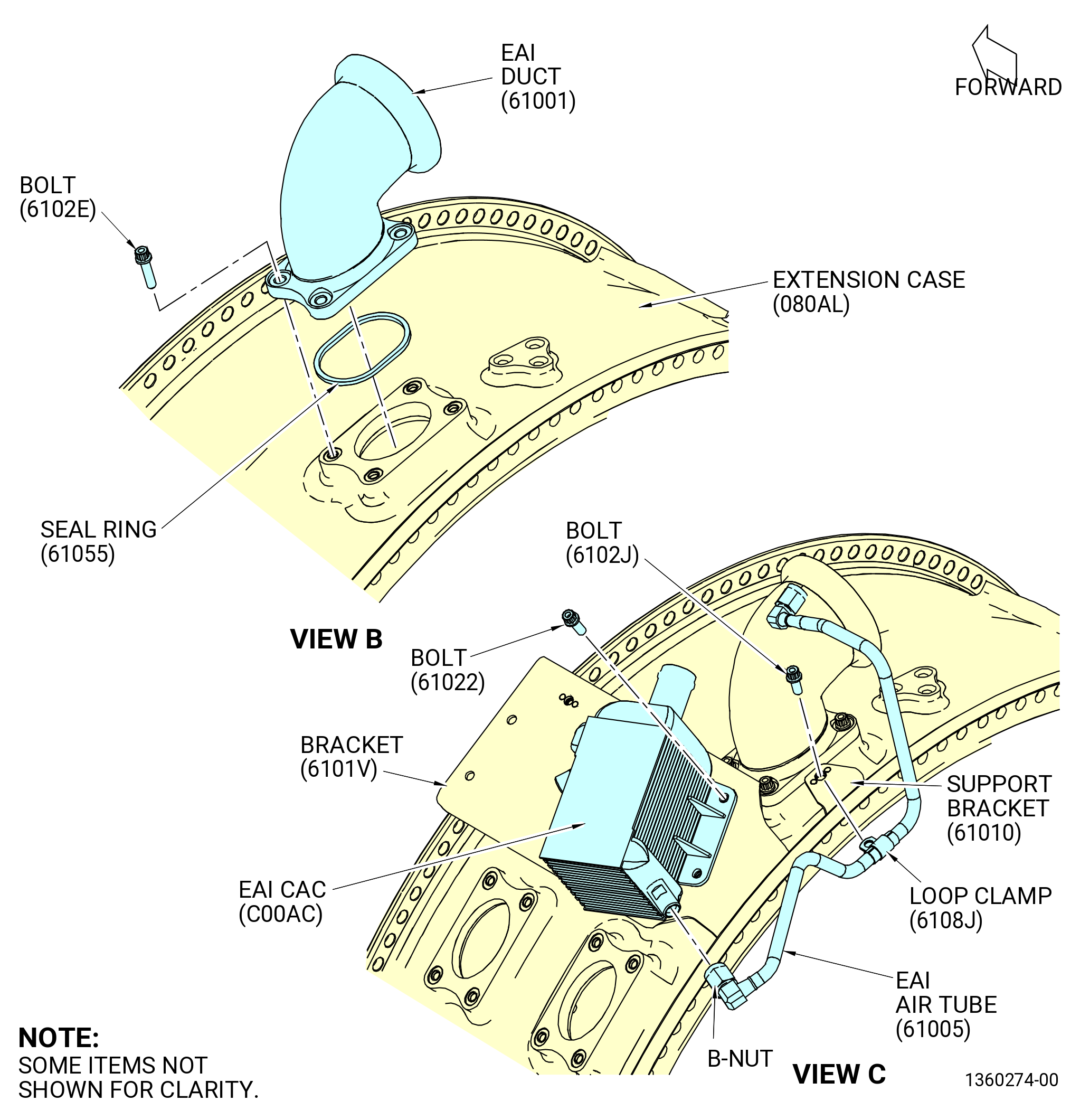
| G. | Remove the engine anti-ice duct (61001) and the EAI CAC (C00AC) as follows. Refer to Figure 509. |
| (1) | Remove the bolt (6102G), loop clamp (6108J), and EAI air tube (61005) from the support bracket (61010). |
| (2) | Remove the four bolts (61022) and EAI CAC (C00AC) from the bracket (6101V). |
| (3) | Remove the four bolts (6102E), EAI duct (61001), and seal ring (61055) from the extension case (080AL). |
| (4) | Put protective caps or protective covers on the extension case, EAI CAC, and EAI duct. |
| Subtask 72-00-02-030-401 |
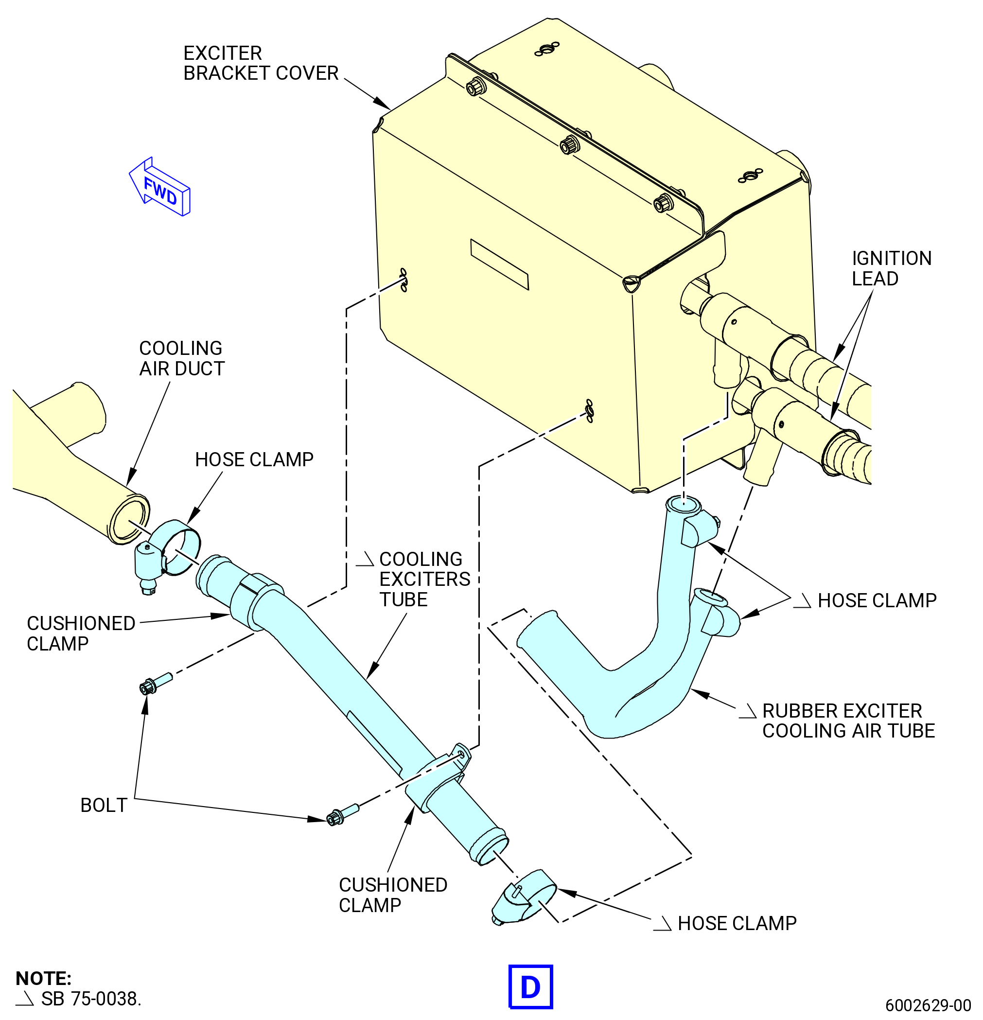
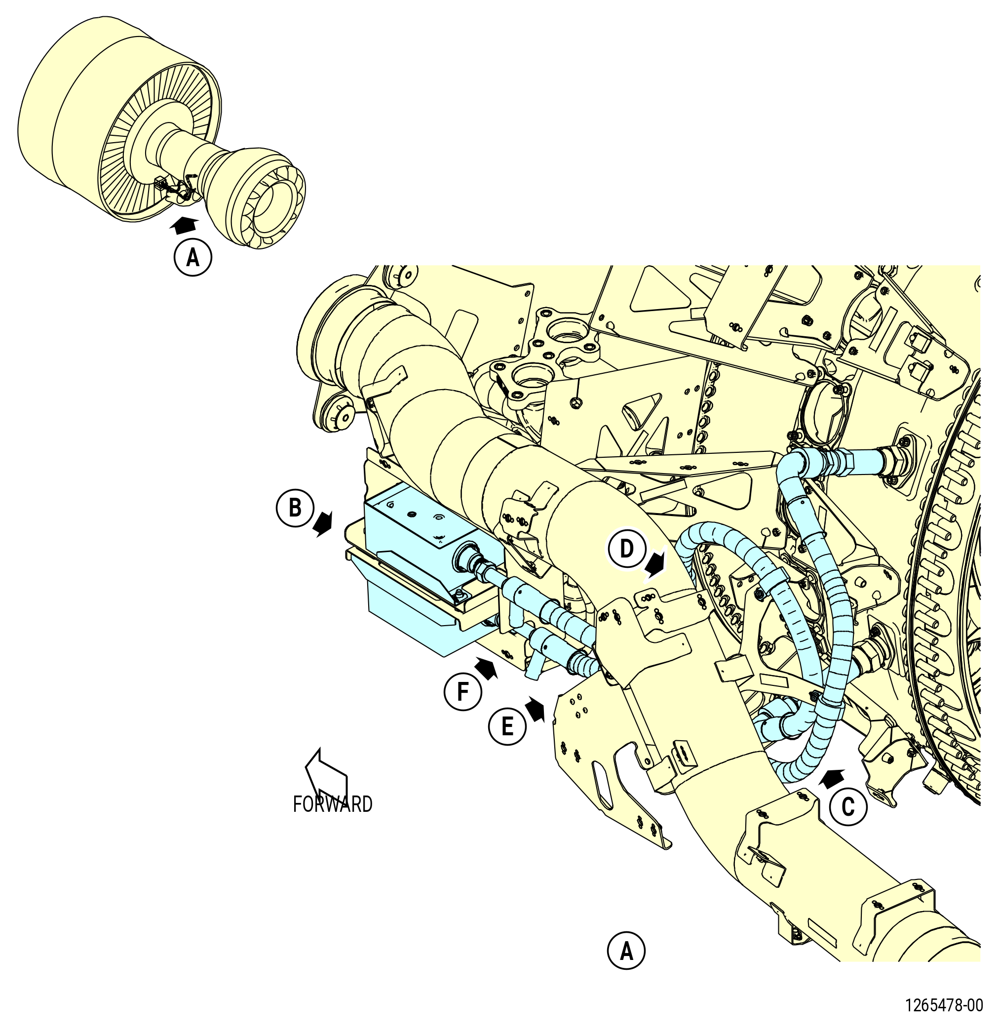
| H. | Remove the ignition cooling system as follows. Refer to Figure 510. |
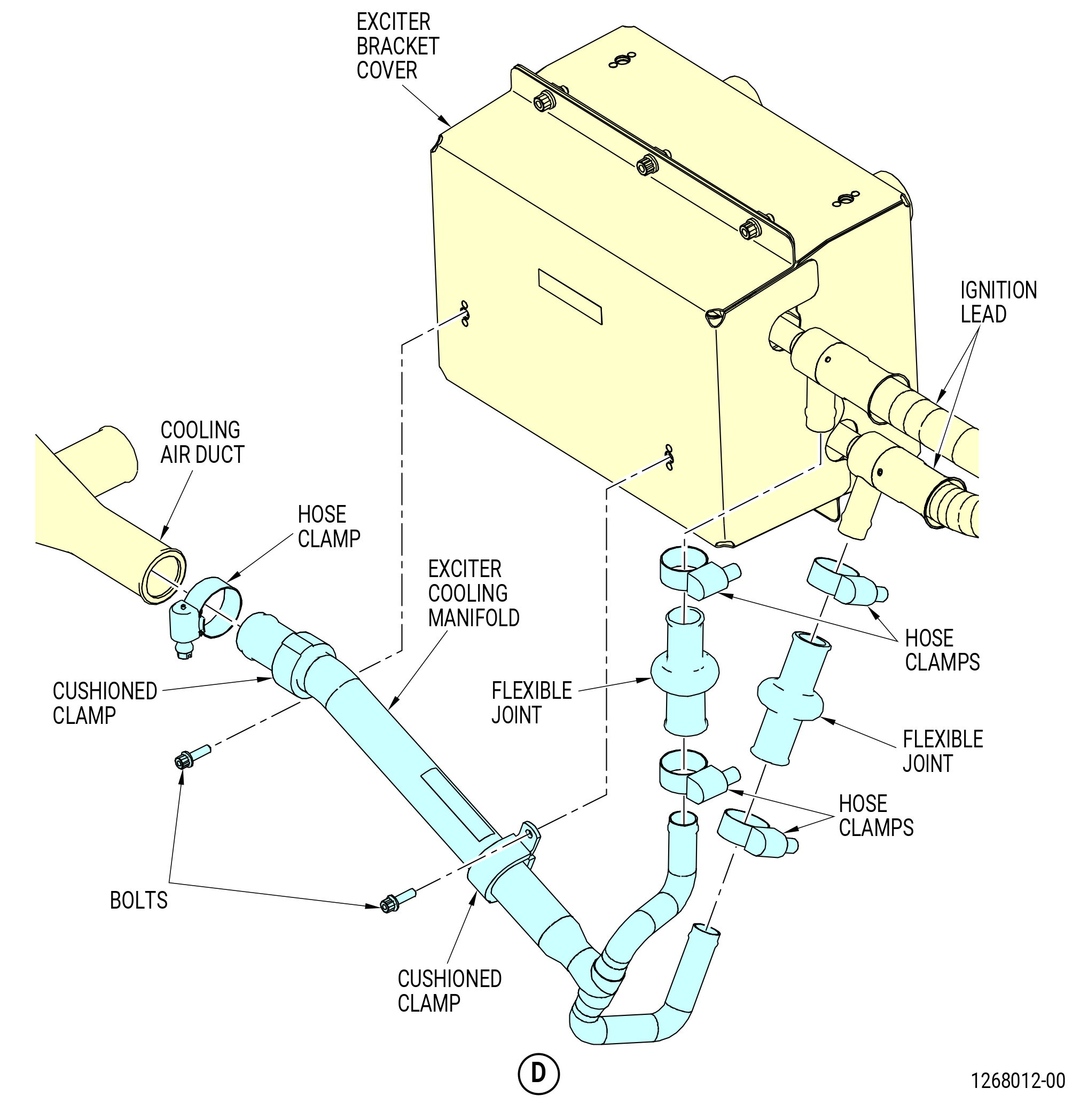
| Subtask 72-00-02-030-769 |
| * * * PRE SB 75-0038( Exciter Cooling System without Improvement ) |
| (1) | Remove the exciter cooling manifold as follows: |
| (a) | Remove the bolts and the cushioned clamps that attach the exciter cooling manifold to the exciter bracket cover. |
| (b) | Remove the hose clamps that attach the exciter cooling manifold to the cooling air duct and the flexible joints. |
| (c) | Remove the exciter cooling manifold from the cooling air duct and flexible joints. |
| (d) | Remove the hose clamps on each end of the flexible joints on the ignition lead air tubes. |
| (e) | Remove the flexible joints from the ignition lead air tubes. |
| * * * END PRE SB 75-0038 |
| Subtask 72-00-02-030-770 |
| * * * SB 75-0038( Exciter Cooling System with Improvement ) |
| (1).A. | Remove the cooling exciters tube as follows: |
| (a) | Remove the bolts and cushioned clamps that attach the cooling exciters tube to the exciter bracket cover. |
| (b) | Remove the hose clamps that attach the cooling exciters tube to the cooling air duct and the rubber exciter cooling air tube. |
| (c) | Remove the cooling exciters tube from the cooling air duct and the rubber exciter cooling air tube. |
| (d) | Remove the hose clamps on each end of the rubber exciter cooling air tube. |
| (e) | Remove the rubber exciter cooling air tube from the ignition lead air tubes. |
| * * * END SB 75-0038 |
| Subtask 72-00-02-030-771 |
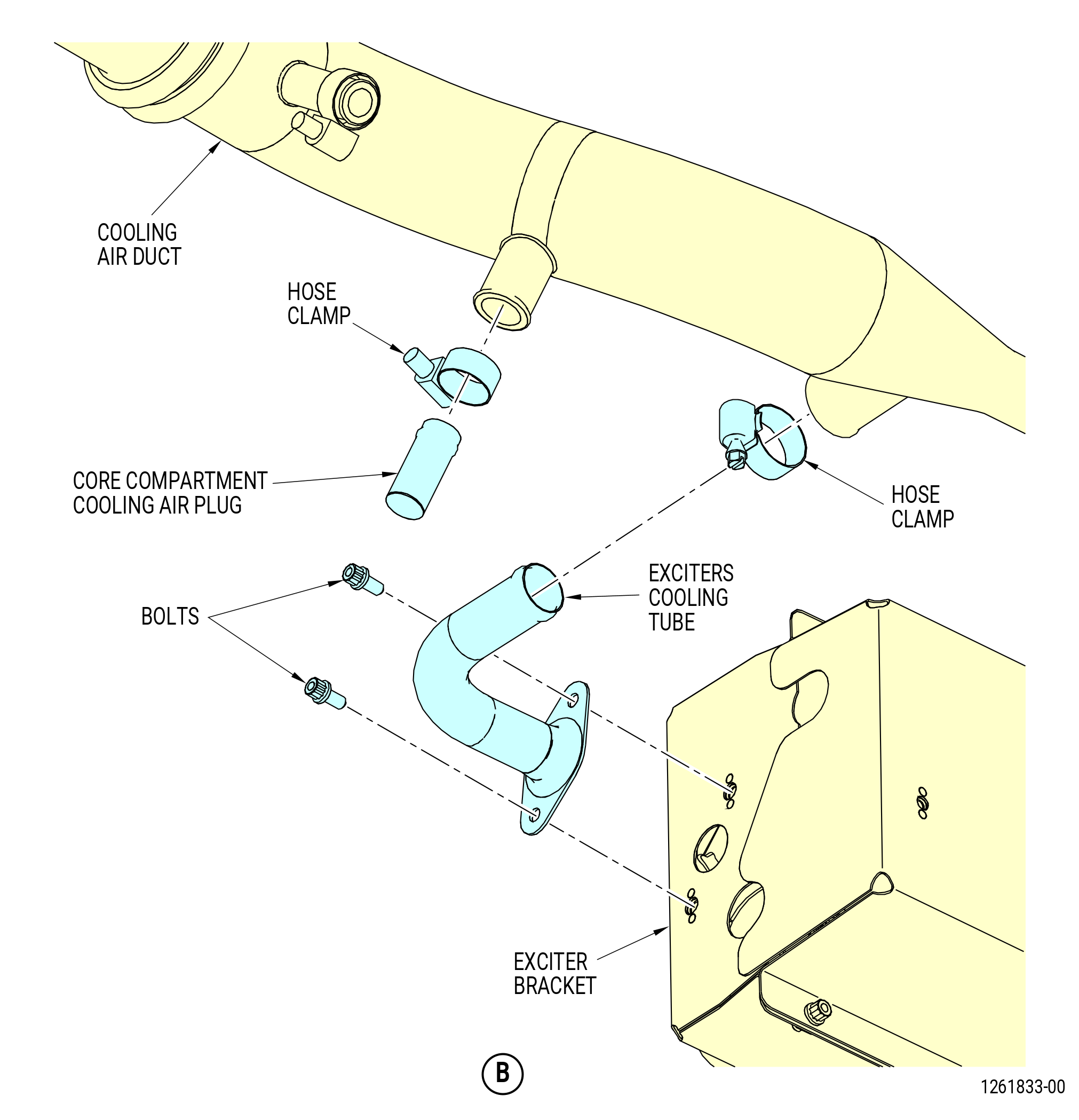
| (2) | Remove the cooling air duct as follows: |
| (a) | Remove the hose clamps from the cooling air duct at the variable bypass valve (VBV) air duct, the engine configuration box, the air tube, and the exciters cooling tube. |
| (b) | Remove the cooling air duct from the air tube and the exciters cooling tube. |
| (c) | Remove the cooling air duct from the engine configuration box. |
| (d) | Remove the cooling air duct from the VBV air duct. |
| (e) | Remove the hose clamp and the core compartment cooling air plug from the cooling air duct. |
| Subtask 72-00-02-030-672 |
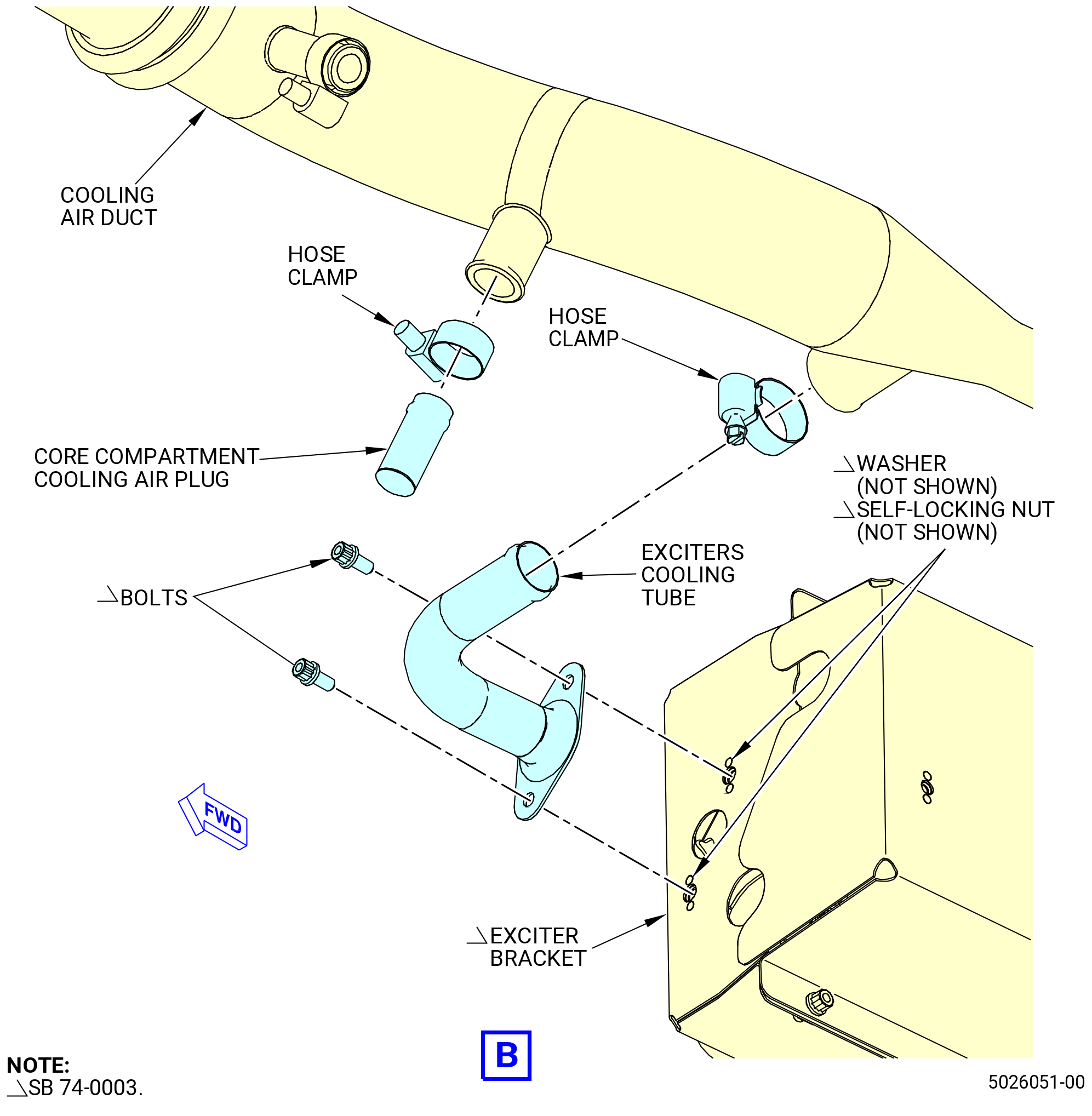
| * * * PRE SB 74-0003( Exciter Bracket with Nutplates ) |
| (3) | Remove the bolts that attach the exciters cooling tube to the exciter bracket and remove the exciters cooling tube. |
| * * * END PRE SB 74-0003 |
| Subtask 72-00-02-030-686 |
| * * * PRE SB 74-0004( Exciter Bracket without Nutplates ) |
| * * * SB 74-0003( Exciter Bracket without Nutplates ) |
| (3).A. | Remove the bolts, the washer, and the self-locking nuts that attach the exciters cooling tube to the exciter bracket and remove the exciters cooling tube. |
| * * * END SB 74-0003 |
| * * * END PRE SB 74-0004 |
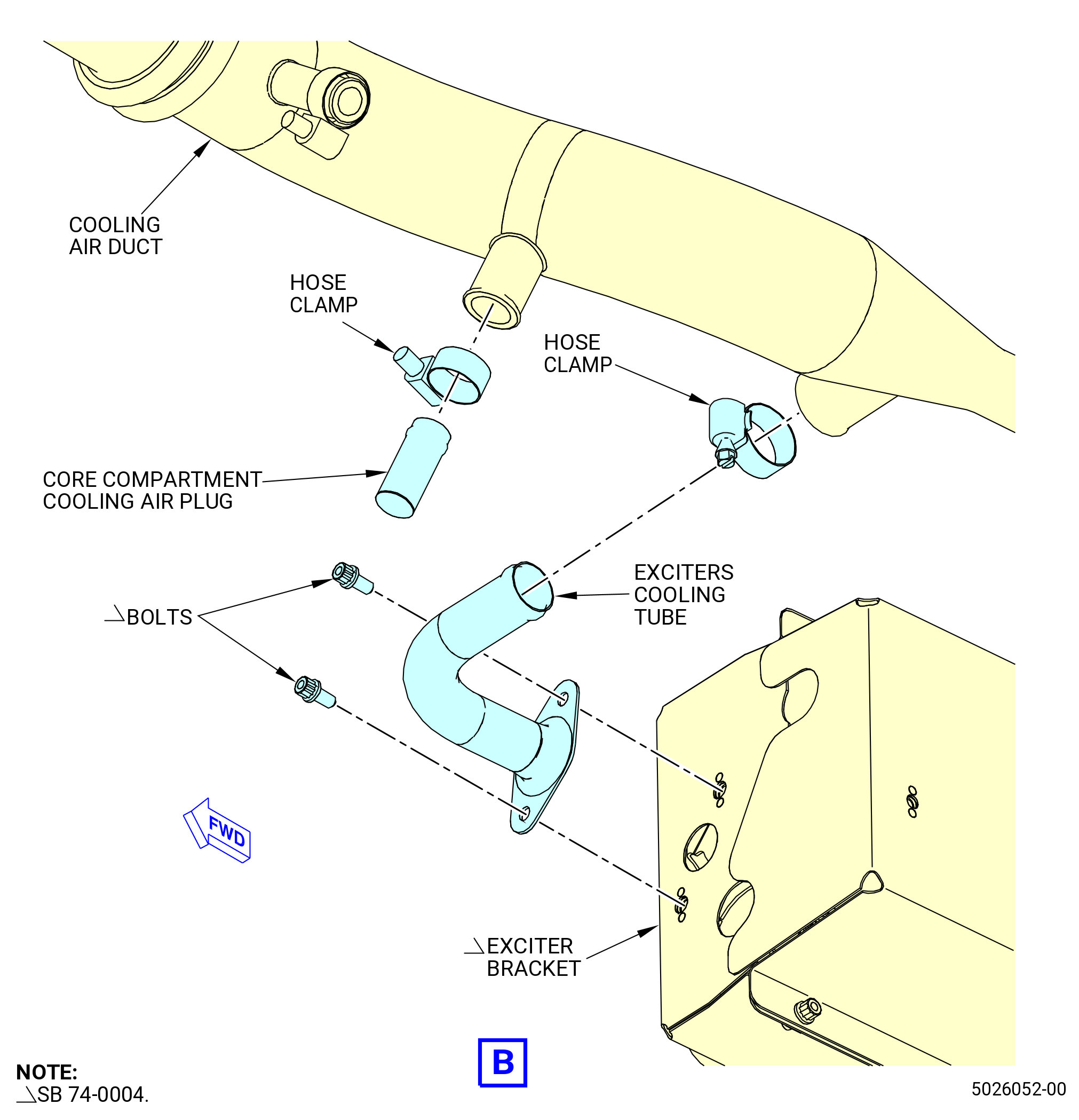
| Subtask 72-00-02-030-687 |
| * * * SB 74-0004( Exciter Bracket with Nutplates ) |
| (3).B. | Remove the bolts that attach the exciters cooling tube to the exciter bracket and remove the exciters cooling tube. |
| * * * END SB 74-0004 |
| Subtask 72-00-02-440-502 |
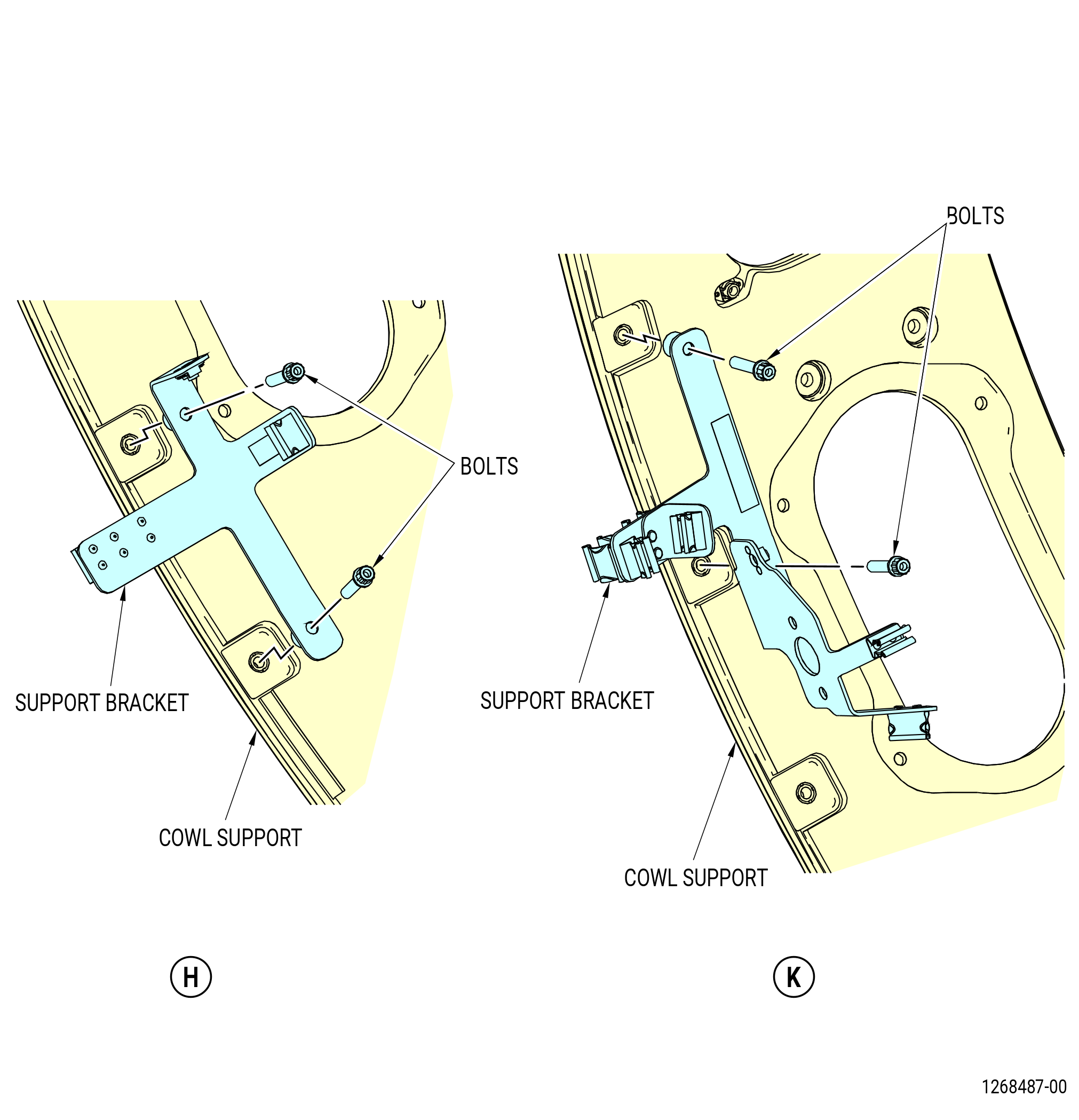
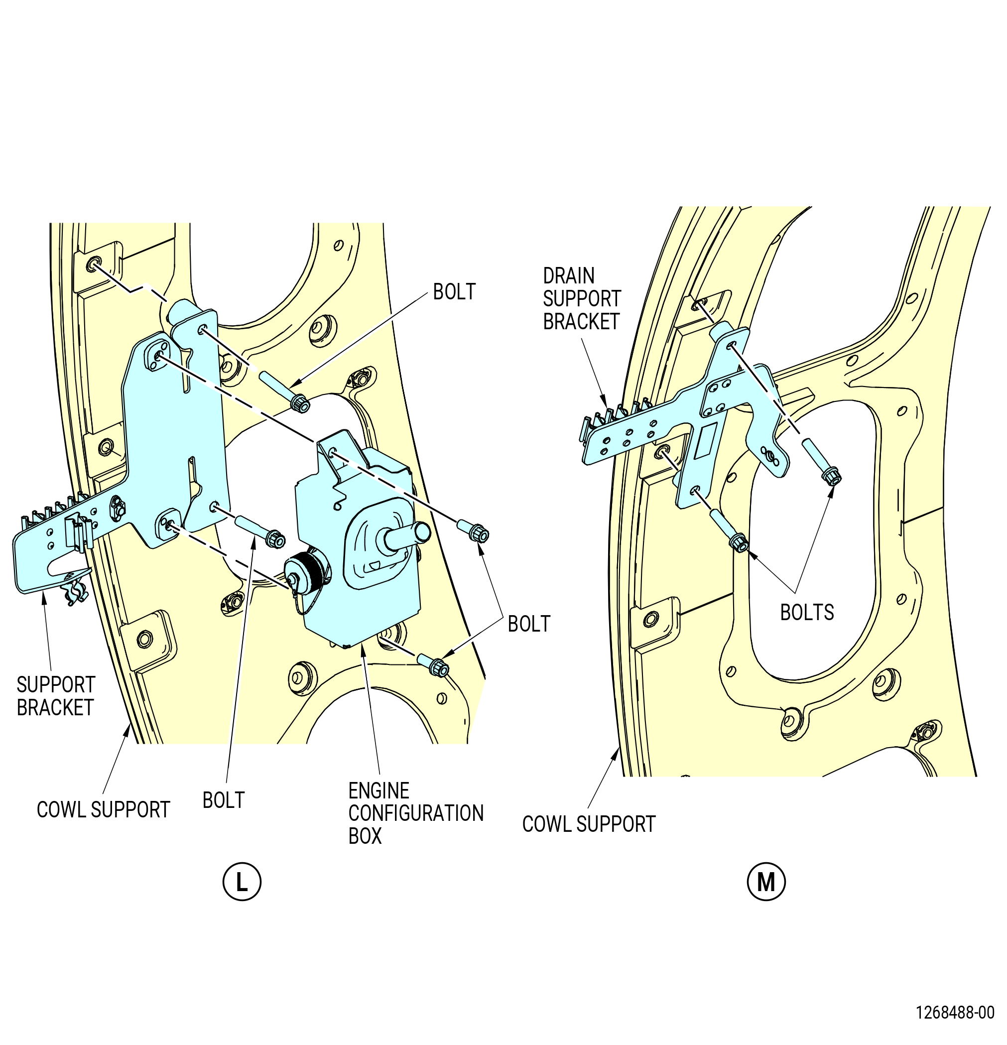
| (4) | Remove the bolts that attach the configuration box to the support bracket on the left side of the cowl support at the 9:30 o'clock position. |
|
|
|
|
| Subtask 72-00-02-030-428 |
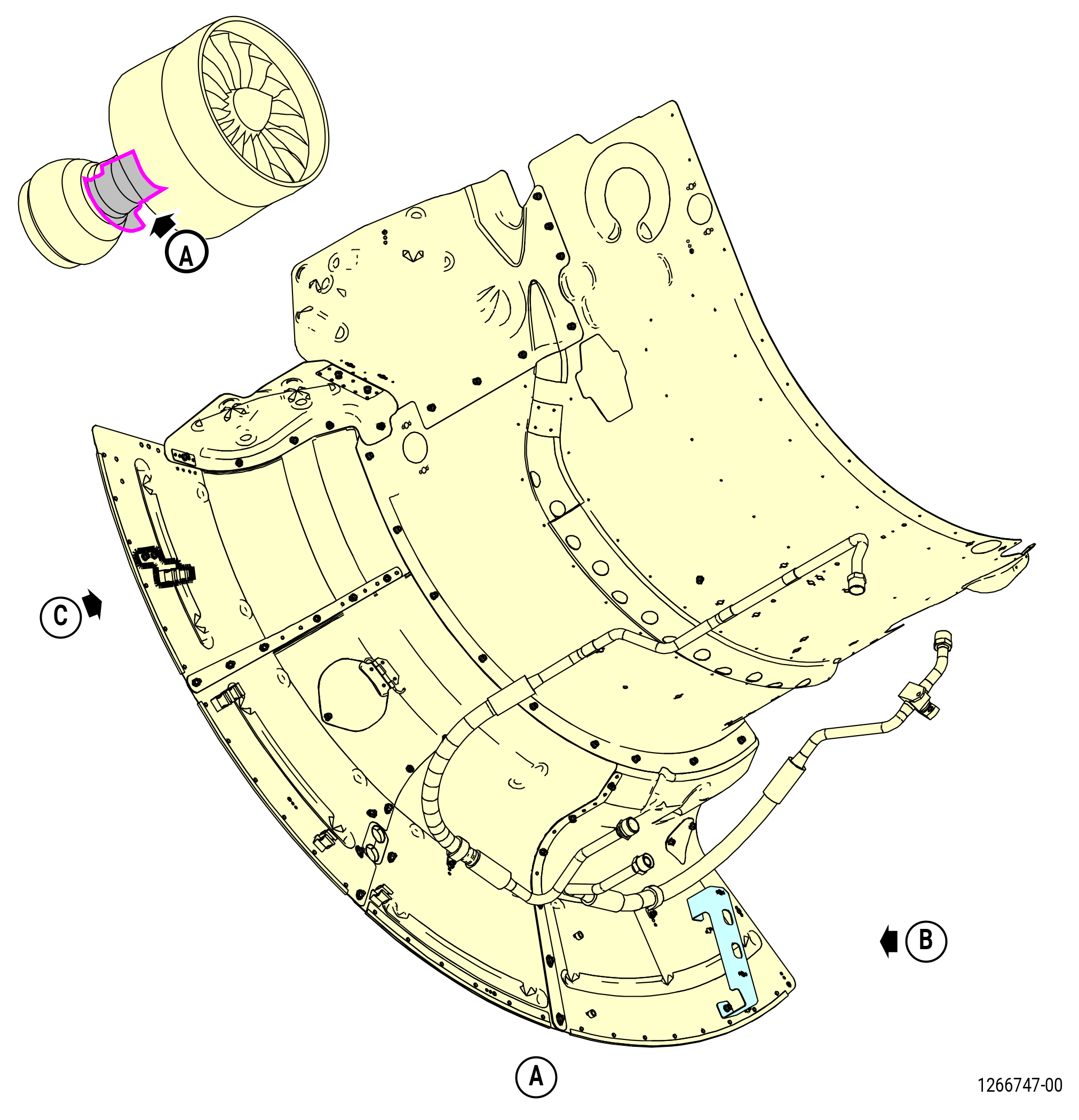
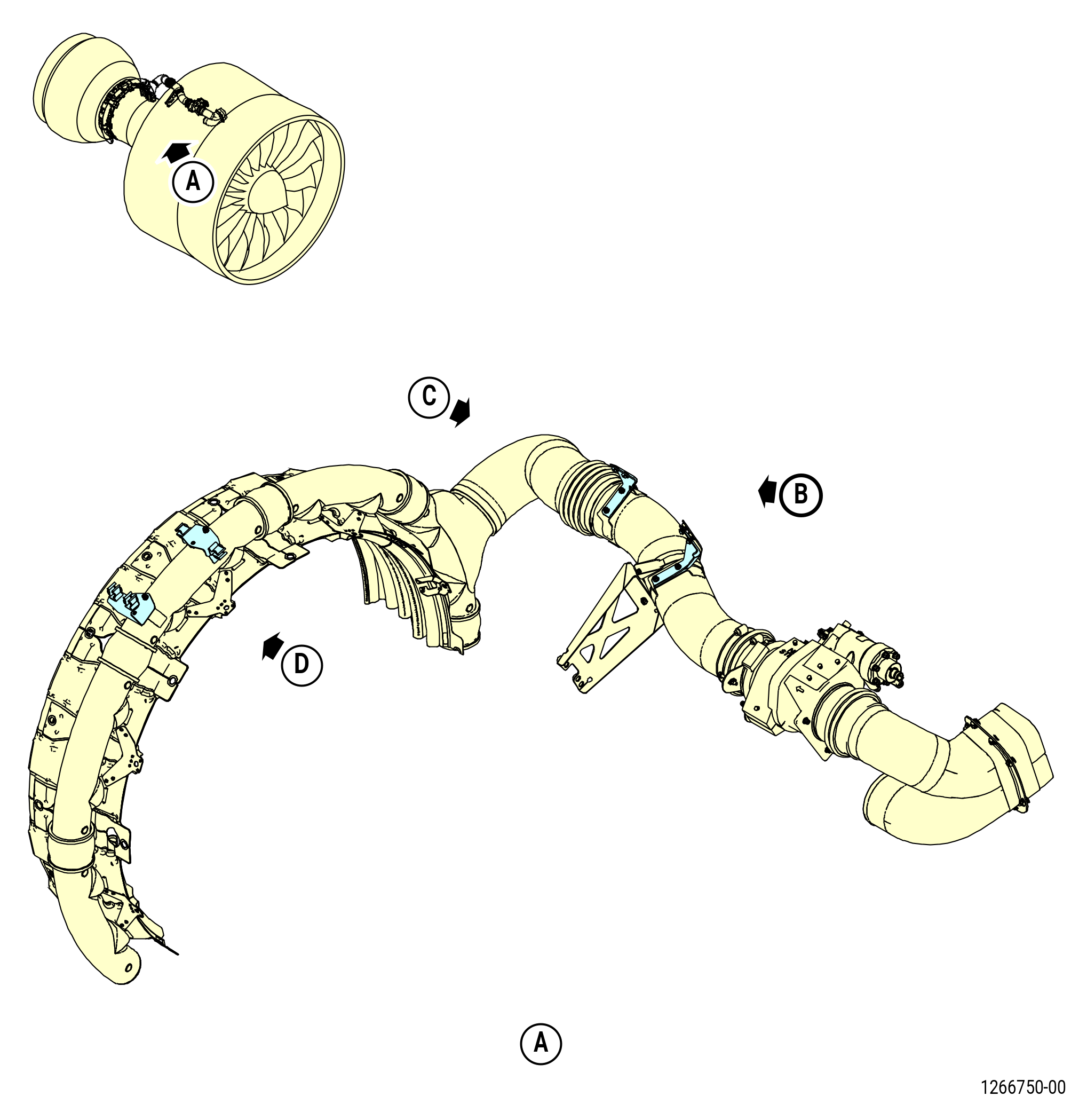
| I. | Remove the cable brackets as follows: |
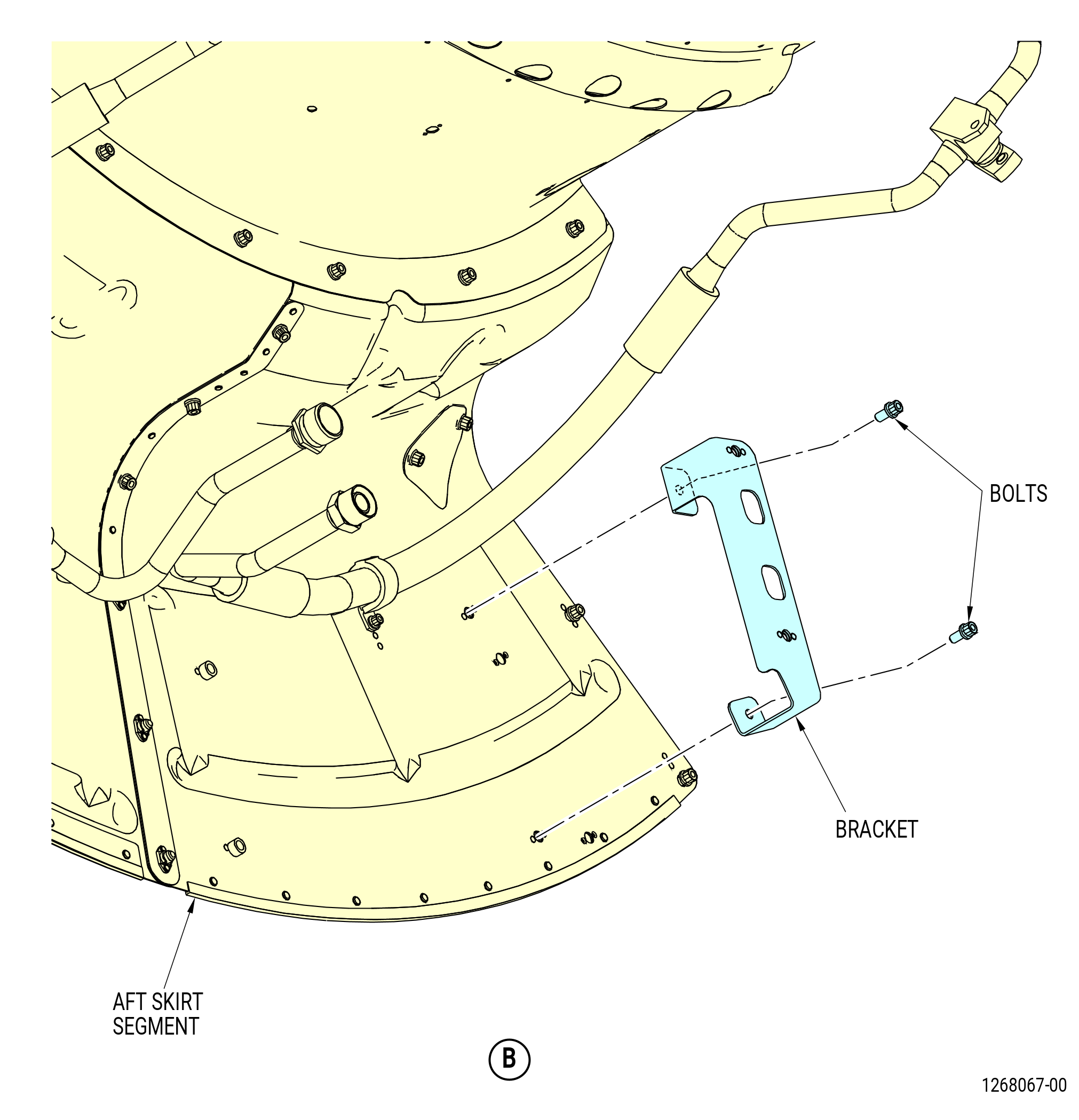
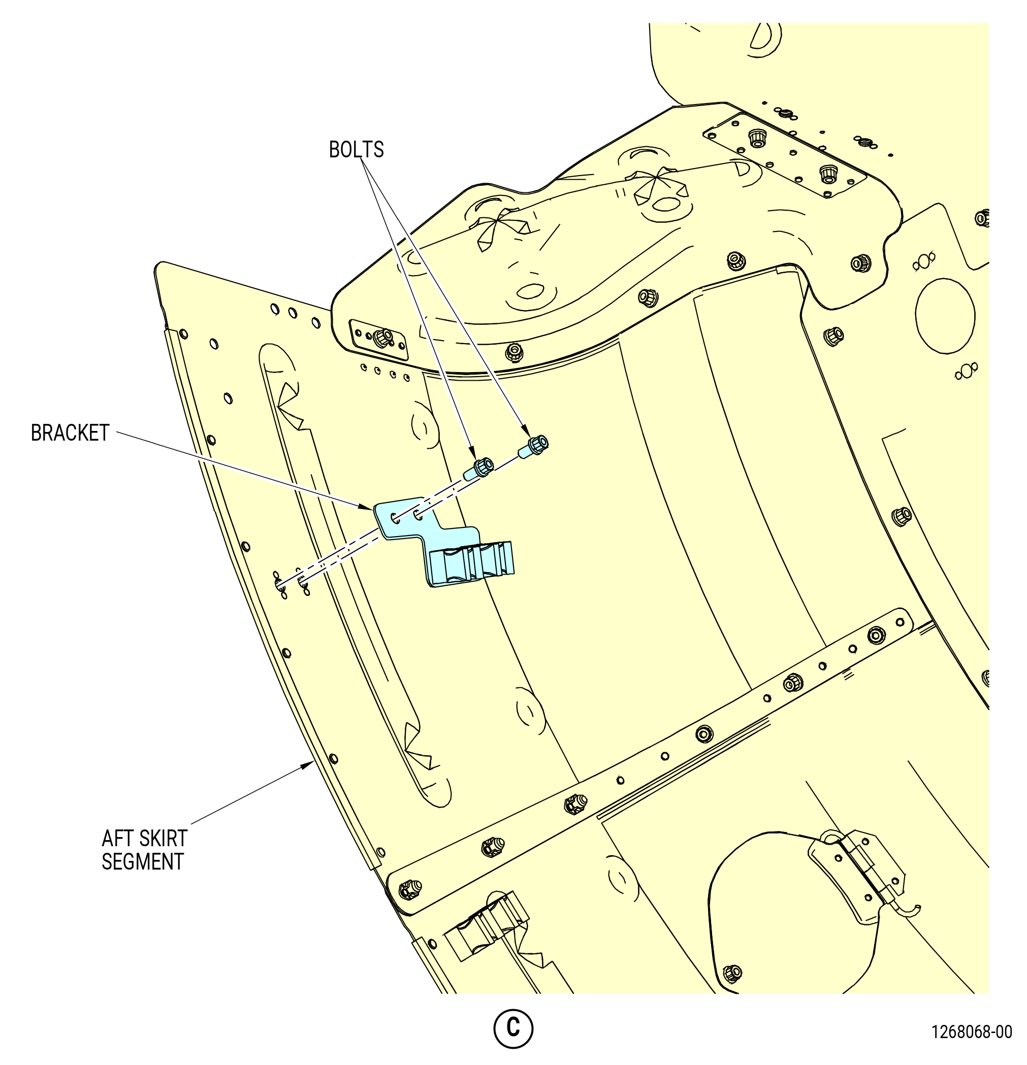
| (1) | Remove the brackets from the heat shield as follows. Refer to Figure 511. |
| (a) | Remove the bolts and bracket from the forward side of the aft skirt segment at the 7:30 o'clock position |
| (b) | Remove the bolts and bracket from the forward side of the aft skirt segment at the 4:00 o'clock position |
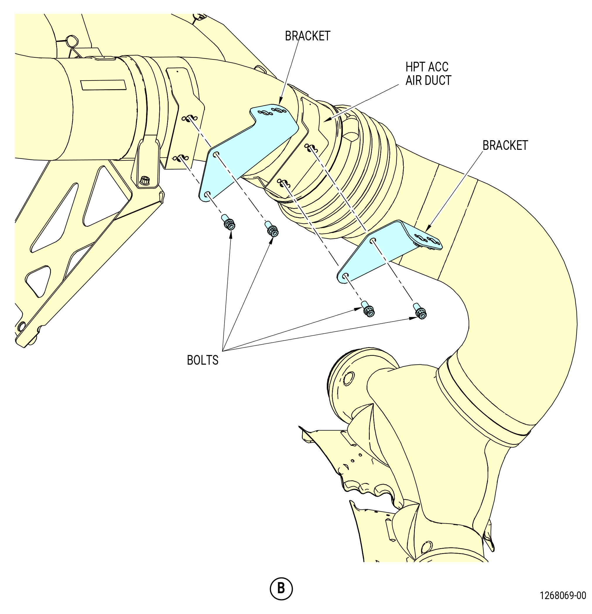
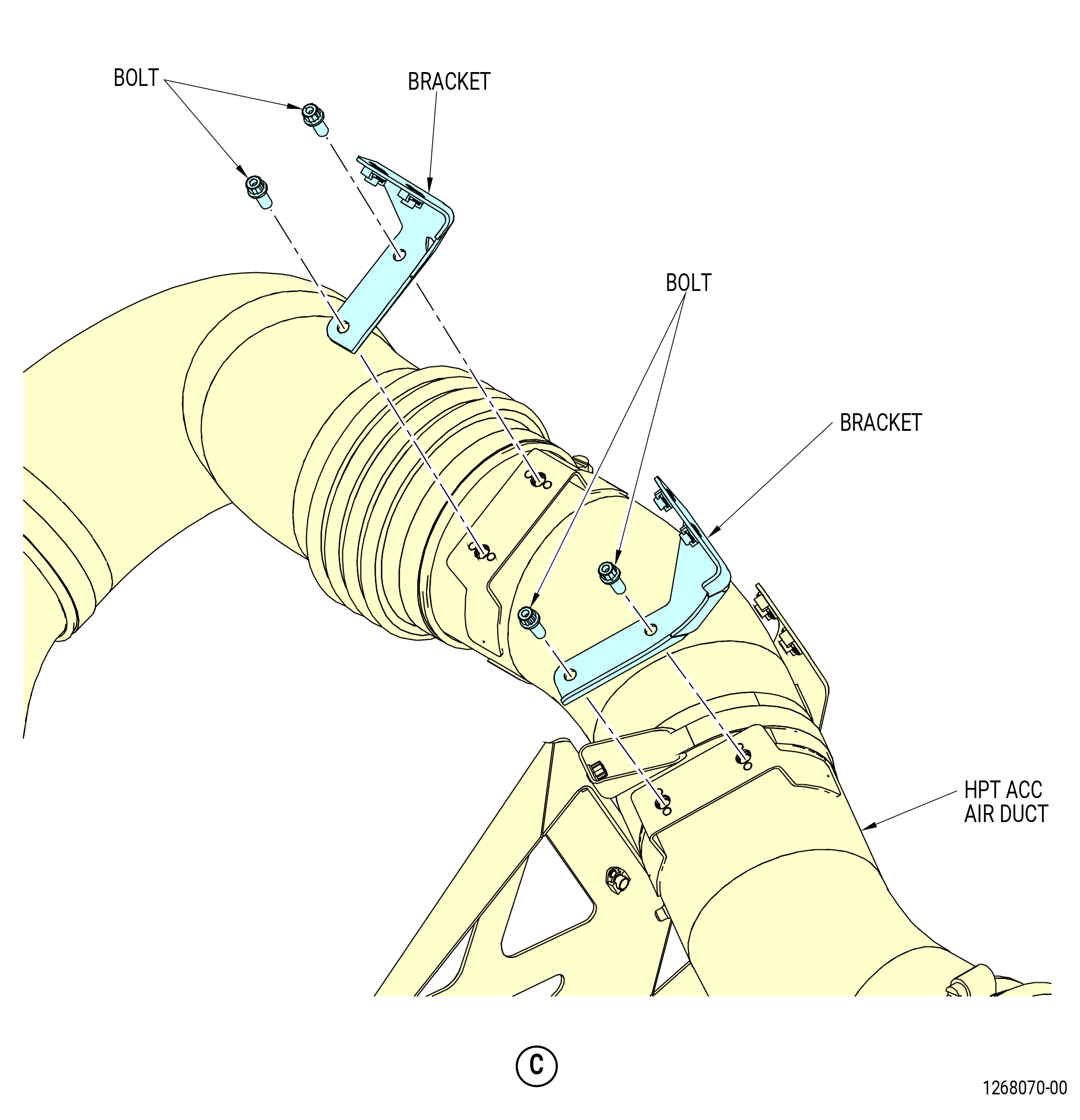
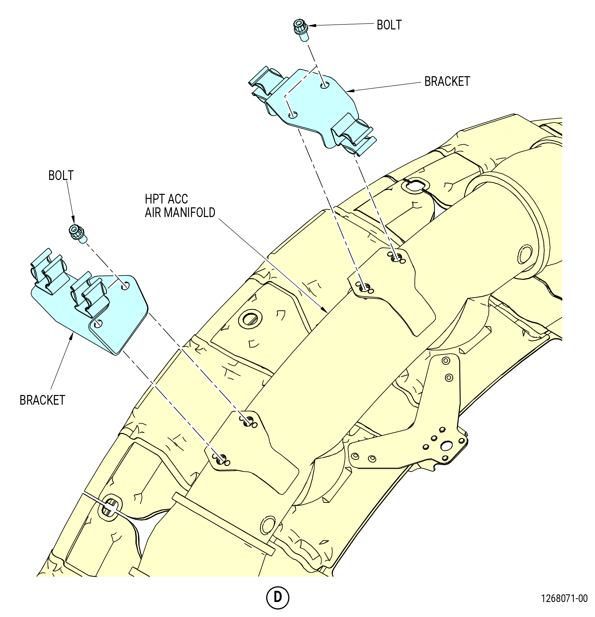
| (2) | Remove the brackets from the high pressure turbine (HPT) active clearance control (ACC) system as follows. Refer to Figure 512. |
| (a) | Remove the bolts and brackets from the HPT ACC air duct at the 10:00 o'clock position |
| (b) | Remove the bolts and bracket from the HPT ACC air manifold at the 1:00 o'clock position. |
| (c) | Remove the bolts and bracket from the HPT ACC air manifold at the 12:30 o'clock position. |
| Subtask 72-00-02-030-429 |
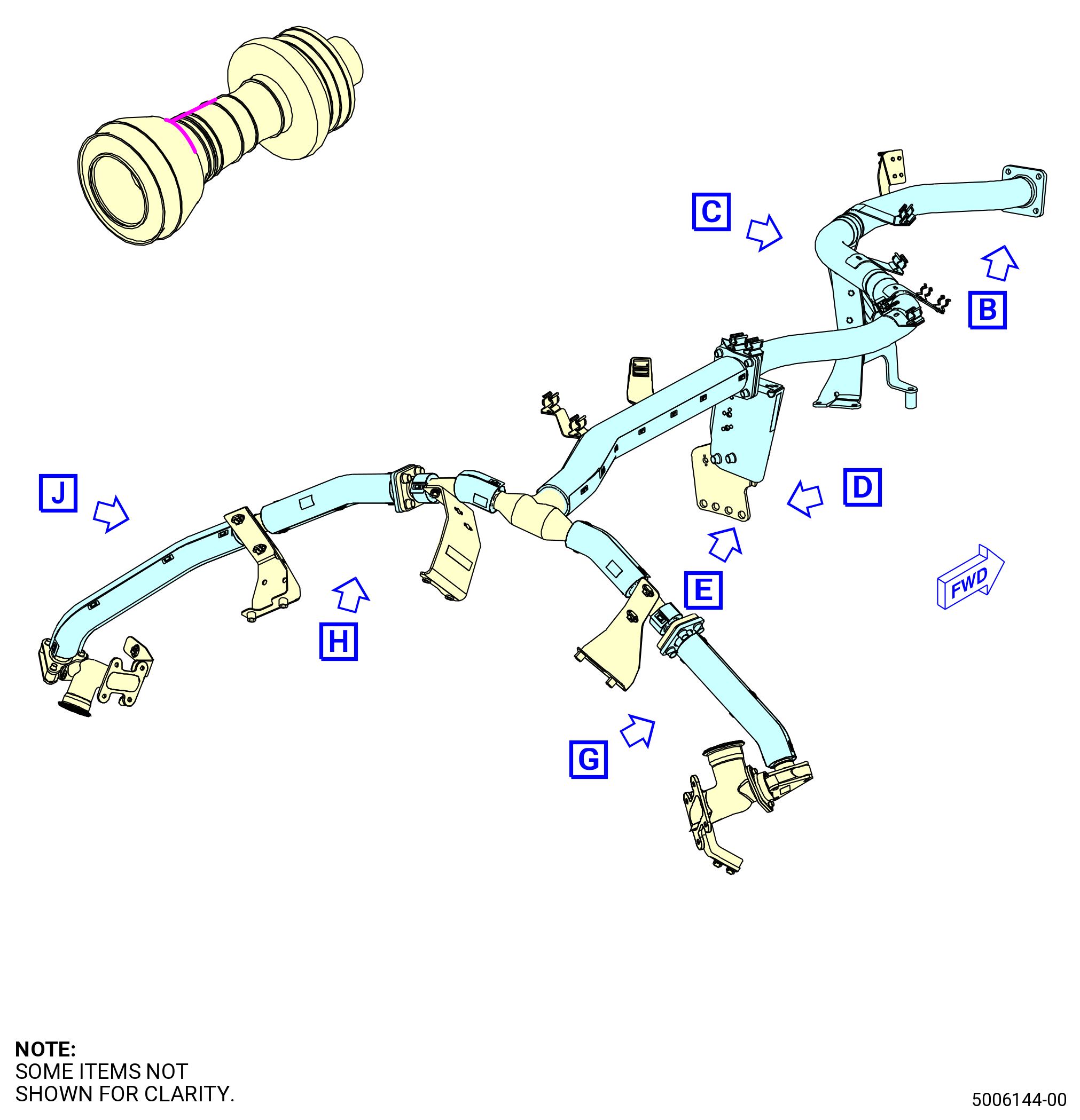
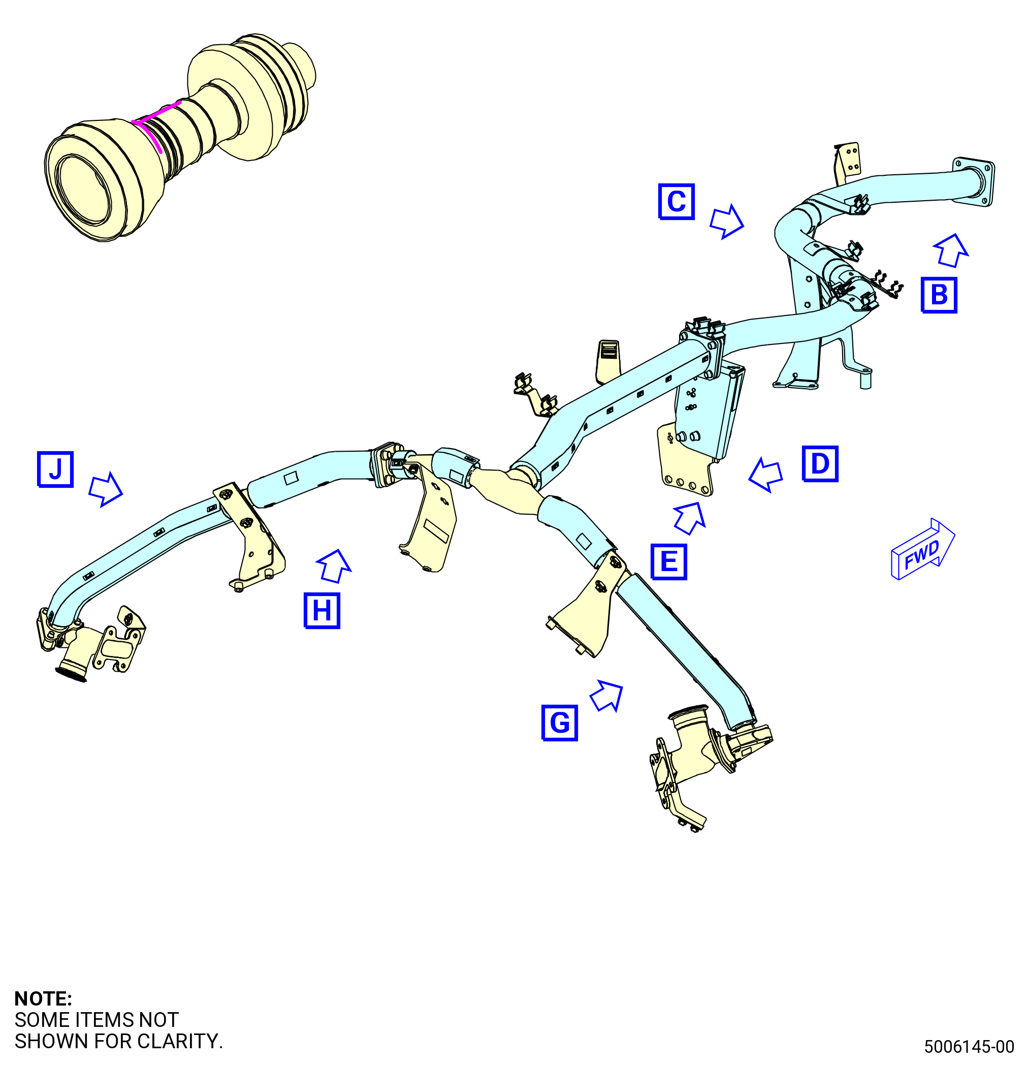
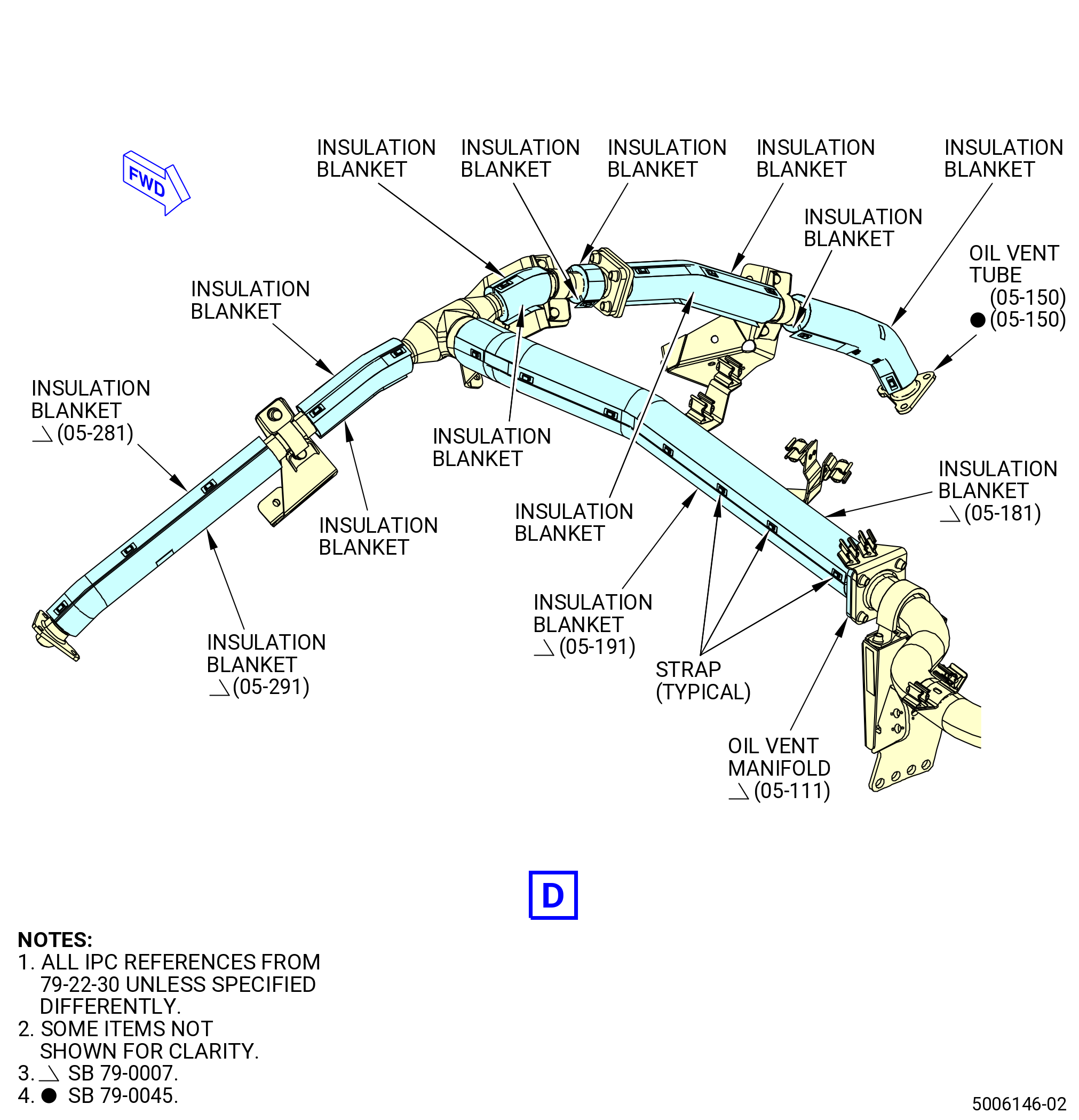
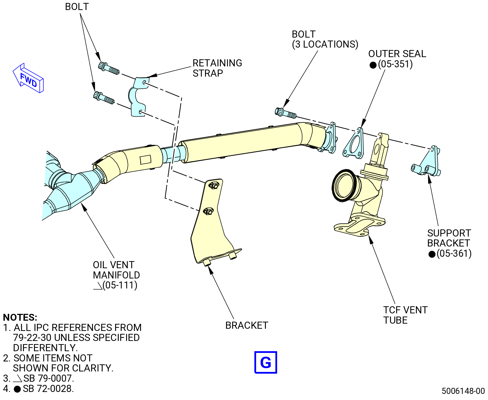
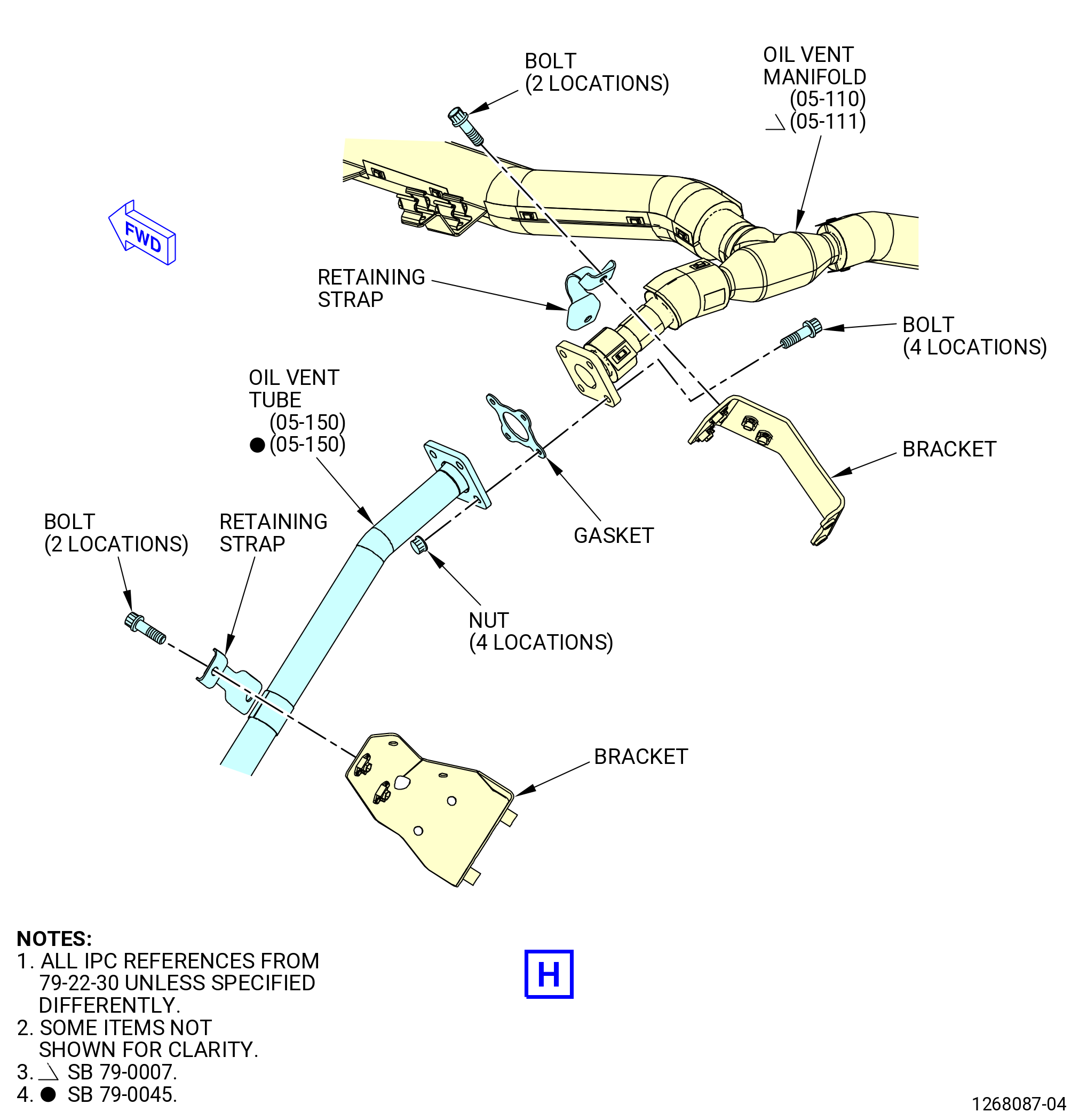
| J. | Remove the B-sump vent system as follows. Refer to Figure 513. |
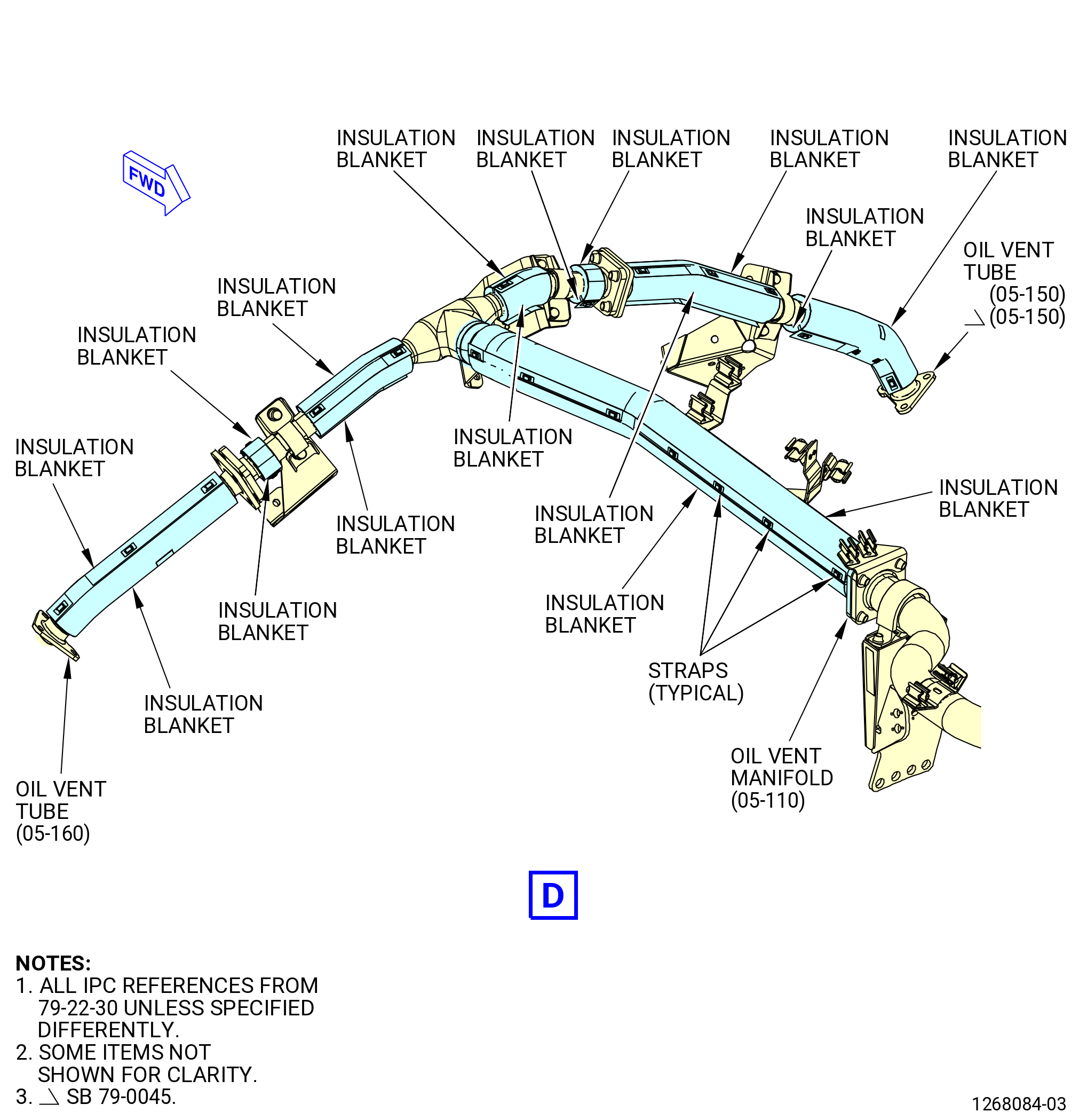
| (1) | Remove the bolts and retaining straps that attach the oil vent tube (05-150 , 79-22-30) (SIN 46102) and the oil vent manifold (05-110 , 79-22-30) (SIN 46101) or (05-111 , 79-22-30) (SIN 46101) to the brackets. |
| Subtask 72-00-02-030-540 |
| * * * PRE SB 79-0007( Oil Vent Manifold without Weight Reduction ) |
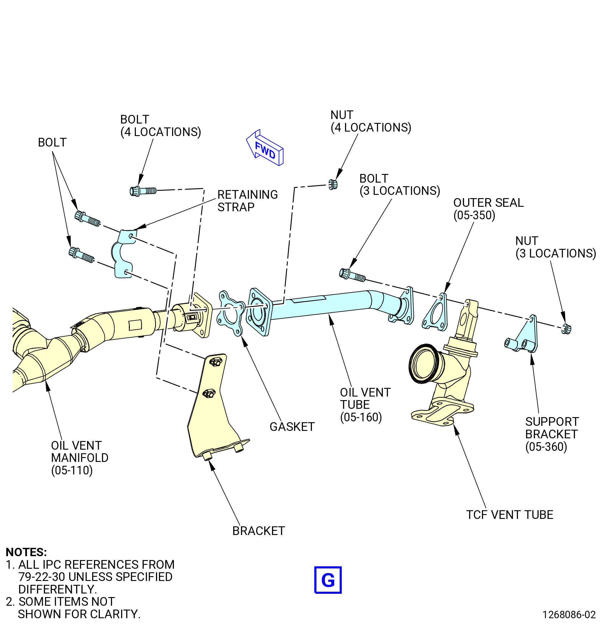
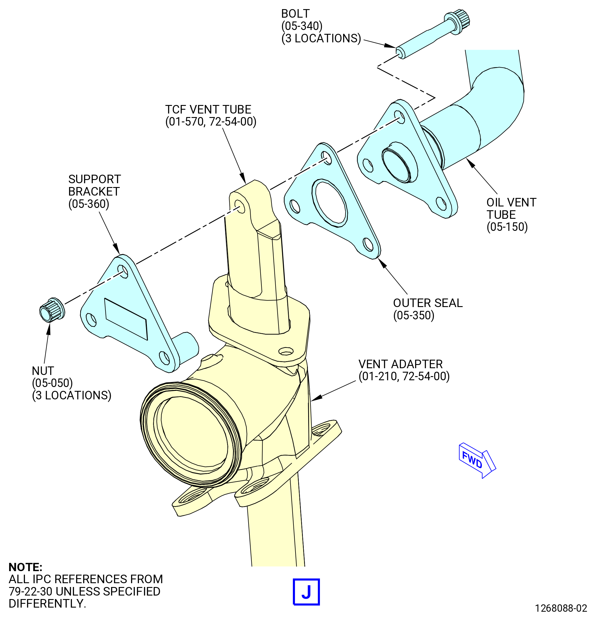
| (2) | Remove the oil vent tubes (05-150 , 79-22-30) (SIN 46102) and (05-160 , 79-22-30) (SIN 46103) from the oil vent manifold (05-110 , 79-22-30) (SIN 46101) as follows: |
| Subtask 72-00-02-030-483 |
| * * * PRE SB 72-0028( Outer Seals, Support Brackets, and Nuts ) |
| (a) | Remove the bolts, support brackets (05-360 , 79-22-30) (SIN 46183), and self-locking nuts (nuts) (05-050 , 79-22-30) (SIN 46141) that attach the oil vent tubes (05-150 , 79-22-30) (SIN 46102) and (05-160 , 79-22-30) (SIN 46103) to the turbine center frame (TCF) vent tubes. |
| * * * END PRE SB 72-0028 |
| Subtask 72-00-02-030-484 |
| * * * SB 72-0028( Outer Seals and Support Brackets with Riveted Nutplates ) |
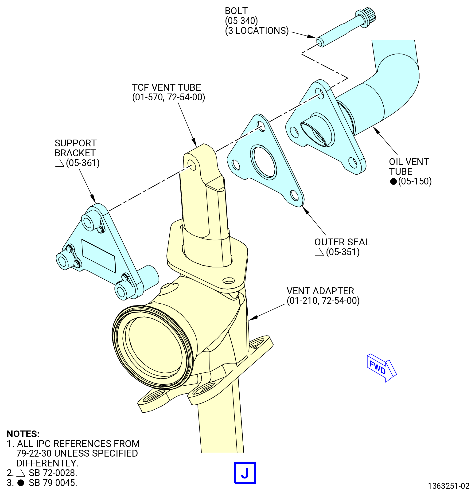
| (a).A. | Remove the bolts and support brackets (05-361 , 79-22-30) (SIN 46183) that attach the oil vent tubes (05-150 , 79-22-30) (SIN 46102) and (05-160 , 79-22-30) (SIN 46103) to the TCF vent tubes. |
| * * * END SB 72-0028 |
| Subtask 72-00-02-030-486 |
| (b) | Remove and discard the outer seals (05-350 , 79-22-30) (SIN 46153) or (05-351 , 79-22-30) (SIN 46153). |
| (c) | Remove the bolts and nuts that attach the oil vent tubes (05-150 , 79-22-30) (SIN 46102) and (05-160 , 79-22-30) (SIN 46103) to the oil vent manifold (05-110 , 79-22-30) (SIN 46101). |
| (d) | Remove and discard the gaskets (05-140 , 79-22-30) (SIN 46151). |
| * * * END PRE SB 79-0007 |
| Subtask 72-00-02-030-487 |
| (e) | Deleted. |
| Subtask 72-00-02-030-485 |
| (f) | Deleted. |
| Subtask 72-00-02-030-542 |
| * * * SB 79-0007( Oil Vent Manifold with Weight Reduction ) |
| (2).F. | Remove the oil vent tube (05-150 , 79-22-30) (SIN 46102) from the oil vent manifold (05-111 , 79-22-30) (SIN 46101) as follows: |
| Subtask 72-00-02-030-547 |
| * * * PRE SB 72-0028( Outer Seals, Support Brackets, and Nuts ) |
| (a) | Remove the bolts, support brackets (05-360 , 79-22-30) (SIN 46183), and nuts (05-050 , 79-22-30) (SIN 46141) that attach the oil vent tube (05-150 , 79-22-30) (SIN 46102) and oil vent manifold (05-111 , 79-22-30) (SIN 46101) to the TCF vent tubes. |
| * * * END PRE SB 72-0028 |
| Subtask 72-00-02-030-543 |
| * * * SB 72-0028( Outer Seals and Support Brackets with Riveted Nutplates ) |
| (a).A. | Remove the bolts and support brackets (05-361 , 79-22-30) (SIN 46183) that attach the oil vent tube (05-150 , 79-22-30) (SIN 46102) and oil vent manifold (05-111 , 79-22-30) (SIN 46101) to the TCF vent tubes. |
| * * * END SB 72-0028 |
| Subtask 72-00-02-030-544 |
| (b) | Remove and discard the outer seals (05-350 , 79-22-30) (SIN 46153) or (05-351 , 79-22-30) (SIN 46153). |
| (c) | Remove the bolts and nuts that attach the oil vent tube (05-150 , 79-22-30) (SIN 46102) to the oil vent manifold (05-111 , 79-22-30) (SIN 46101). |
| (d) | Remove and discard the gasket (05-140 , 79-22-30) (SIN 46151). |
| * * * END SB 79-0007 |
| Subtask 72-00-02-030-545 |
| * * * PRE SB 79-0007( Oil Vent Manifold without Weight Reduction ) |
| (3) | Remove the insulation blankets as follows: |
| (a) | Remove the straps that attach the insulation blankets to the oil vent tubes (05-150 , 79-22-30) (SIN 46102), (05-160 , 79-22-30) (SIN 46103), and oil vent manifold (05-110 , 79-22-30) (SIN 46101). |
| (b) | Remove the insulation blankets. |
| * * * END PRE SB 79-0007 |
| Subtask 72-00-02-030-546 |
| * * * SB 79-0007( Oil Vent Manifold with Weight Reduction ) |
| (3).A. | Remove the insulation blankets as follows: |
| (a) | Remove the straps that attach the insulation blankets to the oil vent tube (05-150 , 79-22-30) (SIN 46102) and oil vent manifold (05-111 , 79-22-30) (SIN 46101). |
| (b) | Remove the insulation blankets. |
| * * * END SB 79-0007 |
| Subtask 72-00-02-030-541 |
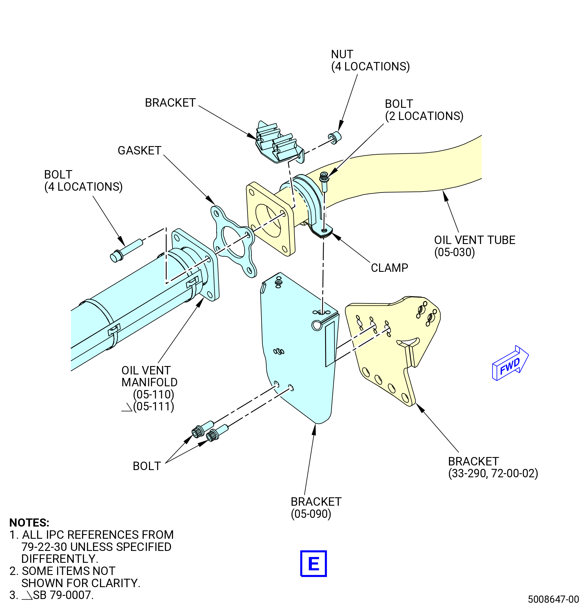
| (4) | Remove the oil vent manifold (05-110 , 79-22-30) (SIN 46101) or (05-111 , 79-22-30) (SIN 46101) from the oil tube (oil vent tube) (05-030 , 79-22-30) (SIN 46100) as follows: |
| (a) | Remove the bolts, nuts, and bracket that attach the oil vent manifold (05-110 , 79-22-30) (SIN 46101) or (05-111 , 79-22-30) (SIN 46101) to the oil vent tube (05-030 , 79-22-30) (SIN 46100). |
| (b) | Remove and discard the gasket (05-140 , 79-22-30) (SIN 46151). |
| Subtask 72-00-02-030-551 |
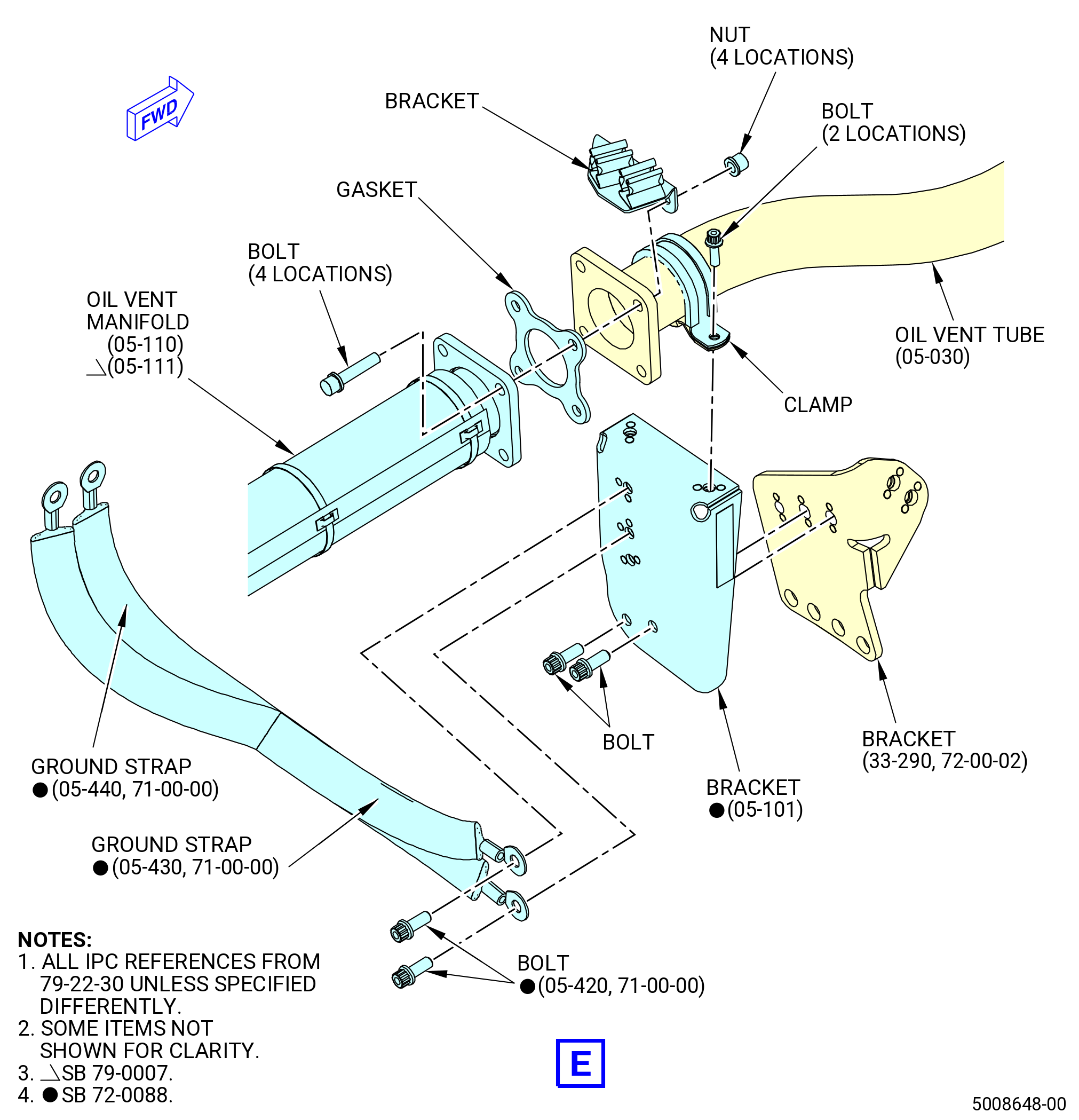
| * * * SB 72-0088( VFSG Harness Configuration with Ground Straps ) |
| (5) | Remove the ground straps (05-430 , 71-00-00) (SIN C00B1) and (05-440 , 71-00-00) (SIN C00B2) from the oil tube bracket (bracket) (05-101 , 79-22-30) (SIN 46110) as follows: |
| NOTE: |
|
| (a) | Remove the machine bolts (bolts) (05-420 , 71-00-00) (SIN C00F5). |
| (b) | Remove the ground straps. |
| * * * END SB 72-0088 |
| Subtask 72-00-02-030-552 |
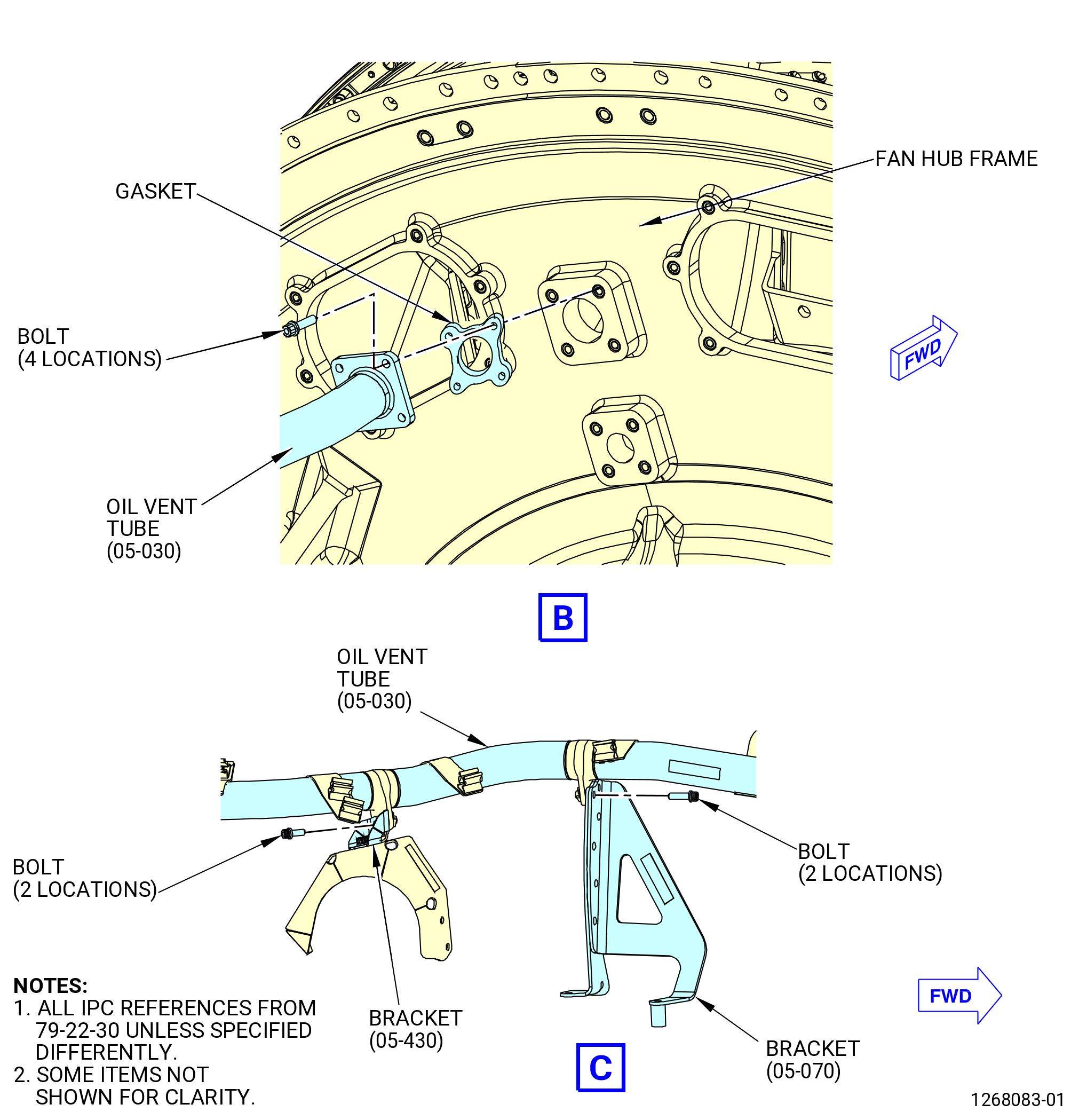
| (6) | Remove the oil vent tube (46100) as follows: |
| (a) | Remove the bolts that attach the oil vent tube (05-030 , 79-22-30) (SIN 46100) to the fan hub frame at the 12:00 o'clock position. |
| (b) | Remove the bolts that attach the oil vent tube (05-030 , 79-22-30) (SIN 46100) to the tube oil brackets (brackets) (05-070 , 79-22-30) (SIN 4611A) and (05-430 , 79-22-30) (SIN 4611E). |
| (c) | Remove the bolts and clamp that attach the oil vent tube (05-030 , 79-22-30) (SIN 46100) to the bracket (05-090 , 79-22-30) (SIN 46110) or (05-101 , 79-22-30) (SIN 46110). |
| (d) | Remove the oil vent tube (46100). |
| (e) | Remove and discard the gasket (05-020 , 79-22-30) (SIN 46150). |
| (f) | Remove the bolts and the bracket (05-090 , 79-22-30) (SIN 46110) or (05-101 , 79-22-30) (SIN 46110) from the support bracket (bracket) (33-290) (SIN 6101K). |
|
|
|
|
|
|
| Subtask 72-00-02-030-433 |
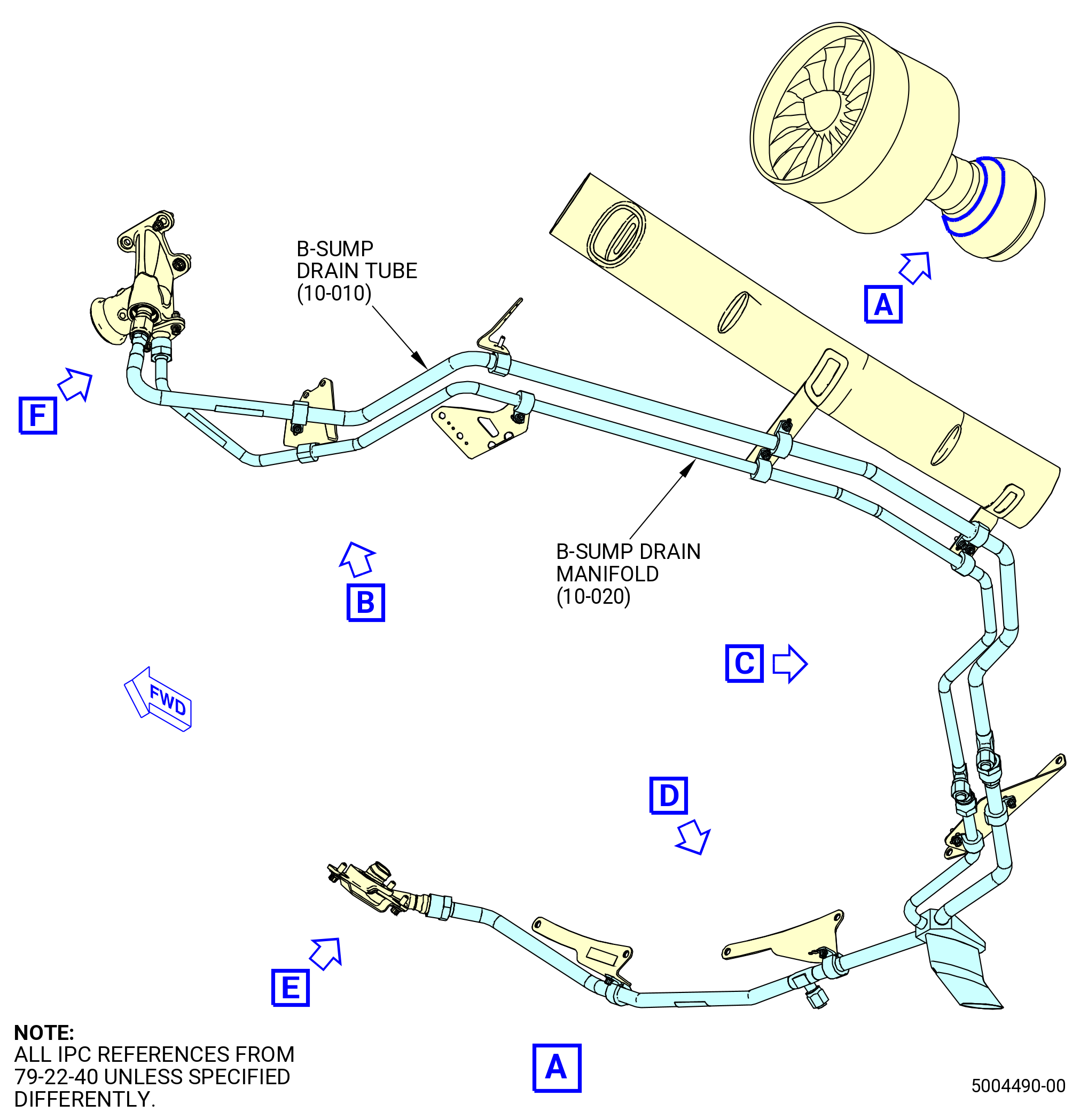
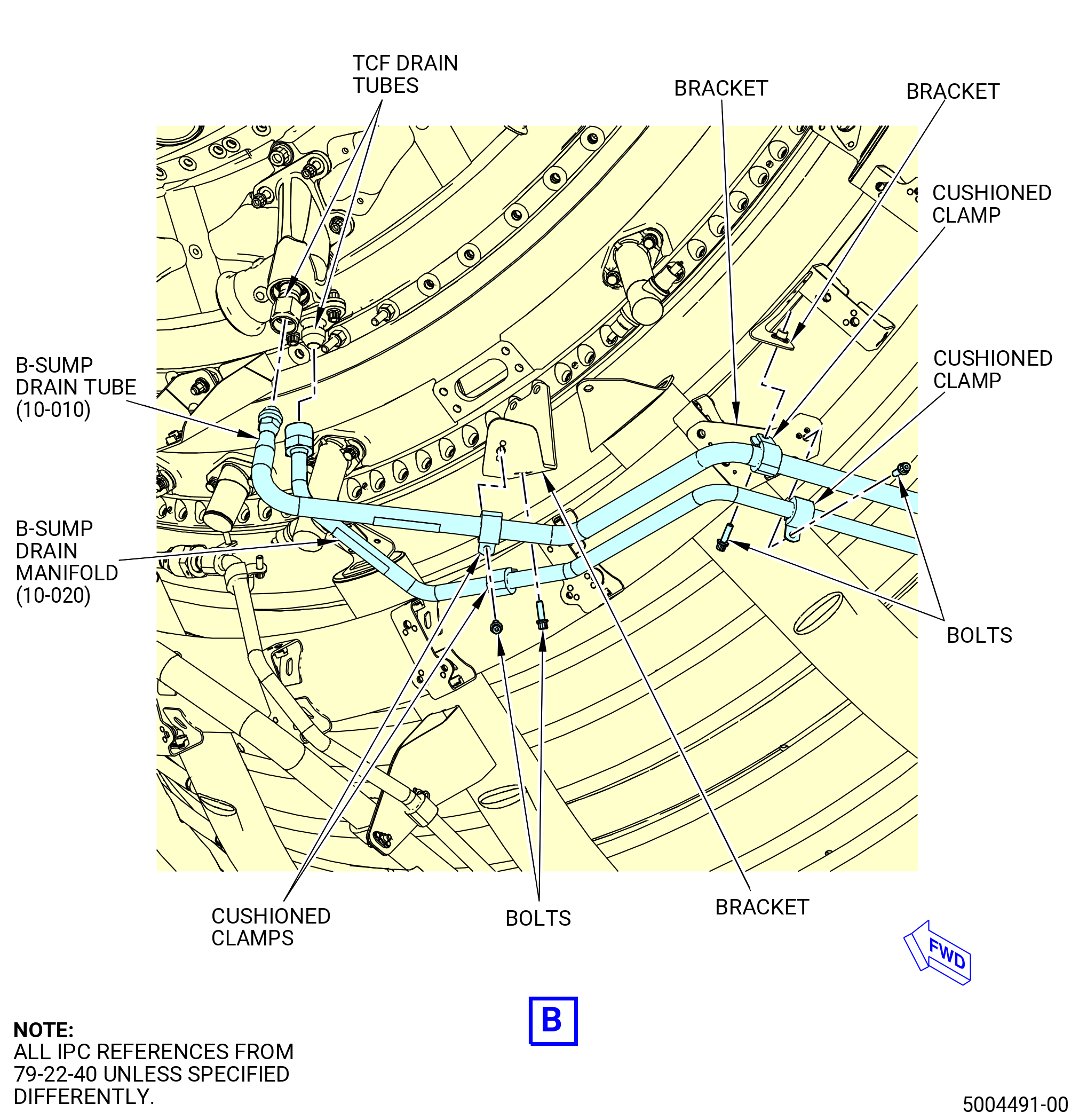
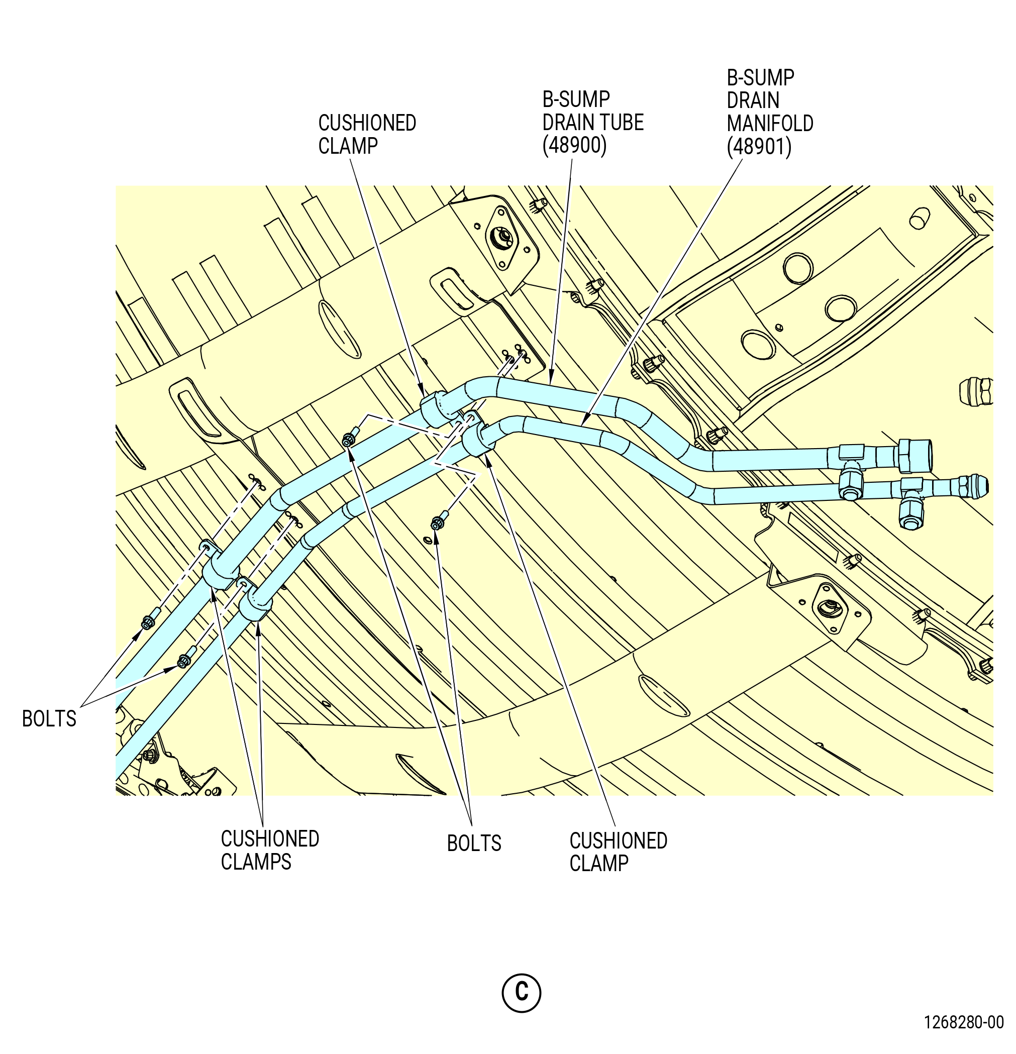
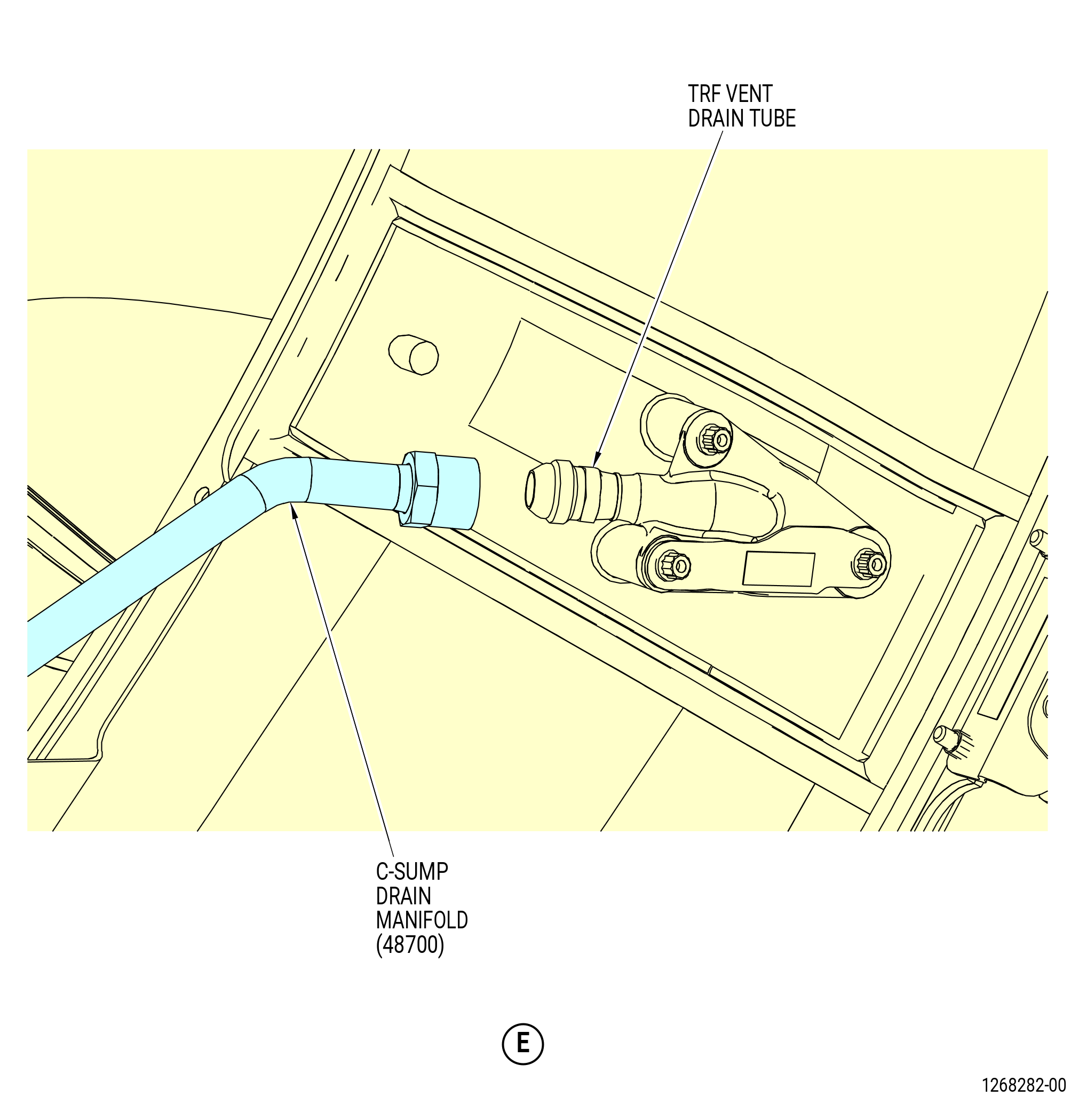
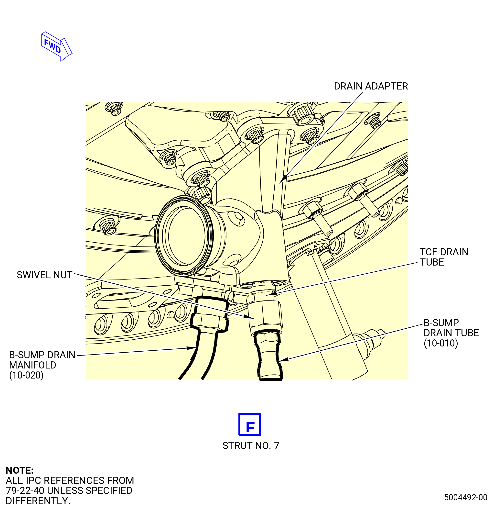
| K. | Remove the turbine center frame/turbine rear frame (TCF/TRF) drain system as follows. Refer to Figure 514. |
| (1) | Disconnect the C-sump drain manifold (48700) from the B-sump drain tube (48900) and the B-sump drain manifold (48901). |
| (2) | Disconnect the C-sump drain manifold (48700) from the TRF vent drain tube at the 4:00 o'clock position. |
| (3) | Remove the bolts and cushioned clamps that attach the oil drain manifold to the brackets. |
| Subtask 72-00-02-030-527 |
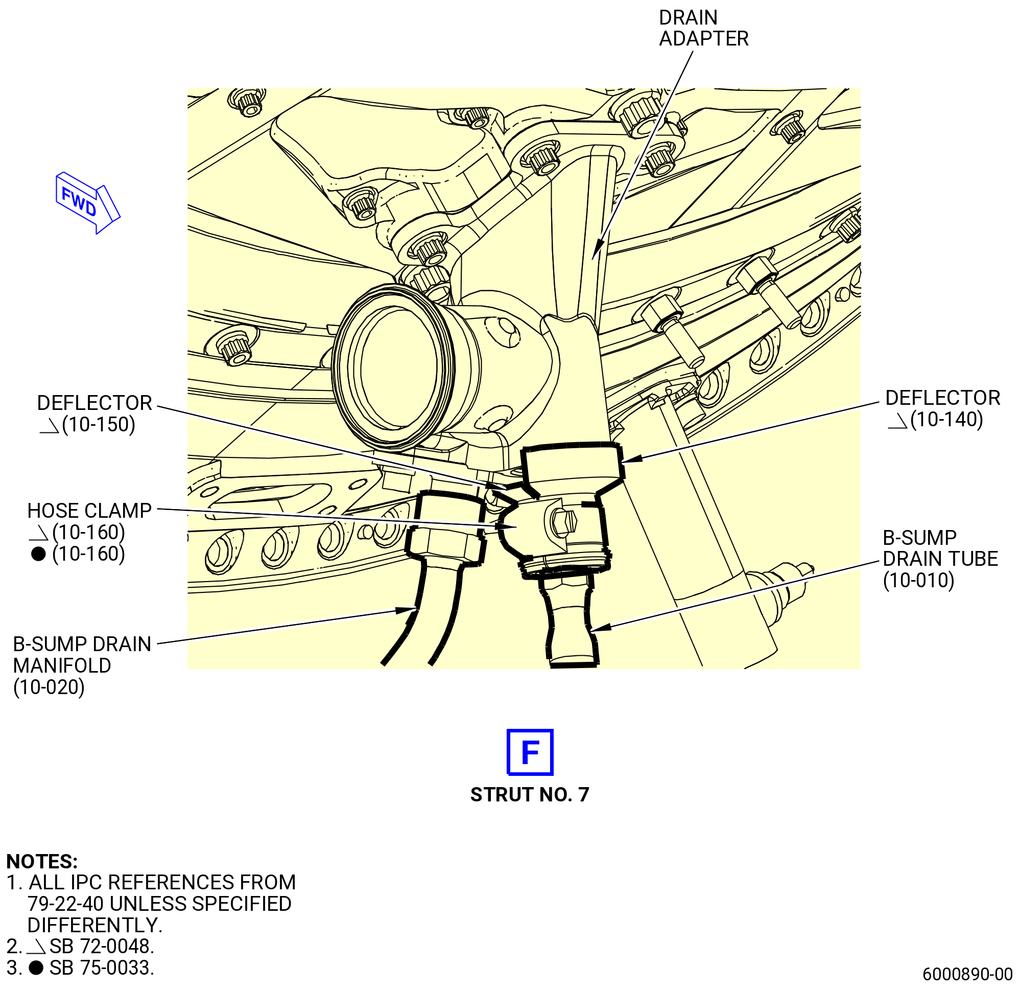
| * * * SB 72-0048( TCF/TRF Drain System with Adapter Cap Deflectors ) |
| (4) | Remove the adapter cap deflectors (deflectors) (10-140 , 79-22-40) (SIN 9259A) and (10-150 , 79-22-40) (SIN 9259C) at the strut No. 7 as follows: |
| NOTE: |
|
| (a) | Remove the hose clamp (10-160 , 79-22-40) (SIN 9258A) that attaches the two deflectors. |
| (b) | Remove the two deflectors from the swivel nut and drain adapter. |
| * * * END SB 72-0048 |
| Subtask 72-00-02-030-528 |
| (5) | Disconnect the B-sump drain tube (48900) and the B-sump drain manifold (48901) from the TCF drain tubes at the 6:00 o'clock position. |
| (6) | Remove the bolts and cushioned clamps that attach the oil drain manifold (48900) and oil drain manifold (48901) to the brackets. |
|
|
| Subtask 72-00-02-030-434 |
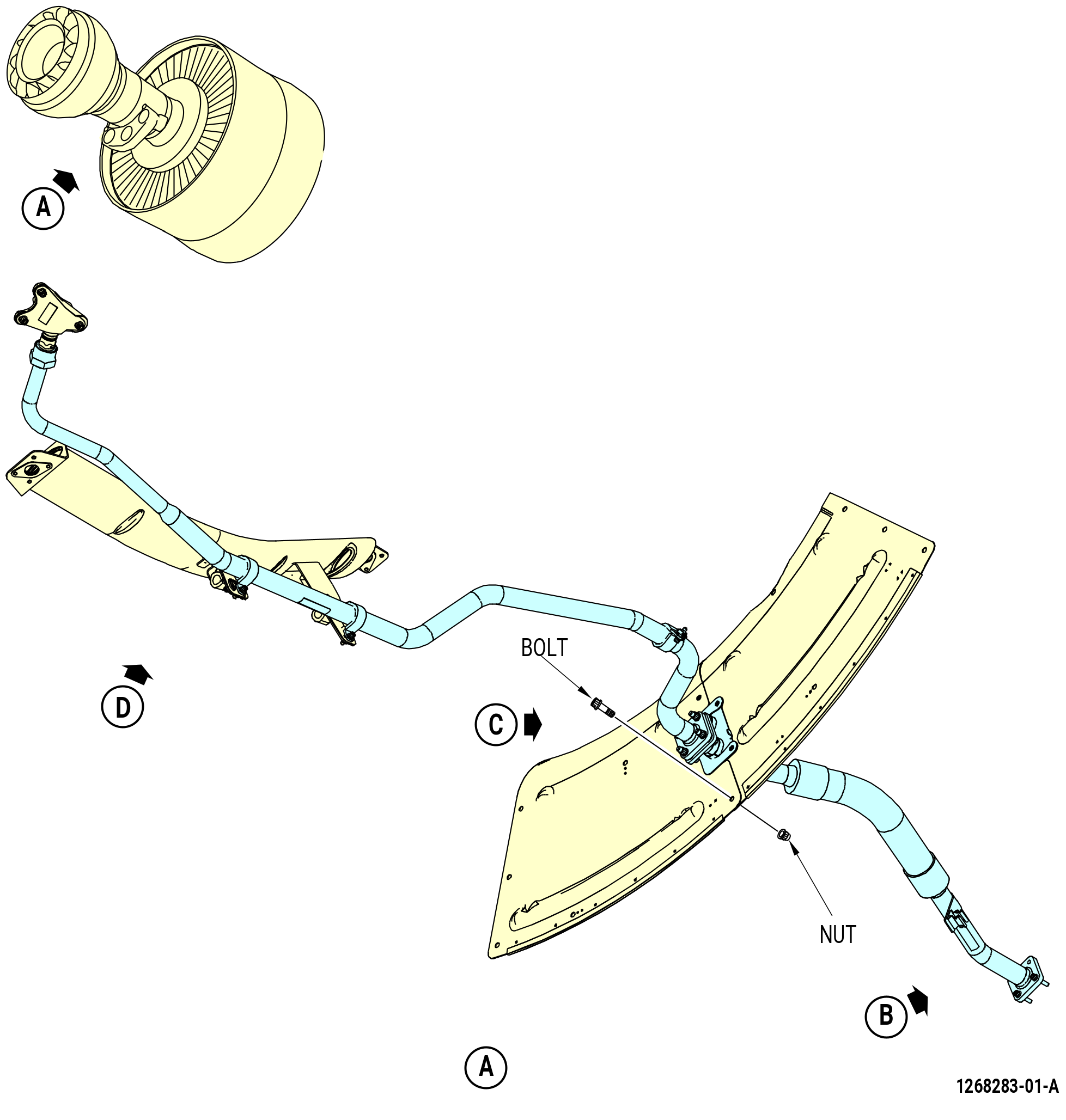
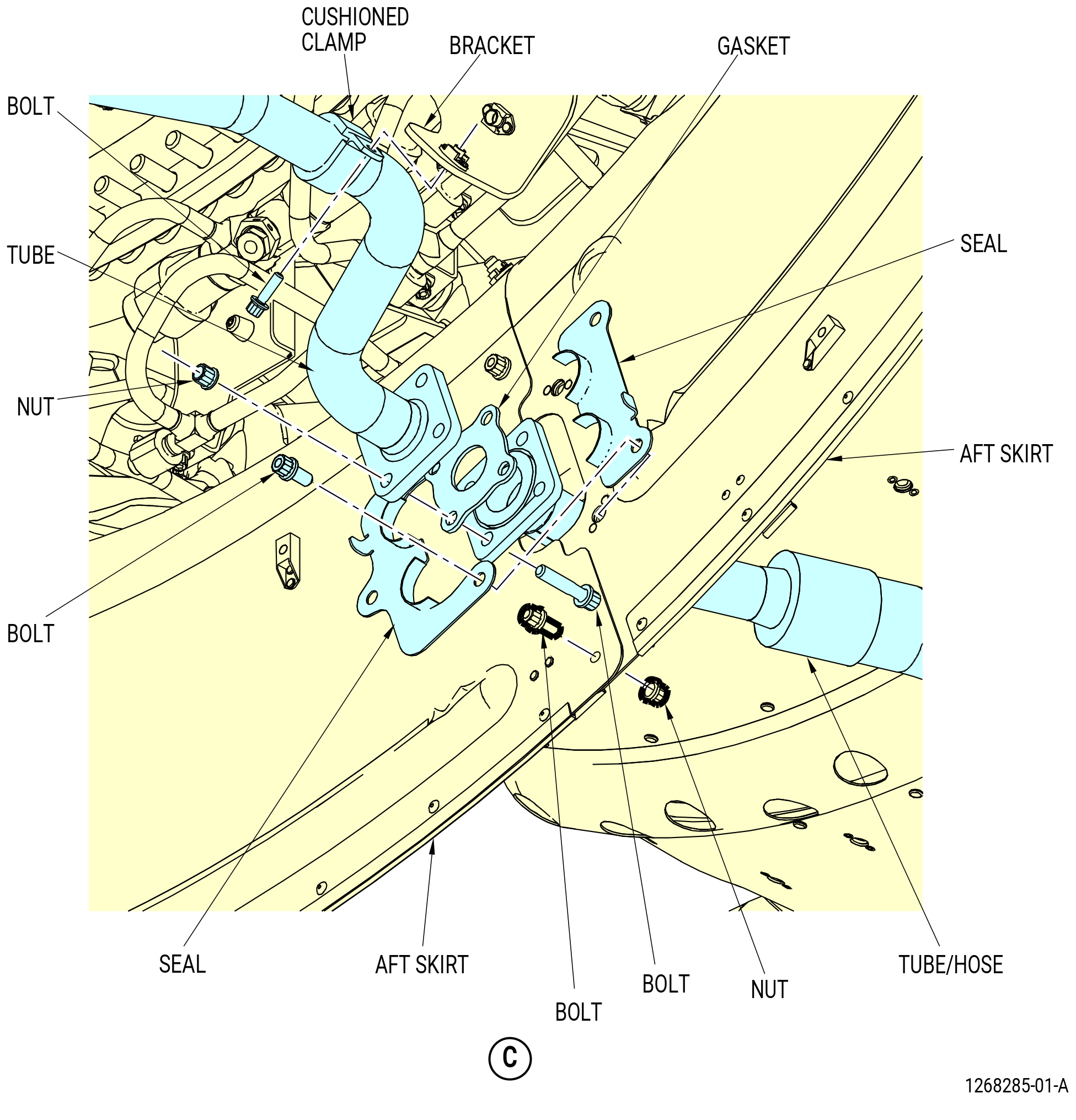
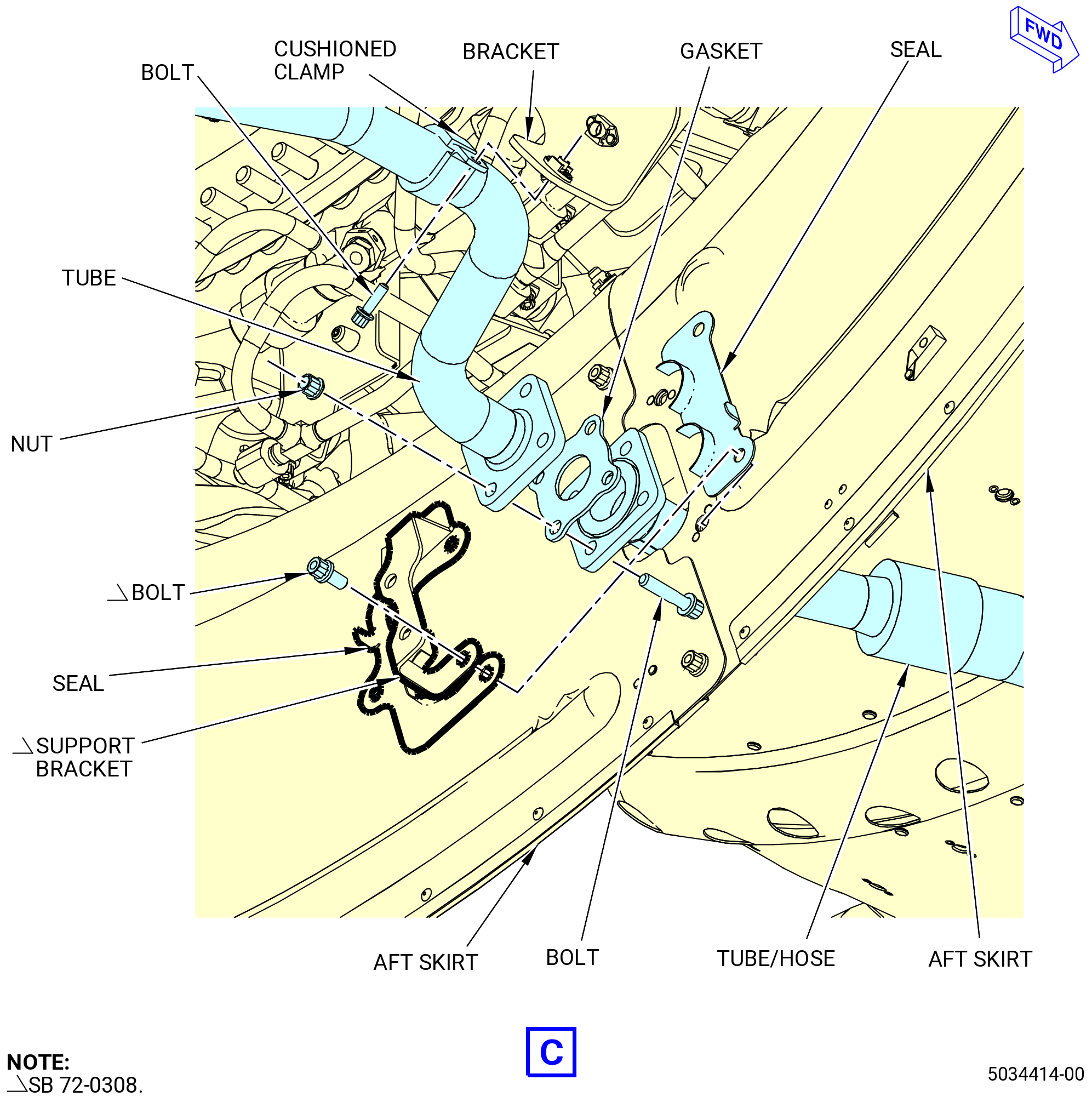
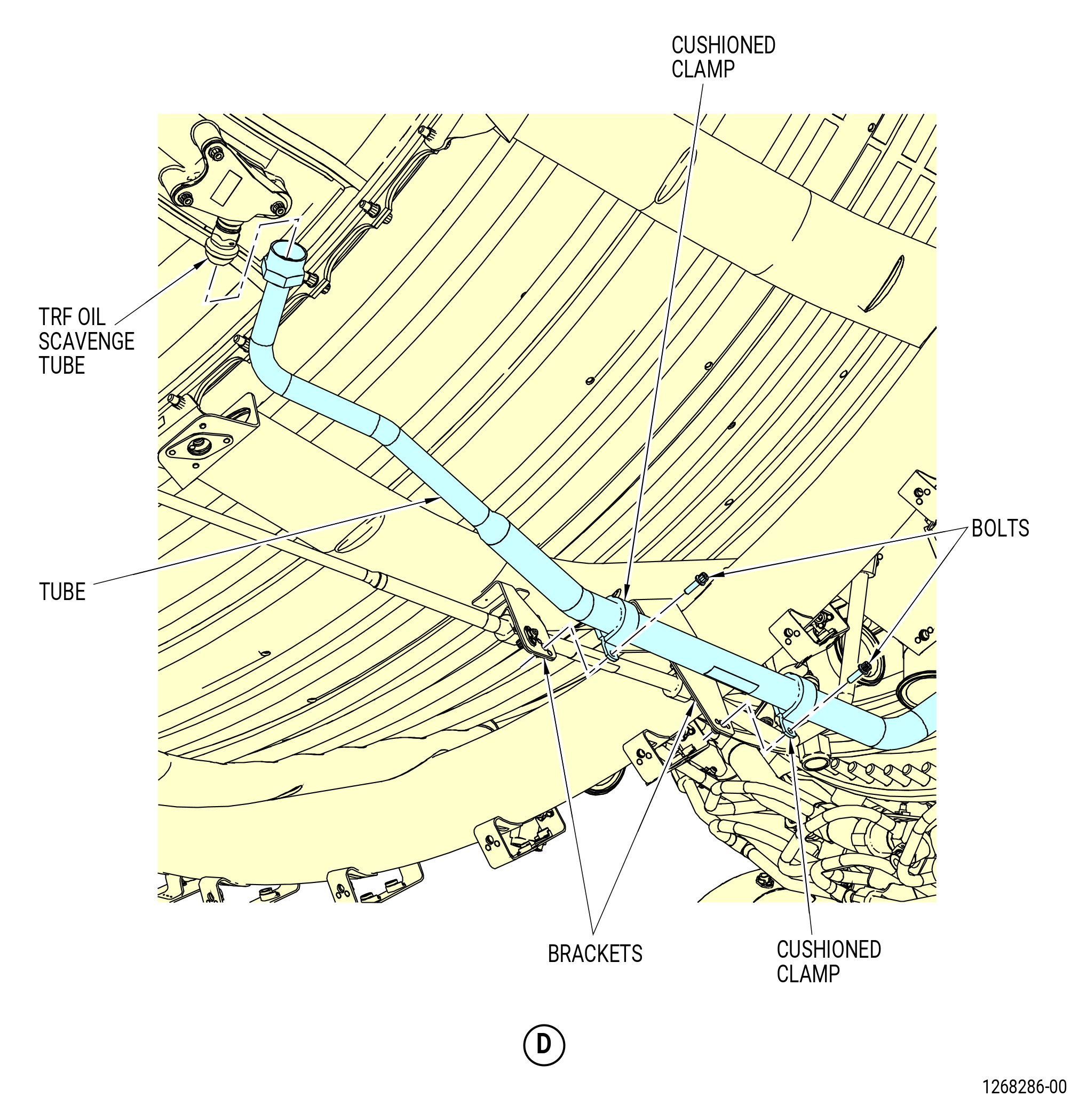
| L. | Remove the TRF scavenge system as follows. Refer to Figure 515. |
| (1) | Remove the nuts and bolts that connect the scavenge oil tube (tube) to the scavenge oil tube/hose (tube/hose). |
| (2) | Remove and discard the flange gasket (10-080 , 79-22-20) (SIN 45250). |
| (3) | Disconnect the tube from the TRF oil scavenge tube at the 5:30 o'clock position. |
| (4) | Remove the bolts and cushioned clamps that attach the tube to the brackets. |
| Subtask 72-00-02-030-728 |
| * * * PRE SB 72-0308( Removal of the Tube/Hose without Support Bracket ) |
| (5) | Remove the bolts and the seals from the aft skirt of the heat shield. |
| * * * END PRE SB 72-0308 |
| Subtask 72-00-02-030-729 |
| * * * SB 72-0308( Removal of the Tube/Hose with Support Bracket ) |
| (5).A. | Remove the bolts, seals, and support scavenge tube bracket (support bracket) from the aft skirt of the heat shield. |
| * * * END SB 72-0308 |
| Subtask 72-00-02-030-730 |
| (6) | Remove the bolts that attach the tube/hose to the accessory gearbox (AGB). |
| (7) | Remove and discard the flange gasket (10-040 , 79-22-20) (SIN 45251). |
| (8) | Remove bolt from the bottom of the aft skirt. |
| (9) | Remove the tube/hose from the aft skirt. |
|
|
| Subtask 72-00-02-030-435 |
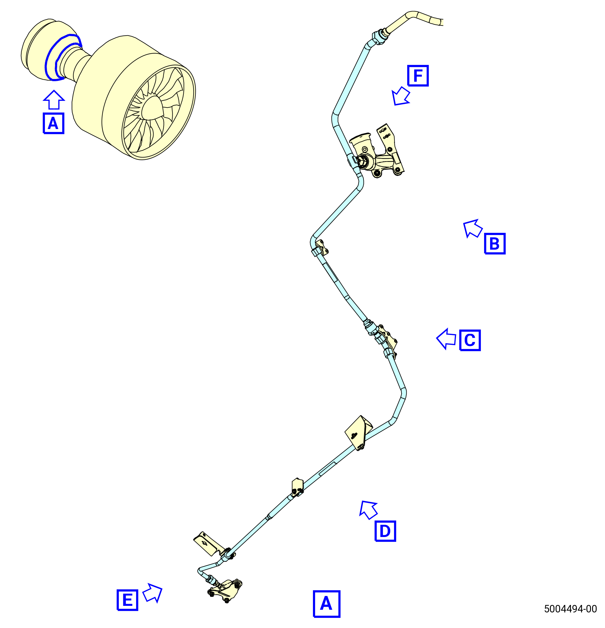
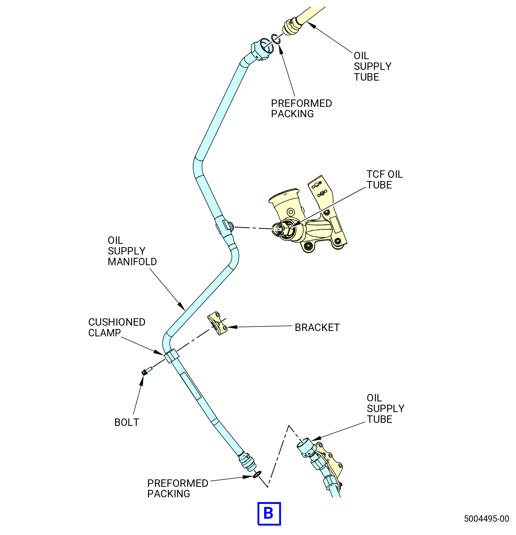
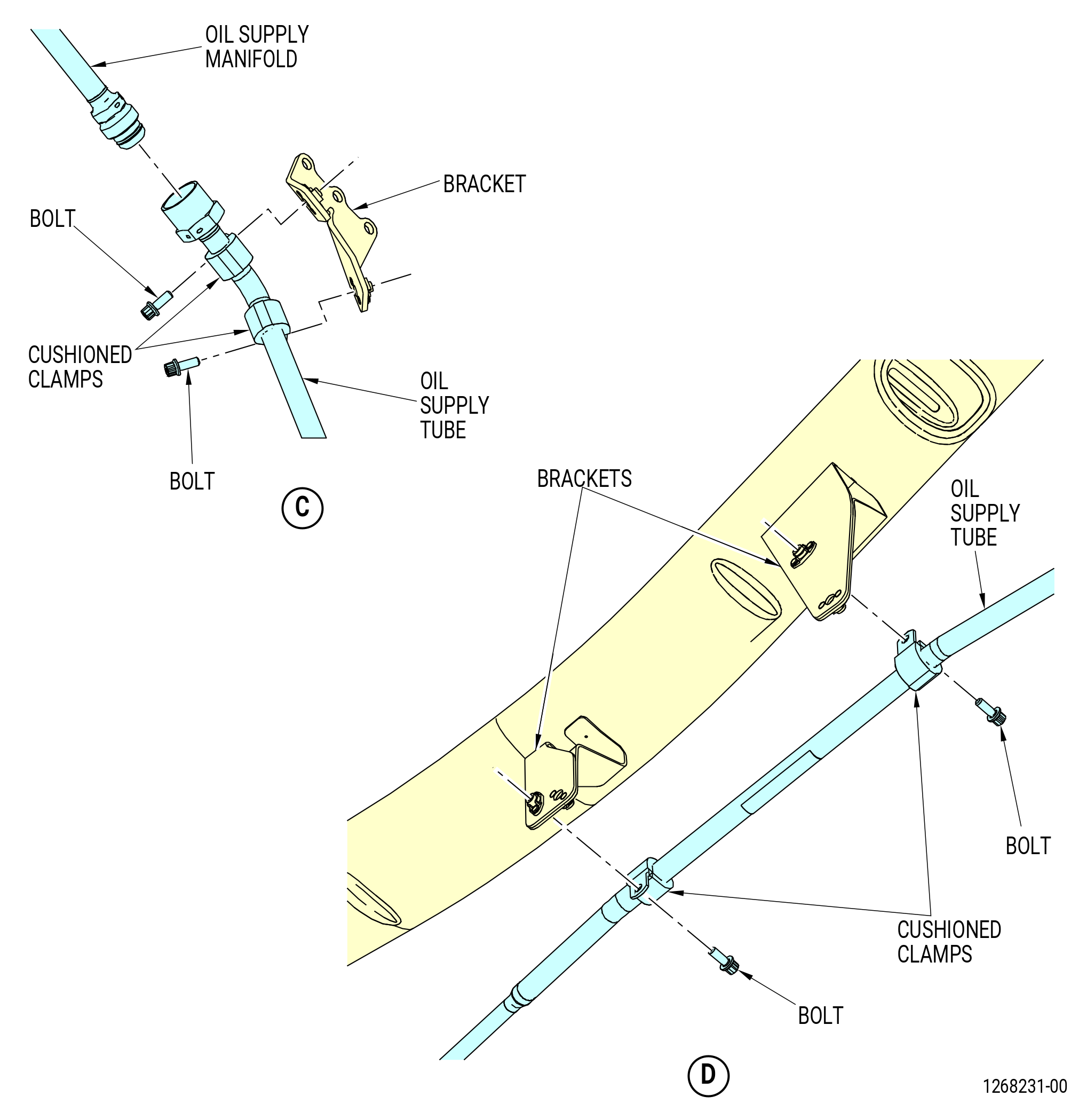
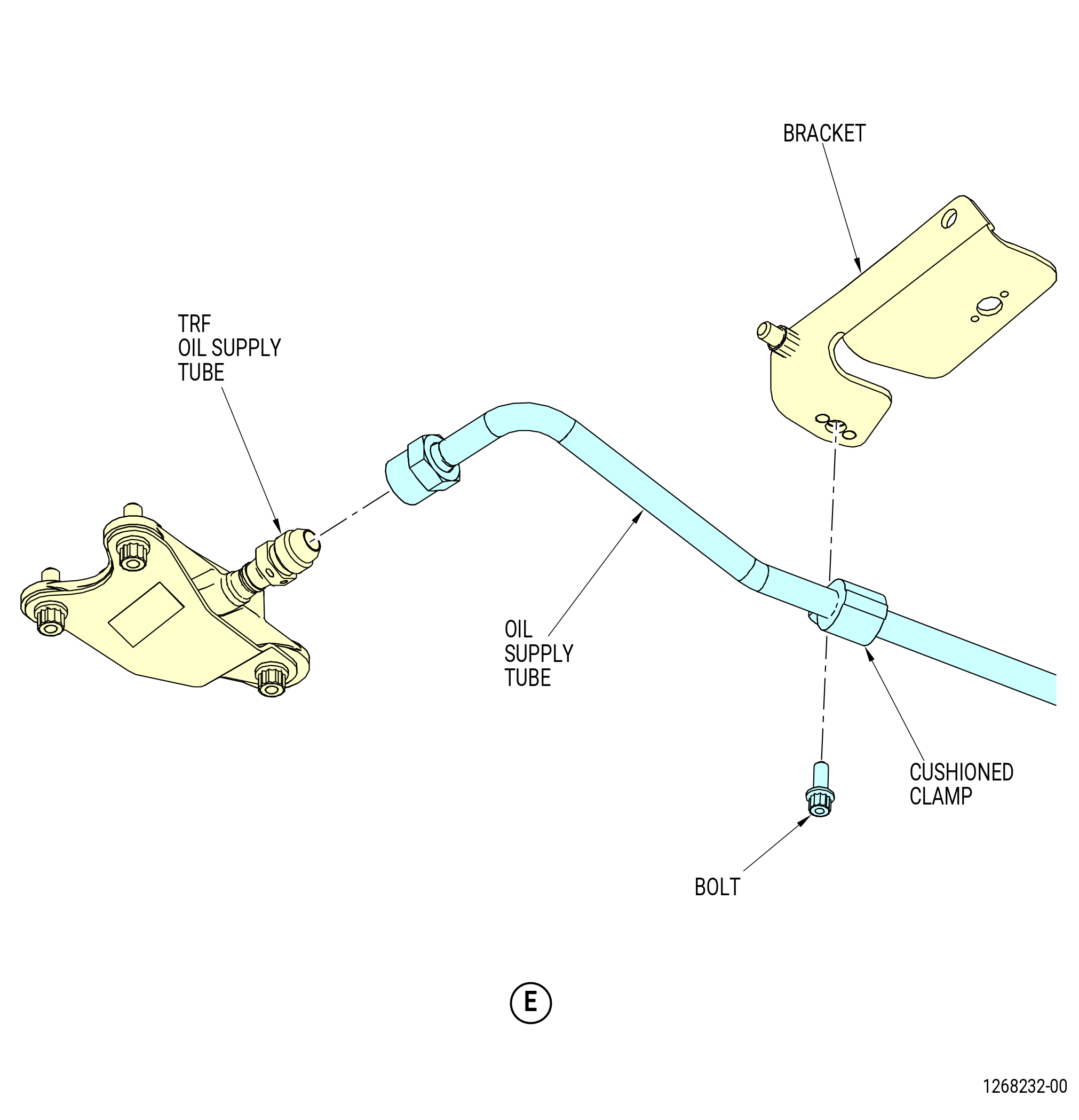
| M. | Remove the TCF/TRF lube system as follows. Refer to Figure 516. |
| (1) | Disconnect the oil supply tube from the TRF oil supply tube at the 6:00 o'clock position. |
| (2) | Disconnect the oil supply tube from the oil supply manifold at the 5:00 o'clock position. Remove and discard the preformed packing (20-140 , 79-22-10) (SIN 44351). |
| (3) | Remove the bolts and cushioned clamps that attach the oil supply tube to the brackets. |
| Subtask 72-00-02-030-529 |
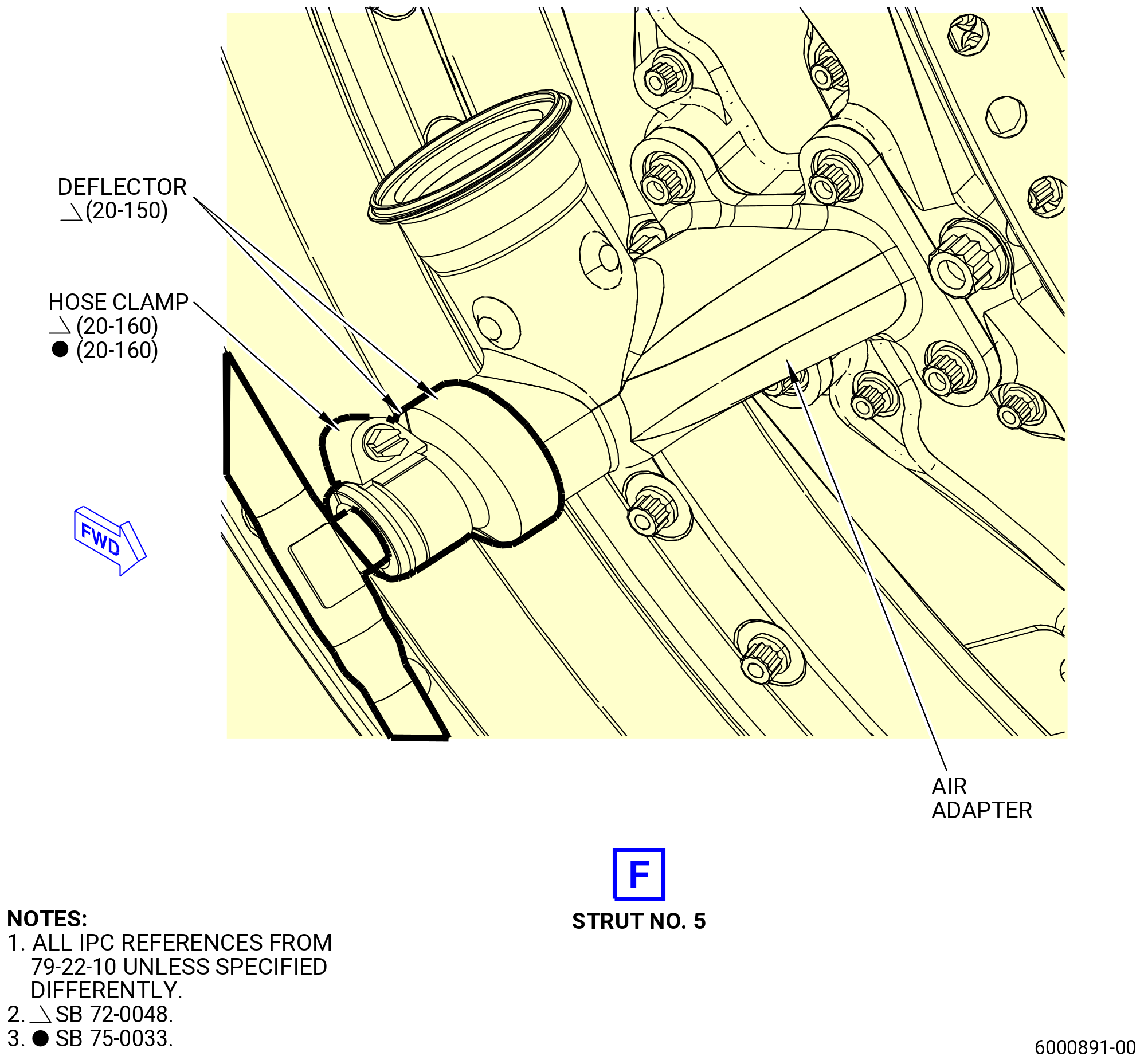
| * * * SB 72-0048( TCF/TRF Lube System with Adapter Cap Deflectors ) |
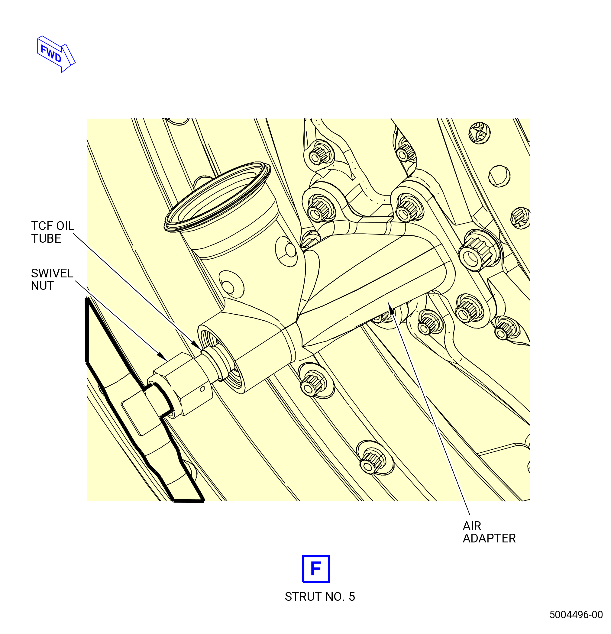
| (4) | Remove the adapter cap deflectors (deflectors) (20-150 , 79-22-10) (SIN 9259A) at the strut No. 5 as follows: |
| NOTE: |
|
| (a) | Remove the hose clamp (20-160 , 79-22-10) (SIN 9258A) that attaches the two deflectors. |
| (b) | Remove the two deflectors from the swivel nut and air adapter. |
| * * * END SB 72-0048 |
| Subtask 72-00-02-030-530 |
| (5) | Disconnect the oil supply manifold from the TCF oil tube at the 4:00 o'clock position. |
| (6) | Disconnect the oil supply manifold from the oil supply tube at the 3:30 o'clock position. Remove and discard the preformed packing (20-090 , 79-22-10) (SIN 44350). |
| (7) | Remove the bolt and cushioned clamp that attach the oil supply manifold to the bracket. |
|
|
| Subtask 72-00-02-030-402 |
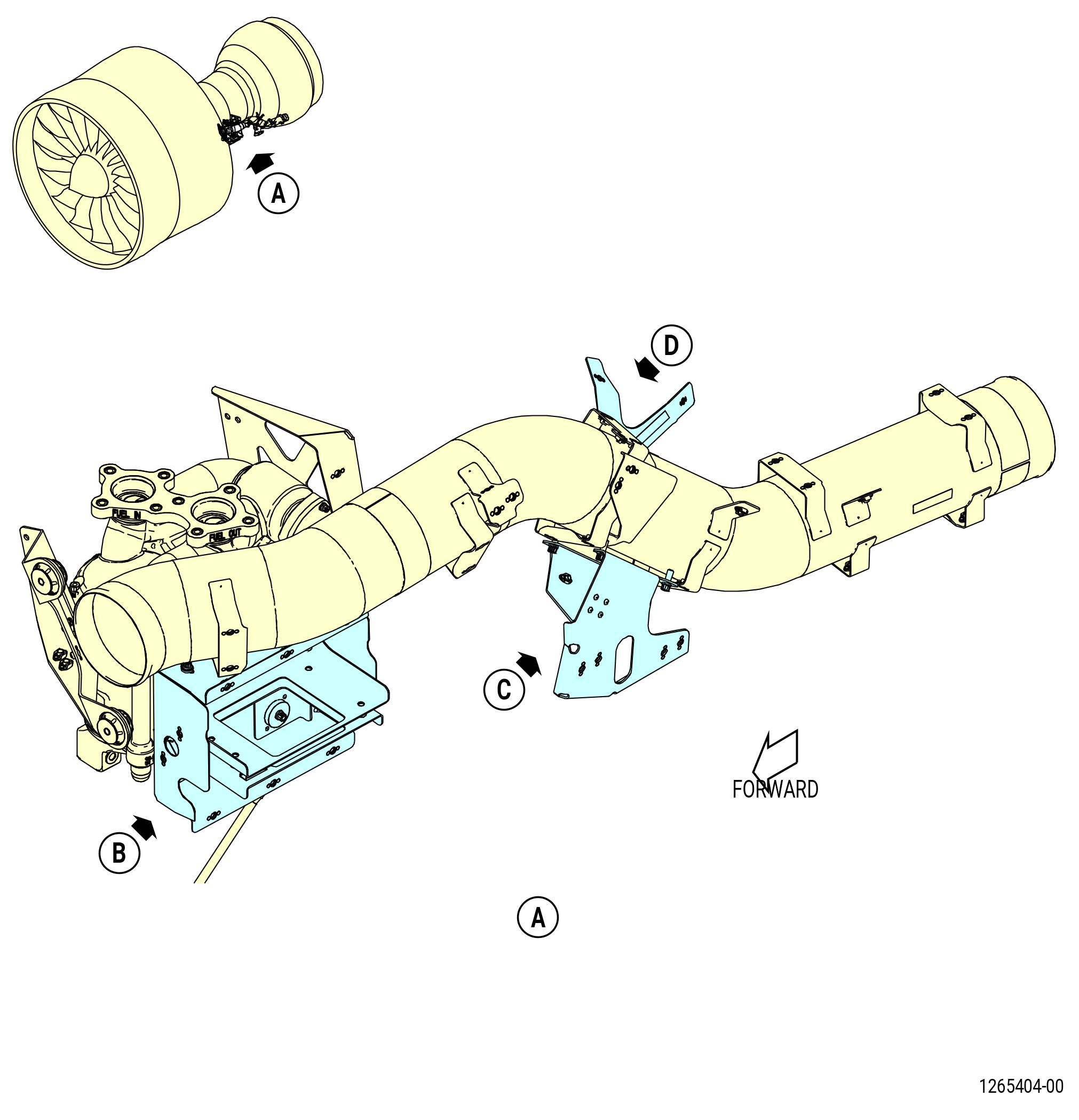
| N. | Remove the ignition system from the left side of the compressor case as follows. |
| (1) | Remove the hose clamps and the cooling shrouds from the igniters at the 8:30 and 9:30 o'clock positions. Refer to Figure 517. |
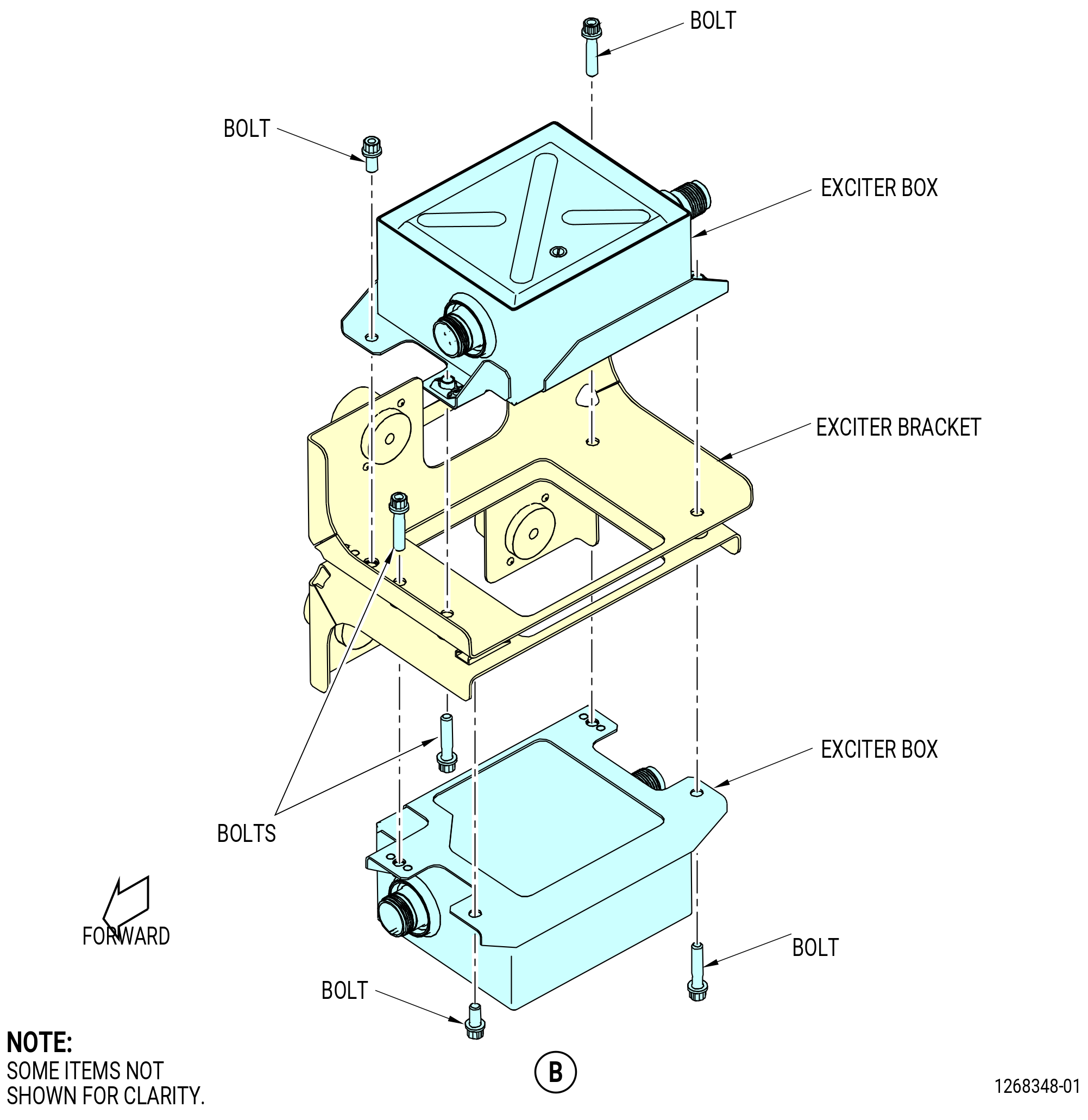
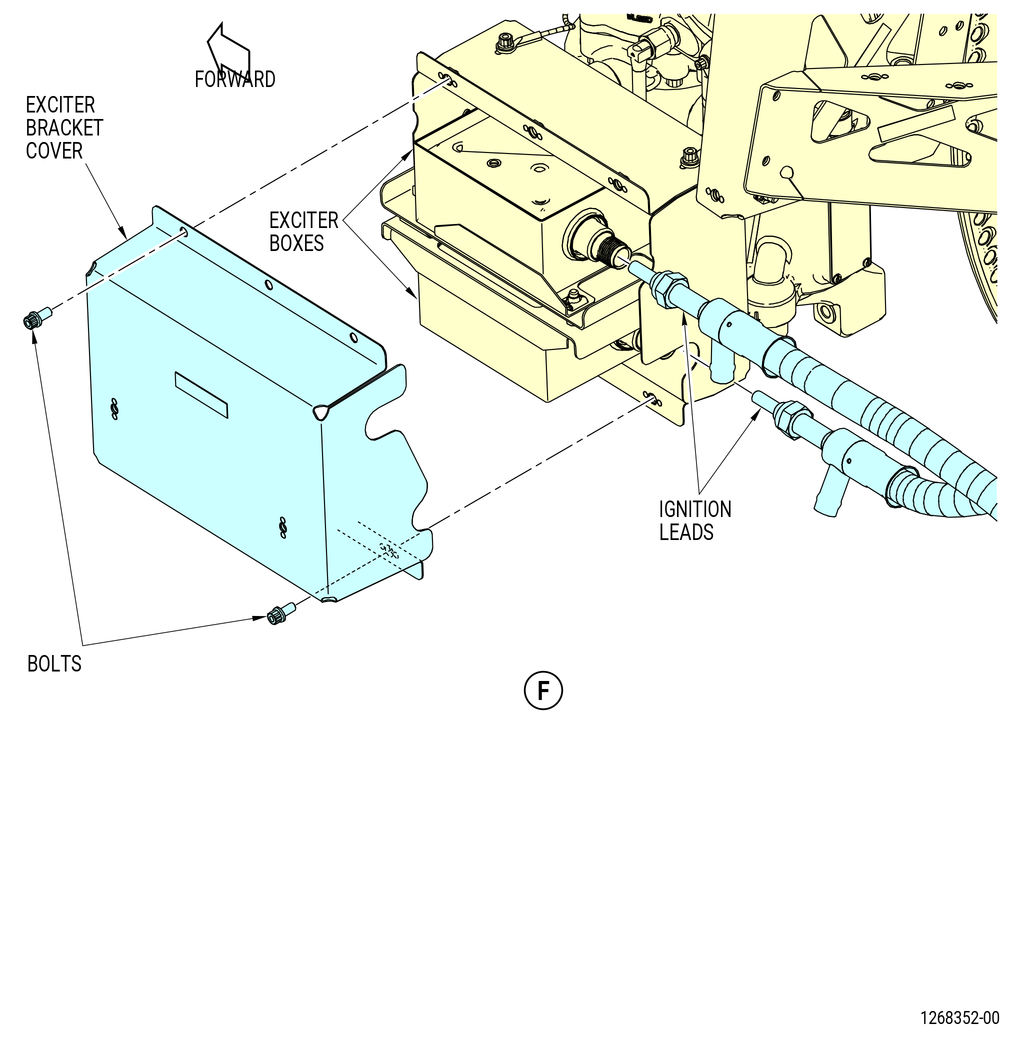
| (2) | Remove the bolts that attach the exciter bracket cover to the exciter bracket. Remove the exciter bracket cover. Refer to Figure 518. |
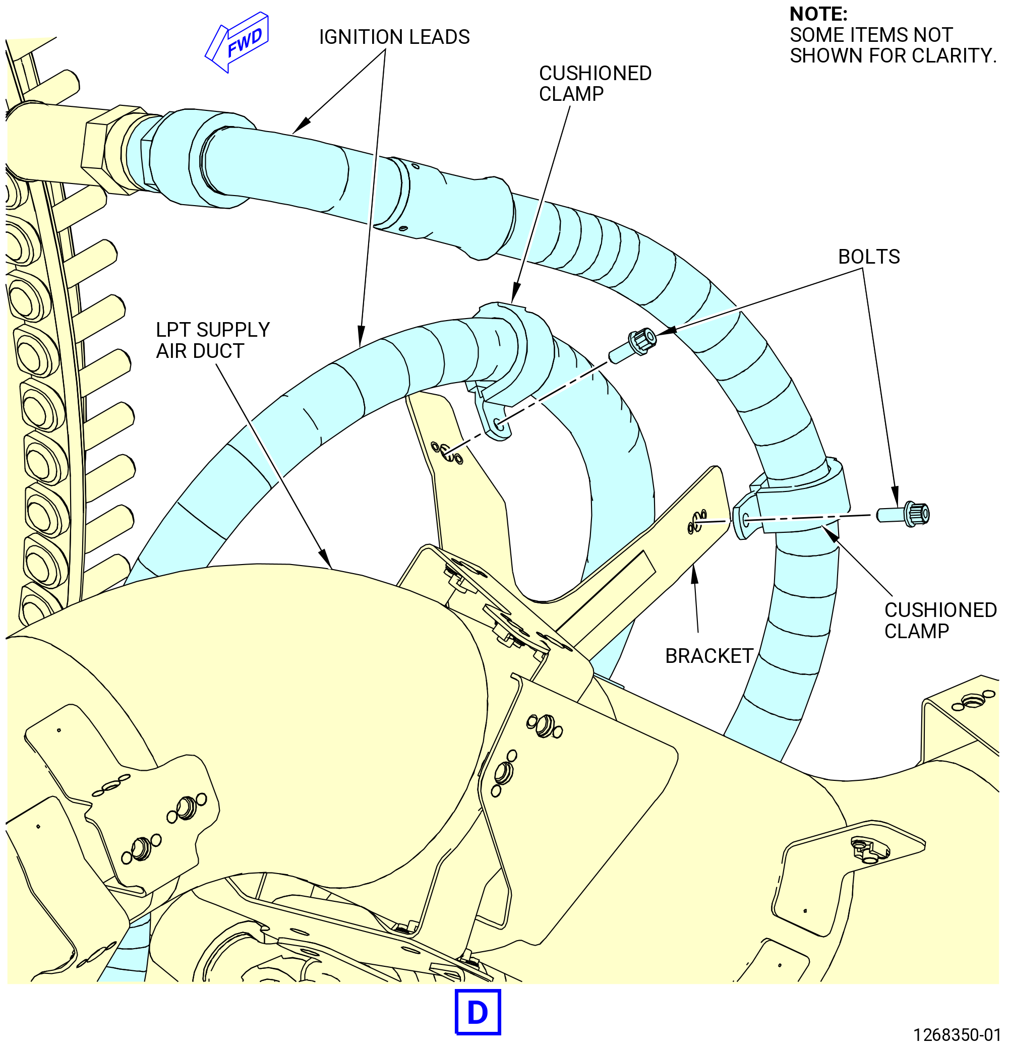
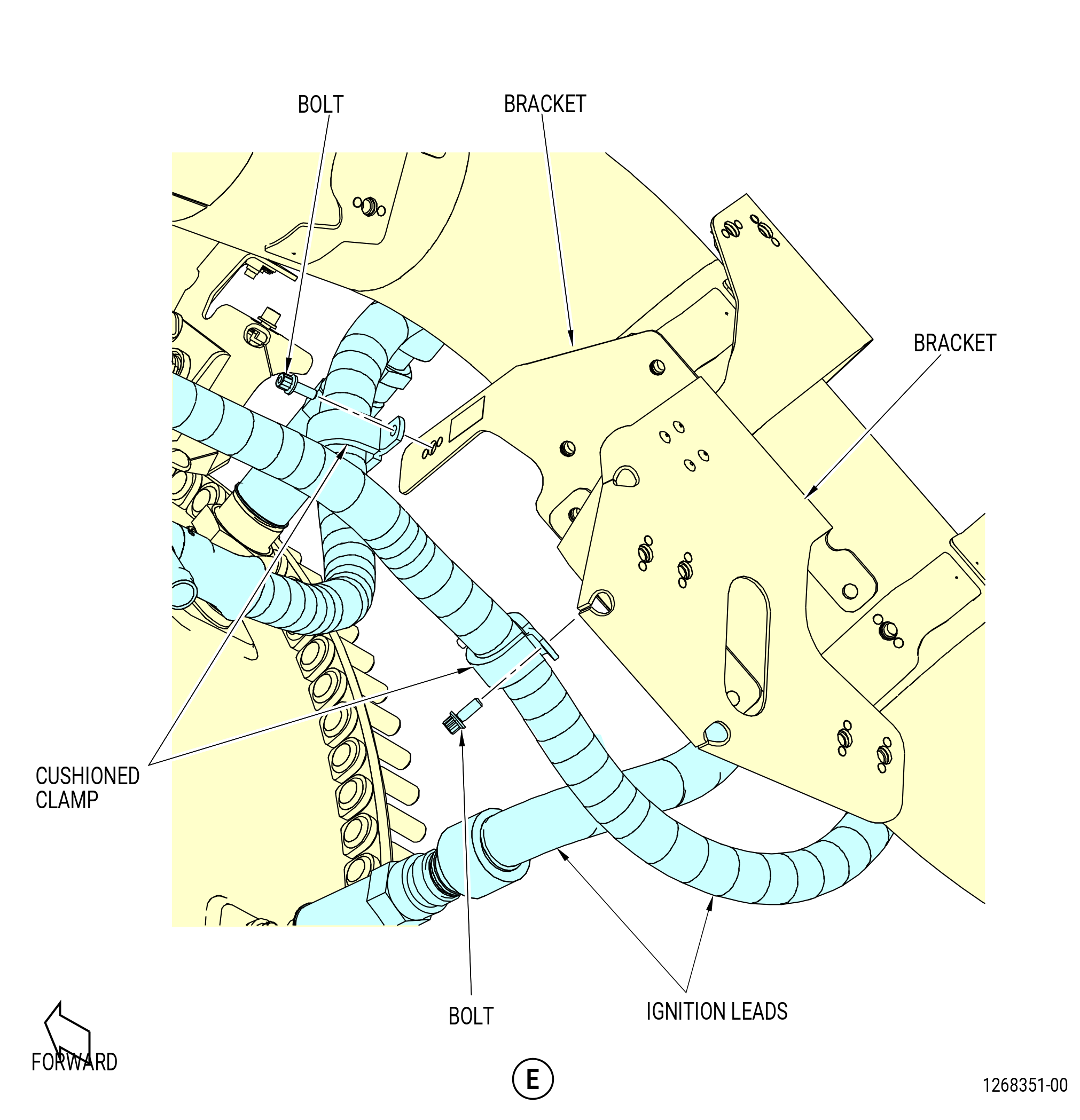
| (3) | Disconnect the ignition leads from the igniters. |
| (4) | Disconnect the ignition leads from the exciter boxes. |
| (5) | Remove the bolts and the cushioned clamps that attach the ignition leads to the brackets. Remove the ignition leads. |
| (6) | Remove the igniters from the igniter plug bushings. |
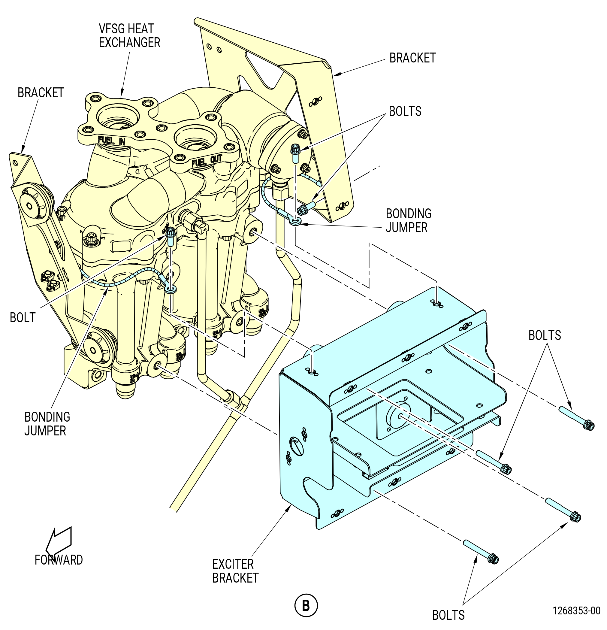
| (7) | Remove the bolts that attach the ignition exciter boxes to the exciter bracket. Remove the exciter boxes. |
| (8) | Remove the bolts that attach the exciter bracket to the variable frequency starter generators (VFSG) heat exchanger. Remove the exciter bracket. |
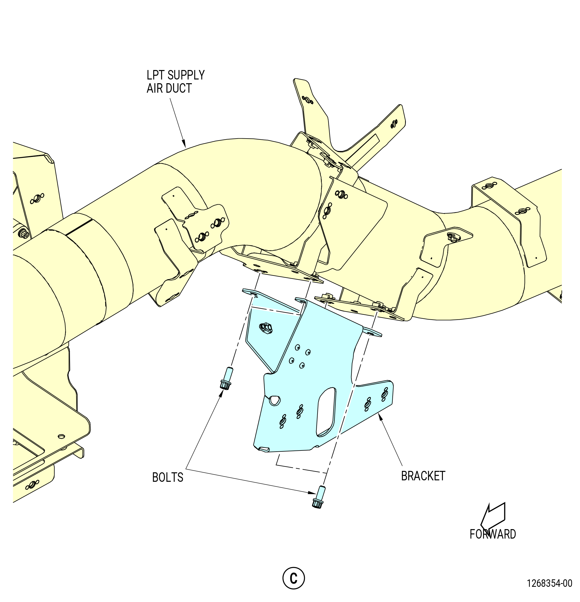
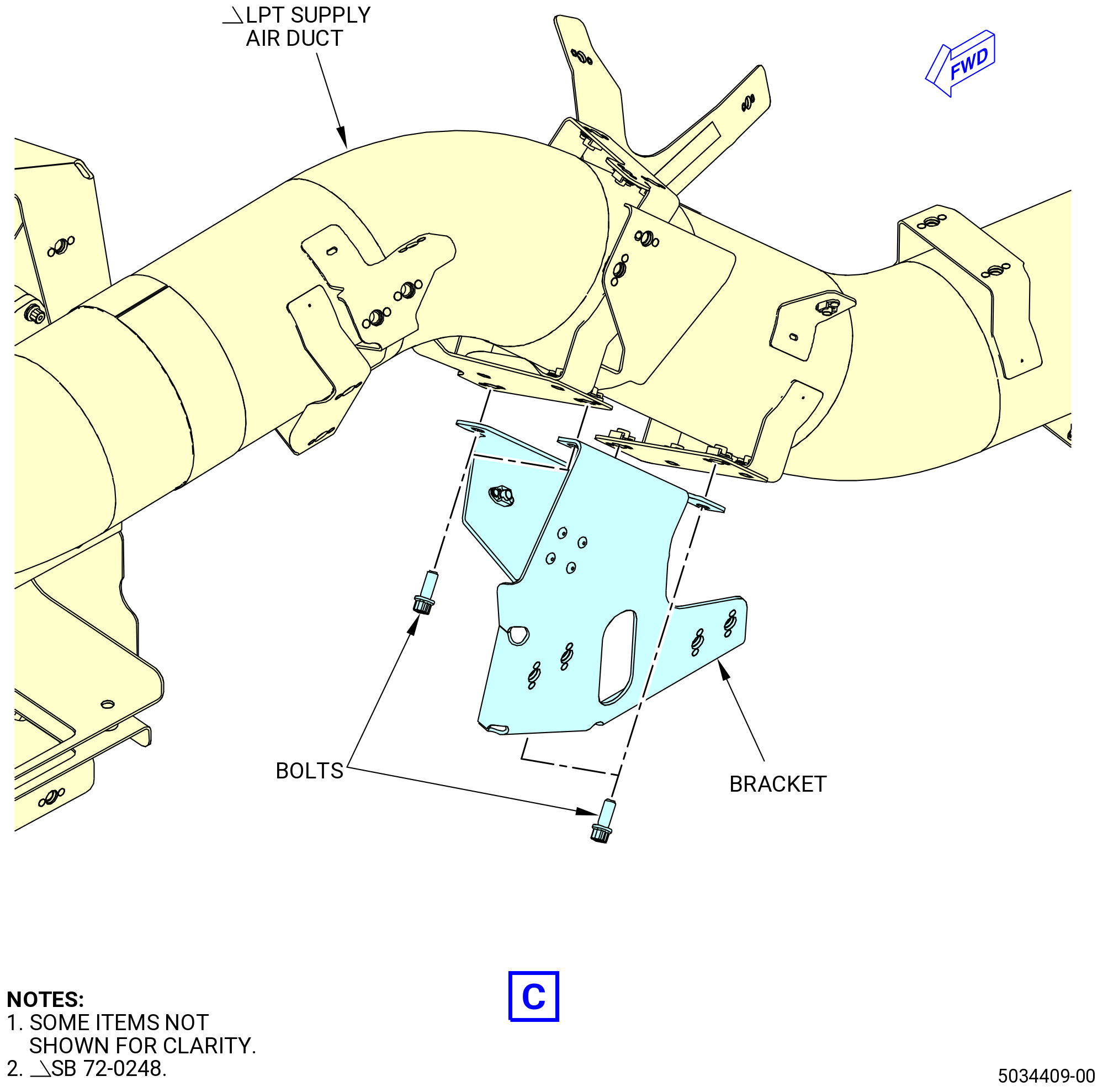
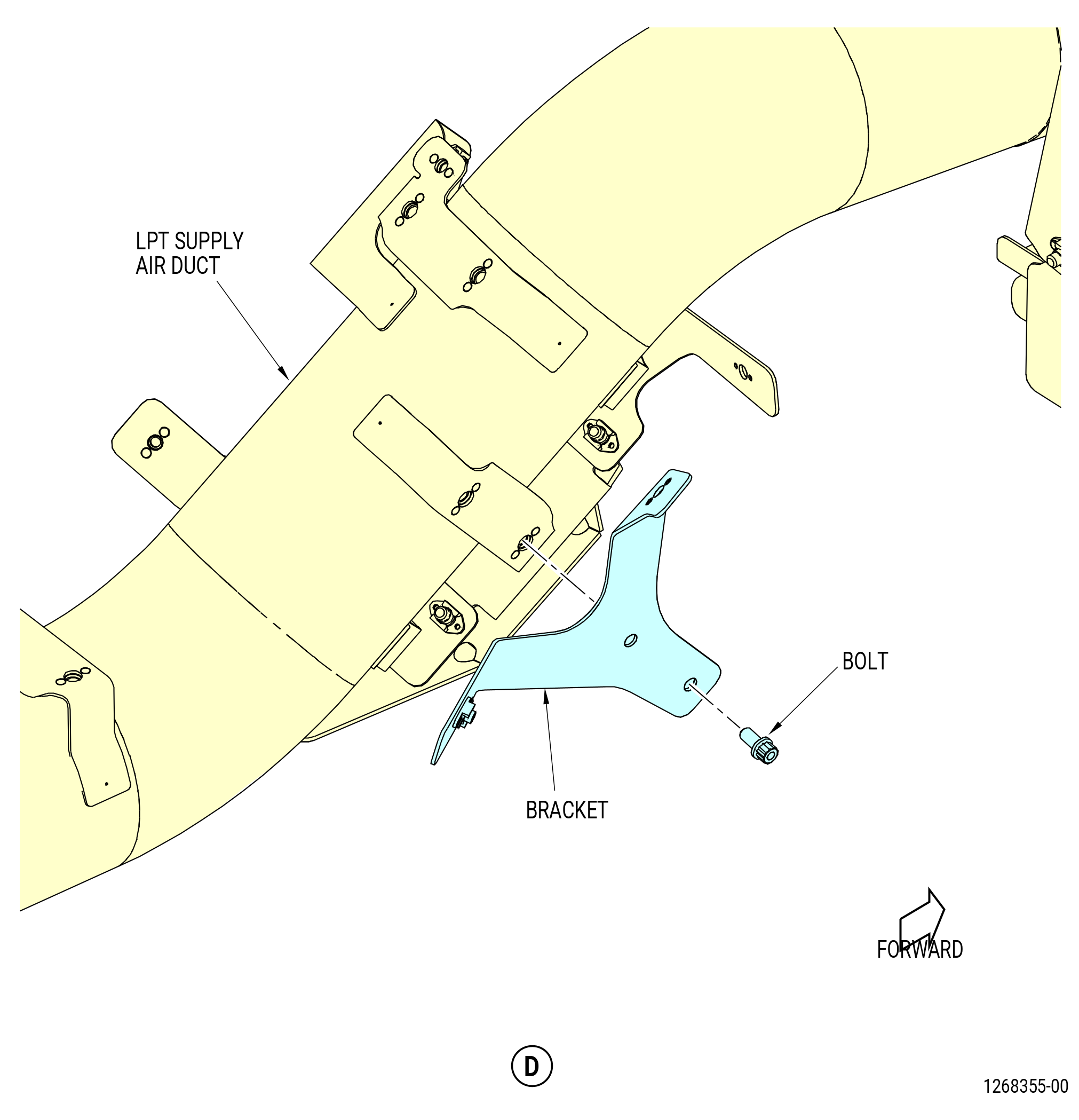
| (9) | Remove the bonding jumpers from the exciter bracket. Refer to Figure 519. |
| (10) | Remove the bolts that attach the brackets to the low pressure turbine (LPT) supply air duct. Remove the brackets. |
|
|
|
|
| Subtask 72-00-02-030-442 |
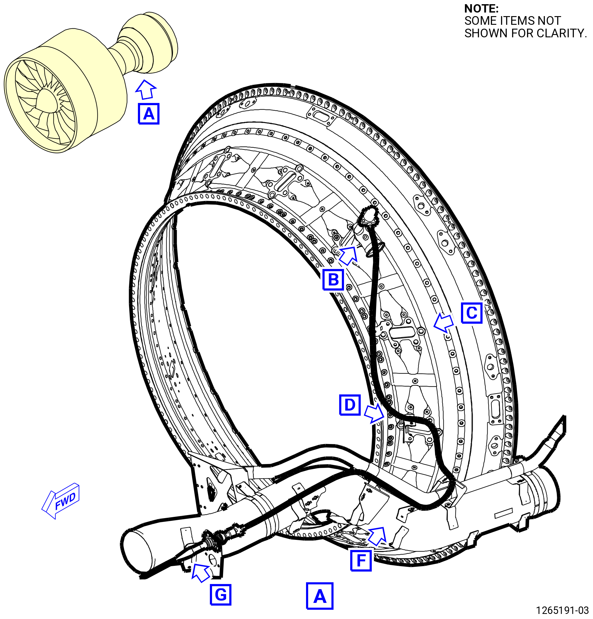
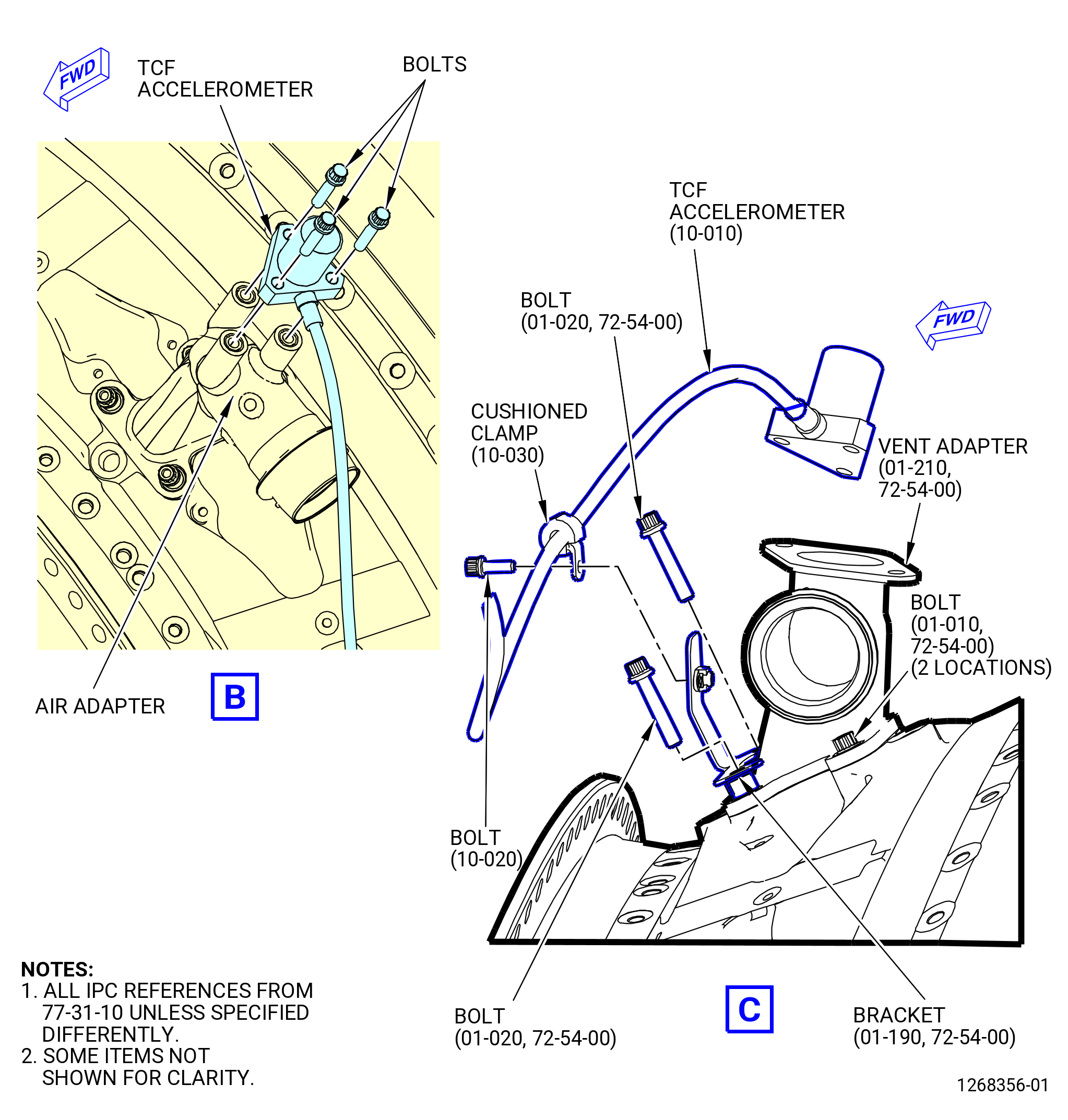
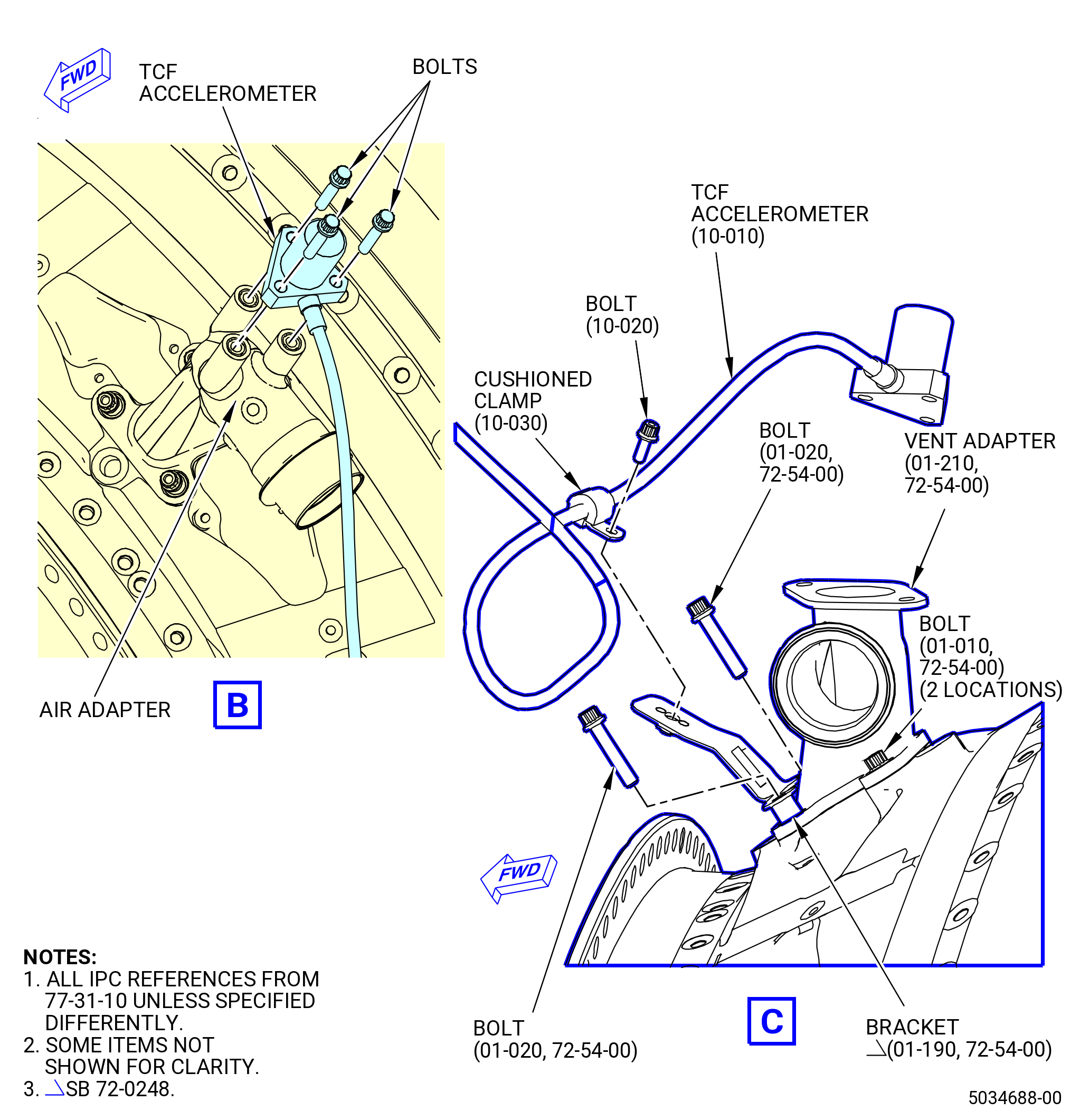
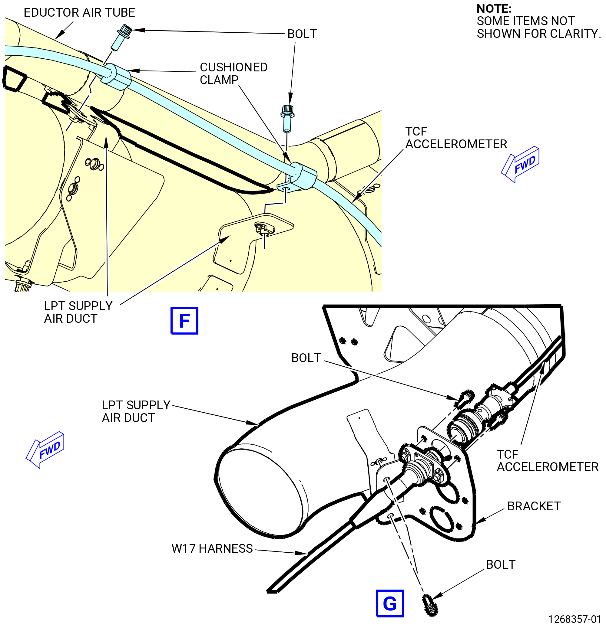
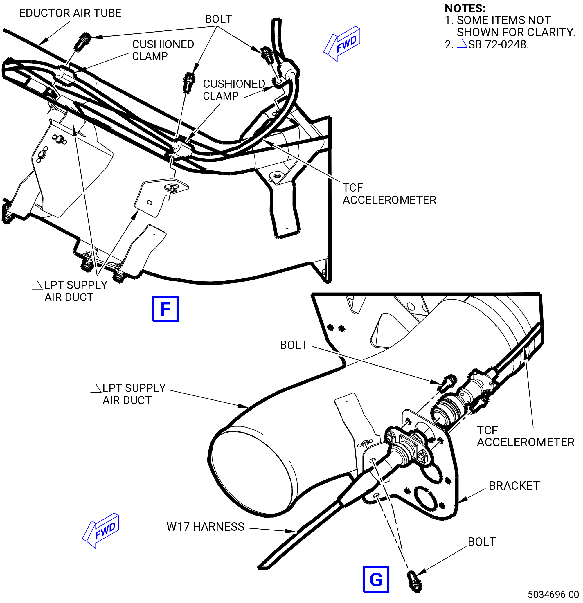
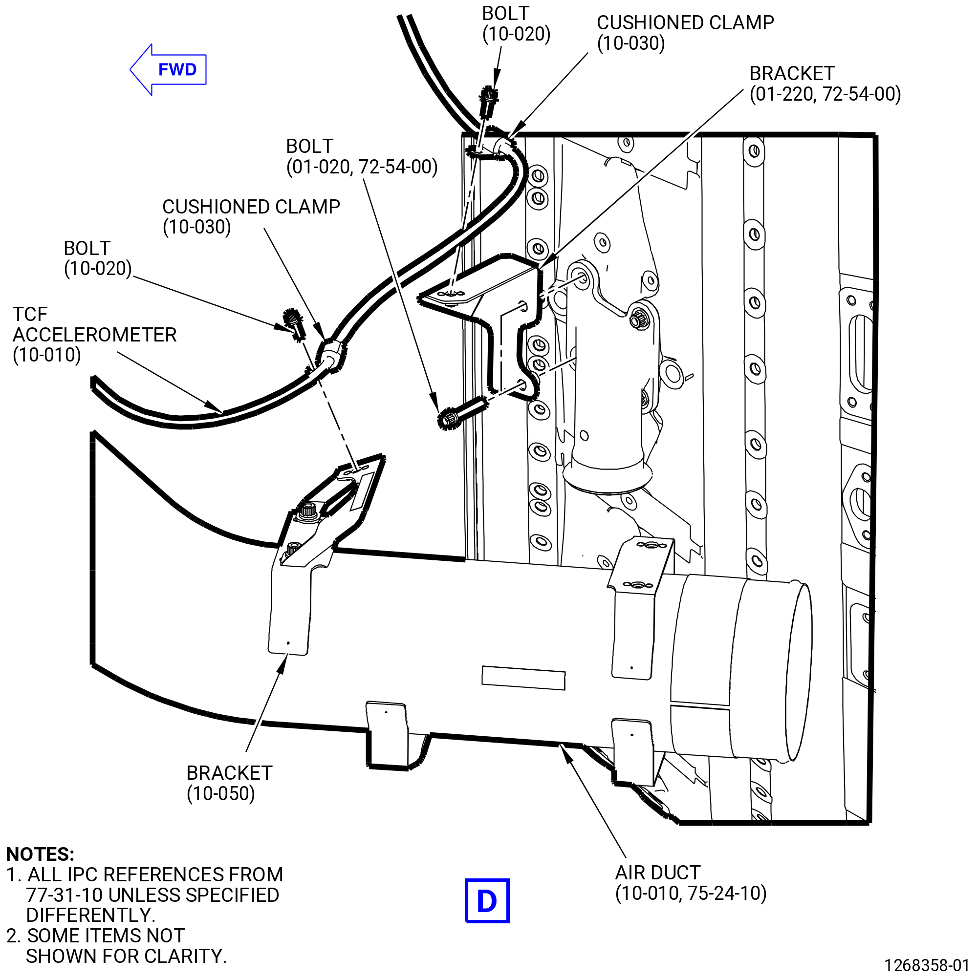
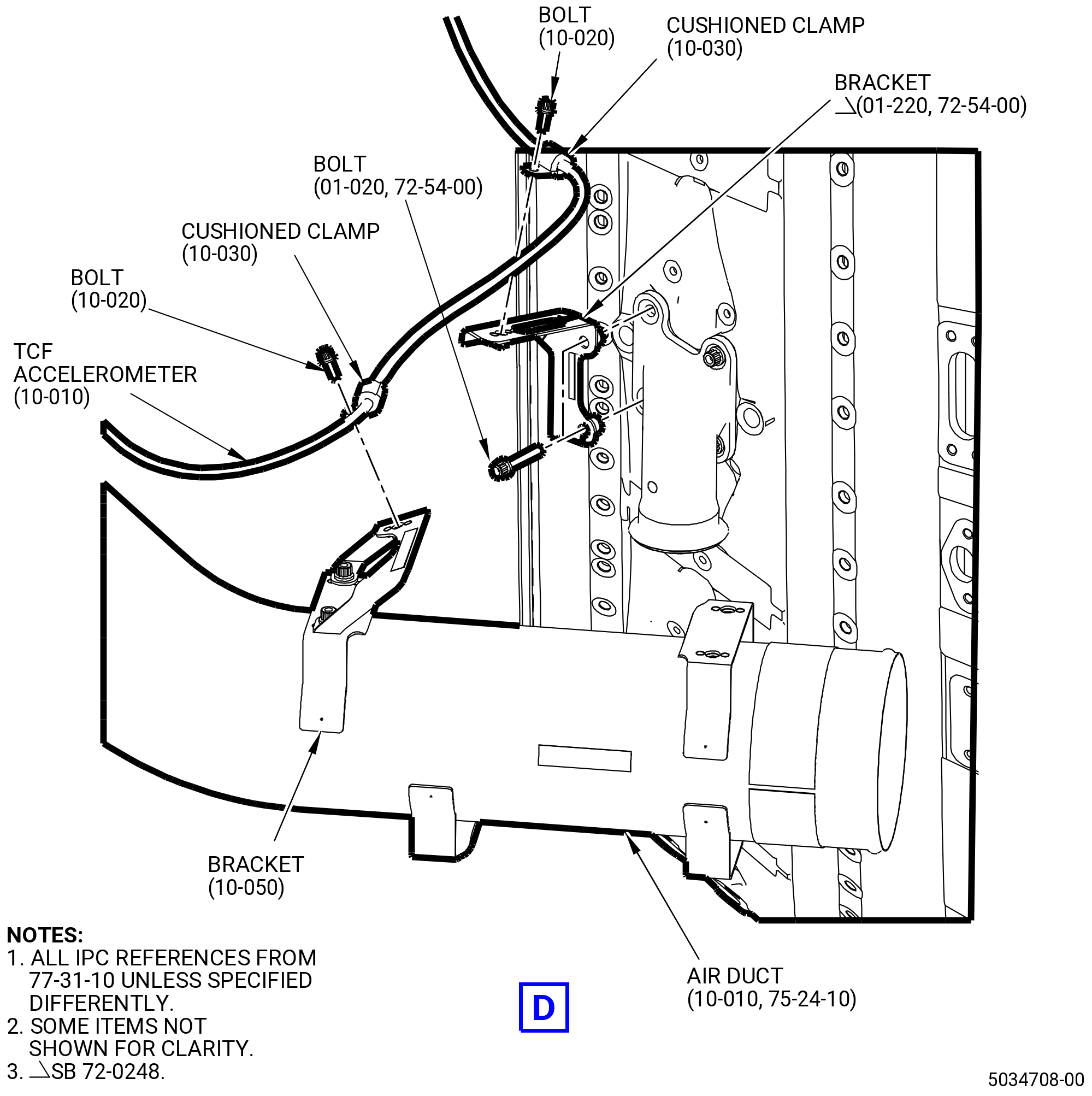
| O. | Remove the TCF accelerometer as follows. Refer to Figure 520. |
| (1) | Disconnect the W17 harness from the TCF accelerometer. |
| (2) | Remove the bolts that attach the W17 harness to the bracket. |
| (3) | Remove the bolts that attach the TCF accelerometer to the air adapter at the 11:00 o'clock position (ALF) on the turbine center frame. |
| (4) | Remove the bolts and cushioned clamps that attach the TCF accelerometer to the brackets and the LPT supply air duct. |
| (5) | Remove the TCF accelerometer. |
|
|
|
|
|
|
| Subtask 72-00-02-030-403 |
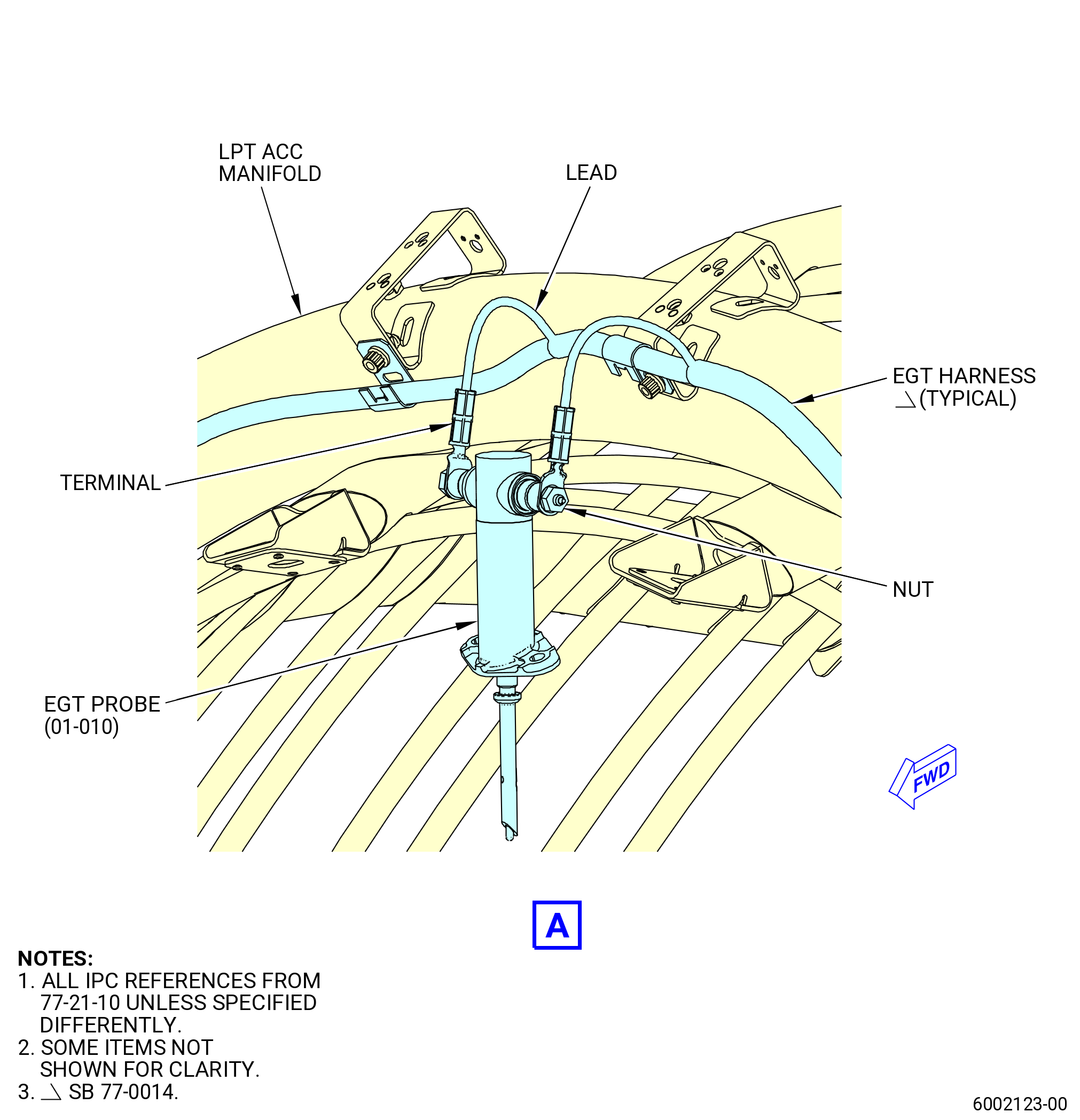
| P. | Remove the upper and lower exhaust gas temperature (EGT) harnesses from the propulsor as follows. Refer to Figure 521. |
| CAUTION: |
|
| CAUTION: |
|
| (1) | Apply a small amount of C02-053 penetrating oil at the ends of the EGT probe studs and on the threads of the harness connector nut. |
| (2) | Remove the upper EGT harness (upper harness) as follows: |
| (a) | Remove the upper harness nuts from the EGT probes. |
| (b) | Remove the bolts that attach the upper harness to the support bracket on the LPT supply air duct. |
| (c) | Remove the bolts that attach the tabs on the upper harness to the support brackets. |
| (d) | Remove the upper harness. |
| WARNING: |
|
| (3) | Clean the threaded surfaces that received penetrating oil with a cotton swab or brush soaked with C04-035 isopropyl alcohol and let them air-dry before re-assembly. |
| NOTE: |
|
| (4) | Do Subtask 72-00-02-030-403 (paragraph 3.P.(1) thru paragraph 3.P.(3)) again for the lower EGT harness (lower harness). |
| (5) | Remove the bolts that attach the support bracket to the LPT supply air duct. Remove the support bracket. |
| (6) | Remove the bolts that attach the support bracket to the LPT ACC manifold. Remove the support bracket. |
|
|
| Subtask 72-00-02-030-468 |
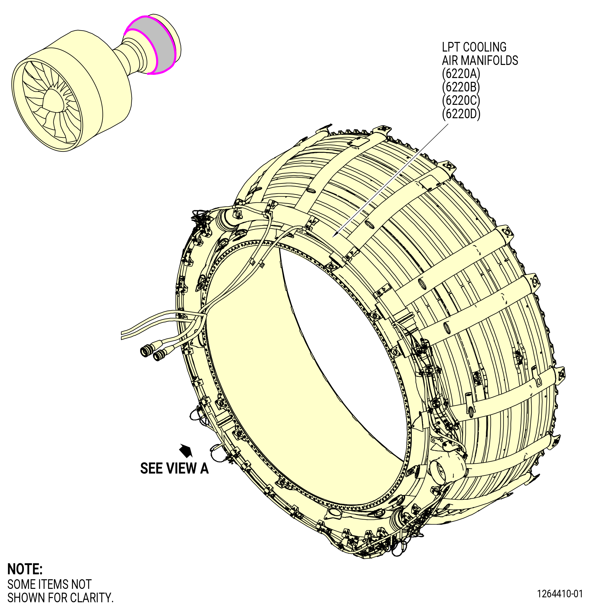
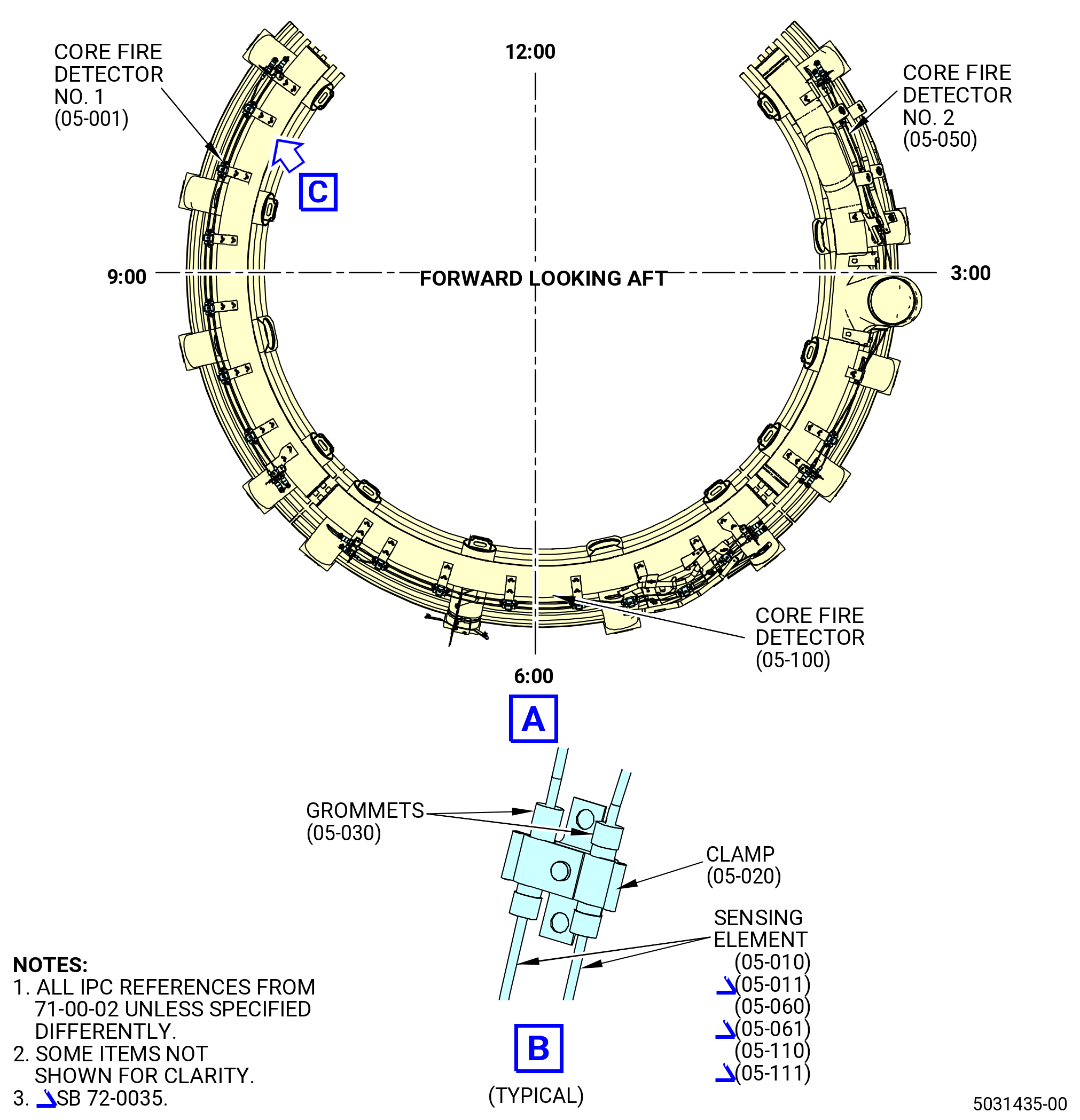
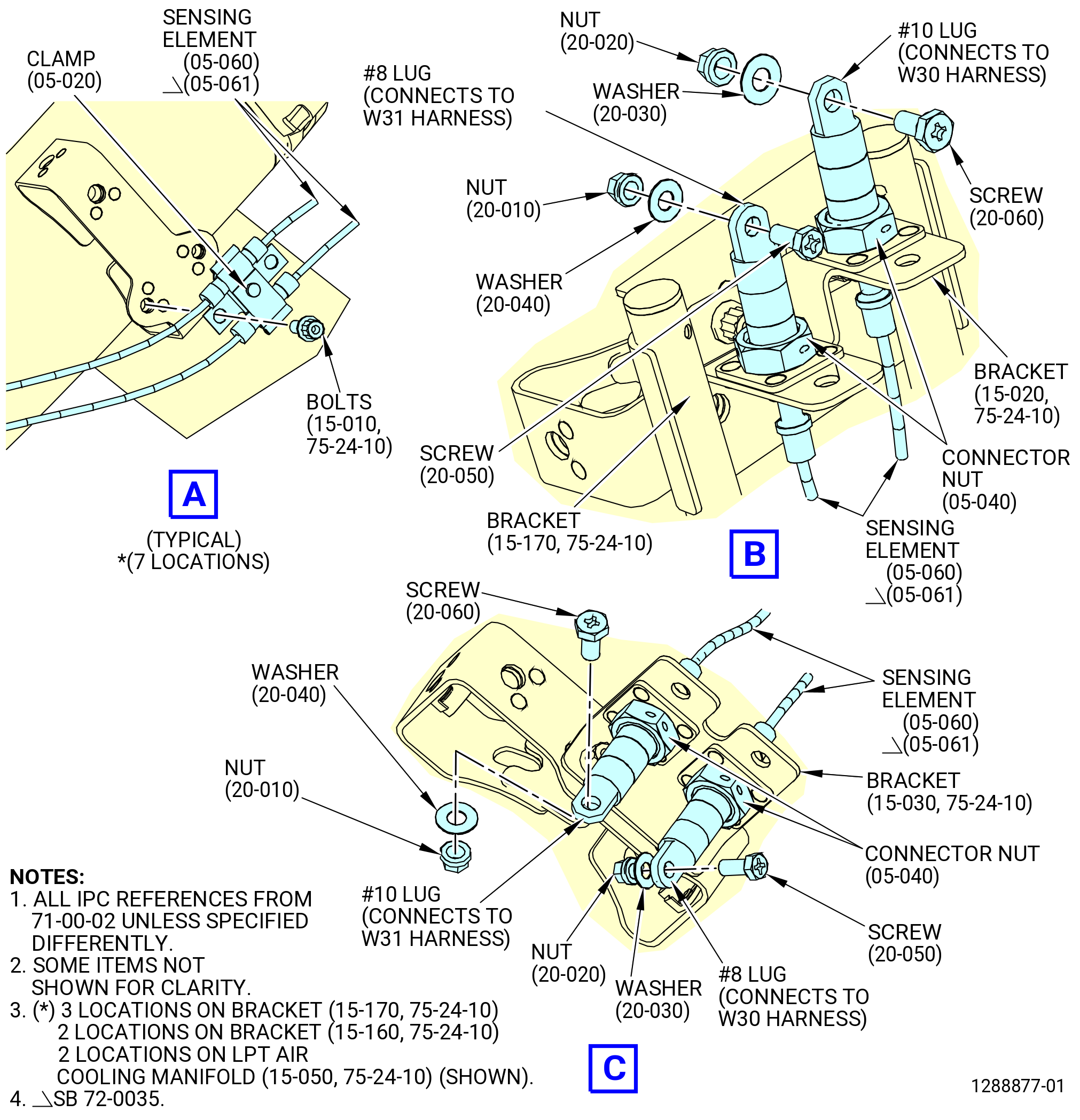
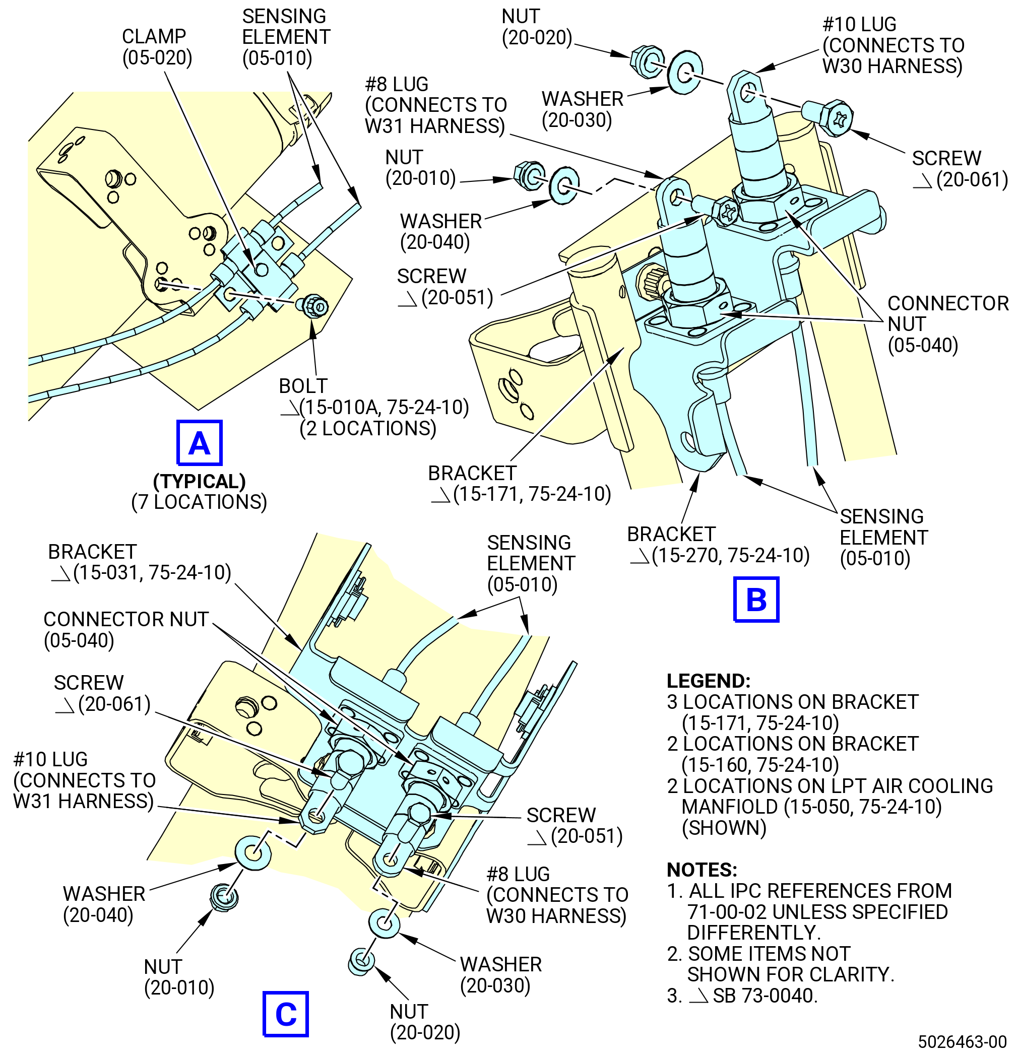
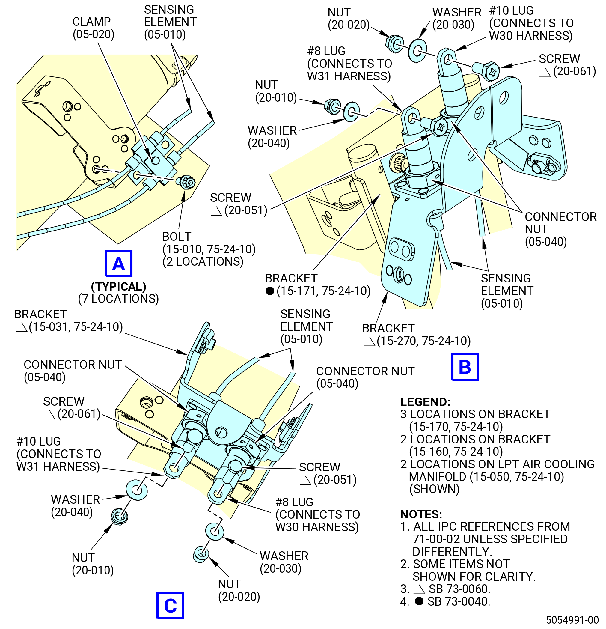
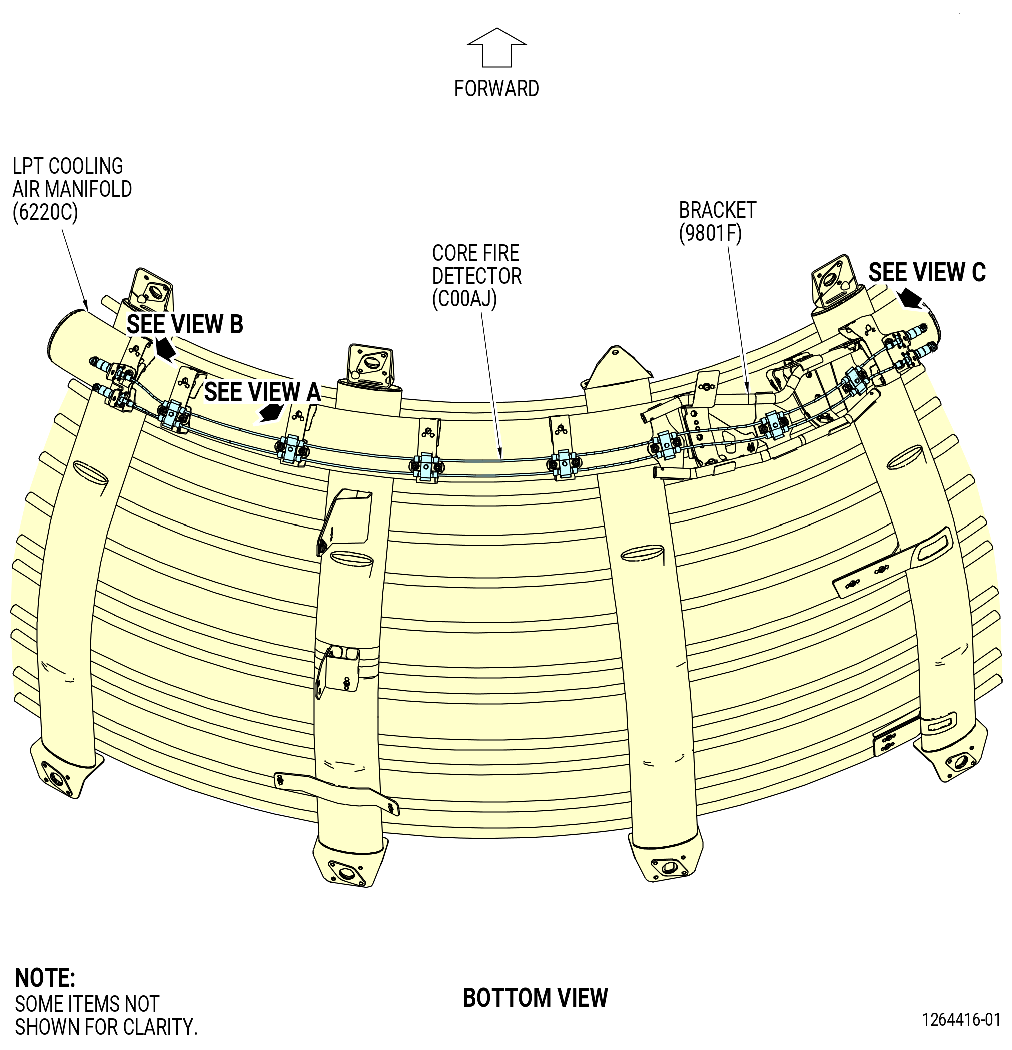
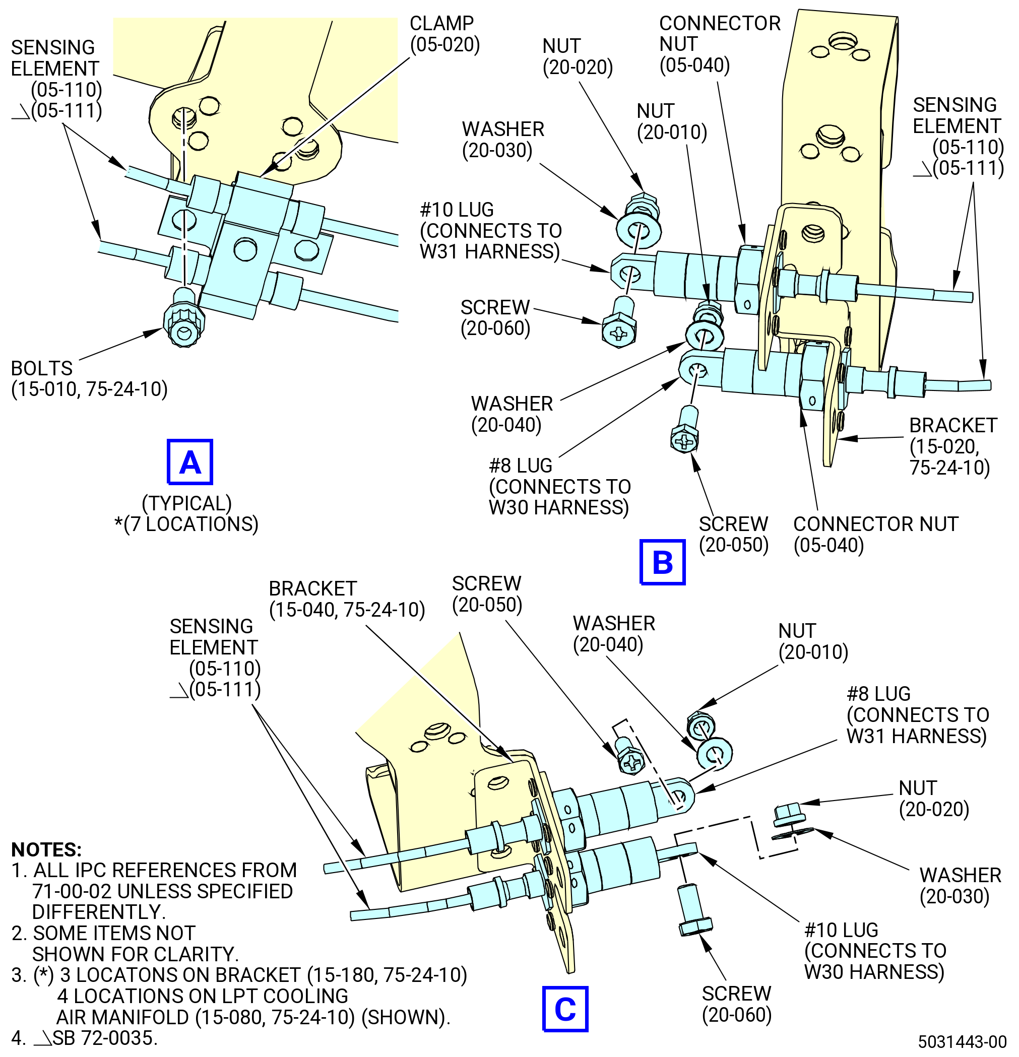
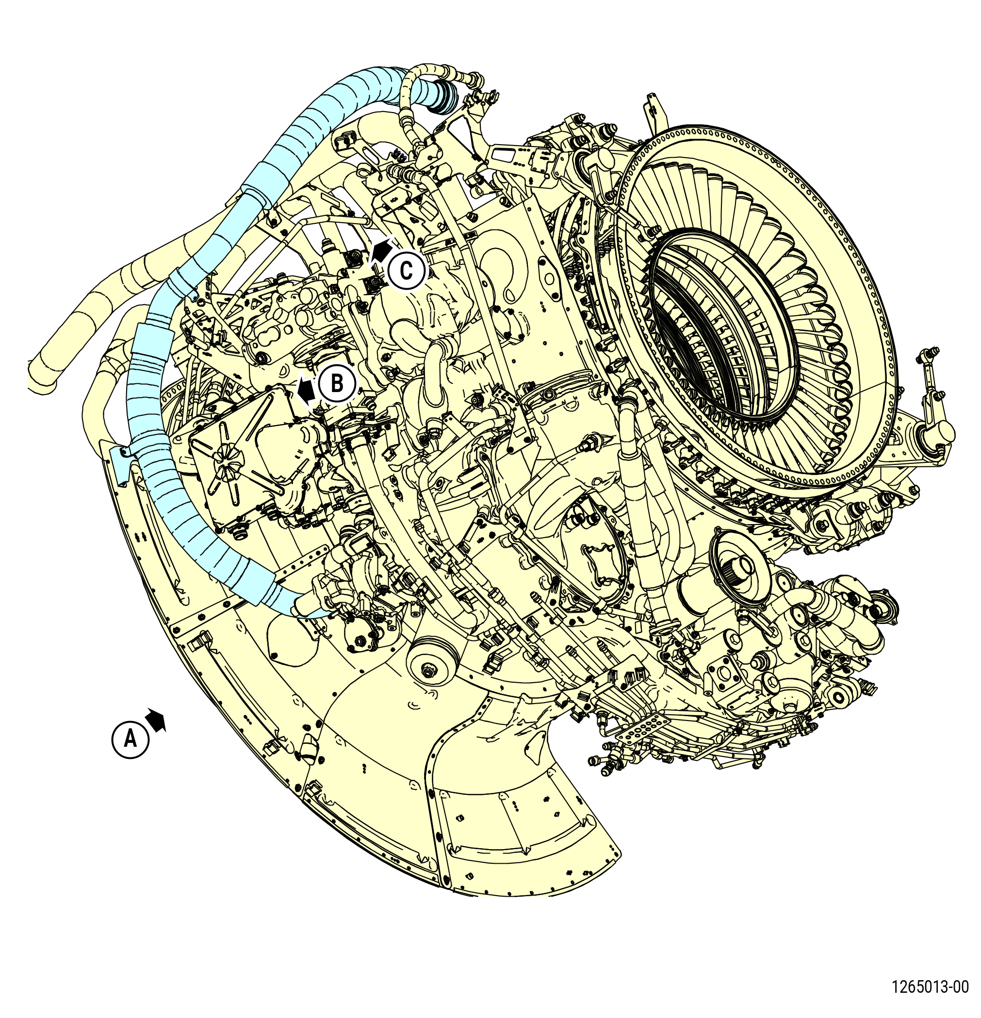
| Q. | Remove the three core fire detectors (C0005, C00AJ, and C0006) as follows. Refer to Figure 522. |
| (1) | Remove the core fire detector No. 1 (C0005) from the LPT ACC air manifold (6220B) as follows. Refer to Figure 523. |
| (a) | Disassemble the sensing elements (05-010 , 71-00-02) (SIN C00A7) or (05-011 , 71-00-02) (SIN C00A7) as follows: |
| 1 | Remove the safety cable from the nut connectors (C00K2). |
| 2 | Loosen all the fasteners of No. 8 lug and No. 10 lug. |
| Subtask 72-00-02-030-673 |
| * * * PRE SB 73-0040( Engines without improved W30 and W31 harness ) |
| 3 | Remove the bolts (15-010 , 75-24-10) (SIN 98020), the clamps (05-020 , 71-00-02) (SIN C00V3), and the grommets (05-030 , 71-00-02) (SIN C00N7) from the sensing elements. |
| * * * END PRE SB 73-0040 |
| Subtask 72-00-02-030-674 |
| * * * SB 73-0040( Engines with improved W30 and W31 harness ) |
| 3.A. | Remove the bolts (15-010A , 75-24-10) (SIN 98020), the clamps (05-020 , 71-00-02) (SIN C00V3), the bracket (15-260 , 75-24-10) (SIN 9801M), and the grommets (05-030 , 71-00-02) (SIN C00N7) from the sensing elements. |
| * * * END SB 73-0040 |
| Subtask 72-00-02-030-675 |
| 4 | Remove nut connectors (C00K2) from the lugs. |
| 5 | Remove the No. 10 nut (C00K4), No. 10 washer (C00J1), and No. 10 screw (C00F4) from the No. 10 lug. |
| 6 | Remove the No. 8 nut (C00K3), the No. 8 washer (C00J0), and the No. 8 screw (C00F3) from the No. 8 lug. |
| 7 | Remove the sensing elements from the LPT ACC air manifold (6220B). |
|
|
| Subtask 72-00-02-030-469 |
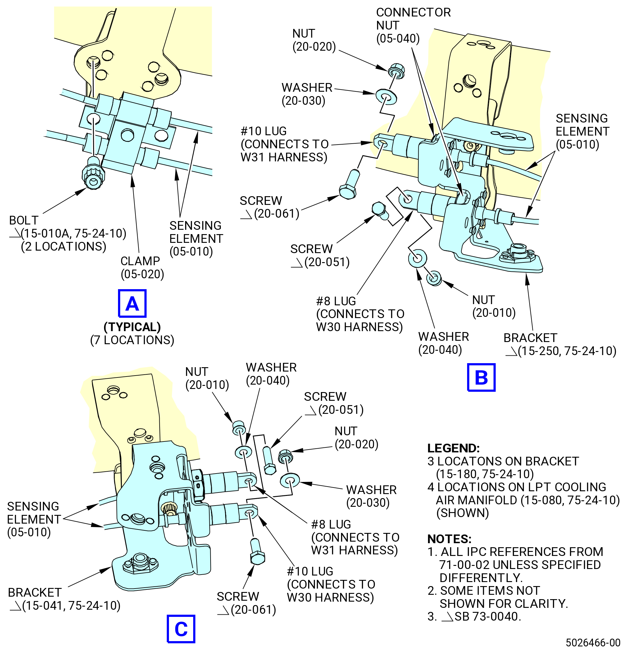
| (5) | Remove core fire detector No. 2 (C0006) from the LPT ACC air manifold (6220D) as follows. Refer to Figure 524. |
| (a) | Disassemble the sensing elements (05-060 , 71-00-02) (SIN C00A7) or (05-061 , 71-00-02) (SIN C00A7) as follows: |
| 1 | Remove the safety cable from nut connectors (C00K2). |
| 2 | Loosen all the fasteners of No. 8 lug and the No. 10 lug. |
| 3 | Remove the bolts (98020), clamps (C00V3), and grommets (C00N7) from the sensing elements. |
| 4 | Remove nut connectors (C00K2) from the lugs. |
| 5 | Remove the No. 10 nut (C00K4), No. 10 washer (C00J1), and No. 10 screw (C00F4) from the No. 10 lug. |
| 6 | Remove the No. 8 nut (C00K3), No. 8 washer (C00J0), and No. 8 screw (C00F3) from the No. 8 lug. |
| 7 | Remove the sensing elements from the LPT ACC air manifold (6220D). |
|
|
| Subtask 72-00-02-030-470 |
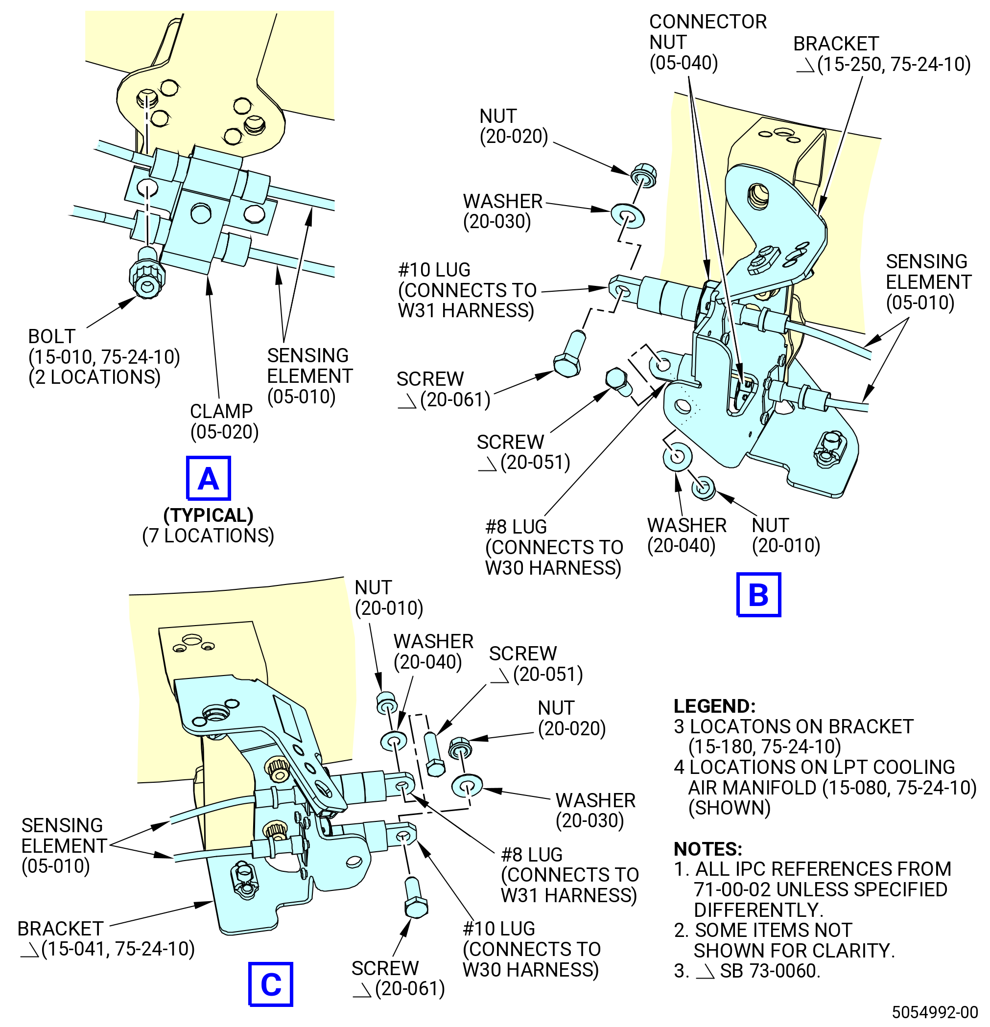
| (6) | Remove core fire detector No. 3 (C00AJ) from the LPT ACC air manifold (6220C) as follows. Refer to Figure 525. |
| (a) | Disassemble the sensing elements (05-110 , 71-00-02) (SIN C00A7) or (05-111 , 71-00-02) (SIN C00A7) as follows: |
| 1 | Remove safety cable from the nut connectors (C00K2). |
| 2 | Loosen all the fasteners of the No. 8 lug and the No. 10 lug. |
| 3 | Remove the bolts (98020), clamps (C00V3), and grommets (C00N7) from the sensing elements. |
| 4 | Remove nut connectors (C00K2) from the lugs. |
| 5 | Remove the No. 10 nut (C00K4), No. 10 washer (C00J1), and No. 10 screw (C00F4) from the No. 10 lug. |
| 6 | Remove the No. 8 nut (C00K3), No. 8 washer (C00J0), and No. 8 screw (C00F3) from the No. 8 lug. |
| 7 | Remove the sensing elements from the LPT ACC air manifold (6220C). |
|
|
| Subtask 72-00-02-030-405 |
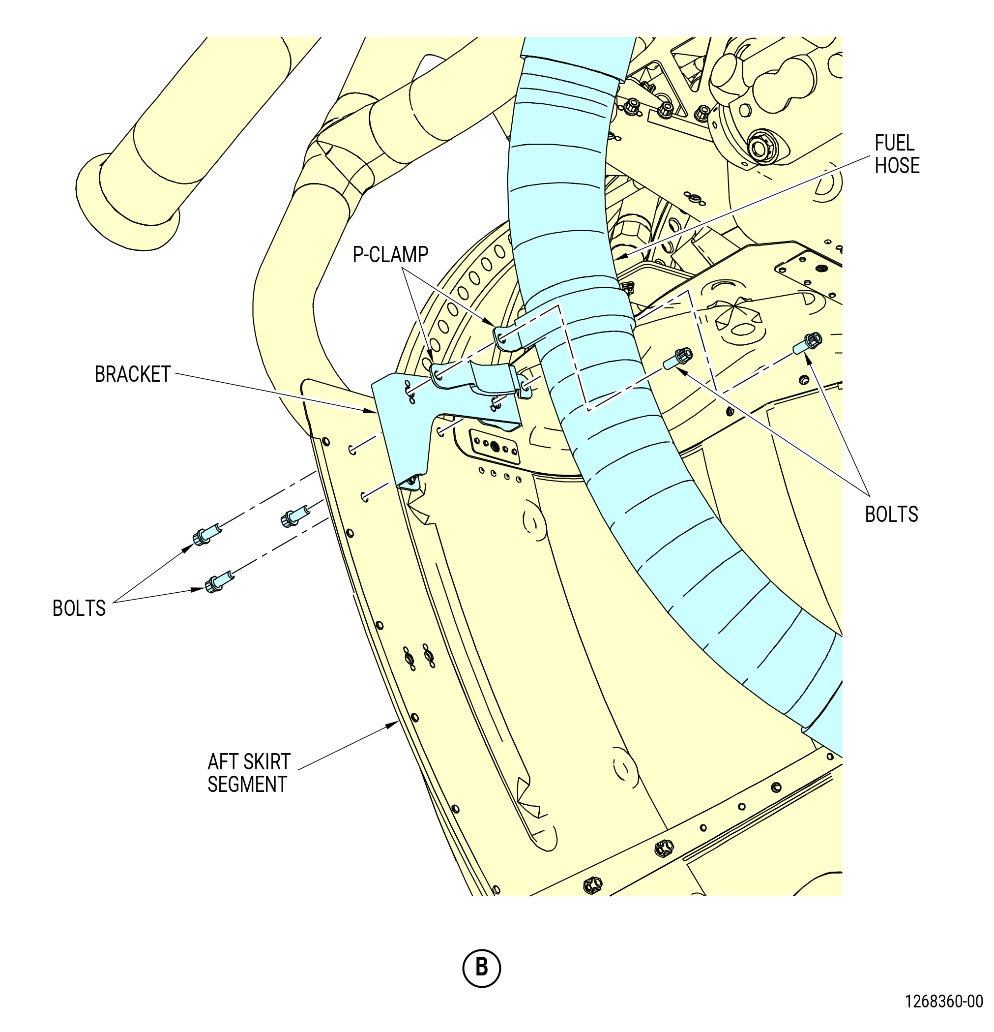
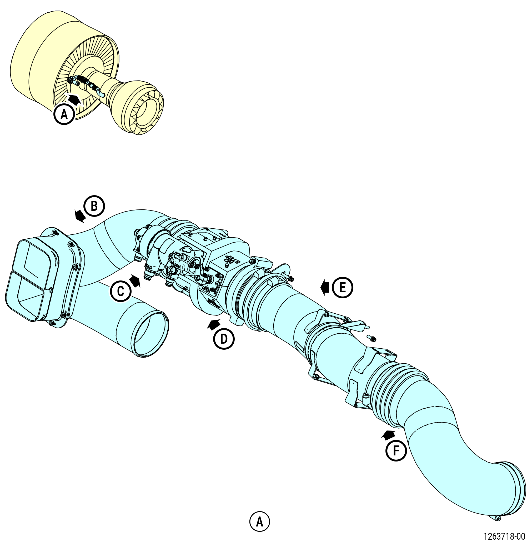
| R. | Remove the fuel system as follows. Refer to Figure 526. |
| (1) | Remove the main inlet fuel tube hose (fuel hose) as follows: |
| Subtask 72-00-02-030-662 |
| * * * PRE SB 73-0031( Fuel System without W13 Harness Electrical Bracket ) |
| (a) | Remove the bolts that attach the fuel hose to the fuel pump. |
| * * * END PRE SB 73-0031 |
| Subtask 72-00-02-030-663 |
| * * * SB 73-0031( Fuel System with W13 Harness Electrical Bracket ) |
| (a).A. | Remove the bolts that attach the W13 harness electrical bracket (bracket) and fuel hose to the fuel pump. Remove the bracket. |
| * * * END SB 73-0031 |
| Subtask 72-00-02-030-664 |
| (b) | Remove the bolts and P-clamps that attach the fuel hose to the brackets. |
| (c) | Remove the fuel hose. Remove and discard the gasket (01-100 , 73-11-40) (SIN 34050). |
| (d) | Remove the bolts that attach the bracket to the aft skirt segment. Remove the bracket. |
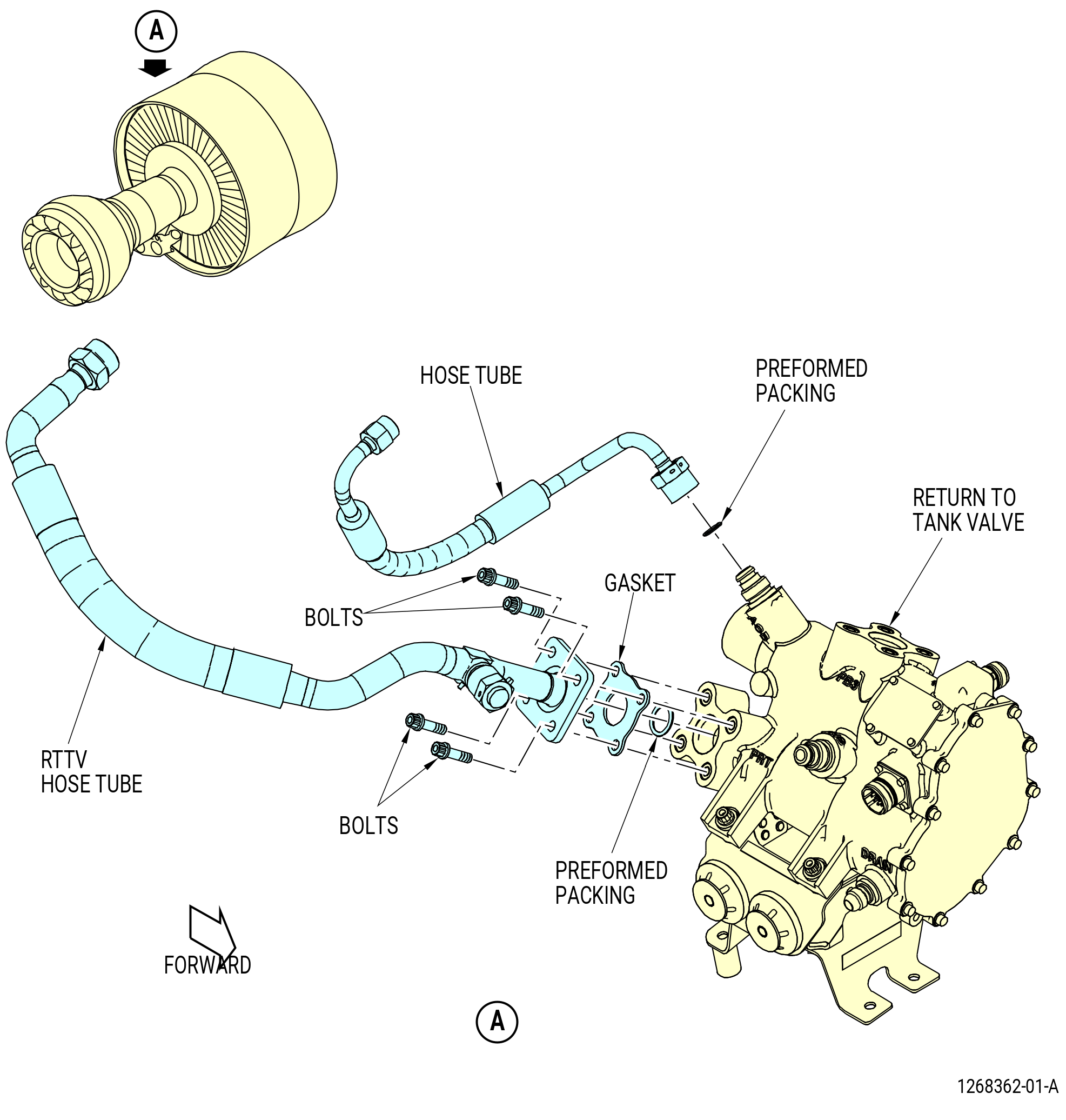
| (2) | Remove the return to tank valve (RTTV) hose tube as follows. Refer to Figure 527. |
| (a) | Remove the four bolts that attach the RTTV hose tube to the RTTV. |
| (b) | Remove and discard the gasket. |
| (c) | Remove and discard the preformed packing from the RTTV body. |
| (3) | Remove the RTTV AC boost hose tube (hose tube) (34001) as follows: |
| (a) | Disconnect the hose tube from the RTTV. |
| (b) | Remove and discard the preformed packing from the RTTV. |
|
|
| Subtask 72-00-02-030-406 |
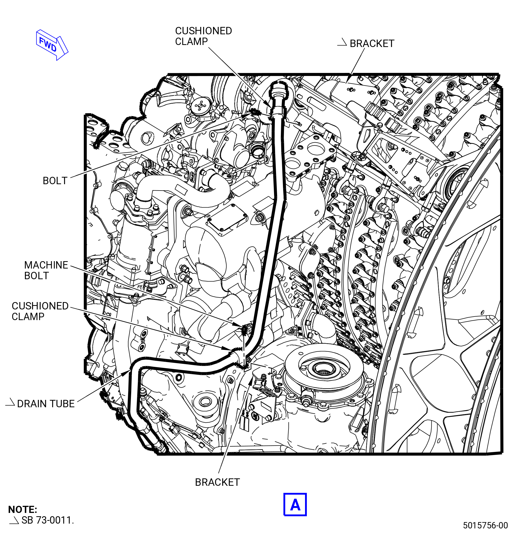
| S. | Remove the aft pylon drain system as follows: |
| (1) | Remove the strut drain hose tube (hose tube) as follows. Refer to Figure 528. |
| (a) | Disconnect the hose tube from the drain to lower BIFI air tube (drain tube). |
| (b) | Remove the bolts and cushioned clamps that attach the hose tube to the brackets. |
| (c) | Remove the hose tube. |
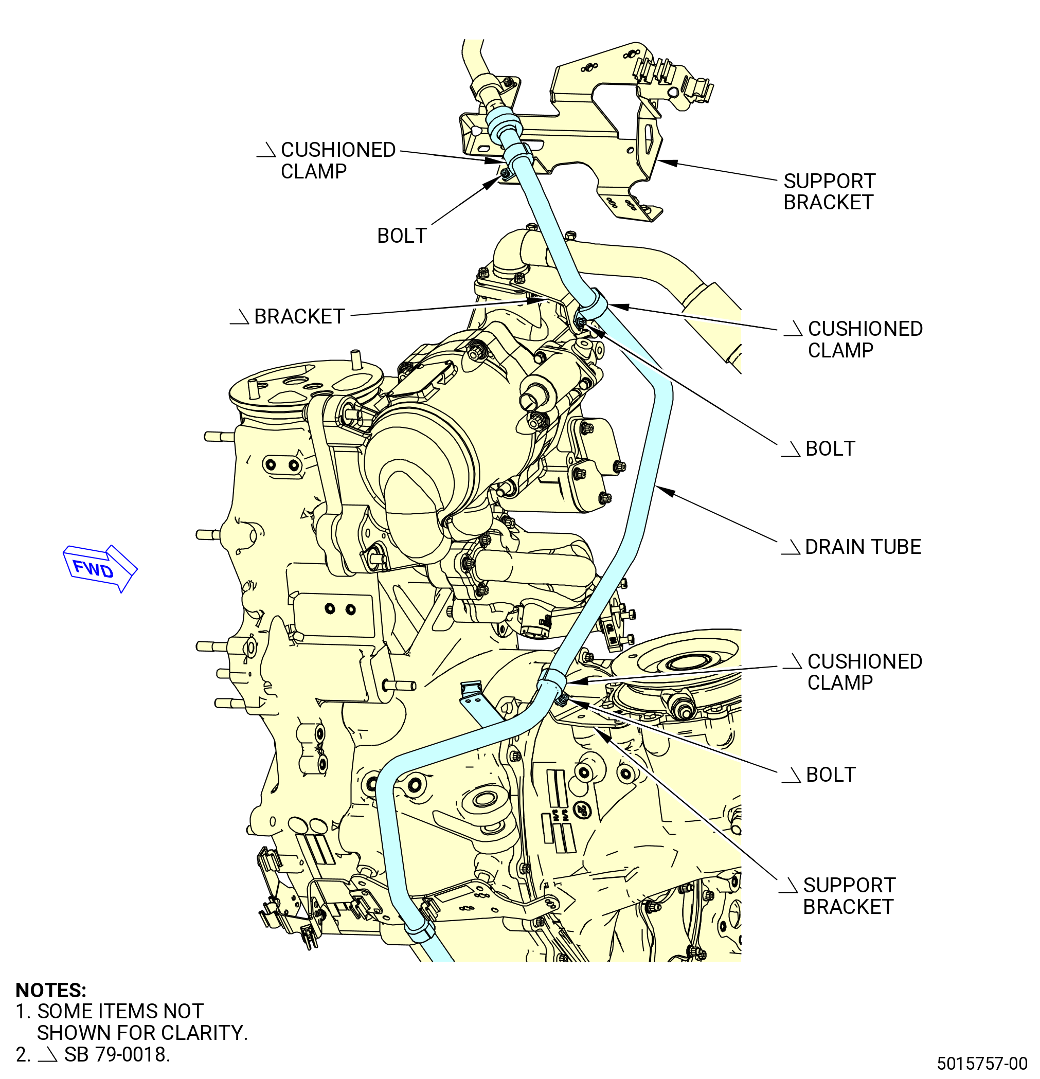
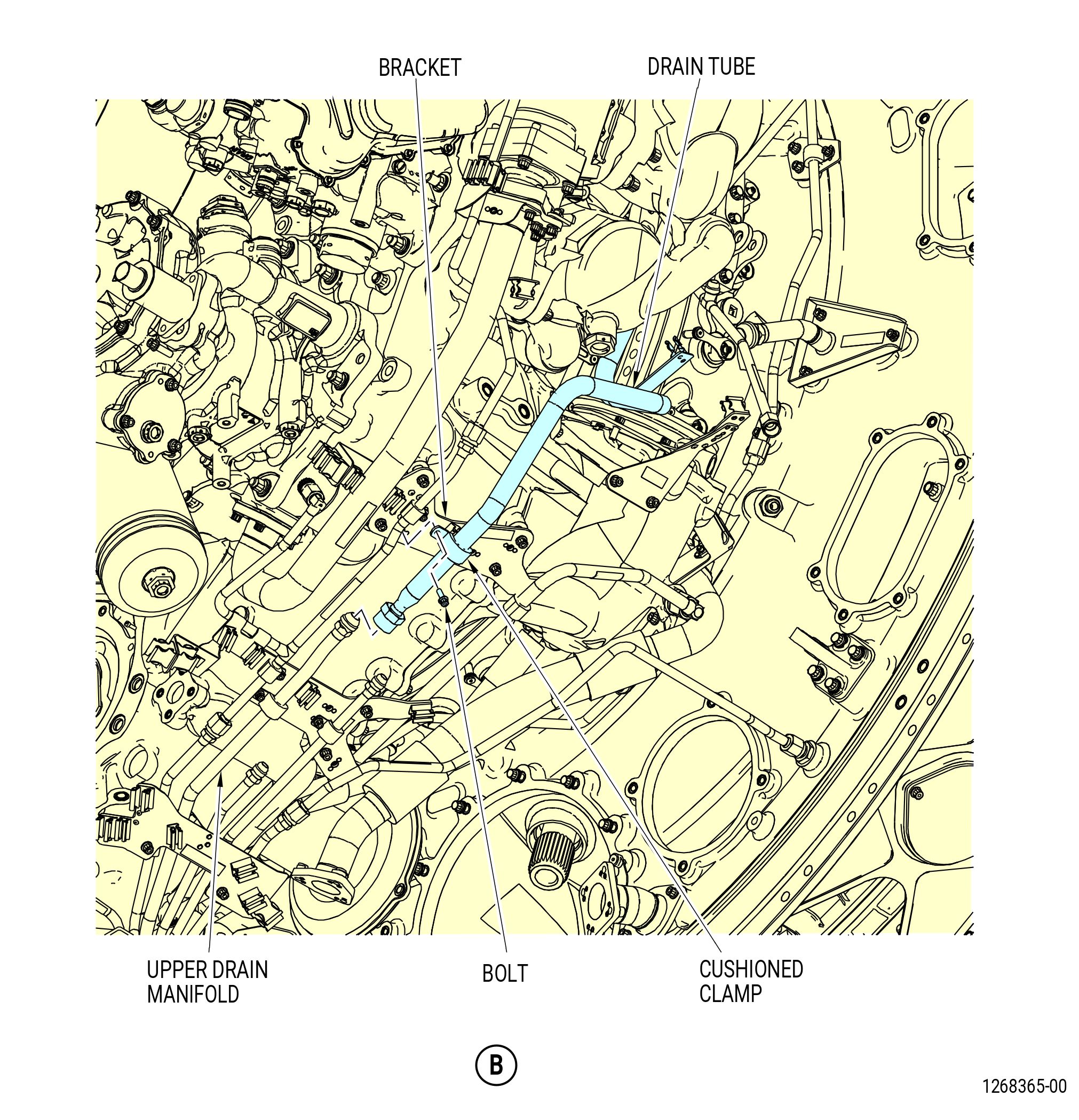
| (2) | Remove the drain to lower BIFI air tube (drain tube) as follows. Refer to Figure 529. |
| (a) | Disconnect the drain tube from the upper drain manifold on the AGB. |
| (b) | Remove the bolts and cushioned clamps that attach the drain tube to the brackets. |
| (c) | Remove the drain tube. |
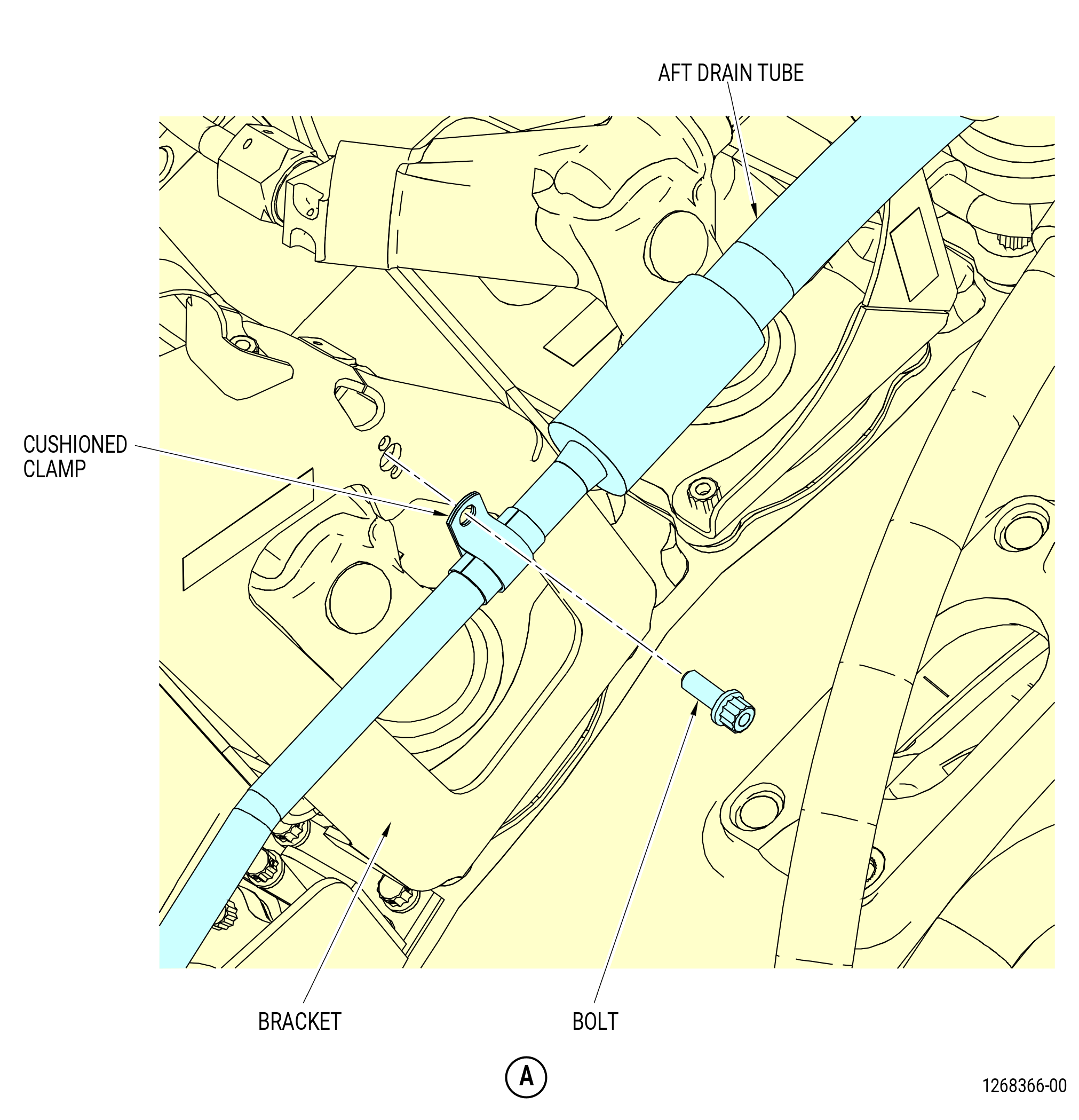
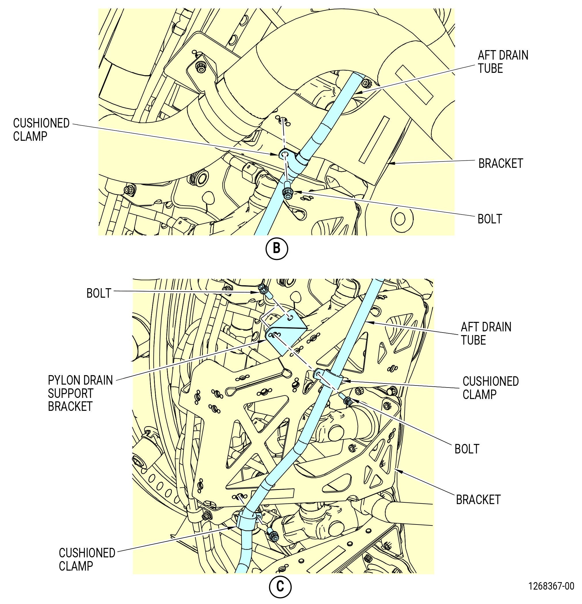
| (3) | Remove the aft drain assembly hose tube (aft drain tube) as follows. Refer to Figure 530. |
| (a) | Remove the bolts and cushioned clamps that attach the aft drain tube to the brackets. |
| (b) | Remove the aft drain tube. |
| (c) | Remove the bolts that attach the pylon drain support bracket to the bracket. Remove the pylon drain support bracket. |
|
|
| Subtask 72-00-02-030-409 |
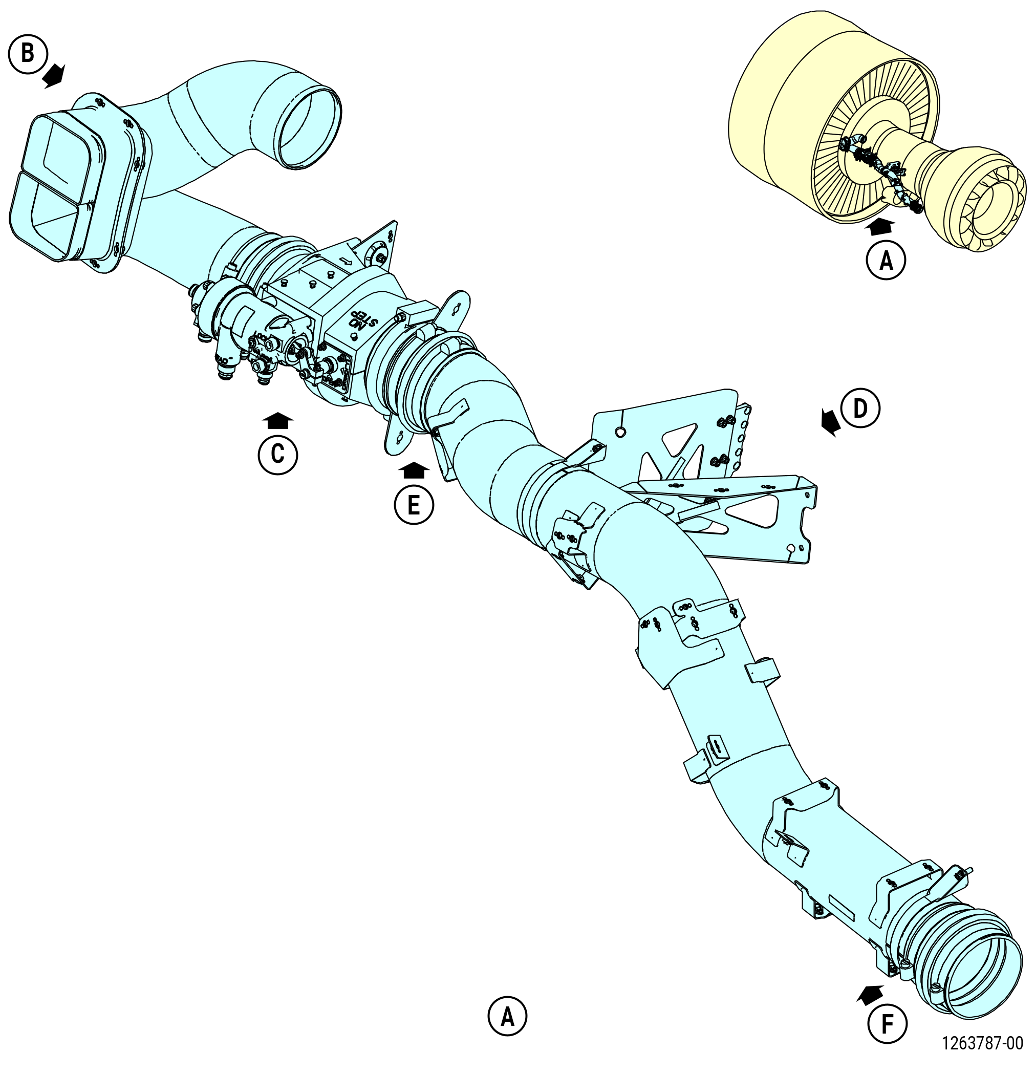
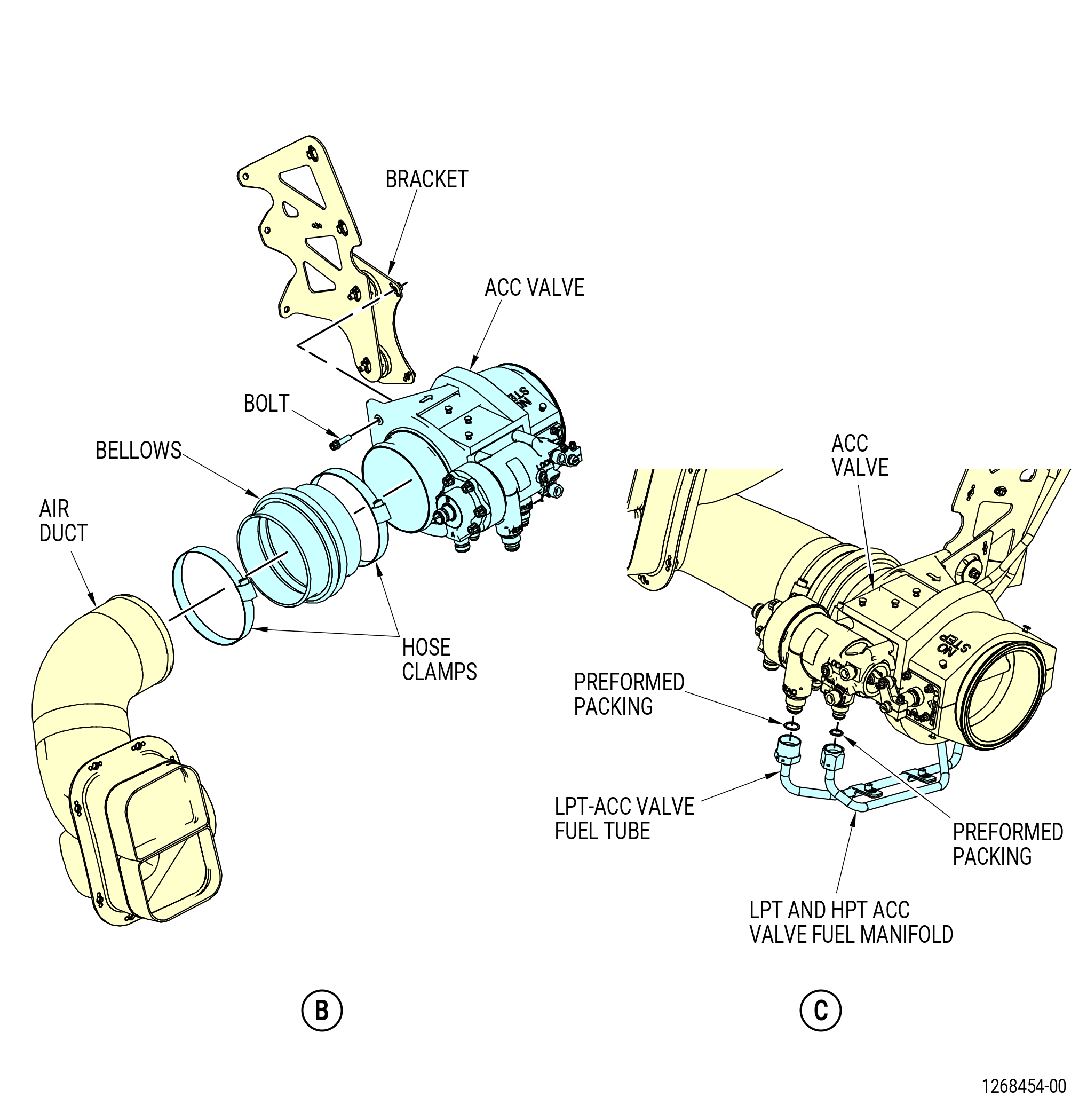
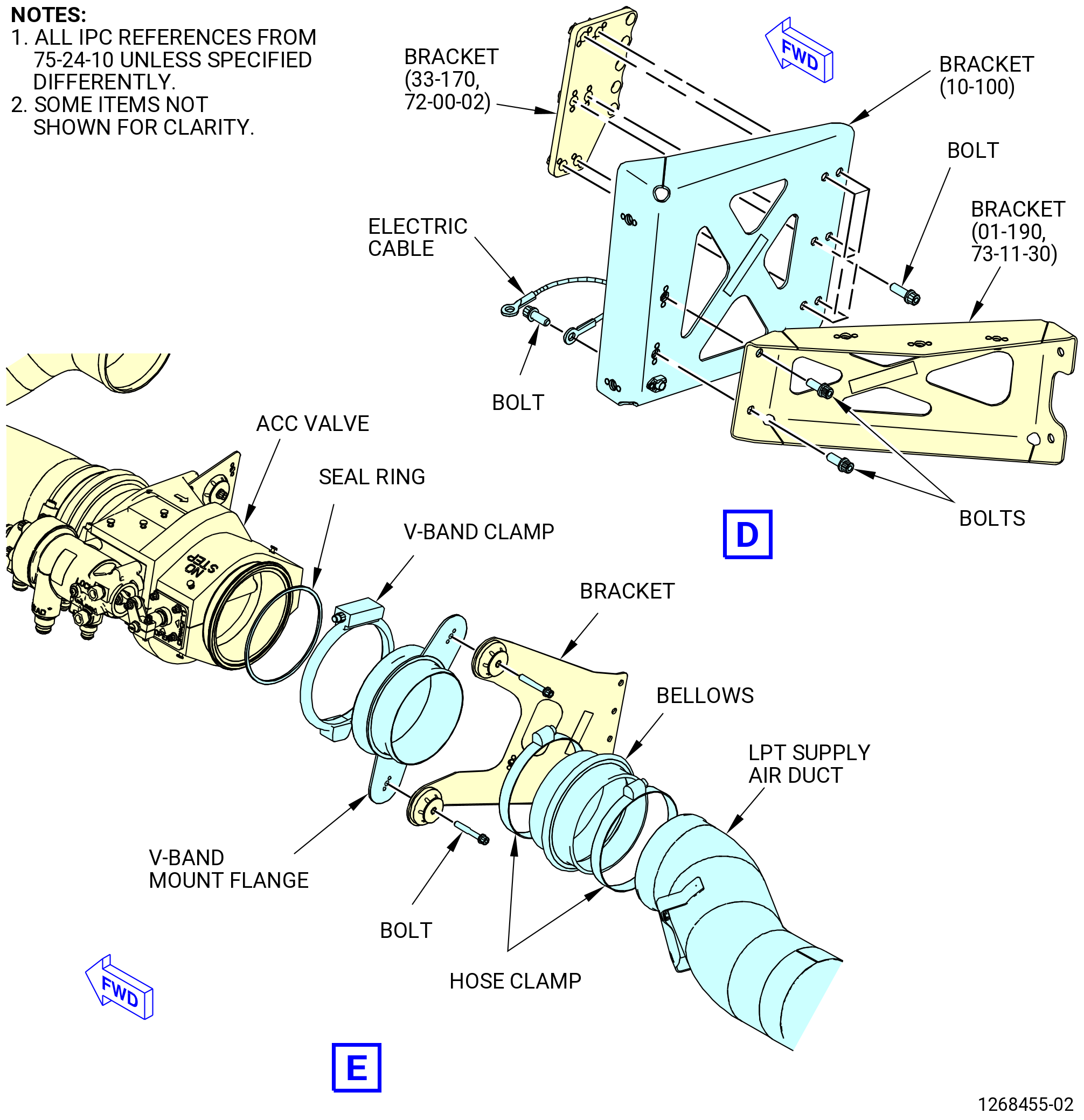
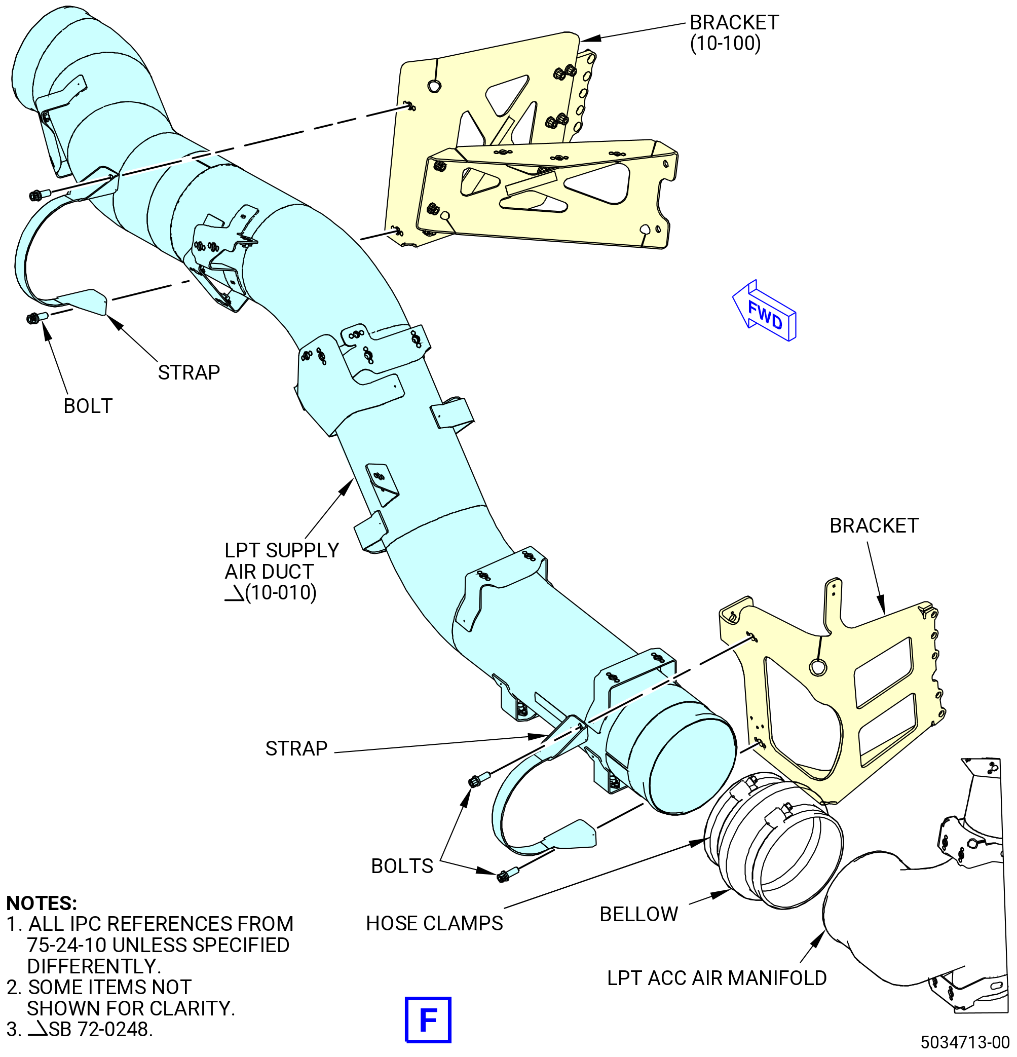
| T. | Remove the LPT supply air duct and valve. Refer to Figure 531 and do as follows. |
| (1) | Remove the LPT supply air duct (air duct) (10-010 , 75-24-10) (SIN 62201) as follows: |
| (a) | Remove the straps that attach the air duct to the brackets. |
| (b) | Loosen the hose clamps on the bellows. |
| (c) | Remove the air duct from the bellows. |
| (d) | Remove the hose clamps and bellows from the V-band mount flange and the LPT ACC manifold. |
| (e) | Remove the bolts that attach the V-band mount flange to the bracket. |
| (f) | Remove the V-band clamp from the V-band mount flange and the ACC valve. |
| (g) | Remove the V-band mount flange and the seal ring from the aft side of the ACC valve. |
| (h) | Remove V-band and seal at the top of the eductor valve. |
| (i) | Remove four clamps. |
| (j) | Remove the B-nut at aft end of tube. |
| (k) | Remove the tube. |
| (2) | Disconnect the fuel lines from the ACC valve as follows: |
| (a) | Disconnect the LPT and HPT ACC valve fuel manifold from the ACC valve. |
| (b) | Disconnect the LPT-ACC valve fuel tube from the ACC valve. |
| (c) | Remove the preformed packings (25-310 , 73-11-40) (SIN 38550) and (20-210 , 73-11-40) (SIN 34751) from the ROD end and HEAD end nipples of the ACC valve. |
| (3) | Remove the ACC valve as follows: |
| (a) | Loosen the hose clamps on the bellows. |
| (b) | Remove the bolts and washers that attach the ACC valve to the bracket. |
| (c) | Remove the ACC valve from the bellows and the bracket. |
| (d) | Remove the bellows and the hose clamps. |
| (4) | Remove bracket (6221C) as follows: |
| (a) | Remove the bolt that attaches the electric cable to bracket (6221C). |
| (b) | Remove the bolts that attach bracket (6221C) to bracket (6221B) and bracket (6221D). |
| (c) | Remove the bracket (6221C) from between bracket (6221B) and bracket (6221D). |
|
|
| Subtask 72-00-02-030-447 |
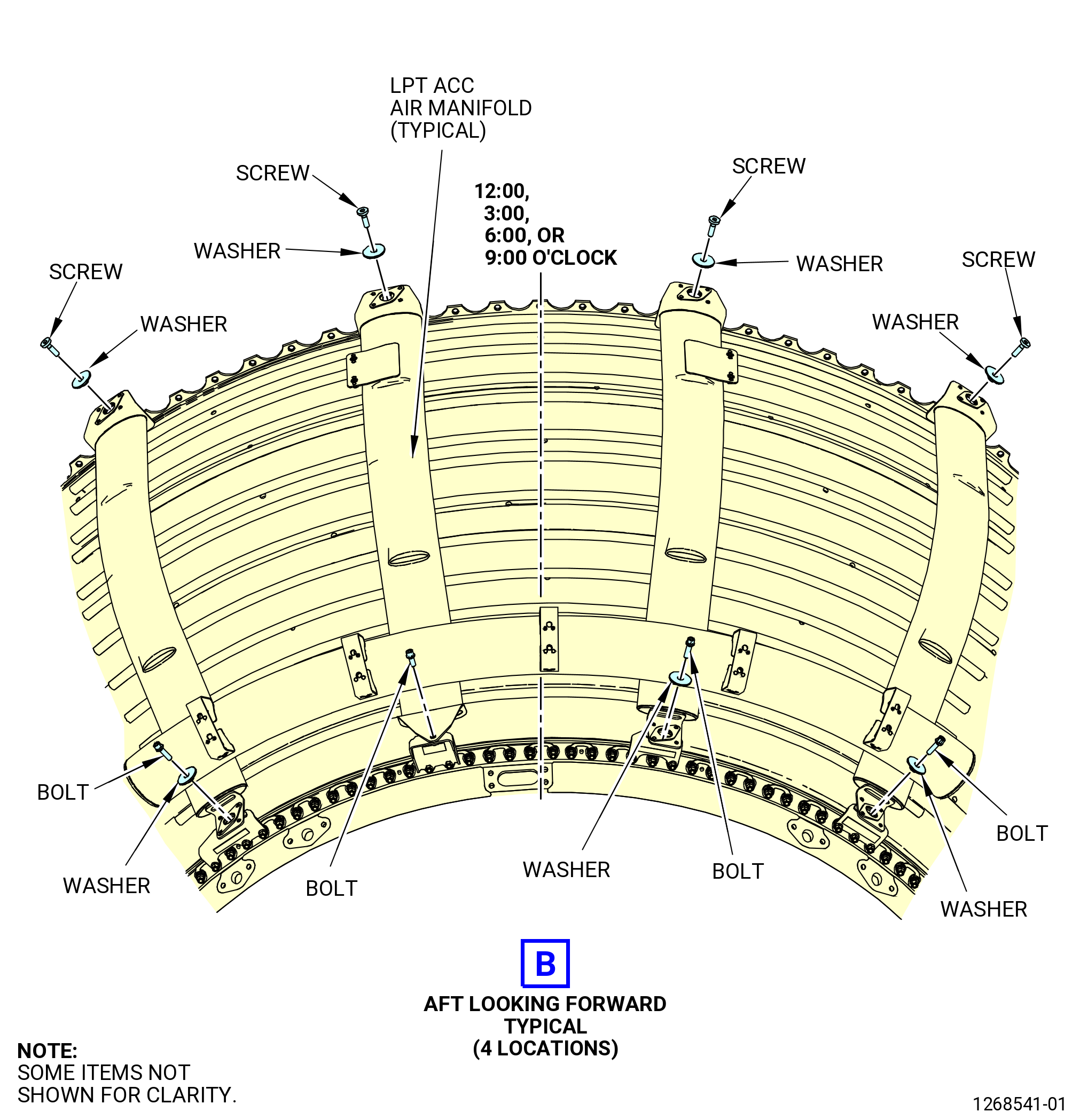
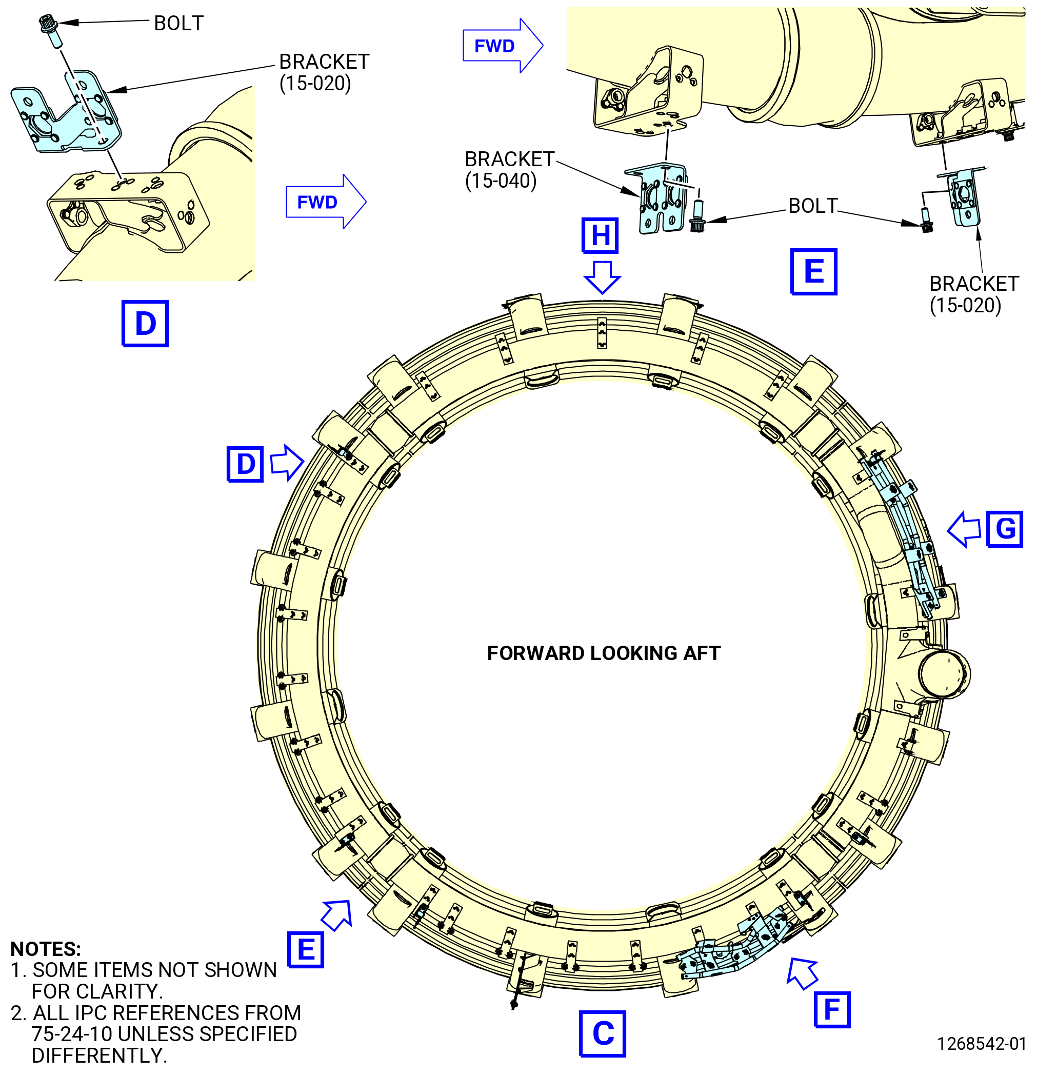
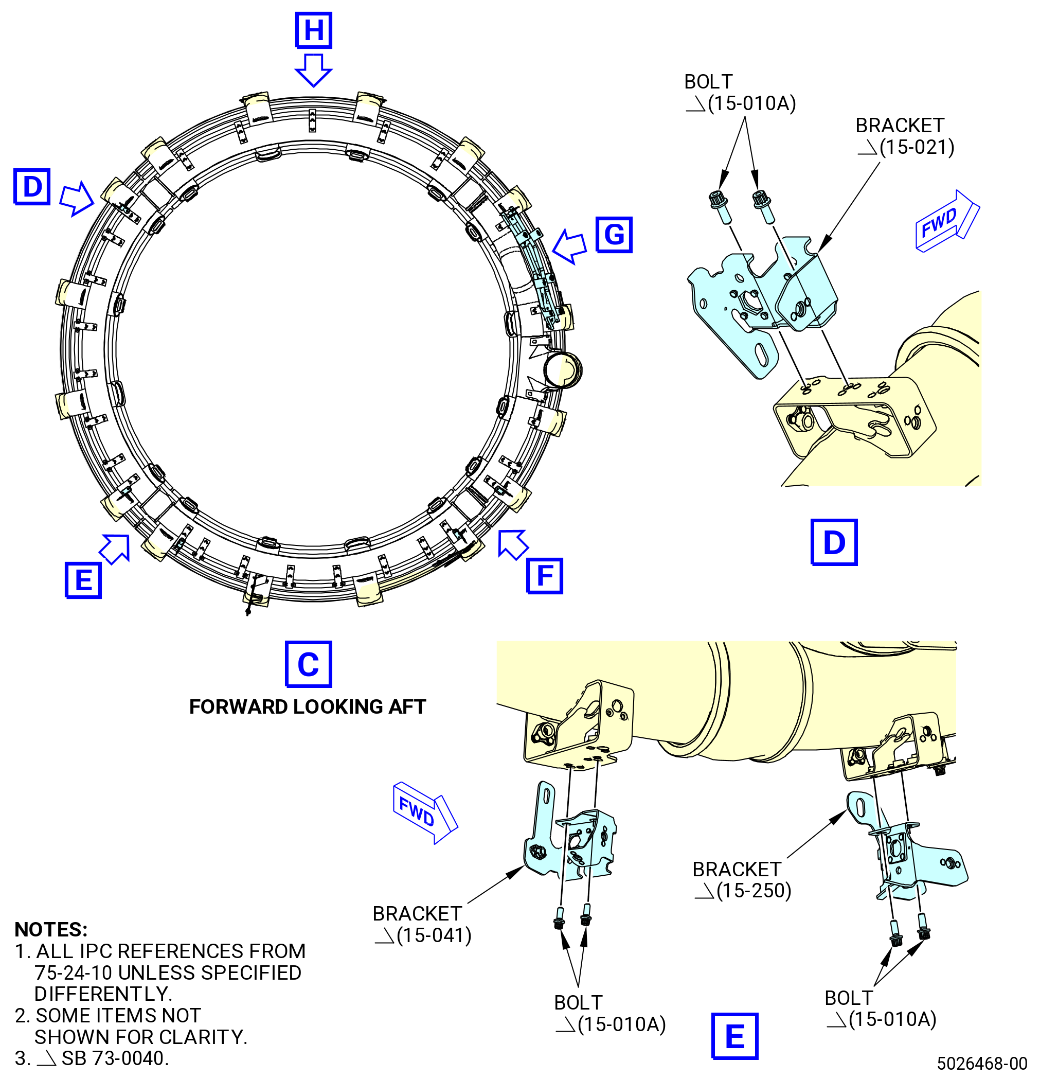
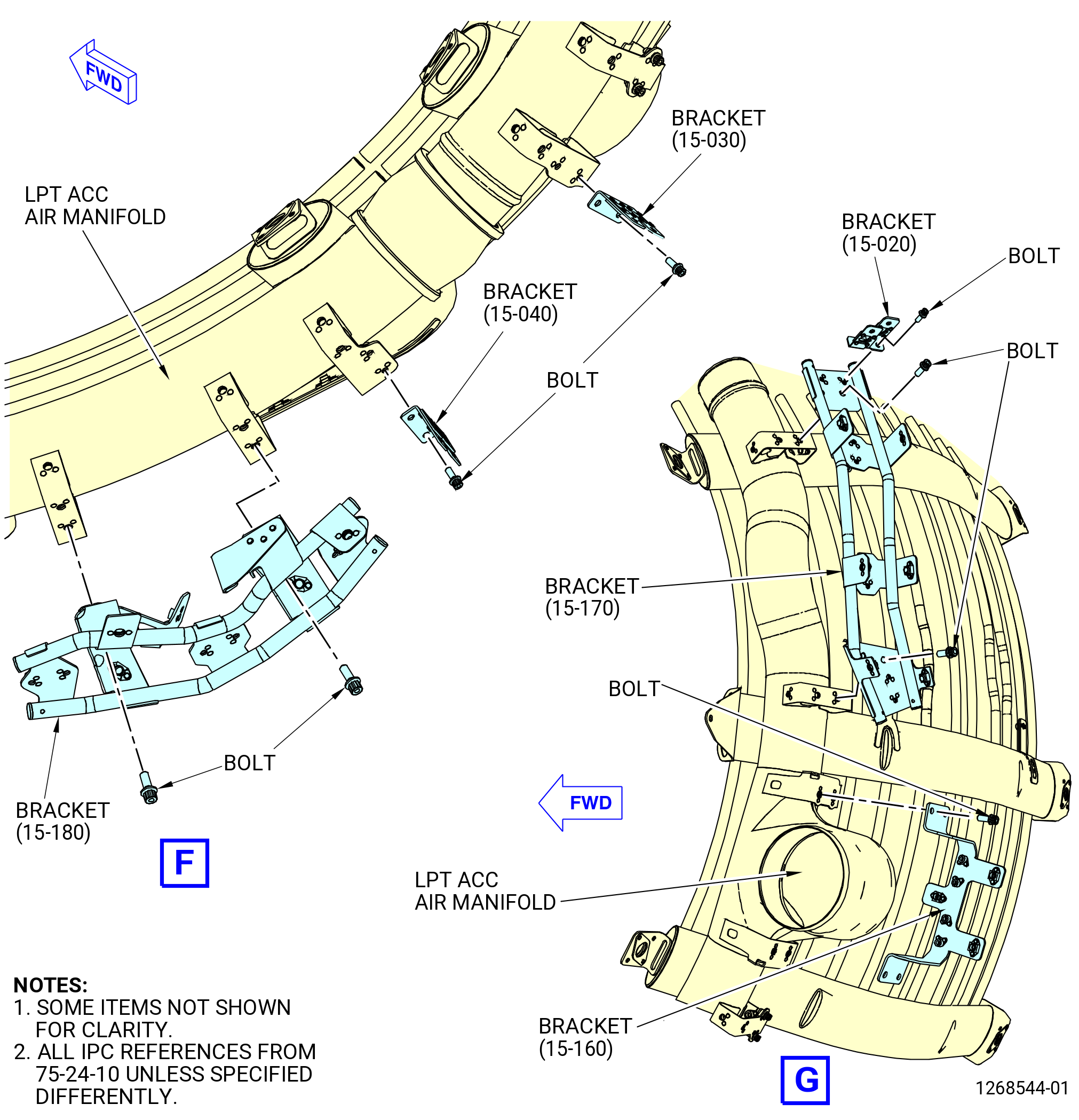
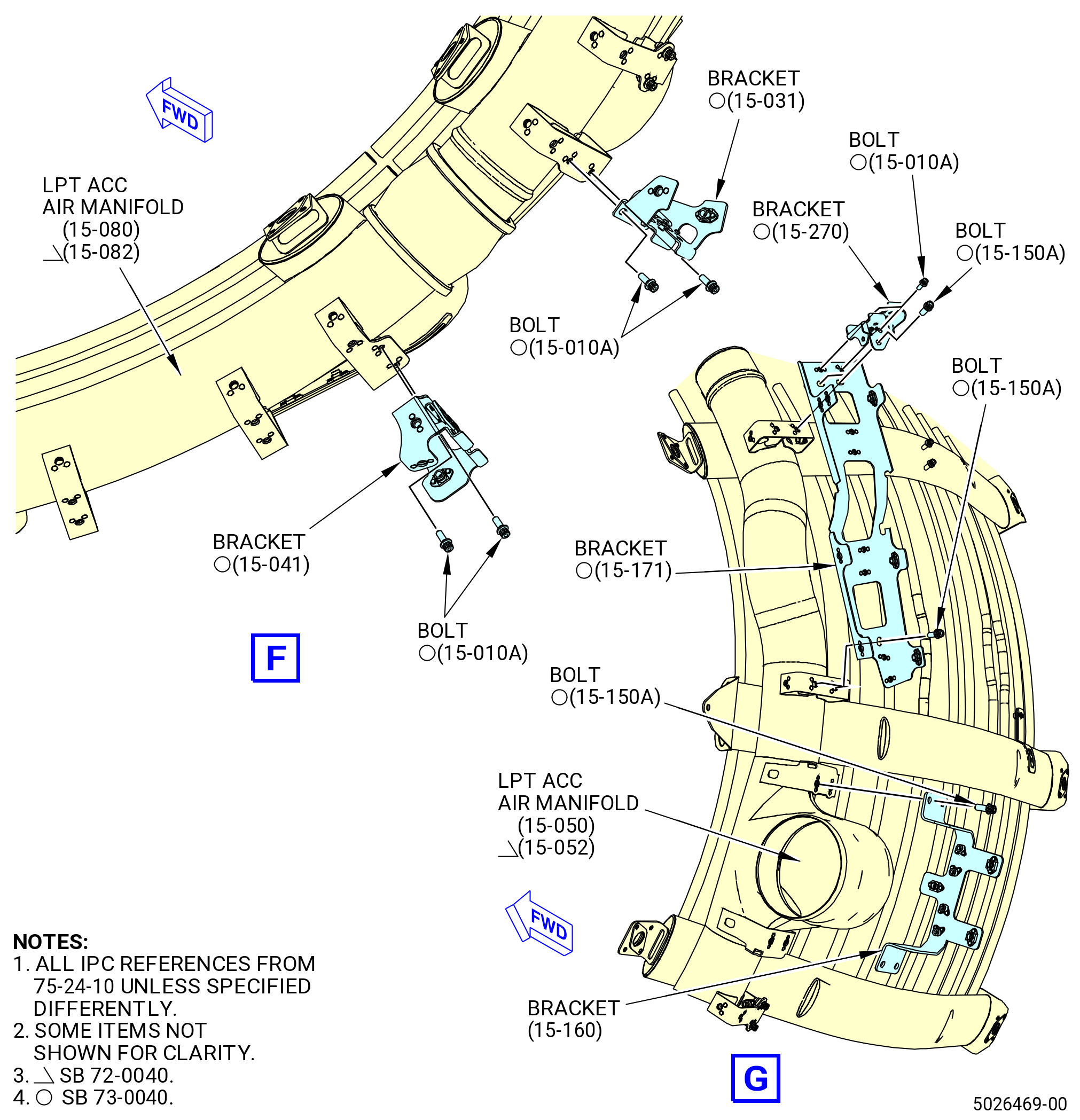
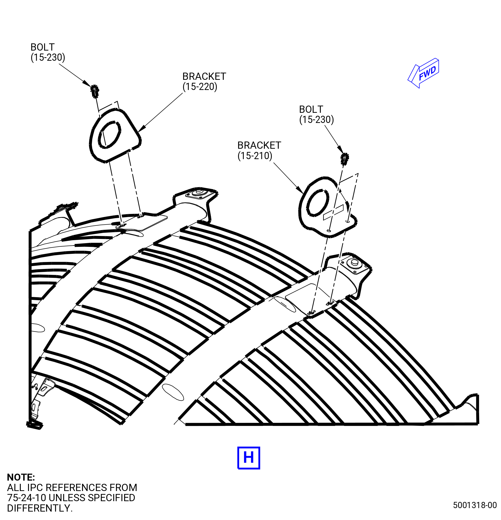
| U. | Remove the LPT ACC manifolds as follows. Refer to Figure 532. |
| (1) | Remove the brackets from the LPT ACC manifold as follows: |
| Subtask 72-00-02-030-676 |
| * * * PRE SB 73-0040( Engines without improved W30 and W31 harness ) |
| (a) | Remove the bolts that attach the bracket (15-020 , 75-24-10) (SIN 9801G) to the bracket (15-170 , 75-24-10) (SIN 9801D) at the 10:00 o'clock position. |
| * * * END PRE SB 73-0040 |
| Subtask 72-00-02-030-677 |
| * * * SB 73-0040( Engines with improved W30 and W31 harness ) |
| (a).A. | Remove the bolts that attach the bracket (15-270 , 75-24-10) (SIN 9801N) to the bracket (15-171 , 75-24-10) (SIN 9801D) at the 10:00 o'clock position. |
| * * * END SB 73-0040 |
| Subtask 72-00-02-030-678 |
| (b) | Remove the bolts that attach the bracket (15-170 , 75-24-10) (SIN 9801D) or (15-171 , 75-24-10) (SIN 9801D) at the 9:30 o'clock position. |
| (c) | Remove the bolts that attach the bracket (15-160 , 75-24-10) (SIN 9801E) at the 8:30 o'clock position. |
| (d) | Remove the bolts that attach the bracket (15-030 , 75-24-10) (SIN 9801K) or (15-031 , 75-24-10) (SIN 9801K) at the 7:30 o'clock position. |
| (e) | Remove the bolts that attach the bracket (15-040 , 75-24-10) (SIN 9801J) or (15-041 , 75-24-10) (SIN 9801J) at the 7:00 o'clock position. |
| (f) | Remove the bolts that attach the bracket (15-180 , 75-24-10) (SIN 9801F), (15-181 , 75-24-10) (SIN 9801F) or (15-182 , 75-24-10) (SIN 9801F) at the 6:30 o'clock position. |
| Subtask 72-00-02-030-679 |
| * * * PRE SB 73-0040( Engines without improved W30 and W31 harness ) |
| (g) | Remove the bolts that attach the bracket (15-020 , 75-24-10) (SIN 9801G) at the 5:00 o'clock position. |
| * * * END PRE SB 73-0040 |
| Subtask 72-00-02-030-680 |
| * * * SB 73-0040( Engines with improved W30 and W31 harness ) |
| (g).A. | Remove the bolts that attach the bracket (15-250 , 75-24-10) (SIN 9801L) at the 5:00 o'clock position. |
| * * * END SB 73-0040 |
| Subtask 72-00-02-030-681 |
| (h) | Remove the bolts that attach the bracket (15-040 , 75-24-10) (SIN 9801J) or (15-041 , 75-24-10) (SIN 9801J) at the 4:30 o'clock position. |
| (i) | Remove the bolts that attach the bracket (15-020 , 75-24-10) (SIN 9801G) or (15-021 , 72-24-10) (SIN 9801G) at the 2:00 o'clock position. |
| (j) | Remove the bolts that attach the bracket (15-210 , 75-24-10) (SIN 62318) at the 12:30 o'clock position. |
| (k) | Remove the bolts that attach the bracket (15-220 , 75-24-10) (SIN 62319) at the 11:30 o'clock position. |
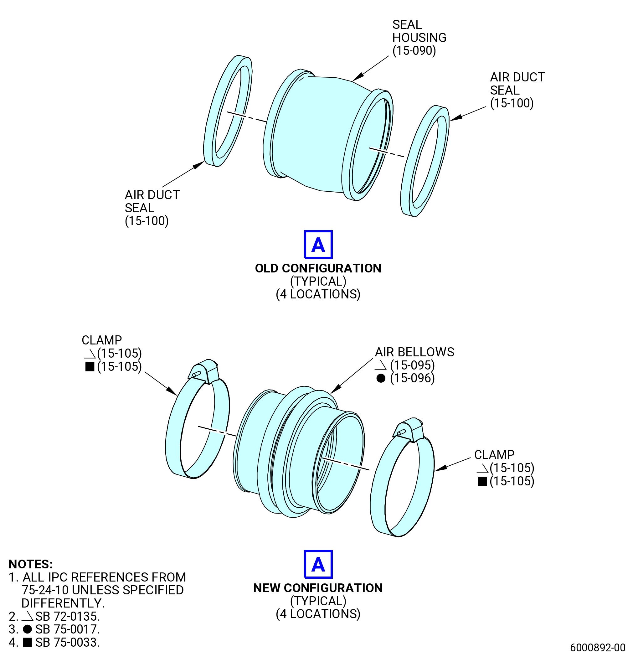
| Subtask 72-00-02-030-521 |
| * * * PRE SB 72-0135( LPT ACC Manifold Titanium Connectors ) |
| (8) | Push the seal housings (15-090 , 75-24-10) (SIN 62255) that connect the LPT ACC air manifolds together on one of the manifolds. |
| * * * END PRE SB 72-0135 |
| Subtask 72-00-02-030-522 |
| * * * SB 72-0135( LPT ACC Manifold Silicone Connectors ) |
| (8).A. | Remove the clamps (15-105 , 75-24-10) (SIN 62280) from the air bellows (15-095 , 75-24-10) (SIN 62205) or (15-096 , 75-24-10) (SIN 62205) and push the air bellows that connect the LPT ACC air manifolds together on one of the manifolds. |
| * * * END SB 72-0135 |
| Subtask 72-00-02-030-523 |
| (9) | Remove the bolts and washers from the forward side of the LPT ACC air manifolds. |
| (10) | Remove the screws and washers from the aft side of the LPT ACC air manifolds. |
| (11) | Remove the LPT ACC air manifolds from the propulsor. |
| Subtask 72-00-02-030-524 |
| * * * PRE SB 72-0135( LPT ACC Manifold Titanium Connectors ) |
| (12) | Remove the seal housings as follows: |
| (a) | Remove the seal housings (15-090 , 75-24-10) (SIN 62255) from the LPT ACC air manifolds. |
| (b) | Remove the air duct seals (15-100 , 75-24-10) (SIN 62256) from the seal housings. |
| * * * END PRE SB 72-0135 |
| Subtask 72-00-02-030-525 |
| * * * SB 72-0135( LPT ACC Manifold Silicone Connectors ) |
| (12).A. | Remove the air bellows (15-095 , 75-24-10) (SIN 62205) or (15-096 , 75-24-10) (SIN 62205) from the LPT ACC air manifolds. |
| * * * END SB 72-0135 |
|
|
|
|
| Subtask 72-00-02-030-410 |
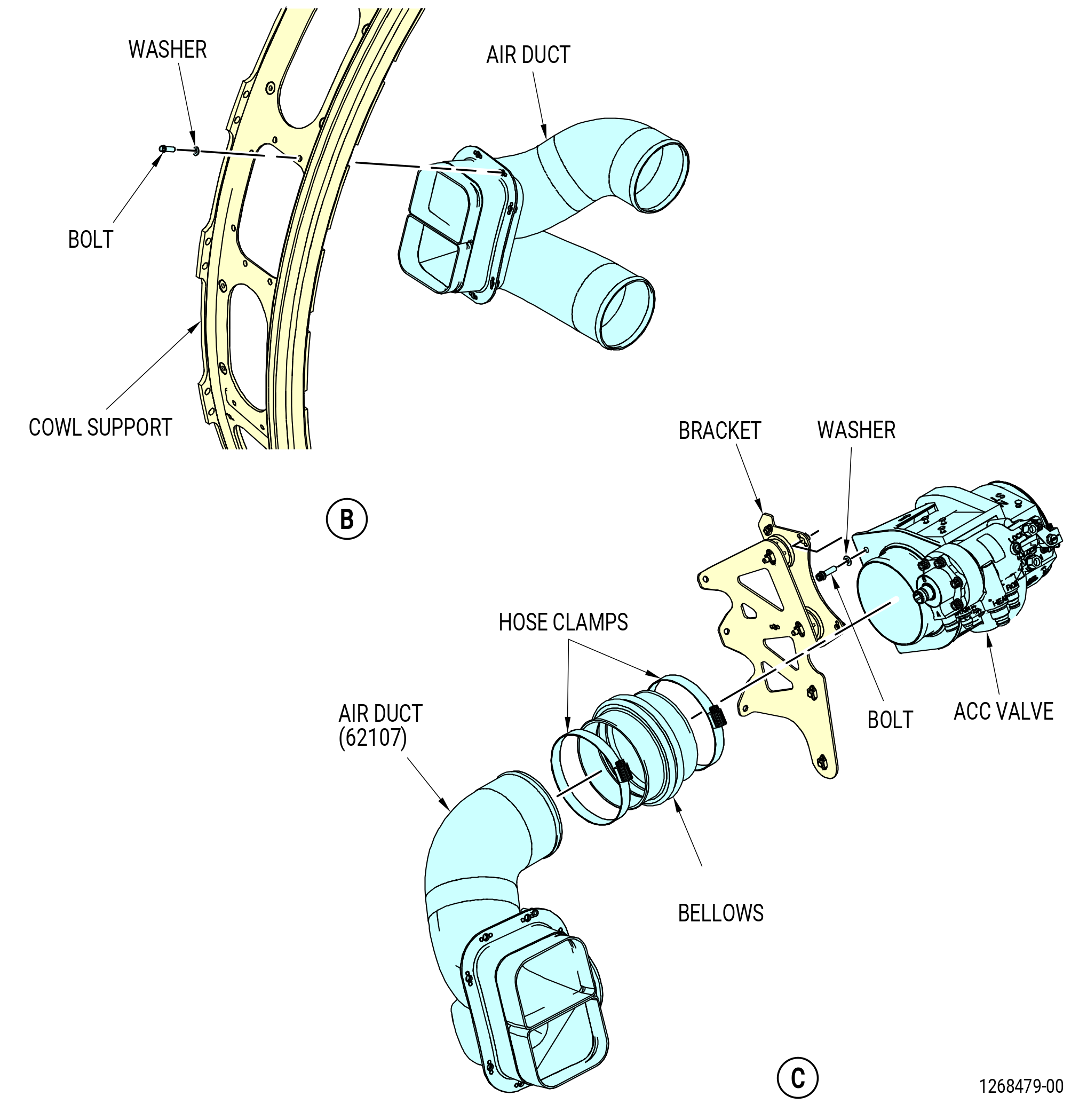
| V. | Remove the HPT ACC valve and duct as follows. Refer to Figure 533. |
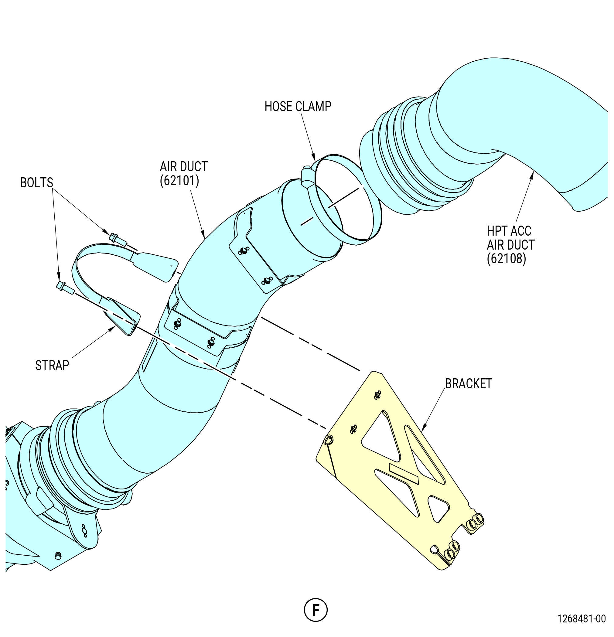
| (1) | Remove the HPT ACC air duct (62108) as follows: |
| (a) | Remove the hose clamps from the HPT ACC air duct (62108). |
| (b) | Remove the HPT ACC air duct (62108) from the HPT supply air duct (62101) and the HPT air manifold. |
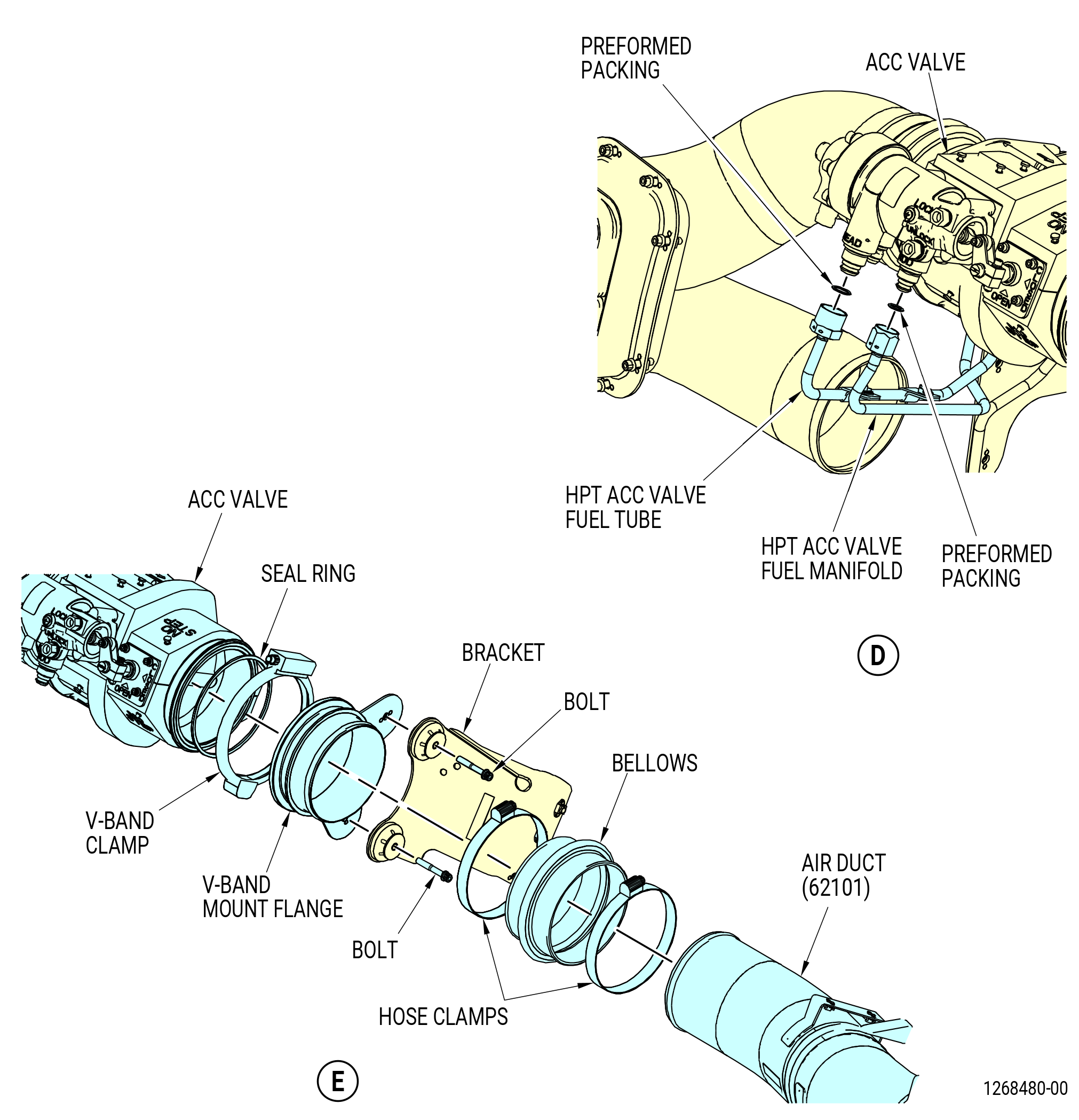
| (2) | Remove the HPT supply air duct (air duct) (62101) as follows: |
| (a) | Loosen the hose clamps on the bellows. |
| (b) | Remove the bolts and strap that attach the air duct to bracket. |
| (c) | Remove the air duct (62101) from the bellows. |
| (d) | Remove the hose clamps and the bellows from the V-band mount flange. |
| (e) | Remove the bolts that attach the V-band mount flange to the bracket. |
| (f) | Remove the V-band clamp that attaches the V-band mount flange to the ACC valve. |
| (g) | Remove the V-band mount flange and the seal ring (01-020 , 75-24-30) (SIN 62150) from the ACC valve. |
| (3) | Disconnect the fuel lines to the ACC valve as follows: |
| (a) | Disconnect the LPT and HPT ACC valve fuel manifold from the ACC valve. |
| (b) | Disconnect the HPT ACC valve fuel tube from the ACC valve. |
| (c) | Remove the preformed packings (20-210 , 73-11-40) (SIN 34751) and (30-200 , 73-11-40) (SIN 38050) from the ROD end and HEAD end nipples of the ACC valve. |
| (4) | Remove the ACC valve as follows: |
| (a) | Loosen the hose clamps on the bellows. |
| (b) | Remove the bolts and washers that attach the ACC valve to the bracket. |
| (c) | Remove the ACC valve from the bellows and the bracket. |
| (d) | Remove the bellows and the hose clamps. |
| (5) | Remove the bolts and washers that attach the HPT and LPT air duct (air duct) (62107) to the cowl support. Remove the air duct. |
| Subtask 72-00-02-030-411 |
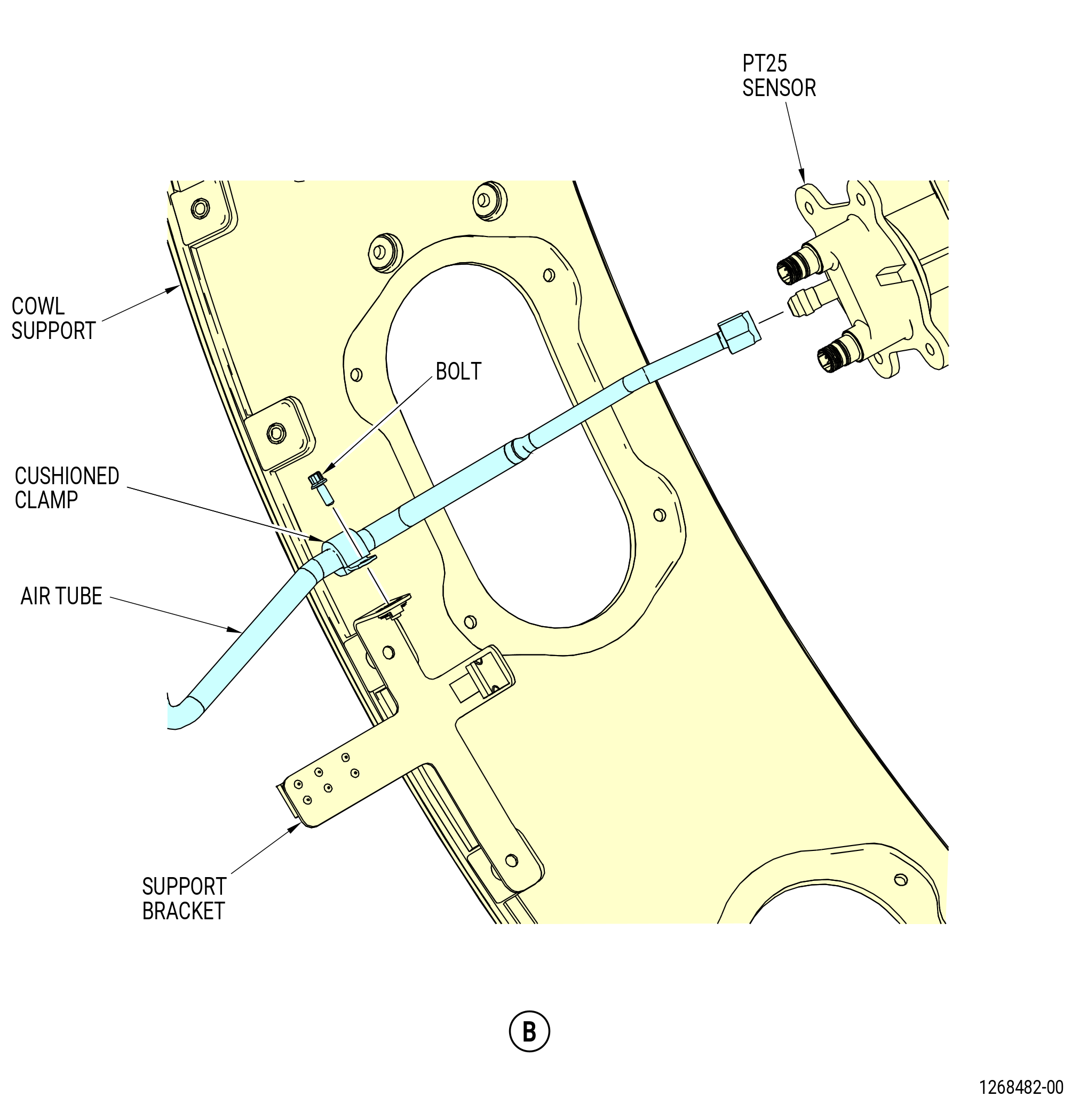
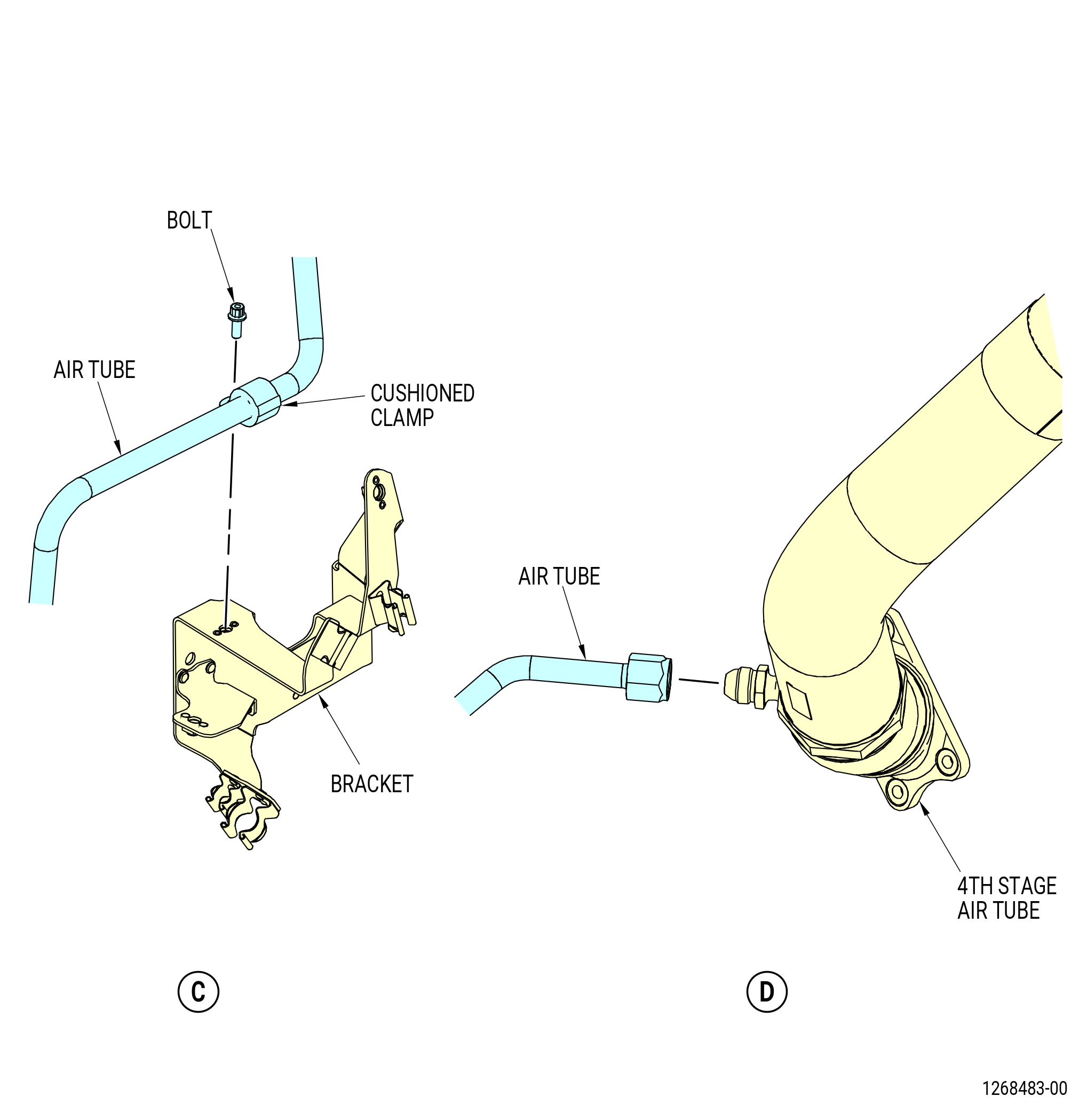
| W. | Remove the PT25 sensor heating air tube (air tube) as follows. Refer to Figure 534. |
| (1) | Disconnect the coupling nut from the PT25 sensor. |
| (2) | Disconnect the coupling nut from the 4th stage air tube. |
| (3) | Remove the bolts and the cushioned clamps that attach the tube to the brackets. |
| (4) | Remove the tube. |
| Subtask 72-00-02-030-412 |
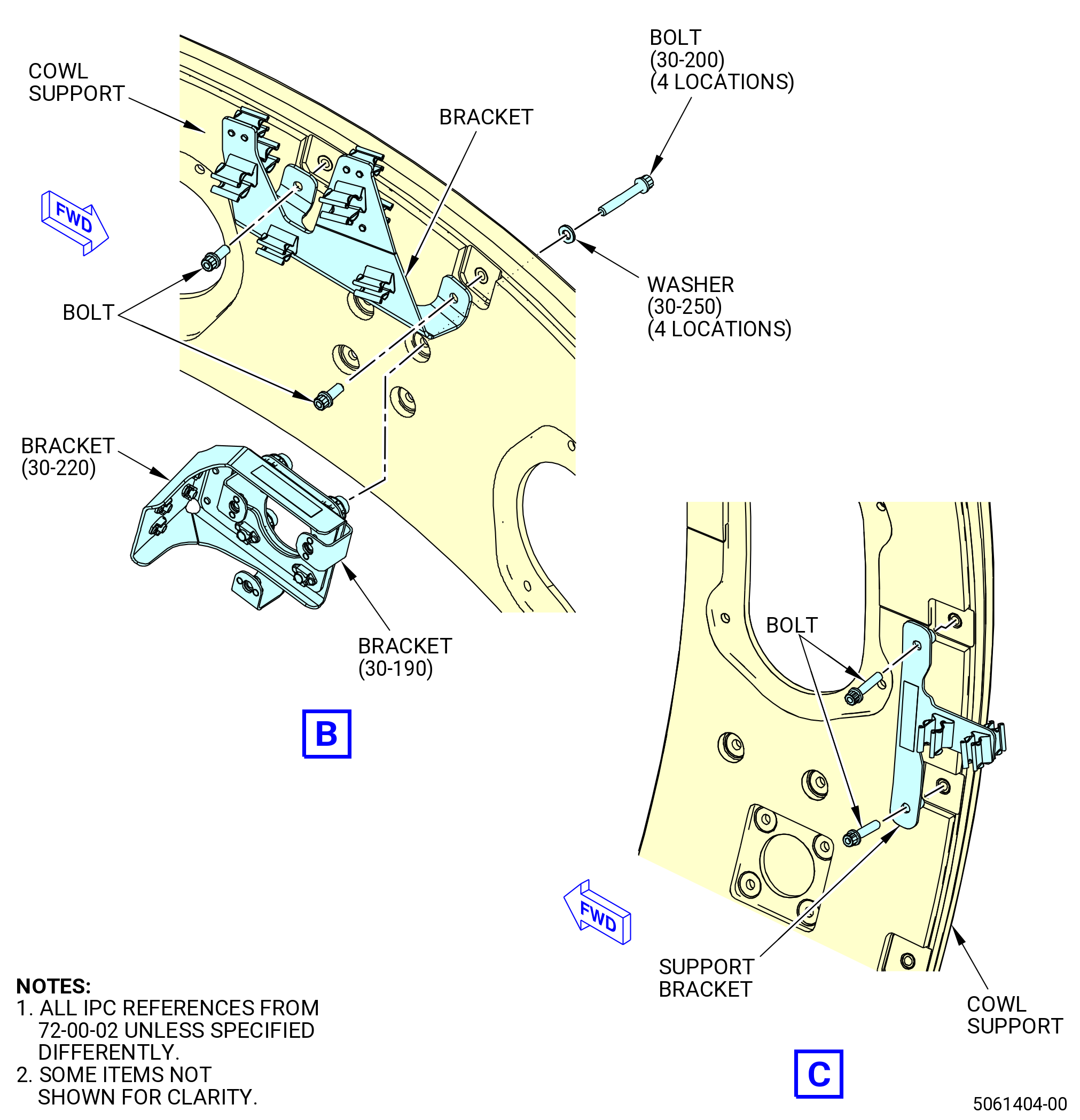
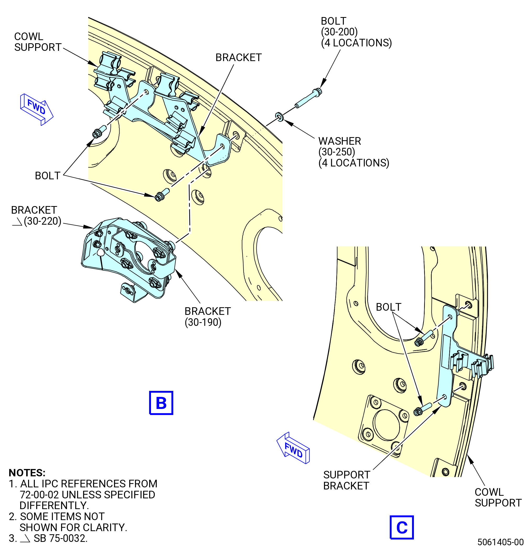
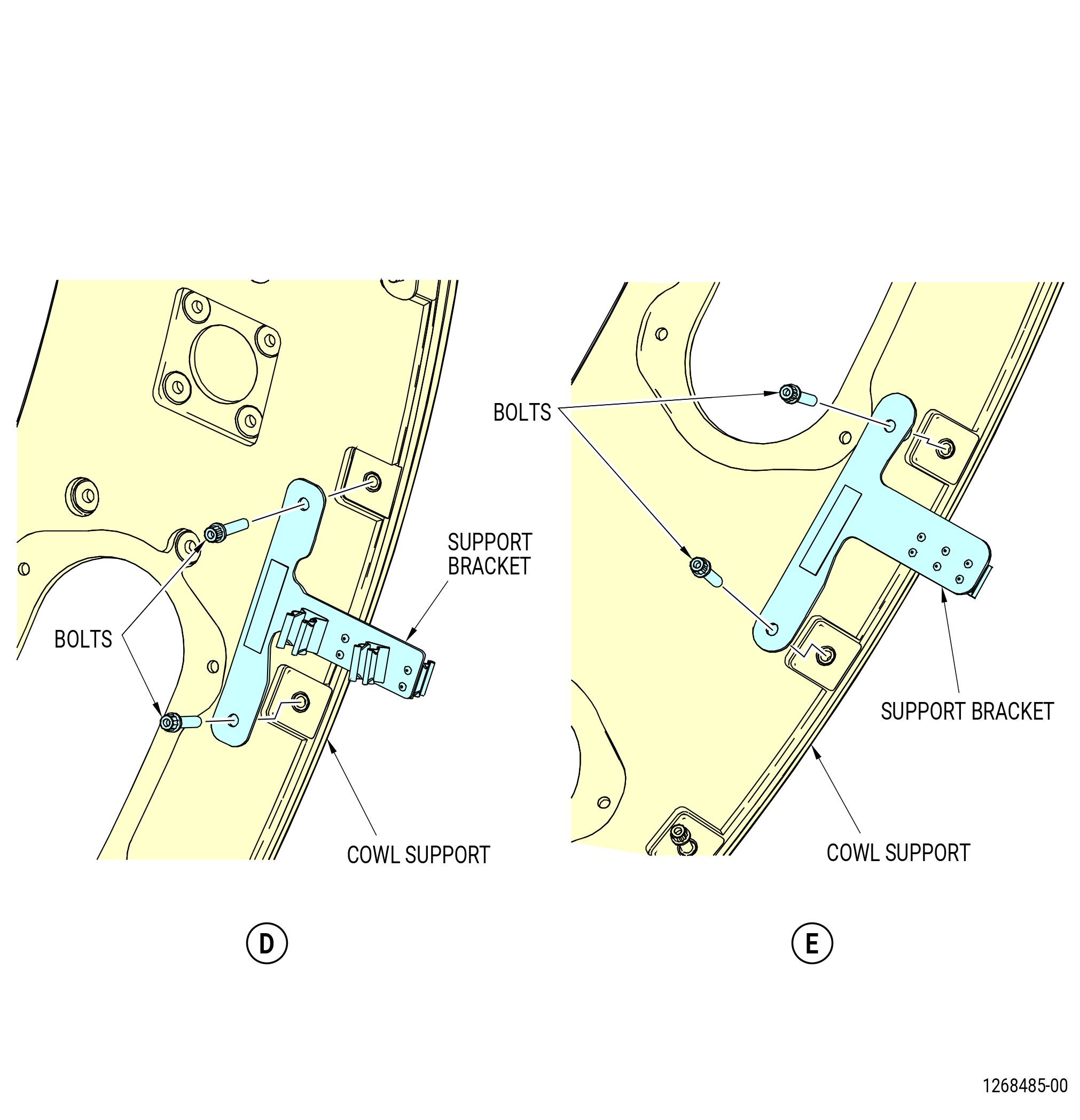
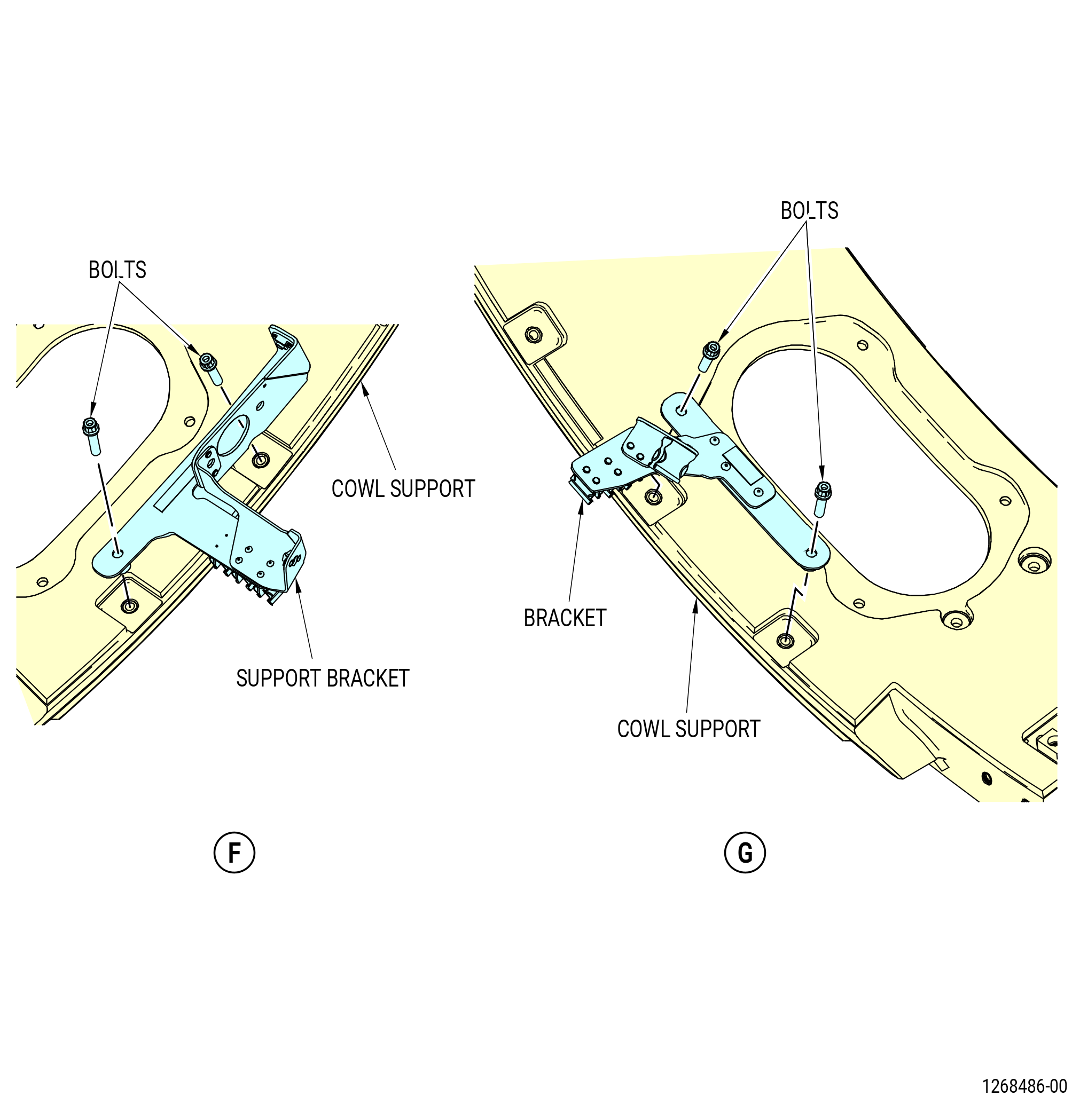
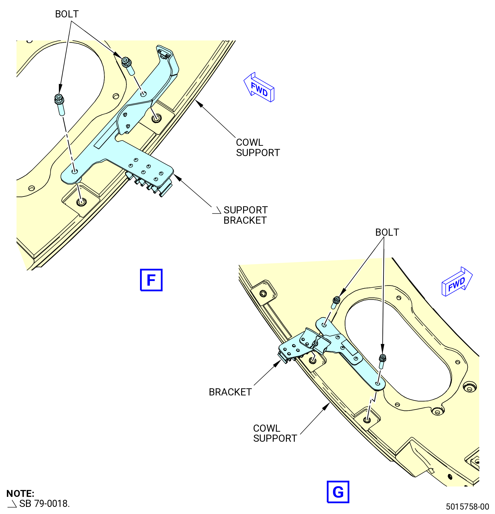
| X. | Remove the cowl support ring brackets as follows. Refer to Figure 535. |
| (1) | Remove the machine bolts (bolts) (30-200) (SIN 6102T) and washers (30-250) (SIN 61033) that attach the EAI controller support bracket (bracket) (30-190) (SIN 6101T) and transducer support bracket (bracket) (30-220) (SIN 63715) on the cowl support at the 1:00 o'clock position. |
| (2) | Remove the support bracket (6101T). |
| (3) | Remove the bracket (30-220) (SIN 63715). |
| (4) | Remove the bolts that attach the engine configuration box to the support bracket on the cowl support at the 9:00 o'clock position. |
| (5) | Remove the engine configuration box. |
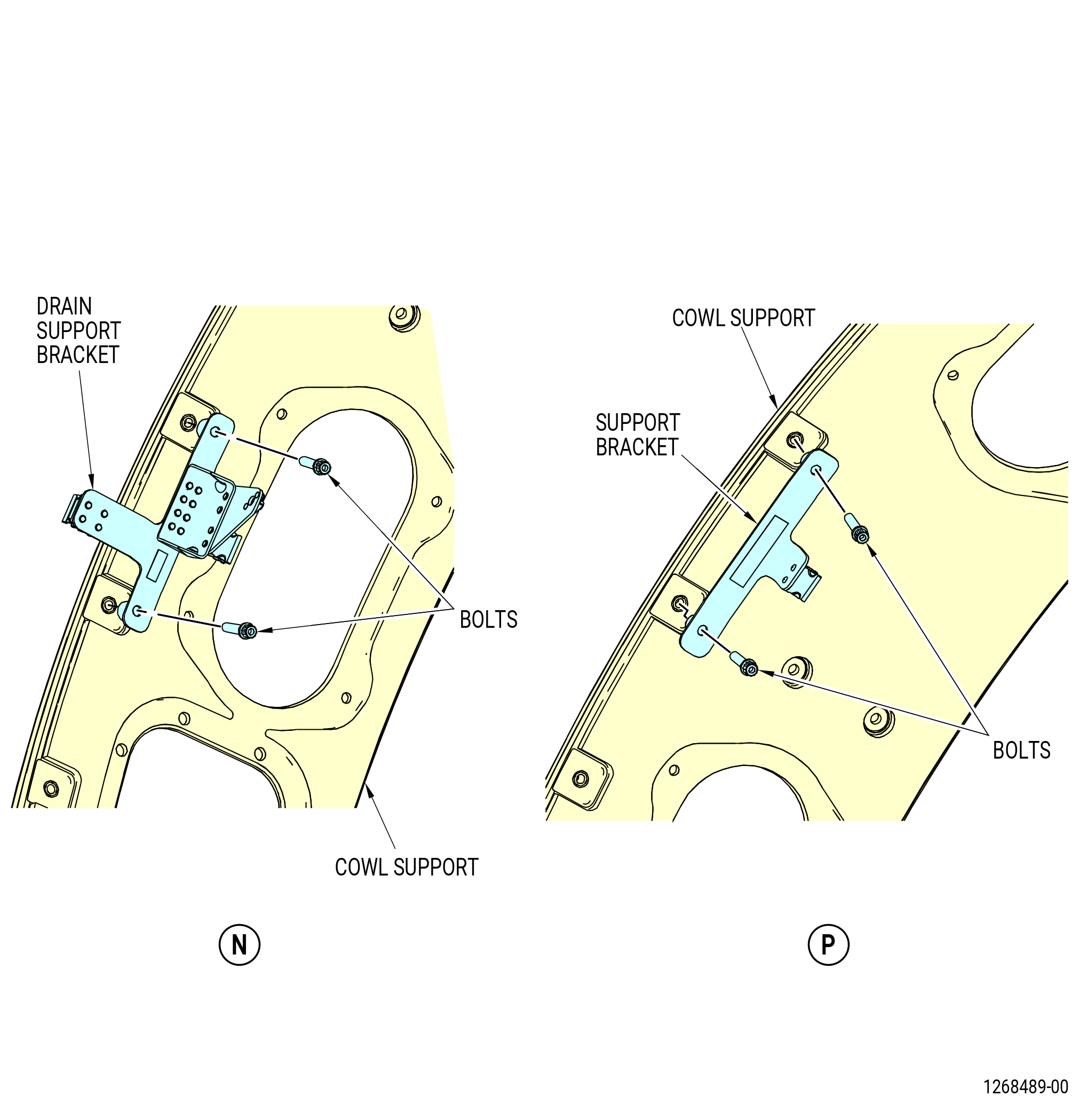
| (6) | Remove the remaining bolts and support brackets from the cowl support. |
|
|
|
|
| Subtask 72-00-02-030-443 |
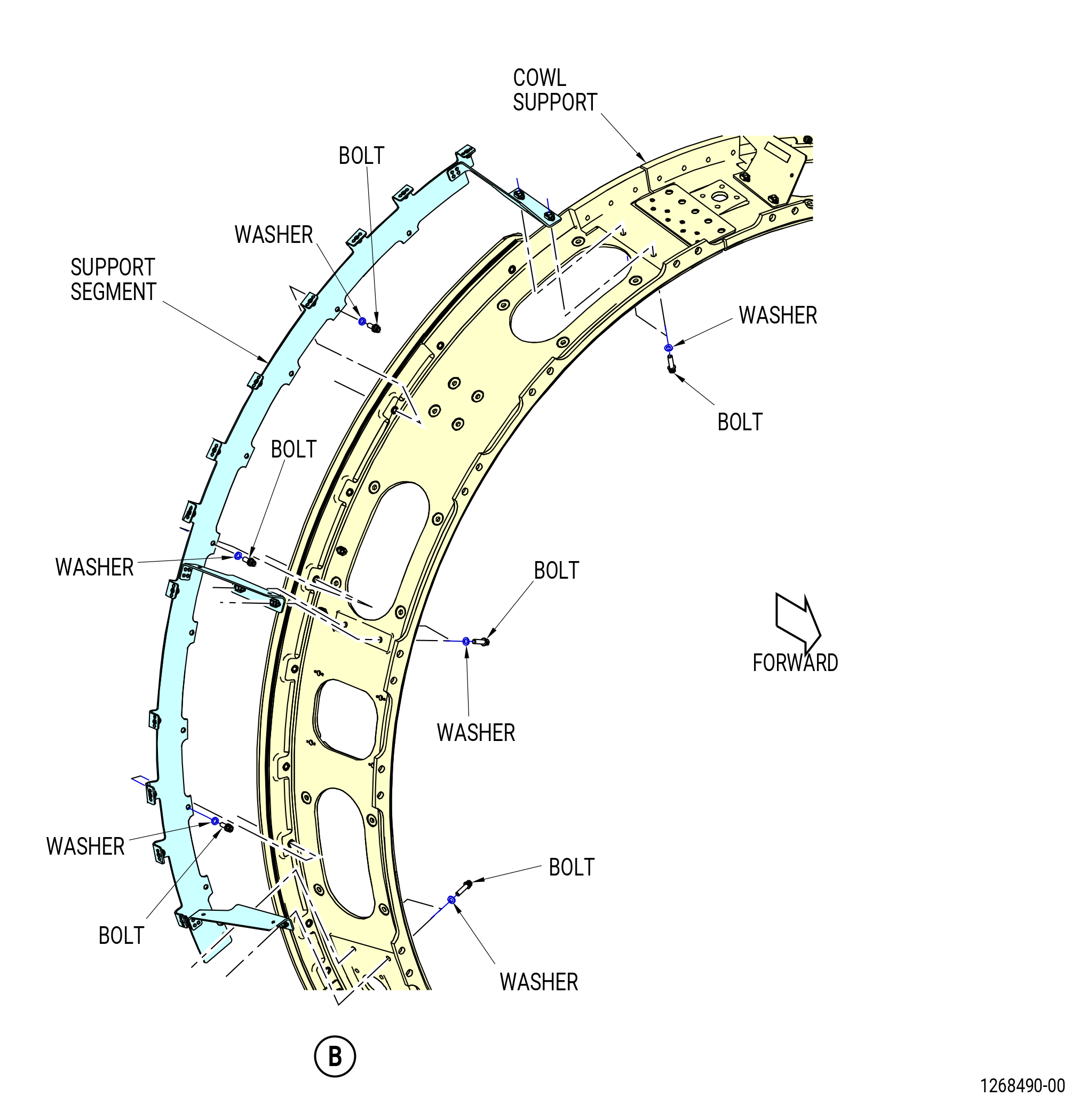
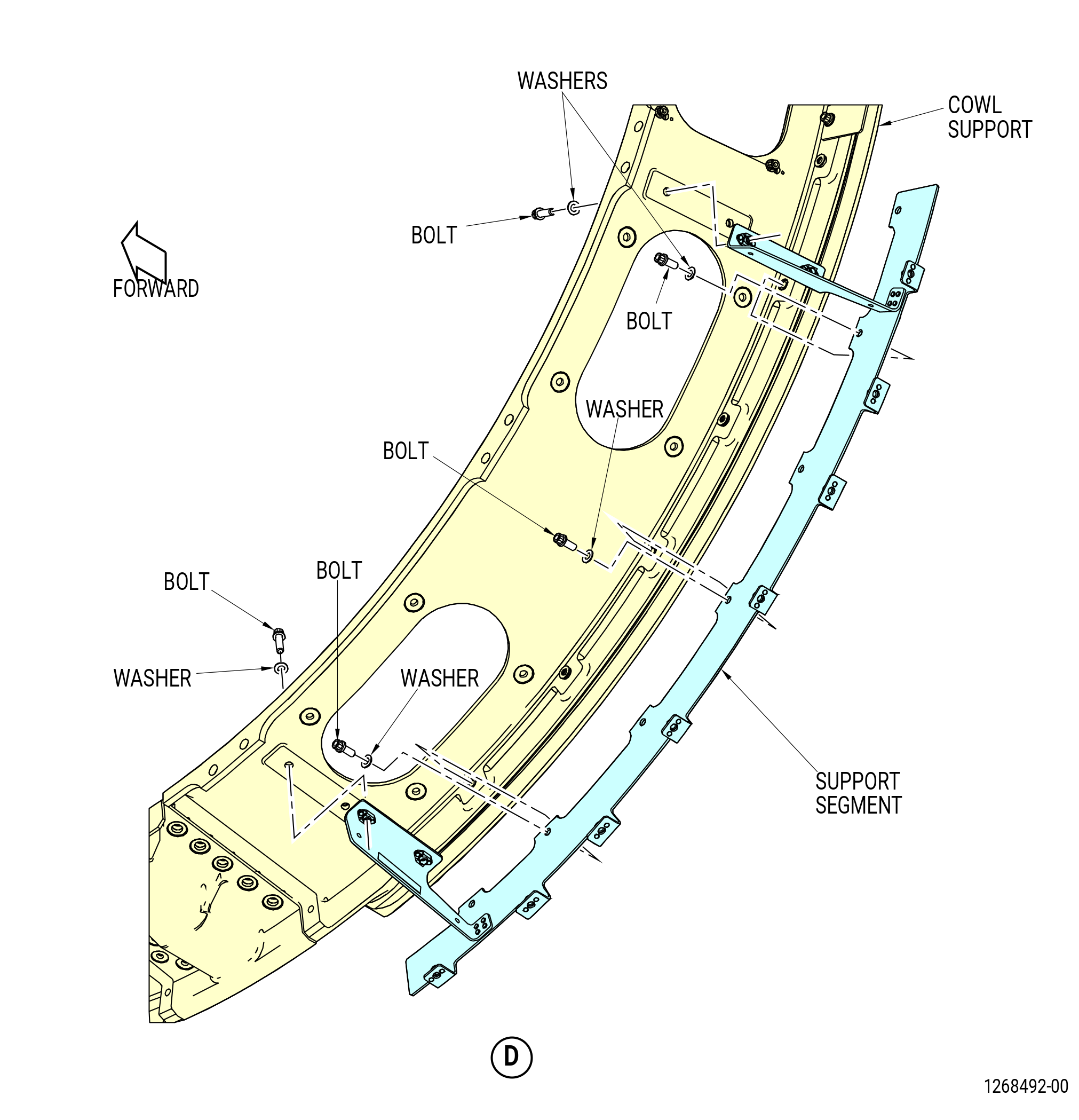
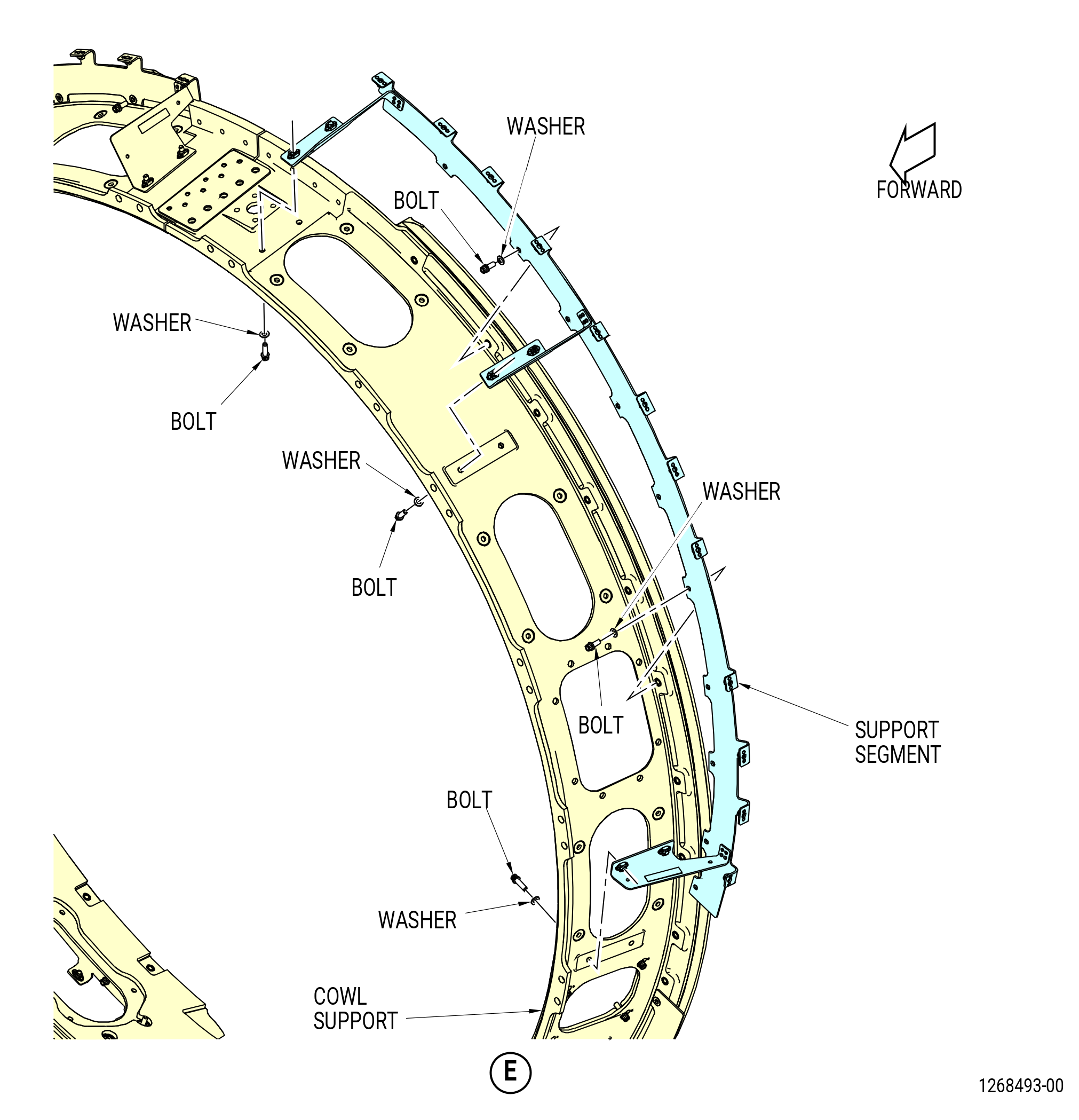
| Y. | Remove the deflector panel support segments (support segments) from the cowl supports as follows. Refer to Figure Figure 536. |
| (1) | Remove the upper right support segment as follows: |
| (a) | Remove the bolts and washers that attach the support segment to the cowl support. |
| (b) | Remove the bolts and washers that attach the support segment to the forward flange of the cowl support. |
| (c) | Remove the support segment from the right-side cowl support. |
| (2) | Install the lower right support segment (95012) as follows: |
| (a) | Remove the bolts and washers that attach the support segment to the cowl support. |
| (b) | Remove the bolts and washers that attach the support segment to the forward flange of the cowl support. |
| (c) | Remove the support segment from the right-side cowl support. |
| (3) | Install the upper left support segment (95010) as follows: |
| (a) | Remove the bolts and washers that attach the support segment to the cowl support. |
| (b) | Remove the bolts and washers that attach the support segment to the forward flange of the cowl support. |
| (c) | Remove the support segment from the left-side cowl support. |
| (4) | Install the lower left support segment (95013) as follows: |
| (a) | Remove the bolts and washers that attach the support segment to the cowl support. |
| (b) | Remove the bolts and washers that attach the support segment to the forward flange of the cowl support. |
| (c) | Remove the support segment from the left-side cowl support. |
| Subtask 72-00-02-030-413 |
| Z. | Remove the cowl supports from the fan hub frame as follows. Refer to Figure 537. |
| (1) | Remove the sealant from between the ends of the cowl supports at the 6:00 and 12:00 o'clock positions. |
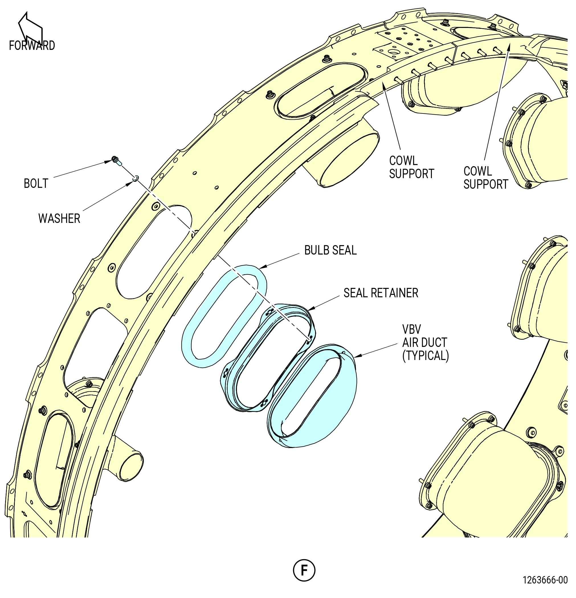
| (2) | Remove the VBV air ducts from the cowl supports as follows: |
| (a) | Remove the bolts and washers that attach the seal retainers to the cowl supports. |
| (b) | Move the seal retainers radially inward, away from the cowl supports. |
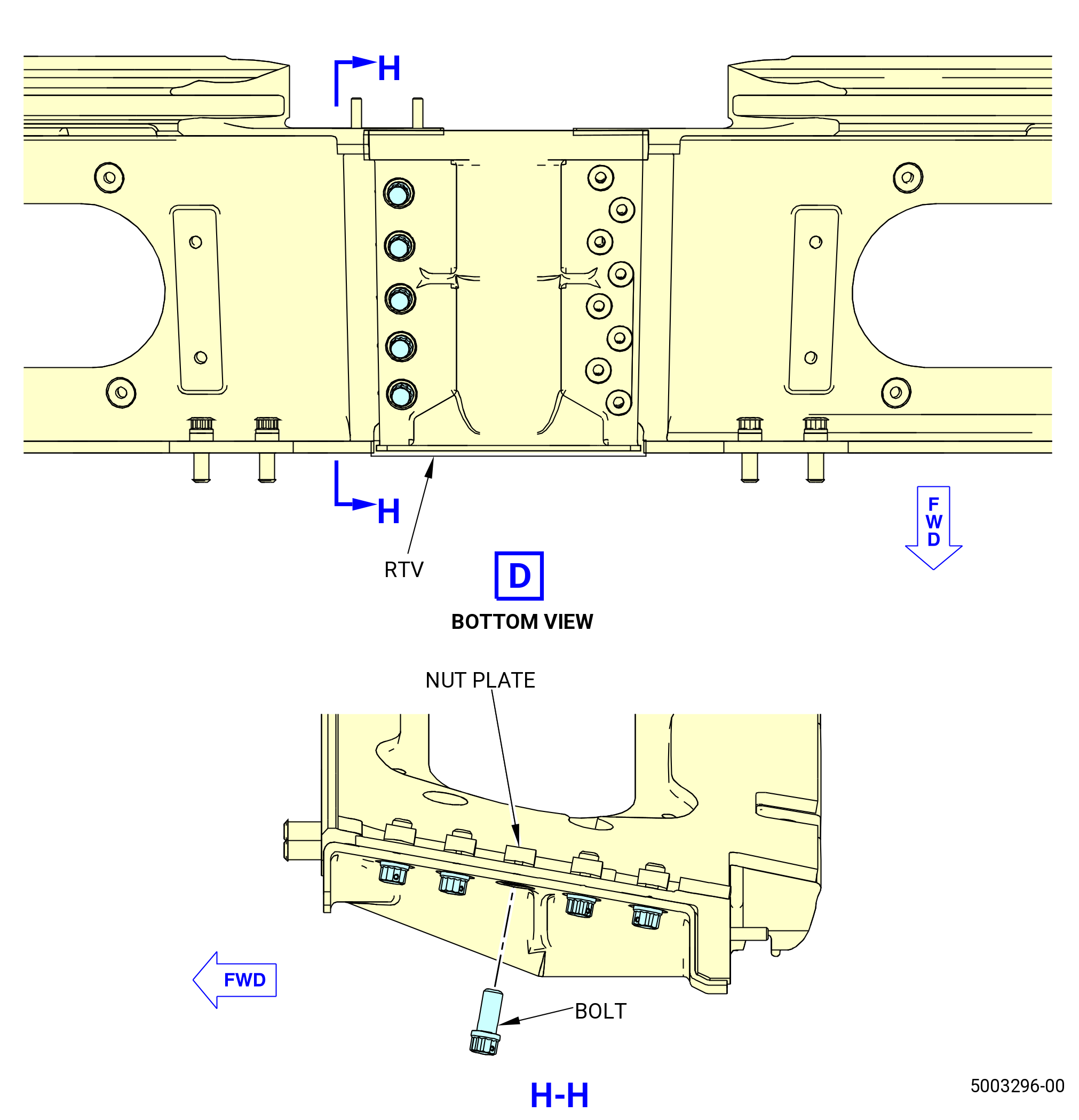
| (3) | Remove the bolts that attach the left-side and right-side cowl supports together at the 6:00 o'clock position. |
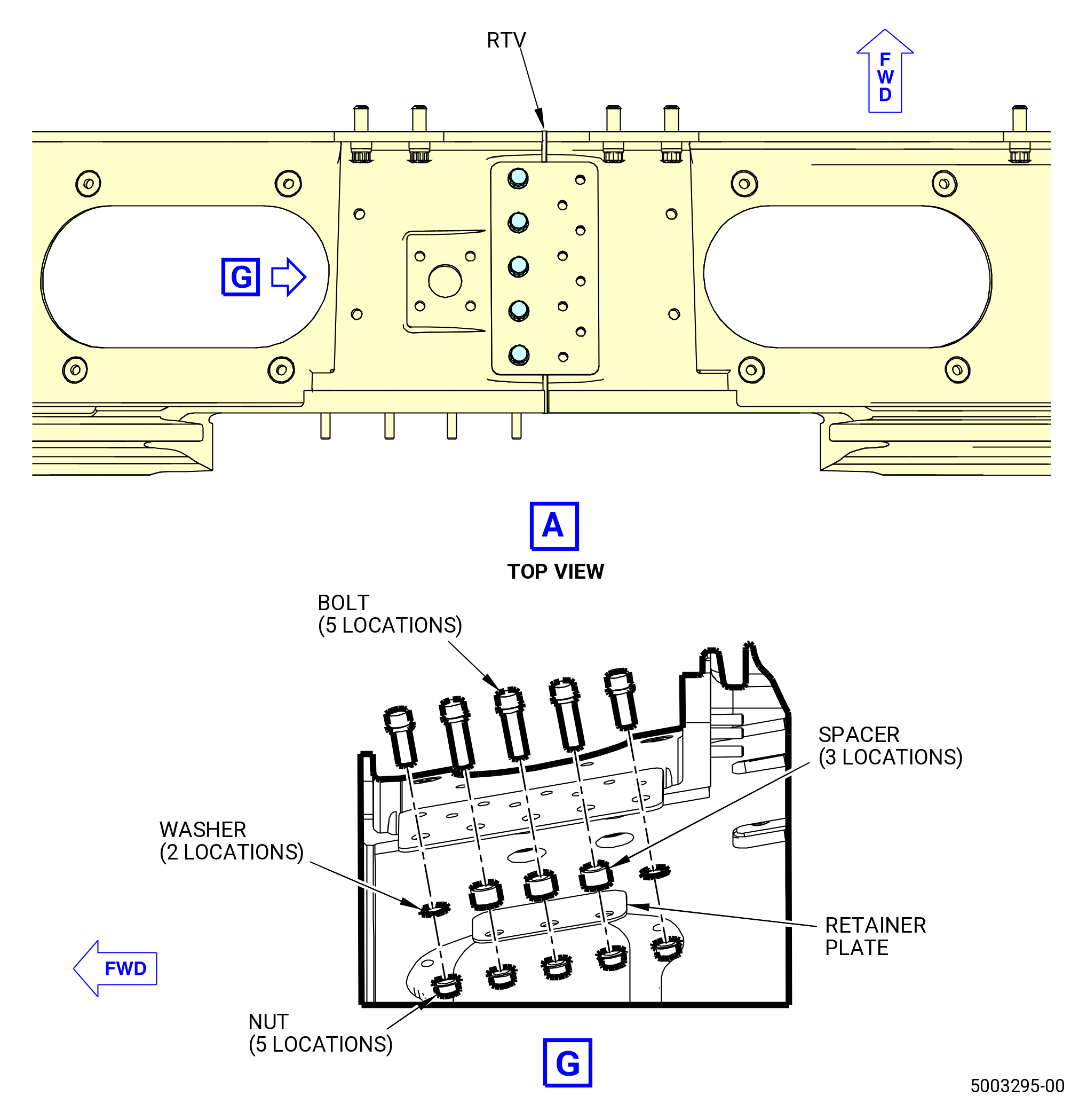
| (4) | Remove the bolts, washers, spacers, retainer plate, and nuts that attach the left-side and right-side cowl supports together at the 12:00 o'clock position. |
| (5) | Remove the bolts and spacer that attach the right-side cowl support to the fan hub frame. |
| (6) | Remove the right-side cowl support from the fan hub frame. |
| (7) | Remove the bolts and spacer that attach the left-side cowl support to the fan hub frame. |
| (8) | Remove the left-side cowl support from the fan hub frame. |
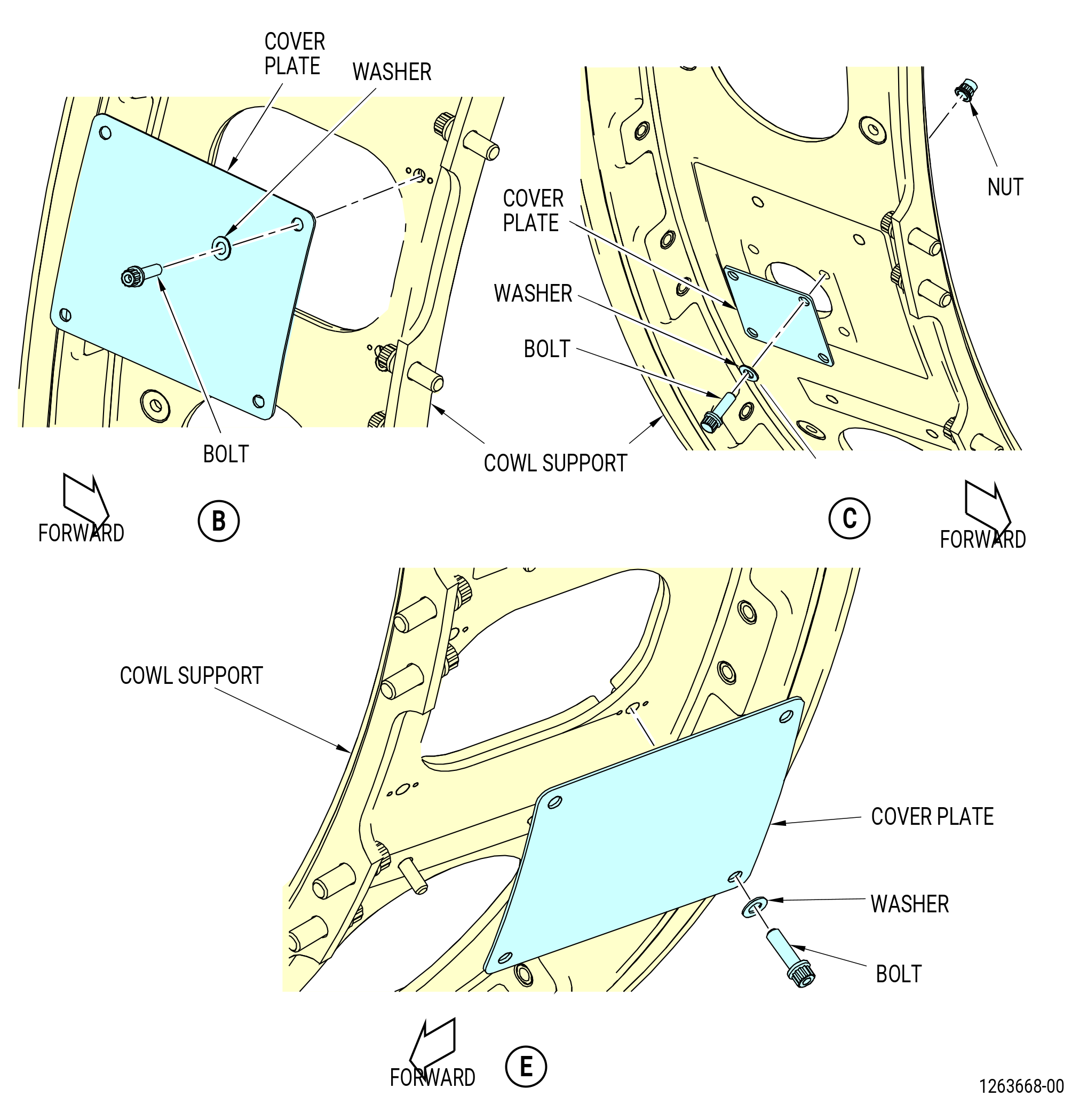
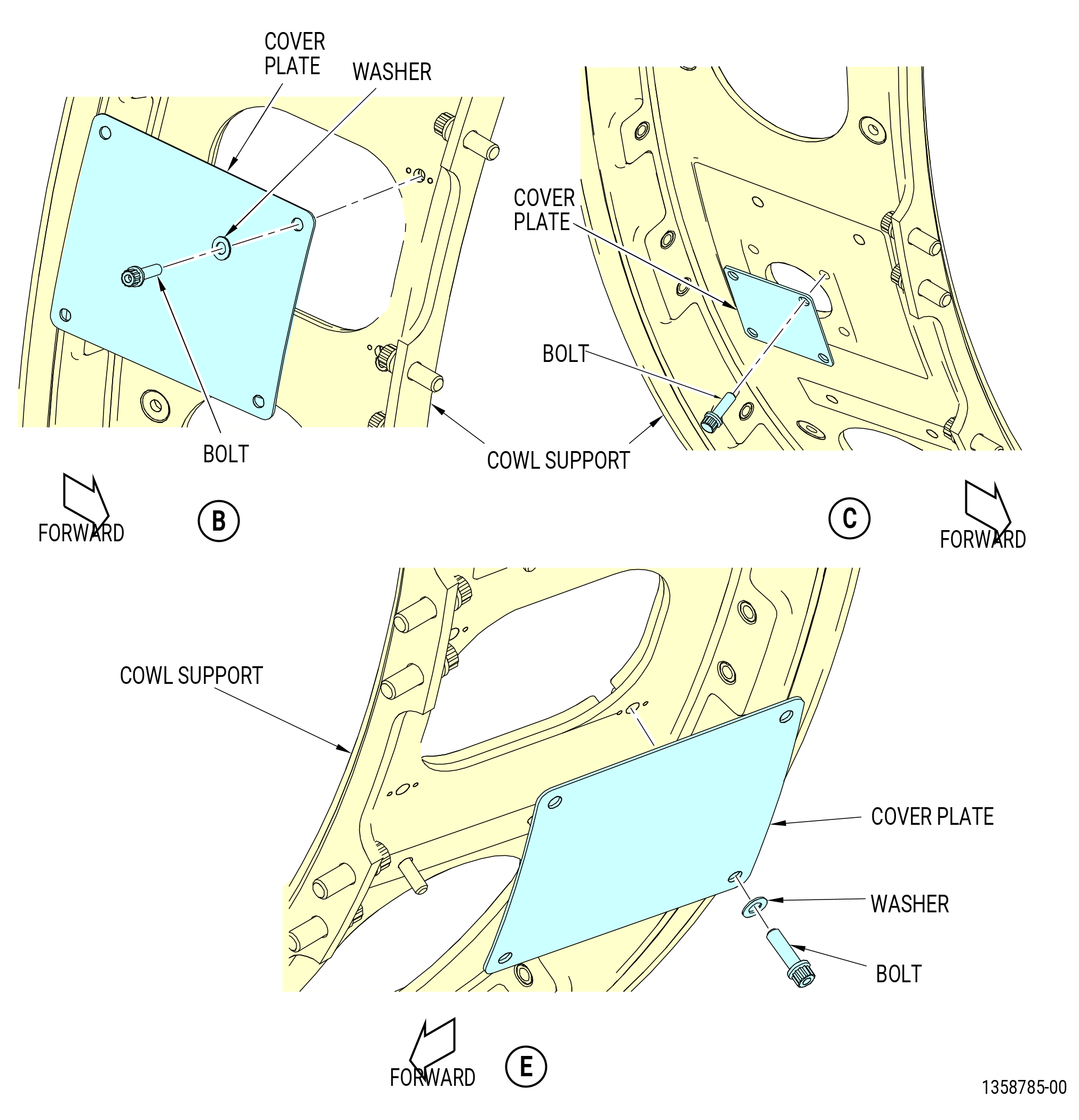
| (9) | Remove the bolts and washers that attach the cover plate at the 8:30 o'clock position on the left-side cowl support. |
| (10) | Remove the bolts and washers that attach the cover plate at the 2:30 o'clock position on the right-side cowl support. |
| Subtask 72-00-02-030-475 |
| * * * PRE SB 72-0050( ) |
| (11) | Remove the bolts and washers that attach the cover plate at the 3:30 o'clock position on the right-side cowl support. |
| * * * END PRE SB 72-0050 |
| Subtask 72-00-02-030-476 |
| * * * SB 72-0050( ) |
| (11).A. | Remove the bolts that attach the cover plate at the 3:30 o'clock position on the right-side cowl support. |
| * * * END SB 72-0050 |
| Subtask 72-00-02-030-477 |
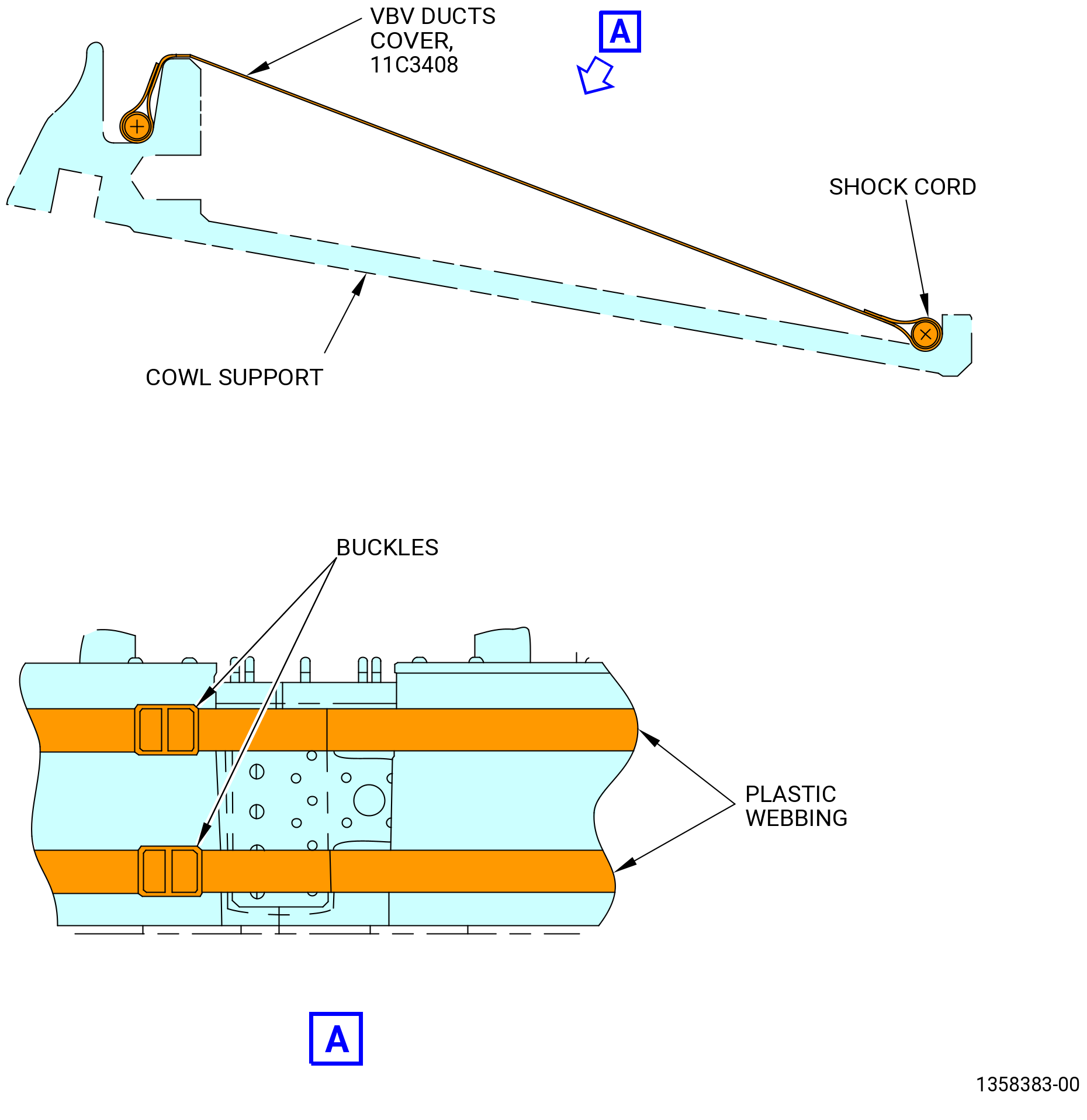
| (12) | Put the 11C3408 VBV ducts cover on the cowl support as follows. Refer to Figure 538. |
| (a) | Put the internal shock cord around both edges of cowl support. |
| (b) | Use plastic webbing and buckles to attach the cover. |
|
|
| Subtask 72-00-02-040-138 |
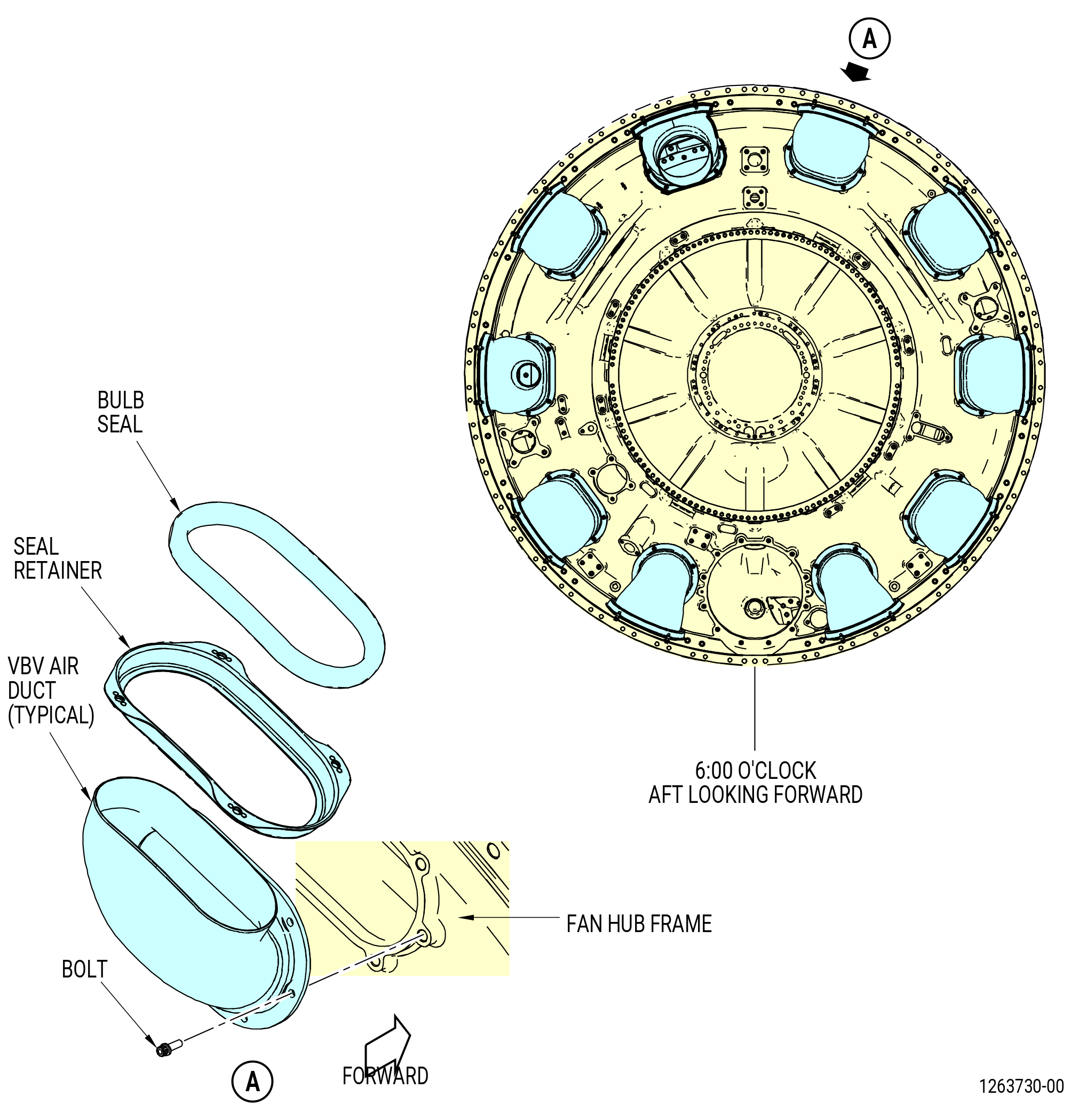
| AA. | Remove the VBV air ducts (air ducts) from the fan hub frame as follows. Refer to Figure 539. |
| (1) | Remove the seal retainers and bulb seals from the air ducts. |
| (2) | Remove the bulb seals from the seal retainers. |
| (3) | Remove the bolts and the nuts that attach the air ducts to the fan hub frame. |
| (4) | Remove the air ducts. |
| Subtask 72-00-02-030-520 |
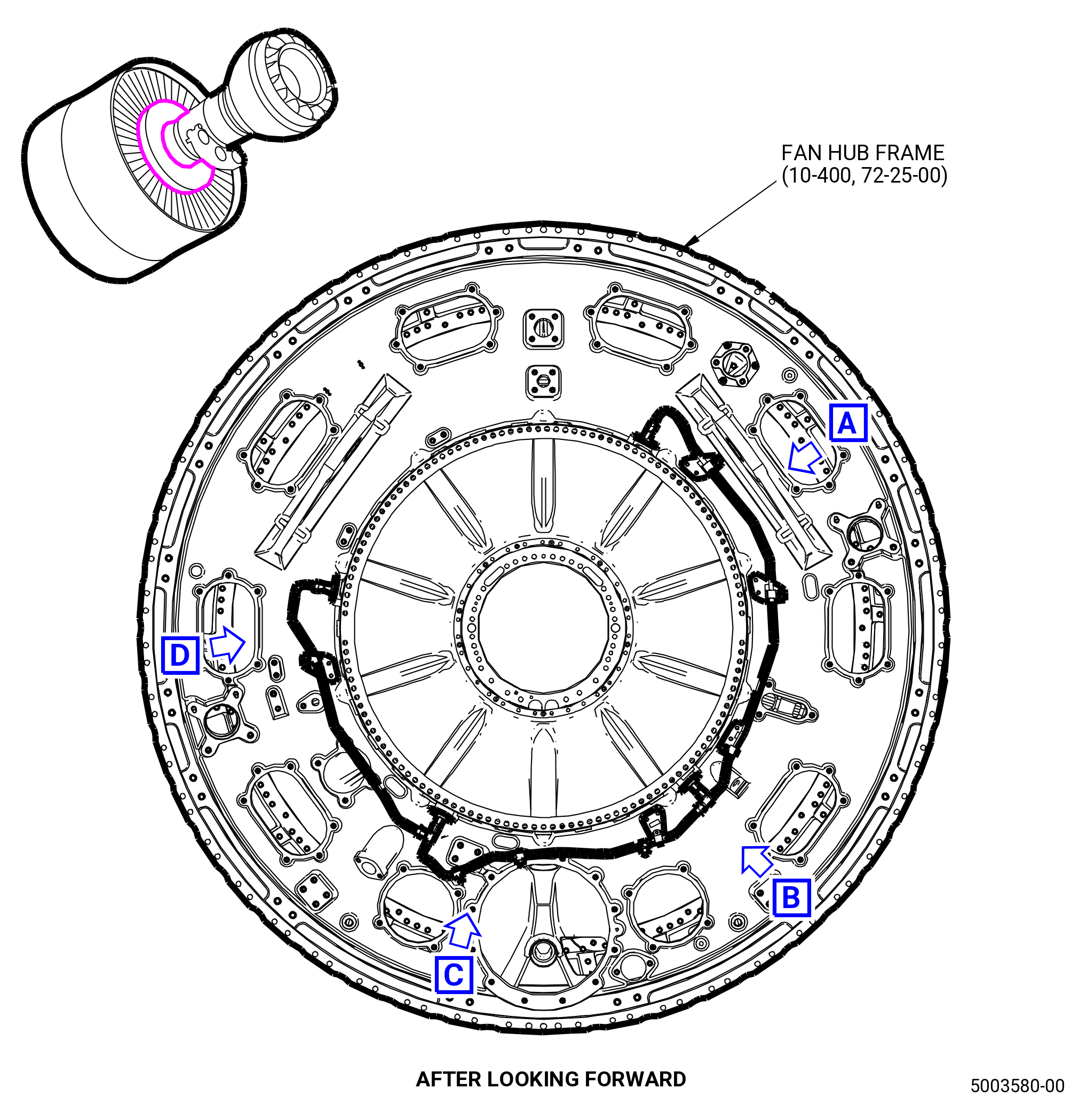
| * * * SB 72-0083( Core Water Wash System Around the Fan Hub Frame ) |
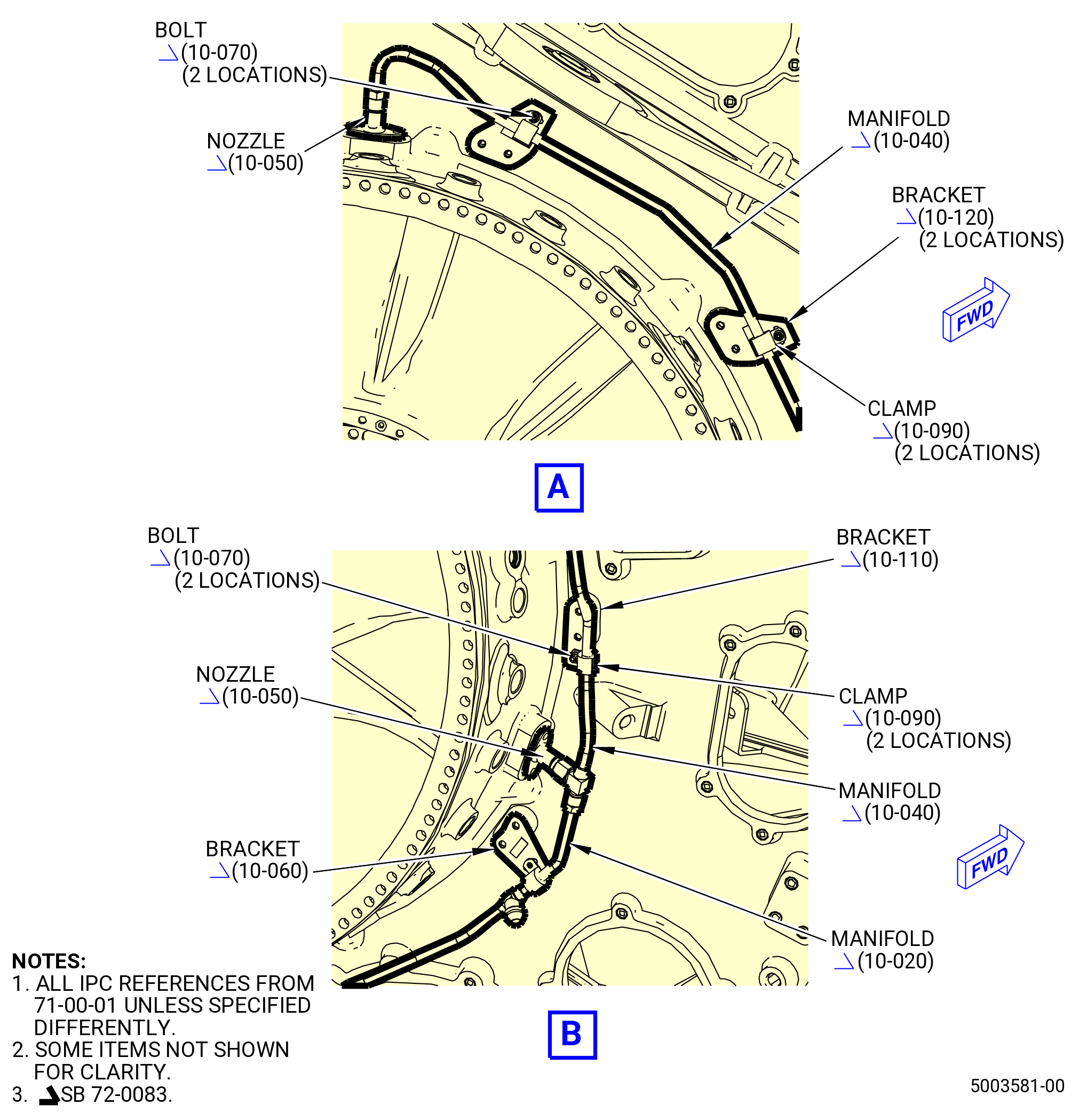
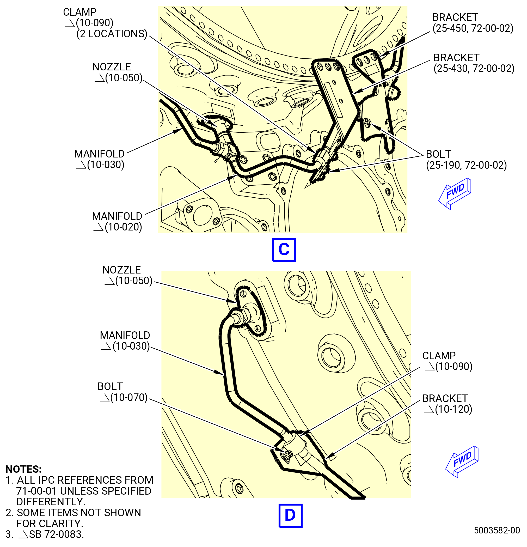
| AB. | Remove the manifolds of the core water wash system around the fan hub frame (10-400 , 72-25-00) (SIN 84000). Refer to Figure 540 and do as follows: |
| (1) | Loosen the B-nuts that attach the core wash manifold (manifold) (10-040 , 71-00-01) (SIN 78004) from the core wash nozzles (nozzle) (10-050 , 71-00-01) (SIN 78005) and core wash manifold (manifold) (10-020 , 71-00-01) (SIN 78002). |
| (2) | Loosen the B-nuts that attach the manifold (10-020 , 71-00-01) (SIN 78002) from the nozzle (10-050 , 71-00-01) (SIN 78005) and core wash tube (manifold) (10-030 , 71-00-01) (SIN 78003). |
| (3) | Loosen the B-nuts that attach the manifold (10-030 , 71-00-01) (SIN 78003) from the nozzle (10-050 , 71-00-01) (SIN 78005). |
| (4) | Remove the machine bolts (bolts) (10-070 , 71-00-01) (SIN 78021) from the cushioned loop clamps (clamps) (10-090 , 71-00-01) (SIN 78081) attached to the support brackets (brackets) (10-120 , 71-00-01) (SIN 78011), (10-110 , 71-00-01) (SIN 78010), and (10-060 , 71-00-01) (SIN 78012). |
| (5) | Remove the machine bolts (bolts) (25-190) (SIN 78023) from the clamps (10-090 , 71-00-01) (SIN 78081) attached to the support brackets (brackets) (25-450) (SIN 44411) and (25-430) (SIN 44413). |
| (6) | Remove the manifolds (10-020 , 71-00-01) (SIN 78002), (10-030 , 71-00-01) (SIN 78003), and (10-040 , 71-00-01) (SIN 78004) and the clamps (10-090 , 71-00-01) (SIN 78081) from the fan hub frame (10-400 , 72-25-00) (SIN 84000). |
| (7) | Remove the clamps (10-090 , 71-00-01) (SIN 78081) from the manifolds (10-020 , 71-00-01) (SIN 78002), (10-030 , 71-00-01) (SIN 78003), and (10-040 , 71-00-01) (SIN 78004). |
| NOTE: |
|
| * * * END SB 72-0083 |
|
|
|
| Subtask 72-00-02-030-407 |
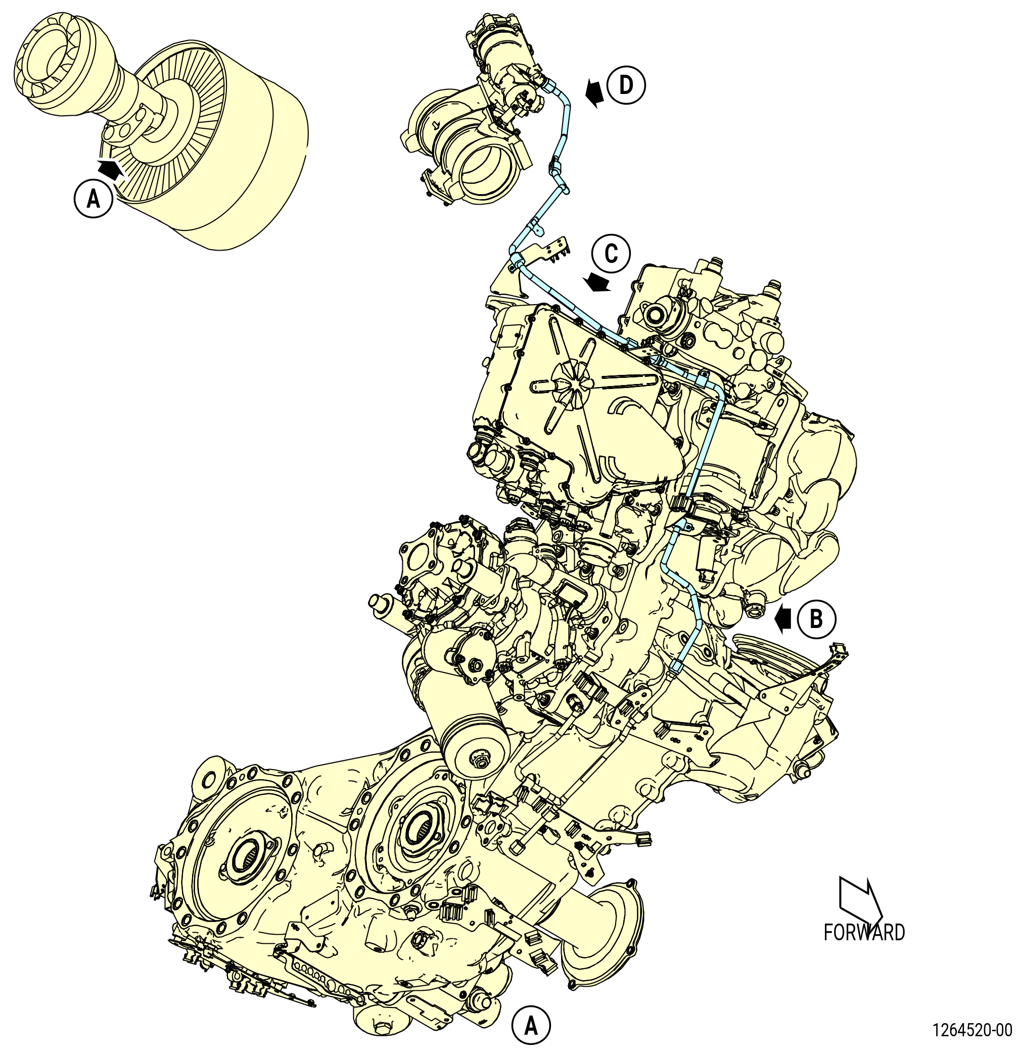
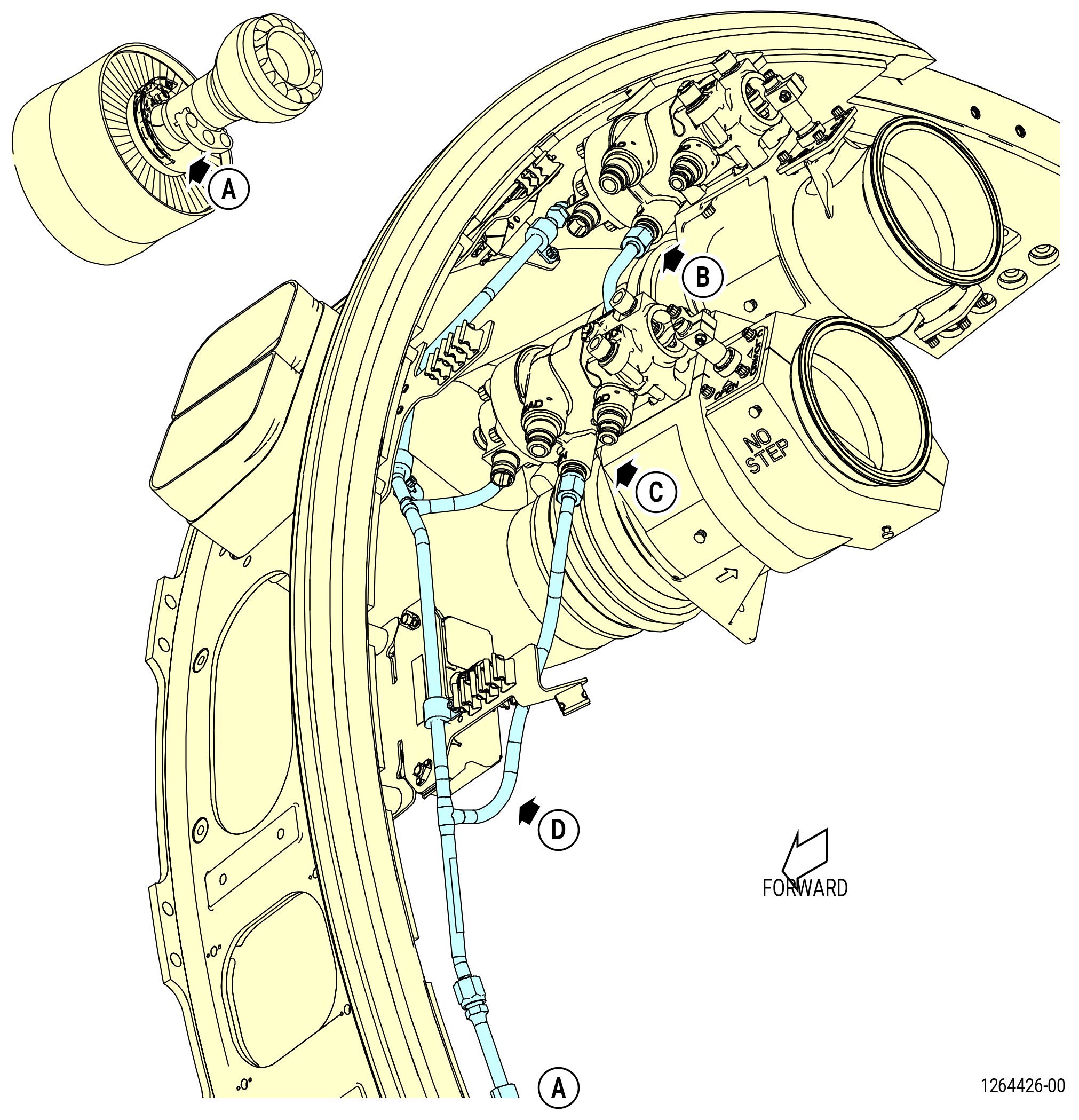
| AC. | Remove the drain tubes on the right side of the engine as follows: |
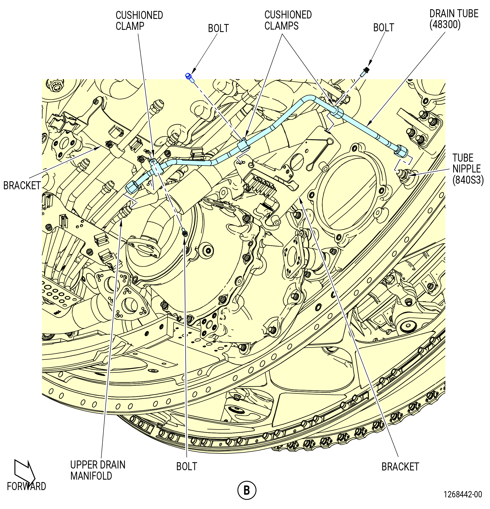
| (1) | Remove the No. 3 bearing seal drain tube (drain tube) (48300) as follows. Refer to Figure 541. |
| (a) | Disconnect the drain tube B-nut from the tube nipple on the fan hub frame. |
| (b) | Disconnect the B-nut from the upper drain manifold on the AGB. |
| (c) | Remove the cushioned clamps and bolts that attach the drain tube to the brackets. |
| (d) | Remove the drain tube. |
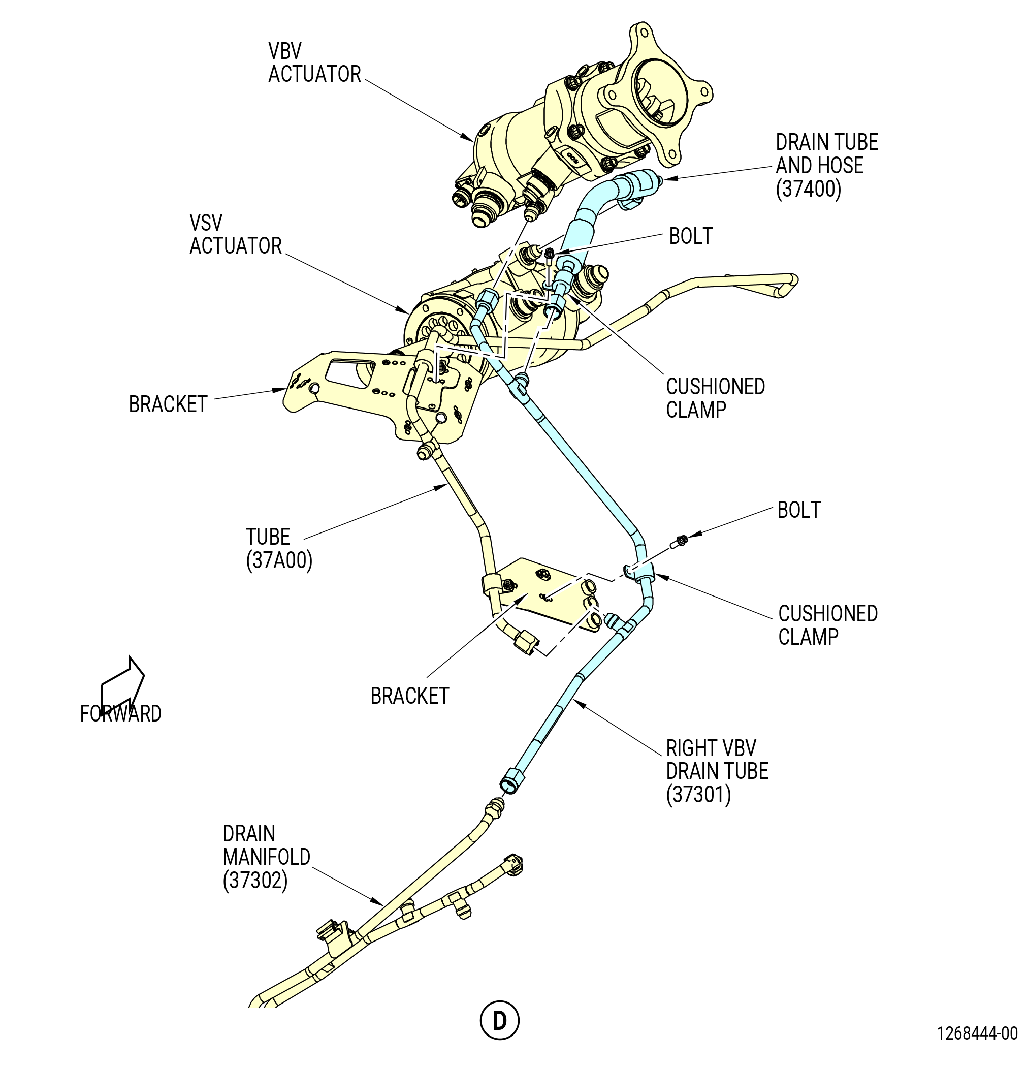
| (2) | Remove the drain tube and hose (37400) as follows: |
| (a) | Disconnect the B-nut from the variable stator vane (VSV) actuator. |
| (b) | Disconnect the B-nut from the right VBV drain tube (37301). |
| (c) | Remove the cushioned clamp and bolt that attach the drain tube and hose to the bracket. |
| (3) | Remove the right VBV drain tube (37301) as follows: |
| (a) | Disconnect the B-nut of the right VBV drain tube from the VBV actuator. |
| (b) | Disconnect the B-nut of the right VBV drain tube from the drain manifold (37302). |
| (c) | Disconnect the B-nut of tube (37A00) from the right VBV drain tube (37301). |
| (d) | Remove the cushioned clamp and bolt that attach the right VBV drain tube to the bracket. |
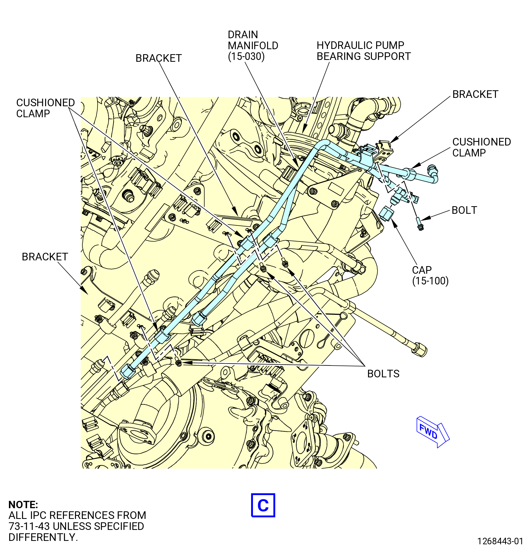
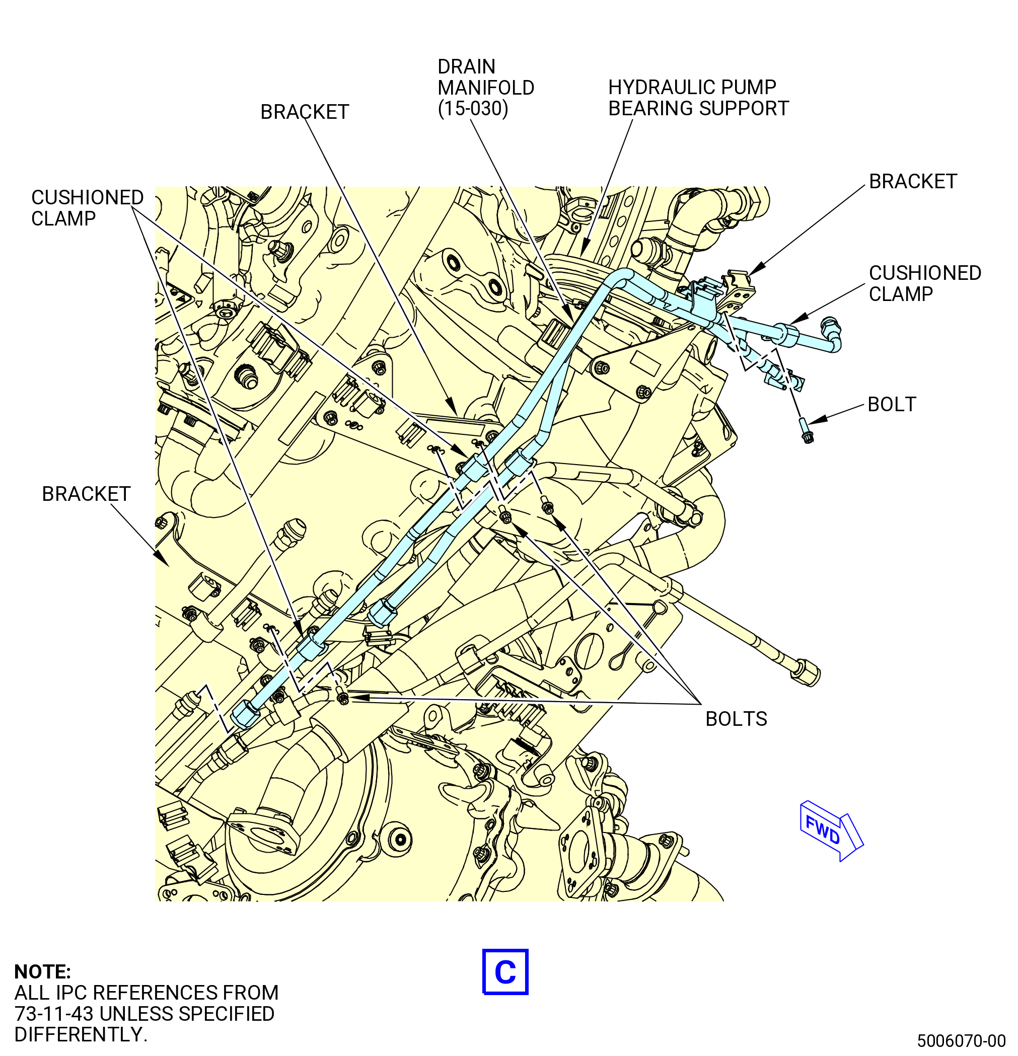
| (4) | Remove the drain manifold (37302) as follows: |
| (a) | Disconnect the two B-nuts from the upper drain manifold. |
| (b) | Disconnect the B-nut from the nipple on the hydraulic pump bearing support. |
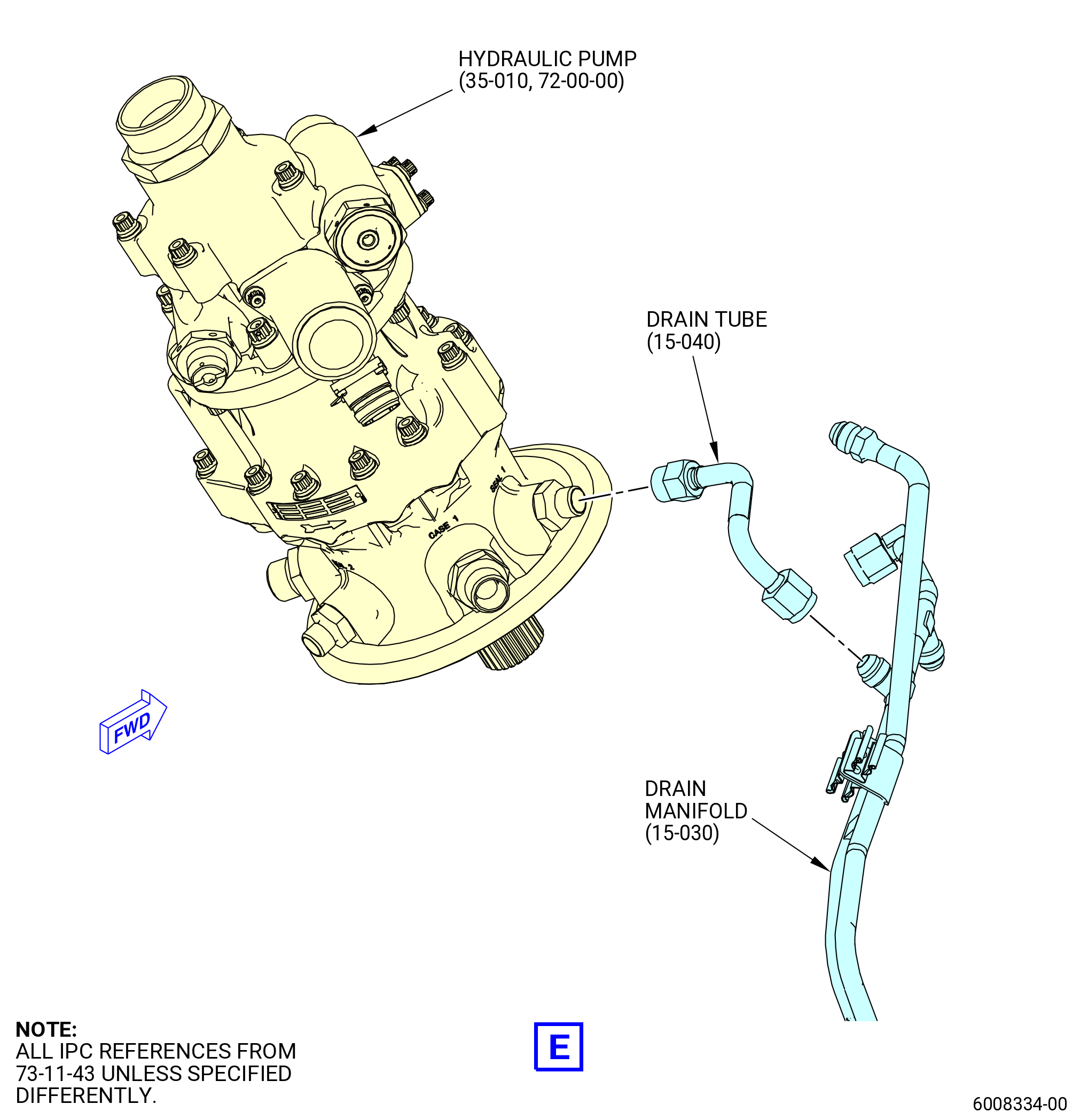
| (c) | Disconnect the B-nut of the drain tube (15-040 , 73-11-43) (SIN 59100) from the drain manifold (15-030 , 73-11-43) (SIN 37302). |
| (d) | Disconnect the B-nut of the drain tube (15-040 , 73-11-43) (SIN 59100) from the hydraulic pump (35-010 , 72-00-00) (SIN C00A6). |
| (e) | Remove the cushioned clamps and bolts that attach the drain manifold to the brackets. |
| Subtask 72-00-02-030-536 |
| * * * PRE SB 73-0020( Drain Manifold with Cap Feature ) |
| (f) | Remove the cap (15-100 , 73-11-43) (SIN 37361) from the drain manifold (15-030 , 73-11-43) (SIN 37302). |
| NOTE: |
|
| * * * END PRE SB 73-0020 |
| Subtask 72-00-02-030-537 |
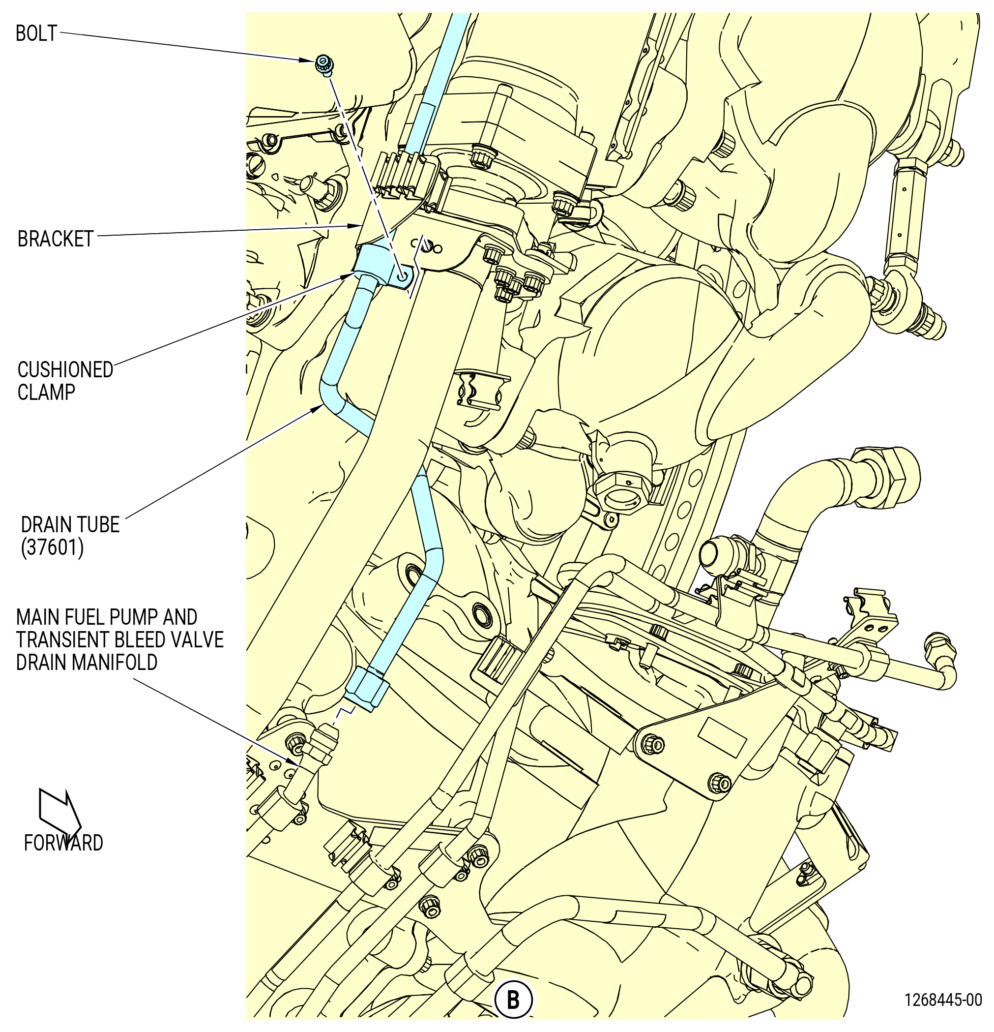
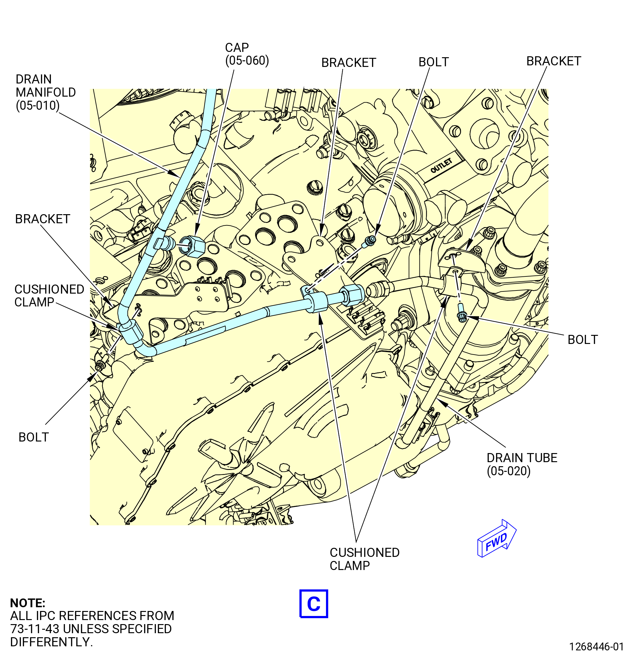
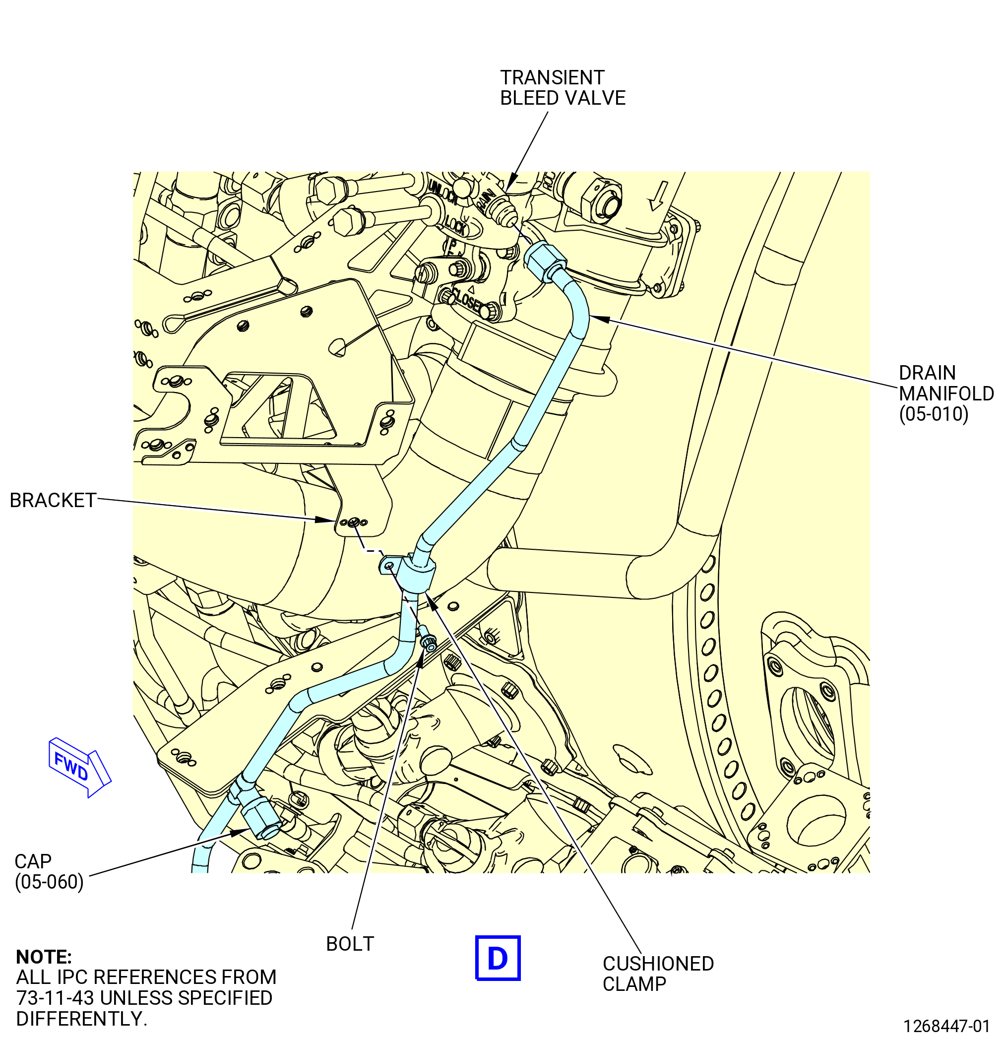
| (5) | Remove the drain manifold (37600) as follows. Refer to Figure 542. |
| (a) | Disconnect the B-nut from the drain tube (37601). |
| (b) | Disconnect the B-nut from the transient bleed valve. |
| (c) | Remove the cushioned clamps and bolts that attach the drain manifold to the brackets. |
| Subtask 72-00-02-030-538 |
| * * * PRE SB 73-0020( Drain Manifold with Cap Feature ) |
| (d) | Remove the cap (05-060 , 73-11-43) (SIN 37661) from the drain manifold (05-010 , 73-11-43) (SIN 37600). |
| NOTE: |
|
| * * * END PRE SB 73-0020 |
| Subtask 72-00-02-030-539 |
| (6) | Remove the drain tube (37601) as follows: |
| (a) | Disconnect the B-nut from the main fuel pump and transient bleed valve drain manifold (37000). |
| (b) | Remove the cushioned clamps and bolts that attach the drain tube to the brackets. |
|
|
|
|
|
|
| Subtask 72-00-02-030-408 |
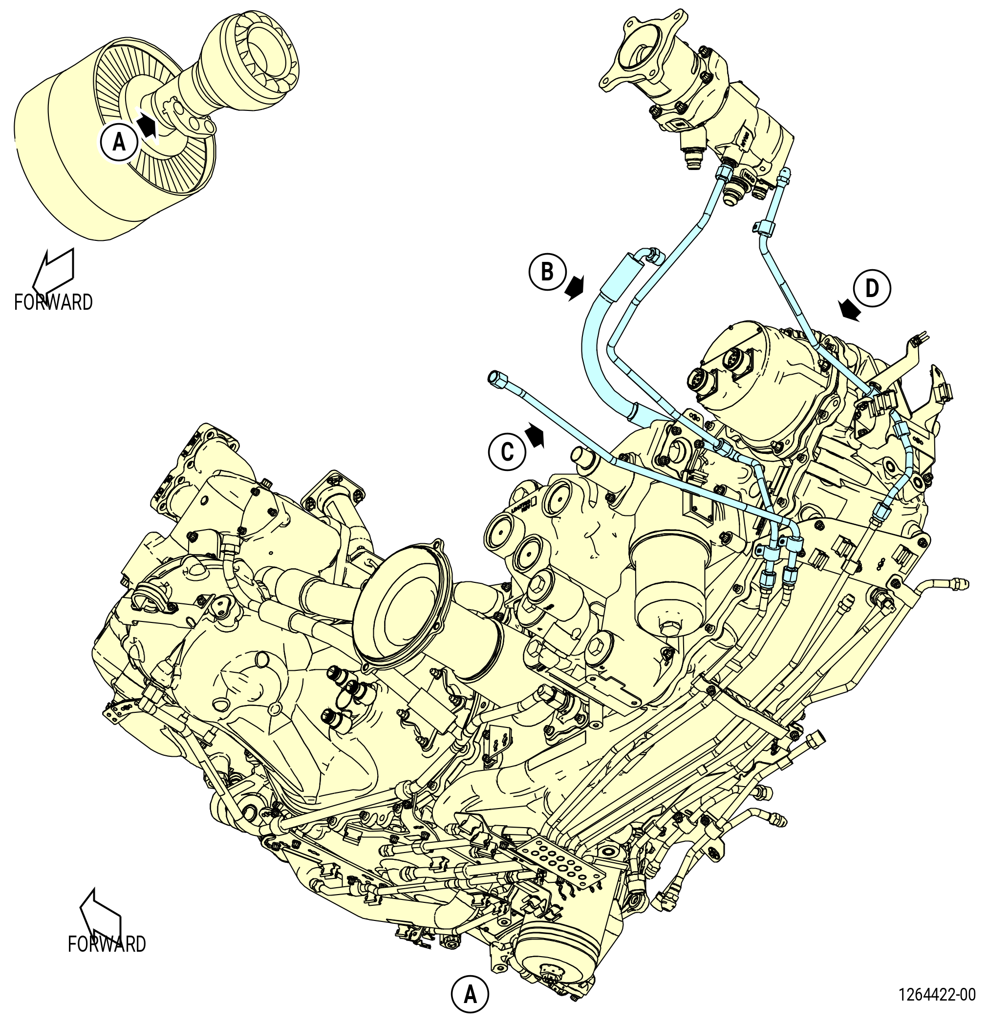
| AD. | Remove the drain tubes on the left side of the engine as follows: |
| (1) | Remove the fuel drain tube (37200) as follows. Refer to Figure 543. |
| (a) | Disconnect the B-nut from the fuel drain tube (37100) |
| (b) | Disconnect the B-nut from the VFSG heat exchanger. |
| (2) | Remove the fuel drain tube (37100) as follows: |
| (a) | Disconnect the B-nut from the upper drain manifold. |
| (b) | Disconnect the B-nut from the VFSG heat exchanger. |
| (c) | Remove the cushioned clamps and bolts that attach the fuel drain tube to the brackets. |
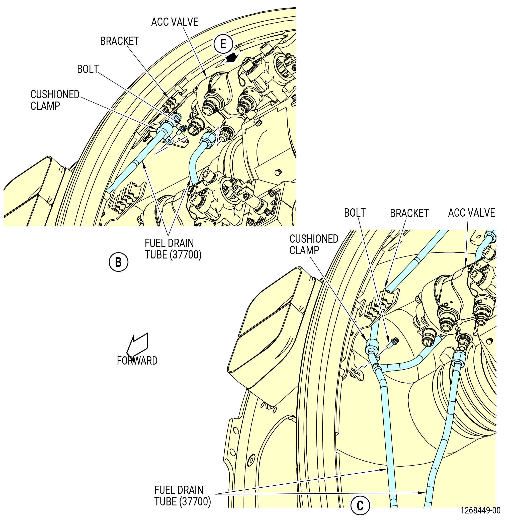
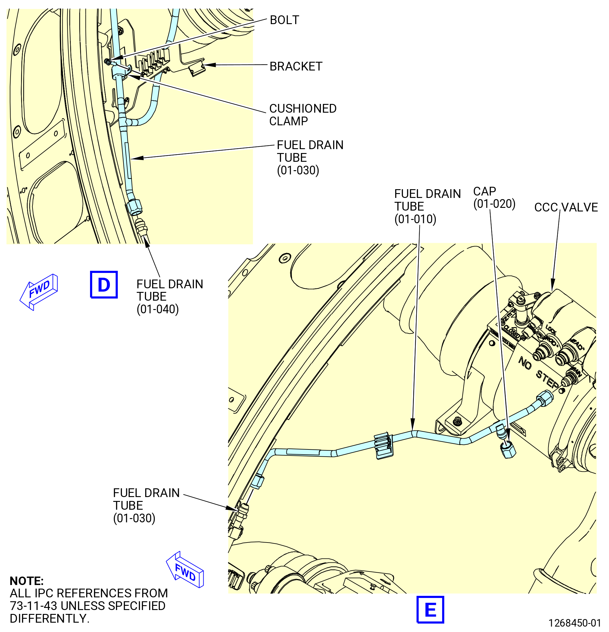
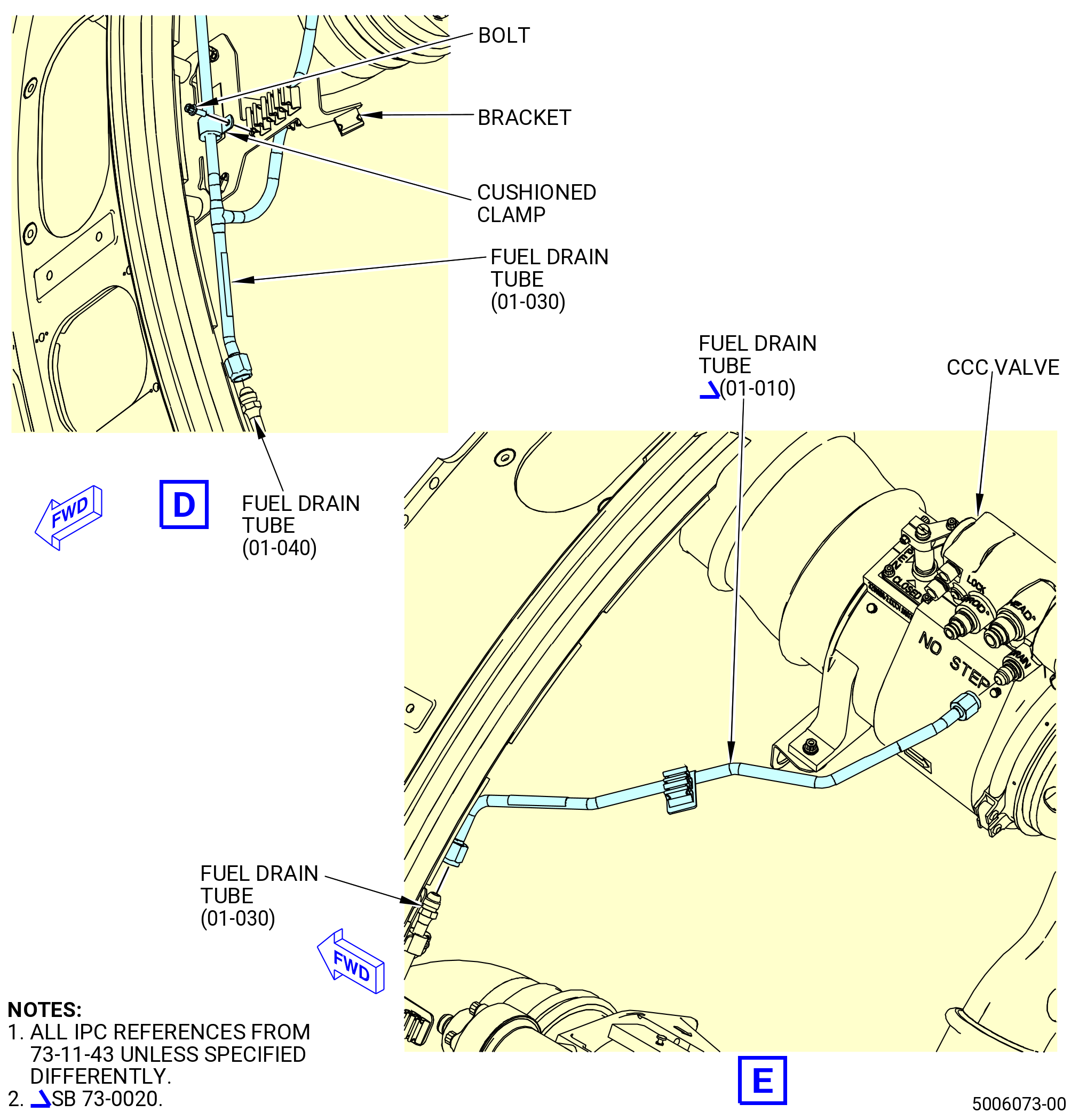
| (3) | Remove the fuel drain tube (37900) as follows. Refer to Figure 544. |
| (a) | Disconnect the B-nut from the fuel drain tube (37700). |
| (b) | Disconnect the B-nut from the core compartment cooling (CCC) valve. |
| Subtask 72-00-02-030-534 |
| * * * PRE SB 73-0020( Fuel Drain Tube with Cap Feature ) |
| (c) | Remove the cap (01-020 , 73-11-43) (SIN 37961) from the fuel drain tube (01-010 , 73-11-43) (SIN 37900). |
| NOTE: |
|
| * * * END PRE SB 73-0020 |
| Subtask 72-00-02-030-535 |
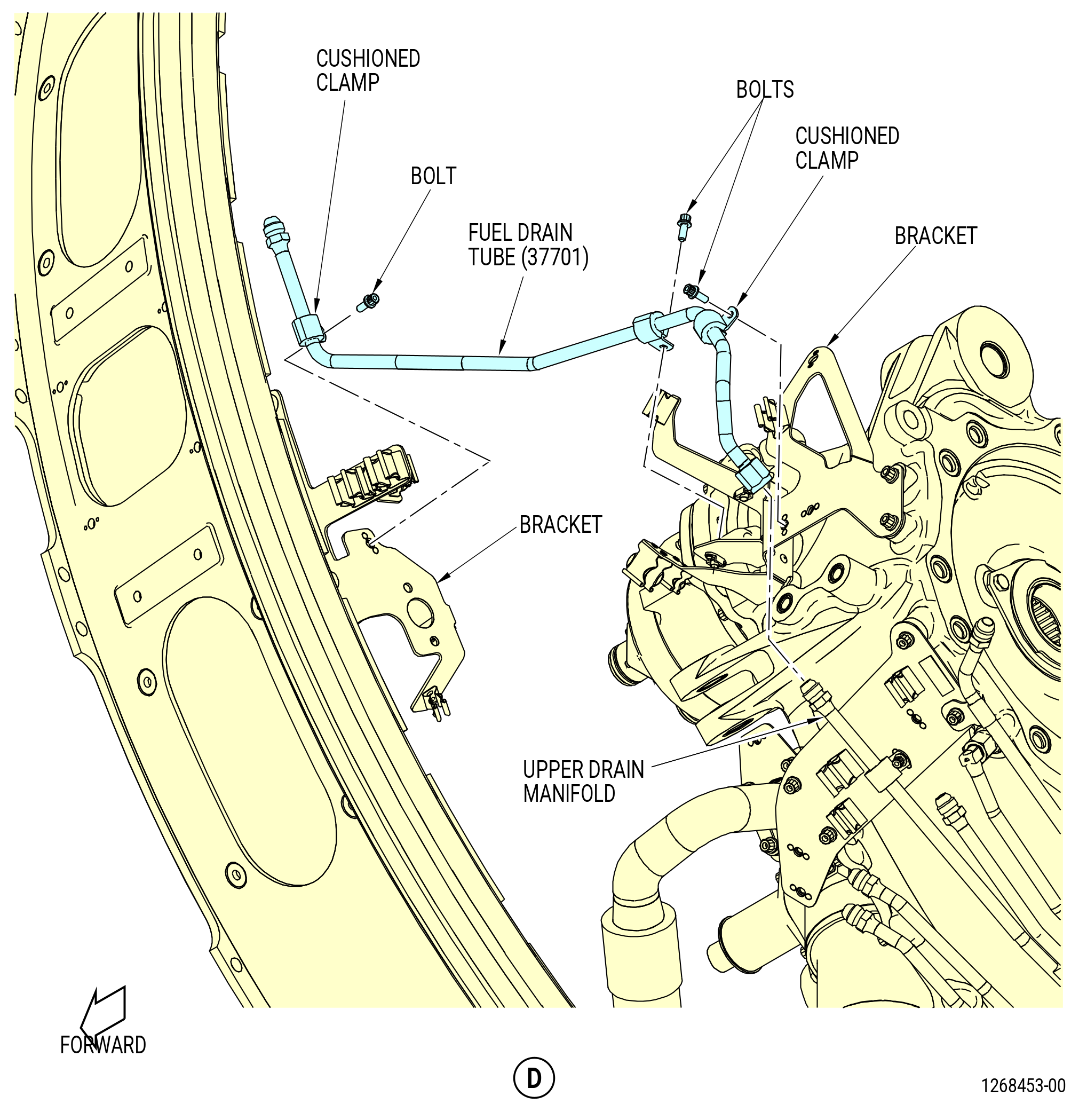
| (4) | Remove the fuel drain tube (37700) as follows: |
| (a) | Disconnect the fuel drain tube B-nut from the fuel drain tube (37701). |
| (b) | Remove the cushioned clamps and bolts that attach the fuel drain tube to the brackets. |
| (5) | Remove the fuel drain tube (37701) as follows: |
| (a) | Disconnect the B-nut from the upper drain manifold. |
| (b) | Remove the cushioned clamps and bolts that attach the fuel drain tube to the brackets. |
| (6) | Remove the No. 1 bearing seal drain tube (drain tube) (48400) as follows: |
| (a) | Disconnect the drain tube B-nut from the tube nipple on the fan hub frame. |
| (b) | Disconnect the B-nut from the upper drain manifold on the AGB module. |
| (c) | Remove the cushioned clamp and bolt that attach the fuel drain tube to the bracket. |
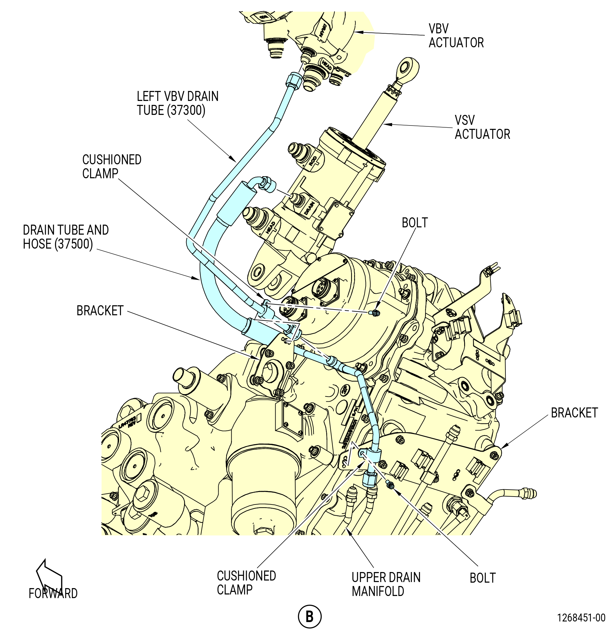
| (7) | Remove the left VBV drain tube (37300) as follows. Refer to Figure 545. |
| (a) | Disconnect the B-nut from the VBV actuator. |
| (b) | Disconnect the B-nut from the drain tube and hose (37500). |
| (c) | Remove the cushioned clamp and bolt that attach the fuel drain tube to the bracket. |
| (8) | Remove the drain tube and hose (37500) as follows: |
| (a) | Disconnect the B-nuts from the VSV actuator and the upper drain manifold. |
| (b) | Remove the cushioned clamp and bolt that attach the drain tube and hose to the bracket. |
|
|
| Subtask 72-00-02-030-415 |
| AE. | Remove the AGB module. Refer to TASK 72-00-05-020-801 (72-00-05, REMOVAL 001). |
| Subtask 72-00-02-030-766 |
| * * * PRE SB 72-0444( with PS25 Sense Line ) |
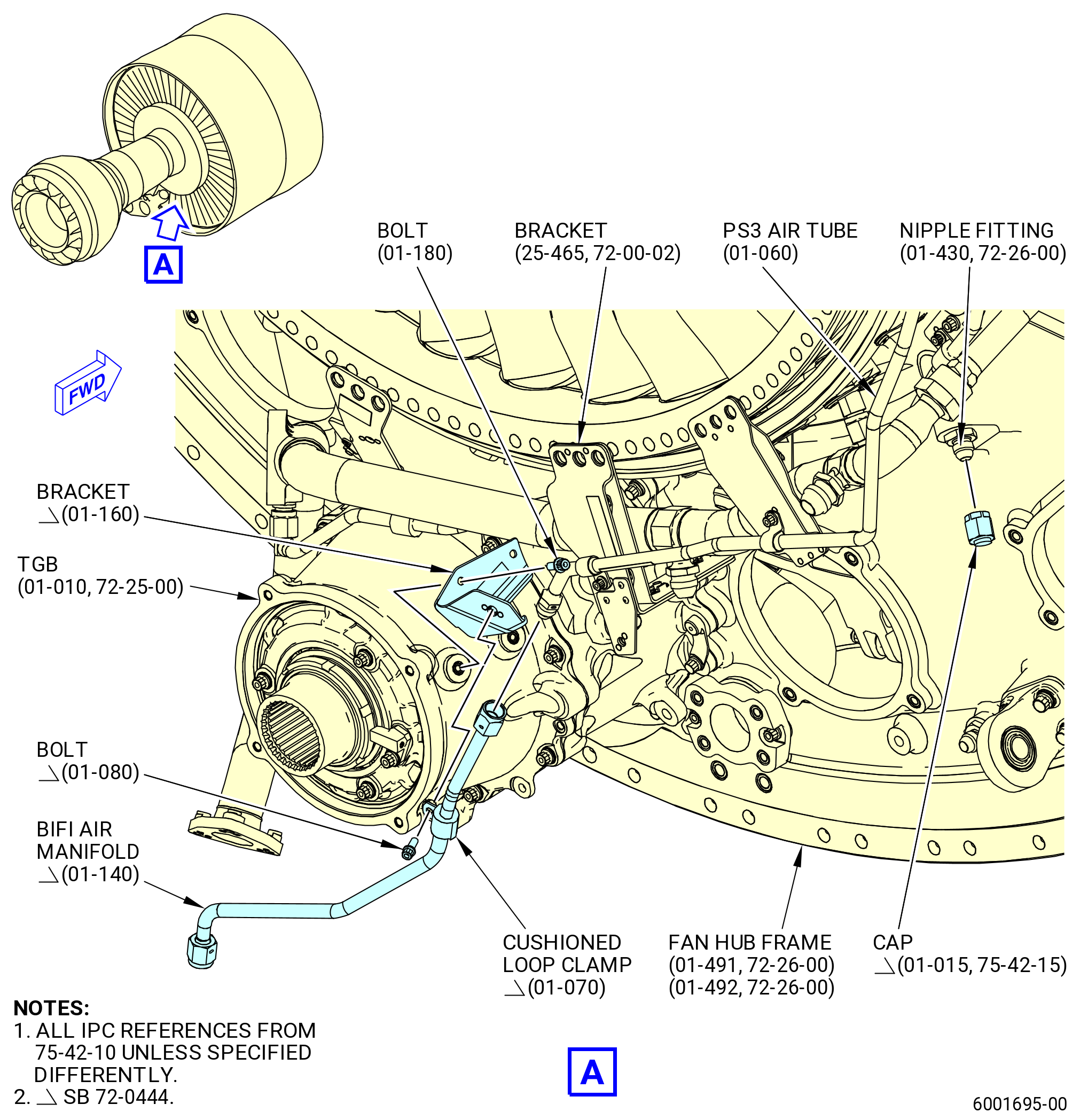
| AF. | Remove the BIFI air manifold (01-140 , 75-42-10) (SIN 99008) and the bracket (01-160 , 75-42-10) (SIN 99010). Refer to Figure 546 and do as follows: |
| (1) | Disconnect the B-nuts of the BIFI air manifold from the PS3 air tube (01-060 , 75-42-10) (SIN 61501) and the PS25 air tube (01-010 , 75-42-15) (SIN 61400). |
| (2) | Remove the bolts that attach the BIFI air manifold to the bracket (01-160 , 75-42-10) (SIN 99010). |
| (3) | Remove the BIFI air manifold. |
| (4) | Remove the bolts (01-180 , 75-42-10) (SIN 99029) that attach the bracket (01-160 , 75-42-10) (SIN 99010) to the TGB. |
| (5) | Remove the bracket (01-160 , 75-42-10) (SIN 99010). |
| * * * END PRE SB 72-0444 |
| Subtask 72-00-02-030-767 |
| * * * SB 72-0444( without PS25 Sense Line ) |
| AF.A. | Remove the BIFI air manifold (01-140 , 75-42-10) (SIN 99008) and the bracket (01-160 , 75-42-10) (SIN 99010). Refer to Figure 546 and do as follows: |
| (1) | Disconnect the B-nut of the BIFI air manifold from the PS3 air tube (01-060 , 75-42-10) (SIN 61501). |
| (2) | Remove the bolt that attach the clamp (01-070 , 75-42-10) (SIN 61581) to the bracket (01-160 , 75-42-10) (SIN 99010). |
| (3) | Remove the BIFI air manifold. |
| (4) | Remove the bolts (01-180 , 75-42-10) (SIN 99029) that attach the bracket (01-160 , 75-42-10) (SIN 99010) to the TGB. |
| (5) | Remove the bracket (01-160 , 75-42-10) (SIN 99010). |
| * * * END SB 72-0444 |
| Subtask 72-00-02-030-416 |
| * * * PRE SB 72-0444( with PS25 Sense Line ) |
| AG. | Remove the PS25 Air System as follows. Refer to Figure 546. |
| (1) | Disconnect the coupling nut from the FHF. |
| (2) | Remove the bolt from the clamp and remove the clamp from the tube. |
| (3) | Remove the tube from the FHF. |
| (4) | Put protective covers on the tube. |
| * * * END PRE SB 72-0444 |
| Subtask 72-00-02-030-768 |
| * * * SB 72-0444( without PS25 Sense Line ) |
| AG.A. | Remove the cap (01-015 , 75-42-15) (SIN 840SB) from the fan hub frame. Refer to Figure 546. |
| * * * END SB 72-0444 |
|
|
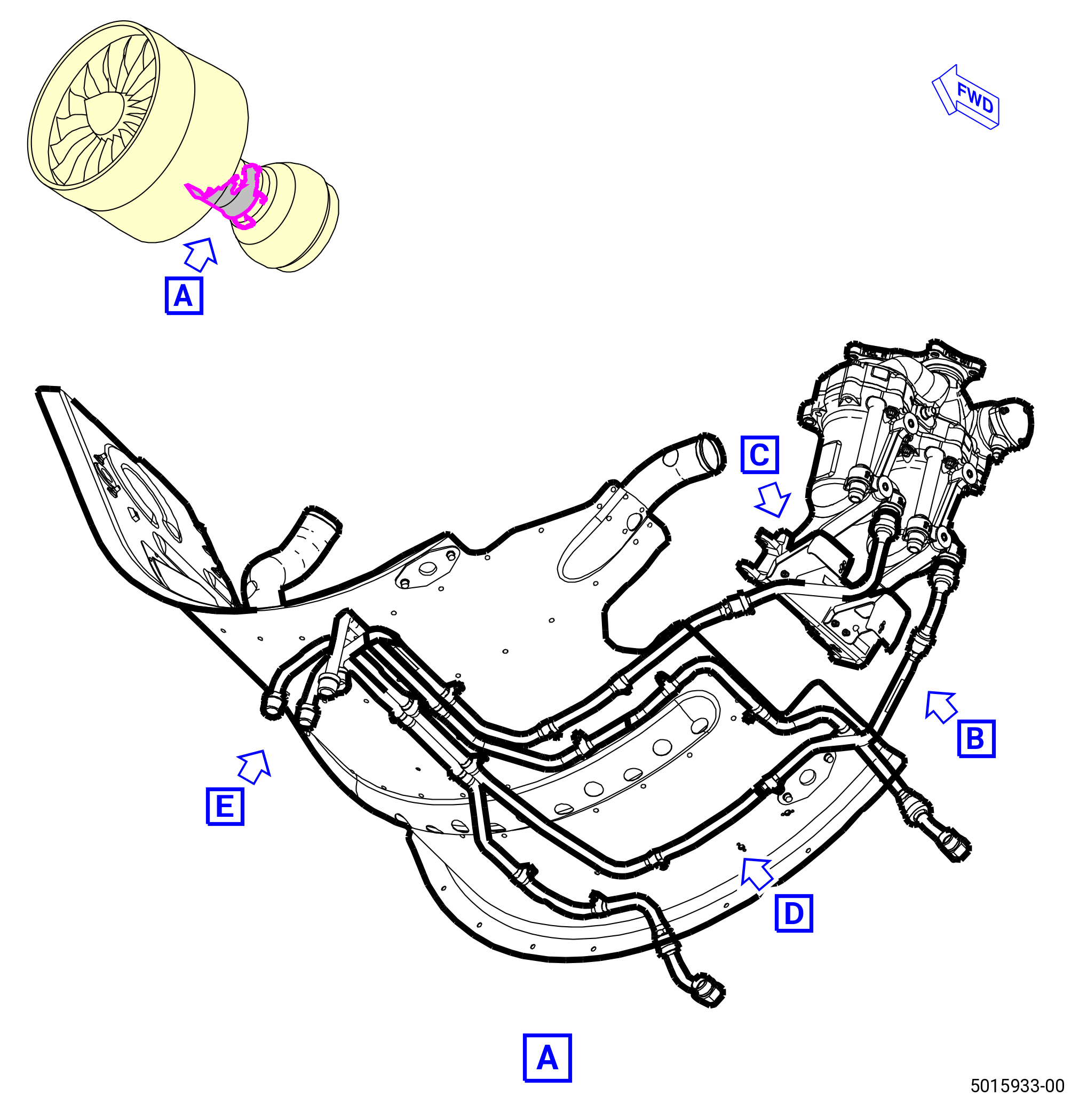
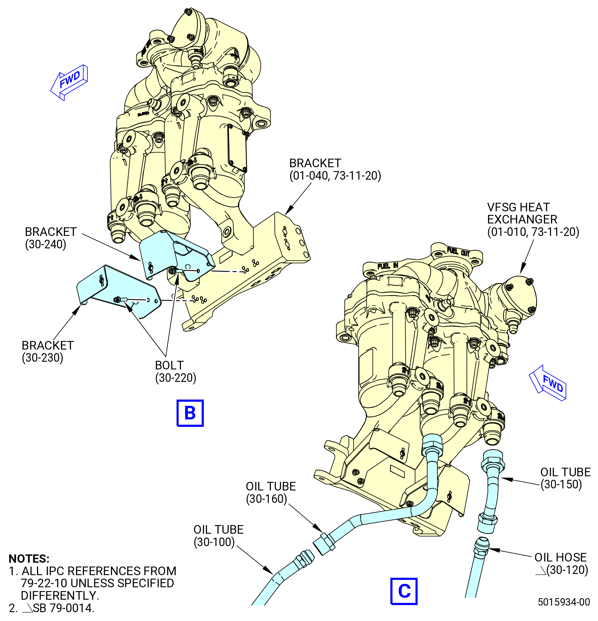
| Subtask 72-00-02-030-417 |
| * * * PRE SB 79-0014( Non-Optimized VFSG Cooling System ) |
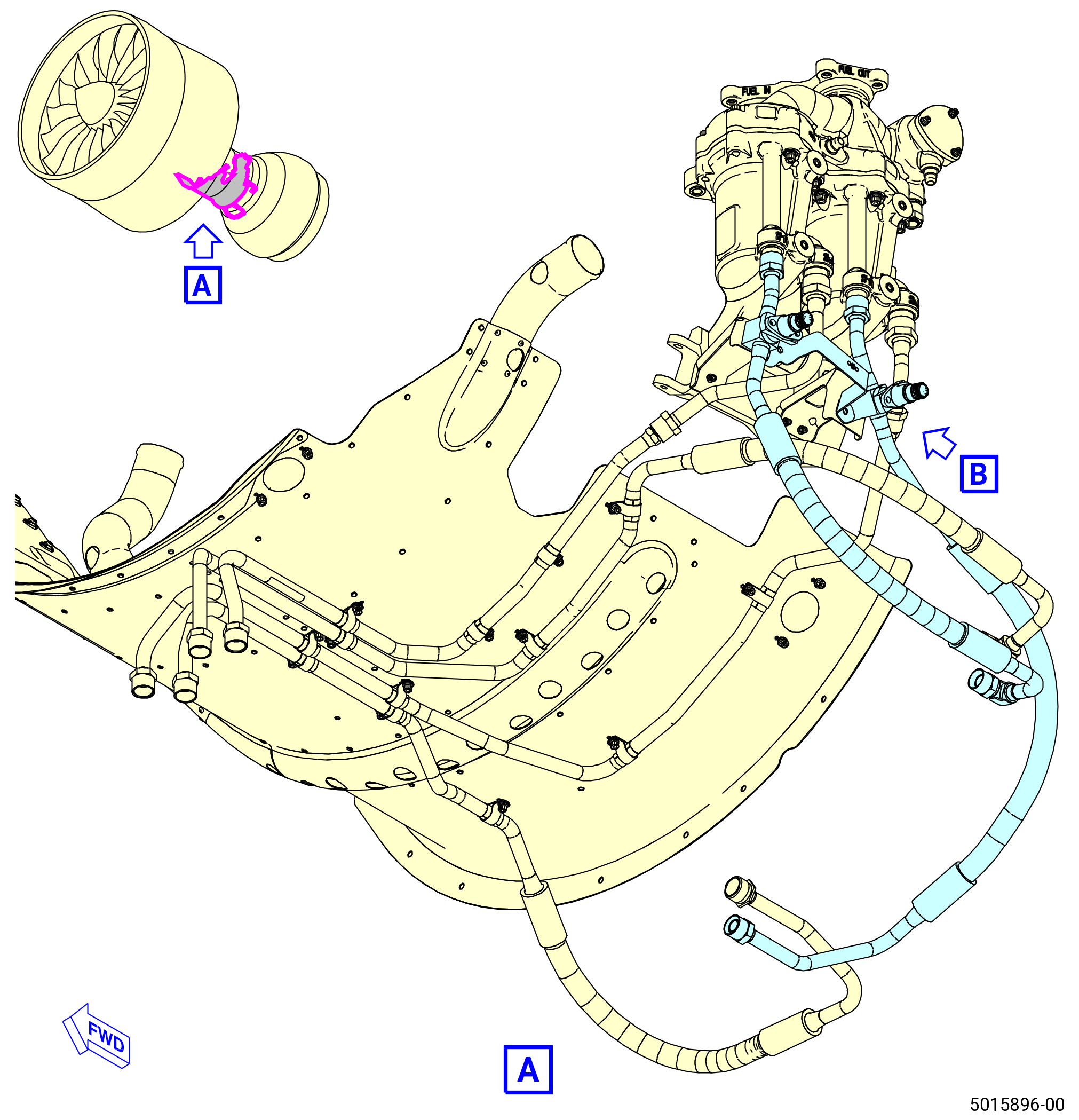
| AH. | Remove the tube/hoses and hose assemblies from the VFSG fuel to the oil heat exchanger (VFSG heat exchanger) as follows: |
| (1) | Remove the bolts and cushioned clamps that attach the VFSG cooling oil tube hose (oil hose) (5210U) to the aft skirt segment. Refer to Figure 547. |
| (2) | Remove the bolts and cushioned clamps that attach the VFSG cooling oil tube hose (oil hose) (5210L) to the aft skirt segment. |
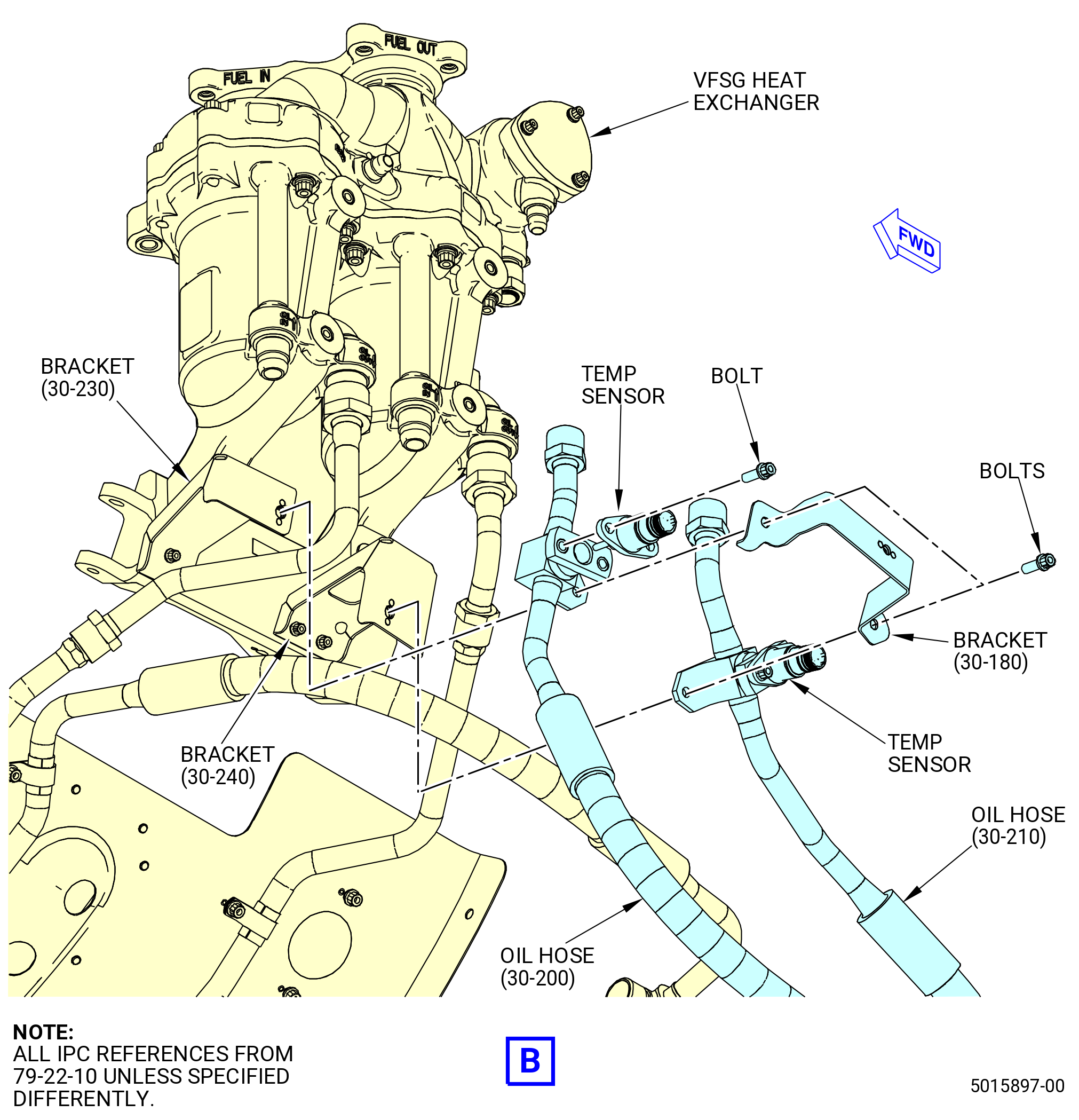
| (3) | Remove the VFSG cooling oil tube hose (oil hose) (5210A) and the oil hose (5210L) as follows. Refer to Figure 548. |
| (a) | Remove the bolts and the temp sensors from the oil hose (5210A) and oil hose (5210L). |
| (b) | Remove the bolts that attach bracket (37112) and the sensor tube tabs of oil hose (5210A) and oil hose (5210L) to the bracket (5211M) and bracket (5211N). |
| (c) | Disconnect the oil hose (5210A) from the VFSG heat exchanger. |
| (d) | Disconnect the oil hose (5210L) from the VFSG heat exchanger. |
| (4) | Remove the VFSG cooling oil tube (oil tube) (5210R) and VFSG cooling oil tube (oil tube) (5210B) as follows. Refer to Figure 549. |
| (a) | Disconnect the oil tube (5210B) from the oil tube (5210R). |
| (b) | Disconnect the oil tube (5210R) from the VFSG heat exchanger. |
| (c) | Remove the bolts and cushioned clamps that attach the oil tube (5210B) to the heat shield. |
| (5) | Remove the bolts and cushioned clamps that attach the VFSG cooling oil tube hose (oil hose) (5210J) to the heat shield. |
| (6) | Remove the bolts and cushioned clamps that attach the oil hose (5210U) to the heat shield. |
| (7) | Remove VFSG cooling oil tube hose (oil hose) (5210K) and VFSG cooling oil tube (oil tube) (5210S) as follows: |
| (a) | Disconnect the oil hose (5210K) from the oil tube (5210S). |
| (b) | Disconnect the oil tube (5210S) from the VFSG heat exchanger. |
| (c) | Remove the bolts and cushioned clamps that attach the oil hose (5210K) to the heat shield. |
| (8) | Remove the bolts that attach the bracket (30-230 , 79-22-10) (SIN 5211M) to the FCOC modification bracket (bracket) (01-040 , 73-11-20) (SIN 42412) or support bracket (01-061 , 73-11-20) (SIN 42413). |
| (9) | Remove the bolts that attach the bracket (30-240 , 79-22-10) (SIN 5211N) to the bracket (01-040 , 73-11-20) (SIN 42412) or (01-041 , 73-11-20) (SIN 42412) or (01-042 , 73-11-20) (SIN 42412). |
| * * * END PRE SB 79-0014 |
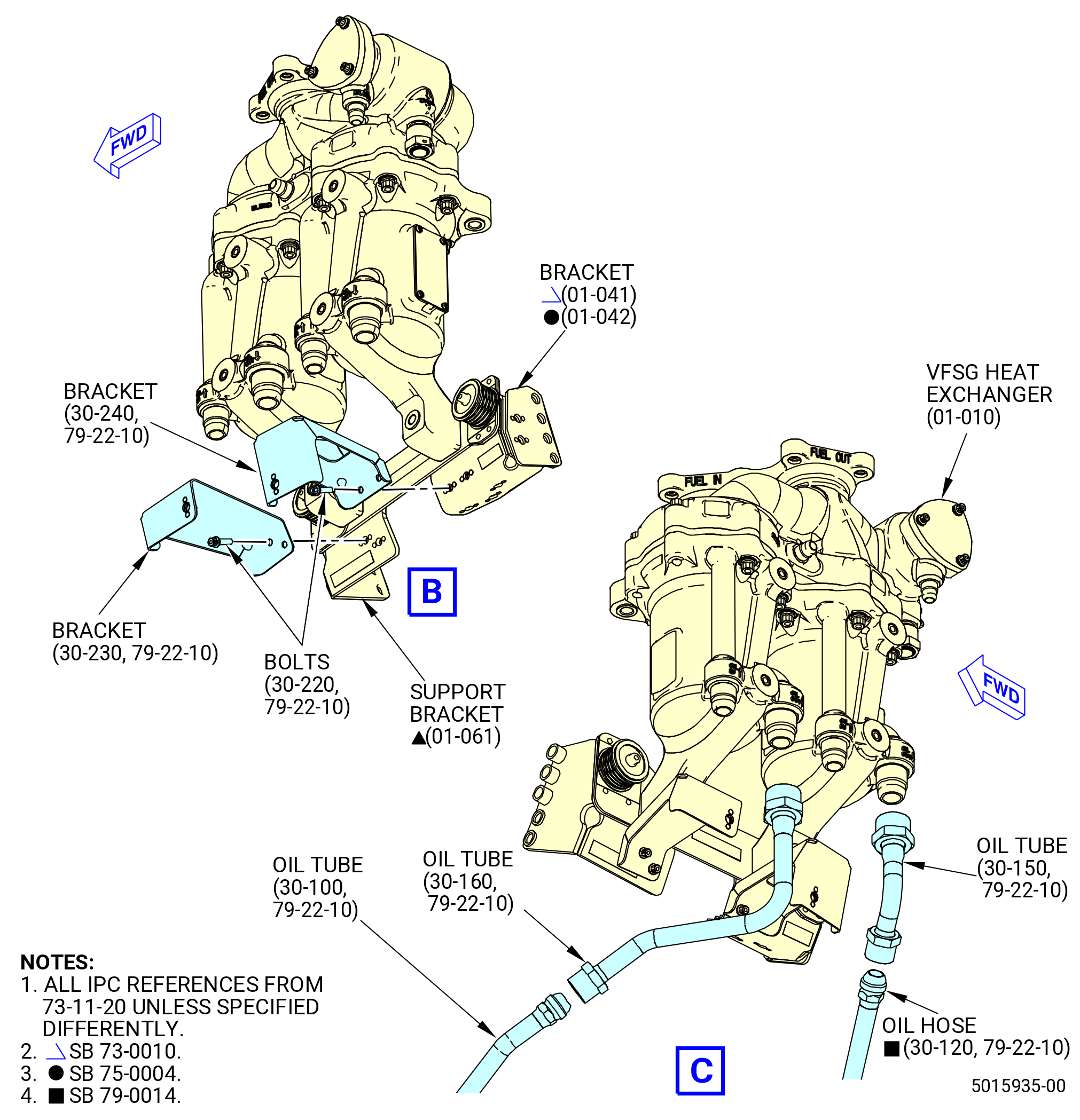
| Subtask 72-00-02-030-620 |
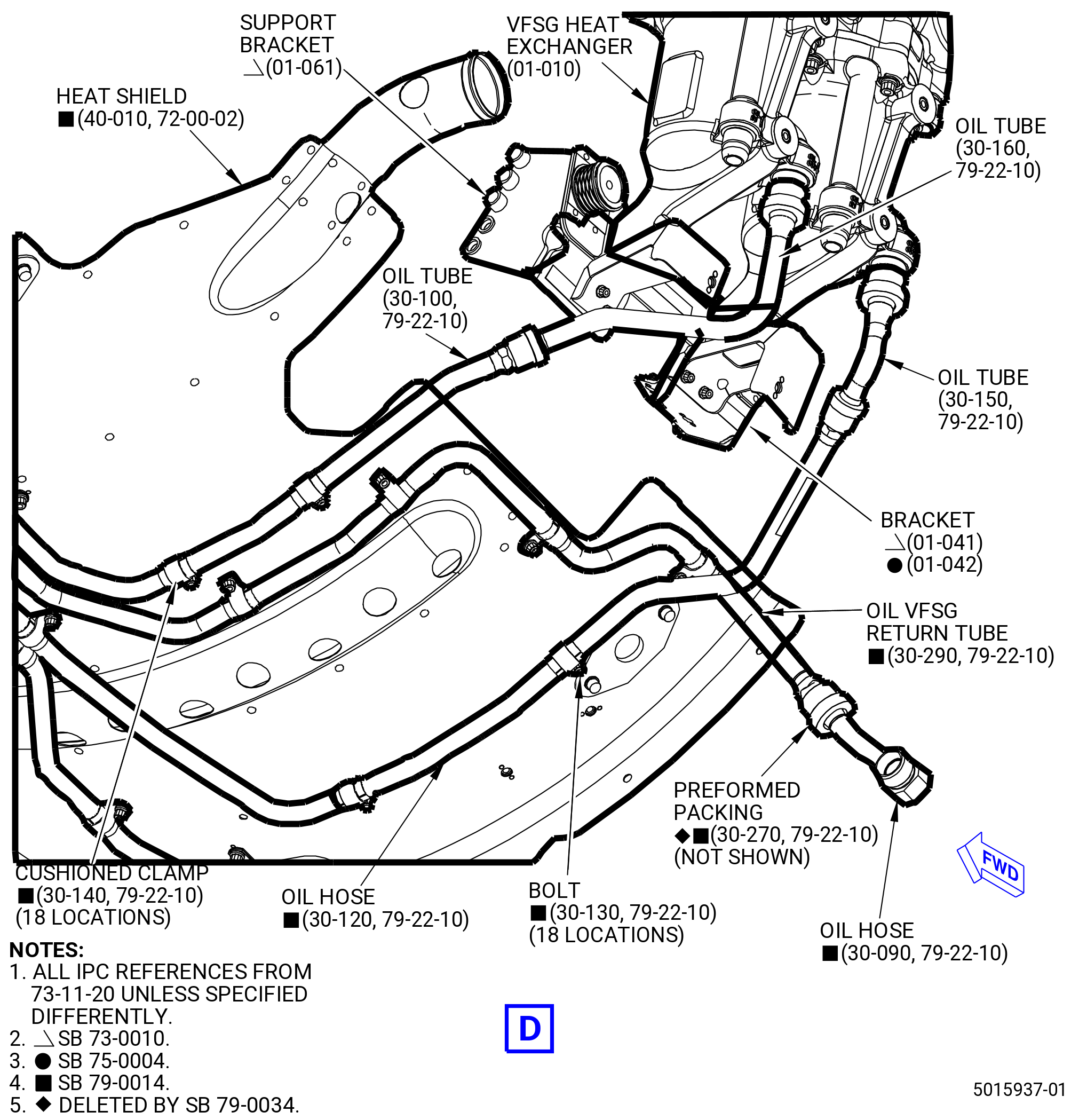
| * * * SB 79-0014( Optimized VFSG Cooling System ) |
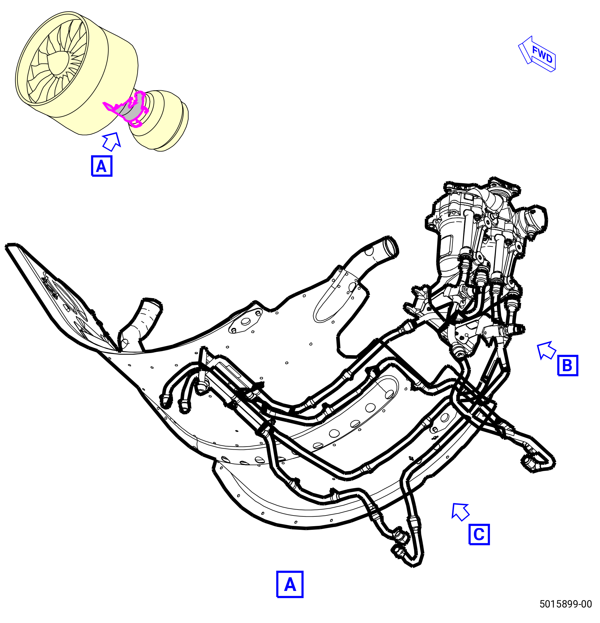
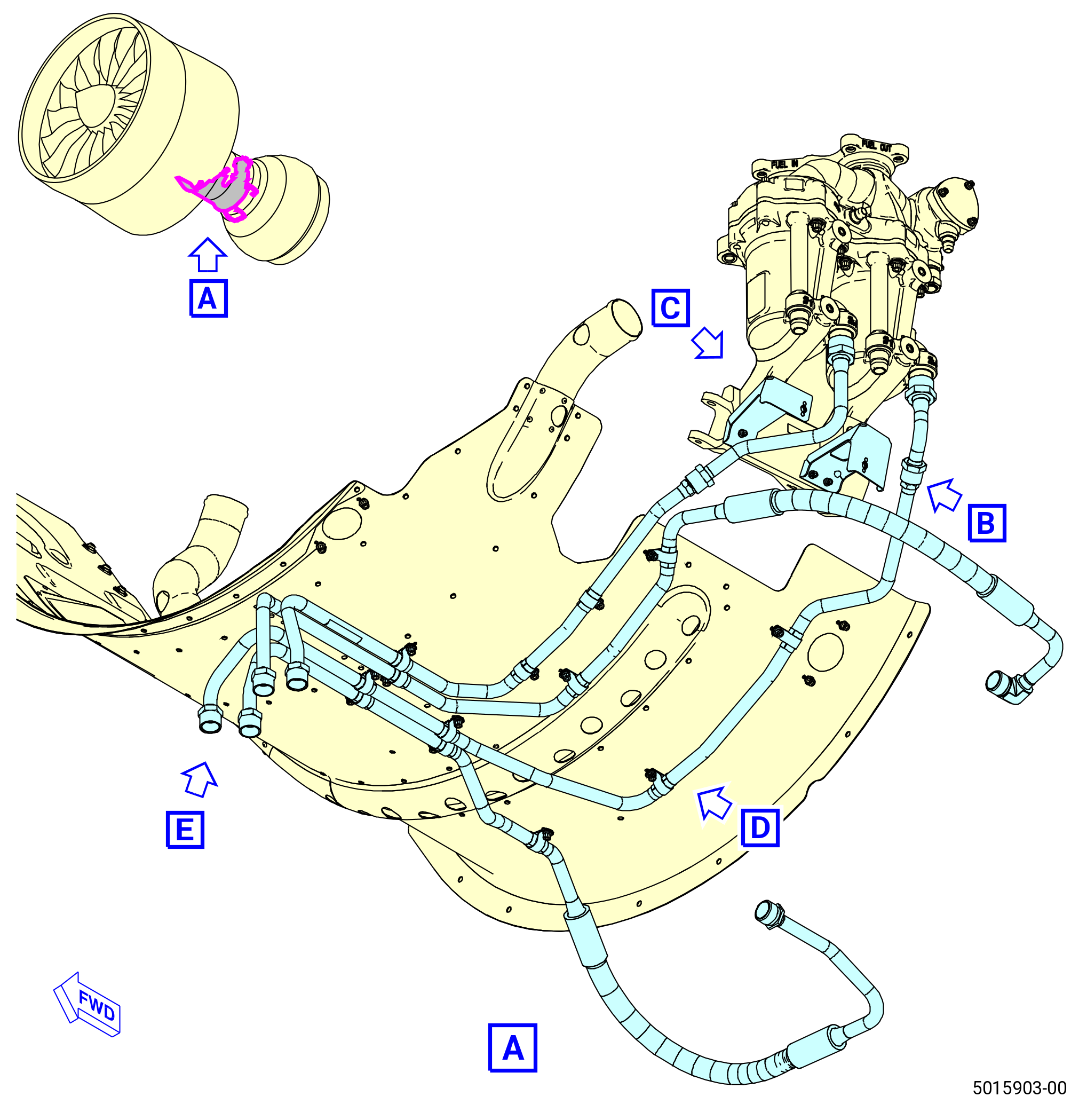
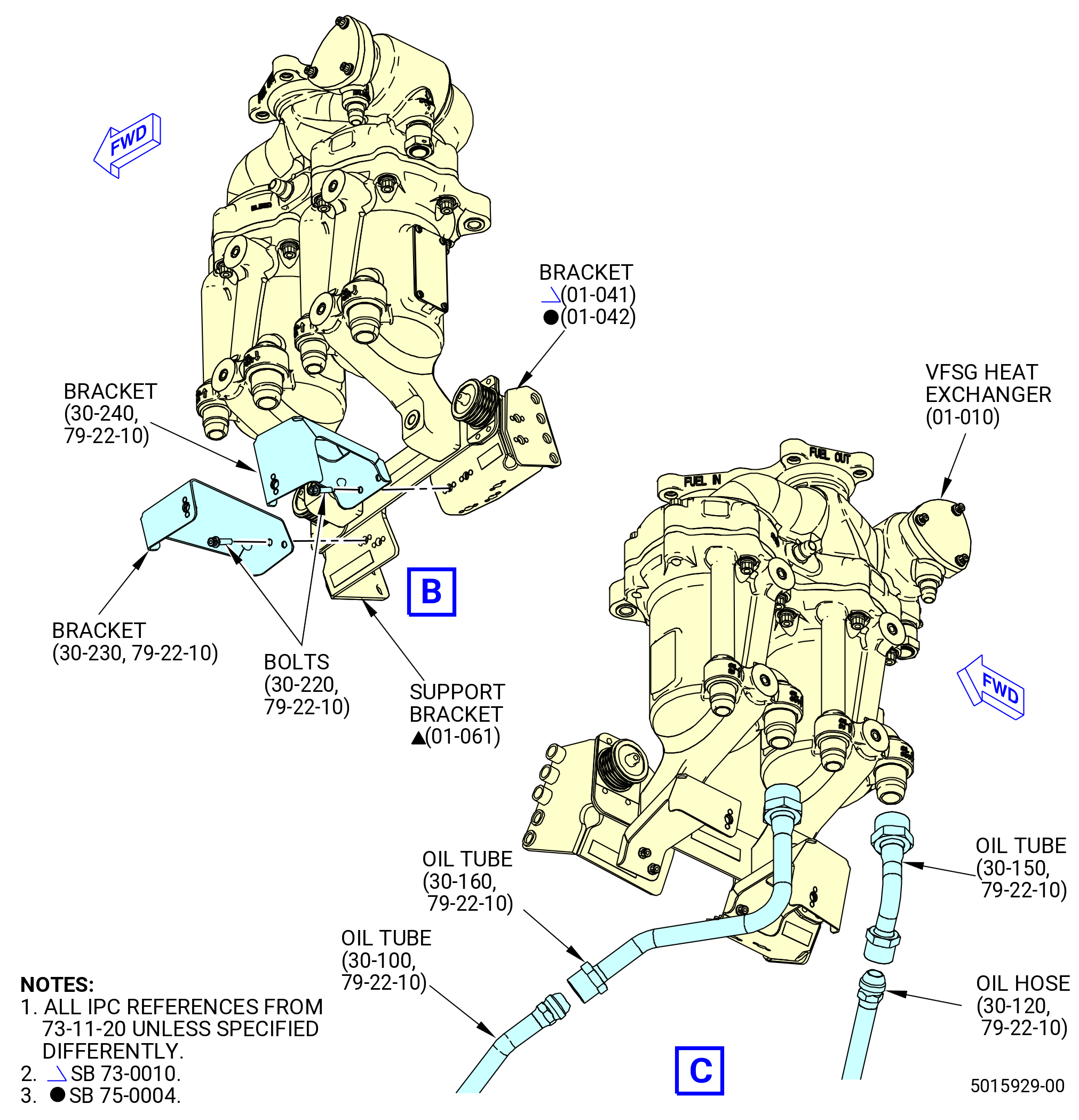
| AH.A. | Remove the tube/hoses and hose assemblies from the VFSG fuel to the VFSG heat exchanger as follows: |
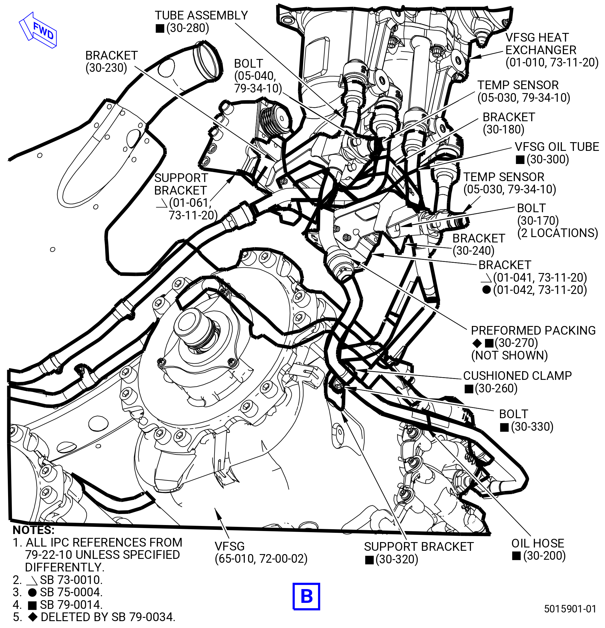
| (1) | Remove the oil hose (30-200 , 79-22-10) (SIN 5210A). Refer to Figure 548A and do as follows: |
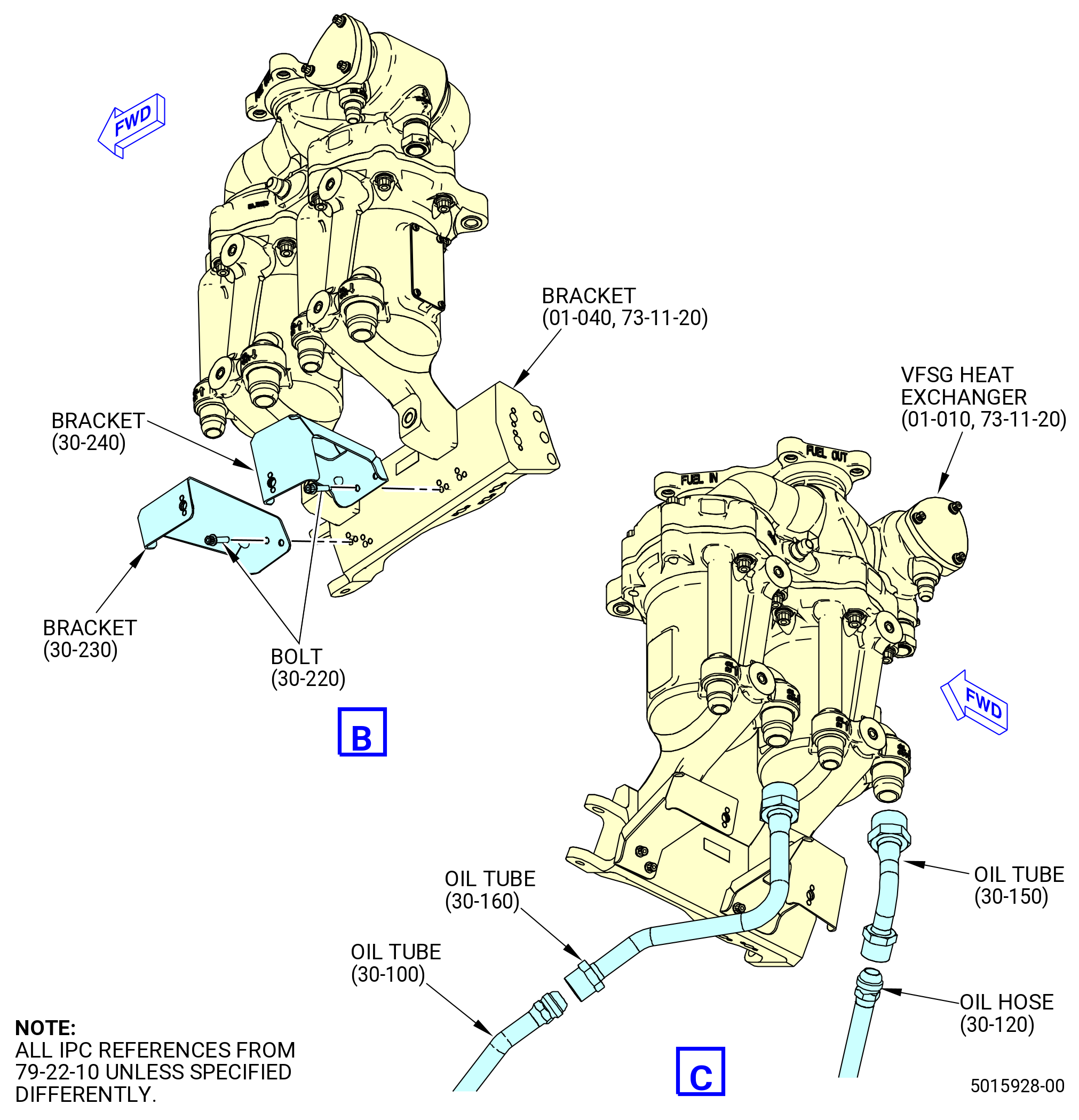
| (a) | Remove the machine bolt (bolt) (30-330 , 79-22-10) (SIN 5212A) and cushion loop clamp (30-260 , 79-22-10) (SIN 52181) from the oil hose (30-200 , 79-22-10) (SIN 5210A) and VFSG (65-010) (SIN C00A0). |
| (b) | Remove the support bracket (30-320 , 79-22-10) (SIN 52110) from the VFSG (65-010) (SIN C00A0). |
| * * * END SB 79-0014 |
| Subtask 72-00-02-030-720 |
| * * * PRE SB 79-0034( Oil VFSG Tube Hose with Preformed Packing ) |
| (c) | Disconnect the oil hose (30-200 , 79-22-10) (SIN 5210A) from the tube assembly (30-280 , 79-22-10) (SIN 5210H). Remove and discard the preformed packing (30-270 , 79-22-10) (SIN 52151). |
| * * * END PRE SB 79-0034 |
| Subtask 72-00-02-030-721 |
| * * * SB 79-0034( Oil VFSG Tube Hose without Preformed Packing ) |
| (c).A. | Disconnect the oil hose (30-200 , 79-22-10) (SIN 5210A) from the tube assembly (30-280 , 79-22-10) (SIN 5210H). |
| * * * END SB 79-0034 |
| Subtask 72-00-02-030-722 |
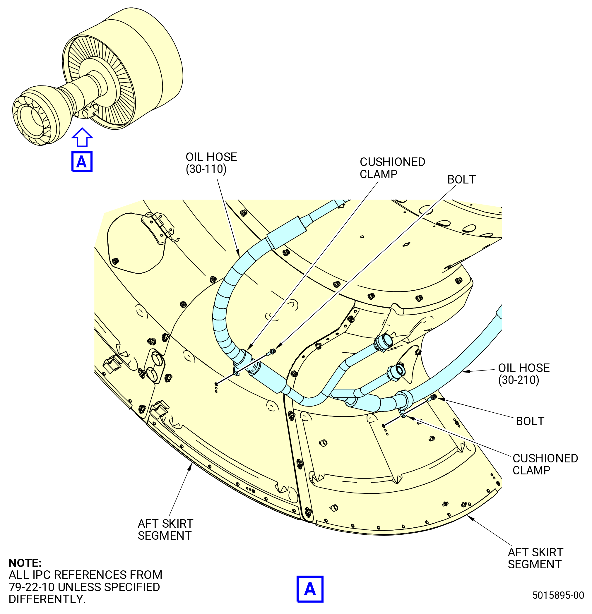
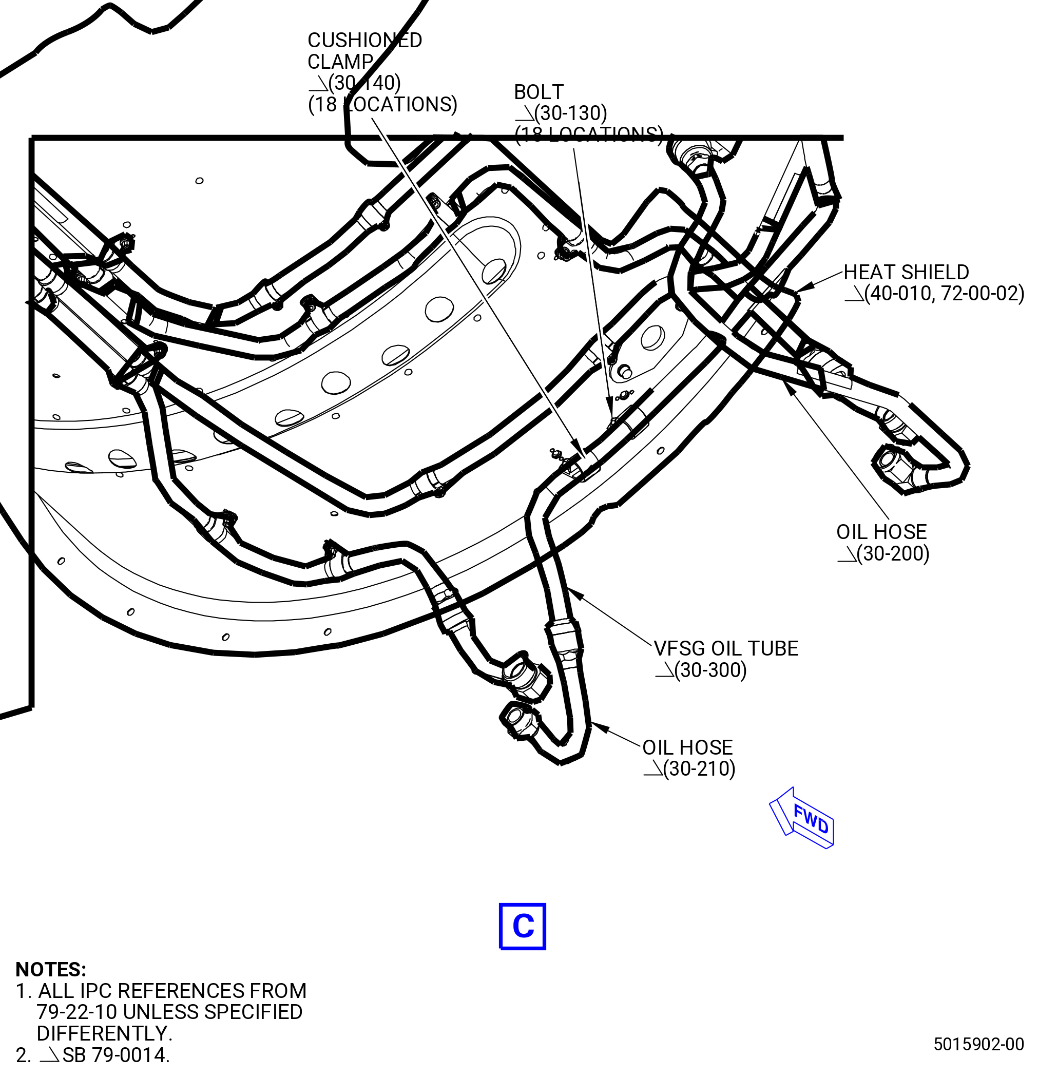
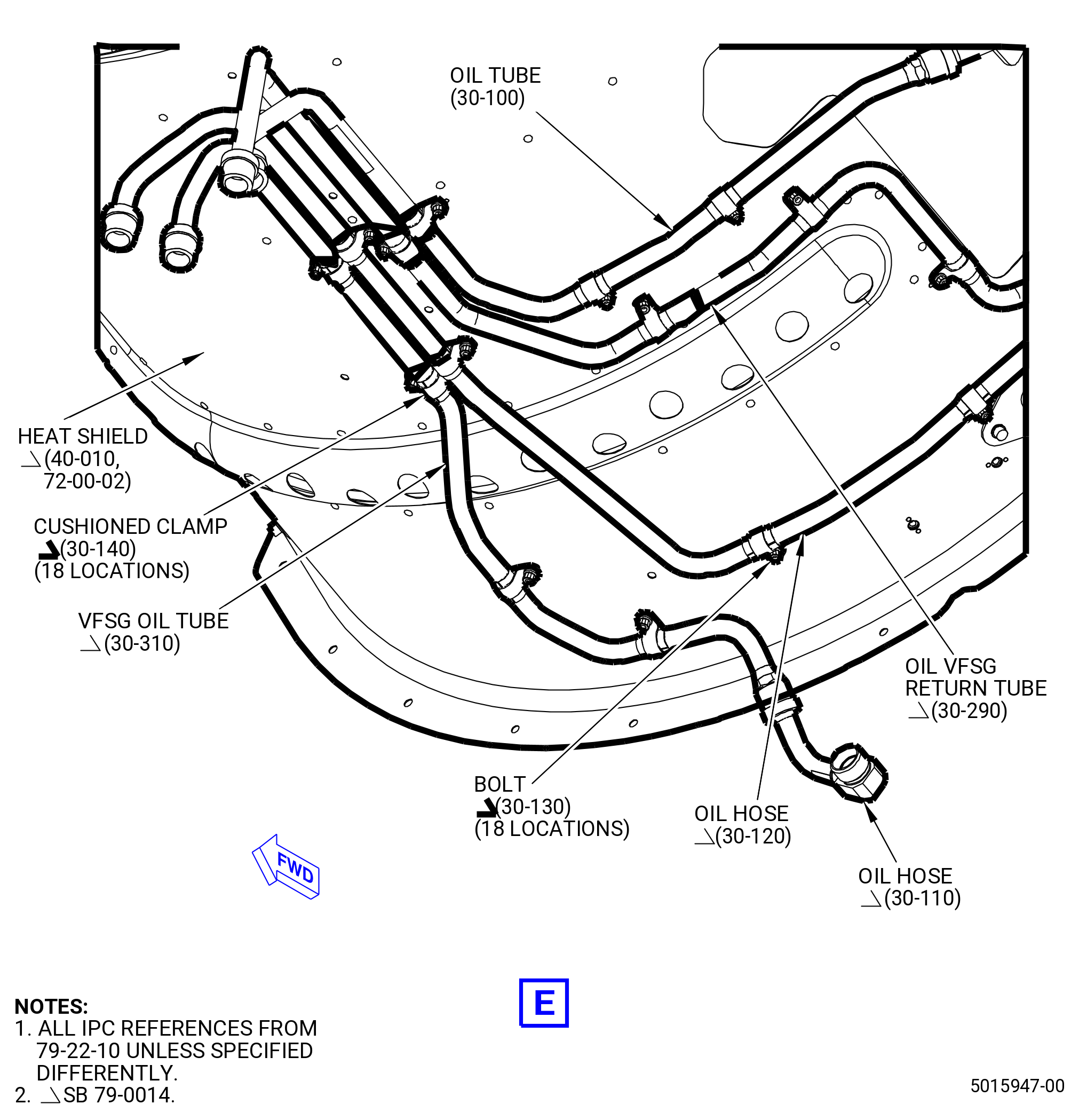
| (4) | Disconnect the oil hose (30-210 , 79-22-10) (SIN 5210L) from the VFSG oil tube (30-300 , 79-22-10) (SIN 5210W). |
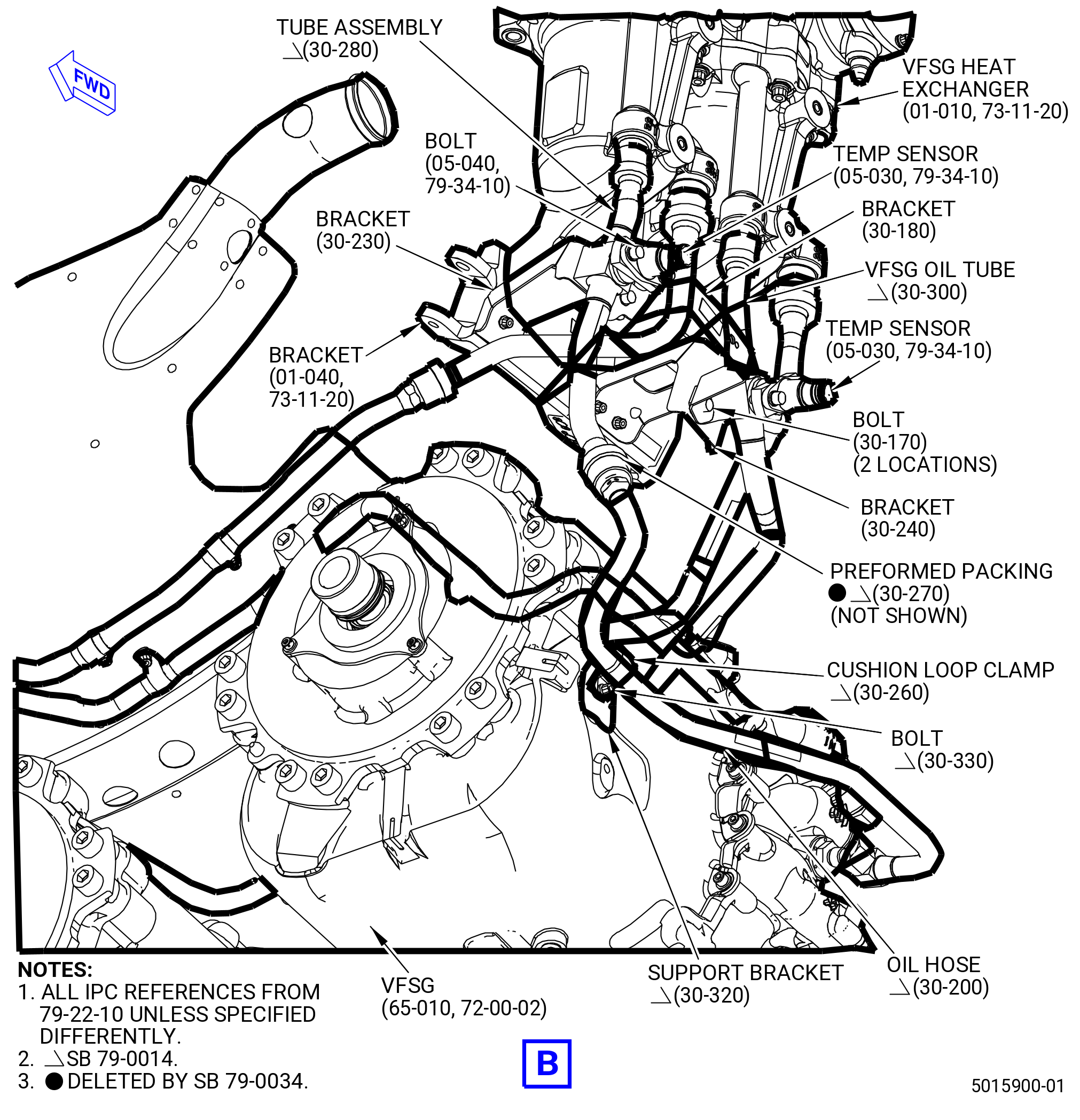
| (5) | Remove the tube assembly (30-280 , 79-22-10) (SIN 5210H) and VFSG oil tube (30-300 , 79-22-10) (SIN 5210W) as follows: |
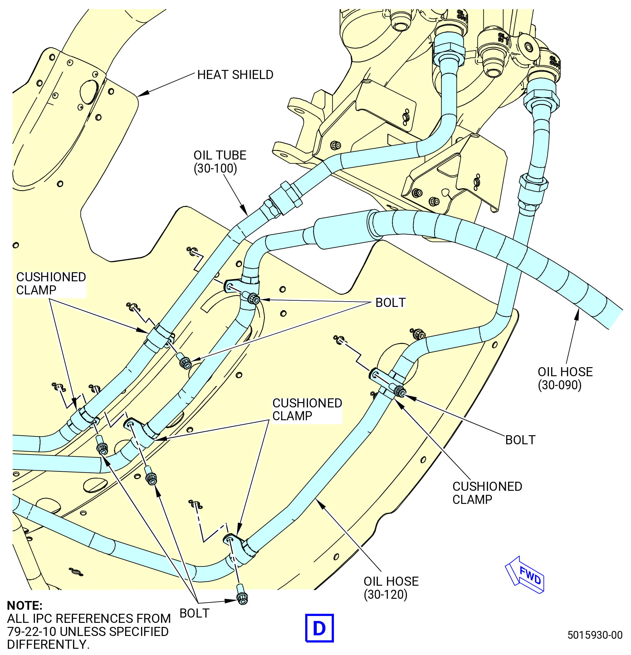
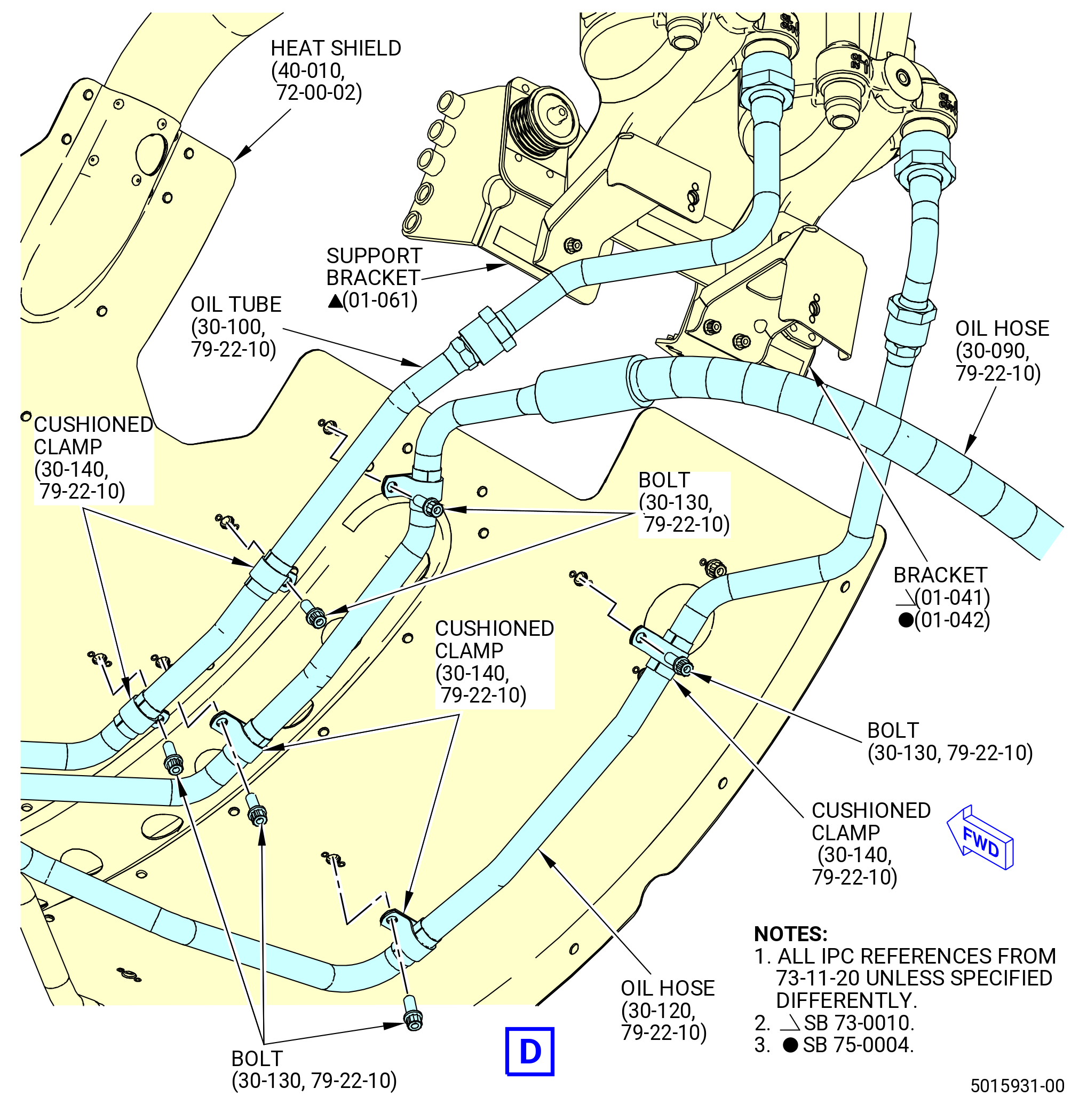
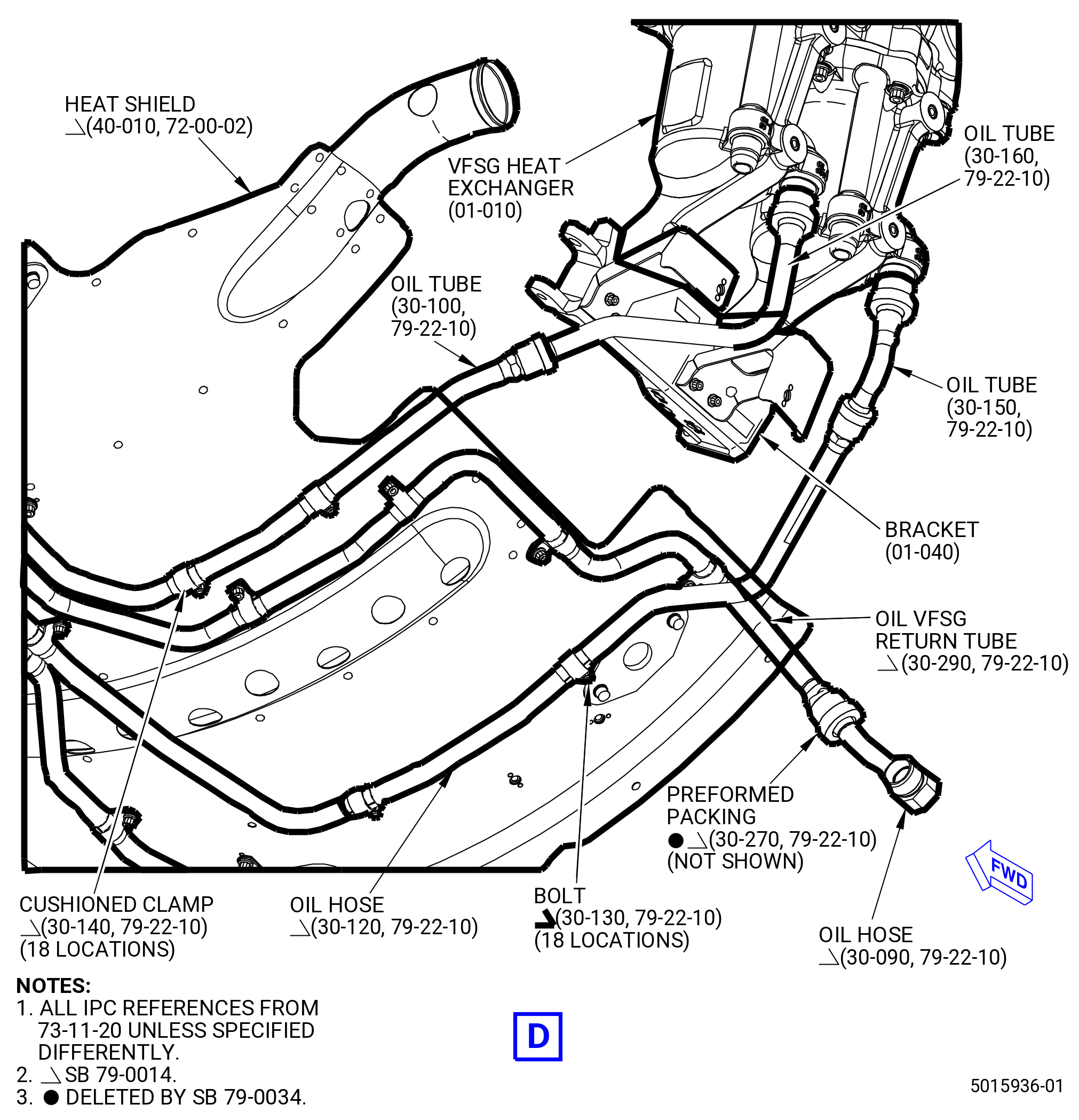
| (a) | Remove the machine bolts (bolts) (30-130 , 79-22-10) (SIN 52122) and cushioned loop clamps (cushioned clamps) (30-140 , 79-22-10) (SIN 52180) that attach the VFSG oil tube (30-300 , 79-22-10) (SIN 5210W) to the main body heat shield (heat shield) (40-010) (SIN 29900). |
| (b) | Remove the bolts (05-040 , 79-34-10) (SIN 65T23) and the fuel/oil temperature sensor (temp sensor) (05-030 , 79-34-10) (SIN 65T04) from the tube assembly (30-280 , 79-22-10) (SIN 5210H) and VFSG oil tube (30-300 , 79-22-10) (SIN 5210W). |
| (c) | Remove the machine bolts (bolts) (30-170 , 79-22-10) (SIN 52121) that attach the bracket (30-180 , 79-22-10) (SIN 37112), sensor tube tabs of the tube assembly (30-280 , 79-22-10) (SIN 5210H), and VFSG oil tube (30-300 , 79-22-10) (SIN 5210W) to the bracket (30-230 , 79-22-10) (SIN 5211M) and bracket (30-240 , 79-22-10) (SIN 5211N). |
| (d) | Disconnect the tube assembly (30-280 , 79-22-10) (SIN 5210H) and VFSG oil tube (30-300 , 79-22-10) (SIN 5210W) from the VFSG heat exchanger (01-010 , 73-11-20) (SIN 42400). |
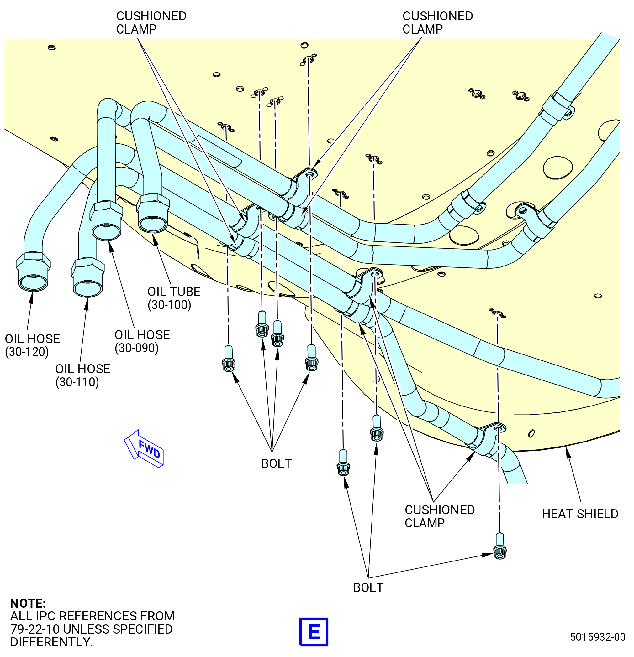
| (6) | Disconnect the oil hose (30-110 , 79-22-10) (SIN 5210U) from the VFSG oil tube (30-310 , 79-22-10) (SIN 5210Y). Refer to Figure 549A. |
| (7) | Remove the bolts (30-130 , 79-22-10) (SIN 52122) and cushioned clamps (30-140 , 79-22-10) (SIN 52180) that attach the VFSG oil tube (30-310 , 79-22-10) (SIN 5210Y) to the heat shield (40-010) (SIN 29900). |
| Subtask 72-00-02-030-725 |
| * * * PRE SB 79-0034( Oil VFSG Return Tube with Preformed Packing ) |
| (8) | Disconnect the oil hose (30-090 , 79-22-10) (SIN 5210J) from the oil VFSG return tube (30-290 , 79-22-10) (SIN 5210T). Remove and discard the preformed packing (30-270 , 79-22-10) (SIN 52151). |
| * * * END PRE SB 79-0034 |
| Subtask 72-00-02-030-726 |
| * * * SB 79-0034( Oil VFSG Return Tube without Preformed Packing ) |
| (8).A. | Disconnect the oil hose (30-090 , 79-22-10) (SIN 5210J) from the oil VFSG return tube (30-290 , 79-22-10) (SIN 5210T). |
| * * * END SB 79-0034 |
| Subtask 72-00-02-030-727 |
| (9) | Remove the bolts (30-130 , 79-22-10) (SIN 52122) and cushioned clamps (30-140 , 79-22-10) (SIN 52180) that attach the oil VFSG return tube (30-290 , 79-22-10) (SIN 5210T) to the heat shield (40-010) (SIN 29900). |
| (10) | Remove the oil tube (30-160 , 79-22-10) (SIN 5210R) and oil tube (30-100 , 79-22-10) (SIN 5210B) as follows: |
| (a) | Disconnect the oil tube (30-100 , 79-22-10) (SIN 5210B) from the oil tube (30-160 , 79-22-10) (SIN 5210R). |
| (b) | Disconnect the oil tube (30-160 , 79-22-10) (SIN 5210R) from the VFSG heat exchanger (01-010 , 73-11-20) (SIN 42400). |
| (c) | Remove the bolts (30-130 , 79-22-10) (SIN 52122) and cushioned clamps (30-140 , 79-22-10) (SIN 52180) that attach the oil tube (30-100 , 79-22-10) (SIN 5210B) to the heat shield (40-010) (SIN 29900). |
| (11) | Remove the oil hose (30-120 , 79-22-10) (SIN 5210K) and oil tube (30-150 , 79-22-10) (SIN 5210S) as follows: |
| (a) | Disconnect the oil hose (30-120 , 79-22-10) (SIN 5210K) from the oil tube (30-150 , 79-22-10) (SIN 5210S). |
| (b) | Disconnect the oil tube (30-150 , 79-22-10) (SIN 5210S) from the VFSG heat exchanger (01-010 , 73-11-20) (SIN 42400). |
| (c) | Remove the bolts (30-130 , 79-22-10) (SIN 52122) and cushioned clamps (30-140 , 79-22-10) (SIN 52180) that attach the oil hose (30-120 , 79-22-10) (SIN 5210K) to the heat shield (40-010) (SIN 29900). |
| (12) | Remove the bolts (30-220 , 79-22-10) (SIN 52128) that attach the bracket (30-230 , 79-22-10) (SIN 5211M) to the bracket (01-040 , 73-11-20) (SIN 42412) or support bracket (01-061 , 73-11-20) (SIN 42413). |
| (13) | Remove the bolts (30-220 , 79-22-10) (SIN 52128) that attach the bracket (30-240 , 79-22-10) (SIN 5211N) to the bracket (01-040 , 73-11-20) (SIN 42412) or (01-041 , 73-11-20) (SIN 42412) or (01-042 , 73-11-20) (SIN 42412). |
| Subtask 72-00-02-030-444 |
| AI. | Continue the disassembly of the propulsor. Refer to TASK 72-00-02-030-803 (72-00-02, DISASSEMBLY 003). |
|
|
|
|
|
|
|
|