| GEnx-1B SERVICE BULLETIN - 72-0444 R02 | Revised: 12/14/2023 | |
| SB 72-0444 R02 ENGINE - General (72-00-00) - Removal of the PS25 Sense Line from the Lower Bifurcation and Propulsor Assemblies | Issued: 04/02/2019 | |
| GEnx-1B SERVICE BULLETIN - 72-0444 R02 | Revised: 12/14/2023 | |
| SB 72-0444 R02 ENGINE - General (72-00-00) - Removal of the PS25 Sense Line from the Lower Bifurcation and Propulsor Assemblies | Issued: 04/02/2019 | |
| GE Designated: -CONFIDENTIAL- | |
| The information contained in this document is GE proprietary information and is disclosed in confidence. It is the property of GE and shall not be used, disclosed to others or reproduced without the express written consent of GE, including, but without limitation, it is not to be used in the creation, manufacture, development, or derivation of any repairs, modifications, spare parts, designs, or configuration changes or to obtain FAA or any other government or regulatory approval to do so. If consent is given for reproduction in whole or in part, this notice and the notice set forth on each page of this document shall appear in any such reproduction in whole or part. | |
| This technical data is considered subject to the Export Administration Regulations (EAR) pursuant to 15 CFR Parts 730-774. Transfer of this data by any means to a Non-U.S. Person, whether in the United States or abroad, without the proper U.S. Government authorization (e.g., License, exemption, NLR, etc.), is strictly prohibited. | |
| Copyright (2023) General Electric Company, U.S.A. |
| TRANSMITTAL INFORMATION |
| REVISION 2 TO SERVICE BULLETIN 72-0444 |
| Revision 2 is issued to update paragraphs 1., PLANNING INFORMATION, 2., MATERIAL INFORMATION, and 3., ACCOMPLISHMENT INSTRUCTIONS. |
| Revision 1 was issued July 31, 2019. The original was issued April 02, 2019. Revision bars in the left margin identify changes. |
| 1. | PLANNING INFORMATION |
| A. | Effectivity |
| * * * FOR GEnx-1B64, -1B64/P1, -1B64/P2, -1B67, -1B67/P1, -1B67/P2, -1B70, -1B70/75/P1, -1B70/75/P2, -1B70/P1, -1B70/P2, -1B70C/P1, -1B70C/P2, -1B74/75/P1, -1B74/75/P2, -1B76/P2, -1B76A/P2 |
| This Service Bulletin has been introduced in production to these GEnx-1B engines: |
| • |
|
| These serial numbers are the best available data. |
| The parts listed in Table 1 are affected by this Service Bulletin. |
|
| B. | Description |
| This Service Bulletin eliminates the affected PS25 air tube and attaching loop clamps from the propulsor assembly and lower bifurcation module. |
| This Service Bulletin also introduces the new parts listed in Table 2. |
|
| C. | Compliance |
| Category 7 |
| GE recommends that you do this Service Bulletin at customer's convenience. |
| Impact E |
| This recommendation is to improve the cost of ownership, reduce maintenance requirements or is a product improvement. |
| NOTE: |
|
| D. | Concurrent Requirements |
| None. |
| E. | Reason |
| (1) | Objective: |
| To remove parts from service. |
| (2) | Condition: |
| The implementation of this change will simplify the assembly of the engine by eliminating manifold complexity and torquing operations, along with a weight reduction. |
| (3) | Cause: |
| This change is made to remove from service hardware that is no longer required for engine functionality, eliminating unnecessary assembly operations. |
| (4) | Improvement: |
| The new design reduces assembly time of the GEnx-1B engines, reduces scrap on lower bifurcation box, and reduces weight of the engine. |
| (5) | Substantiation: |
| Substantiation is by analysis and comparative analysis. |
| F. | Approval |
| The data contained in this Service Bulletin has been reviewed by the FAA or authorized entity representing the FAA and the repair(s) and modification(s) herein comply with the applicable Aviation Regulations and are APPROVED for installation in the model(s) listed in this Service Bulletin. |
| G. | Manpower |
| No additional man-hours are required to comply with this Service Bulletin. |
| H. | Weight and Balance |
| The complete compliance with this Service Bulletin decreases weight by 0.20 lb (0.09 kg). |
| I. | References (Use the latest version of these documents) |
| GEnx-1B, Boeing 787 Aircraft Maintenance Manual (AMM) |
| GEK 9250, Commercial Engine Standard Practices Manual (SPM) |
| GEK 112851, GEnx-1B Engine Manual (EM) |
| GEK 112862, GEnx-1B Cleaning, Inspection, and Repair Manual (CIR) |
| GEK 112864, GEnx-1B Engine Illustrated Parts Catalog (EIPC) |
| GEnx-1B S/B 72-0223, ENGINE - Fan Stator Module, Lower Bifurcation, and Related Parts (72-00-00) - Replacement of the Support Strap with Rigid Support Bracket |
| GEnx-1B S/B 72-0322, ENGINE - Fan Stator Module, Lower Bifurcation, and Related Parts (72-00-00) - Lower Bifurcation Insulation Blanket Redesign |
| GEnx-1B S/B 72-0386, ENGINE - General (72-00-00) - Spare Parts Release for GEnx-1B Engines |
| GEnx-1B S/B 75-0035, AIR - PS25 Pressure Sense Tubes (75-42-15) - Removal of the PS25 Sense Tube and P25 Hose Tube from the Fan Case Module Assembly |
| NOTE: |
|
| J. | Publications Affected |
| GEnx-1B, Boeing 787 Aircraft Maintenance Manual (AMM) |
| GEK 112851, GEnx-1B Engine Manual (EM) |
| GEK 112862, GEnx-1B Cleaning, Inspection, and Repair Manual (CIR) |
| GEK 112864, GEnx-1B Engine Illustrated Parts Catalog (EIPC) |
| K. | Interchangeability |
| Qualified interchangeability. |
| Field configuration 1: This configuration has the same changes as production. The PS25 air tube is removed and the lower bifurcation firewall is replaced with the new lower bifurcation firewall P/N 2782M43G01 . You must also do GEnx-1B S/B 75-0035. |
| Field configuration 2: This configuration has the same changes as production. However, the exception is that the PS25 air tube is not removed and the lower bifurcation firewall is replaced with the new lower bifurcation firewall P/N 2782M44G01. The new lower bifurcation firewall P/N 2782M44G01 is a rework from the lower bifurcation firewall P/N 2782M43G01. Refer to paragraph 3.E., Rework. You must also do GEnx-1B S/B 75-0035. |
| Field configuration 3: This configuration has the same changes as production. The PS25 air tube is removed, the old lower bifurcation firewall remains, and a new lower bifi cover plate P/N 2775M49G01 is installed in the PS25 hole located in the lower bifurcation firewall. You must also do GEnx-1B S/B 75-0035. |
| It is permitted to intermix a propulsor module assembly P/N 2447M20 post-GEnx-1B 72-0444 (PS25 sense line removed) with a lower bifurcation assembly P/N 2305M80G02, P/N 2305M80G03 , or P/N 2305M80G05 with the PS25 sense line installed. |
| It is not permitted to intermix the lower bifurcation assembly P/N 2305M80G06 with any propulsor module assembly P/N 2447M20 pre-GEnx-1B 72-0444. |
| L. | Software Accomplishment Summary |
| Not applicable. |
| 2. | MATERIAL INFORMATION |
| A. | Material - Price and Availability |
| (1) | Parts necessary to do this Service Bulletin: |
|
| *Lower bifi cover plate is required only for field configuration 3. |
| NOTE: |
|
| (2) | Other Spare Parts: |
| None. |
| (3) | Consumables: |
|
| B. | Industry Support Information |
| None. |
| C. | Configuration Chart |
|
|||||||||||||||||||||||||||||||||||||||||||||||||||||||||||||||||||||||||||||||||||||||||||||||||||||||||||||||||||||||||||||||||||||||||||||||||||||||||||||||||||||||||||||||||||||||||||||||||||||||||||||||||||||||||||||||||||||||||||||||||||||||||||||||||||||||||||||||||||||||||||||||||||||||||||||||||||||||||||||||||||||||||||||||||||||||||||||||||||||||||||||||||||||||||||||||||||||||||||||||||||||||||||||||||||||||||||||||||||||||||||||||||||||||||||||||||||||||||||||||||||||||||||||||||||||||||||||||||||||||||||||||||||||||||||||||||||||||||||||||||||||||||||||||||||||||||||||||||||||||||||||||||||||||||||||||||||||||||||||||||||||||||||||||||||||||||||||||||||||||||||||||||||||||||||||||||||||||||||||||||||||||||||||||||||||||||||||||||||||||||||||||||||||||||||||||||||||||||||||||||||||||||||||||||||||||||||||||||||||||||||||||||||||||||||||||||||||||||||||||||||||||||||||||||||||||||||||||||||||||||||||||||||||||||||||||||||||||||||||||||||||||||||||||||||||||||||||||||||||||
| Operation Codes AD=Add DE=Delete QTC=Quantity Change RE=Replace RM=Remains |
| Change Codes 5=Qualified interchangeability. Refer to paragraph 1.K., Interchangeability. |
| Support Codes B=Old parts will be supplied until all old parts are sold. E=Old parts will be supplied, and can be used at other engine locations. |
| D. | Parts Disposition |
| Use serviceable old parts for engines that have not changed. |
| Discard old parts. |
| E. | Tooling - Price and Availability |
| None. |
| 3. | ACCOMPLISHMENT INSTRUCTIONS |
| A. | General |
| (1) | If the engine is on wing, refer to paragraphs 3.B., On-Wing Preparation, 3.C., On-Wing Removal, 3.E., Rework, 3.G., On-Wing Installation, and 3.H., Aircraft Return to Service. |
| (2) | If the engine is in shop, refer to paragraphs 3.D., In-Shop Removal, 3.E., Rework, and 3.F., In-Shop Installation. |
| B. | On-Wing Preparation |
| (1) | Do the steps below to make sure that the ENGINE START switch and the FUEL CONTROL switch are not operated: |
| (a) | On the pilot's overhead panel, P5, make sure that the applicable ENGINE START switch is in the NORM position. |
| (b) | Put a DO-NOT-OPERATE tag on the applicable ENGINE START switch. |
| (c) | On the pilot's aisle control stand, P10, make sure that the applicable FUEL CONTROL switch is in the CUT-OFF position. |
| (d) | Put a DO-NOT-OPERATE tag on the applicable FUEL CONTROL switch. |
| (2) | Make sure that the electronic engine control (EEC) maintenance (MAINT) switch is in the NORM position. Refer to the GEnx-1B, Boeing 787 AMM, G73-21-05, Software Operation, DMC-B787-A-G73-21-05-01A-110B-A. |
| (3) | Do the tasks below in sequence to safely open the left and right thrust reversers on the applicable engine: |
| (a) | Leading edge slat retraction. Refer to the GEnx-1B, Boeing 787 AMM, 27-81-00, Leading Edge Slat Retraction (Task Selection) - Operation, DMC-B787-A-27-81-00-27B-110A-A. |
| (b) | Leading edge slat system deactivation. Refer to the GEnx-1B, Boeing 787 AMM, 27-81-00, Leading Edge Slat System - Deactivation, DMC-B787-A-27-81-00-24A-510B-A. |
| (c) | Thrust reverser deactivation. Refer to the GEnx-1B, Boeing 787 AMM, G78-31-00, Thrust Reverser (For Ground Maintenance) - Deactivation, DMC-B787-A-G78-31-00-15H-510B-A. |
| (d) | For the applicable engine, open the left and right fan cowls. Refer to the GEnx-1B, Boeing 787 AMM, G71-11-04, Fan Cowl (Task Selection) - Open For Access, DMC-B787-A-G71-11-04-00B-540A-A and do as follows: |
| • |
|
| • |
|
| • |
|
| • |
|
| (e) | For the applicable engine, open the left and right thrust reversers. Refer to the GEnx-1B, Boeing 787 AMM, G78-31-00, Thrust Reverser (Task Selection) - Open For Access, DMC-B787-A-G78-31-00-15B-540A-A and do as follows: |
| • |
|
| • |
|
| • |
|
| • |
|
| (f) | Install protective covers P/N SPL-13475 on the left and right variable frequency starter generator (VFSG) air/oil heat exchangers. |
| (g) | Install protective covers P/N SPL-13475 on the left and right air cooled oil coolers (ACOCs). |
| C. | On-Wing Removal |
| (1) | Refer to the GEnx-1B, Boeing 787 AMM, G73-22-01, Engine Control Electrical Harness - Removal, DMC-B787-A-G73-22-01-00A-520A-A and do as follows: |
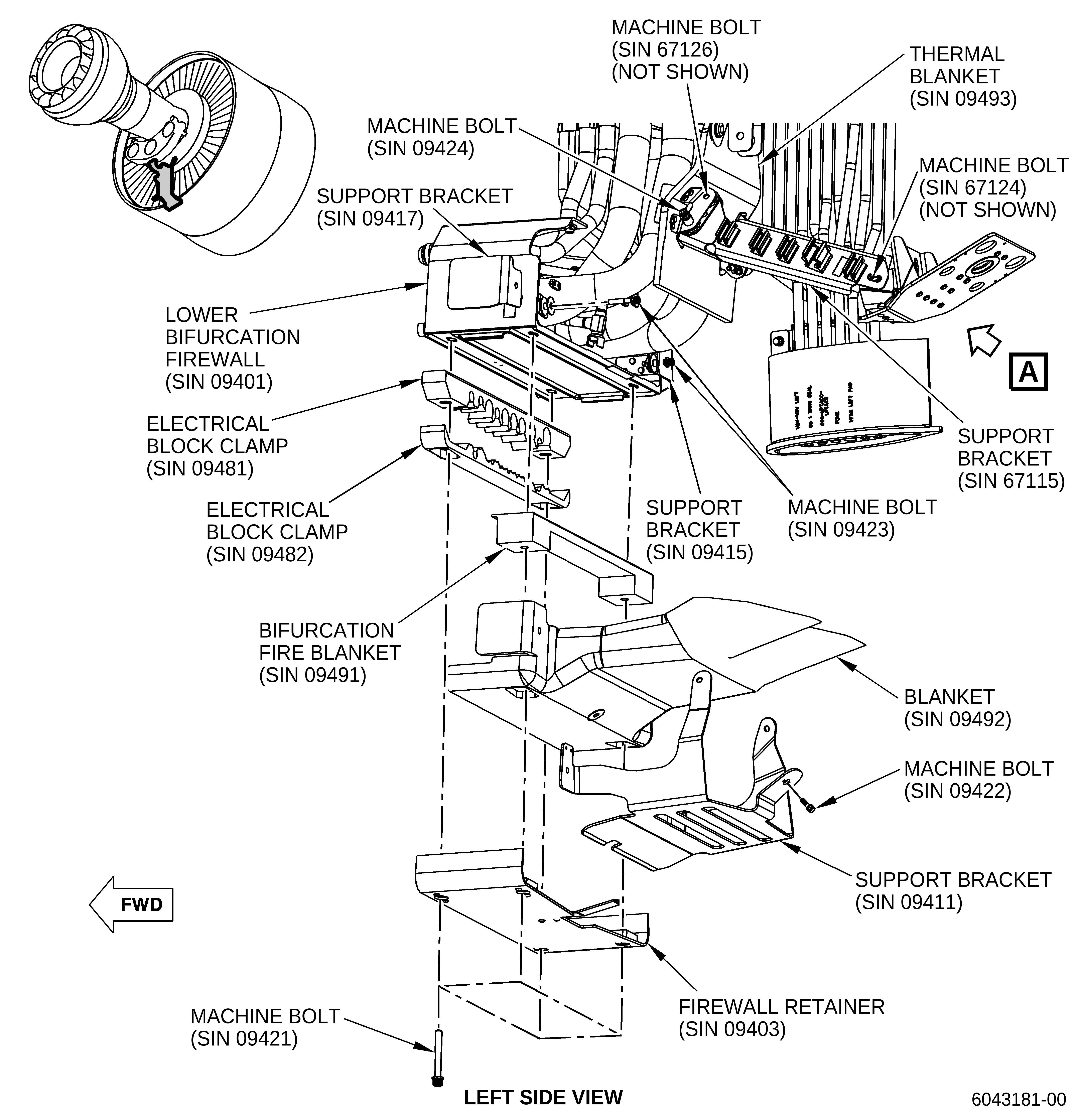
| (a) | Remove the W05, W06, W07, W08, W09, W10, W12, W13, and W17 electrical harnesses from the lower bifurcation firewall (SIN 09401). Refer to Figure 2. |
| (b) | Remove the blanket (SIN 09492) and the support brackets (SIN 09411, SIN 09415, and SIN 09417). Refer to Figure 2 and do as follows: |
| 1 | For pre-GEnx-1B S/B 72-0223 and post-GEnx-1B
S/B 72-0223 engines, refer to GEnx-1B S/B 72-0322,
paragraph 3.A., Removal . |
| 2 | For post-GEnx-1B S/B 72-0322 engines, refer to Figure 2 and do as follows: |
| a | Remove the machine bolts (SIN 09422 and SIN 09423) that attach the support brackets (SIN 09411, SIN 09415, and SIN 09417) to the blanket (SIN 09492) and to the lower bifurcation firewall (SIN 09401). Remove the support brackets (SIN 09415 and SIN 09417). |
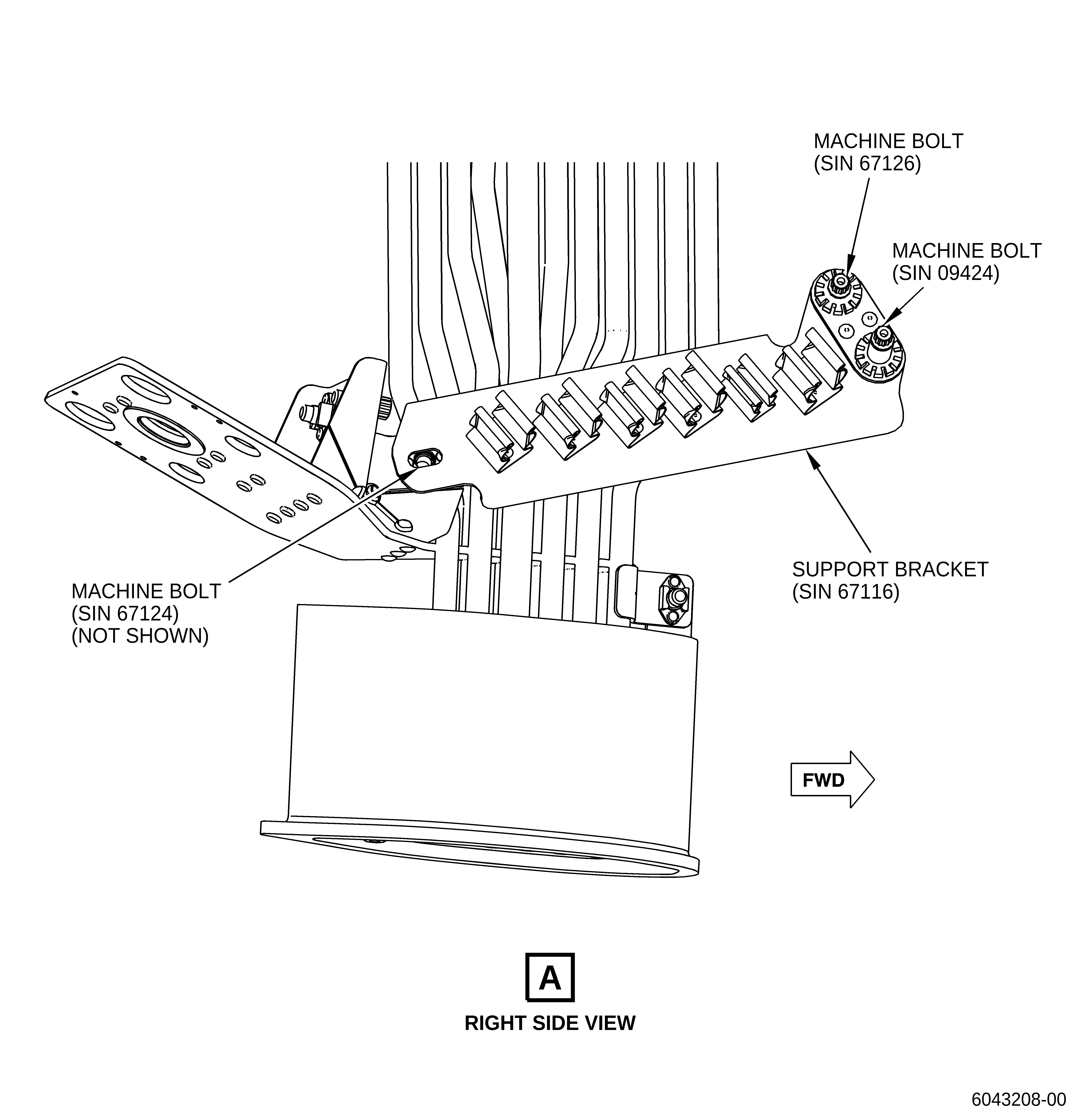
| b | Remove the machine bolts (SIN 09424) that attach the support bracket (SIN 09411) and the thermal blanket (SIN 09493) to the support brackets (SIN 67115 and SIN 67116). Remove the support bracket (SIN 09411). |
| c | Remove the machine bolts (SIN 67126) that attach the thermal blanket (SIN 09493) to the support brackets (SIN 67115 and SIN 67116). |
| d | Remove the machine bolts (SIN 67124) that attach the support brackets (SIN 67115 and SIN 67116) to the lower bifurcation assembly (SIN 09400). Remove the support brackets (SIN 67115 and SIN 67116). |
| e | Remove the machine bolts (SIN 09421) that attach the firewall retainer (SIN 09403) to the lower bifurcation firewall (SIN 09401) through the electrical block clamps (SIN 09481 and SIN 09482), bifurcation fire blanket (SIN 09491), and blanket (SIN 09492). |
| f | Remove the firewall retainer (SIN 09403), electrical block clamps (SIN 09481 and SIN 09482), and bifurcation fire blanket (SIN 09491). |
| g | Remove the blanket (SIN 09492). |
| (2) | Refer to the GEnx-1B, Boeing 787 AMM, G71-00-05, Fan Stator Module to Engine - Removal, DMC-B787-A-G71-00-05-00A-520A-A for preparation of the engine and remove the lower bifurcation assembly (SIN 09400), lower bifurcation firewall (SIN 09401, Figure 2) and lower air and VFSG oil manifold (SIN 99002). |
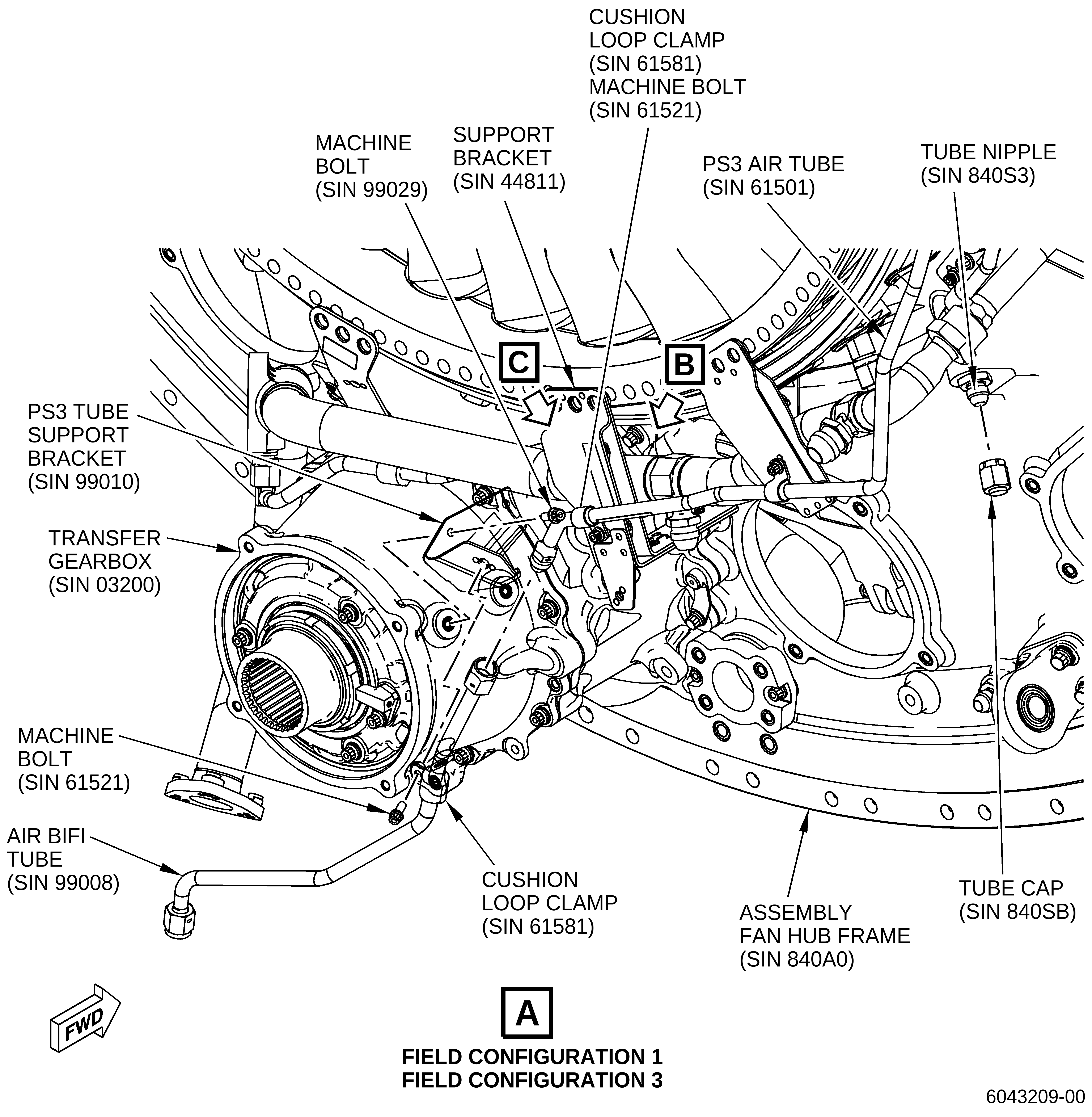
| (3) | Remove the air bifi manifold (SIN 99008), bifi manifold support bracket (SIN 99010), PS25 air tube (SIN 61400), and support bracket (SIN 44811). Refer to Figure 3 and do as follows: |
| (a) | Remove the air bifi manifold (SIN 99008) and the bifi manifold support bracket (SIN 99010) as follows: |
| 1 | Disconnect the B-nut of the air bifi manifold (SIN 99008) from the PS3 air tube (SIN 61501) and the B-nut of the PS25 air tube (SIN 61400) from the air bifi manifold (SIN 99008). |
| 2 | Remove the machine bolts (SIN 9902A) that attach the air bifi manifold (SIN 99008) to the bifi manifold support bracket (SIN 99010). |
| 3 | Remove the air bifi manifold (SIN 99008). |
| 4 | Remove the machine bolts (SIN 99029) that attach the bifi manifold support bracket (SIN 99010) to the transfer gearbox (SIN 03200). |
| 5 | Remove the bifi manifold support bracket (SIN 99010). |
| (b) | Remove the PS25 air tube (SIN 61400) as follows: |
| 1 | Disconnect the coupling nut of the PS25 air tube (SIN 61400) from the tube nipple (SIN 840S3). |
| 2 | Remove the machine bolt (SIN 61421) from the cushion loop clamp (SIN 61481) and remove the cushion loop clamp (SIN 61481) from the PS25 air tube (SIN 61400). |
| 3 | Remove the PS25 air tube (SIN 61400) from the assembly fan hub frame (SIN 840A0). |
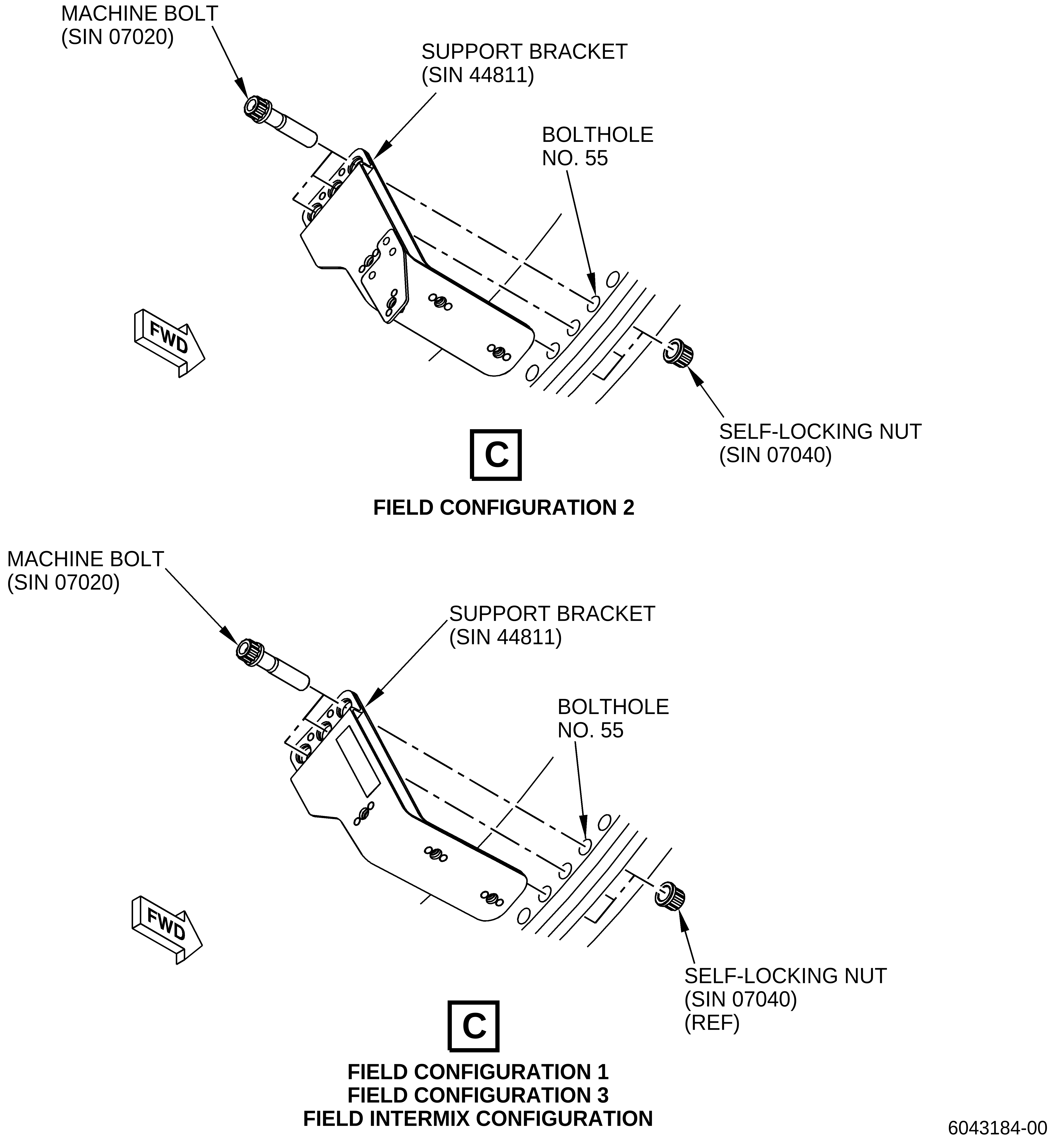
| (c) | Remove the support bracket (SIN 44811). Refer to Figure 3 and do as follows: |
| 1 | Remove the machine bolt (SIN 61521) and cushion loop clamp (SIN 61581) that attach the PS3 air tube (SIN 61501) to the support bracket (SIN 44811). |
| 2 | Remove the two machine bolts (SIN 44424) from the P-clamp (SIN 44481) that attaches to the oil supply tube (SIN 44401) to the support bracket (SIN 44811) and remove the P-clamp (SIN 44481). |
| 3 | Remove the two machine bolts (SIN 44826) from the P-clamp (SIN 44881) that attaches the tube hose (SIN 44800) to the support bracket (SIN 44811) and remove the P-clamp (SIN 44481). |
| 4 | Remove the three machine bolts (SIN 07020) and self-locking nuts (SIN 07040) that attach the support bracket (SIN 44811) to the fan hub module assembly. Remove the support bracket (SIN 44811) from the engine. |
| 5 | Discard the three removed machine bolts (SIN 07020). |
| D. | In-Shop Removal |
| (1) | Before you start this procedure, read the assembly and disassembly techniques section. Refer to the SPM, 70-10-00, ASSEMBLY AND DISASSEMBLY TECHNIQUES. |
| (2) | Remove the lower bifurcation assembly (SIN 09400). Refer to the GEnx-1B EM, 72-00-03, REMOVAL 001. |
| (3) | Remove the lower bifurcation firewall (SIN 09401) and the lower air and VFSG oil manifold (SIN 99002). Refer to the GEnx-1B EM, 72-00-03, DISASSEMBLY 001. |
| (4) | Remove the air bifi manifold (SIN 99008) and the PS25 air tube (SIN 61400). Refer to the GEnx-1B EM, 72-00-02, DISASSEMBLY 002, CONFIG 01 or CONFIG 02. |
| (5) | Remove the support bracket (SIN 44811). Refer to the GEnx-1B EM, 72-00-02, DISASSEMBLY 006, Subtask 72-00-02-030-400. |
| E. | Rework |
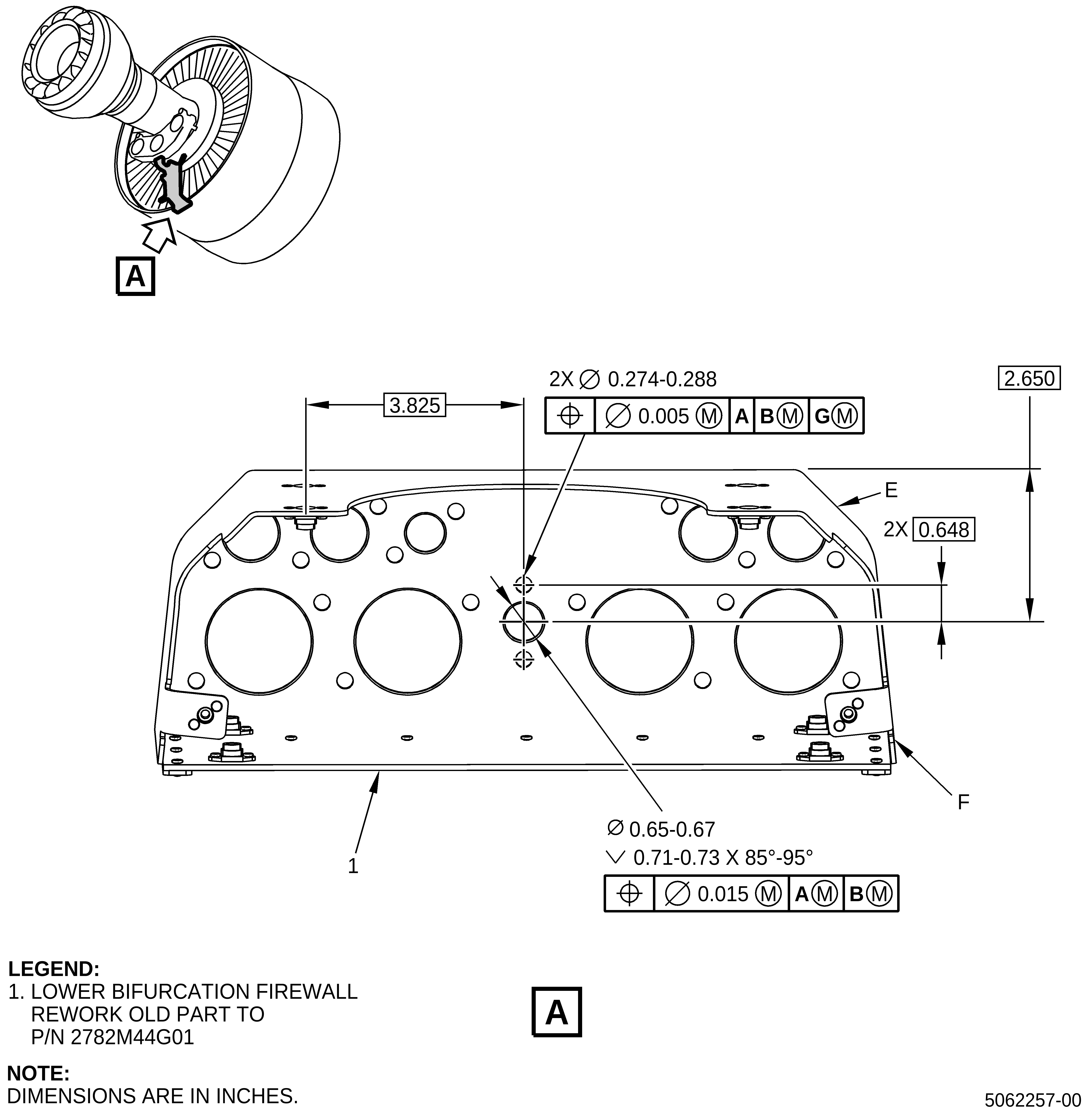
| (1) | Rework the lower bifurcation firewall (1, Figure 1) as follows: |
| (a) | Machine three holes in the lower bifurcation firewall (1). Refer to the SPM, 70-00-03, MACHINING DATA and do as follows: |
| 1 | Put a mark on the correct position of all the holes that you must machine. |
| 2 | Machine the lower bifurcation firewall (1, Figure 1) to the final dimensions. |
| 3 | Blend to remove burrs and/or high metal. Refer to the SPM, 70-42-00, BLENDING AND REMOVAL OF HIGH METAL. |
| (b) | Use the electrochemical etch method to identify again the reworked lower bifurcation firewall with the new part number. Refer to the SPM, 70-16-03, ELECTROCHEMICAL ETC MARKING and do as follows: |
| 1 | Put a mark with a line through the old part number. Make sure that you can read the old part number. |
| 2 | Put a mark with the new part number next to the existing part number as follows: |
|
| F. | In-Shop Installation |
| CAUTION: |
|
| (1) | Install the new support bracket (SIN 44811). Refer to the GEnx-1B EM, 72-00-02, ASSEMBLY 001, CONFIG 01 or CONFIG 02. |
| (2) | Install the new air bifi tube (SIN 99008) and the new bracket (SIN 99010). Refer to the GEnx-1B EM, 72-00-02, ASSEMBLY 005, CONFIG 01 and CONFIG 02. |
| (3) | Install the new lower bifurcation firewall (SIN 09401) and the new lower air VFSG oil manifold (SIN 99002). Refer to the GEnx-1B EM, 72-00-03, ASSEMBLY 001. |
| (4) | Install the lower bifurcation assembly (SIN 09400). Refer to the GEnx-1B EM, 72-00-03, INSTALLATION 001. |
| G. | On-Wing Installation |
| (1) | For field configuration 1, field configuration 3, or field intermix configuration, refer to paragraph 1.K., Interchangeability and do as follows: |
| Install the new support bracket (SIN 44811, Figure 3) as follows: |
| (a) | Install the new support bracket (SIN 44811). Refer to Figure 3 and do as follows: |
| 1 | Install the support bracket (SIN 44811) in the boltholes No. 55 through No. 57 on the aft side of the flange with new machine bolts (SIN 07020) and the self-locking nuts (SIN 07040) and the boltheads aft. Tighten the self-locking nuts (SIN 07040) with your hand. |
| 2 | Torque the self-locking nuts (SIN 07040) to 368 to 432 lb in. (41.5 to 48.8 Nm). |
| 3 | Attach the tube hose (SIN 44800) to the support bracket (SIN 44811) with the P-clamp (SIN 44881) and machine bolts (SIN 44826) on the forward side of the AGB module. |
| 4 | Torque the two machine bolts (SIN 44826) to 60 to 70 lb in. (6.7 to 7.9 Nm). |
| 5 | Attach the oil supply tube (SIN 44401) to the support bracket (SIN 44811) with the P-clamp (SIN 44481) and machine bolts (SIN 44424). |
| 6 | Torque the two machine bolts (SIN 44424) to 51 to 59 lb in. (5.7 to 6.6 Nm). |
| 7 | Attach the PS3 air tube (SIN 61501) to the support bracket (SIN 44811) with the cushion loop clamp (SIN 61581) and machine bolt (SIN 61521). Install the cushion loop clamp (SIN 61581) with the loop down. |
| 8 | Torque the machine bolt (SIN 61521) to 32 to 38 lb in. (3.6 to 4.2 Nm). Make sure that the cushion loop clamp (SIN 61581) does not get twisted when the machine bolt (SIN 61521) is torqued. |
| (b) | Connect the PS3 air tube (SIN 61501) to the new air bifi tube (SIN 99008). Refer to Figure 3 and do as follows: |
| 1 | Connect the tube cap (SIN 840SB) to the tube nipple (SIN 840S3) on the assembly fan hub frame (SIN 840A0) at the 4:00 o'clock position. |
| 2 | Torque the B-nut of the tube cap (SIN 840SB) to 262 to 308 lb in. (29.6 to 34.7 Nm). |
| 3 | Attach the new PS3 tube support bracket (SIN 99010) to the transfer gearbox (TGB) (SIN 03200) with machine bolts (SIN 99029). |
| 4 | Torque the machine bolts (SIN 99029) to 51 lb to 59 lb in. (5.7 to 6.6 Nm). |
| 5 | Connect the air bifi tube (SIN 99008) to the PS3 air tube (SIN 61501). |
| 6 | Attach the air bifi tube (SIN 99008) to the PS3 tube support bracket (SIN 99010) with cushion loop clamp (SIN 61581) and machine bolt (SIN 61521). |
| 7 | Torque the machine bolt (SIN 61521) to 32 lb to 38 lb in. (3.6 to 4.2 Nm). |
| 8 | Tighten the B-nuts on air bifi tube (SIN 99008) as follows: |
| a | Torque the B-nut to 262 to 308 lb in. (29.6 to 34.7 Nm). |
| b | Loosen the B-nut and torque it again to 262 to 308 lb in. (29.6 to 34.7 Nm). |
| c | Loosen the B-nut and torque it again to 262 to 308 lb in. (29.6 to 34.7 Nm). |
| 9 | Safety the B-nuts on the air bifi tube (SIN 99008) on the left (positive direction) with C10-143 safety cable. |
| (c) | Refer to the GEnx-1B Boeing 787 AMM, G71-00-05, Fan Stator Module to Engine - Installation, DMC-B787-A-G71-00-05-00A-720A-A and do as follows: |
| 1 | Install the lower bifurcation assembly (SIN 09400), lower bifurcation firewall (SIN 09401) and lower air VFSG oil manifold (SIN 99002). Select the appropriate field configuration section. Refer to paragraph 1.K., Interchangeability for description of configuration 1, configuration 2, configuration 3, or intermix configuration. |
| NOTE: |
|
| (d) | Refer to the GEnx-1B Boeing 787 AMM, G73-22-01, Engine Control Electrical Harness - Installation, DMC-B787-A-G73-22-01-00A-720A-A and do as follows: |
| 1 | Install the bifurcation fire blanket (SIN 09491), blanket (SIN 09492), and support brackets (SIN 09411, SIN 09415, and SIN 09417). Refer to Figure 2 and do as follows: |
| a | For pre-GEnx-1B S/B 72-0223 and post-GEnx-1B
S/B 72-0223 engines, refer to GEnx-1B S/B 72-0223,
paragraph 3.B., Installation . |
| b | For post-GEnx-1B S/B 72-0322 engines,
refer to GEnx-1B S/B 72-0322, paragraph 3.B., Installation . |
| 2 | Install the W05, W06, W07, W08, W09, W10, W12, W13, and W17 electrical harnesses to the lower bifurcation firewall (SIN 09401). Refer to the GEnx-1B Boeing 787 AMM, G73-22-01, Engine Control Electrical Harness - Installation, DMC-B787-A-G73-22-01-00A-720A-A. |
| H. | Aircraft Return to Service |
| (1) | Do these tasks in sequence to close the left and right thrust reversers on the applicable engine as follows: |
| (a) | Remove the protective covers P/N SPL-13475 from the left and right VFSG air/heat exchangers. |
| (b) | Remove the protective covers P/N SPL-13475 from the ACOCs. |
| (c) | For the applicable engine, close the left and right thrust reversers. Refer to the GEnx-1B, Boeing 787 AMM, G78-31-00, Thrust Reverser (Task Selection) - Close After Access, DMC-B787-A-G78-31-00-15B-740A-A and do as follows: |
| • |
|
| • |
|
| • |
|
| • |
|
| (d) | For the applicable engine, close the left and right fan cowls. Refer to the GEnx-1B, Boeing 787 AMM, G71-11-04, Fan Cowl (Task Selection) - Close After Access, DMC-B787-A-G71-11-04-00B-740A-A and do as follows: |
| • |
|
| • |
|
| • |
|
| • |
|
| (e) | Do the thrust reverser activation. Refer to the GEnx-1B, Boeing 787 AMM, G78-31-00, Thrust Reverser (After Ground Maintenance) - Activation, DMC-B787-A-G78-31-00-15G- 730B-A. |
| (f) | Do the leading edge slat system activation. Refer to the GEnx-1B, Boeing 787 AMM, 27-81-00, Leading Edge Slat System - Activation, DMC-B787-A-27-81-00-24A-730B-A. |
| (g) | Do these steps to remove the DO-NOT-OPERATE tags from the applicable ENGINE START switch and the FUEL CONTROL switch: |
| 1 | On the pilot's overhead panel, P5, remove the DO-NOT-OPERATE tag from the applicable ENGINE START switch. |
| 2 | On the pilot's aisle control stand, P10, remove the DO-NOT-OPERATE tag from the applicable FUEL CONTROL switch. |
| 3 | Do the tests of the engine control electrical harnesses shown in the power plant test reference table. Refer to the GEnx-1B, Boeing 787 AMM, G71-00-00, Power Plant Test Reference Table - Standard Practices, DMC-B787-A-G71-00-00-09A-950A-A. |