| GENX-1B ENGINE MANUAL | Dated: 10/07/2021 | |
| EM 72-00-05 , REMOVAL 001 | ||
| ACCESSORY GEARBOX MODULE - REMOVAL 001 | ||
| GENX-1B ENGINE MANUAL | Dated: 10/07/2021 | |
| EM 72-00-05 , REMOVAL 001 | ||
| ACCESSORY GEARBOX MODULE - REMOVAL 001 | ||
| * * * FOR ALL |
| TASK 72-00-05-020-801 |
| * * * FOR ALL |
| 1 . | General. |
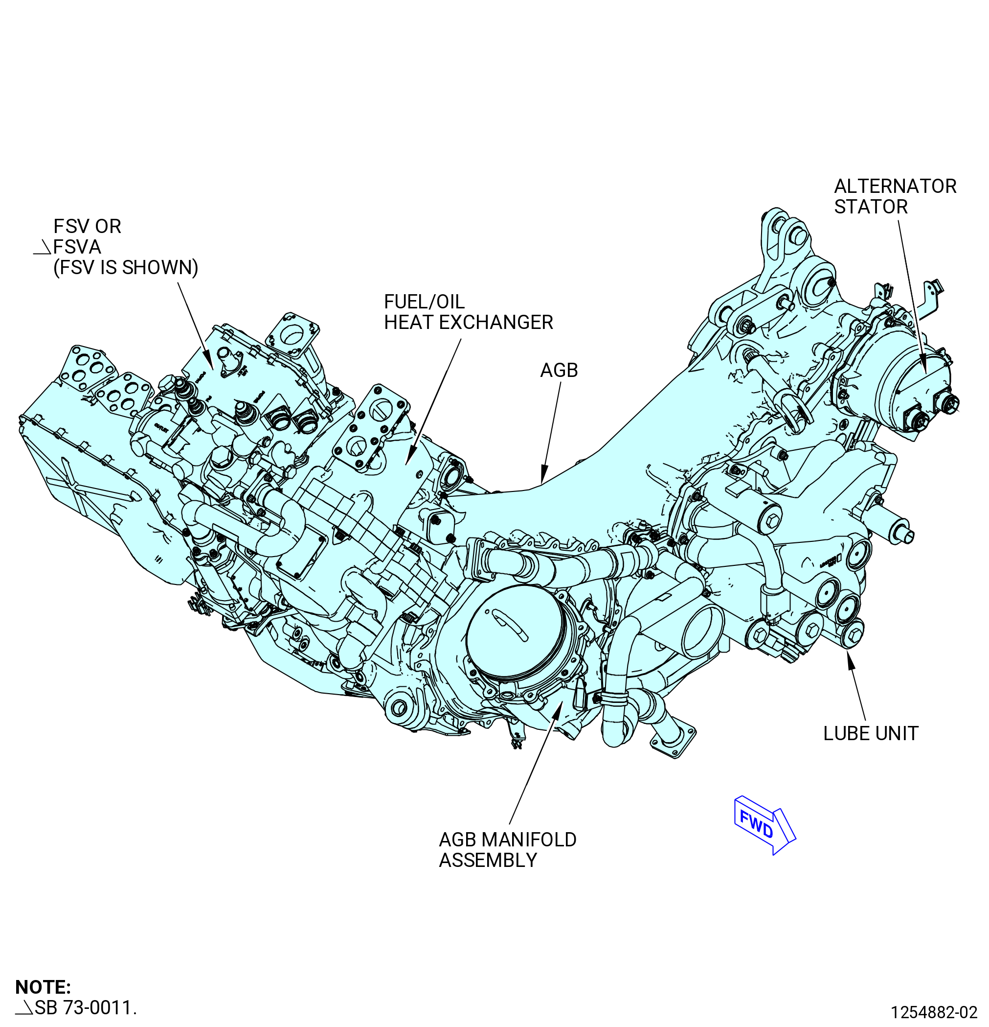
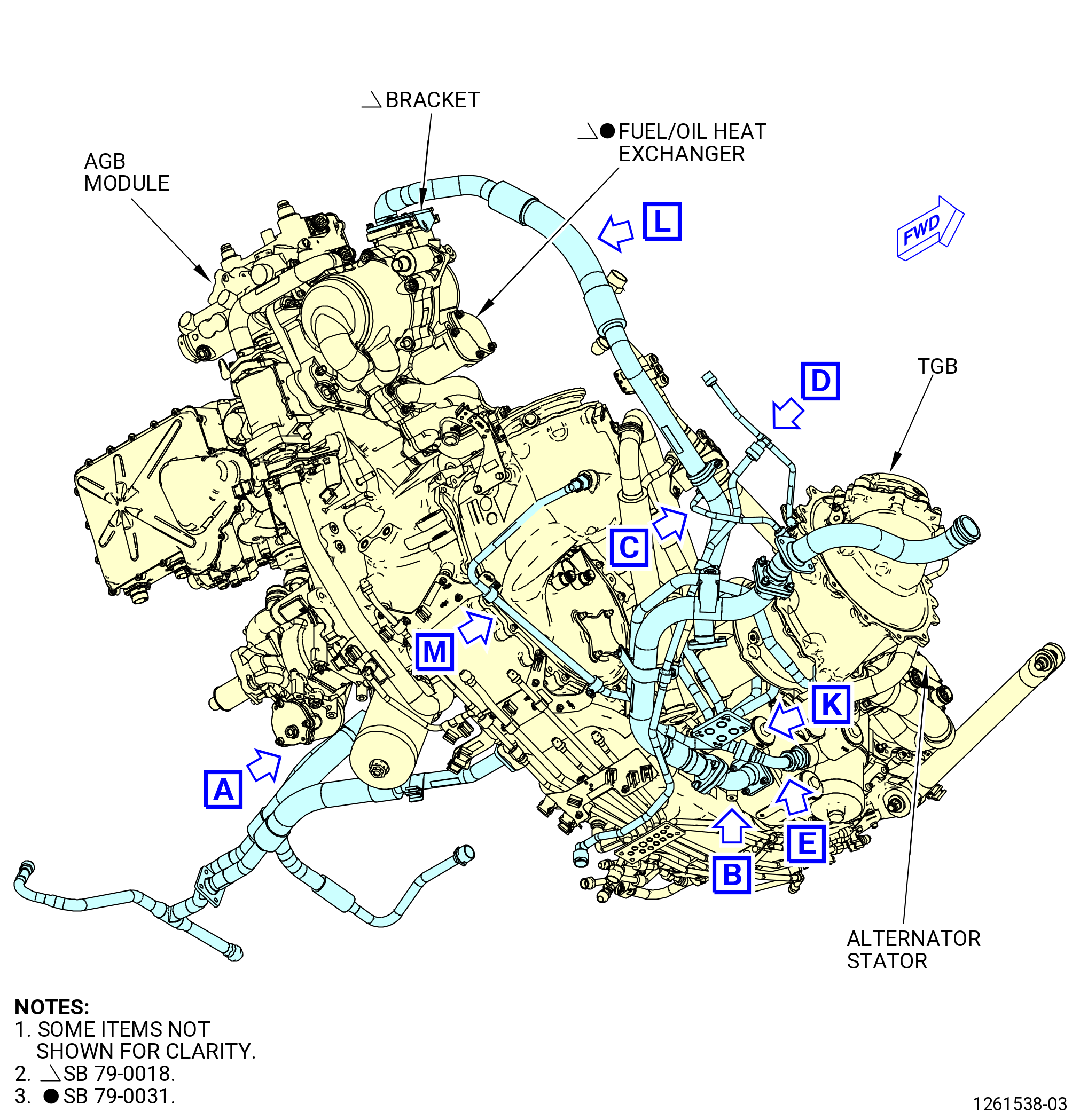
| A. | This procedure gives instructions to remove the accessory gearbox (AGB) module and the necessary tubes and hoses. Refer to Figure 301. |
| B. | This procedure starts with the propulsor attached to an 11C3044 engine module adapter assembly or 11C3281 pedestals. |
| 2 . | Tools, Equipment, and Materials. |
| NOTE: |
|
| A. | Tools and Equipment. |
| (1) | Special Tools. |
| (2) | Standard Tools and Equipment. None. |
| (3) | Locally Manufactured Tools. None. |
| B. | Consumable Materials. None. |
| C. | Referenced Procedures. None. |
| D. | Expendable Parts. None. |
| 3 . | Procedure. |
| Subtask 72-00-05-020-037 |
| * * * FOR ALL |
| A. | If necessary, remove the VFSG from the AGB module. |
| Subtask 72-00-05-020-040 |
| * * * FOR ALL |
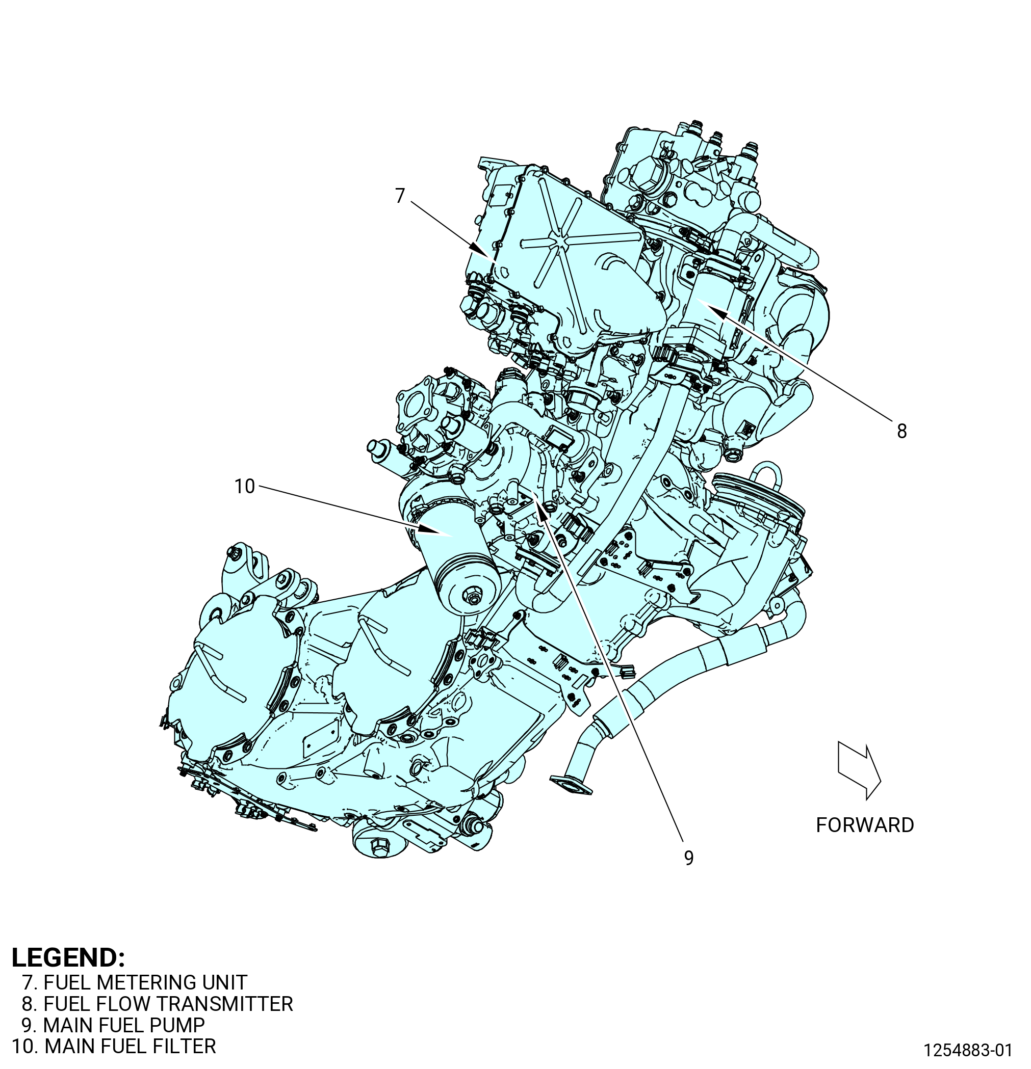
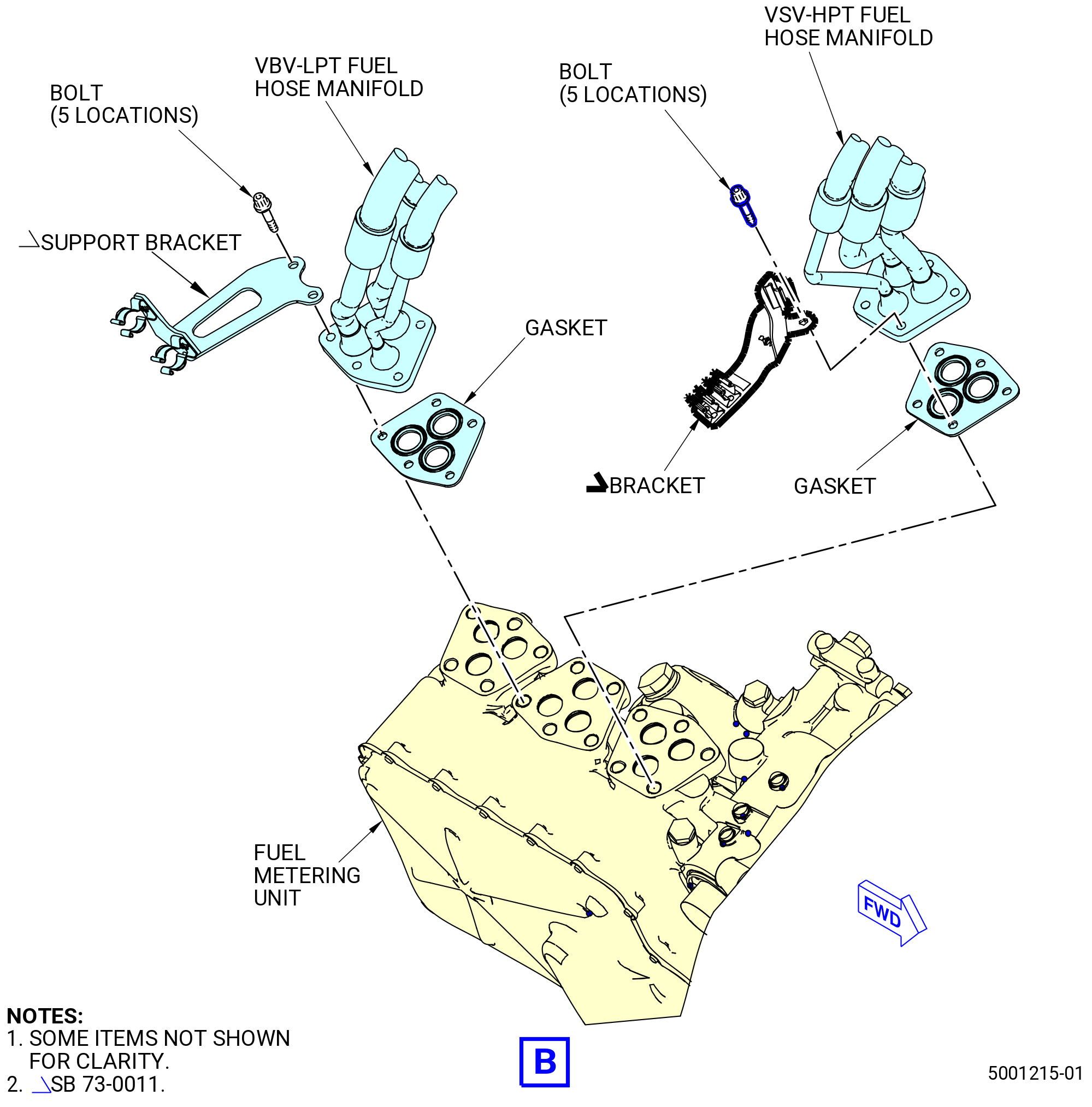
| B. | Remove the fuel tube/hose connections from the accessory gearbox (AGB) as follows. Refer to Figure 302. |
| Subtask 72-00-05-020-021 |
| * * * FOR ALL |
| (1) | Remove the TBV-CCCV-PHS fuel hose manifold from the fuel metering unit (FMU) as follows: |
| (a) | Remove the bolts and bracket from the TBV-CCCV-PHS fuel hose manifold at the FMU. |
| (b) | Remove and discard the gasket (20-060 , 73-11-40) (SIN 38452) from the FMU. |
| (c) | Remove and secure the TBV-CCCV-PHS fuel hose manifold from the FMU to prevent damage. |
| Subtask 72-00-05-020-022 |
| * * * FOR ALL |
| (2) | Remove the VSV-HPT fuel hose manifold from the FMU as follows: |
| (a) | Remove the bolts and bracket from the VSV-HPT fuel hose manifold at the FMU. |
| (b) | Remove and discard the gasket (30-030 , 73-11-40) (SIN 38152) from the FMU. |
| (c) | Remove and secure the VSV-HPT fuel hose manifold from the FMU to prevent damage. |
| Subtask 72-00-05-020-023 |
| * * * FOR ALL |
| (3) | Remove the VBV-LPT fuel hose manifold from the FMU as follows: |
| (a) | Remove the bolts and support bracket from the VBV-LPT fuel hose manifold at the FMU. |
| (b) | Remove and discard the gasket (25-030 , 73-11-40) (SIN 38352) from the FMU. |
| (c) | Remove and secure the VBV-LPT fuel hose manifold from the FMU to prevent damage. |
| Subtask 72-00-05-020-024 |
| * * * FOR ALL |
| * * * FOR ALL |
| * * * PRE SB 73-0011( Engines without Fuel Vapor Accumulator ) |
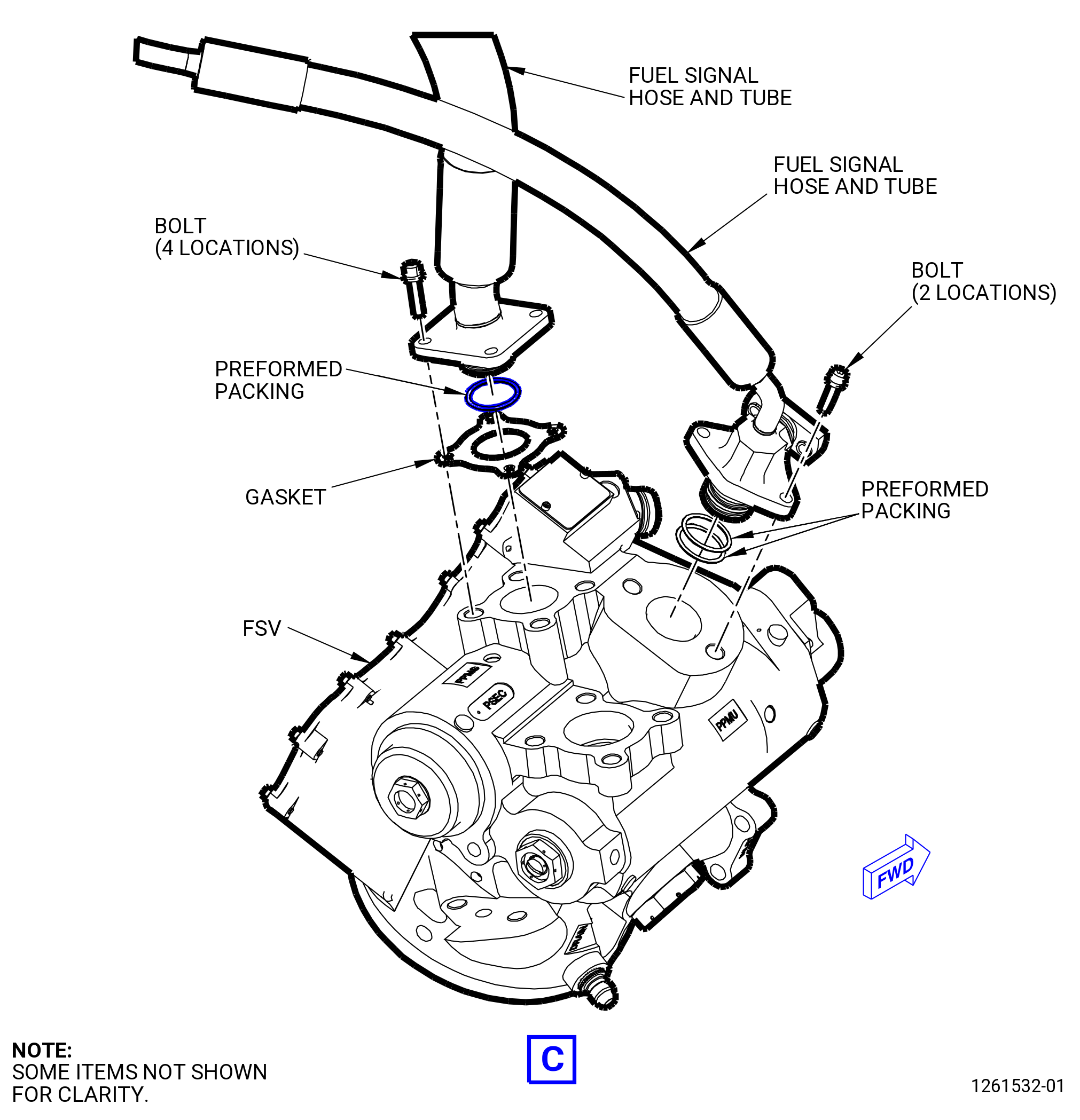
| (4) | Remove each fuel signal hose and tube from the flow splitting valve (FSV) as follows: |
| (a) | Remove the bolts that attach the fuel signal hose/tubes to the FSV. |
| (b) | Remove and discard the gasket (15-150 , 73-11-40) (SIN 34251) from the FSV. |
| (c) | Remove the fuel signal hose/tubes from the FSV. |
| (d) | Safety the fuel signal hose/tubes at the FSV to prevent damage. |
| (e) | Remove and discard the preformed packing (15-120 , 73-11-40) (SIN 34252) from the FSV. |
| * * * FOR ALL |
| * * * END PRE SB 73-0011 |
| Subtask 72-00-05-020-047 |
| * * * FOR ALL |
| * * * FOR ALL |
| * * * SB 73-0011( Engines with Fuel Vapor Accumulator ) |
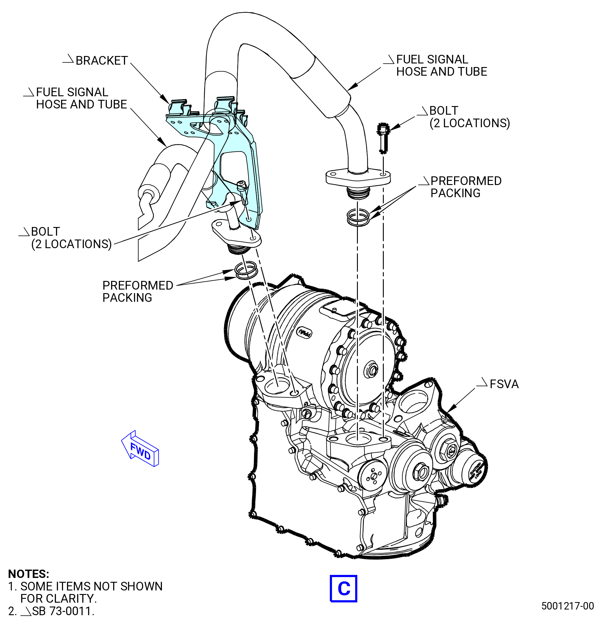
| (4).A. | Remove each fuel signal hose and tube from the flow splitting valve accumulator (FSVA) as follows: |
| (a) | Remove the bolts that attach the fuel signal hose/tubes to the FSVA. |
| (b) | Remove the fuel signal hose/tubes and the bracket from the FSVA. |
| (c) | Safety the fuel signal hose/tubes at the FSVA to prevent damage. |
| (d) | Remove and discard the preformed packing (15-120 , 73-11-40) (SIN 34252) from the FSVA. |
| * * * FOR ALL |
| * * * END SB 73-0011 |
| Subtask 72-00-05-020-025 |
| * * * FOR ALL |
| * * * FOR ALL |
| * * * PRE SB 73-0011( Engines without Fuel Vapor Accumulator ) |
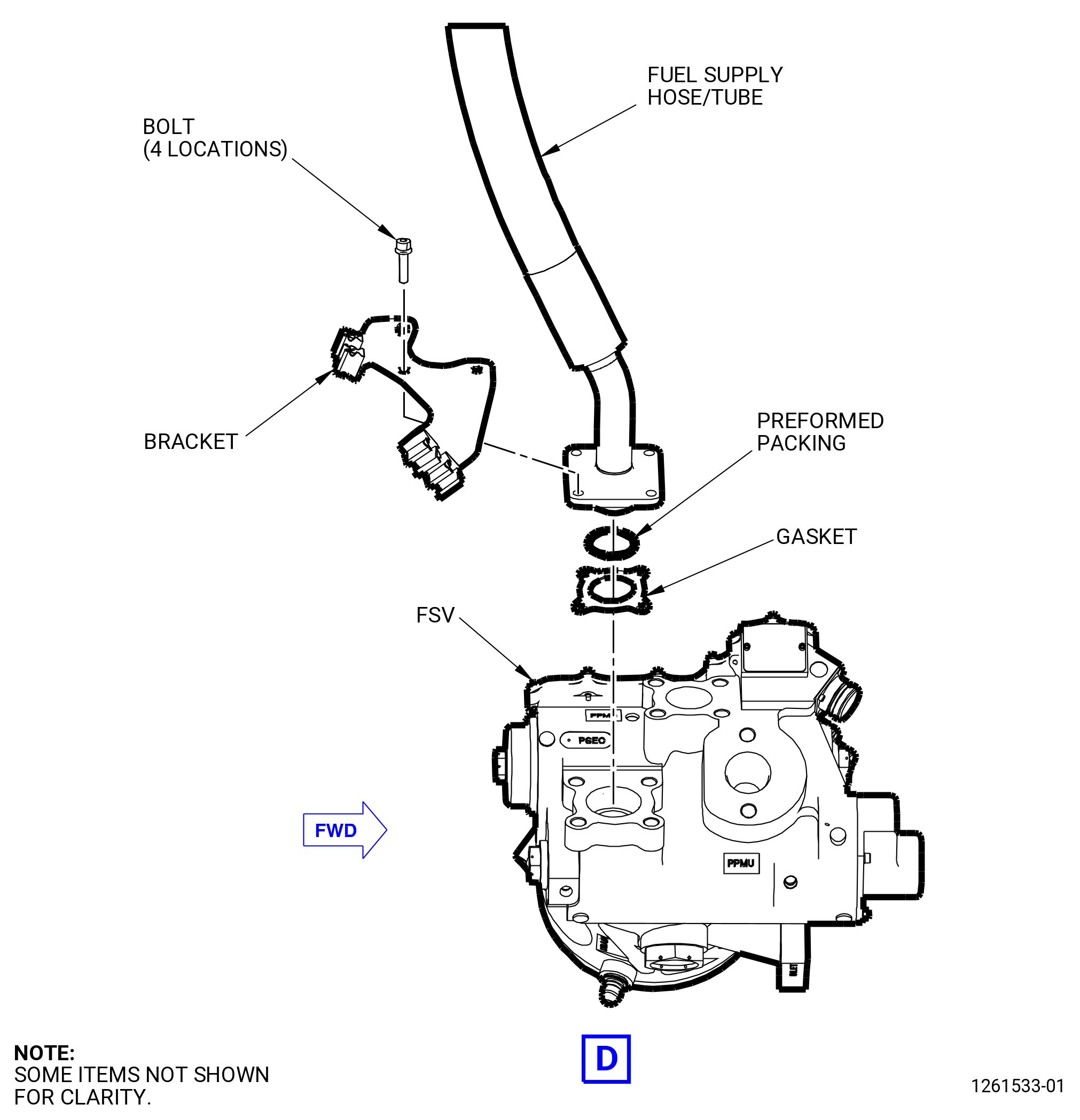
| (5) | Remove the fuel supply hose/tube from the FSV as follows: |
| (a) | Remove the bolts and bracket from the fuel supply hose/tube at the FSV. |
| (b) | Remove and discard the gasket (05-050 , 73-11-40) (SIN 34151) from the FSV. |
| (c) | Remove and safety the fuel supply hose/tube at the FSV to prevent damage. |
| (d) | Remove and discard the preformed packing (05-030 , 73-11-40) (SIN 34152) from the FSV. |
| * * * FOR ALL |
| * * * END PRE SB 73-0011 |
| Subtask 72-00-05-020-049 |
| * * * FOR ALL |
| * * * FOR ALL |
| * * * SB 73-0011( Engines with Fuel Vapor Accumulator ) |
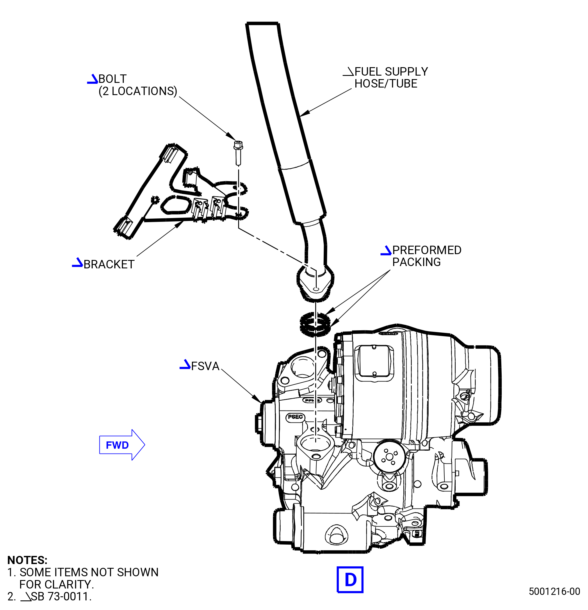
| (5).A. | Remove the fuel supply hose/tube from the FSVA as follows: |
| (a) | Remove the bolts and bracket from the fuel supply hose/tube at the FSV or FSVA. |
| (b) | Remove and safety the fuel supply hose/tube at the FSVA to prevent damage. |
| (c) | Remove and discard the preformed packing (05-030 , 73-11-40) (SIN 34152) from the FSVA. |
| * * * FOR ALL |
| * * * END SB 73-0011 |
| Subtask 72-00-05-020-026 |
| * * * FOR ALL |
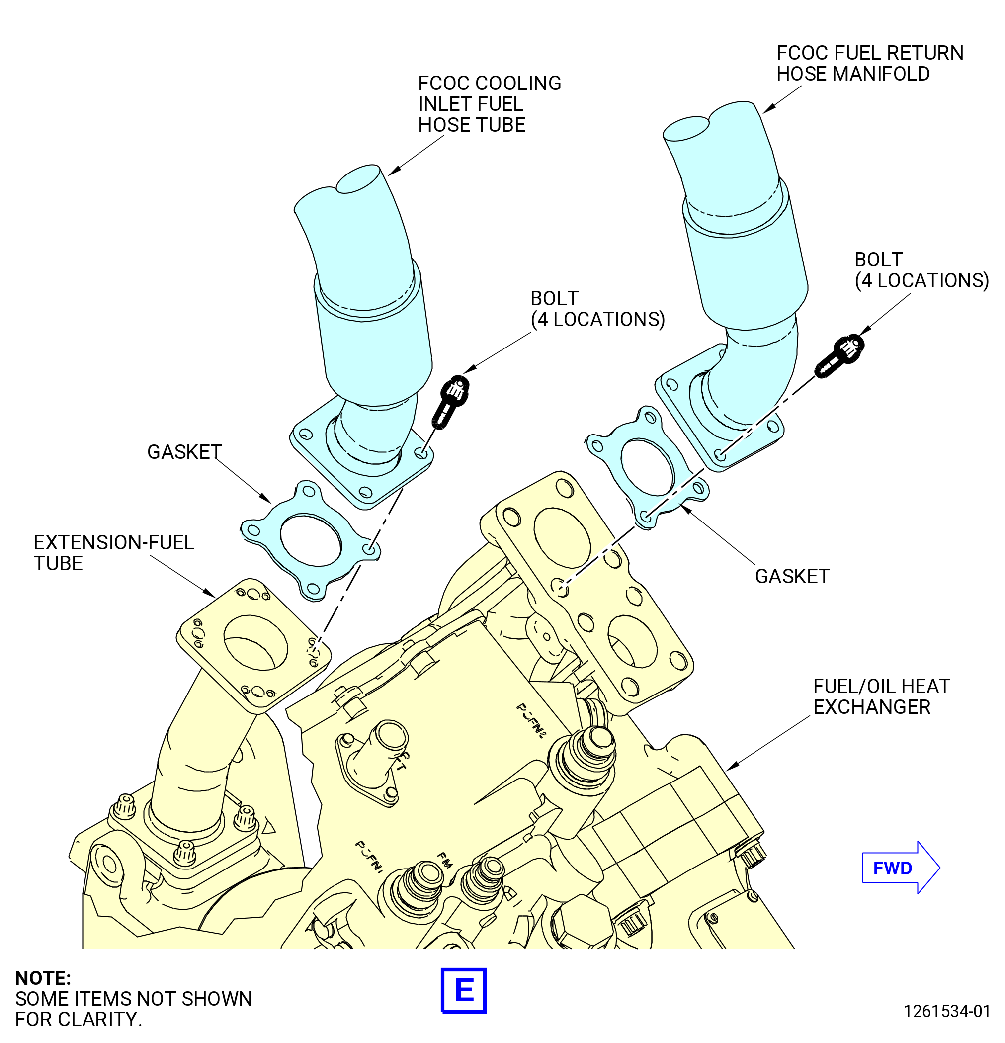
| (6) | Remove the FCOC cooling inlet fuel hose tube from the extension-fuel tube as follows: |
| (a) | Remove the bolts from the FCOC cooling inlet fuel hose tube at the extension-fuel tube. |
| (b) | Remove and discard the gasket (01-040 , 73-11-41) (SIN 34550) from the FCOC cooling inlet fuel hose tube. |
| (c) | Remove and safety the FCOC cooling inlet fuel hose tube at the extension-fuel tube to prevent damage. |
| Subtask 72-00-05-020-027 |
| * * * FOR ALL |
| (7) | Remove the FCOC fuel return hose manifold from the fuel/oil heat exchanger (FOC) as follows: |
| (a) | Remove the bolts from the FCOC fuel return hose manifold at the FOC. |
| (b) | Remove and discard the gasket (01-040 , 73-11-41) (SIN 34550) from the FCOC fuel return hose manifold and FOC. |
| (c) | Remove and safety the FCOC fuel return hose manifold at the FOC to prevent damage. |
|
|
|
|
|
|
| Subtask 72-00-05-020-029 |
| * * * FOR ALL |
| C. | Disconnect the lube/scavenge connections from the accessory gearbox (AGB) as follows. Refer to Figure 303. |
| (1) | Remove the oil scavenge tube/hose from the aft side of the accessory gearbox AGB at the 12:00 o'clock position as follows: |
| (a) | Remove the bolts from the oil scavenge tube/hose from the AGB. |
| (b) | Remove and discard the gasket (10-020 , 79-22-20) (SIN 45450) from the AGB. |
| (c) | Secure the oil scavenge tube/hose to prevent damage. |
| Subtask 72-00-05-020-030 |
| * * * FOR ALL |
| (2) | Remove the oil scavenge tube and hose from the aft side of the AGB at the 6:00 o'clock position as follows: |
| (a) | Remove the bolts from the oil scavenge tube and hose from the AGB. |
| (b) | Remove and discard the gasket (10-040 , 79-22-20) (SIN 45251) from the AGB. |
| (c) | Secure the oil scavenge tube and hose to prevent damage. |
| Subtask 72-00-05-020-031 |
| * * * FOR ALL |
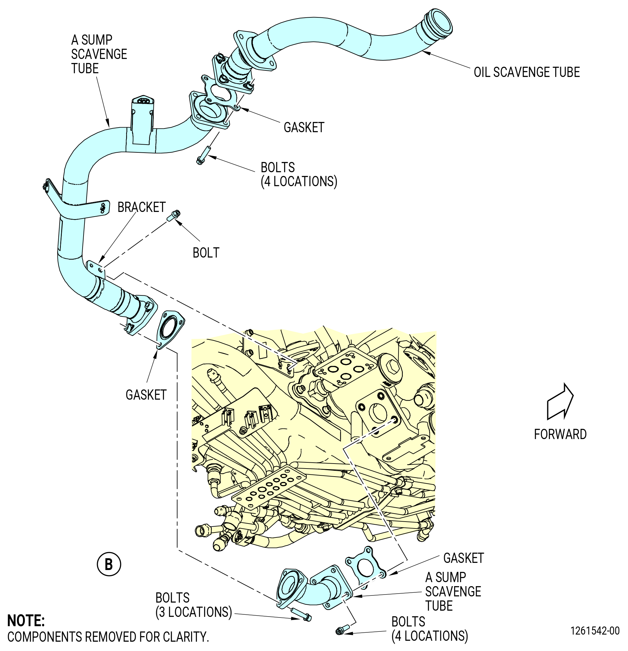
| (3) | Remove the A sump scavenge tube from the forward side of the AGB at the 6:00 o'clock position as follows: |
| (a) | Remove the bolts from the A sump scavenge tube to the A sump scavenge tube attached to the lube unit on the AGB. |
| (b) | Remove and discard the gasket (05-050 , 79-22-20) (SIN 45151) from the A sump scavenge tube. |
| (c) | Remove the bolts at the bracket that attaches the A sump scavenge tube to the housing of the (AGB). |
| (d) | Remove the bolts that attach the A sump scavenge tube to the oil scavenge tube connected to the fan frame. |
| (e) | Remove and discard the gasket (05-140 , 79-22-20) (SIN 45152) from the A sump scavenge tube. |
| (f) | Remove and secure the A sump scavenge tube to prevent damage. |
| Subtask 72-00-05-020-032 |
| * * * FOR ALL |
| (4) | Remove the A sump scavenge tube from the lube unit on the forward side of the AGB at the 6:00 o'clock position as follows: |
| (a) | Remove the bolts from the A sump scavenge tube at the lube unit. |
| (b) | Remove and discard the gasket (05-030 , 79-22-20) (SIN 45150) from the lube unit. |
| (c) | Remove the A sump scavenge tube. |
| Subtask 72-00-05-020-033 |
| * * * FOR ALL |
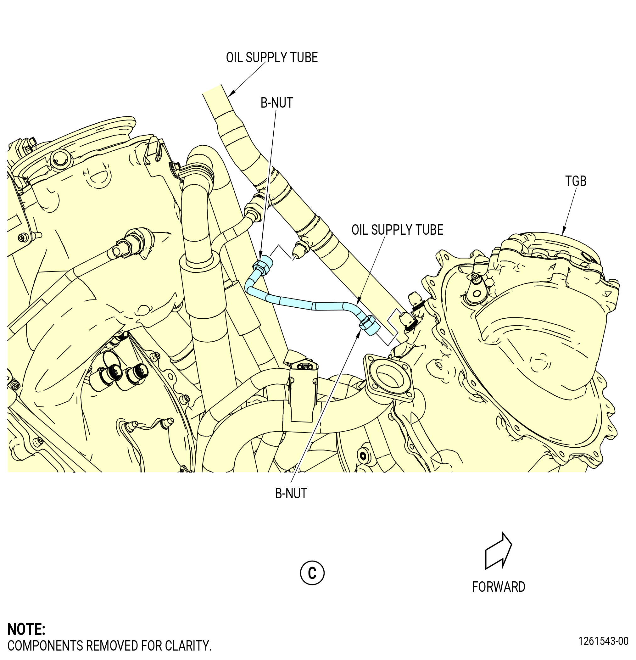
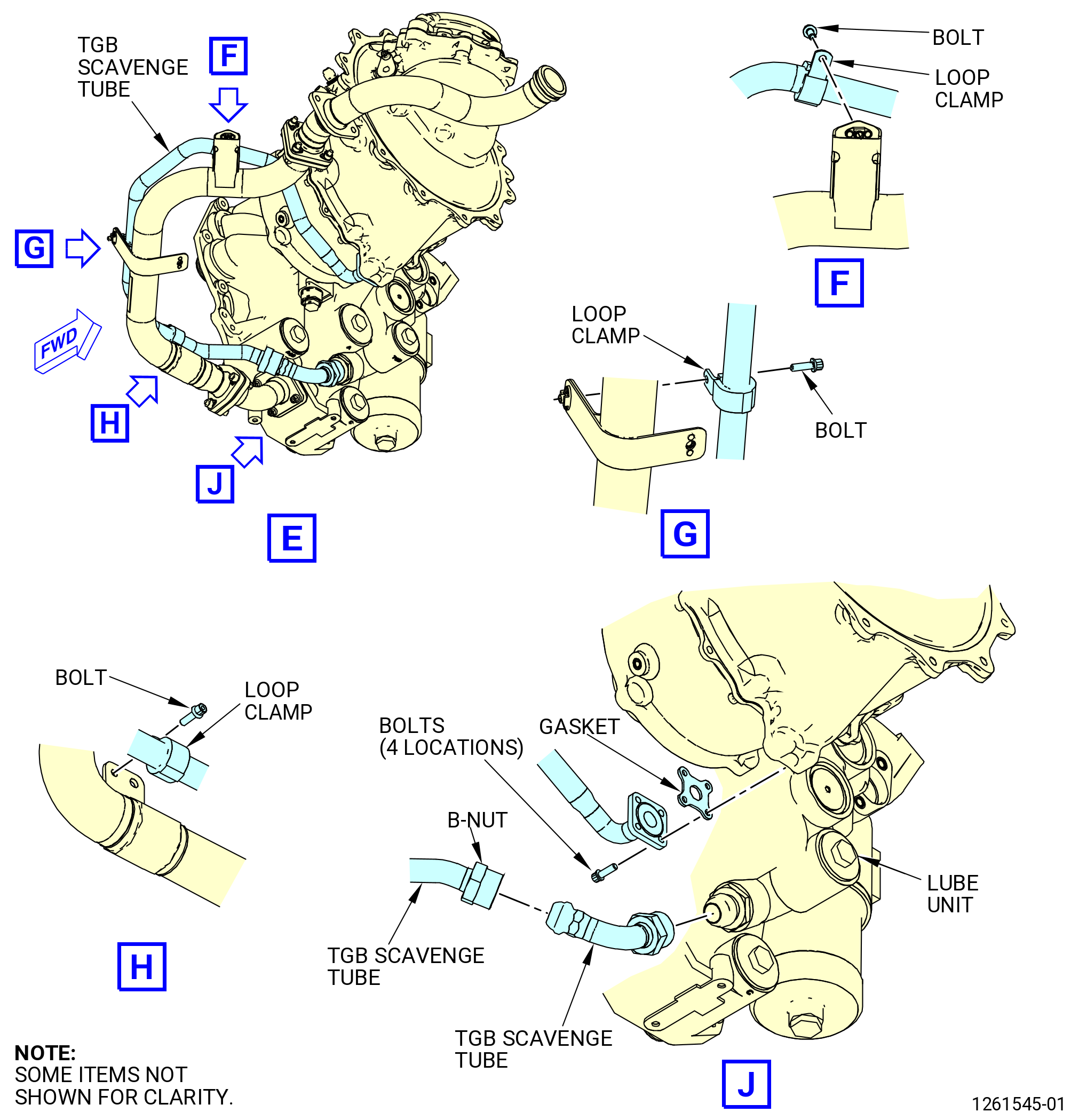
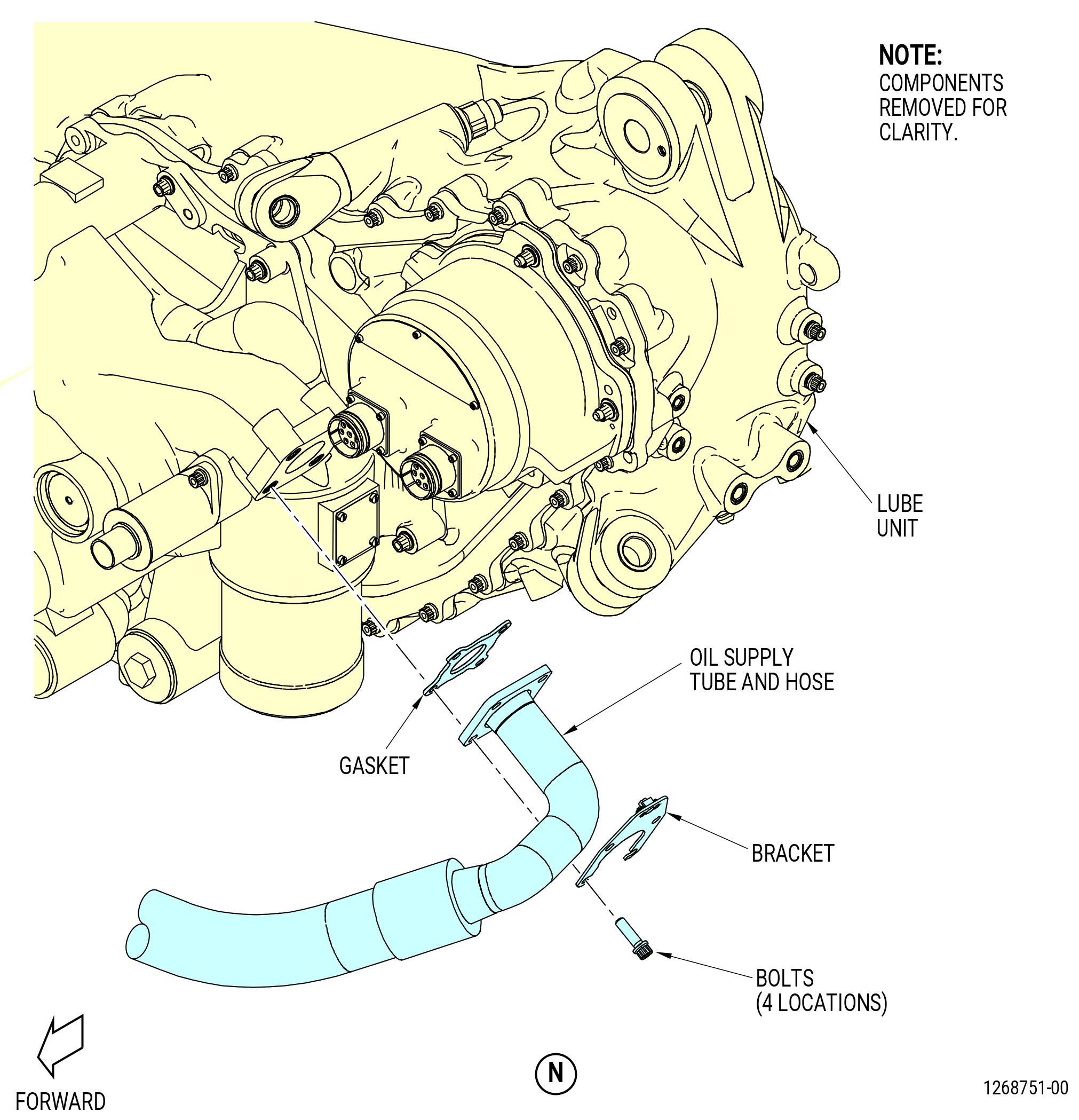
| (5) | Remove the oil supply tube from the lube unit on the forward side of the TGB at the 6:00 o'clock position as follows: |
| (a) | Disconnect the B-nut of the oil supply tube at the aft side of the TGB. |
| (b) | Disconnect the B-nut of the oil supply tube at the oil supply tube at the 12:00 o'clock position on the forward side of the TGB. |
| (c) | Remove the oil supply tube. |
| Subtask 72-00-05-020-034 |
| * * * FOR ALL |
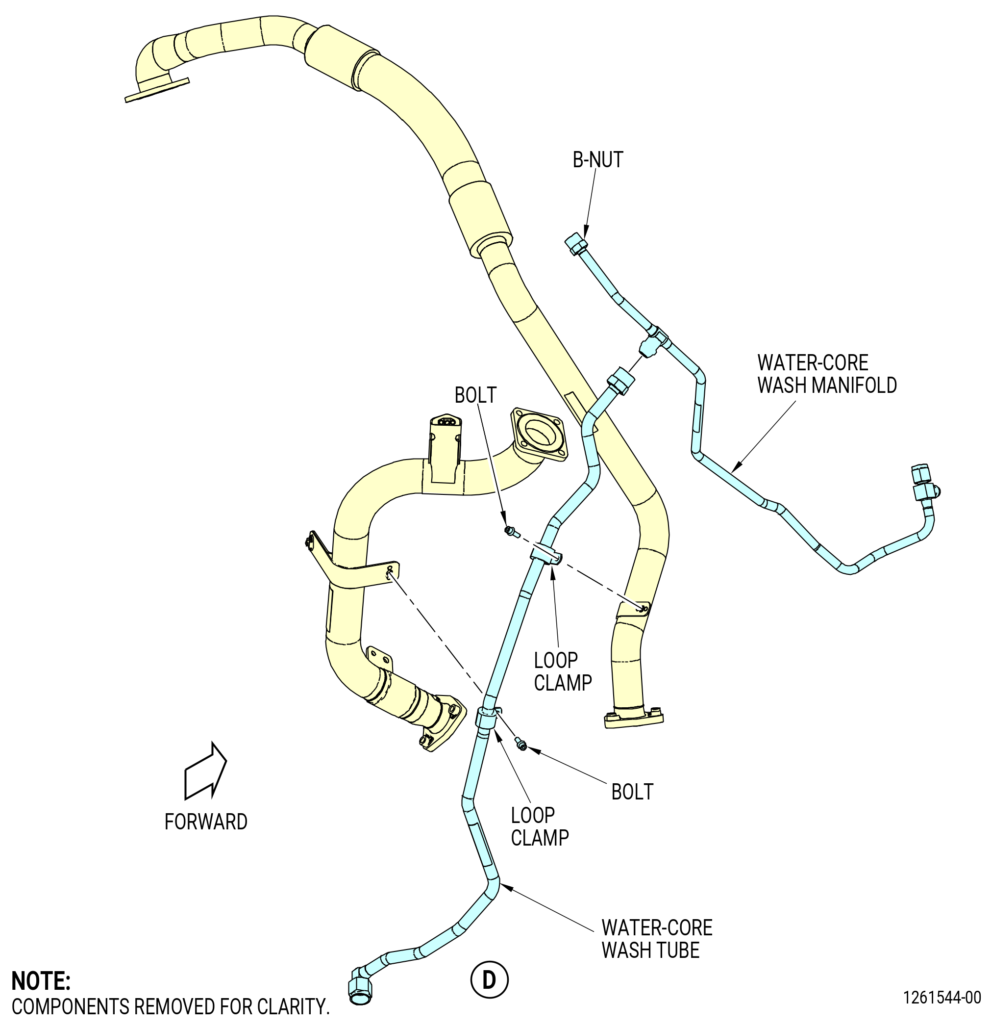
| (6) | Remove the water-core wash tube from the water-core wash manifold on the forward side of the (AGB) as follows: |
| (a) | Disconnect the B-nut of the water-core wash tube from the water-core wash manifold. |
| (b) | Remove the bolts and loop clamps. |
| (c) | Remove the water-core wash tube. |
| Subtask 72-00-05-020-035 |
| * * * FOR ALL |
| (7) | Remove the TGB scavenge tubes from the TGB and lube and scavenge pump (lube unit) as follows: |
| (a) | Remove the bolts that attach the TGB scavenge tube to the TGB. |
| (b) | Remove and discard the gasket (05-130 , 79-22-20) (SIN 45050) from the TGB. |
| (c) | Remove the bolts and loop clamps from the TGB scavenge tube. |
| (d) | Disconnect the B-nut that attaches the TGB scavenge tube to the TGB scavenge tube. |
| (e) | Disconnect the B-nut that attaches the TGB scavenge tube to the lube unit (01-010 , 79-21-10) (SIN 40400) at the forward side of the AGB at the 6:00 o'clock position. |
| (f) | Remove the TGB scavenge tubes. |
| Subtask 72-00-05-020-036 |
| * * * FOR ALL |
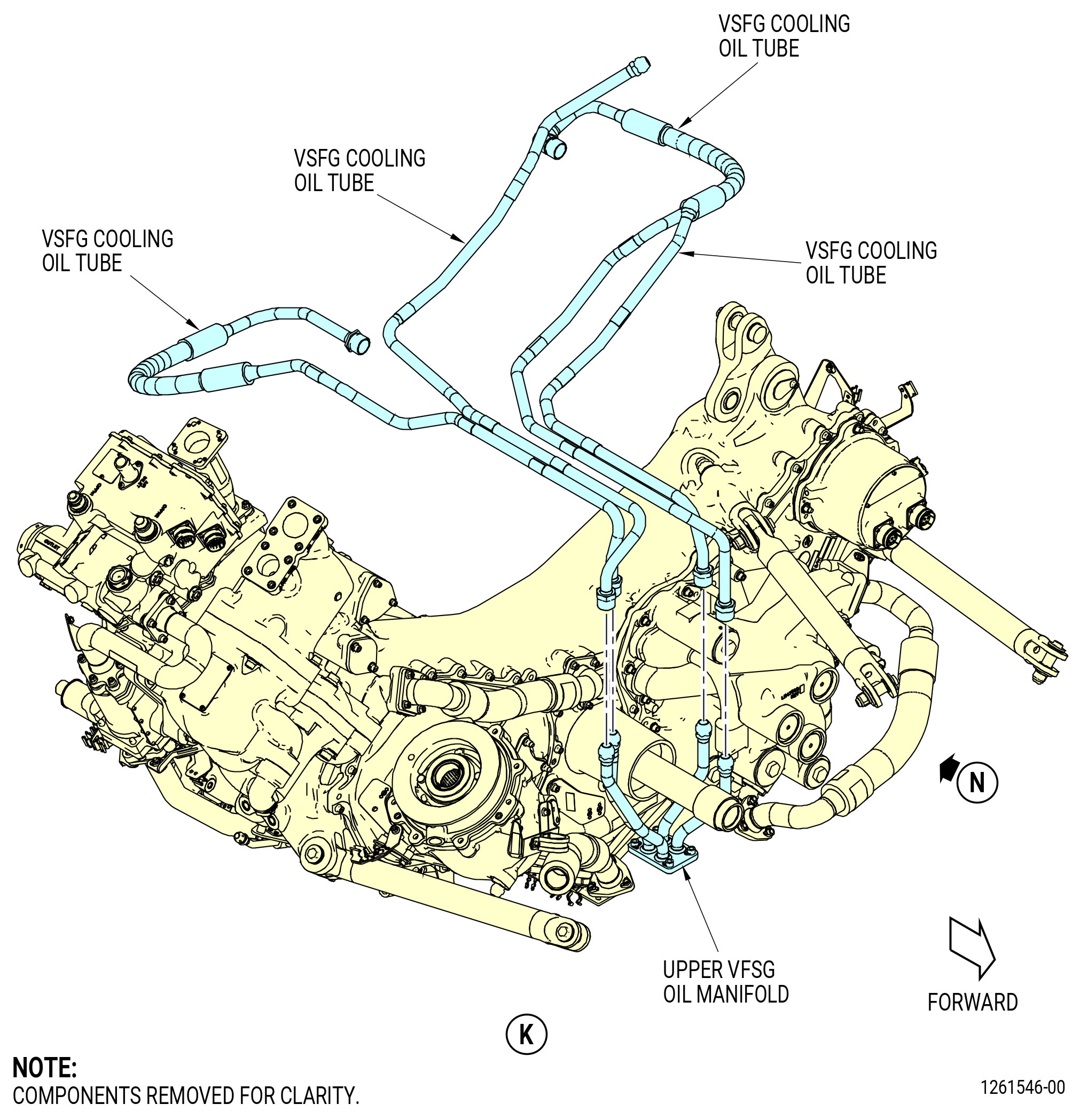
| (8) | Remove the VFSG cooling oil tubes from the upper VFSG oil manifold as follows: |
| (a) | Disconnect the B-nuts on the VFSG cooling oil tubes at the upper VFSG oil manifold. |
| (b) | Remove and secure the VFSG cooling oil tubes to prevent damage. |
| Subtask 72-00-05-020-043 |
| * * * FOR ALL |
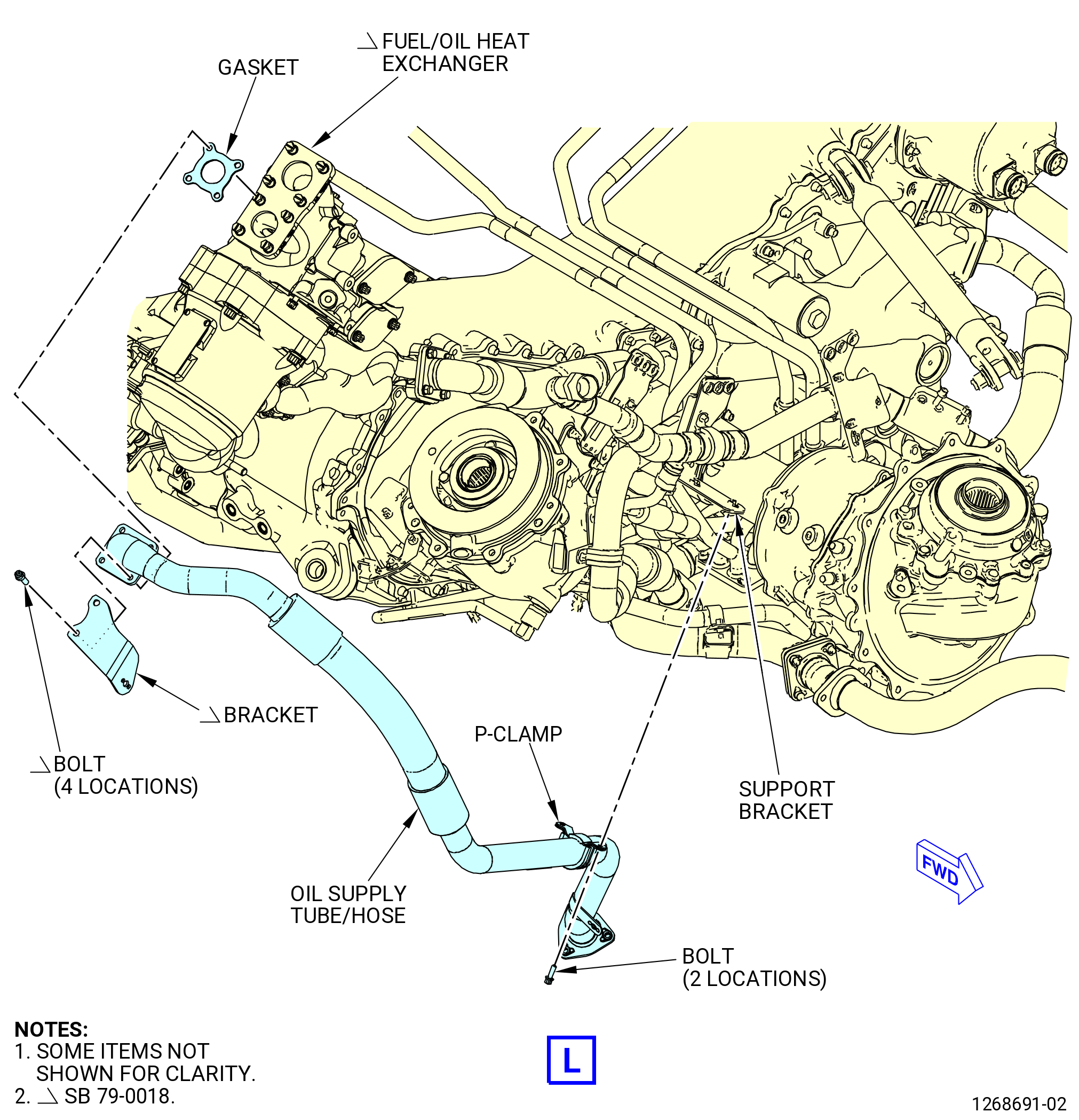
| (9) | Remove the oil supply tube/hose from the fuel/oil heat exchanger and support bracket as follows: |
| (a) |
| Subtask 72-00-05-020-050 |
| * * * FOR ALL |
| * * * FOR |
| * * * PRE SB 79-0018( MFOHX without Indicating Capability ) |
| (a) | Remove the bolts that attach the oil supply tube/hose to the fuel/oil heat exchanger. |
| * * * FOR |
| * * * END PRE SB 79-0018 |
| Subtask 72-00-05-020-051 |
| * * * FOR ALL |
| * * * FOR |
| * * * SB 79-0018( MFOHX with Indicating Capability ) |
| (a).A. | Remove the bolts that attach the oil supply tube/hose and bracket to the fuel/oil heat exchanger. |
| * * * FOR |
| * * * END SB 79-0018 |
| Subtask 72-00-05-020-052 |
| * * * FOR ALL |
| (b) | Remove and discard the gasket (10-030 , 79-22-10) (SIN 44851) from the fuel/oil heat exchanger. |
| (c) | Remove the bolts and P-clamp from the oil supply tube/hose and support bracket. |
| (d) | Remove the oil supply tube/hose. |
| Subtask 72-00-05-020-044 |
| * * * FOR ALL |
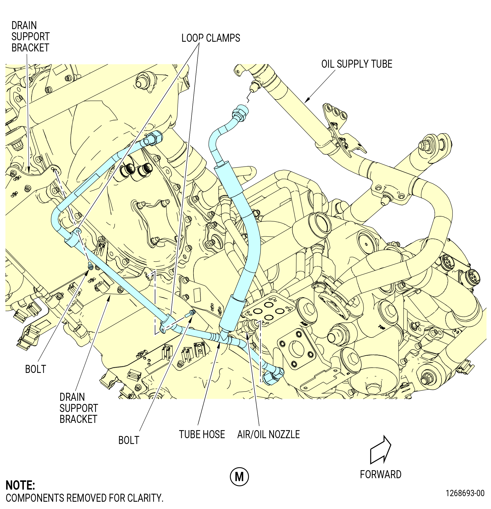
| (10) | Remove the tube hose from the oil supply tube, air/oil nozzle, and drain support brackets as follows: |
| (a) | Disconnect the B-nuts that attach the tube hose to the oil supply tube, air/oil nozzle, and AGB housing. |
| (b) | Remove the bolts and loop clamps from the tube hose. |
| (c) | Remove the tube hose. |
|
|
|
| Subtask 72-00-05-020-042 |
| * * * FOR ALL |
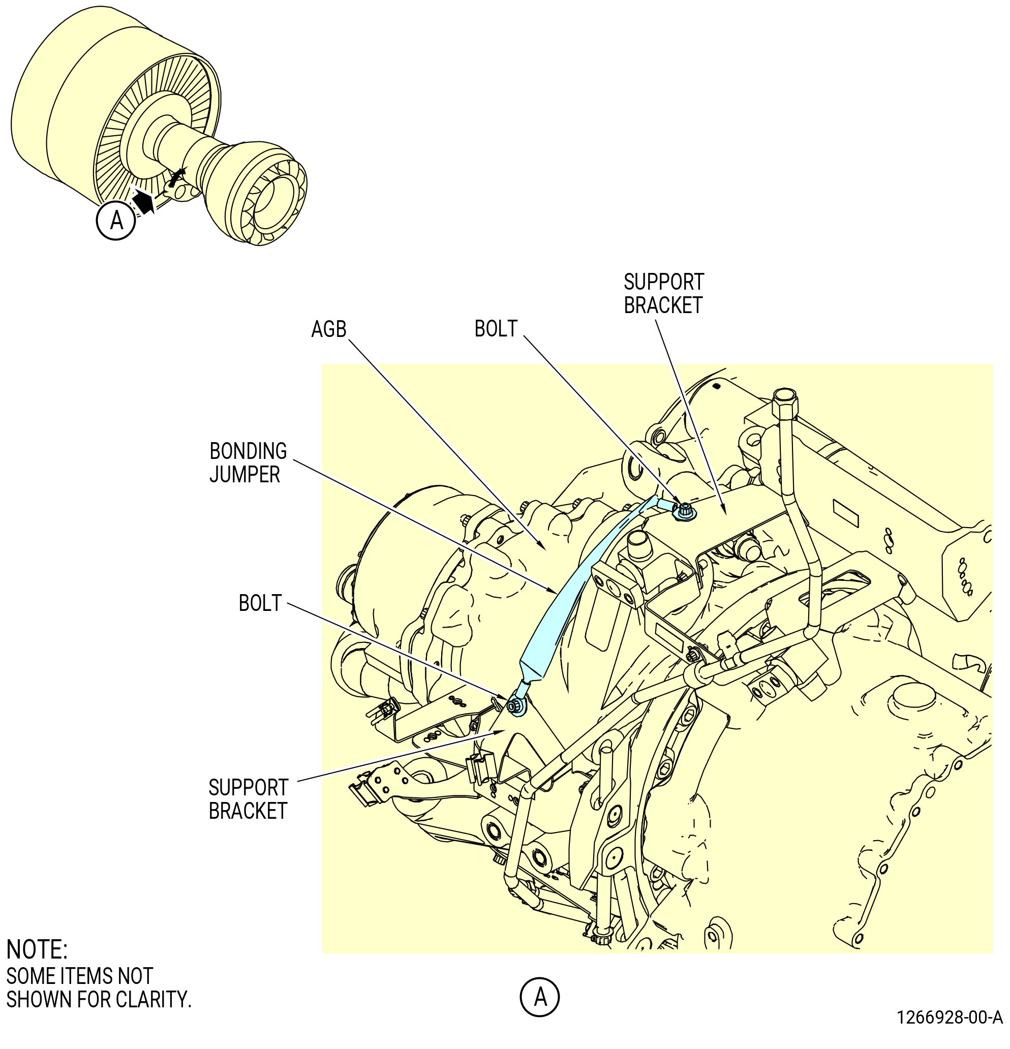
| D. | Disconnect the bonding jumper as follows: |
| (1) | Remove the bolt that attaches the bonding jumper to the support bracket on the left side of the AGB. Refer to Figure 304. |
| Subtask 72-00-05-020-016 |
| * * * FOR ALL |
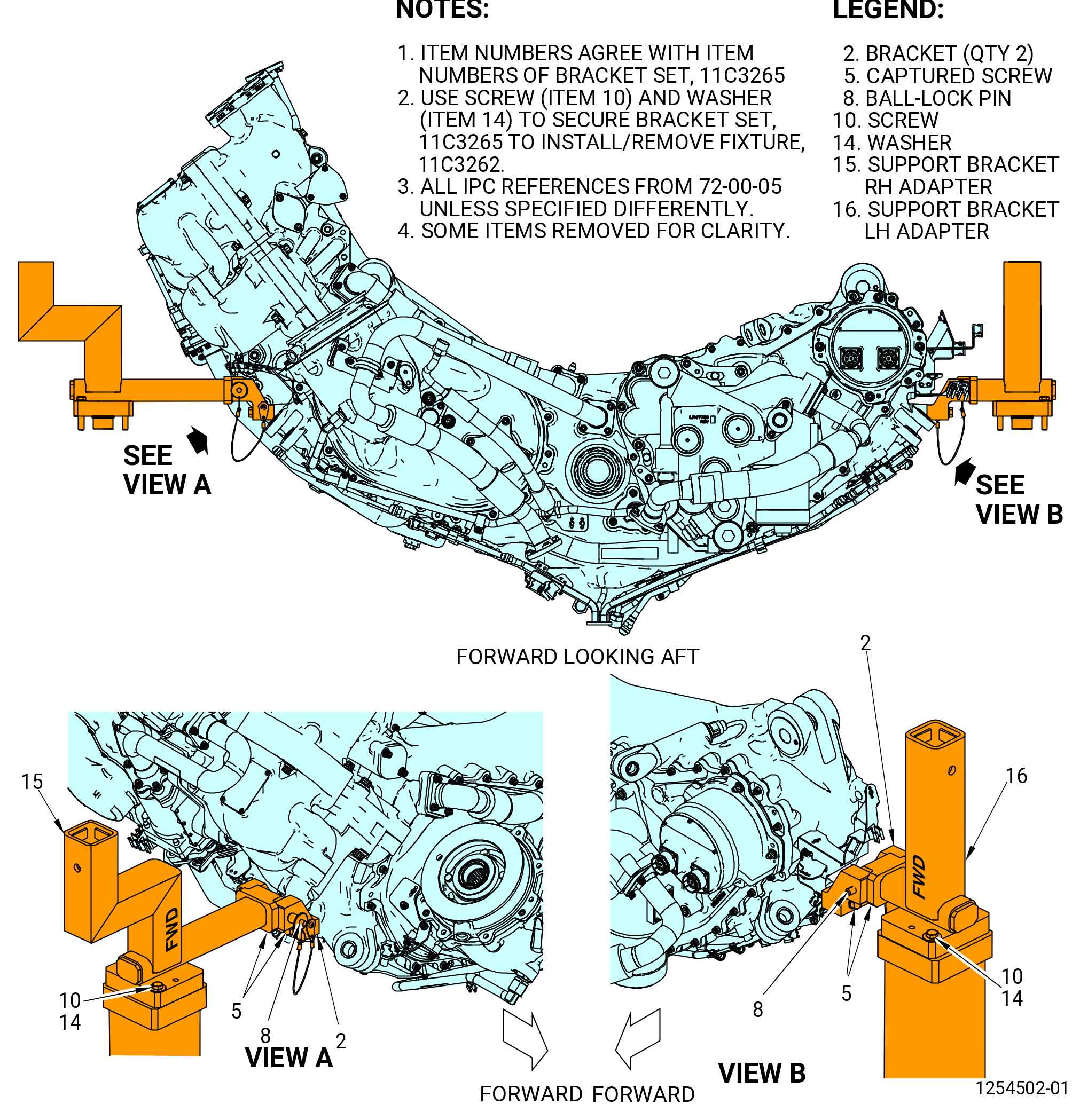
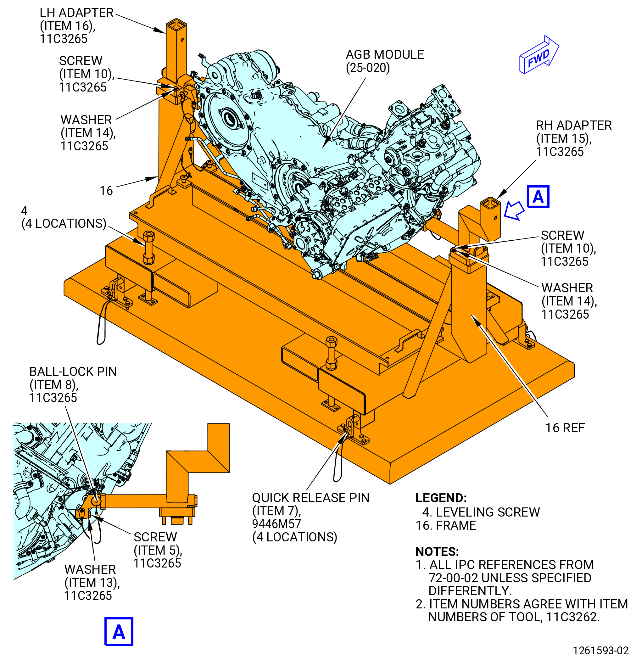
| E. | Install the 11C3265 bracket set, 11C3262 install/remove fixture, and the 9446M57 raise/lower fixture on the AGB. Refer to Figure 305, Figure 306, and as follows: |
| NOTE: |
|
| NOTE: |
|
| (1) | Install the brackets (item 2) of the 11C3265 bracket set to the AGB ground handling bosses with the captured screws (item 5), washers (item 13), and the ball-lock pins (item 8). Tighten the captured screws. |
| (2) | Install the 11C3262 install/remove fixture on the 9446M57 raise/lower fixture as follows: |
| WARNING: |
|
| (a) | Lift the 11C3262 install/remove fixture and install on the 9446M57 raise/lower fixture. |
| (b) | Attach the 9446M57 raise/lower fixture with the quick release pin (item 7) to the frame (item 15) of the11C3262 install/remove fixture. |
| (3) | Install the 11C3262 install/remove fixture on the 11C3265 bracket set that is attached to the AGB module as follows: |
| WARNING: |
|
| (a) | Lower the 9446M57 raise/lower fixture to the lowest point. |
| (b) | Align the 9446M57 raise/lower fixture and the 11C3262 install/remove fixture with the adapter brackets (item 15 and 16) of the 11C3265 bracket set. |
| (4) | Lift the 9446M57 raise/lower fixture to the AGB. |
| (5) | Secure the right hand adapter bracket (item 15) to the 11C3262 install/remove fixture with the screw (item 10) and washer (item 14) of the 11C3265 bracket set. |
| (6) | Secure the left hand adapter bracket (item 16) to the 11C3262 install/remove fixture with the screw (item 10) and washer (item 14) of the 11C3265 bracket set. |
| Subtask 72-00-05-020-038 |
| * * * FOR ALL |
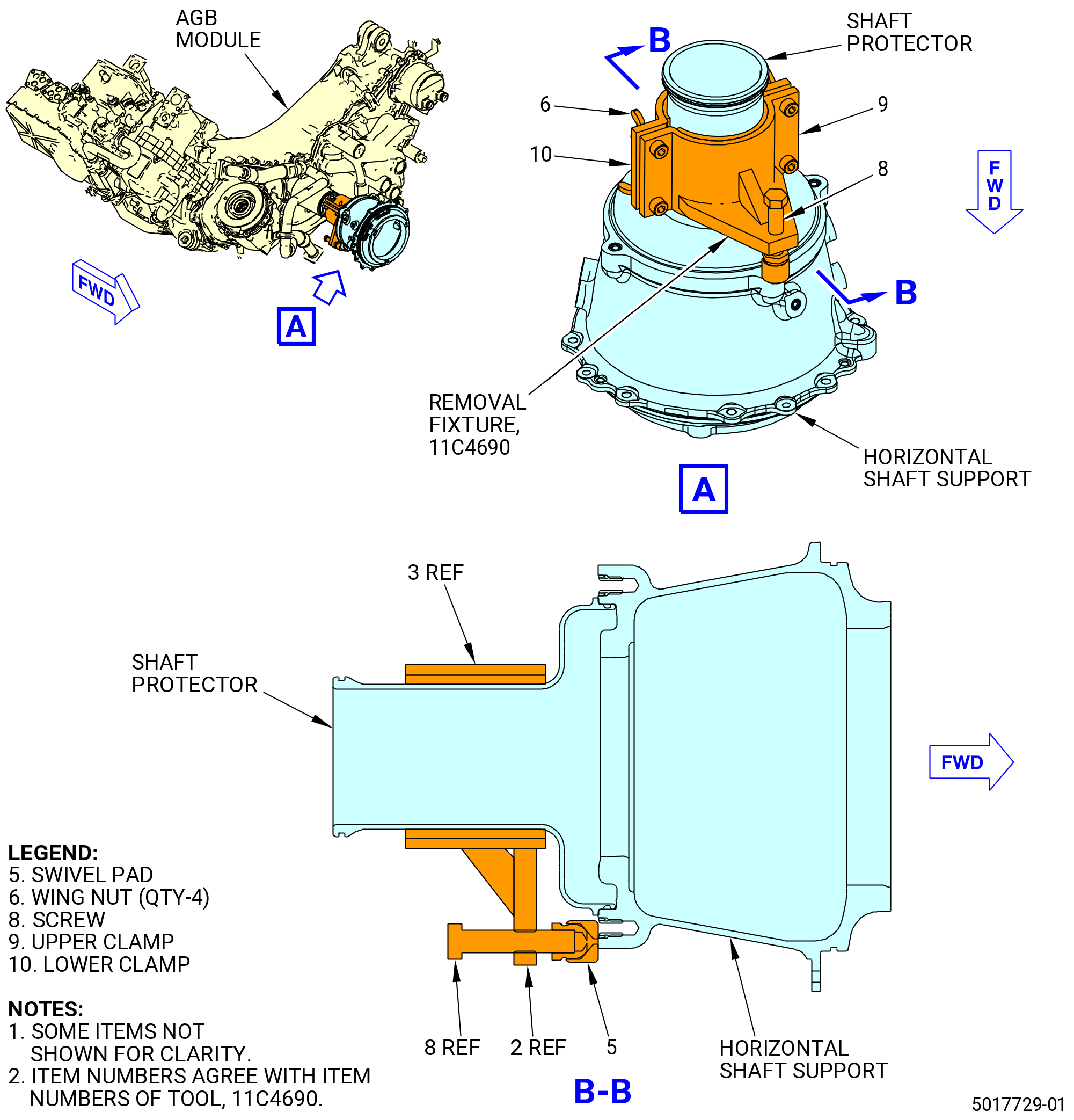
| F. | Disconnect the shaft protector from the TGB as follows. Refer to Figure 308. |
| (1) | Remove the bolts on the retaining ring of the shaft protector at the TGB. |
| (2) | Move the retaining ring toward the aft end of the shaft protector. |
| (3) | Install the 11C4690 removal fixture on the shaft protector. Refer Figure 307 and do as follows: |
| (a) | Unwind the screw (item 8) to make sure that the swivel pad (item 5) is against the tool. |
| (b) | Loosely clamp both halves of the tool around the shaft protector forward side of the shaft. |
| (c) | Screw (item 8) forward until the swivel pad (item 5) mates with the TGB housing in the location where one of the bolts that firmly attaches the retaining ring was installed. |
| (d) | Hand-tighten the clamp halves with wing nuts (item 6). |
| (e) | Apply torque to the screw (item 8) until the shaft protector disengages from the TGB housing. |
| (f) | Remove the 11C4690 removal fixture from the shaft protector. |
| * * * FOR ALL |
| Subtask 72-00-05-020-039 |
| * * * FOR ALL |
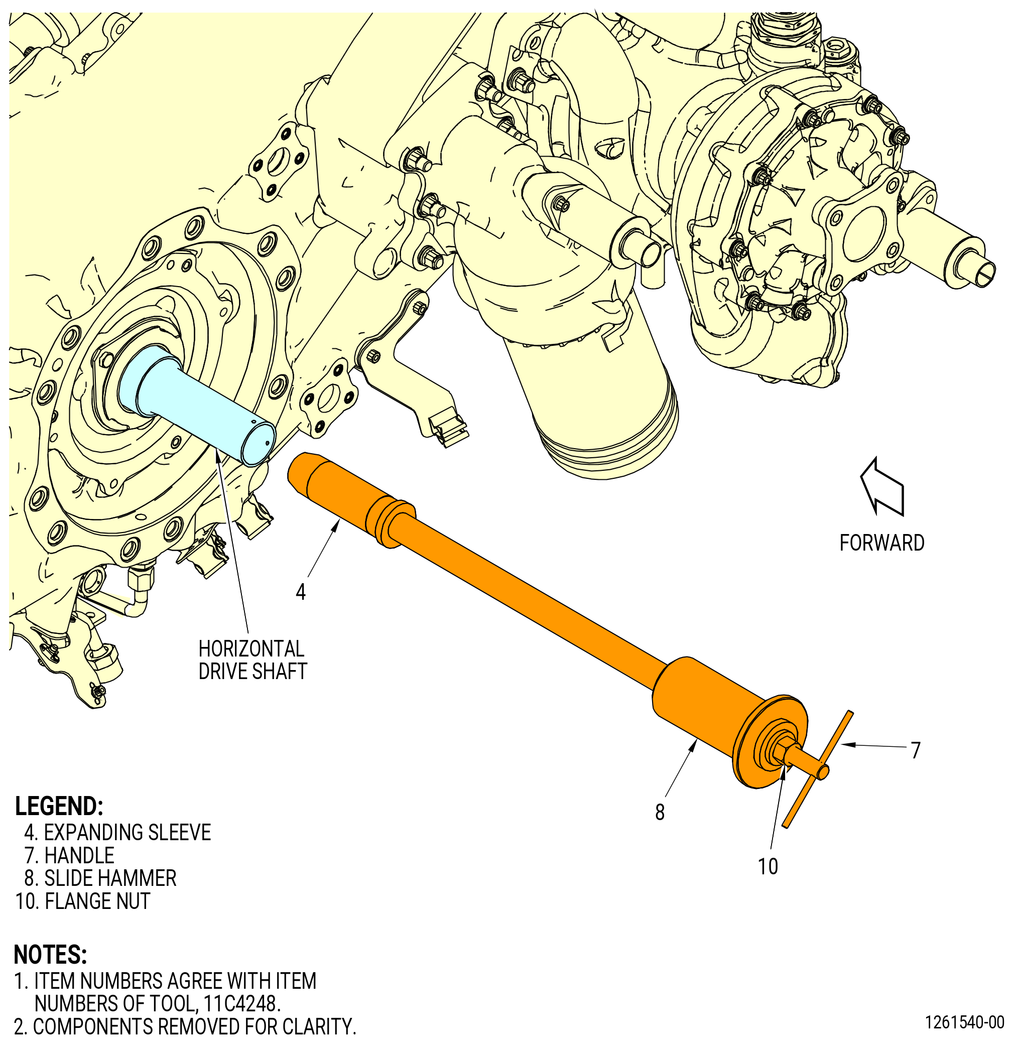
| G. | Disconnect the horizontal drive shaft from the TGB as follows. Refer to Figure 309. |
| (1) | Install the 11C4248 install/remove fixture into the AGB module as follows: |
| (a) | Loosen the flange nut (item 10). |
| (b) | Install the expanding sleeve (item 4) into the ID bore of the horizontal drive shaft from the aft side of the AGB. |
| (c) | Move the expanding sleeve (item 4) in the horizontal drive shaft until it is after the tapered end. |
| (d) | Hold the handle (item 7) and tighten the flange nut (item 10). |
| CAUTION: |
|
| (e) | Use the slide hammer (item 8) to disengage the horizontal drive shaft from the preformed packing. |
| NOTE: |
|
| (f) | Loosen the flange nut (item 10). |
| (g) | Remove the 11C4248 install/remove fixture from the horizontal drive shaft. |
| Subtask 72-00-05-020-017 |
| * * * FOR ALL |
| * * * FOR ALL |
| * * * PRE SB 72-0006 |
| WARNING: |
|
| H. | Remove the AGB vertical links (vertical link) (25-140 , 72-00-02) and (25-170 , 72-00-02) as follows. Refer to Figure 310. |
| (1) | If necessary, remove the insulation blanket from the vertical links (25-140 , 72-00-02) and (25-170 , 72-00-02) to get access to the bolts (25-130 , 72-00-02). |
| (2) | Remove the bolt (25-130 , 72-00-02) from the vertical link (25-170 , 72-00-02) attached to the right side vertical link (25-180 , 72-00-02) on the engine core. |
| (3) | Remove the vertical link (25-170 , 72-00-02). Keep the removed parts. |
| (4) | Remove the bolt (25-130 , 72-00-02) from the vertical link (25-140 , 72-00-02) attached to the left side vertical link (25-160 , 72-00-02) on the engine core. |
| (5) | Remove the vertical link (25-140 , 72-00-02). Keep the removed parts. |
| * * * FOR ALL |
| * * * END PRE SB 72-0006 |
| Subtask 72-00-05-020-045 |
| * * * FOR ALL |
| * * * FOR ALL |
| * * * SB 72-0006 |
| WARNING: |
|
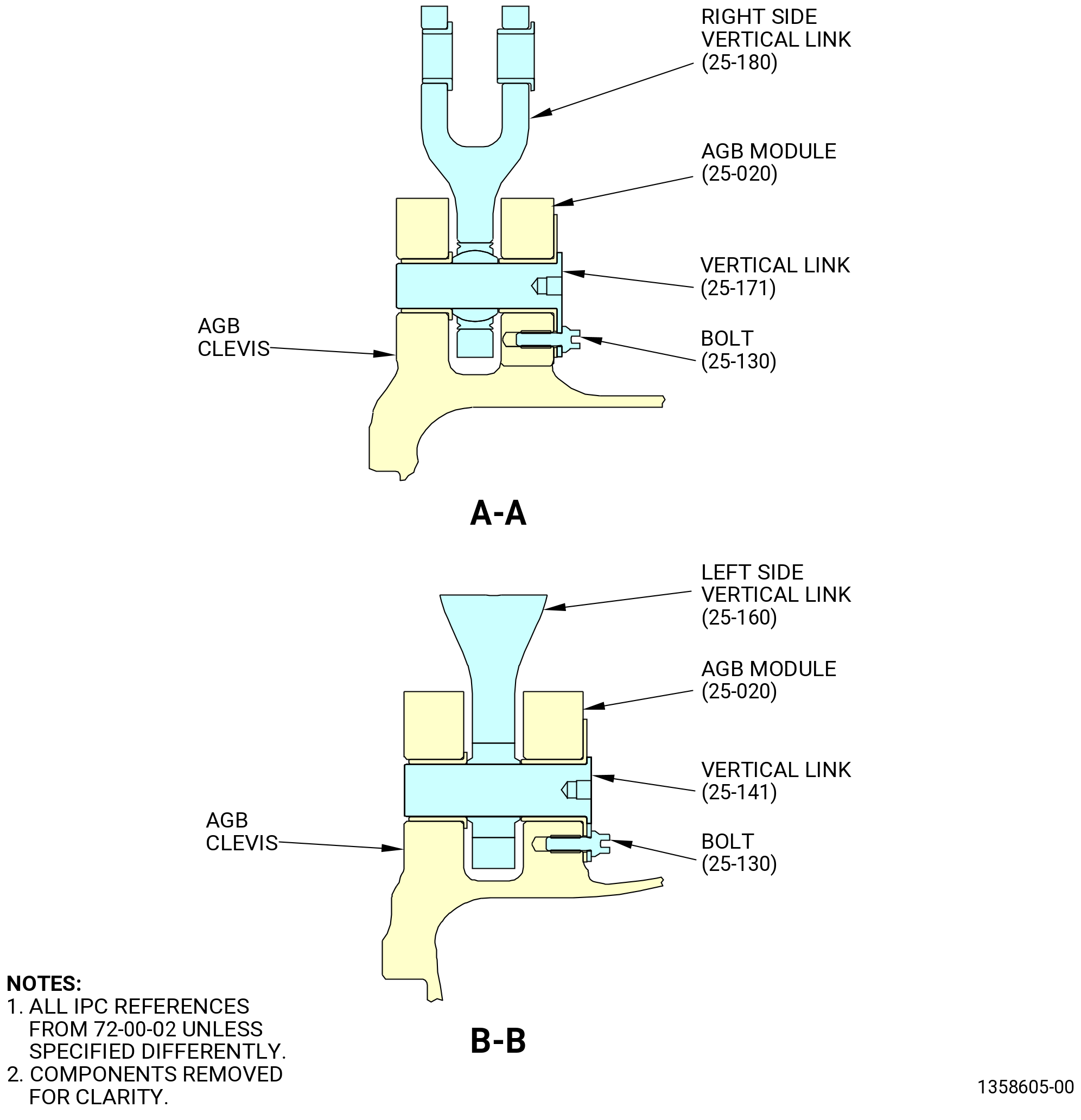
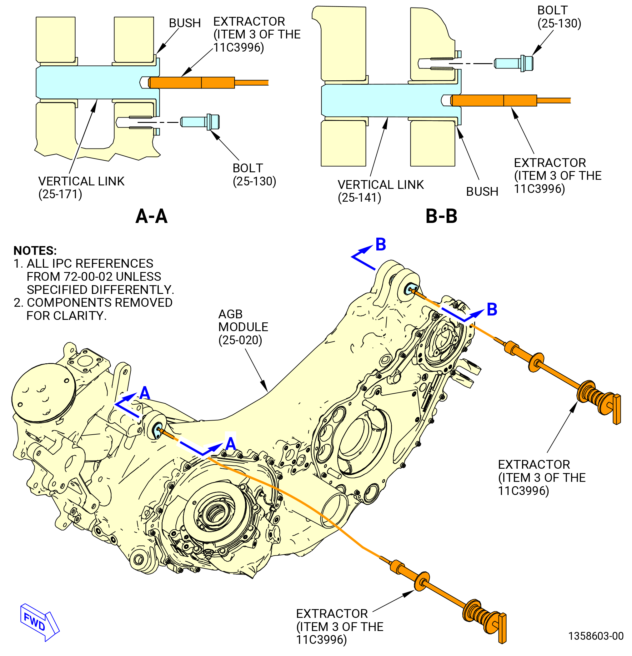
| H.A. | Remove the vertical axe links (vertical link) (25-171 , 72-00-02) and (25-141 , 72-00-02) as follows. Refer to Figure 310 and Figure 311. |
| (1) | Remove the bolt (25-130 , 72-00-02) from the vertical link (25-171 , 72-00-02) that attaches the right side vertical link (25-180 , 72-00-02) to the AGB module (25-020 , 72-00-02). |
| (2) | Remove the vertical link (25-171 , 72-00-02) with the extractor (item 3) of the 11C3996 tool set. |
| (3) | Remove the bolt (25-130 , 72-00-02) from the vertical link (25-141 , 72-00-02) that attaches the left side vertical link (25-160 , 72-00-02) to the AGB module (25-020 , 72-00-02). |
| (4) | Remove the vertical link (25-141 , 72-00-02) with the extractor (item 3) of the 11C3996 tool set. |
| * * * FOR ALL |
| * * * END SB 72-0006 |
| Subtask 72-00-05-020-018 |
| * * * FOR ALL |
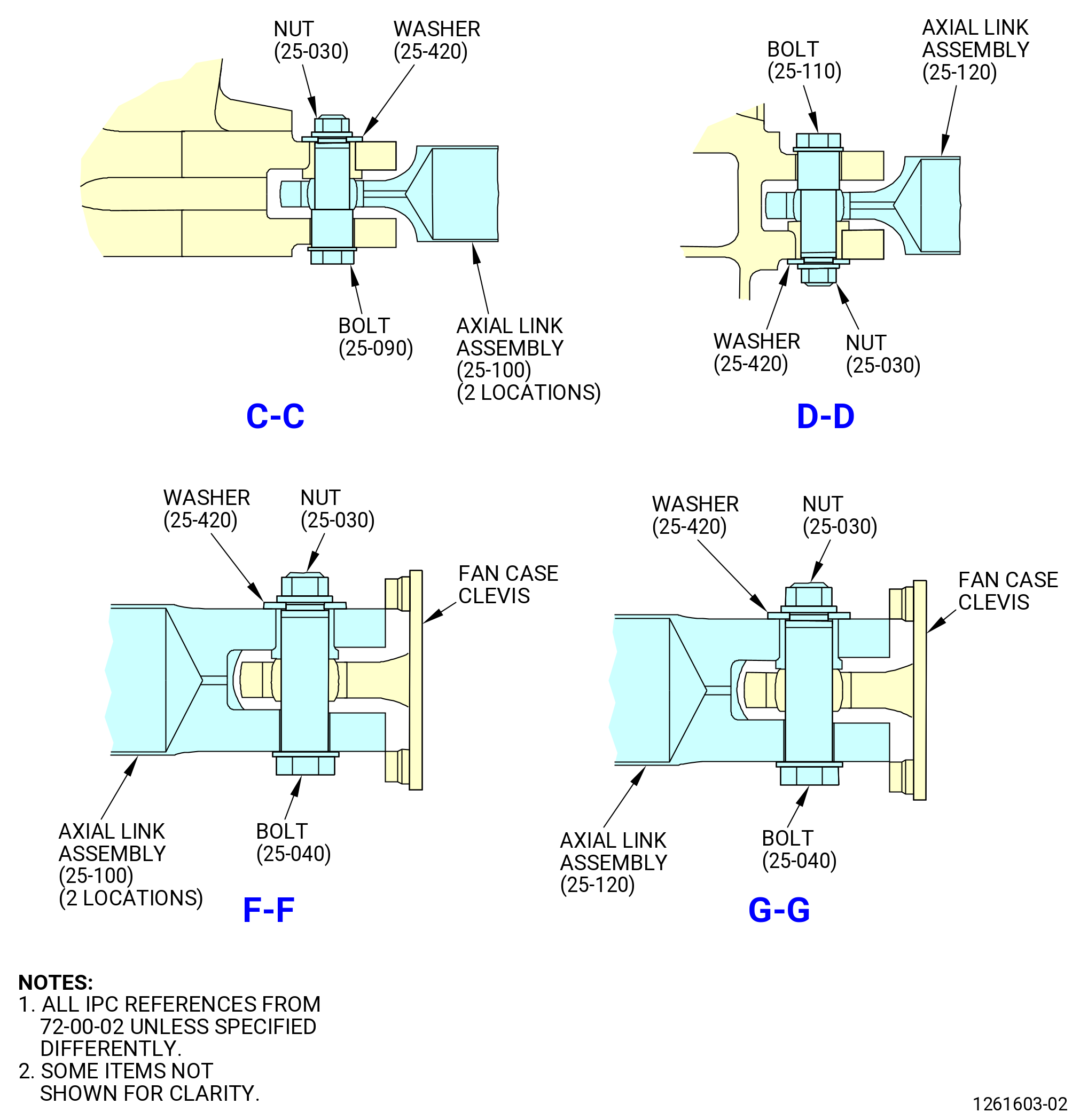
| I. | Remove the AGB axial link assemblies as follows. Refer to Figure 310. |
| (1) | Remove the nuts (25-030 , 72-00-02), washers (25-420 , 72-00-02), and bolts (25-090 , 72-00-02, 25-110 , 72-00-02) that attach the left axial link assembly (25-100 , 72-00-02), center axial link assembly (25-120 , 72-00-02), and right axial link assembly (25-100 , 72-00-02) to the clevises on the AGB. |
| (2) | Remove the nuts (25-030 , 72-00-02), washers (25-420 , 72-00-02), and bolts (25-040 , 72-00-02) that attach the left axial link assembly (25-100 , 72-00-02), center axial link assembly (25-120 , 72-00-02), and right axial link assembly (25-100 , 72-00-02) to the clevises on the fan frame. |
| (3) | Remove the axial link assemblies. Keep the removed parts. |
|
|
| * * * FOR ALL |
| Subtask 72-00-05-020-019 |
| * * * FOR ALL |
| J. | Lower and remove the AGB from the propulsor as follows: |
| (1) | Lower the AGB from the propulsor with the hydraulic release valve at the hydraulic pump on the 9446M57 raise/lower fixture. |
| (2) | Move the AGB from under the propulsor. |
| (3) | Remove the horizontal drive shaft from the AGB module. |