| GENX-1B ENGINE MANUAL | Dated: 09/10/2024 | |
| EM 72-00-02 , ASSEMBLY 005 | ||
| PROPULSOR ASSEMBLY - ASSEMBLY 005 - CONFIGURATION 02 | ||
| GENX-1B ENGINE MANUAL | Dated: 09/10/2024 | |
| EM 72-00-02 , ASSEMBLY 005 | ||
| PROPULSOR ASSEMBLY - ASSEMBLY 005 - CONFIGURATION 02 | ||
| * * * FOR ALL PIP 2 |
| TASK 72-00-02-430-819 |
| 1 . | General. |
| A. | This procedure gives instructions to continue the assembly of the external configuration of the propulsor module assembly (propulsor). |
| • |
|
| • |
|
| • |
|
| B. | This procedure starts with the propulsor in the horizontal position installed in the 11C3044 adapter assembly, attached to the customer overhead rail system, at the equivalent assembly status of TASK 72-00-02-430-822 (72-00-02, ASSEMBLY 004, CONFIG 02) . |
| C. | Make sure that personnel read this procedure and know the step-by-step instructions and special tool usage before they assemble the engine assembly. |
| D. | Make sure that the engine assembly and the parts that you install have the correct support at all times to prevent injury to personnel or damage to engine parts. |
| E. | The special tools in this procedure are designed by the engine manufacturer. They are available at customer's discretion to do engine maintenance efficiently. Correct use of the tools will save maintenance man-hours and help prevent engine damage while work is done on the engine. |
| F. | Cleanliness is extremely important. Put protection on machined surfaces. Wrap precision parts. Put caps or plugs on/in all openings and connections. |
| G. | It is most important that all engine parts are kept free of corrosion. Make sure that instructions which give special handling requirements for engine components are done. |
| H. | Deviations are not permitted for clearances or torque values. Refer to the Standard Practices Manual for assembly and disassembly techniques and for tightening practices and torque values. |
| I. | Clearance limits give the correct dimensional relationship between mating parts. They are not used for routine dimensional inspection of individual parts at the time of assembly. Except where called out for assembly, the clearances shown are for reference only. |
| J. | Unless otherwise specified, install all bolts with the heads forward or from the top. |
| K. | Unless otherwise specified, lubricate the threads and washer faces of bolts, screws, studs or nuts with C02-058 lubricant before installation. After installation, remove unwanted lubricant with C10-182 cleaning cloth. |
| WARNING: |
|
| L. | Clean parts before assembly with C04-035 isopropyl alcohol. |
| M. | Follow the instructions to safety parts with safety wire, safety cable, cotter pins, or tab washers. Refer to TASK 70-11-00-400-001 (FASTENER RETENTION PROCEDURES) . |
| 2 . | Tools, Equipment, and Materials. |
| NOTE: |
|
| A. | Tools and Equipment. |
| (1) | Special Tools. |
|
| (2) | Standard Tools and Equipment. |
|
| (3) | Locally Manufactured Tools. None. |
| B. | Consumable Materials. |
| C. | Referenced Procedures. |
|
| D. | Expendable Parts. |
|
| 3 . | Procedure. |
| Subtask 72-00-02-440-302 |
| A. | Install the variable frequency starter generators (VFSG) lube system. Refer to Figure 1001 and do as follows: |
| Subtask 72-00-02-440-303 |
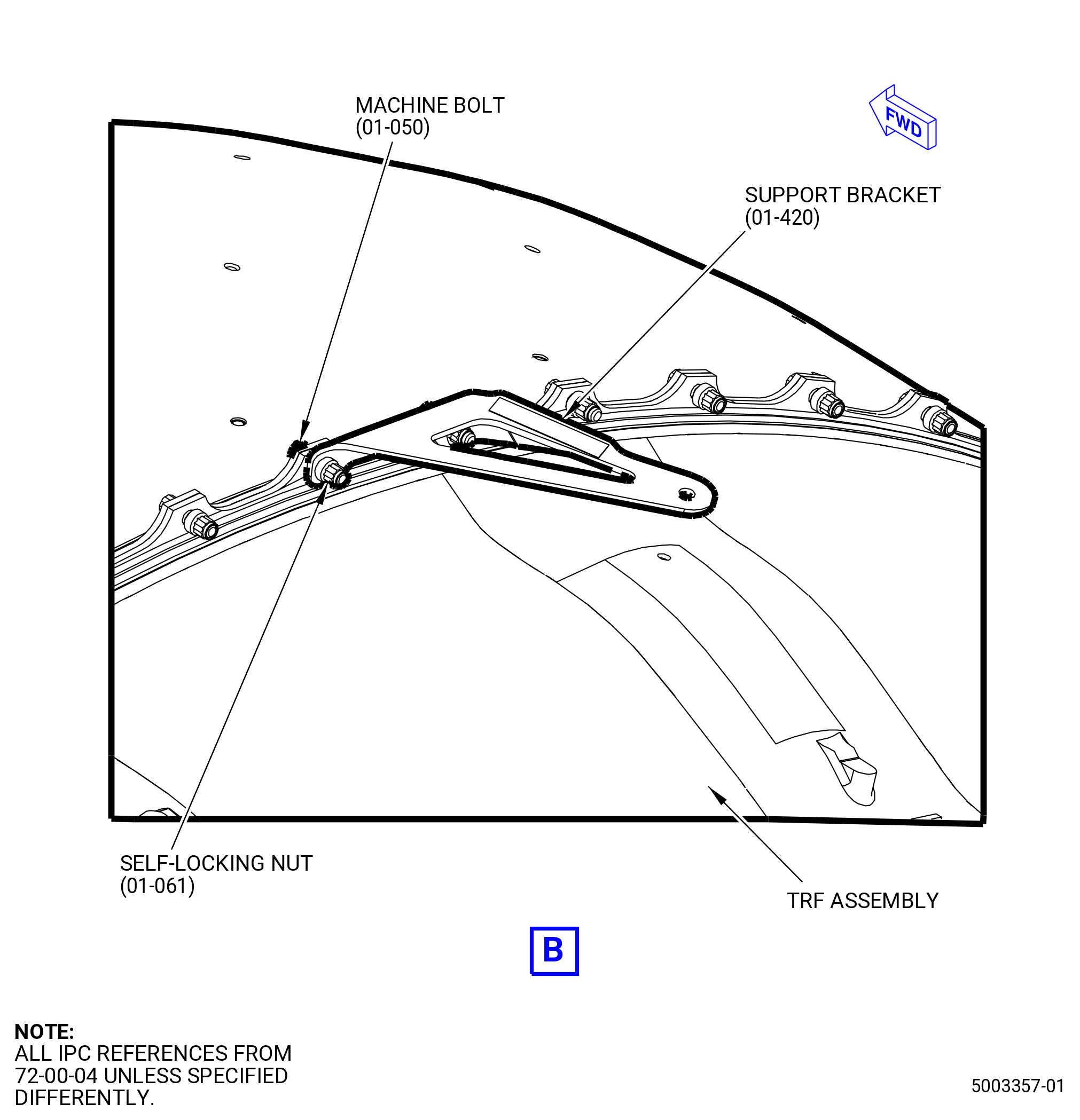
| (1) | Install the support brackets (30-240 , 79-22-10) (SIN 5211N) and (30-230 , 79-22-10) (SIN 5211M) as follows: |
| (a) | Attach the support bracket (30-240 , 79-22-10) (SIN 5211N) to the FCOC modification bracket (01-042 , 73-11-20) (SIN 42412) with bolts (30-220 , 79-22-10) (SIN 52128). |
| (b) | Attach the support bracket (30-230 , 79-22-10) (SIN 5211M) to the support bracket (01-061 , 73-11-20) (SIN 42413) with bolts (30-220 , 79-22-10) (SIN 52128). |
| Subtask 72-00-02-440-304 |
| (2) | Torque the bolts (30-220 , 79-22-10) (SIN 52128) to 106-124 lb in. (12.0-14.0 N.m). |
| (3) | Install VFSG cooling oil tube hose (oil tube) (5210K) and VFSG cooling oil tube (oil tube) (5210S) as follows: |
| (a) | Connect the oil tube (30-150 , 79-22-10) (SIN 5210S) to the aft fitting of the VFSG heat exchanger (01-010 , 73-11-20) (SIN 42400). |
| (b) | Connect the oil tube(5210K) to the oil tube (5210S). |
| NOTE: |
|
| (c) | Attach the oil tube (5210K) to the heat shield (29900) at four locations with cushioned clamps (52180) and bolts (52122). |
| (d) | Torque the B-nut of the oil tube (30-150 , 79-22-10) (SIN 5210S) at the VFSG heat exchanger (01-010 , 73-11-20) (SIN 42400) to 78-92 lb ft (106-125 N.m). |
| (e) | Torque the B-nut of the oil tube (5210S) at the oil tube (5210K) to 55-65 lb ft (75-88 N.m). |
| (f) | Torque the bolts (52122) to 60-70 lb in. (6.8-7.9 N.m). |
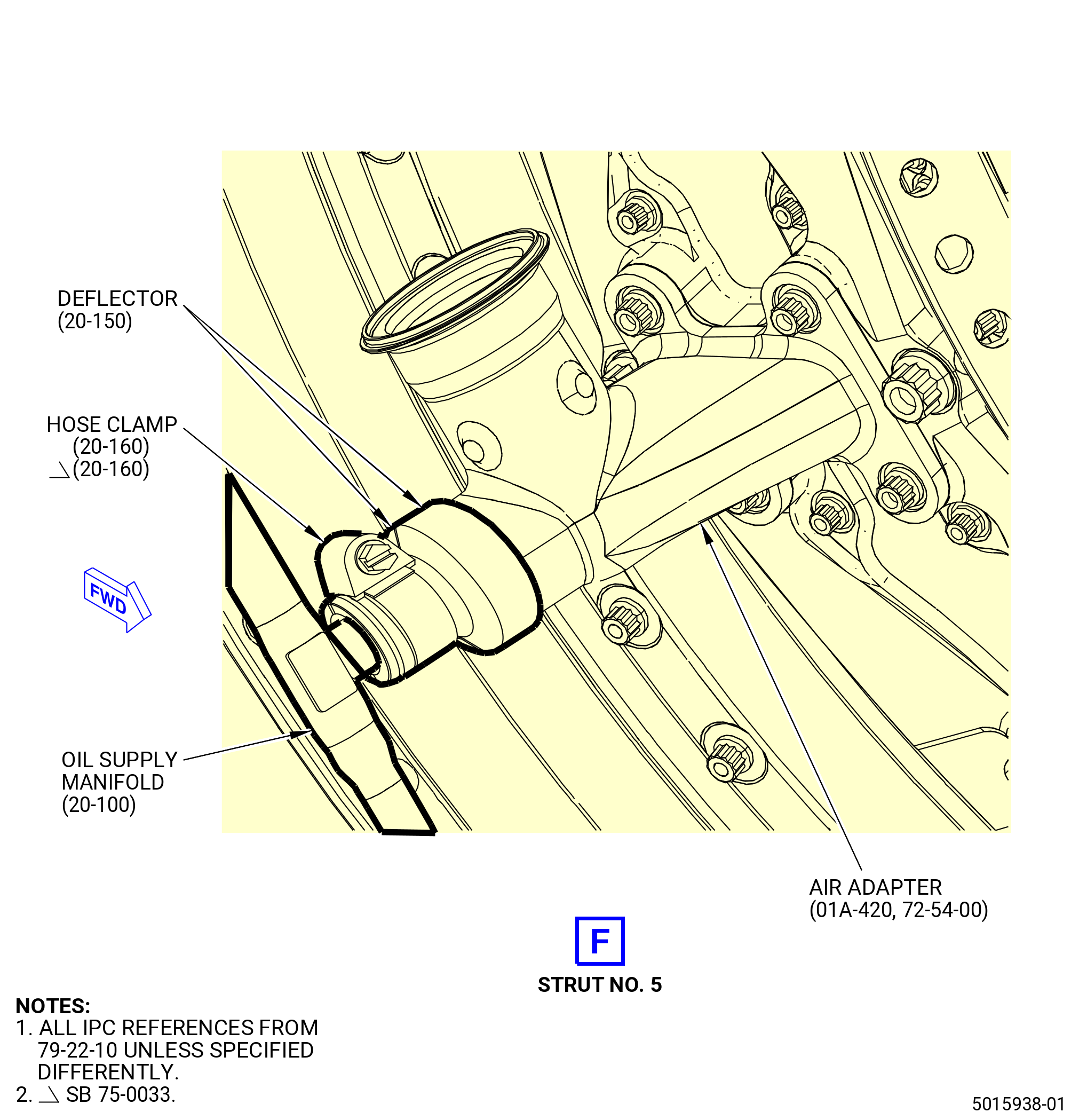
| (4) | Install the VFSG cooling oil tube (oil tube) (5210R) and VFSG cooling oil tube (oil tube) (5210B) as follows: |
| (a) | Connect the oil tube (30-160 , 79-22-10) (SIN 5210R) to the VFSG heat exchanger (01-010 , 73-11-20) (SIN 42400). |
| (b) | Connect the oil tube (5210B) to the oil tube (5210R). |
| NOTE: |
|
| (c) | Attach the oil tube (5210B) to the heat shield (29900) at three locations with cushioned clamp (52180) and bolt (52122). |
| (d) | Torque the B-nut of the oil tube (30-160 , 79-22-10) (SIN 5210R) at the VFSG heat exchanger (01-010 , 73-11-20) (SIN 42400) to 78-92 lb ft (106-125 N.m). |
| (e) | Torque the B-nut of the oil tube (5210R) at the the oil tube (5210B) to 55-65 lb ft (75-88 N.m). |
| (f) | Torque the bolts (52122) to 60-70 lb in. (6.8-7.9 N.m). |
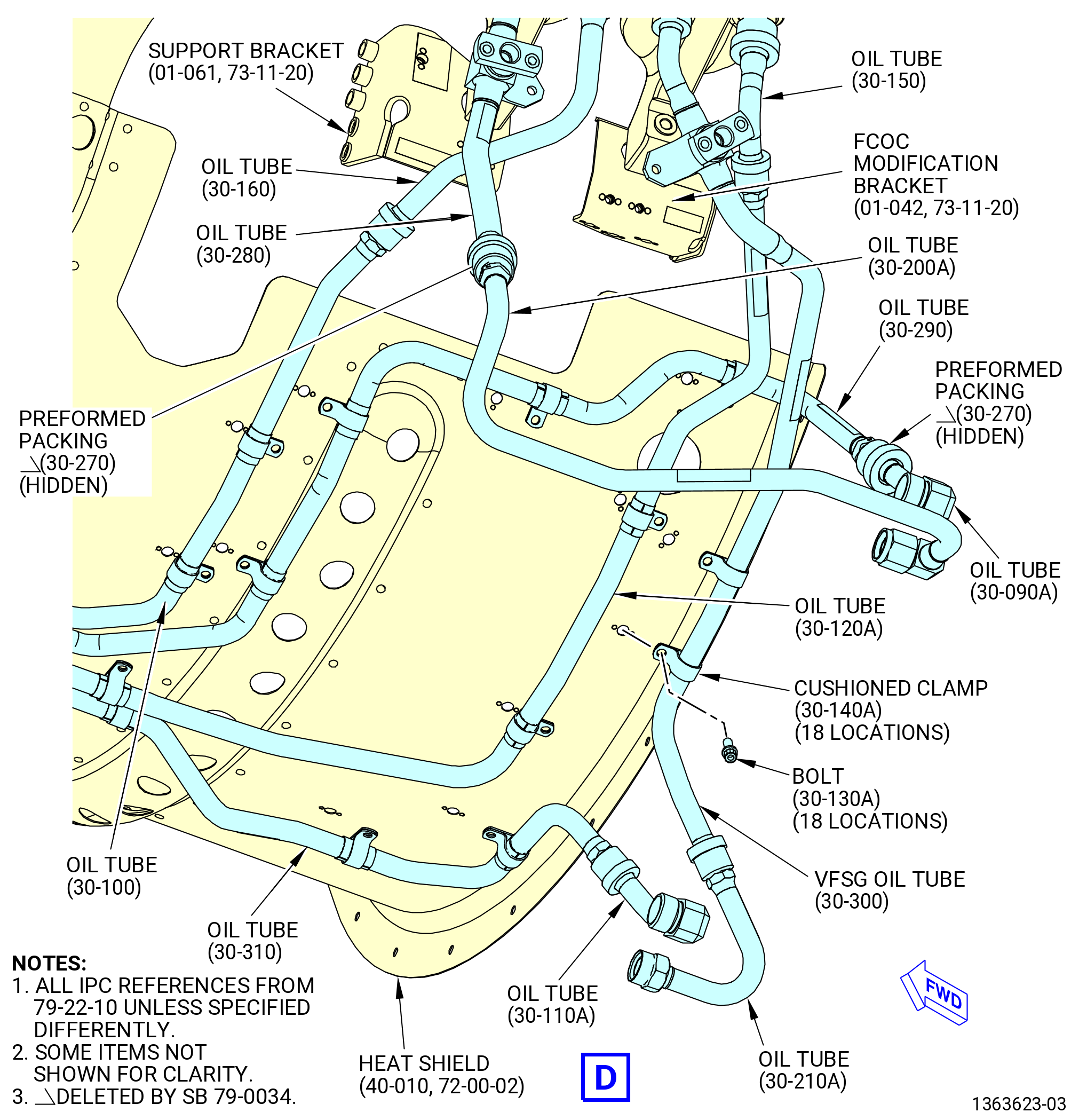
| (5) | Install the oil tube hose (oil tube) (30-090A , 79-22-10) (SIN 5210J), oil VFSG return tube (oil tube) (30-290 , 79-22-10) (SIN 5210T), VFSG oil tube hose (oil tube) (30-110A , 79-22-10) (SIN 5210U), and VFSG oil tube (oil tube) (30-310 , 79-22-10) (SIN 5210Y). Refer to Figure 1001 and do as follows: |
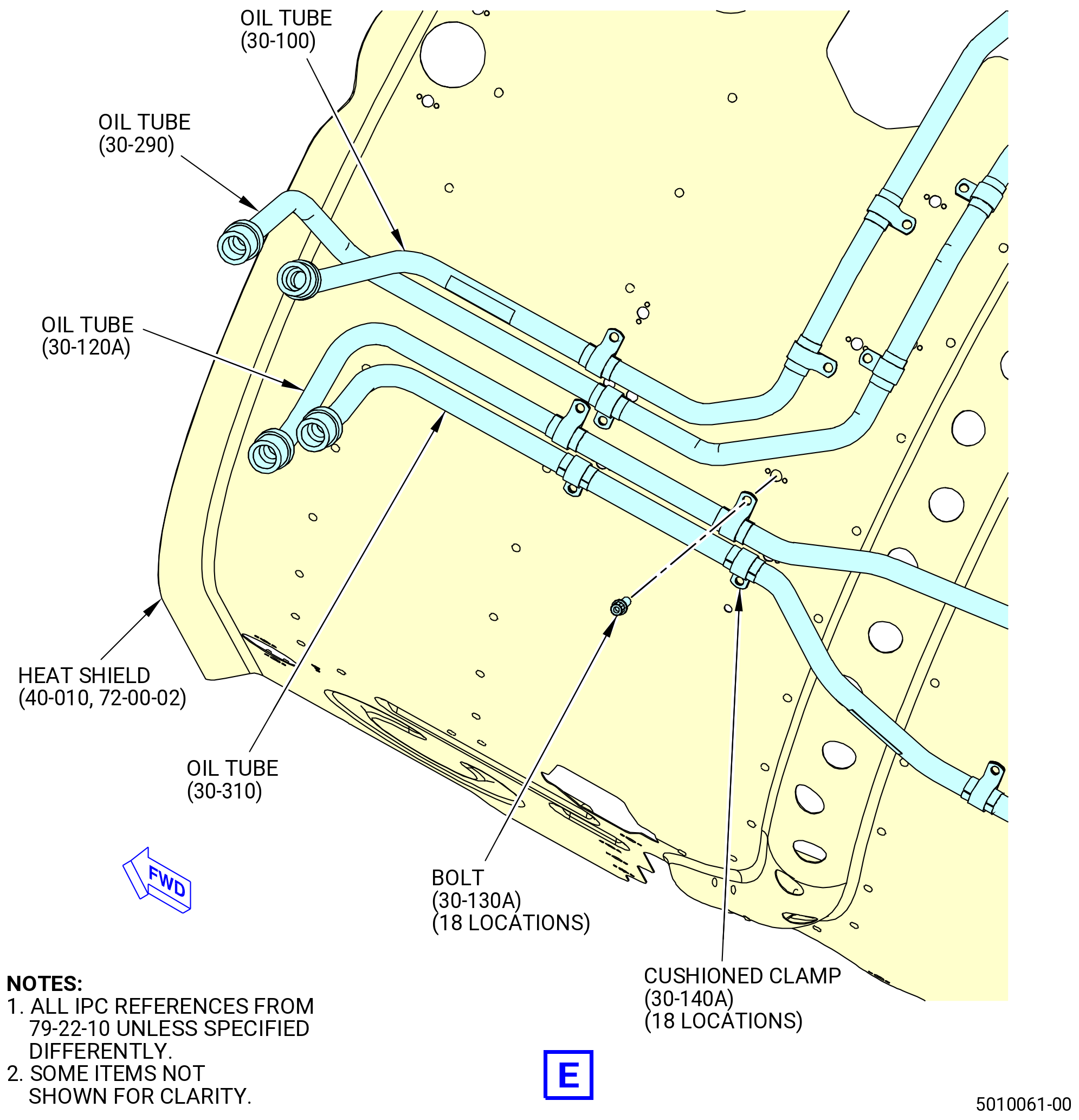
| (a) | Attach the oil tube (30-290 , 79-22-10) (SIN 5210T) to the heat shield (40-010) (SIN 29900) at five locations with cushioned clamps (30-140A , 79-22-10) (SIN 52180) and bolts (30-130A , 79-22-10) (SIN 52122). |
| (b) | Attach the oil tube (30-310 , 79-22-10) (SIN 5210Y) to the heat shield (40-010) (SIN 29900) at four locations with cushioned clamps (30-140A , 79-22-10) (SIN 52180) and bolts (30-130A , 79-22-10) (SIN 52122). |
| (c) | Torque the bolts (30-130A , 79-22-10) (SIN 52122) to 60 to 70 lb in. (6.8 to 7.9 Nm). |
| Subtask 72-00-02-440-576 |
| * * * PRE SB 79-0034( Oil VFSG Return Tube with Preformed Packing ) |
| (d) | Install the preformed packing (30-270 , 79-22-10) (SIN 52151) and do as follows: |
| NOTE: |
|
| WARNING: |
|
| 1 | Apply C02-019 engine oil or C02-023 engine oil to the preformed packing (30-270 , 79-22-10) (SIN 52151). |
| 2 | Install the preformed packing (30-270 , 79-22-10) (SIN 52151) on the oil tube (30-290 , 79-22-10) (SIN 5210T). |
| * * * END PRE SB 79-0034 |
| Subtask 72-00-02-440-577 |
| (e) | Attach the oil tube (30-090A , 79-22-10) (SIN 5210J) to the oil tube (30-290 , 79-22-10) (SIN 5210T). |
| (f) | Torque the B-nut of the oil tube (30-090A , 79-22-10) (SIN 5210J) at the oil tube (30-290 , 79-22-10) (SIN 5210T) to 55 to 65 lb ft. (75.0 to 88.0 Nm). |
| (g) | Attach the oil tube (30-110A , 79-22-10) (SIN 5210U) to the oil tube (30-310 , 79-22-10) (SIN 5210Y). |
| (h) | Torque the B-nut of the oil tube (30-110A , 79-22-10) (SIN 5210U) at the oil tube (30-310 , 79-22-10) (SIN 5210Y) to 55 to 65 lb ft. (75.0 to 88.0 Nm). |
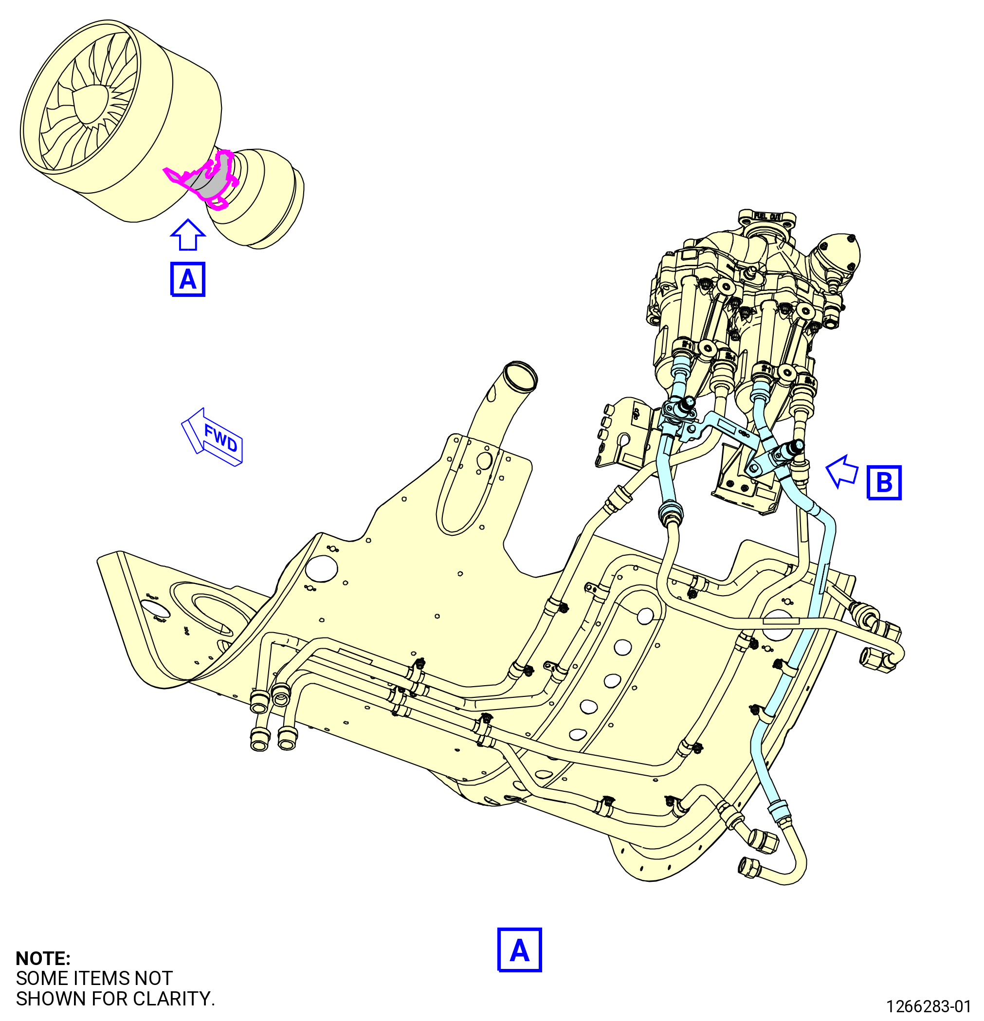
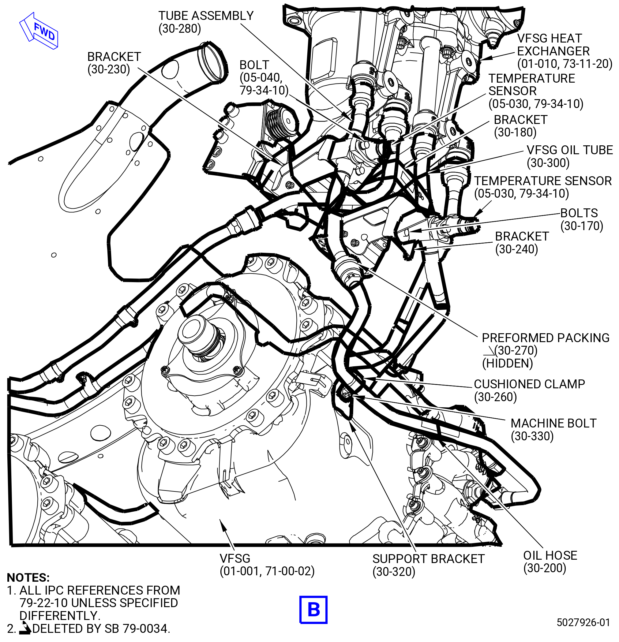
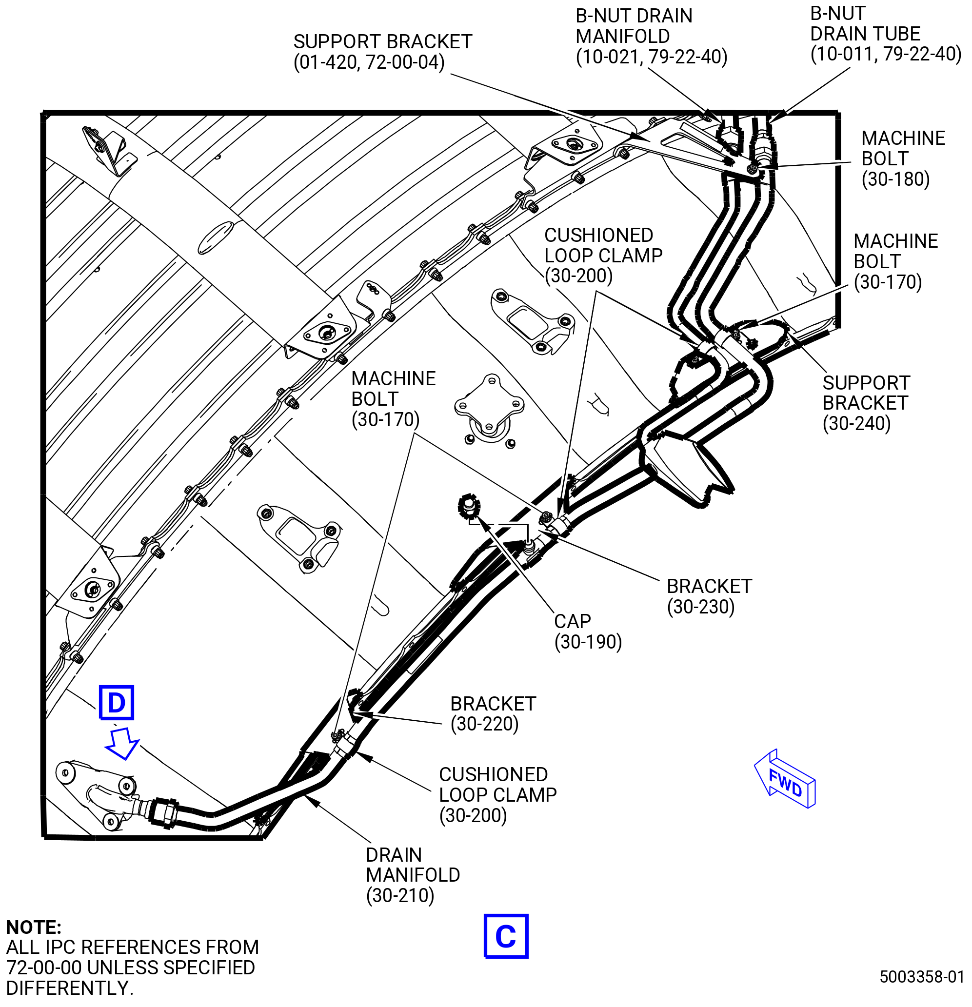
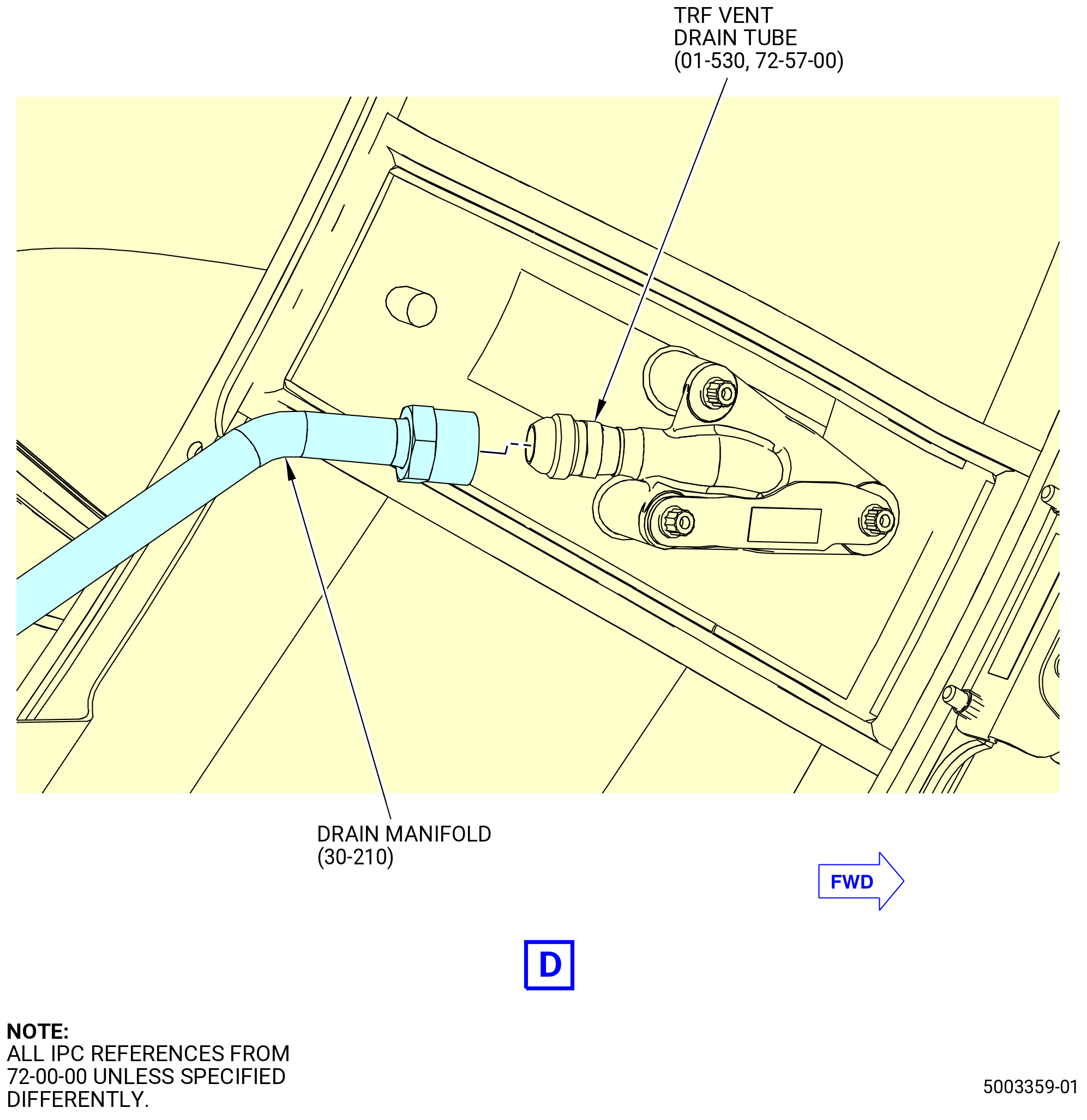
| (6) | Install the VFSG oil tube hose (oil hose) (30-200 , 79-22-10) (SIN 5210A), tube assembly (oil tube) (30-280 , 79-22-10) (SIN 5210H), oil hose (30-210 , 79-22-10) (SIN 5210L), and VFSG oil tube (30-300 , 79-22-10) (SIN 5210W). Refer to Figure 1002 and do as follows: |
| (a) | Connect the oil tube (30-280 , 79-22-10) (SIN 5210H) to the forward fitting of the VFSG heat exchanger (01-010 , 73-11-20) (SIN 42400). |
| Subtask 72-00-02-440-578 |
| * * * PRE SB 79-0034( Oil VFSG Return Tube with Preformed Packing ) |
| (b) | Install the preformed packing (30-270 , 79-22-10) (SIN 52151) and do as follows: |
| NOTE: |
|
| WARNING: |
|
| 1 | Apply C02-019 engine oil or C02-023 engine oil to preformed packing (30-270 , 79-22-10) (SIN 52151). |
| 2 | Install the preformed packing (30-270 , 79-22-10) (SIN 52151) on the oil hose (30-200 , 79-22-10) (SIN 5210A). |
| * * * END PRE SB 79-0034 |
| Subtask 72-00-02-440-579 |
| (c) | Attach the oil hose (30-200 , 79-22-10) (SIN 5210A) to the VFSG (01-001 , 71-00-02) (SIN C00A0) with the support bracket (30-320 , 79-22-10) (SIN 52110), cushioned clamp (30-260 , 79-22-10) (SIN 52181), and machine bolt (30-330 , 79-22-10) (SIN 5212A). |
| (d) | Attach the oil tube (30-280 , 79-22-10) (SIN 5210H) to the oil hose (30-200 , 79-22-10) (SIN 5210A). |
| (e) | Align the hole in the sensor tube tab on oil tube (30-280 , 79-22-10) (SIN 5210H) with the hole in the bracket (30-230 , 79-22-10) (SIN 5211M). |
| (f) | Attach the VFSG oil tube (30-300 , 79-22-10) (SIN 5210W) to the heat shield (40-010) (SIN 29900) at two locations with cushioned clamps (30-140 , 79-22-10) (SIN 52180) and bolts (30-130 , 79-22-10) (SIN 52122). |
| (g) | Connect the oil hose (30-210 , 79-22-10) (SIN 5210L) to the aft fitting of the VFSG heat exchanger (01-010 , 73-11-20) (SIN 42400). |
| (h) | Attach the oil hose (30-210 , 79-22-10) (SIN 5210L) to the VFSG oil tube (30-300 , 79-22-10) (SIN 5210W). |
| (i) | Align the hole in the sensor tube tab on VFSG oil tube (30-300 , 79-22-10) (SIN 5210W) with the hole in the bracket (30-240 , 79-22-10) (SIN 5211N). |
| (j) | Install the bracket (30-180 , 79-22-10) (SIN 37112) on the sensor tube tabs of oil tube (30-280 , 79-22-10) (SIN 5210H) and VFSG oil tube (30-300 , 79-22-10) (SIN 5210W). |
| (k) | Attach the bracket (30-180 , 79-22-10) (SIN 37112) to the bracket (30-230 , 79-22-10) (SIN 5211M) and bracket (30-240 , 79-22-10) (SIN 5211N) with bolts (30-170 , 79-22-10) (SIN 52121). |
| (l) | Torque the B-nut of the oil tube (30-280 , 79-22-10) (SIN 5210H) at the VFSG heat exchanger (01-010 , 73-11-20) (SIN 42400) to 55 to 65 lb ft. (75.0 to 88.0 Nm). |
| (m) | Torque the B-nut of the VFSG oil tube (30-300 , 79-22-10) (SIN 5210W) at the VFSG heat exchanger (01-010 , 73-11-20) (SIN 42400) to 55 to 65 lb ft. (75.0 to 88.0 Nm). |
| (n) | Torque the B-nut of the oil hose (30-200 , 79-22-10) (SIN 5210A) at the oil tube (30-280 , 79-22-10) (SIN 5210H) to 55 to 65 lb ft. (75.0 to 88.0 Nm). |
| Subtask 72-00-02-440-580 |
| * * * SB 79-0034( Oil VFSG Return Tube without Preformed Packing ) |
| (o) | Safety the B-nut of the tube assembly (30-280 , 79-22-10) (SIN 5210H) with C10-071 safety wire. |
| NOTE: |
|
| * * * END SB 79-0034 |
| Subtask 72-00-02-440-581 |
| (p) | Torque the bolts (30-130 , 79-22-10) (SIN 52122) to 60 to 70 lb in. (6.8 to 7.9 Nm). |
| (q) | Torque the B-nut of the VFSG oil tube (30-300 , 79-22-10) (SIN 5210W) at the oil hose (30-210 , 79-22-10) (SIN 5210L) to 55 to 65 lb ft. (75.0 to 88.0 Nm). |
| Subtask 72-00-02-440-582 |
| * * * SB 79-0034( Oil VFSG Return Tube without Preformed Packing ) |
| (r) | Safety the B-nut of the VFSG oil tube (30-300 , 79-22-10) (SIN 5210H) with C10-071 safety wire. |
| NOTE: |
|
| * * * END SB 79-0034 |
| Subtask 72-00-02-440-583 |
| (s) | Torque the bolts (30-170 , 79-22-10) (SIN 52121) to 106 to 124 lb in. (12.0 to 14.0 Nm). |
| WARNING: |
|
| (t) | Fill the cavities for the temperature sensor probes on the oil tube (30-280 , 79-22-10) (SIN 5210H) and VFSG oil tube (30-300 , 79-22-10) (SIN 5210W) with C02-060 anti-seize compound. |
| (u) | Install the temperature sensors (05-030 , 79-34-10) (SIN 65T04) on the oil tube (30-280 , 79-22-10) (SIN 5210H) and VFSG oil tube (30-300 , 79-22-10) (SIN 5210W). Attach with bolts (05-040 , 79-34-10) (SIN 65T23) |
| (v) | Torque the bolts (05-040 , 79-34-10) (SIN 65T23) to 106 to 124 lb in. (12.0 to 14.0 Nm). |
| (w) | Remove unwanted C02-060 anti-seize compound. |
| Subtask 72-00-02-440-305 |
| * * * PRE SB 72-0444( with PS25 Sense Line ) |
| B. | Install the PS25 air tube (61400). Refer to Figure 1003 and do as follows: |
| (1) | Connect the PS25 air tube (61400) to the nipple fitting (840S3) on the fan hub frame at the 4:00 o'clock position. |
| (2) | Attach the PS25 air tube (61400) to bracket (44811) with cushioned clamp (61481) and bolt (61421). |
| (3) | Torque the bolt (61421) to 32-38 lb in. (3.6-4.3 N.m). |
| (4) | Torque the B-nut to 262-308 lb in. (29.6-34.8 N.m). |
| (5) | Attach bracket (01-160 , 75-42-10) (SIN 99010) to the transfer gearbox (TGB) (01-010 , 72-25-00) (SIN 03200) with bolts (01-181 , 75-42-10) (SIN 99029). |
| (6) | Torque the bolts (01-181 , 75-42-10) (SIN 99029) to 51 to 59 lb in. (5.8 to 6.7 Nm). |
| (7) | Connect the BIFI air manifold (99008) to the PS3 air tube (61501). |
| (8) | Connect the PS25 air tube (61400) to the BIFI air manifold (99008). |
| (9) | Attach the BIFI air manifold (99008) to bracket (99010) with bolts (9902A). |
| (10) | Torque the bolts (9902A) to 106-124 lb in. (12.0-14.0 N.m). |
| (11) | Torque the B-nut on the PS25 air tube (61400) to 262-308 lb in. (29.6-34.8 N.m) |
| (12) | Tighten the B-nut on the PS3 air tube (61501) as follows: |
| (a) | Torque the B-nut to 262-308 lb in. (29.6-34.8 N.m). |
| (b) | Loosen the B-nut and torque it again to 262-308 lb in. (29.6-34.8 N.m). |
| (c) | Loosen the B-nut and torque it again to 262-308 lb in. (29.6-34.8 N.m). |
| (13) | Safety the B-nut on BIFI air manifold (99008) on the left (positive direction) with C10-143 safety cable. |
| * * * END PRE SB 72-0444 |
| Subtask 72-00-02-440-642 |
| * * * SB 72-0444( without PS25 Sense Line ) |
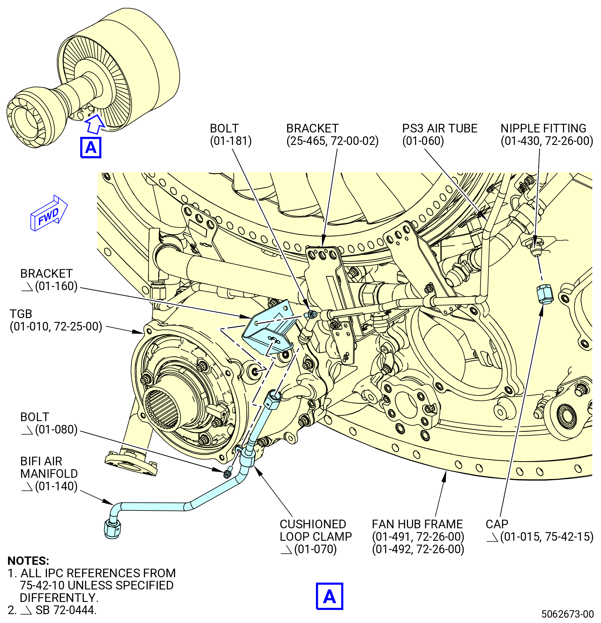
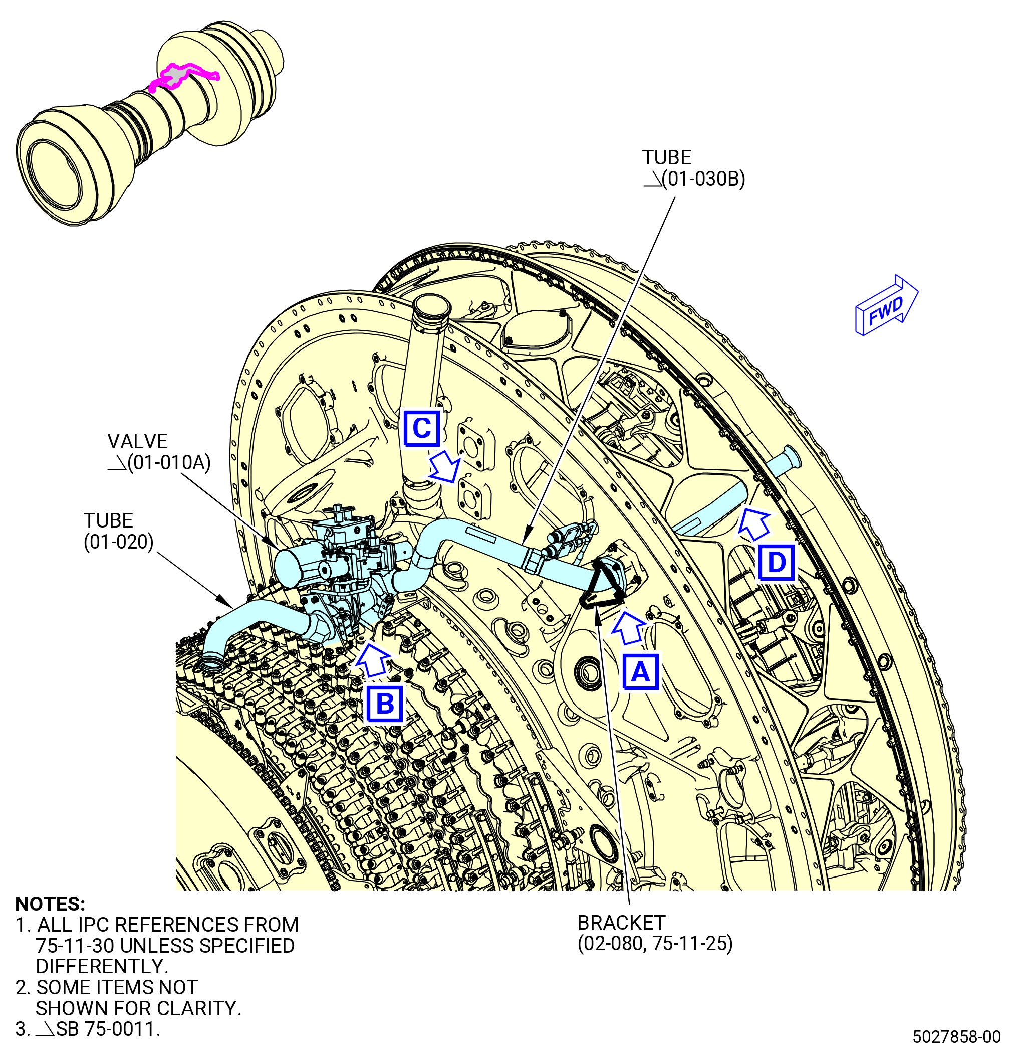
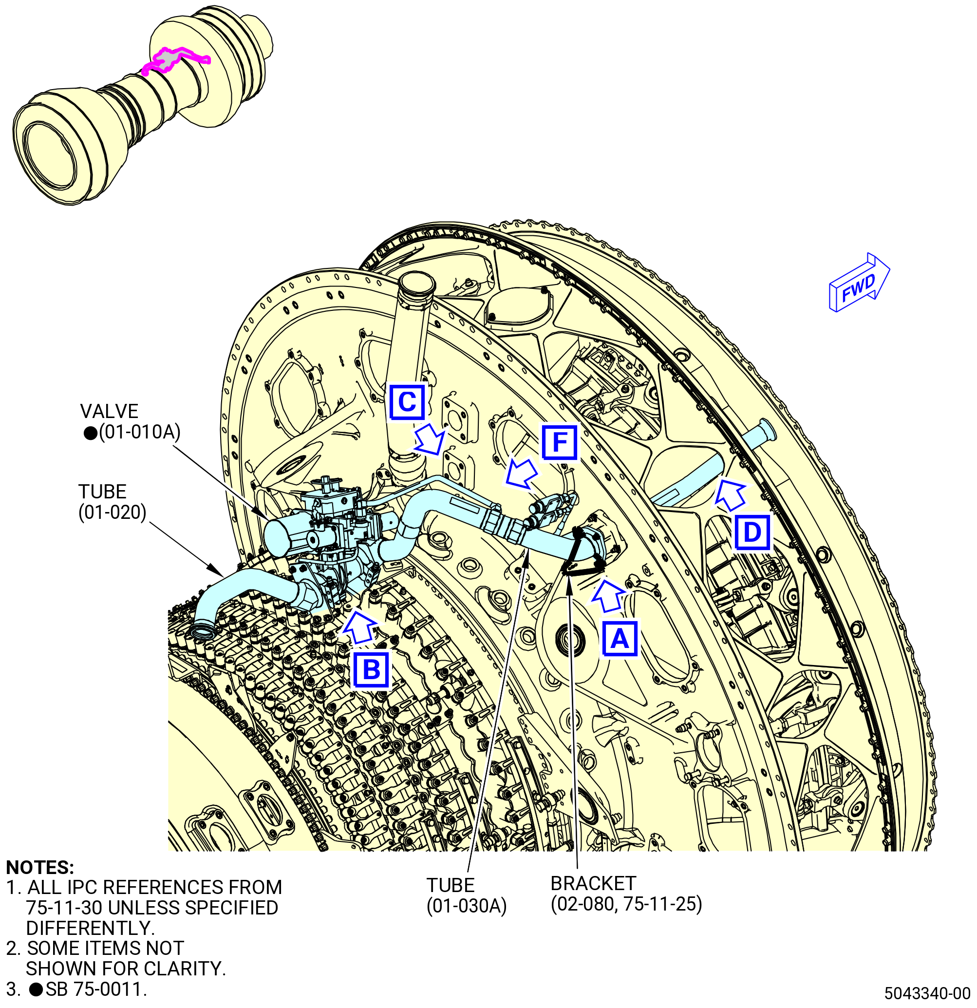
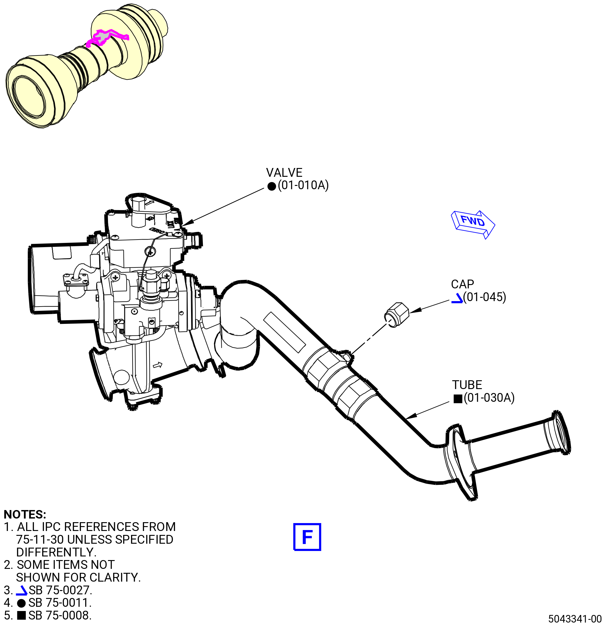
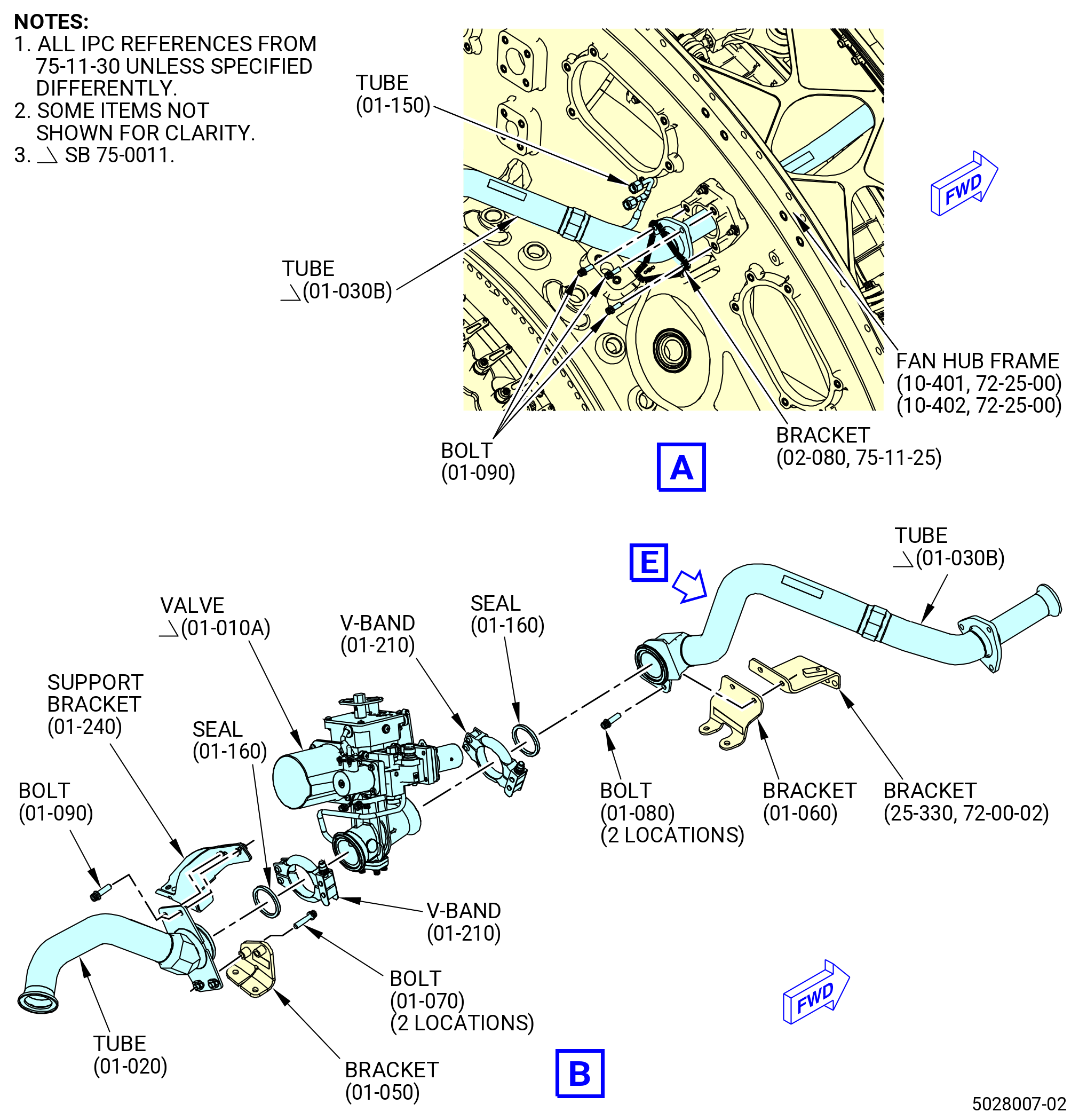
| B.A. | Connect the PS3 air tube (01-080 , 75-42-10) (SIN 61521) to the BIFI air tube (01-140 , 75-42-10) (SIN 99008). Refer to Figure 1003 and as follows: |
| (1) | Connect the cap (01-015 , 75-42-15) (SIN 840SB) to the nipple fitting (01-430 , 72-26-00) (SIN 840S3) on the fan hub frame at the 4:00 o'clock position. |
| (2) | Torque the B-nut of the cap to 262 to 308 lb in. (29.6 to 34.8 Nm). |
| (3) | Attach the bracket (01-160 , 75-42-10) (SIN 99010) to the transfer gearbox (TGB) (01-010 , 72-25-00) (SIN 03200) with bolts (01-181 , 75-42-10) (SIN 99029). |
| (4) | Torque the bolts (01-181 , 75-42-10) (SIN 99029) to 51 to 59 lb in. (5.8 to 6.7 Nm). |
| (5) | Connect the BIFI air manifold (01-140 , 75-42-10) (SIN 99008) to the PS3 air tube (01-060 , 75-42-10) (SIN 61501). |
| (6) | Attach the BIFI air manifold (01-140 , 75-42-10) (SIN 99008) to the bracket (01-160 , 75-42-10) (SIN 99010) with bolt (01-080 , 75-42-10) (SIN 61521). |
| (7) | Torque the bolts (01-080 , 75-42-10) (SIN 61521) to 32 to 38 lb in. (3.6 to 4.3 Nm). |
| (8) | Tighten the B-nut on the PS3 air tube (01-060 , 75-42-10) (SIN 61501) as follows: |
| (a) | Torque the B-nut to 262 to 308 lb in. (29.6 to 34.8 Nm). |
| (b) | Loosen the B-nut and torque it again to 262 to 308 lb in. (29.6 to 34.8 Nm). |
| (c) | Loosen the B-nut and torque it again to 262 to 308 lb in. (29.6 to 34.8 Nm). |
| (9) | Safety the B-nut on BIFI air manifold (01-140 , 75-42-10) (SIN 99008) on the left (positive direction) with C10-143 safety cable. |
| * * * END SB 72-0444 |
|
|
| Subtask 72-00-02-420-049 |
| C. | Install the accessory gearbox (AGB) module. Refer to TASK 72-00-05-420-801 (72-00-05, INSTALLATION 001). |
| Subtask 72-00-02-440-306 |
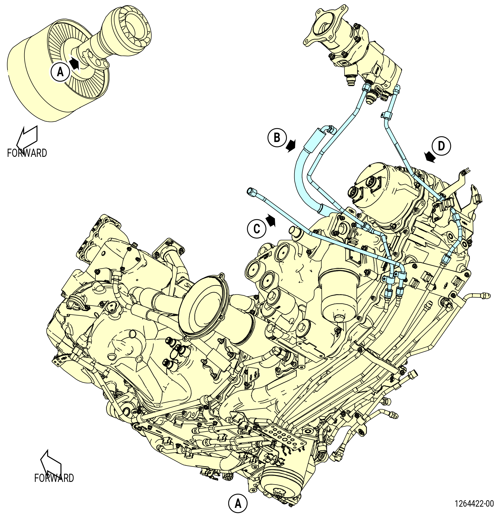
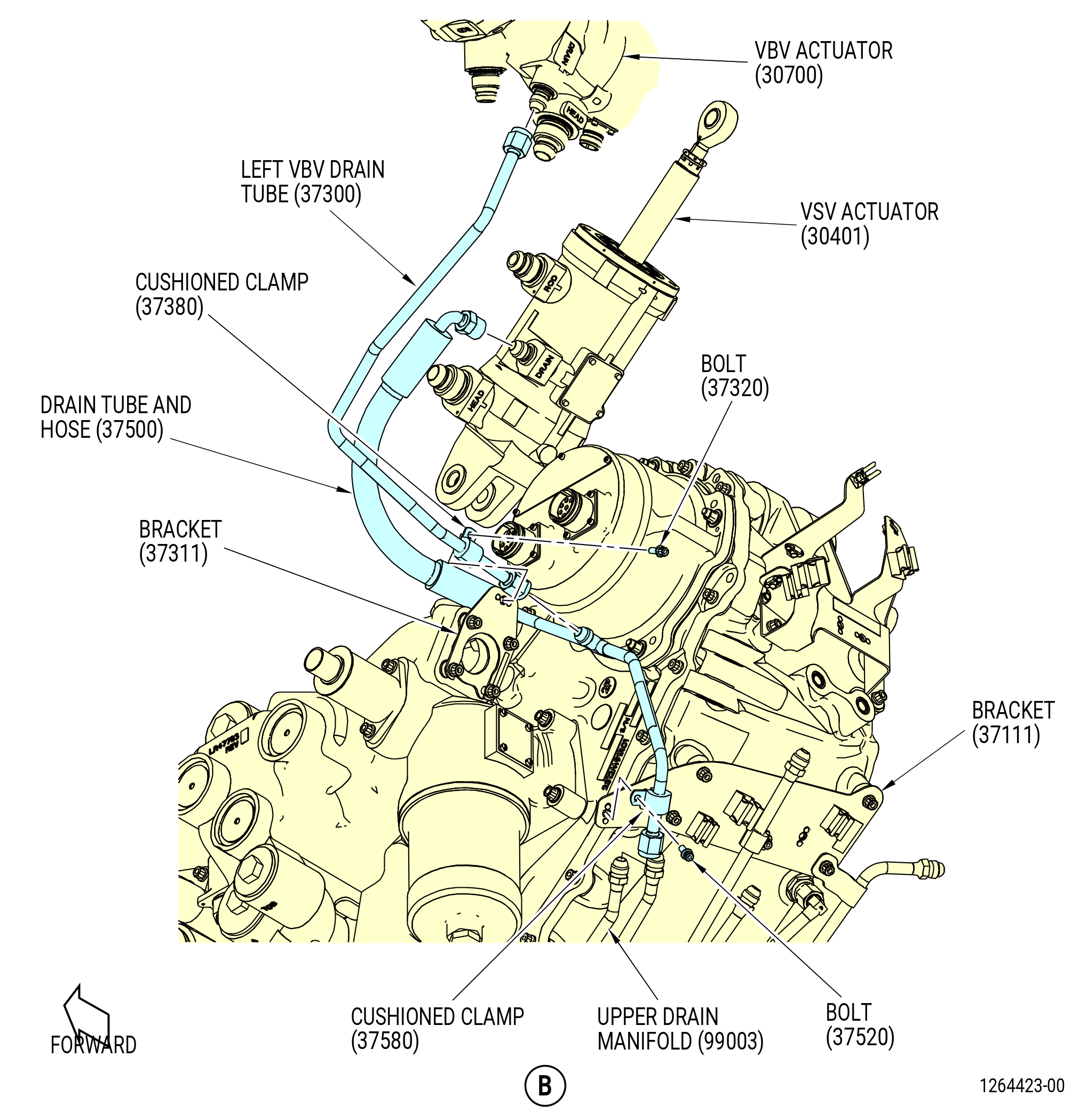
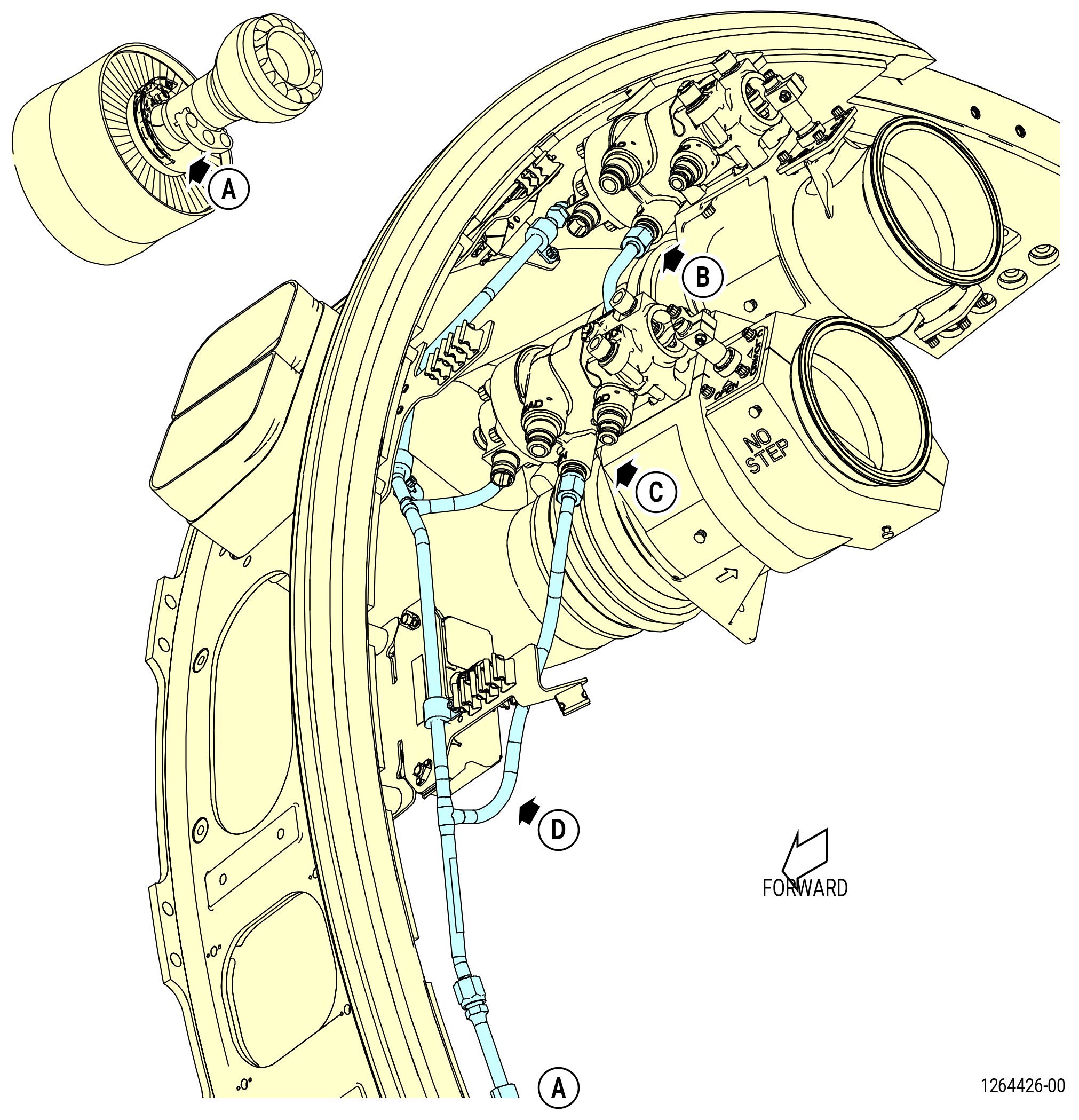
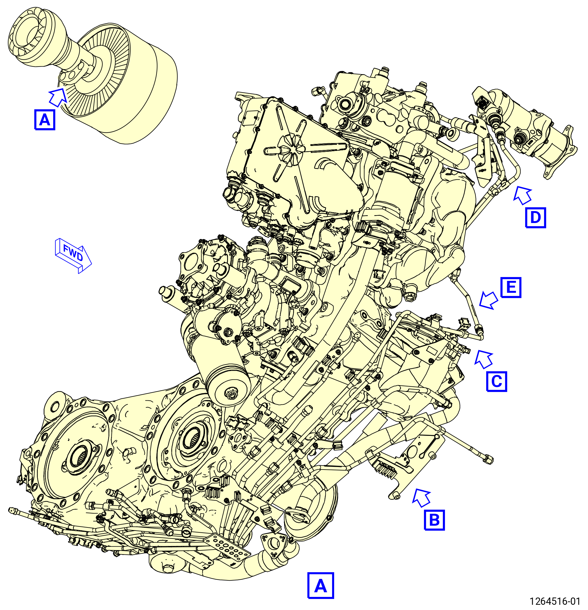
| D. | Install the drain tubes on the left side of the engine as follows: |
| (1) | Install the drain tube and hose (37500). Refer to Figure 1004 and do as follows: |
| (a) | Connect the B-nut of the drain tube and hose to the variable stator vane (VSV) actuator (30401). |
| (b) | Connect the B-nut of the drain tube and hose to the upper drain manifold (01-380 , 72-00-05) (SIN 99003) on the AGB module (25-021) (SIN 00106) or (25-022) (SIN 00106). |
| (c) | Attach the drain tube and hose (37500) to bracket (37111) with cushioned clamp (37580) and bolt (37520). |
| (d) | Torque the B-nuts to 262-308 lb in. (29.6-34.8 N.m). |
| (e) | Torque the bolt (37520) to 32-38 lb in. (3.6-4.3 N.m). |
| (2) | Install the left variable bypass valve (VBV) drain tube (37300) as follows: |
| (a) | Connect the B-nut of the left VBV drain tube to the VBV actuator (30700). |
| (b) | Connect the B-nut of the left VBV drain tube to the fitting on the drain tube and hose (37500). |
| (c) | Attach the left VBV drain tube to bracket (37311) with cushioned clamp (37380) and bolt (37320). |
| (d) | Torque the B-nut to 262-308 lb in. (29.6-34.8 N.m). |
| (e) | Torque the bolt (37320) to 32-38 lb in. (3.6-4.3 N.m). |
| (3) | Install the No. 1 bearing seal drain tube (drain tube) (48400) as follows: |
| (a) | Connect the drain tube B-nut to the tube nipple (01-430 , 72-26-00) (SIN 840S3) on the fan hub frame (01-491 , 72-26-00) (SIN 840A0) or (01-492 , 72-26-00) (SIN 840A0). |
| (b) | Connect the drain tube B-nut to the upper drain manifold (01-380 , 72-00-05) (SIN 99003) on the AGB module (25-021) (SIN 00106) or (25-022) (SIN 00106). |
| (c) | Attach the drain tube (48400) to bracket (37111) with cushioned clamp (48480) and bolt (48420). |
| (d) | Torque the B-nuts to 262-308 lb in. (29.6-34.8 N.m). |
| (e) | Torque the bolt (48420) to 32-38 lb in. (3.6-4.3 N.m). |
| (4) | Install the fuel drain tube (37701) as follows: |
| (a) | Connect the B-nut to the upper drain manifold (99003). |
| (b) | Attach the fuel drain tube to bracket (37110) with cushioned clamps (37780) and bolts (37720). |
| (c) | Attach the fuel drain tube to bracket (6711F) with cushioned clamp (37780) and bolt (37720). |
| (d) | Torque the B-nut to 262-308 lb in. (29.6-34.8 N.m). |
| (e) | Torque the bolts (37720) to 32-38 lb in. (3.6-4.3 N.m). |
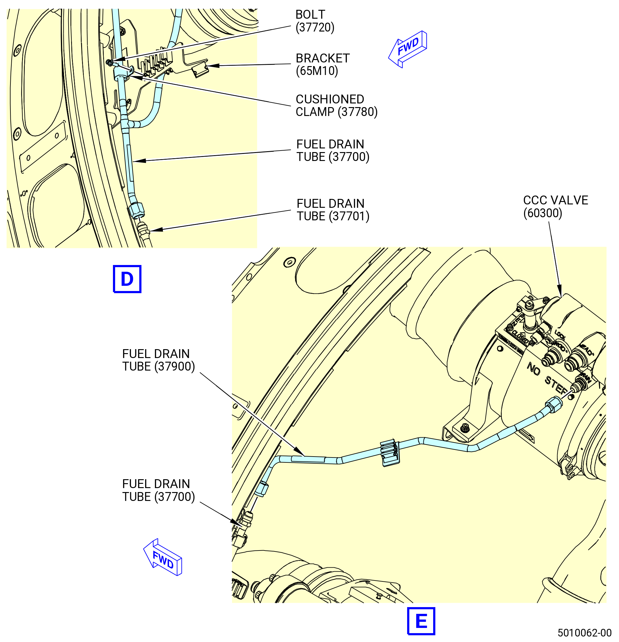
| (5) | Install the fuel drain tube (37700). Refer to Figure 1005 and do as follows: |
| (a) | Connect the fuel drain tube B-Nut to the fuel drain tube (37701). |
| (b) | Connect the remaining B-nuts to the active clearance control (ACC) valve (60500) and ACC valve (60600). |
| (c) | Attach the fuel drain tube to bracket (37711) with cushioned clamp (37780) and bolt (37720). Make sure that the clamp loop is outboard. |
| (d) | Attach the fuel drain tube to bracket (37710) with cushioned clamp (37780) and bolt (37720). Make sure that the clamp loop is outboard. |
| (e) | Attach the fuel drain tube to bracket (65M10) with cushioned clamp (37780) and bolt (37720). Make sure that the clamp loop is forward. |
| (f) | Torque the B-nuts to 262-308 lb in. (29.6-34.8 N.m). |
| (g) | Torque the bolts (37720) to 32-38 lb in. (3.6-4.3 N.m). |
| (6) | Install the fuel drain tube (01-010 , 73-11-43) (SIN 37900) as follows: |
| (a) | Connect the B-nut of the fuel drain tube (01-010 , 73-11-43) (SIN 37900) to the fuel drain tube (01-030 , 73-11-43) (SIN 37700). |
| (b) | Connect the B-nut of the fuel drain tube (01-010 , 73-11-43) (SIN 37900) to the core compartment cooling (CCC) valve (01-010 , 75-24-20) (SIN 60300). |
| (c) | Torque the B-nuts to 262-308 lb in. (29.6-34.8 N.m). |
| Subtask 72-00-02-440-307 |
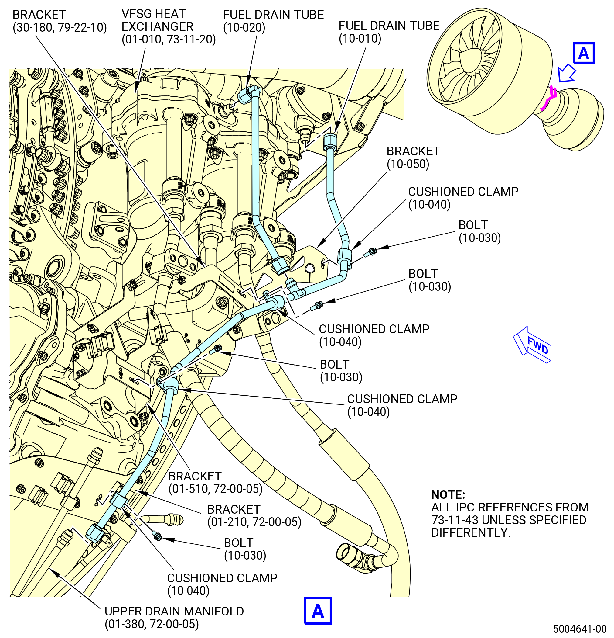
| (7) | Install the fuel drain tube (37100). Refer to Figure 1006 and do as follows: |
| (a) | Connect the B-nut to the upper drain manifold (99003). |
| (b) | Connect the B-nut to the VFSG heat exchanger (01-010 , 73-11-20) (SIN 42400). |
| (c) | Attach the fuel drain tube to bracket (37114) with cushioned clamp (37180) and bolt (37122). Make sure that the clamp loop is forward. |
| (d) | Attach the fuel drain tube to bracket (37112) with cushioned clamp (37180) and bolt (37122). |
| (e) | Attach the fuel drain tube to bracket (37110) with cushioned clamp (37180) and bolt (37122). |
| (f) | Attach the fuel drain tube to bracket (37111) with cushioned clamp (37180) and bolt (37122). Make sure that the clamp loop is forward. |
| (g) | Torque the B-nuts to 262-308 lb in. (29.6-34.8 N.m). |
| (h) | Torque the bolts (37122) to 32-38 lb in. (3.6-4.3 N.m). |
| (8) | Install the fuel drain tube (37200) as follows: |
| (a) | Connect the B-nut to the fuel drain tube (37100) |
| (b) | Connect the B-nut to the VFSG heat exchanger (01-010 , 73-11-20) (SIN 42400). |
| (c) | Torque the B-nuts to 262-308 lb in. (29.6-34.8 N.m). |
| Subtask 72-00-02-440-308 |
| E. | Install the drain tubes on the right side of the engine as follows: |
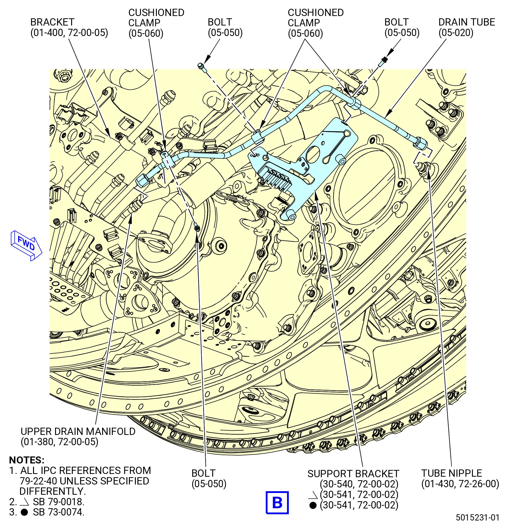
| (1) | Install the No. 3 bearing seal drain tube (drain tube) (48300). Refer to Figure 1007 and do as follows: |
| (a) | Connect the drain tube B-nut to the tube nipple (01-430 , 72-26-00) (SIN 840S3) on the fan hub frame (01-491 , 72-26-00) (SIN 840A0) or (01-492 , 72-26-00) (SIN 840A0). |
| (b) | Connect the drain tube B-nut to the upper drain manifold (01-380 , 72-00-05) (SIN 99003) on the AGB module (25-021) (SIN 00106) or (25-022) (SIN 00106). |
| (c) | Attach the drain tube (05-020 , 79-22-40) (SIN 48300) to the support bracket (30-540) (SIN 6711D) or (30-541) (SIN 6711D) with two cushioned clamps (05-060 , 79-22-40) (SIN 48380) and the bolts (05-050 , 79-22-40) (SIN 48320). |
| (d) | Attach the drain tube (48300) to bracket (37011) with cushioned clamp (48380) and bolt (48320). |
| (e) | Torque the B-nuts to 262 to 308 lb in. (29.6 to 34.8 Nm). |
| (f) | Torque the bolts (48320) to 32 to 38 lb in. (3.6 to 4.3 Nm). |
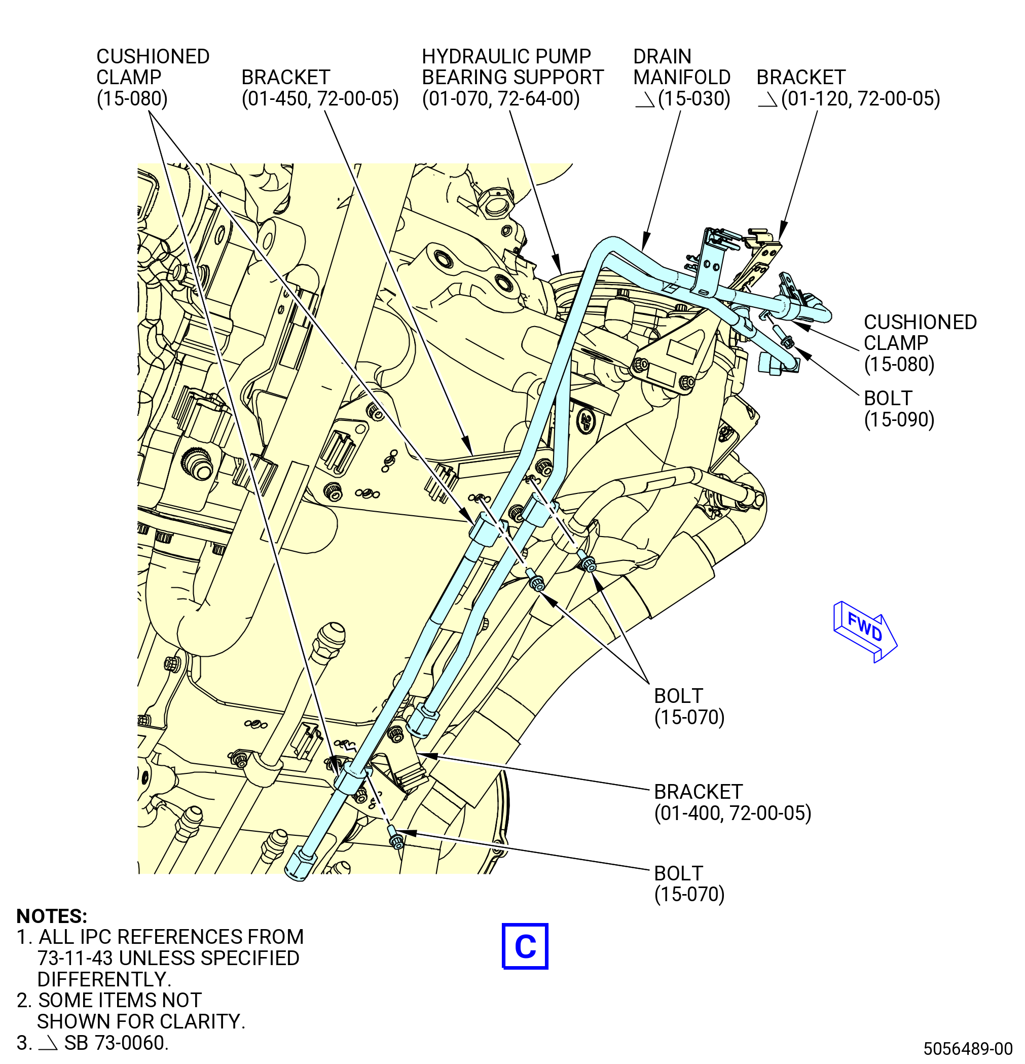
| (2) | Install the drain manifold (15-030 , 73-11-43) (SIN 37302) as follows: |
| (a) | Connect the two B-nuts to the upper drain manifold (99003). |
| (b) | Connect the remaining B-nut to the nipple on the hydraulic pump bearing support (038AB). |
| (c) | Attach the drain manifold (15-030 , 73-11-43) (SIN 37302) to bracket (01-450 , 72-00-05) (SIN 37010) with cushioned clamps (15-080 , 73-11-43) (SIN 37380) and bolts (15-070 , 73-11-43) (SIN 37320). |
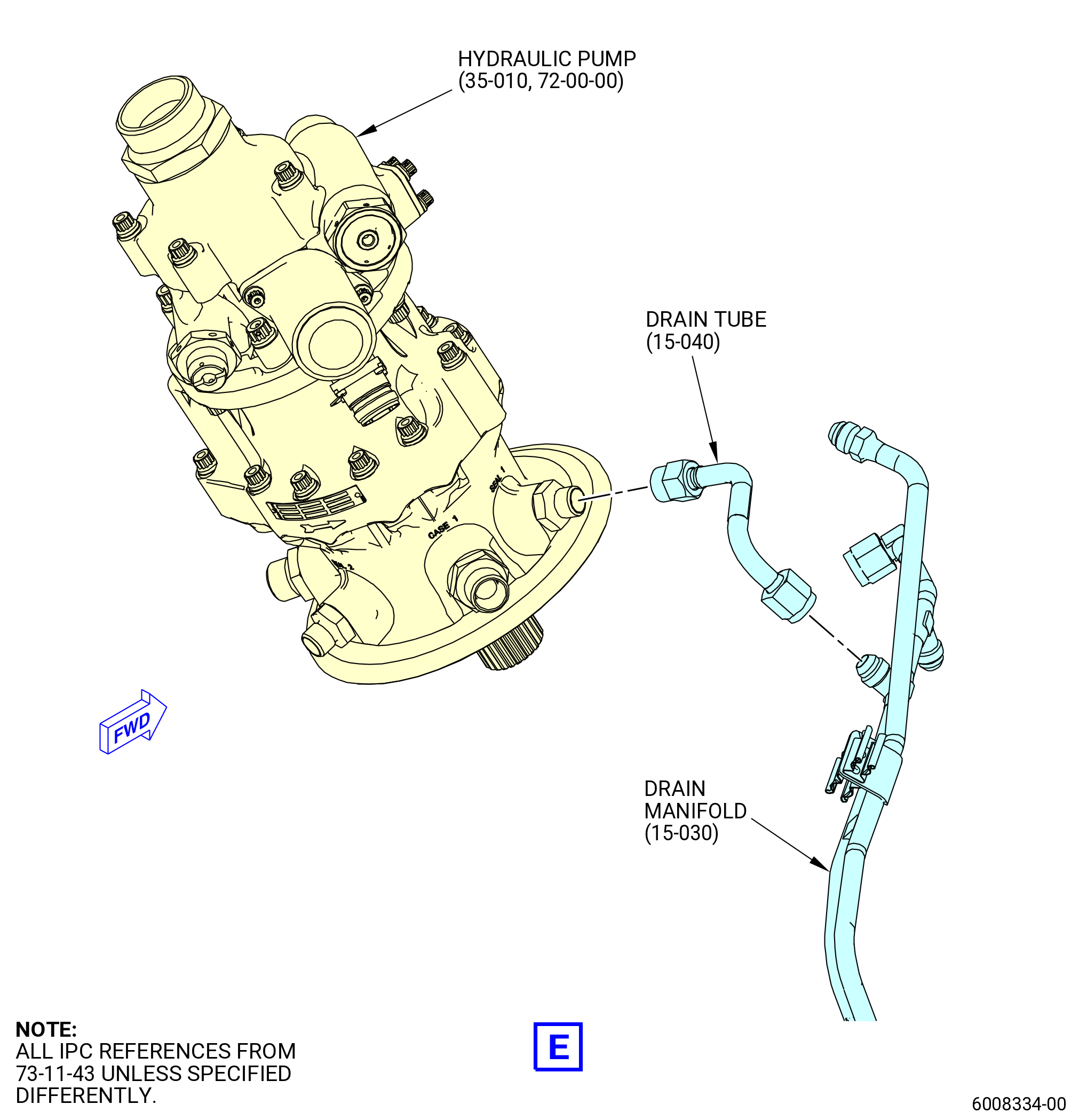
| (d) | Connect the B-nut of the drain tube (15-040 , 73-11-43) (SIN 59100) to the drain manifold (15-030 , 73-11-43) (SIN 37302). |
| (e) | Connect the B-nut of the drain tube (15-040 , 73-11-43) (SIN 59100) to the hydraulic pump (35-010 , 72-00-00) (SIN C00A6). |
| (f) | Attach the drain manifold (15-030 , 73-11-43) (SIN 37302) to bracket (01-400 , 72-00-05) (SIN 37011) with a cushioned clamp (15-080 , 73-11-43) (SIN 37380) and a bolt (15-070 , 73-11-43) (SIN 37320). |
| (g) | Attach the drain manifold (15-030 , 73-11-43) (SIN 37302) to bracket (01-120 , 72-00-05) (SIN 37312) with a cushioned clamp (15-080 , 73-11-43) (SIN 37380) and a bolt (15-090 , 73-11-43) (SIN 37321). |
| (h) | Torque the B-nuts to 262 to 308 lb in. (29.6 to 34.8 Nm). |
| (i) | Torque the bolts (37320) to 32 to 38 lb in. (3.6 to 4.3 Nm). |
| (j) | Torque the bolts (37321) to 32 to 38 lb in. (3.6 to 4.3 Nm). |
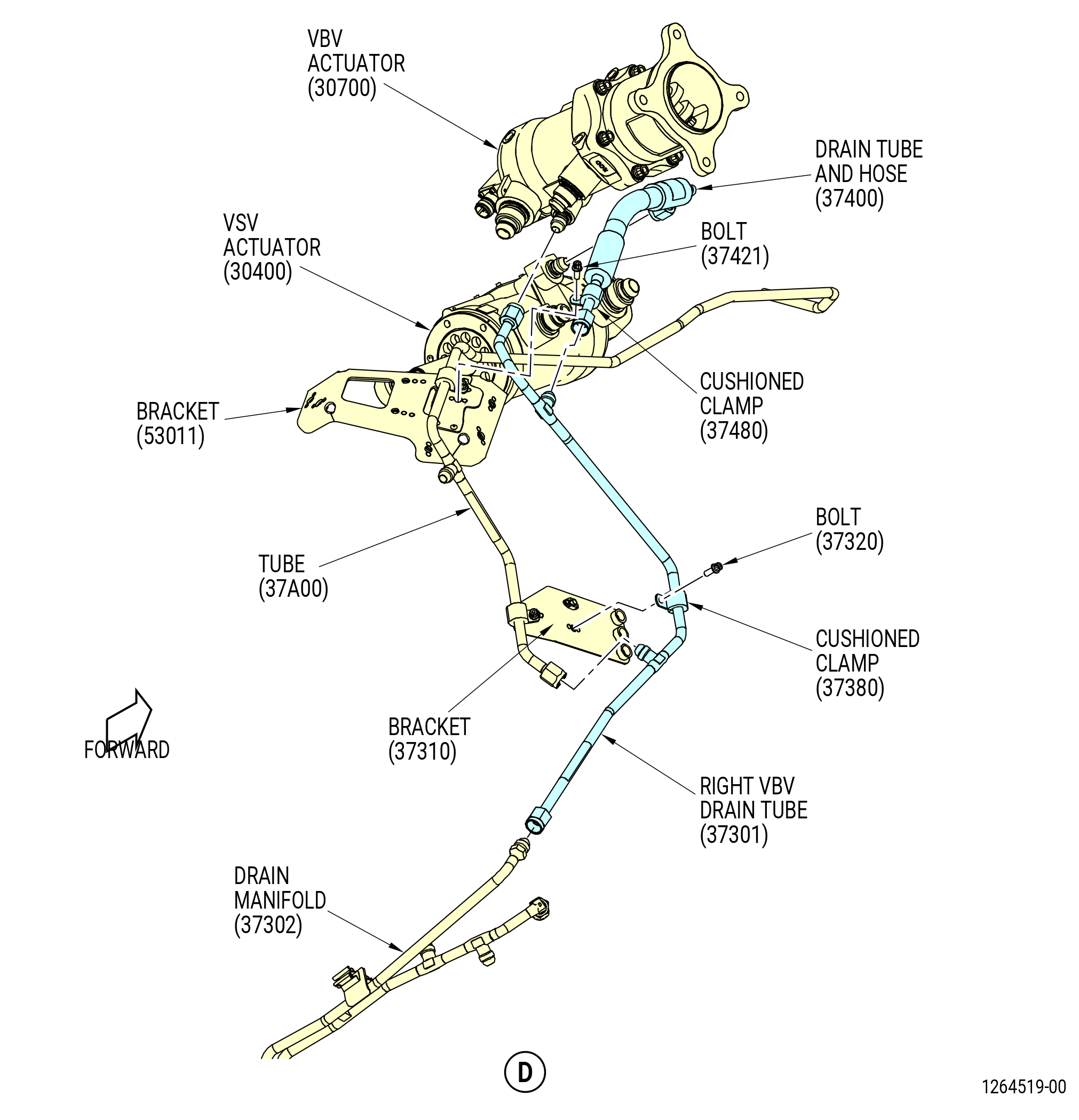
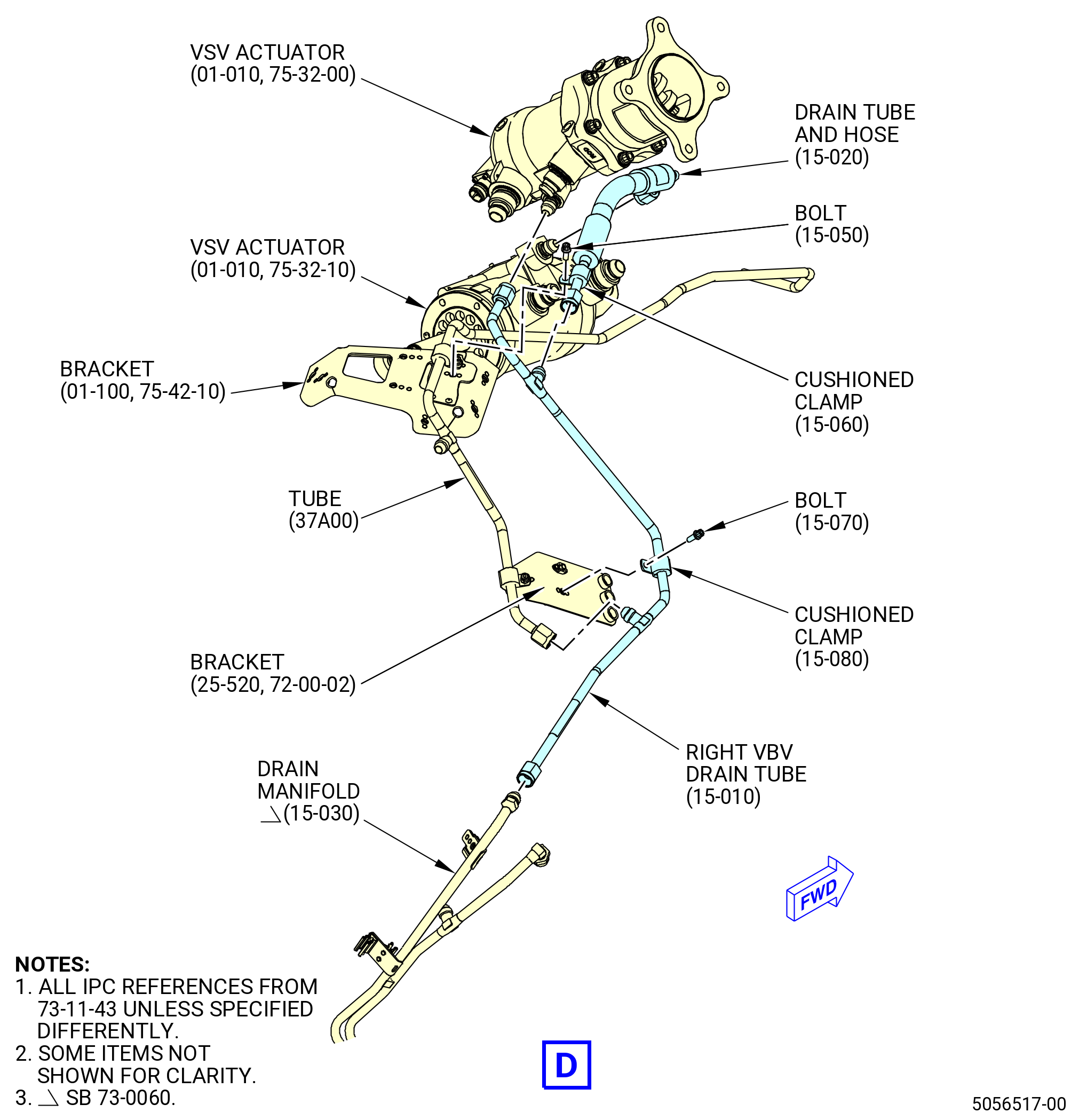
| (3) | Install the right VBV drain tube (37301) as follows: |
| (a) | Connect the B-nut of the right VBV drain tube (37301) to the VBV actuator (30700). |
| (b) | Connect the B-nut of the right VBV drain tube (15-010 , 73-11-43) (SIN 37301) to the drain manifold (15-030 , 73-11-43) (SIN 37302). |
| (c) | Remove the protective cover from tube (37A00) and connect the B-nut to the right VBV drain tube (37301). |
| (d) | Attach the right VBV drain tube (37301) to bracket (37310) with cushioned clamp (37380) and bolt (37320). |
| (e) | Torque the B-nuts to 262-308 lb in. (29.6-34.8 N.m). |
| (f) | Torque the bolt (37320) to 32-38 lb in. (3.6-4.3 N.m). |
| (4) | Install the drain tube and hose (37400) as follows: |
| (a) | Connect the B-nut to the VSV actuator (30400). |
| (b) | Connect the B-nut to the right VBV drain tube (37301). |
| (c) | Attach the drain tube and hose (37400) to bracket (53011) with cushioned clamp (37480) and bolt (37421). |
| (d) | Torque the B-nuts to 262-308 lb in. (29.6-34.8 N.m). |
| (e) | Torque the bolt (37421) to 32-38 lb in. (3.6-4.3 N.m). |
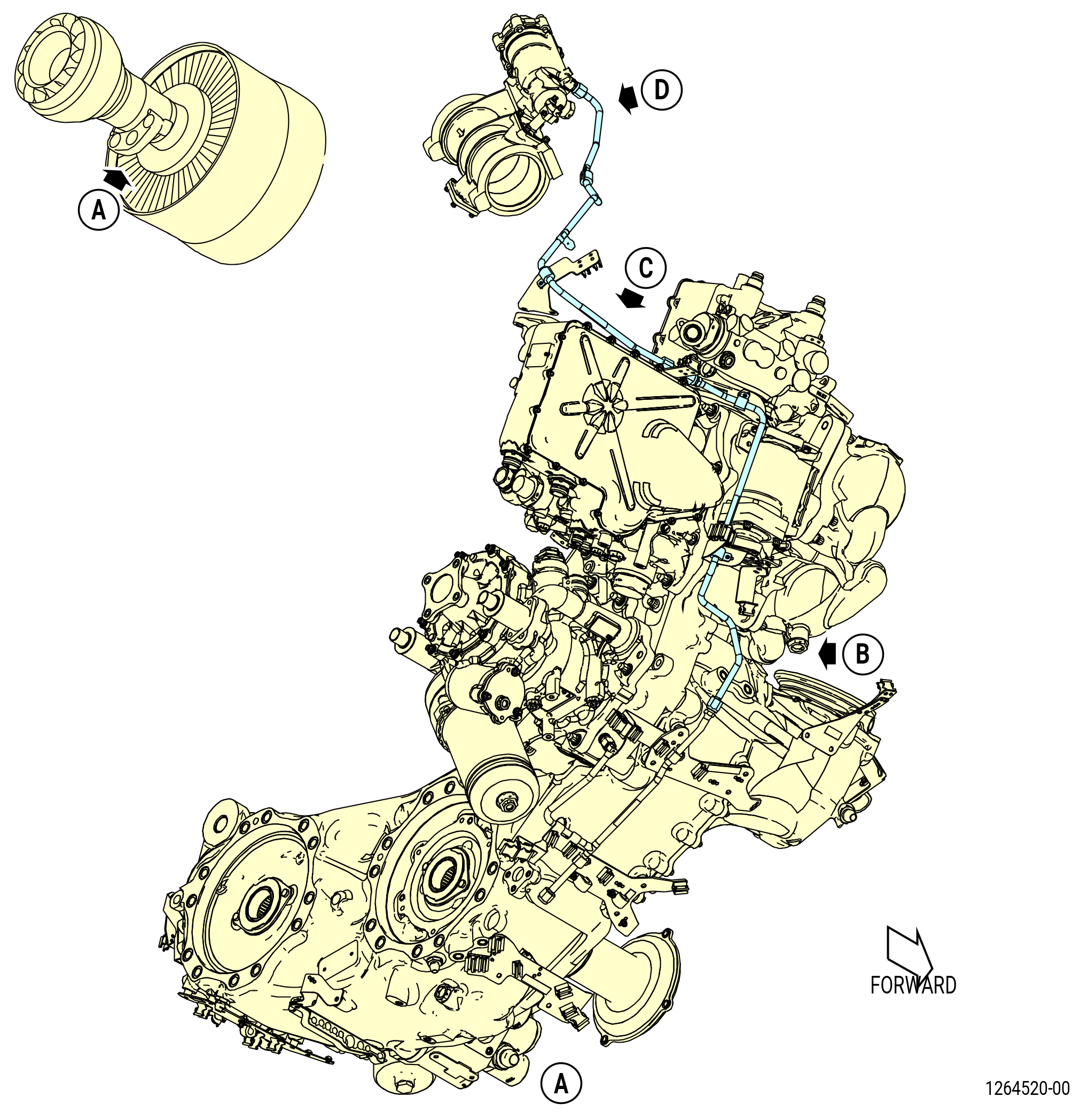
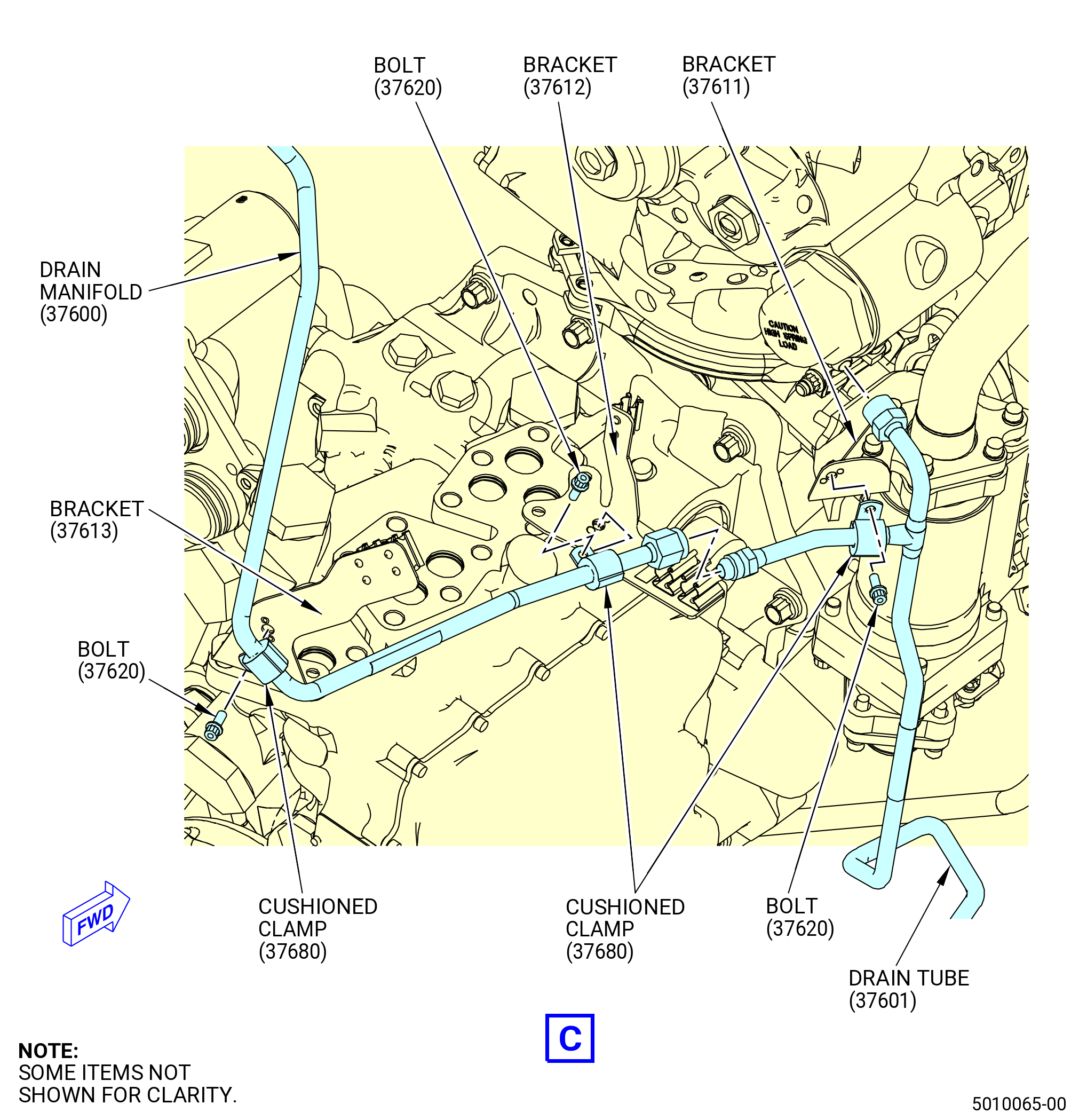
| (5) | Install the drain tube (37601). Refer to Figure 1008 and do as follows: |
| (a) | Connect the B-nut to the main fuel pump and transient bleed valve drain manifold (37000). |
| (b) | Connect the middle B-nut to the flow splitting valve (31700). |
| (c) | Attach the drain tube to the bracket (37610) with a cushioned clamp (37680) and bolt (37620). |
| (d) | Attach the drain tube to the bracket (37611) with a cushioned clamp (37680) and bolt (37620). |
| (e) | Torque the two B-nuts to 262-308 lb in. (29.6-34.8 N.m). |
| (f) | Torque the bolts (37620) to 32-38 lb in. (3.6-4.3 N.m). |
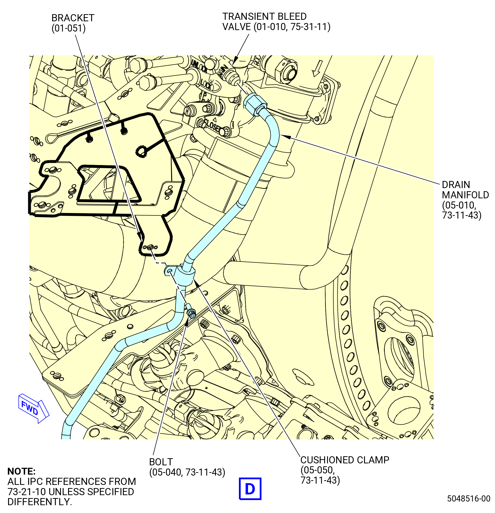
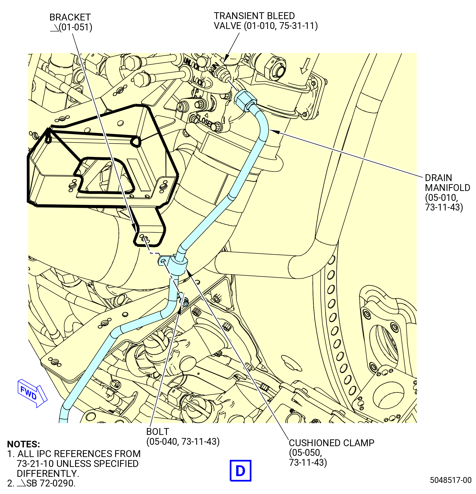
| (6) | Install the drain manifold (05-010 , 73-11-43) (SIN 37600) as follows: |
| (a) | Connect the B-nut to the drain tube (37601). |
| (b) | Connect the B-nut to the transient bleed valve (60700). |
| (c) | Attach the drain manifold (37600) to bracket (37612) with cushioned clamp (37680) and bolt (37620). |
| (d) | Attach the drain manifold (37600) to bracket (37613) with cushioned clamp (37680) and bolt (37620). |
| (e) | Attach the drain manifold (37600) to bracket (01-051 , 73-21-10) (SIN 65N10) with cushioned clamp (37680) and bolt (37620). |
| (f) | Triple torque the B-nuts to 262-308 lb in. (29.6-34.8 N.m). |
| (g) | Torque the bolts (37620) to 32-38 lb in. (3.6-4.3 N.m). |
|
|
|
|
|
| Subtask 72-00-02-440-309 |
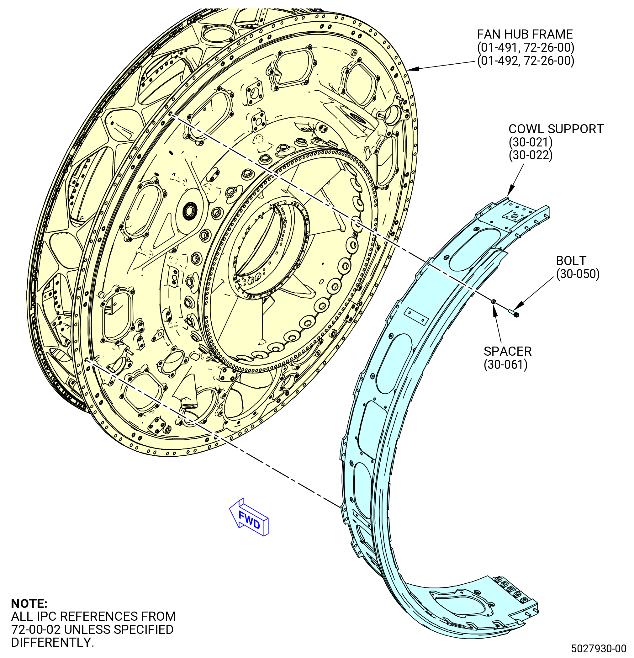
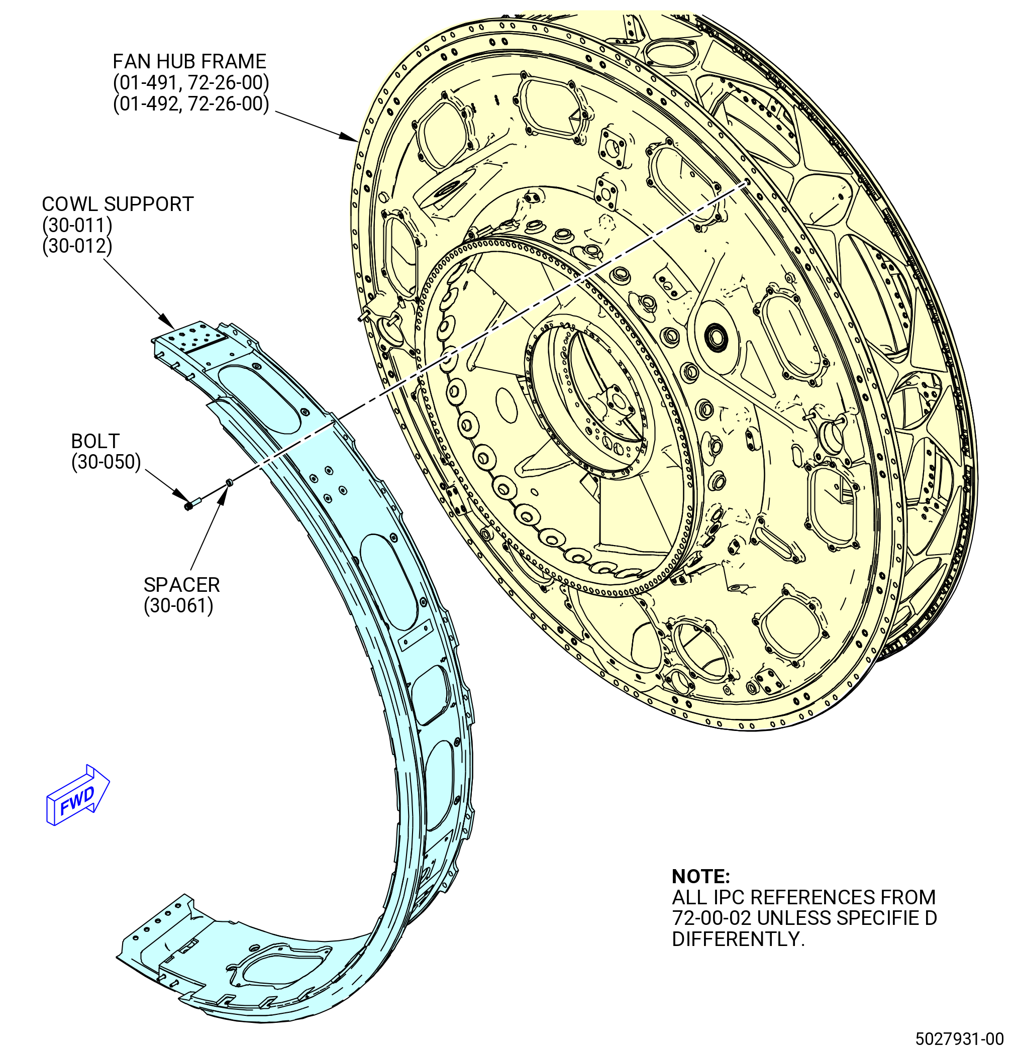
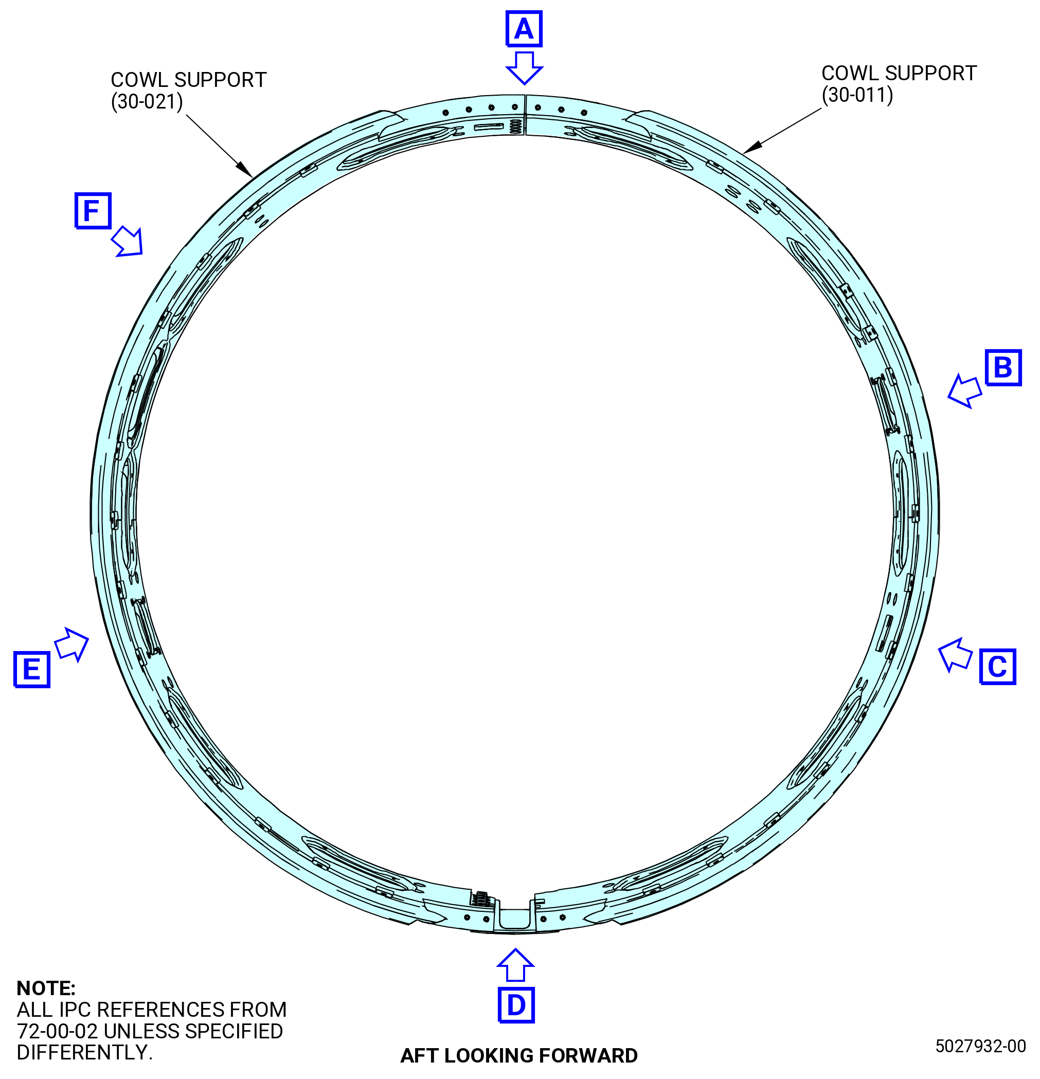
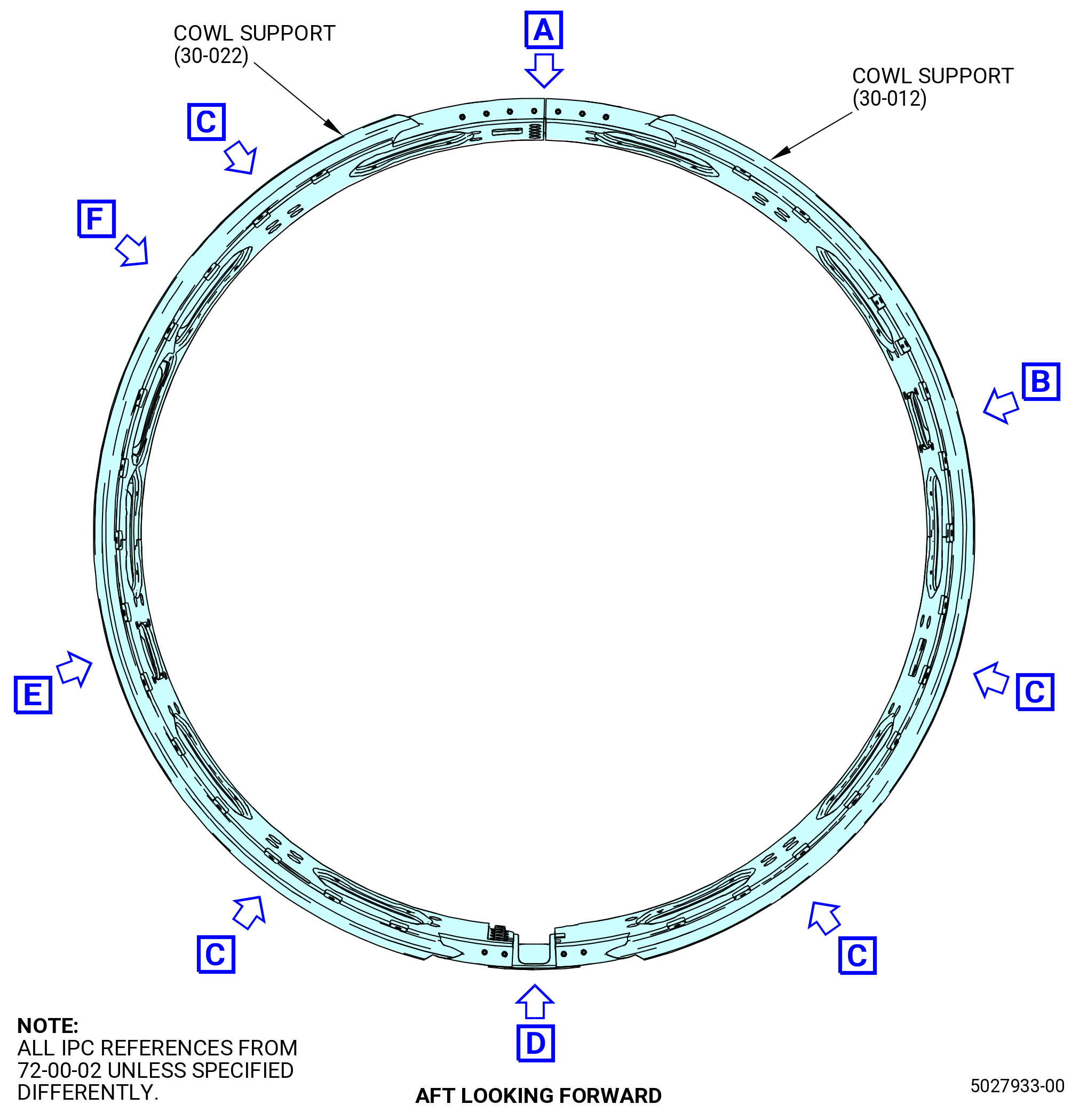
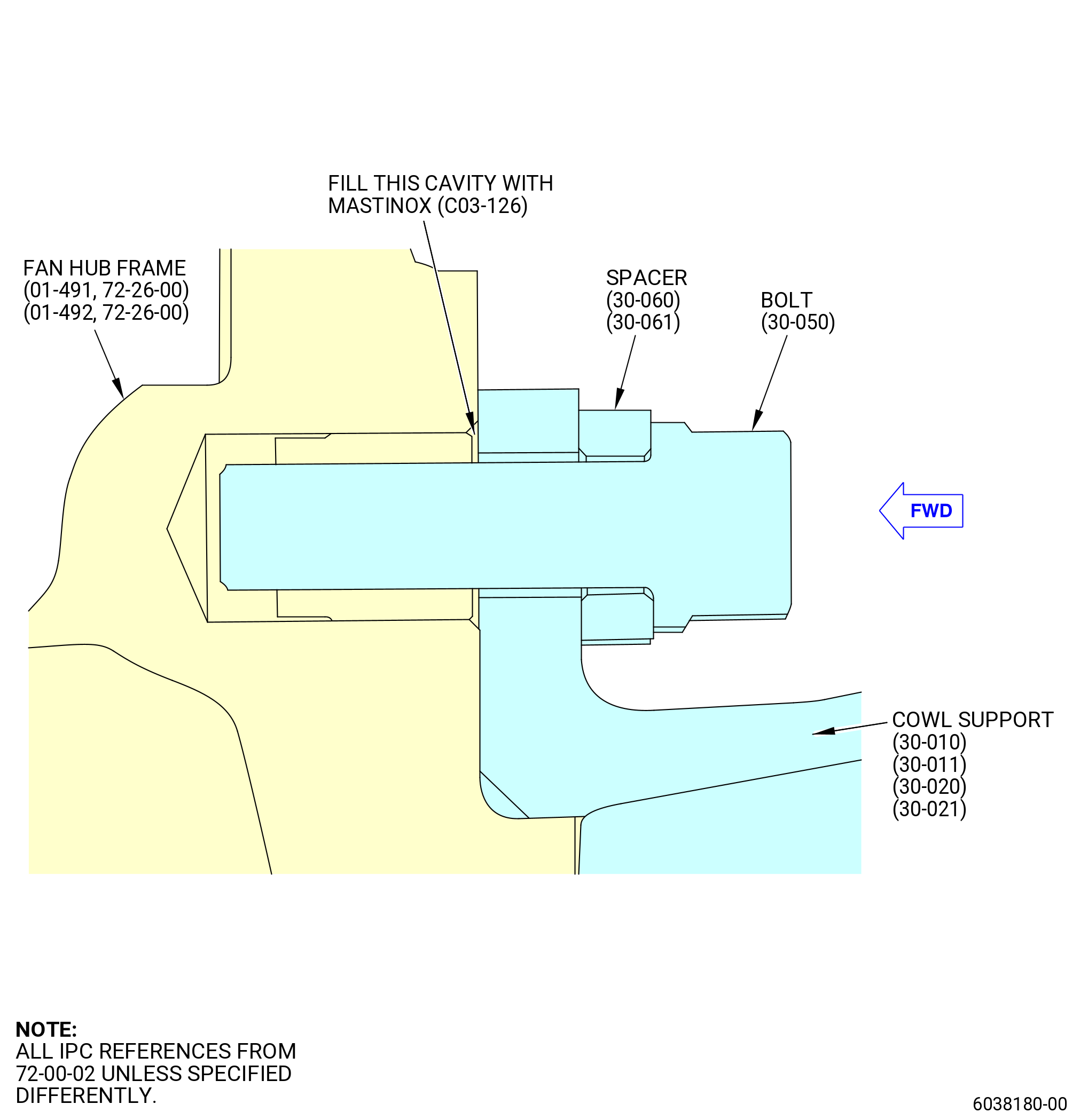
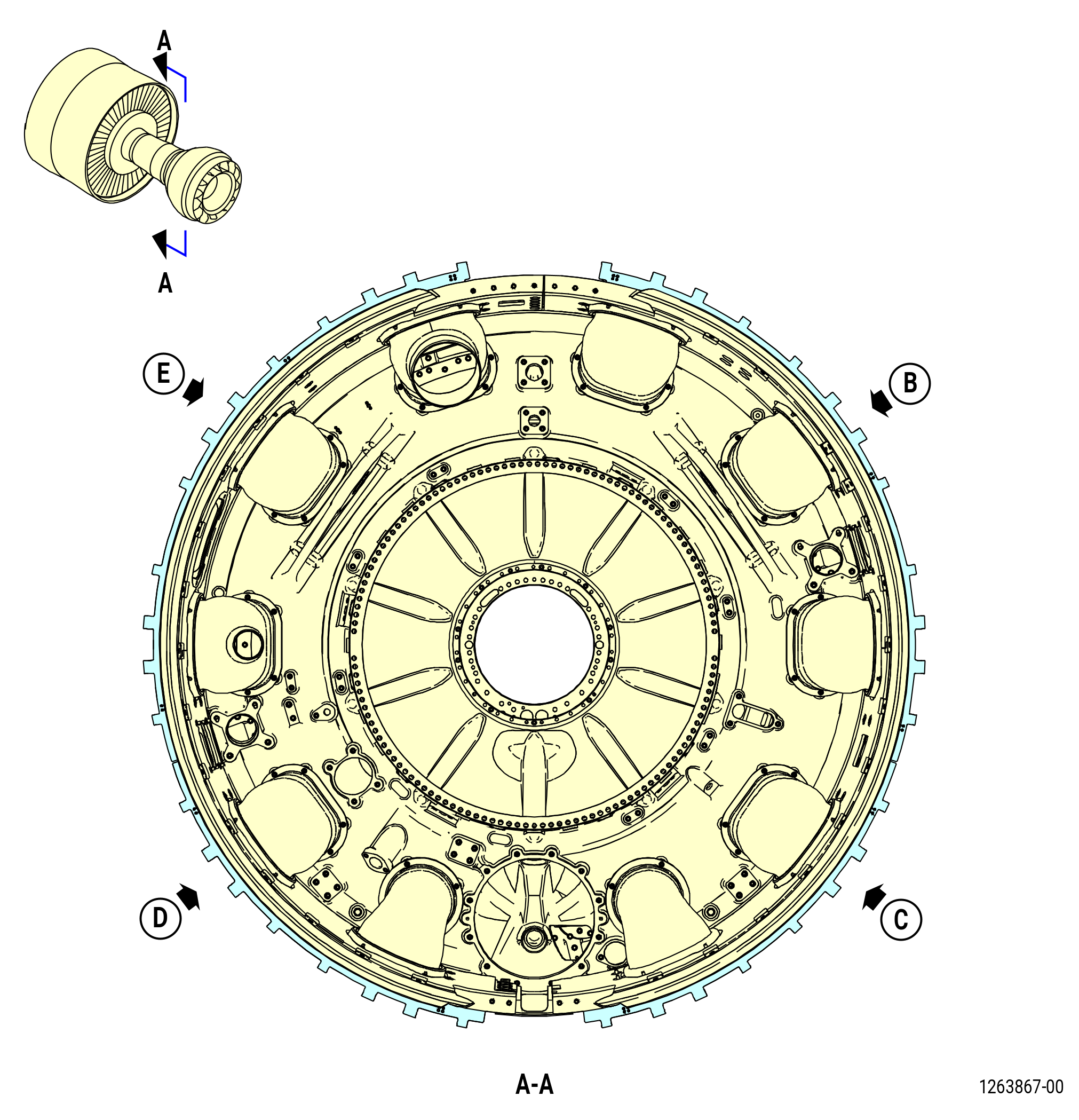
| F. | Install the cowl supports on the fan hub frame. Refer to Figure 1009 and do as follows: |
| Subtask 72-00-02-160-002 |
| WARNING: |
|
| (1) | Clean the fan hub frame flange and left/right cowl support flanges with C04-035 isopropyl alcohol. |
| Subtask 72-00-02-380-001 |
| WARNING: |
|
| (2) | Apply C03-100 primer to the inside diameter of the boltholes on the left/right cowl support flanges and fan hub frame. |
| (3) | Apply C03-100 primer to the shank and the washer face on the bolts (30-050) (SIN 9502D). |
| (4) | Apply C03-100 primer to the contact surface of the spacers (30-061) (SIN 95070). |
| (5) | Apply C01-229 Mastinox on the upper face of threaded insert. Make sure it will fill the area between fan hub frame flange and cowl support flange but will not be trapped between fan hub frame flange and cowl support flange. Make sure that the thread is free of Mastinox. Refer to Figure 1009. |
| NOTE: |
|
| Subtask 72-00-02-440-453 |
| (6) | Install the cowl support (30-021) (SIN 95008) or (30-022) (SIN 95008) on the fan hub frame (01-491 , 72-26-00) (SIN 840A0) or (01-492 , 72-26-00) (SIN 840A0) as follows: |
| (a) | Put the cowl support around the left side of the aft end of the fan hub frame (01-491 , 72-26-00) (SIN 840A0) or (01-492 , 72-26-00) (SIN 840A0). Install the cowl support with the top end adjacent and clockwise (CW) to the top vertical centerline. |
| (b) | Align the VBV air ducts and seal retainers with the left-side cowl support. |
| (c) | Align the boltholes in the cowl support with the boltholes in the fan hub frame and install the bolts (30-050) (SIN 9502D) and sleeve spacers (spacer) (30-061) (SIN 95070). |
| (7) | Install the cowl support (30-011) (SIN 95001) or (30-012) (SIN 95001) on the fan hub frame (01-491 , 72-26-00) (SIN 840A0) or (01-492 , 72-26-00) (SIN 840A0) as follows: |
| (a) | Install the cowl support (30-011) (SIN 95001) or (30-012) (SIN 95001) around the right side of the aft end of the fan hub frame. |
| (b) | Align the VBV air ducts and seal retainers with the right-side cowl support. |
| (c) | Align the boltholes in the cowl support with the boltholes in the fan hub frame and install the bolts (30-050) (SIN 9502D) and spacers (30-061) (SIN 95070). |
| Subtask 72-00-02-380-002 |
| WARNING: |
|
| (8) | Apply C03-100 primer to the shank and the washer face on the bolts (30-030) (SIN 95028) and the contact surface on the washers (30-670) (SIN 95033). |
| (9) | Apply C03-100 primer to the shank and the washer face on the bolts (01-041 , 75-23-10) (SIN 62020) and the contact surface on the washers (01-050 , 75-23-10) (SIN 62030). |
| (10) | Apply C03-100 primer to the shank and the washer face on the bolts (30-420) (SIN 9502F) and the contact surface on the spacers (30-661) (SIN 95038). |
| Subtask 72-00-02-440-454 |
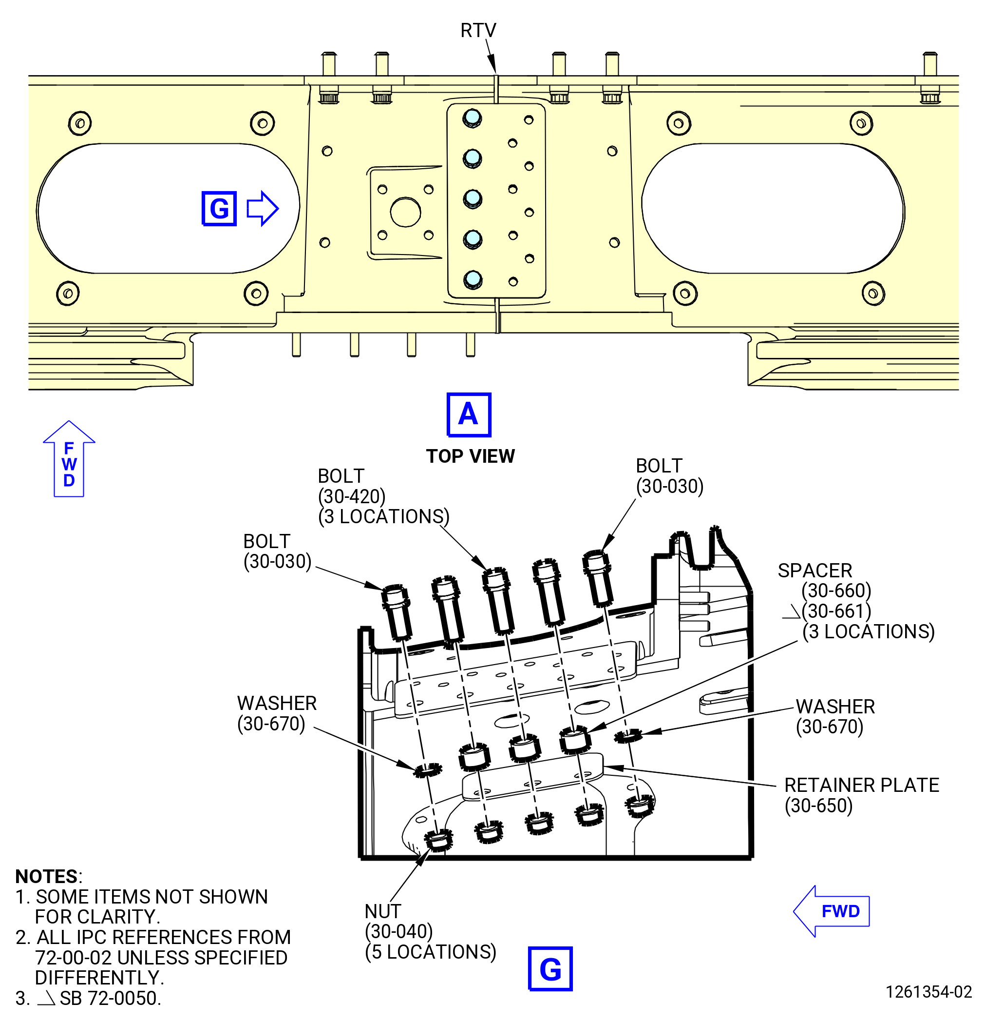
| (11) | Attach the left-side and right-side cowl supports together as follows: |
| WARNING: |
|
| (a) | Apply C02-058 lubricant to the threads and bearing surfaces of bolts (30-030) (SIN 95028) and nuts (30-040) (SIN 95041). |
| (b) | Attach the cowl support (30-011) (SIN 95001) or (30-012) (SIN 95001) to the cowl support (30-021) (SIN 95008) or (30-022) (SIN 95008) at the 12:00 o'clock position as follows: |
| 1 | Install two bolts (30-030) (SIN 95028), boltheads outboard, with two washers (30-670) (SIN 95033) and two nuts (30-040) (SIN 95041) at the forward and rearward ends boltholes. Hand-tighten the nuts. |
| 2 | Install three bolts (30-420) (SIN 9502F), boltheads outboard, with three spacers (30-661) (SIN 95038), one retainer plate (30-650) (SIN 9500U), with the longer side pointing at the 3 o'clock position (ALF), and three nuts (30-040) (SIN 95041) at the remaining boltholes. Hand-tighten the nuts. |
| (c) | Install five bolts (30-030) (SIN 95028), boltheads outboard, at the 6:00 o'clock position to attach the cowl support (30-011) (SIN 95001) or (30-012) (SIN 95001) to the cowl support (30-021) (SIN 95008) or (30-022) (SIN 95008). |
| (d) | Torque the bolts (30-030) (SIN 95028) and (30-420) (SIN 9502F) to 368-432 lb in. (41.6-48.8 N.m.). |
| (e) | Torque the bolts (30-050) (SIN 9502D) to 368-432 lb in. (41.6-48.8 N.m). |
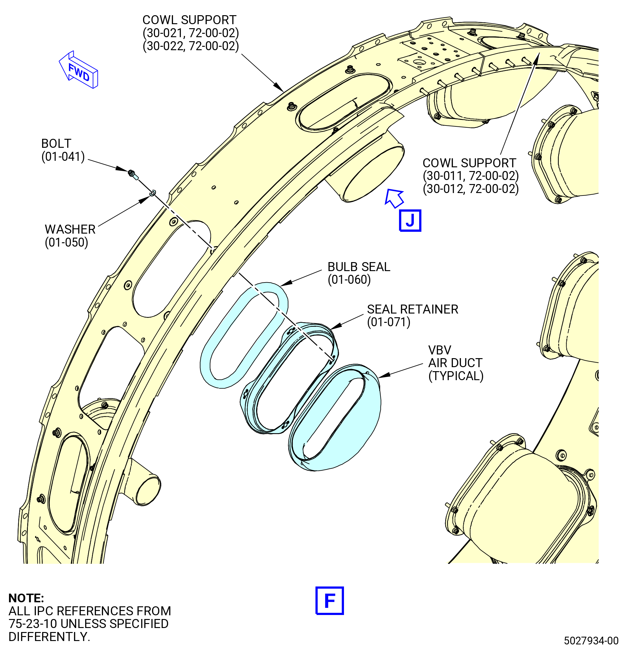
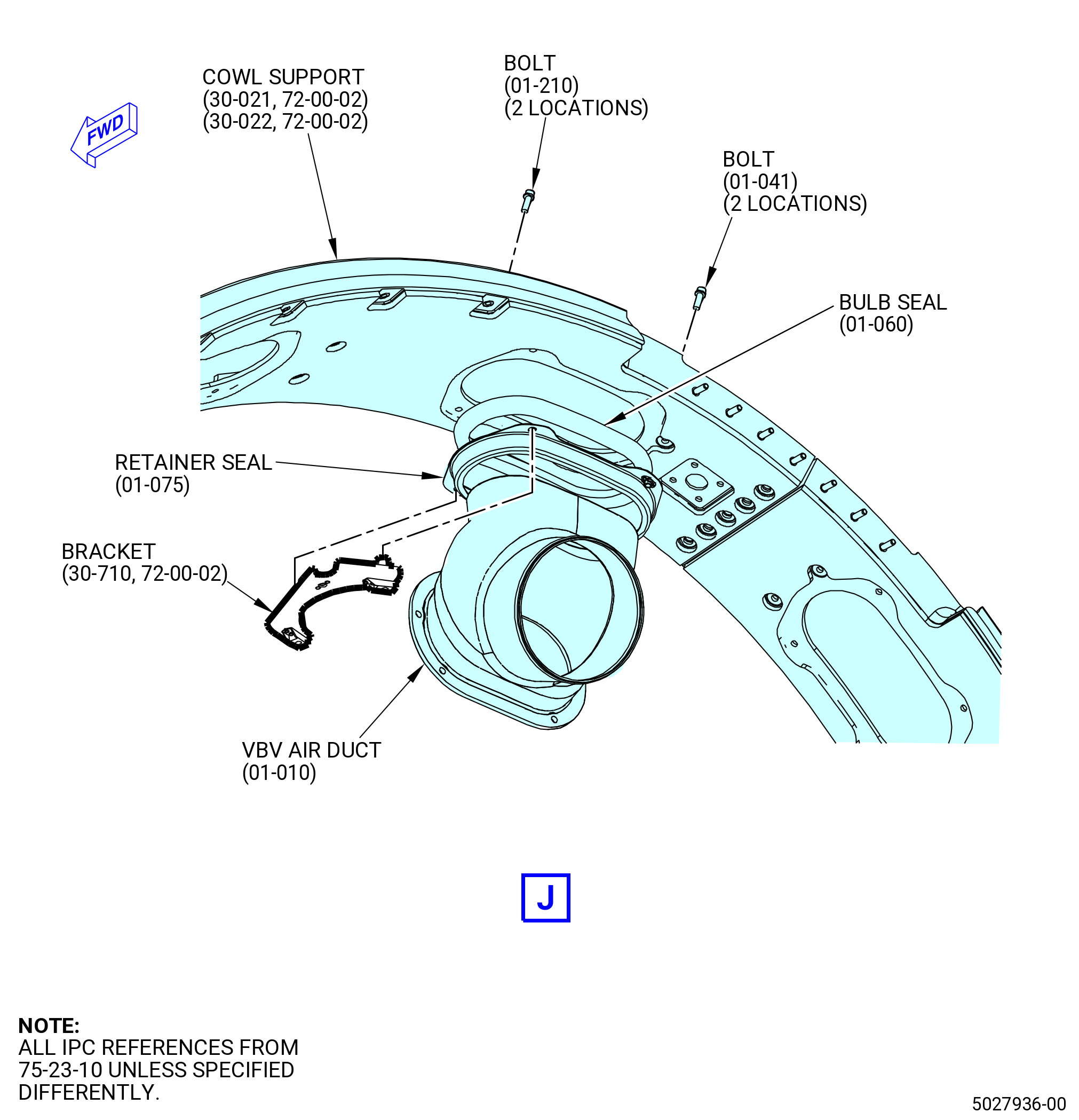
| (12) | Attach the VBV air ducts (62000, 62001, 62002, 62003) to the cowl supports as follows: |
| (a) | Move the seal retainers (01-071 , 75-23-10) (SIN 62010) and (01-075 , 75-23-10) (SIN 62013) and bulb seals (01-060 , 75-23-10) (SIN 62050) radially out against the cowl support (30-011) (SIN 95001) or (30-012) (SIN 95001) and cowl support (30-021) (SIN 95008) or (30-022) (SIN 95008). |
| (b) | Attach the seal retainers (01-170 , 75-23-10) (SIN 62000), (01-180 , 75-23-10) (SIN 62001), (01-190 , 75-23-10) (SIN 62003) to the cowl supports with bolts (01-041 , 75-23-10) (SIN 62020) and washers (01-050 , 75-23-10) (SIN 62030). |
| (c) | Attach the seal retainers (01-010 , 75-23-10) (SIN 62002) to the cowl support as follows: |
| 1 | Put the bracket (30-710) (SIN 610E5) over the seal retainer (01-075 , 75-23-10) (SIN 62013). |
| 2 | Attach the seal retainer and the bracket to the cowl support with bolts (01-210 , 75-23-10) (SIN 62022) and washers (01-050 , 75-23-10) (SIN 62030). |
| 3 | Attach the seal retainer to the cowl support with bolts (01-041 , 75-23-10) (SIN 62020) and washers (01-050 , 75-23-10) (SIN 62030). |
| (d) | Torque the bolts (01-041 , 75-23-10) (SIN 62020) and (01-210 , 75-23-10) (SIN 62022) to 106 to 124 lb in. (12.0 to 14.0 Nm). |
| WARNING: |
|
| (13) | Apply C01-007 RTV 106 to the axial gaps between the ends of the cowl supports as follows. |
| WARNING: |
|
| (a) | Clean the area around the axial gaps with C04-035 isopropyl alcohol. |
| (b) | Mask the area with C10-021 tape . |
| (c) | Apply a bead of C01-007 RTV 106 to fill the axial gaps. Wipe the sealant flush with the cowl support surfaces. |
| (d) | Let the sealant cure for 24 hours at room temperature. |
| Subtask 72-00-02-440-310 |
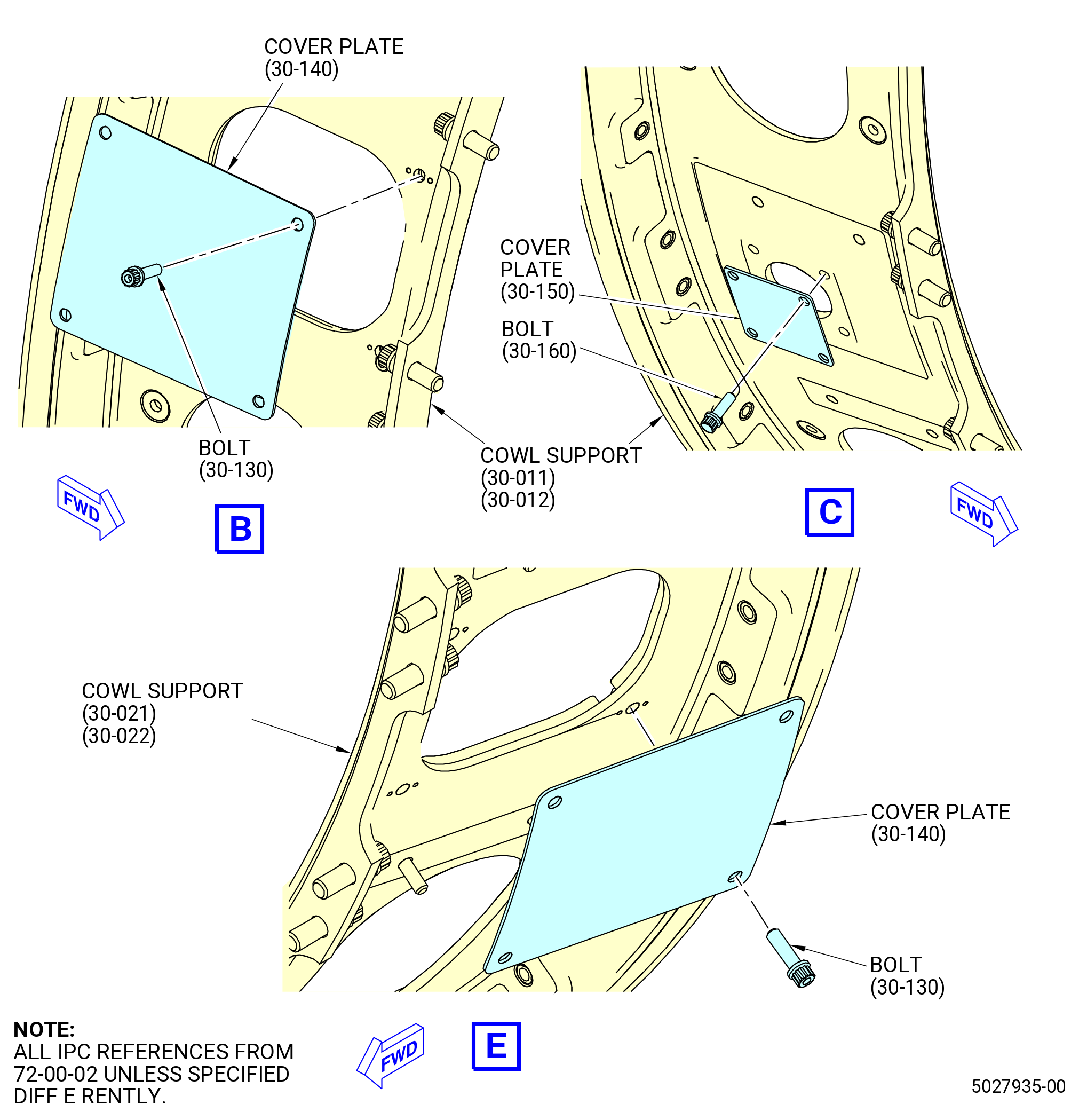
| G. | Install the cover plate (9500J) and cover plates (9500K) on the cowl supports. Refer to Figure 1009 and do as follows: |
| Subtask 72-00-02-440-521 |
| * * * FOR 1B/P2/G01 |
| (1) | Install the cover plate (30-150) (SIN 9500J) at the 3:30 o'clock position on the cowl support (30-011) (SIN 95001). |
| (a) | Attach the cover plate with bolts (30-160) (SIN 9502C). |
| (b) | Torque the bolts in a criss-cross pattern to 106 to 124 lb in. (12.0 to 14.0 Nm). |
| Subtask 72-00-02-440-522 |
| * * * FOR 1B/P2/G02 |
| (2) | Install the cover plates (30-150) (SIN 9500J) as follows: |
| (a) | Install the cover plates at the 3:30 and 4:30 o'clock positions on the cowl support (30-012) (SIN 95001) and attach them with bolts (30-160) (SIN 9502C). |
| (b) | Install the cover plates at the 7:30 and 10:30 o'clock positions on the cowl support (30-022) (SIN 95008) and attach them with bolts (30-160) (SIN 9502C). |
| (c) | Torque the bolts in a criss-cross pattern to 106 to 124 ln in. (12.0 to 14.0 Nm). |
| Subtask 72-00-02-440-523 |
| * * * FOR ALL PIP 2 |
| (3) | Install the cover plate (30-140) (SIN 9500K) at the 2:30 o'clock position on the cowl support (30-011) (SIN 95001) or (30-012) (SIN 95001). |
| (a) | Attach the cover plate (9500K) with bolts (95022). |
| (b) | Torque the bolts to 106-124 lb in. (12.0-14.0 N.m). |
| (4) | Install the cover plate (30-140) (SIN 9500K) at the 8:30 o'clock position on the cowl support (30-021) (SIN 95008) or (30-022) (SIN 95008). |
| (a) | Attach the cover plate (9500K) with bolts (95022). |
| (b) | Torque the bolts to 106-124 lb in. (12.0-14.0 N.m). |
| Subtask 72-00-00-420-050 |
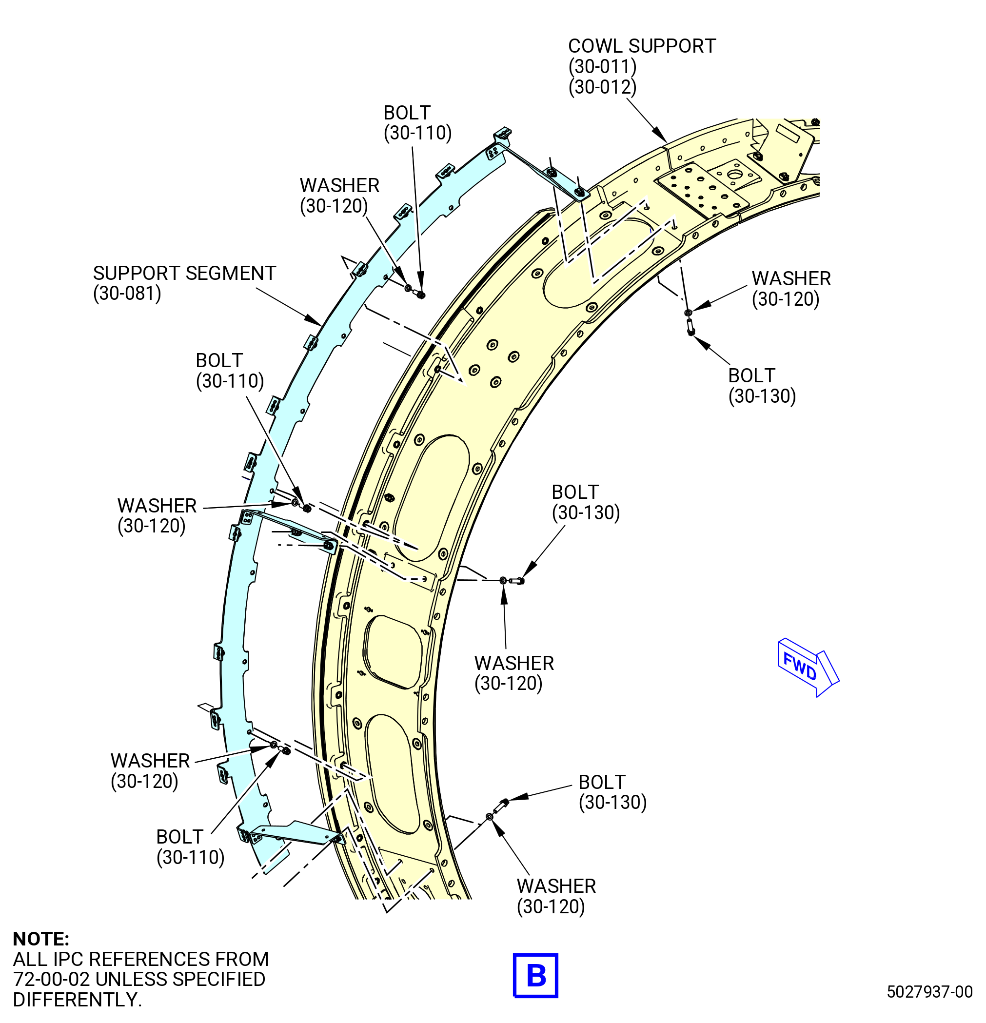
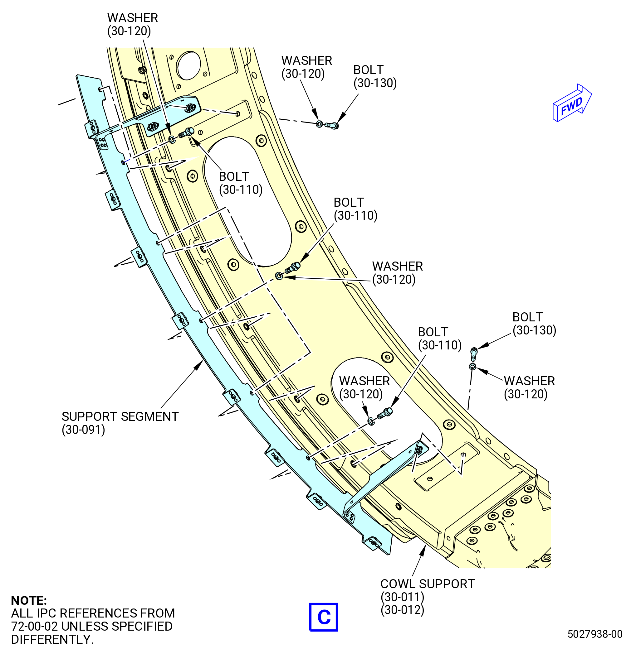
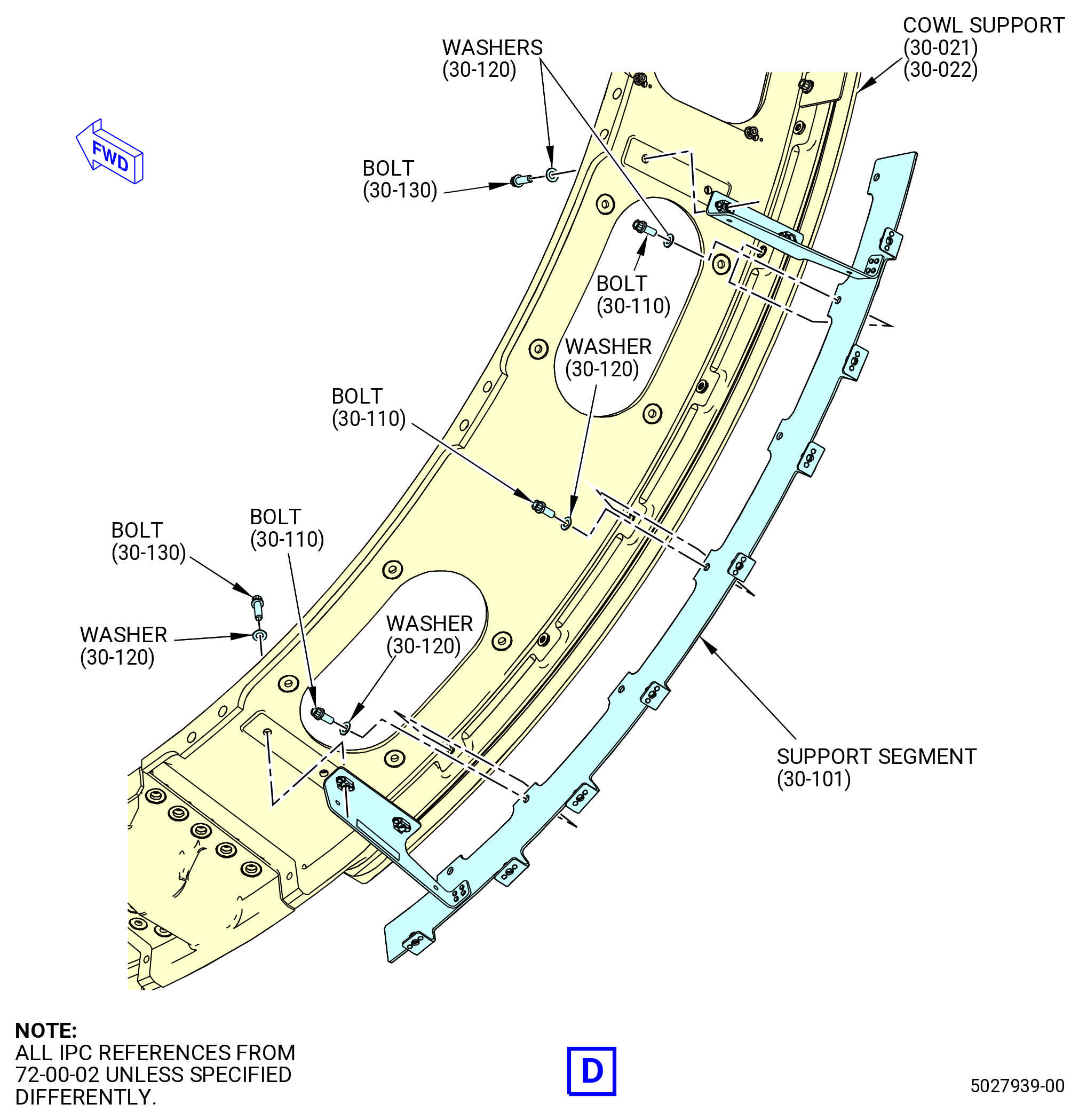
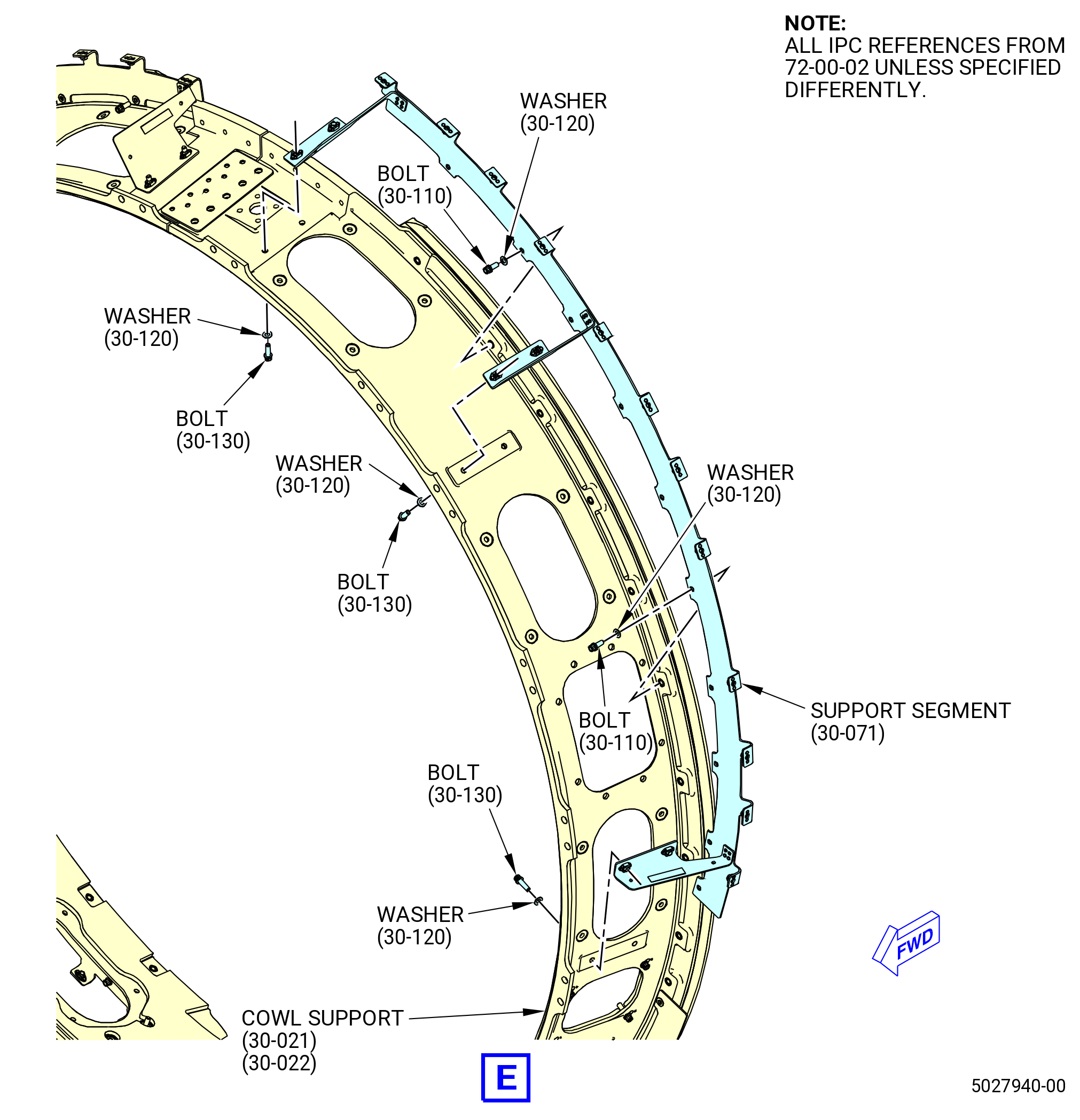
| H. | Install the upper left deflector panel support segment (support segment) (30-071) (SIN 95010), upper right deflector panel support segment (support segment) (30-081) (SIN 95011), lower right deflector panel support segment (support segment) (30-091) (SIN 95012), and lower left deflector panel support segment (support segment) (30-101) (SIN 95013) on the cowl supports. Refer to Figure 1010 and do as follows: |
| (1) | Install the support segment (30-081) (SIN 95011) as follows: |
| (a) | Put the support segment at the 12:00-3:30 o'clock position on the cowl support (30-011) (SIN 95001) or (30-012) (SIN 95001). |
| (b) | Attach the support segment to the forward flange of the cowl support with the bolts (95021) and washers (95031). |
| (c) | Attach the support segment to the cowl support with the bolts (95022) and washers (95031). |
| (d) | Torque the bolts to 106-124 lb in. (12.0-14.0 N.m). |
| (2) | Install the support segment (30-091) (SIN 95012) as follows: |
| (a) | Put the support segment at the 4:00-6:00 o'clock position on the cowl support (30-011) (SIN 95001) or (30-012) (SIN 95001). |
| (b) | Attach the support segment to the forward flange of the cowl support with the bolts (95021) and washers (95031). |
| (c) | Attach the support segment to the cowl support with the bolts (95022) and washers (95031). |
| (d) | Torque the bolts to 106-124 lb in. (12.0-14.0 N.m). |
| (3) | Install the support segment (30-071) (SIN 95010) as follows: |
| (a) | Put the support segment at the 8:30-12:00 o'clock position on the left-side cowl support (30-021) (SIN 95008) or (30-022) (SIN 95008). |
| (b) | Attach the support segment to the forward flange of the cowl support with the bolts (95021) and washers (95031). |
| (c) | Attach the support segment to the cowl support with the bolts (95022) and washers (95031). |
| (d) | Torque the bolts to 106-124 lb in. (12.0-14.0 N.m). |
| (4) | Install the support segment (30-101) (SIN 95013) as follows: |
| (a) | Put the support segment at the 6:00-8:30 o'clock positions on the cowl support (30-021) (SIN 95008) or (30-022) (SIN 95008). |
| (b) | Attach the support segment to the forward flange of the cowl support with the bolts (95021) and washers (95031). |
| (c) | Attach the support segment to the cowl support with the bolts (95022) and washers (95031). |
| (d) | Torque the bolts to 106-124 lb in. (12.0-14.0 N.m). |
| NOTE: |
|
| Subtask 72-00-02-440-311 |
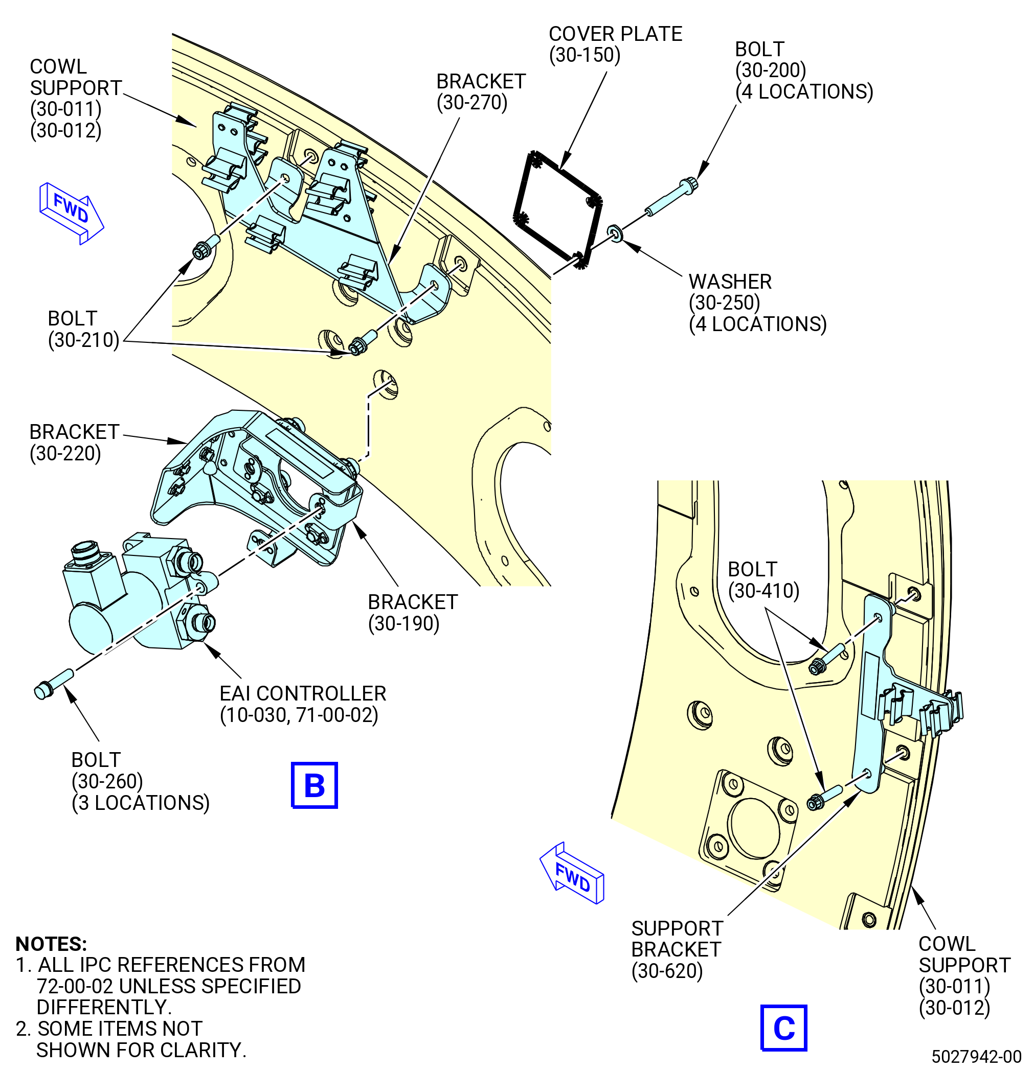
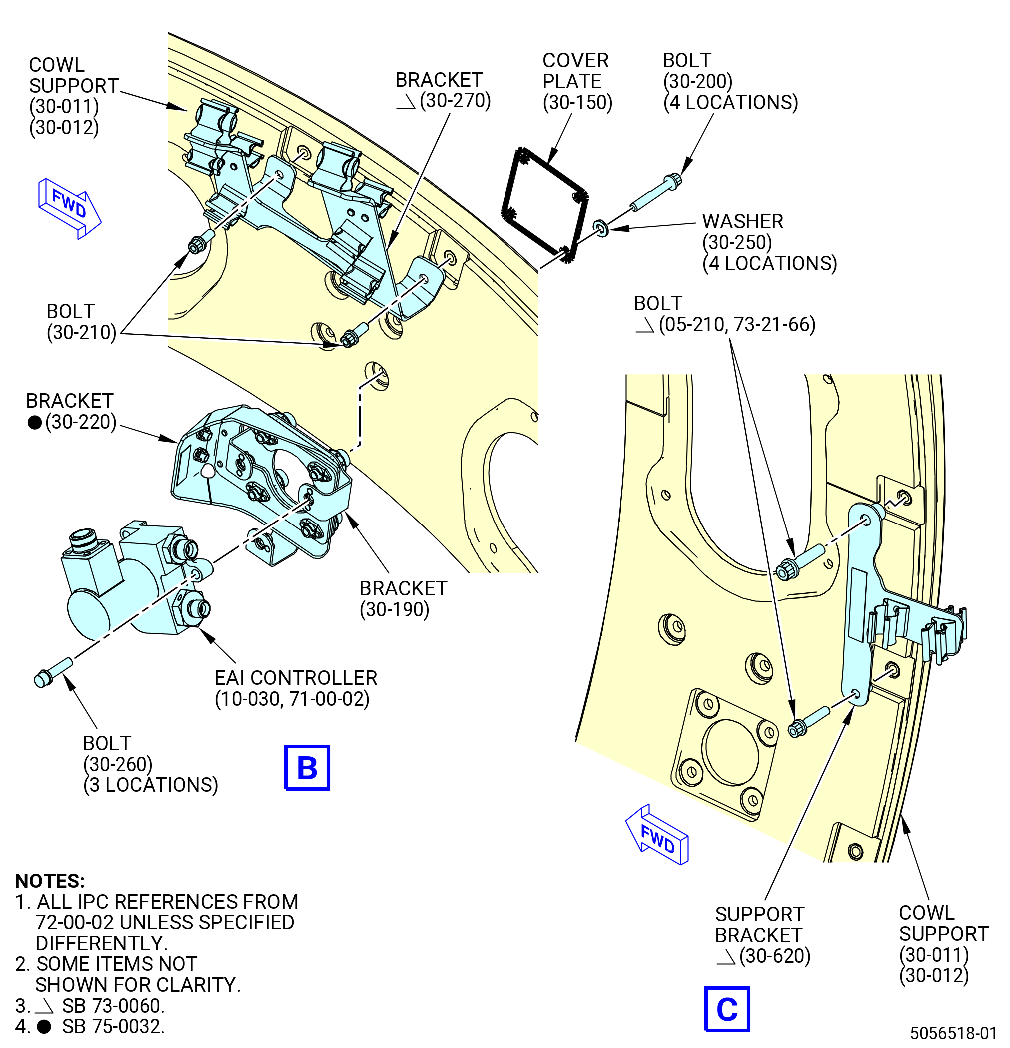
| I. | Install the cowl support brackets. Refer to Figure 1011 and do as follows: |
| (1) | Install the bracket (30-190) (SIN 6101T) and transducer support bracket (bracket) (30-220) (SIN 63715) on the cowl support (30-011) (SIN 95001) or (30-012) (SIN 95001) at the 1:00 o'clock position as follows: |
| (a) | Install the bolts (30-200) (SIN 6102T) and washers (30-250) (SIN 61033) in the cowl support with the cover plate (30-150A) (SIN 9500J). |
| (b) | Attach the bracket (6101T) with bolts (6102T). |
| (c) | Attach the bracket (30-220) (SIN 63715) with bolts (30-200) (SIN 6102T). |
| (d) | Torque the bolts to 32-38 lb in (5.7-6.7 N.m). |
| (2) | Install the control cable support bracket (bracket) (30-270) (SIN 68816) on the cowl support (30-011) (SIN 95001) or (30-012) (SIN 95001) at the 1:00 o'clock position as follows: |
| (a) | Attach the bracket (30-270) (SIN 68816) to the cowl support with bolts (30-210) (SIN 68820). |
| (b) | Torque the bolts to 106-124 lb in. (12.0-14.0 N.m). |
| Subtask 72-00-02-440-623 |
| * * * PRE SB 73-0060( Old Design for W30 and W31 Harnesses ) |
| (3) | Install the support bracket (30-620) (SIN 6711B) on the cowl support (30-011) (SIN 95001) or (30-012) (SIN 95001) at the 3:00 o'clock position as follows: |
| WARNING: |
|
| (a) | Lubricate the threads of the machine bolts (bolts) (30-410) (SIN 67120) with C02-023 engine oil. |
| (b) | Attach the support bracket (6711B) to the cowl support with bolts (67120). |
| (c) | Torque the bolts to 106-124 lb in. (12.0-14.0 N.m). |
| * * * END PRE SB 73-0060 |
| Subtask 72-00-02-440-624 |
| * * * SB 73-0060( W30 and W31 Redesigned Harnesses ) |
| (3).A. | Install the support bracket (30-620) (SIN 6711B) on the cowl support (30-010) (SIN 95001) or (30-011) (SIN 95001) at the 3:00 o'clock position as follows: |
| WARNING: |
|
| (a) | Lubricate the threads of the bolts (05-210 , 73-21-66) (SIN 6712D) with C02-023 engine oil. |
| (b) | Attach the support bracket (30-620) (SIN 6711B) to the cowl support with bolts (05-210 , 73-21-66) (SIN 6712D). |
| (c) | Torque the bolts (05-210 , 73-21-66) (SIN 6712D) to 106 to 124 lb in. (12.0 to 14.0 Nm). |
| * * * END SB 73-0060 |
| Subtask 72-00-02-440-625 |
| (4) | Install the support bracket (30-590) (SIN 6711C) on the cowl support (30-011) (SIN 95001) or (30-012) (SIN 95001) at the 3:45 o'clock position as follows: |
| WARNING: |
|
| (a) | Lubricate the threads of the bolts (30-410) (SIN 67120) with C02-023 engine oil. |
| (b) | Attach the support bracket (6711C) to the cowl support with the bolts (67120). |
| (c) | Torque the bolts to 106-124 lb in. (12.0-14.0 N.m). |
| (5) | Install the support bracket (30-570) (SIN 6711E) or (30-571) (SIN 6711E) on the cowl support (30-011) (SIN 95001) or (30-012) (SIN 95001) at the 4:30 o'clock position as follows: |
| WARNING: |
|
| (a) | Lubricate the threads of the bolts (30-410) (SIN 67120) and (30-641) (SIN 67221) with C02-023 engine oil. |
| (b) | Attach the support bracket (30-570) (SIN 6711E) or (30-571) (SIN 6711E) to the cowl support with the bolts (30-410) (SIN 67120) and (30-641) (SIN 67221). |
| (c) | Torque the bolts to 106-124 lb in. (12.0-14.0 N.m). |
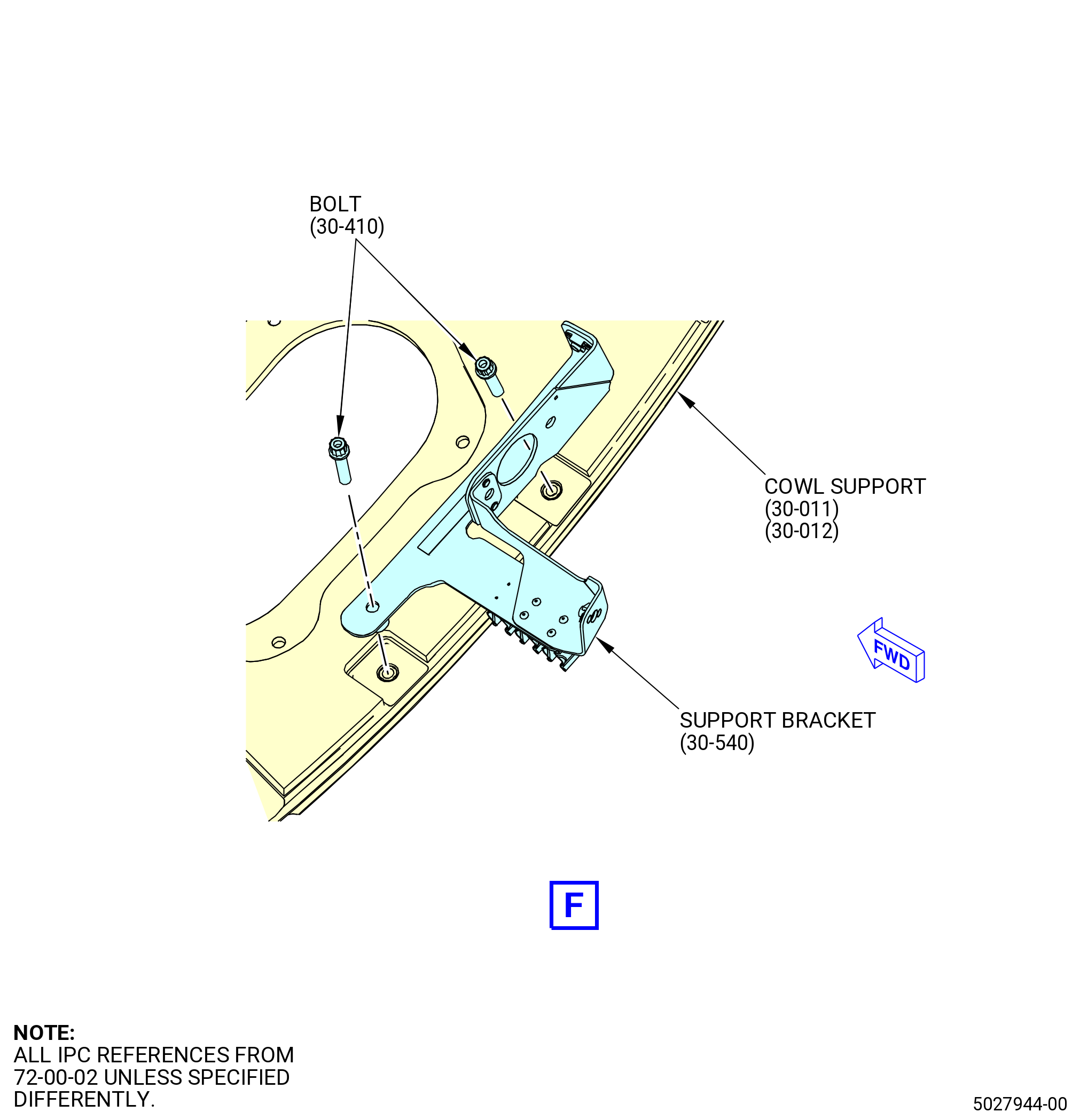
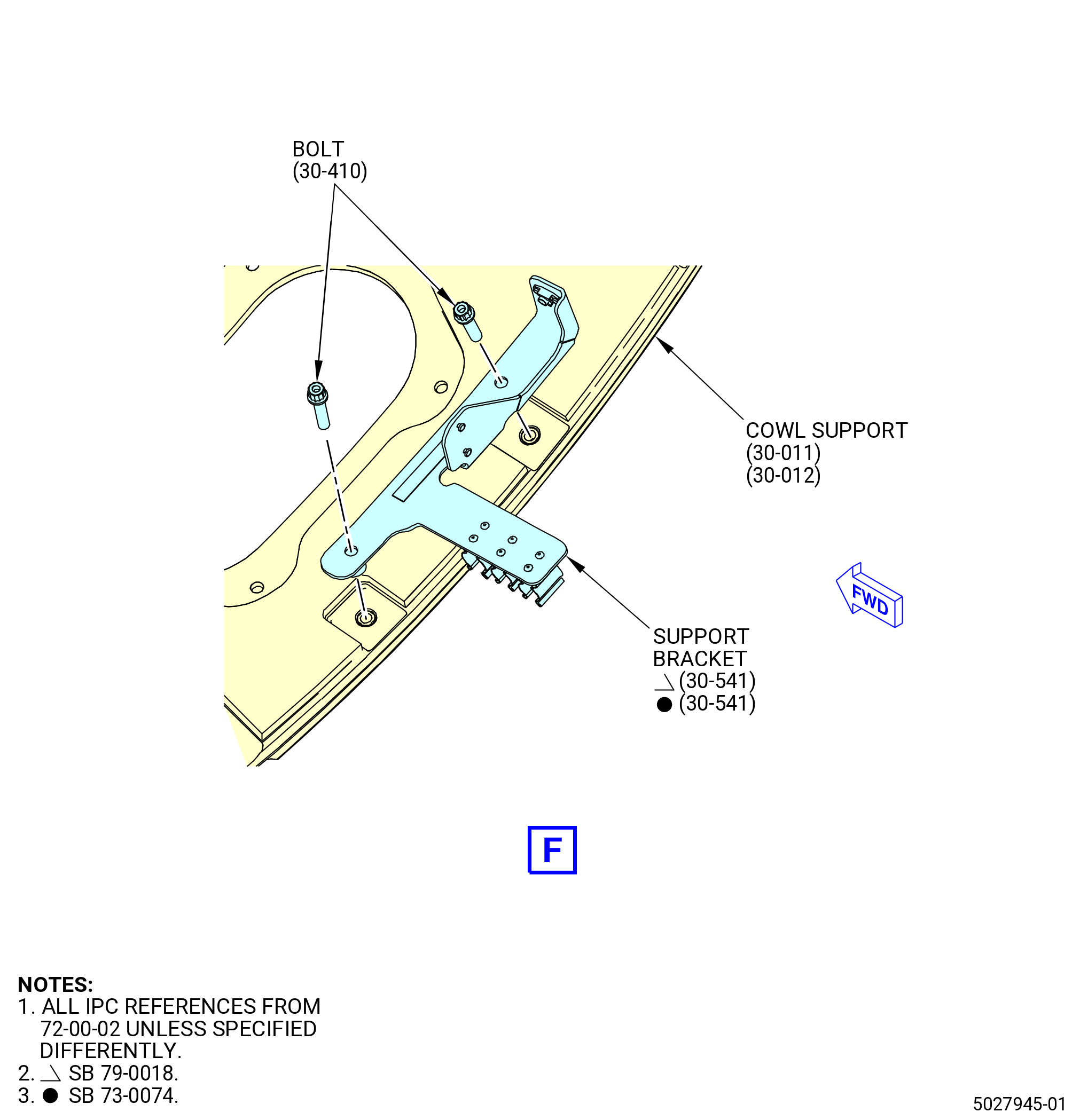
| (6) | Install the support bracket (30-540) (SIN 6711D) or (30-541) (SIN 6711D) on the cowl support (30-011) (SIN 95001) or (30-012) (SIN 95001) at the 5:00 o'clock position as follows: |
| WARNING: |
|
| (a) | Lubricate the threads of bolts (30-410) (SIN 67120) with C02-023 engine oil. |
| (b) | Attach the support bracket (30-540) (SIN 6711D) or (30-541) (SIN 6711D) to the cowl support with the bolts (30-410) (SIN 67120). |
| (c) | Torque the bolts to 106-124 lb in. (12.0-14.0 N.m). |
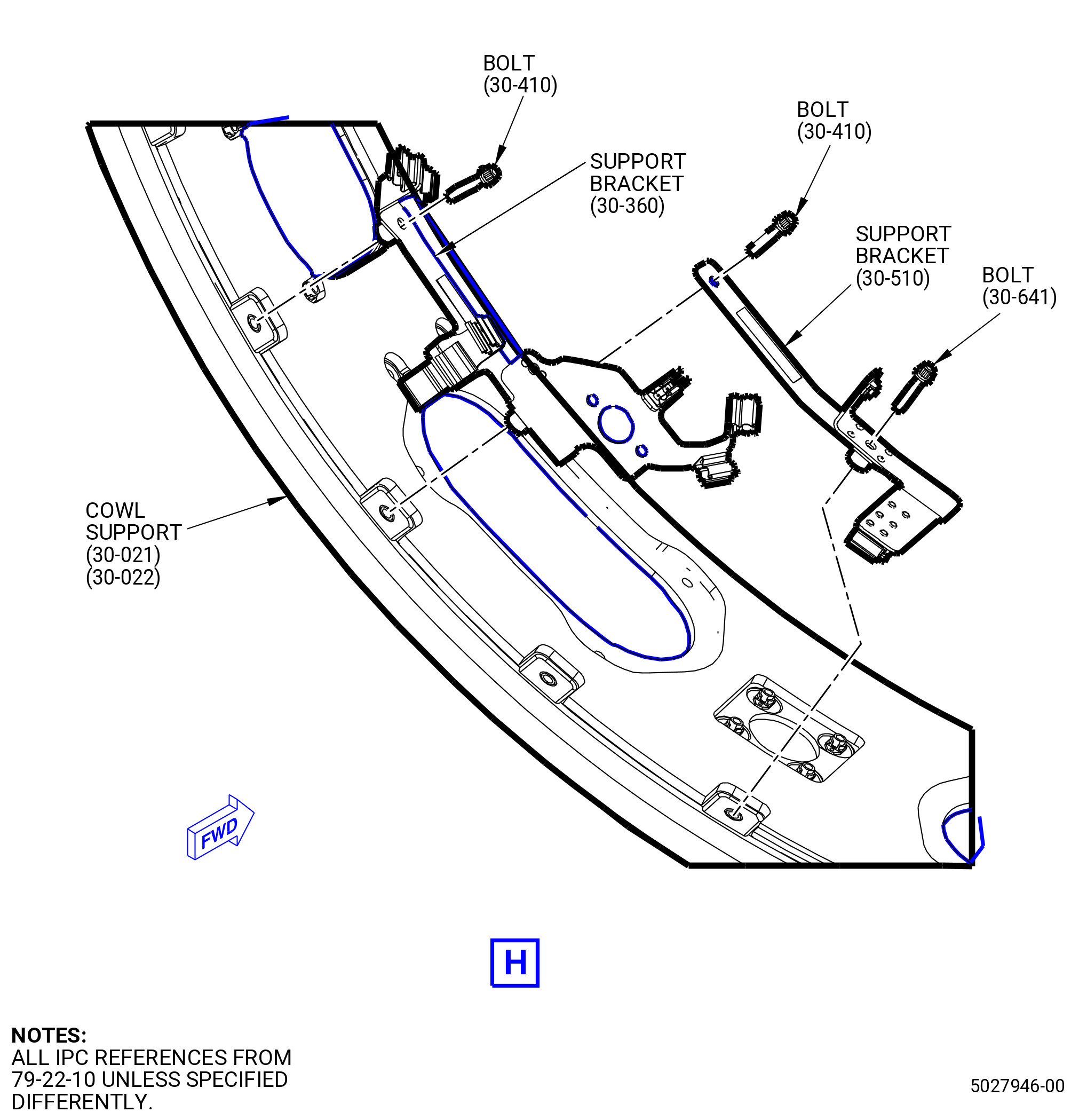
| (7) | Install the drain and wiring support bracket (support bracket) (30-360) (SIN 6711F) on the cowl support (30-021) (SIN 95008) or (30-022) (SIN 95008) at the 8:00 o'clock position as follows: |
| WARNING: |
|
| (a) | Lubricate the threads of bolts (30-410) (SIN 67120) with C02-023 engine oil. |
| (b) | Attach the support bracket (6711F) to the cowl support with bolt (67120). |
| (c) | Torque the bolt to 106-124 lb in. (12.0-14.0 N.m). |
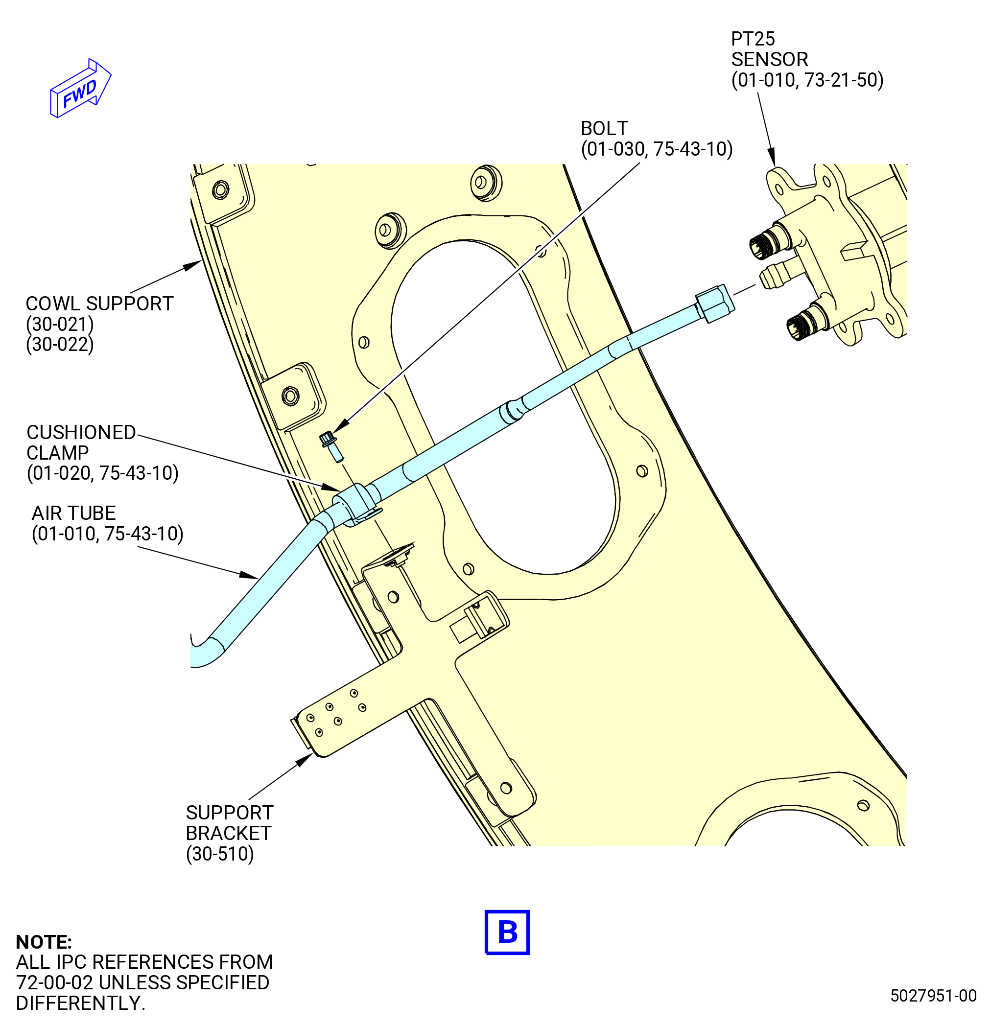
| (8) | Install the support bracket (30-510) (SIN 67218) on the support bracket (30-360) (SIN 6711F) and cowl support (30-021) (SIN 95008) or (30-022) (SIN 95008) at the 7:30 o'clock position as follows: |
| (a) | Attach the support bracket (30-510) (SIN 67218) to the support bracket (30-360) (SIN 6711F) with a bolt (30-410) (SIN 67120). |
| (b) | Attach the support bracket (30-510) (SIN 67218) to the cowl support with a bolt (30-641) (SIN 67221). |
| (c) | Torque the bolts to 106-124 lb in. (12.0-14.0 N.m). |
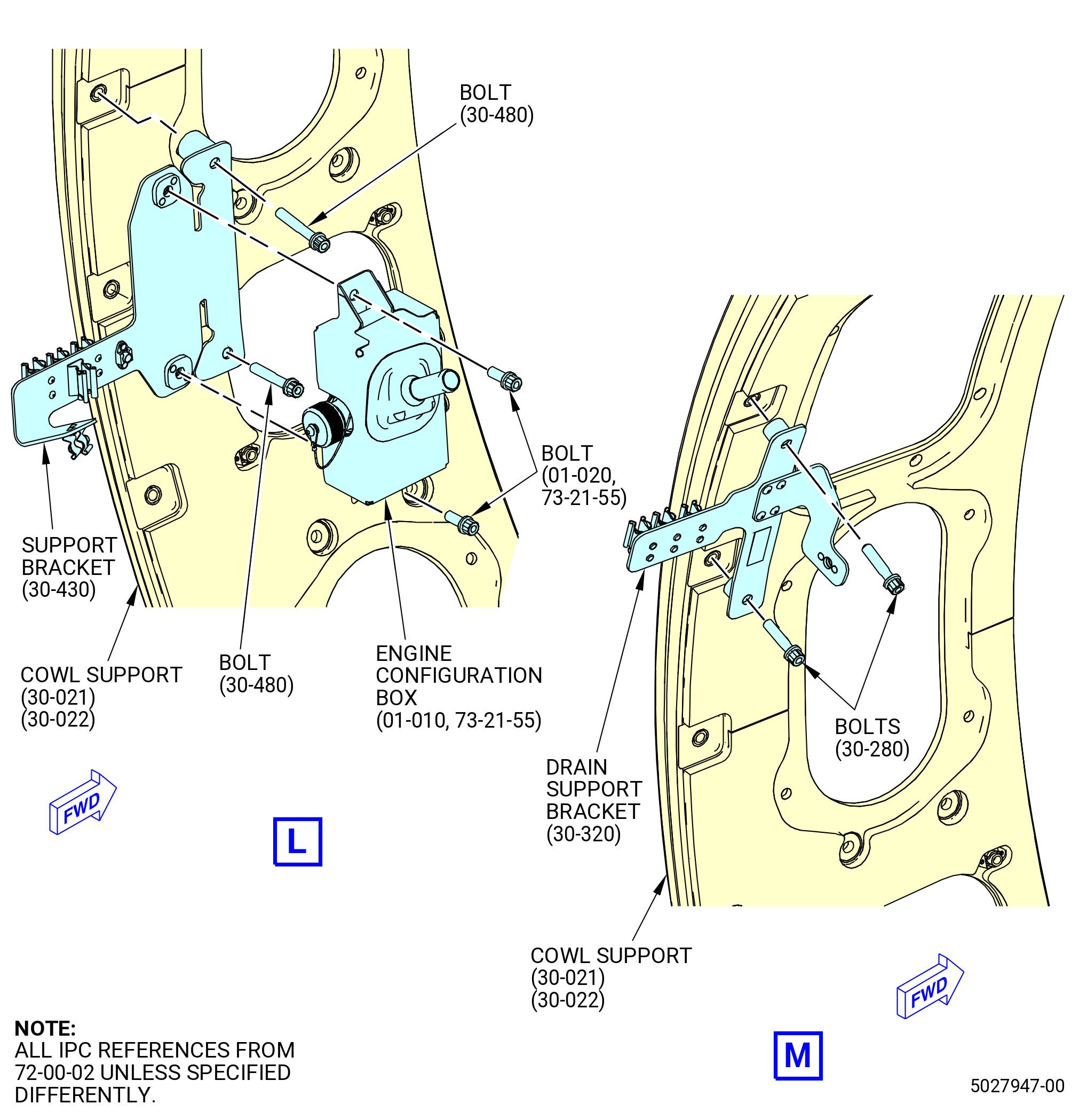
| (9) | Install the configuration box mounting support bracket (support bracket) (30-430) (SIN 65M10) and the engine configuration box (01-010 , 73-21-55) (SIN 65M00) on the cowl support (30-021) (SIN 95008) or (30-022) (SIN 95008) at the 9:00 o'clock position as follows: |
| (a) | Attach the support bracket (65M10) to the cowl support with the bolts (65M21). |
| (b) | Torque the bolts to 106-124 lb in. (12.0-14.0 N.m). |
| (c) | Install the engine configuration box (65M00) on the support bracket (65M10). Attach with the bolts (65M20). |
| (d) | Torque the bolts (65M20) to 106-124 lb in. (12.0-14.0 N.m). |
| (10) | Install the drain support bracket (30-320) (SIN 37710) on the cowl support (30-021) (SIN 95008) or (30-022) (SIN 95008) at the 9:30 o'clock position as follows: |
| (a) | Attach the drain support bracket (37710) to the cowl support with the bolts (37721). |
| (b) | Torque the bolts to 106-124 lb in. (12.0-14.0 N.m). |
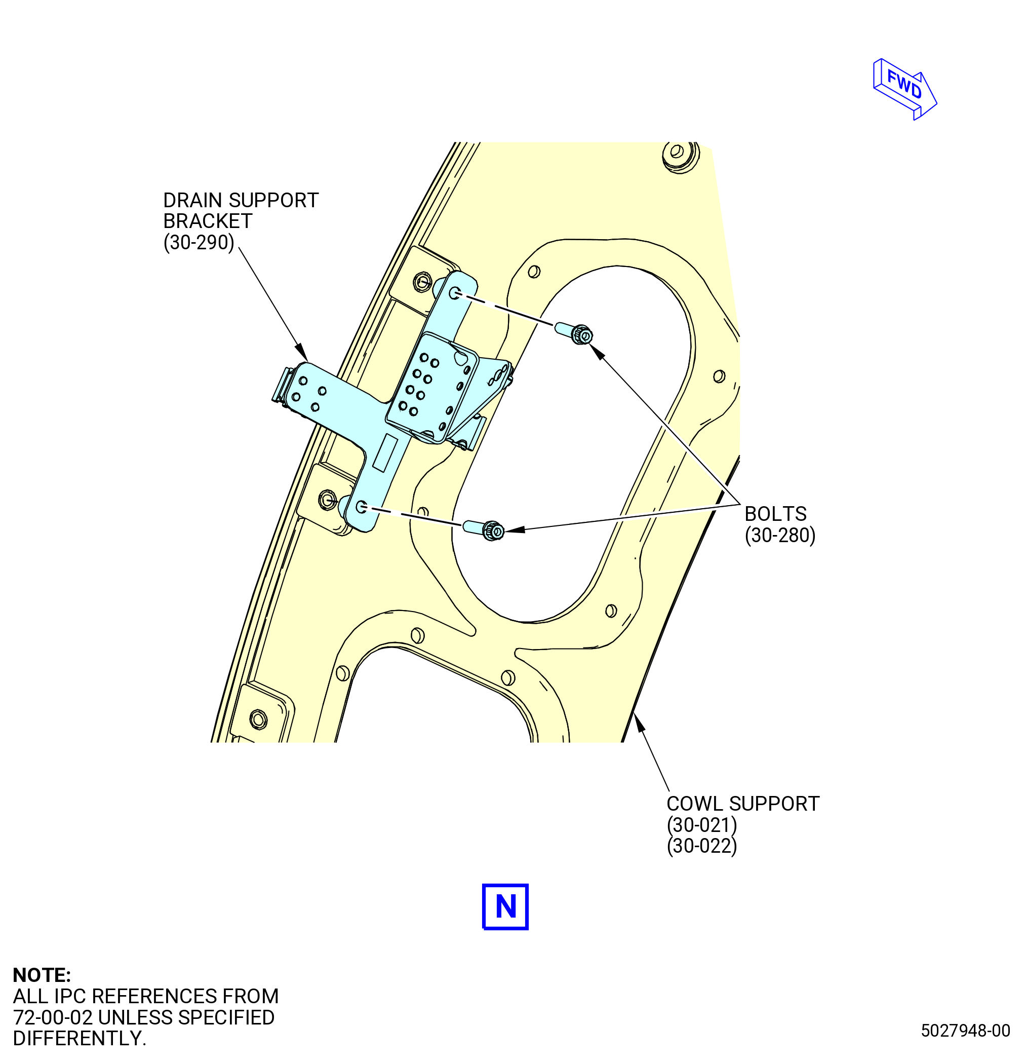
| (11) | Install the drain support bracket (30-290) (SIN 37711) on the cowl support (30-021) (SIN 95008) or (30-022) (SIN 95008) at the 10:00 o'clock position as follows: |
| (a) | Attach the drain support bracket (37711) to the cowl support with the bolts (37721). |
| (b) | Torque the bolts to 106-124 lb in. (12.0-14.0 N.m). |
| (12) | Install the seal retainer (01-075 , 75-23-10) (SIN 62013) in the cowl support (30-021) (SIN 95008) or (30-022) (SIN 95008) with four washers (01-050 , 75-23-10) (SIN 62030) and four bolts (01-041 , 75-23-10) (SIN 62020). |
| (13) | Torque the bolts (01-041 , 75-23-10) (SIN 62020) to 106-124 lb in. (12.0-14.0 N.m). |
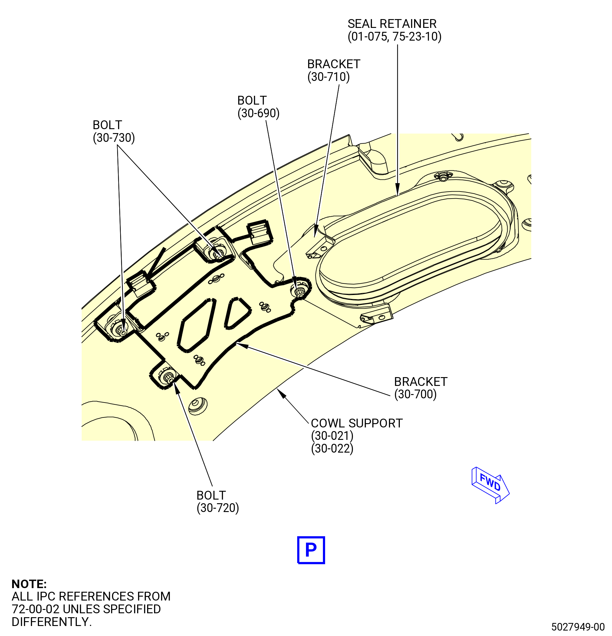
| (14) | Put the bracket (30-700) (SIN 6101V) on the bracket (30-710) (SIN 610E5) and cowl support (30-022) (SIN 95008). |
| (15) | Install bracket (30-700) (SIN 6101V) in the cowl support (30-021) (SIN 95008) or (30-022) (SIN 95008) with two bolts (30-730) (SIN 6102Y), one bolt (30-720) (SIN 6102W) and one bolt (30-690) (SIN 6102K) on the bracket (30-710) (SIN 610E5). |
| (16) | Torque the bolts (30-730) (SIN 6102Y), (30-720) (SIN 6102W), and (30-690) (6102K) to 32-37 lb in. (3.6-4.3N.m). |
|
|
| Subtask 72-00-02-440-312 |
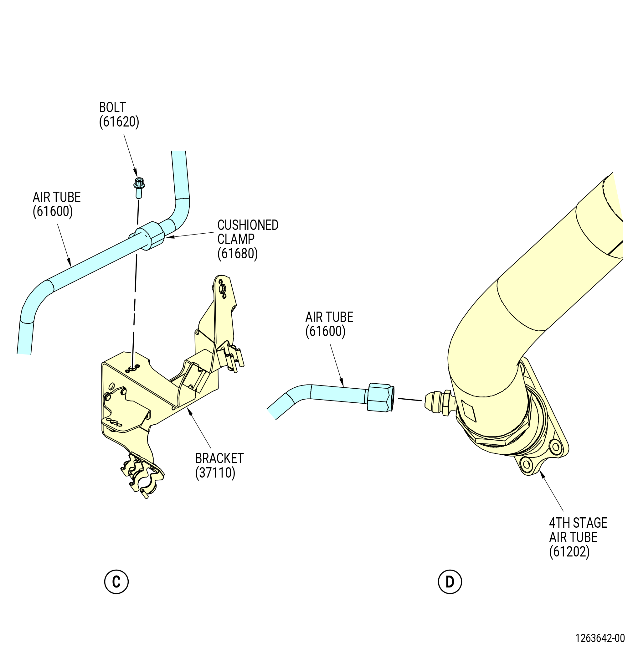
| J. | Install the T25 sensor heating air tube (air tube) (61600). Refer to Figure 1012 and do as follows: |
| WARNING: |
|
| (1) | Apply C02-019 engine oil or C02-023 engine oil to the forward B-nut of the air tube (61600). |
| (2) | Connect the forward B-nut to the T25 sensor (65200). |
| (3) | Connect the aft B-nut of air tube (61600) to the 4th stage air tube (61202). |
| (4) | Attach the air tube (61600) to the bracket (37110) with cushioned clamp (61680) and bolt (61620). |
| (5) | Attach the air tube (61600) to the support bracket (67218) with cushioned clamp (61680) and bolt (61620). |
| (6) | Torque the bolts (61620) to 32-38 lb in. (3.6-4.3 N.m). |
| (7) | Torque the aft B-nut to 460-540 lb in. (52.0-61.0 N.m). |
| (8) | Torque the forward B-nut to 175-205 lb in. (19.8-23.2 N.m). |
| Subtask 72-00-02-440-313 |
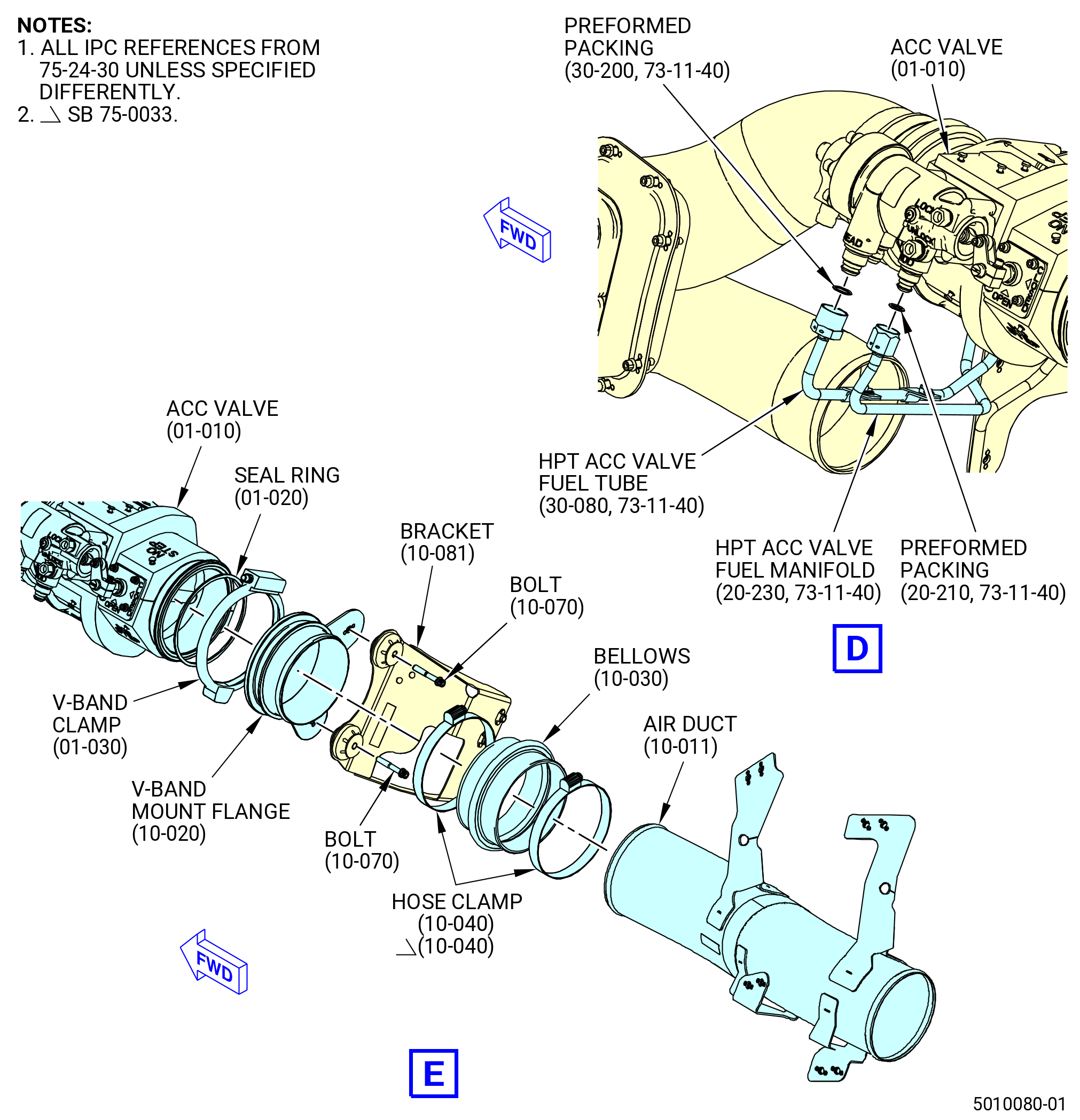
| K. | Install the high pressure turbine (HPT) ACC duct and valve. Refer to Figure 1013 and do as follows: |
| (1) | Install the HPT and low pressure turbine (LPT) air duct (air duct) (62107) as follows: |
| (a) | Put the air duct (01-100 , 75-23-10) (SIN 62107) on the cowl support (30-021) (SIN 95008) or (30-022) (SIN 95008) at the 10:00 o'clock position. |
| (b) | Attach the air duct with bolts (62120) and washers (62131). |
| (c) | Torque the bolts (62120) to 106-124 lb in. (12.0-14.0 N.m). |
| (2) | Install the ACC valve (60600) as follows: |
| (a) | install the HPT ACC bellows (bellows) (62102) on the air duct (62107). |
| (b) | Install the ACC valve (60600) on the bellows (62102) and on the forward side of bracket (62115). |
| (c) | Attach the ACC valve (60600) to the bracket (62115) with bolts (62120) and washers (62131). |
| (d) | Install a hose clamp (01-130 , 75-23-10) (SIN 62182) on each end of the bellows (01-140 , 75-23-10) (SIN 62102). Put the hose clamps in position so the bolt heads are outboard and point to the 12:00 o'clock position. |
| (e) | Torque the bolts (62120) to 106-124 lb in. (12.0-14.0 N.m). |
| (f) | Torque the hose clamps (01-130 , 75-23-10) (SIN 62182) to 32 to 38 lb in. (3.6 to 4.3 Nm). |
| (3) | Connect the fuel lines to the ACC valve as follows: |
| WARNING: |
|
| (a) | Apply C02-019 engine oil or C02-023 engine oil to preformed packing (34751) and preformed packing (38050). |
| (b) | Install the preformed packing (20-210 , 73-11-40) (SIN 34751) on the aft nipple (ROD end) of the ACC valve (60600). |
| (c) | Install the preformed packing (30-200 , 73-11-40) (SIN 38050) on the forward nipple (HEAD end) of the ACC valve (60600). |
| (d) | Connect the HPT ACC valve fuel tube (38000) to the forward nipple (HEAD end). Torque the B-nut to 55-65 lb ft (75-88 N.m). |
| (e) | Connect the LPT and HPT ACC valve fuel manifold (34701) to the aft nipple (ROD end). Torque the B-nut to 460-540 lb in. (52.0-61.0 N.m). |
| (f) | Safety the B-nuts with C10-071 safety wire or C10-143 safety cable. |
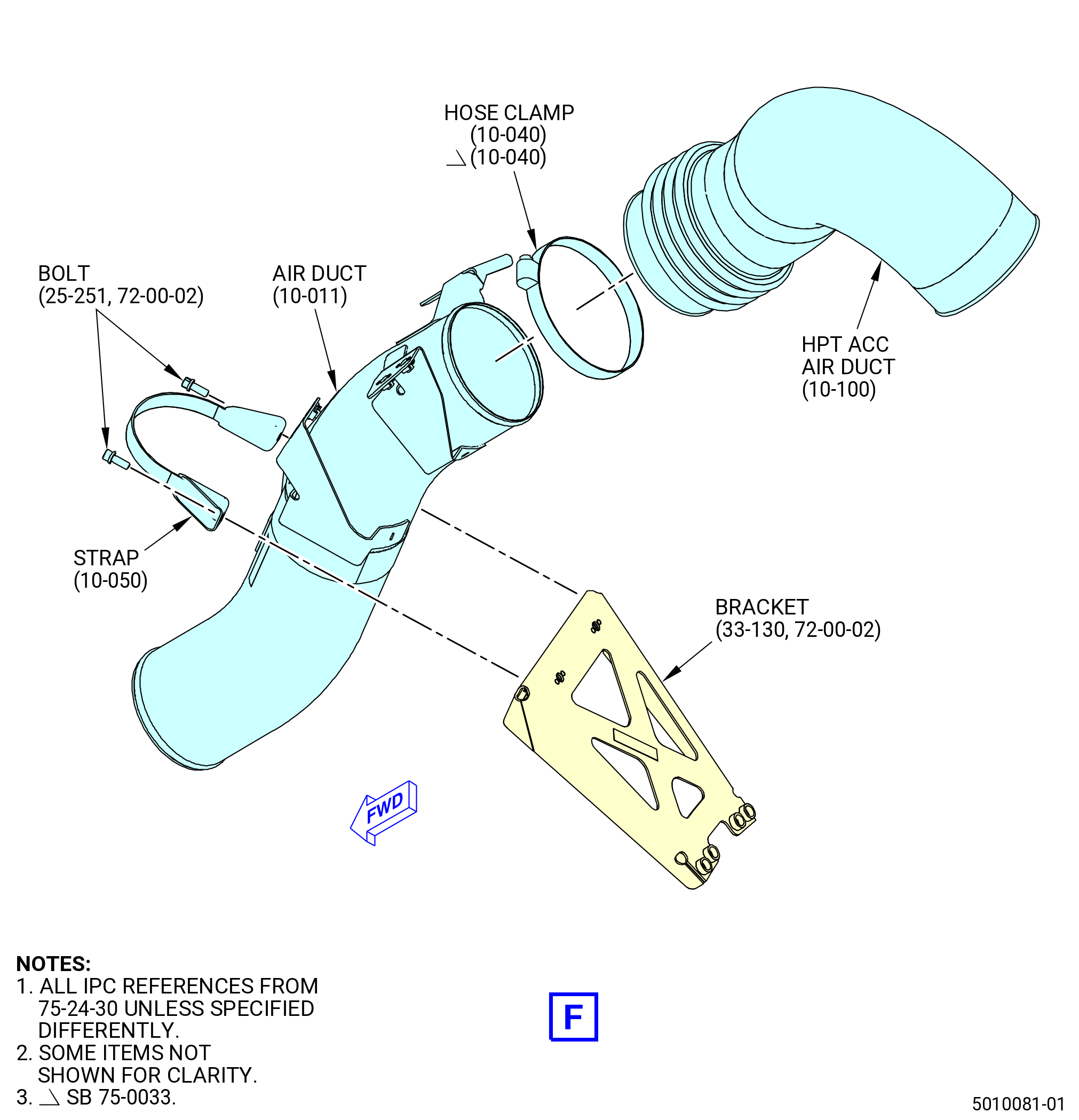
| (4) | Install the HPT supply air duct (air duct) (10-011 , 75-24-30) (SIN 62101) as follows: |
| (a) | Put a seal ring (62150) on the aft side of the ACC valve (60600). |
| (b) | Attach the V-band mount flange (62100) to the ACC valve (60600) with V-band clamp (62180). Install the V-band clamp with the bolt at the 12:00 o'clock position and the bolt head outboard. |
| (c) | Attach the V-band mount flange (62100) to the bracket (10-081 , 75-24-30) (SIN 62113) with bolts (62125). |
| (d) | Install the HPT bellows (bellows) (62103) on the V-band mount flange (62100). |
| (e) | Install the air duct (10-011 , 75-24-30) (SIN 62101) in the bellows (62103). |
| (f) | Attach the air duct to bracket (62114) with strap (62181) and bolts (62123). |
| (g) | Install a hose clamp (01-130 , 75-23-10) (SIN 62182) on each end of the bellows (10-030 , 75-24-30) (SIN 62103). |
| (h) | Torque the V-band clamp (62180) to 106-124 lb in. (12.0-14.0 N.m). |
| (i) | Torque the hose clamps (01-130 , 75-23-10) (SIN 62182) to 32 to 38 lb in. (3.6 to 4.3 Nm). |
| (j) | Torque the bolts (62123) to 106-124 lb in. (12.0-14.0 N.m). |
| (k) | Torque the bolts (62125) to 106-124 lb in. (12.0-14.0 N.m). |
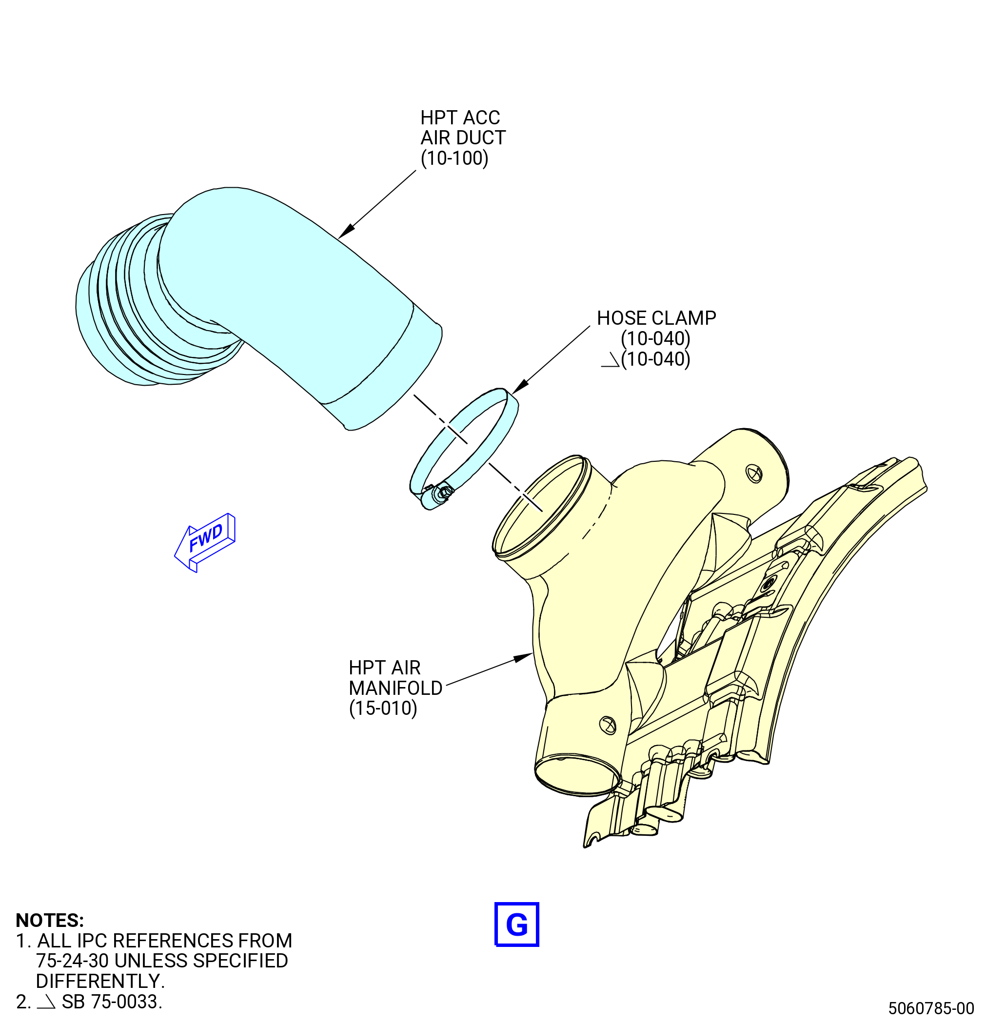
| (5) | Install the HPT ACC air duct (62108) as follows: |
| (a) | Install the HPT ACC air duct (62108) on the air duct (10-011 , 75-24-30) (SIN 62101). |
| (b) | Install a hose clamp (01-130 , 75-23-10) (SIN 62182) on each end of the HPT ACC air duct (10-100 , 75-24-30) (SIN 62108). |
| (c) | Install the HPT ACC air duct (10-100 , 75-24-30) (SIN 62108) on HPT air manifold (15-010 , 75-24-30) (SIN 6210G). |
| (d) | Install a hose clamp (10-040 , 75-24-30) (SIN 62182) on the end of the HPT ACC air duct (10-100 , 75-24-30) (SIN 62108). |
| (e) | Torque the hose clamps (01-130 , 75-23-10) (SIN 62182) to 32 to 38 lb in. (3.6 to 4.3 Nm). |
| Subtask 72-00-02-440-314 |
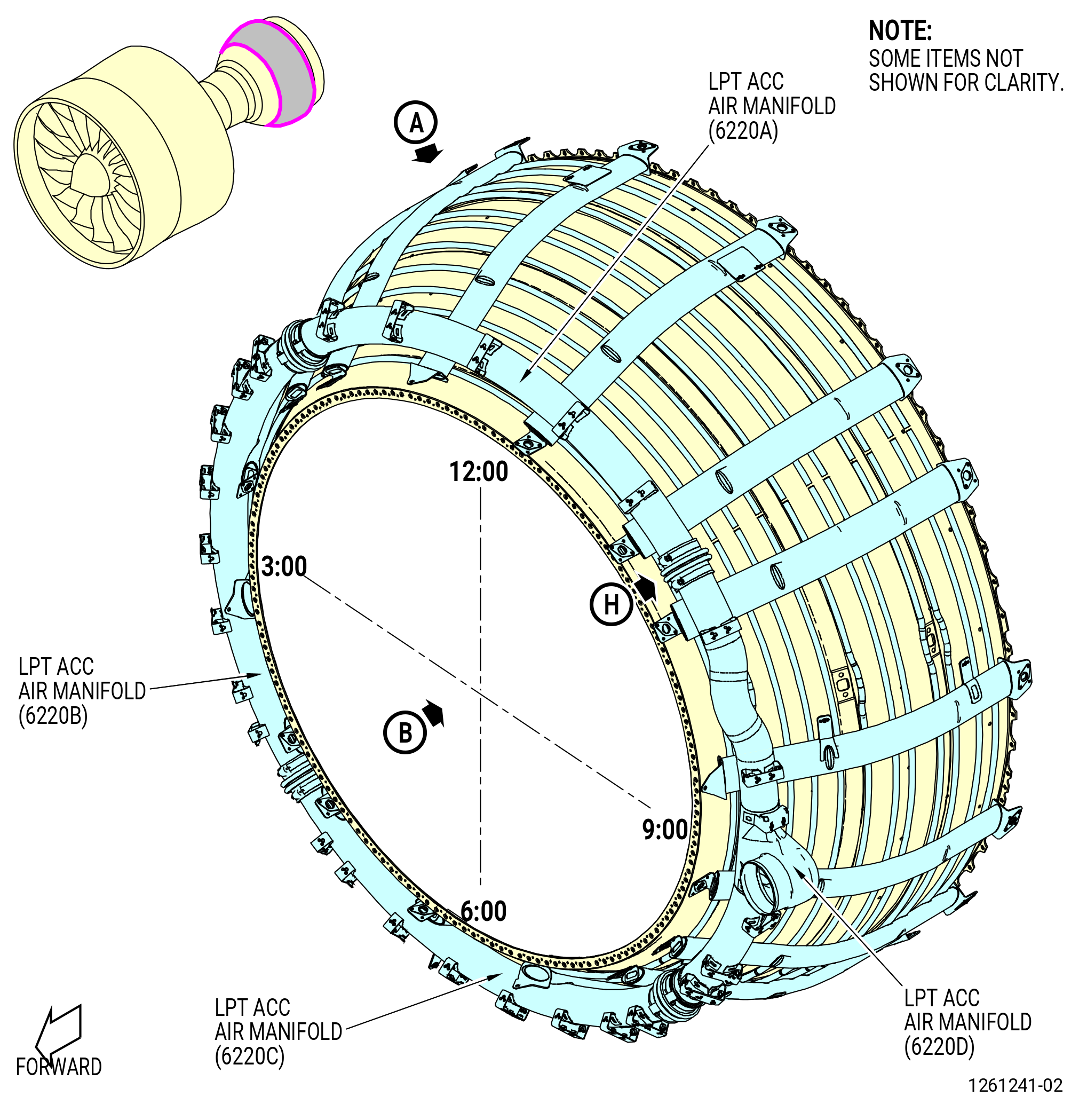
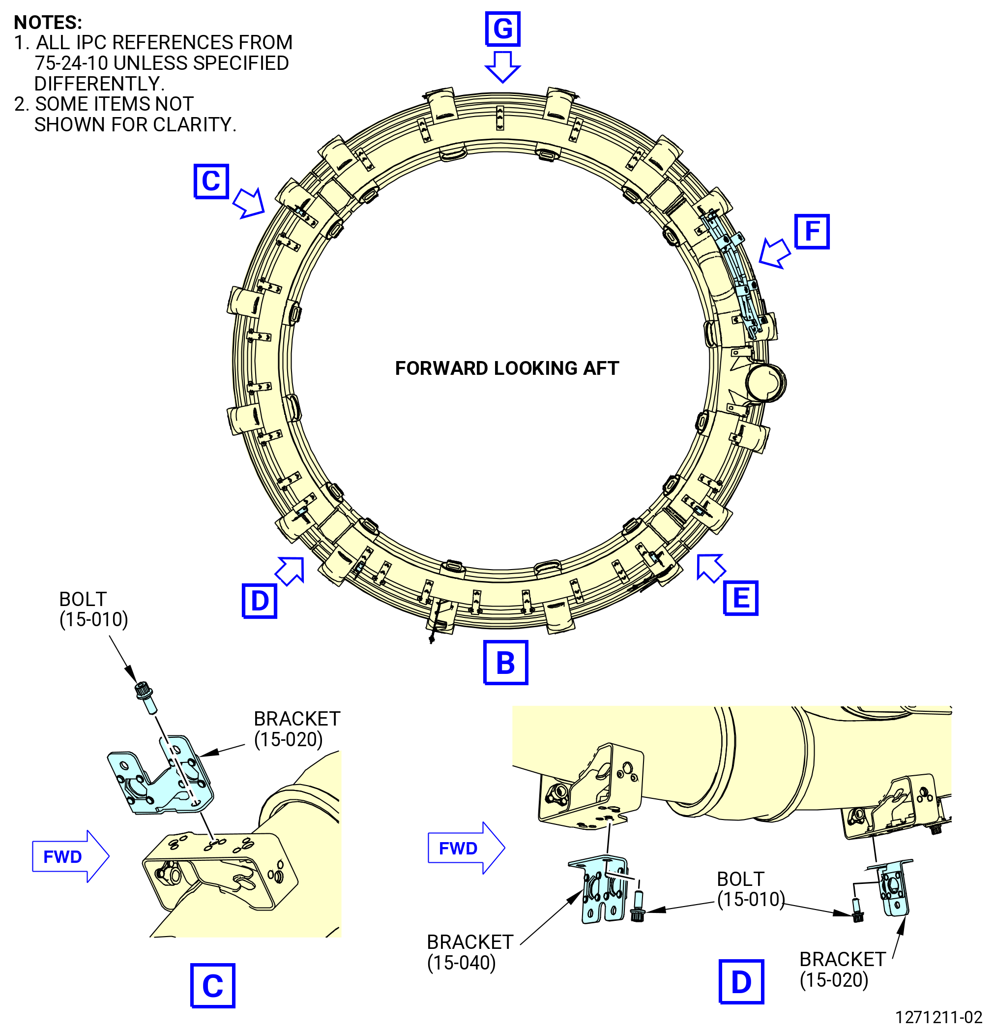
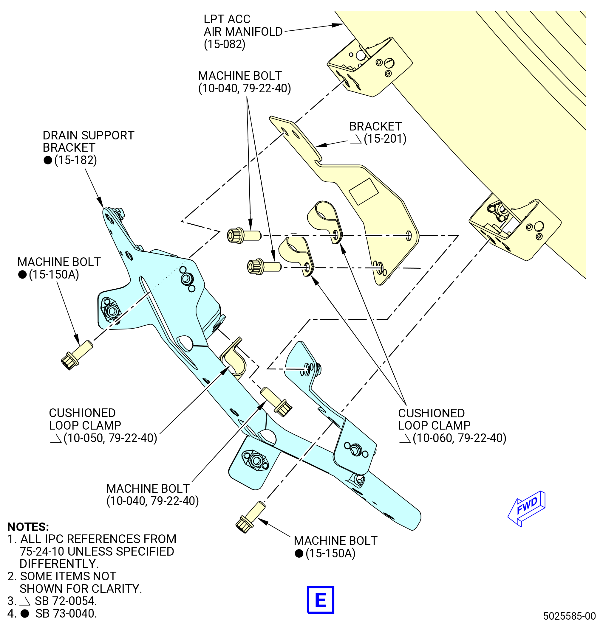
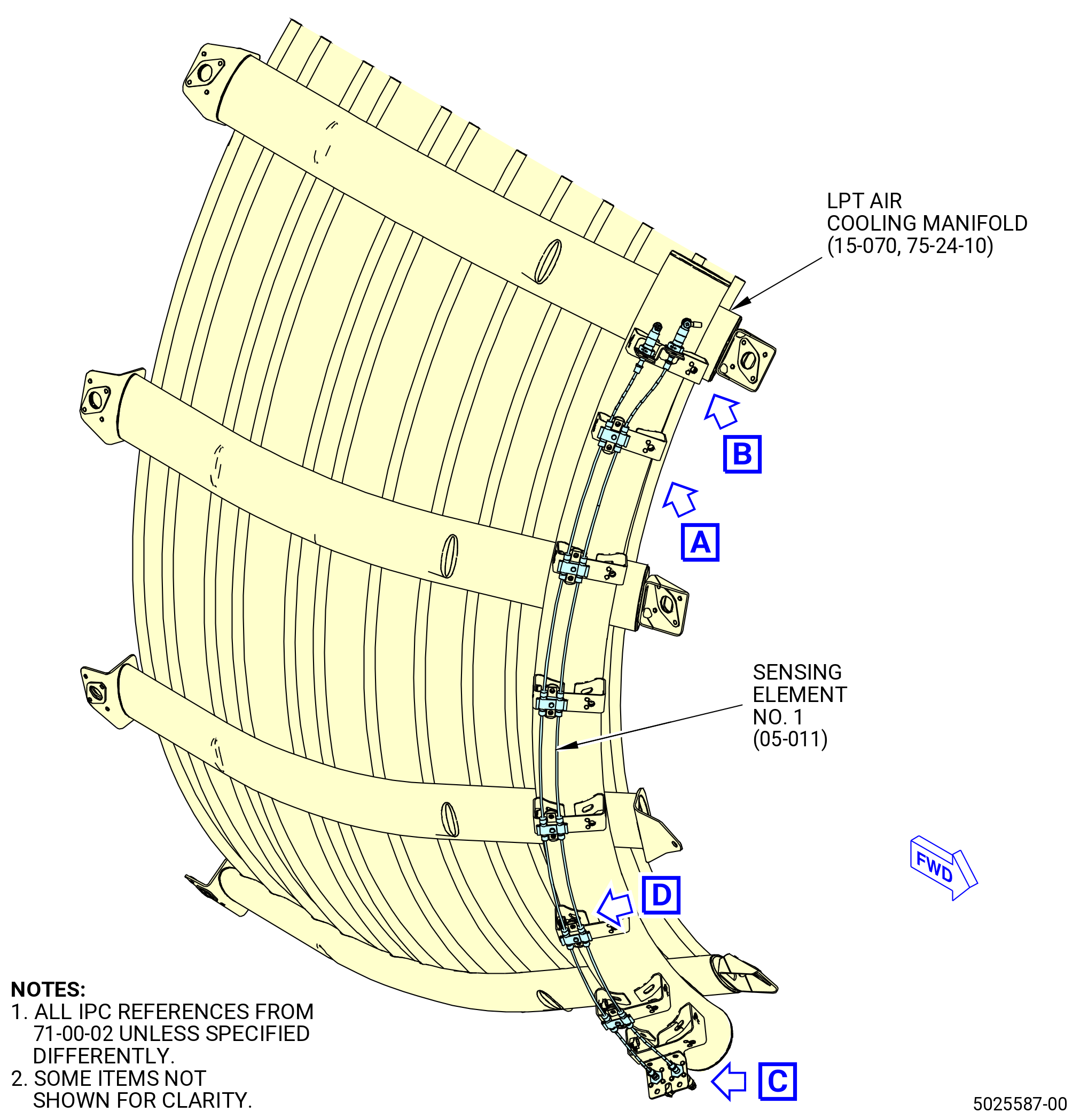
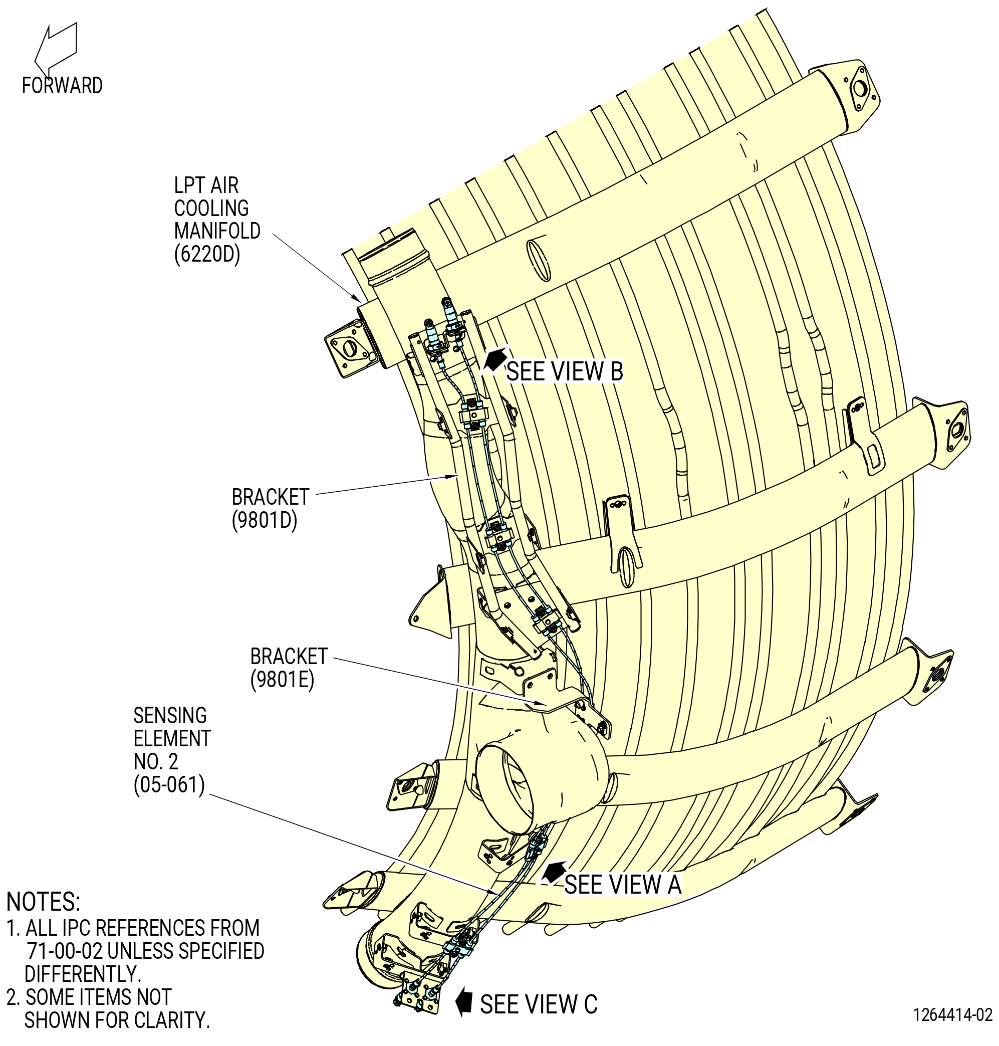
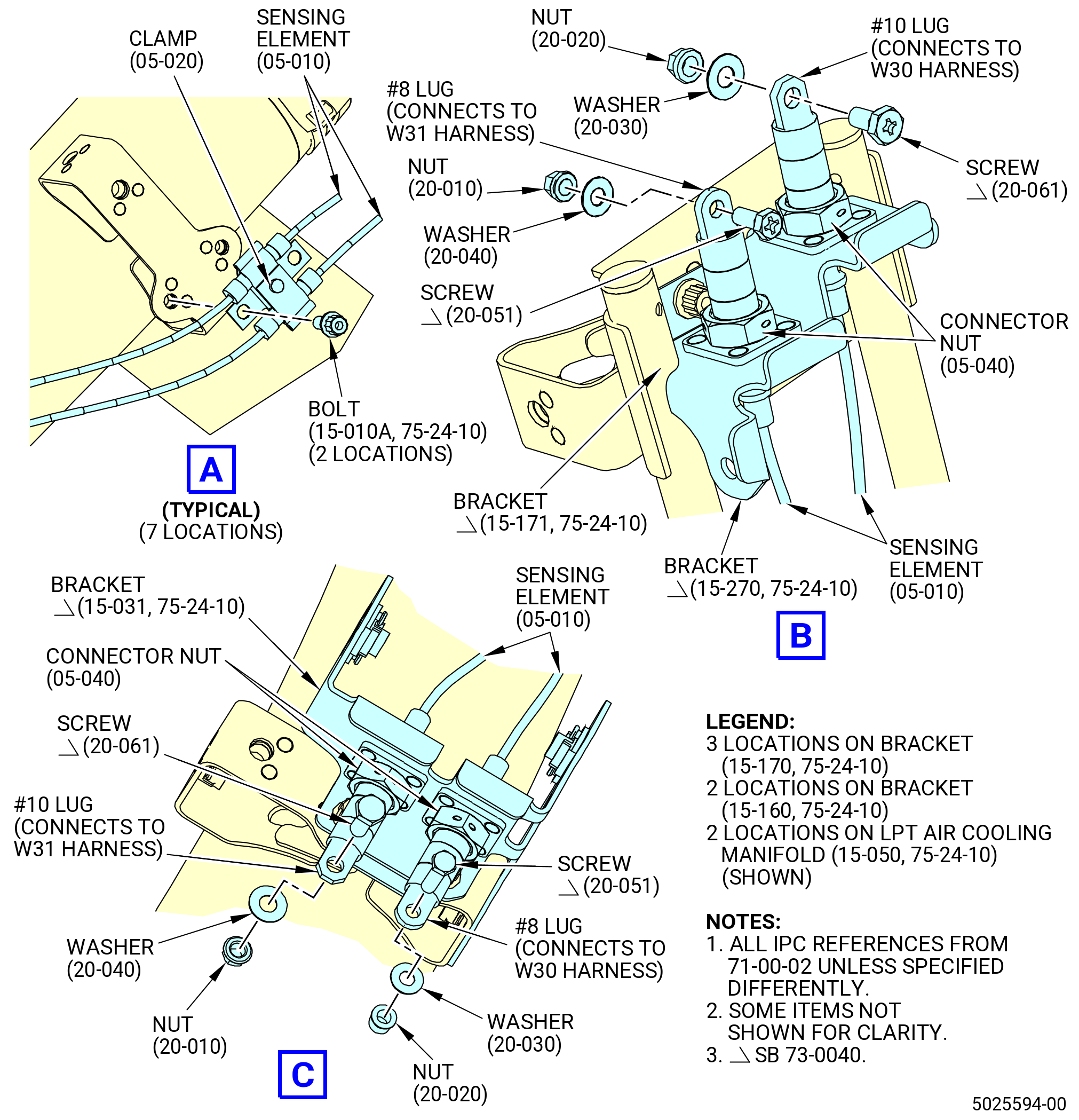
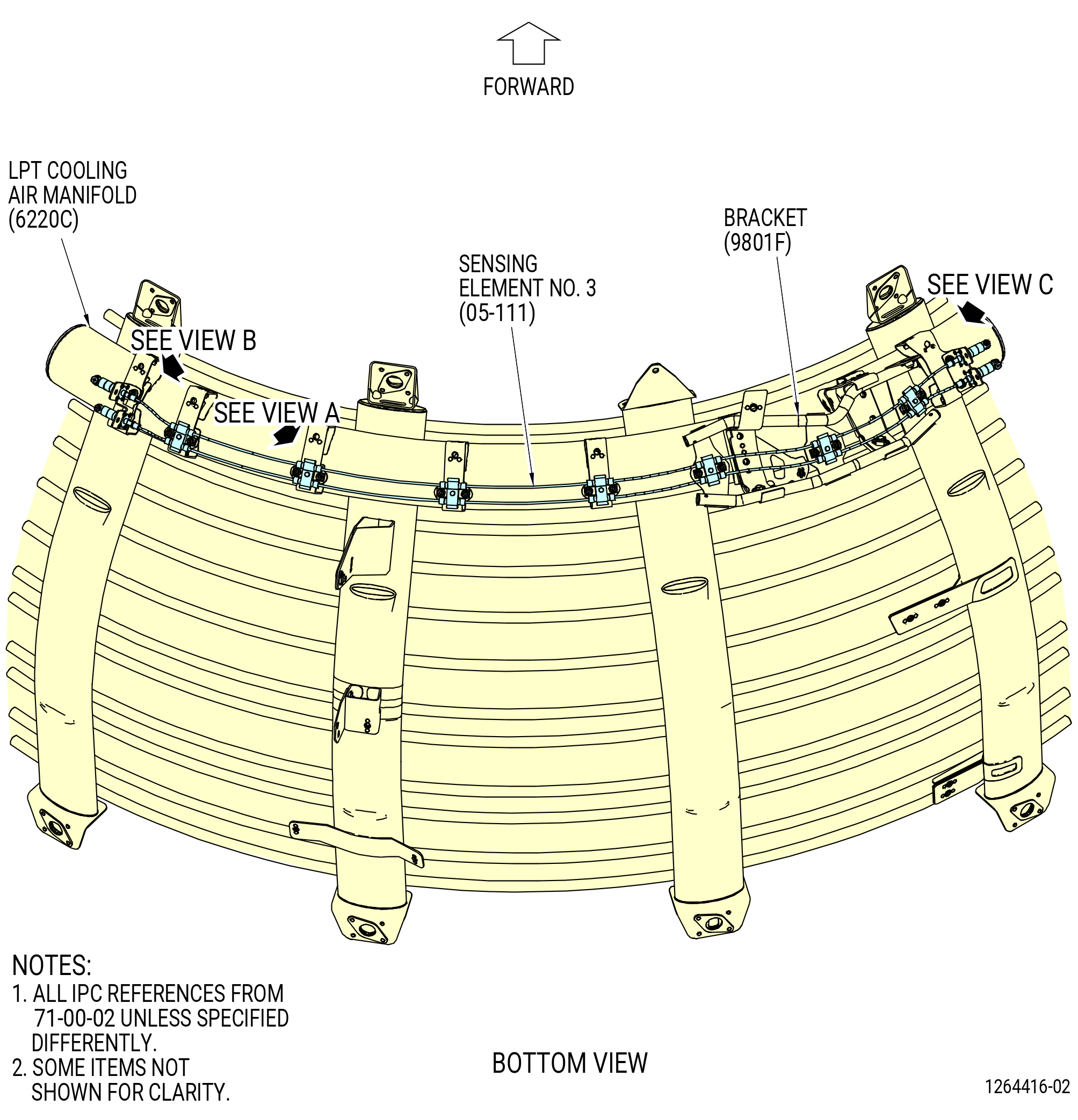
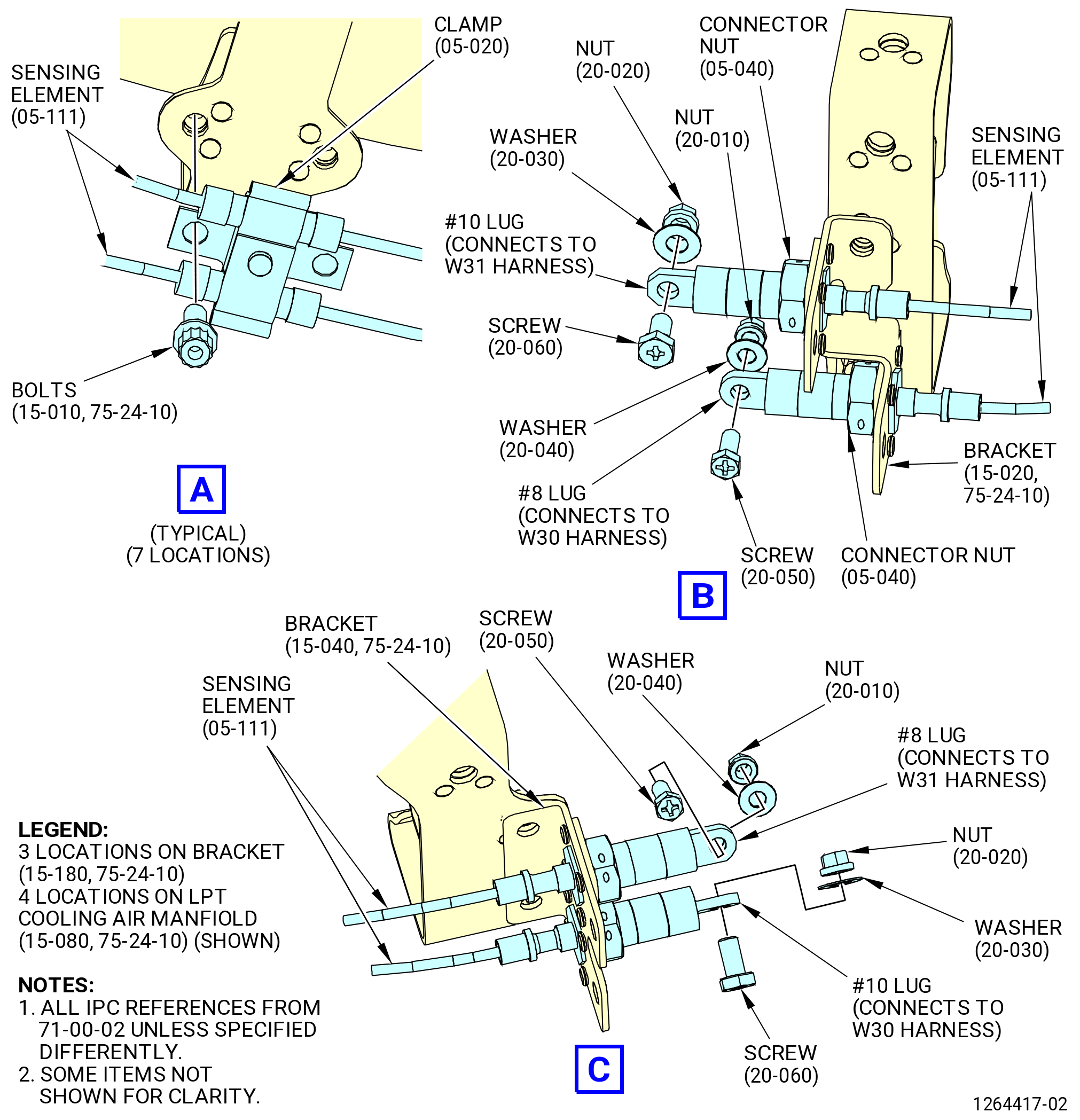
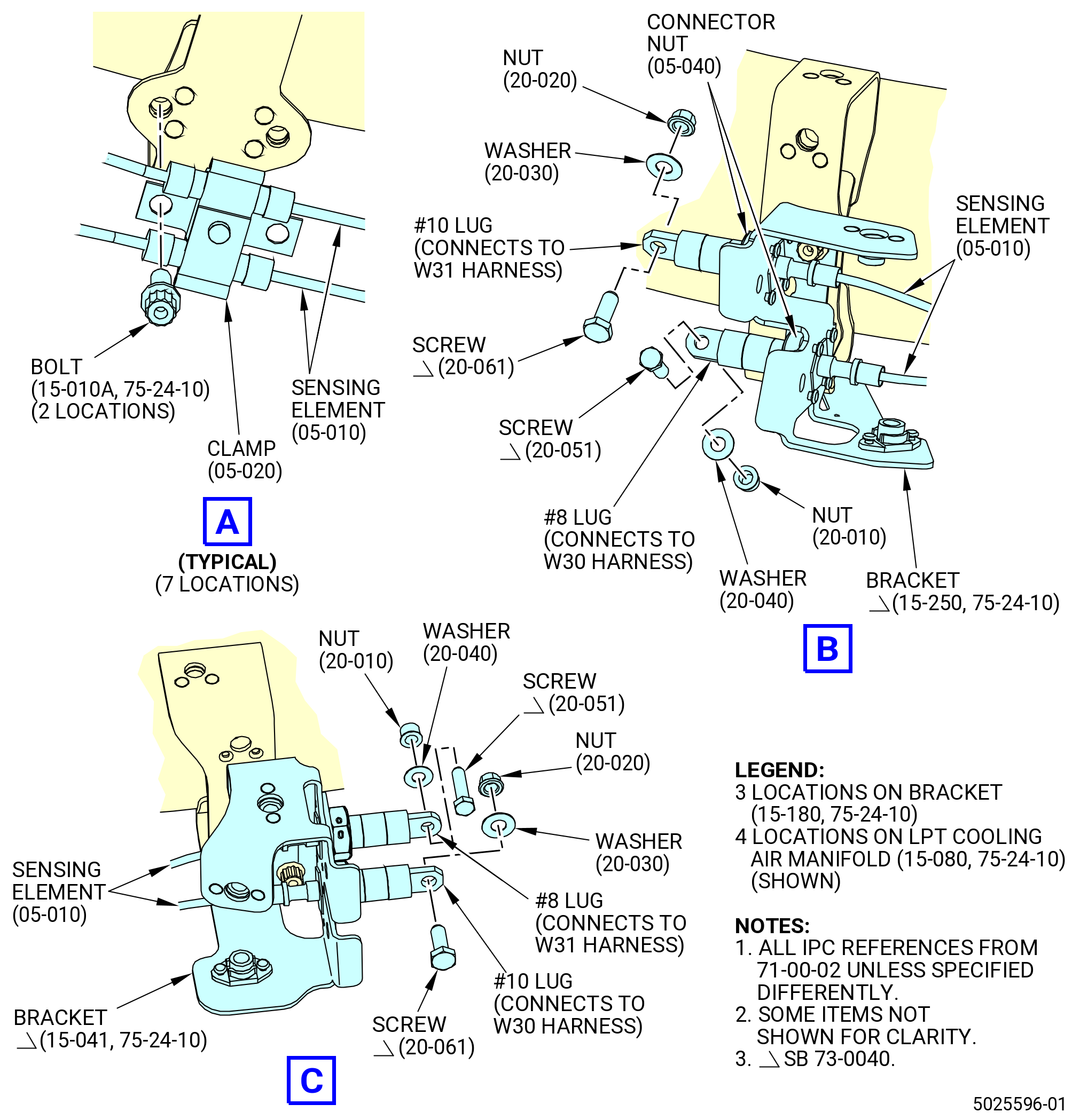
| L. | Install the LPT ACC air manifold and brackets. Refer to Figure 1014 and do as follows: |
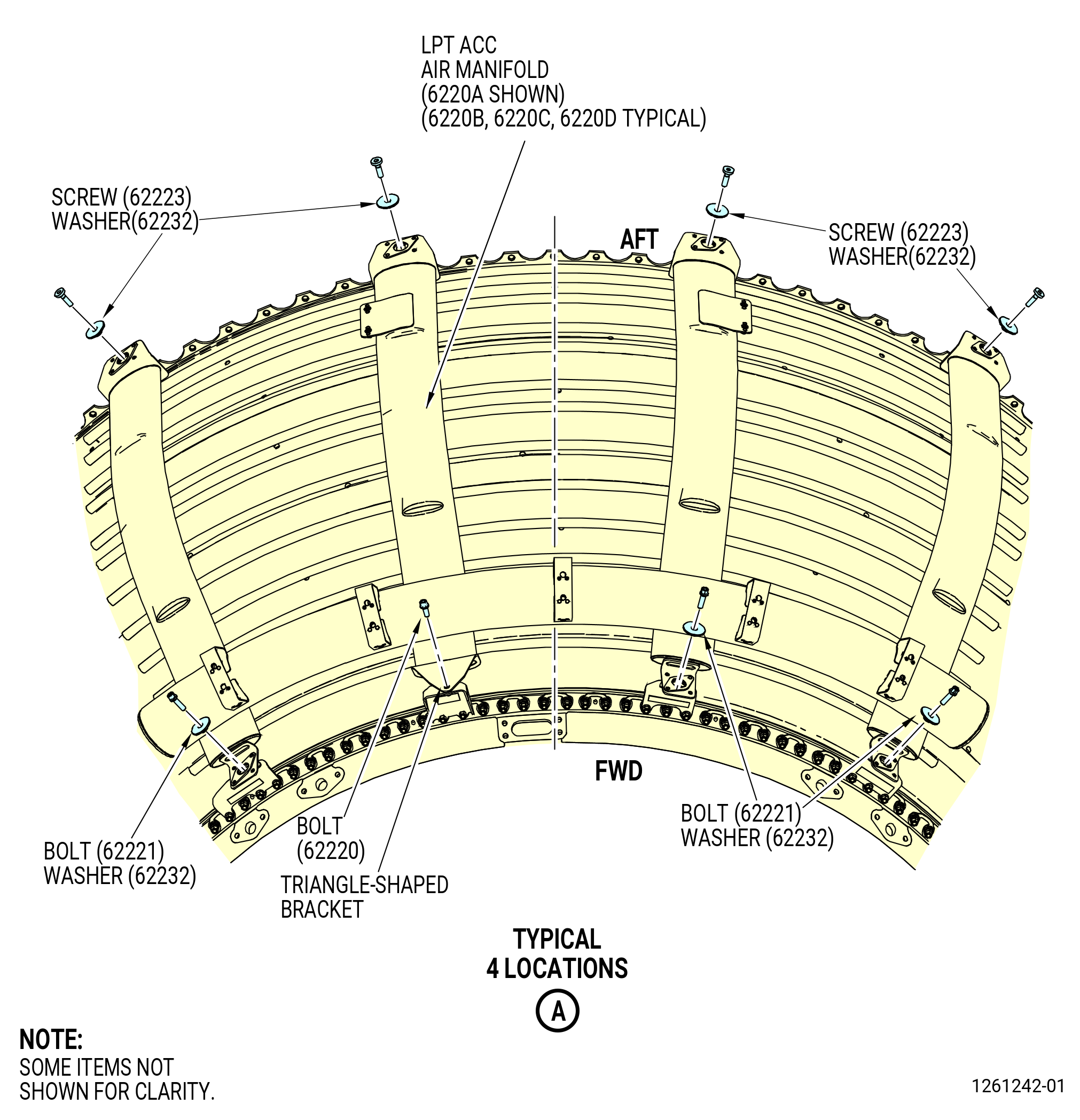
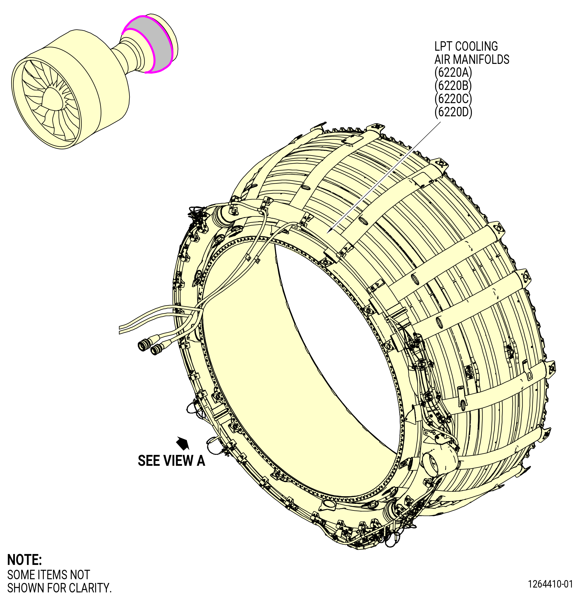
| (1) | Install the LPT ACC air manifold (6220A) across the 12:00 o'clock location as follows: |
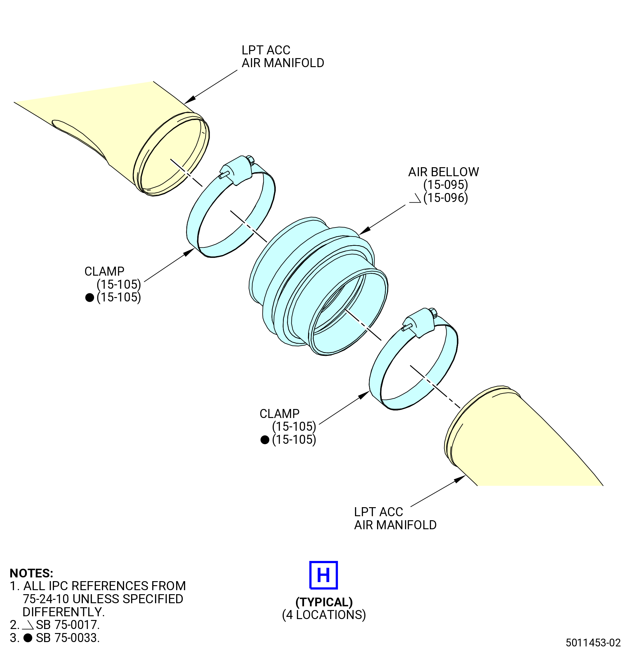
| (a) | Install one air bellow (15-095 , 75-24-10) (SIN 62205) or (15-096 , 75-24-10) (SIN 62205) on the CW end of the large diameter tube on the manifold. Push the air bellow fully onto the tube and attach firmly with a clamp (15-105 , 75-24-10) (SIN 62280). |
| (b) | Align the center of the manifold (6220A) with the 12:00 o'clock location on the LPT case. |
| (c) | Attach the manifold with a bolt (62220) through the triangle-shaped tab on the forward side of the manifold and into the LPT ACC bracket (62214) already installed on the turbine center frame-low pressure turbine (TCF-LPT) flange. |
| (d) | Install three bolts (62221) and three washers (62232) in the remaining tabs on the forward side of the manifold and into brackets on the TCF-LPT flange. |
| (e) | Install four screws (62223) and four washers (62232) on the aft side of the manifold into brackets on the LPT aft flange. |
| (2) | Install the LPT ACC air manifold (6220B) across the 9:00 o'clock location as follows: |
| (a) | Install one air bellow (15-095 , 75-24-10) (SIN 62205) or (15-096 , 75-24-10) (SIN 62205) on the CW end of the large diameter tube on the manifold. Push the air bellow fully onto the tube and attach firmly with a clamp (15-105 , 75-24-10) (SIN 62280). |
| (b) | Align the center of the manifold (6220B) with the 9:00 o'clock location on the LPT case. |
| (c) | Attach firmly the air bellow previously installed in the air manifold (15-062 , 75-24-10) (SIN 6220A) with a clamp (15-105 , 75-24-10) (SIN 62280). |
| (d) | Attach the manifold with a bolt (62220) through the triangle-shaped tab on the forward side of the manifold and into the LPT ACC bracket (62213) already installed on the TCF-LPT flange. |
| (e) | Install three bolts (62221) and three washers (62232) in the remaining tabs on the forward side of the manifold and into brackets on the TCF-LPT flange. |
| (f) | Install four screws (62223) and four washers (62232) on the aft side of the manifold into brackets on the LPT aft flange. |
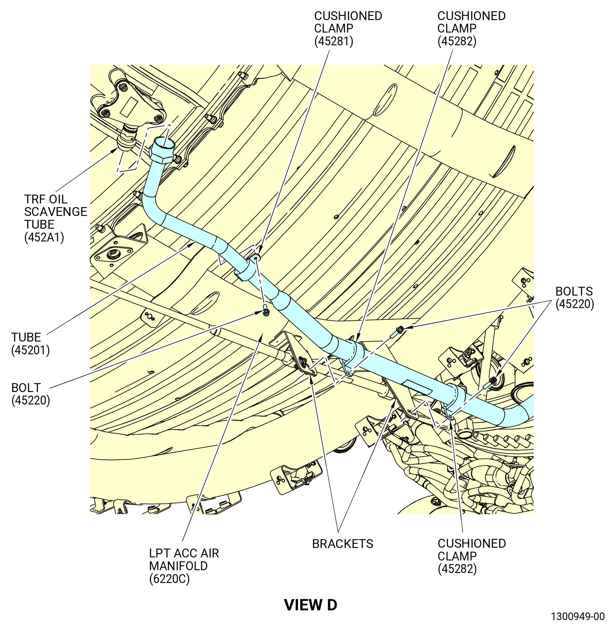
| (3) | Install the LPT ACC air manifold (6220C) across the 6:00 o'clock location as follows: |
| (a) | Install one air bellow (15-095 , 75-24-10) (SIN 62205) or (15-096 , 75-24-10) (SIN 62205) on the CW end of the large diameter tube on the manifold. Push the air bellow fully onto the tube and attach firmly with a clamp (15-105 , 75-24-10) (SIN 62280). |
| (b) | Align the center of the LPT ACC air manifold (6220C) with the 6:00 o'clock location on the LPT case. |
| (c) | Attach firmly the air bellow previously installed in the air manifold (15-072 , 75-24-10) (SIN 6220B) with a clamp (15-105 , 75-24-10) (SIN 62280). |
| (d) | Attach the manifold with a bolt (62220) through the triangle-shaped tab on the forward side of the manifold and into the LPT ACC bracket (62213) already installed on the TCF-LPT flange. |
| (e) | Install three bolts (62221) and three washers (62232) in the remaining tabs on the forward side of the manifold and into the brackets on the TCF-LPT flange. |
| (f) | Install four screws (62223) and four washers (62232) on the aft side of the manifold into brackets on the LPT aft flange. |
| (4) | Install the LPT ACC air manifold (6220D) across the 3:00 o'clock location as follows: |
| (a) | Install one air bellow (15-095 , 75-24-10) (SIN 62205) or (15-096 , 75-24-10) (SIN 62205)(62205) on the CW end of the large diameter tube on the manifold. Push the air bellow fully onto the tube and attach firmly with a clamp (15-105 , 75-24-10) (SIN 62280). |
| (b) | Align the center of the manifold (6220D) with the 3:00 o'clock location on the LPT case. |
| (c) | Attach firmly the air bellow previously installed in the air manifold (15-082 , 75-24-10) (SIN 6220C) with a clamp (15-105 , 75-24-10) (SIN 62280). |
| (d) | Attach firmly the air bellow installed between the air manifolds (15-052 , 75-24-10) (SIN 6220D) and (15-062 , 75-24-10) (SIN 6220A) with a clamp (15-105 , 75-24-10) (SIN 62280). |
| (e) | Attach the manifold with a bolt (62220) through the triangle-shaped tab on the forward side of the manifold and into the LPT ACC bracket (62212) already installed on the TCF-LPT flange. |
| (f) | Install three bolts (62221) and three washers (62232) in the remaining tabs on the forward side of the manifold and into the brackets on the TCF-LPT flange. |
| (g) | Install four screws (62223) and four washers (62232) on the aft side of the manifold into the brackets on the LPT aft flange. |
| (5) | Torque the bolts (62220), (62221), and (62223) to 106-124 lb in. (12.0-14.0 N.m). |
| (6) | Torque the eight clamps (15-105 , 75-24-10) (SIN 62280) to 32 to 38 lb in. (3.6 to 4.3 Nm). |
| Subtask 72-00-02-440-524 |
| * * * PRE SB 73-0040( Engines without Improved W30 and W31 Harnesses ) |
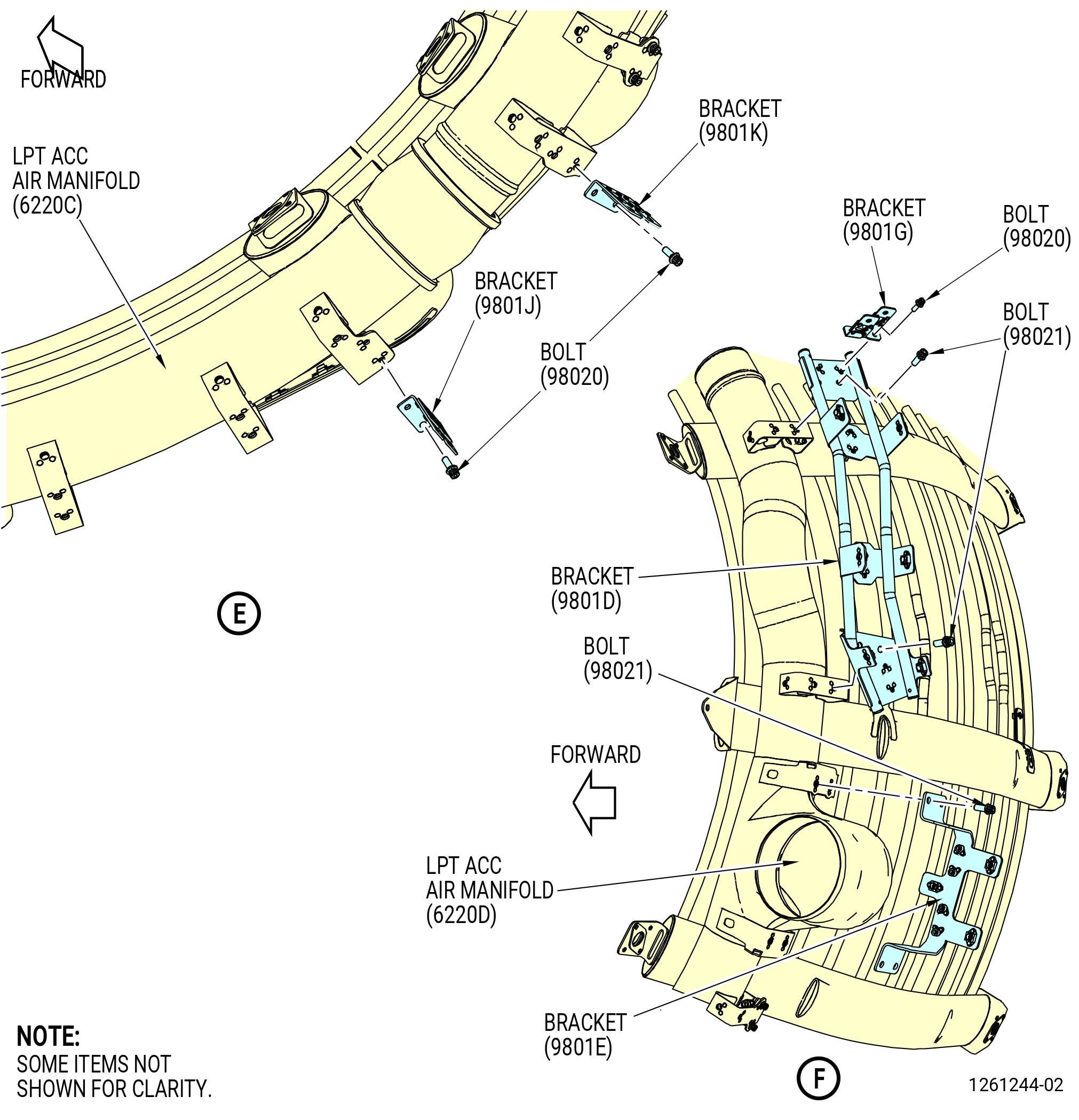
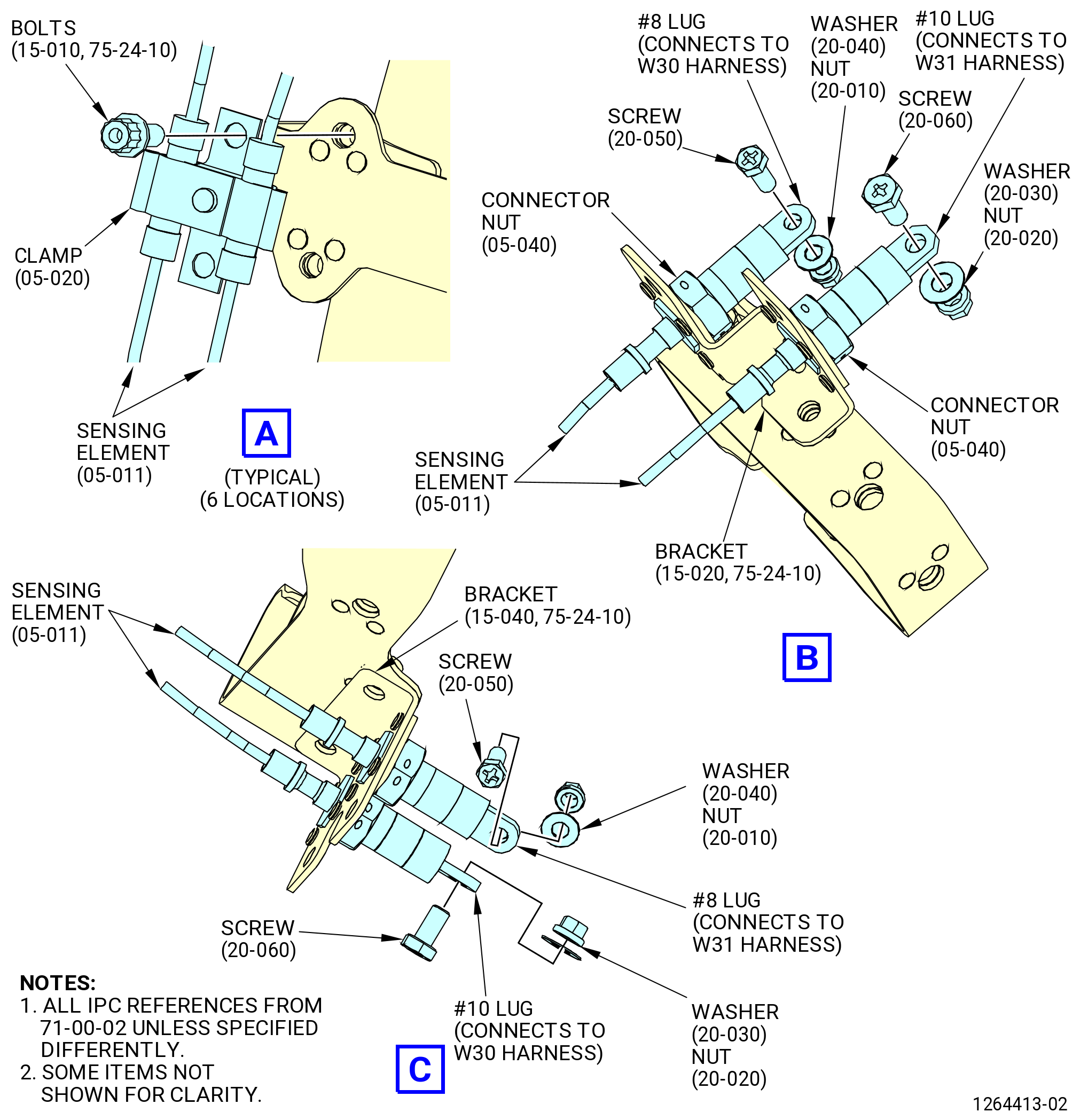
| (7) | Install brackets on the LPT ACC air manifold as follows: |
| (a) | Install the bracket (15-020 , 75-24-10) (SIN 9801G) at the 1:45 o'clock position with two bolts (15-010 , 75-24-10) (SIN 98020). Install the bracket with the wrenching flats toward the 3:00 o'clock position. Torque the bolts to 51 to 59 lb in. (5.8 to 6.7 Nm). |
| (b) | Install the bracket (15-040 , 75-24-10) (SIN 9801J) at the 4:15 o'clock position with two bolts (15-010 , 75-24-10) (SIN 98020). Install the bracket with the wrenching flats toward the 3:00 o'clock position. Torque the bolts to 51 to 59 lb in. (5.8 to 6.7 Nm). |
| (c) | Install the bracket (15-020 , 75-24-10) (SIN 9801G) at the 4:45 o'clock position with two bolts (15-010 , 75-24-10) (SIN 98020). Install the bracket with the wrenching flats toward the 6:00 o'clock position. Torque the bolts to 51 to 59 lb in. (5.8 to 6.7 Nm). |
| (d) | Install the bracket (15-040 , 75-24-10) (SIN 9801J) at the 7:15 o'clock position with two bolts (15-010 , 75-24-10) (SIN 98020). Install the bracket with the wrenching flats toward the 6:00 o'clock position. Torque the bolts to 51 to 59 lb in. (5.8 to 6.7 Nm). |
| (e) | Install the bracket (15-030 , 75-24-10) (SIN 9801K) at the 7:45 o'clock location with two bolts (15-010 , 75-24-10) (SIN 98020). Install the bracket with the wrenching flats toward the 9:00 o'clock position. Torque the bolts to 51 to 59 lb in. (5.8 to 6.7 Nm). |
| (f) | Install the bracket (15-160 , 75-24-10) (SIN 9801E) at the 8:45 o'clock location directly aft of the LPT ACC inlet duct with four bolts (15-150 , 75-24-10) (SIN 98021). |
| (g) | Install the bracket (15-170 , 75-24-10) (SIN 9801D) at the 9:45 o'clock location with four bolts (15-150 , 75-24-10) (SIN 98021). |
| (h) | Install the bracket (15-020 , 75-24-10) (SIN 9801G) at the 10:00 o'clock location on top of the bracket (15-170 , 75-24-10) (SIN 9801D) with two bolts (15-010 , 75-24-10) (SIN 98020). Install the bracket with the wrenching flats toward the 9:00 o'clock position. |
| (i) | Torque the eight bolts (15-150 , 75-24-10) (SIN 98021) to 115 lb in. (13.0 Nm). Torque the two bolts (15-010 , 75-24-10) (SIN 98020) to 60 to 70 lb in. (6.8 to 7.9 Nm). |
| (j) | Install the bracket (15-210 , 75-24-10) (SIN 62318) at the 12:30 o'clock position with two machine bolts (15-231 , 75-24-10) (SIN 62326). Install the bracket with the wrenching flats toward the 3:00 o'clock position. |
| (k) | Torque the machine bolts (15-231 , 75-24-10) (SIN 62326) to 106 to 124 lb in. (12.0 to 14.0 Nm). |
| (l) | Install the bracket (15-220 , 75-24-10) (SIN 62319) at the 11:30 o'clock position with two machine bolts (15-231 , 75-24-10) (SIN 62326). Install the bracket with the wrenching flats toward the 9:00 o'clock position. |
| (m) | Torque the machine bolts (15-231 , 75-24-10) (SIN 62326) to 106 to 124 lb in. (12.0 to 14.0 Nm). |
| * * * END PRE SB 73-0040 |
| Subtask 72-00-02-440-525 |
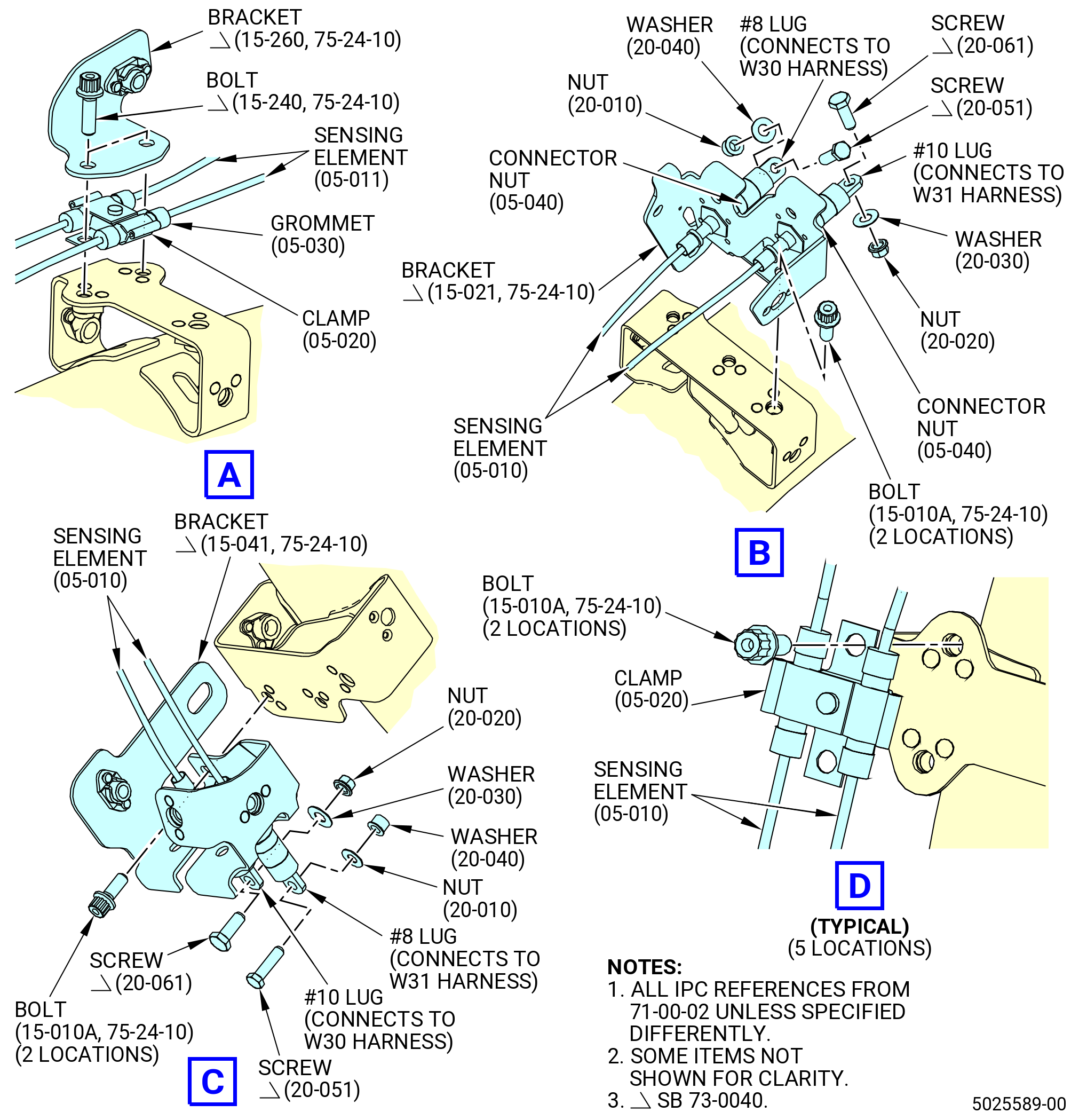
| * * * PRE SB 73-0060( Old Design for W30 and W31 Harnesses ) |
| * * * SB 73-0040( Engines with Improved W30 and W31 Harnesses ) |
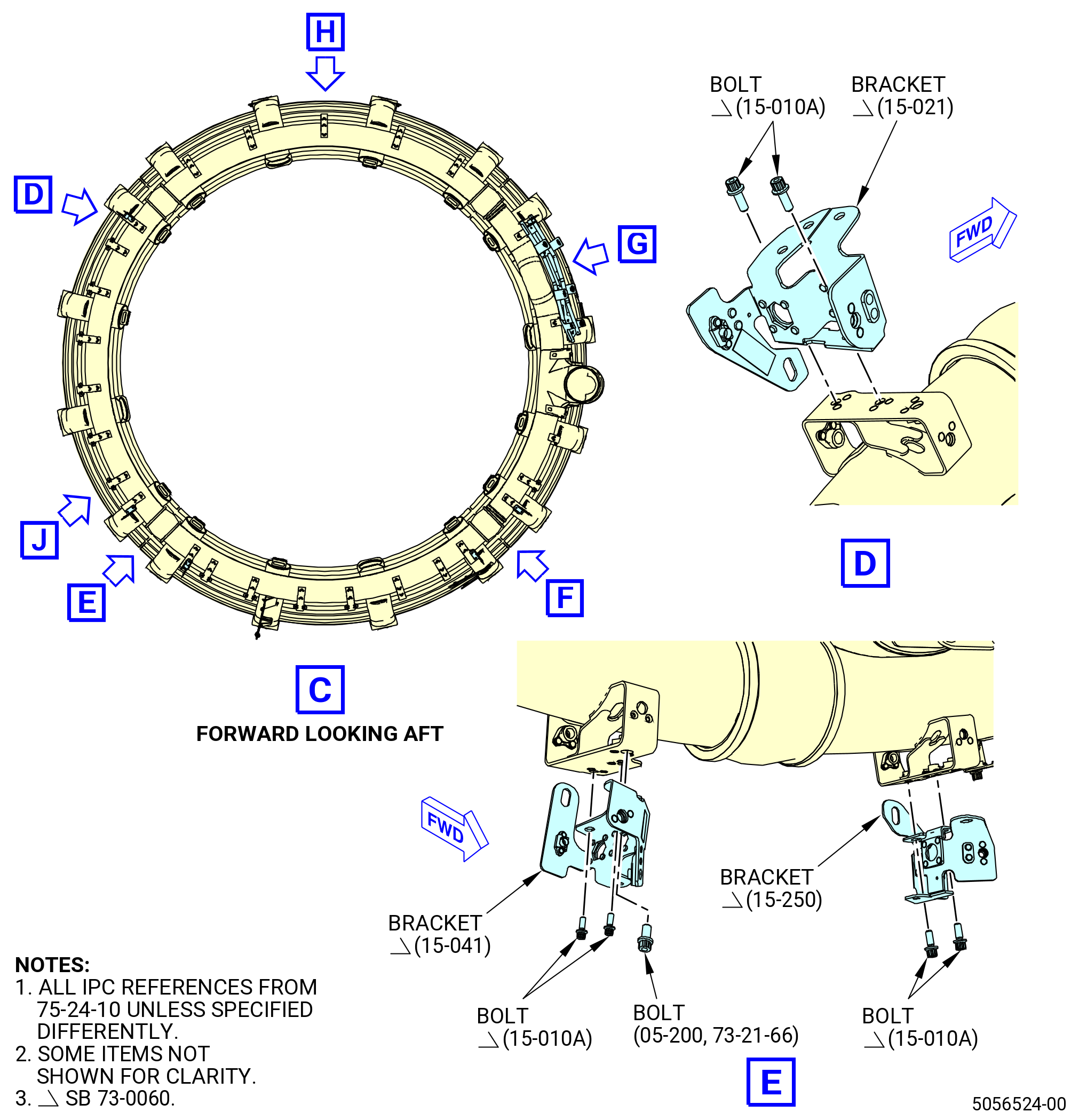
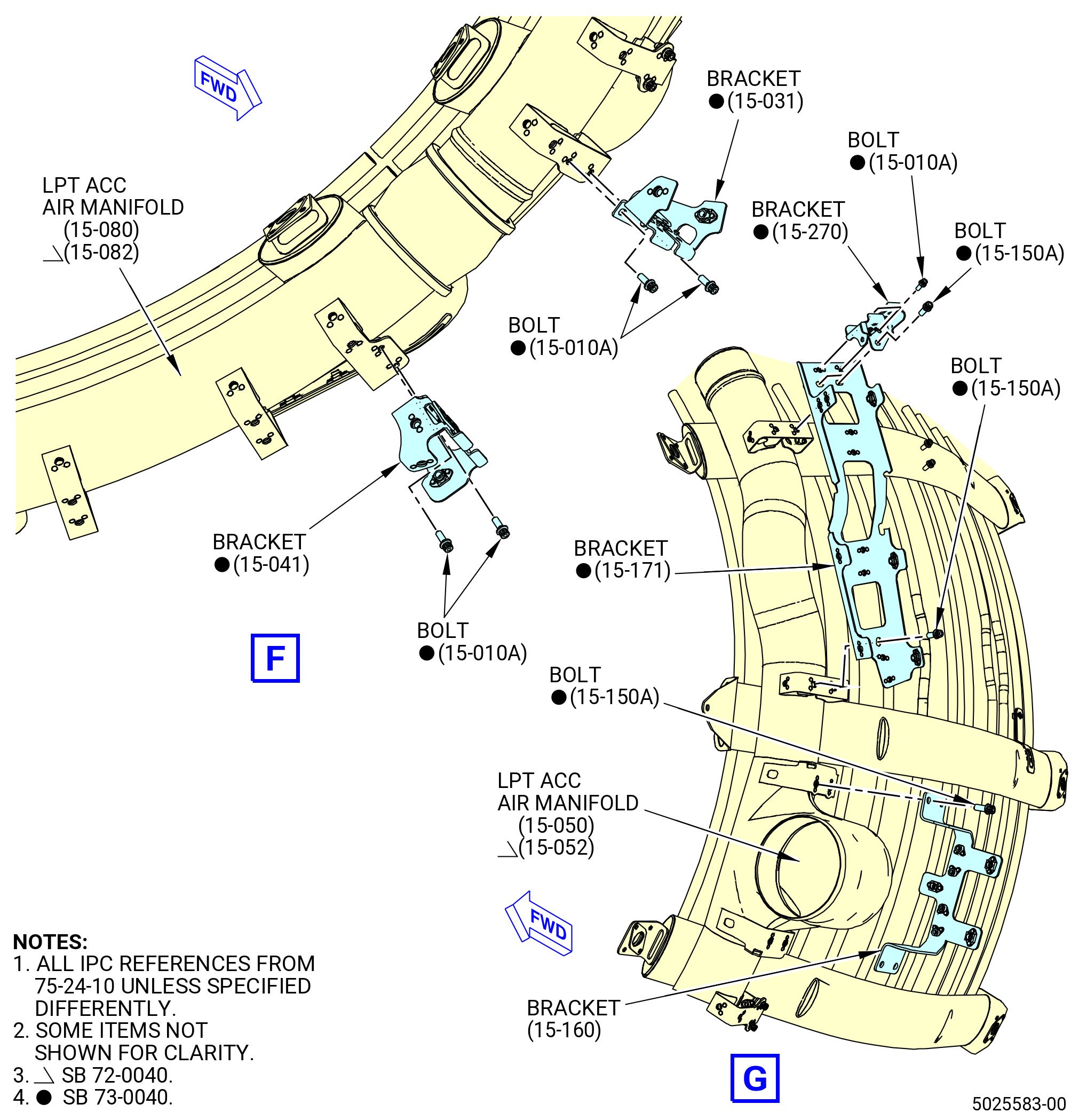
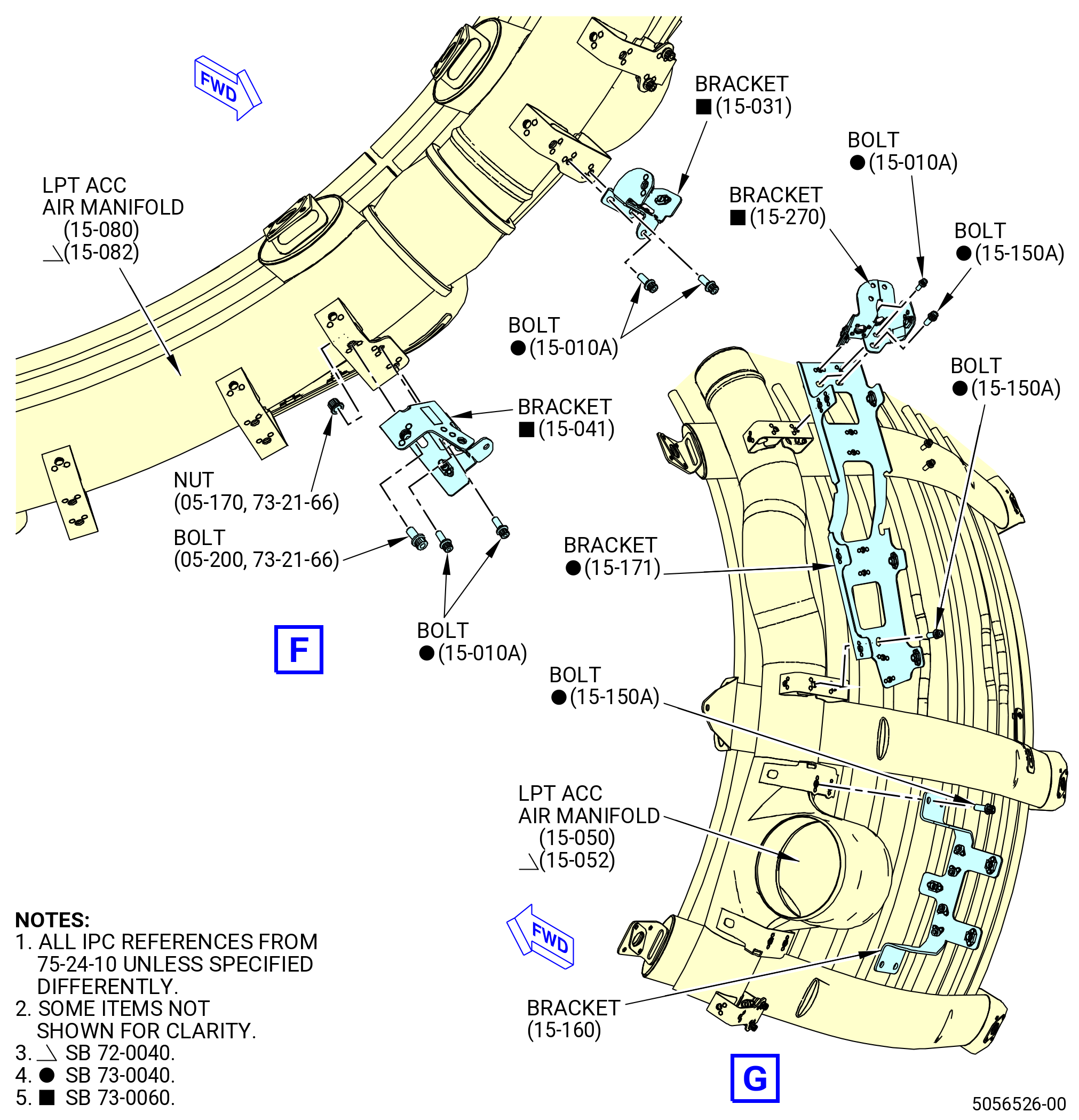
| (7).A. | Install brackets on the LPT ACC air manifold as follows: |
| (a) | Install one bracket (15-021 , 75-24-10) (SIN 9801G) at the 1:45 o'clock position with two bolts (15-010A , 75-24-10) (SIN 98020) and the wrenching flats toward the 3:00 o'clock position. Torque the bolts to 51 to 59 lb in. (5.8 to 6.7 Nm). |
| (b) | Install one bracket (15-041 , 75-24-10) (SIN 9801J) at the 4:15 o'clock position with two bolts (15-010A , 75-24-10) (SIN 98020) and the wrenching flats toward the 3:00 o'clock position. Torque the bolts to 51 to 59 lb in. (5.8 to 6.7 Nm). |
| (c) | Install one bracket (15-250 , 75-24-10) (SIN 9801L) at the 4:45 o'clock position with two bolts (15-010A , 75-24-10) (SIN 98020) and the wrenching flats toward the 6:00 o'clock position. Torque the bolts to 51 to 59 lb in. (5.8 to 6.7 Nm). |
| (d) | Install one bracket (15-041 , 75-24-10) (SIN 9801J) at the 7:15 o'clock position with two bolts (15-010A , 75-24-10) (SIN 98020) and the wrenching flats toward the 6:00 o'clock position. Torque the bolts to 51 to 59 lb in. (5.8 to 6.7 Nm). |
| (e) | Install the bracket (15-031 , 75-24-10) (SIN 9801K) at the 7:45 o'clock position with two bolts (15-010A , 75-24-10) (SIN 98020) and the wrenching flats toward the 9:00 o'clock position. Torque the bolts to 51 to 59 lb in. (5.8 to 6.7 Nm). |
| (f) | Install the bracket (15-160 , 75-24-10) (SIN 9801E) at the 8:45 o'clock position directly aft of the LPT ACC inlet duct with four bolts (15-150 , 75-24-10) (SIN 98021). |
| (g) | Install the bracket (15-171 , 75-24-10) (SIN 9801D) at the 9:45 o'clock position with three bolts (15-150 , 75-24-10) (SIN 98021). |
| (h) | Install the bracket (15-270 , 75-24-10) (SIN 9801N) at the 10:00 o'clock position on top of the bracket (15-171 , 75-24-10) (SIN 9801D) with two bolts (15-010A , 75-24-10) (SIN 98020) and one bolt (15-150 , 75-24-10) (SIN 98021) with the wrenching flats toward the 9:00 o'clock position. |
| (i) | Torque the four bolts (15-150 , 75-24-10) (SIN 98021) to 106 to 124 lb in. (12.0 to 14.0 Nm). Torque the two bolts (15-010A , 75-24-10) (SIN 98020) to 51 to 59 lb in. (5.8 to 6.7 Nm). |
| (j) | Torque the eight bolts (15-150 , 75-24-10) (SIN 98021) to 115 lb in. (13.0 Nm). Torque the two bolts (15-010 , 75-24-10) (SIN 98020) to 60 70 lb in. (6.8 to 7.9 Nm). |
| (k) | Install the bracket (15-210 , 75-24-10) (SIN 62318) at the 12:30 o'clock position with two machine bolts (15-231 , 75-24-10) (SIN 62326). Install the bracket with the wrenching flats toward the 3:00 o'clock position. |
| (l) | Torque the machine bolts (15-231 , 75-24-10) (SIN 62326) to 106 to 124 lb in. (12.0 to 14.0 Nm). |
| (m) | Install the bracket (15-220 , 75-24-10) (SIN 62319) at the 11:30 o'clock position with two machine bolts (15-231 , 75-24-10) (SIN 62326). Install the bracket with the wrenching flats toward the 9:00 o'clock position. |
| (n) | Torque the machine bolts (15-231 , 75-24-10) (SIN 62326) to 106 to 124 lb in. (12.0 to 14.0 Nm). |
| * * * END SB 73-0040 |
| * * * END PRE SB 73-0060 |
| Subtask 72-00-02-440-626 |
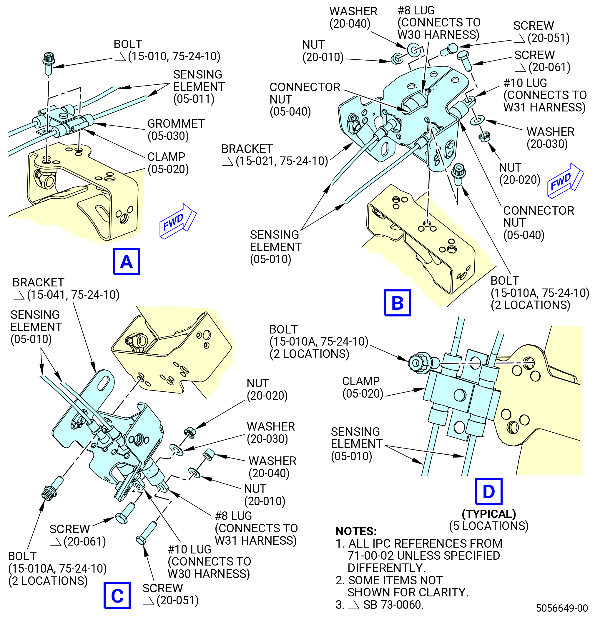
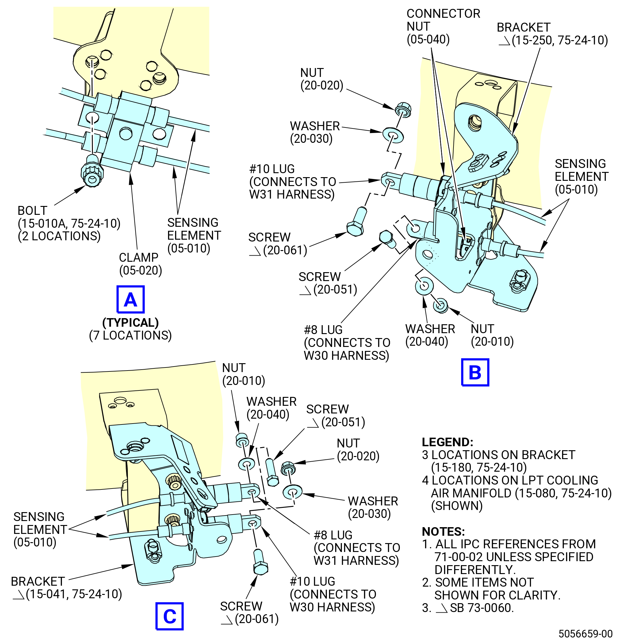
| * * * SB 73-0060( W30 and W31 Redesigned Harnesses ) |
| (7).B. | Install the brackets on the LPT ACC air manifold as follows: |
| (a) | Install one bracket (15-021 , 75-24-10) (SIN 9801G) at the 1:45 o'clock position, ALF, with two bolts (15-010 , 75-24-10) (SIN 98020) and the wrenching flats toward the 3:00 o'clock position. Torque the bolts to 51 to 59 lb in. (5.8 to 6.7 Nm). |
| (b) | Install one bracket (15-041 , 75-24-10) (SIN 9801J) at the 4:15 o'clock position with two bolts (15-010 , 75-24-10) (SIN 98020) and one bolt (05-200 , 73-21-66) (SIN 9802F) and the wrenching flats toward the 3:00 o'clock position. Torque the bolts to 51 to 59 lb in. (5.8 to 6.7 Nm). |
| (c) | Install one bracket (15-250 , 75-24-10) (SIN 9801L) at the 4:45 o'clock position with two bolts (15-010 , 75-24-10) (SIN 98020) and the wrenching flats toward the 6:00 o'clock position. Torque the bolts to 51 to 59 lb in. (5.8 to 6.7 Nm). |
| (d) | Install one bracket (15-041 , 75-24-10) (SIN 9801J) at the 7:15 o'clock position with two bolts (15-010 , 75-24-10) (SIN 98020), one bolt (05-200 , 73-21-66) (SIN 9802F) and nut (05-170 , 73-21-66) (SIN 98045), and the wrenching flats toward the 6:00 o'clock position. Torque the bolts (15-010 , 75-24-10) (SIN 98020) and the nut (05-170 , 73-21-66) (SIN 98045) to 51 to 59 lb in. (5.8 to 6.7 Nm). |
| (e) | Install the bracket (15-031 , 75-24-10) (SIN 9801K) at the 7:45 o'clock position with two bolts (15-010 , 75-24-10) (SIN 98020) and the wrenching flats toward the 9:00 o'clock position. Torque the bolts to 51 to 59 lb in. (5.8 to 6.7 Nm). |
| (f) | Install the bracket (15-160 , 75-24-10) (SIN 9801E) at the 8:45 o'clock position directly aft of the LPT ACC inlet duct with four bolts (15-150 , 75-24-10) (SIN 98021). |
| (g) | Install the bracket (15-171 , 75-24-10) (SIN 9801D) at the 9:45 o'clock position with three bolts (15-150 , 75-24-10) (SIN 98021). |
| (h) | Install the bracket (15-270 , 75-24-10) (SIN 9801N) at the 10:00 o'clock position on top of the bracket (15-171 , 75-24-10) (SIN 9801D) with two bolts (15-010 , 75-24-10) (SIN 98020) and one bolt (15-150 , 75-24-10) (SIN 98021) with the wrenching flats toward the 9:00 o'clock position. |
| (i) | Torque the four bolts (15-150 , 75-24-10) (SIN 98021) to 106 to 124 lb in. (12.0 to 14.0 Nm). Torque the two bolts (15-010 , 75-24-10) (SIN 98020) to 51 to 59 lb in. (5.8 to 6.7 Nm). |
| (j) | Install the harness support bracket (bracket) (05-120 , 73-21-66) (SIN 6231B) as follows: |
| NOTE: |
|
| 1 | Install the bracket (05-120 , 73-21-66) (SIN 6231B) on the left-hand side, FLA of the LPT ACC air manifold (15-072 , 75-24-10) (SIN 6220B), adjacent to the bracket (15-041 , 75-24-10) (SIN 9801J) with one bolt (05-200 , 73-21-66) (SIN 9802F). |
| 2 | Torque the bolt to 60 to 70 lb in. (6.7 to 7.9 Nm). |
| (k) | Install the bracket (15-210 , 75-24-10) (SIN 62318) at the 12:30 o'clock position with two machine bolts (15-231 , 75-24-10) (SIN 62326). Install the bracket with the wrenching flats toward the 3:00 o'clock position. |
| (l) | Torque the machine bolts (15-231 , 75-24-10) (SIN 62326) to 106 to 124 lb in. (12.0 to 14.0 Nm). |
| (m) | Install the bracket (15-220 , 75-24-10) (SIN 62319) at the 11:30 o'clock position with two machine bolts (15-231 , 75-24-10) (SIN 62326). Install the bracket with the wrenching flats toward the 9:00 o'clock position. |
| (n) | Torque the machine bolts (15-231 , 75-24-10) (SIN 62326) to 106 to 124 lb in. (12.0 to 14.0 Nm). |
| * * * END SB 73-0060 |
|
|
|
|
|
| Subtask 72-00-02-440-315 |
| M. | Install the LPT ACC duct and valve. Refer to Figure 1015 and do as follows: |
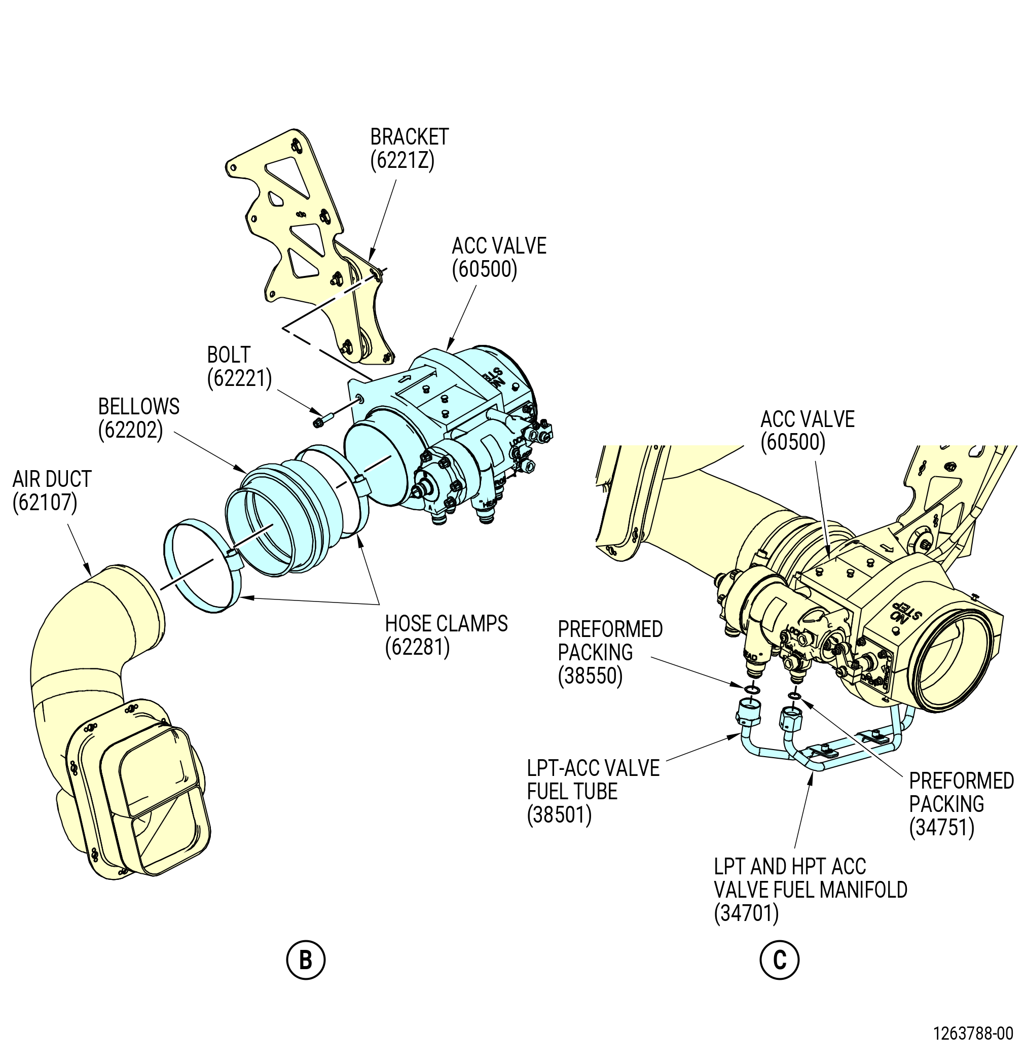
| (1) | Install the ACC valve (60500) as follows: |
| (a) | Install the LPT ACC bellows (bellows) (62202) on the air duct (62107). |
| (b) | Install the ACC valve (60500) on the bellows (62202) and on the forward side of bracket (62112). |
| (c) | Attach the ACC valve (60500) to the bracket (6221Z) with bolts (62221) and washers (62231). |
| (d) | Install a hose clamp (62281) on each end of the bellows (62202). Put the hose clamps in position so the bolt heads are outboard and point to the 12:00 o'clock position. |
| (e) | Torque the bolts (62221) to 106-124 lb in. (12.0-14.0 N.m). |
| (f) | Torque the hose clamps (62281) to 32-38 lb in. (3.6-4.3 N.m). |
| (2) | Connect the fuel lines to the ACC valve as follows: |
| WARNING: |
|
| (a) | Apply C02-019 engine oil or C02-023 engine oil to preformed packing (34751) and preformed packing (38550). |
| (b) | Install the preformed packing (20-210 , 73-11-40) (SIN 34751) on the aft nipple (ROD end) of the ACC valve (60500). |
| (c) | Install the preformed packing (25-310 , 73-11-40) (SIN 38550) on the forward nipple (HEAD end) of the ACC valve (60500). |
| (d) | Connect the LPT-ACC valve fuel tube (38501) to the forward nipple (HEAD end). Torque the B-nut to 55-65 lb ft (75-88 N.m). |
| (e) | Connect the LPT and HPT ACC valve fuel manifold (20-230 , 73-11-40) (SIN 34701) to the aft nipple (ROD end). Torque the B-nut to 460 to 540 lb in. (52.0 to 61.0 Nm). |
| (f) | Safety the B-nuts with C10-071 safety wire or C10-143 safety cable. |
| (3) | Install bracket (6221C) as follows: |
| (a) | Put the bracket (6221C) in position between bracket (6221B) and bracket (6221D). |
| (b) | Attach bracket (6221C) to bracket (6221D) with bolts (62222). |
| (c) | Attach bracket (6221C) to bracket (6221B) with bolts (62220). |
| (d) | Attach electric cable (65880) to bracket (6221C) with bolt (65824). |
| (e) | Torque the bolt (65824) to 106-124 lb in. (12.0-14.0 N.m). |
| (f) | Torque the bolts (62222) to 106-124 lb in. (12.0-14.0 N.m). |
| (g) | Torque the bolts (62220) to 106-124 lb in. (12.0-14.0 N.m). |
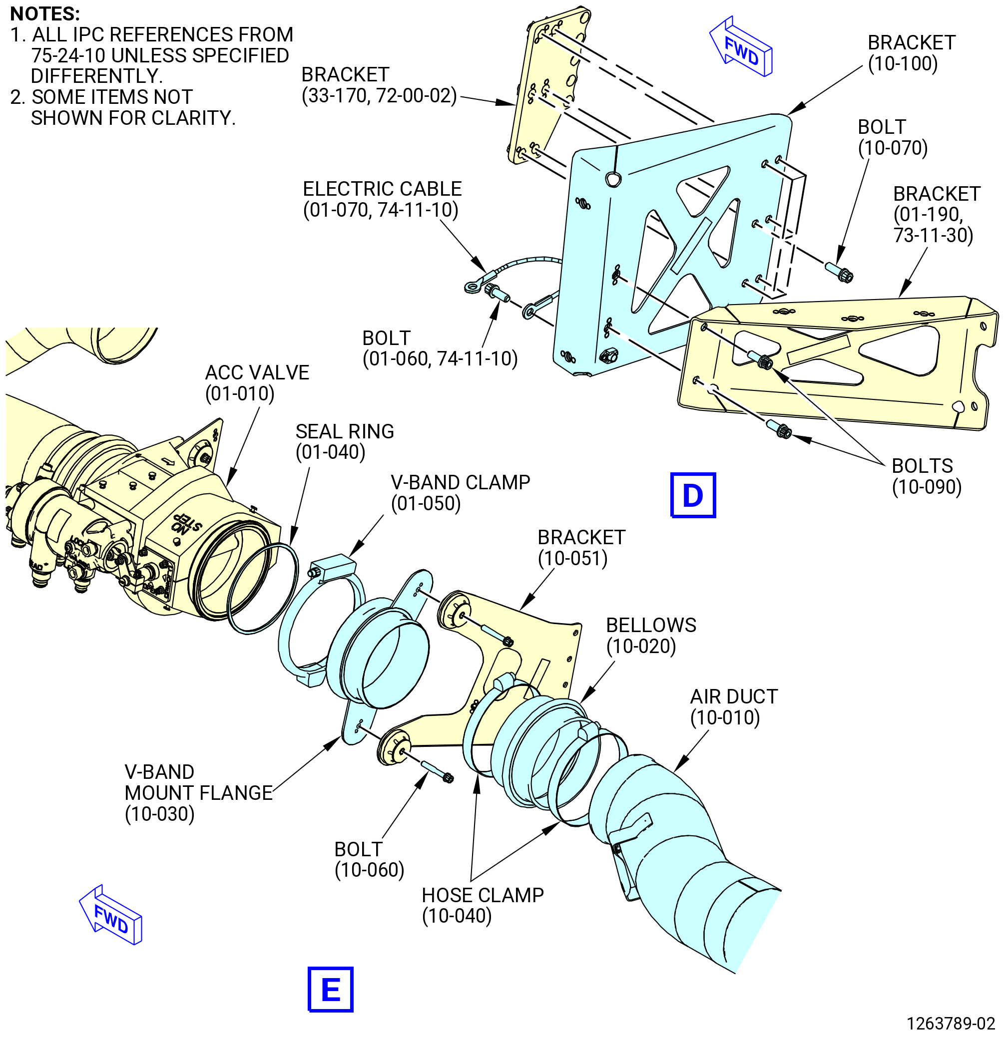
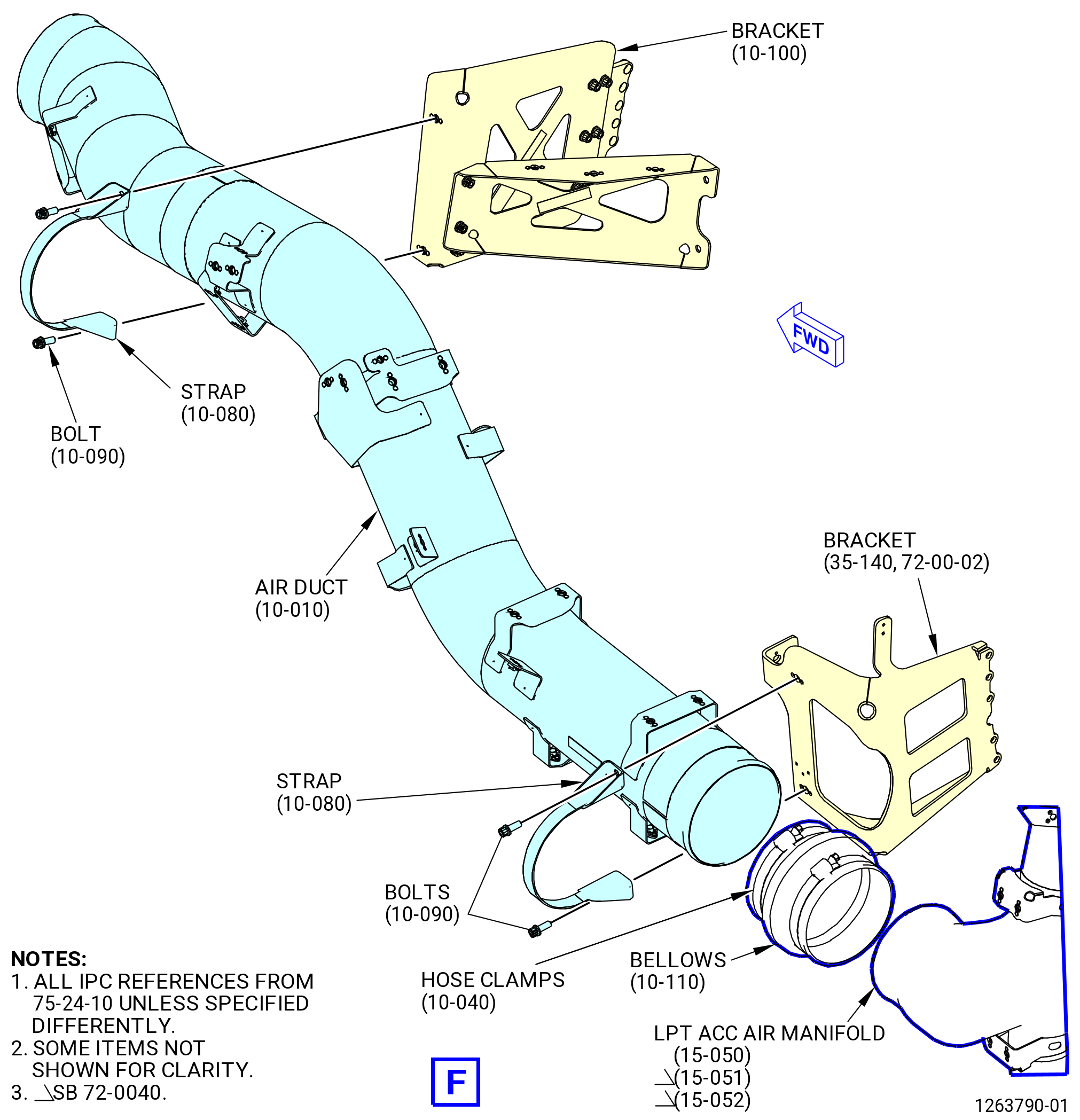
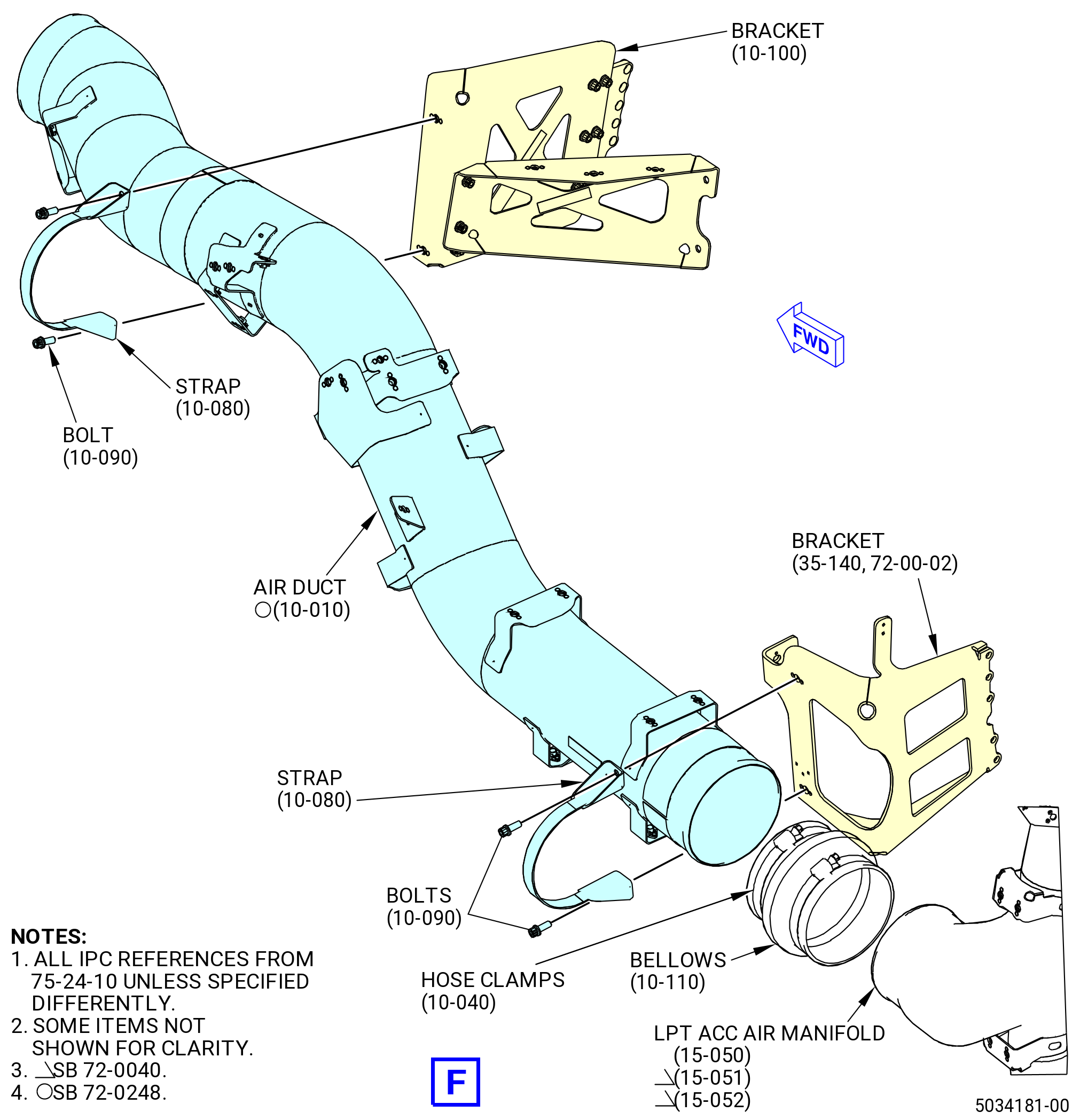
| (4) | Install the LPT supply air duct (air duct) (10-010 , 75-24-10) (SIN 62201) and as follows: |
| (a) | Install a seal ring (62254) on the aft side of the ACC valve (60500). |
| (b) | Attach the V-band mount flange (62200) to the ACC valve (60500) with V-band clamp (62283). Install the V-band clamp with the nut outboard and pointed up. |
| (c) | Attach the V-band mount flange (62200) to the bracket (10-051 , 75-24-10) (SIN 6221G) with bolts (62224). |
| (d) | Install the LPT bellows (bellows) (62204) on the V-band mount flange (62200). |
| (e) | Install the air duct (10-010 , 75-24-10) (SIN 62201) in the bellows (10-020 , 75-24-10) (SIN 62204). |
| (f) | Attach the air duct (10-010 , 75-24-10) (SIN 62201) to bracket (10-100 , 75-24-10) (SIN 6221C) with strap (10-080 , 75-24-10) (SIN 62282) and bolts (10-090 , 75-24-10) (SIN 62220). |
| (g) | Attach the air duct (10-010 , 75-24-10) (SIN 62201) to bracket (35-140) (SIN 6221E) with strap (10-080 , 75-24-10) (SIN 62282) and bolts (10-090 , 75-24-10) (SIN 62220). |
| (h) | Install a HPT bellows (bellows) (10-110 , 75-24-10) (SIN 62202) on the air duct and attach it to the LPT ACC air manifold (15-050 , 75-24-10) (SIN 6220D). |
| (i) | Install a hose clamp (10-040 , 75-24-10) (SIN 62281) on each end of the bellows (10-110 , 75-24-10) (SIN 62202) and (10-020 , 75-24-10) (SIN 62204). |
| (j) | Torque the V-band clamp (62283) to 106-124 lb in. (12.0-14.0 N.m). |
| (k) | Torque the hose clamps (62281) to 32-38 lb in. (3.6-4.3 N.m). |
| (l) | Torque the bolts (62224) to 106-124 lb in. (12.0-14.0 N.m). |
| (m) | Torque the bolts (62220) to 106-124 lb in. (12.0-14.0 N.m). |
|
|
| Subtask 72-00-02-440-316 |
| N. | Install the pylon drain system and fuel hoses as follows: |
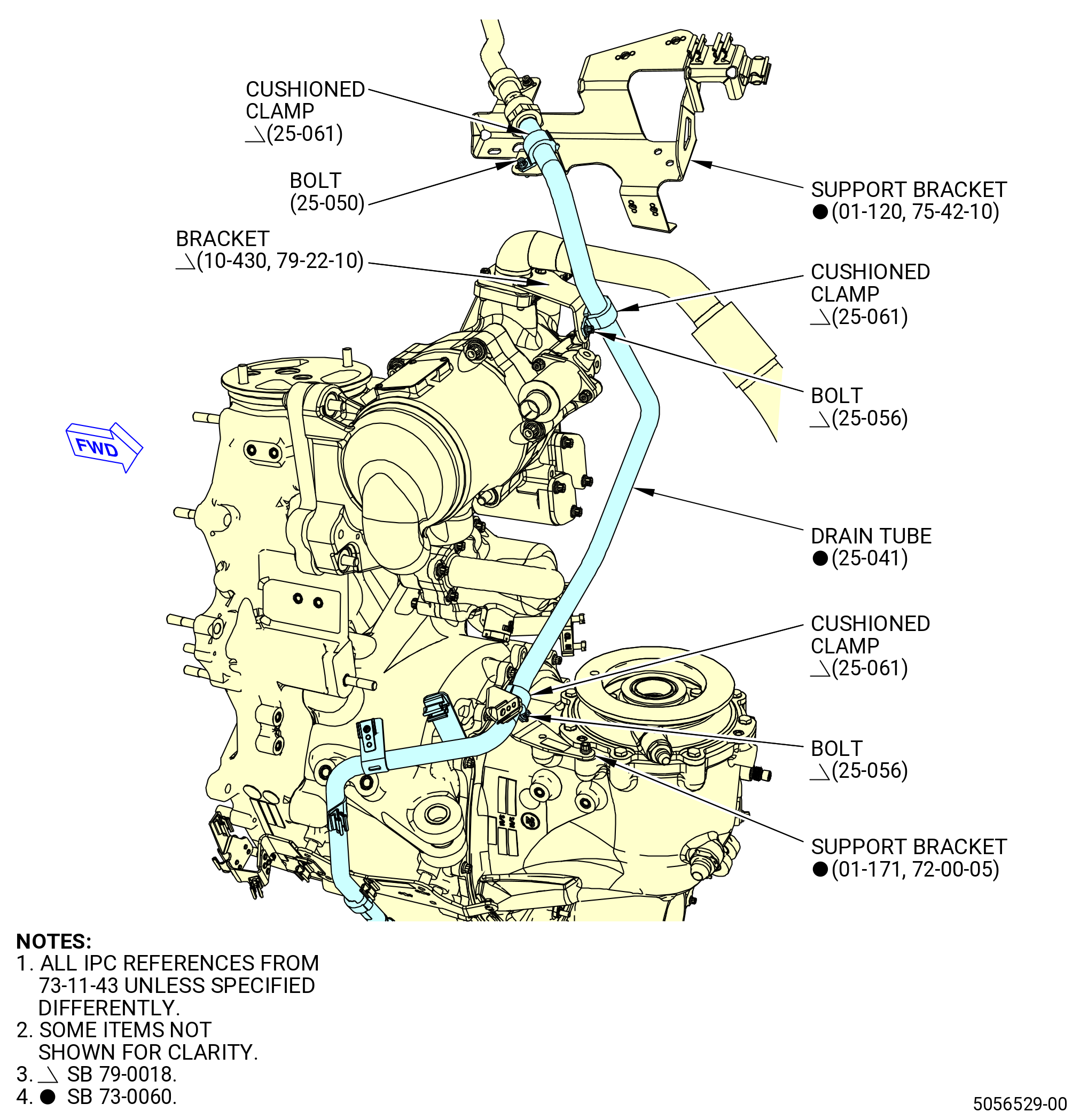
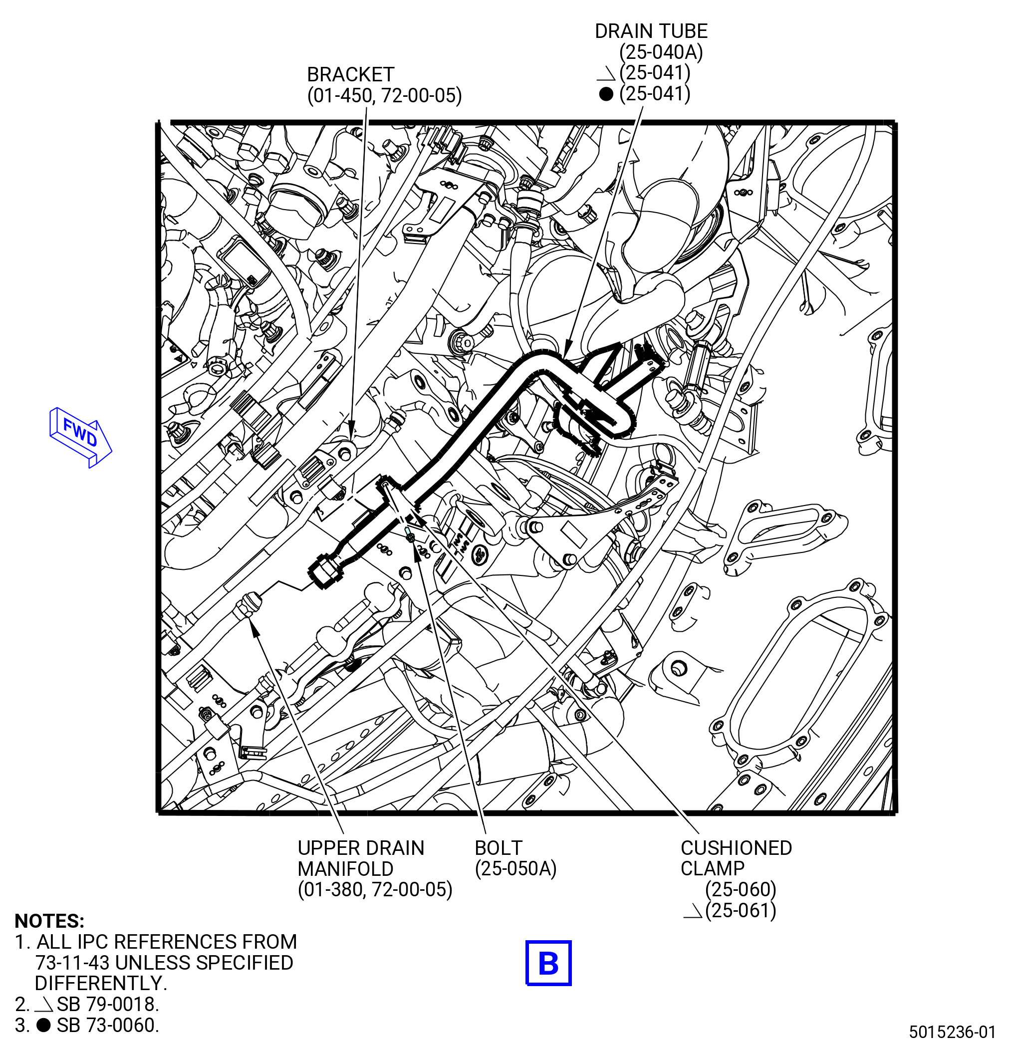
| (1) | Install the drain to the lower BIFI air tube (drain tube) (25-040A , 73-11-43) (SIN 59001) or (25-041 , 73-11-43) (SIN 59001). Refer to Figure 1016 and do as follows: |
| (a) | Connect the B-nuts of the drain tube to the upper drain manifold (99003). |
| (b) | Attach the drain tube to the bracket (01-120 , 75-42-10) (SIN 53012) with a cushioned clamp (25-060 , 73-11-43) (SIN 59080) or (25-061 , 73-11-43) (SIN 59080) and bolt (25-050A , 73-11-43) (SIN 59020). |
| Subtask 72-00-02-440-449 |
| * * * PRE SB 79-0018( MFOHX without Indicating Capability ) |
| (c) | Attach the drain tube (25-040A , 73-11-43) (SIN 59001) to the bracket as follows: |
| WARNING: |
|
| 1 | Lubricate the threads and friction surface of the machine bolt (bolt) (25-055 , 73-11-43) (SIN 59024) with C02-023 engine oil. |
| 2 | Attach the drain tube to the support bracket (01-170 , 72-00-05) (SIN 5901C) with a cushioned clamp (25-060 , 73-11-43) (SIN 59080) and bolt (25-055 , 73-11-43) (SIN 59024). |
| * * * END PRE SB 79-0018 |
| Subtask 72-00-02-440-450 |
| * * * SB 79-0018( MFOHX with Indicating Capability ) |
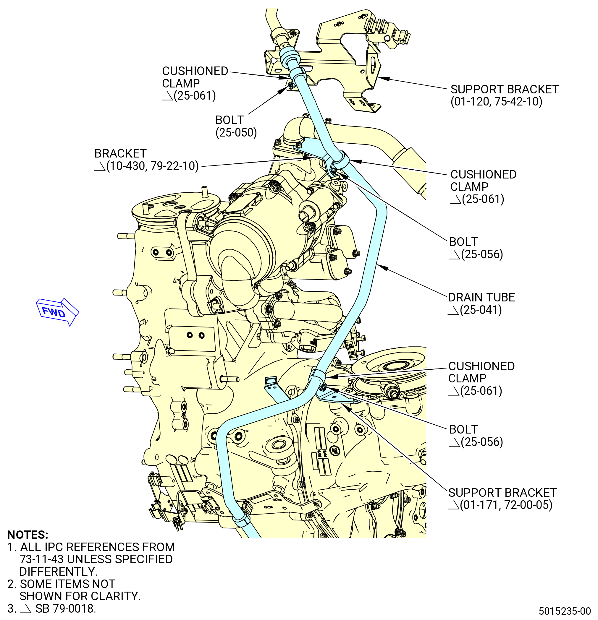
| (c).A. | Attach the drain tube (25-041 , 73-11-43) (SIN 59001) to the brackets as follows: |
| WARNING: |
|
| 1 | Lubricate the threads and friction surfaces of two machine bolts (bolts) (25-056 , 73-11-43) (SIN 59024) with C02-023 engine oil. |
| 2 | Attach the drain tube to the support bracket (01-171 , 72-00-05) (SIN 5901C) and the bracket (10-430 , 79-22-10) (SIN 5901D) with two cushioned clamps (25-061 , 73-11-00) (SIN 59080) and the bolts (25-056 , 73-11-43) (SIN 59024). |
| * * * END SB 79-0018 |
| Subtask 72-00-02-440-451 |
| (d) | Attach the drain tube to the bracket (01-450 , 72-00-05) (SIN 37010) with a cushioned clamp (25-060 , 73-11-43) (SIN 59080) or (25-061 , 73-11-43) (SIN 59080) and a bolt (25-050A , 73-11-43) (SIN 59020). |
| (e) | Torque the B-nut at the upper drain manifold to 460-540 lb in. (52.0-61.0 N.m). |
| (f) | Deleted. |
| (g) | Torque the machine bolts (bolts) (25-050 , 73-11-43) (SIN 59020) and (25-055 , 73-11-43) (SIN 59024) or (25-056 , 73-11-43) (SIN 59024) to 32-38 lb in. (3.6-4.3 N.m). |
| Subtask 72-00-02-440-322 |
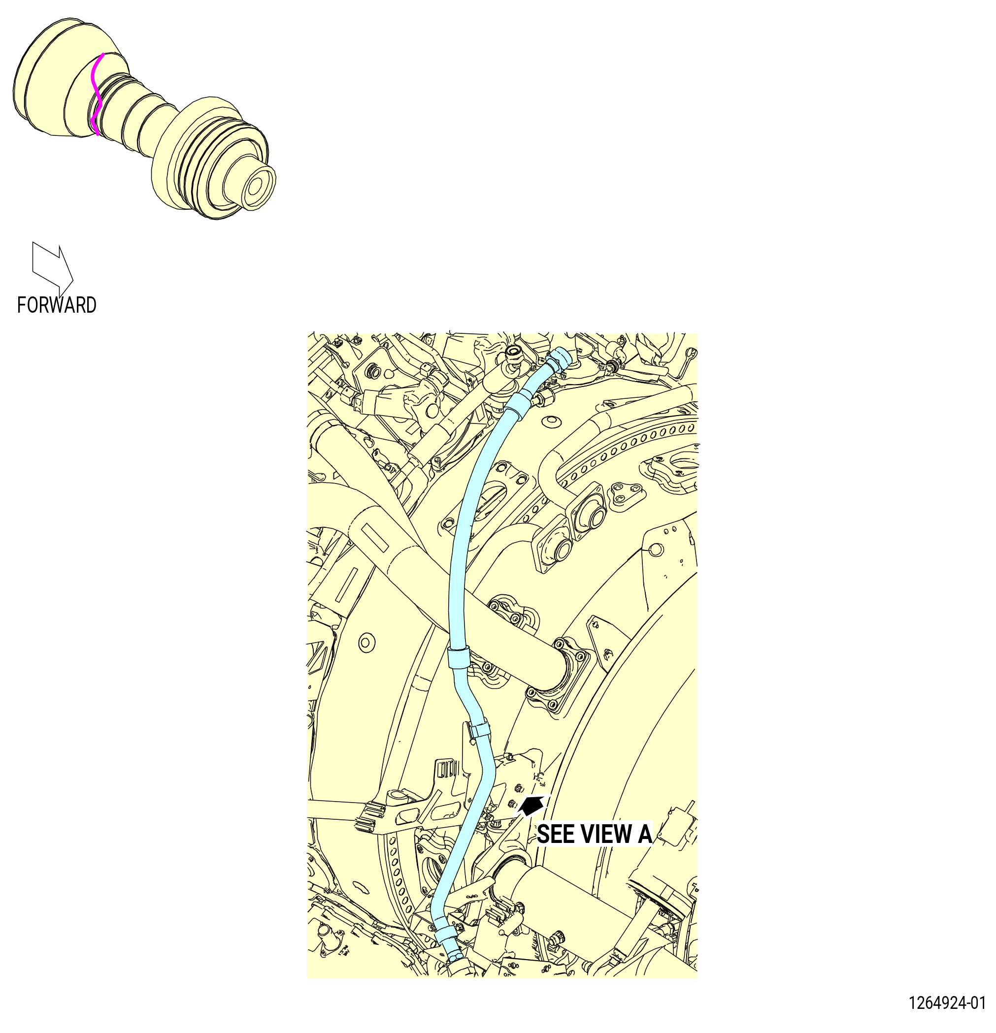
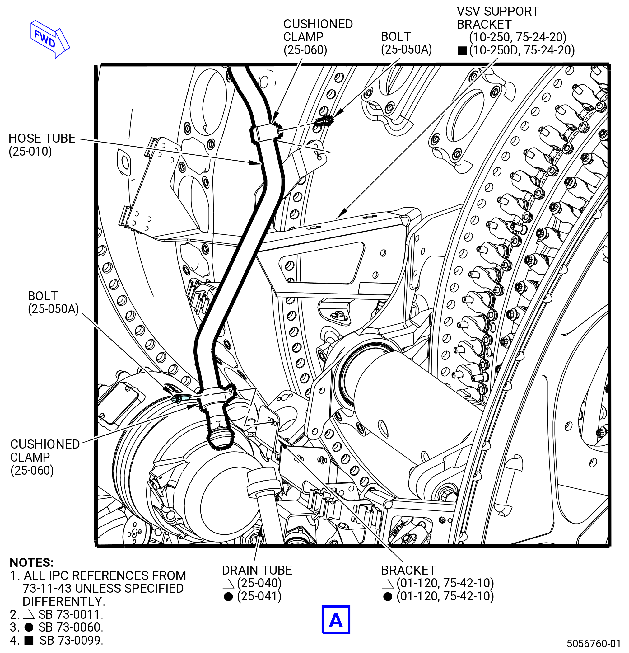
| (5) | Install the strut drain hose tube (hose tube) (25-010 , 73-11-43) (SIN 59000). Refer to Figure 1017 and do as follows: |
| (a) | Connect the B-nut of the hose tube to the drain tube (25-040A , 73-11-43) (SIN 59001) or (25-041 , 73-11-43) (SIN 59001). |
| (b) | Attach the hose tube to the brackets as follows: |
| 1 | Attach the hose tube to the bracket (01-120 , 75-42-10) (SIN 53012) with a cushioned clamp (25-060 , 73-11-43) (SIN 59080) or (25-061 , 73-11-43) (SIN 59080) and bolt (25-050A , 73-11-43) (SIN 59020). |
| 2 | Attach the hose tube to the VSV support bracket (10-250A , 75-24-20) (SIN 38116) or the VSV support bracket (10-250D, 75-24-20) (SIN 38116) with a cushioned clamp (25-060 , 73-11-43) (SIN 59080) or (25-061 , 73-11-43) (SIN 59080) and bolt (25-050A , 73-11-43) (SIN 59020). |
| (c) | Torque B-nut on the drain tube (25-040A , 73-11-43) (SIN 59001) or (25-041 , 73-11-43) (SIN 59001) to 78-92 lb ft (106-125 N.m). |
| (d) | Torque the bolts (25-050A , 73-11-43) (SIN 59020) to 32-38 lb in. (3.6-4.3 N.m). |
| Subtask 72-00-02-440-328 |
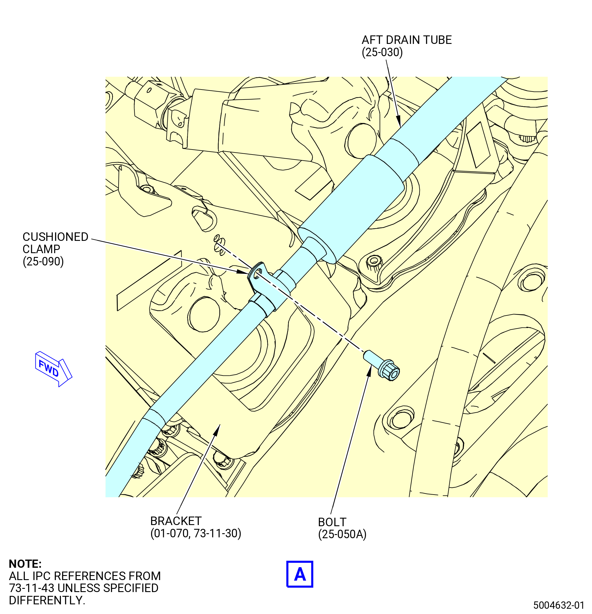
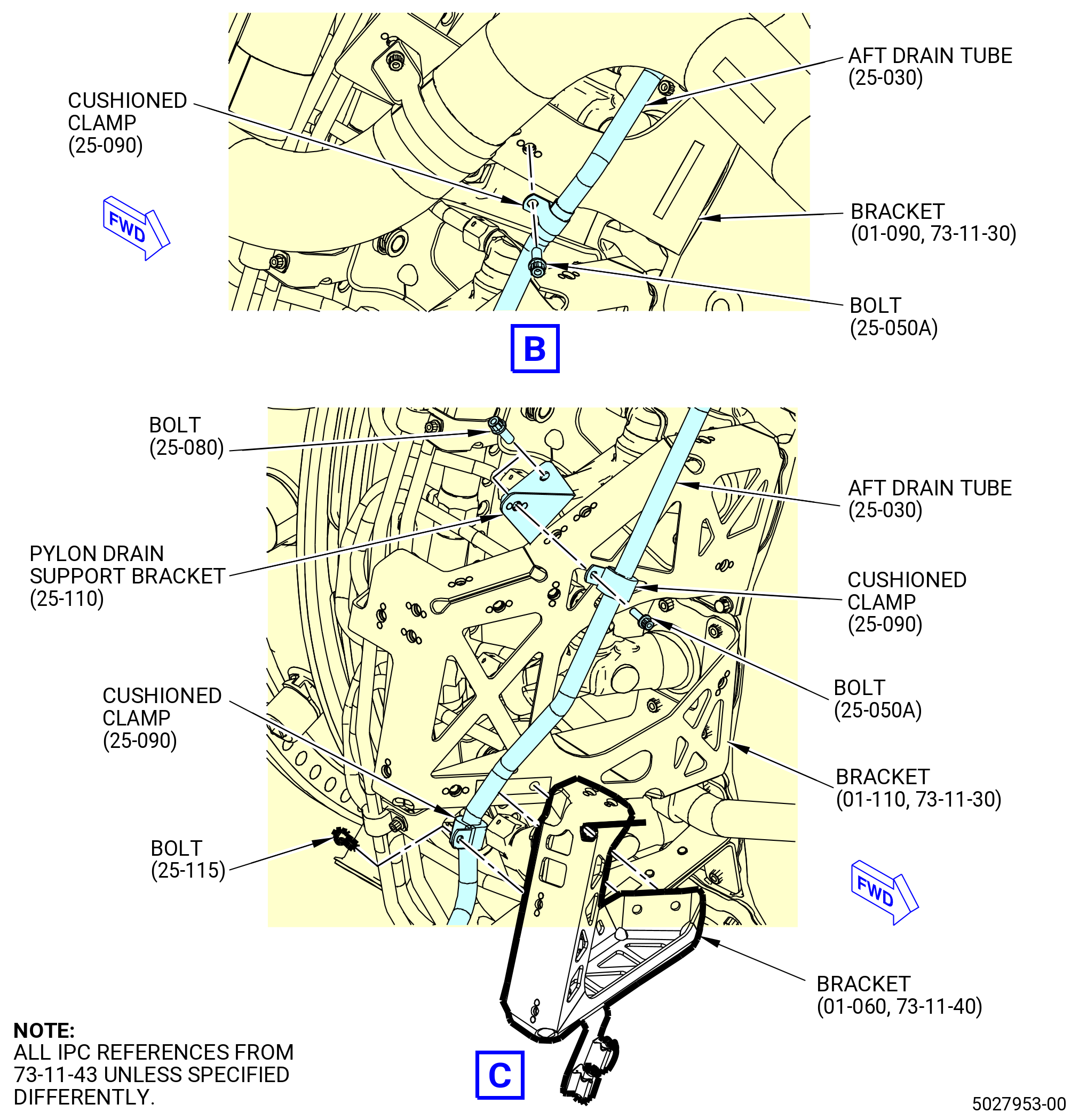
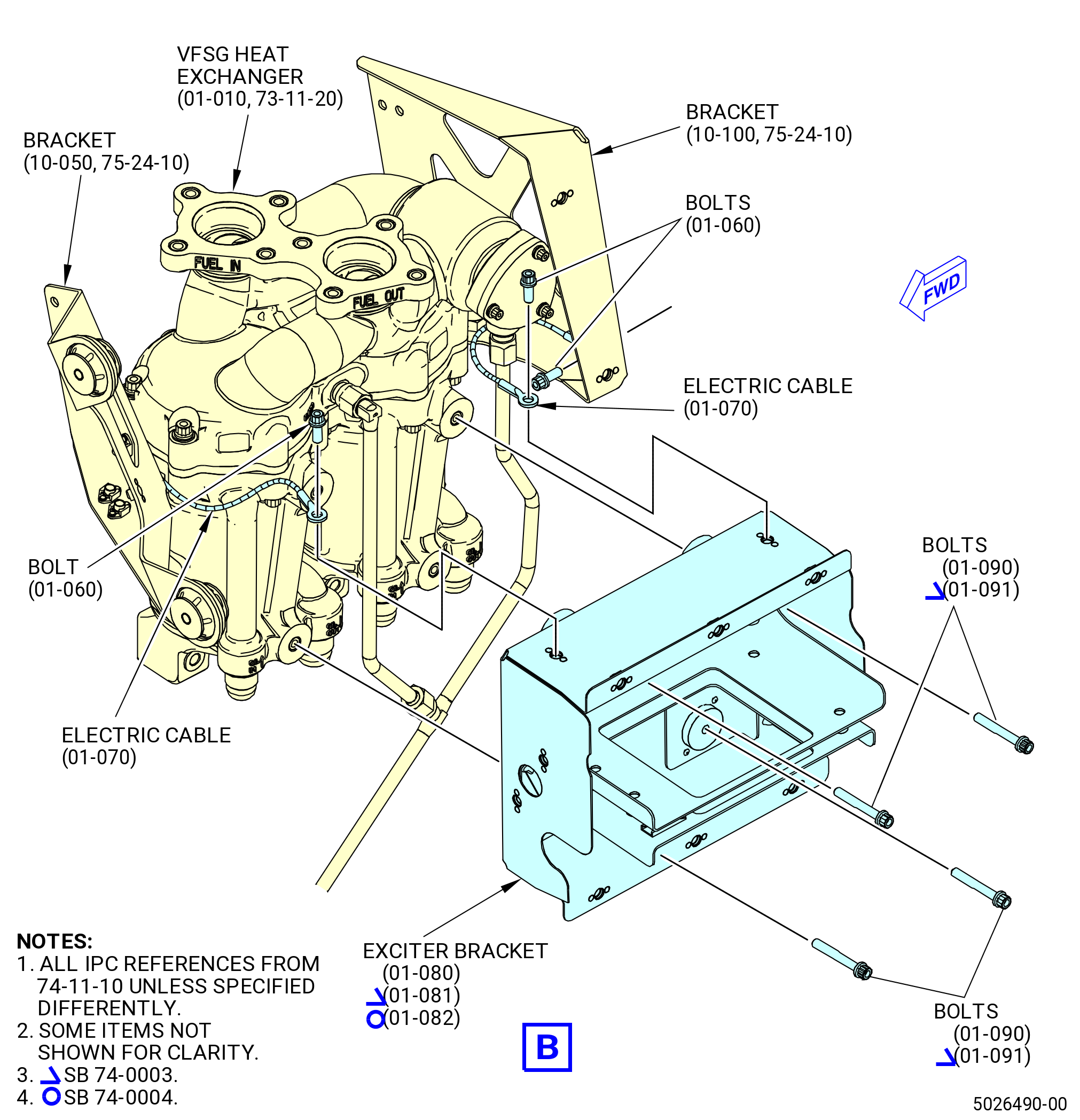
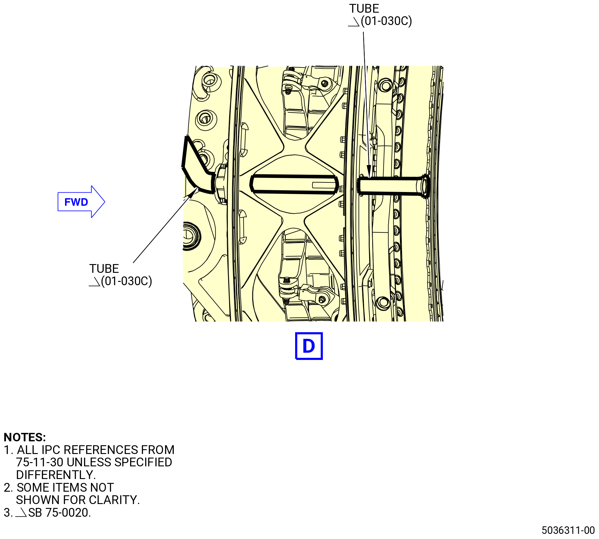
| (6) | Install the aft drain assembly hose tube (aft drain tube) (59003). Refer to Figure 1018 and do as follows: |
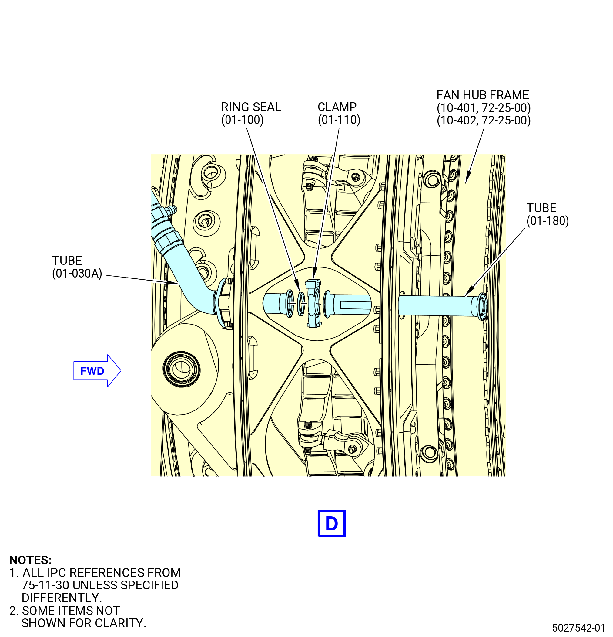
| (a) | Attach the aft drain tube (25-030 , 73-11-43) (SIN 59003) to the bracket (01-070 , 73-11-30) (SIN 61110) with a clamp (25-090 , 73-11-43) (SIN 59082) and bolt (25-050A , 73-11-43) (SIN 59020). |
| (b) | Attach the aft drain tube (25-030 , 73-11-43) (SIN 59003) to the bracket (01-090 , 73-11-30) (SIN 6121M) with a clamp (25-090 , 73-11-43) (SIN 59082) and bolt (25-050A , 73-11-43) (SIN 59020). |
| (c) | Install the pylon drain support bracket (59015) on the bracket (61A12) with bolts (59021). |
| (d) | Torque the bolts (59021) on the bracket to 106-124 lb in. (12.0-14.0 N.m). |
| (e) | Attach the aft drain tube (25-030 , 73-11-43) (SIN 59003) to the bracket (25-110 , 73-11-43) (SIN 59015) with a clamp (25-090 , 73-11-43) (SIN 59082) and bolt (25-050A , 73-43-11) (SIN 59020). |
| (f) | Attach the aft drain tube (25-030 , 73-11-43) (SIN 59003) to the bracket (01-060 , 73-11-40) (SIN 34011) with a clamp (25-090 , 73-11-43) (SIN 59082) and bolt (25-115 , 73-11-43) (SIN 59025). |
| (g) | Torque the bolts (25-050A , 73-43-11) (SIN 59020) and (25-115 , 73-11-43) (SIN 59025) to 32 to 38 lb in. (3.6 to 4.3 Nm). |
| Subtask 72-00-02-440-486 |
| * * * PRE SB 73-0031( Installation of Fuel Hose without W13 Harness Electrical Bracket ) |
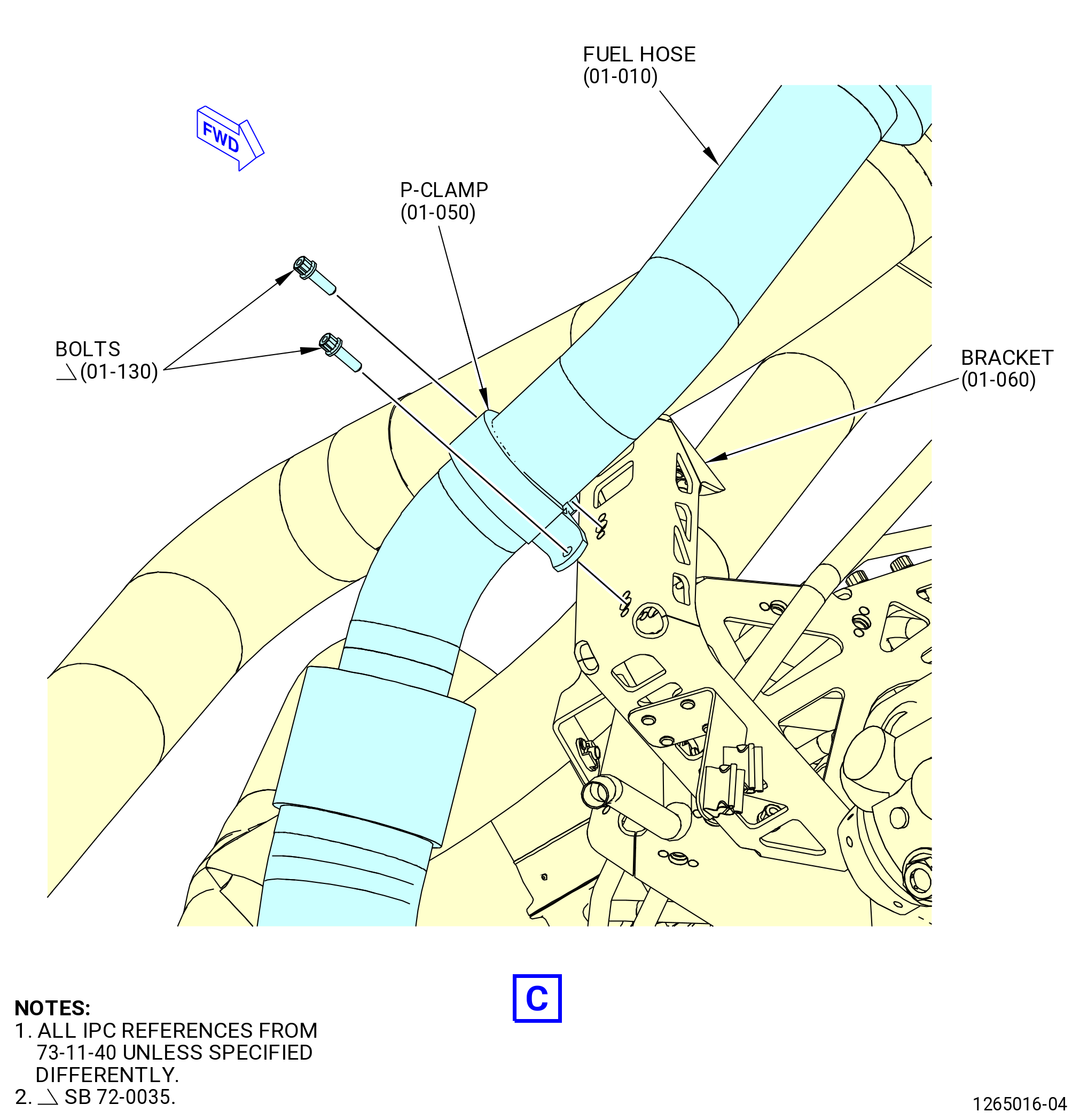
| (7) | Install the main inlet fuel tube hose (fuel hose) (34000). Refer to Figure 1019 and do as follows: |
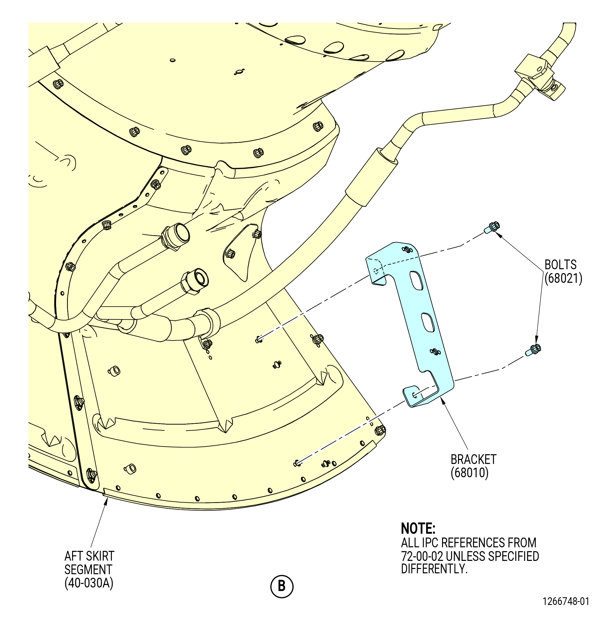
| (a) | Install bracket (34010) on the aft skirt segment (29901) with bolts (34020). |
| (b) | Torque the bolts (34020) to 106-124 lb in. (12.0-14.0 N.m). |
| (c) | Install gasket (34050) on the fuel pump (30900). |
| (d) | Install the fuel hose (34000) on the fuel pump (30900). |
| WARNING: |
|
| (e) | Apply C02-058 lubricant to the threads and washer faces of bolts (01-110 , 73-11-40) (SIN 34022). |
| (f) | Attach the fuel hose (34000) with bolts (34022). |
| (g) | Attach the fuel hose (34000) to the bracket (34010) with P-clamp (34080) and bolts (34020). |
| (h) | Torque the bolts (01-030 , 73-11-40) (SIN 34020) to 106-124 lb in. (12.0-14.0 N.m). |
| (i) | Attach the fuel hose (01-010 , 73-11-40) (SIN 34000) to the bracket (01-060 , 73-11-40) (SIN 34011) with P-clamp (01-050 , 73-11-40) (SIN 34082) and two bolts (01-130 , 73-11-40) (SIN 34025). |
| (j) | Torque the bolts (01-130 , 73-11-40) (SIN 34025) to 51 to 59 lb in. (5.8 to 6.7 Nm). |
| (k) | Torque the bolts (34022) to 235-275 lb in. (26.6-31.1 N.m). |
| (l) | Remove unwanted C02-058 lubricant with C10-182 cleaning cloth. |
| * * * END PRE SB 73-0031 |
| Subtask 72-00-02-440-487 |
| * * * SB 73-0031( Installation of Fuel Hose with W13 Harness Electrical Bracket ) |
| (7).A. | Install the fuel hose (01-010 , 73-11-40) (SIN 34000). Refer to Figure 1019 and do as follows: |
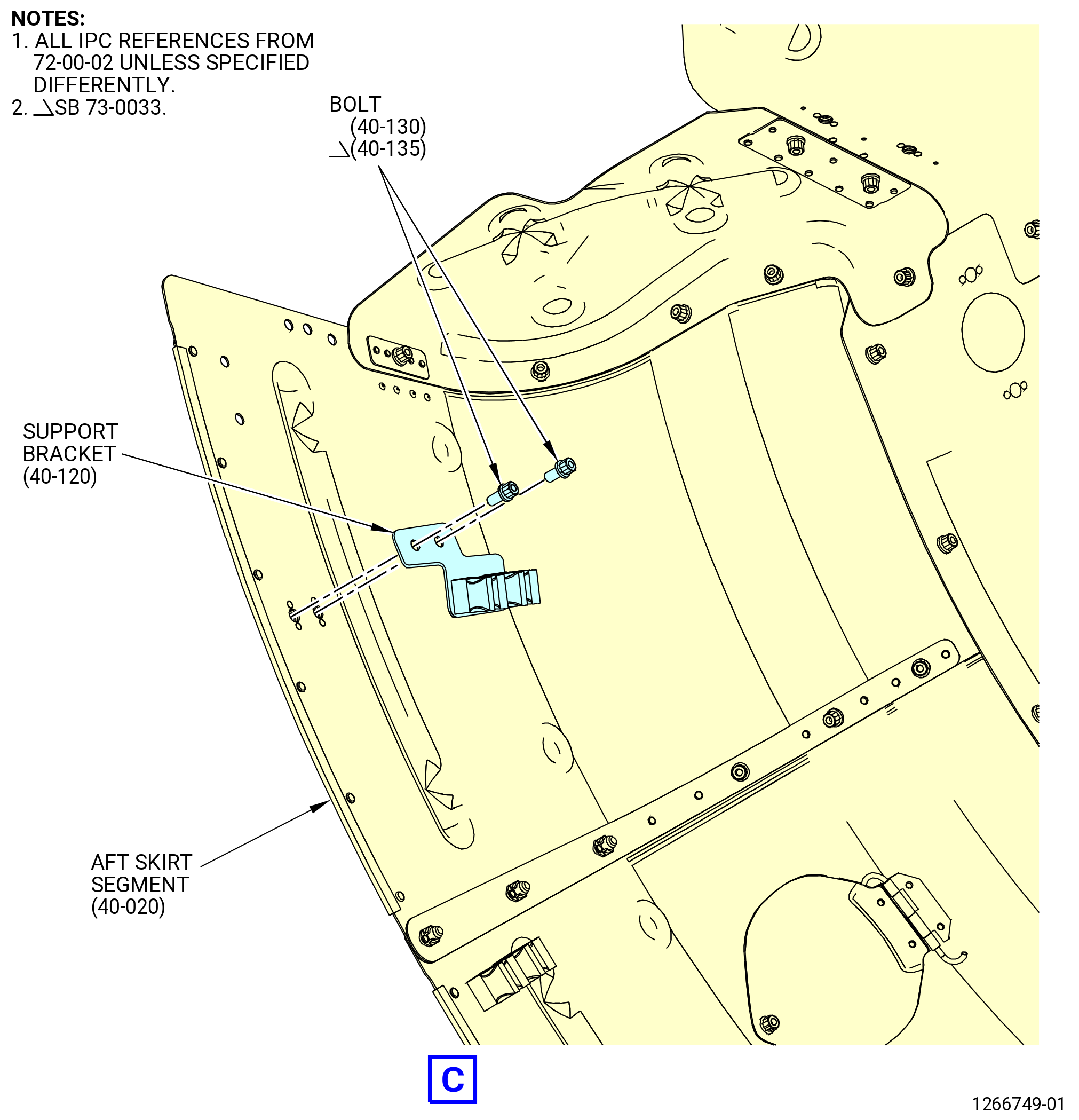
| (a) | Install bracket (01-090 , 73-11-40) (SIN 34010) on the aft skirt segment (40-020) (SIN 29901) with bolts (01-030 , 73-11-40) (SIN 34020). |
| (b) | Torque the bolts (01-030 , 73-11-40) (SIN 34020) to 106 to 124 lb in. (12.0 to 14.0 Nm). |
| (c) | Install gasket (01-100 , 73-11-40) (SIN 34050) on the fuel pump (01-010 , 73-11-00) (SIN 30900). |
| (d) | Install the fuel hose on the fuel pump (01-010 , 73-11-00) (SIN 30900). |
| WARNING: |
|
| (e) | Apply C02-058 lubricant to the threads and washer faces of bolts (01-110 , 73-11-40) (SIN 34022). |
| (f) | Put the W13 harness electrical bracket (bracket) (01-190 , 73-11-40) (SIN 6741N) or (01-205 , 73-11-40) (SIN 6741N) or (01-210 , 73-11-40) (SIN 6741N) on the lower boltholes of the fuel hose. |
| (g) | Attach the fuel hose and bracket (01-190 , 73-11-40) (SIN 6741N) or (01-205 , 73-11-40) (SIN 6741N) or (01-210 , 73-11-40) (SIN 6741N) with bolts (01-110 , 73-11-40) (SIN 34022). |
| (h) | Attach the fuel hose to bracket (01-090 , 73-11-40) (SIN 34010) with P-clamp (01-040 , 73-11-40) (SIN 34080) and bolts (01-030 , 73-11-40) (SIN 34020). |
| (i) | Torque the bolts (01-030 , 73-11-40) (SIN 34020) to 106 to 124 lb in. (12.0 to 14.0 Nm). |
| (j) | Attach the fuel hose to bracket (01-060 , 73-11-40) (SIN 34011) with P-clamp (01-050 , 73-11-40) (SIN 34082) and two bolts (01-130 , 73-11-40) (SIN 34025). |
| (k) | Torque the bolts (01-130 , 73-11-40) (SIN 34025) to 51 to 59 lb in. (5.8 to 6.7 Nm). |
| (l) | Torque the bolts (01-110 , 73-11-40) (SIN 34022) to 235 to 275 lb in. (26.6 to 31.1 Nm). |
| (m) | Remove unwanted C02-058 lubricant with C10-182 cleaning cloth. |
| * * * END SB 73-0031 |
|
|
|
|
| Subtask 72-00-02-440-329 |
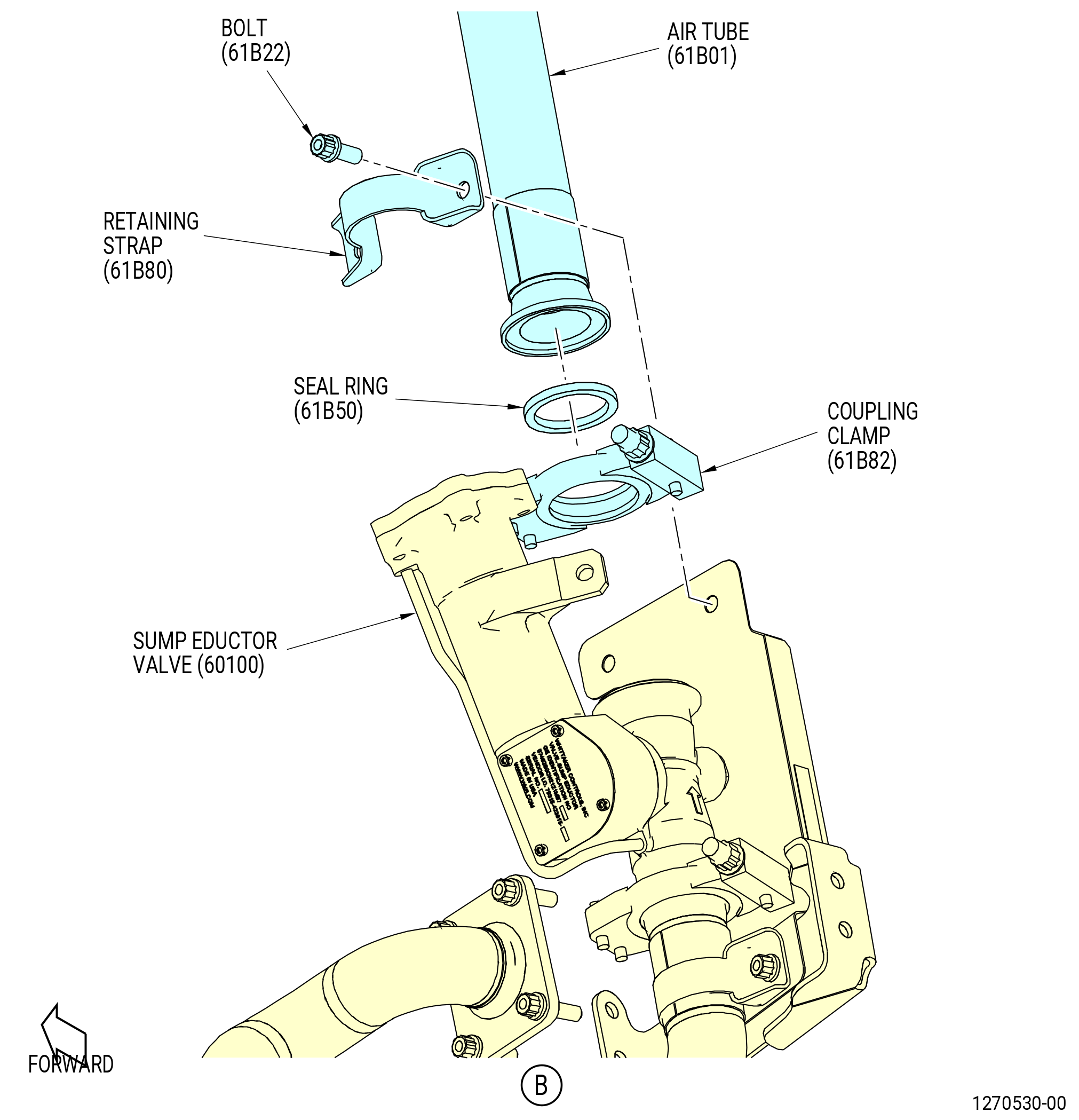
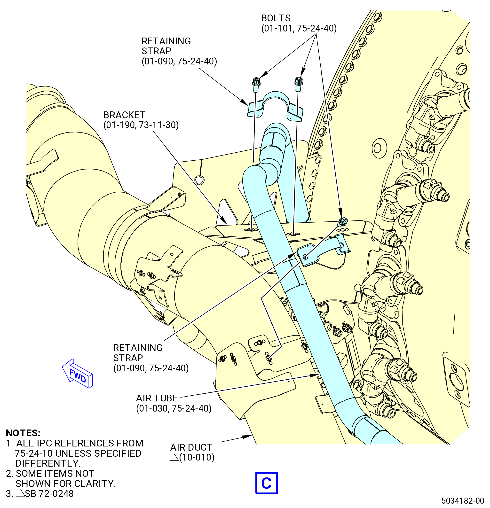
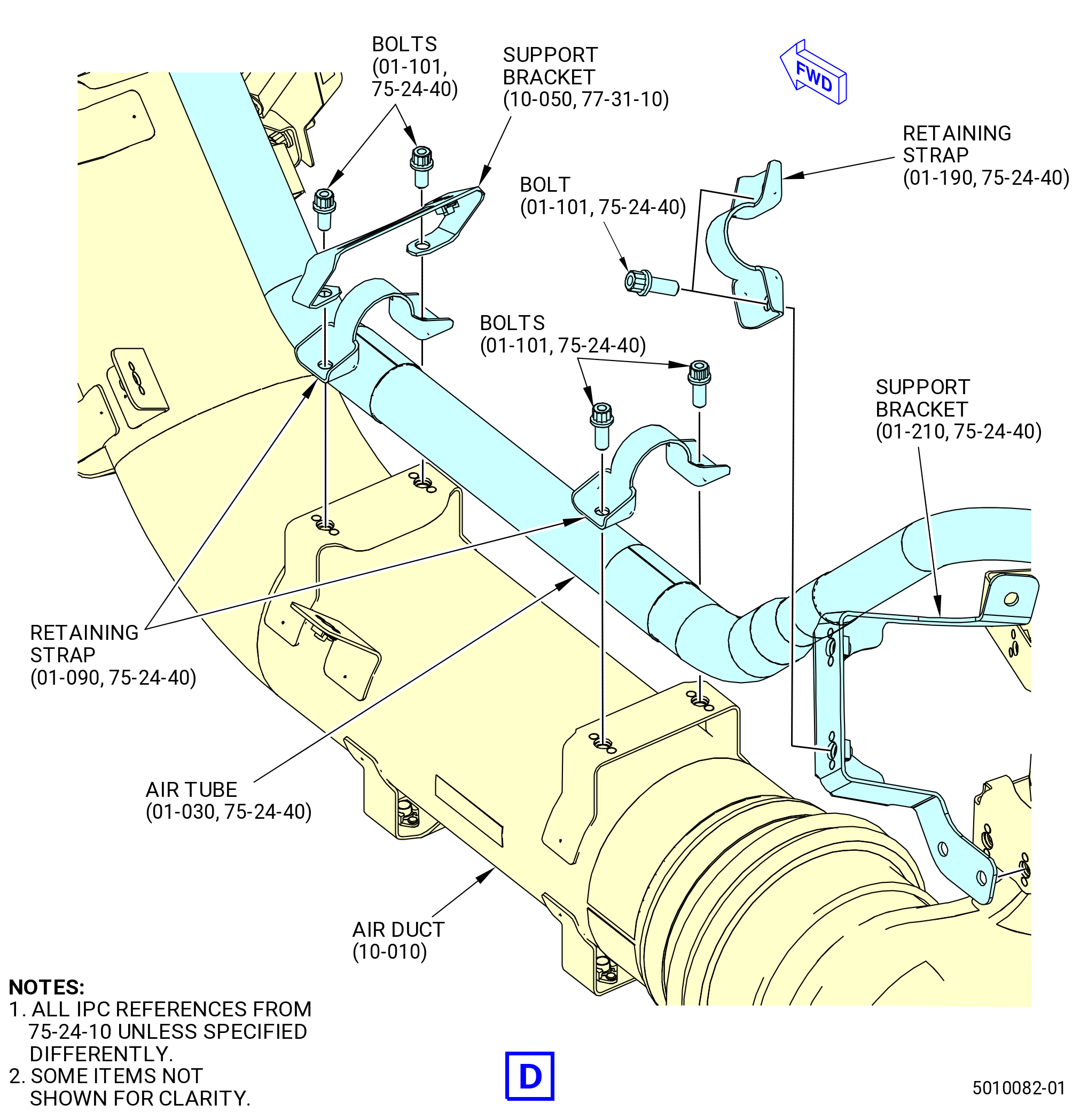
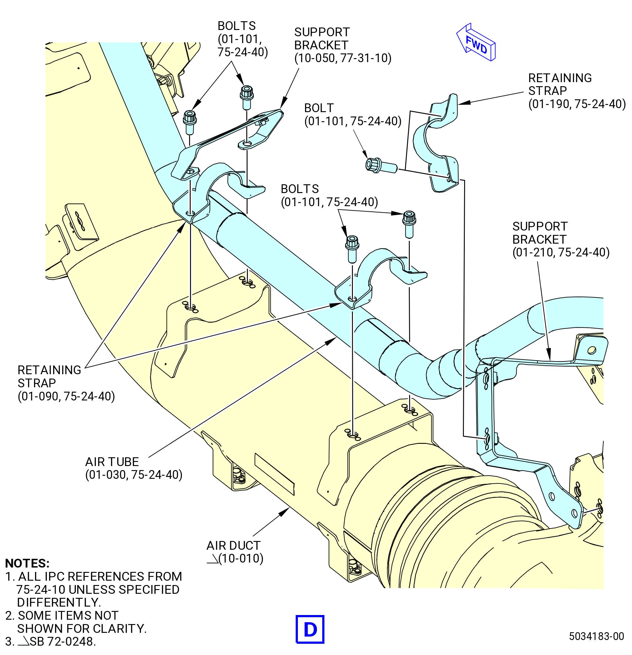
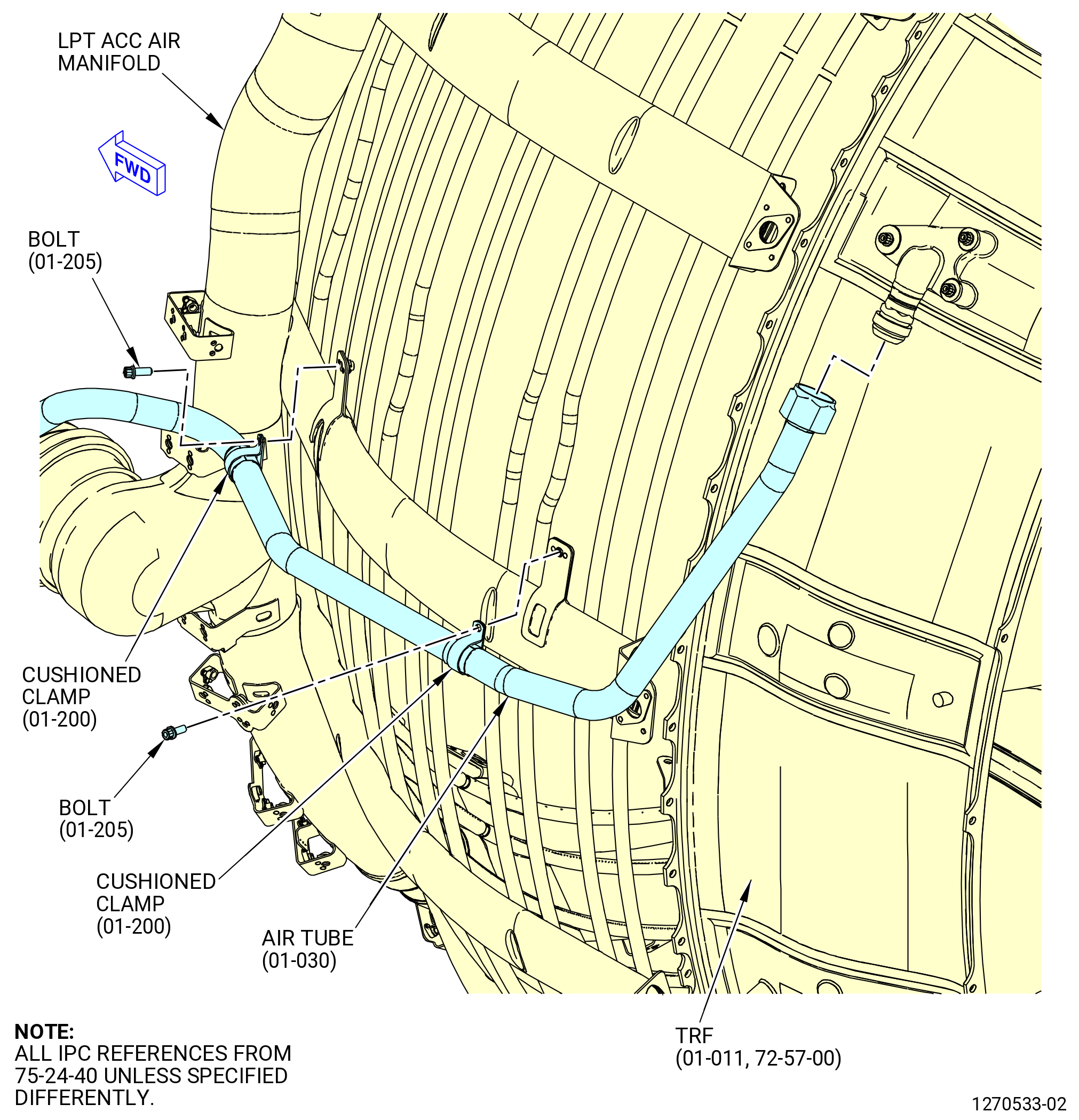
| O. | Install the sump eductor air tube (air tube) (61B01). Refer to Figure 1020 and do as follows: |
| (1) | Put the air tube on the left side of the engine at the 10:30 o'clock position. |
| (2) | Connect the air tube to the fitting on the turbine rear frame (TRF) (01-011 , 72-57-00) (SIN 940A0). |
| (3) | Install a seal ring (61B50) on the sump eductor valve (60100). |
| (4) | Attach the air tube to the sump eductor valve with a coupling clamp (61B82). Do not torque at this time. |
| (5) | Attach the air tube to the bracket (6221B) with a retaining strap (61B80) and two bolts (61B22). Do not torque the bolts at this time. |
| (6) | Attach the air tube to the air duct (10-010 , 75-24-10) (SIN 62201) at the forward attach point with a retaining strap (01-090 , 75-24-40) (SIN 61B80) and two bolts (01-101 , 75-24-40) (SIN 61B22). |
| (7) | Install the support bracket (10-050 , 77-31-10) (SIN 65511) and one retaining strap (01-090 , 75-24-40) (SIN 61B80) with two bolts (01-101 , 75-24-40) (SIN 61B22) at the middle attach point on the air duct (10-010 , 75-24-10) (SIN 62201). |
| (8) | Attach the air tube to the air duct (10-010 , 75-24-10) (SIN 62201) at the aft attach point with a retaining strap (01-090 , 75-24-40) (SIN 61B80) and bolts (01-101 , 75-24-40) (SIN 61B22). |
| (9) | Attach the air tube to the eductor tube support bracket (support bracket) (61B19) with a retaining strap (61B85) and bolts (61B22). |
| (10) | Attach the air tube to the LPT ACC air manifold (6220D) with cushioned clamps (61B84) and bolts (61B26). |
| (11) | Torque the B-nut on the air tube at the TRF to 110-130 lb ft (149-176 N.m). |
| (12) | Torque the coupling clamp (61B82) to 60-70 lb in. (6.8-7.9 N.m). |
| (13) | Torque the ten bolts (61B22) at the retaining straps (61B80) and support bracket (61B19) to 106-124 lb in. (12.0-14.0 N.m). |
| (14) | Torque the two bolts (61B26) at the cushioned clamps (61B84) to 60-70 lb in. (6.8-7.9 N.m). |
|
|
|
|
| Subtask 72-00-02-440-330 |
| * * * PRE SB 73-0033( W32 and W33 Harnesses Hardware without Improvement ) |
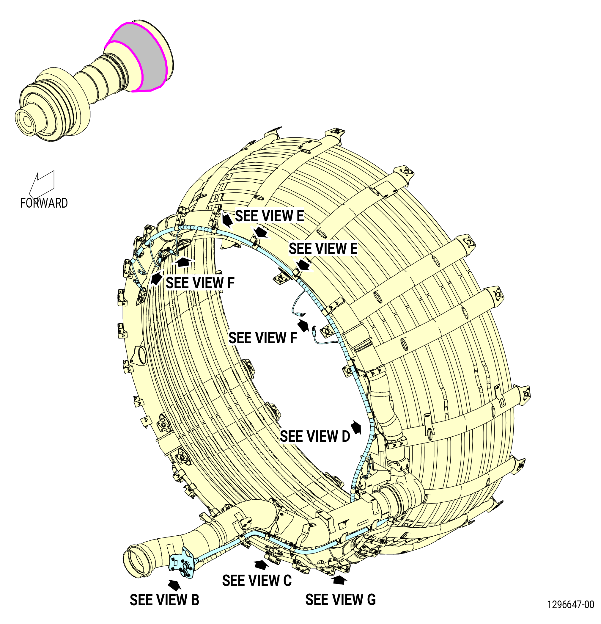
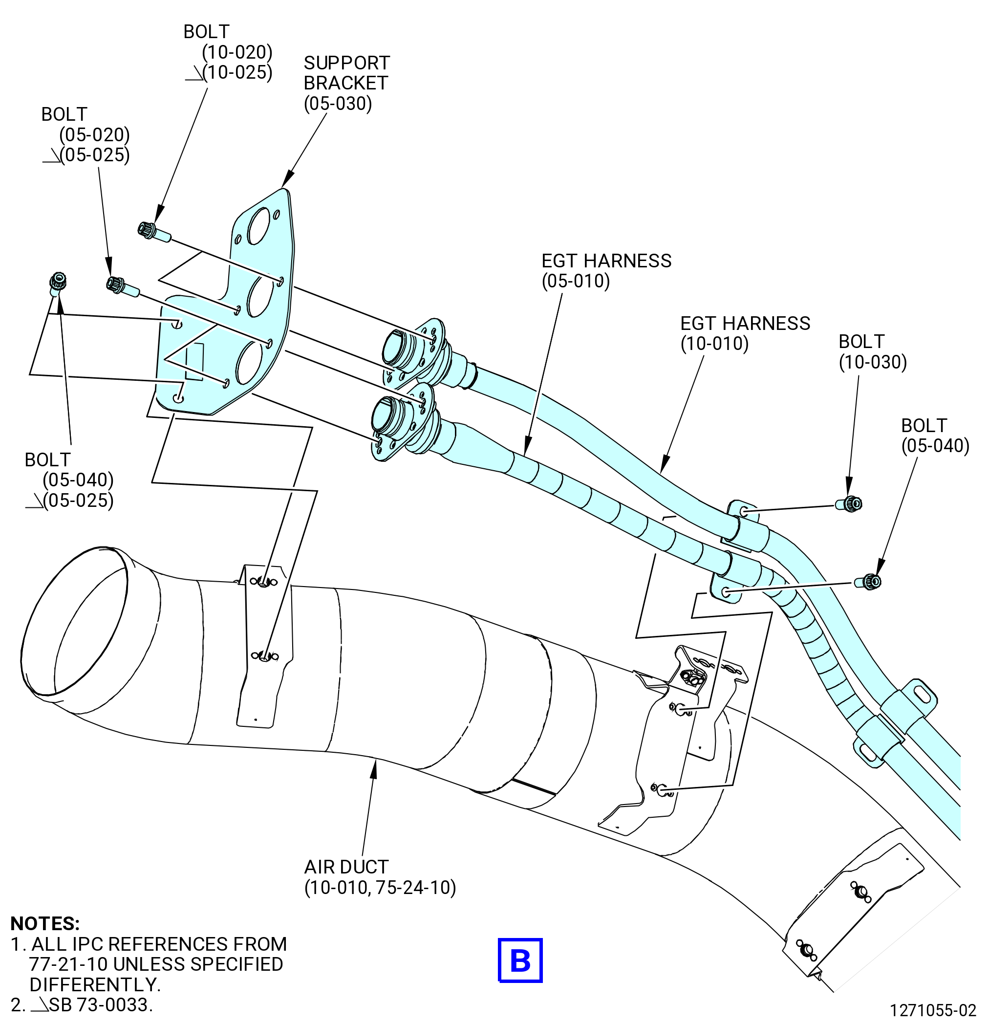
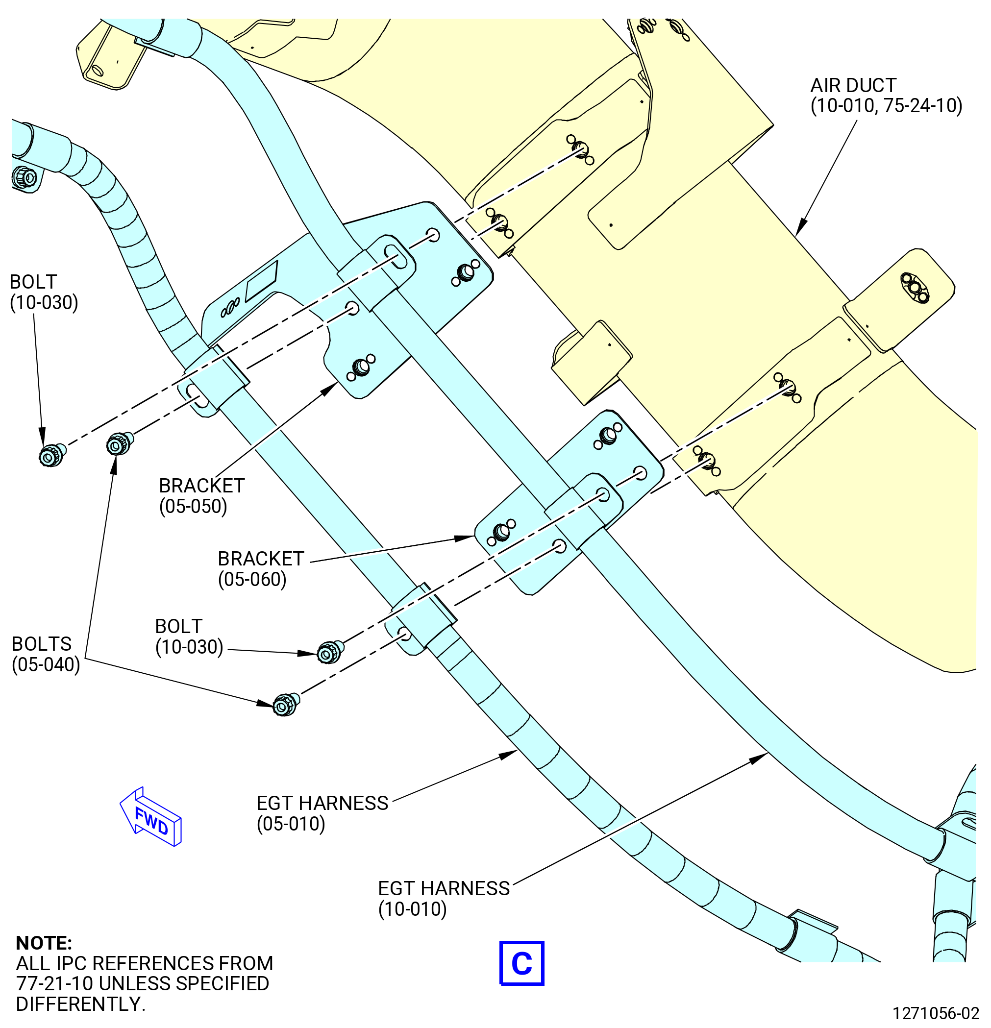
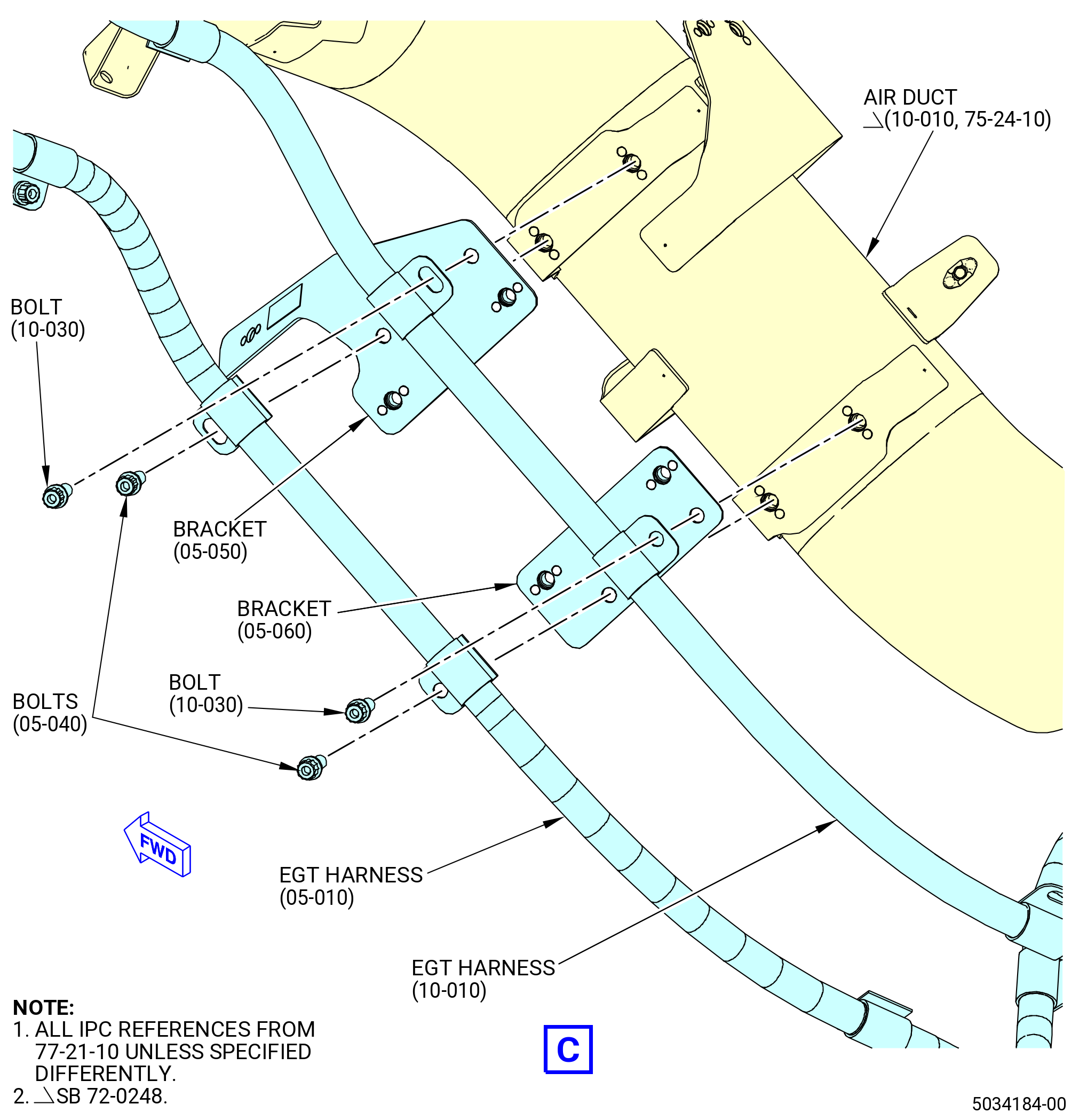
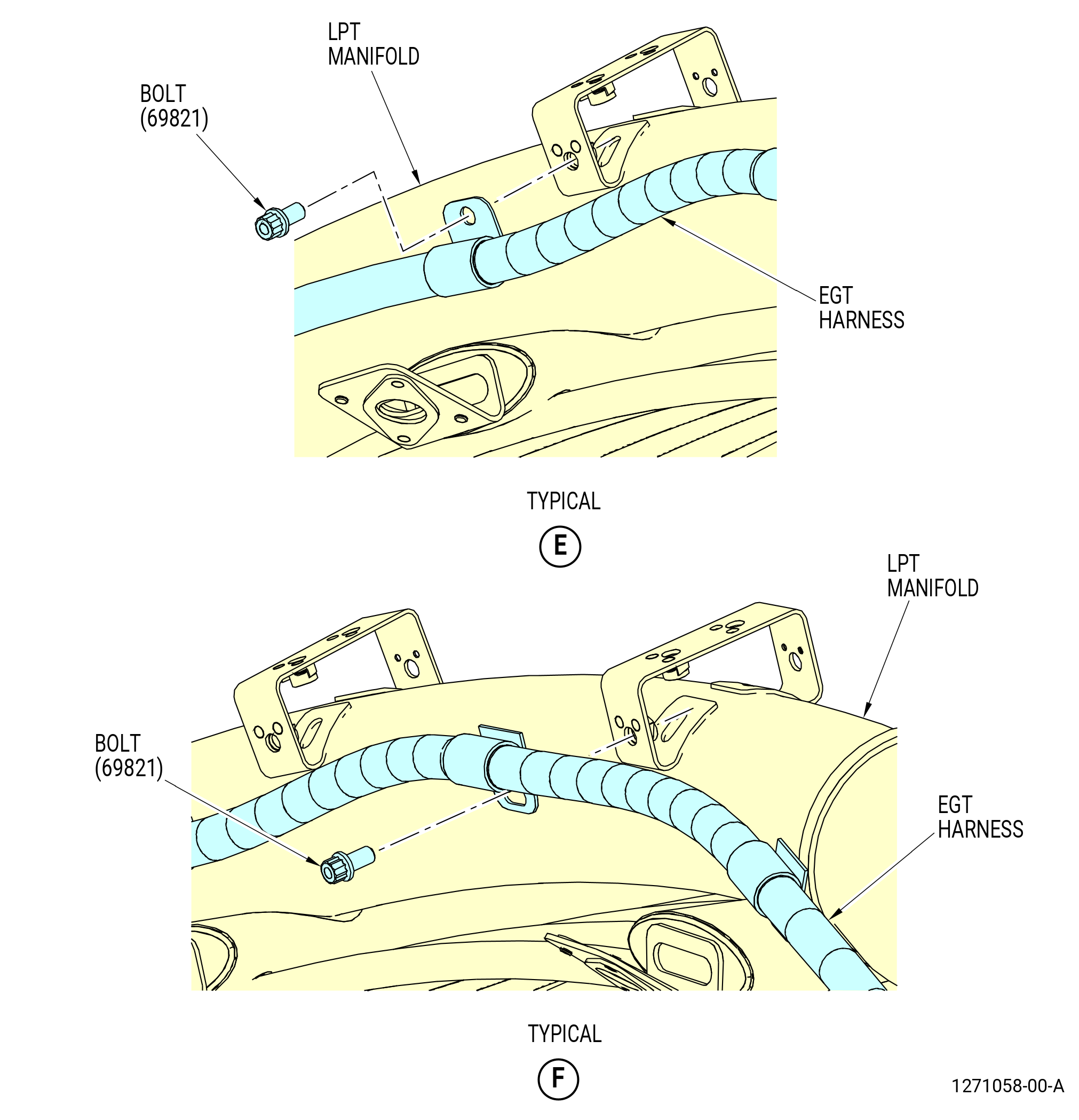
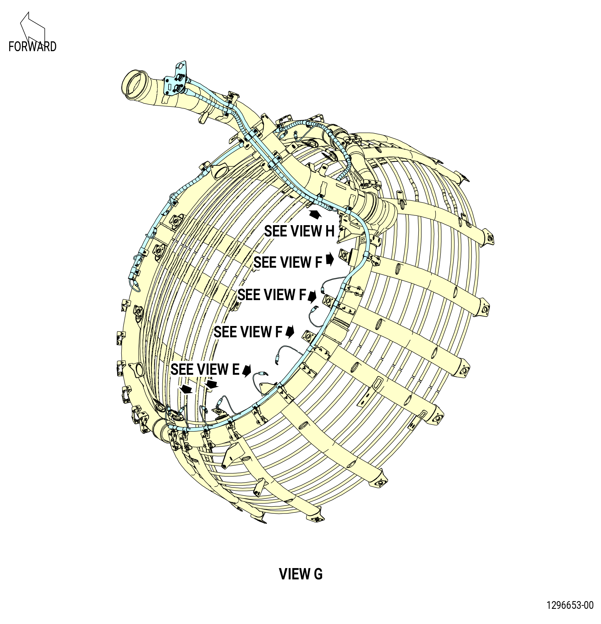
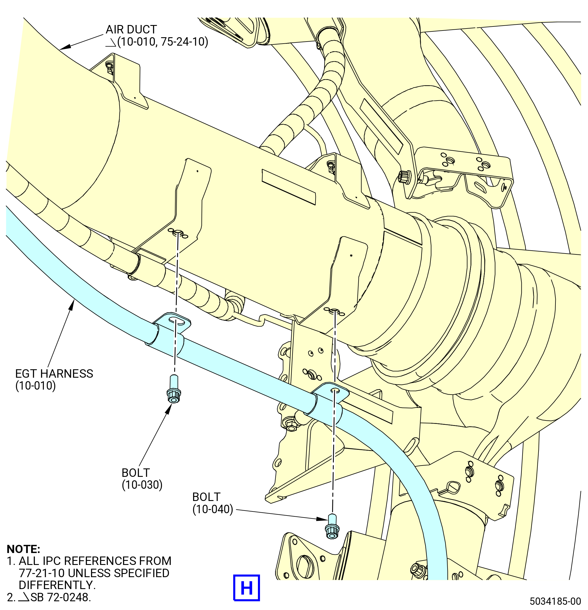
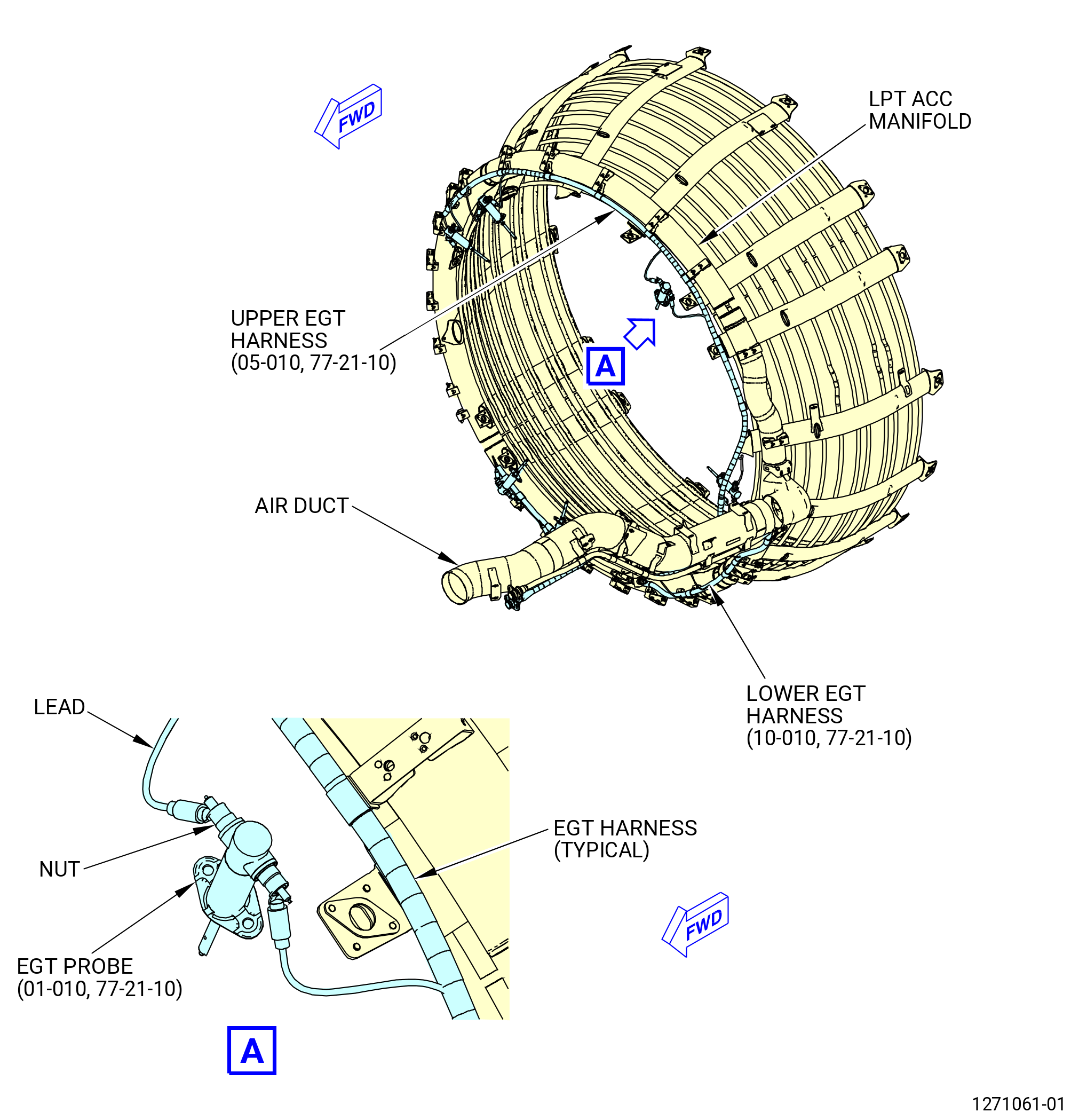
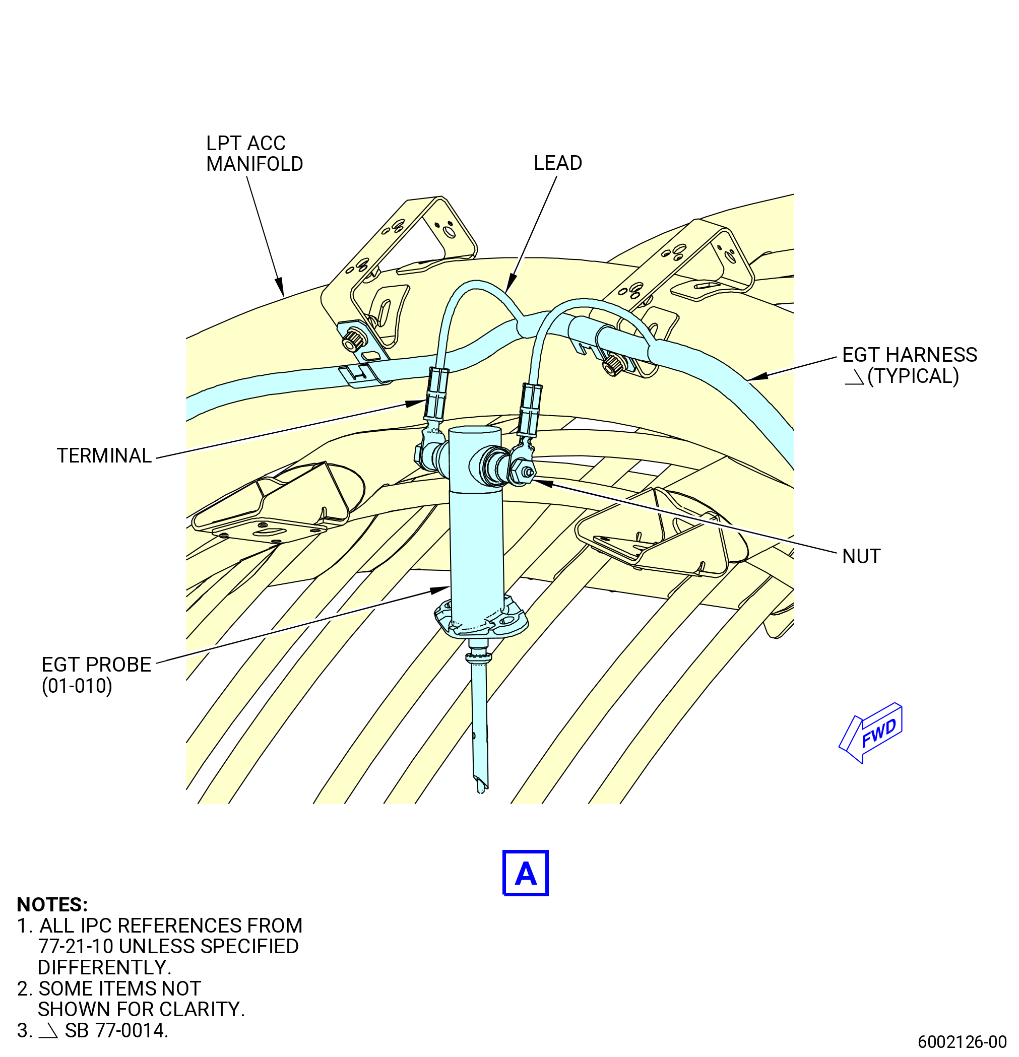
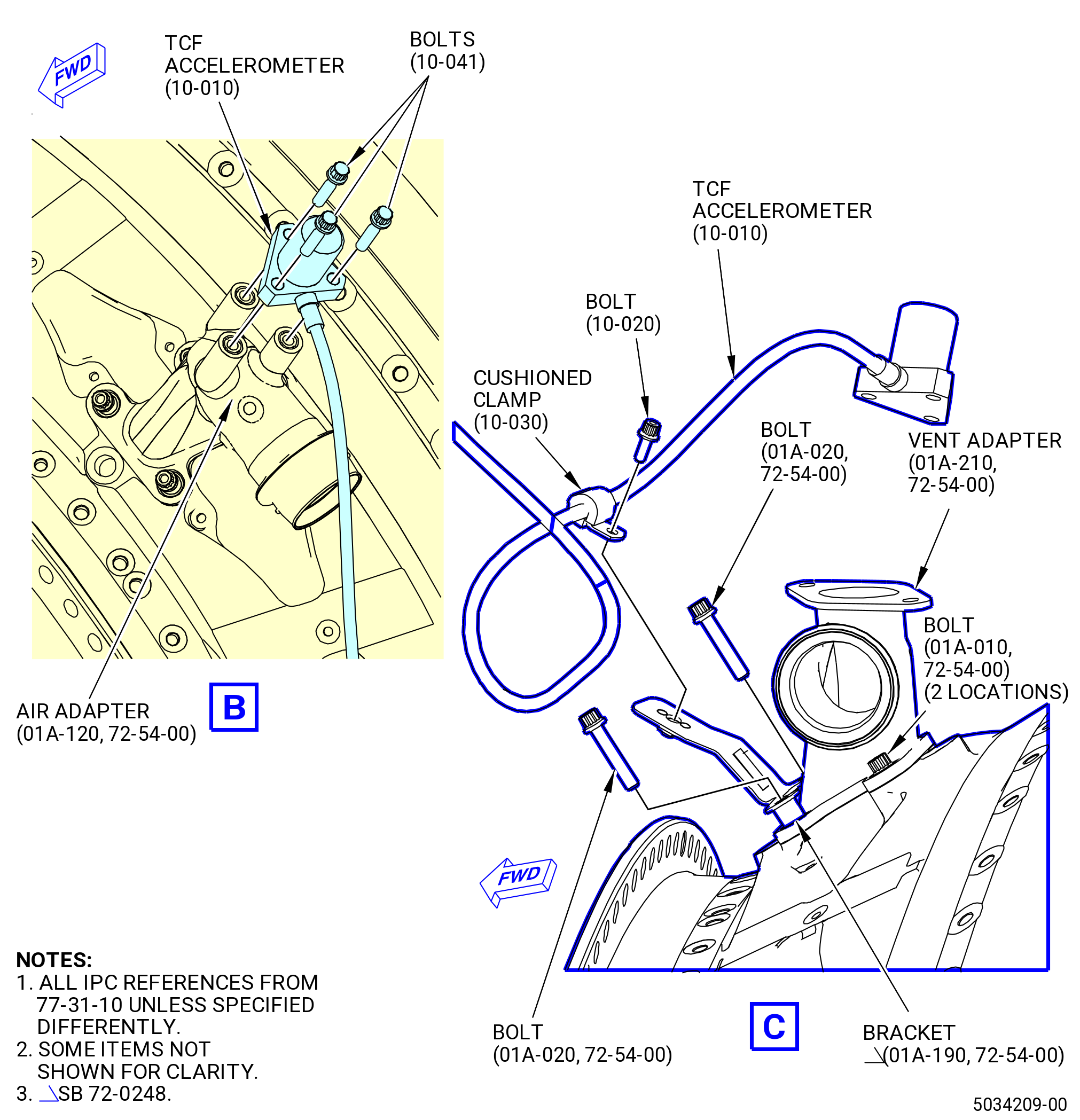
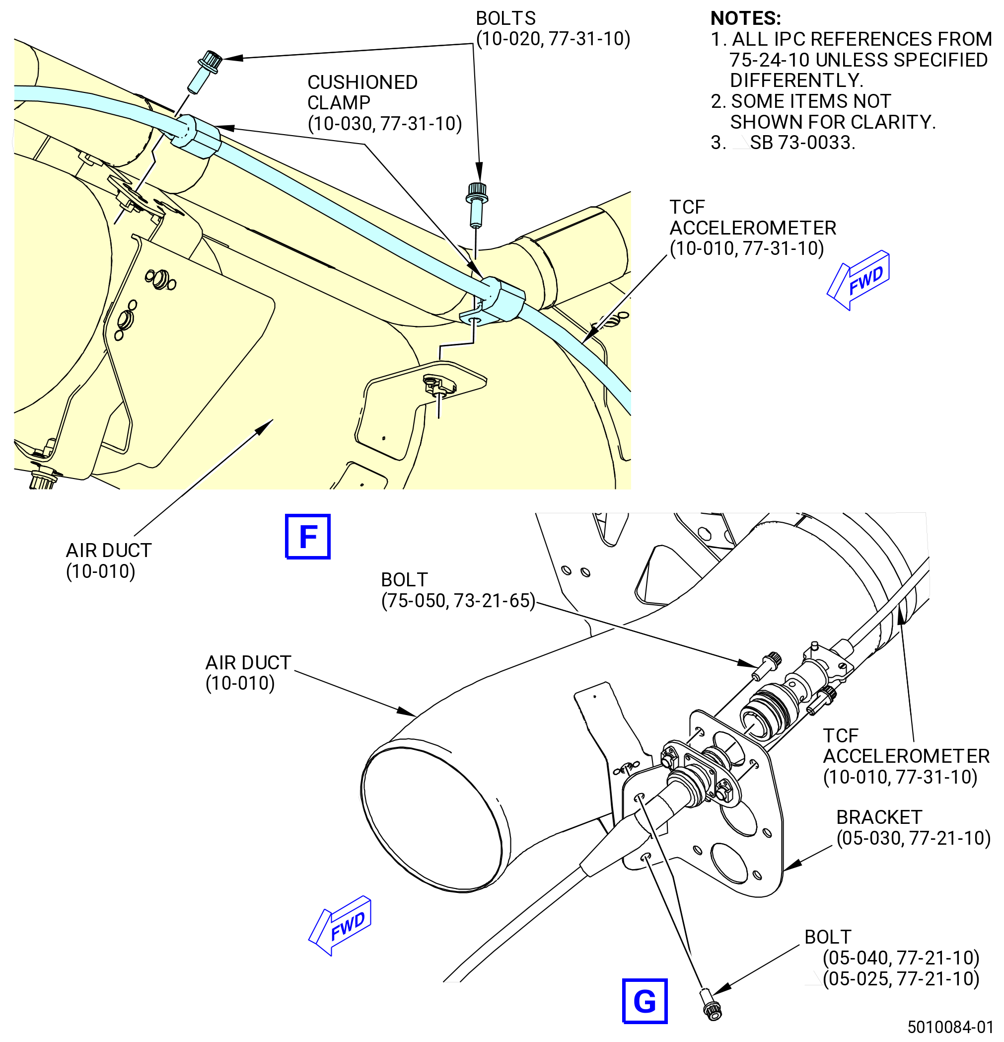
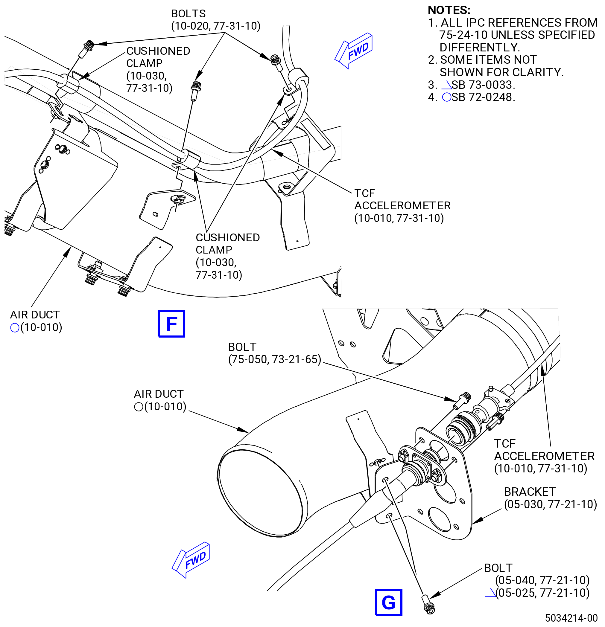
| P. | Install the exhaust gas temperature (EGT) harnesses. Refer to Figure 1021 and do as follows: |
| (1) | Attach the EGT harness support bracket (support bracket) (05-030 , 77-21-10) (SIN 69810) to the air duct (10-010 , 75-24-10) (SIN 62201) with two machine bolts (bolts) (05-040 , 77-21-10) (SIN 69820). |
| (2) | Attach the forward connector of the EGT harness (05-010 , 77-21-10) (SIN 69801) in the lower hole of the support bracket (05-030 , 77-21-10) (SIN 69810) with two bolts (05-020 , 77-21-10) (SIN 69820). |
| (3) | Attach the forward connector of the EGT harness (10-010 , 77-21-10) (SIN 69802) in the middle hole of the support bracket (05-030 , 77-21-10) (SIN 69810) with two bolts (10-020 , 77-21-10) (SIN 69820). |
| (4) | Attach the EGT harness (05-010 , 77-21-10) (SIN 69801) to the air duct (10-010 , 75-24-10) (SIN 62201) lower hole, forward attach point, with one bolt (05-040 , 77-21-10) (SIN 69820). |
| (5) | Attach the EGT harness (10-010 , 77-21-10) (SIN 69802) to the air duct (10-010 , 75-24-10) (SIN 62201) upper hole, forward attach point, with one bolt (10-030 , 77-21-10) (SIN 69820). |
| (6) | Attach the EGT harness (05-010 , 77-21-10) (SIN 69801), the EGT harness (10-010 , 77-21-10) (SIN 69802), and the support bracket (bracket) (05-050 , 77-21-10) (SIN 69111), nut plates aft, to the air duct (10-010 , 75-24-10) (SIN 62201) with bolts (05-040 , 77-21-10) (SIN 69820) and (10-030 , 77-21-10) (SIN 69820). |
| (7) | Attach the EGT harness (05-010 , 77-21-10) (SIN 69801), the EGT harness (10-010 , 77-21-10) (SIN 69802), and the accelerometer cable bracket (bracket) (05-060 , 77-21-10) (SIN 69813), nut plates aft, to the air duct (10-010 , 75-24-10) (SIN 62201) with bolts (05-040 , 77-21-10) (SIN 69820) and (10-030 , 77-21-10) (SIN 69820). |
| (8) | Attach the EGT harness (05-010 , 77-21-10) (SIN 69801) and the EGT harness (10-010 , 77-21-10) (SIN 69802) to the air duct (10-010 , 75-24-10) (SIN 62201) inboard holes with bolts (05-040 , 77-21-10) (SIN 69820) and (10-030 , 77-21-10) (SIN 69820). |
| (9) | Attach the EGT harness (69801) to the ACC LPT duct support bracket (support bracket) (6221E) with one machine bolt (bolt) (69821). |
| (10) | Attach the EGT cable bridge bracket (bracket) (05-080 , 77-21-10) (SIN 69811) to the LPT ACC air manifold (15-052 , 75-24-10) (SIN 6220D) at the 10:00 o'clock position with two bolts (05-040 , 77-21-10) (SIN 69820). |
| (11) | Attach the EGT harness (69801) to bracket (69811) with one bolt (69821), bolthead forward, at two locations. |
| (12) | Attach the EGT harness (69801) to the LPT ACC air manifold (6220A) with one bolt (69821) at five locations. |
| (13) | Attach the EGT harness (69801) to the LPT ACC air manifold (6220B) with one bolt (69821) at two locations. |
| (14) | Connect the EGT harness (69801) to the EGT probes (69800). Refer to Figure 1022 and do as follows: |
| NOTE: |
|
| CAUTION: |
|
| CAUTION: |
|
| CAUTION: |
|
| (a) | Put the EGT harness (69801) leads at two insert clips of support bracket (6221E). |
| (b) | Connect by hand the small nuts of the EGT harness (05-010 , 77-21-10) (SIN 69801) leads to the small posts of the EGT probes at four locations. |
| (c) | Connect by hand the large nuts of the EGT harness (05-010 , 77-21-10) (SIN 69801) leads to the large posts of the EGT probes at four locations. |
| Subtask 72-00-02-440-656 |
| * * * PRE SB 77-0014( Old EGT Harness Configuration ) |
| (d) | Adjust the EGT harness (69801) leads to make sure that there are no kinks and they do not touch adjacent hardware. |
| * * * END PRE SB 77-0014 |
| Subtask 72-00-02-440-657 |
| * * * SB 77-0014( New EGT Harness Configuration ) |
| (d).A. | Orientate the EGT harness (05-010 , 77-21-10) (SIN 69801) terminals radially outward from the engine case assuring a smooth radius of the EGT harness (05-010 , 77-21-10) (SIN 69801) leads and that they do not touch adjacent hardware. |
| * * * END SB 77-0014 |
| Subtask 72-00-02-440-658 |
| CAUTION: |
|
| CAUTION: |
|
| (e) | Maintain the EGT harness terminal orientation while torquing the small nuts of the EGT harness (05-010 , 77-21-10) (SIN 69801) leads to 17 to 19 lb in. (1.9 to 2.1 Nm). |
| 1 | Torque the small nuts to 17-19 lb in. (1.9-2.1 N.m) again. |
| CAUTION: |
|
| (f) | Maintain the EGT harness terminal orientation while torquing the large nuts of the EGT harness (05-010 , 77-21-10) (SIN 69801) leads to 29 to 35 lb in. (3.3 to 4.0 Nm). |
| 1 | Torque the large nuts to 29-35 lb in. (3.3-4.0 N.m) again. |
| (15) | Attach the EGT harness (10-010 , 77-21-10) (SIN 69802) to the air duct (10-010 , 75-24-10) (SIN 62201) aft inboard hole with a bolt (10-040 , 77-21-10) (SIN 69821). |
| (16) | Attach the EGT harness (69802) to the LPT ACC air manifold (6220D) with a bolt (69821) at three locations. |
| (17) | Attach the EGT harness (69802) to the LPT ACC air manifold (6220C) with a bolt (69821) at seven locations. |
| (18) | Connect the EGT harness (69802) to the EGT probes (69800). Refer to Figure 1022 and do as follows: |
| NOTE: |
|
| CAUTION: |
|
| CAUTION: |
|
| CAUTION: |
|
| (a) | Connect by hand the small nuts of the EGT harness (10-010 , 77-21-10) (SIN 69802) leads to the small posts of the EGT probes at four locations. |
| (b) | Connect by hand the large nuts of the EGT harness (10-010 , 77-21-10) (SIN 69802) leads to the large posts of the EGT probes at four locations. |
| Subtask 72-00-02-440-659 |
| * * * PRE SB 77-0014( Old EGT Harness Configuration ) |
| (c) | Adjust the EGT harness (69802) leads to make sure that there are no kinks and they do not touch adjacent hardware. |
| * * * END PRE SB 77-0014 |
| Subtask 72-00-02-440-660 |
| * * * SB 77-0014( New EGT Harness Configuration ) |
| (c).A. | Orientate the EGT harness (10-010 , 77-21-10) (SIN 69802) terminals radially outward from the engine case assuring a smooth radius of the EGT harness (10-010 , 77-21-10) (SIN 69802) leads and that they do not touch adjacent hardware. |
| * * * END SB 77-0014 |
| Subtask 72-00-02-440-661 |
| CAUTION: |
|
| CAUTION: |
|
| (d) | Torque the small nuts of the EGT harness (69802) leads to 17-19 lb in. (1.9-2.1 N.m). |
| 1 | Maintain the EGT harness terminal orientation while torquing the small nuts to 17 to 19 lb in. (1.9 to 2.1 Nm) again. |
| CAUTION: |
|
| (e) | Maintain the EGT harness terminal orientation while torquing the large nuts of the EGT harness (10-010 , 77-21-10) (SIN 69802) leads to 29 to 35 lb in. (3.3 to 4.0 Nm). |
| 1 | Torque the large nuts to 29-35 lb in. (3.3-4.0 N.m) again. |
| (19) | Center and align the integral metal clamps maintaining position while torquing all bolts (05-020 , 77-21-10) (SIN 69820), (05-040 , 77-21-10) (SIN 69820), (10-020 , 77-21-10) (SIN 69820), (10-030 , 77-21-10) (SIN 69820), (05-070 , 77-21-10) (SIN 69821), and (10-040 , 77-21-10) (SIN 69821) to 106 to 124 lb in. (12.0 to 14.0 Nm). |
| * * * END PRE SB 73-0033 |
| Subtask 72-00-02-440-479 |
| * * * SB 73-0033( W32 and W33 Harnesses Hardware Improvement ) |
| P.A. | Install the EGT harnesses. Refer to Figure 1021 and do as follows: |
| (1) | Attach the support bracket (05-030 , 77-21-10) (SIN 69810) to the air duct (10-010 , 75-24-10) (SIN 62201) with two machine bolts (bolts) (05-025 , 77-21-10) (SIN 69822). |
| (2) | Attach the forward connector of the EGT harness (05-010 , 77-21-10) (SIN 69801) in the lower hole of the support bracket (05-030 , 77-21-10) (SIN 69810) with two bolts (05-025 , 77-21-10) (SIN 69822). |
| (3) | Attach the forward connector of the EGT harness (10-010 , 77-21-10) (SIN 69802) in the middle hole of the support bracket (05-030 , 77-21-10) (SIN 69810) with two bolts (10-025 , 77-21-10) (SIN 69822). |
| (4) | Attach the EGT harness (05-010 , 77-21-10) (SIN 69801) to the air duct (10-010 , 75-24-10) (SIN 62201) lower hole, forward attach point, with one bolt (05-040 , 77-21-10) (SIN 69820). |
| (5) | Attach the EGT harness (10-010 , 77-21-10) (SIN 69802) to the air duct (10-010 , 75-24-10) (SIN 62201) upper hole, forward attach point, with one bolt (10-030 , 77-21-10) (SIN 69820). |
| (6) | Attach the EGT harness (05-010 , 77-21-10) (SIN 69801), the EGT harness (10-010 , 77-21-10) (SIN 69802), and the bracket (05-050 , 77-21-10) (SIN 69111), nut plates aft, to the air duct (10-010 , 75-24-10) (SIN 62201) with bolts (05-040 , 77-21-10) (SIN 69820) and (10-030 , 77-21-10) (SIN 69820). |
| (7) | Attach the EGT harness (05-010 , 77-21-10) (SIN 69801), the EGT harness (10-010 , 77-21-10) (SIN 69802), and the bracket (05-060 , 77-21-10) (SIN 69813), nut plates aft, to the air duct (10-010 , 75-24-10) (SIN 62201) with bolts (05-040 , 77-21-10) (SIN 69820) and (10-030 , 77-21-10) (SIN 69820). |
| (8) | Attach the EGT harness (05-010 , 77-21-10) (SIN 69801) and the EGT harness (10-010 , 77-21-10) (SIN 69802) to the air duct (10-010 , 75-24-10) (SIN 62201) inboard holes with bolts (05-040 , 77-21-10) (SIN 69820) and (10-030 , 77-21-10) (SIN 69820). |
| (9) | Attach the EGT harness (05-010 , 77-21-10) (SIN 69801) to the support bracket (35-140) (SIN 6221E) with one bolt (05-070 , 77-21-10) (SIN 69821). |
| (10) | Attach the bracket (05-080 , 77-21-10) (SIN 69811) to the LPT ACC air manifold (15-052 , 75-24-10) (SIN 6220D) at the 10:00 o'clock position with two bolts (05-025 , 77-21-10) (SIN 69822). |
| (11) | Attach the EGT harness (05-010 , 77-21-10) (SIN 69801) to bracket (05-080 , 77-21-10) (SIN 69811) with one bolt (05-070 , 77-21-10) (SIN 69821), bolthead forward, at two locations. |
| (12) | Attach the EGT harness (05-010 , 77-21-10) (SIN 69801) to the LPT ACC air manifold (15-062 , 75-24-10) (SIN 6220A) with one bolt (05-070 , 77-21-10) (SIN 69821) at five locations. |
| (13) | Attach the EGT harness (05-010 , 77-21-10) (SIN 69801) to the LPT ACC air manifold (15-072 , 75-24-10) (SIN 6220B) with one bolt (05-070 , 77-21-10) (SIN 69821) at two locations. |
| (14) | Connect the EGT harness (05-010 , 77-21-10) (SIN 69801) to the EGT probes (01-010 , 77-21-10) (SIN 69800). Refer to Figure 1022 and do as follows: |
| NOTE: |
|
| CAUTION: |
|
| CAUTION: |
|
| CAUTION: |
|
| (a) | Put the EGT harness (05-010 , 77-21-10) (SIN 69801) leads at two insert clips of support bracket (35-140) (SIN 6221E). |
| (b) | Connect by hand the small nuts of the EGT harness (05-010 , 77-21-10) (SIN 69801) leads to the small posts of the EGT probes at eight locations. |
| (c) | Connect by hand the large nuts of the EGT harness (05-010 , 77-21-10) (SIN 69801) leads to the large posts of the EGT probes at eight locations. |
| (d) | Adjust the EGT harness (05-010 , 77-21-10) (SIN 69801) leads to make sure that there are no kinks and they do not touch adjacent hardware. |
| CAUTION: |
|
| (e) | Torque the small nuts of the EGT harness (05-010 , 77-21-10) (SIN 69801) leads to 17 to 19 lb in. (1.9 to 2.1 Nm). |
| 1 | Torque the small nuts to 17 to 19 lb in. (1.9 to 2.1 Nm) again. |
| CAUTION: |
|
| (f) | Torque the large nuts of the EGT harness (05-010 , 77-21-10) (SIN 69801) leads to 29 to 35 lb in. (3.3 to 4.0 Nm). |
| 1 | Torque the large nuts to 29 to 35 lb in. (3.3 to 4.0 Nm) again. |
| (15) | Attach the EGT harness (10-010 , 77-21-10) (SIN 69802) to the air duct (10-010 , 75-24-10) (SIN 62201) aft inboard hole with a bolt (10-040 , 77-21-10) (SIN 69821). |
| (16) | Attach the EGT harness (10-010 , 77-21-10) (SIN 69802) to the LPT ACC air manifold (15-052 , 75-24-10) (SIN 6220D) with a bolt (10-040 , 77-21-10) (SIN 69821) at three locations. |
| (17) | Attach the EGT harness (10-010 , 77-21-10) (SIN 69802) to the LPT ACC air manifold (15-082 , 75-24-10) (SIN 6220C) with a bolt (10-040 , 77-21-10) (SIN 69821) at seven locations. |
| (18) | Connect the EGT harness (10-010 , 77-21-10) (SIN 69802) to the EGT probes (01-010 , 77-21-10) (SIN 69800). Refer to Figure 1022 and do as follows: |
| NOTE: |
|
| CAUTION: |
|
| CAUTION: |
|
| CAUTION: |
|
| (a) | Connect by hand the small nuts of the EGT harness (10-010 , 77-21-10) (SIN 69802) leads to the small posts of the EGT probes at eight locations. |
| (b) | Connect by hand the large nuts of the EGT harness (10-010 , 77-21-10) (SIN 69802) leads to the large posts of the EGT probes at eight locations. |
| (c) | Adjust the EGT harness (10-010 , 77-21-10) (SIN 69802) leads to make sure that there are no kinks and they do not touch adjacent hardware. |
| CAUTION: |
|
| (d) | Torque the small nuts of the EGT harness (10-010 , 77-21-10) (SIN 69802) leads to 17 to 19 lb in. (1.9 to 2.1 Nm). |
| 1 | Torque the small nuts to 17 to 19 lb in. (1.9 to 2.1 Nm) again. |
| CAUTION: |
|
| (e) | Torque the large nuts of the EGT harness (10-010 , 77-21-10) (SIN 69802) leads to 29 to 35 lb in. (3.3 to 4.0 Nm). |
| 1 | Torque the large nuts to 29 to 35 lb in. (3.3 to 4.0 Nm) again. |
| (19) | Torque all bolts (05-025 , 77-21-10) (SIN 69822) and (10-025 , 77-21-10) (SIN 69822) to 106 to 124 lb in. (12.0 to 14.0 Nm). |
| (20) | Torque all bolts (05-040 , 77-21-10) (SIN 69820), (10-030 , 77-21-10) (SIN 69820), (05-070 , 77-21-10) (SIN 69821), and (10-040 , 77-21-10) (SIN 69821) to 60 to 70 lb in. (6.8 to 7.9 Nm). |
| * * * END SB 73-0033 |
|
|
|
|
|
|
| Subtask 72-00-02-440-331 |
| Q. | Install the TCF accelerometer (65500). Refer to Figure 1023 and do as follows: |
| (1) | Install the TCF accelerometer (10-010 , 77-31-10) (SIN 65500) on the air adapter (01A-120 , 72-54-00) (SIN 9250A) at the 11:00 o'clock position aft locking forward (ALF) on the turbine center frame. |
| (2) | Attach the TCF accelerometer (10-010 , 77-31-10) (SIN 65500) with bolts (10-041 , 77-31-10) (SIN 65527). |
| (3) | Attach the TCF accelerometer (10-010 , 77-31-10) (SIN 65500) to bracket (01A-190 , 72-54-00) (SIN 65513) with cushioned clamp (10-030 , 77-31-10) (SIN 65580) and bolt (10-020 , 77-31-10) (SIN 65520). |
| (4) | Attach the TCF accelerometer (10-010 , 77-31-10) (SIN 65500) to support bracket (01A-220 , 72-54-00) (SIN 65512) with cushioned clamp (10-030 , 77-31-10) (SIN 65580) and bolt (10-020 , 77-31-10) (SIN 65520). |
| (5) | Attach the TCF accelerometer (65500) to bracket (65511) with cushioned clamp (65580) and bolt (65520). |
| (6) | Attach the TCF accelerometer (10-010 , 77-31-10) (SIN 65500) to the brackets on the air duct (10-010 , 75-24-10) (SIN 62201) with cushioned clamps (10-030 , 77-31-10) (SIN 65580) and bolts (10-020 , 77-31-10) (SIN 65520). |
| (7) | Deleted. |
| (8) | Torque the bolts (67123) to 106-124 lb in. (12.0-14.0 N.m). |
| (9) | Torque the bolts (10-041 , 77-31-10) (SIN 65527) to 106 to 124 lb in. (12.0 to 14.0 Nm). |
| (10) | Torque the bolts (65520) to 32-38 lb in. (3.6-4.3 N.m). |
| (11) | Make sure that the TCF accelerometer cable does not have kinks. |
|
|
|
|
| Subtask 72-00-02-440-332 |
| R. | Install the ignition system as follows: |
| (1) | Install the igniter system brackets. Refer to Figure 1024 and do as follows: |
| (a) | Install the exciter box base support bracket (exciter bracket) (01-080 , 74-11-10) (SIN 65810), or (01-081 , 74-11-10) (SIN 65810), or (01-082 , 74-11-10) (SIN 65810) on the VFSG heat exchanger (01-010 , 73-11-20) (SIN 42400). |
| (b) | Attach the exciter bracket (01-080 , 74-11-10) (SIN 65810), or (01-081 , 74-11-10) (SIN 65810), or (01-082 , 74-11-10) (SIN 65810) with bolts (01-090 , 74-11-10) (SIN 65821) or (01-091 , 74-11-10) (SIN 65821). |
| (c) | Attach the electric cable (01-070 , 74-11-10) (SIN 65880) to the exciter bracket (01-080 , 74-11-10) (SIN 65810), or (01-081 , 74-11-10) (SIN 65810), or (01-082 , 74-11-10) (SIN 65810) with bolts (01-060 , 74-11-10) (SIN 65824). |
| (d) | Torque the bolts (01-090 , 74-11-10) (SIN 65821) or (01-091 , 74-11-10) (SIN 65821) to 106-124 lb in. (12.0-14.0 N.m). |
| (e) | Torque the bolts (65824) to 106-124 lb in. (12.0-14.0 N.m). |
| (f) | Attach bracket (01-050 , 74-21-10) (SIN 69110) to the air duct (10-010 , 75-24-10) (SIN 62201) with bolts (01-070 , 74-21-10) (SIN 69120). |
| (g) | Torque the bolts (69120) to 106-124 lb in. (12.0-14.0 N.m). |
| (h) | Attach bracket (65-110) (SIN 68013) to the air duct (10-010 , 75-24-10) (SIN 62201) with bolts (65-050A) (SIN 68020). |
| (i) | Torque the bolts (65-050A) (SIN 68020) to 106 to 124 lb in. (12.0 to 14.0 Nm). |
| (2) | Install the exciter boxes (65800). Refer to Figure 1025 and do as follows: |
| (a) | Install the exciter boxes (01-030 , 74-11-10) (SIN 65800) on the exciter bracket (01-080 , 74-11-10) (SIN 65810), or (01-081 , 74-11-10) (SIN 65810), or (01-082 , 74-11-10) (SIN 65810). |
| (b) | Attach the exciter boxes (65800) with bolts (65822) and bolts (65823). |
| (c) | Torque the bolts (65822) and the bolts (65823) to 106-124 lb in. (12.0-14.0 N.m). |
| (3) | Install the igniters (01-011 , 74-21-20) (SIN 66200) as follows: |
| (a) | Apply C02-058 lubricant to the threads of the igniters (01-011 , 74-21-20) (SIN 66200). |
| (b) | Install the igniters (01-011 , 74-21-20) (SIN 66200) in the igniter plug bushings (01-020 , 74-21-20) (SIN 66203) in the compressor discharge nozzle (CDN) at the 8:30 o'clock and 9:30 o'clock positions. |
| (c) | Torque the igniters (01-011 , 74-21-20) (SIN 66200) to 253 to 297 lb in. (28.5 to 33.5 Nm). |
| (4) | Install the ignition leads (69100) as follows: |
| (a) | Connect an ignition lead (69100) to each exciter box (65800). Do not tighten the ignition leads. |
| (b) | Connect the ignition lead (01-010 , 74-21-10) (SIN 69100) from the upper exciter box (01-030 , 74-11-10) (SIN 65800) to the igniter (01-011 , 74-21-20) (SIN 66200) at the 9:30 o'clock position. Do not tighten the ignition lead on the igniter. |
| (c) | Connect the ignition lead (01-010 , 74-21-10) (SIN 69100) from the lower exciter box (01-030 , 74-11-10) (SIN 65800) to the igniter (01-011 , 74-21-20) (SIN 66200) at the 8:30 o'clock position. Do not tighten the ignition lead on the igniter. |
| (d) | Attach the upper ignition lead (69100) to bracket (69110) with cushioned clamp (69180) and bolt (69122). |
| (e) | Attach the upper ignition lead (69100) to bracket (68013) with cushioned clamp (69180) and bolt (69122). |
| (f) | Attach the lower ignition lead (69100) to bracket (69110) with cushioned clamp (69180) and bolt (69122). |
| (g) | Attach the lower ignition lead (69100) to bracket (69111) with cushioned clamp (69180) and bolt (69122). |
| (h) | Adjust the position of the ignition leads (69100) to remove any strain or twists of the ignition leads. |
| (i) | Torque the B-nuts of the ignition leads (01-010 , 74-21-10) (SIN 69100) at the igniters (01-011 , 74-21-20) (SIN 66200) to 253 to 297 lb in. (28.5 to 33.5 Nm). |
| (j) | Adjust the position of the ignition leads (69100) at the exciter boxes (65800) the correct angle.. |
| (k) | Torque the B-nuts of the ignition leads (69100) at the exciter boxes (65800) to 138-162 lb in. (15.6-18.3 N.m). |
| (l) | Torque the bolts (69122) to 32-38 lb in. (3.6-4.3 N.m). Make sure that there are no twists in the ignition leads (69100). |
| (m) | Torque the bolts (69123) to 106-124 lb in. (12.0-14.0 N.m). Make sure that there are no twists in the ignition lead (69100). |
| (5) | Install the main igniter cooling shrouds (cooling shrouds) (66202). Refer to Figure 1026 and do as follows: |
| (a) | Install two cooling shrouds (01-090 , 74-21-10) (SIN 66202) around the igniter (01-011 , 74-21-20) (SIN 66200) and ignition lead (01-010 , 74-21-10) (SIN 69100) at the 8:30 o'clock position. Install the cooling shrouds until the split lines align in the vertical position. |
| (b) | Attach the cooling shrouds (66202) with the hose clamp (66280). Install the hose clamp with the bolt assembly forward and up. |
| (c) | Install two cooling shrouds (01-090 , 74-21-10) (SIN 66202) around the igniter (01-011 , 74-21-20) (SIN 66200) and ignition lead (01-010 , 74-21-10) (SIN 69100) at the 9:30 o'clock position. Install the cooling shrouds until the split lines align in the vertical position. |
| (d) | Attach the cooling shrouds (66202) with the hose clamp (66280). Install the hose clamp with the bolt assembly forward and up. |
| (e) | Torque the hose clamps (66280) to 32-38 lb in. (3.6-4.3 N.m). |
| (6) | Install the exciter bracket cover (01-010 , 74-11-10) (SIN 65811) on the exciter bracket (01-080 , 74-11-10) (SIN 65810), or (01-081 , 74-11-10) (SIN 65810), or (01-082 , 74-11-10) (SIN 65810). Refer to Figure 1025 and do as follows: |
| (a) | Attach the exciter bracket cover (65811) with bolts (65823). |
| (b) | Torque the bolts (65823) to 106-124 lb in. (12.0-14.0 N.m). |
|
|
|
|
|
|
| Subtask 72-00-02-440-333 |
| S. | Install the TCF/TRF lube system. Refer to Figure 1027 and do as follows: |
| WARNING: |
|
| (1) | Apply C02-019 engine oil or C02-023 engine oil to preformed packing (44350) and preformed packing (44351). |
| (2) | Install the preformed packing (20-090 , 79-22-10) (SIN 44350) on the oil supply tube (44301). |
| (3) | Install the preformed packing (20-140 , 79-22-10) (SIN 44351) on the oil supply manifold (44302). |
| (4) | Connect the oil supply tube (20-100 , 79-22-10) (SIN 44302) to the TCF oil tube (01-620 , 72-54-00) (SIN 443B1) at the 4:00 o'clock position. |
| (5) | Connect the oil supply manifold (44302) to the oil supply tube (44301). |
| (6) | Attach the oil supply manifold (44302) to the bracket (44313) with cushioned clamp (44382) and bolt (44320). |
| (7) | Connect the oil supply tube (44304) to the oil supply manifold (44302). |
| (8) | Connect the oil supply tube (44304) to the TRF oil supply tube (443A1). |
| (9) | Attach the oil supply tube (44304) to the bracket (44317) with cushioned clamps (44382) and bolts (44320). |
| (10) | Attach the oil supply tube (44304) to the LPT ACC air manifold (6220C) with cushioned clamps (44382) and bolts (44320). |
| (11) | Attach the oil supply tube (44304) to the bracket (62219) with cushioned clamp (44380) and bolt (44320). |
| (12) | Triple torque the B-nut on the oil supply manifold (44302) at the oil supply tube (44301) to 78-92 lb ft (106-125 N.m). |
| (13) | Triple torque the B-nut on the oil supply manifold (20-100 , 79-22-10) (SIN 44302) at the oil supply tube (01-620 , 72-54-00) (SIN 443B1) to 460-540 lb in. (52.0-61.0 N.m). |
| (14) | Triple torque the B-nut on the oil supply tube (44304) at the oil supply manifold (44302) to 55-65 lb ft (75-88 N.m). |
| (15) | Triple torque the B-nut on the oil supply tube (44304) at the TRF oil supply tube (443A1) to 262-308 lb in. (29.6-34 N.m). |
| (16) | Safety the B-nuts of the oil supply manifold (44302) and oil supply tube (44304) with the C10-071 safety wire or the C10-143 safety cable. |
| (17) | Torque the bolts (44320) to 32-38 lb in. (3.6-4.3 N.m). |
| Subtask 72-00-02-440-455 |
| (18) | Install two adapter cap deflector (deflectors) (20-150 , 79-22-10) (SIN 9259A) at the strut No. 5 as follows: |
| (a) | Install two deflectors around the swivel nut (20-110 , 79-22-10) (SIN 443K1) and the air adapter (01A-420 , 72-54-00) (SIN 92509). |
| (b) | Make sure that the corners of the swivel nut wrenching feature edges do not line up with the spaces between the two deflectors. |
| (c) | Attach the deflectors with the hose clamp (20-160 , 79-22-10) (SIN 9258A). |
| (d) | Torque the hose clamp to 32-38 lb in. (3.6-4.3 N.m). |
| (e) | If necessary, remove the excess in length of the hose clamp until no more than 1.00 inch (25.4 mm) is exposed between the hose clamp and screws. No burrs are permitted. |
| Subtask 72-00-02-440-335 |
| T. | Install the TRF scavenge system. Refer to Figure 1028 and do as follows: |
| WARNING: |
|
| (1) | Apply C02-019 engine oil or C02-023 engine oil to gasket (45250) and gasket (45251). |
| (2) | Put the gasket (10-040 , 79-22-20) (SIN 45251) on the end of the scavenge oil tube/hose (tube/hose) (45202). |
| (3) | Install the tube/hose (45202) on the AGB (03800). Make sure that the spring clip tab on the tube/hose points down and the spring clip is on the outboard side. Attach the tube/hose with bolts (45224). |
| (4) | Torque the bolts (10-030 , 79-22-20) (SIN 45224) to 51 to 59 lb in. (5.8 to 6.7 Nm). |
| Subtask 72-00-02-440-591 |
| * * * PRE SB 72-0308( Installation of Tube/Hose without Support Bracket ) |
| (5) | Install the tube/hose (10-060 , 79-22-20) (SIN 45202) and do as follows: |
| (a) | Remove the bolts (40-080) (SIN 29921) that attach the seal (40-100) (SIN 29980) and seal (40-110) (SIN 29981) to the aft skirt (40-030) (SIN 29902) and aft skirt (40-050) (SIN 29904). |
| (b) | Install the tube/hose (10-060 , 79-22-20) (SIN 45202) through the opening in the aft skirts. |
| (c) | Install the seal (40-100) (SIN 29980) and seal (40-110) (SIN 29981) on the aft skirt (40-030) (SIN 29902) and aft skirt (40-050) (SIN 29904) and attach with bolts (40-080) (SIN 29921). |
| (d) | Torque the bolts (40-080) (SIN 29921) to 106 to 124 lb in. (12.0 to 14.0 Nm). |
| * * * END PRE SB 72-0308 |
| Subtask 72-00-02-440-592 |
| * * * SB 72-0308( Installation of Tube/Hose with Support Bracket ) |
| (5).A. | Install the tube/hose (10-060 , 79-22-20) (SIN 45202) and do as follows: |
| (a) | Remove the machine bolts (bolts) (40-081) (SIN 29927) that attach the seal (40-100) (SIN 29980), seal (40-110) (SIN 29981), and support scavenge tube bracket (support bracket) (40-085) (SIN 4541C) to the aft skirt segment (40-030) (SIN 29902) and aft skirt (40-020) (SIN 29901) or (40-050) (SIN 29904). |
| (b) | Install the tube/hose (10-060 , 79-22-20) (SIN 45202) through the opening in the aft skirts. |
| WARNING: |
|
| (c) | Apply C02-038 lubricant or C02-077 lubricant to the threads and friction surfaces of bolts (40-081) (SIN 29927). |
| (d) | Install the seal (40-100) (SIN 29980), seal (40-110) (SIN 29981), and support bracket (40-085) (SIN 4541C) on the aft skirt segment (40-030) (SIN 29902) and aft skirt (40-020) (SIN 29901) or (40-050) (SIN 29904) and attach with bolts (40-081) (SIN 29927). |
| (e) | Torque the bolts (40-081) (SIN 29927) to 106 to 124 lb in. (12.0 to 14.0 Nm). |
| * * * END SB 72-0308 |
| Subtask 72-00-02-440-593 |
| (6) | Put the gasket (10-080 , 79-22-20) (SIN 45250) on the end of the tube/hose (45202). |
| (7) | Install scavenge oil tube (tube) (45201) on the end of tube/hose (45202). Attach with bolts (45222) and nuts (45242). |
| (8) | Connect the tube (45201) to the TRF oil scavenge tube (452A1) at the 5:30 o'clock position on the TRF. |
| (9) | Attach the tube (45201) to the LPT ACC air manifold (6220C), aft attach point, with a cushion loop clamp (cushioned clamp) (45281) and machine bolt (bolt) (45220). |
| (10) | Attach the tube (10-100 , 79-22-20) (SIN 45201) to the LPT ACC air manifold and support bracket (bracket) (01A-260 , 72-54-00) (SIN 45210) or (10-230 , 79-22-20) (SIN 45210) with cushion loop clamps (cushioned clamps) (10-190 , 79-22-20) (SIN 45282) and bolts (10-180 , 79-22-20) (SIN 45220). |
| (11) | Torque the bolts (45222) to 106-124 lb in. (12.0-14.0 N.m). |
| (12) | Triple torque the B-nut on the tube (45201) to 78-92 lb ft (106-125 N.m). |
| (13) | Torque the bolts (45220) to 32-38 lb in. (3.6-4.3 N.m). |
|
|
| Subtask 72-00-02-440-339 |
| U. | Install the TCF/TRF drain system. Refer to Figure 1029 and do as follows: |
| (1) | Install the drain tube (10-011 , 79-22-40) (SIN 48900) as follows: |
| (a) | Connect the swivel nut (10-030 , 79-22-40) (SIN 489K1) to the drain tube (10-011 , 79-22-40) (SIN 48900). |
| (b) | Attach the drain tube to the support bracket (35-211) (SIN 48910) with the cushioned loop clamp (10-050A , 79-22-40) (SIN 48980) and machine bolt (10-040 , 79-22-40) (SIN 48920). |
| (c) | Attach the drain tube to the LPT ACC air manifold (15-082 , 75-24-10) (SIN 6220C) at two locations with cushioned loop clamps (10-050A , 79-22-40) (SIN 48980) and machine bolts (10-040 , 79-22-40) (SIN 48920). |
| (2) | Install the B-sump tube (tube) (10-021 , 79-22-40) (SIN 48901) as follows: |
| (a) | Connect the B-nut of the tube (10-021 , 79-22-40) (SIN 48901) to the TCF drain tube (01-371 , 72-54-00) (SIN 489A1). |
| (b) | Attach the drain manifold to the support bracket (35-211) (SIN 48910) with a cushioned loop clamp (10-060A , 79-22-40) (SIN 48981) and one machine bolt (10-040 , 79-22-40) (SIN 48920). |
| (c) | Attach the drain manifold to the LPT ACC air manifold (15-082 , 75-24-10) (SIN 6220C) at two locations with cushioned loop clamps (10-050A , 79-22-40) (SIN 48980) and machine bolts (10-040 , 79-22-40) (SIN 48920). |
| (3) | Install the drain support bracket (15-181 , 75-24-10) (SIN 9801F) or (15-182 , 75-24-10) (SIN 9801F) and the bracket (15-201 , 75-24-10) (SIN 48911) at the 5:30 o'clock position as follows: |
| (a) | Put the bracket (15-201 , 75-24-10) (SIN 48911) in position under the drain tube (10-011 , 79-22-40) (SIN 48900) and the tube (10-021 , 79-22-40) (SIN 48901). |
| (b) | Put the upper tab of bracket (15-201 , 75-24-10) (SIN 48911) between the LPT ACC air manifold (15-082 , 75-24-10) (SIN 6220C) and drain support bracket (15-181 , 75-24-10) (SIN 9801F) or (15-182 , 75-24-10) (SIN 9801F). |
| (c) | Put the lower tab of bracket (15-201 , 75-24-10) (SIN 48911) in position, above the middle tab of drain support bracket (15-181 , 75-24-10) (SIN 9801F) or (15-182 , 75-24-10) (SIN 9801F). |
| (d) | Attach the drain support bracket (15-181 , 75-24-10) (SIN 9801F) or (15-182 , 75-24-10) (SIN 9801F) to the LPT ACC air manifold (15-082 , 75-24-10) (SIN 6220C) with machine bolts (15-150 , 75-24-10) (SIN 98021). |
| NOTE: |
|
| (e) | Torque the machine bolts (15-150 , 75-24-10) (SIN 98021) to 106-124 lb in. (12.0-14.0 N.m). |
| (f) | Attach the drain tube (10-011 , 79-22-40) (SIN 48900) to the drain support bracket (15-181 , 75-24-10) (SIN 9801F) or (15-182 , 75-24-10) (SIN 9801F) with a cushioned loop clamp (10-050A , 79-22-40) (SIN 48980) and one machine bolt (10-040 , 79-22-40) (SIN 48920). |
| (g) | Attach the tube (10-021 , 79-22-40) (SIN 48901) to the bracket (15-201 , 75-24-10) (SIN 48911) with cushioned loop clamps (10-060A , 79-22-40) (SIN 48981) and machine bolts (10-040 , 79-22-40) (SIN 48920). |
| (4) | Torque the B-nuts at the TCF drain tubes to 460-540 lb in. (52.0-61.0 N.m). |
| (5) | Torque the machine bolts (10-040 , 79-22-40) (SIN 48920) to 106-124 lb in. (12.0-14.0 N.m). |
| (6) | Install the support bracket (01-420 , 72-00-04) (SIN 48713) as follows: |
| (a) | Remove the two self-locking nuts (01-061 , 72-00-04) (SIN 94040) from the forward flange of the TRF assembly (01-021 , 72-00-04) (SIN 94000) or (01-022 , 72-00-04) (SIN 94000). Do not remove the two machine bolts (01-050B , 72-00-04) (SIN 94020). |
| WARNING: |
|
| (b) | Apply C02-058 lubricant to the threads of the two machine bolts (01-050B , 72-00-04) (SIN 94020). |
| (c) | Put the support bracket (01-420 , 72-00-04) (SIN 48713) on the aft face of the forward flange of the TRF assembly (01-021 , 72-00-04) (SIN 94000) or (01-022 , 72-00-04) (SIN 94000) on the two machine bolts (01-050B , 72-00-04) (SIN 94020). |
| (d) | Attach the support bracket (01-420 , 72-00-04) (SIN 48713) with the self-locking nuts (01-061 , 72-00-04) (SIN 94040). |
| (e) | Torque the self-locking nuts (01-061 , 72-00-04) (SIN 94040) to 106-124 lb in. (12.0-14.0 N.m). |
| (f) | Torque the self-locking nuts (01-061 , 72-00-04) (SIN 94040) again to 106-124 lb in. (12.0-14.0 N.m). |
| Subtask 72-00-02-440-456 |
| (7) | Install the adapter cap deflectors (deflectors) (10-140 , 79-22-40) (SIN 9259A) and (10-150 , 79-22-40) (SIN 9259C) at the strut No. 7 as follows: |
| (a) | Install two deflectors around the swivel nut (10-030 , 79-22-40) (SIN 489K1) and drain adapter (01A-390 , 72-54-00) (SIN 9250D). |
| (b) | Make sure that the deflector (10-150 , 79-22-40) (SIN 9259C) is on the aft side. |
| (c) | Make sure that the corners of the swivel nut wrenching feature edges do not line up with the spaces between the two deflectors. |
| (d) | Attach the deflectors with a hose clamp (10-160 , 79-22-40) (SIN 9258A). |
| (e) | Torque the hose clamp to 32-38 lb in. (3.6-4.3 N.m). |
| (f) | If necessary, remove the excess in length of the hose clamp until no more than 1.00 inch (25.4 mm) is exposed between the hose clamp and screw. No burrs are permitted. |
| Subtask 72-00-02-440-341 |
| (8) | Install the drain manifold (30-210 , 72-00-00) (SIN 48700) as follows: |
| (a) | Connect the sump tube (10-011 , 79-22-40) (SIN 48900) to the B-nut of the drain manifold (30-210 , 72-00-00) (SIN 48700). |
| (b) | Connect the drain manifold (30-210 , 72-00-00) (SIN 48700) to the B-nut of the B-sump tube (10-021 , 79-22-40) (SIN 48901). |
| (c) | Connect the drain manifold (30-210 , 72-00-00) (SIN 48700) to the TRF vent drain tube (01-530 , 72-57-00) (SIN 458A1). |
| (d) | Install one machine bolt (30-180 , 72-00-00) (SIN 48721) to attach the drain manifold to the support bracket (01-420 , 72-00-04) (SIN 48713). Hand-tighten the machine bolt. |
| (e) | Attach the drain manifold to the support bracket (30-240 , 72-00-00) (SIN 48712) with cushioned loop clamps (30-200 , 72-00-00) (SIN 48780) and machine bolts (30-170 , 72-00-00) (SIN 48720). |
| (f) | Attach the drain manifold to the bracket (30-230 , 72-00-00) (SIN 48711) with a cushioned loop clamp (30-200 , 72-00-00) (SIN 48780) and one machine bolt (30-170 , 72-00-00) (SIN 48720). |
| (g) | Attach the drain manifold to the C-sump tube bracket (30-220 , 72-00-00) (SIN 48710) with a cushioned clamp (30-200 , 72-00-00) (SIN 48780) and one machine bolt (30-170 , 72-00-00) (SIN 48720). |
| (h) | Torque the B-nut that connects the drain manifold to the B-sump tube (10-021 , 79-22-40) (SIN 48901) to 55 to 65 lb ft. (75.0 to 88.0 Nm). |
| (i) | Torque the B-nut that connects the sump tube (10-011 , 79-22-40) (SIN 48900) to the drain manifold to 55-65 lb ft (75-88 N.m). |
| (j) | Torque the B-nut at the TRF vent drain tube (01-530 , 72-57-00) (SIN 458A1) to 55-65 lb ft (75-88 N.m). |
| (k) | Torque the machine bolts (30-170 , 72-00-00) (SIN 48720) and (30-180 , 72-00-00) (SIN 48721) to 106-124 lb in. (12.0-14.0 N.m). |
| (l) | Install the cap (30-190 , 72-00-00) (SIN 48760) on the drain manifold. |
| (m) | Torque the cap (30-190 , 72-00-00) (SIN 48760) to 262-308 lb in. (29.6-34.8 N.m). |
|
|
| Subtask 72-00-02-440-342 |
| V. | Install the B sump vent system. Refer to Figure 1030 and do as follows: |
| (1) | Install the oil vent tube (05-030 , 79-22-30) (SIN 46100) as follows: |
| (a) | Attach the oil tube bracket (bracket) (05-101 , 79-22-30) (SIN 46110) to the support bracket (bracket) (33-290) (SIN 6101K) with the bolts (05-060 , 79-22-30) (SIN 46126). |
| WARNING: |
|
| (b) | Apply C02-019 engine oil or C02-023 engine oil to the gasket (05-020 , 79-22-30) (SIN 46150). |
| (c) | Install the gasket (05-020 , 79-22-30) (SIN 46150) on the fan hub frame (01-491 , 72-26-00) (SIN 840A0) or (01-492 , 72-26-00) (SIN 840A0) at the 12:00 o'clock position. |
| (d) | Install the oil vent tube on the fan hub frame (01-491 , 72-26-00) (SIN 840A0) or (01-492 , 72-26-00) (SIN 840A0) at the 12:00 o'clock position. Attach the oil vent tube with bolts (05-010 , 79-22-30) (SIN 46123). |
| (e) | Attach the oil vent tube to the oil tube bracket (bracket) (05-070 , 79-22-30) (SIN 4611A) with two bolts (05-010 , 79-22-30) (SIN 46123). |
| (f) | Attach the oil vent tube to the oil tube bracket (bracket) (05-430 , 79-22-30) (SIN 4611E) with two bolts (05-060 , 79-22-30) (SIN 46126). |
| (g) | Attach the oil vent tube to the bracket (05-101 , 79-22-30) (SIN 46110) with the P-clamp (05-410 , 79-22-30) (SIN 46185) and bolts (05-400 , 79-22-30) (SIN 4612E). |
| (h) | Torque the bolts (05-400 , 79-22-30) (SIN 4612E) to 51 to 59 lb in. (5.8 to 6.7 Nm). |
| (i) | Torque the bolts (05-010 , 79-22-30) (SIN 46123) and (05-060 , 79-22-30) (SIN 46126) to 106 to 124 lb in. (12.0 to 14.0 Nm). |
| (2) | Attach the ground straps (05-430 , 71-00-00) (SIN C00B1) and (05-440 , 71-00-00) (SIN C00B2) to the bracket (05-101 , 79-22-30) (SIN 46110) as follows: |
| WARNING: |
|
| (a) | Clean the surfaces of the ground strap lugs and face of the bracket with C04-035 isopropyl alcohol and a C10-182 cleaning cloth or equivalent. |
| (b) | Attach the ground straps leads to the bracket with two machine bolts (bolts) (05-420 , 71-00-00) (SIN C00F5). |
| (c) | After the bolts (05-420 , 71-00-00) (SIN C00F5) that attach the ground straps to the bracket are installed, put the ground straps so they point toward the left side of the engine ALF and hold them in place while the torque is applied. |
| (d) | Torque the bolts (05-420 , 71-00-00) (SIN C00F5) to 106 to 124 lb in. (12.0 to 14.0 Nm). |
| (3) | Install the insulation blankets on the oil vent manifold (05-111 , 79-22-30) (SIN 46101) as follows: |
| (a) | Install the insulation blanket (05-181 , 79-22-30) (SIN 46190) and (05-191 , 79-22-30) (SIN 46191) on the oil vent manifold. |
| (b) | Attach the insulation blankets with straps (05-175 , 79-22-30) (SIN 4619H). Align the ends of the straps. |
| (c) | Install the insulation blanket (05-240 , 79-22-30) (SIN 46192) and (05-250 , 79-22-30) (SIN 46193) on the oil vent manifold. Attach the with straps (05-175 , 79-22-30) (SIN 4619H). |
| (d) | Install the insulation blanket (05-220 , 79-22-30) (SIN 46196) and (05-230 , 79-22-30) (SIN 46197) on the oil vent manifold. Attach the with straps (05-175 , 79-22-30) (SIN 4619H). |
| (e) | Install the insulation blanket (05-200 , 79-22-30) (SIN 46198) and (05-210 , 79-22-30) (SIN 4619A) on the oil vent manifold. Attach the with straps (05-175 , 79-22-30) (SIN 4619H). |
| (f) | Install the insulation blanket (05-291 , 79-22-30) (SIN 4619F) and (05-281 , 79-22-30) (SIN 4619G) on the oil vent manifold. Attach the with straps (05-175 , 79-22-30) (SIN 4619H). |
| (4) | Install the oil vent manifold (05-111 , 79-22-30) (SIN 46101) to the oil vent tube (05-030 , 79-22-30) (SIN 46100) as follows: |
| WARNING: |
|
| (a) | Apply C02-019 engine oil or C02-023 engine oil to the gasket (05-020 , 79-22-30) (SIN 46150). |
| (b) | Install the gasket (05-020 , 79-22-30) (SIN 46150) on the forward end of the oil vent manifold. |
| (c) | Install the oil vent manifold on the oil vent tube. |
| (d) | Put the bracket (05-380 , 79-22-30) (SIN 4611C) at the upper boltholes on the forward side of the flange. |
| (e) | Attach the tubes with bolts (05-040 , 79-22-30) (SIN 46129) and nuts (05-050 , 79-22-30) (SIN 46141). Install the nuts on the forward side of the flange. |
| Subtask 72-00-02-440-353 |
| (5) | Install the oil vent manifold (05-111 , 79-22-30) (SIN 46101) to the TCF vent tube (01A-570 , 72-54-00) (SIN 46104) as follows: |
| WARNING: |
|
| (a) | Apply C02-019 engine oil or C02-023 engine oil to the outer seal (05-351 , 79-22-30) (SIN 46153). |
| (b) | Put the outer seal (05-351 , 79-22-30) (SIN 46153) on the oil vent manifold. |
| (c) | Put the oil vent manifold and outer seal (05-351 , 79-22-30) (SIN 46153) on the TCF vent tube. |
| Subtask 72-00-02-440-355 |
| CAUTION: |
|
| (d) | Make sure that the protrusion on the flange of the oil vent manifold is fully inserted in the TCF vent tube. |
| (e) | Attach the oil vent manifold to the TCF vent tube with the bolts (05-340 , 79-22-30) (SIN 46125) and support bracket (05-361 , 79-22-30) (SIN 46183). |
| Subtask 72-00-02-440-356 |
| (6) | Attach the oil vent manifold (05-111 , 79-22-30) (SIN 46101) to the bracket (01A-510 , 72-54-00) (SIN 46118) with the retaining strap (05-120 , 79-22-30) (SIN 46184) and bolts (05-060 , 79-22-30) (SIN 46126). |
| (7) | Attach the oil vent manifold (05-111 , 79-22-30) (SIN 46101) to the bracket (01A-040 , 72-54-00) (SIN 46111) with the retaining strap (05-120 , 79-22-30) (SIN 46184) and bolts (05-060 , 79-22-30) (SIN 46126). |
| (8) | Install the insulation blankets on the oil vent tube (05-150 , 79-22-30) (SIN 46102) as follows: |
| (a) | Install the insulation blanket (05-300 , 79-22-30) (SIN 4619B) and (05-310 , 79-22-30) (SIN 4619C) on the oil vent tube. Attach the insulation blankets with straps (05-175 , 79-22-30) (SIN 4619H). |
| (b) | Install the insulation blanket (05-330 , 79-22-30) (SIN 4619D) and (05-320 , 79-22-30) (SIN 4619E) on the oil vent tube. Attach the insulation blankets with straps (05-175 , 79-22-30) (SIN 4619H). |
| (9) | Install the oil vent tube (05-150 , 79-22-30) (SIN 46102) on the oil vent manifold (05-111 , 79-22-30) (SIN 46101) as follows: |
| WARNING: |
|
| (a) | Apply C02-019 engine oil or C02-023 engine oil to the gasket (05-140 , 79-22-30) (SIN 46151) and outer seal (05-351 , 79-22-30) (SIN 46153). |
| (b) | Put the gasket (05-140 , 79-22-30) (SIN 46151) between the oil vent tube and the oil vent manifold. Attach the tubes with bolts (05-130 , 79-22-30) (SIN 46121), nuts (05-050 , 79-22-30) (SIN 46141), and the bolheads toward the 12:00 o'clock position. |
| (c) | Put the outer seal (05-351 , 79-22-30) (SIN 46153) on the oil vent tube. |
| (d) | Put the oil vent tube and outer seal (05-351 , 79-22-30) (SIN 46153) on the TCF vent tube (01A-570 , 72-54-00) (SIN 46104). |
| CAUTION: |
|
| (e) | Attach the oil vent tube to the TCF vent tube as follows: |
| 1 | Make sure that the protrusion on the flange of the oil vent tube (05-150 , 79-22-30) (SIN 46102) is fully inserted in the TCF vent tube. |
| 2 | Attach the oil vent tube to the TCF vent tube with the bolts (05-340 , 79-22-30) (SIN 46125) and support bracket (05-361 , 79-22-30) (SIN 46183). |
| (10) | Attach oil vent manifold (05-150 , 79-22-30) (SIN 46102) to bracket (01A-080 , 72-54-00) (SIN 46115) with retaining strap (05-120 , 79-22-30) (SIN 46184) and bolts (05-060 , 79-22-30) (SIN 46126). |
| (11) | Torque the bolts (05-340 , 79-22-30) (SIN 46125) that attach the oil vent manifold (05-111 , 79-22-30) (SIN 46101), and oil vent tube (05-150 , 79-22-30) (SIN 46102), to the support brackets (05-361 , 79-22-30) (SIN 46183), and TCF vent tubes (01A-570 , 72-54-00) (SIN 46104) to 106 to 124 lb in. (12.0 to 14.0 Nm). |
| (12) | Torque the nuts (05-050 , 79-22-30) (SIN 46141) that attach the oil vent tube (05-150 , 79-22-30) (SIN 46102) to the oil vent manifold (05-111 , 79-22-30) (SIN 46101) to 106 to 124 lb in. (12.0 to 14.0 Nm). |
| (13) | Torque the nuts (05-050 , 79-22-30) (SIN 46141) that attach the oil vent manifold (05-111 , 79-22-30) (SIN 46101) to the oil vent tube (05-030 , 79-22-30) (SIN 46100) to 106 to 124 lb in. (12.0 to 14.0 Nm). |
| (14) | Torque the bolts (05-050 , 79-22-30) (SIN 46141) on the retaining straps (05-120 , 79-22-30) (SIN 46184) to 106 to 124 lb in. (12.0 to 14.0 Nm). |
|
|
| Subtask 72-00-02-440-362 |
| W. | Install the cable brackets as follows: |
| (1) | Attach the bracket (68010) to the forward side of the aft skirt segment (40-030A) (SIN 29902) at the 7:30 o'clock position with bolts (68021). Torque the bolts to 106-124 lb in. (12.0-14.0 N.m). Refer to Figure 1031. |
| Subtask 72-00-02-440-480 |
| * * * PRE SB 73-0033( W32 and W33 Harnesses Hardware without Improvement ) |
| (2) | Attach the support bracket (bracket) (40-120) (SIN 6881B) to the forward side of the aft skirt segment (40-020) (SIN 29901) at the 4:00 o'clock position with bolts (40-130) (SIN 68823). Torque the bolts to 60 to 70 lb in. (6.8 to 7.9 Nm). Refer to Figure 1031. |
| * * * END PRE SB 73-0033 |
| Subtask 72-00-02-440-481 |
| * * * SB 73-0033( W32 and W33 Harnesses Hardware Improvement ) |
| (2).A. | Attach the bracket (40-120) (SIN 6881B) to the forward side of the aft skirt segment (40-020) (SIN 29901) at the 4:00 o'clock position with bolts (40-135) (SIN 68825). Torque the bolts to 106 to 124 lb in. (12.0 to 14.0 Nm). Refer to Figure 1031. |
| * * * END SB 73-0033 |
| Subtask 72-00-02-440-363 |
| X. | Install the three sensing elements (05-011 , 71-00-02) (SIN C00A7), (05-061 , 71-00-02) (SIN C00A7), and (05-111 , 71-00-02) (SIN C00A7). Refer to Figure 1032 and do as follows: |
| Subtask 72-00-02-440-364 |
| (1) | Install the sensing element (05-011 , 71-00-02) (SIN C00A7) on the LPT ACC air manifold (6220B). Refer to Figure 1033 and do as follows: |
| NOTE: |
|
| (a) | Assemble the sensing elements (05-011 , 71-00-02) (SIN C00A7) as follows: |
| NOTE: |
|
| 1 | Put two adjacent sensing elements on a clean work surface. Put the sensing elements opposite each other so the pair of sensing elements has a No. 8 lug and a No. 10 lug at each end. |
| 2 | Install seven grommets (C00N7) on each of the sensing elements. |
| 3 | Connect the pairs of grommets on the sensing elements with clamps (C00V3). |
| (b) | Align the sensing element (05-011 , 71-00-02) (SIN C00A7) along the air tube of the LPT cooling air manifold (6220B). |
| (c) | Insert the #10 lug end of the sensing element (05-011 , 71-00-02) (SIN C00A7) through the forward-side opening in the bracket (15-020 , 75-24-10) (SIN 9801G) or (15-021 , 75-24-10) (SIN 9801G). |
| (d) | Attach the #10 lug to the bracket with the nut connector (C00K2). Torque the nut connector (C00K2) to 92-108 lb in. (10.4-12.2 N.m). |
| (e) | Safety the nut connector with C10-071 safety wire. |
| (f) | Insert the #8 lug end of the other sensing element (05-011 , 71-00-02) (SIN C00A7) through the aft-side opening in the bracket (15-020 , 75-24-10) (SIN 9801G) or (15-021 , 75-24-10) (SIN 9801G). |
| (g) | Attach the #8 lug to the bracket with the nut connector (C00K2). Torque the nut connector (C00K2) to 92-108 lb in. (10.4-12.2 N.m). |
| (h) | Safety the nut connector with C10-071 safety wire. |
| (i) | Attach the screw (20-060 , 71-00-02) (SIN C00F4) or (20-061 , 71-00-02) (SIN C00F4) through the end of the #10 lug with the washer (20-030 , 71-00-02) (SIN C00J1) and nut (20-020 , 71-00-02) (SIN C00K4). Hand-tighten the screw. |
| (j) | Attach the screw (20-050 , 71-00-02) (SIN C00F3) or (20-051 , 71-00-02) (SIN C00F3) through the end of the #8 lug with the washer (20-040 , 71-00-02) (SIN C00J0) and nut (20-010 , 71-00-02) (SIN C00K3). Hand-tighten the screw. |
| Subtask 72-00-02-440-527 |
| * * * PRE SB 73-0040( Engines without Improved W30 and W31 Harnesses ) |
| (k) | Attach the six clamps (C00V3) to the brackets along the length of the LPT cooling air manifold (6220B) with two bolts (98020) at each location. |
| * * * END PRE SB 73-0040 |
| Subtask 72-00-02-440-528 |
| * * * PRE SB 73-0060( Old Design for W30 and W31 Harnesses ) |
| * * * SB 73-0040( Engines with Improved W30 and W31 Harnesses ) |
| (k).A. | Install the bracket (15-260 , 75-24-10) (SIN 9801M) and one clamp (05-020 , 71-00-02) (SIN C00V3) at the 2:00 o'clock position with two bolts (15-240 , 75-24-10) (SIN 9802E). |
| (l) | Attach the five clamps (05-020 , 71-00-02) (SIN C00V3) to the brackets along the length of the LPT cooling air manifold (15-072 , 75-24-10) (SIN 6220B) with two bolts (15-010A , 75-24-10) (SIN 98020) at each location. |
| * * * END SB 73-0040 |
| * * * END PRE SB 73-0060 |
| Subtask 72-00-02-440-627 |
| * * * SB 73-0060( W30 and W31 Redesigned Harnesses ) |
| (l).A. | Attach the six clamps (05-020 , 71-00-02) (SIN C00V3) to the brackets along the length of the LPT cooling air manifold (15-072 , 75-24-10) (SIN 6220B) with two bolts (15-010 , 75-24-10) (SIN 98020) at each location. |
| NOTE: |
|
| * * * END SB 73-0060 |
| Subtask 72-00-02-440-529 |
| (m) | Make sure that you align the #8 and #10 lugs at a 45 degree angle from each other at the bottom of core fire detector No. 1. |
| (n) | Insert the #8 lug end of the sensing element (05-011 , 71-00-02) (SIN C00A7) through the forward-side opening in the bracket (15-040 , 75-24-10) (SIN 9801J) or (15-041 , 75-24-10) (SIN 9801J). |
| (o) | Attach the #8 lug to the bracket with the nut connector (C00K2). Torque the nut connector (C00K2) to 92-108 lb in. (10.4-12.2 N.m). |
| (p) | Safety the nut connector with C10-071 safety wire. |
| (q) | Insert the #10 lug end of the other sensing element (05-011 , 71-00-02) (SIN C00A7) through the aft-side opening in the bracket (15-040 , 75-24-10) (SIN 9801J) or (15-041 , 75-24-10) (SIN 9801J). |
| (r) | Attach the #10 lug to the bracket with the nut connector (C00K2). Torque the nut connector (C00K2) to 98-102 lb in. (10.4-12.2 N.m). |
| (s) | Safety the nut connector with C10-071 safety wire. |
| (t) | Attach the screw (20-050 , 71-00-02) (SIN C00F3) or (20-051 , 71-00-02) (SIN C00F3) through the end of the #8 lug with the washer (20-040 , 71-00-02) (SIN C00J0) and nut (20-010 , 71-00-02) (SIN C00K3). Hand-tighten the screw. |
| (u) | Attach the screw (20-060 , 71-00-02) (SIN C00F4) or (20-061 , 71-00-02) (SIN C00F4) through the end of the #10 lug with the washer (20-030 , 71-00-02) (SIN C00J1) and nut (20-020 , 71-00-02) (SIN C00K4). Hand-tighten the screw. |
| (v) | Torque the bolts (98020) to 51-59 lb in. (5.8-6.7 N.m). |
| Subtask 72-00-02-440-535 |
| * * * SB 73-0040( Engines with Improved W30 and W31 Harnesses ) |
| (v).A. | Torque the bolts (15-240 , 75-24-10) (SIN 9802E) to 51 to 59 lb in. (5.8 to 6.7 Nm). |
| NOTE: |
|
| * * * END SB 73-0040 |
|
|
| Subtask 72-00-02-440-365 |
| (6) | Install the sensing element (05-061 , 71-00-02) (SIN C00A7) on the LPT ACC air manifold (6220D). Refer to Figure 1034 and do as follows: |
| NOTE: |
|
| (a) | Assemble the sensing elements (05-061 , 71-00-02) (SIN C00A7) as follows: |
| NOTE: |
|
| 1 | Put two adjacent sensing elements on a clean work surface. Set the sensing elements opposite each other so the pair of sensing elements has a No. 8 lug and a No. 10 lug at each end. |
| 2 | Install seven grommets (C00N7) on each of the sensing elements. |
| 3 | Connect the pairs of grommets on the sensing elements with clamps (C00V3). |
| (b) | Align the sensing element (05-061 , 71-00-02) (SIN C00A7) along the air tube and above the brackets (15-170 , 75-24-10) (SIN 9801D) or (15-171 , 75-24-10) (SIN 9801D) and (15-160 , 75-24-10) (SIN 9801E). |
| Subtask 72-00-02-440-536 |
| * * * PRE SB 73-0040( Engines without Improved W30 and W31 Harnesses ) |
| (c) | Insert the #8 lug end of the sensing element (05-061 , 71-00-02) (SIN C00A7) through the forward-side opening in the bracket (15-020 , 75-24-10) (SIN 9801G). |
| * * * END PRE SB 73-0040 |
| Subtask 72-00-02-440-537 |
| * * * SB 73-0040( Engines with Improved W30 and W31 Harnesses ) |
| (c).A. | Insert the #8 lug end of the sensing element (05-061 , 71-00-02) (SIN C00A7) through the forward-side opening in the bracket (15-270 , 75-24-10) (SIN 9801N). |
| * * * END SB 73-0040 |
| Subtask 72-00-02-440-538 |
| (d) | Attach the #8 lug to the bracket with the nut connector (C00K2). Torque the nut connector (C00K2) to 92-108 lb in. (10.4-12.2 N.m). |
| (e) | Safety the nut connector with C10-071 safety wire. |
| Subtask 72-00-02-440-539 |
| * * * PRE SB 73-0040( Engines without Improved W30 and W31 Harnesses ) |
| (f) | Insert the #10 lug end of the other sensing element (05-061 , 71-00-02) (SIN C00A7) through the aft-side opening in the bracket (15-020 , 75-24-10) (SIN 9801G). |
| * * * END PRE SB 73-0040 |
| Subtask 72-00-02-440-540 |
| * * * SB 73-0040( Engines with Improved W30 and W31 Harnesses ) |
| (f).A. | Insert the #10 lug end of the other sensing element (05-061 , 71-00-02) (SIN C00A7) through the aft-side opening in the bracket (15-270 , 75-24-10) (SIN 9801N). |
| * * * END SB 73-0040 |
| Subtask 72-00-02-440-541 |
| (g) | Attach the #10 lug to the bracket with the nut connector (C00K2). Torque the nut connector (C00K2) to 92-108 lb in. (10.4-12.2 N.m). |
| (h) | Safety the nut connector with C10-071 safety wire. |
| (i) | Attach the screw (20-050 , 71-00-02) (SIN C00F3) or (20-051 , 71-00-02) (SIN C00F3) through the end of the #8 lug with the washer (20-040 , 71-00-02) (SIN C00J0) and nut (20-010 , 71-00-02) (SIN C00K3). Hand-tighten the screw. |
| (j) | Attach the screw (20-060 , 71-00-02) (SIN C00F4) or (20-061 , 71-00-02) (SIN C00F4) through the end of the #10 lug with the washer (20-030 , 71-00-02) (SIN C00J1) and nut (20-020 , 71-00-02) (SIN C00K4). Hand-tighten the screw. |
| (k) | Attach the seven clamps (05-020 , 71-00-02) (SIN C00V3) to the brackets along the length of the LPT cooling air manifold (15-052 , 75-24-10) (SIN 6220D) and brackets (15-170 , 75-24-10) (SIN 9801D) or (15-171 , 75-24-10) (SIN 9801D) and (15-160 , 75-24-10) (SIN 9801E) with two bolts (15-010A , 75-24-10) (SIN 98020) at each location. |
| (l) | Make sure that you align the #8 and #10 lugs at a 45 degree angle from each other at the bottom of core fire detector No. 2. |
| (m) | Insert the #10 lug end of the sensing element (05-061 , 71-00-02) (SIN C00A7) through the forward-side opening in the bracket (15-030 , 75-24-10) (SIN 9801K) or (15-031 , 75-24-10) (SIN 9801K). |
| (n) | Attach the #10 lug to the bracket with the nut connector (C00K2). Torque the nut connector (C00K2) to 92-108 lb in. (10.4-12.2 N.m). |
| (o) | Safety the nut connector with C10-071 safety wire. |
| (p) | Insert the #8 lug end of the other sensing element (05-061 , 71-00-02) (SIN C00A7) through the aft-side opening in the bracket (15-030 , 75-24-10) (SIN 9801K) or (15-031 , 75-24-10) (SIN 9801K). |
| (q) | Attach the #8 lug to the bracket with the nut connector (C00K2). Torque the nut connector (C00K2) to 92-108 lb in. (10.4-12.2 N.m). |
| (r) | Safety the nut connector with C10-071 safety wire. |
| (s) | Attach the screw (20-060 , 71-00-02) (SIN C00F4) or (20-061 , 71-00-02) (SIN C00F4) through the end of the #10 lug with the washer (20-030 , 71-00-02) (SIN C00J1) and nut (20-020 , 71-00-02) (SIN C00K4). Hand-tighten the screw. |
| (t) | Attach the screw (20-050 , 71-00-02) (SIN C00F3) or (20-051 , 71-00-02) (SIN C00F3) through the end of the #8 lug with the washer (20-040 , 71-00-02) (SIN C00J0) and nut (20-010 , 71-00-02) (SIN C00K3). Hand-tighten the screw. |
| (u) | Torque the bolts (98020) to 51-59 lb in. (5.8-6.7 N.m). |
|
|
| Subtask 72-00-02-440-366 |
| (7) | Install the sensing element (05-111 , 71-00-02) (SIN C00A7) on the LPT ACC air manifold (6220C). Refer to Figure 1035 and do as follows: |
| NOTE: |
|
| (a) | Assemble the sensing elements (05-111 , 71-00-02) (SIN C00A7) as follows: |
| NOTE: |
|
| 1 | Put two adjacent sensing elements on a clean work surface. Put the sensing elements opposite each other so the pair of sensing elements has a No. 8 lug and a No. 10 lug at each end. |
| 2 | Install six grommets (C00N7) on each sensing elements. |
| 3 | Connect the pairs of grommets on the sensing elements with clamps (C00V3). |
| (b) | Align the sensing element (05-111 , 71-00-02) (SIN C00A7) along the air tube and bracket (15-181 , 75-24-10) (SIN 9801F) or (15-182 , 75-24-10) (SIN 9801F). |
| Subtask 72-00-02-440-542 |
| * * * PRE SB 73-0040( Engines without Improved W30 and W31 Harnesses ) |
| (c) | Insert the #10 lug end of the sensing element (05-111 , 71-00-02) (SIN C00A7) through the forward-side opening in the bracket (15-020 , 75-24-10) (SIN 9801G). |
| * * * END PRE SB 73-0040 |
| Subtask 72-00-02-440-543 |
| * * * SB 73-0040( Engines with Improved W30 and W31 Harnesses ) |
| (c).A. | Insert the #10 lug end of the sensing element (05-111 , 71-00-02) (SIN C00A7) through the forward-side opening in the bracket (15-250 , 75-24-10) (SIN 9801L). |
| * * * END SB 73-0040 |
| Subtask 72-00-02-440-544 |
| (d) | Attach the #10 lug to the bracket with the nut connector (C00K2). Torque the nut connector (C00K2) to 98-102 lb in. (10.4-12.2 N.m). |
| (e) | Safety the nut connector with C10-071 safety wire. |
| Subtask 72-00-02-440-545 |
| * * * PRE SB 73-0040( Engines without Improved W30 and W31 Harnesses ) |
| (f) | Insert the #8 lug end of the other sensing element (05-111 , 71-00-02) (SIN C00A7) through the aft-side opening in the bracket (15-020 , 75-24-10) (SIN 9801G). |
| * * * END PRE SB 73-0040 |
| Subtask 72-00-02-440-546 |
| * * * SB 73-0040( Engines with Improved W30 and W31 Harnesses ) |
| (f).A. | Insert the #8 lug end of the other sensing element (05-111 , 71-00-02) (SIN C00A7) through the aft-side opening in the bracket (15-250 , 75-24-10) (SIN 9801L). |
| * * * END SB 73-0040 |
| Subtask 72-00-02-440-547 |
| (g) | Attach the #8 lug to the bracket with the nut connector (C00K2). Torque the nut connector (C00K2) to 98-102 lb in. (10.4-12.2 N.m). |
| (h) | Safety the nut connector with C10-071 safety wire. |
| (i) | Attach the screw (20-060 , 71-00-02) (SIN C00F4) or (20-061 , 71-00-02) (SIN C00F4) through the end of the #10 lug with the washer (20-030 , 71-00-02) (SIN C00J1) and nut (20-020 , 71-00-02) (SIN C00K4). Hand-tighten the screw. |
| (j) | Attach the screw (20-050 , 71-00-02) (SIN C00F3) or (20-051 , 71-00-02) (SIN C00F3) through the end of the #8 lug with the washer (20-040 , 71-00-02) (SIN C00J0) and nut (20-010 , 71-00-02) (SIN C00K3). Hand-tighten the screw. |
| (k) | Attach the seven clamps (C00V3) to the brackets along the length of the LPT cooling air manifold (6220C) with two bolts (98020) at each location. |
| (l) | Torque the bolts (98020) to 51-59 lb in. (5.8-6.7 N.m). |
| (m) | Make sure that you align the #8 and #10 lugs at a 45 degree angle from each other at the right side of the core fire detector. |
| (n) | Insert the #8 lug end of the sensing element (05-111 , 71-00-02) (SIN C00A7) through the forward-side opening in the bracket (15-040 , 75-24-10) (SIN 9801J) or (15-041 , 75-24-10) (SIN 9801J). |
| (o) | Attach the #8 lug to the bracket with the nut connector (C00K2). Torque the nut connector (C00K2) to 98-102 lb in. (10.4-12.2 N.m). |
| (p) | Safety the nut connector with C10-071 safety wire. |
| (q) | Insert the #10 lug end of the other sensing element (05-111 , 71-00-02) (SIN C00A7) through the aft-side opening in the bracket (15-040 , 75-24-10) (SIN 9801J) or (15-041 , 75-24-10) (SIN 9801J). |
| (r) | Attach the #10 lug to the bracket with the nut connector (C00K2). Torque the nut connector (C00K2) to 98-102 lb in. (10.4-12.2 N.m). |
| (s) | Safety the nut connector with C10-071 safety wire. |
| (t) | Attach the screw (20-060 , 71-00-02) (SIN C00F4) or (20-061 , 71-00-02) (SIN C00F4) through the end of the #10 lug with the washer (20-030 , 71-00-02) (SIN C00J1) and nut (20-020 , 71-00-02) (SIN C00K4). Hand-tighten the screw. |
| (u) | Attach the screw (20-050 , 71-00-02) (SIN C00F3) or (20-051 , 71-00-02) (SIN C00F3) through the end of the #8 lug with the washer (20-040 , 71-00-02) (SIN C00J0) and nut (20-010 , 71-00-02) (SIN C00K3). Hand-tighten the screw. |
| (v) | Torque the bolts (98020) to 51-59 lb in. (5.8-6.7 N.m). |
|
|
| Subtask 72-00-02-440-367 |
| Y. | Install the ignition cooling system. Refer to Figure 1036 and do as follows: |
| Subtask 72-00-02-440-515 |
| * * * PRE SB 74-0003( Exciter Bracket with Nutplates ) |
| (1) | Install the exciters cooling tube (05-040 , 75-23-10) (SIN 62503) as follows: |
| (a) | Install the exciters cooling tube (05-040 , 75-23-10) (SIN 62503) on the exciter bracket (01-080 , 74-11-10) (SIN 65810). Attach the exciters cooling tube (05-040 , 75-23-10) (SIN 62503) with bolts (05-130 , 75-23-10) (SIN 62521). |
| (b) | Torque the bolts (05-130 , 75-23-10) (SIN 62521) to 106 to 124 lb in. (12.0 to 14.0 Nm). |
| * * * END PRE SB 74-0003 |
| Subtask 72-00-02-440-516 |
| * * * PRE SB 74-0004( Exciter Bracket without Nutplates ) |
| * * * SB 74-0003( Exciter Bracket without Nutplates ) |
| (1).A. | Install the exciters cooling tube (05-040 , 75-23-10) (SIN 62503) as follows: |
| (a) | Install the exciters cooling tube (05-040 , 75-23-10) (SIN 62503) on the exciter bracket (01-081 , 74-11-10) (SIN 65810). Attach the exciters cooling tube (05-040 , 75-23-10) (SIN 62503) with bolts (05-131 , 75-23-10) (SIN 62521), washer (05-170 , 75-23-10) (SIN 62531), and self-locking nut (05-180 , 75-23-10) (SIN 62542). |
| (b) | Torque the bolts (05-131 , 75-23-10) (SIN 62521) to 106 to 124 lb in. (12.0 to 14.0 Nm). |
| * * * END SB 74-0003 |
| * * * END PRE SB 74-0004 |
| Subtask 72-00-02-440-517 |
| * * * SB 74-0004( Exciter Bracket with Nutplates ) |
| (1).B. | Install the exciters cooling tube (05-040 , 75-23-10) (SIN 62503) as follows: |
| (a) | Install the exciters cooling tube (05-040 , 75-23-10) (SIN 62503) on the exciter bracket (01-082 , 74-11-10) (SIN 65810). Attach the exciters cooling tube (05-040 , 75-23-10) (SIN 62503) with bolts (05-132 , 75-23-10) (SIN 62521). |
| (b) | Torque the bolts (05-132 , 75-23-10) (SIN 62521) to 106 to 124 lb in. (12.0 to 14.0 Nm). |
| * * * END SB 74-0004 |
| Subtask 72-00-02-440-518 |
| (2) | Install the cooling air duct (62504) as follows: |
| (a) | Install the cooling air duct (62504) on the VBV air duct (62003) at the 9:00 o'clock position. |
| (b) | Attach the cooling air duct (05-010 , 75-23-10) (SIN 62504) to the VBV air duct (01-190 , 75-23-10) (SIN 62003) with hose clamp (05-060 , 75-23-10) (SIN 62580). Install the hose clamp with the bolt assembly on the outboard side and the head up. |
| NOTE: |
|
| (c) | Install the cooling air duct (62504) on the exciters cooling tube (62503). |
| (d) | Attach the cooling air duct (62504) to the exciters cooling tube (62503) with hose clamp (05-080A , 75-32-10) (SIN 62583). Install the hose clamp with the bolt assembly aft and the head up. |
| (e) | Install the cooling air duct (62504) on the engine configuration box (65M00). |
| (f) | Attach the cooling air duct (62504) to the engine configuration box (65M00) with hose clamp (05-070A , 75-23-10) (SIN 62581). Install the hose clamp with the bolt assembly aft and the head up. |
| (g) | Deleted. |
| (h) | Deleted. |
| (i) | Install the core cooling air plug (05-050 , 75-23-10) (SIN 62505) on the cooling air duct (05-010 , 75-23-10) (SIN 62504). |
| (j) | Attach the core compartment cooling air plug (05-050 , 75-23-10) (SIN 62505) to the cooling air duct (05-010 , 75-23-10) (SIN 62504) with hose clamp (05-075 , 75-23-10) (SIN 62587). Install the hose clamp with the bolt assembly on the outboard side and the head aft. |
| (k) | Install the air tube (05-031 , 75-23-10) (SIN 6100A) on the cooling air duct (62504). |
| (l) | Attach the cooling air duct (05-010 , 75-23-10) (SIN 62504) to the air tube (05-031 , 75-23-10) (SIN 6100A) with hose clamp (05-075 , 75-23-10) (SIN 62587). Install the hose clamp with the bolt assembly on the outboard side and the head aft. |
| (m) | Torque the hose clamp (05-060 , 75-23-10) (SIN 62580), hose clamps (05-070 , 75-23-10) (SIN 62581), hose clamp (05-080 , 75-23-10) (SIN 62583), and hose clamps (05-075 , 75-23-10) (SIN 62587) to 32 to 38 lb in. (3.6 to 4.3 N.m). |
| Subtask 72-00-02-440-663 |
| * * * PRE SB 75-0038( Exciter Cooling System without Improvement ) |
| (3) | Install the exciter cooling manifold (62501) as follows: |
| (a) | Install a flexible joint (62502) on the air tube at each of the ignition leads (69100). |
| (b) | Attach the flexible joint (05-160 , 75-23-10) (SIN 62502) to the ignition lead (01-010 , 74-21-10) (SIN 69100) with hose clamp (05-070 , 75-23-10) (SIN 62581). Install the hose clamp with the bolt assembly aft and the head outboard. |
| (c) | Install the forward end of the exciter cooling manifold (62501) in the cooling air duct (62504). |
| (d) | Install the aft end of the exciter cooling manifold (62501) in the two flexible joints (62502). |
| (e) | Attach the forward end of the exciter cooling manifold (05-020 , 75-23-10) (SIN 62501) to the cooling air duct (05-010 , 75-23-10) (SIN 62504) with hose clamp (05-080 , 75-23-10) (SIN 62583). Install the hose clamp with the bolt assembly outboard and the head down. |
| (f) | Attach the aft end of the exciter cooling manifold (62501) to the flexible joints (62502) with hose clamps (05-070A , 75-23-10) (SIN 62581). Install the hose clamp with the bolt assembly aft and the head outboard. |
| (g) | Attach the exciter cooling manifold (62501) to the exciter bracket cover (65811) with cushioned clamps (62584) and bolts (62520). |
| (h) | Torque the hose clamps (05-070A , 75-23-10) (SIN 62581) and hose clamp (05-080 , 75-23-10) (SIN 62583) to 32 to 38 lb in. (3.6 to 4.3 Nm). |
| (i) | Torque the bolts (62520) to 32-38 lb in. (3.6-4.3 N.m). |
| * * * END PRE SB 75-0038 |
| Subtask 72-00-02-440-664 |
| * * * SB 75-0038( Exciter Cooling System with Improvement ) |
| (3).A. | Install the rubber exciter cooling air tube (05-020A , 75-23-10) (SIN 62501) as follows: |
| (a) | Install the rubber exciter cooling air tube (05-020A , 75-23-10) (SIN 62501) at each of the ignition leads (01-010 , 74-21-10) (SIN 69100). |
| (b) | Attach the rubber exciter cooling air tube (05-020A , 75-23-10) (SIN 62501) to the ignition leads (01-010 , 74-21-10) (SIN 69100) with hose clamps (05-070E , 75-23-10) (SIN 62581). Install the hose clamps (05-070E , 75-23-10) (SIN 62581) with the bolt assembly aft and the head outboard. |
| (c) | Install the forward end of the cooling exciters tube (05-018 , 75-23-10) (SIN 62507) in the cooling air duct (05-010 , 75-23-10) (SIN 62504). |
| (d) | Install the aft end of the cooling exciters tube (05-018 , 75-23-10) (SIN 62507) in the rubber exciter cooling air tube (05-020A , 75-23-10) (SIN 62501). |
| (e) | Attach the forward end of the cooling exciters tube (05-018 , 75-23-10) (SIN 62507) to the cooling air duct (05-010 , 75-23-10) (SIN 62504) with hose clamp (05-080 , 75-23-10) (SIN 62583). Install the hose clamp (05-080 , 75-23-10) (SIN 62583) with the bolt assembly outboard and the head down. |
| (f) | Attach the aft end of the cooling exciters tube (05-018 , 75-23-10) (SIN 62507) to the rubber exciter cooling air tube (05-020A , 75-23-10) (SIN 62501) with the hose clamp (05-015 , 75-23-10) (SIN 62589). Install the hose clamp (05-015 , 75-23-10) (SIN 62589) with the bolt assembly outboard and the head down. |
| (g) | Attach the cooling exciters tube (05-018 , 75-23-10) (SIN 62507) to the exciter cover bracket (01-010 , 74-11-10) (SIN 65811) with the cushion loop clamps (05-150 , 75-23-10) (SIN 62584) and machine bolts (05-140 , 75-23-10) (SIN 62520). |
| (h) | Torque the hose clamps (05-070E , 75-23-10) (SIN 62581), (05-080 , 75-23-10) (SIN 62583), and (05-015 , 75-23-10) (SIN 62589) to 32 to 38 lb in. (3.6 to 4.2 Nm). |
| (i) | Torque the machine bolts (05-140 , 75-23-10) (SIN 62520) to 32 to 38 lb in. (3.6 to 4.2 Nm). |
| * * * END SB 75-0038 |
|
|
|
|
| Subtask 72-00-02-440-376 |
| Z. | Install the engine anti-ice (EAI). Refer to Figure 1037 and do as follows: |
| Subtask 72-00-02-440-377 |
| AA. | Install the EAI duct (61001) and the EAI controller air cooler (CAC) (C00AC). Refer to Figure 1037, Figure 1038, and do as follows: |
| WARNING: |
|
| (1) | Lubricate the threads of all the bolts with C02-019 engine oil or C02-023 engine oil. |
| WARNING: |
|
| (2) | Apply a light coating of C02-019 engine oil or C02-023 engine oil to the seal ring (61055). |
| (3) | Attach the seal ring (61055) and the EAI duct (61001) to the extension case (080AL) with four bolts (6102E). |
| (4) | Torque the bolts (6102E) to 106-124 lb in. (12.0-14.0 N.m). |
| (5) | Remove all caps or protective covers from the EAI CAC (C00AC). Record the serial number of the EAI CAC. |
| (6) | Attach the EAI CAC (C00AC) to the bracket (30-700) (SIN 6101V) with four bolts (61022). |
| (7) | Torque the bolt (61022) to 106-124 lb in. (12.0-14.0 N.m). |
| (8) | Attach the B-nut of the EAI sense line air tube (EAI air tube) (02-060 , 75-11-25) (SIN 61005) to the port on the aft side of the EAI CAC (C00AC). |
| (9) | Install two loop clamps (02-070 , 75-11-25) (SIN 6108J) around the EAI air tube and attach it to the support bracket (33-101) (SIN 61010) and fuel bracket (bracket) (01-170 , 73-11-41) (SIN 34513) with a machine bolt (bolt) (02-040 , 75-11-25) (SIN 6102H). |
| (10) | Torque the bolt (02-040 , 75-11-25) (SIN 6102H) to 32 to 38 lb in. (3.6 to 4.3 Nm). |
| (11) | Torque the B-nut on the EAI air tube to 262-308 lb in. (29.6-34.8 N.m). |
| Subtask 72-00-02-440-378 |
| AB. | Install the support brackets (6101A, 6101N). Refer to Figure 1037, Figure 1039, and do as follows: |
| WARNING: |
|
| (1) | Apply C02-019 engine oil or C02-023 engine oil to the threads of bolts (61022, 6102G, 6102J). |
| (2) | Attach the EAI support bracket (support bracket) (6101A) to the extension case (080AL) with three bolts (61022). |
| (3) | Attach the support bracket (6101N) to the support bracket (6101A) with two bolts (6102J). |
| (4) | Attach the other end of the support bracket (6101N) to support bracket (6101J) with two bolts (6102G). |
| (5) | Torque the bolts (61022, 6102G, 6102J) to 106-124 lb in. (12.0-14.0 N.m). |
| Subtask 72-00-02-440-379 |
| AC. | Install the EAI controller air tubes (EAI air tubes) (02-010 , 75-11-25) (SIN 61007) and (02-020 , 75-11-25) (SIN 6100C) on the support brackets of the compressor case. Refer to Figure 1037, Figure 1040, and do as follows: |
| NOTE: |
|
| (1) | Remove the hex bolt (bolt) (25-050A , 73-11-43) (SIN 59020) and cushion loop clamp (clamp) (59082) from the drain assembly tube/hose (tube/hose) (59002) to make the installation of EAI air tubes easier. |
| (2) | Connect the B-nut of the EAI air tube (02-020 , 75-11-25) (SIN 6100C) to the port on the forward side of the EAI CAC (C00AC). |
| (3) | Attach the EAI air tube (02-020 , 75-11-25) (SIN 6100C) to brackets (02-080 , 75-11-25) (SIN 61019) and (02-090 , 75-11-25) (SIN 610E1) in three locations with loop clamps (02-030 , 75-11-25) (SIN 61082) and bolts (02-040 , 75-11-25) (SIN 6102H). |
| (4) | Attach the EAI air tube (02-010 , 75-11-25) (SIN 61007) to bracket (01-145 , 75-11-20) (SIN 6101B) and manifold (10-030 , 75-24-20) (SIN 63101) in two locations with loop clamps (02-030 , 75-11-25) (SIN 61082) and bolts (02-040 , 75-11-25) (SIN 6102H). |
| (5) | Torque all bolts (02-040 , 75-11-25) (SIN 6102H) to 32 to 38 lb in. (3.6 to 4.3 Nm). |
| (6) | Torque the B-nut on the EAI air tube (02-020 , 75-11-25) (SIN 6100C) at the EAI CAC to 262-308 lb in. (29.6-34.8 N.m). |
| Subtask 72-00-02-440-380 |
| AD. | Install the EAI valve (C00AB). Refer to Figure 1037, Figure 1041, and do as follows: |
| (1) | Remove all caps or protective covers from the EAI valve (C00AB). Record the serial number of the EAI valve. |
| WARNING: |
|
| (2) | Lubricate two seal rings (61059) and four bolts (6102G) with C02-019 engine oil or C02-023 engine oil. |
| (3) | Attach one seal ring (61059) and the EAI valve (C00AB) to the EAI air duct (61001) with the coupling clamp (6108H). |
| (4) | Torque the coupling clamp (6108H) to 106-124 lb in. (12.0-14.0 N.m). |
| (5) | Attach the B-nut of the EAI air tube (02-060 , 75-11-25) (SIN 61005) to the EAI valve. |
| (6) | Install a loop clamp (02-070 , 75-11-25) (SIN 6108J) around the EAI air tube and attach it to the fuel bracket (01-170 , 73-11-41) (SIN 34513) with a bolt (6102H). |
| (7) | Torque the bolt (6102H) to 32-38 lb in. (3.7-4 N.m). |
| (8) | Torque the B-nut to 175-205 lb in. (19.8-18.9 N.m). |
| (9) | Attach the B-nut of the EAI air tube (02-010 , 75-11-25) (SIN 61007) to the other side of the EAI valve. Refer to Figure 1040. |
| (10) | Torque the B-nut to 143-167 lb in. (16.2-18.9 N.m). |
| Subtask 72-00-02-440-381 |
| AE. | Install the EAI core forward valve insulated air duct (EAI air duct) (61002). Refer to Figure 1037, Figure 1042, and do as follows: |
| (1) | Put the EAI air duct (61002) on the brackets of the compressor case. |
| (2) | Attach a seal ring (61059) and the aft end of the EAI air duct (61002) to the EAI valve (C00AB) with a coupling clamp (6108H). |
| NOTE: |
|
| (3) | Attach the forward end of the EAI air duct (61002) to the support bracket (6101B) with a retaining strap (6108C) and two bolts (6102J). Hand-tighten the bolts. |
| (4) | Attach the aft end of the EAI air duct to the support brackets (6101N) and (33-290) (SIN 6101K) with four bolts (6102G). Hand-tighten the bolts. |
| (5) | Torque the coupling clamp (6108H) to 106-124 lb in. (12.0-14.0 N.m). |
| (6) | Torque the four bolts (6102G) to 106-124 lb in. (12.0-14.0 N.m). |
| Subtask 72-00-02-440-382 |
| AF. | Install the booster anti-ice system. Refer to Figure 1043 and do as follows: |
| (1) | Install the tube (01-030A , 75-11-30) (SIN 63703) or (01-030B , 75-11-30) (SIN 63703) or (01-030C , 75-11-30) (SIN 63703) as follows: |
| (a) | Attach the tube (01-030A , 75-11-30) (SIN 63703) or (01-030B , 75-11-30) (SIN 63703) or (01-030C , 75-11-30) (SIN 63703) with support bracket (02-080 , 75-11-25) (SIN 61019) to the fan hub frame (10-401 , 72-25-00) (SIN 84000) or (10-402 , 72-25-00) (SIN 84000) at the 1:00 o'clock position ALF, with machine bolts (bolt) (01-090 , 75-11-30) (SIN 63724). Hand-tighten the bolts. |
| (b) | Attach the tube (01-030A , 75-11-30) (SIN 63703) or (01-030B , 75-11-30) (SIN 63703) or (01-030C , 75-11-30) (SIN 63703) to the brackets (25-330) (SIN 63711) and (01-060 , 75-11-30) (SIN 63712) with bolts (01-080 , 75-11-30) (SIN 63723). Hand-tighten the bolts. |
| (c) | Attach the tube (01-030A , 75-11-30) (SIN 63703) or (01-030B , 75-11-30) (SIN 63703) or (01-030C , 75-11-30) (SIN 63703) to the bracket (01-141 , 75-11-30) (SIN 63717) with the strap (01-230 , 75-11-30) (SIN 6378B) and bolts (01-090 , 75-11-30) (SIN 63724) or (01-093 , 75-11-30) (SIN 6372C). Hand-tighten the bolts. |
| (d) | Install the seal (01-160 , 75-11-30) (SIN 63753) to the tube (01-030A , 75-11-30) (SIN 63703) or (01-030B , 75-11-30) (SIN 63703) or (01-030C , 75-11-30) (SIN 63703) aft end down. |
| (2) | Install the nacelle valve (valve) (01-010 , 75-11-30) (SIN 63700) or (01-010A , 75-11-30) (SIN 63700) as follows: |
| (a) | Install the valve to the tube (01-030A , 75-11-30) (SIN 63703) or (01-030B , 75-11-30) (SIN 63703) or (01-030C , 75-11-30) (SIN 63703) with the v-band (01-210 , 75-11-30) (SIN 63784). Install the v-band with the nut assembly towards the 3:00 o'clock position, with the nut facing outboard. Install the v-band loosely. |
| (3) | Install the tube (63702) as follows: |
| (a) | Install the seal (63753) to the valve. |
| (b) | Attach the tube (01-020 , 75-11-30) (SIN 63702) to the valve with a v-band (01-210 , 75-11-30) (SIN 63784). Line up the keyway to the valve. Install the v-band with the nut assembly towards the 3:00 o'clock position, with the nut facing outboard. Rotate the v-band 10 degrees CCW. Install the v-band loosely. |
| (c) | Attach the tube (63702) to the bracket (63710) with bolts (63722). Hand-tighten the bolts. |
| WARNING: |
|
| (d) | Apply C02-019 engine oil or C02-023 engine oil to the friction surfaces and threads of the bolts (01-090 , 75-11-30) (SIN 63724). |
| (e) | Attach the tube (01-020 , 75-11-30) (SIN 63702) to the support bracket (01-240 , 75-11-30) (SIN 63718) with the bolts (01-090 , 75-11-30) (SIN 63724). Hand-tighten the bolts at this time. |
| Subtask 72-00-02-440-466 |
| * * * PRE SB 75-0020( Two Tubes Configuration ) |
| * * * PRE SB 75-0011( Nacelle Valve with Manual Lock Open Feature ) |
| * * * PRE SB 75-0027( BAI Configuration with BAI Air Sense Tube ) |
| (4) | Install the BAI air sense tube (tube) (01-040 , 75-11-30) (SIN 63708) to the tube (01-030A , 75-11-30) (SIN 63703) and valve (01-010 , 75-11-30) (SIN 63700). Do not torque the B-nuts of the tube (01-040 , 75-11-30) (SIN 63708) at this time. |
| NOTE: |
|
| NOTE: |
|
| * * * END PRE SB 75-0027 |
| * * * END PRE SB 75-0011 |
| Subtask 72-00-02-440-611 |
| * * * FOR ALL PIP 2.ALL PIP 2 |
| * * * SB 75-0011( Nacelle Valve without Manual Lock Open Feature ) |
| * * * SB 75-0027( BAI Configuration without BAI Air Sense Tube ) |
| (4).A. | Install the cap assembly tube (cap) (01-045 , 75-11-30) (SIN 63762) on the tube (01-030A , 75-11-30) (SIN 63703) as follows: |
| NOTE: |
|
| NOTE: |
|
| NOTE: |
|
| (a) | Install the cap (01-045 , 75-11-30) (SIN 63762) on the tube (01-030A , 75-11-30) (SIN 63703). |
| (b) | Torque the cap (01-045 , 75-11-30) (SIN 63762) to 263 to 307 lb in. (29.7 to 34.6 Nm). |
| * * * END SB 75-0027 |
| * * * END SB 75-0011 |
| * * * END PRE SB 75-0020 |
| Subtask 72-00-02-440-467 |
| (5) | Torque the bolts (63724) to 106-124 lb in. (12.0-14.0 N.m). |
| (6) | Torque the bolts (63723) to 106-124 lb in. (12.0-14.0 N.m). |
| (7) | Torque the v-band (01-210 , 75-11-30) (SIN 63784) that attaches the tube (01-030A , 75-11-30) (SIN 63703) or (01-030B , 75-11-30) (SIN 63703) or (01-030C , 75-11-30) (SIN 63703) to the valve, to 106 to 124 lb in. (12.0 to 14.0 Nm). Use a mallet and lightly tap the v-band while torquing. |
| (8) | Torque the bolts (63722) to 106-124 lb in. (12.0-14.0 N.m). |
| (9) | Torque the v-band (63784) that attaches the tube (63702) to the valve, to 106-124 lb in. (12.0-14.0 N.m). Use a mallet and lightly tap the v-band while torquing. |
| Subtask 72-00-02-440-468 |
| * * * PRE SB 75-0011( Nacelle Valve with Manual Lock Open Feature ) |
| (10) | Torque the B-nuts of the tube (01-040 , 75-11-30) (SIN 63708) to 262-308 lb in. (29.6-34.8 N.m). |
| NOTE: |
|
| * * * END PRE SB 75-0011 |
| Subtask 72-00-02-440-469 |
| * * * PRE SB 75-0020( Two Tubes Configuration ) |
| (11) | Install the BAI air tube (tube) (63704) as follows: |
| NOTE: |
|
| (a) | Install the ring seal (63750) to the tube (63704). |
| (b) | Attach the tube (01-180 , 75-11-30) (SIN 63704) to the tube (01-030A , 75-11-30) (SIN 63703) or (01-030B , 75-11-30) (SIN 63703) through the fan hub frame (10-401 , 72-25-00) (SIN 84000) or (10-402 , 72-25-00) (SIN 84000) with a coupling clamp (clamp) (01-110 , 75-11-30) (SIN 63780). Install the clamp with the nut assembly facing left and the nut facing outboard. |
| (c) | Torque the clamp (63780) to 106-124 lb in. (12.0-14.0 N.m). Use a mallet and lightly tap the clamp while torquing. |
| (d) | Make sure that the tube (63704) is centered into the fan frame hole. |
| * * * END PRE SB 75-0020( ) |
| Subtask 72-00-02-440-631 |
| * * * PRE SB 75-0032( Two Separate Single-Channel Sensors ) |
| (12) | Install the sensors (01-170 , 75-11-30) (SIN 63701) as follows: |
| (a) | Install the sensors (01-170 , 75-11-30) (SIN 63701) on the bracket (30-220) (SIN 63715). |
| (b) | Attach the sensors (01-170 , 75-11-30) (SIN 63701) to the bracket (30-220) (SIN 63715) with four machine bolts (bolts) (01-190 , 75-11-30) (SIN 63725). |
| (c) | Torque the four bolts (01-190 , 75-11-30) (SIN 63725) to 51 to 59 lb in. (5.7 to 6.7 Nm). |
| * * * END PRE SB 75-0032 |
| Subtask 72-00-02-440-632 |
| * * * SB 75-0032( One Dual-Channel Sensor ) |
| (12).A. | Install the sensors (01-170 , 75-11-30) (SIN 63701) as follows: |
| (a) | Install the sensors (01-170 , 75-11-30) (SIN 63701) on the bracket (30-220) (SIN 63715). |
| (b) | Attach the sensors (01-170 , 75-11-30) (SIN 63701) to the bracket (30-220) (SIN 63715) with two bolts (01-190 , 75-11-30) (SIN 63725). |
| (c) | Torque the two bolts (01-190 , 75-11-30) (SIN 63725) to 51 to 59 lb in. (5.7 to 6.7 Nm). |
| * * * END SB 75-0032 |
| Subtask 72-00-02-440-633 |
| (13) | Install the tube (01-150 , 75-11-30) (SIN 63709) as follows: |
| (a) | Install the tube (01-150 , 75-11-30) (SIN 63709) to the tube (01-030A , 75-11-30) (SIN 63703) or (01-030B , 75-11-30) (SIN 63703) or (01-030C , 75-11-30) (SIN 63703). Do not torque the B-nuts of the tube (01-150 , 75-11-30) (SIN 63709) at this time. |
| Subtask 72-00-02-440-634 |
| * * * PRE SB 75-0032( Two Separate Single-Channel Sensors ) |
| (b) | Install the tubes (01-150 , 75-11-30) (SIN 63709) to the sensors (01-170 , 75-11-30) (SIN 63701) as follows: |
| 1 | Install the tubes (01-150 , 75-11-30) (SIN 63709) to the sensors (01-170 , 75-11-30) (SIN 63701) at two positions. |
| 2 | Torque the tubes (01-150 , 75-11-30) (SIN 63709) attached to the sensors (01-170 , 75-11-30) (SIN 63701) to 143 to 167 lb in. (16.1 to 18.9 Nm). |
| * * * END PRE SB 75-0032 |
| Subtask 72-00-02-440-635 |
| * * * SB 75-0032( One Dual-Channel Sensor ) |
| (b).A. | Install the tube (01-150 , 75-11-30) (SIN 63709) to the sensor (01-170 , 75-11-30) (SIN 63701) as follows: |
| 1 | Install the tube (01-150 , 75-11-30) (SIN 63709) to the sensor (01-170 , 75-11-30) (SIN 63701) at one position. |
| 2 | Torque the tube (01-150 , 75-11-30) (SIN 63709) attached to the sensor (01-170 , 75-11-30) (SIN 63701) to 143 to 167 lb in. (16.1 to 18.9 Nm). |
| * * * END SB 75-0032 |
| Subtask 72-00-02-440-636 |
| (c) | Torque the tube (01-150 , 75-11-30) (SIN 63709) B-nut attached to the tube (01-030A , 75-11-30) (SIN 63703) or (01-030B , 75-11-30) (SIN 63703) or (01-030C , 75-11-30) (SIN 63703) to 262- to 308 lb in. (30.0 to 35.0 Nm). |
| (d) | Deleted. |
|
|
|
|
|
|
|
|
| Subtask 72-00-02-440-383 |
| AG. | Install the CAC air tube (05-031 , 75-23-10) (SIN 6100A). Refer to Figure 1037, Figure 1044, and do as follows: |
| WARNING: |
|
| (1) | Lubricate the threads of two bolts (05-091 , 75-23-10) (SIN 6102H) with C02-019 engine oil or C02-023 engine oil. |
| (2) | Deleted. |
| (3) | Connect the flex joint (05-110 , 75-23-10) (SIN 6109E) to the EAI CAC (10-020 , 71-00-02) (SIN C00AC). Attach the flex joint (05-110 , 75-23-10) (SIN 6109E) with one hose clamp (05-120 , 75-23-10) (SIN 61089). |
| (4) | Put the CAC air tube (05-031 , 75-23-10) (SIN 6100A) on the brackets of the compressor case. |
| (5) | Connect the CAC air tube to the flex joint (05-110 , 75-23-10) (SIN 6109E). Attach the flex joint (05-110 , 75-23-10) (SIN 6109E) with the hose clamp (05-120 , 75-23-10) (SIN 61089). |
| (6) | Connect the CAC air tube to the cooling air duct (05-010 , 75-23-10) (SIN 62504). Attach the CAC air tube with the hose clamp (05-070 , 75-23-10) (SIN 62581). Install the hose clamp with the bolt assembly on the outboard side with the head aft. |
| (7) | Deleted. |
| (8) | Deleted. |
| (9) | Attach the CAC air tube to the support bracket (25-580) (SIN 6101Y) and (25-590) (610E2) with bolts (05-091 , 75-23-10) (SIN 6102H) and loop clamps (05-101 , 75-23-10) (SIN 61088). Hand-tighten the bolts. |
| (10) | Deleted. |
| (11) | Deleted. |
| (12) | Torque the two bolts (05-091 , 75-23-10) (SIN 6102H) to 32 to 38 lb in. (3.6 to 4.3 Nm). |
| (13) | Deleted. |
| (14) | Torque the hose clamps (05-120 , 75-23-10) (SIN 61089) on both ends of the flex joint to 32 to 38 lb in. (3.6 to 4.3 Nm). |
| (15) | Torque the hose clamp (05-070 , 75-23-10) (SIN 62581) to 32 to 38 lb in. (3.6 to 4.3 Nm). |
| Subtask 72-00-02-440-384 |
| AH. | Install the EAI controller (C00AD). Refer to Figure 1045 and do as follows: |
| (1) | Remove all caps or protective covers from the EAI controller (C00AD). |
| (2) | Record the serial number of the EAI controller. |
| WARNING: |
|
| (3) | Lubricate the three bolts (6102E) with C02-019 engine oil or C02-023 engine oil. |
| (4) | Make sure that you attach the EAI controller in the correct position. |
| NOTE: |
|
| (5) | Attach the EAI controller on the EAI controller support bracket (support bracket) (6101T) with three bolts (6102E). Torque the bolts to 106-124 lb in. (12.0-14.0 N.m). |
| (6) | Attach the B-nut of the EAI air tube (02-010 , 75-11-25) (SIN 61007) to the port on the aft side of the EAI controller. |
| (7) | Attach the B-nut of the EAI air tube (02-020 , 75-11-25) (SIN 6100C) to the port on the forward side of the EAI controller. |
| (8) | Torque the B-nut on the EAI air tube (02-010 , 75-11-25) (SIN 61007), aft end, at the EAI controller to 262-308 lb in. (29.6-34.8 N.m). |
| (9) | Torque the B-nut on the EAI air tube (02-020 , 75-11-25) (SIN 6100C), fwd end, at the EAI controller to 175-205 lb in. (19.8-23.2 N.m). |
| Subtask 72-00-02-420-051 |
| AI. | Continue to assemble the propulsor. Refer to TASK 72-00-02-430-818 (72-00-02, ASSEMBLY 006). |