| GENX-1B ENGINE MANUAL | Dated: 10/06/2023 | |
| EM 72-00-02 , ASSEMBLY 006 | ||
| PROPULSOR ASSEMBLY - ASSEMBLY 006 | ||
| GENX-1B ENGINE MANUAL | Dated: 10/06/2023 | |
| EM 72-00-02 , ASSEMBLY 006 | ||
| PROPULSOR ASSEMBLY - ASSEMBLY 006 | ||
| * * * FOR ALL |
| TASK 72-00-02-430-818 |
| 1 . | General. |
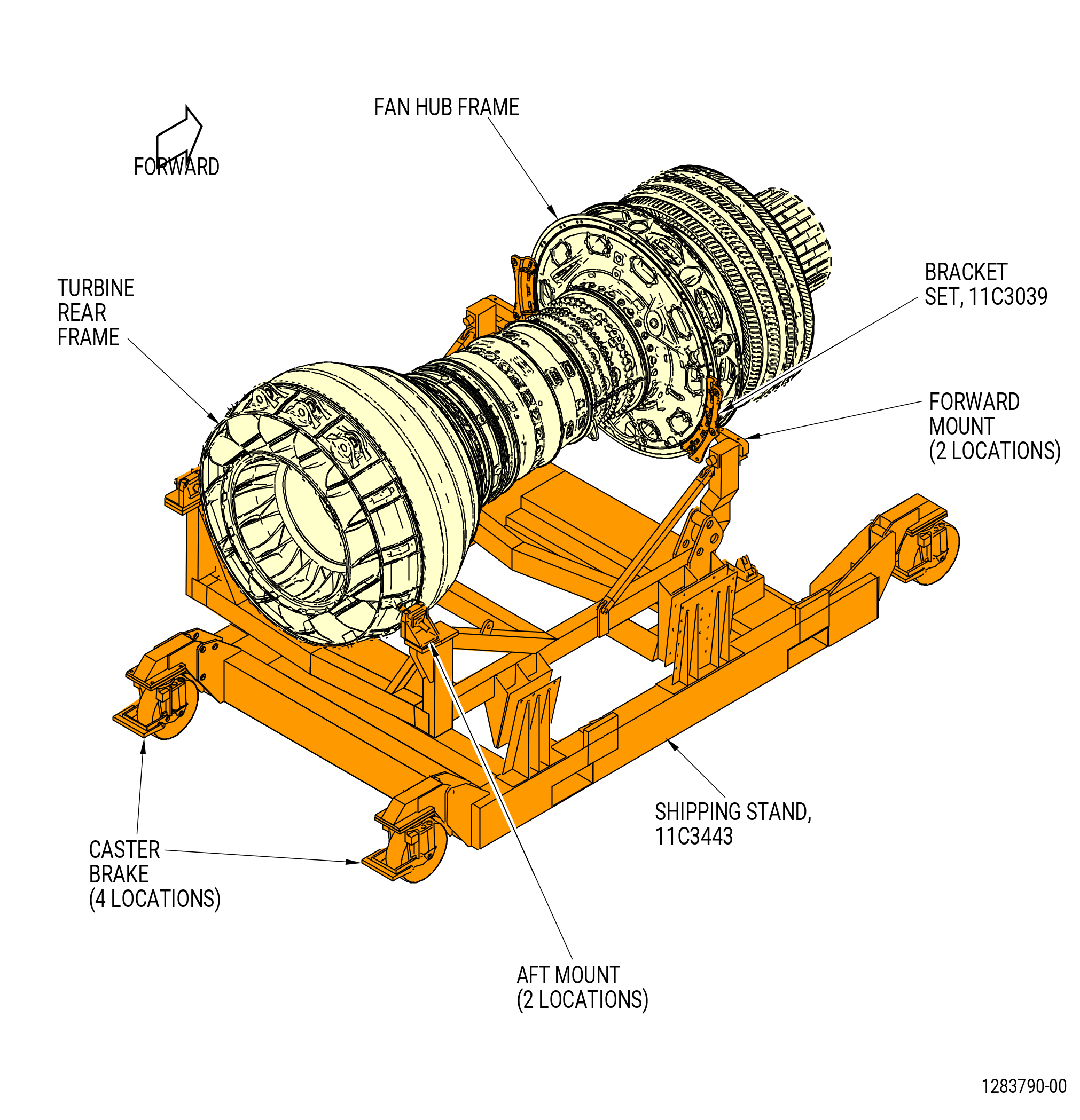
| A. | This procedure gives instructions to assemble the GEnx™ series engine propulsor assembly. This procedure includes the installation of the propulsor assembly in the 11C3443 shipping stand and the installation of the variable frequency starter generators (VFSG) (C00A0) and the quick attach/detach (QAD) rings on the accessory gearbox (AGB). |
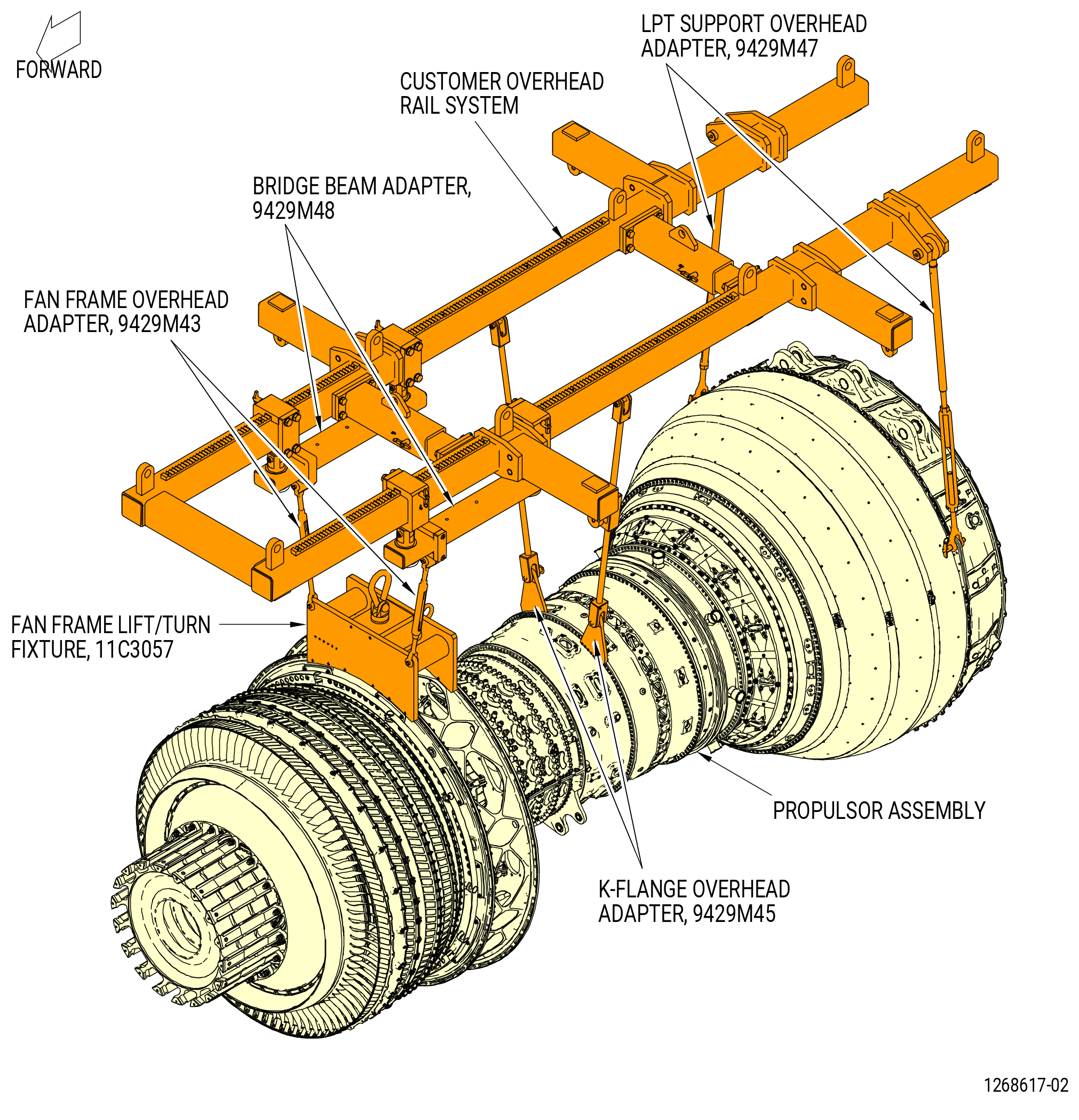
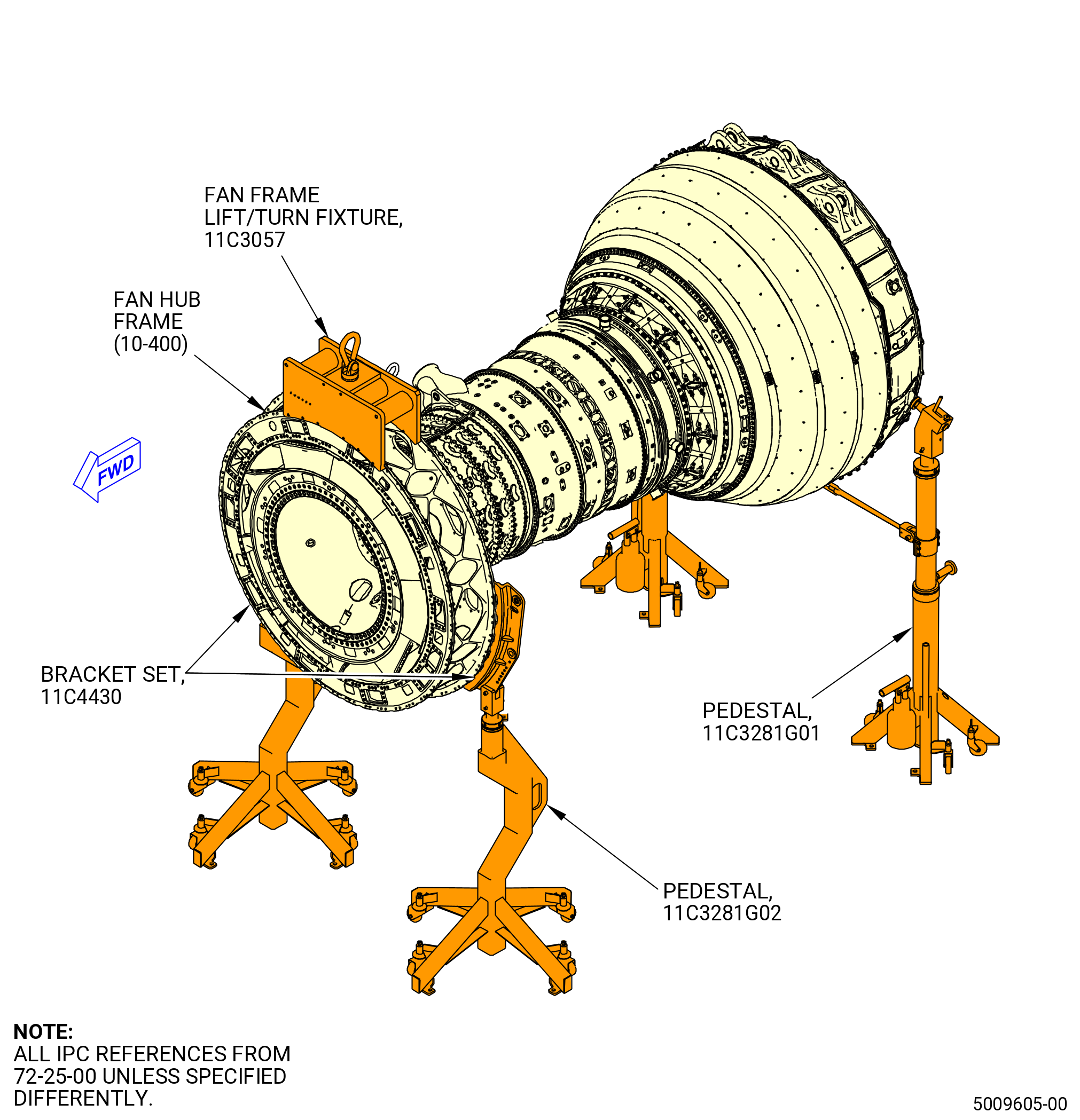
| B. | This procedure starts with the propulsor assembly in the horizontal position installed in either the 11C3044 adapter assembly, attached to the customer overhead rail system, or supported by the 11C3281 pedestals, at the equivalent assembly status of TASK 72-00-02-430-816 (72-00-02, ASSEMBLY 005 CONFIG 01) or TASK 72-00-02-430-819 (72-00-02, ASSEMBLY 005 CONFIG 02) . Refer to Figure 1001. |
| NOTE: |
|
| C. | This procedure will remove the propulsor assembly from the 11C3044 adapter assembly and install it in the 11C3443 shipping stand. |
| D. | Apply lubricant to the threads and friction surfaces only. |
| E. | All clock positions are aft looking forward (ALF), unless differently specified. |
| F. | Before you do this procedure, read the assembly and disassembly techniques section. Refer to TASK 70-10-00-800-009 (ASSEMBLY AND DISASSEMBLY TECHNIQUES) . |
| G. | Make sure that the assembly has the correct support at all times to prevent injury to personnel or damage to engine parts. |
| H. | Make sure that personnel read this procedure and know the step-by-step instructions and special tool usage before they disassemble the engine propulsor. |
| I. | Install protective covers/plugs on electrical connectors to prevent damage and contamination. |
| J. | Make sure that you obey all site safety and environmental controls or personal injury can occur. |
| K. | Follow the instructions to safety parts with a safety wire, safety cable, cotter pins, or tab washers. Refer to TASK 70-11-00-400-001 (FASTENER RETENTION PROCEDURES) . |
| 2 . | Tools, Equipment, and Materials. |
| NOTE: |
|
| L. | Tools and Equipment. |
| (1) | Special Tools. |
| (2) | Standard Tools and Equipment. |
|
| (3) | Locally Manufactured Tools. None. |
| M. | Consumable Materials. |
|
| N. | Referenced Procedures. Refer to Engine Manual GEK 112851 unless instructed differently. |
|
| O. | Expendable Parts. |
|
| 3 . | Procedure. |
| Subtask 72-00-02-430-770 |
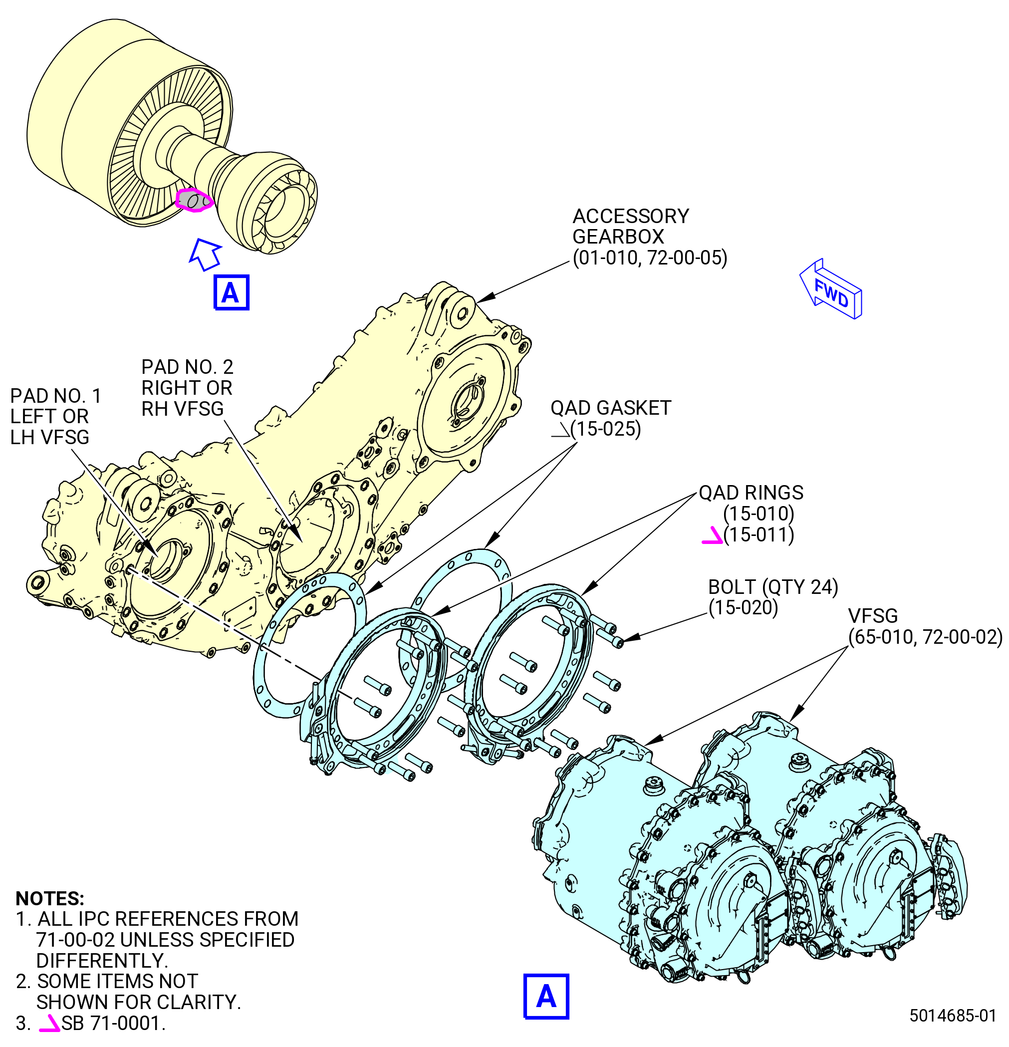
| A. | Install the plate and bracket assembly (QAD rings) (15-010 , 71-00-02) (SIN C00V0) or (15-011 , 71-00-02) (SIN C00V0) to the AGB (03800) as follows. Refer to Figure 1003. |
| WARNING: |
|
| WARNING: |
|
| (1) | Clean the mating faces of the No. 1 and No. 2 pads on the AGB (03800) as follows: |
| (a) | Use C04-035 isopropyl alcohol, C04-002 Stoddard solvent, or a 50-50 blend of C04-035 isopropyl alcohol and C04-014 denatured alcohol to clean the No. 1 and No. 2 mount pads on the AGB. |
| (b) | Do a visual inspection of the No. 1 and No. 2 mount pads on the AGB. Make sure there is no unwanted material, grease, or raised metal. |
| (2) | Install the QAD rings (15-010 , 71-00-02) (SIN C00V0) or (15-011 , 71-00-02) (SIN C00V0) as follows. Refer to Figure 1003. |
| NOTE: |
|
| (a) | Record the serial number of the QAD rings by position number. |
| NOTE: |
|
| (b) | Lubricate the threads of 24 socket-head bolts (C00F0) with C02-071 lubricant. |
| (c) | Make sure that the QAD gasket (15-025 , 71-00-02) (SIN C00V7) is in position on the forward face of the QAD rings (15-010 , 71-00-02) (SIN C00V0) or (15-011 , 71-00-02) (SIN C00V0). |
| WARNING: |
|
| (d) | If necessary, to attach a new gasket, clean the surface of the QAD ring with C04-035 isopropyl alcohol, C04-002 Stoddard solvent, or a 50-50 blend of C04-035 isopropyl alcohol and C04-014 denatured alcohol. Carefully remove the backing from the new gasket and set the gasket on the pilot lip of the QAD ring, and at the same time align the holes in the gasket with the holes in the QAD ring. Then push the gasket tightly into place on the surface of the QAD ring. |
| NOTE: |
|
| (e) | Put and align the QAD rings on pads No. 1 and No. 2 of AGB. Refer to Figure 1004. |
| NOTE: |
|
| (f) | Attach the QAD rings to the AGB with 24 bolts (C00F0). |
| (g) | Torque the 24 bolts (C00F0) to 50-54 lb ft (68.0-73.0 N.m) in a criss-cross pattern. |
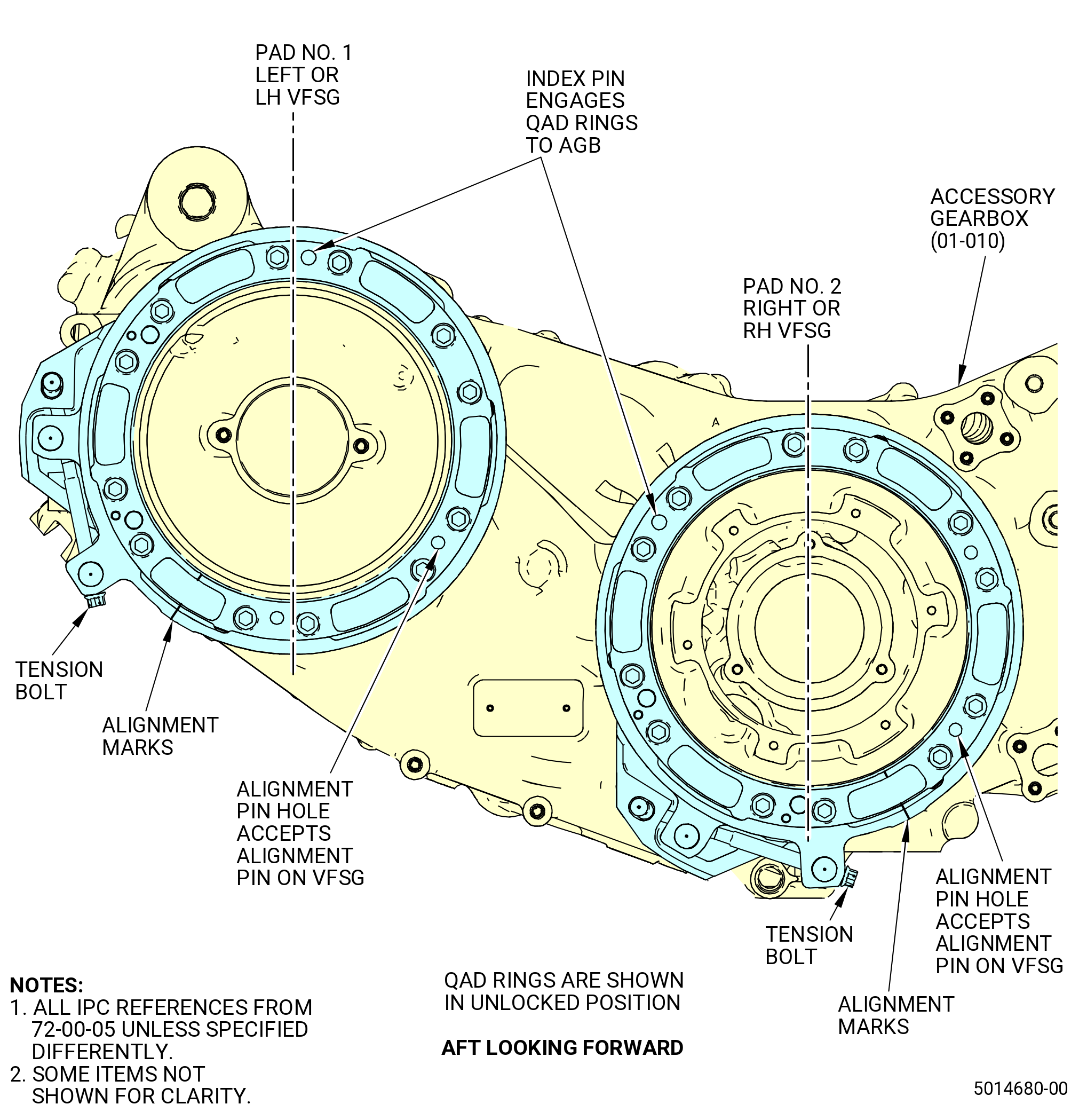
| (h) | Push the tension bolts to turn the QAD rings clockwise (CW) or counter clockwise (CCW) to line up the alignment marks. |
| NOTE: |
|
| Subtask 72-00-02-430-751 |
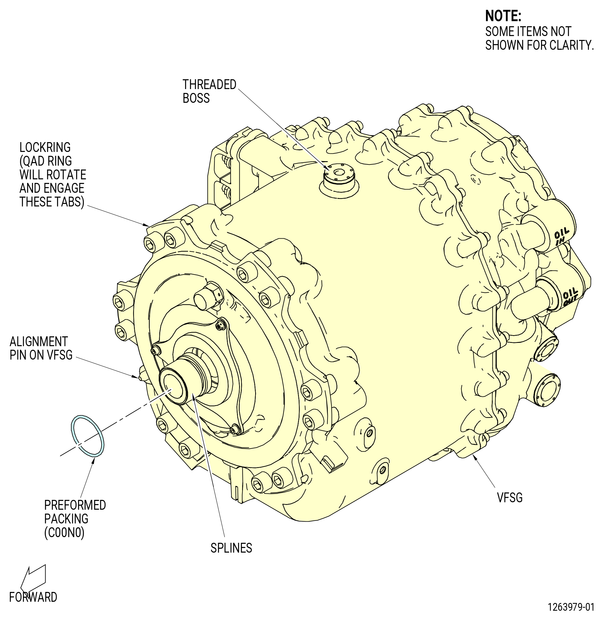
| B. | Prepare the VFSGs (C00A0) for installation as follows. Refer to Figure 1005. |
| NOTE: |
|
| CAUTION: |
|
| (1) | Record the serial numbers of the VFSG by position number. |
| NOTE: |
|
| WARNING: |
|
| (2) | Lubricate the two preformed packings (01-010 , 71-00-02) (SIN C00N0), the splines of the VFSGs, and the splines and lead-in chamfers on the AGB with C02-019 engine oil or C02-023 engine oil. |
| NOTE: |
|
| (3) | If not installed by the vendor, install the preformed packings into the packing groove on the splined shaft of each VFSG. |
| Subtask 72-00-02-430-753 |
| C. | Alternative Procedure Available. Install the VFSG (65-010) (C00A0) to the AGB (01-010 , 72-00-05) (03800) as follows: |
| NOTE: |
|
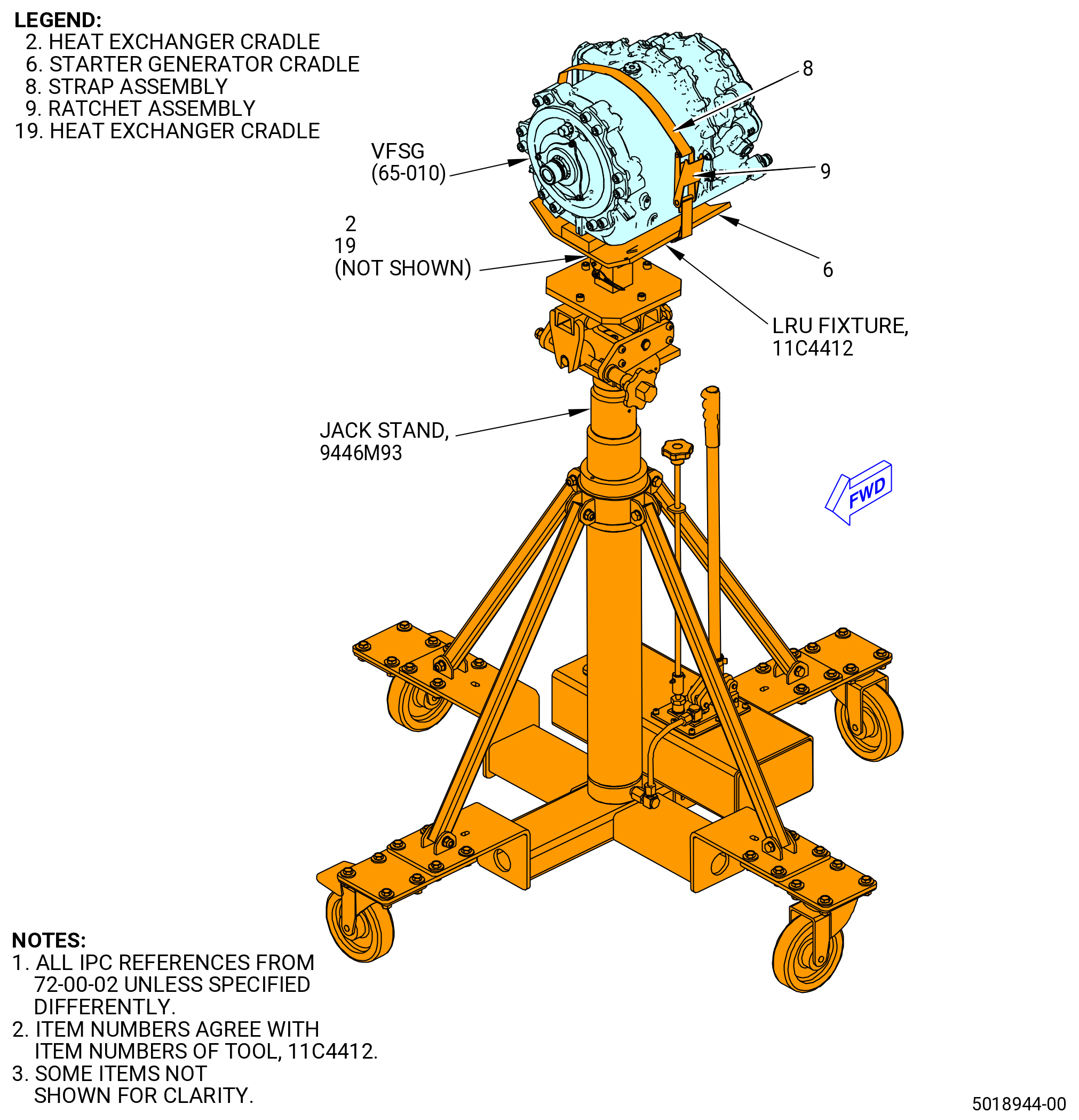
| (1) | Install the VFSG on the 11C4412 LRU fixture as follows. Refer to Figure 1006. |
| (a) | If it was not assembled before, install the starter generator cradle (item 6) of the 11C4412 LRU fixture on the 9446M93 jack stand and attach it with the adjustment screw. |
| (b) | Tighten the adjustment screw hand-tight. |
| WARNING: |
|
| (c) | Use a lift eye threaded into the boss on top of VFSG, and a lift strap to lift the VFSG on the cradle. Secure the VFSG with the strap assembly (item 8). |
| (d) | Remove the lift strap and lift eye. |
| (2) | Put the 11C4412 LRU fixture and VFSG under the engine and behind AGB pad No. 2 (LOWER PAD). |
| (3) | Make sure that the alignment marks stay aligned on the QAD ring. If not, turn the tension bolt on the QAD rings (15-010 , 71-00-02) (SIN C00V0) or (15-011 , 71-00-02) (SIN C00V0) CW or CCW as necessary to align the alignment marks. |
| (4) | Adjust the 9446M93 jack stand as necessary to align the VFSG with the AGB. |
| (5) | Slowly push the 11C4412 LRU fixture forward and carefully align the splines of the VFSG and the AGB. |
| (6) | Engage the lockring on the forward face of the VFSG with the cutouts in the QAD ring. Make sure that the alignment pin on the forward face of the VFSG is seated in the alignment pin hole on the QAD ring. |
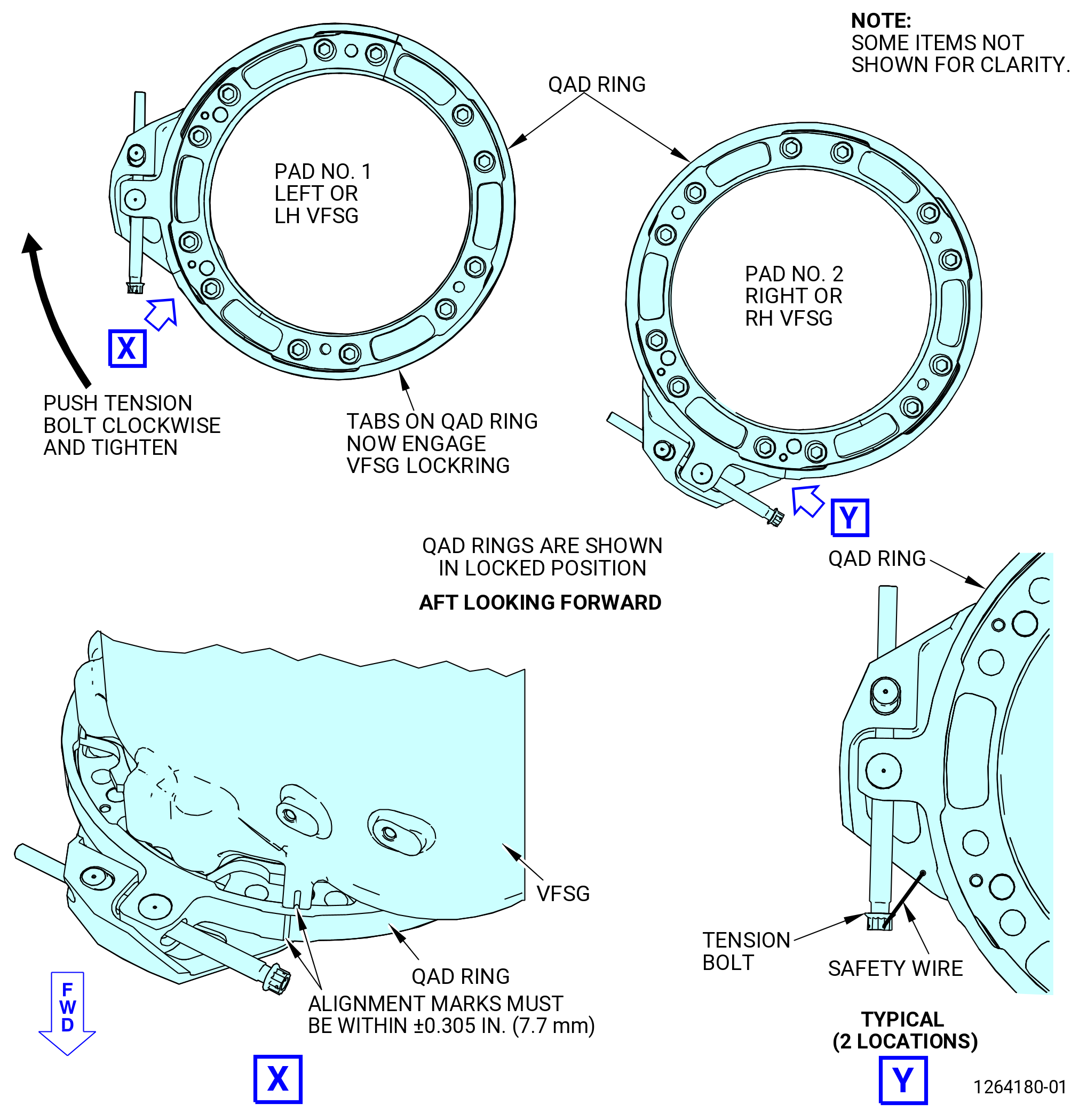
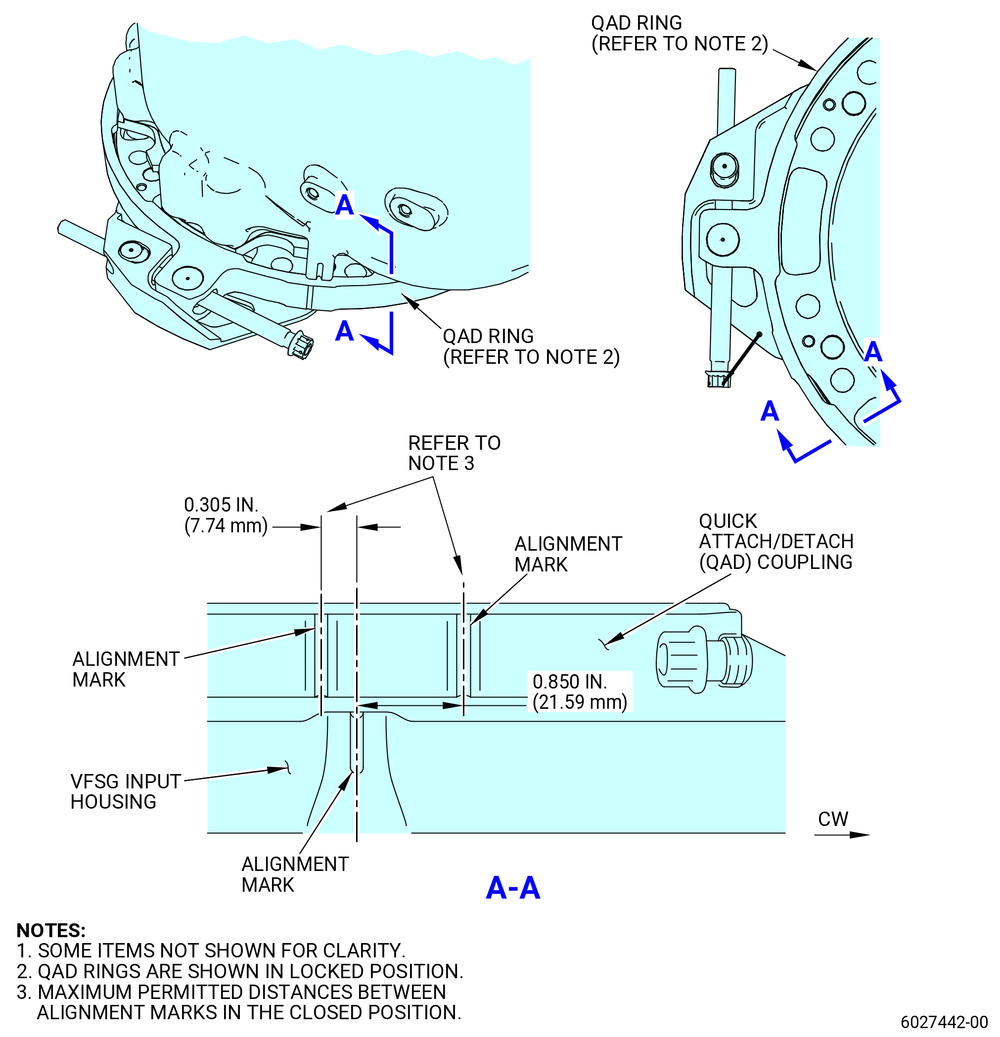
| (7) | Make sure that the VFSG (C00A0) is fully seated against the AGB flange and the lockring is fully engaged with the QAD rings (15-010 , 71-00-02) (SIN C00V0) or (15-011 , 71-00-02) (SIN C00V0). Push the tension bolt to turn the QAD ring to the LOCKED position. Refer to Figure 1008. |
| (8) | Torque the tension bolt on the QAD ring as follows: |
| (a) | Torque the tension bolt to 360 lb in. (40.7 N.m). |
| (b) | Use a brass drift and a rubber mallet to lightly tap around the QAD ring outer diameter to evenly seat the flanges. |
| NOTE: |
|
| (c) | Re-torque the tension bolt to 360 lb in. (40.7 N.m). |
| (d) | Do steps (b) and (c) again until you can apply a torque value of 360 lb in. (40.7 Nm) without movement of the tension bolt. Torque applied must not be more than 384 lb in. (43.4 Nm). |
| (e) | Deleted. |
| (9) | Make sure that the VFSG (C00A0) is correctly engaged into the QAD ring as follows: |
| (a) | Do a visual inspection of the alignment marks on the VFSG and the QAD ring. Alignment marks must be 0.305 inch (7.74 mm) or less in the counterclockwise direction, and 0.850 inch (21.59 mm) or less in the clockwise direction. Refer to Figure 1008. |
| (b) | Do a visual inspection for complete coverage of the VFSG lockring tabs with the tabs on the QAD ring. Refer to Figure 1008. |
| NOTE: |
|
| (10) | Loosen and remove the assembly strap (item 8) of the 11C4412 LRU fixture and lower the 9446M93 jack stand. |
| (11) | Safety the tension bolt to the QAD ring with C10-071 safety wire. |
| (12) | Repeat Subtask 72-00-02-430-753 (paragraph 3.C.(1)) thru (paragraph 3.C.(10)) to install the LH VFSG at the AGB pad No. 1. |
| Subtask 72-00-02-431-030 |
| C.A. | Alternative Procedure. Install the VFSG (65-010) (SIN C00A0) to the AGB (01-010 , 72-00-05) (SIN 03800) as follows: |
| NOTE: |
|
| (1) | Install the VFSG on the 11C4412 LRU fixture as follows. Refer to Figure 1007. |
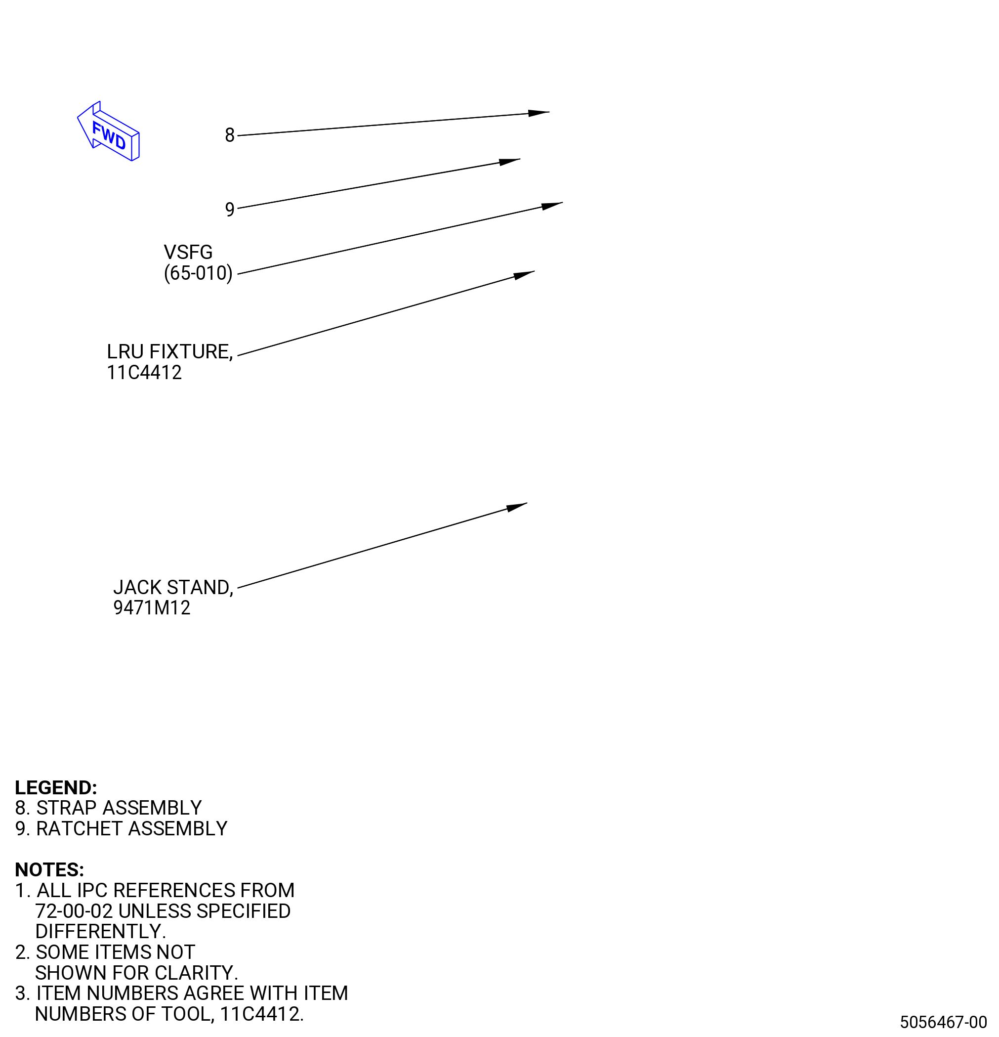
| (a) | If it was not assembled before, install the starter generator cradle (item 6) of the 11C4412 LRU fixture on the 9471M12 jack stand and attach it with the adjustment screw. |
| (b) | Tighten the adjustment screw hand-tight. |
| WARNING: |
|
| (c) | Use a lift eye threaded into the boss on the top of the VFSG, and a lift strap to lift the VFSG on the cradle. Secure the VFSG with the strap assembly (item 8). |
| (d) | Remove the lift strap and the lift eye. |
| (2) | Put the 11C4412 LRU fixture and VFSG under the engine and behind AGB pad No. 2 (LOWER PAD). |
| (3) | Make sure that the alignment marks stay aligned on the QAD ring. If not, turn the tension bolt on the QAD rings (15-010 , 71-00-02) (SIN C00V0) or (15-011 , 71-00-02) (SIN C00V0) CW or CWW as necessary to align the alignment. |
| (4) | Adjust the 9471M12 jack stand as necessary to align the VFSG with the AGB. |
| (5) | Slowly push the 11C4412 LRU fixture forward and carefully align the splines. |
| (6) | Engage the lockring on the forward face of the VFSG with the cutouts in the QAD ring. Make sure that the alignment pin on the forward face of the VFSG is seated in the alignment pin hole on the QAD ring. |
| (7) | Make sure that the VFSG is fully seated against the AGB flange and the lockring is fully engaged with the QAD rings (15-010 , 71-00-02) (SIN C00V0) or (15-011 , 71-00-02) (SIN C00V0). Push the tension bolt to turn the QAD ring to the LOCKED position. Refer to Figure 1008. |
| (8) | Torque the tension bolt on the QAD ring as follows: |
| (a) | Torque the tension bolt to 360 lb in. (40.7 Nm). |
| (b) | Use a brass drift and a rubber mallet to lightly tap around the QAD ring outer diameter to evenly seat the flanges. |
| NOTE: |
|
| (c) | Re-torque the tension bolt to 360 lb in. (40.7 Nm). |
| (d) | Do steps (b) and (c) again until you can apply a torque value of 360 lb in. (40.7 Nm) without movement of the tension bolt. Torque applied must not be more than 384 lb in. (43.4 Nm). |
| (e) | Deleted. |
| Subtask 72-00-02-220-108 |
| (9) | Make sure that the VFSG is correctly engaged into the QAD ring as follows: |
| (a) | Do a visual inspection of the alignment marks on the VFSG and the QAD ring. Alignment marks must be 0.305 inch (7.74 mm) or less in the counterclockwise direction, and 0.850 inch (21.59 mm) or less in the clockwise direction. Refer to Figure 1008. |
| (b) | Do a visual inspection for complete coverage of the VFSG lockring tabs with the tabs on the QAD ring. Refer to Figure 1008. |
| NOTE: |
|
| Subtask 72-00-02-431-031 |
| (10) | Loosen and remove the strap assembly (item 8) of the 11C4412 LRU fixture and lower the 9471M12 jack stand. |
| (11) | Safety the tension bolt to the QAD ring with C10-071 safety wire. |
| (12) | Repeat Subtask 72-00-02-431-030 (paragraph 3.C.A.(1)) thru Subtask 72-00-02-431-031 (paragraph 3.C.A.(10)) to install the LH VFSG at the AGB pad No. 1. |
| Subtask 72-00-02-430-755 |
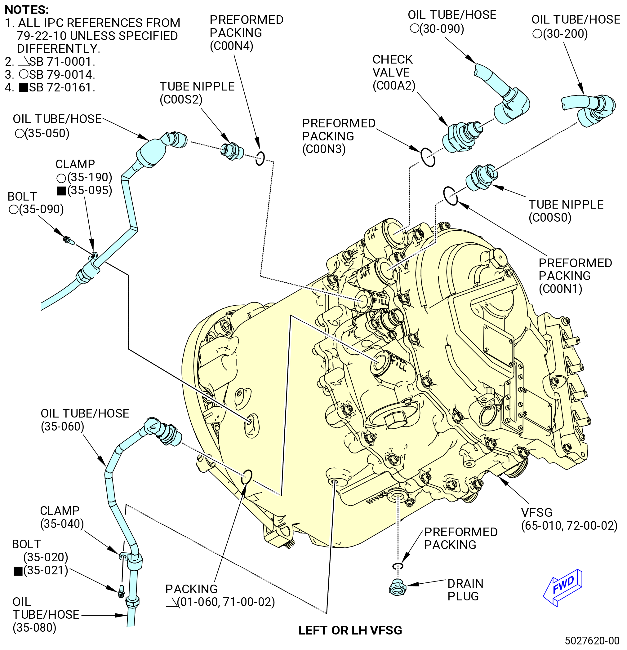
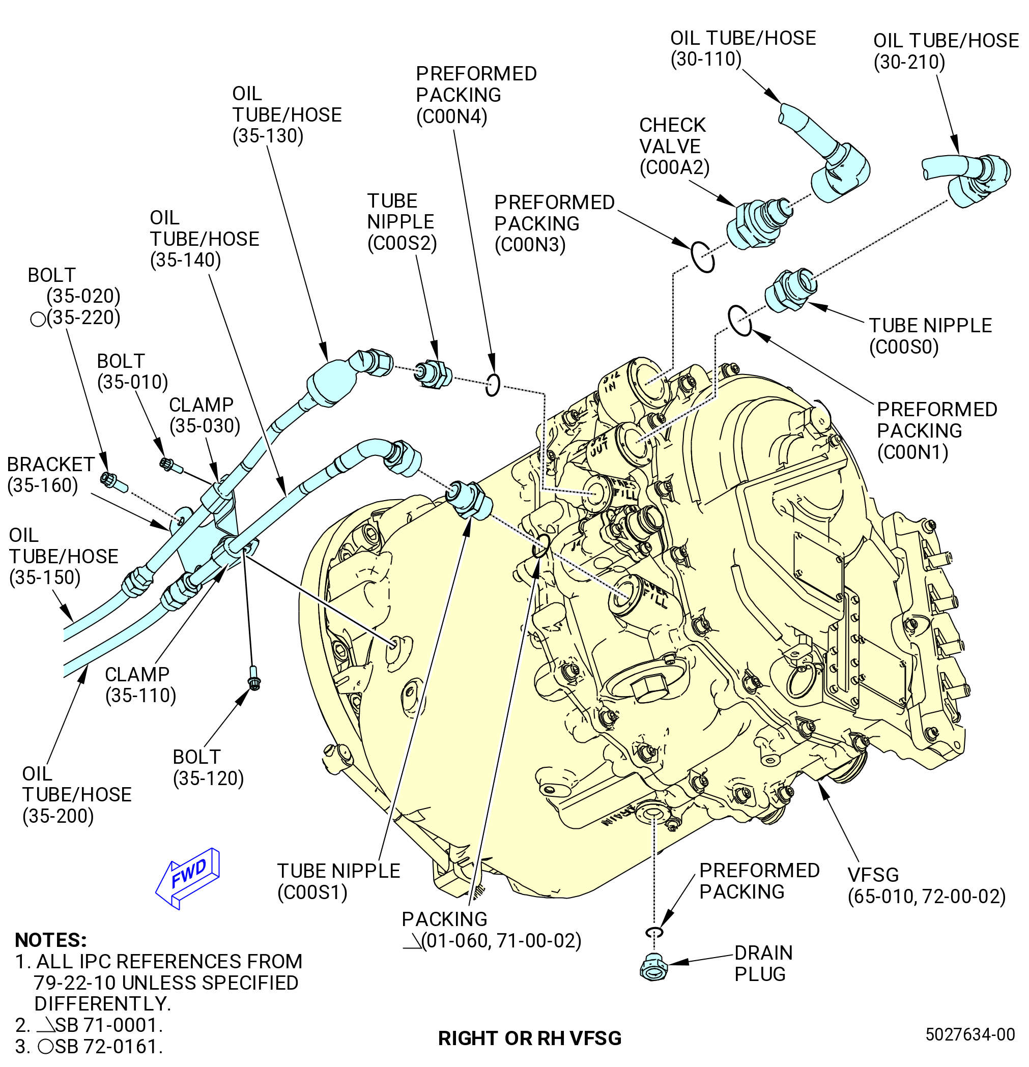
| D. | Install the fittings and connect the oil tube/hoses to the VFSGs (C00A0) as follows. Refer to Figure 1009. |
| NOTE: |
|
| (1) | If necessary, remove all protective caps and covers from the VFSG. |
| WARNING: |
|
| (2) | Lubricate two preformed packings (C00N3) with C02-019 engine oil or C02-023 engine oil and install them on the check valves (C00A2). |
| CAUTION: |
|
| (3) | Install the check valves into the OIL-IN port on the VFSG. Torque the check valves to 175-205 lb in. (19.8-23.2 N.m). |
| WARNING: |
|
| (4) | Lubricate two preformed packings (C00N1) with C02-019 engine oil or C02-023 engine oil and install them on the tube nipples (C00S0). |
| (5) | Install the tube nipples (C00S0) into the OIL-OUT port on the VFSG. Torque the tube nipples to 143-167 lb in. (16.2-18.9 N.m). |
| WARNING: |
|
| (6) | Lubricate two preformed packings (C00N4) with C02-019 engine oil or C02-023 engine oil and install on the tube nipples (C00S2). |
| (7) | Install the tube nipples (C00S2) into the PRESS-FILL port on both VFSG (C00A0). Torque the tube nipples to 87-103 lb in. (9.8-11.6 N.m). |
| WARNING: |
|
| (8) | Lubricate the packing (01-060 , 71-00-02) (SIN C00N2) with C02-019 engine oil or C02-023 engine oil and install it on the tube nipple (SIN C00S1). |
| (9) | Install the tube nipple (SIN C00S1) into the OVER-FILL port on the RH VFSG. Torque the tube nipple to 106-124 lb in. (12.0-14.0 N.m). |
| (10) | Install the oil tubes/hoses on the RH VSFG as follows: |
| (a) | Connect the oil tube/hose (5210U) to check valve (C00A2). Use a backup wrench and crowfoot 90 degrees to torque the B-nut to 938-1102 lb in. (106.0-124.5 N.m). |
| (b) | Connect the oil tube/hose (5210L) to the tube nipple (C00S0). Use a backup wrench and crowfoot at 90 degrees to torque the B-nut to 662-778 lb in. (74.8-87.9 N.m). |
| Subtask 72-00-02-440-519 |
| * * * FOR 1B/P/G03.1B/P/G04.1B/P1/G01 |
| * * * PRE SB 72-0161( Propulsor Module - Non PIP2 Configuration ) |
| (c) | Attach the bracket (35-160 , 79-22-10) (SIN 44B17) to the VFSG with two bolts (35-020 , 79-22-10) (SIN 44B21). Torque the bolts to 60 to 70 lb in. (6.8 to 7.9 Nm). |
| * * * END PRE SB 72-0161 |
| Subtask 72-00-02-440-520 |
| * * * FOR ALL PIP 2 |
| * * * SB 72-0161( Propulsor Module - PIP2 Configuration ) |
| (c).A. | Attach the bracket (35-160 , 79-22-10) (SIN 44B17) to the VFSG with two bolts (35-220 , 79-22-10) (SIN 44B22). Torque the bolts to 106 to 124 lb in. (12.0 to 14.0 Nm). |
| * * * END SB 72-0161 |
| Subtask 72-00-02-431-008 |
| * * * FOR ALL |
| (d) | Connect the oil tube/hose (44A04) to the tube nipple (C00S2) at the PRES-FILL port. |
| (e) | Connect the oil tube/hose (44A06) to the oil tube/hose (44A04). |
| (f) | Attach the oil tube/hose (44A04) to the bracket (44B17) with a clamp (44A80) and a bolt (44A20). Torque the bolt to 60-70 lb in. (6.8-7.9 N.m). |
| (g) | Use a backup wrench and crowfoot at 90 degrees to torque the B-nut on the oil tube/hose (44A04) at the PRES-FILL port to 262-308 lb in. (29.6-34.8 N.m). |
| (h) | Use a backup wrench and crowfoot at 90 degrees to torque the B-nut on oil tube/hose (44A06) at the oil tube/hose (44A04) to 262-308 lb in. (29.6-34.8 N.m). |
| (i) | Connect the oil tube/hose (44B04) to the tube nipple (C00S1) at the OVER-FILL port. |
| (j) | Connect the oil tube/hose (44B04) to the oil tube/hose (44B05). |
| (k) | Attach the oil tube/hose (44B04) to the bracket (44B17) with a clamp (44B80) and a bolt (44B20). Torque the bolt to 60-70 lb in. (6.8-7.9 N.m). |
| (l) | Use a backup wrench and crowfoot at 90 degrees to torque the B-nut on the oil tube/hose (44B04) at the OVER-FILL port to 460-540 lb in. (52.0-61.0 N.m). |
| (m) | Use a backup wrench and crowfoot at 90 degrees to torque the B-nut on oil tube/hose (44B04) at the oil tube/hose (44B05) to 262-308 lb in. (29.6-34.8 N.m). |
| (11) | Install the oil tubes/hoses on the LH VSFG as follows: |
| (a) | Connect the oil tube/hose (30-090 , 79-22-10) (SIN 5210J) to the check valve (SIN C00A2). Use a backup wrench and crowfoot at 90 degrees to torque the B-nut to 938-1102 lb in. (106.0-124.5 N.m). |
| (b) | Connect the oil tube/hose (30-200 , 79-22-10) (SIN 5210A) to the tube nipple (SIN C00S0). Use a backup wrench and crowfoot at 90 degrees to torque the B-nut to 662-778 lb in. (74.8-87.9 N.m). |
| Subtask 72-00-02-430-971 |
| * * * PRE SB 79-0014( Non-Optimized VFSG Cooling System ) |
| (c) | Attach the bracket (35-100 , 79-22-10) (SIN 44A10) to the VFSG with two bolts (35-090 , 79-22-10) (SIN 44A23). Torque the bolts to 106-124 lb in. (12.0-14.0 N.m). |
| NOTE: |
|
| * * * END PRE SB 79-0014 |
| Subtask 72-00-02-430-972 |
| (d) | Connect the oil tube/hose (35-050 , 79-22-10) (SIN 44A03) to the tube nipple (C00S2) at the PRES-FILL port. |
| (e) | Deleted. |
| (f) | Connect the oil tube/hose (35-050 , 79-22-10) (SIN 44A03) to the oil tube/hose (35-070 , 79-22-10) (SIN 44A05). |
| Subtask 72-00-02-430-973 |
| * * * PRE SB 79-0014( Non-Optimized VFSG Cooling System ) |
| (g) | Attach the oil tube/hose (35-050 , 79-22-10) (SIN 44A03) to the bracket (35-100 , 79-22-10) (SIN 44A10) with a clamp (35-030 , 79-22-10) (SIN 44A80) and a bolt (35-010 , 79-22-10) (SIN 44A20). Torque the bolt to 60-70 lb in. (6.8-7.9 N.m). |
| * * * END PRE SB 79-0014 |
| Subtask 72-00-02-430-974 |
| * * * SB 79-0014( Optimized VFSG Cooling System ) |
| (g).A. | Attach the oil tube/hose (35-050 , 79-22-10) (SIN 44A03) to the VFSG with a clamp (35-190 , 79-22-10) (SIN 44A81) or (35-095 , 79-22-10) (SIN 44A85) and a bolt (35-090 , 79-22-10) (SIN 44A23). Torque the bolt to 60 to 70 lb in. (6.8 to 7.9 Nm). |
| * * * END SB 79-0014 |
| Subtask 72-00-02-430-975 |
| (h) | Use a backup wrench and crowfoot at 90 degrees to torque the B-nut on the oil tube/hose (35-050 , 79-22-10) (SIN 44A03) at the PRES-FILL port to 262-308 lb in. (29.6-34.8 N.m). |
| (i) | Use a backup wrench and crowfoot at 90 degrees to torque the B-nut on the oil tube/hose (35-050 , 79-22-10) (SIN 44A03) at the oil tube/hose (35-070 , 79-22-10) (SIN 44A05) to 262-308 lb in. (29.6-34.8 N.m). |
| WARNING: |
|
| (j) | Lubricate the packing (01-060 , 71-00-02) (SIN C00N2) with C02-019 engine oil or C02-023 engine oil and install on the end of the oil tube/hose (35-060 , 79-22-10) (SIN 44B03). |
| (k) | Install the oil tube/hose (35-060 , 79-22-10) (SIN 44B03) on the OVER-FILL port on the LH VFSG. |
| NOTE: |
|
| (l) | Connect the oil tube/hose (44B06) to the oil tube/hose (44B03). |
| (m) | Attach the oil tube/hose (35-060 , 79-22-10) (SIN 44B03) to the VFSG housing with a clamp (35-040 , 79-22-10) (SIN 44B81) and a bolt (35-020 , 79-22-10) (SIN 44B21) or (35-021 , 79-22-10) (SIN 44B21). Torque the bolt to 60 to 70 lb in. (6.8 to 7.9 Nm). |
| (n) | Use a backup wrench and a crowfoot at 90 degrees to torque the B-nut on the oil tube/hose (44B03) at the OVER-FILL port to 460-540 lb in. (52.0-61.0 N.m). |
| (o) | Use a backup wrench and crowfoot at 90 degrees to torque the B-nut on the oil tube/hose (44B03) at the oil tube/hose (44B06) to 262-308 lb in. (29.6-34.8 N.m). |
| Subtask 72-00-02-430-976 |
| (12) | Make sure that drain plugs are installed in the bottom of the VFSGs. Refer to Figure 1009. |
| NOTE: |
|
| WARNING: |
|
| (a) | If necessary, lubricate a preformed packing with C02-019 engine oil or C02-023 engine oil and install it on the drain plug. |
| (b) | Connect the drain plug into the opening with the mark DRAIN on the bottom of the VFSG. |
|
|
| Subtask 72-00-02-430-764 |
| E. | Install the W30 and the W31 harnesses as follows: |
| Subtask 72-00-02-431-032 |
| * * * PRE SB 73-0060( Old Design for W30 and W31 Harnesses ) |
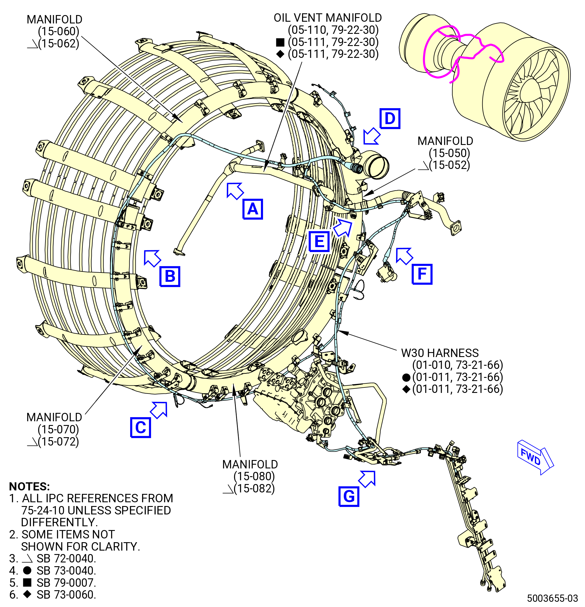
| (1) | Install the W30 harness (01-010 , 73-21-66) (SIN 68800) or (01-011 , 73-21-66) (SIN 68800). Refer to Figure 1010 and do as follows: |
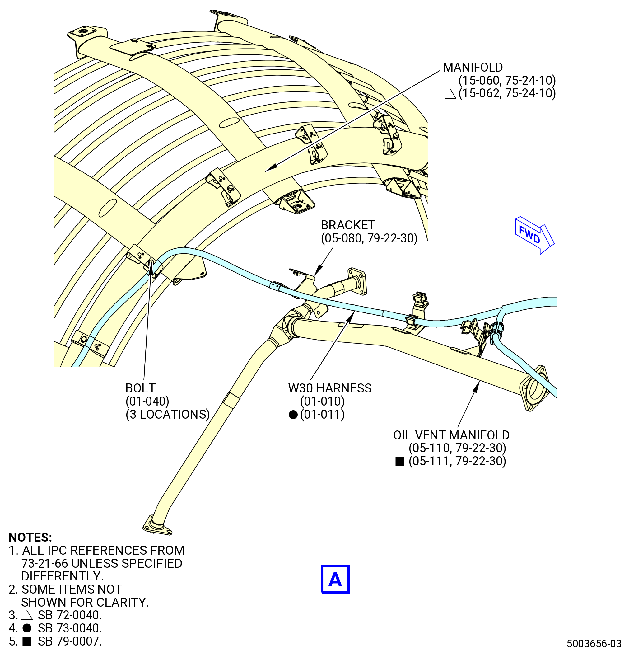
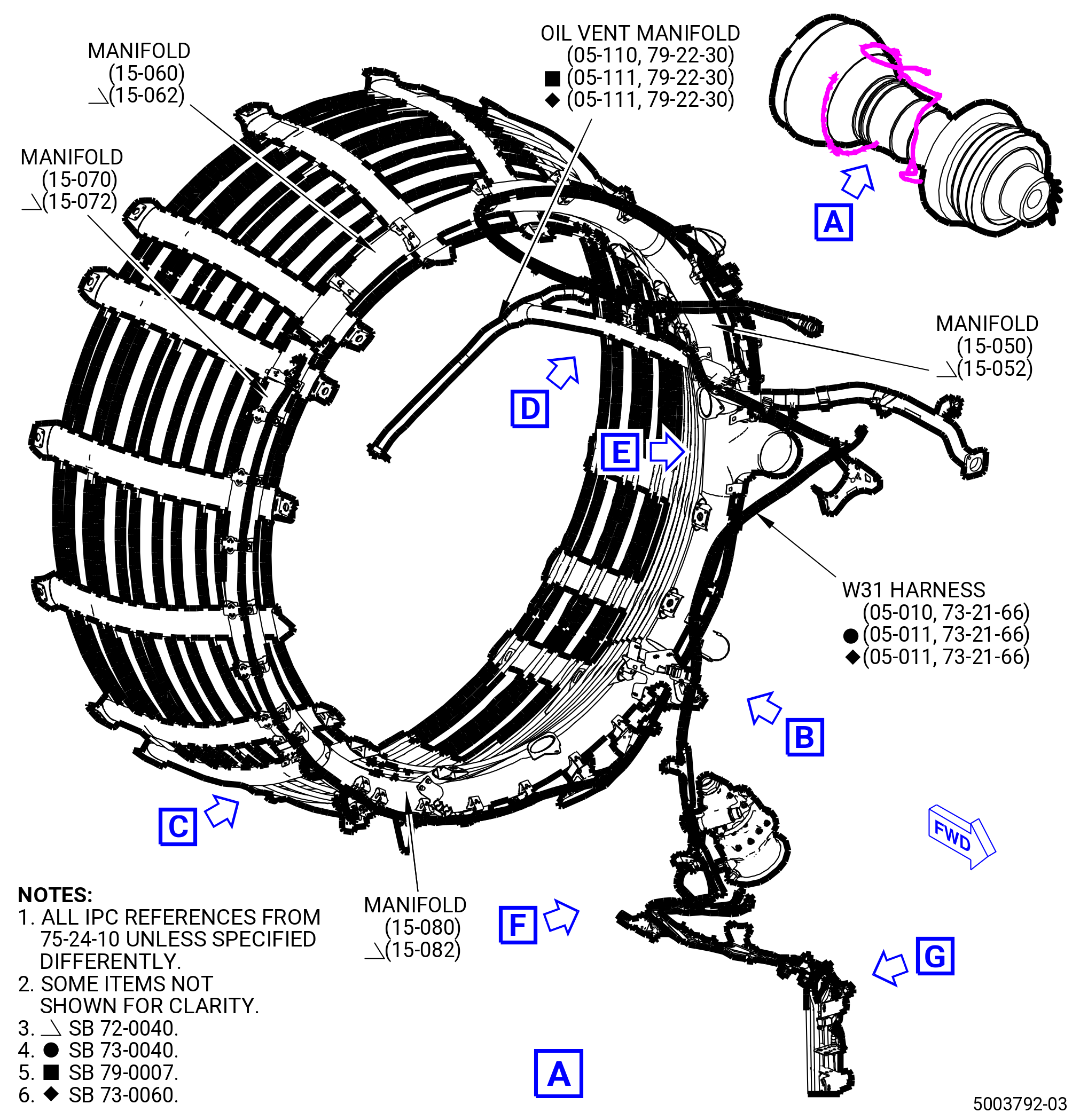
| (a) | Put the W30 harness (01-010 , 73-21-66) (SIN 68800) or (01-011 , 73-21-66) (SIN 68800) in position along the LPT active clearance control (ACC) air manifold (manifold) (15-060 , 75-24-10) (SIN 6220A) or (15-062 , 75-24-10) (SIN 6220A). |
| (b) | Attach the W30 harness (01-010 , 73-21-66) (SIN 68800) or (01-011 , 73-21-66) (SIN 68800) to the bracket (05-080 , 79-22-30) (SIN 6881D) with one bolt (01-040 , 73-21-66) (SIN 68823). Hand tighten the bolt. |
| (c) | Attach the W30 harness (01-010 , 73-21-66) (SIN 68800) or (01-011 , 73-21-66) (SIN 68800) to the manifold (15-060 , 75-24-10) (SIN 6220A) or (15-062 , 75-24-10) (SIN 6220A) with two bolts (01-040 , 73-21-66) (SIN 68823). Hand tighten the bolts. |
| Subtask 72-00-02-431-016 |
| * * * PRE SB 73-0040( W30 and W31 Harnesses without Improvements ) |
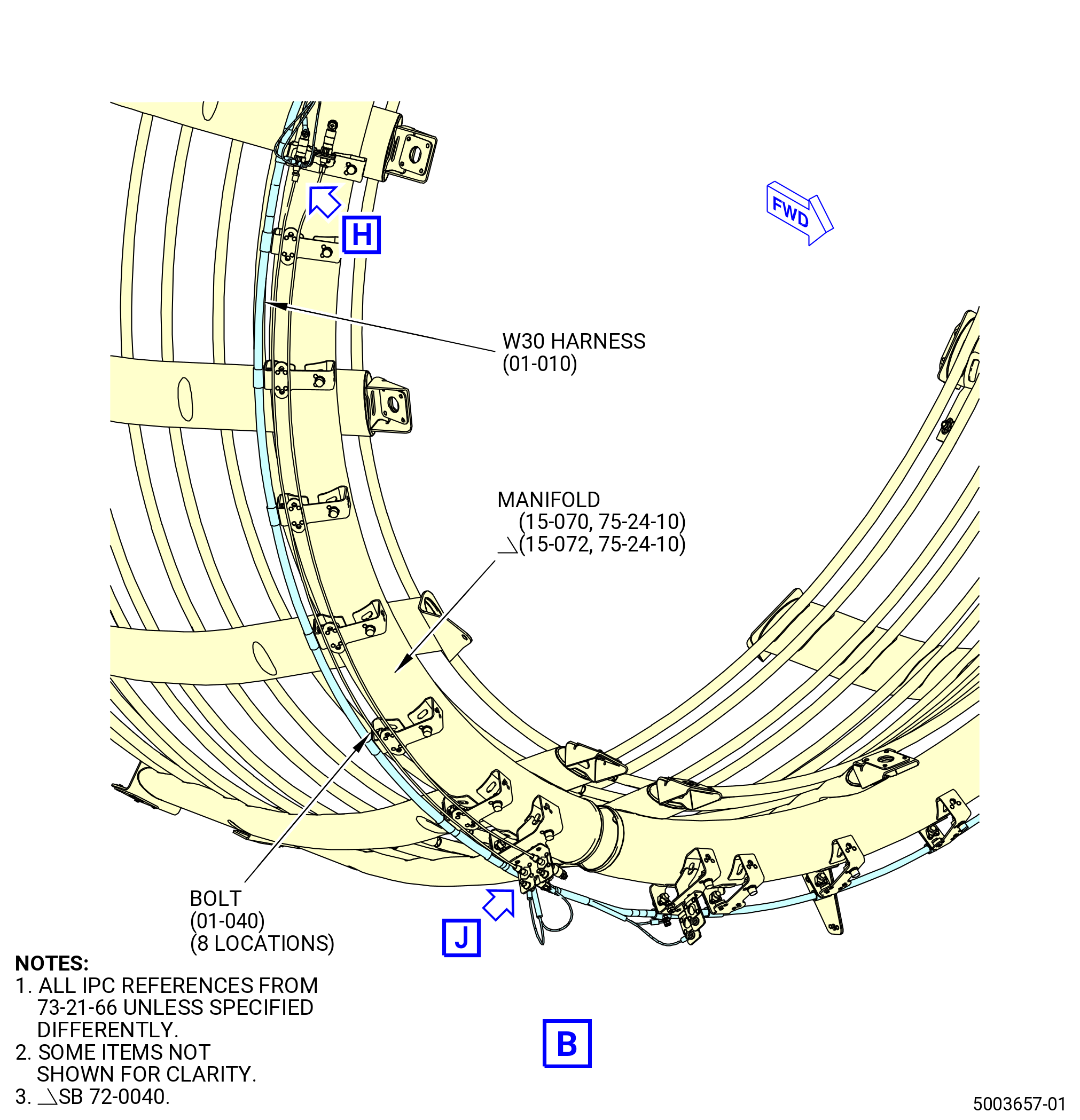
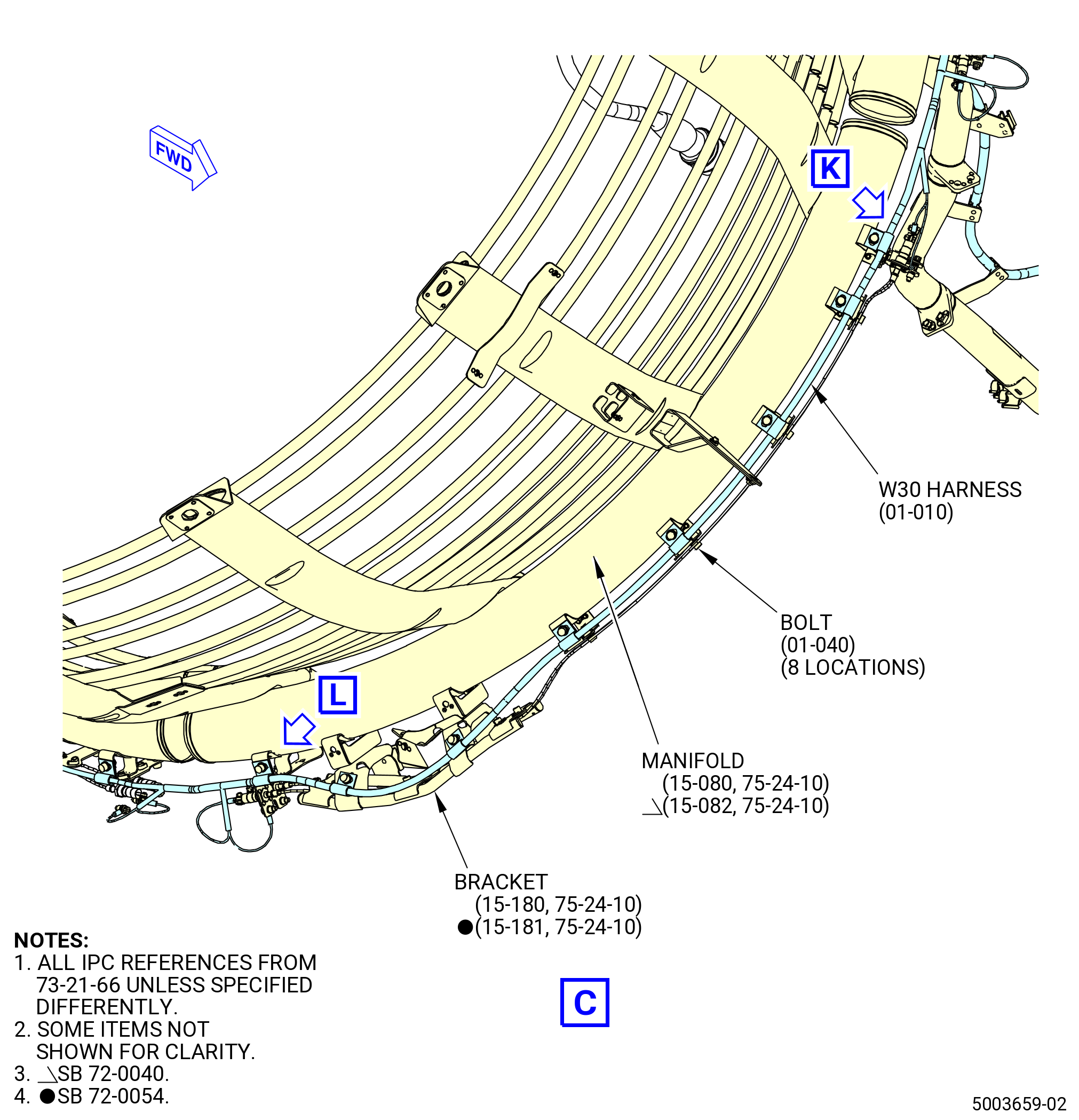
| (d) | Attach the W30 harness (01-010 , 73-21-66) (SIN 68800) to the manifold (15-070 , 75-24-10) (SIN 6220B) or (15-072 , 75-24-10) (SIN 6220B) with eight bolts (01-040 , 73-21-66) (SIN 68823). Hand tighten the bolts. |
| (e) | Attach the W30 harness (01-010 , 73-21-66) (SIN 68800) to the manifold (15-080 , 75-24-10) (SIN 6220C) or (15-082 , 75-24-10) (SIN 6220C) and bracket (15-180 , 75-24-10) (SIN 9801F) or (15-181 , 75-24-10) (SIN 9801F) with eight bolts (01-040 , 73-21-66) (SIN 68823). Hand tighten the bolts. |
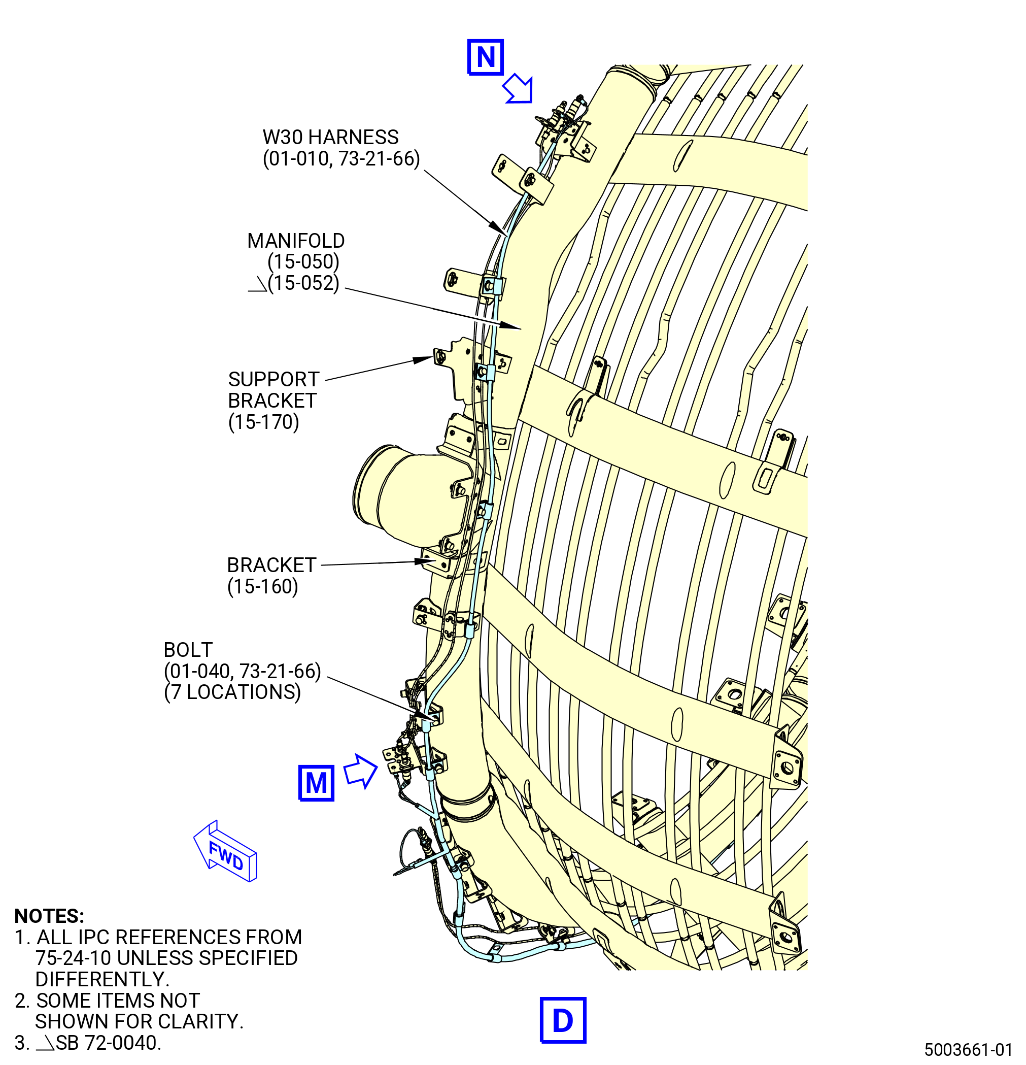
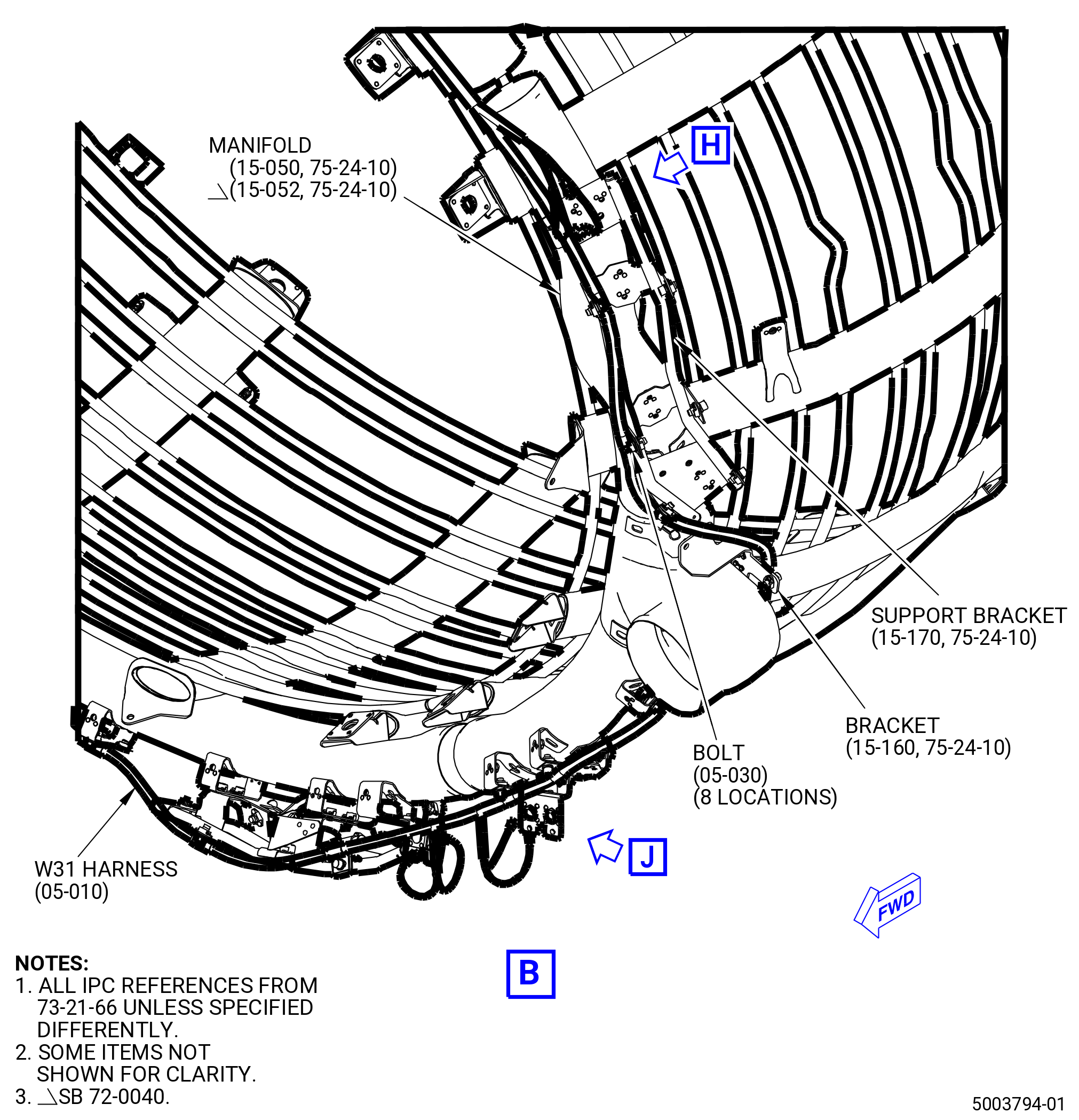
| (f) | Attach the W30 harness (01-010 , 73-21-66) (SIN 68800) to the manifold (15-050 , 75-24-10) (SIN 6220D) or (15-052 , 75-24-10) (SIN 6220D), bracket (15-160 , 75-24-10) (SIN 9801E), and support bracket (15-170 , 75-24-10) (SIN 9801D) with seven bolts (01-040 , 73-21-66) (SIN 68823). Hand tighten the bolts. |
| * * * END PRE SB 73-0040 |
| Subtask 72-00-02-431-017 |
| * * * SB 73-0040( Improved W30 and W31 Harnesses ) |
| * * * END PRE SB 73-0060 |
| * * * SB 73-0060 |
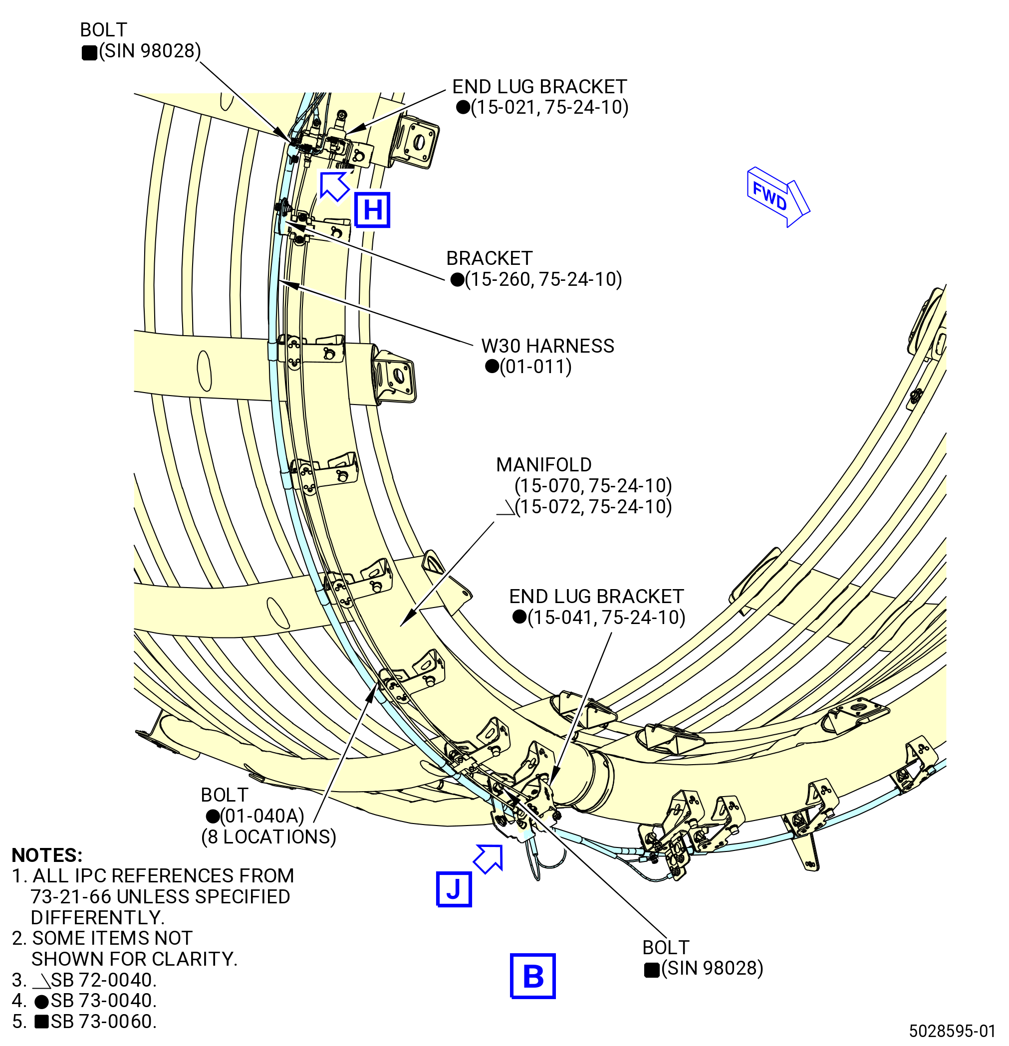
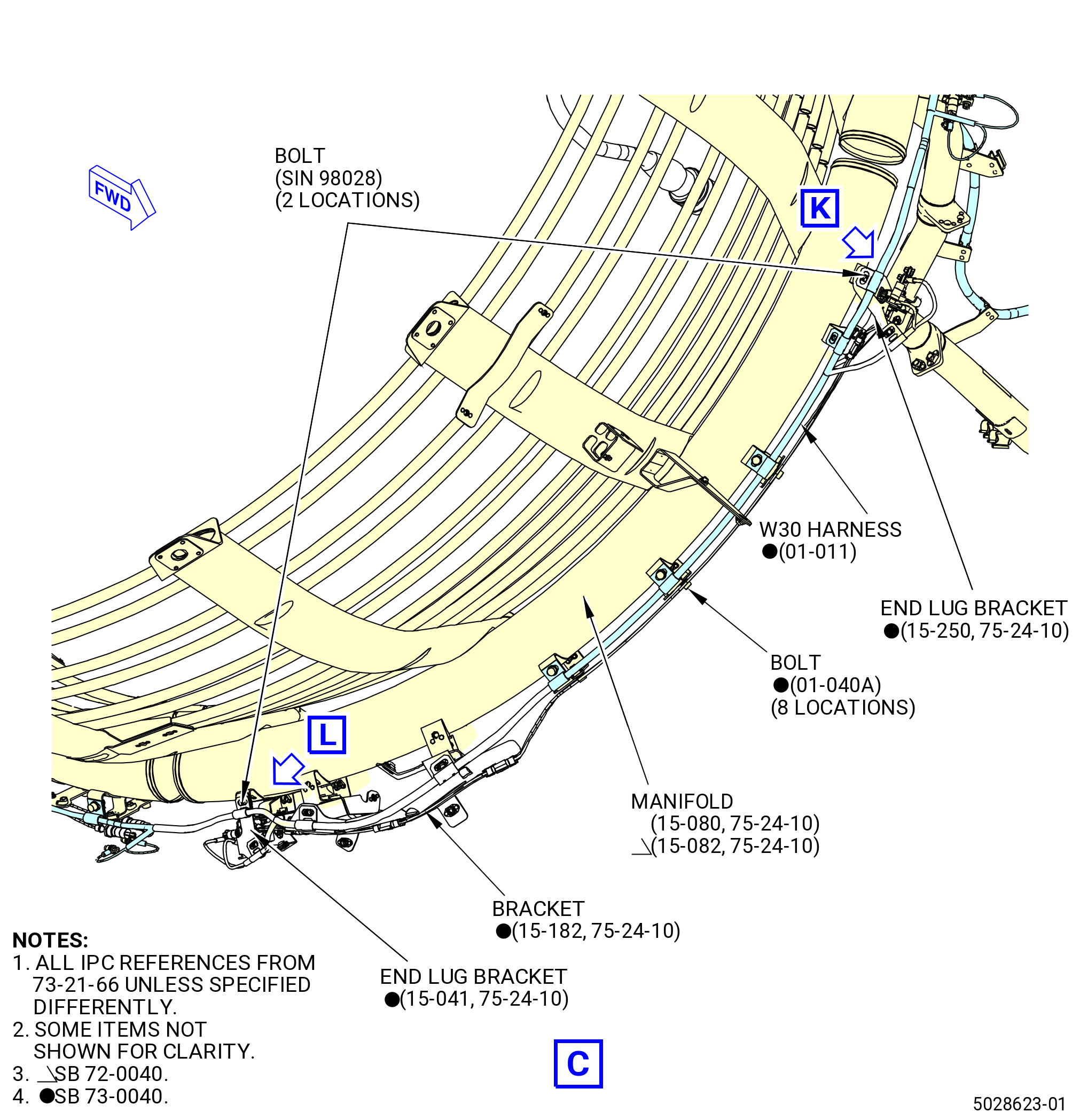
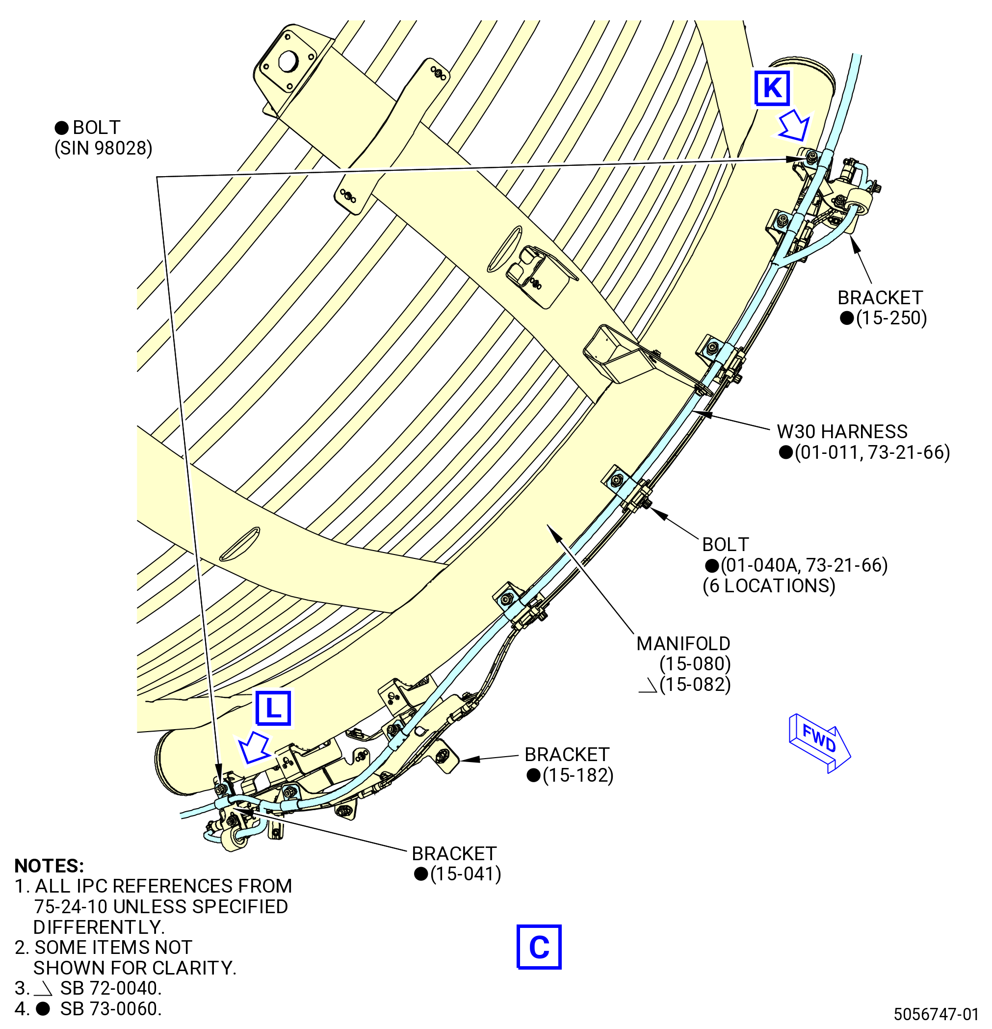
| (g) | Attach the W30 harness (01-011 , 73-21-66) (SIN 68800) to the manifold (15-070 , 75-24-10) (SIN 6220B) or (15-072 , 75-24-10) (SIN 6220B) and bracket (15-021 , 75-24-10) (SIN 9801G) with a bolt (15-155 , 72-24-10) (SIN 98028). Hand-tighten the bolt. |
| NOTE: |
|
| * * * END SB 73-0060 |
| * * * PRE SB 73-0060 |
| (h) | Attach the W30 harness (01-011 , 73-21-66) (SIN 68800) to the manifold (15-070 , 75-24-10) (SIN 6220B) or (15-072 , 75-24-10) (SIN 6220B) with six bolts (01-040A , 73-21-66) (SIN 68823). Hand tighten the bolts. |
| * * * END PRE SB 73-0060 |
| * * * SB 73-0060 |
| (i) | Attach the W30 harness (01-011 , 73-21-66) (SIN 68800) to the manifold (15-070 , 75-24-10) (SIN 6220B) or (15-072 , 75-24-10) (SIN 6220B) and bracket (15-041 , 75-24-10) (SIN 9801J) with a bolt (15-155 , 72-24-10) (SIN 98028). Hand-tighten the bolt. |
| NOTE: |
|
| * * * END SB 73-0060 |
| * * * PRE SB 73-0060 |
| (j) | Attach the W30 harness (01-011 , 73-21-66) (SIN 68800) branches to the brackets (15-260 , 75-24-10) (SIN 9801M) and (15-021 , 75-24-10) (SIN 9801G) with two bolts (01-040A , 73-21-66) (SIN 68823). Hand-tighten the bolts. |
| * * * END PRE SB 73-0060 |
| * * * SB 73-0060 |
| (k) | Attach the W30 harness (01-011 , 73-21-66) (SIN 68800) to the manifold (15-080 , 75-24-10) (SIN 6220C) or (15-082 , 75-24-10) (SIN 6220C) and bracket (15-250 , 75-24-10) (SIN 9801L) with a bolt (15-155 , 72-24-10) (SIN 98028). Hand-tighten the bolt. |
| NOTE: |
|
| * * * END SB 73-0060 |
| * * * PRE SB 73-0060 |
| (l) | Attach the W30 harness (01-011 , 73-21-66) (SIN 68800) to the manifold (15-080 , 75-24-10) (SIN 6220C) or (15-082 , 75-24-10) (SIN 6220C) and bracket (15-182 , 75-24-10) (SIN 9801F) with six bolts (01-040A , 73-21-66) (SIN 68823). Hand tighten the bolts. |
| * * * END PRE SB 73-0060 |
| * * * SB 73-0060 |
| (m) | Attach the W30 harness (01-011 , 73-21-66) (SIN 68800) to the manifold (15-080 , 75-24-10) (SIN 6220C) or (15-082 , 75-24-10) (SIN 6220C) and bracket (15-041 , 75-24-10) (SIN 9801J) with a bolt (15-155 , 72-24-10) (SIN 98028). Hand-tighten the bolt. |
| NOTE: |
|
| * * * END SB 73-0060 |
| * * * PRE SB 73-0060 |
| (n) | Attach the W30 harness (01-011 , 73-21-66) (SIN 68800) branches to the brackets (15-250 , 75-24-10) (SIN 9801L) and (15-041 , 75-24-10) (SIN 9801J) with two bolts (01-040A , 73-21-66) (SIN 68823). Hand tighten the bolt. |
| * * * END PRE SB 73-0060 |
| * * * SB 73-0060 |
| (o) | Attach the W30 harness (01-011 , 73-21-66) (SIN 68800) to the manifold (15-080 , 75-24-10) (SIN 6220C) or (15-082 , 75-24-10) (SIN 6220C) and bracket (15-041 , 75-24-10) (SIN 9801J) with a bolt (15-155 , 72-24-10) (SIN 98028). Hand-tighten the bolt. |
| NOTE: |
|
| * * * END SB 73-0060 |
| * * * PRE SB 73-0060 |
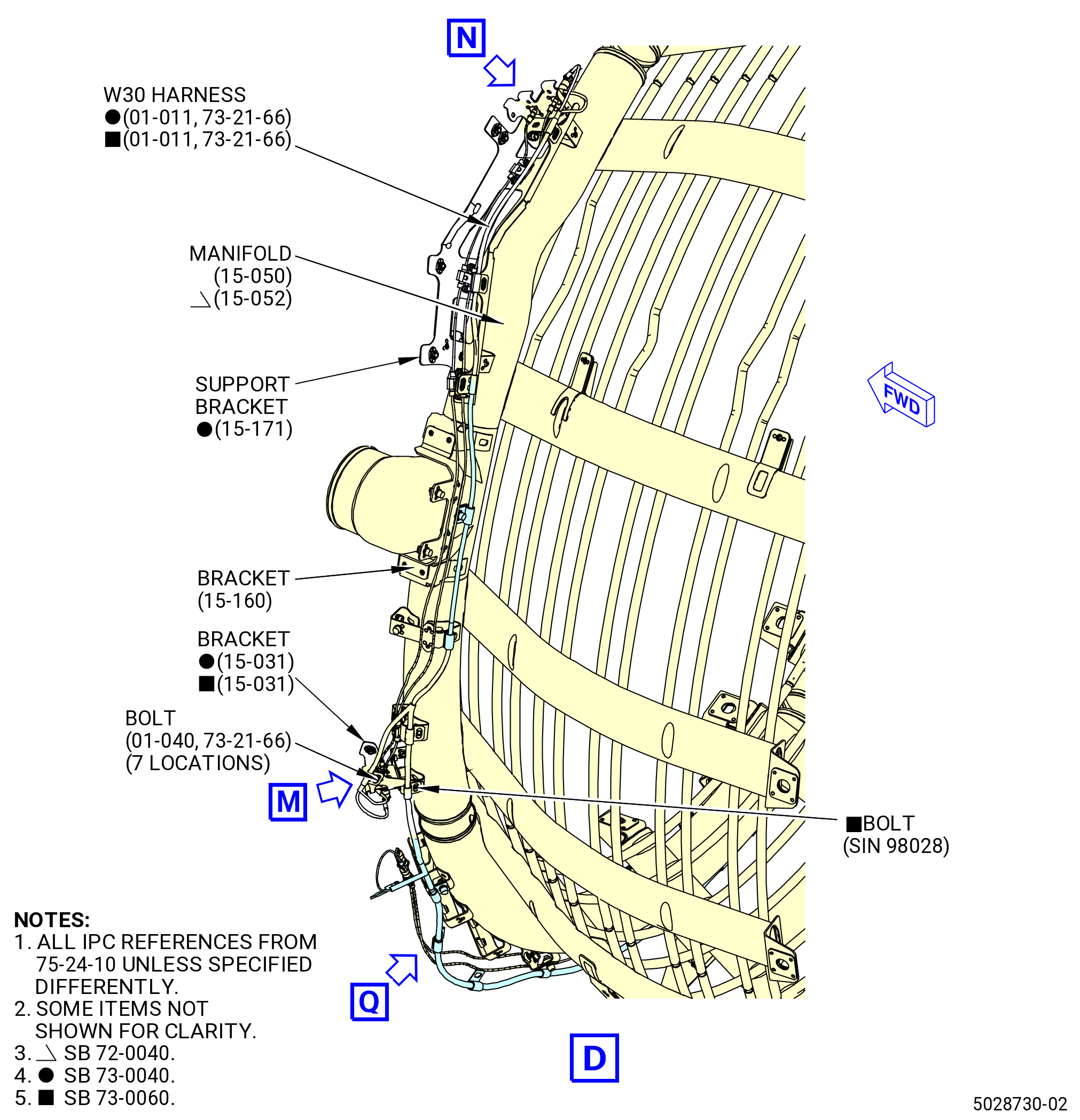
| (p) | Attach the W30 harness (01-011 , 73-21-66) (SIN 68800) to the manifold (15-050 , 75-24-10) (SIN 6220D) or (15-052 , 75-24-10) (SIN 6220D), bracket (15-160 , 75-24-10) (SIN 9801E), and support bracket (15-171 , 75-24-10) (SIN 9801D) with six bolts (01-040A , 73-21-66) (SIN 68823). Hand tighten the bolts. |
| (q) | Attach the W30 harness (01-011 , 73-21-66) (SIN 68800) branch to the bracket (15-031 , 75-24-10) (SIN 9801K) with a bolt (01-040A , 73-21-66) (SIN 68823). Hand tighten the bolt. |
| * * * END SB 73-0040 |
| Subtask 72-00-02-431-018 |
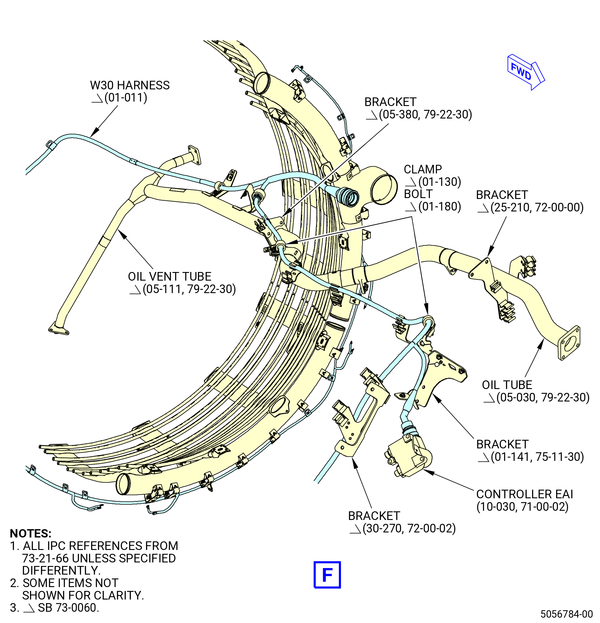
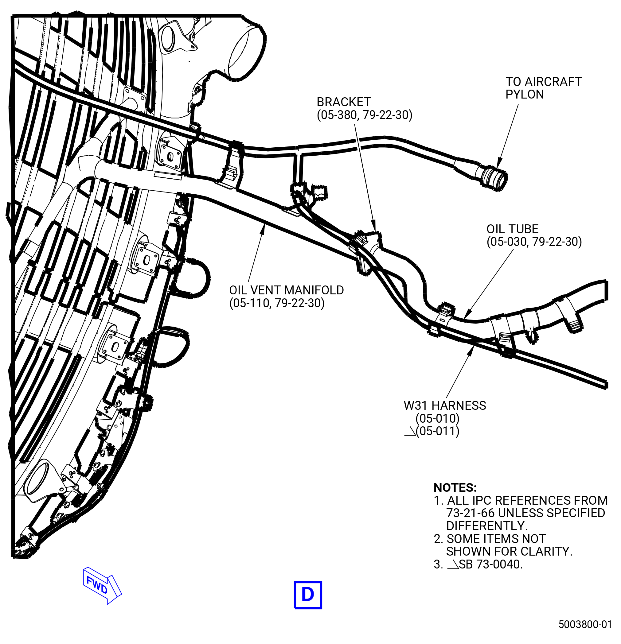
| (r) | Put the W30 harness (01-010 , 73-21-66) (SIN 68800) or (01-011 , 73-21-66) (SIN 68800) in the spring clip attached to the bracket on the oil vent manifold (05-110 , 79-22-30) (SIN 46101) or (05-111 , 79-22-30) (SIN 46101). |
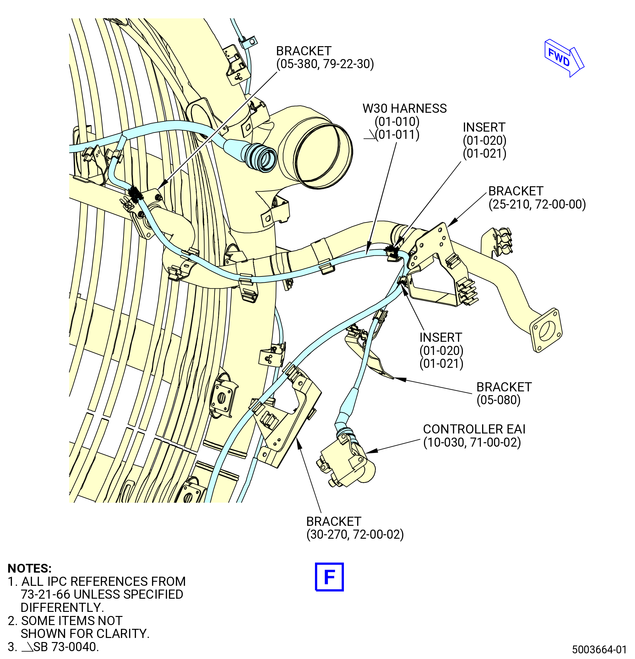
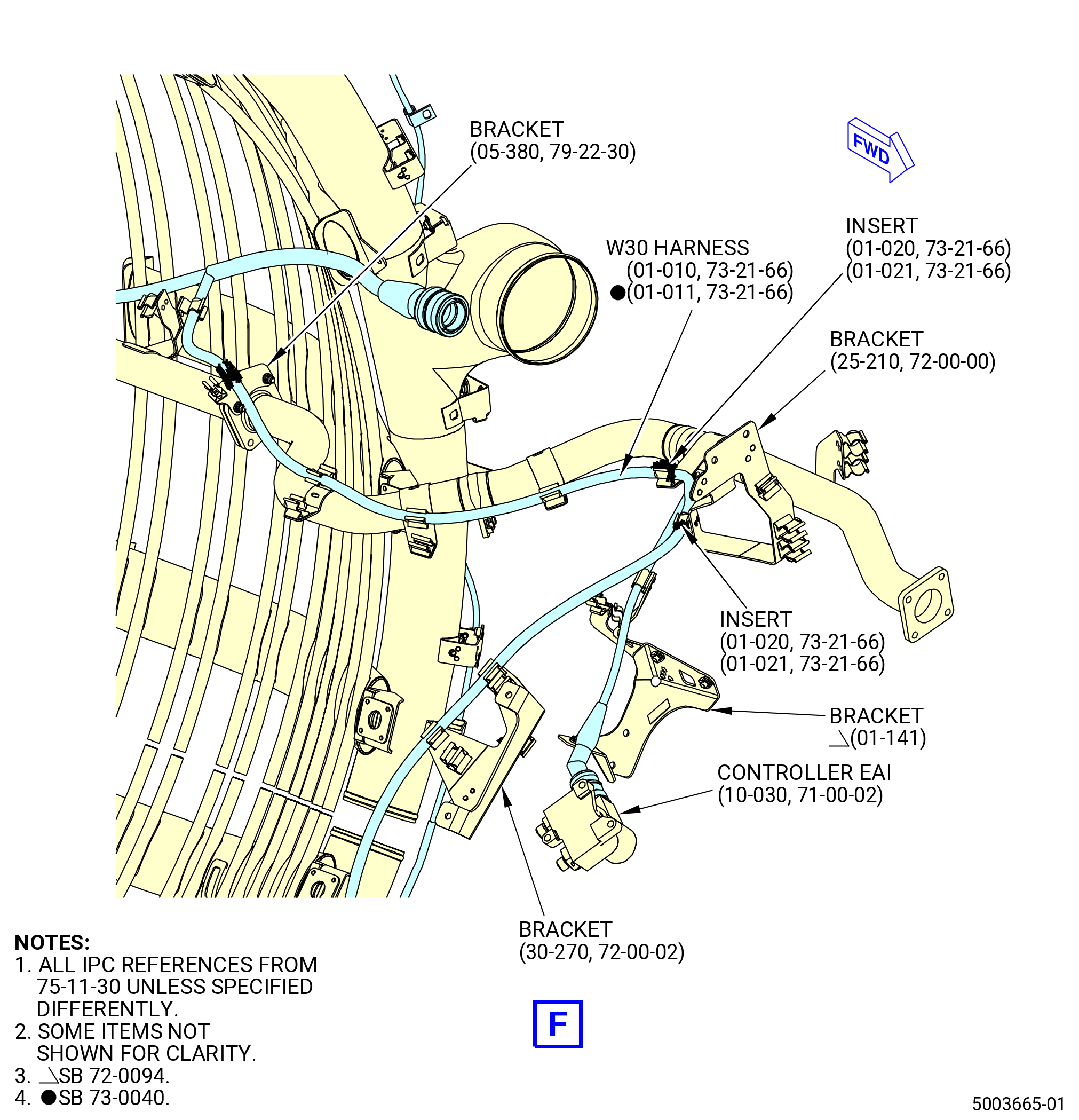
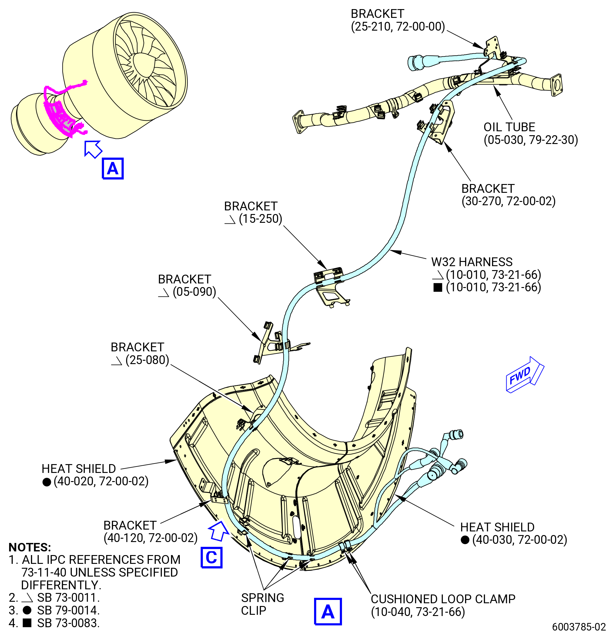
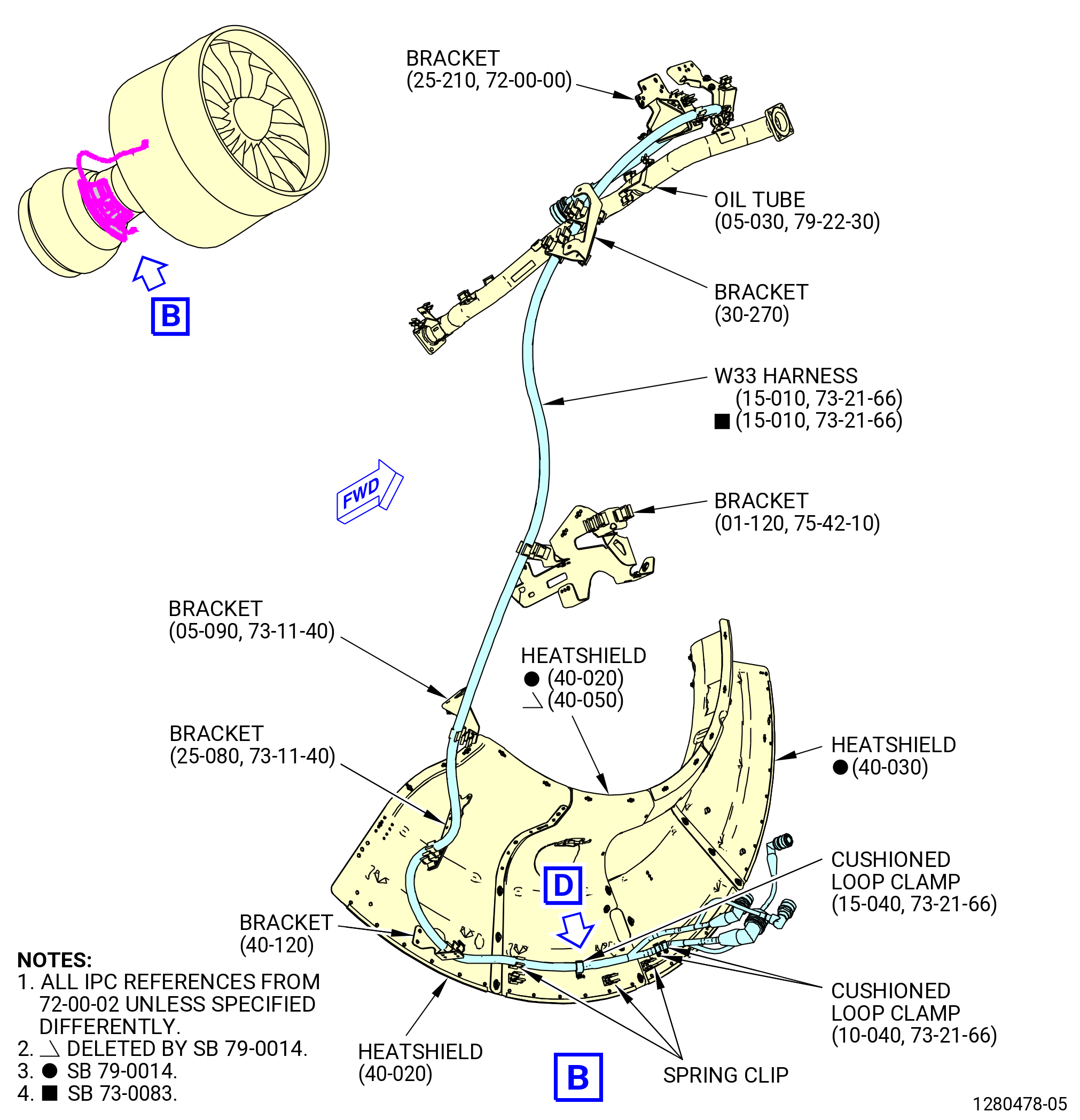
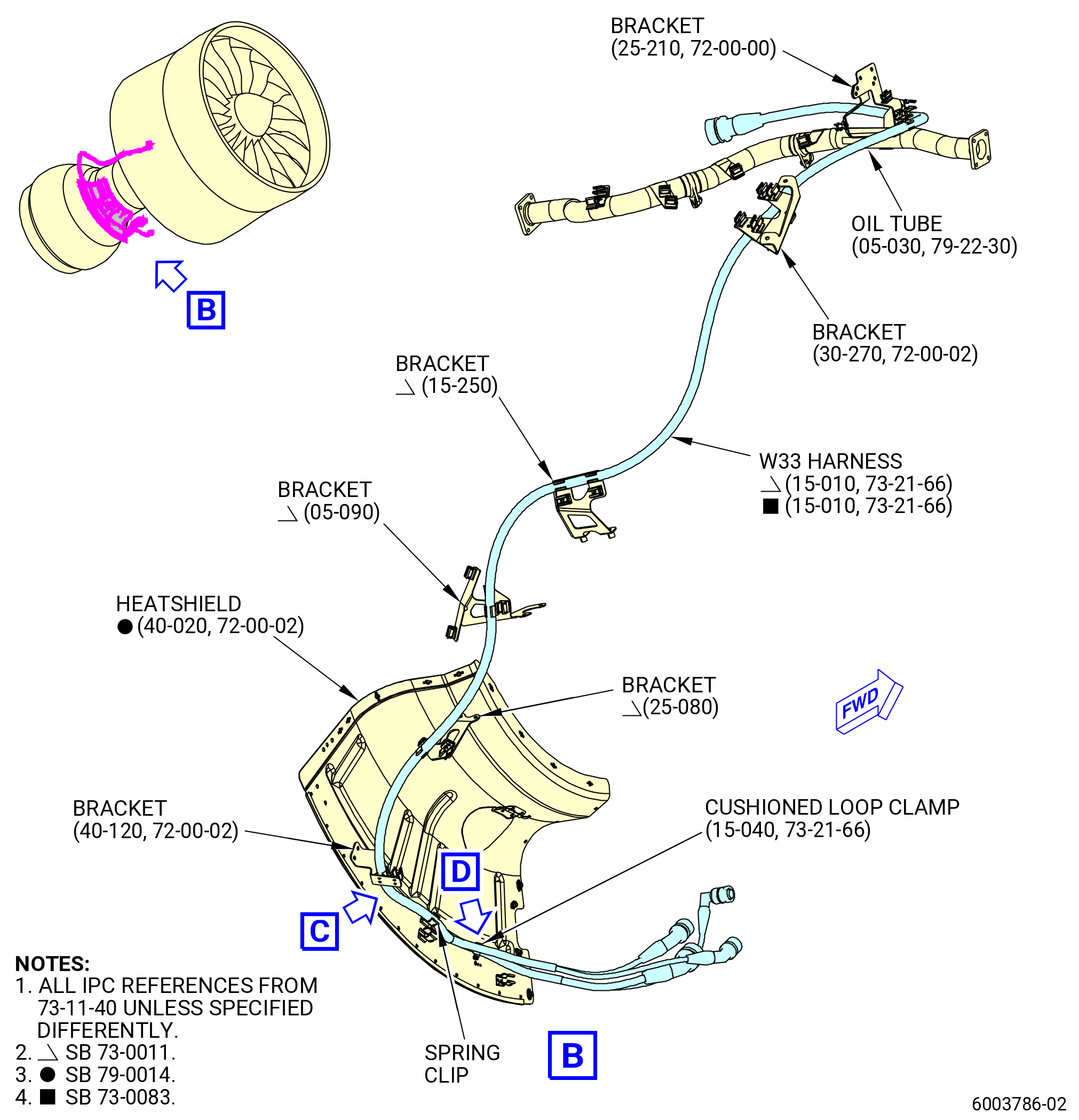
| (s) | Install two inserts (01-021 , 73-21-66) (SIN 68837) on the oil tube (05-030 , 79-22-30) (SIN 46100) spring clip forward of the bracket (05-070 , 79-22-30) (SIN 4611A) and bracket (25-210 , 72-00-00) (SIN 68812) aft spring clip. |
| (t) | Put the W30 harness (01-010 , 73-21-66) (SIN 68800) or (01-011 , 73-21-66) (SIN 68800) in the spring clips attached to the bracket (05-380 , 79-22-30) (SIN 4611C) and on the oil tube (05-030 , 79-22-30) (SIN 46100). |
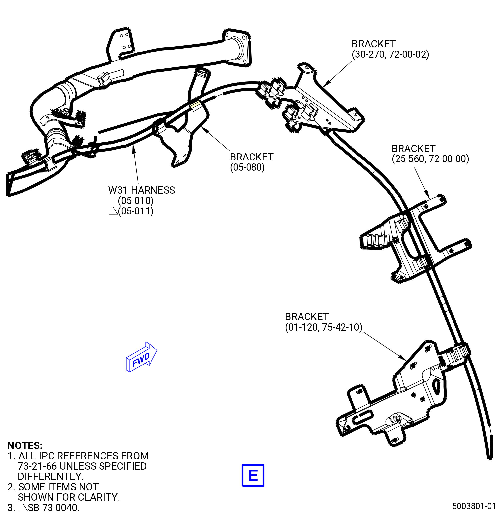
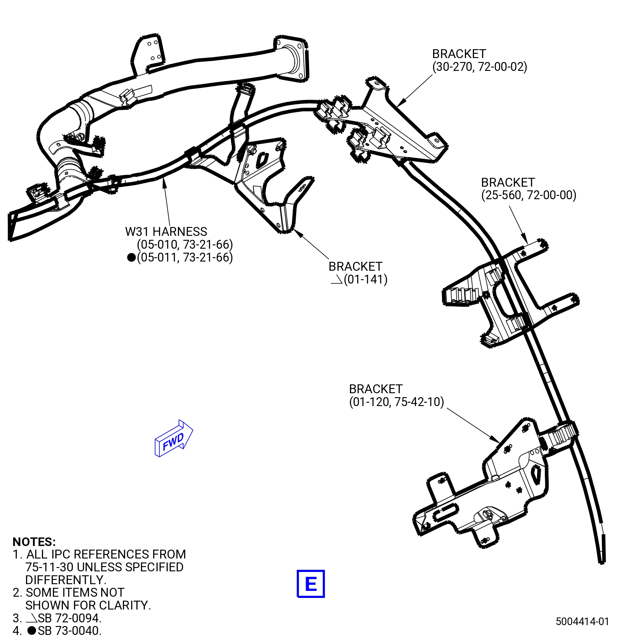
| (u) | Put the W30 harness (01-010 , 73-21-66) (SIN 68800) or (01-011 , 73-21-66) (SIN 68800) in the spring clips attached to brackets (25-210 , 72-00-00) (SIN 68812), (30-270) (SIN 68816), and (25-560 , 72-00-00) (SIN 6881U). |
| * * * PRE SB 72-0094( Engine without Engine Anti-Ice ) |
| (v) | Put the W30 harness (01-010 , 73-21-66) (SIN 68800) in the spring clip attached to the bracket (05-080 , 73-21-66) (SIN 6881V). |
| NOTE: |
|
| * * * END PRE SB 72-0094 |
| * * * SB 72-0094( Engine with Engine Anti-Ice ) |
| (v).A. | Put the W30 harness (01-010 , 73-21-66) (SIN 68800) or (01-011 , 73-21-66) (SIN 68800) in the spring clip attached to the bracket (01-141 , 75-11-30) (SIN 63717). |
| * * * END SB 72-0094 |
| Subtask 72-00-02-431-019 |
| * * * SB 73-0040( Improved W30 and W31 Harnesses ) |
| (v).B. | Put the W30 harness (01-011 , 73-21-66) (SIN 68800) in the spring clip attached to the bracket (01-141 , 75-11-30) (SIN 63717). |
| * * * END SB 73-0040 |
| Subtask 72-00-02-431-020 |
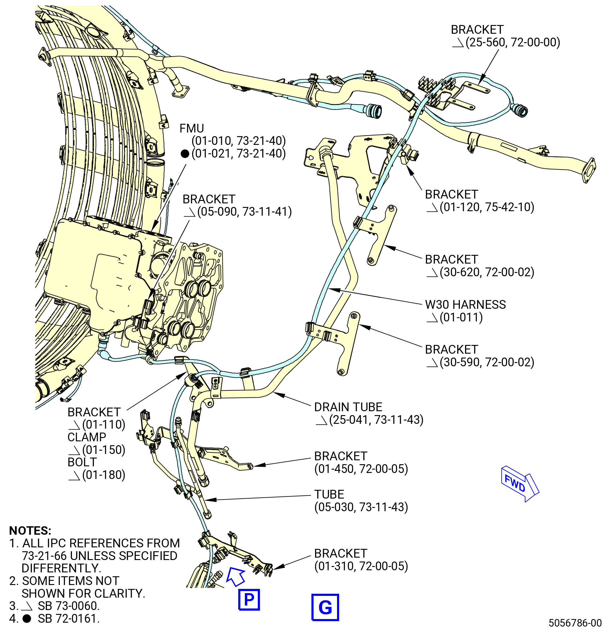
| (w) | Connect the P303 harness connector to the controller EAI (10-030 , 71-00-02) (SIN C00AD). |
| CAUTION: |
|
| (x) | Tighten the P303 harness connector with teflon-jawed pliers. |
| (y) | Put the W30 harness (01-010 , 73-21-66) (SIN 68800) or (01-011 , 73-21-66) (SIN 68800) in the spring clip attached to bracket (01-120 , 75-42-10) (SIN 53012). |
| (z) | Put the W30 harness (01-010 , 73-21-66) (SIN 68800) or (01-011 , 73-21-66) (SIN 68800) in the spring clips attached to the brackets (30-620) (SIN 6711B) and (30-590) (SIN 6711C), and the drain tube (25-040 , 73-11-43) (SIN 59001) or (25-041 , 73-11-43) (SIN 59001). |
| (aa) | Install the insert (01-030 , 73-21-66) (SIN 68834) on the bracket (01-450 , 72-00-05) (SIN 37010). |
| (ab) | Put the W30 harness (01-010 , 73-21-66) (SIN 68800) or (01-011 , 73-21-66) (SIN 68800) in the spring clip attached to the bracket (01-450 , 72-00-05) (SIN 37010). |
| (ac) | Put the W30 harness (01-010 , 73-21-66) (SIN 68800) or (01-011 , 73-21-66) (SIN 68800) in the spring clip attached to the tube (05-030 , 73-11-43) (SIN 37000). |
| (ad) | Put the W30 harness (01-010 , 73-21-66) (SIN 68800) or (01-011 , 73-21-66) (SIN 68800) in the spring clip attached to the bracket (01-310 , 72-00-05) (SIN 6711G). |
| (ae) | Put the W30 harness (01-010 , 73-21-66) (SIN 68800) or (01-011 , 73-21-66) (SIN 68800) in the spring clip attached to the bracket (05-090 , 73-11-41) (SIN 37610). |
| (af) | Connect the P301 harness connector to the fuel metering unit (FMU) (01-010 , 73-21-40) (SIN 30000) or (01-011 , 73-21-40) (SIN 30000). |
| CAUTION: |
|
| (ag) | Tighten the P301 harness connector with teflon-jawed pliers. |
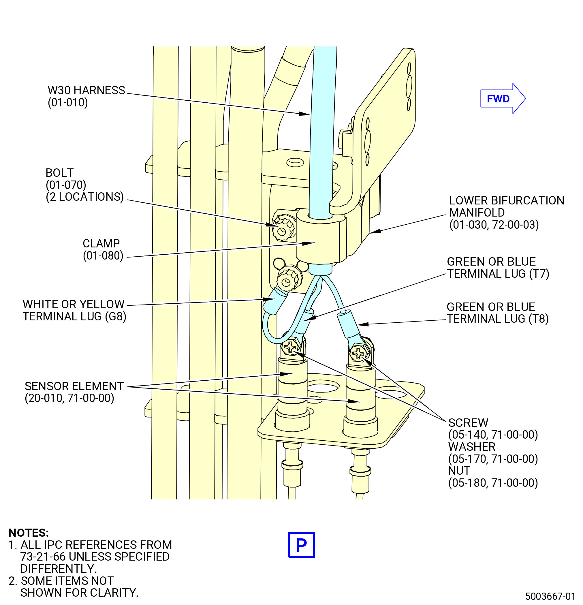
| (ah) | Attach the W30 harness (01-010 , 73-21-66) (SIN 68800) or (01-011 , 73-21-66) (SIN 68800) to the fill and overfill lower bifurcation manifold (lower bifurcation manifold) (01-030 , 72-00-03) (SIN 99004) with one clamp (01-080 , 73-21-66) (SIN 68884) and one bolt (01-070 , 73-21-66) (SIN 68822). Torque the bolt to 32 to 38 lb in. (3.6 to 4.3 Nm). |
| Subtask 72-00-02-431-021 |
| * * * PRE SB 73-0040( W30 and W31 Harnesses without Improvements ) |
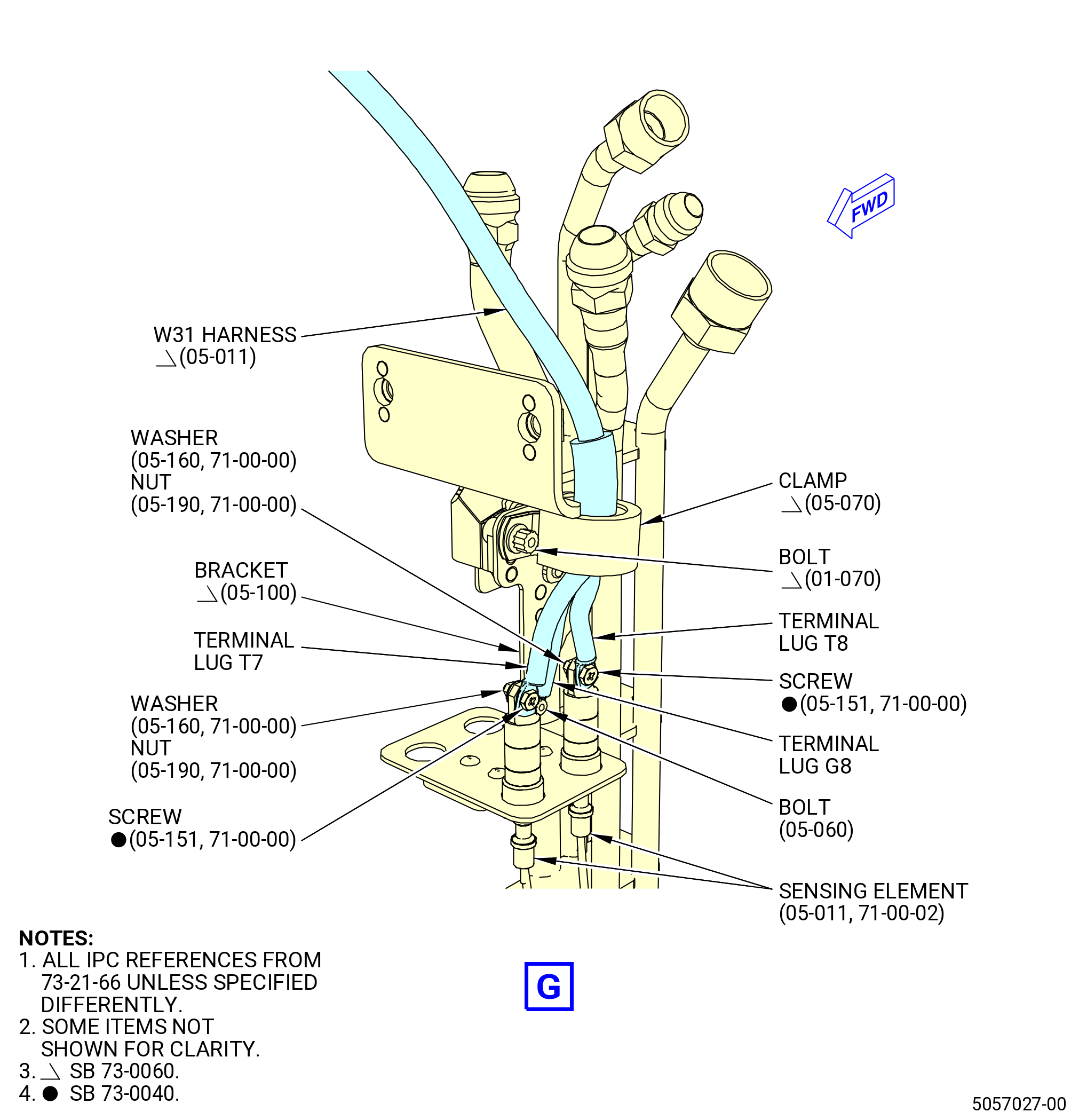
| (ai) | Connect the harness white or yellow terminal lug G8 to the lower bifurcation manifold (01-030 , 72-00-03) (SIN 99004) with one bolt (01-070 , 73-21-66) (SIN 68822). Torque the bolt to 32 to 38 lb in. (3.6 to 4.3 Nm). |
| (aj) | Connect the harness green or blue terminal lugs T7 and T8 to the No. 8 sensor element (sensor element) (20-010 , 71-00-00) (SIN C00A8) on the lower bifurcation manifold (01-030 , 72-00-03) (SIN 99004) with No. 8 screws (05-140 , 71-00-00) (SIN C00F3), washers (05-170 , 71-00-00) (SIN C00J0), and nuts (05-180 , 71-00-00) (SIN C00K3). Make sure that the terminal lugs are under the screwheads and torque the nuts to 23 to 27 lb in. (2.6 to 3.1 Nm). Re-apply torque a second time. |
| (ak) | Connect the W30 harness (01-010 , 73-21-66) (SIN 68800) to the sensor elements (05-060 , 71-00-02) (SIN C00A7) or (05-061 , 71-00-02) (SIN C00A7), (05-110 , 71-00-02) (SIN C00A7) or (05-111 , 71-00-02) (SIN C00A7), and (05-010 , 71-00-02) (SIN C00A7) or (05-011 , 71-00-02) (SIN C00A7) on the manifolds (15-070 , 75-24-10) (SIN 6220B) or (15-072 , 75-24-10) (SIN 6220B), (15-080 , 75-24-10) (SIN 6220C) or (15-082 , 75-24-10) (SIN 6220C), and (15-050 , 75-24-10) (SIN 6220D) or (15-052 , 75-24-10) (SIN 6220D) as follows: |
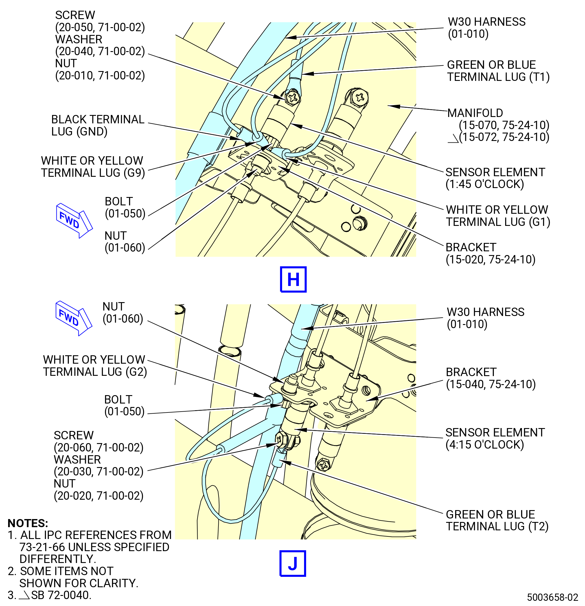
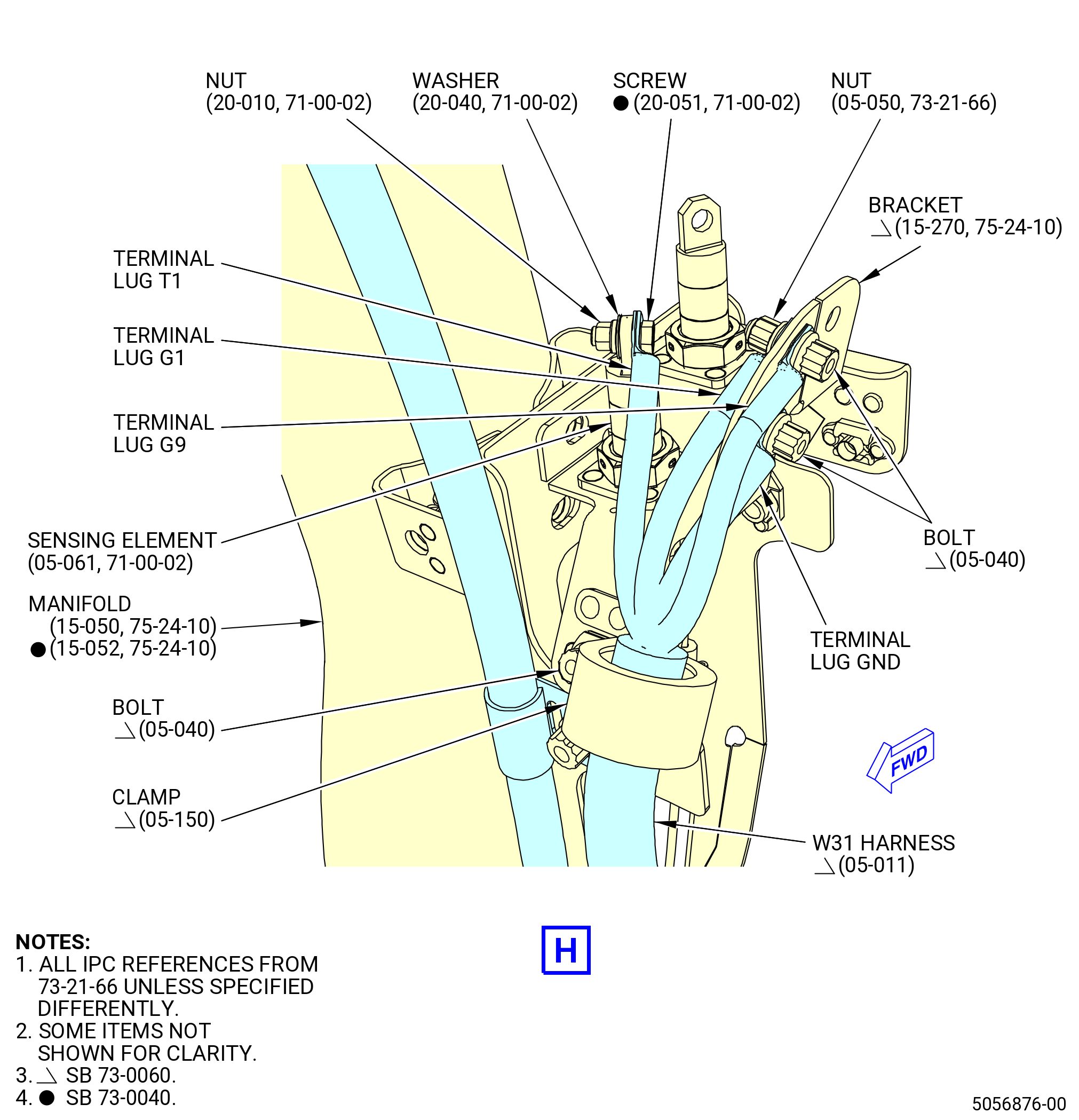
| 1 | Connect the harness white or yellow terminal lugs G1, G9, and the black terminal lug GND to the bracket (15-020 , 75-24-10) (SIN 9801G) at the 1:45 o'clock position with one bolt (01-050 , 73-21-66) (SIN 68824) and nut (01-060 , 73-21-66) (SIN 68840). Make sure that the terminal lugs are under the bolthead and torque the nut to 51 to 59 lb in. (5.8 to 6.7 Nm). |
| 2 | Connect the harness green or blue terminal lug T1 to the sensor element at the 1:45 o'clock position with one No. 8 screw (screw) (20-050 , 71-00-02) (SIN C00F3), washer (20-040 , 71-00-02) (SIN C00J0), and nut (20-010 , 71-00-02) (SIN C00K3). Make sure that the terminal lug is under the screwhead and the washer is under the nut. Torque the nut to 23 to 27 lb in. (2.6 to 3.1 Nm). |
| 3 | Connect the harness white or yellow terminal lug G2 to the bracket (15-040 , 75-24-10) (SIN 9801J) at the 4:15 o'clock position with one bolt (01-050 , 73-21-66) (SIN 68824) and nut (01-060 , 73-21-66) (SIN 68840). Make sure that the terminal lug is under the bolthead and torque the nut to 51 to 59 lb in. (5.8 to 6.7 Nm). |
| 4 | Connect the harness green or blue terminal lug T2 to the sensor element at the 4:15 o'clock position with one No. 10 screw (screw) (20-060 , 71-00-02) (SIN C00F4), No. 10 washer (washer) (20-030 , 71-00-02) (SIN C00J1), and No. 10 nut (nut) (20-020 , 71-00-02) (SIN C00K4). Make sure that the terminal lug is under the screwhead and the washer is under the nut. Torque the nut to 32 to 38 lb in. (3.6 to 4.3 Nm). |
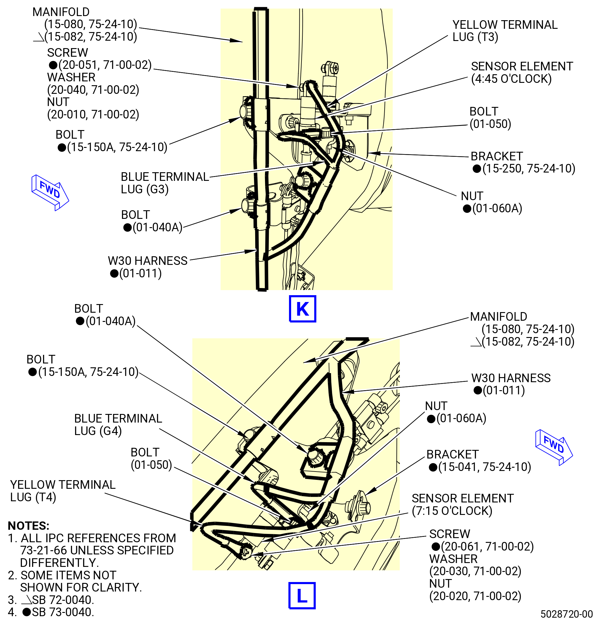
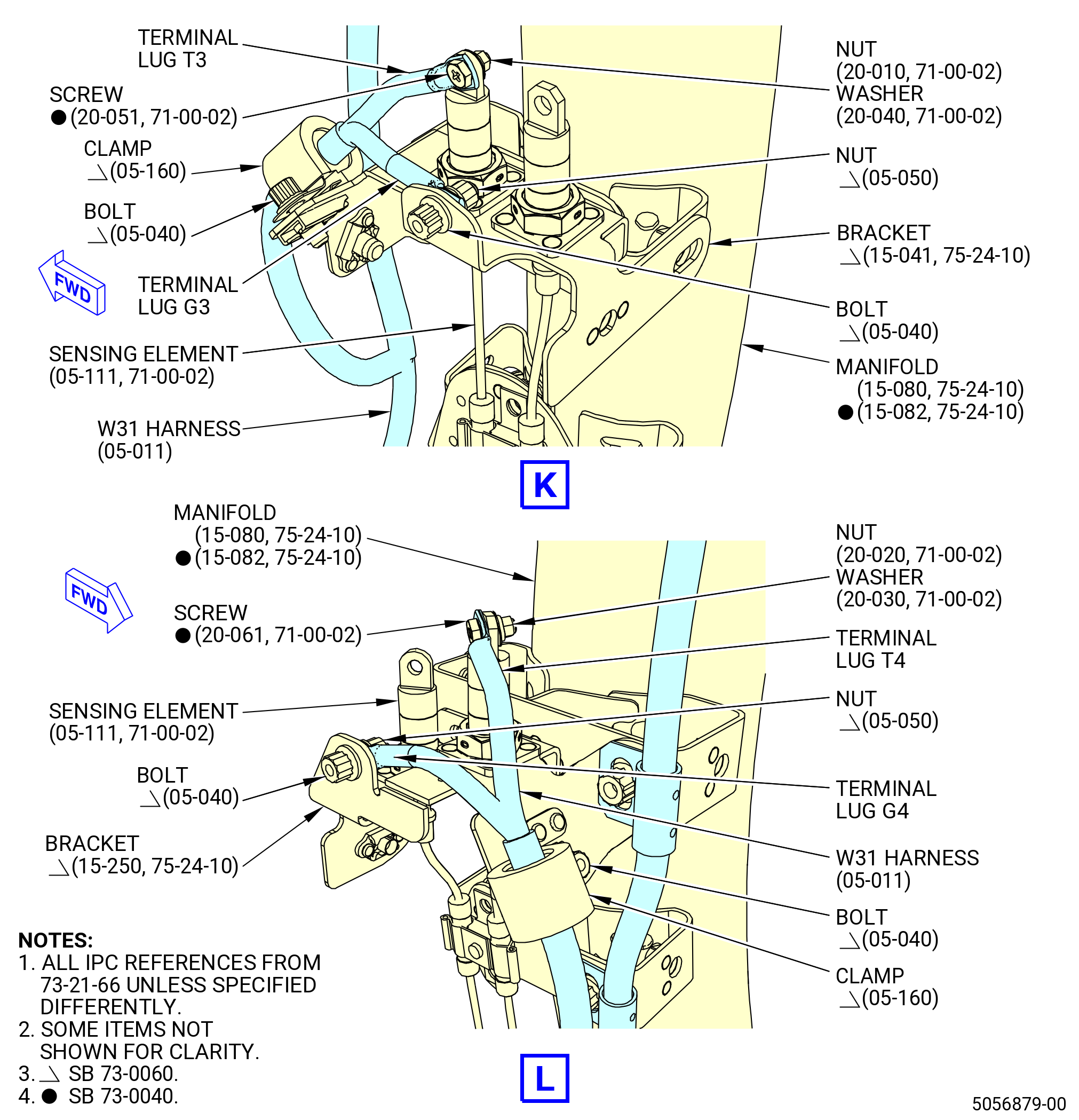
| 5 | Connect the harness white or yellow terminal lug G3 to the bracket (15-020 , 75-24-10) (SIN 9801G) at the 4:45 o'clock position with one bolt (01-050 , 73-21-66) (SIN 68824) and nut (01-060 , 73-21-66) (SIN 68840). Make sure that the terminal lug is under the bolthead and torque the nut to 51 to 59 lb in. (5.8 to 6.7 Nm). |
| 6 | Connect the harness green or blue terminal lug T3 to the sensor element at the 4:45 o'clock position with one screw (20-050 , 71-00-02) (SIN C00F3), washer (20-040 , 71-00-02) (SIN C00J0), and nut (20-010 , 71-00-02) (SIN C00K3). Make sure that the terminal lug is under the screwhead and the washer is under the nut. Torque the nut to 23 to 27 lb in. (2.6 to 3.1 Nm). |
| 7 | Connect the harness white or yellow terminal lug G4 to the bracket (15-040 , 75-24-10) (SIN 9801J) at the 7:15 o'clock position with one bolt (01-050 , 73-21-66) (SIN 68824) and nut (01-060 , 73-21-66) (SIN 68840). Make sure that the terminal lug is under the bolthead and torque the nut to 51 to 59 lb in. (5.8 to 6.7 Nm). |
| 8 | Connect the harness green or blue terminal lug T4 to the sensor element at the 7:15 o'clock position with one screw (20-060 , 71-00-02) (SIN C00F4), washer (20-030 , 71-00-02) (SIN C00J1), and nut (20-020 , 71-00-02) (SIN C00K4). Make sure that the terminal lug is under the screwhead and the washer is under the nut. Torque the nut to 32 to 38 lb in. (3.6 to 4.3 Nm). |
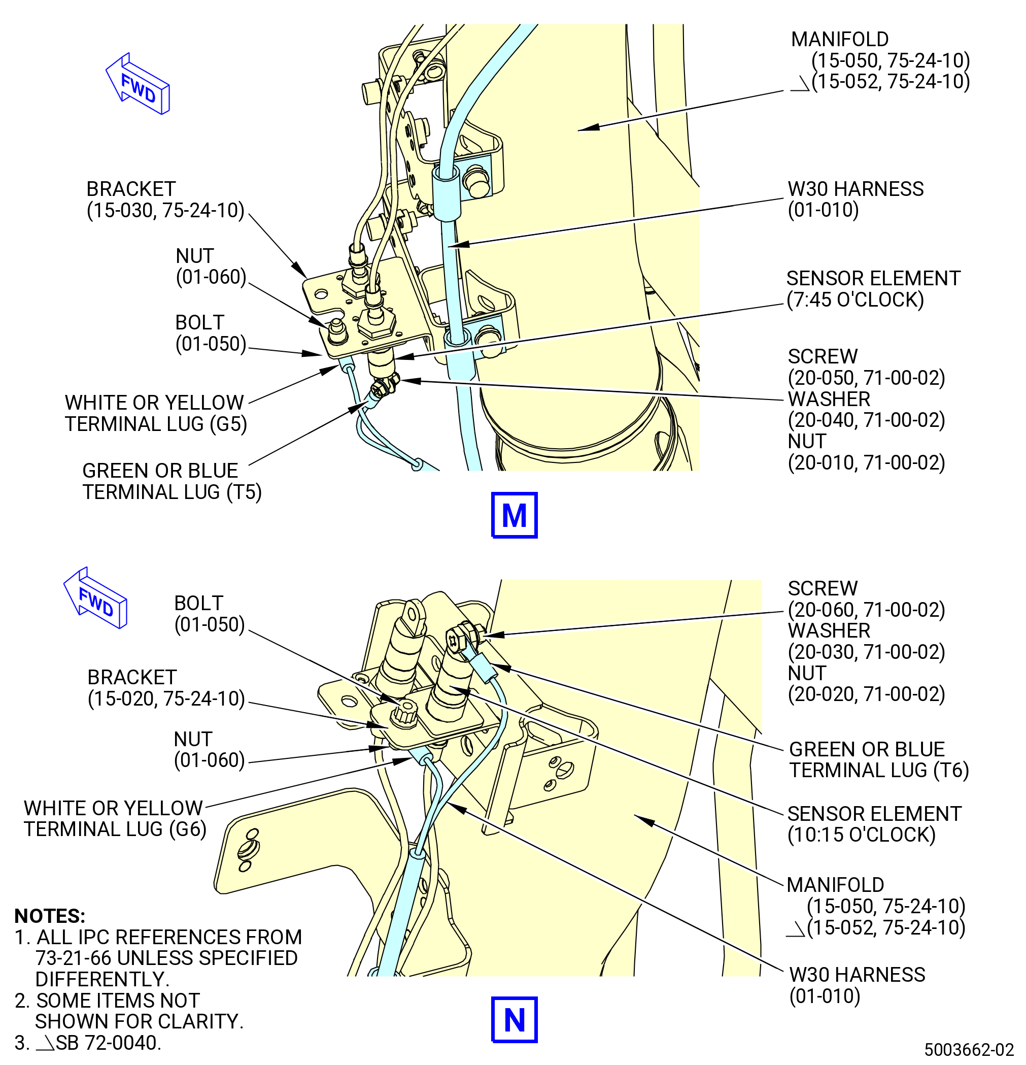
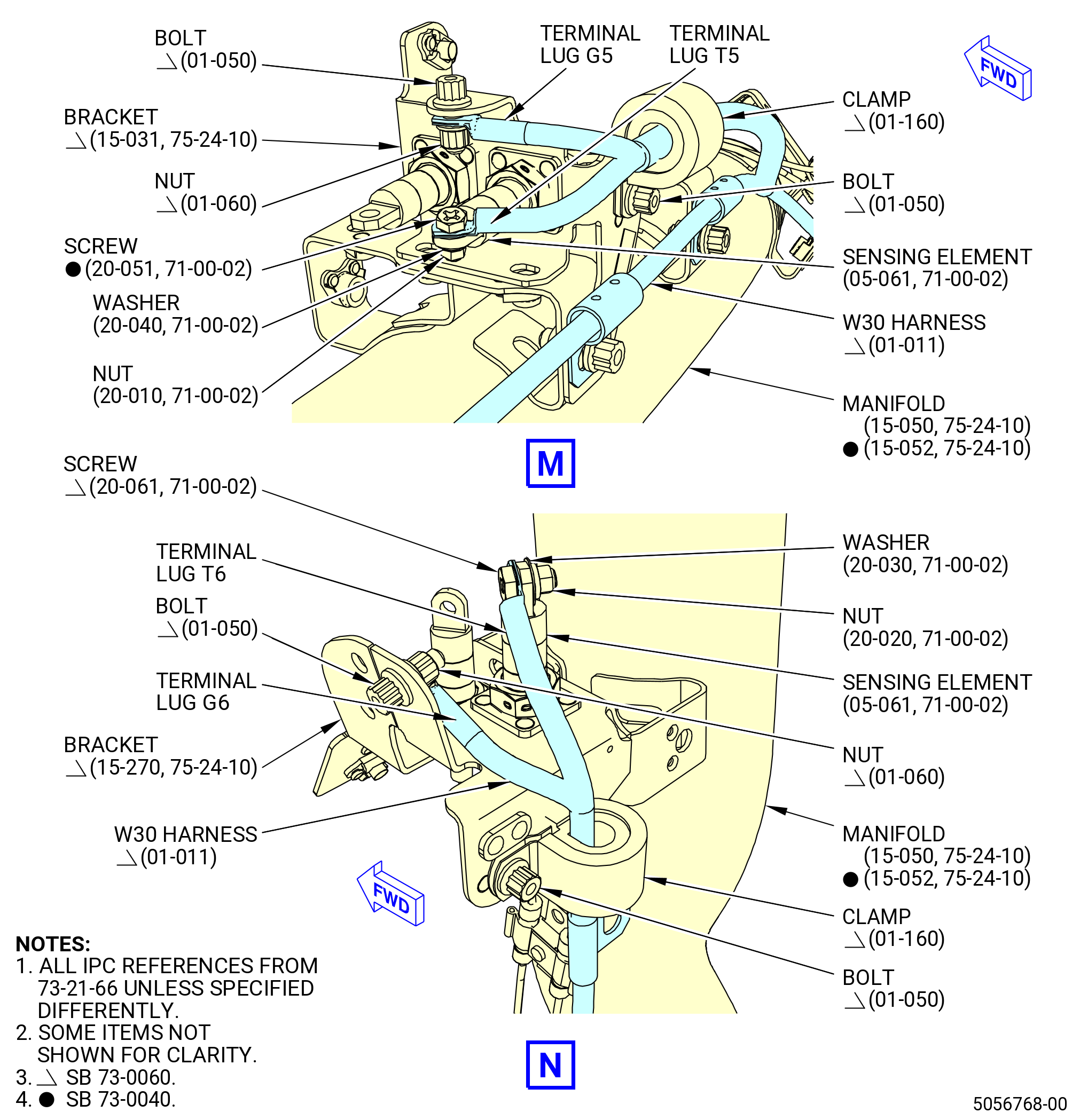
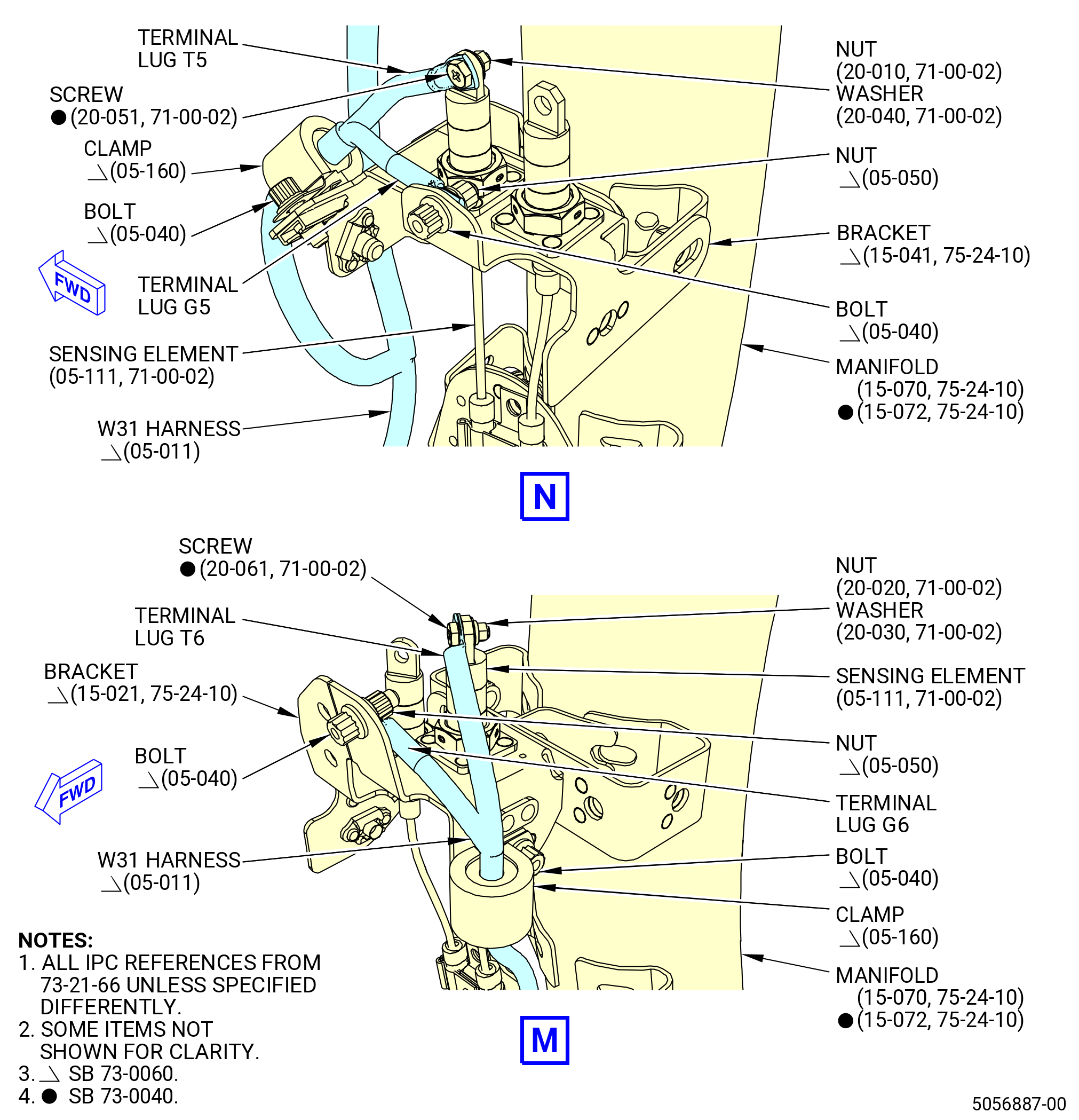
| 9 | Connect the harness white terminal lug G5 to the bracket (15-030 , 75-24-10) (SIN 9801K) at the 7:45 o'clock position with one bolt (01-050 , 73-21-66) (SIN 68824) and nut (01-060 , 73-21-66) (SIN 68840). Make sure that the terminal lug is under the bolthead and torque the nut to 51-59 lb in. (5.8-6.7 N.m). |
| 10 | Connect the harness green or blue terminal lug T5 to the sensor element at the 7:45 o'clock position with one screw (20-050 , 71-00-02) (SIN C00F3), washer (20-040 , 71-00-02) (SIN C00J0), and nut (20-010 , 71-00-02) (SIN C00K3). Make sure that the terminal lug is under the screwhead and the washer is under the nut. Torque the nut to 23 to 27 lb in. (2.6 to 3.1 Nm). |
| 11 | Connect the harness white or yellow terminal lug G6 to the bracket (15-020 , 75-24-10) (SIN 9801G) at the 10:15 o'clock position with one bolt (01-050 , 73-21-66) (SIN 68824) and nut (01-060 , 73-21-66) (SIN 68840). Make sure that the terminal lug is under the nut and torque the bolt to 51 to 59 lb in. (5.8 to 6.7 Nm). |
| 12 | Connect the harness green or blue terminal lug T6 to the sensor element at the 10:15 o'clock position with the screw (20-060 , 71-00-02) (SIN C00F4), washer (20-030 , 71-00-02) (SIN C00J1), and nut (20-020 , 71-00-02) (SIN C00K4). Make sure that the terminal lug is under the screwhead and the washer is under the nut. Torque the nut to 32 to 38 lb in. (3.6 to 4.3 Nm). |
| * * * END PRE SB 73-0040 |
| Subtask 72-00-02-431-022 |
| * * * SB 73-0040( Improved W30 and W31 Harnesses ) |
| (al) | Make sure to use the correct W30 harness (01-011 , 73-21-66) (SIN 68800) to avoid any inappropriate installation due to terminal lug colors identification. |
| (am) | Connect the harness blue terminal lug G8 to the lower bifurcation manifold (01-030 , 72-00-03) (SIN 99004) with one bolt (01-070 , 73-21-66) (SIN 68822). Torque the bolt to 32 to 38 lb in. (3.6 to 4.3 Nm). |
| (an) | Connect the harness yellow terminal lugs T7 and T8 to the No. 8 sensor element (sensor element) (20-010 , 71-00-00) (SIN C00A8) on the lower bifurcation manifold (01-030 , 72-00-03) (SIN 99004) with No. 8 screws (05-141 , 71-00-00) (SIN C00F3), washers (05-170 , 71-00-00) (SIN C00J0), and nuts (05-180 , 71-00-00) (SIN C00K3). Make sure that the terminal lugs are under the screwheads and torque the nuts to 23 to 27 lb in. (2.6 to 3.1 Nm). Re-apply torque a second time. |
| (ao) | Connect the W30 harness (01-011 , 73-21-66) (SIN 68800) to the sensor elements (05-060 , 71-00-02) (SIN C00A7) or (05-061 , 71-00-02) (SIN C00A7), (05-110 , 71-00-02) (SIN C00A7) or (05-111 , 71-00-02) (SIN C00A7) and (05-010 , 71-00-02) (SIN C00A7) or (05-011 , 71-00-02) (SIN C00A7) on the manifolds (15-070 , 75-24-10) (SIN 6220B) or (15-072 , 75-24-10) (SIN 6220B), (15-080 , 75-24-10) (SIN 6220C) or (15-082 , 75-24-10) (SIN 6220C), and (15-050 , 75-24-10) (SIN 6220D) or (15-052 , 75-24-10) (SIN 6220D) as follows: |
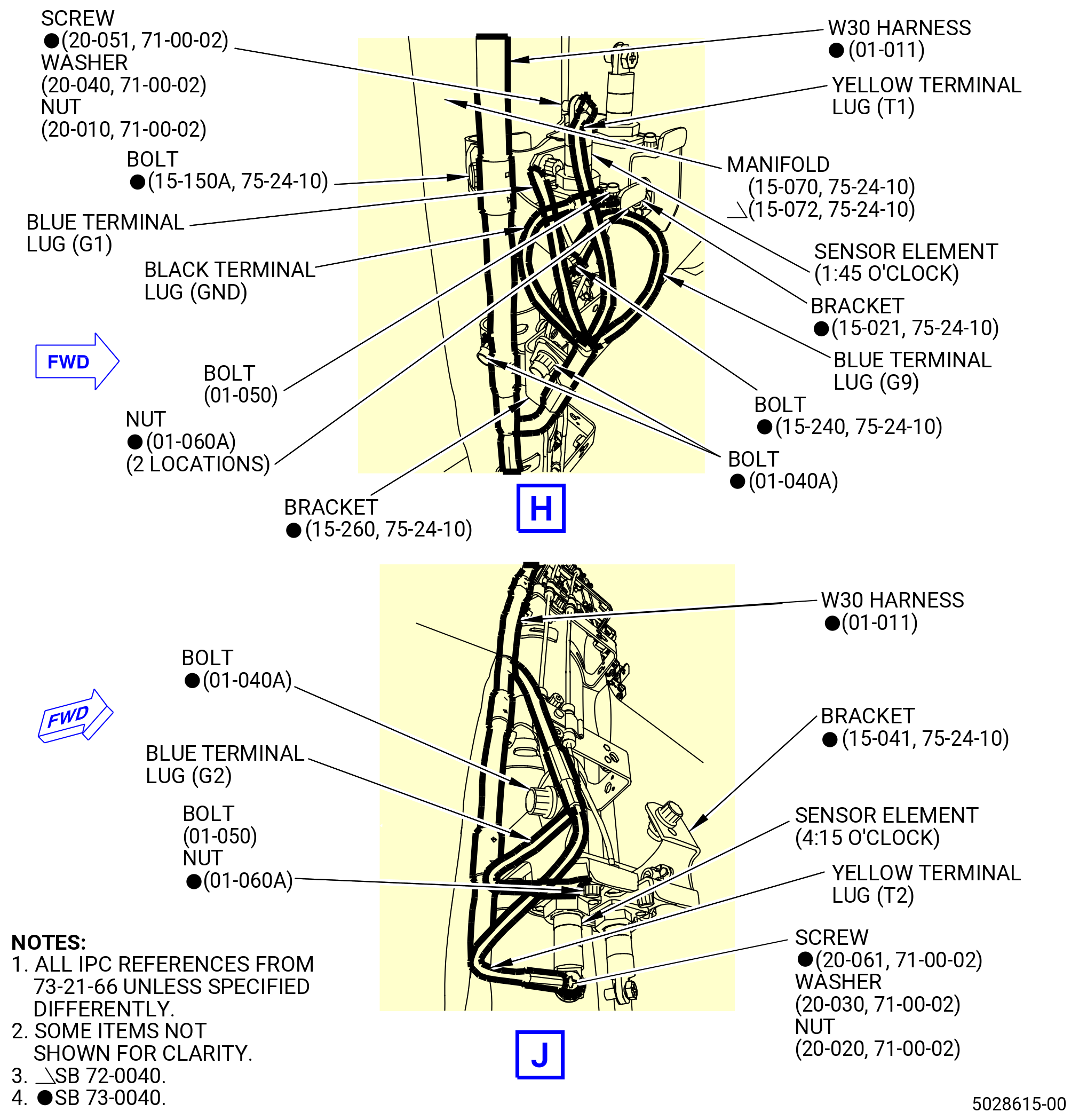
| 1 | Connect the harness blue terminal lugs G1, G9, with one bolt (15-240 , 75-24-10) (SIN 9802E) and the black terminal lug GND with one bolt (01-050 , 73-21-66) (SIN 68824) with two nuts (01-060 , 73-21-66) (SIN 68840) to the bracket (15-021 , 75-24-10) (SIN 9801G) at the 1:45 o'clock position. Make sure that the terminal lugs are under the bolthead and torque the nut to 51 to 59 lb in. (5.8 to 6.7 Nm). |
| 2 | Connect the harness yellow terminal lug T1 to the sensor element at the 1:45 o'clock position with one No. 8 screw (screw) (20-051 , 71-00-02) (SIN C00F3), washer (20-040 , 71-00-02) (SIN C00J0), and nut (20-010 , 71-00-02) (SIN C00K3). Make sure that the terminal lug is under the screwhead and the washer is under the nut. Torque the nut to 23 to 27 lb in. (2.6 to 3.1 Nm). |
| 3 | Connect the harness blue terminal lug G2 to the bracket (15-041 , 75-24-10) (SIN 9801J) at the 4:15 o'clock position with one bolt (01-050 , 73-21-66) (SIN 68824) and nut (01-060 , 73-21-66) (SIN 68840). Make sure that the terminal lug is under the bolthead and torque the nut to 51 to 59 lb in. (5.8 to 6.7 Nm). |
| 4 | Connect the harness yellow terminal lug T2 to the sensor element at the 4:15 o'clock position with one No. 10 screw (screw) (20-061 , 71-00-02) (SIN C00F4), No. 10 washer (washer) (20-030 , 71-00-02) (SIN C00J1), and No. 10 nut (nut) (20-020 , 71-00-02) (SIN C00K4). Make sure that the terminal lug is under the screwhead and the washer is under the nut. Torque the nut to 32 to 38 lb in. (3.6 to 4.3 Nm). |
| 5 | Connect the harness blue terminal lug G3 to the bracket (15-250 , 75-24-10) (SIN 9801L) at the 4:45 o'clock position with one bolt (01-050 , 73-21-66) (SIN 68824) and nut (01-060 , 73-21-66) (SIN 68840). Make sure that the terminal lug is under the bolthead and torque the nut to 51 to 59 lb in. (5.8 to 6.7 Nm). |
| 6 | Connect the harness yellow terminal lug T3 to the sensor element at the 4:45 o'clock position with one screw (20-051 , 71-00-02) (SIN C00F3), washer (20-040 , 71-00-02) (SIN C00J0), and nut (20-010 , 71-00-02) (SIN C00K3). Make sure that the terminal lug is under the screwhead and the washer is under the nut. Torque the nut to 23 to 27 lb in. (2.6 to 3.1 Nm). |
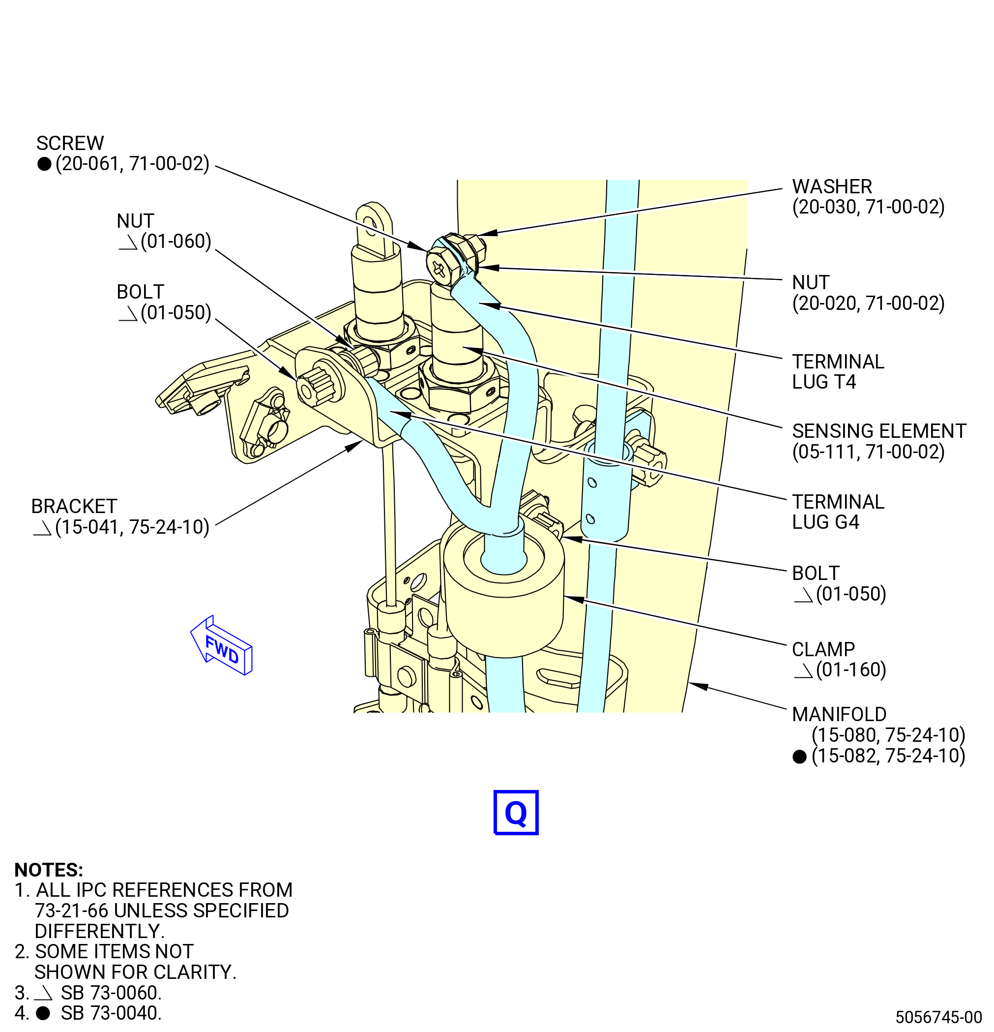
| 7 | Connect the harness blue terminal lug G4 to the bracket (15-041 , 75-24-10) (SIN 9801J) at the 7:15 o'clock position with one bolt (01-050 , 73-21-66) (SIN 68824) and nut (01-060 , 73-21-66) (SIN 68840). Make sure that the terminal lug is under the bolthead and torque the nut to 51 to 59 lb in. (5.8 to 6.7 Nm). |
| 8 | Connect the harness yellow terminal lug T4 to the sensor element at the 7:15 o'clock position with one screw (20-061 , 71-00-02) (SIN C00F4), washer (20-030 , 71-00-02) (SIN C00J1), and nut (20-020 , 71-00-02) (SIN C00K4). Make sure that the terminal lug is under the screwhead and the washer is under the nut. Torque the nut to 32 to 38 lb in. (3.6 to 4.3 Nm). |
| 9 | Connect the harness blue terminal lug G5 to the bracket (15-031 , 75-24-10) (SIN 9801K) at the 7:45 o'clock position with one bolt (01-050 , 73-21-66) (SIN 68824) and nut (01-060 , 73-21-66) (SIN 68840). Make sure that the terminal lug is under the bolthead and torque the nut to 51 to 59 lb in. (5.8 to 6.7 Nm). |
| 10 | Connect the harness yellow terminal lug T5 to the sensor element at the 7:45 o'clock position with one screw (20-051 , 71-00-02) (SIN C00F3), washer (20-040 , 71-00-02) (SIN C00J0), and nut (20-010 , 71-00-02) (SIN C00K3). Make sure that the terminal lug is under the screwhead and the washer is under the nut. Torque the nut to 23 to 27 lb in. (2.6 to 3.1 Nm). |
| 11 | Connect the harness blue terminal lug G6 to the bracket (15-270 , 75-24-10) (SIN 9801N) at the 10:15 o'clock position with one bolt (01-050 , 73-21-66) (SIN 68824) and nut (01-060 , 73-21-66) (SIN 68840). Make sure that the terminal lug is under the nut and torque the bolt to 51 to 59 lb in. (5.8 to 6.7 Nm). |
| 12 | Connect the harness yellow terminal lug T6 to the sensor element at the 10:15 o'clock position with the screw (20-061 , 71-00-02) (SIN C00F4), washer (20-030 , 71-00-02) (SIN C00J1), and nut (20-020 , 71-00-02) (SIN C00K4). Make sure that the terminal lug is under the screwhead and the washer is under the nut. Torque the nut to 32 to 38 lb in. (3.6 to 4.3 Nm). |
| * * * END SB 73-0040 |
| Subtask 72-00-02-431-023 |
| (ap) | Torque the bolt (01-040 , 73-21-66) (SIN 68823) at the bracket (05-080 , 79-22-30) (SIN 6881D) to 60 to 70 lb in. (6.8 to 7.9 Nm). |
| (aq) | Torque the two bolts (01-040 , 73-21-66) (SIN 68823) on the manifold (15-060 , 75-24-10) (SIN 6220A) or (15-062 , 75-24-10) (SIN 6220A) to 60 to 70 lb in. (6.8 to 7.9 Nm). |
| (ar) | Torque the eight bolts (01-040 , 73-21-66) (SIN 68823) on the manifold (15-070 , 75-24-10) (SIN 6220B) or (15-072 , 75-24-10) (SIN 6220B) to 60 to 70 lb in. (6.8 to 7.9 Nm). |
| (as) | Torque the eight bolts (01-040 , 73-21-66) (SIN 68823) on the manifold (15-080 , 75-24-10) (SIN 6220C) or (15-082 , 75-24-10) (SIN 6220C) and bracket (15-180 , 75-24-10) (SIN 9801F), (15-181 , 75-24-10) (SIN 9801F) or (15-182 , 75-24-10) (SIN 9801F) to 60 to 70 lb in. (6.8 to 7.9 Nm). |
| (at) | Torque the seven bolts (01-040 , 73-21-66) (SIN 68823) on the manifold (15-050 , 75-24-10) (SIN 6220D) or (15-052 , 75-24-10) (SIN 6220D), bracket (15-170 , 75-24-10) (SIN 9801D) or (15-171 , 75-24-10) (SIN 9801D), and bracket (15-160 , 75-24-10) (SIN 9801E) to 60 to 70 lb in. (6.8 to 7.9 Nm). |
| * * * END PRE SB 73-0060 |
| * * * SB 73-0060 |
| (au) | Torque the five bolts (15-155 , 75-24-10) (SIN 98028) to 60 to 70 lb in. (6.7 to 7.9 Nm). |
| NOTE: |
|
| * * * END SB 73-0060 |
| Subtask 72-00-02-431-033 |
| * * * SB 73-0060( W30 and W31 Redesigned Harnesses ) |
| (9).A. | Install the W30 harness (01-011 , 73-21-66) (SIN 68800). Refer to Figure 1010 and do as follows: |
| (a) | Put the W30 harness (01-011 , 73-21-66) (SIN 68800) in position along the manifold (15-062 , 75-24-10) (SIN 6220A). |
| (b) | Attach the W30 harness (01-011 , 73-21-66) (SIN 68800) to the bracket (05-080 , 79-22-30) (SIN 6881D) with one bolt (01-040 , 73-21-66) (SIN 68823). Hand-tighten the bolt. |
| (c) | Attach the W30 harness (01-011 , 73-21-66) (SIN 68800) to the manifold (15-062 , 75-24-10) (SIN 6220A) with two bolts (01-040 , 73-21-66) (SIN 68823). Hand-tighten the bolts. |
| (d) | Attach the W30 harness (01-011 , 73-21-66) (SIN 68800) to the manifold (15-072 , 75-24-10) (SIN 6220B) and bracket (15-021 , 75-24-10) (SIN 9801G) with a bolt (15-155 , 75-24-10) (SIN 98028). Hand-tighten the bolt. |
| (e) | Attach the W30 harness (01-011 , 73-21-66) (SIN 68800) to the manifold (15-072, 75-24-10) (SIN 6220B) with six bolts (01-040, 73-21-66) (SIN 68823). Hand-tighten the bolts. |
| (f) | Attach the W30 harness (01-011 , 73-21-66) (SIN 68800) to the manifold (15-072 , 75-24-10) (SIN 6220B) and bracket (15-041 , 75-24-10) (SIN 9801J) with a bolt (15-155 , 75-24-10) (SIN 98028). Hand-tighten the bolt. |
| (g) | Attach the W30 harness (01-011 , 73-21-66) (SIN 68800) branches to the brackets (15-021 , 75-24-10) (SIN 9801G) and (15-041 , 75-24-10) (SIN 9801J) with clamps (01-150 , 73-21-66) (SIN 6888E) and (01-160 , 73-21-66) (SIN 6888C) and with two bolts (01-050 , 73-21-66) (SIN 68824) respectively. Hand-tighten the bolts. |
| (h) | Attach the W30 harness (01-011 , 73-21-66) (SIN 68800) to the manifold (15-082 , 75-24-10) (SIN 6220C) and drain support bracket (bracket) (15-250 , 75-24-10) (SIN 9801L) with a bolt (15-155 , 75-24-10) (SIN 98028). Hand-tighten the bolt. |
| (i) | Attach the W30 harness (01-011 , 73-21-66) (SIN 68800) to the manifold (15-082 , 75-24-10) (SIN 6220C) with four bolts (01-040 , 73-21-66) (SIN 68823). Hand-tighten the bolts. |
| (j) | Attach the W30 harness (01-011 , 73-21-66) (SIN 68800) to the manifold (15-082 , 75-24-10) (SIN 6220C) and bracket (15-182 , 75-24-10) (SIN 9801F) with two bolts (01-040 , 73-21-66) (SIN 68823). Hand-tighten the bolts. |
| (k) | Attach the W30 harness (01-011 , 73-21-66) (SIN 68800) to the manifold (15-082 , 75-24-10) (SIN 6220C) and bracket (15-041 , 75-24-10) (SIN 9801J) with a bolt (15-155 , 75-24-10) (SIN 98028). Hand-tighten the bolt. |
| (l) | Attach the W30 harness (01-011 , 73-21-66) (SIN 68800) branches to the brackets (15-041 , 75-24-10) (SIN 9801J) and (15-250 , 75-24-10) (SIN 9801L) with two clamps (01-160 , 73-21-66) (SIN 6888E) and two bolts (01-050 , 73-21-66) (SIN 68824). Hand-tighten the bolts. |
| (m) | Attach the W30 harness (01-011 , 73-21-66) (SIN 68800) to the manifold (15-052 , 75-24-10) (SIN 6220D) and bracket (15-031 , 75-24-10) (SIN 9801K) with a bolt (15-155 , 75-24-10) (SIN 98028). Hand-tighten the bolt. |
| (n) | Attach the W30 harness (01-011 , 73-21-66) (SIN 68800) to the manifold (15-052 , 75-24-10) (SIN 6220D), bracket (15-160 , 75-24-10) (SIN 9801E), and support bracket (15-171 , 75-24-10) (SIN 9801D) with six bolts (01-040 , 73-21-66) (SIN 68823). Hand-tighten the bolts. |
| (o) | Attach the W30 harness (01-011 , 73-21-66) (SIN 68800) branches to the brackets (15-031 , 75-24-10) (SIN 9801K) and (15-270 , 75-24-10) (SIN 9801N) with two clamps (01-160 , 73-21-66) (SIN 6888E) and two bolts (01-050 , 73-21-66) (SIN 68824). Hand-tighten the bolts. |
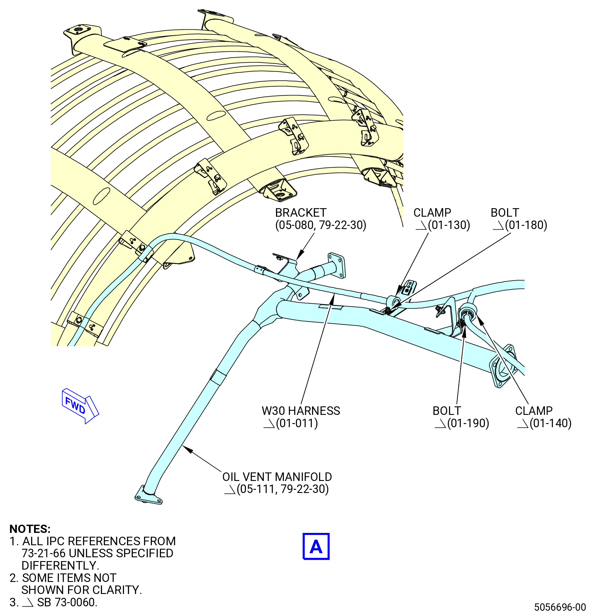
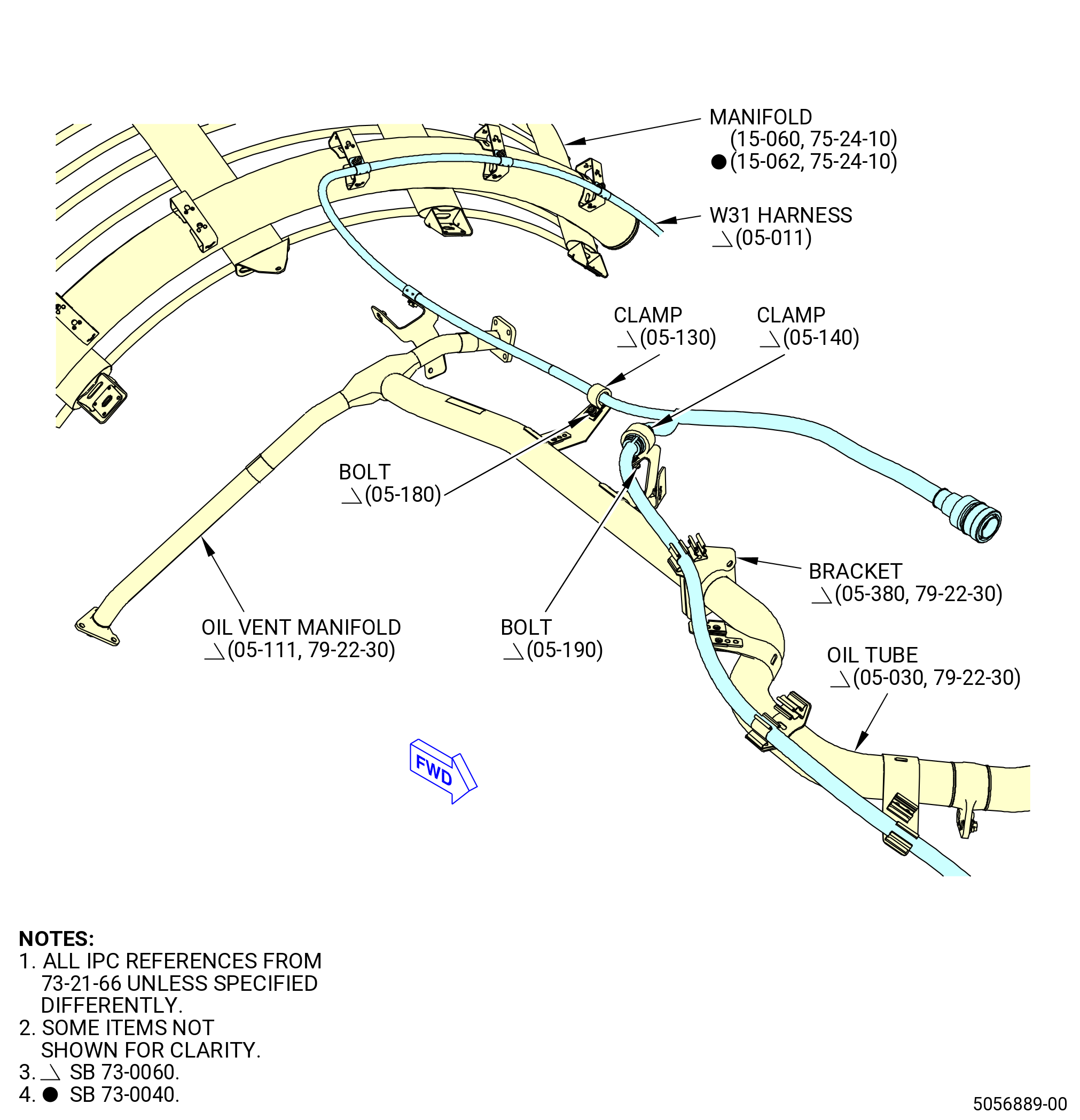
| (p) | Attach the W30 harness (01-011 , 73-21-66) (SIN 68800) to the oil vent manifold (05-111 , 79-22-30) (SIN 46101) with two clamps (01-130 , 73-21-66) (SIN 6888D) and (01-140 , 73-21-66) (SIN 6888F) and bolts (01-180 , 73-21-66) (SIN 6882M) and (01-190 , 73-21-66) (SIN 6882N) respectively. Torque the bolts (01-180 , 73-21-66) (SIN 6882M) and (01-190 , 73-21-66) (SIN 6882M) to 32 to 38 lb in. (3.6 to 4.2 Nm). |
| (q) | Put the W30 harness (01-011 , 73-21-66) (SIN 68800) in the spring clips of the bracket (05-380 , 79-22-30) (SIN 4611C) and to the remaining spring clips of the oil tube (05-030 , 79-22-30) (SIN 46100). |
| (r) | Attach the W30 harness (01-011 , 73-21-66) (SIN 68800) to the oil tube (05-030 , 79-22-30) (SIN 46100) with a clamp (01-130 , 73-21-66) (SIN 6888D) and a bolt (01-180 , 73-21-66) (SIN 6882M). Torque the bolt (01-180 , 73-21-66) (SIN 6882M) to 32 to 38 lb in. (3.6 to 4.2 Nm). |
| (s) | Put the W30 harness (01-011 , 73-21-66) (SIN 68800) in the spring clips of the brackets (30-270) (SIN 68816) and (25-560 , 72-00-00) (SIN 6881U). |
| (t) | Put the W30 harness (01-011 , 73-21-66) (SIN 68800) in the spring clip of the bracket (01-141 , 75-11-30) (SIN 63717) and attach it with a clamp (01-130 , 73-21-66) (SIN 6888D) and bolt (01-180 , 73-21-66) (SIN 6882M). Torque the bolt (01-180 , 73-21-66) (SIN 6882M) to 32 to 38 lb in. (3.6 to 4.2 Nm). |
| (u) | Connect the P303 harness connector (VIEW H) to the engine anti-ice (EAI) controller (10-030 , 71-00-02) (SIN C00AD). |
| CAUTION: |
|
| (v) | Tighten the P303 harness connector with teflon-jawed pliers. |
| (w) | Put the W30 harness (01-011 , 73-21-66) (SIN 68800) in the spring clip of the bracket (01-120 , 75-42-10) (SIN 53012). |
| (x) | Put the W30 harness (01-011 , 73-21-66) (SIN 68800) in the spring clips of the brackets (30-620) (SIN 6711B) and (30-590) (SIN 6711C) and the drain tube (25-041 , 73-11-43) (SIN 59001). |
| (y) | Attach the W30 harness (01-011 , 73-21-66) (SIN 68800) to the bracket (05-090 , 73-11-41) (SIN 37610) with a clamp (01-160 , 73-21-66) (SIN 6888C) and a bolt (01-190 , 73-21-66) (SIN 6882N). Torque the bolt (01-190 , 73-21-66) (SIN 6882N) to 32 to 38 lb in. (3.6 to 4.2 Nm). |
| (z) | Attach the W30 harness (01-011 , 73-21-66) (SIN 68800) to the bracket (01-110 , 73-21-66) (SIN 6881J) with a clamp (01-150 , 73-21-66) (SIN 6888E) and a bolt (01-180 , 73-21-66) (SIN 6882M) and to the spring clip. Torque the bolt (01-180 , 73-21-66) (SIN 6882M) to 32 to 38 lb in. (3.6 to 4.2 Nm). |
| (aa) | Connect the P301 harness connector to the fuel metering unit (FMU). |
| (ab) | Tighten the P301 harness connector with teflon-jawed pliers. |
| (ac) | Put the W30 harness (01-011 , 73-21-66) (SIN 68800) on the spring clips of the bracket (01-450 , 72-00-05) (SIN 37010). |
| (ad) | Put the W30 harness (01-011 , 73-21-66) (SIN 68800) in the spring clip attached to the tube (05-030 , 73-11-43) (SIN 37000). |
| (ae) | Put the W30 harness (01-011 , 73-21-66) (SIN 68800) on the spring clips of the bracket (01-310 , 72-00-05) (SIN 6711G). |
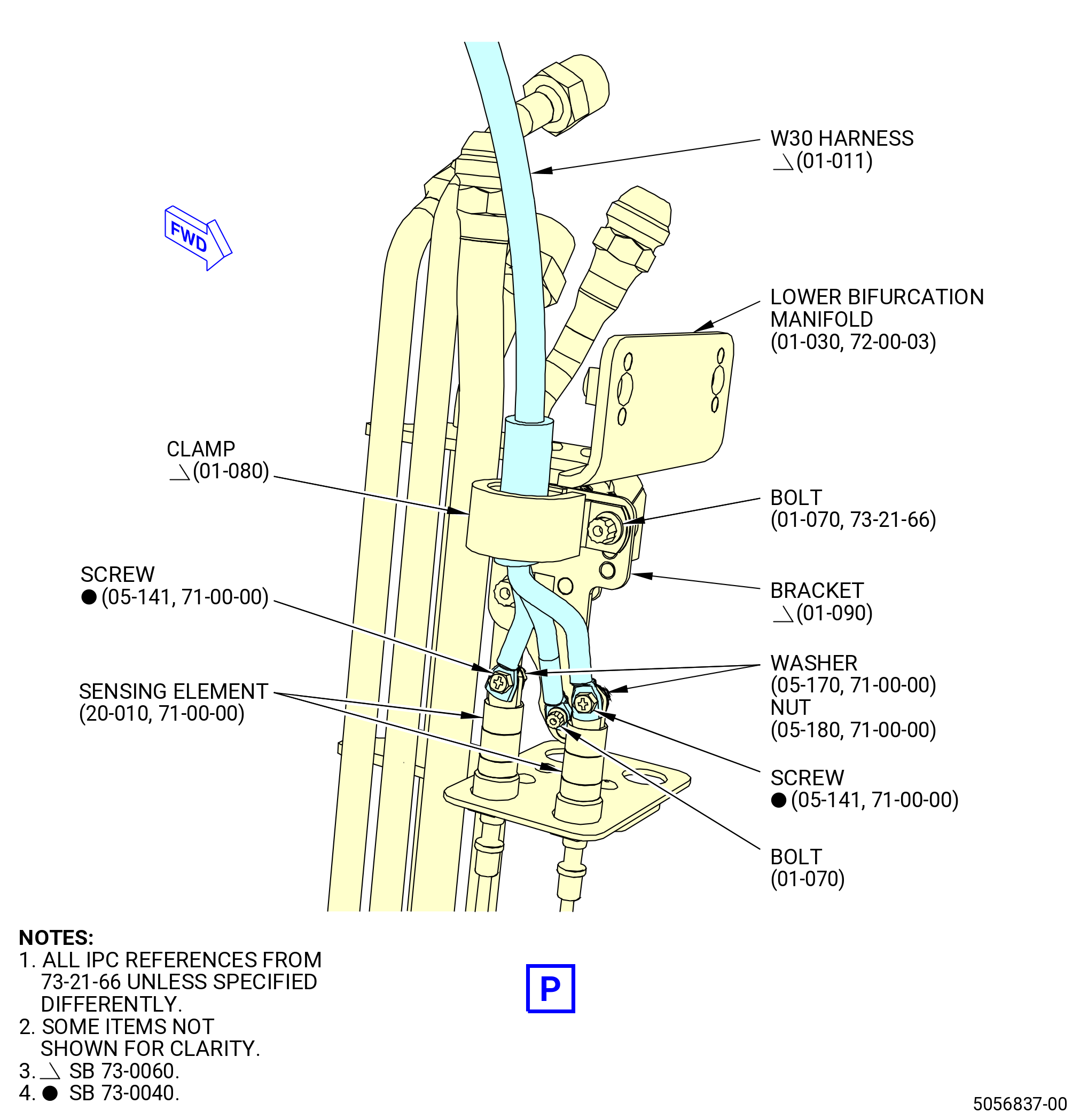
| (af) | Attach the W30 harness (01-011 , 73-21-66) (SIN 68800) to the bracket (01-090 , 73-21-66) (SIN 9901U) with one clamp (01-080 , 73-21-66) (SIN 68884) and one bolt (01-070 , 73-21-66) (SIN 68822). Torque the bolt (01-070 , 73-21-66) (SIN 68822) to 32 to 38 lb in. (3.6 to 4.2 Nm). |
| (ag) | Install the W30 harness (01-011 , 73-21-66) (SIN 68800) into the sensor elements (20-010 , 71-00-00) (SIN C00A8) as follows: |
| CAUTION: |
|
| 1 | Connect the harness blue terminal lug G8 as follows: |
| a | Attach the terminal lug G8 to the bracket (01-090 , 73-21-66) (SIN 9901U) on the lower bifurcation manifold (manifold) (01-030 , 72-00-03) (SIN 99004) with a bolt (01-070 , 73-21-66) (SIN 68822). |
| b | Torque the bolt (01-070 , 73-21-66) (SIN 68822) to 32 to 38 lb in. (3.6 to 4.2 Nm). |
| 2 | Connect the harness yellow terminal lugs T7 and T8 as follows: |
| a | Attach the terminal lugs T7 and T8 to the sensor element (20-010 , 71-00-00) (SIN C00A8) on the manifold (01-030 , 72-00-03) (SIN 99004) with two No. 8 screws (05-141 , 71-00-00) (SIN C00F3), washers (05-170 , 71-00-00) (SIN C00J0), and nuts (05-180 , 71-00-00) (SIN C00K3). Make sure that the terminal lugs T7 and T8 are below the screwheads of the No. 8 screws (05-141 , 71-00-00) (SIN C00F3). |
| b | Torque the nuts (05-180 , 71-00-00) (SIN C00K3) to 23 to 27 lb in. (2.5 to 3.0 Nm). |
| 3 | Connect the W30 harness (01-011 , 73-21-66) to the sensing elements (05-011 , 71-00-02) (SIN C00A7), (05-061 , 71-00-02) (SIN C00A7), and (05-111 , 71-00-02) (SIN C00A7) on the manifolds as follows: |
| NOTE: |
|
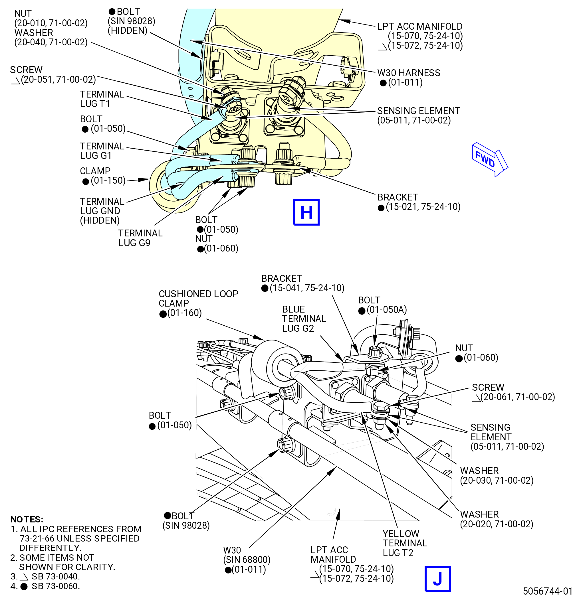
| a | Connect the harness blue terminal lugs G1 and G9 on the manifold (15-072 , 75-24-10) (SIN 6220B) at the 1:45 o'clock position as follows: |
| (1) | Attach the terminal lugs G1 and G9 to the bracket (15-021 , 75-24-10) (SIN 9801G) with a bolt (01-050 , 73-21-66) (SIN 68824) and nut (01-060 , 73-21-66) (SIN 68840). Make sure that the terminal lug G9 is below the screwhead of the bolt (01-050 , 73-21-66) (SIN 68824) and the terminal lug G1 is installed at the other side of the bracket (15-021 , 75-24-10) (SIN 9801G) with the nut (01-060 , 73-21-66) (SIN 68840). |
| (2) | Torque the nuts (01-060 , 73-21-66) (SIN 68840) to 51 to 59 lb in. (5.7 to 6.6 Nm). |
| b | Connect the harness black terminal lug GND on the manifold (15-072 , 75-24-10) (SIN 6220B) at the 1:45 o'clock position as follows: |
| (1) | Attach the terminal lug GND to the bracket (15-021 , 75-24-10) (SIN 9801G) with a bolt (01-050 , 73-21-66) (SIN 68824) and nut (01-060 , 73-21-66) (SIN 68840). |
| (2) | Torque the nut (01-060 , 73-21-66) (SIN 68840) to 51 to 59 lb in. (5.7 to 6.6 Nm). |
| c | Connect the harness yellow terminal lug T1 on the manifold (15-072 , 75-24-10) (SIN 6220B) at the 1:45 o'clock position as follows: |
| (1) | Attach the terminal T1 to the sensing element (05-011 , 71-00-02) (SIN C00A7) with one No. 8 screw (20-051 , 71-00-02) (SIN C00F3), washer (20-040 , 71-00-02) (SIN C00J0), and nut (20-010 , 71-00-02) (SIN C00K3). Make sure that the terminal lug T1 is below the screwhead of the No. 8 screw (20-051 , 71-00-02 (SIN C00F3) and the washer (20-040 , 71-00-02) (SIN C00J0) is below the nut (20-010 , 71-00-02) (SIN C00K3). |
| (2) | Torque the nut (20-010 , 71-00-02) (SIN C00K3) to 23 to 27 lb in. (2.5 to 3.0 Nm). |
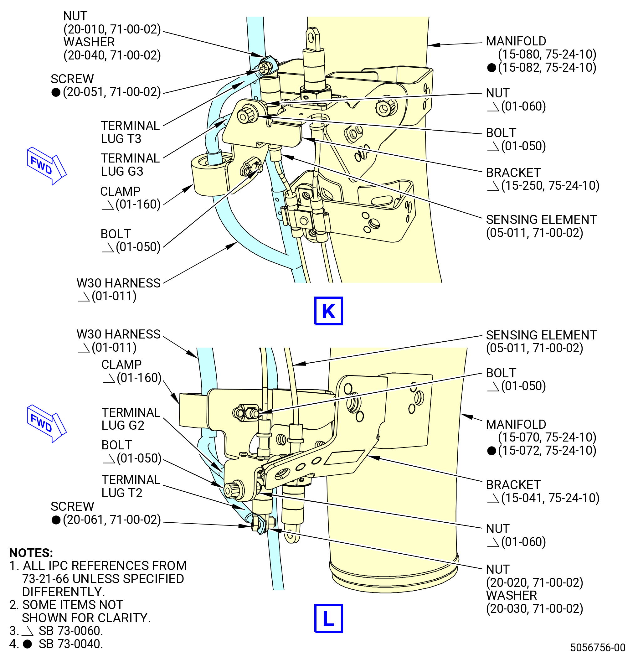
| d | Connect the harness blue terminal lug G2 on the manifold (15-072 , 75-24-10) (SIN 6220B) at the 4:15 o'clock position as follows: |
| (1) | Attach the terminal lug G2 to the bracket (15-041 , 75-24-10) (SIN 9801J) with a bolt (01-050 , 73-21-66) (SIN 68824) and nut (01-060 , 73-21-66) (SIN 68840). Hand-tighten the nut (01-060 , 73-21-66) (SIN 68840). Make sure that the terminal lug G2 is installed in the same bracket side of the nut (01-060 , 73-21-66) (SIN 68840). |
| e | Connect the harness yellow terminal lug T2 on the manifold (15-072 , 75-24-10) (SIN 6220B) at the 4:15 o'clock position as follows: |
| (1) | Attach the terminal lug T2 to the sensing element (05-011 , 71-00-02) (SIN C00A7) with a No. 10 screw (20-061 , 71-00-02) (SIN C00F4), No. 10 washer (washer) (20-030 , 71-00-02) (SIN C00J1), and No. 10 nut (nut) (20-020 , 71-00-02) (SIN C00K4). Make sure that the terminal lug G2 is below the screwhead of the No. 10 screw (20-061 , 71-00-02) (SIN C00F4) and the washer (20-030 , 71-00-02) (SIN C00J1) is below the nut (20-020 , 71-00-02) (SIN C00K4). |
| (2) | Torque the nut (20-020 , 71-00-02) (SIN C00K4) to 32 to 38 lb in. (3.6 to 4.2 Nm). |
| f | Connect the harness blue terminal lug G3 on the manifold (15-082 , 75-24-10) (SIN 6220C) at the 4:45 o'clock position as follows: |
| (1) | Attach the terminal lug G3 to the bracket (15-250 , 75-24-10) (SIN 9801L) with a bolt (01-050 , 73-21-66) (SIN 68824) and nut (01-060 , 73-21-66) (SIN 68840). Hand-tighten the nut (01-060 , 73-21-66) (SIN 68840). Make sure that the terminal lug G3 is installed in the same bracket side of the nut (01-060 , 73-21-66) (SIN 68840). |
| g | Connect the harness yellow terminal lug T3 on the manifold (15-082 , 75-24-10) (SIN 6220C) at the 4:45 o'clock position as follows: |
| (1) | Attach the terminal lug T3 to the sensing element (05-111 , 71-00-02) (SIN C00A7) with a No. 8 screw (20-051 , 71-00-02) (SIN C00F3), washer (20-040 , 71-00-02) (SIN C00J0), and nut (20-010 , 71-00-02) (SIN C00K3). Make sure that the terminal lug T3 is below the screwhead of the No. 8 screw (20-051 , 71-00-02) (SIN C00F3) and the washer (20-040 , 71-00-02) (SIN C00J0) is below the nut (20-010 , 71-00-02) (SIN C00K3). |
| (2) | Torque the nut (20-010 , 71-00-02) (SIN C00K3) to 23 to 27 lb in. (2.5 to 3.0 Nm). |
| h | Connect the harness blue terminal lug G4 on the manifold (15-082 , 75-24-10) (SIN 6220C) at the 7:15 o'clock position as follows: |
| (1) | Attach the terminal lug G4 to the bracket (15-041 , 75-24-10) (SIN 9801J) with a bolt (01-050 , 73-21-66) (SIN 68824) and nut (01-060 , 73-21-66) (SIN 68840). Hand-tighten the nut (01-060 , 73-21-66) (SIN 68840). Make sure that the terminal lug G4 is installed in the same bracket side of the nut (01-060 , 73-21-66) (SIN 68840). |
| i | Connect the harness yellow terminal lug T4 on the manifold (15-082 , 75-24-10) (SIN 6220C) at the 7:15 o'clock position as follows: |
| (1) | Attach the terminal lug T4 to the sensing element (05-111 , 71-00-02) (SIN C00A7) with a No. 10 screw (20-061 , 71-00-02) (SIN C00F4), washer (20-030 , 71-00-02) (SIN C00J1), and nut (20-020 , 71-00-02) (SIN C00K4). Make sure that the terminal lug T4 is below the screwhead of the No. 10 screw (20-061 , 71-00-02) (SIN C00F4) and the washer (20-030 , 71-00-02) (SIN C00J1) is below the nut (20-020 , 71-00-02) (SIN C00K4). |
| (2) | Torque the nut (20-020 , 71-00-02) (SIN C00K4) to 32 to 38 lb in. (3.6 to 4.2 Nm). |
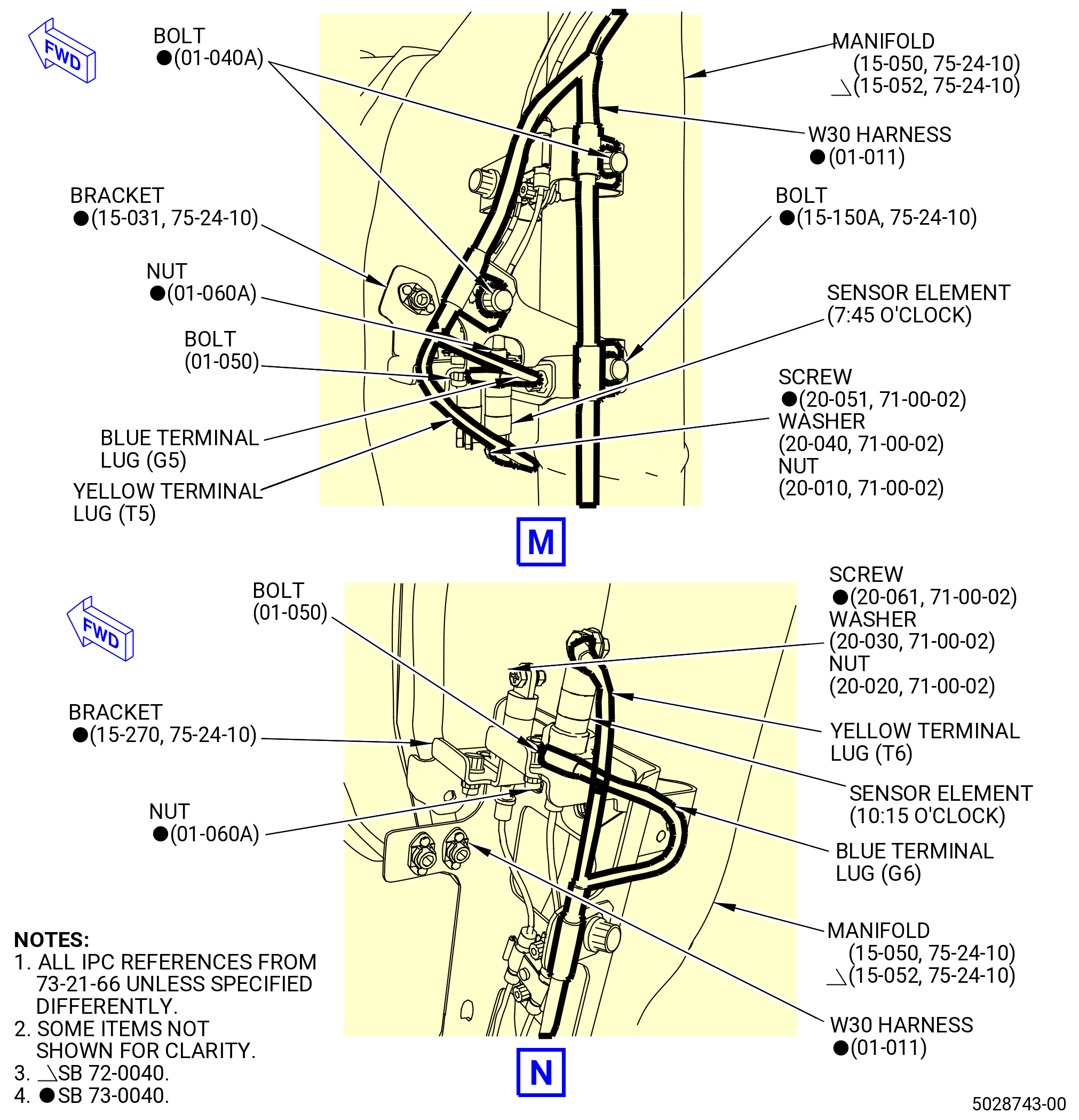
| j | Connect the harness blue terminal lug G5 on the manifold (15-052 , 75-24-10) (SIN 6220D) at the 7:45 o'clock position as follows: |
| (1) | Attach the terminal lug G5 to the bracket (15-031 , 75-24-10) (SIN 9801K) with a bolt (01-050 , 73-21-66) (SIN 68824) and nut (01-060 , 73-21-66) (SIN 68840). Hand-tighten the nut (01-060 , 73-21-66) (SIN 68840). Make sure that the terminal lug G5 is installed in the same bracket side of the nut (01-060 , 73-21-66) (SIN 68840). |
| k | Connect the harness yellow terminal lug T5 on the manifold (15-052 , 75-24-10) (SIN 6220D) at the 7:45 o'clock position as follows: |
| (1) | Attach the terminal lug T5 to the sensing element (05-061 , 71-00-02) (SIN C00A7) with a No. 8 screw (20-051 , 71-00-02) (SIN C00F3), washer (20-040 , 71-00-02) (SIN C00J0), and nut (20-010 , 71-00-02) (SIN C00K3). Make sure that the terminal lug T5 is below the screwhead of the No. 8 screw (20-051 , 71-00-02) (SIN C00F3) and the washer (20-040 , 71-00-02) (SIN C00J0) is below the nut (20-010 , 71-00-02) (SIN C00K3). |
| (2) | Torque the nut (20-010 , 71-00-02) (SIN C00K3) to 23 to 27 lb in. (2.5 to 3.0 Nm). |
| l | Connect the harness blue terminal lug G6 on the manifold (15-052 , 75-24-10) (SIN 6220D) at the 10:15 o'clock position as follows: |
| (1) | Attach the terminal lug G6 to the bracket (15-270 , 75-24-10) (SIN 9801N) with a bolt (01-050 , 73-21-66) (SIN 68824) and the nut (01-060 , 73-21-66) (SIN 68840). Make sure that the terminal lug G6 is installed in the same bracket side of the nut (01-060 , 73-21-66) (SIN 68840). |
| (2) | Torque the nut (01-060 , 73-21-66) (SIN 68840) to 51 to 59 lb in. (5.7 to 6.6 Nm). |
| m | Connect the harness yellow terminal lug T6 on the manifold (15-052 , 75-24-10) (SIN 6220D) at the 10:15 o'clock position as follows: |
| (1) | Attach the terminal lug T6 to the sensing element (05-061 , 71-00-02) (SIN C00A7) with a No. 10 screw (20-061 , 71-00-02) (SIN C00F4), washer (20-030 , 71-00-02) (SIN C00J1), and nut (20-020 , 71-00-02) (SIN C00K4). Make sure that the terminal lug T6 is below the screwhead of the No. 10 screw (20-061 , 71-00-02) (SIN C00F4) and the washer (20-030 , 71-00-02) (SIN C00J1) is below the nut (20-020 , 71-00-02) (SIN C00K4). |
| (2) | Torque the nut (20-020 , 71-00-02) (SIN C00K4) to 32 to 38 lb in. (3.6 to 4.2 Nm). |
| 4 | Torque the bolts (01-040 , 73-21-66) (SIN 68823) to 60 to 70 lb in. (6.7 to 7.9 Nm). |
| 5 | Torque the bolts (15-155 , 75-24-10) (SIN 98028) to 60 to 70 lb in. (6.7 to 7.9 Nm). |
| 6 | Torque the bolts (01-050 , 73-21-66) (SIN 68824) to 32 to 38 lb in. (3.6 to 4.2 Nm). |
| * * * END SB 73-0060 |
|
|
|
|
|
|
|
|
|
|
|
|
|
|
|
|
|
|
|
|
| Subtask 72-00-02-431-034 |
| * * * PRE SB 73-0060( Old Design for W30 and W31 Harnesses ) |
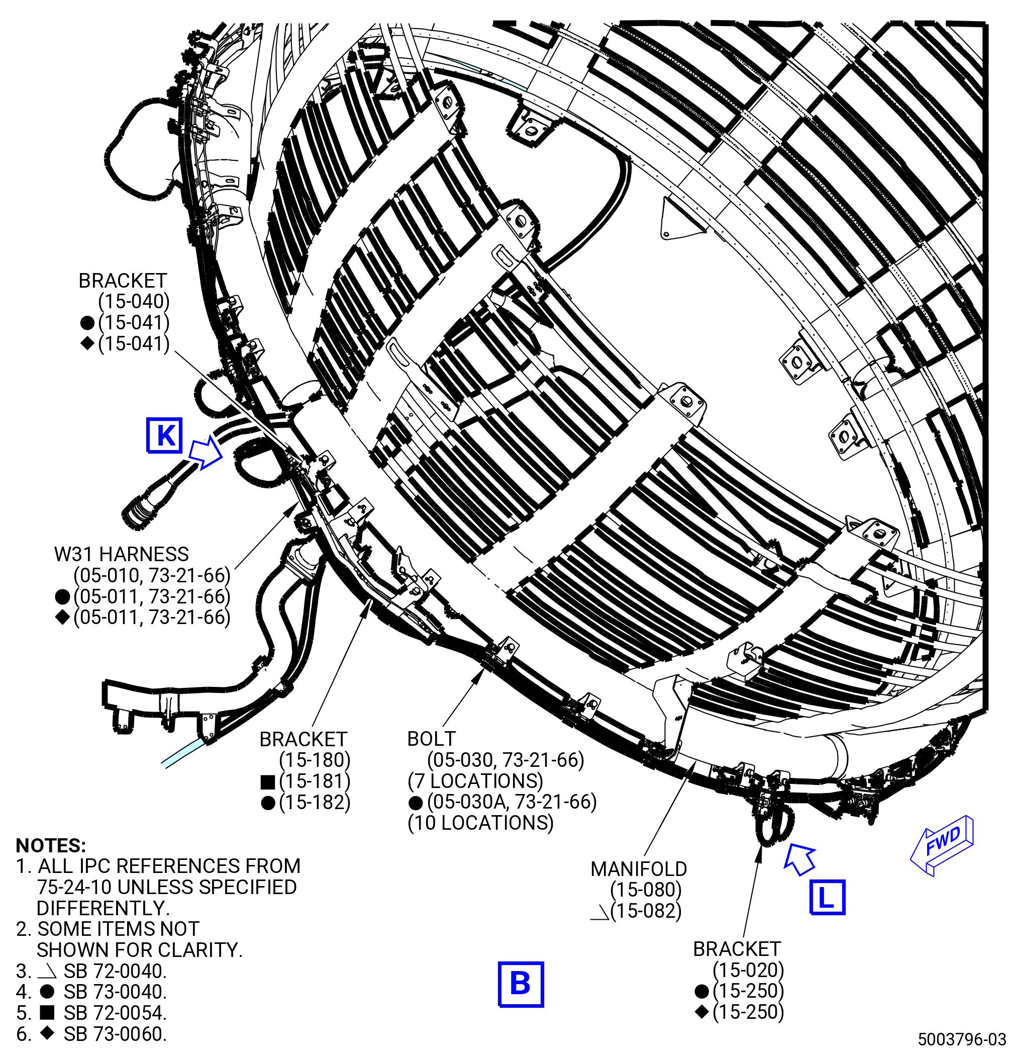
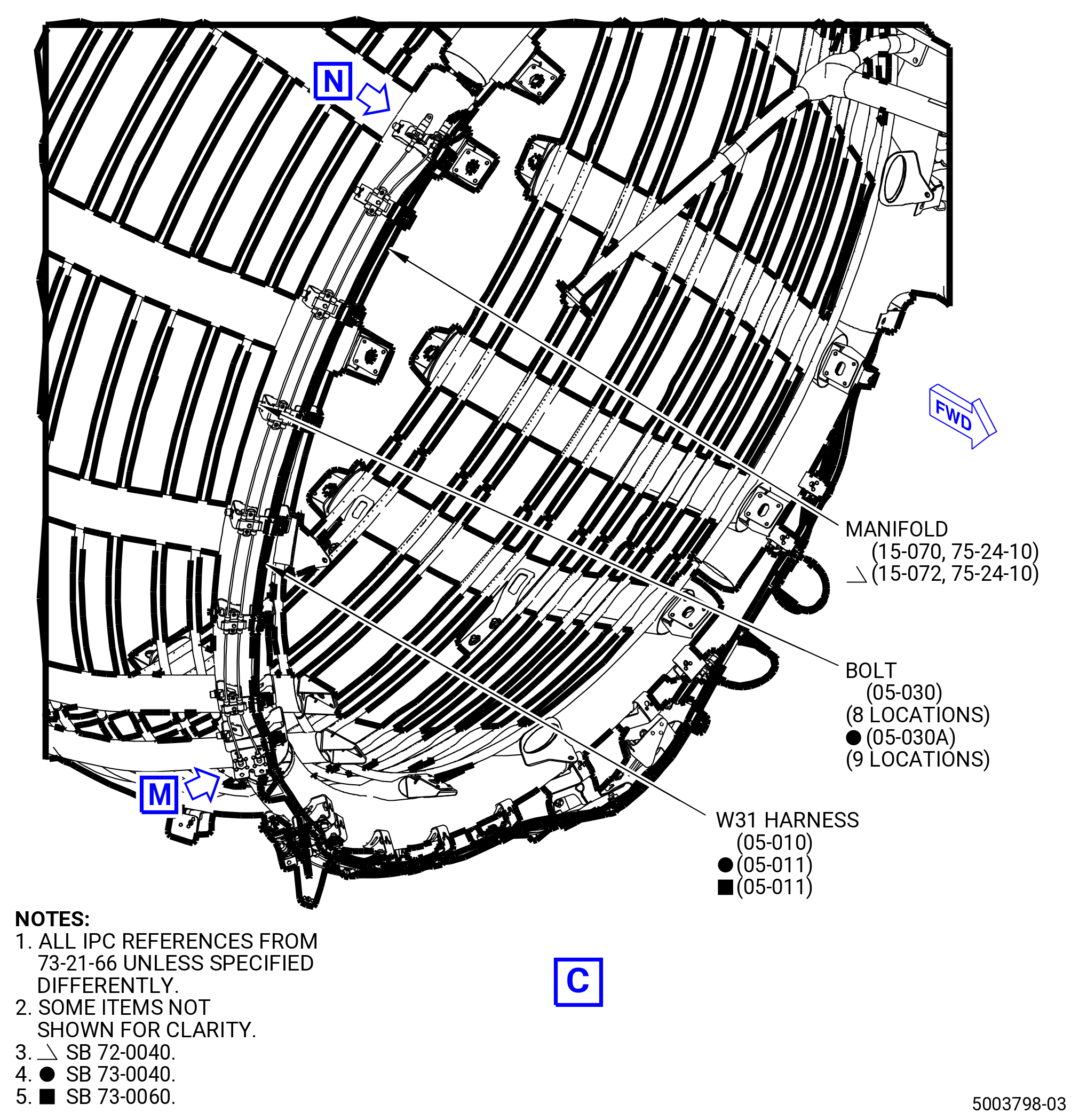
| (10) | Install the W31 harness (05-010 , 73-21-66) (SIN 68801) or (05-011 , 73-21-66) (SIN 68801). Refer to Figure 1011 and do as follows: |
| (a) | Put the W31 harness (05-010 , 73-21-66) (SIN 68801) or (05-011 , 73-21-66) (SIN 68801) in position along the manifold (15-060 , 75-24-10) (SIN 6220A) or (15-062 , 75-24-10) (SIN 6220A). |
| (b) | Attach the W31 harness (05-010 , 73-21-66) (SIN 68801) or (05-011 , 73-21-66) (SIN 68801) to the bracket (05-080 , 79-22-30) (SIN 6881D) with one bolt (05-030 , 73-21-66) (SIN 68823). Hand tighten the bolt. |
| (c) | Attach the W31 harness (05-010 , 73-21-66) (SIN 68801) or (05-011 , 73-21-66) (SIN 68801) to the manifold (15-060 , 75-24-10) (SIN 6220A) or (15-062 , 75-24-10) (SIN 6220A) with three bolts (05-030 , 73-21-66) (SIN 68823). Hand tighten the bolts. |
| Subtask 72-00-02-431-024 |
| * * * PRE SB 73-0040( W30 and W31 Harnesses without Improvements ) |
| (d) | Attach the W31 harness (05-010 , 73-21-66) (SIN 68801) to the manifold (15-050 , 75-24-10) (SIN 6220D) or (15-052 , 75-24-10) (SIN 6220D), bracket (15-160 , 75-24-10) (SIN 9801E), and support bracket (15-170 , 75-24-10) (SIN 9801D) with eight bolts (05-030 , 73-21-66) (SIN 68823). Hand tighten the bolts. |
| (e) | Attach the W31 harness (05-010 , 73-21-66) (SIN 68801) to the manifold (15-080 , 75-24-10) (SIN 6220C) or (15-082 , 75-24-10) (SIN 6220C) and bracket (15-180 , 75-24-10) (SIN 9801F) or (15-181 , 75-24-10) (SIN 9801F) with seven bolts (05-030 , 73-21-66) (SIN 68823). Hand tighten the bolts. |
| (f) | Attach the W31 harness (05-010 , 73-21-66) (SIN 68801) to the manifold (15-070 , 75-24-10) (SIN 6220B) or (15-072 , 75-24-10) (SIN 6220B) with eight bolts (05-030 , 73-21-66) (SIN 68823). Hand tighten the bolts. |
| * * * END PRE SB 73-0040 |
| Subtask 72-00-02-431-025 |
| * * * SB 73-0040( Improved W30 and W31 Harnesses ) |
| (g) | Attach the W31 harness (05-011 , 73-21-66) (SIN 68801) to the manifold (15-050 , 75-24-10) (SIN 6220D) or (15-052 , 75-24-10) (SIN 6220D), bracket (15-160 , 75-24-10) (SIN 9801E), and support bracket (15-171 , 75-24-10) (SIN 9801D) with eight bolts (05-030A , 73-21-66) (SIN 68823). Hand tighten the bolts. |
| (h) | Attach the W31 harness (05-011 , 73-21-66) (SIN 68801) branches to support bracket (15-270 , 75-24-10) (SIN 9801N) and end lug bracket (15-031 , 75-24-10) (SIN 9801K) with two bolts (01-040A , 73-21-66) (SIN 68823). Hand-tighten the bolts. |
| (i) | Attach the W31 harness (05-011 , 73-21-66) (SIN 68801) to the manifold (15-080 , 75-24-10) (SIN 6220C) or (15-082 , 75-24-10) (SIN 6220C), end lug bracket (15-041 , 75-24-10) (SIN 9801J) and bracket (15-182 , 75-24-10) (SIN 9801F) with eight bolts (05-030A , 73-21-66) (SIN 68823). Hand tighten the bolts. |
| (j) | Attach the W31 harness (05-011 , 73-21-66) (SIN 68801) branches to end lug brackets (15-041 , 75-24-10) (SIN 9801J) and (15-250 , 75-24-10) (SIN 9801L) with two bolts (01-040A , 73-21-66) (SIN 68823). Hand tighten the bolts. |
| (k) | Attach the W31 harness (05-011 , 73-21-66) (SIN 68801) to the manifold (15-070 , 75-24-10) (SIN 6220B) or (15-072 , 75-24-10) (SIN 6220B), end lug bracket (15-021 , 75-24-10) (SIN 9801G) and (15-041 , 75-24-10) (SIN 9801J) with eight bolts (05-030A , 73-21-66) (SIN 68823). Hand tighten the bolts. |
| (l) | Attach the W31 harness (05-011 , 73-21-66) (SIN 68801) branch to end lug bracket (15-041 , 75-24-10) (SIN 9801J) with a bolt (01-040A , 73-21-66) (SIN 68823). Hand tighten the bolts. |
| * * * END SB 73-0040 |
| Subtask 72-00-02-431-026 |
| (m) | Attach the W31 harness (05-011 , 73-21-66) (SIN 68801) branch to end lug bracket (15-021 , 75-24-10) (SIN 9801G) with a bolt (01-040A , 73-21-66) (SIN 68823). Hand-tighten the bolts. |
| (n) | Put the W31 harness (05-010 , 73-21-66) (SIN 68801) or (05-011 , 73-21-66) (SIN 68801) in the spring clips attached to the brackets on the oil vent manifold (05-110 , 79-22-30) (SIN 46101) or (05-111 , 79-22-30) (SIN 46101). |
| (o) | Put the W31 harness (05-010 , 73-21-66) (SIN 68801) or (05-011 , 73-21-66) (SIN 68801) in the spring clips attached to the bracket (05-380 , 79-22-30) (SIN 4611C) and the brackets attached to the oil tube (05-030 , 79-22-30) (SIN 46100). |
| * * * PRE SB 72-0094( Engine without Engine Anti-Ice ) |
| (p) | Put the W31 harness (05-010 , 73-21-66) (SIN 68801) in the spring clips attached to the bracket (05-080 , 73-21-66) (SIN 6881V). |
| NOTE: |
|
| * * * END PRE SB 72-0094 |
| * * * SB 72-0094( Engine with Engine Anti-Ice ) |
| (p).A. | Put the W31 harness (05-010 , 73-21-66) (SIN 68801) or (05-011 , 73-21-66) (SIN 68801) in the spring clips attached to the bracket (01-141 , 75-11-30) (SIN 63717). |
| * * * END SB 72-0094 |
| (q) | Put the W31 harness (05-010 , 73-21-66) (SIN 68801) or (05-011 , 73-21-66) (SIN 68801) in the spring clips attached to brackets (30-270) (SIN 68816), (25-560 , 72-00-00) (SIN 6881U), (01-120 , 75-42-10) (SIN 53012), (30-620) (SIN 6711B), and (30-590) (SIN 6711C). |
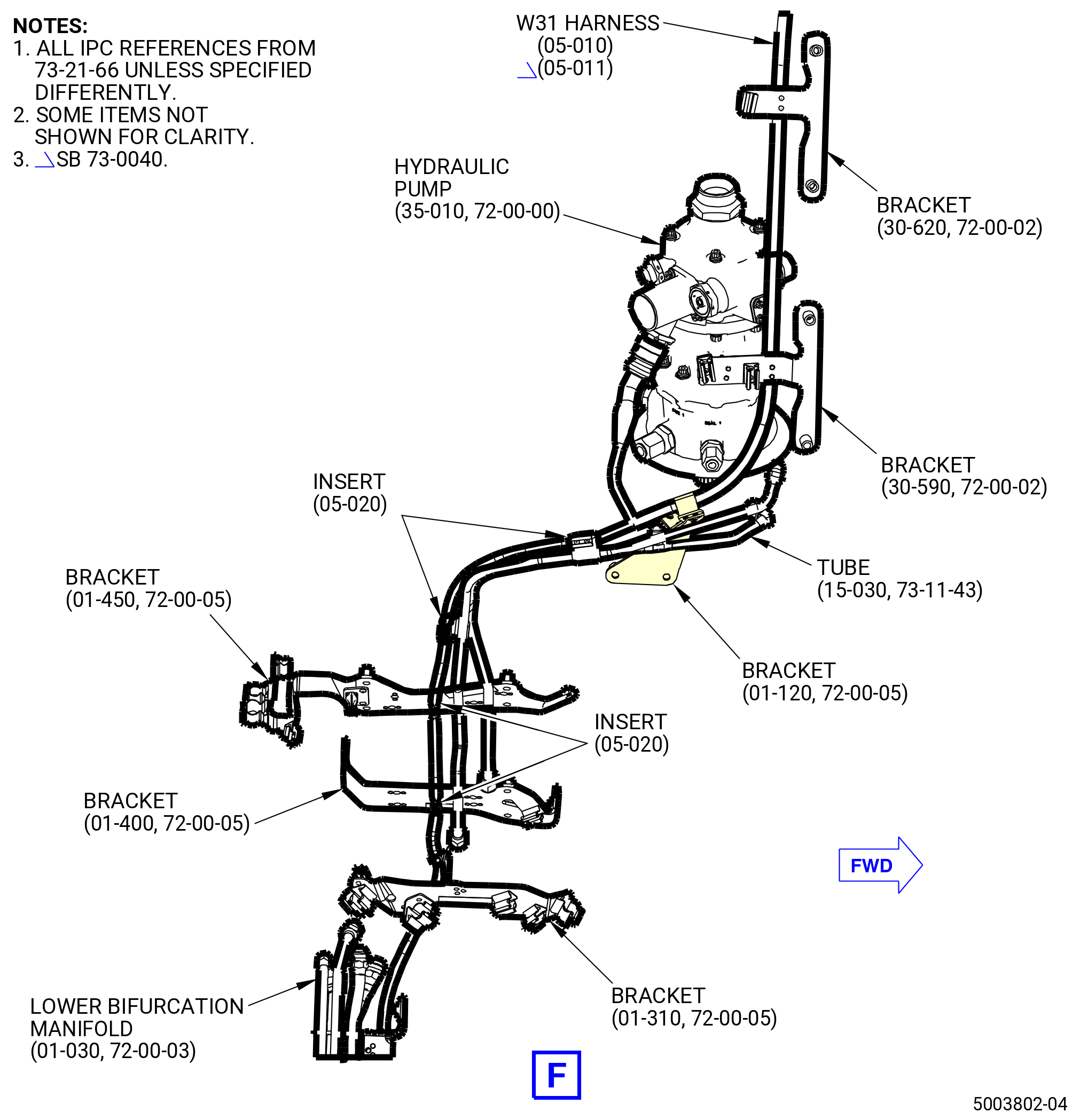
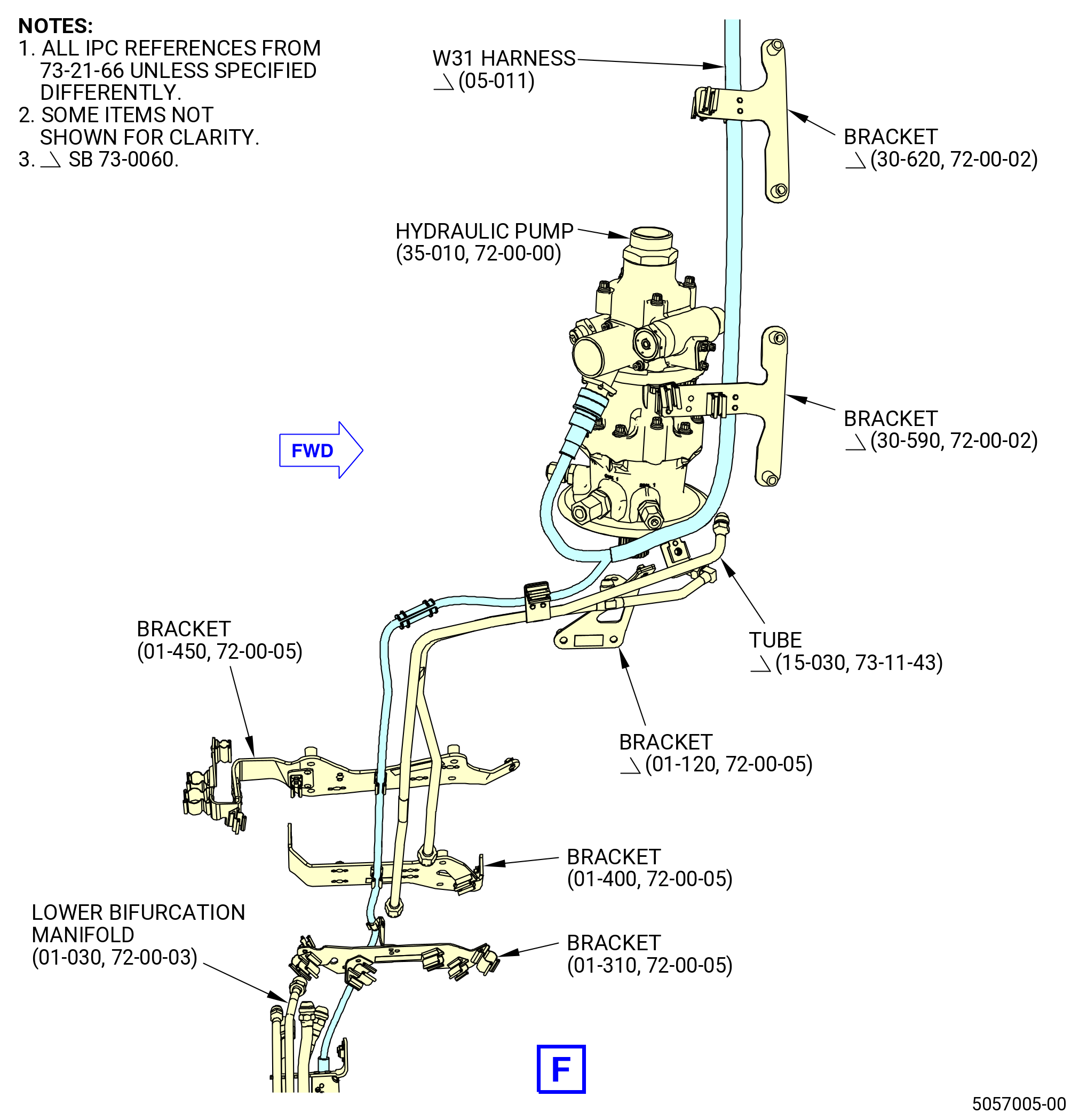
| (r) | Put the W31 harness (05-010 , 73-21-66) (SIN 68801) or (05-011 , 73-21-66) (SIN 68801) in the spring clips attached to the support drain bracket (bracket) (01-120 , 72-00-05) (SIN 37312). |
| (s) | Install two inserts (05-020 , 73-21-66) (SIN 68834) on the spring clips attached to the tube (15-030 , 73-11-43) (SIN 37302). |
| (t) | Put the W31 harness (05-010 , 73-21-66) (SIN 68801) or (05-011 , 73-21-66) (SIN 68801) in the spring clips attached to the tube (15-030 , 73-11-43) (SIN 37302). |
| CAUTION: |
|
| (u) | Connect the P311 harness connector to the hydraulic pump (35-010 , 72-00-00) (SIN C00A6). |
| CAUTION: |
|
| (v) | Tighten the P311 harness connector with teflon-jaw pliers. |
| (w) | Install inserts (05-020 , 73-21-66) (SIN 68834) on the spring clips of the brackets (01-450 , 72-00-05) (SIN 37010) and (01-400 , 72-00-05) (SIN 37011). |
| (x) | Put the W31 harness (05-010 , 73-21-66) (SIN 68801) or (05-011 , 73-21-66) (SIN 68801) in the spring clips attached to the brackets (01-450 , 72-00-05) (SIN 37010) and (01-400 , 72-00-05) (SIN 37011). |
| (y) | Put the W31 harness (05-010 , 73-21-66) (SIN 68801) or (05-011 , 73-21-66) (SIN 68801) in the spring clips attached to the bracket (01-310 , 72-00-05) (SIN 6711G). |
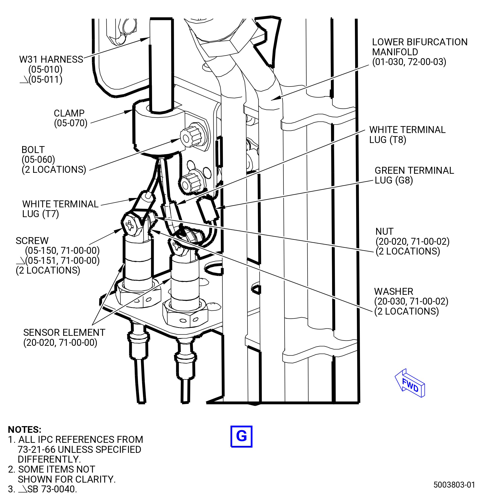
| (z) | Attach the W31 harness (05-010 , 73-21-66) (SIN 68801) or (05-011 , 73-21-66) (SIN 68801) to the lower bifurcation manifold (01-030 , 72-00-03) (SIN 99004) with one clamp (05-070 , 73-21-66) (SIN 68884) and bolt (05-060 , 73-21-66) (SIN 68822). Torque the bolt to 32 to 38 lb in. (3.6 to 4.3 Nm). |
| (aa) | Connect the harness green terminal lug G8 to the lower bifurcation manifold (01-030 , 72-00-03) (SIN 99004) with one bolt (05-060 , 73-21-66) (SIN 68822). Torque the bolt to 32 to 38 lb in. (3.6 to 4.3 Nm). |
| Subtask 72-00-02-431-027 |
| * * * PRE SB 73-0040( W30 and W31 Harnesses without Improvements ) |
| (ab) | Connect the harness white terminal lugs T7 and T8 to the No. 10 sensor element (sensor element) (20-020 , 71-00-00) (SIN C00A9) on the lower bifurcation manifold (01-030 , 72-00-03) (SIN 99004) with No. 10 screws (05-150 , 71-00-00) (SIN C00F4), washers (05-160 , 71-00-00) (SIN C00J1), and nuts (05-190 , 71-00-00) (SIN C00K4). Make sure that the terminal lugs are under the screwheads and torque the nuts to 32-38 lb in. (3.6-4.3 N.m). |
| (ac) | Connect the W31 harness to the sensor elements on manifolds (15-060 , 75-24-10) (SIN 6220A) or (15-062 , 75-24-10) (SIN 6220A), (15-070 , 75-24-10) (SIN 6220B) or (15-072 , 75-24-10) (SIN 6220B), (15-080 , 75-24-10) (SIN 6220C) or (15-082 , 75-24-10) (SIN 6220C), and (15-050 , 75-24-10) (SIN 6220D) or (15-052 , 75-24-10) (SIN 6220D) as follows: |
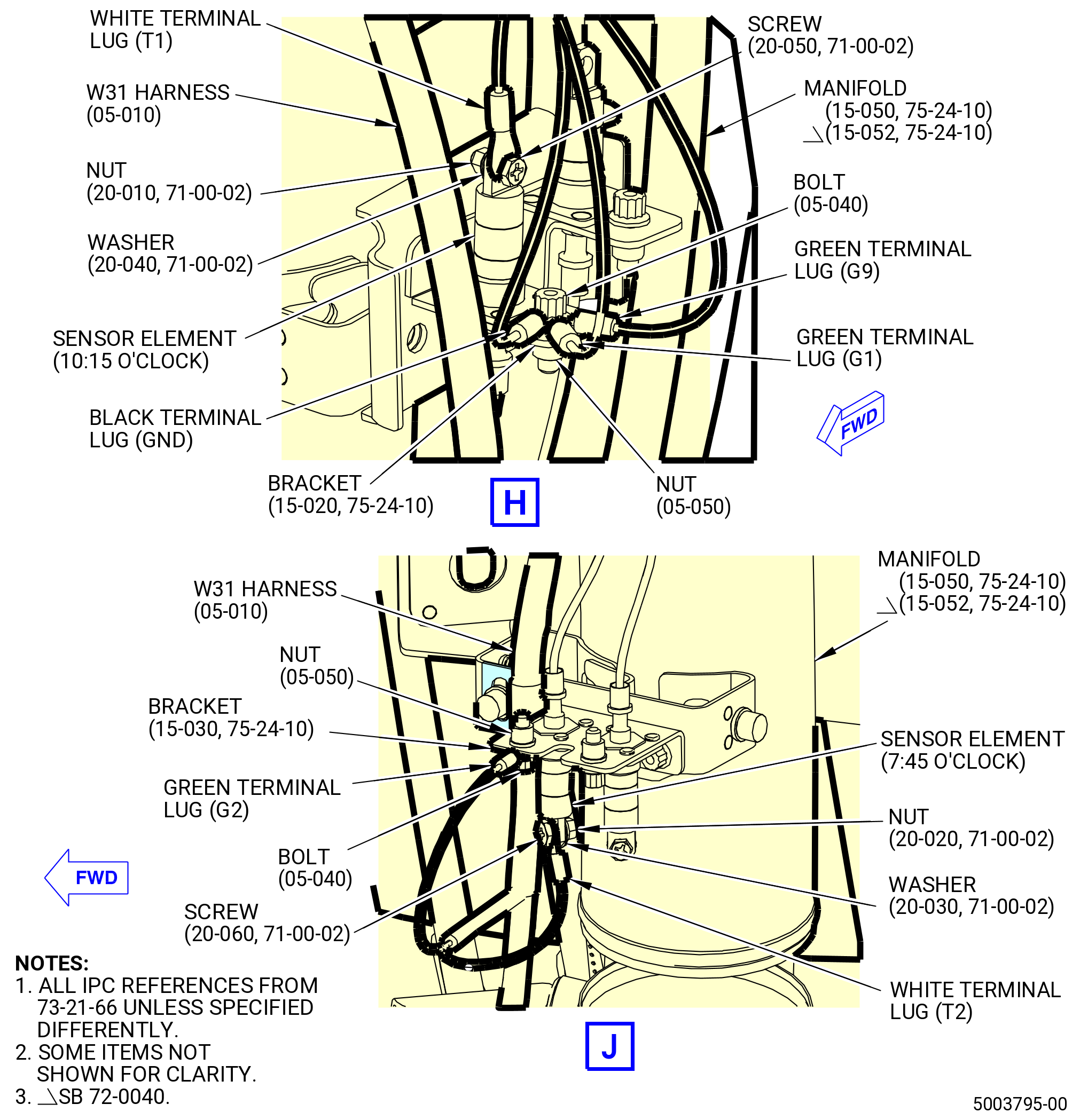
| 1 | Connect the harness green terminal lugs G1 and G9 and the black terminal lug GND to the bracket (15-020 , 75-24-10) (SIN 9801G) at the 10:15 o’clock position with the bolt (05-040 , 73-21-66) (SIN 68824) and nut (05-050 , 73-21-66) (SIN 68840). Make sure that the terminal lugs are under the bolthead and torque the nut to 51-59 lb in. (5.8-6.7 N.m). |
| 2 | Connect the harness white terminal lug T1 to the sensor element at the 10:15 o'clock position with one screw (20-050 , 71-00-02) (SIN C00F3), washer (20-040 , 71-00-02) (SIN C00J0), and nut (20-010 , 71-00-02) (SIN C00K3). Make sure that the terminal lug is under the screwhead and the washer is under the nut. Torque the nut to 23-27 lb in. (2.6-3.1 N.m). |
| 3 | Connect the harness green terminal lug G2 to the bracket (15-030 , 75-24-10) (SIN 9801K) at the 7:45 o'clock position with the bolt (05-040 , 73-21-66) (SIN 68824) and nut (05-050 , 73-21-66) (SIN 68840). Make sure that the terminal lug is under the bolthead and torque the nut to 51-59 lb in. (5.8-6.7 N.m). |
| 4 | Connect the harness white terminal lug T2 to the sensor element at the 7:45 o'clock position with one screw (20-060 , 71-00-02) (SIN C00F4), washer (20-030 , 71-00-02) (SIN C00J1), and nut (20-020 , 71-00-02) (SIN C00K4). Make sure that the terminal lug is under the screwhead and the washer is under the nut. Torque the nut to 32-38 lb in. (3.6-4.3 N.m). |
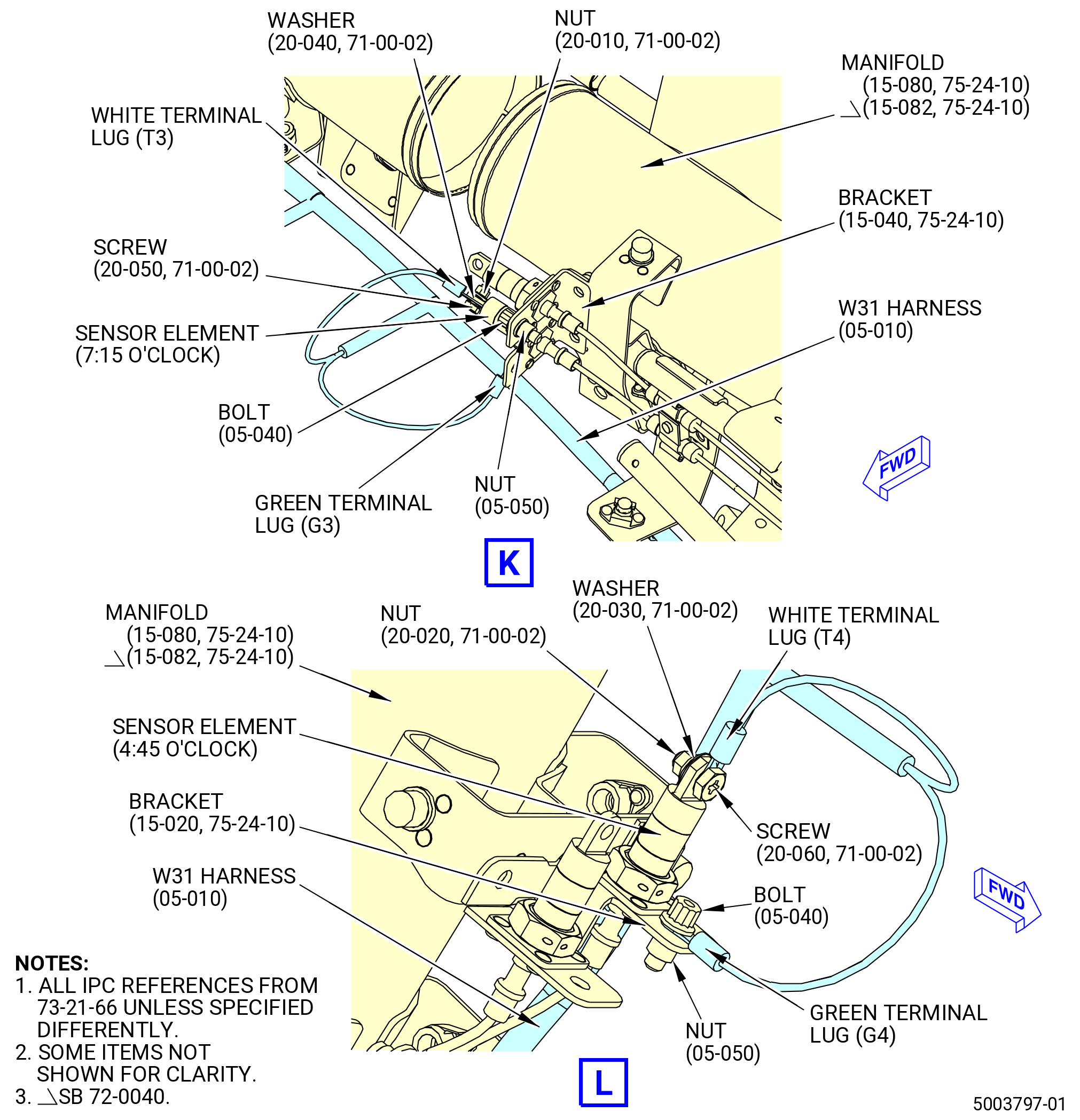
| 5 | Connect the harness green terminal lug G3 to the bracket (15-040 , 75-24-10) (SIN 9801J) at the 7:15 o'clock position with the bolt (05-040 , 73-21-66) (SIN 68824) and nut (05-050 , 73-21-66) (SIN 68840). Make sure that the terminal lug is under the bolthead and torque the nut to 51-59 lb in. (5.8-6.7 N.m). |
| 6 | Connect the harness white terminal lug T3 to the sensor element at the 7:15 o'clock position with one screw (20-050 , 71-00-02) (SIN C00F3), washer (20-040 , 71-00-02) (SIN C00J0), and nut (20-010 , 71-00-02) (SIN C00K3). Make sure that the terminal lug is under the screwhead and the washer is under the nut. Torque the nut to 23-27 lb in. (2.6-3.1 N.m). |
| 7 | Connect the harness green terminal lug G4 to the ground at the 4:45 o'clock position on the bracket (15-020 , 75-24-10) (SIN 9801G) with one bolt (05-040 , 73-21-66) (SIN 68824) and nut (05-050 , 73-21-66) (SIN 68840). Make sure that the terminal lug is under the bolthead and torque the nut to 51-59 lb in. (5.8-6.7 N.m). |
| 8 | Connect the harness white terminal lug T4 to the sensor element at the 4:45 o'clock position with one screw (20-060 , 71-00-02) (SIN C00F4), washer (20-030 , 71-00-02) (SIN C00J1), and nut (20-020 , 71-00-02) (SIN C00K4). Make sure that the terminal lug is under the screwhead and the washer is under the nut. Torque the nut to 32-38 lb in. (3.6-4.3 N.m). |
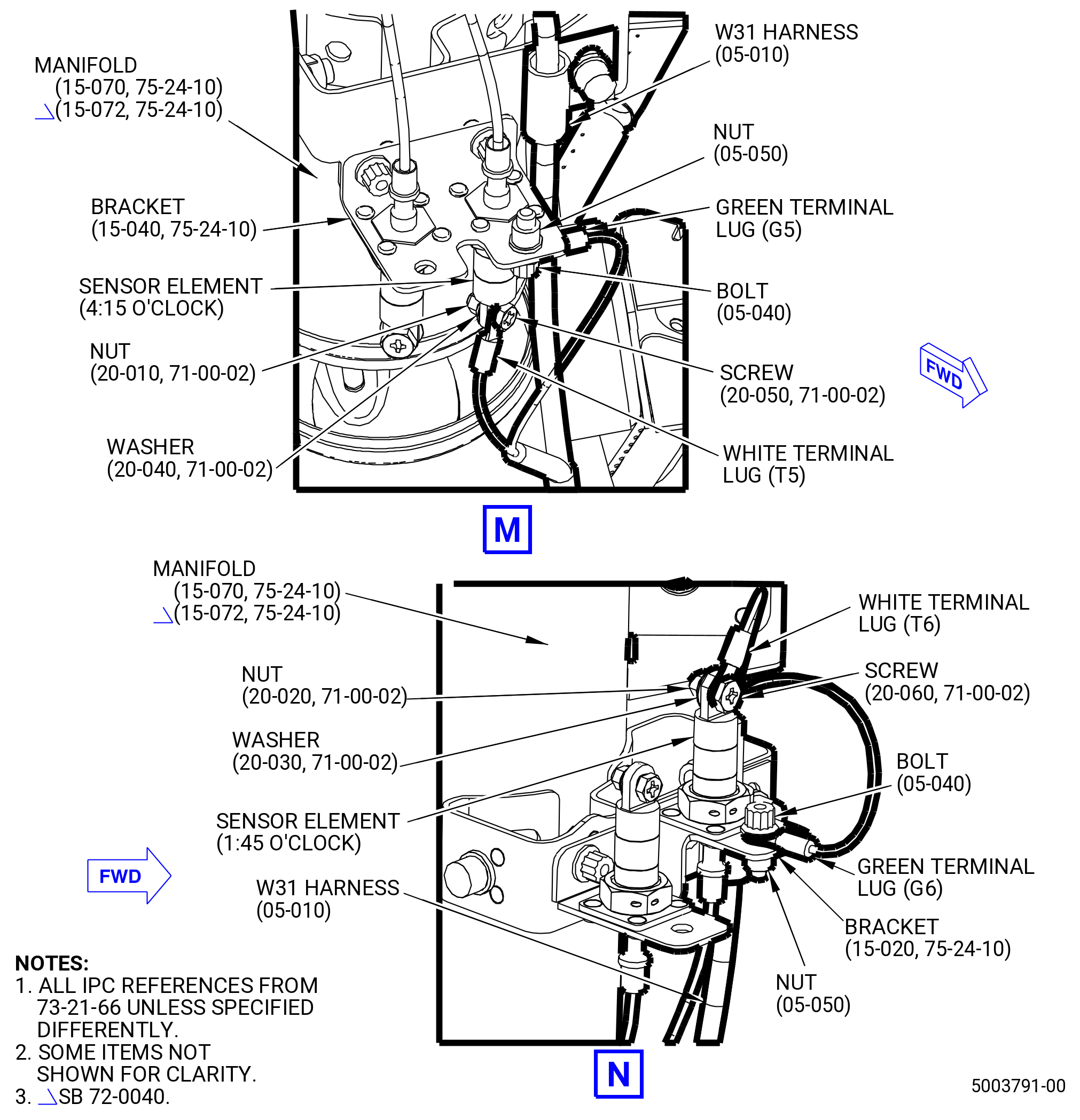
| 9 | Connect the harness green terminal lug G5 to the ground at the 4:15 o'clock position on the bracket (15-040 , 75-24-10) (SIN 9801J) with one bolt (05-040 , 73-21-66) (SIN 68824) and nut (05-050 , 73-21-66) (SIN 68840). Make sure that the terminal lug is under the bolthead and torque the nut to 51-59 lb in. (5.8-6.7 N.m). |
| 10 | Connect the harness white terminal lug T5 to the sensor element at the 4:15 o'clock position with one screw (20-050 , 71-00-02) (SIN C00F3), washer (20-040 , 71-00-02) (SIN C00J0), and nut (20-010 , 71-00-02) (SIN C00K3). Make sure that the terminal lug is under the screwhead and the washer is under the nut. Torque the nut to 23-27 lb in. (2.6-3.1 N.m). |
| 11 | Connect the harness green terminal lug G6 to the ground at the 1:45 o'clock position on the bracket (15-020 , 75-24-10) (SIN 9801G) with one bolt (05-040 , 73-21-66) (SIN 68824) and nut (05-050 , 73-21-66) (SIN 68840). Make sure that the terminal lug is under the bolthead and torque the nut to 51-59 lb in. (5.8-6.7 N.m). |
| 12 | Connect the harness white terminal lug T6 to the sensor element at the 1:45 o'clock position with one screw (20-060 , 71-00-02) (SIN C00F4), washer (20-030 , 71-00-02) (SIN C00J1), and nut (20-020 , 71-00-02) (SIN C00K4). Make sure that the terminal lug is under the screwhead and the washer is under the nut. Torque the nut to 32-38 lb in. (3.6-4.3 N.m). |
| * * * END PRE SB 73-0040 |
| Subtask 72-00-02-431-028 |
| * * * SB 73-0040( Improved W30 and W31 Harnesses ) |
| (ad) | Connect the W31 harness (05-011 , 73-21-66) (SIN 68801) white terminal lugs T7 and T8 to the No. 10 sensor element (sensor element) (20-020 , 71-00-00) (SIN C00A9) on the lower bifurcation manifold (01-030 , 72-00-03) (SIN 99004) with No. 10 screws (05-151 , 71-00-00) (SIN C00F4), washers (05-160 , 71-00-00) (SIN C00J1), and nuts (05-190 , 71-00-00) (SIN C00K4). Make sure that the terminal lugs are under the screwheads and torque the nuts to 32 to 38 lb in. (3.6 to 4.3 Nm). |
| (ae) | Connect the W31 harness (05-011 , 73-21-66) (SIN 68801) to the sensor elements on manifolds (15-060 , 75-24-10) (SIN 6220A) or (15-062 , 75-24-10) (SIN 6220A), (15-070 , 75-24-10) (SIN 6220B) or (15-072 , 75-24-10) (SIN 6220B), (15-080 , 75-24-10) (SIN 6220C) or (15-082 , 75-24-10) (SIN 6220C), and (15-050 , 75-24-10) (SIN 6220D) or (15-052 , 75-24-10) (SIN 6220D) as follows: |
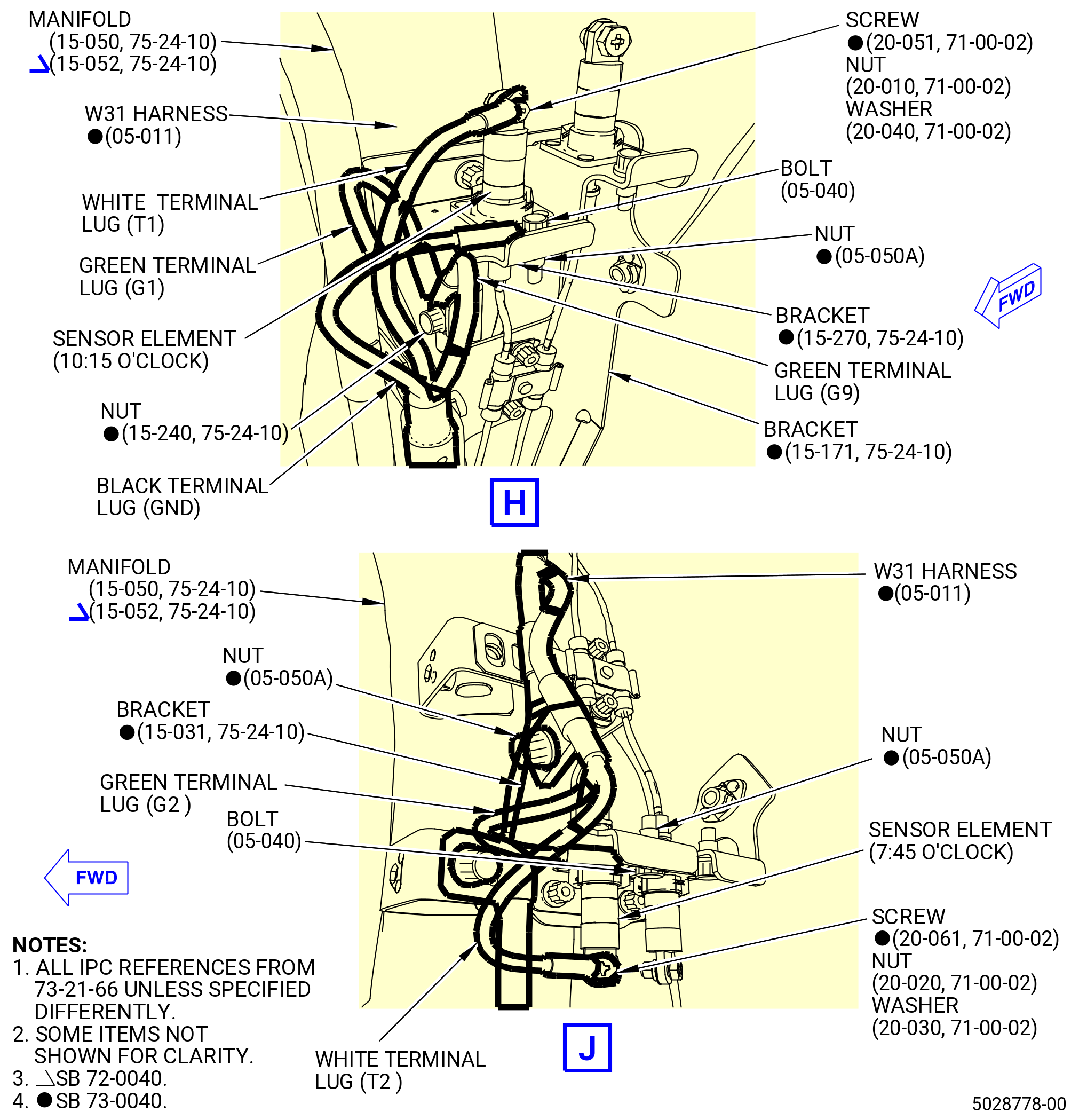
| 1 | Connect the harness green terminal lugs G1 and G9 with one bolt (15-240 , 75-24-10) (SIN 9802E) and the black terminal lug GND with one bolt (01-050 , 73-21-66) (SIN 68824) to the bracket (15-270 , 75-24-10) (SIN 9801N) at the 10:15 o’clock position with two nuts (05-050A , 73-21-66) (SIN 68840). Make sure that the terminal lugs are under the bolthead and torque the nut to 51 to 59 lb in. (5.8 to 6.7 Nm). |
| 2 | Connect the harness white terminal lug T1 to the sensor element at the 10:15 o'clock position with one screw (20-051 , 71-00-02) (SIN C00F3), washer (20-040 , 71-00-02) (SIN C00J0), and nut (20-010 , 71-00-02) (SIN C00K3). Make sure that the terminal lug is under the screwhead and the washer is under the nut. Torque the nut to 23 to 27 lb in. (2.6 to 3.1 Nm). |
| 3 | Connect the harness green terminal lug G2 to the bracket (15-031 , 75-24-10) (SIN 9801K) at the 7:45 o'clock position with the bolt (05-040 , 73-21-66) (SIN 68824) and nut (05-050A , 73-21-66) (SIN 68840). Make sure that the terminal lug is under the bolthead and torque the nut to 51 to 59 lb in. (5.8 to 6.7 Nm). |
| 4 | Connect the harness white terminal lug T2 to the sensor element at the 7:45 o'clock position with one screw (20-061 , 71-00-02) (SIN C00F4), washer (20-030 , 71-00-02) (SIN C00J1), and nut (20-020 , 71-00-02) (SIN C00K4). Make sure that the terminal lug is under the screwhead and the washer is under the nut. Torque the nut to 32 to 38 lb in. (3.6 to 4.3 Nm). |
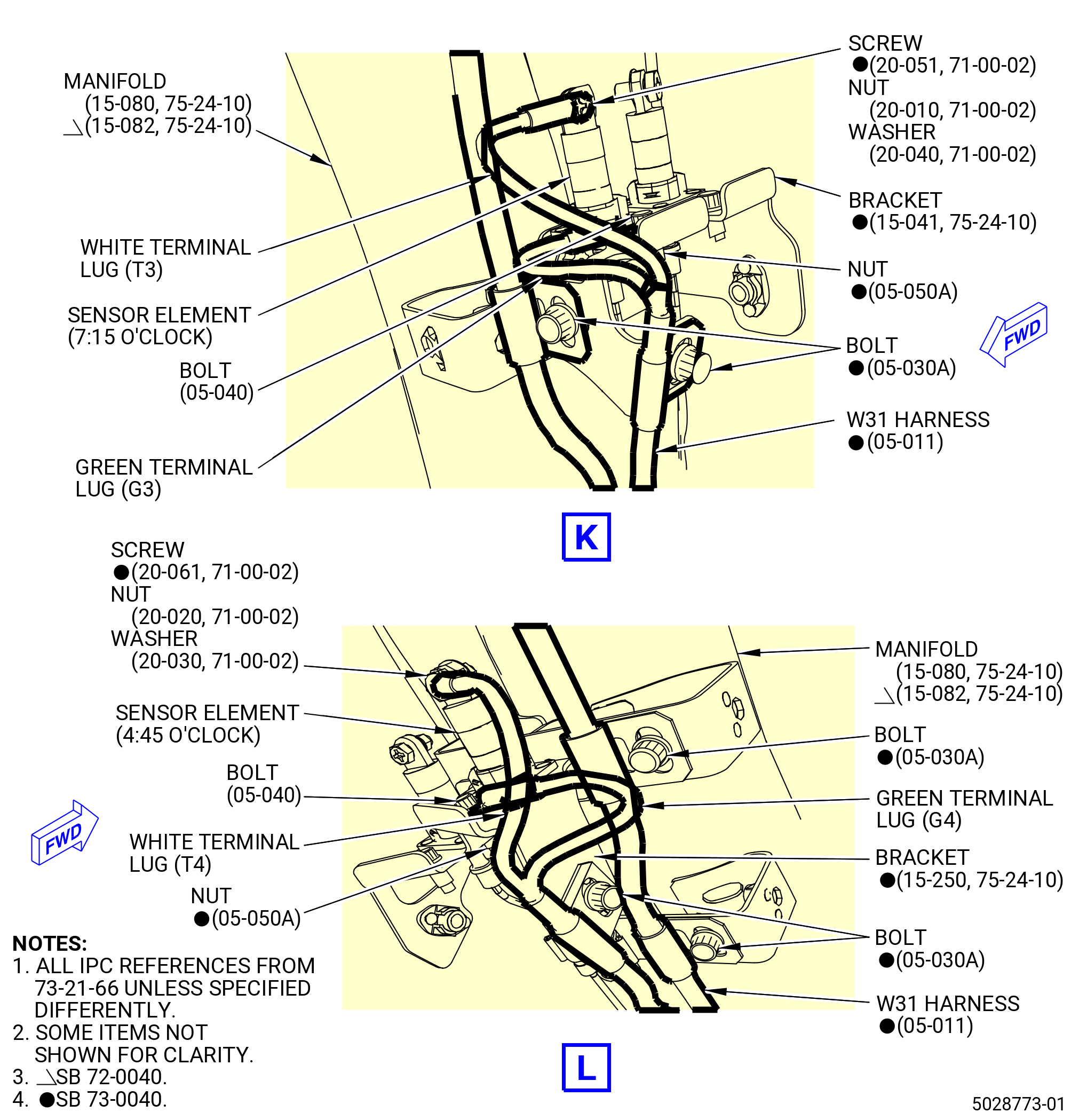
| 5 | Connect the harness green terminal lug G3 to the bracket (15-041 , 75-24-10) (SIN 9801J) at the 7:15 o'clock position with the bolt (05-040 , 73-21-66) (SIN 68824) and nut (05-050A , 73-21-66) (SIN 68840). Make sure that the terminal lug is under the bolthead and torque the nut to 51 to 59 lb in. (5.8 to 6.7 Nm). |
| 6 | Connect the harness white terminal lug T3 to the sensor element at the 7:15 o'clock position with one screw (20-051 , 71-00-02) (SIN C00F3), washer (20-040 , 71-00-02) (SIN C00J0), and nut (20-010 , 71-00-02) (SIN C00K3). Make sure that the terminal lug is under the screwhead and the washer is under the nut. Torque the nut to 23 to 27 lb in. (2.6 to 3.1 Nm). |
| 7 | Connect the harness green terminal lug G4 to the ground at the 4:45 o'clock position on the bracket (15-250 , 75-24-10) (SIN 9801L) with one bolt (05-040 , 73-21-66) (SIN 68824) and nut (05-050A , 73-21-66) (SIN 68840). Make sure that the terminal lug is under the bolthead and torque the nut to 51 to 59 lb in. (5.8 to 6.7 Nm). |
| 8 | Connect the harness white terminal lug T4 to the sensor element at the 4:45 o'clock position with one screw (20-061 , 71-00-02) (SIN C00F4), washer (20-030 , 71-00-02) (SIN C00J1), and nut (20-020 , 71-00-02) (SIN C00K4). Make sure that the terminal lug is under the screwhead and the washer is under the nut. Torque the nut to 32 to 38 lb in. (3.6 to 4.3 Nm). |
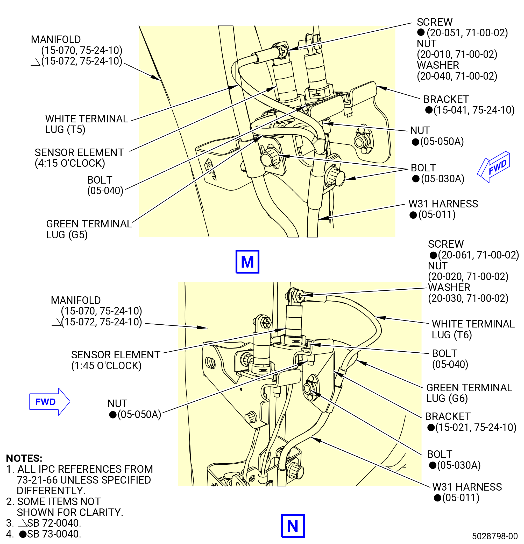
| 9 | Connect the harness green terminal lug G5 to the ground at the 4:15 o'clock position on the bracket (15-041 , 75-24-10) (SIN 9801J) with one bolt (05-040 , 73-21-66) (SIN 68824) and nut (05-050A , 73-21-66) (SIN 68840). Make sure that the terminal lug is under the bolthead and torque the nut to 51 to 59 lb in. (5.8 to 6.7 Nm). |
| 10 | Connect the harness white terminal lug T5 to the sensor element at the 4:15 o'clock position with one screw (20-051 , 71-00-02) (SIN C00F3), washer (20-040 , 71-00-02) (SIN C00J0), and nut (20-010 , 71-00-02) (SIN C00K3). Make sure that the terminal lug is under the screwhead and the washer is under the nut. Torque the nut to 23 to 27 lb in. (2.6 to 3.1 Nm). |
| 11 | Connect the harness green terminal lug G6 to the ground at the 1:45 o'clock position on the bracket (15-021 , 75-24-10) (SIN 9801G) with one bolt (05-040 , 73-21-66) (SIN 68824) and nut (05-050A , 73-21-66) (SIN 68840). Make sure that the terminal lug is under the bolthead and torque the nut to 51 to 59 lb in. (5.8 to 6.7 Nm). |
| 12 | Connect the harness white terminal lug T6 to the sensor element at the 1:45 o'clock position with one screw (20-061 , 71-00-02) (SIN C00F4), washer (20-030 , 71-00-02) (SIN C00J1), and nut (20-020 , 71-00-02) (SIN C00K4). Make sure that the terminal lug is under the screwhead and the washer is under the nut. Torque the nut to 32 to 38 lb in. (3.6 to 4.3 Nm). |
| * * * END SB 73-0040 |
| Subtask 72-00-02-431-029 |
| (af) | Torque the bolt (05-030 , 73-21-66) (SIN 68823) at the bracket (05-080 , 79-22-30) (SIN 6881D) to 60 to 70 lb in. (6.8 to 7.9 Nm). |
| (ag) | Torque the three bolts (05-030 , 73-21-66) (SIN 68823) on the manifold (15-060 , 75-24-10) (SIN 6220A) or (15-062 , 75-24-10) (SIN 6220A) to 60 to 70 lb in. (6.8 to 7.9 Nm). |
| (ah) | Torque the eight bolts (05-030 , 73-21-66) (SIN 68823) on the manifold (15-050 , 75-24-10) (SIN 6220D) or (15-052 , 75-24-10) (SIN 6220D) and on the support brackets (15-170 , 75-24-10) (SIN 9801D), (15-171 , 75-24-10) (SIN 9801D) and (15-160 , 75-24-10) (SIN 9801E) to 60 to 70 lb in. (6.8 to 7.9 Nm). |
| (ai) | Torque the seven bolts (05-030 , 73-21-66) (SIN 68823) on the manifold (15-080 , 75-24-10) (SIN 6220C) or (15-082 , 75-24-10) (SIN 6220C) and bracket (15-180 , 75-24-10) (SIN 9801F), (15-181 , 75-24-10) (SIN 9801F) or (15-182 , 75-24-10) (SIN 9801F) to 60 to 70 lb in. (6.8 to 7.9 Nm). |
| (aj) | Torque the eight bolts (05-030 , 73-21-66) (SIN 68823) on the manifold (15-070 , 75-24-10) (SIN 6220B) or (15-072 , 75-24-10) (SIN 6220B) to 60 to 70 lb in. (6.8 to 7.9 Nm). |
| * * * END PRE SB 73-0060 |
| Subtask 72-00-02-431-035 |
| * * * SB 73-0060( W30 and W31 Redesigned Harnesses ) |
| (17).A. | Install the W31 harness (05-011 , 73-21-66) (SIN 68801). Refer to Figure 1011 and do as follows: |
| (a) | Install the W31 harness (05-011 , 73-21-66) (SIN 68801) as follows: |
| 1 | Put the W31 harness (05-011 , 73-21-66) (SIN 68801) in position along the manifold (15-062 , 75-24-10) (SIN 6220A). |
| 2 | Attach the W31 harness (05-011 , 73-21-66) (SIN 68801) to the bracket (05-080 , 79-22-30) (SIN 6881D) with one bolt (05-030 , 73-21-66) (SIN 68823). Hand-tighten the bolt. |
| 3 | Attach the W31 harness (05-011 , 73-21-66) (SIN 68801) to the manifold (15-062 , 75-24-10) (SIN 6220A) with three bolts (05-030 , 73-21-66) (SIN 68823). Hand-tighten the bolts. |
| 4 | Attach the W31 harness (05-011 , 73-21-66) (SIN 68801) to the manifold (15-052 , 75-24-10) (SIN 6220D), bracket (15-160 , 75-24-10) (SIN 9801E), and support bracket (15-171 , 75-24-10) (SIN 9801D) with eight bolts (05-030 , 73-21-66) (SIN 68823). Hand-tighten the bolts. |
| 5 | Attach the W31 harness (05-011 , 73-21-66) (SIN 68801) branches to the bracket (15-270 , 75-24-10) (SIN 9801N) and to the bracket (15-031 , 75-24-10) (SIN 9801K) with two clamps (05-150 , 73-21-66) (SIN 6888E) and (05-160 , 73-21-66) (SIN 6888C) and two bolts (05-040 , 73-21-66) (SIN 68824) respectively. Hand-tighten the bolts. |
| 6 | Attach the W31 harness (05-011 , 73-21-66) (SIN 68801) to the manifold (15-082 , 75-24-10) (SIN 6220C), bracket (15-041 , 75-24-10) (SIN 9801J), bracket (15-182 , 75-24-10) (SIN 9801F), and bracket (15-250 , 75-24-10) (SIN 9801L) with eight bolts (05-030 , 73-21-66) (SIN 68823). Hand-tighten the bolts. |
| 7 | Attach the W31 harness (05-011 , 73-21-66) (SIN 68801) branches to the end lug brackets (15-041 , 75-24-10) (SIN 9801J) and (15-250 , 75-24-10) (SIN 9801L) with two clamps (05-160 , 73-21-66) (SIN 6888C) and two bolts (05-040 , 73-21-66) (SIN 68824). Hand-tighten the bolts. |
| 8 | Attach the W31 harness (05-011 , 73-21-66) (SIN 68801) to the manifold (15-072 , 75-24-10) (SIN 6220B) and brackets (15-041 , 75-24-10) (SIN 9801J) and (15-021 , 75-24-10) (SIN 9801G) with eight bolts (05-030 , 73-21-66) (SIN 68823). Hand-tighten the bolts. |
| 9 | Attach the W31 harness (05-011 , 73-21-66) (SIN 68801) to the bracket (15-021 , 75-24-10) (SIN 9801G) with a clamp (05-160 , 73-21-66) (SIN 6888C) and a bolt (05-040 , 73-21-66) (SIN 68824). Hand-tighten the bolt. |
| 10 | Attach the W31 harness (05-011 , 73-21-66) (SIN 68801) branch to the bracket (15-041 , 75-24-10) (SIN 9801J) with a clamp (05-160 , 73-21-66) (SIN 6888C) and a bolt (05-040 , 73-21-66) (SIN 68824). Hand-tighten the bolt. |
| 11 | Attach the W31 harness (05-011 , 73-21-66) (SIN 68801) to the oil brackets on the oil vent manifold (05-111 , 79-22-30) (SIN 46101) with two clamps (05-130 , 73-21-66) (SIN 6888D) and (05-140 , 73-21-66) (SIN 6888G) and two bolts (05-180 , 73-21-66) (SIN 6882M) and (05-190 , 73-21-66) (SIN 6882N) respectively. Torque the bolts to 32 to 38 lb in. (3.6 to 4.2 Nm). |
| 12 | Put the W31 harness (05-011 , 73-21-66) (SIN 68801) in the spring clips attached to the bracket (05-380 , 79-22-30) (SIN 4611C) and the brackets attached to the oil tube (05-030 , 79-22-30) (SIN 46100). |
| 13 | Attach the W31 harness (05-011 , 73-21-66) (SIN 68801) to the oil tube (05-030 , 79-22-30) (SIN 46100) with a clamp (05-150 , 73-21-66) (SIN 6888E) and a bolt (05-180 , 73-21-66) (SIN 6882M). Torque the bolt (05-180 , 73-21-66) (SIN 6882M) to 32 to 38 lb in. (3.6 to 4.2 Nm). |
| 14 | Put the W31 harness (05-011 , 73-21-66) (SIN 68801) in the spring clips attached to the bracket (01-141 , 75-11-30) (SIN 63717) and attach it with a clamp (05-150 , 73-21-66) (SIN 6888E) and a bolt (05-180 , 73-21-66) (SIN 6882M). Torque the bolt (05-180 , 73-21-66) (SIN 6882M) to 32 to 38 lb in. (3.6 to 4.2 Nm). |
| 15 | Put the W31 harness (05-011 , 73-21-66) (SIN 68801) in the spring clips attached to the brackets (30-270) (SIN 68816), (25-560 , 72-00-00) (SIN 6881U), (01-120 , 75-24-10) (SIN 53012), (30-620) (SIN 6711B), and (30-590) (SIN 6711C). |
| 16 | Put the W31 harness (05-011 , 73-21-66) (SIN 68801) in the spring clips attach to the tube (15-030 , 73-11-43) (SIN 37302) and attach it with a clamp (05-150 , 73-21-66) (SIN 6888E) and a bolt (05-180 , 73-21-66) (SIN 6882M). Torque the bolt (05-180 , 73-21-66) (SIN 6882M) to 32 to 38 lb in. (3.6 to 4.2 Nm). |
| CAUTION: |
|
| 17 | Connect the P311 harness connector to the hydraulic pump (35-010 , 72-00-00) (SIN C00A6). |
| CAUTION: |
|
| 18 | Tighten the P311 harness connector with teflon-jaw pliers. |
| 19 | Attach the W31 harness (05-011 , 73-21-66) (SIN 68801) to the bracket (01-171 , 72-00-05) (SIN 5901C) with a clamp (05-130 , 73-21-66) (SIN 6888D) and a bolt (05-180 , 73-21-66) (SIN 6882M). Torque the bolt (05-180 , 73-21-66) (SIN 6882M) to 32 to 38 lb in. (3.6 to 4.2 Nm). |
| 20 | Put the W31 harness (05-011 , 73-21-66) (SIN 68801) in the spring clips of the drain tube (25-041 , 73-11-43) (SIN 59001) and attach it with a clamp (12) and a bolt (05-180 , 73-21-66) (SIN 6882M). Torque the bolt (05-180 , 73-21-66) (SIN 6882M) to 32 to 38 lb in. (3.6 to 4.2 Nm). |
| 21 | Put the W31 harness (05-011 , 73-21-66) (SIN 68801) in the spring clips attached to the brackets (01-450 , 72-00-05) (SIN 37010) and (01-400 , 72-00-05) (SIN 37011). |
| 22 | Put the W31 harness (05-011 , 73-21-66) (SIN 68801) in the spring clips attached to the bracket (01-310 , 72-00-05) (SIN 6711G). |
| 23 | Put the W31 harness (05-011 , 73-21-66) (SIN 68801) in the spring clips attached to the bracket (30-250 , 72-00-00) (SIN 0971J). |
| 24 | Attach the W31 harness (05-011 , 73-21-66) (SIN 68801) to the bracket (05-100 , 73-21-66) (SIN 9901T) with one clamp (05-070 , 73-21-66) (SIN 68884) and bolt (01-070 , 73-21-66) (SIN 68822). Torque the bolt to 32 to 38 lb in. (3.6 to 4.2 Nm). |
| 25 | Attach a bolt (05-030 , 73-21-66) (SIN 68823) to the bracket (15-171 , 75-24-10) (SIN 9801D). |
| 26 | Torque the bolt (05-030 , 73-21-66) (SIN 68823) to 60 to 70 lb in. (6.7 to 7.9 Nm). |
| NOTE: |
|
| (b) | Install the W31 harness into the sensing elements. Refer to Figure 1011 and as follows: |
| 1 | Connect the harness green terminal lug G8 as follows: |
| a | Attach the harness green terminal lug G8 to a machine bolt (bolt) (05-060 , 73-21-66) (SIN 68822). |
| b | Attach the bolt (05-060 , 73-21-66) (SIN 68822) to the bracket (05-100 , 73-21-66) (SIN 9901T). |
| c | Torque the bolt (05-060 , 73-21-66) (SIN 68822) to 32 to 38 lb in. (3.6 to 4.2 Nm). |
| 2 | Connect the harness white terminal lugs T7 and T8 as follows: |
| a | Attach the terminal lugs T7 and T8 to the No. 10 sensor element (sensor element) (20-020 , 71-00-00) (SIN C00A9) on the lower bifurcation manifold with No. 10 screws (screws) (05-151 , 71-00-00) (SIN C00F4), washers (05-160 , 71-00-00) (SIN C00J1), and nuts (05-190 , 71-00-00) (SIN C00K4). |
| b | Make sure that the terminal lugs T7 and T8 are below the head of the screw (05-151 , 71-00-00) (SIN C00F4) and the washer (05-160 , 71-00-00) (SIN C00J1) is below the nut (05-190 , 71-00-00) (SIN C00K4). |
| c | Torque the nuts (05-190 , 71-00-00) (SIN C00K4) to 32 to 38 lb in. (3.6 to 4.2 Nm). |
| 3 | Connect the W31 harness (05-011 , 73-21-66) (SIN 68801) to the sensing elements (05-011 , 71-00-02) (SIN C00A7), (05-061 , 71-00-02) (SIN C00A7), and (05-111 , 71-00-02) (SIN C00A7) on the manifolds as follows: |
| NOTE: |
|
| a | Connect the harness green terminal lugs G1 and G9 as follows: |
| (1) | Attach the terminal lug G9 to a bolt (05-040 , 73-21-66) (SIN 68824). |
| (2) | Attach the bolt (05-040 , 73-21-66) (SIN 68824) to the bracket (15-270 , 75-24-10) (SIN 9801N) at the 10:15 o'clock position. |
| (3) | Attach the terminal lug G1 with a bolt (05-040 , 73-21-66) (SIN 68824) and a nut (05-050 , 73-21-66) (SIN 68840). |
| (4) | Torque the nut (05-050 , 73-21-66) (SIN 68840) to 51 to 59 lb in. (5.7 to 6.6 Nm). |
| b | Connect the harness black terminal lug GND as follows: |
| (1) | Attach the terminal GND to a bolt (05-040 , 73-21-66) (SIN 68824) at the 10:15 o'clock position. |
| (2) | Attach the bolt (05-040 , 73-21-66) (SIN 68824) to the bracket (15-270 , 75-24-10) (SIN 9801N) with a nut (05-050 , 73-21-66) (SIN 68840). |
| (3) | Torque the nut (05-050 , 73-21-66) (SIN 68840) to 51 to 59 lb in. (5.7 to 6.6 Nm). |
| c | Connect the harness white terminal lug T1 as follows: |
| (1) | Attach the terminal lug T1 to the sensing element (05-061 , 71-00-02) (SIN C00A7) at the 10:15 o'clock position with one screw (20-051 , 71-00-02) (SIN C00F3), washer (20-040 , 71-00-02) (SIN C00J0), and nut (20-010 , 71-00-02) (SIN C00K3). |
| (2) | Make sure that the terminal lug T1 is below the head of the screw (20-051 , 71-00-02) (SIN C00F3) and the washer (20-040 , 71-00-02) (SIN C00J0) is below the nut (20-010 , 71-00-02) (SIN C00K3). |
| (3) | Torque the nut (20-010 , 71-00-02) (SIN C00K3) to 23 to 27 lb in. (2.5 to 3.0 Nm). |
| d | Connect the harness green terminal lug G2. Refer to Figure 1011 and as follows: |
| (1) | Loosen the nut (05-050 , 73-21-66) (SIN 68840) on the bracket (15-031 , 75-24-10) (SIN 9801K) at the 7:45 o'clock position. |
| (2) | Attach the terminal lug G2 with a bolt (05-040 , 73-21-66) (SIN 68824) and a nut (05-050 , 73-21-66) (SIN 68840) to the bracket (15-031 , 75-24-10) (SIN 9801K) at the 7:45 o'clock position. |
| (3) | Torque the nut (05-050 , 73-21-66) (SIN 68840) to 51 to 59 lb in. (5.7 to 6.6 Nm). |
| e | Connect the harness white terminal lug T2 as follows: |
| (1) | Attach the terminal lug T2 to the sensing element (05-061 , 71-00-02) (SIN C00A7) at the 7:45 o'clock position with one screw (20-061 , 71-00-02) (SIN C00F4), washer (20-030 , 71-00-02) (SIN C00J1), and nut (20-020 , 71-00-02) (SIN C00K4). |
| (2) | Make sure that the terminal lug T2 is below the head of the screw (20-061 , 71-00-02) (SIN C00F4) and the washer (20-030 , 71-00-02) (SIN C00J1) is below the nut (20-020 , 71-00-02) (SIN C00K4). |
| (3) | Torque the nut (20-020 , 71-00-02) (SIN C00K4) to 32 to 38 lb in. (3.6 to 4.2 Nm). |
| f | Connect the harness green terminal lug G3 as follows: |
| (1) | Loosen the nut (05-050 , 73-21-66) (SIN 68840) on the bracket (15-041 , 75-24-10) (SIN 9801J) at the 7:15 o'clock position. |
| (2) | Attach the terminal lug G3 with a bolt (05-040 , 73-21-66) (SIN 68824) and a nut (05-050 , 73-21-66) (SIN 68840). |
| (3) | Torque the nut (05-050 , 73-21-66) (SIN 68840) to 51 to 59 lb in. (5.7 to 6.6 Nm). |
| g | Connect the harness white terminal lug T3 as follows: |
| (1) | Attach the terminal lug T3 to the sensing element (05-111 , 71-00-02) (SIN C00A7) at the 7:15 o'clock position with one screw (20-051 , 71-00-02) (SIN C00F3), washer (20-040 , 71-00-02) (SIN C00J0), and nut (20-010 , 71-00-02) (SIN C00K3). |
| (2) | Make sure that the terminal lug T3 is below the head of the screw (20-051 , 71-00-02) (SIN C00F3) and the washer (20-040 , 71-00-02) (SIN C00J0) is below the nut (20-010 , 71-00-02) (SIN C00K3). |
| (3) | Torque the nut (20-010 , 71-00-02) (SIN C00K3) to 23 to 27 lb in. (2.5 to 3.0 Nm). |
| h | Connect the harness green terminal lug G4. Refer to Figure 1011 and as follows: |
| (1) | Loosen the nut (05-050 , 73-21-66) (SIN 68840) located on the bracket (15-250 , 75-24-10) (SIN 9801L) at the 4:45 o'clock position. |
| (2) | Attach the terminal lug G4 with a bolt (05-040 , 73-21-66) (SIN 68824) and a nut (05-050 , 73-21-66) (SIN 68840). |
| (3) | Torque the nut (05-050 , 73-21-66) (SIN 68840) to 51 to 59 lb in. (5.7 to 6.6 Nm). |
| i | Connect the harness white terminal lug T4 as follows: |
| (1) | Attach the terminal lug T4 to the sensing element (05-111 , 71-00-02) (SIN C00A7) at the 4:45 o'clock position with one screw (20-061 , 71-00-02) (SIN C00F4), washer (20-030 , 71-00-02) (SIN C00J1), and nut (20-020 , 71-00-02) (SIN C00K4). |
| (2) | Make sure that the terminal lug T4 is below the head of the screw (20-061 , 71-00-02) (SIN C00F4) and the washer (20-030 , 71-00-02) (SIN C00J1) is below the nut (20-020 , 71-00-02) (SIN C00K4). |
| (3) | Torque the nut (20-020 , 71-00-02) (SIN C00K4) to 32 to 38 lb in. (3.6 to 4.2 Nm). |
| j | Connect the harness green terminal lug G5 as follows: |
| (1) | Loosen the nut (05-050 , 73-21-66) (SIN 68840) located on the bracket (15-041 , 75-24-10) (SIN 9801J) at the 4:15 o'clock position. |
| (2) | Attach the terminal lug G5 with a bolt (05-040 , 73-21-66) (SIN 68824) and a nut (05-050 , 73-21-66) (SIN 68840). |
| (3) | Torque the nut (05-050 , 73-21-66) (SIN 68840) to 51 to 59 lb in. (5.7 to 6.6 Nm). |
| k | Connect the harness white terminal lug T5 as follows: |
| (1) | Attach the terminal lug T5 to the sensing element (05-111 , 71-00-02) (SIN C00A7) at the 4:15 o'clock position with one screw (20-051 , 71-00-02) (SIN C00F3), washer (20-040 , 71-00-02) (SIN C00J0), and nut (20-010 , 71-00-02) (SIN C00K3). |
| (2) | Make sure that the terminal lug T5 is below the head of the screw (20-051 , 71-00-02) (SIN C00F3) and the washer (20-040 , 71-00-02) (SIN C00J0) is below the nut (20-010 , 71-00-02) (SIN C00K3). |
| (3) | Torque the nut (20-010 , 71-00-02) (SIN C00K3) to 23 to 27 lb in. (2.5 to 3.0 Nm). |
| l | Connect the harness green terminal lug G6 as follows: |
| (1) | Attach the terminal lug G6 with a bolt (05-040 , 73-21-66) (SIN 68824) and a nut (05-050 , 73-21-66) (SIN 68840). |
| (2) | Torque the nut (05-050 , 73-21-66) (SIN 68840) to 51 to 59 lb in. (5.7 to 6.6 Nm). |
| m | Connect the harness white terminal lug T6 as follows: |
| (1) | Attach the terminal lug T6 to the sensing element (05-011 , 71-00-02) (SIN C00A7) at the 1:45 o'clock position with one screw (20-061 , 71-00-02) (SIN C00F4), washer (20-030 , 71-00-02) (SIN C00J1), and nut (20-020 , 71-00-02) (SIN C00K4). |
| (2) | Make sure that the terminal lug T6 is below the head of the screw (20-061 , 71-00-02) (SIN C00F4) and the washer (20-030 , 71-00-02) (SIN C00J1) is below the nut (20-020 , 71-00-02) (SIN C00K4). |
| (3) | Torque the nut (20-020 , 71-00-02) (SIN C00K4) to 32 to 38 lb in. (3.6 to 4.2 Nm). |
| 4 | Torque the bolts (05-030 , 73-21-66) (SIN 68823) to 60 to 70 lb in. (6.8 to 7.9 Nm). |
| 5 | Torque the bolts (05-040 , 73-21-66) (SIN 68824) to 32 to 38 lb in. (3.6 to 4.3 Nm). |
| * * * END SB 73-0060 |
|
|
|
|
|
|
|
|
|
|
|
|
|
|
|
|
| Subtask 72-00-02-430-765 |
| * * * PRE SB 73-0011( Engines without Fuel Vapor Accumulator ) |
| F. | Install the W32 harness (10-010 , 73-21-66) (SIN 68802) and W33 harness (15-010 , 73-21-66) (SIN 68803). Refer to Figure 1012 and do as follows: |
| Subtask 72-00-02-430-990 |
| * * * PRE SB 79-0014 |
| (1) | Attach the W32 harness (10-010 , 73-21-66) (SIN 68802) to the right side of the engine as follows: |
| (a) | Make sure to remove the protective covers on the W32 harness connector, before the W32 harness installation. |
| (b) | Attach the W32 harness to the AFT skirt segment heat shield (heat shield) (40-030) (SIN 29902) with two cushioned loop clamps (10-040 , 73-21-66) (SIN 68881) and two bolts (10-030 , 73-21-66) (SIN 6882G). Torque the bolts to 32 to 38 lb in. (3.6 to 4.3 Nm). |
| (c) | Attach the W32 harness to the spring clip of the heat shield (40-030) (SIN 29902) at one position. |
| (d) | Attach the W32 harness to the spring clips of the aft skirt segment heat shield (heat shield) (40-020) (SIN 29901) at two positions. |
| (e) | Attach the W32 harness to the spring clip of the support bracket (bracket) (40-120) (SIN 6881B) attached to the heat shield (40-020) (SIN 29901). |
| NOTE: |
|
| * * * END PRE SB 79-0014 |
| Subtask 72-00-02-430-991 |
| * * * SB 79-0014 |
| (1).A. | Attach the W32 harness (10-010 , 73-21-66) (SIN 68802) to the right side of the engine as follows: |
| (a) | Make sure to remove the protective covers on the W32 harness connector, before the W32 harness installation. |
| (b) | Attach the W32 harness to the heat shield (40-030) (SIN 29902) with two cushioned loop clamps (10-040 , 73-21-66) (SIN 68881) and two bolts (10-030 , 73-21-66) (SIN 6882G). Torque the bolts to 32 to 38 lb in. (3.6 to 4.3 Nm). |
| (c) | Attach the W32 harness to the spring clip of the heat shield (40-030) (SIN 29902) at one position. |
| (d) | Attach the W32 harness to the spring clips of the heat shield (40-020) (SIN 29901) at two positions. |
| (e) | Attach the W32 harness to the spring clip of the bracket (40-120) (SIN 6881B) attached to the heat shield (40-020) (SIN 29901). |
| NOTE: |
|
| * * * END SB 79-0014 |
| Subtask 72-00-02-430-992 |
| (f) | Attach the W32 harness to the spring clip of the support bracket (bracket) (25-080 , 73-11-40) (SIN 6881C). |
| (g) | Attach the W32 harness to the spring clip of the bracket (05-090 , 73-11-40) (SIN 6881A). |
| (h) | Attach the W32 harness to the spring clip of the support bracket (bracket) (01-120 , 75-42-10) (SIN 53012). |
| (i) | Attach the W32 harness to the spring clip of the bracket (30-270) (SIN 68816). |
| (j) | Attach the W32 harness to the spring clip attached to oil tube (05-030 , 79-22-30) (SIN 46100). |
| (k) | Attach the W32 harness to the spring clip of the bracket (25-210 , 72-00-00) (SIN 68812). |
| Subtask 72-00-02-430-993 |
| * * * PRE SB 79-0014 |
| (2) | Attach the W33 harness (15-010 , 73-21-66) (SIN 68803) to the right side of the engine as follows: |
| (a) | Make sure to remove the protective covers on the W33 harness connector, before the W33 harness installation. |
| Subtask 72-00-02-431-040 |
| * * * PRE SB 73-0074( Harness Support Spring Clips with Clip Inserts ) |
| (b) | Attach the W33 harness (15-010 , 73-21-66) (SIN 68803) to the heat shield (40-050) (SIN 29904) with a cushioned loop clamp (15-040 , 73-21-66) (SIN 68881) and a bolt (15-030 , 73-21-66) (SIN 68824). |
| * * * END PRE SB 73-0074 |
| Subtask 72-00-02-431-041 |
| * * * SB 73-0074( Harness Support Spring Clips without Clip Inserts ) |
| (b).A. | Attach the W32 harness (10-010 , 73-21-66) (SIN 68802) and W33 harness (15-010 , 73-21-66) (SIN 68803) to the heat shield (40-050) (SIN 29904) with a cushioned loop clamp (10-045 , 73-21-66) (SIN 68883), a cushioned loop clamp (15-045 , 73-21-66) (SIN 68883), and a bolt (15-030 , 73-21-66) (SIN 68824). Refer to Subtask 72-00-02-430-990 (paragraph 3.F.(1)). |
| * * * END SB 73-0074 |
| Subtask 72-00-02-431-042 |
| (c) | Torque the bolt (15-030 , 73-21-66) (SIN 68824) to 32 to 38 lb in. (3.6 to 4.3 Nm). |
| (d) | Attach the W33 harness (15-010 , 73-21-66) (SIN 68803) to the spring clip of the heat shield (40-050) (SIN 29904) at one position. |
| (e) | Attach the W33 harness to the spring clip of the bracket (40-120) (SIN 6881B) attached to the heat shield (40-020) (SIN 29901). |
| NOTE: |
|
| * * * END PRE SB 79-0014 |
| Subtask 72-00-02-430-994 |
| * * * SB 79-0014 |
| (2).D. | Attach the W33 harness (15-010 , 73-21-66) (SIN 68803) to the right side of the engine as follows: |
| (a) | Make sure to remove the protective covers on the W33 harness connector, before the W33 harness installation. |
| Subtask 72-00-02-431-043 |
| * * * PRE SB 73-0074( Harness Support Spring Clip with Clip Inserts ) |
| (b) | Attach the W33 harness (15-010 , 73-21-66) (SIN 68803) to the heat shield (40-020) (SIN 29901) with a cushioned loop clamp (15-040 , 73-21-66) (SIN 68881) and a bolt (15-030 , 73-21-66) (SIN 68824). |
| * * * END PRE SB 73-0074 |
| Subtask 72-00-02-431-044 |
| * * * SB 73-0074( Harness Support Spring Clips without Clip Inserts ) |
| (b).A. | Attach the W32 harness (10-010 , 73-21-66) (SIN 68802) and W33 harness (15-010 , 73-21-66) (SIN 68803) to the heatshield (40-050) (SIN 29904) with a cushioned loop clamp (10-045 , 73-21-66) (SIN 68883), a cushioned loop clamp (15-045 , 73-21-66) (SIN 68883), and a bolt (15-030 , 73-21-66) (SIN 68824). Refer to Subtask 72-00-02-430-991 (paragraph 3.F.(1)A). |
| * * * END SB 73-0074 |
| Subtask 72-00-02-431-045 |
| (c) | Torque the bolt (15-030 , 73-21-66) (SIN 68824) to 32 to 38 lb in. (3.6 to 4.3 Nm). |
| (d) | Attach the W33 harness (15-010 , 73-21-66) (SIN 68803) to the spring clip of the heat shield (40-020) (SIN 29901) at one position. |
| (e) | Attach the W33 harness to the spring clip of the bracket (40-120) (SIN 6881B) attached to the heat shield (40-020) (SIN 29901). |
| NOTE: |
|
| * * * END SB 79-0014 |
| Subtask 72-00-02-430-986 |
| (f) | Attach the W33 harness to the spring clip of the bracket (25-080 , 73-11-40) (SIN 6881C). |
| (g) | Attach the W33 harness to the spring clip of the bracket (05-090 , 73-11-40) (SIN 6881A). |
| (h) | Attach the W33 harness to the spring clip of the bracket (01-120 , 75-42-10) (SIN 53012). |
| (i) | Attach the W33 harness to the spring clip of the bracket (30-270) (SIN 68816). |
| (j) | Attach the W33 harness to the spring clip attached to oil tube (05-030 , 79-22-30) (SIN 46100). |
| (k) | Attach the W33 harness to the spring clip of the bracket (25-210 , 72-00-00) (SIN 68812). |
| * * * END PRE SB 73-0011 |
| Subtask 72-00-02-430-862 |
| * * * SB 73-0011( Engines with Fuel Vapor Accumulator ) |
| F.A. | Install the W32 harness (10-010 , 73-21-66) (SIN 68802) and W33 harness (15-010 , 73-21-66) (SIN 68803). Refer to Figure 1012 and do as follows: |
| Subtask 72-00-02-430-995 |
| * * * PRE SB 79-0014 |
| (1) | Attach the W32 harness (10-010 , 73-21-66) (SIN 68802) to the right side of the engine as follows: |
| (a) | Make sure to remove the protective covers on the W32 harness connector, before the W32 harness installation. |
| (b) | Attach the W32 harness to the heat shield (40-030) (SIN 29902) with two cushioned loop clamps (10-040 , 73-21-66) (SIN 68881) and two bolts (10-030 , 73-21-66) (SIN 6882G). Torque the bolts to 32 to 38 lb in. (3.6 to 4.3 Nm). |
| (c) | Attach the W32 harness to the spring clip of the heat shield (40-030) (SIN 29902) at one position. |
| (d) | Attach the W32 harness to the spring clips of the heat shield (40-050) (SIN 29904) at two positions. |
| (e) | Attach the W32 harness to the spring clip of the bracket (40-120) (SIN 6881B) attached to the heat shield (40-020) (SIN 29901). |
| NOTE: |
|
| * * * END PRE SB 79-0014 |
| Subtask 72-00-02-430-996 |
| * * * SB 79-0014 |
| (1).A. | Attach the W32 harness (10-010 , 73-21-66) (SIN 68802) to the right side of the engine as follows: |
| (a) | Make sure to remove the protective covers on the W32 harness connector, before the W32 harness installation. |
| (b) | Attach the W32 harness to the heat shield (40-030) (SIN 29902) with two cushioned loop clamps (10-040 , 73-21-66) (SIN 68881) and two bolts (10-030 , 73-21-66) (SIN 6882G). Torque the bolts to 32 to 38 lb in. (3.6 to 4.3 Nm). |
| (c) | Attach the W32 harness to the spring clip of the heat shield (40-030) (SIN 29902) at one position. |
| (d) | Attach the W32 harness to the spring clips of the heat shield (40-020) (SIN 29901) at two positions. |
| (e) | Attach the W32 harness to the spring clip of the bracket (40-120) (SIN 6881B) attached to the heat shield (40-020) (SIN 29901). |
| NOTE: |
|
| * * * END SB 79-0014 |
| Subtask 72-00-02-430-997 |
| (f) | Attach the W32 harness to the spring clip of the bracket (25-080 , 73-11-40) (SIN 6881C). |
| (g) | Attach the W32 harness to the spring clip of the bracket (05-090 , 73-11-40) (SIN 6881A). |
| (h) | Attach the W32 harness to the spring clip of the support bracket (bracket) (15-250 , 73-11-40) (SIN 6881Y). |
| (i) | Attach the W32 harness to the spring clip of the bracket (30-270) (SIN 68816). |
| (j) | Attach the W32 harness to the spring clip attached to the oil tube (05-030 , 79-22-30) (SIN 46100). |
| (k) | Attach the W32 harness to the spring clip of the bracket (25-210 , 72-00-00) (SIN 68812). |
| Subtask 72-00-02-430-998 |
| * * * PRE SB 79-0014 |
| (2) | Attach the W33 harness (15-010 , 73-21-66) (SIN 68803) to the right side of the engine as follows: |
| (a) | Make sure to remove the protective covers on the W33 harness connector, before the W33 harness installation. |
| Subtask 72-00-02-431-048 |
| * * * PRE SB 73-0074( Harness Support Spring Clips with Clip Inserts ) |
| (b) | Attach the W33 harness (15-010 , 73-21-66) (SIN 68803) to the heat shield (40-050) (SIN 29904) with a cushioned loop clamp (15-040 , 73-21-66) (SIN 68881) and a bolt (15-030 , 73-21-66) (SIN 68824). |
| * * * END PRE SB 73-0074 |
| Subtask 72-00-02-431-046 |
| * * * SB 73-0074( Harness Support Spring Clips without Clip Inserts ) |
| (b).A. | Attach the W32 harness (10-010 , 73-21-66) (SIN 68802) and W33 harness (15-010 , 73-21-66) (SIN 68803) to the heatshield (40-050) (SIN 29904) with a cushioned clamp (10-045 , 73-21-66) (SIN 68883), a cushioned loop clamp (15-045 , 73-21-66) (SIN 68883), and a bolt (15-030 , 73-21-66) (SIN 68824). Refer to Subtask 72-00-02-430-995 (paragraph 3.F.A.(1)) . |
| * * * END SB 73-0074 |
| Subtask 72-00-02-431-047 |
| (c) | Torque the bolts (15-030 , 73-21-66) (SIN 68824) to 32 to 38 lb in. (3.6 to 4.3 Nm). |
| (d) | Attach the W33 harness to the spring clip of the heat shield (40-050) (SIN 29904) at one position. |
| (e) | Attach the W33 harness to the spring clip of the bracket (40-120) (SIN 6881B) attached to the heat shield (40-020) (SIN 29901). |
| NOTE: |
|
| * * * END PRE SB 79-0014 |
| Subtask 72-00-02-430-999 |
| * * * SB 79-0014 |
| (2).D. | Attach the W33 harness (15-010 , 73-21-66) (SIN 68803) to the right side of the engine as follows: |
| (a) | Make sure to remove the protective covers on the W33 harness connector, before the W33 harness installation. |
| Subtask 72-00-02-431-049 |
| * * * PRE SB 73-0074( Harness Support Spring Clips with Clip Inserts ) |
| (b) | Attach the W33 harness to the heat shield (40-020) (SIN 29901) with a cushioned loop clamp (15-040 , 73-21-66) (SIN 68881) and a bolt (15-030 , 73-21-66) (SIN 68824). |
| * * * END PRE SB 73-0074 |
| Subtask 72-00-02-431-050 |
| * * * SB 73-0074( Harness Support Spring Clips without Clip Inserts ) |
| (b).A. | Attach the W32 harness (10-010 , 73-21-66) (SIN 68802) and W33 harness (15-010 , 73-21-66) (SIN 68803) to the heatshield (40-050) (SIN 29904) with a cushioned loop clamp (10-045 , 73-21-66) (SIN 68883), a cushioned loop clamp (15-045 , 73-21-66) (SIN 68883), and a bolt (15-030 , 73-21-66) (SIN 68824). Refer to Subtask 72-00-02-430-996 (paragraph 3.F.A.(1)A) . |
| * * * END SB 73-0074 |
| Subtask 72-00-02-431-051 |
| (c) | Torque the bolts (15-030 , 73-21-66) (SIN 68824) to 32 to 38 lb in. (3.6 to 4.3 Nm). |
| (d) | Attach the W33 harness to the spring clip of the heat shield (40-020) (SIN 29901) at one position. |
| (e) | Attach the W33 harness to the spring clip of the bracket (40-120) (SIN 6881B) attached to the heat shield (40-020) (SIN 29901). |
| NOTE: |
|
| * * * END SB 79-0014 |
| Subtask 72-00-02-430-989 |
| (f) | Attach the W33 harness to the spring clip of the bracket (25-080 , 73-11-40) (SIN 6881C). |
| (g) | Attach the W33 harness to the spring clip of the bracket (05-090 , 73-11-40) (SIN 6881A). |
| (h) | Attach the W33 harness to the spring clip of the bracket (15-250 , 73-11-40) (SIN 6881Y). |
| (i) | Attach the W33 harness to the spring clip of the bracket (30-270) (SIN 68816). |
| (j) | Attach the W33 harness to the spring clip attached to the oil tube (05-030 , 79-22-30) (SIN 46100). |
| (k) | Attach the W33 harness to the spring clip of the bracket (25-210 , 72-00-00) (SIN 68812). |
| * * * END SB 73-0011 |
|
|
|
|
|
| Subtask 72-00-02-430-981 |
| G. | Install the power feeders bracket. Refer to Figure 1014 and do as follows: |
| (1) | Attach the power feeders bracket (bracket) (65-080) (SIN 68010) to the forward side of the aft skirt segment heat shield (40-030) (SIN 29902) at the 7:30 o'clock position with machine bolts (bolts) (65-060) (SIN 68021). |
| (2) | Torque the bolts to 106-124 lb in. (12.0-14.0 N.m). |
| Subtask 72-00-02-430-767 |
| * * * PRE SB 72-0088( Installation of W32 and W33 Harnesses to the VFSG without Bracket ) |
| H. | Install the VFSG power feeder harness (power cable RH) (65-040) (SIN 68001) and VFSG power feeder harness (power cable LH) (65-030) (SIN 68000). Refer to Figure 1013, Figure 1014, and do as follows: |
| (1) | Connect the power cable RH (65-040) (SIN 68001) to the VFSG (65-010) (SIN C00A0) as follows: |
| NOTE: |
|
| NOTE: |
|
| (a) | Install the four ends of the power cable RH close to the 6:00 o'clock position on the VFSG terminal block from the top to the bottom in this order: RED, YELLOW, BLUE, and WHITE. |
| (b) | Attach each cable with a self-locking nut (C00L0). Do not torque at this time. |
| WARNING: |
|
| (2) | Use C02-019 engine oil or C02-023 engine oil to lubricate only the seating surfaces of the bolts (65-060) (SIN 68021), (65-070) (SIN 68024), (65-160) (SIN 68025), and (65-170) (SIN 68026) for the block clamp (65-090) (SIN 68080) and hinged clamp (65-100) (SIN 68085). Do not apply lubricant to the threads. |
| (3) | Put the power cable RH in the two block clamps (65-090) (SIN 68080) and attach them to the heat shield (40-030) (SIN 29902) or (40-040) (SIN 29903) with bolts (65-060) (SIN 68021) and (65-160) (SIN 68025). Do not torque the bolts at this time. |
| (4) | Attach the hinged clamp (65-100) (SIN 68085) to the support bracket (65-110) (SIN 68013) with bolts (65-070) (SIN 68024). |
| (5) | Attach the hinged clamp (65-100) (SIN 68085) to the LPT supply air duct (10-010 , 75-24-10) (SIN 62201) with bolts (65-070) (SIN 68024). |
| (6) | Attach two hinged clamps (65-100) (SIN 68085) to the brackets (65-130) (SIN 68014), (65-140) (SIN 68015), and to the HPT supply air duct (10-010 , 75-24-30) (SIN 62101) with bolts (65-070) (SIN 68024). |
| (7) | Torque the bolts (65-070) (SIN 68024) to 55-70 lb in. (6.2-7.9 N.m). |
| (8) | Put the power cable RH in the hinged clamps (65-100) (SIN 68085) and attach them with bolts (65-060) (SIN 68021). Do not torque the bolts at this time. |
| (9) | Connect power cable LH (65-030) (SIN 68000) to the VFSG as follows: |
| (a) | Install the four ends of the power cable LH close to the 7:00 o'clock position on the VFSG terminal block from the top to the bottom in this order: RED, YELLOW, BLUE, and WHITE. |
| (b) | Attach each cable with a self-locking nut (C00L0). Do not torque the nut at this time. |
| (10) | Put the power cable LH in the block clamp (65-090) (SIN 68080) and attach the block clamp to the bracket (65-080) (SIN 68010) with bolts (65-170) (SIN 68026). Do not torque the bolts at this time. |
| (11) | Attach the hinged clamp (65-100) (SIN 68085) to the support bracket (65-110) (SIN 68013) with bolts (65-070) (SIN 68024). |
| (12) | Attach the hinged clamp (65-100) (SIN 68085) to the LPT supply air duct (10-010 , 75-24-10) (SIN 62201) with bolts (65-070) (SIN 68024). |
| (13) | Attach two hinged clamps (65-100) (SIN 68085) to the brackets (65-120) (SIN 68016), (65-150) (SIN 68017) and to the HPT supply air duct (10-010 , 75-24-30) (SIN 62101) with bolts (65-070) (SIN 68024). |
| (14) | Torque the bolts (65-070) (SIN 68024) to 55-70 lb in. (6.2-7.9 N.m). |
| (15) | Put the power cable LH in the hinged clamps (65-100) (SIN 68085) and attach them with bolts (65-060) (SIN 68021). Do not torque the bolts at this time. |
| (16) | Torque the self-locking nuts (C00L0) to 143-167 lb in. (16.2-18.9 N.m). |
| (17) | Torque the bolts (65-060) (SIN 68021), (65-160) (SIN 68025), and (65-170) (SIN 68026) to 55 to 70 lb in. (6.2 to 7.9 Nm). |
| (18) | Install the terminal cover (01-020 , 71-00-02) (SIN C00A1) or (01-021 , 71-00-02) (SIN C00A1) to the VFSG at the 6:00 o'clock position with a screw (C00F7) and washer (C00J7). Torque the screw to 18-22 lb in. (2.0-2.5 N.m). |
| (19) | Install the terminal cover (01-020 , 71-00-02) or (01-021 , 71-00-02) (SIN C00A1) to the VFSG at the 7:00 o'clock with a screw (C00F7) and washer (C00J7). Torque the screw to 18-22 lb in. (2.0-2.5 N.m). |
| (20) | Verify the cable orientation as follows: |
| (a) | Verify that the order of the power cables LH and RH from fwd to aft is WHITE, BLUE, YELLOW, and RED on upper locations. |
| (b) | Verify that the order of the power cables LH and RH from top to the bottom is RED, YELLOW, BLUE, and WHITE on lower locations. |
| (21) | Connect the W32 harness (10-010 , 73-21-66) (SIN 68802) to the LH VFSG (65-010) (SIN C00A0) as follows: |
| (a) | Route the W32 harness to the VFSG. Put in position the three connectors that attach the W32 harness to the inboard side of the VFSG and the connector that attaches the W32 harness to the aft side of the VFSG. |
| CAUTION: |
|
| (b) | Use soft-jaw pliers to attach each connector to the VFSG. |
| (c) | Attach the W32 harness to the VFSG with one cushioned loop clamp (clamp) (10-060 , 73-21-66) (SIN 68885) and bolt (10-050 , 73-21-66) (SIN 68824). |
| (d) | Torque the bolt (10-050 , 73-21-66) (SIN 68824) to 53-56 lb in. (6.0-6.3 N.m). |
| (22) | Connect the W33 harness (15-010 , 73-21-66) (SIN 68803) to the RH VFSG (65-010) (SIN C00A0) as follows: |
| (a) | Route the W33 harness to the VFSG. Put in position the three connectors that attach the W33 harness to the inboard side of the VFSG and the connector that attaches the W33 harness to the aft side of the VFSG. |
| CAUTION: |
|
| (b) | Use soft-jaw pliers to attach each connector to the VFSG. |
| (c) | Attach the W33 harness to the VFSG with one cushioned loop clamp (clamp) (15-050 , 73-21-66) (SIN 68885) and bolt (15-030 , 73-21-66) (SIN 68824). |
| (d) | Torque the bolt (15-030 , 73-21-66) (SIN 68824) to 53-56 lb in. (6.0-6.3 N.m). |
| (23) | Make sure that the two power cable floating block clamps are located at the 9:00 o'clock position with the 11C4673 VFSG power feeder cable guide. Refer to Figure 1014 and do as follows: |
| (a) | Do an inspection of the tool to make sure that all fasteners are firmly attached and that the tool was not damaged. |
| (b) | Do an inspection of the tool to make sure that the pad and plate are firmly attached to the bracket. |
| (c) | Set the bracket on the support bracket (65-110) (SIN 68013). The slot between the pad and the plate can slide over the support bracket (65-110) (SIN 68013). If the 11C4673 VFSG power feeder cable guide does not slide over, loosen the screws slightly to create a bigger clearance. Refer to Figure 1014 for the final location. |
| (d) | Move the guide inward until the L-shaped stop hits the aft skirt. Refer to Figure 1014. |
| NOTE: |
|
| (e) | If the guide cannot reach the aft skirt because it hits the power cable RH (65-040) (SIN 68001), power cable LH (65-030) (SIN 68000), or hinged clamps (65-100) (SIN 68085) that hold the power cables, adjust and position again the power cable RH, power cable LH, or hinged clamps as follows: |
| 1 | Move the guide outward and remove the tool from the engine hardware. |
| 2 | Adjust and position again the power cable RH (65-040) (SIN 68001), power cable LH (65-030) (SIN 68000), or hinged clamps. Refer to paragraph 3.H. |
| 3 | Install the tool again. Do paragraph 3.H.(23). |
| (f) | Make sure that there is a clearance between the outboard corner of the two floating block clamps and the guide. |
| (g) | Move the guide outward and remove the tool from the engine hardware. |
| (h) | If the clearance between the outboard corner of the two floating block clamps and the guide is less than 0.75 inch (19.0 mm), adjust the power cables RH or LH. Refer to paragraph 3.H. |
| * * * END PRE SB 72-0088 |
| Subtask 72-00-02-430-869 |
| * * * SB 72-0088( Installation of W32 and W33 Harnesses to the VFSG with Bracket ) |
| H.A. | Install the VFSG power feeder harness (power cable RH) (65-041) (SIN 68001) and VFSG power feeder harness (power cable LH) (65-031) (SIN 68000). Refer to Figure 1013A, Figure 1014, and do as follows: |
| (1) | Connect the power cable RH (65-041) (SIN 68001) to the VFSG (65-010) (SIN C00A0) as follows: |
| NOTE: |
|
| (a) | Install power cables with single lugs to the VFSG and double lugs to the aircraft interface. |
| (b) | Install the four ends of the power cable RH close to the 6:00 o'clock position on the VFSG terminal block from the top to the bottom in this order: RED, YELLOW, BLUE, and WHITE. |
| (c) | Attach each cable with a self-locking nut (01-050 , 71-00-02) (SIN C00L0). Do not torque at this time. |
| WARNING: |
|
| (2) | Use C02-019 engine oil or C02-023 engine oil to lubricate only the seating surfaces of the bolts (65-060) (SIN 68021), (65-070) (SIN 68024), (65-160) (SIN 68025), and (65-170) (SIN 68026) for the block clamp (65-091) (SIN 68080) and hinged clamp (65-101) (SIN 68085). Do not apply lubricant to the threads. |
| (3) | Put the power cable RH in the two block clamps (65-091) (SIN 68080) and attach them to the heat shield (40-040) (SIN 29903) with bolts (65-060) (SIN 68021) and (65-160) (SIN 68025). Do not torque the bolts at this time. |
| (4) | Attach the hinged clamp (65-101) (SIN 68085) to the support bracket (65-110) (SIN 68013) with bolts (65-070) (SIN 68024). |
| (5) | Attach the hinged clamp (65-101) (SIN 68085) to the LPT supply air duct (10-010 , 75-24-10) (SIN 62201) with bolts (65-070) (SIN 68024). |
| Subtask 72-00-02-431-009 |
| * * * FOR 1B/P/G03.1B/P/G04.1B/P1/G01 |
| * * * PRE SB 72-0161( Propulsor Module - Non PIP2 Configuration ) |
| (6) | Attach two hinged clamps (65-101) (SIN 68085) to the brackets (65-130) (SIN 68014) and (65-140) (SIN 68015) with bolts (65-070) (SIN 68024). |
| * * * END PRE SB 72-0161 |
| Subtask 72-00-02-431-010 |
| * * * FOR ALL PIP 2 |
| * * * SB 72-0161( Propulsor Module - PIP2 Configuration ) |
| (6).A. | Attach two hinged clamps (65-101) (SIN 68085) to the HPT supply air duct (10-011 , 75-24-30) (SIN 62101) with bolts (65-070) (SIN 68024). |
| * * * END SB 72-0161 |
| Subtask 72-00-02-431-011 |
| * * * FOR ALL |
| (7) | Torque the bolts (65-070) (SIN 68024) to 55-70 lb in. (6.2-7.9 N.m). |
| (8) | Put the power cable RH in the hinged clamps (65-101) (SIN 68085) and attach them with bolts (65-060) (SIN 68021). Do not torque the bolts at this time. |
| (9) | Connect power cable LH (65-031) (SIN 68000) to the VFSG as follows: |
| (a) | Install the four ends of the power cable LH close to the 7:00 o'clock position on the VFSG terminal block from the top to the bottom in this order: RED, YELLOW, BLUE, and WHITE. |
| (b) | Attach each cable with a self-locking nut (01-050 , 71-00-02) (SIN C00L0). Do not torque the nut at this time. |
| (10) | Put the power cable LH in the block clamp (65-091) (SIN 68080) and attach the block clamp to the bracket (65-080) (SIN 68010) with bolts (65-170) (SIN 68026). Do not torque the bolts at this time. |
| (11) | Attach the hinged clamp (65-101) (SIN 68085) to the support bracket (65-110) (SIN 68013) with bolts (65-070) (SIN 68024). |
| (12) | Attach the hinged clamp (65-101) (SIN 68085) to the LPT supply air duct (10-010 , 75-24-10) (SIN 62201) with bolts (65-070) (SIN 68024). |
| Subtask 72-00-02-431-012 |
| * * * FOR 1B/P/G03.1B/P/G04.1B/P1/G01 |
| * * * PRE SB 72-0161( Propulsor Module - Non PIP2 Configuration ) |
| (13) | Attach two hinged clamps (65-101) (SIN 68085) to the brackets (65-120) (SIN 68016) and (65-150) (SIN 68017) with bolts (65-070) (SIN 68024). |
| * * * END PRE SB 72-0161 |
| Subtask 72-00-02-431-013 |
| * * * FOR ALL PIP 2 |
| * * * SB 72-0161( Propulsor Module - PIP2 Configuration ) |
| (13).A. | Attach two hinged clamps (65-101) (SIN 68085) to the HPT supply air duct (10-011 , 75-24-30) (SIN 62101) with bolts (65-070) (SIN 68024). |
| * * * END SB 72-0161 |
| Subtask 72-00-02-431-014 |
| * * * FOR ALL |
| (14) | Torque the bolts (65-070) (SIN 68024) to 55-70 lb in. (6.2-7.9 N.m). |
| (15) | Put the power cable LH in the hinged clamps (65-101) (SIN 68085) and attach them with bolts (65-060) (SIN 68021). Do not torque the bolts at this time. |
| (16) | Torque the self-locking nuts (01-050 , 71-00-02) (SIN C00L0) to 143-167 lb in. (16.2-18.9 N.m). |
| (17) | Torque the bolts (65-060) (SIN 68021), (65-160) (SIN 68025), and (65-170) (SIN 68026) to 55 to 70 lb in. (6.2 to 7.9 Nm). |
| (18) | Install the terminal cover (01-020 , 71-00-02) (SIN C00A1) or (01-021 , 71-00-02) (SIN C00A1) to the VFSG at the 6:00 o'clock position with a screw (01-040 , 71-00-02) (SIN C00F7) and washer (01-030 , 71-00-02) (SIN C00J7). Torque the screw to 18-22 lb in. (2.0-2.5 N.m). |
| (19) | Install the terminal cover (01-020 , 71-00-02) (SIN C00A1) or (01-021 , 71-00-02) (SIN C00A1) to the VFSG at the 7:00 o'clock position with a screw (01-040 , 71-00-02) (SIN C00F7) and washer (01-030 , 71-00-02) (SIN C00J7). Torque the screw to 18-22 lb in. (2.0-2.5 N.m). |
| (20) | Do an inspection of the cable orientation as follows: |
| (a) | Make sure that the order of the power cables LH and RH from fwd to aft is WHITE, BLUE, YELLOW, and RED on upper locations. |
| (b) | Make sure that the order of the power cables LH and RH from top to the bottom is RED, YELLOW, BLUE, and WHITE on lower locations. |
| (21) | Connect the W32 harness (10-010 , 73-21-66) (SIN 68802) to the LH VFSG (65-010) (SIN C00A0) as follows: |
| (a) | Route the W32 harness to the VFSG. Put in position the three connectors that attach the W32 harness to the inboard side of the VFSG and the connector that attaches the W32 harness to the aft side of the VFSG. |
| CAUTION: |
|
| (a) | Use soft-jaw pliers to attach each connector to the VFSG. |
| (b) | Attach the bracket (10-090 , 73-21-66) (SIN 69911) with one machine bolt (bolt) (10-080 , 73-21-66) (SIN 69921) on the VFSG. Hand-tighten the bolt. |
| (c) | Put a clamp (10-060 , 73-21-66) (SIN 68885) on the W32 harness into position on the bracket. |
| WARNING: |
|
| (d) | Before the RTV compound is applied, clean all surfaces to remove contamination with C04-035 isopropyl alcohol and let it dry. |
| 1 | Use a cloth or lint free wipe to remove the unwanted RTV sealant from around the bolthead and bracket mating surfaces. |
| (e) | Apply C01-006 RTV 103 or C01-007 RTV 106 in 360 degrees under the boltheads of the bolts (10-070 , 73-21-66) (SIN 69923) and (10-080 , 73-21-66) (SIN 69921) that attach the bracket (10-090 , 73-21-66) (SIN 69911) with the VFSG. |
| (f) | Torque the bolts (10-070 , 73-21-66) (SIN 69923) and (10-080 , 73-21-66) (SIN 69921) to 32-38 lb in. (3.6-4.3 N.m). |
| (g) | Apply C01-006 RTV 103 or C01-007 RTV 106 to seal around the boltheads of the bolts (10-070 , 73-21-66) (SIN 69923) and (10-080 , 73-21-66) (SIN 69921) that attach the bracket (10-090 , 73-21-66) (SIN 69911) with the VFSG. On the bolt (10-080 , 73-21-66) (SIN 69921) interface apply C01-006 RTV 103 or C01-007 RTV 106 to the bracket spacer and VFSG bosses to fully cover the VFSG bosses. |
| (h) | Attach W32 harness to the bracket (10-090 , 73-21-66) (SIN 69911) with one clamp (10-060 , 73-21-66) (SIN 68885) and one bolt (10-070 , 73-21-66) (SIN 69923). |
| (i) | Torque the bolt (10-070 , 73-21-66) (SIN 69923) to 32-38 lb in. (3.6-4.3 N.m). |
| (22) | Connect the power cable LH (65-031) (SIN 68000) ground lugs to the bracket (10-090 , 73-21-66) (SIN 69911) as follows: |
| WARNING: |
|
| (a) | Clean the surfaces of the power cable LH ground lug and the surfaces on the bracket with C04-035 isopropyl alcohol and a C10-182 lint-free cloth or equivalent. |
| (b) | Connect the power cable LH end ground lugs to the bracket with two machine bolts (bolts) (65-055) (SIN 69922). |
| (c) | Torque the bolts (65-055) (SIN 69922) to 106-124 lb in. (12.0-14.0 N.m). |
| (23) | Connect the W33 harness (15-010 , 73-21-66) (SIN 68803) to the RH VFSG (65-010) (SIN C00A0) as follows: |
| (a) | Route the W33 harness to the VFSG. Put in position the three connectors that attach the W33 harness to the inboard side of the VFSG and the connector that attaches the W33 harness to the aft side of the VFSG. |
| CAUTION: |
|
| (b) | Use soft-jaw pliers to attach each connector to the VFSG. |
| (c) | Attach the bracket (15-080 , 73-21-66) (SIN 69911) with one machine bolt (bolt) (15-070 , 73-21-66) (SIN 69921) on the VFSG. Hand-tighten the bolt. |
| (d) | Put a clamp (15-050 , 73-21-66) (SIN 68885) on the W33 harness into position on the bracket. |
| (e) | Align the boltholes of the bracket with the threaded boss on the VFSG and install one machine bolt (bolt) (15-060 , 73-21-66) (SIN 69923) through the clamp (15-050 , 73-21-66) (SIN 68885) and bracket. Hand-tighten the bolt. |
| WARNING: |
|
| (f) | Before the RTV compound is applied, clean all surfaces to remove contamination with C04-035 isopropyl alcohol and let it dry. |
| 1 | Use a cloth or lint free wipe to remove the unwanted RTV sealant from around the bolthead and bracket mating surfaces. |
| (g) | Apply C01-006 RTV 103 or C01-007 RTV 106 in 360 degrees under the boltheads of the bolts (15-060 , 73-21-66) (SIN 69923) and (15-070 , 73-21-66) (SIN 69921) that attach the bracket (15-080 , 73-21-66) (SIN 69911) with the VFSG. |
| (h) | Torque the bolts (15-060 , 73-21-66) (SIN 69923) and (15-070 , 73-21-66) (SIN 69921) to 32-38 lb in. (3.6-4.3 N.m). |
| (i) | Apply C01-006 RTV 103 or C01-007 RTV 106 to seal around the boltheads of the bolts (15-060 , 73-21-66) (SIN 69923) and (15-070 , 73-21-66) (SIN 69921) that attach the bracket (15-080 , 73-21-66) (SIN 69911) with the VFSG. On the bolt (15-070 , 73-21-66) (SIN 69921) interface apply C01-006 RTV 103 or C01-007 RTV 106 to the bracket spacer and VFSG bosses to fully cover the VFSG bosses. |
| (j) | Attach the W33 harness to the bracket (15-080 , 73-21-66) (SIN 69911) with one clamp (15-050 , 73-21-66) (SIN 68885) and one bolt (15-060 , 73-21-66) (SIN 69923). |
| (k) | Torque the bolt (15-060 , 73-21-66) (SIN 69923) to 32-38 lb in. (3.6-4.3 N.m). |
| (24) | Connect the power cable RH (65-041) (SIN 68001) ground lugs to the bracket (15-080 , 73-21-66) (SIN 69911) as follows: |
| WARNING: |
|
| (a) | Clean the surfaces of the power cable RH ground lug and the surfaces on the bracket with C04-035 isopropyl alcohol and a C10-182 lint-free cloth or equivalent. |
| (b) | Connect the power cable RH end ground lugs to the bracket with two bolts (65-055) (SIN 69922). |
| (c) | Torque the bolts (65-055) (SIN 69922) to 106-124 lb in. (12.0-14.0 N.m). |
| (25) | Make sure that the two power cable floating block clamps are located at the 9:00 o'clock position with the 11C4673 VFSG power feeder cable guide. Refer to Figure 1014 and do as follows: |
| (a) | Do an inspection of the tool to make sure that all fasteners are firmly attached and that the tool was not damaged. |
| (b) | Do an inspection of the tool to make sure that the pad and plate are firmly attached to the bracket. |
| (c) | Set the bracket on the support bracket (65-110) (SIN 68013). The slot between the pad and plate can slide over the support bracket (65-110) (SIN 68013). If the 11C4673 VFSG power feeder cable guide does not slide over, loosen the screws slightly to create a bigger clearance. Refer to Figure 1014 for the final location. |
| (d) | Move the guide inward until the L-shaped stop hits the aft skirt. Refer to Figure 1014. |
| NOTE: |
|
| (e) | If the guide cannot reach the aft skirt because it hits the power cable RH (65-041) (SIN 68001), power cable LH (65-031) (SIN 68000), or hinged clamps (65-101) (SIN 68085) that hold the power cables, adjust and position again the power cable RH, power cable LH, or hinged clamps as follows: |
| 1 | Move the guide outward and remove the tool from the engine hardware. |
| 2 | Adjust and position again the power cable RH (65-041) (SIN 68001), the power cable LH (65-031) (SIN 68000), or the hinged clamps. Refer to paragraph 3.H.A. |
| 3 | Install the tool again. Do paragraph 3.H.A.(25). |
| (f) | Make sure that there is a clearance between the outboard corner of the two floating block clamps and the guide. |
| (g) | Move the guide outward and remove the tool from the engine hardware. |
| (h) | If the clearance between the outboard corner of the two floating block clamps and the guide is less than 0.75 inch (19.0 mm), adjust the power cables RH or LH. Refer to paragraph 3.H.A. |
| * * * END SB 72-0088 |
|
|
|
|
|
|
|
|
|
| Subtask 72-00-02-430-745 |
| I. | Remove the propulsor from the 11C3044 overhead support and install it in the 11C3443 shipping stand as follows: |
| NOTE: |
|
| (1) | Install the 11C3039 bracket set on the cowl support (30-020) (SIN 95008), or (30-021) (SIN 95008), or (30-022) (SIN 95008) and the fan hub frame (01-490 , 72-26-00) (SIN 840A0), or (01-491 , 72-26-00) (SIN 840A0), or (01-492 , 72-26-00) (SIN 840A0). Refer to Figure 1015 and do as follows: |
| (a) | Remove the bolts (95022) from the cover plate (9500K) on the left and right side of the propulsor assembly. |
| (b) | Put the cover plate and bolts into storage and attach to the fan hub frame. |
| (c) | Remove the bolts (30-050) (SIN 9502D) and the spacers (30-060) (SIN 95070) or (30-061) (SIN 95070) at seven locations on the left and right-side of the cowl support (30-020) (SIN 95008), or (30-021) (SIN 95008), or (30-022) (SIN 95008) and the fan hub frame (01-490 , 72-26-00) (SIN 840A0), or (01-491 , 72-26-00) (SIN 840A0), or (01-492 , 72-26-00) (SIN 840A0). |
| (d) | Remove two bolts and spacers from above the centerline and five from below the centerline. |
| (e) | Store the bolts and spacers and attach to the fan hub frame. |
| (f) | Attach the left hand bracket (item 3) and the right hand bracket (item 2) to the propulsor assembly as follows: |
| WARNING: |
|
| 1 | Lift the bracket and align the bolthole marked 1ST HOLE ABOVE SPLIT LINE with the equivalent bolthole on the cowl support (30-020) (SIN 95008), or (30-021) (SIN 95008), or (30-022) (SIN 95008) and the fan hub frame (01-490 , 72-26-00) (SIN 840A0), or (01-491 , 72-26-00) (SIN 840A0), or (01-492 , 72-26-00) (SIN 840A0). |
| 2 | Attach the bracket with the cap bolt (item 4) at seven locations. |
| 3 | Tighten the cap bolt (item 4). |
| Subtask 72-00-02-430-746 |
| (2) | Move the 11C3443 shipping stand under the propulsor assembly installed in the 11C3044 overhead support. |
| (3) | If necessary, put the bottom half of the 11C3210 propulsor cover on the 11C3443 shipping stand. |
| NOTE: |
|
| (4) | Install the propulsor assembly in the 11C3443 shipping stand as follows. Refer to Figure 1016. |
| (a) | Move the shipping stand under the propulsor assembly. Make sure the shipping stand is level and stable. |
| CAUTION: |
|
| (b) | Make sure that the caster brakes are locked to prevent movement of the shipping stand. |
| WARNING: |
|
| (c) | Carefully lower the propulsor assembly to a position above the shipping stand. |
| (d) | If necessary, adjust the turnbuckles of the 9429M43 fan frame overhead adapter or the 9429M47 LPT support overhead adapter until the propulsor assembly is in a horizontal position. Refer to Figure 1001. |
| (e) | Adjust the aft mount pins upward to align them with the turbine rear frame as you lower the propulsor assembly. |
| (f) | Carefully lower the propulsor assembly on the 11C3443 shipping stand. |
| (g) | Align the forward mounts with the 11C3039 bracket set and attach with the pin of the 11C3443 shipping stand. Safety the pin. |
| Subtask 72-00-02-430-747 |
| (5) | Remove the 11C3057 fan frame lift/turn fixture from the fan hub frame. Refer to Figure 1001. |
| (6) | Remove the 9429M47 LPT overhead support adapter from the LPT module assembly on the propulsor assembly. |
| (7) | Remove the 9429M45 K-flange overhead adapter from the propulsor assembly. |
| Subtask 72-00-02-430-748 |
| (8) | If necessary, install the 11C3084 fan disk bore protector, 11C3083 disk protector, and 11C4634 protector on the stage 1 fan disk. Refer to Figure 1017 and do as follows: |
| (a) | Fold the 11C4634 protector and install it in the bore behind the last web of the stage 1 fan disk. Unfold the 11C4634 protector. |
| (b) | Fold the 11C3084 stage 1 fan disk bore protector and install it in the bore of the stage 1 fan disk. Unfold the bore protector. |
| (c) | Push the cover (item 2) of the 11C3083 stage 1 fan disk protector on the stage 1 fan disk and attach with the bolts (item 5) at nine locations. |
| Subtask 72-00-02-430-749 |
| J. | Continue to assemble the propulsor assembly installed in the 11C3443 shipping stand. Refer to TASK 72-00-00-420-801 (72-00-00, Assembly 001). |