| GENX-1B ENGINE MANUAL | Dated: 03/09/2023 | |
| EM 72-00-00 , ASSEMBLY 001 | ||
| ENGINE ASSEMBLY - ASSEMBLY 001 | ||
| GENX-1B ENGINE MANUAL | Dated: 03/09/2023 | |
| EM 72-00-00 , ASSEMBLY 001 | ||
| ENGINE ASSEMBLY - ASSEMBLY 001 | ||
| * * * FOR ALL |
| TASK 72-00-00-420-801 |
| 1 . | General. |
| A. | This procedure gives instructions to assemble the engine modules into a completed GEnx series engine assembly. |
| B. | This procedure starts with the propulsor module assembly (propulsor) in the horizontal position. The propulsor can be installed in the 11C3044 engine module adapter assembly, or attached to the customer overhead rail system, or supported by the 11C3281 pedestals, at the equivalent disassembly status of TASK 72-00-02-030-801 (72-00-02, DISASSEMBLY 001) . |
| C. | Make sure that personnel read this procedure and know the step-by-step instructions and special tool usage before they assemble the engine assembly. |
| D. | Make sure that the engine assembly and the parts that you install have the correct support at all times to prevent injury to personnel or damage to engine parts. |
| E. | The special tools in this procedure are designed by the engine manufacturer. They are available at the customer's discretion to do engine maintenance efficiently. Correct use of the tools will save maintenance man-hours and help prevent engine damage while work is done on the engine. |
| F. | Cleanliness is extremely important. Put protection on machined surfaces. Wrap precision parts. Put caps or plugs on/in all openings and connections. |
| G. | It is important that all engine parts be kept free of corrosion. All instructions which provide special handling requirements for engine components must be followed. |
| H. | Deviations are not permitted for clearances or torque values. Refer to TASK 70-10-00-800-009 (ASSEMBLY AND DISASSEMBLY TECHNIQUES) and TASK 70-51-00-400-004 (TIGHTENING PRACTICES AND TORQUE VALUES) . |
| I. | Clearance limits give the proper dimensional relationship between mating parts. They are not used for routine dimensional inspection of individual parts at the time of assembly. Except where called out for assembly, the clearances shown are for reference only. |
| J. | Unless otherwise specified, install all bolts with the heads forward or from the top. |
| K. | Unless otherwise specified, lubricate the threads and washer faces of bolts, screws, studs or nuts with C02-058 lubricant before installation. After installation, remove unwanted lubricant with a clean, C10-182 cleaning cloth. |
| WARNING: |
|
| WARNING: |
|
| L. | Clean the parts before assembly with a 50-50 blend of C04-014 denatured alcohol and C04-035 isopropyl alcohol, C04-002 stoddard solvent, C04-035 isopropyl alcohol. |
| M. | Follow the instructions to safety parts with safety wire, safety cable, cotter pins, or tab washers. Refer to TASK 70-11-01-400-005 (SAFETY WIRE PROCEDURE) . |
| 2 . | Tools, Equipment, and Materials. |
| NOTE: |
|
| A. | Tools and Equipment. |
| (1) | Special Tools. |
| (2) | Standard Tools and Equipment. |
|
| (3) | Locally Manufactured Tools. None. |
| B. | Consumable Materials. |
|
| C. | Referenced Procedures. |
|
| D. | Expendable Parts. None. |
| 3 . | Procedure. |
| Subtask 72-00-00-420-525 |
| A. | Install the fan stator module assembly (fan stator module) (30-010) (SIN 00103) or (30-011) (SIN 00103) or (30-012) (SIN 00103). Refer to TASK 72-00-01-420-801 (72-00-01, INSTALLATION 001, CONFIG 01) or TASK 72-00-01-420-802 (72-00-01, INSTALLATION 001, CONFIG 02). |
| Subtask 72-00-00-420-526 |
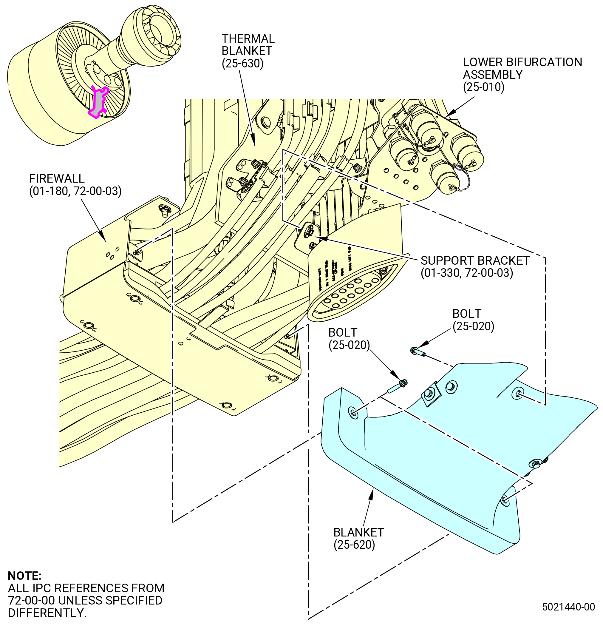
| B. | Install the lower bifurcation assembly (25-010) (SIN 09400) or (25-011) (SIN 09400). Refer to TASK 72-00-03-420-802 (72-00-03, INSTALLATION 001). |
| Subtask 72-00-00-440-017 |
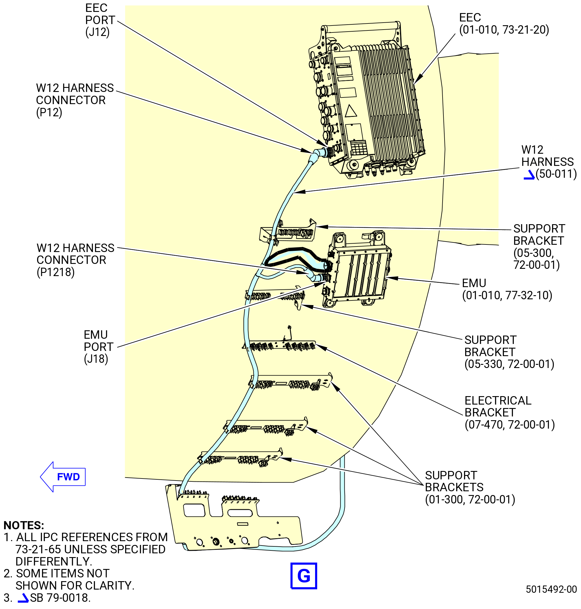
| C. | Install the electronic engine control (EEC) (65H00) and engine monitoring unit (EMU) (65Z00) as follows. Refer to Figure 1001. |
| CAUTION: |
|
| CAUTION: |
|
| (1) | Install the EEC as follows: |
| (a) | Find the four support brackets (65H10, 65H11, 65H12, 65H13) at the 3:00 o'clock position forward looking aft (FLA) on the outside of the aft fan case. |
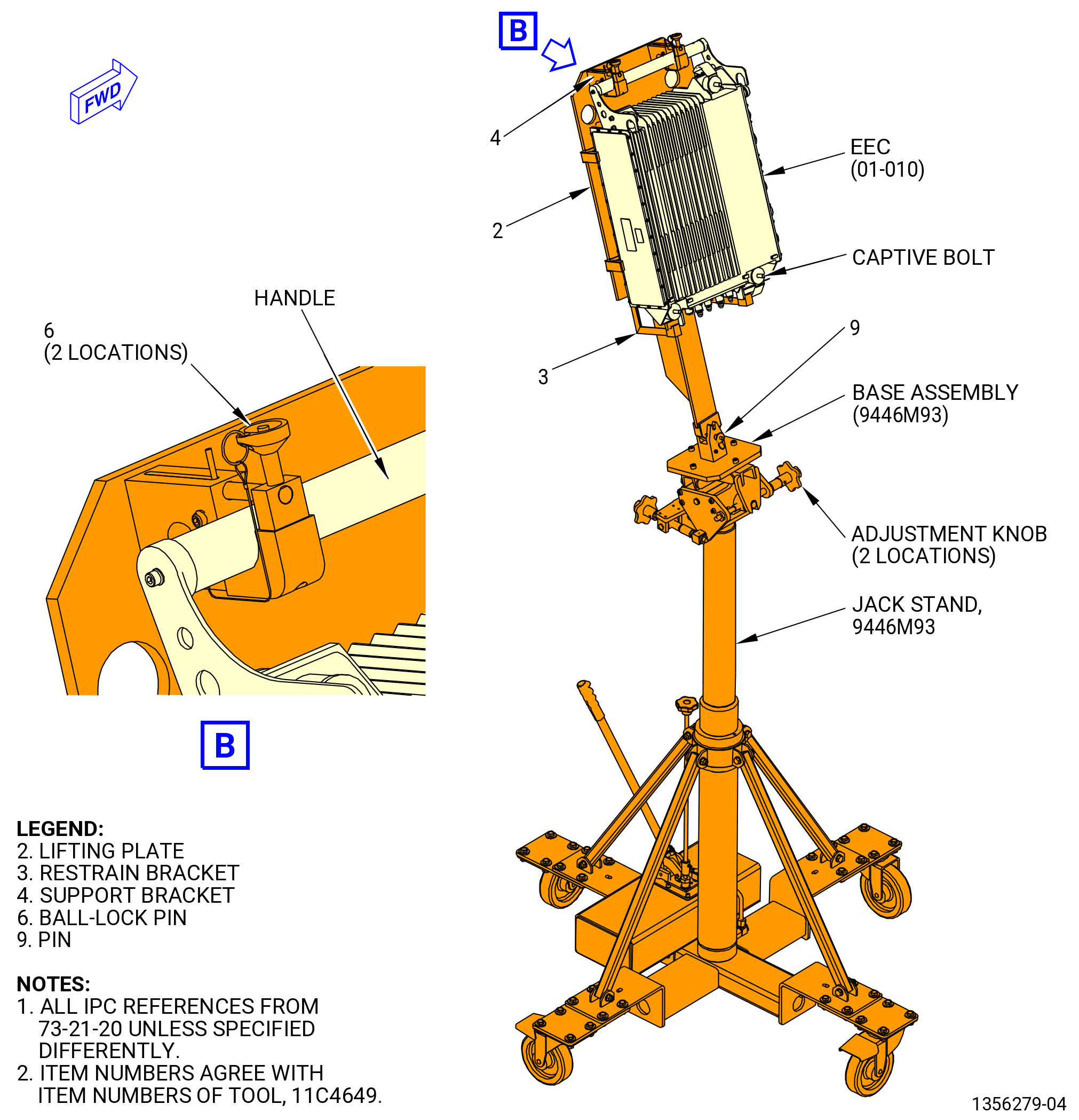
| (b) | Install the EEC in the 11C4649 EEC lift fixture. Refer to Figure 1002 and do as follows: |
| 1 | Lift the lifting plate (item 2) into the V notch of the 9446M93 jack stand and attach it with the jack stand hand screw. |
| 2 | Remove the ball-lock pins (item 6) from the holes in the lifting plate (item 2). |
| 3 | Install the EEC in the lifting plate (item 2), make sure that the bottom of the EEC is installed behind the tabs on the lower restrain brackets (item 3) and that the EEC handle is inserted into the notches of the two upper support brackets (item 4). |
| 4 | Insert the two ball-lock pins (item 6) in position. |
| (c) | Use the adjustments knobs on the 9446M93 jack stand to align the EEC in position until the hooks of the handle are attach to the horizontal posts on the top two support brackets (05-040 , 72-00-01) (SIN 65H10), (05-080 , 72-21-00) (SIN 65H11). |
| (d) | Attach the EEC to the four support brackets with the four captive bolts that are part of the EEC. |
| (e) | Torque the captive bolts to 216-240 lb in. (24.4-27.1 N.m). |
| (f) | Remove the 11C4649 EEC lift fixture and the 9446M93 jack stand as follows: |
| 1 | Release the two ball-lock pins (item 6) that attach the EEC handle to the 11C4649 EEC lift fixture. |
| 2 | Carefully move the 9446M93 jack stand away from the engine. |
| 3 | Remove the pin (item 9) and the 11C4649 EEC lift fixture from the 9446M93 jack stand. |
| (2) | Install the EMU to the aft fan case at approximately the 4:00 o'clock location FLA on the brackets (05-250 , 72-00-01, 05-280 , 72-00-01, 05-130 , 72-00-01, and 05-160 , 72-00-01) or (05-271 , 72-00-01, 05-291 , 72-00-01, 05-156 , 72-00-01, and 05-161 , 72-00-01) with the four captive bolts supplied with the EMU. |
| (3) | Torque the captive bolts to 108-132 lb in. (12.2-14.9 N.m). |
| Subtask 72-00-00-440-055 |
| * * * PRE SB 79-0018( MFOHX without Indicating Capability ) |
| * * * SB 72-0056( New EMU Brackets ) |
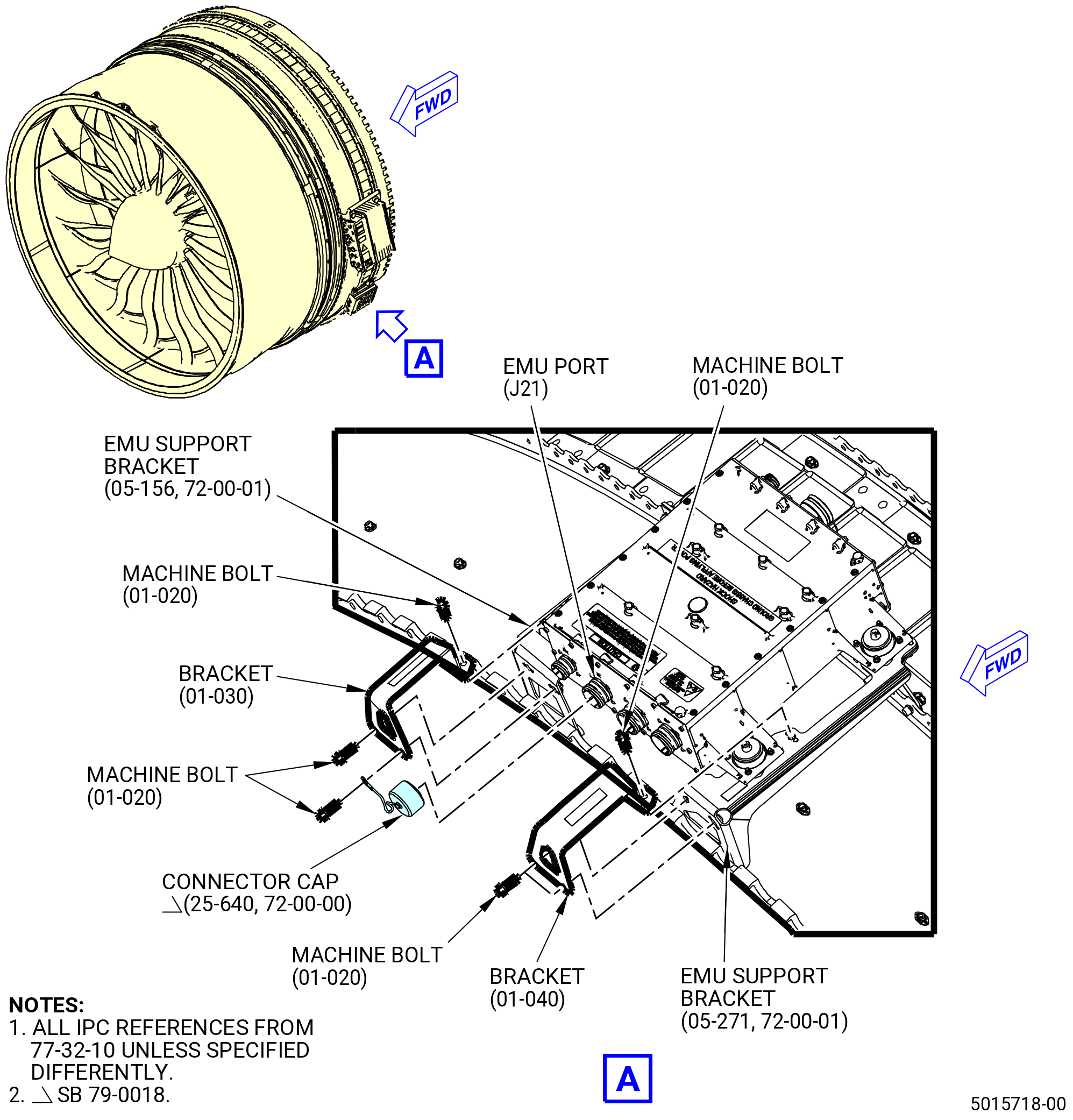
| (4) | Install the brackets (01-030 , 77-32-10, 01-040 , 77-32-10) as follows. Refer to Figure 1003. |
| (a) | Attach the bracket (01-030 , 77-32-10) to the EMU support bracket (05-156 , 72-00-01) with machine bolts (01-020 , 77-32-10). |
| (b) | Attach the bracket (01-040 , 77-32-10) to the EMU support bracket (05-271 , 72-00-01) with machine bolts (01-020 , 77-32-10). |
| (c) | Torque the machine bolts (01-020 , 77-32-10) to 106-124 lb in. (12.0-14.0 N.m). |
| NOTE: |
|
| * * * END SB 72-0056 |
| * * * END PRE SB 79-0018 |
| Subtask 72-00-00-440-084 |
| * * * SB 79-0018( MFOHX with Indicating Capability ) |
| (4).A. | Install the brackets (01-030 , 77-32-10) (SIN 65Z15) and (01-040 , 77-32-10) (SIN 65Z16) and connector cap (25-640) (SIN 65K02). Refer to Figure 1003 and do as follows: |
| (a) | Install the connector cap on the EMU (01-010 , 77-32-10) (SIN 65Z00) port (J21) with soft jaw pliers. |
| (b) | Install the lanyard of the connector cap on one machine bolt (01-020 , 77-32-10) (SIN 65Z20). |
| (c) | Attach the bracket (01-030 , 77-32-10) (SIN 65Z15) to the EMU support bracket (05-156 , 72-00-01) (SIN 65Z12) with the machine bolt (01-020 , 77-32-10) (SIN 65Z20) at the right bolthole, FLA. |
| (d) | Attach the bracket (01-030 , 77-32-10) (SIN 65Z15) with the two remaining machine bolts (01-020 , 77-32-10) (SIN 65Z20). |
| (e) | Attach the bracket (01-040 , 77-32-10) (SIN 65Z16) to the EMU support bracket (05-271 , 72-00-01) (SIN 65Z10) with machine bolts (01-020 , 77-32-10) (SIN 65Z20). |
| (f) | Torque the machine bolts (01-020 , 77-32-10) (SIN 65Z20) to 106-124 lb in. (12.0-14.0 N.m). |
| * * * END SB 79-0018 |
| Subtask 72-00-00-440-230 |
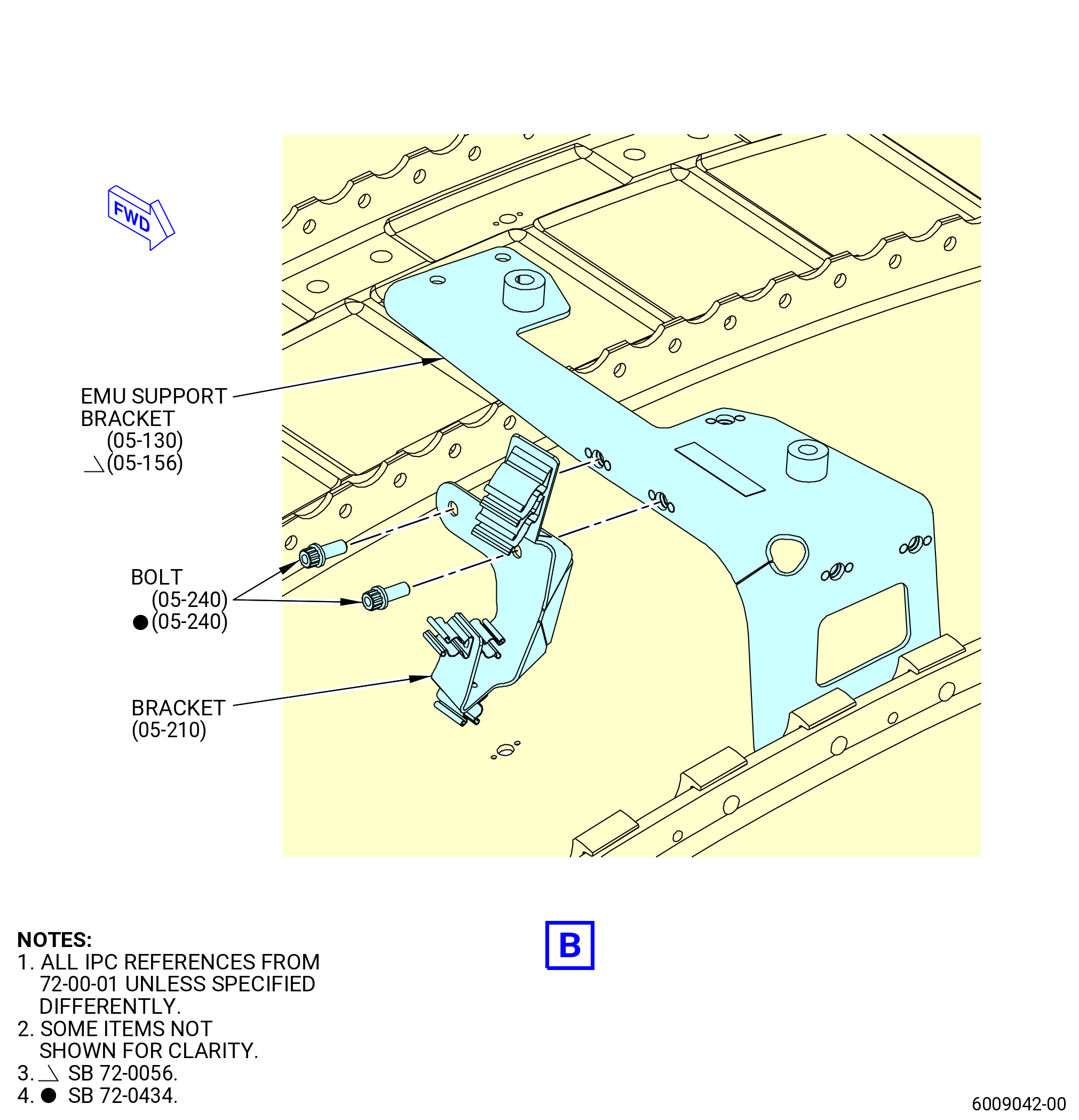
| (5) | Attach the support bracket (bracket) (05-210 , 72-00-01) (SIN 6701U) as follows: |
| (a) | Attach the bracket (05-210 , 72-00-01) (SIN 6701U) to the EMU support bracket (05-130 , 72-00-01) (SIN 65Z12) or (05-156 , 72-00-01) (SIN 65Z12) with the two machine bolts (bolts) (05-240 , 72-00-01) (SIN 67021). |
| (b) | Torque the bolts (05-240 , 72-00-01) (SIN 67021) to 106 to 124 lb in. (11.9 to 14.0 Nm). |
| Subtask 72-00-00-440-018 |
| D. | Make additional connections to the EEC (65H00) and EMU (65Z00) as follows. Refer to Figure 1004. |
| (1) | Install three air system tubes to the EEC as follows: |
| Subtask 72-00-00-440-155 |
| * * * PRE SB 75-0035( Engines with PS25 Pressure Sense Tube and Air P25 Hose Tube ) |
| (a) | Install the P25 tube (01-070 , 75-42-15) (SIN 61402) to the lower left port on the bottom of the EEC. |
| NOTE: |
|
| NOTE: |
|
| * * * END PRE SB 75-0035 |
| Subtask 72-00-00-440-156 |
| (b) | Install the PS3 tube (61503) to the second from left port from bottom of the EEC. |
| Subtask 72-00-00-440-168 |
| (c) | Deleted. |
| Subtask 72-00-00-440-169 |
| * * * PRE SB 75-0035( Current P0 Tube Installation ) |
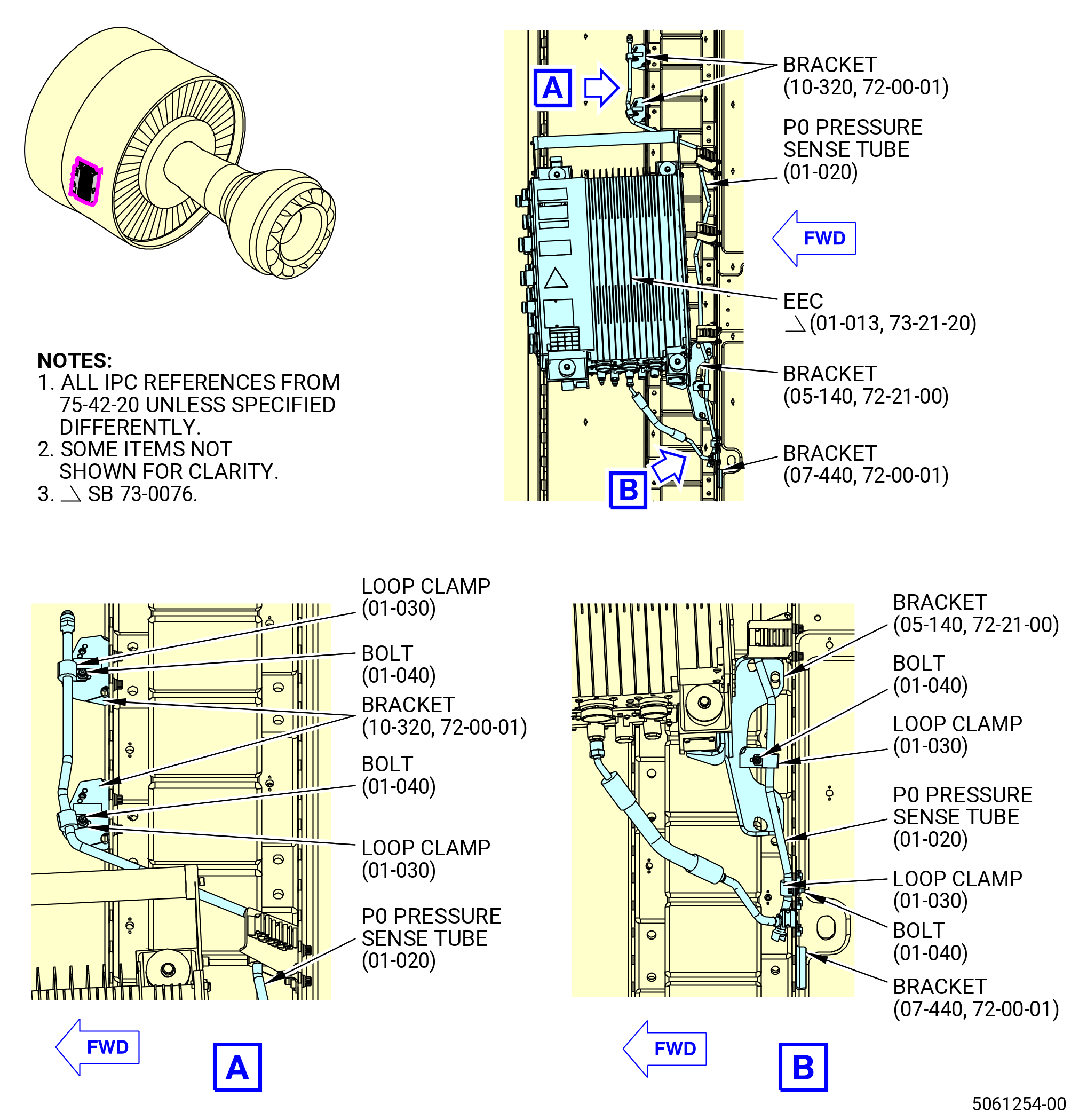
| (d) | Install the tube hose (P0 tube) (01-020 , 75-42-20) (SIN 61301) to the third from left port from the bottom of the EEC. |
| * * * END PRE SB 75-0035 |
| Subtask 72-00-00-440-186 |
| * * * SB 73-0076( New EEC ) |
| * * * SB 75-0035( New P0 Tube Installation ) |
| (d).A. | Install the P0 tube (01-020 , 75-42-20) (SIN 61301) as follows: |
| 1 | Before connecting the P0 tube to the EEC, loosen the machine bolts (bolts) (01-040 , 75-42-20) (SIN 61320) and cushion loop clamps (clamps) (01-030 , 75-42-20) (SIN 61380) that attaches the P0 tube to the brackets (10-320 , 72-00-01) (SIN 61311), (07-380 , 72-00-01) (SIN 61310), (05-140 , 72-21-00) (SIN 65H13), and (07-440 , 72-00-01) (SIN 6701L). |
| CAUTION: |
|
| 2 | Pull the two ends of the P0 tube downward at the same time. |
| 3 | Do an inspection of the P0 tube as follows: |
| a | Make sure that the P0 tube is clean and free of unwanted material. |
| WARNING: |
|
| b | If necessary, use C04-035 isopropyl alcohol to clean the P0 tube. |
| 4 | Connect the P0 tube to the EEC. |
| CAUTION: |
|
| 5 | Torque the P0 tube to 175 to 205 lb in. (19.7 to 23.2 Nm). |
| 6 | Torque the bolts (01-040 , 75-42-20) (SIN 61320) to 51 to 59 lb in. (5.7 to 6.7 Nm). |
| * * * END SB 73-0076 |
| * * * END SB 75-0035 |
| Subtask 72-00-00-440-157 |
| * * * PRE SB 75-0035( Engines with PS25 Pressure Sense Tube and Air P25 Hose Tube ) |
| (e) | Torque the P25 tube (01-070 , 75-42-15) (SIN 61402) B-nut to 143 to 167 lb in. (16.2 to 18.9 Nm). |
| NOTE: |
|
| * * * END PRE SB 75-0035 |
| Subtask 72-00-00-440-158 |
| (f) | Torque the B-nut (61301) to 175-205 lb in. (19.8-23.2 N.m). |
| (g) | Triple torque the B-nut (61503) to 262-308 lb in. (29.6-34.8 N.m). |
| Subtask 72-00-00-440-170 |
| (h) | Deleted. |
| Subtask 72-00-00-440-171 |
| (2) | Install the EEC cables to the EEC and the EMU as follows: |
| CAUTION: |
|
| CAUTION: |
|
| CAUTION: |
|
| CAUTION: |
|
| CAUTION: |
|
| (a) | Match the identification numbers on each electrical cable with the same number on the ports of the EEC or EMU. Refer to Figure 1004. |
| (b) | Engage the cable connector with its mating interface and turn the knurled coupling while carefully shaking the backshell assembly. |
| (c) | After you fully seat the coupling ring, use teflon-jaw pliers and apply the final torque. |
| (d) | Turn the cable connector until the pliers begin to slip. |
| (e) | Make sure there is no movement between the mating connectors, and that the witness line between the connectors is not visible. |
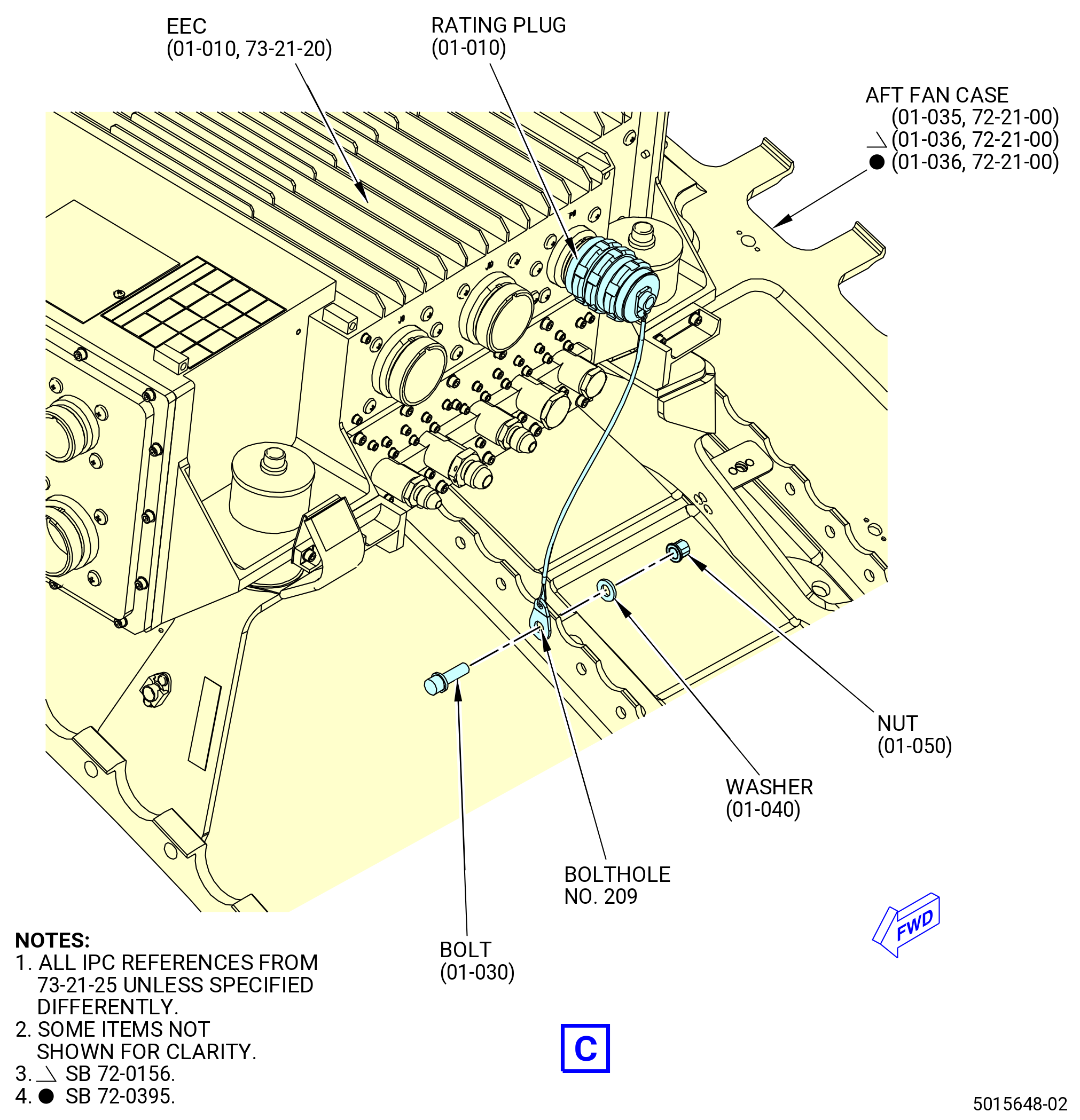
| (3) | Install the data entry plug (rating plug) (01-010 , 73-21-25) (SIN 65K00) as follows: |
| (a) | Attach the rating plug to the lower right hand side of the EEC (01-010 , 73-21-20) (SIN 65H00) with soft jaw pliers and tighten it until the pliers slip. |
| (b) | Firmly attach the rating plug lanyard to the forward side of C1 flange bolthole No. 209 of the aft fan case (01-035 , 72-21-00) (SIN 84100) or (01-036 , 72-21-00) (SIN 84100). Refer to Figure 1004 and do as follows: |
| WARNING: |
|
| 1 | Apply C03-085 epoxy primer or C03-079 epoxy primer to the mating surfaces of the machine bolt (bolt) (01-030 , 73-21-25) (SIN 65K20), washer (01-040 , 73-21-25) (SIN 65K30), lanyard eyelet face, and inside diameter of bolthole No. 209 of the aft fan case. |
| 2 | Make sure to install the hardware before the epoxy primer coating dries. |
| 3 | Put the lanyard lug of the rating plug on the forward side of the C1 flange bolthole No. 209. |
| 4 | Wet install the bolt, with the bolthead forward, and washer. |
| 5 | Install the self-locking nut (nut) (01-050 , 73-21-25) (SIN 65K40) and torque it to 106-124 lb in. (12.0-14.0 N.m). |
| Subtask 72-00-00-440-015 |
| CAUTION: |
|
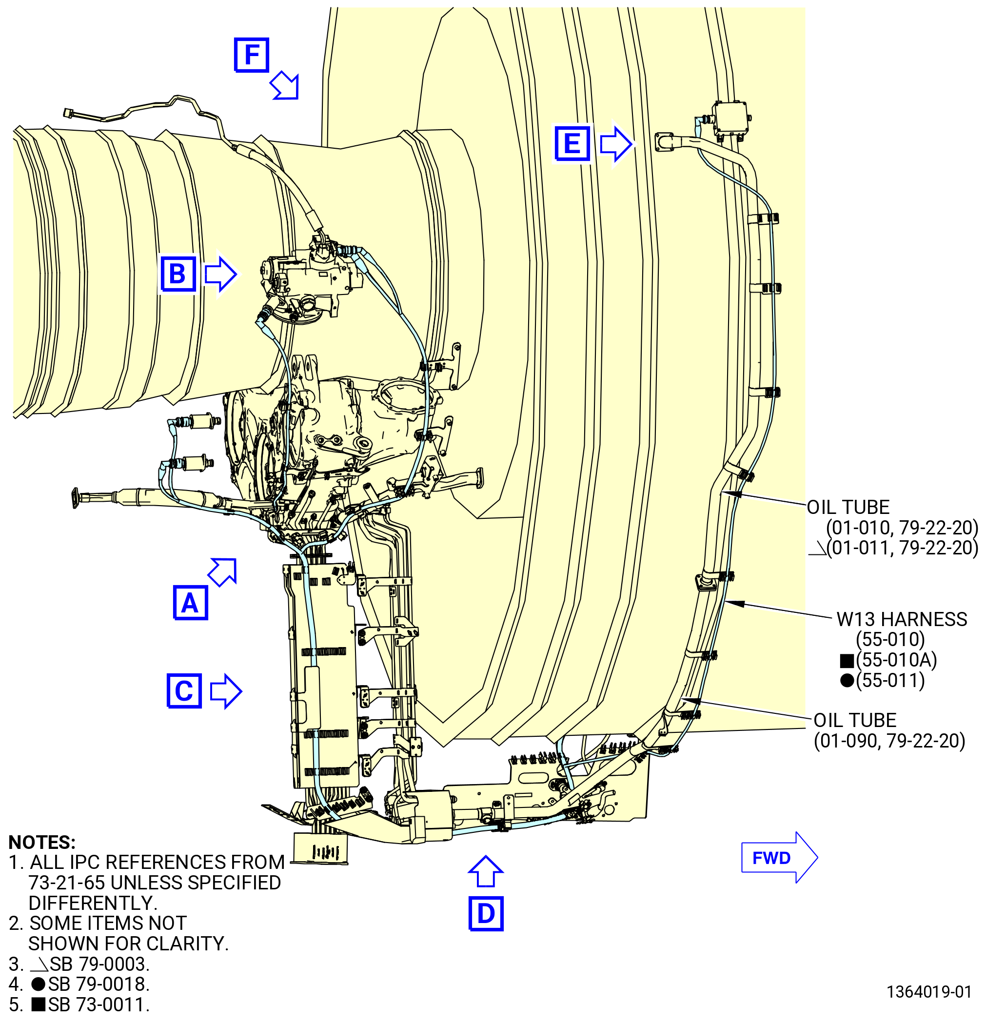
| E. | Install the W13 harness (55-010 , 73-21-65) (SIN 6700B) or (55-010A , 73-21-65) (SIN 6700B) or (55-011 , 73-21-65) (SIN 6700B) on the propulsor. Refer to Figure 1006 and do as follows: |
| (1) | Remove the protective covers from the harness connectors and component connectors. |
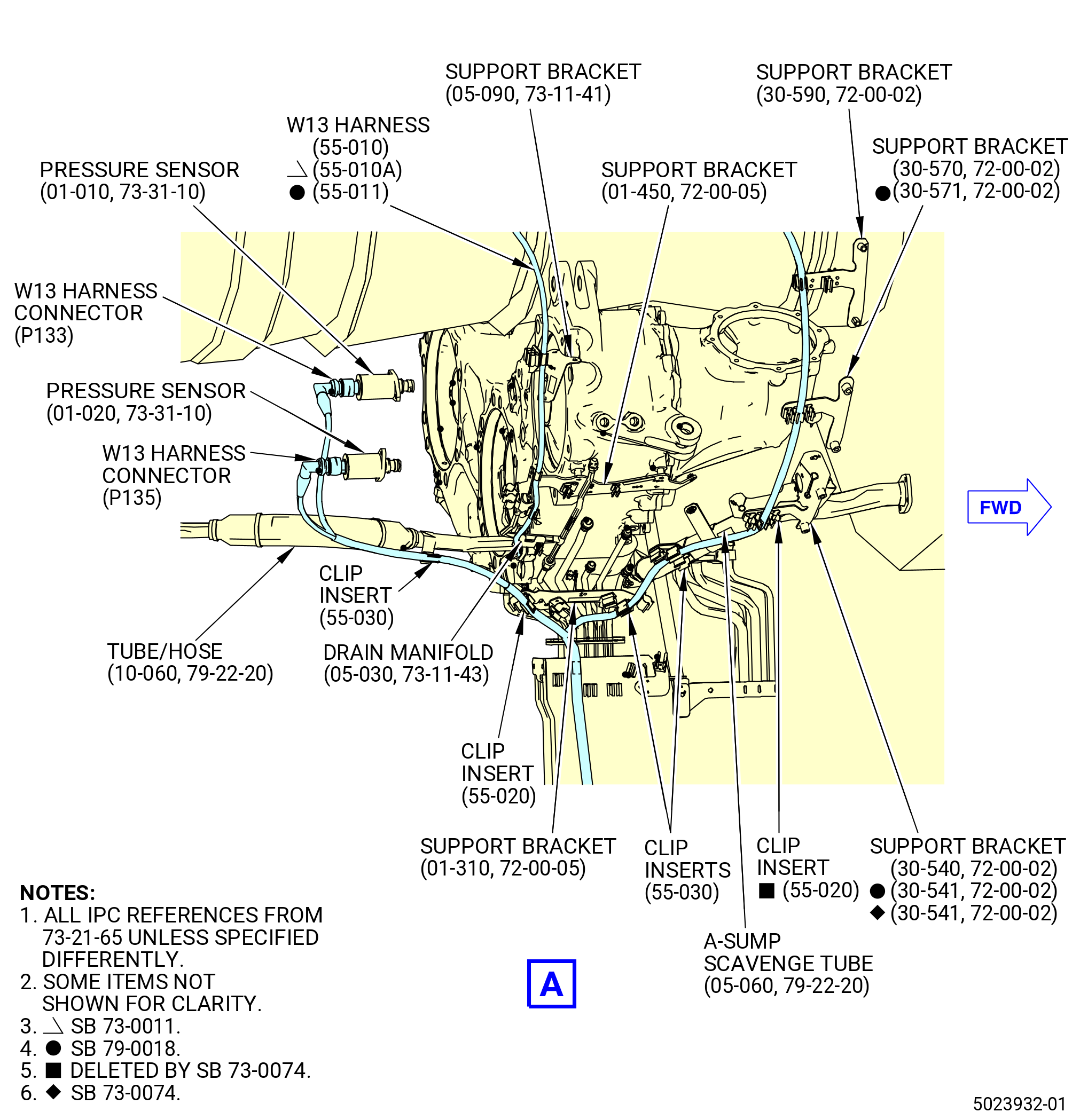
| (2) | Put the W13 harness in the clip of the support bracket (6711G) with an electrical clip insert (clip insert) (67175). |
| (3) | Put the W13 harness in the clip of the support bracket (6711G) with an electrical clip insert (clip insert) (67174). |
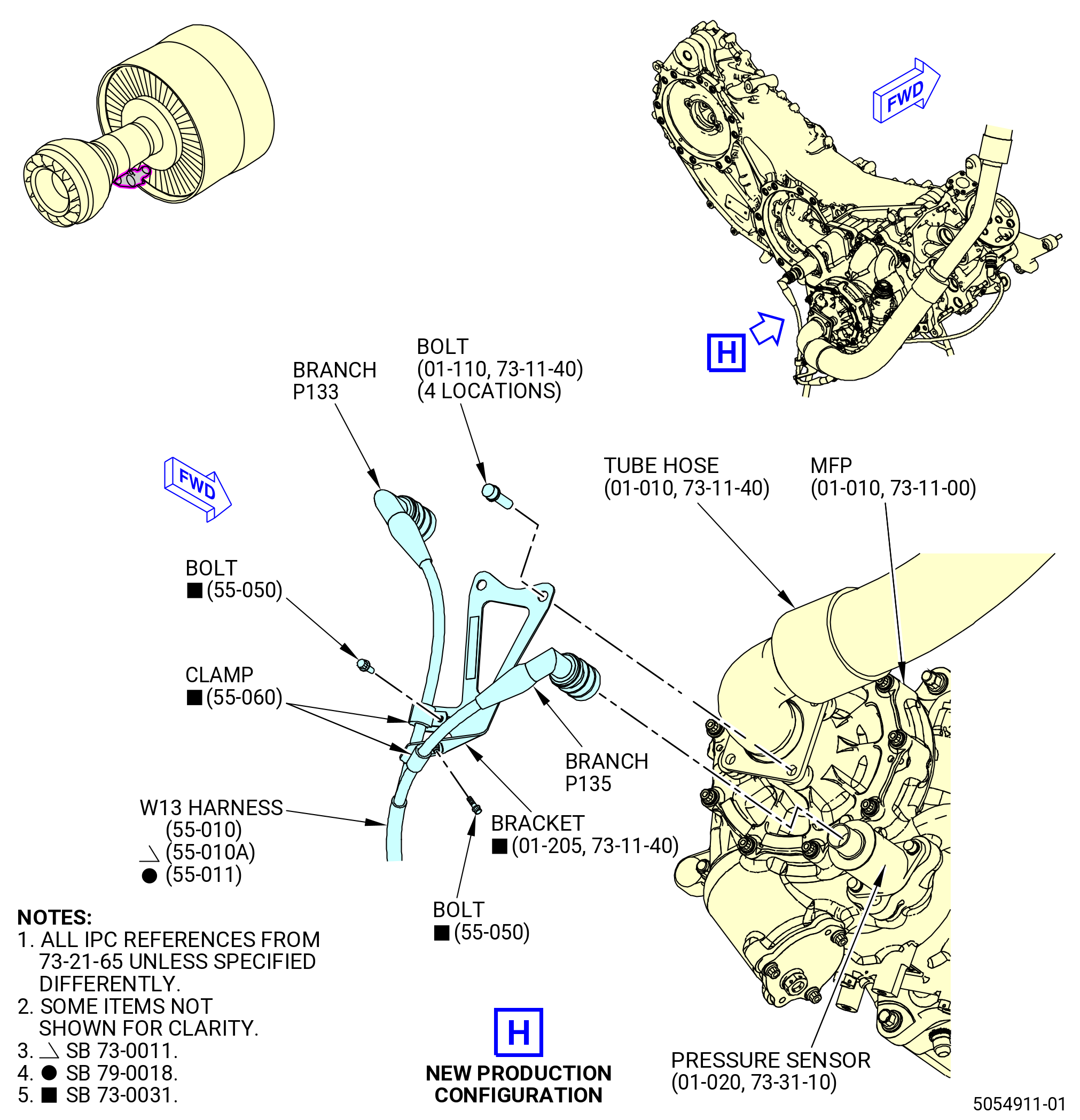
| (4) | Connect the W13 harness connector (P135) to the pressure sensor (31501) as follows: |
| (a) | Put the W13 harness in the clip of the oil scavenge tube and hose (tube/hose) (45202) with a clip insert (67174). |
| Subtask 72-00-00-440-093 |
| * * * SB 73-0031( Installation of W13 Harness with additional Bracket ) |
| (b) | Put the W13 harness in the clip of the W13 harness electrical bracket (bracket) (01-190 , 73-11-40) (SIN 6741N). |
| NOTE: |
|
| * * * END SB 73-0031 |
| Subtask 72-00-00-440-094 |
| (c) | Connect the W13 harness connector (P135) to the FSDP port of the pressure sensor. |
| (d) | Tighten the W13 harness connector (P135) with teflon-jaw pliers. |
| (5) | Connect the W13 harness connector (P133) to the pressure sensor (31500) as follows: |
| Subtask 72-00-00-440-095 |
| * * * SB 73-0031( Installation of W13 Harness with additional Bracket ) |
| (a) | Attach the W13 harness to the bracket (01-190 , 73-11-40) (SIN 6741N) with cushion loop clamp (clamp) (55-060 , 73-21-65) (SIN 6708E) and bolt (55-050 , 73-21-65) (SIN 6702A). Torque the bolt 32 to 38 lb in. (3.6 to 4.3 Nm). |
| NOTE: |
|
| * * * END SB 73-0031 |
| Subtask 72-00-00-440-152 |
| * * * SB 73-0031( Installation of W13 Harness to New Bracket with Two Clamps Attach Positions - Production Option ) |
| (a).A. | Attach the W13 harness to the bracket (01-205 , 73-11-40) (SIN 6741N) with two cushion loop clamps (clamps) (55-060 , 73-21-65) (SIN 6708E) and bolts (55-050 , 73-21-65) (SIN 6702A). Torque the bolt 32 to 38 lb in. (3.6 to 4.3 Nm). |
| NOTE: |
|
| * * * END SB 73-0031( ) |
| Subtask 72-00-00-440-153 |
| * * * SB 73-0031( Installation of W13 Harness to New Bracket with Two Clamps Attach Positions - Field Option ) |
| (a).B. | Attach the W13 harness to the bracket (01-205 , 73-11-40) (SIN 6741N) with two clamps (55-060 , 73-21-65) (SIN 6708E) and two bolts (55-050 , 73-21-65) (SIN 6702A) or one clamp (55-060 , 73-21-65) (SIN 6708E) with one bolt (55-050 , 73-21-65) (SIN 6702A) and one clamp (55-060 , 73-21-65) (SIN 6708E) with one double hexagon head machine bolt (bolt) (55-065 , 73-21-65) (SIN 67429). Torque the bolts 32 to 38 lb in. (3.6 to 4.3 Nm). |
| NOTE: |
|
| * * * END SB 73-0031 |
| Subtask 72-00-00-440-154 |
| * * * SB 73-0031( Installation of W13 Harness to Bracket with Two Clamps Attach Positions - Reworked Option ) |
| (a).C. | Attach the W13 harness to the reworked bracket (01-210 , 73-11-40) (SIN 6741N) with two clamps (55-060 , 73-21-65) (SIN 6708E) and two bolts (55-050 , 73-21-65) (SIN 6702A) or one clamp (55-060 , 73-21-65) (SIN 6708E) with one bolt (55-060 , 73-21-65) (SIN 6702A) and one clamp (55-060 , 73-21-65) (SIN 6708E) with one bolt (55-065 , 73-21-65) (SIN 67429) and one self-locking nut (nut) (55-070 , 73-21-65) (SIN 67441). Torque the bolts 32 to 38 lb in. (3.6 to 4.3 Nm). |
| NOTE: |
|
| NOTE: |
|
| * * * END SB 73-0031 |
| Subtask 72-00-00-440-096 |
| (b) | Connect the W13 harness connector (P133) to the FFDP port of the pressure sensor. |
| (c) | Tighten the W13 harness connector (P133) with teflon-jaw pliers. |
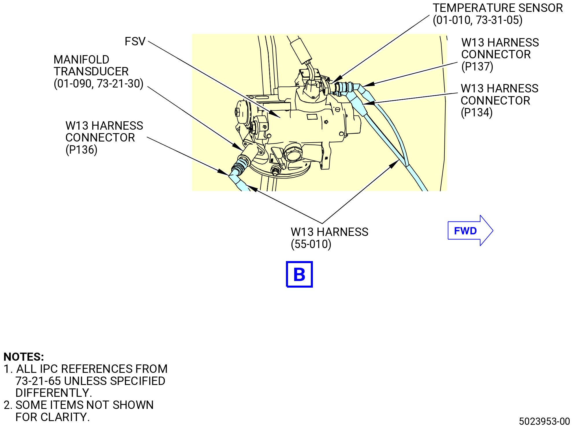
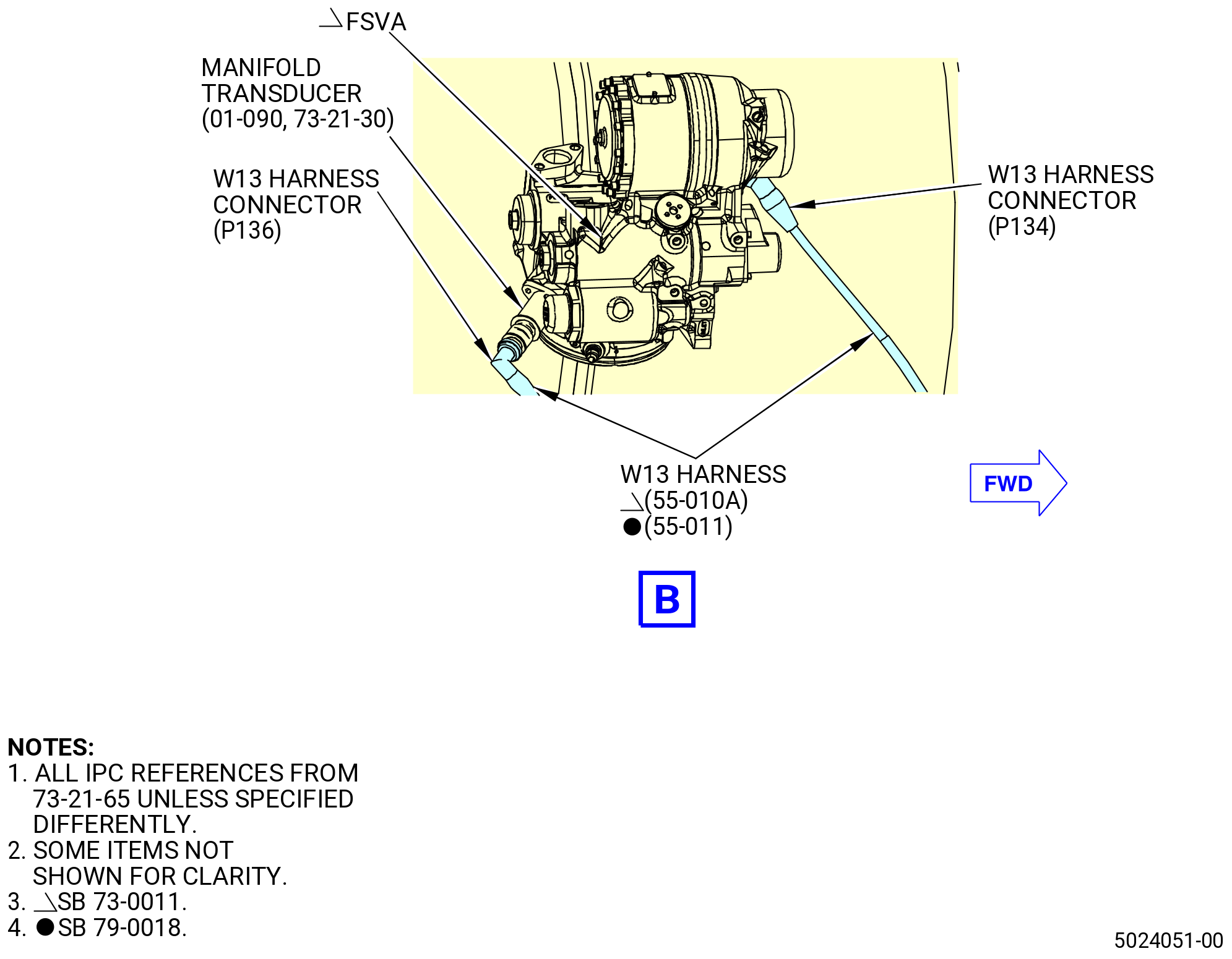
| (6) | Connect the W13 harness connector (P136) to the manifold transducer (31701) as follows: |
| (a) | Put the W13 harness in the clip of the MFP and TBV drain manifold (drain manifold) (37000). |
| (b) | Put the W13 harness in the clip of the support bracket (37010) at two locations. |
| Subtask 72-00-00-440-149 |
| * * * PRE SB 73-0060( Old Design for W30 and W31 Harnesses ) |
| (c) | Put the W13 harness in the clip of the support bracket (37610). |
| * * * END PRE 73-0060 |
| Subtask 72-00-00-440-150 |
| * * * SB 73-0060( W30 and W31 Redesigned Harnesses ) |
| (c).A. | Put the W13 harness in the two clips of the support bracket (05-090 , 73-11-41) (SIN 37610). |
| * * * END SB 73-0060 |
| Subtask 72-00-00-440-151 |
| (d) | Connect the W13 harness connector (P136) to the FMP port of the manifold transducer. |
| (e) | Tighten the W13 harness connector (P136) with teflon-jaw pliers. |
| Subtask 72-00-00-440-059 |
| * * * PRE SB 73-0011( Engines without Fuel Vapor Accumulator ) |
| (7) | Connect the W13 harness (55-010 , 73-21-65) (SIN 6700B) connector (P134) to the flow splitting valve (FSV) (01-010 , 73-21-30) (SIN 31700) as follows: |
| (a) | Put the W13 harness in the clip of the A-sump scavenge tube (05-060 , 79-22-20) (SIN 45100) with a clip insert (55-030 , 73-21-65) (SIN 67174). |
| Subtask 72-00-00-440-196 |
| * * * PRE SB 73-0074( Harness Support Spring Clips with Clip Inserts ) |
| (b) | Put the W13 harness in the clip of the support bracket (30-540 , 72-00-02) (SIN 6711D) with a clip insert (55-020 , 73-21-65) (SIN 67175). |
| * * * END PRE SB 73-0074 |
| Subtask 72-00-00-440-197 |
| * * * SB 73-0074( Harness Support Spring Clips without Clip Inserts ) |
| (b).A. | Put the W13 harness in the clip of the support bracket (30-540 , 72-00-02) (SIN 6711D). |
| * * * END SB 73-0074 |
| Subtask 72-00-00-440-198 |
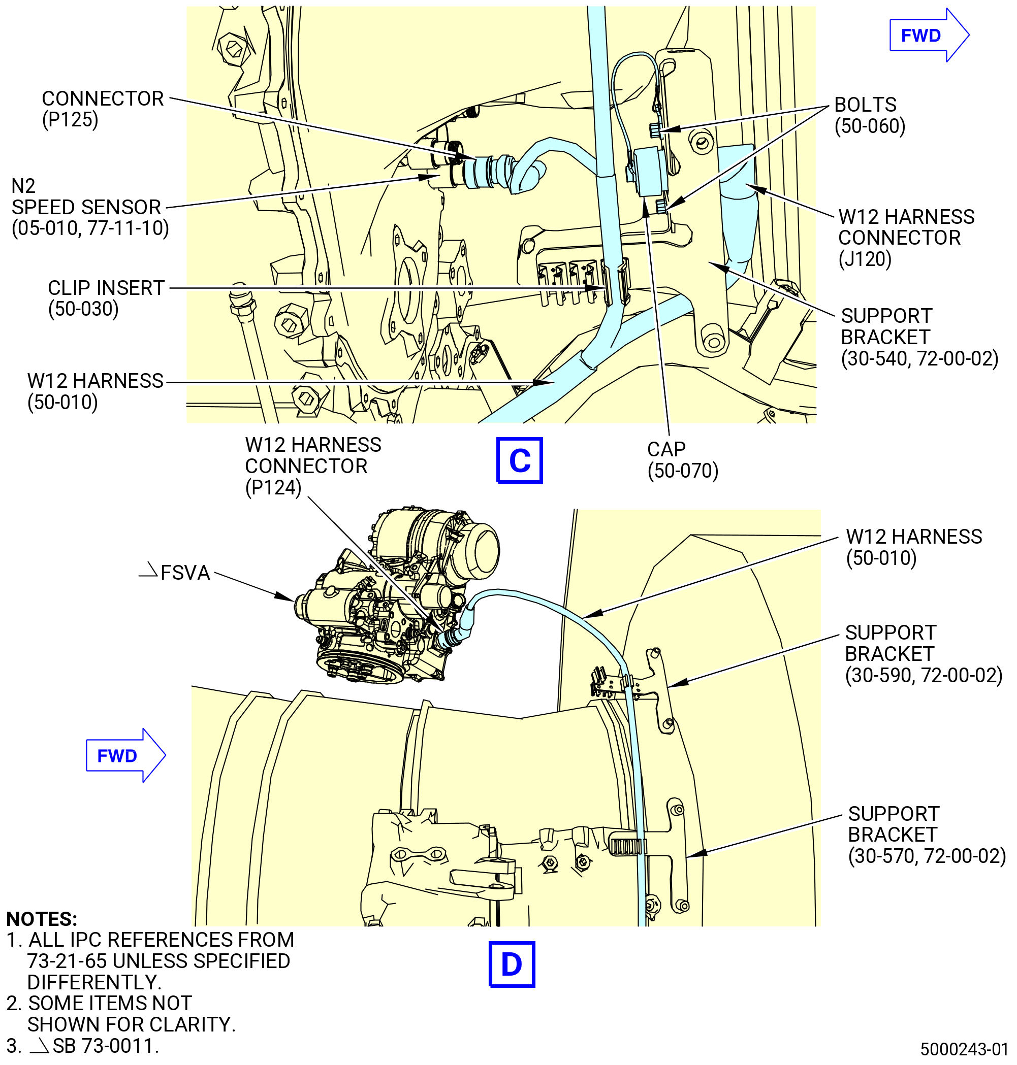
| (c) | Put the W13 harness in the clip of the support brackets (30-570 , 72-00-02) (SIN 6711E) and (30-590 , 72-00-02) (SIN 6711C). |
| (d) | Connect the W13 harness connector (P134) to the FSV-A port of the FSV. |
| (e) | Tighten the W13 harness connector (P134) with teflon-jaw pliers. |
| * * * END PRE SB 73-0011 |
| Subtask 72-00-00-440-060 |
| * * * SB 73-0011( Engines with Fuel Vapor Accumulator ) |
| (7).D. | Connect the W13 harness (55-010A , 73-21-65) (SIN 6700B) connector (P134) to the flow splitting valve accumulator (FSVA) (01-010A , 73-21-30) (SIN 31700) as follows: |
| (a) | Put the W13 harness in the clip of the A-sump scavenge tube (05-060 , 79-22-20) (SIN 45100) with a clip insert (55-030 , 73-21-65) (SIN 67174). |
| Subtask 72-00-00-440-199 |
| * * * PRE SB 73-0074( Harness Support Spring Clips with Clip Inserts ) |
| (b) | Put the W13 harness in the clip of the support bracket (30-540 , 72-00-02) (SIN 6711D) with a clip insert (55-020 , 73-21-65) (SIN 67175). |
| * * * END PRE SB 73-0074 |
| Subtask 72-00-00-440-220 |
| * * * SB 73-0074( Harness Support Spring Clips without Clip Inserts ) |
| (b).A. | Put the W13 harness in the clip of the support bracket (30-540 , 72-00-02) (SIN 6711D). |
| * * * END SB 73-0074 |
| Subtask 72-00-00-440-201 |
| (c) | Put the W13 harness in the clip of the support brackets (30-570 , 72-00-02) (SIN 6711E) and (30-590 , 72-00-02) (SIN 6711C). |
| (d) | Connect the W13 harness connector (P134) to the FSV-A port of the FSVA. |
| (e) | Tighten the W13 harness connector (P134) with teflon-jaw pliers. |
| * * * END SB 73-0011 |
| Subtask 72-00-00-440-086 |
| * * * SB 79-0018( MFOHX with Indicating Capability ) |
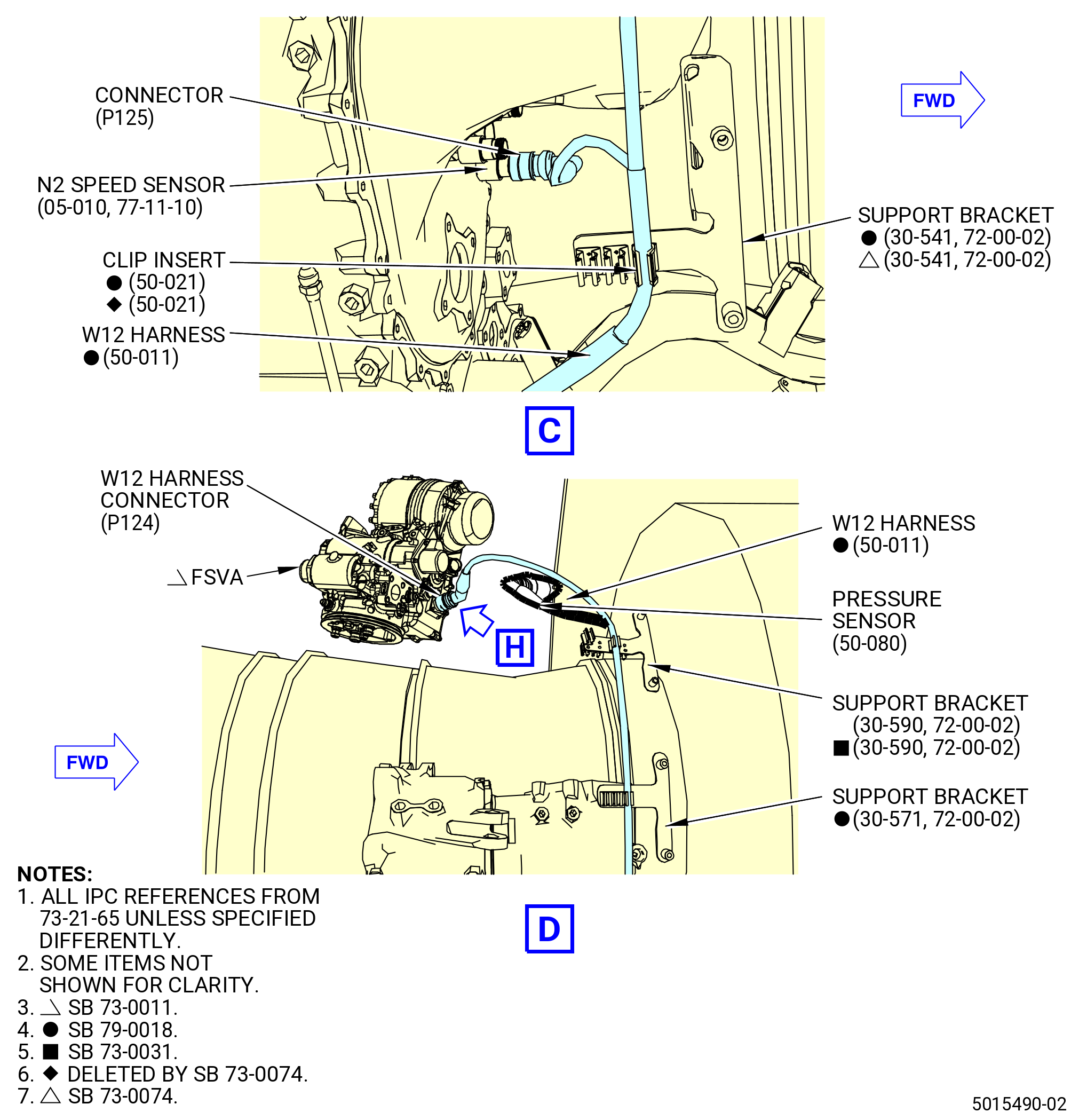
| (8).B. | Connect the W13 harness connector (P134) to the FSVA (01-010A , 73-21-30) (SIN 31700) as follows: |
| (a) | Put the W13 harness in the clip of the A-sump scavenge tube (05-060 , 79-22-20) (SIN 45100) with a clip insert (55-030 , 73-21-65) (SIN 67174). |
| * * * END SB 79-0018 |
| Subtask 72-00-00-440-202 |
| * * * PRE SB 73-0074( Harness Support Spring Clips with Clip Inserts ) |
| (b) | Put the W13 harness in the clip of the support bracket (30-541 , 72-00-02) (SIN 6711D) with a clip insert (55-020 , 73-21-65) (SIN 67175). |
| * * * END PRE SB 73-0074 |
| Subtask 72-00-00-440-221 |
| * * * SB 73-0074( Harness Support Spring Clips without Clip Inserts ) |
| (b).A. | Put the W13 harness in the clip of the support bracket (30-541 , 72-00-02) (SIN 6711D). |
| * * * END SB 73-0074 |
| Subtask 72-00-00-440-204 |
| (c) | Put the W13 harness in the clip of the support brackets (30-571 , 72-00-02) (SIN 6711E) and (30-590 , 72-00-02) (SIN 6711C). |
| (d) | Connect the W13 harness connector (P134) to the FSV-A port of the FSVA. |
| (e) | Tighten the W13 harness connector (P134) with teflon-jaw pliers. |
| * * * END SB 79-0018 |
| Subtask 72-00-00-440-061 |
| * * * PRE SB 73-0011( Engines without Fuel Vapor Accumulator ) |
| (9) | Connect the W13 harness (55-010 , 73-21-65) (SIN 6700B) connector (P137) to the temperature sensor (01-010 , 73-31-05) (SIN 65T01) as follows: |
| (a) | Connect the W13 harness connector (P137) to the FMT port of the temperature sensor. |
| (b) | Tighten the W13 harness connector (P137) with teflon-jaw pliers. |
| NOTE: |
|
| * * * END PRE SB 73-0011 |
| Subtask 72-00-00-440-062 |
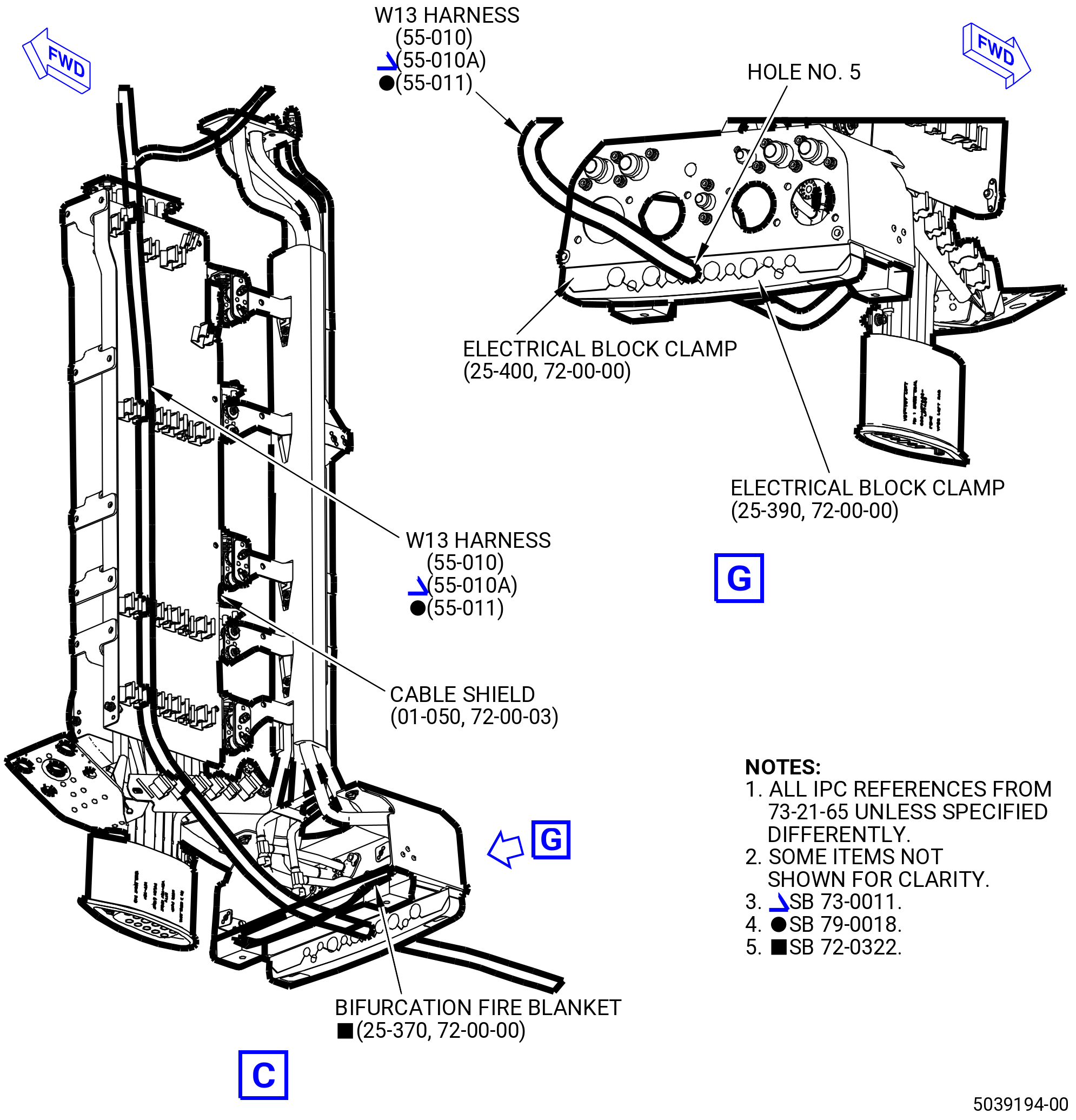
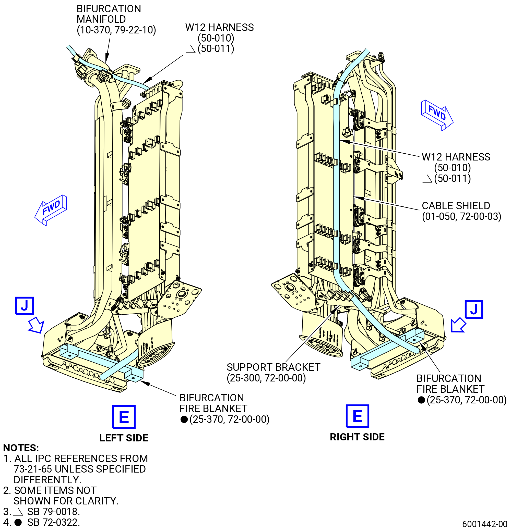
| (10) | Put the W13 harness in the clips of the right side cable shield (cable shield) (09711). |
| (11) | Put the W13 harness in the clip of the support bracket (67116). |
| Subtask 72-00-00-440-108 |
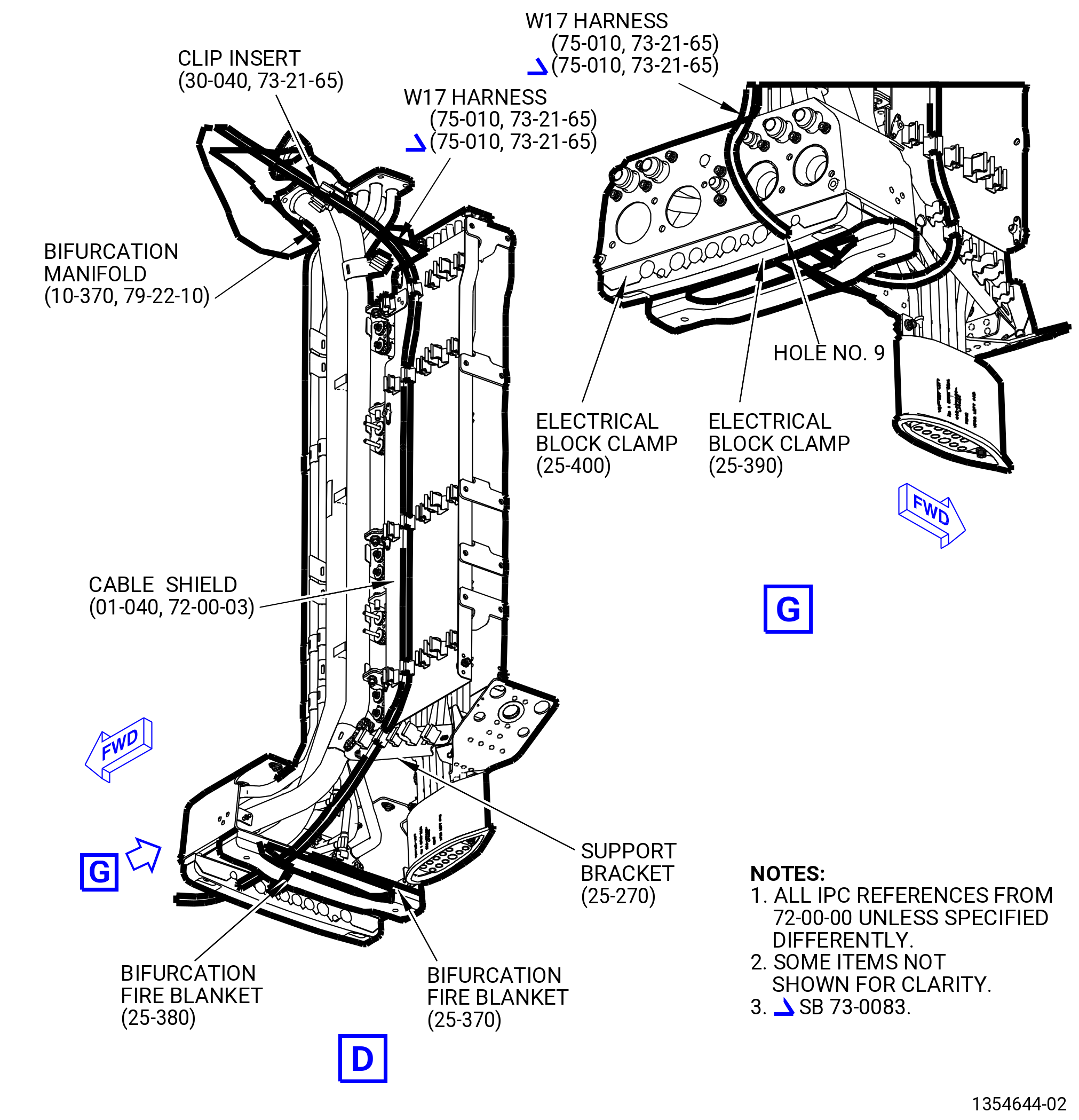
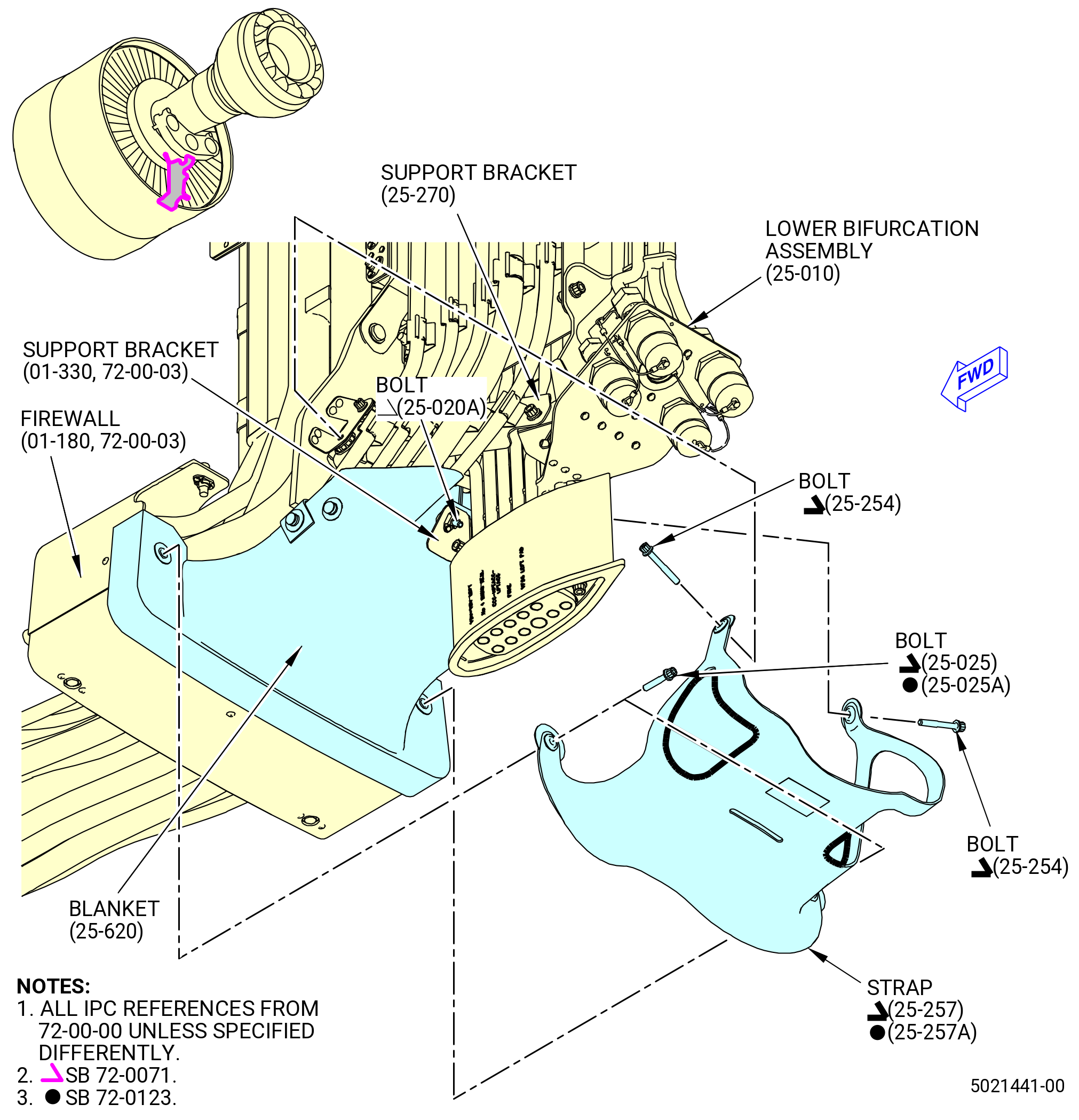
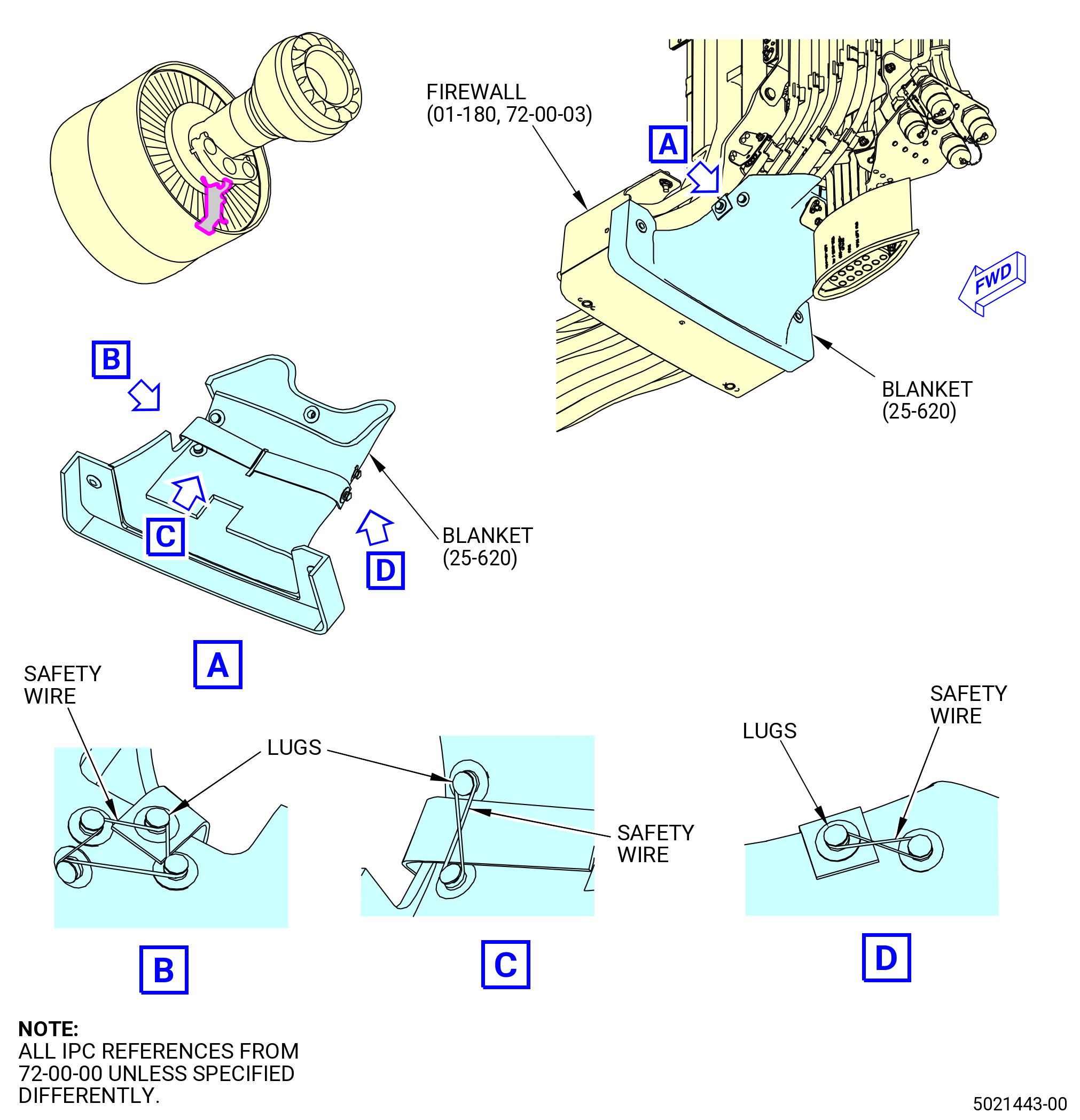
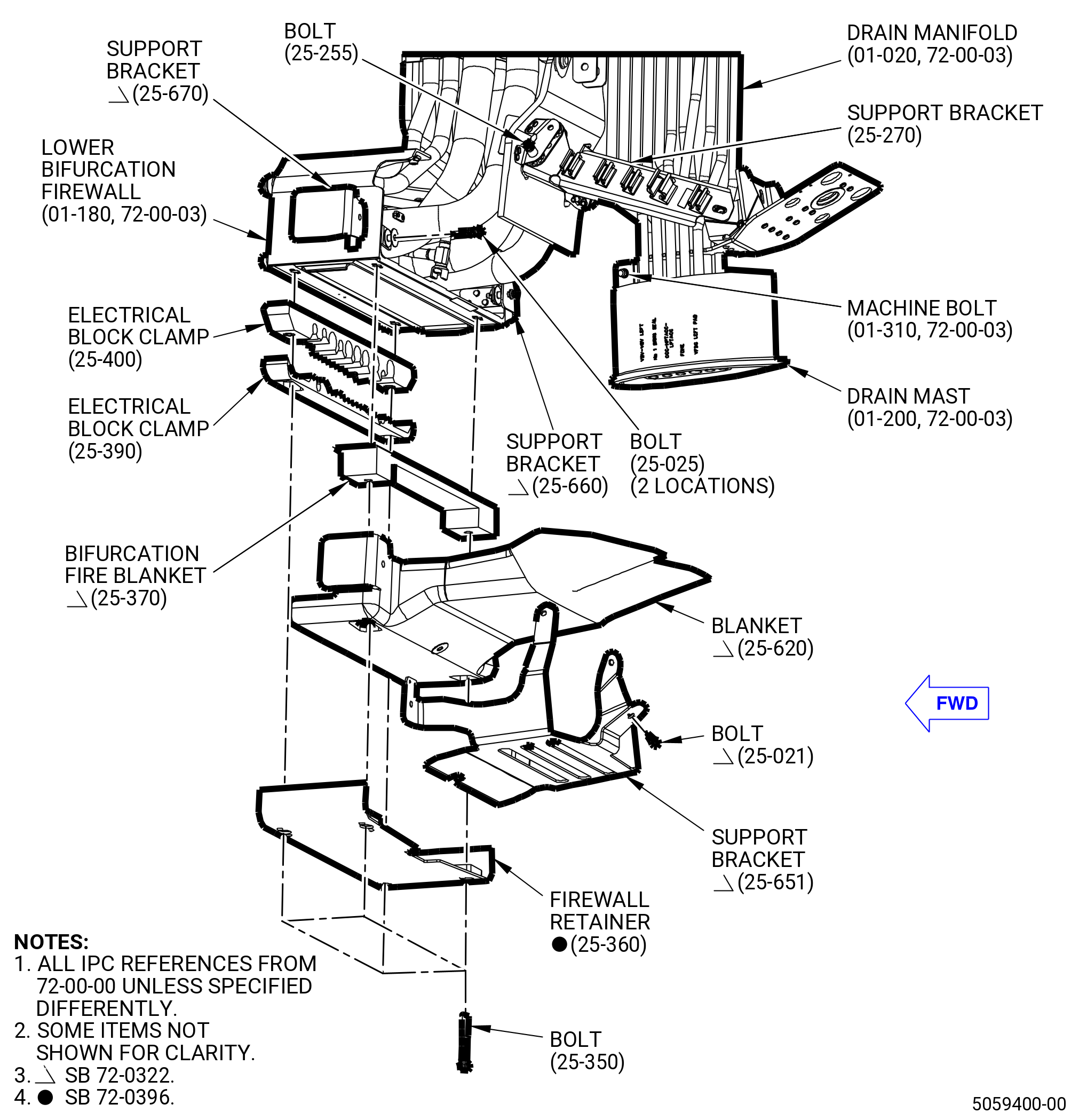
| * * * PRE SB 72-0322( Lower Bifurcation Firewall with Two Bifurcation Fire Blankets ) |
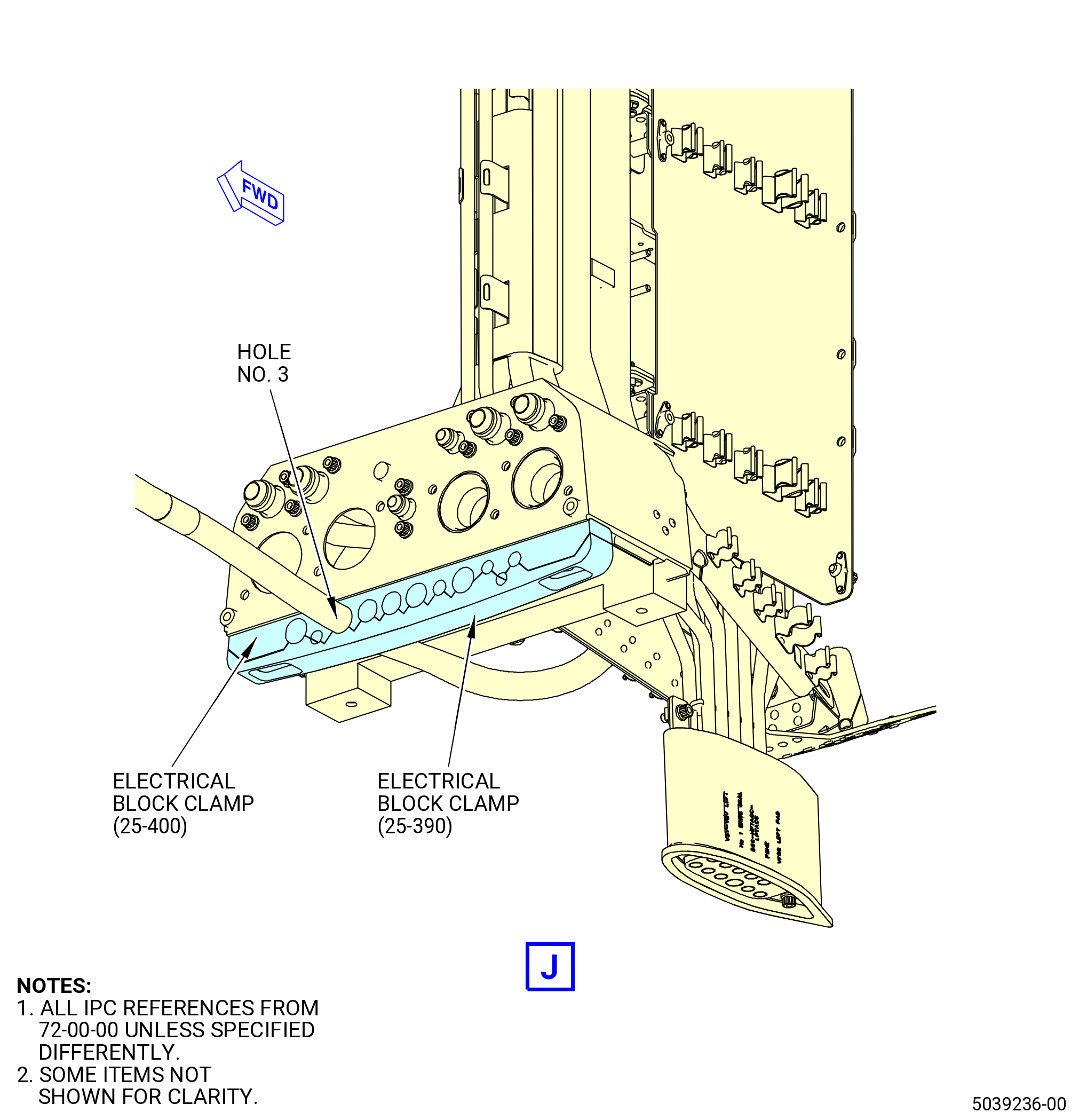
| (12) | Attach the W13 harness to the bifurcation fire blankets (25-380) (SIN 09490) and (25-370) (SIN 09491) and electrical block clamps (25-400) (SIN 09481), (25-390) (SIN 09482) as follows: |
| (a) | Attach the W13 harness through the bifurcation fire blankets and electrical block clamps in the hole No. 5 from left to right forward looking aft (FLA). |
| * * * END PRE SB 72-0322 |
| Subtask 72-00-00-440-109 |
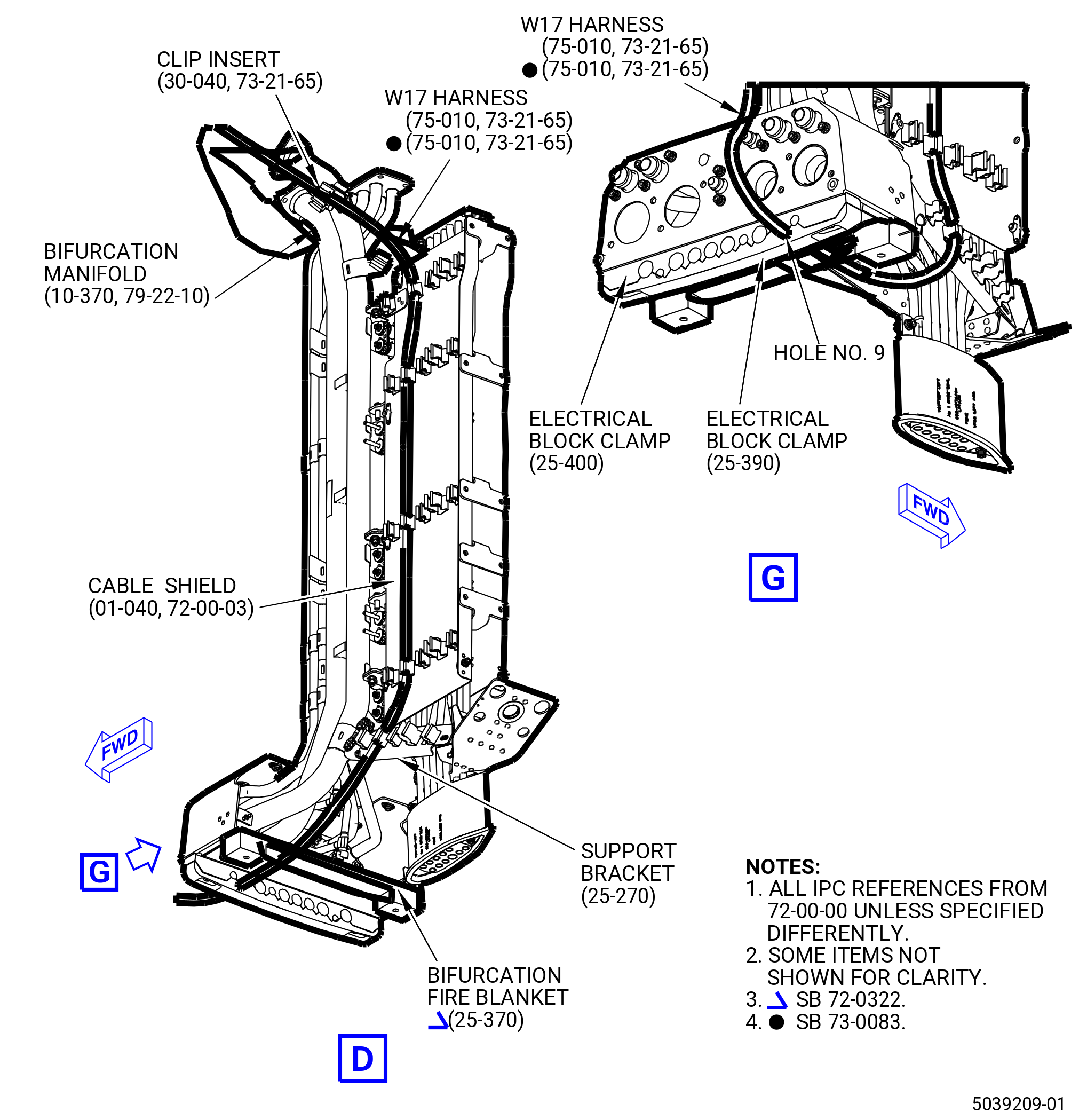
| * * * SB 72-0322( Lower Bifurcation Firewall with One Bifurcation Fire Blanket ) |
| (12).A. | Attach the W13 harness to the bifurcation fire blanket (25-370) (SIN 09491) and electrical block clamps (25-400) (SIN 09481) and (25-390) (SIN 09482) as follows: |
| (a) | Attach the W13 harness through the bifurcation fire blanket and electrical block clamps in the hole No. 5 from left to right, FLA. |
| * * * END SB 72-0322 |
| Subtask 72-00-00-440-110 |
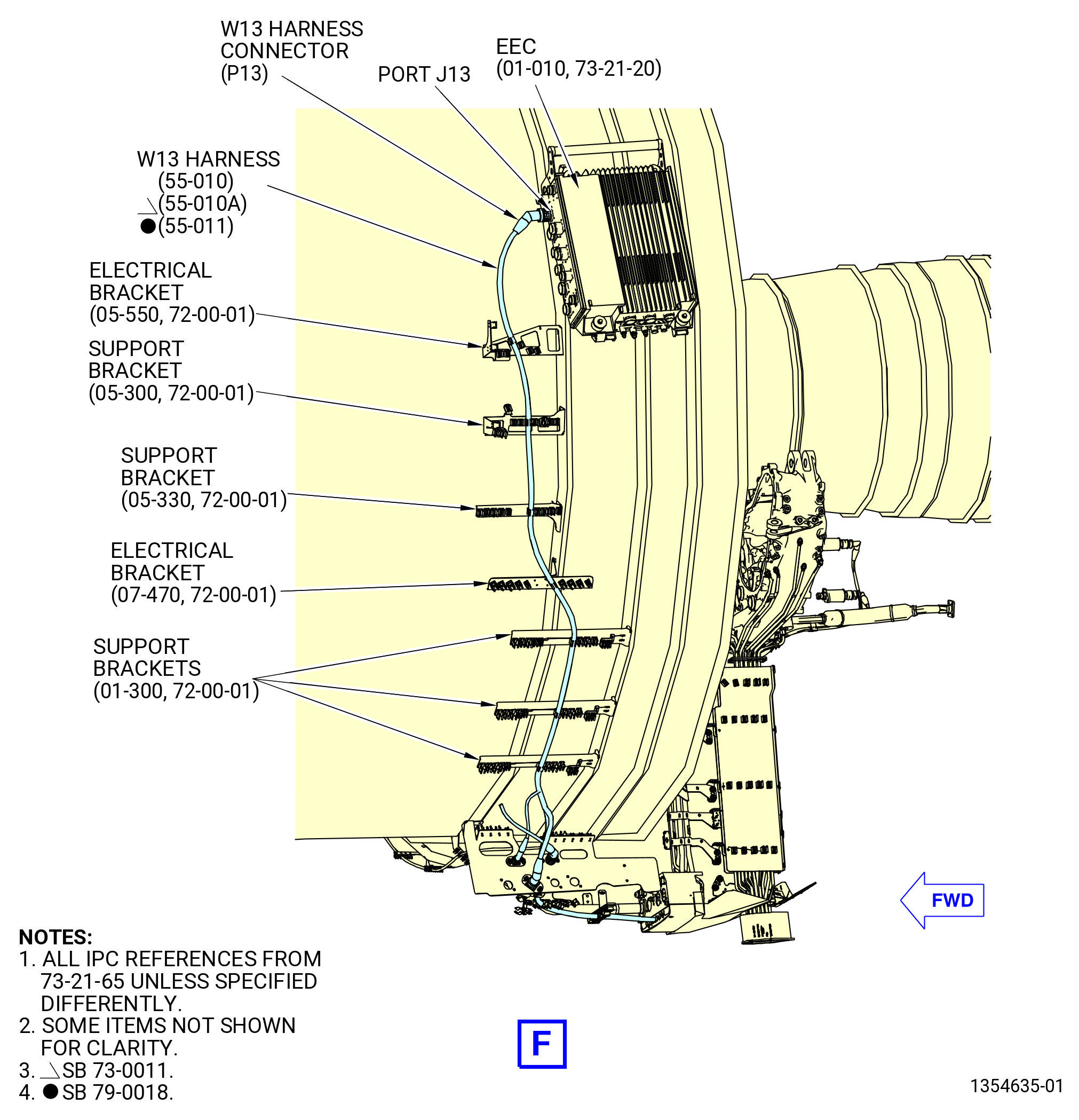
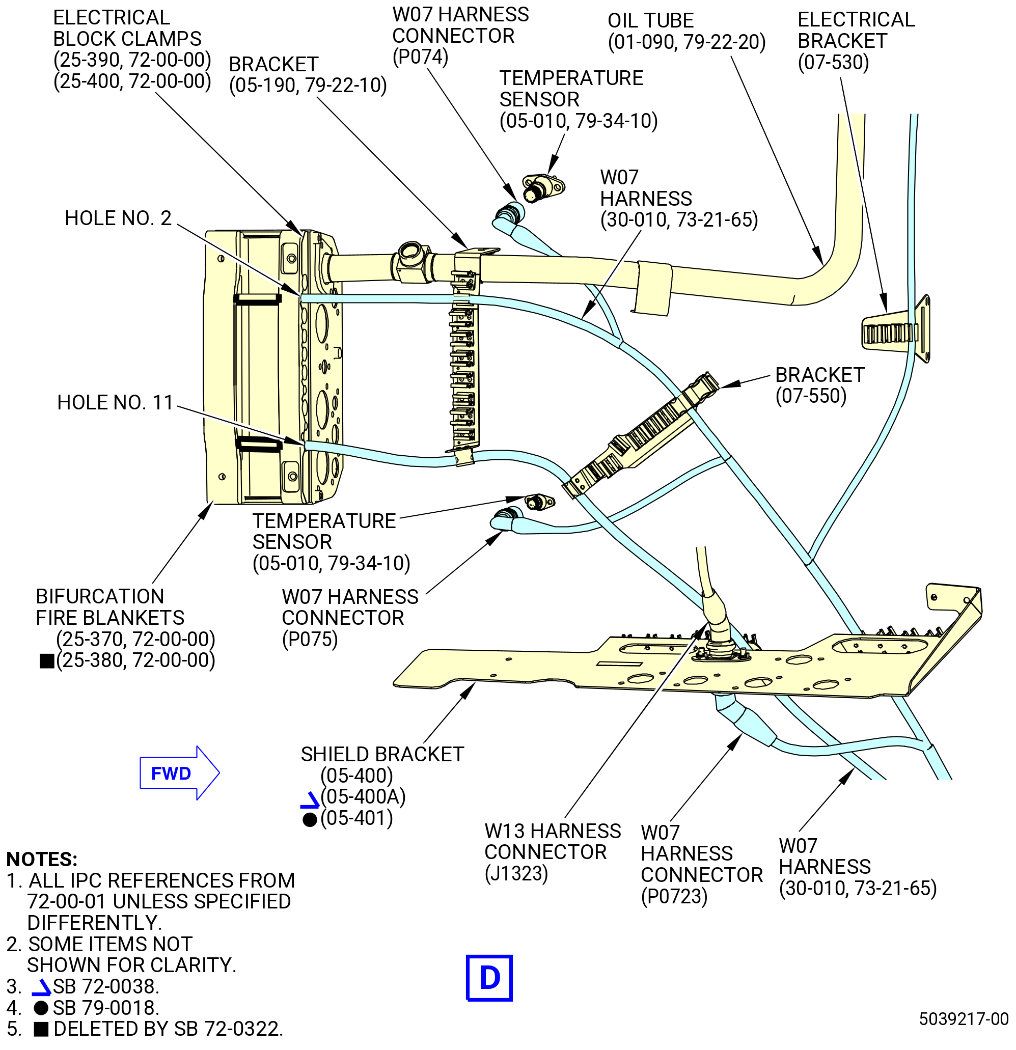
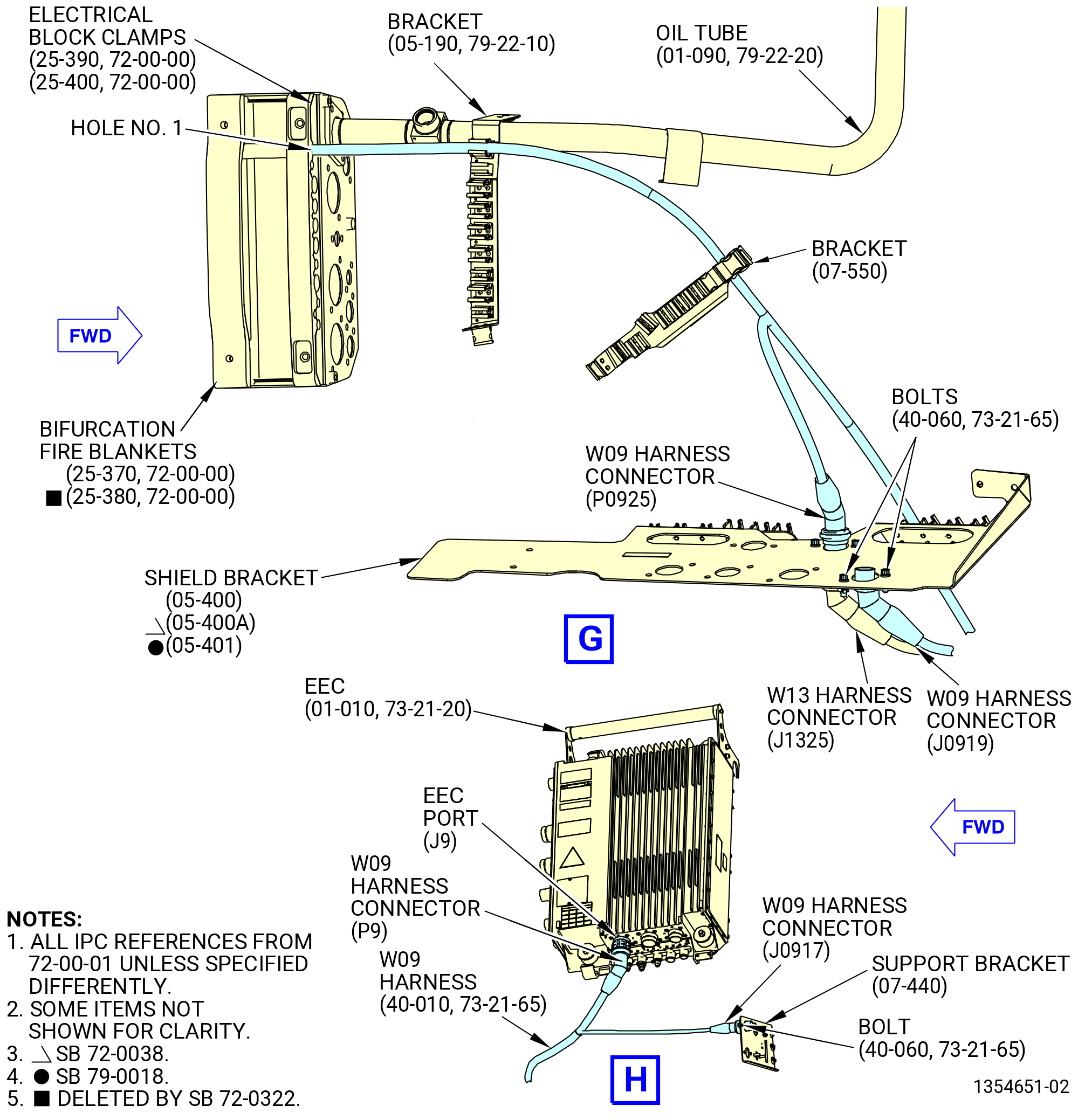
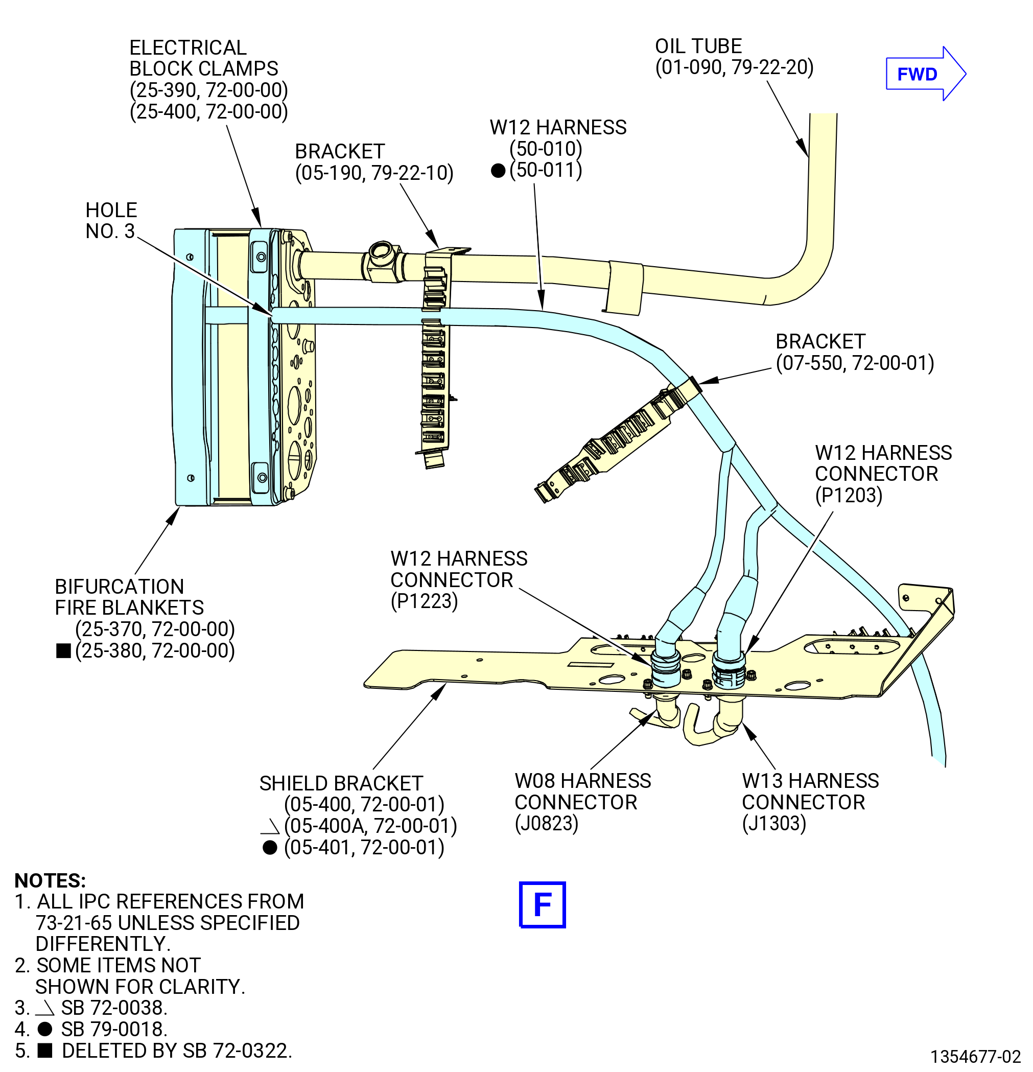
| (13) | Attach the W13 harness connectors (J1303, J1323, and J1325) to the shield bracket (05-400 , 72-00-01) (SIN 6701F) or (05-400A , 72-00-01) (SIN 6701F) or (05-401 , 72-00-01) (SIN 6701F) as follows: |
| (a) | Put the W13 harness in the clips of the bracket (05-190 , 79-22-10) (SIN 67018), electrical bracket (bracket) (07-550 , 72-00-01) (SIN 67019), and shield bracket (05-400 , 72-00-01) (SIN 6701F) or (05-400A , 72-00-01) (SIN 6701F) or (05-401 , 72-00-01) (SIN 6701F). |
| (b) | Attach the W13 harness connector (J1303) to the W13-W12 port of the shield bracket with two bolts (67021). |
| (c) | Attach the W13 harness connector (J1323) to the W13-W07 port of the shield bracket with two bolts (67021). |
| (d) | Attach the W13 harness connector (J1325) to the W13-W09 port of the shield bracket with two bolts (67021). |
| (e) | Torque the bolts (67021) to 106-124 lb in. (12.0-14.0 N.m). |
| (14) | Connect the W13 harness connector (P132) to the debris monitoring system (DMS) amplifier (42500) as follows: |
| (a) | Put the W13 harness in the clip of the electrical bracket (07-530 , 72-00-01) (SIN 6711S). |
| (b) | Put the W13 harness in the middle spring clips of the return oil tubes (oil tubes) (01-090 , 79-22-20) (SIN 45302) and (01-010 , 79-22-20) (SIN 45304) or (01-011 , 79-22-20) (SIN 45304). |
| (c) | Connect the W13 harness connector (P132) to the DMS COND port of the DMS amplifier. |
| (d) | Tighten the W13 harness connector (P132) with teflon-jaw pliers. |
| (15) | Connect the W13 harness connector (P13) to the EEC (65H00) as follows: |
| (a) | Put the W13 harness in the clips of the brackets (61419, 6701C, 6701E, 6701S, 6701Z). |
| (b) | Connect the W13 harness connector (P13) to the EEC port (J13). |
| (c) | Tighten the W13 harness connector (P13) with teflon-jaw pliers. |
|
|
|
|
|
|
|
|
|
| Subtask 72-00-00-440-009 |
| CAUTION: |
|
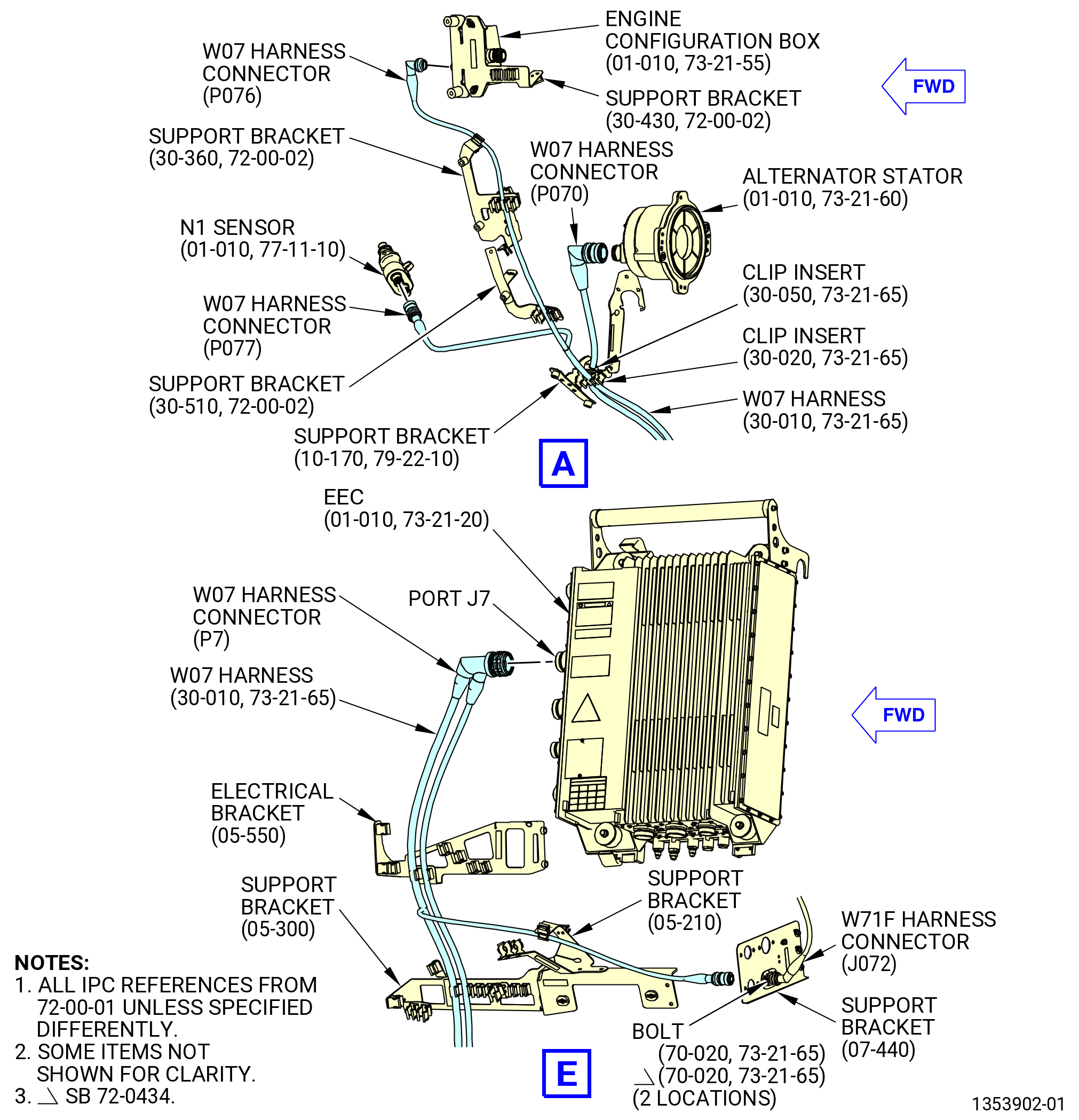
| F. | Install the W07 harness (67006) on the propulsor as follows. Refer to Figure 1007. |
| NOTE: |
|
| (1) | Remove the protective covers from the harness connectors and component connectors. |
| (2) | Connect the W07 harness connector (P076) to the engine configuration box (65M00) as follows: |
| (a) | Connect the W07 harness connector (P076) to the ECM-A port of the engine configuration box. |
| (b) | Tighten the W07 harness connector (P076) with teflon-jaw pliers. |
| (3) | Put the W07 harness in the clips of the support bracket (6711F) at two locations. |
| (4) | Put the W07 harness in the clip of the support bracket (67218). |
| (5) | Connect the W07 harness connector (P077) to the N1 sensor (65400) as follows: |
| (a) | Connect the W07 harness connector (P077) to the N1-A port of the N1 sensor. |
| (b) | Tighten the W07 harness connector (P077) with teflon-jaw pliers. |
| (6) | Put the W07 harness in the clip of the support bracket (37311) with an electrical clip insert (clip insert) (67173). |
| (7) | Connect the W07 harness connector (P070) to the alternator stator (65301) as follows: |
| (a) | Connect the W07 harness connector (P070) to the CHANNEL A connector (left side of stator) of the alternator stator. |
| (b) | Tighten the W07 harness connector (P070) with teflon-jaw pliers. |
| (8) | Put the W07 harness in the clip of the support bracket (37311) with a clip insert (67174). |
| (9) | Put the W07 harness in the clip of the bracket (67217) with an electrical clip insert (clip insert) (67178). |
| (10) | Put the W07 harness in the clip of the bifurcation manifold (99006) with an electrical clip insert (clip insert) (67177). |
| (11) | Put the W07 harness in the clips of the left side cable shield (cable shield) (09710). |
| (12) | Put the W07 harness in the clip of the support bracket (67115). |
| (13) | Put the W07 harness in the clips of the cable shield (09711). |
| (14) | Put the W07 harness in the clip of the support bracket (67116). |
| Subtask 72-00-00-440-111 |
| * * * PRE SB 72-0322( Lower Bifurcation Firewall with Two Bifurcation Fire Blankets ) |
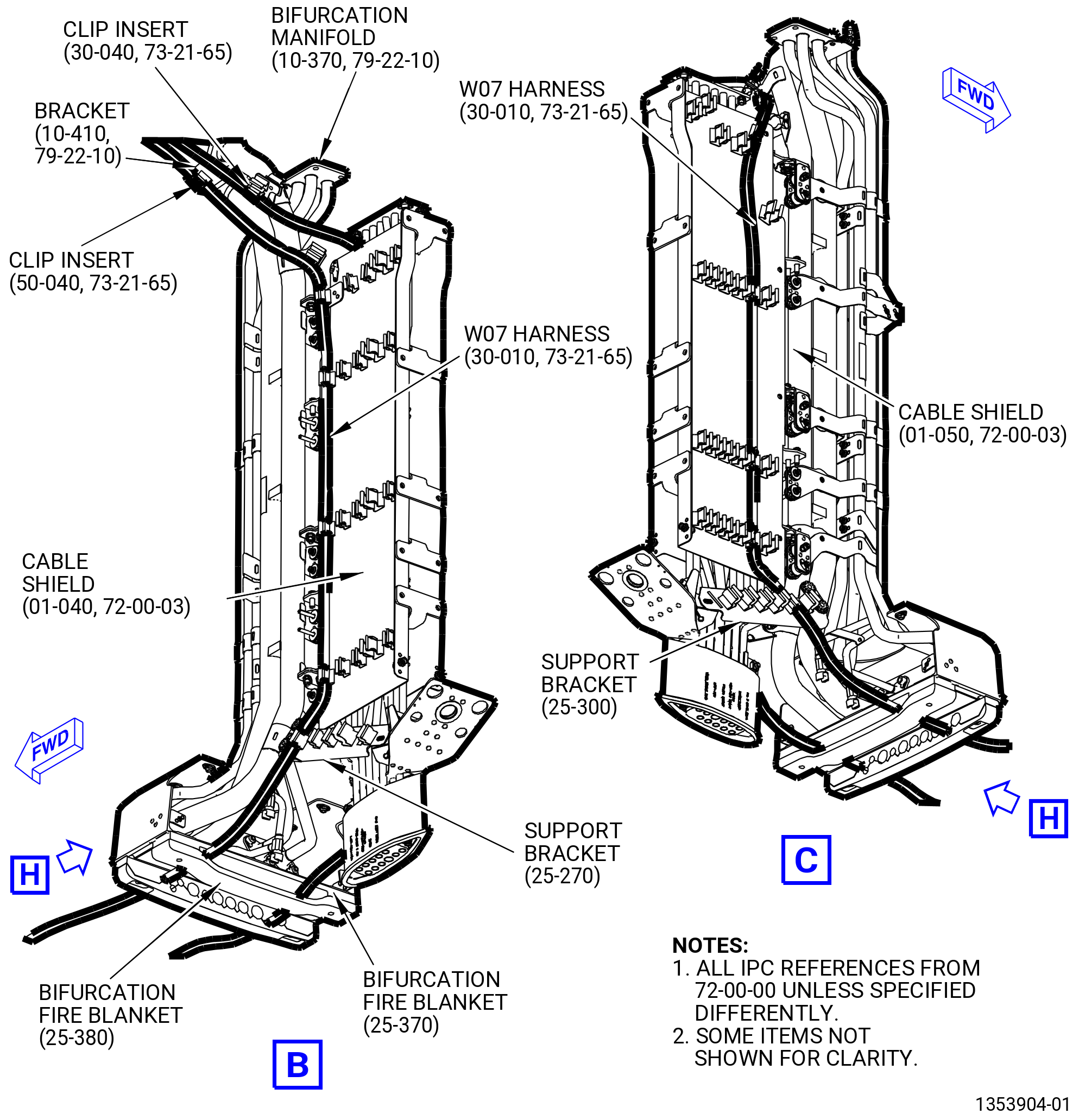
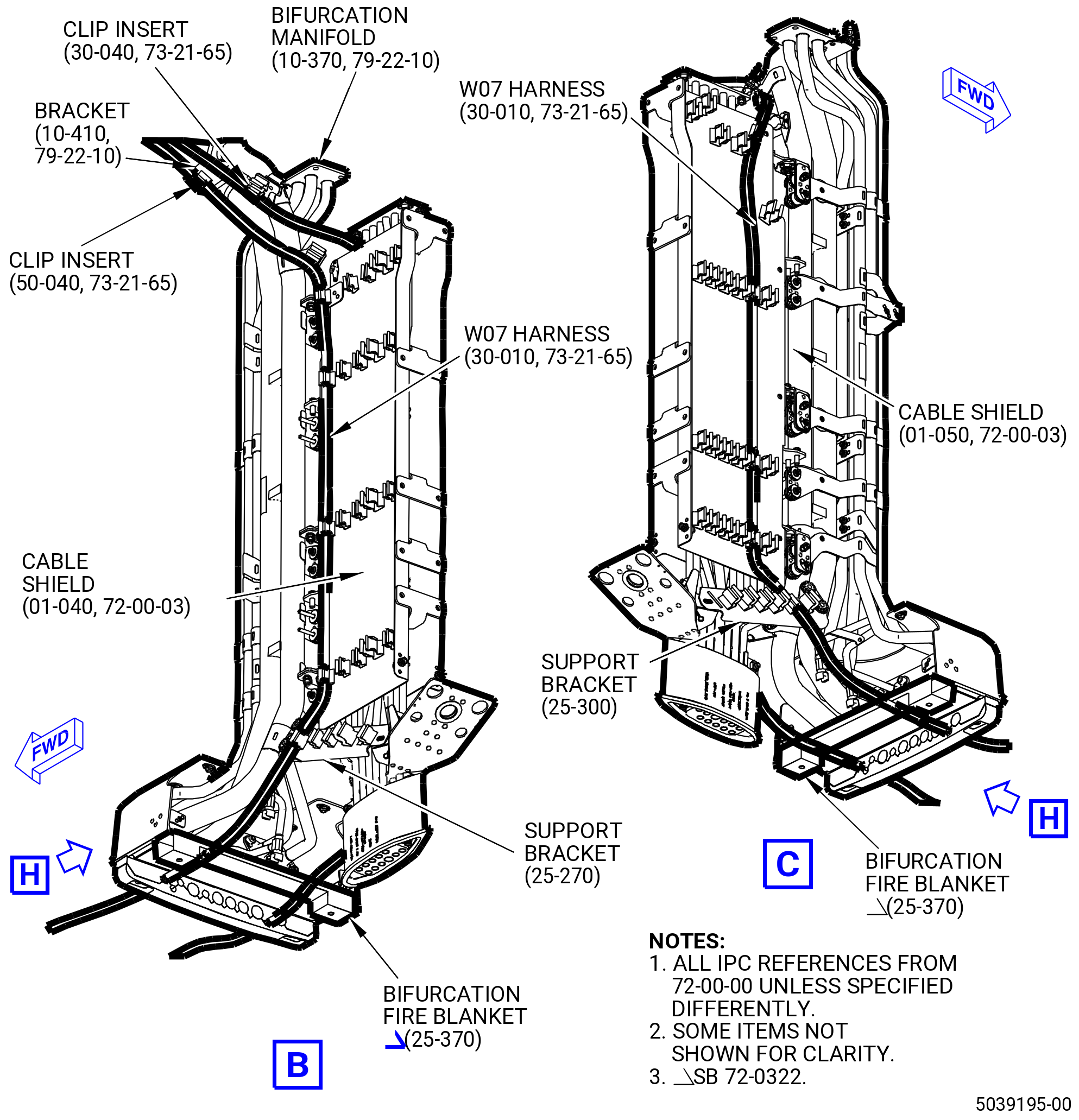
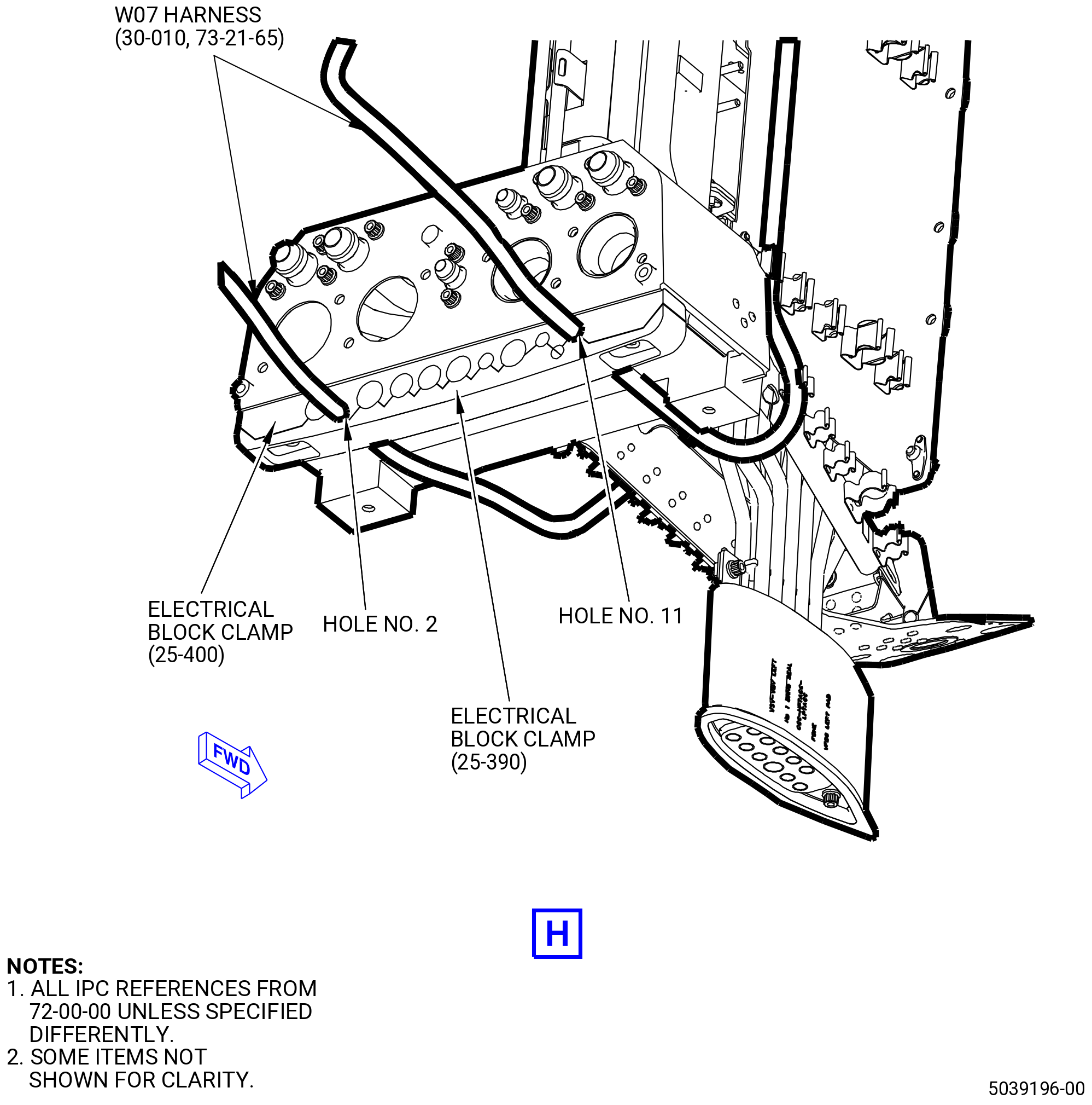
| (15) | Attach the W07 harness to the bifurcation fire blankets (25-380) (SIN 09490) and (25-370) (SIN 09491) and electrical block clamps (25-400) (SIN 09481), (25-390) (SIN 09482) as follows: |
| (a) | Attach the W07 harness located at the cable shield (09710) through the bifurcation fire blankets and electrical block clamps in the hole No. 11 from left to right, FLA. |
| (b) | Attach the W07 harness located at the cable shield (09711) through the bifurcation fire blankets and electrical block clamps in the hole No. 2 from left to right, FLA. |
| * * * END PRE SB 72-0322 |
| Subtask 72-00-00-440-112 |
| * * * SB 72-0322( Lower Bifurcation Firewall with One Bifurcation Fire Blanket ) |
| (15).A. | Attach the W07 harness to the bifurcation fire blanket (25-370) (SIN 09491) and electrical block clamps (25-400) (SIN 09481) and (25-390) (SIN 09482) as follows: |
| (a) | Attach the W07 harness located at the cable shield (01-040 , 72-00-03) (SIN 09710) through the bifurcation fire blanket and electrical block clamps in the hole No. 11 from left to right, FLA. |
| (b) | Attach the W07 harness located at the cable shield (01-050 , 72-00-03) (SIN 09711) through the bifurcation fire blanket and electrical block clamps in the hole No. 2 from left to right, FLA. |
| * * * END SB 72-0322 |
| Subtask 72-00-00-440-113 |
| (16) | Connect the W07 harness connectors (P074, P075) to the fuel/oil temperature sensors (temperature sensor) (65T03) as follows: |
| (a) | Put the W07 harness in the clips of the brackets (67018, 67019). |
| (b) | Connect the W07 harness connectors (P074) to the GEN1-IN port of the temperature sensor. |
| (c) | Tighten the W07 harness connector (P074) with teflon-jaw pliers. |
| (d) | Connect the W07 harness connectors (P075) to the GEN2-IN port of the temperature sensor. |
| (e) | Tighten the W07 harness connector (P075) with teflon-jaw pliers. |
| (17) | Connect the W07 harness connector (P0723) to the W13 harness connector (J1323) as follows: |
| (a) | Put the W07 harness in the clips of the shield bracket (05-400 , 72-00-01) (SIN 6701F) or (05-400A , 72-00-01) (SIN 6701F) or (05-401 , 72-00-01) (SIN 6701F). |
| (b) | Connect the W07 harness connector (P0723) to the W13 harness connector (J1323) at the shield bracket (05-400 , 72-00-01) (SIN 6701F) or (05-400A , 72-00-01) (SIN 6701F) or (05-401 , 72-00-01) (SIN 6701F). |
| (c) | Tighten the W07 harness connector (P0723) with teflon-jaw pliers. |
| (18) | Connect the W07 harness connector (P072) to the W71F harness connector (J072) as follows: |
| (a) | Put the W07 harness in the clips of the brackets (61419, 6701E, 6701S, 6701Z). |
| (b) | Attach the W71F harness connector (J072) to the support bracket (07-440 , 72-00-01) (SIN 6701L) with the two machine bolts (bolts) (70-020 , 73-21-65) (SIN 67021). |
| (c) | Torque the bolts to 106 to 124 lb in. (11.9 to 14.0 Nm). |
| (d) | Connect the W07 harness connector (P072) to the W71F harness connector (J072) at the support bracket (07-440 , 72-00-01) (SIN 6701L) below the EEC (01-010 , 73-21-20) (SIN 65H00). |
| (e) | Tighten the W07 harness connector (P072) with teflon-jaw pliers. |
| (19) | Connect the W07 harness connector (P7) to the EEC as follows: |
| (a) | Put the W07 harness in the clips of the electrical bracket (6701C). |
| (b) | Connect the W07 harness connector (P7) to the EEC port (J7). |
| (c) | Tighten the W07 harness connector (P7) with teflon-jaw pliers. |
| (20) | Connect the W07 harness connector (P073) to the oil level temperature sensor (temperature sensor) (01-020 , 79-31-40) (SIN 400A3) as follows: |
| (a) | Put the W07 harness in the clip of the electrical bracket (07-530 , 72-00-01) (SIN 6711S). |
| (b) | Put the W07 harness in the right spring clips of the oil tubes (01-090 , 79-22-20) (SIN 45302), and (01-010 , 79-22-20) (SIN 45304) or (01-011 , 79-22-20) (SIN 45304). |
| (c) | Connect the W07 harness connector (P073) to the ENG OIL TK-A port of the temperature sensor at the oil tank (40000). |
| (d) | Tighten the W07 harness connector (P073) with teflon-jaw pliers. |
|
|
| Subtask 72-00-00-440-010 |
| CAUTION: |
|
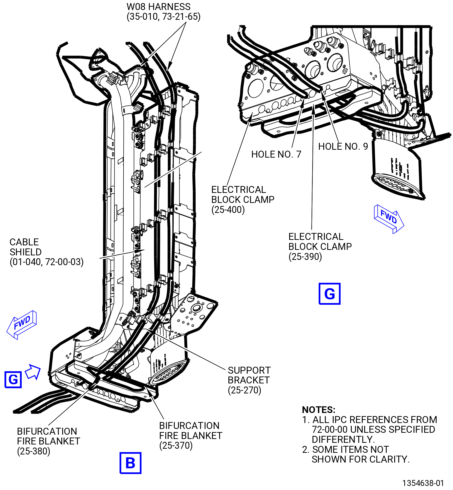
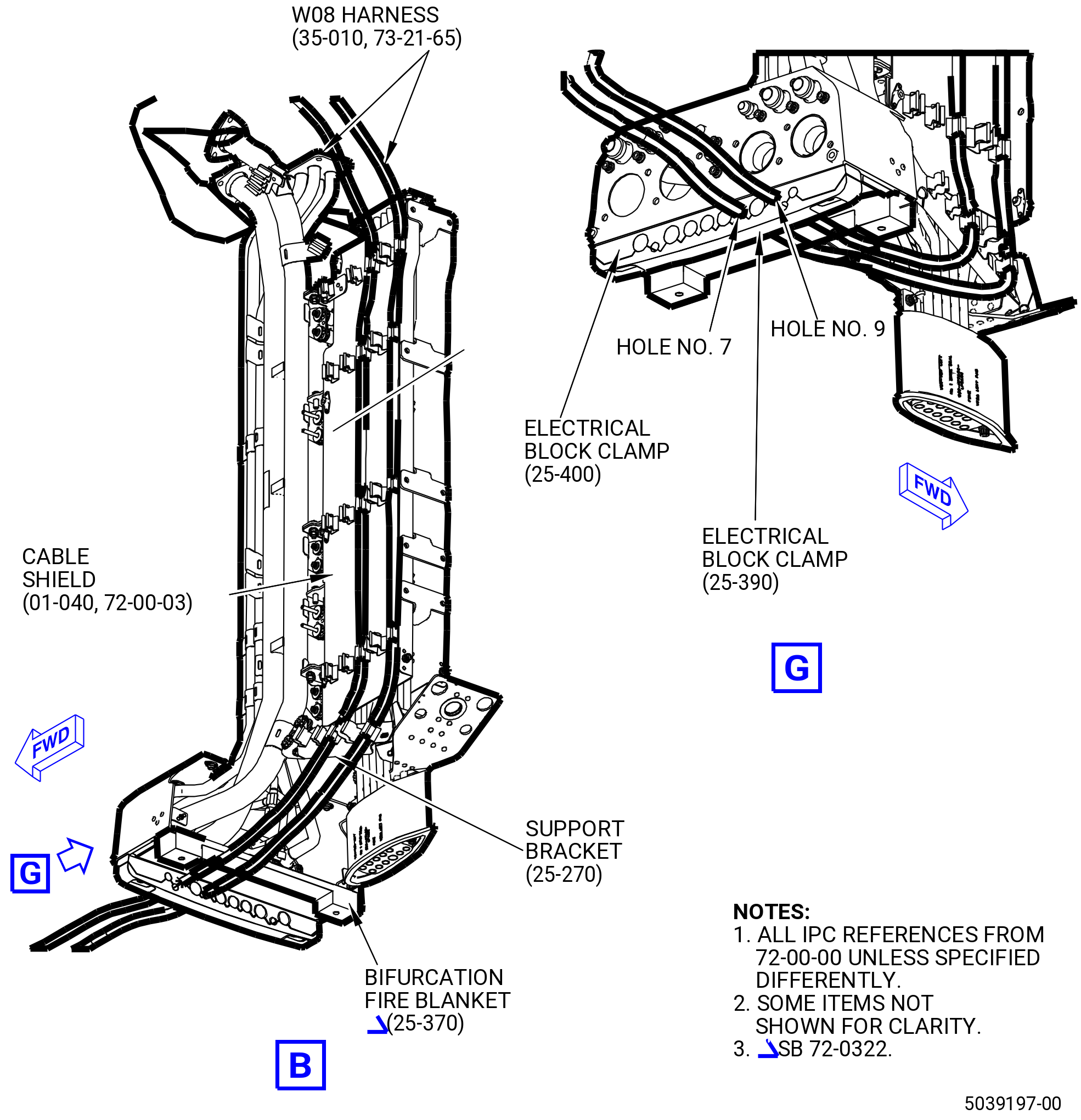
| G. | Install the W08 harness (67007) on the propulsor as follows. Refer to Figure 1008. |
| NOTE: |
|
| (1) | Remove the protective covers from the harness connectors and component connectors. |
| (2) | Connect the W08 harness connector (P084) to the engine configuration box (65M00) as follows: |
| (a) | Connect the W08 harness connector (P084) to the ECM-B port of the engine configuration box. |
| (b) | Tighten the W08 harness connector (P084) with teflon-jaw pliers. |
| (3) | Put the W08 harness in the clips of the support bracket (6711F) at two locations. |
| (4) | Connect the W08 harness connectors (P086, P087) to the fuel/oil temperature sensors (temperature sensors) (65T04) as follows: |
| (a) | Connect the W08 harness connector (P086) to the STARTER GEN1-OUT port of the temperature sensor. |
| (b) | Tighten the W08 harness connector (P086) with teflon-jaw pliers. |
| (c) | Connect the W08 harness connector (P087) to the STARTER GEN2-OUT port of the temperature sensor. |
| (d) | Tighten the W08 harness connector (P087) with teflon-jaw pliers. |
| Subtask 72-00-00-440-205 |
| * * * PRE SB 73-0074( Harness Support Spring Clips with Clip Inserts ) |
| (5) | Put the W08 harness (35-010 , 73-21-65) (SIN 67007) in the clips of the support bracket (01-510 , 72-00-05) (SIN 37110) at two locations with two clip inserts (35-030 , 73-21-65) (SIN 67173). |
| * * * END PRE SB 73-0074 |
| Subtask 72-00-00-440-222 |
| * * * SB 73-0074( Harness Support Spring Clips without Clip Inserts ) |
| (5).A. | Put the W08 harness (35-010 , 73-21-65) (SIN 67007) in the clips of the support bracket (01-510 , 72-00-05) (SIN 37110) at two locations. |
| * * * END SB 73-0074 |
| Subtask 72-00-00-440-207 |
| (6) | Put the W08 harness in the clip of the support drain bracket (support bracket) (37111). |
| (7) | Put the W08 harness in the clip of the No. 1 bearing seal drain tube (drain tube) (48400) with a clip insert (67174). |
| (8) | Connect the W08 harness connector (P085) to the N1 sensor (65400) as follows: |
| (a) | Connect the W08 harness connector (P085) to the N1-B port of the N1 sensor. |
| (b) | Tighten the W08 harness connector (P085) with teflon-jaw pliers. |
| (9) | Put the W08 harness in the middle spring clip of the upper drain manifold (drain manifold) (99003). |
| (10) | Put the W08 harness in the lower spring clip of the drain manifold with a clip insert (67173). |
| (11) | Connect the W08 harness connector (P080) to the alternator stator (65301) as follows: |
| (a) | Route the W08 harness connector (P080) behind the W08 harness connectors (P084, P086, P087) and connect it to the CHANNEL B connector (right side of stator) of the alternator stator. |
| (b) | Tighten the W08 harness connector (P080) with teflon-jaw pliers. |
| (12) | Put the W08 harness in the clip of the CCC air manifold (63100) with a clip insert (67174). |
| Subtask 72-00-00-440-208 |
| * * * PRE SB 73-0074( Harness Support Spring Clips with Clip Inserts ) |
| (13) | Put the W08 harness (35-010 , 73-21-65) (SIN 67007) in the clip of the support bracket (01-510 , 72-00-05) (SIN 37110) with a clip insert (35-050 , 73-21-65) (SIN 67175). |
| * * * END PRE SB 73-0074 |
| Subtask 72-00-00-440-223 |
| * * * SB 73-0074( Harness Support Spring Clips without Clip Inserts ) |
| (13).A. | Put the W08 harness (35-010 , 73-21-65) (SIN 67007) in the clip of the support bracket (01-510 , 72-00-05) (SIN 37110). |
| * * * END SB 73-0074 |
| Subtask 72-00-00-440-210 |
| (14) | Put the W08 harness in the clip of the support bracket (37111). |
| (15) | Put the W08 harness in the upper and middle spring clips of the drain manifold (99003). |
| (16) | Put the W08 harness in the lower spring clip of the drain manifold with a clip insert (67174). |
| (17) | Put the W08 harness in the clips of the cable shield (09710). |
| (18) | Put the W08 harness in the clips of the support bracket (67115). |
| Subtask 72-00-00-440-114 |
| * * * PRE SB 72-0322( Lower Bifurcation Firewall with Two Bifurcation Fire Blankets ) |
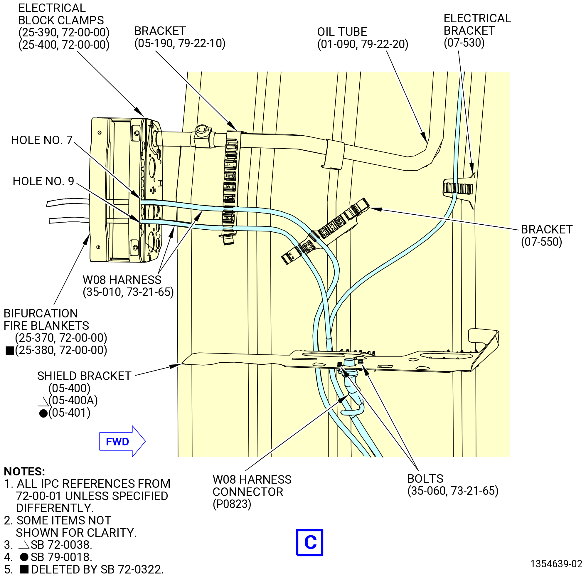
| (19) | Attach the W08 harness to the bifurcation fire blankets (25-380) (SIN 09490) and (25-370) (SIN 09491) and electrical block clamps (25-400) (SIN 09481), (25-390) (SIN 09482) as follows: |
| (a) | Attach the W08 harness through the bifurcation fire blankets and electrical block clamps in the holes No. 7 and No. 9 from left to right, FLA. |
| * * * END PRE SB 72-0322 |
| Subtask 72-00-00-440-115 |
| * * * SB 72-0322( Lower Bifurcation Firewall with One Bifurcation Fire Blanket ) |
| (19).A. | Attach the W08 harness to the bifurcation fire blanket (25-370) (SIN 09491) and electrical block clamps (25-400) (SIN 09481) and (25-390) (SIN 09482) as follows: |
| (a) | Attach the W08 harness through the bifurcation fire blanket and electrical block clamps in the holes No. 7 and No. 9 from left to right, FLA. |
| * * * END SB 72-0322 |
| Subtask 72-00-00-440-116 |
| (20) | Put the W08 harness in the clips of the brackets (67018, 67019). |
| (21) | Put the W08 harness in the clips of the shield bracket (05-400 , 72-00-01) (SIN 6701F) or (05-400A , 72-00-01) (SIN 6701F) or (05-401 , 72-00-01) (SIN 6701F). |
| (22) | Attach the W08 harness connector (J0823) to the shield bracket as follows: |
| (a) | Attach the W08 harness connector (J0823) to the W08-W12 port of the shield bracket with two hex bolts (bolts) (67021). |
| (b) | Torque the bolts (67021) to 106-124 lb in. (12.0-14.0 N.m). |
| (23) | Put the W08 harness in the clips of the brackets (61419, 6701E, 6701S, 6701U, 6701Z). |
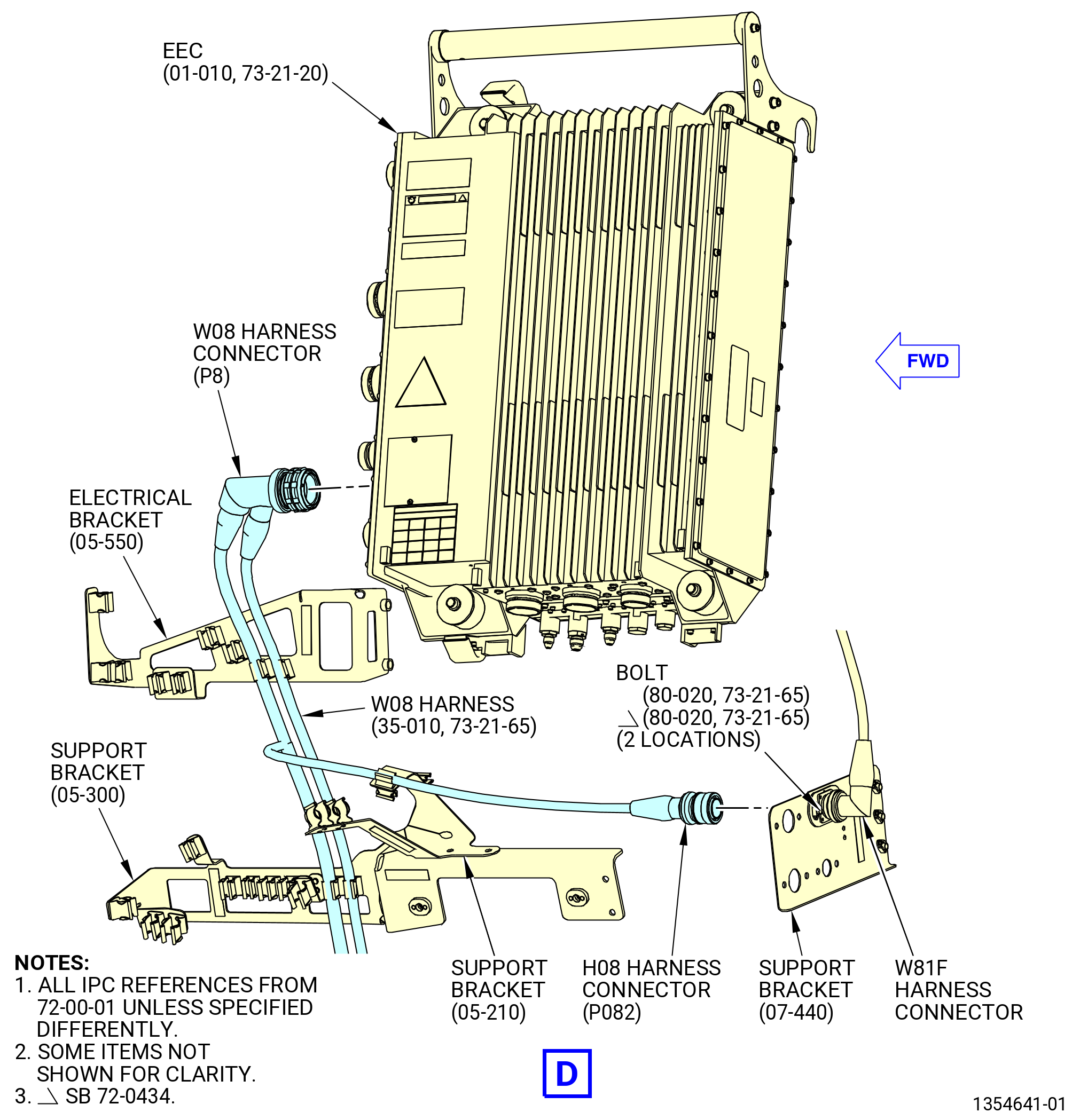
| (24) | Connect the W08 harness connector (P082) to the W81F harness connector (J082) as follows: |
| (a) | Attach the W81 harness connector (J082) to the support bracket (07-440 , 72-00-01) (SIN 6701L) with the two bolts (80-020 , 73-21-65) (SIN 67021). |
| (b) | Torque the bolts to 106 to 124 lb in. (11.9 to 14.0 Nm). |
| (c) | Connect the W08 harness connector (P082) to the W81F harness connector (J082) at the support bracket (6701L) below the EEC. |
| (d) | Tighten the W08 harness connector (P082) with teflon-jaw pliers. |
| (25) | Put the W08 harness in the clips of the electrical bracket (6701C). |
| (26) | Connect the W08 harness connector (P8) to the EEC (65H00) as follows: |
| (a) | Connect the W08 harness connector (P8) to the EEC port (J8). |
| (b) | Tighten the W08 harness connector (P8) with teflon-jaw pliers. |
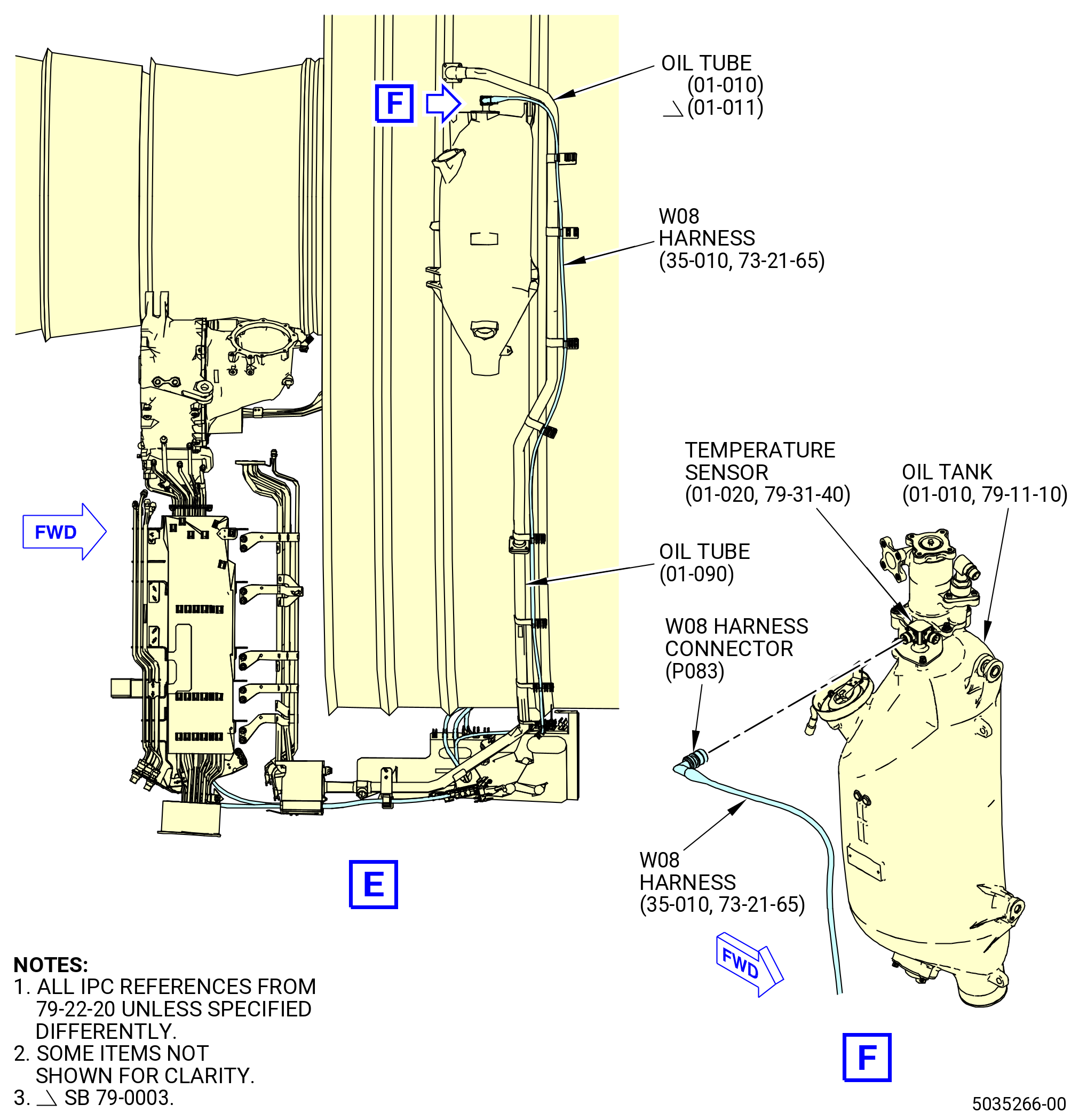
| (27) | Put the P083 harness in the clip of the electrical bracket (07-530 , 72-00-01) (SIN 6711S). |
| (28) | Put the P083 harness in the left spring clips of the oil tubes (01-090 , 79-22-20) (SIN 45302) and (01-010 , 79-22-20) (SIN 45304) or (01-011 , 79-22-20) (SIN 45304). |
| (29) | Connect the W08 harness connector (P083) to the temperature sensor (01-020 , 79-31-40) (SIN 400A3) as follows: |
| (a) | Connect the W08 harness connector (P083) to the ENG OIL TK-B port of the temperature sensor at the oil tank (40000). |
| (b) | Tighten the W08 harness connector (P083) with teflon-jaw pliers. |
|
|
| Subtask 72-00-00-440-008 |
| CAUTION: |
|
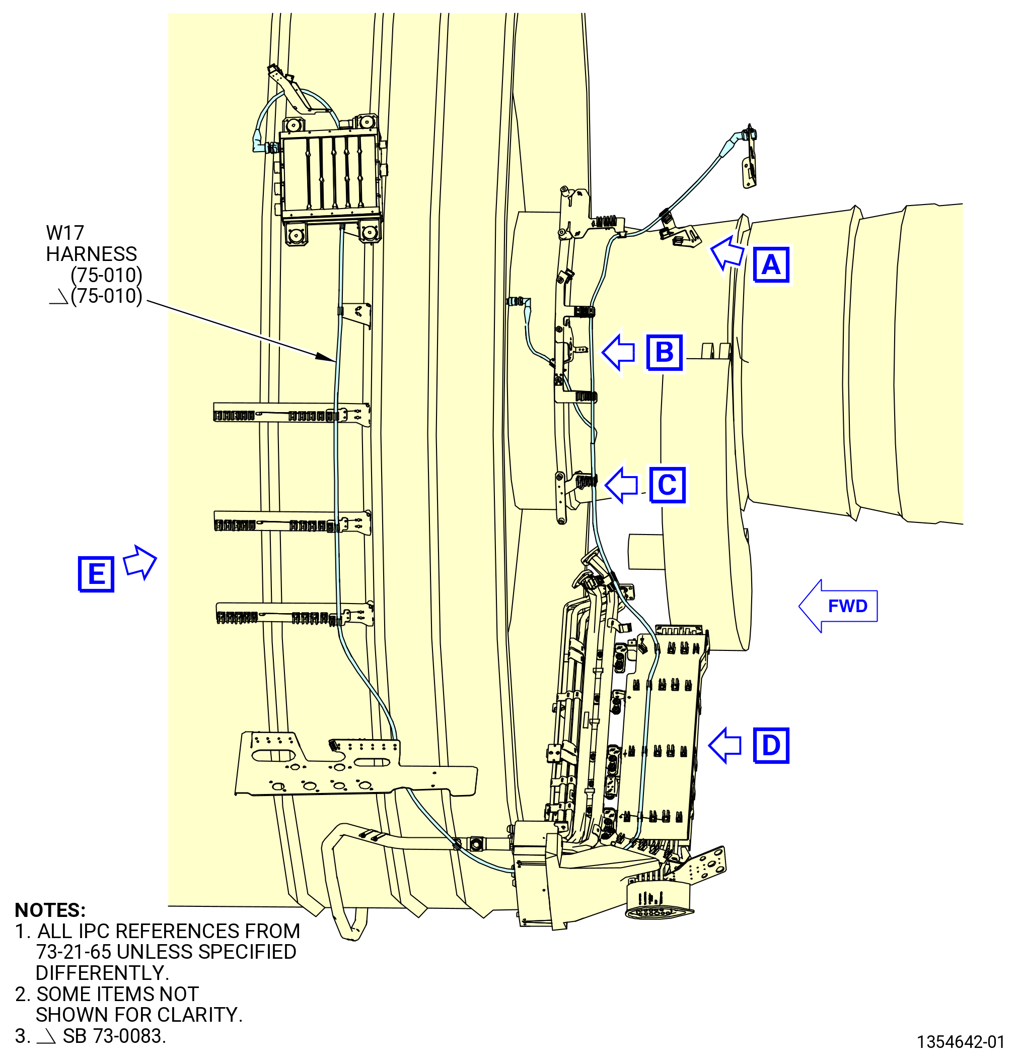
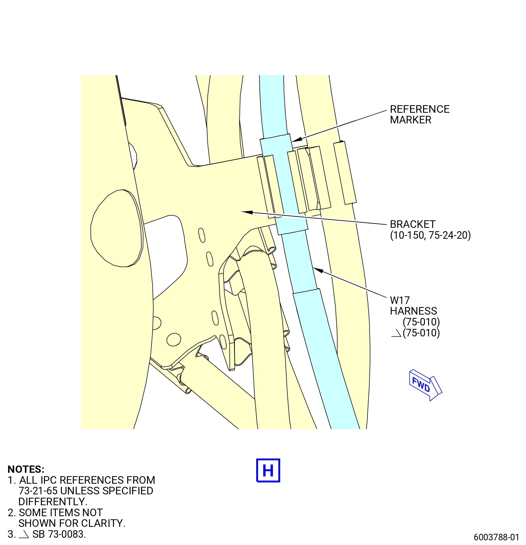
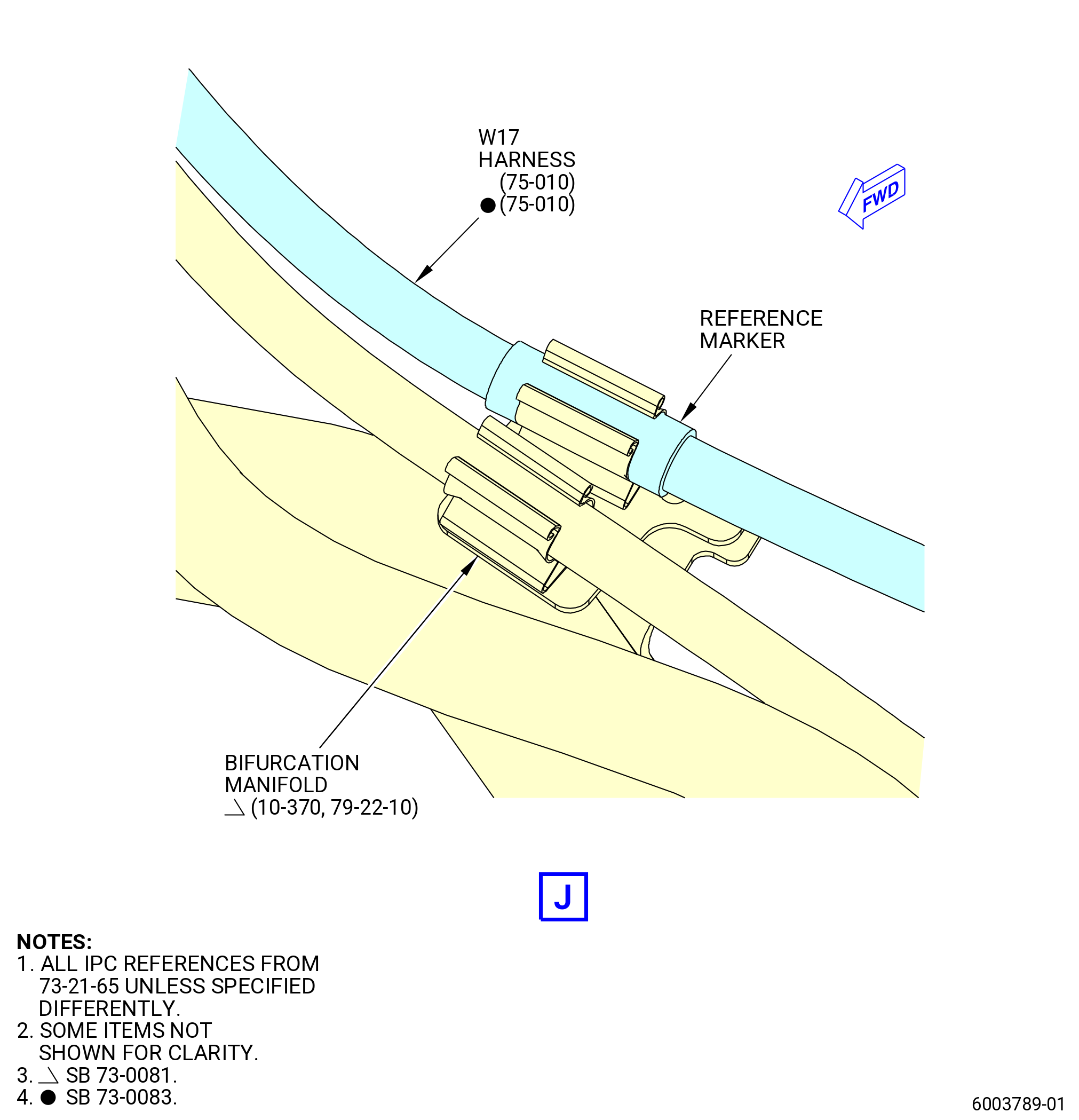
| H. | Install the W17 harness (75-010 , 73-21-65) (SIN 6710B) on the propulsor. Refer to Figure 1009 and do as follows: |
| (1) | Remove the protective covers from the harness connectors and component connectors. |
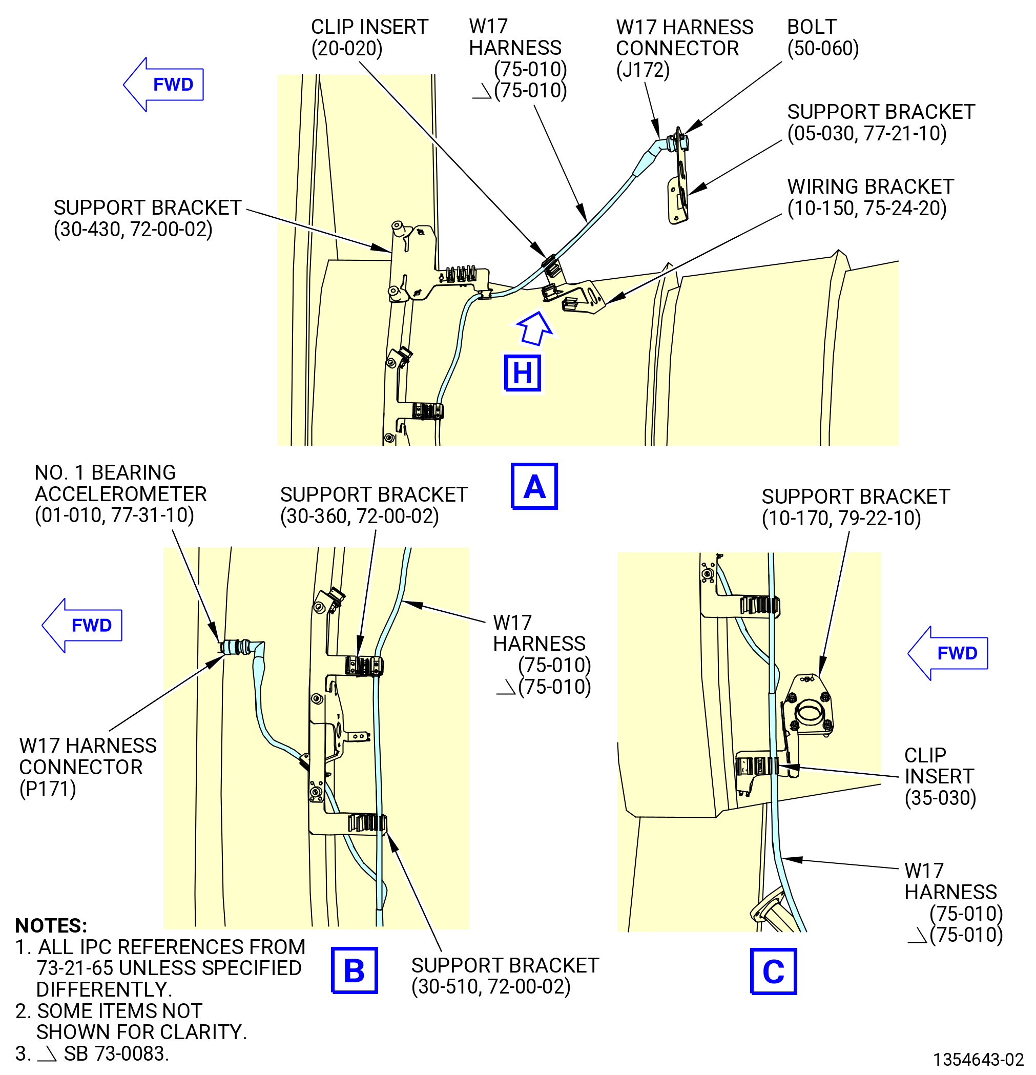
| (2) | Attach the W17 harness connector (J172) to the EGT harness support bracket (support bracket) (69810) as follows: |
| (a) | Attach the W17 harness connector (J172) to the TCF ACCEL port of the support bracket with two bolts (67123). |
| (b) | Torque the bolts (67123) to 106-124 lb in. (12.0-14.0 N.m). |
| Subtask 72-00-00-440-187 |
| * * * PRE SB 73-0073( Electrical Clip Insert Elimination ) |
| (3) | Put the W17 harness in the clip of the wiring bracket (67219) with a clip insert (67172). |
| * * * END PRE SB 73-0073 |
| Subtask 72-00-00-440-188 |
| * * * SB 73-0073( Electrical Clip Insert Elimination ) |
| (3).A. | Put the W17 harness in the clip of the wiring bracket (10-150 , 75-24-20) (SIN 67219). |
| NOTE: |
|
| * * * END SB 73-0073 |
| Subtask 72-00-00-440-189 |
| (4) | Put the W17 harness in the clip of the support brackets (65M10, 6711F, 67218). |
| (5) | Put the W17 harness in the clip of the support bracket (37311) with a clip insert (67173). |
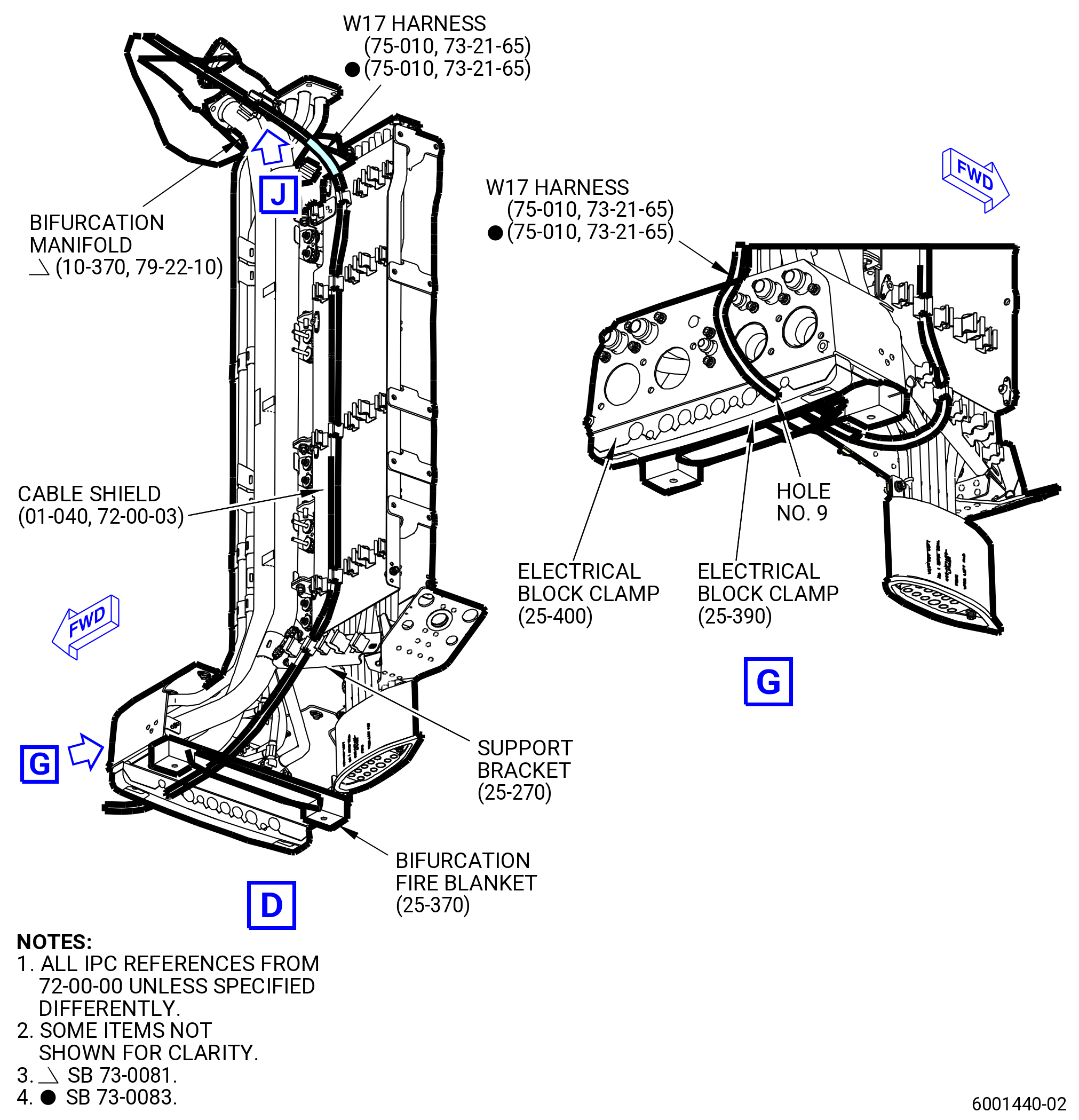
| Subtask 72-00-00-440-180 |
| * * * PRE SB 73-0081( Electrical Clip Insert Elimination ) |
| (6) | Put the W17 harness in the clip of the bifurcation manifold (99006) with a clip insert (67177). |
| * * * END PRE SB 73-0081 |
| Subtask 72-00-00-440-181 |
| * * * SB 73-0081( Electrical Clip Insert Elimination ) |
| (6).A. | Put the W17 harness in the clip of the bifurcation manifold (10-370 , 79-22-10) (SIN 99006). |
| NOTE: |
|
| * * * END SB 73-0081 |
| Subtask 72-00-00-440-182 |
| (7) | Connect the W17 harness connector (P171) to the No. 1 bearing accelerometer (66A00) as follows: |
| (a) | Put the W17 harness in the clip of the support bracket (6711F). |
| (b) | Connect the W17 harness connector (P171) to the NO. 1 BRG ACCEL port of the No. 1 bearing accelerometer. |
| (c) | Tighten the W17 harness connector (P171) with teflon-jaw pliers. |
| (8) | Put the W17 harness in the clips of the cable shield (09710). |
| (9) | Put the W17 harness in the clip of the support bracket (67115). |
| Subtask 72-00-00-440-117 |
| * * * PRE SB 72-0322( Lower Bifurcation Firewall with Two Bifurcation Fire Blankets ) |
| (10) | Attach the W17 harness to the bifurcation fire blankets (25-380) (SIN 09490) and (25-370) (SIN 09491) and electrical block clamps (25-400) (SIN 09481), (25-390) (SIN 09482) as follows: |
| (a) | Attach the W17 harness through the bifurcation fire blankets and electrical block clamps in the hole No. 10 from left to right, FLA. |
| * * * END PRE SB 72-0322 |
| Subtask 72-00-00-440-118 |
| * * * SB 72-0322( Lower Bifurcation Firewall with One Bifurcation Fire Blanket ) |
| (10).A. | Attach the W17 harness to the bifurcation fire blanket (25-370) (SIN 09491) and electrical block clamps (25-400) (SIN 09481) and (25-390) (SIN 09482) as follows: |
| (a) | Attach the W17 harness through the bifurcation fire blanket and electrical block clamps in the holes No. 10 from left to right, FLA. |
| * * * END SB 72-0322 |
| Subtask 72-00-00-440-119 |
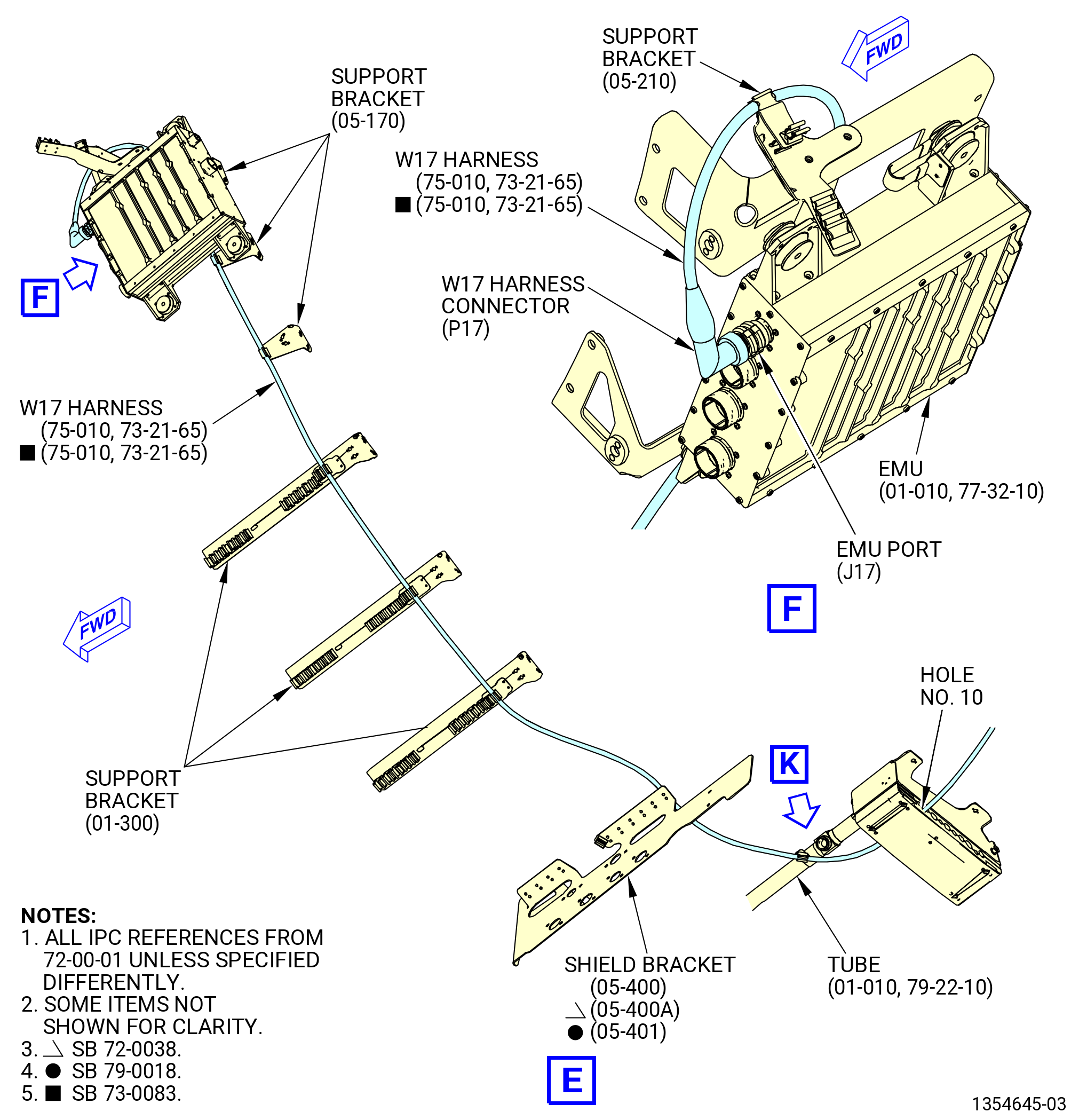
| (11) | Put the W17 harness in the clips of the oil tube (tube) (01-010 , 79-22-10) (SIN 44000), support brackets (05-170 , 72-00-01) (SIN 61414), (05-210 , 72-00-01) (SIN 6701U), and (01-300 , 72-00-01) (SIN 61419), and shield bracket (05-400 , 72-00-01) (SIN 6701F) or (05-400A , 72-00-01) (SIN 6701F) or (05-401 , 72-00-01) (SIN 6701F). |
| NOTE: |
|
| (12) | Connect the W17 harness connector (P17) to the EMU (65Z00) as follows: |
| (a) | Connect the W17 harness connector (P17) to the EMU port (J17). |
| (b) | Tighten the W17 harness connector (P17) with teflon-jaw pliers. |
|
|
|
|
|
| Subtask 72-00-00-440-012 |
| CAUTION: |
|
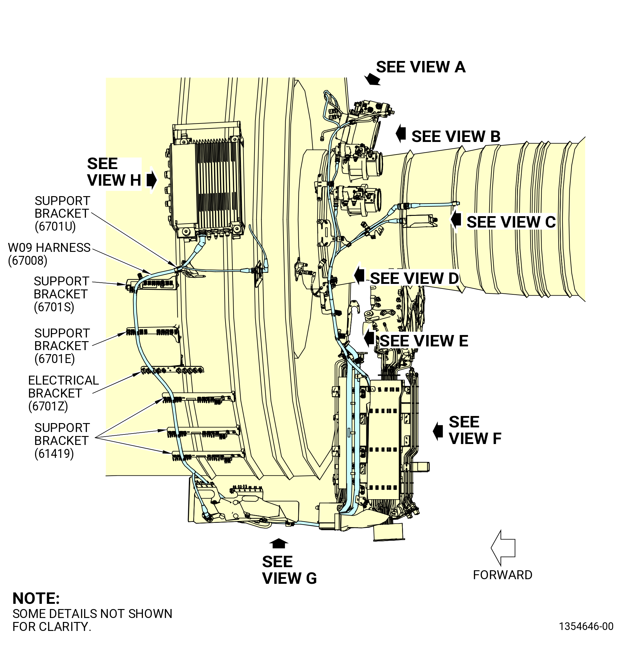
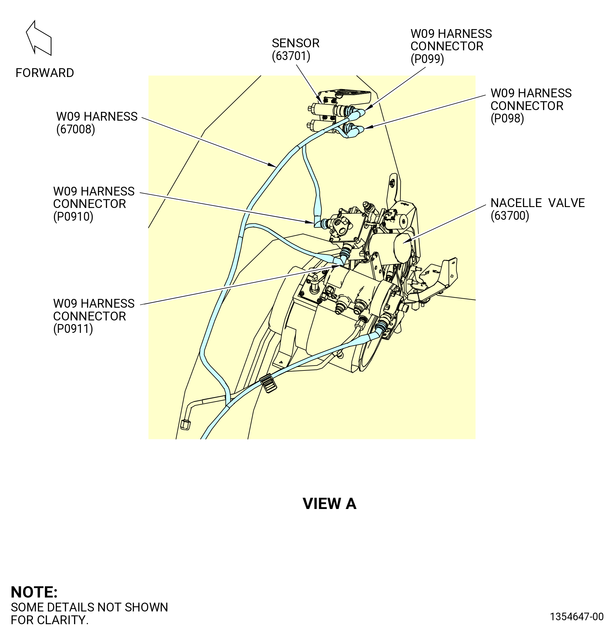
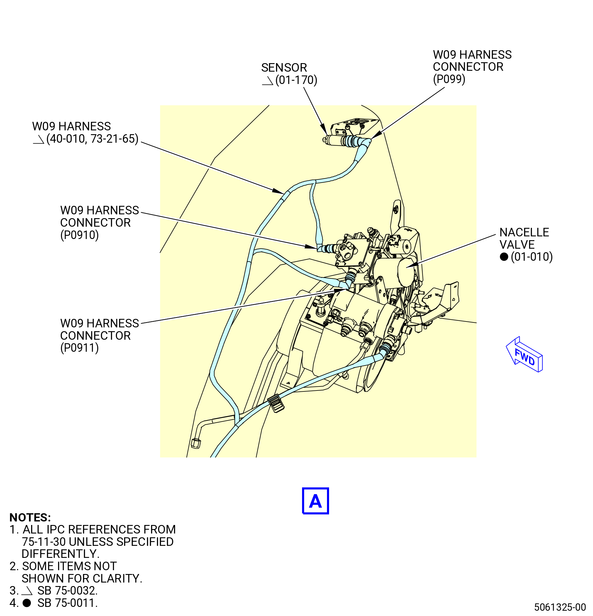
| I. | Install the W09 harness (20-010 , 73-21-65) (SIN 67008) on the propulsor. Refer to Figure 1010 and do as follows: |
| (1) | Remove the protective covers from the harness connectors and component connectors. |
| Subtask 72-00-00-440-159 |
| * * * PRE SB 75-0032( Two Separate Single-Channel Sensors ) |
| (2) | Connect the W09 harness connectors (P098, P099) to the sensors (01-170 , 75-11-30) (SIN 63701) as follows: |
| (a) | Connect the W09 harness connector (P098) to the BAI PRESS-A port of the sensor. |
| (b) | Tighten the W09 harness connector (P098) with teflon-jaw pliers. |
| (c) | Connect the W09 harness connector (P099) to the BAI PRESS-B port of the sensor. |
| (d) | Tighten the W09 harness connector (P099) with teflon-jaw pliers. |
| * * * END PRE SB 75-0032 |
| Subtask 72-00-00-440-160 |
| * * * SB 75-0032( One Dual-Channel Sensor ) |
| (2).A. | Connect the W09 harness connector (P099) to the air pressure sensor (sensor) (01-170 , 75-11-30) (SIN 63701) as follows: |
| (a) | Connect the W09 harness connector (P099) to the BAI PRESS-B port of the sensor. |
| (b) | Tighten the W09 harness connector (P099) with teflon-jaw pliers. |
| * * * END SB 75-0032 |
| Subtask 72-00-00-440-161 |
| (3) | Connect the W09 harness connectors (P0910, P0911) to the nacelle valve (63700) as follows: |
| (a) | Connect the W09 harness connector (P0910) to the BAI SOL-A port of the nacelle valve. |
| (b) | Tighten the W09 harness connector (P0910) with teflon-jaw pliers. |
| (c) | Connect the W09 harness connector (P0911) to the BAI SOL-B port of the nacelle valve. |
| (d) | Tighten the W09 harness connector (P0911) with teflon-jaw pliers. |
| (4) | Connect the W09 harness connector (P095) to the core compartment cooling (CCC) valve (60300) as follows: |
| (a) | Connect the W09 harness connector (P095) to the CCCV-A port of the CCC valve. |
| (b) | Tighten the W09 harness connector (P095) with teflon-jaw pliers. |
| (5) | Put the W09 harness in the clip of the CCC valve drain tube (drain tube) (37900) with a clip insert (67173). |
| (6) | Connect the W09 harness connector (P093) to the active clearance control (ACC) valve (60600) as follows: |
| (a) | Connect the W09 electrical harness connector (P093) to the HPTCCV-A port of the ACC valve. |
| (b) | Tighten the W09 harness connector (P093) with teflon-jaw pliers. |
| (7) | Put the W09 harness in the clips of the drain support bracket (support bracket) (37711) at two locations. |
| (8) | Connect the W09 harness connector (P094) to the ACC valve (60500) as follows: |
| (a) | Connect the W09 electrical harness connector (P094) to the LPTCCV-A port of the ACC valve. |
| (b) | Tighten the W09 harness connector (P094) with teflon-jaw pliers. |
| (9) | Put the W09 harness in the clips of the support bracket (65M10) at two locations. |
| (10) | Connect the W09 harness connector (P097) to the exhaust gas temperature (EGT) harness (69801) as follows: |
| (a) | Connect the W09 harness connector (P097) to the EGT-A port of the EGT harness. |
| (b) | Tighten the W09 harness connector (P097) with teflon-jaw pliers. |
| (11) | Put the W09 harness in the clip of the wiring bracket (67219) with a clip insert (67174). |
| (12) | Connect the W09 harness connector (P096) to the ignition exciter (65800) as follows: |
| (a) | Connect the W09 harness connector (P096) to the EXCT-A port of the ignition exciter. |
| (b) | Tighten the W09 harness connector (P096) with teflon-jaw pliers. |
| (13) | Put the W09 harness in the clip of the wiring bracket (67219) with a clip insert (67174). |
| (14) | Put the W09 harness in the clips of the support brackets (6711F, 67218). |
| (15) | Connect the W09 harness connector (P092) to the T25 sensor (65200) as follows: |
| (a) | Put the W09 harness in the clip of the support bracket (6711F). |
| (b) | Connect the W09 harness connector (P092) to the T25-A port of the T25 sensor. |
| (c) | Tighten the W09 harness connector (P092) with teflon-jaw pliers. |
| (16) | Attach the W09 harness connector (J0909) to the support bracket (6711F) as follows: |
| (a) | Attach the W09 harness connector (J0909) to the support bracket with two bolts (67123). |
| (b) | Torque the bolts (67123) to 106-124 lb in. (12.0-14.0 N.m). |
| (17) | Put the W09 harness in the clip of the support bracket (37311) with an electrical clip insert (clip insert) (6717A). |
| (18) | Put the W09 harness in the clip of the bracket (67217) with an electrical clip insert (clip insert) (67179). |
| (19) | Put the W09 harness in the clip of the bifurcation manifold (99006). |
| Subtask 72-00-00-440-091 |
| * * * SB 72-0176( Introduction of Additional Harness Support Bracket ) |
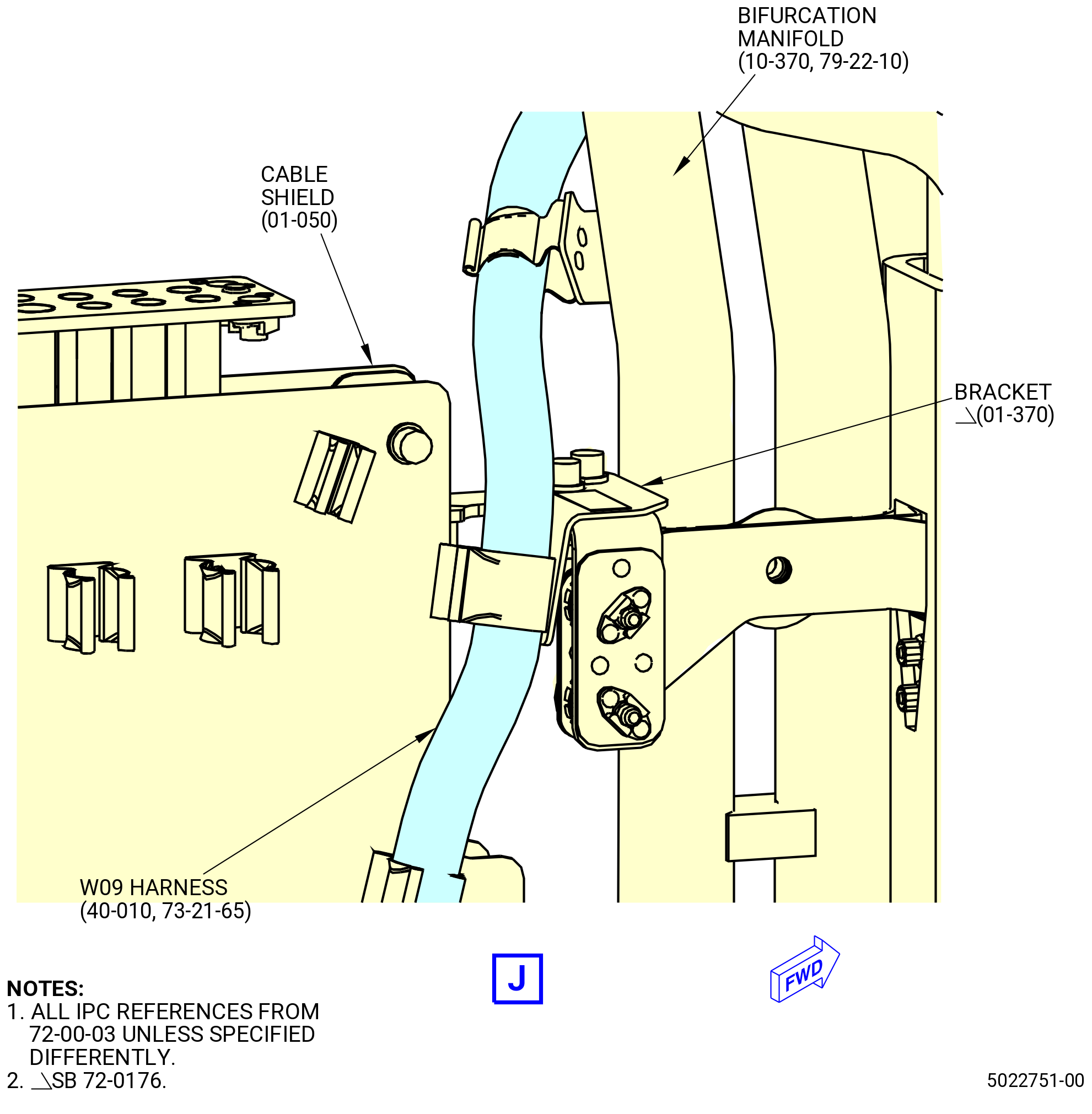
| (20) | Put the W09 harness in the clip of the harness support bracket (bracket) (01-370 , 72-00-03) (SIN 9901S). |
| NOTE: |
|
| * * * END SB 72-0176 |
| Subtask 72-00-00-440-092 |
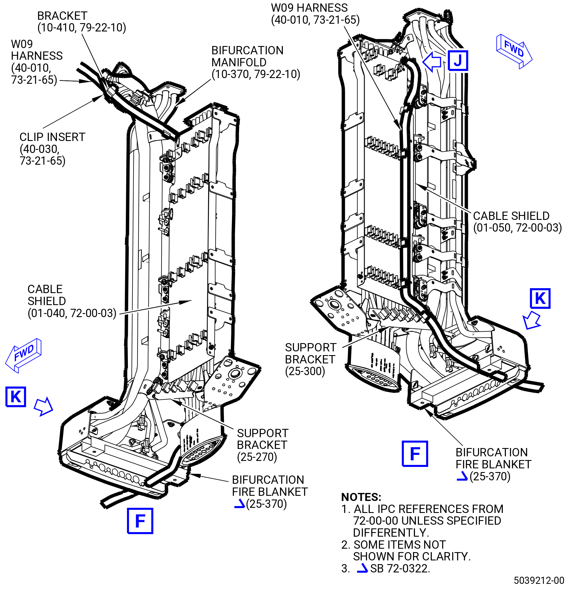
| (21) | Put the W09 harness in the clips of the cable shield (09711). |
| (22) | Put the W09 harness in the clips of the support bracket (67116). |
| Subtask 72-00-00-440-120 |
| * * * PRE SB 72-0322( Lower Bifurcation Firewall with Two Bifurcation Fire Blankets ) |
| (23) | Attach the W09 harness to the bifurcation fire blankets (25-380) (SIN 09490) and (25-370) (SIN 09491) and electrical block clamps (25-400) (SIN 09481), (25-390) (SIN 09482) as follows: |
| (a) | Attach the W09 harness through the bifurcation fire blankets and electrical block clamps in the hole No. 1 from left to right, FLA. |
| * * * END PRE SB 72-0322 |
| Subtask 72-00-00-440-121 |
| * * * SB 72-0322( Lower Bifurcation Firewall with One Bifurcation Fire Blanket ) |
| (23).A. | Attach the W09 harness to the bifurcation fire blanket (25-370) (SIN 09491) and electrical block clamps (25-400) (SIN 09481) and (25-390) (SIN 09482) as follows: |
| (a) | Attach the W09 harness through the bifurcation fire blankets and electrical block clamps in the hole No. 1 from left to right, FLA. |
| * * * END SB 72-0322 |
| Subtask 72-00-00-440-122 |
| (24) | Put the W09 harness in the clips of the brackets (67018, 67019). |
| (25) | Connect the W09 harness connector (P0925) to the W13 harness connector (J1325) as follows: |
| (a) | Connect the W09 harness connector (P0925) to the W13 harness connector (J1325) port at the shield bracket (05-400 , 72-00-01) (SIN 6701F) or (05-400A , 72-00-01) (SIN 6701F) or (05-401 , 72-00-01) (SIN 6701F). |
| (b) | Tighten the W09 harness connector (P0925) with teflon-jaw pliers. |
| (26) | Attach the W09 harness connector (J0919) to the shield bracket (05-400 , 72-00-01) (SIN 6701F) or (05-400A , 72-00-01) (SIN 6701F) or (05-401 , 72-00-01) (SIN 6701F) as follows: |
| (a) | Attach the W09 harness connector (J0919) to the shield bracket with two bolts (67021). |
| (b) | Torque the bolts (67021) to 106-124 lb in. (12.0-14.0 N.m). |
| (27) | Put the W09 harness in the clips of the brackets (61419, 6701E, 6701S, 6701U, 6701Z). |
| (28) | Attach the W09 harness connector (J0917) to the support bracket (6701L) as follows: |
| (a) | Attach the W09 harness connector (J0917) to the support bracket with two bolts (67021). |
| (b) | Torque the bolts (67021) to 106-124 lb in. (12.0-14.0 N.m). |
| (29) | Connect the W09 harness connector (P9) to the EEC (65H00) as follows: |
| (a) | Connect the W09 harness connector (P9) to the EEC port (J9). |
| (b) | Tighten the W09 harness connector (P9) with teflon-jaw pliers. |
|
|
|
| Subtask 72-00-00-440-011 |
| CAUTION: |
|
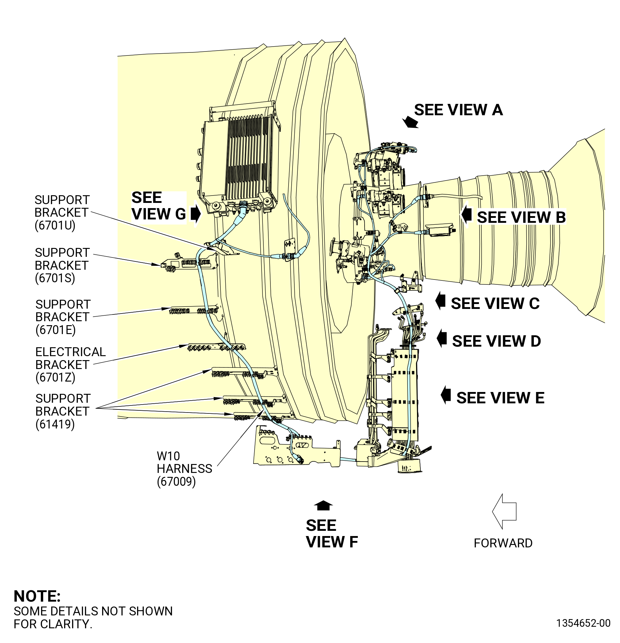
| J. | Install the W10 harness (67009) on the propulsor as follows. Refer to Figure 1011. |
| (1) | Remove the protective covers from the harness connectors and component connectors. |
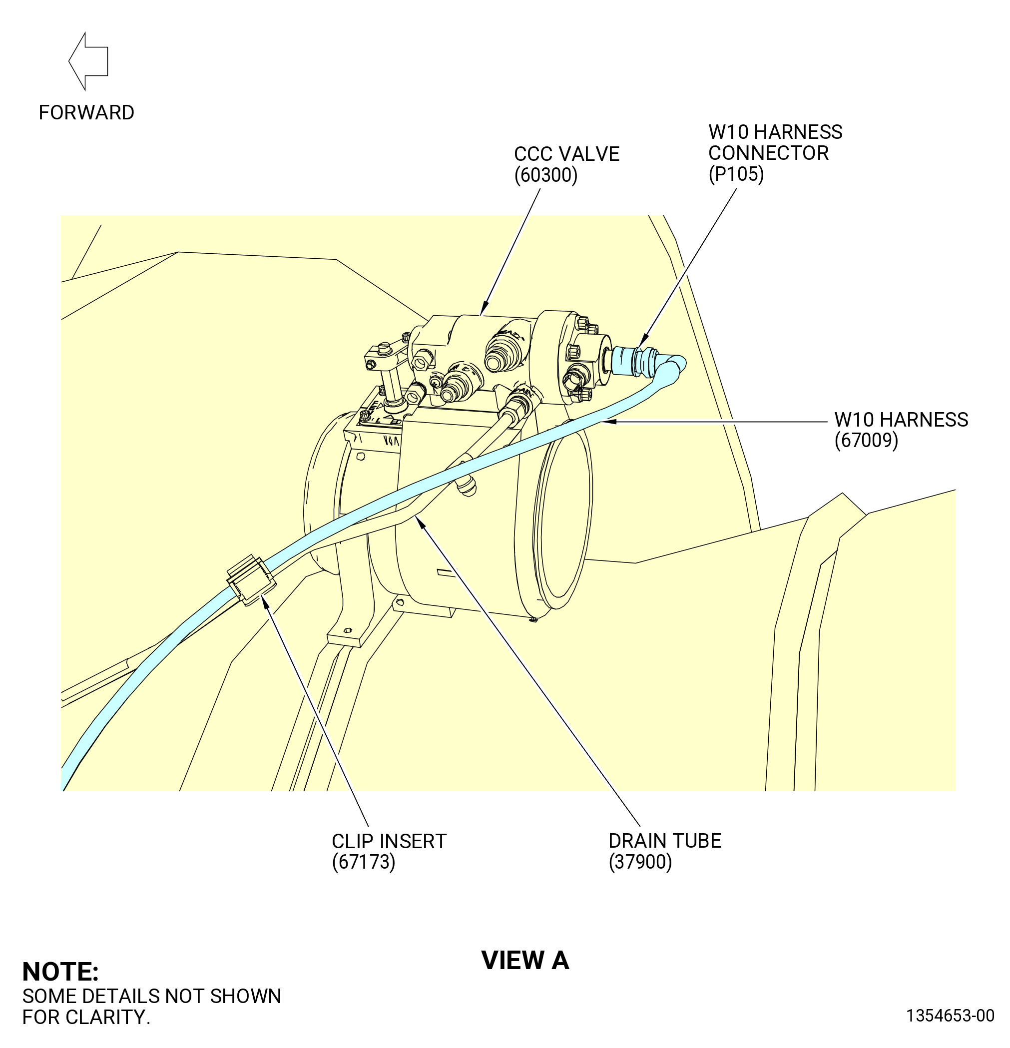
| (2) | Connect the W10 harness connector (P105) to the CCC valve (60300) as follows: |
| (a) | Connect the W10 harness connector (P105) to the CCCV-B port of the CCC valve at the 11:00 o'clock position. |
| (b) | Tighten the W10 harness connector (P105) with teflon-jaw pliers. |
| (3) | Put the W10 harness in the clip of the drain tube (37900) with a clip insert (67173). |
| (4) | Put the W10 harness in the clip of the support bracket (37711). |
| (5) | Connect the W10 harness connector (P103) to the ACC valve (60600) as follows: |
| (a) | Connect the W10 harness connector (P103) to the HPTCCV-B port of the ACC valve. |
| (b) | Tighten the W10 harness connector (P103) with teflon-jaw pliers. |
| (6) | Put the W10 harness in the clip of the support bracket (37710). |
| (7) | Connect the W10 harness connector (P104) to the ACC valve (60500) as follows: |
| (a) | Connect the W10 harness connector (P104) to the LPTCCV-B port of the ACC valve. |
| (b) | Tighten the W10 harness connector (P104) with teflon-jaw pliers. |
| (8) | Put the W10 harness in the clip of the support bracket (65M10). |
| (9) | Put the W10 harness in the clip of the support bracket (6711F). |
| (10) | Connect the W10 harness connector (P109) to the EGT harness (69802) as follows: |
| (a) | Connect the W10 harness connector (P109) to the EGT-B port of the EGT harness at the support bracket (69810). |
| (b) | Tighten the W10 harness connector (P109) with teflon-jaw pliers. |
| (11) | Connect the W10 harness connector (P106) to the ignition exciter (65800) as follows: |
| (a) | Connect the W10 harness connector (P106) to the EXCT-B port of the ignition exciter. |
| (b) | Tighten the W10 harness connector (P106) with teflon-jaw pliers. |
| (12) | Put the W10 harness in the clips of the wiring bracket (67219) with clip inserts (67174) at two locations. |
| (13) | Connect the W10 harness connector (P1009) to the W09 harness connector (J0909) as follows: |
| (a) | Connect the W10 harness connector (P1009) to the W09 harness connector (J0909) at the support bracket (6711F). |
| (b) | Tighten the W10 harness connector (P1009) with teflon-jaw pliers. |
| (14) | Connect the W10 harness connector (P107) to the VSV actuator (30401) as follows: |
| (a) | Connect the W10 harness connector (P107) to the VSV-B port of the VSV actuator. |
| (b) | Tighten the W10 harness connector (P107) with teflon-jaw pliers. |
| (15) | Connect the W10 harness connector (P108) to the VBV actuator (30700) as follows: |
| (a) | Connect the W10 harness connector (P108) to the VBV-B port of the VBV actuator. |
| (b) | Tighten the W10 harness connector (P108) with teflon-jaw pliers. |
| (16) | Connect the W10 harness connector (P102) to the T25 sensor (65200) as follows: |
| (a) | Connect the W10 harness connector (P102) to the T25-B port of the T25 sensor. |
| (b) | Tighten the W10 harness connector (P102) with teflon-jaw pliers. |
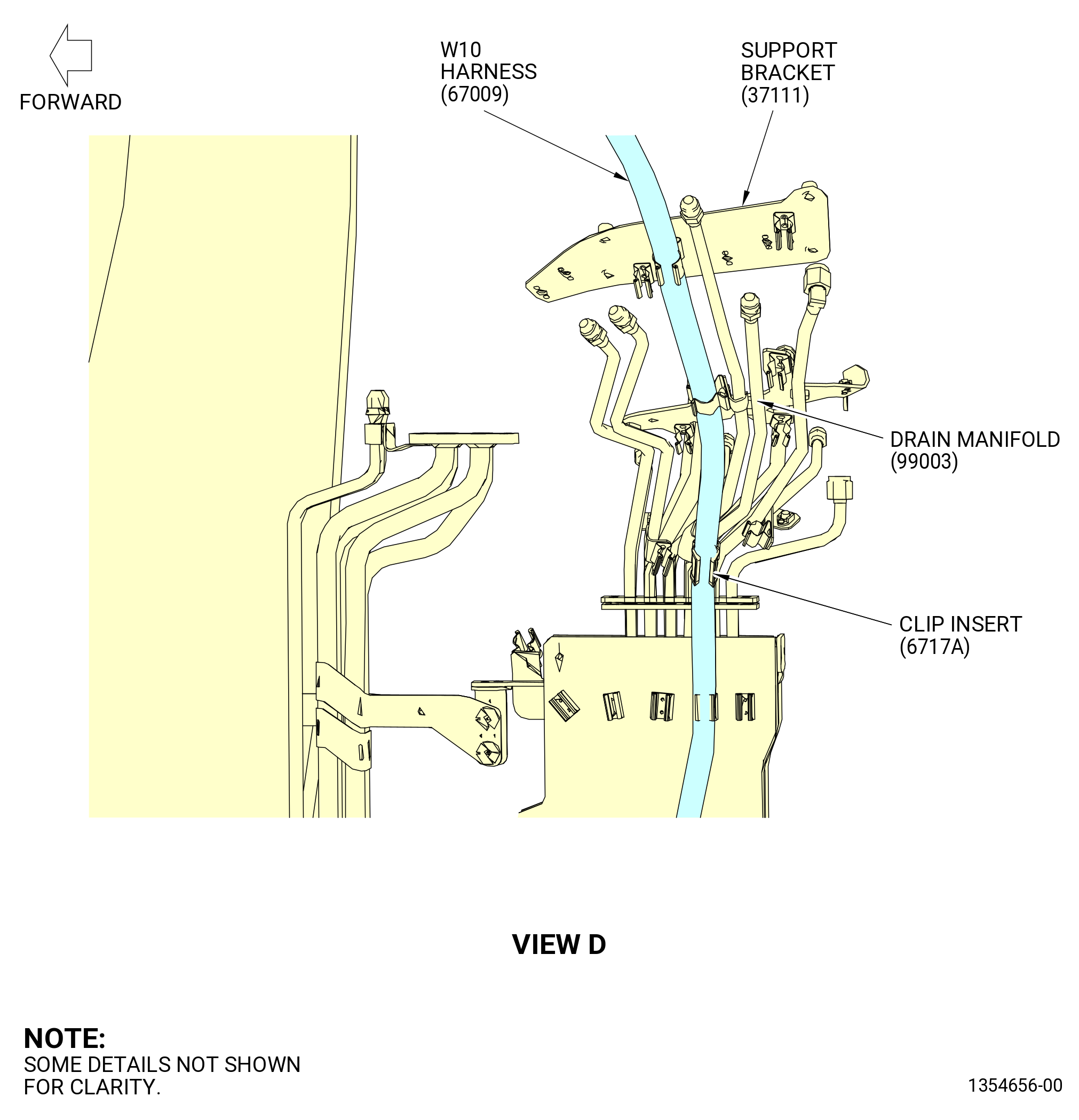
| (17) | Put the W10 harness in the clip of the support bracket (37110) with a clip insert (6717A). |
| (18) | Put the W10 harness in the clip of the support bracket (37111). |
| (19) | Put the W10 harness in the upper clip of the drain manifold (99003). |
| (20) | Put the W10 harness in the lower clip of the drain manifold with a clip insert (6717A). |
| (21) | Put the W10 harness in the clips of the cable shield (09710). |
| (22) | Put the W10 harness in the clip of the support bracket (67115). |
| Subtask 72-00-00-440-123 |
| * * * PRE SB 72-0322( Lower Bifurcation Firewall with Two Bifurcation Fire Blankets ) |
| (23) | Attach the W10 harness to the bifurcation fire blankets (25-380) (SIN 09490) and (25-370) (SIN 09491) and electrical block clamps (25-400) (SIN 09481), (25-390) (SIN 09482) as follows: |
| (a) | Attach the W10 harness through the bifurcation fire blankets and electrical block clamps in the hole No. 8 from left to right, FLA. |
| * * * END PRE SB 72-0322 |
| Subtask 72-00-00-440-124 |
| * * * SB 72-0322( Lower Bifurcation Firewall with One Bifurcation Fire Blanket ) |
| (23).A. | Attach the W10 harness to the bifurcation fire blanket (25-370) (SIN 09491) and electrical block clamps (25-400) (SIN 09481) and (25-390) (SIN 09482) as follows: |
| (a) | Attach the W10 harness through the bifurcation fire blanket and electrical block clamps in the hole No. 8 from left to right, FLA. |
| * * * END SB 72-0322 |
| Subtask 72-00-00-440-125 |
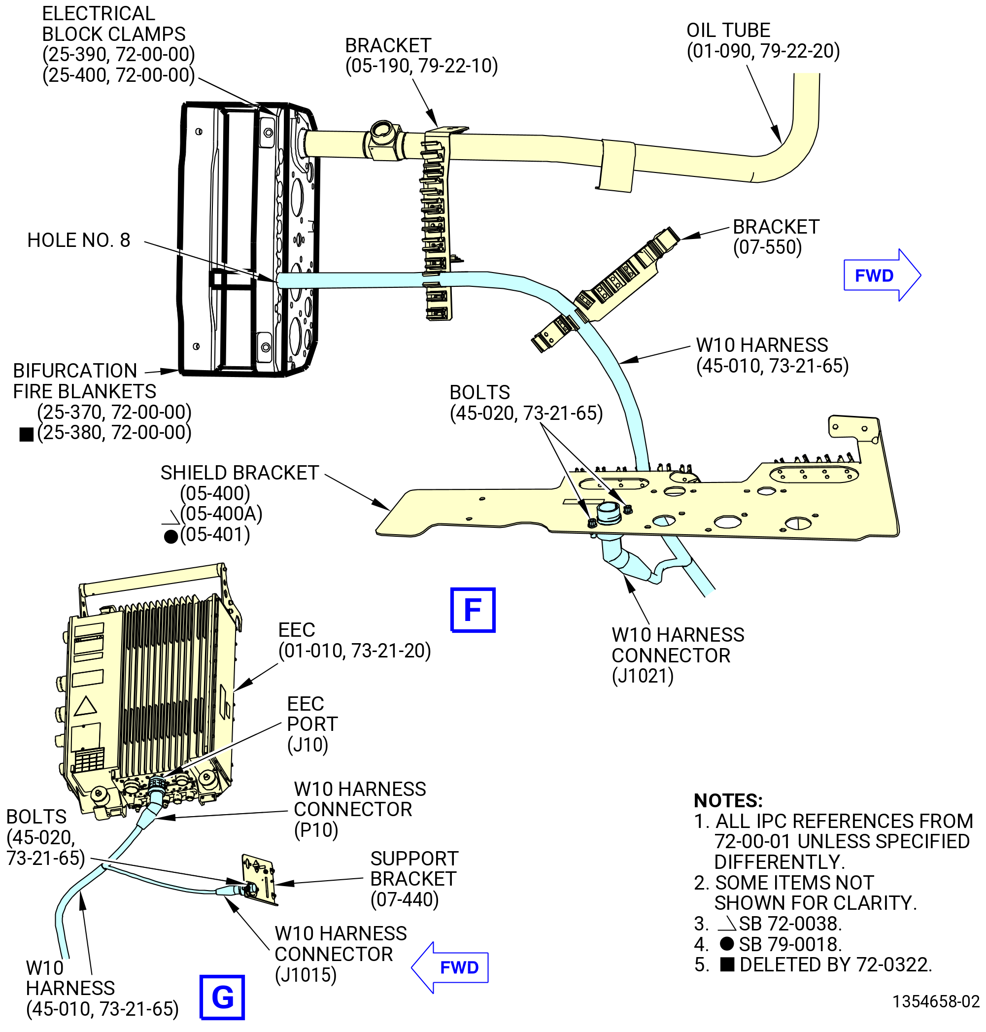
| (24) | Put the W10 harness in the clips of the brackets (05-190 , 79-22-10) (SIN 67018) and (07-550 , 72-00-01) (SIN 67019) and shield bracket (05-400 , 72-00-01) (SIN 6701F) or (05-400A , 72-00-01) (SIN 6701F) or (05-401 , 72-00-01) (SIN 6701F). |
| (25) | Attach the W10 harness connector (J1021) to the shield bracket (05-400 , 72-00-01) (SIN 6701F) or (05-400A , 72-00-01) (SIN 6701F) or (05-401 , 72-00-01) (SIN 6701F) as follows: |
| (a) | Attach the W10 harness connector (J1021) to the shield bracket with two bolts (67021). |
| (b) | Torque the bolts (67021) to 106-124 lb in. (12.0-14.0 N.m). |
| (26) | Put the W10 harness in the clips of the brackets (61419, 6701E, 6701S, 6701U, 6701Z). |
| (27) | Attach the W10 harness connector (J1015) to the support bracket (6701L) as follows: |
| (a) | Attach the W10 harness connector (J1015) to the support bracket with two bolts (67021). |
| (b) | Torque the bolts (67021) to 106-124 lb in. (12.0-14.0 N.m). |
| (28) | Connect the W10 harness connector (P10) to the EEC (65H00) as follows: |
| (a) | Connect the W10 harness connector (P10) to the EEC port (J10). |
| (b) | Tighten the W10 harness connector (P10) with teflon-jaw pliers. |
|
|
| Subtask 72-00-00-440-016 |
| CAUTION: |
|
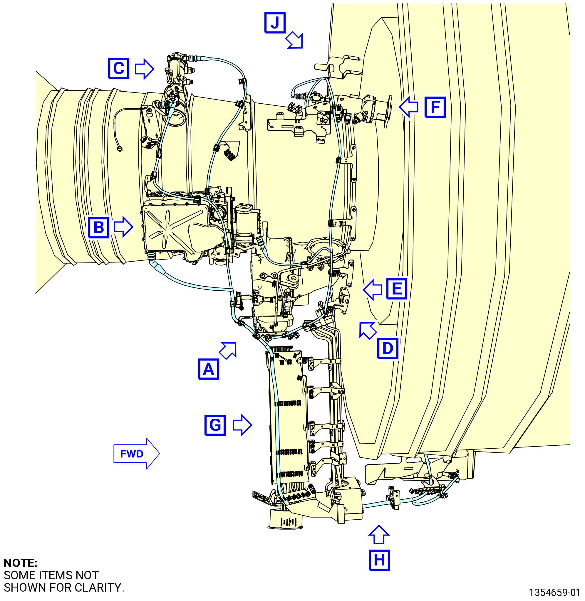
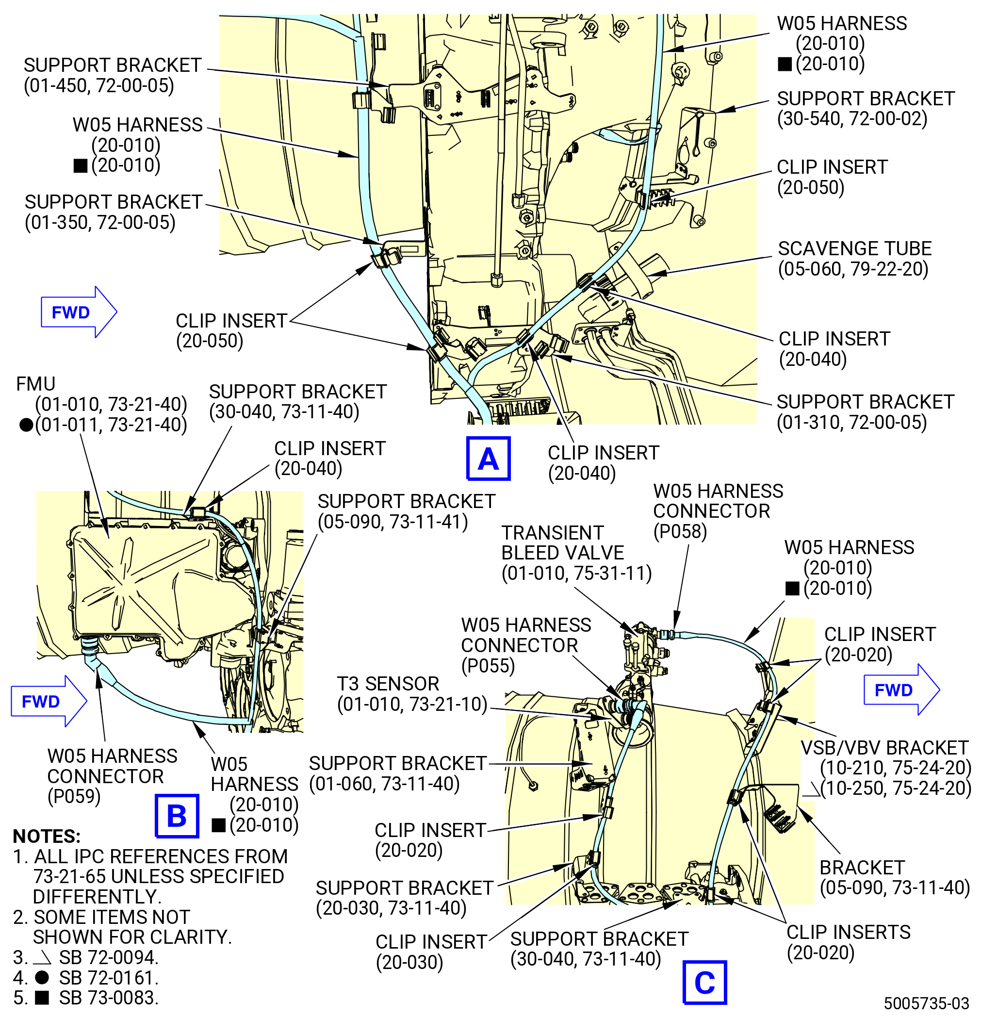
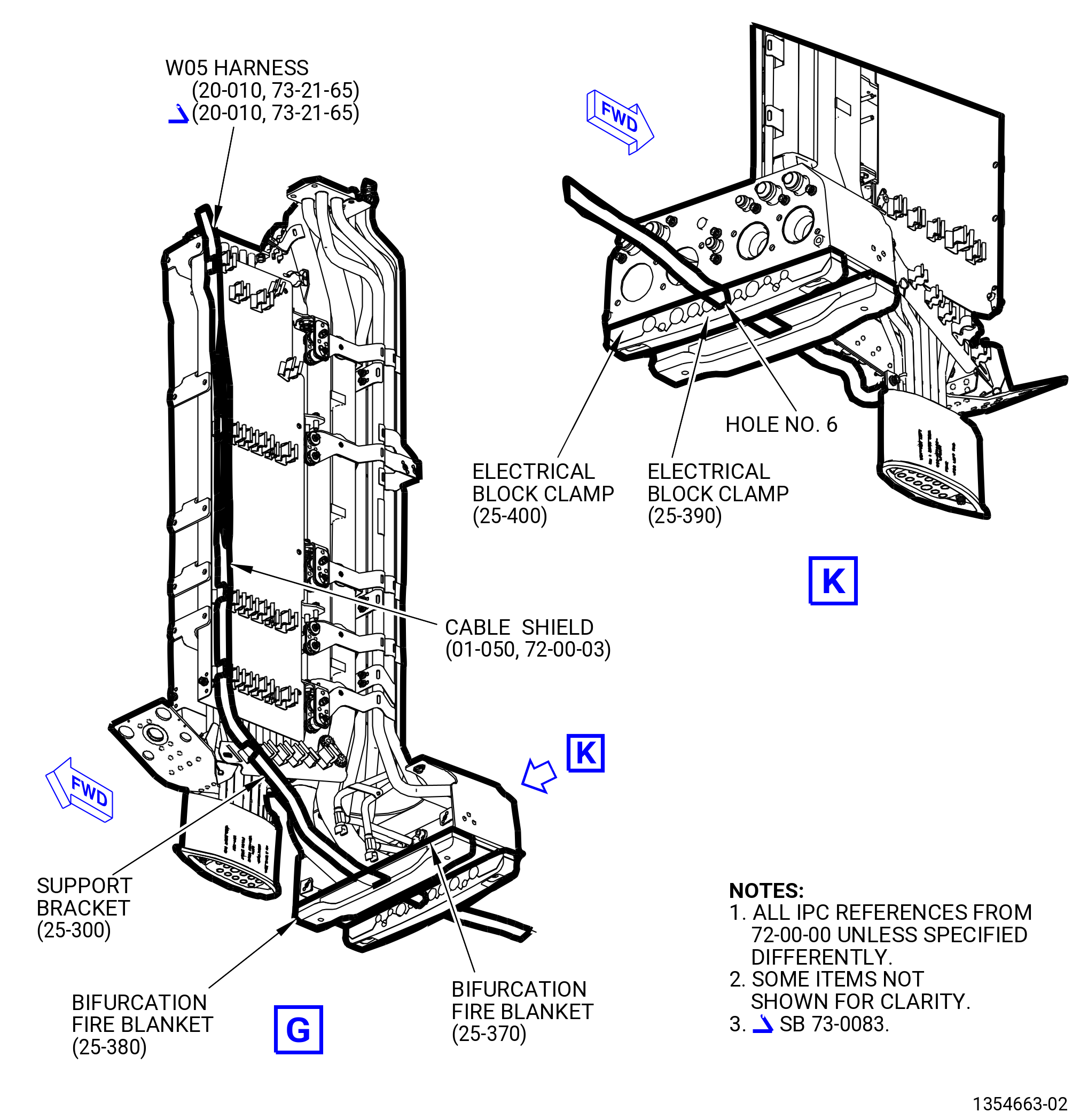
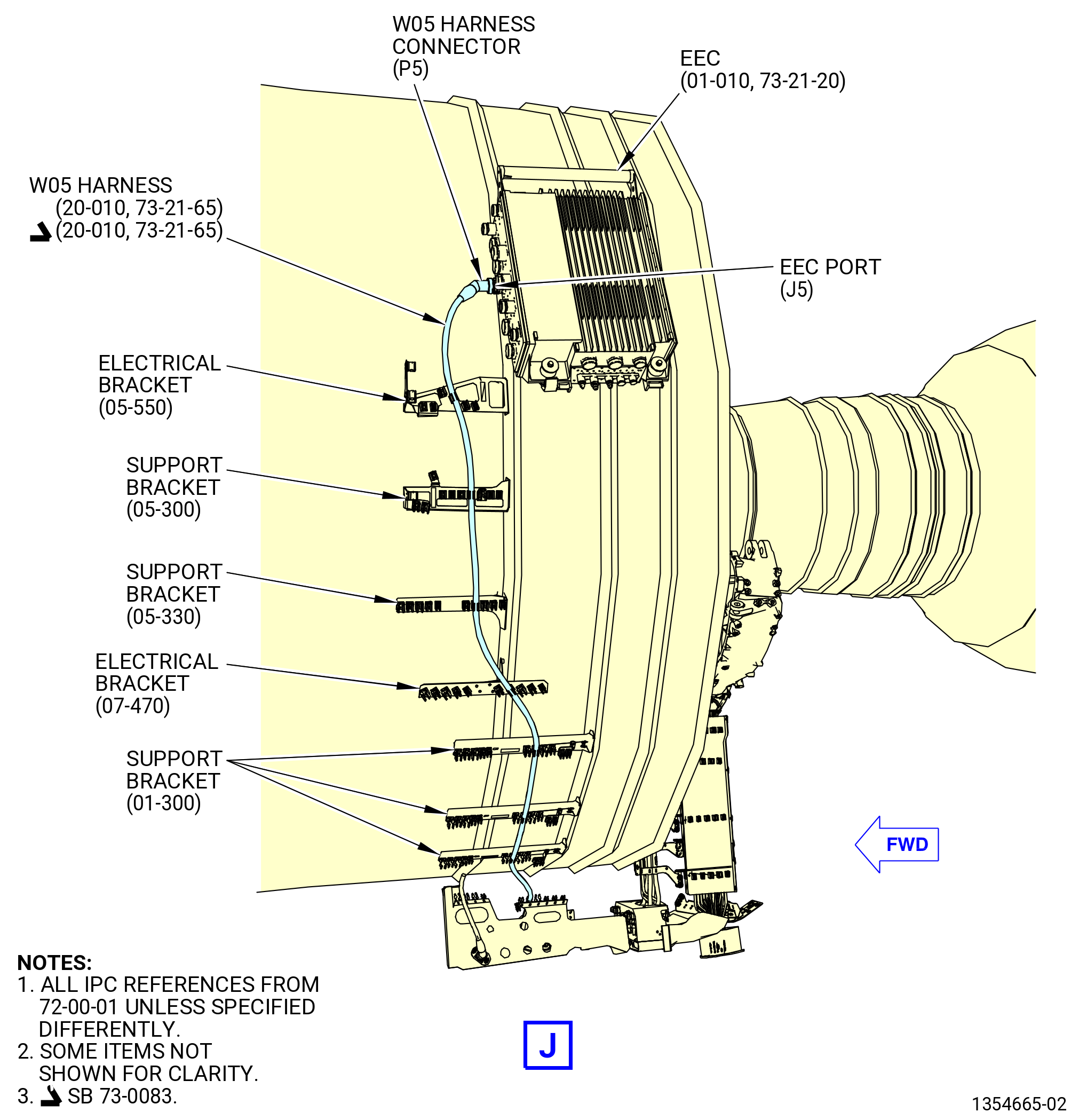
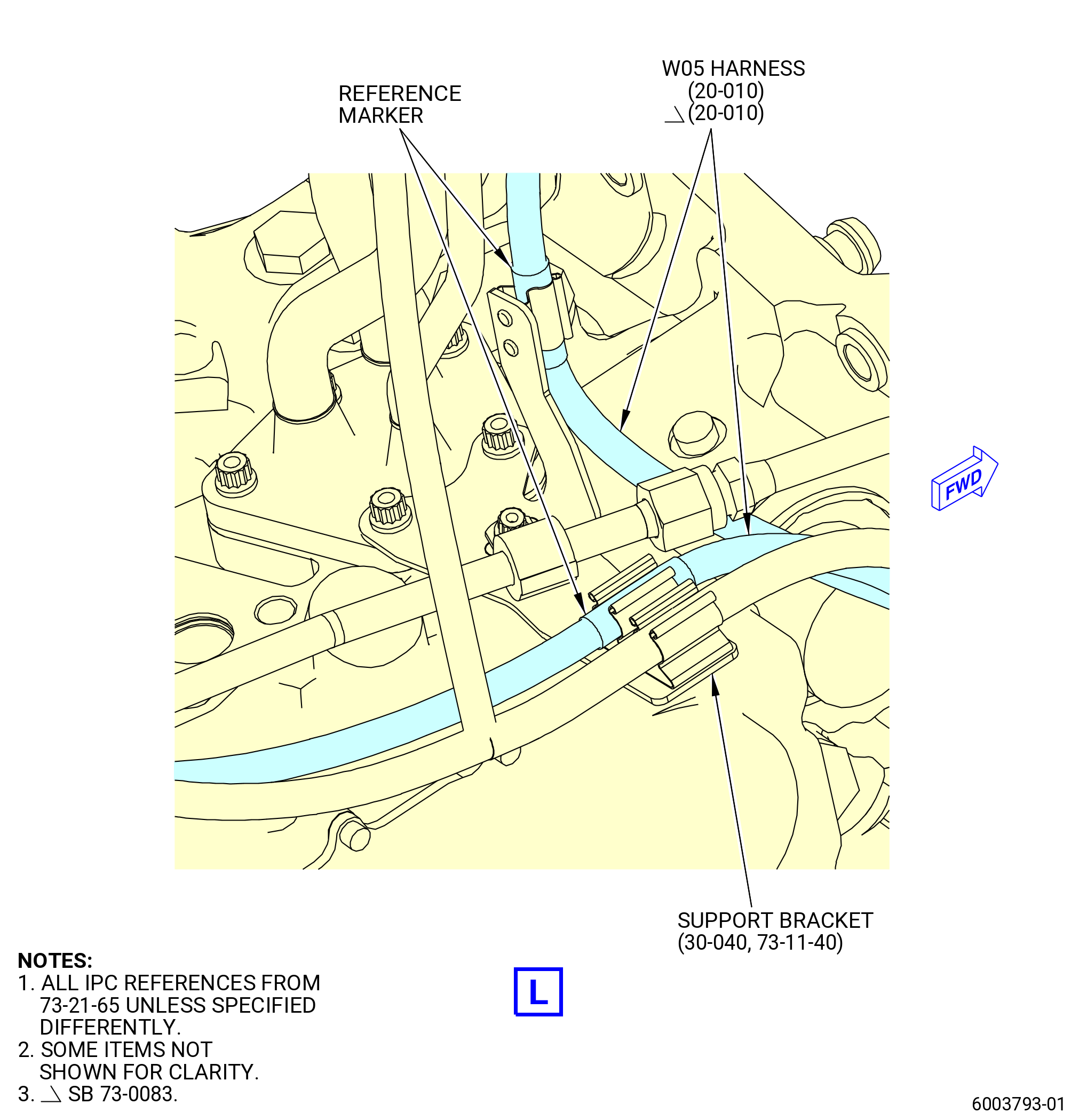
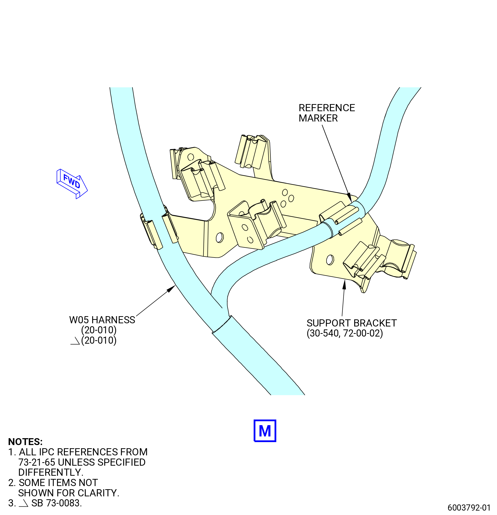
| K. | Install the W05 harness (20-010 , 73-21-65) (SIN 67004) on the propulsor. Refer to Figure 1012 and as follows: |
| NOTE: |
|
| (1) | Remove the protective covers from the harness connectors and component connectors. |
| Subtask 72-00-00-440-190 |
| * * * PRE SB 73-0073( Electrical Clip Insert Elimination ) |
| (2) | Put the W05 harness in the clip of the support bracket (6711G) with a clip insert (67174). |
| * * * END PRE SB 73-0073 |
| Subtask 72-00-00-440-191 |
| * * * SB 73-0073( Electrical Clip Insert Elimination ) |
| (2).A. | Put the W05 harness in the clip of the support bracket (01-310 , 72-00-05) (SIN 6711G). |
| NOTE: |
|
| * * * END SB 73-0073 |
| Subtask 72-00-00-440-192 |
| (3) | Put the W05 harness in the clip of the support brackets (6711G, 6711H) with two clip inserts (67175). |
| (4) | Put the W05 harness in the clip of the support bracket (37010). |
| (5) | Connect the W05 harness connector (P059) to the fuel metering unit (FMU)(01-010 , 73-21-40) (SIN 30000) or (01-011 , 73-21-40) (SIN 30000) as follows: |
| (a) | Connect the W05 harness connector (P059) to the FMU-A port of the FMU. |
| (b) | Tighten the W05 harness connector (P059) with teflon-jaw pliers. |
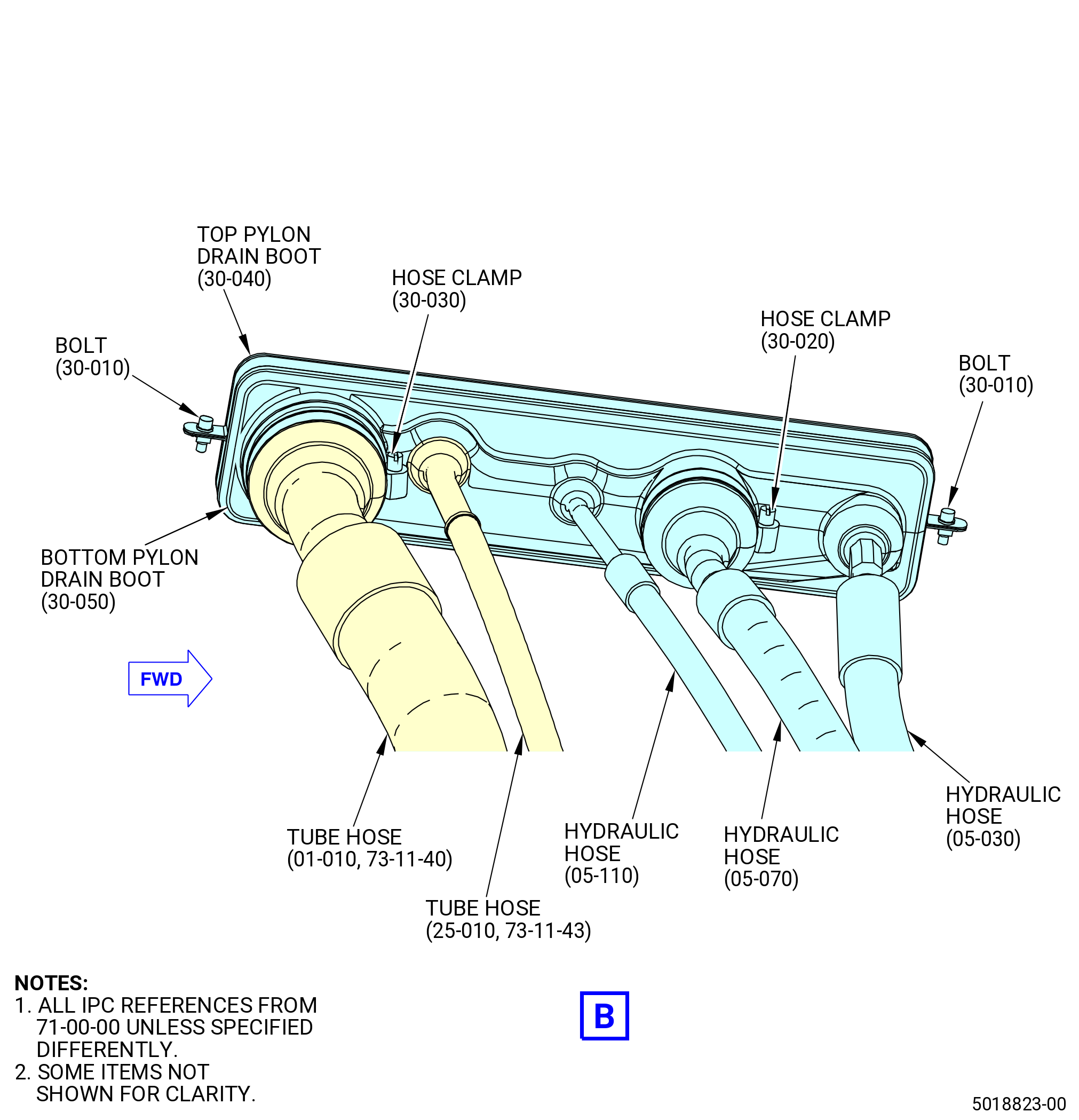
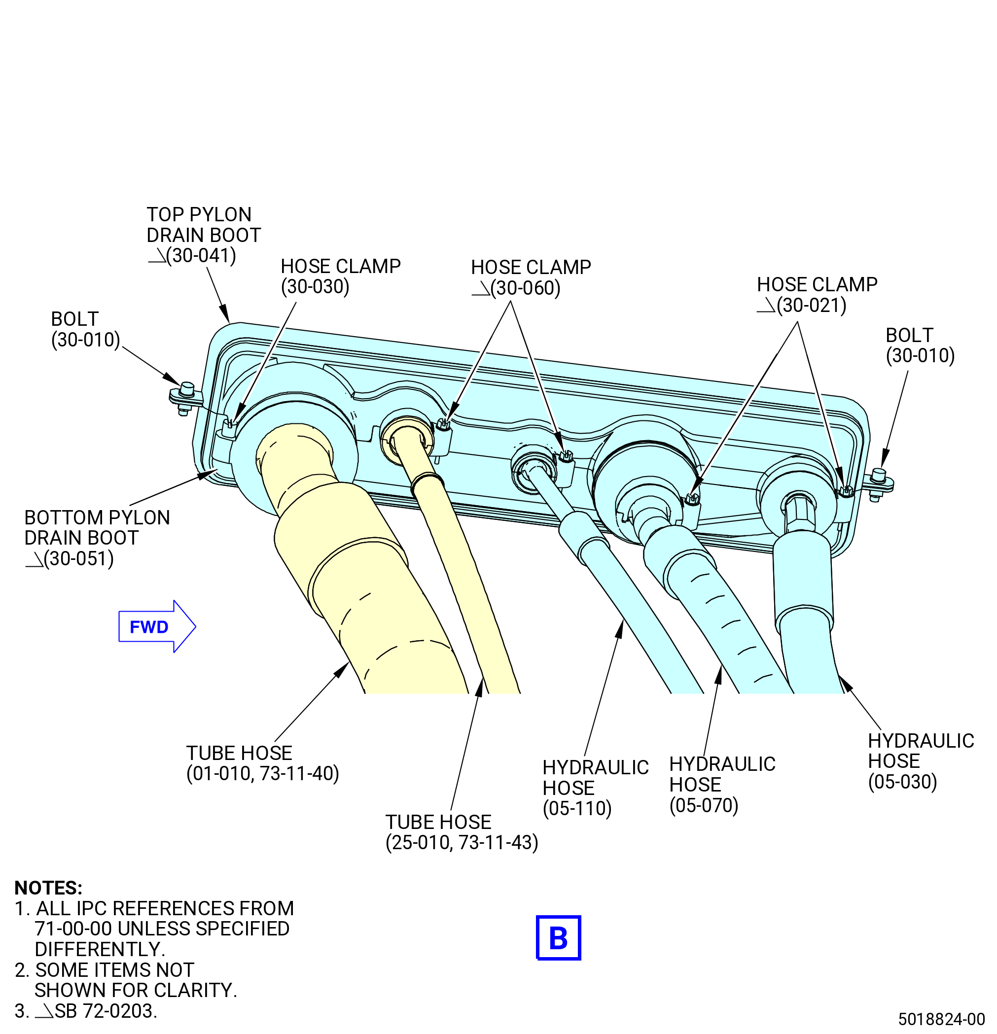
| (6) | Put the W05 harness in the clip of the support bracket (05-090 , 73-11-41) (SIN 37610). |
| Subtask 72-00-00-440-193 |
| * * * PRE SB 73-0073( Electrical Clip Insert Elimination ) |
| (7) | Put the W05 harness in the clip of the support bracket (30-040 , 73-11-40) (SIN 37612) with a clip insert (67174). |
| * * * END PRE SB 73-0073 |
| Subtask 72-00-00-440-194 |
| * * * SB 73-0073( Electrical Clip Insert Elimination ) |
| (7).A. | Put the W05 harness in the clip of the support bracket (30-040 , 73-11-40) (SIN 37612). |
| NOTE: |
|
| * * * END SB 73-0073 |
| Subtask 72-00-00-440-195 |
| (8) | Put the W05 harness in the clip of the support bracket (37613) with a clip insert (67173). |
| (9) | Put the W05 harness in the clip of the support bracket (34011) with a clip insert (67172). |
| (10) | Connect the W05 harness connector (P055) to the T3 sensor (65N00) as follows: |
| (a) | Connect the W05 harness connector (P055) to the T3-A port of the T3 sensor. |
| (b) | Tighten the W05 harness connector (P055) with teflon-jaw pliers. |
| Subtask 72-00-00-440-063 |
| * * * PRE SB 73-0011( Engines without Fuel Vapor Accumulator ) |
| (11) | Put the W05 harness in the clip of the support bracket (30-040 , 73-11-40) (SIN 37612) with a clip insert (67172). |
| * * * END PRE SB 73-0011 |
| Subtask 72-00-00-440-064 |
| * * * SB 73-0011( Engines with Fuel Vapor Accumulator ) |
| (11).A. | Put the W05 harness in the clip of the support bracket (30-040 , 73-11-40) (SIN 37612). |
| NOTE: |
|
| * * * END SB 73-0011 |
| Subtask 72-00-00-440-065 |
| * * * PRE SB 73-0011( Engines without Fuel Vapor Accumulator ) |
| (12) | Put the W05 harness in the clip of the bracket (05-090 , 73-11-40) (SIN 6881A) with a clip insert (67172). |
| * * * END PRE SB 73-0011 |
| Subtask 72-00-00-440-066 |
| * * * SB 73-0011( Engines with Fuel Vapor Accumulator ) |
| (12).A. | Put the W05 harness in the clip of the bracket (05-090 , 73-11-40) (SIN 6881A). |
| * * * END SB 73-0011 |
| Subtask 72-00-00-440-067 |
| * * * PRE SB 73-0011( Engines without Fuel Vapor Accumulator ) |
| (13) | Put the W05 harness in the forward clips of the VSV/VBV bracket (10-210 , 75-24-20) (SIN 38116) or (10-250 , 75-24-20) (SIN 38116) with two clip inserts (20-020 , 73-21-65) (SIN 67172) at two locations. |
| * * * END PRE SB 73-0011 |
| Subtask 72-00-00-440-068 |
| * * * SB 73-0011( Engines with Fuel Vapor Accumulator ) |
| (13).A. | Put the W05 harness in the forward clips of the VSV/VBV bracket (10-250 , 75-24-20) (SIN 38116) at two locations. |
| * * * END SB 73-0011 |
| Subtask 72-00-00-440-069 |
| (14) | Connect the W05 harness connector (P058) to the transient bleed valve (60700) as follows: |
| (a) | Connect the W05 harness connector (P058) to the TBV-A port of the transient bleed valve. |
| (b) | Tighten the W05 harness connector (P058) with teflon-jaw pliers. |
| (15) | Put the W05 harness in the clip of the A sump scavenge tube (scavenge tube) (45100) with a clip insert (67174). |
| Subtask 72-00-00-440-211 |
| * * * PRE SB 73-0074( Harness Support Spring Clips with Clip Inserts ) |
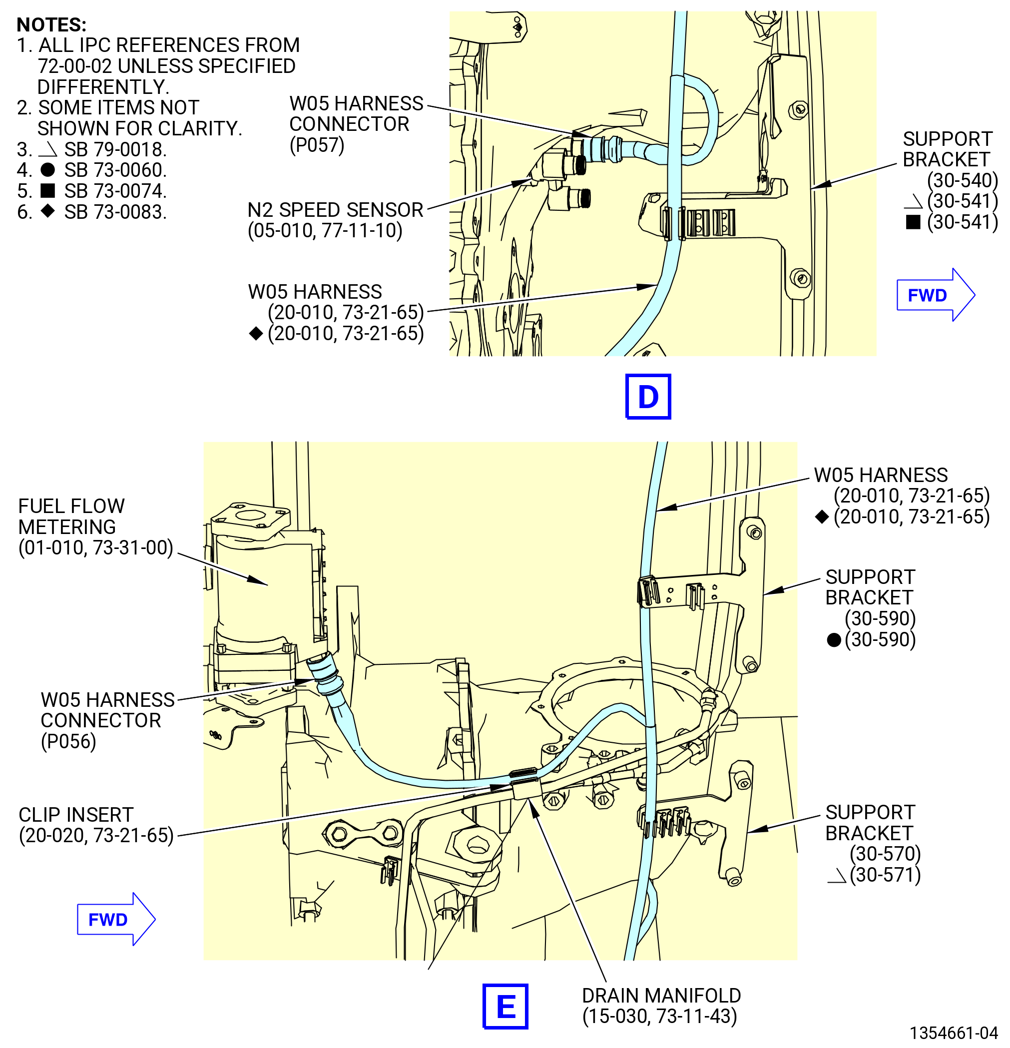
| (16) | Put the W05 harness (20-010 , 73-21-65) (SIN 67004) in the clip of the support bracket (30-540 , 72-00-02) (SIN 6711D) or (30-541 , 72-00-02) (SIN 6711D) with a clip insert (20-050 , 73-21-65) (SIN 67175). |
| * * * END PRE SB 73-0074 |
| Subtask 72-00-00-440-224 |
| * * * SB 73-0074( Harness Support Spring Clips without Clip Inserts ) |
| (16).A. | Put the W05 harness (20-010 , 73-21-65) (SIN 67004) in the clip of the support bracket (30-540 , 72-00-02) (SIN 6711D) or (30-541 , 72-00-02) (SIN 6711D). |
| * * * END SB 73-0074 |
| Subtask 72-00-00-440-213 |
| (17) | Connect the W05 harness connector (P057) to the N2 speed sensor (65D00) as follows: |
| (a) | Connect the W05 harness connector (P057) to the N2-A port of the N2 speed sensor. |
| (b) | Tighten the W05 harness connector (P057) with teflon-jaw pliers. |
| (18) | Put the W05 harness in the clip of the support bracket (30-570 , 72-00-02) (SIN 6711E) or (30-571 , 72-00-02) (SIN 6711E). |
| (19) | Put the W05 harness in the clip of the support bracket (6711C). |
| (20) | Put the W05 harness in the clip of the drain manifold (37302) with a clip insert (67172). |
| (21) | Connect the W05 harness connector (P056) to the fuel flow metering (30800) as follows: |
| (a) | Connect the W05 harness connector (P056) to the WFM port of the fuel flow metering. |
| (b) | Tighten the W05 harness connector (P056) with teflon-jaw pliers. |
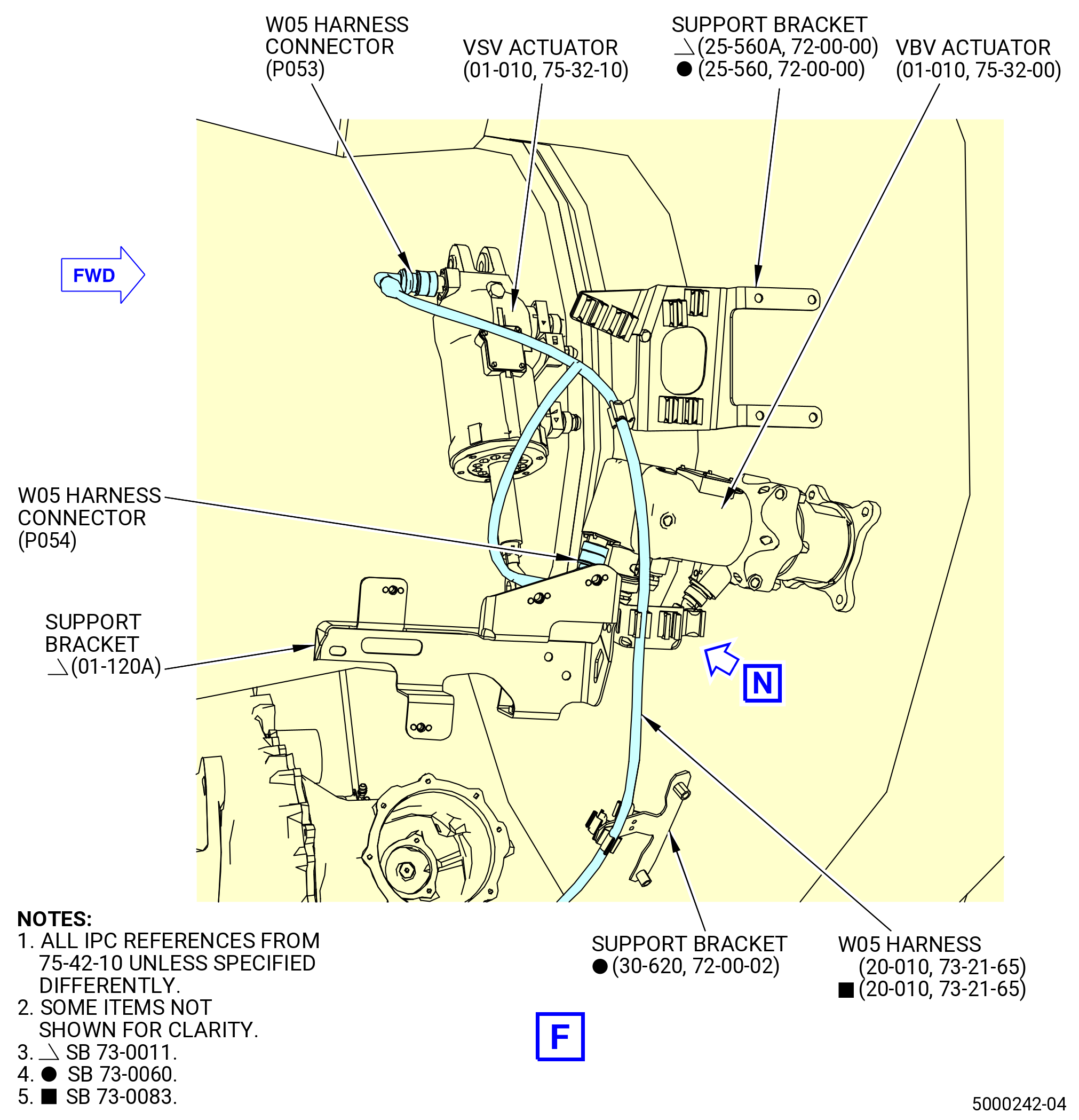
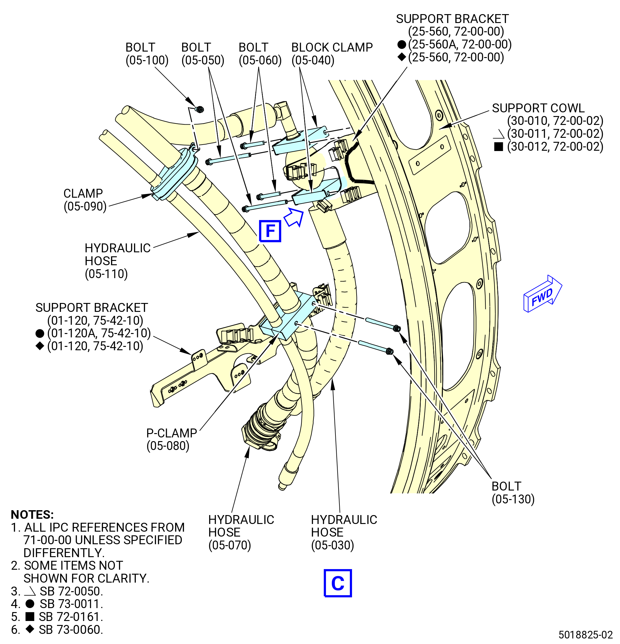
| (22) | Put the W05 harness in the clip of the support bracket (01-120 , 75-42-10) (SIN 53012) or (01-120A , 75-42-10) (SIN 53012). |
| NOTE: |
|
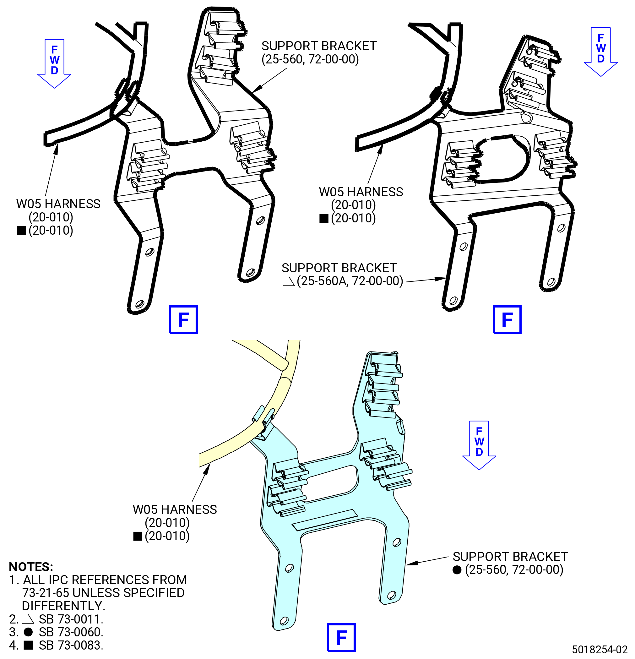
| (23) | Put the W05 harness in the clip of the support bracket (25-560) (SIN 6881U) or (25-560A) (SIN 6881U). |
| (24) | Connect the W05 harness connector (P054) to the VBV actuator (30700) as follows: |
| (a) | Connect the W05 harness connector (P054) to the VBV-A port of the VBV actuator. |
| (b) | Tighten the W05 harness connector (P054) with teflon-jaw pliers. |
| (25) | Connect the W05 harness connector (P053) to the VSV actuator (30400) as follows: |
| (a) | Connect the W05 harness connector (P053) to VSV-A port of the VSV actuator. |
| (b) | Tighten the W05 harness connector (P053) with teflon-jaw pliers. |
| (26) | Put the W05 harness in the clips of the cable shield (09711). |
| (27) | Put the W05 harness in the clip of the support bracket (67116). |
| Subtask 72-00-00-440-126 |
| * * * PRE SB 72-0322( Lower Bifurcation Firewall with Two Bifurcation Fire Blankets ) |
| (28) | Attach the W05 harness to the bifurcation fire blankets (25-380) (SIN 09490) and (25-370) (SIN 09491) and electrical block clamps (25-400) (SIN 09481) , (25-390) (SIN 09482) as follows: |
| (a) | Attach the W05 harness through the bifurcation fire blankets and electrical block clamps in the hole No. 6 from left to right, FLA. |
| * * * END PRE SB 72-0322 |
| Subtask 72-00-00-440-127 |
| * * * SB 72-0322( Lower Bifurcation Firewall with One Bifurcation Fire Blanket ) |
| (28).A. | Attach the W05 harness to the bifurcation fire blankets (25-370) (SIN 09491) and electrical block clamps (25-400) (SIN 09481) and (25-390) (SIN 09482) as follows: |
| (a) | Attach the W05 harness through the bifurcation fire blankets and electrical block clamps in the hole No. 6 from left to right, FLA. |
| * * * END SB 72-0322 |
| Subtask 72-00-00-440-128 |
| (29) | Put the W05 harness in the clips of the brackets (67018, 67019). |
| NOTE: |
|
| (30) | Connect the W05 harness connector (P0519) to the W09 harness connector (J0919) as follows:Put the W05 harness in the clips of the brackets (67018, 67019). |
| (a) | Connect the W05 harness connector (P0519) to the W09 harness connector (J0919). |
| (b) | Tighten the W05 harness connector (P0519) with teflon-jaw pliers. |
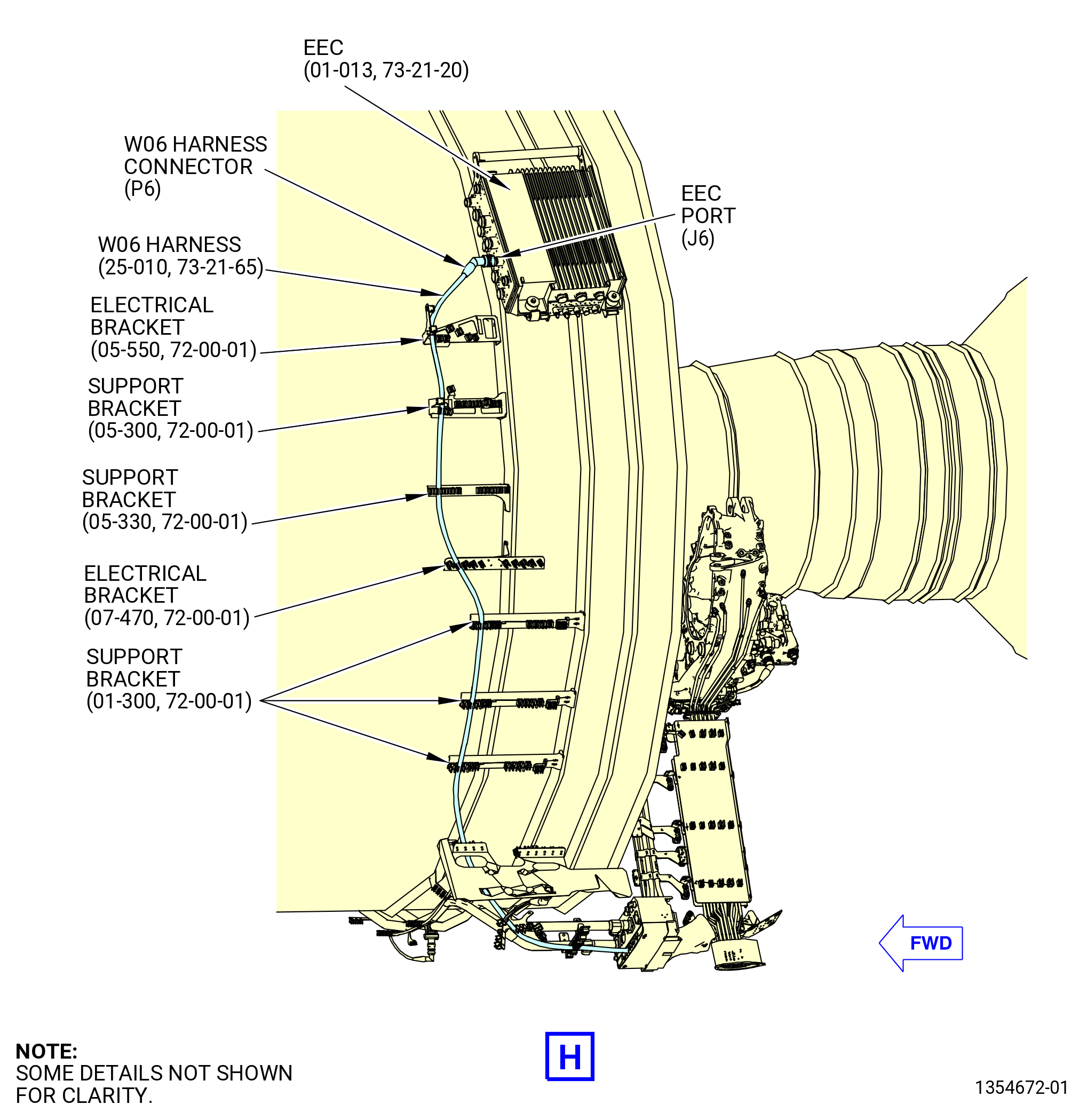
| (31) | Put the W05 harness in the clips of the support brackets (01-300 , 72-00-01) (SIN 61419), (05-300 , 72-00-01) (SIN 6701S), and (05-330 , 72-00-01) (SIN 6701E), electrical brackets (05-550 , 72-00-01) (SIN 6701C) and (07-470 , 72-00-01) (SIN 6701Z), and shield bracket (05-400 , 72-00-01) (SIN 6701F) or (05-400A , 72-00-01) (SIN 6701F) or (05-401 , 72-00-01) (SIN 6701F). |
| (32) | Connect the W05 harness connector (P5) to the EEC (65H00) as follows: |
| (a) | Connect the W10 harness connector (P5) to the EEC port (J5). |
| (b) | Tighten the W10 harness connector (P5) with teflon-jaw pliers. |
|
|
|
|
|
|
|
|
|
|
| Subtask 72-00-00-440-014 |
| CAUTION: |
|
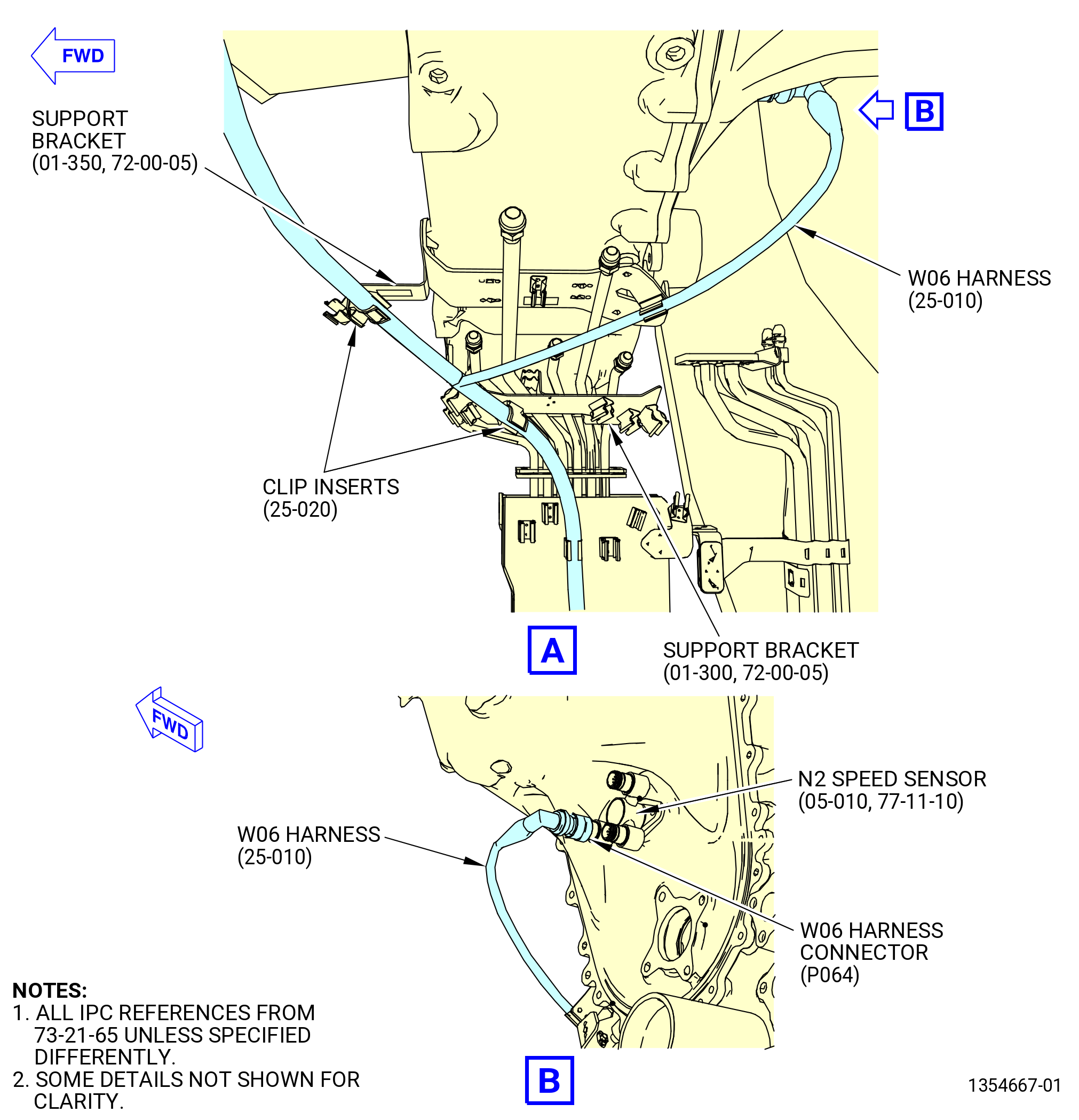
| L. | Install the W06 harness (67005) on the propulsor as follows. Refer to Figure 1013. |
| NOTE: |
|
| (1) | Remove the protective covers from the harness connectors and component connectors. |
| (2) | Put the W06 harness in the clips of the support brackets (6711G, 6711H) with two clip inserts (67176). |
| (3) | Connect the W06 harness connector (P064) to the N2 speed sensor (65D00) as follows: |
| (a) | Put the W06 harness in the clip of the support bracket (6711H). |
| (b) | Connect the W06 harness connector (P064) to the N2-B port of the N2 speed sensor. |
| (c) | Tighten the W06 harness connector (P064) with teflon-jaw pliers. |
| (4) | Connect the W06 harness connector (P067) to the FMU (01-010 , 73-21-40) (SIN 30000) or (01-011 , 73-21-40) (SIN 30000) as follows: |
| (a) | Connect the W06 harness connector (P067) to the FMJ-B port of the fuel metering unit. |
| (b) | Tighten the W06 harness connector (P067) with teflon-jaw pliers. |
| (5) | Put the W06 harness in the clip of the support bracket (05-090 , 73-11-41) (SIN 37610). |
| (6) | Put the W06 harness in the clip of the support bracket(30-040 , 73-11-40) (SIN 37612) with a clip insert (67174). |
| (7) | Put the W06 harness in the clips of the support brackets (37613, 34011) with two clip inserts (67173). |
| (8) | Connect the W06 harness connector (P063) to the T3 sensor (65N00) as follows: |
| (a) | Connect the W06 harness connector (P063) to the T3-B port of the T3 sensor. |
| (b) | Tighten the W06 harness connector (P063) with teflon-jaw pliers. |
| Subtask 72-00-00-440-139 |
| * * * PRE SB 72-0290( Engines with Temperature Sensor ) |
| (9) | Connect the W06 harness connector (P065) to the CC temperature sensor (temperature sensor) (65T00) as follows: |
| NOTE: |
|
| (a) | Connect the W06 harness connector (P065) to the T-CORE port of the temperature sensor. |
| (b) | Tighten the W06 harness connector (P065) with teflon-jaw pliers. |
| * * * END PRE SB 72-0290 |
| Subtask 72-00-00-440-070 |
| * * * PRE SB 73-0011( Engines without Fuel Vapor Accumulator ) |
| (10) | Put the W06 harness in the clip of the bracket (05-090 , 73-11-40) (SIN 6881A) with a clip insert (67172). |
| * * * END PRE SB 73-0011 |
| Subtask 72-00-00-440-071 |
| * * * SB 73-0011( Engines with Fuel Vapor Accumulator ) |
| (10).A. | Put the W06 harness in the clip of the bracket (05-090 , 73-11-40) (SIN 6881A). |
| * * * END SB 73-0011 |
| Subtask 72-00-00-440-072 |
| * * * PRE SB 73-0011( Engines without Fuel Vapor Accumulator ) |
| (11) | Put the W06 harness in the aft clips of the VSV/VBV bracket (10-210 , 75-24-20) (SIN 38116) or (10-250 , 75-24-20) (SIN 38116) at two locations with clip inserts (25-050 , 73-21-65) (SIN 67172). |
| * * * END PRE SB 73-0011 |
| Subtask 72-00-00-440-073 |
| * * * SB 73-0011( Engines with Fuel Vapor Accumulator ) |
| (11).A. | Put the W06 harness in the clips of the VSV/VBV bracket (10-250 , 75-24-20) (SIN 38116) at two locations. |
| * * * END SB 73-0011 |
| Subtask 72-00-00-440-074 |
| (12) | Connect the W06 harness connector (P066) to the transient bleed valve (60700) as follows: |
| (a) | Connect the W06 harness connector (P066) to the TBV-B port of the transient bleed valve. |
| (b) | Tighten the W06 harness connector (P066) with teflon-jaw pliers. |
| (13) | Put the W06 harness in the clips of the cable shield (09711). |
| (14) | Put the W06 harness in the clip of the support bracket (67116). |
| Subtask 72-00-00-440-129 |
| * * * PRE SB 72-0322( Lower Bifurcation Firewall with Two Bifurcation Fire Blankets ) |
| (15) | Attach the W06 harness to the bifurcation fire blankets (25-380) (SIN 09490) and (25-370) (SIN 09491) and electrical block clamps (25-400) (SIN 09481), (25-390) (SIN 09482) as follows: |
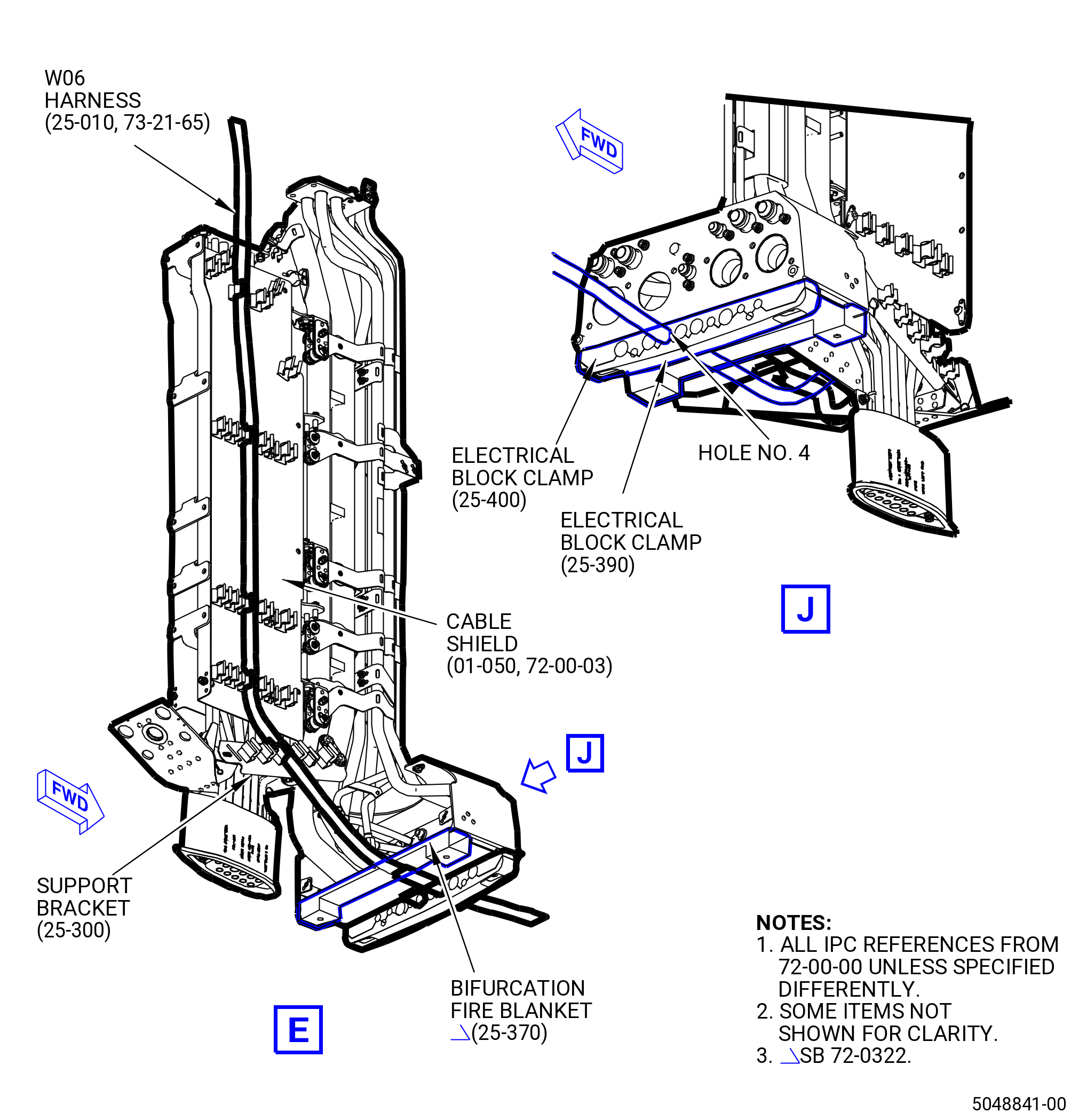
| (a) | Attach the W06 harness through the bifurcation fire blankets and electrical block clamps in the hole No. 4 from left to right, FLA. |
| * * * END PRE SB 72-0322 |
| Subtask 72-00-00-440-130 |
| * * * SB 72-0322( Lower Bifurcation Firewall with One Bifurcation Fire Blanket ) |
| (15).A. | Attach the W06 harness to the bifurcation fire blankets (25-370) (SIN 09491) and electrical block clamps (25-400) (SIN 09481) and (25-390) (SIN 09482) |
| (a) | Attach the W06 harness through the bifurcation fire blanket and electrical block clamps in the hole No. 4 from left to right, FLA. |
| * * * END SB 72-0322 |
| Subtask 72-00-00-440-131 |
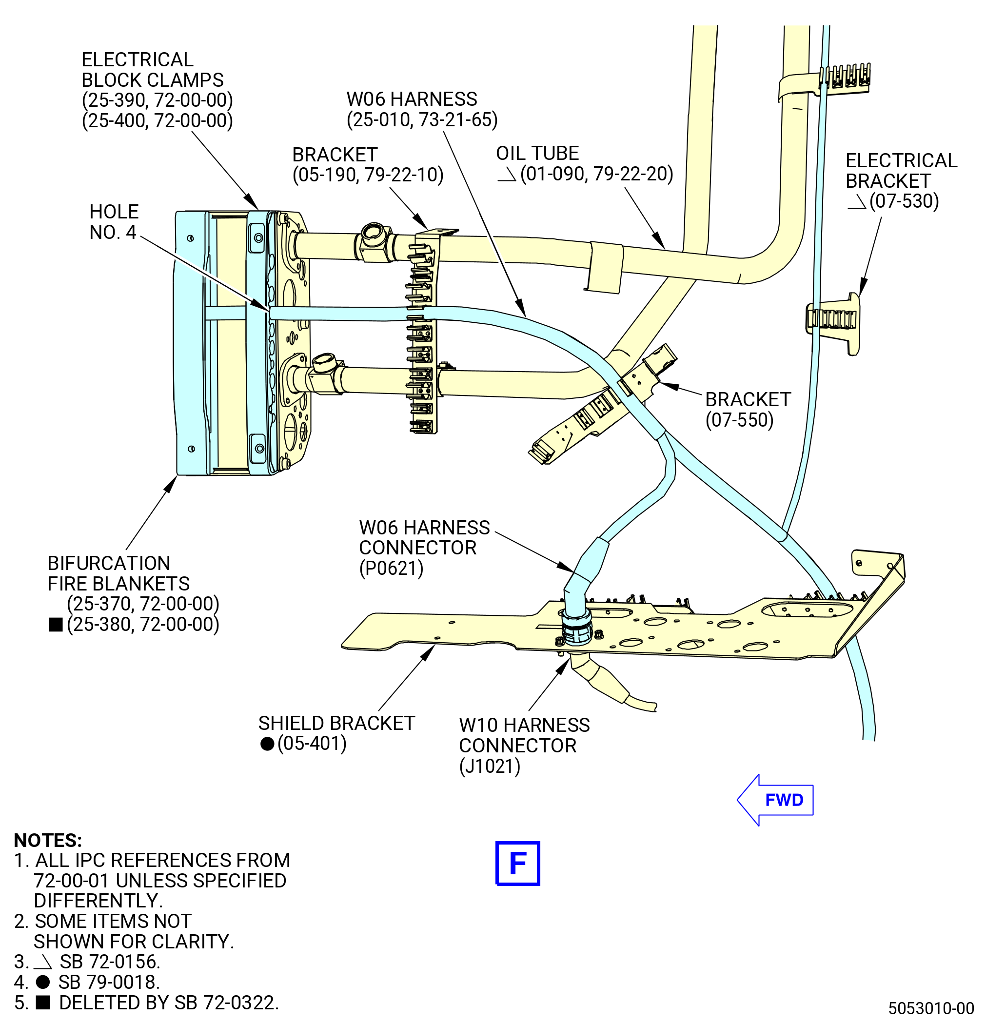
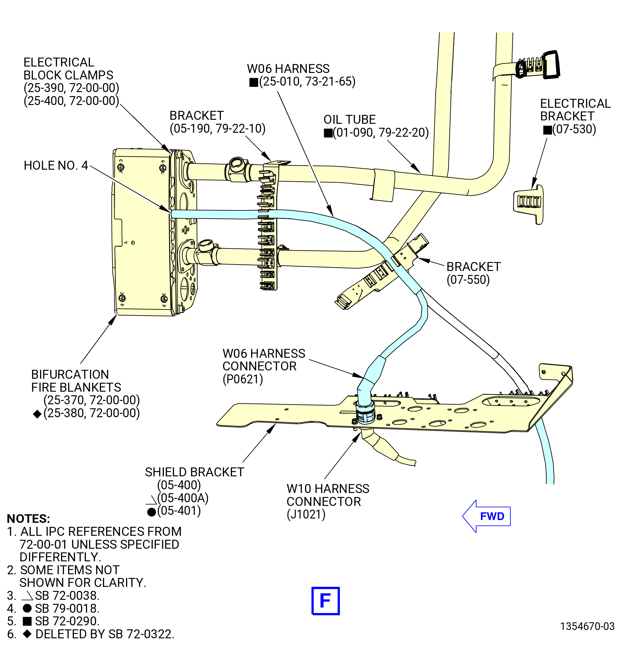
| (16) | Put the W06 harness in the clips of the brackets (05-190 , 79-22-10) (SIN 67018) and (07-550 , 72-00-01) (SIN 67019) and shield bracket (05-400 , 72-00-01) (SIN 6701F) or (05-400A , 72-00-01) (SIN 6701F) or (05-401 , 72-00-01) (SIN 6701F). |
| (17) | Connect the W06 harness connectors (P0621) to the W10 harness connector (J1021) as follows: |
| (a) | Connect the W06 harness connector (P0621) to the W10 harness connector (J1021) at the shield bracket (05-400 , 72-00-01) (SIN 6701F) or (05-400A , 72-00-01) (SIN 6701F) or (05-401 , 72-00-01) (SIN 6701F). |
| (b) | Tighten the W06 harness connector (P0621) with teflon-jaw pliers. |
| Subtask 72-00-00-440-144 |
| * * * FOR 1B/P/G03.1B/P/G04.1B/P1/G01 |
| * * * PRE SB 72-0290( Engines with Temperature Sensor ) |
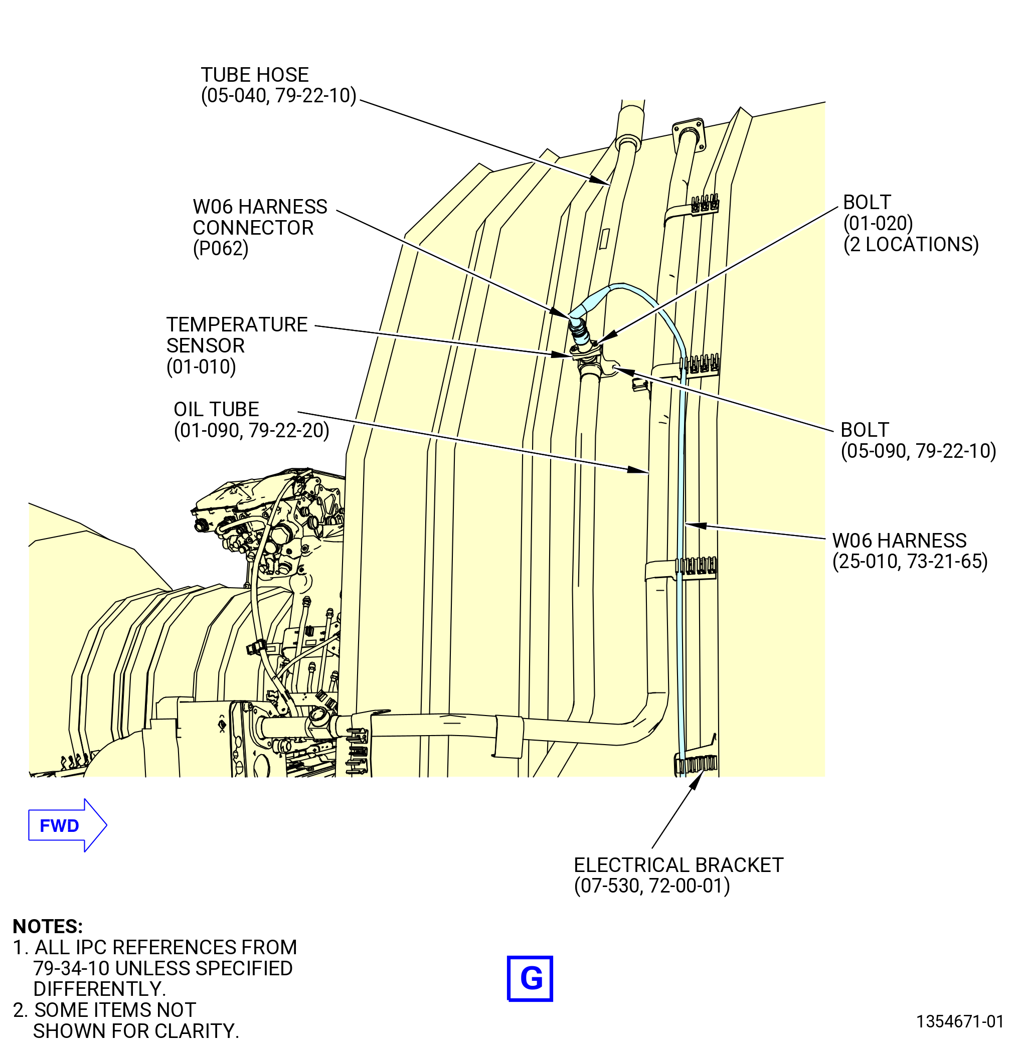
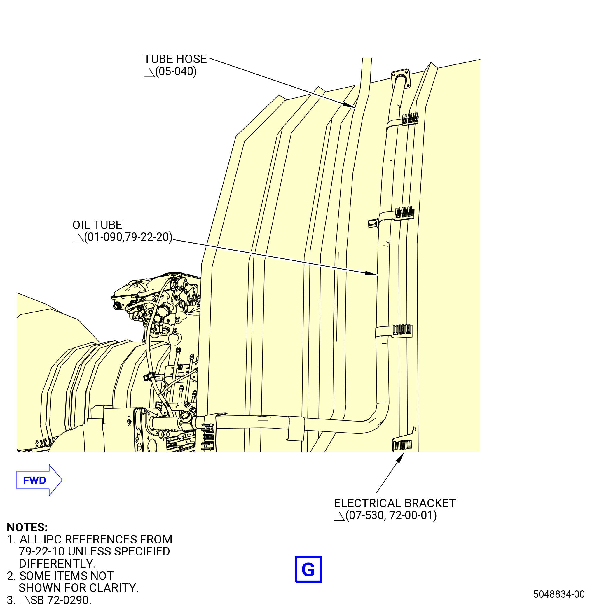
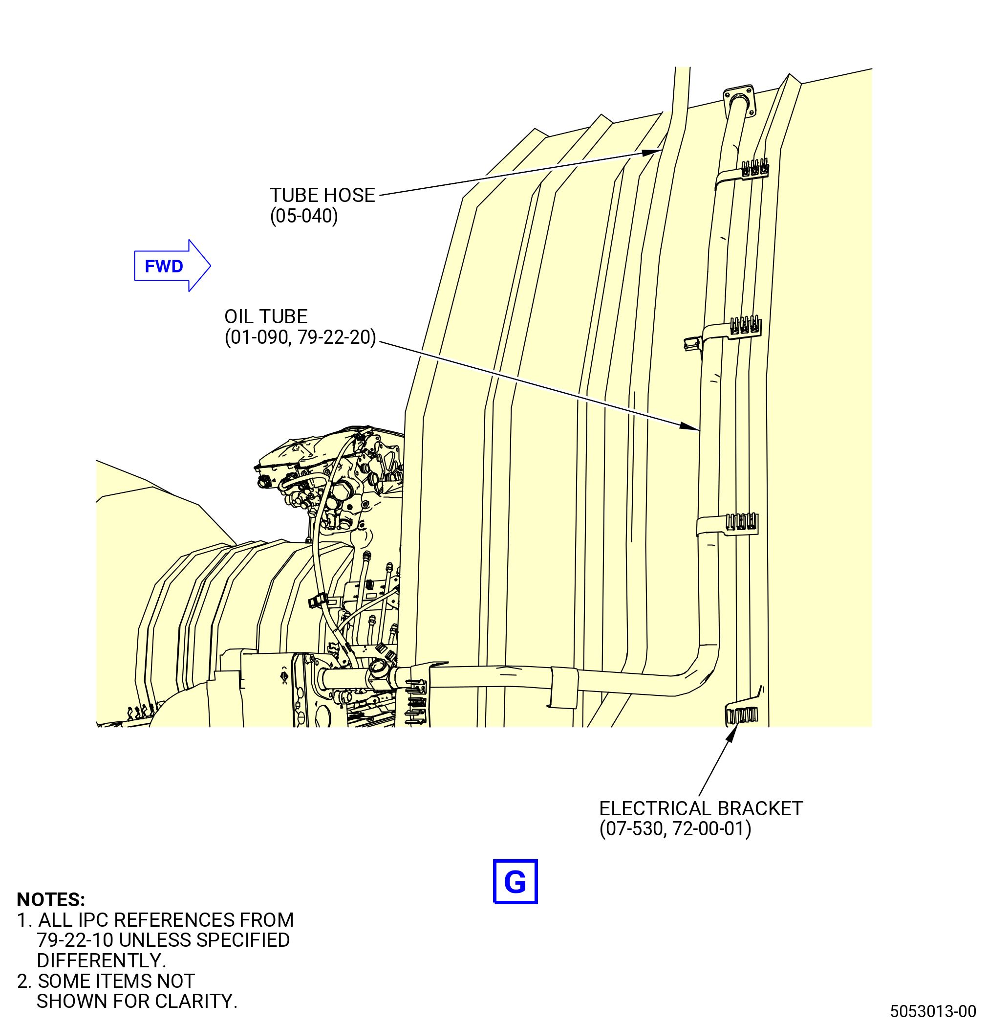
| (18) | Put the W06 harness in the clip of the electrical bracket (07-530 , 72-00-01) (SIN 6711S). |
| NOTE: |
|
| * * * END PRE SB 72-0290 |
| Subtask 72-00-00-440-145 |
| * * * FOR ALL PIP 2 |
| * * * SB 72-0156( Engine with Temperature Sensor ) |
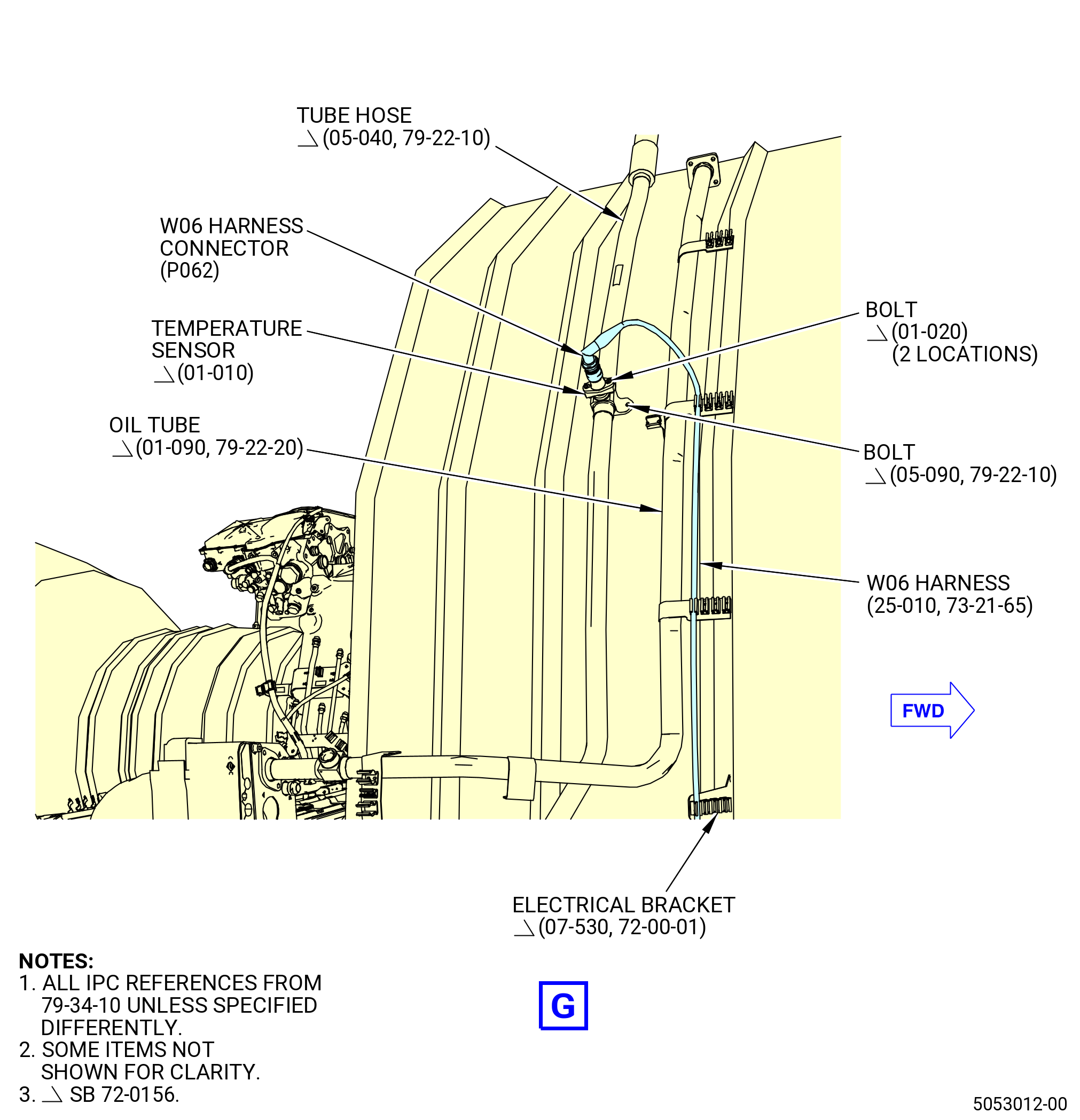
| (18).A. | Put the W06 harness in the clip of the electrical bracket (07-530 , 72-00-01) (SIN 6711S). |
| NOTE: |
|
| * * * END SB 72-0156 |
| Subtask 72-00-00-440-140 |
| * * * FOR 1B/P/G03.1B/P/G04.1B/P1/G01 |
| * * * PRE SB 72-0290( Engines with Temperature Sensor ) |
| (19) | Put the W06 harness in the spring clips of the oil tube (01-090 , 79-22-20) (SIN 45302). |
| NOTE: |
|
| * * * END PRE SB 72-0290 |
| Subtask 72-00-00-440-146 |
| * * * FOR ALL PIP 2 |
| * * * SB 72-0156( Engine with Temperature Sensor ) |
| (19).A. | Put the W06 harness in the spring clips of the oil tube (01-090 , 79-22-20) (SIN 45302). |
| NOTE: |
|
| * * * END SB 72-0156 |
| Subtask 72-00-00-440-142 |
| * * * FOR 1B/P/G03.1B/P/G04.1B/P1/G01 |
| * * * PRE SB 72-0290( Engines with Temperature Sensor ) |
| (20) | Connect the W06 harness connector (P062) to the temperature sensor (01-010 , 79-34-10) (SIN 40800). |
| NOTE: |
|
| (a) | Connect the W06 harness connector (P062) to the OET port of the temperature sensor at the tube hose (05-040 , 79-22-10) (SIN 44900). |
| (b) | Tighten the W06 harness connector (P062) with teflon-jaw pliers. |
| * * * END PRE SB 72-0290 |
| Subtask 72-00-00-440-147 |
| * * * FOR ALL PIP 2 |
| * * * SB 72-0156( Engine with Temperature Sensor ) |
| (20).A. | Connect the W06 harness connector (P062) to the temperature sensor (01-010 , 79-34-10) (SIN 40800). |
| NOTE: |
|
| (a) | Connect the W06 harness connector (P062) to the OET port of the temperature sensor at the tube hose (05-040 , 79-22-10) (SIN 44900). |
| (b) | Tighten the W06 harness connector (P062) with teflon-jaw pliers. |
| * * * END SB 72-0156 |
| Subtask 72-00-00-440-143 |
| * * * FOR ALL |
| (21) | Put the W06 harness in the clips of the brackets (61419, 6701C, 6701E, 6701S, 6701Z). |
| (22) | Connect the W06 harness connector (P6) to the EEC (65H00) as follows: |
| (a) | Connect the W06 harness connector (P6) to the EEC port (J6). |
| (b) | Tighten the W06 harness connector (P6) with teflon-jaw pliers. |
|
|
|
|
|
|
|
|
|
|
| Subtask 72-00-00-440-013 |
| * * * PRE SB 79-0018( MFOHX without Indicating Capability ) |
| CAUTION: |
|
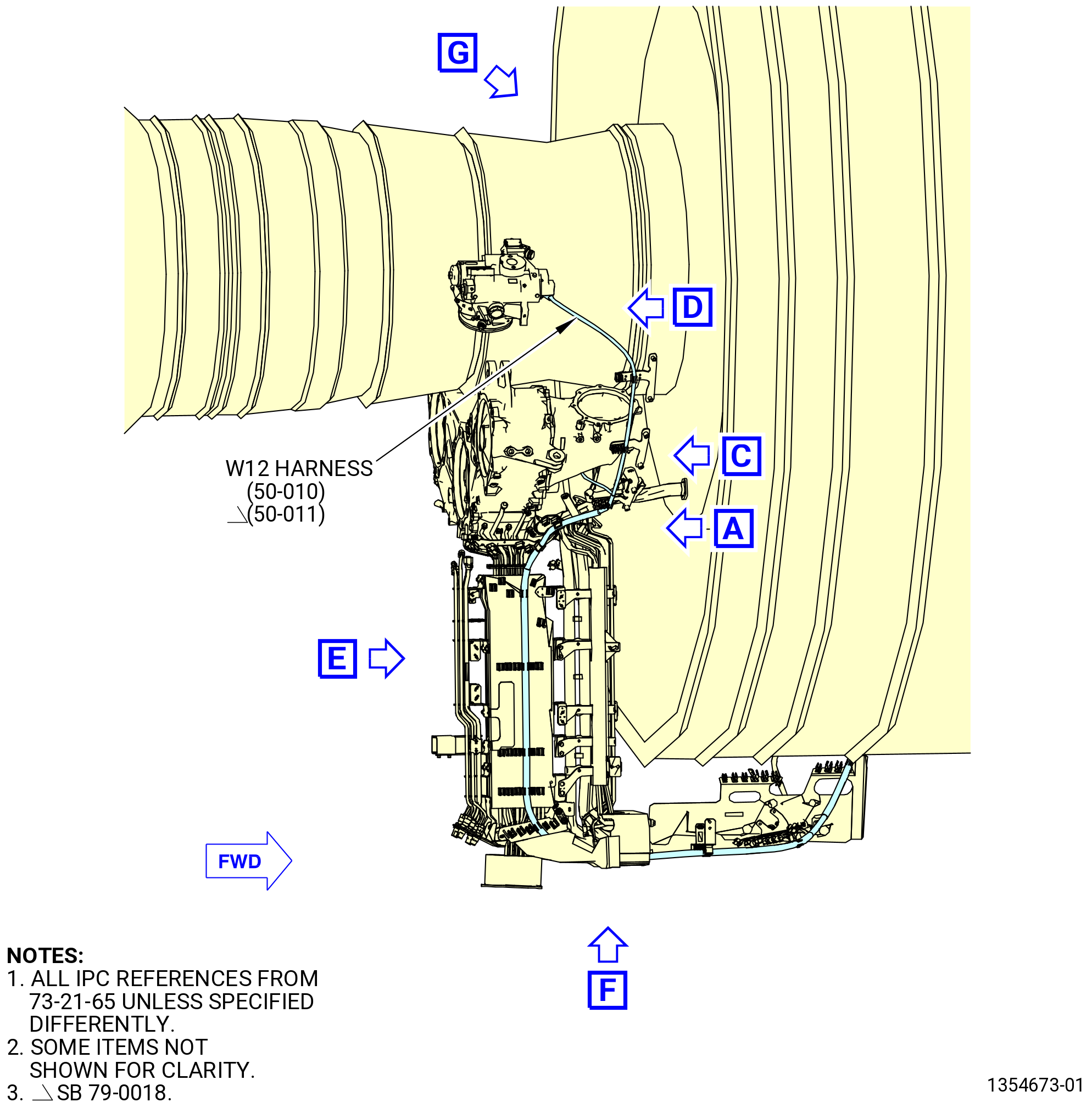
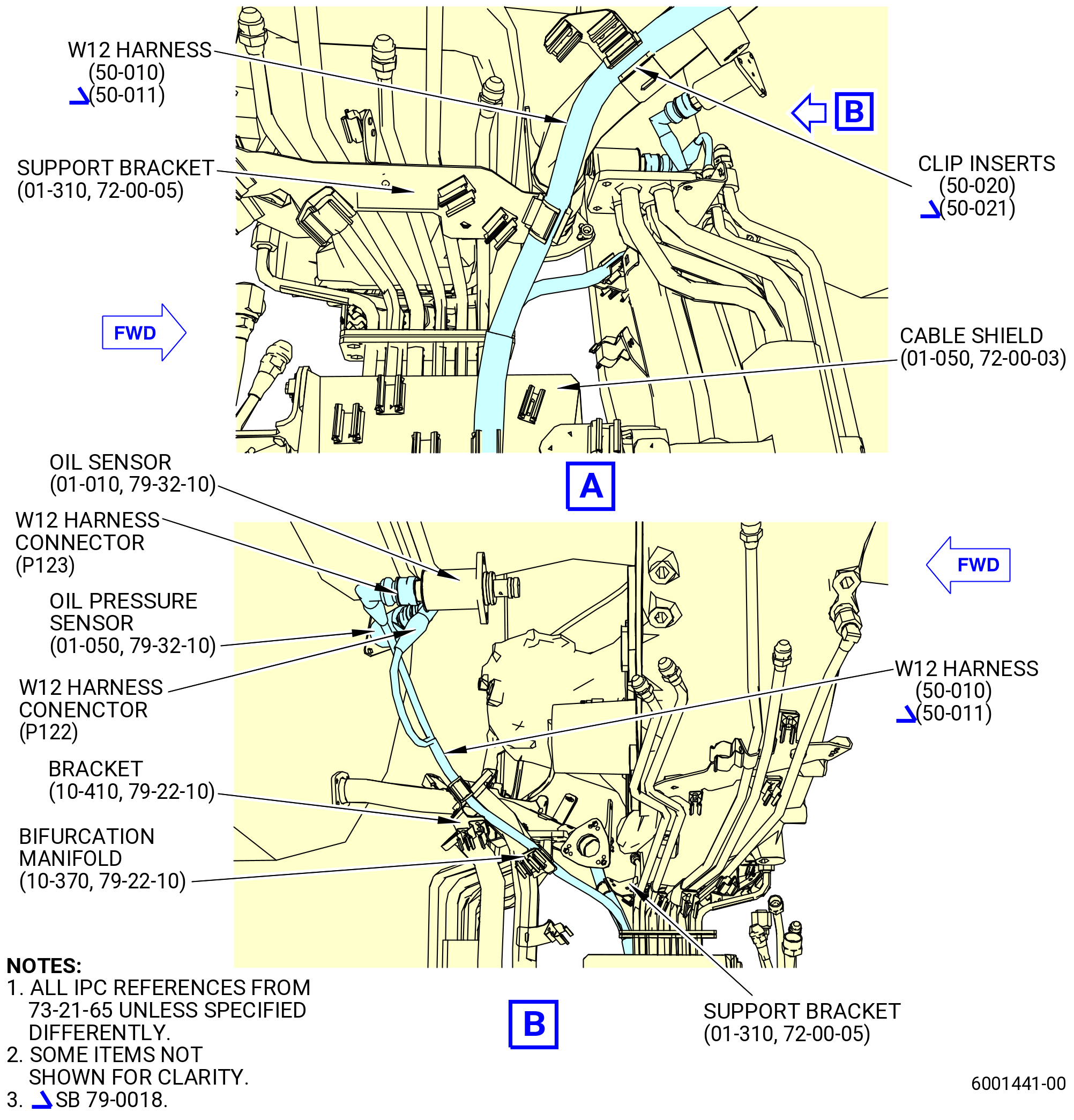
| M. | Install the W12 harness (50-010 , 73-21-65) (SIN 6700A) on the propulsor. Refer to Figure 1014 and do as follows: |
| NOTE: |
|
| (1) | Remove the protective covers from the harness connectors and component connectors. |
| (2) | Put the W12 harness in the clip of the support bracket (01-310 , 72-00-05) (SIN 6711G) with a clip insert (50-020 , 73-21-65) (SIN 67176). |
| Subtask 72-00-00-440-183 |
| * * * PRE SB 73-0081( Electrical Clip Insert Elimination ) |
| (3) | Put the W12 harness in the clip of the bifurcation manifold (99006) with a clip insert (67178). |
| * * * END PRE SB 73-0081 |
| Subtask 72-00-00-440-184 |
| * * * SB 73-0081( Electrical Clip Insert Elimination ) |
| (3).A. | Put the W12 harness in the clip of the bifurcation manifold (10-370 , 79-22-10) (SIN 99006). |
| * * * END SB 73-0081 |
| Subtask 72-00-00-440-185 |
| (4) | Put the W12 harness in the clip of the bracket (67217) with a clip insert (67178). |
| (5) | Connect the W12 harness connector (P122) to the oil pressure sensor (40501) as follows: |
| (a) | Connect the W12 harness connector (P122) to the ENG OIL port of the oil pressure sensor. |
| (b) | Tighten the W12 harness connector (P122) with teflon-jaw pliers. |
| (6) | Connect the W12 harness connector (P123) to the delta P oil sensor switch (oil sensor) (40500) as follows: |
| (a) | Connect the W12 harness connector (P123) to the OFDP port of the oil sensor. |
| (b) | Tighten the W12 harness connector (P123) with teflon-jaw pliers. |
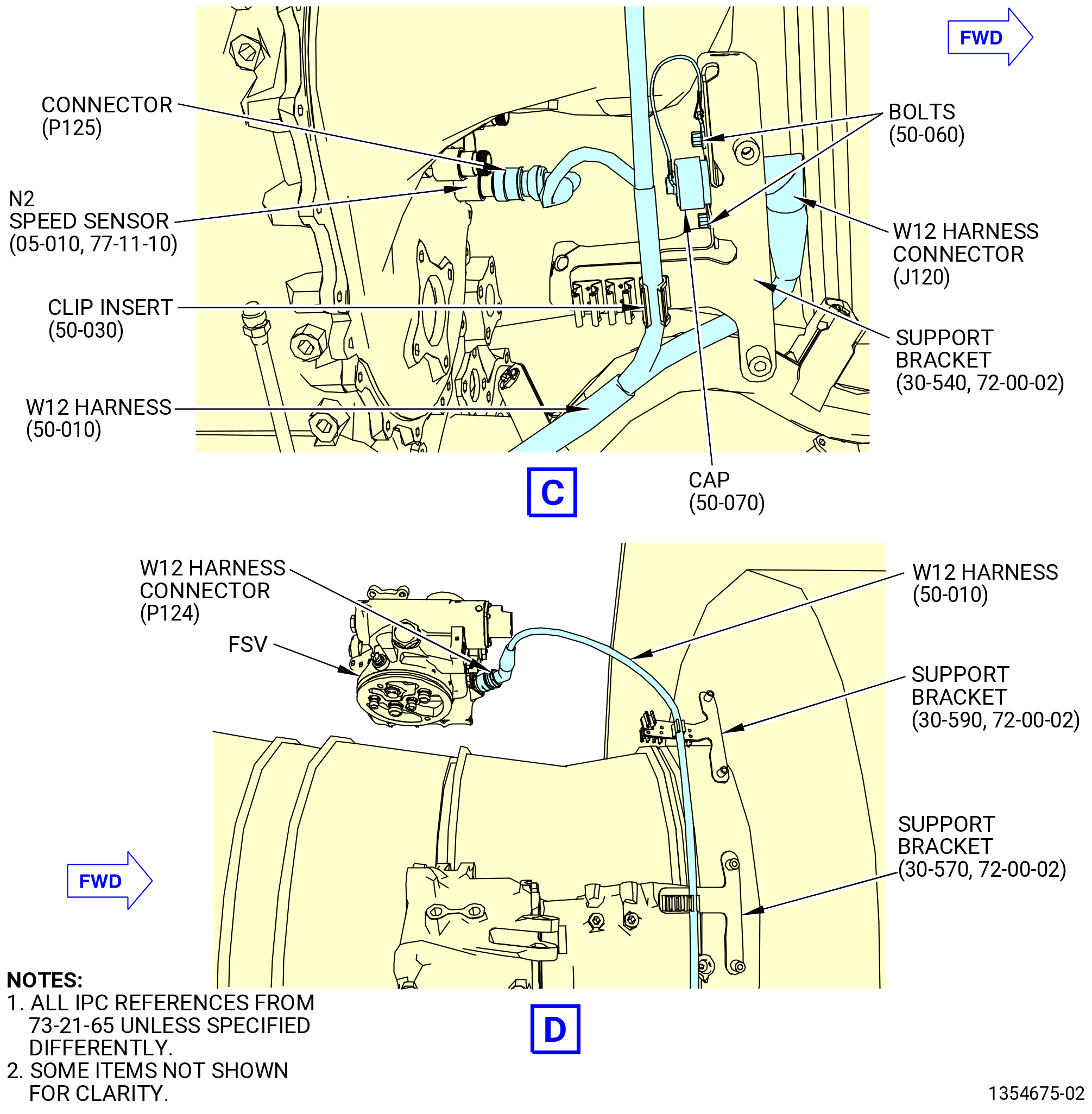
| (7) | Attach the W12 harness (50-010 , 73-21-65) (SIN 6700A) connector (J120) to the support bracket (30-540 , 72-00-02) (SIN 6711D) as follows: |
| NOTE: |
|
| (a) | Attach the W12 harness connector (J120) to the support bracket with two bolts (50-060 , 73-21-65) (SIN 67123). |
| 1 | Attach the cap (50-070 , 73-21-65) (SIN 67090) to the upper bolthole of the support bracket with the bolt (50-060 , 73-21-65) (SIN 67123). |
| 2 | Put the cap on the W12 harness connector (J120). |
| (b) | Torque the bolts (50-060 , 73-21-65) (SIN 67123) to 106 to 124 lb in. (12.0 to 14.0 Nm). |
| Subtask 72-00-00-440-214 |
| * * * PRE SB 73-0074( Harness Support Spring Clips with Clip Inserts ) |
| (8) | Put the W12 harness (50-010 , 73-21-65) (SIN 6700A) in the clip of the support bracket (30-540 , 72-00-02) (SIN 6711D) with a clip insert (50-030 , 73-21-65) (SIN 67175). |
| * * * END PRE SB 73-0074 |
| Subtask 72-00-00-440-225 |
| * * * SB 73-0074( Harness Support Spring Clips without Clip Inserts ) |
| (8).A. | Put the W12 harness (50-010 , 73-21-65) (SIN 6700A) in the clip of the support bracket (30-540 , 72-00-02) (SIN 6711D). |
| * * * END SB 73-0074 |
| Subtask 72-00-00-440-216 |
| (9) | Connect the W12 harness connector (P125) to the N2 speed sensor (65D00) as follows: |
| (a) | Connect the W12 harness connector (P125) to the N2-A/C port of the N2 speed sensor. |
| (b) | Tighten the W12 harness connector (P125) with teflon-jaw pliers. |
| (10) | Put the W12 harness in the clip of the support brackets (30-570 , 72-00-02) (SIN 6711E) and (30-590 , 72-00-02) (SIN 6711C). |
| Subtask 72-00-00-440-075 |
| * * * PRE SB 73-0011( Engines without Fuel Vapor Accumulator ) |
| (11) | Connect the W12 harness (50-010 , 73-21-65) (SIN 6700A) connector (P124) to the FSV (01-010 , 73-21-30) (SIN 31700) as follows: |
| (a) | Connect the W12 harness connector (P124) to the FSV-B port of the FSV. |
| (b) | Tighten the W12 harness connector (P124) with teflon-jaw pliers. |
| * * * END PRE SB 73-0011 |
| Subtask 72-00-00-440-076 |
| * * * SB 73-0011( Engines with Fuel Vapor Accumulator ) |
| (11).A. | Connect the W12 harness (50-010 , 73-21-65) (SIN 6700A) connector (P124) to the FSVA (01-010A , 73-21-30) (SIN 31700) as follows: |
| (a) | Connect the W12 harness connector (P124) to the FSV-B port of the FSVA. |
| (b) | Tighten the W12 harness connector (P124) with teflon-jaw pliers. |
| * * * END SB 73-0011 |
| Subtask 72-00-00-440-077 |
| (12) | Put the W12 harness in the clips of the cable shield (09711). |
| (13) | Put the W12 harness in the clip of the support bracket (67116). |
| Subtask 72-00-00-440-132 |
| * * * PRE SB 72-0322( Lower Bifurcation Firewall with Two Bifurcation Fire Blankets ) |
| (14) | Attach the W12 harness to the bifurcation fire blankets (25-380) (SIN 09490) and (25-370) (SIN 09491) and electrical block clamps (25-400) (SIN 09481), (25-390) (SIN 09482) as follows: |
| (a) | Attach the W12 harness through the bifurcation fire blankets and electrical block clamps in the hole No. 3 from left to right, FLA. |
| * * * END PRE SB 72-0322 |
| Subtask 72-00-00-440-133 |
| * * * SB 72-0322( Lower Bifurcation Firewall with One Bifurcation Fire Blanket ) |
| (14).A. | Attach the W12 harness to the bifurcation fire blanket (25-370) (SIN 09491) and electrical block clamps (25-400) (SIN 09481) and (25-390) (SIN 09482) as follows: |
| (a) | Attach the W12 harness through the bifurcation fire blankets and electrical block clamps in the hole No. 3 from left to right, FLA. |
| * * * END SB 72-0322 |
| Subtask 72-00-00-440-134 |
| (15) | Put the W12 harness in the clips of the brackets (05-190 , 79-22-10) (SIN 67018) and (07-550 , 72-00-01) (SIN 67019) and shield bracket (05-400 , 72-00-01) (SIN 6701F) or (05-400A , 72-00-01) (SIN 6701F). |
| (16) | Connect the W12 harness connectors (P1223) to the W08 harness connector (J0823) as follows: |
| (a) | Connect the W12 harness connector (P1223) to the W08 harness connector (J0823) at the shield bracket (05-400 , 72-00-01) (SIN 6701F) or (05-400A , 72-00-01) (SIN 6701F). |
| (b) | Tighten the W12 harness connector (P1223) with teflon-jaw pliers. |
| (17) | Connect the W12 harness connectors (P1203) to the W13 harness connector (J1303) as follows: |
| (a) | Connect the W12 harness connector (P1203) to the W13 harness connector (J1303) at the shield bracket (05-400 , 72-00-01) (SIN 6701F) or (05-400A , 72-00-01) (SIN 6701F). |
| (b) | Tighten the W12 harness connector (P1203) with teflon-jaw pliers. |
| (18) | Put the W12 harness in the clips of the brackets (61419, 6701E, 6701Z). |
| (19) | Connect the W12 harness (50-010 , 73-21-65) (SIN 6700A) connectors (P1218, P1221) to the EMU (01-010 , 77-32-10) (SIN 65Z00) as follows: |
| (a) | Connect the W12 harness connector (P1218) to the EMU port (J18). |
| (b) | Tighten the W12 harness connector (P1218) with teflon-jaw pliers. |
| (c) | Connect the W12 harness connector (P1221) to the EMU port (J21). |
| (d) | Tighten the W12 harness connector (P1221) with teflon-jaw pliers. |
| (20) | Put the W12 harness in the clip of the support bracket (6701S). |
| (21) | Connect the W12 harness connector (P12) to the EEC (65H00) as follows: |
| (a) | Connect the W12 harness connector (P12) to the EEC port (J12). |
| (b) | Tighten the W12 harness connector (P12) with teflon-jaw pliers. |
| * * * END PRE SB 79-0018 |
| Subtask 72-00-00-440-087 |
| * * * SB 79-0018( MFOHX with Indicating Capability ) |
| CAUTION: |
|
| M.A. | Install the W12 harness (50-011 , 73-21-65) (SIN 6700A) on the propulsor. Refer to Figure 1014 and do as follows: |
| NOTE: |
|
| (1) | Remove the protective covers from the harness connectors and component connectors. |
| (2) | Put the W12 harness in the clip of the support bracket (01-310 , 72-00-05) (SIN 6711G) with a clip insert (50-021 , 73-21-65) (SIN 67176). |
| (3) | Put the W12 harness in the clip of the bifurcation manifold (10-370 , 79-22-10) (SIN 99006) with a clip insert (50-040 , 73-21-65) (SIN 67178). |
| (4) | Put the W12 harness in the clip of the bracket (10-410 , 79-22-10) (SIN 67217) with a clip insert (50-040 , 73-21-65) (SIN 67178). |
| (5) | Connect the W12 harness connector (P122) to the oil pressure sensor (01-050 , 79-32-10) (SIN 40501) as follows: |
| (a) | Connect the W12 harness connector (P122) to the ENG OIL port of the oil pressure sensor. |
| (b) | Tighten the W12 harness connector (P122) with teflon-jaw pliers. |
| (6) | Connect the W12 harness connector (P123) to the oil sensor (01-010 , 79-32-10) (SIN 40500) as follows: |
| (a) | Connect the W12 harness connector (P123) to the OFDP port of the oil sensor. |
| (b) | Tighten the W12 harness connector (P123) with teflon-jaw pliers. |
| Subtask 72-00-00-440-217 |
| * * * PRE SB 73-0074( Harness Support Spring Clips with Clip Inserts ) |
| (7) | Put the W12 harness (50-011 , 73-21-65) (SIN 6700A) in the clip of the support bracket (30-541 , 72-00-02) (SIN 6711D) with a clip insert (50-021 , 73-21-65) (SIN 67176). |
| * * * END PRE SB 73-0074 |
| Subtask 72-00-00-440-226 |
| * * * SB 73-0074( Harness Support Spring Clips without Clip Inserts ) |
| (7).A. | Put the W12 harness (50-011 , 73-21-65) (SIN 6700A) in the clip of the support bracket (30-541 , 72-00-02) (SIN 6711D). |
| * * * END SB 73-0074 |
| Subtask 72-00-00-440-219 |
| (8) | Connect the W12 harness connector (P125) to the N2 speed sensor (05-010 , 77-11-10) (SIN 65D00) as follows: |
| (a) | Connect the W12 harness connector (P125) to the N2-A/C port of the N2 speed sensor. |
| (b) | Tighten the W12 harness connector (P125) with teflon-jaw pliers. |
| (9) | Put the W12 harness in the clip of the support brackets (30-571 , 72-00-02) (SIN 6711E) and (30-590 , 72-00-02) (SIN 6711C). |
| (10) | Connect the W12 harness connector (P1201) to the pressure sensor (50-080 , 73-21-65) (SIN 31502) as follows: |
| NOTE: |
|
| Subtask 72-00-00-440-097 |
| * * * PRE SB 79-0031( MFOHX without Improved Fuel Valve Guide ) |
| (a) | Connect the W12 harness connector (P1201) to the pressure sensor of the fuel/oil heat exchanger (MFOHX) (01-011 , 79-21-00) (SIN 40700) or (01-012 , 79-21-00) (SIN 40700). |
| * * * END PRE SB 79-0031 |
| Subtask 72-00-00-440-098 |
| * * * SB 79-0031( MFOHX with Improved Fuel Valve Guide ) |
| (a).A. | Connect the W12 electrical harness connector (P1201) to the pressure sensor of the MFOHX (01-013 , 79-21-00) (SIN 40700) or (01-014 , 79-21-00) (SIN 40700). |
| * * * END SB 79-0031 |
| Subtask 72-00-00-440-099 |
| (b) | Tighten the W12 harness connector (P1201) with teflon-jaw pliers. |
| (c) | Install the delta pressure sensor thermal insulation blanket (blanket) (50-140 , 73-21-65) (SIN 31590) onto the pressure sensor with the overlapped section wrapped around the pressure sensor. |
| (d) | Make sure that the blanket covers the pressure sensor and pressure sensor mounting pad on the MFOHX. |
| (e) | Firmly attach the blanket to the pressure sensor with two hose clamps (50-130 , 73-21-65) (SIN 31581). |
| (f) | Torque the hose clamps (50-130 , 73-21-65) (SIN 31581) to 32-38 lb in. (3.6-4.3 N.m). |
| Subtask 72-00-00-440-088 |
| * * * SB 73-0011( Engines with Fuel Vapor Accumulator ) |
| (11) | Connect the W12 harness (50-011 , 73-21-65) (SIN 6700A) connector (P124) to the FSVA (01-010A , 73-21-30) (SIN 31700) as follows: |
| (a) | Connect the W12 harness connector (P124) to the FSV-B port of the FSVA. |
| (b) | Tighten the W12 harness connector (P124) with teflon-jaw pliers. |
| * * * END SB 73-0011 |
| Subtask 72-00-00-440-089 |
| (12) | Put the W12 harness in the clips of the cable shield (01-050 , 72-00-03) (SIN 09711). |
| (13) | Put the W12 harness in the clip of the support bracket (25-300) (SIN 67116). |
| Subtask 72-00-00-440-135 |
| * * * PRE SB 72-0322( Lower Bifurcation Firewall with Two Bifurcation Fire Blankets ) |
| (14) | Attach the W12 harness to the bifurcation fire blankets (25-370) (SIN 09491) and (25-380) (SIN 09490) and electrical block clamps (25-390) (SIN 09482) and (25-400) (SIN 09481) as follows: |
| (a) | Attach the W12 harness through the bifurcation fire blankets and electrical block clamps in the hole No. 3 from left to right, FLA. |
| * * * END PRE SB 72-0322 |
| Subtask 72-00-00-440-136 |
| * * * SB 72-0322( Lower Bifurcation Firewall with One Bifurcation Fire Blanket ) |
| (14).A. | Attach the W12 harness to the bifurcation fire blanket (25-370) (SIN 09491) and electrical block clamps (25-390) (SIN 09482) and (25-400) (SIN 09481) as follows: |
| (a) | Attach the W12 harness through the bifurcation fire blankets and electrical block clamps in the hole No. 3 from left to right, FLA. |
| * * * END SB 72-0322 |
| Subtask 72-00-00-440-137 |
| (15) | Put the W12 harness in the clips of the brackets (05-190 , 79-22-10) (SIN 67018) and (07-550 , 72-00-01) (SIN 67019) and shield bracket (05-400A , 72-00-01) (SIN 6701F) or (05-401 , 72-00-01) (SIN 6701F). |
| (16) | Connect the W12 harness connectors (P1223) to the W08 harness connector (J0823) as follows: |
| (a) | Connect the W12 harness connector (P1223) to the W08 harness connector (J0823) at the shield bracket (05-400A , 72-00-01) (SIN 6701F) or (05-401 , 72-00-01) (SIN 6701F). |
| (b) | Tighten the W12 harness connector (P1223) with teflon-jaw pliers. |
| (17) | Connect the W12 harness connectors (P1203) to the W13 harness connector (J1303) as follows: |
| (a) | Connect the W12 harness connector (P1203) to the W13 harness connector (J1303) at the shield bracket (05-400A , 72-00-01) (SIN 6701F) or (05-401 , 72-00-01) (SIN 6701F). |
| (b) | Tighten the W12 harness connector (P1203) with teflon-jaw pliers. |
| (18) | Put the W12 harness in the clips of the support brackets (01-300 , 72-00-01) (SIN 61419) and (05-330 , 72-00-01) (SIN 6701E) and electrical bracket (07-470 , 72-00-01) (SIN 6701Z). |
| (19) | Connect the W12 harness (50-011 , 73-21-65) (SIN 6700A) connector (P1218) to the EMU (01-010 , 77-32-10) (SIN 65Z00) as follows: |
| (a) | Connect the W12 harness connector (P1218) to the EMU port (J18). |
| (b) | Tighten the W12 harness connector (P1218) with teflon-jaw pliers. |
| (20) | Put the W12 harness in the clip of the support bracket (05-300 , 72-00-01) (SIN 6701S). |
| (21) | Connect the W12 harness connector (P12) to the EEC (01-010 , 73-21-20) (SIN 65H00) as follows: |
| (a) | Connect the W12 harness connector (P12) to the EEC port (J12). |
| (b) | Tighten the W12 harness connector (P12) with teflon-jaw pliers. |
| * * * END SB 79-0018 |
|
|
|
|
|
|
|
| Subtask 72-00-00-420-581 |
| * * * PRE SB 72-0322( Old Blankets and Support Brackets Configuration ) |
| N. | Install the firewall retainer (25-360) (SIN 09403). Refer to Figure 1015 and do as follows: |
| (1) | Install the firewall retainer (25-360) (SIN 09403) to the lower bifurcation firewall (01-180) (SIN 09401) thru the electrical block clamps (25-400) (SIN 09481) and (25-390) (SIN 09482) and bifurcation fire blankets (25-380) (SIN 09490) and (25-370) (SIN 09491). |
| (2) | Install four machine bolts (bolts) (25-350) (SIN 09421) through the firewall retainer (25-360) (SIN 09403) and electrical block clamp (25-390) (SIN 09482) and bifurcation fire blanket (25-370) (SIN 09491). |
| (3) | Torque the four bolts (25-350) (SIN 09421) to 106 to 124 lb in. (12.0 to 14.0 Nm). |
| Subtask 72-00-00-420-576 |
| * * * PRE SB 72-0071( Bifurcation Firewall Insulation Blanket without Support Strap ) |
| (4) | Install the blanket (25-620) (SIN 09492). Refer to Figure 1016 and do as follows: |
| (a) | Put the blanket on the lower bifurcation firewall (firewall) (01-180 , 72-00-03) (SIN 09401). |
| (b) | Install the blanket around the electrical harnesses and safety the three sets of lugs on the blanket together with C10-071 safety wire. Refer to Figure 1017. |
| (c) | Attach the blanket to the firewall with two machine bolts (bolts) (25-020) (SIN 09422). Torque bolts to 32 to 38 lb in. (3.6 to 4.3 Nm). |
| (d) | Attach the blanket to the support bracket (01-330 , 72-00-03) (SIN 09410) on the lower bifurcation assembly (25-010) (SIN 09400) with one bolt (25-020) (SIN 09422). Torque bolt to 32 to 38 lb in. (3.6 to 4.3 Nm). |
| * * * END PRE SB 72-0071 |
| Subtask 72-00-00-420-577 |
| * * * PRE SB 72-0223( Installation of the Blanket with Flexible Support Strap ) |
| * * * SB 72-0071( Bifurcation Firewall Insulation Blanket with Support Strap ) |
| (4).A. | Install the blanket (25-620) (SIN 09492) and support strap (strap) (25-257) (SIN 09494) or (25-257A) (SIN 09494). Refer to Figure 1016 and do as follows: |
| (a) | Put the blanket on the firewall (01-180 , 72-00-03) (SIN 09401). |
| (b) | Install the blanket around the electrical harnesses and safety the three sets of lugs on the blanket together with C10-071 safety wire. Refer to Figure 1017. |
| WARNING: |
|
| (c) | If necessary, use C02-058 lubricant or C02-023 engine oil before the installation of the bolts. |
| (d) | Attach the blanket to the support bracket (01-330 , 72-00-03) (SIN 09410) on the lower bifurcation assembly (25-010) (SIN 09400) with one bolt (25-020A) (SIN 09422). Torque bolt to 32 to 38 lb in. (3.6 to 4.3 Nm). |
| (e) | Put the strap on the blanket and attach it to the firewall (01-180 , 72-00-03) (SIN 09401) with two bolts (25-025) (SIN 09423) or (25-025A) (SIN 09423). Hand-tighten the bolts. |
| (f) | Attach the strap to the thermal blanket (25-630) (SIN 09493) and support bracket (25-300) (SIN 67116) with one machine bolt (bolt) (25-254) (SIN 09424). Hand-tighten the bolt. |
| (g) | Attach the strap to the thermal blanket (25-630) (SIN 09493) and support bracket (25-270) (SIN 67115) with one bolt (25-254) (SIN 09424). Hand-tighten the bolt. |
| Subtask 72-00-00-420-578 |
| * * * PRE SB 72-0123( Introduction of Support Strap without Torque Change in Bolts ) |
| (h) | Torque the machine bolts (bolts) (25-025) (SIN 09423) and bolts (25-254) (SIN 09424) to 51 to 59 lb in. (5.8 to 6.7 Nm). |
| * * * END PRE SB 72-0123 |
| Subtask 72-00-00-420-579 |
| * * * SB 72-0123( Introduction of Support Strap with Torque Change in Bolts ) |
| (h).A. | Torque the bolts (25-025A) (SIN 09423) and (25-254) (SIN 09424) to 32 to 38 lb in. (3.6 to 4.3 Nm). |
| * * * END SB 72-0123 |
| * * * END SB 72-0071 |
| * * * END PRE SB 72-0223 |
| Subtask 72-00-00-420-580 |
| * * * SB 72-0223( Installation of the Blanket with Rigid Support Bracket ) |
| (4).D. | Install the blanket (25-620) (SIN 09492) and support bracket (25-650) (SIN 09411). Refer to Figure 1016 and do as follows: |
| (a) | Put the blanket on the firewall (01-180 , 72-00-03) (SIN 09401). |
| (b) | Install the blanket around the electrical harnesses and safety the three sets of lugs on the blanket together with C10-071 safety wire. Refer to Figure 1017. |
| WARNING: |
|
| (c) | If necessary, use C02-058 lubricant or C02-023 engine oil before the installation of the bolts. |
| (d) | Put the support bracket (25-650) (SIN 09411) on the blanket and attach them with the bolt (25-021) (SIN 09422). Hand-tighten the bolt. |
| (e) | Attach the support bracket (25-650) (SIN 09411) and blanket to the firewall (01-180 , 72-00-03) (SIN 09401) with two bolts (25-025A) (SIN 09423). Hand-tighten the bolts. |
| (f) | Attach the support bracket (25-650) (SIN 09411) to the thermal blanket (25-630) (SIN 09493) and support bracket (25-300) (SIN 67116) with one bolt (25-255) (SIN 09424). Hand-tighten the bolt. |
| (g) | Attach the support bracket (25-650) (SIN 09411) to the thermal blanket and support bracket (25-270) (SIN 67115) with one bolt (25-255) (SIN 09424). Hand-tighten the bolt. |
| (h) | Torque the bolts (25-021) (SIN 09422), (25-025A) (SIN 09423), and (25-255) (SIN 09424) to 32 to 38 lb in. (3.6 to 4.3 Nm). |
| * * * END SB 72-0223 |
| * * * END PRE SB 72-0322 |
| Subtask 72-00-00-420-582 |
| * * * SB 72-0322( New Blankets and Support Brackets Configuration ) |
| N.A. | Install the bifurcation fire blanket (25-370) (SIN 09491), blanket (25-620) (SIN 09492), and support brackets (25-651) (SIN 09411), (25-660) (SIN 09415), and (25-670) (SIN 09417). Refer to Figure 1017 and do as follows: |
| WARNING: |
|
| (1) | Apply C02-058 lubricant or C02-023 engine oil to the threads of bolt (25-021) (SIN 09422), bolts (25-025) (SIN 09423), bolts (25-255) (SIN 09424), and bolts (25-350) (SIN 09421). |
| (2) | Put the blanket (25-620) (SIN 09492) onto the bifurcation fire blanket (25-370) (SIN 09491). |
| (3) | Tighten the blanket (25-620) (SIN 09492) around the electrical harnesses and firmly attach it with C10-071 safety wire or C10-143 safety cable. |
| (4) | Put the support bracket (25-651) (SIN 09411) on the blanket (25-620) (SIN 09492). |
| (5) | Install the bolt (25-021) (SIN 09422) and torque it to 32 to 38 lb in. (3.6 to 4.2 Nm). |
| (6) | Attach the blanket (25-620) (SIN 09492) and support bracket (25-651) (SIN 09411) with the support bracket (25-660) (SIN 09415) on the left side and the support bracket (25-670) (SIN 09417) on the right side, FLA, and install it on the lower bifurcation firewall (01-180 , 72-00-03) (SIN 09401) with two bolts (25-025) (SIN 09423). Hand-tighten the bolts. |
| (7) | Attach the support bracket (25-651) (SIN 09411) to the support bracket (25-270) (SIN 67115) on the left side and to the support bracket (25-300) (SIN 67116) on the right side, ALF, with two bolts (25-255) (SIN 09424). Hand-tighten the bolts. |
| (8) | Torque the bolts (25-025) (SIN 09423) and (25-255) (SIN 09424) to 32 to 38 lb in. (3.6 to 4.2 Nm). |
| (9) | Install the firewall retainer (25-360) (SIN 09403) onto the electrical block clamp (25-390) (SIN 09482) and blanket (25-620) (SIN 09492). |
| (10) | Install the four bolts (25-350) (SIN 09421) and torque them to 106 to 124 lb in. (11.9 to 14.0 Nm). |
| * * * END SB 72-0322 |
|
|
| Subtask 72-00-00-400-001 |
| O. | Install the engine build unit (EBU) PTT (738L103) as follows. Refer to Figure 1018. |
| (1) | Clean the mating flanges as follows. Refer to Figure 1018. |
| WARNING: |
|
| (a) | Use C04-035 isopropyl alcohol to clean the hydraulic pad on the accessory gear box (AGB) (038A0) where the hydraulic pump will be installed. |
| (b) | Use C04-035 isopropyl alcohol to clean the inner surfaces of the pylon drain boot where the hydraulic hose assemblies will be installed. |
| (2) | Install the hydraulic supply hose tubes (hydraulic hoses) (05-070 , 71-00-00) (SIN 53000), (05-030 , 71-00-00) (SIN 53100), (05-110 , 71-00-00) (SIN 53200), fuel main tube hose (tube hose) (01-010 , 73-11-40) (SIN 34000), and strut drain hose tube (tube hose) (25-010 , 73-11-43) (SIN 59000). Refer to Figure 1018 and do as follows: |
| (a) | Find the three hydraulic hoses and the two tube hoses and align them in their approximate installation position on the upper right side (ALF) above the compressor section. Remove all caps or protective covers from the hydraulic hoses and tube hoses. |
| (b) | Put the bottom pylon drain boot (30-050 , 71-00-00) (SIN 59091) or (30-051 , 71-00-00) (SIN 59091) in position above the compressor section. |
| (c) | Insert the upper ends of the three hydraulic hoses and the two tube hoses into the bottom pylon drain boot as follows: |
| 1 | Put the hydraulic hose (05-030 , 71-00-00) (SIN 53100) in the forward recess of the bottom pylon drain boot. |
| 2 | Put the hydraulic hose (05-070 , 71-00-00) (SIN 53000) in the next forward recess of the bottom pylon drain boot. |
| 3 | Put the hydraulic hose (05-110 , 71-00-00) (SIN 53200) in the center recess of the bottom pylon drain boot. |
| 4 | Put the tube hose (25-010 , 73-11-43) (SIN 59000) in the next aft recess of the bottom pylon drain boot. |
| 5 | Put the tube hose (01-010 , 73-11-40) (SIN 34000) in the aft recess of the bottom pylon drain boot. |
| (d) | Put the top pylon drain boot (30-040 , 71-00-00) (SIN 59090) or (30-041 , 71-00-00) (SIN 59090) on the bottom pylon drain boot, three hydraulic hoses, and two tube hoses. |
| (e) | Install the two bolts (30-010 , 71-00-00) (SIN 59022) and torque to 65 lb in. (7.3 N.m). |
| Subtask 72-00-00-400-020 |
| * * * PRE SB 72-0203( Installation of Drain Boots without Additional Clamps ) |
| (f) | Install the hose clamps (30-020 , 71-00-00) (SIN 59083) and (30-030 , 71-00-00) (SIN 59085) to firmly attach the bottom pylon drain boot (30-050 , 71-00-00) (SIN 59091) and top pylon drain boot (30-040 , 71-00-00) (SIN 59090). Torque the hose clamps to 7 lb in. (0.8 N.m). |
| * * * END PRE SB 72-0203 |
| Subtask 72-00-00-400-021 |
| * * * SB 72-0203( Installation of New Drain Boots with Additional Clamps ) |
| (f).A. | Install the hose clamps (30-021 , 71-00-00) (SIN 59083), (30-030 , 71-00-00) (SIN 59085), and (30-060 , 71-00-00) (SIN 59086) to firmly attach the bottom pylon drain boot (30-051 , 71-00-00) (SIN 59091) and top pylon drain boot (30-041 , 71-00-00) (SIN 59090). Torque the hose clamps to 7 lb in. (0.8 N.m). |
| * * * END SB 72-0203 |
| Subtask 72-00-00-400-022 |
| WARNING: |
|
| (g) | Apply C02-058 lubricant to the threads and friction surfaces of bolt (05-100 , 71-00-00) or bolts (05-101 , 71-00-00) (SIN 53021). |
| Subtask 72-00-00-400-012 |
| * * * PRE SB 72-0057( One Clamp Tube Support ) |
| (h) | Attach hydraulic supply hose tube (hydraulic hose) (53000) and hydraulic case drain hose (hydraulic hose) (53200) together with a clamp (53081) and a bolt (05-100 , 71-00-00). Torque the bolt to 60-70 lb in. (6.8- 7.9.0 N.m). |
| * * * END PRE SB 72-0057 |
| Subtask 72-00-00-400-013 |
| * * * SB 72-0057( Two Clamp Tube Support ) |
| (h).A. | Attach hydraulic supply hose tube (hydraulic hose) (53000) and hydraulic case drain hose (hydraulic hose) (53200) together as follows: |
| 1 | Install the two cushioned clamps (05-390 , 71-00-00) (SIN 53082) on the hydraulic hose (53000) with one on each side of the locating feature. |
| 2 | Put the bracket (05-370 , 71-00-00) between the hydraulic hose (53000) and hydraulic hose (53200). |
| 3 | Attach the cushioned clamps (05-390 , 71-00-00) to the bracket (05-370 , 71-00-00) with two bolts (05-101 , 71-00-00). Do not torque the bolts at this time. |
| 4 | Install the cushioned loop clamp (05-400 , 71-00-00) on the hydraulic hose (53200). |
| 5 | Attach the cushioned loop clamp (05-400 , 71-00-00) to the bracket (05-370 , 71-00-00) with one bolt (05-101 , 71-00-00). Do not torque the bolt at this time. |
| 6 | Adjust the bracket (05-370 , 71-00-00) as required to position the cushioned clamps (05-390 , 71-00-00) and the cushioned loop clamp (05-400 , 71-00-00). |
| 7 | Hold the cushioned clamps (05-390 , 71-00-00) and the cushioned loop clamp (05-400 , 71-00-00) in position. |
| 8 | Torque the three bolts (05-101 , 71-00-001) to 32-38 lb in. (3.6-4.3 N.m). |
| * * * END SB 72-0057 |
| Subtask 72-00-00-400-014 |
| (i) | Attach the hydraulic hoses (05-070 , 71-00-00) (SIN 53000) and (05-110 , 71-00-00) (SIN 53200) with a P-clamp (05-080 , 71-00-00) (SIN 53080) and two machine bolts (bolts) (05-130 , 71-00-00) (SIN 53220) to the support bracket (01-120 , 75-42-10) (SIN 53012) or (01-120A , 75-42-10) (SIN 53012). Torque the bolts to 106 to 124 lb in. (12.0 to 14.0 Nm). |
| WARNING: |
|
| (j) | Apply C03-001 primer or an alternative primer to the surface of the support bracket (25-560) (SIN 6881U) or (25-560A) (SIN 6881U) that will contact the support cowl (30-010 , 72-00-02) (SIN 95001) or (30-011 , 72-00-02) (SIN 95001) or (30-012 , 72-00-02) (SIN 95001). |
| (k) | Install the support bracket (25-560) (SIN 6881U) or (25-560A) (SIN 6881U) on the support cowl with the nut plates boltholes aligned with two machine bolts (bolts) (05-060 , 71-00-00) (SIN 53122) and two machine bolts (bolts) (05-050 , 71-00-00) (SIN 53121). |
| (l) | Attach the hydraulic hose (05-030 , 71-00-00) (SIN 53100) to the support bracket (25-560) (SIN 6881U) or (25-560A) (SIN 6881U) and support cowl with two hydraulic pressure block clamps (block clamps) (05-040 , 71-00-00) (SIN 53180), two bolts (05-050 , 71-00-00) (SIN 53121) at the aft boltholes, and two bolts (05-060 , 71-00-00) (SIN 53122) at the forward boltholes. |
| (m) | Torque the bolts (05-050 , 71-00-00) (SIN 53121) and (05-060 , 71-00-00) (SIN 53122) to 106-124 lb in. (12.0-14.0 N.m). |
| (n) | Deleted. |
| (o) | Push the W05 harness (20-010 , 73-21-65) (SIN 67004) into the spring clip of the aft side of the support bracket (25-560) (SIN 6881U) or (25-560A) (SIN 6881U). |
| (3) | Install the hydraulic pump (35-010) (SIN C00A6) on the AGB. Refer to Figure 1018 and do as follows: |
| (a) | Remove all caps or protective covers from the hydraulic pump. |
| (b) | Install the hydraulic cap (C00S6) on the port with a label CASE 2 on the hydraulic pump. Torque the cap to 500 lb in. (56.4 N.m). |
| (c) | Install the hydraulic cap (C00S5) on the port with a label SEAL 2 on the hydraulic pump. Torque the cap to 255 lb in. (28.8 N.m). |
| WARNING: |
|
| (d) | Lubricate two O-rings (SIN C00N5, SIN C00N6) with C02-019 engine oil or C02-023 engine oil and install them on the hydraulic pump (35-010) (SIN C00A6). Do not apply lubricant to the pump splines or to the sump cavity. |
| (e) | Align the pin on the hydraulic pump (35-010) (SIN C00A6) with the hole to seat it on the hydraulic pad of the AGB. |
| (f) | Attach the hydraulic pump (35-010) (SIN C00A6) to the pad on the AGB with the hydraulic clamp (15-010 , 71-00-00) (SIN C00V2). |
| (g) | Apply an initial torque to the nut on the hydraulic clamp (C00V2) to 40 lb in. (4.5 N.m). |
| (h) | Use a rubber mallet and lightly tap the edges of the clamp. Apply the final torque to the nut on the clamp to 65-75 lb in. (6.8-9.2 N.m). |
| (i) | Deleted. |
| (4) | Attach the hydraulic hose assemblies (53000, 53100, 53200) to the hydraulic pump as follows. Refer to Figure 1018. |
| CAUTION: |
|
| (a) | Torque the coupling nut on the hydraulic hose (53000) as follows: |
| 1 | Torque the coupling nut to 855-945 lb in. (96.6-106.8 N.m). |
| 2 | Loosen the coupling nut until the coupling nut can run freely. |
| 3 | Apply specified torque again to 855-945 lb in. (96.6-106.8 N.m) to joint. |
| (b) | Torque the coupling nut on the hose (53100) as follows: |
| 1 | Torque the coupling nut to 855-945 lb in. (96.6-106.8 N.m). |
| 2 | Loosen the coupling nut until the coupling nut can run freely. |
| 3 | Apply specified torque again to 855-945 lb in. (96.6-106.8 N.m) to joint. |
| (c) | Torque the coupling nut of the hydraulic hose (53200) as follows: |
| 1 | Torque the coupling nut to 470-550 lb in. (53.1-62.1 N.m). |
| 2 | Loosen the coupling nut until the coupling nut can run freely. |
| 3 | Apply specified torque to 470-550 lb in. (53.1-62.1 N.m). |
|
|
|
|
|
|
| Subtask 72-00-00-400-002 |
| * * * FOR 1B/P/G03.1B/P/G04.1B/P1/G01 |
| * * * PRE SB 72-0066( Fire Extinguishing System with Fire Suppression Tubes ) |
| P. | Install the fire support nozzle (05-010 , 71-00-00) (SIN 9900A). Refer to Figure 1019 and do as follows: |
| (1) | Connect the fire support nozzle (05-010 , 71-00-00) (SIN 9900A) to the suppression fire tube (tube) (60-010 , 72-00-02) (SIN 99301). |
| (2) | Attach the fire support nozzle (05-010 , 71-00-00) (SIN 9900A) to the fire suppression support bracket (bracket) (25-200) (SIN 9931A) with machine bolts (bolts) (25-090) (SIN 99329). |
| (3) | Connect the fire suppression tube (tube) (25-060) (SIN 99302) to the fire support nozzle (05-010 , 71-00-00) (SIN 9900A). |
| (4) | Torque the B-nut of the tube (60-010 , 72-00-02) (SIN 99301) to 460-540 lb in. (52.0-61.0 N.m). |
| (5) | Torque the B-nut of the fire support nozzle (05-010 , 71-00-00) (SIN 9900A) to 78.2-91.8 lb ft (105.8-124.5 N.m). |
| (6) | Torque the bolts (25-090) (SIN 99329) to 59 to 70 lb in. (6.6 to 7.9 Nm). |
| * * * END PRE SB 72-0066 |
| Subtask 72-00-00-400-017 |
| * * * FOR 1B/P/G03.1B/P/G04.1B/P1/G01 |
| * * * PRE SB 72-0198( Fire Extinguishing System - PIP/PIP1 Configuration ) |
| * * * SB 72-0066( Fire Extinguishing System without Fire Suppresion Tubes ) |
| P.A. | Install the fire support nozzle (05-010 , 71-00-00) (SIN 9900A). Refer to Figure 1019A and do as follows: |
| (1) | If necessary, connect the tube cap (05-410 , 71-00-00) (SIN 99064) to the fire support nozzle (05-010 , 71-00-00) (SIN 9900A). |
| (2) | Attach the fire support nozzle (05-010 , 71-00-00) (SIN 9900A) to the bracket (25-200) (SIN 9931A) with the bolts (25-090) (SIN 99329). |
| (3) | Connect the tube (25-060) (SIN 99302) to the fire support nozzle (05-010 , 71-00-00) (SIN 9900A). |
| (4) | Torque the tube cap (05-410 , 71-00-00) (SIN 99064) to 460-540 lb in. (52.0-61.0 N.m). |
| (5) | Torque the B-nut of the fire support nozzle (05-010 , 71-00-00) (SIN 9900A) to 78.2-91.8 lb ft (105.8-124.5 N.m). |
| (6) | Torque the bolts (25-090) (SIN 99329) to 59 to 70 lb in. (6.6 to 7.9 Nm). |
| * * * END SB 72-0066 |
| * * * END PRE SB 72-0198 |
| Subtask 72-00-00-400-019 |
| * * * FOR ALL PIP 2 |
| * * * SB 72-0198( Fire Extinguishing System - PIP 2 Configuration ) |
| P.B. | Install the fire support nozzle (05-011 , 71-00-00) (SIN 9900A). Refer to Figure 1019B and do as follows: |
| (1) | Put the fire support nozzle onto the fire suppression tube (25-060) (SIN 99302) and fire suppression support bracket (25-200) (SIN 9931A). |
| (2) | Hand-tighten the fire support nozzle B-nut onto the fitting on the fire suppression tube (25-060) (SIN 99302). |
| (3) | Align the fire support nozzle boltholes with the nut plates in the fire suppression support bracket (25-200) (SIN 9931A) and hand-tighten the two machine bolts (25-090) (SIN 99329). |
| CAUTION: |
|
| (4) | Torque the B-nut of the fire support nozzle (05-011 , 71-00-00) (SIN 9900A) to 78.2 to 91.8 lb ft (106.03 to 124.46 Nm). |
| (5) | Torque the bolts (25-090) (SIN 99329) to 59 to 70 lb in. (6.6 to 7.9 Nm). |
| * * * END SB 72-0198 |
| Subtask 72-00-00-400-018 |
| * * * FOR ALL |
| Q. | Install the fire detection rail (15-030 , 71-00-00) (SIN C00AF). Refer to Figure 1020 and do as follows: |
| (1) | Remove the bolts (10-230 , 72-00-01) (SIN 53321) from the bracket (10-280 , 72-00-01) (SIN 53311), the bolts (25-600) (SIN 98027) and washers (25-610) (SIN 98031) from the aft fan case (01-035 , 72-21-00) (SIN 84100) or (01-036 , 72-21-00) (SIN 84100), and the bolts (25-590) (SIN 98024) from the bracket (01-210 , 72-00-01) (SIN 9801H). |
| (2) | Put the fire detection rail at the 11:00 o'clock position on the aft fan case. |
| (3) | Install the bolts (25-600) (SIN 98027) that attach the fire detection rail to the aft fan case (01-035 , 72-21-00) (SIN 84100) or (01-036 , 72-21-00) (SIN 84100) and hand tighten. |
| (4) | Install the bolts (98024) that attach the fire detection rail to the bracket (9801H) and hand tighten. |
| (5) | Install the bolts (53321) that attach the fire detection rail to the bracket (53311) and hand tighten |
| (6) | Torque the bolts (98024, 98027) to 106-124 lb in. (12.0-14.0 N.m) |
| (7) | Torque the bolts (53321) to 109-127 lb in. (12.3-14.3 N.m). |
| * * * FOR 1B/P/G03.1B/P/G04.1B/P1/G01 |
|
| * * * FOR 1B/P/G03.1B/P/G04.1B/P1/G01 |
| * * * FOR ALL PIP 2 |
|
| Subtask 72-00-00-400-003 |
| R. | Install the lower bifurcation EBU (474339). |
| CAUTION: |
|
| (1) | Install the left sensing element (C00A9) as follows. Refer to Figure 1021 |
| (a) | Assemble the sensing elements as follows: |
| 1 | Put the sensing element on a clean work surface. |
| 2 | Install six grommets (C00N7) at the sensing element. |
| (b) | Install the sensing element at the left side of the manifold (99004) with nut connectors (C00K2). Tighten the nuts hand-tight. |
| (c) | Install the three clamps (C00V3) with six bolts (98023) on the grommets at manifold (99004). Tighten the bolts hand-tight. |
| (d) | Torque the nut connectors (C00K2) to 92-108 lb in. (10.4-12.2 Nm.). Safety the nut connectors with C10-071 safety wire. |
| (e) | Torque the bolts (98023) to 50.6-59.4 lb in. (5.7-6.7 Nm.). |
| (2) | Install the right sensing element (C00A8) as follows. Refer to Figure 1021. |
| (a) | Assemble the sensing elements as follows: |
| 1 | Put the sensing element on a clean work surface. |
| 2 | Install six grommets (C00N7) on the sensing element. |
| (b) | Install the sensing element at the right side of the manifold (99004) with nut connectors (C00K2). Tighten the nuts hand-tight. |
| (c) | Install the three clamps (C00V3) with six bolts (98023) on the grommets at manifold (99004). Tighten the bolts hand-tight. |
| (d) | Torque the nut connectors (C00K2) to 92-108 lb in. (10.4-12.2 Nm.). Safety the nut connectors with C10-071 safety wire. |
| (e) | Torque the bolts (98023) to 50.6-59.4 lb in. (5.7-6.7 Nm.). |
| Subtask 72-00-00-400-005 |
| S. | Install the powerplant - T12 sensor kit (738L104). Refer to TASK 71-00-00-420-805 (71-00-00, INSTALLATION 001). |
| Subtask 72-00-00-400-006 |
| T. | Install the fan module - fan bracket kit (738L102). Refer to TASK 72-00-01-430-803 (72-00-01, ASSEMBLY 001). |
| Subtask 72-00-00-400-008 |
| U. | Install the propulsor - fire detector kit. Refer to TASK 72-00-02-430-816 (72-00-02, ASSEMBLY 005 - CONFIG 01) or TASK 72-00-02-430-819 (72-00-02, ASSEMBLY 005 - CONFIG 02). |
| Subtask 72-00-00-400-009 |
| V. | Install the propulsor - engine anti-ice kit. Refer to TASK 72-00-02-430-816 (72-00-02, ASSEMBLY 005 - CONFIG 01) or TASK 72-00-02-430-819 (72-00-02, ASSEMBLY 005 - CONFIG 02). |
| Subtask 72-00-00-400-010 |
| W. | Install the propulsor - VFSG kit (7002879/7001330). Refer to TASK 72-00-02-430-818 (72-00-02, ASSEMBLY 006). |
| Subtask 72-00-00-040-044 |
| * * * SB 73-0074( Clip Insert Elimination ) |
| X. | Deleted. |
| Subtask 72-00-00-040-045 |
| Y. | Deleted. |
| Subtask 72-00-00-040-046 |
| Z. | Deleted. |
| Subtask 72-00-00-440-162 |
| AA. | Install the new support bracket (30-541B , 72-00-02) (SIN 6711D) on the cowl support (30-011 , 72-00-02) (SIN 95001) or (30-012 , 72-00-02) (SIN 95001) at the 5:00 o'clock position as follows: |
| WARNING: |
|
| (1) | Lubricate the threads of bolts (30-410 , 72-00-02) (SIN 67120) with C02-023 engine oil. |
| (2) | Attach the support bracket (30-541B , 72-00-02) (SIN 6711D) to the cowl support with the bolts (30-410 , 72-00-02) (SIN 67120). |
| (3) | Torque the bolts to 106 to 124 lb in. (12.0 to 14.0 Nm). |
| (4) | Install the W05 harness (20-010 , 73-21-65) (SIN 67004), the W12 harness (50-010 , 73-21-65) (SIN 6700A) and the W13 harness (55-010 , 73-21-65) (SIN 6700B) to the spring clips. |
| Subtask 72-00-00-040-047 |
| AB. | Deleted. |
| Subtask 72-00-00-440-163 |
| AC. | Install support bracket (01-510 , 72-00-05) (SIN 37110) from the lower sides of the AGB (01-010 , 72-00-05) (SIN 03800) with bolts (01-500 , 72-00-05) (SIN 37120). |
| Subtask 72-00-00-440-165 |
| AD. | Install W08 harness (35-010 , 73-21-65) (SIN 67007) to the spring clips. |
| Subtask 72-00-00-440-166 |
| AE. | For rework procedure of shield (40-020 , 72-00-02) (SIN 29901) or (40-020A , 72-00-02) (SIN 29901) and shield (40-020B , 72-00-024) (SIN 29901), refer to SB 73-0074. |
| Subtask 72-00-00-440-167 |
| AF. | For rework procedure of shield (40-030 , 72-00-02) (SIN 29902) or 40-030A , 72-00-02) (SIN 29902) and shield (40-030B , 72-00-02) (SIN 29902), refer to SB 73-0074. |
| NOTE: |
|
| Subtask 72-00-00-040-048 |
| AG. | Remove the clip insert supporting the W33 harness (15-010 , 73-21-66) (SIN 68803) or (15-010A , 73-21-66) (SIN 68803) as follows: |
| (1) | Remove the W33 harness (15-010 , 73-21-66) (SIN 68803) or (15-010A , 73-21-66) (SIN 68803) from shield clip (40-020 , 72-00-02) (SIN 29901). |
| (2) | Remove the clip insert (10-020 , 73-21-66) (SIN 68831) from shield clip (40-020 , 72-00-02) (SIN 29901). |
| Subtask 72-00-00-040-049 |
| AH. | Remove the clip insert supporting the W32 harness (10-010A , 73-21-66) (SIN 68802) or (10-010B , 73-21-66) (SIN 68802) as follows: |
| (1) | Remove the W32 harness (10-010A , 73-21-66) (SIN 68802) or (10-010B , 73-21-66) (SIN 68802) from shield clip (40-020 , 72-00-02) (SIN 29901). |
| (2) | Remove the clip insert (10-020 , 73-21-66) (SIN 68831) and (15-020 , 73-21-66) (SIN 68831) from shield clip (40-020 , 72-00-02) (SIN 29901) |
| (3) | Remove the W32 harness (10-010A , 73-21-66) (SIN 68802) or (10-010B , 73-21-66) (SIN 68802) from shield clip (40-030 , 72-00-02) (SIN 29902). |
| (4) | Remove the clip insert (10-020 , 73-21-66) (SIN 68831) and (15-020 , 73-21-66) (SIN 68831) from shield clip (40-030 , 72-00-02) (SIN 29902). |
| Subtask 72-00-00-440-164 |
| AI. | Deleted. |
| * * * END SB 73-0074 |