| GENX-1B ENGINE MANUAL | Dated: 02/20/2020 | |
| EM 72-00-03 , INSTALLATION 001 | ||
| LOWER BIFURCATION ASSEMBLY - INSTALLATION 001 | ||
| GENX-1B ENGINE MANUAL | Dated: 02/20/2020 | |
| EM 72-00-03 , INSTALLATION 001 | ||
| LOWER BIFURCATION ASSEMBLY - INSTALLATION 001 | ||
| * * * FOR ALL |
| TASK 72-00-03-420-802 |
| 1 . | General. |
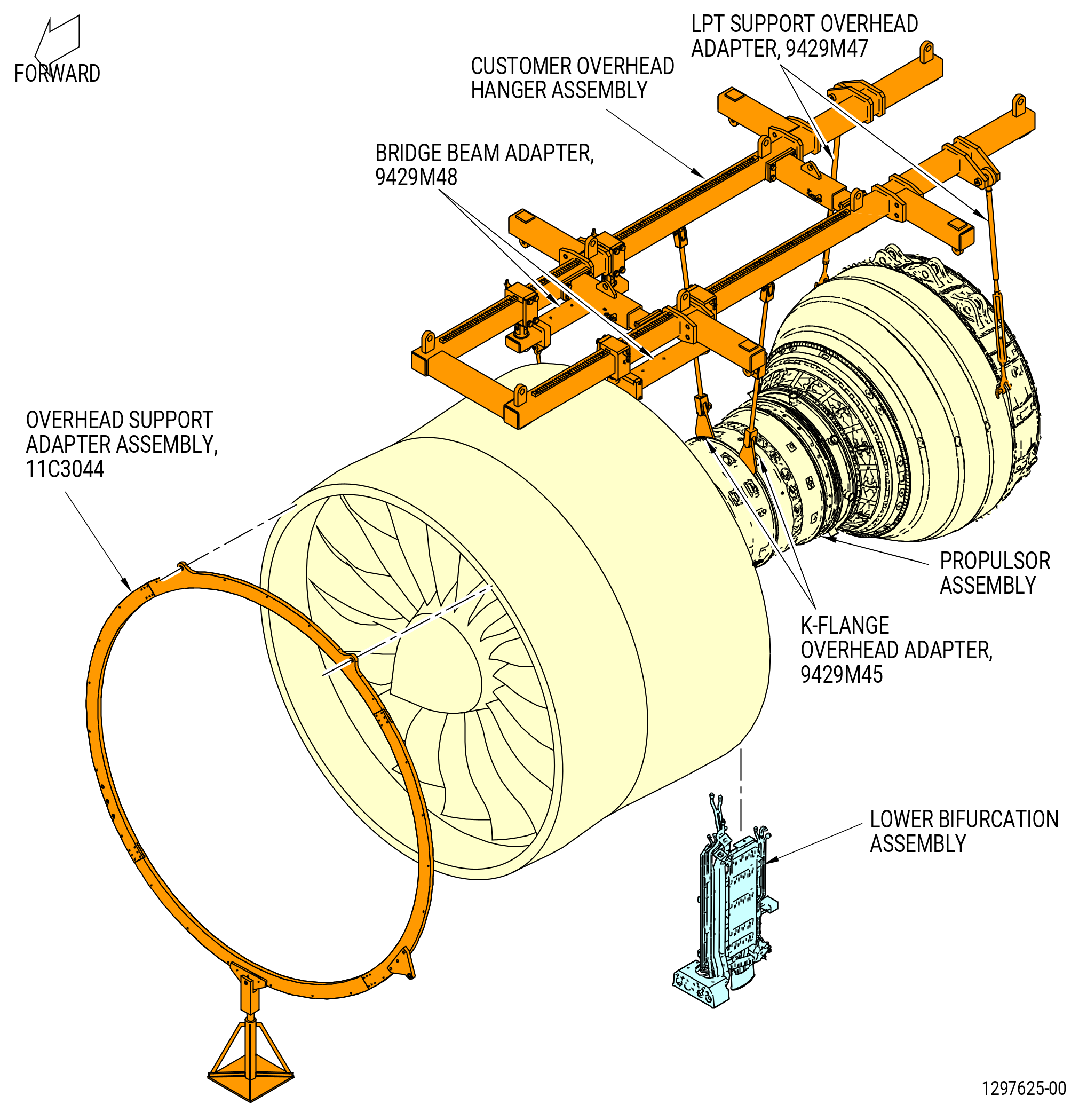
| A. | This procedure gives instructions for the installation of the lower bifurcation assembly (25-010 , 72-00-00) (SIN 09400) or (25-011 , 72-00-00) (SIN 09400). Refer to Figure 401. |
| B. | Before starting this procedure, assemble the lower bifurcation assembly. Refer to TASK 72-00-03-440-802 (72-00-03, ASSEMBLY 001) . |
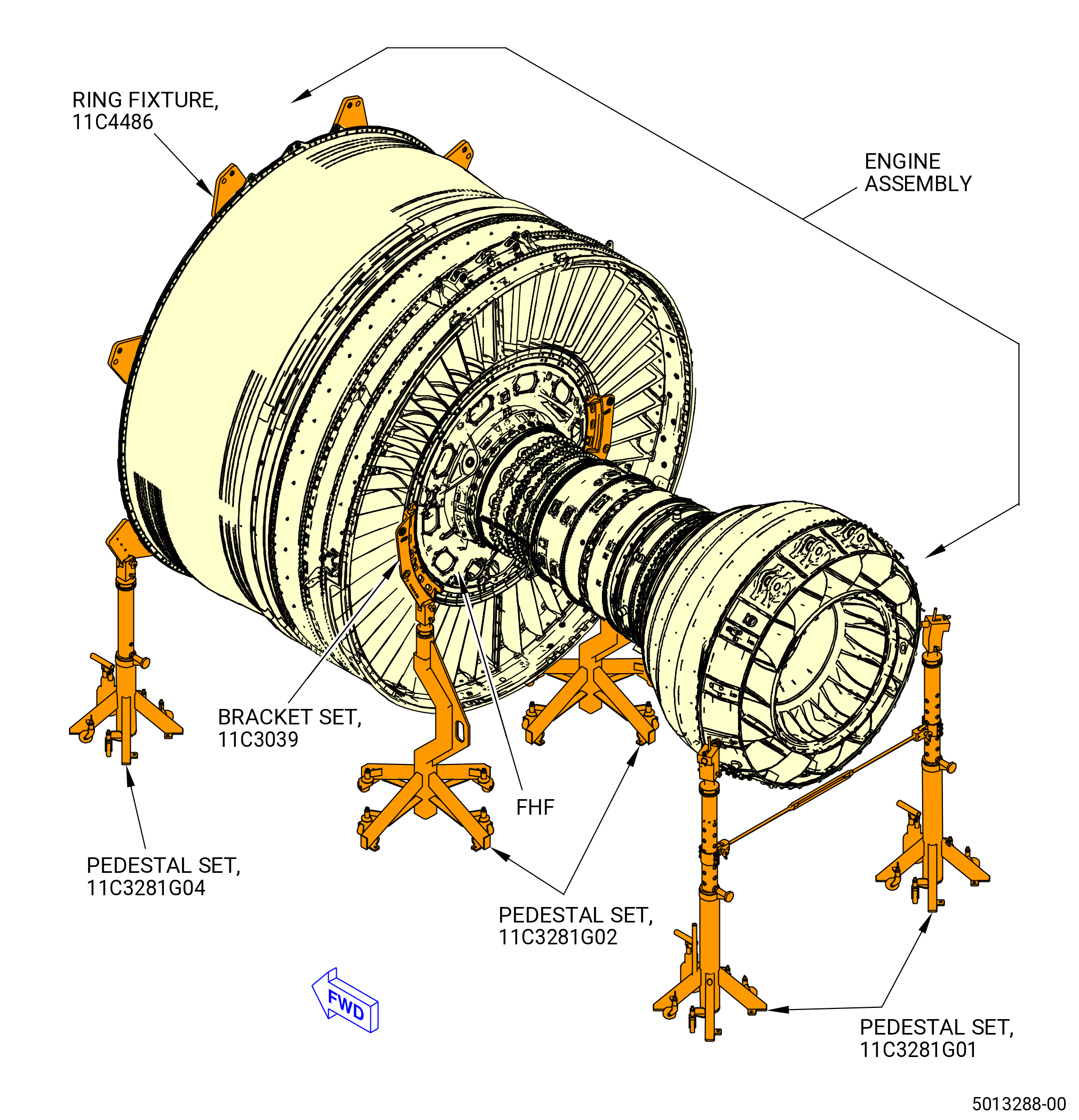
| C. | This procedure begins with the assembled engine in the horizontal position installed in the 11C3044 engine module adapter assembly attached to the customer overhead rail system, or in the 11C3281 pedestal set, and the lower bifurcation assembly installed in the 11C3251 installation fixture, at the equivalent assembly status of TASK 72-00-03-440-802 (72-00-03, ASSEMBLY 001) . |
| D. | Install the B-nuts with C10-145 safety cable. Refer to TASK 70-11-00-400-001 (FASTENER RETENTION PROCEDURES) . |
| 2 . | Tools, Equipment, and Materials. |
| NOTE: |
|
| A. | Tools and Equipment. |
| (1) | Special Tools. |
| (2) | Standard Tools and Equipment. |
|
| (3) | Locally Manufactured Tools. None. |
| B. | Consumable Materials. |
|
| C. | Referenced Procedures. |
|
| D. | Expendable Parts. |
|
| 3 . | Procedure. |
| Subtask 72-00-03-030-001 |
| A. | Deleted. |
| Subtask 72-00-03-200-001 |
| B. | Do an inspection of the tubes of the lower bifurcation assembly for black caps or other blockages as follows: |
| (1) | Use a flashlight to do an inspection of the upper and lower tube ends of the lower bifurcation assembly for black caps or other blockages. |
| Subtask 72-00-03-420-025 |
| C. | Deleted. |
| Subtask 72-00-03-420-012 |
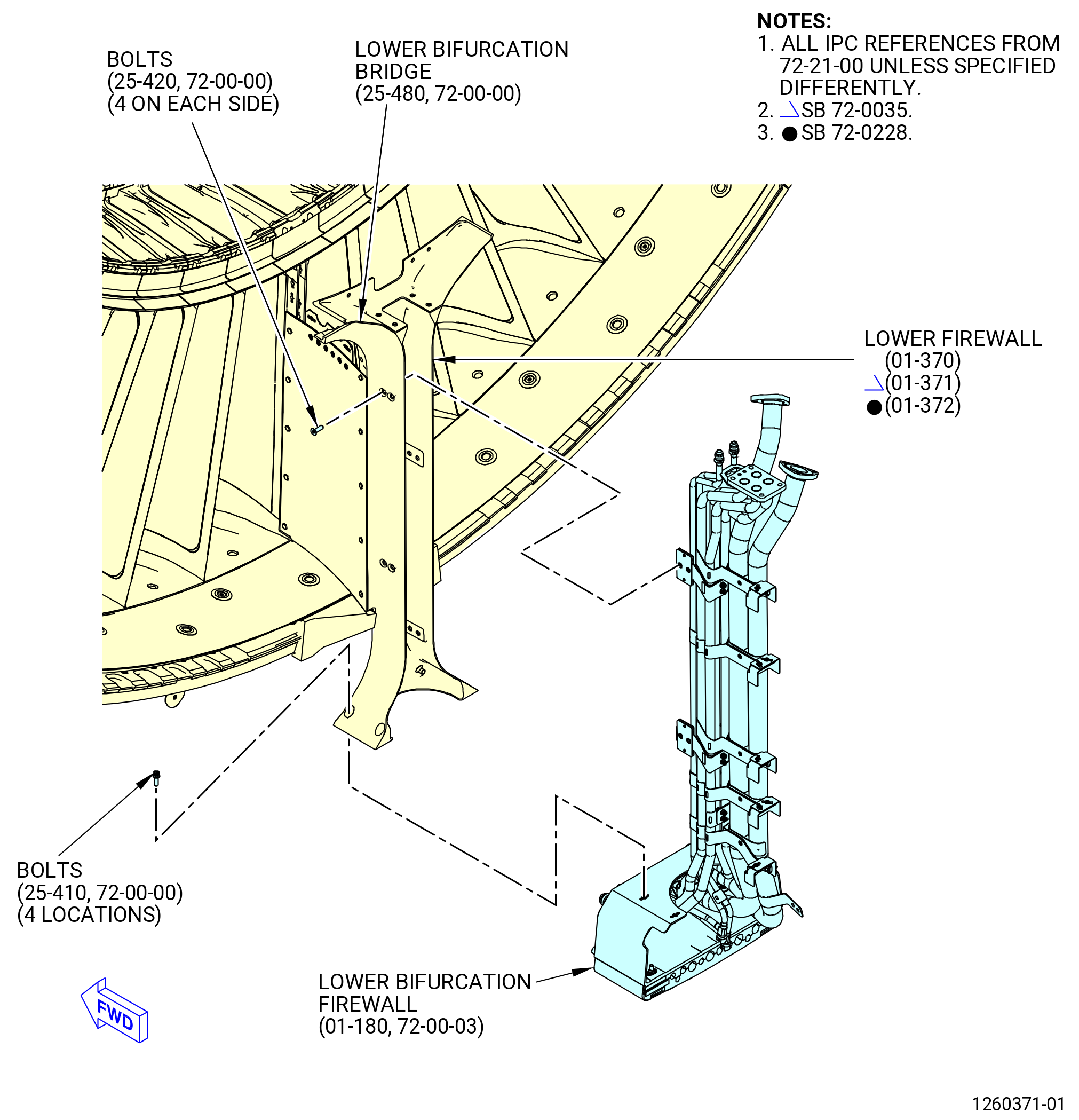
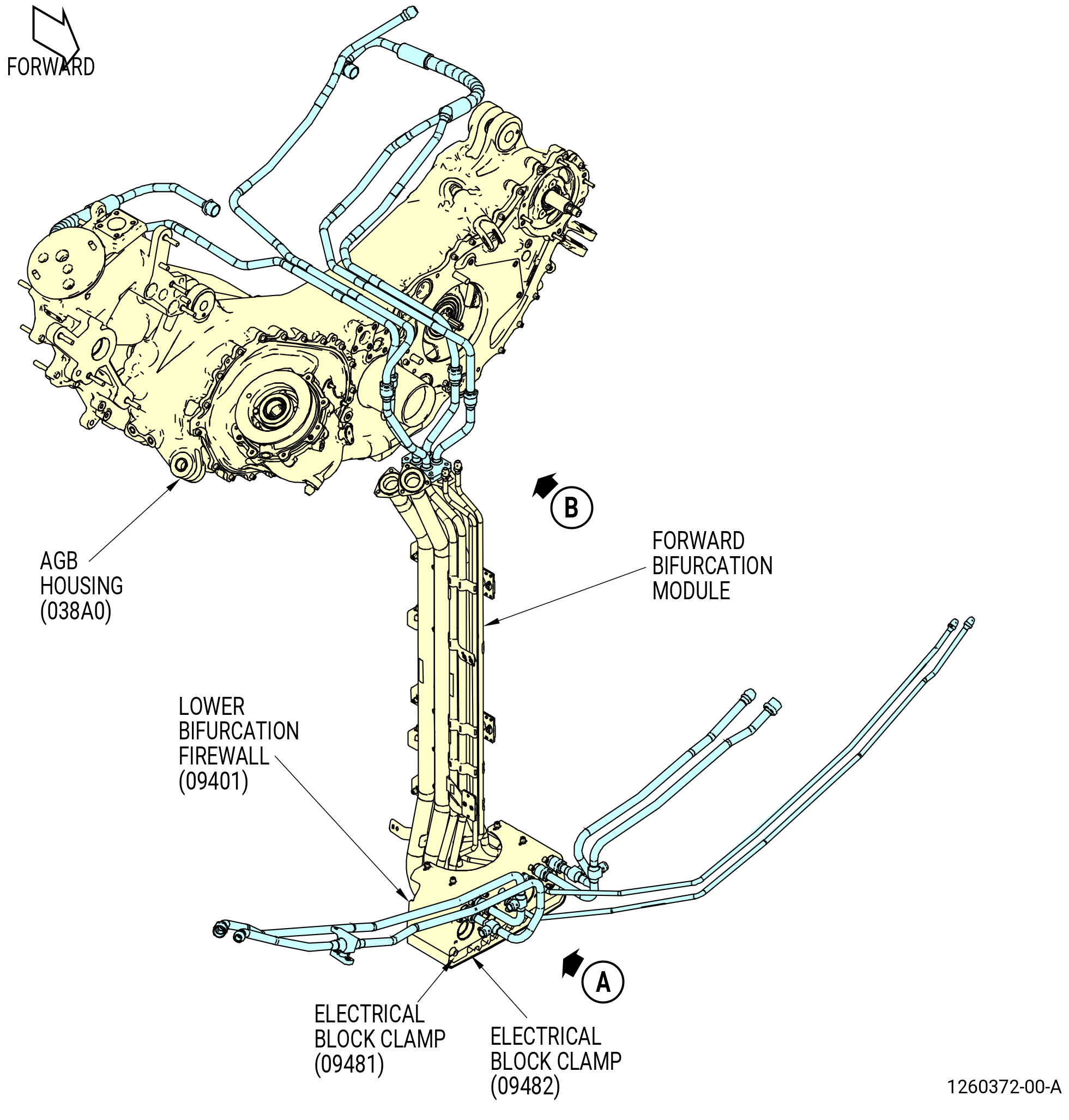
| D. | Attach the forward part of the lower bifurcation assembly to the lower firewall (01-370 , 72-21-00) (SIN 84501) or (01-371 , 72-21-00) (SIN 84501) or (01-372 , 72-21-00) (SIN 84501) and the lower bifurcation firewall (01-180) (SIN 09401) on the aft side of the fan hub frame at the 6:00 o'clock position. Refer to Figure 404, Figure 405, and do as follows: |
| CAUTION: |
|
| (1) | Place the lower bifurcation assembly with the 11C3251 installation fixture on its position as follows: |
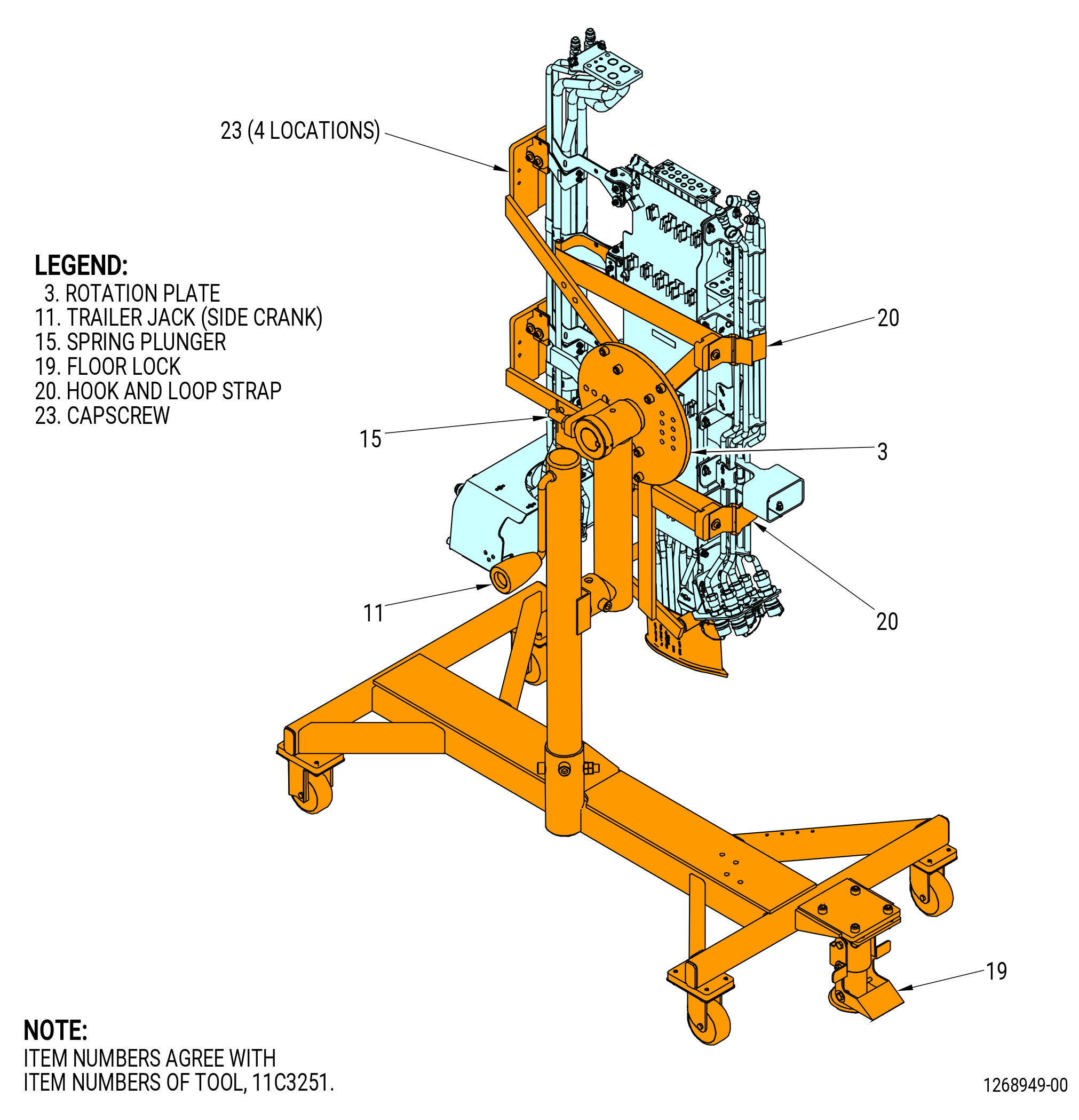
| (a) | Adjust the height of the 11C3251 installation fixture with the side crank of the trailer jack (item 11). |
| CAUTION: |
|
| (b) | Put the floor lock (item 19) in the locked (down) position. Make sure the floor lock contacts the floor. |
| (2) | Attach the forward part of the lower bifurcation assembly to the lower firewall with bolts (25-420 , 72-00-00) (SIN 99023). |
| (3) | Attach the forward part of the lower bifurcation firewall (01-180) (SIN 09401) to the lower firewall with bolts (25-410 , 72-00-00) (SIN 09420). |
| (4) | Torque the bolts (25-420 , 72-00-00) (SIN 99023) to 106 to 124 lb in. (12.0 to 14.0 Nm). |
| (5) | Torque the bolts (25-410 , 72-00-00) (SIN 09420) to 106 to 124 lb in. (12.0 to 14.0 Nm). |
| (6) | Put a cover of C10-040 Teflon tape on the heads of the bolts (25-420 , 72-00-00) (SIN 99023) or fill the drive recess in the bolt head with C10-109 wax. |
| WARNING: |
|
| (7) | Apply C01-007 RTV 106 to cover the bolt heads and fill the adjacent recess up to flush with the firewall assembly surface. |
| Subtask 72-00-03-420-026 |
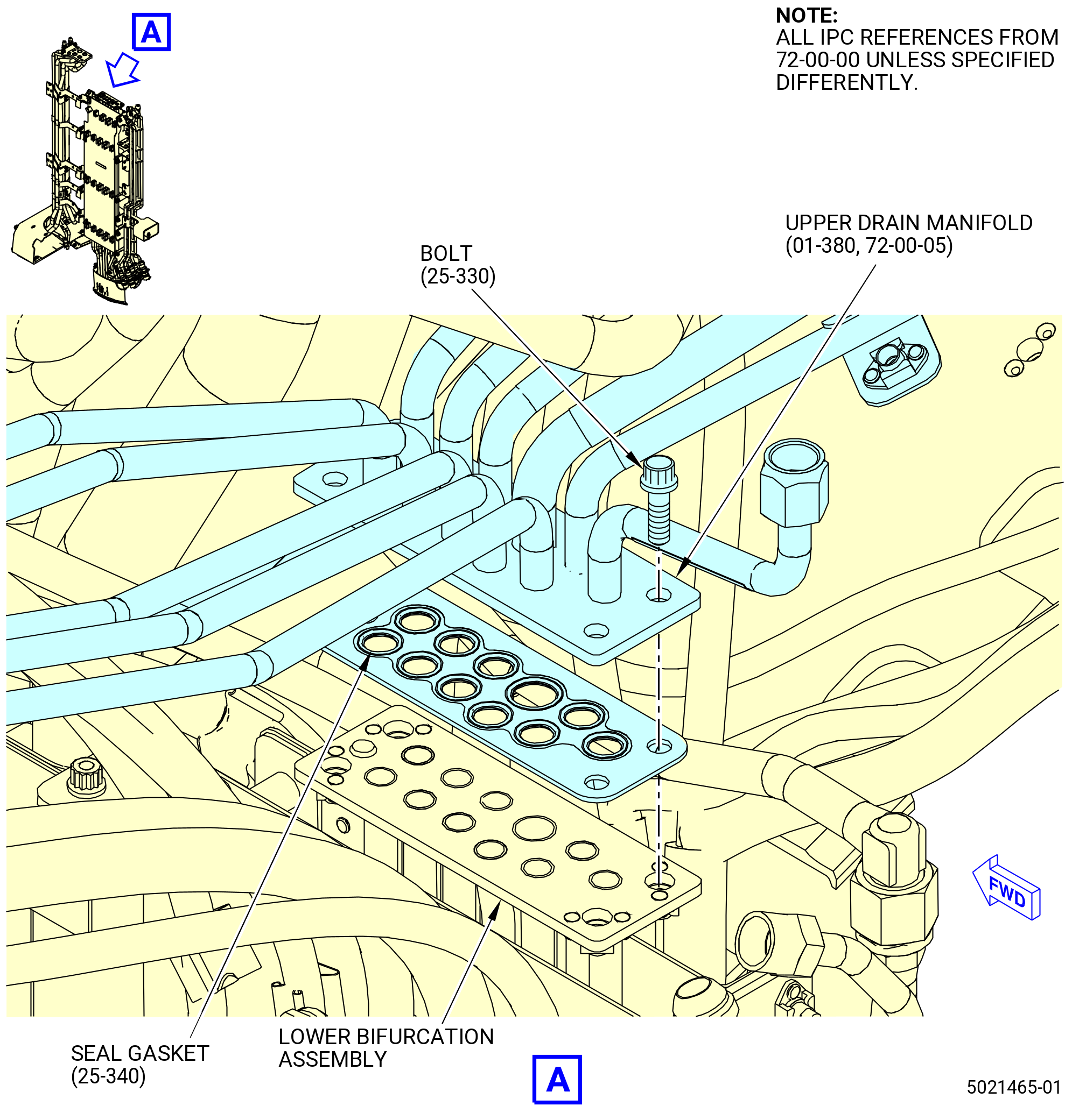
| E. | Install the upper drain manifold (01-380 , 72-00-05) (SIN 99003) to the lower bifurcation assembly. Refer to Figure 406 and do as follows: |
| (1) | Install the seal gasket (25-340 , 72-00-00) (SIN 99051) in the lower bifurcation assembly. |
| (2) | Align the upper drain manifold to the lower bifurcation assembly. |
| (3) | Attach the upper drain manifold to the lower bifurcation assembly with four machine bolts (bolts) (25-330 , 72-00-00) (SIN 99027). |
| (4) | Torque the bolts (99027) to 106-124 lb in. (12.0-14.0 N.m). |
| Subtask 72-00-03-420-027 |
| F. | Connect the lube service tubes to the aft top side of the lower bifurcation assembly. Refer to Figure 407 and do as follows: |
| WARNING: |
|
| (1) | Apply C02-019 engine oil to the B-nuts of the lube service tube (78001), (44A05), (44B06), (44A06), and (44B05). |
| (2) | Attach the lube service tube (78001) to the BIFI fill and overfill manifold, torque the B-nut to 460-540 lb in. (52.0-61.0 N.m). |
| (3) | Attach the lube service tube (44A05) to the BIFI fill and overfill manifold, torque the B-nut to 460-540 lb in. (52.0-61.0 N.m). |
| (4) | Attach the lube service tube (44B06) to the BIFI fill and overfill manifold, torque the B-nut to 460-540 lb in. (52.0-61.0 N.m). |
| (5) | Attach the lube service tube (44A06) to the BIFI fill and overfill manifold, torque the B-nut to 262-308 lb in. (29.6-34.8 N.m). |
| (6) | Attach the lube service tube (44B05) to the BIFI fill and overfill manifold, torque the B-nut to 262-308 lb in. (29.6-34.8 N.m). |
| Subtask 72-00-03-420-013 |
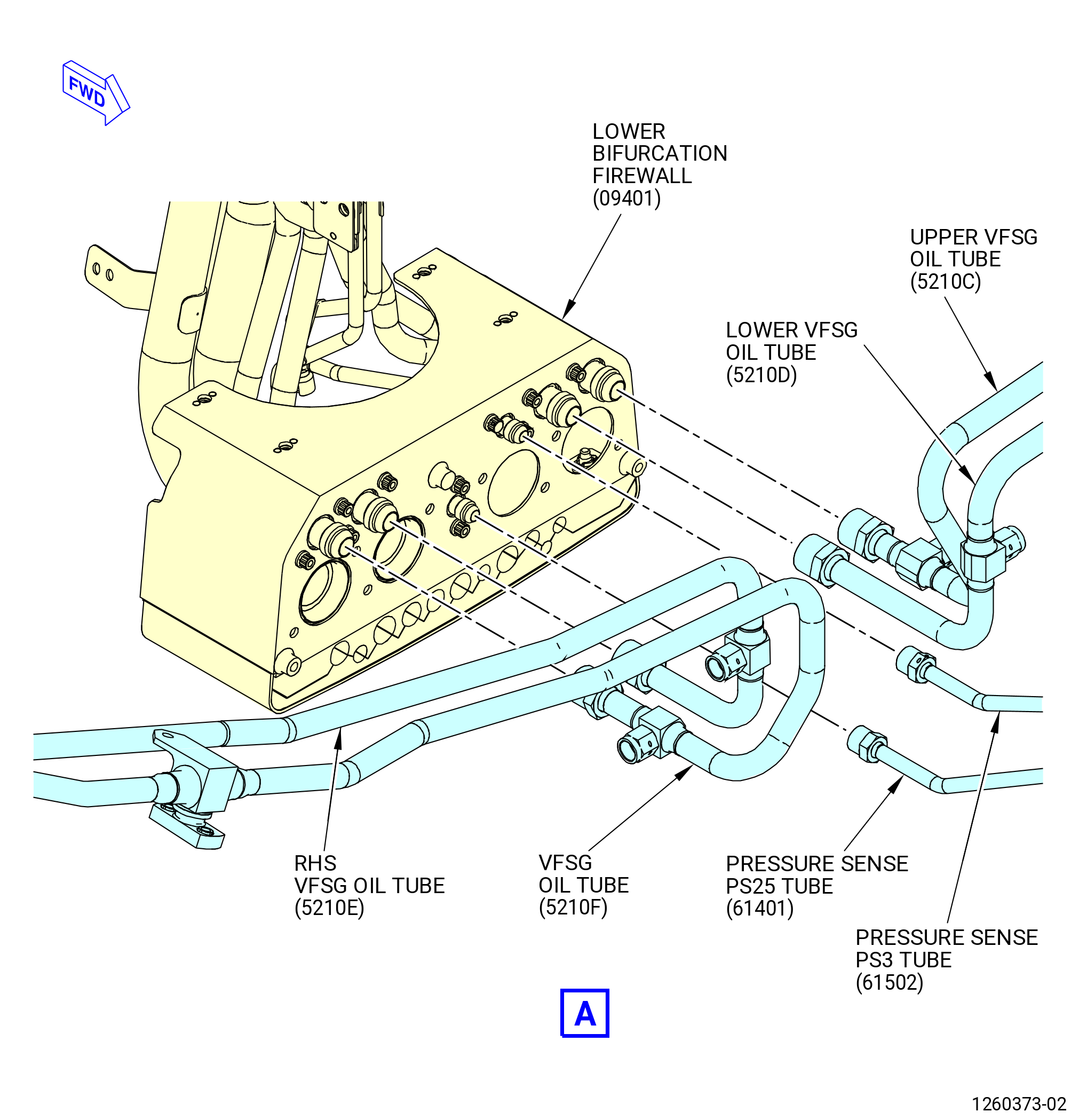
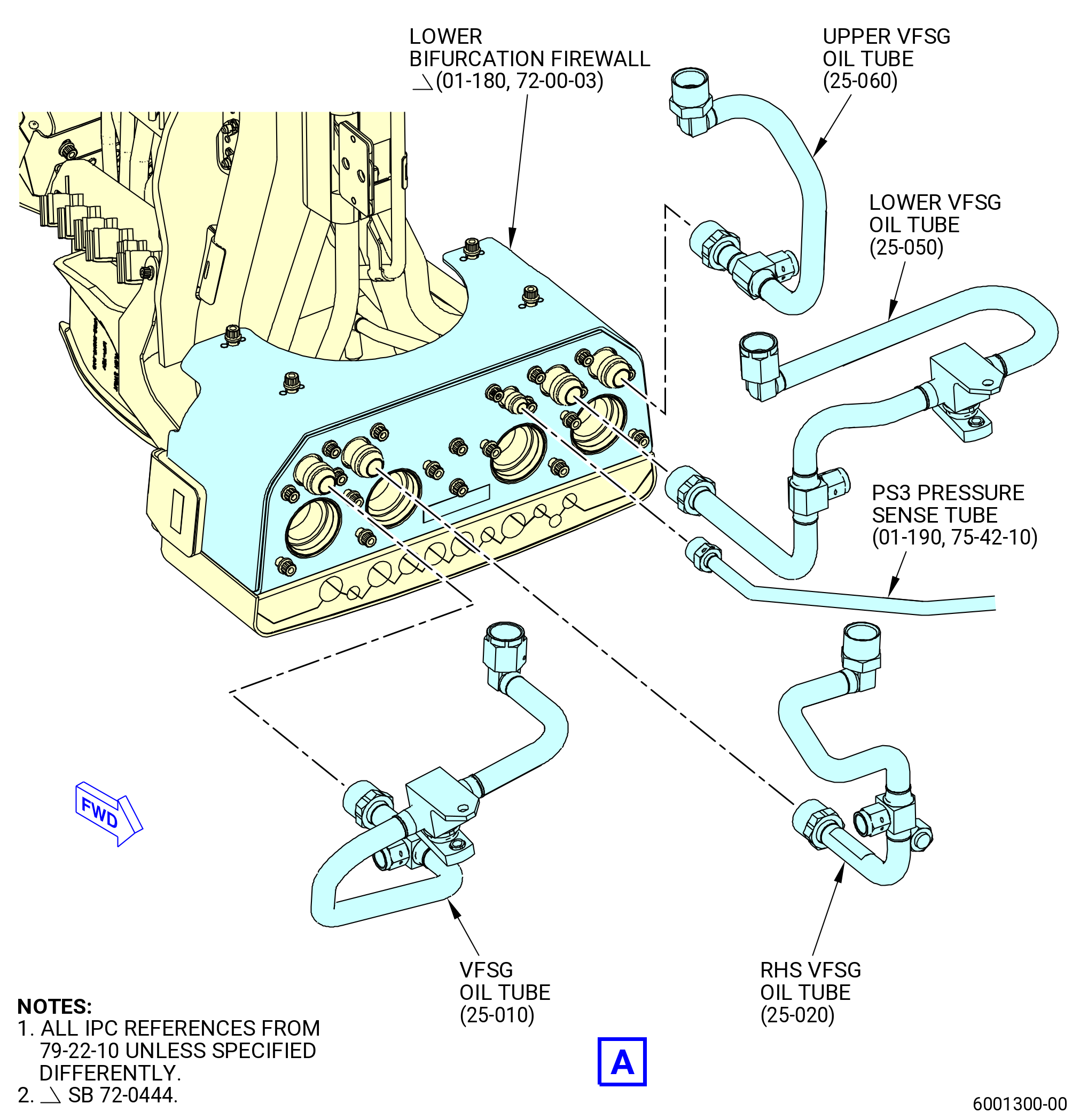
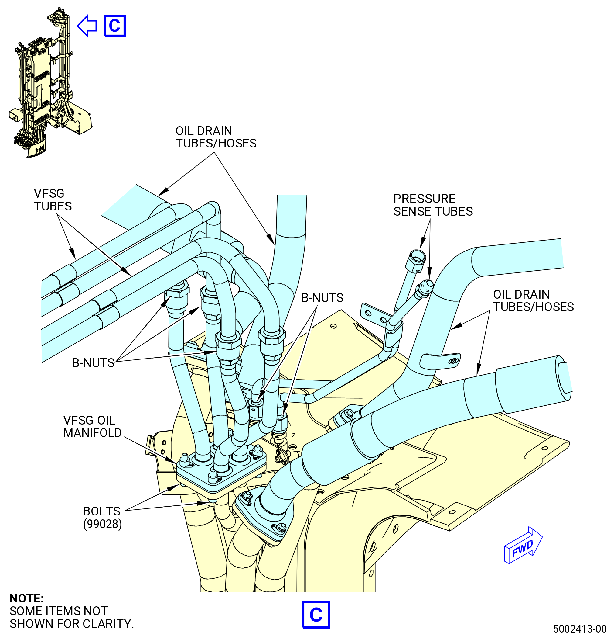
| G. | Install the frequency starter generator (VFSG) tubing to the forward part of the lower bifurcation assembly. Refer to Figure 408 and do as follows: |
| (1) | Install the VFSG tubes to the bottom of the lower bifurcation assembly. |
| Attach the upper VFSG oil tube (5210C) to the bottom right side of the lower bifurcation assembly forward looking aft (FLA). |
| (2) | Attach the lower VFSG oil tube (5210D) to the left side of the upper VFSG oil tube (5210C) on the bottom right side of the lower bifurcation assembly FLA. Refer to Figure 408. |
| (3) | Attach the RHS VFSG oil tube (5210E) to the left side of the lower VFSG oil tube (5210D) on the bottom left side of the lower bifurcation assembly FLA. |
| (4) | Attach the VFSG oil tube (5210F) to the left of the RHS VFSG oil tube (5210E) on the bottom left side of the lower bifurcation assembly FLA. |
| (5) | Torque the B-nuts of the tubes to 55-65 lb ft (75-88 N.m). |
| Subtask 72-00-03-420-014 |
| * * * PRE SB 72-0444( with PS25 Sense Line ) |
| H. | Install the pressure sense tubes to the forward part of the lower bifurcation assembly as follows: |
| (1) | Install the pressure sense lines to the bottom of the lower bifurcation assembly. |
| (2) | Attach the pressure sense PS3 tube (61502) to the left of the lower VFSG oil tube (5210D) on the bottom of the lower bifurcation assembly FLA. |
| Subtask 72-00-03-420-035 |
| * * * PRE SB 75-0035( Engines with PS25 Pressure Sense Tube and Air P25 Hose Tube ) |
| (3) | Attach the pressure sense PS25 tube (01-040 , 75-42-15) (SIN 61401) to the left and below the pressure sense PS3 tube (01-190 , 75-42-10) (SIN 61502) on the bottom of the lower bifurcation module FLA. |
| * * * END PRE SB 75-0035 |
| Subtask 72-00-03-420-036 |
| * * * SB 75-0035( Engines without PS25 Pressure Sense Tube and Air P25 Hose Tube ) |
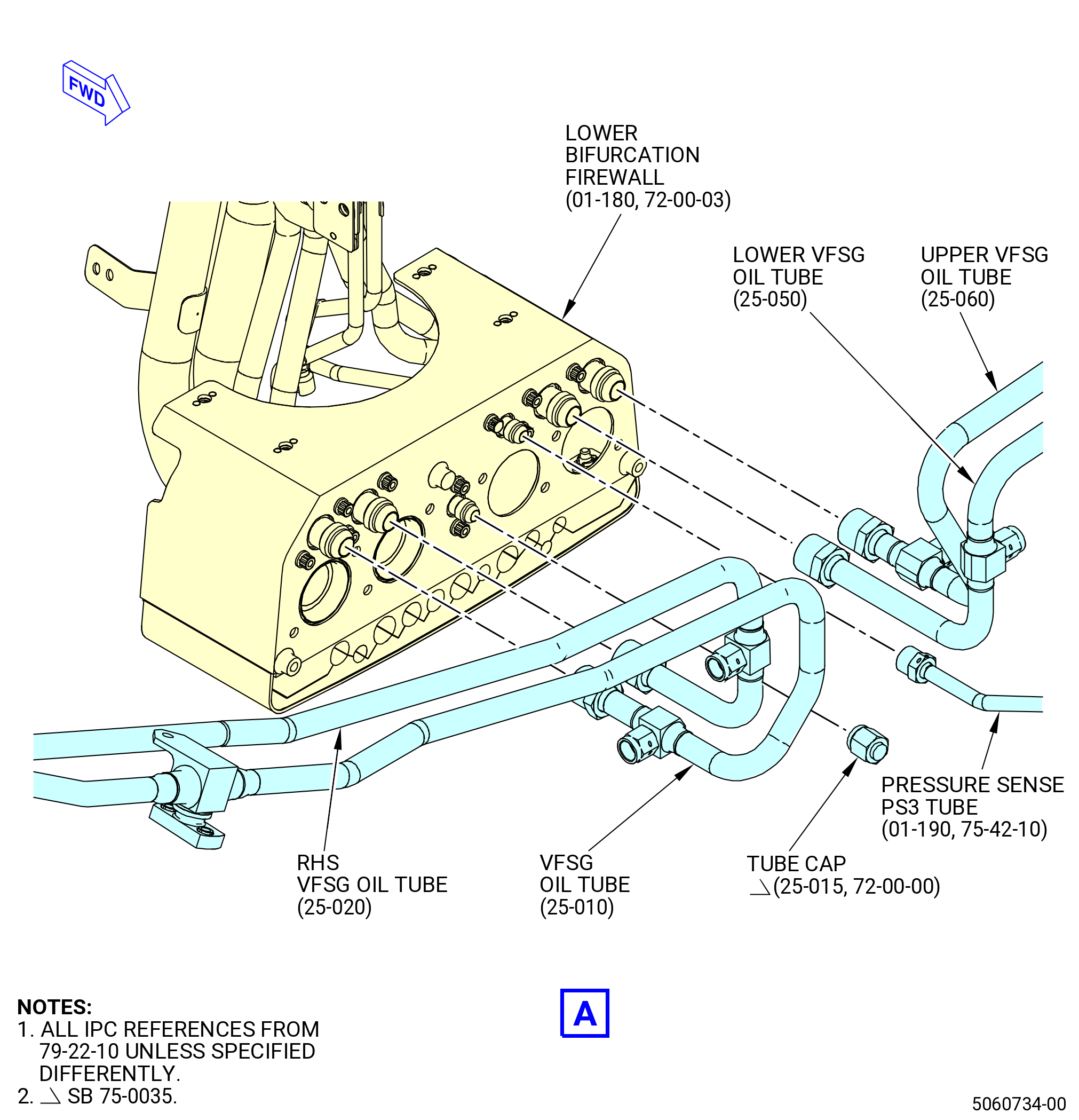
| (3).A. | Install the tube cap (25-015 , 72-00-00) (SIN 61460). Refer to Figure 408 and do as follows: |
| (a) | Attach the tube cap (25-015 , 72-00-00) (SIN 61460) to the left and below the pressure sense PS3 tube (01-190 , 75-42-10) (SIN 61502) on the bottom of the lower bifurcation module FLA. |
| (b) | Torque the tube cap (25-015 , 72-00-00) (SIN 61460) to 262 to 308 lb in. (29.6 to 34.7 Nm). |
| * * * END SB 75-0035 |
| Subtask 72-00-03-420-037 |
| (4) | Torque the B-nuts of the tubes to 262-308 lb in. (29.6-34.8 N.m). |
| (5) | Safety the B-nut of the pressure sense PS3 tube (61502) to the bottom of the lower bifurcation assembly with C10-145 safety cable. |
| * * * END PRE SB 72-0444 |
| Subtask 72-00-03-420-039 |
| * * * SB 72-0444( without PS25 Sense Line ) |
| H.A. | Install the pressure sense tubes to the forward part of the lower bifurcation assembly as follows: |
| (1) | Install the pressure sense lines to the bottom of the lower bifurcation assembly. |
| (2) | Attach the pressure sense PS3 tube (01-190 , 75-42-10) (SIN 61502) to the left of the lower VFSG oil tube (25-050 , 79-22-10) (SIN 5210D) on the bottom of the lower bifurcation assembly FLA. |
| (3) | Torque the B-nuts of the tubes to 262 to 308 lb in. (29.6 to 34.8 Nm). |
| (4) | Safety the B-nut of the pressure sense PS3 tube (01-190 , 75-42-10) (SIN 61502) to the bottom of the lower bifurcation assembly with C10-145 safety cable. |
| * * * END SB 72-0444 |
|
|
|
| Subtask 72-00-03-420-028 |
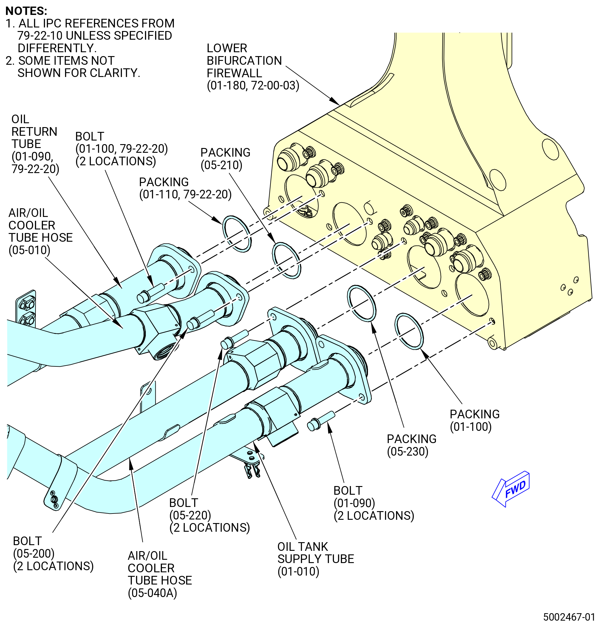
| I. | Install the oil tank tubes to the lower bifurcation firewall (09401) as follows. Refer to Figure 409. |
| (1) | Install the packing (01-110 , 79-22-20) (SIN 45355) to the lower bifurcation firewall (09401). |
| (2) | Align the oil return tube (01-090 , 79-22-20) (SIN 45302) to the lower bifurcation firewall (01-180) (SIN 09401). |
| (3) | Attach the oil return tube (01-090 , 79-22-20) (SIN 45302) to the lower bifurcation firewall (01-180) (SIN 09401) with two bolts (01-100 , 79-22-20) (SIN 45328). |
| (4) | Torque the bolts (45328) to 106-124 lb in. (12.0-14.0 N.m). |
| (5) | Install the air/oil cooler tube packing (packing) (05-210 , 79-22-10) (SIN 44854) to the lower bifurcation firewall (09401). |
| (6) | Align the air/oil cooler tube hose (44801) to the lower bifurcation firewall (09401). |
| (7) | Attach the air/oil cooler tube hose (44801) to the lower bifurcation firewall (09401) with two bolts (44825). |
| (8) | Torque the bolts (44825) to 106-124 lb in. (12.0-14.0 N.m). |
| (9) | Install the air/oil cooler tube packing (packing) (05-230 , 79-22-10) (SIN 44952) to the lower bifurcation firewall (09401). |
| (10) | Align the air/oil cooler tube hose (44900) to the lower bifurcation firewall (09401). |
| (11) | Attach the air/oil cooler tube hose (44900) to the lower bifurcation firewall (09401) with two bolts (44924). |
| (12) | Torque the bolts (44924) to 106-124 lb in. (12.0-14.0 N.m). |
| (13) | Install the packing (01-100 , 79-22-10) (SIN 44056) to the lower bifurcation firewall (09401). |
| (14) | Align the oil tank supply tube (44000) to the lower bifurcation firewall (09401). |
| (15) | Attach the oil tank supply tube (44000) to the lower bifurcation firewall (09401) with two bolts (44026). |
| (16) | Torque the bolts (44026) to 106-124 lb in. (12.0-14.0 N.m). |
| Subtask 72-00-03-420-015 |
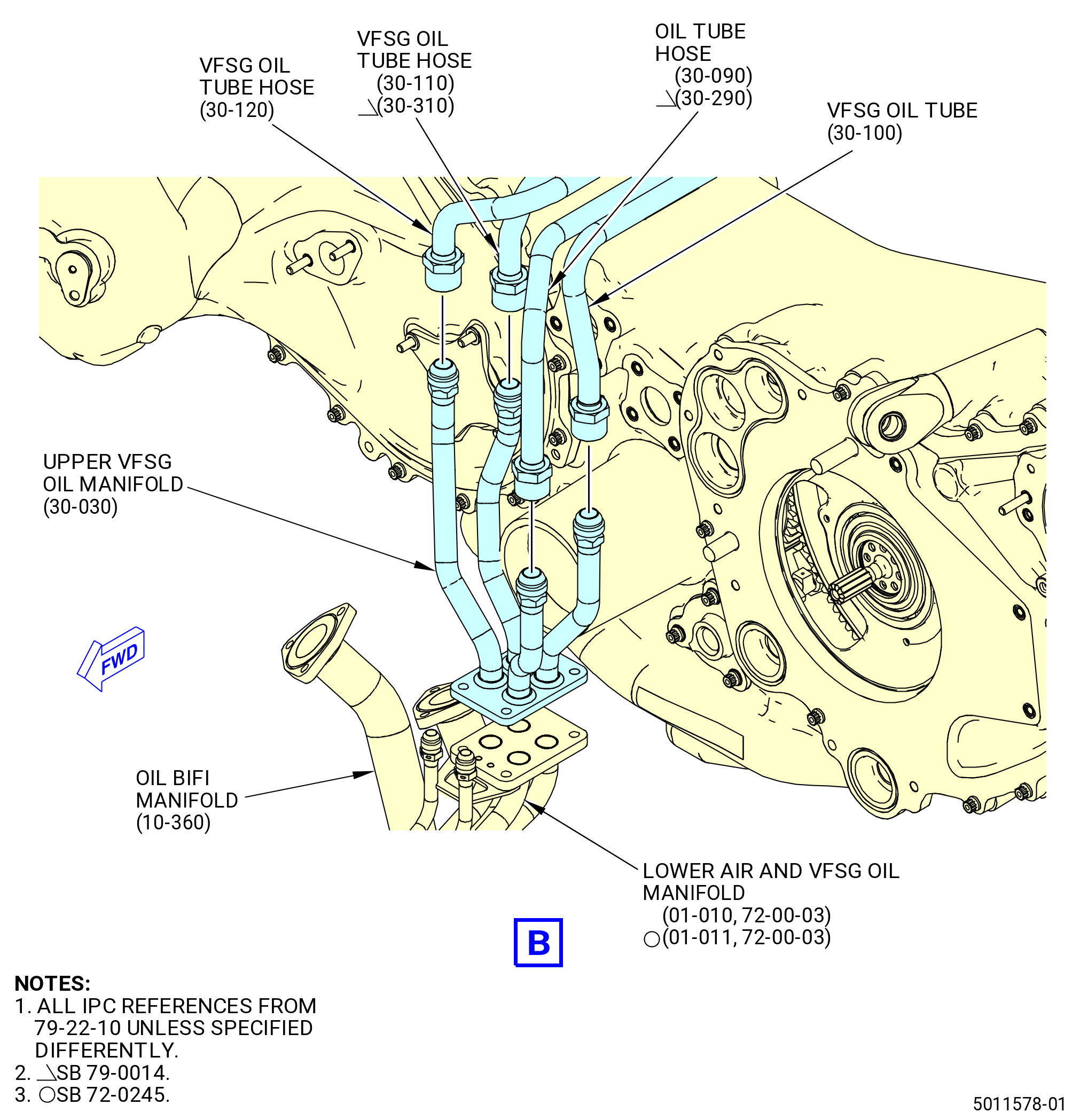
| J. | Install the VFSG tubes at the top of the lower bifurcation assembly. Refer to Figure 408 and do as follows: |
| (1) | Attach the VFSG oil tube (30-100 , 79-22-10) (SIN 5210B) to the aft VFSG tube at the top right side of the lower bifurcation assembly. |
| Subtask 72-00-03-420-029 |
| * * * PRE SB 79-0014( Non-Optimized VFSG Cooling System ) |
| (2) | Attach the oil tube hose (30-090 , 79-22-10) (SIN 5210J) to the forward VFSG tube at the top right side of the lower bifurcation assembly. |
| * * * END PRE SB 79-0014 |
| Subtask 72-00-03-420-030 |
| * * * SB 79-0014( Optimized VFSG Cooling System ) |
| (2).A. | Attach the oil VFSG return tube (oil tube hose) (30-290 , 79-22-10) (SIN 5210T) to the forward VFSG tube at the top right side of the lower bifurcation assembly. |
| * * * END SB 79-0014 |
| Subtask 72-00-03-420-031 |
| (3) | Attach the VFSG oil tube hose (30-120 , 79-22-10) (SIN 5210K) to the forward VFSG tube at the top left side of the lower bifurcation assembly. |
| Subtask 72-00-03-420-032 |
| * * * PRE SB 79-0014( Non-Optimized VFSG Cooling System ) |
| (4) | Attach the VFSG oil tube hose (30-110 , 79-22-10) (SIN 5210U) to the aft VFSG tube at the top left side of the lower bifurcation assembly. |
| * * * END PRE SB 79-0014 |
| Subtask 72-00-03-420-033 |
| * * * SB 79-0014( Optimized VFSG Cooling System ) |
| (4).A. | Attach the oil VFSG tube (30-310 , 79-22-10) (SIN 5210Y) to the aft VFSG tube at the top left side of the lower bifurcation assembly. |
| * * * END SB 79-0014 |
| Subtask 72-00-03-420-034 |
| (5) | Torque the B-nuts on the tubes to 55-65 lb ft (75-88 N.m). |
| (6) | Install the gasket (30-020 , 79-22-10) (SIN 99050) in the lower air and VFSG oil manifold (01-010) (SIN 99002) or (01-011) (SIN 99002). |
| (7) | Align the upper VFSG oil manifold (30-030 , 79-22-10) (SIN 99007) to the lower air and VFSG oil manifold (01-010) (SIN 99002) or (01-011) (SIN 99002). |
| (8) | Attach the upper VFSG oil manifold (30-030 , 79-22-10) (SIN 99007) to the lower air and VFSG oil manifold (01-010) (SIN 99002) or (01-011) (SIN 99002) and the bracket (01-015) (SIN 9901V) with four bolts (30-010 , 79-22-10) (SIN 99028). |
| (9) | Torque the bolts (30-010 , 79-22-10) (SIN 99028) to 106-124 lb in. (12.0-14.0 N.m). |
| Subtask 72-00-03-440-037 |
| * * * PRE SB 72-0444( with PS25 Sense Line ) |
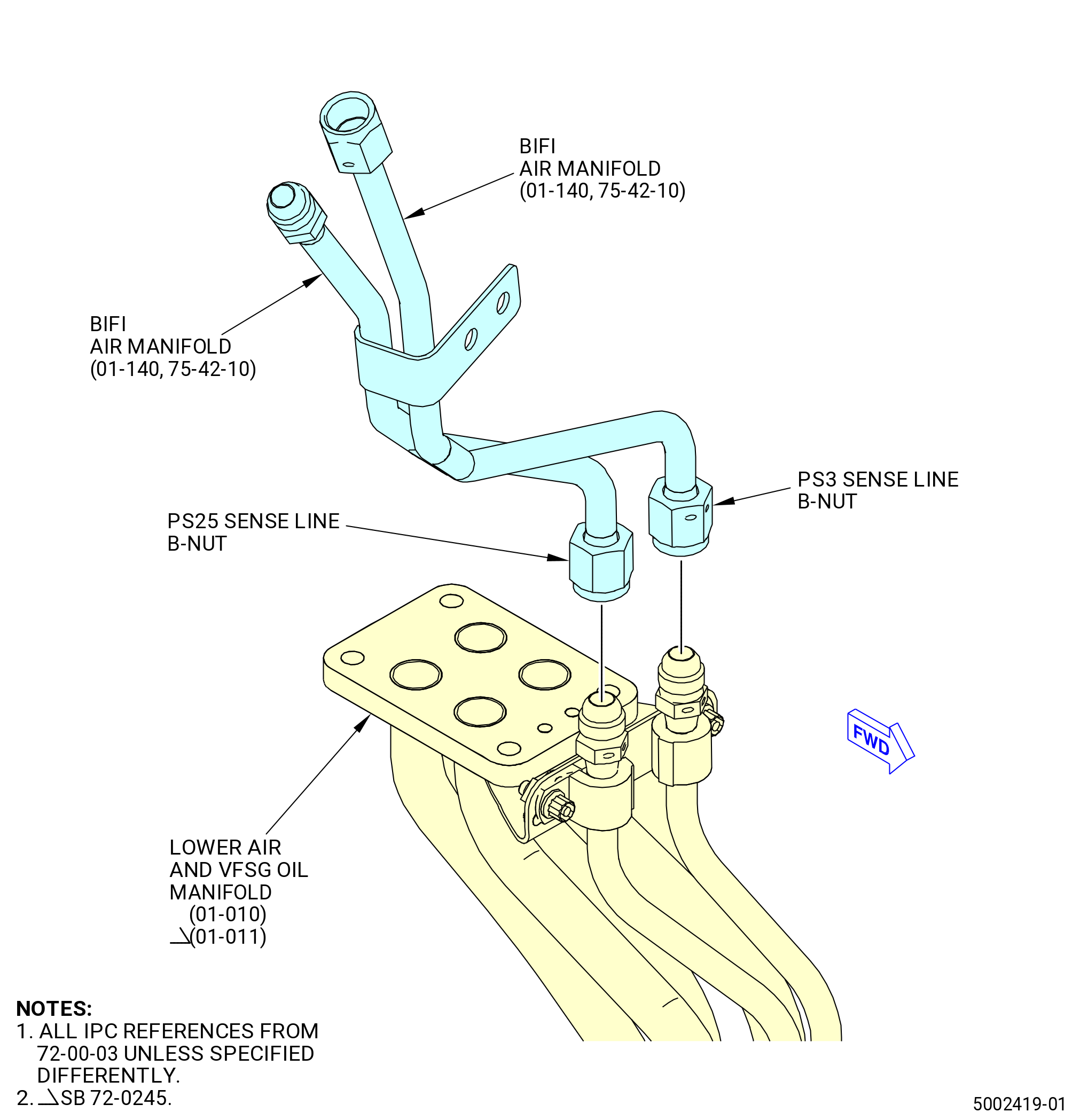
| K. | Install the sense tubes to the top of the lower bifurcation assembly. Refer to Figure 410 and do as follows: |
| (1) | Attach the PS3 sense line from the BIFI air manifold (01-140 , 75-42-10) (SIN 99008) to the lower air and VFSG oil manifold (01-010) (SIN 99002) or (01-011) (SIN 99002). |
| (2) | Triple torque the BIFI air manifold (SIN 99008) PS3 sense line B-nut to 262-308 lb in. (29.6-34.8 N.m). Refer to TASK 70-51-00-400-004 (TIGHTENING PRACTICES AND TORQUE VALUES). |
| (3) | Safety the PS3 sense line from the BIFI air manifold (SIN 99008) with C10-145 safety cable. Refer to TASK 70-11-00-400-001 (FASTENER RETENTION PROCEDURES). |
| (4) | Attach the PS25 sense line from the BIFI air manifold (01-140 , 75-42-10) (SIN 99008) to the lower air and VFSG oil manifold (01-010) (SIN 99002) or (01-011) (SIN 99002). |
| (5) | Triple torque the BIFI air manifold (SIN 99008) PS25 sense line B-nut to 262-308 lb in. (29.6-34.8 N.m). Refer to TASK 70-51-00-400-004 (TIGHTENING PRACTICES AND TORQUE VALUES). |
| (6) | Safety the PS25 sense line from the BIFI air manifold (SIN 99008) with C10-145 safety cable. Refer to TASK 70-11-00-400-001 (FASTENER RETENTION PROCEDURES). |
| * * * END PRE SB 72-0444 |
| Subtask 72-00-03-440-047 |
| * * * SB 72-0444( without PS25 Sense Line ) |
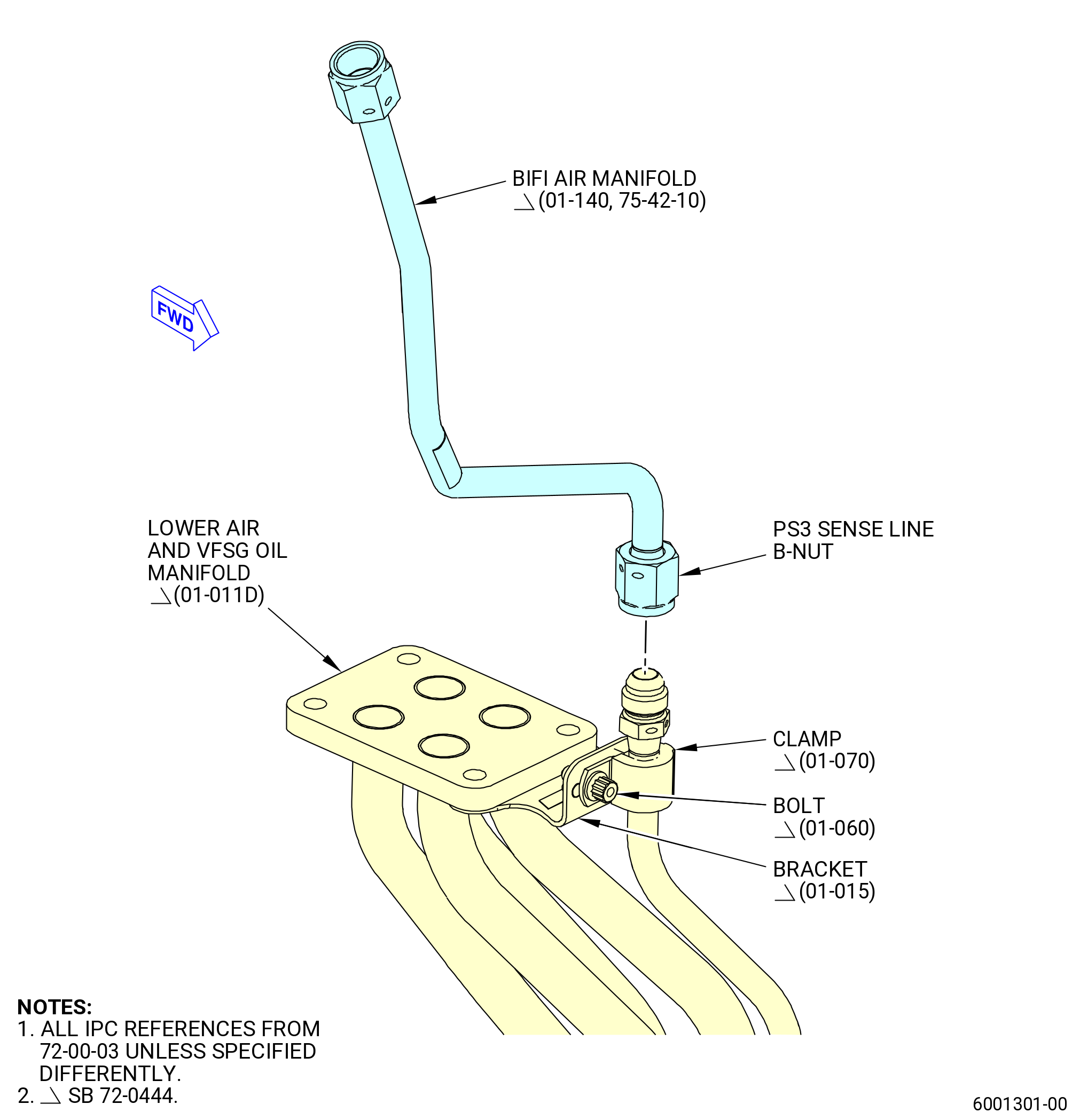
| K.A. | Install the sense tubes to the top of the lower bifurcation assembly. Refer to Figure 410 and do as follows: |
| (1) | Attach the PS3 sense line from the BIFI air tube (01-140 , 75-42-10) (SIN 99008) to the lower air and VFSG oil manifold (01-011D) (SIN 99002). |
| (2) | Triple torque the BIFI air tube (01-140 , 75-42-10) (SIN 99008) PS3 sense line B-nut to 262 to 308 lb in. (29.6 to 34.8 Nm). Refer to TASK 70-51-00-400-004 (TIGHTENING PRACTICES AND TORQUE VALUES). |
| (3) | Safety the PS3 sense line from the BIFI air manifold (01-140 , 75-42-10) (SIN 99008) with C10-145 safety cable. Refer to TASK 70-11-00-400-001 (FASTENER RETENTION PROCEDURES). |
| WARNING: |
|
| (4) | Apply C02-019 engine oil or C02-023 engine oil to the bolt (01-060) (SIN 9902B). |
| (5) | Attach the lower air and VFSG oil manifold (01-011D) (SIN 99002) to the bracket (01-015) (SIN 9901V) with one clamp (01-070) (SIN 99083) and a bolt (01-060) (SIN 9902B). |
| (6) | Torque the bolt (01-060) (SIN 9902B) to 32 to 38 lb in. (3.7 to 4.3 Nm). |
| * * * END SB 72-0444 |
|
|
| Subtask 72-00-03-420-022 |
| L. | Deleted. |
| Subtask 72-00-03-420-023 |
| L.A. | Deleted. |
| Subtask 72-00-03-420-018 |
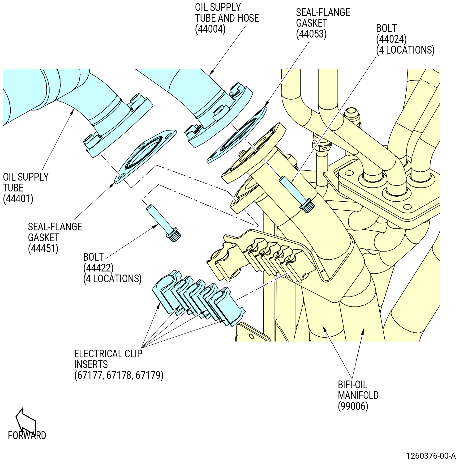
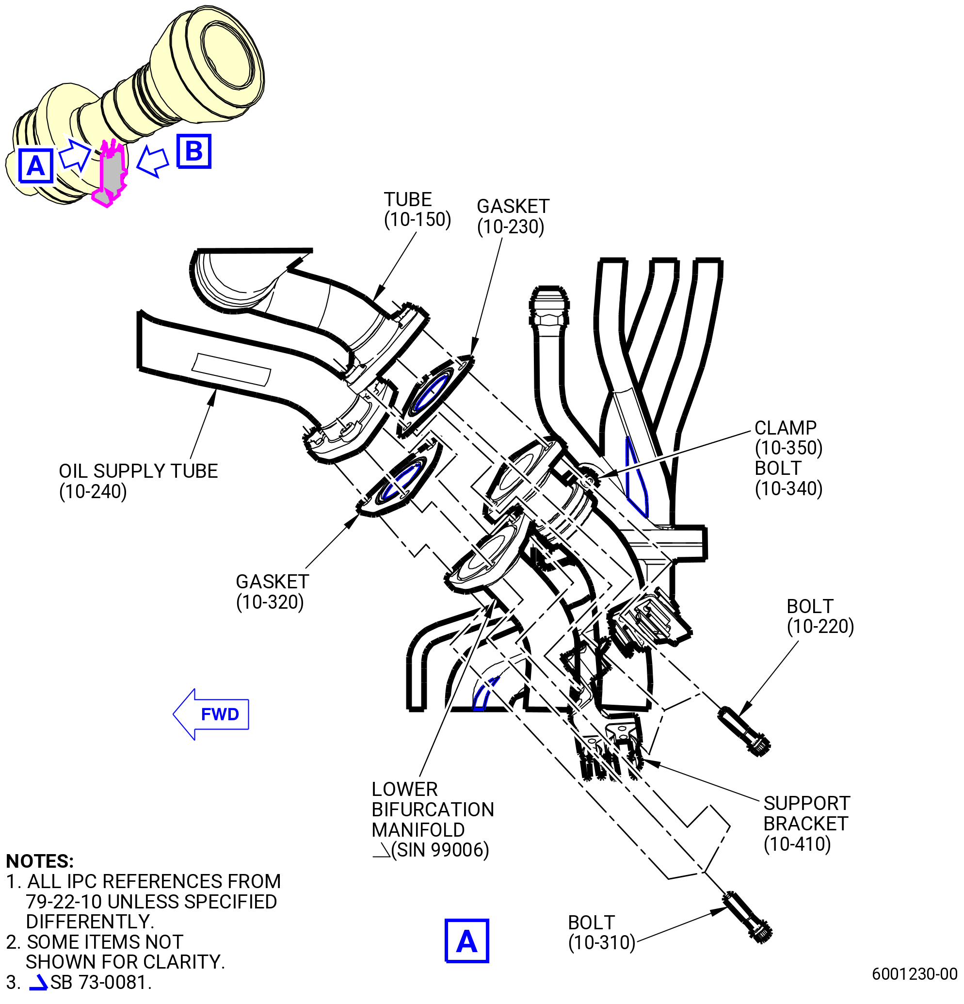
| M. | Attach the oil tank tubing to the top left hand side of the lower bifurcation assembly. Refer to Figure 413 and do as follows: |
| (1) | Attach the oil supply tube (44401) to the forward tube on the top left hand side of the lower bifurcation assembly as follows: |
| WARNING: |
|
| (a) | Apply C02-019 engine oil or C02-023 engine oil to seal-flange gasket (10-320 , 79-22-10) (SIN 44451) and the retaining plate attached to the BIFI oil manifold tube (99006). |
| (b) | Put the seal-flange gasket (10-320 , 79-22-10) (SIN 44451) between the oil supply tube (44401) and the BIFI oil manifold tube (99006). |
| (c) | Attach the tubes with the bolts (44422). |
| (2) | Attach the oil supply tube hose (44004) to the aft tube on the right hand side of the top of the lower bifurcation assembly as follows: |
| WARNING: |
|
| (a) | Apply C02-019 engine oil or C02-023 engine oil to seal-flange gasket (10-230 , 79-22-10) (SIN 44053) and the retaining plate attached to the BIFI oil manifold tube (99006). |
| (b) | Put the seal-flange gasket (10-230 , 79-22-10) (SIN 44053) between the oil supply tube hose (44004) and the BIFI oil manifold tube (99006). |
| (c) | Attach the tubes with the bolts (44024). |
| Subtask 72-00-03-420-041 |
| * * * PRE SB 73-0081( Engine with Clip Inserts ) |
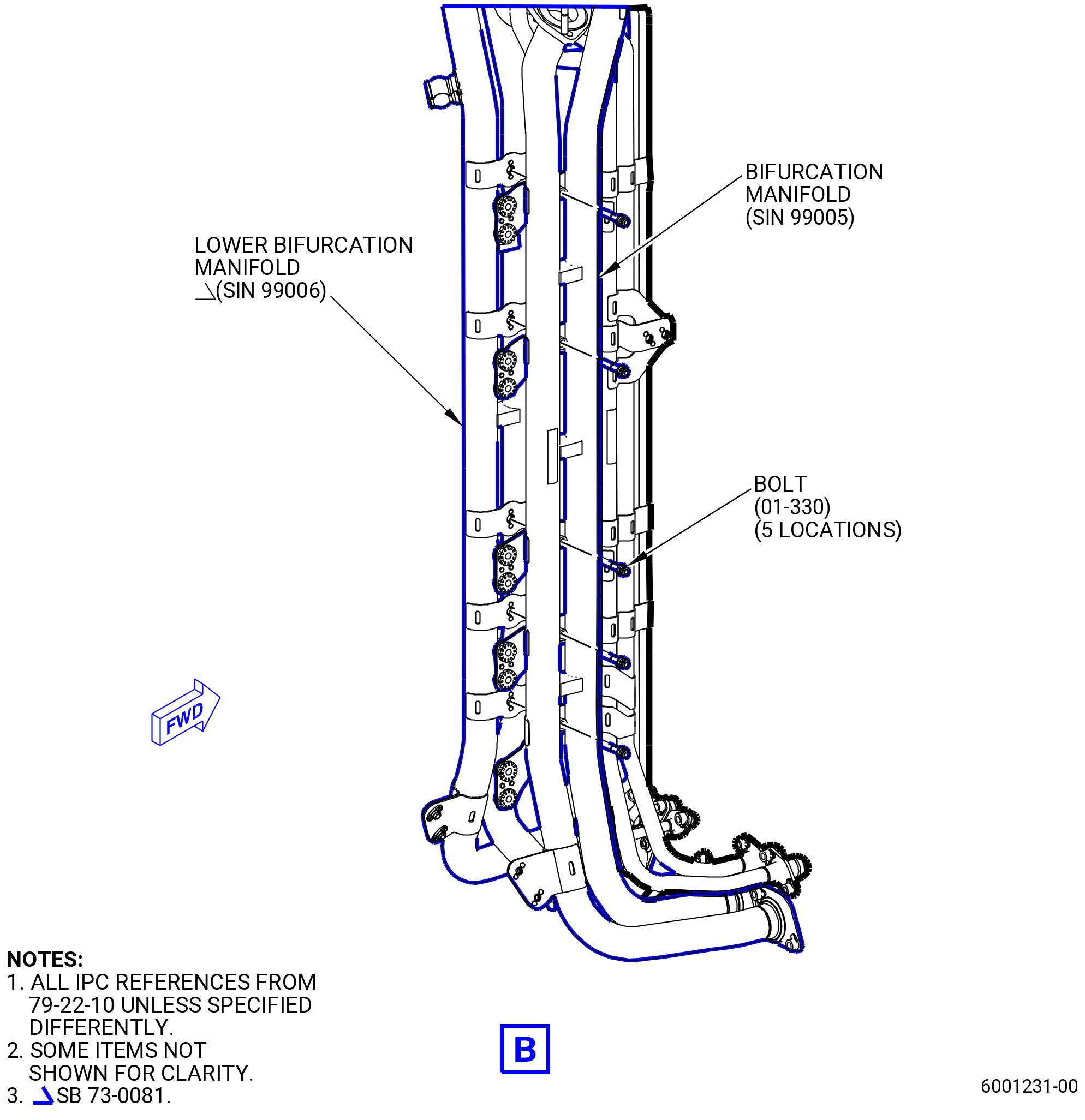
| (3) | Install the electrical clip inserts (67177), (67178), (67179) in the clips on the bracket attached to the BIFI manifold (99006). |
| NOTE: |
|
| * * * END PRE SB 73-0081 |
| Subtask 72-00-03-420-042 |
| (4) | Torque the bolts (44024) and (44422) to 106-124 lb in. (12.0-14.0 N.m). |
| (5) | Attach the oil lines to the lower bifurcation manifold (SIN 99006) with the clamp (10-350 , 79-22-10) (SIN 99085) and bolt (10-340 , 79-22-10) (SIN 9902D). |
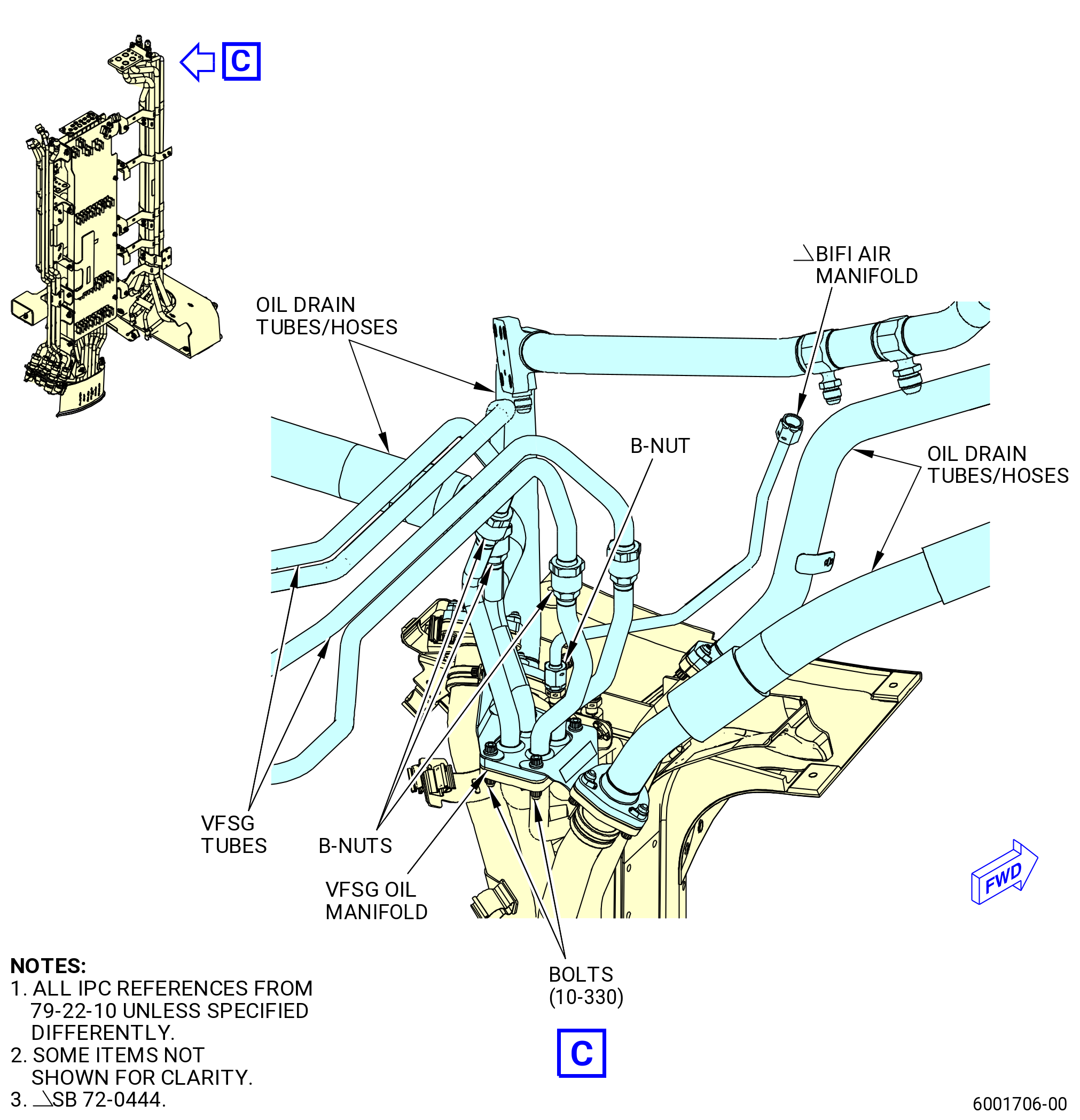
| (6) | Install and torque the five bolts (10-330 , 79-22-10) (SIN 99028) to 106 to 124 lb in. (11.9 to 14.0 Nm). |
| (7) | Torque the bolt (10-340 , 79-22-10) (SIN 9902D) to 51 to 59 lb in. (5.7 to 6.6 Nm). |
| (8) | Install and torque the bolts (25-250 , 72-00-00) (SIN 67126) and (25-255 , 72-00-00) (SIN 09424) to 32 to 38 lb in. (3.6 to 4.2 Nm). |
|
|
|
| Subtask 72-00-03-440-038 |
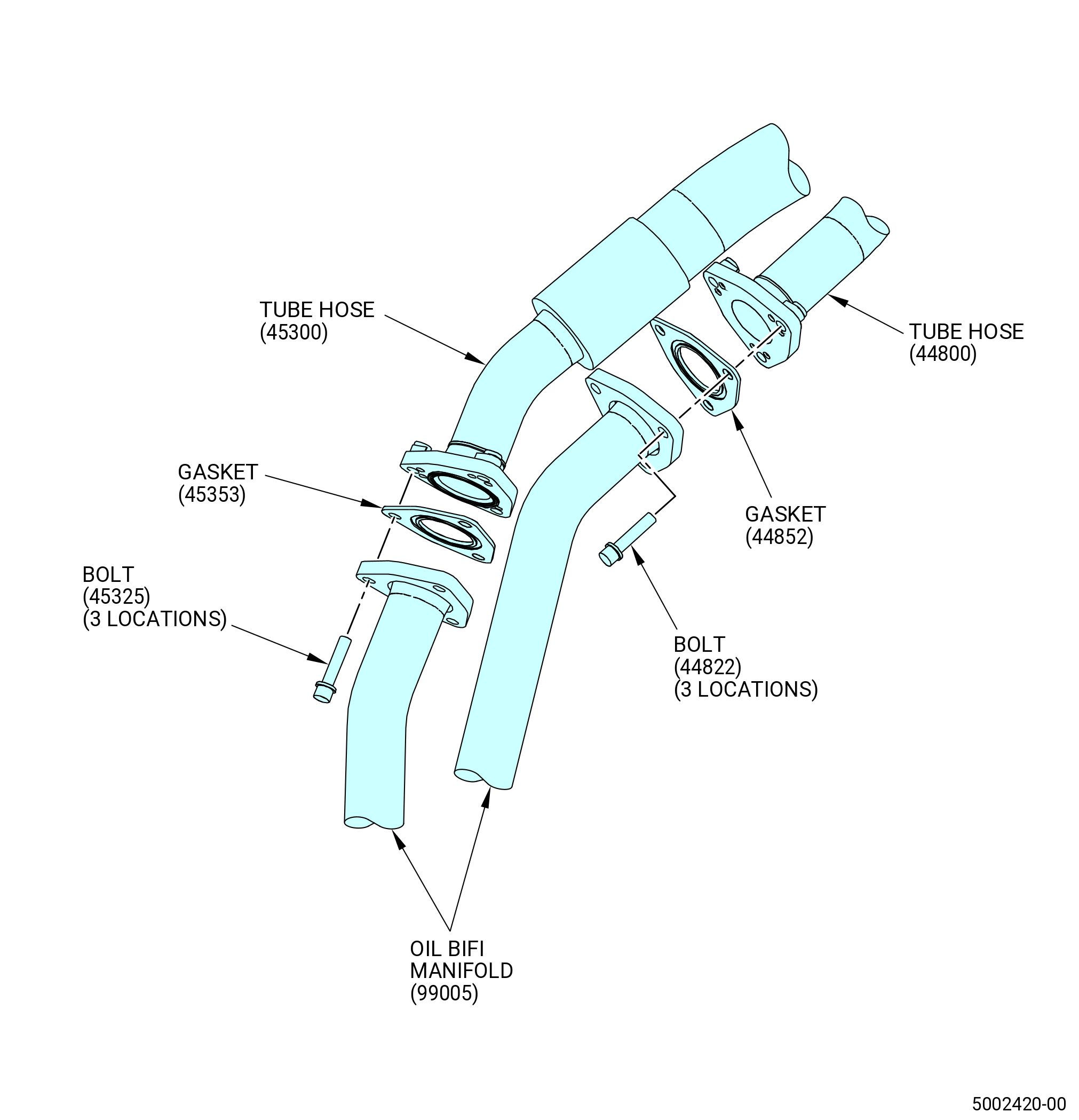
| N. | Install the tube hoses (10-010 , 79-22-10) (SIN 44800) and (10-080 , 79-22-10) (SIN 45300) to the lower bifurcation assembly. Refer to Figure 414 and do as follows: |
| (1) | Install gasket (10-070 , 79-22-10) (SIN 44852) in the oil BIFI manifold (99005). |
| (2) | Align the tube hose (44800) to the oil BIFI manifold (99005). |
| (3) | Attach the tube hose (44800) to the oil BIFI manifold (99005) with four bolts (44822). |
| (4) | Torque the bolts (44822) to 106-124 lb in. (12.0-14.0 N.m). |
| (5) | Install gasket (10-140 , 79-22-10) (SIN 45353) in the oil BIFI manifold (99005). |
| (6) | Align the tube hose (45300) to the oil BIFI manifold (99005). |
| (7) | Attach the tube hose (45300) to the oil BIFI manifold (99005) with four bolts (45325). |
| (8) | Torque the bolts (45325) to 106-124 lb in. (12.0-14.0 N.m). |
| Subtask 72-00-03-420-021 |
| O. | Continue to assembly the engine. Refer to 72-00-00-420-801 (72-00-00, Assembly 001). |
| Subtask 72-00-03-420-038 |
| P. | Remove the 11C3251 installation fixture from the lower bifurcation assembly as follows: |
| (1) | Remove the hook and loop strap (item 20) from the lower bifurcation assembly at two locations. |
| (2) | Remove the brackets with the capscrews (item 23) at four locations. |
| (3) | Put the floor lock (item 19) in the open (up) position. |
| (4) | Remove the arms around the lower bifurcation assembly. |
| (5) | Lower the height of the 11C3251 installation fixture with the side crank of the trailer jack (item 11). |