| GENX-1B ENGINE MANUAL | Dated: 02/20/2020 | |
| EM 72-00-03 , ASSEMBLY 001 | ||
| LOWER BIFURCATION ASSEMBLY - ASSEMBLY 001 | ||
| GENX-1B ENGINE MANUAL | Dated: 02/20/2020 | |
| EM 72-00-03 , ASSEMBLY 001 | ||
| LOWER BIFURCATION ASSEMBLY - ASSEMBLY 001 | ||
| * * * FOR ALL |
| TASK 72-00-03-440-802 |
| 1 . | General. |
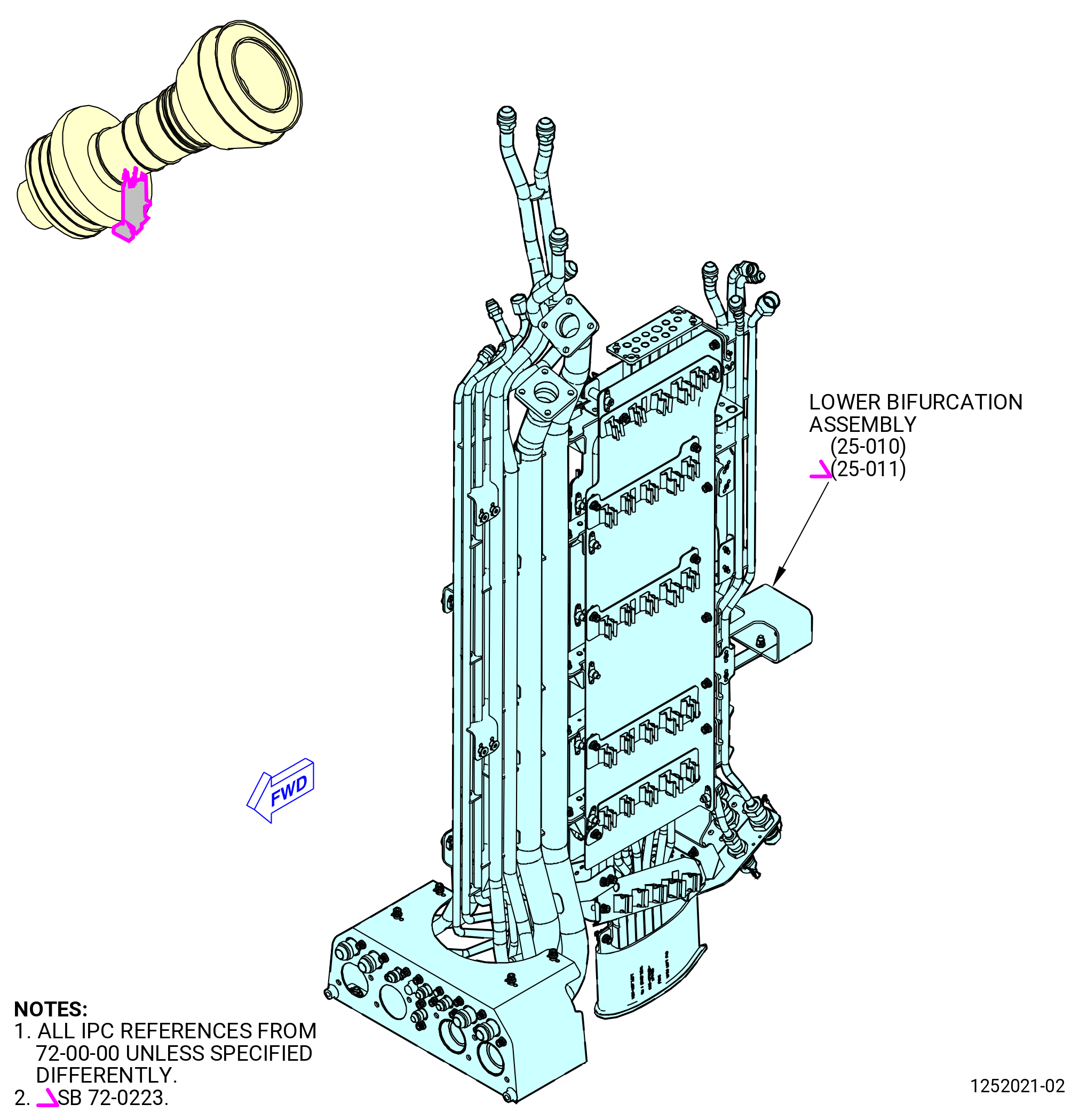
| A. | This procedure gives instructions to assemble the lower bifurcation assembly (25-010 , 72-00-00) (SIN 09400) or (25-011 , 72-00-00) (SIN 09400). Refer to Figure 1001. |
| WARNING: |
|
| WARNING: |
|
| B. | Cleaning of parts is permitted with C04-002 solvent or C04-035 isopropyl alcohol. |
| C. | Install the tubes, the clamps, brackets, and manifolds as follows: |
| (1) | Install tubing from port-to-port and tighten by hand. |
| (2) | Install all clamps loosely. |
| (3) | Put all clamps and brackets so a minimum quantity of strain is applied to the tube assembly. |
| (4) | Torque the tube joint, then torque the clamps, and safety with C10-143 safety cable assembly. Refer to TASK 70-11-02-400-006 (SAFETY CABLE PROCEDURE) . |
| D. | A minimum clearance of 0.125 inch (3.18 mm) must be kept between the outside diameter (OD) of a tube, a tube-hose, and a flex line, or a fitting and its adjacent parts, except as follows: |
| (1) | A minimum clearance of 0.06 inch (1.5 mm) from the OD is permitted as follows: |
| (a) | Within 2.00 inches (50.8 mm) of a support for tubes 0.375 inch (9.52 mm) OD and under. |
| (b) | Within 3.00 inches (76.2 mm) of a support for tubes 0.50 inch (12.7 mm) and 0.625 inch (15.88 mm) OD. |
| (c) | Within 3.50 inches (88.9 mm) of a support for 0.75 inch (19.0 mm) OD tubes. |
| (d) | Within 4.00 inches (101.6 mm) of a support for tubes 1.00 inch (25.4 mm) OD and over. |
| (2) | For tubes fixed together in a cluster by weld, braze, or other permanent method, the requirements paragraph 1.D.(1) are applicable according to the individual tube diameters. The clearance requirement of paragraph 1.D.(1) does not apply between tubes within a cluster. |
| (3) | Parts that are attached with a metal strap and a non-cushioned loop clamp, can touch with the smooth surface of a support bracket within the plane of the bracket at the support point. A minimum clearance for all other types of clamps or straps is 0.06 inch (1.52 mm). |
| (4) | Contact is permitted between a clamp and a spring clip when they are on the same mounting surface. |
| (5) | There must be a minimum clearance of 0.06 inch (1.52 mm) between adjacent components that are on a common mounting surface. |
| (6) | Safety cable or safety wire must touch only the hardware that they attach. |
| 2 . | Tools, Equipment, and Materials. |
| NOTE: |
|
| A. | Tools and Equipment. |
| (1) | Special Tools. |
|
| (2) | Standard Tools and Equipment. None. |
| (3) | Locally Manufactured Tools. None. |
| B. | Consumable Materials. |
| C. | Referenced Procedures. |
|
| D. | Expendable Parts. None. |
| 3 . | Procedure. |
| Subtask 72-00-03-440-027 |
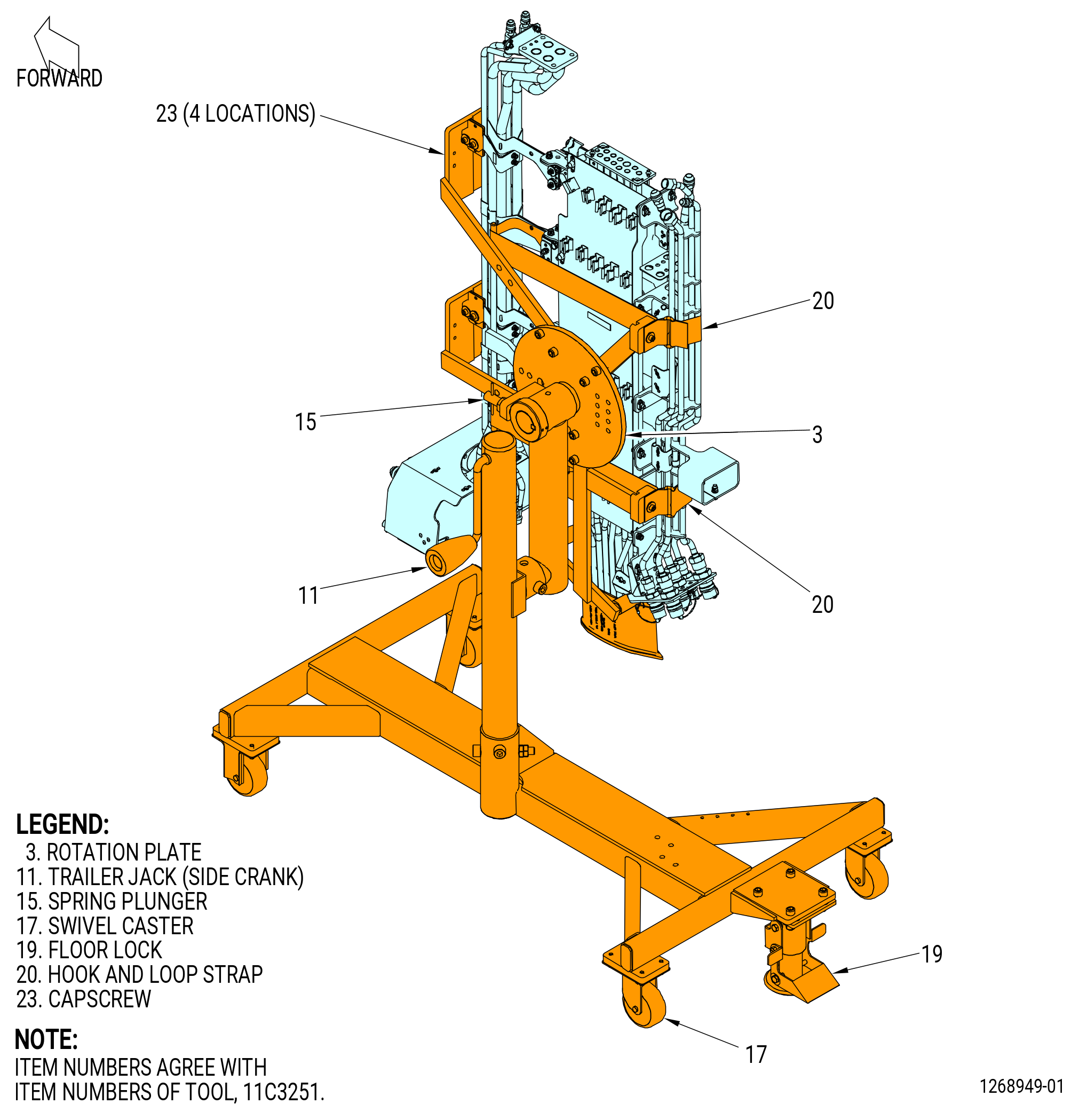
| A. | Install the lower bifurcation assembly (25-010 , 72-00-00) (SIN 09400) or (25-011 , 72-00-00) (SIN 09400) on the 11C3251 installation fixture. Refer to Figure 1002 and do as follows: |
| CAUTION: |
|
| (1) | Make sure that the swivel casters (item 17) are in the locked position. |
| (2) | Install the bracket assemblies on the assembly fixture as follows: |
| (a) | Loosen the screws and remove the support and the lug from the installation fixture. |
| (b) | Attach the bracket assemblies to the installation fixture with the screws. Tighten the screws. |
| (c) | Open the two hinged straps of each bracket assembly as wide as possible. |
| (d) | Install a wedge into each bracket assembly. |
| (e) | Install the flexible clamps on the wedges. |
| NOTE: |
|
| Subtask 72-00-03-440-028 |
| * * * PRE SB 72-0223( Installation of Drain Manifold with Support Bracket ) |
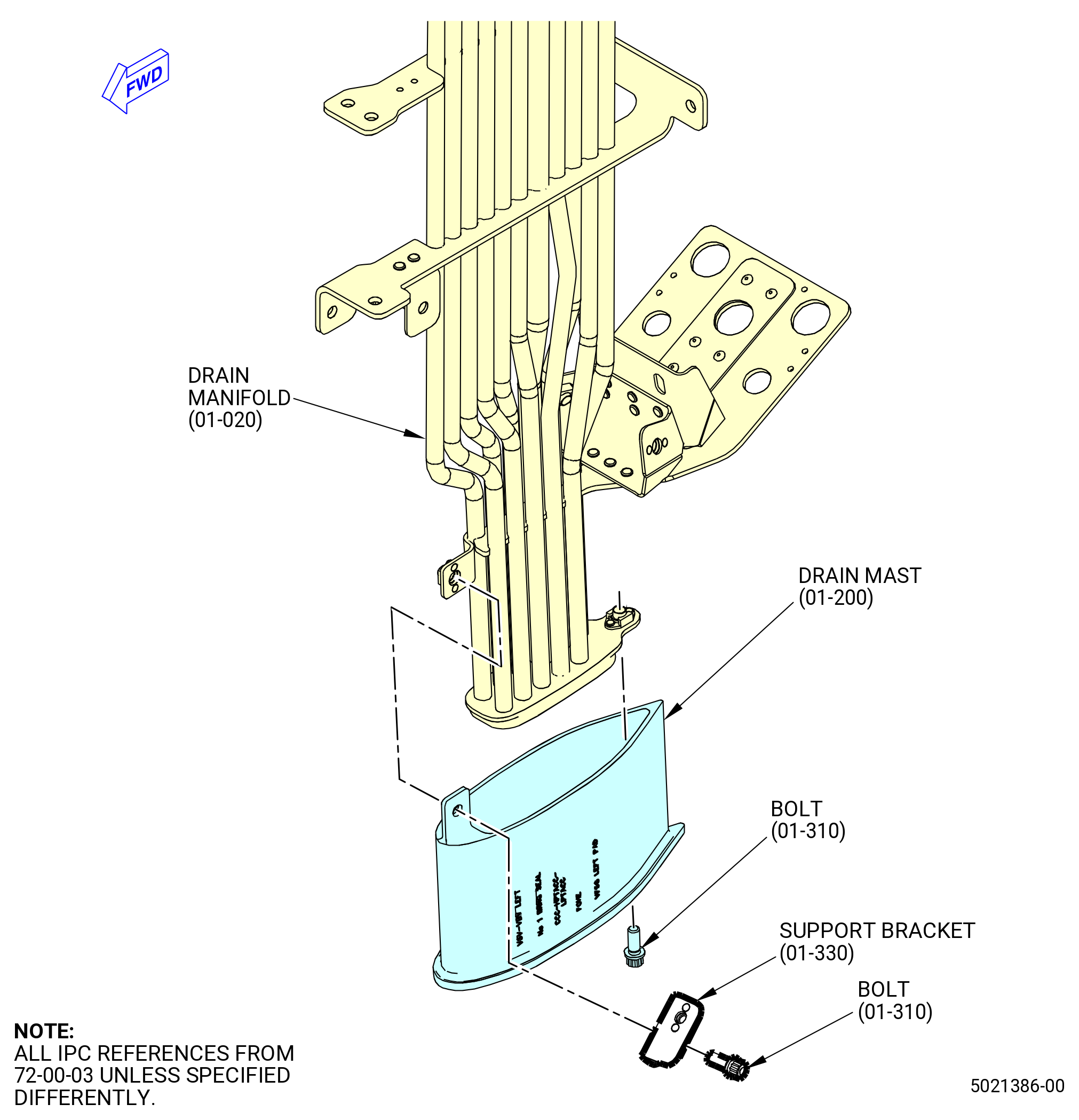
| B. | Install the lower bifurcation drain manifold (drain manifold) (99001) as follows. Refer to Figure 1003. |
| WARNING: |
|
| (1) | Apply C02-019 engine oil or C02-023 engine oil to the threads of the bolts (99024). |
| (2) | Attach the drain manifold to the drain mast (01-200) (SIN 99000) with the support bracket (01-330) (SIN 09410) and two bolts (01-310) (SIN 99024). |
| (3) | Torque the bolts to 106-124 lb in. (12.0-14.0 N.m). |
| * * * END PRE SB 72-0223 |
| Subtask 72-00-03-440-041 |
| * * * SB 72-0223( Installation of Drain Manifold without Support Bracket ) |
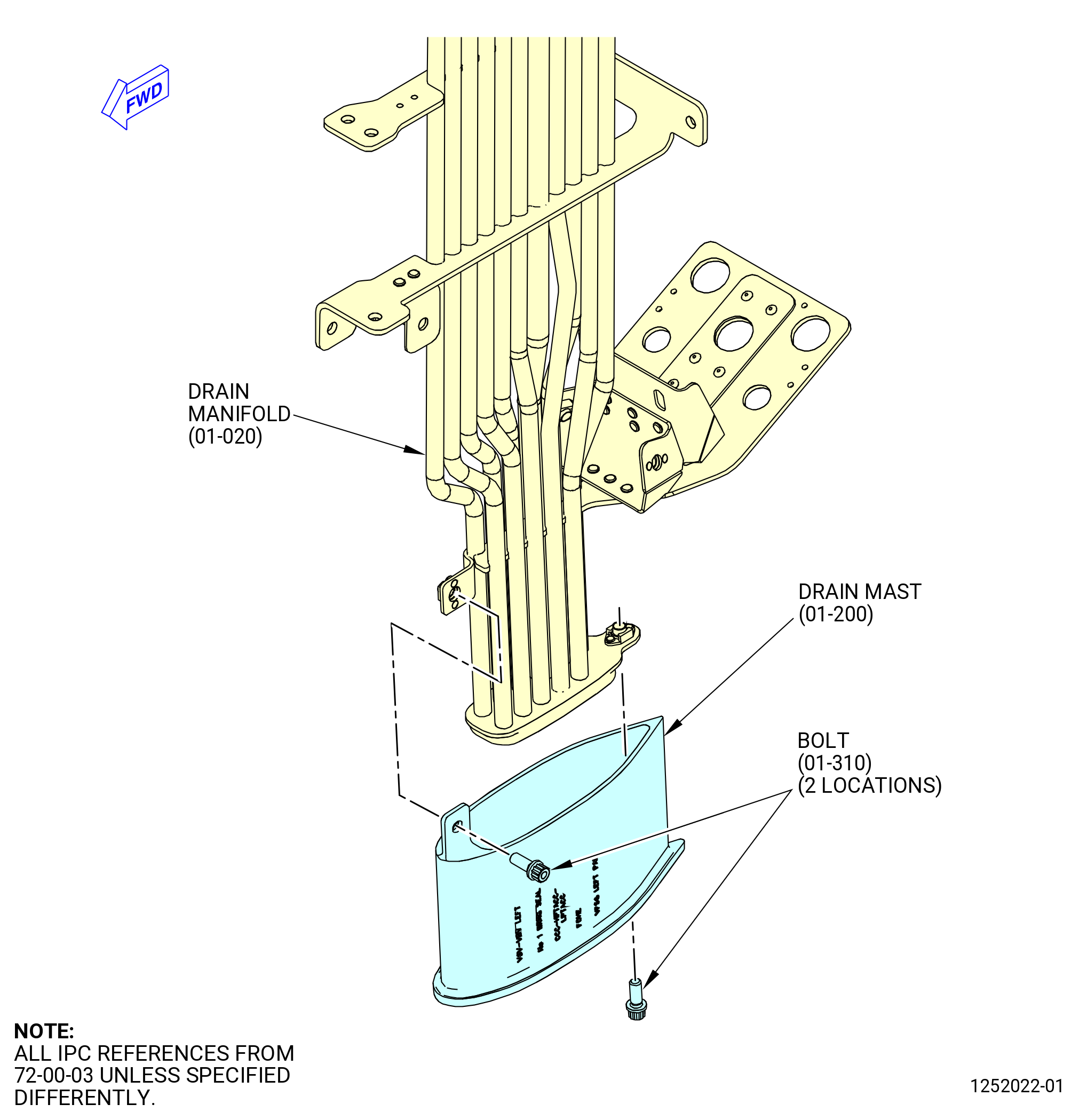
| B.A. | Install the drain manifold (01-020) (SIN 99001). Refer to Figure 1003 and do as follows: |
| WARNING: |
|
| (1) | Apply C02-019 engine oil or C02-023 engine oil to the threads of the bolts (01-310) (SIN 99024). |
| (2) | Attach the drain manifold to the drain mast (01-200) (SIN 99000) with the bolts (01-310) (SIN 99024). |
| (3) | Torque the bolts to 106 to 124 lb in. (12.0 to 14.0 Nm). |
| * * * END SB 72-0223 |
| Subtask 72-00-03-440-039 |
| * * * SB 72-0035( Bifurcation Assembly with Insulation Blanket ) |
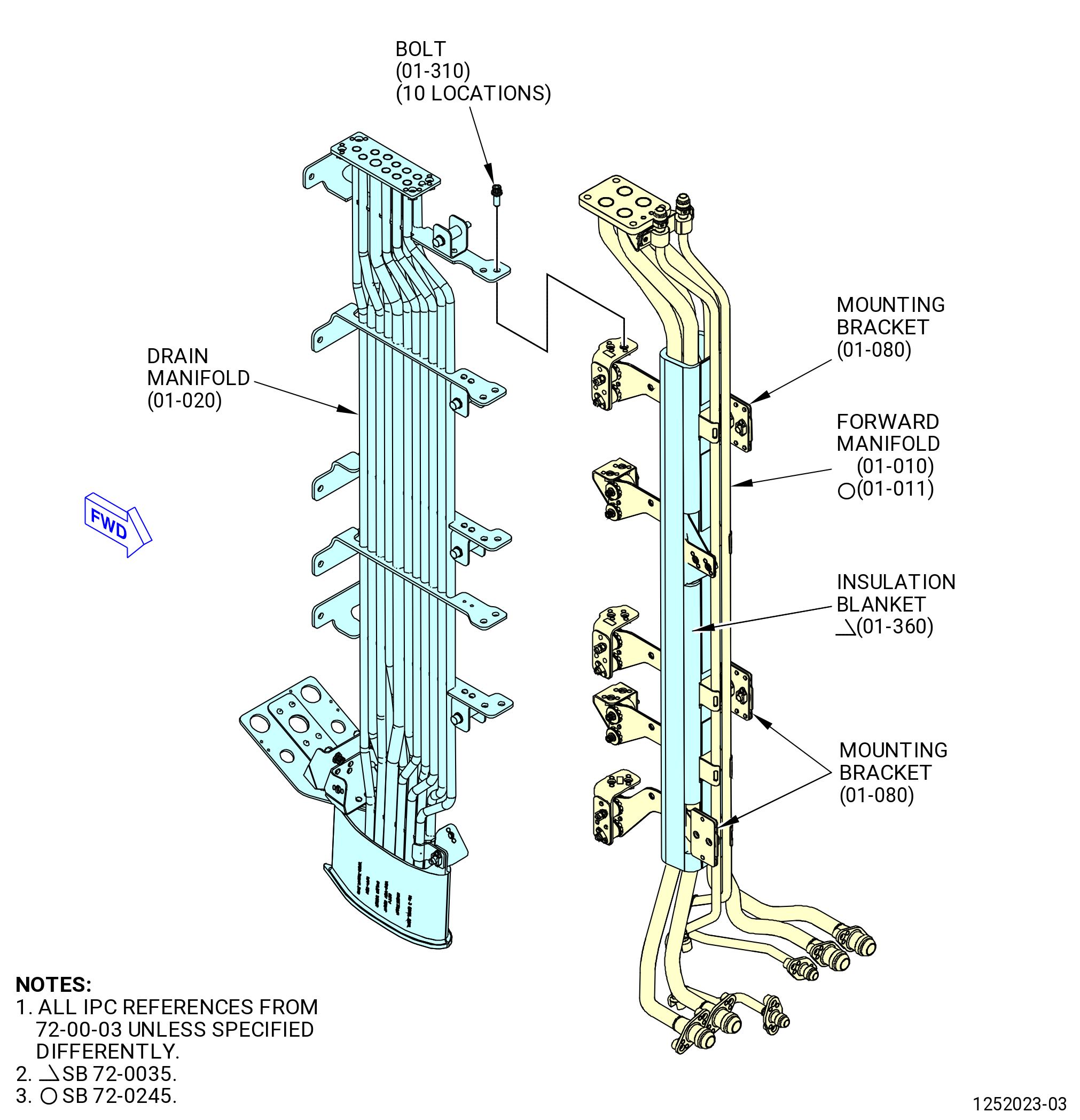
| C. | Install the insulation blanket (01-360) (SIN 99090) on the forward manifold as follows. Refer to Figure 1003. |
| NOTE: |
|
| (1) | If the support bracket assemblies (mounting brackets) (01-080) (SIN 99012) are not installed, install them to lower air and VFSG oil manifold (forward manifold) (01-010) (SIN 99002) or (01-011) (SIN 99002) as follows: |
| WARNING: |
|
| (a) | Apply C02-023 engine oil to the bolts (01-060) (SIN 9902B). |
| (b) | Attach the mounting brackets to the forward manifold with bolts. |
| (c) | Torque the bolts to 60-70 lb in. (6.8-7.9 N.m). |
| (2) | Install the insulation blanket from the aft side of the forward manifold. Make sure to align the openings of the insulation blanket with the forward manifold mounting brackets. |
| (3) | Put the insulation blanket around the forward manifold and secure with the seven snap fasteners. |
| * * * END SB 72-0035 |
| Subtask 72-00-03-440-029 |
| * * * PRE SB 72-0444( with PS25 Sense Line ) |
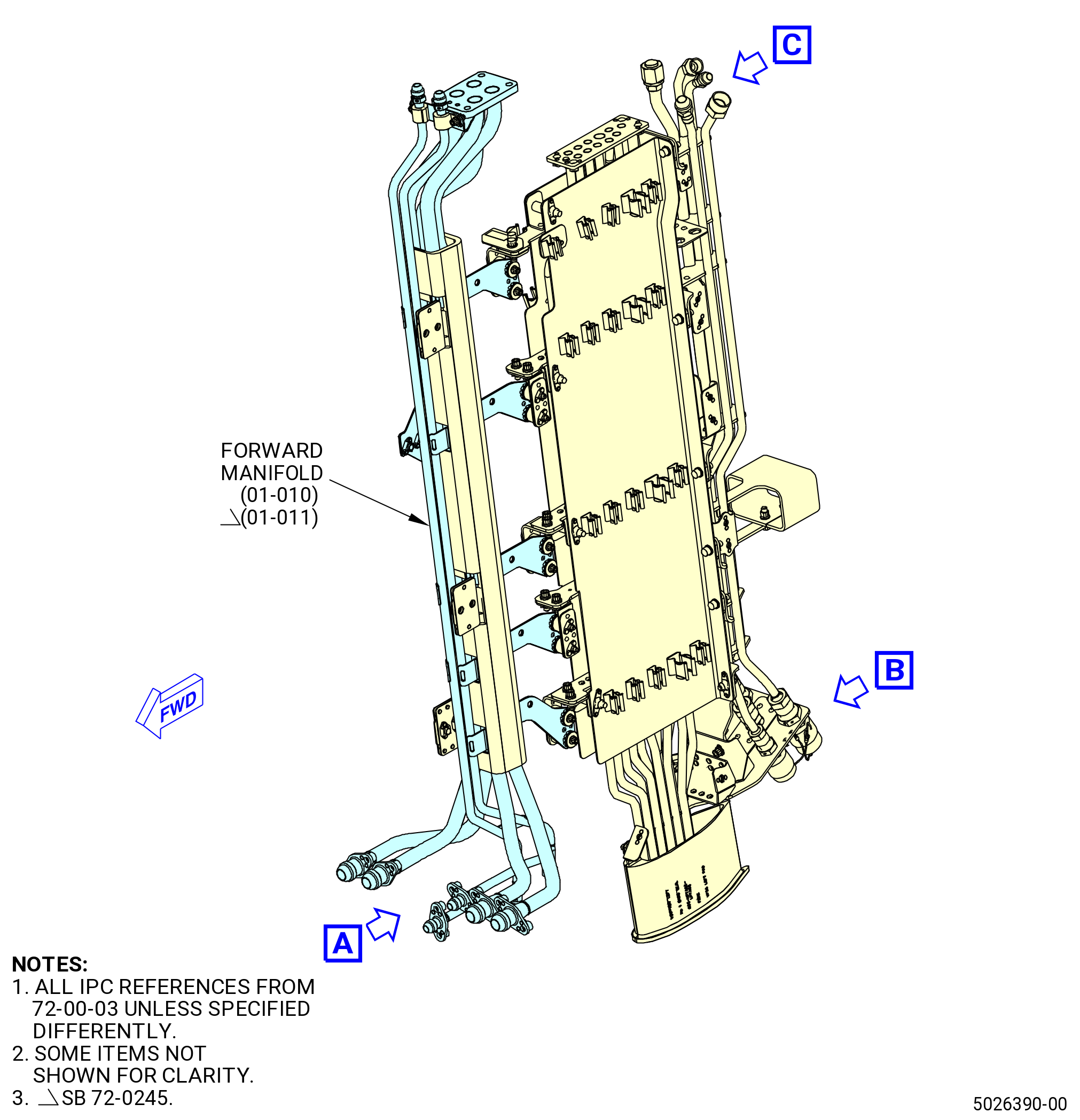
| D. | Install the lower bifurcation forward manifold (forward manifold) (01-010) (SIN 99002) or (01-011) (SIN 99002) as follows. Refer to Figure 1003. |
| WARNING: |
|
| (1) | Apply C02-019 engine oil or C02-023 engine oil to the threads of the bolts (99024). |
| (2) | Attach the forward manifold to the drain manifold (99001) with the bolts (99024). |
| (3) | Torque the bolts to 106-124 lb in. (12.0-14.0 N.m). |
| * * * END PRE SB 72-0444 |
| Subtask 72-00-03-440-044 |
| * * * SB 72-0444( without PS25 Sense Line ) |
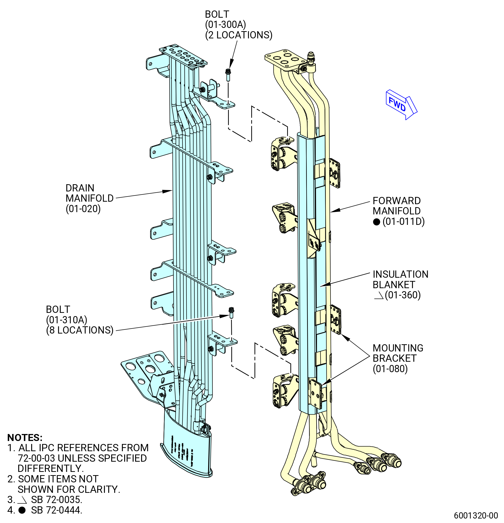
| D.A. | Install the lower bifurcation forward manifold (forward manifold) (01-011D) (SIN 99002). Refer to Figure 1003 and as follows: |
| WARNING: |
|
| (1) | Apply C02-019 engine oil or C02-023 engine oil to the threads of the bolts (01-310A) (SIN 99024) and (01-300A) (SIN 99022). |
| (2) | Attach the forward manifold to the drain manifold (01-020) (SIN 99001) with the bolts (01-310A) (SIN 99024) and (01-300A) (SIN 99022). |
| (3) | Torque the bolts to 106 to 124 lb in. (12.0 to 14.0 Nm). |
| * * * END SB 72-0444 |
|
|
|
|
|
|
| Subtask 72-00-03-440-030 |
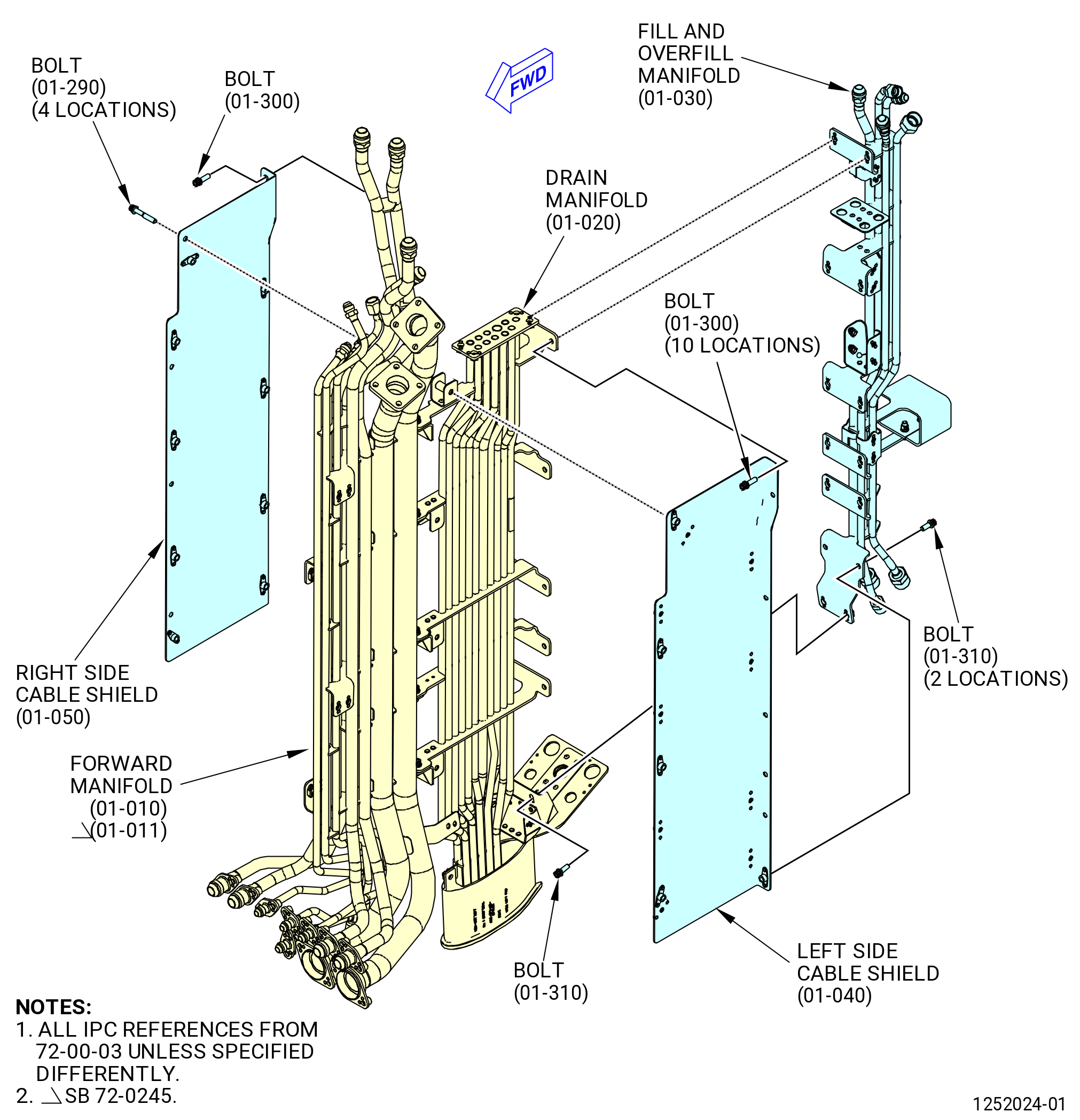
| E. | Install the left-side cable shield (09710) and right-side cable shield (09711) as follows. Refer to Figure 1003. |
| (1) | Attach the left-side cable shield (09710) to the aft side of the drain manifold (99001). |
| (a) | Align the left-side cable shield with the four U-shaped brackets. |
| (b) | Make sure that the lip of the left-side cable shield is in an outward direction. |
| (2) | Attach the right-side cable shield (09711) to the forward side of the drain manifold (99001). |
| (a) | Align the right-side cable shield with the four U-shaped brackets. |
| (b) | Make sure that the lip of the right-side cable shield is in an outward direction. |
| (3) | Attach the left-side cable shield to the right-side cable shield with the bolts (09720). |
| (4) | Torque the bolts to 106-124 lb in. (12.0-14.0 N.m). |
| Subtask 72-00-03-440-031 |
| F. | Install the fill and overfill lower bifurcation manifold (fill and overfill manifold) (99004) as follows. Refer to Figure 1003. |
| WARNING: |
|
| (1) | Apply C02-019 engine oil or C02-023 engine oil to the threads of the bolts (99022, 99024). |
| (2) | Attach the fill and overfill manifold to the drain manifold (99001) and the left-side cable shield (09710) with the bolts (99022, 99024). |
| (3) | Attach the fill and overfill manifold to the drain manifold (99001) and the right-side cable shield (09711) with the bolts (99022, 99024). |
| Subtask 72-00-03-440-042 |
| * * * SB 73-0060( W30 and W31 Redesigned Harnesses ) |
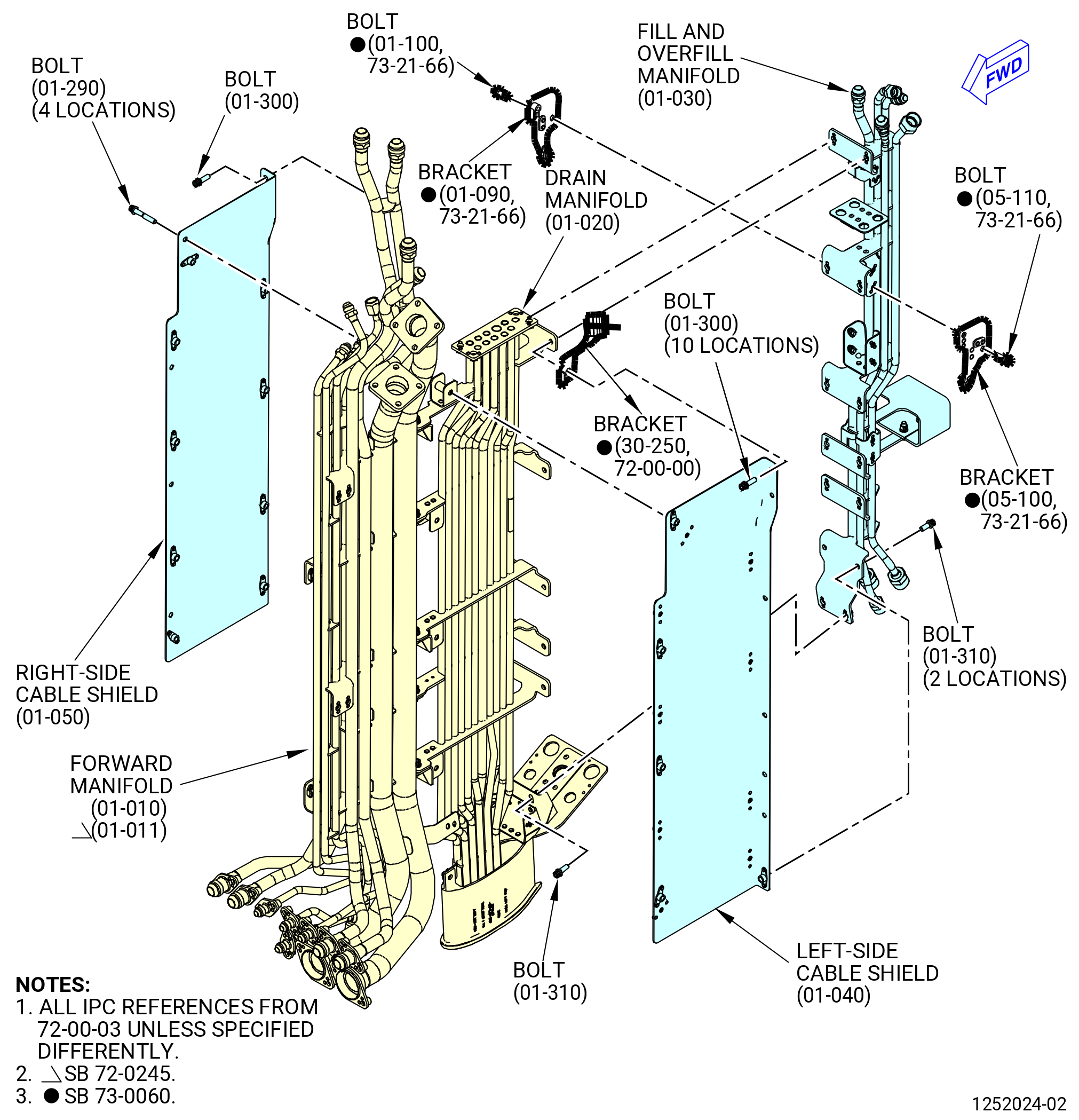
| (3).A. | Install the W31 electrical harness support bracket (bracket) (30-250 , 72-00-00) (SIN 0971J), harness W30 support bracket (bracket) (01-090 , 73-21-66) (SIN 9901U), and harness W31 support bracket (bracket) (05-100 , 73-21-66) (SIN 9901T) as follows: |
| NOTE: |
|
| (a) | Attach the bracket (30-250 , 72-00-00) (SIN 0971J) to the left-side cable shield (01-040) (SIN 09710), drain manifold (01-020) (SIN 99001), and fill and overfill manifold (01-030) (SIN 99004) with a bolt (01-300) (SIN 99022). |
| (b) | Attach the brackets (01-090 , 73-21-66) (SIN 9901U) and (05-100 , 73-21-66) (SIN 9901T) to the fill and overfill manifold (01-030) (SIN 99004) with machine bolts (bolts) (01-100 , 73-21-66) (SIN 9902H) and (05-110 , 73-21-66) (SIN 9902H) to their related bracket. |
| (c) | Attach the fill and overfill manifold (01-030) (SIN 99004) to the drain manifold (01-020) (SIN 99001) and left-side cable shield (01-040) (SIN 09710) with the rest of bolts (01-300) (SIN 99022) and bolts (01-310) (SIN 99024). |
| (d) | Torque the bolts (01-100 , 73-21-66) (SIN 9902H) and (05-110 , 73-21-66) (SIN 9902H) to 106-124 lb in. (12.0-14.0 Nm.). |
| * * * END SB 73-0060 |
| Subtask 72-00-03-440-043 |
| (4) | Torque the bolts to 106-124 lb in. (12.0-14.0 N.m). |
| Subtask 72-00-03-440-032 |
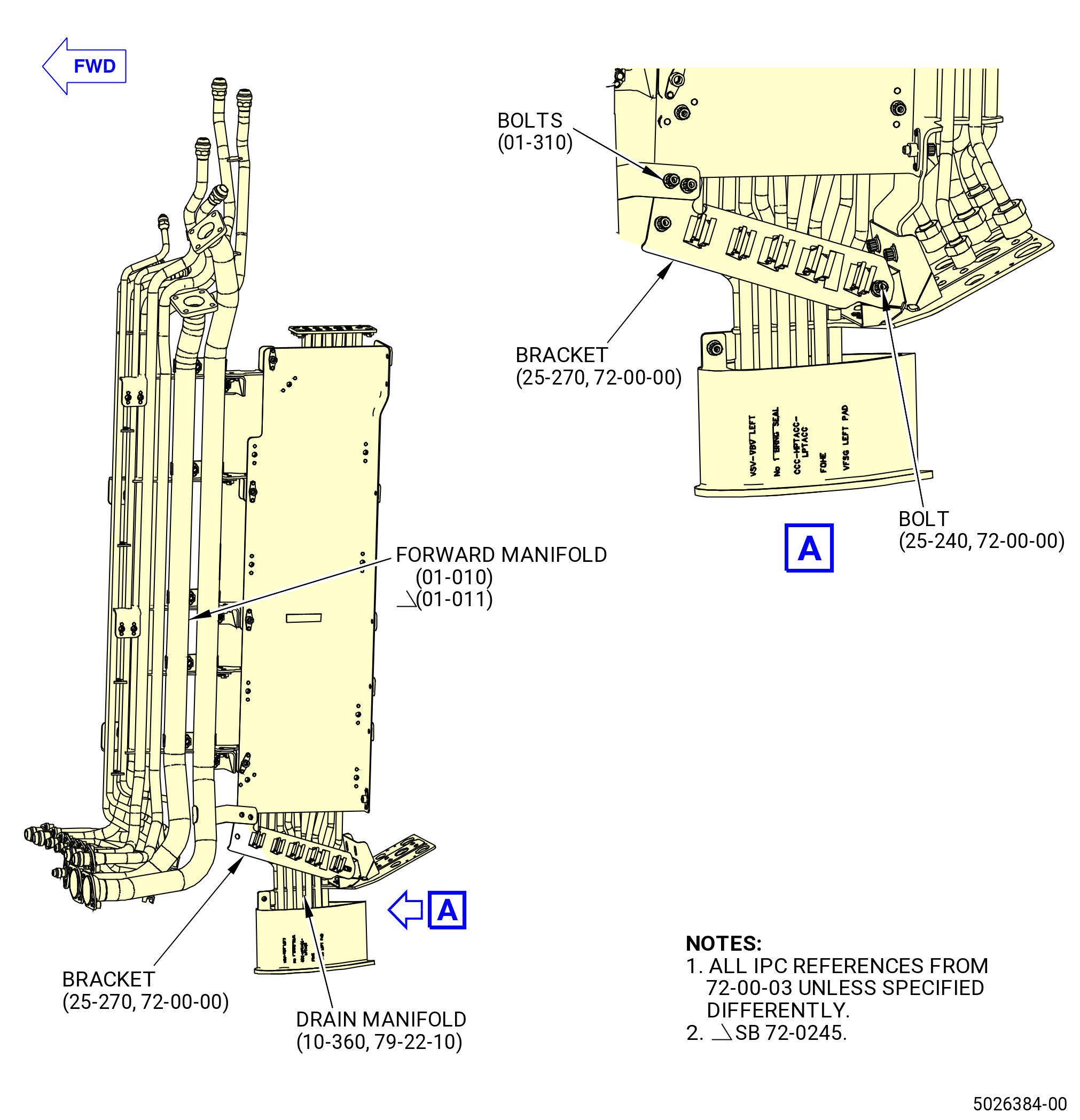
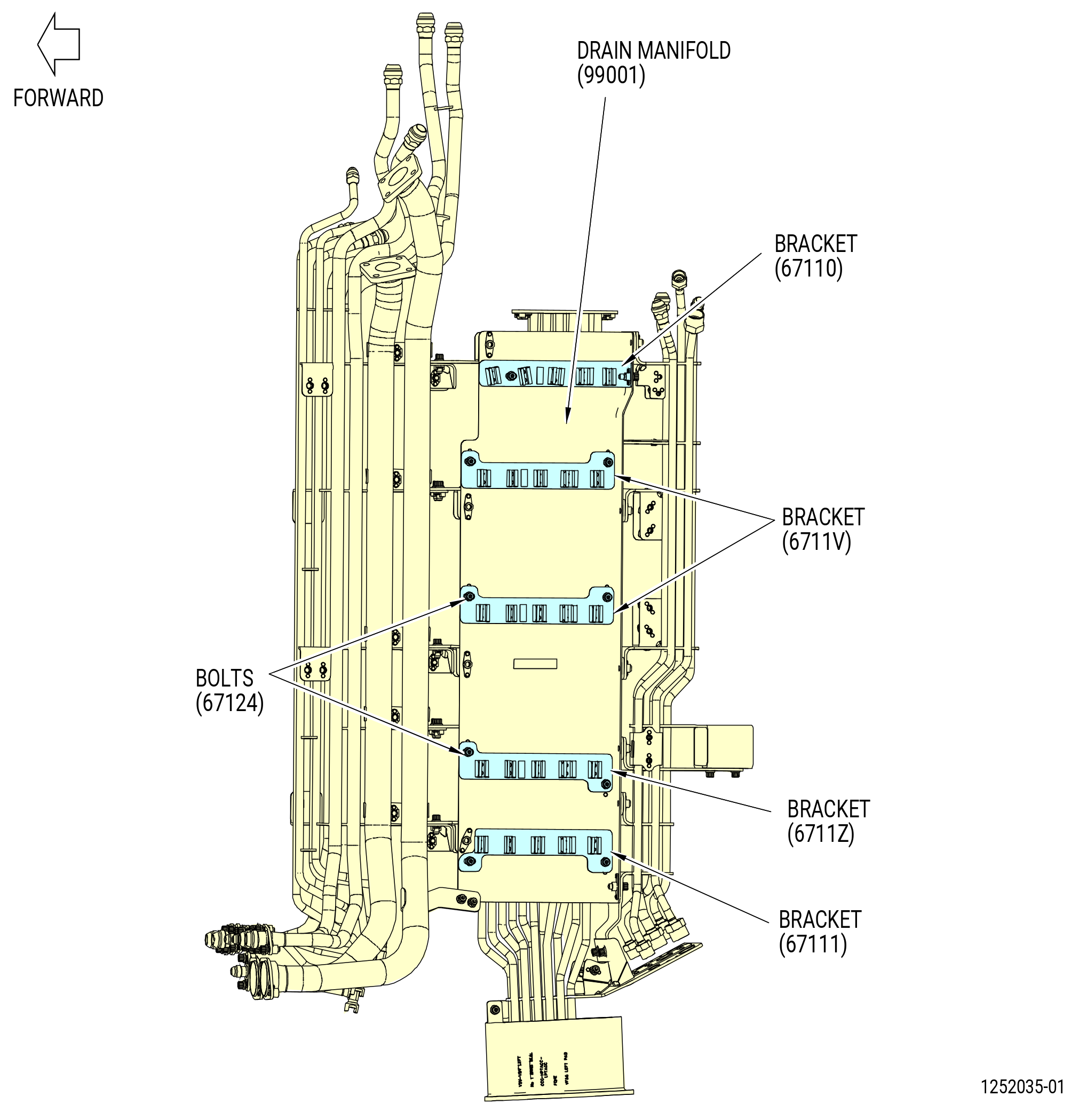
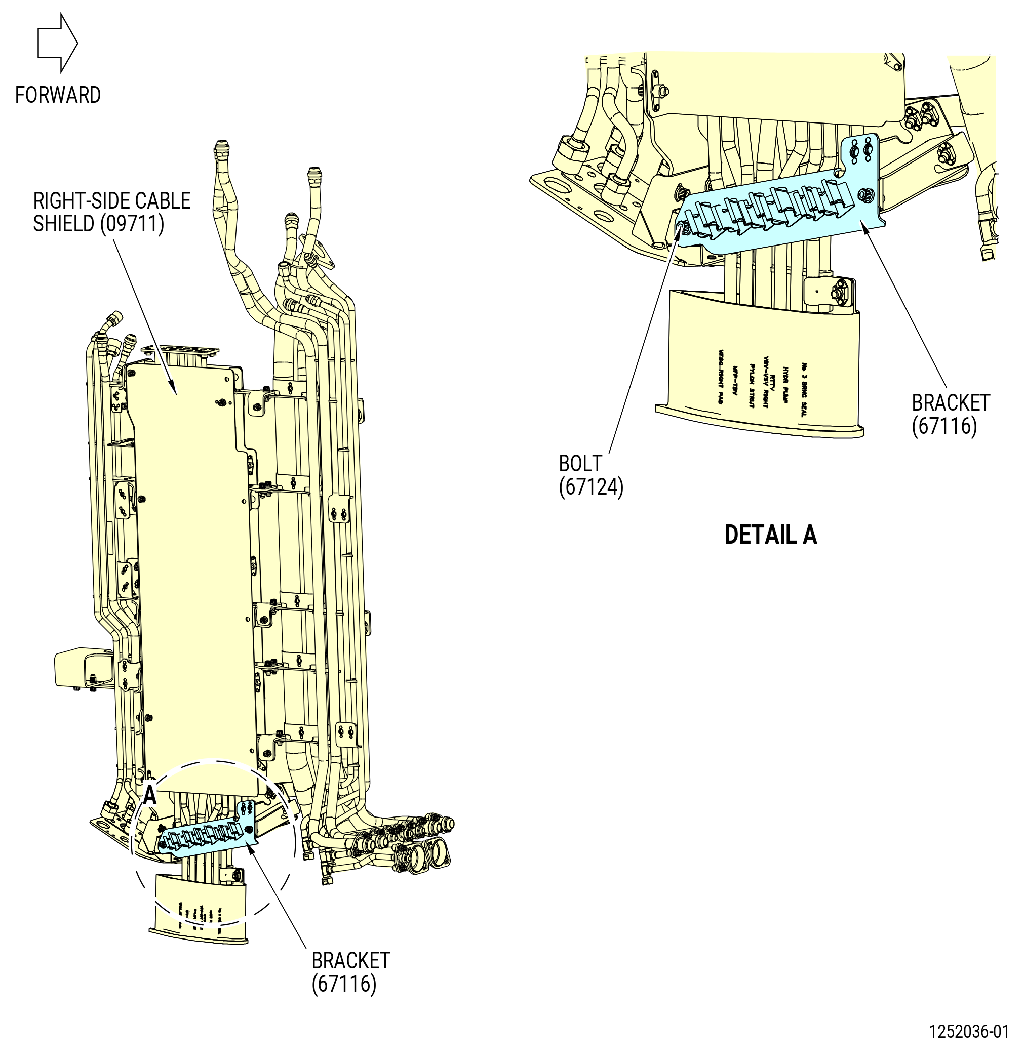
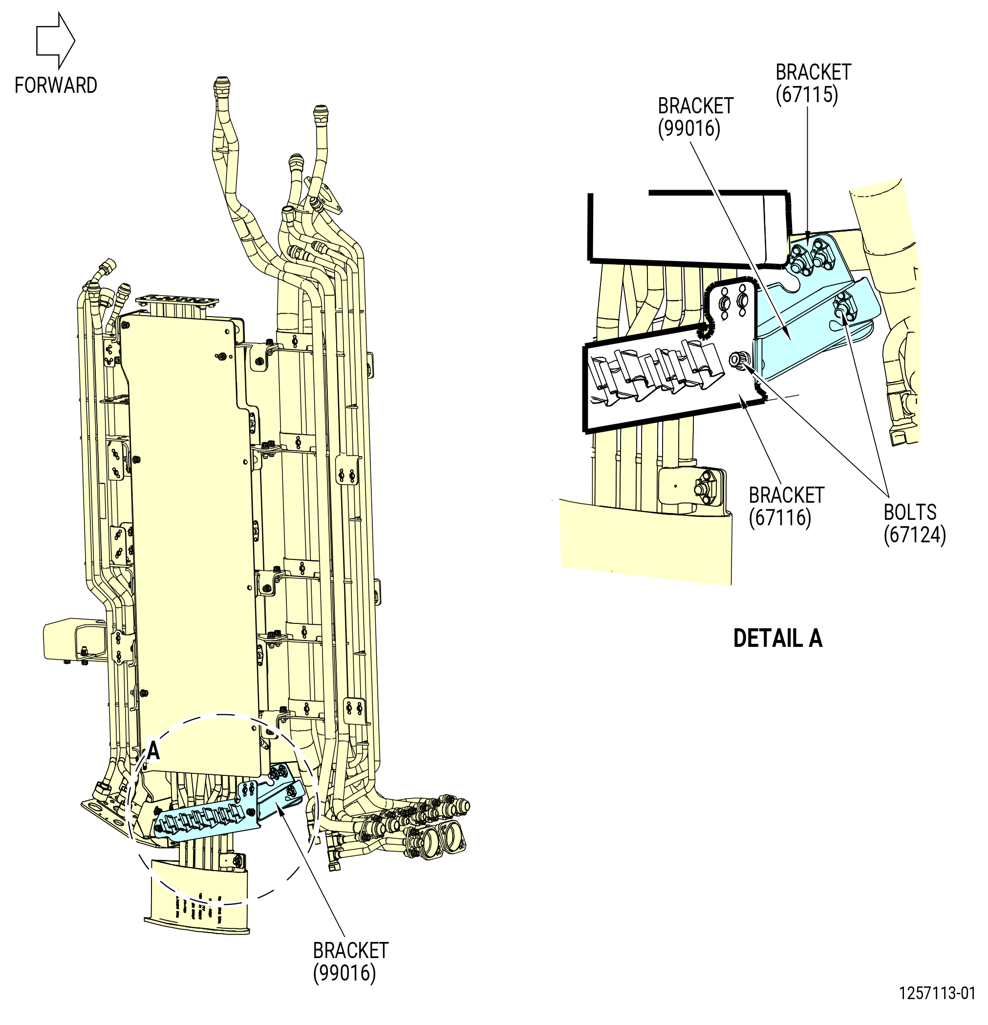
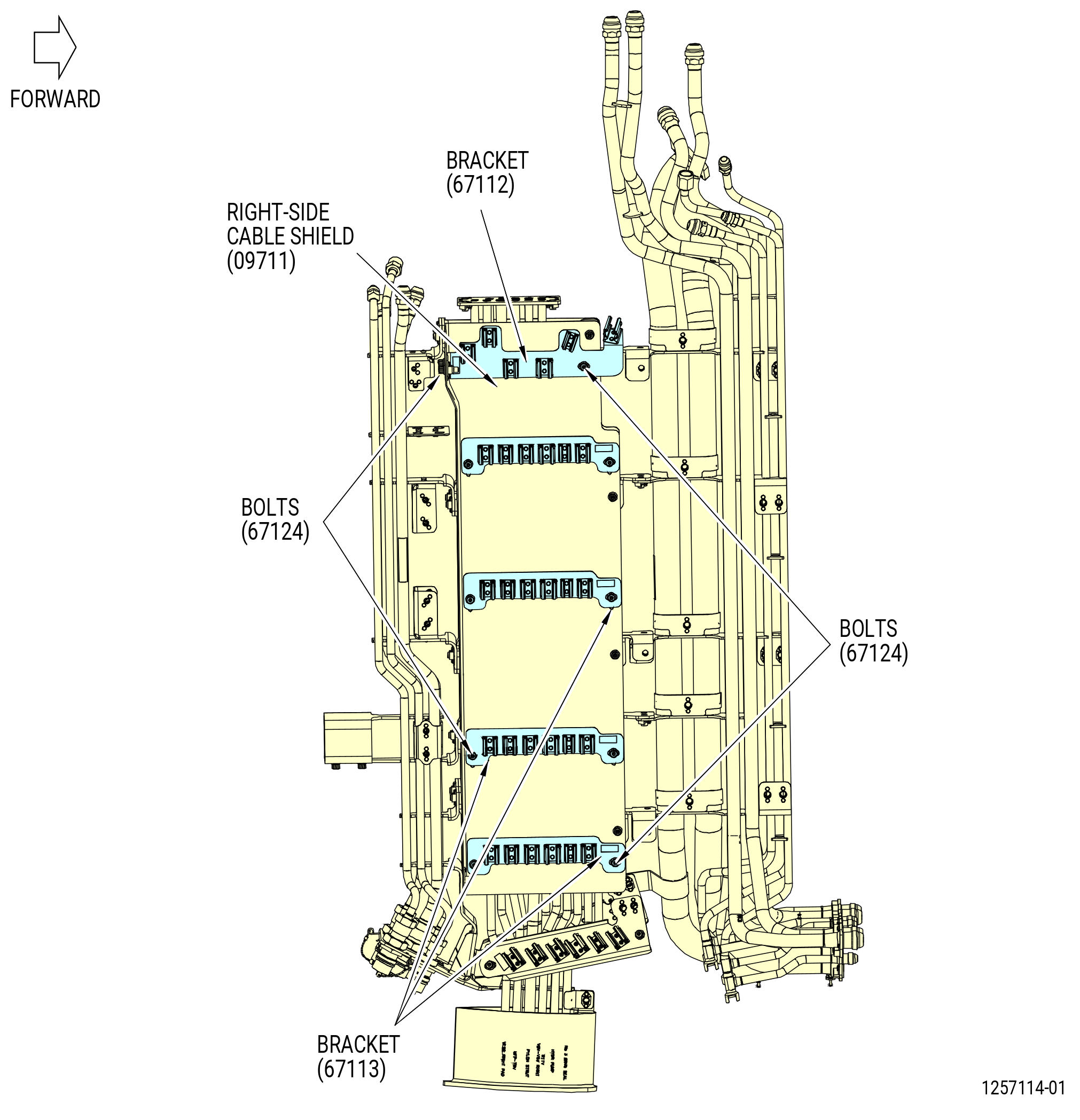
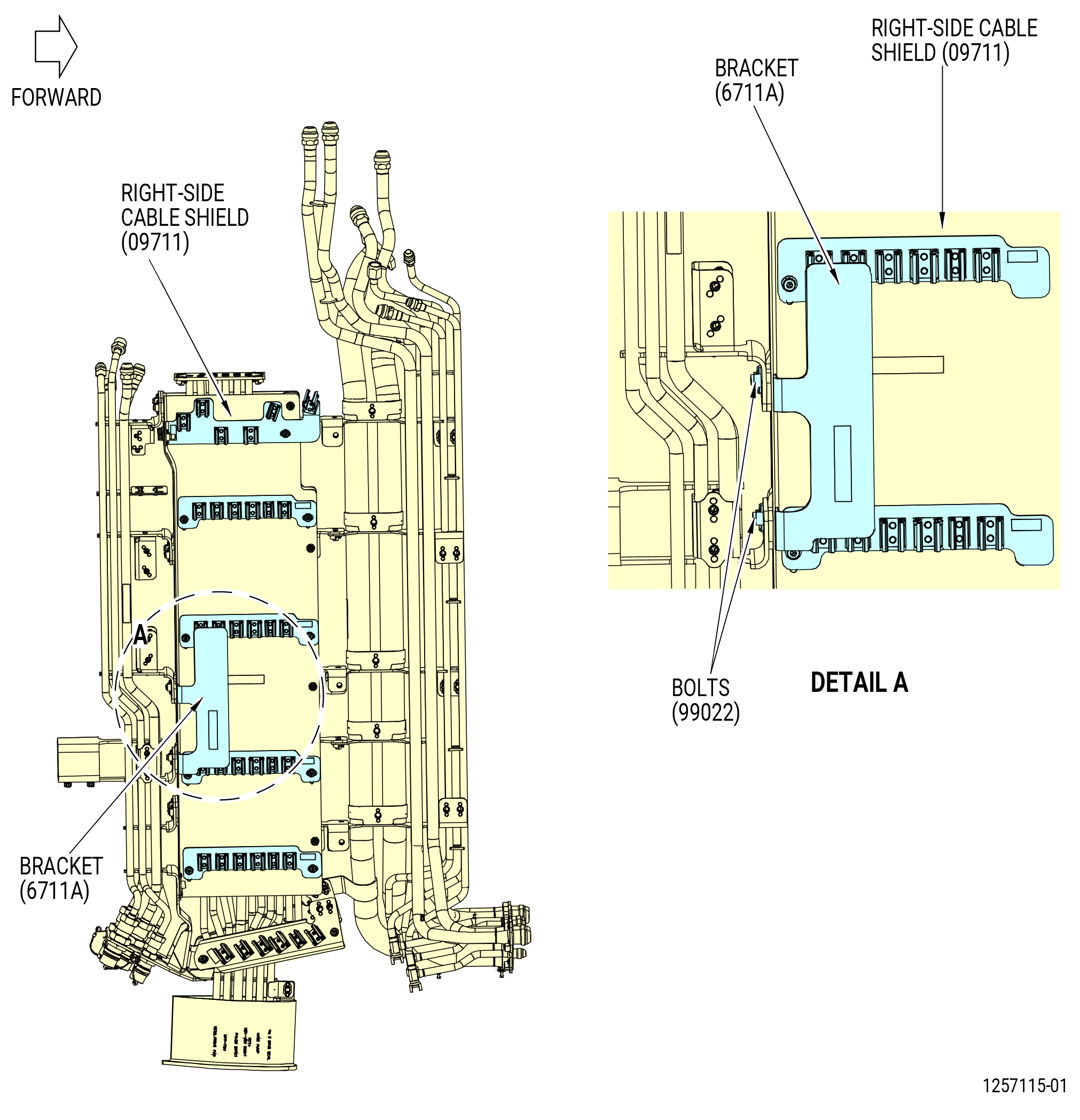
| G. | Install the support brackets (brackets) (67110, 67111, 67112, 67113, 67115, 67116, 6711A, 6711V, 6711Z, 99016) as follows. Refer to Figure 1004. |
| WARNING: |
|
| (1) | Apply C02-019 engine oil or C02-023 engine oil to the threads of the bolts (67124, 99022, 99024). |
| (2) | Attach the bracket (25-270 , 72-00-00) (SIN 67115) to the drain manifold (01-020) (SIN 99001) and the bracket on the forward manifold (01-010) (SIN 99002) or (01-011) (SIN 99002) with the bolts (25-240 , 72-00-00) (SIN 67124) (01-310) (SIN 99024). |
| (3) | Attach the brackets (67110, 67111, 6711V, 6711Z) to the drain manifold (99001) with the bolts (67124). |
| (4) | Attach the bracket (67116) to the right-side cable shield (09711) with the bolts (67124). |
| (5) | Attach the bracket (99016) to the inside of brackets (67115, 67116) with the bolts (67124). |
| (6) | Attach the brackets (67112, 67113) to the right-side cable shield (09711) with the bolts (67124). |
| (7) | Attach the bracket (6711A) to the right-side cable shield (09711) with the bolts (99022). |
| (8) | Torque the bolts to 106-124 lb in. (12.0-14.0 N.m). |
| Subtask 72-00-03-440-033 |
| * * * PRE SB 72-0444( with PS25 Sense Line ) |
| H. | Install the lower bifurcation firewall (firewall) (09401) as follows. Refer to Figure 1005. |
| WARNING: |
|
| (1) | Apply C02-019 engine oil or C02-023 engine oil to the threads of the bolts (99024, 99026). |
| (2) | Attach the firewall to the forward manifold (01-010) (SIN 99002) or (01-011) (SIN 99002) with the bolts (01-310) (SIN 99024), (01-190) (SIN 99026). |
| (3) | Torque the bolts to 106-124 lb in. (12.0-14.0 N.m). |
| * * * END PRE SB 72-0444 |
| Subtask 72-00-03-440-045 |
| * * * SB 72-0444( without PS25 Sense Line, Field Configurations 1 and 2 ) |
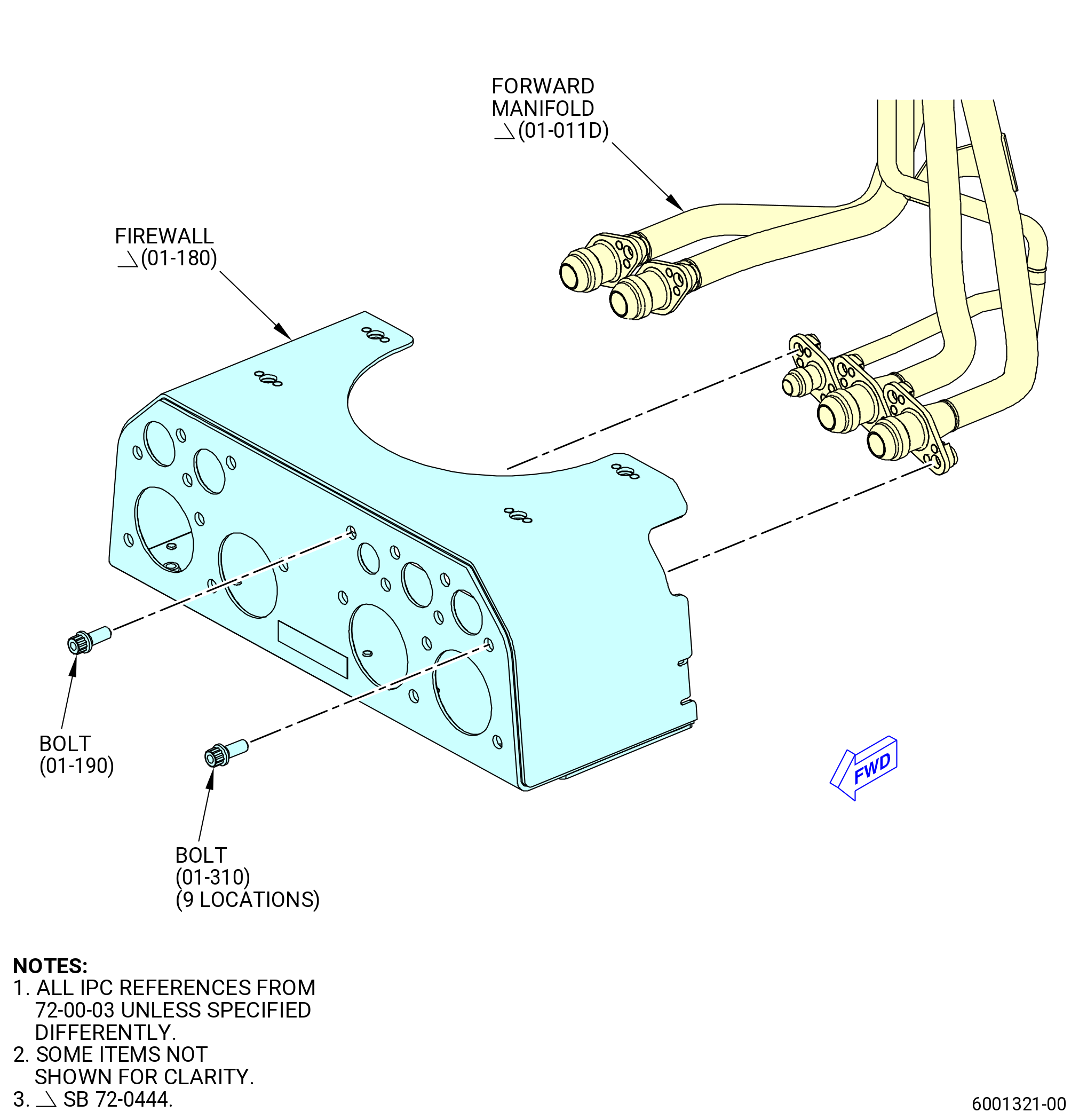
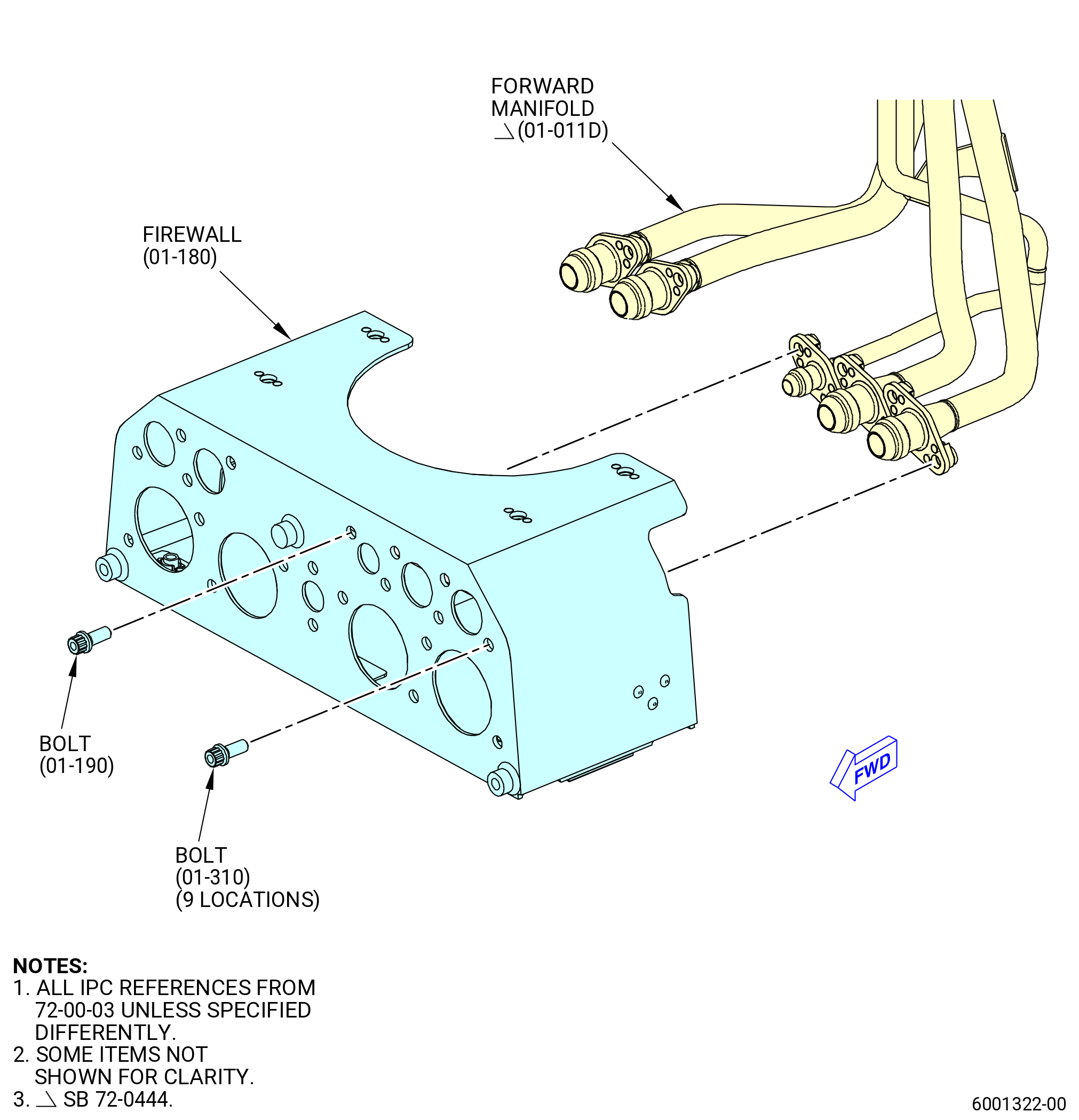
| H.A. | Install the lower bifurcation firewall (firewall) (01-180) (SIN 09401). Refer to Figure 1005 and as follows: |
| WARNING: |
|
| (1) | Apply C02-019 engine oil or C02-023 engine oil to the threads of the bolts (01-310) (SIN 99024) and (01-190) (SIN 99026). |
| (2) | Attach the firewall to the forward manifold (01-011D) (SIN 99002) with the bolts (01-310) (SIN 99024) and (01-190) (SIN 99026). |
| (3) | Torque the bolts to 106 to 124 lb in. (12.0 to 14.0 Nm). |
| * * * END SB 72-0444 |
| Subtask 72-00-03-440-046 |
| * * * SB 72-0444( without PS25 Sense Line, Field Configuration 3 ) |
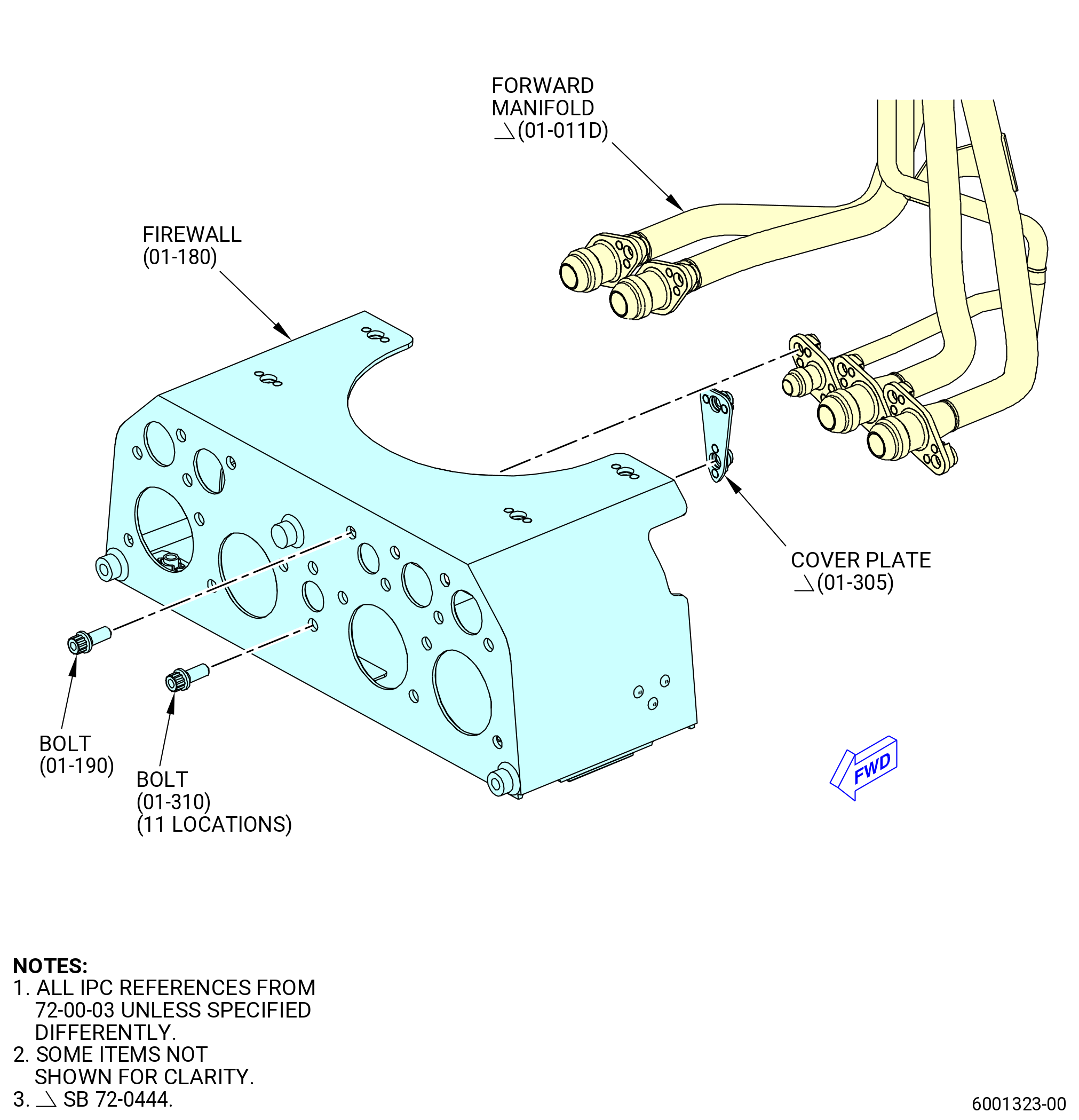
| H.B. | Install the lower bifurcation firewall (firewall) (01-180) (SIN 09401). Refer to Figure 1005 and as follows: |
| WARNING: |
|
| (1) | Apply C02-019 engine oil or C02-023 engine oil to the threads of the bolts (01-310) (SIN 99024) and (01-190) (SIN 99026). |
| (2) | Attach the cover plate (01-305) (SIN 99066) to the firewall with the bolts (01-310) (SIN 99024). |
| (3) | Attach the firewall to the forward manifold (01-011D) (SIN 99002) with the bolts (01-310) (SIN 99024) and (01-190) (SIN 99026). |
| (4) | Torque the bolts to 106 to 124 lb in. (12.0 to 14.0 Nm). |
| * * * END SB 72-0444 |
| Subtask 72-00-03-440-034 |
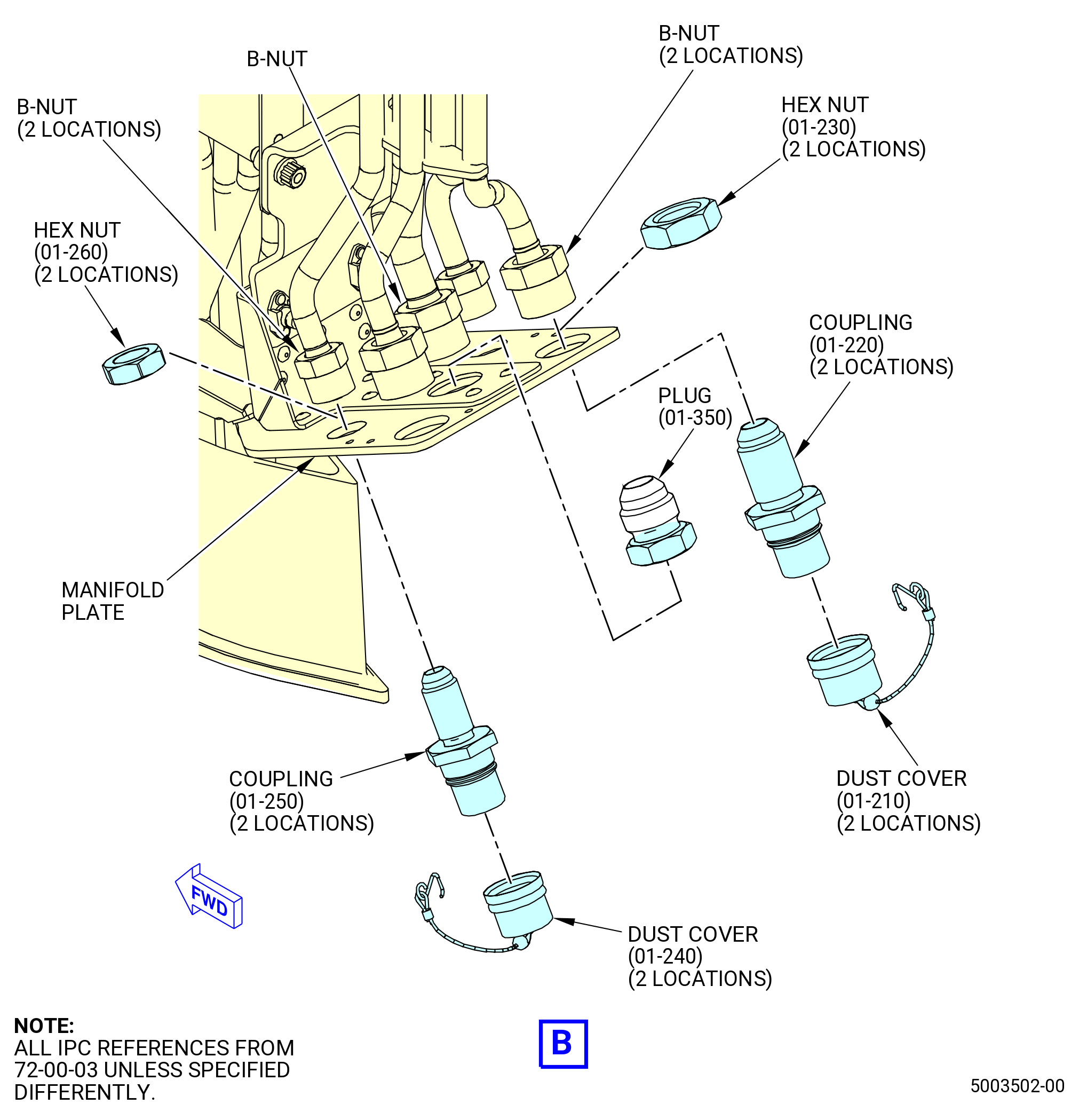
| I. | Install the couplings (01-250) (SIN 44A61) on the forward side of the manifold plate as follows. Refer to Figure 1005. |
| WARNING: |
|
| (1) | Apply C02-019 engine oil or C02-023 engine oil to the threads of the couplings. |
| (2) | Put the hex nuts (01-260) (SIN 44A40) between the B-nuts and the manifold plate. |
| (3) | Put the couplings through the manifold plate and attach the couplings to the hex nuts. Make sure that the shoulder of the couplings are tight against the manifold plate. |
| (4) | Tighten the B-nuts on the threads of the couplings. |
| (5) | Torque the hex nuts to 175-205 lb in. (19.8-23.2 N.m). |
| (6) | Torque the B-nuts to 262-308 lb in. (29.6-34.8 N.m). |
| (7) | Attach the quick-disconnect dust covers (dust covers) (01-240) (SIN 44A90) to the couplings. |
| (8) | Safety the manifold plate with C10-145 Safety Cable. Refer to TASK 70-11-00-400-001 (FASTENER RETENTION PROCEDURES). |
|
|
|
|
|
|
|
| Subtask 72-00-03-440-035 |
| * * * PRE SB 72-0083( Coupling without Spacer ) |
| J. | Install the plug (01-350) (SIN 99061) and the tube cap (01-320) (SIN 99060) in the core wash line of the drain manifold. Refer to Figure 1005 and do as follows: |
| WARNING: |
|
| (1) | Apply C02-023 engine oil to the threads of the plug. |
| (2) | Install the plug in the lower end of the center line of the drain manifold. |
| (3) | Apply C02-023 engine oil to the threads of the tube cap. |
| (4) | Install the tube cap in the upper end of the line. |
| (5) | Torque the plug and the tube cap to 460-540 lb in. (52.0-61.0 N.m). |
| * * * END PRE SB 72-0083 |
| Subtask 72-00-03-440-040 |
| * * * SB 72-0083( Coupling with Spacer ) |
| J.A. | Install the fitting connection of the core wash system in the drain manifold. Refer to Figure 1005 and do as follows: |
| WARNING: |
|
| (1) | Apply C02-019 engine oil or C02-023 engine oil to the threads of the coupling (10-150 , 71-00-01) (SIN 78060). |
| (2) | Insert the spacer (10-130 , 71-00-01) (SIN 78030) on the coupling. |
| (3) | Attach the coupling and the spacer to the manifold plate with the nut (10-140 , 71-00-01) (SIN 78040) hand tight. |
| (4) | Connect the coupling to the central line of the manifold. |
| (a) | Hand tighten the coupling. |
| (5) | Torque the nut (10-140 , 71-00-01) (SIN 78040) to 262-308 lb in. (29.6-34.8 N.m). |
| (6) | Use C10-143 safety cable assembly or C10-071 safety wire to firmly attach the nut (10-140 , 71-00-01) (SIN 78040). |
| (7) | Torque the B-nut of the manifold to 262-308 lb in. (29.6-34.8 N.m). |
| WARNING: |
|
| (8) | Apply C02-058 lubricant to the coupling threads and install the tube cap (10-160 , 71-00-01) (SIN 78090). |
| (a) | Torque the tube cap to 262-308 lb in. (29.6-34.8 N.m). |
| (9) | Attach the lanyard (10-170 , 71-00-01) (SIN 78091) to the manifold plate and the tube cap (10-160 , 71-00-01) (SIN 78090). |
| * * * END SB 72-0083 |
| Subtask 72-00-03-440-036 |
| K. | Install the couplings (01-220) (SIN 44B61) on the aft side of the manifold plate. Refer to Figure 1005 and do as follows: |
| WARNING: |
|
| (1) | Apply C02-019 engine oil or C02-023 engine oil to the threads of the couplings. |
| (2) | Put the hex nuts (01-230) (SIN 44B40) between the B-nuts and the manifold plate. |
| (3) | Put the couplings through the manifold plate and attach the couplings to the hex nuts. Make sure that the shoulder of the couplings are tight against the manifold plate. |
| (4) | Tighten the B-nuts on the threads of the couplings. |
| (5) | Torque the hex nuts to 262-308 lb in. (29.6-34.8 N.m). |
| (6) | Torque the B-nuts to 460-540 lb-in. (52.0-61.0 N.m). |
| (7) | Attach the quick-disconnect dust covers (dust covers) (01-210) (SIN 44B90) to the couplings. |
| (8) | Safety the manifold plate with C10-145 Safety Cable. Refer to TASK 70-11-00-400-001 (FASTENER RETENTION PROCEDURES). |