| GENX-1B ENGINE MANUAL | Dated: 12/20/2024 | |
| EM 72-00-01 , ASSEMBLY 001 | ||
| FAN STATOR MODULE ASSEMBLY - ASSEMBLY 001 | ||
| GENX-1B ENGINE MANUAL | Dated: 12/20/2024 | |
| EM 72-00-01 , ASSEMBLY 001 | ||
| FAN STATOR MODULE ASSEMBLY - ASSEMBLY 001 | ||
| * * * FOR ALL |
| TASK 72-00-01-430-803 |
| 1 . | General. |
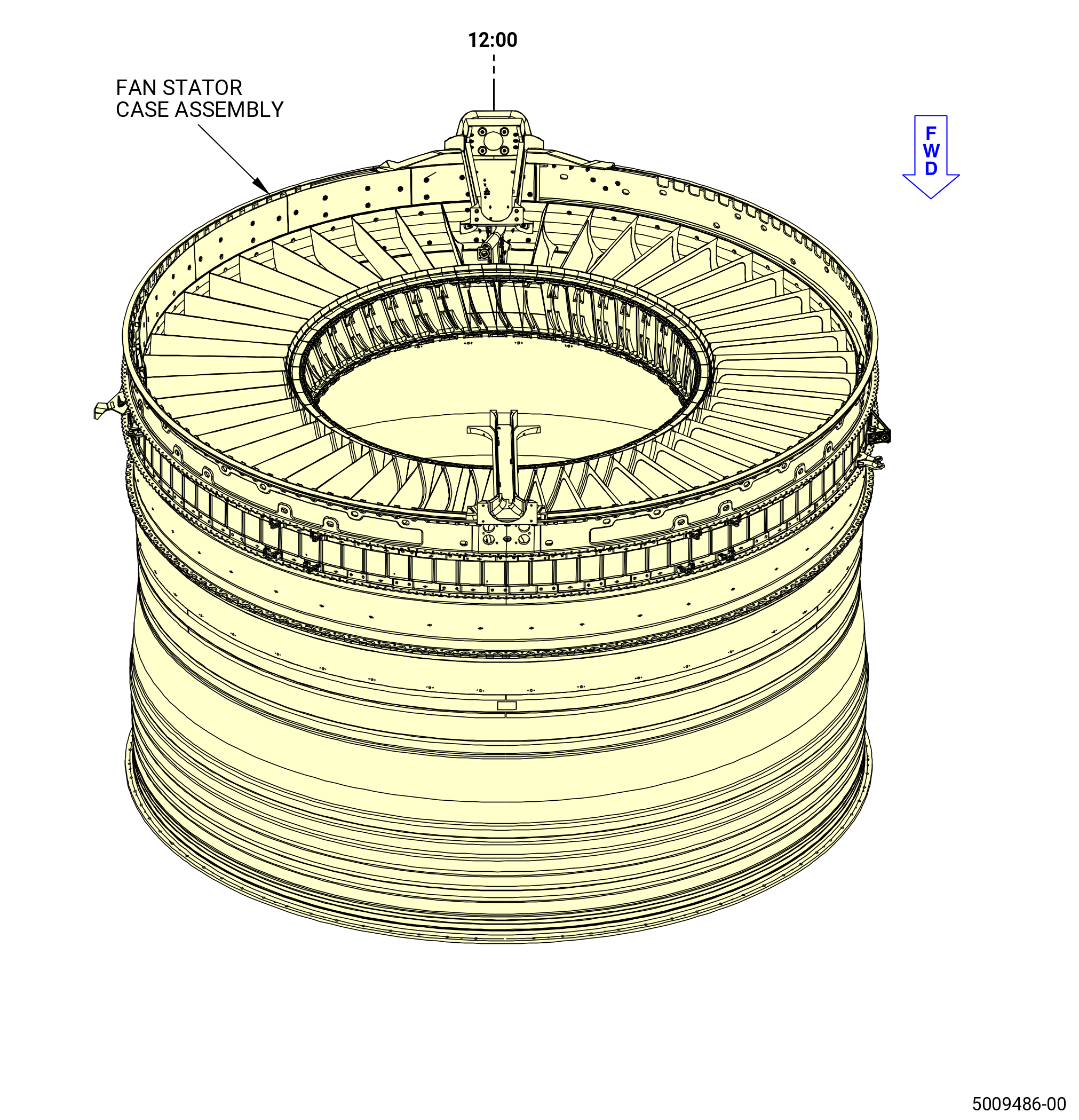
| A. | This procedure continues to assemble the fan stator case assembly in the vertical position at the equivalent build status of TASK 72-21-00-440-804 (72-21-00, ASSEMBLY 001 CONFIG 01) or TASK 72-21-00-440-806 (72-21-00, ASSEMBLY 001 CONFIG 02) . Refer to Figure 1001. |
|
| • |
|
| • |
|
|
| • |
|
| • |
|
| • |
|
| • |
|
| • |
|
| • |
|
| • |
|
| B. | Make sure that there is no foreign material in the modules. |
| C. | Make sure that the mating parts are serviceable and have no damage. |
| D. | Read this procedure and become familiar with the instructions and special tools before you install the modules. |
| E. | Before you do this procedure, read the cleaning engine parts section. Refer to TASK 70-20-00-100-001 (CLEANING ENGINE PARTS) . |
| F. | Install all bolts with the boltheads up or forward, unless otherwise specified. |
| CAUTION: |
|
| G. | Refer to TASK 70-51-00-400-004 (TIGHTENING PRACTICES AND TORQUE VALUES) when you tighten the tube and hose B-nuts. |
| H. | Follow the instructions to safety parts with safety wire, safety cable, cotter pins, or tab washers. Refer to TASK 70-11-00-400-001 (FASTENER RETENTION PROCEDURES) . |
| I. | The torque values given in this procedure are the actual torque to apply to the fastener. If a torque multiplier is used, do the necessary calculations to find the specified torque, the value that appears on the scale or dial of the torque wrench. Refer to TASK 70-51-00-400-004 (TIGHTENING PRACTICES AND TORQUE VALUES) . |
| J. | You can use C02-058 lubricant on the bearing and friction surfaces of bolts that attach the loop clamps (clamp) for easier assembly. |
| 2 . | Tools, Equipment, and Materials. |
| NOTE: |
|
| A. | Tools and Equipment. |
| (1) | Special Tools. |
| (2) | Standard Tools and Equipment. None. |
| (3) | Locally Manufactured Tools. None. |
| B. | Consumable Materials. |
|
| C. | Referenced Procedures. |
|
| D. | Expendable Parts. |
|
| 3 . | Procedure. |
| Subtask 72-00-01-430-386 |
| A. | Install the fan stator case assembly forward end down on a clean work surface. |
| Subtask 72-00-01-430-387 |
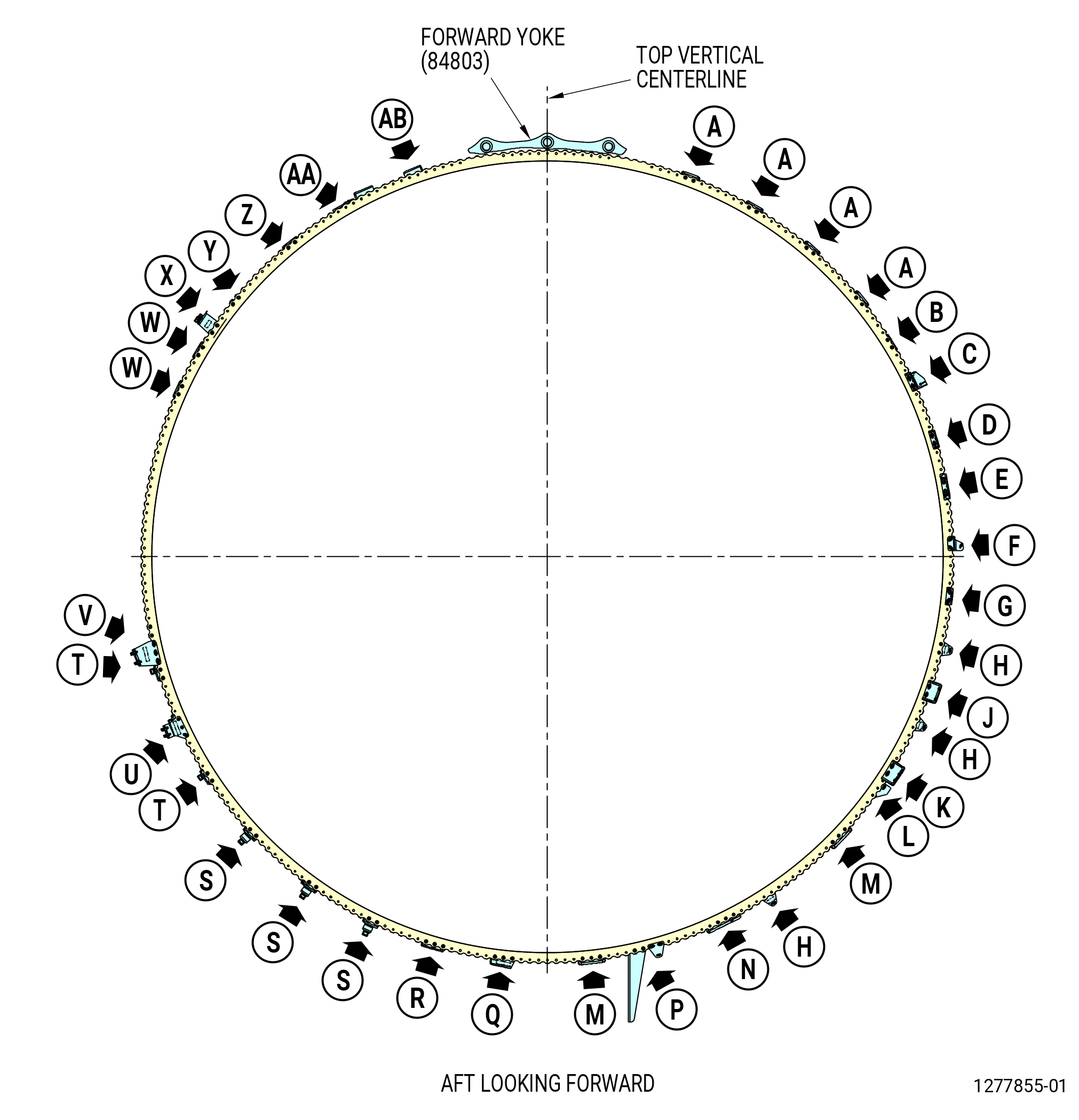
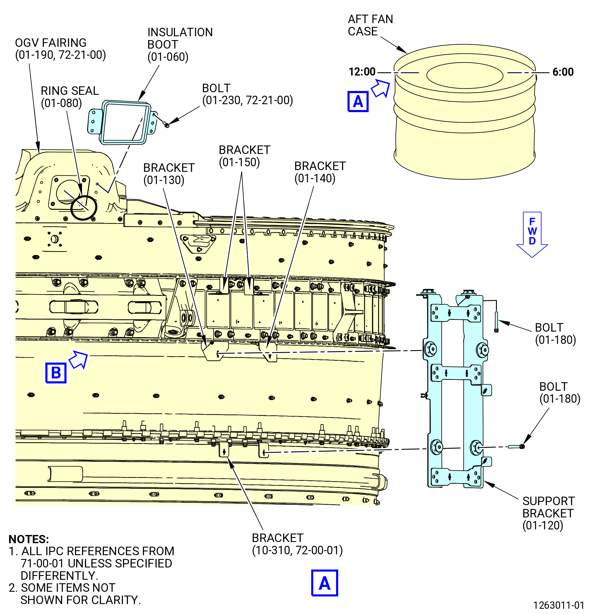
| B. | Install the brackets and hardware on the aft fan case mid ring flange (mid ring). Refer to Figure 1002 and do as follows: |
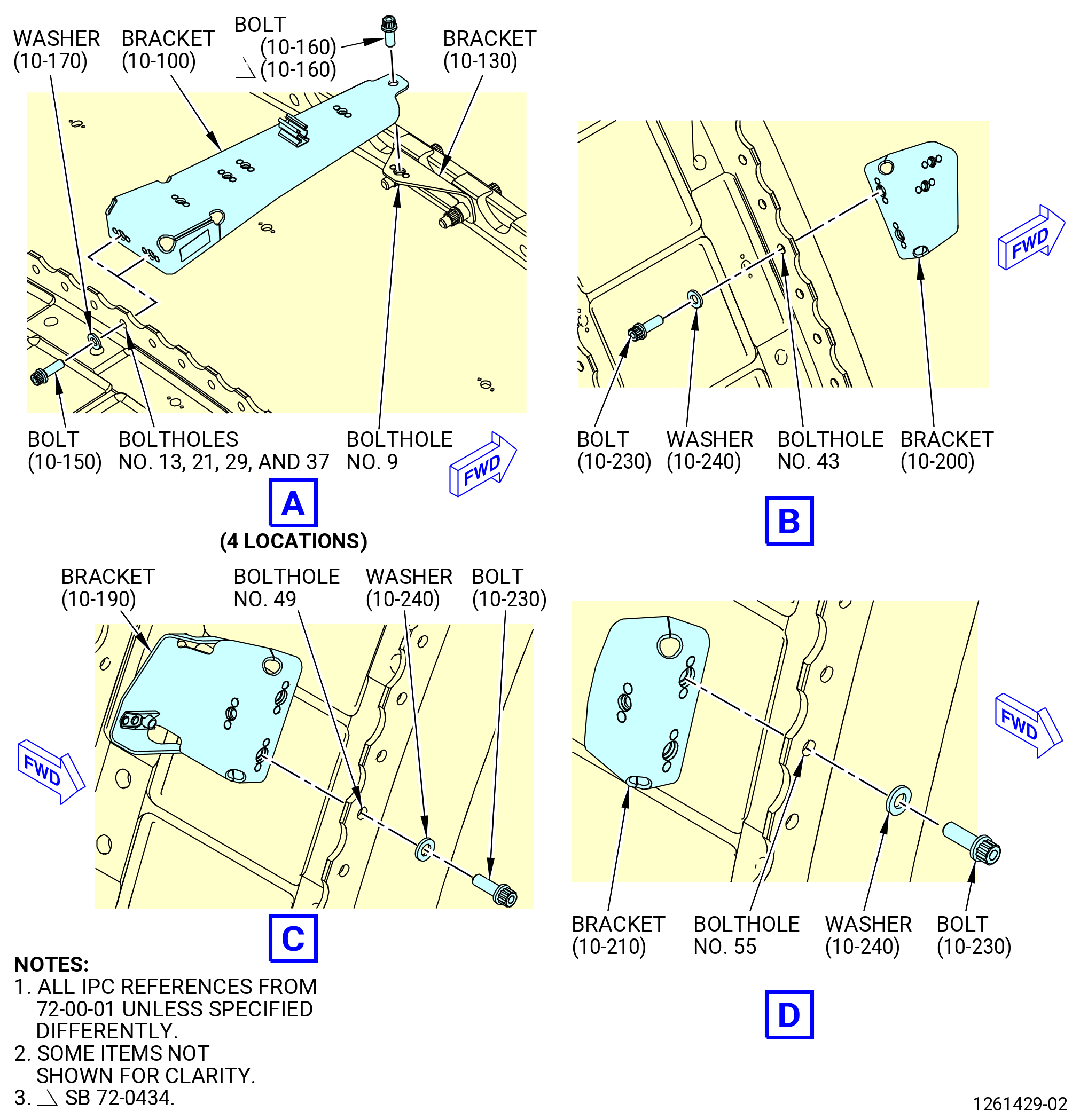
| (1) | Install the support brackets (46012) at boltholes No. 13 and 14, 21 and 22, 29 and 30, and 37 and 38 as follows: |
| Subtask 72-00-01-380-075 |
| (a) | Apply C03-001 primer or C03-100 primer to the threads and friction surfaces of the bolts (46023), the friction surfaces of the washers (46030), the inside diameter (ID) of the boltholes, and the surface of the bracket (46012) that makes contact with the fan case. |
| Subtask 72-00-01-430-388 |
| (b) | Install the bolts (46023) and washers (46030) on the aft side of the mid ring at boltholes No. 13 and 14, 21 and 22, 29 and 30, and 37 and 38. |
| (c) | Install the brackets (46012) on the forward side of the mid ring and attach with the bolts (46023) at boltholes No. 13 and 14, 21 and 22, 29 and 30, and 37 and 38. |
| (d) | Torque the bolts (10-150) (SIN 46023) to 106 to 124 lb in. (12.0 to 14.0 Nm). |
| (e) | Torque the bolts again to 106 to 124 lb in. (12.0 to 14.0 Nm). |
| (f) | Attach the bracket (10-100) (SIN 46012) to the support bracket (10-130) (SIN 46013) (three locations) on the fan case forward ring with bolts (10-160) (SIN 46025). Refer to TASK 72-21-00-440-805 (72-21-00, ASSEMBLY 002 CONFIG 01) or (TASK 72-21-00-440-808 (72-21-00, ASSEMBLY 002 CONFIG 02) for the installation of the support brackets (10-130) (SIN 46013). |
| (g) | Torque the bolts (10-160) (SIN 46025) to 106 to 124 lb in. (12.0 to 14.0 Nm). |
|
|
| Subtask 72-00-01-430-389 |
| (2) | Install the bracket (53318) on the mid ring at boltholes No. 43 and 44 as follows. Refer to Figure 1002. |
| Subtask 72-00-01-380-076 |
| (a) | Apply C03-001 primer or C03-100 primer to the threads and friction surfaces of the bolts (53321), the friction surfaces of the washers (53330), the ID of the boltholes, and the surface of the bracket (53318) that makes contact with the fan case. |
| Subtask 72-00-01-430-390 |
| (b) | Install the bolts (53321) and the washers (53330) on the aft side of the mid ring at boltholes No. 43 and 44. |
| (c) | Install the bracket (53318) on the forward side of the mid ring and attach with the bolts (53321) at boltholes No. 43 and 44. |
| (d) | Torque the bolts (10-230) (SIN 53321) to 106 to 124 lb in. (12.0 to 14.0 Nm). |
| (e) | Torque the bolts (10-230) (SIN 53321) again to 106 to 124 lb in. (12.0 to 14.0 Nm). |
| Subtask 72-00-01-430-391 |
| (3) | Install the bracket (53314) on the mid ring at boltholes No. 48 and 49 as follows. Refer to Figure 1002. |
| Subtask 72-00-01-380-077 |
| (a) | Apply C03-001 primer or C03-100 primer to the threads and friction surfaces of the bolts (53321), the friction surfaces of the washers (53330), the ID of the boltholes, and the surface of the bracket (53314) that makes contact with the fan case. |
| Subtask 72-00-01-430-392 |
| (b) | Install the bolts (53321) and the washers (53330) on the forward side of the mid ring at boltholes No. 48 and 49. |
| (c) | Install the bracket (53314) on the aft side of the mid ring and attach with the bolts (53321) at boltholes No. 48 and 49. |
| (d) | Torque the bolts (10-230) (SIN 53321) to 106 to 124 lb in. (12.0 to 14.0 Nm). |
| (e) | Torque the bolts (10-230) (SIN 53321) again to 106 to 124 lb in.(12.0 to 14.0 Nm). |
| Subtask 72-00-01-430-393 |
| (4) | Install the support bracket (5331A) on the mid ring at boltholes No. 55 and 56 as follows. Refer to Figure 1002. |
| Subtask 72-00-01-380-078 |
| (a) | Apply C03-001 primer or C03-100 primer to the threads and friction surfaces of the bolts (53321), the friction surfaces of the washers (53330), the ID of the boltholes, and the surface of the bracket (5331A) that makes contact with the fan case. |
| Subtask 72-00-01-430-394 |
| (b) | Install the bolts (53321) and the washers (53330) on the forward side of the mid ring at boltholes No. 55 and 56. |
| (c) | Install the bracket (5331A) on the aft side of the mid ring and attach with the bolts (53321) at boltholes No. 55 and 56. |
| (d) | Torque the bolts (10-230) (SIN 53321) to 106 to 124 lb in. (12.0 to 14.0 Nm). |
| (e) | Torque the bolts (10-230) (SIN 53321) again to 106 to 124 lb in. (12.0 to 14.0 Nm). |
| Subtask 72-00-01-430-395 |
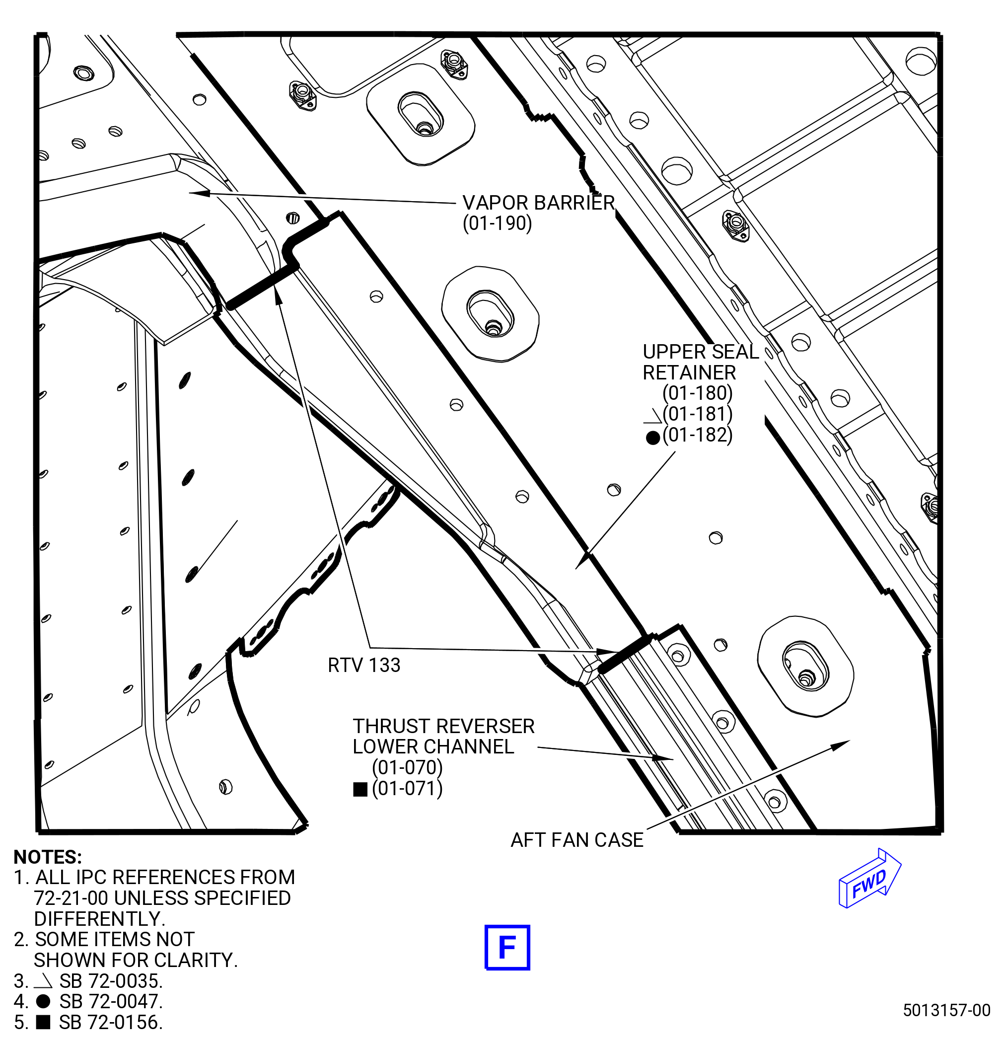
| (5) | Install the bracket (10-180) (SIN 53313) and the oil tank assembly (oil tank) (01-010) (SIN 00400) bonding strap (bracket) (01-240 , 79-11-10) (SIN 40110) or (01-241 , 79-11-10) (SIN 40110) on the mid ring at boltholes No. 60 and 62. Refer to Figure 1002 and do as follows: |
| Subtask 72-00-01-160-006 |
| WARNING: |
|
| (a) | Clean the surface areas where the bonding strap (01-240 , 79-11-10) (SIN 40110) touches the aft fan case to make sure that electrical bonding occurs. Clean the surfaces with C04-002 Stoddard solvent, C04-035 isopropyl alcohol, or a 50-50 blend of C04-035 isopropyl alcohol and C04-228 denatured alcohol. |
| Subtask 72-00-01-380-079 |
| WARNING: |
|
| (b) | Apply C03-001 primer or C03-100 primer to the threads and friction surfaces of the bolts (01-230 , 79-11-10) (SIN 40028) and (10-230) (SIN 53321), the ID of the boltholes, and the surface of the brackets (01-240 , 79-11-10) (SIN 40110) or (01-241 , 79-11-10) (SIN 40110) and the bracket (10-180) (SIN 53313) that makes contact with the fan case. |
| Subtask 72-00-01-430-396 |
| (c) | Install the bolt (53321) and the washer (53330) on the forward side of the mid ring at bolthole No. 60. |
| (d) | Install the bolt (01-230 , 79-11-10) (SIN 40028) and the bracket (01-240 , 79-11-10) (SIN 40110) or (01-241 , 79-11-10) (SIN 40110) on the forward side of the mid ring at bolthole No. 62. If necessary, remove the bracket (01-240 , 79-11-10) (SIN 40110) or (01-241 , 79-11-10) (SIN 40110) from the oil tank (01-010) (SIN 00400). |
| (e) | Install the bracket (53313) on the aft side of the mid ring at boltholes No. 60 and 62 and attach with the bolt (53321) at bolthole No. 60 and bolt (40028) at bolthole No. 62. |
| (f) | Torque the bolts (01-230 , 79-11-10) (SIN 40028), (10-230) (SIN 53321) to 106 to 124 lb in. (12.0 to 14.0 Nm). |
| (g) | Torque the bolts (10-230) (SIN 53321) again to 106 to 124 lb in.(12.0 to 14.0 Nm). |
| Subtask 72-00-01-430-550 |
| (6) | Install the bracket (5331B) on the mid ring at boltholes No. 67 and 68 as follows. Refer to Figure 1002. |
| Subtask 72-00-01-380-117 |
| (a) | Apply C03-001 primer or C03-100 primer to the threads and friction surfaces of the bolts (53321), the friction surfaces of the washers (53330), the ID of the boltholes, and the surface of the bracket (5331B) that makes contact with the fan case. |
| Subtask 72-00-01-430-551 |
| (b) | Install the bolts (53321) and the washers (53330) on the forward side of the mid ring at boltholes No. 67 and 68. |
| (c) | Install the bracket (5331B) on the aft side of the mid ring at boltholes No. 67 and 68 and attach with the bolts (53321) at boltholes No. 67 and 68. |
| (d) | Torque the bolts (10-230) (SIN 53321) to 106 to 124 lb in.(12.0 to 14.0 Nm). |
| (e) | Torque the bolts (10-230) (SIN 53321) again to 106 to 124 lb in. (12.0 to 14.0 Nm). |
| Subtask 72-00-01-430-399 |
| (7) | Install the bracket (48511) on the mid ring at boltholes No. 73 and 74 as follows. Refer to Figure 1002. |
| Subtask 72-00-01-380-081 |
| (a) | Apply C03-001 primer or C03-100 primer to the threads and friction surfaces of the bolts (48521), the friction surfaces of the washers (48530), the ID of the boltholes, and the surface of the bracket (48511) that makes contact with the fan case. |
| Subtask 72-00-01-430-400 |
| (b) | Install the bolts (48521) and the washers (48530) on the forward side of the mid ring at boltholes No. 73 and 74. |
| (c) | Install the bracket (48511) and washers (48530) on the aft side of the mid ring at boltholes No. 73 and 74 and attach with the bolts (48521) at boltholes No. 73 and 74. |
| (d) | Torque the bolts (01-490) (SIN 48521) to 106 to 124 lb in. (12.0 to 14.0 Nm). |
| (e) | Torque the bolts (01-490) (SIN 48521) again to 106 to 124 lb in. (12.0 to 14.0 Nm). |
| Subtask 72-00-01-430-401 |
| (8) | Install the support bracket (bracket) (48510) on the mid ring at boltholes No. 79 and 80, 88 and 89, and 114 and 115 (three locations) as follows. Refer to Figure 1002. |
| Subtask 72-00-01-380-082 |
| (a) | Apply C03-001 primer or C03-100 primer to the threads and friction surfaces of the bolts (48521), the friction surfaces of the washers (48530), the ID of the boltholes, and the surface of the bracket (48510) that makes contact with the fan case. |
| Subtask 72-00-01-430-402 |
| (b) | Install the bolts (48521) and the washers (48530) on the aft side of the mid ring at boltholes No. 79 and 80, 88 and 89, and 114 and 115. |
| (c) | Install the bracket (48510) on the forward side of the mid ring and attach with the bolts (48521) at boltholes No. 79 and 80, 88 and 89, and 114 and 115. |
| (d) | Torque the bolts (01-490) (SIN 48521) to 106 to 124 lb in. (12.0 to 14.0 Nm). |
| (e) | Torque the bolts (01-490) (SIN 48521) again to 106 to 124 lb in. (12.0 to 14.0 Nm). |
| Subtask 72-00-01-430-552 |
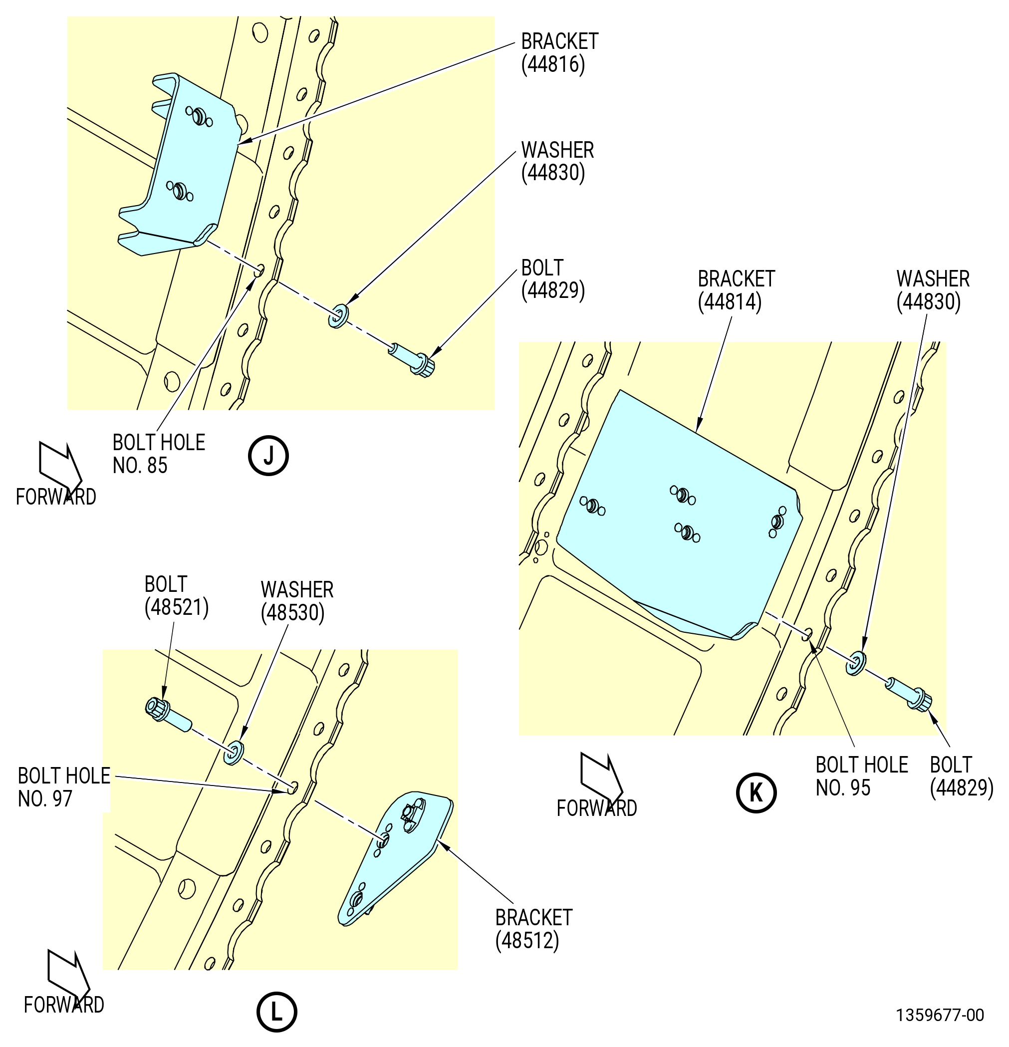
| (9) | Install the bracket (44816) on the mid ring at boltholes No. 84 and 85 as follows. Refer to Figure 1002. |
| Subtask 72-00-01-380-118 |
| (a) | Apply C03-001 primer or C03-100 primer to the threads and friction surfaces of the bolts (44829), the friction surfaces of the washers (44830), the ID of the boltholes, and the surface of the bracket (44816) that makes contact with the fan case. |
| Subtask 72-00-01-430-553 |
| (b) | Install the bolts (44829) and the washers (44830) on the forward side of the mid ring at boltholes No. 84 and 85. |
| (c) | Install the bracket (44816) on the aft side of the mid ring and attach with the bolts (44829) at boltholes No. 84 and 85. |
| (d) | Torque the bolts (05-810) (SIN 44829) to 106 to 124 lb in. (12.0 to 14.0 Nm). |
| (e) | Torque the bolts (05-810) (SIN 44829) again to 106 to 124 lb in. (12.0 to 14.0 Nm). |
| Subtask 72-00-01-430-654 |
| (10) | Attach the bracket (05-770) (SIN 44815) as follows: |
| (a) | Install the two machine bolts (bolts) (05-820) (SIN 4482B) thru the bracket (05-770) (SIN 44815) and the bracket (05-790) (SIN 44816). |
| (b) | Torque the bolts (05-820) (SIN 4482B) to 106 to 124 lb in. (12.0 to 14.0 Nm). |
| Subtask 72-00-01-430-554 |
| (11) | Install the bracket (44814) on the mid ring at boltholes No. 94 and 95 as follows. Refer to Figure 1002. |
| Subtask 72-00-01-380-119 |
| (a) | Apply C03-001 primer or C03-100 primer to the threads and friction surfaces of the bolts (44829), the friction surfaces of the washers (44830), the ID of the boltholes, and the surface of the bracket (44814) that makes contact with the fan case. |
| Subtask 72-00-01-430-555 |
| (b) | Install the bolts (44829) and the washers (44830) on the forward side of the mid ring at boltholes No. 94 and 95. |
| (c) | Install the bracket (44814) on the aft side of the mid ring and attach with the bolts (44829) at boltholes No. 94 and 95. |
| (d) | Torque the bolts (05-810) (SIN 44829) to 106 to 124 lb in. (12.0 to 14.0 Nm). |
| (e) | Torque the bolts (05-810) (SIN 44829) again to 106 to 124 lb in. (12.0 to 14.0 Nm). |
| Subtask 72-00-01-430-556 |
| (12) | Install the bracket (48512) on the mid ring at boltholes No. 97 and 98 as follows. Refer to Figure 1002. |
| Subtask 72-00-01-380-120 |
| (a) | Apply C03-001 primer or C03-100 primer to the threads and friction surfaces of the bolts (48521), the friction surfaces of the washers (48530), the ID of the boltholes, and the surface of the bracket (48512) that makes contact with the fan case. |
| Subtask 72-00-01-430-557 |
| (b) | Install the bolts (48521) and the washers (48530) on the aft side of the mid ring at boltholes No. 97 and 98. |
| (c) | Install the bracket (48512) on the forward side of the mid ring and attach with the bolts (48521) at boltholes No. 97 and 98. |
| (d) | Torque the bolts (01-490) (SIN 48521) to 106 to 124 lb in. (12.0 to 14.0 Nm). |
| (e) | Torque the bolts (01-490) (SIN 48521) again to 106 to 124 lb in. (12.0 to 14.0 Nm). |
| Subtask 72-00-01-430-405 |
| (13) | Install the bracket (44011) on the mid ring at boltholes No. 103-105 and 135-137 (two locations) as follows. Refer to Figure 1002. |
| Subtask 72-00-01-380-084 |
| (a) | Apply C03-001 primer or C03-100 primer to the threads and friction surfaces of the bolts (44022), the friction surfaces of the washers (44030), the ID of the boltholes, and the surface of the bracket (44011) that makes contact with the fan case. |
| Subtask 72-00-01-430-406 |
| (b) | Install the bolts (44022) and the washers (44030) on the aft side of the mid ring at boltholes No. 103-105 and 135-137. |
| (c) | Install the bracket (44011) on the forward side of the mid ring and attach with the bolts (44022) at boltholes No. 103-105 and 135-137. |
| (d) | Torque the bolts (05-670) (SIN 44022) to 106 to 124 lb in. (12.0 to 14.0 Nm). |
| (e) | Torque the bolts (05-670) (SIN 44022) again to 106 to 124 lb in. (12.0 to 14.0 Nm). |
| Subtask 72-00-01-430-407 |
| (14) | Install the bracket (44010) on the mid ring at boltholes No. 120-122 as follows. Refer to Figure 1002. |
| Subtask 72-00-01-380-085 |
| (a) | Apply C03-001 primer or C03-100 primer to the threads and friction surfaces of the bolts (44022), the friction surfaces of the washers (44030), the ID of the boltholes, and the surface of the bracket (44010) that makes contact with the fan case. |
| Subtask 72-00-01-430-408 |
| (b) | Install the bolts (44022) and the washers (44030) on the aft side of the mid ring at boltholes No. 120-122. |
| (c) | Install the bracket (44010) on the forward side of the mid ring and attach with the bolts (44022) at boltholes No. 120-122. |
| (d) | Torque the bolts (05-670) (SIN 44022) to 106 to 124 lb in. (12.0 to 14.0 Nm). |
| (e) | Torque the bolts (05-670) (SIN 44022) again to 106 to 124 lb in. (12.0 to 14.0 Nm). |
| Subtask 72-00-01-430-576 |
| (15) | Install the bracket (48510) on the mid ring at boltholes No. 128 and 129 as follows. Refer to Figure 1002. |
| Subtask 72-00-01-380-123 |
| (a) | Apply C03-001 primer or C03-100 primer to the threads and friction surfaces of the bolts (48521), the friction surfaces of the washers (48530), the ID of the boltholes, and the surface of the bracket (48510) that makes contact with the fan case. |
| Subtask 72-00-01-430-577 |
| (b) | Install the bolts (48521) and the washers (48530) on the forward side of the mid ring at boltholes No. 128 and 129. |
| (c) | Install the brackets (48510) on the aft side of the mid ring and attach with the bolts (48521) at boltholes No. 128 and 129. |
| (d) | Torque the bolts (48521) to 109-127 lb in. (12.3-14.4 Nm). |
| (e) | Torque the bolts (48521) again to 109-127 lb in. (12.3-14.4 Nm). |
| Subtask 72-00-01-430-409 |
| (16) | Install the bracket (6701J) on the mid ring at boltholes No. 130 and 131 as follows. Refer to Figure 1002. |
| Subtask 72-00-01-380-086 |
| (a) | Apply C03-001 primer or C03-100 primer to the threads and friction surfaces of the bolts (05-490) (SIN 67022), the friction surfaces of the washers (05-360) (SIN 67030), the ID of the boltholes, and the surface of the bracket (05-520) (SIN 6701J) that makes contact with the fan case. |
| Subtask 72-00-01-430-410 |
| (b) | Install the bolts (05-490) (SIN 67022) and the washers (05-360) (SIN 67030) on the aft side of the mid ring at boltholes No. 130 and 131. |
| (c) | Install the bracket (6701J) on the forward side of the mid ring and attach with the bolts (67022) at boltholes No. 130 and 131. |
| (d) | Torque the bolts (05-490) (SIN 67022) to 106 to 124 lb in. (12.0 to 14.0 Nm). |
| (e) | Torque the bolts (05-490) (SIN 67022) again to 106 to 124 lb in. (12.0 to 14.0 Nm). |
| Subtask 72-00-01-430-411 |
| (17) | Install the tube support bracket (bracket) (61418) on the mid ring at boltholes No. 145-147 as follows. Refer to Figure 1002. |
| Subtask 72-00-01-380-087 |
| (a) | Apply C03-001 primer or C03-100 primer to the threads and friction surfaces of the bolts (01-390) (SIN 61422), the friction surfaces of the washers (01-400) (SIN 61430), the ID of the boltholes, and the surface of the bracket (01-410) (SIN 61418) that makes contact with the fan case. |
| Subtask 72-00-01-430-412 |
| (b) | Install the bolts (01-390) (SIN 61422) and the washers (01-400) (SIN 61430) on the aft side of the mid ring at boltholes No. 145-147. |
| (c) | Install the bracket (01-410) (SIN 61418) on the forward side of the mid ring and attach with the bolts (01-390) (SIN 61422) at boltholes No. 145-147. |
| (d) | Torque the bolts (01-390) (SIN 61422) to 106 to 124 lb in. (12.0 to 14.0 Nm). |
| (e) | Torque the bolts (01-390) (SIN 61422) again to 106 to 124 lb in. (12.0 to 14.0 Nm). |
| Subtask 72-00-01-430-413 |
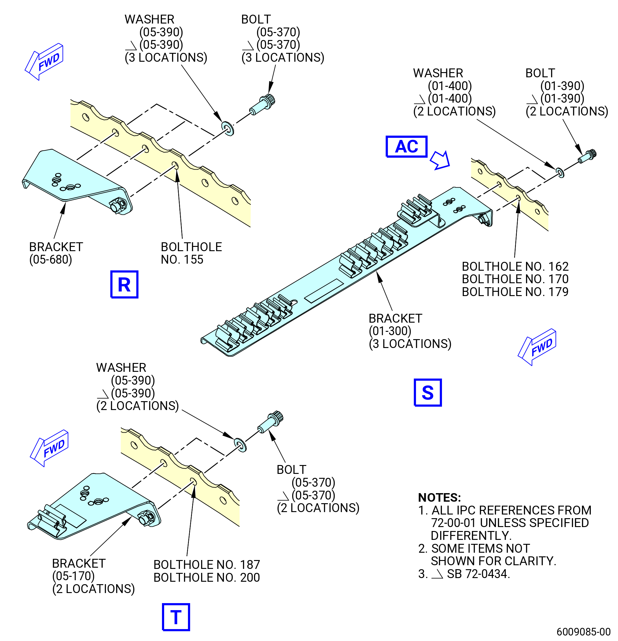
| (18) | Install the support bracket (bracket) (61412) on the mid ring at boltholes No. 153-155 as follows. Refer to Figure 1002. |
| Subtask 72-00-01-380-088 |
| (a) | Apply C03-001 primer or C03-100 primer to the threads and friction surfaces of the bolts (05-370) (SIN 61422), the friction surfaces of the washers (05-390) (SIN 61430), the ID of the boltholes, and the surface of the bracket (05-680) (SIN 61412) that makes contact with the fan case. |
| Subtask 72-00-01-430-414 |
| (b) | Install the bolts (05-370) (SIN 61422) and the washers (05-390) (SIN 61430) on the aft side of the mid ring at boltholes No. 153-155. |
| (c) | Install the bracket (05-680) (SIN 61412) on the forward side of the mid ring and attach with the bolts (05-370) (SIN 61422) at boltholes No. 153-155. |
| (d) | Torque the bolts (05-370) (SIN 61422) to 106 to 124 lb in. (12.0 to 14.0 Nm). |
| (e) | Torque the bolts (05-370) (SIN 61422) again to 106 to 124 lb in. (12.0 to 14.0 Nm). |
| Subtask 72-00-01-430-415 |
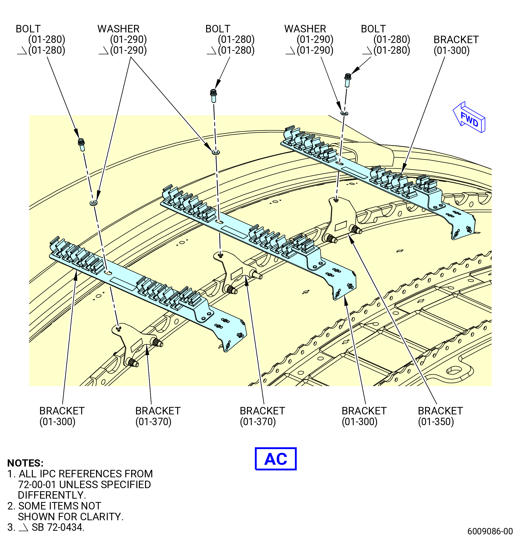
| (19) | Install the tube support bracket (bracket) (61419) on the mid ring at boltholes No. 161 and 162, 169 and 170, and 178 and 179 (three locations) as follows. Refer to Figure 1002. |
| Subtask 72-00-01-380-089 |
| (a) | Apply C03-001 primer or C03-100 primer to the threads and friction surfaces of the bolts (01-390) (SIN 61422), the friction surfaces of the washers (01-400) (SIN 61430), the ID of the boltholes, and the surface of the bracket (01-300) (SIN 61419) that makes contact with the fan case. |
| Subtask 72-00-01-430-416 |
| (b) | Install the bolts (01-390) (SIN 61422) and the washers (01-400) (SIN 61430) on the aft side of the mid ring at boltholes No. 161 and 162, 169 and 170, and 178 and 179. |
| (c) | Install the bracket (01-300) (SIN 61419) on the forward side of the mid ring and attach with the bolts (01-390) (SIN 61422) at boltholes No. 161 and 162, 169 and 170, and 178 and 179. |
| (d) | Torque the bolts (01-390) (SIN 61422) to 106 to 124 lb in. (12.0 to 14.0 Nm). |
| (e) | Torque the bolts (01-390) (SIN 61422) again to 106 to 124 lb in. (12.0 to 14.0 Nm). |
| (f) | Attach the three brackets (01-300) (SIN 61419) on the bracket (01-350) (SIN 67015) at one location and on the brackets (01-370) (SIN 67016) at two locations with a washer (01-290) (SIN 67030) and a bolts (01-280) (SIN 67021). Refer to TASK 72-21-00-440-805 (72-21-00 ASSEMBLY 002 CONFIG 01) or TASK 72-21-00-440-808 (72-21-00 ASSEMBLY 002 CONFIG 02) for brackets (01-350) (SIN 67015) and (01-370) (SIN 67016) installation procedures. |
| Subtask 72-00-01-430-419 |
| (20) | Install the support bracket (bracket) (61414) on the mid ring at boltholes No. 186 and 187, and 199 and 200 (two locations) as follows. Refer to Figure 1002. |
| Subtask 72-00-01-380-091 |
| (a) | Apply C03-001 primer or C03-100 primer to the threads and friction surfaces of the bolts (05-370) (SIN 61422), the friction surfaces of the washers (05-390) (SIN 61430), the ID of the boltholes, and the surface of the bracket (05-170) (SIN 61414) that makes contact with the fan case. |
| Subtask 72-00-01-430-420 |
| (b) | Install the bolts (05-370) (SIN 61422) and the washers (05-390) (SIN 61430) on the aft side of the mid ring at boltholes No. 186, 187, 199, and 200. |
| (c) | Install the bracket (05-170) (SIN 61414) on the forward side of the mid ring and attach with the bolts (05-370) (SIN 61422) at boltholes No. 186, 187, 199, and 200. |
| (d) | Torque the bolts (05-370) (SIN 61422) to 106 to 124 lb in. (12.0 to 14.0 Nm). |
| (e) | Torque the bolts (05-370) (SIN 61422) again to 106 to 124 lb in. (12.0 to 14.0 Nm). |
| Subtask 72-00-01-430-421 |
| * * * PRE SB 72-0056( Heavy Brackets ) |
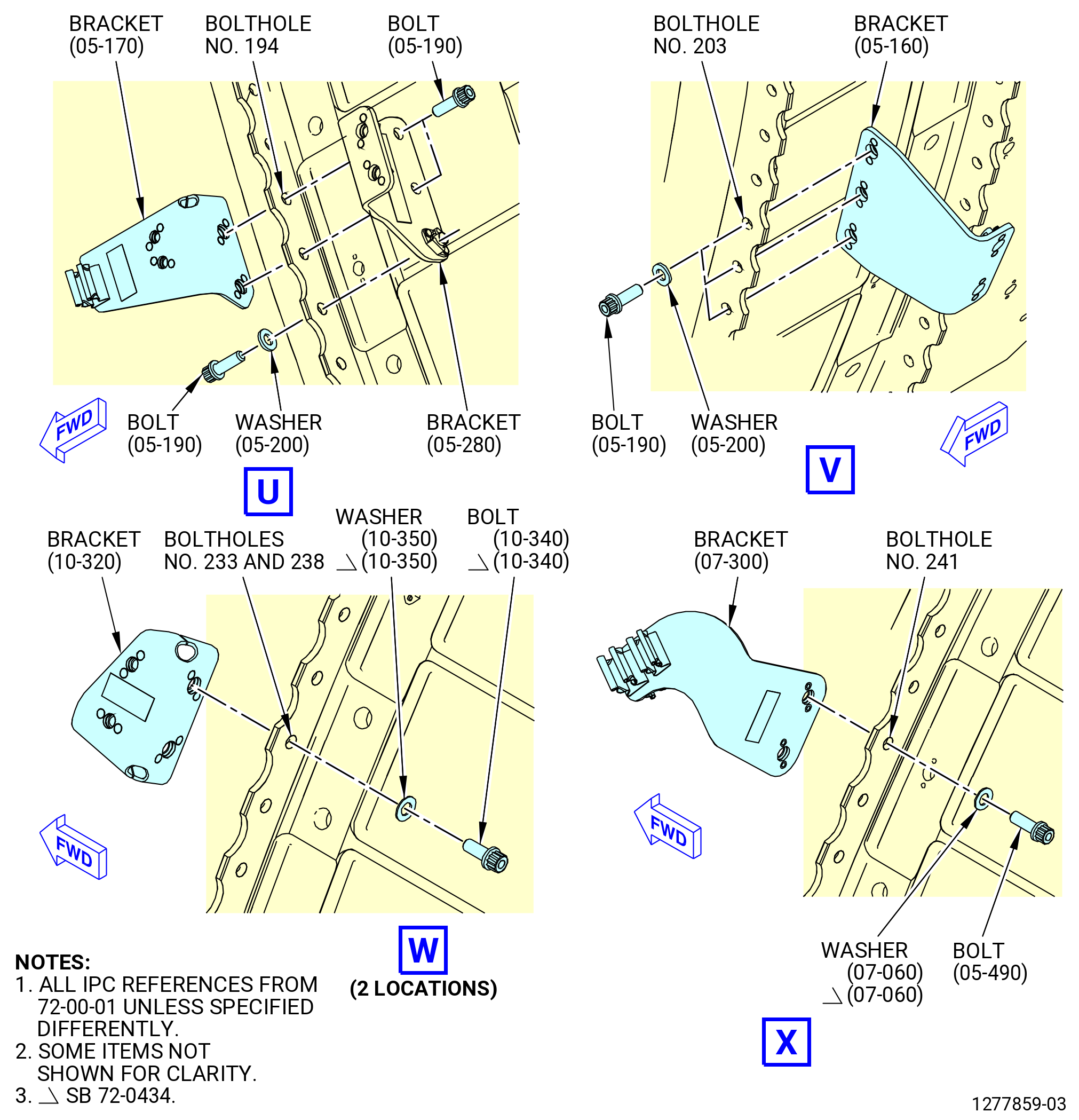
| (21) | Install the support brackets (bracket) (61414), (05-280) (SIN 65Z11) on the mid ring at boltholes No. 192-194 as follows. Refer to Figure 1002. |
| Subtask 72-00-01-380-092 |
| (a) | Apply C03-001 primer or C03-100 primer to the threads and friction surfaces of the bolts (05-190) (SIN 65Z20), friction surfaces of the washers (05-200) (SIN 65Z30), ID of boltholes, and surface of the brackets (61414), (05-280) (SIN 65Z11) that touches the fan case. |
| Subtask 72-00-01-430-422 |
| (b) | Install the bolt (05-190) (SIN 65Z20) and washer (05-200) (SIN 65Z30) on the forward side of the mid ring at bolthole No. 192. |
| (c) | Install the bracket (05-280) (SIN 65Z11) on the aft side of the mid ring on the bolt (05-190) (SIN 65Z20) at bolthole No. 192. |
| (d) | Install the bolts (05-190) (SIN 65Z20) on the bracket (05-280) (SIN 65Z11) on the aft side of the mid ring in boltholes No. 193 and 194. |
| (e) | Install the bracket (61414) on the forward side of the mid ring on the bolts (05-190) (SIN 65Z20) at boltholes No. 193 and 194. |
| (f) | Torque the bolts (05-190) (SIN 65Z20) to 106 to 124 lb in. (12.0 to 14.0 Nm). |
| (g) | Torque the bolts (05-190) (SIN 65Z20) again to 106 to 124 lb in. (12.0 to 14.0 Nm). |
| * * * END PRE SB 72-0056 |
| Subtask 72-00-01-430-592 |
| * * * SB 72-0056( Light Brackets ) |
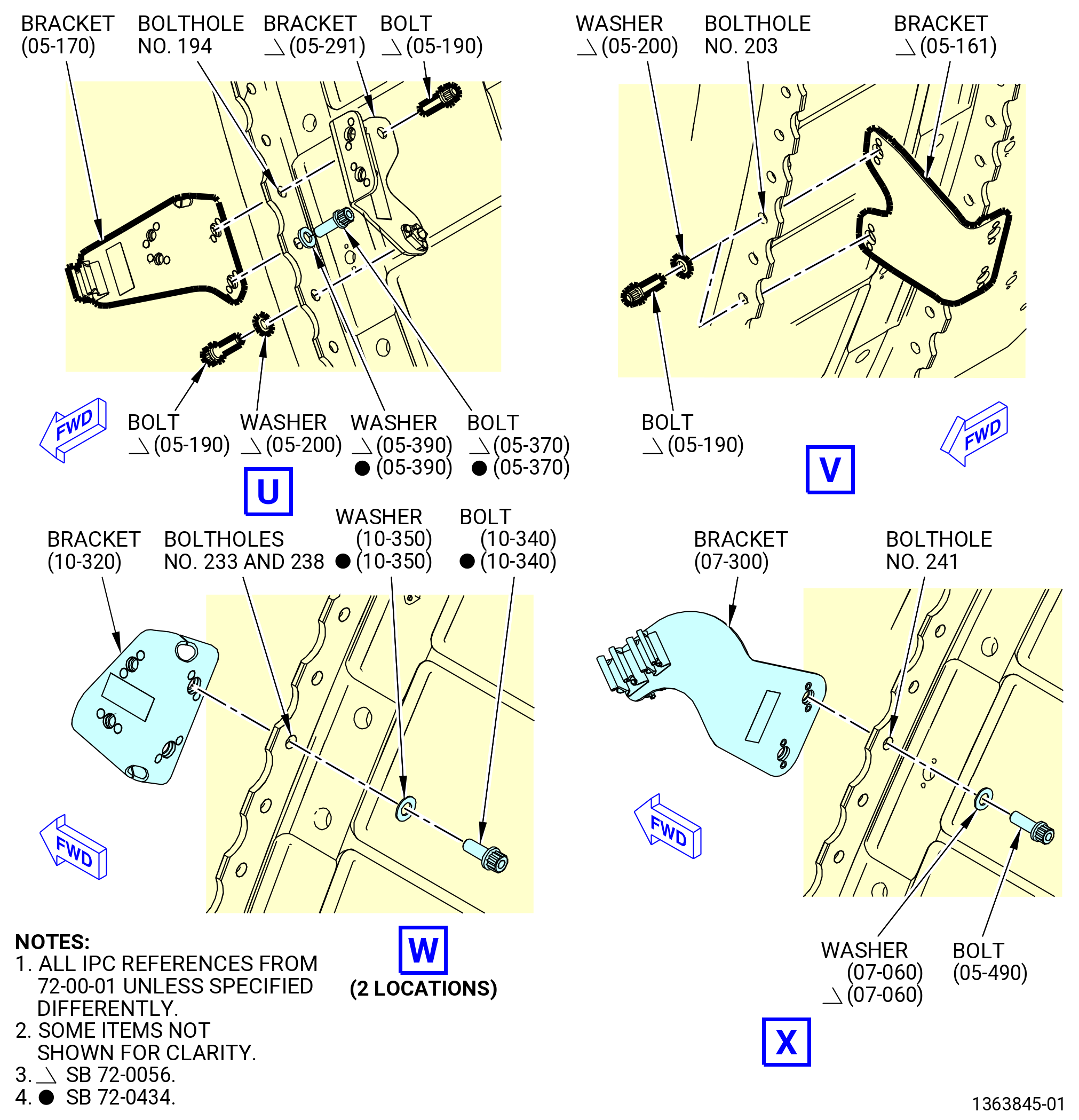
| (21).C. | Install the support brackets (bracket) (61414), (05-291) (SIN 65Z11) on the mid ring at boltholes No. 192-194 as follows. Refer to Figure 1002. |
| Subtask 72-00-01-380-127 |
| (a) | Apply C03-001 primer or C03-100 primer to the threads and friction surfaces of the bolts (05-190) (SIN 65Z20), (05-370) (SIN 61422), friction surfaces of the washers (05-200) (SIN 65Z30), (05-390) (SIN 61430), ID of boltholes, and surface of the brackets (05-170) (SIN 61414) and (05-291) (SIN 65Z11) that touches the fan case. |
| Subtask 72-00-01-430-593 |
| (b) | Install the bolt (05-190) (SIN 65Z20) and washer (05-200) (SIN 65Z30) on the forward side of the mid ring at bolthole No. 192. |
| (c) | Install the bracket (05-291) (SIN 65Z11) on the aft side of the mid ring on the bolt (05-190) (SIN 65Z20) at bolthole No. 192. |
| (d) | Install the bolt (05-370) (SIN 61422) and washer (05-390) (SIN 61430) on the aft side of the mid ring at bolthole No. 193. |
| (e) | Install the bolt (05-190) (SIN 65Z20) on the bracket (05-291) (SIN 65Z11) on the aft side of the mid ring at bolthole No. 194. |
| (f) | Install the bracket (05-170) (SIN 61414) on the forward side of the mid ring on the bolts (05-190) (SIN 65Z20) and (05-370) (SIN 61422) at boltholes No. 193 and 194. |
| (g) | Torque the bolts (05-190) (SIN 65Z20) and (05-370) (SIN 61422) to 106 to 124 lb in. (12.0 to 14.0 Nm). |
| (h) | Torque the bolts (05-190) (SIN 65Z20) and (05-370) (SIN 61422) again to 106 to 124 lb in. (12.0 to 14.0 Nm). |
| * * * END SB 72-0056 |
| Subtask 72-00-01-430-423 |
| * * * PRE SB 72-0056( Heavy Brackets ) |
| (22) | Install the support bracket (bracket) (05-160) (SIN 65Z13) on the mid ring at boltholes No. 201-203 as follows. Refer to Figure 1002. |
| Subtask 72-00-01-380-093 |
| (a) | Apply C03-001 primer or C03-100 primer to the threads and friction surfaces of the bolts (05-190) (SIN 65Z20), friction surfaces of the washers (05-200) (SIN 65Z30), ID of boltholes, and surface of the bracket (05-160) (SIN 65Z13) that touches the fan case. |
| Subtask 72-00-01-430-424 |
| (b) | Install the bolts (05-190) (SIN 65Z20) and washers (05-200) (SIN 65Z30) on the forward side of the mid ring at boltholes No. 201-203. |
| (c) | Install the bracket (05-160) (SIN 65Z13) on the aft side of the mid ring and attach with the bolts (05-190) (SIN 65Z20) at boltholes No. 201-203. |
| (d) | Torque the bolts (05-190) (SIN 65Z20) to 106 to 124 lb in. (12.0 to 14.0 Nm). |
| (e) | Torque the bolts (05-190) (SIN 65Z20) again to 106 to 124 lb in. (12.0 to 14.0 Nm). |
| * * * END PRE SB 72-0056 |
| Subtask 72-00-01-430-594 |
| * * * SB 72-0056( Light Brackets ) |
| (22).C. | Install the support bracket (bracket) (05-161) (SIN 65Z13) on the mid ring at boltholes No. 201 and 203 as follows. Refer to Figure 1002. |
| Subtask 72-00-01-380-128 |
| (a) | Apply C03-001 primer or C03-100 primer to the threads and friction surfaces of the bolts (05-190) (SIN 65Z20), friction surfaces of the washers (05-200) (SIN 65Z30), ID of boltholes, and surface of the bracket (05-161) (SIN 65Z13) that touches the fan case. |
| Subtask 72-00-01-430-595 |
| (b) | Install the bolts (05-190) (SIN 65Z20) and washers (05-200) (SIN 65Z30) on the forward side of the mid ring at boltholes No. 201 and 203. |
| (c) | Install the bracket (05-161) (SIN 65Z13) on the aft side of the mid ring and attach with the bolts (05-190) (SIN 65Z20) at boltholes No. 201 and 203. |
| (d) | Torque the bolts (05-190) (SIN 65Z20) to 106 to 124 lb in. (12.0 to 14.0 Nm). |
| (e) | Torque the bolts (05-190) (SIN 65Z20) again to 106 to 124 lb in. (12.0 to 14.0 Nm). |
| * * * END SB 72-0056 |
| Subtask 72-00-01-430-425 |
| (23) | Install the support bracket (bracket) (61311) on the mid ring at boltholes No. 232 and 233, and 237 and 238 (two locations) as follows. Refer to Figure 1002. |
| Subtask 72-00-01-380-094 |
| (a) | Apply C03-001 primer or C03-100 primer to the threads and friction surfaces of the bolts (10-340) (SIN 61321), the friction surfaces of the washers (10-350) (SIN 61330), the ID of boltholes, and the surface of the bracket (10-320) (SIN 61311) that makes contact with the fan case. |
| Subtask 72-00-01-430-426 |
| (b) | Install the bolts (10-340) (SIN 61321) and the washers (10-350) (SIN 61330) on the aft side of the mid ring at boltholes No. 232, 233, 237, and 238. |
| (c) | Install the bracket (10-320) (SIN 61311) on the forward side of the mid ring and attach with the bolts (10-340) (SIN 61321) at boltholes No. 232, 233, 237, and 238. |
| (d) | Torque the bolts (10-340) (SIN 61321) to 106 to 124 lb in. (12.0 to 14.0 Nm). |
| (e) | Torque the bolts (10-340) (SIN 61321) again to 106 to 124 lb in. (12.0 to 14.0 Nm). |
| Subtask 72-00-01-430-427 |
| (24) | Install the support bracket (bracket) (6701B) on the mid ring at boltholes No. 240 and 241 as follows. Refer to Figure 1002. |
| Subtask 72-00-01-380-095 |
| (a) | Apply C03-001 primer or C03-100 primer to the threads and friction surfaces of the bolts (07-100) (SIN 67022), the friction surfaces of the washers (07-060) (SIN 67030), the ID of boltholes, and the surface of the bracket (07-300) (SIN 6701B) that makes contact with the fan case. |
| Subtask 72-00-01-430-428 |
| (b) | Install the bolts (07-100) (SIN 67022) and the washers (07-060) (SIN 67030) on the aft side of the mid ring at boltholes No. 240 and 241. |
| (c) | Install the bracket (6701B) on the forward side of the mid ring and attach with the bolts (67022) at boltholes No. 240 and 241. |
| (d) | Torque the bolts (07-100) (SIN 67022) to 106 to 124 lb in. (12.0 to 14.0 Nm). |
| (e) | Torque the bolts (07-100) (SIN 67022) again to 106 to 124 lb in. (12.0 to 14.0 Nm). |
| Subtask 72-00-01-430-537 |
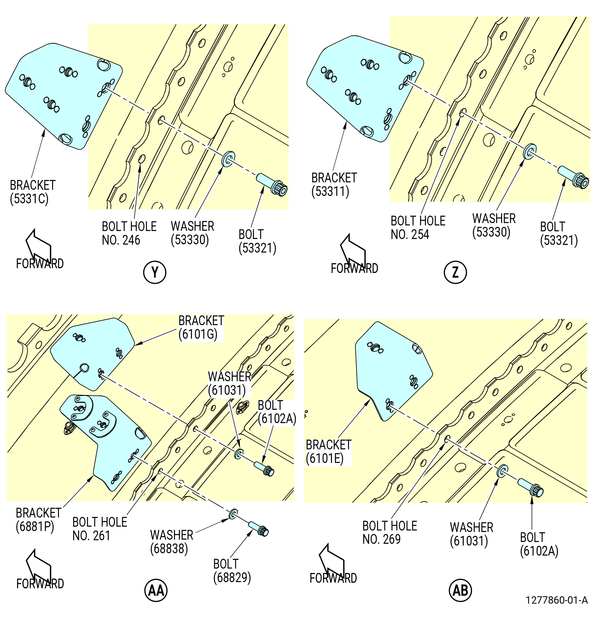
| (25) | Install the support bracket (5331C) on the mid ring at boltholes No. 246 and 247. Refer to Figure 1002. |
| Subtask 72-00-01-380-113 |
| (a) | Apply C03-001 primer or C03-100 primer to the threads and friction surfaces of the bolts (53321), the friction surfaces of the washers (53330), the ID of boltholes, and the surface of the bracket (5331C) that makes contact with the fan case. |
| Subtask 72-00-01-430-538 |
| (b) | Install the bolts (53321) and the washers (53330) on the aft side of the mid ring at boltholes No. 246 and 247. |
| (c) | Install the bracket (5331C) on the forward side of the mid ring and attach with the bolts (53321) at boltholes No. 246 and 247. |
| (d) | Torque the bolts (10-230) (SIN 53321) to 106 to 124 lb in. (12.0 to 14.0 Nm). |
| (e) | Torque the bolts (10-230) (SIN 53321) again to 106 to 124 lb in. (12.0 to 14.0 Nm). |
| Subtask 72-00-01-430-429 |
| (26) | Install the bracket (53311) on the mid ring at boltholes No. 253 and 254 as follows. Refer to Figure 1002. |
| Subtask 72-00-01-380-096 |
| (a) | Apply C03-001 primer or C03-100 primer to the threads and friction surfaces of the bolts (53321), the friction surfaces of the washers (53330), the ID of the boltholes, and the surface of the bracket (53311) that makes contact with the fan case. |
| Subtask 72-00-01-430-430 |
| (b) | Install the bolts (53321) and the washers (53330) on the aft side of the mid ring at boltholes No. 253 and 254. |
| (c) | Install the bracket (53311) on the forward side of the mid ring and attach with the bolts (53321) at boltholes No. 253 and 254. |
| (d) | Torque the bolts (10-230) (SIN 53321) to 106 to 124 lb in. (12.0 to 14.0 Nm). |
| (e) | Torque the bolts (10-230) (SIN 53321) again to 106 to 124 lb in. (12.0 to 14.0 Nm). |
| Subtask 72-00-01-430-431 |
| (27) | Install the bracket (6881P) on the mid ring at boltholes No. 260 and 261 as follows. Refer to Figure 1002. |
| Subtask 72-00-01-380-097 |
| (a) | Apply C03-001 primer or C03-100 primer to the threads and friction surfaces of the bolts (68829), the friction surfaces of the washers (68838), the ID of the boltholes, and the surface of the bracket (6881P) that makes contact with the fan case. |
| Subtask 72-00-01-430-432 |
| (b) | Install the bolts (68829) and the washers (68838) on the aft side of the mid ring at boltholes No. 260 and 261. |
| (c) | Install the bracket (6881P) on the forward side of the mid ring and attach with the bolts (68829) at boltholes No. 260 and 261. |
| (d) | Torque the bolts (01-190) (SIN 68829) to 106 to 124 lb in. (12.0 to 14.0 Nm). |
| (e) | Torque the bolts (01-190) (SIN 68829) again to 106 to 124 lb in. (12.0 to 14.0 Nm). |
| Subtask 72-00-01-430-433 |
| (28) | Install the bracket (6101G) on the mid ring at boltholes No. 263 and 264 as follows. Refer to Figure 1002. |
| Subtask 72-00-01-380-098 |
| (a) | Apply C03-001 primer or C03-100 primer to the threads and friction surfaces of the bolts (6102A), the friction surfaces of the washers (61031), the ID of the boltholes, and the surface of the bracket (6101G) that makes contact with the fan case. |
| Subtask 72-00-01-430-434 |
| (b) | Install the bolts (6102A) and the washers (61031) on the aft side of the mid ring at boltholes No. 263 and 264. |
| (c) | Install the bracket (6101G) on the forward side of the mid ring and attach with the bolts (6102A) at boltholes No. 263 and 264. |
| (d) | Torque the bolts (6102A) to 109-127 lb in. (12.3-14.4 N.m). |
| (e) | Torque the bolts (6102A) again to 109-127 lb in. (12.3-14.4 N.m). |
| Subtask 72-00-01-430-435 |
| (29) | Install the bracket (6101E) on the mid ring at boltholes No. 269 and 270 as follows. Refer to Figure 1002. |
| Subtask 72-00-01-380-099 |
| (a) | Apply C03-001 primer or C03-100 primer to the threads and friction surfaces of the bolts (6102A), the friction surfaces of the washers (61031), the ID of the boltholes, and the surface of the bracket (6101E) that makes contact with the fan case. |
| Subtask 72-00-01-430-436 |
| (b) | Install the bolts (6102A) and the washers (61031) on the aft side of the mid ring at boltholes No. 269 and 270. |
| (c) | Install the bracket (6101E) on the forward side of the mid ring and attach with the bolts (6102A) at boltholes No. 269 and 270. |
| (d) | Torque the bolts (6102A) to 109-127 lb in. (12.3-14.4 N.m). |
| (e) | Torque the bolts (6102A) again to 109-127 lb in. (12.3-14.4 N.m). |
| Subtask 72-00-01-430-437 |
| C. | Install the brackets and hardware on the aft fan case aft ring. Refer to Figure 1003 and do as follows: |
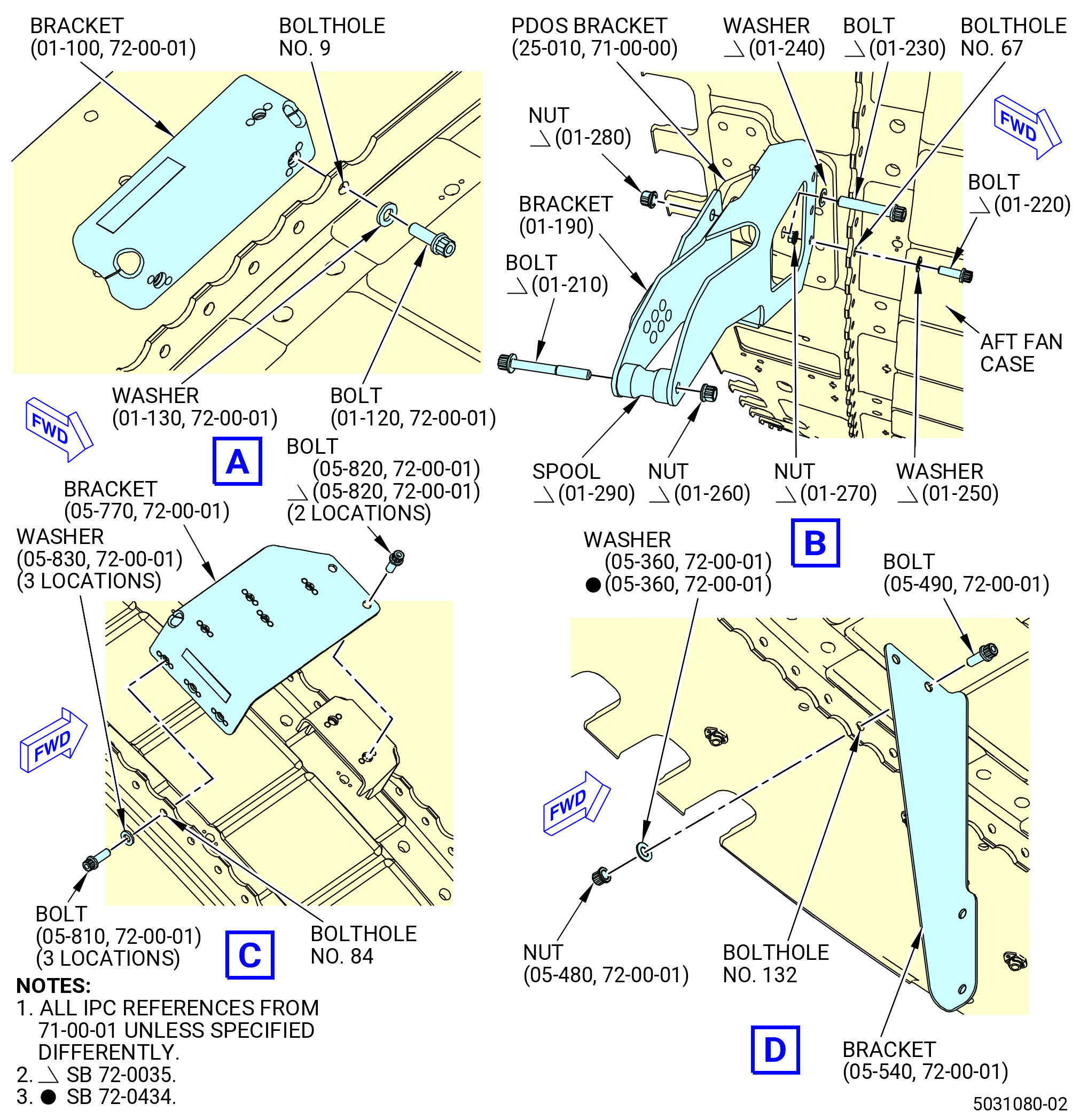
| (1) | Install the support bracket (bracket) (46011) on the aft ring at boltholes No. 9 and 12 as follows: |
| Subtask 72-00-01-380-100 |
| (a) | Apply C03-001 primer or C03-100 primer to the threads and friction surfaces of the bolts (46023), the friction surfaces of the washers (46030), the ID of the boltholes, and the surface of the bracket (46011) that makes contact with the fan case. |
| Subtask 72-00-01-430-438 |
| (b) | Install the bolts (46023) and the washers (46030) on the forward side of the aft ring at boltholes No. 9 and 12. |
| (c) | Install the bracket (46011) on the aft side of the aft ring and attach with the bolts. |
| (d) | Torque the bolts (46023) to 106-124 lb in. (12.0-14.0 N.m). |
| Subtask 72-00-01-430-558 |
| * * * SB 72-0035 |
| (2) | Install the support bracket (bracket) (01-190 , 71-00-01) (SIN 99111) on the aft ring at boltholes 65 to 67. Refer to Figure 1003 and do as follows: |
| NOTE: |
|
| Subtask 72-00-01-380-121 |
| WARNING: |
|
| (a) | Apply C03-001 primer or C03-100 primer to the threads and friction surfaces of the bolts (01-220 , 71-00-01) (SIN 99122), the friction surfaces of the washers (01-250 , 71-00-01) (SIN 99132) and nuts (01-270 , 71-00-01) (SIN 99142), the ID of the boltholes, and the surface of the bracket (01-190 , 71-00-01) (SIN 99111) that makes contact with the fan case. |
| Subtask 72-00-01-430-559 |
| (b) | Install the bolts (01-220 , 71-00-01) (SIN 99122) and washers (01-250 , 71-00-01) (SIN 99132) on the forward side of the aft ring at boltholes No. 66 and 67. |
| (c) | Install the bracket (01-190 , 71-00-01) (SIN 99111) on the aft side of the aft ring and attach with the nuts (01-270 , 71-00-01) (SIN 99142) at boltholes No. 66 and 67. |
| (d) | Install the bolt (01-220 , 71-00-01) (SIN 99122) on the aft side of the aft ring at bolthole No. 65. |
| (e) | Attach the bracket (01-190 , 71-00-01) (SIN 99111) with the washer (01-250 , 71-00-01) (SIN 99132) and nut (01-270 , 71-00-01) (SIN 99142) at bolthole No. 65. Make sure to install the washer on the forward side of the aft ring. |
| (f) | Torque the nuts (01-270 , 71-00-01) (SIN 99142) to 106 to 124 lb in. (12.0 to 14.0 Nm). |
| Subtask 72-00-01-430-610 |
| (3) | Install the bracket (01-190 , 71-00-01) (SIN 99111) to the power door opening system (PDOS) bracket (25-010 , 71-00-00) (SIN 95111). Refer to Figure 1003 and do as follows: |
| Subtask 72-00-01-380-129 |
| WARNING: |
|
| (a) | Apply C03-001 primer or C03-100 primer to the threads and friction surfaces of the machine bolt (bolt) (01-230 , 71-00-01) (SIN 99123) and the friction surfaces of the washer (01-240 , 71-00-01) (SIN 99131) and self-locking nut (nut) (01-280 , 71-00-01) (SIN 99143), and contact surfaces of bracket (01-190 , 71-00-01) (SIN 99111) with PDOS bracket (25-010 , 71-00-00) (SIN 95111). |
| Subtask 72-00-01-430-611 |
| (b) | Attach the bracket (01-190 , 71-00-01) (SIN 99111) to the PDOS bracket (25-010 , 71-00-00) (SIN 95111) with a bolt (01-230 , 71-00-01) (SIN 99123), washer (01-240 , 71-00-01) (SIN 99131), and nut (01-280 , 71-00-01) (SIN 99143). Make sure to install the bolthead of the bolt forward looking aft (FLA) and the washer is installed on the forward side of the bracket (25-010 , 71-00-00) (SIN 95111). |
| (c) | Torque the nut (01-280 , 71-00-01) (SIN 99143) to 106 to 124 lb in. (12.0 to 14.0 Nm). |
| Subtask 72-00-01-430-612 |
| (4) | Install the spool (01-290 , 71-00-01) (SIN 99171). Refer to Figure 1003 and do as follows: |
| (a) | Put the spool (01-290 , 71-00-01) (SIN 99171) between the 2 parts of the bracket (01-190 , 71-00-01) (SIN 99111). |
| (b) | Attach the spool (01-290 , 71-00-01) (SIN 99171) with the machine bolt (bolt) (01-210 , 71-00-01) (SIN 99121) and self-locking nut (nut) (01-260 , 71-00-01) (SIN 99141). |
| (c) | Torque the nut to 51 to 59 lb in. (5.8 to 6.7 Nm). |
| * * * END SB 72-0035 |
| Subtask 72-00-01-430-560 |
| (5) | Install the bracket (44815) on the aft ring at boltholes No. 84-86 locations as follows. Refer to Figure 1003. |
| Subtask 72-00-01-380-122 |
| (a) | Apply C03-001 primer or C03-100 primer to the threads and friction surfaces of the bolts (44829), the friction surfaces of the washers (44830), the ID of the boltholes, and the surface of the bracket (44815) that makes contact with the fan case. |
| Subtask 72-00-01-430-561 |
| (b) | Install the bolts (44829) and the washers (44830) on the aft side of the aft ring at boltholes No. 84-86. |
| (c) | Install the bracket (44815) on the forward side of the aft ring and attach with the bolts (44829) at boltholes No. 84-86. |
| (d) | Torque the bolts (44829) to 106-124 lb in. (12.0-14.0 N.m). |
| Subtask 72-00-01-430-578 |
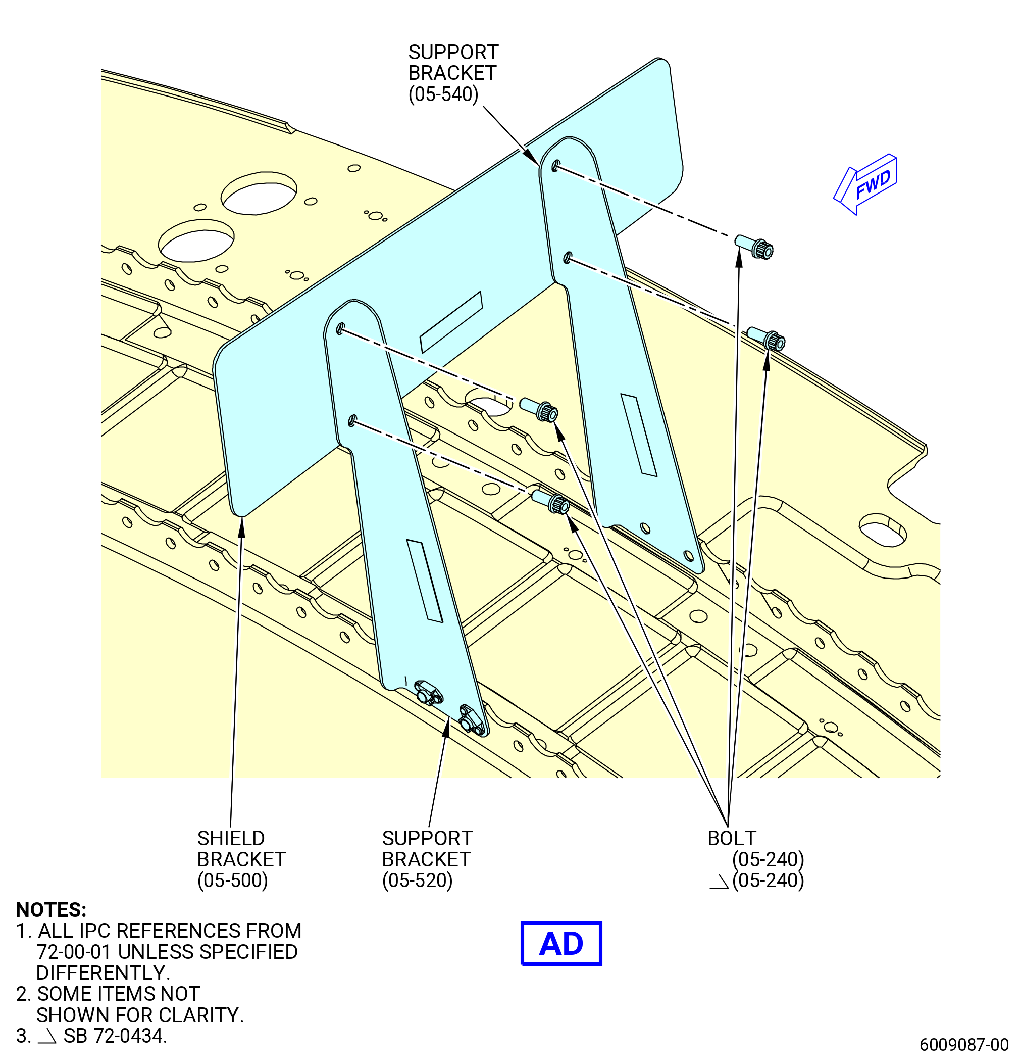
| (6) | Install the bracket (67014) on the aft ring at boltholes No. 131 and 132 as follows. Refer to Figure 1003. |
| Subtask 72-00-01-380-124 |
| (a) | Apply C03-001 primer or C03-100 primer to the threads and friction surfaces of the bolts (05-490) (SIN 67022), the friction surfaces of the washers (05-360) (SIN 67030) and the nuts (05-480) (SIN 67040), the ID of the boltholes, and the surface of the bracket (05-540) (SIN 67014) that makes contact with the fan case. |
| Subtask 72-00-01-430-579 |
| (b) | Install the bolts (67022) and the bracket (67014) on the forward side of the aft ring at boltholes No. 131 and 132. |
| (c) | Install the washers (05-360) (SIN 67030) and nuts (05-480) (SIN 67040) on the aft side of the aft ring on the bolts (05-490) (SIN 67022) at boltholes No. 131 and 132. |
| (d) | Torque the nuts (67040) to 106 to 124 lb in. (12.0 to 14.0 Nm). |
| Subtask 72-00-01-430-439 |
| (7) | Install the bracket (5211F) on the aft ring at boltholes No. 137 and 138 locations as follows. Refer to Figure 1003. |
| Subtask 72-00-01-380-101 |
| (a) | Apply C03-001 primer or C03-100 primer to the threads and friction surfaces of the bolts (52124), the friction surfaces of the washers (52137), the ID of the boltholes, and the surface of the bracket (5211F) that makes contact with the fan case. |
| Subtask 72-00-01-430-440 |
| (b) | Install the bolts (52124) and the washers (52137) on the aft side of the aft ring at boltholes No. 137 and 138. |
| (c) | Install the bracket (5211F) on the forward side of the aft ring and attach with the bolts (52124) at boltholes No. 137 and 138. |
| (d) | Torque the bolts (52124) to 106-124 lb in. (12.0-14.0 N.m). |
| Subtask 72-00-01-430-655 |
| (8) | Attach the shield bracket (05-500) (SIN 6701G) as follows: |
| (a) | Attach the shield bracket (05-500) (SIN 6701G) to the support bracket (05-540) (SIN 67014) with two machine bolts (bolts) (05-240) (SIN 67021). Hand-tighten the bolts at this time. |
| (b) | Attach the shield bracket (05-500) (SIN 6701G) to the support bracket (05-520) (SIN 6701J) with two bolts (05-240) (SIN 67021). Hand-tighten the bolts at this time. |
| (c) | Torque the four bolts (05-240) (SIN 67021) to 106 to 124 lb in. (11.9 to 14.0 Nm). |
| Subtask 72-00-01-430-580 |
| (9) | Install the bracket (61417) on the aft ring at boltholes No. 142 and 143 as follows. Refer to Figure 1003. |
| Subtask 72-00-01-380-125 |
| (a) | Apply C03-001 primer or C03-100 primer to the threads and friction surfaces of the bolts (01-390) (SIN 61422), the friction surfaces of the washers (01-400) (SIN 61430), the ID of the boltholes, and the surface of the bracket (01-430) (SIN 61417) that makes contact with the fan case. |
| Subtask 72-00-01-430-581 |
| (b) | Install the bolts (01-390) (SIN 61422) and the washers (01-400) (SIN 61430) on the aft side of the aft ring at boltholes No. 142 and 143. |
| (c) | Install the bracket (01-430) (SIN 61417) on the forward side of the aft ring and attach with the bolts (01-390) (SIN 61422) at boltholes No. 142 and 143. |
| (d) | Torque the bolts (01-390) (SIN 61422) to 106 to 124 lb in. (12.0 to 14.0 Nm). |
| Subtask 72-00-01-430-441 |
| (10) | Install the bracket (5211Y) on the aft ring at boltholes No. 147 and 150 as follows. Refer to Figure 1003. |
| Subtask 72-00-01-380-102 |
| (a) | Apply C03-001 primer or C03-100 primer to the threads and friction surfaces of the bolts (52124), the friction surfaces of the washers (52137), the ID of the boltholes, and the surface of the bracket (5211Y) that makes contact with the fan case. |
| Subtask 72-00-01-430-442 |
| (b) | Install the bolts (52124) and the washers (52137) on the aft side of the aft ring at boltholes No. 147 and 150. |
| (c) | Install the bracket (5211Y) on the forward side of the aft ring and attach with the bolts (52124) at boltholes No. 147 and 150. |
| (d) | Torque the bolts (52124) to 106-124 lb in. (12.0-14.0 N.m). |
| Subtask 72-00-01-430-447 |
| (11) | Install the bracket (05-440) (SIN 6701K) on the aft ring at boltholes No. 152 and 153. Refer to Figure 1003 and do as follows: |
| Subtask 72-00-01-380-105 |
| (a) | Apply C03-001 primer or C03-100 primer to the threads and friction surfaces of the bolts (05-490) (SIN 67022), the friction surfaces of the washers (05-360) (SIN 67030) and the nuts (05-480) (SIN 67040), the ID of the boltholes, and the surface of the bracket (05-440) (SIN 6701K) that makes contact with the fan case. |
| Subtask 72-00-01-430-448 |
| (b) | Install the bolts (67022) and the bracket (6701K) on the forward side of the aft ring at boltholes No. 152 and 153. |
| (c) | Install the washers (05-360) (SIN 67030) and nuts (05-480) (SIN 67040) on the aft side of the aft ring, on the bolts (05-490) (SIN 67022). |
| (d) | Torque the nuts (67040) to 106-124 lb in. (12.0-14.0 N.m). |
| (e) | Attach the bracket (05-400) (SIN 6701F) or (05-401) (SIN 6701F) to bracket (05-440) (SIN 6701K) with two bolts (05-240) (SIN 67021). |
| (f) | Torque the bolts (05-240) (SIN 67021) to 106-124 lb in. (12.0-14.0 N.m). |
| Subtask 72-00-01-430-451 |
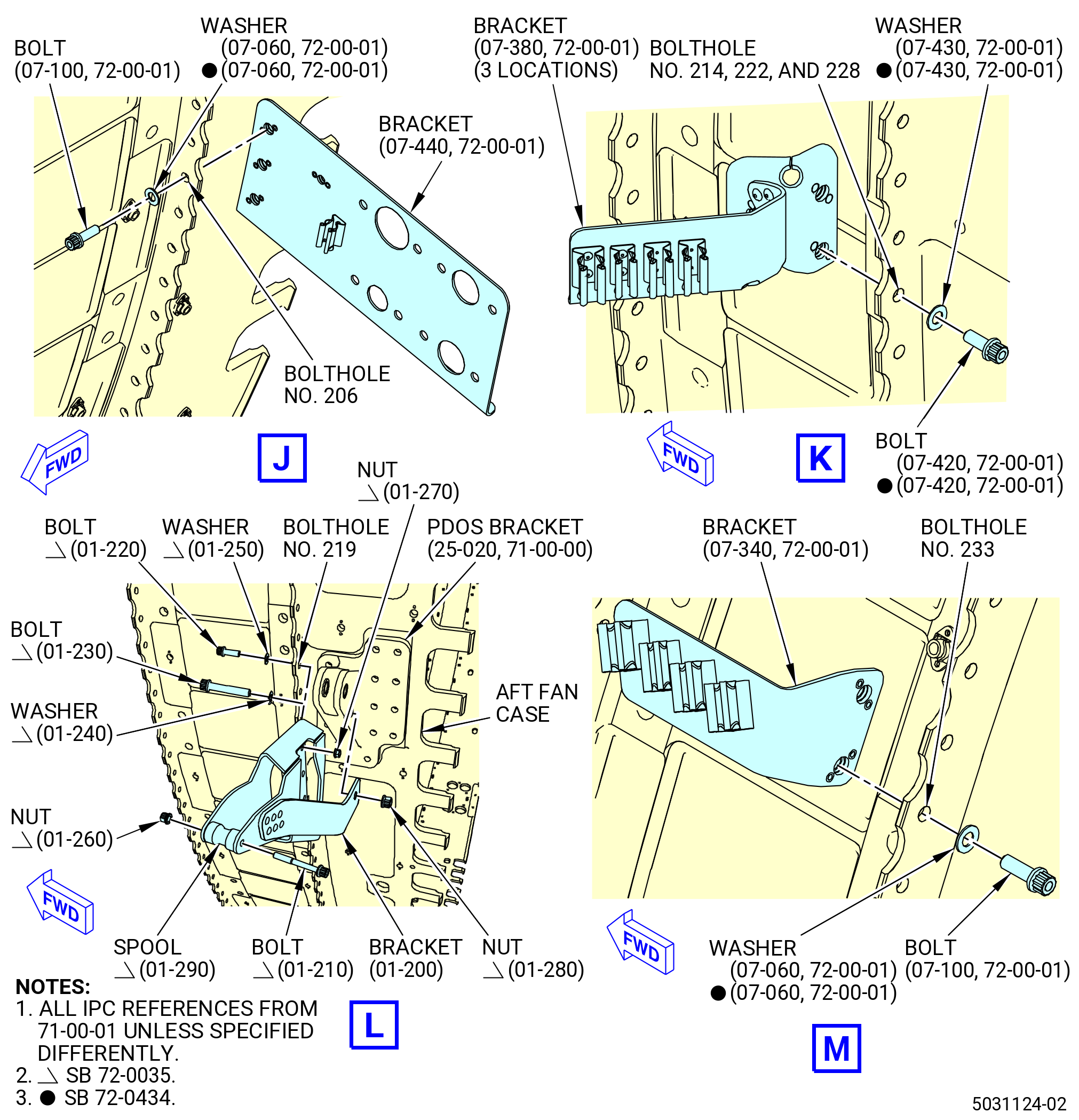
| (12) | Install the support bracket (bracket) (6701L) on the aft ring at boltholes No. 204-206 as follows. Refer to Figure 1003. |
| Subtask 72-00-01-380-107 |
| (a) | Apply C03-001 primer or C03-100 primer to the threads and friction surfaces of the bolts (07-100) (SIN 67022), the friction surfaces of the washers (07-060) (SIN 67030), the ID of the boltholes, and the surface of the bracket (07-440) (SIN 6701L) that makes contact with the fan case. |
| Subtask 72-00-01-430-452 |
| (b) | Install the bolts (07-100) (SIN 67022) and the washers (07-060) (SIN 67030) on the forward side of the aft ring at boltholes No. 204-206. |
| (c) | Install the bracket (6701L) on the aft side of the aft ring and attach with the bolts (67022) at boltholes No. 204-206. |
| (d) | Torque the bolts (67022) to 106 to 124 lb in. (12.0 to 14.0 Nm). |
| Subtask 72-00-01-430-453 |
| (13) | Install the support bracket (bracket) (61310) on the aft ring at boltholes No. 214 and 215, 222 and 223, and 228 and 229 (three locations) as follows. Refer to Figure 1003. |
| Subtask 72-00-01-380-108 |
| (a) | Apply C03-001 primer or C03-100 primer to the threads and friction surfaces of the bolts (07-420) (SIN 61321), the friction surfaces of the washers (07-430) (SIN 61330), the ID of the boltholes, and the surface of the bracket (07-380) (SIN 61310) that makes contact with the fan case. |
| Subtask 72-00-01-430-454 |
| (b) | Install the bolts (07-420) (SIN 61321) and the washers (07-430) (SIN 61330) on the aft side of the aft ring at boltholes No. 214 and 215, 222 and 223, and 228 and 229. |
| (c) | Install the bracket (07-380) (SIN 61310) on the forward side of the aft ring and attach with the bolts (07-420) (SIN 61321) at boltholes No. 214 and 215, 222 and 223, and 228 and 229. |
| (d) | Torque the bolts (07-420) (SIN 61321) to 106 to 124 lb in. (12.0 to 14.0 Nm). |
| Subtask 72-00-01-430-582 |
| * * * SB 72-0035 |
| (14) | Install the support bracket (bracket) (01-200 , 71-00-01) (SIN 99112) on the aft ring at boltholes 217 to 219. Refer to Figure 1003 and do as follows: |
| NOTE: |
|
| Subtask 72-00-01-380-126 |
| WARNING: |
|
| (a) | Apply C03-001 primer or C03-100 primer to the threads and friction surfaces of the bolts (01-220 , 71-00-01) (SIN 99122), the friction surfaces of the washers (01-250 , 71-00-01) (SIN 99132) and the nuts (01-270 , 71-00-01) (SIN 99142), the ID of the boltholes, and the surface of the bracket (01-220 , 71-00-01) (SIN 99122) that makes contact with the fan case. |
| Subtask 72-00-01-430-583 |
| (b) | Install the bolts (01-220 , 71-00-01) (SIN 99122) and the washers (01-250 , 71-00-01) (SIN 99132) on the forward side of the aft ring at boltholes No. 217 to 219. |
| (c) | Install the bracket (01-200 , 71-00-01) (SIN 99122) on the aft side of the aft ring and attach with the nuts (01-270 , 71-00-01) (SIN 99142) at boltholes No. 217 to 219. |
| (d) | Torque the nuts (01-270 , 71-00-01) (SIN 99142) to 106 to 124 lb in. (12.0 to 14.0 Nm). |
| Subtask 72-00-01-430-613 |
| (15) | Install the bracket (01-200 , 71-00-01) (SIN 99112) to the PDOS bracket (25-020 , 71-00-00) (SIN 95112). Refer to Figure 1003 and do as follows: |
| Subtask 72-00-01-380-130 |
| WARNING: |
|
| (a) | Apply C03-001 primer or C03-100 primer to the threads and friction surfaces of the bolt (01-230 , 71-00-01) (SIN 99123) and the friction surfaces of the washer (01-240 , 71-00-01) (SIN 99131) and nut (01-280 , 71-00-01) (SIN 99143), and contact surfaces of bracket (01-200 , 71-00-01) (SIN 99112) with PDOS bracket (25-020 , 71-00-00) (SIN 95112). |
| Subtask 72-00-01-430-614 |
| (b) | Attach the bracket (01-200 , 71-00-01) (SIN 99112) to the PDOS bracket (25-020 , 71-00-00) (SIN 95112) with a bolt (01-230 , 71-00-01) (SIN 99123), washer (01-240 , 71-00-01) (SIN 99131), and nut (01-280 , 71-00-01) (SIN 99143). Make sure to install the bolthead of the bolt FLA and the washer is installed on the forward side of the bracket (25-020 , 71-00-00) (SIN 95112). |
| (c) | Torque the nut (01-280 , 71-00-01) (SIN 99143) to 106 to 124 lb in. (12.0 to 14.0 Nm). |
| Subtask 72-00-01-430-615 |
| (16) | Install the spool (01-290 , 71-00-01) (SIN 99171). Refer to Figure 1003 and do as follows: |
| (a) | Put the spool (01-290 , 71-00-01) (SIN 99171) between the 2 parts of the bracket (01-200 , 71-00-01) (SIN 99112). |
| (b) | Attach the spool (01-290 , 71-00-01) (SIN 99171) with the machine bolt (bolt) (01-210 , 71-00-01) (SIN 99121) and nut (01-260 , 71-00-01) (SIN 99141). |
| (c) | Torque the nut (01-260 , 71-00-01) (SIN 99141) to 51 to 59 lb in. (5.8 to 6.7 Nm). |
| * * * END SB 72-0035 |
| Subtask 72-00-01-430-455 |
| (17) | Install the support bracket (bracket) (6701A) on the aft ring at boltholes No. 233 and 234 as follows. Refer to Figure 1003. |
| Subtask 72-00-01-380-109 |
| (a) | Apply C03-001 primer or C03-100 primer to the threads and friction surfaces of the bolts (07-100) (SIN 67022), the friction surfaces of the washers (07-060) (SIN 67030), the ID of the boltholes, and the surface of the bracket (07-340) (SIN 6701A) that makes contact with the fan case. |
| Subtask 72-00-01-430-456 |
| (b) | Install the bolts (07-100) (SIN 67022) and the washers (07-060) (SIN 67030) on the aft side of the aft ring at boltholes No. 233 and 234. |
| (c) | Install the bracket (6701A) on the forward side of the aft ring and attach with the bolts (67022) at boltholes No. 233 and 234. |
| (d) | Torque the bolts (67022) to 106 to 124 lb in. (12.0 to 14.0 Nm). |
| Subtask 72-00-01-430-457 |
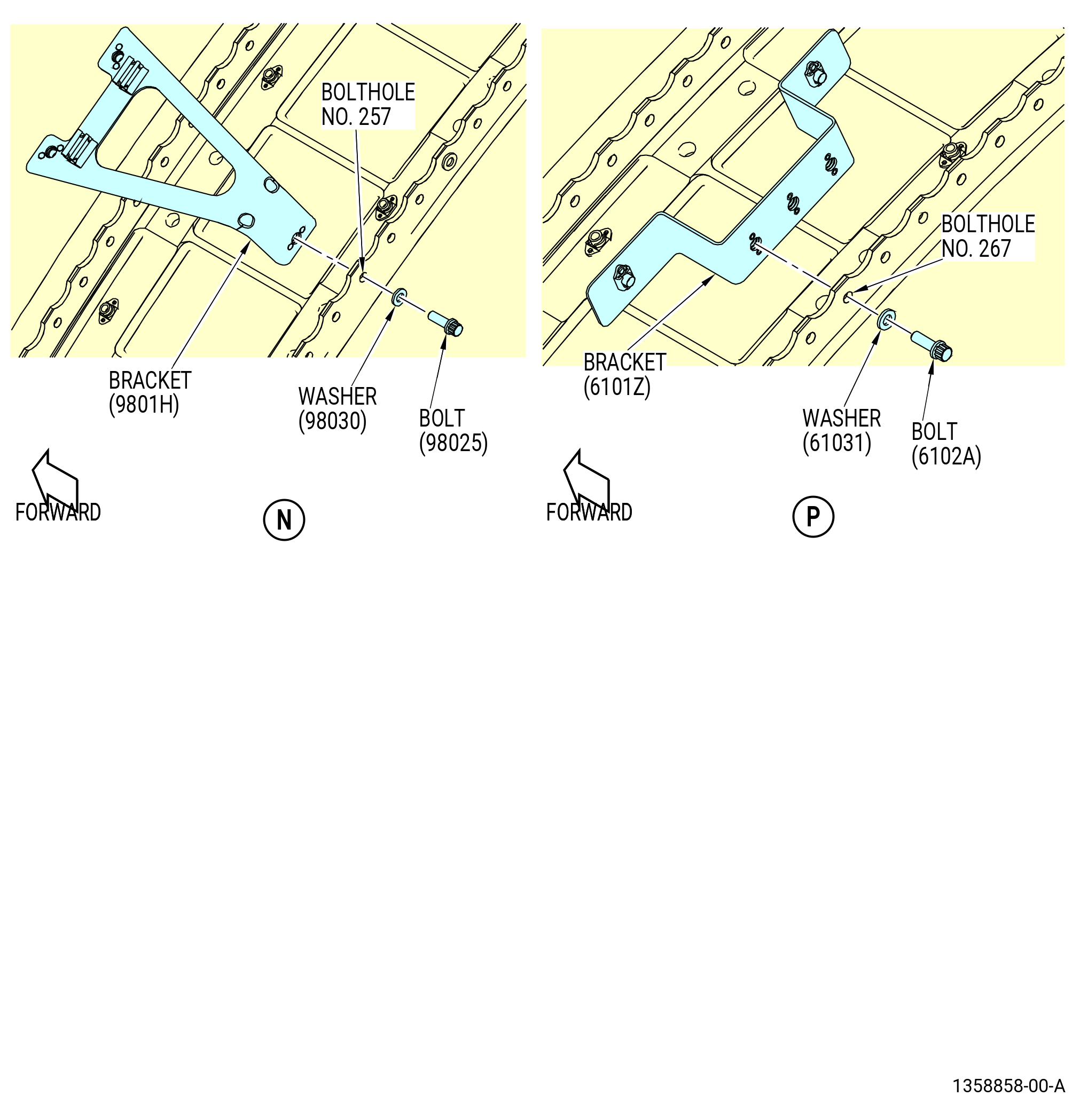
| (18) | Install the bracket (9801H) on the aft ring at bolthole No. 257 as follows. Refer to Figure 1003. |
| Subtask 72-00-01-380-110 |
| (a) | Apply C03-001 primer or C03-100 primer to the threads and friction surfaces of the bolts (98025), the friction surfaces of the washers (98030), the ID of the boltholes, and the surface of the bracket (9801H) that makes contact with the fan case. |
| Subtask 72-00-01-430-458 |
| (b) | Install the bolt (98025) and the washer (98030) on the aft side of the aft ring at bolthole No. 257. |
| (c) | Install the bracket (9801H) on the forward side of the aft ring and attach with the bolt (98025) at bolthole No. 257. |
| (d) | Torque the bolts (98025) to 106-124 lb in. (12.0-14.0 N.m). |
| Subtask 72-00-01-430-459 |
| (19) | Install the bracket (6101Z) on the aft ring at boltholes No. 267-269 as follows. Refer to Figure 1003. |
| Subtask 72-00-01-380-111 |
| (a) | Apply C03-001 primer or C03-100 primer to the threads and friction surfaces of the bolts (6102A), the friction surfaces of the washers (61031), the ID of the boltholes, and the surface of the bracket (6101Z) that makes contact with the fan case. |
| Subtask 72-00-01-430-460 |
| (b) | Install the bolts (6102A) and the washers (61031) on the aft side of the aft ring at boltholes No. 267-269. |
| (c) | Install the bracket (6101Z) on the forward side of the aft ring and attach with the bolts (6102A) at boltholes No. 267-269. |
| (d) | Torque the bolts (6102A) to 106-124 lb in. (12.0-14.0 N.m). |
| Subtask 72-00-01-430-461 |
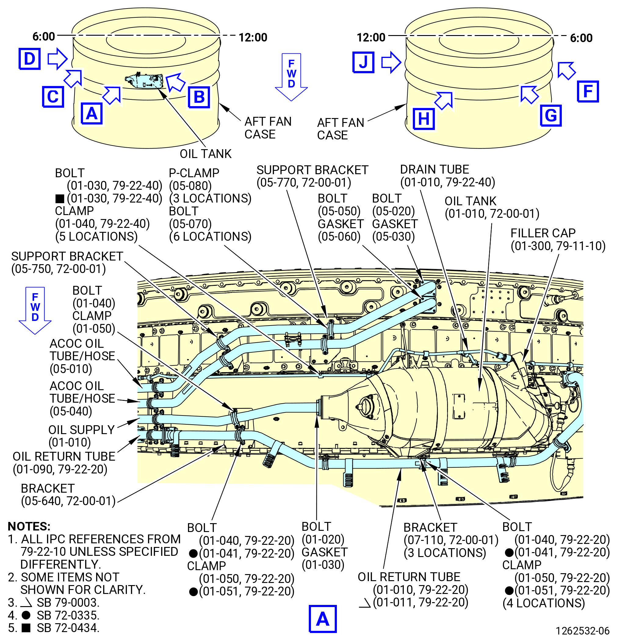
| D. | Install the oil storage tank (oil tank) (01-010) (SIN 00400), hardware, and piping on the aft fan case. Refer to Figure 1004 and do as follows: |
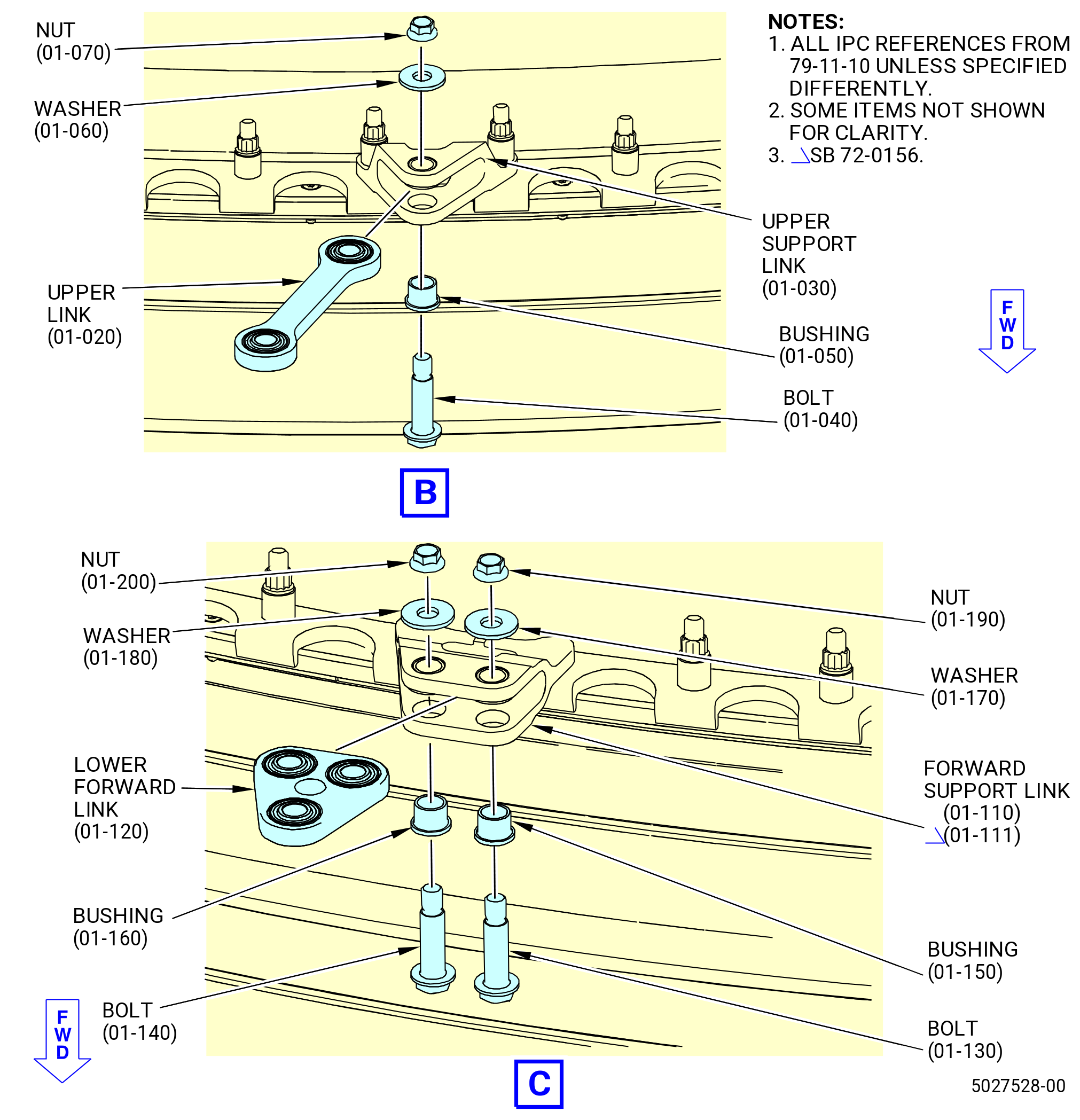
| (1) | Attach the upper link (01-019 , 79-11-10) (SIN 40013) to the upper support link (01-030 , 79-11-10) (SIN 40014) on the aft fan case and the fan containment case forward ring flange (fan case forward ring) as follows: |
| Subtask 72-00-01-640-037 |
| WARNING: |
|
| (a) | Apply C02-058 lubricant to the threads of the top axial axe link mount (bolt) (40022). |
| (b) | Apply a thin layer of C02-060 anti-seize compound to the shank of the bolt (40022) and to the friction surfaces and bores of the washers (40031, 40033). |
| Subtask 72-00-01-430-462 |
| (c) | Attach the upper link (40013) to the upper support link (40014) with the bolts (40022), washer (40031), the bushing (40070), and the nut (40040). Make sure that the bolthead is forward. |
| (d) | Torque the nut (40040) to 202-238 lb in. (22.8-26.9 N.m). |
| (3) | Attach the lower forward link (01-120 , 79-11-10) (SIN 40011) to the forward support link (01-110 , 79-11-10) (SIN 40012) or (01-111 , 79-11-10) (SIN 40012) on the fan case forward ring as follows: |
| Subtask 72-00-01-640-038 |
| (a) | Apply C02-058 lubricant to the threads of the bolts (40023, 40026). |
| (b) | Apply a thin layer of C02-060 anti-seize compound to the shank of the bolts (40023, 40026) and to the friction surfaces and bores of the washers (40033, 40034). |
| Subtask 72-00-01-430-463 |
| (c) | Attach the lower forward link (01-120 , 79-11-10) (SIN 40011) to the forward support link (01-110 , 79-11-10) (SIN 40012) or (01-111 , 79-11-10) (SIN 40012) with the bolts (01-140 , 79-11-10) (SIN 40023), (01-130 , 79-11-10) (SIN 40026), the bushings (01-160 , 79-11-10) (SIN 40071), (01-150 , 79-11-10) (SIN 40072), the washers (01-180 , 79-11-10) (SIN 40033), (01-170 , 79-11-10) (SIN 40034), and the nuts (01-200 , 79-11-10) (SIN 40044), (01-190 , 79-11-10) (SIN 40045). |
| (d) | Torque the nuts (40044, 40045) to 202-238 lb in. (22.8-26.9 N.m). |
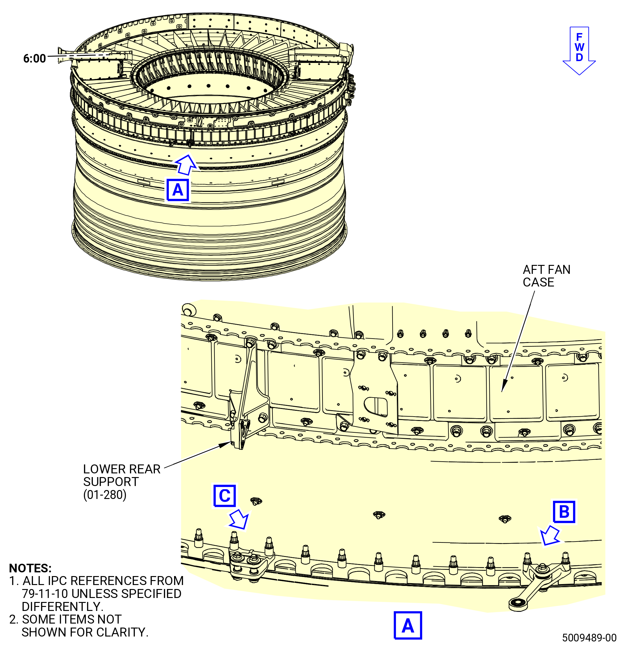
| (4) | If necessary, install the lower rear support (01-280 , 79-11-10) (SIN 40010) on the aft fan case. Refer to TASK 72-21-00-440-804 (72-21-00, ASSEMBLY 001 CONFIG 01) or TASK 72-21-00-440-806 (72-21-00, ASSEMBLY 001 CONFIG 02). |
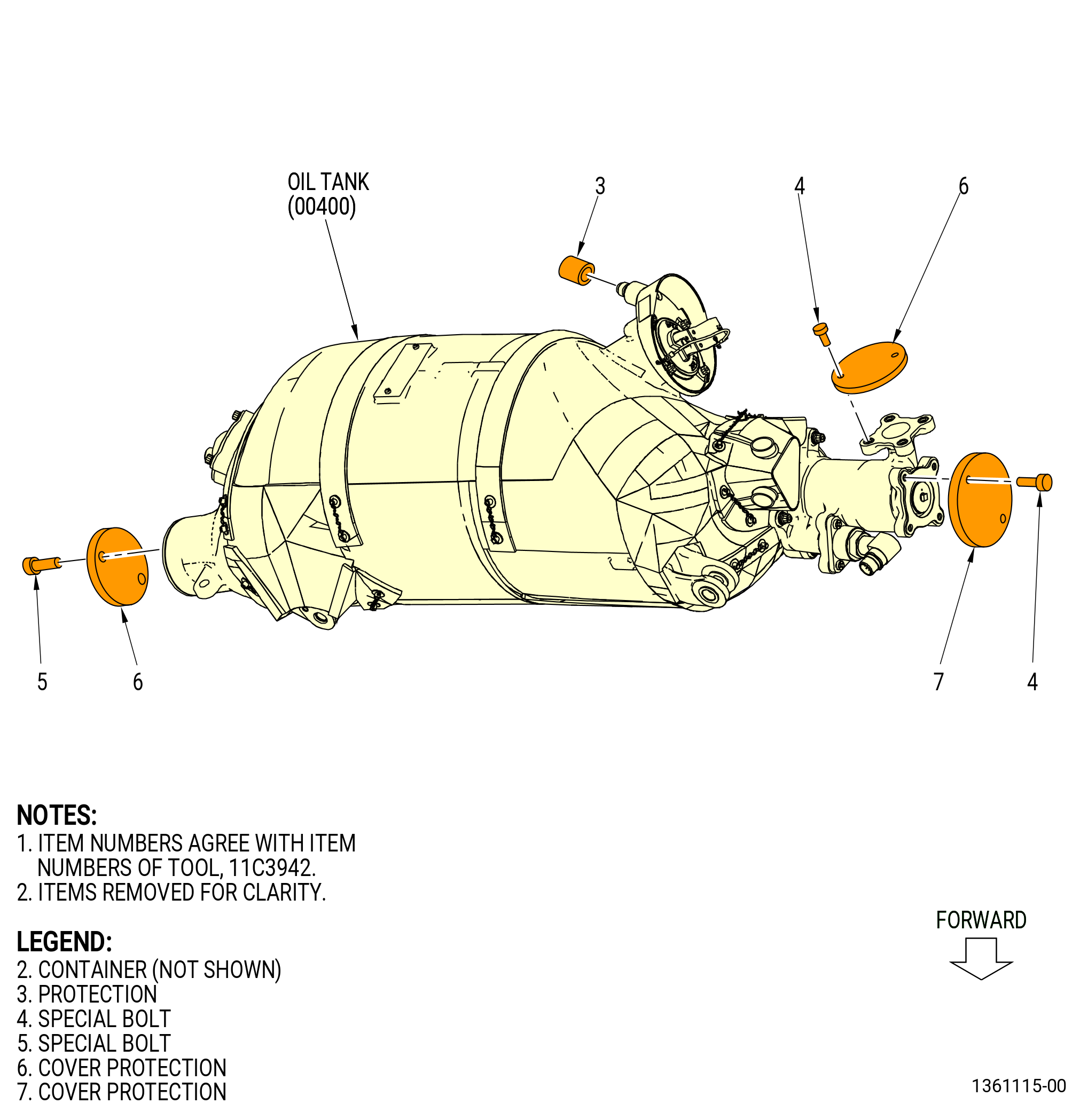
| (5) | Install the oil tank (00400) as follows. Refer to Figure 1005. |
| NOTE: |
|
| (a) | Attach the oil tank to the upper link (40013) as follows: |
| Subtask 72-00-01-640-039 |
| 1 | Apply C02-058 lubricant to the threads of the nut (40027). |
| 2 | Apply C02-060 anti-seize compound to the shank of the bolts (40024, 40027, 40028), and to the bores and the friction surfaces of the washers (40032). |
| Subtask 72-00-01-430-464 |
| 3 | Attach the oil tank to the upper link (40013) with the bolt (40027), the washer (40032), and the nut (40042). Make sure that the bolthead is forward and the nut is aft. Do not torque the nut at this time. |
| NOTE: |
|
| (b) | Attach the oil tank (00400) to the lower forward link (40011) as follows: |
| 1 | Align the oil tank with the lower forward link (40011). |
| NOTE: |
|
| 2 | Install the AXE (bolt) (40024) in the oil tank and the lower forward link (40011). Secure the bolt (40024) flange with the bolt (4002B). |
| 3 | Torque the bolt (4002B) to 51-59 lb in. (5.7-6.7 N.m). |
| (c) | Attach the oil tank to the lower rear support (40010) as follows: |
| Subtask 72-00-01-640-040 |
| 1 | Apply C02-058 lubricant to the threads of the nut (40020). Refer to Figure 1005. |
| 2 | Apply C02-058 lubricant to the to the shank of the bolts (40020), and to the bore and the friction surfaces of the washer (40030). |
| Subtask 72-00-01-430-465 |
| 3 | Align the oil tank to the lower rear support (40010). |
| NOTE: |
|
| 4 | Attach the oil tank with the bolt (40020), the washer (40030), and the nut (40043). Install the bolt (40020) with the bolthead up. |
| 5 | Torque the nut (40043) to 202-238 lb in. (22.8-26.9 N.m). |
| (d) | Torque the nut (40042) that attaches the upper link (40013) to the oil tank to 202-238 lb in. (22.8-26.9 N.m). |
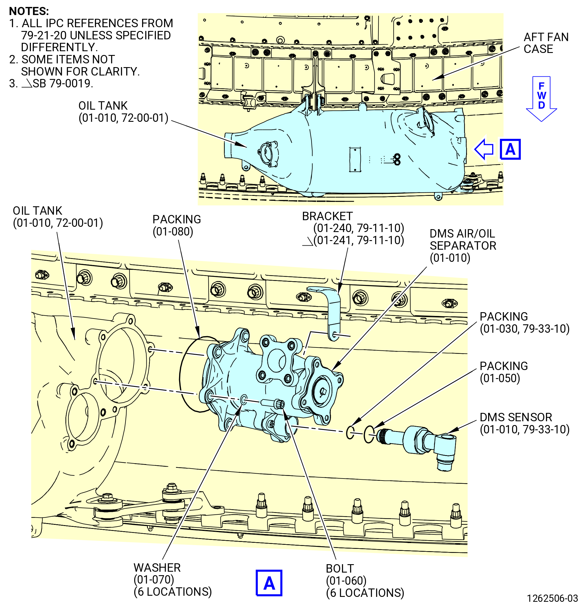
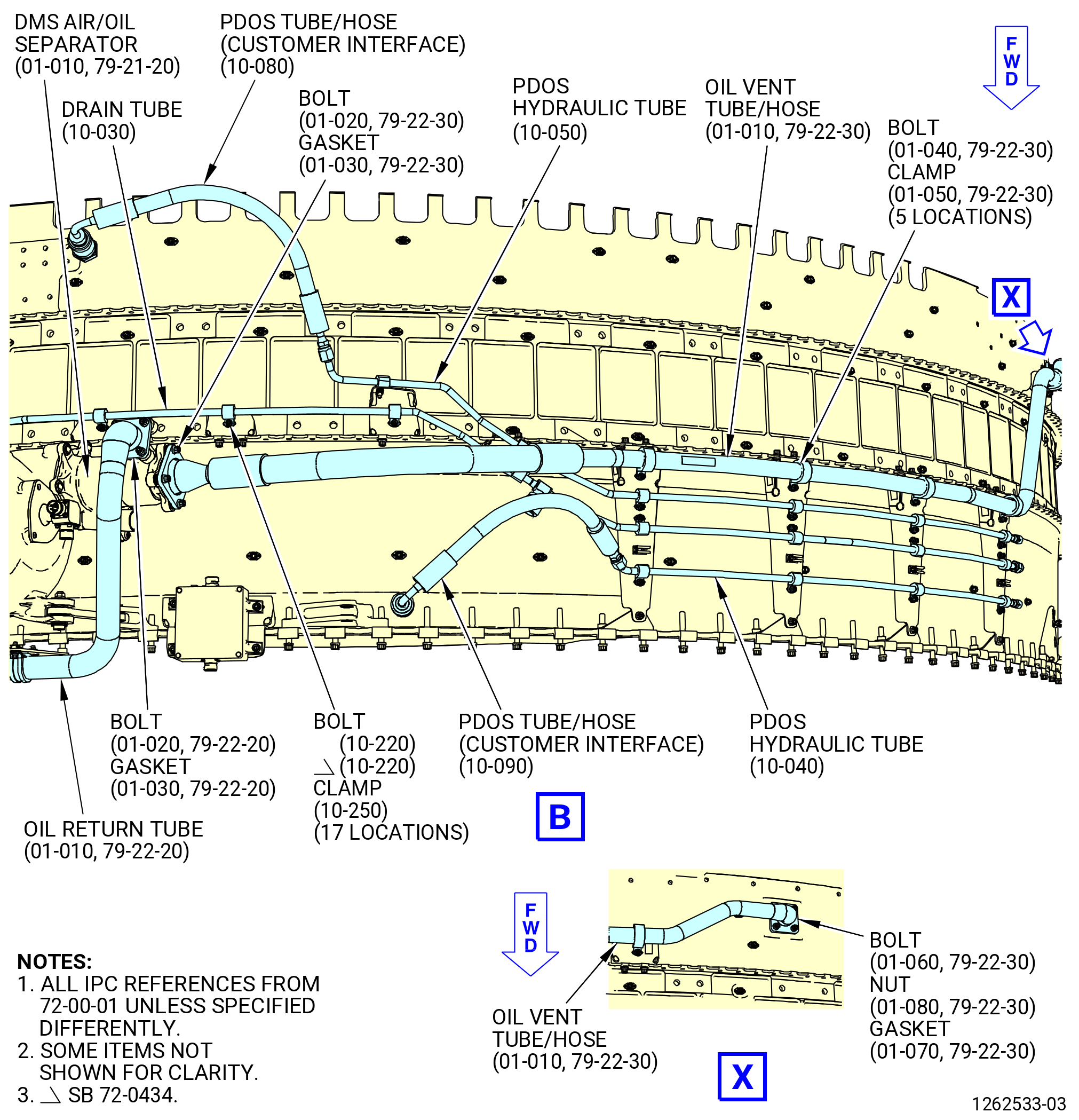
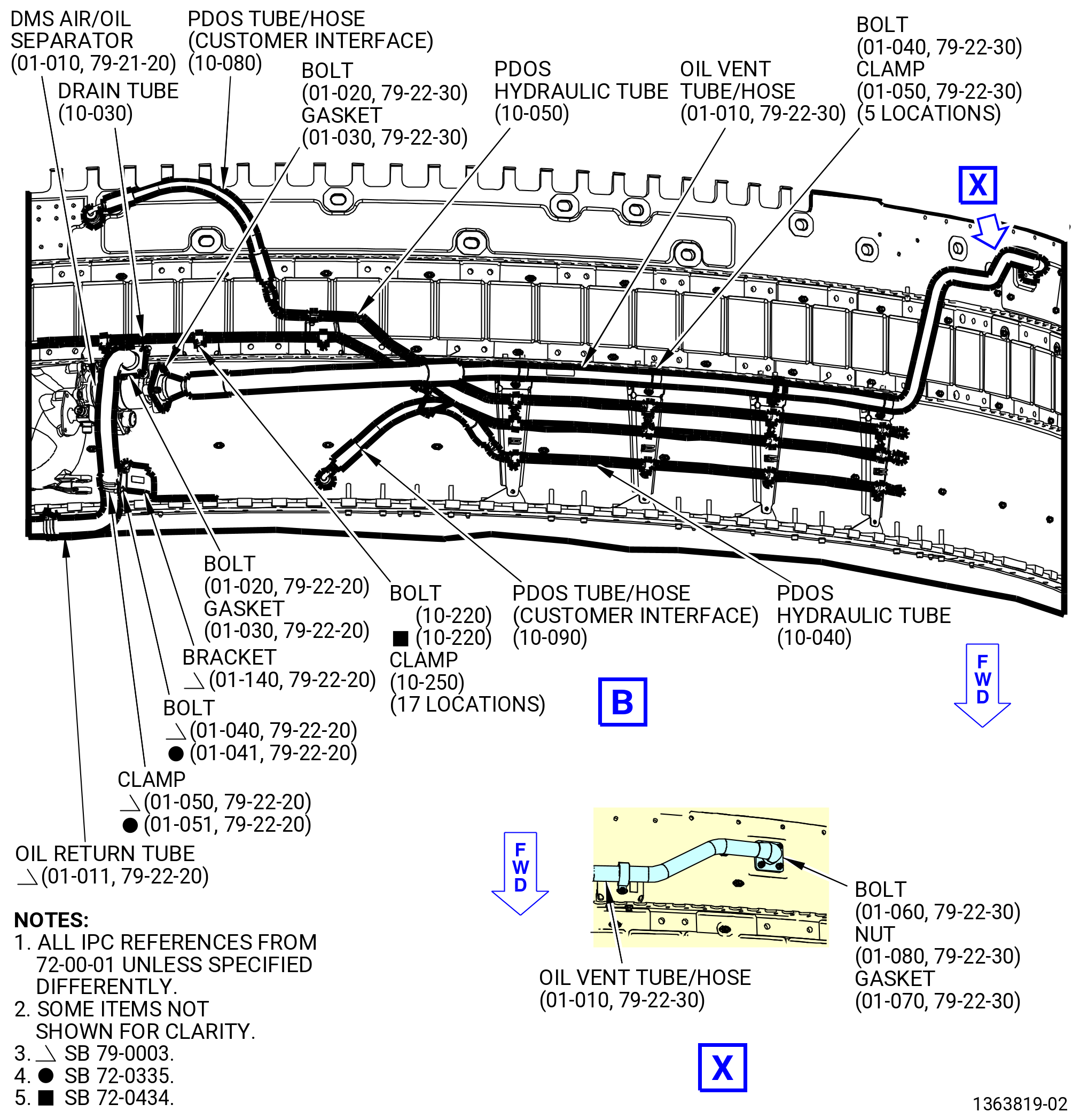
| (6) | Remove the bolt (4002A) from the debris monitoring system (DMS) air/oil separator (400A1) from the oil tank (00400). Refer to Figure 1006. |
| (7) | Attach the bracket (01-240 , 79-11-10) (SIN 40110) or (01-241 , 79-11-10) (SIN 40110) to the oil tank (01-010) (SIN 00400) with the bolt (01-060 , 79-21-20) (SIN 4002A). Torque the bolt to 106 to 124 lb in. (12.0 to 14.0 Nm). |
| Subtask 72-00-01-430-466 |
| E. | Install the oil debris monitoring separator (DMS) assembly (DMS air/oil separator) (400A1) on the oil tank (00400) as follows. Refer to Figure 1006. |
| Subtask 72-00-01-640-041 |
| WARNING: |
|
| (1) | Apply C02-019 engine oil or C02-023 engine oil to the packing (01-080 , 79-21-20) (SIN 40051). |
| Subtask 72-00-01-430-467 |
| (2) | Install the packing (01-080 , 79-21-20) (SIN 40051) on the DMS air/oil separator. |
| (3) | Install the DMS air/oil separator in the oil tank. |
| (4) | Attach the DMS air/oil separator with the bolts (4002A) and the washers (40035) at six locations. Make sure that the run-on torque is 3.5-33.6 lb in. (0.40-3.80 N.m). If the run-on torque is less than 3.5 lb in. (0.40 N.m), replace the bolt (4002A) or the heli-coil insert in the oil tank. |
| (5) | Torque the bolts (4002A) to 78-96 lb in. (8.8-10.8 N.m). |
| Subtask 72-00-01-430-468 |
| F. | Install the DMS sensor (42100) on the DMS air/oil separator (400A1) as follows. Refer to Figure 1006. |
| Subtask 72-00-01-640-042 |
| WARNING: |
|
| (1) | Apply C02-019 engine oil or C02-023 engine oil to the B-nut of the DMS sensor and the preformed packings (01-050 , 79-21-20) (SIN 40055) and (01-030 , 79-33-10) (SIN 42150). |
| Subtask 72-00-01-430-469 |
| (2) | Install the preformed packings (01-050 , 79-21-20) (SIN 40055) and (01-030 , 79-33-10) (SIN 42150) on the DMS sensor fitting. |
| (3) | Install the DMS sensor on the DMS air/oil separator. |
| Subtask 72-00-01-430-470 |
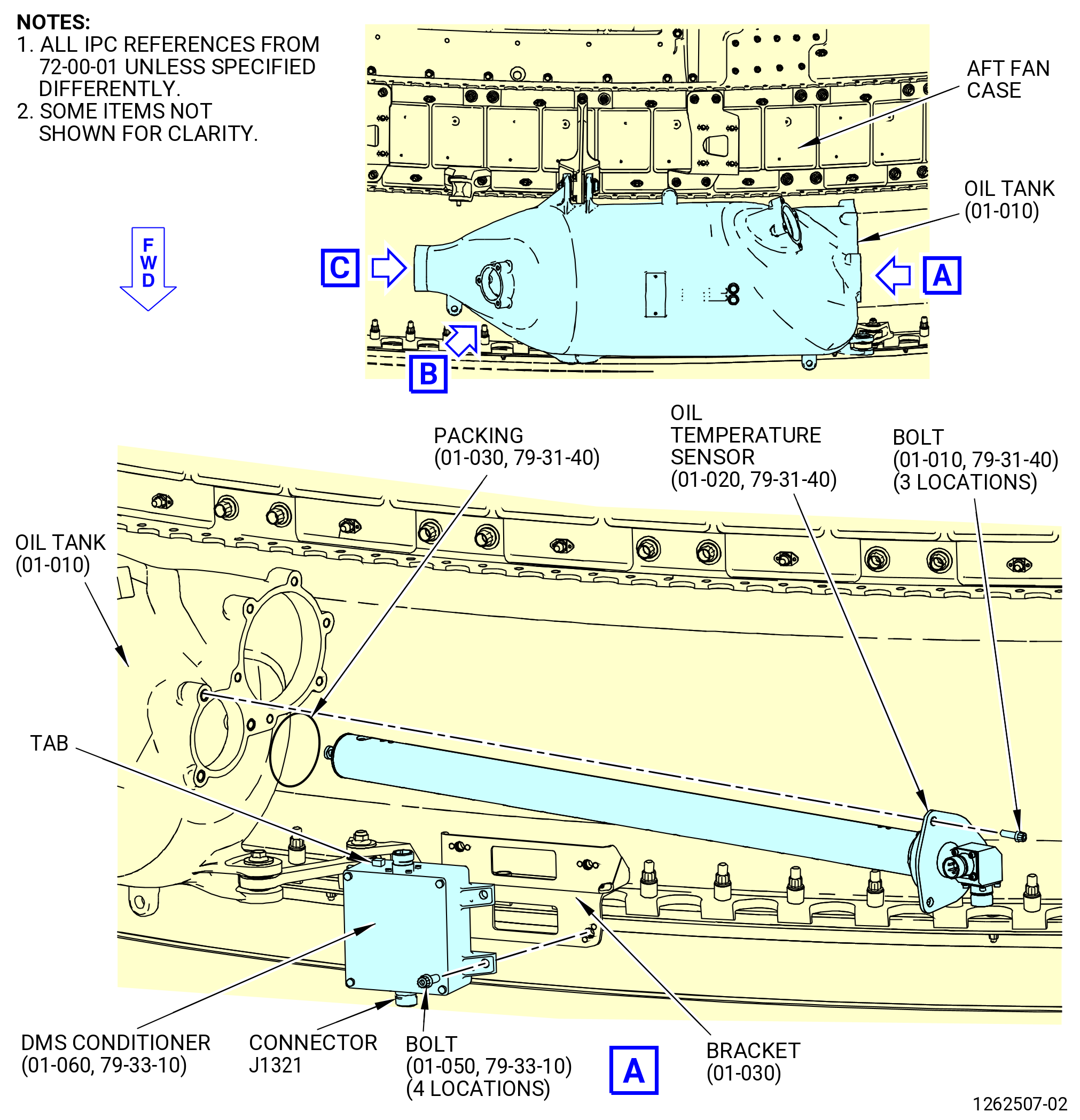
| G. | Install DMS conditioner (42500) on the fan case bracket (42510) as follows. Refer to Figure 1007. |
| (1) | Put the DMS conditioner on the bracket (42510) with the connector J1321 forward, connector J132 aft, and the locator tab aft. |
| (2) | Attach the DMS conditioner to the bracket (42510) with the bolts (42521) at four locations. |
| (3) | Torque the bolts (42521) to 106-124 lb in. (12.0-14.0 N.m). |
| Subtask 72-00-01-430-471 |
| * * * PRE SB 79-0025( Oil Temperature Sensor with Stainless Steel External Flange ) |
| CAUTION: |
|
| H. | Install the oil level sensor assembly (oil temperature sensor) (01-020 , 79-31-40) (SIN 400A3) in the oil tank (01-010) (SIN 00400). Refer to Figure 1007 and do as follows: |
| Subtask 72-00-01-640-043 |
| WARNING: |
|
| (1) | Apply C02-019 engine oil or C02-023 engine oil to the preformed packing (01-030 , 79-31-40) (SIN 40052) and the grooves of the oil temperature sensor. |
| Subtask 72-00-01-430-472 |
| (2) | Install the preformed packing (01-030 , 79-31-40) (SIN 40052) in the groove on the oil temperature sensor. |
| (3) | Install the oil temperature sensor into the top of the oil tank with the connectors outboard. |
| (4) | Attach the oil temperature sensor to the oil tank with the machine bolts (bolts) (01-010 , 79-31-40) (SIN 4002C) at three locations. Make sure that the run-on torque is 3.5 to 33.6 lb in. (0.40 to 3.80 Nm). If the run-on torque is less than 3.5 lb in. (0.40 Nm), replace the bolt (01-010 , 79-31-40) (SIN 4002C) or the heli-coil insert in the oil tank. |
| (5) | Torque the bolts (01-010 , 79-31-40) (SIN 4002C) to 78 to 96 lb in. (8.8 to 10.8 Nm). |
| * * * END PRE SB 79-0025 |
| Subtask 72-00-01-430-616 |
| * * * SB 79-0025( Oil Temperature Sensor with Aluminium External Flange ) |
| CAUTION: |
|
| H.A. | Install the oil temperature sensor (01-020 , 79-31-40) (SIN 400A3) in the oil tank (01-010) (SIN 00400). Refer to Figure 1007 and do as follows: |
| WARNING: |
|
| (1) | Apply C02-019 engine oil or C02-023 engine oil to the preformed packing (01-030 , 79-31-40) (SIN 40052) and the grooves of the oil temperature sensor. |
| (2) | Install the preformed packing (01-030 , 79-31-40) (SIN 40052) in the groove on the oil temperature sensor. |
| (3) | Install the oil temperature sensor into the top of the oil tank with the connectors outboard. |
| WARNING: |
|
| (4) | Lubricate the threads and friction surfaces of the bolts (01-010 , 79-31-40) (SIN 4002C) with clean C02-019 engine oil or C02-023 engine oil. |
| (5) | Attach the oil temperature sensor to the oil tank with the bolts (01-010 , 79-31-40) (SIN 4002C) and flat washers (washers) (01-012 , 79-31-40) (SIN 40039) at three locations. Make sure that the run-on torque is 3.5 to 33.6 lb in. (0.40 to 3.80 Nm). If the run-on torque is less than 3.5 lb in. (0.40 Nm), replace the bolt (01-010 , 79-31-40) (SIN 4002C) or the heli-coil insert in the oil tank. |
| (6) | Torque the bolts (01-010 , 79-31-40) (SIN 4002C) to 78 to 96 lb in. (8.8 to 10.8 Nm). |
| * * * END SB 79-0025 |
| Subtask 72-00-01-430-539 |
| CAUTION: |
|
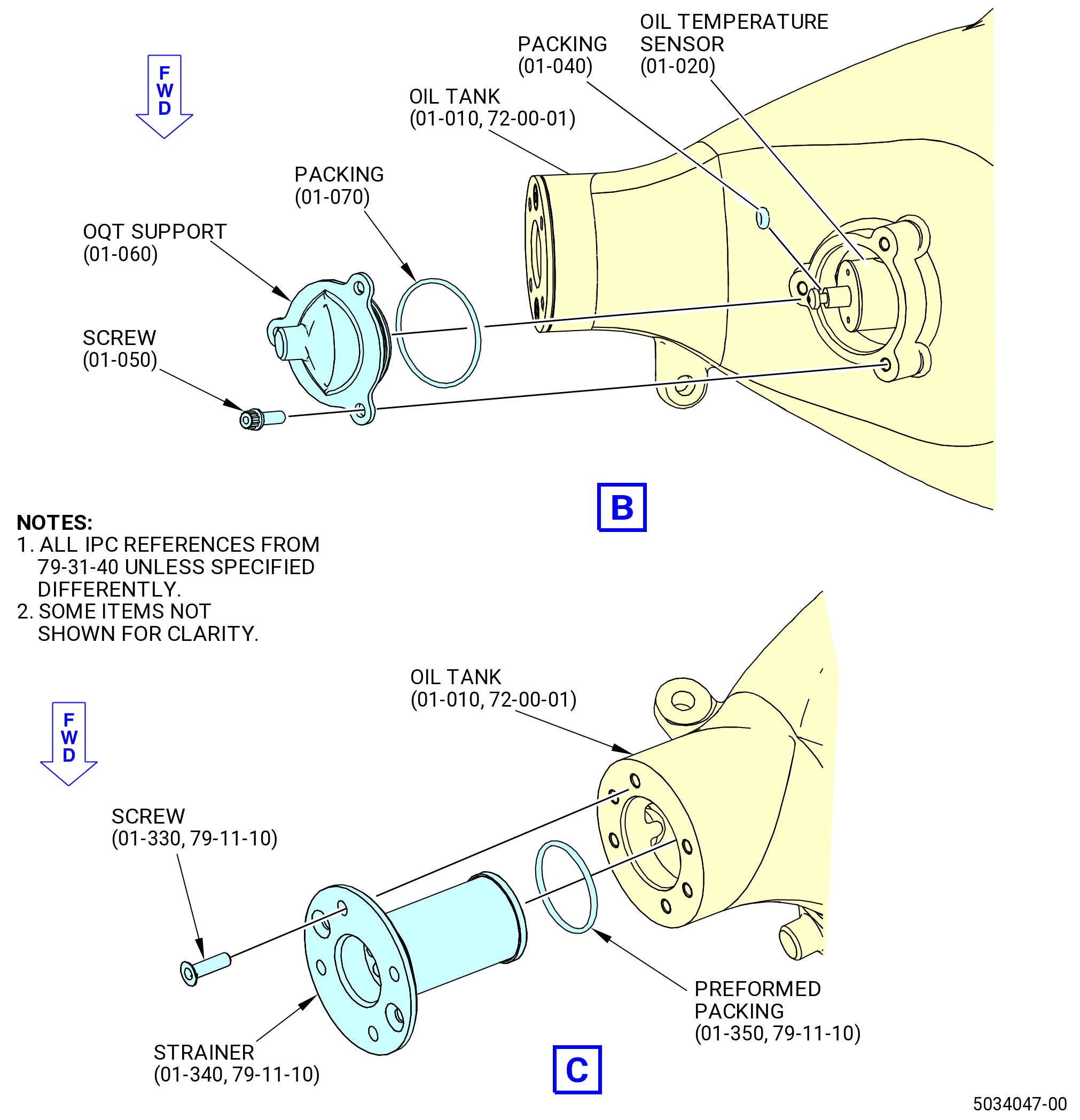
| I. | With the oil temperature sensor (01-020 , 79-31-40) (SIN 400A3) not installed, then install the oil temperature support (01-060 , 79-31-40) (SIN 40001) on the oil tank (01-010) (SIN 00400). Refer to Figure 1007 and do as follows: |
| Subtask 72-00-01-640-055 |
| WARNING: |
|
| (1) | Apply C02-019 engine oil or C02-023 engine oil to the preformed packing (01-040 , 79-31-40) (SIN 40053) and (01-070 , 79-31-40) (SIN 40054) and the grooves of the oil temperature sensor (01-020 , 79-31-40) (SIN 400A3). |
| Subtask 72-00-01-430-540 |
| (2) | Install the preformed packing (01-070 , 79-31-40) (SIN 40054) on the oil temperature support (40001). |
| (3) | Install the preformed packing (01-040 , 79-31-40) (SIN 40053) on the oil level sensor (01-020 , 79-31-40) (SIN 400A3). |
| (4) | Put the oil temperature support (40001) on the oil tank (00400). |
| (5) | Attach the oil temperature support (40001) to the oil tank (00400) with the bolts (4002D) at three locations. Make sure that the run-on torque is 3.5-33.6 lb in. (0.40-3.80 N.m). If the run-on torque is less than 3.5 lb in. (0.40 N.m), replace the bolt (4002D) or the heli-coil insert in the oil tank. |
| (6) | Torque the bolts (4002D) to 78-96 lb in. (8.8-10.8 N.m). |
| Subtask 72-00-01-430-545 |
| J. | Install the air/oil (A/O) strainer (strainer) (400A0) on the oil tank (00400) as follows. Refer to Figure 1007. |
| Subtask 72-00-01-640-058 |
| WARNING: |
|
| (1) | Apply C02-019 engine oil or C02-023 engine oil to the preformed packing (01-350 , 79-11-10) (SIN 40050), the threads of the screws (40029), and the internal groove in the oil tank (00400). |
| Subtask 72-00-01-430-546 |
| (2) | Install the preformed packing (01-350 , 79-11-10) (SIN 40050) on the strainer (400A0). |
| (3) | Put the strainer (400A0) into the oil tank (00400). |
| (4) | Attach the strainer (400A0) with the screws (40029) at two locations. Make sure that the run-on torque is 3.5-33.6 lb in. (0.40-3.80 N.m). If the run-on torque is less than 3.5 lb in. (0.40 N.m), replace the screw (40029) or the heli-coil insert in the oil tank. |
| (5) | Torque the screws (40029) to 78-96 lb in. (8.8-10.8 N.m). |
|
|
| Subtask 72-00-01-430-473 |
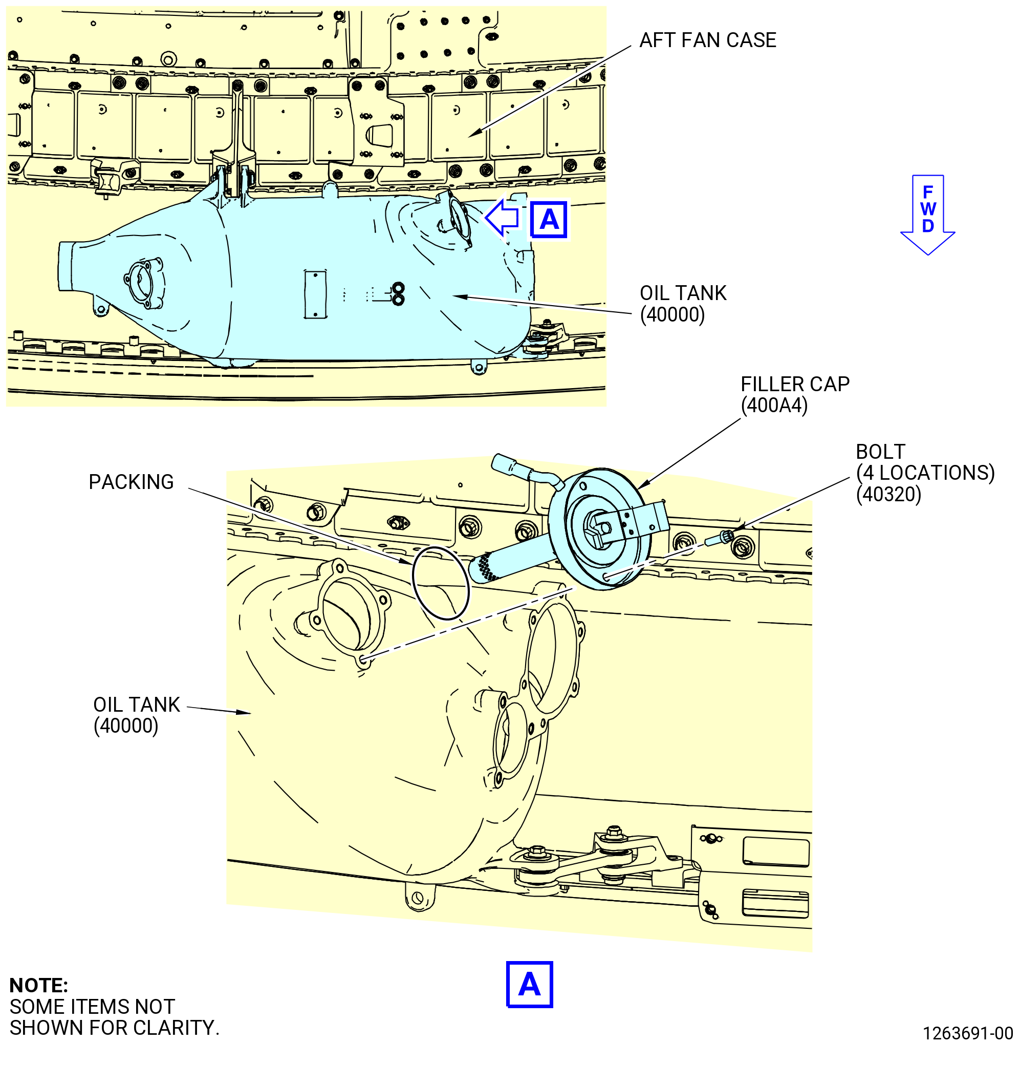
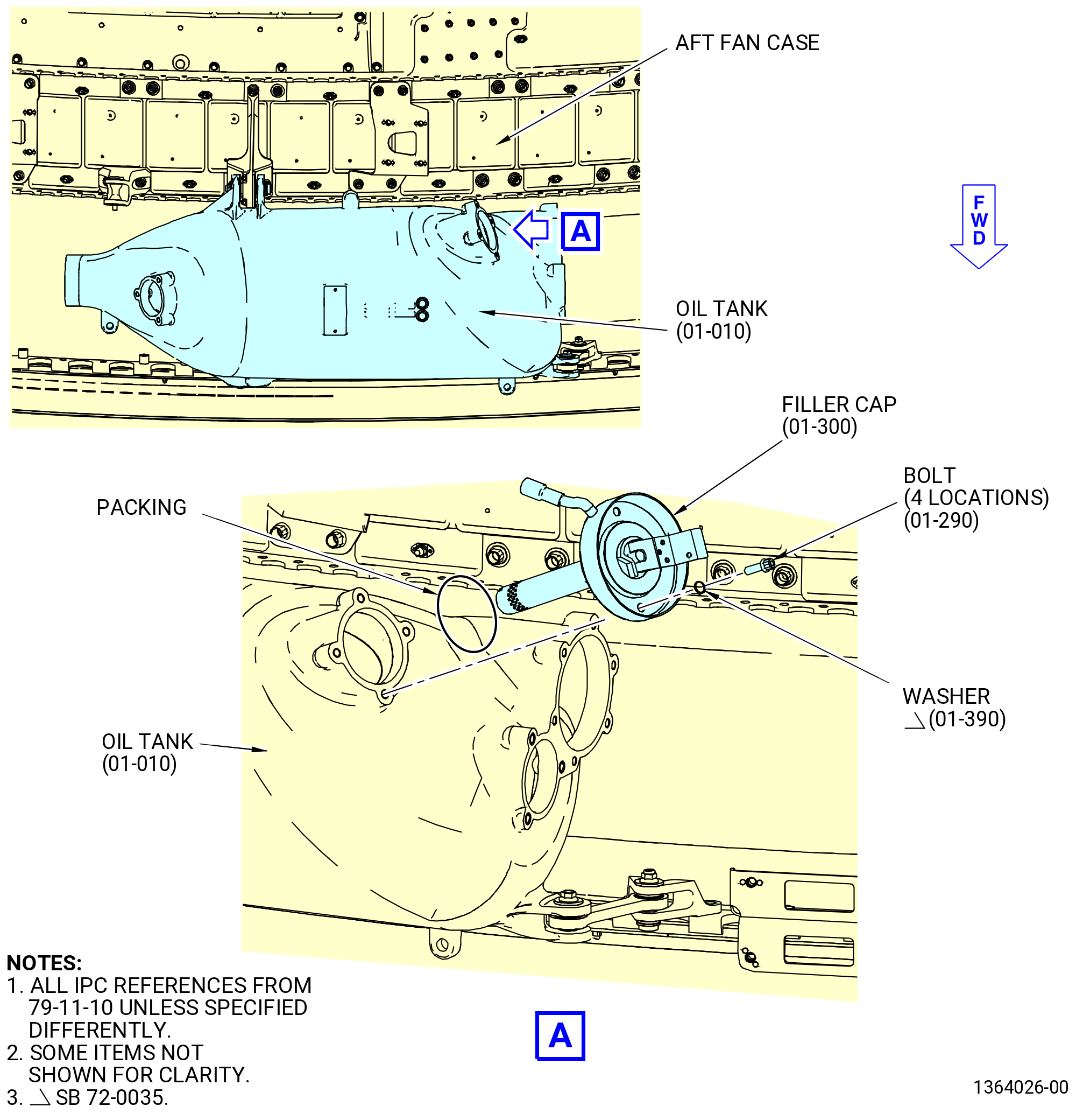
| K. | Install the filler cap (400A4) on the oil tank (00400) as follows. Refer to Figure 1008 and Figure 1008A. |
| Subtask 72-00-01-640-044 |
| WARNING: |
|
| (1) | Apply C02-019 engine oil or C02-023 engine oil to the preformed packing (01-310 , 79-11-10) (SIN 40350) and the grooves of the filler cap (400A4). |
| Subtask 72-00-01-430-474 |
| (2) | Install the preformed packing (01-310 , 79-11-10) (SIN 40350) in the groove on the filler cap (400A4). |
| CAUTION: |
|
| (3) | Carefully center and install the filler cap (01-300 , 79-11-10) (SIN 400A4) into the oil tank assembly (01-010) (SIN 40000). |
| Subtask 72-00-01-430-617 |
| * * * SB 72-0035( Filler Cap Bolts with Washers ) |
| (4) | Install the flat washers (washers) (01-390 , 79-11-10) (SIN 40037) on the bolts (40320) at four locations. |
| NOTE: |
|
| * * * END SB 72-0035 |
| Subtask 72-00-01-430-618 |
| (5) | Install the four bolts (01-290 , 79-11-10) (SIN 40320) that attach the filler cap to the oil tank. |
| (6) | Tighten the four bolts in a criss-cross pattern to slowly ease the filler cap (01-300 , 79-11-10) (SIN 400A4) into the oil tank (01-010 , 72-00-00) (SIN 00400). |
| (7) | Make sure that the run-on torque is 3.5 to 33.6 lb in. (0.40 to 3.80 Nm). If the run-on torque is less than 3.5 lb in. (0.40 Nm), replace the bolt (01-290 , 79-11-10) (SIN 40320) or the heli-coil insert in the oil tank. |
| (8) | Torque the bolts (40320) to 78-96 lb in. (8.8-10.8 N.m). |
| Subtask 72-00-01-430-475 |
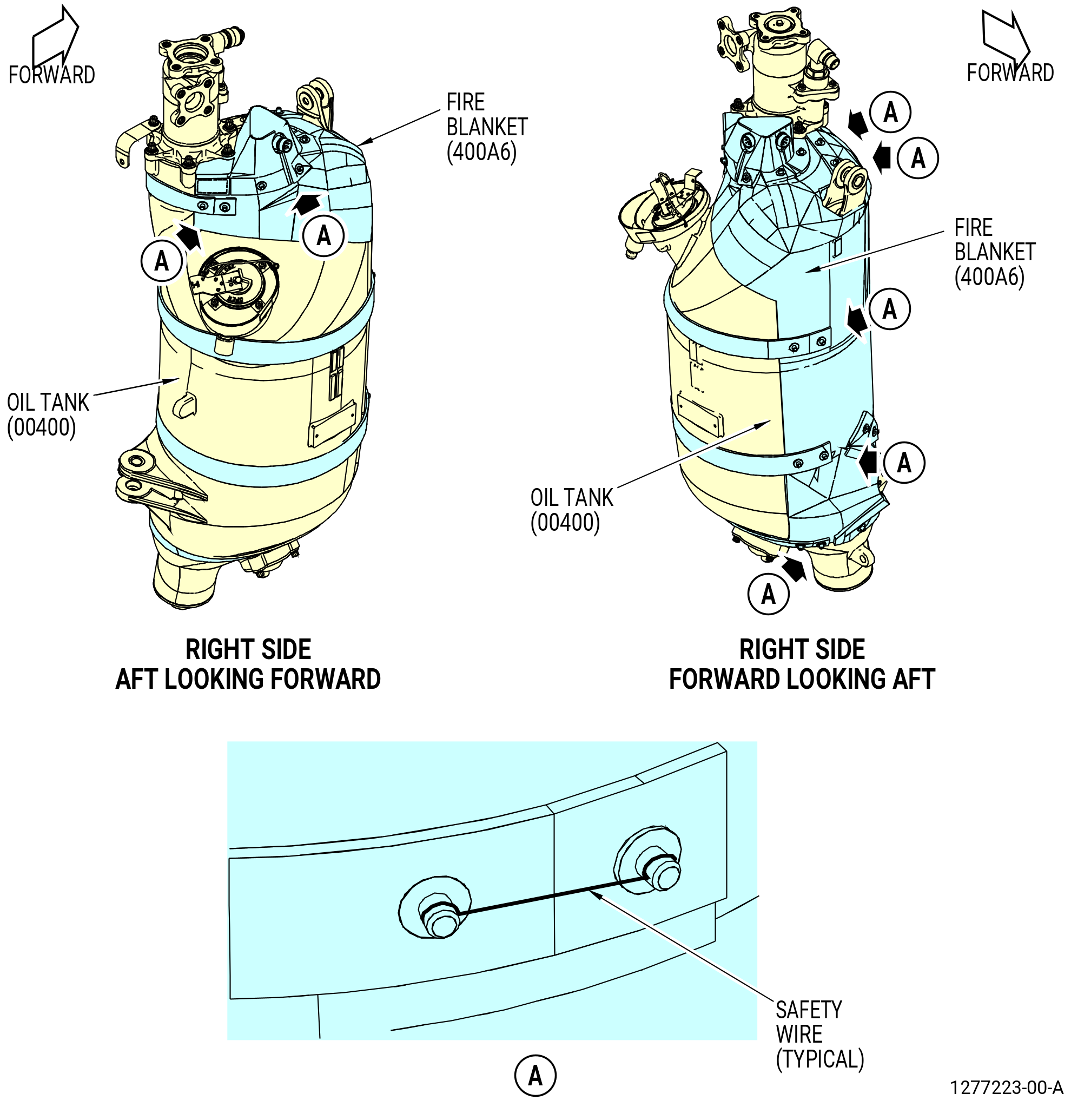
| L. | Install the fire blanket (400A6) on the oil tank (00400) as follows. Refer to Sheet 1. |
| (1) | Put the fire blanket (400A6) in position around the oil tank. |
| (2) | Use C10-143 safety cable assembly to attach the fire blanket (400A6). |
|
|
| Subtask 72-00-01-430-563 |
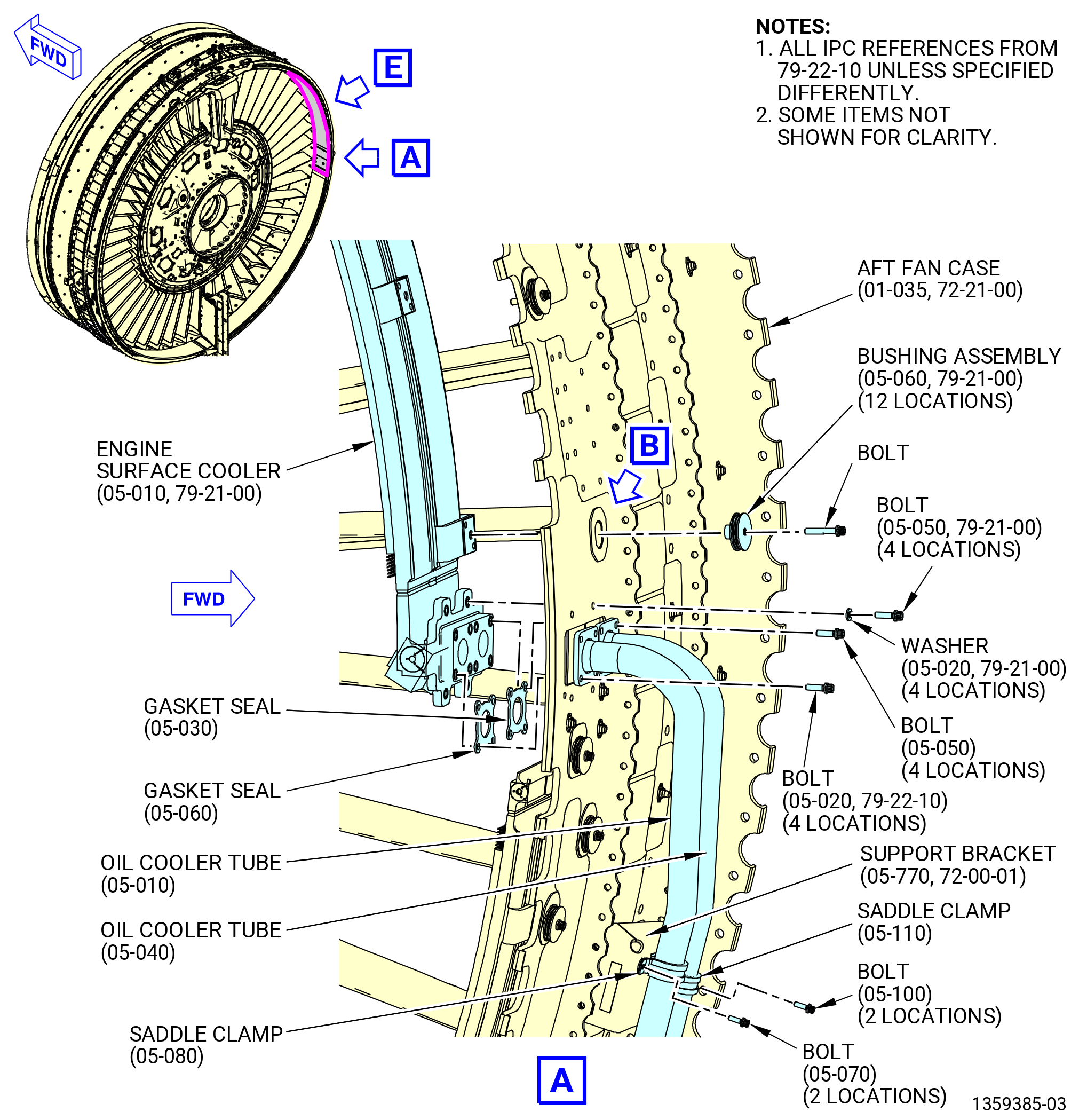
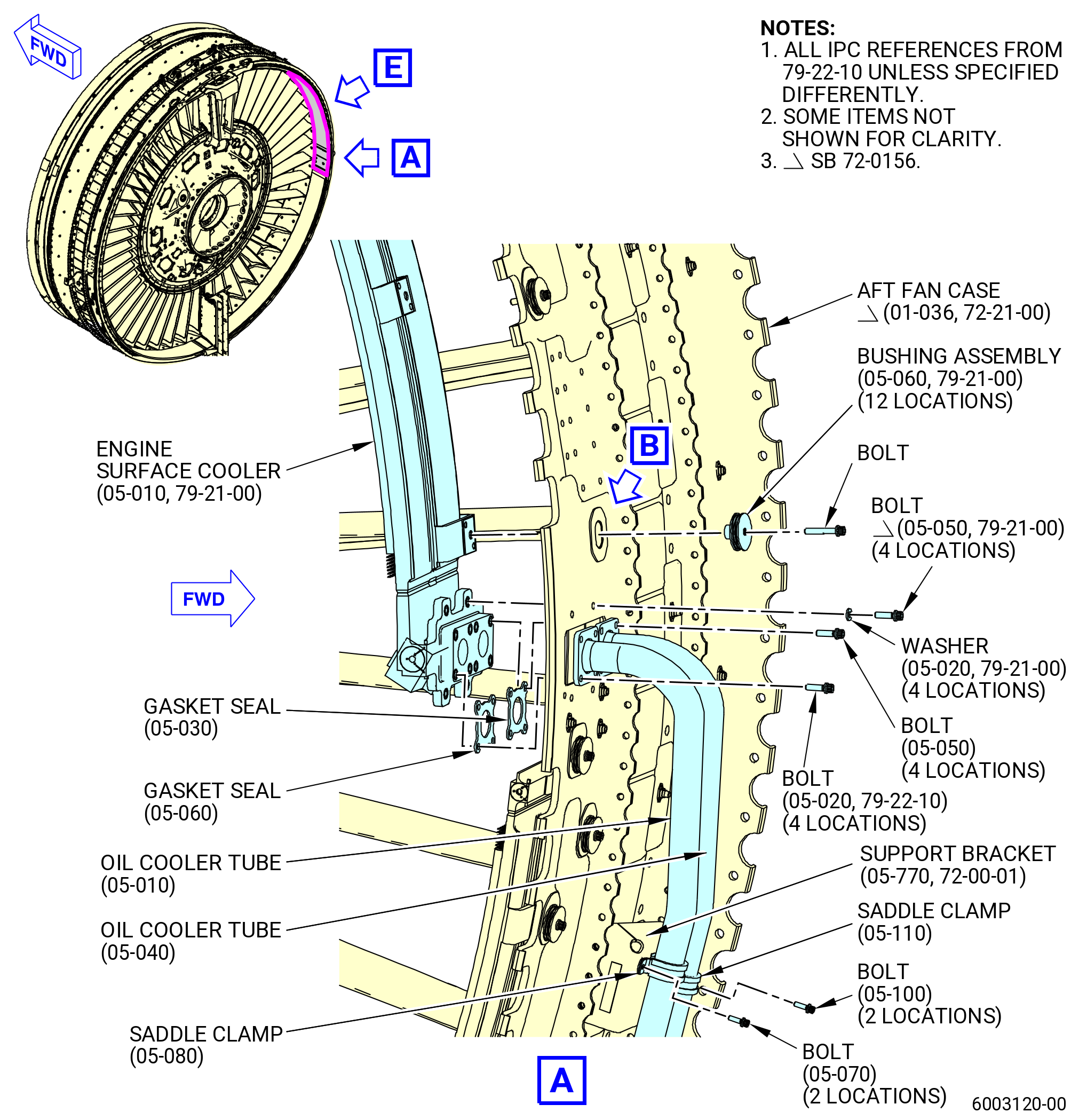
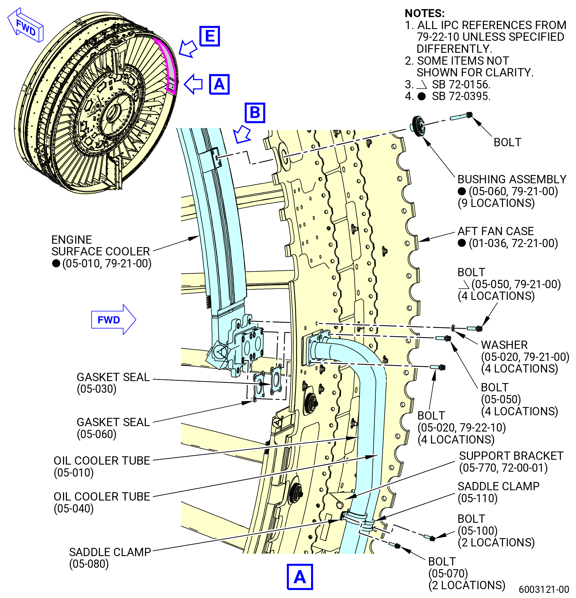
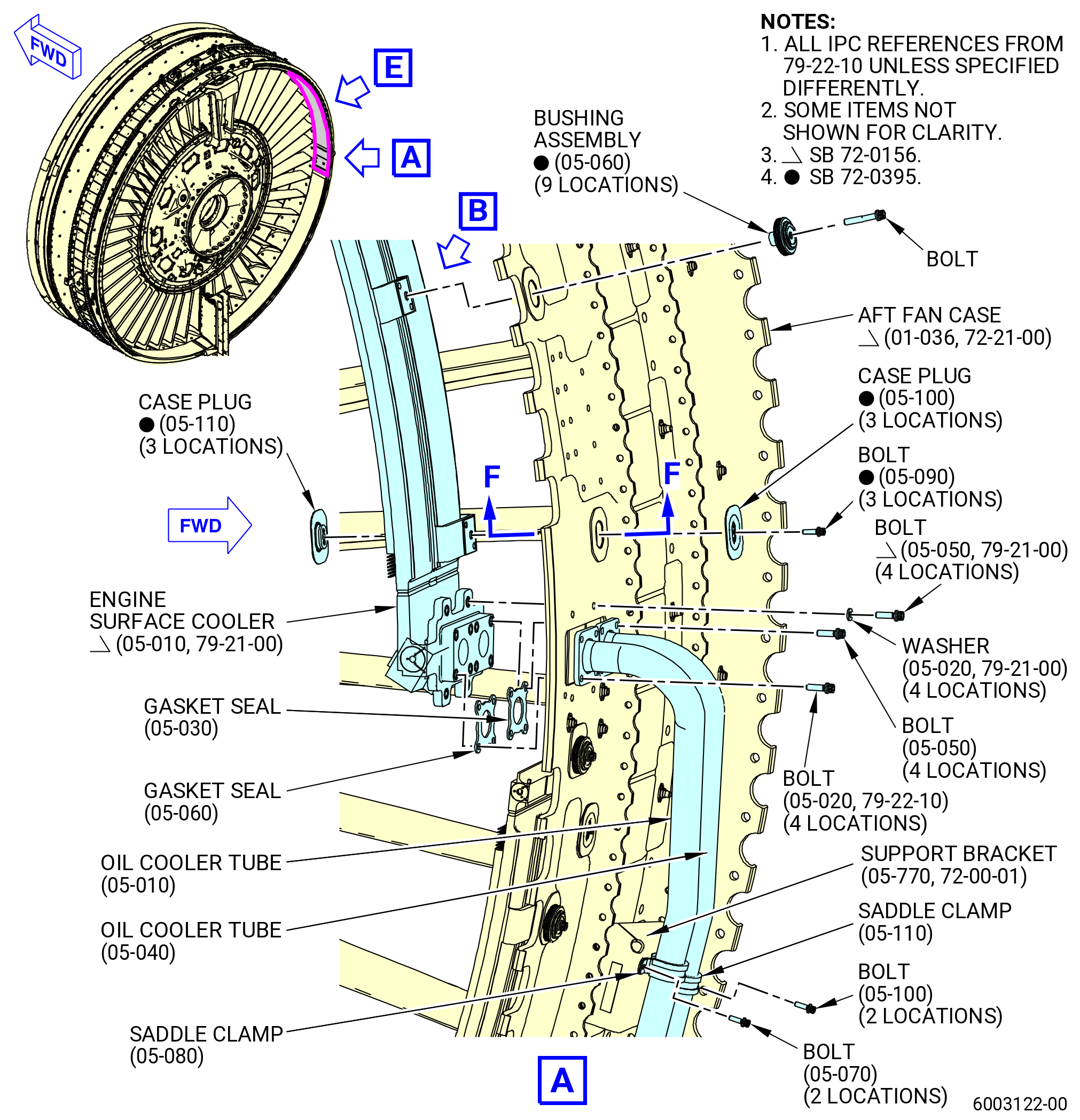
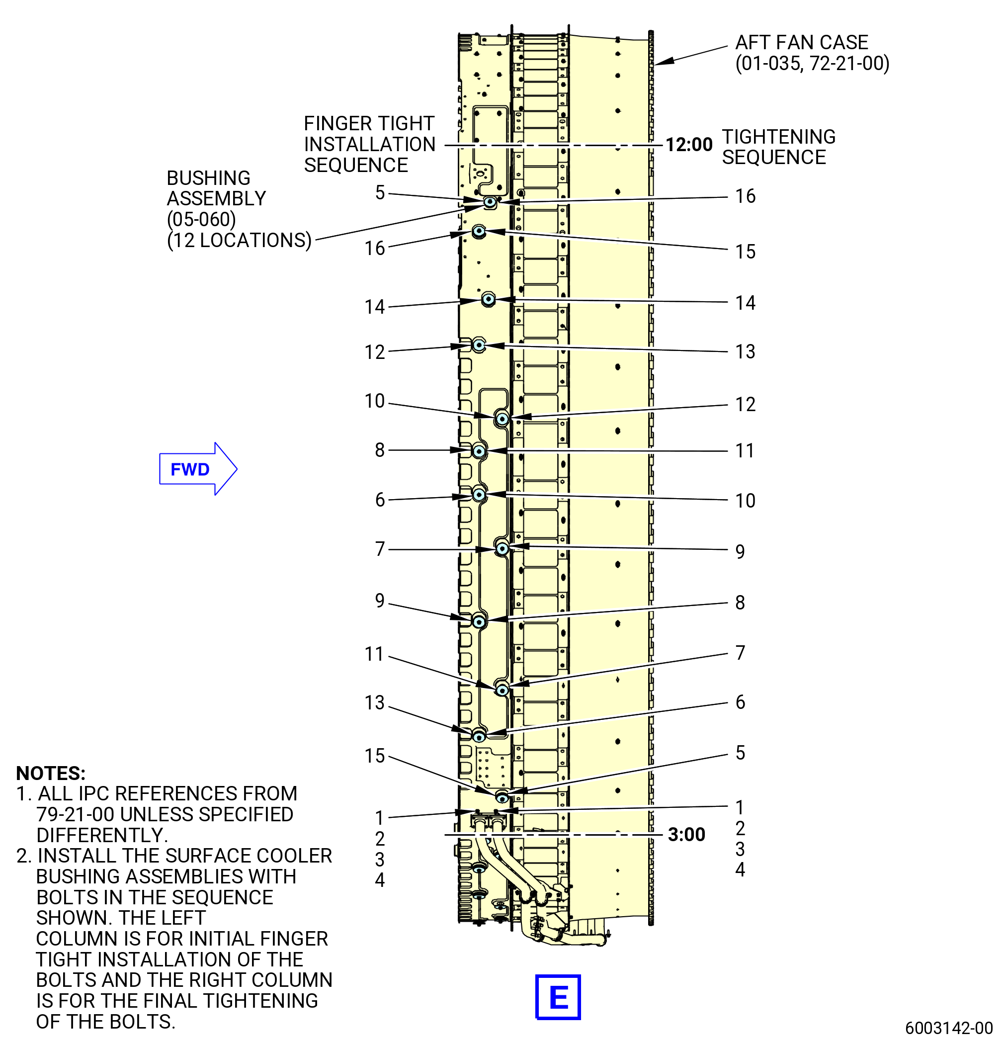
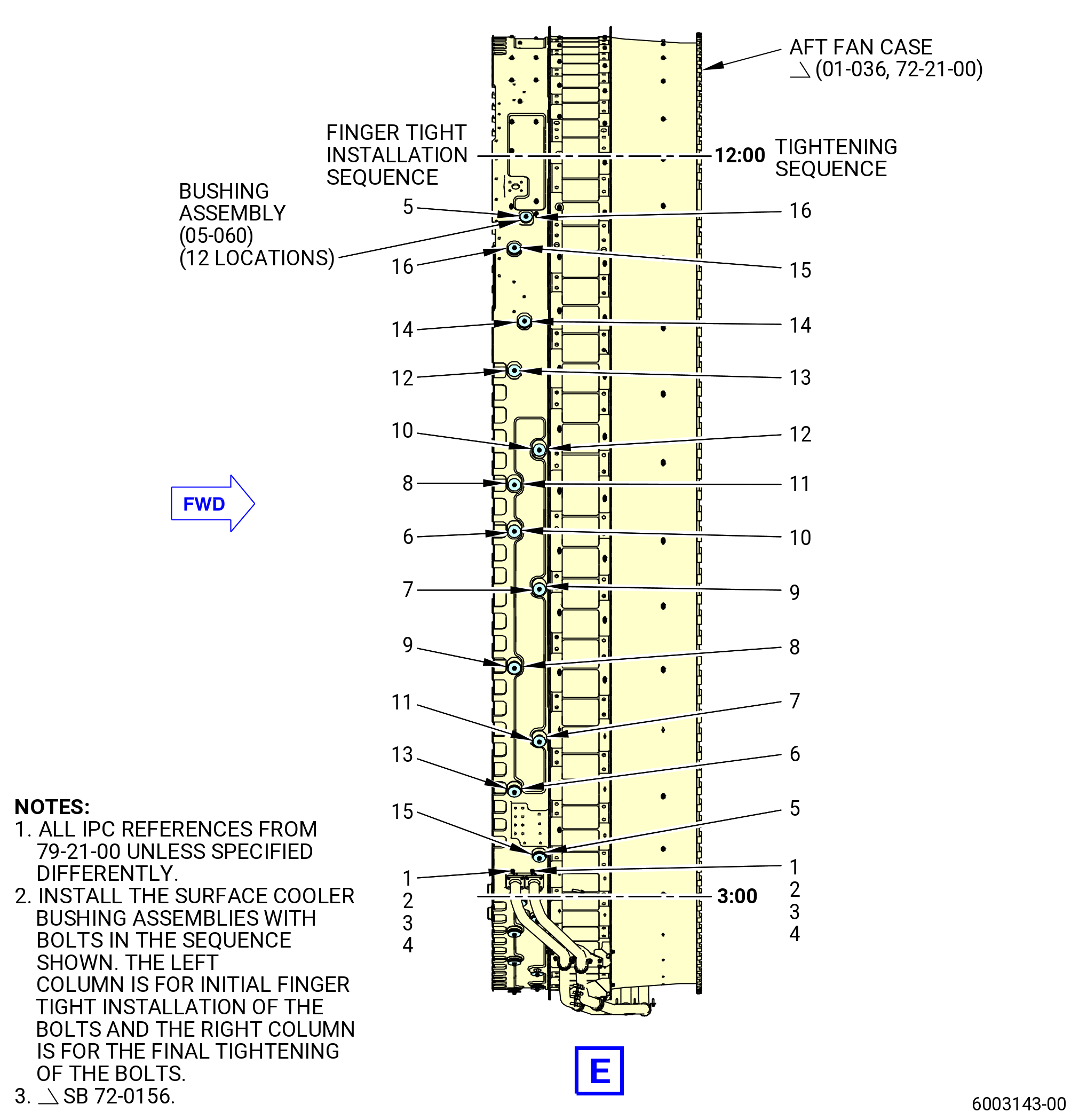
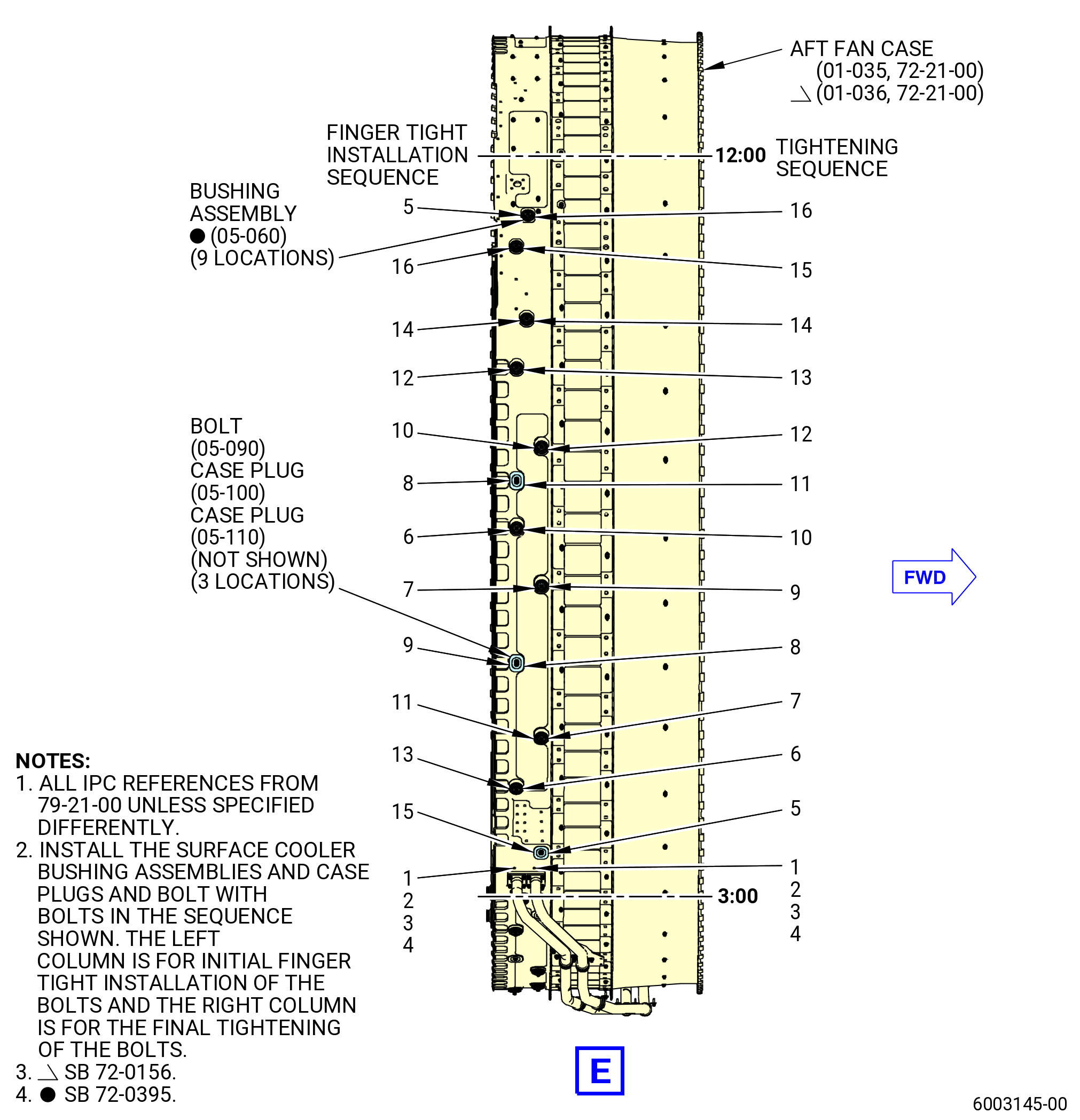
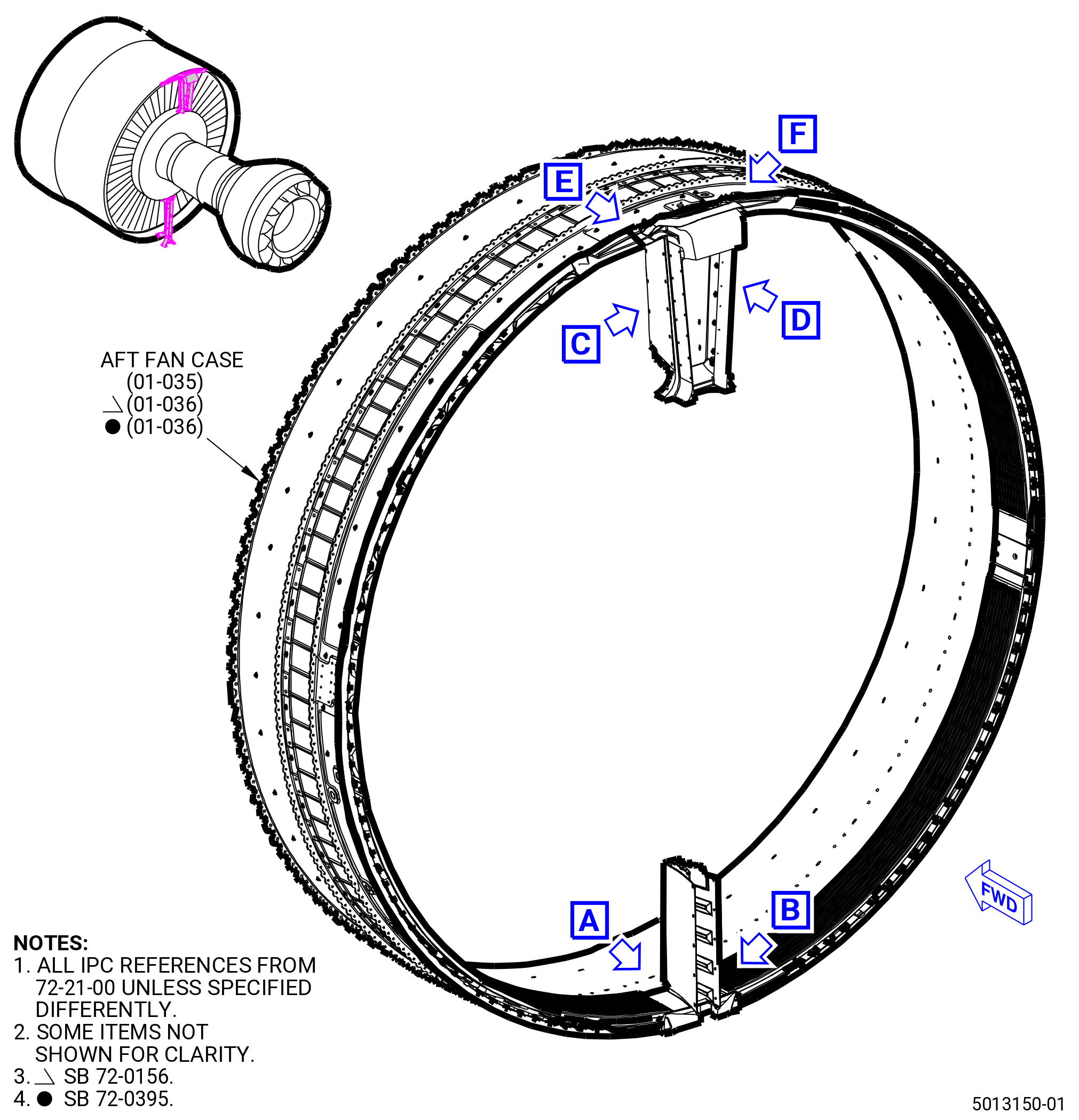
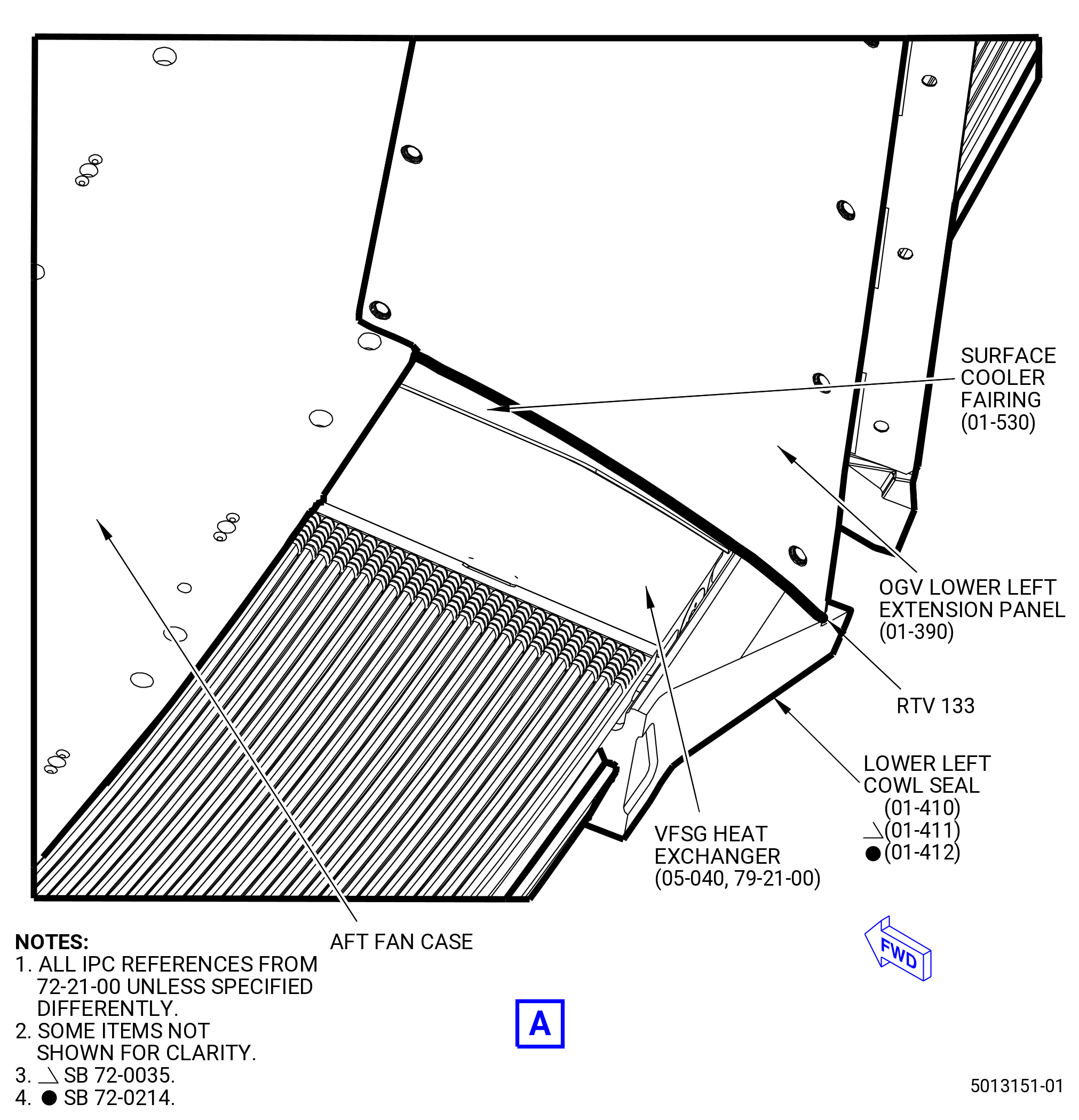
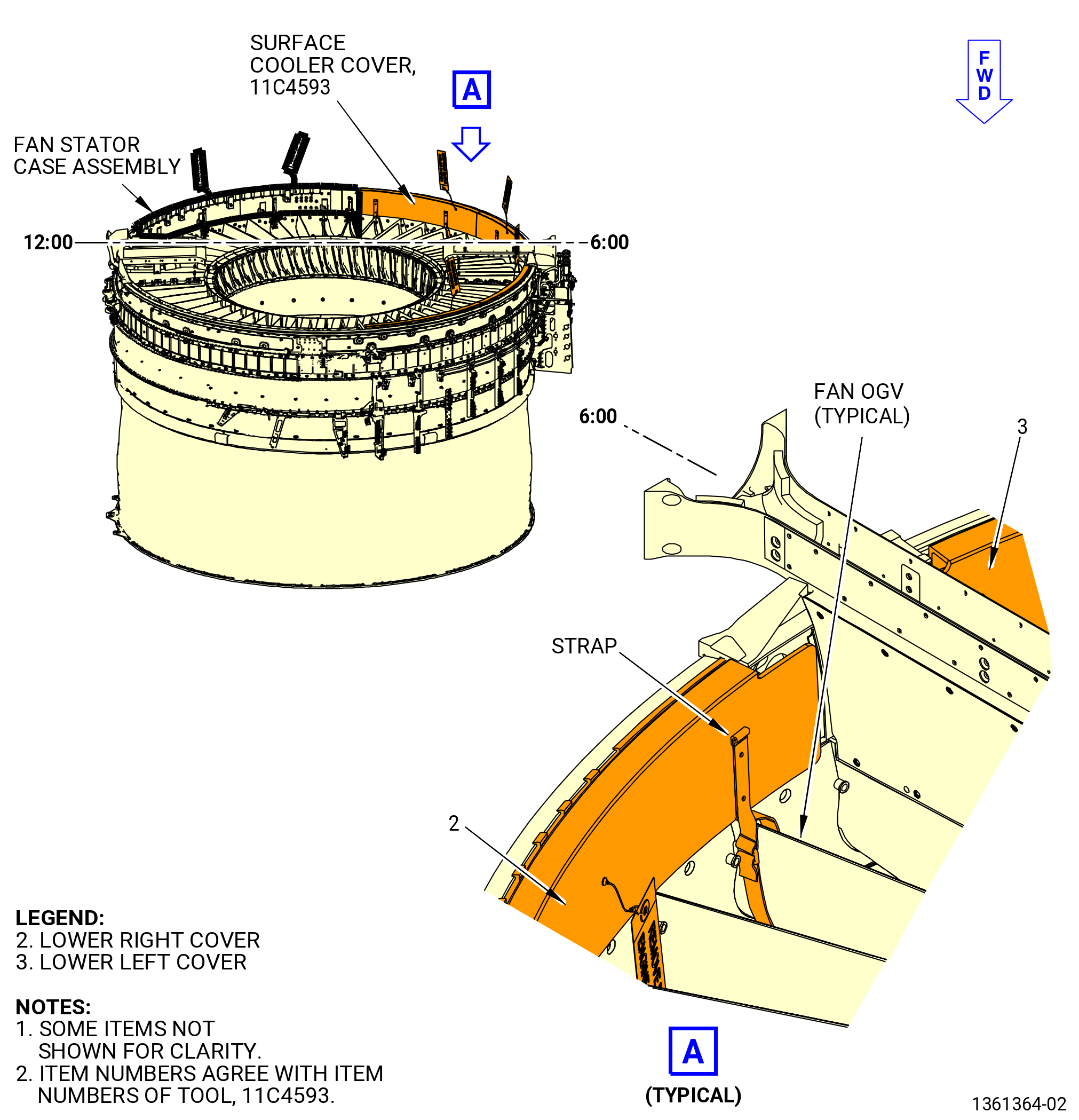
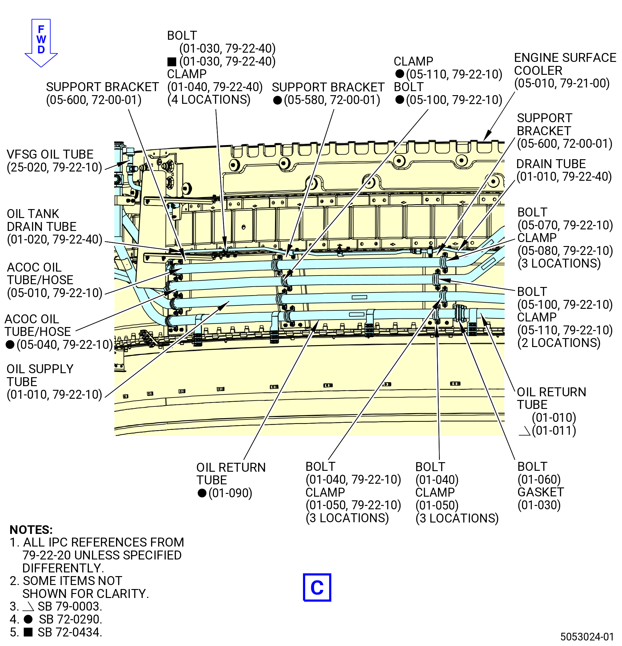
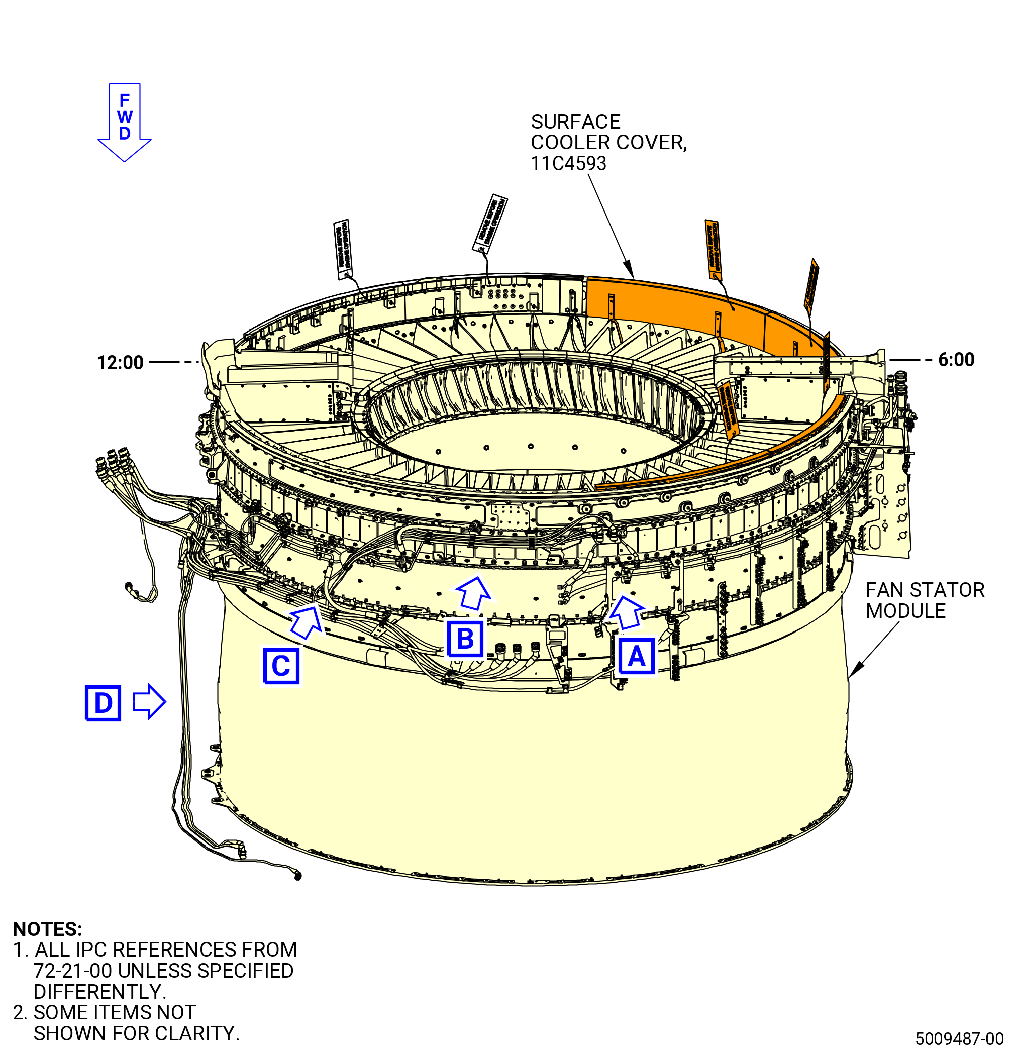
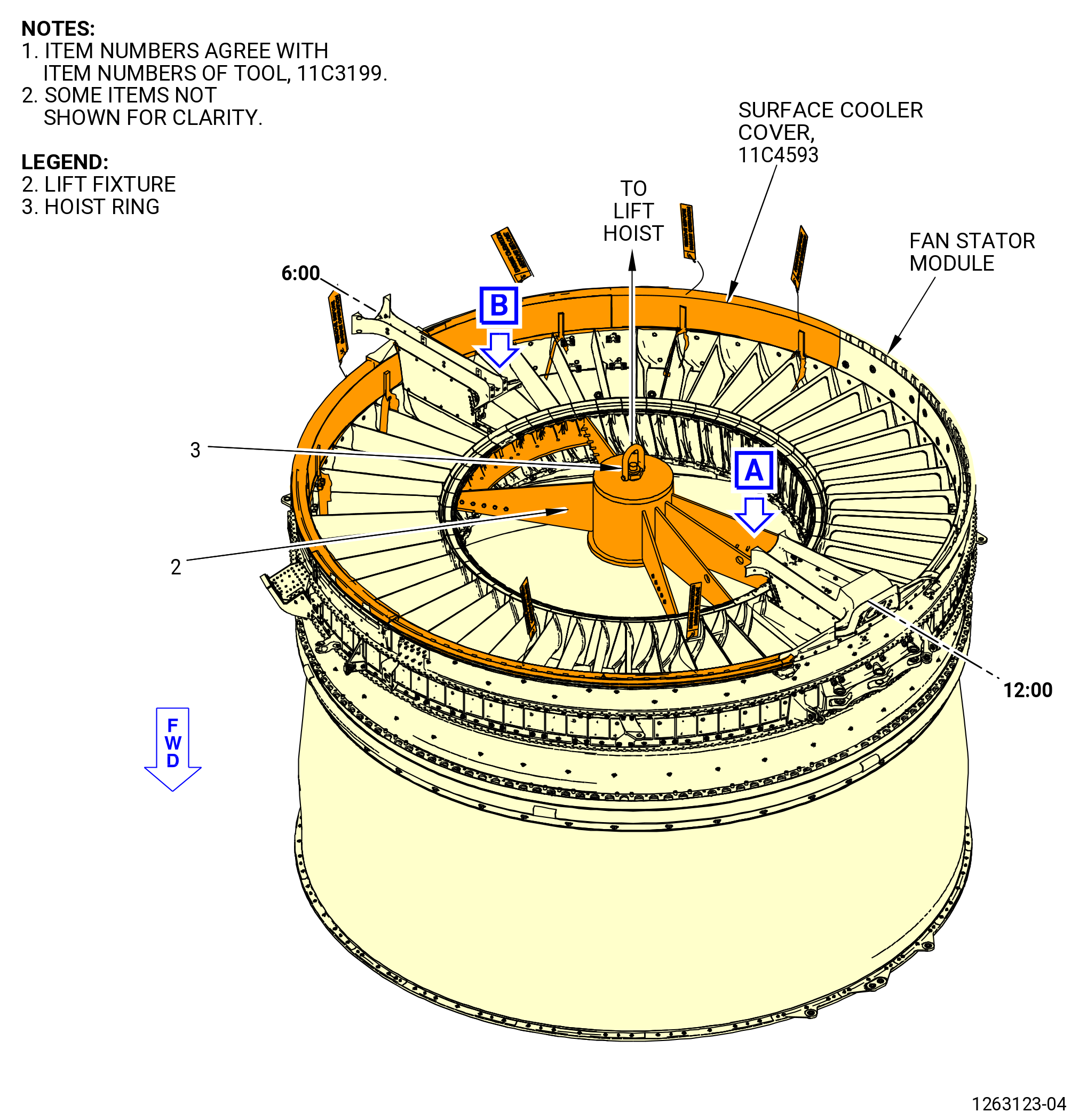
| M. | Install the left-side and right-side VFSG heat exchangers (surface coolers) (05-040 , 79-21-00) (SIN 52100) and (05-030 , 79-21-00) (SIN 52101) and engine surface cooler (05-010 , 79-21-00) (SIN 52102) on the fan stator case as follows: |
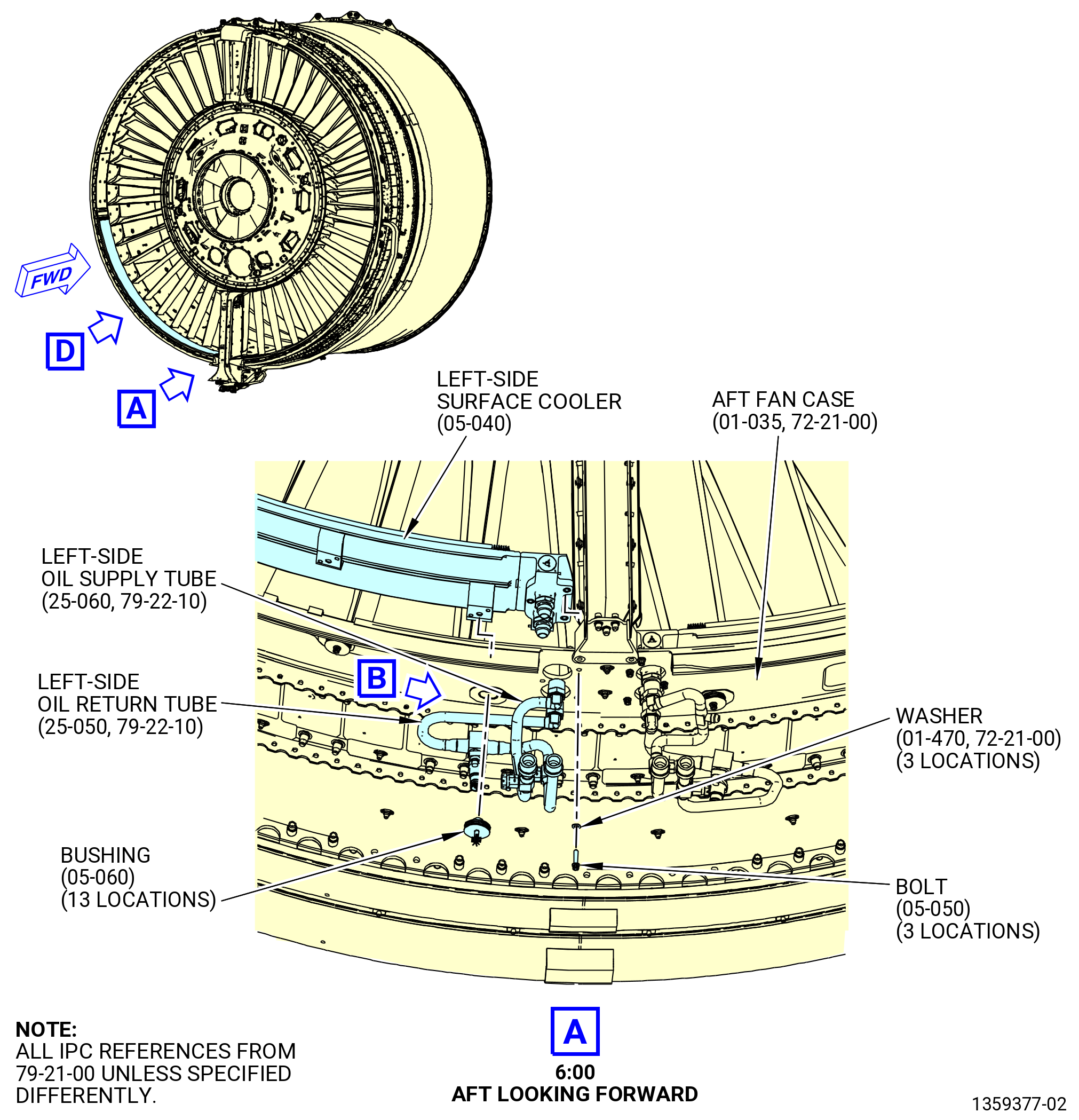
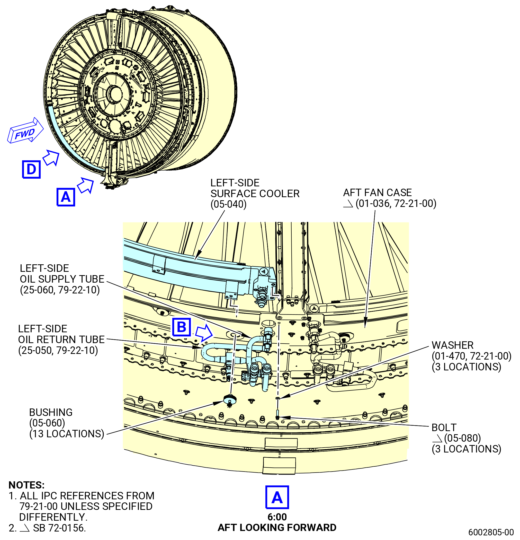
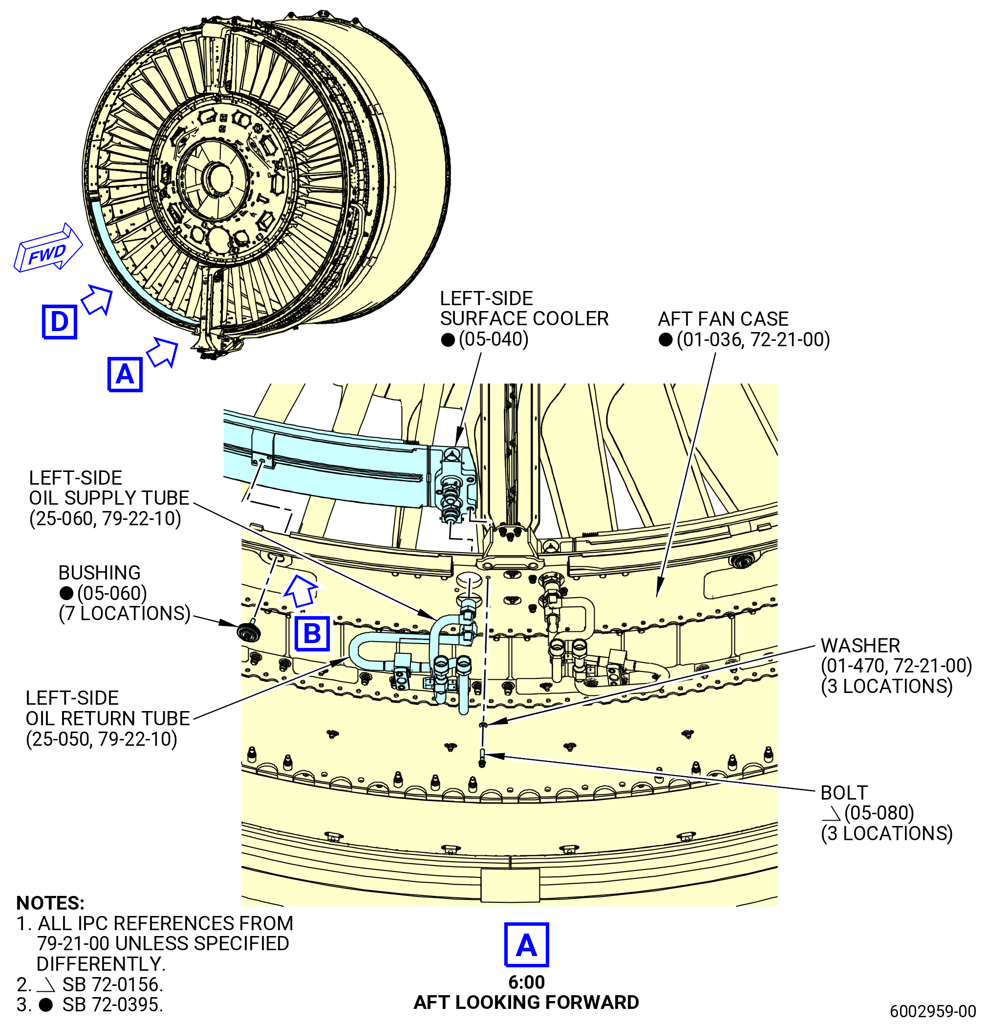
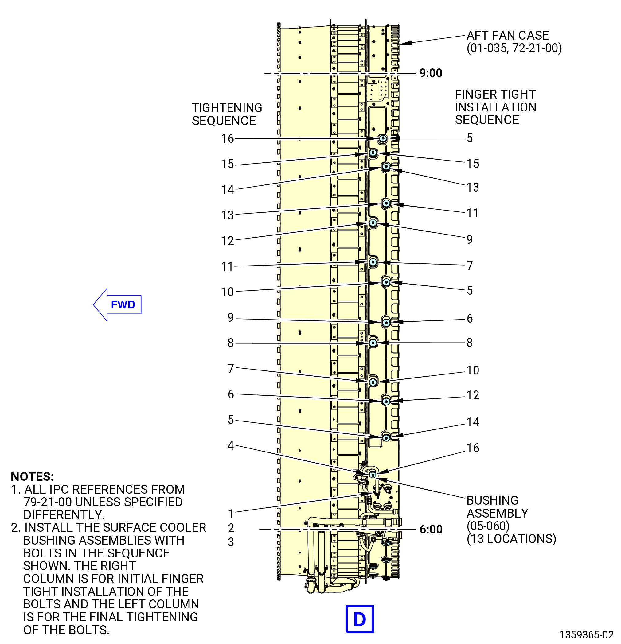
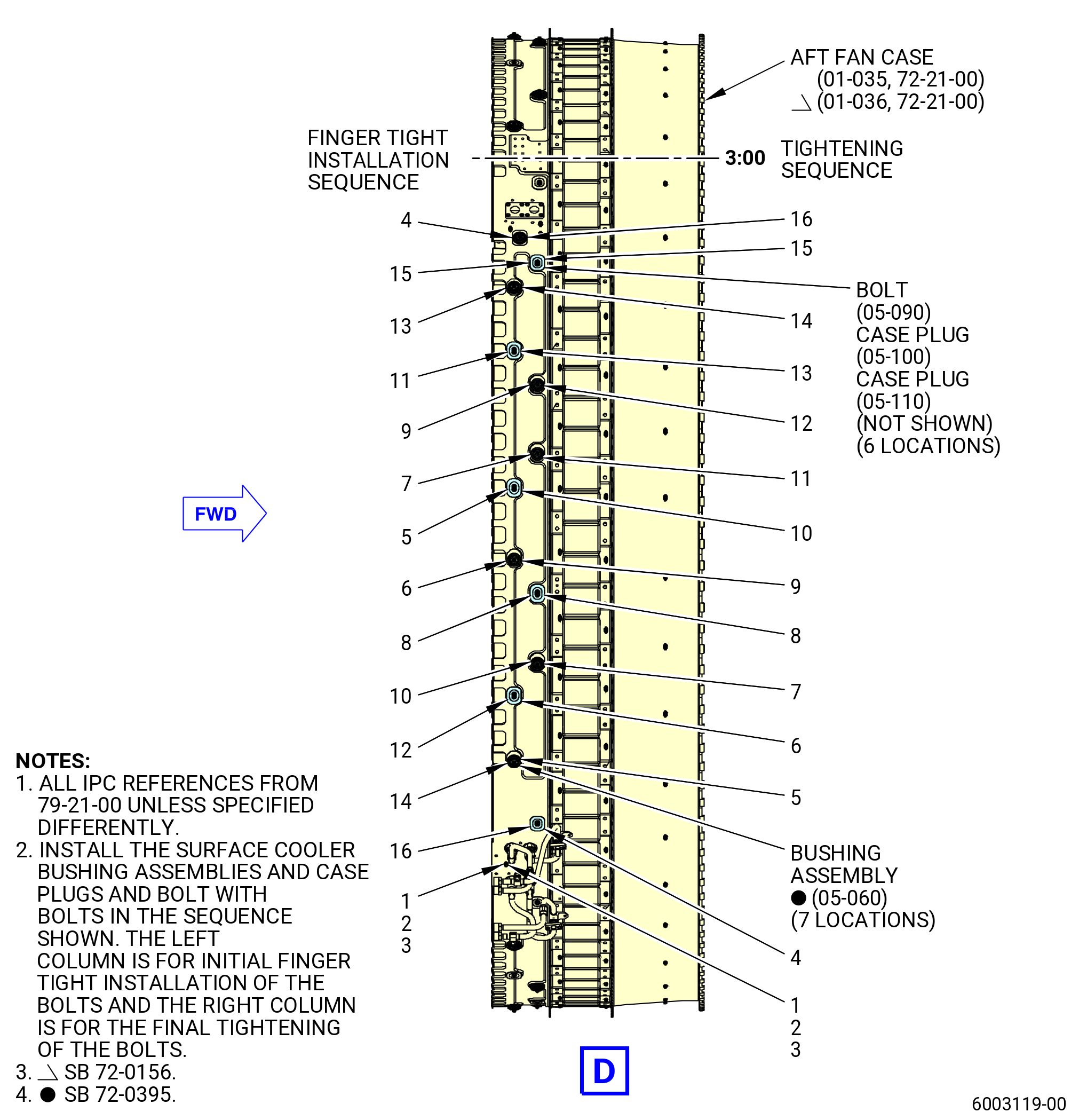
| (1) | Install the left-side surface cooler (05-040 , 79-21-00) (SIN 52100) at the 6:00 o'clock and 9:00 o'clock positions of the aft fan case. Refer to Figure 1010. |
|
|
|
|
|
|
|
| Subtask 72-00-01-640-059 |
| (a) | Apply C02-058 lubricant to the threads of the bushing assembly (05-060 , 79-21-00) (SIN 52191) bolts. |
| Subtask 72-00-01-430-564 |
| CAUTION: |
|
| (b) | Put the left-side surface cooler oil tube fittings on the aft fan case at the 6:00 o'clock position, aft looking forward. |
| (c) | Put the other end of the left-side surface cooler on the aft fan case at the 9:00 o'clock position, aft looking forward. |
| (d) | Make sure the left-side surface cooler surface fittings are in the correct position in the aft fan case clearance hole. |
| Subtask 72-00-01-430-600 |
| * * * FOR 1B/P/G03.1B/P/G04.1B/P1/G01 |
| * * * PRE SB 72-0156( Fan Module without PIP 2 Configuration ) |
| (e) | Loosely install the three bolts (05-050 , 79-21-00) (SIN 52126) and washers (05-020 , 79-21-00) (SIN 52138) that attach the left-side surface cooler to the aft fan case (01-035 , 72-21-00) (SIN 84100). |
| * * * END PRE SB 72-0156 |
| Subtask 72-00-01-430-601 |
| * * * FOR ALL PIP 2 |
| * * * SB 72-0395( Optimized Surface Cooler System - Production ) |
| * * * SB 72-0156( Fan Module PIP 2 Configuration ) |
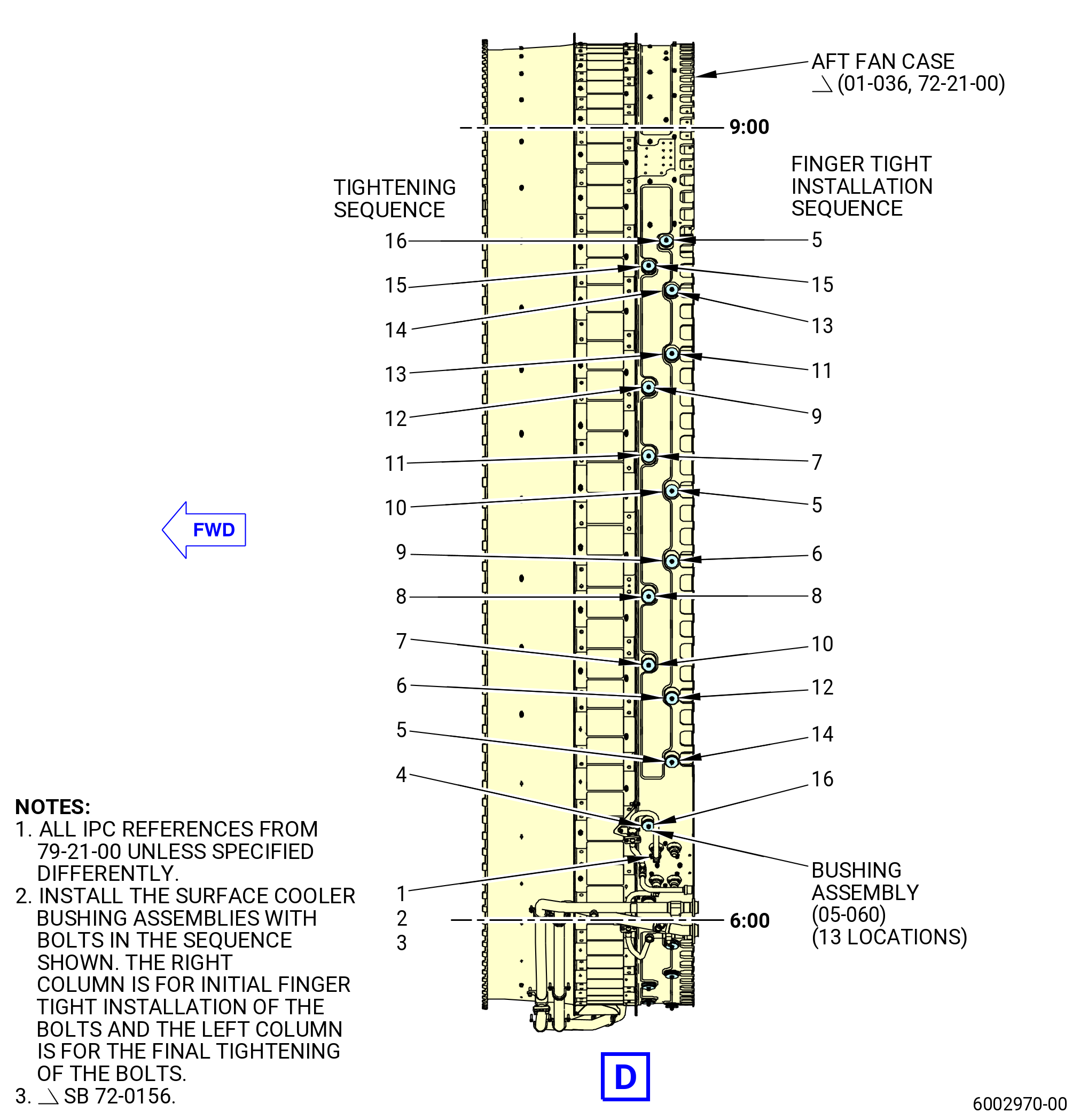
| (e).A. | Loosely install the three bolts (05-080 , 79-21-00) (SIN 5212D) and washers (05-020 , 79-21-00) (SIN 52138) that attach the left-side surface cooler to the aft fan case (01-036 , 72-21-00) (SIN 84100). |
| * * * END SB 72-0156 |
| * * * END SB 72-0395 |
| Subtask 72-00-01-430-604 |
| * * * FOR ALL |
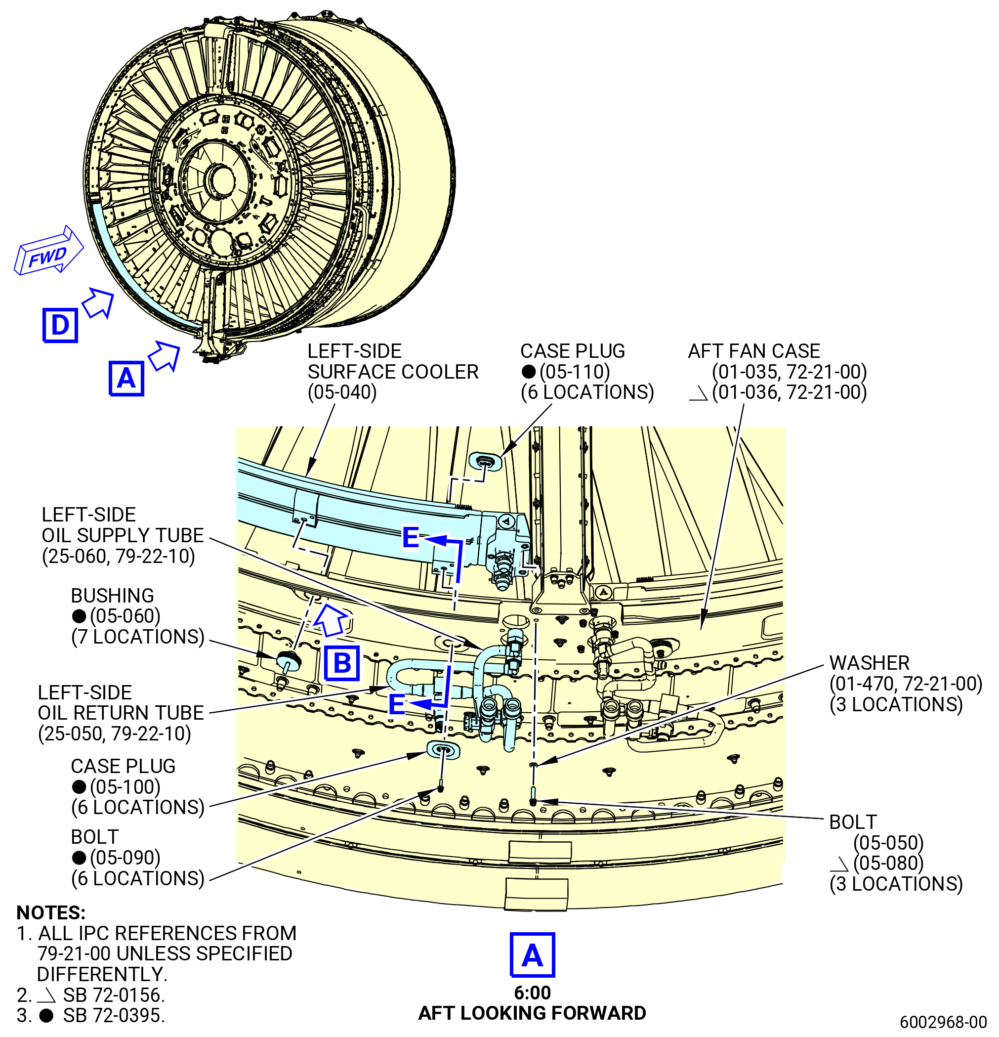
| (f) | Loosely install the surface cooler bushing assembly (05-060 , 79-21-00) (SIN 52191), that attaches the left-side surface cooler to the aft fan case, at the 9:00 o'clock position. |
| Subtask 72-00-01-430-627 |
| * * * FOR 1B/P/G03.1B/P/G04.1B/P1/G01 |
| * * * PRE SB 72-0395( Old Surface Cooler System ) |
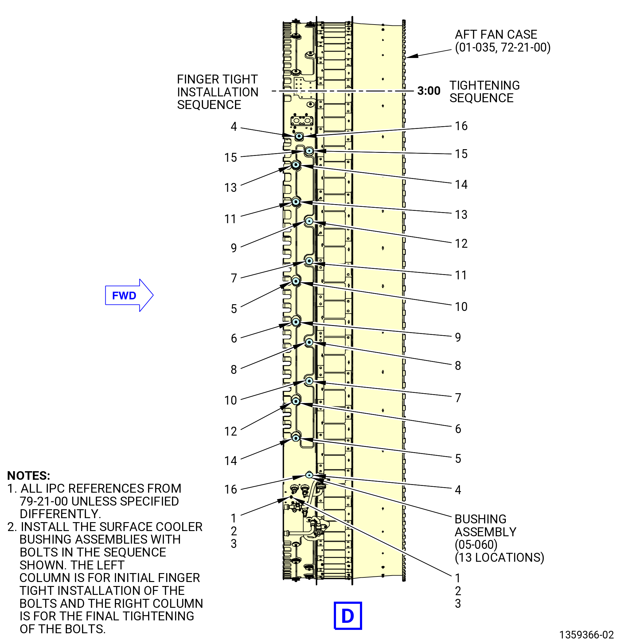
| (g) | Install the 12 remaining bushing assemblies (05-060 , 79-21-00) (SIN 52191) on the aft fan case (01-035 , 72-21-00) (SIN 84100) and the left-side surface cooler (05-040 , 79-21-00) (SIN 52100) in the sequence shown in Figure 1010 and tighten the bolts finger-tight. |
| * * * END PRE SB 72-0395 |
| Subtask 72-00-01-430-628 |
| * * * FOR ALL PIP 2 |
| * * * PRE SB 72-0395( Old Surface Cooler System ) |
| * * * SB 72-0156( Fan Module PIP 2 Configuration ) |
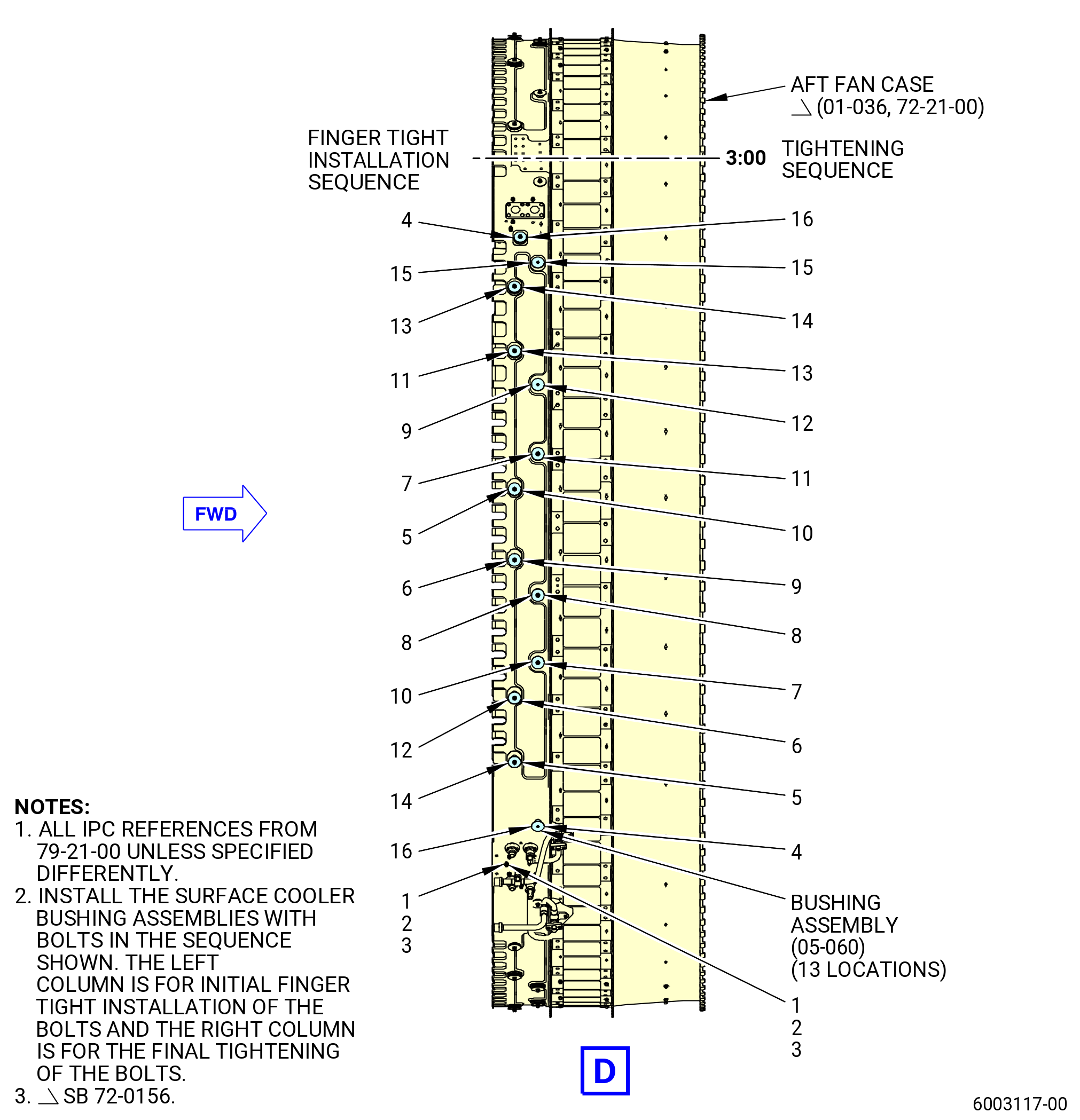
| (g).A. | Install the 12 remaining bushing assemblies (05-060 , 79-21-00) (SIN 52191) in the sequence shown in Figure 1010. Hand-tighten the bolts at this time. |
| * * * END SB 72-0156 |
| * * * END PRE SB 72-0395 |
| Subtask 72-00-01-430-629 |
| * * * FOR ALL PIP 2 |
| * * * SB 72-0395( Optimized Surface Cooler System - Production ) |
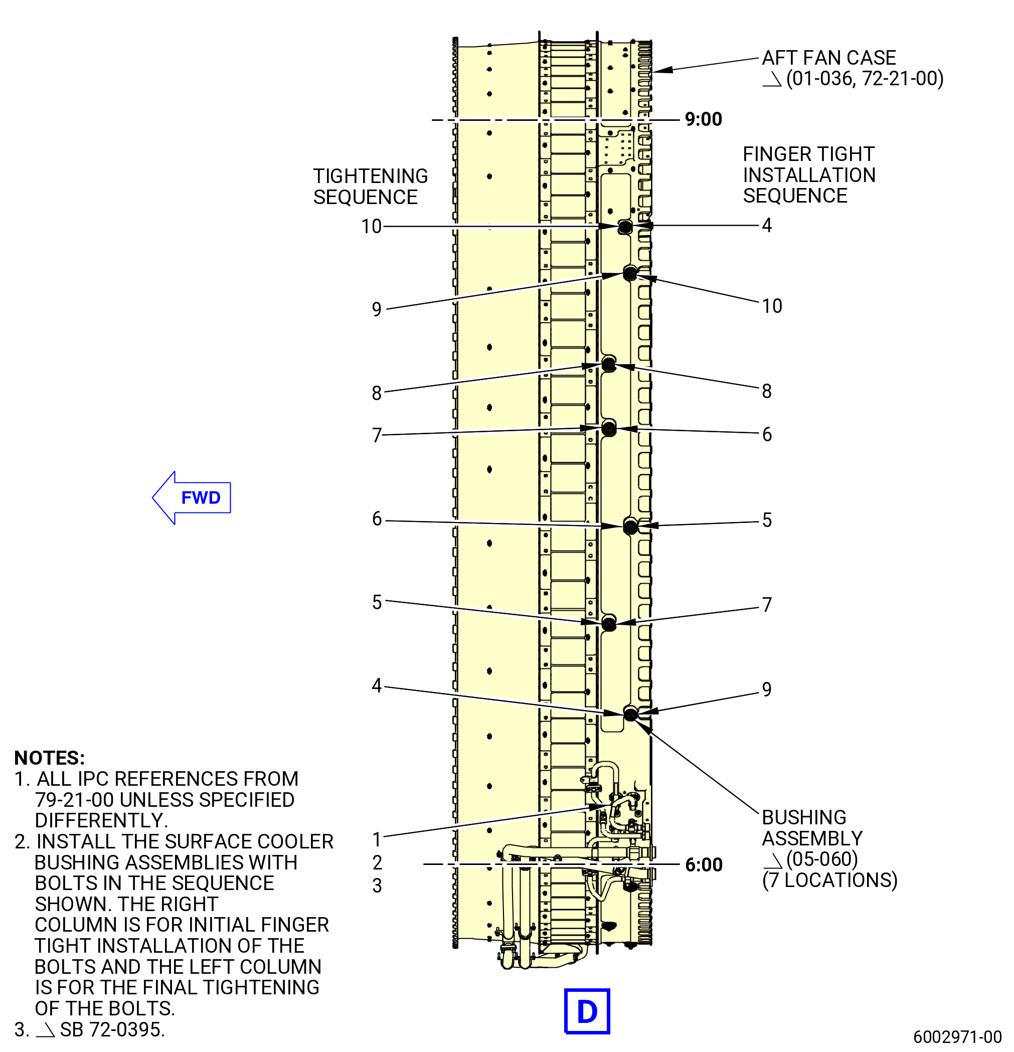
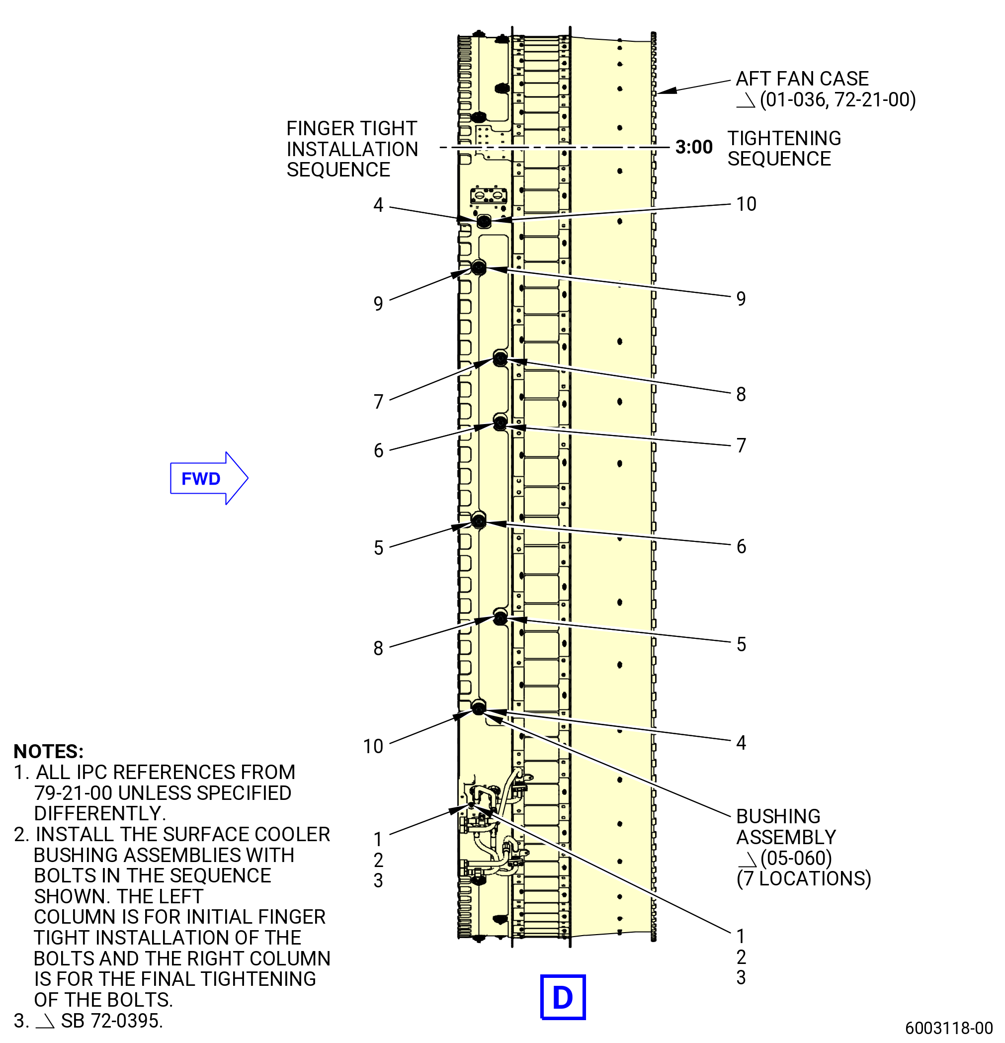
| (g).B. | Install the six remaining bushing assemblies (05-060 , 79-21-00) (SIN 52191) in the sequence shown in Figure 1010. Hand-tighten the bolts at this time. |
| * * * END SB 72-0395 |
| Subtask 72-00-01-430-630 |
| * * * FOR ALL |
| * * * SB 72-0395( Optimized Surface Cooler System - Field ) |
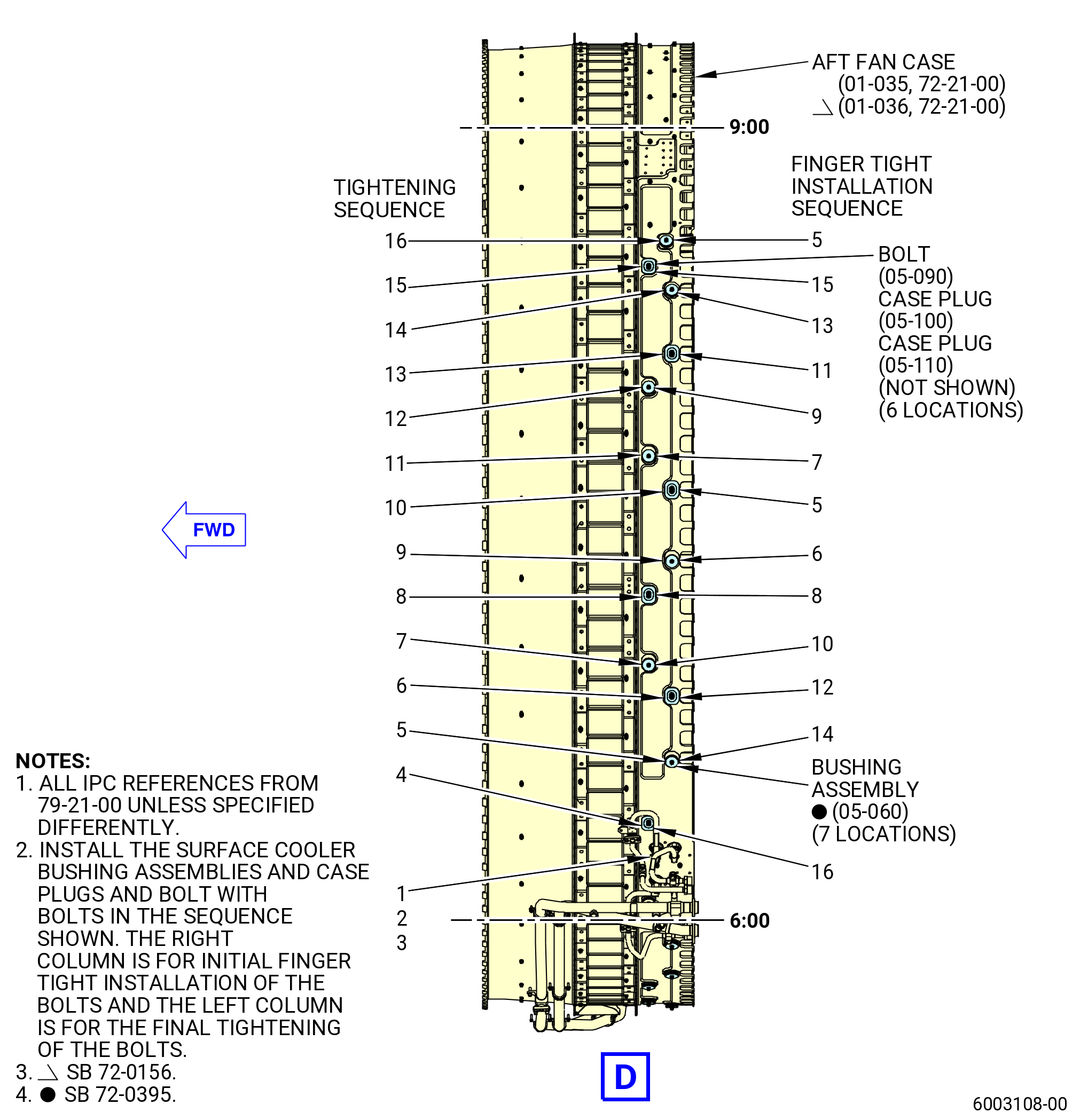
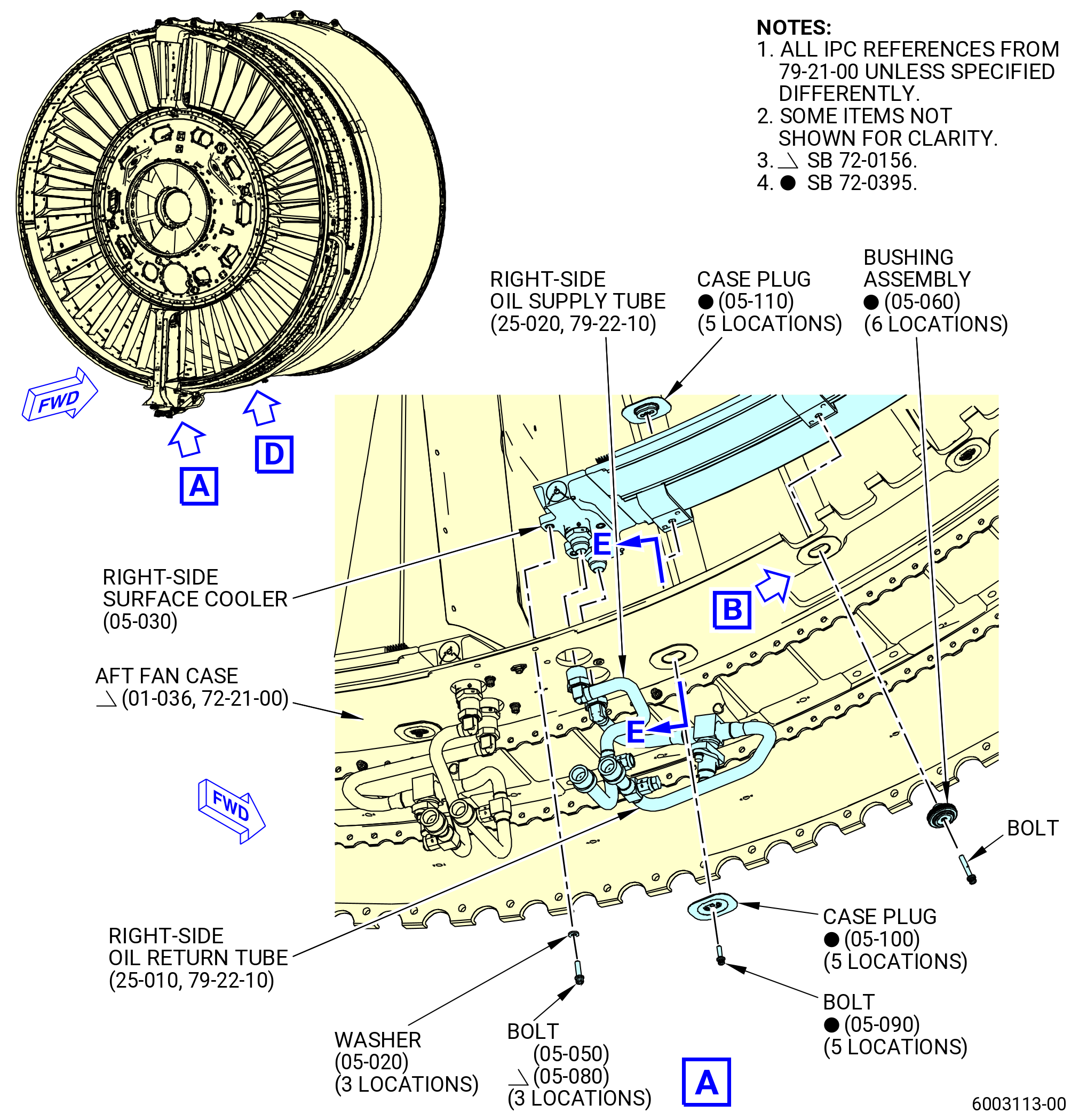
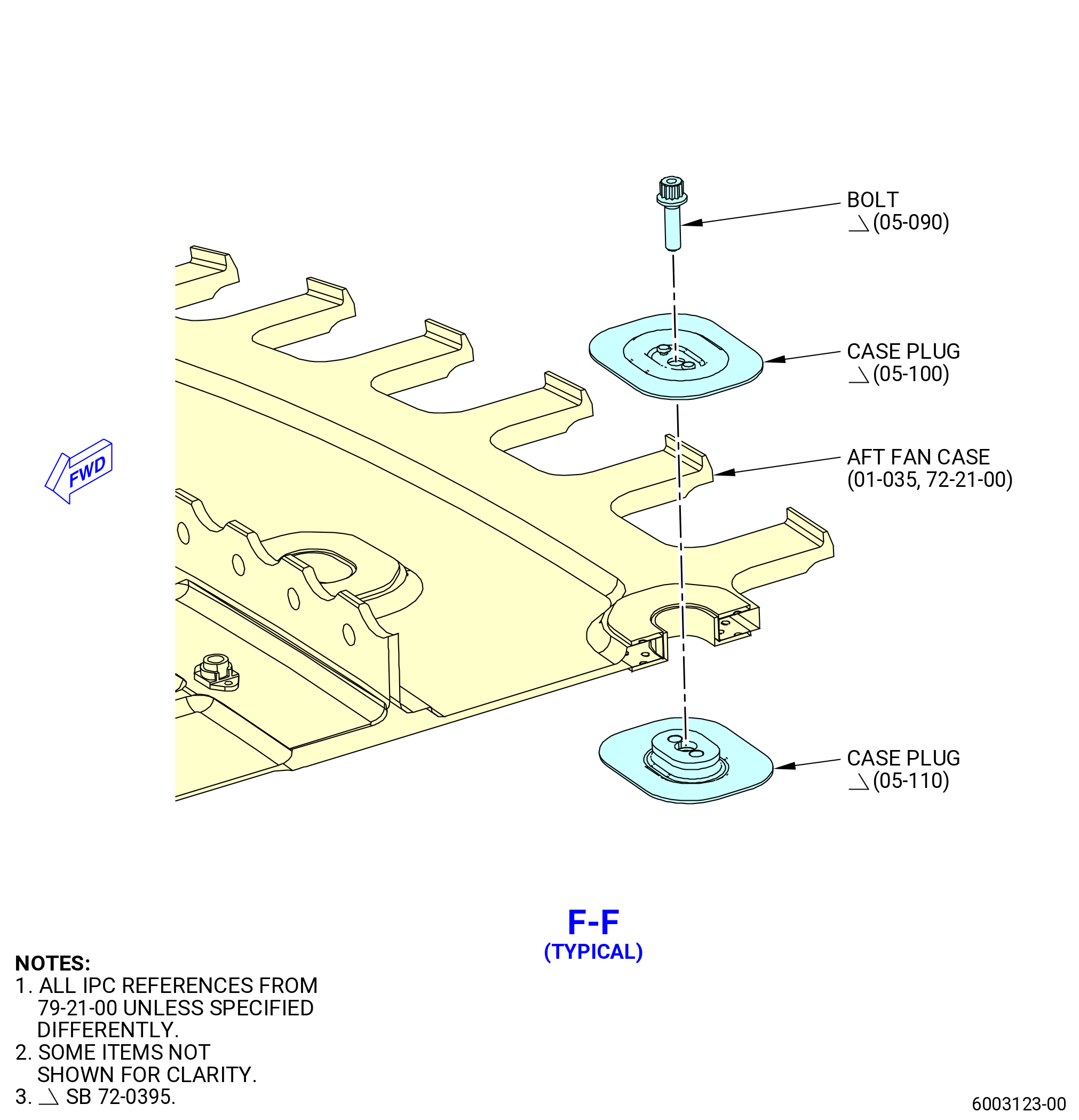
| (g).C. | Install the six remaining bushing assemblies (05-060 , 79-21-00) (SIN 52191), the six machine bolts (bolts) (05-090 , 79-21-00) (SIN 5212E), and the six case plugs (05-100 , 79-21-00) (SIN 52161) and (05-110 , 79-21-00) (SIN 52162) in the sequence shown in Figure 1010. Hand-tighten the bolts at this time. |
| * * * END SB 72-0395 |
| Subtask 72-00-01-430-631 |
| (h) | Make sure the left-side surface cooler (05-040 , 79-21-00) (SIN 52100) has interface with the aft fan case seal and is compressed within the surface cooler, outlet guide vanes (OGVs), and fairings. |
| (i) | Torque the three bolts (05-050 , 79-21-00) (SIN 52126) or (05-080 , 79-21-00) (SIN 5212D) to 106 to 124 lb in. (12.0 to 14.0 Nm). |
| Subtask 72-00-01-430-632 |
| * * * FOR 1B/P/G03.1B/P/G04.1B/P1/G01 |
| * * * PRE SB 72-0395( Old Surface Cooler System ) |
| (j) | Start with the bushing assembly (05-060 , 79-21-00) (SIN 52191) bolt at the 6:00 o'clock position and torque the 13 bolts to 106 to 124 lb in. (12.0 to 14.0 Nm). |
| * * * END PRE 72-0395 |
| Subtask 72-00-01-430-633 |
| * * * FOR ALL PIP 2 |
| * * * PRE SB 72-0395( Old Surface Cooler System ) |
| * * * SB 72-0156( Fan Module PIP 2 Configuration ) |
| (j).A. | Start with the bushing assembly (05-060 , 79-21-00) (SIN 52191) at the 6:00 o’clock position and torque the 13 bolts to 106 to 124 lb in. (12.0 to 14.0 Nm). |
| * * * END SB 72-0156 |
| * * * END PRE SB 72-0395 |
| Subtask 72-00-01-430-634 |
| * * * FOR ALL PIP 2 |
| * * * SB 72-0395( Optimized Surface Cooler System - Production ) |
| (j).B. | Start with the bushing assembly (05-060 , 79-21-00) (SIN 52191) at the 6:00 o’clock position and torque the seven bolts to 106 to 124 lb in. (12.0 to 14.0 Nm). |
| * * * END SB 72-0395 |
| Subtask 72-00-01-430-635 |
| * * * FOR ALL |
| * * * SB 72-0395( Optimized Surface Cooler System - Field ) |
| (j).C. | Start with the bolt (05-090 , 72-21-00) (SIN 5212E) at the 6:00 o’clock position and continue the torque procedure according with the sequence shown in Figure 1010 and do as follows: |
| 1 | Torque the seven bushing assemblies (05-060 , 79-21-00) (SIN 52191) to 106 to 124 lb in. (12.0 to 14.0 Nm). |
| 2 | Torque the bolts (05-090 , 79-21-00) (SIN 5212E) to 51 to 59 lb in. (5.7 to 6.7 Nm). |
| * * * END SB 72-0395 |
| Subtask 72-00-01-220-027 |
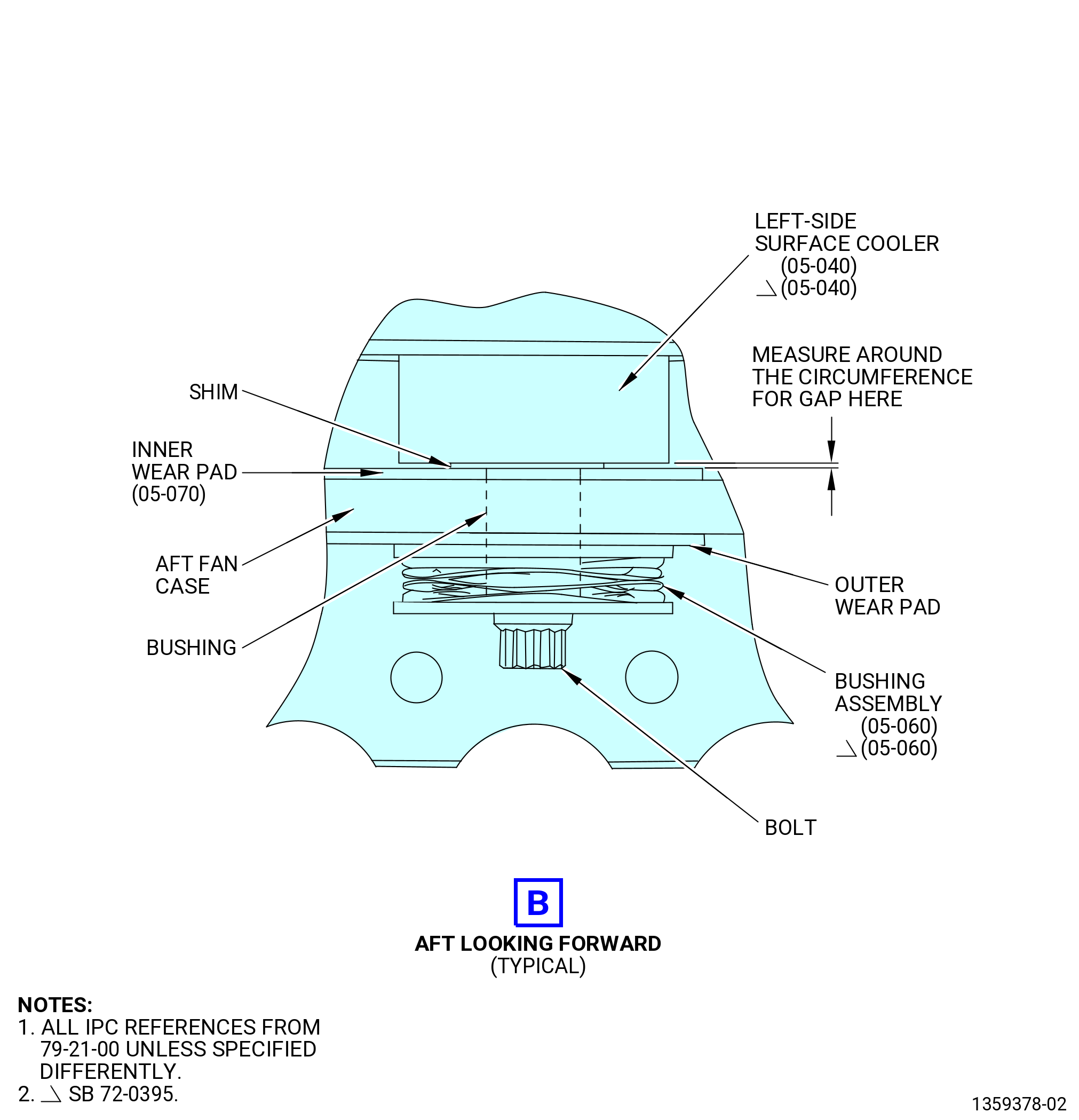
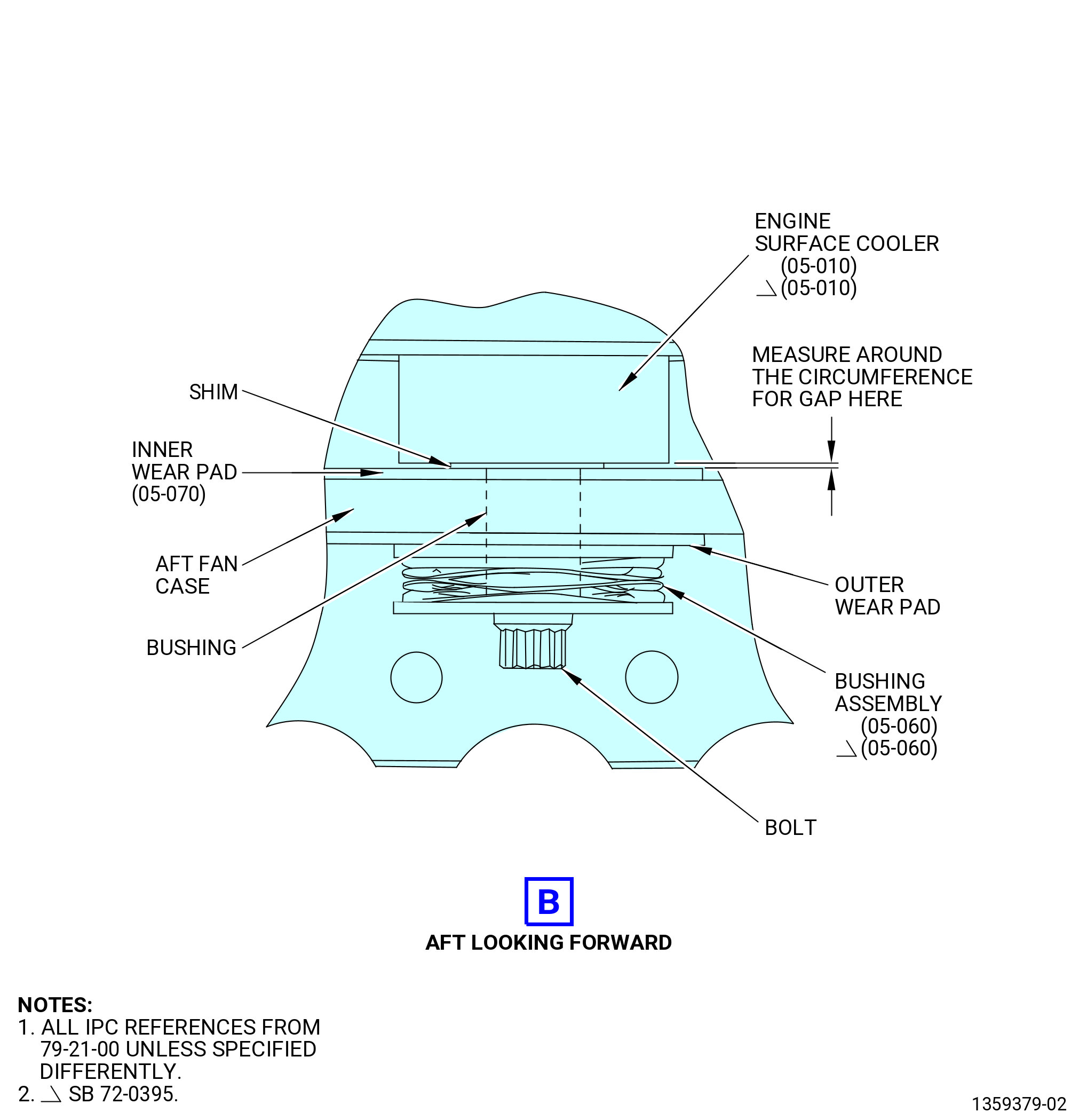
| (k) | Make sure the left-side surface cooler is correctly attached to the aft fan case as follows: |
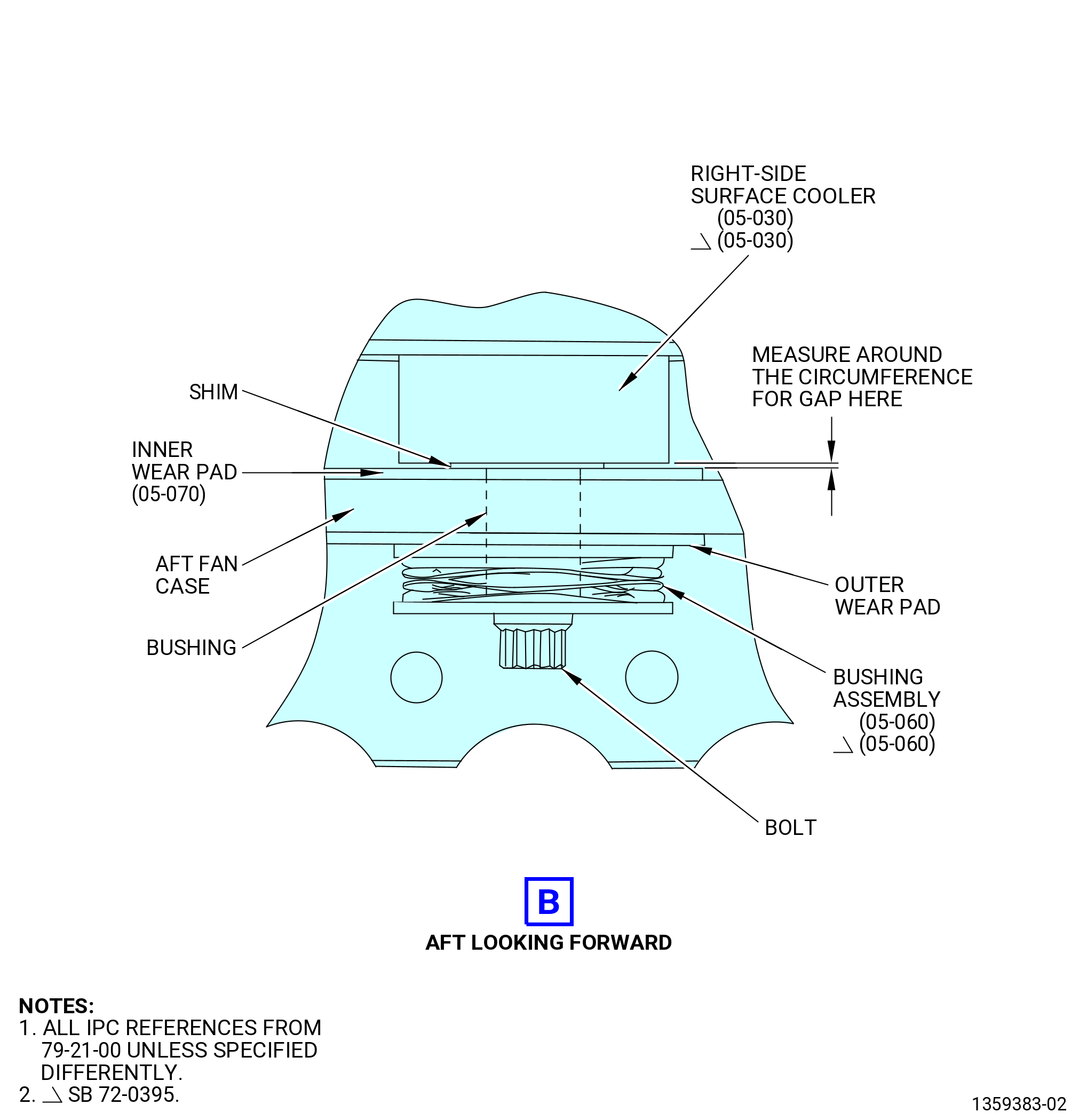
| 1 | Use a feeler gauge and measure around the circumference of the 13 bushings of the bushing assemblies (05-060 , 79-21-00) (SIN 52191) between the inner wear pad (05-070 , 79-21-00) (SIN 521T1) and the surface cooler wear pad. |
| 2 | Identify all locations with a gap of 0.003-0.080 inch (0.08-2.03 mm). |
| 3 | If a gap is more than 0.080 inch (2.03 mm), replace the left-side surface cooler (05-040 , 79-21-00) (SIN 52100). |
| NOTE: |
|
| 4 | If you find more than three circumferentially consecutive gaps that are more than 0.003 inch (0.08 mm), then you must install a shim or shims in the gap. |
| 5 | Select the gap that is closest to the center of the span of the brackets on the aft side of the left-side surface cooler (05-040 , 79-21-00) (SIN 52100). |
| 6 | Measure the thickness of the shim(s) necessary to close the gap at the selected location. |
| 7 | Select a shim that is closest to the measurement. |
| 8 | Install the necessary number of shims to get the gap between the inner wear pad (05-070 , 79-21-00) (SIN 521T1) and the left-side surface cooler (05-040 , 79-21-00) (SIN 52100) to 0.003 inch (0.08 mm) or less, as follows: |
| a | Remove the bolt that attaches the bushing assembly (52191) and remove the assembly. |
| b | Put the shim between the inner wear pad (05-070 , 79-21-00) (SIN 521T1) and the surface cooler wear pad. |
| NOTE: |
|
| c | Install the bushing assembly (05-060 , 79-21-00) (SIN 52191) that attaches the left-side surface cooler to the aft fan case. |
| d | Torque the bushing assembly (52191) bolt to 106-124 lb in. (12.0-14.0 N.m). |
| e | If you loosened any adjacent bushing assembly (52191) bolts, tighten the bolts to 106-124 lb in. (12.0-14.0 N.m). |
| f | Measure around the circumference of the 13 bushings of the bushing assembly (52191) again. Make sure that no other locations adjacent to the shimmed location has more than three consecutive gaps that are more than 0.003 inch (0.08 mm). |
| Subtask 72-00-01-640-060 |
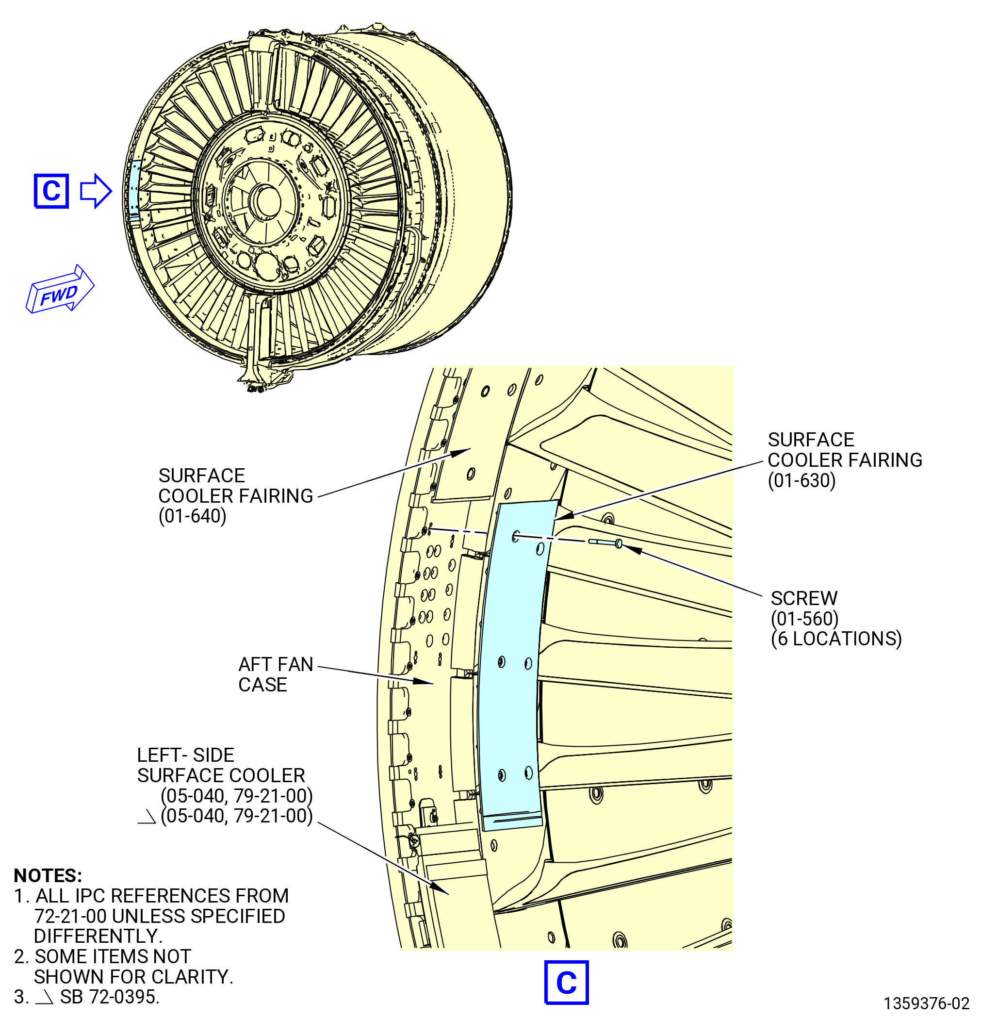
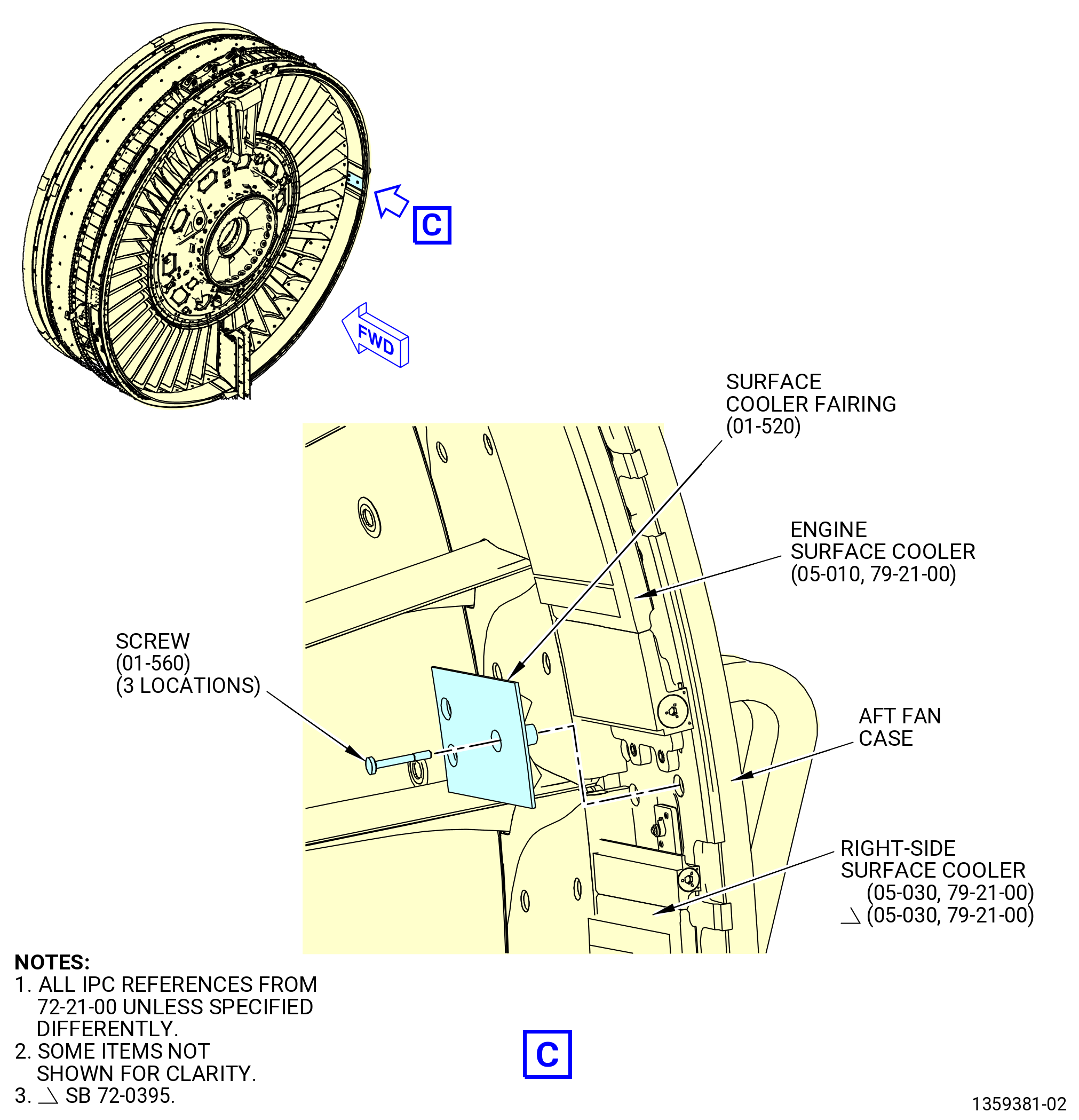
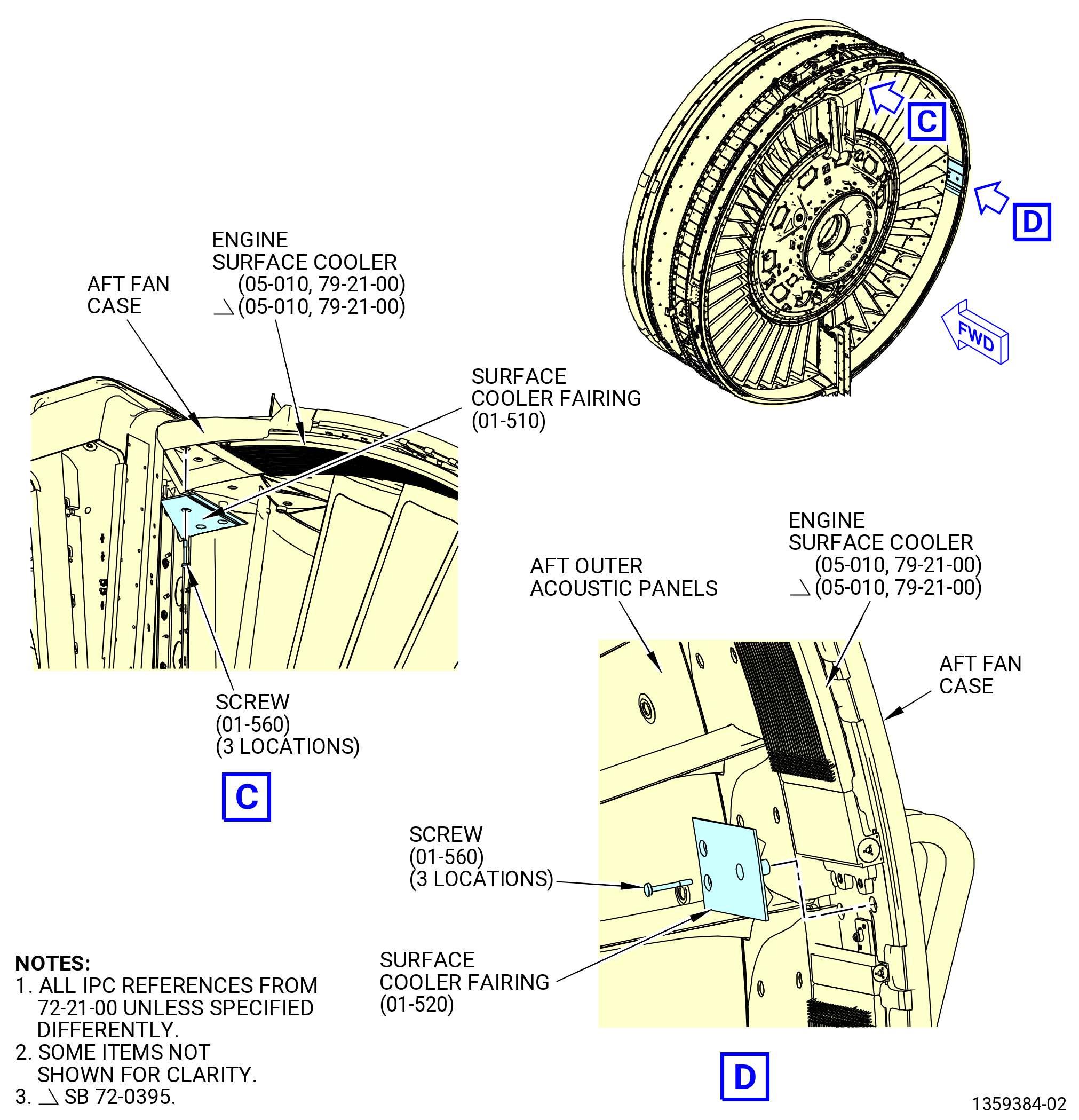
| (l) | Install the surface cooler fairing (83507) as follows: |
| 1 | Apply C02-058 lubricant to the threads of the screws (83523). |
| Subtask 72-00-01-430-566 |
| 2 | Put the surface cooler fairing (01-630 , 72-21-00) (SIN 83507) in position on the aft fan case and loosely install three screws (01-560 , 72-21-00) (SIN 83523), equally spaced. |
| 3 | Tighten the screws (83523) finger-tight to prevent movement. |
| 4 | Make sure there is a minimum 0.010 inch (0.25 mm) gap between the surface cooler fairing (83507) and the adjacent panels. |
| 5 | If necessary, you can chamfer the edge of a surface cooler fairing (83507) or surface cooler fairing (83508) by 0.050 inch (1.27 mm) maximum. |
| 6 | Torque the six screws (83523) as follows: |
| a | Torque the two screws (83523) in the middle of the surface cooler fairing (83507) to 83-97 lb in. (9.4-11.0 N.m). |
| b | Torque the two upper screws (83523) to 83-97 lb in. (9.4-11.0 N.m). |
| c | Torque the two lower screws (83523) to 83-97 lb in. (9.4-11.0 N.m). |
| d | Torque the screws (83523) again, in the same sequence, to 83-97 lb in. (9.4-11.0 N.m). |
| e | After 15 minutes, torque the screws (83523) again, in the same sequence, to 83-97 lb in. (9.4-11.0 N.m). |
| Subtask 72-00-01-640-063 |
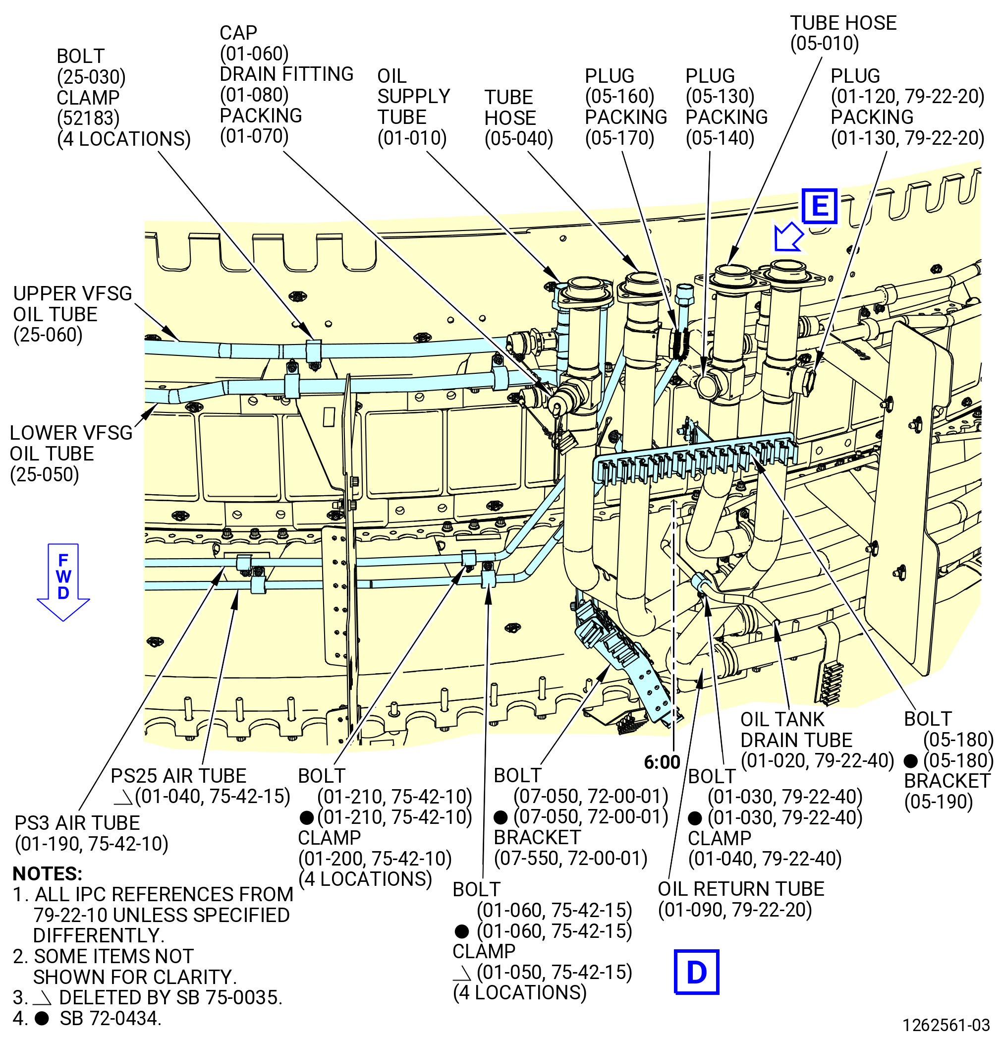
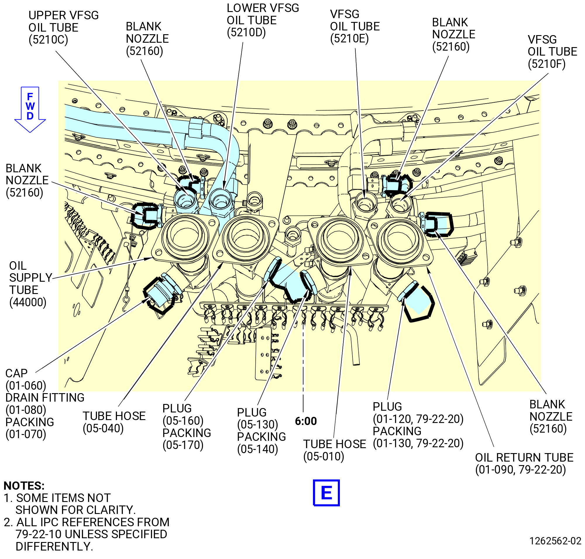
| (m) | Connect the left-side oil supply tube (5210C) and the left-side oil return tube (5210D) to the left-side surface cooler (52100) as follows: |
| WARNING: |
|
| CAUTION: |
|
| 1 | Apply C02-019 engine oil to the threads of the left-side oil return tube (5210D). |
| Subtask 72-00-01-430-571 |
| 2 | Loosely connect the left-side oil return tube (5210D) to the left-side surface cooler (52100). |
| CAUTION: |
|
| 3 | Hold the fitting on the left-side surface cooler (52100) with a second wrench. |
| 4 | Torque the left-side oil return tube (5210D) B-nut to 662-778 lb in. (74.8-88.0 N.m). |
| 5 | Loosely connect the left-side oil supply tube (5210C) to the left-side surface cooler (52100). |
| CAUTION: |
|
| 6 | Hold the fitting on the left-side surface cooler (52100) with a second wrench. |
| 7 | Torque the left-side oil supply tube (5210C) B-nut to 662-778 lb in. (74.8-88.0 N.m). |
| Subtask 72-00-01-430-567 |
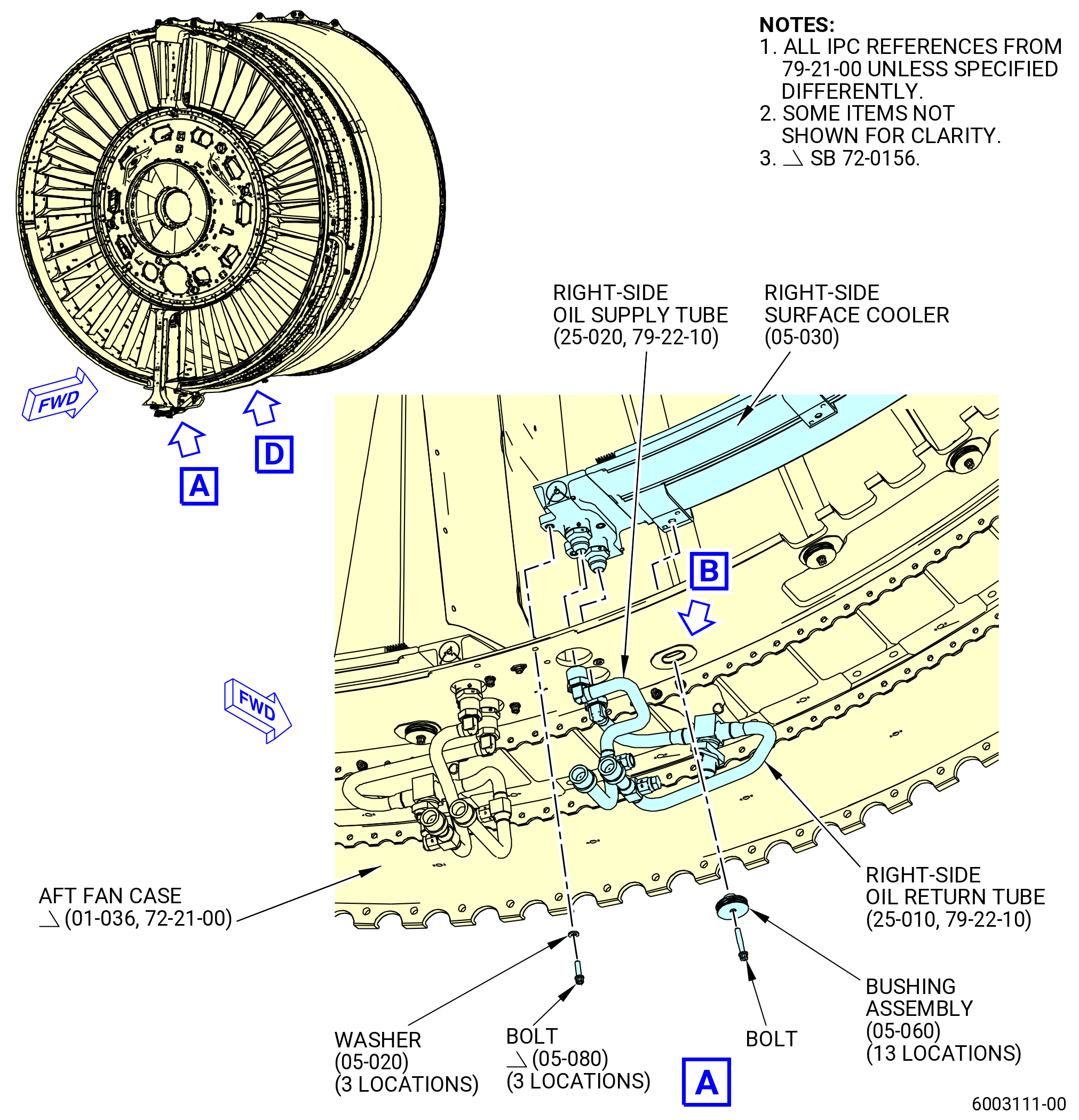
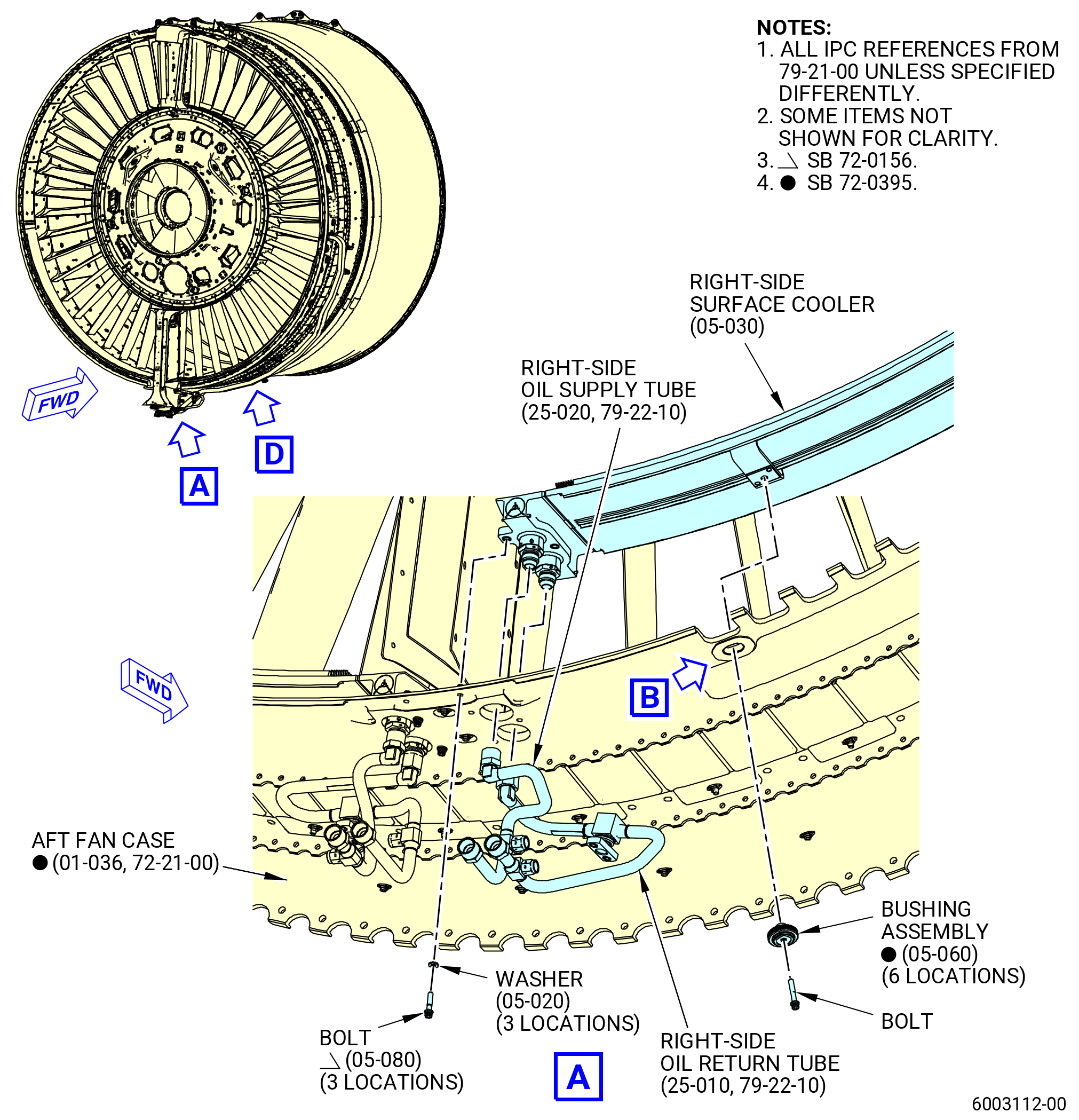
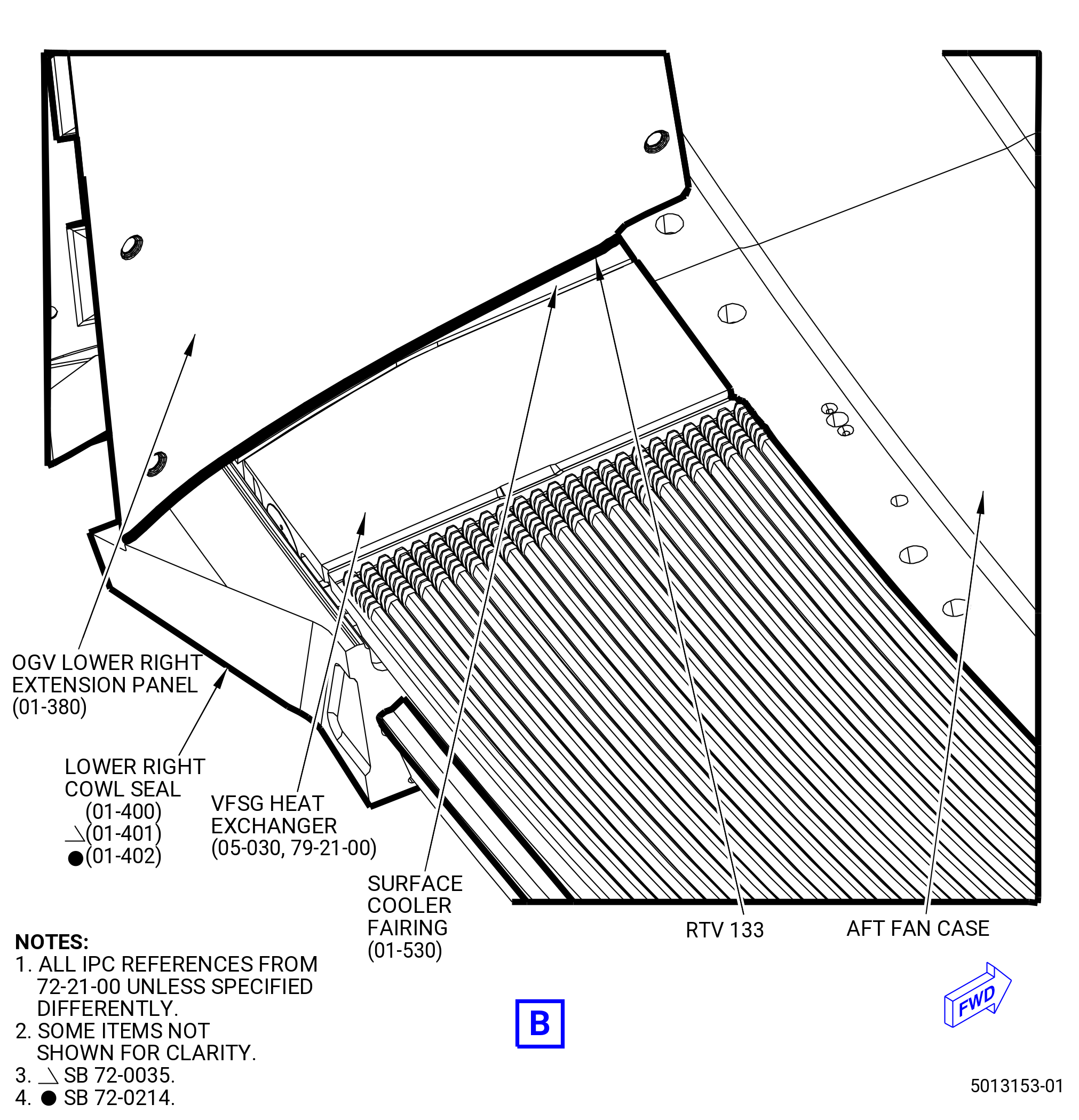
| (12) | Install the right-side surface cooler (05-030 , 79-21-00) (SIN 52101) at the 6:00 and 3:00 o'clock positions of the aft fan case. Refer to Figure 1011. |
|
|
|
|
|
|
|
| Subtask 72-00-01-640-061 |
| (a) | Apply C02-058 lubricant to the threads of the bushing assembly (05-060 , 79-21-00) (SIN 52191) bolts. |
| Subtask 72-00-01-430-568 |
| CAUTION: |
|
| (b) | Put the right-side surface cooler oil tube fittings on the aft fan case at the 6:00 o'clock position, aft looking forward. |
| (c) | Put the other end of the right-side surface cooler on the aft fan case at the 3:00 o'clock position, aft looking forward. |
| (d) | Make sure the right-side surface cooler surface fittings are in the correct position in the aft fan case clearance hole. |
| Subtask 72-00-01-430-602 |
| * * * FOR 1B/P/G03.1B/P/G04.1B/P1/G01 |
| * * * PRE SB 72-0156( Fan Module without PIP 2 Configuration ) |
| (e) | Loosely install the three bolts (05-050 , 79-21-00) (SIN 52126) and washers (05-020 , 79-21-00) (SIN 52138) that attach the right-side surface cooler to the aft fan case (01-035 , 72-21-00) (SIN 84100). |
| * * * END PRE SB 72-0156 |
| Subtask 72-00-01-430-603 |
| * * * FOR ALL PIP 2 |
| * * * SB 72-0395( Optimized Surface Cooler System - Production ) |
| * * * SB 72-0156( Fan Module PIP 2 Configuration ) |
| (e).A. | Loosely install the three bolts (05-080 , 79-21-00) (SIN 5212D) and washers (05-020 , 79-21-00) (SIN 52138) that attach the right-side surface cooler to the aft fan case (01-036 , 72-21-00) (SIN 84100). |
| * * * END SB 72-0156 |
| * * * END SB 72-0395 |
| Subtask 72-00-01-430-605 |
| * * * FOR ALL |
| (f) | Loosely install the bushing assembly (05-060 , 79-21-00) (SIN 52191), that attaches the right-side surface cooler to the aft fan case, at the 9:00 o'clock position. |
| Subtask 72-00-01-430-636 |
| * * * FOR 1B/P/G03.1B/P/G04.1B/P1/G01 |
| * * * PRE SB 72-0395( Old Surface Cooler System ) |
| (g) | Install the 12 remaining bushing assemblies (05-060 , 79-21-00) (SIN 52191) in the sequence shown in Figure 1011 and tighten the bolts finger-tight. |
| * * * END PRE SB 72-0395( ) |
| Subtask 72-00-01-430-637 |
| * * * FOR ALL PIP 2 |
| * * * PRE SB 72-0395( Old Surface Cooler System ) |
| * * * SB 72-0156( Fan Module PIP 2 Configuration ) |
| (g).A. | Install the 12 remaining bushing assemblies (05-060 , 79-21-00) (SIN 52191) in the sequence shown in Figure 1011. Hand-tighten the bolts at this time. |
| * * * END SB 72-0156 |
| * * * END PRE SB 72-0395 |
| Subtask 72-00-01-430-638 |
| * * * FOR ALL PIP 2 |
| * * * SB 72-0395( Optimized Surface Cooler System - Production ) |
| (g).B. | Install the six remaining bushing assemblies (05-060 , 79-21-00) (SIN 52191) in the sequence shown in Figure 1011. Hand-tighten the bolts at this time. |
| * * * END SB 72-0395 |
| Subtask 72-00-01-430-639 |
| * * * FOR ALL |
| * * * SB 72-0395( Optimized Surface Cooler System - Field ) |
| (g).C. | Install the six remaining bushing assemblies (05-060 , 79-21-00) (SIN 52191), the six machine bolts (bolts) (05-090 , 79-21-00) (SIN 5212E), and the six case plugs (05-100 , 79-21-00) (SIN 52161) and (05-110 , 79-21-00) (SIN 52162) in the sequence shown in Figure 1011. Hand-tighten the bolts at this time. |
| * * * END SB 72-0395 |
| Subtask 72-00-01-430-640 |
| (h) | Make sure the right-side surface cooler (05-030 , 79-21-00) (SIN 52101) has interface with the aft fan case seal and is compressed within the surface cooler, OGVs, and fairings. |
| (i) | Torque the three bolts (05-050 , 79-21-00) (SIN 52126) or (05-080 , 79-21-00) (SIN 5212D) to 106 to 124 lb in. (12.0 to 14.0 Nm). |
| Subtask 72-00-01-430-641 |
| * * * FOR 1B/P/G03.1B/P/G04.1B/P1/G01 |
| * * * PRE SB 72-0395( Old Surface Cooler System ) |
| (j) | Start with the bushing assembly (05-060 , 79-21-00) (SIN 52191) bolts at the 6:00 o'clock position and torque the 13 bolts to 106 to 124 lb in. (12.0 to 14.0 Nm). |
| * * * END PRE SB 72-0395 |
| Subtask 72-00-01-430-642 |
| * * * FOR ALL PIP 2 |
| * * * PRE SB 72-0395( Old Surface Cooler System ) |
| * * * SB 72-0156( Fan Module PIP 2 Configuration ) |
| (j).A. | Start with the bushing assembly (05-060 , 79-21-00) (SIN 52191) at the 6:00 o’clock position and torque the 13 bolts to 106 to 124 lb in. (12.0 to 14.0 Nm). |
| * * * END SB 72-0156 |
| * * * END PRE SB 72-0395 |
| Subtask 72-00-01-430-643 |
| * * * FOR ALL PIP 2 |
| * * * SB 72-0395( Optimized Surface Cooler System - Production ) |
| (j).B. | Start with the bushing assembly (05-060 , 79-21-00) (SIN 52191) at the 6:00 o’clock position and torque the seven bolts to 106 to 124 lb in. (12.0 to 14.0 Nm). |
| * * * END SB 72-0395 |
| Subtask 72-00-01-430-644 |
| * * * FOR ALL |
| * * * SB 72-0395( Optimized Surface Cooler System - Field ) |
| (j).C. | Start with the bolt (05-090 , 79-21-00) (SIN 5212E) at the 6:00 o’clock position and continue the torque procedure according with the sequence shown in Figure 1011 and do as follows: |
| 1 | Torque the seven bushing assemblies (05-060 , 79-21-00) (SIN 52191) to 106 to 124 lb in. (12.0 to 14.0 Nm). |
| 2 | Torque the six bolts (05-090 , 79-21-00) (SIN 5212E) to 51 to 59 lb in. (5.7 to 6.7 Nm). |
| * * * END SB 72-0395 |
| Subtask 72-00-01-220-028 |
| (k) | Make sure that the right-side surface cooler is correctly attached to the aft fan case as follows: |
| 1 | Use a feeler gauge and measure around the circumference of the 13 bushings of the bushing assemblies (05-060 , 79-21-00) (SIN 52191) between the inner wear pad (05-070 , 79-21-00) (SIN 521T1) and the surface cooler wear pad. |
| 2 | Identify all locations with a gap of 0.003-0.080 inch (0.08-2.03 mm). |
| 3 | If a gap is more than 0.080 inch (2.03 mm), then you can replace the right-side surface cooler (05-030 , 79-21-00) (SIN 52101). |
| NOTE: |
|
| 4 | If you find more than three circumferentially consecutive gaps that are more than 0.003 inch (0.08 mm), then you can install a shim or shims in the gap. |
| 5 | Select the gap that is closest to the center of the span of the brackets on the aft side of the right-side surface cooler (05-030 , 79-21-00) (SIN 52101). |
| 6 | Measure the thickness of the shim(s) necessary to close the gap at the selected location. |
| 7 | Select a shim that is closest to the measurement. |
| 8 | Install the necessary number of shims to get the gap between the inner wear pad (05-070 , 79-21-00) (SIN 521T1) and the right-side surface cooler (05-030 , 79-21-00) (SIN 52101) to 0.003 inch (0.08 mm) or less, as follows: |
| a | Remove the bolt that attaches the bushing assembly (52191) and remove the assembly. |
| b | Put the shim between the inner wear pad (05-070 , 79-21-00) (SIN 521T1) and the surface cooler wear pad. |
| NOTE: |
|
| c | Install the bushing assembly (05-060 , 79-21-00) (SIN 52191) that attaches the right-side surface cooler to the aft fan case. |
| d | Torque the bushing assembly (52191) bolt to 106-124 lb in. (12.0-14.0 N.m). |
| e | If you loosened any adjacent bushing assembly (52191) bolts, tighten the bolts to 106-124 lb in. (12.0-14.0 N.m). |
| f | Measure around the circumference of the 13 bushing assemblies (52191) bushings again. Make sure that no other locations adjacent to the shimmed location has more than three consecutive gaps that are more than 0.003 inch (0.08 mm). |
| Subtask 72-00-01-640-065 |
| (l) | Connect the right-side oil supply tube (5210E) and the right-side oil return tube (5210F) to the right-side surface cooler (52101) as follows: |
| WARNING: |
|
| CAUTION: |
|
| 1 | Apply C02-019 engine oil to the threads of the left-side oil return tube (5210F). |
| Subtask 72-00-01-430-573 |
| 2 | Loosely connect the right-side oil return tube (5210F) to the right-side surface cooler (52101). |
| CAUTION: |
|
| 3 | Hold the fitting on the right-side surface cooler (52101) with a second wrench. |
| 4 | Torque the right-side oil return tube (5210F) B-nut to 662-778 lb in. (74.8-88.0 N.m). |
| 5 | Loosely connect the right-side oil supply tube (5210E) to the right-side surface cooler (52101). |
| CAUTION: |
|
| 6 | Hold the fitting on the right-side surface cooler (52101) with a second wrench. |
| 7 | Torque the right-side oil supply tube (5210E) B-nut to 662-778 lb in. (74.8-88.0 N.m). |
| Subtask 72-00-01-430-569 |
| (22) | Install the engine surface cooler (05-010 , 79-21-00) (SIN 52102) at the 3:00 and 12:00 o'clock positions of the aft fan case. Refer to Figure 1012. |
|
|
|
|
|
|
|
| Subtask 72-00-01-640-062 |
| (a) | Apply C02-058 lubricant to the threads of the bushing assembly (05-060 , 79-21-00) (SIN 52191) bolts. |
| Subtask 72-00-01-430-570 |
| CAUTION: |
|
| (b) | Carefully put the engine surface cooler in its position on the aft fan case. |
| (c) | Make sure the inlet manifold ends are in the correct position in the aft fan case clearance hole. |
| (d) | Loosely install the four bolts (05-050 , 79-21-00) (SIN 52126) and washers (05-020 , 79-21-00) (SIN 52138) that attach the engine surface cooler to the aft fan case. |
| (e) | Loosely install the 12:00 o'clock bushing assembly (05-060 , 79-21-00) (SIN 52191) that attaches the engine surface cooler to the aft fan case. |
| Subtask 72-00-01-430-645 |
| * * * FOR 1B/P/G03.1B/P/G04.1B/P1/G01 |
| * * * PRE SB 72-0395( Old Surface Cooler System ) |
| (f) | Install the 11 remaining bushing assemblies (05-060 , 79-21-00) (SIN 52191) in the sequence shown in Figure 1012 and tighten the bolts finger-tight. |
| * * * END PRE SB 72-0395 |
| Subtask 72-00-01-430-646 |
| * * * FOR ALL PIP 2 |
| * * * PRE SB 72-0395( Old Surface Cooler System ) |
| * * * SB 72-0156( Fan Module PIP 2 Configuration ) |
| (f).A. | Install the 11 remaining bushing assemblies (05-060 , 79-21-00) (SIN 52191) in the sequence shown in Figure 1012. Hand-tighten the bolts at this time. |
| * * * END SB 72-0156 |
| * * * END PRE SB 72-0395 |
| Subtask 72-00-01-430-647 |
| * * * FOR ALL PIP 2 |
| * * * SB 72-0395( Optimized Surface Cooler System - Production ) |
| (f).B. | Install the eight remaining bushing assemblies (05-060 , 79-21-00) (SIN 52191) in the sequence shown in Figure 1012. Hand-tighten the bolts at this time. |
| * * * END SB 72-0395 |
| Subtask 72-00-01-430-648 |
| * * * FOR ALL |
| * * * SB 72-0395( Optimized Surface Cooler System - Field ) |
| (f).C. | Install the eight remaining bushing assemblies (05-060 , 79-21-00) (SIN 52191), the three machine bolts (bolts) (05-090 , 79-21-00) (SIN 5212E), and three case plugs (05-100 , 79-21-00) (SIN 52161) and (05-110 , 79-21-00) (SIN 52162) in the sequence shown in Figure 1012. Hand-tighten the bolts at this time. |
| * * * END SB 72-0395 |
| Subtask 72-00-01-430-649 |
| (g) | Make sure the engine surface cooler (05-010 , 79-21-00) (SIN 52102) has interface with the aft fan case seal and is compressed within the engine cooler, OGVs, and fairings. |
| (h) | Torque the four bolts (52126) to 106 to 124 lb in. (12.0 to 14.0 Nm). |
| Subtask 72-00-01-430-650 |
| * * * FOR 1B/P/G03.1B/P/G04.1B/P1/G01 |
| * * * PRE SB 72-0395( Old Surface Cooler System ) |
| (i) | Start with the bushing assembly (05-060 , 79-21-00) (SIN 52191) at the 3:00 o'clock position and torque the 12 bushing assemblies (05-060 , 79-21-00) (SIN 52191) bolts to 106 to 124 lb in. (12.0 to 14.0 Nm) in a counterclockwise direction. |
| * * * END PRE SB 72-0395 |
| Subtask 72-00-01-430-651 |
| * * * FOR ALL PIP 2 |
| * * * PRE SB 72-0395( Old Surface Cooler System ) |
| * * * SB 72-0156( Fan Module PIP 2 Configuration ) |
| (i).A. | Start with the bushing assembly (05-060 , 79-21-00) (SIN 52191) at the 3:00 o’clock position and torque the 12 bolts to 106 to 124 lb in. (12.0 to 14.0 Nm). |
| * * * END SB 72-0156 |
| * * * END PRE SB 72-0395 |
| Subtask 72-00-01-430-652 |
| * * * FOR ALL PIP 2 |
| * * * SB 72-0395( Optimized Surface Cooler System - Production ) |
| (i).B. | Start with the bushing assembly (05-060 , 79-21-00) (SIN 52191) at the 3:00 o’clock position and torque the nine bolts to 106 to 124 lb in. (12.0 to 14.0 Nm). |
| * * * END SB 72-0395 |
| Subtask 72-00-01-430-653 |
| * * * FOR ALL |
| * * * SB 72-0395( Optimized Surface Cooler System - Field ) |
| (i).C. | Start with the bolt (05-090 , 79-21-00) (SIN 5212E) at the 3:00 o’clock position and continue the torque procedure. Refer to Figure 1012 and do as follows: |
| 1 | Torque the nine bushing assemblies (05-060 , 79-21-00) (SIN 52191) to 106 to 124 lb in. (12.0 to 14.0 Nm). |
| 2 | Torque the three bolts (05-090 , 79-21-00) (SIN 5212E) to 51 to 59 lb in. (5.7 to 6.7 Nm). |
| * * * END SB 72-0395( ) |
| Subtask 72-00-01-220-029 |
| (j) | Make sure the engine surface cooler is correctly attached to the aft fan case as follows: |
| 1 | Use a feeler gauge and measure around the circumference of the 12 bushings (05-060 , 79-21-00) (SIN 52191) between the inner wear pad (05-070 , 79-21-00) (SIN 521T1) and the surface cooler wear pad. |
| 2 | Identify all locations with a gap of 0.003-0.080 inch (0.08-2.03 mm). |
| 3 | If a gap is more than 0.080 inch (2.03 mm), then you must replace the engine surface cooler (05-010 , 79-21-00) (SIN 52102). |
| NOTE: |
|
| 4 | If you find more than three circumferentially consecutive gaps that are more than 0.003 inch (0.08 mm), install a shim or shims in the gap. |
| 5 | Select the gap that is closest to the center of the span of the brackets on the aft side of the engine surface cooler (05-010 , 79-21-00) (SIN 52102). |
| 6 | Measure the thickness of the shim(s) necessary to close the gap at the selected location. |
| 7 | Select a shim that is closest to the measurement. |
| 8 | Install the necessary number of shims to get the gap between the inner wear pad (05-070 , 79-21-00) (SIN 521T1) and the engine surface cooler (05-010 , 79-21-00) (SIN 52102) to 0.003 inch (0.08 mm) or less, as follows: |
| a | Remove the bolt that attaches the bushing assembly (52191) and remove the bushing assembly. |
| b | Put the shim(s) between the inner wear pad (05-070 , 79-21-00) (SIN 521T1) and the surface cooler wear pad. |
| NOTE: |
|
| c | Install the bushing assembly (05-060 , 79-21-00) (SIN 52191) that attaches the engine surface cooler to the aft fan case. |
| d | Torque the bushing assembly (52191) bolt to 106-124 lb in. (12.0-14.0 N.m). |
| e | If you loosened any adjacent bushing assembly (52191) bolts, tighten the bolts to 106-124 lb in. (12.0-14.0 N.m). |
| f | Measure around the circumference of the 12 bushing assembly (52191) bushings again. Make sure that no other locations adjacent to the shimmed location has more than three consecutive gaps that are more than 0.003 inch (0.08 mm). |
| Subtask 72-00-01-640-066 |
| (k) | Install the surface cooler fairing (83504) as follows: |
| 1 | Apply C02-058 lubricant to the threads of the screws (83523). |
| Subtask 72-00-01-430-574 |
| 2 | Put the surface cooler fairing (01-510 , 72-21-00) (SIN 83504) in position on the aft fan case and loosely install the three screws (01-560 , 72-21-00) (SIN 83523). |
| 3 | Tighten the screws (83523) finger-tight to prevent movement. |
| 4 | Make sure there is a minimum 0.010 inch (0.25 mm) gap between the surface cooler fairing (01-510 , 72-21-00) (SIN 83504), the engine surface cooler (05-010 , 79-21-00) (SIN 52102), and the right-side surface cooler (05-030 , 79-21-00) (SIN 52101). |
| 5 | If necessary, you can chamfer the edge of a surface cooler fairing (83504) by 0.050 inch (1.27 mm) maximum. |
| 6 | Torque the screws (83523) as follows: |
| a | Torque the two screws (83523) in the middle of the surface cooler fairing (83504) to 83-97 lb in. (9.4-11.0 N.m). |
| b | Torque the two upper screws (83523) to 83-97 lb in. (9.4-11.0 N.m). |
| c | Torque the two lower screws (83523) to 83-97 lb in. (9.4-11.0 N.m). |
| d | Torque the screws (83523) again, in the same sequence, to 83-97 lb in. (9.4-11.0 N.m). |
| e | After 15 minutes, torque the screws (83523) again, in the same sequence, to 83-97 lb in. (9.4-11.0 N.m). |
| Subtask 72-00-01-640-068 |
| (l) | Install the surface cooler fairing (83505) as follows: |
| 1 | Apply C02-058 lubricant to the threads of the screws (83523). |
| Subtask 72-00-01-430-584 |
| 2 | Put the surface cooler fairing (01-520 , 72-21-00)(SIN 83505) in position on the aft fan case and loosely install the three screws (01-560 , 72-21-00) (SIN 83523). |
| 3 | Tighten the screws (83523) finger-tight to prevent movement. |
| 4 | Make sure there is a minimum 0.010 inch (0.25 mm) gap between the surface cooler fairing (01-520 , 79-21-00) (SIN 83505), the right-side surface cooler (05-030 , 79-21-00) (SIN 52101), and engine surface cooler (05-010 , 79-21-00) (SIN 52102). |
| 5 | If necessary, you can chamfer the edge of a surface cooler fairing (83505) by 0.050 inch (1.27 mm) maximum. |
| 6 | Torque the screws (83523) as follows: |
| a | Torque the two screws (83523) in the middle of the surface cooler fairing (83505) to 83 to 97 lb in. (9.4 to 11.0 Nm). |
| b | Torque the two upper screws (83523) to 83 to 97 lb in. (9.4 to 11.0 Nm). |
| c | Torque the two lower screws (83523) to 83 to 97 lb in. (9.4 to 11.0 Nm). |
| d | Torque the screws (83523) again, in the same sequence, to 83 to 97 lb in. (9.4 to 11.0 Nm). |
| e | After 15 minutes, torque the screws (83523) again, in the same sequence, to 83 to 97 lb in. (9.4 to 11.0 Nm). |
| Subtask 72-00-01-640-067 |
| (m) | Connect the oil cooler tube (05-010 , 79-22-10) (SIN 44801) and oil cooler tube (05-040 , 79-22-10) (SIN 44900) to the engine surface cooler (05-010 , 79-21-00) (SIN 52102) as follows: |
| WARNING: |
|
| CAUTION: |
|
| 1 | Apply C02-019 engine oil on the gasket seal (05-030 , 79-22-10) (SIN 44850) and gasket seal (05-060 , 79-22-10) (SIN 44950). |
| Subtask 72-00-01-430-575 |
| 2 | Put the gasket seal (05-030 , 79-22-10) (SIN 44850) into its position between the oil cooler tube (05-010 , 79-22-10) (SIN 44801) and the engine surface cooler (05-010 , 79-21-00) (SIN 52102). |
| 3 | Install the four bolts (05-020 , 79-22-10) (SIN 44820) that attach the oil cooler tube (05-010 , 79-22-10) (SIN 44801) to the engine surface cooler (05-010 , 79-21-00) (SIN 52102). |
| 4 | Torque the four bolts (44820) to 106-124 lb in. (12.0-14.0 N.m). |
| 5 | Install the bolts (44823) that attach the saddle clamp (44880) and the oil cooler tube (44801) to the support bracket (44815). |
| 6 | Torque the bolts (05-070 , 79-22-10) (SIN 44823) to 51 to 59 lb in. (5.7 to 6.7 Nm). |
| 7 | Put the gasket seal (05-060 , 79-22-10) (SIN 44950) into its position between the oil cooler tube (05-040 , 79-22-10) (SIN 44900) and the engine surface cooler (05-010 , 79-21-00) (SIN 52102). |
| 8 | Install the four bolts (05-050 , 79-22-10) (SIN 44920) that attach the oil cooler tube (05-040 , 79-22-10) (SIN 44900) to the engine surface cooler (05-010 , 79-21-00) (SIN 52102). |
| 9 | Torque the four bolts (44920) to 106-124 lb in. (12.0-14.0 N.m). |
| 10 | Install the bolts (05-100 , 79-22-10) (SIN 44923) that attaches the saddle clamp (05-110 , 79-22-10) (SIN 44980) and the oil cooler tube (05-040 , 79-22-10) (SIN 44900) to the support bracket (05-770) (SIN 44815). |
| 11 | Torque the bolts (05-100 , 79-22-10) (SIN 44923) to 51 to 59 lb in. (5.7 to 6.7 Nm). |
| Subtask 72-00-01-430-585 |
| (34) | Install the 11C4593 surface cooler cover on the fan stator case assembly. Refer to Figure 1014 and as follows: |
| (a) | Attach the lower right cover (item 2) to the variable frequency starter generator (VFSG) heat exchanger (05-030 , 79-21-00) (SIN 52101). |
| (b) | Attach each of the four straps of the lower right cover (item 2) to a fan OGV. |
| (c) | Attach the lower left cover (item 3) to the VFSG heat exchanger (05-040 , 79-21-00) (SIN 52101). |
| (d) | Attach each of the four straps of the lower left cover (item 3) to a fan OGV. |
| (e) | Attach the upper right cover (item 4) to the engine heat exchanger (05-010 , 79-21-00) (SIN 52101). |
| (f) | Attach each of the four straps of the upper right cover to the fan OGV. |
| Subtask 72-00-01-430-606 |
| N. | Apply C01-176 RTV 133 to the inboard row of the screws (01-560 , 72-21-00) (SIN 83523) that attach the surface cooler fairings (01-510 , 72-21-00) (SIN 83504), (01-520 , 72-21-00) (SIN 83505), and (01-630 , 72-21-00) (SIN 83507). Refer to Figure 1010, Figure 1012, and do as follows: |
| NOTE: |
|
| (1) | Apply C10-109 utility wax or C10-040 Teflon tape to drive the recesses of the screws. |
| (2) | Apply C01-176 RTV 133 to the heads of the screws (01-560 , 72-21-00) (SIN 83523). |
| (3) | Use a spatula, wooden depressor, or rubber glove to manually smooth the C01-176 RTV 133. |
| (4) | Remove all excess of the C01-176 RTV 133 and make a smooth surface that is flush to the cooler fairing surface. |
| (5) | Make sure that the C01-176 RTV 133 does not extend onto the surface cooler fairings more than the filled clearance. |
| (6) | Make sure that the C01-176 RTV 133 is equally smooth and flush after application. |
| (7) | Let the C01-176 RTV 133 dry for a minimum of two hours. |
| Subtask 72-00-01-430-607 |
| O. | Caulk the clearances between the hardware with C01-176 RTV 133. Refer to Figure 1013 and do as follows: |
| Subtask 72-00-01-160-001 |
| WARNING: |
|
| (1) | Clean all surfaces with C04-035 isopropyl alcohol or equivalent and let them dry for 15 minutes. |
| Subtask 72-00-01-430-608 |
| (2) | Apply C01-159 RTV primer to the surfaces that will be filled with C01-176 RTV 133. |
| (3) | If necessary, apply C01-176 RTV 133 to the clearances between the hardware that follows: |
| (a) | The upper seal retainer (01-180 , 72-21-00) (SIN 84404), (01-181 , 72-21-00) (SIN 84404), or (01-182 , 72-21-00) (SIN 84404) and surface cooler fairing (01-510 , 72-21-00) (SIN 83504). |
| (b) | The upper seal retainer (01-340 , 72-21-00) (SIN 84504) or (01-341 , 72-21-00) (SIN 84504) and surface cooler fairing (01-650 , 72-21-00) (SIN 83509). |
| (c) | The surface cooler fairing (01-650 , 72-21-00) (SIN 83509) and OGV upper left extension panel (01-170 , 72-21-00) (SIN 84403). |
| (d) | The surface cooler fairing (01-510 , 72-21-00) (SIN 83504) and OGV upper right extension panel (01-160 , 72-21-00) (SIN 84402). |
| (e) | The OGV lower right extension panel (01-380 , 72-21-00) (SIN 84502) and surface cooler fairing (01-530 , 72-21-00) (SIN 83506). |
| (f) | The OGV lower left extension panel (01-390 , 72-21-00) (SIN 84503) and surface cooler fairing (01-530 , 72-21-00) (SIN 83506). |
| (g) | The OGV upper right extension panel (01-160 , 72-21-00) (SIN 84402) and upper seal retainer (01-180 , 72-21-00) (SIN 84404), (01-181 , 72-21-00) (SIN 84404), or (01-182 , 72-21-00) (SIN 84404). |
| (h) | The OGV upper left extension panel (01-170 , 72-21-00) (SIN 84403) and upper seal retainer (01-340 , 72-21-00) (SIN 84504) or (01-341 , 72-21-00) (SIN 84504). |
| (i) | The OGV lower right extension panel (01-380 , 72-21-00) (SIN 84502) and lower right cowl seal (01-400 , 72-21-00) (SIN 84151) or (01-401 , 72-21-00) (SIN 84151) or (01-402 , 72-21-00) (SIN 84151). |
| (j) | The OGV lower left extension panel (01-390 , 72-21-00) (SIN 84503) and lower left cowl seal (01-410 , 72-21-00) (SIN 84152) or (01-411 , 72-21-00) (SIN 84152) or (01-412 , 72-21-00) (SIN 84152). |
| (k) | The upper seal retainer (01-340 , 72-21-00) (SIN 84504) or (01-341 , 72-21-00) (SIN 84504) and surface cooler fairing (01-670 , 72-21-00) (SIN 8350B). |
| (l) | The upper seal retainer (01-180 , 72-21-00) (SIN 84404), (01-181 , 72-21-00) (SIN 84404), or (01-182 , 72-21-00) (SIN 84404) and thrust reverser lower channel (01-070 , 72-21-00) (SIN 84118). |
| (m) | The upper seal retainer (01-340 , 72-21-00) (SIN 84504) or (01-341 , 72-21-00) (SIN 84504) and lower thrust reverser channel (01-060 , 72-21-00) (SIN 84116) or (01-061 , 72-21-00) (SIN 84116). |
| (n) | The upper seal retainer (01-340 , 72-21-00) (SIN 84504) or (01-341 , 72-21-00) (SIN 84504) and vapor barrier (01-190 , 72-21-00) (SIN 84405). |
| (o) | The upper seal retainer (01-180 , 72-21-00) (SIN 84404), (01-181 , 72-21-00) (SIN 84404), or (01-182 , 72-21-00) (SIN 84404) and vapor barrier (01-190 , 72-21-00) (SIN 84405). |
| (4) | Make sure that the C01-176 RTV 133 is equally smooth and flush after application. |
| (5) | Let the C01-176 RTV 133 dry for a minimum of two hours. |
| Subtask 72-00-01-430-483 |
| P. | Install the oil lines to the oil tank (00400) as follows: |
| (1) | Attach the drain tube (48500) to the oil tank (00400) as follows: |
| (a) | Remove the 11C3942 protection tool set as follows. Refer to Figure 1015. |
| 1 | Remove two special bolts (item 4) and the cover protection (item 7). |
| 2 | Remove two special bolts (item 4) and the cover protection (item 6). |
| 3 | Remove the protection (item 3). |
| 4 | Remove two special bolts (item 5) and the cover protection (item 6). |
| 5 | Put all loose parts of the 11C3942 protection tool set in the container (item 2). |
| (b) | Connect the drain tube (48500) to the oil tank (00400) filler cap (400A4) drain line. Refer to Figure 1016. |
| (c) | Connect the drain tube (48500) to the drain tube (53302), if the drain tube (53302) is installed at this time. |
| (d) | Connect the drain tube (48500) to the oil tank drain tube (48501). |
| (e) | Put a clamp (01-040 , 79-22-40) (SIN 48580) around the drain tube (01-010 , 79-22-40) (SIN 48500) at five locations. |
| (f) | Attach the clamp (01-040 , 79-22-40) (SIN 48580) to the brackets (01-470) (SIN 48511), (01-450) (SIN 48510) (two locations), (05-600) (SIN 44011), and (01-510) (SIN 48512) with a bolt (01-030 , 79-22-40) (SIN 48520). |
| (g) | Torque the B-nuts on the drain tube (48500) to 262 to 308 lb in. (29.6 to 34.8 Nm). |
| (h) | Torque the bolts (01-030 , 79-22-40) (SIN 48520) on the clamps (01-040 , 79-22-40) (SIN 48580) to 32 to 38 lb in. (3.6 to 4.3 Nm). |
| (2) | Attach the oil supply tube (44000) to the oil tank (00400) as follows: |
| Subtask 72-00-01-640-048 |
| WARNING: |
|
| (a) | Apply C02-019 engine oil or C02-023 engine oil to the gasket (01-030 , 79-22-10) (SIN 44051). |
| Subtask 72-00-01-430-484 |
| (b) | Install the gasket (01-030 , 79-22-10) (SIN 44051) on the oil tank (00400) and attach the oil supply tube (44000) with the bolts (44020) at four locations. |
| (c) | Put a clamp (01-050 , 79-22-10) (SIN 44080) on the oil supply tube (01-010 , 79-22-10) (SIN 44000) at four locations. |
| (d) | Attach the clamps (01-050 , 79-22-10) (SIN 44080) with bolts (01-040 , 79-22-10) (SIN 44023). |
| (e) | Torque the bolts (44020) on the oil tank (00400) to 106-124 lb in. (12.0-14.0 N.m). |
| (f) | Torque the bolts (01-040 , 79-22-10) (SIN 44023) on the clamps (01-050 , 79-22-10) (SIN 44080) to 51 to 59 lb in. (5.7 to 6.7 Nm). |
|
|
|
|
|
|
| Subtask 72-00-01-430-588 |
| * * * PRE SB 79-0003( Oil Return Tube with Small Clearance ) |
| (3) | Attach the oil return tube (01-010 , 79-22-20) (SIN 45304) to the oil tank (00400) as follows: |
| Subtask 72-00-01-640-049 |
| WARNING: |
|
| (a) | Apply C02-019 engine oil C02-023 engine oil to the gasket (01-030 , 79-22-20) (SIN 45351). |
| Subtask 72-00-01-430-485 |
| (b) | Install the gasket (01-030 , 79-22-20) (SIN 45351) on the oil tank (00400) DMS air/oil separator (400A1) and attach the oil return tube (01-010 , 79-22-20) (SIN 45304) with the bolts (45320) at four locations. Do not torque the bolts at this time. Refer to Figure 1016. |
| (c) | Put a clamp (45381) around the oil return tube (01-010 , 79-22-20) (SIN 45304) at four locations. |
| (d) | Attach the clamps (45381) with the bolts (45323). |
| (e) | Torque the bolts (45320) that attach the oil return tube (01-010 , 79-22-20) (SIN 45304) to the DMS air/oil separator (400A1) to 106-124 lb in. (12.0-14.0 N.m). |
| (f) | Torque the bolts (01-040 , 79-22-20) (SIN 45323) on the clamps (01-050 , 79-22-20) (SIN 45381) to 51 to 59 lb in. (5.7 to 6.7 Nm). |
| * * * END PRE SB 79-0003 |
| Subtask 72-00-01-430-589 |
| * * * PRE SB 72-0335( Increased Assembly Time Configuration ) |
| * * * SB 79-0003( Oil Return Tube with More Clearance ) |
| (3).C. | Attach the oil return tube (01-011 , 79-22-20) (SIN 45304) to the oil tank (00400) as follows: |
| Subtask 72-00-01-640-070 |
| WARNING: |
|
| (a) | Apply C02-019 engine oil C02-023 engine oil to the gasket (01-030 , 79-22-20) (SIN 45351). |
| Subtask 72-00-01-430-590 |
| (b) | Install the gasket (01-030 , 79-22-20) (SIN 45351) on the oil tank (00400) DMS air/oil separator (400A1) and attach the oil return tube (01-011 , 79-22-20) (SIN 45304) with the bolts (45320) at four locations. Do not torque the bolts at this time. Refer to Figure 1016. |
| (c) | Install a clamp (01-050 , 79-22-20) (SIN 45381) on the bracket (01-140 , 79-22-20) (SIN 45312) with bolts (01-040 , 79-22-20) (SIN 45323). |
| (d) | Install the remaining clamps (01-050 , 79-22-20) (SIN 45381) around the oil scavenge tube (01-011 , 79-22-20) (SIN 45304) at four locations with the remaining bolts (01-040 , 79-22-20) (SIN 45323). |
| (e) | Torque the bolts (45320) that attach the oil return tube (01-011 , 79-22-20) (SIN 45304) to the DMS air/oil separator (400A1) to 106-124 lb in. (12.0-14.0 N.m). |
| (f) | Torque the bolts (01-040 , 79-22-20) (SIN 45323) on the clamps (01-050 , 79-22-20) (SIN 45381) to 51 to 59 lb in. (5.7 to 6.7 Nm). |
| (g) | Deleted. |
| * * * END SB 79-0003 |
| * * * END PRE SB 72-0335 |
| Subtask 72-00-01-430-624 |
| * * * SB 72-0335( Reduced Assembly Time Configuration ) |
| (3).D. | Attach the oil return tube (01-011 , 79-22-20) (SIN 45304) to the oil tank (01-010) (SIN 00400) as follows: |
| WARNING: |
|
| (a) | Apply C02-019 engine oil or C02-023 engine oil to the gasket (01-030 , 79-22-20) (SIN 45351). |
| (b) | Install the gasket (01-030 , 79-22-20) (SIN 45351) on the oil tank (01-010 , 72-00-11) (SIN 00400) DMS air/oil separator (01-010 , 79-21-20) (SIN 400A1) and attach the oil return tube (01-011 , 79-22-20) (SIN 45304) with the bolts (01-020 , 79-22-20) (SIN 45320) at four locations. Do not torque the bolts at this time. Refer to Figure 1016. |
| (c) | Install a clamp (01-051 , 79-22-20) (SIN 45384) on the bracket (01-140 , 79-22-20) (SIN 45312) with bolts (01-041 , 79-22-20) (SIN 4532C). |
| (d) | Install the remaining clamps (01-051 , 79-22-20) (SIN 45384) around the oil scavenge tube (01-011 , 79-22-20) (SIN 45304) at four locations with the remaining bolts (01-041 , 79-22-20) (4532C). |
| (e) | Torque the bolts (01-020 , 79-22-20) (SIN 45320) that attach the oil return tube (01-011 , 79-22-20) (SIN 45304) to the DMS air/oil separator (01-010 , 79-21-20) (SIN 400A1) to 106-124 lb in. (12.0-14.0 Nm). |
| (f) | Torque the bolts (01-041 , 79-22-20) (SIN 4532C) on the clamps (01-051 , 79-22-20) (SIN 45384) to 51-59 lb in. (5.7-6.7 Nm). |
| * * * END SB 72-0335( ) |
| Subtask 72-00-01-430-486 |
| (4) | Install the air cooled oil cooler (ACOC) oil tube/hose (05-040 , 79-22-10) (SIN 44900) on the support brackets (05-750) (SIN 44814), (05-600) (SIN 44011) in two positions, and (05-580) (SIN 44010). Refer to Figure 1016 and do as follows: |
| Subtask 72-00-01-640-050 |
| WARNING: |
|
| (a) | Apply C02-019 engine oil or C02-023 engine oil to the gasket (05-060 , 79-22-10) (SIN 44950). |
| Subtask 72-00-01-430-487 |
| (b) | Attach the ACOC oil tube/hose and the gasket (05-060 , 79-22-10) (SIN 44950) to the heat exchanger (52102) inner connector with the bolt (44920) at four locations. |
| Subtask 72-00-01-430-619 |
| * * * PRE SB 72-0290( Engines with Temperature Sensor ) |
| * * * SB 72-0156( Engine with Temperature Sensor ) |
| (c) | Put a clamp (05-110 , 79-22-10) (SIN 44980) and two bolts (05-100 , 79-22-10) (SIN 44923) around the ACOC oil tube/hose (05-040 , 79-22-10) (SIN 44900) at three locations and attach the ACOC oil tube/hose to the support bracket (05-580) (SIN 44010) with a double hexagonal head machine bolt (bolt) (05-090 , 79-22-10) (SIN 44921). |
| NOTE: |
|
| * * * END PRE 72-0290 |
| * * * END SB 72-0156 |
| Subtask 72-00-01-430-620 |
| * * * PRE SB 72-0156( Engine without Temperature Sensor ) |
| * * * SB 72-0290( Engines without Temperature Sensor ) |
| (c).A. | Put a P-clamp (05-100 , 79-22-10) (SIN 44980) and two bolts (05-100 , 79-22-10) (SIN 44923) around the oil tube/hose (05-040 , 79-22-10) (SIN 44900) at four locations. |
| NOTE: |
|
| * * * END PRE SB 72-0156 |
| * * * END SB 72-0290 |
| Subtask 72-00-01-430-621 |
| (d) | Attach the clamps (05-110 , 79-22-10) (SIN 44980) with bolts (05-100 , 79-22-10) (SIN 44923) to the support brackets (05-750) (SIN 44814), (05-600) (SIN 44011) in two positions, and (05-580) (SIN 44010). |
| (e) | Torque the bolts (44920) on the heat exchanger (52102) to 106-124 lb in. (12.0-14.0 N.m). |
| (f) | Torque the bolts (05-100 , 79-22-10) (SIN 44923) on the clamps (05-110 , 79-22-10) (SIN 44980) to 51 to 59 lb in. (5.7 to 6.7 Nm). |
| Subtask 72-00-01-430-622 |
| * * * FOR 1B/P/G03.1B/P/G04.1B/P1/G01 |
| * * * PRE SB 72-0290( Engines with Temperature Sensor ) |
| (g) | Continue the installation of the temperature sensor (01-010 , 79-34-10) (SIN 40800) as follows: |
| NOTE: |
|
| 1 | Fill the cavity for the temperature sensor on the ACOC oil tube/hose (05-040 , 79-22-10) (SIN 44900) with C02-060 anti-seize compound. |
| 2 | Attach the temperature sensor (01-010 , 79-34-10) (SIN 40800) to the ACOC oil tube/hose (05-040 , 79-22-10) (SIN 44900) with two bolts (01-020 , 79-34-10) (SIN 44921). |
| 3 | Torque the three bolts (01-020 , 79-34-10) (SIN 44921) and (05-090 , 79-22-10) (SIN 44921) to 106-124 lb in. (12.0-14.0 N.m). |
| 4 | Remove the unwanted C02-060 anti-seize compound. |
| * * * END PRE SB 72-0290 |
| Subtask 72-00-01-430-623 |
| * * * FOR ALL PIP 2 |
| * * * SB 72-0156( Engine with Temperature Sensor ) |
| (g).A. | Continue the installation of the temperature sensor (01-010 , 79-34-10) (SIN 40800) as follows: |
| NOTE: |
|
| 1 | Fill the cavity for the temperature sensor on the ACOC oil tube/hose (05-040 , 79-22-10) (SIN 44900) with C02-060 anti-seize compound. |
| 2 | Attach the temperature sensor (01-010 , 79-34-10) (SIN 40800) to the ACOC oil tube/hose (05-040 , 79-22-10) (SIN 44900) with two bolts (01-020 , 79-34-10) (SIN 44921). |
| 3 | Torque the three bolts (01-020 , 79-34-10) (SIN 44921) and (05-090 , 79-22-10) (SIN 44921) to 106-124 lb in. (12.0-14.0 N.m). |
| 4 | Remove the unwanted C02-060 anti-seize compound. |
| * * * END SB 72-0156 |
| Subtask 72-00-01-430-488 |
| * * * FOR ALL |
| (5) | Install the VFSG oil tube (ACOC oil tube/hose) (05-010 , 79-22-10) (SIN 44801) on the support brackets (05-750) (SIN 44814), (05-600) (SIN 44011) in two positions, and (05-580) (SIN 44010). Refer to Figure 1016 and do as follows: |
| Subtask 72-00-01-640-051 |
| WARNING: |
|
| (a) | Apply C02-019 engine oil or C02-023 engine oil to the gasket (05-030 , 79-22-10) (SIN 44850). |
| Subtask 72-00-01-430-489 |
| (b) | Attach the ACOC oil tube/hose and the gasket (44850) to the heat exchanger (52102) outer connector with the bolt (44820) at four locations. |
| (c) | Put a clamp (05-080 , 79-22-10) (SIN 44880) around the ACOC oil tube/hose (44801) at four locations. |
| (d) | Attach the clamps (05-080 , 79-22-10) (SIN 44880) with bolts (05-070 , 79-22-10) (SIN 44823) to the support brackets (05-750) (SIN 44814), (05-600) (SIN 44011) in two positions, and (05-580) (SIN 44010). |
| (e) | Torque the bolts (44820) on the heat exchanger (52102) to 106-124 lb in. (12.0-14.0 N.m). |
| (f) | Torque the bolts (05-070 , 79-22-10) (SIN 44823) on the clamps (05-080 , 79-22-10) (SIN 44880) to 60-70 lb in. (6.8-7.9 N.m). |
| Subtask 72-00-01-430-490 |
| (6) | Install the drain tube (53302) as follows. Refer to Figure 1016. |
| (a) | Connect the drain tube (53302) to the drain tube (48500). |
| (b) | Connect the drain tube (10-030) (SIN 53302) to the brackets with clamps (10-250) (SIN 53380) and bolts (10-220) (SIN 53320). |
| (c) | Torque the B-nuts on the drain tube (48500, 53302) to 262 to 308 lb in. (29.6 to 34.8 Nm). |
| (d) | Torque the bolts (10-220) (SIN 53320) to 32 to 38 lb in. (3.6 to 4.3 Nm). |
| Subtask 72-00-01-430-491 |
| (7) | Install the PDOS hydraulic tube (53304) and the PDOS tube/hose (53307) as follows. Refer to Figure 1016. |
| (a) | Attach the PDOS hydraulic tube (10-050) (SIN 53304) with clamps (10-250) (SIN 53380) and bolts (10-220) (SIN 53320) at six locations. |
| (b) | Connect the PDOS hydraulic tube (53304) to the PDOS tube/hose (53307). |
| (c) | Torque the B-nuts on the PDOS hydraulic tube (53304) and the PDOS tube/hose (53307) to 262 to 308 lb in. (29.6 to 34.8 Nm). |
| (d) | Torque the bolts (10-220) (SIN 53320) to 32 to 38 lb in. (3.6 to 4.3 Nm). |
| Subtask 72-00-01-430-492 |
| (8) | Install the PDOS hydraulic tube (53303) and the PDOS tube/hose (53308) as follows: |
| (a) | Attach the PDOS hydraulic tube (10-040) (SIN 53303) with the clamps (10-250) (SIN 53380) and the bolts (10-220) (SIN 53320) at four locations. |
| (b) | Connect the PDOS tube/hose (53308) to the PDOS hydraulic tube (53303). |
| (c) | Torque the B-nuts to 262 to 308 lb in. (29.6 to 34.8 Nm). |
| (d) | Torque the bolts (10-220) (SIN 53320) to 32 to 38 lb in. (3.6 to 4.3 Nm). |
| Subtask 72-00-01-430-493 |
| (9) | Attach the oil vent tube/hose (46000) to the oil tank (00400) DMS air/oil separator (400A1) upper flange as follows. Refer to Figure 1016. |
| Subtask 72-00-01-640-052 |
| WARNING: |
|
| (a) | Apply C02-019 engine oil or C02-023 engine oil to the gaskets (01-030 , 79-22-30) (SIN 46050) and (01-070 , 79-22-30) (SIN 46053). |
| Subtask 72-00-01-430-494 |
| (b) | Install the gasket (01-030 , 79-22-30) (SIN 46050) and the oil vent tube/hose (46000) to the oil tank (00400) DMS air/oil separator (400A1) upper flange with the bolts (46027). |
| (c) | Install the gasket (01-070 , 79-22-30) (SIN 46053) and the oil vent tube/hose (01-010 , 79-22-30) (SIN 46000) on the aft fan case at 12:00 o'clock position. |
| (d) | Attach the oil vent tube/hose (01-010 , 79-22-30) (SIN 46000) to the oil vent tube/hose (01-090 , 79-22-30) (SIN 46004) or (01-091 , 79-22-30) (SIN 46004) with bolts (01-060 , 79-22-30) (SIN 46026) and the nuts (01-080 , 79-22-30) (SIN 46040). Put the bolts on the outboard side of the aft fan case. |
| (e) | Install the clamps (46081) and the bolts (46024) on the oil vent tube/hose (46000) at five locations. |
| (f) | Torque the bolts (46026, 46027) and the nuts (46040) to 106-124 lb in. (12.0-14.0 N.m). |
| (g) | Torque the bolts (01-040 , 79-22-30) (SIN 46024) to 51 to 59 lb in. (5.7 to 6.7 Nm). |
| Subtask 72-00-01-430-495 |
| (10) | Install the variable frequency starter generator (VFSG) oil tubes (5210F, 5210P) as follows. Refer to Figure 1016. |
| (a) | Attach the VFSG oil tube (5210P) to the heat exchanger (52101) inner connector. |
| (b) | Attach the VFSG oil tube (5210F) to the VFSG oil tube (5210P). |
| (c) | Attach the VFSG oil tube (5210F) to the fan case with the bolt (52123). |
| (d) | Install the clamp (52183) and bolt (52123) at three locations. |
| (e) | Torque the B-nut on the VFSG oil tubes to 55.2-64.8 lb ft. (74.9-87.8 N.m). |
| (f) | Torque the bolt (52123) that attaches the VFSG oil tube (5210F) to the fan case to 33-37 lb in. (3.7-4.2 N.m). |
| (g) | Fill the cavity for the temperature sensor on the VFSG oil tube (5210F) with C02-060 anti-seize compound. |
| (h) | Install the temperature sensor (65T03) on the VFSG oil tube (5210F) with bolts (65T24). |
| (i) | Torque the bolts (65T24) to 106-124 lb in. (12.0-14.0 N.m). |
| (j) | Remove the unwanted C02-060 anti-seize compound. |
| (k) | Torque the bolts (52123) on the clamps to 33-37 lb in. (3.7-4.2 N.m). |
| Subtask 72-00-01-430-496 |
| (11) | Install the right-hand side (RHS) variable frequency starter generator (VFSG) oil tube (VFSG oil tube) (5210E) and the VFSG oil tube (5210N) as follows. Refer to Figure 1016. |
| (a) | Attach the VFSG oil tube (5210N) to the heat exchanger (52101) outer connector. |
| (b) | Attach the VFSG oil tube (5210E) to the VFSG oil tube (5210N). |
| (c) | Install the clamp (52183) and bolt (52123) at four locations. |
| (d) | Torque the B-nut on the VFSG oil tubes to 55.2-64.8 lb ft. (74.9-87.8 N.m). |
| (e) | Torque the bolts (52123) on the clamps to 33-37 lb in. (3.7-4.2 N.m). |
| Subtask 72-00-01-430-497 |
| (12) | Install oil tank drain tube (48501) on the fan case as follows. Refer to Figure 1016. |
| (a) | Deleted. |
| (b) | Put a clamp (01-040 , 79-22-40) (SIN 48580) around the oil tank drain tube (01-020 , 79-22-40) (SIN 48501) at five locations. |
| (c) | Attach the clamp (48580) with the bolts (48520). |
| (d) | Torque the B-nut on the oil tank drain tubes (01-010 , 79-22-40) (SIN 48500) and (01-020 , 79-22-40) (SIN 48501) to 262 to 308 lb in. (29.6 to 34.8 Nm). |
| (e) | Torque the bolts (01-030 , 79-22-40) (SIN 48520) to 32 to 38 lb in. (3.6 to 4.3 Nm). |
| Subtask 72-00-01-430-498 |
| (13) | Install the oil return tube (01-090 , 79-22-20) (SIN 45302) on the support brackets (05-600) (SIN 44011) (two positions) and (05-580) (SIN 44010). Refer to Figure 1016 and do as follows: |
| Subtask 72-00-01-640-053 |
| WARNING: |
|
| (a) | Apply C02-019 engine oil or C02-023 engine oil to the gasket (01-030 , 79-22-20) (SIN 45351). |
| Subtask 72-00-01-430-499 |
| (b) | Attach the oil return tube (01-090 , 79-22-20) (SIN 45302) and the gasket (01-030 , 79-22-20) (SIN 45351) to the oil return tube (01-010 , 79-22-20) (SIN 45304) or (01-011 , 79-22-20) (SIN 45304) with bolts (01-060 , 79-22-20) (SIN 45321). |
| (c) | Put a clamp (01-050 , 79-22-20) (SIN 45381) around the oil return tube (01-090 , 79-22-20) (SIN 45302) at three locations. |
| (d) | Attach the clamps (01-050 , 79-22-20) (SIN 45381) with the bolts (01-040 , 79-22-20) (SIN 45323) to the support brackets. |
| (e) | Torque the bolts (01-060 , 79-22-20) (SIN 45321) that attaches the oil return tube (01-090 , 79-22-20) (SIN 45302) to the oil return tube (01-010 , 79-22-20) (SIN 45304) or (01-011 , 79-22-20) (SIN 45304) to 106 to 124 lb in. (12.0 to 14.0 Nm). |
| (f) | Torque the bolts (01-040 , 79-22-20) (SIN 45323) that attach the clamps (01-050 , 79-22-20) (SIN 45381) to 51 to 59 lb in. (5.7 to 6.7 Nm). |
| Subtask 72-00-01-430-500 |
| (14) | Attach the oil tank drain tube (01-020 , 79-22-40) (SIN 48501) to the bracket on the oil return tube (01-090 , 79-22-20) (SIN 45302). Refer to Figure 1016 and do as follows: |
| (a) | Put a clamp (48580) around the oil tank drain tube (48501). |
| (b) | Attach the clamp to the bracket on the oil return tube (01-090 , 79-22-20) (SIN 45302) with a bolt (01-030 , 79-22-40) (SIN 48520). |
| (c) | Torque the bolt (01-030 , 79-22-40) (SIN 48520) to 32 to 38 lb in. (3.6 to 4.3 Nm). |
| Subtask 72-00-01-430-501 |
| * * * PRE SB 75-0035( Engines with PS25 Pressure Sense Tube and Air P25 Hose Tube ) |
| (15) | Install the PS25 tube (01-040 , 75-42-15) (SIN 61401) on the fan stator case. Refer to Figure 1016 and do as follows: |
| (a) | Put a clamp (01-050 , 75-42-15) (SIN 61480) on the PS25 tube (01-040 , 75-42-15) (SIN 61401) at four locations. |
| (b) | Attach the clamps (01-050 , 75-42-15) (SIN 61480) with the bolts (01-060 , 75-42-15) (SIN 61420). |
| (c) | Torque the bolt (01-060 , 75-42-15) (SIN 61420) to 51 to 59 lb in. (5.7 to 6.7 Nm). |
| * * * END PRE SB 75-0035 |
| Subtask 72-00-01-430-625 |
| * * * SB 75-0035( Engines without PS25 Pressure Sense Tube and Air P25 Hose Tube ) |
| (15).A. | Install the bolts (01-060 , 75-42-15) (SIN 61420) as follows: |
| (a) | Install the bolts (01-060 , 75-42-15) (SIN 61420) at four locations on the bracket (01-430) (SIN 61417), (01-410) (SIN 61418), (05-680) (SIN 61412), and (01-300) (SIN 61419). |
| (b) | Torque the bolts (01-060 , 75-42-15) (SIN 61420) to 51 to 59 lb in. (5.7 to 6.7 Nm). |
| * * * END SB 75-0035 |
| Subtask 72-00-01-430-502 |
| (16) | Install the PS3 tube (61502) on the fan stator case as follows. Refer to Figure 1016. |
| (a) | Put a clamp (61580) on the PS3 tube (61502) at four locations. |
| (b) | Attach the clamps (01-200 , 75-42-10) (SIN 61580) with the bolts (01-210 , 75-42-10) (SIN 61520). |
| (c) | Torque the bolts (01-210 , 75-42-10) (SIN 61520) to 51 to 59 lb in. (5.7 to 6.7 Nm). |
| Subtask 72-00-01-430-503 |
| (17) | Install the upper VFSG oil tube (5210M) and the lower VFSG oil tube (5210D) as follows. Refer to Figure 1016. |
| (a) | Attach the upper VFSG oil tube (5210M) to the inner fitting on the VFSG heat exchanger (52100). |
| (b) | Put a clamp (52183) around the upper VFSG oil tube (5210M) at two locations. |
| (c) | Attach the clamp (52183) to the fan stator case bracket with a bolt (52123). |
| (d) | Put a clamp (52183) around the lower VFSG oil tube (5210D) at two locations. |
| (e) | Attach the lower VFSG oil tube (5210D) to the upper VFSG oil tube (5210M). |
| (f) | Attach the clamps (52183) to the fan stator case bracket with a bolt (52123). |
| (g) | Torque the B-nut on the upper VFSG oil tube (5210M) to the VFSG heat exchanger (52100) to 55-65 lb ft. (74.9-87.9 N.m). |
| (h) | Put the lower VFSG oil tube (5210D) lower fitting in the aft direction from the fan stator case. |
| (i) | Torque the B-nut on the lower VFSG oil tube (5210D) to the upper VFSG oil tube (5210M) to 55-65 lb ft. (74.9-87.9 N.m). |
| (j) | Torque the bolt (52123) on the clamps (52183) to 33-37 lb in. (3.7-4.2 N.m). |
| (k) | Fill the cavity for the temperature sensor on the VFSG oil tube (5210M) with C02-060 anti-seize compound. |
| (l) | Attach the temperature sensor (65T03) to the upper VFSG oil tube (5210M) with the bolts (65T24) at two locations. |
| (m) | Torque the bolts (65T24) to 106-124 lb in. (12.0-14.0 N.m). |
| (n) | Remove the unwanted C02-060 anti-seize compound. |
| Subtask 72-00-01-430-504 |
| (18) | Install the left-hand side (LHS) VFSG oil tube (5210G) and the upper VFSG oil tube (5210C) on fan stator case as follows. Refer to Figure 1016. |
| (a) | Attach the LHS VFSG oil tube (5210G) to the outer fitting on the VFSG heat exchanger (52100). |
| (b) | Put a clamp (52183) around the upper LHS VFSG oil tube (5210M) at two locations. |
| (c) | Attach the clamps (52183) to the fan stator case bracket with a bolt (52123). |
| (d) | Put a clamp (52183) around the upper VFSG oil tube (5210C) at two locations. |
| (e) | Attach the upper VFSG oil tube (5210C) to the LHS VFSG oil tube (5210G). |
| (f) | Attach the clamps (52183) to the fan stator case bracket with a bolt (52123). |
| (g) | Put the upper VFSG oil tube (5210C) lower fitting in the aft direction from the fan stator case. |
| (h) | Torque the B-nut on the LHS VFSG oil tube (5210G) to the upper VFSG oil tube (5210C) to 55-65 lb ft. (74.9-87.9 N.m). |
| (i) | Torque the bolt (52123) on the clamps (52183) to 33-37 lb in. (3.7-4.2 N.m). |
| Subtask 72-00-01-430-505 |
| (19) | Install the bracket (67019) on the oil supply tube (44000) as follows. Refer to Figure 1016. |
| (a) | Attach the bracket (07-550) (SIN 67019) to the brackets at two locations on the oil supply tube (01-010 , 79-22-10) (SIN 44000) with bolts (07-050) (SIN 67021). |
| (b) | Torque the bolts (07-050) (SIN 67021) to 106 to 124 lb in. (11.9 to 14.0 Nm). |
| Subtask 72-00-01-430-506 |
| (20) | Install the bracket (05-190 , 79-22-10) (SIN 67018) to the brackets on the ACOC oil tube/hoses (01-090 , 79-22-20) (SIN 45302), (05-040 , 79-22-10) (SIN 44900). Refer to Figure 1016 and do as follows: |
| (a) | Attach the bracket (05-190 , 79-22-10) (SIN 67018) to the brackets at three locations on the ACOC oil tube/hoses (01-090 , 79-22-20) (SIN 45302), (05-040 , 79-22-10) (SIN 44900) with bolts (05-180 , 79-22-10) (SIN 67021). |
| (b) | Torque the bolts (05-180 , 79-22-10) (SIN 67021) to 106 to 124 lb in. (11.9 to 14.0 Nm). |
| Subtask 72-00-01-430-507 |
| (21) | Install the drain fitting (01-080 , 79-22-10) (SIN 44060) on the oil tube (01-010 , 79-22-10) (SIN 44000) or machine plugs (plugs) (05-160 , 79-22-10) (SIN 44960), (05-130 , 79-22-10) (SIN 44860), (01-120 , 79-22-20) (SIN 45360) on the tube hose (05-010 , 79-22-10) (SIN 44801), (05-040 , 79-22-10) (SIN 44900) and oil return tube (01-090 , 79-22-20) (SIN 45302) as follows. Refer to Figure 1016. |
| Subtask 72-00-01-640-054 |
| WARNING: |
|
| (a) | Apply C02-019 engine oil or C02-023 engine oil to the packings (01-070 , 79-22-10) (SIN 44050), (05-170 , 79-22-10) (SIN 44951), (05-140 , 79-22-10) (SIN 44853), and (01-130 , 79-22-20) (SIN 45354). |
| Subtask 72-00-01-430-508 |
| (b) | Install the packing (01-070 , 79-22-10) (SIN 44050) in the oil supply tube (44000). |
| (c) | Install the packings (05-040 , 79-22-10) (SIN 44951) in the ACOC oil tube/hose (05-040 , 79-22-10) (SIN 44900). |
| (d) | Install the packings (05-140 , 79-22-10) (SIN 44853) in the ACOC oil tube/hose (44801). |
| (e) | Install the packings (01-130 , 79-22-20) (SIN 45354) in the oil return tube (01-090 , 79-22-20) (SIN 45302). |
| (f) | Install the drain fitting (44060) in the oil supply tube (44000). |
| (g) | Install the plug (05-160 , 79-22-10) (SIN 44960) in the tube hose (05-040 , 79-22-10) (SIN 44900). |
| (h) | Install the plug (05-130 , 79-22-10) (SIN 44860) in the tube hose (05-010 , 79-22-10) (SIN 44801). |
| (i) | Install the plug (01-120 , 79-22-20) (SIN 45360) in the oil return tube (01-090 , 79-22-20) (SIN 45302). |
| (j) | Torque the drain fittings (01-080 , 79-22-10) (SIN 44060) to 460-540 lb in. (52.0-61.0 N.m). |
| (k) | Torque the plugs (05-160 , 79-22-10) (SIN 44960), (05-130 , 79-22-10) (SIN 44860), (01-120 , 79-22-20) (SIN 45360) to 460-540 lb in. (52.0-61.0 N.m). |
| (l) | Safety the drain fittings (01-080 , 79-22-10) (SIN 44060) and the plugs (05-160 , 79-22-10) (SIN 44960), (05-130 , 79-22-10) (SIN 44860), (01-120 , 79-22-20) (SIN 45360) with C10-143 safety cable assembly. |
| (m) | Install the cap (44090) on the drain fitting (44060). |
| Subtask 72-00-01-430-509 |
| (22) | Install couplings (52160) in the upper/lower VFSG oil tubes (5210C, 5210D) and the RHS VFSG oil tube (5210E), and the VFSG oil tube (5210F) as follows. Refer to Figure 1016. |
| (a) | Install the couplings (52160) in the upper/lower VFSG oil tubes (5210C, 5210D) and the VFSG oil tubes (5210E, 5210F). |
| (b) | Torque the couplings to 262-308 lb in. (29.6-34.8 N.m). |
| Subtask 72-00-01-430-510 |
| * * * PRE SB 75-0035( Engines with PS25 Pressure Sense Tube and Air P25 Hose Tube ) |
| (23) | Install the P25 air tube (01-070 , 75-42-15) (SIN 61402) on the fan stator case. Refer to Figure 1016 and do as follows: |
| (a) | Attach the P25 air tube (01-070 , 75-42-15) (SIN 61402) B-nut to the PS25 tube (01-040 , 75-42-15) (SIN 61401). |
| (b) | Put a clamp (01-050 , 75-42-15) (SIN 61480) on the P25 air tube (01-070 , 75-42-15) (SIN 61402) with the bolthole tab in the aft direction at five locations. |
| (c) | Attach the clamp to the fan stator case brackets with bolts (01-060 , 75-42-15) (SIN 61420). |
| (d) | Rotate the P25 air tube (01-070 , 75-42-15) (SIN 61402) to the position shown. |
| (e) | Torque the B-nut to 262 to 308 lb in. (29.6 to 34.8 Nm). |
| (f) | Torque the bolts (01-060 , 75-42-15) (SIN 61420) to 51 to 59 lb in. (5.7 to 6.7 Nm). |
| * * * END PRE SB 75-0035 |
| Subtask 72-00-01-430-626 |
| * * * SB 75-0035( Engines without PS25 Pressure Sense Tube and Air P25 Hose Tube ) |
| (23).A. | Install the bolts (01-060 , 75-42-15) (SIN 61420) as follows: |
| (a) | Attach the five bolts (01-060 , 75-42-15) (SIN 61420) to two brackets (01-300) (SIN 61419) and three brackets (05-170) (SIN 61414). |
| (b) | Torque the bolts (01-060 , 75-42-15) (SIN 61420) to 51 to 59 lb in. (5.7 to 6.7 Nm). |
| * * * END SB 75-0035 |
| Subtask 72-00-01-430-511 |
| (24) | Install the PS3 air tube (61503) on the fan stator case brackets as follows. Refer to Figure 1016. |
| (a) | Attach the B-nut of the PS3 air tube (61503) to the PS3 tube (61502). |
| (b) | Put a clamp (61580) on the PS3 air tube (61503) with the bolthole tab in the forward direction at five locations. |
| (c) | Attach the clamp (01-200 , 75-42-10) (SIN 61580) to the fan stator brackets with bolts (01-210 , 75-42-10) (SIN 61520). |
| (d) | Rotate the PS3 air tube (61503) to the position shown. |
| (e) | Torque the B-nut to 262 to 308 lb in. (29.6 to 34.8 Nm). |
| (f) | Torque the bolts (01-210 , 75-42-10) (SIN 61520) to 51 to 59 lb in. (5.7 to 6.7 Nm). |
| Subtask 72-00-01-430-512 |
| CAUTION: |
|
| (25) | Install the PO air tube/hose (61301) on the fan stator case brackets as follows. Refer to Figure 1016. |
| (a) | Put the clamps (61380) on the PO air tube/hose (61301) at seven locations. The bolthole tab is in the aft direction at six locations and in the forward direction at one location. |
| (b) | Attach the clamps (01-030 , 75-42-20) (SIN 61380) with the bolts (01-040 , 75-42-20) (SIN 61320). |
| (c) | Torque the bolts (01-040 , 75-42-20) (SIN 61320) to 51 to 59 lb in. (5.7 to 6.7 Nm). |
| Subtask 72-00-01-430-513 |
| (26) | Install the PO pressure sense tube (61300) on the fan stator case as follows. Refer to Figure 1016. |
| (a) | Attach the B-nut on the PO pressure sense tube (61300) to the PO air tube/hose (61301). |
| (b) | Put the clamps (61380) on the PO pressure tube (61300) at six locations. The bolthole tab is in the aft direction at four locations and in the forward direction at two locations. |
| (c) | Attach the clamps (01-030 , 75-42-20) (SIN 61380) to the fan stator case with the bolts (01-040 , 75-42-20) (SIN 61320). |
| (d) | Torque the B-nut on the PO pressure sense tube (61300) to 262 to 308 lb in. (29.6 to 34.8 Nm). |
| (e) | Torque the bolts (01-040 , 75-42-20) (SIN 61320) to 51 to 59 lb in. (5.7 to 6.7 Nm). |
| Subtask 72-00-01-430-514 |
| (27) | Install the PDOS LHS hydraulic tube (53300) and the fan cowl LHS PDOS tube/hose (53306) on the fan stator case as follows. Refer to Figure 1016. |
| (a) | Put the clamps (53380) on the PDOS LHS hydraulic tube (53300) at four locations. The bolthole tab is in the aft direction at two locations and in the forward direction at two locations. |
| (b) | Attach the clamps (10-250) (SIN 53380) to the fan stator case brackets with bolts (10-220) (SIN 53320). |
| (c) | Connect the B-nut of the PDOS LHS hydraulic tube (53300) to the fan cowl LHS PDOS tube/hose (53306). |
| (d) | Torque the B-nut to 262 to 308 lb in. (29.6 to 34.8 Nm). |
| (e) | Torque the bolts (10-220) (SIN 53320) to 32 to 38 lb in. (3.6 to 4.3 Nm). |
| Subtask 72-00-01-430-515 |
| (28) | Install the PDOS LHS hydraulic tube (53301) and the C-duct LHS PDOS tube/hose (53305) on the fan stator case as follows. Refer to Figure 1016. |
| (a) | Put the clamps (53380) on the PDOS LHS hydraulic tube (53301) at six locations with the bolthole tab in the forward direction. |
| (b) | Attach the clamps (10-250) (SIN 53380) to the fan stator case and brackets with bolts (10-220) (SIN 53320). |
| (c) | Connect the B-nut of the PDOS LHS hydraulic tube (53301) to the C-duct LHS PDOS tube/hose (53305). |
| (d) | Torque the B-nut to 262 to 308 lb in. (29.6 to 34.8 Nm). |
| (e) | Torque the bolts (10-220) (SIN 53320) to 32 to 38 lb in. (3.6 to 4.3 Nm). |
| Subtask 72-00-01-430-596 |
| Q. | Install the air duct (01-030 , 75-11-20) (SIN 61004) on the air duct (01-010 , 71-00-01) (SIN 6100B). Refer to Figure 1017 and do as follows: |
| (1) | Align the support bracket (01-180 , 75-11-20) (SIN 6101C) to the upper firewall (01-150 , 72-21-00) (SIN 84401) or (01-151 , 72-21-00) (SIN 84401) or (01-152 , 72-21-00) (SIN 84401). |
| (2) | Attach the support bracket to the upper firewall with four machine bolts (bolts) (01-160 , 75-11-20) (SIN 61024). |
| (3) | Torque the bolts to 106-124 lb in. (12.0-14.0 N.m). |
| (4) | Install the V retainer coupling (retainer) (01-190 , 75-11-20) (SIN 61081) to the upper side of the air duct (01-030 , 75-11-20) (SIN 61004). Do not tighten the retainer bolt at this time. |
| (5) | Install one ring seal (01-200 , 75-11-20) (SIN 61051) to the upper side of the air duct (01-030 , 75-11-20) (SIN 61004). |
| (6) | Align the upper side of the air duct (01-030 , 75-11-20) (SIN 61004) to the ring seal and the air duct (01-010 , 71-00-01) (SIN 6100B). |
| (7) | Adjust the retainer (01-190 , 75-11-20) (SIN 61081) to connect the upper side of the air duct (01-030 , 75-11-20) (SIN 61004) and the air duct (01-010 , 71-00-01) (SIN 6100B). |
| (8) | Torque the retainer bolt to 106-124 lb in. (12.0-14.0 N.m). |
| (9) | Attach the air duct (01-030 , 75-11-20) (SIN 61004) to the support bracket with the retaining strap (01-170 , 75-11-20) (SIN 61084) with two bolts (01-160 , 75-11-20) (SIN 61024). |
| (10) | Torque the bolts to 106-124 lb in. (12.0-14.0 N.m). |
| Subtask 72-00-01-430-516 |
| R. | Install the air duct (01-010 , 71-00-01) (SIN 6100B) on the aft fan case as follows: |
| (1) | Install the engine anti-icing (EAI) fan support bracket (support bracket) (01-120 , 71-00-01) (SIN 6101D) on the aft fan case. Refer to Figure 1018 and as follows: |
| (a) | Put the support bracket (6101D) on the brackets (6101E, 6101F, 6101G). |
| (b) | Attach the support bracket (6101D) to the bracket (6101Z) with bolts (6102B) at two locations. |
| (c) | Attach the support bracket (6101D) to the bracket (6101F) with bolts (6102B) at two locations. |
| (d) | Attach the support bracket (6101D) to the bracket (6101G) with bolts (6102B) at two locations. |
| (e) | Torque the bolts (6102B) to 106-124 lb in. (12.0-14.0 N.m). |
| (2) | Put the insulation boot (61092) on the aft end of the air duct (6100B). Do not attach the insulation boot at this time. |
| (3) | Put the aft valve insulation boot (insulation boot) (61093) on the support bracket (6101D). |
| (4) | Install the ring seal (61053) on the aft end of the air duct (6100B). |
| (5) | Attach the aft end of the air duct (6100B) to the OGV fairing (84405) with bolts (61029) at four locations. Tighten the bolts, but do not torque at this time. |
| (6) | Attach the forward end of the air duct (6100B) to the support bracket (6101D) with the retaining strap (strap) (61085), the insulation boot (61093), and bolts (61025). Torque the bolts (61025) to 55-70 lb in. (6.2-7.9 N.m). |
| (7) | Torque the bolts (61029) to 106-124 lb in. (12.0-14.0 N.m). |
| (8) | Attach the insulation boot (61092) on the OGV fairing (84405) and attach with bolts (84421). Torque the bolts (84421) to 55-70 lb in. (6.2-7.9 N.m). |
| (9) | Put the insulation boots (61098, 6109A, 6109J) on the air duct (6100B) aft end and secure with straps (01-050 , 71-00-01) (SIN 61087) at two locations. |
| (10) | Safety the insulation boot (6109A) to the insulation boots (61098, 6109J) at three locations with C10-145 safety cable. Attach the safety cable to the capstans on the insulation boots. |
| Subtask 72-00-01-430-549 |
| S. | Install the fan EAI valve (15-020 , 71-00-00) (SIN C00AK), the air duct (05-200 , 71-00-00) (SIN 61003), the insulation boot (05-300 , 71-00-00) (SIN 61095), the insulation boot (05-320 , 71-00-00) (SIN 6109D), and the air tube (05-210 , 71-00-00) (SIN 61009) on the aft fan case. Refer to Figure 1019 and as follows: |
| (1) | Install the fan EAI valve to the air duct (6100B) as follows: |
| (a) | Install the ring seal (61052) to the air duct (6100B). |
| (b) | Install the fan EAI valve to the air duct (6100B) with the v-band clamp (clamp) (6108B). Install the clamp with the nut assembly towards the 3:00 o'clock position ALF, with the nut facing up. |
| (c) | Torque the seal ring (clamp) (05-260 , 71-00-00) (SIN 6108B) to 69-81 lb in. (7.8-9.2 N.m). |
| (2) | Install the air duct (61003) to the fan EAI valve as follows: |
| (a) | Install the ring seal (61052) to the fan EAI valve. |
| (b) | Install the air duct (61003) to the fan EAI valve with the clamp (6108B). Install the clamp with the nut assembly towards the 3:00 o'clock position ALF, with the nut facing up. |
| (c) | Torque the clamp (05-260 , 71-00-00) (SIN 6108B) to 69-81 lb in. (7.8-9.2 N.m). |
| (3) | Cover the forward end of the air duct (61303) with bubble wrap. |
| (4) | Install the insulation boots (6109D and 61095) below the air duct (61003) as follows: |
| (a) | Install the insulation boot (61095) below the air duct (61003) with machine bolts (6102L). Install the bolts loosely. |
| (b) | Install the insulation boot (6109D) below the air duct (61003) with machine bolts (6102L) and with the retaining straps (6108F). The insulation boot (6109D) is installed inside the insulation boot (61095). Install the bolts loosely. |
| (c) | Torque the four machine bolts (05-230 , 71-00-00) (SIN 6102L) to 23-27 lb in. (2.6-3.1 N.m). |
| (5) | Install the air tube (61009) to the air duct (61003) and the fan EAI valve as follows: |
| (a) | Attach the B-nuts of the air tube (61009) to the air duct (61003) and to the fan EAI valve. Do not torque the B-nuts of the air tube (61009) at this time. |
| (b) | Attach the two loop clamps (61083) and the two bolts (61023) to the air tube (61009). |
| (c) | Torque the machine bolts (bolts) (05-220 , 71-00-00) (SIN 61023) to 51-59 lb in. (5.8-6.7 N.m). |
| (d) | Torque the B-nuts of the air tube (61009) as follows: |
| 1 | Torque the B-nut connected to the fan EAI valve (15-020 , 71-00-00) (SIN C00AK) to 133 to 157 lb in. (15.1 to 17.7 Nm). |
| 2 | Torque the B-nut connected to the air duct (05-200 , 71-00-00) (SIN 61003) to 262-308 lb in. (29.6-34.8 N.m). |
| (6) | Install the insulations (6109M and 6109L) and the insulation boot (6109K, 6109F, and 6109B) as follows: |
| (a) | Install the insulations (6109M and 6109L) to the air tube (61009) that is connected to the air duct (61003). |
| (b) | Attach both insulations (6109M and 6109L) together with two straps (05-290 , 71-00-00) (SIN 6108K). |
| (c) | Install the insulation boots (6109K) below the fan EAI valve. |
| (d) | Install the insulation boots (6109F) on top of the insulation boot (6109K). |
| (e) | Install the insulation boot (6109B) aft the fan EAI valve above the insulation boot (61093). |
| (f) | Attach both insulation boots (6109B and 61093) together with a strap (01-040 , 71-00-00) (SIN 6108G). |
| (7) | Install the forward axial joint insulation boot (6109C) and the forward valve insulation boot (61094) to the air duct (61003) as follows: |
| (a) | Install the forward axial joint insulation boot (6109C) to the air duct (61003). |
| (b) | Install the forward valve insulation boot (61094) above the aft end of the forward axial joint insulation boot (6109C) on the air duct (61003). |
| (c) | Attach the forward axial joint insulation boot (6109C) and the forward valve insulation boot (61094) together with five straps (01-040 , 71-00-00) (SIN 6108G). |
| Subtask 72-00-01-430-517 |
| CAUTION: |
|
| T. | Attach the electrical harnesses as follows. Refer to Figure 1020. |
| (1) | Alternative Procedure Available. If you can get access to the electrical connectors with Teflon slip joint pliers, tighten the electrical connectors when necessary as follows: |
| (a) | Turn the knurled coupling ring by hand. |
| (b) | Move the backshell assembly from side-to-side, while you turn the knurled coupling ring, until the electrical connectors are tight. |
| (c) | Put the Teflon slip joint pliers on the knurled coupling ring of the electrical connectors. |
| (d) | Tighten the knurled coupling ring with the Teflon slip joint pliers until it cannot move. |
| Subtask 72-00-01-430-547 |
| (1).A. | Alternative Procedure. If you cannot get access to the electrical connectors with Teflon slip joint pliers, tighten the electrical connectors when necessary as follows: |
| (a) | Tighten the knurled coupling ring by hand as tight as you can. |
| (b) | Make sure there is no movement when you manually move the backshell assembly from side-to-side. |
| (c) | If the backshell assembly moves, disconnect the electrical connectors. |
| (d) | Do steps (a) thru (c) again to connect the electrical connectors. |
| Subtask 72-00-01-430-548 |
| (2) | Secure loose connections with tie wraps. |
| (3) | Make sure that you install a protective cap on all loose connectors. |
| Subtask 72-00-01-430-518 |
| NOTE: |
|
| (4) | Install the W01-W09 harness (67000) (black) as follows. Refer to Figure 1020. |
| (a) | Apply C02-058 lubricant to the threads and washer surfaces of the bolts (67021). |
| (b) | Put the W01-W09 harness with connector P19 EMU in the spring clip on the forward side of the bracket assembly (6701L). Keep the cable connector loose at this time. |
| (c) | Attach the W01-W09 harness connector P0117 to the bracket (6701L) with bolts (67021). |
| (d) | Torque the bolts (67021) to 106-124 lb in. (12.0-14.0 N.m). |
| (e) | Install the main cable of the W01-W09 harness as follows: |
| 1 | Put the main cable in the No. 4 spring clip on the aft side of the bracket (61310) at three locations. |
| 2 | Put the main cable in the No. 4 spring clip on the aft side of the bracket (6701A). |
| 3 | Put the main cable in the No. 2 spring clip on the aft side of the bracket (6701B). |
| (f) | Install the branch of the W01-W09 harness (67000) with connector P1 FADEC as follows: |
| 1 | Put the harness in the inner spring clip on the aft side of the bracket (6711N). |
| 2 | Put the harness in the inner spring clip on the forward side of the bracket (6711M). |
| (g) | Install the branch of the W01-W09 harness (67000) with connector P012 PYLON as follow: |
| 1 | Put the harness in the No. 2 spring clip on the aft side of the bracket (6701P) at two locations. |
| 2 | Put the harness in the No. 2 spring clip on the aft side of the bracket (6701R). |
| 3 | Put the harness in the No. 2 spring clip, then the No. 1 spring clip on the aft side of the bracket (6701T). |
| 4 | Put the harness in the No. 1 spring clip on the aft side of the bracket (6701N.) |
| 5 | Put the harness in the No. 2 spring clip on the aft side of the bracket (6701Y). |
| (h) | Keep the harness connectors P19 EMU and P1 FADEC loose at this time. Use tape or tie wrap to keep the cable in a loop and prevent damage. Make sure that protective caps are installed on all loose harness connectors. |
| Subtask 72-00-01-430-519 |
| (5) | Install the W02-W10 harness (67001) (brown) as follows. Refer to Figure 1020. |
| (a) | Apply C02-058 lubricant to the threads and washer surfaces of the bolts (67021). |
| (b) | Attach the W02-W10 harness connector P2 FADEC to the bracket (6701L) with bolts (67021). |
| (c) | Torque the bolts (67021) to 106-124 lb in. (12.0-14.0 N.m). |
| (d) | Install the W02-W10 harness with connector P2 FADEC as follows: |
| 1 | Put the harness cable in the No. 3 spring clip on the aft side of the bracket (61310) at three locations. |
| 2 | Put the harness in the No. 3 spring clip of the bracket (6701A). |
| 3 | Put the harness in the inner spring clip on the aft side of the bracket (6701B). |
| (e) | Install the main cable of the W02-W10 harness (67001) with connector P2 FADEC as follows: |
| 1 | Put the harness in the No. 2 spring clip on the aft side of the bracket (6711N). |
| 2 | Put the harness in the No. 2 spring clip on the aft side of the bracket (6711M). |
| 3 | Put the harness in the No. 2 spring clip on the aft side of the bracket (6701D). |
| (f) | Install the branch of the W02-W10 harness (67001) with connector P021 PYLON as follow: |
| 1 | Put the harness in the No. 3 spring clip on the aft side of the bracket (6701P) at two locations. |
| 2 | Put the harness in the No. 3 spring clip on the aft side of the bracket (6701R). |
| 3 | Put the harness in the No. 3, then the No. 2 spring clips on the aft side of the bracket (6701T). |
| 4 | Put the harness in the No. 2 spring clip on the aft side of the bracket (6701N.) |
| 5 | Put the harness in the No. 3 spring clip on the aft side of the bracket (6701Y). |
| (g) | Keep the harness connectors P2 FADEC and P021 PYLON loose at this time. Use tape or tie wrap to keep the cable in a loop and prevent damage. Make sure that protective caps are installed on all loose harness connectors. |
| Subtask 72-00-01-430-520 |
| (6) | Install the W81F-W08 harness (6700G) (violet) as follows. Refer to Figure 1020. |
| (a) | Apply C02-058 lubricant to the threads and washer surfaces of the bolts (67021). |
| (b) | Attach the W81F-W08 harness connector J082 to the bracket (6701L) with bolts (67021). |
| (c) | Torque the bolts (67021) to 106-124 lb in. (12.0-14.0 N.m). |
| (d) | Install the main cable of the W81F-W08 harness as follows: |
| 1 | Put the main cable in the No. 1 spring clip on the aft side of the bracket (61310) at three locations. |
| 2 | Put the main cable in the No. 1 spring clip of the bracket (6701A). |
| 3 | Put the main cable in the No. 1 inner spring clip on the forward side of the bracket (6701B). |
| 4 | Put the harness in the No. 1 spring clip on the aft side of the bracket (6701P) at two locations. |
| 5 | Put the harness in the No. 1 spring clip on the aft side of the bracket (6701R). |
| (e) | Install the branch of the W81F-W08 harness (6700G) with connector P0811 as follows: |
| 1 | Put the harness in the No. 1 spring clip, then the No. 3 spring clip on the aft side of the bracket (6701T). |
| (f) | Install the W81F-W08 harness with connector P0811 in the inner spring clip on the branch of the bracket (6701T) forward side. |
| (g) | Keep the W81F-W08 harness connectors P0811 and P088 PYLON loose at this time. Use tape or tie wrap to keep the cable in a loop and prevent damage. |
| NOTE: |
|
| Subtask 72-00-01-430-521 |
| (7) | Install the W71F-W7 harness (6700F) (blue) as follows. Refer to Figure 1020. |
| (a) | Apply C02-058 lubricant to the threads and washer surfaces of the bolts (67021). |
| (b) | Attach the W71F-W7 harness connector J072 to the bracket (6701L) with bolts (67021). |
| (c) | Torque the bolts (67021) to 106-124 lb in. (12.0-14.0 N.m). |
| (d) | Install the W71F-W7 harness as follows: |
| 1 | Put the harness in the No. 2 spring clip on the aft side of the bracket (61310) at three locations. |
| 2 | Put the harness in the No. 2 spring clip of the bracket (6701A). |
| 3 | Put the harness in the No. 2 inner spring clip on the forward side of the bracket (6701B). |
| 4 | Put the harness in the No. 1 spring clip on the forward side of the bracket (6701P) at two locations. |
| 5 | Put the harness in the No. 1 spring clip on the forward side of the bracket (6701R). |
| 6 | Put the harness in the No. 1 spring clip on the forward side of the bracket (6701T). |
| (e) | Keep the W71F-W7 harness connector P0711 loose at this time. Use tape or tie wrap to keep the cable in a loop and prevent damage. |
| Subtask 72-00-01-430-522 |
| (8) | Install the W03 harness (67002) (red) as follows. Refer to Figure 1021. |
| (a) | Put the main harness with connector P3 FADEC in the No. 4 spring clip on the aft side of the bracket (6701D). |
| (b) | Put the main harness in the No. 4 spring clip on the forward side of the bracket (6711M). |
| (c) | Put the main harness in the No. 3 spring clip on the forward side of the bracket (6711N). |
| (d) | Put the main harness in the No. 4 spring clip on the forward side of the bracket (6701P) at two locations. |
| (e) | Put the main harness in the No. 4 spring clip on the forward side of the bracket (6701R). |
| (f) | Put the main harness of the W03 harness with connector P035 PYLON in the outer, then the No. 3 spring clip on the forward side of the bracket (6701T). |
| (g) | Keep the branch of the W03 harness with connector P034 PYLON loose at this time. Use tape or tie wrap to keep the cable in a loop and prevent damage. |
| NOTE: |
|
| Subtask 72-00-01-430-523 |
| (9) | Install the W04 harness (67003) (brown) as follows. Refer to Figure 1021. |
| (a) | Put the main harness with connector P4 FADEC in the No. 1 spring clip on the aft side of the bracket (6701D). |
| (b) | Put the main harness in the No. 2 spring clip on the forward side of the bracket (6711M). |
| (c) | Put the main harness in the No. 1 spring clip on the forward side of the bracket (6711N). |
| (d) | Put the main harness in the No. 2 spring clip on the forward side of the bracket (6701P) at two locations. |
| (e) | Put the main harness in the No. 2 spring clip on the forward side of the bracket (6701R). |
| (f) | Put the harness in the No. 1 (spring clip by branch with two spring clips), then the No. 1 spring clip on the forward side of the bracket (6701T). |
| (g) | Put the harness in the No. 1 spring clip on the forward side of the bracket (6701N). |
| (h) | Put the harness in the branch with the spring clip on the forward side of the bracket (6701Y). |
| (i) | Keep the P4 FADEC and the P047 PYLON connectors loose at this time. |
| Subtask 72-00-01-430-524 |
| (10) | Install the W14 harness (6700C) (red/blue) as follows. Refer to Figure 1021. |
| (a) | Put the main harness with connector P14 FADEC in the No. 2 spring clip on the forward side of the bracket (6701Y). |
| (b) | Put the main harness in the No. 2 spring clip on the forward side of the bracket (6701N). |
| (c) | Put the main harness in the No. 2, then the No. 3 spring clip on the forward side of the bracket (6701T). |
| (d) | Put the main harness in the No. 3 spring clip on the forward side of the bracket (6701R). |
| (e) | Put the main harness in the No. 3 spring clip on the forward side of the bracket (6701P) at two locations. |
| (f) | Put the main harness in the No. 2 spring clip on the forward side of the bracket (6711N). |
| (g) | Put the main harness in the No. 3 spring clip on the forward side of the bracket (6711M). |
| (h) | Install the branch of the W14 harness with connector P20 EMU as follows: |
| 1 | Put the harness in the two spring clips on the forward side of the bracket (6701D). |
| 2 | Put the harness in the two spring clips on the aft side of the bracket (6701C). |
| 3 | Put the harness in the spring clip of the No. 2 branch of the bracket (6701S). |
| (i) | Keep the P20 EMU and the P141 PYLON connectors loose at this time. Use tape or a tie wrap to keep wire harness in a loop and to prevent damage. |
| Subtask 72-00-01-430-525 |
| (11) | Install the W15 harness (6700D) (red/violet) as follows. Refer to Figure 1021. |
| (a) | Put the harness with connector P15 FADEC in the No. 3 spring clip on the aft side of the bracket (6701D). |
| (b) | Put the harness in the No. 2 spring clip on the aft side of the bracket (6711M). |
| (c) | Put the harness in the No. 3 spring clip on the aft side of the bracket (6711N). |
| (d) | Put the harness in the No. 4 spring clip on the aft side of the brackets (6701P) at two locations. |
| (e) | Put the harness in the No. 3 spring clip on the aft side of the bracket (6701R). |
| (f) | Put the harness in the No. 4, then the No. 3 spring clip on the aft side of the bracket (6701T). |
| (g) | Keep the P151 PYLON harness connector loose at this time. |
| Subtask 72-00-01-430-526 |
| (12) | Install the W35 harness (68805) (blue/pink) on the fan stator case as follows. Refer to Figure 1022. |
| (a) | Put the harness in the spring clips on the brackets (6101D, 53317). |
| (b) | Put a clamp (68882) on the W35 harness (68805) and attach to the bracket (6881P) with a bolt (68828). Torque the bolt to 51-59 lb in. (5.7-6.7 N.m). |
| (c) | Keep the P350 PANEL, the P351 PDOS AC POWER, and the P352 PDOS DC POWER harness connectors loose at this time. |
| Subtask 72-00-01-430-597 |
| (13) | Connect the W35 harness (25-010 , 73-21-66)(SIN 68805) to the fire detection rail (15-030 , 71-00-00) (SIN C00AF) as follows: |
| (a) | Put the W35 harness in the two spring clips on the fire detection rail. |
| (b) | Connect the W35 signal (T1) (green) lug to the sensor No. 4 with the sensor bolt, washer, and nut. |
| (c) | Make sure that the lug is bellow the bolthead and aft. |
| (d) | Torque the nut to 23-27 lb in. (2.6-3.1 N.m) |
| (e) | Repeat the torque to the nut to 23-27 lb in. (2.6-3.1 N.m) |
| (f) | Connect the W35 shield ground (G1) (white) to the fire detection rail at the left (ALF) outboard position with the bolt (25-040 , 73-21-66) (SIN 6882E) and nut (25-050 , 73-21-66) (SIN 68842). |
| (g) | Make sure that the lug is bellow the bolthead and outside the fire detection rail. |
| (h) | Torque the nut to 51-59 lb in. (5.8-6.7 N.m)). |
| (i) | Connect the harness T2 signal lug (green) to the sensor No. 2 with the sensor bolt and nut. |
| (j) | Make sure that the lug is bellow the bolthead and aft. |
| (k) | Torque the nut to 32-37 lb in. (3.6-4.2 N.m). |
| (l) | Connect the W35 ground (G2) (white), (G3) (white), and (GND) (clear) lugs to the fire detection rail at the right (ALF) inboard position with the bolt (25-040 , 73-21-66) (SIN 6882E) and nut (25-050 , 73-21-66) (SIN 68842). |
| (m) | Make sure that the lugs are bellow the bolthead and outside the fire detection rail. |
| (n) | Torque the nut to 51-59 lb in. (5.8-6.7 N.m) |
| Subtask 72-00-01-430-527 |
| (14) | Install the W34 harness (68804) (blue/gray) on the fan stator case as follows. Refer to Figure 1022. |
| (a) | Put the harness in the spring clips on the brackets (6701Y, 6881F, 6701T, and 6101D). |
| (b) | Put a clamp (68882) on the W34 harness and attach to the bracket (6881P) with a bolt (68828). Torque the bolt to 51-59 lb in. (5.7-6.7 N.m). |
| Subtask 72-00-01-430-598 |
| (15) | Connect the W34 harness (20-010 , 73-21-66) (SIN 68804) to the fire detection rail (15-030 , 71-00-00) (SIN C00AF) as follows: |
| (a) | Put the W34 harness in the two spring clips on the bracket (01-210) (SIN 9801H). |
| (b) | Connect the W34 signal (T1) (green) lug to the sensor No. 3 with the sensor bolt, washer, and nut. |
| (c) | Make sure that the lug is bellow the bolthead and aft. |
| (d) | Torque the nut to 32-37 lb in. (3.6-4.2 N.m). |
| (e) | Connect the W34 ground (G1) (white), (G3) (white), and (GND) (clear) lugs to the fire detection rail at the left (ALF) inboard position with the bolt (20-040 , 73-21-66) (SIN 6882E) and nut (20-050 , 73-21-66) (SIN 68842). |
| (f) | Make sure that the lugs are bellow the bolthead and outside of the fire detection rail. |
| (g) | Torque the nut to 51-59 lb in. (5.8-6.7 N.m). |
| (h) | Connect the harness T2 signal lug (green) to the #1 sensor with the sensor bolt, washer, and nut. |
| (i) | Make sure that the lug is bellow the bolthead and aft. |
| (j) | Torque the nut to 23-27 lb in. (2.6-3.1 N.m). |
| (k) | Repeat the torque to the nut to 23-27 lb in. (2.6-3.1 N.m). |
| (l) | Connect the W34 ground (G2) (white) lug to the fire detection rail at the right (ALF) outboard position with the bolt (20-040 , 73-21-66) (SIN 6882E) and nut (20-050 , 73-21-66) (SIN 68842). |
| (m) | Make sure that the lug is bellow the bolthead and outside the fire detection rail. |
| (n) | Torque the nut to 51-59 lb in. (5.8-6.7 N.m). |
| Subtask 72-00-01-430-528 |
| (16) | Install the W131F harness (6700E) (red/violet) as follows. Refer to Figure 1023. |
| (a) | If necessary, install the DMS conditioner (42500) on the aft fan bracket (42510). Refer to Subtask 72-00-01-430-470 (paragraph 3.G.). |
| (b) | Attach the W131F harness (6700E) connector P1321 to DMS conditioner (42500) J1 SENSOR connector. |
| (c) | Attach the W131F harness (6700E) connector P1322 to the DMS sensor (42100) on the oil tank (00400). |
| (d) | Attach all loose harness connectors with a tie-wrap. |
| (e) | Make sure that protective caps are installed on all loose harness connectors. |
| (17) | Attach all loose connectors in a group with a tie-wrap. |
| (18) | Make sure that protective caps are installed on all loose connectors. |
| Subtask 72-00-01-430-529 |
| U. | Install the 11C3199 lift/turn fixture to the upper fan OGV pylons on the aft end of the fan stator case as follows. Refer to Figure 1024. |
| (1) | Attach an overhead hoist to the 11C3199 lift/turn fixture. |
| WARNING: |
|
| (2) | Lift the 11C3199 lift/turn fixture and lower on the fan stator case assembly. Tilt one end of the fixture as you lower on the module assembly. |
| (3) | Align the TOP mark to the 12:00 o'clock position. |
| (4) | Attach the fixture with bolts (item 4 and item 5). |
| (5) | Torque the bolts (item 4 and item 5) in a criss-cross pattern to prevent movement. Do not apply too much torque. |
| Subtask 72-00-01-430-530 |
| V. | If necessary, install the 11C4486 fan case ring on the forward end of the fan stator case assembly as follows. Refer to Figure 1025. |
| WARNING: |
|
| (1) | Lift the fan stator module assembly with the 11C3199 lift/turn fixture to get access to the forward end of the fan stator module assembly. |
| (2) | Install the top segment (item 2) of the 11C4486 fan case ring at 10:00 o'clock to 2:00 o'clock positions ALF with shoulder screws (item 15), washers (item 11), and nuts (item 16). Align the TOP VERT mark at 12:00 o'clock. Put the washers (item 11) and the nuts (item 16) on the forward side. |
| (3) | Install the right segment (item 5) at 2:00 o'clock to 4:30 o'clock positions ALF with shoulder screws (item 15), washers (item 11), and nuts (item 16). Put the washers (item 11) and the nuts (item 16) on the forward side. |
| (4) | Install the bottom segment (item 4) at 4:30 o'clock to 7:30 o'clock positions ALF with shoulder screws (item 15), washers (item 11), and nuts (item 16). Put the washers (item 11) and the nuts (item 16) on the forward side. |
| (5) | Install the left segment (item 3) at 7:30 o'clock to 10:00 o'clock positions ALF with shoulder screws (item 15), washers (item 11), and nuts (item 16). Put the washers (item 11) and the nuts (item 16) on the forward side. |
| (6) | Torque the nuts (item 16) to prevent movement. Do not apply too much torque. |
| Subtask 72-00-01-430-531 |
| W. | Rotate the fan stator case assembly from the vertical position to the horizontal position as follows: |
| WARNING: |
|
| (1) | Lift the fan stator case assembly with the 11C3199 lift/turn fixture. |
| (2) | Attach a clevis to the right hanger (item 6) and the left hanger (item 8) of the 11C4486 fan case ring that are attached at 11:00 o'clock and 1:00 o'clock positions. |
| (3) | Attach an overhead hoist to each clevis on the hangers. |
| CAUTION: |
|
| (4) | Carefully lift the fan stator case assembly forward end, and lower the aft end to rotate to a horizontal position. Do not rotate to a straight horizontal position, to prevent damage to the upper firewall from the aft lift. |
| Subtask 72-00-01-430-532 |
| X. | Prepare the fan stator case assembly for installation on the 11C4490 separation dolly as follows: |
| (1) | Remove the forward ground handling mount (01-590 , 72-21-00) (SIN 98218) from the OGVs 19 and 20 on the aft fan case at 4:00 o'clock position ALF. |
| (2) | Remove the forward ground handling mount (01-600 , 72-21-00) (SIN 98219) from the OGVs 29 and 30 on the aft fan case at 7:00 o'clock position ALF. |
| (3) | Put the forward ground handling mounts (98218, 98219) into storage for shipment with the engine. |
| (4) | Install the RH ground handling mount (98212) to the OGVs 19 and 21 on the aft fan case at 4:00 o'clock position ALF. |
| (5) | Install the LH ground handling mount (98213) to the OGVs 29 and 30 on the aft fan case at 7:00 o'clock position ALF. |
| Subtask 72-00-01-430-533 |
| Y. | Install the fan stator case assembly on the 11C4490 separation dolly. Refer to Figure 1026. |
| (1) | Install one side frame assembly to the fan stator module assembly. |
| (2) | Use the overhead hoist to adjust the fan stator module assembly. |
| (3) | Attach the forward support plate to the fan containment case forward flange. |
| (4) | Attach the aft support plate to the aft fan case with pins. |
| (5) | Do steps 1 thru 4 again to attach the second side frame assembly to the fan stator module assembly. |
| (6) | Attach the left/right support arms on the LH/RH ground handling mounts (98212, 98213). |
| (7) | Remove the 11C3199 lift/turn fixture. |
| Subtask 72-00-01-430-609 |
| Z. | If the fan stator module assembly will be stored or shipped, install the fan stator module assembly on the 11C3004 air ship stand. Refer to Figure 1027 and do as follows: |
| (1) | Prepare the 11C3004 air ship stand. Refer to Figure 1027 and do as follows: |
| NOTE: |
|
| (a) | Set the air ship stand in the pallet in a vertical position with the pallet base in the B747 position. |
| (b) | Set the center support in the raised position. |
| (c) | Set the mounting plate turned to the 12:00 o’clock position and firmly attached by the rotation lock pin. Refer to Figure 1028. |
| (2) | Remove the mounting hardware from the storage container located on the center support frame. |
| (3) | Remove the OGV support ring from the storage location on the center support frame and set it aside. |
| (4) | Use the 11C4490 separation dolly to bring the fan stator module assembly to the 11C3004 air ship stand with the forward flange pointing to the air ship stand. |
| (5) | If necessary, use the jacking legs of the 11C4490 separation dolly to align the fan stator module assembly with the mounting plate holes. |
| (6) | Install as many mounting bolts as possible with the boltheads pointing to the mounting plate. |
| (7) | Install the OGV support ring as follows: |
| (a) | Align the TOP C/L mark to the 12:00 o’clock position. |
| NOTE: |
|
| (b) | Install one mounting bolt for each OGV in each hole marked 1B. |
| (8) | Remove the fan stator support. |
| (9) | Pull the rotation lock pin clear of the mounting plate and turn the plate to the designated SHIP position. |
| (10) | Install all the remaining mounting hardware. |
| (11) | Install four turnbuckle shipping braces between the OGV support ring and center support and tighten them to push out against the support ring. Refer to Figure 1027. |
| (12) | Lower the center support and install the two shipping braces when the pin holes align. |
| (13) | Continue to lower the support until it is on the down stop blocks on the main base frame. |
| (14) | Move the C valve handle to the OFF position. |