| GENX-1B ENGINE MANUAL | Dated: 02/21/2020 | |
| EM 72-21-00 , ASSEMBLY 001 | ||
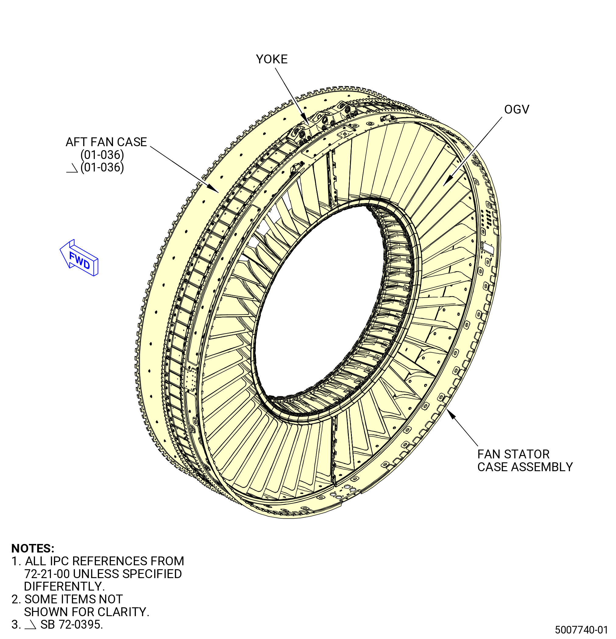
| FAN STATOR ASSEMBLY - ASSEMBLY 001 - CONFIGURATION 02 | ||
| GENX-1B ENGINE MANUAL | Dated: 02/21/2020 | |
| EM 72-21-00 , ASSEMBLY 001 | ||
| FAN STATOR ASSEMBLY - ASSEMBLY 001 - CONFIGURATION 02 | ||
| * * * FOR ALL PIP 2 |
| TASK 72-21-00-440-806 |
| 1 . | General. |
| A. | This procedure gives instructions to assemble the stator case assembly (01-021 , 72-00-01) (SIN 00109) thru the installation of the outlet guide vanes (OGVs) and OGV related hardware. |
| B. | Make sure that there is no foreign material inside the aft fan case (01-036) (SIN 84100). |
| C. | Before this procedure is done, read the Assembly and Disassembly Techniques section. Refer to TASK 70-10-00-800-009 (ASSEMBLY AND DISASSEMBLY TECHNIQUES) . |
| D. | Make sure that the mating parts are serviceable and have no damage. |
| WARNING: |
|
| E. | Clean surfaces with C04-002 Stoddard solvent , or C04-035 isopropyl alcohol , or 50-50 alcohol blend. |
| F. | Install all bolts with heads uppermost or forward unless noted otherwise. |
| 2 . | Tools, Equipment, and Materials. |
| NOTE: |
|
| A. | Tools and Equipment. |
| (1) | Special Tools. |
| (2) | Standard Tools and Equipment. |
|
| (3) | Locally Manufactured Tools. |
|
| B. | Consumable Materials. |
|
| C. | Referenced Procedures. Refer to Engine Manual GEK 112851, unless instructed differently. |
|
| D. | Expendable Parts. None. |
| 3 . | Procedure. |
| Subtask 72-21-00-220-046 |
| A. | Do the dimensional inspection of boltholes to determine if outlet guide vanes were previously drilled during assembly procedure. Refer to Figure 1025 and do as follows: |
| (1) | Upper OGV fan pylon (OGV) 1 pylon (11-290) (SIN 8400J). |
| (2) | Type 1 outlet guide vane (OGV) 2 (11-310) (SIN 8400L) at one location. |
| (3) | Type 6 outlet guide vane (OGV) 48 (11-320) (SIN 8400M) at one location. |
| Subtask 72-21-00-440-754 |
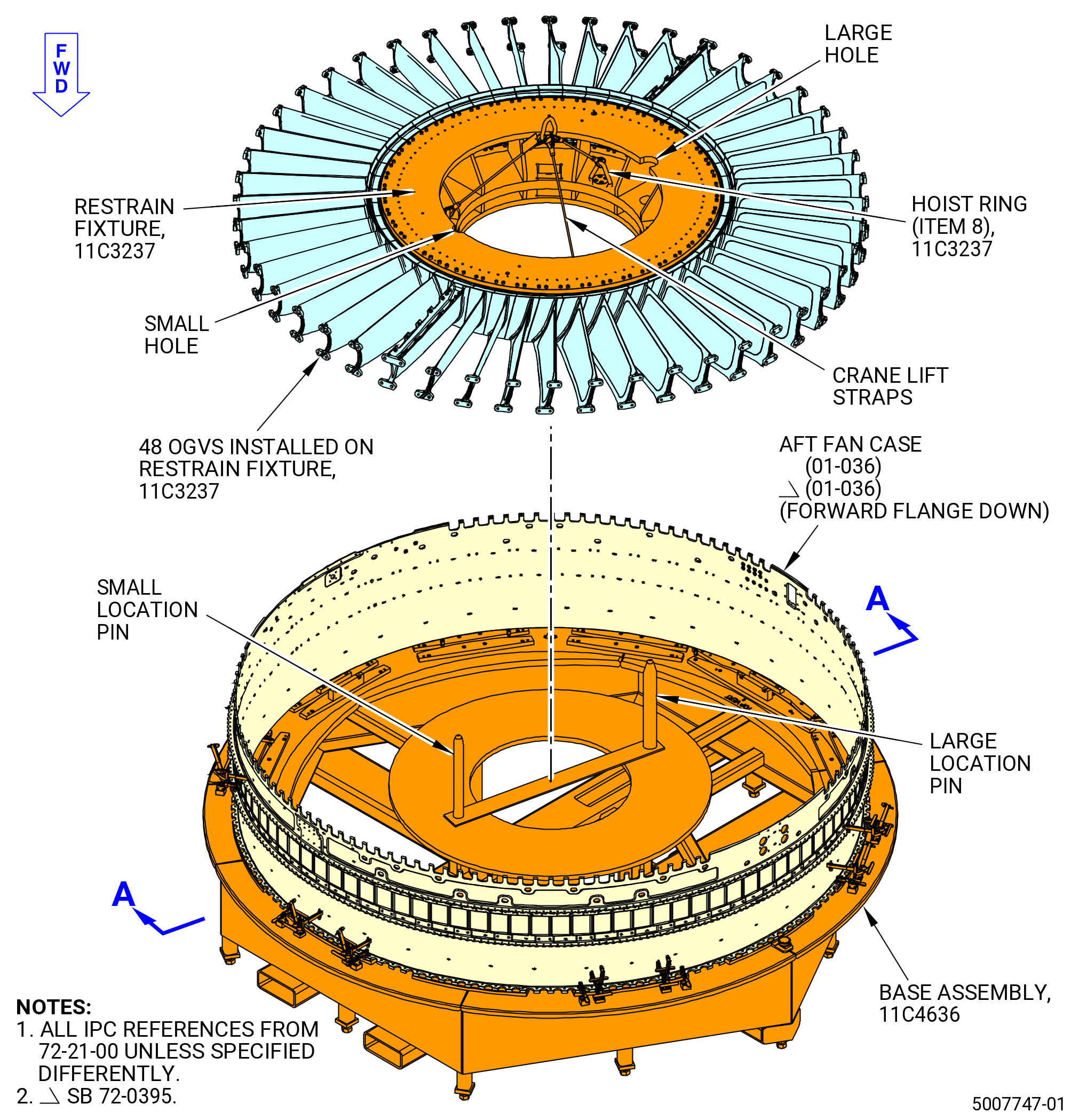
| B. | Install the fan outlet guide vane OGV 1 pylon, OGVs 2-24, OGV 25 pylon, and OGVs 26-48, on the 11C3237 restrain fixture as follows: |
| (1) | Record the part number for each of the 48 OGVs that will be installed. Refer to Figure 1002 and as follows: |
| • |
|
| • |
|
| • |
|
| • |
|
| • |
|
| • |
|
| • |
|
| • |
|
| • |
|
| • |
|
| • |
|
| WARNING: |
|
| (2) | Attach a lift sling to the 11C3237 restrain fixture and lift it to put it on a floor mounted support stand. The support stands must be a minimum of 36.0 inches (914 mm) in height. |
| (3) | Engage the pins on the floor stand with the corresponding bushings on the hub fixture to secure the 11C3237 restrain fixture to the floor stand. |
| (4) | Remove the lift sling from the 11C3237 restrain fixture. |
| CAUTION: |
|
| (5) | Install each OGV on the 11C3237 restrain fixture as follows: |
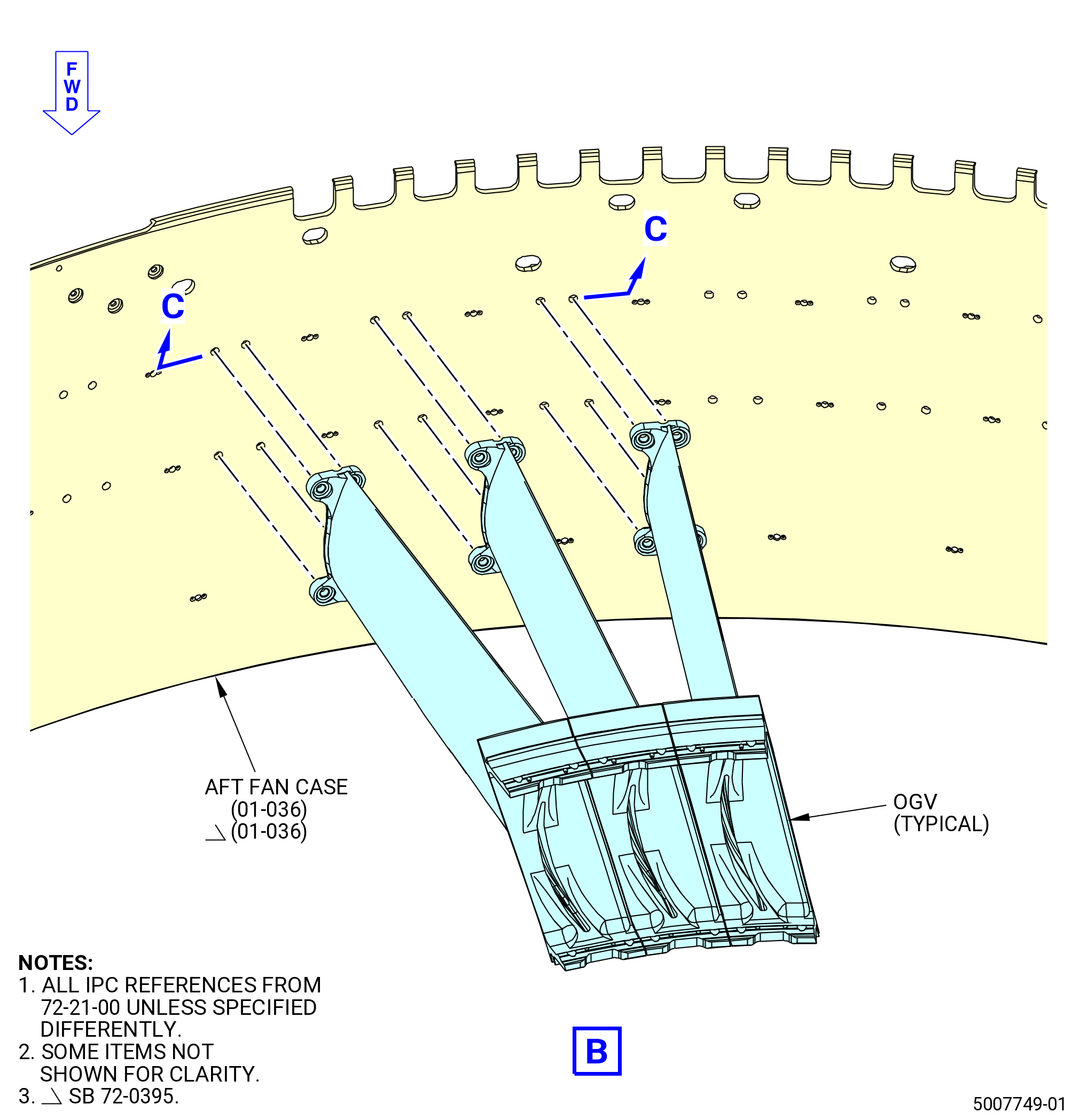
| (a) | Install the OGVs into position on the 11C3237 restrain fixture and make sure to install the OGVs in the correct position. Refer to Figure 1003 and do as follows: |
| 1 | Use the locator pins (item 17) to align the OGVs at the bottom V groove above the frame (item 16) and use the top V groove to set the assembly position of the OGVs above the frame (item 16). |
| NOTE: |
|
| 2 | Attach the OGVs to the 11C3237 restrain fixture with the capscrews (item 10) at hole locations 9-16 on the aft inner mounting flange of the inner platform. |
| 3 | Attach the OGVs to the 11C3237 restrain fixture with the capscrews (item 15) at the remaining hole locations on the aft inner mounting flange of the inner platform. |
| (b) | Hand-tighten the capscrews (item 10 and 15). |
| (c) | Make sure that the 48 OGVs are in the correct position on the 11C3237 restrain fixture. |
|
|
| Subtask 72-21-00-440-756 |
| C. | Attach the aft fan case (01-036) (SIN 84100) to the 11C4636 base assembly. Refer to Figure 1004 and do as follows: |
| (1) | Remove the aft fan case from the shipping container as follows: |
| (a) | Attach lift straps or equivalent to the aft fan case at four to six locations on the aft flange. |
| WARNING: |
|
| (b) | Slowly lift the aft fan case from the shipping container with a lift fixture. |
| (2) | Lower the aft fan case onto four stands or a table (or equivalent) to support the aft fan case. |
| (3) | Install the aft fan case on the 11C4636 base assembly. Refer to Figure 1004 and do as follows: |
| (a) | Make sure that the 11C4636 base assembly is on a level surface and the base fixture plate is flat 0.002 inch (0.05 mm) or less before the aft fan case is installed on the 11C4636 base assembly. |
| (b) | Make sure that the dial indicator (item 58) is at zero before the aft fan case is installed. |
| (c) | Remove the cover (item 52) and make sure that the toggle clamps (item 37) and horizontal clamps (item 56) are in the open position. |
| WARNING: |
|
| (d) | Lift the aft fan case and slowly lower it onto the 11C4636 base assembly with the forward flange downward and make sure that it points to the 11C4636 base assembly. |
| (e) | Align the top vertical centerline (TVCL) of the aft fan case with the TVCL mark on the 11C4636 base assembly. |
| (f) | Align the offset flange hole on the forward flange of the aft fan case with the clocking pin (item 13) of the 11C4636 base assembly. |
| (g) | Put the 12 horizontal clamps (item 56) to hold the aft fan case. |
| (h) | Put the indicator base (item 21), locator button (item 48), dovetail (item 57), dial indicator (item 58), and bracket dovetail (item 59) on the body of the aft fan case. Do not put the indicator base (item 21), locator button (item 48), dovetail (item 57), dial indicator (item 58), and bracket dovetail (item 59) against the flange of the aft fan case. Refer to Figure 1004. |
| (i) | Make sure that the dial indicator (item 58) is at zero before starting the inspection. |
| (j) | Put the indicator base (item 21), locator button (item 48), dovetail (item 57), dial indicator (item 58), and bracket dovetail (item 59) at the 11:00 o'clock position with the locator block (item 4) set to zero. |
| (k) | With the full weight of the aft fan case on the 11C4636 base assembly, slowly move the dial indicator (item 58) to each locator (items 3, 4, 5, and 12) around the aft fan case. |
| (l) | Adjust the aft fan case to the center of the 11C4636 base assembly to a total run-out of 0.010 inch (0.25 mm) with a maximum of 0.020 inch (0.51 mm). |
| (4) | Remove the lift straps or equivalent from the aft fan case. |
| Subtask 72-21-00-440-757 |
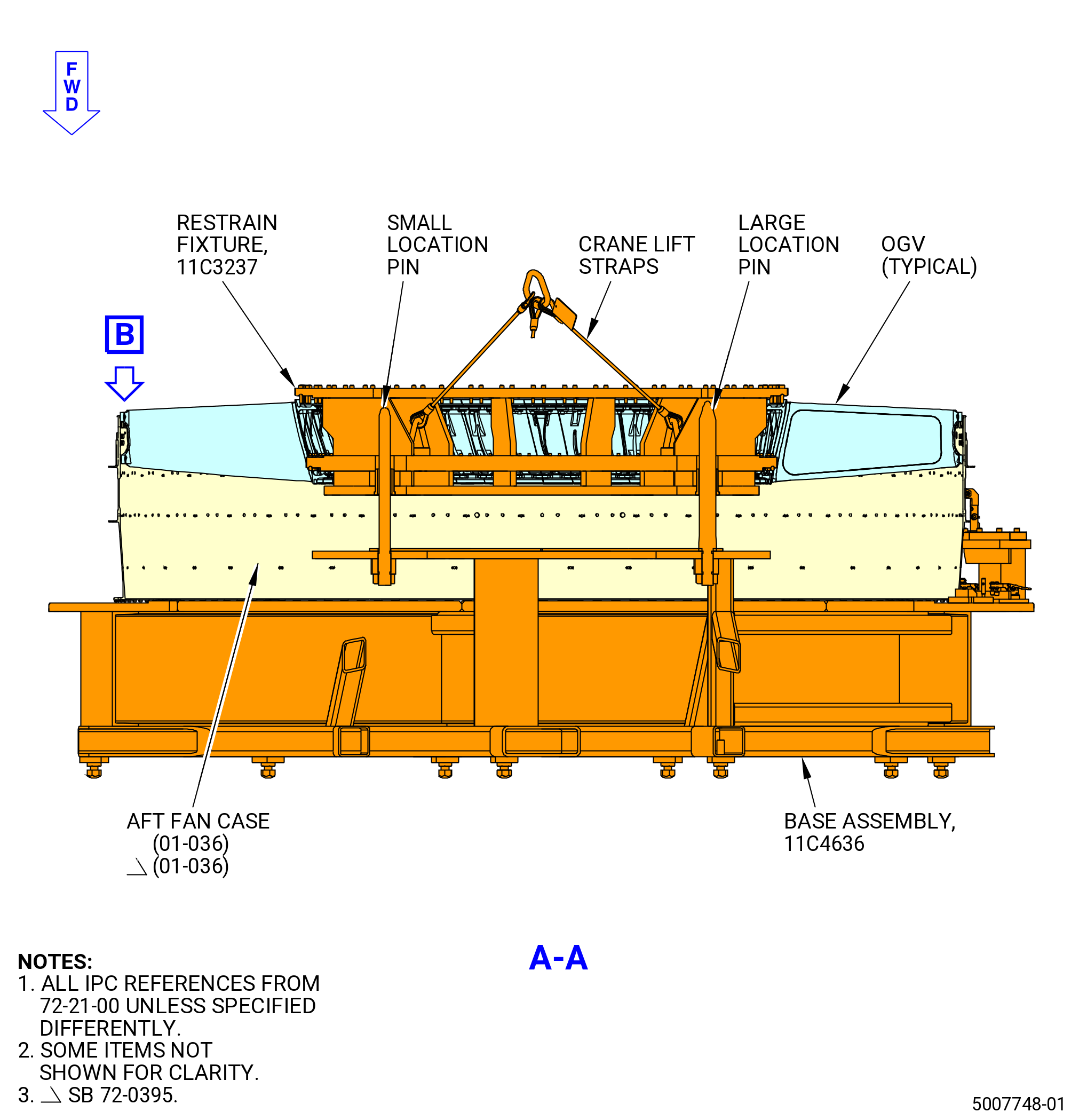
| D. | Alternative Procedure Available. Install the 11C3237 restrain fixture with the 48 OGVs attached, to the aft fan case (01-036) (SIN 84100). Refer to Figure 1005 and do as follows: |
| WARNING: |
|
| CAUTION: |
|
| (1) | Lift the 11C3237 restrain fixture with the three hoist rings (item 8) and slowly lower it onto the 11C4636 base assembly. Hold the OGVs and the 11C3237 restrain fixture to prevent it from turning when is lifted. Refer to Figure 1003 and Figure 1005. |
| NOTE: |
|
| (a) | Make sure that the holes in the 11C3237 restrain fixture align with the two large pins on the 11C4636 base assembly, and the 12:00 o'clock position on the aft fan case is aligned with the TVCL mark on the 11C3237 restrain fixture. |
| (2) | Align the TVCL of the 11C3237 restrain fixture with the TVCL of the 11C4636 base assembly. |
| (3) | Lower the 11C3237 restrain fixture and the OGVs into the aft fan case. |
| (4) | Remove the hoist from the 11C3237 restrain fixture. |
| (5) | Make sure that the OGVs holes are aligned with the aft fan case holes. |
| (6) | Put the OGV 1 pylon (11-290) (SIN 8400J) at position 1. |
| (7) | Measure all 48 OGVs and record the radial gap between the OGVs at the position 1 outer bosses (four positions) and the aft fan case inner diameter. |
| NOTE: |
|
| (8) | Make sure that all OGVs are in the correct positions. |
| Subtask 72-21-00-440-758 |
| (9) | Calculate the number of shims necessary to fill the radial gaps with the criteria that follows: |
| NOTE: |
|
| NOTE: |
|
| (a) | A maximum of three shims can be used at each hole to fill the radial gap at each OGV boss location. The total installed shim thickness must be within 0.055 to 0.145 inch (1.40 to 3.68 mm). |
| (b) | A maximum radial gap of 0.006 inch (0.15 mm) is permitted after the shims are installed and before each OGV vane is tightened to the aft fan case. |
| (c) | If the shim thickness and radial gap are difficult to get, the 11C3237 restrain fixture must be removed from the 11C4636 base assembly and Subtask 72-21-00-440-756 (paragraph 3.C.) thru Subtask 72-21-00-440-757 (paragraph 3.D.) done again to get the correct radial gap and the shim thickness. |
| (d) | Install a shim to get the correct bore position between the aft fan case (01-036) (SIN 84100), left cowl support bracket (left bracket) (05-060) (SIN 98113), and right cowl support bracket (right bracket) (05-050) (SIN 98112) as follows: |
| 1 | The total thickness of the shims must be 0.100 to 0.160 inch (2.54 to 4.06 mm). |
| 2 | All shim thickness must be 0.005 inch (0.13 mm) within adjacent shim. |
| Subtask 72-21-00-440-943 |
| D.A. | Alternative Procedure. If the upper OGV fan pylon (11-290) (SIN 8400J), type 1 outlet guide vane (OGV) 2 (11-310) (SIN 8400L), and type 6 outlet guide vane (OGV) 48 (11-320) (SIN 8400M), were not drilled during assembly procedure. Install the 11C3237 restrain fixture with the 48 OGVs attached, to the aft fan case (01-036) (SIN 84100). Refer to Figure 1005 and do as follows: |
| WARNING: |
|
| CAUTION: |
|
| (1) | Lift the 11C3237 restrain fixture with the three hoist rings (item 8) and slowly lower it onto the 11C4636 base assembly. Hold the OGVs and the 11C3237 restrain fixture to prevent it from turning when it is lifted. Refer to Figure 1003, Figure 1005, and as follows: |
| NOTE: |
|
| (a) | Make sure that the holes in the 11C3237 restrain fixture align with the two large pins on the 11C4636 base assembly, and the 12:00 o'clock position on the aft fan case is aligned with the TVCL mark on the 11C3237 restrain fixture. |
| (2) | Align the TVCL of the 11C3237 restrain fixture with the TVCL of the 11C4636 base assembly. |
| (3) | Lower the 11C3237 restrain fixture and the OGVs into the aft fan case. |
| (4) | Make sure that the OGVs holes are aligned with the aft fan case holes. |
| (5) | Put the OGV 1 pylon (11-290) (SIN 8400J) at position 1. |
| (6) | Do a check of the OGVs 1, 2, 48 holes and aft fan case (01-036) (SIN 84100) holes alignment. Refer to Figure 1025, Figure 1006, and do as follows: |
| (a) | Put the pin gauge at location 3 through aft fan case and OGV 1 pylon. |
| (b) | Put the pin gauge at location 6 through aft fan case and OGV 2. |
| (c) | Put the pin gauge at location 1 through aft fan case and OGV 48. |
| (d) | If the gauge does not go through holes in all locations, do Subtask 72-21-00-440-945 (paragraph 3.E.). |
| (7) | Remove the hoist from the 11C3237 restrain fixture. |
| (8) | Measure all 48 OGVs and record the radial gap between the OGVs at the position 1 outer bosses (four positions) and the aft fan case inner diameter. |
| NOTE: |
|
| (9) | Make sure that all OGVs are in the correct positions. |
| Subtask 72-21-00-440-944 |
| (10) | Calculate the number of shims necessary to fill the radial gaps with the criteria that follows: |
| NOTE: |
|
| NOTE: |
|
| (a) | A maximum of three shims can be used at each hole to fill the radial gap at each OGV boss location. The total installed shim thickness must be within 0.055 to 0.145 inch (1.40 to 3.68 mm). |
| (b) | A maximum radial gap of 0.006 inch (0.15 mm) is permitted after the shims are installed and before each OGV vane is tightened to the aft fan case. |
| (c) | If the shim thickness and radial gap are difficult to get, the 11C3237 restrain fixture must be removed from the 11C4636 base assembly and Subtask 72-21-00-440-756 (paragraph 3.C.) thru Subtask 72-21-00-440-757 (paragraph 3.D.) done again to get the correct radial gap and the shim thickness. |
| (d) | Install a shim to get the correct bore position between the aft fan case (01-036) (SIN 84100), left cowl support bracket (left bracket) (05-060) (SIN 98113), and right cowl support bracket (right bracket) (05-050) (SIN 98112) as follows: |
| 1 | The total thickness of the shims must be 0.100 to 0.160 inch (2.54 to 4.06 mm). |
| 2 | All shim thickness must be 0.005 inch (0.13 mm) within adjacent shim. |
| Subtask 72-21-00-440-945 |
| E. | Replace the OGVs 1, 2, 48 holes that are not aligned with the aft fan case (01-036) (SIN 84100) holes as follows: |
| (1) | Slowly lift the11C3237 restrain fixture with the three hoist rings (item 8) from the 11C4636 base assembly. Hold the OGVs and the 11C4636 base assembly to prevent it from turning when it is lifted. Refer to Figure 1005. |
| (2) | Put the 11C3237 restrain fixture on a floor mounted support stand. The support stands must be a minimum of 36.0 inches (914 mm) in height. Refer to Figure 1003 and Figure 1005. |
| (3) | Remove OGV from the 11C3237 restrain fixture. |
| (4) | Install another OGV, refer to Subtask 72-21-00-440-754 (paragraph 3.B.). |
| (5) | Install the 11C3237 restrain fixture with the 48 OGVs attached, to the aft fan case (01-036) (SIN 84100). Refer to the Subtask 72-21-00-440-757 (paragraph 3.D.) and Figure 1005. |
| Subtask 72-21-00-440-759 |
| F. | Alternative Procedure Available. Install the forward engine mount yoke (yoke) (05-010) (SIN 84803) on the aft fan case (01-036) (SIN 84100) as follows: |
| (1) | Put a mark on OGVs 1, 2, and 48 with a C05-003 marking pen to show their positions. Refer to TASK 70-16-02-350-017 (TEMPORARY MARKING). |
| (2) | Put a temporary mark of the OGV position number on the shims after removal. Refer to TASK 70-16-02-350-017 (TEMPORARY MARKING). Use C10-021 tape and a C05-003 marking pen. |
| (3) | Measure the 12 aft fan case boltholes at the yoke position for OGVs 1, 2, and 48 as follows: |
| (a) | If the aft fan case holes at the yoke position have a diameter of 0.501 to 0.503 inch (12.73 to 12.78 mm) at six locations and a diameter of 0.626 to 0.628 inch (15.90 to 15.95 mm) at six locations, refer to Subtask 72-21-00-220-037 (paragraph 3.J.). |
| (b) | If the 12 aft fan case holes at the yoke position have a diameter less than 0.501 inch (12.73 mm), refer to Subtask 72-21-00-220-037 (paragraph 3.J.). |
| Subtask 72-21-00-320-045 |
| WARNING: |
|
| CAUTION: |
|
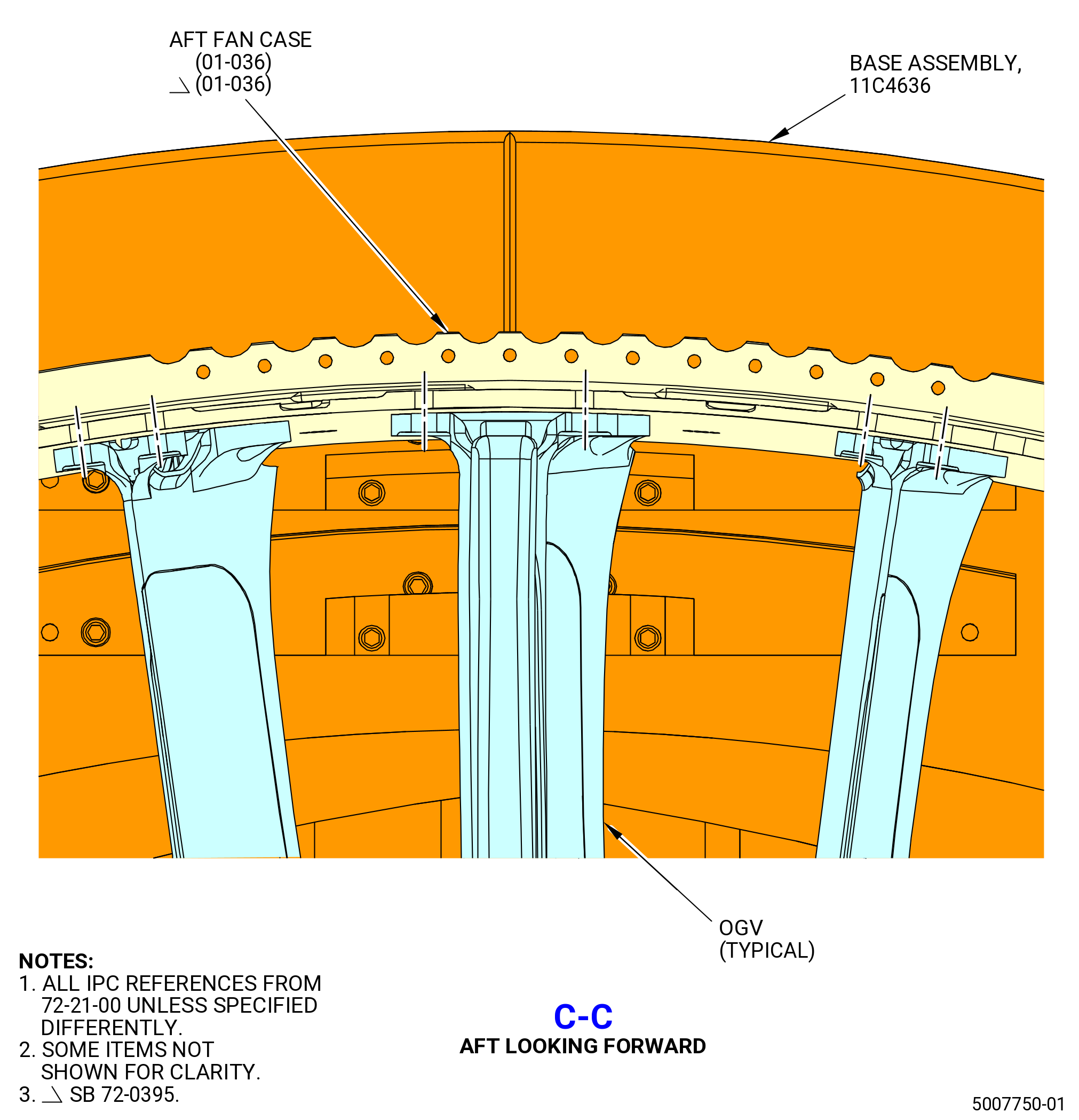
| (4) | Drill the aft fan case (01-036) (SIN 84100) that is not attached to the yoke (05-010) (SIN 84803), at pylon OGV 1 pylon, OGV 2, and OGV 48. Drill at the hole locations shown for holes DN and DP. Refer to Figure 1006 and do as follows: |
| Subtask 72-21-00-160-013 |
| WARNING: |
|
| (a) | Clean the surface of the drill fixture that will be mounted to the aft fan case with C04-035 isopropyl alcohol. |
| Subtask 72-21-00-320-046 |
| WARNING: |
|
| CAUTION: |
|
| (b) | Put a yellow protective tape on the open end of the OGVs 1, 2, and 48. |
| WARNING: |
|
| (c) | Attach a plastic tap to the aft fan case inner wall with C10-021 tape to hold the C02-047 lubricant and metal particles. |
| (d) | Put plastic tape on the aft fan case flange where the drill fixture will be mounted. |
| WARNING: |
|
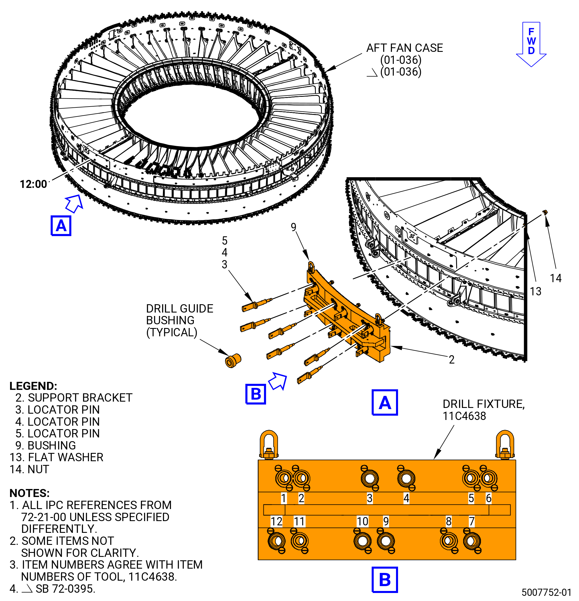
| (e) | Attach an overhead hoist and lift slings to the hoist swivel rings (item 11) of the 11C4638 drill fixture and lift the support bracket (item 2 or 7) onto the aft fan case (01-036) (SIN 84100) aligned with the TVCL. |
| CAUTION: |
|
| (f) | Attach the 11C4638 drill fixture to the aft fan case at OGV’s No. 48, 1, and 2. Refer to Figure 1006 (Sheet 1) and do as follows: |
| 1 | Insert the locator pin (item 4) at location 9 through the aft fan case and the OGV pylon. Attach tightly with a flat washer (item 13) and a hexagonal nut (item 14) to prevent movement. |
| CAUTION: |
|
| 2 | Insert a locator pin (item 4) at location 3 through the aft fan case and the OGV pylon. Attach tightly with a flat washer (item 13) and a hexagonal nut (item 14) to prevent movement. |
| 3 | Insert locator pins (item 3) at locations 1, 6, 8, and 11 through the aft fan case and the OGV pylon. Attach each one tightly with a screw lock (item 12), flat washer (item 13), and a hexagonal nut (item 14) to prevent movement. |
| Subtask 72-21-00-320-047 |
| (g) | Install a drill bushing for a 31/64 inch (12.30 mm) drill and a 31/64 inch (12.30 mm) drill on the drill gun. Drill holes through the aft fan case (01-036) (SIN 84100) and the OGV’s at locations 2, 4, 5, 7, 10, and 12. Refer to Figure 1006 (Sheet 1). |
| (h) | Install a drill bushing for a 1/2 inch (12.70 mm) drill and a 1/2 inch (12.70 mm) reamer on the drill gun. Ream holes through the aft fan case and the OGV’s at locations 2 and 5. Refer to Figure 1006 (Sheet 1). |
| (i) | Install a drill bushing for a 39/64 inch (15.47 mm) drill and a 39/64 inch (15.47 mm) drill on the drill gun. Drill holes through the aft fan case and the OGV’s at locations 4, 7, 10, and 12. Refer to Figure 1006 (Sheet 1). |
| (j) | Install a drill bushing for a 5/8 inch (15.88 mm) drill and a 5/8 inch (15.88 mm) reamer on the drill gun. Ream holes through the aft fan case and the OGV’s at locations 4, 7, 10, and 12. Refer to Figure 1006 (Sheet 1). |
| (k) | Insert the locator pins (item 5) at locations 2 and 5 through the aft fan case and the OGV pylon. Attach each one tightly with a flat washer (item 13) and a hexagonal nut (item 14) to prevent movement. Refer to Figure 1006 (Sheet 1). |
| (l) | Insert the locator pins (item 6) at locations 4, 7, 10, and 12 through the aft fan case and the OGV pylon. Attach each one tightly with a flat washer (item 13) and a hexagonal nut (item 14) to prevent movement. Refer to Figure 1006 (Sheet 1). |
| (m) | Remove the locator pins (items 3 and 4) at locations 1, 3, 6, 8, 9, and 11 from the 11C4638 drill fixture. Refer to Figure 1006 (Sheet 1). |
| (n) | Install a drill bushing for a 31/64 inch (12.30 mm) drill and a 31/64 inch (12.30 mm) drill on the drill gun. Drill holes through the aft fan case and the OGV’s at locations 1, 6, 8, and 11. Refer to Figure 1006 (Sheet 1). |
| (o) | Install a drill bushing for a 1/2 inch (12.70 mm) drill and a 1/2 inch (12.70 mm) reamer on the drill gun. Ream holes through the aft fan case and the OGV’s at locations 1, 6, 8, and 11. Refer to Figure 1006 (Sheet 1). |
| (p) | Install a drill bushing for a 39/64 inch (15.47 mm) drill and a 39/64 inch (15.47 mm) drill on the drill gun. Drill holes through the aft fan case and the OGV’s at locations 3 and 9. Refer to Figure 1006 (Sheet 1). |
| (q) | Install a drill bushing for a 5/8 inch (15.88 mm) drill and a 5/8 inch (15.88 mm) reamer on the drill gun. Ream holes through the aft fan case and the OGV’s at locations 3 and 9. Refer to Figure 1006 (Sheet 1). |
| (r) | Remove all the remaining drill bushings and locator pins from the tool and store them in the container (item 10). |
| WARNING: |
|
| (s) | Attach a lift fixture with the applicable capacity to the hoist swivel rings (item 11). |
| (t) | Lift the support brackets (item 2 or 7) and remove them from the engine. |
| (u) | Make sure that the final dimensions of the drilled holes agree with the ones shown in Figure 1006. |
| Subtask 72-21-00-320-048 |
| (5) | Deburr all the drilled holes on the aft fan case (01-036) (SIN 84100). Refer to TASK 70-42-00-350-002 (BLENDING AND REMOVAL OF HIGH METAL PROCEDURES). |
| WARNING: |
|
| (6) | Remove all sharp edges from the drilled holes DN and DP in the aft fan case and OGV 1 pylon (11-290) (SIN 8400J), OGV 2 (11-310) (SIN 8400L), and OGV 48 (11-320) (SIN 8400M). Refer to Figure 1006 and do as follows: |
| (a) | Chamfer holes DP to 0.57 to 0.59 inch (14.48 to 14.99 mm). |
| (b) | Chamfer holes DN to 0.71 to 0.73 inch (18.03 to 18.54 mm). |
| (7) | Install a location bushing in the drilled hole locations of the 11C4638 drill fixture. If necessary, make a location bushing that fits the shank of the chamfer tool and the fixture hole. Refer to Figure 1007. |
| (8) | Install the chamfer tool (from the far side) through the OGV vane, aft fan case, and location bushing. Refer to Figure 1007. |
| (9) | Attach the chamfer tool in the chuck of an air gun. |
| (10) | Start the air gun and set it to the slowest run speed. |
| (11) | Make sure that the chamfer surface finish is as smooth or smoother than a new bolthole at an undrilled location. |
| (12) | Retract the air gun until it touches the OGV with the chamfer, then lightly machine the chamfer. |
| (13) | Stop the air gun and remove the chamfer. |
| (14) | Remove the air gun. |
| (15) | Do a check of the dimensions of the chamfer holes. Refer to Figure 1006. |
| Subtask 72-21-00-320-049 |
| (16) | Do the procedure again for the remaining holes (in the same axial plane). |
| (17) | Carefully remove unwanted material from the drilled areas. |
| Subtask 72-21-00-440-760 |
| (18) | Put a temporary mark with a C05-003 marking pen on the three drilled OGVs (positions 1, 2, and 48) with their aft fan case positions. Refer to TASK 70-16-02-350-017 (TEMPORARY MARKING). |
| (19) | Remove the OGVs 1, 2, and 48 from the 11C3237 restrain fixture. |
| Subtask 72-21-00-350-016 |
| (20) | Remove all sharp edges from the drilled holes DN and DP in the aft fan case (01-036) (SIN 84100) and OGV 1 pylon (11-290) (SIN 8400J), OGV 2 (11-310) (SIN 8400L), and OGV 48 (11-320) (SIN 8400M). Refer to Figure 1006 and do as follows: |
| (a) | Chamfer holes DP to 0.57 to 0.59 inch (14.48 to 14.99 mm). |
| (b) | Chamfer holes DN to 0.71 to 0.73 inch (18.03 to 18.54 mm). |
| (21) | Remove the plastic tap from the aft fan case and the OGVs. |
| Subtask 72-21-00-440-946 |
| F.A. | Alternative Procedure. If the upper OGV fan pylon (11-290) (SIN 8400J), type 1 outlet guide vane (OGV) 2 (11-310) (SIN 8400L) and type 6 outlet guide vane (OGV) 48 (11-320) (SIN 8400M), were previously drilled during assembly procedure. Install the yoke (05-010) (SIN 84803) on the aft fan case (01-036) (SIN 84100) as follows: |
| (1) | Put a mark on OGVs 1, 2, and 48 with a C05-003 marking pen to show their positions. Refer to TASK 70-16-02-350-017 (TEMPORARY MARKING). |
| (2) | Put a temporary mark of the OGV position number on the shims after removal. Refer to TASK 70-16-02-350-017 (TEMPORARY MARKING). Use C10-021 tape and a C05-003 marking pen. |
| (3) | Measure the 12 aft fan case boltholes at the yoke position for OGVs 1, 2, and 48 as follows: |
| (a) | If the aft fan case holes at the yoke position have a diameter of 0.501 to 0.503 inch (12.73 to 12.78 mm) at six locations and a diameter of 0.626 to 0.628 inch (15.90 to 15.95 mm) at six locations, refer to Subtask 72-21-00-220-037 (paragraph 3.J.). |
| (b) | If the 12 aft fan case holes at the yoke position have a diameter less than 0.501 inch (12.73 mm), refer to Subtask 72-21-00-220-037 (paragraph 3.J.). |
| Subtask 72-21-00-320-055 |
| WARNING: |
|
| CAUTION: |
|
| (4) | Drill the aft fan case (01-036) (SIN 84100) that is not attached to the yoke (05-010) (SIN 84803), at pylon OGV 1 pylon, OGV 2, and OGV 48. Drill at the hole locations shown for holes DN and DP. Refer to Figure 1006 and do as follows: |
| Subtask 72-21-00-160-016 |
| WARNING: |
|
| (a) | Clean the surface of the drill fixture that will be mounted to the aft fan case with C04-035 isopropyl alcohol. |
| Subtask 72-21-00-320-056 |
| WARNING: |
|
| WARNING: |
|
| CAUTION: |
|
| (b) | Attach a plastic tap to the aft fan case inner wall with C10-021 tape to hold the C02-047 lubricant and metal particles. |
| (c) | Put plastic tape on the aft fan case flange where the drill fixture will be mounted. |
| WARNING: |
|
| (d) | Attach an overhead hoist and lift slings to the hoist swivel rings (item 11) of the 11C4638 drill fixture and lift the support bracket (item 2 or 7) onto the aft fan case (01-036) (SIN 84100) aligned with the TVCL. |
| CAUTION: |
|
| (e) | Attach the 11C4638 drill fixture to the aft fan case at OGV’s No. 48, 1, and 2. Refer to Figure 1006 and do as follows: |
| 1 | Insert the locator pin (item 4) at location 9 through the aft fan case. Put a stack of washers which will emulate previously drilled OGVs, attach tightly with a flat washer (item 13) and a hexagonal nut (item 14) to prevent movement. |
| 2 | Insert the locator pin (item 4) at location 3 through the aft fan case. Put a stack of washers which will emulate previously drilled OGVs, attach tightly with a flat washer (item 13) and a hexagonal nut (item 14) to prevent movement. |
| 3 | Insert locator pins (item 3) at locations 1, 6, 8, and 11 through the aft fan case. Put a stack of washers which will emulate previously drilled OGVs, attach each one tightly with a screw lock (item 12), flat washer (item 13), and a hexagonal nut (item 14) to prevent movement. |
| Subtask 72-21-00-320-057 |
| (f) | Install a drill bushing for a 31/64 inch (12.30 mm) drill and a 31/64 inch (12.30 mm) drill on the drill gun. Drill holes through the aft fan case (01-036) (SIN 84100) at locations 2, 4, 5, 7, 10, and 12. Refer to Figure 1006. |
| (g) | Install a drill bushing for a 1/2 inch (12.70 mm) drill and a 1/2 inch (12.70 mm) reamer on the drill gun. Ream holes through the aft fan case and at locations 2 and 5. Refer to Figure 1006. |
| (h) | Install a drill bushing for a 39/64 inch (15.47 mm) drill and a 39/64 inch (15.47 mm) drill on the drill gun. Drill holes through the aft fan case and at locations 4, 7, 10, and 12. Refer to Figure 1006. |
| (i) | Install a drill bushing for a 5/8 inch (15.88 mm) drill and a 5/8 inch (15.88 mm) reamer on the drill gun. Ream holes through the aft fan case at locations 4, 7, 10, and 12. Refer to Figure 1006. |
| (j) | Insert the locator pins (item 5) at locations 2 and 5 through the aft fan case. Put a stack of washers which will emulate previously drilled OGVs, attach each one tightly with a flat washer (item 13) and a hexagonal nut (item 14) to prevent movement. Refer to Figure 1006. |
| (k) | Insert the locator pins (item 6) at locations 4, 7, 10, and 12 through the aft fan case. Put a stack of washers which will emulate previously drilled OGVs, attach each one tightly with a flat washer (item 13) and a hexagonal nut (item 14) to prevent movement. Refer to Figure 1006. |
| (l) | Remove the locator pins (items 3 and 4) at locations 1, 3, 6, 8, 9, and 11 from the 11C4638 drill fixture. Refer to Figure 1006. |
| (m) | Install a drill bushing for a 31/64 inch (12.30 mm) drill and a 31/64 inch (12.30 mm) drill on the drill gun. Drill holes through the aft fan case at locations 1, 6, 8, and 11. Refer to Figure 1006. |
| (n) | Install a drill bushing for a 1/2 inch (12.70 mm) drill and a 1/2 inch (12.70 mm) reamer on the drill gun. Ream holes through the aft fan case at locations 1, 6, 8, and 11. Refer to Figure 1006. |
| (o) | Install a drill bushing for a 39/64 inch (15.47 mm) drill and a 39/64 inch (15.47 mm) drill on the drill gun. Drill holes through the aft fan case at locations 3 and 9. Refer to Figure 1006. |
| (p) | Install a drill bushing for a 5/8 inch (15.88 mm) drill and a 5/8 inch (15.88 mm) reamer on the drill gun. Ream holes through the aft fan case at locations 3 and 9. Refer to Figure 1006. |
| (q) | Remove all the remaining drill bushings and locator pins from the tool and store them in the container (item 10). |
| WARNING: |
|
| (r) | Attach a lift fixture with the applicable capacity to the hoist swivel rings (item 11). |
| (s) | Lift the support brackets (item 2 or 7) and remove them from the engine. |
| (t) | Make sure that the final dimensions of the drilled holes agree with the ones shown in Figure 1006. |
| Subtask 72-21-00-320-058 |
| (5) | Deburr all the drilled holes on the aft fan case (01-036) (SIN 84100). Refer to TASK 70-42-00-350-002 (BLENDING AND REMOVAL OF HIGH METAL PROCEDURES). |
| WARNING: |
|
| (6) | Remove all sharp edges from the drilled holes DN and DP in the aft fan case. Refer to Figure 1006 |
| (7) | Install a location bushing in the drilled hole locations of the 11C4638 drill fixture. If necessary, make a location bushing that fits the shank of the chamfer tool and the fixture hole. Refer to Figure 1007. |
| (8) | Install the chamfer tool (from the far side) through the OGV vane, aft fan case, and location bushing. Refer to Figure 1007. |
| (9) | Attach the chamfer tool in the chuck of an air gun. |
| (10) | Start the air gun and set it to the slowest run speed. |
| (11) | Make sure that the chamfer surface finish is as smooth or smoother than a new bolthole at an undrilled location. |
| (12) | Retract the air gun until it touches the OGV with the chamfer, then lightly machine the chamfer. |
| (13) | Stop the air gun and remove the chamfer. |
| (14) | Remove the air gun. |
| (15) | Do a check of the dimensions of the chamfer holes. Refer to Figure 1006. |
| Subtask 72-21-00-320-059 |
| (16) | Do the procedure again for the remaining holes (in the same axial plane). |
| (17) | Carefully remove unwanted material from the drilled areas. |
| Subtask 72-21-00-440-947 |
| (18) | Put a temporary mark with a C05-003 marking pen on the three drilled OGVs (positions 1, 2, and 48) with their aft fan case positions. Refer to TASK 70-16-02-350-017 (TEMPORARY MARKING). |
| (19) | Remove the OGVs 1, 2, and 48 from the 11C3237 restrain fixture. |
| Subtask 72-21-00-350-018 |
| (20) | Remove all sharp edges from the drilled holes DN and DP in the aft fan case (01-036) (SIN 84100) and OGV 1 pylon (11-290) (SIN 8400J), OGV 2 (11-310) (SIN 8400L), and OGV 48 (11-320) (SIN 8400M). Refer to Figure 1006 and do as follows: |
| (a) | Chamfer holes DP to 0.57 to 0.59 inch (14.48 to 14.99 mm). |
| (b) | Chamfer holes DN to 0.71 to 0.73 inch (18.03 to 18.54 mm). |
| (21) | Remove the plastic tap from the aft fan case and the OGVs. |
| Subtask 72-21-00-110-071 |
| WARNING: |
|
| CAUTION: |
|
| G. | Clean the mating surface of the aft fan case (01-036) (SIN 84100), OGV 1 pylon (11-290) (SIN 8400J), OGV 2 (11-310) (SIN 8400L), OGV 48 (11-320) (SIN 8400M), and the drilled areas of the aft fan case. Use a clean, white C10-182 cloth wet with C04-002 Stoddard solvent, C04-035 isopropyl alcohol, or 50-50 alcohol blend. |
| Subtask 72-21-00-230-006 |
| H. | Do a fluorescent penetrant inspection of the drilled areas. Use a Class A penetrant, but use Class B acceptance data. Refer to TASK 70-32-02-230-001 (FLUORESCENT PENETRANT INSPECTION) and as follows: |
| • |
|
| • |
|
| Subtask 72-21-00-380-270 |
| I. | Do a surface refinish of the 12 drilled holes on the aft fan case (01-036) (SIN 84100). Refer to TASK 70-43-07-380-007 (CHEMICAL TOUCH-UP SURFACE REFINISHING PROCESS FOR ALUMINUM). |
| WARNING: |
|
| (1) | Apply C03-001 primer or C03-100 primer to the inner hole diameters on the aft fan case. |
| Subtask 72-21-00-220-037 |
| J. | Measure and record each of the six drilled holes as follows: |
| (1) | OGV holes DP at OGVs 1, 2, and 48. The drilled boltholes must be a 0.501 to 0.503 inch (12.73 to 12.78 mm) in diameter. Refer to Figure 1006. |
| (2) | Aft fan case (01-036) (SIN 84100) holes DN at OGV 1 pylon (11-290) (SIN 8400J), OGV 2 (11-310) (SIN 8400L), and OGV 48 (11-320) (SIN 8400M). The holes must be 0.626 to 0.628 inch (15.90 to 15.95 mm) in diameter. |
| Subtask 72-21-00-440-761 |
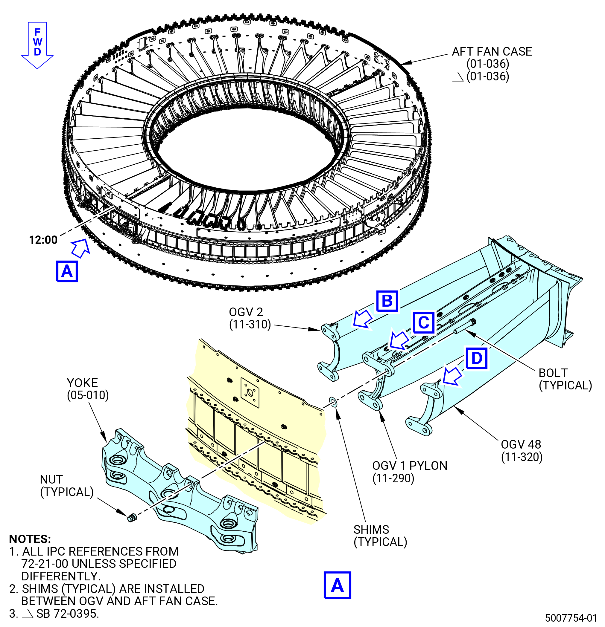
| K. | Install the yoke (05-010) (SIN 84803) at OGV 1 pylon (11-290) (SIN 8400J), OGV 2 (11-310) (SIN 8400L), and OGV 48 (11-320) (SIN 8400M). Refer to Figure 1008 and do as follows: |
| (1) | Make sure that the OGVs 24 thru 28 are shimmed. |
| Subtask 72-21-00-380-271 |
| WARNING: |
|
| (2) | Apply C03-072 primer to the hardware and holes that follow: |
| • |
|
| • |
|
| • |
|
| • |
|
| NOTE: |
|
| Subtask 72-21-00-640-227 |
| WARNING: |
|
| (3) | Apply C02-058 lubricant to the threads of the bolts (11-360) (SIN 84123). |
| Subtask 72-21-00-440-762 |
| (4) | Attach the yoke (05-010) (SIN 84803) to the two sides of the outer platform of OGV 1 pylon (11-290) (SIN 8400J) with the shear double bolts (bolts) (05-020) (SIN 84124), shims, and self-locking nuts (05-040) (SIN 84840). |
| (5) | Attach the yoke (05-010) (SIN 84803) to the OGV 2 (11-310) (SIN 8400L) and OGV 48 (11-320) (SIN 8400M) with the bolts (11-360) (SIN 84123), shims, spacers (05-030) (SIN 8417Y) under the two aft boltheads, and self-locking nuts (11-410) (SIN 84141). |
| (6) | Attach the yoke (05-010) (SIN 84803) to the OGV 2 (11-310) (SIN 8400L) and OGV 48 (11-320) (SIN 8400M) with the bolts (05-020) (SIN 84124), shims, and self-locking nuts (05-040) (SIN 84840). |
| (7) | Attach the yoke (05-010) (SIN 84803) to the aft fan case (01-036) (SIN 84100) with bolts (05-020) (SIN 84124), boltheads below the aft fan case, spacers (05-170) (SIN 84130), under boltheads, and self-locking nuts (05-040) (SIN 84840). |
| (8) | Hand-tighten the self-locking nuts (05-040) (SIN 84840) and (11-410) (SIN 84141) on the bolts (11-360) (SIN 84123) and (05-020) (SIN 84124) at the OGV 1 pylon (11-290) (SIN 8400J), OGV 2 (11-310) (SIN 8400L), OGV 48 (11-320) (SIN 8400M), and aft fan case (01-036) (SIN 84100) sufficient to prevent movement. Do not torque at this time. |
| (9) | Remove the 11C3237 restrain fixture from the aft fan case (01-036) (SIN 84100). |
| Subtask 72-21-00-440-763 |
| L. | Prepare the brackets, OGVs, and aft fan case (01-036) (SIN 84100) for installation as follows: |
| Subtask 72-21-00-110-072 |
| (1) | Clean mating surfaces to make sure of a good electrical bonding as follows: |
| WARNING: |
|
| (a) | Clean the mating surfaces of the components with C04-002 Stoddard solvent, C04-035 isopropyl alcohol, or 50-50 alcohol blend: |
| • |
|
| • |
|
| • |
|
| • |
|
| • |
|
| • |
|
| • |
|
| • |
|
| Subtask 72-21-00-380-272 |
| WARNING: |
|
| (2) | Apply C03-001 primer or C03-100 primer to the bearing surfaces of the brackets. Let the primer to air dry before assembly. |
| (3) | Apply C03-001 primer or C03-100 primer to the shank and bearing surfaces of the bolts, bearing surfaces of the washers and shims, and to OGV inside mating surfaces of the holes. Install bolts, shims, and washers while primer is wet. |
| Subtask 72-21-00-640-228 |
| WARNING: |
|
| (4) | Apply C02-058 lubricant to the threads of the bolts. |
| Subtask 72-21-00-440-764 |
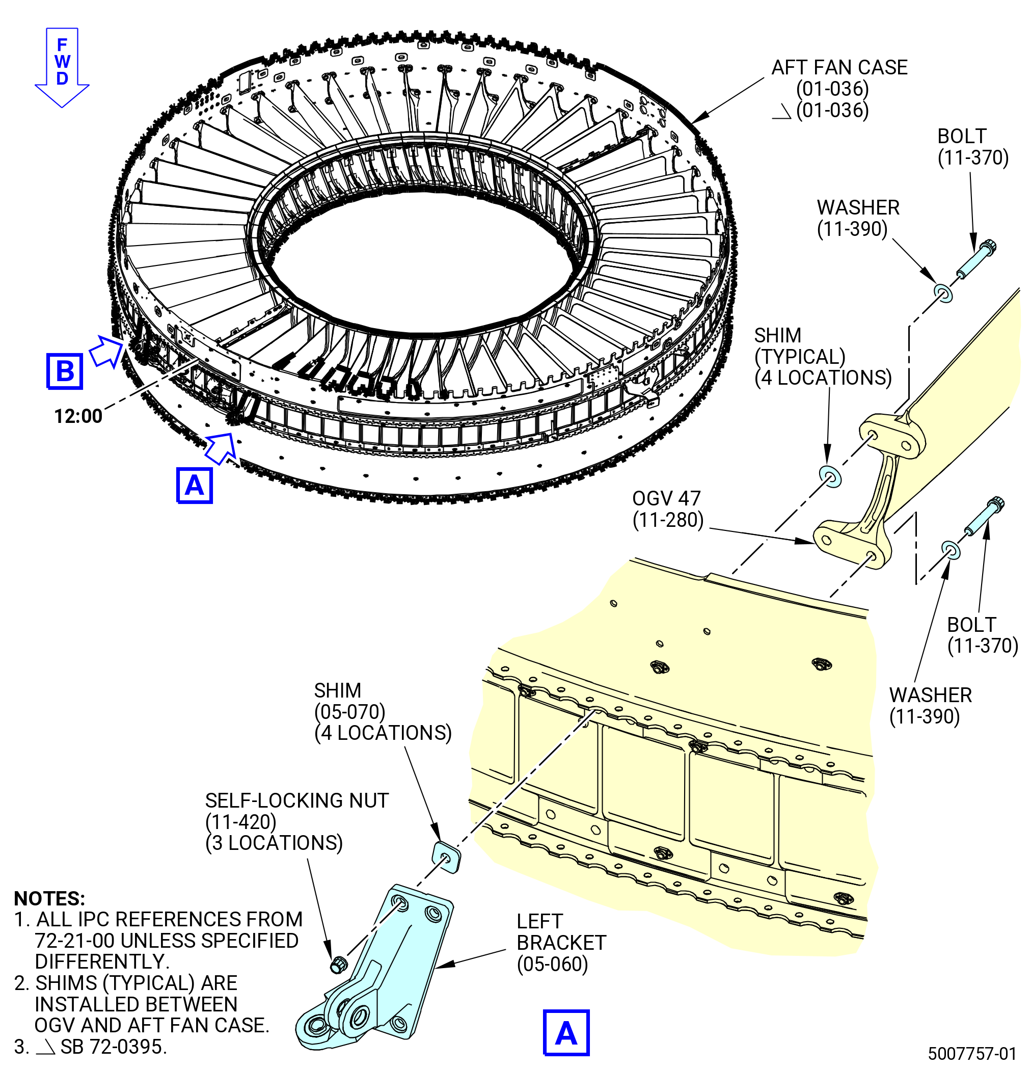
| M. | Install the left bracket (05-060) (SIN 98113) on OGV 47 (11-280) (SIN 8400H) and the right bracket (05-050) (SIN 98112) on the OGV 3 (11-230) (SIN 8400C), and the aft fan case (01-036) (SIN 84100). Refer to Figure 1009 and do as follows: |
| (1) | Find the laminated shims (shims) (05-070) (SIN 8417A) thickness to install with the cowl support bracket locator of the 11C4636 base assembly. Refer to Figure 1004 and do as follows: |
| (a) | Attach the cowl support bracket locator (bracket locator) to the 11C4636 base assembly. |
| (b) | Pivot the nut plate to align the captive nut with the bushed holes. |
| (c) | Insert the pin through the right bracket (05-050) (SIN 98112) and thread into the nut plate. |
| (d) | Insert the pin through the left bracket (05-060) (SIN 98113) and thread into the nut plate. |
| (e) | Measure the gap between the right and left brackets and the aft fan case at the eight bolthole locations. |
| (f) | Install shims to get the correct bore position between the aft fan case and the left bracket (05-060) (SIN 98113) at OGV 47 and the right bracket (05-050) (SIN 98112) at OGV 3 as follows: |
| 1 | The total thickness of the shims must be 0.100 to 0.160 inch (2.54 to 4.06 mm). |
| 2 | All shim thickness must be 0.005 inch (0.13 mm) within adjacent shim. |
| NOTE: |
|
| 3 | Trim the edge of the shim to prevent it from extending the edge of the bracket 0.050 inch (1.27 mm). |
| (2) | Install the left bracket (05-060) (SIN 98113) as follows: |
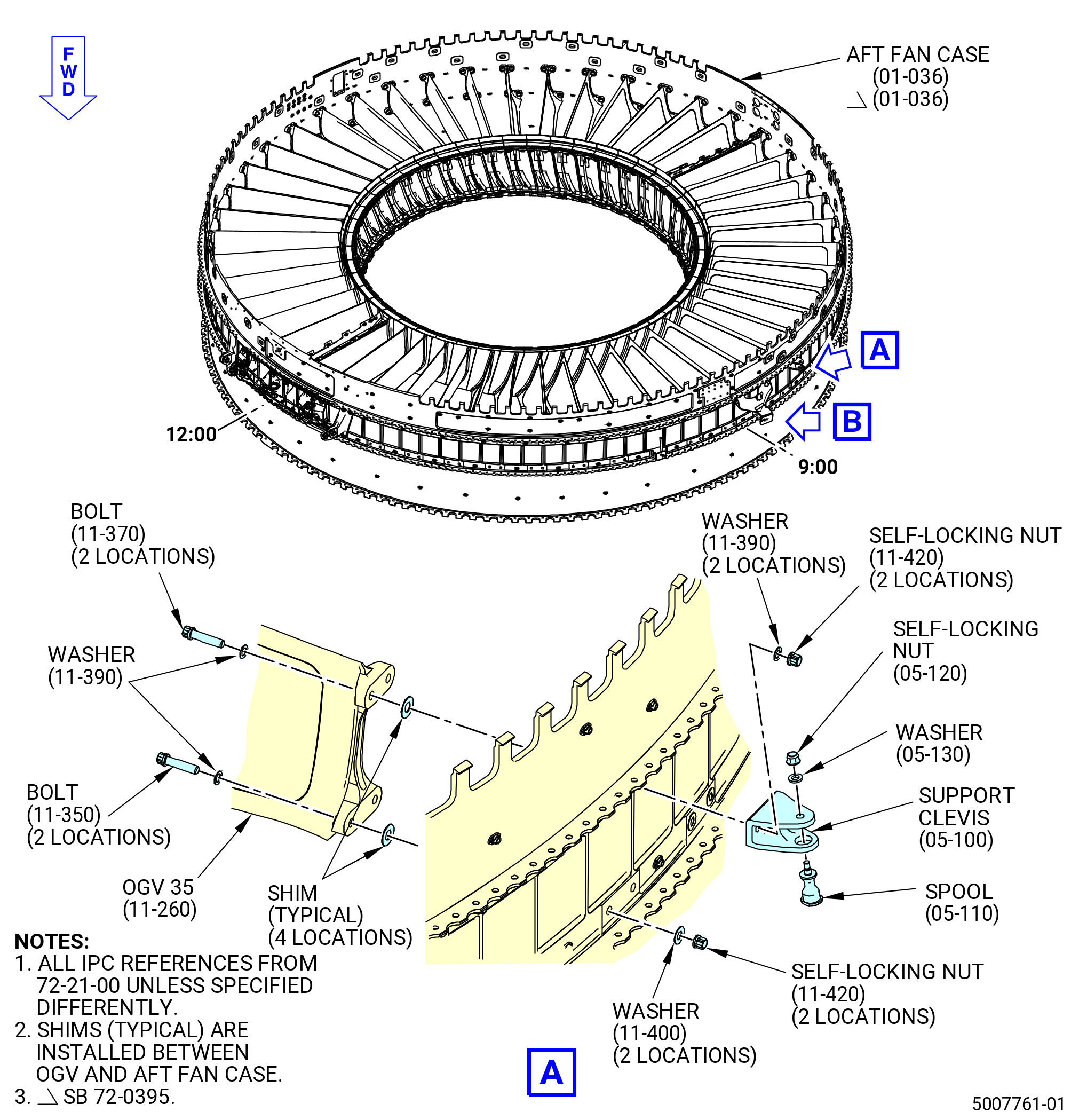
| (a) | Attach it with the machine bolts (bolts) (11-370) (SIN 84129), shims (05-070) (SIN 8417A), flat washers (washers) (11-390) (SIN 84131), and self-locking nuts (11-420) (SIN 84143) at the two aft locations. Do not torque at this time. Install the shims between the bracket and the aft fan case. |
| (b) | Attach it with the bolt, shim, and washer at the two forward locations. Do not torque at this time. |
| (3) | Install the right bracket (05-050) (SIN 98112) as follows: |
| (a) | Attach it with the bolts (11-370) (SIN 84129), shims (05-070) (SIN 8417A), washers (11-390) (SIN 84131), and self-locking nuts (11-420) (SIN 84143) at four locations. Do not torque at this time. Install the shims between the bracket and the aft fan case. |
| (4) | Tighten the bolts to prevent movement. |
| (5) | Make sure that the bolt thread extends 0.100 inch (2.54 mm) above the self-locking nut. |
| (6) | Make sure that the left bracket and the right bracket flanges are correctly aligned. Put a 0.490 inch (12.45 mm) pin into both ends of the brackets. If the pin does not go through the brackets, do paragraph 3.M.(1) thru (paragraph 3.M.(5) again. |
| (7) | Remove the bracket locator of the 11C4636 base assembly away from the aft fan case. |
| Subtask 72-21-00-440-765 |
| (8) | Remove the bolts (11-370) (SIN 84129), shims (05-070) (SIN 8417A), washers (11-390) (SIN 84131), self-locking nuts (11-420) (SIN 84143), left bracket (05-060) (SIN 98113), and right bracket (05-050) (SIN 98112). |
| Subtask 72-21-00-380-273 |
| WARNING: |
|
| (9) | Apply C03-072 primer to the two sides of the shims (05-070) (SIN 8417A). |
| Subtask 72-21-00-440-766 |
| (10) | Reinstall the left bracket (05-060) (SIN 98113), right bracket (05-050) (SIN 98112), bolts (11-370) (SIN 84129), shims (05-070) (SIN 8417A), washers (11-390) (SIN 84131), and self-locking nuts (11-420) (SIN 84143) as follows: |
| (a) | Make sure that the shims (05-070) (SIN 8417A) between the bracket and the aft fan case are installed. |
| (b) | Install the washers under the heads of the bolts. |
| (c) | Tighten the self-locking nuts to prevent movement. Do not torque at this time. |
| (11) | Install the bracket locator of the 11C4636 base assembly to the left and right cowl support brackets. |
| (12) | Tighten the self-locking nuts to prevent movement. Do not torque at this time. |
| (13) | Remove the bracket locator of the 11C4636 base assembly. |
| (14) | Make sure that the OGVs 24 thru 28 are shimmed before torquing the yoke (05-010) (SIN 84803), left bracket (05-060) (SIN 98113), and right bracket (05-050) (SIN 98112). Refer to Subtask 72-21-00-440-767 (paragraph 3.N.) and Figure 1008. |
| (15) | Torque the self-locking nuts (11-410) (SIN 84141) on the bolts (11-360) (SIN 84123) at OGV 1 pylon, OGV 2, and OGV 48 to 69 to 81 lb ft (94 to 110 Nm). |
| NOTE: |
|
| (16) | Torque the self-locking nuts (05-040) (SIN 84840) on the bolts (05-020) (SIN 84124) at OGVs 1, 2, and 48 to 125 to 145 lb ft (169 to 197 Nm). |
| NOTE: |
|
| (17) | Torque again the self-locking nuts (05-040) (SIN 84840) on the bolts (05-020) (SIN 84124) at OGV 1 pylon, OGV 2 and, OGV 48 to 125 to 145 lb ft (169 to 197 Nm). |
| (18) | Torque the self-locking nuts (11-420) (SIN 84143) on the bolts (11-370) (SIN 84129) at OGVs 3 and 47 to 368 to 432 lb in. (41.6 to 48.8 Nm). |
| (19) | Make sure that the bolt thread extends 0.100 inch (2.54 mm) above the self-locking nut. |
| Subtask 72-21-00-440-767 |
| N. | Install the OGV 24 (11-270) (SIN 8400G), OGV 25 pylon (11-300) (SIN 8400K), OGVs 26-27 (11-240) (SIN 8400D), and OGV 28 (11-250) (SIN 8400E) to the aft fan case (01-036) (SIN 84100) as follows: |
| (1) | Prepare the OGVs for installation. Refer to Subtask 72-21-00-440-763 (paragraph 3.L.). |
| (2) | Attach the OGV 24 to the aft fan case as follows: |
| (a) | Install the bolts (11-355) (SIN 8412D), washers (11-390) (SIN 84131), and flat washers (washers) (11-405) (SIN 84136), shims, and self-locking nuts (11-420) (SIN 84143) on the OGV 24. Refer to Figure 1010 and do as follows: |
| 1 | Install the washers (11-390) (SIN 84131) under the boltheads. |
| 2 | Install the shims between the OGV and the aft fan case. |
| 3 | Install the washers (11-405) (SIN 84136) under the self-locking nuts. |
| (3) | Attach the OGVs 25-28 to the aft fan case as follows: |
| (a) | Install the machine bolts (bolts) (11-350) (SIN 84121), flat washers (washers) (11-390) (SIN 84131), washers (11-400) (SIN 84135), shims, and self-locking nuts (11-420) (SIN 84143) on the OGVs 25-28. Refer to Figure 1010 and do as follows: |
| 1 | Install the washers (11-390) (SIN 84131) under the boltheads. |
| 2 | Install the shims between the OGV and the aft fan case. |
| 3 | Install the washers (11-400) (SIN 84135) under the self-locking nuts. |
| (4) | Make sure that the OGV 1 pylon, OGV 2, and OGV 48 have shims installed. |
| (5) | Torque the self-locking nuts at OGVs 24-28 to 368-432 lb in. (41.6-48.8 N.m). |
| Subtask 72-21-00-440-768 |
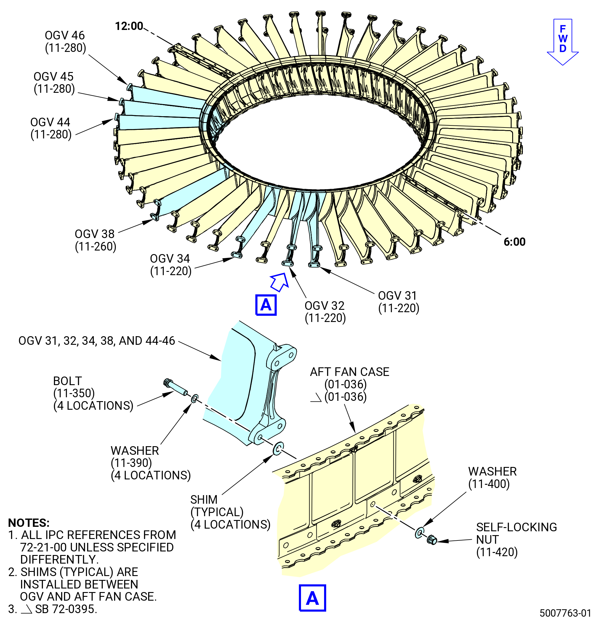
| O. | Attach the OGVs 35-38 (11-260) (SIN 8400F), OGV 39 (11-270) (SIN 8400G) to the aft fan case (01-036) (SIN 84100) as follows: |
| (1) | Prepare the brackets and OGVs for installation. Refer to Subtask 72-21-00-440-763 (paragraph 3.L.). |
| (2) | Attach the horizontal support clevis (clevis) (05-100) (SIN 98217) at the 8:30 o'clock position to the OGV 35 (11-260) (SIN 8400F). Refer to Figure 1011 and do as follows: |
| (a) | Attach the bracket to the OGV 35 as follows: |
| NOTE: |
|
| 1 | Install the washers (11-390) (SIN 84131) under the head of the bolts (11-370) (SIN 84129) and under the self-locking nuts (11-420) (SIN 84143). |
| 2 | Install the shims between the OGV and the aft fan case. |
| (b) | Install the bolts (11-350) (SIN 84121), washers (11-390) (SIN 84131), washers (11-400) (SIN 84135), shims, self-locking nuts (11-420) (SIN 84143) on the OGV 35 (11-260) (SIN 8400F) forward holes at two locations as follows: |
| 1 | Install the washers (11-390) (SIN 84131) under the head of the bolts (11-350) (SIN 84121). |
| 2 | Install the shims between the OGV and the aft fan case. |
| 3 | Install the washers (11-400) (SIN 84135) under the self-locking nuts (11-420) (SIN 84143). |
| (c) | Attach the hold open rod spool (spool) (05-110) (SIN 98270) to the flanges on the support bracket (05-100) (SIN 98217) as follows: |
| 1 | Put the threaded shaft of the spool into the forward flange of the clevis and into the aft flange. |
| 2 | Attach the spool with a washer (05-130) (SIN 98230) and a self-locking nut (05-120) (SIN 98240). |
| 3 | Torque the self-locking nut to 69 to 81 lb in. (7.8 to 9.2 Nm). |
| (3) | Install the full authority digital engine control support bracket (FADEC bracket) (05-140) (SIN 65H13) to the OGVs 36 and 37 and the aft fan case at the 9:00 o'clock position. Refer to Figure 1012 and do as follows: |
| (a) | Attach the FADEC bracket on the aft holes of the OGV as follows: |
| 1 | Install the washers (11-390) (SIN 84131) under the head of the machine bolts (bolts) (11-380) (SIN 8412C). |
| 2 | Install the shims between the OGV and the aft fan case. |
| 3 | Install the self-locking nut (11-420) (SIN 84143) on the bolt (11-380) (SIN 8412C) and FADEC bracket. |
| (b) | Install the bolts (11-350) (SIN 84121), washers (11-390) (SIN 84131), washers (11-400) (SIN 84135), shims, self-locking nuts (11-420) (SIN 84143) on the OGV 36 and 37 at three locations. |
| 1 | Install the washers (11-390) (SIN 84131) under the head of the bolts. |
| 2 | Install the shims between the OGV and the aft fan case. |
| 3 | Install the washers (11-400) (SIN 84135) under the self-locking nuts (11-420) (SIN 84143). |
| (4) | Attach the OGV 38 to the aft fan case. Refer to Figure 1013 and do as follows: |
| (a) | Install the bolts (11-350) (SIN 84121), washers (11-390) (SIN 84131), washers (11-400) (SIN 84135), shims, and self-locking nuts (11-420) (SIN 84143) on the OGVs as follows: |
| 1 | Install the washers (11-390) (SIN 84131) under the head of the bolts. |
| 2 | Install the shims between the OGV and the aft fan case. |
| 3 | Install the washers (11-400) (SIN 84135) under the self-locking nuts. |
| (5) | Install the FADEC support bracket (FADEC bracket) (05-080) (SIN 65H11) to the OGV 39 and the aft fan case at the 9:30 o'clock position. Refer to Figure 1014 and do as follows: |
| (a) | Attach the FADEC bracket to the OGV 39 on the forward holes at two locations as follows: |
| 1 | Install the washers (11-390) (SIN 84131) under the head of the bolts (11-380) (SIN 8412C). |
| 2 | Install the shims between the OGV and the aft fan case. |
| (b) | Install the bolts (11-355) (SIN 8412D), washers (11-390) (SIN 84131), washers (11-405) (SIN 84136), shims, and self-locking nuts (11-420) (SIN 84143) on the OGV 39 on the aft holes at two locations as follows: |
| 1 | Install the washers (11-390) (SIN 84131) under the head of the bolts. |
| 2 | Install the shims between the OGV and the aft fan case. |
| 3 | Install the washers (11-405) (SIN 84136) under the self-locking nuts. |
| (6) | Make sure that the OGVs 11-15 have shims installed. |
| (7) | Torque the self-locking nuts (11-420) (SIN 84143) at OGVs 35-39 to 368-432 lb in. (41.6-48.8 N.m). |
| Subtask 72-21-00-440-769 |
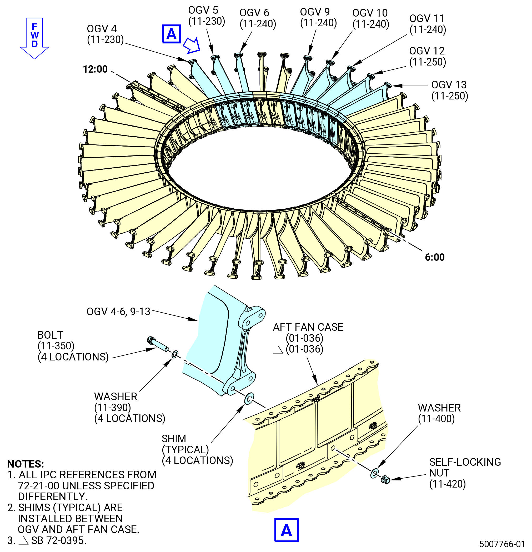
| P. | Attach the OGV 11 (11-240) (SIN 8400D) and OGVs 12-15 (11-250) (SIN 8400E) to the aft fan case (01-036) (SIN 84100) as follows: |
| (1) | Prepare the OGVs for installation. Refer to Subtask 72-21-00-440-763 (paragraph 3.L.). |
| (2) | Attach the OGVs 11-13 to the aft fan case. Refer to Figure 1015 and do as follows: |
| (a) | Install the bolts (11-350) (SIN 84121), washers (11-390) (SIN 84131), washers (11-400) (SIN 84135), shims, and self-locking nuts (11-420) (SIN 84143) on the OGVs as follows: |
| 1 | Install the washers (11-390) (SIN 84131) under the head of the bolts. |
| 2 | Install the shims between the OGV and the aft fan case. |
| 3 | Install the washers (11-400) (SIN 84135) under the self-locking nuts. |
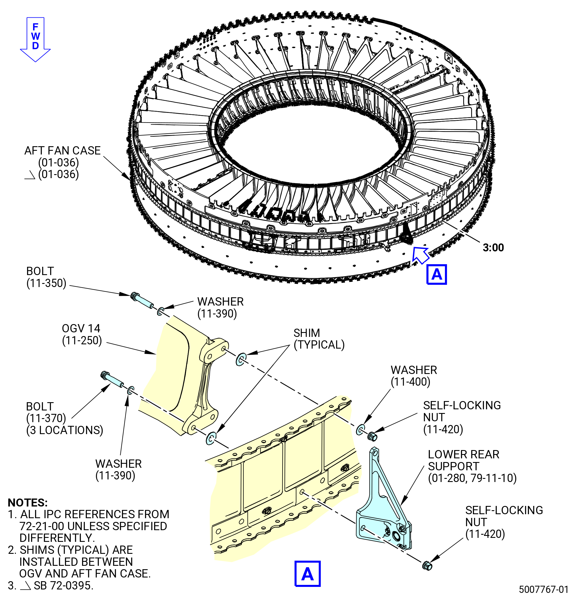
| (3) | Install the lower rear support (01-280 , 79-11-10) (SIN 40010) to the OGV 14 (11-250) (SIN 8400E) and the aft fan case at the 3:00 o'clock position. Refer to Figure 1016 and do as follows: |
| (a) | Attach the lower rear support assembly with the bolts (11-370) (SIN 84129), washers (11-390) (SIN 84131), shims, and self-locking nuts (11-420) (SIN 84143) to the OGV 14 at three locations as follows: |
| 1 | Install the washers under the head of the bolts. |
| 2 | Install the shims between the OGV and the aft fan case. |
| (b) | Install the bolt (11-350) (SIN 84121), washers (11-390) (SIN 84131), washers (11-400) (SIN 84135), shims, and self-locking nuts (11-420) (SIN 84143) on the OGV 14 (11-250) (SIN 8400E) as follows: |
| 1 | Install the washers (11-390) (SIN 84131) under the head of the bolts. |
| 2 | Install the shims between the OGV and the aft fan case. |
| 3 | Install the washers (11-400) (SIN 84135) under the self-locking nuts. |
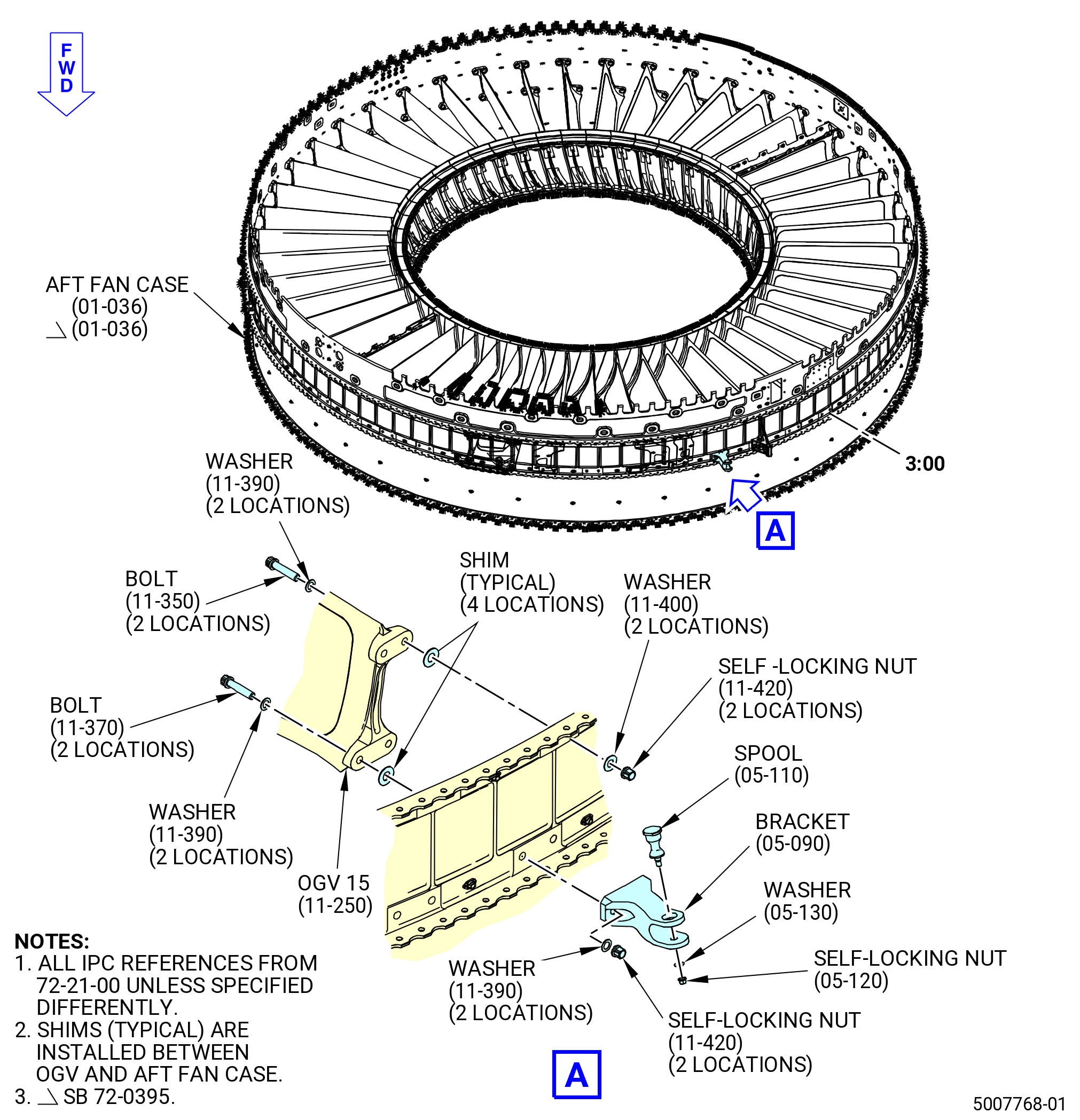
| (4) | Attach the horizontal support clevis (bracket) (05-090) (SIN 98216) to the OGV 15 and the aft fan case at the 3:30 o'clock position. Refer to Figure 1017 and do as follows: |
| (a) | Attach the bracket with the bolts (11-370) (SIN 84129), washers (11-390) (SIN 84131) under the head of the bolts and self-locking nuts, shims, and self-locking nuts (11-420) (SIN 84143) to the OGV 15 at two locations. |
| NOTE: |
|
| (b) | Install the bolts (11-350) (SIN 84121), washers (11-390) (SIN 84131), washers (11-400) (SIN 84135), shims, and self-locking nuts (11-420) (SIN 84143) on the OGV 15 aft holes at two locations as follows: |
| 1 | Install the washers (11-390) (SIN 84131) under the head of the bolts. |
| 2 | Install the shims between the OGV and the aft fan case. |
| 3 | Install the washers (11-400) (SIN 84135) under the self-locking nuts. |
| (c) | Attach the spool (05-110) (SIN 98270) to the flanges on the bracket (05-090) (SIN 98216) as follows: |
| 1 | Put the threaded shaft of the spool into the aft flange of the bracket and into the forward flange. |
| 2 | Attach the spool with a washer (05-130) (SIN 98230) and a self-locking nut (05-120) (SIN 98240). |
| 3 | Torque the self-locking nut (05-120) (SIN 98240) to 69-81 lb in. (7.8-9.2 N.m). |
| (5) | Make sure that the OGVs 35-39 have the shims installed. |
| (6) | Torque the self-locking nuts (11-420) (SIN 84143) at OGVs 11-15 to 368-432 lb in. (41.6-48.8 N.m). |
| Subtask 72-21-00-440-770 |
| Q. | Attach the OGVs 42 and 43 (11-270) (SIN 8400G) and OGVs 44-46 (11-280) (SIN 8400H) to the aft fan case (01-036) (SIN 84100) as follows: |
| (1) | Prepare the OGVs for installation. Refer to Subtask 72-21-00-440-763 (paragraph 3.L.). |
| (2) | Install the aft ground handling mount (bracket) (01-605) (SIN 9821A) to the OGVs 42 and 43 and the aft fan case. Refer to Figure 1018 and do as follows: |
| (a) | Attach with the bolts (11-380) (SIN 8412C), washers (11-390) (SIN 84131), shims, self-locking nuts (11-430) (SIN 84144), and nut retainers (11-440) (SIN 84180) at four locations as follows: |
| 1 | Install the washers under the head of the bolts. |
| 2 | Install the shims between the OGV and the aft fan case. |
| (3) | Install the bootstrap bracket (bracket) (01-590) (SIN 98218) to OGVs 42 and 43 and the aft fan case. Refer to Figure 1018 and do as follows: |
| (a) | Attach with the bolts (11-380) (SIN 8412C), washers (11-390) (SIN 84131), shims, self-locking nuts (11-430) (SIN 84144), and nut retainers (11-440) (SIN 84180) at four locations as follows: |
| 1 | Install the washers under the head of the bolts. |
| 2 | Install the shims between the OGV and the aft fan case. |
| (4) | Attach the OGVs 44-46 to the aft fan case. Refer to Figure 1013 and do as follows: |
| (a) | Install the bolts (11-350) (SIN 84121), washers (11-390) (SIN 84131), washers (11-400) (SIN 84135), shims, and self-locking nuts (11-420) (SIN 84143) on the OGVs as follows: |
| 1 | Install the washers (11-390) (SIN 84131) under the head of the bolts. |
| 2 | Install the shims between the OGV and the aft fan case. |
| 3 | Install the washers (11-400) (SIN 84135) under the self-locking nuts. |
| (5) | Make sure that OGVs 19-23 have shims installed. |
| (6) | Hand-tighten the bolts (11-380) (SIN 8412C) for OGVs 42 and 43. Do not torque the bolts at this time. |
| (7) | Torque the self-locking nuts for OGVs 44-46 to 368 to 432 lb in. (41.6 to 48.8 Nm). |
| Subtask 72-21-00-440-771 |
| R. | Attach the OGV 19 (11-220) (SIN 8400A), OGVs 20-22 (11-260) (SIN 8400F), and OGV 23 (11-270) (SIN 8400G) to the aft fan case (01-036) (SIN 84100) as follows: |
| (1) | Prepare the OGVs for installation. Refer to Subtask 72-21-00-440-763 (paragraph 3.L.). |
| (2) | Attach the OGVs 19 and 22 to the aft fan case. Refer to Figure 1010 and do as follows: |
| (a) | Install the bolts (11-350) (SIN 84121), washers (11-390) (SIN 84131), washers (11-400) (SIN 84135), shims, and self-locking nuts (11-420) (SIN 84143) on the OGVs as follows: |
| 1 | Install the washers (11-390) (SIN 84131) under the head of the bolts. |
| 2 | Install the shims between the OGV and the aft fan case. |
| 3 | Install the washers (11-400) (SIN 84135) under the self-locking nuts. |
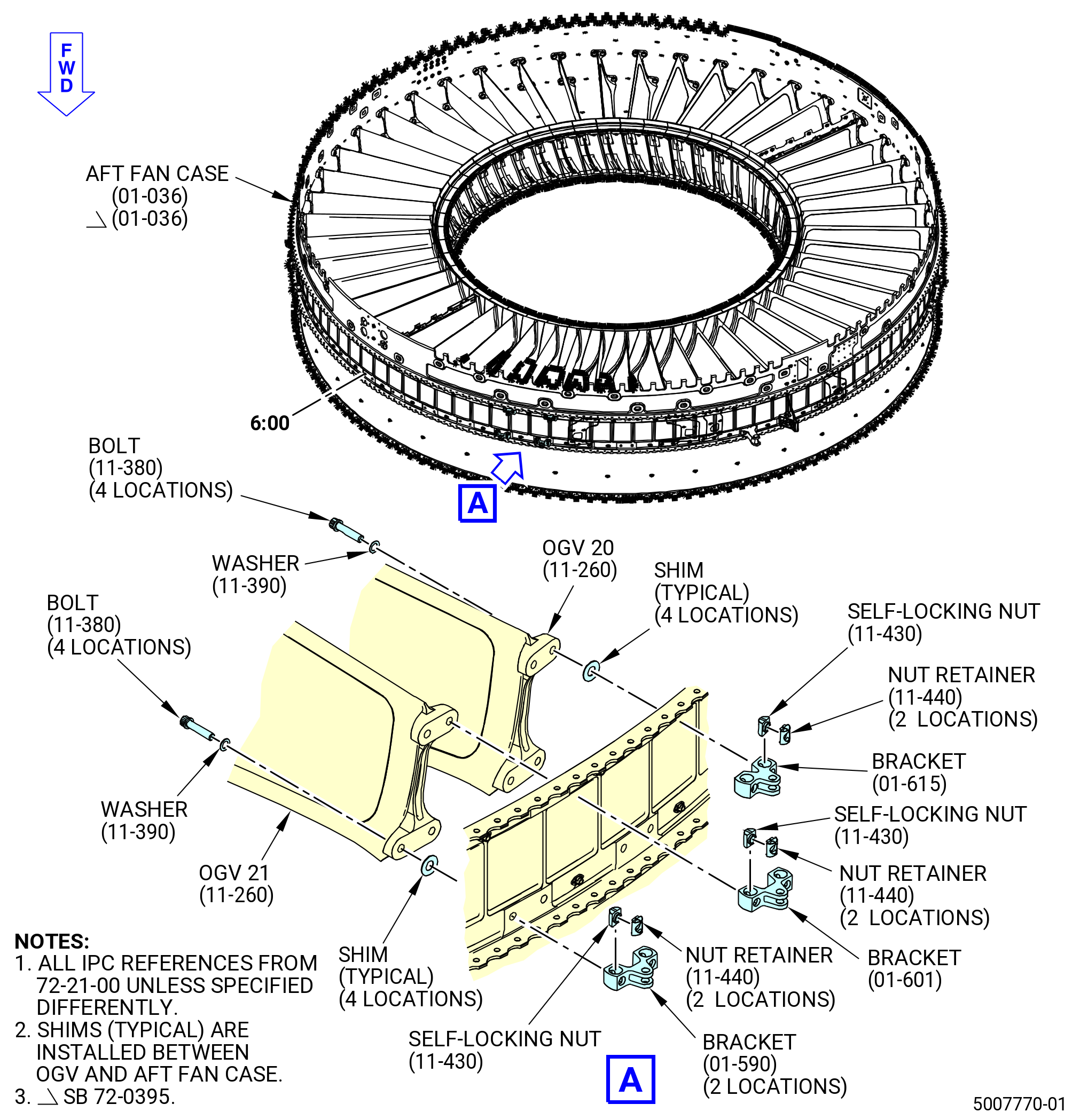
| (3) | Install the aft ground handling mount (bracket) (01-615) (SIN 9821B) to the OGV 20 and the aft fan case. Refer to Figure 1019 and do as follows: |
| (a) | Attach with the bolts (11-380) (SIN 8412C), washers (11-390) (SIN 84131), shims, self-locking nuts (11-430) (SIN 84144), and nut retainers (11-440) (SIN 84180) at two locations as follows: |
| 1 | Install the washers under the head of the bolts. |
| 2 | Install the shims between the OGV and the aft fan case. |
| (4) | Install the bootstrap bracket (bracket) (01-601) (SIN 98219) to the OGV 21 and the aft fan case. Refer to Figure 1019 and do as follows: |
| (a) | Attach with the bolts (11-380) (SIN 8412C), washers (11-390) (SIN 84131), shims, self-locking nuts (11-430) (SIN 84144), and nut retainers (11-440) (SIN 84180) at two locations as follows: |
| 1 | Install the washers under the head of the bolts. |
| 2 | Install the shims between the OGV and the aft fan case. |
| (5) | Install the bracket (01-590) (SIN 98218) to OGVs 20 and 21 and the aft fan case. Refer to Figure 1019 and do as follows: |
| (a) | Attach with the bolts (11-380) (SIN 8412C), washers (11-390) (SIN 84131), shims, self-locking nuts (11-430) (SIN 84144), and nut retainer (11-440) (SIN 84180) at four locations as follows: |
| 1 | Install the washers under the head of the bolts. |
| 2 | Install the shims between the OGV and the aft fan case. |
| (6) | Attach the OGV 23 to the aft fan case. Refer to Figure 1010 and do as follows: |
| (a) | Install the bolts (11-355) (SIN 8412D), washers (11-390) (SIN 84131), washers (11-405) (SIN 84136), shims, and self-locking nuts (11-420) (SIN 84143) on the OGVs as follows: |
| 1 | Install the washers (11-390) (SIN 84131) under the boltheads. |
| 2 | Install the shims between the OGVs and the aft fan case. |
| 3 | Install the washers (11-405) (SIN 84136) under the self-locking nuts. |
| Subtask 72-21-00-440-772 |
| (7) | Make sure that OGVs 43-47 have shims installed. |
| (8) | Hand-tighten the bolts (11-380) (SIN 8412C) for OGVs 20 and 21. Do not torque the bolts at this time. |
| (9) | Torque the self-locking nuts (11-420) (SIN 84143) at OGVs 19, 22, and 23 to 368 to 432 lb in. (41.6 to 48.8 Nm). |
| Subtask 72-21-00-440-773 |
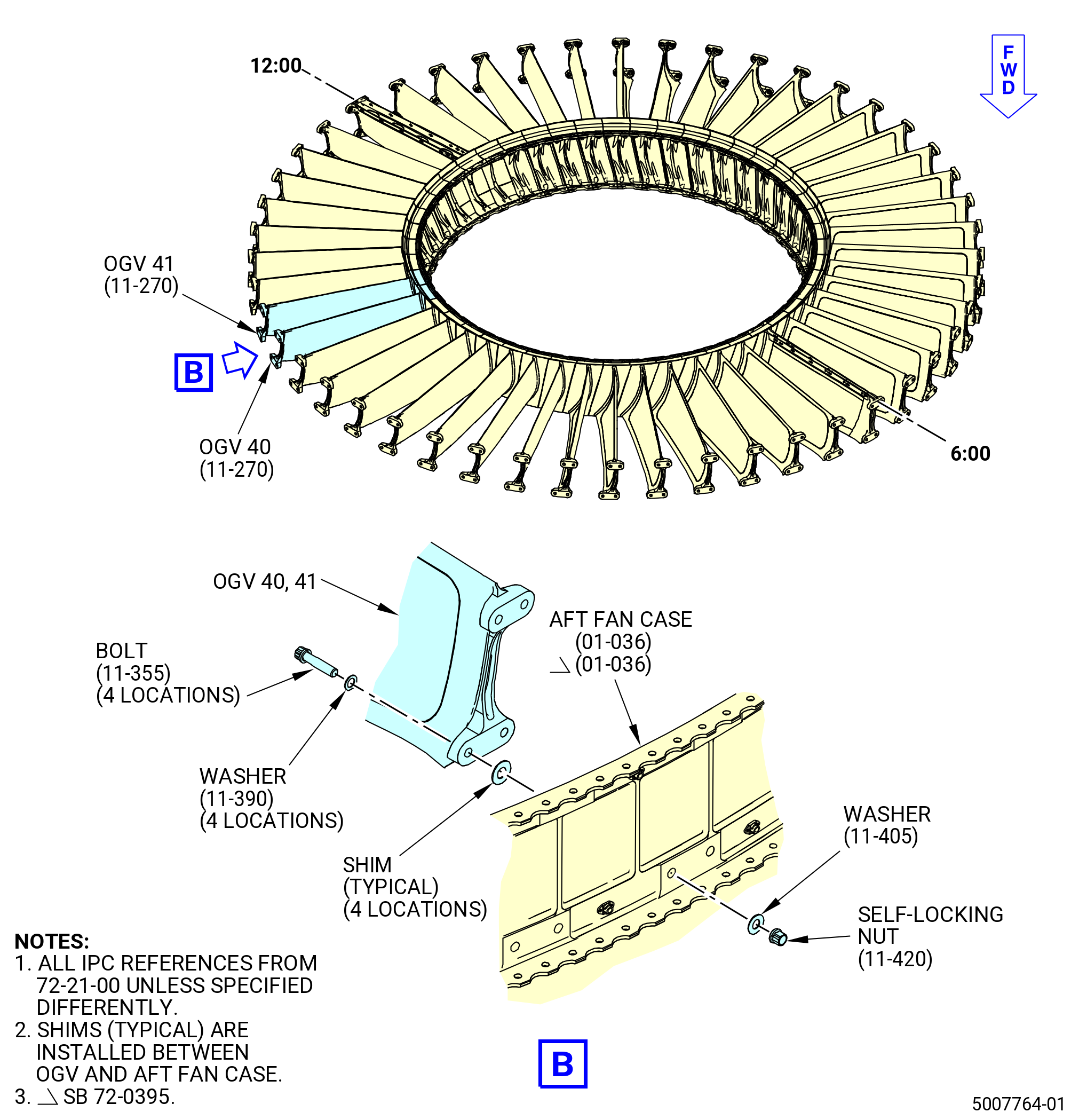
| S. | Attach the OGVs 40 and 41 (11-270) (SIN 8400G) to the aft fan case (01-036) (SIN 84100). Refer to Figure 1013 and do as follows: |
| (1) | Prepare the OGVs for installation. Refer to Subtask 72-21-00-440-763 (paragraph 3.L.). |
| (2) | Install the bolts (11-355) (SIN 8412D), washers (11-390) (SIN 84131), washers (11-405) (SIN 84136), shims, and self-locking nuts (11-420) (SIN 84143) on the OGVs as follows: |
| (a) | Install the washers (11-390) (SIN 84131) under the head of the bolts. |
| (b) | Install the shims between the OGV and the aft fan case. |
| (c) | Install the washers (11-405) (SIN 84136) under the self-locking nuts. |
| (3) | Make sure that OGVs 19-23 have shims installed. |
| (4) | Torque the self-locking nuts for OGVs 16-18 to 368 to 432 lb in. (41.6 to 48.8 Nm). |
| Subtask 72-21-00-440-774 |
| T. | Attach the OGV 16 (11-250) (SIN 8400E), OGVs 17 and 18 (11-220) (SIN 8400A) to the aft fan case (01-036) (SIN 84100) as follows: |
| (1) | Prepare the OGVs for installation. Refer to Subtask 72-21-00-440-763 (paragraph 3.L.). |
| (2) | Install the bolts (11-350) (SIN 84121), washers (11-390) (SIN 84131), washers (11-400) (SIN 84135), shims, and self-locking nuts (11-420) (SIN 84143) on the OGVs 16-18. Refer to Figure 1010 and do as follows: |
| (a) | Install the washers (11-390) (SIN 84131) under the head of the bolts. |
| (b) | Install the shims between the OGV and the aft fan case. |
| (c) | Install the washers (11-400) (SIN 84135) under the self-locking nuts. |
| (3) | Make sure that OGVs 40-42 have shims installed. |
| (4) | Torque the self-locking nuts for OGVs 16-18 to 368 to 432 lb in. (41.6 to 48.8 Nm). |
| Subtask 72-21-00-440-775 |
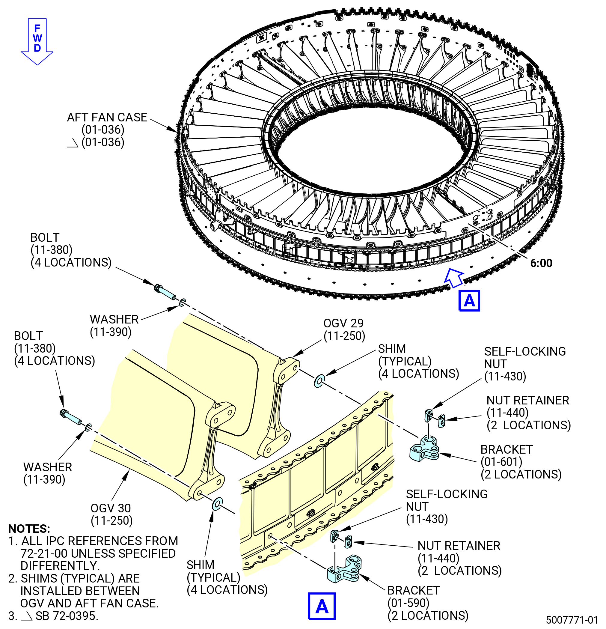
| U. | Attach the OGVs 29 and 30 (11-250) (SIN 8400E), OGVs 31-34 (11-220) (SIN 8400A) to the aft fan case (01-036) (SIN 84100) as follows: |
| (1) | Prepare the OGVs for installation. Refer to Subtask 72-21-00-440-763 (paragraph 3.L.). |
| (2) | Install the bracket (01-601) (SIN 98219) to the OGVs 29 and 30 and the aft fan case. Refer to Figure 1020 and do as follows: |
| (a) | Attach with the bolts (11-380) (SIN 8412C), washers (11-390) (SIN 84131), shims, self-locking nuts (11-430) (SIN 84144), and nut retainers (11-440) (SIN 84180) at four locations as follows: |
| 1 | Install the washers under the head of the bolts. |
| 2 | Install the shims between the OGV and the aft fan case. |
| (3) | Install the bracket (01-590) (SIN 98218) to OGVs 29 and 30 and the aft fan case. Refer to Figure 1020 and do as follows: |
| (a) | Attach with the bolts (11-380) (SIN 8412C), washers (11-390) (SIN 84131), shims, self-locking nuts, and nut retainer at four locations as follows: |
| 1 | Install the washers under the head of the bolts. |
| 2 | Install the shims between the OGV and the aft fan case. |
| (4) | Install the bolts (11-350) (SIN 84121), washers (11-390) (SIN 84131), washers (11-400) (SIN 84135), shims, and self-locking nuts (11-420) (SIN 84143) on the OGVs 31 and 34 at four locations. Refer to Figure 1013 and do as follows: |
| (a) | Install the washers (11-390) (SIN 84131) under the head of the bolts (11-350) (SIN 84121). |
| (b) | Install the shims between the OGV and the aft fan case. |
| (c) | Install the washers (11-400) (SIN 84135) under the self-locking nuts (11-420) (SIN 84143). |
| (5) | Make sure that OGVs 4-9 have shims installed. |
| (6) | Hand-tighten the bolts (11-380) (SIN 8412C) for OGVs 29 and 30. Do not torque the bolts at this time. |
| (7) | Torque the self-locking nuts for OGVs 31-34 to 368 to 432 lb in. (41.6 to 48.8 Nm). |
| Subtask 72-21-00-440-776 |
| V. | Attach the OGVs 4 and 5 (11-230) (SIN 8400C) and OGVs 6-10 (11-240) (SIN 8400D) to the aft fan case (01-036) (SIN 84100) as follows: |
| (1) | Prepare the OGVs for installation. Refer to Subtask 72-21-00-440-763 (paragraph 3.L.). |
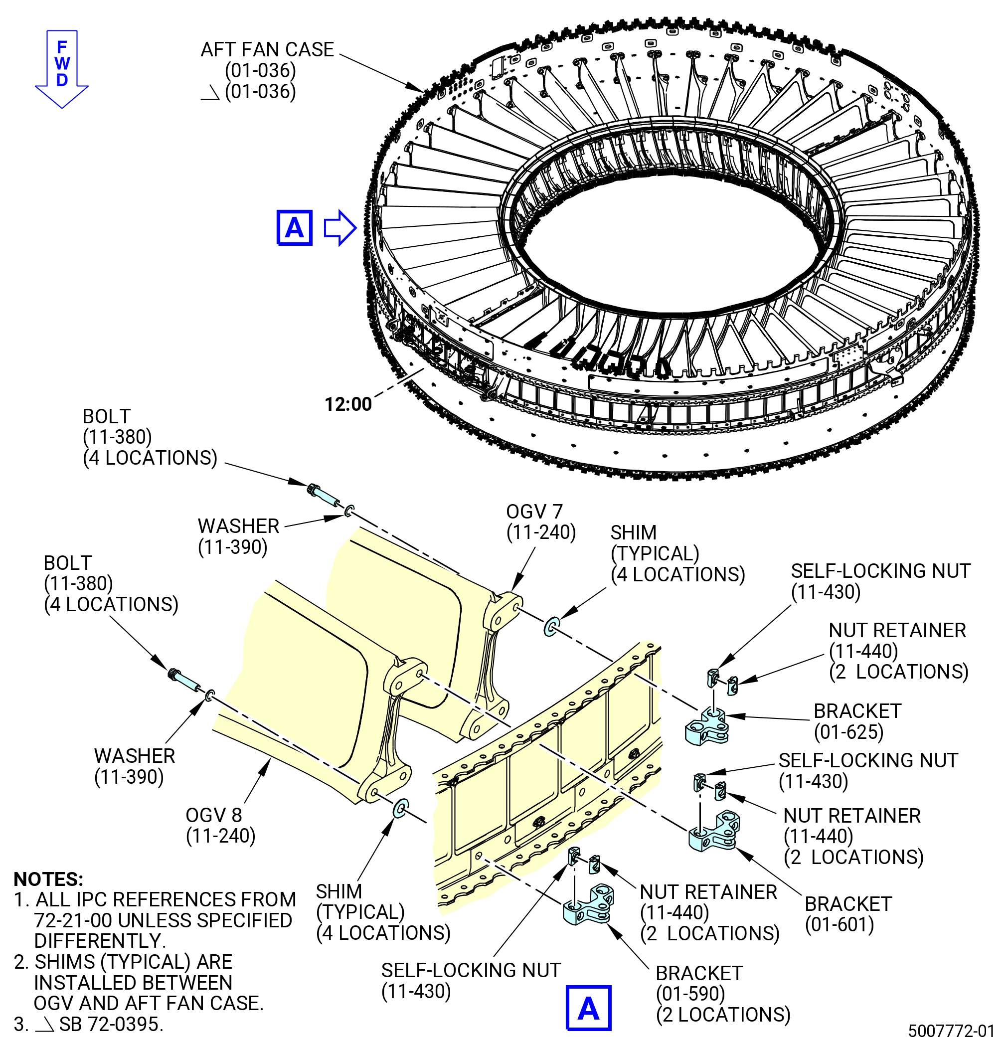
| (2) | Install the aft ground handling mount (bracket) (01-625) (SIN 9821C) to the OGV 7 and the aft fan case. Refer to Figure 1021 and do as follows: |
| (a) | Attach with the bolts (11-380) (SIN 8412C), washers (11-390) (SIN 84131), shims, self-locking nuts (11-430) (SIN 84144), and nut retainers (11-440) (SIN 84180) at two locations as follows: |
| 1 | Install the washers under the head of the bolts. |
| 2 | Install the shims between the OGV and the aft fan case. |
| (3) | Install the bracket (01-601) (SIN 98219) to the OGV 8 and the aft fan case. Refer to Figure 1021 and do as follows: |
| (a) | Attach with the bolts (11-380) (SIN 8412C), washers (11-390) (SIN 84131), shims, self-locking nuts (11-430) (SIN 84144), and nut retainers (11-440) (SIN 84180) at four locations as follows: |
| 1 | Install the washers under the head of the bolts. |
| 2 | Install the shims between the OGV and the aft fan case. |
| (4) | Install the bracket (01-590) (SIN 98218) to OGVs 7 and 8 and the aft fan case. Refer to Figure 1021 and do as follows: |
| (a) | Attach with the bolts (11-380) (SIN 8412C), washers (11-390) (SIN 84131), shims, self-locking nuts (11-430) (SIN 84144), and nut retainers (11-440) (SIN 84180) at four locations as follows: |
| 1 | Install the washers under the head of the bolts. |
| 2 | Install the shims between the OGV and the aft fan case. |
| (5) | Install the bolts (11-350) (SIN 84121), washers (11-390) (SIN 84131), washers (11-400) (SIN 84135), shims, and self-locking nuts (11-420) (SIN 84143) on the OGVs 4-6, 9, and 10 at four locations. Refer to Figure 1015 and do as follows: |
| (a) | Install the washers (11-390) (SIN 84131) under the head of the bolts. |
| (b) | Install the shims between the OGV and the aft fan case. |
| (c) | Install the washers (11-400) (SIN 84135) under the self-locking nuts. |
| (6) | Make sure that OGVs 29-34 have shims installed. |
| (7) | Hand-tighten the bolts (11-380) (SIN 8412C) for OGVs 7 and 8. Do not torque the bolts at this time. |
| (8) | Torque the self-locking nuts for OGVs 4-6, 9, and 10 to 368 to 432 lb in. (41.6 to 48.8 Nm). |
| Subtask 72-21-00-220-038 |
| W. | Make sure that the washers (11-390) (SIN 84131) are installed under the self-locking nuts (11-420) (SIN 84143) on the OGVs attached to the aft fan case (01-036) (SIN 84100) as follows: |
| (1) | Make sure that a washer is under the self-locking nut at four locations on OGVs 3-5, 9-18, 22-28, 31-41, and 44-46. |
| (2) | On OGV 14, make sure that the washer is under the upper right self-locking nut. |
| NOTE: |
|
| (3) | For OGV 15, make sure that the washer (11-400) (SIN 84135) is under the upper left and the upper right self-locking nut. Make sure that the washer (11-390) (SIN 84131) is under the self-locking nut that attaches the bracket (05-090) (SIN 98216). |
| (4) | For OGV 35, make sure that the washer is under the lower left and the lower right self-locking nut. Make sure that the washer (11-390) (SIN 84131) is under the self-locking nut that attaches the support clevis (05-100) (SIN 98217). |
| (5) | For OGV 36, make sure that the washer (11-400) (SIN 84135) is under the lower left, lower right, and upper right self-locking nut. |
| (6) | For OGV 39, make sure a washer is under the upper left and the upper right self-locking nut. |
| Subtask 72-21-00-440-777 |
| X. | Align the brackets (01-601) (SIN 98219), (01-590) (SIN 98218), (01-605) (SIN 9821A), (01-615) (SIN 9821B), and (01-625) (SIN 9821C) on the aft fan case (01-036) (SIN 84100) as follows: |
| (1) | Install the 11C4524 alignment bracket on the OGV brackets. Refer to Figure 1023 and do as follows: |
| NOTE: |
|
| NOTE: |
|
| (a) | Put each of the four locating pins (item 7) on the right upper installation bracket (item 3) and into the OGV brackets. |
| (b) | If it is not possible to put the locating pin (item 7) into one or more of the OGV brackets, loosen the bolt (11-380) (SIN 8412C) and retain the OGV bracket at the same time. Move the OGV bracket until it aligns with the locating pin. |
| CAUTION: |
|
| (2) | Gradually increase the torque to 368 to 432 lb in. (41.6 to 48.8 Nm) on each bolt (11-380) (SIN 8412C), rotating through all positions. |
| (3) | Repeat paragraphs 3.X.(1) and 3.X.(2) for left upper installation bracket (item 2), left lower installation bracket (item 4), and right lower installation bracket (item 5) at the remaining locations. |
| Subtask 72-21-00-440-778 |
| (4) | Deleted. |
| Subtask 72-21-00-220-039 |
| Y. | Do a check of the outer diameter runout of the forward flange rabbet. Refer to Figure 1004 and do as follows: |
| (1) | Release the 24 clamps of the 11C4636 base assembly from the forward flange of the aft fan case (01-036) (SIN 84100). |
| WARNING: |
|
| (2) | Slowly lift the aft fan case and the 11C4636 base assembly. Lift until the forward rabbet of the aft fan case does not touch the locating rabbet of the base assembly fixture. |
| (3) | Install aluminum shims of the same thickness, or equivalent, under the aft fan case. |
| (4) | Lower the aft fan case on the 11C4636 base assembly. |
| (5) | Do a check of the outer diameter runout of the forward flange rabbet with the dial indicator (item 58) of the 11C4636 base assembly as follows: |
| (a) | Move the dial indicator block on the plate until the locator buttons touch with the outside diameter of the locator block. |
| (b) | If the dial indicator does not engage with the aft fan case flange, adjust the dial indicator block as follows: |
| 1 | Loosen the two lock screws on the indicator bracket. |
| 2 | Turn the adjusting screw until the contact point of the indicator engages the aft fan case flange. |
| 3 | Tighten the two lock screws. |
| (c) | Slowly move the indicator block along the outside diameter of the locator block. Keep contact with the locator buttons and the locator block. |
| (d) | Record the high and the low indicator values for the ten locator blocks. |
| (e) | Determine the highest and the lowest values of the ten locator blocks. |
| (6) | If the runout is more than 0.050 inch (1.27 mm), do Subtask 72-21-00-440-757 (paragraph 3.D.) and Subtask 72-21-00-440-761 (paragraph 3.K.) thru Subtask 72-21-00-440-776 (paragraph 3.V.), after removal of all the OGVs. Do this procedure until the runout is not more than 0.050 inch (1.27 mm). |
| Subtask 72-21-00-440-779 |
| Z. | Continue to assemble the fan stator. Refer to TASK 72-21-00-440-808 (72-21-00, ASSEMBLY 002, CONFIGURATION 02). |