| GENX-1B ENGINE MANUAL | Dated: 12/20/2024 | |
| EM 72-21-00 , ASSEMBLY 002 | ||
| FAN STATOR ASSEMBLY - ASSEMBLY 002 - CONFIGURATION 02 | ||
| GENX-1B ENGINE MANUAL | Dated: 12/20/2024 | |
| EM 72-21-00 , ASSEMBLY 002 | ||
| FAN STATOR ASSEMBLY - ASSEMBLY 002 - CONFIGURATION 02 | ||
| * * * FOR ALL PIP 2 |
| TASK 72-21-00-440-808 |
| 1 . | General. |
| A. | This procedure gives instructions to assemble the aft fan stator case assembly (stator case assembly) (01-021 , 72-00-01) (SIN 00109). Refer to Figure 1001. |
| B. | This procedure starts with the stator case assembly in the vertical position, forward end down, at the equivalent build status of TASK 72-21-00-440-806 (72-21-00, ASSEMBLY 001 CONFIG 02) . |
| C. | Make sure that there is no foreign material inside the forward containment fan case (01-013) (SIN 83500) and the aft fan case (01-036) (SIN 84100). |
| D. | Before this procedure is done, read the Assembly and Disassembly Techniques section. Refer to TASK 70-10-00-800-009 (ASSEMBLY AND DISASSEMBLY TECHNIQUES) . |
| E. | Make sure that the mating parts are serviceable and have no damage. |
| WARNING: |
|
| F. | Clean surfaces with C04-002 stoddard solvent , C04-035 isopropyl alcohol , or 50-50 alcohol blend of C04-036 toluene and C04-035 isopropyl alcohol. Refer to TASK 70-21-23-110-053 (CLEANING METHOD NO. 23 - HAND-WIPE DEGREASING) . |
| G. | Install all bolts with heads uppermost or forward unless specified differently. |
| H. | Obey the instruction to safety parts with safety wire, safety cable, cotter pins, or tab washers. Refer to TASK 70-11-00-400-001 (FASTENER RETENTION PROCEDURES) . |
| 2 . | Tools, Equipment, and Materials. |
| NOTE: |
|
| A. | Tools and Equipment. |
| (1) | Special Tools. |
| (2) | Standard Tools and Equipment. |
|
| (3) | Locally Manufactured Tools. None. |
| B. | Consumable Materials. |
|
| C. | Referenced Procedures. |
|
| D. | Expendable Parts. |
|
| 3 . | Procedure. |
| Subtask 72-21-00-440-806 |
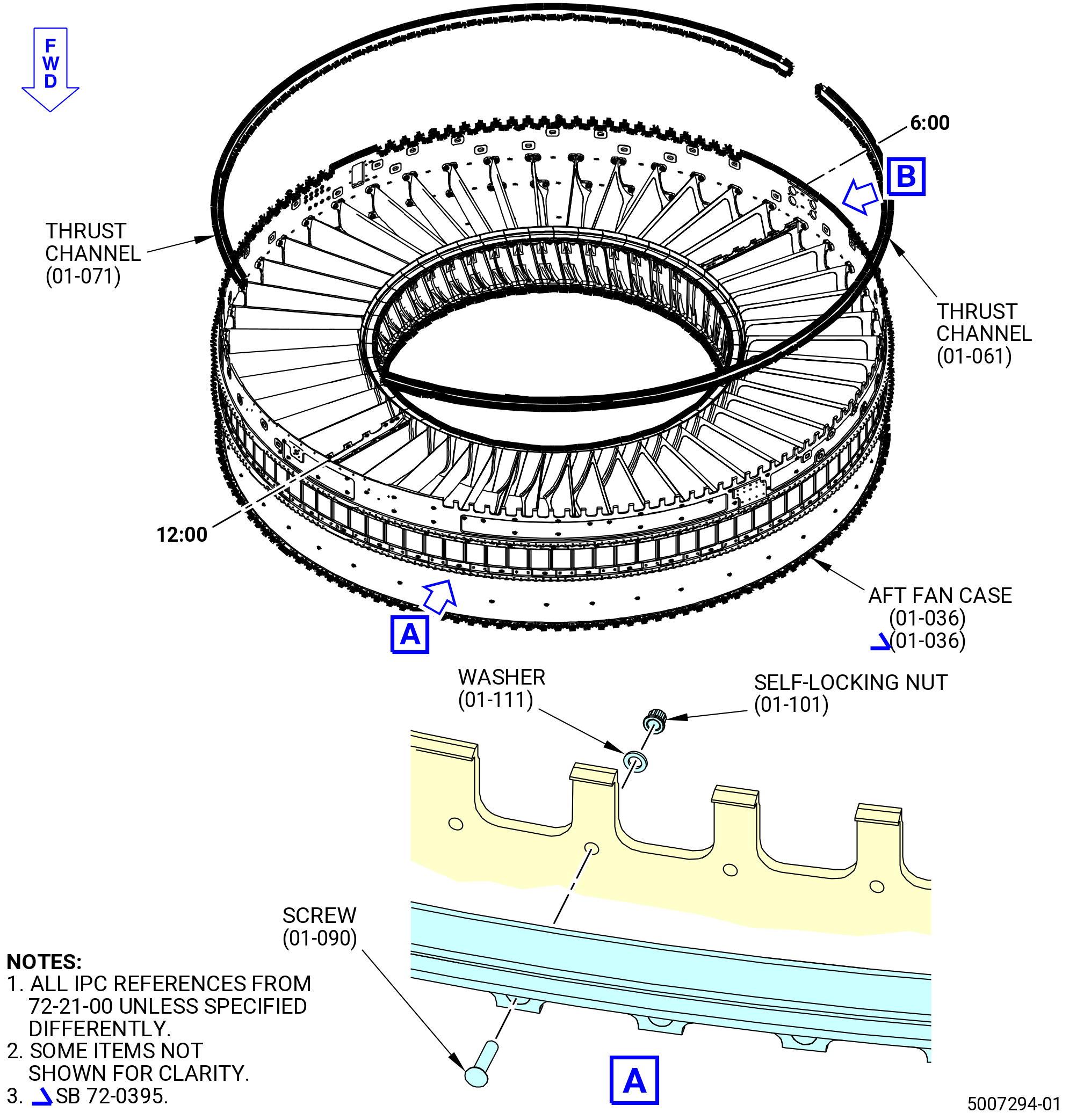
| A. | Match-drill the lower thrust reverser channels (thrust channels) (01-061) (SIN 84116) and (01-071) (SIN 84118) to the aft fan case if they are new as follows: |
| (1) | Match-drill the thrust channels to the aft fan case if they are new. Refer Figure 1002 and do as follows: |
| CAUTION: |
|
| (a) | Put the thrust channels on the outer diameter of the aft fan case (01-036) (SIN 84100) as follows: |
| 1 | Align the thrust channels to the aft fan case. Use the undersized pilot hole in the aft fan case and the undersized hole in the thrust channels to align. |
| 2 | Install a 0.240 inch (6.10 mm) stepped pin into the pilot hole in the thrust channels and the pilot hole in the aft fan case from one end to the opposite end. |
| NOTE: |
|
| NOTE: |
|
| NOTE: |
|
| 3 | Keep a gap of 0.0000-0.0100 inch (0.000-0.254 mm) between the bottom surface of the lip on the end to the opposite end on the thrust reverser channel. |
| 4 | Use a non-abrasive scissor clamp to firmly attach the thrust channels to the aft fan case. |
| 5 | Attach a scissor clamp every 15.0 inches (381 mm). |
| 6 | The holes in each thrust channels must align with the pilot hole in the aft fan case. |
| CAUTION: |
|
| CAUTION: |
|
| (b) | Match-drill through the thrust channels and aft fan case. |
| (c) | Drill at the hole adjacent to the pilot holes in the thrust channels and the aft fan case. Use a 0.243 inch (6.17 mm) diameter drill bit. |
| (d) | Make sure that the drill stays level so the machine screws (screws) (01-090) (SIN 84424) are against the thrust channels and the aft fan case in the correct position. |
| (e) | Install an avdel pin, a slave bolt, a washer, and a self-locking nut, or equivalent through the match-drilled hole and tighten them into position. |
| NOTE: |
|
| (f) | Do this procedure again for the remaining holes in the thrust channel. |
| (g) | Install a new 0.2500 inch (6.350 mm) diameter spiral fluted reamer in a drill gun. |
| WARNING: |
|
| (h) | Make sure that the drill gun is in the correct position and locked. |
| (i) | Start the drill gun and set the controls to the slowest speed and feed settings. |
| WARNING: |
|
| (j) | Ream through the thrust channels and the aft fan case. Use C02-047 lubricant when reaming. |
| NOTE: |
|
| (k) | After the reamer goes through the thrust channels and the aft fan case, slowly remove it, but do not turn off the drill gun. |
| (l) | Turn off the drill gun after the reamer is removed from the hole. |
| (m) | Chamfer and deburr the aft fan case and thrust channels drilled holes. |
| (n) | Remove all raised material and sharp edges. Refer to TASK 70-42-00-350-002 (BLENDING AND REMOVAL OF HIGH METAL PROCEDURES). |
| (o) | Do the procedure again for the remaining holes in the thrust channels and aft fan case. |
| Subtask 72-21-00-110-075 |
| WARNING: |
|
| CAUTION: |
|
| (p) | Clean the mating surfaces and drilled/reamed areas of the aft fan case (01-036) (SIN 84100) and thrust channels (01-061) (SIN 84116) and (01-071) (SIN 84118). Use a clean C10-182 cloth wet with C04-002 stoddard solvent, C04-035 isopropyl alcohol, or 50-50 alcohol blend. |
| Subtask 72-21-00-220-043 |
| (q) | Use a 0.250 to 0.254 inch (6.35 to 6.45 mm) go-no-go gage to do an inspection of the drilled holes. |
| (r) | If the aft fan case or the thrust channels (01-061) (SIN 84116) and (01-071) (SIN 84118) were scored, do an inspection. Refer to TASK 72-21-02-200-801 (72-21-02, INSPECTION 001) to inspect the aft fan case (01-036) (SIN 84100) and TASK 72-21-60-200-801 (72-21-60, INSPECTION 001) to do an inspection of the thrust channels. |
| Subtask 72-21-00-380-278 |
| (s) | Apply C03-083 coating to the inner diameter of the 12 drilled holes on the aft fan case (01-036) (SIN 84100). Refer to TASK 70-43-07-380-007 (CHEMICAL TOUCH-UP SURFACE REFINISHING PROCESS FOR ALUMINUM). |
| WARNING: |
|
| (t) | Apply C03-001 primer or C03-100 primer to the drilled holes and uncoated surfaces of the aft fan case. |
| (u) | Apply C03-001 primer or C03-100 primer to the drilled holes, V-grooves, and uncoated surfaces on the thrust channels (01-061) (SIN 84116) and (01-071) (SIN 84118). |
| Subtask 72-21-00-440-807 |
| B. | Install the thrust channels (01-061) (SIN 84116) and (01-071) (SIN 84118) on the aft fan case (01-036) (SIN 84100). Refer to Figure 1002 and do as follows: |
| Subtask 72-21-00-640-231 |
| WARNING: |
|
| (1) | Apply C02-058 lubricant to the threads of the screws (01-090) (SIN 84424) and shear bolts (bolts) (01-125) (SIN 8442P). |
| Subtask 72-21-00-380-279 |
| (2) | Apply C03-001 primer or C03-100 primer to the self-locking nuts (nuts) (01-101) (SIN 84440), screws (01-090) (SIN 84424), washers (01-111) (SIN 84534), bolts (01-125) (SIN 8442P), and self-locking nuts (nuts) (01-730) (SIN 84449) as follows: |
| (a) | To the bearing surfaces of the nuts and washers. |
| (b) | To the shanks and the chamfers of the screws and bolts. |
| Subtask 72-21-00-440-808 |
| (3) | Attach the thrust channels (01-061) (SIN 84116) and (01-071) (SIN 84118) to the aft fan case (01-036) (SIN 84100) with the screws (01-090) (SIN 84424), washers (01-111) (SIN 84534) and nuts (01-101) (SIN 84440) wet with C03-001 primer or C03-100 primer. The washer is installed under the self-locking nut. Do not install screws, washers, or nuts in the last three bottom holes of each thrust channel near the 6:00 o'clock position. |
| (4) | Attach the thrust channels to the aft fan case with six bolts (01-125) (SIN 8442P), flat washers (washers) (01-105) (SIN 84535) and (01-115) (SIN 84536), and nuts (01-730) (SIN 84449) near the 6:00 o'clock position. Install one washer (01-115) (SIN 84536) under each bolt and one washer (01-105) (SIN 84535) under each nut. |
| (5) | Torque the nuts (01-101) (SIN 84440) to 83 to 97 lb in. (9.4 to 11.0 Nm). |
| (6) | Torque the nuts again to 83 to 97 lb in. (9.4 to 11.0 Nm). |
| (7) | Torque the nuts (01-730) (SIN 84449) to 202 to 238 lb in. (22.8 to 26.9 Nm). |
| (8) | Torque the nuts (01-730) (SIN 84449) again to 202 to 238 lb in. (22.8 to 26.9 Nm). |
| (9) | Make sure that the head of the screws are below the surface of the thrust channels. The head of the screws must be below the surface of the trust reverser channels. |
| Subtask 72-21-00-110-076 |
| WARNING: |
|
| (10) | Clean any excess C03-001 primer, C03-100 primer, or C03-083 coating from the trust reverser channels (01-061) (SIN 84116) and (01-071) (SIN 84118) and the aft fan case (01-036) (SIN 84100). Use a clean C10-182 cloth wet with C04-035 isopropyl alcohol or equivalent. |
| (11) | Make sure to remove the C03-100 primer from the inside of the V-groove and below the V-groove of the thrust channels. |
| Subtask 72-21-00-440-809 |
| C. | Install the power door opening system (PDOS) brackets (25-010 , 71-00-00) (SIN 95111) and (25-020 , 71-00-00) (SIN 95112) on the aft fan case (01-036) (SIN 84100). Refer to Figure 1003 and do as follows: |
| Subtask 72-21-00-640-232 |
| WARNING: |
|
| (1) | Apply C02-058 lubricant to the threads of the bolts (25-030 , 71-00-00) (SIN 95121). |
| Subtask 72-21-00-380-280 |
| (2) | Apply C03-001 primer or C03-100 primer as follows: |
| (a) | To the shank of the bolts (25-030 , 71-00-00) (SIN 95121). |
| (b) | To the PDOS brackets (25-010 , 71-00-00) (SIN 95111) and (25-020 , 71-00-00) (SIN 95112) and washer (25-040) (SIN 95130) contact surfaces. |
| (c) | To the inside diameter of the boltholes. |
| Subtask 72-21-00-440-810 |
| (3) | Put the PDOS bracket (25-010 , 71-00-00) (SIN 95111) on the aft fan case (01-036) (SIN 84100) at the 3:00 o'clock position between the OGVs 12 and 13. |
| (4) | Put the PDOS bracket (25-020 , 71-00-00) (SIN 95112) on the aft fan case at the 9:00 o'clock position between the OGVs 37 and 38. |
| (5) | Attach the PDOS bracket with bolts (25-030 , 71-00-00) (SIN 95121), washers (25-040 , 71-00-00) (SIN 95130), and nuts (25-050 , 71-00-00) (SIN 95140). The washers are installed under the bolts and under the nuts. |
| (6) | Torque the nuts to 69 to 81 lb in. (7.8 to 9.2 Nm). |
| (7) | Torque the nuts again to 69 to 81 lb in. (7.8 to 9.2 Nm). |
| (8) | Torque the nuts to 69 to 81 lb in. (7.8 to 9.2 Nm) again to make sure that all nuts are torqued correctly. |
| Subtask 72-21-00-440-811 |
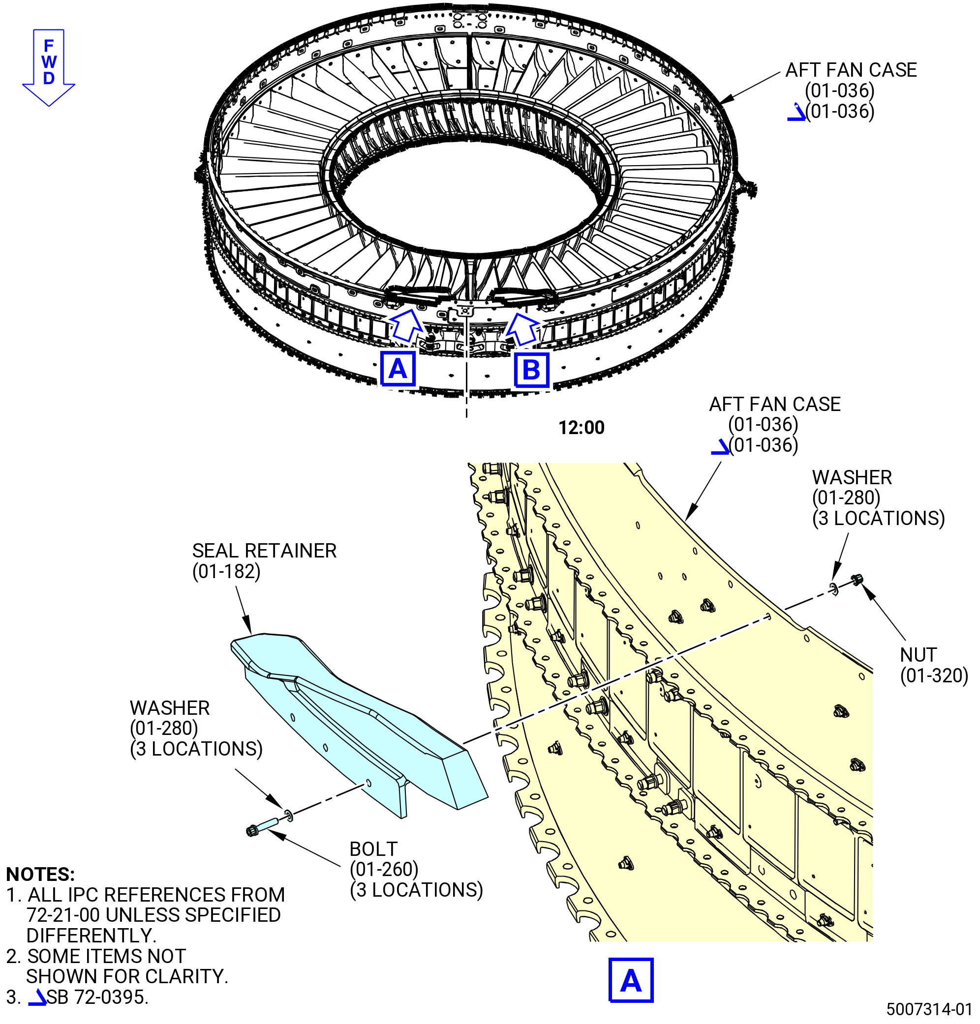
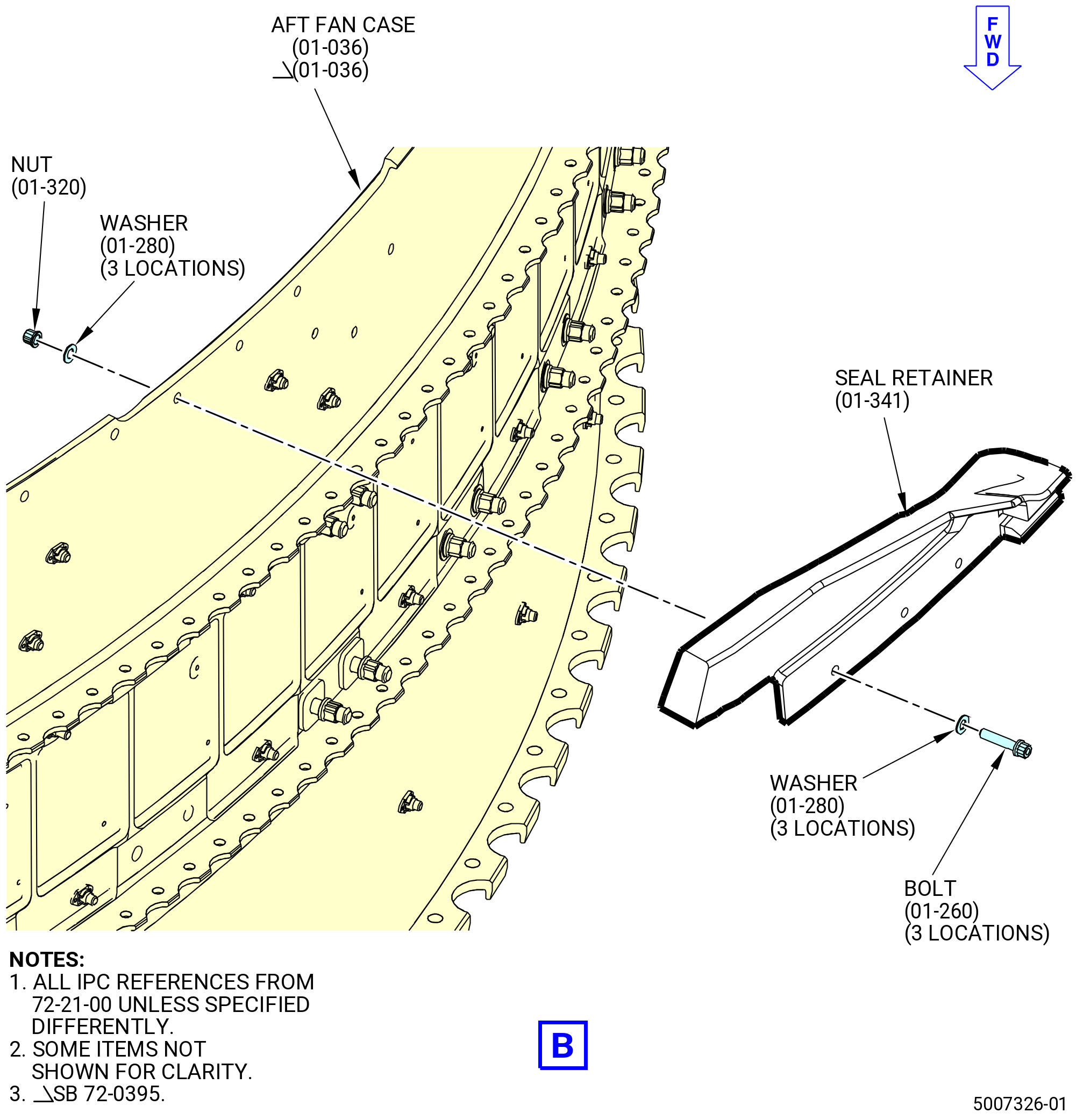
| D. | Install the upper seal retainers (seal retainers) (01-182) (SIN 84404) and (01-341) (SIN 84504) on the aft fan case (01-036) (SIN 84100). Refer to Figure 1004 and do as follows: |
| Subtask 72-21-00-380-281 |
| WARNING: |
|
| (1) | Apply C03-001 primer or C03-100 primer as follows: |
| (a) | To the bolt (01-260) (SIN 8442E) shank and the bearing surface of the bolt head. Do not apply C03-001 primer or C03-100 primer to the bolt threads. |
| (b) | To the pre-drilled holes in the aft fan case (01-036) (SIN 84100) and seal retainers (01-182) (SIN 84404) and (01-341) (SIN 84504). |
| (c) | To the self-locking nut (nut) (01-320) (SIN 84445) and washer (01-280) (SIN 84435) contact surfaces. |
| (d) | To the inside diameter of the boltholes in the aft fan case and the seal retainers (01-182) (SIN 84404) and (01-341) (SIN 84504). |
| Subtask 72-21-00-640-233 |
| WARNING: |
|
| (2) | Apply C02-058 lubricant to the threads of the bolts (01-260) (SIN 8442E). |
| Subtask 72-21-00-440-812 |
| (3) | Put the seal retainer (01-182) (SIN 84404) on the right side (ALF) of the aft fan case (01-036) (SIN 84100) at the 12:30 o'clock position. |
| (4) | Put the seal retainer (01-341) (SIN 84504) on the left side (ALF) of the aft fan case at the 11:30 o'clock position. |
| (5) | Attach the seal retainers with bolts (01-260) (SIN 8442E), washers (01-280) (SIN 84435), and nuts (01-320) (SIN 84445) at three locations. |
| NOTE: |
|
| (6) | Do not torque the nuts at this time. |
| Subtask 72-21-00-440-916 |
| E. | Install the upper firewall fire shields (fire shields) (01-680) (SIN 844A1), (01-690) (SIN 844A2), (01-700) (SIN 844A3), and (01-710) (SIN 844A4) and lower firewall insulation blanket (insulation blanket) (01-720) (SIN 844A5) to the upper firewall (01-152) (SIN 84401) and lower firewall (01-372) (SIN 84501). Refer to Figure 1005, Figure 1006, and do as follows: |
| (1) | Bond the insulation blanket (01-720) (SIN 844A5) to the lower firewall as follows: |
| WARNING: |
|
| (a) | Clean the bonding area of the insulation blanket and lower firewall with a 50-50 blend of C04-014 denatured alcohol and C04-035 isopropyl alcohol or C04-002 stoddard solvent. |
| (b) | Apply C01-159 RTV primer to the insulation blanket bonding surface. |
| (c) | Clean the insulation blanket and lower firewall in the surfaces adjacent to the bonding surface with a 50-50 blend of C04-014 denatured alcohol and C04-035 isopropyl alcohol or C04-002 stoddard solvent. |
| (d) | Mask the area with C10-021 tape . |
| (e) | Apply C01-007 RTV 106 to the transition areas where the insulation blanket touches other surfaces. Make sure that there is a smooth transition of the sealant between mating components. |
| (f) | Apply sufficient pressure to prevent movement of the insulation blanket during cure of C01-007 RTV 106. |
| (g) | Let the sealant cure for 12 hours at room temperature. |
| (h) | Remove the C10-021 tape from the masked area. |
| (2) | Bond the fire shields (01-680) (SIN 844A1), (01-690) (SIN 844A2), (01-700) (SIN 844A3), and (01-710) (SIN 844A4) to the upper firewall (01-152) (SIN 84401) as follows: |
| WARNING: |
|
| (a) | Clean the bonding area of each fire shield and upper firewall with a 50-50 blend of C04-014 denatured alcohol and C04-035 isopropyl alcohol or C04-002 stoddard solvent. |
| (b) | Apply C01-159 RTV primer to the fire shield bonding surface. |
| (c) | Clean the fire shield and lower firewall in the surfaces adjacent to the bonding surface with a 50-50 blend of C04-014 denatured alcohol and C04-035 isopropyl alcohol or C04-002 stoddard solvent. |
| (d) | Mask the area with C10-021 tape . |
| (e) | Trim the fire shields as required to bond flush. |
| (f) | Apply C01-007 RTV 106 to the transition areas where the fire shield touches other surfaces. Make sure that there is a smooth transition of the sealant between mating components. |
| (g) | Apply sufficient pressure to prevent movement of the fire shield during cure of C01-007 RTV 106. |
| (h) | Let the sealant cure for 12 hours at room temperature. |
| (i) | Remove the C10-021 tape from the masked area. |
| Subtask 72-21-00-440-813 |
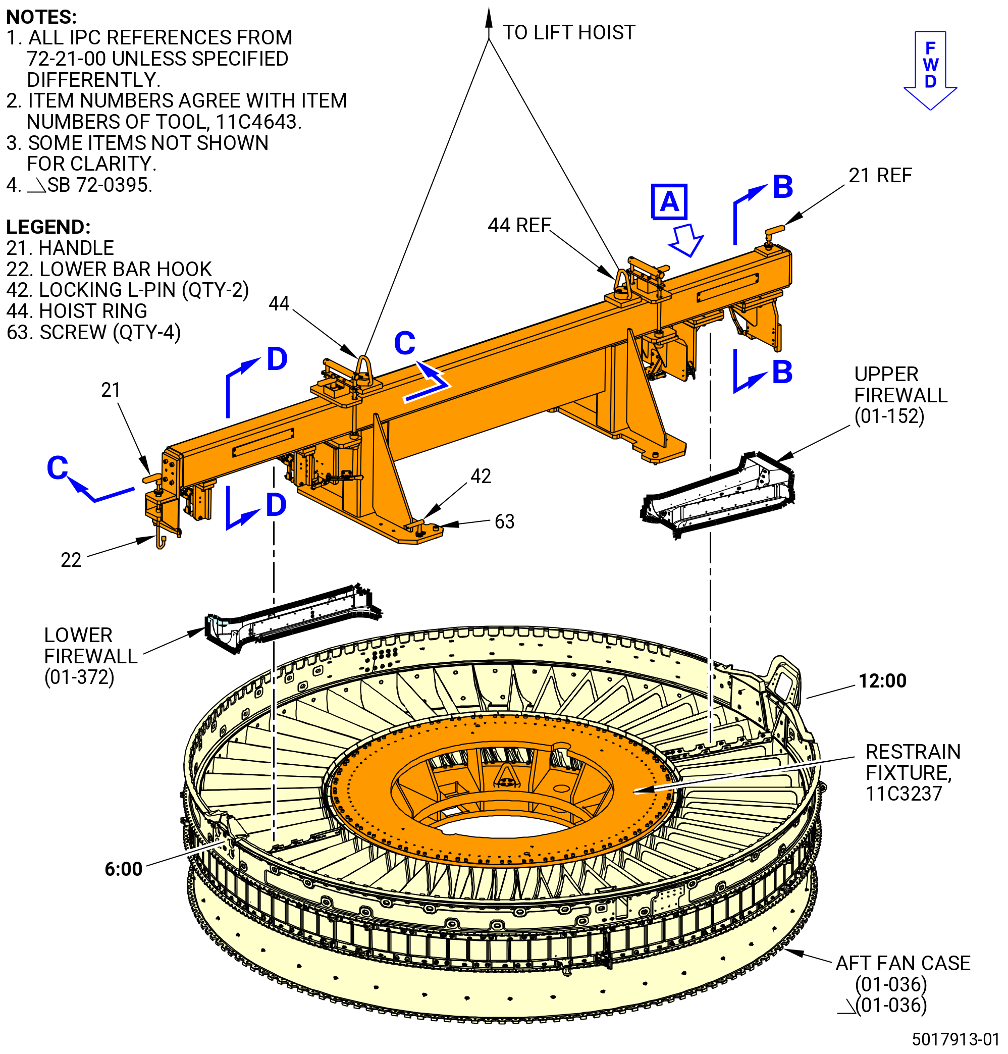
| F. | Install the upper firewall (01-152) (SIN 84401) and lower firewall (01-372) (SIN 84501) on the 11C4643 firewall fixture as follows: |
| (1) | Put the upper firewall on a clean, secure workbench with the aft end down. The surface coated with grey oil is the aft end. |
| (2) | Prepare the 11C4643 firewall fixture to install the upper firewall on the fixture. Refer to Figure 1007 and do as follows: |
| WARNING: |
|
| (a) | Attach an overhead hoist to the pivoting hoist rings (item 44) and lift the 11C4643 firewall fixture. |
| (b) | Disengage all toogle clamps (item 31), vertical hold down clamps (item 38), and horizontal spanners (item 39). |
| (c) | Loosen the knurled knobs (item 43) to release the lower bar hook (item 22) and upper bar hook (item 32) through the head press fit bushings (items 33 and 34). |
| Subtask 72-21-00-440-814 |
| (3) | Attach the upper firewall (01-152) (SIN 84401) to the 11C4643 firewall fixture as follows: |
| (a) | Take the upper firewall and manually put its face against the surface of the upper stopper bracket (item 7). |
| (b) | Carefully move the upper firewall until the three protuberant points on the internal surface of the upper firewall touch the upper block locator back, front and center inboards (items 10, 11, and 14). |
| (c) | Make sure that the two protuberant points on the side of the upper firewall contact the upper block locator back and center inboard (items 10 and 14) faces. Carefully move the upper firewall to make sure there is contact between surfaces. |
| (d) | When the protuberant points of the upper firewall contact each other, turn the handle (item 21) inwards to close the upper bar hook (item 32) and pull it up to support the internal top surface of the upper firewall. |
| (e) | Manually tighten the knurled knob (item 43) to secure the position of the upper bar hook (item 32). |
| (f) | Complete the clamping of the upper firewall by engaging the toggle clamps (item 31) and three horizontal spanners (item 39). If needed, adjust the position of the spindles (item 41) with the hexagonal nuts (item 66). |
| (4) | Attach the lower firewall (01-372) (SIN 84501) to the 11C4643 firewall fixture as follows: |
| (a) | Take the lower firewall and manually put its face against the surface of the lower stopper bracket (item 6). |
| (b) | Carefully move the lower firewall until the three protuberant points on the internal surface of the lower firewall touch the locator block pin (item 18) and locator lower pins (item 20). |
| (c) | Make sure that the two protuberant points on the side of the lower firewall contact the locator center pins (item 19). Carefully adjust the lower firewall to make sure there is contact between surfaces. |
| (d) | When the protuberant points of the lower firewall contact each other, turn the handle (item 21) inwards to close the lower bar hook (item 22) and pull it up to support the bottom surface of the lower firewall. |
| (e) | Tighten the knurled knob (item 43) to secure the position of the lower bar hook (item 22). |
| (f) | Complete the clamping of the lower firewall by engaging the two vertical hold down clamps (item 38) and the three horizontal spanners (item 39). If needed, adjust the position of the spindles (item 41) with the hexagonal nuts (item 66). |
| NOTE: |
|
| (5) | Install the 11C4643 firewall fixture, upper firewall (01-152) (SIN 84401), and lower firewall (01-372) (SIN 84501) to the aft fan case. Refer to Figure 1007 and do as follows: |
| WARNING: |
|
| (a) | Use the overhead hoist or crane to lift and move the 11C4643 firewall fixture with the firewalls attached. |
| (b) | Put the 11C4643 firewall fixture over the 11C3237 restrain fixture that is already seated on 11C4636 base assembly. |
| (c) | Lower the 11C4643 firewall fixture to align it over the top surface of the 11C3237 restrain fixture. |
| (d) | Attach the 11C4643 firewall fixture with the two locking L pins (item 42) and four screws (item 63). |
| (6) | Torque the nuts (01-320) (SIN 84445) to 83 to 97 lb in. (9.4 to 11.0 Nm). Refer to Figure 1004. |
| (7) | Torque the nuts again to 83 to 97 lb in. (9.4 to 11.0 Nm). |
| Subtask 72-21-00-440-815 |
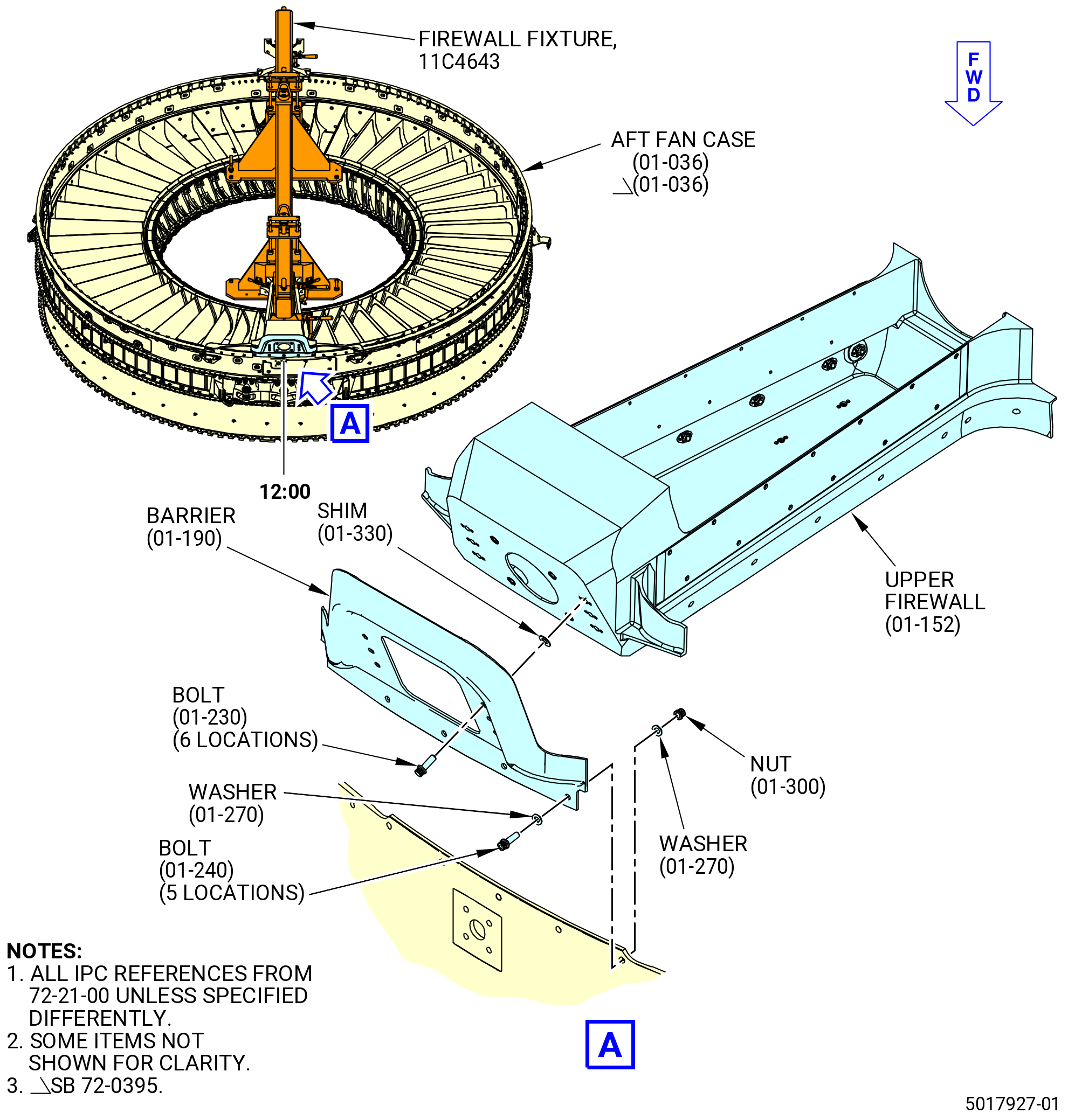
| G. | Install the vapor barrier (barrier) (01-190) (SIN 84405) on the aft fan case (01-036) (84100) and upper firewall (01-152) (SIN 84401). Refer to Figure 1008 and do as follows: |
| Subtask 72-21-00-640-234 |
| WARNING: |
|
| (1) | Apply C02-058 lubricant to the threads of the bolts (01-230) (SIN 84421) and (01-240) (SIN 84422). |
| Subtask 72-21-00-440-816 |
| (2) | Align the barrier with the aft fan case. |
| (3) | Attach the barrier with the bolts (01-240) (SIN 84422), washers (01-270) (SIN 84432) (ten locations), and self-locking nuts (nuts) (01-300) (SIN 84441) as follows: |
| (a) | Put the head of the bolt on the outside of the aft fan case and the nut on the inside. |
| (b) | Put a washer under the head of the bolt and the nut. |
| (4) | Do not torque the nuts at this time. |
| Subtask 72-21-00-440-817 |
| (5) | Install shims (01-330) (SIN 84470) between the barrier (01-190) (SIN 84405) and upper firewall (01-152) (SIN 84401) as follows: |
| (a) | Use a taper gauge to measure the gap between the barrier and the upper firewall. The gap must not be more than 0.100 inch (2.54 mm). If the gap is more than 0.100 inch (2.54 mm), determine the cause and correct it before installing the shims. |
| (b) | Remove the barrier from the aft fan case. |
| (c) | Peel the shim to the size of the measured gap. The shim must give a 0.000-0.006 inch (0.00-0.15 mm) gap between the barrier and the upper firewall. |
| Subtask 72-21-00-380-282 |
| WARNING: |
|
| (d) | Apply C03-001 primer or C03-100 primer to the bearing surface of the shims (01-330) (SIN 84470). |
| Subtask 72-21-00-440-818 |
| (e) | Install the shims (01-330) (SIN 84470) on the barrier (01-190) (SIN 84405) and upper firewall (01-152) (SIN 84401) at six locations. |
| (f) | Install the barrier (01-190) (SIN 84405) to the aft fan case with bolts (01-240) (SIN 84422), washers (01-270) (SIN 84432), and nuts (01-300) (SIN 84441). |
| (g) | Attach the barrier to the upper firewall with the bolts (01-230) (SIN 84421). |
| NOTE: |
|
| (h) | Torque the bolts (01-230) (SIN 84421) to 83-97 lb in. (9.4-11.0 N.m). |
| (i) | Torque the bolts (01-230) (SIN 84421) again to 83-97 lb in. (9.4-11.0 N.m). |
| (j) | Torque the nuts to 83-97 lb in. (9.4-11.0 N.m). |
| (k) | Torque the nuts again to 83-97 lb in. (9.4-11.0 N.m). |
| Subtask 72-21-00-110-077 |
| WARNING: |
|
| (l) | Clean all surfaces around the barrier (01-190) (SIN 84405) gaps with C04-035 isopropyl alcohol or equivalent. |
| (m) | Make sure that all tools are clean before applying C01-176 RTV 133. |
| (n) | Clean the areas adjacent to the seal retainers (01-182) (SIN 84404) and (01-341) (SIN 84504) with C04-035 isopropyl alcohol or equivalent. Refer to Figure 1004. |
| Subtask 72-21-00-440-819 |
| (6) | Apply C01-176 RTV 133 around the barrier (01-190) (SIN 84405) and upper firewall (01-152) (SIN 84401). Refer to Figure 1015 and do as follows: |
| Subtask 72-21-00-380-283 |
| WARNING: |
|
| (p) | Apply C01-159 RTV primer to all surfaces where the C01-176 RTV 133 will be applied. |
| (q) | Apply C01-176 RTV 133 to the gaps between the barrier (01-190) (SIN 84405) and upper firewall (01-152) (SIN 84401) around the center hole. |
| (r) | Apply C01-176 RTV 133 to the inside edges of the barrier (01-190) (SIN 84405) adjacent to the seal retainers (01-182) (SIN 84404) and (01-341) (SIN 84504). Refer to Figure 1004. |
| (s) | If necessary, apply C01-176 RTV 133 with a syringe to the area between the barrier lower edge, aft surface of the aft fan case (01-036) (SIN 84100), and seal retainers (01-182) (SIN 84404) and (01-341) (SIN 84504). Refer to Figure 1004. |
| (t) | Make sure that all areas of the C01-176 RTV 133 are smooth after application. |
| (u) | Remove the unwanted C01-176 RTV 133. |
| Subtask 72-21-00-440-820 |
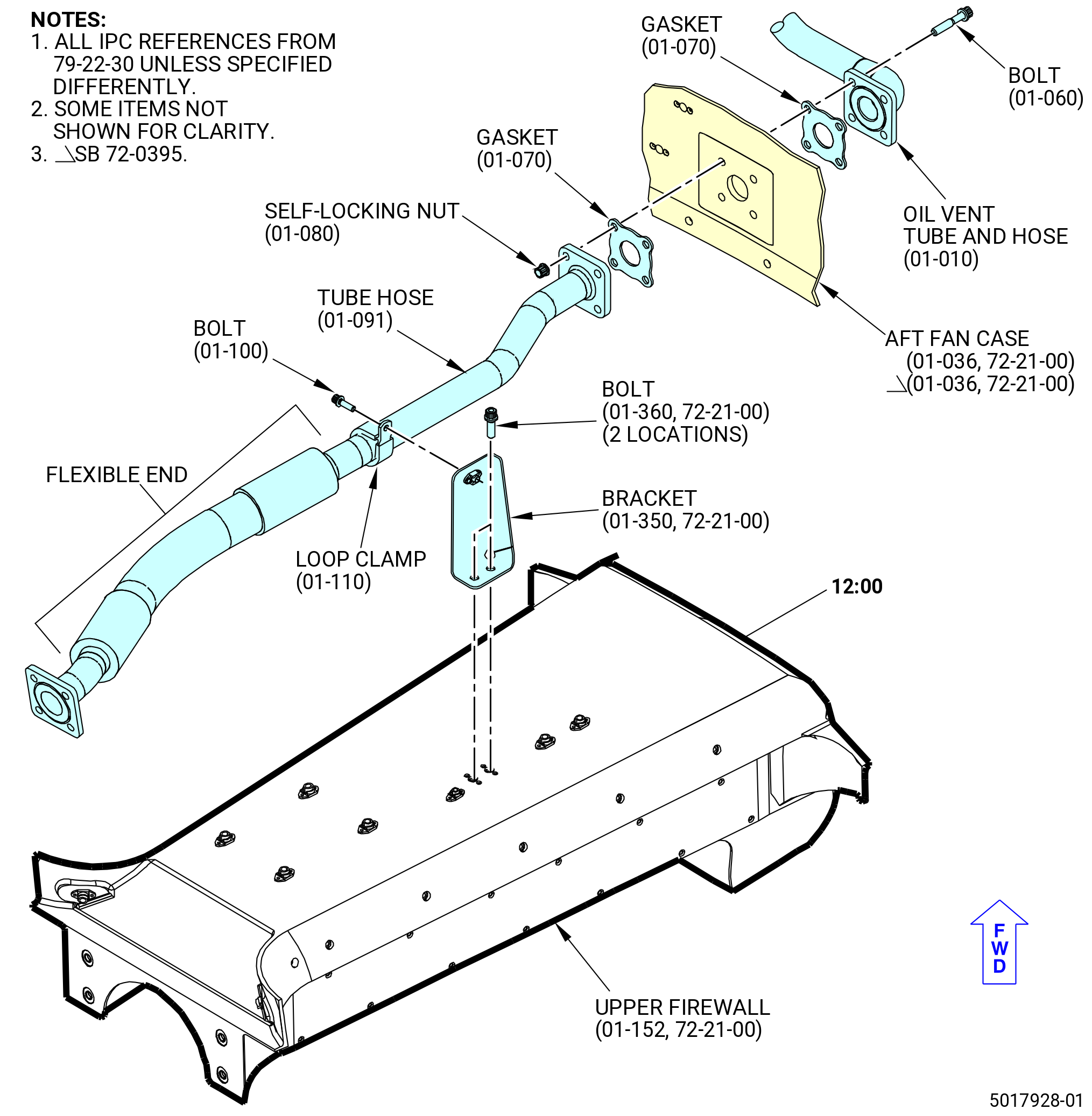
| H. | Install the oil vent hose tube (tube hose) (01-091 , 79-22-30) (SIN 46004), on the upper firewall (01-152) (SIN 84401). Refer to Figure 1009 and do as follows: |
| (1) | Install the oil tube support bracket (bracket) (01-350) (SIN 46010) on the forward face of the upper firewall. Refer to Figure 1009. |
| NOTE: |
|
| (2) | Attach the bracket with bolts (01-360) (SIN 46020). Do not use lubricant on the bolts. |
| (3) | Torque the bolts to 106 to 124 lb in. (12.0 to 14.0 Nm). |
| (4) | Torque the bolts again to 106 to 124 lb in. (12.0 to 14.0 Nm). |
| (5) | Put the cushion loop clamp (loop clamp) (01-110 , 79-22-30) (SIN 46080) on tube hose. |
| NOTE: |
|
| (6) | Attach the loop clamp to the bracket (01-350) (SIN 46010) with a bolt (01-100 , 79-22-30) (SIN 46021). Do not use lubricant on the bolt. |
| (7) | Tighten the bolt enough to hold the tube hose in the loop clamp, but let the tube hose slide inboard and outboard. Do not torque the bolt at this time. |
| (8) | Put the two flange seal gaskets (gasket) (01-070 , 79-22-30) (SIN 46053) before the tube hose (01-091 , 79-22-30) (SIN 46004) is attached to the aft fan case (01-036) (SIN 84100), oil vent tube and hose (01-010 , 79-22-30) (SIN 46000), and brackets (10-100 , 72-00-01) (SIN 46012). |
| (9) | Attach the tube hose (01-091 , 79-22-30) (SIN 46004) to the aft fan case, oil vent tube and hose (01-010 , 79-22-30) (SIN 46000), and brackets. Refer to TASK 72-00-01-430-803 (72-00-01, ASSEMBLY 001). |
| Subtask 72-21-00-440-821 |
| * * * PRE SB 72-0215( Lower Firewall without Bumper ) |
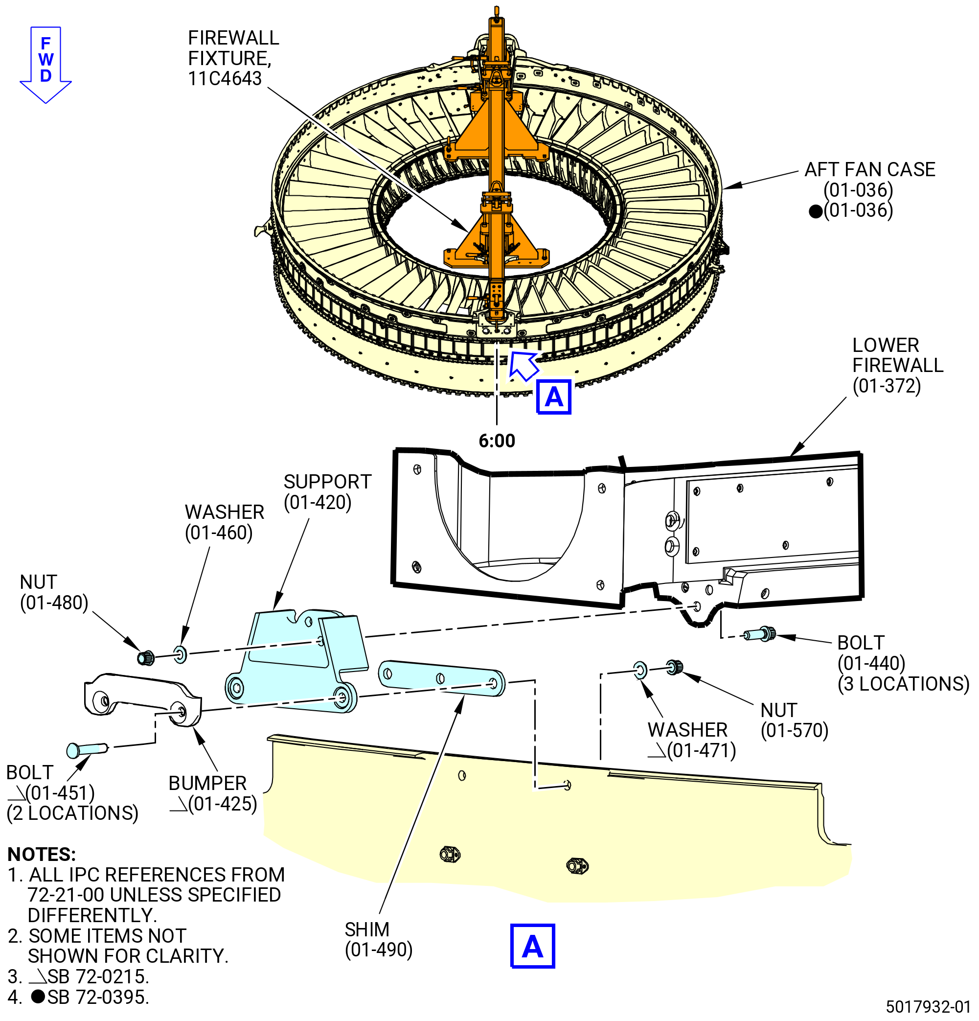
| I. | Install the lower extension support (support) (01-420) (SIN 84508) to the lower firewall (01-372) (SIN 84501) and aft fan case (01-036) (SIN 84100). Refer to Figure 1010 and do as follows: |
| Subtask 72-21-00-640-235 |
| WARNING: |
|
| (1) | Apply C02-058 lubricant to the threads of the bolts (01-440) (SIN 84521) and (01-450) (SIN 84522). |
| Subtask 72-21-00-380-284 |
| (2) | Apply C03-001 primer or C03-100 primer as follows: |
| (a) | To the shank and bearing surface of the bolts (01-440) (SIN 84521) and (01-450) (SIN 84522). |
| (b) | To the bearing surface of the washers (01-460) (SIN 84532) and (01-470) (SIN 84533). |
|
|
| Subtask 72-21-00-440-822 |
| (3) | Align the support (01-420) (SIN 84508) to the three holes on the lower firewall (01-372) (SIN 84501). Refer to Figure 1010. |
| (4) | Install the bolts (01-440) (SIN 84521) from the inboard side of the aft fan case (01-036) (SIN 84100) on the support. |
| (5) | Install the washers (01-460) (SIN 84532) and self-locking nuts (nuts) (01-480) (SIN 84541) on the bolts. Tighten the nuts to prevent movement. Do not torque the nuts at this time. |
| (6) | Align the support to the two holes on the aft fan case. |
| (7) | Install the bolts (01-450) (SIN 84522) to align the support to the aft fan case. |
| (8) | Install shims (01-490) (SIN 84570) between the support and the aft fan case as follows: |
| (a) | Use a taper gauge to measure the gap between the support and aft fan case. The gap must not be more than 0.100 inch (2.54 mm). If the gap is more than 0.100 inch (2.54 mm), determine the cause and correct it before installing the shims. |
| (b) | Peel the shim to the size of the measured gap. The shim must give a +0.000 to -0.003 inch (+0.00 to -0.08 mm) gap between the support and the aft fan case. |
| (c) | Bend the shim to fit the radius of the aft fan case. |
| Subtask 72-21-00-380-285 |
| WARNING: |
|
| (9) | Apply C03-001 primer or C03-100 primer to both sides of the shim (01-490) (SIN 84570). |
| Subtask 72-21-00-440-823 |
| (10) | Loosen the nuts (01-480) (SIN 84541) on the bolts (01-440) (SIN 84521). |
| (11) | Remove the bolts (01-450) (SIN 84522) from the support (01-420) (SIN 84508). |
| (12) | Install the shim (01-490) (SIN 84570) between the support and aft fan case (01-036) (SIN 84100). Make sure the holes are aligned. |
| (13) | Install the bolts and washers (01-470) (SIN 84533) on the support from the outboard side. |
| (14) | Install the self-locking nuts (nuts) (01-570) (SIN 84542) on the bolts on the aft fan case inboard side. |
| (15) | Torque the nuts (01-480) (SIN 84541) and (01-570) (SIN 84542) to 83-97 lb in. (9.4-11.0 N.m). |
| (16) | Torque the nuts (01-480) (SIN 84541) and (01-570) (SIN 84542) again to 83-97 lb in. (9.4-11.0 N.m). |
| * * * END PRE SB 72-0215 |
| Subtask 72-21-00-440-929 |
| * * * SB 72-0215( Lower Firewall with Bumper ) |
| I.A. | Install the support (01-420) (SIN 84508) to the lower firewall (01-372) (SIN 84501) and aft fan case (01-036) (SIN 84100). Refer to Figure 1010 and do as follows: |
| Subtask 72-21-00-640-269 |
| WARNING: |
|
| (1) | Apply C02-058 lubricant to the threads of the bolts (01-440) (SIN 84521). |
| (2) | Apply C02-071 anti-seize to the threads of the bolts (01-451) (SIN 84522). |
| Subtask 72-21-00-380-320 |
| (3) | Apply C03-001 primer or C03-100 primer as follows: |
| (a) | To the shank and bearing surface of the bolts (01-440) (SIN 84521). |
| (b) | To the bearing surface of the washers (01-460) (SIN 84532) and (01-470) (SIN 84533). |
| Subtask 72-21-00-440-930 |
| (4) | Align the support (01-420) (SIN 84508) with the three holes on the lower firewall (01-372) (SIN 84501). Refer to Figure 1010. |
| (5) | Install the bolts (01-440) (SIN 84521) from the inboard side of the aft fan case (01-036) (SIN 84100) on the support. |
| (6) | Install the washers (01-460) (SIN 84532) and nuts (01-480) (SIN 84541) on the bolts. Tighten the nuts to prevent movement. Do not torque the nuts at this time. |
| (7) | Align the support with the two holes on the aft fan case. |
| (8) | Install the bolts (01-451) (SIN 84522) to align the support with the aft fan case. |
| (9) | Install shims (01-490) (SIN 84570) between the support and aft fan case as follows: |
| (a) | Use a taper gauge to measure the gap between the support and aft fan case. The gap must not be more than 0.100 inch (2.54 mm). If the gap is more than 0.100 inch (2.54 mm), find the cause and correct it before the shims are installed. |
| (b) | Peel the shim to the size of the measured gap. The shim must give a plus 0.000 to minus 0.003 inch (plus 0.00 to minus 0.08 mm) gap between the support and aft fan case. |
| (c) | Bend the shim to fit the radius of the aft fan case. |
| Subtask 72-21-00-380-321 |
| WARNING: |
|
| (10) | Apply C03-001 primer or C03-100 primer to the two sides of the shim (01-490) (SIN 84570). |
| Subtask 72-21-00-440-931 |
| (11) | Loosen the nuts (01-480) (SIN 84541) on the bolts (01-440) (SIN 84521). |
| (12) | Remove the bolts (01-451) (SIN 84522) from the support (01-420) (SIN 84508). |
| (13) | Install the shim (01-490) (SIN 84570) between the support and aft fan case (01-036) (SIN 84100). Make sure the holes are aligned. |
| (14) | Install the bumper (01-425) (SIN 84518), bolts (01-451) (SIN 84522), and washers (01-471) (SIN 84533) on the support from the outboard side. |
| (15) | Install the nuts (01-570) (SIN 84542) on the bolts on the aft fan case inboard side. |
| (16) | Torque the nuts (01-480) (SIN 84541) and (01-570) (SIN 84542) to 83 to 97 lb in. (9.4 to 11.0 Nm). |
| (17) | Torque the nuts (01-480) (SIN 84541) and (01-570) (SIN 84542) again to 83 to 97 lb in. (9.4 to 11.0 Nm). |
| * * * END SB 72-0215 |
| Subtask 72-21-00-440-824 |
| J. | Install the surface cooler fairing (fairing) (01-530) (SIN 83506) on the aft fan case (01-036) (SIN 84100) and lower OGV fan pylon (OGV 25) (11-300) (SIN 8400K). Refer to Figure 1011 and do as follows: |
| WARNING: |
|
| (1) | Apply C03-001 primer or C03-100 primer to the shank and bearing surface of two screws (01-560) (SIN 83523). |
| (2) | Apply C02-058 lubricant to the threads of the screws (01-560) (SIN 83523). |
| (3) | Install the fairing to the aft fan case at the 6:00 o'clock position with the screws (01-560) (SIN 83523). |
| (4) | Torque the screws (01-560) (SIN 83523) to 83 to 97 lb in. (9.4 to 11.0 Nm). |
| Subtask 72-21-00-440-825 |
| K. | Install the lower right cowl seal (01-402) (SIN 84151) and lower left cowl seal (01-412) (SIN 84152) on the aft fan case (01-036) (SIN 84100). Refer to Figure 1011 and do as follows: |
| Subtask 72-21-00-110-078 |
| WARNING: |
|
| (1) | Clean the mating surfaces and adjacent areas of the aft fan case (01-036) (SIN 84100) with C04-035 isopropyl alcohol or equivalent, where the lower right cowl seal (01-402) (SIN 84151) and lower left cowl seal (01-412) (SIN 84152) will be installed. |
| (2) | Wipe off the excess of C04-035 isopropyl alcohol or equivalent, with a clean C10-182 cloth. |
| (3) | Let the area to dry for 5 minutes. |
| Subtask 72-21-00-440-826 |
| (4) | Attach the lower right cowl seal (01-402) (SIN 84151) and lower left cowl seal (01-412) (SIN 84152) to the aft fan case (01-036) (SIN 84100) as follows: |
| WARNING: |
|
| (a) | Apply C01-159 RTV primer to the aft fan case, thrust channel (01-061) (SIN 84116), and support (01-420) (SIN 84508) in the areas where the cowl door seal will make contact. |
| (b) | Apply C01-122 RTV 157 to the mating surfaces of the aft fan case. Use a tool to apply an adhesive layer of approximately 0.020 inch (0.51 mm) in thickness. |
| (c) | Put the lower right cowl seal (01-402) (SIN 84151) and the lower left cowl seal (01-412) (SIN 84152) on the aft fan case. |
| (d) | Apply C10-021 tape to hold the lower right cowl seal (01-402) (SIN 84151) and lower left cowl seal (01-412) (SIN 84152) tightly in place. |
| (e) | Let the adhesive cure for one hour. |
| (f) | Remove the C10-021 tape. |
| Subtask 72-21-00-440-827 |
| L. | Install the OGV upper right extension panel (upper right extension panel) (01-160) (SIN 84402) and OGV upper left extension panel (upper left extension panel) (01-170) (SIN 84403) on the upper firewall (01-152) (SIN 84401). Refer to Figure 1012 and do as follows: |
| (1) | Make sure all accessible components are installed before the installation of the panels. Refer to Subtask 72-21-00-440-813 (paragraph 3.F.) thru Subtask 72-21-00-440-826 (paragraph 3.K.(4)). |
| Subtask 72-21-00-640-236 |
| WARNING: |
|
| (2) | Apply C02-058 lubricant to the threads of the Torx recess bolts (bolts) (01-220) (SIN 84420). |
| Subtask 72-21-00-440-828 |
| (3) | Install the upper right extension panel (01-160) (SIN 84402) and the upper left extension panel (01-170) (SIN 84403) as follows: |
| (a) | Align the upper right extension panel (01-160) (SIN 84402) and the upper left extension panel (01-170) (SIN 84403) holes with the upper firewall (01-152) (SIN 84401). |
| (b) | Attach the upper right extension panel (01-160) (SIN 84402) and the upper left extension panel (01-170) (SIN 84403) with the bolts (01-220) (SIN 84420) at the 20 locations. |
| (4) | Torque the bolts to 83-97 lb in. (9.4-11.0 N.m). |
| (5) | Torque the bolts again to 83-97 lb in. (9.4-11.0 N.m). |
| Subtask 72-21-00-440-829 |
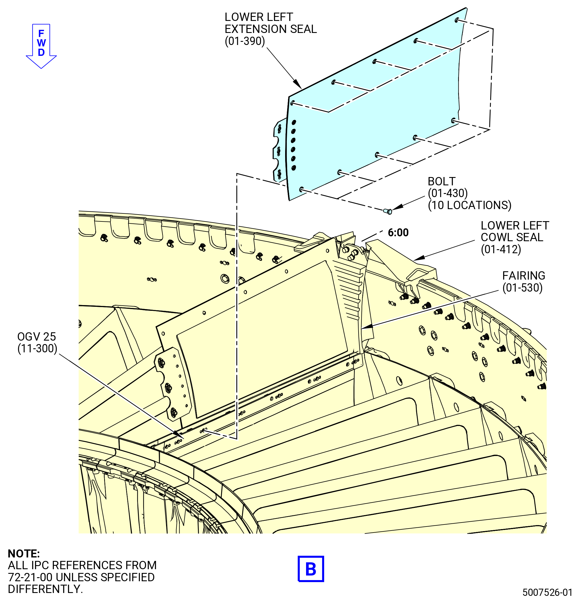
| M. | Install the OGV lower right extension panel (lower right extension panel) (01-380) (SIN 84502) and OGV lower left extension panel (lower left extension panel) (01-390) (84503) on the aft fan case (01-036) (SIN 84100) and lower OGV fan pylon (OGV 25) (11-300) (SIN 8400K). Refer to Figure 1013 and do as follows: |
| (1) | Make sure that all accessible components are installed before the installation of the panels. Refer to Subtask 72-21-00-440-813 (paragraph 3.F.) thru Subtask 72-21-00-440-826 (paragraph 3.K.(4)). |
| Subtask 72-21-00-640-237 |
| WARNING: |
|
| (2) | Apply C02-058 lubricant to the threads of the bolts (01-430) (SIN 84520). |
| Subtask 72-21-00-440-830 |
| (3) | Install the lower right extension panel (01-380) (SIN 84502) and lower left extension panel (01-390) (SIN 84503) as follows: |
| (a) | Align the lower right extension panel and the lower left extension panel holes with the OGV 25 (11-300) (SIN 8400K). |
| (b) | Attach the lower right extension panel and the lower left extension panel with the Torx recess bolts (bolts) (01-430) (SIN 84520) at the 20 locations. |
| (c) | Torque the bolts to 83 to 97 lb in. (9.4 to 11.0 Nm). |
| (d) | Torque the bolts again to 83 to 97 lb in. (9.4 to 11.0 Nm). |
| Subtask 72-21-00-380-286 |
| WARNING: |
|
| (4) | Apply C01-159 RTV primer where the lower right extension panel (01-380) (SIN 84502) and lower left extension panel (01-390) (SIN 84503) touch the fairing (01-530) (SIN 83506), lower left cowl seal (01-412) (SIN 84152), and lower right cowl seal (01-402) (SIN 84151). |
| (5) | Apply C01-176 RTV 133 where the lower right extension panel (01-380) (SIN 84502) and lower left extension panel (01-390) (SIN 84503) touch the lower left cowl seal (01-412) (SIN 84152) and lower right cowl seal (01-402) (SIN 84151). |
| Subtask 72-21-00-440-917 |
| N. | Remove the 11C4643 firewall fixture from the aft fan case (01-036) (SIN 84100). Refer to Figure 1007 and do as follows: |
| (1) | Prepare the upper end of the 11C4643 firewall fixture to remove as follows: |
| (a) | Loosen the knurled knob (item 43) to release the upper bar hook (item 32) that secures and supports the internal top surface of upper firewall. |
| (b) | Disengage the two horizontal spanners (item 39) at the sides of the upper stopper bracket (item 7). |
| (c) | Disengage the toggle clamps (item 31) that secure the side surface of the upper firewall. |
| (d) | Manually take the bar handle (item 26) to bring up the locating round and diamond bars (items 27 and 28) until these are attached by the clips (item 30) with the headless straight pins (item 49). |
| (e) | Manually loosen the bar handle (item 36) that is attached to the adjustment rod (item 29) until the upper stopper bracket (item 7) can be moved manually to the left to prevent damage to the engine hardware when disengaging the horizontal spanner (item 39) that attaches the bottom surface of the upper firewall. |
| (f) | Manually tighten again the bar handle (item 36) to maintain the position of the upper stopper bracket (item 7) in order to remove the fixture from the aft fan case. |
| (2) | Prepare the lower end of the 11C4643 firewall fixture to remove as follows: |
| (a) | Loosen the knurled knob (item 43) to release the lower bar hook (item 22) that secures and supports the lower firewall from its bottom surface. |
| (b) | Disengage the two vertical hold down clamps (item 38) that secure the side surface of the lower firewall. |
| (c) | Manually take the bar handle (item 26) to bring up the locating round and diamond bars (items 27 and 28) until these are attached by the clips (item 30) with the headless straight pins (item 49). |
| (d) | Disengage the two horizontal spanners (item 39) at the sides of the lower stopper bracket (item 6). |
| (e) | Manually loosen the bar handle (item 36) that attach the adjustment rod (item 29) until the lower stopper bracket (item 6) can be moved manually to the right to prevent damage to the engine hardware when disengaging the horizontal spanner (item 39) that attaches the bottom surface of the lower firewall. |
| (f) | Manually tighten again the bar handle (item 36) to maintain the position of the lower stopper bracket (item 6) in order to remove the fixture from the aft fan case. |
| (3) | Remove the screws (item 63) and disengage the locking L-pins (item 42) that firmly attach the 11C4643 firewall fixture over the surface of the 11C3237 restrain fixture. |
| (4) | Attach a bridle sling to the hoist rings (item 44) at two locations. |
| WARNING: |
|
| (5) | Lift the 11C4643 firewall fixture from the aft fan case. |
| (6) | Safely store the 11C4643 firewall fixture. |
| Subtask 72-21-00-440-833 |
| O. | Install the 1-48 OGV assembly fairings (OGV fairings) between the OGVs 1-48. Refer to Figure 1014 and do as follows: |
| Subtask 72-21-00-640-238 |
| WARNING: |
|
| (1) | Apply C02-058 lubricant to the threads of the screws (11-200) (SIN 84127) and (11-210) (SIN 84128). |
| Subtask 72-21-00-380-287 |
| (2) | Apply C03-001 primer to the shank of the screws (11-200) (SIN 84127) and (11-210) (SIN 84128). Dip the screw in the primer. Install and torque the screws in less but not more than three hours after you apply the C03-001 primer. |
| Subtask 72-21-00-440-834 |
| (3) | Install the 1-10 OGV fairings between the OGVs 1-11 as follows: |
| (a) | Install the OGV fairing (11-190) (SIN 8410S) between the OGVs 1 and 2 (11-290) (SIN 8400J) and (11-310) (SIN 8400L). |
| (b) | Install the OGV fairing (11-180) (SIN 8410R) between the OGVs 2 and 3 (11-310) (SIN 8400L) and (11-230) (SIN 8400C). |
| (c) | Install the two OGV fairings (11-170) (SIN 8410P) between the OGVs 3 and 5 (11-230) (SIN 8400C). |
| (d) | Install the OGV fairing (11-160) (SIN 8410J) between the OGVs 5 and 6 (11-230) (SIN 8400C) and (11-240) (SIN 8400D). |
| (e) | Install the five OGV fairings (11-130) (SIN 8410F) between the OGVs 6 and 11 (11-240) (SIN 8400D). |
| (f) | Attach the OGV fairings with the screws (11-200) (SIN 84127) in the forward hole of each fairing. |
| (g) | Attach the OGV fairings with the screws (11-210) (SIN 84128) in the aft hole of each fairing. |
| (h) | Tighten the screws (11-200) (SIN 84127) and (11-210) (SIN 84128) to prevent movement. Do not torque the screws at this time. |
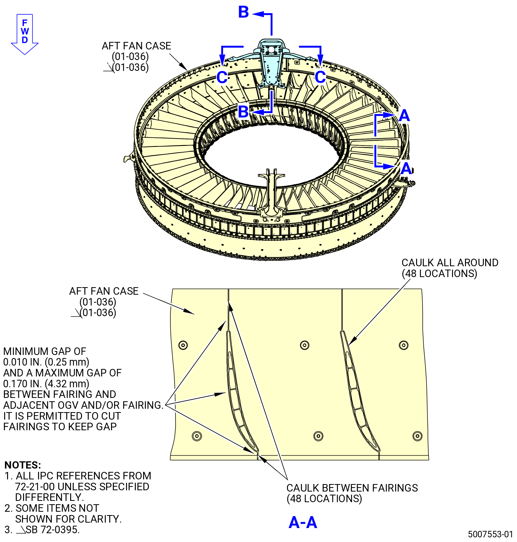
| (i) | Make sure that there is a 0.010-0.170 inch (0.25-4.32 mm) gap between the OGV and the fairing. If necessary, trim the OGV fairing to the correct gap. |
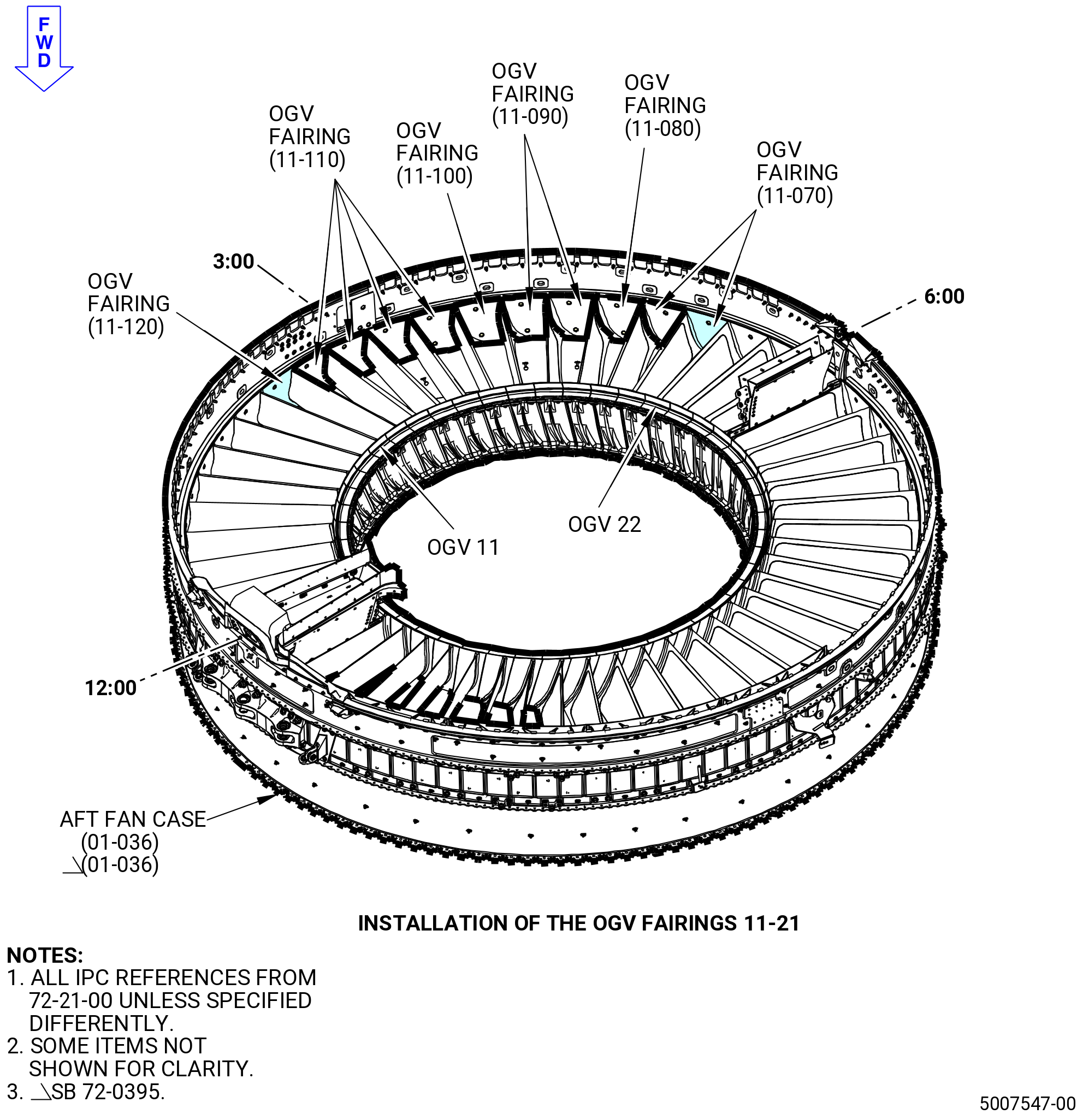
| (4) | Install the fairings 11-21 between the OGVs 11-22 as follows: |
| (a) | Install the OGV fairing (11-120) (SIN 8410E) between the OGVs 11 and 12 (11-240) (SIN 8400D) and (11-250) (SIN 8400E). |
| (b) | Install the four OGV fairings (11-110) (SIN 8410D) between the OGVs 12 and 16 (11-250) (SIN 8400E). |
| (c) | Install the OGV fairing (11-100) (SIN 8410C) between the OGVs 16 and 17 (11-250) (SIN 8400E) and (11-220) (SIN 8400A). |
| (d) | Install two OGV fairings (11-090) (SIN 8410B) between the OGVs 17 and 19 (11-220) (SIN 8400A). |
| (e) | Install the OGV fairing (11-080) (SIN 8410A) between the OGVs 19 and 20 (11-220) (SIN 8400A) and (11-260) (SIN 8400F). |
| (f) | Install two OGV fairings (11-070) (SIN 84109) between the OGVs 20 and 22 (11-260) (SIN 8400F). |
| (g) | Tighten the screws (11-200) (SIN 84127) and (11-210) (SIN 84128) to prevent movement. Do not torque the screws at this time. |
| (h) | Make sure that there is a 0.010-0.170 inch (0.25-4.32 mm) gap between the OGV and the faring. If necessary, cut the OGV fairing to the correct gap. |
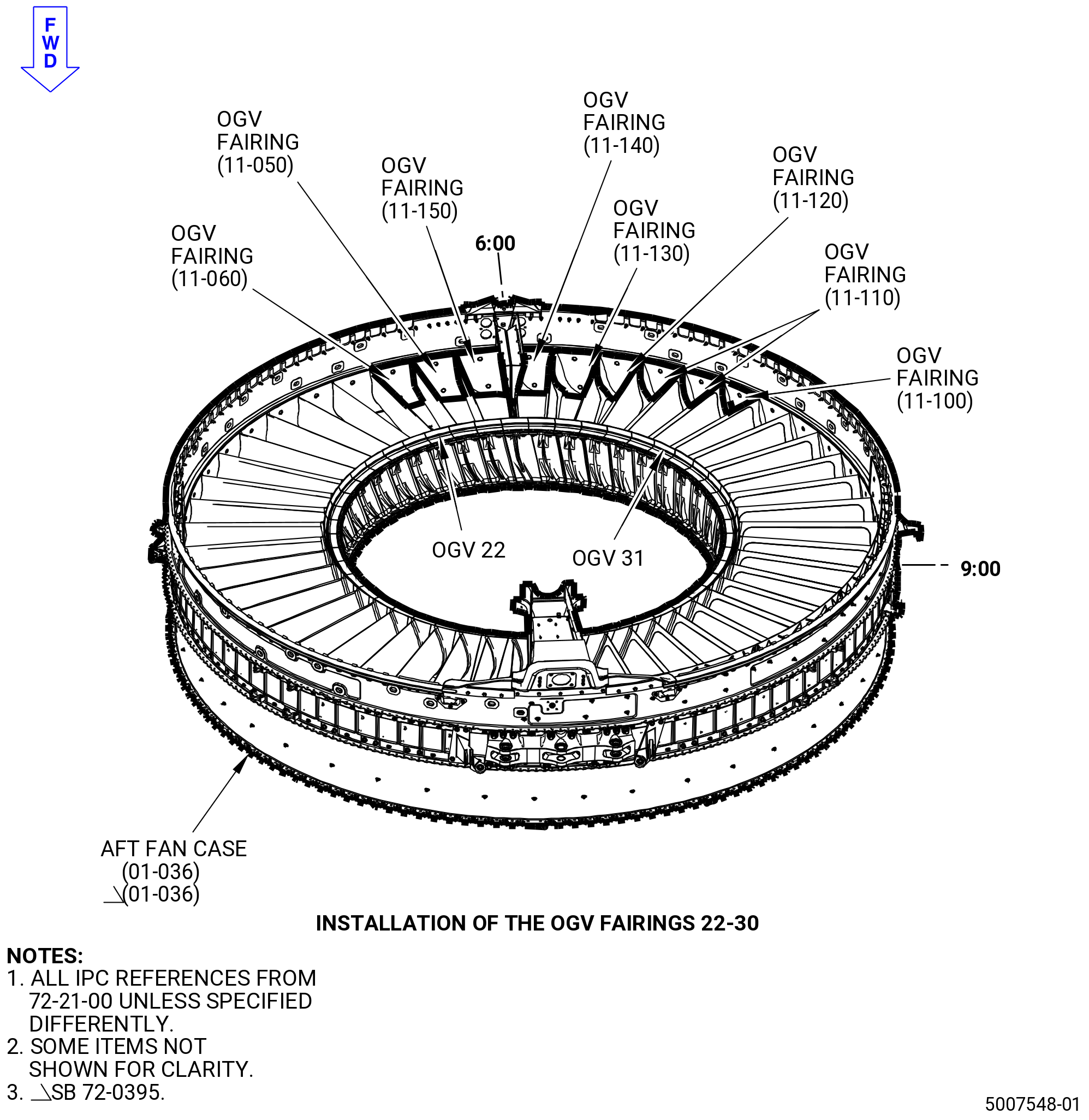
| (5) | Install the fairings 22-30 between the OGVs 22-31 as follows: |
| (a) | Install the OGV fairing (11-060) (SIN 84108) between the OGVs 22 and 23 (11-260) (SIN 8400F) and (11-270) (SIN 8400G). |
| (b) | Install the OGV fairing (11-050) (SIN 84107) between the OGVs 23 and 24 (11-270) (SIN 8400G). |
| (c) | Install the OGV fairing (11-150) (SIN 8410H) between the OGVs 24 and 25 (11-270) (SIN 8400G) and (11-300) (SIN 8400K). |
| (d) | Install the OGV fairing (11-140) (SIN 8410G) between the OGVs 25 and 26 (11-300) (SIN 8400K) and (11-240) (SIN 8400D). |
| (e) | Install the OGV fairing (11-130) (SIN 8410F) between the OGVs 26 and 27 (11-240) (SIN 8400D). |
| (f) | Install the OGV fairing (11-120) (SIN 8410E) between the OGVs 27 and 28 (11-240) (SIN 8400D) and (11-250) (SIN 8400E) . |
| (g) | Install two OGV fairings (11-110) (SIN 8410D) between the OGVs 28 and 30 (11-250) (SIN 8400E). |
| (h) | Install the OGV fairing (11-100) (SIN 8410C) between the OGVs 30 and 31 (11-250) (SIN 8400E) and (11-220) (SIN 8400A). |
| (i) | Attach the fairings with the screws (11-200) (SIN 84127) in the forward hole of each fairing. |
| (j) | Attach the fairings with the screws (11-210) (SIN 84128) in the aft hole of each fairing. |
| (k) | Tighten the screws (11-200) (SIN 84127) and (11-210) (SIN 84128) to prevent movement. Do not torque the screws at this time. |
| (l) | Make sure that there is a 0.010-0.170 inch (0.25-4.32 mm) gap between the OGV and the faring. If necessary, cut the OGV fairing to the correct gap. |
| Subtask 72-21-00-440-835 |
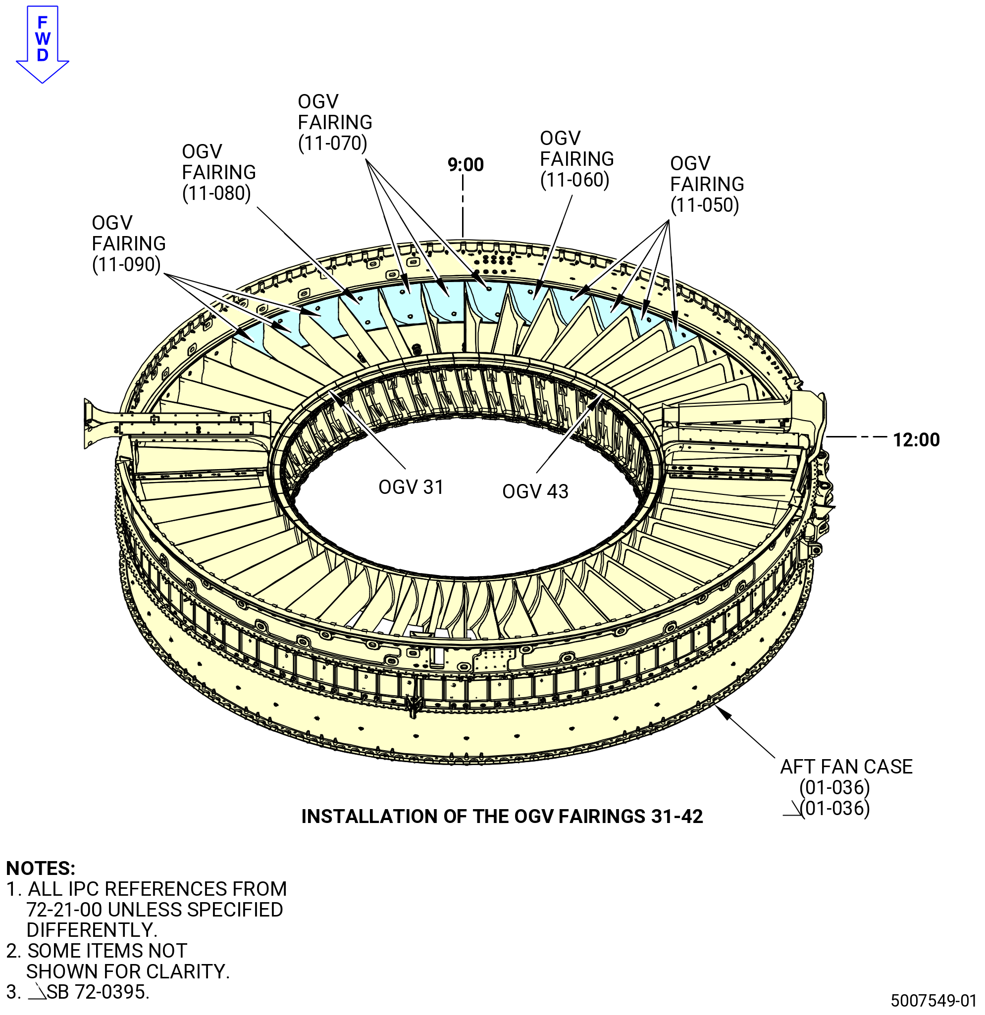
| (6) | Install the fairings 31-42 between the OGVs 31-43 as follows: |
| (a) | Install three OGV fairings (11-090) (SIN 8410B) between the OGVs 31 and 34 (11-220) (SIN 8400A). |
| (b) | Install the OGV fairing (11-080) (SIN 8410A) between the OGVs 34 and 35 (11-220) (SIN 8400A) and (11-260) (SIN 8400F). |
| (c) | Install three OGV fairings (11-070) (SIN 84109) between the OGVs 35 and 38 (11-260) (SIN 8400F). |
| (d) | Install the OGV fairing (11-060) (SIN 84108) between the OGVs 38 and 39 (11-260) (SIN 8400F) and (11-270) (SIN 8400G). |
| (e) | Install four OGV fairings (11-050) (SIN 84107) between the OGVs 39 and 43 (11-270) (SIN 8400G). |
| (f) | Attach the OGV fairings with the screws (11-200) (SIN 84127) in the forward hole of each fairing. |
| (g) | Attach the OGV fairings with the screws (11-210) (SIN 84128) in the aft hole of each fairing. |
| (h) | Tighten the screws (11-200) (SIN 84127) and (11-210) (SIN 84128) to prevent movement. Do not torque the screws at this time. |
| (i) | Make sure that there is a 0.010-0.170 inch (0.25-4.32 mm) gap between the OGV and the OGV faring. If necessary, cut the OGV fairing to the correct gap. |
| (7) | Install the OGV fairings 43-48 between the OGVs 43-1 as follows: |
| (a) | Install the OGV fairing (11-040) (SIN 84106) between the OGVs 43 and 44 (11-270) (SIN 8400G) and (11-280) (SIN 8400H). |
| (b) | Install three OGV fairings (11-030) (SIN 84105) between the OGVs 44 and 47 (11-280) (SIN 8400H). |
| (c) | Install the OGV fairing (11-020) (SIN 84104) between the OGVs 47 and 48 (11-280) (SIN 8400H) and (11-320) (SIN 8400M). |
| (d) | Install the OGV fairing (11-010) (SIN 84103) between the OGVs 48 and 1 (11-320) (SIN 8400M) and (11-290) (SIN 8400J). |
| (e) | Attach the OGV fairings with the screws (11-200) (SIN 84127) in the forward hole of each fairing. |
| (f) | Attach the OGV fairings with the screws (11-210) (SIN 84128) in the aft hole of each fairing. |
| (g) | Tighten the screws (11-200) (SIN 84127) and (11-210) (SIN 84128) to prevent movement. Do not torque the screws at this time. |
| (h) | Make sure that there is a 0.010-0.170 inch (0.25-4.32 mm) gap between the OGV and the OGV faring. If necessary, cut the OGV fairing to the correct gap. |
| (8) | Torque the screws (11-200) (SIN 84127) and (11-210) (SIN 84128) to 83-97 lb in. (9.4-11.0 N.m). |
| (9) | Torque the screws again (11-200) (SIN 84127) and (11-210) (SIN 84128) to 83-97 lb in. (9.4-11.0 N.m). |
| (10) | Make sure there is a 0.010-0.170 inch (0.25-4.32 mm) gap between the OGV and the OGV faring. If necessary, cut the OGV fairing to the correct gap. |
| Subtask 72-21-00-110-079 |
| WARNING: |
|
| (11) | Clean the OGVs 1-48 and the OGV fairings 1-48 with C04-035 isopropyl alcohol or equivalent, within a minimum of 2.00 inches (50.8 mm) on both sides of the area where the C01-176 RTV 133 will be applied. |
| Subtask 72-21-00-380-288 |
| (12) | Apply C01-159 RTV primer to the OGV fairings 1-48 and OGVs 1-48 as follows: |
| (a) | Do some up and down brush strokes to make sure there is a complete primer coverage. |
| (b) | Apply primer to the edges of the OGV fairings 1-48. |
| (c) | Apply primer 0.250 inch (6.35 mm) to the back side of the OGVs. |
| (d) | Apply primer 0.250-0.500 inch (6.35-12.70 mm) in width to each side of the OGV fairing gap surfaces, at the forward and aft ends of the OGVs. |
| (e) | Let the primer to dry for a minimum 15 minutes. |
| Subtask 72-21-00-440-836 |
| WARNING: |
|
| (13) | Apply C01-176 RTV 133 to the OGV fairings 1-48. Refer to Figure 1015 and do as follows: |
| (a) | Make sure that all tools are clean before use. |
| (b) | Apply C01-176 RTV 133 between the OGV and OGV fairing 0.250 inch (6.35 mm) behind the OGV fairing surface. The RTV must be above the OGV fairing surface. |
| (c) | Use a rubber glove to smooth the C01-176 RTV 133 manually. Remove all excess of RTV and make a smooth surface that is flush to the surface of the OGV fairing. The RTV must not extend onto the OGV fairing or the OGV more than the filled gap. |
| (d) | Put C10-021 tape on the aft side of the OGV fairings and the joint between the OGV fairing that is aft of the OGV. Put the tape at approximately 0.500 inch (12.70 mm) on each side of the gap. |
| (e) | Put C10-021 tape on the forward side of the OGV fairings and the joint between the OGV fairing that is forward of the OGV. Put the tape at approximately 0.500 inch (12.70 mm) on each side of the gap. |
| (f) | Apply C01-176 RTV 133 to the joints between the OGV fairings. Use a tool to smooth the RTV. |
| (g) | Make sure that all surfaces are flush, smooth, and equal to the OGVs and the OGV fairings. |
| (14) | Do Subtask 72-21-00-380-288 (paragraph 3.O.(12)) and Subtask 72-21-00-440-836 (paragraph 3.O.(13)) for all the OGVs and the OGV fairings. |
| Subtask 72-21-00-440-837 |
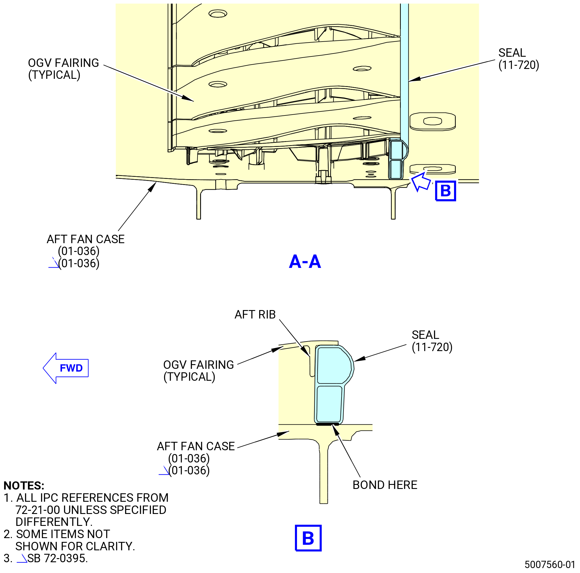
| P. | Install the seal (11-720) (SIN 521J0). Refer to Figure 1016 and do as follows: |
| WARNING: |
|
| (1) | Clean the aft fan case and the OGV fairings 1-48 with C04-035 isopropyl alcohol or equivalent at the area where the C01-208 silicone rubber adhesive will be applied. |
| (2) | Bond the seal (11-720) (SIN 521J0) to the aft fan case (01-036) (SIN 84100) with C01-208 silicone rubber adhesive to sit flush against the aft ribs of the OGV fairings 1-48. |
| NOTE: |
|
| Subtask 72-21-00-440-925 |
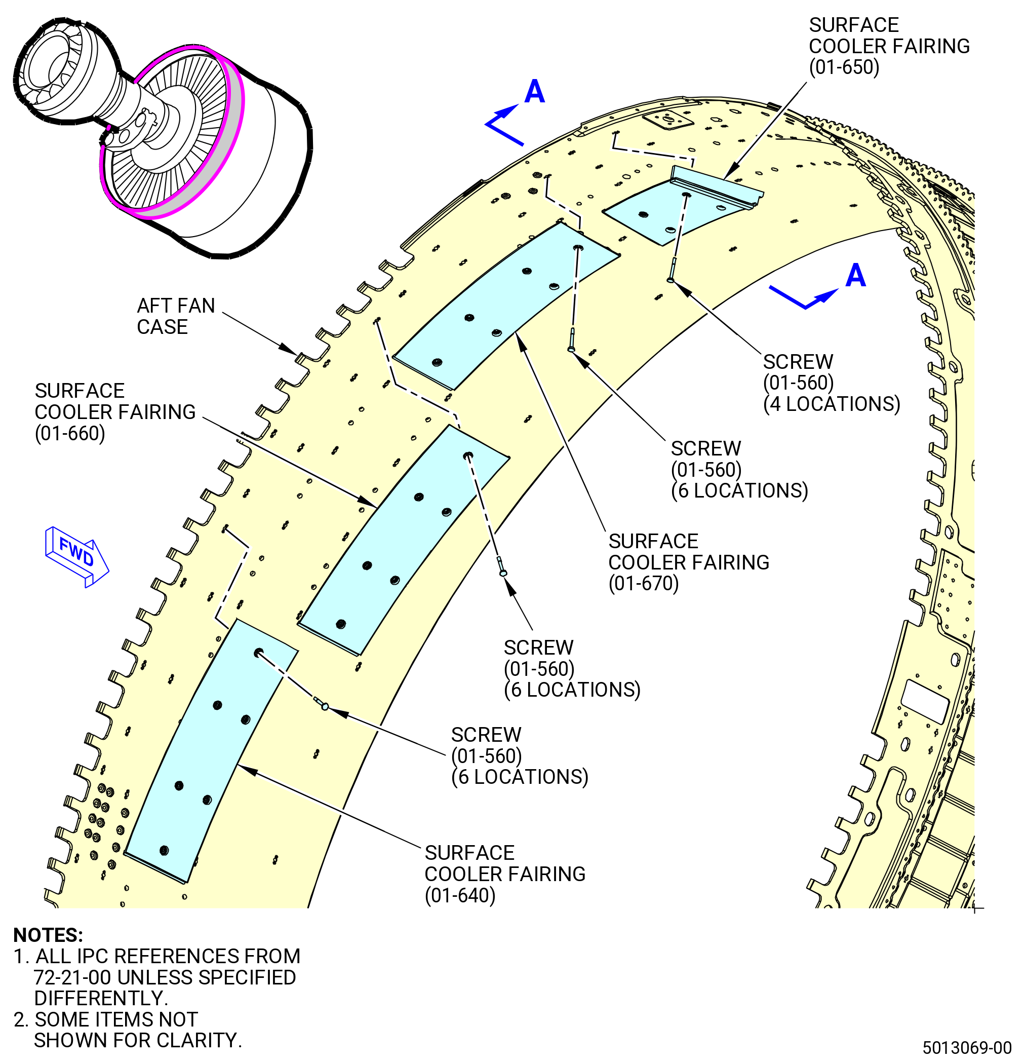
| Q. | Install the surface cooler fairings (01-640) (SIN 83508), (01-650) (SIN 83509), (01-660) (SIN 8350A), and (01-670) (SIN 8350B). Refer to Figure 1017 and do as follows: |
| (1) | Install the surface cooler fairing (01-650) (SIN 83509) as follows: |
| WARNING: |
|
| (a) | Apply C02-058 lubricant to the threads of the screws (01-560) (SIN 83523). |
| (b) | Put the surface cooler fairing (01-650) (SIN 83509) in position on the aft fan case and loosely install the four screws (01-560) (SIN 83523). |
| (c) | Hand tighten the screws (01-560) (SIN 83523) to prevent movement. |
| (d) | Torque the screws (01-560) (SIN 83523) as follows: |
| 1 | Torque the two upper screws (01-560) (SIN 83523) to 83-97 lb in. (9.4-11.0 N.m). |
| 2 | Torque the two lower screws (01-560) (SIN 83523) to 83-97 lb in. (9.4-11.0 N.m). |
| 3 | Torque the screws (01-560) (SIN 83523) again, in the same sequence, to 83-97 lb in. (9.4-11.0 N.m). |
| 4 | After 15 minutes, torque the screws (01-560) (SIN 83523) again, in the same sequence, to 83-97 lb in. (9.4-11.0 N.m). |
| (2) | Install the surface cooler fairing (01-670) (SIN 8350B) as follows: |
| WARNING: |
|
| (a) | Apply C02-058 lubricant to the threads of the screws (01-560) (SIN 83523). |
| (b) | Put the surface cooler fairing (01-670) (SIN 8350B) in position on the aft fan case and loosely install the six screws (01-560) (SIN 83523). |
| (c) | Hand tighten the screws (01-560) (SIN 83523) to prevent movement. |
| (d) | Make sure there is a minimum 0.010 inch (0.25 mm) gap between the surface cooler fairing (01-670) (SIN 8350B) and the adjacent panels. |
| (e) | Torque the screws (01-560) (SIN 83523) as follows: |
| 1 | Torque the four screws (01-560) (SIN 83523) in the middle of the surface cooler fairing (01-670) (SIN 8350B) to 83-97 lb in. (9.4-11.0 N.m). |
| 2 | Torque the upper screw (01-560) (SIN 83523) to 83-97 lb in. (9.4-11.0 N.m). |
| 3 | Torque the lower screw (01-560) (SIN 83523) to 83-97 lb in. (9.4-11.0 N.m). |
| 4 | Torque the screws (01-560) (SIN 83523) again, in the same sequence, to 83-97 lb in. (9.4-11.0 N.m). |
| 5 | After 15 minutes, torque the screws (01-560) (SIN 83523) again, in the same sequence, to 83-97 lb in. (9.4-11.0 N.m). |
| (3) | Install the surface cooler fairing (01-660) (SIN 8350A) as follows: |
| WARNING: |
|
| (a) | Apply C02-058 lubricant to the threads of the screws (01-560) (SIN 83523). |
| (b) | Put the surface cooler fairing (01-660) (SIN 8350A) in position on the aft fan case and loosely install the six screws (01-560) (SIN 83523). |
| (c) | Hand tighten the screws (01-560) (SIN 83523) to prevent movement. |
| (d) | Make sure there is a minimum 0.010 inch (0.25 mm) gap between the surface cooler fairing (01-660) (SIN 8350A) and the adjacent panels. |
| (e) | Torque the screws (01-560) (SIN 83523) as follows: |
| 1 | Torque the four screws (01-560) (SIN 83523) in the middle of the surface cooler fairing (01-660) (SIN 8350A) to 83-97 lb in. (9.4-11.0 N.m). |
| 2 | Torque the upper screw (01-560) (SIN 83523) to 83-97 lb in. (9.4-11.0 N.m). |
| 3 | Torque the lower screw (01-560) (SIN 83523) to 83-97 lb in. (9.4-11.0 N.m). |
| 4 | Torque the screws (01-560) (SIN 83523) again, in the same sequence, to 83-97 lb in. (9.4-11.0 N.m). |
| 5 | After 15 minutes, torque the screws (01-560) (SIN 83523) again, in the same sequence, to 83-97 lb in. (9.4-11.0 N.m). |
| (4) | Install the surface cooler fairing (01-640) (SIN 83508) as follows: |
| WARNING: |
|
| (a) | Apply C02-058 lubricant to the threads of the screws (01-560) (SIN 83523). |
| (b) | Put the surface cooler fairing (01-640) (SIN 83508) in position on the aft fan case and loosely install the six screws (01-560) (SIN 83523). |
| (c) | Hand tighten the screws (01-560) (SIN 83523) to prevent movement. |
| (d) | Make sure there is a minimum 0.010 inch (0.25 mm) gap between the surface cooler fairing (01-640) (SIN 83508) and the adjacent panels. |
| (e) | Torque the screws (01-560) (SIN 83523) as follows: |
| 1 | Torque the four screws (01-560) (SIN 83523) in the middle of the surface cooler fairing (01-640) (SIN 83508) to 83-97 lb in. (9.4-11.0 N.m). |
| 2 | Torque the upper screw (01-560) (SIN 83523) to 83-97 lb in. (9.4-11.0 N.m). |
| 3 | Torque the lower screw (01-560) (SIN 83523) to 83-97 lb in. (9.4-11.0 N.m). |
| 4 | Torque the screws (01-560) (SIN 83523) again, in the same sequence, to 83-97 lb in. (9.4-11.0 N.m). |
| 5 | After 15 minutes, torque the screws (01-560) (SIN 83523) again, in the same sequence, to 83-97 lb in. (9.4-11.0 N.m). |
| Subtask 72-21-00-440-926 |
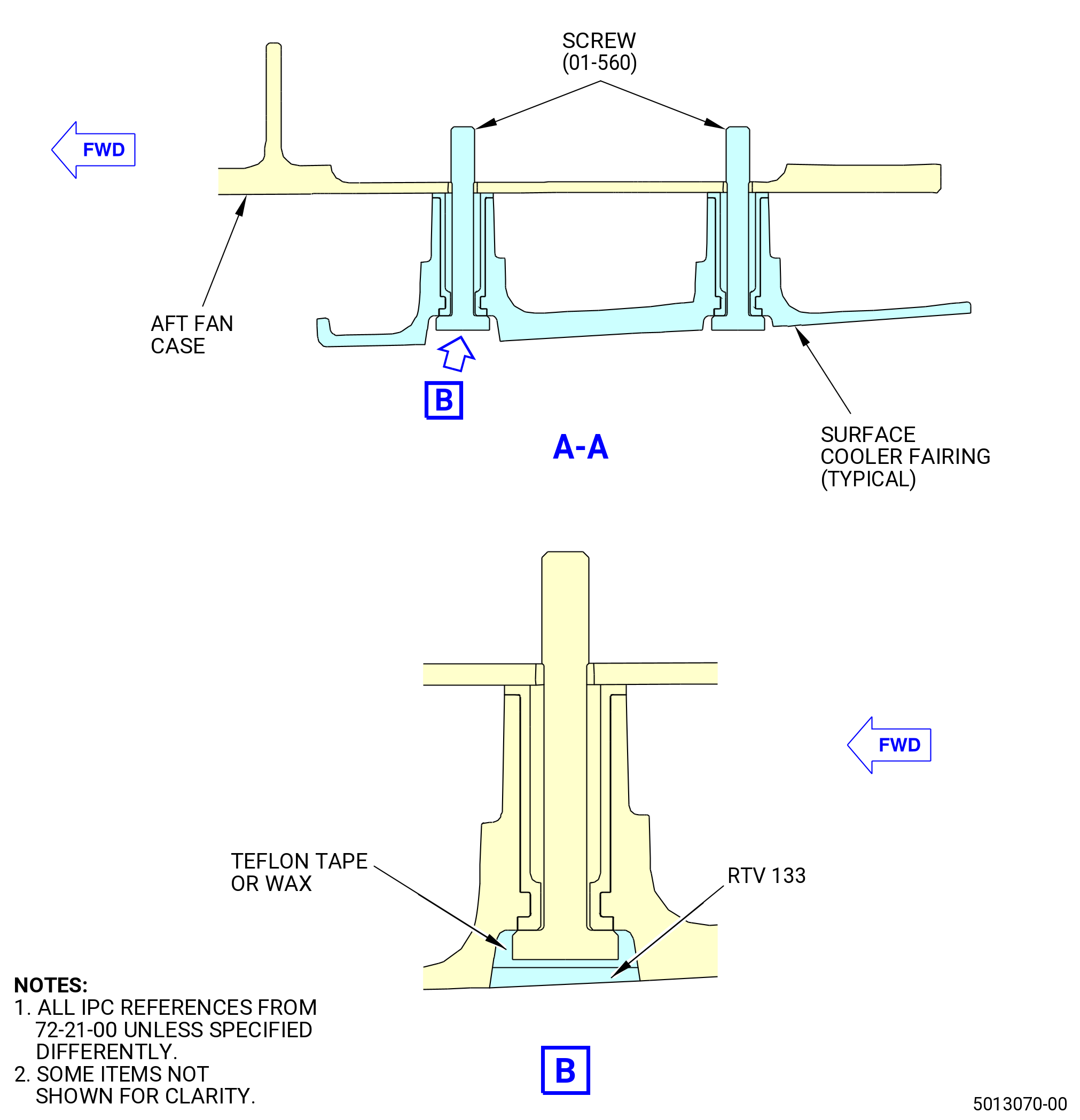
| R. | Apply C01-176 RTV 133 to the forward row of the screws (01-560) (SIN 83523) that attach the surface cooler fairings. Refer to Figure 1017 and do as follows: |
| (1) | Apply C10-109 wax or C10-040 Teflon tape to drive recesses of the screws. |
| (2) | Apply C01-176 RTV 133 to heads of the screws (01-560) (SIN 83523). |
| (3) | Use a spatula, wooden depressor, or a rubber glove, to manually smooth the C01-176 RTV 133. |
| (4) | Remove all excess of C01-176 RTV 133 and make a smooth surface that is flush to the surface. |
| (5) | Make sure that the C01-176 RTV 133 does not extend onto the surface cooler fairings more than the filled gap. |
| (6) | Make sure the C01-176 RTV 133 is smooth, flush, and equal after application. |
| (7) | Let the C01-176 RTV 133 dry for a minimum of 2 hours. |
| Subtask 72-21-00-440-927 |
| S. | Apply C01-176 RTV 133 to the aft row of screws (11-210) (SIN 84128) that attach the OGV fairings. Refer to Figure 1014 and do as follows: |
| NOTE: |
|
| (1) | Apply C10-109 wax or C10-040 Teflon tape to drive recesses of the bolts. |
| (2) | Apply C01-176 RTV 133 to heads of the screws (11-210) (SIN 84128). |
| (3) | Use a spatula, wooden depressor, or a rubber glove, to manually smooth the C01-176 RTV 133. |
| (4) | Remove all excess of C01-176 RTV 133 and make a smooth surface that is flush to the surface. |
| (5) | Make sure that the C01-176 RTV 133 does not extend onto the OGV fairings more than the filled gap. |
| (6) | Make sure the C01-176 RTV 133 is smooth, flush, and equal after application. |
| (7) | Let the C01-176 RTV 133 dry for a minimum of 2 hours. |
| Subtask 72-21-00-440-838 |
| * * * PRE SB 72-0217( Titanium Upper Alignment Guides ) |
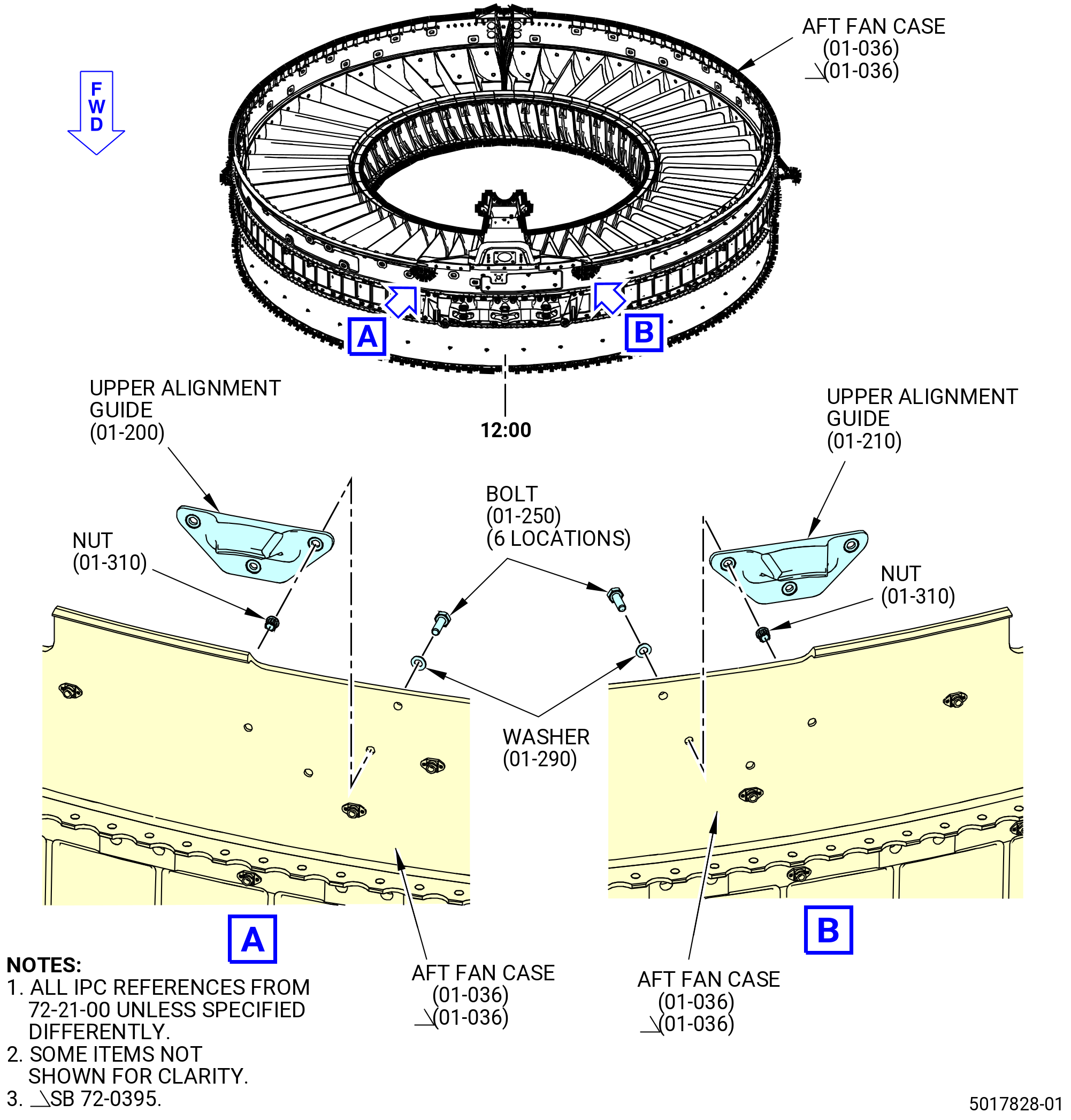
| T. | Install the left/right upper alignment guides (01-200) (SIN 84408) and (01-210) (SIN 84409) on the aft fan case (01-036) (SIN 84100). Refer to Figure 1018 and do as follows: |
| Subtask 72-21-00-640-239 |
| WARNING: |
|
| (1) | Apply C02-058 lubricant to the threads of the machine bolts (bolts) (01-250) (SIN 8442C). |
| Subtask 72-21-00-380-289 |
| (2) | Apply C03-001 primer or C03-100 primer to the shank of the bolts (01-250) (SIN 8442C) as follows: |
| (a) | Soak the bolts in primer for a few seconds. |
| (b) | Torque all hardware in less but not more than 3 hours after applying the primer. |
| (c) | Apply C03-001 primer or C03-100 primer to the inside diameter of the bolthole in the aft fan case (01-036) (SIN 84100). |
| (d) | Apply C03-001 primer or C03-100 primer to the bearing surface of the washer (01-290) (SIN 84436) and the left/right upper alignment guides (01-200) (SIN 84408) and (01-210) (SIN 84409). |
| Subtask 72-21-00-440-839 |
| (3) | Attach the left/right upper alignment guides (01-200) (SIN 84408) and (01-210) (SIN 84409) to the aft fan case (01-036) (SIN 84100) with the bolts (01-250) (SIN 8442C) and washers (01-290) (SIN 84436) from the inboard side of the aft fan case. |
| (4) | Install the self-locking nuts (nuts) (01-310) (SIN 84443) on the bolts. |
| (5) | Torque the nuts to 83 to 97 lb in. (9.4 to 11.0 Nm). |
| * * * END PRE SB 72-0217 |
| Subtask 72-21-00-440-937 |
| * * * SB 72-0217( Aluminum Upper Alignment Guides ) |
| T.A. | Install the left/right upper alignment guides (01-201) (SIN 84408) and (01-211) (SIN 84409) on the aft fan case (01-036) (SIN 84100). Refer to Figure 1018 and do as follows: |
| Subtask 72-21-00-640-272 |
| WARNING: |
|
| (1) | Apply C02-058 lubricant to the threads of the machine bolts (bolts) (01-250) (SIN 8442C). |
| Subtask 72-21-00-380-325 |
| WARNING: |
|
| (2) | Apply C03-001 primer or C03-100 primer to the shank of the bolts (01-250) (SIN 8442C) as follows: |
| (a) | Soak the bolts in primer for a few seconds. |
| (b) | Torque all hardware in less but not more than 3 hours after applying the primer. |
| (c) | Apply C03-001 primer or C03-100 primer to the inside diameter of the bolthole in the aft fan case (01-036) (SIN 84100). |
| (d) | Apply C03-001 primer or C03-100 primer to the bearing surface of the washer (01-291) (SIN 84436) and to the left/right upper alignment guides (01-201) (SIN 84408) and (01-211) (SIN 84409). |
| Subtask 72-21-00-440-938 |
| (3) | Attach the left/right upper alignment guides (01-201) (SIN 84408) and (01-211) (SIN 84409) to the aft fan case (01-036) (SIN 84100) with the bolts (01-250) (SIN 8442C) and washers (01-291) (SIN 84436) from the inboard side of the aft fan case. |
| (4) | Install the washers (01-291) (SIN 84436) and self-locking nuts (nuts) (01-310) (SIN 84443) on the bolts. |
| (5) | Torque the nuts to 83 to 97 lb in. (9.4 to 11.0 Nm). |
| * * * END SB 72-0217 |
|
|
| Subtask 72-21-00-440-840 |
| U. | Install the thrust reverser seal (seal) (01-080) (SIN 84150) in the V-groove of the thrust channels (01-061) (SIN 84116) and (01-071) (SIN 84118), and seal retainers (01-182) (SIN 84404) and (01-341) (SIN 84504) on the aft fan case (01-036) (SIN 84100). Refer to Figure 1019 and do as follows: |
| NOTE: |
|
| Subtask 72-21-00-110-080 |
| (1) | Clean the V-grooves in the seal retainers (01-182) (SIN 84404) and (01-341) (SIN 84504), and thrust channels (01-061) (SIN 84116) and (01-071) (84118) as follows: |
| (a) | Use compressed air to remove loose dirt from the V-groove. |
| WARNING: |
|
| (b) | Clean the V-groove with a clean C10-182 cloth, moist with C04-035 isopropyl alcohol or equivalent. Let the isopropyl alcohol or equivalent dry for a minimum of 5 minutes. |
| Subtask 72-21-00-380-290 |
| (2) | Apply C01-159 RTV primer over the entire length of the V-groove in the thrust channels (01-061) (SIN 84116) and (01-071) (SIN 84118). |
| (3) | Apply C01-159 RTV primer to the V-groove of the seal retainers (01-182) (SIN 84404) and (01-341) (SIN 84504). |
| (4) | Make sure to apply the primer up to the scribe lines. |
| Subtask 72-21-00-440-841 |
| (5) | Apply C01-178 RTV in the V-grooves. Use a spatula approximately 0.40 inch (10.2 mm) in width to apply a maximum 0.050 inch (1.27 mm) layer of adhesive in the V-groove. |
| (6) | Install the seal (01-080) (SIN 84150) in the V-grooves. It is recommended to put the seal in the V-groove in less but not more than 2 minutes after applying the C01-178 RTV. Use two people to apply C01-178 RTV and install the seal. |
| Subtask 72-21-00-440-842 |
| (7) | Cut the seal (01-080) (SIN 84150) 1.50-1.90 inches (38.1-48.3 mm) from the edge of the seal retainers (01-182) (SIN 84404) and (01-341) (SIN 84504). Refer to Figure 1019. |
| (8) | Cut the seal ± 0.100 inch (2.54 mm) from the edge of the thrust channel (01-071) (SIN 84118). |
| (9) | Hold the seal in the V-groove with C10-067 platers tape for a minimum of 1 hour to let the C01-178 RTV dry. |
| Subtask 72-21-00-440-843 |
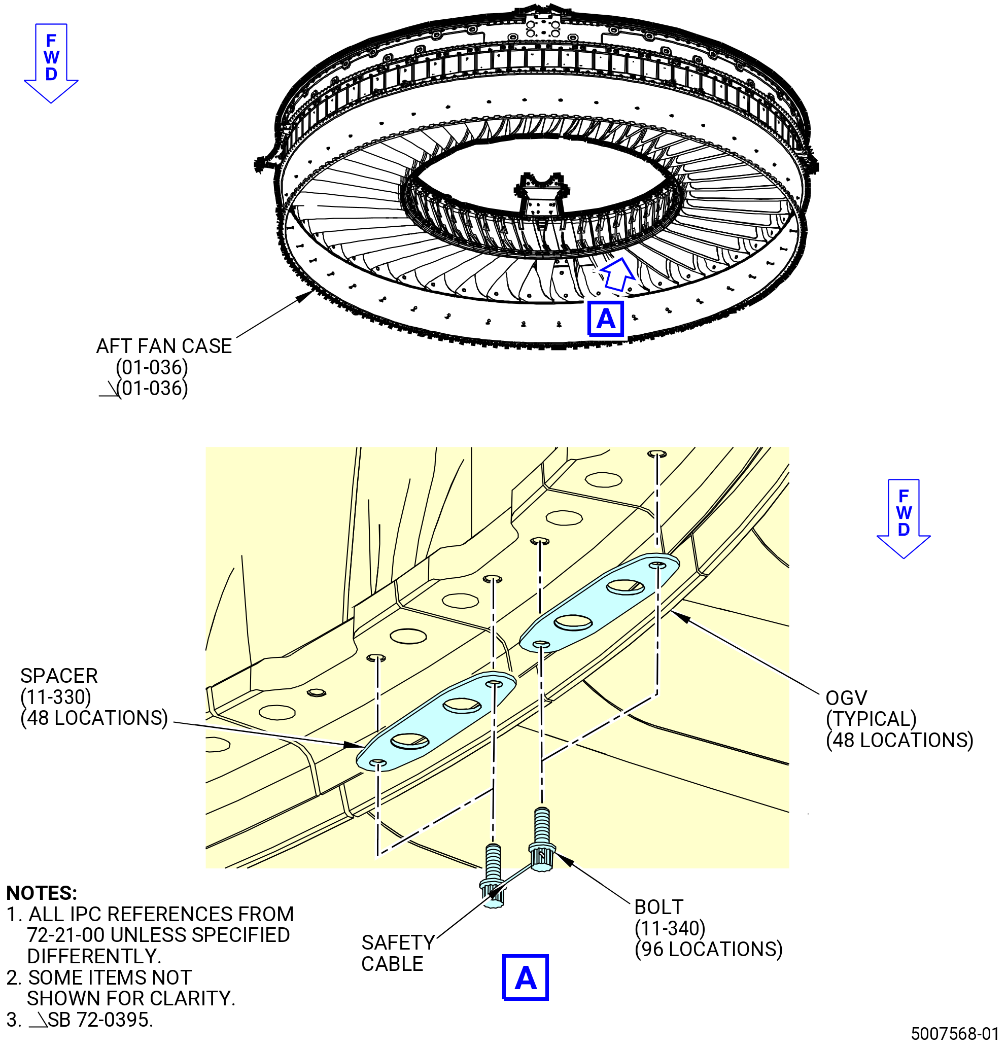
| V. | Install the spacer (11-330) (SIN 8417B) on the OGVs 1-48. Refer to Figure 1020 and do as follows: |
| Subtask 72-21-00-640-240 |
| WARNING: |
|
| (1) | Apply C02-058 lubricant to the threads of the 12 point head bolts (bolts) (11-340) (SIN 84023). |
| Subtask 72-21-00-440-844 |
| (2) | Align the spacers (11-330) (SIN 8417B) to the OGVs 1-48. The spacers overlap each OGV. Use an alignment pin to align the spacers. |
| (3) | Attach the spacer at 48 locations with the bolts (11-340) (SIN 84023) at 96 locations. Put the bolthead forward. |
| Subtask 72-21-00-440-846 |
| (4) | Torque the bolts (11-340) (SIN 84023) as follows: |
| (a) | Torque the bolts to 32-38 lb in. (3.6-4.3 N.m). |
| (b) | Torque the bolts again to 32-38 lb in. (3.6-4.3 N.m). |
| (c) | Safety the adjacent boltheads with C10-071 safety wire or C10-143 safety cable. |
| Subtask 72-21-00-440-847 |
| W. | Install the aft fan case (01-036) (SIN 84100) to the forward containment fan case (01-013) (SIN 83500) as follows. The forward containment fan case must be in the horizontal position with the forward end down. |
| (1) | Prepare the forward containment fan case as follows: |
| (a) | Use the 11C3458 handling fixture, if necessary, to move the forward containment fan case into position. |
| (b) | Count the holes in the split flange, aft ring, and forward ring from the 12:00 o'clock position, aft looking forward. Use C10-021 tape to identify every tenth hole. |
| NOTE: |
|
| Subtask 72-21-00-220-044 |
| (c) | Do an inspection of the aft fan case (01-036) (SIN 84100) forward flange for bare metal. If necessary, repair the bare metal as follows: |
| Subtask 72-21-00-110-081 |
| WARNING: |
|
| 1 | Clean the repair area with C04-035 isopropyl alcohol or equivalent. |
| Subtask 72-21-00-380-291 |
| 2 | Apply a C03-083 coating to bare metal on the aft fan case (01-036) (SIN 84100) forward flange. |
| Subtask 72-21-00-440-848 |
| (2) | Install the aft fan case (01-036) (SIN 84100) on the forward containment fan case (01-013) (SIN 83500) as follows: |
| (a) | If necessary, attach the 11C3237 restrain fixture to the OGVs. Refer to TASK 72-21-00-440-806 (72-21-00, ASSEMBLY 001 CONFIG 02). |
| WARNING: |
|
| (b) | Lift the aft fan case (01-036) (SIN 84100) with the 11C3237 restrain fixture and carefully lower it onto the forward containment fan case. Lower the aft fan case until there are 2.00 to 3.00 inches (50.8 to 76.2 mm) above the forward containment fan case. |
| (c) | Align the offset holes at four locations 90 degrees apart on the aft fan case and the forward containment fan case. Use alignment pins to align the offset holes. |
| (d) | Carefully lower the aft fan case onto the forward containment fan case. Make sure the rabbet diameter on the aft fan case captures the outside diameter of the forward flange on the forward containment fan case. |
| (e) | Remove the alignment pins. |
| Subtask 72-21-00-440-849 |
| CAUTION: |
|
| X. | Install the brackets and hardware on the aft fan case (01-036) (SIN 84100) and forward containment fan case (01-013) (SIN 83500) flanges as follows: |
| (1) | Install a protective tape 1.00-2.00 inches (25.4-50.8 mm) below the aft flange of the forward containment fan case. |
| (2) | Install 41 machine bolts (bolts) (01-047) (SIN 8352H), 7 machine bolts (bolts) (01-081 , 72-00-01) (SIN 8352H), 8 machine bolts (bolts) (05-031 , 72-00-01) (SIN 8352H), 5 machine bolts (bolts) (07-041 , 72-00-01) (SIN 8352H), and 3 machine bolts (bolts) (10-401 , 72-00-01) (SIN 8352H), 64 sleeve spacers (spacers) (01-052) (SIN 8357H), and 41 self-locking nuts (nuts) (01-042) (SIN 8354H), 7 self-locking nuts (nuts) (01-062 , 72-00-01) (SIN 8354H), 8 self-locking nuts (nuts) (05-022 , 72-00-01) (SIN 8354H), 5 self-locking nuts (nuts) (07-022 , 72-00-01) (SIN 8354H), and 3 self-locking nuts (nuts) (10-272 , 72-00-01) (SIN 8354H) in the boltholes No. 6-8, 11, 12, 15, 16, 19, 20, 23-26, 36-38, 42, 43, 46-48, 51-53, 56-61, 64-69, 74-76, 79-82, 85, 86, 89, 90, 93, 94, 97, 101, 102, 105, 106, 109, 110, 121, 122, 125, 126, 129, 134, 138, and 142. Refer to Figure 1021 and do as follows: |
| Subtask 72-21-00-640-241 |
| WARNING: |
|
| (a) | Apply C03-001 primer or C03-100 primer to the friction surfaces of the bolts and ID of the boltholes and friction surfaces of the spacer that touches the fan case. |
| (b) | Apply C02-058 lubricant to the threads of the bolts and nuts. |
| Subtask 72-21-00-440-850 |
| (c) | Install the bolts on the forward side of the flange. |
| (d) | Attach the spacers and nuts to the bolts on the aft side of the flange. |
| (e) | Torque the nuts to 202 to 238 lb in. (22.8 to 26.9 Nm). Apply torque in a criss-cross pattern to all nuts to seat the B-flanges as follows: |
| 1 | Divide all boltholes to eight sectors (equal bolthole numbers for each sector). |
| 2 | When one sector is completed, continue with the next diametrically opposed sector until all the sectors are complete. |
| (f) | Torque the nuts again to 202 to 238 lb in. (22.8 to 26.9 Nm). |
| Subtask 72-21-00-440-851 |
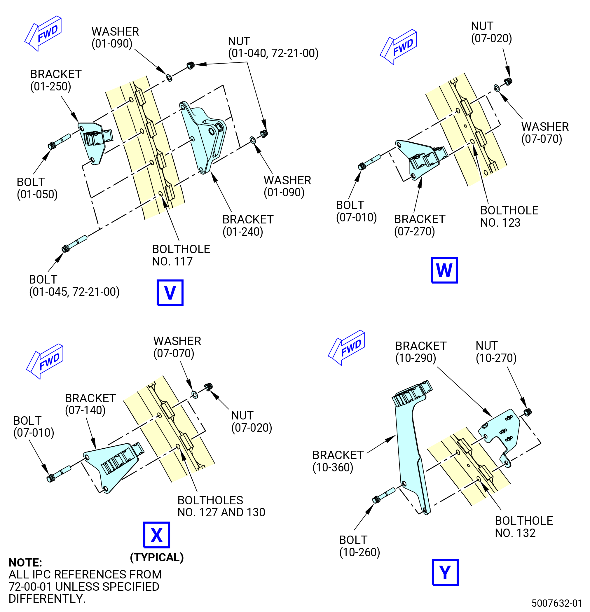
| (3) | Install the wiring support brackets (brackets) (01-150 , 72-00-01) (SIN 6701N) and (01-140 , 72-00-01) (SIN 6881F) to the forward ring where the fan case assembly and fan aft case are connected at the boltholes No. 143, 144, and 1. Refer to Figure 1022 and do as follows: |
| Subtask 72-21-00-380-292 |
| WARNING: |
|
| (a) | Apply C03-001 primer or C03-100 primer to the friction surfaces of the bolts (01-045) (SIN 83520) and (01-050 , 72-00-01) (SIN 83525), friction surfaces of the washer (01-090 , 72-00-01) (SIN 83530), ID of the boltholes, and surface of the bracket (01-140 , 72-00-01) (SIN 6881F) that contacts the fan case. |
| Subtask 72-21-00-640-242 |
| (b) | Apply C02-058 lubricant to the threads of the bolts (01-045) (SIN 83520) and (01-050 , 72-00-01) (SIN 83525) and the self-locking nuts (nuts) (01-040) (SIN 83540). |
| Subtask 72-21-00-440-852 |
| (c) | Install the bolts (01-050 , 72-00-01) (SIN 83525) and bracket (01-150 , 72-00-01) (SIN 6701N) at the boltholes No. 143 and 144 on the forward side of the fan case forward ring. |
| (d) | Install the bolt (01-045) (SIN 83520) at bolthole No. 1 on the forward side of the split flange. |
| (e) | Install the bracket (01-140 , 72-00-01) (SIN 6881F) on the aft side of the split flange at the boltholes No. 1 and 144. The tab of the bracket (01-140 , 72-00-01) (SIN 6881F) must point aft. |
| (f) | Install the nuts (01-040) (SIN 83540) on the bolts at boltholes No. 1 and 144 on the aft side of the fan case forward ring. |
| (g) | Install a washer (01-090 , 72-00-01) (SIN 83530) and a nut on the bolt at the bolthole No. 143. |
| (h) | Torque the nuts to 202-238 lb in. (22.8-26.9 N.m). |
| (i) | Torque the nuts again to 202-238 lb in. (22.8-26.9 N.m). |
| Subtask 72-21-00-440-853 |
| (4) | Install the brackets (07-230 , 72-00-01) (SIN 6701Y) to the forward ring where the forward containment fan case and aft fan case are connected at the boltholes No. 2 and 3. Refer to Figure 1022 and do as follows: |
| Subtask 72-21-00-380-293 |
| WARNING: |
|
| (a) | Apply C03-001 primer or C03-100 primer to the friction surfaces of the bolts (07-010 , 72-00-01) (SIN 83525), ID of the boltholes, and surface of the bracket (07-230 , 72-00-01) (SIN 6701Y) that contacts the fan case. |
| Subtask 72-21-00-640-243 |
| (b) | Apply C02-058 lubricant to the threads of the bolts (07-010 , 72-00-01) (SIN 83525) and the self-locking nuts (nuts) (07-020 , 72-00-01) (SIN 83540). |
| Subtask 72-21-00-440-854 |
| (c) | Install the bolt (07-010 , 72-00-01) (SIN 83525) at the boltholes No. 2 and 3 on the forward side of the fan case forward ring. |
| (d) | Install the bracket (07-230 , 72-00-01) (SIN 6701Y) on the aft side of the split flange at the boltholes No. 2 and 3. The tab of the support bracket must point aft. |
| (e) | Install the nuts (07-020 , 72-00-01) (SIN 83540) at the boltholes No. 2 and 3 on the aft side of the fan case forward ring. |
| (f) | Torque the nuts to 202-238 lb in. (22.8-26.9 N.m). |
| (g) | Torque the nuts again to 202-238 lb in. (22.8-26.9 N.m). |
| Subtask 72-21-00-440-855 |
| (5) | Install the bracket (07-130 , 72-00-01) (SIN 53319) or (07-130A , 72-00-01) (SIN 53319) to the forward ring where the forward containment fan case and aft fan case are connected at the boltholes No. 4 and 5. Refer to Figure 1022 and do as follows: |
| Subtask 72-21-00-380-294 |
| WARNING: |
|
| (a) | Apply C03-001 primer or C03-100 primer to the friction surfaces of the bolts (01-045) (SIN 83520), ID of the boltholes, and surface of the bracket (07-130 , 72-00-01) (SIN 53319) or (07-130A , 72-00-01) (SIN 53319) that contacts the fan case. |
| Subtask 72-21-00-640-244 |
| (b) | Apply C02-058 lubricant to the threads of the bolts (01-045) (SIN 83520) and the nuts (01-040) (SIN 83540). |
| Subtask 72-21-00-440-856 |
| (c) | Install the bolts (01-045) (SIN 83520) at boltholes No. 4 and 5 on the forward side of the fan case forward ring. |
| (d) | Install the bracket (07-130 , 72-00-01) (SIN 53319) or (07-130A , 72-00-01) (SIN 53319) on the aft side of the split flange at the boltholes No. 4 and 5. |
| (e) | Install the nuts (01-040) (SIN 83540) at boltholes No. 4 and 5 on the aft side of the fan case forward ring. |
| (f) | Torque the nuts to 202-238 lb in. (22.8-26.9 N.m). |
| (g) | Torque the nuts again to 202-238 lb in. (22.8-26.9 N.m). |
| Subtask 72-21-00-440-857 |
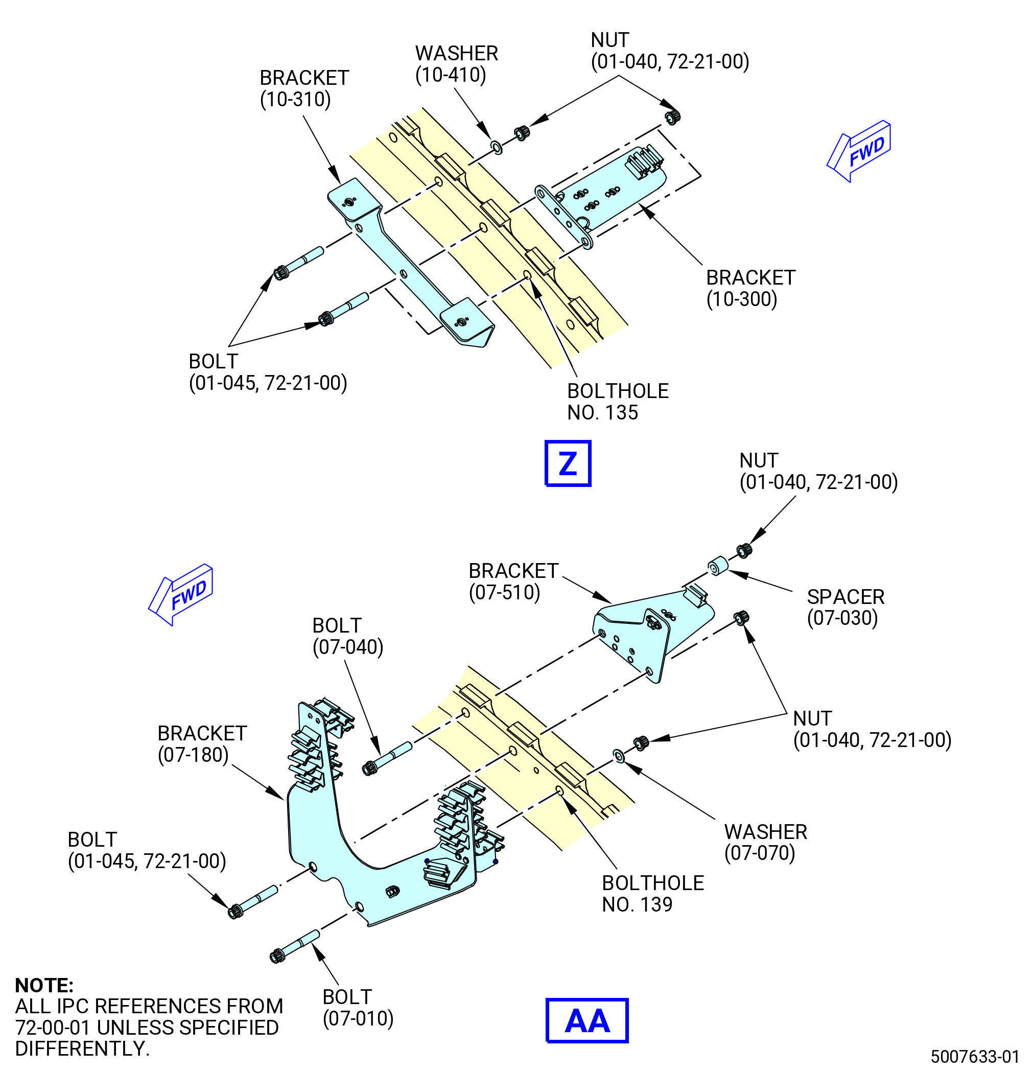
| (6) | Install the support brackets (brackets) (10-130 , 72-00-01) (SIN 46013) at four locations, to the forward ring where the forward containment fan case and aft fan case are connected in boltholes No. 9 and 10, 13 and 14, 17 and 18, and 21 and 22. Refer to Figure 1022 and do as follows: |
| Subtask 72-21-00-380-295 |
| WARNING: |
|
| (a) | Apply C03-001 primer or C03-100 primer to the friction surfaces of the bolts (10-260 , 72-00-01) (SIN 83525), ID of the boltholes, and surface of the bracket (10-130 , 72-00-01) (SIN 46013) that touches the fan case. |
| Subtask 72-21-00-640-245 |
| (b) | Apply C02-058 lubricant to the threads of the bolts (10-260 , 72-00-01) (SIN 83525) and the self-locking nuts (nuts) (10-270 , 72-00-01) (SIN 83540). |
| Subtask 72-21-00-440-858 |
| (c) | Install the bolts (10-260 , 72-00-01) (SIN 83525) in the boltholes on the forward side of the fan case forward ring. |
| (d) | Install the brackets (10-130 , 72-00-01) (SIN 46013) on the aft side of the split flange. |
| (e) | Install the nuts (10-270 , 72-00-01) (SIN 83540) on the bolts on the aft side of the fan case forward ring boltholes No. 9, 10, 13, 14, 17, 18, 21, and 22. |
| (f) | Torque the nuts to 202-238 lb in. (22.8-26.9 N.m). |
| (g) | Torque the nuts again to 202-238 lb in. (22.8-26.9 N.m). |
| Subtask 72-21-00-440-859 |
| (7) | Install the bracket (01-070 , 72-00-01) (SIN 98214) to the forward ring where the forward containment fan case and aft fan case are connected at the boltholes No. 27, 28, and 29. Refer to Figure 1022 and do as follows: |
| Subtask 72-21-00-380-296 |
| WARNING: |
|
| (a) | Apply C03-001 primer or C03-100 primer to the friction surfaces of the bolts (01-045) (SIN 83520), ID of the boltholes, the friction surfaces of the washers (01-090 , 72-00-01) (SIN 83530), and surface of the bracket (01-070 , 72-00-01) (SIN 98214) that contacts the fan case. |
| Subtask 72-21-00-640-246 |
| (b) | Apply C02-058 lubricant to the threads of the bolts (01-045) (SIN 83520) and the self-locking nuts (nuts) (01-040) (SIN 83540). |
| Subtask 72-21-00-440-860 |
| (c) | Install the bolts (01-045) (SIN 83520) in the boltholes on the forward side of the fan case forward ring. |
| (d) | Install the bracket (01-070 , 72-00-01) (SIN 98214) on the aft side of the fan case forward ring at the boltholes No. 27, 28, and 29. |
| (e) | Install the washers (01-090 , 72-00-01) (SIN 83530) and nuts (01-040) (SIN 83540) on the bolts on the aft side of the fan case forward ring. |
| (f) | Torque the nuts to 202-238 lb in. (22.8-26.9 N.m). |
| (g) | Torque the nuts again to 202-238 lb in. (22.8-26.9 N.m). |
| Subtask 72-21-00-440-861 |
| (8) | Install the bracket (01-140 , 79-22-20) (SIN 45312) and the support bracket (bracket) (01-030 , 72-00-01) (SIN 42510) to the forward ring where the forward containment fan case and aft fan case are connected at the boltholes No. 30 and 31. Refer to Figure 1022 and do as follows: |
| WARNING: |
|
| (a) | Clean the surface areas where the brackets (01-140 , 79-22-20) (SIN 45312) and (01-030 , 72-00-01) (SIN 42510) touch the fan case ring to ensure electrical bonding. Clean the surfaces with C04-002 Stoddard solvent, C04-035 isopropyl alcohol, or a 50-50 blend of C04-035 isopropyl alcohol and C04-228 denatured alcohol. |
| WARNING: |
|
| (b) | Apply C03-001 primer or C03-100 primer to the friction surfaces of the bolts (01-050 , 72-00-01) (SIN 83525), ID of the boltholes, and surface of the bracket (01-030 , 72-00-01) (SIN 42510) that contacts the fan case. |
| (c) | Apply C02-058 lubricant to the threads of the bolts (01-050 , 72-00-01) (SIN 83525) and the nuts (01-060 , 72-00-01) (SIN 83540). |
| (d) | Install the bolts (01-050 , 72-00-01) (SIN 83525) in the boltholes on the forward side of the fan case forward ring. |
| (e) | Install the bracket (01-140 , 79-22-20) (SIN 45312) and the bracket (01-030 , 72-00-01) (SIN 42510) on the aft side of the split flange at the boltholes No. 30 and 31. |
| (f) | Install the nuts (01-060 , 72-00-01) (SIN 83540) on the bolts on the aft side of the fan case forward ring. |
| (g) | Torque the nuts to 202-238 lb in. (22.8-26.9 N.m). |
| (h) | Torque the nuts again to 202-238 lb in. (22.8-26.9 N.m). |
| Subtask 72-21-00-440-862 |
| (9) | Install the upper support link (01-030 , 79-11-10) (SIN 40014) to the forward ring where the forward containment fan case and aft fan case are connected at the boltholes No. 32 and 33. Refer to Figure 1022 and do as follows: |
| Subtask 72-21-00-380-297 |
| WARNING: |
|
| (a) | Apply C03-001 primer or C03-100 primer to the friction surfaces of the bolts (01-050 , 72-00-01) (SIN 83525), ID of the boltholes, and surface of the upper support link (01-030 , 79-11-10) (SIN 40014) that touches the fan case. |
| Subtask 72-21-00-640-247 |
| (b) | Apply C02-058 lubricant to the threads of the bolts (01-050 , 72-00-01) (SIN 83525) and the self-locking nuts (nuts) (01-040) (SIN 83540). |
| Subtask 72-21-00-440-863 |
| (c) | Install the bolts (01-050 , 72-00-01) (SIN 83525) in the boltholes on the forward side of the fan case forward ring. |
| (d) | Install the upper support link (01-030 , 79-11-10) (SIN 40014) on the aft side of the split flange at the boltholes No. 32 and 33. |
| (e) | Install the nuts (01-040) (SIN 83540) on the bolts on the aft side of the fan case forward ring. |
| (f) | Torque the nuts to 202-238 lb in. (22.8-26.9 N.m). |
| (g) | Torque the nuts again to 202-238 lb in. (22.8-26.9 N.m). |
| Subtask 72-21-00-440-864 |
| (10) | Install the bracket (07-110 , 72-00-01) (SIN 45311) to the forward ring where the forward containment fan case and aft fan case are connected at the boltholes No. 34 and 35. Refer to Figure 1022 and do as follows: |
| Subtask 72-21-00-380-298 |
| WARNING: |
|
| (a) | Apply C03-001 primer or C03-100 primer to the friction surfaces of the bolts (07-010 , 72-00-01) (SIN 83525), ID of the boltholes, friction surfaces of the washers (07-070 , 72-00-01) (SIN 83530), and surface of the bracket (07-110 , 72-00-01) (SIN 45311) that touches the fan case. |
| Subtask 72-21-00-640-248 |
| (b) | Apply C02-058 lubricant to the threads of the bolts (07-010 , 72-00-01) (SIN 83525) and the nuts (07-020 , 72-00-01) (SIN 83540). |
| Subtask 72-21-00-440-865 |
| (c) | Install the bolts (07-010 , 72-00-01) (SIN 83525) and bracket (07-110 , 72-00-01) (SIN 45311) on the forward side of the fan case forward ring at the boltholes No. 34 and 35. |
| (d) | Install the washers (07-070 , 72-00-01) (SIN 83530) and the nuts (07-020 , 72-00-01) (SIN 83540) on the bolts on the aft side of the fan case forward ring. |
| (e) | Torque the nuts to 202-238 lb in. (22.9-26.9 N.m). |
| (f) | Torque the nuts again to 202-238 lb in. (22.9-26.9 N.m). |
| Subtask 72-21-00-440-866 |
| (11) | Install the brackets (07-110 , 72-00-01) (SIN 45311) and forward support link (01-111 , 79-11-10) (SIN 40012) to the forward ring where the forward containment fan case and aft fan case are connected at the boltholes No. 39, 40, and 41. Refer to Figure 1022 and do as follows: |
| Subtask 72-21-00-380-299 |
| WARNING: |
|
| (a) | Apply C03-001 primer or C03-100 primer to the friction surfaces of the bolts (01-045) (SIN 83520) and (07-010 , 72-00-01) (SIN 83525), ID of the boltholes, friction surfaces of the washer (07-070 , 72-00-01) (SIN 83530), and surface of the brackets that touches the fan case. |
| Subtask 72-21-00-640-249 |
| (b) | Apply C02-058 lubricant to the threads of the bolts (01-045) (SIN 83520) and (07-010 , 72-00-01) (SIN 83525) and the nuts (01-040) (SIN 83540). |
| Subtask 72-21-00-440-867 |
| (c) | Install the bolt (01-045) (SIN 83520) and the bracket (07-110 , 72-00-01) (SIN 45311) on the forward side of the fan case forward ring at bolthole No. 40. |
| (d) | Install the bolts (07-010 , 72-00-01) (SIN 83525) and bracket on the forward side of the fan case forward ring at the boltholes No. 39 and 41. |
| (e) | Install the forward support link (01-111 , 79-11-10) (SIN 40012) on the aft side of the fan case forward ring at the boltholes No. 40 and 41. |
| (f) | Install the washer (07-070 , 72-00-01) (SIN 83530) on the bolt at the bolthole No. 39 on the aft side of the fan case forward ring. |
| (g) | Install the nuts (01-040) (SIN 83540) on the bolts on the aft side of the fan case forward ring. |
| (h) | Torque the nuts to 202-238 lb in. (22.8-26.9 N.m). |
| (i) | Torque the nuts again to 202-238 lb in. (22.8-26.9 N.m). |
| Subtask 72-21-00-440-868 |
| (12) | Install the bracket (07-110 , 72-00-01) (SIN 45311) to the forward ring where the forward containment fan case and aft fan case are connected at the boltholes No. 44 and 45. Refer to Figure 1022 and do as follows: |
| Subtask 72-21-00-380-300 |
| WARNING: |
|
| (a) | Apply C03-001 primer or C03-100 primer to the friction surfaces of the bolts (07-010 , 72-00-01) (SIN 83525), ID of the boltholes, friction surfaces of the washers (07-070 , 72-00-01) (SIN 83530), and surface of the bracket (07-110 , 72-00-01) (SIN 45311) that contacts the fan case. |
| Subtask 72-21-00-640-250 |
| (b) | Apply C02-058 lubricant to the threads of the bolts (07-010 , 72-00-01) (SIN 83525) and the nuts (07-020 , 72-00-01) (SIN 83540). |
| Subtask 72-21-00-440-869 |
| (c) | Install the bolts (07-010 , 72-00-01) (SIN 83525) and bracket (07-110 , 72-00-01) (SIN 45311) on the forward side of the fan case forward ring at the boltholes No. 44 and 45. |
| (d) | Install the washers (07-070 , 72-00-01) (SIN 83530) and nuts (07-020 , 72-00-01) (SIN 83540) on the bolts on the aft side of the fan case forward ring. |
| (e) | Torque the nuts to 202-238 lb in. (22.8-26.9 N.m). |
| (f) | Torque the nuts again to 202-238 lb in. (22.8-26.9 N.m). |
| Subtask 72-21-00-440-870 |
| (13) | Install the bracket (05-640 , 72-00-01) (SIN 44013) to the forward ring where the forward containment fan case and aft fan case are connected at the boltholes No. 49 and 50. Refer to Figure 1022 and as follows: |
| Subtask 72-21-00-380-301 |
| WARNING: |
|
| (a) | Apply C03-001 primer or C03-100 primer to the friction surfaces of the bolts (05-010 , 72-00-01) (SIN 83525), ID of the boltholes, and surface of the bracket (05-640 , 72-00-01) (SIN 44013) that touches the aft fan case. |
| Subtask 72-21-00-640-251 |
| (b) | Apply C02-058 lubricant to the threads of the bolts (05-010 , 72-00-01) (SIN 83525) and the self-locking nuts (nuts) (05-020 , 72-00-01) (SIN 83540). |
| Subtask 72-21-00-440-871 |
| (c) | Install the bolts (05-010 , 72-00-01) (SIN 83525) on the forward side of the fan case forward ring at the boltholes No. 49 and 50. |
| (d) | Install the bracket (05-640 , 72-00-01) (SIN 44013) on the aft side of the aft fan case forward ring at the boltholes No. 49 and 50. |
| (e) | Install the nuts (05-020 , 72-00-01) (SIN 83540) on the bolts on the aft side of the fan case forward ring. |
| (f) | Torque the nuts to 202-238 lb in. (22.8-26.9 N.m). |
| (g) | Torque the nuts again to 202-238 lb in. (22.8-26.9 N.m). |
| Subtask 72-21-00-440-872 |
| (14) | Install the brackets (05-620 , 72-00-01) (SIN 44012) to the forward ring where the forward containment fan case and aft fan case are connected at the boltholes No. 54 and 55, and 70 and 71. Refer to Figure 1022 and do as follows: |
| Subtask 72-21-00-380-302 |
| WARNING: |
|
| (a) | Apply C03-001 primer or C03-100 primer to the friction surfaces of the bolts (05-010 , 72-00-01) (SIN 83525), ID of the boltholes, and surface of the bracket (05-620 , 72-00-01) (SIN 44012) that contacts the aft fan case. |
| Subtask 72-21-00-640-252 |
| (b) | Apply C02-058 lubricant to the threads of the bolts (05-010 , 72-00-01) (SIN 83525) and the nuts (05-020 , 72-00-01) (SIN 83540). |
| Subtask 72-21-00-440-873 |
| (c) | Install the bolts (05-010 , 72-00-01) (SIN 83525) on the forward side of the fan case forward ring at the boltholes No. 54 and 55, and 70 and 71. |
| (d) | Install the bracket (05-620 , 72-00-01) (SIN 44012) on the bolts on the aft side of the fan case forward ring at the boltholes No. 54 and 55, and 70 and 71. |
| (e) | Install the nuts (05-020 , 72-00-01) (SIN 83540) on the bolts on the aft side of the fan case forward ring. |
| (f) | Torque the nuts to 202-238 lb in. (22.8-26.9 N.m). |
| (g) | Torque the nuts again to 202-238 lb in. (22.8-26.9 N.m). |
| (h) | Install the bracket (05-600 , 72-00-01) (SIN 44011) on the bracket (05-620 , 72-00-01) (SIN 44012) with bolts (05-660 , 72-00-01) (SIN 44021). Torque the bolts to 106 to 124 lb in. (12.0 to 14.0 Nm). |
| Subtask 72-21-00-440-874 |
| (15) | Install the bracket (05-620 , 72-00-01) (SIN 44012) to the forward ring where the forward containment fan case and aft fan case are connected at the boltholes No. 62 and 63, and the bracket (05-580 , 72-00-01) (SIN 44010). Refer to Figure 1022 and do as follows: |
| Subtask 72-21-00-380-303 |
| WARNING: |
|
| (a) | Apply C03-001 primer or C03-100 primer to the friction surfaces of the bolts (05-010 , 72-00-01) (SIN 83525), ID of the boltholes, and surface of the bracket (05-620 , 72-00-01) (SIN 44012) that touches the aft fan case. |
| Subtask 72-21-00-640-253 |
| (b) | Apply C02-058 lubricant to the threads of the bolts (05-010 , 72-00-01) (SIN 83525) and the nuts (05-020 , 72-00-01) (SIN 83540). |
| Subtask 72-21-00-440-875 |
| (c) | Install the bolts (05-010 , 72-00-01) (SIN 83525) on the forward side of the fan case forward ring at the boltholes No. 62 and 63. |
| (d) | Install the bracket (05-620 , 72-00-01) (SIN 44012) on the aft side of the fan case forward ring. |
| (e) | Install the nuts (05-020 , 72-00-01) (SIN 83540) on the bolts on the aft side of the fan case forward ring. |
| (f) | Torque the nuts to 202-238 lb in. (22.8-26.9 N.m). |
| (g) | Torque the nuts again to 202-238 lb in. (22.8-26.9 N.m). |
| (h) | Install the bracket (05-580 , 72-00-01) (SIN 44010) on the bracket (05-620 , 72-00-01) (SIN 44012) with bolts (05-660 , 72-00-01) (SIN 44021). Torque the bolts to 106-124 lb in. (12.0-14.0 N.m). |
| Subtask 72-21-00-440-876 |
| (16) | Install the support bracket (bracket) (07-530 , 72-00-01) (SIN 6711S) to the forward ring where the forward containment fan case and aft fan case are connected at the boltholes No. 72 and 73. Refer to Figure 1022 and do as follows: |
| Subtask 72-21-00-380-304 |
| WARNING: |
|
| (a) | Apply C03-001 primer or C03-100 primer to the friction surfaces of the bolts (07-010 , 72-00-01) (SIN 83525), ID of the boltholes, friction surfaces of the washers (07-070 , 72-00-01) (SIN 83530), and surface of the bracket (07-530 , 72-00-01) (SIN 6711S) that touches the fan case. |
| Subtask 72-21-00-640-254 |
| (b) | Apply C02-058 lubricant to the threads of the bolts (07-010 , 72-00-01) (SIN 83525) and the nuts (07-020 , 72-00-01) (SIN 83540). |
| Subtask 72-21-00-440-877 |
| (c) | Install the bolts (07-010 , 72-00-01) (SIN 83525) and bracket (07-530 , 72-00-01) (SIN 6711S) on the forward side of the fan case forward ring at the boltholes No. 72 and 73. |
| (d) | Install the washers (07-070 , 72-00-01) (SIN 83530) and nuts (07-020 , 72-00-01) (SIN 83540) on the aft side of the fan case forward ring. |
| (e) | Torque the nuts to 202-238 lb in. (22.8-26.9 N.m). |
| (f) | Torque the nuts again to 202-238 lb in. (22.8-26.9 N.m). |
| Subtask 72-21-00-440-878 |
| (17) | Install the support brackets (bracket) (05-460 , 72-00-01) (SIN 6701H) and (05-400 , 72-00-01) (SIN 6701F) or (05-401 , 72-00-01) (SIN 6701F) to the forward ring where the forward containment fan case and aft fan case are connected at the boltholes No. 77 and 78. Refer to Figure 1022 and do as follows: |
| Subtask 72-21-00-380-305 |
| WARNING: |
|
| (a) | Apply C03-001 primer or C03-100 primer to the friction surfaces of the bolts (05-010 , 72-00-01) (SIN 83525), ID of the boltholes, friction surfaces of the washers (05-380 , 72-00-01) (SIN 83530), and surface of the bracket (05-460 , 72-00-01) (SIN 6701H) that touches the fan case. |
| Subtask 72-21-00-640-255 |
| (b) | Apply C02-058 lubricant to the threads of the bolts (05-010 , 72-00-01) (SIN 83525) and the nuts (05-020 , 72-00-01) (SIN 83540). |
| Subtask 72-21-00-440-879 |
| (c) | Install the bolts (05-010 , 72-00-01) (SIN 83525) and bracket (05-460 , 72-00-01) (SIN 6701H) on the forward side of the fan case forward ring at the boltholes No. 77 and 78. |
| (d) | Install the washers (05-380 , 72-00-01) (SIN 83530) and nuts (05-020 , 72-00-01) (SIN 83540) on the bolts on the aft side of the fan case forward ring. |
| (e) | Torque the nuts to 202-238 lb in. (22.8-26.9 N.m). |
| (f) | Torque the nuts again to 202-238 lb in. (22.8-26.9 N.m). |
| (g) | Install the bracket (05-400 , 72-00-01) (SIN 6701F) or (05-401 , 72-00-01) (SIN 6701F) on the bracket (05-460 , 72-00-01) (SIN 6701H) with bolts (05-240 , 72-00-01) (SIN 67021). Torque the bolts to 106-124 lb in. (12.0-14.0 N.m). |
| Subtask 72-21-00-440-880 |
| (18) | Install the electrical bracket (bracket) (01-370 , 72-00-01) (SIN 67016) at two locations in the forward ring where the forward containment fan case and aft fan case are connected at the boltholes No. 83 and 84, and 87 and 88. Refer to Figure 1022 and do as follows: |
| Subtask 72-21-00-380-306 |
| WARNING: |
|
| (a) | Apply C03-001 primer or C03-100 primer to the friction surfaces of the bolts (01-050 , 72-00-01) (SIN 83525), ID of the boltholes, and surface of the bracket (01-370 , 72-00-01) (SIN 67016) that touches the fan case. |
| Subtask 72-21-00-640-256 |
| (b) | Apply C02-058 lubricant to the threads of the bolts (01-050 , 72-00-01) (SIN 83525) and the nuts (01-060 , 72-00-01) (SIN 83540). |
| Subtask 72-21-00-440-881 |
| (c) | Install the bolts (01-050 , 72-00-01) (SIN 83525) on the forward side of the fan case forward ring on the bolts at the boltholes No. 83 and 84, and 87 and 88. |
| (d) | Install the bracket (01-370 , 72-00-01) (SIN 67016) on the bolts on the aft side of the fan case forward ring. |
| (e) | Install the nuts (01-060 , 72-00-01) (SIN 83540) on the bolts on the aft side of the fan case forward ring. |
| (f) | Torque the nuts to 202-238 lb in. (22.8-26.9 N.m). |
| (g) | Torque the nuts again to 202-238 lb in. (22.8-26.9 N.m). |
| Subtask 72-21-00-440-882 |
| (19) | Install the electrical bracket (bracket) (01-350 , 72-00-01) (SIN 67015) to the forward ring where the forward containment fan case and aft fan case are connected at the boltholes No. 91 and 92. Refer to Figure 1022 and do as follows: |
| Subtask 72-21-00-380-307 |
| WARNING: |
|
| (a) | Apply C03-001 primer or C03-100 primer to the friction surfaces of the bolts (01-050 , 72-00-01) (SIN 83525), ID of the boltholes, and surface of the bracket (01-350 , 72-00-01) (SIN 67015) that touches the fan case. |
| Subtask 72-21-00-640-257 |
| (b) | Apply C02-058 lubricant to the threads of the bolts (01-050 , 72-00-01) (SIN 83525) and the nuts (01-060 , 72-00-01) (SIN 83540). |
| Subtask 72-21-00-440-883 |
| (c) | Install the bolts (01-050 , 72-00-01) (SIN 83525) on the forward side of the fan case forward ring at the boltholes No. 91 and 92. |
| (d) | Install the bracket (01-350 , 72-00-01) (SIN 67015) on the bolts on the aft side of the fan case forward ring. |
| (e) | Install the nuts (01-060 , 72-00-01) (SIN 83540) on the bolts on the aft side of the fan case forward ring. |
| (f) | Torque the nuts to 202-238 lb in. (22.8-26.9 N.m). |
| (g) | Torque the nuts again to 202-238 lb in. (22.8-26.9 N.m). |
| (h) | Attach the bracket (01-300 , 72-00-01) (SIN 61419) to the bracket (01-350 , 72-00-01) (SIN 67015) with a washer (01-290 , 72-00-01) (SIN 67030) and a bolt (01-280 , 72-00-01) (SIN 67021). Torque the bolt (01-280 , 72-00-01) to 106 to 124 lb in. (12.0 to 14.0 Nm). |
| Subtask 72-21-00-440-884 |
| (20) | Install the electrical bracket (bracket) (07-470 , 72-00-01) (SIN 6701Z) to the forward ring where the forward containment fan case and aft fan case are connected at the boltholes No. 95 and 96. Refer to Figure 1022 and do as follows: |
| Subtask 72-21-00-380-308 |
| WARNING: |
|
| (a) | Apply C03-001 primer or C03-100 primer to the friction surfaces of the bolts (07-010 , 72-00-01) (SIN 83525), ID of the boltholes, friction surfaces of the washers (07-070 , 72-00-01) (SIN 83530), and surface of the bracket (07-470 , 72-00-01) (SIN 6701Z) that touches the fan case. |
| Subtask 72-21-00-640-258 |
| (b) | Apply C02-058 lubricant to the threads of the bolts (07-010 , 72-00-01) (SIN 83525) and the nuts (07-020 , 72-00-01) (SIN 83540). |
| Subtask 72-21-00-440-885 |
| (c) | Install the bolts (07-010 , 72-00-01) (SIN 83525) on the forward side of the fan case forward ring on the bolts at the boltholes No. 95 and 96. |
| (d) | Install the bracket (07-470 , 72-00-01) (SIN 6701Z) on the bolts on the forward side of the fan case forward ring. |
| (e) | Install the washers (07-070 , 72-00-01) (SIN 83530) and nuts (07-020 , 72-00-01) (SIN 83540) on the bolts on the aft side of the fan case forward ring. |
| (f) | Torque the nuts to 202-238 lb in. (22.8-26.9 N.m). |
| (g) | Torque the nuts again to 202-238 lb in. (22.8-26.9 N.m). |
| Subtask 72-21-00-440-886 |
| (21) | Install the EMU support bracket as follows: |
| (a) | Install the support bracket (bracket) (05-330 , 72-00-01) (SIN 6701E) and EMU mounting support bracket (bracket) (05-271 , 72-00-01) (SIN 65Z10) to the forward ring where the forward containment fan case and the aft fan case are connected at the boltholes No. 98, 99, and 100. Refer to Figure 1022 and do as follows: |
| WARNING: |
|
| 1 | Apply C03-001 primer or C03-100 primer to the friction surfaces of the bolts (05-010 , 72-00-01) (SIN 83525), ID of the boltholes, friction surfaces of the washer (05-380 , 72-00-01) (SIN 83530), and surface of the bracket (05-330 , 72-00-01) (SIN 6701E) that touches the fan case. |
| 2 | Apply C02-058 lubricant to the threads of the bolts (05-010 , 72-00-01) (SIN 83525), and the nuts (05-020 , 72-00-01) (SIN 83540). |
| 3 | Install the bolt (05-010 , 72-00-01) (SIN 83525) and bracket (05-330 , 72-00-01) (SIN 6701E) on the forward side of the fan case forward ring at the boltholes No. 98, 99, and 100. |
| 4 | Install the washer (05-380 , 72-00-01) (SIN 83530) and nut (05-020 , 72-00-01) (SIN 83540) on the bolt (05-010 , 72-00-01) (SIN 83525) on the aft side of the fan case forward ring at the bolthole No. 98. |
| 5 | Install the bracket (05-271 , 72-00-01) (SIN 65Z10) and the nuts (05-020 , 72-00-01) (SIN 83540) on the aft side of the fan case forward ring at the boltholes No. 99 and 100. |
| 6 | Torque the nuts to 202-238 lb in. (22.8-26.9 N.m). |
| 7 | Torque the nuts (05-020 , 72-00-01) (SIN 83540) again to 202-238 lb in. (22.8-26.9 N.m). |
| (b) | Install the EMU support bracket (bracket) (01-040 , 77-32-10) (SIN 65Z16) as follows: |
| 1 | Attach the bracket (01-040 , 77-32-10) (SIN 65Z16) to the bracket (05-271 , 72-00-01) (SIN 65Z10) with bolts (01-020 , 77-32-10) (SIN 65Z20). |
| 2 | Torque the bolts (01-020 , 77-32-10) (SIN 65Z20) to 106-124 lb in. (12.0-14.0 N.m). |
| (c) | Install the support bracket (bracket) (05-300 , 72-00-01) (SIN 6701S) and EMU support bracket (bracket) (05-156 , 72-00-01) (SIN 65Z12) to the forward ring where the forward containment fan case and aft fan case are connected at the boltholes No. 103 and 104. Refer to Figure 1022 and do as follows: |
| WARNING: |
|
| 1 | Apply C03-001 primer or C03-100 primer to the friction surfaces of the bolts (01-045) (SIN 83520), ID of the boltholes, and surface of the bracket (05-300 , 72-00-01) (SIN 6701S) and bracket (05-156 , 72-00-01) (SIN 65Z12) that touches the fan case. |
| 2 | Apply C02-058 lubricant to the threads of the bolts (01-045) (SIN 83520) and the nuts (01-040) (SIN 83540). |
| 3 | Install the bolts (01-045) (SIN 83520) and bracket (05-300 , 72-00-01) (SIN 6701S) on the forward side of the fan case forward ring at boltholes No. 103 and 104. |
| 4 | Install the bracket (05-156 , 72-00-01) (SIN 65Z12) on the bolts on the aft side of the fan case forward ring. |
| 5 | Install the nuts (01-040) (SIN 83540) on the bolts on the aft side of the fan case forward ring. |
| 6 | Torque the nuts to 202-238 lb in. (22.8-26.9 N.m). |
| 7 | Torque the nuts again to 202-238 lb in. (22.8-26.9 N.m). |
| (d) | Install the EMU support bracket (bracket) (01-030 , 77-32-10) (SIN 65Z15) as follows: |
| 1 | Attach the bracket (01-030 , 77-32-10) (SIN 65Z15) to the bracket (05-156 , 72-00-01) (SIN 65Z12) with bolts (01-020 , 77-32-10) (SIN 65Z20). |
| 2 | Torque the bolts (01-020 , 77-32-10) (SIN 65Z20) to 106-124 lb in. (12.0-14.0 N.m). |
| Subtask 72-21-00-440-887 |
| (22) | Install the electrical bracket (bracket) (05-550 , 72-00-01) (SIN 6701C) and FADEC support bracket (bracket) (05-070 , 72-00-01) (SIN 65H12) to the forward ring where the forward containment fan case and aft fan case are connected at the boltholes No. 107 and 108. Refer to Figure 1022 and do as follows: |
| Subtask 72-21-00-380-309 |
| WARNING: |
|
| (a) | Apply C03-001 primer or C03-100 primer to the friction surfaces of the bolts (01-045) (SIN 83520), ID of the boltholes, and surface of the brackets (05-550 , 72-00-01) (SIN 6701C) and (05-070 , 72-00-01) (SIN 65H12) that touches the fan case. |
| Subtask 72-21-00-640-259 |
| (b) | Apply C02-058 lubricant to the threads of the bolts (01-045) (SIN 83520) and the nuts (01-040) (SIN 83540). |
| Subtask 72-21-00-440-888 |
| (c) | Install the bolts (01-045) (SIN 83520) and bracket (05-550 , 72-00-01) (SIN 6701C) on the forward side of the fan case forward ring at boltholes No. 107 and 108. |
| (d) | Install the bracket (05-070 , 72-00-01) (SIN 65H12) on the bolts (01-045) (SIN 83520) on the aft side of the fan case forward ring. |
| (e) | Install the nuts (01-040) (SIN 83540) on the bolts on the aft side of the fan case forward ring. |
| (f) | Torque the nuts to 202-238 lb in. (22.8-26.9 N.m). |
| (g) | Torque the nuts again to 202-238 lb in. (22.8-26.9 N.m). |
| Subtask 72-21-00-440-889 |
| (23) | Install the FADEC support bracket (bracket) (05-710 , 72-00-01) (SIN 65H16) to the forward ring where the forward containment fan case and aft fan case are connected at the boltholes No. 111 and 112. Refer to Figure 1022 and do as follows: |
| Subtask 72-21-00-380-310 |
| WARNING: |
|
| (a) | Apply C03-001 primer or C03-100 primer to the friction surfaces of the bolts (01-045) (SIN 83520), ID of the spacer (05-120 , 72-00-01) (SIN 83570), ID of the boltholes, and surface of the bracket (05-710 , 72-00-01) (SIN 65H16) that contacts the fan case. |
| Subtask 72-21-00-640-260 |
| (b) | Apply C02-058 lubricant to the threads of the bolts (01-045) (SIN 83520) and the nuts (01-040) (SIN 83540). |
| Subtask 72-21-00-440-890 |
| (c) | Install the bolts (01-045) (SIN 83520) on the forward side of the fan case forward ring at boltholes No. 111 and 112. |
| (d) | Install the bracket (05-710 , 72-00-01) (SIN 65H16) on the bolts at the boltholes No. 111 and 112 on the aft side of the fan case forward ring. |
| (e) | Put the spacers (05-120 , 72-00-01) (SIN 83570) and the nuts (01-040) (SIN 83540) on the aft side of the fan case forward ring. |
| (f) | Torque the nuts (01-040) (SIN 83540) to 202 to 238 lb in. (22.8 to 26.9 Nm). |
| (g) | Torque the nuts (01-040) (SIN 83540) again to 202 to 238 lb in. (22.8 to 26.9 Nm). |
| Subtask 72-21-00-440-891 |
| (24) | Install the wiring bracket (bracket) (05-100 , 72-00-01) (SIN 6701D) to the forward ring where the forward containment fan case and aft fan case are connected at the boltholes No. 113 and 114 and the FADEC support bracket (bracket) (05-040 , 72-00-01) (SIN 65H10) at the boltholes No. 115 and 116. Refer to Figure 1022 and do as follows: |
| Subtask 72-21-00-380-311 |
| WARNING: |
|
| (a) | Apply C03-001 primer or C03-100 primer to the friction surfaces of the bolts (05-010 , 72-00-01) (SIN 83525), ID of the boltholes, friction surfaces of the washers (05-380 , 72-00-01) (SIN 83530), and surface of the bracket (05-100 , 72-00-01) (SIN 6701D) that touches the fan case. |
| Subtask 72-21-00-640-261 |
| (b) | Apply C02-058 lubricant to the threads of the bolts (05-010 , 72-00-01) (SIN 83525) and the nuts (05-020 , 72-00-01) (SIN 83540). |
| Subtask 72-21-00-440-892 |
| (c) | Install the bolts (05-010 , 72-00-01) (SIN 83525) and bracket (05-100 , 72-00-01) (SIN 6701D) on the forward side of the fan case forward ring at the boltholes No. 113 and 114. |
| (d) | Install the nuts (05-020 , 72-00-01) (SIN 83540) and washers (05-380 , 72-00-01) (SIN 83530) on the bolts on the aft side of the fan case forward ring at the boltholes No. 113 and 114. |
| (e) | Install the bolts (05-010 , 72-00-01) (SIN 83525) on the forward side of the fan case forward ring at the boltholes No. 115 and 116. |
| (f) | Install the bracket (05-040 , 72-00-01) (SIN 65H10) and nuts (05-020 , 72-00-01) (SIN 83540) on the aft side of the fan case forward ring at the boltholes No. 115 and 116. |
| (g) | Torque the nuts to 202-238 lb in. (22.8-26.9 N.m). |
| (h) | Torque the nuts again to 202-238 lb in. (22.8-26.9 N.m). |
| Subtask 72-21-00-440-893 |
| (25) | Install the landyard (05-725 , 72-00-01) (SIN 65H80) or (05-726 , 72-00-01) (SIN 65H80) on the brackets (05-070 , 72-00-01) (SIN 65H12) and (05-040 , 72-00-01) (SIN 65H10) to the forward ring where the forward containment fan case and aft fan case are connected. Refer to Figure 1022 and do as follows: |
| (a) | Put the landyard through the loop on the bracket (05-710 , 72-00-01) (SIN 65H16). |
| (b) | Attach the landyard to the brackets (05-070 , 72-00-01) (SIN 65H12) and (05-040 , 72-00-01) (SIN 65H10) with bolts (05-720 , 72-00-01) (SIN 65H21). |
| (c) | Torque the bolts to 207-243 lb in. (23.4-27.5 N.m). |
| Subtask 72-21-00-440-894 |
| (26) | Install the fan bracket (bracket) (01-240 , 72-00-01) (SIN 98215) and bracket (01-250 , 72-00-01) (SIN 6711M) to the forward ring where the forward containment fan case and aft fan case are connected at the boltholes No. 117 thru 120. Refer to Figure 1022 and do as follows: |
| Subtask 72-21-00-380-312 |
| WARNING: |
|
| (a) | Apply C03-001 primer or C03-100 primer to the friction surfaces of the bolts (01-045) (SIN 83520) and (01-050 , 72-00-01) (SIN 83525), ID of the boltholes, friction surfaces of the washers (01-090 , 72-00-01) (SIN 83530), and surfaces of the brackets (01-250 , 72-00-01) (SIN 6711M) and (01-240 , 72-00-01) (SIN 98215) that contact the fan case. |
| Subtask 72-21-00-640-262 |
| (b) | Apply C02-058 lubricant to the threads of the bolts (01-045) (SIN 83520) and (01-050 , 72-00-01) (SIN 83525) and the nuts (01-040) (SIN 83540). |
| Subtask 72-21-00-440-895 |
| (c) | Install the bolts (01-045) (SIN 83520) at boltholes No. 117 and 118 on the forward side of the fan case forward ring. |
| (d) | Install the bolt (01-045) (SIN 83520) and bracket (01-250 , 72-00-01) (SIN 6711M) on the forward side of the fan case forward ring at bolthole No. 119. |
| (e) | Install the bracket (01-240 , 72-00-01) (SIN 98215) on the bolts (01-045) (SIN 83520) on the aft side of the fan case forward ring at boltholes No. 117, 118, and 119. |
| (f) | Install the nuts (01-040) (SIN 83540) and washers (01-090 , 72-00-01) (SIN 83530) on the bolts (01-045) (SIN 83520) on the aft side of the fan case forward ring at boltholes No. 117, 118, and 119. |
| (g) | Install a bolt (01-050 , 72-00-01) (SIN 83525) on the bracket (01-250 , 72-00-01) (SIN 6711M) on the forward side of the fan case forward ring at the bolthole No. 120. |
| (h) | Install a nut and a washer (01-090 , 72-00-01) (SIN 83530) on the bolt on the aft side of the fan case forward ring at the bolthole No. 120. |
| (i) | Torque the nuts to 202-238 lb in. (22.8-26.9 N.m). |
| (j) | Torque the nuts again to 202-238 lb in. (22.8-26.9 N.m). |
| Subtask 72-21-00-440-896 |
| (27) | Install the wiring bracket (bracket) (07-270 , 72-00-01) (SIN 6711N) to the forward ring where the forward containment fan case and aft fan case are connected at the boltholes No. 123 and 124. Refer to Figure 1022 and do as follows: |
| Subtask 72-21-00-380-313 |
| WARNING: |
|
| (a) | Apply C03-001 primer or C03-100 primer to the friction surfaces of the bolts (07-010 , 72-00-01) (SIN 83525), ID of the boltholes, friction surfaces of the washers (07-070 , 72-00-01) (SIN 83530), and surface of the bracket (07-270 , 72-00-01) (SIN 6711N) that contacts the fan case. |
| Subtask 72-21-00-640-263 |
| (b) | Apply C02-058 lubricant to the threads of the bolts (07-010 , 72-00-01) (SIN 83525) and the nuts (07-020 , 72-00-01) (SIN 83540). |
| Subtask 72-21-00-440-897 |
| (c) | Install the bolts (07-010 , 72-00-01) (SIN 83525) and bracket (07-270 , 72-00-01) (SIN 6711N) on the forward side of the fan case forward ring at the boltholes No. 123 and 124. |
| (d) | Install the nuts (07-020 , 72-00-01) (SIN 83540) and washers (07-070 , 72-00-01) (SIN 83530) on the bolts on the aft side of the fan case forward ring. |
| (e) | Torque the nuts to 202-238 lb in. (22.8-26.9 N.m). |
| (f) | Torque the nuts again to 202-238 lb in. (22.8-26.9 N.m). |
| Subtask 72-21-00-440-898 |
| (28) | Install the wiring bracket (bracket) (07-140 , 72-00-01) (SIN 6701P) to the forward ring where the forward containment fan case and aft fan case are connected at the boltholes No. 127 and 128, and 130 and 131. Refer to Figure 1022 and do as follows: |
| Subtask 72-21-00-380-314 |
| WARNING: |
|
| (a) | Apply C03-001 primer or C03-100 primer to the friction surfaces of the bolts (07-010 , 72-00-01) (SIN 83525), ID of the boltholes, friction surfaces of the washers (07-070 , 72-00-01) (SIN 83530), and surface of the bracket (07-140 , 72-00-01) (SIN 6701P) that touches the fan case. |
| Subtask 72-21-00-640-264 |
| (b) | Apply C02-058 lubricant to the threads of the bolts (07-010 , 72-00-01) (SIN 83525) and the nuts (07-020 , 72-00-01) (SIN 83540). |
| Subtask 72-21-00-440-899 |
| (c) | Install the bolts (07-010 , 72-00-01) (SIN 83525) and bracket (07-140 , 72-00-01) (SIN 6701P) on the forward side of the fan case forward ring at the boltholes No. 127 and 128, and 130 and 131. |
| (d) | Install the nuts (07-020 , 72-00-01) (SIN 83540) and washers (07-070 , 72-00-01) (SIN 83530) on the bolts on the aft side of the fan case forward ring. |
| (e) | Torque the nuts to 202-238 lb in. (22.8-26.9 N.m). |
| (f) | Torque the nuts again to 202-238 lb in. (22.8-26.9 N.m). |
| Subtask 72-21-00-440-900 |
| (29) | Install the wiring bracket (bracket) (10-360 , 72-00-01) (SIN 6701R) and support bracket (bracket) (10-290 , 72-00-01) (SIN 53316) to the forward ring where the forward containment fan case and aft fan case are connected at the boltholes No. 132 and 133. Refer to Figure 1022 and do as follows: |
| Subtask 72-21-00-380-315 |
| WARNING: |
|
| (a) | Apply C03-001 primer or C03-100 primer to the friction surfaces of the bolts (10-260 , 72-00-01) (SIN 83525), ID of the boltholes, and surfaces of the brackets (10-290 , 72-00-01) (SIN 53316) and (10-360 , 72-00-01) (SIN 6701R) that touch the fan case. |
| Subtask 72-21-00-640-265 |
| (b) | Apply C02-058 lubricant to the threads of the bolts (10-260 , 72-00-01) (SIN 83525) and the nuts (10-270 , 72-00-01) (SIN 83540). |
| Subtask 72-21-00-440-901 |
| (c) | Install the bolts (10-260 , 72-00-01) (SIN 83525) and bracket (10-360 , 72-00-01) (SIN 6701R) on the forward side of the fan case forward ring at the boltholes No. 132 and 133. |
| (d) | Install the bracket (10-290 , 72-00-01) (SIN 53316) on the aft side of the forward ring at the boltholes No. 132 and 133. |
| (e) | Install the nuts (10-270 , 72-00-01) (SIN 83540) on the bolts on the aft side of the fan case forward ring. |
| (f) | Torque the nuts to 202-238 lb in. (22.8-26.9 N.m). |
| (g) | Torque the nuts again to 202-238 lb in. (22.8-26.9 N.m). |
| Subtask 72-21-00-440-902 |
| (30) | Install the support brackets (brackets) (10-310 , 72-00-01) (SIN 6101F) and (10-300 , 72-00-01) (SIN 53317) to the forward ring where the forward containment fan case and aft fan case are connected at the boltholes No. 135, 136, and 137. Refer to Figure 1022 and do as follows: |
| Subtask 72-21-00-380-316 |
| WARNING: |
|
| (a) | Apply C03-001 primer or C03-100 primer to the friction surfaces of the bolts (01-045) (SIN 83520), ID of the boltholes, friction surfaces of the washers (10-410 , 72-00-01) (SIN 83530), and surfaces of the brackets (10-300 , 72-00-01) (SIN 53317) and (10-310 , 72-00-01) (SIN 6101F) that touches the fan case. |
| Subtask 72-21-00-640-266 |
| (b) | Apply C02-058 lubricant to the threads of the bolts (01-045) (SIN 83520) and the nuts (01-040) (SIN 83540). |
| Subtask 72-21-00-440-903 |
| (c) | Install the bolts (01-045) (SIN 83520) and bracket (10-310 , 72-00-01) (SIN 6101F) on the forward side of the fan case forward ring at boltholes No. 135, 136, and 137. |
| (d) | Install the bracket (10-300 , 72-00-01) (SIN 53317) on the bolts on the aft side of the fan case forward ring at the boltholes No. 135 and 136. |
| (e) | Install the nuts (01-040) (SIN 83540) on the bolts on the aft side of the fan case forward ring at boltholes No. 135 and 136. |
| (f) | Install a nut and a washer (10-410 , 72-00-01) (SIN 83530) on the bolt on the aft side of the fan case forward ring at the bolthole No. 137. |
| (g) | Torque the nuts to 202-238 lb in. (22.8-26.9 N.m). |
| (h) | Torque the nuts again to 202-238 lb in. (22.8-26.9 N.m). |
| Subtask 72-21-00-440-904 |
| (31) | Install the wiring bracket (bracket) (07-180 , 72-00-01) (SIN 6701T) and support bracket (bracket) (07-510 , 72-00-01) (SIN 53310) to the forward ring where the forward containment fan case and e aft fan case are connected at the boltholes No. 139, 140, and 141. Refer to Figure 1022 and do as follows: |
| Subtask 72-21-00-380-317 |
| WARNING: |
|
| (a) | Apply C03-001 primer or C03-100 primer to the friction surfaces of the bolts (01-045) (SIN 83520) and (07-010 , 72-00-01) (SIN 83525), ID of the boltholes, friction surfaces of the washers (07-070 , 72-00-01) (SIN 83530), and surfaces of the brackets (07-180 , 72-00-01) (SIN 6701T) and (07-510 , 72-00-01) (SIN 53310) that touches the fan case. |
| Subtask 72-21-00-640-267 |
| (b) | Apply C02-058 lubricant to the threads of the bolts (01-045) (SIN 83520) and (07-010 , 72-00-01) (SIN 83525) and the nuts (01-040) (SIN 83540). |
| Subtask 72-21-00-440-905 |
| (c) | Install a bolt (07-010 , 72-00-01) (SIN 83525) and bracket (07-180 , 72-00-01) (SIN 6701T) on the forward side of the fan case forward ring at the bolthole No. 139. |
| (d) | Install a bolt (01-045) (SIN 83520) and bracket (07-180 , 72-00-01) (SIN 6701T) on the forward side of the fan case forward ring at bolthole No. 140. |
| (e) | Install a nut (01-040) (SIN 83540) and a washer (07-070 , 72-00-01) (SIN 83530) on the bolt (07-010 , 72-00-01) (SIN 83525) on the aft side of the fan case forward ring at bolthole No. 139. |
| (f) | Install the bracket (07-510 , 72-00-01) (SIN 53310) and a nut on the aft side of the fan case forward ring on the bolt (01-045) (SIN 83520) at bolthole No. 140. |
| (g) | Install a bolt (01-045) (SIN 83520) on the forward side of the fan case forward ring at bolthole No. 141. |
| (h) | Install a spacer (07-030 , 72-00-01) (SIN 83570) and a nut (01-040) (SIN 83540) on the bolt (01-045) (SIN 83520) and bracket (07-510 , 72-00-01) (SIN 53310) at bolthole No. 141 on the aft side of the fan case forward ring. |
| (i) | Torque the nuts to 202-238 lb in. (22.8-26.9 N.m). |
| (j) | Torque the nuts again to 202-238 lb in. (22.8-26.9 N.m). |
| (32) | Remove the protective tape from below the aft flange on the forward containment fan case (01-013) (SIN 83500). |
| (33) | After completion of all the stator-level assembly, do a secondary torquing of all fasteners in a circumferential pattern to specified torque. |
| (34) | Do a final-torque verification with a manual torque wrench on the B-flange hardware in a circumferential pattern. |
| Subtask 72-21-00-440-906 |
| Y. | Install the mid-outer acoustic liners (acoustic liners) (01-501) (SIN 83503) on the forward containment fan case (01-013) (SIN 83500). Refer to Figure 1023 and do as follows: |
| Subtask 72-21-00-110-082 |
| WARNING: |
|
| (1) | Clean the aft end of the acoustic liners (01-501) (SIN 83503) with C04-035 isopropyl alcohol or equivalent approximately 1.00 inch (25.4 mm) in width. Refer to Figure 1024. |
| (2) | Clean the forward end of the acoustic liners with C04-035 isopropyl alcohol or equivalent approximately 1.00 inch (25.4 mm) in width. |
| Subtask 72-21-00-440-907 |
| (3) | Put a 1 or 2 inches (25.4 or 50.8 mm) wide C10-021 tape on the inner aft end of the acoustic liners (01-501) (SIN 83503). The tape must be flush with the aft end of the liners. |
| (4) | Put a 1 or 2 inches (25.4 or 50.8 mm) wide C10-021 tape on the inner forward end of the OGVs. The tape must be flush with the forward end of the OGVs. |
| Subtask 72-21-00-380-318 |
| WARNING: |
|
| (5) | Apply C01-159 RTV primer to the OGVs surface where the C01-176 RTV 133 will be applied as follows: |
| (a) | Do not apply the C01-159 RTV primer to the acoustic liners (01-501) (SIN 83503). |
| (b) | To the inner diameter of the forward containment fan case (01-013) (SIN 83500) and aft fan case (01-036) (SIN 84100) where the acoustic liners will be installed. |
| (c) | To the forward end (lip) of each of the OGVs. Do not apply any primer past the radius of the OGVs. |
| (6) | Apply C03-001 primer or C03-100 primer to the shank of the screws (01-540) (SIN 83521) and (01-550) (SIN 83522). Put the screws in the primer momentarily. Refer to Figure 1023. |
| Subtask 72-21-00-640-268 |
| WARNING: |
|
| (7) | Apply C02-058 lubricant to the threads of the screws (01-540) (SIN 83521) and (01-550) (SIN 83522). |
| Subtask 72-21-00-440-908 |
| (8) | Attach the acoustic liners (01-501) (SIN 83503) with the screws (01-540) (SIN 83521) and (01-550) (SIN 83522) as follows: |
| (a) | Put the screws (01-540) (SIN 83521) in the forward row of holes. |
| (b) | Put the screws (01-550) (SIN 83522) in the aft row of holes. |
| (c) | Tighten the screws to prevent movement of the liner. |
| (9) | Make sure there is a 0.010 inch (0.25 mm) minimum gap between the acoustic liners. If necessary, adjust or chamfer the liners before torquing the screws. If necessary, remove 0.050 inch (1.27 mm) maximum from the acoustic liners. |
| Subtask 72-21-00-220-045 |
| (10) | Make sure that the acoustic liners are installed flush. |
| Subtask 72-21-00-440-909 |
| (11) | If the attaching acoustic liner does not fit, loosen the adjacent acoustic liners as necessary to adjust and let the two acoustic liners stay flat. |
| Subtask 72-21-00-440-910 |
| (12) | Torque the screws (01-540) (SIN 83521) and (01-550) (SIN 83522) that attach the acoustic liners as follows: |
| (a) | Torque the two center screws (forward and aft) to 106-124 lb in. (12.0-14.0 N.m). |
| (b) | Torque the screws (forward and aft) that are adjacent to the center screws to 106-124 lb in. (12.0-14.0 N.m). |
| (c) | Continue to torque two outer screws (forward and aft) to 106-124 lb in. (12.0-14.0 N.m) until all 14 screws are torqued. |
| (d) | Torque the screws (forward and aft) again in the same sequence. |
| (e) | After 15 minutes, torque the screws (01-540) (SIN 83521) and (01-550) (SIN 83522) again to 106-124 lb in. (12.0-14.0 N.m), in the same sequence that the screws were torqued before. |
| WARNING: |
|
| (13) | Apply C01-176 RTV 133 between the acoustic liners and OGVs. Refer to Figure 1024. |
| (a) | Caulk the gap between the acoustic liners. |
| (b) | Caulk between the acoustic liners and OGV fairings. |
| (c) | Use a spatula, wooden depressor, or a rubber glove, to manually smooth the C01-176 RTV 133. |
| (d) | Remove all excess of C01-176 RTV 133 and make a smooth surface that is flush to the surface. |
| (e) | Make sure that the C01-176 RTV 133 does not extend onto the OGVs more than the filled gap. |
| (f) | Make sure the C01-176 RTV 133 is smooth, flush, and equal after application. |
| (14) | Remove all the C10-021 tape. |
| WARNING: |
|
| (15) | Remove all high ridges of C01-176 RTV 133. Use C04-035 isopropyl alcohol or equivalent to help remove the C01-176 RTV 133. |
| Subtask 72-21-00-440-911 |
| Z. | Apply C01-176 RTV 133 to the inboard gap between the OGVs as follows: |
| Subtask 72-21-00-110-083 |
| WARNING: |
|
| (1) | Clean the gap between the OGVs with C04-035 isopropyl alcohol or equivalent. Let the area dry. |
| Subtask 72-21-00-440-912 |
| (2) | Put C10-021 tape between the inboard side of the OGVs as follows: |
| (a) | Put a 1.00 or 2.00 inches (25.4 or 50.8 mm) in width tape on both sides of the gap between the OGVs. The total width of the C01-176 RTV 133 and the gap must be approximately 0.50 inch (12.7 mm). Make sure the gap width is the same for all locations. |
| (b) | Put the tape between the OGVs to prevent the C01-176 RTV 133 from moving the OGVs. This makes a barrier with the tape to contain the RTV. |
| Subtask 72-21-00-380-319 |
| WARNING: |
|
| (3) | Apply C01-159 RTV primer to the area where the C01-176 RTV 133 will be applied. Let the primer dry for 15 minutes. |
| Subtask 72-21-00-440-913 |
| (4) | Apply C01-176 RTV 133 to the gap between the OGVs as follows: |
| (a) | Immediately use a spatula or a wooden depressor to smooth the C01-176 RTV 133. |
| (b) | Remove all excess C01-176 RTV 133 and make a smooth surface that is flush to the surface. |
| (c) | Make sure that the C01-176 RTV 133 does not extend onto the OGVs more than the filled gap. |
| (d) | Make sure the C01-176 RTV 133 is smooth, and without lines, bubbles, and voids. |
| (e) | The C01-176 RTV 133 should be thick enough to fill the gap and provide good coverage. |
| NOTE: |
|
| (f) | After applying the C01-176 RTV 133 to five gaps between the OGVs, remove the C10-021 tape from the inside diameter gap where the C01-176 RTV 133 was applied first. Carefully smooth the RTV that changed when removing the tape. |
| WARNING: |
|
| (g) | Continue to apply the C01-176 RTV 133 between the OGV gaps until the gap between the 48 OGVs is filled. |
| (5) | Let the C01-176 RTV 133 dry for a minimum of 2 hours. |
| (6) | Remove the C10-021 tape from the backside of the OGVs gap. |
| (7) | Continue to remove the tape only if the C01-176 RTV 133 is not damaged when removing the tape. |
| Subtask 72-21-00-110-084 |
| (8) | Wipe off unwanted C01-159 RTV primer from the inboard and the outboard edges of the OGVs with a clean C10-182 cloth as follows: |
| WARNING: |
|
| (a) | Remove unwanted C01-159 RTV primer that remains around the inboard and the outboard surfaces of the primer with C04-035 isopropyl alcohol or C04-003 acetone. |
| Subtask 72-21-00-440-924 |
| AA. | Deleted. |
| Subtask 72-21-00-440-939 |
| AB. | Install the forward flange doublers as follows: |
| (1) | Do a visual inspection of the clean area for any glossy resin surface appearance. If found, manually abrade surface with C10-010 Scotch Brite pads. |
| (2) | Clean the case surface with C04-035 isopropyl alcohol or citrus based cleaner dampened lint free rag to remove all foreign object damage (FOD). Refer to Figure 1025. |
| (3) | Clean the surface until residue does not show on the lint free rag. Refer to TASK 70-21-23-110-053 (CLEANING METHOD NO. 23 - HAND-WIPE DEGREASING). |
| (4) | Use C10-010 Scotch Brite pads, lightly sand the mating face of each doubler. |
| (5) | Clean each doubler with a moist lint-free C10-182 cloth with C04-035 isopropyl alcohol or citrus based cleaner and let air dry for a minimum of 15 minutes. Refer to TASK 70-21-23-110-053 (CLEANING METHOD NO. 23 - HAND-WIPE DEGREASING). |
| (6) | Do not move the part with bare hands. |
| (7) | Get the following materials in the table: |
|
| (8) | Use a layer C03-017 yellow primer inside of the boltholes and the surrounding edges on the doublers with a brush. |
| (9) | If original/removed doublers are used, align them with match-marked locations. |
| (10) | If doublers are replaced, refer to Figure 1026 for locations. |
| (11) | Put the first doubler (item 35) on the flange and attach it in place with the screw (item 36) and a plastic clamp to dry-fit the doublers to the forward flange. Paint the shank with the primer to do a wet installation of the screw (item 36) and nut (item 37). Use a brush to apply the primer before the nut (item 37) has been hand-tightened. Do not torque during the dry-fit operation. Put the bolts in the two end holes of each doubler. Attach each other doubler in position first, then fill in the balance of the doublers, refer to Figure 1026. |
| (12) | Apply C01-062 sealant or C01-073 sealant to the screws (item 36). Full coverage of the countersink cavity is required. |
| (13) | Make sure that the fit of the doublers to the case. Look for doublers that are not flush to the outer diameter of the flange, raised doublers that are not laying flat to the flange, or other fit and/or align issues. |
| (14) | Attach the balance of the bolts and nuts into the assembly. |
| (15) | Hand-tighten each fastener, and torque them to 40 to 45 lb in. (4.5 to 5.1 Nm). |
| (16) | Make sure that all fasteners are a minimum of 0.010 inch (0.25 mm) below the surface of the flange face with 6.00 inches (152.4 mm) calipers. |
| (17) | Make sure that both alignment holes of the doublers (item 41) and (item 42) are not blocked with a 1/4 inch pin punch, refer to Figure 1026. |
| (18) | Alignment holes are shown in Figure 1027. |
| (19) | Make sure that the angle of doublers (item 33) and (item 34) are correct. Refer to Figure 1028. |
| Subtask 72-21-00-440-940 |
| AC. | Install the aft flange doublers as follows: |
| (1) | Do a visual inspection of the clean area for any glossy resin surface appearance. If found, manually abrade surface with C10-010 Scotch Brite pads. |
| (2) | Clean the case surface with C04-035 isopropyl alcohol or citrus based cleaner dampened lint free rag to remove all FOD. Refer to Figure 1029. |
| (3) | Clean the surface until residue does not show on the lint free rag. Refer to TASK 70-21-23-110-053 (CLEANING METHOD NO. 23 - HAND-WIPE DEGREASING). |
| (4) | Use C10-010 Scotch Brite pads, lightly sand the mating face of each doubler. |
| (5) | Clean each doubler with a moist lint-free C10-182 cloth with C04-035 isopropyl alcohol or citrus based cleaner and let air dry for a minimum of 15 minutes. Refer to TASK 70-21-23-110-053 (CLEANING METHOD NO. 23 - HAND-WIPE DEGREASING). |
| (6) | Do not move the part with bare hands. |
| (7) | Get the following materials in the table: |
|
| (8) | Put the first doubler (item 39) on the flange and attach it in place with the screw (item 40) and nut (item 37) to dry-fit the doublers to the aft flange. Do not torque during the dry-fit operation. Put the screws in the two end holes of each doubler. Attach each other doubler in position first, then fill in the balance of the doublers, refer to Figure 1030. |
| NOTE: |
|
| (9) | Make sure that the fit of the doublers to the case. Look for doublers that are not flush to the outer diameter of the flange, raised doublers that are not laying flat to the flange, or other fit and/or align issues. |
| (10) | Attach the balance of the screws and nuts into the assembly. |
| (11) | Hand-tighten each fastener, and torque them to 40 to 45 lb in. (4.5 to 5.1 Nm). |
| (12) | Make sure that all fasteners are fully flush or below the surface, with a 6.00 inches (152.4 mm) calipers. |
| Subtask 72-21-00-160-015 |
| AD. | Clean the inside and outside diameter of the stator case assembly (01-021 , 72-00-01) (SIN 00109) as follows: |
| WARNING: |
|
| (1) | Remove all the loose unwanted material with clean, dry compressed air. |
| WARNING: |
|
| (2) | Use a C10-182 cloth moist with C04-035 isopropyl alcohol or equivalent to clean the stator case assembly. |
| Subtask 72-21-00-210-006 |
| AE. | Do an inspection of the stator case assembly (01-021 , 72-00-01) (SIN 00109). Refer to TASK 72-00-01-200-801 (72-00-01, INSPECTION 001) and do as follows: |
| (1) | Look for tape that was not removed and remove it from the stator case assembly. |
| (2) | Do an inspection of the surface cooler fairings (01-530) (SIN 83506), (01-640) (SIN 83508), (01-650) (SIN 83509), (01-660) (SIN 8350A), (01-670) (SIN 8350B), and the acoustic liners (01-501) (SIN 83503) on the aft fan case (01-036) (SIN 84100) for chips, scratches, or poorly matched paint. |
| (3) | Look at the RTV beads for voids and a smooth change from one surface to the next surface. |
| (4) | Do an inspection of the abradable shroud on the forward containment fan case (01-013) (SIN 83500) for voids and damage. |
| (5) | Look for scratched or nicked areas on the inner surfaces of the stator case assembly. |
| (6) | Look at the trench filler areas on the abradable panels of the forward containment fan case for exposed fibers. |
| (7) | Do random torque checks as follows: |
| (a) | Do a check of the torque on the forward engine mount (yoke) (05-010) (SIN 84803) self-locking nuts (11-410) (SIN 84141) as follows: |
| 1 | Torque all the engine mount self-locking nuts on the OGVs 1, 2, and 48 to 69 to 81 lb ft. (94 to 110 Nm). |
| 2 | Do a check of the torque again on all self-locking nuts (11-410) (SIN 84141) on the OGVs 1, 2, and 48 if there are self-locking nuts not sufficiently torqued. |
| (b) | Do a check of the torque on the yoke self-locking nuts (05-040) (SIN 84840) as follows: |
| 1 | Torque all the engine mount self-locking nuts on the OGVs 1, 2, and 48 to 125 to 145 lb ft. (169 to 197 Nm). |
| 2 | Do a check of the torque again on all self-locking nuts (11-410) (SIN 84141) on the OGVs 1, 2, and 48 if there are self-locking nuts not sufficiently torqued. |
| (c) | Do a check of the torque on the OGVs 3-47 and self-locking nuts (11-420) (SIN 84143) and (11-430) (SIN 84144) as follows: |
| 1 | Torque all the self-locking nuts (11-420) (SIN 84143) and (11-430) (SIN 84144) on the OGVs 3-47 to 368 to 432 lb in. (41.6 to 48.8 Nm). |
| 2 | Do a check of the torque again on all self-locking nuts (11-420) (SIN 84143) and (11-430) (SIN 84144) on the OGVs 3-47 if there are self-locking nuts not sufficiently torqued. |
| (d) | Do a check of the torque on the aft fan case to the forward containment fan case (01-013) (SIN 83500) split line nuts (01-042) (SIN 8354H), (01-062 , 72-00-01) (SIN 8354H), (05-022 , 72-00-01) (SIN 8354H), (07-022 , 72-00-01) (SIN 8354H), (10-272 , 72-00-01) (SIN 8354H), (01-060 , 72-00-01) (SIN 83540), (05-020 , 72-00-01) (SIN 83540), (07-020 , 72-00-01) (SIN 83540), (10-270 , 72-00-01) (SIN 83540), and (01-040) (SIN 83540) as follows: |
| 1 | Torque all the split line self-locking nuts to 202 to 238 lb in. (22.8 to 26.9 Nm). |
| 2 | Do a check of the torque again on all split line self-locking nuts if there are self-locking nuts not sufficiently torqued. |
| Subtask 72-21-00-440-914 |
| AF. | Continue to assemble the fan stator module assembly. Refer to TASK 72-00-01-430-803 (72-00-01, ASSEMBLY 001). |