| GENX-1B ENGINE MANUAL | Dated: 04/11/2023 | |
| EM 72-00-05 , INSTALLATION 001 | ||
| ACCESSORY GEARBOX MODULE - INSTALLATION 001 | ||
| GENX-1B ENGINE MANUAL | Dated: 04/11/2023 | |
| EM 72-00-05 , INSTALLATION 001 | ||
| ACCESSORY GEARBOX MODULE - INSTALLATION 001 | ||
| * * * FOR ALL |
| TASK 72-00-05-420-801 |
| 1 . | General. |
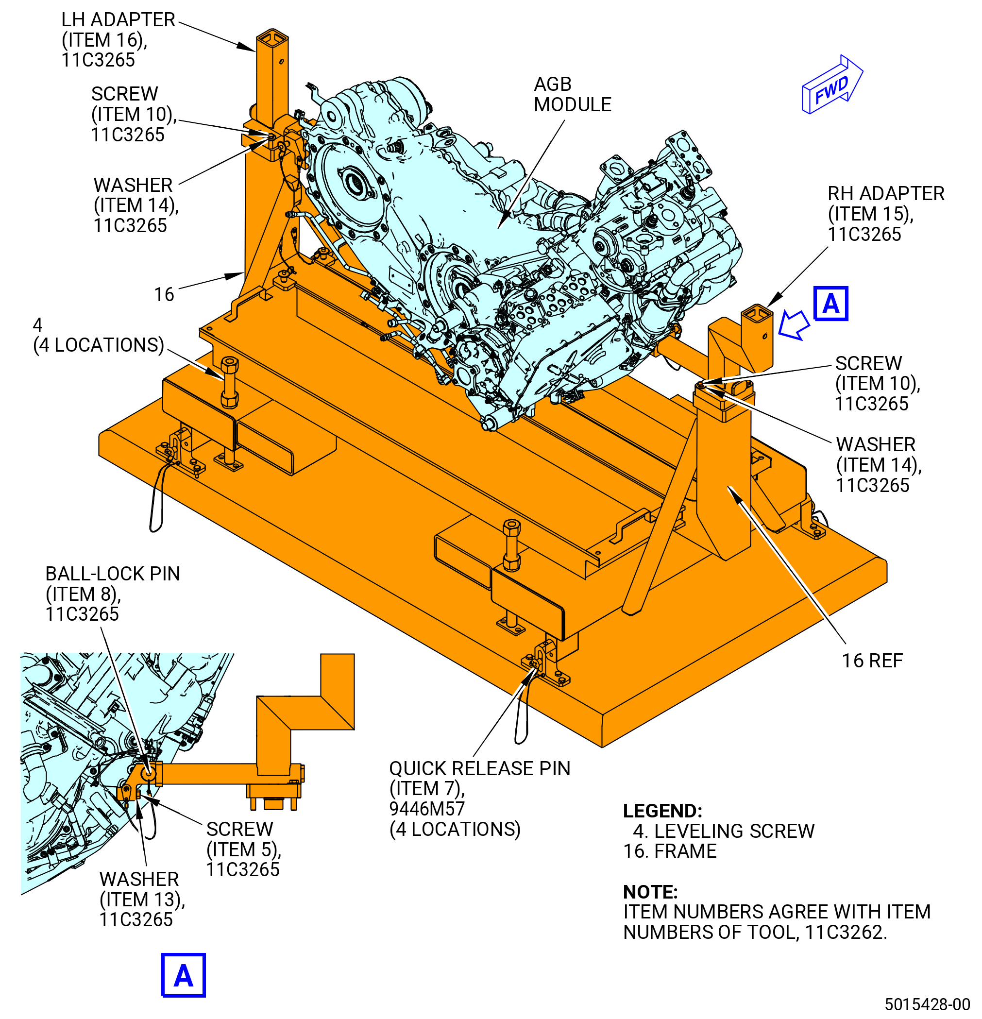
| A. | This procedure gives instructions to install the accessory gearbox (AGB) module on the propulsor assembly. The AGB module is assumed to be in the 11C3262 install/remove fixture, in the 9446M57 raise/lower fixture , and the 11C3265 bracket set . Refer to Figure 401. |
| • |
|
| • |
|
| • |
|
| B. | This procedure assumes that the propulsor assembly is in the horizontal position and supported by 11C3281 pedestals or the 11C3044 engine module adapter assembly. |
| NOTE: |
|
| NOTE: |
|
| C. | Make sure that there are no foreign materials in the engine. |
| D. | Make sure that the mating parts are serviceable and have no deterioration. |
| E. | Make sure that the correct engine supports are in position at the engine and the assemblies when you do the maintenance. |
| F. | Read this procedure and become familiar with the instructions and special tool usage before you install the AGB Module on the propulsor assembly. |
| G. | The torque values given in this procedure are the actual torque to apply to the fastener. If a torque multiplier is used, do the necessary calculations to find the specified torque, the value that appears on the scale or dial of the torque wrench. Refer to TASK 70-51-00-400-004 (TIGHTENING PRACTICES AND TORQUE VALUES) . |
| H. | Follow the instructions to safety parts with safety wire, safety cable, cotter pins, or tab washers. Refer to TASK 70-11-00-400-001 (FASTENER RETENTION PROCEDURES) . |
| 2 . | Tools, Equipment, and Materials. |
| NOTE: |
|
| A. | Tools and Equipment. |
| (1) | Special Tools. |
| (2) | Standard Tools and Equipment. |
|
| (3) | Locally Manufactured Tools. None. |
| B. | Consumable Materials. |
|
| C. | Referenced Procedures. |
|
| D. | Expendable Parts. |
|
| 3 . | Procedure. |
| Subtask 72-00-05-420-024 |
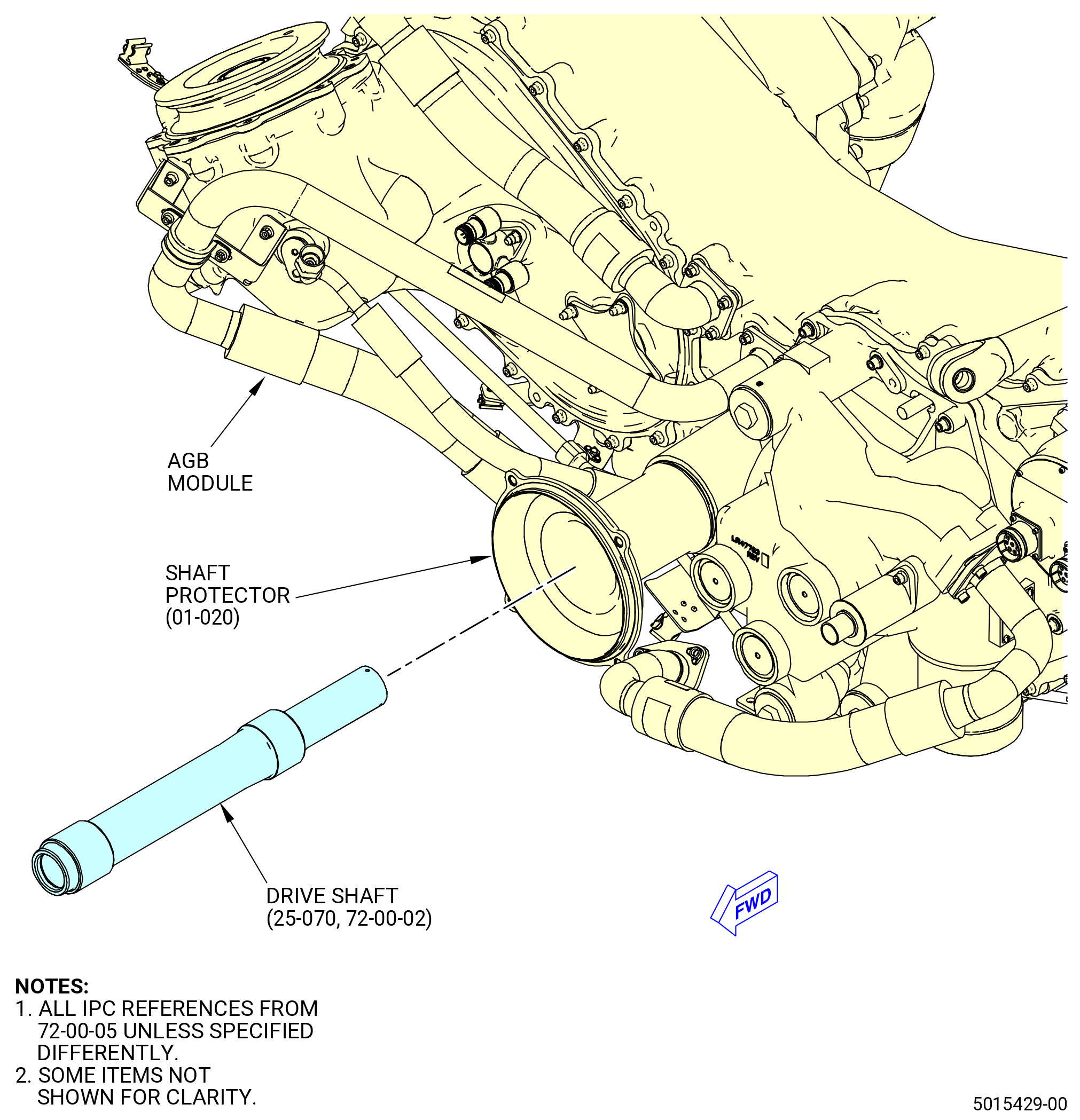
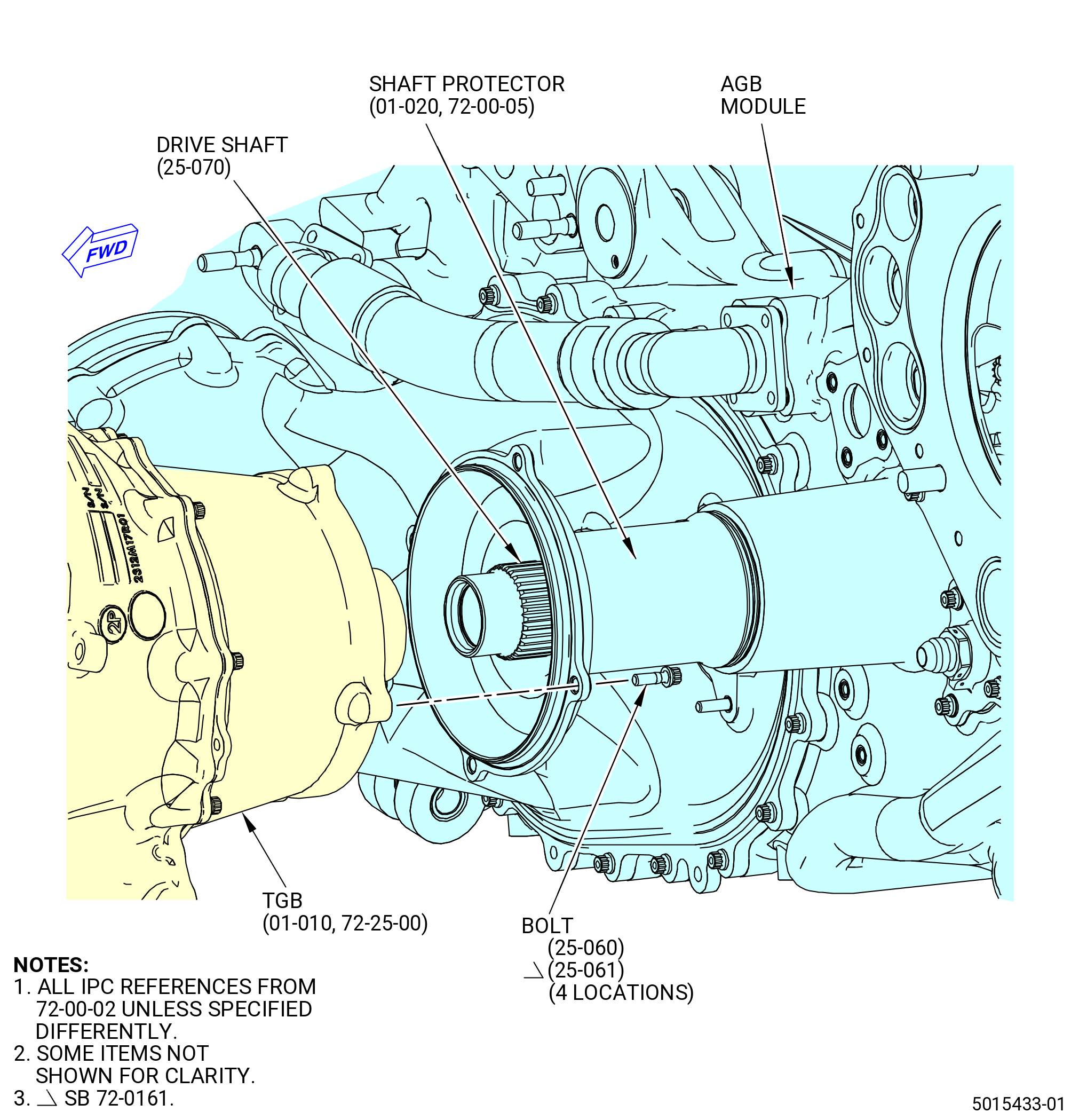
| A. | Install the horizontal drive shaft (drive shaft) (25-070 , 72-00-02) (SIN 03301) into the horizontal shaft protector (shaft protector) (01-020) (SIN 03302) on the AGB module. Refer to Figure 402 and do as follows: |
| WARNING: |
|
| CAUTION: |
|
| (1) | Apply the C02-019 engine oil or C02-023 engine oil to the splines of the drive shaft. |
| (2) | Install the aft end of the drive shaft through the shaft protector and into the bore on the forward face of the AGB module. |
| (3) | Align the splines of the drive shaft with the spline on the AGB module. |
| (4) | Use a nylon drift and a hammer to hit the forward face of the drive shaft to engage the drive shaft splines through the oil dam seal in the AGB module. |
| (5) | Install the drive shaft as far as possible into the AGB module. |
| Subtask 72-00-05-420-026 |
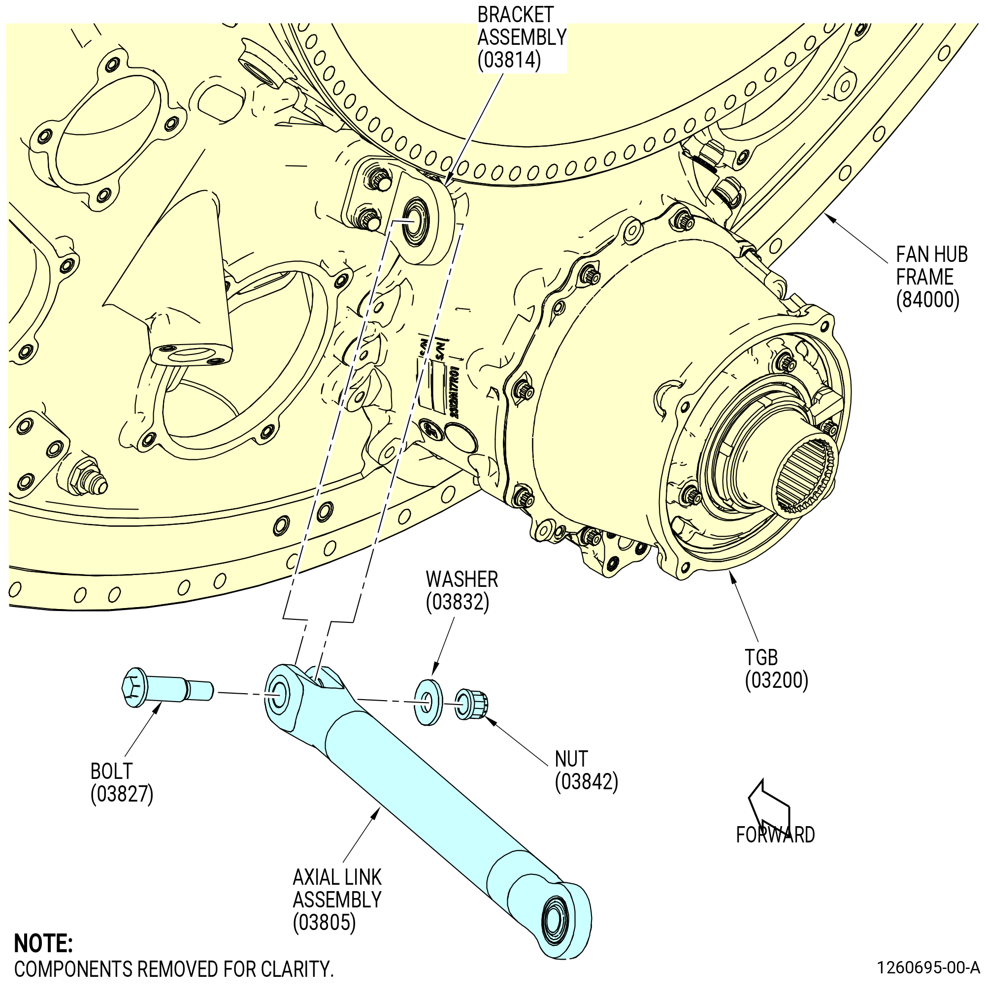
| B. | Install the left side inboard axial link assembly (link) (03805) to the fan hub frame assembly as follows. Refer to Figure 403. |
| (1) | Apply C02-060 anti-seize compound to the thread, washer face, and shank of the bolt (03827). |
| (2) | Apply C02-060 anti-seize compound to the threads and washer face of the nut (03842). |
| (3) | Install the forward end of the link to the bracket (03814) on the fan hub frame with the bolt (03827), washer (03832), and nut (03842). Make sure that the bolt head points to the 9:00 o'clock position of the fan hub frame. |
| (4) | Torque the nut (03842) to 552-648 lb in. (62.4-73.2 N.m). |
| (5) | Secure the aft end of the link to the fan hub frame with a plastic tie wrap to prevent interference during the installation of the AGB module. |
| Subtask 72-00-05-420-001 |
| C. | Install the AGB module to the propulsor assembly mounts. Refer to Figure 401 and do as follows: |
| NOTE: |
|
| NOTE: |
|
| (1) | Put the 9446M57 raise/lower fixture below the 11C3262 install/remove fixture. If necessary, adjust the leveling screws (item 4) on the 11C3262 install/remove fixture until the fixture is supported by the 9446M57 raise/lower fixture evenly. |
| WARNING: |
|
| CAUTION: |
|
| (2) | Lift the 9446M57 raise/lower fixture until the 11C3262 install/remove fixture is off the floor. |
| (3) | Use the 9446M57 raise/lower fixture to lift or lower the AGB module in position under the engine. |
| (4) | Use the leveling screws (item 4) on the 11C3262 install/remove fixture for final adjustments. |
| (5) | Align the links on the propulsor assembly with the clevises on the AGB module. If necessary adjust the position to get correct alignment. |
| (6) | Apply C02-058 lubricant to the threads and washer face of the bolts (03822). |
| (7) | Apply C02-060 anti-seize compound to the shank of the vertical links (03825, 0382C). |
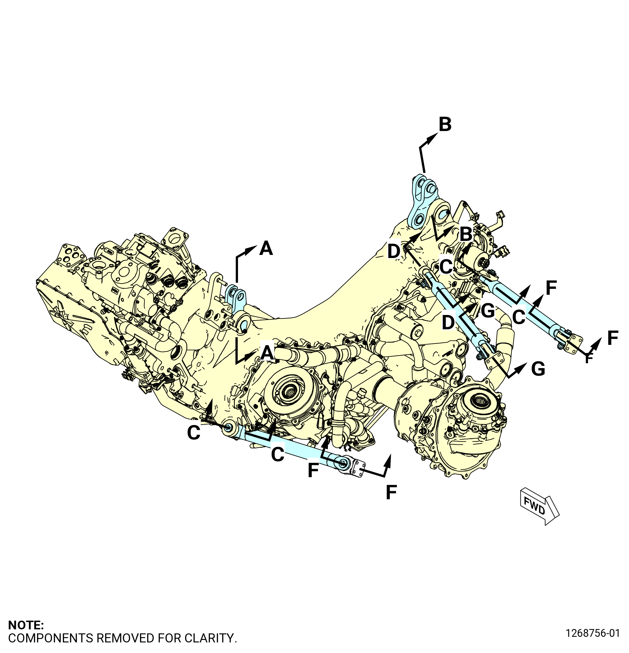
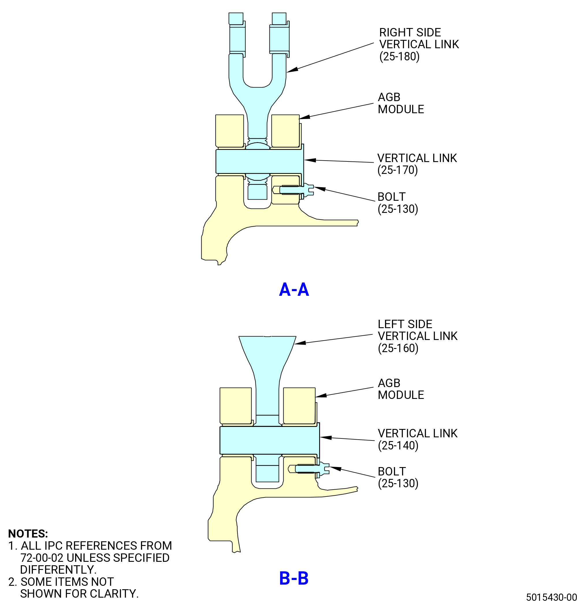
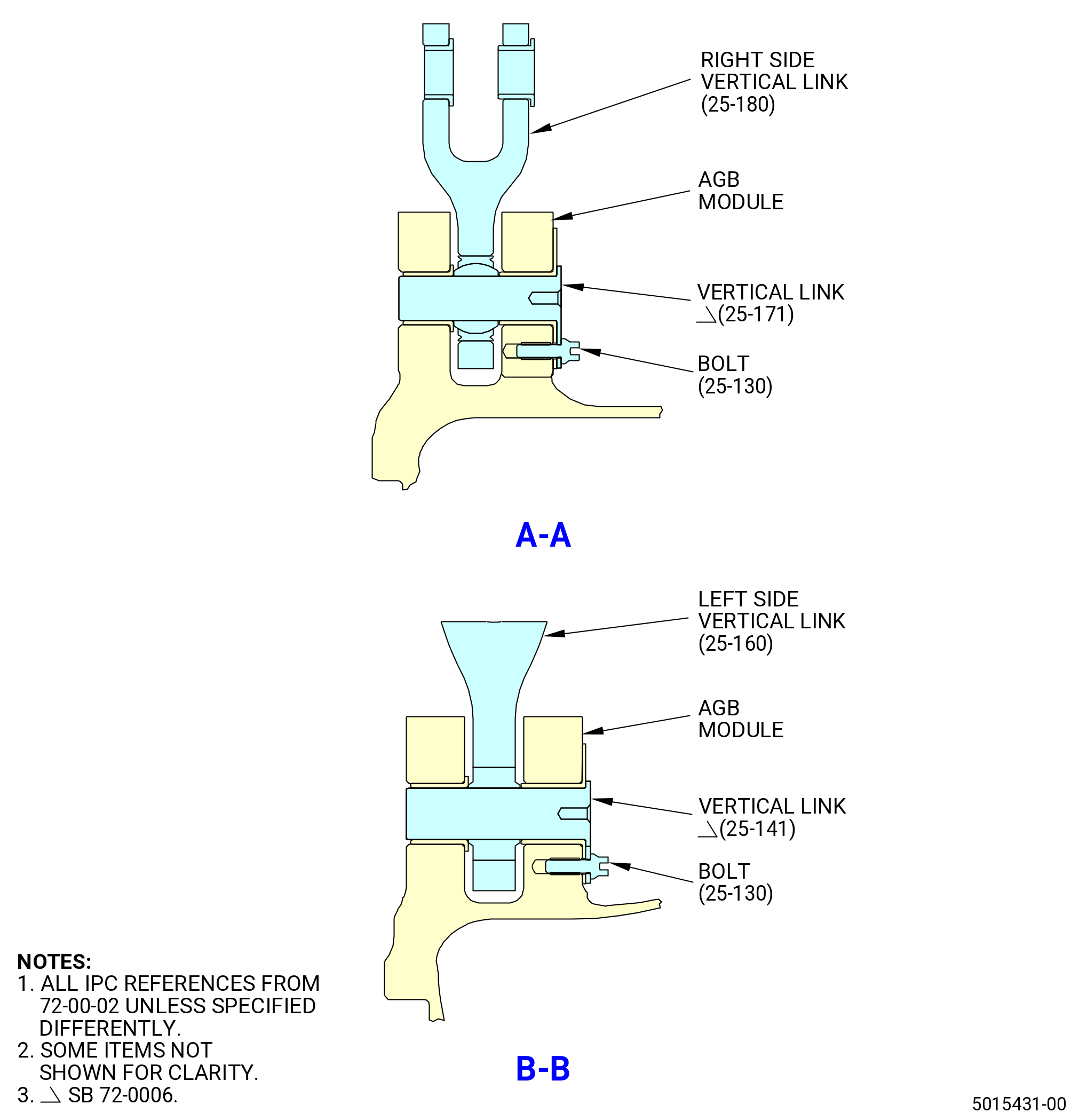
| (8) | Install the vertical link (0382C) to the left side of the engine at the left side vertical link (03801). Refer to Figure 404. |
| (9) | Install the bolt (03822) into the vertical link (0382C) hand-tight. |
| (10) | Install the vertical link (03825) to the right side of the engine at the right side vertical link (03802). |
| (11) | Install the bolt (03822) into the vertical link (03825) hand-tight. |
| (12) | Torque the bolts (25-130 , 72-00-02) (SIN 03822) to 106 to 124 lb. in. (12.0 to 14.0 Nm). |
| Subtask 72-00-05-420-004 |
| D. | Install the AGB horizontal links as follows. Refer to Figure 404. |
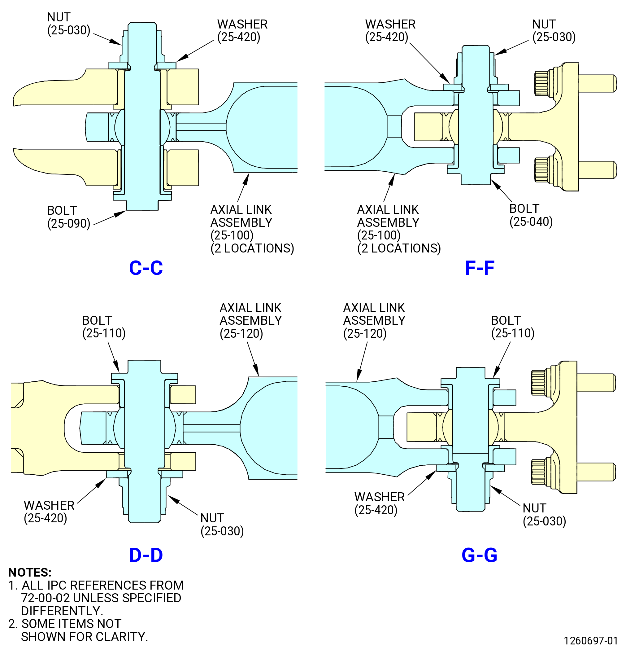
| (1) | Install the left side inboard axial link assembly (03805) as follows: |
| (a) | Apply C02-060 anti-seize compound to the threads, washer face, and shank of the bolt (03829). |
| (b) | Remove the plastic tie wrap (or equivalent) from the aft end of the axial link assembly (03805) and the fan hub frame. Refer to Figure 403. |
| (c) | Attach the axial link assembly (25-120 , 72-00-02) (SIN 03805) at the 6:30 o'clock position to the clevis on the AGB module with the bolt (25-110 , 72-00-02) (SIN 03829), washer (25-420 , 72-00-02) (SIN 03830), and nut (25-030 , 72-00-02) (SIN 03842). Make sure that the bolthead is up and pointed to the 9:00 o'clock position. |
| (d) | Torque the nuts (03842) to 552-648 lb in. (62.4-73.2 N.m). |
| WARNING: |
|
| (e) | Clean excess C02-060 anti-seize compound off axial link assembly with C04-035 isopropyl alcohol. |
| (2) | Install the left side outboard axial link assembly (03804) as follows: |
| (a) | Apply C02-060 anti-seize compound to the threads, washer face, and shank of the bolts (03823, 03827) and the threads and washer face of the nuts (03842). |
| (b) | Install the axial link assembly (03804) at the 7:30 o'clock position between the bracket (03814) on the fan frame and the clevis on the AGB module. |
| (c) | Attach the forward end of the axial link with the bolt (03827), washer (03832) and the nut (03842) to the fan frame. Make sure that the bolt head is up and pointed to the 9:00 o'clock position. |
| (d) | Attach the aft end of the axial link with the bolt (03823), washer (03832), and the nut (03842) to the AGB module. Make sure that the bolt head is up and pointed to the 9:00 o'clock position. |
| (e) | Torque the nuts (03842) to 552-648 lb in. (62.4-73.2 N.m). |
| WARNING: |
|
| (f) | Clean excess C02-060 anti-seize compound off the axial link assembly with C04-035 isopropyl alcohol. |
| (3) | Install the right side outboard axial link assembly (03804) as follows: |
| (a) | Apply C02-060 anti-seize compound to the threads, washer face, and shank of the bolt (03823, 03827) and the threads and washer face of the nuts (03842). |
| (b) | Install the axial link assembly (03804) at the 4:30 o'clock position between the bracket (03814) on the fan frame and the clevis on the AGB module. |
| (c) | Attach the forward end of the axial link with the bolt (03827), washer (03832), and the nut (03842) to fan frame. Make sure that the bolt head is up and pointed to the 3:00 o'clock position. |
| (d) | Attach the aft end of the axial link with the bolt (03823), washer (03832) and the nut (03842) to the AGB. Make sure that the bolt head is up and pointed to the 3:00 o'clock position. |
| (e) | Torque the nuts (03842) to 552-648 lb in. (62.4-73.2 N.m). |
| WARNING: |
|
| (f) | Clean excess C02-060 anti-seize compound off the axial link assembly with C04-035 isopropyl alcohol. |
| Subtask 72-00-05-420-006 |
| E. | Remove the 11C3265 bracket set and 11C3262 install/remove fixture from the AGB module. Refer to Figure 401 and do as follows: |
| (1) | Remove the left and right side ball lock pins (item 8) of the 11C3265 bracket set from the frame (item 15) of the 11C3262 install/remove fixture. |
| (2) | Lower the 9446M57 raise/lower fixture and the 11C3262 install/remove fixture and move away from the engine. |
| (3) | Remove the screws (item 5) and the washers (item 13) of the 11C3265 bracket set from the AGB module. |
| (4) | Remove the 11C3265 bracket set. |
| Subtask 72-00-05-420-007 |
| F. | Attach the horizontal drive shaft (drive shaft) (25-070 , 72-00-02) (SIN 03301) to the transfer gearbox assembly (TGB) (01-010 , 72-25-00) (SIN 03200) as follows. Refer to Figure 402 and Figure 405. |
| (1) | Install the drive shaft to the TGB as follows: |
| CAUTION: |
|
| (a) | Remove the four self-locking nuts (01-250 , 72-64-00) (SIN 038W0) that attach the cover (01-260 , 72-64-00) (SIN 038AF) to the forward face of the AGB module. Use nylon pry (item 7) of 11C3990 tool set to remove the cover. |
| CAUTION: |
|
| (b) | Use a 1/2 inch drive extension inserted into the motoring pad and 1/2 inch drive ratchet, turn as necessary to align the splines of the drive shaft and the TGB. |
| (c) | When splines of the AGB module and the TGB are aligned, engage the drive shaft into the TGB as far as possible by hand. |
| (d) | Use a nylon drift and a hammer to hit the aft face of the drive shaft to engage the drive shaft splines through the oil dam seal in the TGB. |
| WARNING: |
|
| CAUTION: |
|
| (e) | Apply C02-019 engine oil or C02-023 engine oil to the lead in chamfer on the TGB. |
| CAUTION: |
|
| (f) | Use steady, even pressure while you twist the shaft protector (03302), and move the shaft protector forward until mated with the flange of the TGB housing. |
| (g) | Move the retaining ring (03391) forward and align the boltholes with the flange on the TGB housing. |
| (h) | Apply C02-058 lubricant to the threads and washer faces of the bolts (25-060 , 72-00-02) (SIN 03320) or (25-061 , 72-00-02) (SIN 03320). |
| (i) | Attach the shaft protector (01-020) (SIN 03302) and the retaining ring (01-030) (SIN 03391) to the TGB with the bolts (25-060 , 72-00-02) (SIN 03320) or (25-061 , 72-00-02) (SIN 03320). |
| (j) | Torque the bolts (25-060 , 72-00-02) (SIN 03320) or (25-061 , 72-00-02) (SIN 03320) to 106-124 lb in. (12.0-14.0 Nm). |
| (k) | Make sure that the preformed packing (01-040) (SIN 03350) is seated correctly by trying to install a 0.010 inch (0.25 mm) feeler gauge between the horizontal shaft protector and the shaft bore on the AGB housing as follows: |
| 1 | If the feeler gauge moves freely into the bore at any location, the preformed packing is damaged or not seated correctly and must be replaced. |
| 2 | If the feeler gauge does not move freely into the bore at any location, the preformed packing is seated correctly. |
| (2) | Make sure that the drive shaft is correctly installed as follows: |
| CAUTION: |
|
| (a) | Use a 1/2 inch drive extension inserted into the motoring pad and a 0-100 lb ft. (0-150 N.m) dial torque wrench, turn the core rotor CW while you listen for unusual noises. |
| NOTE: |
|
| (b) | Make sure that the core rotor can be turned independently of the fan/LPT rotor. |
| (c) | If more than 50 lb ft. (60 N.m) of torque is needed to turn the core rotor, contact the Assembly Engineer or Supervisor. |
| (d) | Remove the 1/2 inch drive extension and dial torque wrench. |
| (e) | Install the cover on the motoring pad with the self-locking nuts (038W0). Install the self-locking nuts in a criss-cross pattern. |
| (f) | Torque the self-locking nuts (038W0) to 57-67 lb in. (6.4-7.6 N.m). |
| Subtask 72-00-05-420-009 |
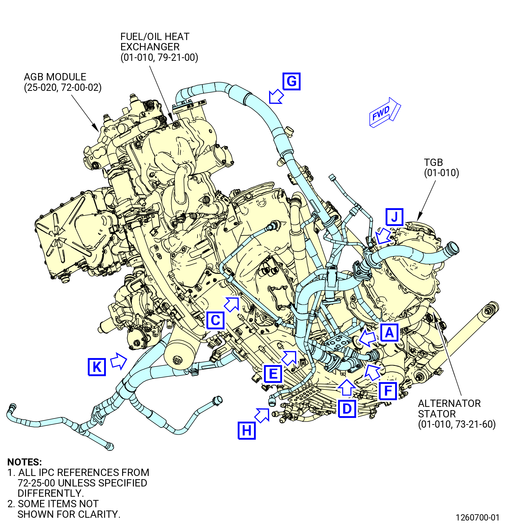
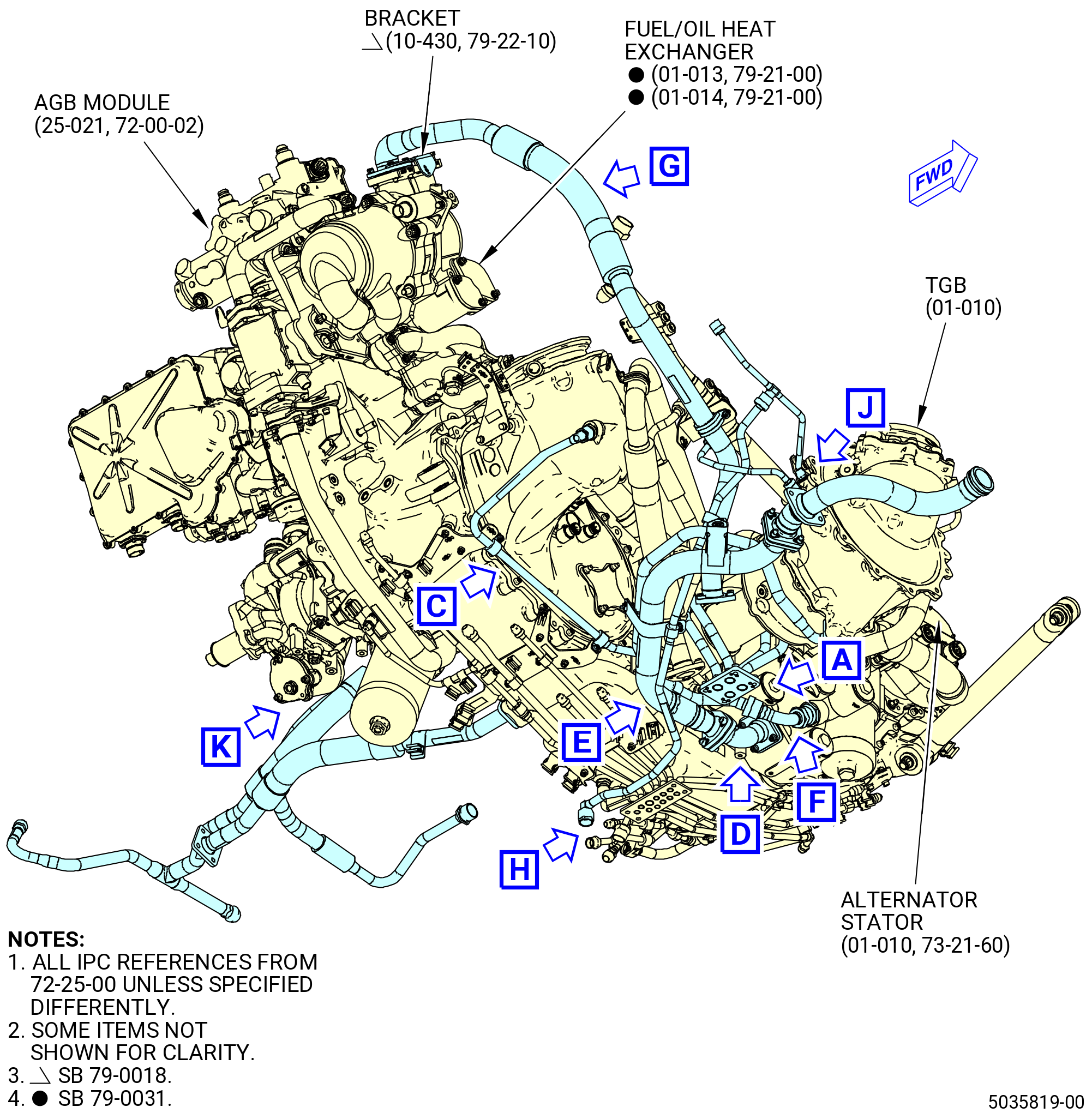
| G. | Attach the AGB lubrication system hoses and tubes as follows. Refer to Figure 406. |
| (1) | Find the TGB (01-010 , 72-25-00) (SIN 03200) at the 6:00 o'clock position on the AGB module, forward looking aft (FLA). |
| Subtask 72-00-05-420-036 |
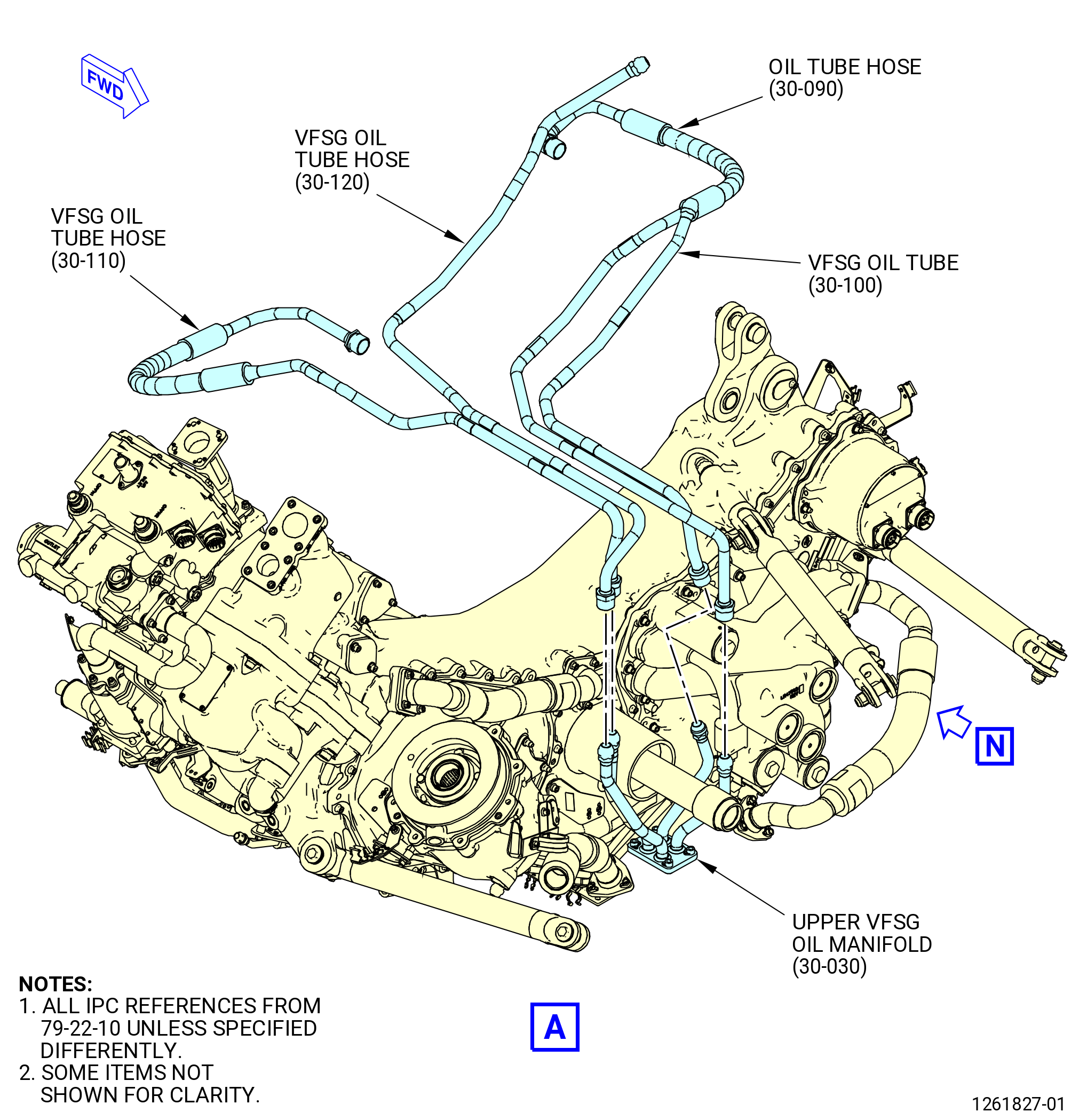
| * * * PRE SB 79-0014( Non-Optimized VFSG Cooling System ) |
| (2) | Attach the upper VFSG oil manifold (30-030 , 79-22-10) (SIN 99007) to the B-nuts on the oil tube hose (30-090 , 79-22-10) (SIN 5210J), VFSG oil tube (30-100 , 79-22-10) (SIN 5210B), and VFSG oil tube hoses (30-110 , 79-22-10) (SIN 5210U) and (30-120 , 79-22-10) (SIN 5210K). |
| * * * END PRE SB 79-0014 |
| Subtask 72-00-05-420-037 |
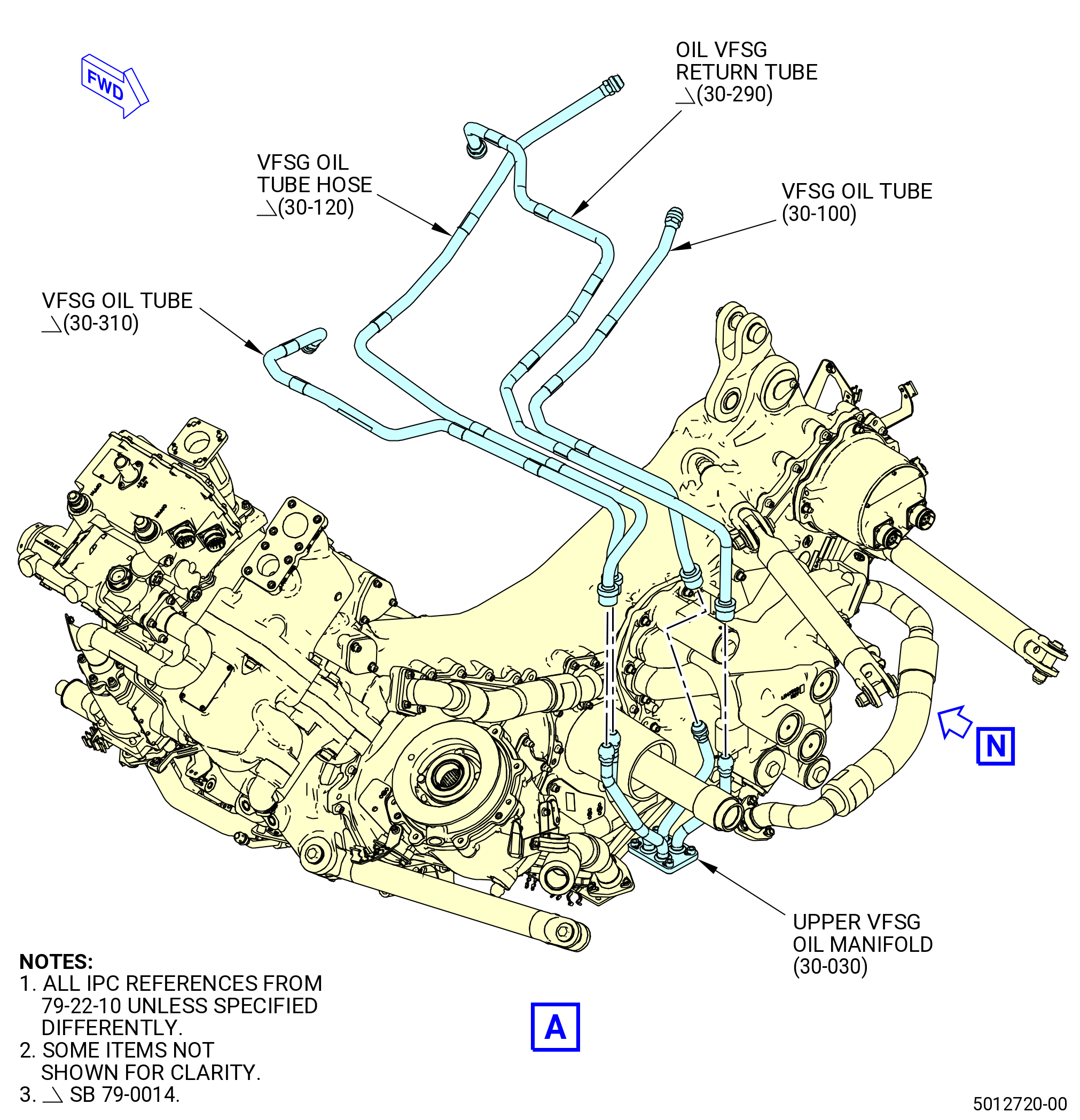
| * * * SB 79-0014( Optimized VFSG Cooling System ) |
| (2).A. | Attach the upper VFSG oil manifold (30-030 , 79-22-10) (SIN 99007) to the B-nuts on the oil VFSG return tube (30-290 , 79-22-10) (SIN 5210T), VFSG oil tube hose (30-120 , 79-22-10) (SIN 5210K), and VFSG oil tubes (30-100 , 79-22-10) (SIN 5210B) and (30-310 , 79-22-10) (SIN 5210Y). |
| * * * END SB 79-0014 |
| Subtask 72-00-05-420-038 |
| (3) | Torque the B-nuts to 662-778 lb in. (74.8-87.9 N.m). |
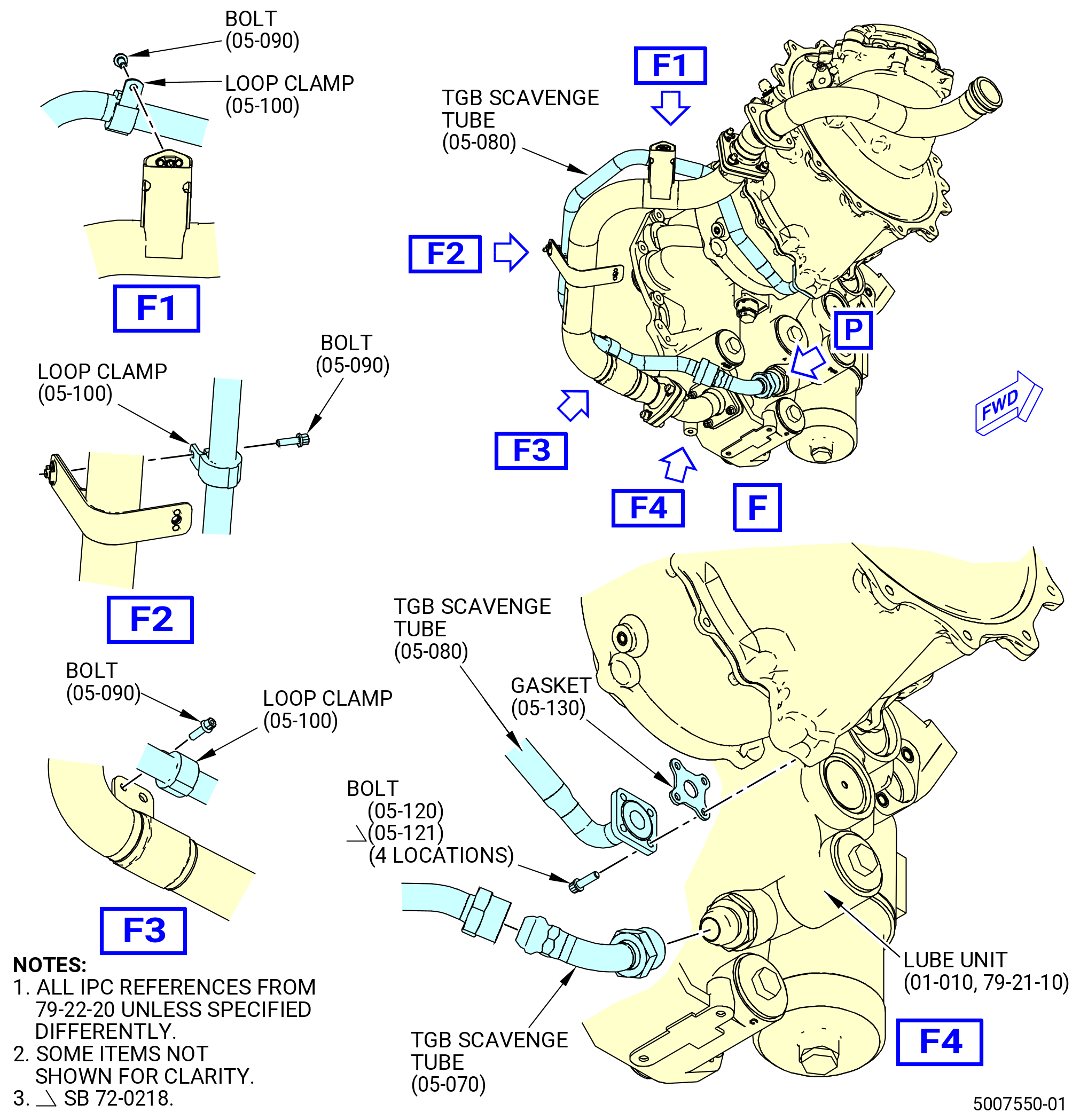
| (4) | Attach the transfer gear box (TGB) scavenge tube (05-070 , 79-22-20) (SIN 45002) to the lube and scavenge pump (lube unit) (01-010 , 79-21-10) (SIN 40400) with the B-nut at the forward side of the AGB at the 6:00 o'clock position. Hand tighten the B-nut. |
| WARNING: |
|
| CAUTION: |
|
| (5) | Apply C02-019 engine oil or C02-023 engine oil to the gasket (05-130 , 79-22-20) (SIN 45050) and C02-058 lubricant to the bolts (05-120 , 79-22-20) (SIN 45020) or (05-121 , 79-22-20) (SIN 45020). |
| (6) | Attach the TGB scavenge tube (45001) to the TGB scavenge tube (45002) with the B-nut. |
| (7) | Attach the TGB scavenge tube (05-080 , 79-22-20) (SIN 45001) to the aft side of the TGB (01-010 , 72-25-00) (SIN 03200) with the gasket (05-130 , 79-22-20) (SIN 45050) and bolts (05-120 , 79-22-20) (SIN 45020) or (05-121 , 79-22-20) (SIN 45020) hand-tight. |
| (8) | Attach the TGB scavenge tube (45001) to the AGB module with the loop clamps (45080) and bolts (45021) hand-tight. |
| (9) | Triple torque the B-nuts that attach the TGB scavenge tube (05-080 , 79-22-20) (SIN 45001) to the TGB scavenge tube (05-070 , 79-22-20) (SIN 45002), and the TGB scavenge tube (05-070 , 79-22-20) (SIN 45002) to the AGB module to 78-92 lb ft (106-125 N.m). Refer to TASK 70-51-00-400-004 (TIGHTENING PRACTICES AND TORQUE VALUES). |
| (10) | Torque the four bolts (05-120 , 79-22-20) (SIN 45020) or (05-121 , 79-22-20) (SIN 45020) at the TGB to 51-59 lb in. (5.8-6.7 N.m) in a criss-cross pattern. |
| (11) | Torque the three bolts (45021) for the loop clamps (45080) to 32-38 lb in. (3.6-4.3 N.m). |
| Subtask 72-00-05-420-039 |
| * * * PRE SB 79-0018( MFOHX without Indicating Capability ) |
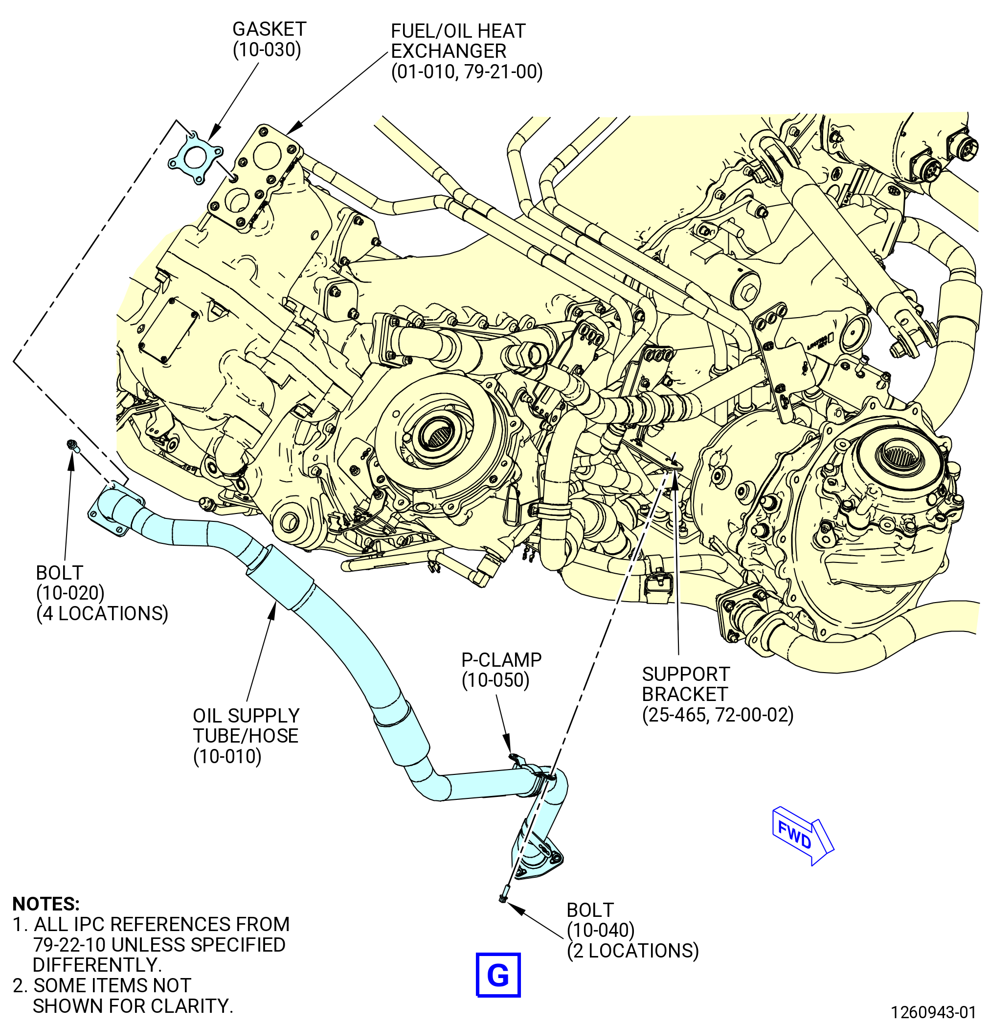
| (12) | Attach the tube hose (oil supply tube/hose) (10-010 , 79-22-10) (SIN 44800) to the fuel/oil heat exchanger (01-010 , 79-21-00) (SIN 40700) as follows: |
| WARNING: |
|
| CAUTION: |
|
| (a) | Apply C02-019 engine oil or C02-023 engine oil to the flange seal gasket (gasket) (10-030 , 79-22-10) (SIN 44851) and bolts (10-020 , 79-22-10) (SIN 44824). |
| (b) | Attach the oil supply tube/hose (10-010 , 79-22-10) (SIN 44800) at the fuel/oil heat exchanger with the gasket (10-030 , 79-22-10) (SIN 44851) and the bolts (10-020 , 79-22-10) (SIN 44824) to the small port outboard with the OIL OUT mark. |
| * * * END PRE SB 79-0018 |
| Subtask 72-00-05-420-040 |
| * * * SB 79-0018( MFOHX with Indicating Capability ) |
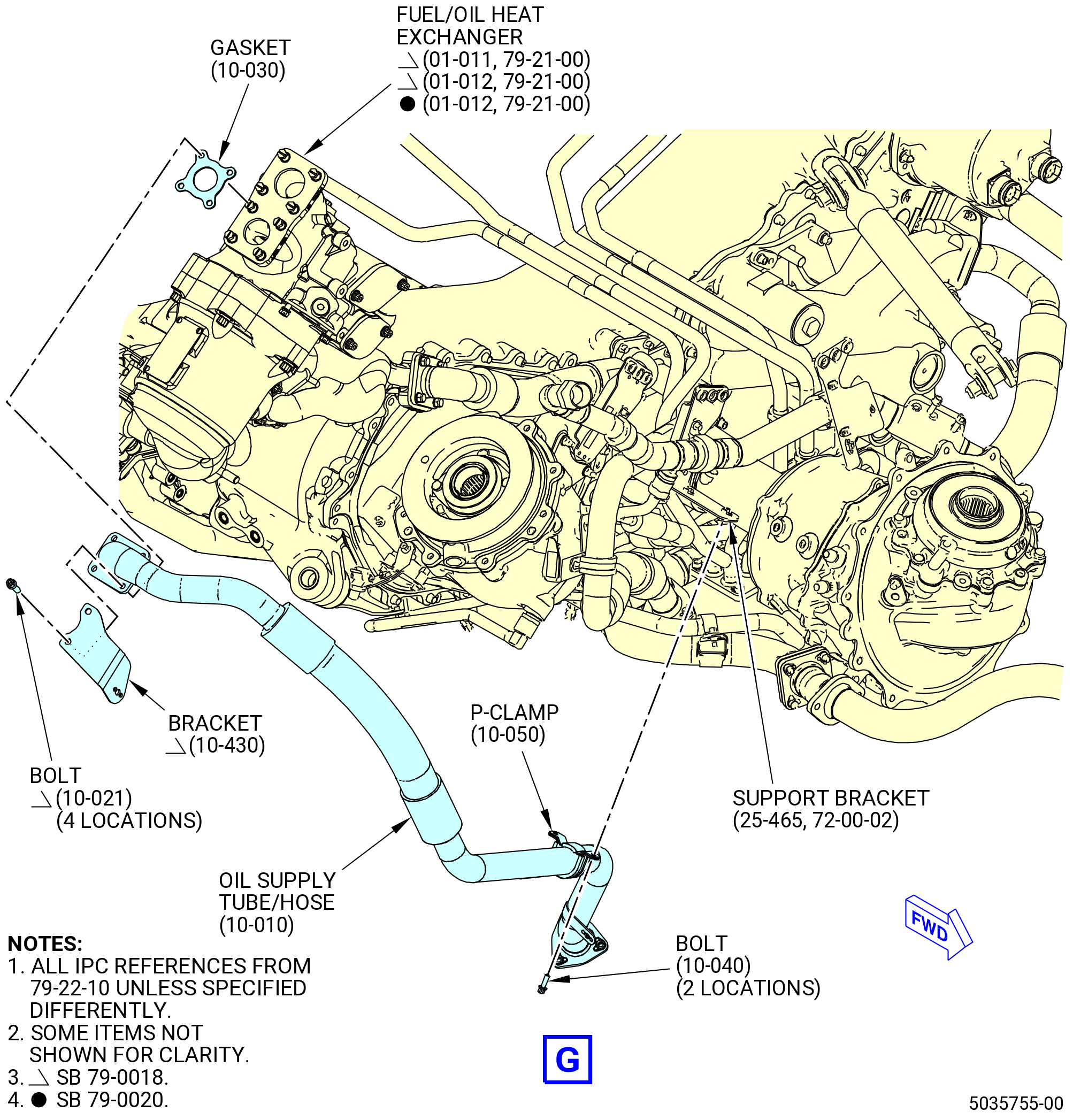
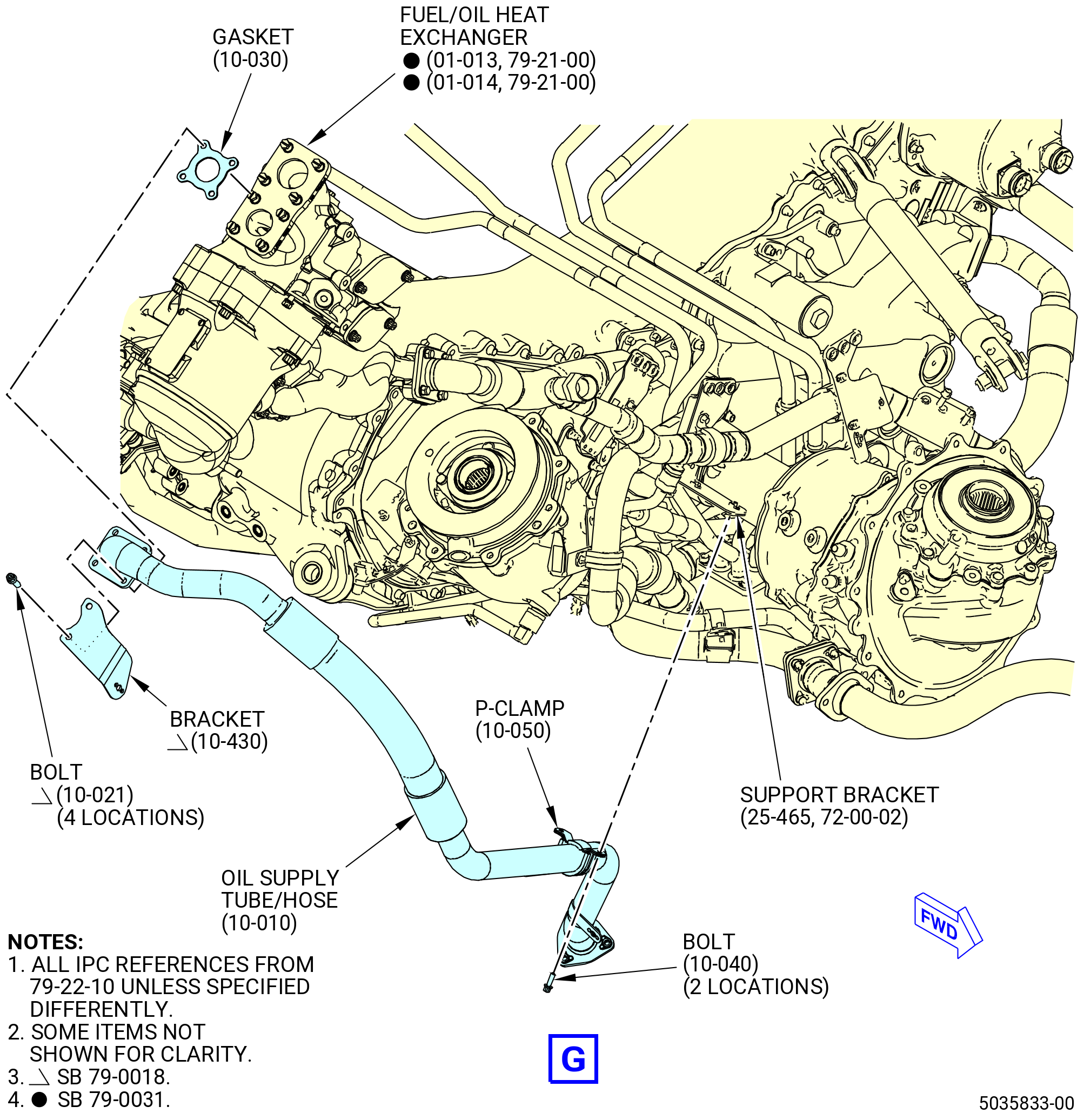
| (12).A. | Attach the oil supply tube/hose (10-010 , 79-22-10) (SIN 44800) to the fuel/oil heat exchanger (01-011 , 79-21-00) (SIN 40700) or (01-012 , 79-21-00) (SIN 40700) or (01-013 , 79-21-00) (SIN 40700) or (01-014 , 79-21-00) (SIN 40700) as follows: |
| WARNING: |
|
| CAUTION: |
|
| (a) | Apply C02-019 engine oil or C02-023 engine oil to the gasket (10-030 , 79-22-10) (SIN 44851) and bolts (10-021 , 79-22-10) (SIN 44824). |
| (b) | Attach the oil supply tube/hose (10-010 , 79-22-10) (SIN 44800) at the fuel/oil heat exchanger with the bracket (10-430 , 79-22-10) (SIN 5901D), the gasket (10-030 , 79-22-10) (SIN 44851), and the bolts (10-021 , 79-22-10) (SIN 44824) to the small port outboard with the OIL OUT mark. |
| * * * END SB 79-0018 |
| Subtask 72-00-05-420-041 |
| (13) | Attach the oil supply tube/hose to the support bracket (25-465 , 72-00-02) (SIN 44811) with the P-clamp (10-050 , 79-22-10) (SIN 44881) and bolts (10-040 , 79-22-10) (SIN 44826) on the forward side of the AGB module. |
| (14) | Keep the protective cap on the other end of the oil supply tube/hose at this time. |
| (15) | Torque the four bolts (10-020 , 79-22-10) (SIN 44824) to 106-124 lb in. (12.0-14.0 N.m). |
| (16) | Torque the two bolts (10-040 , 79-22-10) (SIN 44826) to 60-70 lb in. (6.8-7.9 N.m). |
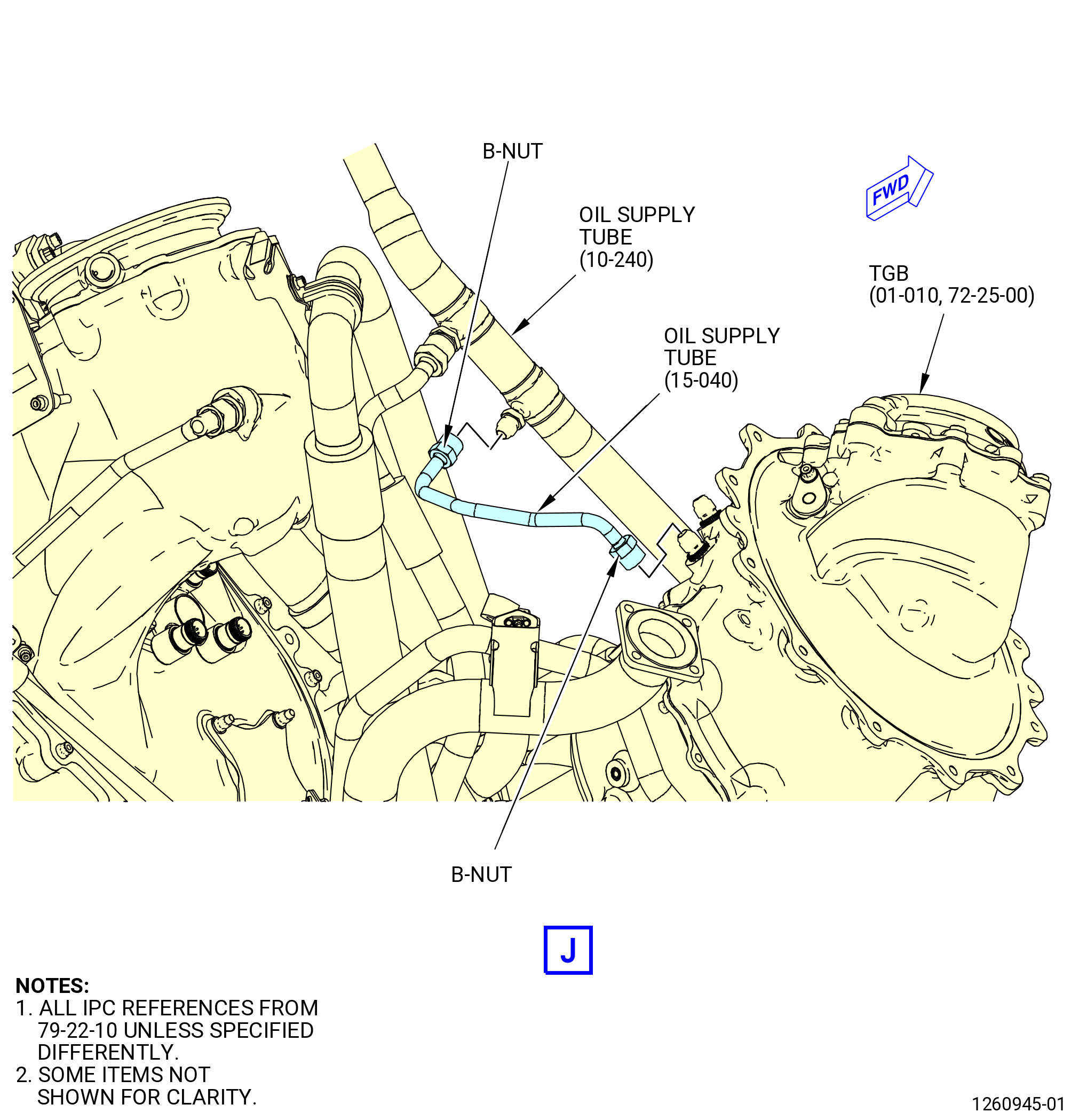
| (17) | Attach the oil supply tube (15-040 , 79-22-10) (SIN 44100) to the aft side of the TGB (01-010 , 72-25-00) (SIN 03200) with the B-nut. Torque the B-nut to 262-308 lb in. (29.6-34.8 N.m). |
| (18) | Attach the oil supply tube (15-040 , 79-22-10) (SIN 44100) to the oil supply tube (10-240 , 79-22-10) (SIN 44401) with the B-nut. Torque the B-nut to 262-308 lb in. (29.6-34.8 N.m). |
| WARNING: |
|
| CAUTION: |
|
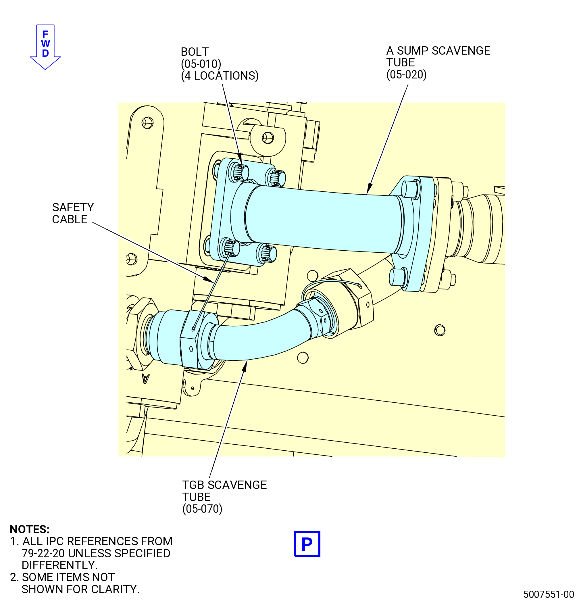
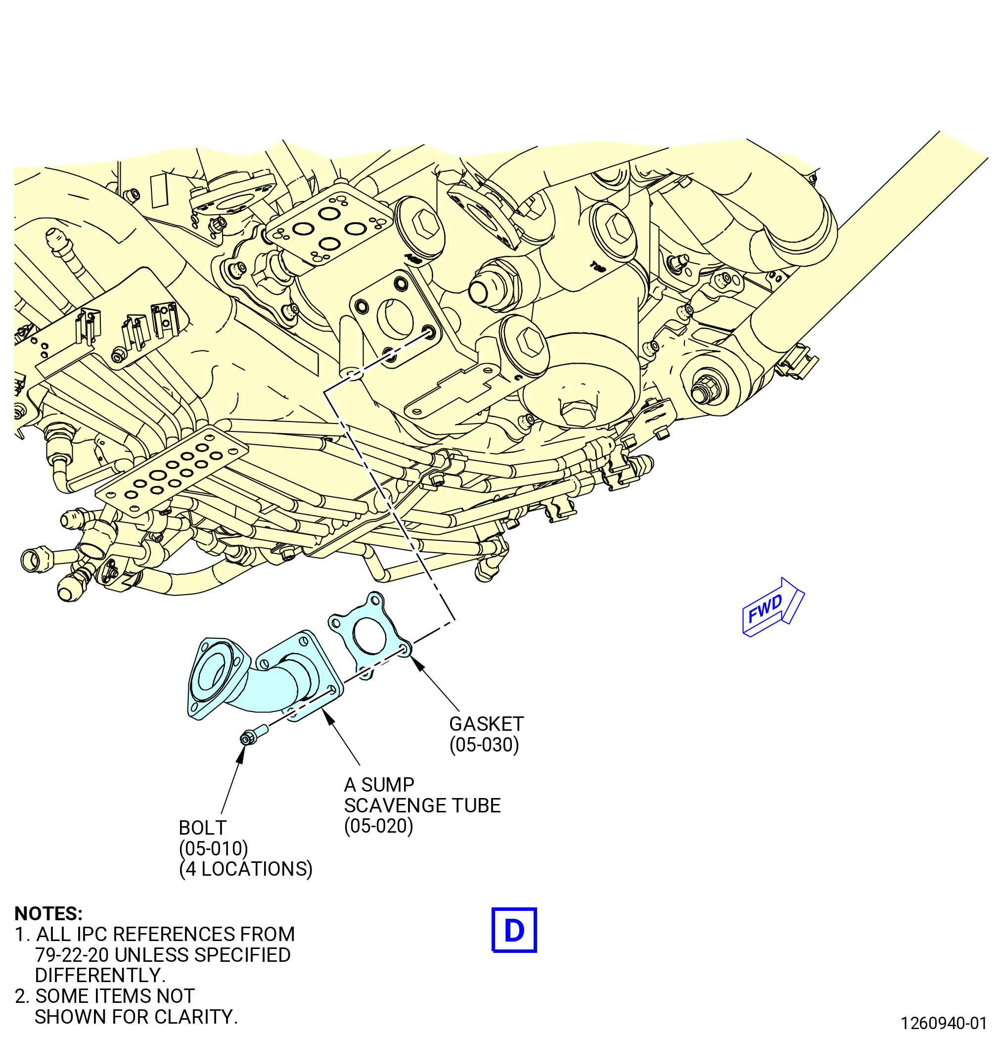
| (19) | Apply C02-019 engine oil or C02-023 engine oil to the gasket (05-030 , 79-22-20) (SIN 45150). |
| (20) | Attach the A sump scavenge tube (05-020 , 79-22-20) (SIN 45101) to the lube unit (01-010 , 79-21-10) (SIN 40400) with the gasket (05-030 , 79-22-20) (SIN 45150) and bolts (05-010 , 79-22-20) (SIN 45121) hand-tight. |
| WARNING: |
|
| CAUTION: |
|
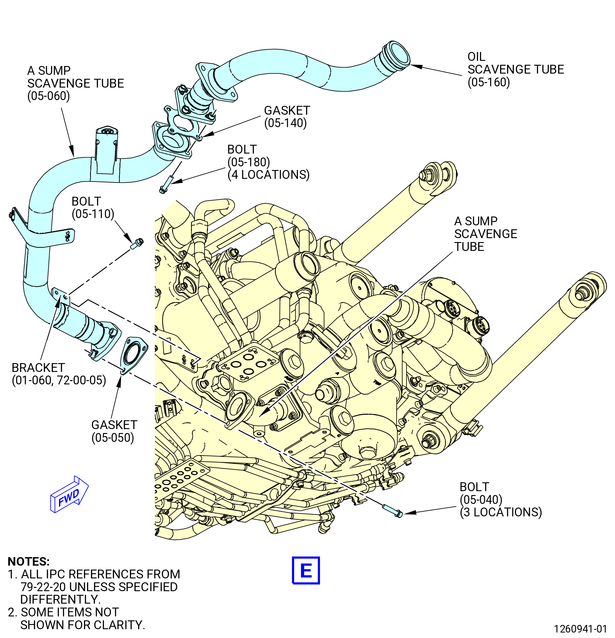
| (21) | Apply C02-019 engine oil or C02-023 engine oil to the gaskets (05-050 , 79-22-20) (SIN 45151) and (05-140 , 79-22-20) (SIN 45152). |
| (22) | Attach the A sump scavenge tube (05-060 , 79-22-20) (SIN 45100) to the A sump scavenge tube (05-020 , 79-22-20) (SIN 45101) with the gasket (05-050 , 79-22-20) (SIN 45151) and bolts (05-040 , 79-22-20) (SIN 45120) hand-tight. |
| (23) | Attach the A sump scavenge tube to the oil scavenge tube (05-160 , 79-22-20) (SIN 451A1) on the fan frame with the gasket (05-140 , 79-22-20) (SIN 45152) and the bolts (05-180 , 79-22-20) (SIN 45123) hand-tight. |
| (24) | Attach the A sump scavenge tube to the AGB module with the bracket (01-060) (SIN 45010) and bolt (05-110 , 79-22-20) (SIN 45122) hand-tight. |
| (25) | Torque the four bolts (05-010 , 79-22-20) (SIN 45121) where the A sump scavenge tube (05-020 , 79-22-20) (SIN 45101) is connected to the lube unit (01-010 , 79-21-10) (SIN 40400) to 106-124 lb in. (12.0-14.0 N.m) in a criss-cross pattern. |
| (26) | Torque the three bolts (05-040 , 79-22-20) (SIN 45120) to 106-124 lb-in. (12.0-14.0 N.m) in a criss-cross pattern. |
| (27) | Torque the four bolts (05-180 , 79-22-20) (SIN 45123) to 106-124 lb-in. (12.0-14.0 N.m) in a criss-cross pattern. |
| (28) | Torque the bolt (05-110 , 79-22-20) (SIN 45122) at the bracket (01-060) (SIN 45010) to 106-124 lb in. (12.0-14.0 N.m). |
| WARNING: |
|
| CAUTION: |
|
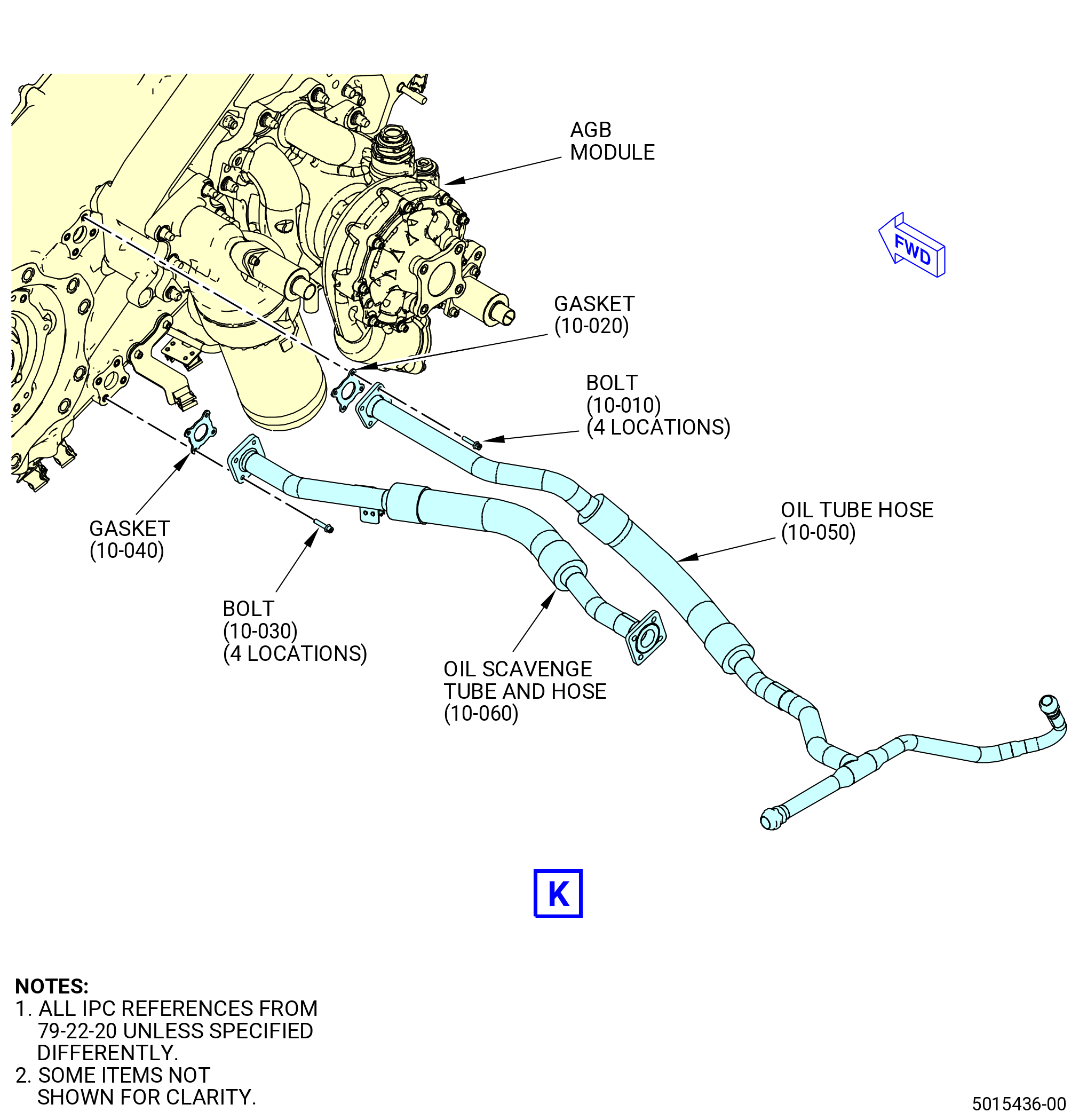
| (29) | Apply C02-019 engine oil or C02-023 engine oil to the gasket (10-040 , 79-22-20) (SIN 45251). |
| (30) | Attach the oil scavenge tube and hose (10-060 , 79-22-20) (SIN 45202) to the aft side of the AGB module with the gasket (10-040 , 79-22-20) (SIN 45251) and bolts (10-030 , 79-22-20) (SIN 45224) hand-tight. |
| (31) | Torque the four bolts (10-030 , 79-22-20) (SIN 45224) where the oil scavenge tube and hose (10-060 , 79-22-20) (SIN 45202) is connected to the AGB module to 51 to 59 lb in. (5.8 to 6.7 Nm) in a criss-cross pattern. |
| (32) | Attach the tube hose (44501) with the B-nut to the oil supply tube (44401). |
| (33) | Attach the oil supply tube and hose (tube hose) (15-030 , 79-22-10) (SIN 44501) with the B-nuts to the air/oil nozzle (10-040 , 72-64-00) (SIN 038D2) and housing on the AGB module as follows: |
| (a) | If necessary, remove the safety wire to help the use of a back-up wrench when you apply torque to the B-nuts of the tube hose (15-030 , 79-22-10) (SIN 44501). |
| (b) | If you removed the safety wire, replace the safety wire after the installation of the tube hose (15-030 , 79-22-10) (SIN 44501). |
| (34) | Torque the B-nuts on the tube hose (44501) to 460-540 lb in. (52.0-61.0 N.m). |
| (35) | Attach the tube hose (44501) to the drain support brackets (37010, 37011) with the bolts (44520) and the loop clamps (44580). |
| (36) | Torque the bolts (44520) to 32-38 lb in. (3.6-4.3 N.m). |
| (37) | Deleted. |
| (38) | Safety the TGB scavenge tube (05-070 , 79-22-20) (SIN 45002) B-nut and the TGB scavenge tube (05-080 , 79-22-20) (SIN 45001) B-nut with C10-071 safety wire or C10-143 safety cable. Refer to Figure 406. |
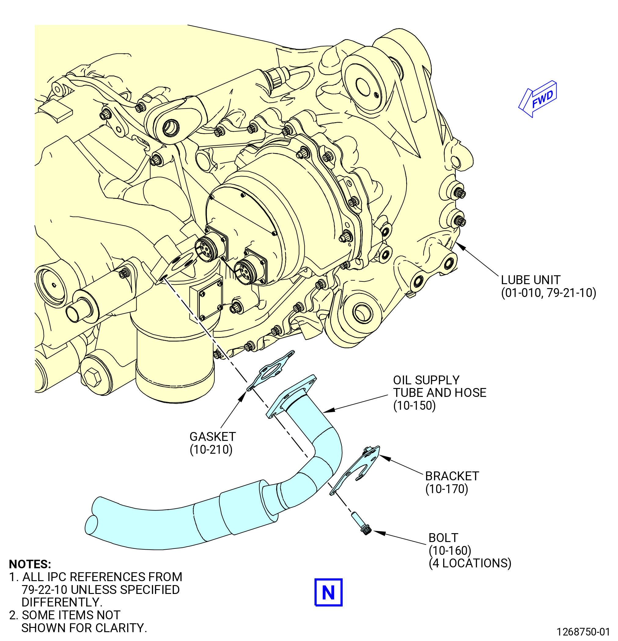
| (39) | Install the bracket (10-170 , 79-22-10) (SIN 37311) to the flange of the oil supply tube and hose (10-150 , 79-22-10) (SIN 44004) at the lube unit (01-010 , 79-21-10) (SIN 40400). |
| Subtask 72-00-05-420-029 |
| * * * SB 72-0059( Machine Bolts Lubrication ) |
| WARNING: |
|
| (40) | Apply C02-023 engine oil to the threads and friction surfaces of the machine bolts (44025). Refer to Figure 406. |
| NOTE: |
|
| * * * END SB 72-0059 |
| Subtask 72-00-05-420-030 |
| (41) | Attach the oil supply tube and hose (10-150 , 79-22-10) (SIN 44004) with the bracket (10-170 , 79-22-10) (SIN 37311), gasket (10-210 , 79-22-10) (SIN 44055), and bolt (10-160 , 79-22-10) (SIN 44025) to the lube unit (01-010 , 79-21-10) (SIN 40400). Torque the bolts (10-160 , 79-22-10) (SIN 44025) to 106-124 lb in. (12.0-14.0 N.m) in a criss-cross pattern. |
| (42) | Keep the protective cap on the other end of the oil supply tube and hose (44004) at this time. |
| WARNING: |
|
| (43) | Apply C02-019 engine oil or C02-023 engine oil to the gasket (10-020 , 79-22-20) (SIN 45450). |
| (44) | Connect the oil tube hose (10-050 , 79-22-20) (SIN 45401) to the left side, aft looking forward (ALF) of the AGB module with the gasket (10-020 , 79-22-20) (SIN 45450) and bolts (10-010 , 79-22-20) (SIN 45423). Torque the bolts to 51 to 59 lb in. (5.8 to 6.7 Nm). |
| Subtask 72-00-05-440-003 |
| * * * SB 72-0083( Engines with Core Water Wash Kit ) |
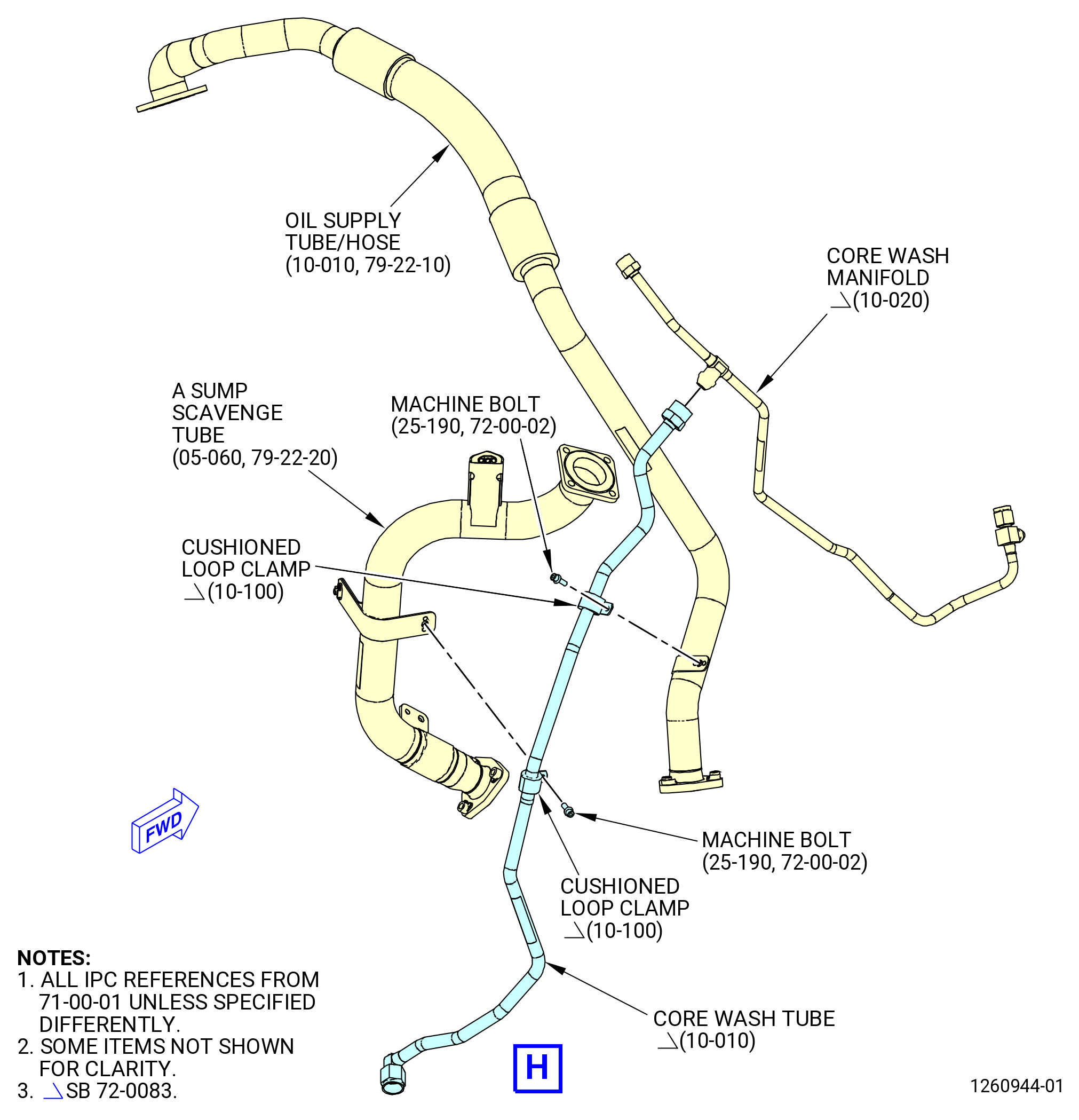
| H. | Install the core wash tube (10-010 , 71-00-01) (SIN 78001) between the lower bifurcation assembly and the core wash manifold (10-020 , 71-00-01) (SIN 78002) as follows. Refer to Figure 406. |
| NOTE: |
|
| (1) | Put two cushioned loop clamps (10-100 , 71-00-01) (SIN 78082) around the core wash tube. |
| (2) | Connect both B-nuts of the core wash tube to the core wash manifold and to the lower bifurcation assembly. |
| (3) | Hand tighten the B-nuts. |
| (4) | Attach the cushion loop clamps to the tabs on the oil supply tube/hose (10-010 , 79-22-10) (SIN 44800) and on the A sump scavenge tube (05-060 , 79-22-20) (SIN 45100) with machine bolts (25-190 , 72-00-02) (SIN 78023). |
| (5) | Hand tighten the machine bolts. |
| (6) | Torque the B-nuts to 262-308 lb in. (29.6-34.8 N.m). |
| (7) | Torque the bolts to 51-59 lb in. (5.8-6.7 N.m). |
| * * * END SB 72-0083 |
|
|
|
|
| Subtask 72-00-05-420-010 |
| I. | Attach the AGB fuel hoses and tubes. Refer to Figure 407 and do as follows: |
| WARNING: |
|
| CAUTION: |
|
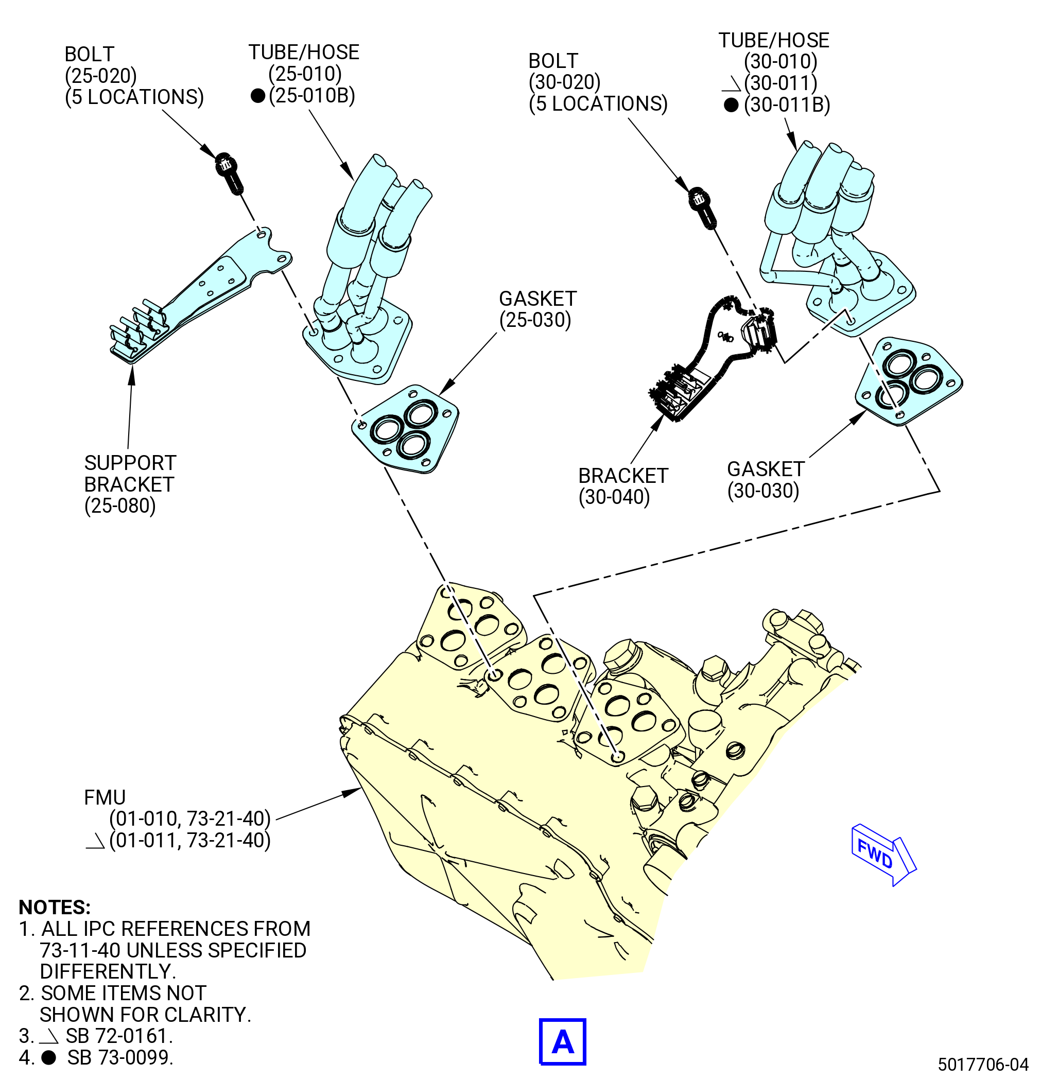
| (1) | Apply C02-019 engine oil or C02-023 engine oil to the gasket (30-030 , 73-11-40) (SIN 38152). |
| (2) | Attach the VSV-HPT fuel hose manifold (tube/hose) (30-010 , 73-11-40) (SIN 38100), (30-011 , 73-11-40) (SIN 38100), or (30-011B , 73-11-40) (SIN 38100) to the forward side of the fuel metering unit (01-010 , 73-21-40) (SIN 30000) or (01-011 , 73-21-40) (SIN 30000) with the gasket (30-030 , 73-11-40) (SIN 38152), bracket (30-040 , 73-11-40) (SIN 37612), and bolts (30-020 , 73-11-40) (SIN 38127). |
| NOTE: |
|
| (3) | Torque the five bolts (38127) to 106-124 lb in. (12.0-14.0 N.m) in a criss-cross pattern. |
| WARNING: |
|
| CAUTION: |
|
| (4) | Apply C02-019 engine oil or C02-023 engine oil to the gasket (25-030 , 73-11-40) (SIN 38352). |
| (5) | Attach the VBV-LPT fuel hose manifold (tube/hose) (25-010 , 73-11-40) (SIN 38300) or (25-010B , 73-11-40) (SIN 38300) to the fuel metering unit (01-010 , 73-21-40) (SIN 30000) or (01-011 , 73-21-40) (SIN 30000) with gasket (25-030 , 73-11-40) (SIN 38352), support bracket (25-080 , 73-11-40) (SIN 6881C) or (25-080A , 73-11-40) (SIN 6881C), and bolts (25-020 , 73-11-40) (SIN 38321). |
| (6) | Torque the five bolts (38321) to 106-124 lb in. (12.0-14.0 N.m). |
| WARNING: |
|
| CAUTION: |
|
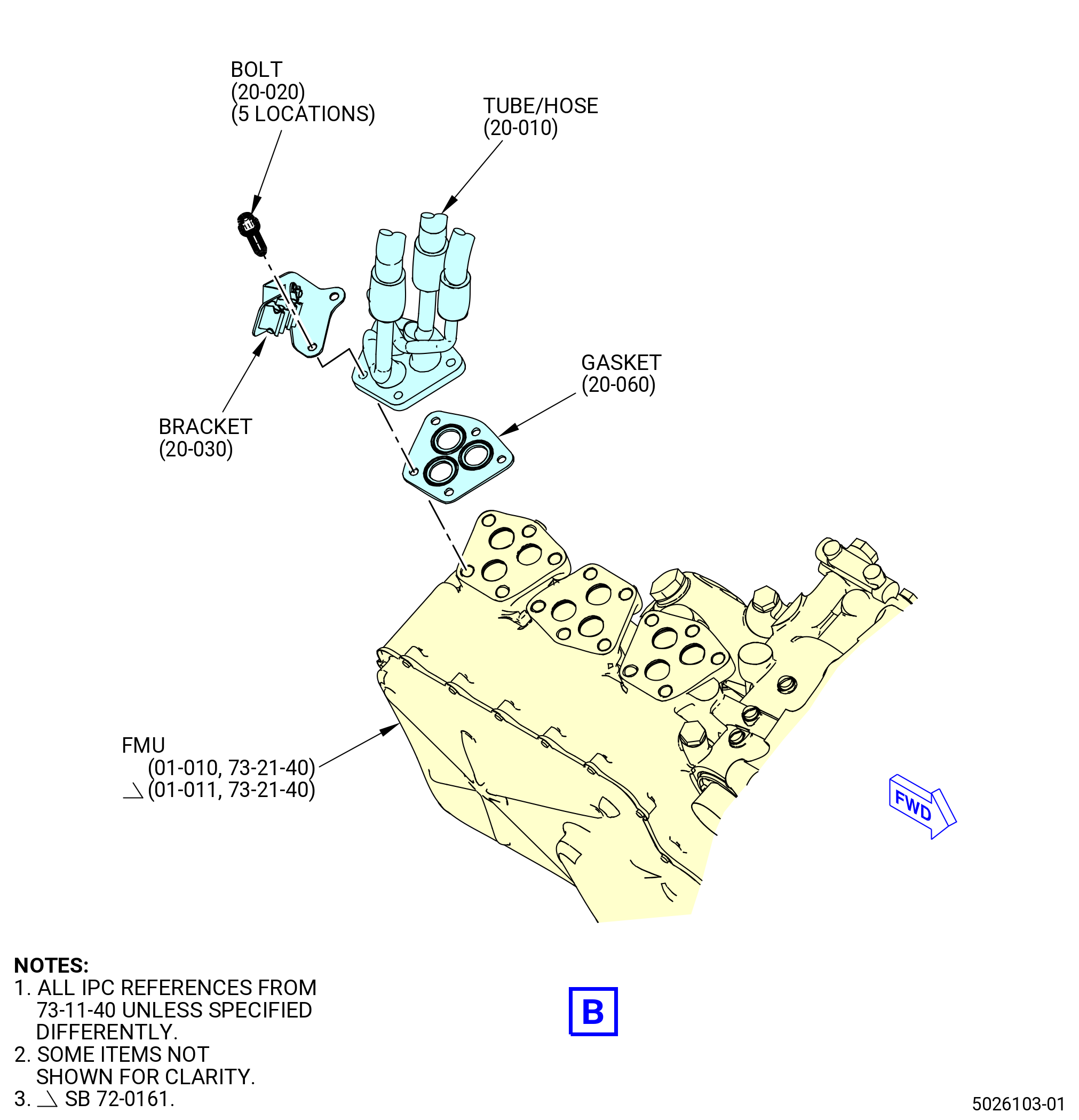
| (7) | Apply C02-019 engine oil or C02-023 engine oil to the gasket (20-060 , 73-11-40) (SIN 38452). |
| (8) | Attach the TBV-CCCV-PHS fuel hose manifold (tube/hose) (20-010 , 73-11-40) (SIN 38400) to the fuel metering unit (01-010 , 73-21-40) (SIN 30000) or (01-011 , 73-21-40) (SIN 30000) with the gasket (20-060 , 73-11-40) (SIN 38452), bracket (20-030 , 73-11-40) (SIN 37613), and the bolts (20-020 , 73-11-40) (SIN 38421). |
| NOTE: |
|
| (9) | Torque the five bolts (38421) to 106-124 lb in. (12.0-14.0 N.m) in a criss-cross pattern. |
| (10) | Deleted. |
| (11) | Deleted. |
| (12) | Deleted. |
| (13) | Deleted. |
| WARNING: |
|
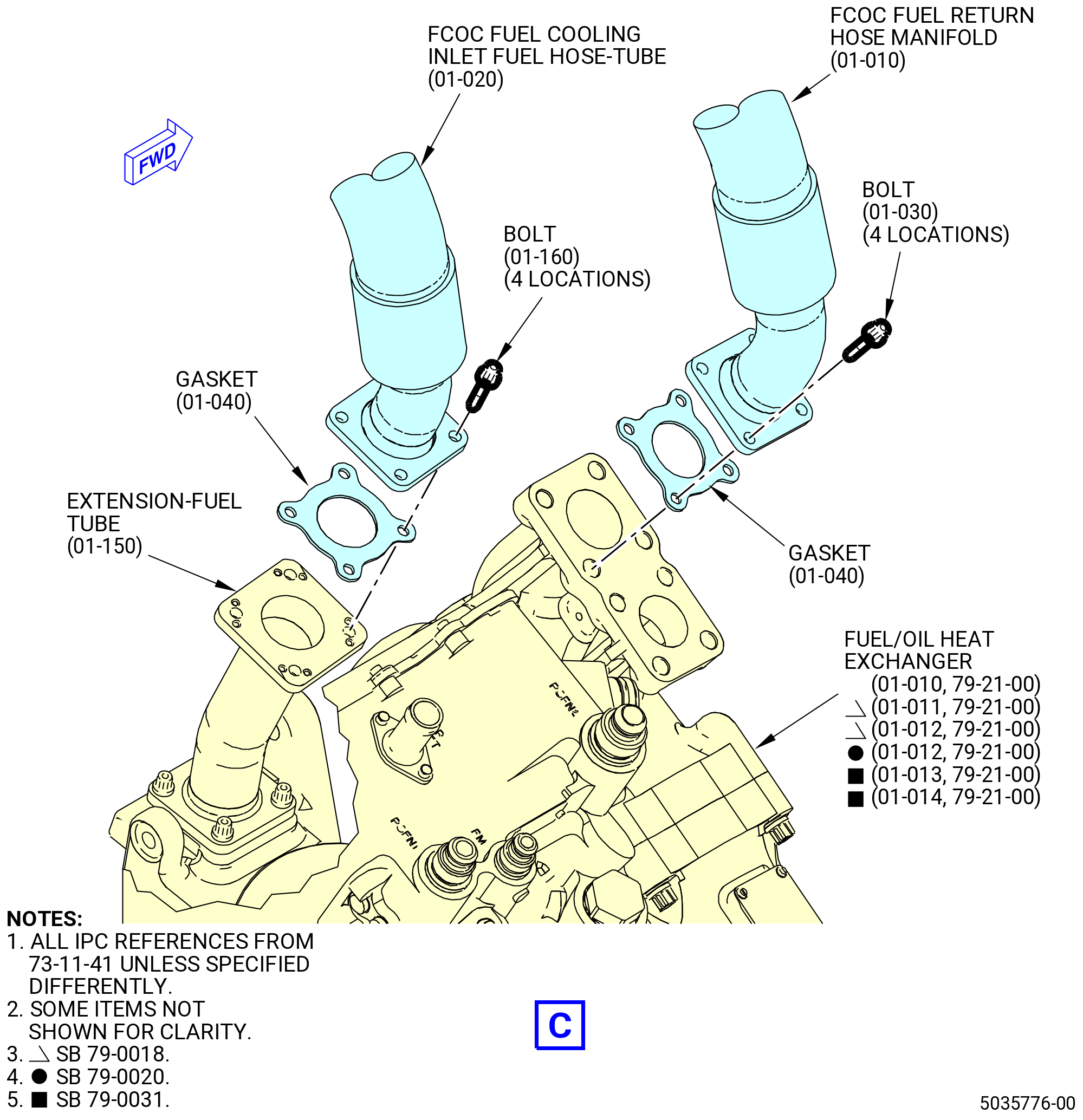
| (14) | Apply C02-019 engine oil or C02-023 engine oil to the gaskets (01-040 , 73-11-41) (SIN 34550) and (01-140 , 73-11-41) (SIN 34555). |
| (15) | Connect the FCOC cooling inlet fuel hose-tube (34501) to the fuel-extension tube (34502) with the gasket (01-040 , 73-11-41) (SIN 34550) and bolts (34525). Torque the bolts (34525) to 106-124 lb in. (12.0-14.0 Nm). |
| (16) | Attach the fuel-extension tube (34502) to the fuel adapter (038AP) with gasket (01-140 , 73-11-41) (SIN 34555) and bolts (34526). Torque the bolts to 106-124 lb-in. (12.0-14.0 Nm). |
| (17) | Connect the FCOC fuel return hose manifold (01-010 , 73-11-41) (SIN 34500) to the fuel/oil heat exchanger (01-010 , 79-21-00) (SIN 40700), (01-011 , 79-21-00) (SIN 40700), or (01-012 , 79-21-00) (SIN 40700) or (01-013 , 79-21-00) (SIN 40700) or (01-014 , 79-21-00) (SIN 40700) with the gasket (01-040 , 73-11-41) (SIN 34550) and the bolts (01-030 , 73-11-41) (SIN 34522). Torque the bolts (01-030 , 73-11-41) (SIN 34522) to 106 to 124 lb in. (12.0 to 14.0 Nm). |
| Subtask 72-00-05-420-031 |
| * * * PRE SB 73-0011( Engines without Fuel Vapor Accumulator ) |
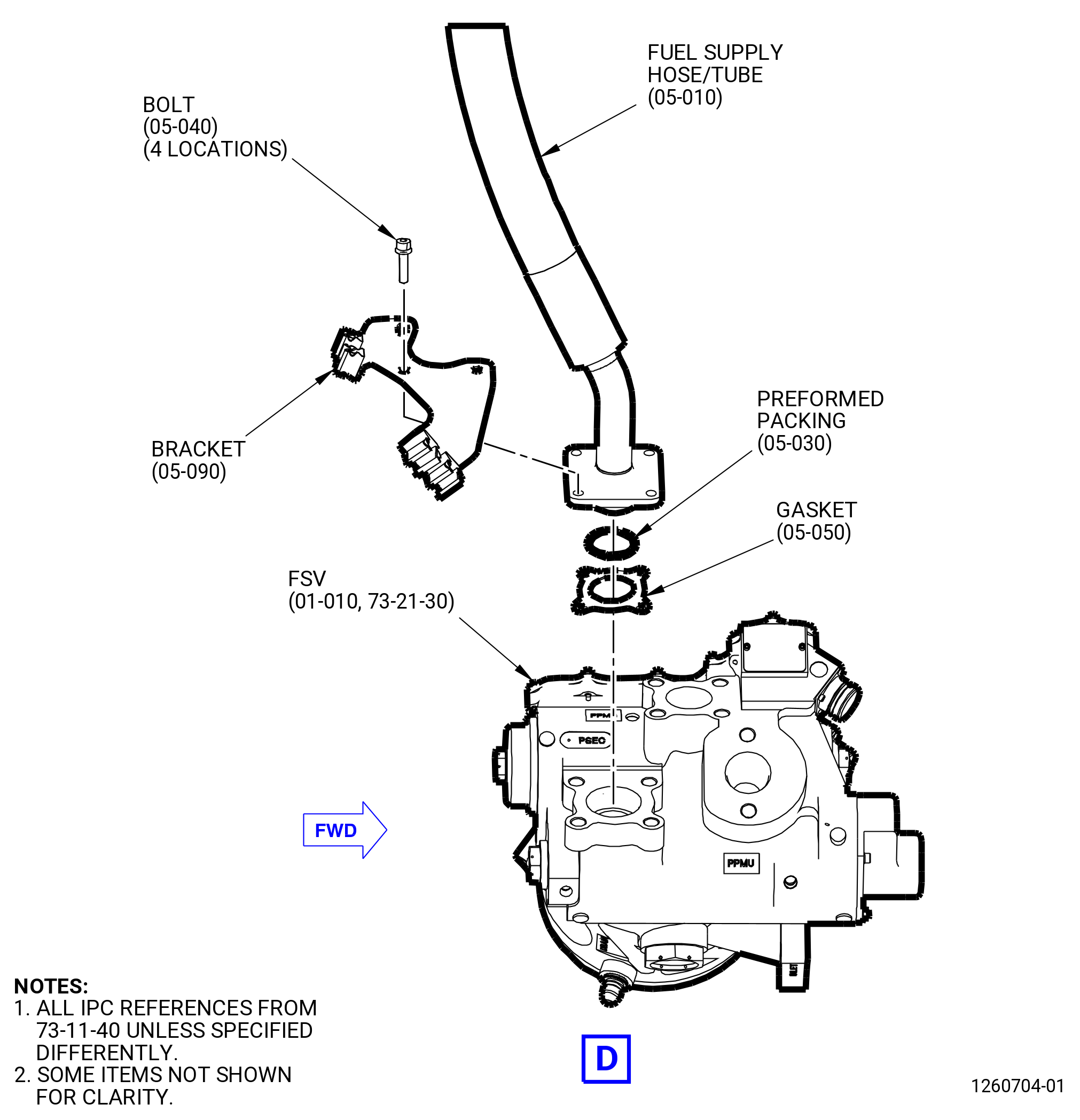
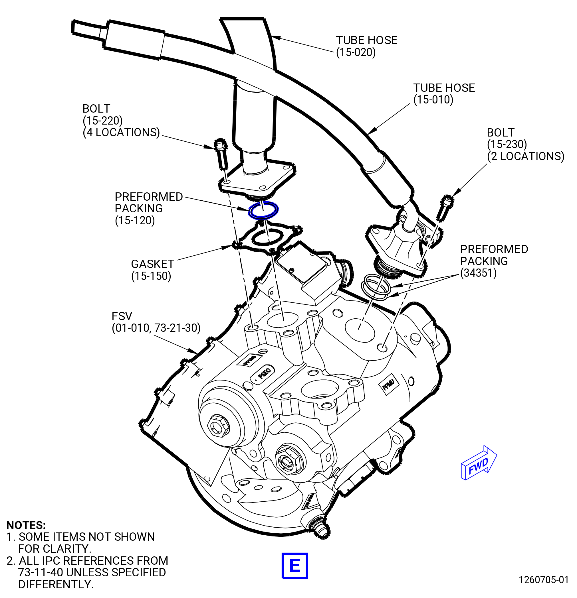
| (18) | Connect the fuel supply hose/tube (05-010 , 73-11-40) (SIN 34100) to the flow splitting valve (FSV) (01-010 , 73-21-30) (SIN 31700) with the gasket (05-050 , 73-11-40) (SIN 34151), bracket (05-090 , 73-11-40) (SIN 6881A), preformed packing (05-030 , 73-11-40) (SIN 34152), and four bolts (05-040 , 73-11-40) (SIN 34123) as follows: |
| (a) | Apply C02-008 petroleum jelly to the new preformed packing. |
| (b) | Install the new preformed packing on the flange end of the fuel supply hose/tube. |
| (c) | Install four bolts through the bracket, flange of the fuel supply hose/tube, and gasket to attach them to the FSV. |
| NOTE: |
|
| (d) | Torque the four bolts to 106-124 lb in. (12.0-14.0 N.m). |
| (19) | Connect the fuel-signal hose and tube (tube hose) (15-020 , 73-11-40) (SIN 34200) to the right side of the AGB module ALF with the gasket (15-150 , 73-11-40) (SIN 34251), preformed packing (15-120 , 73-11-40) (SIN 34252), and four bolts (15-220 , 73-11-40) (SIN 34222) as follows: |
| (a) | Remove the protective covers and install a new preformed packing on the flange end of the tube hose. |
| (b) | Fully install the flanged end of the tube hose and gasket into the FSV. |
| WARNING: |
|
| (c) | Apply C02-058 lubricant to the threads of the four bolts. |
| (d) | Install the four bolts thru the tube hose and into the FSV. |
| (e) | Torque the four bolts to 106-124 lb in. (12.0-14.0 N.m). |
| * * * END PRE SB 73-0011 |
| Subtask 72-00-05-420-032 |
| * * * SB 73-0011( Engines with Fuel Vapor Accumulator ) |
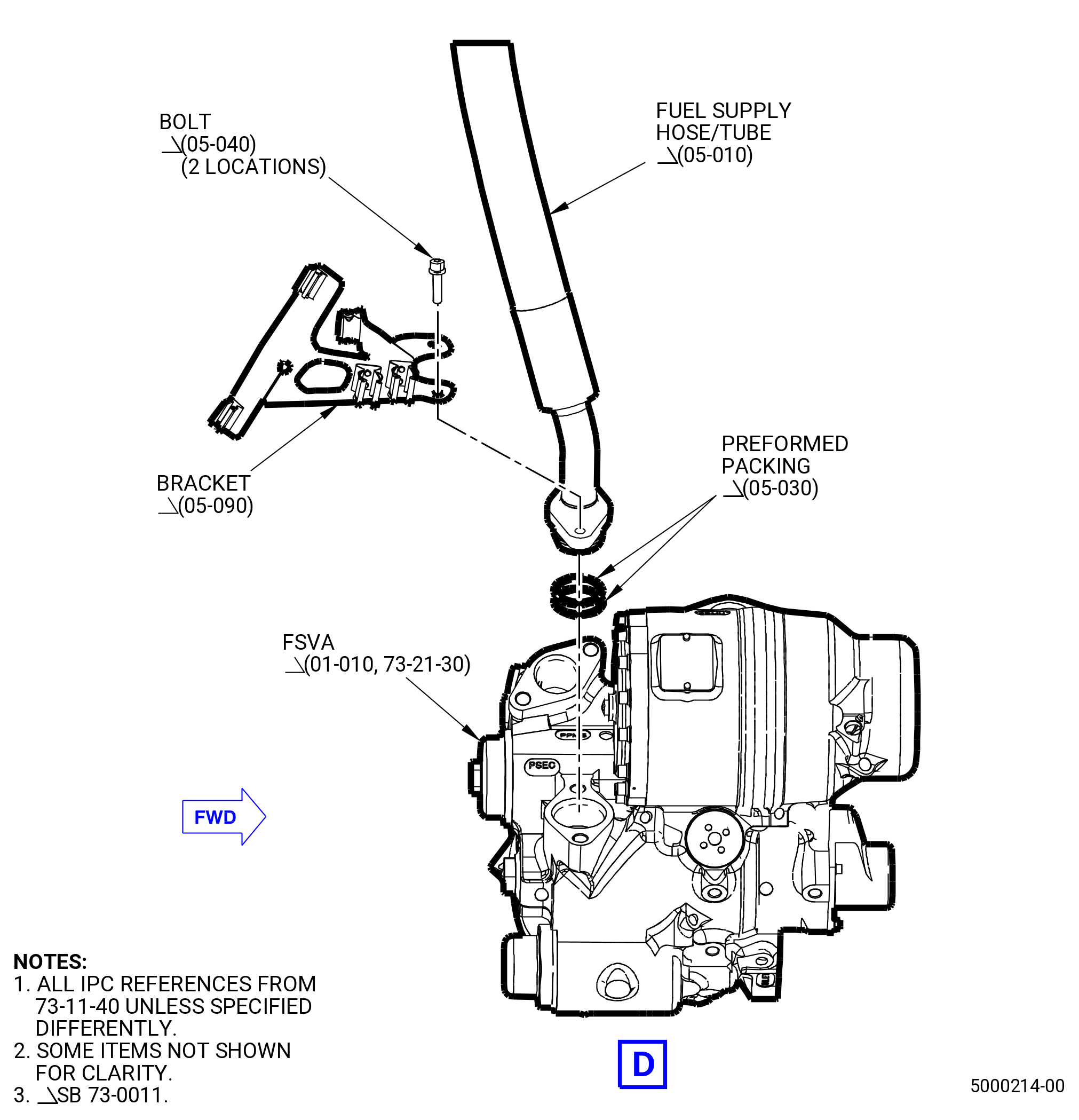
| (20) | Connect the fuel supply hose/tube (05-010 , 73-11-40) (SIN 34100) to the flow splitting valve accumulator (FSVA) (01-010 , 73-21-30) (SIN 31700) with the bracket (05-090 , 73-11-40) (SIN 6881A), two preformed packings (05-030 , 73-11-40) (SIN 34152), and two bolts (05-040 , 73-11-40) (SIN 34123) as follows: |
| (a) | Apply C02-008 petroleum jelly to the two new preformed packings. |
| (b) | Install the two new preformed packings on the flange end of the fuel supply hose/tube. |
| (c) | Install two bolts through the bracket and flange of the fuel supply hose/tube to attach them to the FSVA. |
| (d) | Torque the bolts to 106-124 lb in. (12.0-14.0 N.m). |
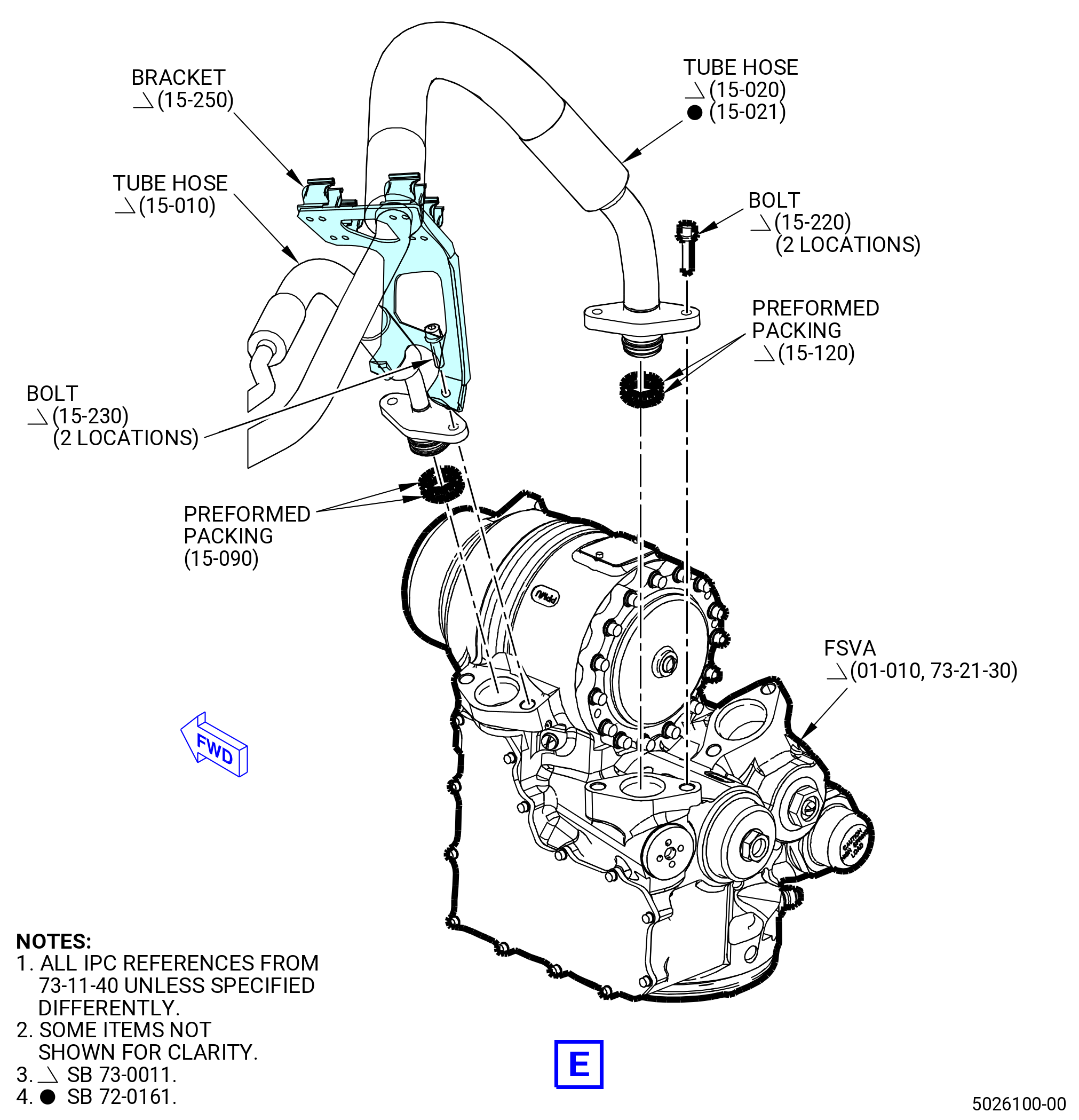
| (21) | Connect the tube hose (15-020 , 73-11-40) (SIN 34200) or (15-021 , 73-11-40) (SIN 34200) to the right side of the AGB module, ALF, with two preformed packings (15-120 , 73-11-40) (SIN 34252) and two bolts (15-220 , 73-11-40) (SIN 34222) as follows: |
| (a) | Remove the protective covers and install two new preformed packings on the flange end of the tube hose. |
| (b) | Fully install the flanged end of the tube hose into the FSVA. |
| WARNING: |
|
| (c) | Apply C02-058 lubricant to the threads of the two bolts. |
| (d) | Install the two bolts thru the tube hose and into the FSVA. |
| (e) | Torque the two bolts to 106-124 lb in. (12.0-14.0 N.m). |
| * * * END SB 73-0011 |
| Subtask 72-00-05-420-033 |
| * * * PRE SB 73-0011( Engines without Fuel Vapor Accumulator ) |
| (22) | Connect the fuel-signal hose and tube (tube hose) (15-010 , 73-11-40) (SIN 34300) to the right side of the AGB module ALF with two preformed packings (15-090 , 73-11-40) (SIN 34351) and two bolts (15-230 , 73-11-40) (SIN 34322). |
| (a) | Torque the two bolts to 106-124 lb in. (12.0-14.0 N.m). |
| * * * END PRE SB 73-0011 |
| Subtask 72-00-05-420-034 |
| * * * SB 73-0011( Engines with Fuel Vapor Accumulator ) |
| (23) | Connect the tube hose (15-010 , 73-11-40) (SIN 34300) and bracket (15-250 , 73-11-40) (SIN 6881Y) to the right side of the AGB module ALF with two preformed packings (15-090 , 73-11-40) (SIN 34351) and two bolts (15-230 , 73-11-40) (SIN 34322). |
| (a) | Apply C02-008 petroleum jelly to the two new preformed packings. |
| (b) | Install the two new preformed packings on the flange end of the tube hose. |
| WARNING: |
|
| (c) | Apply C02-058 lubricant to the threads of the two bolts. |
| (d) | Install two bolts through the bracket and the flange end of the tube hose to attach them to the FSVA. |
| (e) | Torque the two bolts to 106-124 lb in. (12.0-14.0 N.m). |
| * * * END SB 73-0011 |
| Subtask 72-00-05-420-028 |
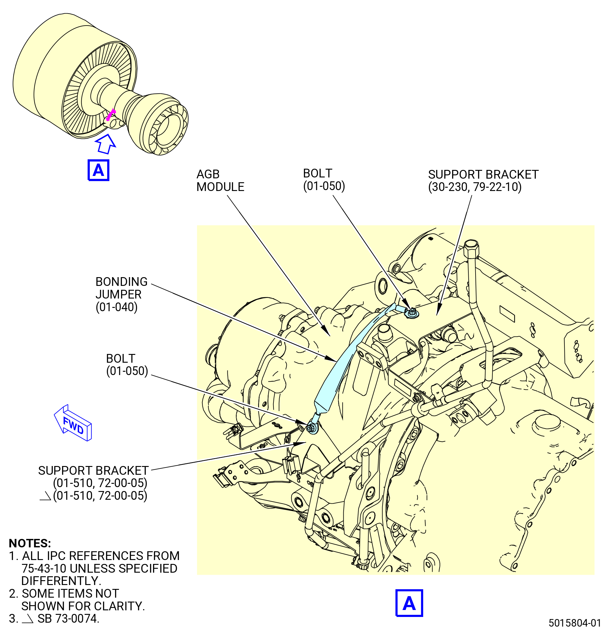
| J. | Attach the bonding jumper (65A00) as follows. Refer to Figure 408. |
| (1) | Attach the bonding jumper (01-040 , 75-43-10) (SIN 65A00) to the AGB module with the bolt (01-050 , 75-43-10) (SIN 65A20) to the drain support bracket (support bracket) (01-510) (SIN 37110). |
|
|
|
|
|
|