| GENX-1B ENGINE MANUAL | Dated: 11/27/2023 | |
| EM 72-00-05 , ASSEMBLY 001 | ||
| ACCESSORY GEARBOX MODULE - ASSEMBLY 001 | ||
| GENX-1B ENGINE MANUAL | Dated: 11/27/2023 | |
| EM 72-00-05 , ASSEMBLY 001 | ||
| ACCESSORY GEARBOX MODULE - ASSEMBLY 001 | ||
| * * * FOR ALL |
| TASK 72-00-05-430-801 |
| * * * FOR ALL |
| 1 . | General. |
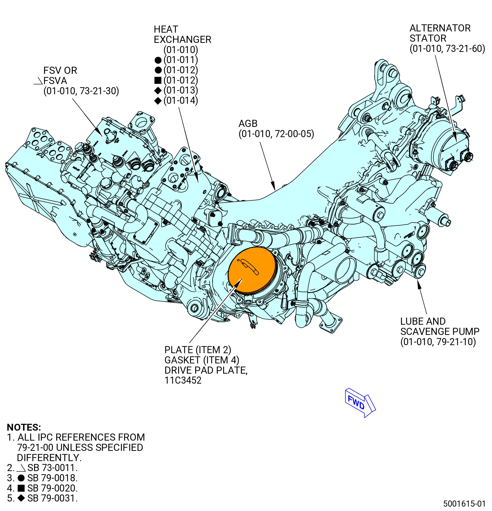
| A. | This procedure gives instructions to assemble the accessory gearbox (AGB) module. Refer to Figure 1001. |
| • |
|
| • |
|
| • |
|
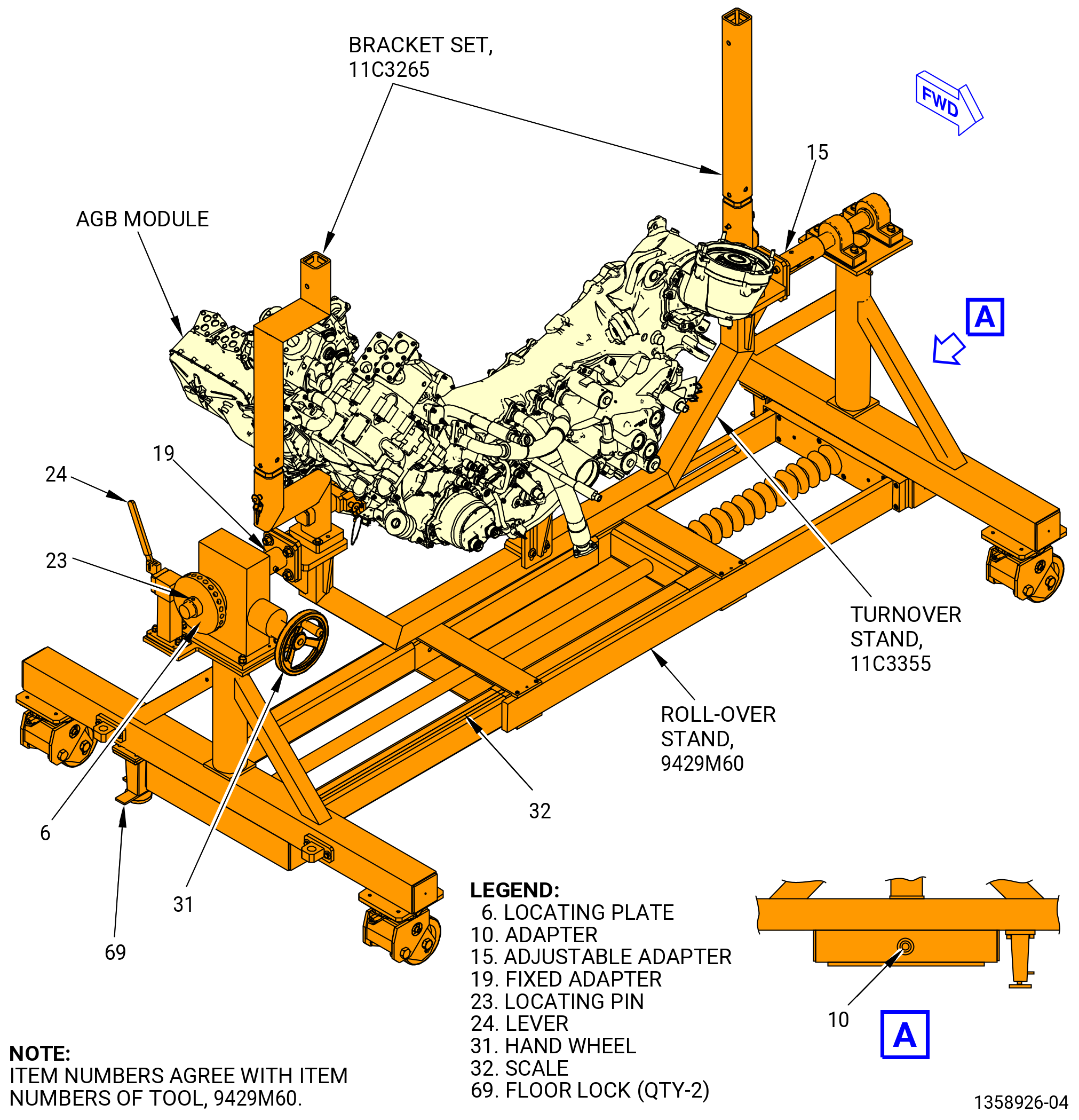
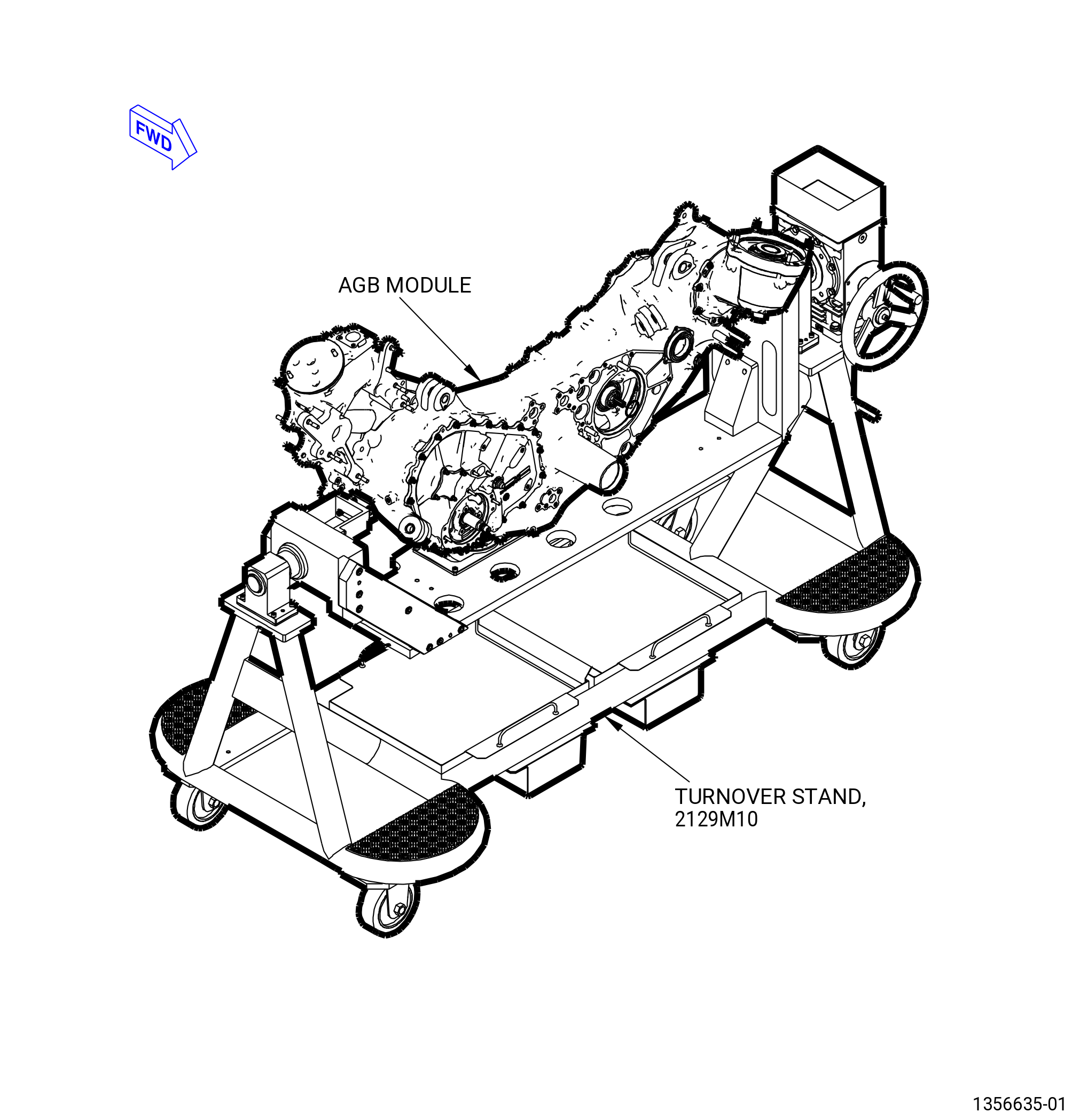
| B. | This procedure starts with the AGB (03800) in the 2129M10 turnover stand or 11C3355 turnover stand installed in the 9429M60 roll-over stand and attached with 11C3265 bracket set. The pad (item 2), gasket (item 4), plate/plug (item 3), and o-ring (item 5) of the tool 11C3452 drive pad plates are installed as necessary. Refer to Figure 1001. |
| C. | Follow the instructions to safety parts with safety wire, safety cable, cotter pins, or tab washers. Refer to TASK 70-11-00-400-001 (FASTENER RETENTION PROCEDURES) . |
| 2 . | Tools, Equipment, and Materials. |
| NOTE: |
|
| A. | Tools and Equipment. |
| (1) | Special Tools. |
| (2) | Standard Tools and Equipment. |
|
| (3) | Locally Manufactured Tools. None. |
| B. | Consumable Materials. |
|
| C. | Referenced Procedures. |
|
| D. | Expendable Parts. |
|
| * * * FOR ALL |
| 3 . | Procedure. |
| Subtask 72-00-05-430-001 |
| A. | Make sure that the AGB (03800) is installed in the 9429M60 roll-over stand. The AGB is supported by the 11C3265 bracket set and the 2129M10 turnover stand or 11C3355 turnover stand. Refer to Figure 1002 and Figure 1003. |
| * * * FOR ALL |
| * * * FOR ALL |
| Subtask 72-00-05-430-004 |
| * * * FOR ALL |
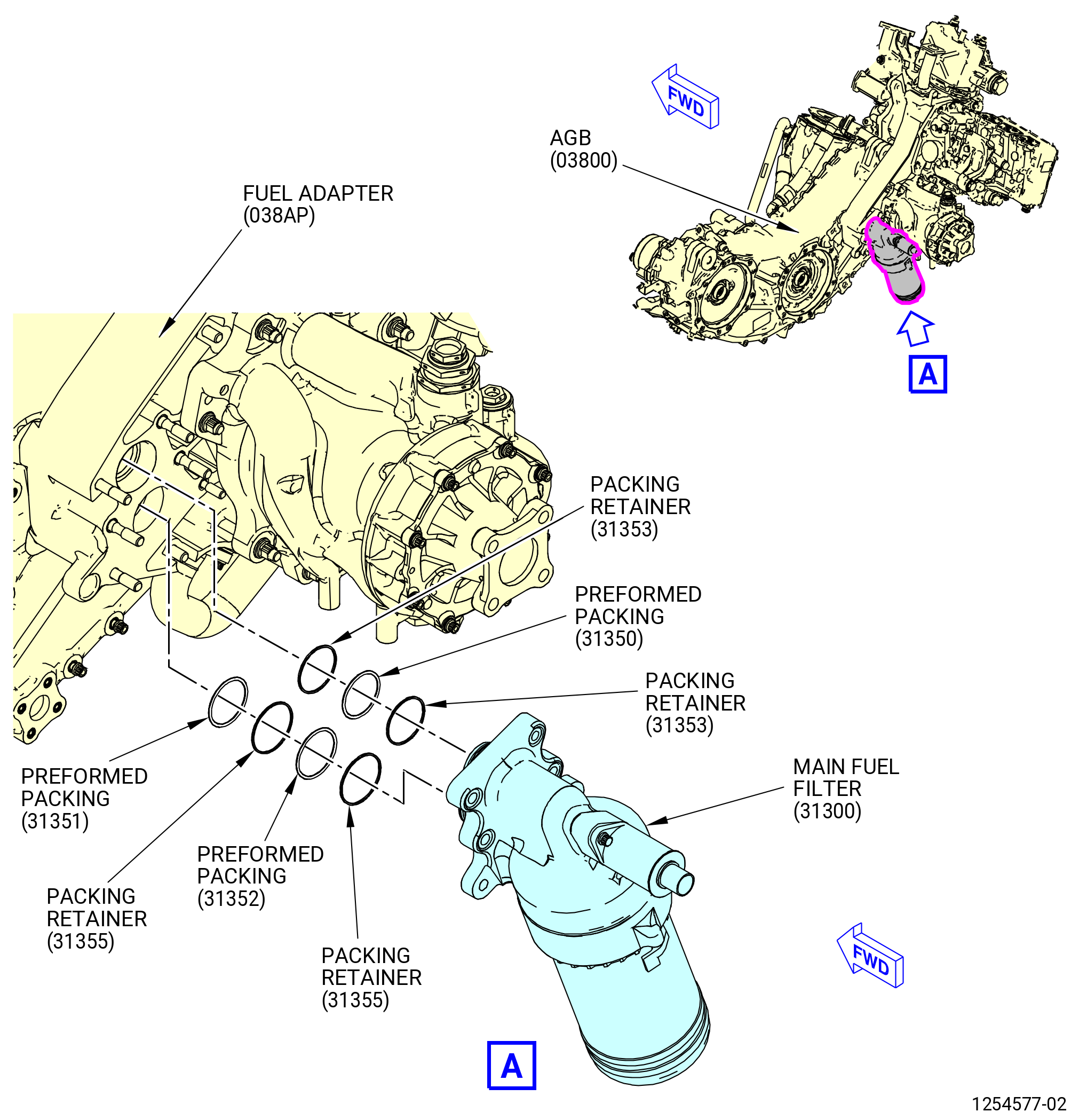
| B. | Install the main fuel filter (31300) on the fuel adapter (038AP) of the AGB (03800) as follows. Refer to Figure 1004. |
| WARNING: |
|
| (1) | Apply C02-019 engine oil or C02-023 engine oil to the preformed packings (01-120 , 73-11-01) (SIN 31350), (01-130 , 73-11-01) (SIN 31351), and (01-140 , 73-11-01) (SIN 31352) and the packing retainers (01-150 , 73-11-01) (SIN 31353) and (01-160 , 73-11-01) (SIN 31355). |
| (2) | Install the preformed packings (01-120 , 73-11-01) (SIN 31350), (01-130 , 73-11-01) (SIN 31351) and (01-140 , 73-11-01) (SIN 31352) and the packing retainers (01-150 , 73-11-01) (SIN 31353) and (01-160 , 73-11-01) (SIN 31355) on the main fuel filter adapters as follows: |
| CAUTION: |
|
| CAUTION: |
|
| CAUTION: |
|
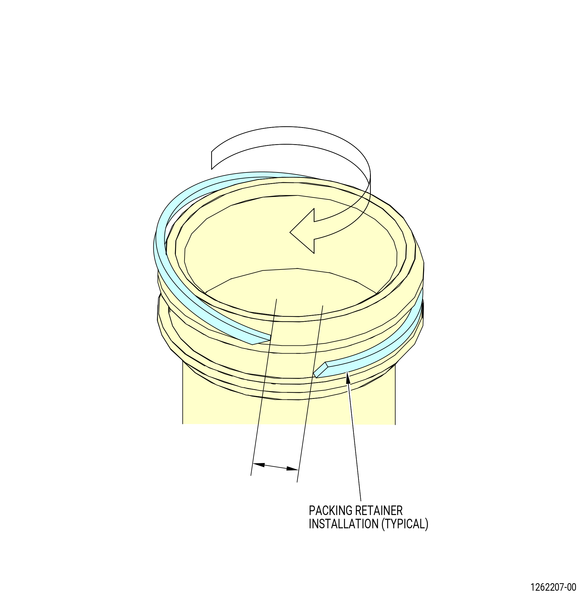
| (a) | Install one packing retainer (01-150 , 73-11-01) (SIN 31353) and (01-160 , 73-11-01) (SIN 31355) on each adapter of the main fuel filter. |
| (b) | Install a preformed packing (01-120 , 73-11-01) (SIN 31350) and (01-140 , 73-11-01) (SIN 31352) on each adapter of the main fuel filter. |
| CAUTION: |
|
| (c) | Install the second packing retainer (01-150 , 73-11-01) (SIN 31353) and (01-160 , 73-11-01) (SIN 31355) on the adapter of the main fuel filter. |
| NOTE: |
|
| * * * FOR ALL |
| Subtask 72-00-05-220-010 |
| * * * FOR ALL |
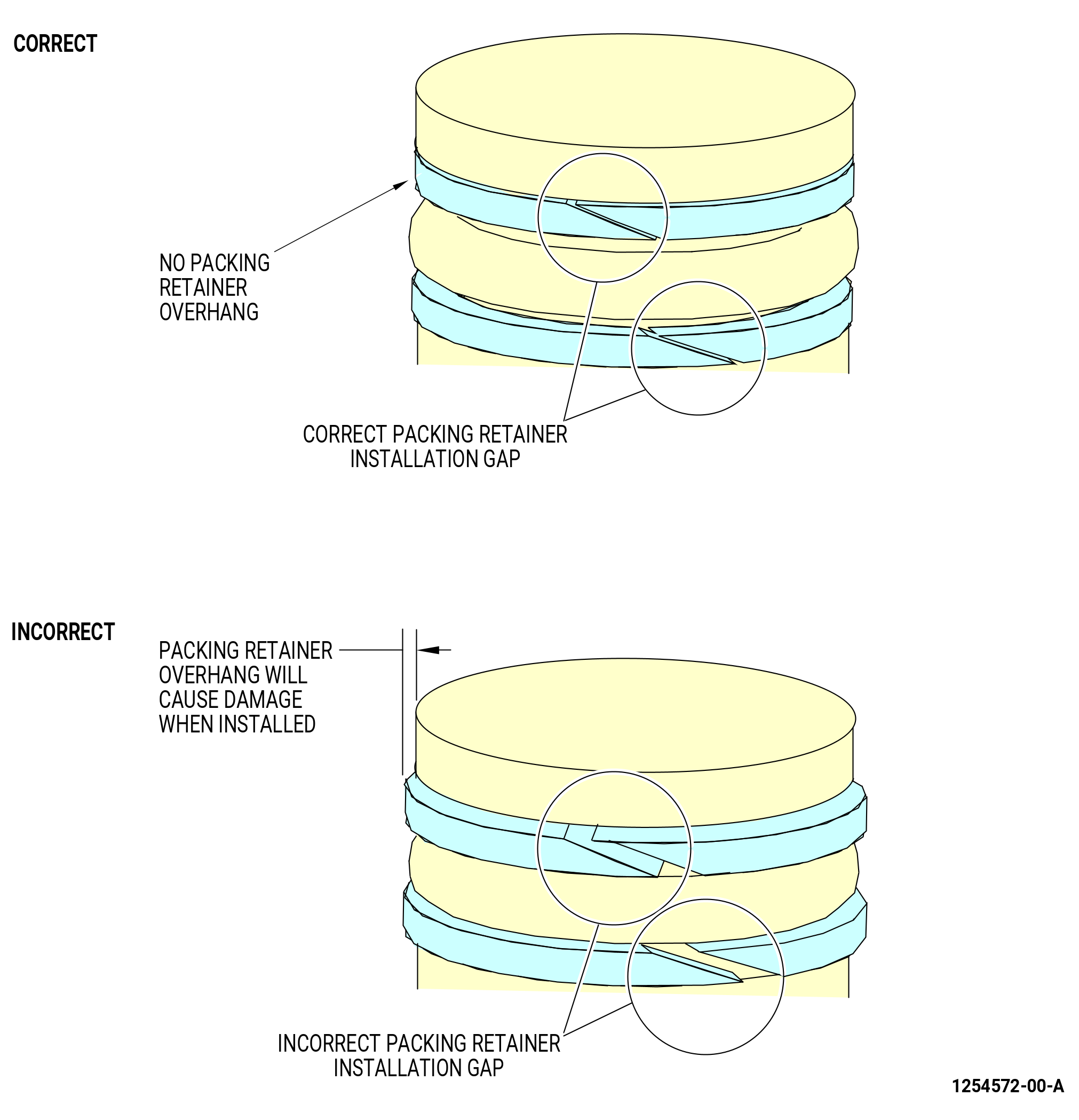
| (d) | Do a visual inspection of the packing retainers (01-150 , 73-11-01) (SIN 31353) and (01-160 , 73-11-01) (SIN 31355) to make sure that there is not an excessive gap at the split and it is set on the adapter correctly. Refer to Figure 1005 and do as follows: |
| CAUTION: |
|
| 1 | If there is an excessive gap and overhang, the packing retainer is not correctly installed in the groove of the adapter and you must replace the packing retainer (31353, 31355). |
| WARNING: |
|
| 2 | Apply C02-019 engine oil or C02-023 engine oil to the lead chamfers on the main fuel filter. |
| * * * FOR ALL |
| Subtask 72-00-05-430-069 |
| * * * FOR ALL |
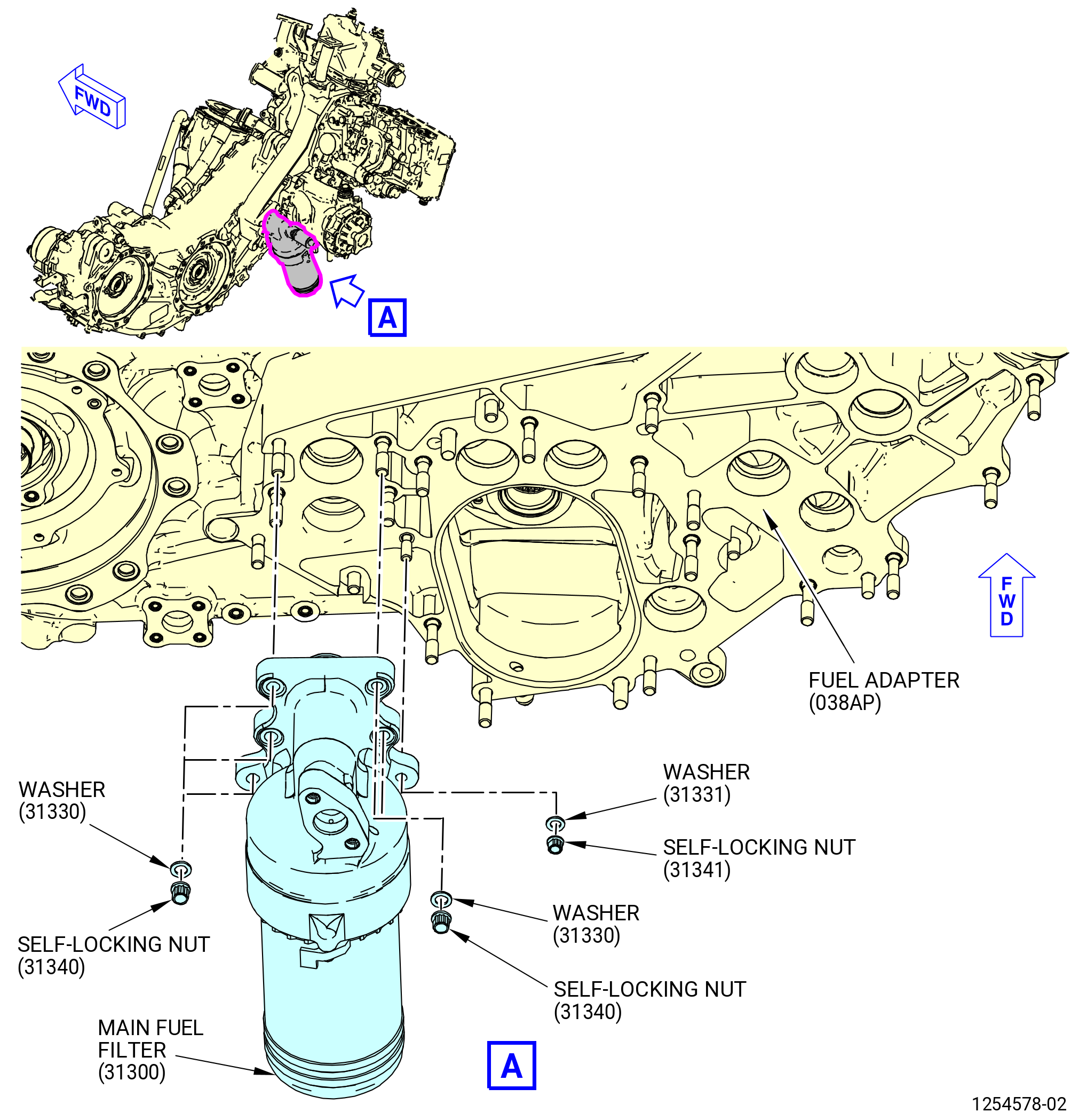
| (3) | Install the main fuel filter on the manifold assembly of the AGB as follows. Refer to Figure 1006. |
| WARNING: |
|
| (a) | Lubricate the guide pins with clean oil, C02-019 engine oil or C02-023 engine oil. |
| (b) | Install the main fuel filter on the guide pins of the manifold assembly. |
| (c) | Install a washer (31330) and self-locking nut (31340) on two opposite guide pins. |
| NOTE: |
|
| (d) | Tighten but do not torque the self-locking nuts (31340) until the main fuel filter is installed on the manifold assembly. |
| NOTE: |
|
| (e) | Install the remaining washers (31330) and the self-locking nuts (31340) and tighten by hand. |
| (f) | Install the washer (31331) and the self-locking nut (31341) and tighten by hand. |
| (g) | Torque the self-locking nuts (31340, 31341) as follows: |
| 1 | Torque the self-locking nuts (31340, 31341) in a criss-cross pattern to 106-124 lb-in. (12.0-14.0 N.m). |
| NOTE: |
|
| 2 | Torque the self-locking nuts (01-080 , 73-11-01) (SIN 31340) in a criss-cross pattern to 244-286 lb-in. (27.6-32.3 N.m). |
| 3 | Do a final torque to the self-locking nut (31341) to 235-275 lb-in. (26.5-31.1 N.m). |
| * * * FOR ALL |
| Subtask 72-00-05-430-039 |
| * * * FOR ALL |
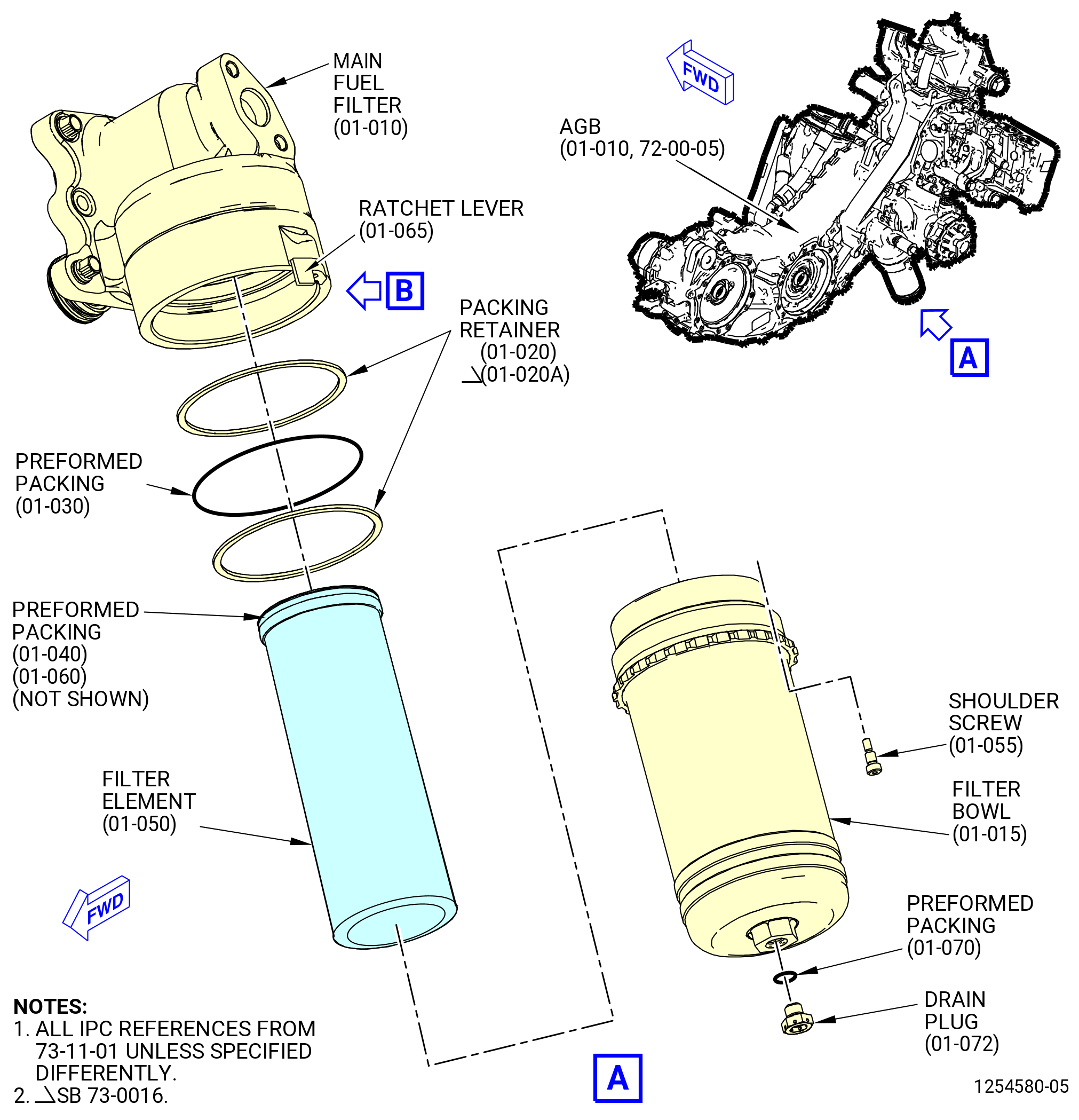
| C. | Install the filter element in the main fuel filter (31300) filter bowl as follows. Refer to Figure 1007. |
| (1) | Remove the drain plug from the bottom of the filter bowl (01-015 , 73-11-01). |
| WARNING: |
|
| (2) | Apply C02-019 engine oil or C02-023 engine oil to the preformed packing (01-030 , 73-11-01) and packing retainers (01-020 , 73-11-01) or (01-020A , 73-11-01) of the main fuel filter (01-010 , 73-11-01) (SIN 31300), and to the preformed packings (01-040 , 73-11-01) and (01-060 , 73-11-01) of the filter element (01-050 , 73-11-01). |
| NOTE: |
|
| (3) | Install the preformed packing and packing retainers as follows: |
| (a) | Install one packing retainer (01-020 , 73-11-01) or (01-020A , 73-11-01) on the filter bowl (01-015 , 73-11-01). |
| (b) | Install the preformed packing (01-030 , 73-11-01) on the filter bowl. |
| (c) | Install the remaining packing retainer (01-020 , 73-11-01) on the filter bowl. |
| (d) | Remove the unwanted lubricant with a lint-free cloth. |
| (4) | Install the filter element in the filter bowl as follows: |
| (a) | Make sure that the preformed packings (01-040 , 73-11-01) and (01-060 , 73-11-01) are installed on the filter element. If not, replace the filter element. |
| CAUTION: |
|
| (b) | Install the filter element end with the preformed packing (01-060 , 73-11-01) at the bottom of the filter bowl (01-015 , 73-11-01). |
| (5) | Install the filter bowl on the main fuel filter as follows: |
| (a) | Align the filter bowl (01-015 , 73-11-01) and the filter element (01-050 , 73-11-01) with the main fuel filter (01-010 , 73-11-01) (SIN 31300). |
| (b) | Make sure that the filter head, filter element, and main fuel filter are correctly aligned for easier installation. |
| (c) | Manually turn the filter bowl clockwise (CW). |
| (d) | Continue to manually turn the filter bowl CW until it is tight. |
| NOTE: |
|
| NOTE: |
|
| NOTE: |
|
| (e) | Use a socket with a STD-6839 torque wrench over the hex shaped flange on the bottom of the filter bowl. |
| (f) | Use the STD-6839 torque wrench to monitor the torque when the filter bowl (01-015 , 73-11-01) is tightened as follows: |
| 1 | Make sure not to tighten the filter bowl more than 600 lb in. (67.8 N.m). |
| 2 | If the torque is approximately 600 lb in. (67.8 N.m) when the filter bowl is tightened, do as follows: |
| a | Remove the filter bowl. |
| b | Do an inspection for damage of the threads on the filter bowl and main fuel filter (01-010 , 73-11-01) (SIN 31300). |
| c | If there is no damage, make sure that the filter element (01-050 , 73-11-01) can be installed correctly into the main fuel filter. |
| (g) | Turn the socket CW until the filter bowl (01-015 , 73-11-01) is fully seated in the fuel filter head and the ratchet lever (01-065 , 73-11-01) has a full span-wise engagement with the bowl locking ring. |
| NOTE: |
|
| WARNING: |
|
| (6) | Apply C02-019 engine oil or C02-023 engine oil to the preformed packing (01-070 , 73-11-01). |
| (7) | Install the preformed packing (01-070 , 73-11-01) on the drain plug. |
| (8) | Install the drain plug in the bottom of the filter bowl. |
| (9) | Torque the drain plug to 105-115 lb in. (11.9-13.0 N.m). |
| (10) | Safety the drain plug with C10-071 safety wire or C10-143 safety cable assembly. |
| NOTE: |
|
| Subtask 72-00-05-430-081 |
| * * * FOR ALL |
| * * * FOR |
| * * * PRE SB 73-0037( Main Fuel Filter without Improvement ) |
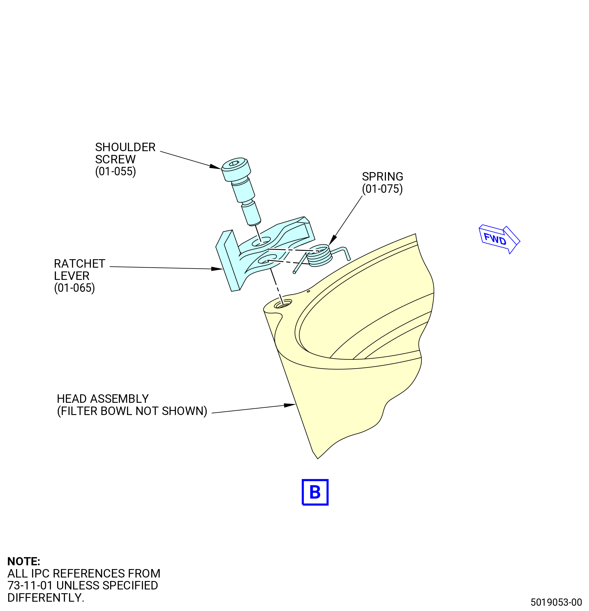
| (11) | Install the ratchet lever (01-065 , 73-11-01) on the main fuel filter (01-010 , 73-11-01) (SIN 31300) as follows: |
| (a) | Deleted. |
| (b) | Put the flat side of the ratchet lever with the ratchet lever spring (01-075 , 73-11-01) next to the filter bowl (01-015 , 73-11-01). |
| (c) | Install the shoulder screw (01-055 , 73-11-01) on the ratchet lever. |
| (d) | Torque the shoulder screw (01-055 , 73-11-01) of the ratchet lever until it touches the main fuel filter. |
| * * * FOR |
| * * * END PRE SB 73-0037 |
| Subtask 72-00-05-430-082 |
| * * * FOR ALL |
| * * * FOR |
| * * * SB 73-0037( Main Fuel Filter with Improvement ) |
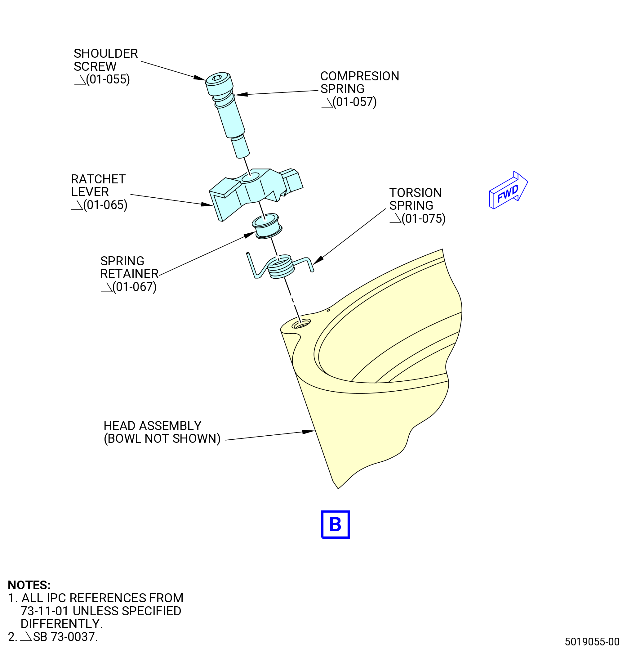
| (11).A. | Install the ratchet lever (01-065 , 73-11-01) on the main fuel filter (01-010 , 73-11-01) (SIN 31300) as follows: |
| (a) | Slide the compression spring (01-057 , 73-11-01) over the shoulder screw (01-055 , 73-11-01). |
| CAUTION: |
|
| (b) | Assemble the shoulder screw (01-055 , 73-11-01) and compression spring (01-057 , 73-11-01) through the ratchet lever, spring retainer (01-067 , 73-11-01), and torsion spring (01-075 , 73-11-01). |
| (c) | Align the short end of the torsion spring (01-075 , 73-11-01) with the 0.040 inch (1.02 mm) hole in the head assembly. |
| (d) | Attach the assembled ratchet lever to the head assembly with the shoulder screw (01-055 , 73-11-01). |
| NOTE: |
|
| (e) | Torque the shoulder screw (01-055 , 73-11-01) to 21-23 lb. in. (2.37-2.60 N.m). |
| * * * FOR |
| * * * END SB 73-0037 |
|
|
|
|
| Subtask 72-00-05-430-036 |
| * * * FOR ALL |
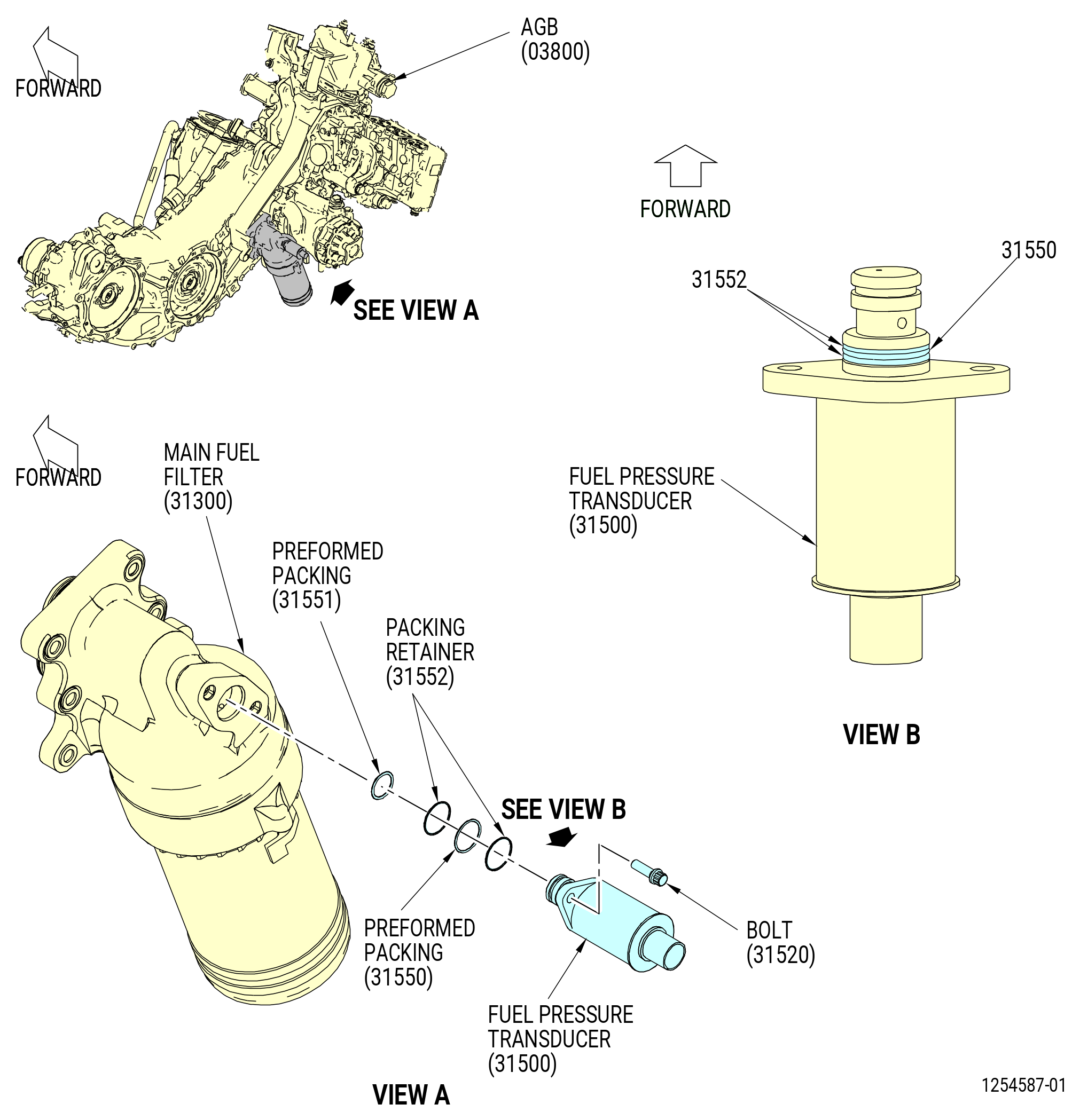
| D. | Install the fuel pressure transducer (31500) on the main fuel filter (31300) as follows. Refer to Figure 1008. |
| (1) | Apply C02-058 lubricant to the threads and friction surfaces of the bolts (31520). |
| WARNING: |
|
| (2) | Apply C02-019 engine oil or C02-023 engine oil to the preformed packings (01-040 , 73-31-10) (SIN 31550) and (01-050 , 73-31-10) (SIN 31551), lead in chamfer, and the packing retainers (01-060 , 73-31-10) (SIN 31552). |
| (3) | Install the packing retainer (01-060 , 73-31-10) (SIN 31552) and the preformed packings (01-040 , 73-31-10) (SIN 31550) and (01-050 , 73-31-10) (SIN 31551) as follows: |
| CAUTION: |
|
| CAUTION: |
|
| CAUTION: |
|
| (a) | Install one packing retainer (01-060 , 73-31-10) (SIN 31552) on the adapter of the fuel pressure transducer. |
| (b) | Install a preformed packing (01-040 , 73-31-10) (SIN 31550) on the adapter of the fuel pressure transducer. |
| CAUTION: |
|
| (c) | Install the second packing retainer (01-060 , 73-31-10) (SIN 31552) on the adapter of the fuel pressure transducer. |
| NOTE: |
|
| Subtask 72-00-05-220-009 |
| * * * FOR ALL |
| (d) | Do a visual inspection of the packing retainer (01-060 , 73-31-10) (SIN 31552) to make sure that there is not an excessive gap at the split and it is set on the adapter correctly. Refer to Figure 1005 and do as follows: |
| CAUTION: |
|
| 1 | If there is an excessive gap and overhang, the packing retainer is not correctly installed in the groove of the adapter, the packing retainer (31552) must be replaced. |
| Subtask 72-00-05-430-061 |
| * * * FOR ALL |
| (4) | Install the preformed packing (01-050 , 73-31-10) (SIN 31551) on the fuel pressure transducer. |
| WARNING: |
|
| (5) | Apply C02-019 engine oil or C02-023 engine oil to the lead chamfers on the fuel pressure transducer. |
| (6) | Install the fuel pressure transducer into the main fuel filter. |
| (7) | Attach the fuel pressure transducer to the main fuel filter with the bolts (31520). Torque the bolts to 106-124 lb in. (12.0-14.0 N.m). |
| * * * FOR ALL |
| Subtask 72-00-05-430-002 |
| * * * FOR ALL |
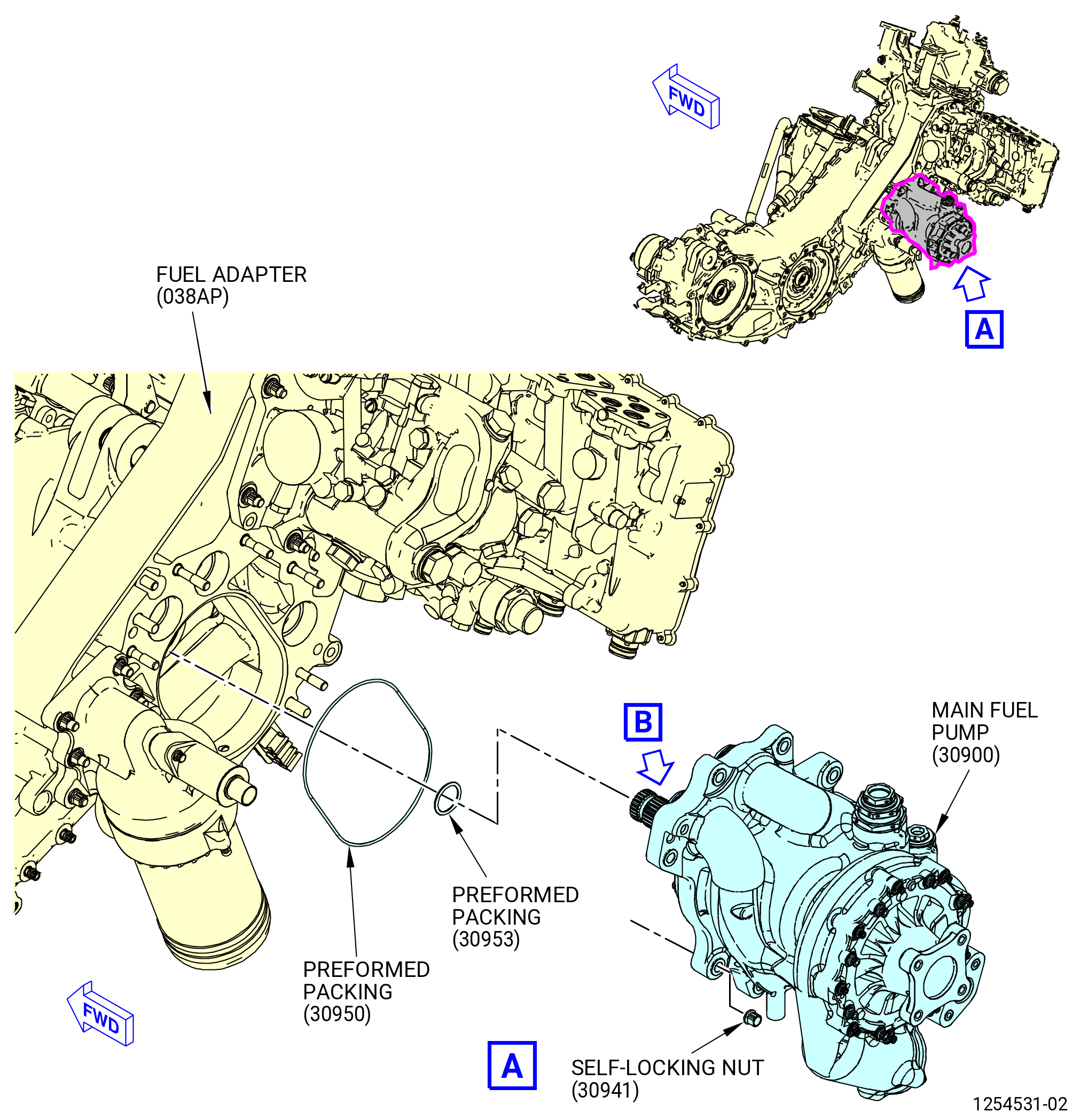
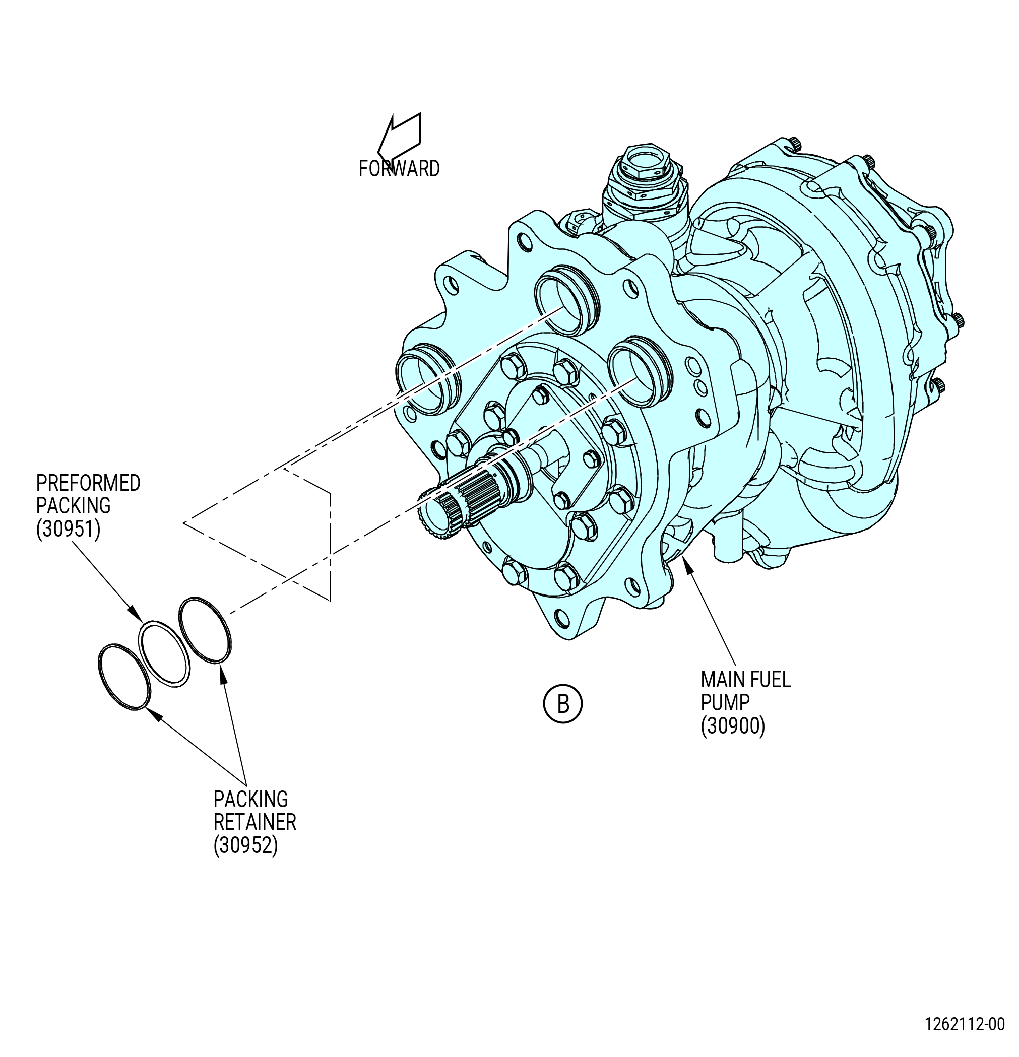
| E. | Install the main fuel pump (30900) on the AGB (03800) as follows. Refer to Figure 1009. |
| WARNING: |
|
| (1) | Apply C02-019 engine oil or C02-023 engine oil to the preformed packings (01-070 , 73-11-00) (SIN 30950), (01-090 , 73-11-00) (SIN 30951), and (01-100 , 73-11-00) (SIN 30953) and packing retainers (01-080 , 73-11-00) (SIN 30952) at six locations. |
| (2) | Install the preformed packing (01-100 , 73-11-00) (SIN 30953) on the shaft of the main fuel pump. |
| (3) | Install the preformed packing (01-070 , 73-11-00) (SIN 30950) in the fuel adapter (038AP). |
| (4) | Install the three preformed packings (01-090 , 73-11-00) (SIN 30951) and the packing retainers (01-080 , 73-11-00) (SIN 30952) on the fuel in the gear discharge and the boost discharge ports of the main fuel pump as follows: |
| CAUTION: |
|
| CAUTION: |
|
| CAUTION: |
|
| (a) | Install one packing retainer (01-080 , 73-11-00) (SIN 30952) on each port of the main fuel pump. |
| (b) | Install a preformed packing (01-090 , 73-11-00) (SIN 30951) on each port of the main fuel pump. |
| CAUTION: |
|
| (c) | Install the second packing retainer (01-080 , 73-11-00) (SIN 30952) on each port of the main fuel pump. |
| NOTE: |
|
| Subtask 72-00-05-220-001 |
| * * * FOR ALL |
| (d) | Do a visual inspection of the packing retainers (01-080 , 73-11-00) (SIN 30952) to make sure that there is not an excessive gap at the split and they are set in the groove of the port correctly. Refer to Figure 1005 and do as follows: |
| CAUTION: |
|
| 1 | If there is an excess gap and overhang, the packing retainers are not correctly installed in the groove of the port and you must replace the packing retainers (30952). |
| (5) | Do a visual inspection to make sure that the AGB cavity is free from unwanted material and handling damage. |
| Subtask 72-00-05-440-001 |
| * * * FOR ALL |
| WARNING: |
|
| CAUTION: |
|
| (6) | Apply C02-019 engine oil or C02-023 engine oil to the lead chamfers on the main fuel pump (30900). |
| (7) | Insert the fuel pump cradle (item 3) or (item 20) of the 11C4412 LRU fixture in the 9446M93 jack stand, and attach it with the screw knob from the 9446M93 jack stand. |
| (8) | Install the main fuel pump (01-010 , 73-11-00) (SIN 30900) on the fuel pump cradle (item 3) or (item 20) of the 11C4412 LRU fixture in the appropriate holes using three screws (item 15). |
| (9) | Use the 9446M93 jack stand to lift the main fuel pump into place on the engine. |
| (10) | Install the main fuel pump on the fuel adapter (038AP) of the AGB as follows: |
| (a) | Install the main fuel pump on the guide pins of the fuel adapter (038AP) of the AGB. |
| (b) | If necessary, rotate the internal gears of the AGB so the splines on the main fuel pump shaft are aligned correctly to the AGB as follows: |
| CAUTION: |
|
| 1 | Remove the four nuts (038W0) from the hand crank cover (038AF) on the forward side of the AGB. Use nylon pry (item 7) of 11C3990 tool set to remove the cover. Refer to Figure 1010. |
| 2 | Use a 0.50 inch (12.7 mm) square end extension bar to rotate the AGB gears. |
| 3 | Install the 9C1194 locking adapter on the forward side of the AGB as follows: |
| a | Install the square shaft of the adapter (item 4) in the spur gearshaft (038B9). |
| NOTE: |
|
| Subtask 72-00-05-440-002 |
| * * * FOR ALL |
| (11) | Attach the main fuel pump to the fuel adapter (038AP) as follows. Refer to Figure 1009. |
| WARNING: |
|
| (a) | Lubricate the studs with clean oil, C02-019 engine oil or C02-023 engine oil. |
| (b) | Install a self-locking nut (30941) on two opposite studs. |
| NOTE: |
|
| (c) | Tighten but do not torque the self-locking nuts (30941) until the main fuel pump is installed on the fuel adapter (038AP). |
| NOTE: |
|
| (d) | Install the remaining self-locking nuts (30941) and tighten by hand. |
| (e) | Torque the self-locking nuts (30941) in a criss-cross pattern to 92-108 lb-in. (10.4-12.2 N.m). |
| (f) | Torque the self-locking nuts (01-060 , 73-11-00) (SIN 30941) in a criss-cross pattern to 244-286 lb-in. (27.6-32.3 N.m). |
| (g) | Torque the self-locking nuts (01-060 , 73-11-00) (SIN 30941) in a circular pattern to 244-286 lb-in. (27.6-32.3 N.m). |
| (12) | Remove the three screws (item 15) of the 11C4412 LRU fixture from the main fuel pump (30900). |
| (13) | Put the screws (item 15) in the bolt storage. |
| (14) | Lower the 9446M93 jack stand and remove the 11C4412 LRU fixture. |
| * * * FOR ALL |
| * * * FOR ALL |
| Subtask 72-00-05-430-040 |
| * * * FOR ALL |
| F. | Install the fuel pressure transducer (31501) on the main fuel pump (30900) as follows. Refer to Figure 1011. |
| (1) | Apply C02-058 lubricant to the threads and friction surfaces of the bolts (31520). |
| WARNING: |
|
| (2) | Apply C02-019 engine oil or C02-023 engine oil to the preformed packings (01-040 , 73-31-10) (SIN 31550) and (01-050 , 73-31-10) (SIN 31551) and the packing retainers (01-060 , 73-31-10) (SIN 31552). |
| (3) | Install the packing retainers (01-060 , 73-31-10) (SIN 31552) and the preformed packings (01-040 , 73-31-10) (SIN 31550) and (01-050 , 73-31-10) (SIN 31551) as follows: |
| CAUTION: |
|
| CAUTION: |
|
| CAUTION: |
|
| (a) | Install one packing retainer (01-060 , 73-31-10) (SIN 31552) on the adapter of the fuel pressure transducer. |
| (b) | Install a preformed packing (01-040 , 73-31-10) (SIN 31550) on the adapter of the fuel pressure transducer. |
| CAUTION: |
|
| (c) | Install the second packing retainer (01-060 , 73-31-10) (SIN 31552) on the adapter of the fuel pressure transducer. |
| NOTE: |
|
| Subtask 72-00-05-220-002 |
| * * * FOR ALL |
| (d) | Do a visual inspection of the packing retainers (01-060 , 73-31-10) (SIN 31552) to make sure that there is not an excessive gap at the split and that they are set on the adapter correctly. Refer to Figure 1005 and do as follows: |
| CAUTION: |
|
| 1 | If there is an excessive gap and overhang, the packing retainers are not correctly installed in the groove of the adapter and you must replace the packing retainers (31552). |
| Subtask 72-00-05-430-062 |
| * * * FOR ALL |
| (4) | Install the preformed packing (01-050 , 73-31-10) (SIN 31551) on the fuel pressure transducer. |
| WARNING: |
|
| (5) | Apply C02-019 engine oil or C02-023 engine oil to the lead in chamfers on the fuel pressure transducer (31501). |
| (6) | Install the fuel pressure transducer into the main fuel pump. |
| (7) | Attach the fuel pressure transducer to the main fuel pump with the bolts (31520). Torque the bolts to 106-124 lb in. (12.0-14.0 N.m). |
| * * * FOR ALL |
| Subtask 72-00-05-430-007 |
| * * * FOR ALL |
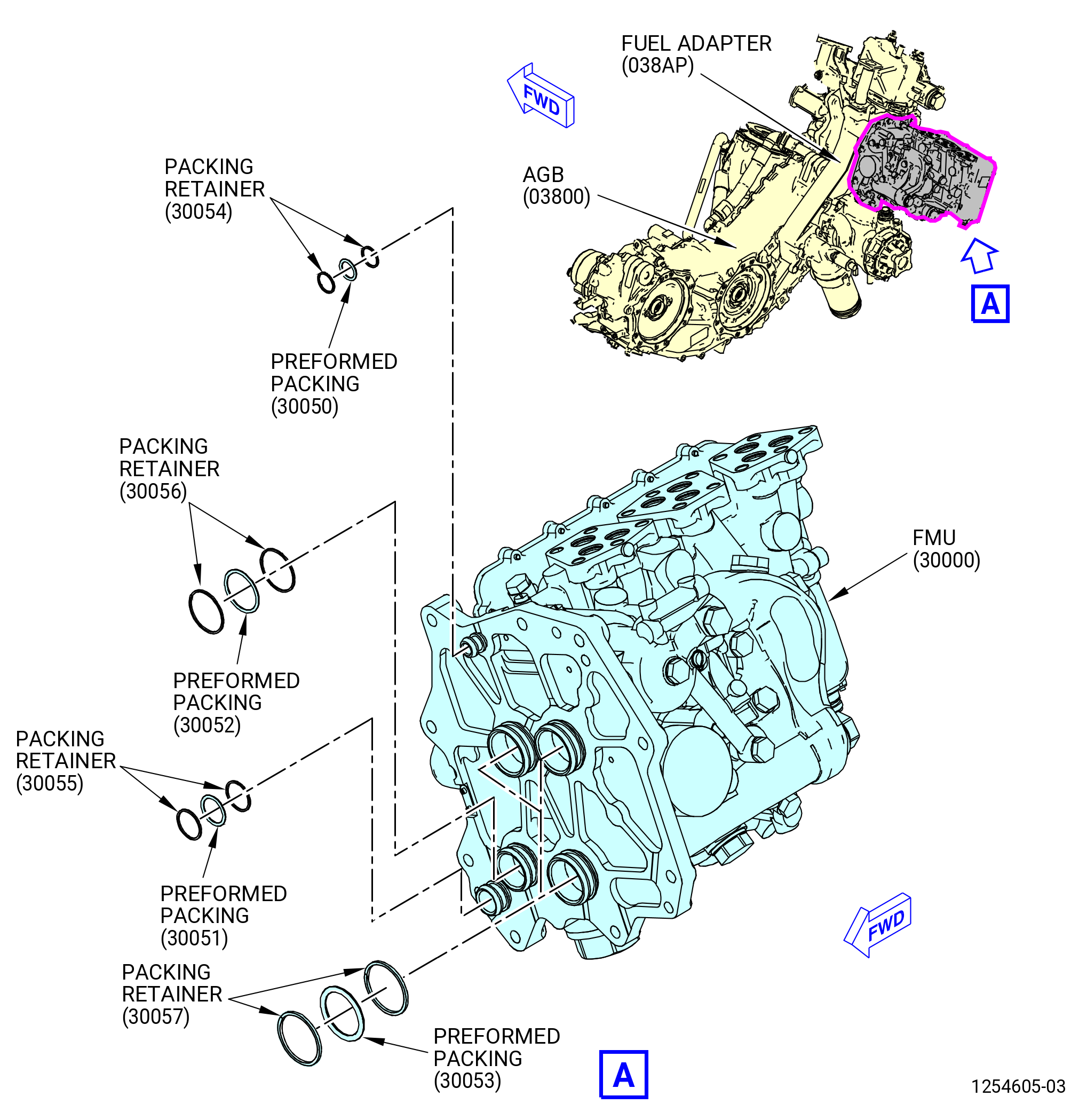
| G. | Install the fuel metering unit (FMU) (01-010 , 73-21-40) (SIN 30000) or (01-011 , 73-21-40) (SIN 30000) on the fuel adapter (05-300 , 72-64-00) (SIN 038AP) of the AGB (01-010) (SIN 03800). Refer to Figure 1012 and as follows: |
| WARNING: |
|
| (1) | Apply C02-019 engine oil or C02-023 engine oil to the packing retainers (01-080 , 73-21-40) (SIN 30054), (01-090 , 73-21-40) (SIN 30055), (01-100 , 73-21-40) (SIN 30056), and (01-110 , 73-21-40) (SIN 30057) and the preformed packings (01-040 , 73-21-40) (SIN 30050), (01-050 , 73-21-40) (SIN 30051), (01-060 , 73-21-40) (SIN 30052), and (01-070 , 73-21-40) (SIN 30053). |
| (2) | Install the packing retainers (30054, 30055, 30056, 30057) and the preformed packings (30050, 30051, 30052, 30053) on the forward side of the FMU as follows: |
| CAUTION: |
|
| CAUTION: |
|
| CAUTION: |
|
| (a) | Install one packing retainer (01-080 , 73-21-40) (SIN 30054), (01-090 , 73-21-40) (SIN 30055), (01-100 , 73-21-40) (SIN 30056), and (01-110 , 73-21-40) (SIN 30057) on each port of the FMU. |
| (b) | Install one preformed packing (01-040 , 73-21-40) (SIN 30050), (01-050 , 73-21-40) (SIN 30051), (01-060 , 73-21-40) (SIN 30052) and (01-070 , 73-21-40) (SIN 30053) on each port of the FMU. |
| CAUTION: |
|
| (c) | Install the second packing retainer (01-080 , 73-21-40) (SIN 30054), (01-090 , 73-21-40) (SIN 30055), (01-100 , 73-21-40) (SIN 30056), and (01-110 , 73-21-40) (SIN 30057) on each port of the FMU. |
| NOTE: |
|
| Subtask 72-00-05-220-003 |
| * * * FOR ALL |
| (d) | Do a visual inspection of the packing retainers (01-080 , 73-21-40) (SIN 30054), (01-090 , 73-21-40) (SIN 30055), (01-100 , 73-21-40) (SIN 30056), and (01-110 , 73-21-40) (SIN 30057) to make sure that there is not an excessive gap at the split and that they are set in the groove of the port correctly. Refer to Figure 1005 and do as follows: |
| CAUTION: |
|
| 1 | If there is an excessive gap and overhang, the packing retainers are not correctly installed in the groove of the adapter and you must replace the packing retainer (30054, 30055, 30056, 30057). |
| WARNING: |
|
| 2 | Apply C02-019 engine oil or C02-023 engine oil to the lead in chamfers on the FMU (01-010 , 73-21-40) (SIN 30000) or (01-011 , 73-21-40) (SIN 30000) and the AGB (01-010) (SIN 03800). |
| (3) | Examine the cavities of the FMU to make sure that there is not unwanted material or handling damage. Refer to Figure 1012. |
| Subtask 72-00-05-430-063 |
| * * * FOR ALL |
| WARNING: |
|
| CAUTION: |
|
| (4) | Insert the fuel metering cradle (item 16) or (item 18) of the 11C4412 LRU fixture in the 9446M93 jack stand and attach it with the screw knob from the 9446M93 jack stand. |
| (5) | Install the FMU (01-010 , 73-21-40) (SIN 30000) or (01-011 , 73-21-40) (SIN 30000) on the fuel metering cradle (item 16) or (item 18) of the 11C4412 LRU fixture using the appropriate holes and three screws (item 15). |
| (6) | Use the 9446M93 jack stand to lift the FMU into position on the manifold assembly on the aft side of the AGB. |
| WARNING: |
|
| (7) | Lubricate the dowel pin with clean oil, C02-019 engine oil or C02-023 engine oil. |
| (8) | Align the dowel pin of the FMU with the manifold assembly. |
| (9) | Attach the FMU to the manifold assembly as follows: |
| (a) | Install the FMU on the guide pins of the manifold assembly. |
| (b) | Install a self-locking nut (30040) on two opposite guide pins. |
| NOTE: |
|
| (c) | Remove the lift sling. |
| (d) | Tighten but do not torque the self-locking nuts (30040) until the FMU is installed on the manifold assembly. |
| NOTE: |
|
| (e) | Install the remaining self-locking nuts (30040) and tighten by hand. |
| (f) | Torque the self-locking nuts (30040) in a criss-cross pattern to 92-108 lb-in. (10.4-12.2 N.m). |
| (g) | Torque the self-locking nuts (01-030 , 73-21-40) (SIN 30040) in a criss-cross pattern to 244-286 lb-in. (27.6-32.3 N.m). |
| (10) | Remove the three screws (item 15) of the 11C4412 LRU fixture from the FMU. |
| (11) | Put the screws (item 15) in the bolt storage. |
| (12) | Remove the 11C4412 LRU fixture from the 9446M93 jack stand. |
| Subtask 72-00-05-420-035 |
| * * * FOR |
| * * * SB 72-0161( PIP2 Engines ) |
| (13) | Install the cap (01-120 , 73-21-40) (SIN 30060) in the FMU (01-011 , 73-21-40) (SIN 30000). Refer to Figure 1012. |
| (14) | Torque the cap (01-120 , 73-21-40) (SIN 30060) to 435-565 lb in. (49.1-63.8 N.m). |
| (15) | Safety the drain plug with C10-071 safety wire or C10-143 safety cable assembly. |
| NOTE: |
|
| * * * FOR |
| * * * END SB 72-0161 |
| * * * FOR ALL |
|
|
|
|
| Subtask 72-00-05-430-041 |
| * * * FOR |
| * * * DELETED ( ) |
| H. | Deleted. |
| (1) | Deleted. |
| Subtask 72-00-05-430-083 |
| * * * FOR ALL |
| * * * FOR ALL |
| * * * DELETED |
| (2) | Deleted. |
| * * * FOR |
| * * * DELETED ( ) |
| Subtask 72-00-05-220-004 |
| * * * FOR ALL |
| (3) | Deleted. |
| Subtask 72-00-05-430-064 |
| * * * FOR ALL |
| (4) | Deleted. |
| * * * FOR |
| * * * DELETED ( ) |
| Subtask 72-00-05-430-073 |
| * * * FOR ALL |
| * * * FOR |
| * * * SB 79-0018( MFOHX with Indicating Capability ) |
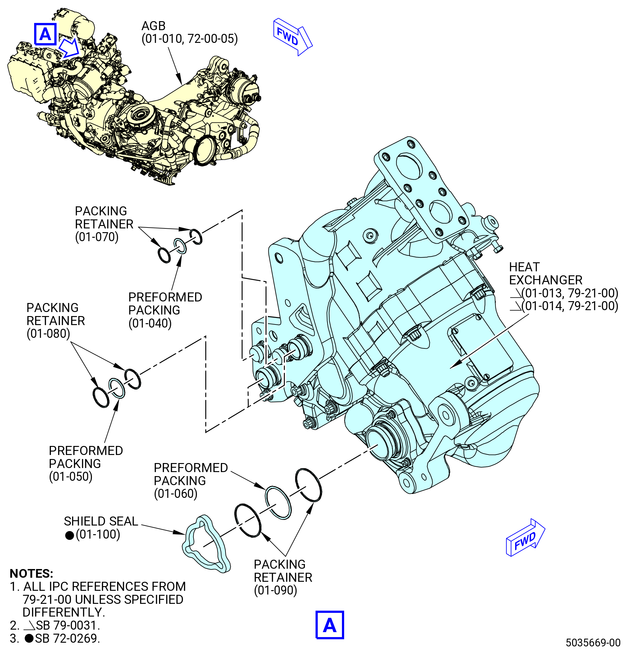
| H.A. | Install the heat exchanger (01-011 , 79-21-00) (SIN 40700) or (01-012 , 79-21-00) (SIN 40700) or (01-013 , 79-21-00) (SIN 40700) or (01-014 , 79-21-00) (SIN 40700) on the fuel adapter (05-300 , 72-64-00) (SIN 038AP) of the AGB (01-010) (SIN 03800). Refer to Figure 1013, Figure 1014, and do as follows: |
| WARNING: |
|
| (1) | Apply C02-019 engine oil or C02-023 engine oil to the four packing retainers (01-070 , 79-21-00) (SIN 40753), four packing retainers (01-080 , 79-21-00) (SIN 40754), two packing retainers (01-090 , 79-21-00) (SIN 40755), two preformed packings (01-040 , 79-21-00) (SIN 40750), two preformed packings (01-050 , 79-21-00) (SIN 40751), and preformed packing (01-060 , 79-21-00) (SIN 40752). |
| (2) | Install the packing retainers (01-070 , 79-21-00) (SIN 40753), (01-080 , 79-21-00) (SIN 40754), and (01-090 , 79-21-00) (SIN 40755) and preformed packings (01-040 , 79-21-00) (SIN 40750), (01-050 , 79-21-00) (SIN 40751), and (01-060 , 79-21-00) (SIN 40752) on the aft side of the heat exchanger as follows: |
| CAUTION: |
|
| CAUTION: |
|
| CAUTION: |
|
| (a) | Install one packing retainer (01-070 , 79-21-00) (SIN 40753) on each of the two smallest diameter ports of the heat exchanger. |
| (b) | Install one packing retainer (01-080 , 79-21-00) (SIN 40754) on each of the two medium diameter ports of the heat exchanger. |
| (c) | Install one packing retainer (01-090 , 79-21-00) (SIN 40755) on the largest port of the heat exchanger. |
| (d) | Install a preformed packing (01-040 , 79-21-00) (SIN 40750) on each of the two smallest diameter ports of the heat exchanger. |
| (e) | Install a preformed packing (01-050 , 79-21-00) (SIN 40751) on each of the two medium diameter ports of the heat exchanger. |
| (f) | Install a preformed packing (01-060 , 79-21-00) (SIN 40752) on the largest port of the heat exchanger. |
| NOTE: |
|
| CAUTION: |
|
| (g) | Install the second packing retainer (01-070 , 79-21-00) (SIN 40753) on each of the two smallest diameter ports of the heat exchanger. |
| (h) | Install the second packing retainer (01-080 , 79-21-00) (SIN 40754) on each of the two medium diameter ports of the heat exchanger. |
| (i) | Install the second packing retainer (01-090 , 79-21-00) (SIN 40755) on the largest port of the heat exchanger. |
| Subtask 72-00-05-430-084 |
| * * * FOR ALL |
| * * * FOR |
| * * * SB 72-0269( ) |
| (j) | Install the fuel/oil heat exchanger fuel seal (shield seal) (01-100 , 79-21-00) (SIN 40757) after the second packing retainer (01-090 , 79-21-00) (SIN 40755). |
| NOTE: |
|
| * * * FOR |
| * * * END SB 72-0269 |
| Subtask 72-00-05-220-012 |
| * * * FOR ALL |
| (k) | Do a visual inspection of the packing retainers (01-070 , 79-21-00) (SIN 40753), (01-080 , 79-21-00) (SIN 40754), and (01-090 , 79-21-00) (SIN 40755) to make sure that there is not too much clearance at the separation and that they are correctly installed in the groove of the port. Refer to Figure 1005 and do as follows: |
| CAUTION: |
|
| 1 | If there is too much clearance and overhang, then the packing retainers (01-070 , 79-21-00) (SIN 40753), (01-080 , 79-21-00) (SIN 40754), and (01-090 , 79-21-00) (SIN 40755) are not correctly installed in the groove of the port and must be replaced. |
| Subtask 72-00-05-430-075 |
| * * * FOR ALL |
| WARNING: |
|
| CAUTION: |
|
| (3) | Apply C02-019 engine oil or C02-023 engine oil to the lead chamfers on the heat exchanger (01-011 , 79-21-00) (SIN 40700) or (01-012 , 79-21-00) (SIN 40700) or (01-013 , 79-21-00) (SIN 40700) or (01-014 , 79-21-00) (SIN 40700) and the AGB casing (10-010 , 72-64-00) (SIN 038A0). |
| (4) | Insert the heat exchanger cradle (item 2) of the 11C4693 LRU fixture in the 9446M93 jack stand and secure it with the support jack supplied ball-lock pin from the 9446M93 jack stand. |
| NOTE: |
|
| (5) | Install the heat exchanger on the heat exchanger cradle (item 2) of the 11C4693 LRU fixture in the applicable holes, two screws (item 7). |
| WARNING: |
|
| (6) | Use the 9446M93 jack stand to lift the heat exchanger into position on the manifold assembly on the forward side of the AGB. |
| WARNING: |
|
| (7) | Lubricate the dowel pin with clean oil, C02-019 engine oil or C02-023 engine oil. |
| (8) | Align the dowel pin on the manifold assembly with the heat exchanger. |
| (9) | Attach the heat exchanger to the manifold assembly as follows: |
| (a) | Install the heat exchanger on the guide pins of the manifold assembly. |
| (b) | Install a self-locking nut (01-031 , 79-21-00) (SIN 40740) on each of two opposite guide pins. |
| NOTE: |
|
| (c) | Remove the lift sling. |
| (d) | Hand-tighten the self-locking nuts (01-031 , 79-21-00) (SIN 40740) until the heat exchanger is installed on the manifold assembly. Do not torque the self-locking nuts at this time. |
| (e) | Turn the two self-locking nuts (01-031 , 79-21-00) (SIN 40740) in half a turn increments to keep a parallel seat of the heat exchanger to the manifold assembly. |
| (f) | Install the remaining self-locking nuts (01-031 , 79-21-00) (SIN 40740). Hand-tighten the self-locking nuts. |
| (g) | Torque the five self-locking nuts (01-031 , 79-21-00) (SIN 40740) in a criss-cross pattern to 92-108 lb in. (10.4-12.2 N.m). |
| (h) | Torque again the five self-locking nuts (01-031 , 79-21-00) (SIN 40740) in a criss-cross pattern to 244-286 lb in. (27.6-32.3 N.m). |
| (i) | Apply a final torque to the five self-locking nuts (01-031 , 79-21-00) (SIN 40740) in a circular pattern to 244-286 lb in. (27.6-32.3 N.m). |
| (10) | Remove the two screws (item 7) of the 11C4693 LRU fixture from the heat exchanger. |
| (11) | Put the two screws (item 13) in the bolt storage of the 11C4693 LRU fixture. |
| (12) | Remove the 11C4693 LRU fixture from the 9446M93 jack stand. |
| Subtask 72-00-05-430-078 |
| * * * FOR ALL |
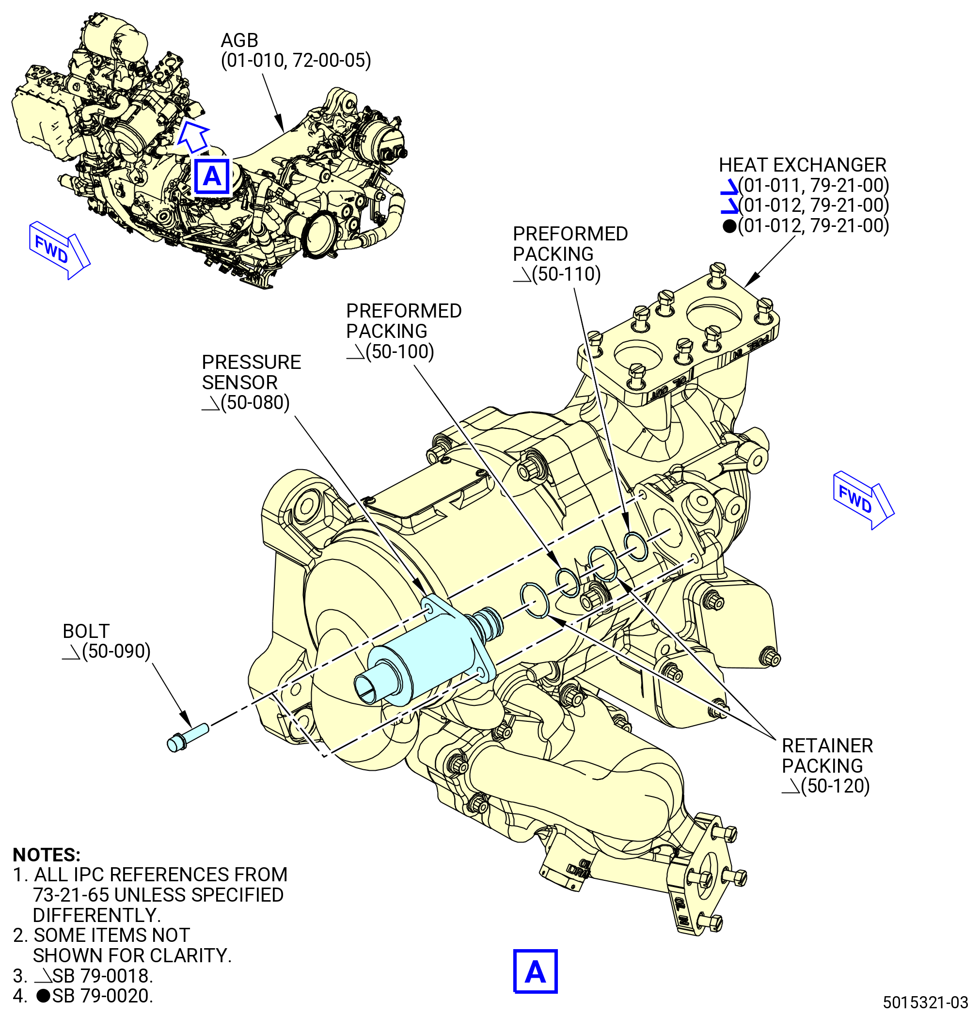
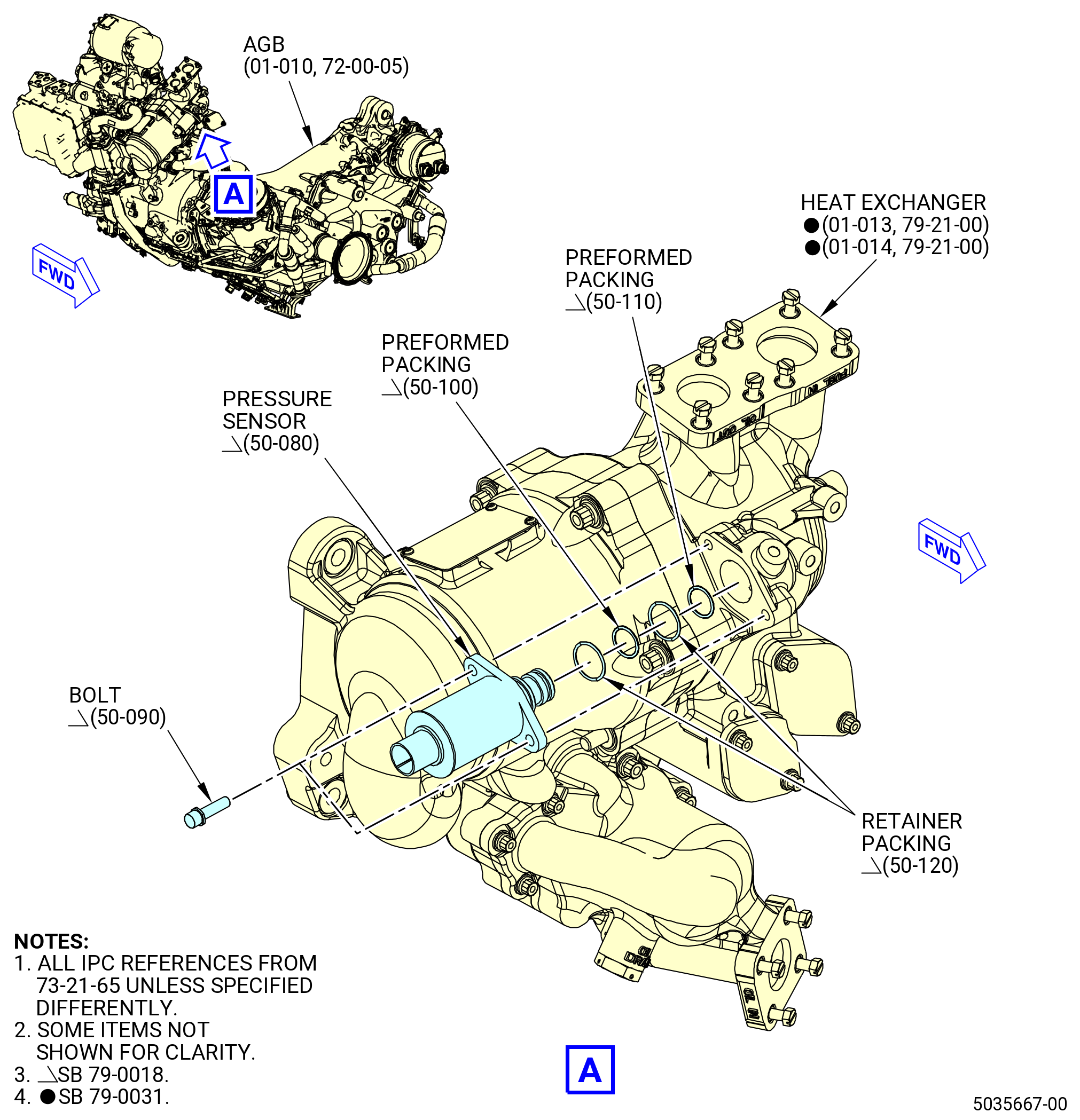
| (13) | Install the pressure sensor (50-080 , 73-21-65) (SIN 31502) on the heat exchanger (01-011 , 79-21-00) (SIN 40700) or (01-012 , 79-21-00) (SIN 40700) or (01-013 , 79-21-00) (SIN 40700) or (01-014 , 79-21-00) (SIN 40700). Refer to Figure 1013 and do as follows: |
| WARNING: |
|
| (a) | Apply C02-058 lubricant to the threads and friction surfaces of the bolts (50-090 , 73-21-65) (SIN 31520). |
| (b) | Apply C02-019 engine oil or C02-023 engine oil to the preformed packings (50-100 , 73-21-65) (SIN 31550) and (50-110 , 73-21-65) (SIN 31551) and retainer packings (50-120 , 73-21-65) (SIN 31552). |
| (c) | Install the retainer packings (50-120 , 73-21-65) (SIN 31552) and preformed packings (50-100 , 73-21-65) (SIN 31550) and (50-110 , 73-21-65) (SIN 31551) as follows: |
| CAUTION: |
|
| CAUTION: |
|
| CAUTION: |
|
| 1 | Install one retainer packing (50-120 , 73-21-65) (SIN 31552) on the adapter of the pressure sensor (50-080 , 73-21-65) (SIN 31502). |
| 2 | Install the preformed packing (50-100 , 73-21-65) (SIN 31550) on the adapter of the pressure sensor (50-080 , 73-21-65) (SIN 31502). |
| CAUTION: |
|
| 3 | Install the second retainer packing (50-120 , 73-21-65) (SIN 31552) on the adapter of the pressure sensor (50-080 , 73-21-65) (SIN 31502). |
| NOTE: |
|
| Subtask 72-00-05-220-013 |
| * * * FOR ALL |
| 4 | Do a visual inspection of the retainer packings (50-120 , 73-21-65) (SIN 31552) to make sure that there is not too much clearance at the separation and that they are correctly installed on the adapter. Refer to Figure 1005 and as follows: |
| CAUTION: |
|
| a | If there is too much clearance and overhang, then the retainer packings are not correctly installed in the groove of the adapter and must be replaced. |
| Subtask 72-00-05-430-079 |
| * * * FOR ALL |
| (d) | Install the preformed packing (50-110 , 73-21-65) (SIN 31551) on the adapter of the fuel pressure transducer. |
| WARNING: |
|
| (e) | Apply C02-019 engine oil or C02-023 engine oil to the lead in chamfers on the pressure sensor (50-080 , 73-21-65) (SIN 31502). |
| (f) | Install the pressure sensor (50-080 , 73-21-65) (SIN 31502) into the heat exchanger (01-011 , 79-21-00) (SIN 40700) or (01-012 , 79-21-00) (SIN 40700) or (01-013 , 79-21-00) (SIN 40700) or (01-014 , 79-21-00) (SIN 40700). |
| (g) | Attach the pressure sensor to the heat exchanger with the bolts (50-090 , 73-21-65) (SIN 31520). Torque the bolts to 106 to 124 lb in. (12.0 to 14.0 Nm). |
| * * * FOR |
| * * * END SB 79-0018 |
| * * * FOR ALL |
|
| Subtask 72-00-05-430-042 |
| * * * FOR ALL |
| * * * PRE SB 73-0011( Engines without Fuel Vapor Accumulator ) |
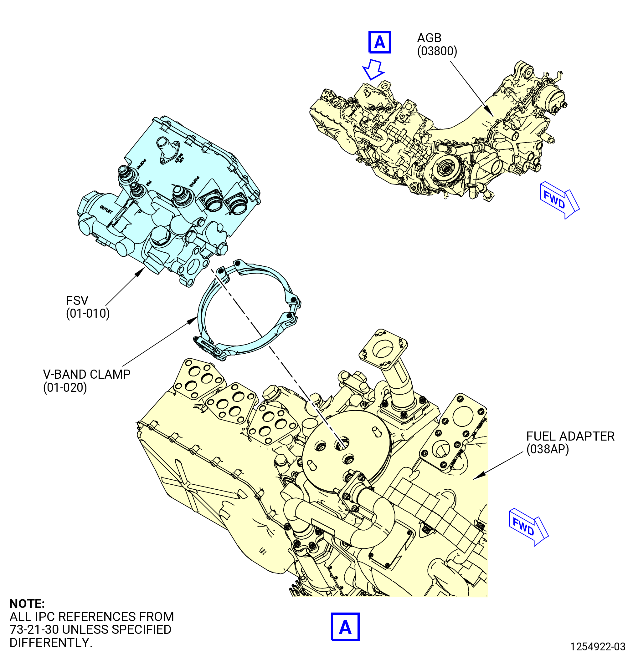
| I. | Install the flow splitting valve (FSV) (01-010 , 73-21-30) (SIN 31700) on the fuel adapter (038AP) of the AGB (03800) as follows. Refer to Figure 1016. |
| WARNING: |
|
| (1) | Apply C02-019 engine oil or C02-023 engine oil to the packing retainers (01-060 , 73-21-30) (SIN 31753), (01-070 , 73-21-30) (SIN 31754) and (01-080 , 73-21-30) (SIN 31755) and the preformed packings (01-030 , 73-21-30) (SIN 31750), (01-040 , 73-21-30) (SIN 31751) and (01-050 , 73-21-30) (SIN 31752). |
| (2) | Install the packing retainers and the preformed packings on the aft side of the FSV as follows: |
| CAUTION: |
|
| CAUTION: |
|
| CAUTION: |
|
| (a) | Install one packing retainer on each adapter of the FSV. Make sure that the packing retainer is opened (separated) in the axial direction only or permanent damage will occur. Refer to Figure 1005. |
| (b) | Install a preformed packing on each adapter of the FSV. |
| CAUTION: |
|
| (c) | Install the second packing retainer on each adapter of the FSV. Make sure that the packing retainer is opened (separated) in the axial direction only. Do not spread outward or permanent deformation will occur. |
| NOTE: |
|
| (d) | Do a visual inspection of the packing retainers to make sure that there is not too much gap at the split and that they are installed in the groove of the port correctly. |
| CAUTION: |
|
| (e) | Replace the packing retainers that have too much gap or overhang because they are not correctly installed. |
| (3) | Install the FSV on the fuel adapter (038AP) as follows. Refer to Figure 1016. |
| (a) | Align the dowel pins on the fuel adapter to the FSV and install the FSV on the fuel adapter. |
| (b) | Make sure that the FSV is against the fuel adapter. |
| (c) | Install the V-band clamp (01-020 , 73-21-30) (SIN 31781) on the flanges of the FSV and the fuel adapter. |
| (d) | Lightly tap the V-band clamp around the circumference as the nut is tightened. Torque the nut to 106-124 lb in. (12.0-14.0 N.m). |
| (e) | Lightly tap the V-band clamp around the circumference a second time as the nut is tightened. Torque the nut to 106-124 lb in. (12.0-14.0 N.m). |
| (f) | Lightly tap the V-band clamp around the circumference a third time as the nut is tightened. Torque the nut to 106-124 lb in. (12.0-14.0 N.m). |
| * * * FOR |
| * * * END PRE SB 73-0011 |
| Subtask 72-00-05-430-072 |
| * * * FOR ALL |
| * * * SB 73-0011( Engines with Fuel Vapor Accumulator ) |
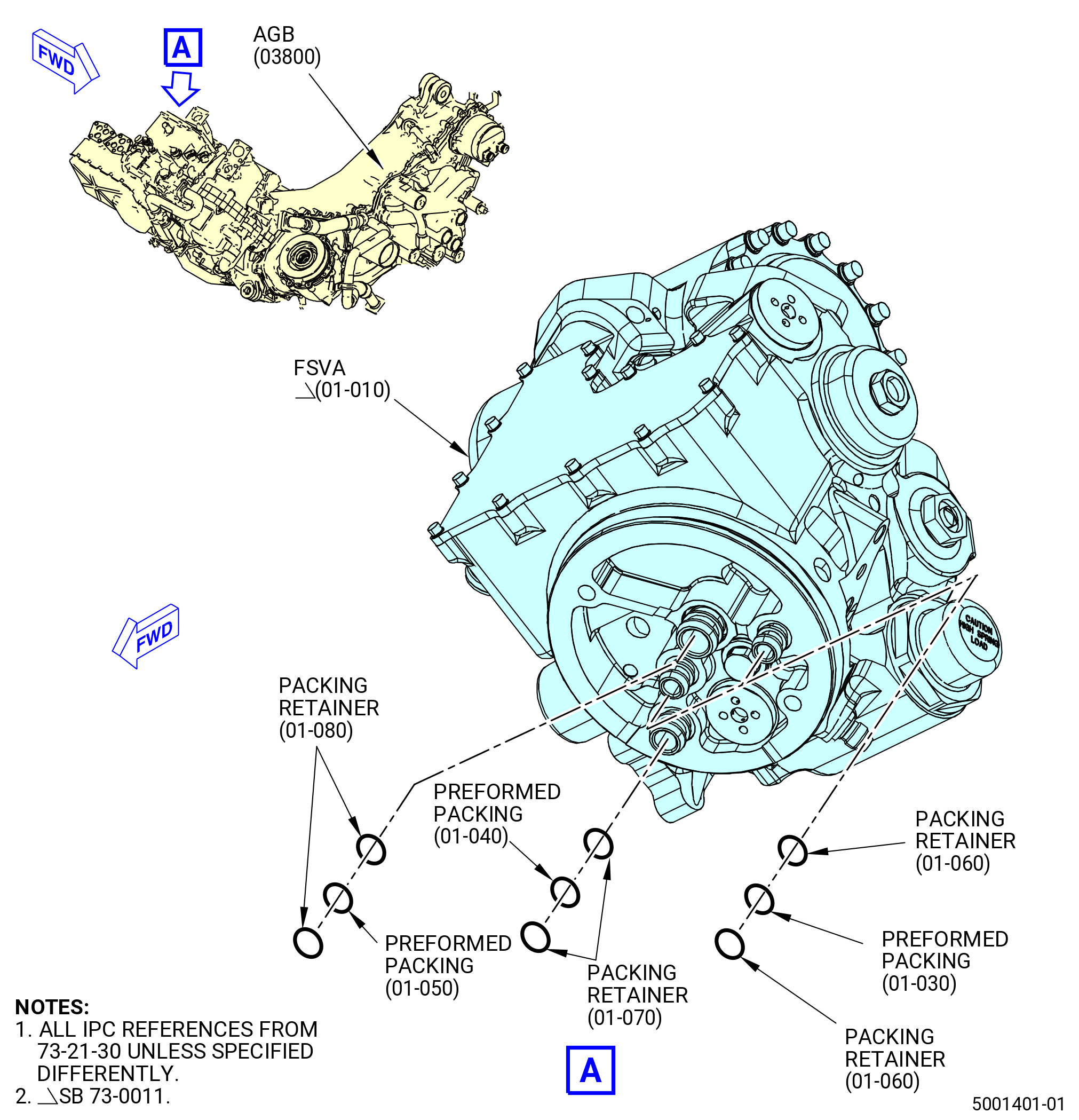
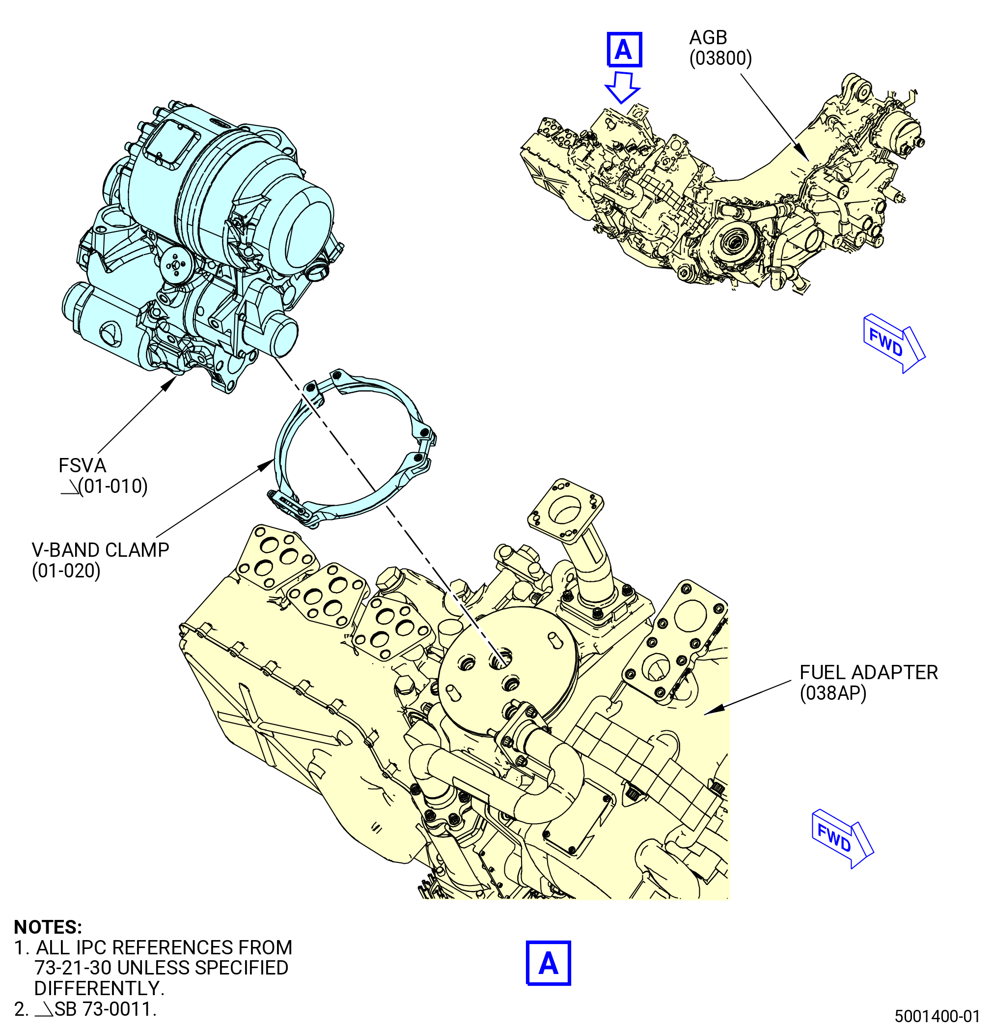
| I.A. | Install the flow splitting valve accumulator (FSVA) (01-010 , 73-21-30) (SIN 31700) on the fuel adapter (038AP) of the AGB (03800) as follows. Refer to Figure 1016. |
| WARNING: |
|
| (1) | Apply C02-019 engine oil or C02-023 engine oil to the packing retainers (01-060 , 73-21-30) (SIN 31753), (01-070 , 73-21-30) (SIN 31754) and (01-080 , 73-21-30) (SIN 31755) and the preformed packings (01-030 , 73-21-30) (SIN 31750), (01-040 , 73-21-30) (SIN 31751) and (01-050 , 73-21-30) (SIN 31752). |
| (2) | Install the packing retainers and the preformed packings on the aft side of the FSVA as follows: |
| CAUTION: |
|
| CAUTION: |
|
| CAUTION: |
|
| (a) | Install one packing retainer on each adapter of the FSVA. |
| (b) | Install a preformed packing on each adapter of the FSVA. |
| CAUTION: |
|
| (c) | Install the second packing retainer on each adapter of the FSVA. |
| NOTE: |
|
| (d) | Do a visual inspection of the packing retainers to make sure that there is not too much gap at the split and that they are installed in the groove of the port correctly. Refer to Figure 1005. |
| CAUTION: |
|
| (e) | Replace the packing retainers that have too much gap or overhang because they are not correctly installed. |
| (3) | Install the FSVA on the fuel adapter (038AP) as follows. Refer to Figure 1016. |
| (a) | Put the end of the 11C4641 adapter with the steel block on the mounting interface of the 9446M93 jack stand and attach it with the ball lock pin. Refer to Figure 1015. |
| WARNING: |
|
| (b) | Use an overhead hoist with a minimum 45 kg (100 lbs) lifting capacity and lift the FSVA up to the mounting interface on the 11C4641 adapter. |
| (c) | Align the three threaded bosses of the FSVA with the mount holes on the 11C4641 adapter interface and attach it with the three mounting screws (item 3) of the 11C4641 adapter. |
| (d) | Remove the overhead hoist from the FSVA. |
| WARNING: |
|
| (e) | Transport the 9446M93 jack stand and 11C4641 adapter with the FSVA attached. |
| (f) | Lift the 9446M93 jack stand to the applicable height to where the FSVA must be installed on the engine. |
| (g) | Do a visual inspection of the FSVA and manifold assembly for unwanted material in the cavities. |
| WARNING: |
|
| (h) | Apply C02-019 engine oil or C02-023 engine oil to the lead chamfers on the FSVA and the fuel adapter (038AP). |
| (i) | Align the dowel pins on the fuel adapter to the FSVA and install the FSVA on the fuel adapter. |
| (j) | Make sure that the FSVA is against the fuel adapter. |
| (k) | Install the V-band clamp (01-020 , 73-21-30) (SIN 31781) on the flanges of the FSVA and the fuel adapter. |
| (l) | Lightly tap the V-band clamp around the circumference as the nut is tightened. Torque the nut to 110-130 lb in. (12.4-14.7 N.m). |
| (m) | Lightly tap the V-band clamp around the circumference a second time as the nut is tightened. Torque the nut to 110-130 lb in. (12.4-14.7 N.m). |
| (n) | Lightly tap the V-band clamp around the circumference a third time as the nut is tightened. Torque the nut to 110-130 lb in. (12.4-14.7 N.m). |
| (o) | After the FSVA is attached on the gearbox, remove the three screws from the mounting interface on the 11C4641 adapter and lower the 9446M93 jack stand. |
| (p) | Remove the 11C4641 adapter from the 9446M93 jack stand and manually transport to storage. |
| * * * FOR |
| * * * END SB 73-0011 |
|
|
|
|
|
| Subtask 72-00-05-430-066 |
| * * * FOR ALL |
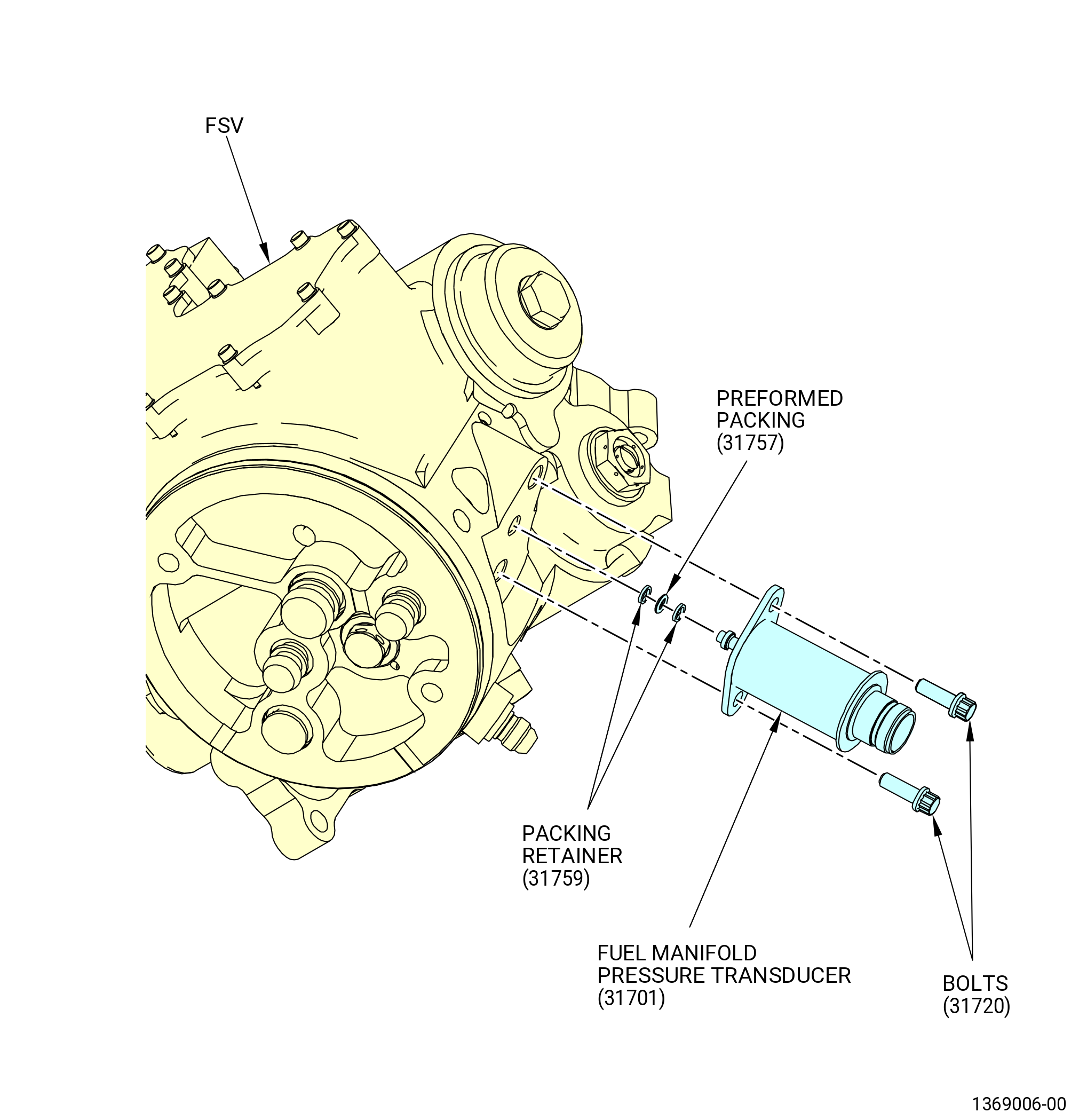
| J. | Install the fuel manifold pressure transducer (31701) on the FSV or FSVA (01-010 , 73-21-30) (SIN 31700) as follows. Refer to Figure 1017. |
| WARNING: |
|
| (1) | Apply C02-019 engine oil or C02-023 engine oil to preformed packing (31757) and the packing retainers (31759). |
| (2) | Apply C02-058 lubricant to the threads and friction surfaces of the bolts (31720). |
| (3) | Install the packing retainers (01-120 , 73-21-30) (SIN 31759) and the preformed packing (01-110 , 73-21-30) (SIN 31757) as follows: |
| CAUTION: |
|
| CAUTION: |
|
| CAUTION: |
|
| (a) | Install one packing retainer (01-120 , 73-21-30) (SIN 31759) on the adapter of the fuel manifold pressure transducer (31701). |
| (b) | Install a preformed packing (31757) on the adapter of the fuel manifold pressure transducer (31701). |
| CAUTION: |
|
| (c) | Install the second packing retainer (01-120 , 73-21-30) (SIN 31759) on the adapter of the fuel manifold pressure transducer (31701). |
| NOTE: |
|
| Subtask 72-00-05-220-006 |
| * * * FOR ALL |
| (d) | Do a visual inspection of the packing retainers (31759) to make sure that there is not an excessive gap at the split and that they are set in the adapter correctly. Refer to Figure 1005 and do as follows: |
| CAUTION: |
|
| 1 | If there is an excessive gap and overhang, the packing retainers are not correctly installed in the groove of the adapter, the packing retainers (31759) must be replaced. |
| Subtask 72-00-05-430-067 |
| * * * FOR ALL |
| (4) | Install the fuel manifold pressure transducer (31701) into the FSV or FSVA (01-010 , 73-21-30) (SIN 31700). |
| (5) | Attach the fuel manifold pressure transducer to the FSV or FSVA with the bolts (31720). Torque the bolts to 106-124 lb in. (12.0-14.0 N.m). |
| Subtask 72-00-05-430-080 |
| * * * FOR ALL |
| * * * FOR |
| * * * SB 73-0011( Engines with Fuel Vapor Accumulator ) |
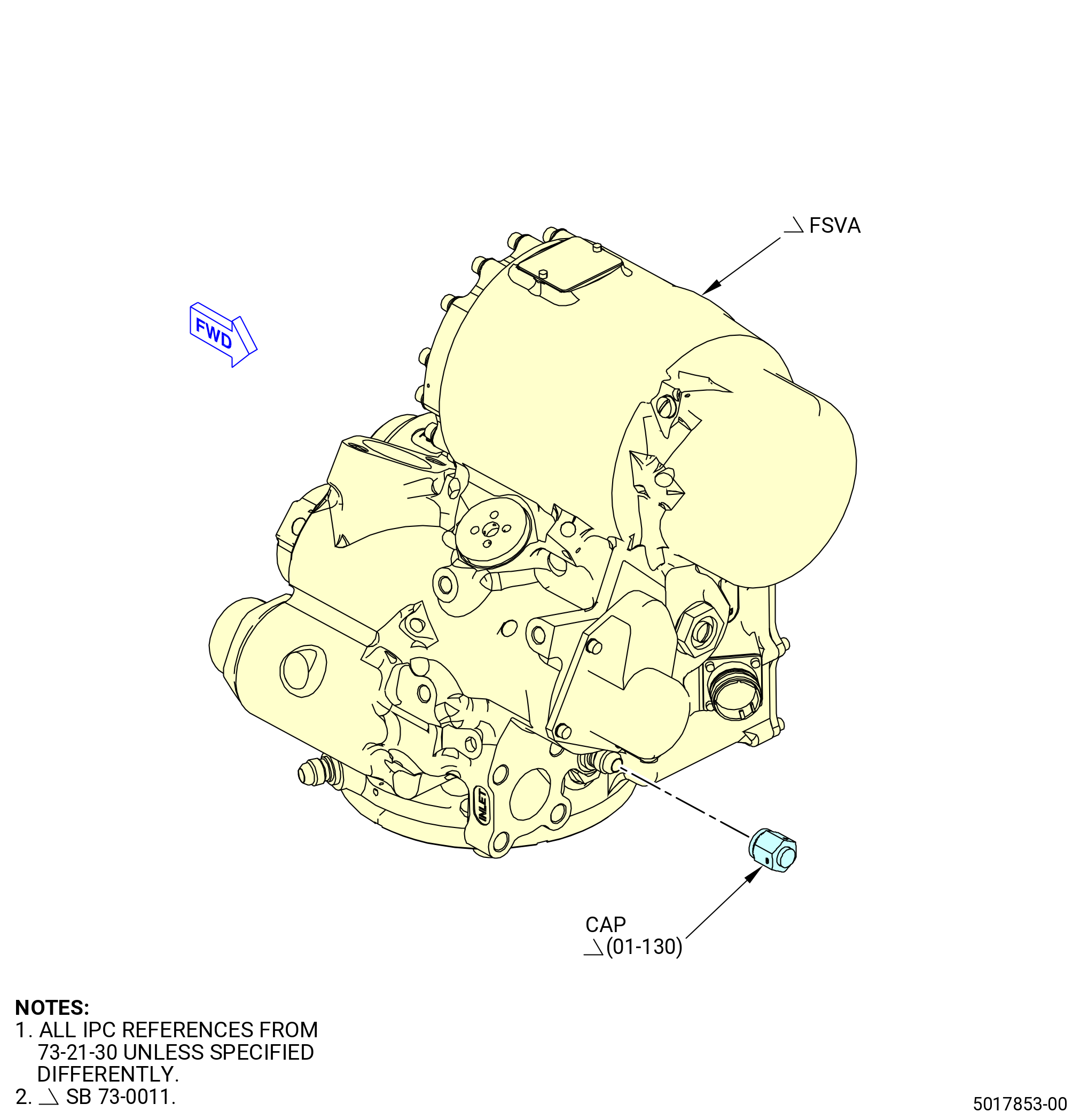
| K. | Install the cap (01-130 , 73-21-30) (SIN 31760) on the FSVA. Refer to Figure 1018 and do as follows: |
| NOTE: |
|
| (1) | Install the cap on the FSVA PD fitting attachment. |
| (2) | Triple-torque the cap to 262-308 lb in. (29.6-34.8 N.m). |
| (3) | Safety the cap with C10-071 safety wire or C10-143 safety cable assembly. |
| * * * FOR |
| * * * END SB 73-0011 |
|
|
|
| Subtask 72-00-05-430-043 |
| * * * FOR ALL |
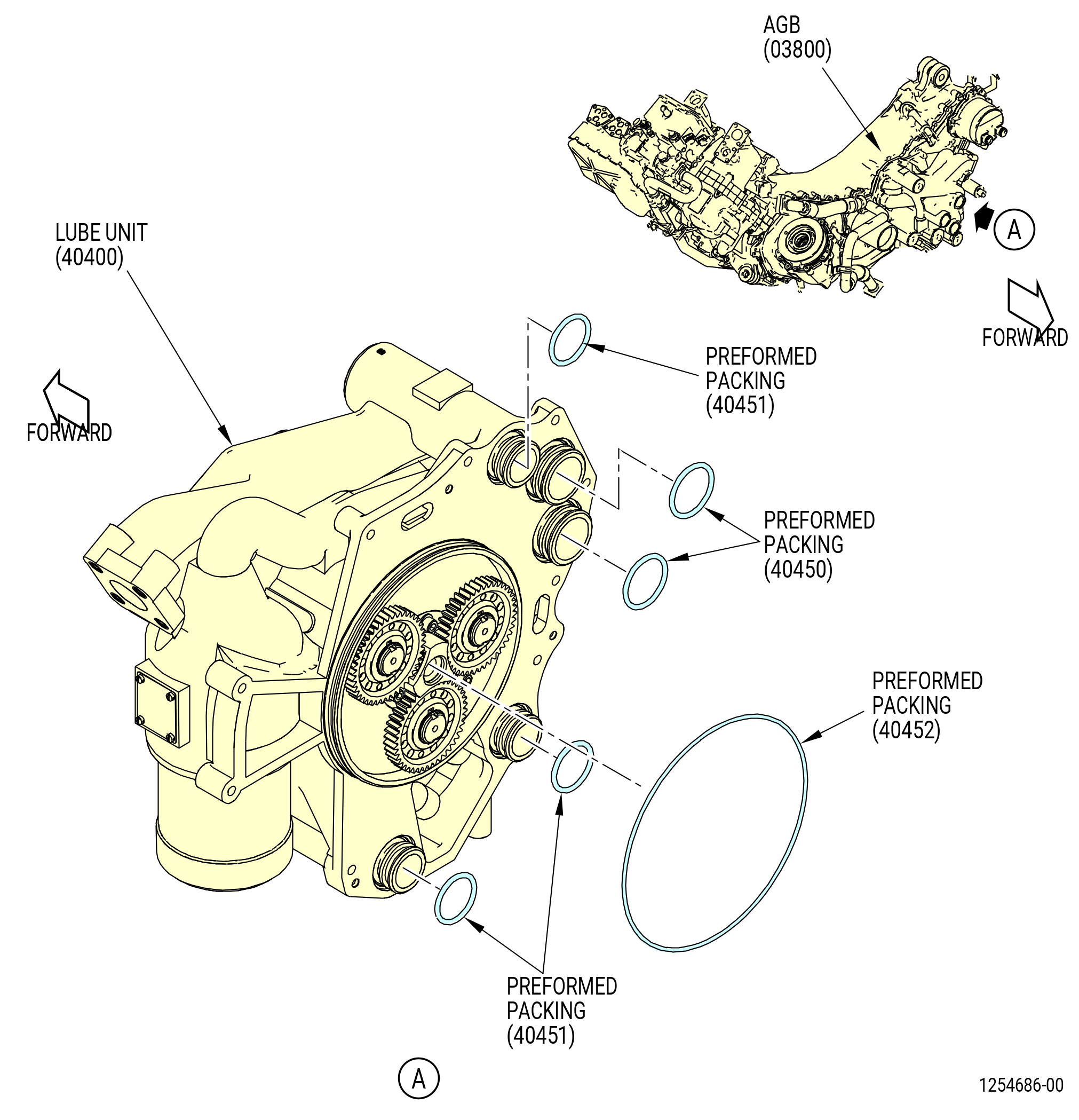
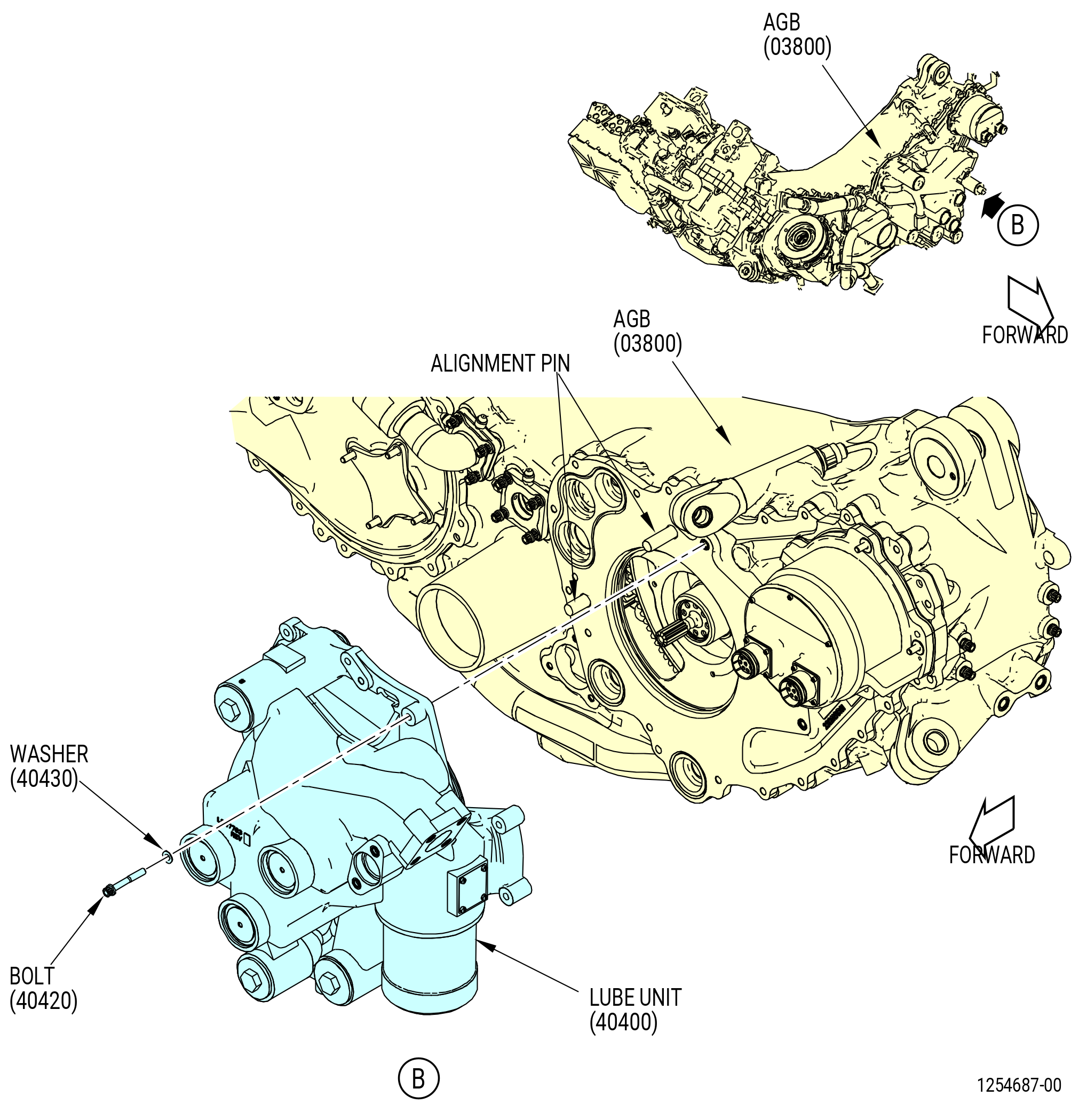
| L. | Install the lube unit (40400) on the AGB (03800) as follows. Refer to Figure 1019. |
| WARNING: |
|
| (1) | Apply C02-019 engine oil or C02-023 engine oil to the preformed packings (01-110 , 79-21-10) (SIN 40450) (QTY 2), (01-120 , 79-21-10) (SIN 40451) (QTY 3) and (01-130 , 79-21-10) (SIN 40452) (QTY 1). |
| (2) | Install the preformed packing (01-130 , 79-21-10) (SIN 40452) on the aft side of the lube unit. |
| (3) | Install the two preformed packings (01-110 , 79-21-10) (SIN 40450) on the aft side of the lube unit. |
| (4) | Install the three preformed packings (01-120 , 79-21-10) (SIN 40451) on the aft side of the lube unit. |
| WARNING: |
|
| (5) | Apply C02-019 engine oil or C02-023 engine oil to the lead chamfers on the lube unit (40400) and the AGB housing. |
| (6) | Insert the lube pump cradle (item 3) or (item 20) of the 11C4412 LRU fixture in the 9446M93 jack stand and attach it with the screw knob from the 9446M93 jack stand. |
| (7) | Install the lube unit on the lube pump cradle (item 3) or (item 20) of the 11C4412 LRU fixture in the appropriate holes using three screws (item 15). |
| (8) | Use the 9446M93 jack stand to lift the lube pump into place on the AGB. |
| (9) | Install the lube unit on the AGB as follows: |
| (a) | Apply C02-058 lubricant to the threads and friction surfaces of the bolts (40420 (QTY 9)) and washers (40430). |
| (b) | Align the lube unit to the alignment pins on the AGB. |
| (c) | Put the lube unit on the AGB and align the boltholes. |
| (d) | Install the washers (40430) and bolts (40420) to secure the lube unit. |
| NOTE: |
|
| (e) | Tighten the bolts (40420) finger-tight. |
| (f) | Torque the bolts (40420) in a criss-cross pattern to 106-124 lb-in. (12.0-14.0 N.m). |
| (g) | Torque the bolts (40420) in a circular pattern to 106-124 lb-in. (12.0-14.0 N.m). |
| (10) | Remove the screws (item 15) of the 11C4412 LRU fixture from the lube unit. |
| (11) | Put the screws (item 15) in the bolt storage. |
| (12) | Remove the 11C4412 LRU fixture from the 9446M93 jack stand. |
| Subtask 72-00-05-430-044 |
| * * * FOR ALL |
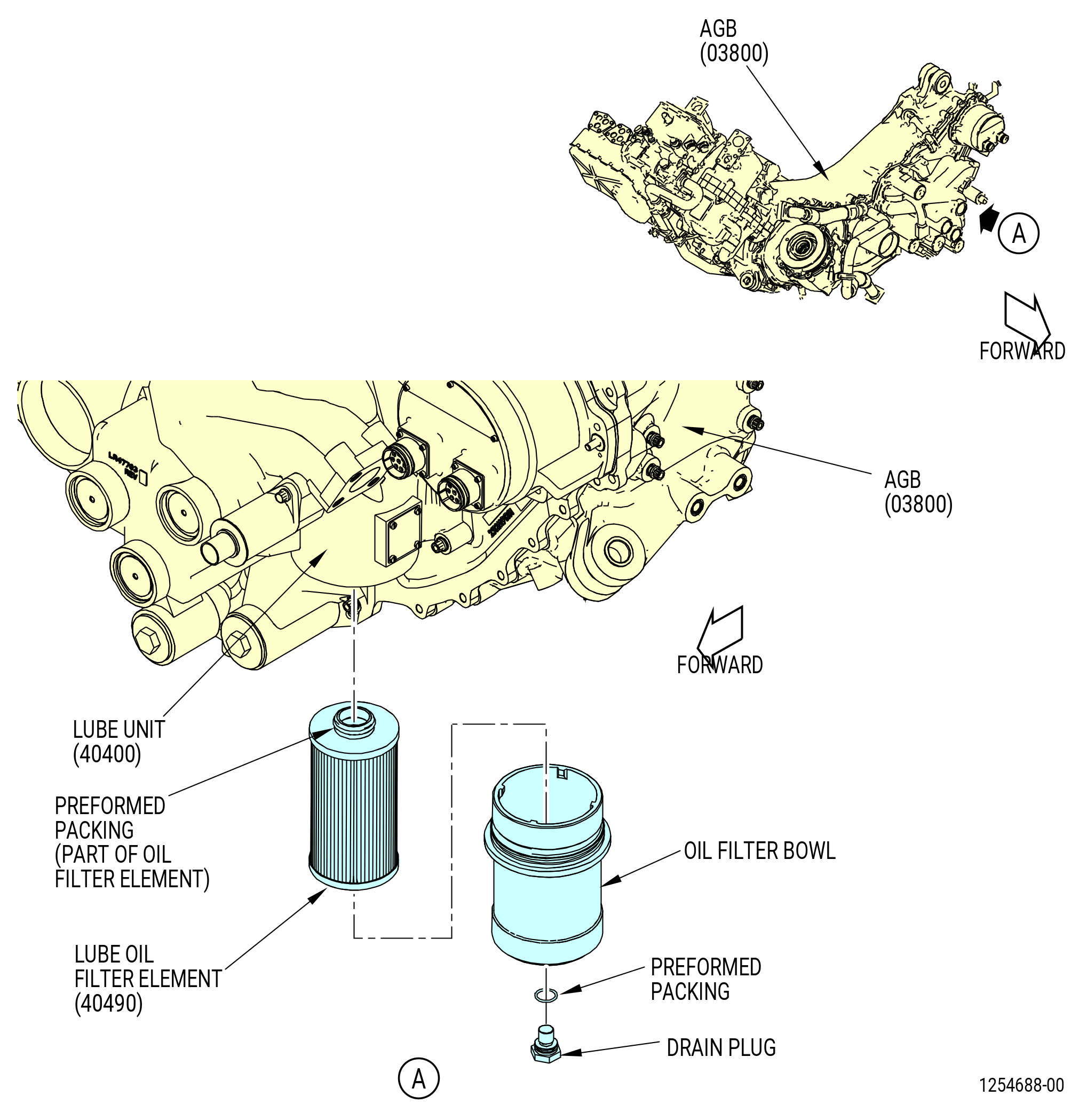
| M. | Install the drain plug and lube oil filter element (40490) in the lube unit (40400) filter bowl as follows. Refer to Figure 1020. |
| (1) | Remove the lube unit filter bowl from the lube unit. Turn the filter bowl counterclockwise to remove. |
| (2) | Install the lube oil filter element in the lube unit filter bowl as follows: |
| (a) | Make sure that the external preformed packing (01-030 , 79-21-10) is installed on the end of the lube oil filter element. If not, replace the lube oil filter element. |
| NOTE: |
|
| (b) | Put the filter element in the filter bowl with the filter element external preformed packing up. Do not install the filter element end with the external preformed packing in the filter bowl. |
| NOTE: |
|
| WARNING: |
|
| (3) | Apply C02-019 engine oil or C02-023 engine oil to the drain plug preformed packing (01-020 , 79-21-10). |
| (4) | Install the preformed packing (01-020 , 79-21-10) on the drain plug. |
| (5) | Install the drain plug in the bottom of the lube unit filter bowl. |
| (6) | Torque the drain plug to 10 to 15 lb in. (1.1 to 1.7 Nm) above the run-in torque. |
| (7) | Deleted. |
| (8) | Install the lube oil filter bowl on the lube unit as follows: |
| WARNING: |
|
| (a) | Apply C02-019 engine oil or C02-023 engine oil to the filter bowl preformed packing (01-040 , 79-21-10). |
| (b) | Put the preformed packing (01-040 , 79-21-10) on the filter bowl. |
| (c) | Install the filter bowl in the lube unit. |
| (d) | Tighten the filter bowl by hand in a clockwise direction until it touches the lube unit. |
| * * * FOR ALL |
| Subtask 72-00-05-430-045 |
| * * * FOR ALL |
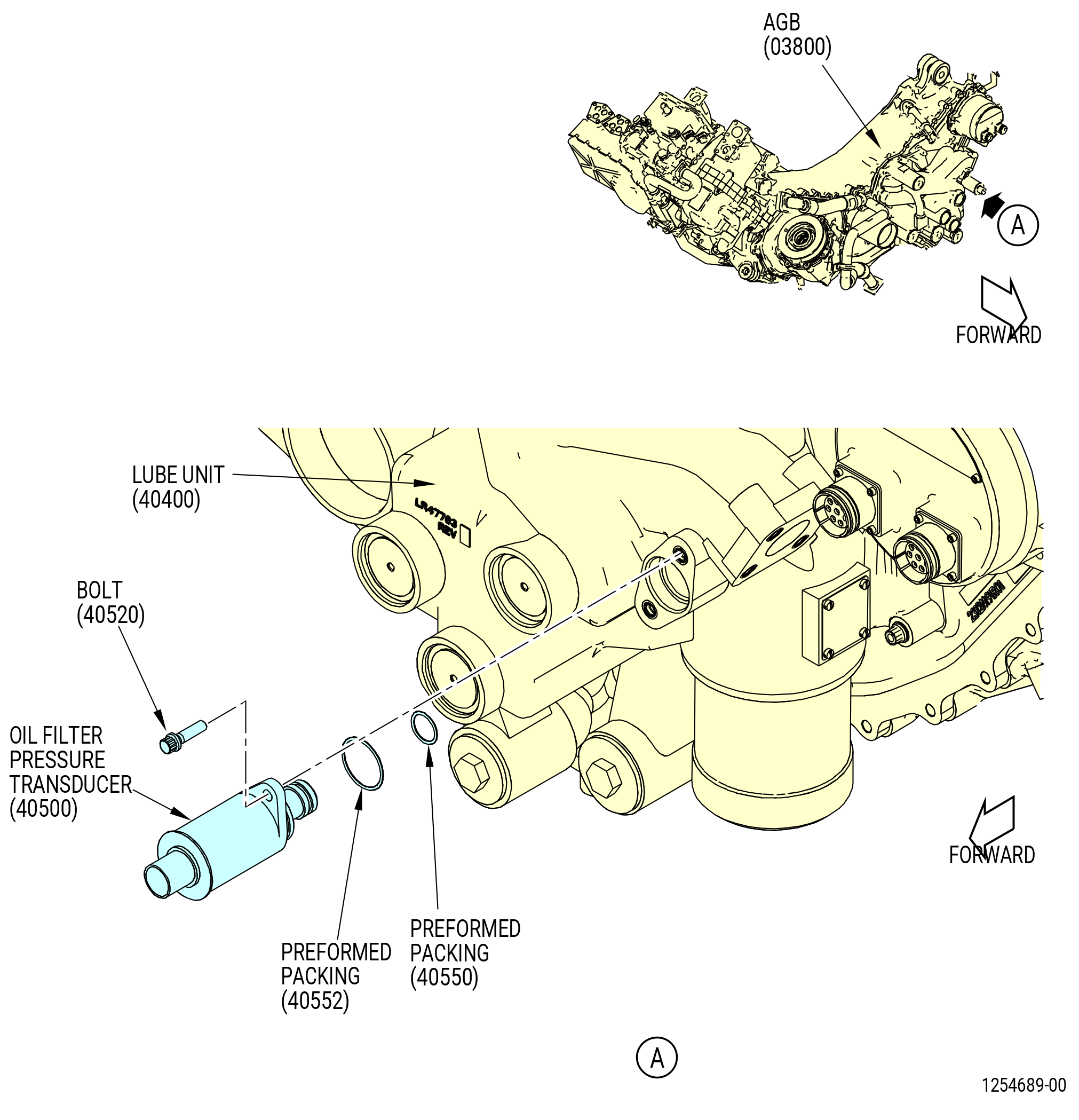
| N. | Install the oil filter pressure transducer (40500) in the lube unit (40400) as follows. Refer to Figure 1021. |
| WARNING: |
|
| (1) | Apply C02-019 engine oil or C02-023 engine oil to the preformed packings (01-030 , 79-32-10) (SIN 40552) and (01-040 , 79-32-10) (SIN 40550). |
| (2) | Install the preformed packings (01-030 , 79-32-10) (SIN 40552) and (01-040 , 79-32-10) (SIN 40550) on the oil filter pressure transducer. |
| (3) | Install the oil filter pressure transducer in the lube unit. |
| (4) | Apply C02-058 lubricant to the threads and friction surfaces of the bolts (40520). |
| (5) | Install the bolts (40520) to secure the oil filter pressure transducer. |
| (6) | Torque the bolts (40520) to 106-124 lb-in. (12.0-14.0 N.m). |
| * * * FOR ALL |
| Subtask 72-00-05-430-046 |
| * * * FOR ALL |
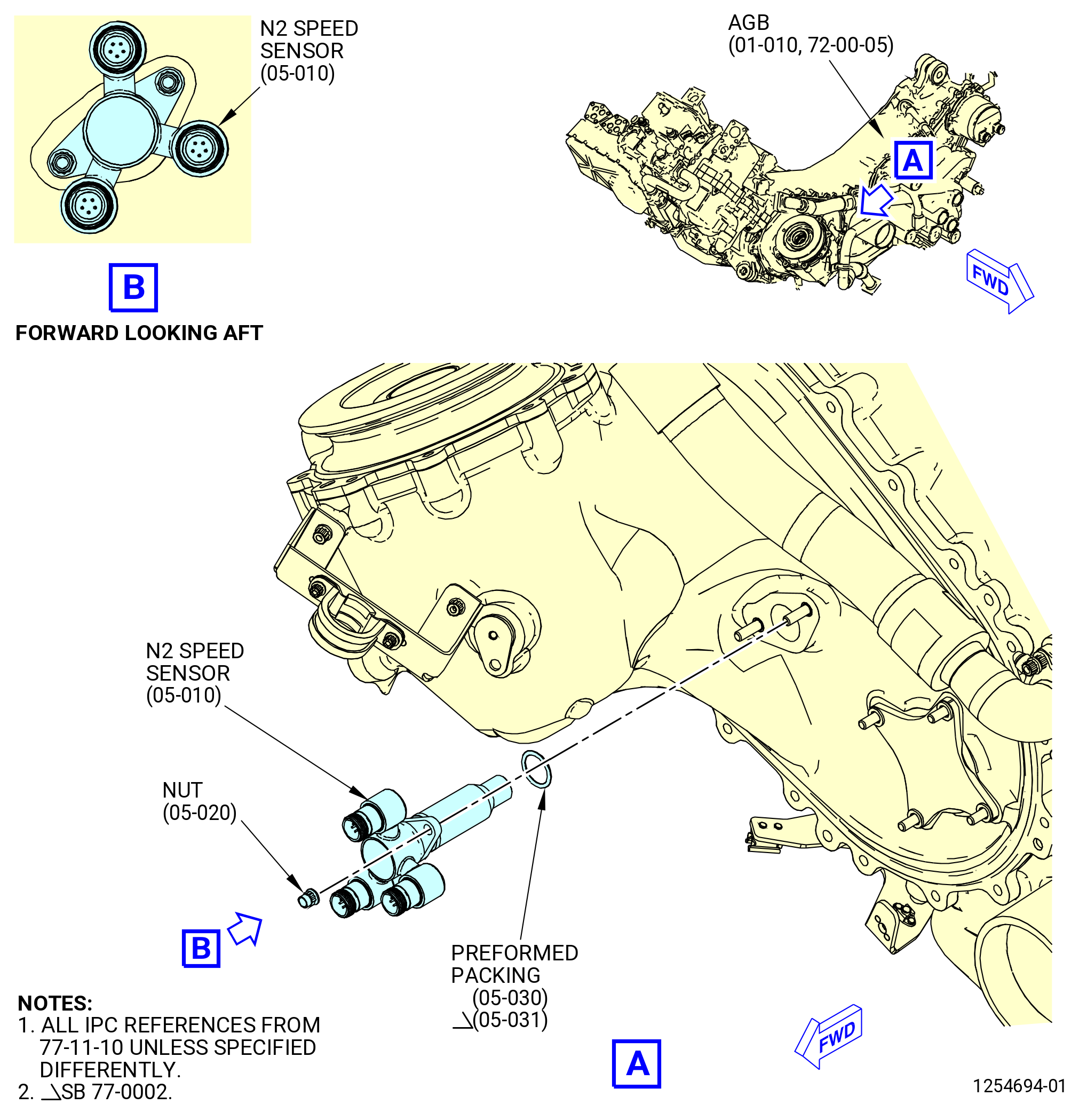
| O. | Install the core speed sensor (N2 speed sensor) (65D00) on the AGB (03800) as follows. Refer to Figure 1022. |
| WARNING: |
|
| (1) | Apply C02-019 engine oil or C02-023 engine oil to the preformed packing (05-030 , 77-11-10) (SIN 65D50) or (05-031 , 77-11-10) (SIN 65D50). |
| (2) | Install the preformed packings (05-030 , 77-11-10) (SIN 65D50) or (05-031 , 77-11-10) (SIN 65D50) on the N2 speed sensor. |
| WARNING: |
|
| (3) | Apply C02-019 engine oil or C02-023 engine oil to the lead chamfers on the core speed sensor (65D00) and the AGB housing. |
| (4) | Install the N2 speed sensor in the AGB. |
| (5) | Apply C02-058 lubricant to the threads and friction surfaces of the nuts (65D40). |
| (6) | Install the nuts (65D40) to secure the N2 speed sensor. |
| (7) | Torque the nuts (65D40) to 106-124 lb-in. (12.0-14.0 N.m). |
| * * * FOR ALL |
| Subtask 72-00-05-430-047 |
| * * * FOR ALL |
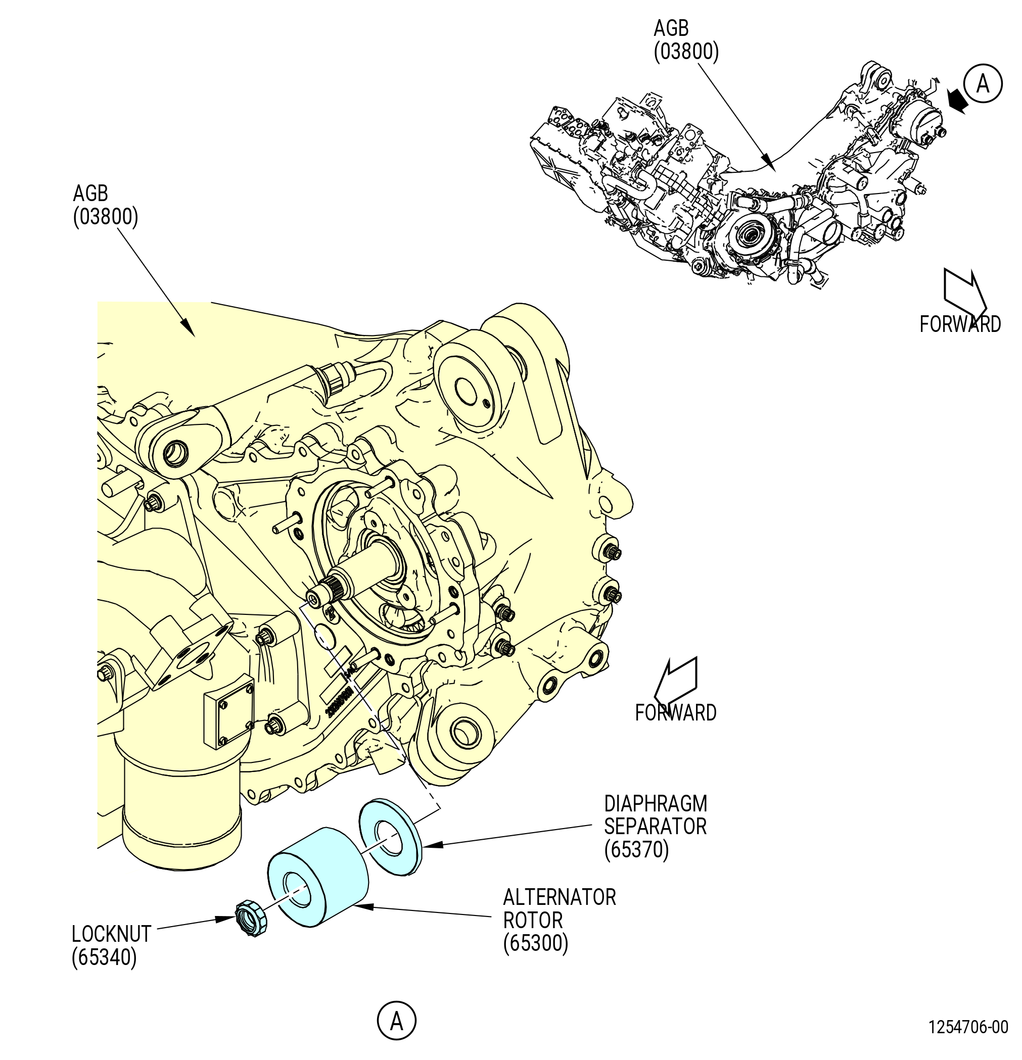
| P. | Install the alternator rotor (65300) on the AGB (03800) as follows: |
| (1) | Install the 9C1194 locking adapter on the forward side of the AGB as follows. Refer to Figure 1010. |
| (a) | If necessary, remove the nuts (038W0) and the hand crank cover (038AF) from the forward side of the AGB. |
| (b) | Install the square shaft of the adapter (item 4) in the spur gearshaft (038B9). |
| NOTE: |
|
| Subtask 72-00-05-220-007 |
| * * * FOR ALL |
| (c) | Do a visual inspection of the forward side of the AGB for unwanted material in the cavities. |
| Subtask 72-00-05-430-068 |
| * * * FOR ALL |
| (2) | Install the diaphragm separator (65370) on the forward side of the AGB with the holes of the diaphragm put against the bearing. Refer to Figure 1023. |
| (3) | Put the alternator rotor on the spur gearshaft (038B9). |
| CAUTION: |
|
| (4) | Install the locknut (65340) on the spur gearshaft (038B9) as follows: |
| (a) | Put the locknut (65340) on the spur gearshaft (038B9) with the locking feature outward. |
| (b) | Tighten the locknut (65340) until the locknut touches the alternator rotor. |
| (c) | Loosen the locknut (65340) one-half turn. |
| (d) | Tighten again and measure the maximum run-on torque before the locknut (65340) touches the alternator rotor. Use a dial torque wrench to measure the run-up torque. |
| (e) | Torque the locknut (65340) to 485 lb in. (54.8 N.m) above the maximum run-on torque. |
| (f) | Torque the locknut (65340) again to 485 lb in. (54.8 N.m) above the maximum run-on torque. |
| Subtask 72-00-05-430-048 |
| * * * FOR ALL |
| Q. | Install the alternator stator (65301) on the forward side of the AGB (03800) as follows. Refer to Figure 1024. |
| (1) | Install the 9C1194 locking adapter to lock the spur gearshaft (038B9) on the forward side of the AGB as follows. Refer to Figure 1010. |
| (a) | If necessary, remove the nuts (038W0) and the hand crank cover (038AF) from the forward side of the AGB. |
| (b) | Install the 9C1194 locking adapter in the spur gearshaft (038B9). |
| NOTE: |
|
| (c) | Install the three 11C3462 guide pins on the stator mounting pad. |
| (2) | Apply C02-058 lubricant to the threads and friction surfaces of the nuts (65341). |
| WARNING: |
|
| (3) | Apply C02-019 engine oil or C02-023 engine oil to the o-ring surface around the stator. |
| (4) | Install o-ring on the alternator stator (65301). |
| CAUTION: |
|
| (5) | Put the alternator stator on the AGB above the alternator rotor (65300). |
| (6) | Remove the three 11C3462 guide pins from the stator mounting pad. |
| (7) | Secure the alternator stator with nuts (65341) finger-tight. |
| (8) | Torque the nuts (65341) to 106-124 lb-in. (12.0-14.0 N.m). |
| (9) | Remove the 9C1194 locking adapter from the spur gearshaft (038B9) on the forward side of the AGB. Refer to Figure 1010. |
| (10) | Install the crank cover (038AF) and the nuts (038W0) on the AGB. |
| (11) | Torque the nuts (038W0) to 57-67 lb in. (6.4-7.6 N.m). |
| Subtask 72-00-05-430-020 |
| * * * FOR ALL |
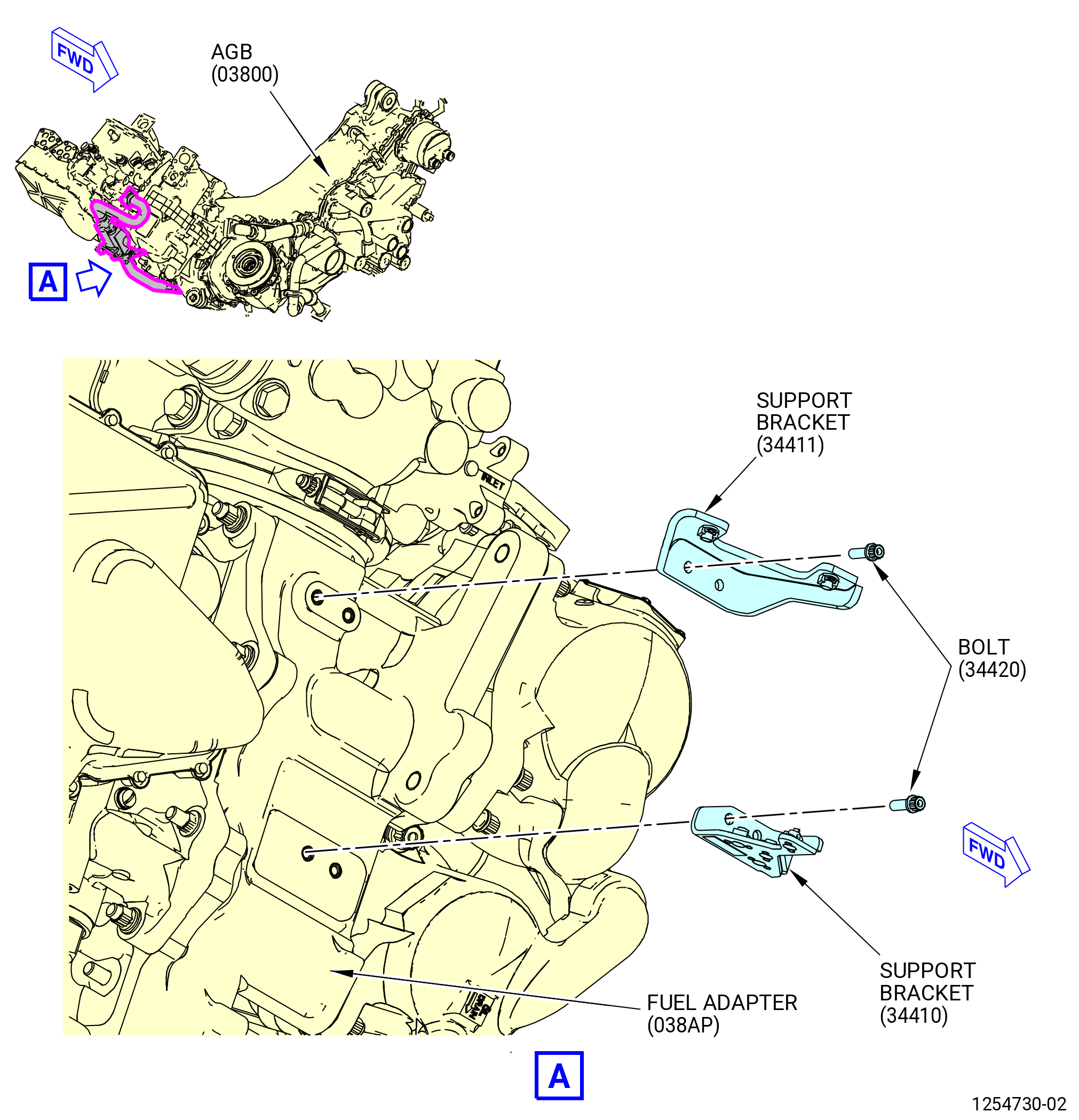
| R. | Install the fuel flow transmitter (fuel flowmeter) (30800), inlet fuel tubes (34400), and outlet fuel tube (05-010 , 73-11-41) (SIN 34401) on the AGB (03800) as follows: |
| (1) | Install the flowmeter outlet support bracket (support bracket) (34411) on the fuel adapter (038AP) of the AGB as follows. Refer to Figure 1025. |
| (a) | Apply C02-058 lubricant to the threads and friction surfaces of the bolts (34420). |
| (b) | Attach the support bracket (34411) to the fuel adapter with the bolts (34420). Do not torque the bolts at this time. |
| (2) | Install the flowmeter inlet support bracket (34410) on the fuel adapter (038AP) of the AGB as follows. Refer to Figure 1025. |
| (a) | Apply C02-058 lubricant to the threads and friction surfaces of the bolts (34420). |
| (b) | Attach the support bracket (34410) to the fuel adapter with the bolts (34420). Do not torque the bolts at this time. |
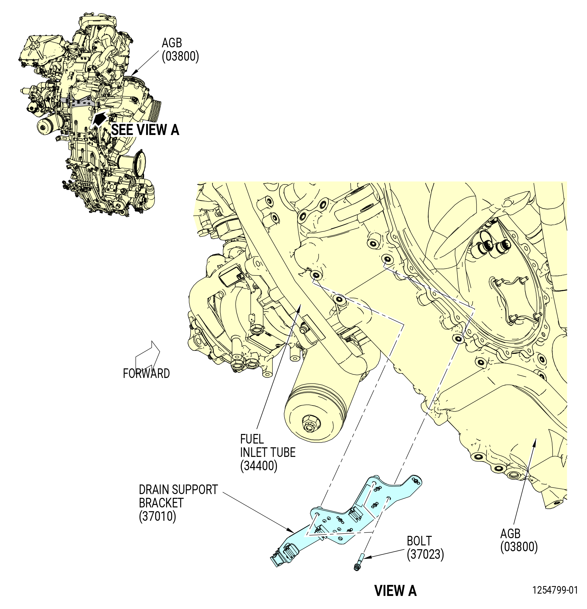
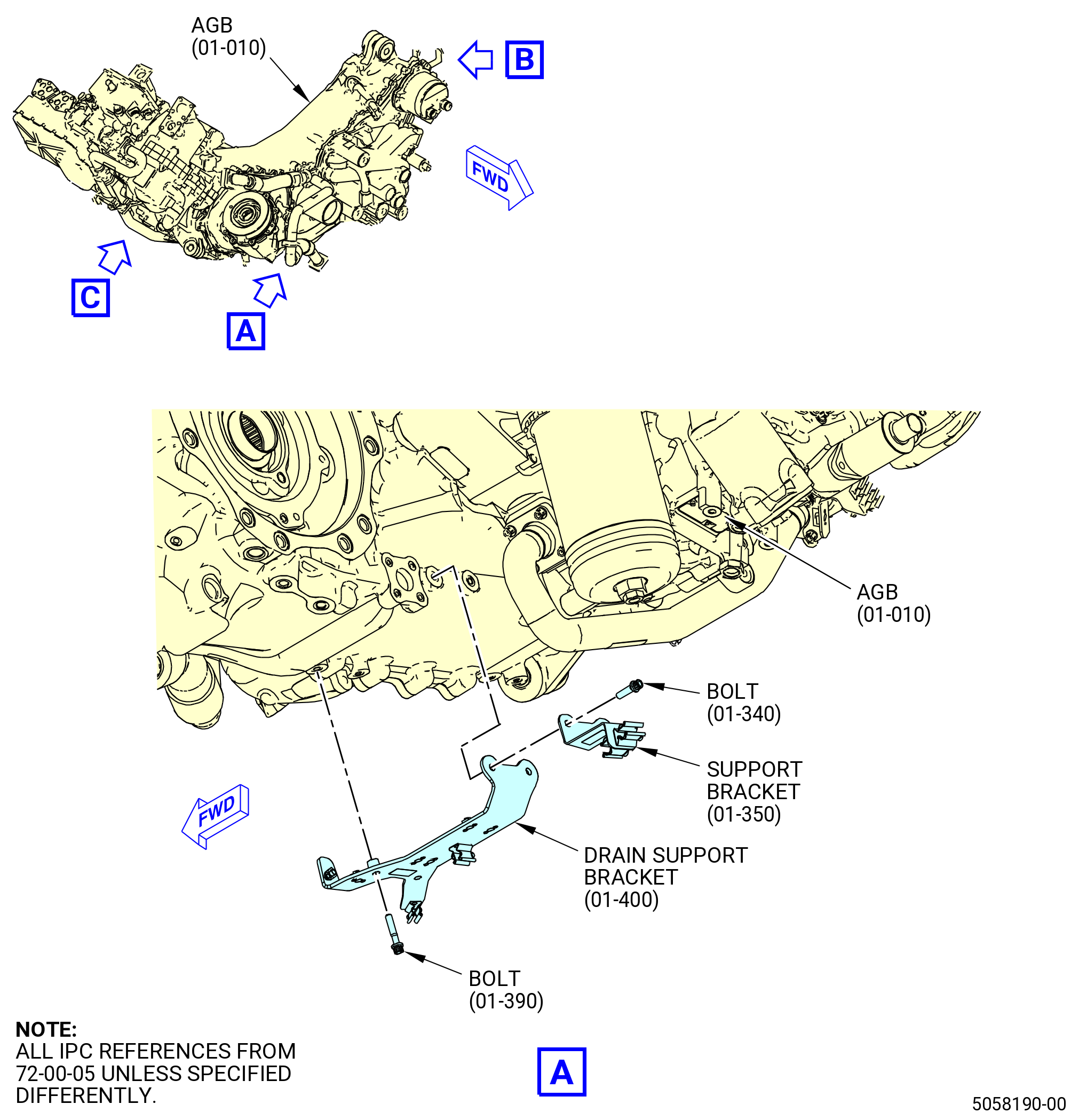
| (3) | Install the drain support bracket (37010) on the AGB as follows. Refer to Figure 1026. |
| (a) | Apply C02-058 lubricant to the threads and friction surfaces of the bolts (37023). |
| (b) | Attach the drain support bracket (37010) to the bottom side of the AGB with bolts (37023). Torque the bolts to 106-124 lb-in. (12.0-14.0 N.m). |
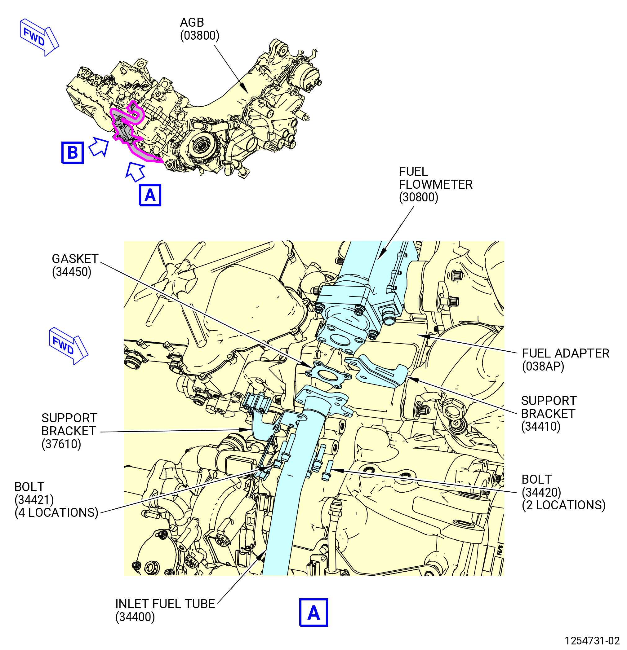
| (4) | Install the flowmeter inlet fuel tube (inlet fuel tube) (34400) as follows. Refer to Figure 1027. |
| WARNING: |
|
| (a) | Apply C02-058 lubricant to the threads and friction surfaces of the bolts (34420, 34421, 34422). |
| (b) | Apply C02-019 engine oil or C02-023 engine oil to the gaskets (05-040 , 73-11-41) (SIN 34450). |
| (c) | Attach the inlet fuel tube and gasket (05-040 , 73-11-41) (SIN 34450) to the fuel adapter (038AP) on the AGB with the bolts (34422). Do not torque the bolts at this time. |
| (d) | Put the support bracket (37610) and gasket (34450) on the inlet fuel tube. |
| (e) | Attach the fuel flowmeter, gasket (34450), and support bracket (37610) to the inlet fuel tube with the bolts (34421). Do not torque the bolts at this time. |
| (f) | Install the support bracket (34410) on the inlet fuel tube with the bolts (34420). Do not torque the bolts at this time. |
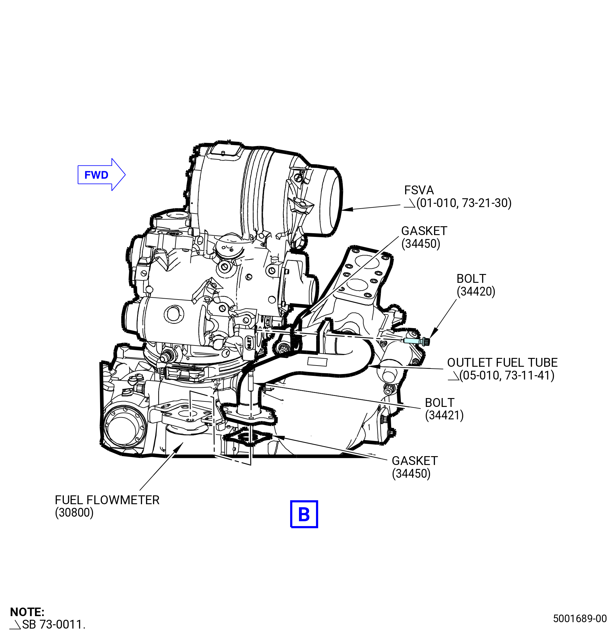
| (5) | Install the outlet fuel tube (05-010 , 73-21-41) (SIN 34401) on the fuel flowmeter and the FSV or FSVA (01-010 , 73-21-41) (SIN 31700) as follows. Refer to Figure 1027. |
| WARNING: |
|
| (a) | Apply C02-058 lubricant to the threads and friction surfaces of the bolts (34421, 34422). |
| (b) | Apply C02-019 engine oil or C02-023 engine oil to the gaskets (34450). |
| (c) | Put the outlet fuel tube and the gasket (05-040 , 73-11-41) (SIN 34450) on the fuel flowmeter. |
| (d) | Attach the outlet fuel tube and gasket (34450) to the fuel flowmeter with the bolts (34421). Do not torque the bolts at this time. |
| (e) | Attach the outlet fuel tube and gasket (34450) to the FSV or FSVA with the bolts (34422). Do not torque the bolts at this time. |
| (6) | Torque the bolts in the sequence that follows. Refer to Figure 1027. |
| (a) | Torque the bolts (34420) on the support brackets (34410, 34411) and the fuel adapter (038AP) to 106-124 lb-in. (12.0-14.0 N.m). |
| (b) | Torque the bolts (34422) on the inlet fuel tube and the fuel adapter to 106-124 lb-in. (12.0-14.0 N.m). |
| (c) | Torque the bolts (34421) on the support bracket (37610) and the fuel flowmeter to 106-124 lb-in. (12.0-14.0 N.m). |
| (d) | Torque the bolts (34420) on the inlet fuel tube and the support bracket (34410) to 106-124 lb-in. (12.0-14.0 N.m). |
| (e) | Torque the bolts (34421) on the outlet fuel tube and the support bracket (34411) to 106-124 lb-in. (12.0-14.0 N.m). |
| (f) | Torque the bolts (34422) on the outlet fuel tube and the FSV or FSVA to 106-124 lb-in. (12.0-14.0 N.m). |
| * * * FOR ALL |
| * * * FOR ALL |
| * * * FOR ALL |
|
|
| Subtask 72-00-05-430-021 |
| S. | Install the drain support brackets (37011, 37111) and the support brackets (37110, 6711H) on the AGB (03800) as follows. Refer to Figure 1028. |
| (1) | Apply C02-058 lubricant to the threads and friction surfaces of the bolts (37021, 37022, 37120, 37121, 37123). |
| (2) | Put the support bracket (6711H) on the drain support bracket (37011). |
| (3) | Attach the support bracket (6711H) and the drain support bracket (37011) with the bolts (37021, 37022). Torque the bolts to 106-124 lb-in. (12.0-14.0 N.m). |
| (4) | Put the support bracket (37110) on the AGB. |
| (5) | Attach the support bracket (37110) with the bolts (37120). Torque the bolts to 106-124 lb-in. (12.0-14.0 N.m). |
| (6) | Put the drain support bracket (37111) on the AGB. |
| Subtask 72-00-05-430-087 |
| * * * FOR ALL |
| * * * SB 73-0060( W30 and W31 Redesigned Harnesses ) |
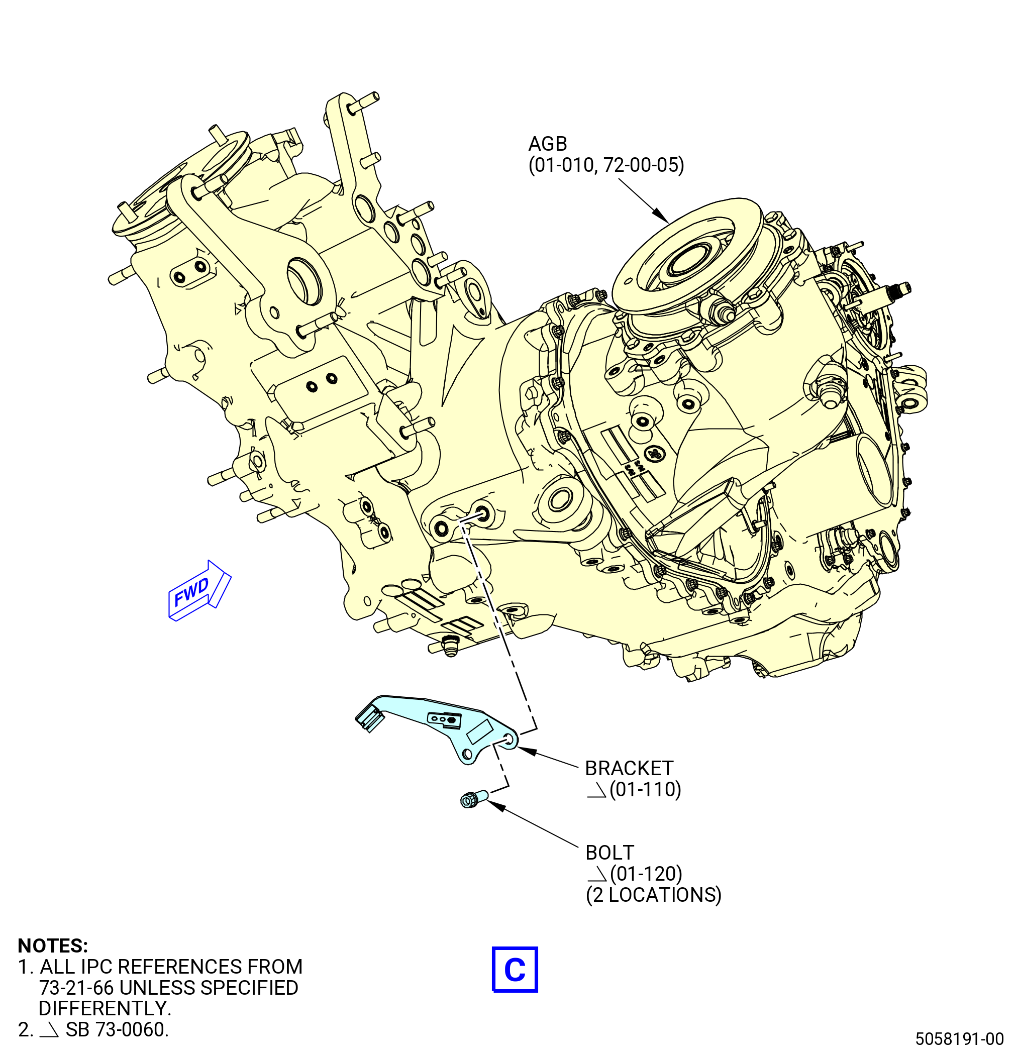
| (7) | Install the harness support bracket (bracket) (01-110 , 73-21-66) (SIN 6881J) as follows: |
| NOTE: |
|
| (a) | Attach the bracket (01-110 , 73-21-66) (SIN 6881J) to the accessory gearbox casing (10-010 , 72-64-00) (SIN 038A0) with two machine bolts (bolts) (01-120 , 73-21-66) (SIN 0382G). |
| (b) | Torque the bolts (01-120 , 73-21-66) (SIN 0382G) to 106 to 124 lb in. (11.9 to 14.0 Nm). |
| * * * FOR |
| * * * END SB 73-0060 |
| Subtask 72-00-05-430-085 |
| * * * FOR ALL |
| * * * FOR |
| * * * PRE SB 79-0014( Non-Optimized VFSG Cooling System ) |
| (8) | Attach the drain support bracket (01-210) (SIN 37111) with three bolts (01-180) (SIN 37121). Torque the bolts to 106 to 124 lb in. (12.0 to 14.0 Nm). |
| * * * FOR |
| * * * END PRE SB 79-0014( ) |
| Subtask 72-00-05-430-086 |
| * * * FOR ALL |
| * * * FOR |
| * * * SB 79-0014( Optimized VFSG Cooling System ) |
| (8).A. | Attach the drain support bracket (01-210) (SIN 37111) with four bolts (01-180) (SIN 37121). Torque the bolts to 106 to 124 lb in. (12.0 to 14.0 Nm). |
| * * * FOR |
| * * * END SB 79-0014 |
| Subtask 72-00-05-430-022 |
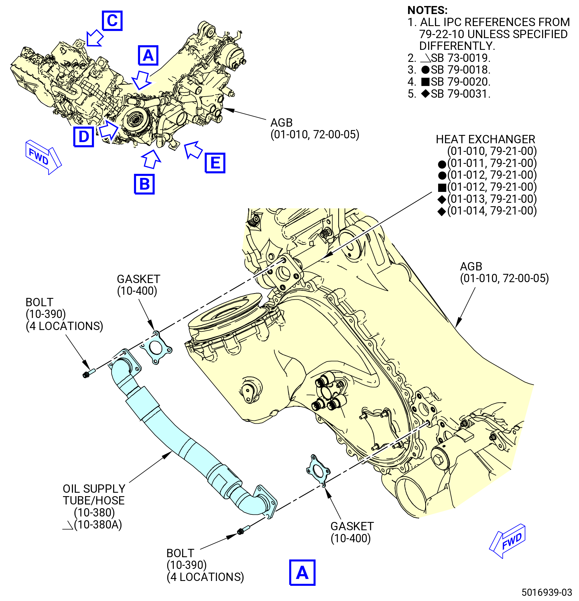
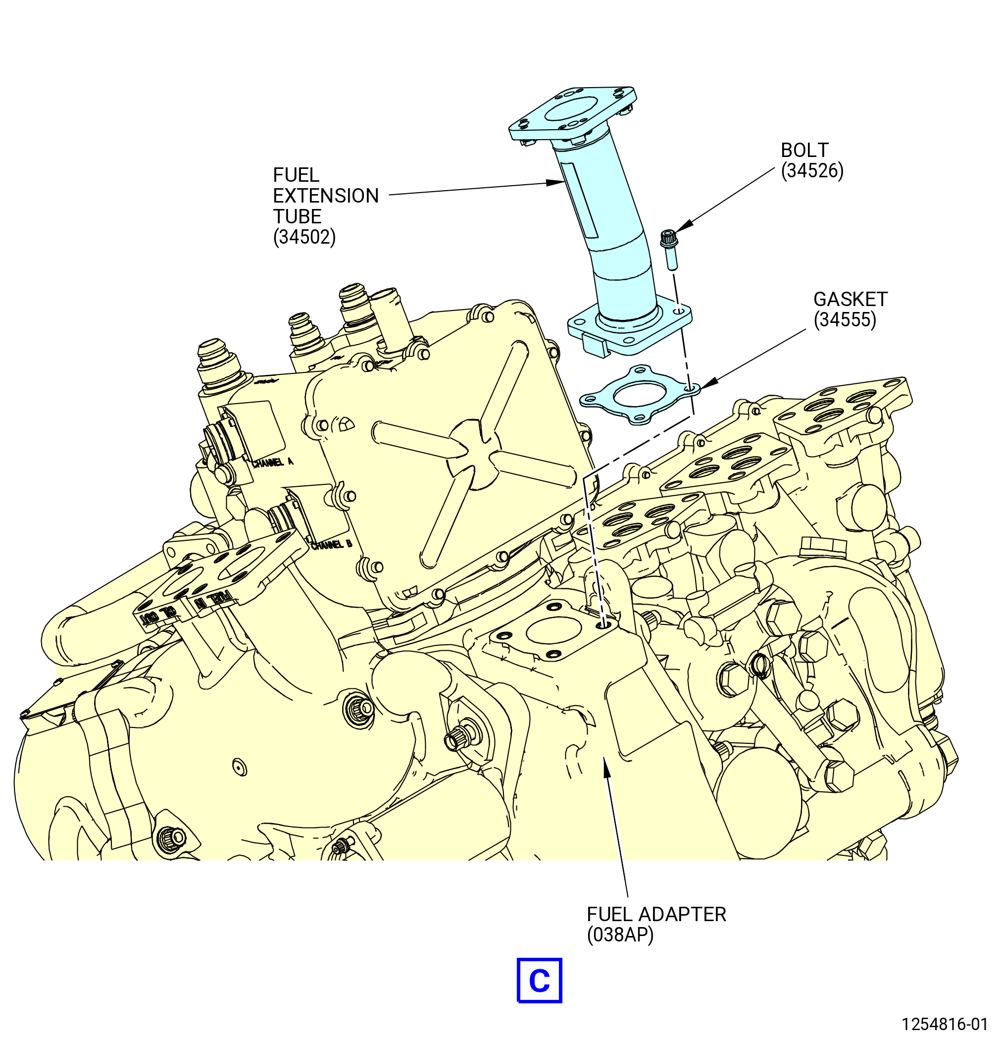
| T. | Install the oil supply tube/hose (10-380 , 79-22-10) (SIN 44700) or (10-380A , 79-22-10) (SIN 44700), the tube hose (scavenge oil tube/hose) (10-080 , 79-22-10) (SIN 45300), and the fuel extension tube (01-150 , 73-11-41) (SIN 34502) on the AGB (01-010) (SIN 03800) and the heat exchanger (01-010 , 79-21-00) (SIN 40700) or (01-011 , 79-21-00) (SIN 40700) or (01-012 , 79-21-00) (SIN 40700) or (01-013 , 79-21-00) (SIN 40700) or (01-014 , 79-21-00) (SIN 40700). Refer to Figure 1029 and do as follows: |
| (1) | Apply C02-058 lubricant to the threads and friction surfaces of the bolts (34526, 44720, 45322, 45324, 45326). |
| WARNING: |
|
| (2) | Apply C02-019 engine oil or C02-023 engine oil to the gaskets (10-400 , 79-22-10) (SIN 44750). |
| (3) | Put the gaskets (10-400 , 79-22-10) (SIN 44750) between the oil supply tube/hose, the AGB and the heat exchanger. |
| (4) | Attach the oil supply tube/hose with the bolts (44720). Torque the bolts to 106-124 lb-in. (12.0-14.0 N.m). |
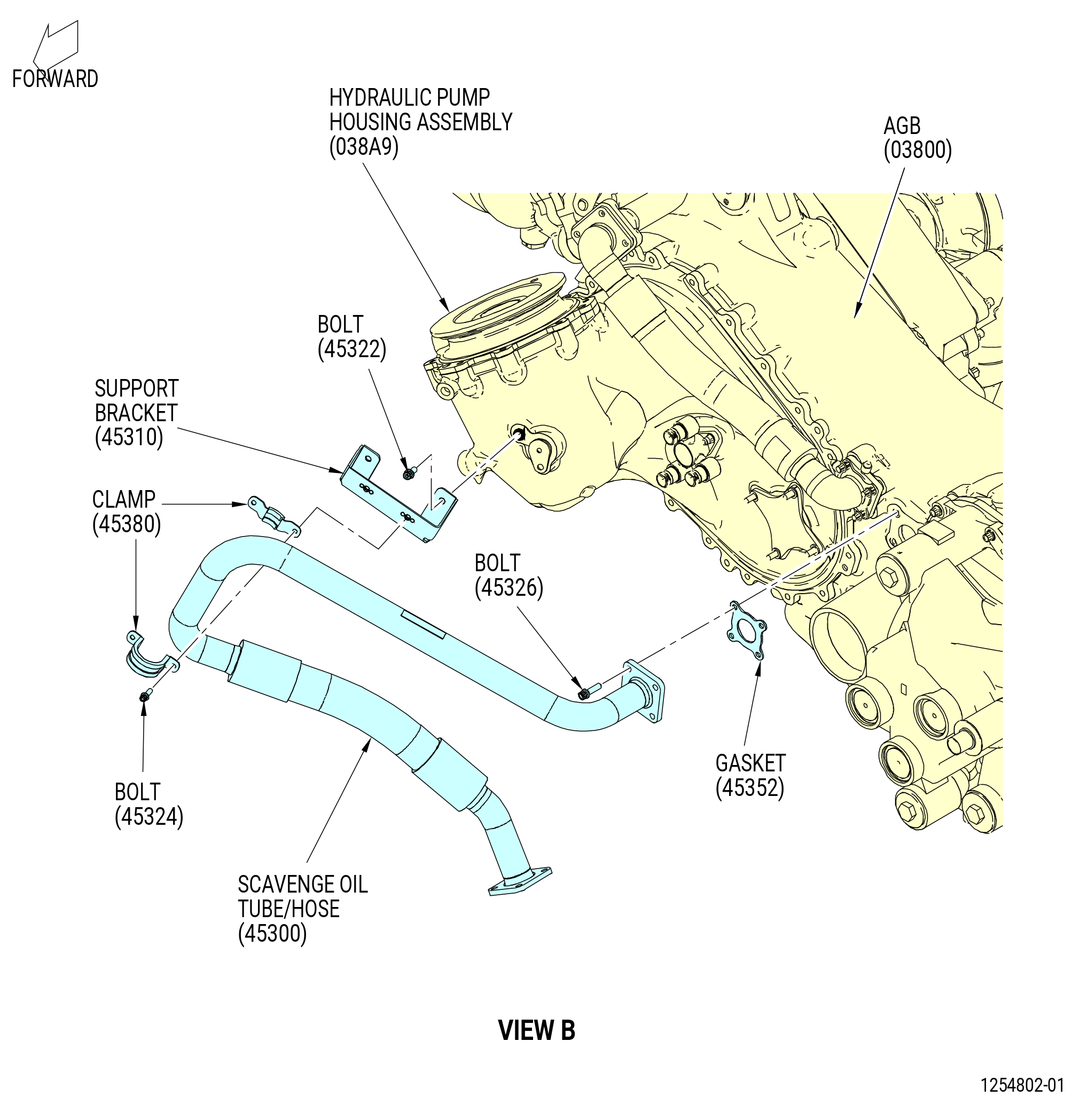
| (5) | Put the support bracket (45310) on the hydraulic pump housing assembly (038A9). |
| (6) | Attach the support bracket (45310) to the hydraulic pump housing assembly (038A9) with the bolts (45322). Torque the bolts to 106-124 lb-in. (12.0-14.0 N.m). |
| WARNING: |
|
| (7) | Apply C02-019 engine oil or C02-023 engine oil to the gasket (10-100 , 79-22-10) (SIN 45352). |
| (8) | Put the gasket (10-100 , 79-22-10) (SIN 45352) between the scavenge oil tube/hose and the AGB. |
| (9) | Attach the scavenge oil tube/hose with the bolts (45326). |
| (10) | Put the clamp (45380) on the scavenge oil tube/hose. |
| (11) | Attach the clamp (45380) to the support bracket (45310) with bolts (45324). |
| (12) | Torque the bolts (45326) to 106-124 lb-in. (12.0-14.0 N.m). |
| (13) | Torque the bolts (45324) to 51-59 lb-in. (5.8-6.7 N.m). |
| WARNING: |
|
| (14) | Apply C02-019 engine oil or C02-023 engine oil to the gasket (01-140 , 73-11-41) (SIN 34555). |
| (15) | Put the gasket (01-140 , 73-11-41) (SIN 34555) between the fuel extension tube and the fuel adapter (038AP). |
| (16) | Attach the fuel extension tube (34502) with bolts (34526). Torque the bolts to 106-124 lb-in. (12.0-14.0 N.m). |
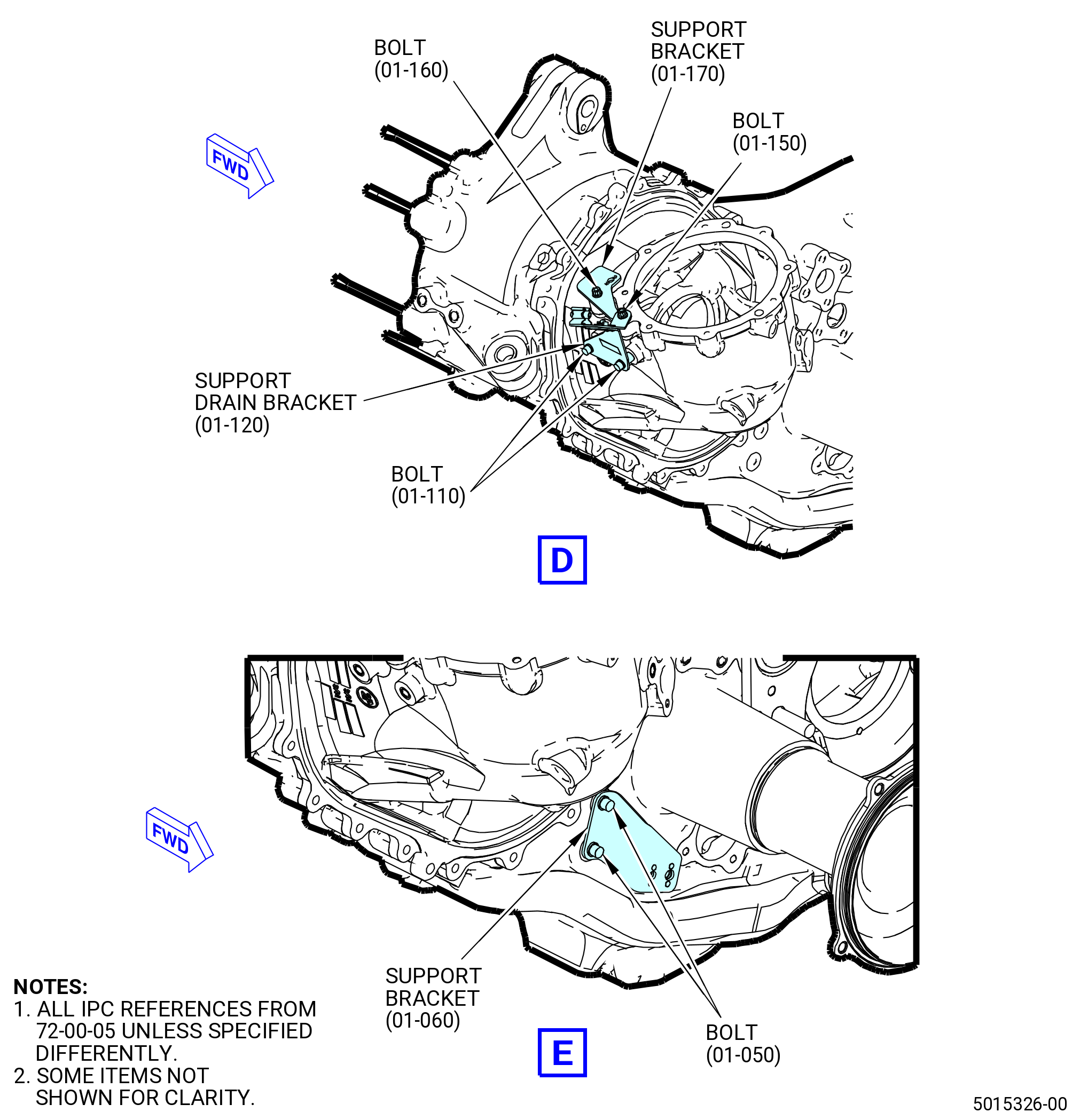
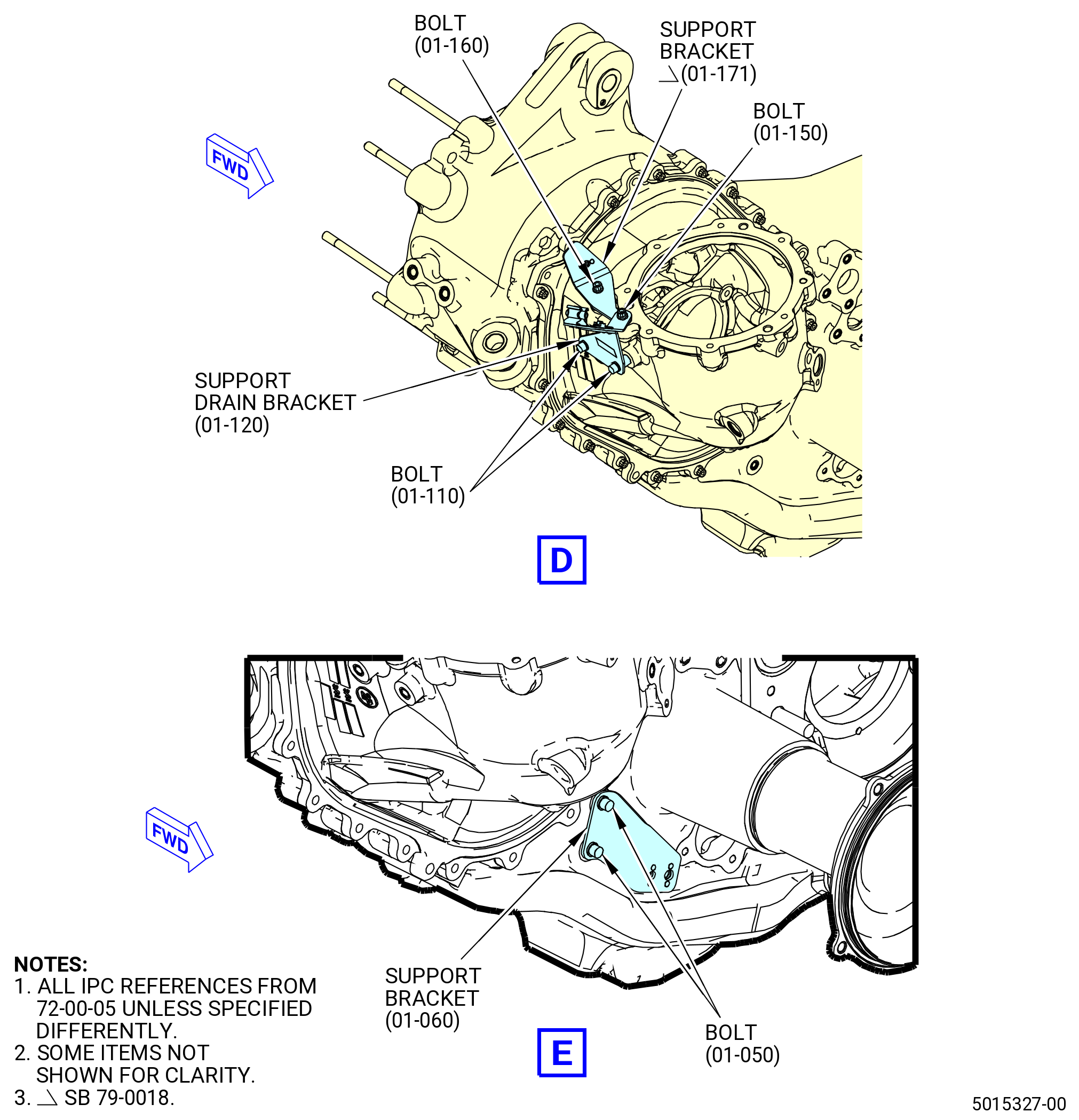
| (17) | Install the support bracket (01-170) (SIN 5901C) or (01-171) (SIN 5901C), support drain bracket (01-120) (SIN 37312), and TBG scavenge support bracket (support bracket) (01-060) (SIN 45010) on the AGB (01-010) (SIN 03800) as follows: |
| WARNING: |
|
| (a) | Apply C02-058 lubricant to the threads and friction surfaces of the bolts (37322, 37323, 45022, 45322, and 59021). |
| (b) | Attach the support bracket (01-170) (SIN 5901C) or (01-171) (SIN 5901C) with bolts (01-160) (SIN 59021). Do not torque the bolts at this time. |
| (c) | Attach the support drain bracket (37312) with bolts (37323 and 37322). Torque the bolts (37322, 37323, and 59021) to 106-124 lb-in. (12.0-14.0 N.m). |
| (d) | Attach the support bracket (45010) with bolts (45022). Torque the bolts to 106-124 lb-in. (12.0-14.0 N.m). |
|
|
| Subtask 72-00-05-430-051 |
| * * * FOR ALL |
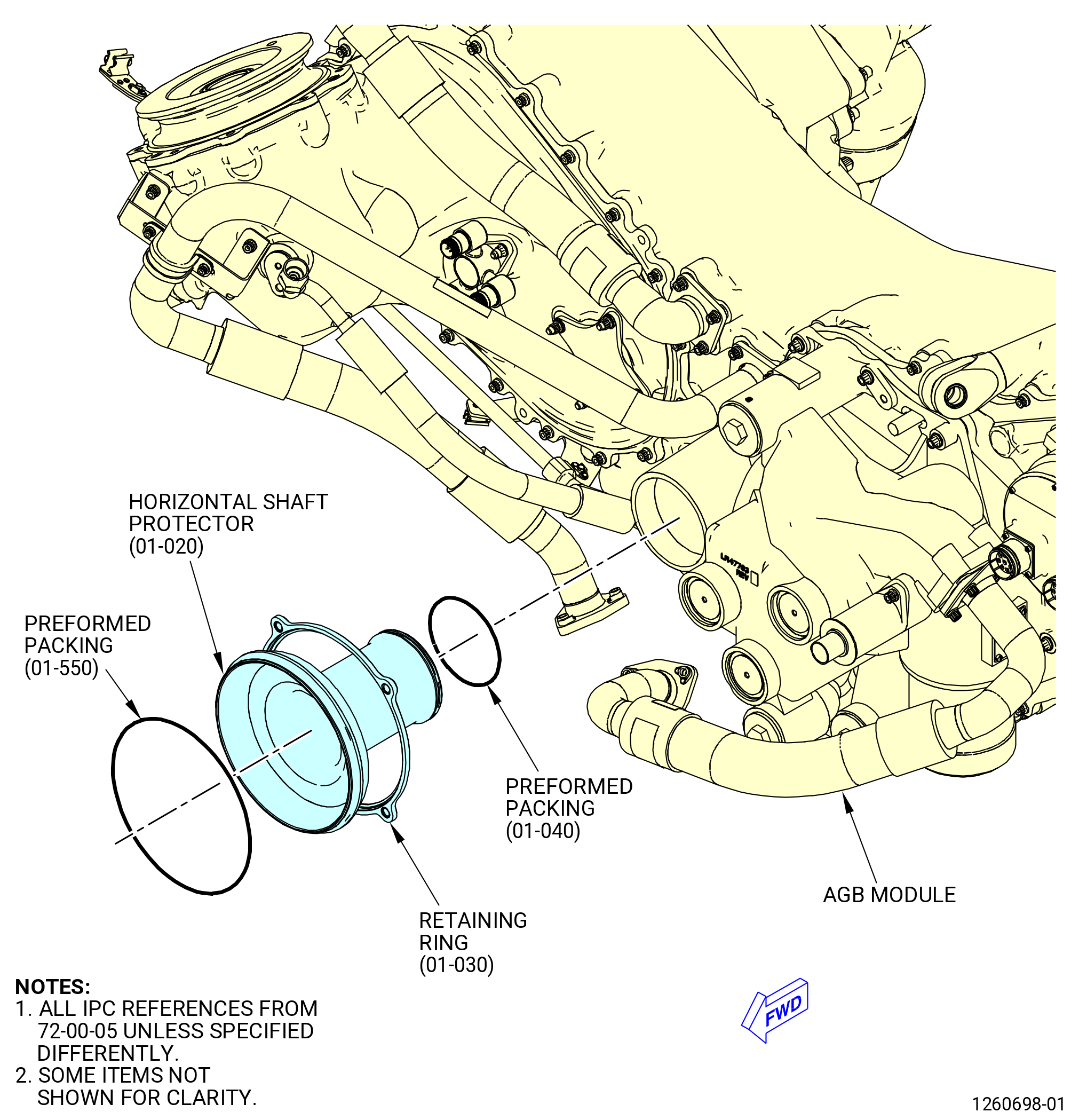
| U. | Install the horizontal shaft protector (shaft protector) (01-020) (SIN 03302) on the AGB module. Refer to Figure 1030 and do as follows: |
| WARNING: |
|
| CAUTION: |
|
| (1) | Apply C02-019 engine oil or C02-023 engine oil to the preformed packings (01-040) (SIN 03350) and (01-550) (SIN 03351) and lead in chamfer of the shaft protector. |
| CAUTION: |
|
| (2) | Install the performed packing (01-040) (SIN 03350) into the groove on the aft end of the shaft protector. |
| (3) | Install the horizontal shaft protector retaining ring (retaining ring) (03391) above the aft end of the shaft protector with the rabbet on ID of the retaining ring forward. |
| (4) | Move the retaining ring forward and seat it against the lip on the forward end of the shaft protector. |
| (5) | Install the performed packing (01-550) (SIN 03551) into the groove on the forward end of the shaft protector. |
| (6) | Install the shaft protector into the AGB module port until the shaft protector stops. |
| Subtask 72-00-05-430-052 |
| * * * FOR ALL |
| V. | Install the oil fill, supply, and drain tubes/hoses, and manifolds on the bottom of the AGB (03800) as follows: |
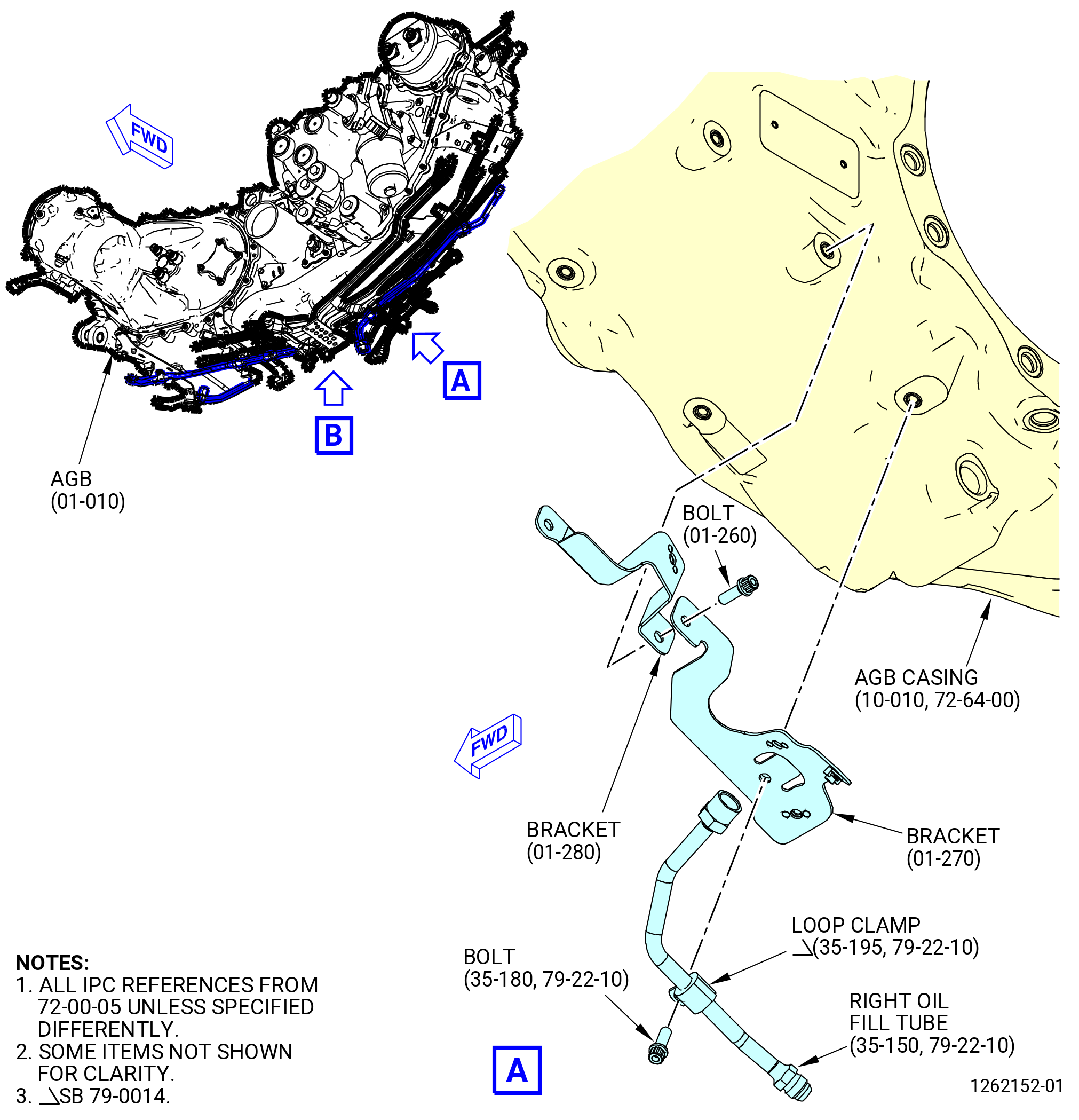
| (1) | Install the right hand VFSG oil fill tube (right oil fill tube) (35-150 , 79-22-10) (SIN 44A06) on the AGB casing (10-010 , 72-64-00) (SIN 038A0). Refer to Figure 1031 and do as follows: |
| WARNING: |
|
| (a) | Apply C02-058 lubricant to the threads and friction surfaces of the machine bolts (bolts) (35-180 , 79-22-10) (SIN 44A21) and (01-260) (SIN 99021). |
| (b) | Deleted. |
| (c) | Attach the brackets (01-270) (SIN 44B19) and (01-280) (SIN 99011) together to the AGB casing with a bolt (01-260) (SIN 99021). Bracket (01-270) (SIN 44B19) is on bracket (01-280) (SIN 99011). |
| (d) | Install a loop clamp (44A81) on the right oil fill tube. |
| (e) | Attach the loop clamp (44A81) to the bracket (44B19) and the AGB with the bolt (44A21). |
| (f) | Torque the bolt (44A21) to 60-70 lb in. (6.8-7.9 N.m). |
| (2) | Deleted. |
| NOTE: |
|
| (3) | Deleted. |
| (4) | Install the upper drain manifold (99003) on the AGB as follows: |
| (a) | Deleted. |
| (b) | Attach the upper drain manifold B-nuts to the seal drain ports on the AGB casing (038A0). Tighten hand tight. |
| WARNING: |
|
| (c) | Apply C02-058 lubricant to the threads and friction surfaces of the bolt (01-260) (SIN 99021) and machine bolt (bolt) (01-250) (SIN 99025). |
| (d) | Attach the upper drain manifold (01-380) (SIN 99003) to the bracket (01-280) (SIN 99011) and AGB (01-010) (SIN 03800) with the bolt (01-250) (SIN 99025). Hand-tighten the bolt. |
| (e) | Attach the upper drain manifold to the AGB with the bolt (01-260) (SIN 99021). Hand-tighten the bolt. |
| (f) | Attach the upper drain manifold to the bracket (37111) with a loop clamp (99081) and a bolt (99020). |
| (g) | Attach the upper drain manifold to the bracket (37011) with a loop clamp (99082) and a bolt (99020). |
| (h) | Attach the upper drain manifold to the bracket (37011) with a loop clamp (99081) and a bolt (99020). |
| (i) | Torque the upper drain manifold B-nuts on the seal drain ports to 262-308 lb in. (29.6-34.8 N.m). |
| (j) | Deleted. |
| (k) | Torque the bolts (01-190) (SIN 99020) on the bracket loop clamps to 32-38 lb in. (3.6-4.3 N.m). |
| (5) | Attach the bracket (6711G) to the upper drain manifold (99003) with the bolts (67125). |
| * * * FOR ALL |
| Subtask 72-00-05-430-070 |
| * * * FOR ALL |
| * * * FOR |
| * * * PRE SB 79-0014( Non-Optimized VFSG Cooling System ) |
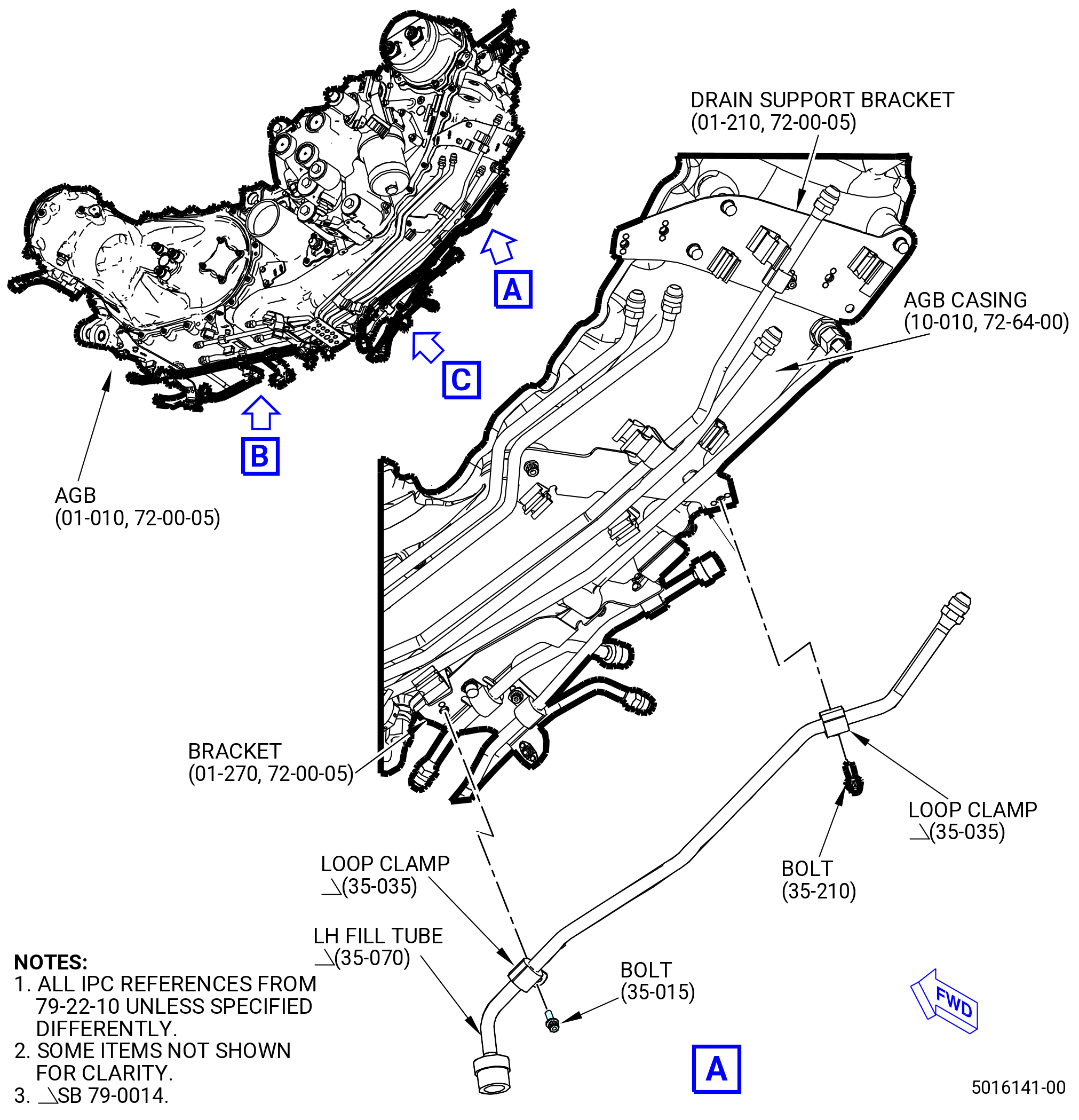
| (6) | Install the left hand (LH) variable frequency starter generator (VFSG) fill tube (LH fill tube) (35-070 , 79-22-10) (SIN 44A05) to the AGB (01-010) (SIN 03800). Refer to Figure 1032 and do as follows: |
| WARNING: |
|
| (a) | Apply C02-058 lubricant to the threads and friction surfaces of the machine bolt (bolt) (35-170 , 79-22-10) (SIN 44A22). |
| (b) | Attach the LH fill tube to the drain support bracket (01-210) (SIN 37111) and AGB casing (10-010 , 72-64-00) (SIN 038A0) with a bolt (35-170 , 79-22-10) (SIN 44A22). |
| (c) | Attach the LH fill tube to the support bracket on the upper drain manifold (01-380) (SIN 99003) with a loop clamp (35-030 , 79-22-10) (SIN 44A80) and a bolt (35-210 , 79-22-10) (SIN 44A24). |
| (d) | Attach the LH fill tube to the bracket (01-270) (SIN 44B19) with a loop clamp (35-030 , 79-22-10) (SIN 44A80) and a bolt (35-015 , 79-22-10) (SIN 44A20). |
| (e) | Torque bolts (35-210 , 79-22-10) (SIN 44A24) and (35-015 , 79-22-10) (SIN 44A20) to 32-38 lb in. (3.6-4.3 N.m). |
| (f) | Torque the bolt (35-170 , 79-22-10) (SIN 44A22) to 106-124 lb in. (12.0-14.0 N.m). |
| * * * FOR |
| * * * END PRE SB 79-0014 |
| Subtask 72-00-05-430-076 |
| * * * FOR ALL |
| * * * FOR |
| * * * SB 79-0014( Optimized VFSG Cooling System ) |
| (6).A. | Install the LH fill tube (35-070 , 79-22-10) (SIN 44A05) to the AGB (01-010) (SIN 03800). Refer to Figure 1032 and do as follows: |
| (a) | Attach the LH fill tube to the support bracket on the upper drain manifold (01-380) (SIN 99003) with a loop clamp (35-035 , 79-22-10) (SIN 44A80) and a bolt (35-210 , 79-22-10) (SIN 44A24). |
| (b) | Attach the LH fill tube to the bracket (01-270) (SIN 44B19) with a loop clamp (35-035 , 79-22-10) (SIN 44A80) and a bolt (35-015 , 79-22-10) (SIN 44A29). |
| (c) | Torque the bolts (35-210 , 79-22-10) (SIN 44A24) and (35-015 , 79-22-10) (SIN 44A20) to 32-38 lb in. (3.6-4.3 N.m). |
| * * * FOR |
| * * * END SB 79-0014 |
| Subtask 72-00-05-430-077 |
| * * * FOR ALL |
| (7) | Install the MFP/TBV drain manifold (37000) on the AGB as follows. Refer to Figure 1032. |
| (a) | Attach the MFP/TBV drain manifold to the fuel adapter (038AP) drain port. Tighten the B-nut hand tight. |
| (b) | Attach the MFP/TBV drain manifold to the upper drain manifold (99003). Tighten the B-nut hand tight. |
| (c) | Attach the MFP/TBV drain manifold to the bracket (37011) with a loop clamp (37080) and a bolt (37020). Tighten the bolt hand tight. |
| (d) | Attach the MFP/TBV drain manifold to the bracket (37010) with a loop clamp (37080) and a bolt (37020). Tighten the bolt hand tight. |
| (e) | Torque the MFP/TBV drain manifold B-nut to the fuel adapter and the upper drain manifold to 262-308 lb in. (29.6-34.8 N.m). |
| (f) | Deleted. |
| (g) | Torque the bolts (37020) to 32-38 lb in. (3.6-4.3 N.m). |
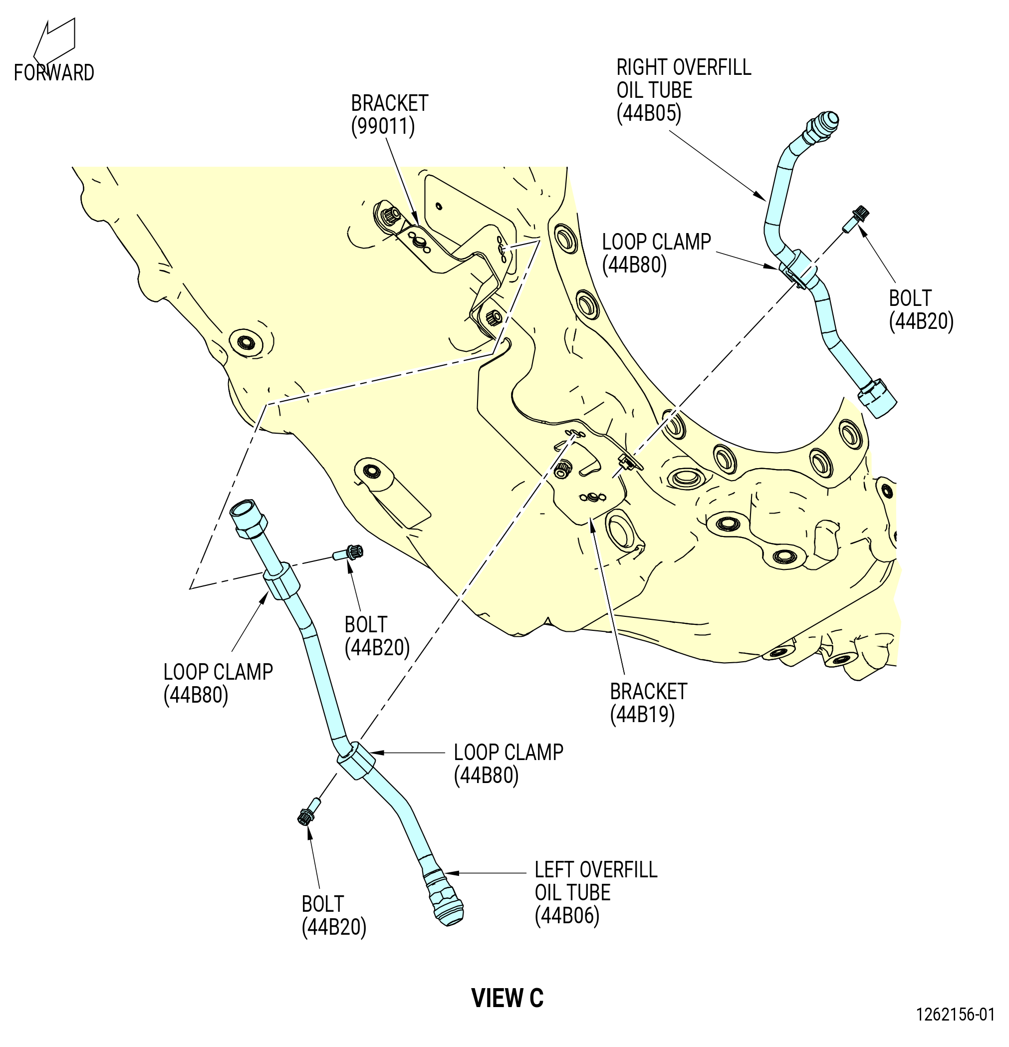
| (8) | Install the left overfill oil tube (44B06) and the right overfill oil tube (44B05) on the AGB as follows. Refer to Figure 1032. |
| (a) | Attach the right overfill oil tube (44B05) to the bracket (44B19) with a loop clamp (44B80) and a bolt (44B20). |
| (b) | Attach the left overfill oil tube (44B06) to the bracket (99011) with a loop clamp (44B80) and a bolt (44B20). |
| (c) | Attach the left overfill oil tube (44B06) to the bracket (44B19) with a loop clamp (44B80) and a bolt (44B20). |
| (d) | Torque the bolts (44B20) to 60-70 lb in. (6.7-7.9 N.m). |
| (e) | Torque the bolt (01-250) (SIN 99025) to 106-124 lb in. (12.0-14.0 N.m). |
| (f) | Torque the bolt (01-260) (SIN 99021) to 106-124 lb in. (12.0-14.0 N.m). |
| (g) | Torque the bolts (67125) to 106-124 lb in. (12.0-14.0 N.m). |
| * * * FOR ALL |
|
|
| Subtask 72-00-05-430-071 |
| * * * FOR ALL |
| W. | Alternative Procedure Available. Install the AGB module on the 11C3262 install/remove fixture as follows: |
| (1) | Put the 11C3262 install/remove fixture on the 9C2532 raise/lower fixture. Refer to Figure 1034. |
| (2) | Attach the 11C3262 install/remove fixture to the 9C2532 raise/lower fixture with the quick-release pins (item 7). |
| (3) | Install the 2129M82 lifting fixture in the AGB as follows: |
| NOTE: |
|
| (a) | Put the standard lifting slings (belts) between each couple of upper lugs on AGB casing. |
| (b) | Install the pin (item 4) of the 2129M82 lifting fixture in the lug, closer to the fuel adapter and verify if it is engaged with the lifting sling eye. |
| (c) | Install two washers (item 5) and lock the pin in the opposite side with the nut (item 3). |
| (d) | Install the pin (item 2) in the lug, closer to the fuel adapter and verify if it is engaged with the lifting sling eye. |
| (e) | Install two washers (item 6) and lock the pin in the opposite side with the nut (item 3). |
| (f) | Install the standard lifting sling on the crane hook and carefully lift the AGB. |
| (4) | Attach brackets (item 2) of the 11C3265 bracket set to the lifting lugs on either side of the AGB casing with screws (item 5). |
| (5) | Install ball lock pins (item 8) through the RH and LH adapters (item 15 and item 16) and the brackets (item 2). |
| (6) | Install the AGB module on the 11C3262 install/remove fixture. Refer to Figure 1034 and do as follows: |
| WARNING: |
|
| (a) | Lower the AGB module onto the 11C3262 install/remove fixture. |
| (b) | Use the washers (item 14) and capscrews (item 10) of the 11C3265 bracket set to attach the RH adapter (item 15) and LH adapter (item 16) to the frame (item 16) of the 11C3262 install/remove fixture. |
| (7) | Remove the 2129M82 lifting fixture from the AGB module. |
| Subtask 72-00-05-430-031 |
| * * * FOR ALL |
| W.A. | Alternative Procedure. Install the AGB module on the 11C3262 install/remove fixture as follows: |
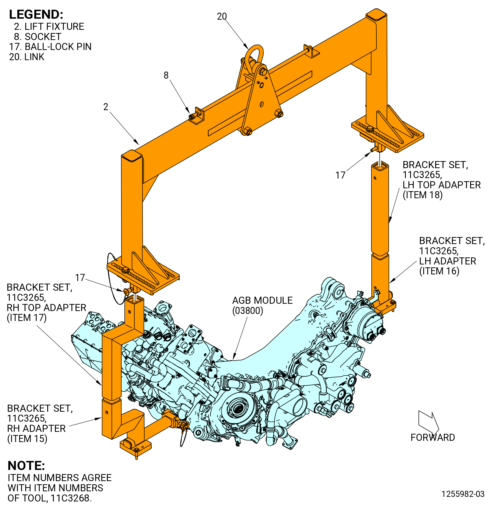
| (1) | Attach the 11C3268 lift fixture to the 11C3265 bracket set as follows. Refer to Figure 1033. |
| (a) | Make sure that the AGB is installed in the 9429M60 roll-over stand in the horizontal position, top vertical centerline up. |
| (b) | Install RH top adapter (item 17) and LH top adapter (item 18) of the 11C3265 bracket set to the RH adapter (item 15) and LH adapter (item 16). |
| (c) | Attach the RH top adapter (item 17) to the adapter (item 3) of the 11C3268 lift fixture with the ball-lock pin (item 17). |
| (d) | Attach the LH top adapter (item 18) of the 11C3265 bracket set to the adapter (item 4) of the 11C3268 lift fixture with the ball-lock pin (item 17). |
| WARNING: |
|
| (e) | Attach an overhead hoist to the link (item 20) of the 11C3268 lift fixture to lift the lift fixture and the 11C3265 bracket set. |
| (f) | Adjust the position of the trolley (item 12), as necessary, to keep the 11C3268 lift fixture level. |
| WARNING: |
|
| (g) | Lift the AGB to take the load off of the 9429M60 roll-over stand. |
| (h) | Remove the capscrews (item 10) and washers (item 14) that attach the LH/RH adapters (item 3 and 4) to the 11C3355 turnover stand installed on the 9429M60 roll-over stand. |
| WARNING: |
|
| (i) | Lift the AGB module from the 9429M60 roll-over stand. |
| * * * FOR ALL |
| Subtask 72-00-05-430-050 |
| * * * FOR ALL |
| (2) | Install the AGB module on the 11C3262 install/remove fixture as follows. Refer to Figure 1034. |
| (a) | Make sure that the 11C3262 install/remove fixture is on the 9C2532 raise/lower fixture. |
| WARNING: |
|
| (b) | Lower the AGB on the 11C3262 install/remove fixture. |
| (c) | Use the washers (item 14) and capscrews (item 10) of the 11C3265 bracket set to attach the RH adapter (item 15) and LH adapter (item 16) to the frame (item 16) of the 11C3262 install/remove fixture. |
| (3) | Lift the 11C3262 install/remove fixture with the 11C3268 lift fixture and place them on the 9C2532 raise/lower fixture. |
| (4) | Attach firmly the 11C3268 lift fixture to the 9C2532 raise/lower fixture with the quick-release pins (item 7). |
| (5) | Remove the ball-lock pins (item 17) of the 11C3268 lift fixture from the 11C3265 bracket set. Refer to Figure 1033. |
| WARNING: |
|
| (6) | Lift the 11C3268 lift fixture from the AGB module. |
| * * * FOR ALL |
| Subtask 72-00-05-430-032 |
| * * * FOR ALL |
| X. | Do a visual inspection of the full assembly for: |
| (1) | Unwanted material. Make sure that there is not unwanted material caught in the assembly. |
| (2) | Apparent or obvious mis-assembly. |
| (3) | Damaged parts. |
| (4) | Make sure that the hand crank cover (038AF) is installed on the forward side of the AGB. If necessary, install the hand crank cover (038AF) as follows. Refer to Figure 1005. |
| (a) | Put the hand crank cover (038AF) and nuts (038W0) on the AGB (03800). |
| NOTE: |
|
| (b) | Torque the nuts (038W0) to 57-67 lb in. (6.4-7.6 N.m). |