| GENX-1B ENGINE MANUAL | Dated: 01/17/2024 | |
| EM 72-00-02 , ASSEMBLY 001 | ||
| PROPULSOR ASSEMBLY - ASSEMBLY 001 - CONFIGURATION 01 | ||
| GENX-1B ENGINE MANUAL | Dated: 01/17/2024 | |
| EM 72-00-02 , ASSEMBLY 001 | ||
| PROPULSOR ASSEMBLY - ASSEMBLY 001 - CONFIGURATION 01 | ||
| * * * FOR 1B/P/G03.1B/P/G04.1B/P1/G01 |
| TASK 72-00-02-430-801 |
| 1 . | General. |
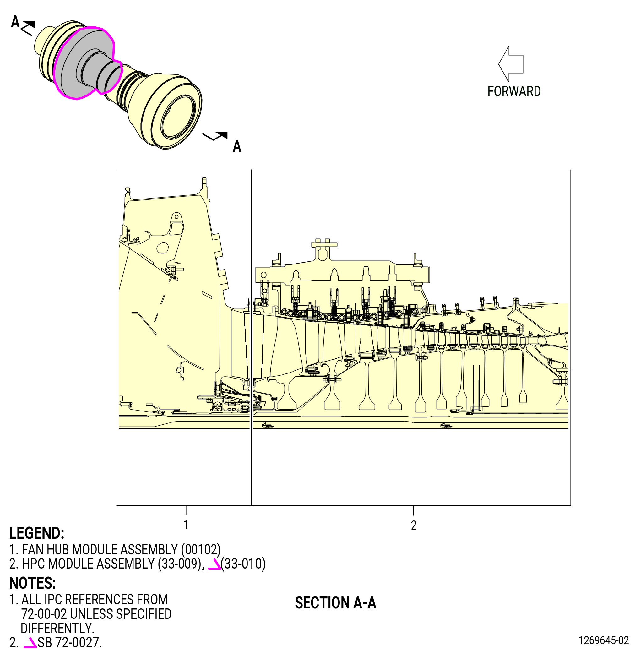
| A. | This procedure gives instructions to install the high pressure compressor (HPC) module assembly to the fan hub module (fan hub module assembly) (25-010) (SIN 00102) of the propulsor module assembly (propulsor assembly) (30-020 , 72-00-00) (SIN 0010C). Refer to Figure 1001. |
| • |
|
| • |
|
| • |
|
| B. | Use this procedure to install the HPC module assembly to the fan hub module assembly in the vertical position in the 9481M84 assembly stand or 11C4582 core module build-up fixture. |
| C. | This procedure starts with the HPC module assembly installed in the 11C4279 core module build-up fixture or 11C3010 build-up fixture on the 9429M56 propulsor build stand in the vertical position, at the equivalent assembly status of TASK 72-30-00-440-802 (72-30-00, Assembly 002) . |
| D. | Before you do this procedure, read the assembly and disassembly techniques section. Refer to TASK 70-10-00-800-009 (ASSEMBLY AND DISASSEMBLY TECHNIQUES) . |
| E. | Make sure that you obey all site safety and environmental controls or personal injury can occur. |
| F. | Make sure that there is no unwanted material in the assemblies and modules of the propulsor assembly. |
| WARNING: |
|
| WARNING: |
|
| WARNING: |
|
| G. | Before installation make sure that all rabbet and flange mating surfaces are free of unwanted material and raised metal. Clean the rabbets, flanges, and threads of the studs with C04-002 Stoddard solvent, C04-003 acetone, or C04-035 isopropyl alcohol. |
| H. | Make sure that the mating parts are serviceable and have no deterioration. |
| I. | This procedure gives instructions to adjust and rig the IGV actuator system. There are two types of VSV torque shaft design: |
| • |
|
| • |
|
| (1) | Do the applicable procedure assigned to the proper torque shaft linkage design installed on the engine. All rigging instructions are the same for Configuration 2 and Configuration 3. |
| J. | Read this procedure and know the instructions and the tools before you install the HPC module assembly to the fan hub module assembly for the propulsor assembly. |
| K. | Install all bolts with the heads up or forward, unless specified differently. |
| L. | Clock positions are aft looking forward (ALF), unless specified differently. |
| 2 . | Tools, Equipment, and Materials. |
| NOTE: |
|
| A. | Tools and Equipment. |
| (1) | Special Tools. |
| (2) | Standard Tools and Equipment. |
|
| (3) | Locally Manufactured Tools. None. |
| B. | Consumable Materials. |
|
| C. | Referenced Procedures. |
|
| D. | Expendable Parts. |
|
| 3 . | Procedure. |
| Subtask 72-00-02-430-661 |
| A. | Install the fan hub module assembly (25-010) (SIN 00102) in the 9481M84 assembly stand or 11C4582 core module build-up fixture as follows: |
| NOTE: |
|
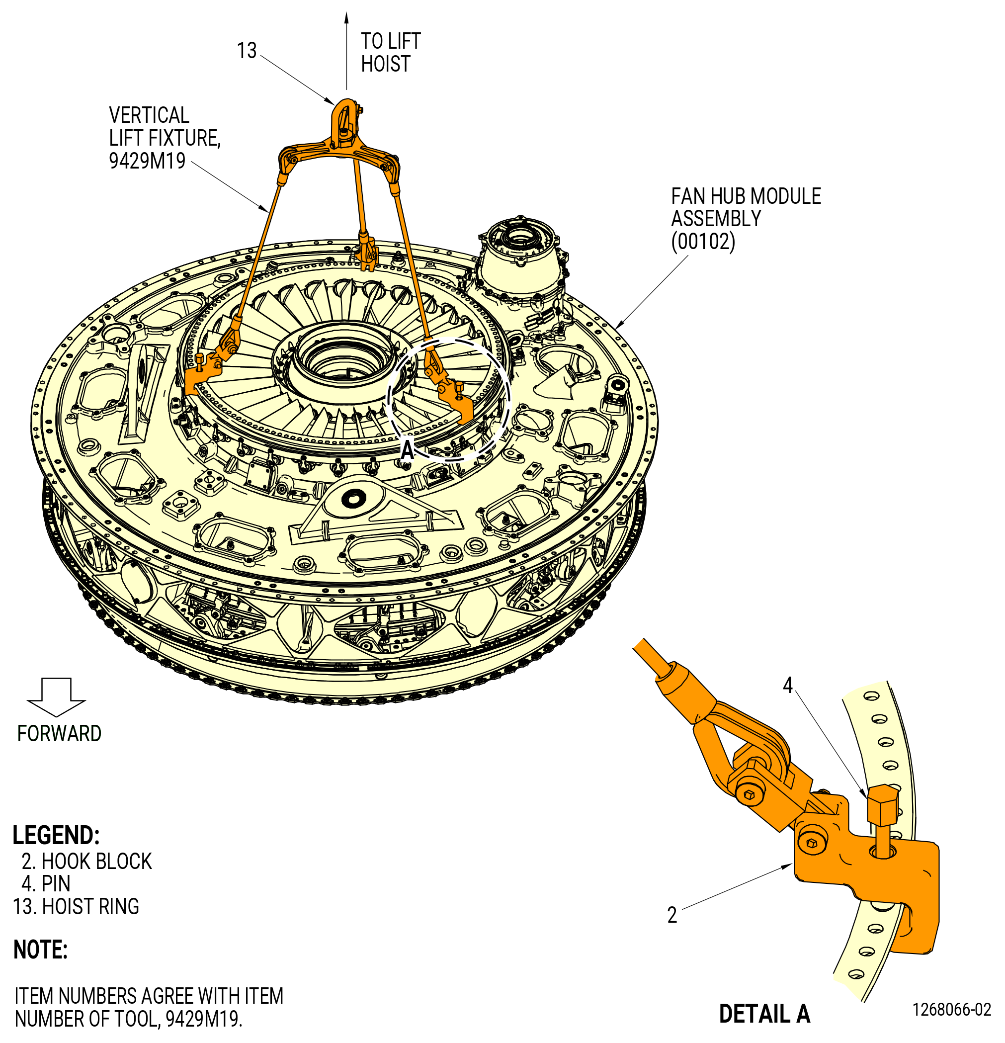
| (1) | Attach the three slings of the 9429M19 vertical lift fixture to the fan hub module assembly aft inner flange as follows. Refer to Figure 1002. |
| (a) | Turn the pin (item 4) clockwise (CW) to retract from the hook block (item 2). |
| (b) | Put the hook block (item 2) at three equally spaced locations on the aft inner flange of the fan hub module assembly. |
| (c) | Turn the pin (item 4) CW to attach the hook block (item 2) to the aft flange. Make sure that the hook block is captive to the fan hub module flange. |
| Subtask 72-00-02-430-775 |
| WARNING: |
|
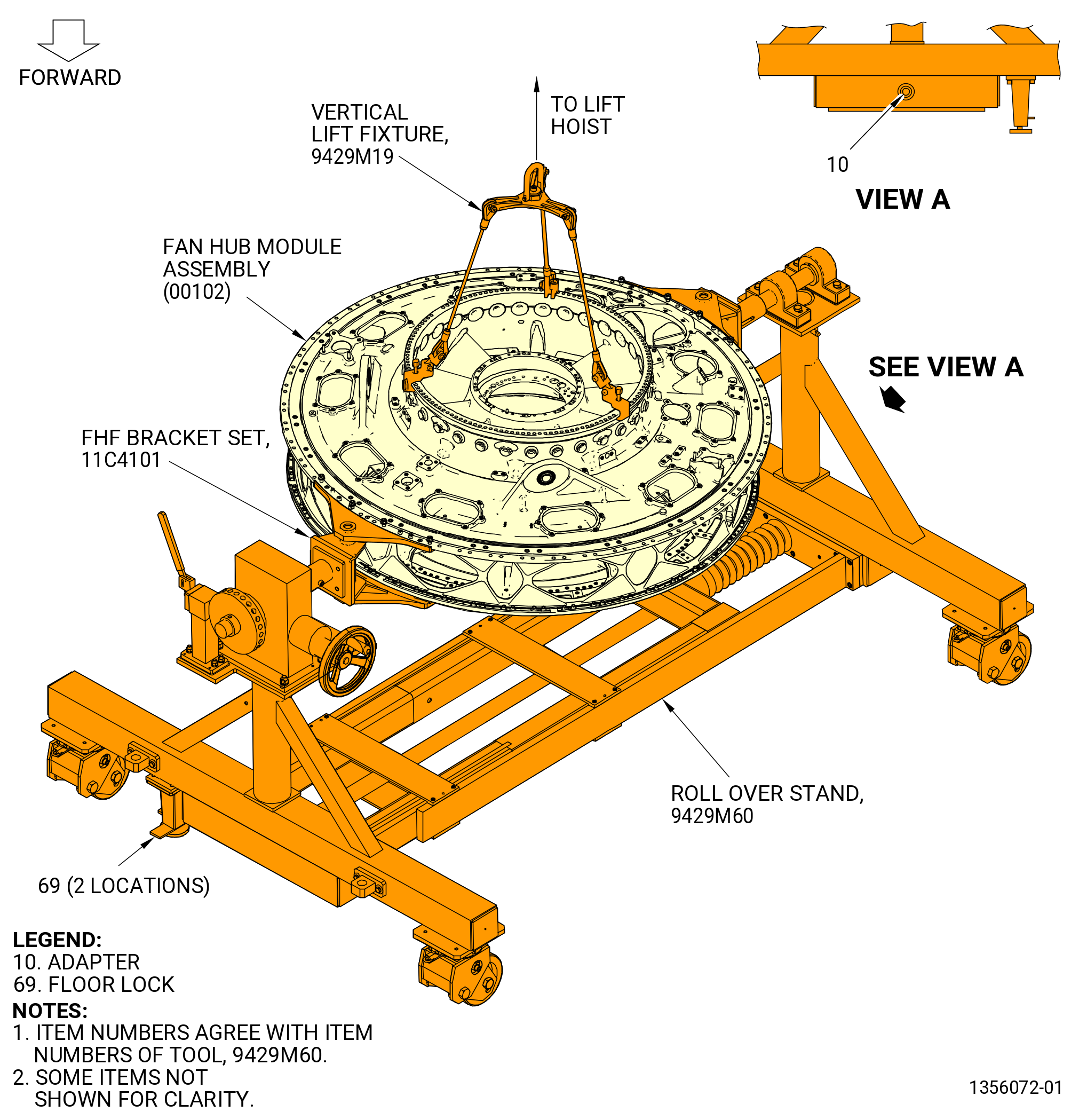
| (2) | Alternative Procedure Available. Remove the fan hub module assembly (00102) from the 9429M60 roll over stand as follows. Refer to Figure 1003. |
| CAUTION: |
|
| (a) | Lower the floor locks (item 69) of the 9429M60 roll over stand until they touch the floor. The floor locks must remain in contact with the floor to prevent movement of the roll over stand. Make sure that the roll over stand is level. |
| (b) | Attach an overhead hoist to the 9429M19 vertical lift fixture. |
| (c) | Apply a lift pressure to the fan hub module assembly to take the load off the 11C4101 FHF bracket set. |
| (d) | Remove the 11C4101 FHF bracket set from the fan hub module assembly. |
| NOTE: |
|
| (e) | Turn the adapter (item 10) on the 9429M60 roll over stand to move the 11C4101 FHF bracket set away from the fan hub module assembly. |
| (f) | Lift the fan hub module assembly from the 9429M60 roll over stand. |
| Subtask 72-00-02-430-776 |
| WARNING: |
|
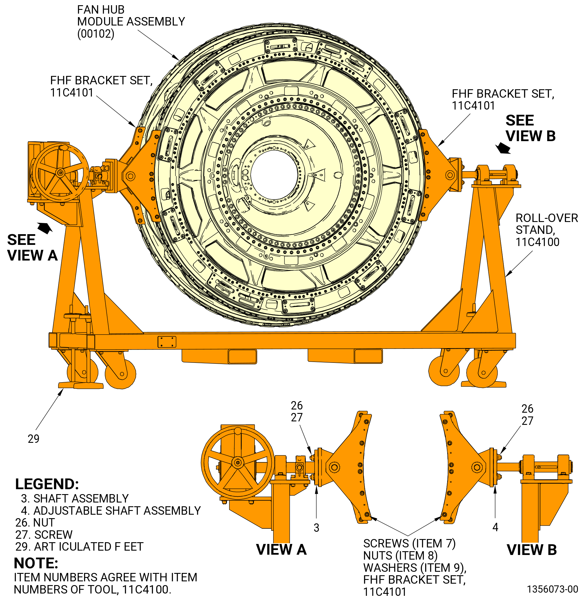
| (2).A. | Alternative Procedure. Remove the fan hub module assembly (00102) from the 11C4100 roll-over stand as follows. Refer to Figure 1004. |
| CAUTION: |
|
| (a) | Lower the articulated feet (item 29) of the 11C4100 roll-over stand until they touch the floor. The articulated feet must remain in contact with the floor to prevent movement of the 11C4100 roll-over stand. Make sure that the 11C4100 roll-over stand is level. |
| (b) | Attach an overhead hoist to the 9429M19 vertical lift fixture. |
| (c) | Apply a lift pressure to the fan hub module assembly to take the load off from the 11C4101 FHF bracket set. |
| (d) | Unlock the screws that attach the adjustable shaft assembly (item 4) along its axial direction. |
| (e) | Remove the four nuts (item 26) and four screws (item 27) from the adjustable shaft assembly (item 4). |
| (f) | Push back the adjustable shaft assembly (item 4) in the fully closed position to get the maximum gap. |
| (g) | Remove the four nuts (item 26) and four screws (item 27) from the shaft assembly (item 3). |
| (h) | Lift the fan hub module assembly from the 11C4100 roll-over stand. |
| Subtask 72-00-02-430-662 |
| B. | Install the 11C3197 bracket set on the fan hub module assembly (25-010) (SIN 00102) with the 9481M84 assembly stand. Refer to Figure 1005 and do as follows: |
| WARNING: |
|
| (1) | Attach an overhead hoist to the hoist ring (item 4) and lift the right bracket (item 2). |
| (2) | Put the right bracket at the 9:00 o'clock position ALF on the fan hub module assembly. |
| (3) | Put the right bracket on the inner side of the aft flange of the fan hub module assembly. Make sure that the boltholes are aligned. |
| (4) | Remove the capscrews (item 6) and the washers (item 5) from the storage location. |
| (5) | Install the capscrews and the washers in the right bracket and the flange of the fun hub module assembly. |
| (6) | Torque the capscrews (item 6) to 190-230 lb in. (21.5-26.0 N.m). |
| Subtask 72-00-02-430-663 |
| (7) | Install the left bracket (item 3) on the FHF at the 3:00 o'clock position ALF. Refer to Subtask 72-00-02-430-662 (paragraph 3.B.). |
| Subtask 72-00-02-430-664 |
| C. | Install the 11C3047 lift/turn bracket on the fan hub module assembly (25-010) (SIN 00102) with the 9481M84 assembly stand at the 6:00 o'clock position. Refer to Figure 1006 and do as follows: |
| (1) | Put the bracket (item 2) at the 6:00 o'clock position ALF on the FHF. |
| (2) | Slide the bracket (item 2) in with the bracket flanges on the forward side of the fan hub frame assembly. Make sure that the boltholes are aligned. |
| (3) | Remove the capscrews (item 3) and the nut (item 4) from the bolt storage location. |
| (4) | Install the capscrews and the nuts in the bracket and the flange of the FHF. |
| (5) | Torque the nuts to 190-230 lb in. (21.5-26.0 N.m). |
| Subtask 72-00-02-430-665 |
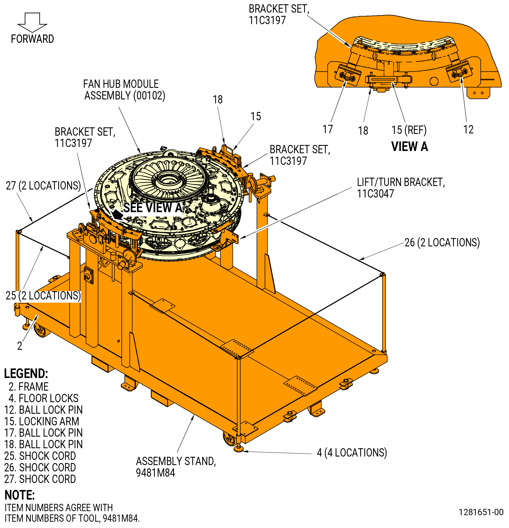
| D. | Alternative Procedure Available. Install the fan hub module assembly (25-010) (SIN 00102) in the 9481M84 assembly stand. Refer to Figure 1007 and do as follows: |
| (1) | Prepare the 9481M84 assembly stand to install the propulsor system as follows: |
| CAUTION: |
|
| (a) | Make sure that the floor locks (item 4) are against the floor to prevent movement of the assembly stand. |
| (b) | Remove one end of the shock cords (items 25, 26, and 27) at two locations each. |
| WARNING: |
|
| (2) | Lift the fan hub module assembly to a position over the 9481M84 assembly stand and lower on the assembly stand. |
| (3) | Align the trunnions on the left and right brackets (items 3 and 4) of the 11C3197 bracket set with the cradle supports on the frame (item 2) of the 9481M84 assembly stand and install in the frame. |
| (4) | Secure the fan hub module assembly in the horizontal position as follows: |
| (a) | Install the ball lock pins (items 12 and 17) to secure the 11C3197 bracket set to the 9481M84 assembly stand. |
| (b) | Install the locking arms (item 15) and secure with the ball lock pins (item 18) at four locations. |
| (5) | Attach the shock cords (items 25, 26, and 27). |
| Subtask 72-00-02-430-865 |
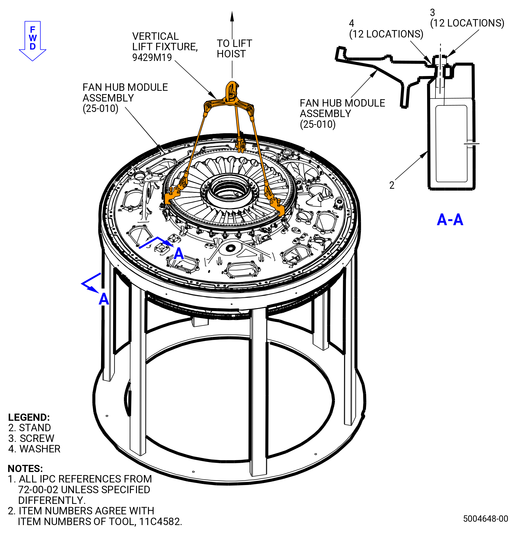
| D.A. | Alternative Procedure. Install the fan hub module assembly (25-010) (SIN 00102) in the 11C4582 core module build-up fixture. Refer to Figure 1007A and do as follows: |
| (1) | Make sure that the 11C4582 core module build-up fixture is installed on a flat surface and secured. |
| WARNING: |
|
| (2) | Use the 9429M19 vertical lift fixture to lift the fan hub module assembly. |
| (3) | Lower the fan hub module assembly into the 11C4582 core module build-up fixture. |
| (4) | Attach the 11C4582 core module build-up fixture with 12 screws (item 3) and washers (item 4) to the fan hub module assembly QEC flange. |
| (5) | Remove the 9429M19 vertical lift fixture. |
| Subtask 72-00-02-430-666 |
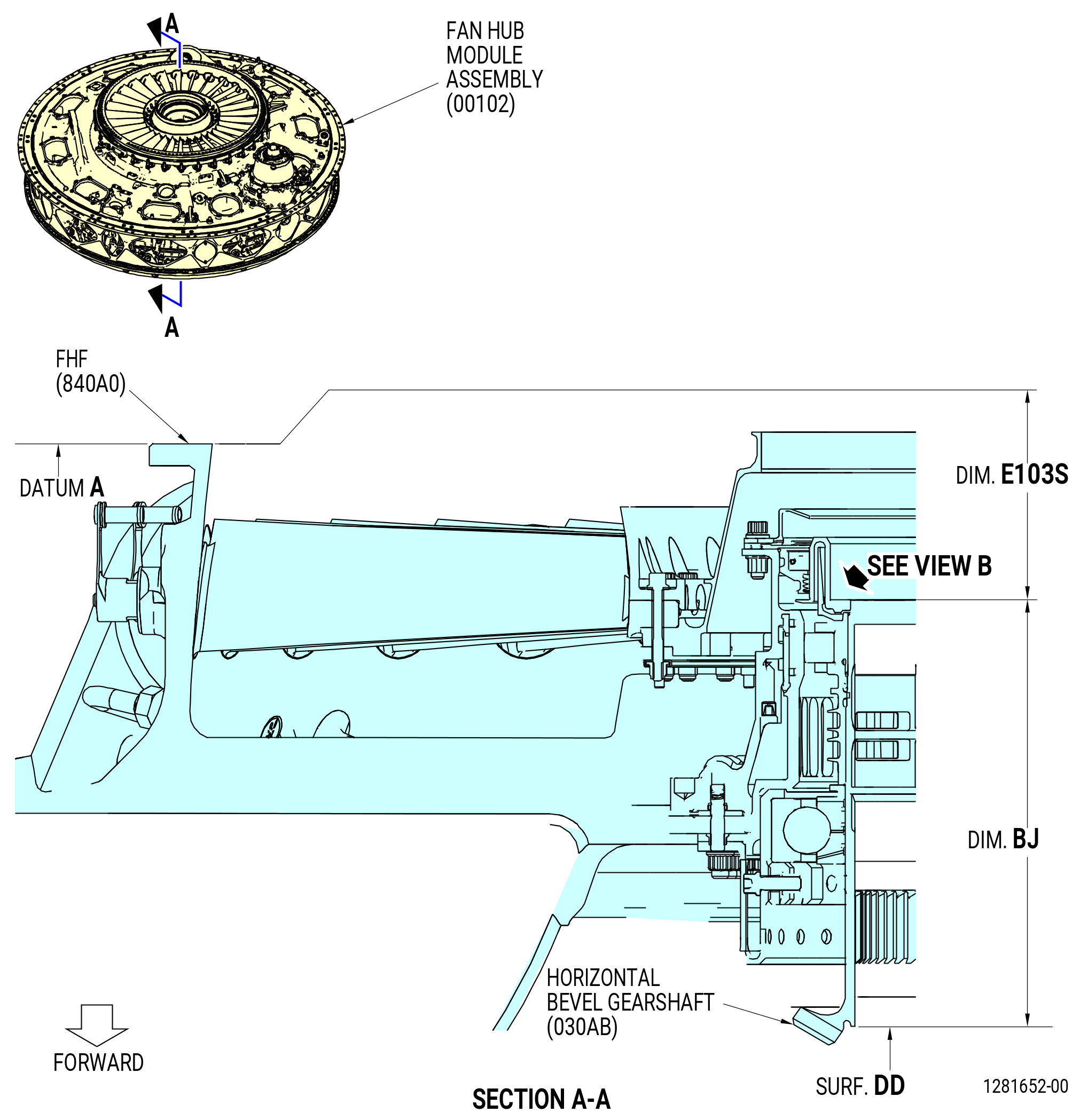
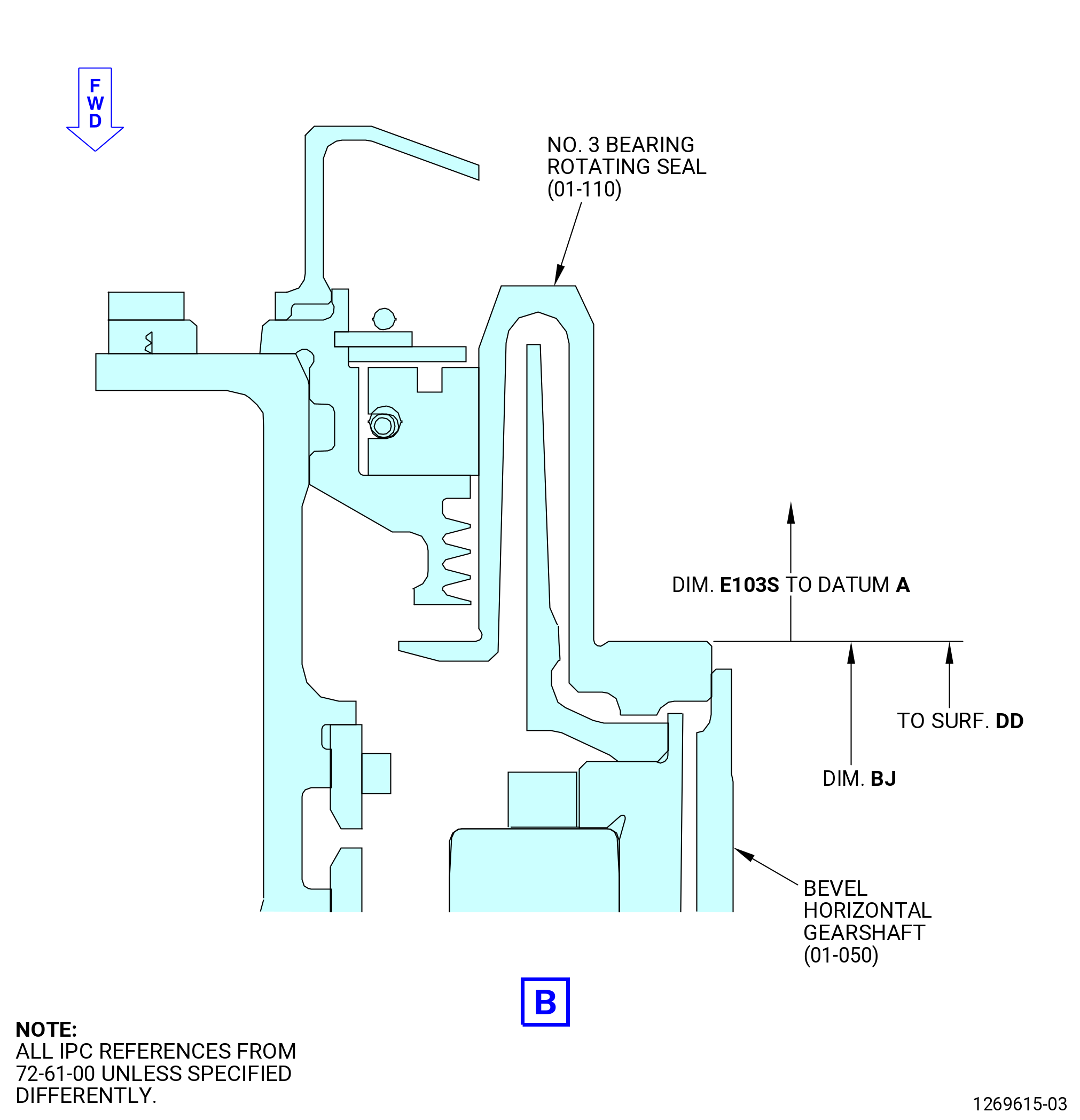
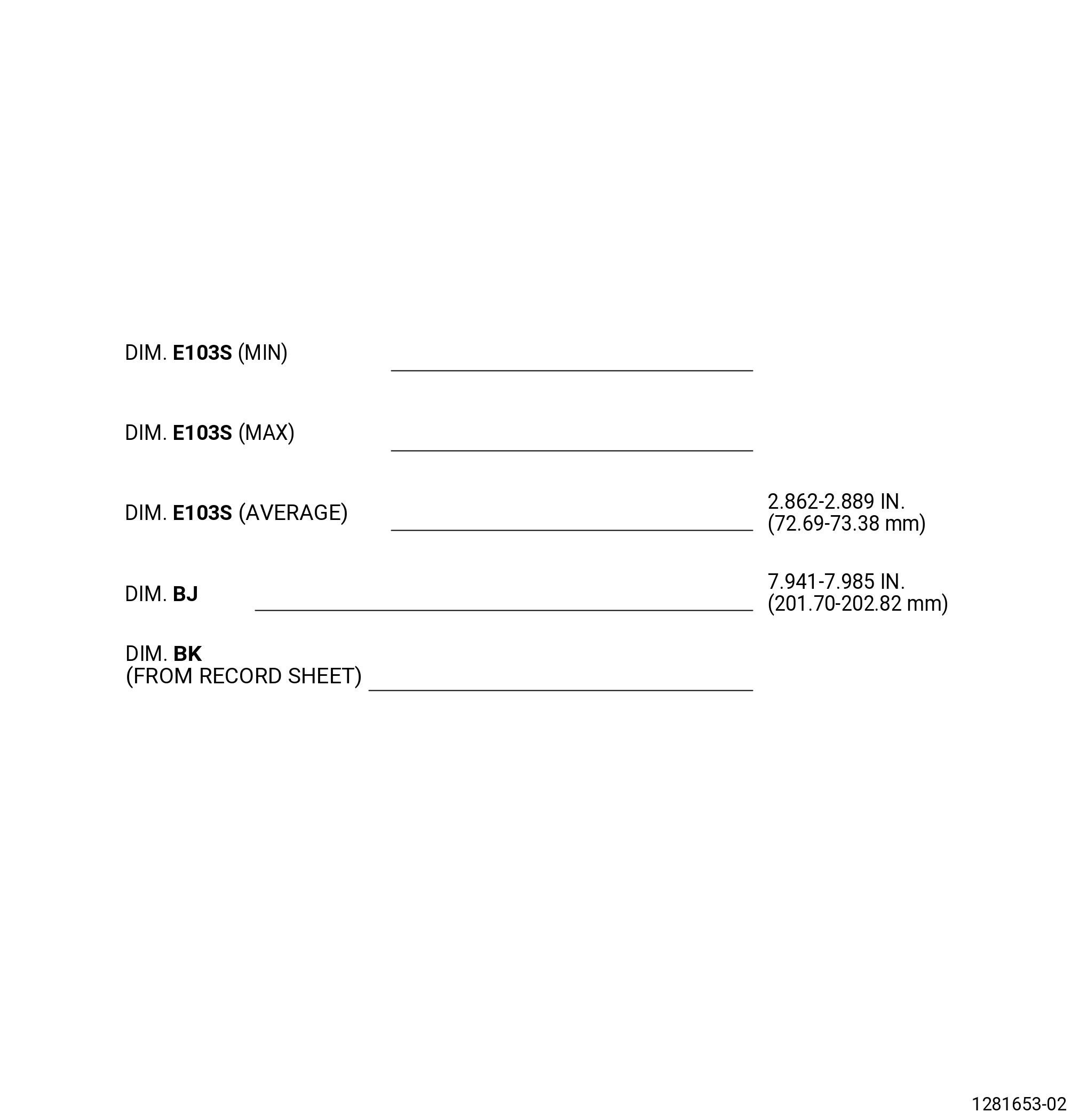
| E. | Measure and record the fan hub module assembly (00102) dimensions E103S and BJ as follows. Refer to Figure 1008. |
| CAUTION: |
|
| (1) | Measure and record Dim. E103S and Dim. BJ which will be used for calculation of engine clearances at higher levels of assembly. |
| NOTE: |
|
| (2) | Measure the Dim. E103S as follows: |
| (a) | Measure the Dim. E103S at four equally spaced locations. |
| (b) | Record the minimum and the maximum value for Dim. E103S on the record sheet. Refer to Figure 1009. |
| (c) | The tolerance for Dim. E103S is 2.862-2.889 inches (72.69-73.38 mm). |
| (3) | Record the value for Dim. BJ, 7.941-7.985 inches (201.70-202.82 mm), on the record sheet. Refer to TASK 72-61-00-440-801 (72-61-00, ASSEMBLY 001) for the record of Dim. BJ. |
| (a) | If there is no record for Dim. BJ, measure Dim. BJ as follows. Refer to Figure 1008. |
| 1 | Measure Dim. BJ at four equally spaced locations. |
| 2 | Calculate the average for Dim. BJ and record on the record sheet. Refer to Figure 1009. |
| (4) | Find the stamp with the thickness dimension on the FHF (840A0) forward flange (No. 1 bearing support flange) at the 12:00 o'clock position. Refer to Figure 1009. Make a record of Dim. BK and record on the record sheet. For Dim. BK, refer to Subtask 72-25-00-440-003 (72-25-00, Assembly 001). |
| Subtask 72-00-02-140-010 |
| WARNING: |
|
| F. | Clean the HPC module assembly forward flange mating surface with C04-002 Stoddard solvent, C04-003 acetone, or C04-035 isopropyl alcohol. |
| Subtask 72-00-02-430-667 |
| G. | Mark the forward flange of the HPC module assembly with the bolthole numbers as follows: |
| (1) | Begin at bolthole No. 1, right of the top vertical centerline (TVCL) ALF, and mark in increments of ten the bolthole location with a C05-003 pen. |
| (2) | Put the mark on the aft side of the forward flange on the HPC module assembly. |
| Subtask 72-00-02-430-668 |
| H. | Remove the HPC module assembly from the 11C4279 core module build-up fixture or 11C3010 build-up fixture installed on the 9429M56 propulsor build stand as follows: |
| Subtask 72-00-02-430-669 |
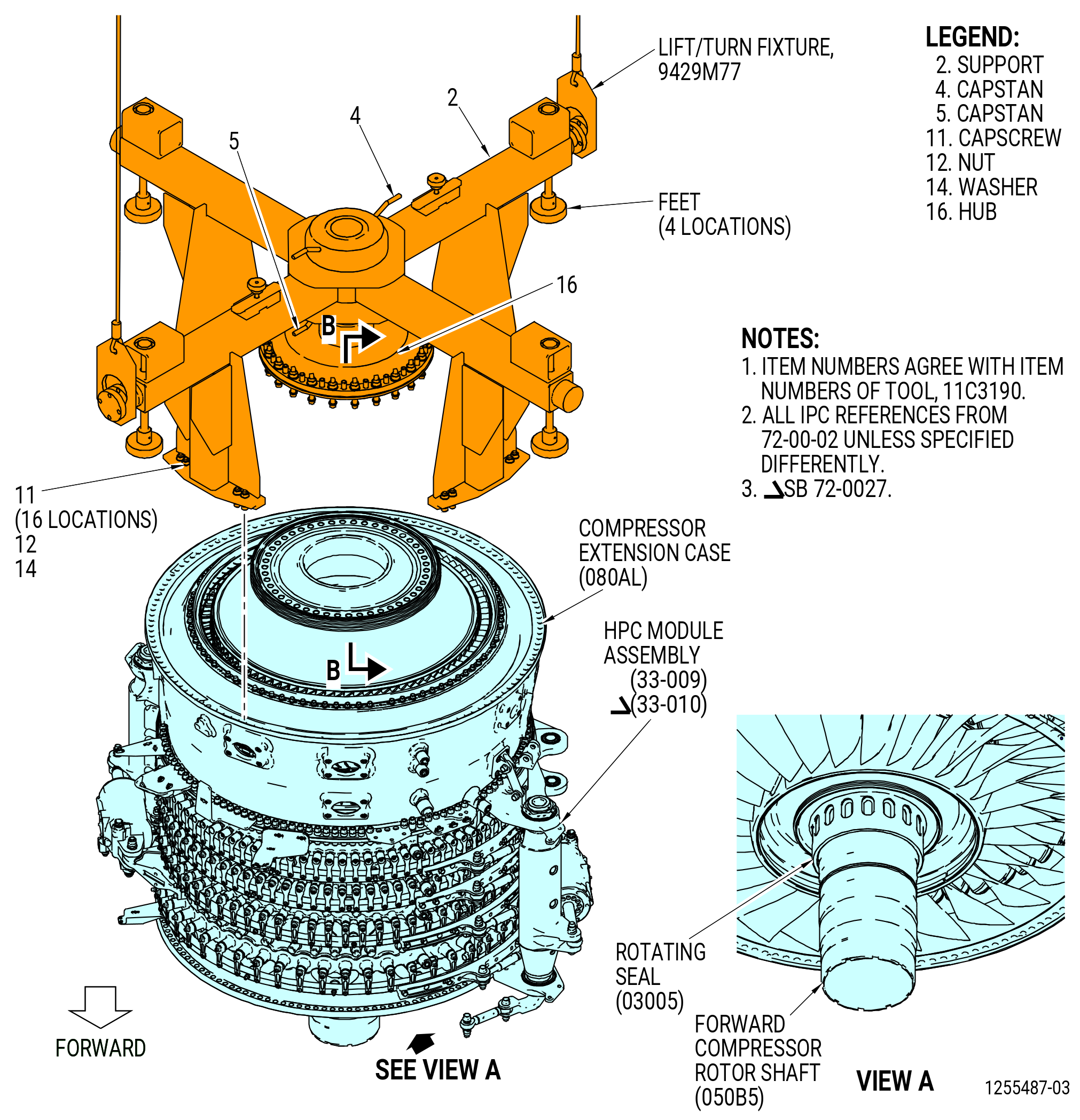
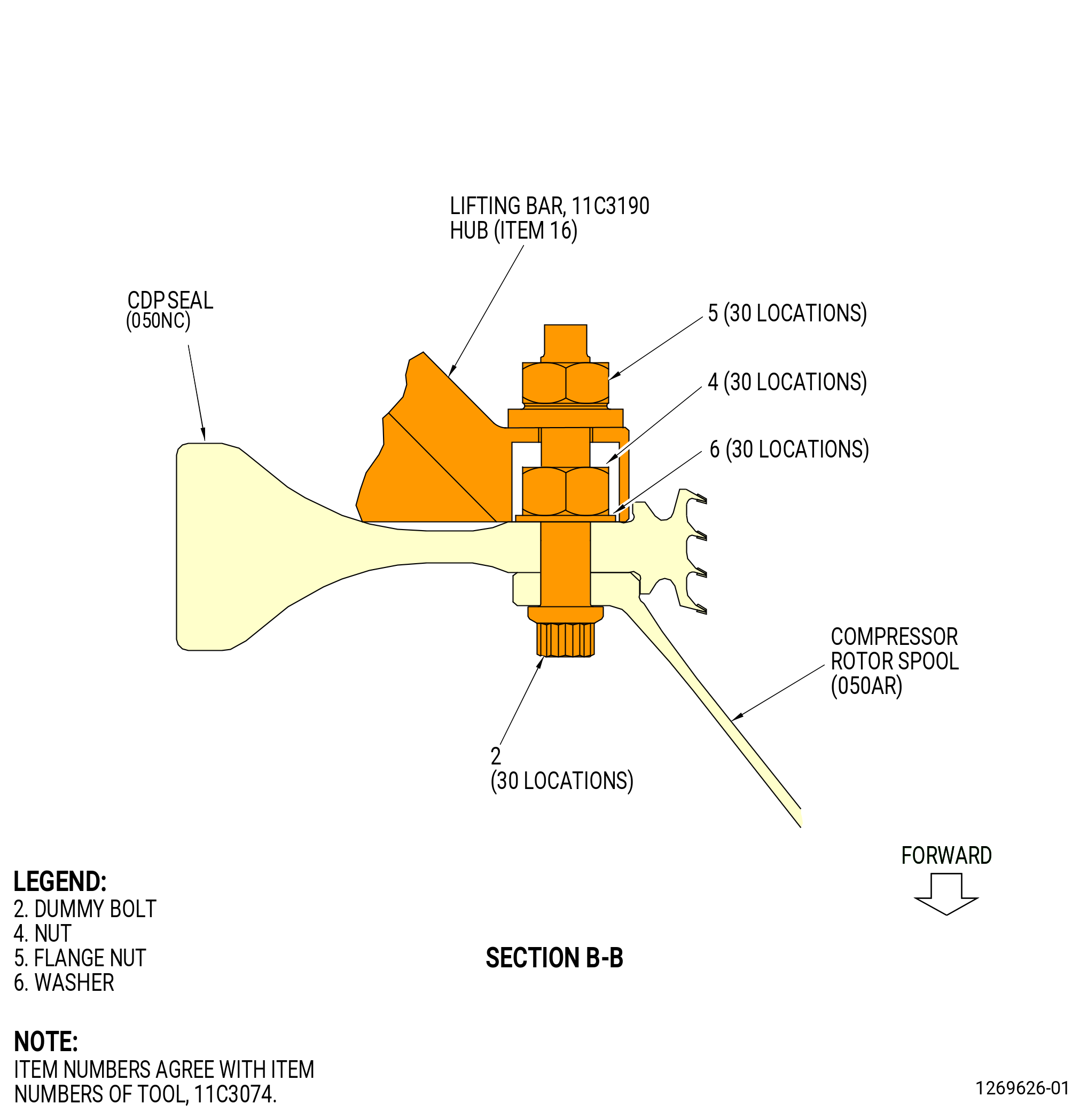
| (1) | Alternative Procedure Available. Install the 11C3190 lifting bar to the HPC module assembly. Refer to Figure 1010 and do as follows: |
| (a) | Install the dummy bolts (item 2), the washers (item 6), and the nuts (item 4) of the 11C3074 tool kit to the stage 6-10 compressor rotor spool (compressor rotor spool) (050AR) aft end. |
| (b) | Attach the 9429M77 lift/turn fixture to the support (item 2) of the 11C3190 lifting bar. |
| (c) | Adjust the hub (item 3) of the 11C3190 lifting bar up with the capstans (items 4 and 5). |
| WARNING: |
|
| (d) | Lift the 11C3190 lifting bar on the HPC module assembly and lower the support (item 2) on the extension case (compressor extension case) (10-080 , 72-30-00) (SIN 080AL). |
| (e) | Put the capscrew (item 11) of the 11C3190 lifting bar and the washer (item 14) on the forward side of the compressor extension case (080AL) flange. |
| (f) | Attach the support (item 2) of the 11C3190 lifting bar to the capscrew (item 11) with the nut (item 12). Tighten the nut. |
| (g) | Turn the capstans (items 4 and 5) to carefully lower and align the hub (item 16) of the 11C3190 lifting bar on the 11C3074 tool kit and the CDP seal (050NC). Remove all gaps between the hub (item 16) and the CDP seal. |
| (h) | Attach the hub (item 16) to the CDP seal with the flange nut (item 5) of the 11C3074 tool kit. |
| Subtask 72-00-02-430-670 |
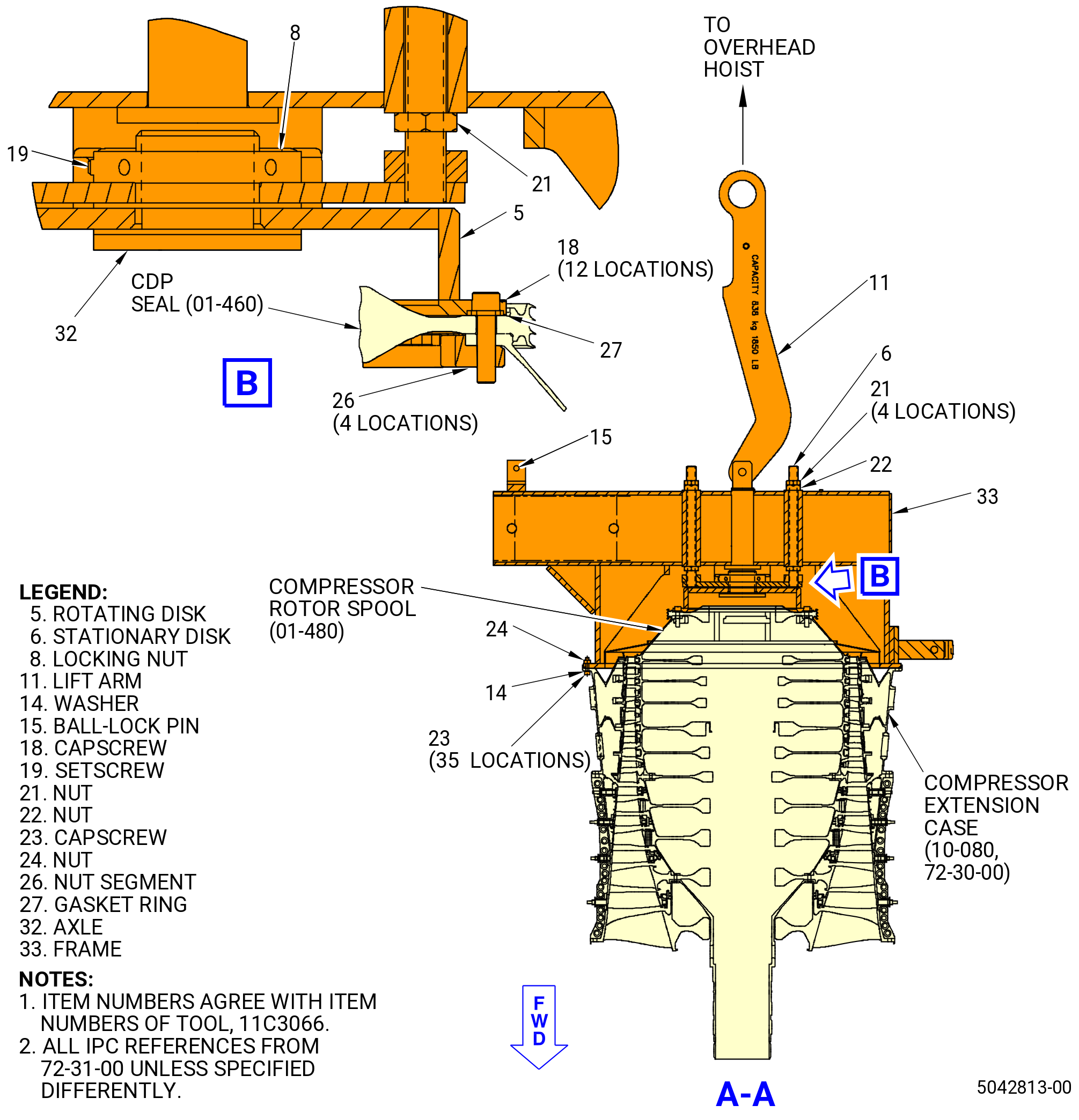
| (1).A. | Alternative Procedure. Install the 11C3066 lift/turn fixture on the aft end of the HPC module assembly. Refer to Figure 1011 and do as follows: |
| (a) | Remove the capscrews (item 18), the nut segment (item 26), and the gasket ring (item 27) from the storage location on the rotating disk (item 5). |
| CAUTION: |
|
| (b) | Put the gasket ring (item 27) on the aft flange of the CDP seal (050NC). |
| (c) | Install a nut segment (item 26) at 12:00 o’clock on the forward flange of the compressor rotor spool (050AR) with one capscrew (item 18). The capscrew will attach the gasket ring (item 27) and rotating disk (item 5) to the spool and will be installed into the middle hole of the nut segment. |
| (d) | Install the last three nut segments (item 26) at the 3:00, 6:00, and 9:00 o’clock positions with one capscrew (item 18) each. |
| (e) | Remove the nuts (items 21 and 22) to let the stationary disk move up and down. |
| WARNING: |
|
| (f) | Lift the frame (item 33) and carefully lower on the aft end of the HPC module assembly. |
| (g) | Loosen the setscrew (item 19) to let the rotating disk (item 5) turn. |
| (h) | Turn the rotating disk (item 5) to align the holes with the nut segments (item 26). |
| (i) | Attach the rotating disk (item 5) to the gasket ring (item 27), the rotating disk (item 5), and the nut segments (item 26) at 12:00, 3:00, 6:00, and 9:00 with two capscrews (item 18) at each nut segment. |
| NOTE: |
|
| (j) | Turn the frame (item 33) to align the holes with the compressor extension case (10-080 , 72-30-00) (SIN 080AL) aft flange. |
| (k) | Attach the frame (item 33) to the compressor extension case with the capscrews (item 23), the washers (item 14), and the nuts (item 24) at 35 locations. Install the capscrews and washers on the forward side of the compressor extension case flange. |
| (l) | Tighten the capscrew (item 19). |
| (m) | Attach the stationary disk (item 6) of the 11C3066 lift/turn fixture to the rotating disk (item 5) as follows: |
| CAUTION: |
|
| 1 | Tighten the locking nut (item 8) on the axle (item 32) and lock in position with the setscrew (item 19). |
| 2 | Tighten the nuts (item 21) on the threaded rod of the stationary disk (item 6). |
| NOTE: |
|
| 3 | Tighten the nuts (item 22) on the threaded rod of the stationary disk (item 6). |
| NOTE: |
|
| 4 | Tighten the nuts (item 21) on the threaded rod of the stationary disk (item 6). |
| NOTE: |
|
| Subtask 72-00-02-430-672 |
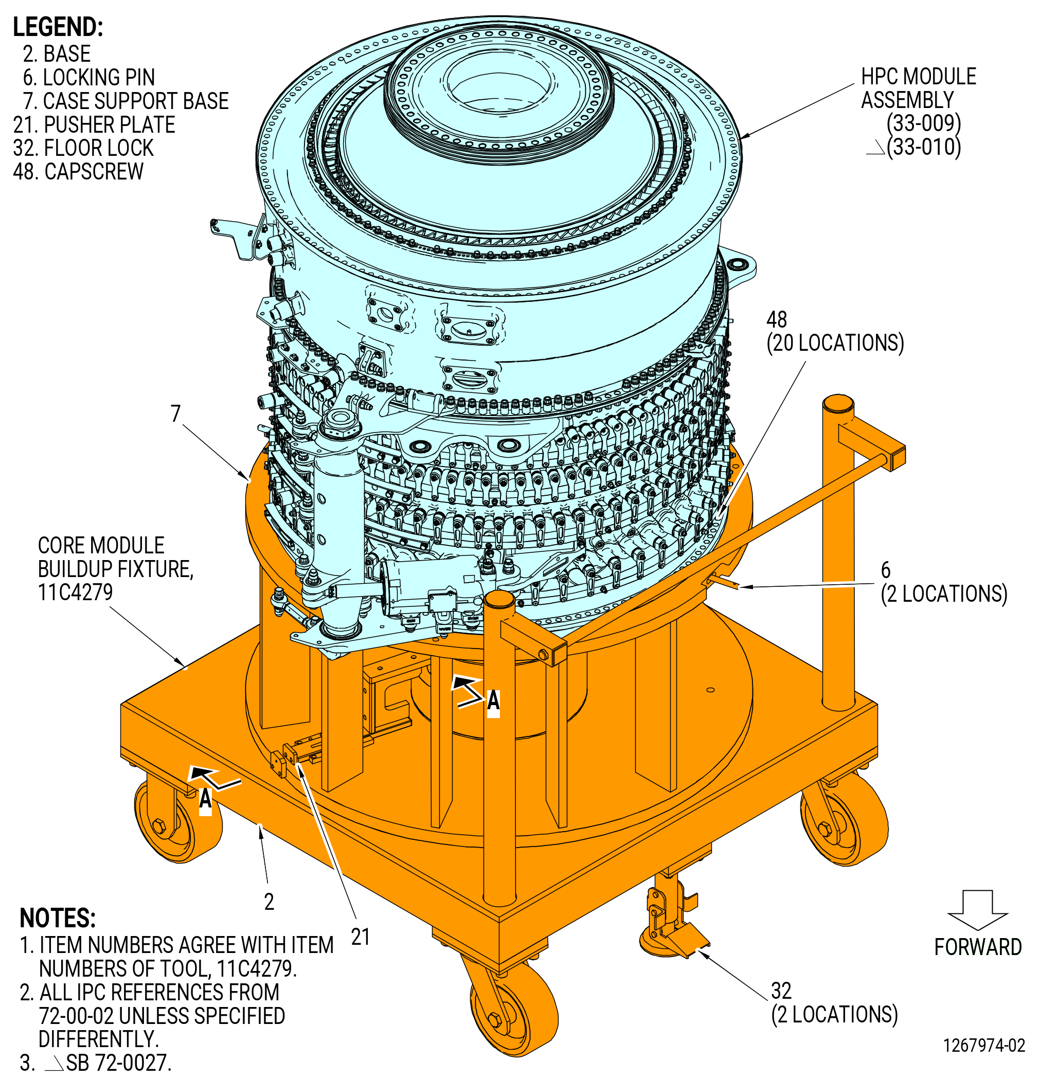
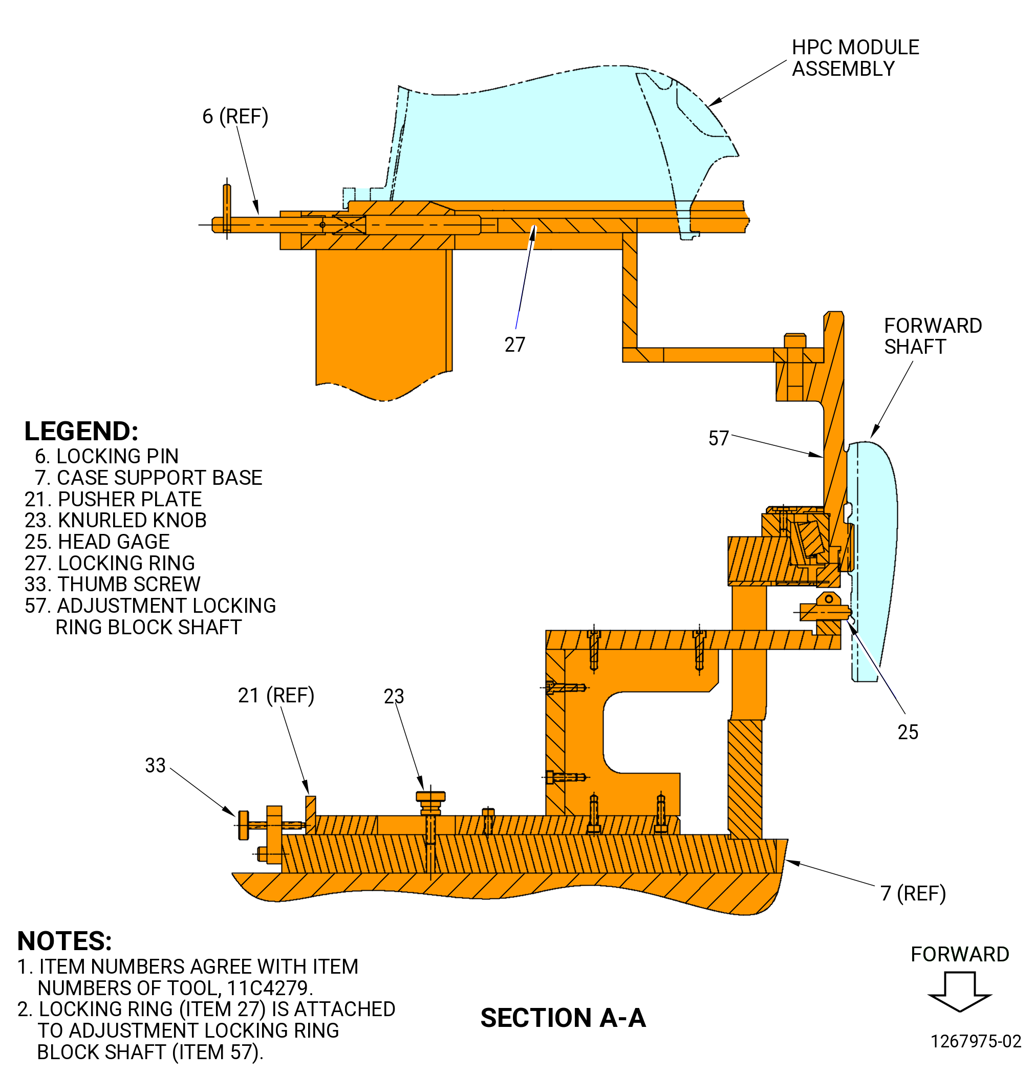
| (2) | Alternative Procedure Available. Remove the HPC module assembly from the 11C4279 core module build-up fixture. Refer to Figure 1012 and do as follows: |
| NOTE: |
|
| CAUTION: |
|
| (a) | Make sure that the floor locks (item 32) touch the floor and remain locked to prevent movement of the core module build-up fixture. |
| (b) | Loosen the knurled knob (item 23) that secures the pusher plate (item 21). |
| (c) | Turn the thumbscrew (item 33) counterclockwise (CCW) to remove the thumbscrew away from the pusher plate (item 21). |
| (d) | Move the pusher plate (item 21) and the head gage (item 25) outward and away from the forward shaft on the HPC module assembly. |
| (e) | Pull the locking pin (item 6) out at two locations and turn CW or CCW to secure in unlocked position. This will permit the adjustment locking ring block shaft (item 57) and the locking ring (item 27) to turn. |
| (f) | Remove the capscrews (item 48) that attach the HPC module assembly to the case support base (item 7) at 20 locations. |
| Subtask 72-00-02-430-671 |
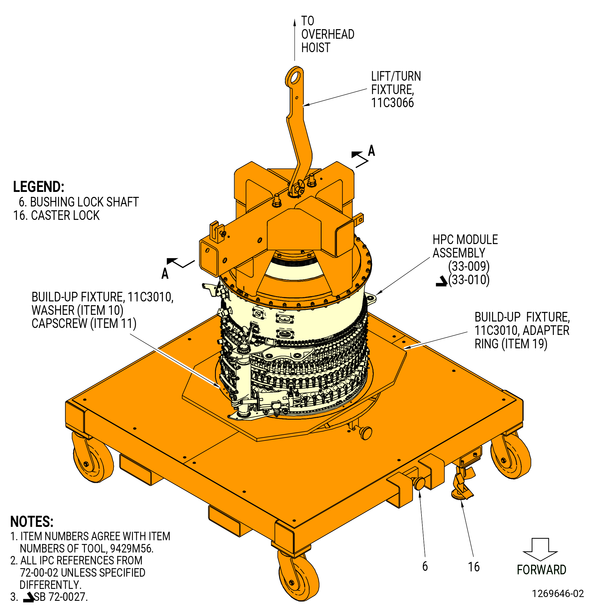
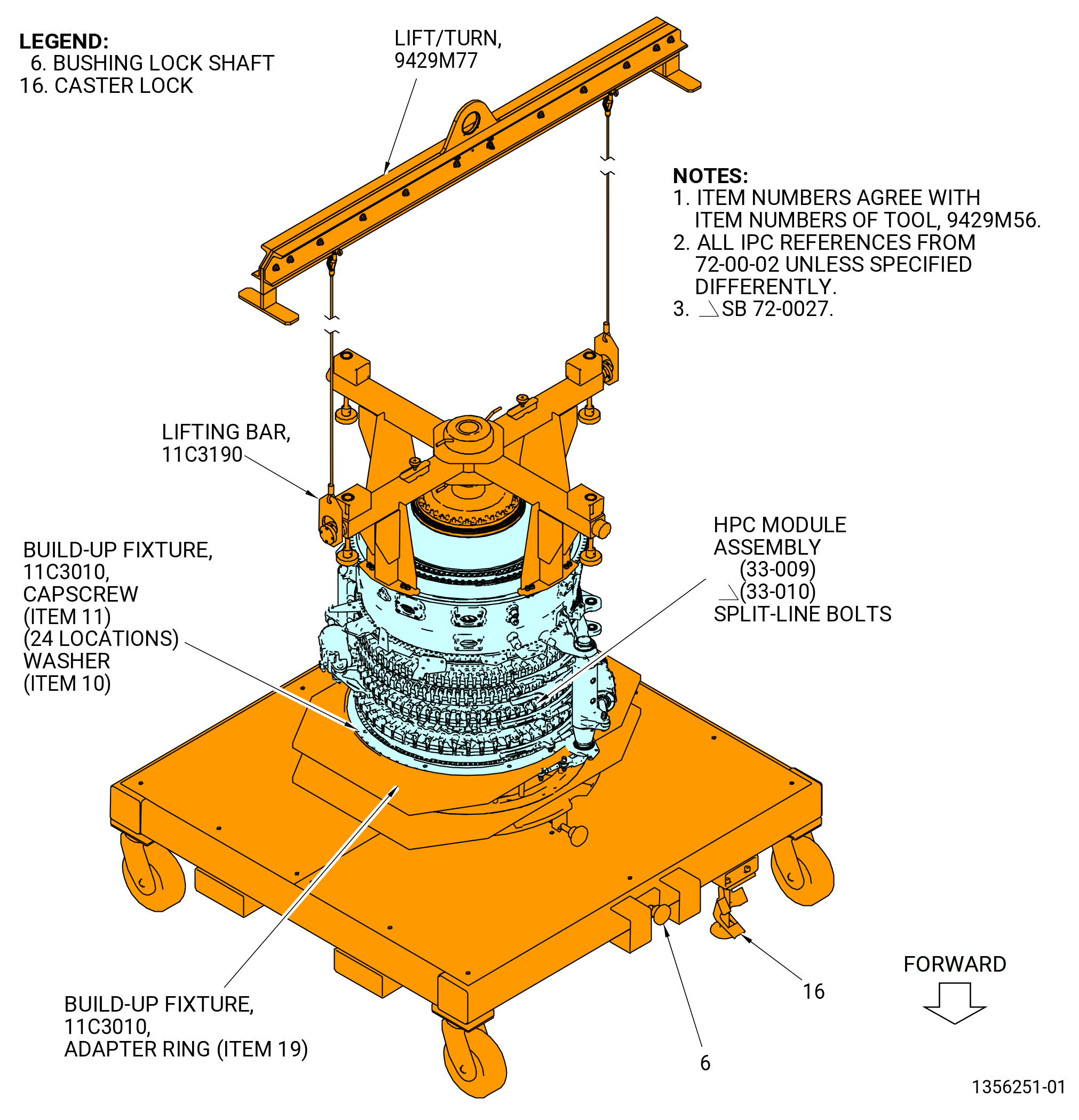
| (2).A. | Alternative Procedure. Remove the HPC module assembly from the 9429M56 propulsor build stand. Refer to Figure 1013 and do as follows: |
| CAUTION: |
|
| (a) | Lower the caster locks (item 16) of the 9429M56 propulsor build stand until they touch the floor. Make sure that the build stand does not move. |
| (b) | Pull to remove the bushing lock shaft (item 6) to the disengaged position. |
| (c) | Remove the capscrews (item 11) and washers (item 10) of the 11C3010 build-up fixture from the HPC module assembly upper/lower forward stator assembly (15-010 , 72-32-00) or (15-011 , 72-32-00) (SIN 073A0). |
| (d) | Remove two split-line bolts at the 3:00 o'clock and two split-line bolts at the 9:00 o'clock positions. |
| WARNING: |
|
| (e) | Carefully lift the HPC module assembly from the 11C3010 build-up fixture on the 9429M56 propulsor build stand. |
| (f) | Put the HPC module assembly on a safety stand. |
| (g) | Make sure that the rotating seal (03005) is installed on the forward shaft (050B5). Refer to Figure 1010. If not installed, refer to TASK 72-30-00-440-801 (72-30-00, Assembly 001) to install the rotating seal (03005). |
| Subtask 72-00-02-430-777 |
| WARNING: |
|
| (3) | Lift the HPC module assembly from the 11C4279 core module build-up fixture. |
| (4) | Install the HPC module assembly on a safety stand. |
| Subtask 72-00-02-160-003 |
| WARNING: |
|
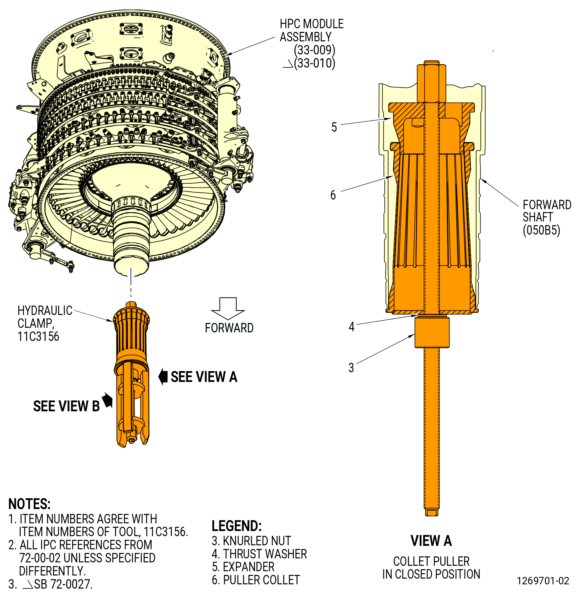
| I. | Before the installation of the shaft guide (item 11) of the 11C3156 hydraulic clamp, clean the OD and ID of the forward compressor rotor shaft, and clean the surfaces of the shaft guide with new C10-182 wipers and an approved solvent, such as a 50-50 blend of C04-014 denatured alcohol and C04-035 isopropyl alcohol, C04-002 Stoddard solvent, or C04-035 isopropyl alcohol. |
| Subtask 72-00-02-430-673 |
| J. | Install the shaft guide (item 11) of the 11C3156hydraulic clamp on the forward shaft (050B5) as follows. Refer to Figure 1014. |
| (1) | Put the collet puller (item 6) on the threaded rod of the expander (item 5) and attach with the thrust washer (item 4) and the knurled nut (item 3). |
| (2) | Turn the knurled nut (item 3) on the expander (item 5) rod until the expander touches the puller collet (item 6). |
| (3) | Put the collet puller (item 6) and the expander (item 5) up into the forward shaft. |
| CAUTION: |
|
| (4) | Tighten the knurled nut (item 3) until the finger on the collet puller (item 6) expands and touches the forward shaft. |
| NOTE: |
|
| (5) | Put the shaft guide (item 11) on the threaded rod of the expander (item 5) and attach with the coupling nut (item 9). |
| Subtask 72-00-02-430-674 |
| K. | Install the HPC module assembly on the fan hub module assembly (25-010) (SIN 00102) as follows: |
| Subtask 72-00-02-160-004 |
| WARNING: |
|
| (1) | Before joining the modules, the ID and OD surfaces of the shaft require a last chance wipe from the front of the shaft back to the cone, using new C10-182 wipers with clean C02-019 engine oil. |
| Subtask 72-00-02-431-038 |
| (2) | Match mark the top vertical centerlines (TVCL) of the HPC module assembly and the fan hub module assembly to identify the TVCL after the horizontal bevel gearshaft (030AB) is heated. |
| (3) | Apply C02-097 lubricant to the bolts (25-290) (SIN 07020), (25-410) (SIN 07021), (25-390) (SIN 07023) and to the threads and friction surfaces of self-locking nuts (25-280) (SIN 07040) or (25-281) (SIN 07040). |
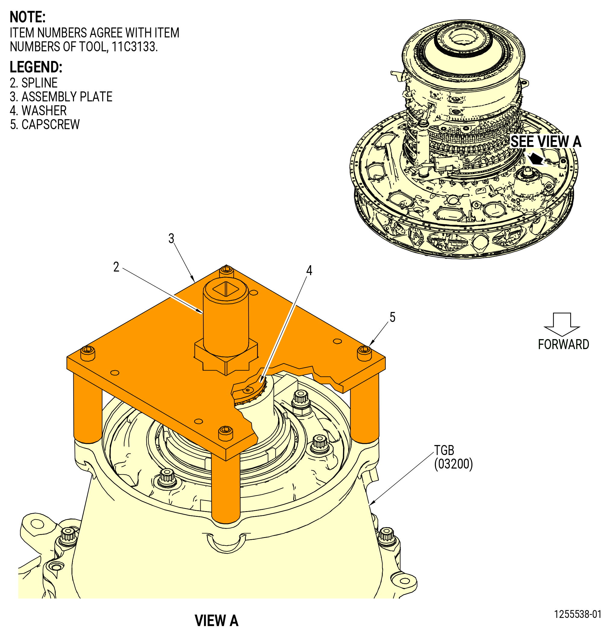
| (4) | Install the 11C3133 lock fixture on the transfer gearbox (TGB) (03200). Refer to Figure 1015. |
| (a) | Put the spline (item 2) of the 11C3133 lock fixture on the TGB output shaft. Make sure that the spline (item 2) is correctly aligned with the TGB drive shaft. |
| (b) | Put the assembly plate (item 3) on the TGB and engage the spline (item 2). |
| (c) | Attach the assembly plate (item 3) to the TGB with the capscrews (item 5). |
| (d) | Torque the capscrews (item 5) to a maximum 55-70 lb in. (6.215-7.910 N·m) to secure the 11C3133 lock fixture to the TGB. |
| Subtask 72-00-02-430-675 |
| WARNING: |
|
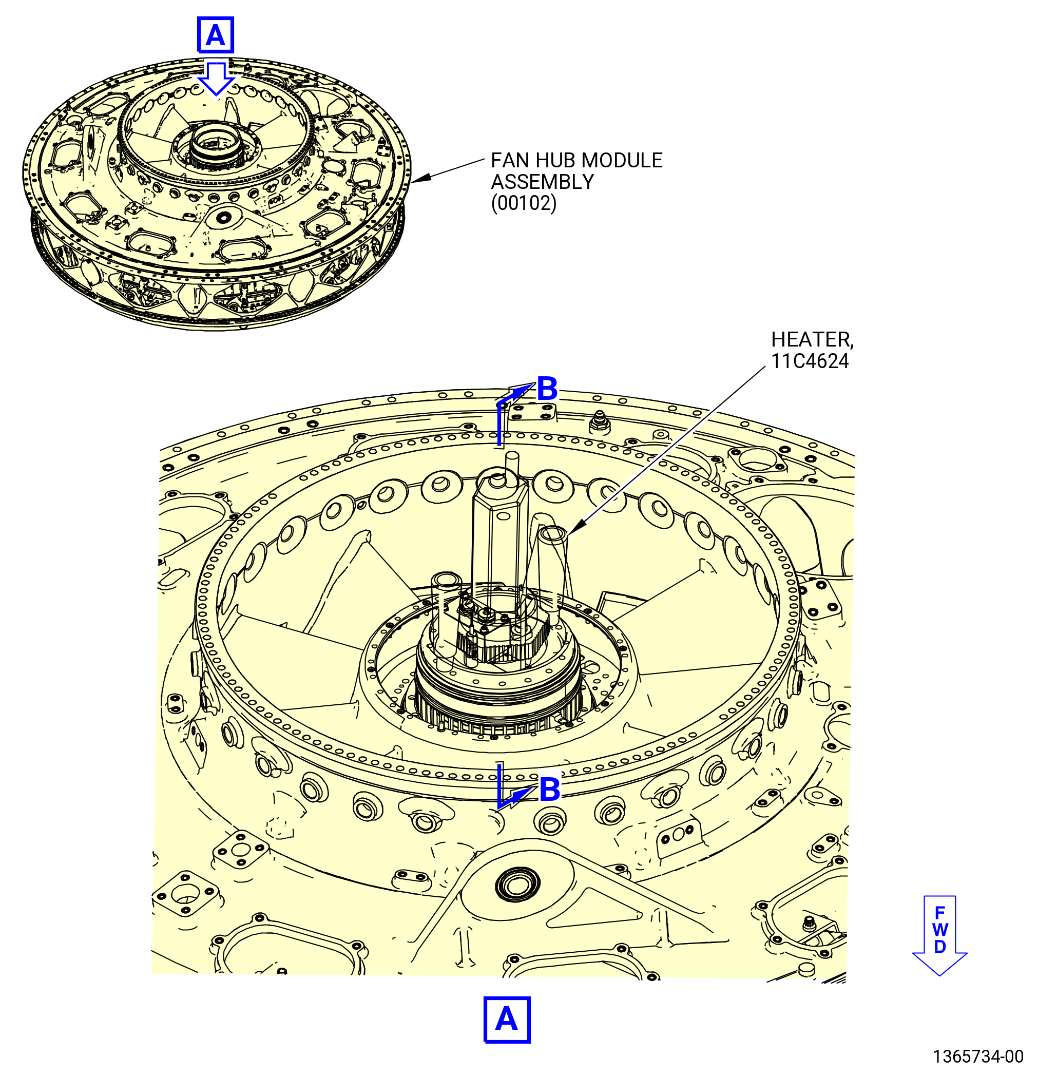
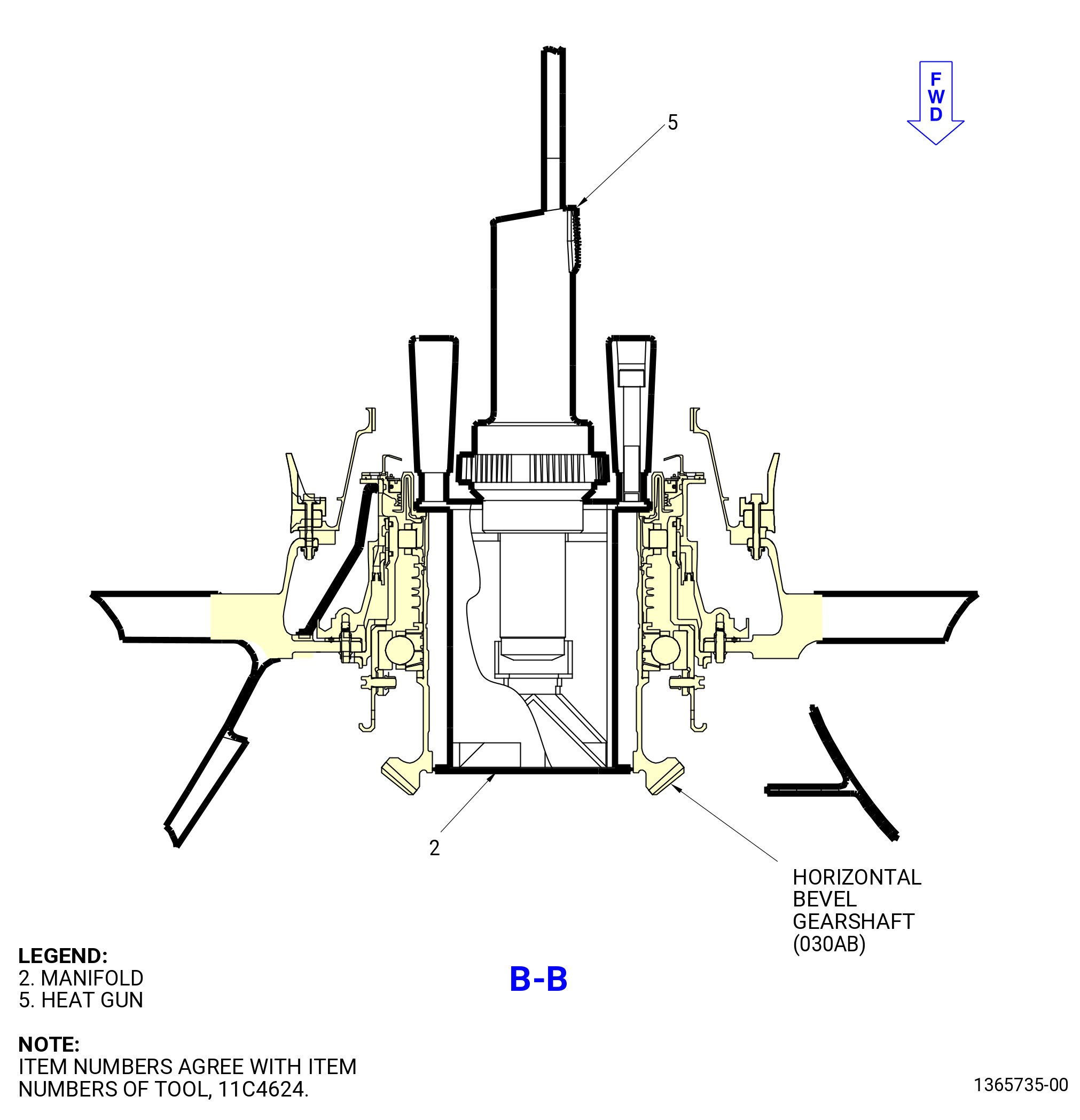
| (5) | Apply heat to the horizontal bevel gearshaft (030AB) and the inlet gearbox (IGB) (03000) with the 11C4624 heater as follows. Refer to Figure 1016. |
| (a) | Put the manifold (item 2) into the horizontal bevel gearshaft. |
| (b) | Assemble the heat gun (item 5) into the manifold (item 2). |
| (c) | Make sure that the switch is turned off before the heat gun (item 5) is connected. |
| (d) | Connect the heat gun (item 5) into a 220-240 VAC single phase outlet. |
| (e) | Set the temperature of the heat gun (item 5) to the maximum level permitted and turn it on. |
| (f) | Measure the temperature of the horizontal bevel gearshaft with a temperature probe or infrared sensor every 5 minutes until the horizontal bevel gearshaft temperature is 300°F (149°C) as follows: |
| 1 | Turn off the heat gun (item 5). |
| 2 | Make sure that the heat gun (item 5) is disconnected from the power source and the power cord is gathered and properly secured. |
| 3 | Remove the heat gun (item 5) from the manifold (item 2). |
| 4 | Remove the manifold (item 2) from the horizontal bevel gearshaft. |
| 5 | Measure the temperature of the horizontal bevel gearshaft and make sure that it is 300°F (149°C). |
| 6 | If necessary, do Subtask 72-00-02-430-675 (paragraph 3.J.(4)(a)) thru Subtask 72-00-02-430-675 (paragraph 3.J.(4)(f)) again. |
| (g) | Put the 11C4624 heater in the storage fixture. |
| Subtask 72-00-02-430-676 |
| (6) | Install the HPC module assembly into the fan hub module assembly (25-010) (SIN 00102). Refer to Figure 1017 and do as follows: |
| CAUTION: |
|
| NOTE: |
|
| (a) | Align the TVCL of the HPC module assembly and the fan hub module assembly. |
| (b) | Carefully lower the shaft guide (item 11) of the 11C3156hydraulic clamp into the fan hub module assembly. |
| (c) | Put a bolt (07021), a spacer (07070), and a self-locking nut (25-280) or (25-281) in bolthole No. 66 as a guide. All boltheads are aft with a spacer below the bolthead. |
| (d) | Slowly lower the HPC module assembly on the fan hub module assembly. |
| (e) | Install a bolt (07020), a spacer (07070), and a self-locking nut (25-280) or (25-281) in boltholes No. 18 and 101. Put the boltheads on the aft side of the flange. |
| WARNING: |
|
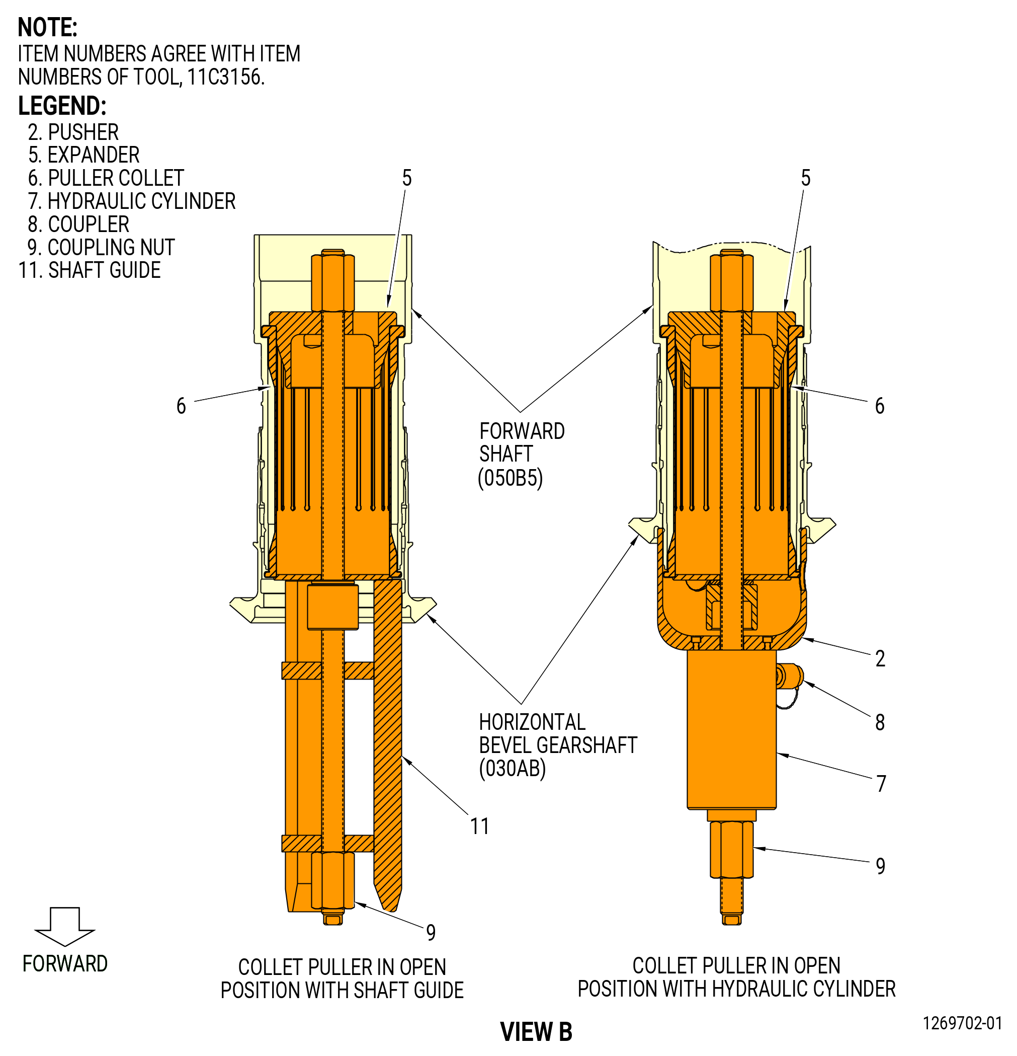
| (f) | Change the 11C3156hydraulic clamp from a guide fixture to install the HPC module assembly on the fan hub module assembly (25-010) (SIN 00102). Refer to Figure 1014 and do as follows: |
| 1 | Remove the coupling nut (item 9) and the shaft guide (item 11) from the threaded rod of the expander (item 5). |
| 2 | Put the pusher (item 2) and the hydraulic cylinder (item 7) on the threaded rod of the expander (item 5). |
| 3 | Connect the hydraulic cylinder (item 7) to the hydraulic hand pump. |
| (g) | Loosen the 11C3133 lock fixture on the transfer gearbox (TGB) (03200). Refer to Figure 1015. |
| (h) | Apply pressure to the 11C3156hydraulic clamp and pull the HPC module assembly forward until the flanges begin to seat. |
| (i) | There can be a 0.040 inch (1.02 mm) clearance between the flanges when the rotor is seated. |
| (j) | When the horizontal bevel gearshaft (030AB) and the forward shaft (050B5) splines engage, tighten the 11C3133 lock fixture. |
| CAUTION: |
|
| (k) | Apply 3000 psig (20685 kPa gauge) to the hydraulic cylinder (item 7) of the 11C3156hydraulic clamp. |
| CAUTION: |
|
| (l) | Increase the pressure to 5000 psig (34475 kPa gauge). |
| (m) | Make sure there is no clearance between the flanges of the HPC module assembly and the fan hub module assembly. |
| Subtask 72-00-02-430-677 |
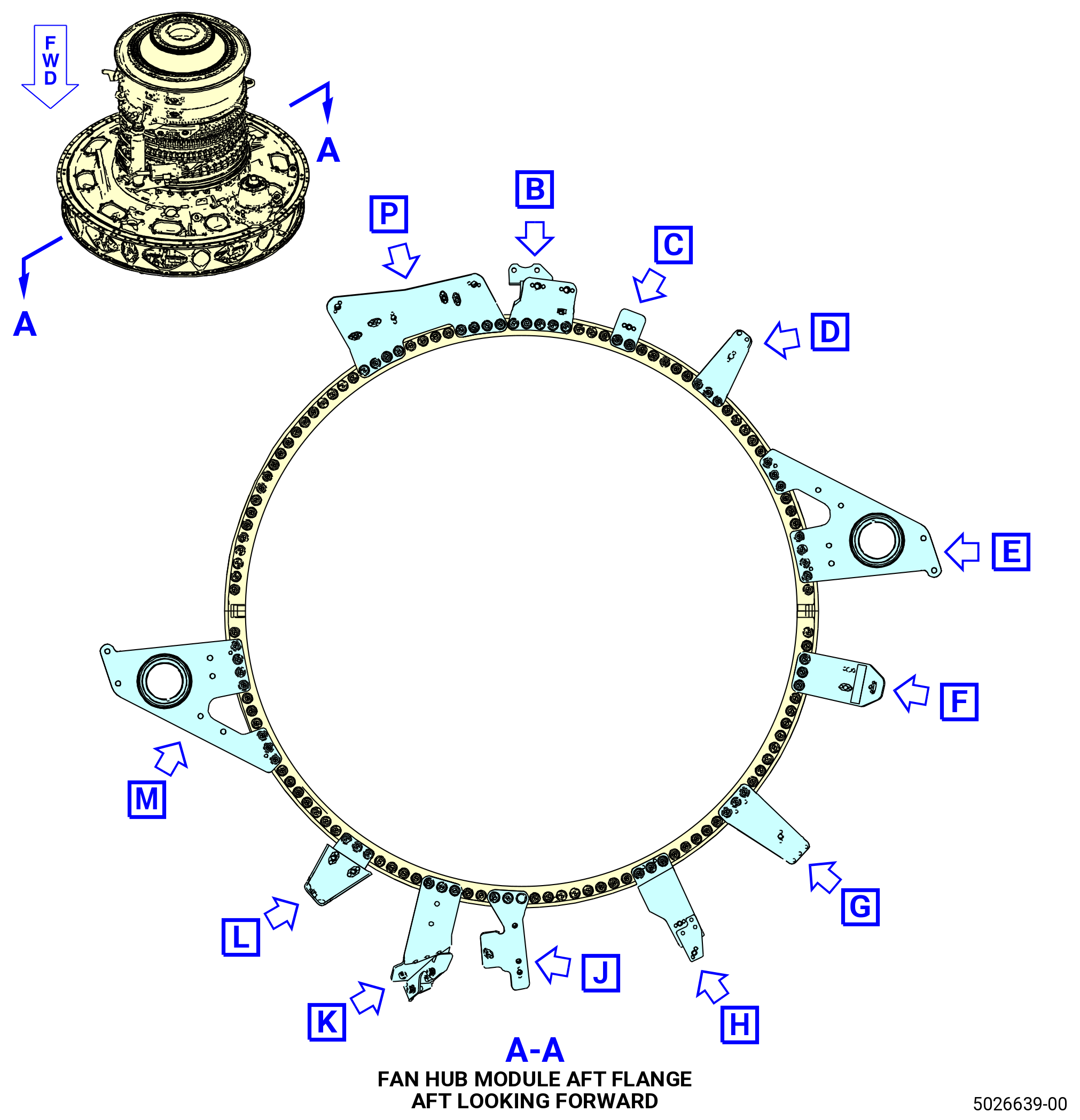
| (7) | Before the assembly normalizes, attach the HPC module assembly forward flange to the fan hub module assembly (25-010) (SIN 00102). Refer to Figure 1018 and do as follows: |
| (a) | Install the bolts (25-290) (SIN 07020), the spacers (25-300) (SIN 07070), and the self-locking nuts (25-280) (SIN 07040) or (25-281) (SIN 07040) in boltholes No. 5, 28, 35, 45, 60, 69, 81, 93, 113, and 124 with the bolthead AFT and the spacer under the bolthead. |
| (b) | Deleted. |
| (c) | Torque the self-locking nuts (25-280) or (25-281) in a criss-cross pattern to 276-324 lb in. (31.2-36.6 N.m). |
| (d) | Let the assembly normalize and release the pressure applied by the 11C3156hydraulic clamp. |
| (e) | Remove the 11C3156hydraulic clamp from the HPC module assembly and the fan hub module assembly. |
|
|
|
|
|
|
|
|
| Subtask 72-00-02-430-678 |
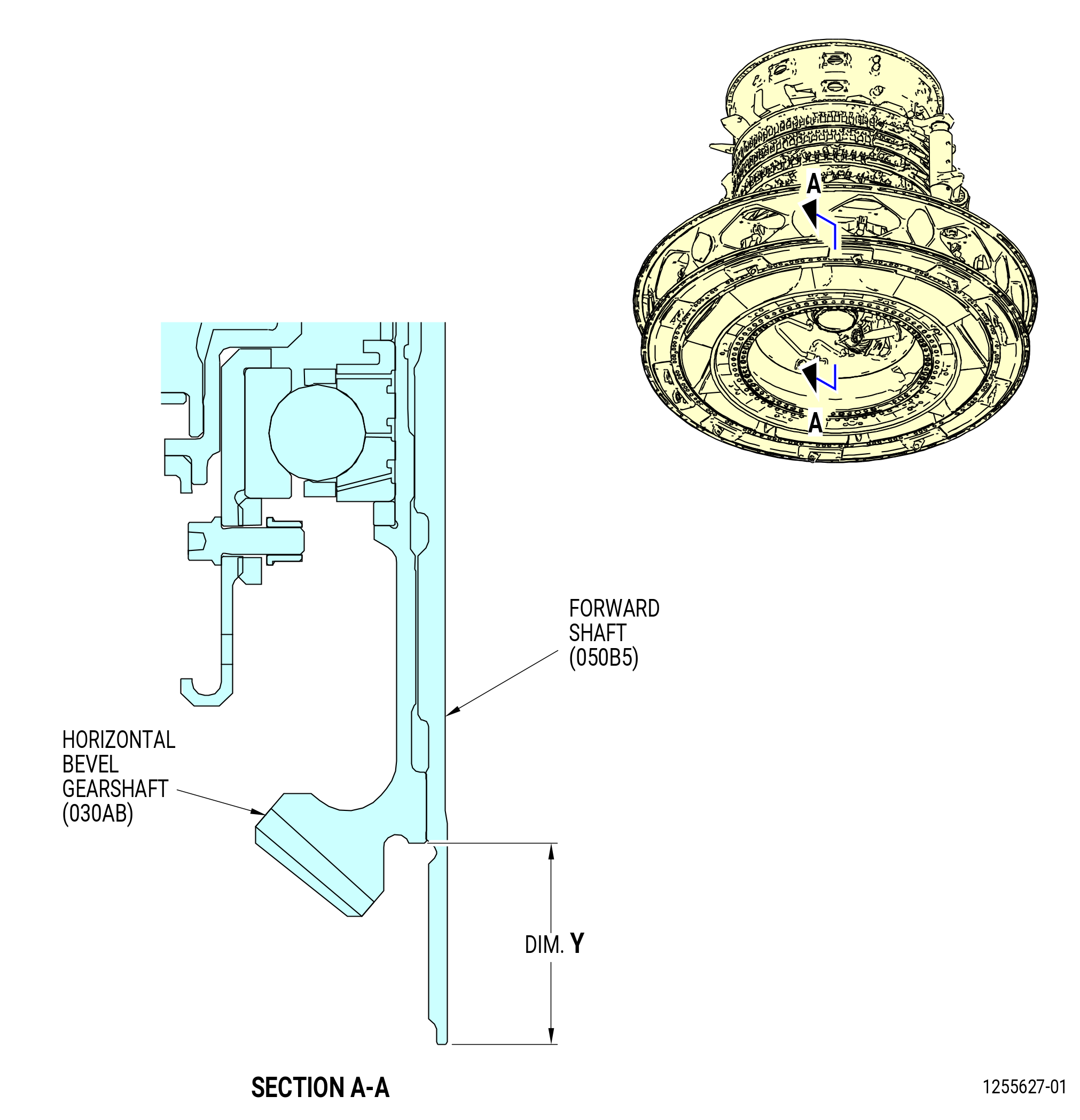
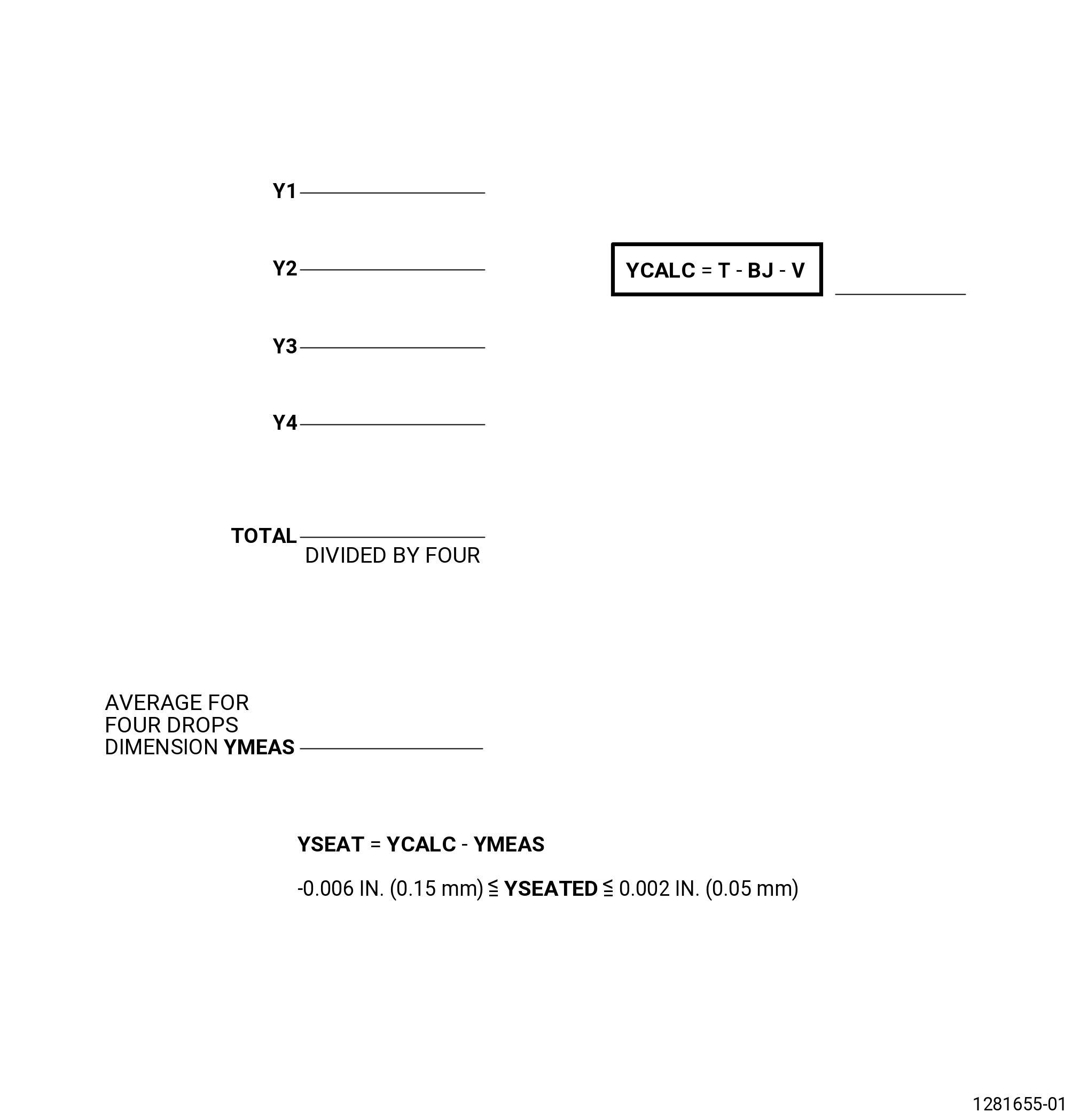
| (8) | Measure Dim. Y as follows. Refer to Figure 1019. |
| (a) | Calculate the preliminary seating for YCALC (YCALC = T - BJ - V) and record. |
| 1 | Refer to TASK 72-30-00-440-801 (72-30-00, Assembly 001) for Dim. T and Dim. V. |
| 2 | Refer to Subtask 72-00-02-430-666 (paragraph 3.E.) for Dim. BJ. |
| (b) | Measure the distance from the forward flange of the forward shaft (050B5) to the forward flange of the horizontal bevel gearshaft (030AB) and record as Y1. Refer to Figure 1020. |
| (c) | Measure the distance from the forward flange of the forward shaft to the forward flange of the horizontal bevel gearshaft at a equally spaced location 90 degrees apart from Y1 and record as Y2. |
| (d) | Measure the distance from the forward flange of the forward shaft to the forward flange of the horizontal bevel gearshaft at a equally spaced location 90 degrees apart from Y2 and record as Y3. |
| (e) | Measure the distance from the forward flange of the forward shaft to the forward flange of the horizontal bevel gearshaft at a equally spaced location 90 degrees apart from Y3 and record as Y4. |
| (f) | Calculate the average for Y1, Y2, Y3, and Y4 and record as Dim. YMEAS. |
| (g) | Compare the calculated seating Dim. YCALC to the measured seating Dim. YMEAS. |
| (h) | YSEAT must be equal to YCALC minus YMEAS. YSEAT must be more than minus 0.006 inch (0.15 mm) and less than 0.002 (0.05 mm). |
| Subtask 72-00-02-430-680 |
| (9) | Install the brackets on the fan hub module assembly (25-010) (SIN 00102) and the HPC module assembly flange. If necessary, remove the bolts that were installed to install the HPC module assembly in Subtask 72-00-02-430-677 (paragraph J.(6)). Refer to Figure 1018 and do as follows: |
| NOTE: |
|
| (a) | Apply C02-097 lubricant to the threads and friction surfaces of self-locking nuts (25-280) (SIN 07040) or (25-281) (SIN 07040). |
| (b) | Install the bolts (07023) and self-locking nuts (25-280) or (25-281) as follows: |
| 1 | Install the bolts (07023) and self-locking nuts (25-280) or (25-281) in hole numbers 33, 34, 98, and 99 with the bolthead AFT. |
| 2 | If necessary, remove the bolts (073G3) and nuts (073L2) from the split-line at the 3:00 o'clock and the 9:00 o'clock position ALF. Tighten the self-locking nuts hand-tight. |
| 3 | If removed, install the bolts (073G3) and nuts (073L2) in the split-line. |
| 4 | Torque the four nuts (073L2) that were loosened to seat the fan hub module assembly (00102) to 552-648 lb in. (62.4-73.2 N.m). |
| Subtask 72-00-02-431-001 |
| * * * SB 72-0027( VSV Linkage Assembly Configuration 1 ) |
| (c) | Install the bolts (25-290) (SIN 07020), the spacers (25-300) (SIN 07070), and the self-locking nuts (25-280) (SIN 07040) or (25-281) (SIN 07040) in the boltholes 6, 7, 10 thru 14, 19 thru 22, 27, 29, 39 thru 44, 46, 50 thru 54, 58, 59, 61 thru 65, 70, 74 thru 77, 82 thru 87, 92, 94, 100, 102 thru 112, 113 thru 118, 123, 125, and 126 with the boltheads AFT and the spacer under the bolthead. Hand-tighten the self-locking nuts. |
| * * * END SB 72-0027 |
| Subtask 72-00-02-431-002 |
| * * * PRE SB 72-0027( VSV Linkage Assembly Configuration 2 ) |
| (c).A. | Install the bolts (25-290) (SIN 07020), the spacers (25-300) (SIN 07070), and the self-locking nuts (25-280) (SIN 07040) or (25-281) (SIN 07040) in the boltholes 6, 7, 10 thru 14, 19 thru 22, 26, 28, 39 thru 44, 46, 50 thru 54, 58, 59, 61 thru 65, 70, 74 thru 77, 82 thru 87, 91, 92, 100, 102 thru 112, 113 thru 118, 123, 125, and 126 with the boltheads AFT and the spacer under the bolthead. Hand-tighten the self-locking nuts. |
| * * * END PRE SB 72-0027 |
| Subtask 72-00-02-431-003 |
| * * * SB 72-0027( VSV Linkage Assembly Configuration 3 ) |
| (c).B. | Install the bolts (25-290) (SIN 07020), the spacers (25-300) (SIN 07070), and the self-locking nuts (25-280) (SIN 07040) or (25-281) (SIN 07040) in the boltholes 6, 7, 10 thru 14, 19 thru 22, 26, 28, 39 thru 44, 46, 50 thru 54, 58, 59, 61 thru 65, 70, 74 thru 77, 82 thru 87, 91, 92, 100, 102 thru 112, 113 thru 118, 123, 125, and 126 with the boltheads AFT and the spacer under the bolthead. Hand-tighten the self-locking nuts. |
| * * * END SB 72-0027 |
| Subtask 72-00-02-431-004 |
| * * * SB 72-0066( Fire Extinguishing System without Fire Suppression Tubes ) |
| (d) | Install the bolts (25-290) (SIN 07020), the spacers (25-300) (SIN 07070), and the self-locking nuts (25-280) (SIN 07040) or (25-281) (SIN 07040) in the boltholes 78 thru 80 with the boltheads AFT and the spacer under the bolthead. Hand-tighten the self-locking nuts. |
| NOTE: |
|
| * * * END SB 72-0066 |
| Subtask 72-00-02-431-005 |
| * * * PRE SB 73-0099( ) |
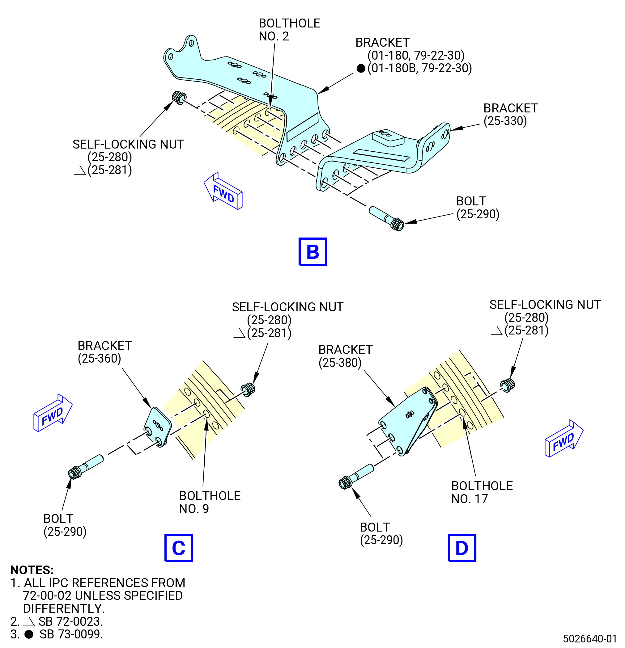
| (e) | Install the bracket (01-180 , 79-22-30) (SIN 38117) on the aft side of the flange and install the bracket (25-330) (SIN 63711) aft the bracket (01-180 , 79-22-30) (SIN 38117) in boltholes No. 131 and 1 thru 4 with the bolts (25-290) (SIN 07020) and the self-locking nuts (25-280) (SIN 07040) or (25-281) (SIN 07040) and the bolthead aft. Hand-tighten the self-locking nuts. |
| * * * END PRE SB 73-0099( ) |
| * * * SB 73-0099( ) |
| (e).A. | Install the bracket (01-180B , 79-22-30) (SIN 38117) on the aft side of the flange and install the bracket (25-330) (SIN 63711) aft bracket (01-180B , 79-22-30) (SIN 38117) in boltholes No. 131 and 1 thru 4 with the bolts (25-290) (SIN 07020) and the self-locking nuts (25-280) (SIN 07040) or (25-281) (SIN 07040) and the bolthead aft. Hand-tighten the self-locking nuts. |
| * * * END SB 73-0099( ) |
| (f) | Install the bracket (38510) in boltholes No. 8 and 9 on the AFT side of the flange with the bolts (07020) and self-locking nuts (25-280) or (25-281) and the bolthead aft. Hand-tighten the self-locking nuts. |
| (g) | Install the support bracket (59014) in boltholes No. 15 thru 17 on the AFT side of the flange with the bolts (07020) and self-locking nuts (25-280) or (25-281) and the bolthead aft. Hand-tighten the self-locking nuts. |
| Subtask 72-00-02-430-787 |
| * * * SB 72-0027( VSV Linkage Assembly Configuration 1 ) |
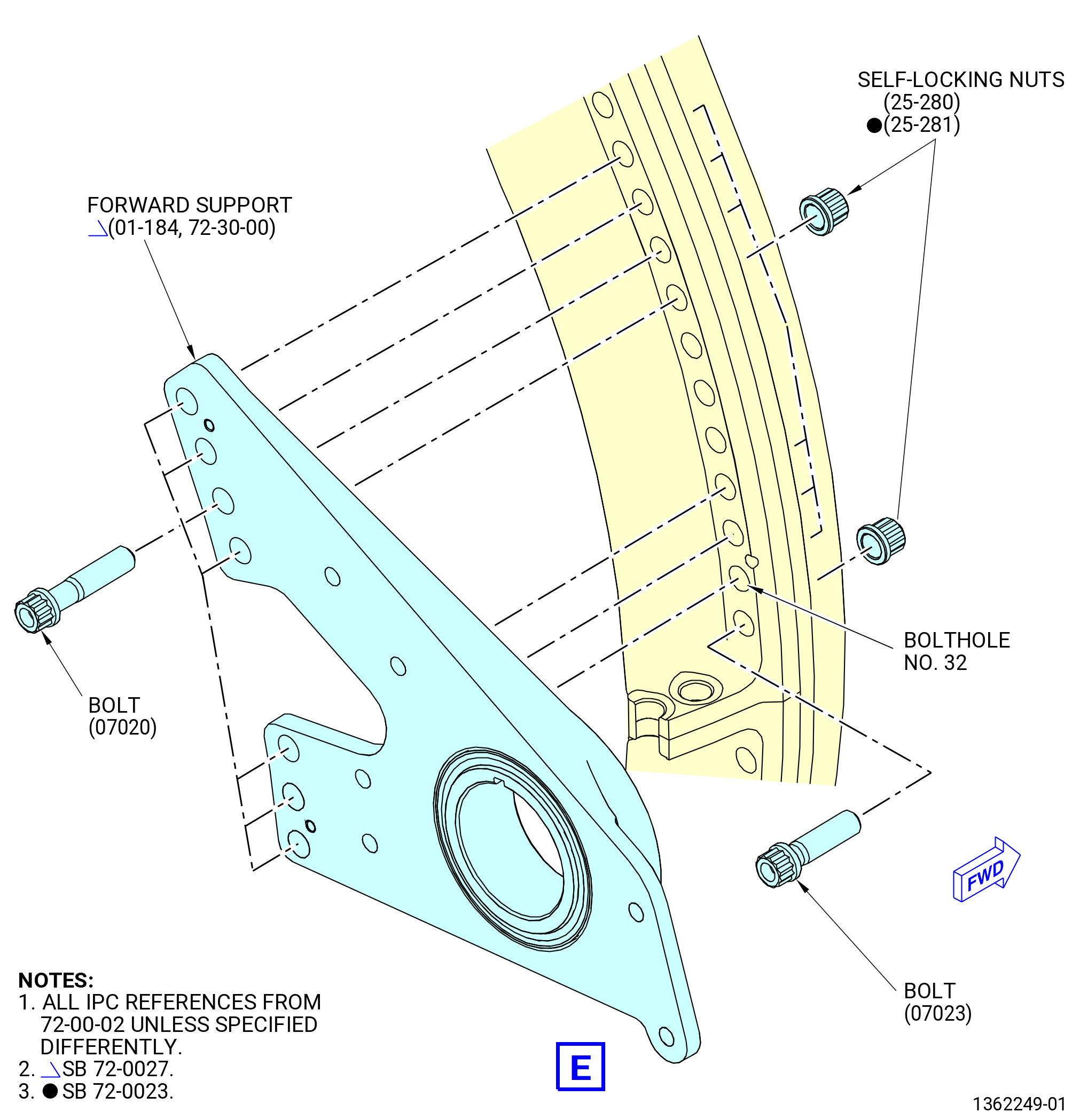
| (h) | Install the forward support (01-184 , 72-30-00) of the VSV torque shaft linkage in boltholes No. 23 thru 26 and 30 thru 32 on the AFT side of the flange with bolts (07020), bolthead aft, and self-locking nuts (25-280) or (25-281). Hand-tighten the self-locking nuts. |
| * * * END SB 72-0027 |
| Subtask 72-00-02-430-788 |
| * * * PRE SB 72-0027( VSV Linkage Assembly Configuration 2 ) |
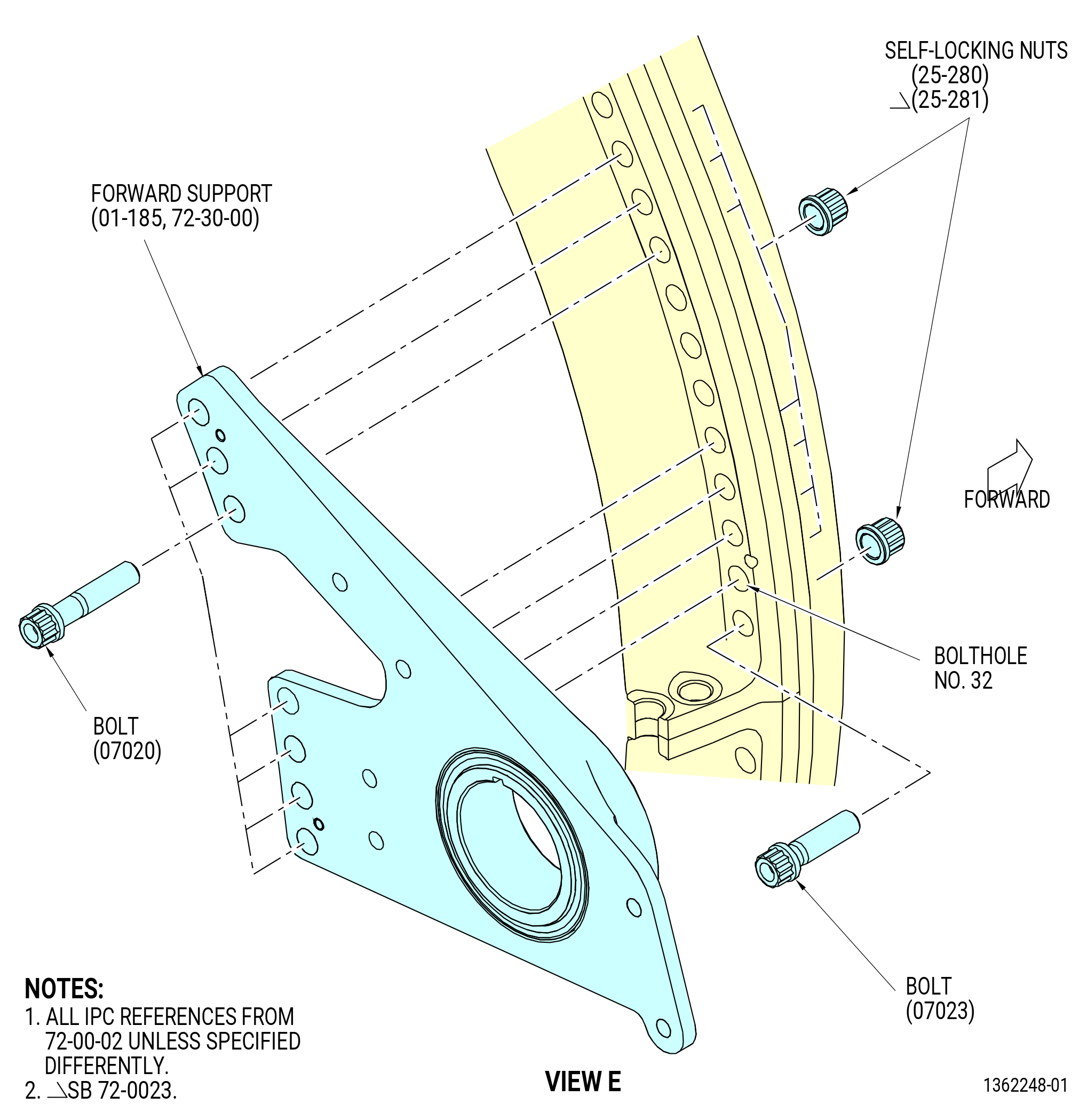
| (h).A. | Install the forward support (01-185 , 72-30-00) of the VSV torque shaft linkage in boltholes No. 23 thru 25 and 29 thru 32 on the AFT side of the flange with bolts (07020), bolthead aft, and self-locking nuts (25-280) or (25-281). Hand-tighten the self-locking nuts. |
| * * * END PRE SB 72-0027 |
| Subtask 72-00-02-430-811 |
| * * * SB 72-0027( VSV Linkage Assembly Configuration 3 ) |
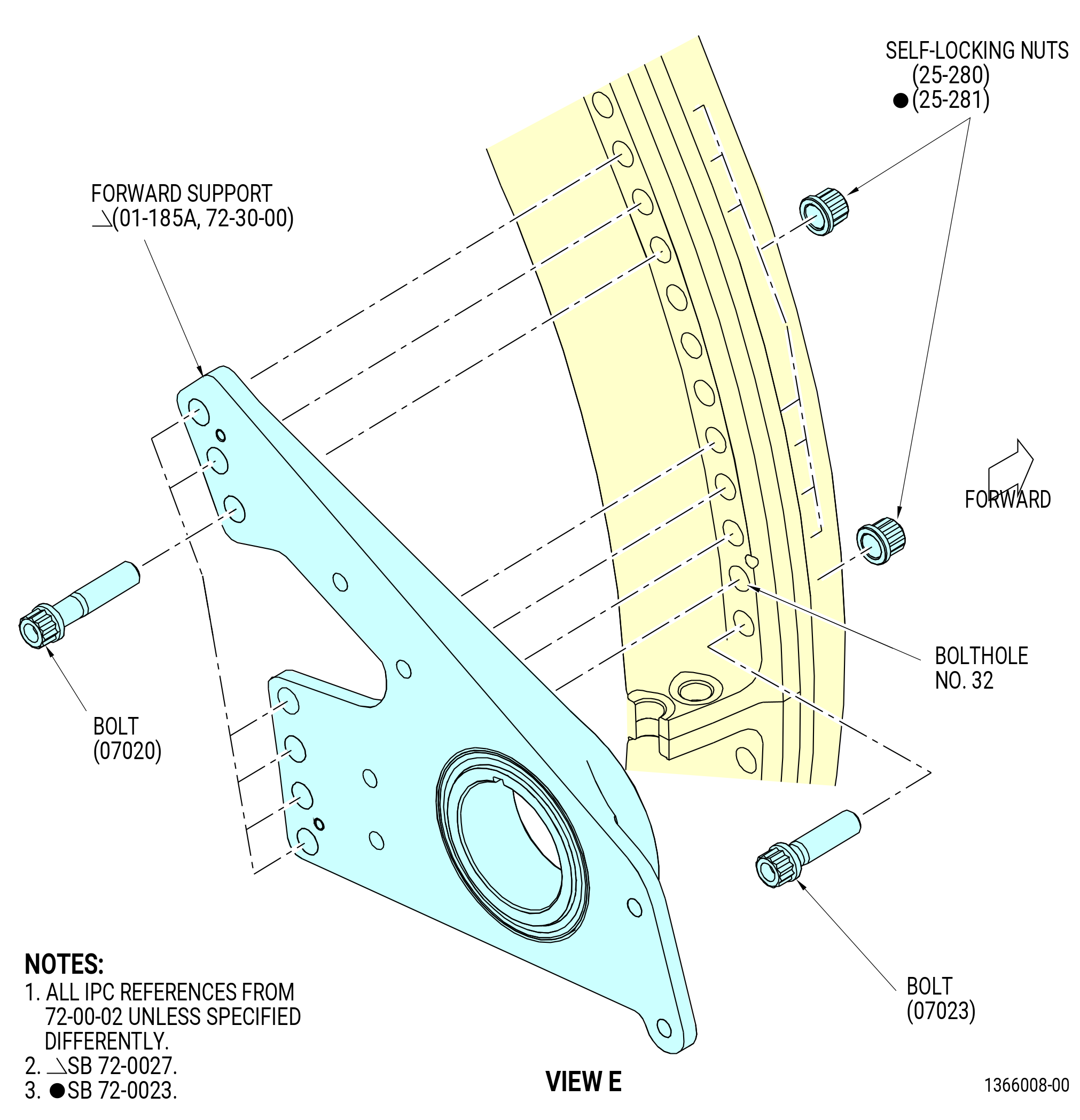
| (h).B. | Install the forward support (01-185A , 72-30-00) of the VSV torque shaft linkage in boltholes No. 23 thru 25 and 29 thru 32 on the AFT side of the flange with bolts (07020), bolthead aft, and self-locking nuts (25-280) or (25-281). Hand-tighten the self-locking nuts. |
| * * * END SB 72-0027 |
| Subtask 72-00-02-430-789 |
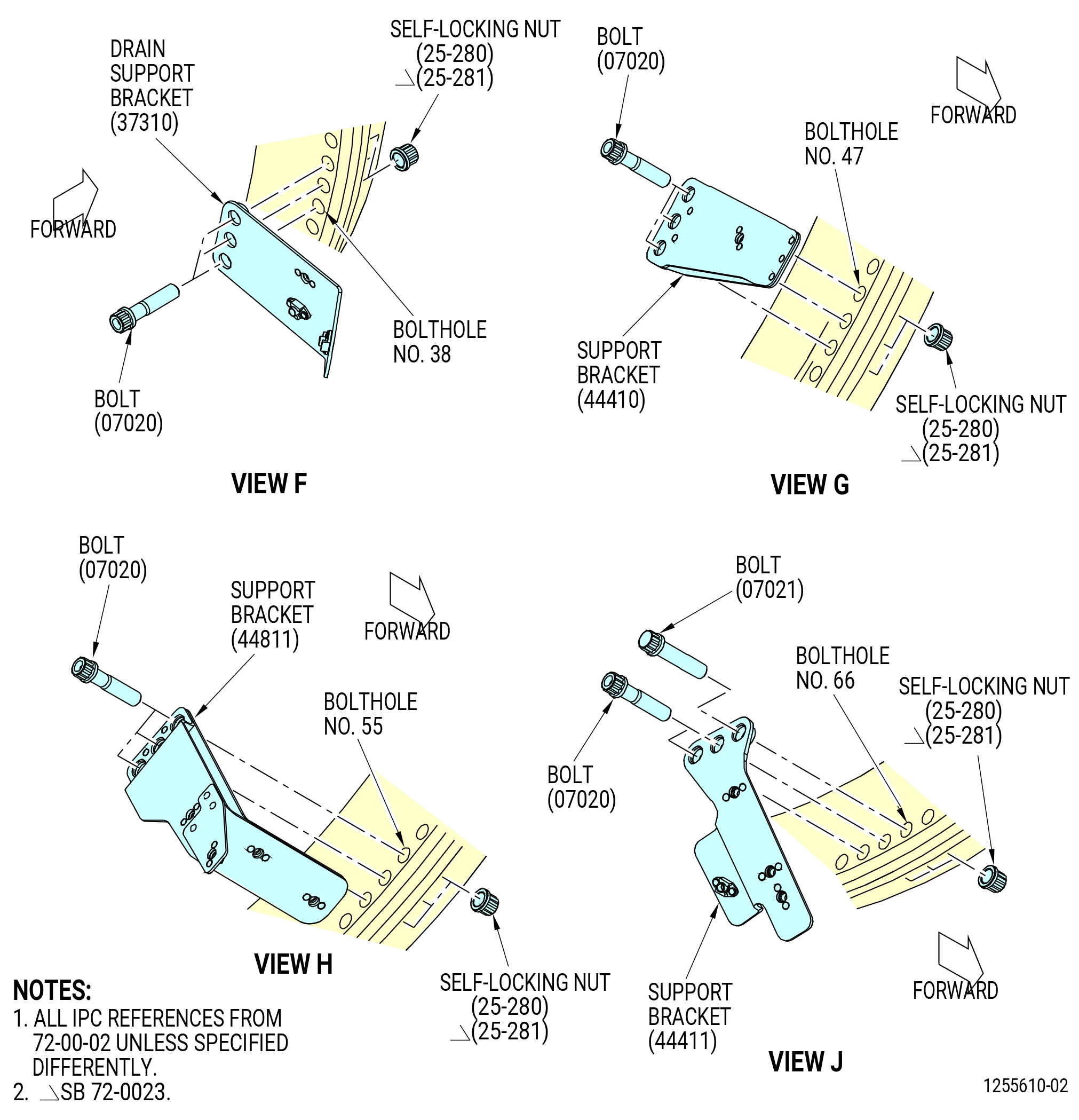
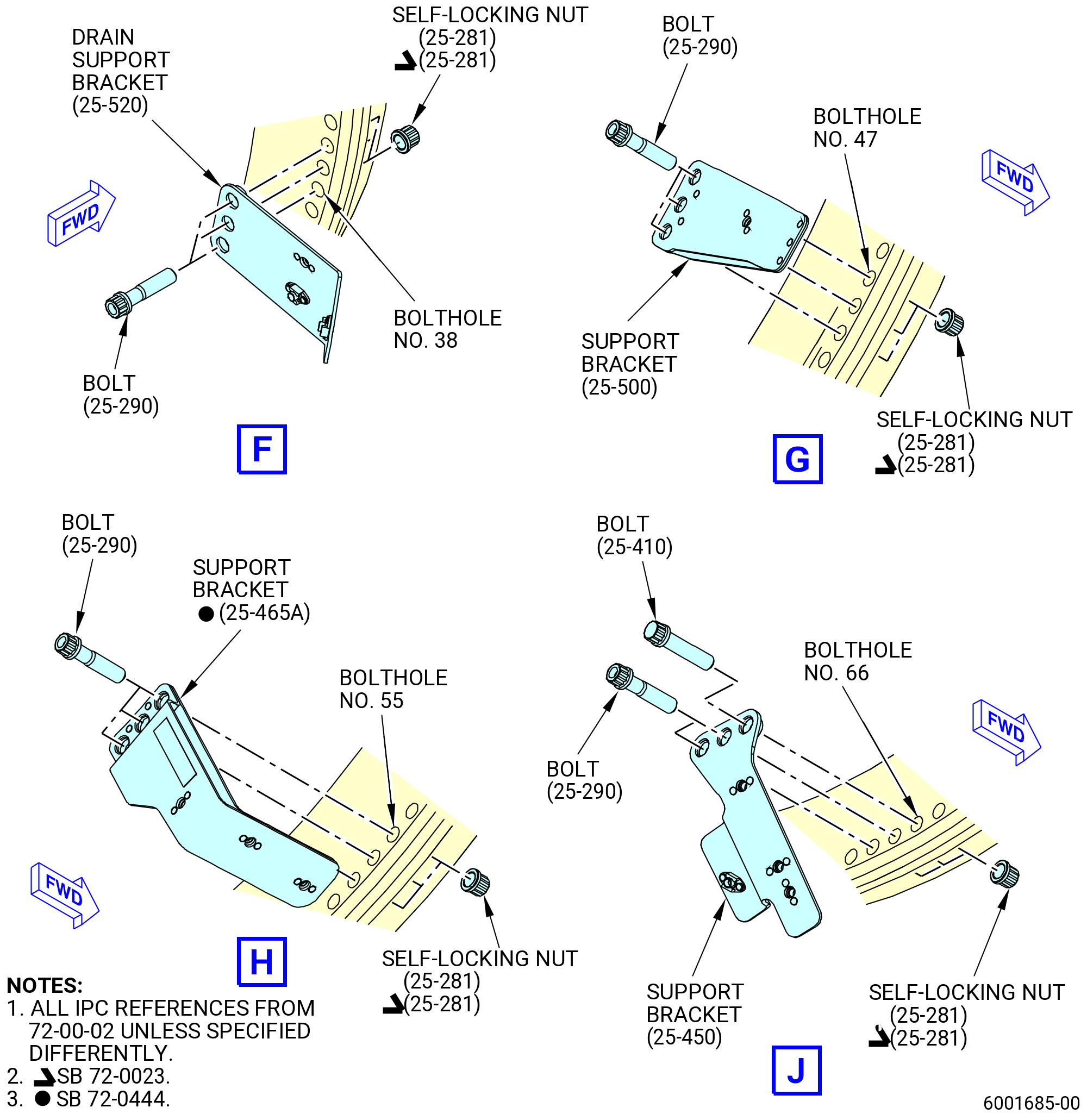
| (i) | Install the drain support bracket (37310) in boltholes No. 36 thru 38 on the AFT side of the flange with the bolts (07020) and self-locking nuts (25-280) or (25-281) and the bolthead aft. Hand-tighten the self-locking nuts. |
| (j) | Install the support bracket (44410) in boltholes No. 47 thru 49 on the AFT side of the flange with bolts (07020) and self-locking nuts (25-280) or (25-281) and the bolthead AFT. Hand-tighten the self-locking nuts. |
| (k) | Install the support bracket (25-465) (SIN 44811) in boltholes No. 55 thru 57 on the AFT side of the flange with the bolts (25-290) (SIN 07020) and self-locking nuts (25-280) (SIN 07040) or (25-281) (SIN 07040) and the bolthead AFT. Hand-tighten the self-locking nuts. |
| (l) | Install the support bracket (44411) in boltholes No. 66 thru 68 on the AFT side of the flange as follows: |
| 1 | Remove the bolt (25-410) (SIN 07021), the spacer (25-300) (SIN 07070), and the self-locking nut (25-280) (SIN 07040) or (25-281) (SIN 07040) from bolthole No. 66 used previously as a guide. |
| 2 | Install the bolts (07020) and self-locking nuts (25-280) or (25-281) and the bolthead AFT in boltholes No. 67 and 68. Hand-tighten the self-locking nuts. |
| 3 | Install the bolt (07021) and self-locking nut (25-280) or (25-281) and the bolthead AFT in bolthole No. 66. Hand-tighten the self-locking nut. |
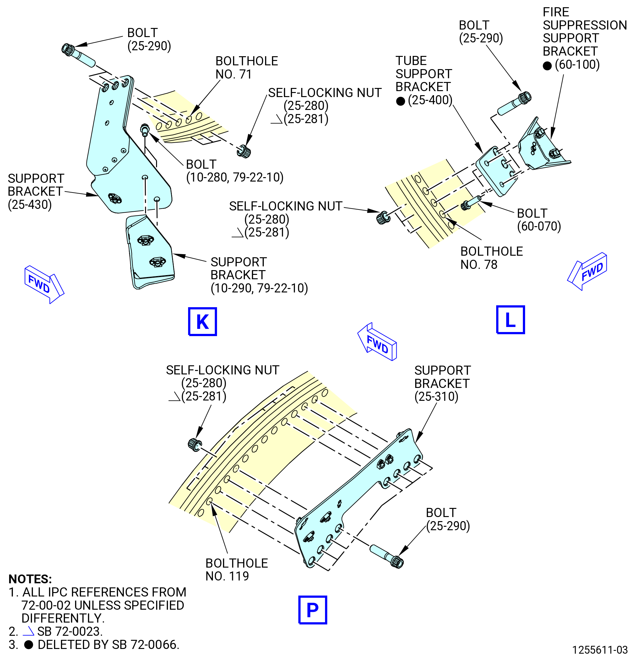
| (m) | Install the support brackets (44413, 44414) in boltholes No. 71 thru 73 on the AFT side of the flange as follows: |
| 1 | Attach the support bracket (44413) with the bolts (07020) and self-locking nuts (25-280) or (25-281) and the boltheads aft. Hand-tighten the self-locking nuts. |
| 2 | Attach the support bracket (10-290 , 79-22-10) (SIN 44414) to the support bracket (25-430) (SIN 44413) with the bolts (10-280 , 79-22-10) (SIN 44421). |
| 3 | Torque the bolts (44421) to 106-124 lb in. (12.0-14.0 N.m). |
| Subtask 72-00-02-430-867 |
| * * * PRE SB 72-0066( Fire Extinguishing System with Fire Suppression Tubes ) |
| (n) | Install the tube support bracket (25-400) (SIN 9931C) and the fire suppression support bracket (60-100) (SIN 99018) in boltholes No. 78 thru 80 on the AFT side of the flange as follows: |
| NOTE: |
|
| 1 | Attach the tube support bracket (25-400) (SIN 9931C) with the bolts (25-290) (SIN 07020) and self-locking nuts (25-280) (SIN 07040) or (25-281) (SIN 07040) and the boltheads aft. Hand-tighten the self-locking nuts. |
| 2 | Attach the fire suppression support bracket (60-100) (SIN 99018) to the tube support bracket (25-400) (SIN 9931C) with bolts (60-070) (SIN 99326). |
| 3 | Torque the bolts (60-070) (SIN 99326) to 106-124 lb in. (12.0-14.0 N.m). |
| * * * END PRE SB 72-0066 |
| Subtask 72-00-02-430-790 |
| * * * SB 72-0027( VSV Linkage Assembly Configuration 1 ) |
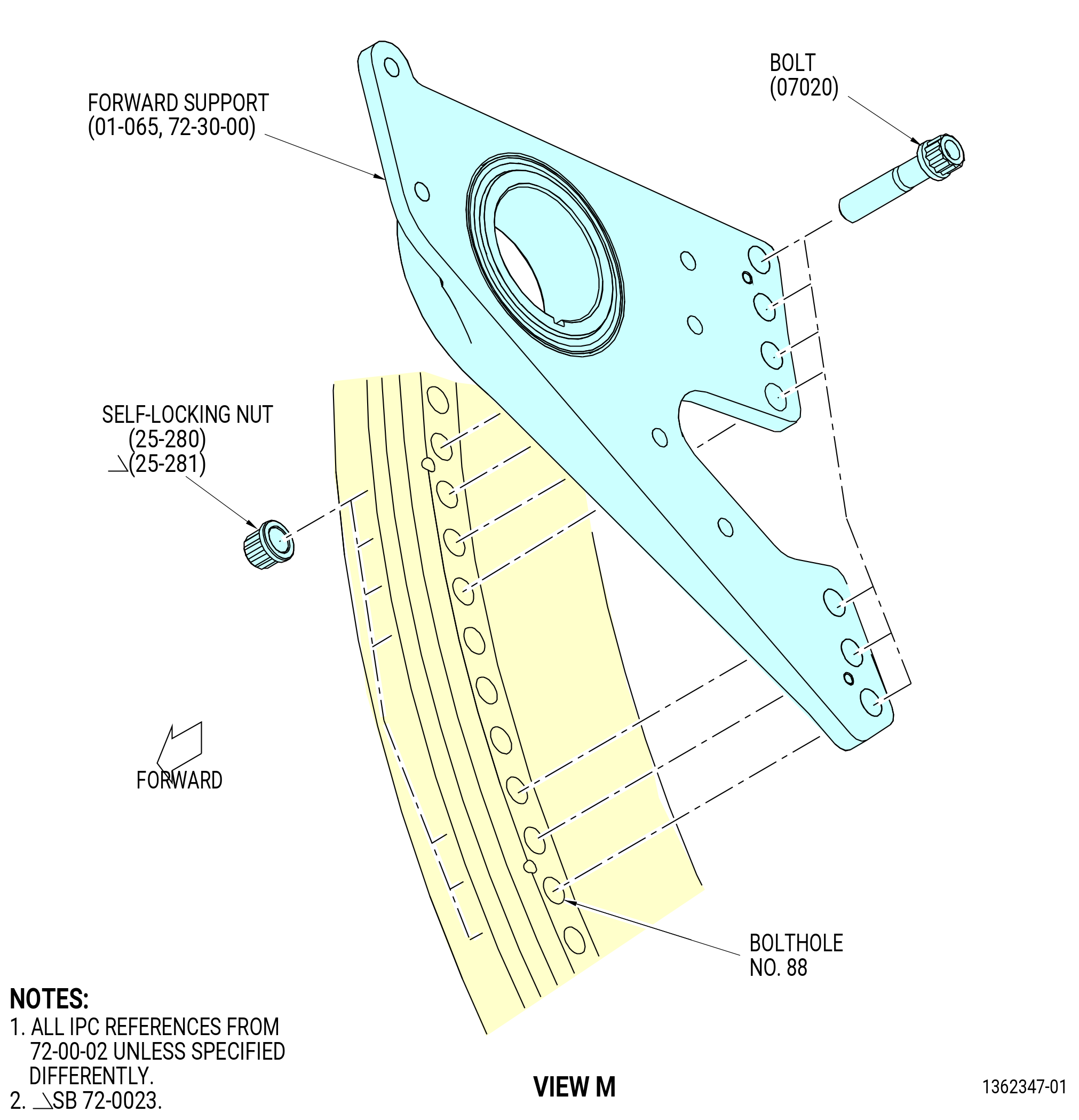
| (o) | Install the forward support (01-064 , 72-30-00) of the VSV torque shaft linkage in boltholes No. 88 thru 91 and 95 thru 97 on the aft side of the flange with bolts (07020), bolthead aft, and self-locking nuts (25-280) or (25-281). Hand-tighten the self-locking nuts. |
| * * * END SB 72-0027 |
| Subtask 72-00-02-430-791 |
| * * * PRE SB 72-0027( VSV Linkage Assembly Configuration 2 ) |
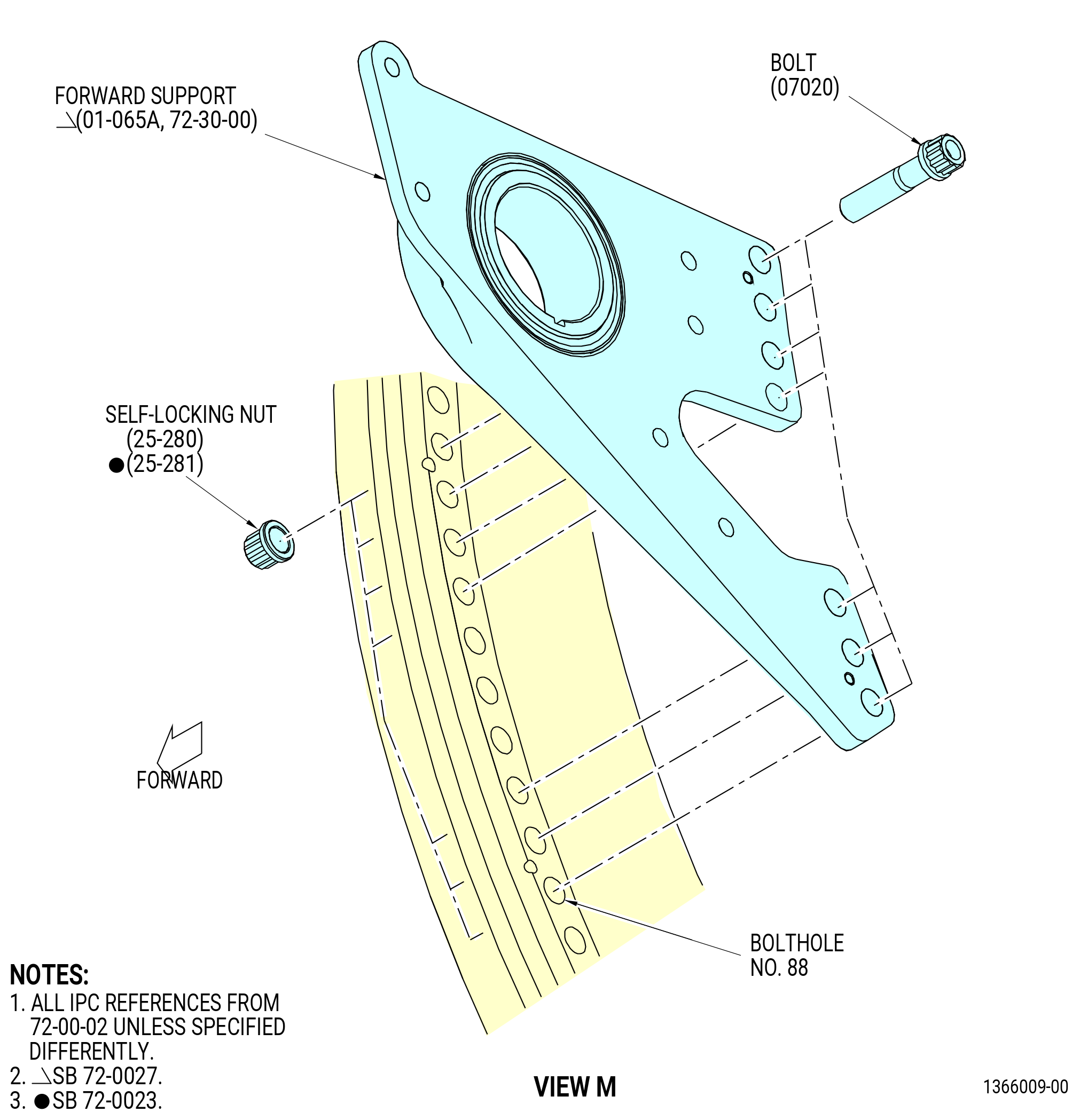
| (o).A. | Install the forward support (01-065 , 72-30-00) of the VSV torque shaft linkage in boltholes No. 88 thru 90 and 94 thru 97 on the aft side of the flange with bolts (07020), bolthead aft, and self-locking nuts (25-280) or (25-281). Hand-tighten the self-locking nuts. |
| * * * END PRE SB 72-0027 |
| Subtask 72-00-02-430-812 |
| * * * SB 72-0027( VSV Linkage Assembly Configuration 3 ) |
| (o).B. | Install the forward support (01-065A , 72-30-00) of the VSV torque shaft linkage in boltholes No. 88 thru 90 and 94 thru 97 on the aft side of the flange with bolts (07020), bolthead aft, and self-locking nuts (25-280) or (25-281). Hand-tighten the self-locking nuts. |
| * * * END SB 72-0027 |
| Subtask 72-00-02-430-792 |
| (p) | Install the support bracket (63111) in boltholes No. 119 thru 122 and 127 thru 130 on the AFT side of the flange with the bolts (07020) and self-locking nuts (25-280) or (25-281) and boltheads aft. Hand-tighten the self-locking nuts. |
| (q) | Torque the self-locking nuts as follows: |
| 1 | Torque the self-locking nut (25-280) or (25-281) in bolthole No. 66 to 368-432 lb in. (41.6-48.8 N.m). |
| 2 | Torque 14 self-locking nuts (25-280) or (25-281) in a equally spaced criss-cross pattern to 276-324 lb in. (31.2-36.6 N.m). |
| 3 | Make sure there is no clearance between the flanges. Use a 0.001 inch (0.03 mm) gauge to check the clearance between the flanges. |
| 4 | Torque all the self-locking nuts (25-280) or (25-281) in a circular pattern to 368-432 lb in. (41.6-48.8 N.m). |
| Subtask 72-00-02-430-681 |
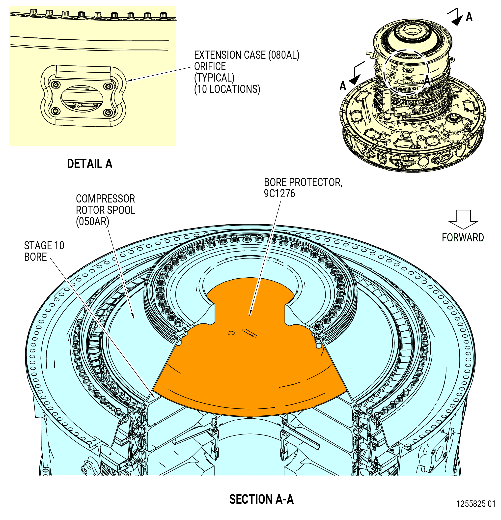
| L. | Install the 9C1276 bore protector on the stage 10 bore of the compressor rotor spool (050AR). Refer to Figure 1021. |
| M. | Mark to identify that the No. 4 and 7 stage HPC case holes are not installed on the compressor extension case (080AL). Use a non-conformance tag on the bolthole or put tape on the orifice hole. Refer to Figure 1021. |
| Subtask 72-00-02-430-682 |
| N. | If necessary, install the 11C3066 lift/turn fixture on the compressor extension case (10-080 , 72-30-00) (SIN 080AL) of the propulsor assembly aft end. Refer to Subtask 72-00-02-430-670 (paragraph 3.H.(1)A.) and Figure 1011. |
| Subtask 72-00-02-430-683 |
| O. | Remove the 11C3133 lock fixture from the TGB (03200). Refer to Figure 1015. |
| Subtask 72-00-02-430-845 |
| * * * SB 72-0027( VSV Linkage Assembly Configuration 1 ) |
| P. | Do the IGV system adjustment and rigging for shimmed and separable clevis torque shaft linkage as follows: |
| NOTE: |
|
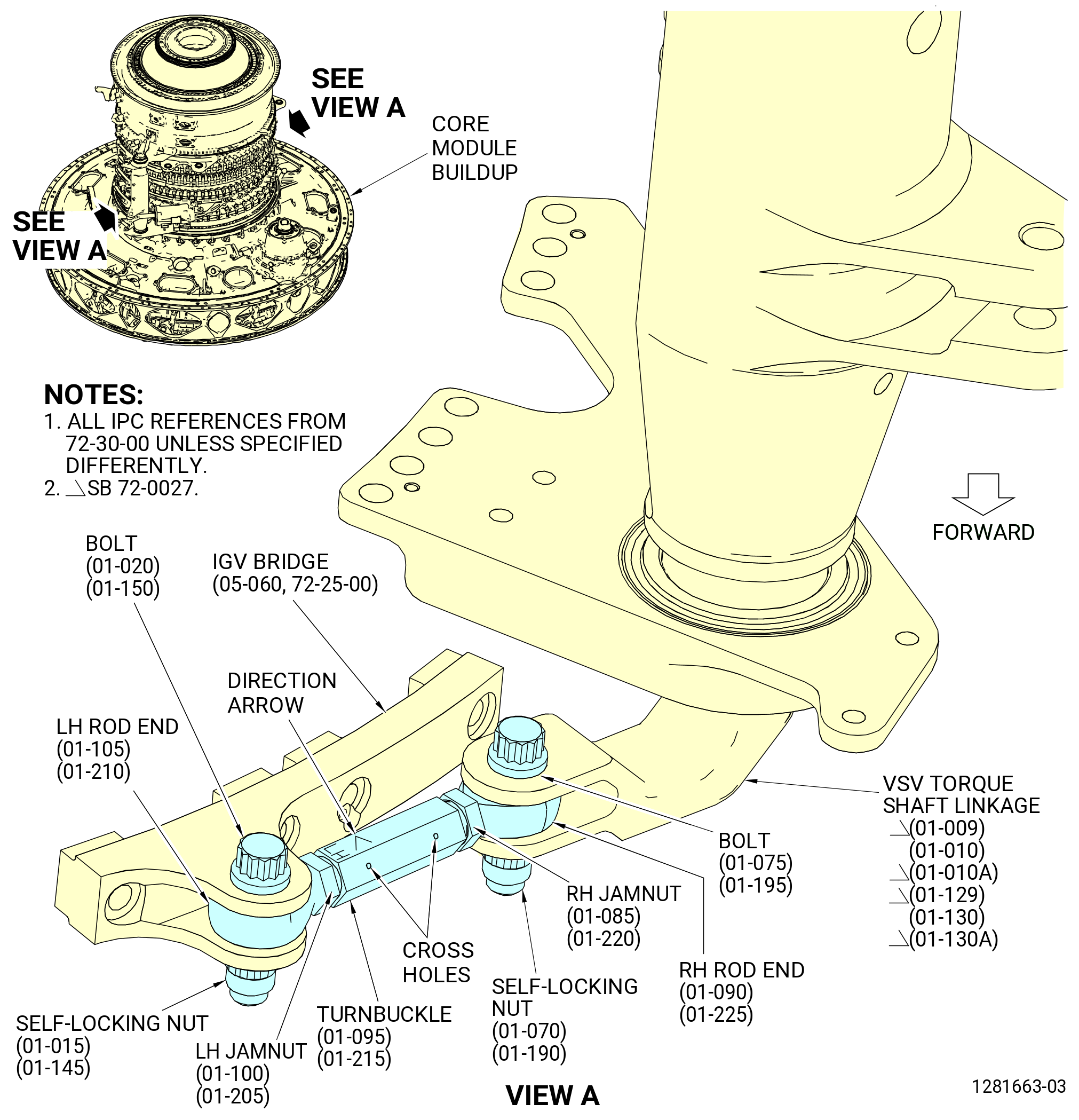
| (1) | Install the assembled left/right side IGV turnbuckles of the VSV torque shaft linkages (01-009 , 72-30-00) (SIN 07501) and (01-129 , 72-30-00) (SIN 07500) with the RH rod end, LH rod end, RH self-locking nut (RH jamnut), and the LH self-locking nut (LH jamnut) on the VSV torque shaft linkages and the IGV bridge at the 3:00 and the 9:00 o'clock positions as follows. Refer to Figure 1022. |
| (a) | Put the RH rod end (01-090 , 72-30-00) (SIN 07501-10) or (01-225 , 72-30-00) (SIN 07500-10) in the IGV shaft clevis. |
| (b) | Make sure that the direction arrow of the turnbuckle (01-095 , 72-30-00) (SIN 07501-12) or (01-215 , 72-30-00) (SIN 07500-12) is away from the VSV torque shaft linkages. The direction arrow will be on the turnbuckle end with the LH rod end (01-105 , 72-30-00) (SIN 07501-14) or (01-210 , 72-30-00) (SIN 07500-14). |
| NOTE: |
|
| (c) | Connect the RH rod end to the IGV shaft clevis with a bolt (01-075 , 72-30-00) (SIN 07501-9) or (01-195 , 72-30-00) (SIN 07500-9) and a self-locking nut (01-070 , 72-30-00) (SIN 07501-8) or (01-190 , 72-30-00) (SIN 07500-8). Put the bolthead aft. |
| (d) | Torque the self-locking nuts (01-070 , 72-30-00) (SIN 07501-8) or (01-190 , 72-30-00) (SIN 07500-8) to 460-540 lb in. (52.0-61.0 N.m). |
| (e) | Connect the LH rod end to the IGV bridge (05-060 , 72-25-00) (SIN 071E0) with a bolt (01-020 , 72-30-00) (SIN 07501-16) or (01-150 , 72-30-00) (SIN 07500-16) and a self-locking nut (01-015 , 72-30-00) (SIN 07501-15) or (01-145 , 72-30-00) (SIN 07500-15). Put the bolthead aft. |
| (f) | Torque the self-locking nuts (01-015 , 72-30-00) (SIN 07501-15) or (01-145 , 72-30-00) (SIN 07500-15) to 460-540 lb in. (52.0-61.0 N.m). |
| Subtask 72-00-02-430-846 |
| WARNING: |
|
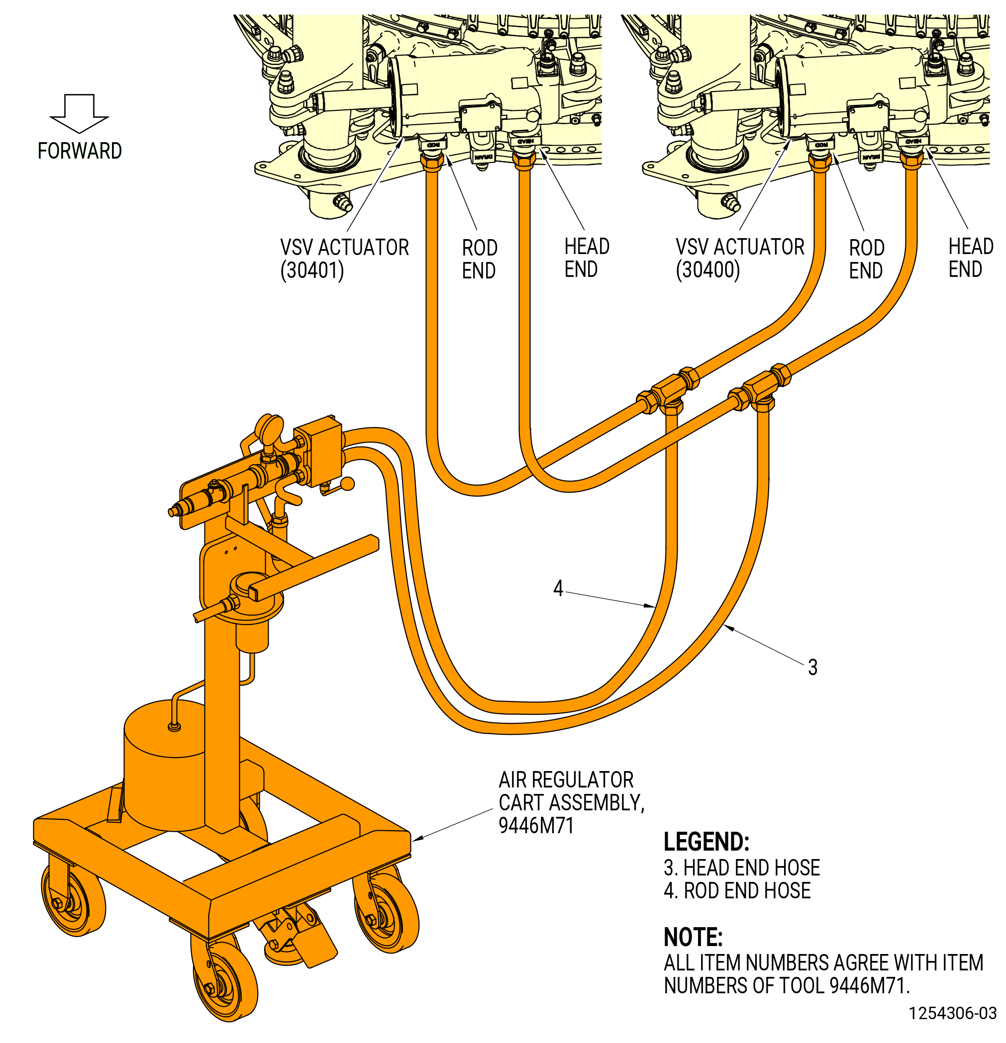
| (2) | Alternative Procedure Available. Connect the rod end hose (item 4) and head end hose (item 3) of the 9446M71 air regulator cart assembly to the head and rod fittings on the VSV actuators (30400, 30401). Use nitrogen gas with the 9446M71 air regulator cart assembly. Refer to Figure 1023. |
| Subtask 72-00-02-430-847 |
| WARNING: |
|
| (2).A. | Alternative Procedure. Connect the hoses between the head and rod fittings on the VSV actuators (30400, 30401) and the head and rod fittings on the 9461M39 hydraulic hand pump. Use C02-019 engine oil or C02-021 grade 1010 oil with the pump. Refer to Figure 1024. |
| Subtask 72-00-02-820-006 |
| (3) | Adjust the VSV actuation system for the IGV vanes as follows: |
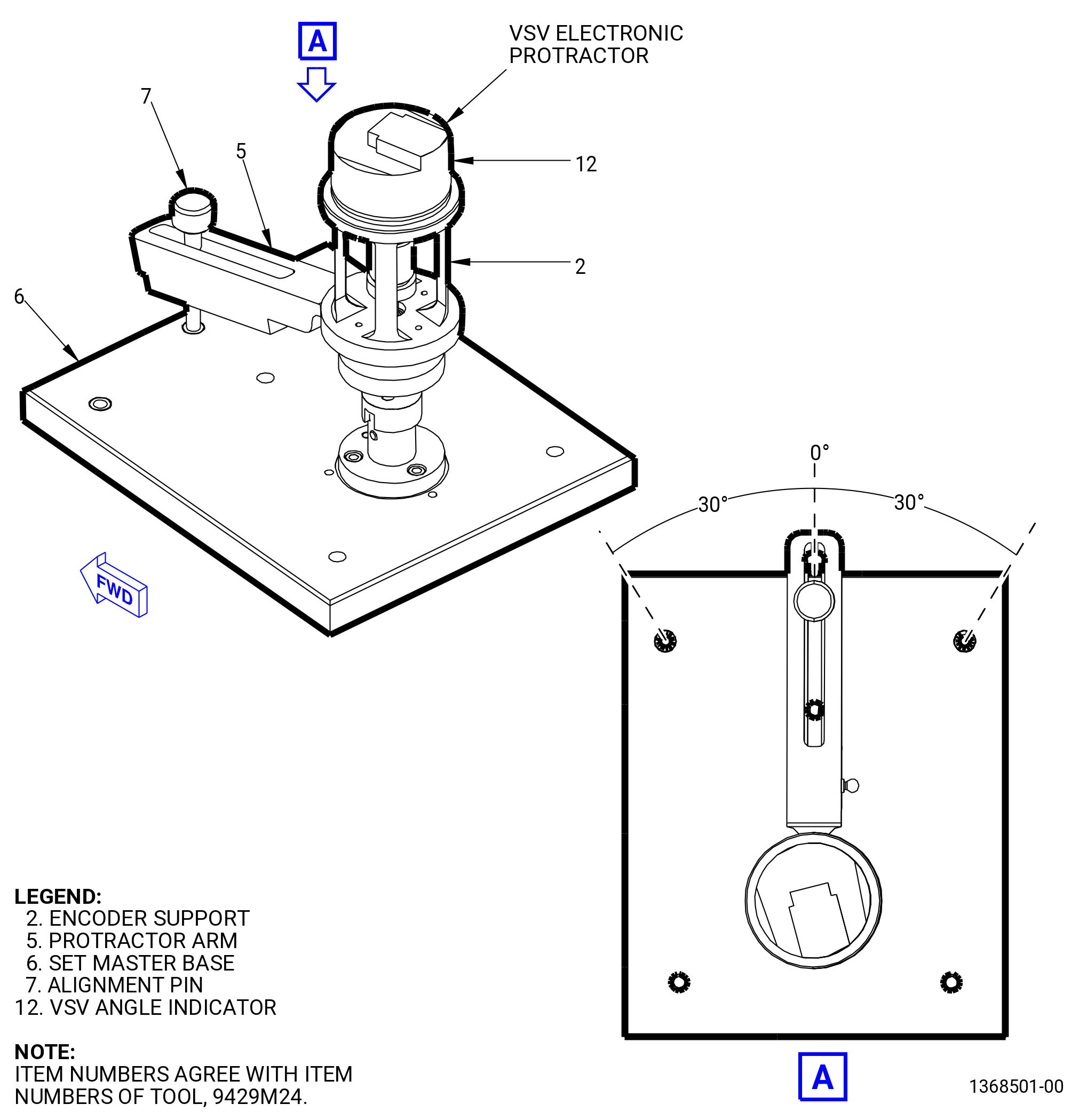
| (a) | Calibrate the VSV angle indicator (item 12) encoders A, B, C, and D of the 9429M24 VSV electronic protractor on the set master base (item 6) as follows. Refer to Figure 1025. |
| NOTE: |
|
| NOTE: |
|
| 1 | Install the VSV angle indicator encoder A of the 9429M24 VSV electronic protractor on the set master base (item 6). |
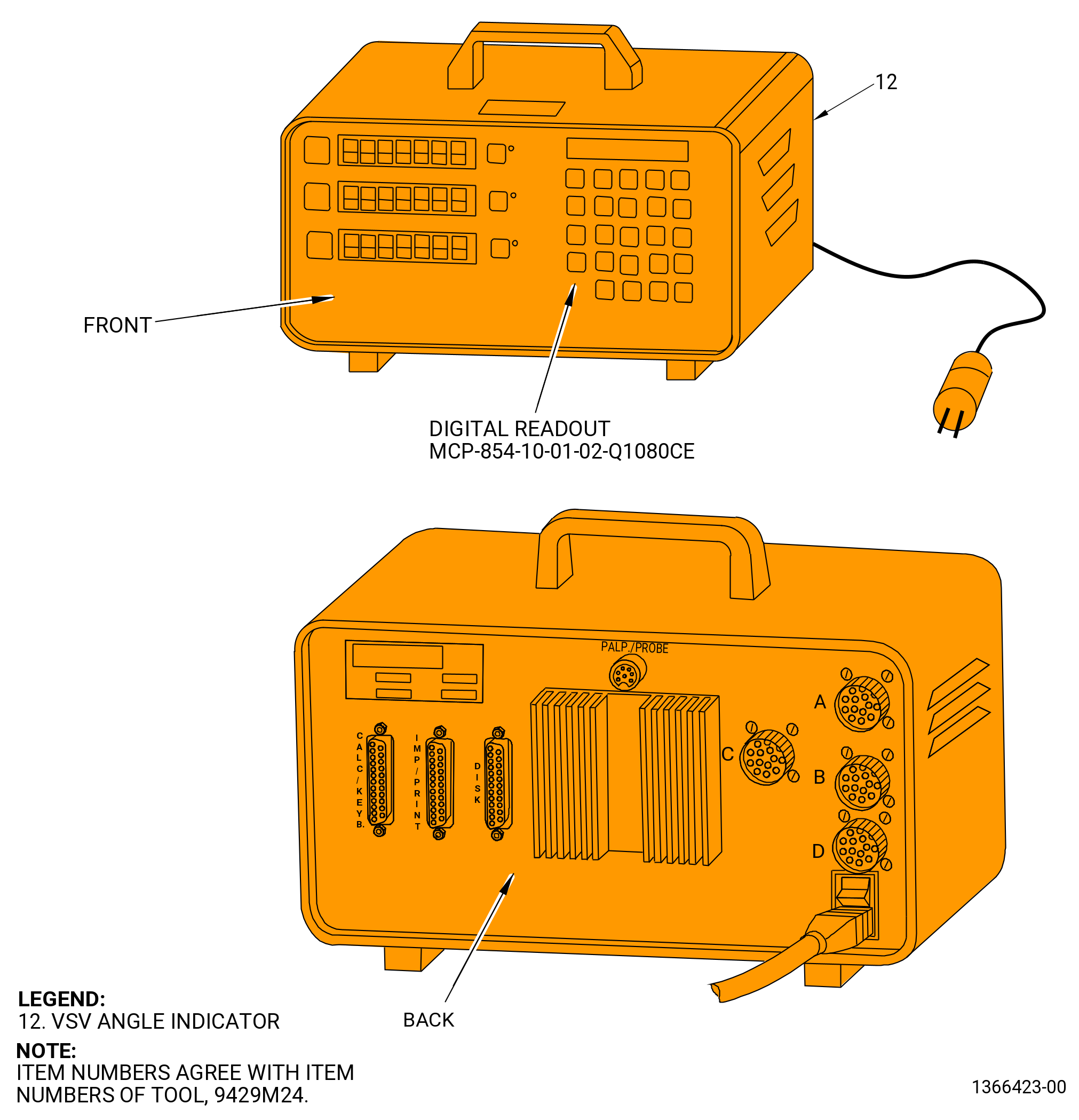
| 2 | Connect the VSV angle indicator encoder A to the channel A connector on the back of the VSV angle indicator. Refer to Figure 1026. |
| Subtask 72-00-02-430-859 |
| 3 | Turn on the power of the VSV angle indicator (item 12) digital readout of the 9429M24 VSV electronic protractor. |
| 4 | Press the F button on the front of the VSV angle indicator (item 12) digital readout to select channel A. |
| 5 | Move the protractor arm (item 5) to align with the zero mark on the set master base (item 6). Refer to Figure 1025. |
| 6 | Install the alignment pin (item 7) through the protractor arm (item 5) and into the set base master (item 6) to keep the alignment arm in place. |
| 7 | Press the zero button on the front of the VSV angle indicator (item 12) digital readout to zero the sensor. Read an angle of 00.0 degrees on the display. |
| 8 | Remove the alignment pin (item 7), turn the protractor arm (item 5) CW to the right and stop at the angle +30 degrees marked on the set master base (item 6). |
| 9 | Make sure that the digital indicator shows a positive number. |
| 10 | Install the alignment pin (item 7) through the protractor arm (item 5) and into the set master base (item 6) to keep the alignment arm in position. |
| 11 | Read the angle on the digital readout. Make sure that the reading is in the range of 29.8 to 30.2 degrees. |
| NOTE: |
|
| 12 | Remove the alignment pin (item 7), turn the protractor arm (item 5) CCW to the left and stop at the zero mark on the set master base (item 6). |
| 13 | Install the alignment pin (item 7) through the protractor arm (item 5) and into the set master base (item 6) to keep the alignment arm in place. |
| 14 | Read the angle of 00.0 degrees on the digital readout. |
| 15 | Remove the alignment pin (item 7) and turn the protractor arm (item 5) CCW to the left and stop at the angle -30 degrees mark on the set master base (item 6). |
| 16 | Install the alignment pin (item 7) through the protractor arm (item 5) and into the set master base (item 6) to keep the alignment arm in position. |
| 17 | Make sure that the digital indicator shows a negative number. |
| 18 | Read the angle on the VSV angle indicator (item 12) digital readout. Make sure that the reading is in the range of -29.8 to -30.2. |
| NOTE: |
|
| 19 | Remove the VSV electronic protractor from the set master base (item 6). |
| Subtask 72-00-02-430-848 |
| 20 | Do this procedure again for the remaining VSV electronic protractors B, C, and D on the digital readout channels B, C, and D. Refer to Subtask 72-00-02-820-006 (paragraph 3.P.(3)). |
| Subtask 72-00-02-430-849 |
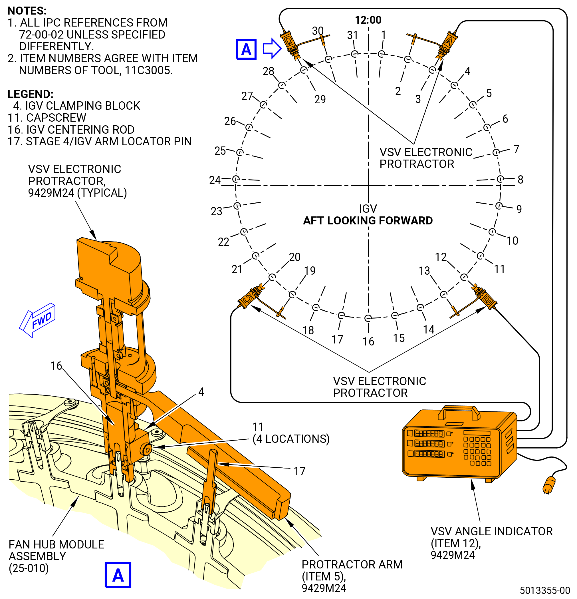
| (b) | Install the 11C3005 IGV/VSV tool kit on the IGV stator vane (IGV vane) (072A0) at positions 3, 12, 20, and 29 as follows. Refer to Figure 1027. |
| NOTE: |
|
| 1 | Put the four IGV centering rods (item 16) of the 11C3005 IGV/VSV tool kit on the IGV vanes (05-110 , 72-25-00) (SIN 072A0) at positions 3, 12, 20, and 29 in a CW direction ALF. |
| NOTE: |
|
| 2 | Put the IGV clamping block (item 4) at four locations on the IGV centering rod (item 16). Push to snap in position and tighten the setscrews. |
| 3 | Put the stage 4/IGV arm locator pin (item 17) on the IGV vane (05-110 , 72-25-00) (SIN 072A0) at positions 2, 13, 19, and 30. |
| Subtask 72-00-02-430-850 |
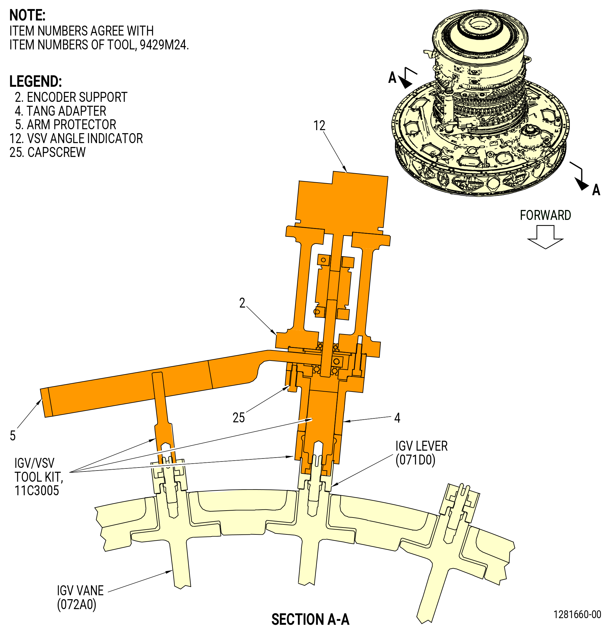
| (c) | Install the 9429M24 VSV electronic protractor on the 11C3005 IGV/VSV tool kit at the IGV vane (072A0) positions 3, 12, 20, and 29 as follows. Refer to Figure 1028. |
| 1 | If necessary, put the tang adapter (item 4) of the 9429M24 VSV electronic protractor on the IGV centering rod (item 16) of the 11C3005 IGV/VSV tool kit. Make sure that the tang adapter (item 4) engages the vane spindle flats. |
| 2 | Carefully align the arm protractor (item 5) of the 9429M24 VSV electronic protractor with the stage 4/IGV arm locator pin (item 17) of the 11C3005 IGV/VSV tool kit. |
| 3 | Move the arm protractor (item 5) of the 9429M24 VSV electronic protractor on the stage 4/IGV arm locator pin (item 17) of the 11C3005 IGV/VSV tool kit and align the notch on the tang adapter (item 4) of the 9429M24 VSV electronic protractor with the IGV clamping block (item 4) of the 11C3005 IGV/VSV tool kit. |
| Subtask 72-00-02-430-851 |
| (d) | Install the VSV angle indicator (item 12) calibrated encoders A, B, C, and D of the 9429M24 VSV electronic protractor on the fan hub module assembly (00102) IGV's as follows. Refer to Figure 1029. |
| 1 | Make sure that the side of the IGV clamping blocks (item 4) and the channel are aligned with the IGV arms. Install them on the IGV centering rods (item 16) of the 11C3005 IGV/VSV tool kit. Do not tighten the capscrews (item 11) of the clamping blocks. |
| 2 | Install the stage 4/IGV arm locator pin (item 17) on the IGV's at positions No. 2, 13, 19, and 30 in a CW direction ALF. Protractor arms must extend to 12 at top and 6 at bottom. |
| 3 | Put the VSV angle indicator (item 12) encoder A, B, C, and D of the 9429M24 VSV electronic protractor, the encoder support (item 2), and the arm support (item 5) on the IGV vanes No. 3, 12, 20, and 29. |
| Subtask 72-00-02-430-860 |
| CAUTION: |
|
| (e) | Slowly apply a pressure of 75.0-125.0 psig (517.1-861.8 kPa gage) maximum to the system with the 9446M71 air regulator cart assembly or 9461M39 hydraulic hand pump. |
| (f) | Carefully actuate the VSV linkage system through a full range of motion. Make sure the movement is smooth with no binding of the turnbuckles against their mating clevises and no interference or binding of other components. |
| Subtask 72-00-02-430-861 |
| (g) | Operate the system to the fully closed position (actuator rods extended) and the fully open position (actuator rods retracted) four times. |
| NOTE: |
|
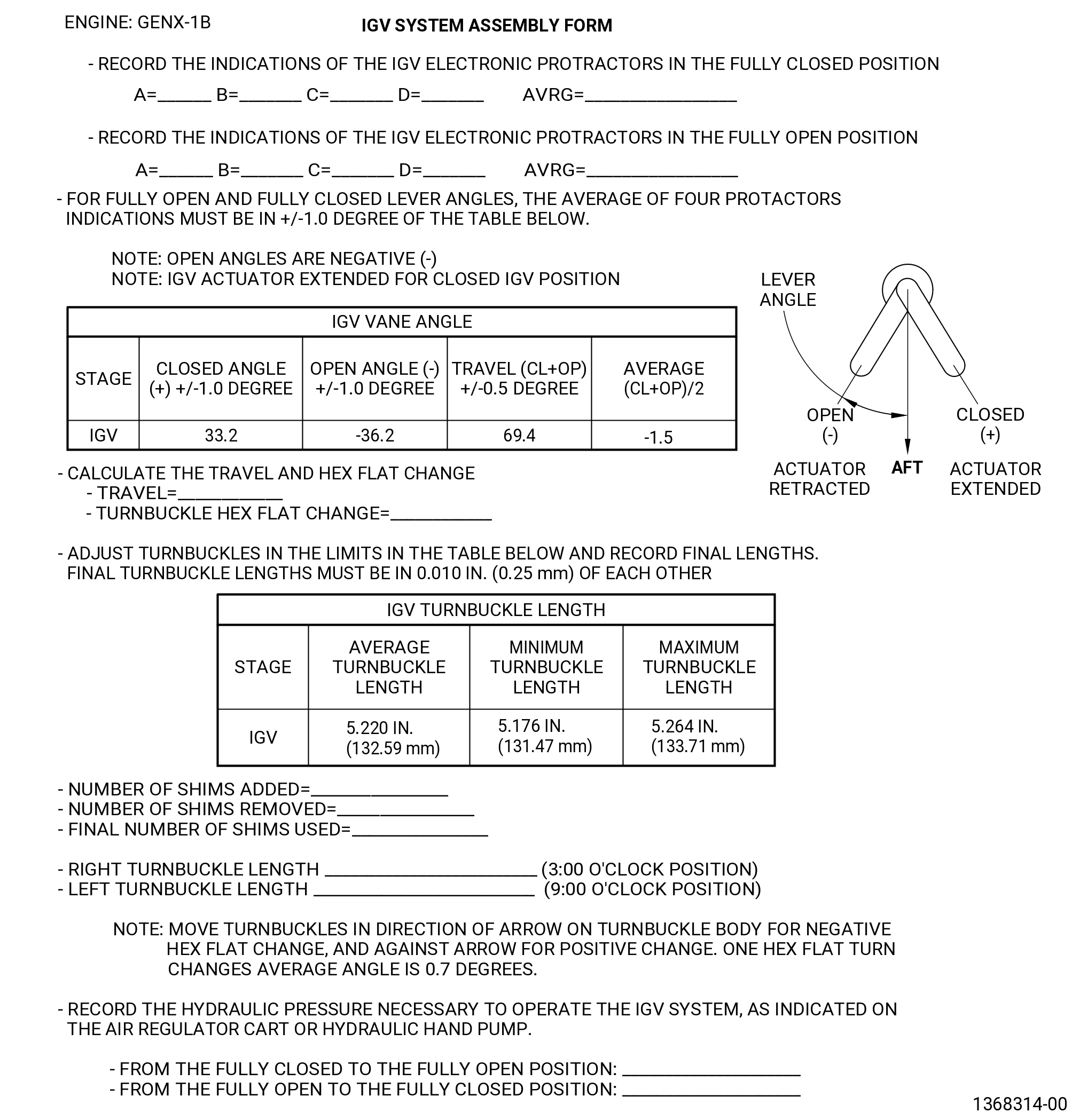
| (h) | Record the indications on the IGV assembly form. Refer to Figure 1030. |
| (i) | Calculate the average of two checks as follows: |
| 1 | Make sure the average closed and open values of the IGV electronic protractors A, B, C, and D on the IGV vanes No. 3, 12, 19, and 29 of the 9429M24 VSV electronic protractor are plus or minus 1.0 degree of the values shown in the table in Figure 1030. |
| 2 | Make sure to calculate the travel by adding the open and closed angles. Ignore the sign of the open angle. |
| 3 | Make sure the average travel of the four electronic protractors A, B, C and D is in 0.5 degree of the value in the table in Figure 1030. |
| Subtask 72-00-02-430-852 |
| (j) | If the fully open and fully closed average readings are not in 1.0 degree of the values shown in the table of Figure 1030, correct the IGV system as follows: |
| 1 | If the travel is out of limits, add or remove clevis shims (07570) to meet travel angle requirements as follows. Refer to Figure 1030. |
| NOTE: |
|
| a | Remove the self-locking nut and bolt that attach the IGV turnbuckle to the shaft clevis. |
| b | Remove the self-locking nut that attaches the shaft clevis to the torque shaft. |
| c | Remove the shaft clevis from the torque shaft and remove or add shims as necessary. Add one shim to increase the total travel angle and average angle as shown in the table on Figure 1030 and as follows: |
|
| d | If shims are removed or added from one of the VSV torque shaft linkages (9:00 o'clock position), add or remove the same number of shims from the other VSV torque shaft linkage (3:00 o'clock position). |
| e | Record any shim quantity changes and final shim total in the IGV assembly form. Refer to Figure 1030. |
| f | Attach the IGV turnbuckle to the shaft clevis with a bolt and self-locking nut. Torque the self-locking nut to 460-540 lb in. (52.0-61.0 N.m). |
| g | Install the shaft clevis in the torque shaft and attach it with a self-locking nut. Torque the self-locking nut to 552-648 lb in. (62.4-73.2 N.m). |
| 2 | If necessary, calculate the two hex flat change for the IGV turnbuckle to help determining the amount of adjustment required as follows: |
| a | Add the average measured open angle to the average measured closed angle and divide by 2. Do not ignore the negative sign of the average open angle. |
| b | Add the average design open angle to the average design closed angle and divide by 2. Do not ignore the negative sign of the average open angle. |
| c | Find the difference between the two values calculated above (Average measured - Average design) and divide by 0.7. This will give the number of hex flats to turn the turnbuckle. |
| d | Record the turnbuckle hex flat change on the IGV assembly form. Refer to Figure 1030. |
| NOTE: |
|
| 3 | If necessary, adjust the turnbuckle length to change the open and closed angles as follows: |
| a | Remove the bolt and self-locking nut that attache the turnbuckle to the IGV bridge (05-060 , 72-25-00) (SIN 071E0). |
| b | Remove the bolt and self-locking nut that attache the turnbuckle to the VSV torque shaft linkage (01-009 , 72-30-00) (SIN 07501) and (01-129 , 72-30-00) (SIN 07500) clevis. Remove the turnbuckle from the IGV system. |
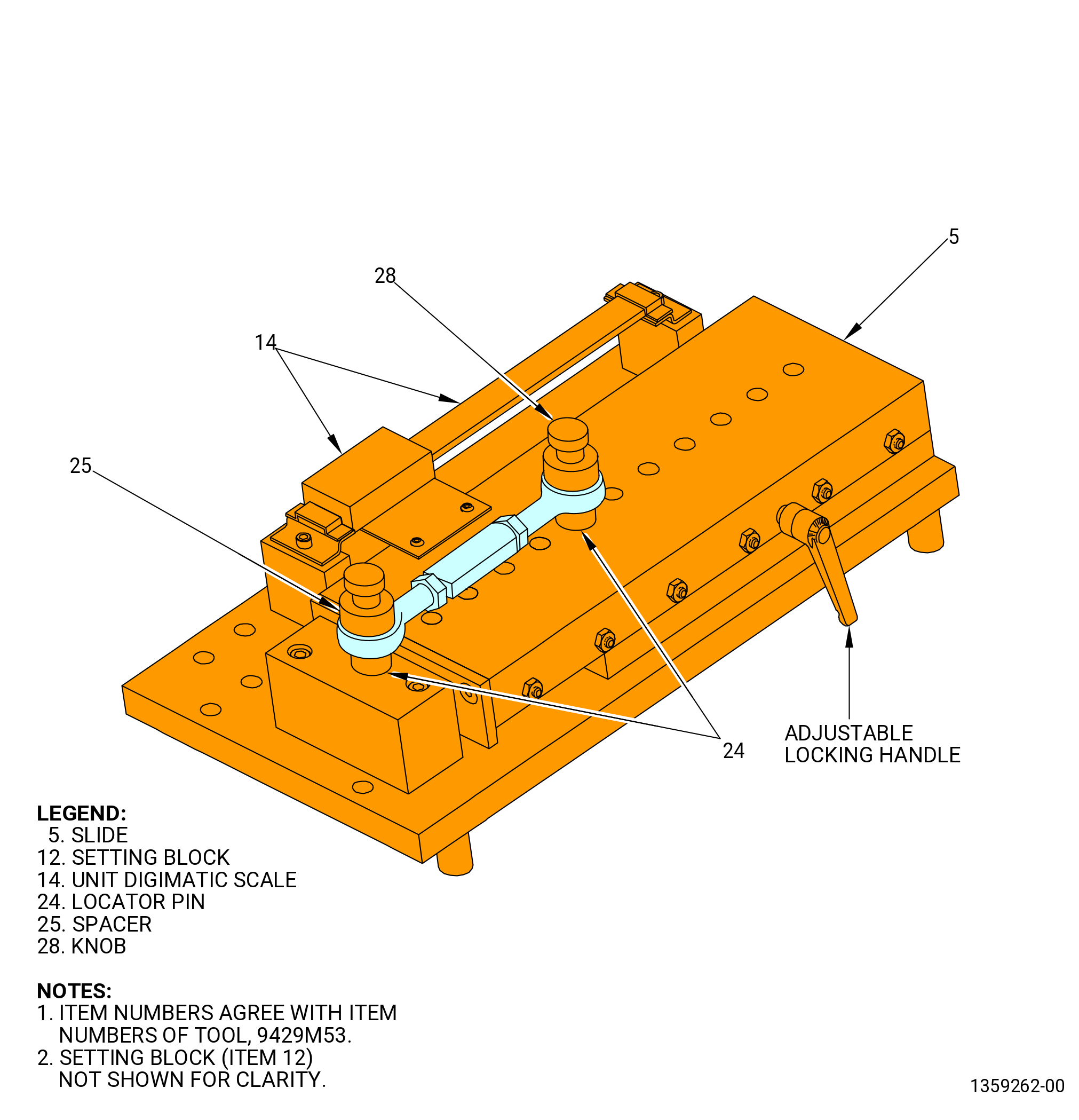
| c | Adjust the length of the turnbuckle with the 9429M53 gauging fixture as follows. Refer to Figure 1031. |
| d | Check the accuracy of the 9429M53 gauging fixture as follows: |
| (1) | Unlock the slide (item 5) of the 9429M53 gauging fixture with the adjustable locking handle. |
| (2) | Adjust the slide (item 5) and install the setting block (item 12) on the locator pins (item 24). The slotted open end of the setting block should be engaged with the locator pin (item 24) on the slide (item 5). |
| (3) | The unit digimatic scale (item 14) must read 5.000 plus or minus 0.001 inch (127.00 plus or minus 0.03 mm). If not, send the unit digimatic scale (item 14) to be calibrated. |
| (4) | With the setting block (item 12) still installed on the two locator pins (item 24), lock the slide (item 5) and reset the digital scale unit (item 14) to zero to establish the reference point. |
| (5) | Remove the setting block (item 12). |
| e | Unlock the slide (item 5) of the 9429M53 gauging fixture with the adjustable locking handle. |
| f | Put the turnbuckle in the 9429M53 gauging fixture as follows: |
| (1) | Put the holes of both turnbuckle rod ends on the protruded bosses on the locator pins (item 24) and install the rod ends on the pins until they seat on the top of the two flat planes of the locator pins (item 24) of the 9429M53 gauging fixture. |
| (2) | Install the two spacers (item 25) on the two protruded bosses of the locator pins (item 24), one on each boss until they are installed on the flat surfaces of the rod ends of the turnbuckles. |
| (3) | Install the two knobs (item 28) into the threaded holes on protruded bosses of the locator pins (item 24). Hand-tighten the knobs to keep the assembly without movement. |
| (4) | Loosen the self-locking nuts on the turnbuckle and turn the turnbuckle the number of hex flats recorded on the IGV assembly form. Refer to Figure 1030. |
| (5) | Follow the direction arrow for a positive hex flat change and turn against the arrow for a negative hex flat change. |
| (6) | Make sure the turnbuckle body is centered between the each rod end bearing. |
| NOTE: |
|
| (7) | Lock the slide (item 5) with the adjustable locking handle to restrain any slip movement of the slide (item 5). |
| (8) | Make sure that the slide (item 5) is locked and torque the jamnuts on each end of the turnbuckle to 235-275 lb in. (26.6-31.1 N.m). |
| (9) | Record the length of the turnbuckle. Refer to Figure 1030. |
| (10) | Remove the two knobs (item 28), two spacers (item 25), and turnbuckle from the 9429M53 gauging fixture. |
| g | Put the rod end bearings into the clevises on the IGV bridge (05-060 , 72-25-00) (SIN 071E0) and VSV torque shaft linkage so the direction arrow is away from the torque shaft. |
| NOTE: |
|
| h | Attach the rod end bearing to the IGV bridge and torque shaft with the bolts and self-locking nuts previously removed. Put the boltheads aft. |
| i | Torque the self-locking nuts to 460-540 lb in. (52.0-61.0 N.m). |
| (k) | Install the left/right IGV turnbuckles on the propulsor as follows: |
| 1 | Connect the RH rod end (01-090 , 72-30-00) (SIN 07501-10) or (01-225 , 72-30-00) (SIN 07500-10) to the IGV shaft clevis with a bolt (01-075 , 72-30-00) (SIN 07501-9) or (01-195 , 72-30-00) (SIN 07500-9) and a self-locking nut (01-070 , 72-30-00) (SIN 07501-8) or (01-190 , 72-30-00) (SIN 07500-8). Put the bolthead aft. |
| 2 | Connect the LH rod end (01-105 , 72-30-00) (SIN 07501-14) or (01-210 , 72-30-00) (SIN 07500-14) to the IGV bridge (05-060 , 72-25-00) (SIN 071E0) with a bolt (01-020 , 72-30-00) (SIN 07501-16) or (01-150 , 72-30-00) (SIN 07500-14) and a self-locking nut (01-015 , 72-30-00) (SIN 07501-15) or (01-145 , 72-30-00) (SIN 07500-15). Put the bolthead aft. |
| 3 | Torque the self-locking nuts (01-015 , 72-30-00) (SIN 07501-15) or (01-070 , 72-30-00) (SIN 07501-8) or (01-145 , 72-30-00) (SIN 07500-15) or (01-190 , 72-30-00) (SIN 07500-8) to 460-540 lb in. (52.0-61.0 N.m). |
| (l) | Torque the IGV clevis shaft nut to 46-54 lb ft. (62-73 N.m). |
| (m) | Do Subtask 72-00-02-430-860 (paragraph 3.P.(3)(f)) thru Subtask 72-00-02-430-861 (paragraph 3.P.(3)(g)) again to make sure that the system is in limits. Do this each time the IGV turnbuckles are adjusted. |
| (n) | Remove the VSV angle indicators (item 12), arm protractor (item 5), and tang adapter (item 4) of the 9429M24 VSV electronic protractor from the 11C3005 IGV/VSV tool kit. Refer to Figure 1028. |
| (o) | Remove the stage 4/IGV arm locator pin (item 17), IGV centering rod (item 16), and IGV clamping block (item 4) of the 11C3005 IGV/VSV tool kit from the IGV lever (05-020 , 72-25-00) (SIN 071D0). Refer to Figure 1027. |
| (p) | Carefully operate the system from full open (actuator rods retracted) to full close (actuator rods extended) four times to make sure that there is no binding or interference. |
| (q) | Disconnect the 9446M71 air regulator cart assembly or 9461M39 hydraulic hand pump from the VSV actuators (30400, 30401). |
| (r) | Remove and store the 9429M24 VSV electronic protractor and the 11C3005 IGV/VSV tool kit in applicable containers. |
| * * * END SB 72-0027 |
| Subtask 72-00-02-430-853 |
| * * * SB 72-0027( VSV Linkage Assembly Configuration 2 and 3 ) |
| P.A. | Do the IGV system adjustment and rigging of the integral clevis torque shaft linkage as follows: |
| NOTE: |
|
| (1) | Install the assembled left/right side IGV turnbuckle of the VSV torque shaft linkages (01-010 , 72-30-00) (SIN 07501) or (01-010A , 72-30-00) (SIN 07501) and (01-130 , 72-30-00) (SIN 07500) or (01-130A , 72-30-00) (SIN 07500) with the RH rod end, LH rod end, RH jamnut, and LH jamnut on the VSV torque shaft linkages and the IGV bridge at the 3:00 and the 9:00 o'clock positions as follows. Refer to Figure 1022. |
| (a) | Put the RH rod end (01-090 , 72-30-00) (SIN 07501-10) or (01-225 , 72-30-00) (SIN 07500-10) in the IGV shaft clevis. |
| (b) | Make sure that the direction arrow of the turnbuckle (01-095 , 72-30-00) (SIN 07501-12) or (01-215 , 72-30-00) (SIN 07500-12) is away from the VSV torque shaft linkages. The direction arrow will be on the turnbuckle end with the LH rod end (01-105 , 72-30-00) (SIN 07501-14) or (01-210 , 72-30-00) (SIN 07500-14). |
| NOTE: |
|
| (c) | Connect the RH rod end to the IGV shaft clevis with a bolt (01-075 , 72-30-00) (SIN 07501-9) or (01-195 , 72-30-00) (SIN 07500-9) and a self-locking nut (01-070 , 72-30-00) (SIN 07501-8) or (01-190 , 72-30-00) (SIN 07500-8). Put the bolthead aft. |
| (d) | Torque the self-locking nuts (01-070 , 72-30-00) (SIN 07501-8) or (01-190 , 72-30-00) (SIN 07500-8) to 331-389 lb in. (37.4-44.0 N.m). |
| (e) | Connect the LH rod end to the IGV bridge (05-060 , 72-25-00) (SIN 071E0) with a bolt (01-020 , 72-30-00) (SIN 07501-16) or (01-150 , 72-30-00) (SIN 07500-16) and a self-locking nut (01-015 , 72-30-00) (SIN 07501-15) or (01-145 , 72-30-00) (SIN 07500-15). Put the bolthead aft. |
| (f) | Torque the self-locking nuts (01-015 , 72-30-00) (SIN 07501-15) or (01-145 , 72-30-00) (SIN 07500-15) to 460-540 lb in. (52.0-61.0 N.m). |
| Subtask 72-00-02-430-854 |
| WARNING: |
|
| (2) | Alternative Procedure Available. Connect the rod end hose (item 4) and head end hose (item 3) of the 9446M71 air regulator cart assembly to the head and rod fittings on the VSV actuators (30400, 30401). Use nitrogen gas with the 9446M71 air regulator cart assembly. Refer to Figure 1023. |
| Subtask 72-00-02-430-855 |
| WARNING: |
|
| (2).A. | Alternative Procedure. Connect the hoses between the head and rod fittings on the VSV actuators (30400, 30401) and the head and rod fittings on the 9461M39 hydraulic hand pump. Use C02-019 engine oil or C02-021 grade 1010 oil with the pump. Refer to Figure 1024. |
| Subtask 72-00-02-820-007 |
| (3) | Rig the VSV actuation system for the IGV vanes as follows: |
| (a) | Calibrate the VSV angle indicator (item 12) encoders A, B, C, and D of the 9429M24 VSV electronic protractor on the set master base (item 6). Refer to Subtask 72-00-02-820-006 (paragraph 3.P.(3)(a)) thru Subtask 72-00-02-430-860 (paragraph 3.P.(3)(e)). |
| Subtask 72-00-02-430-856 |
| (4) | Operate the system to the fully closed position (actuator rods extended) and the fully open position (actuator rods retracted) four times. |
| NOTE: |
|
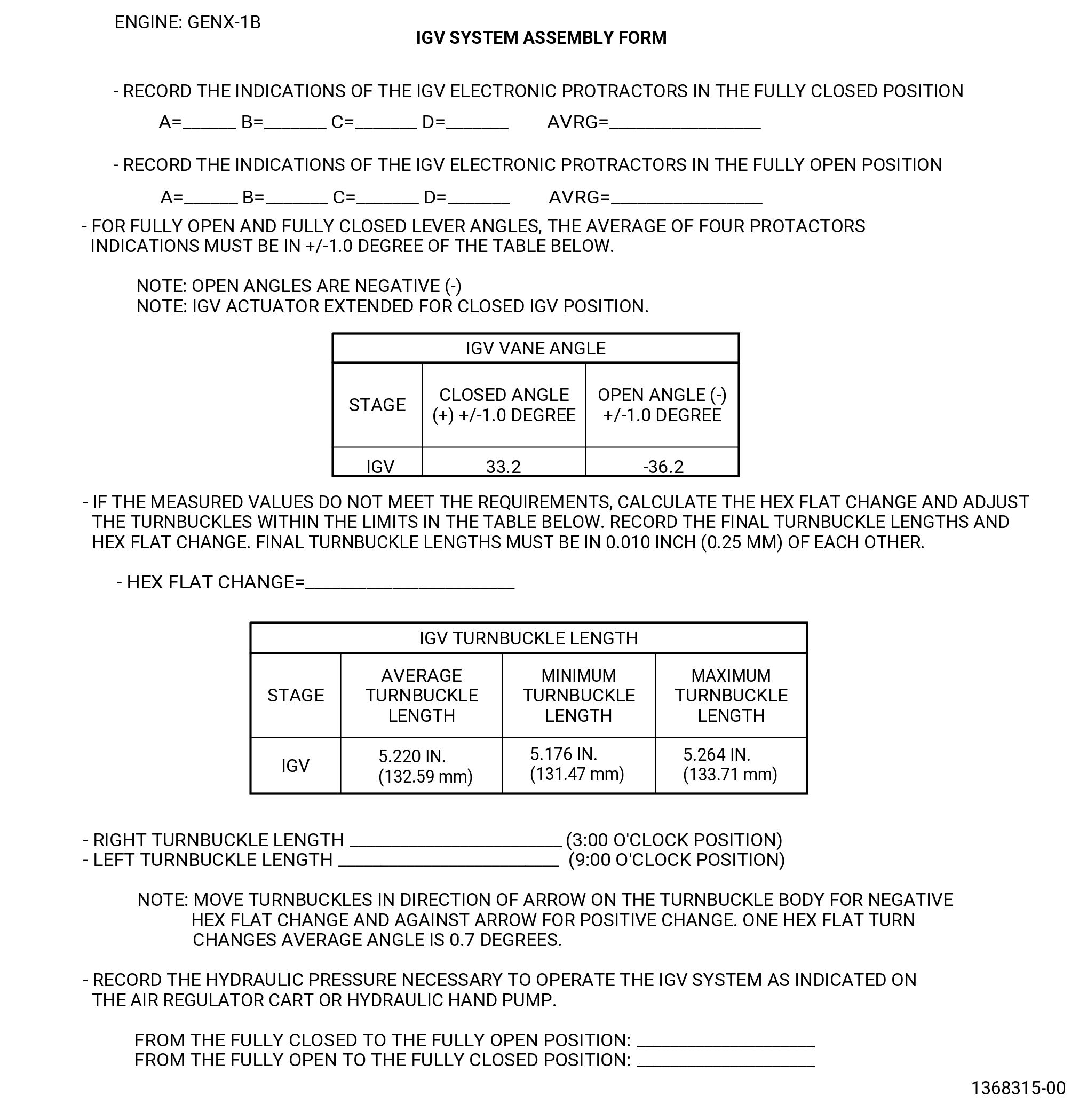
| (5) | Record the pressure necessary to operate the system on the IGV actuator pressure form. Refer to Figure 1032. |
| (6) | Record the final value for the fully closed position for each electronic protractors A, B, C, and D and the average of the four sensors on the IGV assembly form. |
| (7) | Make sure the average of the four VSV electronic protractors A, B, C, and D on the IGV vanes No. 3, 12, 20, and 29 of the 9429M24 VSV electronic protractor is ±1.0 degree of the values from the Figure 1032. |
| (8) | Record the final value for the fully open position for each electronic protractors A, B, C, and D and the average of the four sensors on the IGV assembly form. |
| (9) | Make sure the average of the four VSV electronic protractors A, B, C, and D on the IGV vanes No. 3, 12, 20, and 29 of the 9429M24 VSV electronic protractor is ±1.0 degree of the values from the Figure 1032. |
| (10) | If the measured values for the fully closed and fully open lever angles are in the limits, continue with Subtask 72-00-02-430-858 (paragraph 3.P.A.(12)) . If not, continue with Subtask 72-00-02-430-857 (paragraph 3.P.A.(11)). |
| Subtask 72-00-02-430-857 |
| (11) | If measured values for the fully closed and fully open lever angles are not in the limits from Figure 1032, adjust the turnbuckle length to change the open and closed angles as follows: |
| (a) | Remove the bolt and self-locking nut that attach the turnbuckle to the IGV bridge (05-060 , 72-25-00) (SIN 071E0). |
| (b) | Remove the bolt and self-locking nut that attach the turnbuckle to the VSV torque shaft linkage clevis. Remove the turnbuckle from the IGV system. |
| (c) | Calculate the hex flat change for the IGV turnbuckle to help determining the amount of adjustment required as follows: |
| 1 | Add the average measured open angle to the average measured closed angle and divide by 2. Do not ignore the negative sign of the average open angle. |
| 2 | Add the average design open angle to the average design closed angle and divide by 2. Do not ignore the negative sign of the average open angle. |
| 3 | Find the difference between the two values calculated above (Average measured - Average design) and divide by 0.7. This will give the number of the hex flats to turn the turnbuckle. Record the turnbuckle hex flat change on the IGV assembly form. Refer to Figure 1032. |
| NOTE: |
|
| (d) | Adjust the length of the turnbuckle with the 9429M53 gauging fixture as follows. Refer to Figure 1031. |
| 1 | Check the accuracy of the 9429M53 gauging fixture. |
| a | Unlock the slide (item 5) of the 9429M53 gauging fixture with the adjustable locking handle. |
| b | Adjust the slide and install the setting block (item 12) on the locator pins (item 24). The slotted open end of the setting block must be engaged with the locator pin (item 24) on the slide (item 5). |
| c | The unit digimatic scale (item 14) must read 5.000 plus or minus 0.001 inch (127.00 plus or minus 0.03 mm). If not, send the scale (item 14) to be calibrated. |
| d | With the setting block (item 12) still installed on the two locator pins (item 24), lock the slide (item 5) and reset the digital scale unit (item 14) to zero to establish the reference point. |
| e | Remove the setting block (item 12). |
| 2 | Unlock the slide (item 5) of the 9429M53 gauging fixture with the adjustable locking handle. |
| 3 | Put the turnbuckle in the 9429M53 gauging fixture as follows: |
| a | Put the holes of both turnbuckle rod ends on the protruded bosses on the locator pins (item 24) and install the rod ends on the pins until they seat on the top of the two flat planes of the locator pins (item 24) of the 9429M53 gauging fixture. |
| b | Install the two spacers (item 25) on the two protruded bosses of the locator pins (item 24), one on each boss until they are installed on the flat surfaces of the rod ends of the turnbuckles. |
| c | Install the two knobs (item 28) into the threaded holes on protruded bosses of the locator pins (item 24). Hand-tighten the knobs to keep the assembly without movement. |
| d | Loosen the self-locking nuts on the turnbuckle and turn the turnbuckle. |
| NOTE: |
|
| e | Record the number of turned hex flats on the IGV assembly form. Refer to Figure 1032. |
| NOTE: |
|
| f | Lock the slide (item 5) with the adjustable locking handle to restrain any movement of the slide (item 5). |
| g | Make sure that the slide (item 5) is locked and torque the turnbuckle RH jamnut (01-085 , 72-30-00) (SIN 07501-11) or (01-220 , 72-30-00) (SIN 07500-11) and LH jamnut (01-100 , 72-30-00) (SIN 07501-13) or (01-205 , 72-30-00) (SIN 07500-13) to 235-275 lb in. (26.6-31.1 N.m). |
| h | Record the length of the turnbuckles. Refer to Figure 1032. |
| i | Remove the two knobs (item 28), two spacers (item 25), and turnbuckle from the 9429M53 gauging fixture. |
| 4 | After all adjustments are made, actuate the system from full open to full closed four times. Make sure there is no binding or interference. |
| NOTE: |
|
| 5 | Install the left/right IGV turnbuckles on the propulsor assembly as follows. Refer to Figure 1022. |
| a | Connect the RH rod end (01-090 , 72-30-00) (SIN 07501-10) or (01-225 , 72-30-00) (SIN 07500-10) to the IGV shaft clevis with a bolt (01-075 , 72-30-00) (SIN 07501-9) or (01-195 , 72-30-00) (SIN 07500-9) and a self-locking nut (01-070 , 72-30-00) (SIN 07501-9) or (01-190 , 72-30-00) (SIN 07500-8). Put the bolthead aft. |
| b | Connect the LH rod end (01-105 , 72-30-00) (SIN 07501-14) or (01-210 , 72-30-00) (SIN 07500-14) to the IGV bridge with a bolt (01-020 , 72-30-00) (SIN 07501-16) or (01-150 , 72-30-00) (SIN 07500-16) and a self-locking nut (01-015 , 72-30-00) (SIN 07501-15) or (01-145 , 72-30-00) (SIN 07500-15). Put the bolthead aft. |
| c | Torque the self-locking nuts (01-015 , 72-30-00) (SIN 07501-15) or (01-070 , 72-30-00) (SIN 07501-9) or (01-145 , 72-30-00) (SIN 07500-15) or (01-190 , 72-30-00) (SIN 07500-8) 460-540 lb in. (52.0-61.0 N.m). |
| (e) | Torque the IGV shaft clevis nut to 46-54 lb ft. (62-73 N.m). |
| (f) | Do Subtask 72-00-02-430-856 (paragraph 3.P.A.(4)) thru Subtask 72-00-02-430-856 (paragraph 3.P.A.(7)) again to make sure that the system is in limits. Do this step each time the IGV turnbuckles are adjusted. |
| Subtask 72-00-02-430-858 |
| (12) | Remove the VSV angle indicators (item 12), protractor arm (item 5), and tang adapter (item 4) of the 9429M24 VSV electronic protractor from the 11C3005 IGV/VSV tool kit. Refer to Figure 1028. |
| (13) | Remove the stage 4/GV arm locator pin (item 17), IGV centering rod (item 16), and IGV clamping block (item 4) of the 11C3005 IGV/VSV tool kit from the IGV lever arm (05-020 , 72-25-00) (SIN 071D0). Refer to Figure 1027. |
| (14) | Carefully cycle the system from full open (actuator rods retracted) to full closed (actuator rods extended) four times to make sure there is no binding or interference. |
| (15) | Make sure that the VSV electronic protractors A, B, C, and D of the 9429M24 VSV electronic protractor are in calibration limits. Refer to Subtask 72-00-02-430-859 (paragraph 3.P.(3)(a)3) thru Subtask 72-00-02-430-848 (paragraph 3.P.(3)(a)20). |
| (16) | If for the 00.0 degrees angle position the digital readout is not in -00.2 thru 00.2 degree, do the rigging of the IGV system once again to make sure that the results are correct. Refer to Subtask 72-00-02-820-006 (paragraph 3.P.(3)(a)) thru Subtask 72-00-02-430-860 (paragraph 3.P.(3)(e)). |
| (17) | Disconnect the 9461M39 hydraulic hand pump from the VSV actuators (30400, 30401). Refer to Figure 1024. |
| (18) | Store the 9429M24 VSV electronic protractor and the 11C3005 IGV/VSV tool kit in applicable containers. |
| * * * END SB 72-0027 |
| Subtask 72-00-02-430-695 |
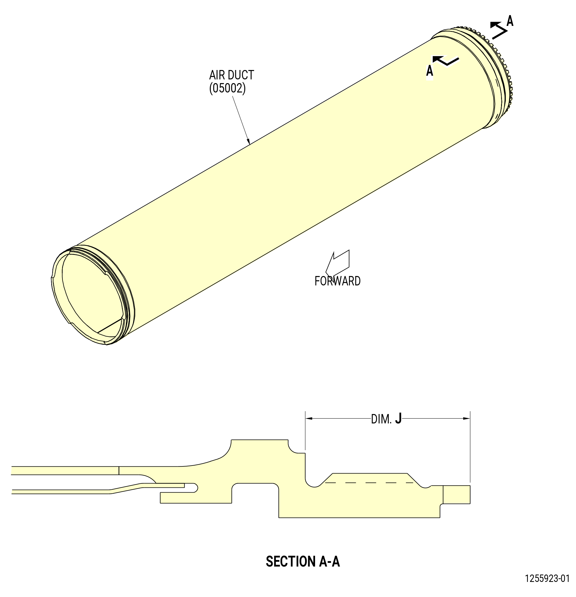
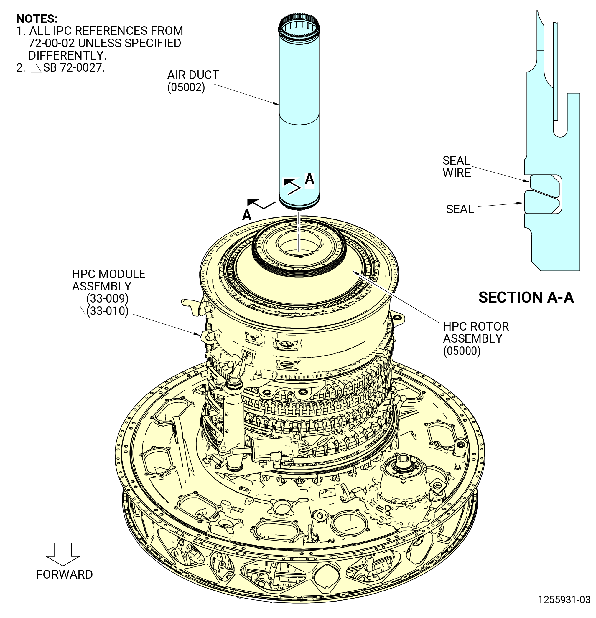
| Q. | Install the HPT rotor air duct (air duct) (34-310) (SIN 05002) in the HPC module assembly as follows: |
| (1) | Remove the 9C1276 bore protector from the stage 10 bore of the compressor rotor spool (050AR). Refer to Figure 1021. |
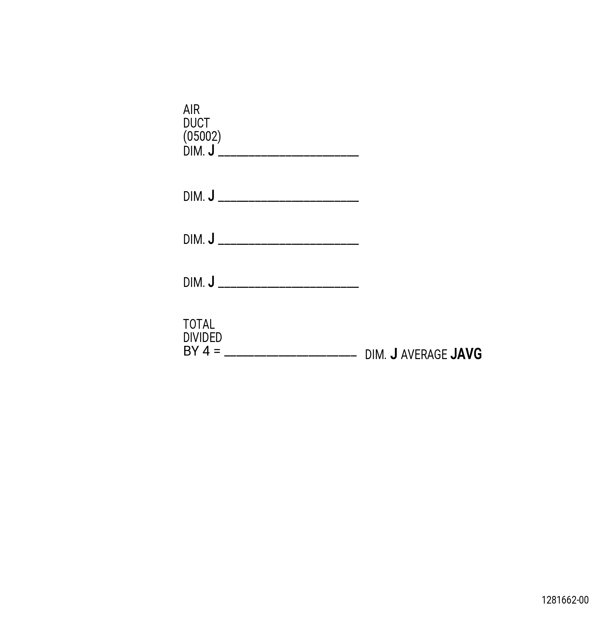
| (2) | Measure dimension Dim. J on the air duct (05002) as follows. Refer to Figure 1033. |
| (a) | Measure Dim. J from the aft end to the location where the air duct will seat against the HPT rotor assembly (15000) at four equally spaced locations. Record on the record sheet. Refer to Figure 1034. |
| (b) | Calculate the average for Dim. J and record on the record sheet as JAVG. |
| (3) | Make sure that the seal wire and seal are installed on the forward end of the air duct (05002) with the end gaps 180 degrees apart. Refer to Figure 1035. |
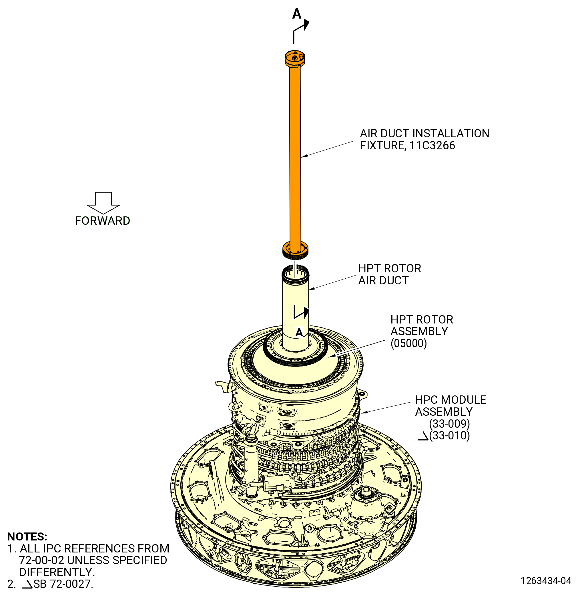
| (4) | Install the air duct (05002) in the HPT rotor assembly (05000) as follows: |
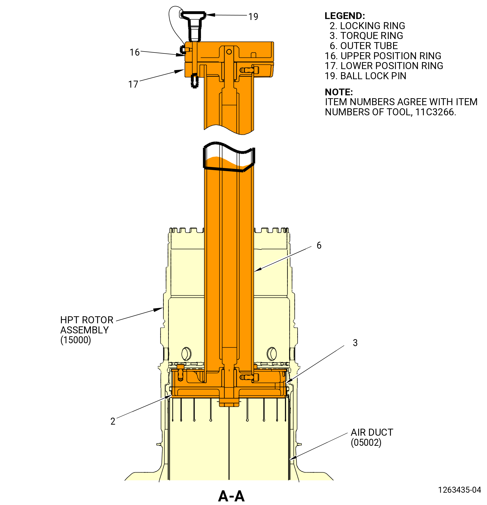
| (a) | Turn the lower position ring (item 17), in relation to the upper position ring (item 16), until the teeth in the locking ring (item 2) and the torque ring (item 3) are aligned. The ball lock pin (item 19) must be in the slot of the unlocked position. |
| CAUTION: |
|
| (b) | Put the fixture in the center so the teeth of the fixture are in the teeth of the air duct. Hold the 11C3266 air duct installation fixture very tightly at all times to prevent movement that can cause damage to the propulsor assembly. |
| NOTE: |
|
| (c) | Remove the ball lock pin (item 19) and rotate the lower position ring (item 17), in relation to the upper position ring (item 16), until the locking ring (item 2) is in the locked position. The ball lock pin (item 19) must be in the slot of the locked position. Move the air duct aft with the fixture. |
| (d) | Hold the 11C3266 air duct installation fixture very tightly and move the outer tube (item 6) to align the outer threads on the air duct with the inner threads of the HPT rotor stage 1 disk (150A1) aft shaft. |
| (e) | Rotate the fixture by hand in a CCW direction to thread the air duct into the HPT rotor stage 1 disk. Turn the air duct until it bottoms out in the disk. The air duct must be turned a minimum of two turns. |
| (f) | Remove the ball lock pin (item 19). |
| (g) | Turn the lower position ring (item 17) to disengage the splines from the air duct. |
| (h) | Remove the 11C3266 air duct installation fixture. |
| (5) | Put a protective cover on the bore area. |
| Subtask 72-00-02-430-696 |
| R. | Continue to assemble the propulsor assembly. Refer to TASK 72-00-02-430-817 (72-00-02, Assembly 002). |